Craftsman 13953919D User Manual GARAGE DOOR OPENER Manuals And Guides L0520651
CRAFTSMAN Garage Door Opener Manual L0520651 CRAFTSMAN Garage Door Opener Owner's Manual, CRAFTSMAN Garage Door Opener installation guides
User Manual: Craftsman 13953919D 13953919D CRAFTSMAN GARAGE DOOR OPENER - Manuals and Guides View the owners manual for your CRAFTSMAN GARAGE DOOR OPENER #13953919D. Home:Garage Door & Opener Parts:Craftsman Parts:Craftsman GARAGE DOOR OPENER Manual
Open the PDF directly: View PDF ![]() .
.
Page Count: 80
Owner's Manual/Manual Del Propietario
II:RRFTSMRNI
315MNz GARAGE DOOR OPENER
ABRIDOR DE PUERTA DE COCHERA 315MN=
For Residential Use Only/Solo para uso residencial
Model/Modelo 139.53919D
m
G3
m
"13
Z_
O
Read and follow all safety rules
and operating instructions before
first use of this product.
Fasten the manual near the garage
door after installation.
Leer y seguir todas las reglas de
seguridad y las instrucciones de
operacion antes de usar este
producto por primera vez.
Guardar este manual cerca de la
puerta de la cochera.
Periodic checks of the opener are
required to ensure safe operation.
Se deben realizar revisiones
periodicas del abridor de puertas
para asegurar su operacion
segura.
Sears, Roebuck and Co., Hoffman Estates, IL 60179 U.S.A
www.sears.com/craftsman
TABLE OF CONTENTS
Introduction 2- 7
Safety symbol and signal word review ........................ 2
Preparing your garage door ........................................ 3
Tools needed ............................................................... 3
Planning .................................................................. 4-5
Carton inventory .......................................................... 6
Hardware inventory ..................................................... 7
Assembly 8.11
Assemble the rail and install the trolley ...................... 8
Fasten the rail to the motor unit and
Install the idler pulley ................................................... 9
Install the belt and attach the belt cap retainer ......... 10
Set the tension .......................................................... 11
Installation 11-26
Installation safety instructions .................................... 11
Determine the header bracket location ..................... 12
Install the header bracket .......................................... 13
Attach the rail to the header bracket ......................... 14
Position the opener ................................................... 15
Hang the opener ....................................................... 16
Install the door control ............................................... 17
Install the lights ......................................................... 18
Attach the emergency release rope and handle ....... 18
Electrical requirements .............................................. 19
Install The Protector System ®.............................. 20-22
Fasten the door bracket ....................................... 23-24
Connect the door arm to the trolley ..................... 25-26
Adjustment 27-29
Program the travel limits ........................................... 27
Setting the force ........................................................ 28
Test the safety reversal system ................................. 29
Test The Protector System ®...................................... 29
Operation 30-36
Operation safety instructions ..................................... 30
Using your garage door opener ................................ 30
Using the wall-mounted Door Control ....................... 31
To open the door manually ........................................ 31
Battery backup unit .............................................. 32-33
Care of your garage door opener .............................. 34
Having a problem? .................................................... 35
Diagnostic chart ......................................................... 36
Programming 37-38
To add or reprogram a hand-held remote control .....37
To erase all codes ..................................................... 37
3-Function Remotes .................................................. 37
To add, reprogram or change
a Keyless Entry PIN .................................................. 38
Repair Parts 39-40
Rail assembly parts ................................................... 39
Installation parts ........................................................ 39
Motor unit assembly parts ......................................... 40
Accessories 41
Warran ty 41
Repair Parts & Service Back Cover
INTRODUCTION
Safety Symbol
and Signal Word Review
This garage door opener has been designed and tested to offer safe service provided it is installed, operated,
maintained and tested in strict accordance with the instructions and warnings contained in this manual.
Mechanical
Electrical
When you see these Safety Symbols and Signal
Words on the following pages, they will alert you to
the possibility of serious injury or death if you do
not comply with the warnings that accompany them.
The hazard may come from something mechanical
or from electric shock. Read the warnings carefully.
When you see this Signal Word on the following
pages, it will alert you to the possibility of damage to
your garage door and/or the garage door opener if
you do not comply with the cautionary statements
that accompany it. Read them carefully.
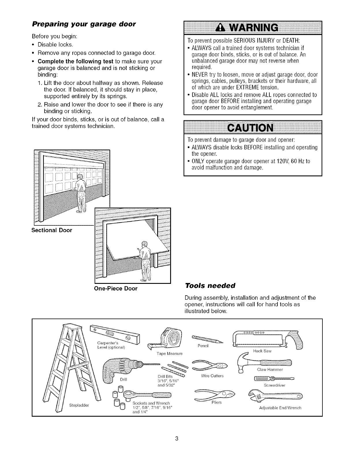
Preparing your garage door
Before you begin:
•Disable locks.
•Remove any ropes connected to garage door.
•Complete the following test to make sure your
garage door is balanced and is not sticking or
binding:
1. Lift the door about halfway as shown. Release
the door. If balanced, it should stay in place,
supported entirely by its springs.
2. Raise and lower the door to see if there is any
binding or sticking.
If your door binds, sticks, or is out of balance, call a
trained door systems technician.
To prevent possible SERIOUSINJURYor DEATH:
•ALWAYScall atrained door systems technician if
garage door binds, sticks, or is out of balance.An
unbalancedgarage door may not reverse when
required.
• NEVERtry to loosen, move or adjust garage door, door
springs, cables, pulleys, brackets or their hardware,all
of which are under EXTREMEtension.
• Disable ALL locks and removeALL ropes connected to
garage door BEFOREinstalling and operating garage
door opener to avoid entanglement.
To prevent damageto garage door and opener:
•ALWAYSdisable locks BEFOREinstalling and operating
the opener
•ONLYoperate garagedoor opener at 120V,60 Hzto
avoid malfunction and damage
Sectional Door
One-Piece Door Tools needed
During assembly, installation and adjustment of the
opener, instructions will call for hand tools as
illustrated below.
Stepladder
Carpenter's
Level (optional) Pencil
Tape Measure
Drill D_
Wire Cutters
and 1/4"
Hack Saw
Screwdriver
Adjustable End Wrench
Planning
Identify the type and height of your garage door.
Survey your garage area to see if any of the
conditions below apply to your installation. Additional
materials may be required. You may find it helpful to
refer back to this page and the accompanying
illustrations as you proceed with the installation of
your opener.
Depending on your requirements, there are several
installation steps which may call for materials or
hardware not included in the carton.
• Installation Step 1 - Look at the wall or ceiling
above the garage door. The header bracket must
be securely fastened to structural supports.
• Installation Step 5 - Do you have a finished ceiling
in your garage? If so, a support bracket and
additional fastening hardware may be required.
• Installation Step 10- Depending upon garage
construction, extension brackets or wood blocks
may be needed to install sensors.
• Installation Step 10 -Alternate floor mounting of
the safety reversing sensor will require hardware
not provided.
Do you have an access door in addition to the
garage door? If not, Model 53702 Emergency Key
Release is required. See Accessories page.
Look at the garage door where it meets the floor.
Any gap between the floor and the bottom of the
door must not exceed 1/4" (6 mm). Otherwise, the
safety reversal system may not work properly. See
Adjustment Step 3. Floor or door should be
repaired.
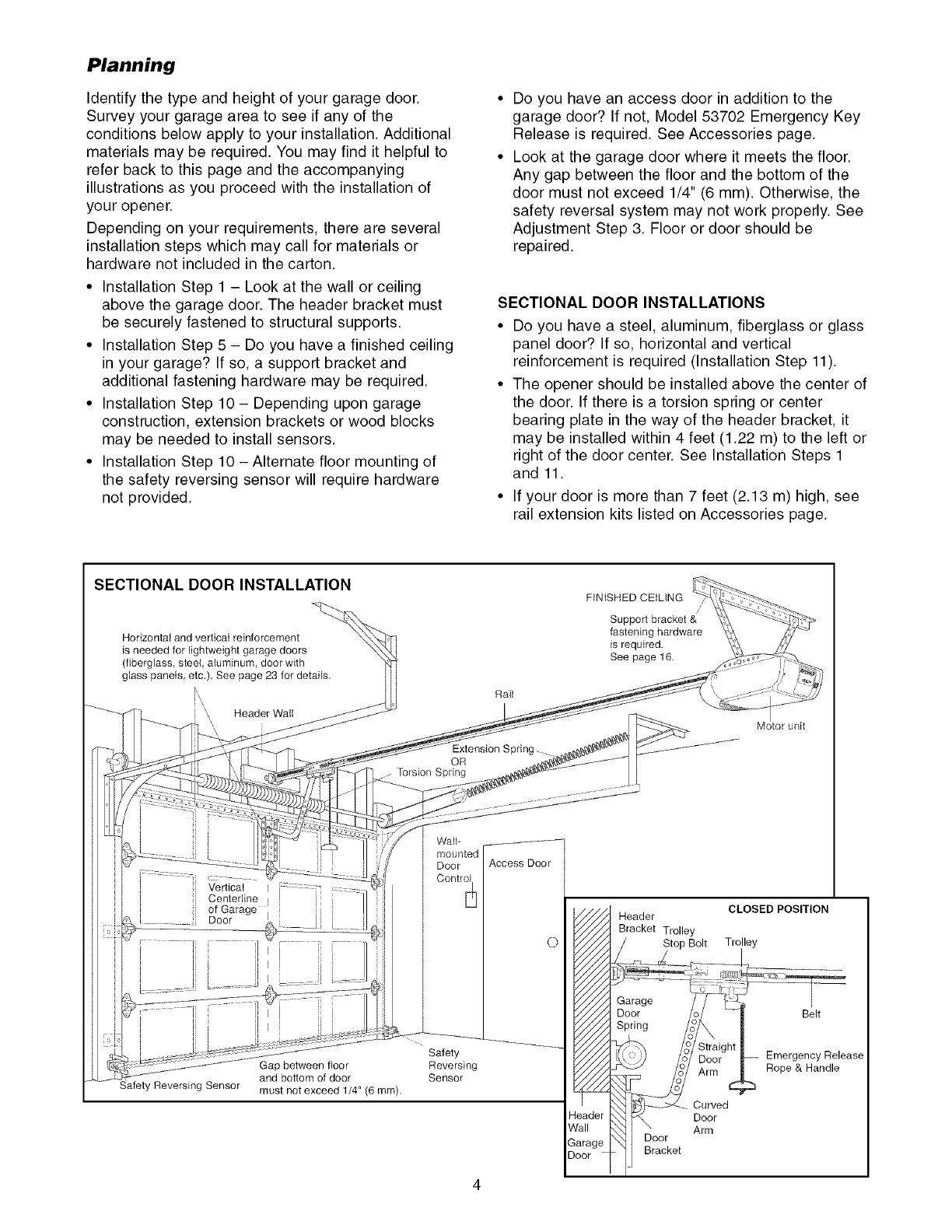
SECTIONAL DOOR INSTALLATIONS
• Do you have a steel, aluminum, fiberglass or glass
panel door? If so, horizontal and vertical
reinforcement is required (Installation Step 11).
• The opener should be installed above the center of
the door. If there is a torsion spring or center
bearing plate in the way of the header bracket, it
may be installed within 4 feet (1.22 m) to the left or
right of the door center. See Installation Steps 1
and 11.
• If your door is more than 7 feet (2.13 m) high, see
rail extension kits listed on Accessories page.
SECTIONAL DOOR INSTALLATION
Horizontal and vertical reinforcement
is needed for lightweight garage doors
(fiberglass, steel, aluminum, door with
glass panels etc.). See page 23 for details.
:: \,\ Header Wall
Extension Spring
OR
.... Torsion Spring
FiNiSHED CEUNG
/
Support bracket &
fastening hardware
is required,
See page 16,
Gap between floor
and bottom of door
Safety Reversing Sensor must not exceed 1/4" (6 mm),
Wall-
mounted
Door
Control
Safety
Reversing
Sensor
Access Door
©
leader
Call
iarage
,oor
CLOSED POSITION
Header
Bracket Trolley
rolley -_
Door Zo/ - Belt
/c°/ St)aigl
_:p) /_/ Door -- Emergency Release
m"..-:J /c°/ Arm Rope & Handle
&_ _,_ Door
_1 _oor Arm
11 _ck_t
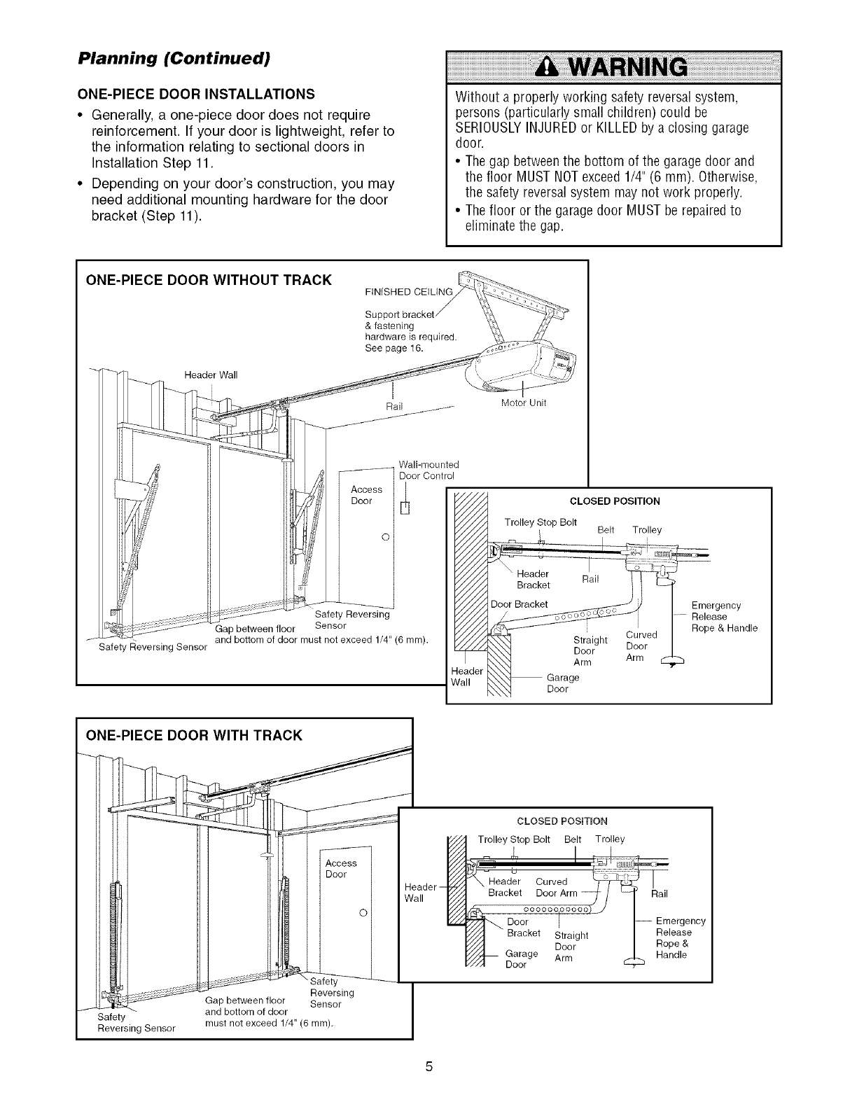
Planning (Continued)
ONE-PIECE DOOR INSTALLATIONS
•Generally, a one-piece door does not require
reinforcement If your door is lightweight, refer to
the information relating to sectional doors in
Installation Step 11
• Depending on your door's construction, you may
need additional mounting hardware for the door
bracket (Step 11)
Without a properly working safety reversal system,
persons (particularly small children) could be
SERIOUSLYINJUREDor KILLEDby a closing garage
door.
• The gap betweenthe bottom of the garage door and
the floor MUST NOTexceed 1/4" (6 mm). Otherwise,
the safety reversal system may not work properly.
• The floor or the garage door MUST be repairedto
eliminate the gap.
ONE-PIECE DOOR WITHOUT TRACK FINISHED CEILING
Safety Reversing Sensor
& fastening
hardware is required.
See page 16.
I
Rail ...........
........... Wall-mounted
Dioor Control
_' Access
Door
Safety Reversing
Gap between floor Sensor
and bottom of door must not exceed 1/4" (6 ram).
teader
Vail
t
Motor Unit
CLOSED POSITION
Trolley Stop Bolt Belt Trolley
Straight
Door Door
Arm Arm
Garage
Door
Emergency
Release
Rope & Handle
ONE-PIECE DOOR WITH TRACK
let
Reversing
Gap between floor Sensor
J Safety and bottom of door
Reversing Sensor must not exceed 1/4" (6 ram).
Header
Wall
CLOSED POSmON
Trolley Stop Bolt Belt Trolley
I --
J_-Head_r Curved
Bracket Door Arm _- /
idh,. °°°°°°l°°°°°)_
Door I
_////'_ Bracket Straight
_//I Door
///"_1_ Garage Arm
_/I Door
Rail
-- Emergency
Release
Rope &
Handle
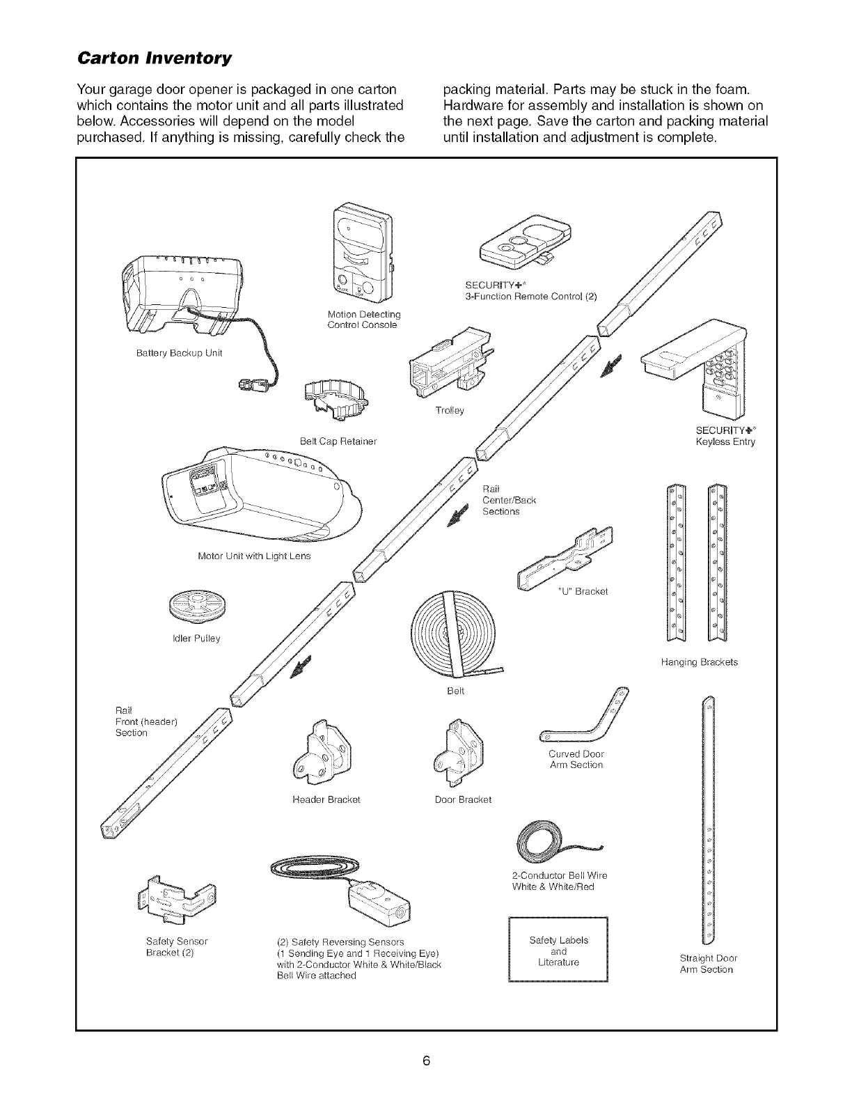
Carton Inventory
Your garage door opener is packaged in one carton
which contains the motor unit and all parts illustrated
below. Accessories will depend on the model
purchased. If anything is missing, carefully check the
packing material. Parts may be stuck in the foam.
Hardware for assembly and installation is shown on
the next page. Save the carton and packing material
until installation and adjustment is complete.
BelJ Wire attached
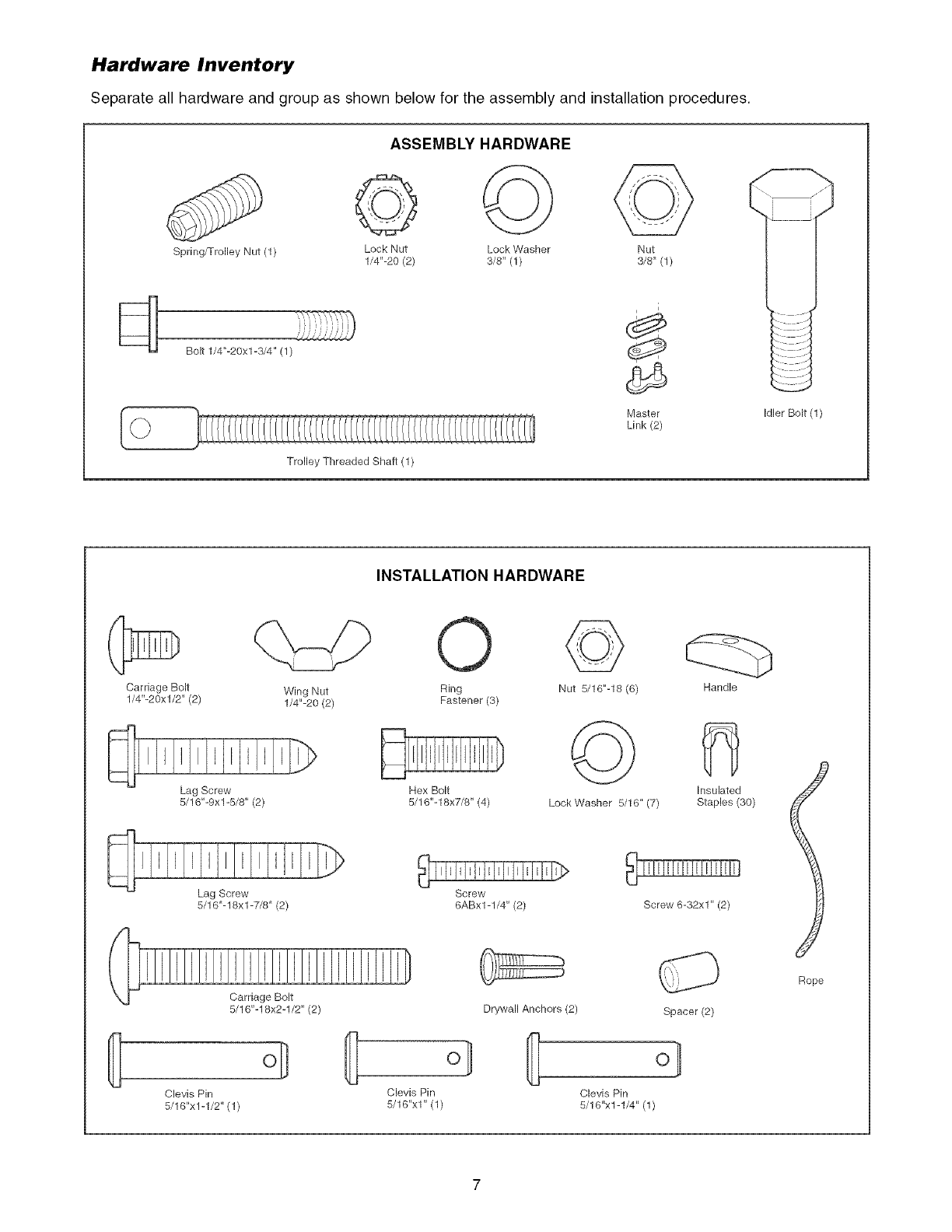
Hardware Inventory
Separate all hardware and group as shown below for the assembly and installation procedures.
Spring/Trolley Nut (1)
Bolt 1/4"-20xl-3/4" (1)
ASSEMBLY HARDWARE
© @ @
Lock Nut Lock Washer Nut
1/4"-20 (2) 3/8" (1) 3/8" (1)
Trolley Threaded Shaft (1)
i
ds
Master
Link (2)
Idler Bolt (1)
INSTALLATION HARDWARE
Carriage Bolt
1/4"-20xl/2" (2) Wing Nut
1/4"-20 (2)
Lag Screw
5/16"-9xl -5/8" (2)
Lag Screw
5/16"-18xl -7/8" (2)
Carriage Bolt
5/16"-18x2-1/2" (2)
o_
Clevis Pin
5/16"x1-1/2" (1)
Ring
Fastener (3)
Hex Bolt
5/16"-18x7/8" (4)
Nut 5/16"-18 (6)
©
LockWasher 5/16' (7)
Screw
6ABx1-1/4" (2)
Handle
Insulated
Staples (30)
Drywall Anchors (2)
Screw 6-32x1" (2)
Spacer (2)
I]] ol I]] ol
Clevis Pin Clevis Pin
5/16"x1" (1) 5/16"x1-1/4" (1)
Rope
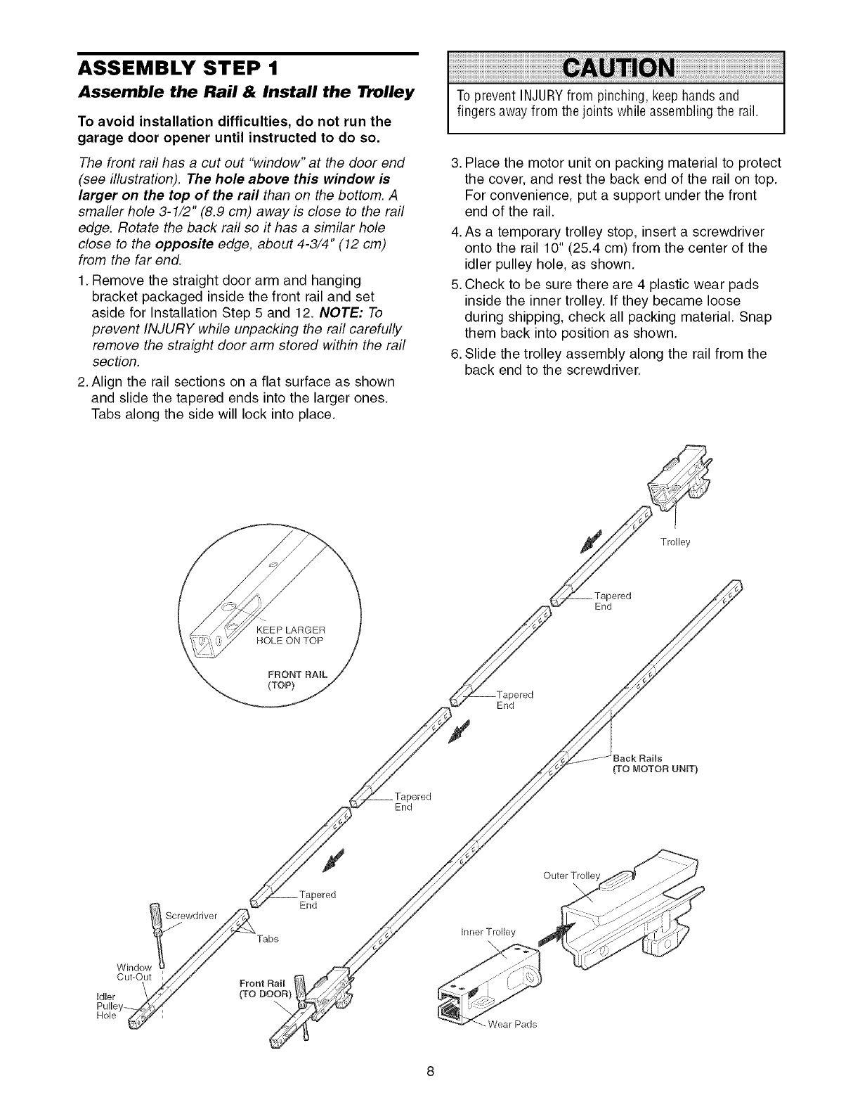
ASSEMBLY STEP 1
Assemble the Rail & Install the Trolley
To avoid installation difficulties, do not run the
garage door opener until instructed to do so.
The front rail has a cut out "window" at the door end
(see illustration). The hole above this window is
larger on the top of the rail than on the bottom. A
smaller hole 3-1/2" (8.9 cm) away is close to the rail
edge. Rotate the back rail so it has a similar hole
close to the opposite edge, about 4-3/4" (12 cm)
from the far end.
1. Remove the straight door arm and hanging
bracket packaged inside the front rail and set
aside for Installation Step 5 and 12. NOTE: To
prevent INJURY while unpacking the rail carefully
remove the straight door arm stored within the rail
section.
2. Align the rail sections on a flat surface as shown
and slide the tapered ends into the larger ones.
Tabs along the side will lock into place.
To prevent INJURYfrom pinching, keep hands and
fingers awayfrom the joints while assembling the rail.
3. Place the motor unit on packing material to protect
the cover, and rest the back end of the rail on top.
For convenience, put a support under the front
end of the rail.
4. As a temporary trolley stop, insert a screwdriver
onto the rail 10" (25.4 cm) from the center of the
idler pulley hole, as shown.
5. Check to be sure there are 4 plastic wear pads
inside the inner trolley. If they became loose
during shipping, check all packing material. Snap
them back into position as shown.
6. Slide the trolley assembly along the rail from the
back end to the screwdriver.
Trolley
_ered
End
End
aek Rails
(TO MOTOR UNIT)
End
Window
Cut-Out
ScreW_Tab s
Front Rail !
(ToDOOR)
\
End
InnerTrolley
\
-Wear Pads
Outer Trolley
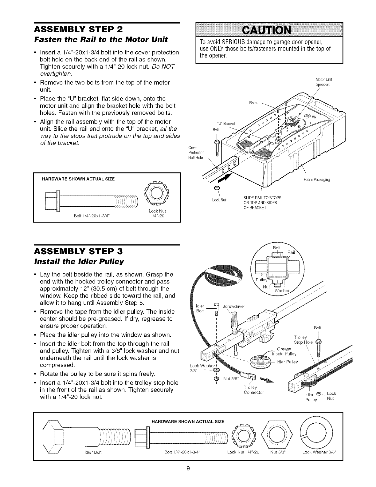
ASSEMBLY STEP 2
Fasten the Rail to the Motor Unit
•Insert a 1/4"-20xl-3/4 bolt into the cover protection
bolt hole on the back end of the rail as shown.
Tighten securely with a 1/4"-20 lock nut. Do NOT
overtighten.
• Remove the two bolts from the top of the motor
unit.
• Place the "U" bracket, flat side down, onto the
motor unit and align the bracket hole with the bolt
holes. Fasten with the previously removed bolts.
• Align the rail assembly with the top of the motor
unit. Slide the rail end onto the "U" bracket, all the
way to the stops that protrude on the top and sides
of the bracket.
To avoid SERIOUSdamageto garagedoor opener,
use ONLYthose bolts/fasteners mounted in the top of
the opener.
Motor Unit
Sprocket
Bolts
"U" Bracket
Bolt
I
Cover
Protection
Bolt Hole X
HARDWARE SHOWN ACTUAL SIZE
d ©
Lock Nut
Bolt 1/4"-20x 1-3/4" 1/4"-20
o:\
Lock Nut SLIDE RAILTO STOPS
ON TOPAND SIDES
OF BRACKET
FoamPackaging
ASSEMBLY STEP 3
Install the Idler Pulley
• Lay the belt beside the rail, as shown. Grasp the
end with the hooked trolley connector and pass
approximately 12" (30.5 cm) of belt through the
window. Keep the ribbed side toward the rail, and
allow it to hang until Assembly Step 5.
• Remove the tape from the idler pulley. The inside
center should be pre-greased. If dry, regrease to
ensure proper operation.
• Place the idler pulley into the window as shown.
• Insert the idler bolt from the top through the rail
and pulley. -lighten with a 3/8" lock washer and nut
underneath the rail until the lock washer is
compressed.
• Rotate the pulley to be sure it spins freely.
• Insert a 1/4"-20xl-3/4 bolt into the trolley stop hole
in the front of the rail as shown. Tighten securely
with a 1/4"-20 lock nut.
Lock Washerl
3/8" 9
Bolt
Trolley
Stop Hole
Grease IJ
-_ _side Pulley
--- Idle, Pulley __
Connector _ Idler (_ Lock
Pulley i Nut
HARDWARE SHOWN ACTUAL SIZE ©
Bolt 1/4"-20xl-3/4" Lock Nut 1/4"-20 Nut 3/8" Lock Washer 3/8"
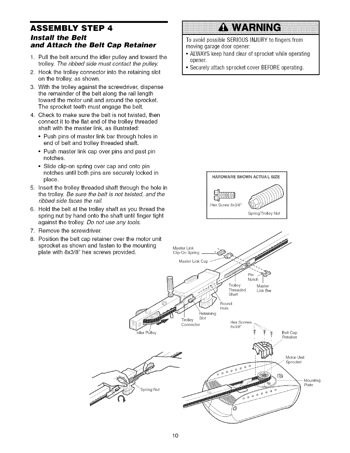
ASSEMBLY STEP 4
Install the Belt
and Attach the Belt Cap Retainer
1. Pull the belt around the idler pulley and toward the
trolley. The ribbed side must contact the pulley.
2. Hook the trolley connector into the retaining slot
on the trolley, as shown.
3. With the trolley against the screwdriver, dispense
the remainder of the belt along the rail length
toward the motor unit and around the sprocket.
The sprocket teeth must engage the belt.
4. Check to make sure the belt is not twisted, then
connect it to the flat end of the trolley threaded
shaft with the master link, as illustrated:
• Push pins of master link bar through holes in
end of belt and trolley threaded shaft.
• Push master link cap over pins and past pin
notches.
• Slide clip-on spring over cap and onto pin
notches until both pins are securely locked in
place.
5. Insert the trolley threaded shaft through the hole in
the trolley. Be sure the belt is not twisted, and the
ribbed side faces the rail.
6. Hold the belt at the trolley shaft as you thread the
spring nut by hand onto the shaft until finger tight
against the trolley. Do not use any tools.
7. Remove the screwdriver.
8. Position the belt cap retainer over the motor unit
sprocket as shown and fasten to the mounting
plate with 8x3/8" hex screws provided.
To avoid possible SERIOUSINJURYto fingers from
moving garage door opener:
• ALWAYSkeep hand clear of sprocket while operating
opener.
• Securelyattach sprocket cover BEFOREoperating.
HARDWARE SHOWN ACTUA L SIZE
Hex Screw 8x3/8"
Spring/Trolley Nut
Master Link
Clip-On Spring
Master Link Cap
Pin
Notch I
Trolley Master
Threaded Link Bar
Shaft
Idler PL ey
Retaining
Trolley Slot
Connector
Round
Hole
Hex Screws
8x3/8"
Belt Cap
Retainer
/
//
Motor Unit
Plate
10
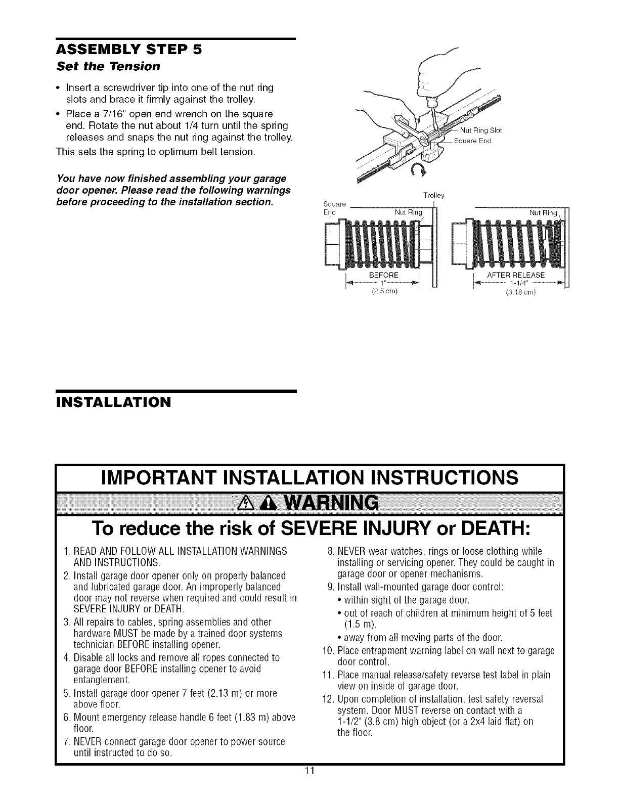
ASSEMBLY STEP 5
Set the Tension
•Insert a screwdriver tip into one of the nut ring
slots and brace it firmly against the trolley.
• Place a 7/16" open end wrench on the square
end. Rotate the nut about 1/4 turn until the spring
releases and snaps the nut ring against the trolley.
This sets the spring to optimum belt tension.
You have now finished assembling your garage
door opener. Please read the following warnings
before proceeding to the installation section. Square
End
_Nut Rin Slot
Trolley
Nut Ring Nut Rin(
INSTALLATION
IMPORTANT INSTALLATION INSTRUCTIONS
To reduce the risk of SEVERE INJURY or DEATH:
1. READAND FOLLOWALL INSTALLATIONWARNINGS
AND INSTRUCTIONS.
2. Install garage door opener only on properly balanced
and lubricated garage door. An improperly balanced
door may not reversewhen required and could result in
SEVEREINJURYor DEATH.
3. All repairs to cables, spring assembliesand other
hardware MUST be made by a trained door systems
technician BEFOREinstalling opener.
4. Disableall locks and removeall ropes connected to
garage door BEFOREinstalling opener to avoid
entanglement.
5. Install garage door opener 7 feet (2.13 m) or more
above floor.
6. Mount emergency releasehandle 6 feet (1.83 m) above
floor.
7. NEVERconnect garage door openerto power source
until instructed to do so.
8. NEVERwear watches, rings or loose clothing while
installing or servicing opener.They could be caught in
garage door or opener mechanisms.
9. Install wall-mounted garage door control:
• within sight of the garage door.
• out of reach of children at minimum height of 5 feet
(1.5 m).
• awayfrom all moving parts of the door.
10. Placeentrapment warning label on wall next to garage
door control.
11. Placemanual release/safetyreversetest label in plain
view on inside of garage door.
12. Upon completion of installation, test safety reversal
system. Door MUST reverseon contact with a
1-1/2" (3.8 cm) high object (or a 2x4 laid flat) on
the floor.
11
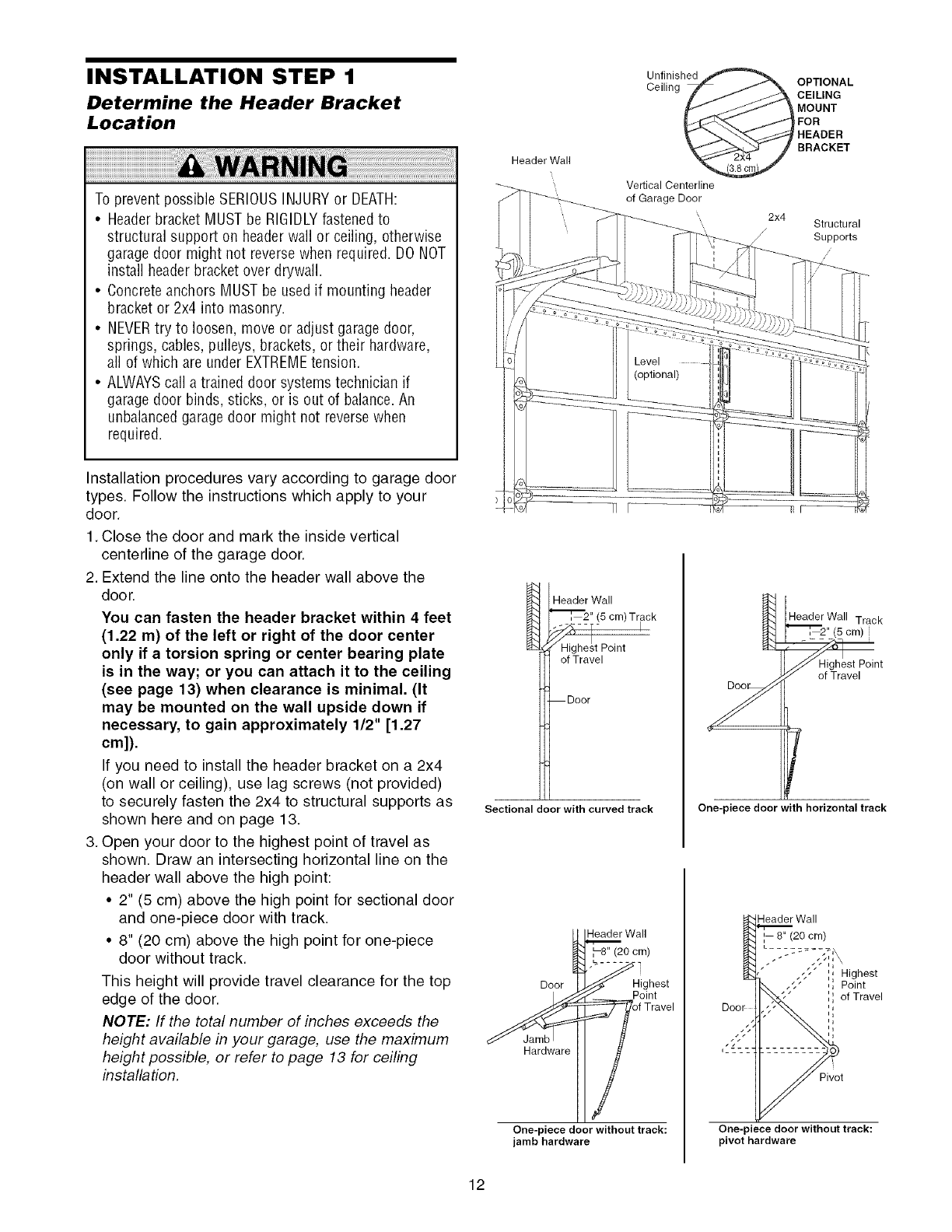
INSTALLATION STEP 1
Determine the Header Bracket
Location
To prevent possible SERIOUSINJURYor DEATH:
•Headerbracket MUST be RIGIDLYfastenedto
structural support on headerwall or ceiling, otherwise
garagedoor might not reversewhen required. DO NOT
install headerbracket over drywall.
• Concreteanchors MUST be used if mounting header
bracket or 2x4 into masonry.
• NEVERtry to loosen, move or adjust garagedoor,
springs, cables, pulleys, brackets, or their hardware,
all of which are under EXTREMEtension.
• ALWAYScall a trained door systems technician if
garagedoor binds, sticks, or is out of balance.An
unbalancedgarage door might not reversewhen
required.
Installation procedures vary according to garage door
types. Follow the instructions which apply to your
door.
1. Close the door and mark the inside vertical
centerline of the garage door.
2. Extend the line onto the header wall above the
door.
You can fasten the header bracket within 4 feet
(1.22 m) of the left or right of the door center
only if a torsion spring or center bearing plate
is in the way; or you can attach it to the ceiling
(see page 13) when clearance is minimal. (It
may be mounted on the wall upside down if
necessary, to gain approximately 1/2" [1.27
cm]).
If you need to install the header bracket on a 2x4
(on wall or ceiling), use lag screws (not provided)
to securely fasten the 2x4 to structural supports as
shown here and on page 13.
3. Open your door to the highest point of travel as
shown. Draw an intersecting horizontal line on the
header wall above the high point:
•2" (5 cm) above the high point for sectional door
and one-piece door with track.
• 8" (20 cm) above the high point for one-piece
door without track.
This height will provide travel clearance for the top
edge of the door.
NOTE: If the total number of inches exceeds the
height available in your garage, use the maximum
height possible, or refer to page 13 for ceiling
installation.
Header Wall
Unfinished
Ceilin _ _ OPTIONAL
CE,L,HG
p_ _ \ UOUHT
[J¢_-_'_ j_l POR
[ _\_ HEADER
_ BRACKET
Vertical Centerline
of Garage Door
2x4 Structural
/Supports
/
/
Header Wall
"_, 2" (5 cm) Track
Highest Point
of Travel
Door
Sectional door with curved track
1_ eader Wall Track
"_[_ 2" (5 cm)
_Highest Point
of Travel
f
One-piece door with horizontal track
_Wall
H ighest
__ PfOiTntave I
Hardware
One-piece door without track:
jamb hardware
Header Wall
', 8" (20 cm)
,5" ',i Highest
,, Point
Q
,, of Travel
One-piece door without track:
pivot hardware
12
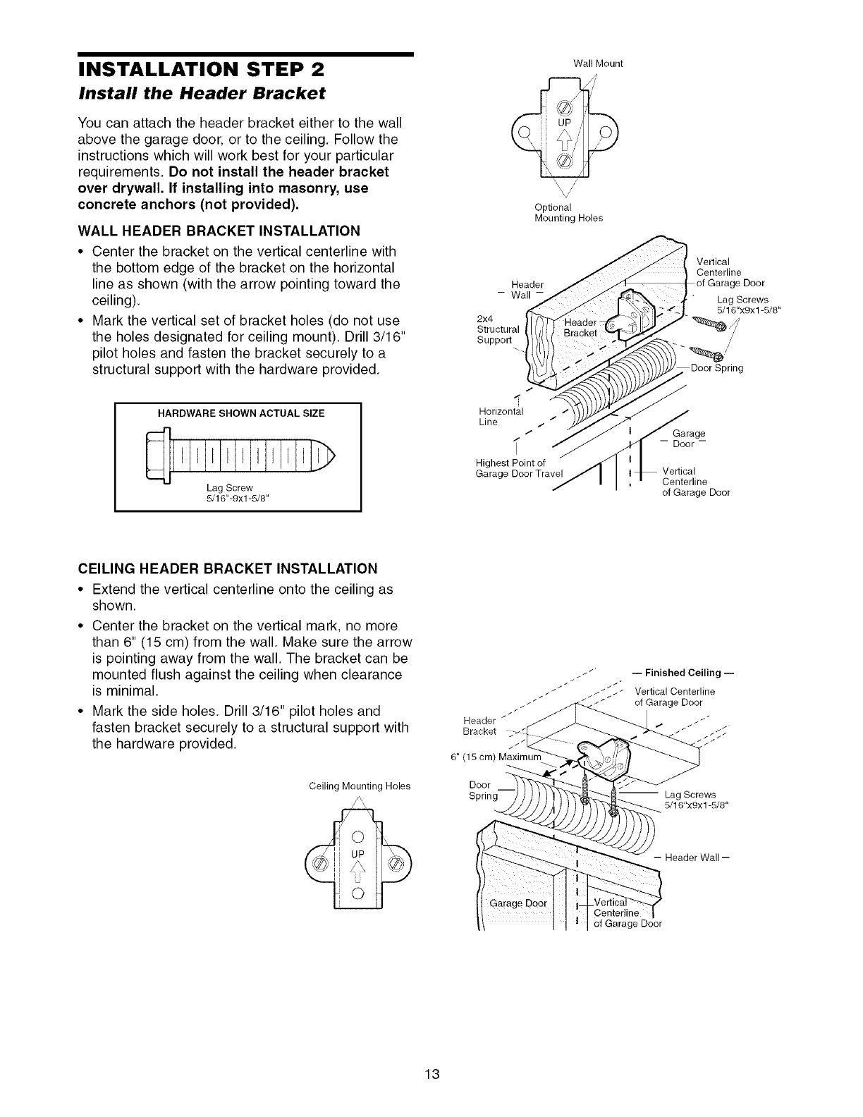
INSTALLATION STEP 2
Install the Header Bracket
You can attach the header bracket either to the wall
above the garage door, or to the ceiling. Follow the
instructions which will work best for your particular
requirements. Do not install the header bracket
over drywall. If installing into masonry, use
concrete anchors (not provided).
WALL HEADER BRACKET INSTALLATION
•Center the bracket on the vertical centerline with
the bottom edge of the bracket on the horizontal
line as shown (with the arrow pointing toward the
ceiling).
•Mark the vertical set of bracket holes (do not use
the holes designated for ceiling mount). Drill 3/16"
pilot holes and fasten the bracket securely to a
structural support with the hardware provided.
Header
- Wall-
2x4
Structural
Support
Wall Mount
,v//
Optional
Mounting Holes
Vertical
Centerline
of Garage Door
Lag Screws
5/16"x9x 1-5/8"
/
HARDWARE SHOWN ACTUAL SIZE
Lag Screw
5/16"-9xl -5/8"
Horizontal
Line _, /
/
Highest Point of
Garage Door Travel
Garage
-- Door-
Vertical
Centerline
of Garage Door
CEILING HEADER BRACKET INSTALLATION
• Extend the vertical centerline onto the ceiling as
shown.
• Center the bracket on the vertical mark, no more
than 6" (15 cm) from the wall. Make sure the arrow
is pointing away from the wall. The bracket can be
mounted flush against the ceiling when clearance
is minimal.
• Mark the side holes. Drill 3/16" pilot holes and
fasten bracket securely to a structural support with
the hardware provided.
Ceiling Mounting Holes
Header _
Bracket
6" (15 cm) Maximum
Door
Spring
/Finished Ceiling
Vertical Centerline
__ of Garage Door
" Lag Screws
5/16"x9x1-5/8"
-- Header Wall --
Center]ine
of Garage Door
13
//
//
//
//
//
Garage
Door
Bracket
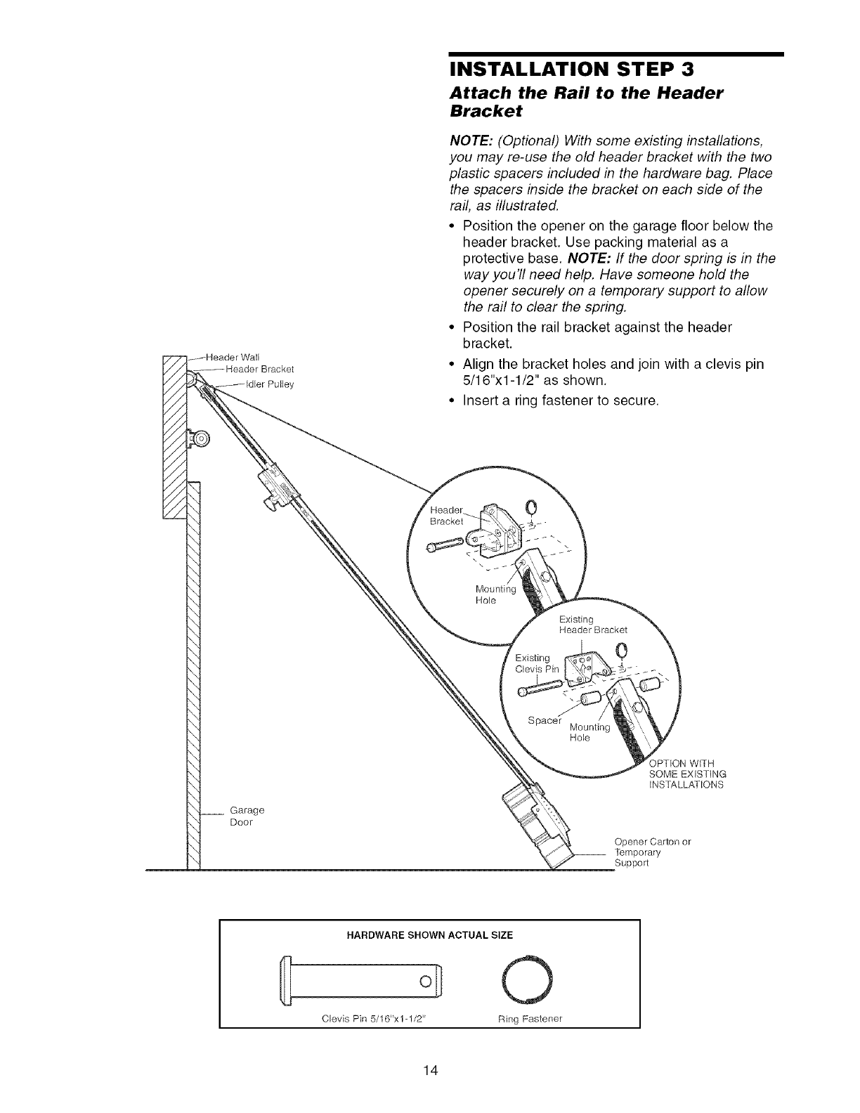
INSTALLATION STEP 3
Attach the Rail to the Header
Bracket
NOTE: (Optional) With some existing installations,
you may re-use the old header bracket with the two
plastic spacers included in the hardware bag. Place
the spacers inside the bracket on each side of the
rail, as illustrated.
• Position the opener on the garage floor below the
header bracket. Use packing material as a
protective base. NOTE: If the door spring is in the
way you'll need help. Have someone hold the
opener securely on a temporary support to allow
the rail to clear the spring.
• Position the rail bracket against the header
bracket.
• Align the bracket holes and join with a clevis pin
5/16"xl-1/2" as shown.
• Insert a ring fastener to secure.
0
\
Mounting
Hole
Existing
Header Bracket
Existing 0
Clevis Pin
Spacer Mounting
Hole
IPT_ON WITH
SOME EXISTING
INSTALLATIONS
Opener Carton or
__ temporary
Support
HARDWARE SHOWN ACTUAL SIZE
@
Clevis Pin 5/16"x 1-1/2" Ring Fastener
14
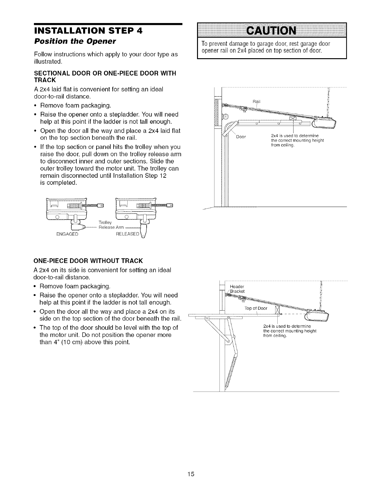
INSTALLATION STEP 4
Position the Opener
Follow instructions which apply to your door type as
illustrated.
SECTIONAL DOOR OR ONE-PIECE DOOR WITH
TRACK
A 2x4 laid flat is convenient for setting an ideal
door-to-rail distance.
• Remove foam packaging.
• Raise the opener onto a stepladder. You will need
help at this point if the ladder is not tall enough.
• Open the door all the way and place a 2x4 laid flat
on the top section beneath the rail.
• If the top section or panel hits the trolley when you
raise the door, pull down on the trolley release arm
to disconnect inner and outer sections. Slide the
outer trolley toward the motor unit. The trolley can
remain disconnected until Installation Step 12
is completed.
To prevent damageto garage door, rest garage door
opener rail on 2x4 placed on top section of door.
ENGAGED
ONE-PIECE DOOR WITHOUT TRACK
A 2x4 on its side is convenient for setting an ideal
door-to-rail distance.
• Remove foam packaging.
• Raise the opener onto a stepladder. You will need
help at this point if the ladder is not tall enough.
• Open the door all the way and place a 2x4 on its
side on the top section of the door beneath the rail.
• The top of the door should be level with the top of
the motor unit. Do not position the opener more
than 4" (10 cm) above this point.
2x4 is used to determine
the correct mounting height
from ceiling.
15
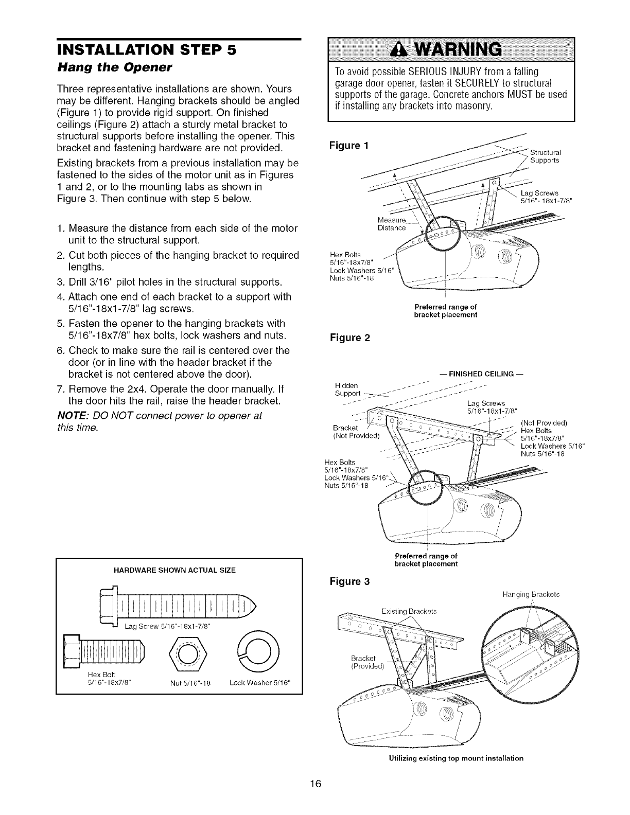
INSTALLATION STEP 5
Hang the Opener
Three representative installations are shown. Yours
may be different. Hanging brackets should be angled
(Figure 1) to provide rigid support. On finished
ceilings (Figure 2) attach a sturdy metal bracket to
structural supports before installing the opener. This
bracket and fastening hardware are not provided.
Existing brackets from a previous installation may be
fastened to the sides of the motor unit as in Figures
1 and 2, or to the mounting tabs as shown in
Figure 3. Then continue with step 5 below.
1. Measure the distance from each side of the motor
unit to the structural support.
2. Cut both pieces of the hanging bracket to required
lengths.
3. Drill 3/16" pilot holes in the structural supports.
4. Attach one end of each bracket to a support with
5/16"-18xl-7/8" lag screws.
5. Fasten the opener to the hanging brackets with
5/16"-18x7/8" hex bolts, lock washers and nuts.
6. Check to make sure the rail is centered over the
door (or in line with the header bracket if the
bracket is not centered above the door).
7. Remove the 2x4. Operate the door manually. If
the door hits the rail, raise the header bracket.
NOTE: DO NOT connect power to opener at
this time.
To avoid possible SERIOUSINJURYfrom a falling
garage door opener,fasten it SECURELYto structural
supports of the garage. Concrete anchors MUST be used
if installing any brackets into masonry.
Figure 1
Measure '_,
Distance
Lag Screws
5/16"-18xl-7/8"
Hex Bolts
5/16"-18x7/8"
Lock Washers 5/16"
Nuts 5/16"-18
Figure 2
Preferred range of
bracket placement
Bracket
(Not Provided)
Hex Bolts
5/16"-18x7/8"
Lock Washers 5/16"
Nuts 5/16"-18
(Not Provided)
Hex Bolts
5/16"- 18x7/8"
Lock Washers 5/16"
Nuts 5/16"-18
HARDWARE SHOWN ACTUAL SIZE
Lag Screw 5/16"-18xl -7/8"
© ©
Hex Bolt
5/16"-18x7/8" Nut 5/16"-18 Lock Washer 5/16"
Figure 3
Bracket
(Provided)
Preferred range of
bracket placement
Existing Brackets
Hanging Brackets
Utilizing existing top mount installation
16
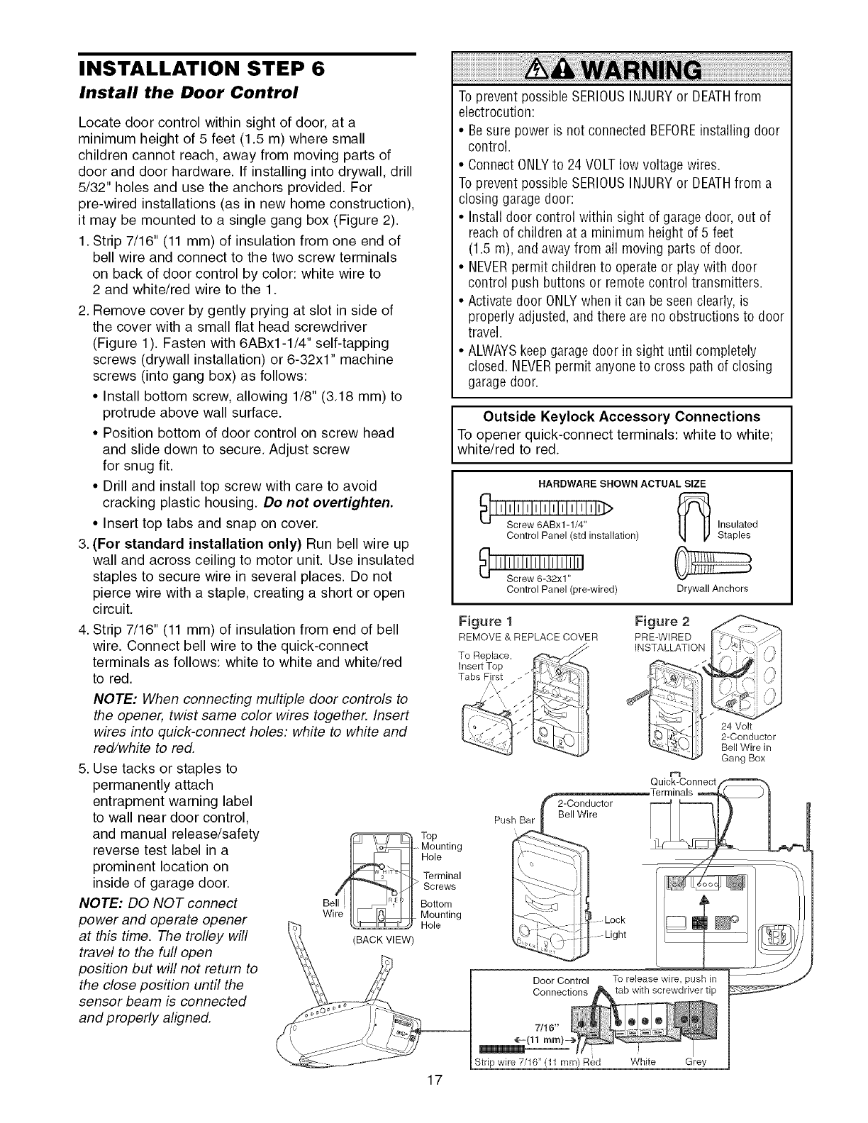
INSTALLATION STEP 6
Install the Door Control
Locate door control within sight of door, at a
minimum height of 5 feet (1.5 m) where small
children cannot reach, away from moving parts of
door and door hardware. If installing into drywall, drill
5/32" holes and use the anchors provided. For
pre-wired installations (as in new home construction),
it may be mounted to a single gang box (Figure 2).
1. Strip 7/16" (11 mm) of insulation from one end of
bell wire and connect to the two screw terminals
on back of door control by color: white wire to
2 and white/red wire to the 1.
2. Remove cover by gently prying at slot in side of
the cover with a small flat head screwdriver
(Figure 1). Fasten with 6ABx1-1/4" self-tapping
screws (drywall installation) or 6-32x1" machine
screws (into gang box) as follows:
•Install bottom screw, allowing 1/8" (3.18 mm) to
protrude above wall surface.
• Position bottom of door control on screw head
and slide down to secure. Adjust screw
for snug fit.
• Drill and install top screw with care to avoid
cracking plastic housing. Do not overtighten.
• Insert top tabs and snap on cover.
3. (For standard installation only) Run bell wire up
wall and across ceiling to motor unit. Use insulated
staples to secure wire in several places. Do not
pierce wire with a staple, creating a short or open
circuit.
4. Strip 7/16" (11 mm) of insulation from end of bell
wire. Connect bell wire to the quick-connect
terminals as follows: white to white and white/red
to red.
NOTE: When connecting multiple door controls to
the opener, twist same color wires together. Insert
wires into quick-connect holes: white to white and
red/white to red.
5. Use tacks or staples to
permanently attach
entrapment warning label
to wall near door control,
and manual release/safety
reverse test label in a
prominent location on
inside of garage door. ,/
NOTE: DO NOT connect Beil
Wire
power and operate opener
at this time. The trolley will BACKVIEW'
travel to the furl open
position but will not return to
the close position until the
sensor beam is connected
and properly aligned.
To prevent possible SERIOUSINJURYor DEATHfrom
electrocution:
• Besure power is not connected BEFOREinstalling door
control.
• Connect ONLYto 24 VOLTlow voltage wires.
To prevent possible SERIOUSINJURYor DEATHfrom a
closing garagedoor:
• Install door control within sight of garage door, out of
reach of children at a minimum height of 5 feet
(1.5 m), and away from all moving parts of door.
• NEVERpermit children to operateor play with door
control push buttons or remote control transmitters.
• Activate door ONLYwhen it can be seen clearly, is
properly adjusted, andthere are no obstructions to door
travel.
• ALWAYSkeep garage door in sight until completely
closed. NEVERpermit anyone to cross path of closing
garagedoor.
Outside Keylock Accessory Connections
To opener quick-connect terminals: white to white;
white/red to red.
HARDWARE SHOWN ACTUAL SIZE
Top
Mounting
Hole
Terminal
Screws
Bottom
Mounting
Hole
17
Control Panel (std installation)
Control Panel (pre-wired)
Insulated
Staples
Drywall Anchors
Figure 1
REMOVE & REPLACE COVER
To Replace,
Insert Top
Tabs First
/,, ///_
2-Conductor
Bell Wire
Push Bar
Figure 2
PRE-WIRED
INSTALLATION
24 Volt
2-Conductor
Bell Wire in
Gang Box
r_
Quick-Connect f_'_- N
Door Control To release wire, push in
Strip wire 7/16" (11 mm) Red White Grey
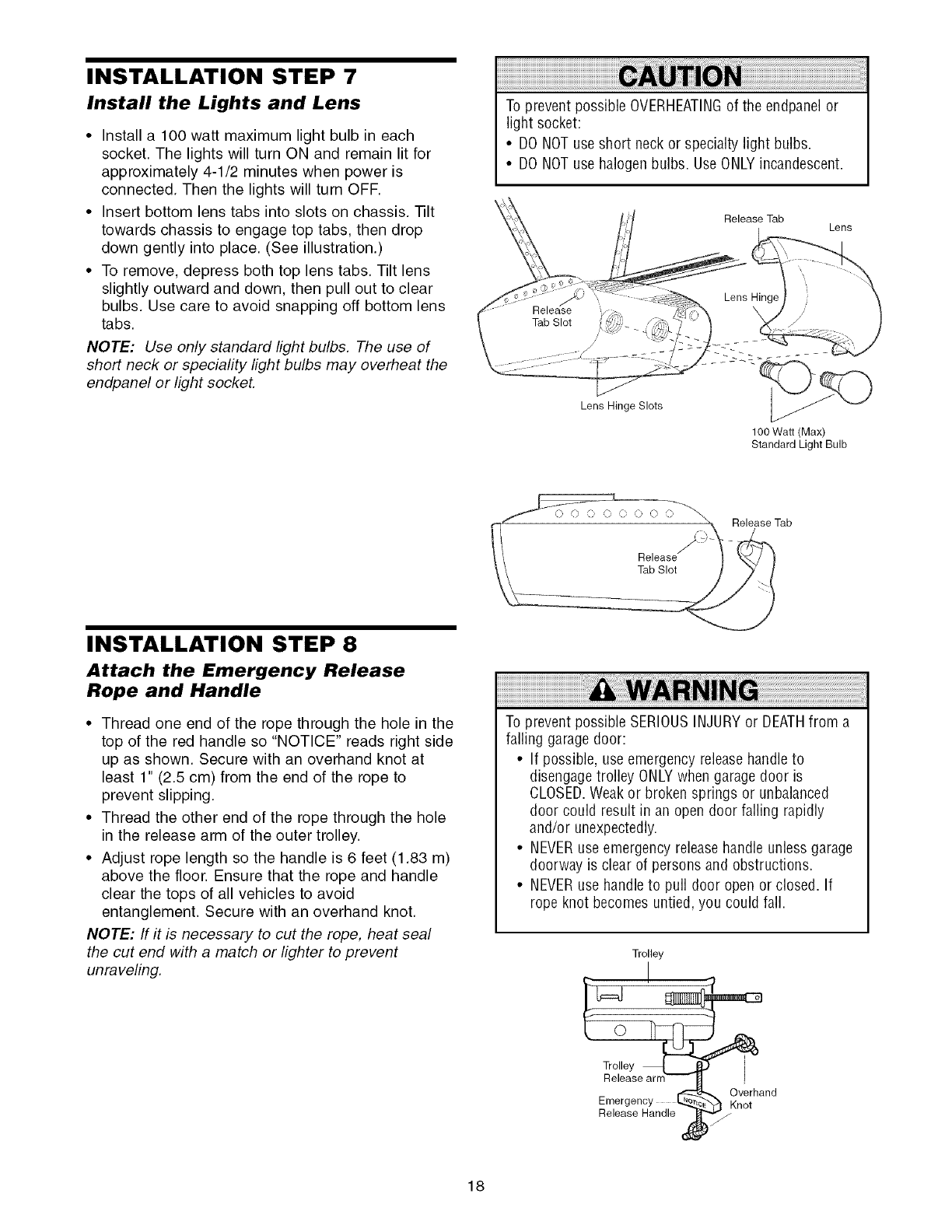
INSTALLATION STEP 7
Install the Lights and Lens
•Install a 100 watt maximum light bulb in each
socket. The lights will turn ON and remain lit for
approximately 4-1/2 minutes when power is
connected. Then the lights will turn OFF.
• Insert bottom lens tabs into slots on chassis. -lilt
towards chassis to engage top tabs, then drop
down gently into place. (See illustration.)
• To remove, depress both top lens tabs. Tilt lens
slightly outward and down, then pull out to clear
bulbs. Use care to avoid snapping off bottom lens
tabs.
NOTE: Use only standard light bulbs. The use of
short neck or speciafity light bulbs may overheat the
endpanel or light socket.
To prevent possible OVERHEATINGof the endpanelor
light socket:
• DO NOTuse short neck or specialty light bulbs.
• DO NOTuse halogenbulbs. UseONLYincandescent.
Release Tab Lens
ease
Tab Slot
Lens Hinge Slots
100 Watt (Max)
Standard Light Bulb
Release Tab
INSTALLATION STEP 8
Attach the Emergency Release
Rope and Handle
• Thread one end of the rope through the hole in the
top of the red handle so "NOTICE" reads right side
up as shown. Secure with an overhand knot at
least 1" (2.5 cm) from the end of the rope to
prevent slipping.
• Thread the other end of the rope through the hole
in the release arm of the outer trolley.
• Adjust rope length so the handle is 6 feet (1.83 m)
above the floor. Ensure that the rope and handle
clear the tops of all vehicles to avoid
entanglement. Secure with an overhand knot.
NOTE: If it is necessary to cut the rope, heat seal
the cut end with a match or lighter to prevent
unraveling.
To prevent possible SERIOUSINJURYor DEATHfrom a
falling garage door:
• If possible, useemergency releasehandleto
disengage trolley ONLYwhen garage door is
CLOSED.Weakor broken springs or unbalanced
door could result in an open door falling rapidly
and/or unexpectedly.
• NEVERuse emergency releasehandle unless garage
doorway is clear of persons and obstructions.
• NEVERuse handle to pull door open or closed. If
rope knot becomes untied, you could fall.
Trolley
0
Trolley
Release arm-
Emergency
Release Handle
Overhand
Knot
18
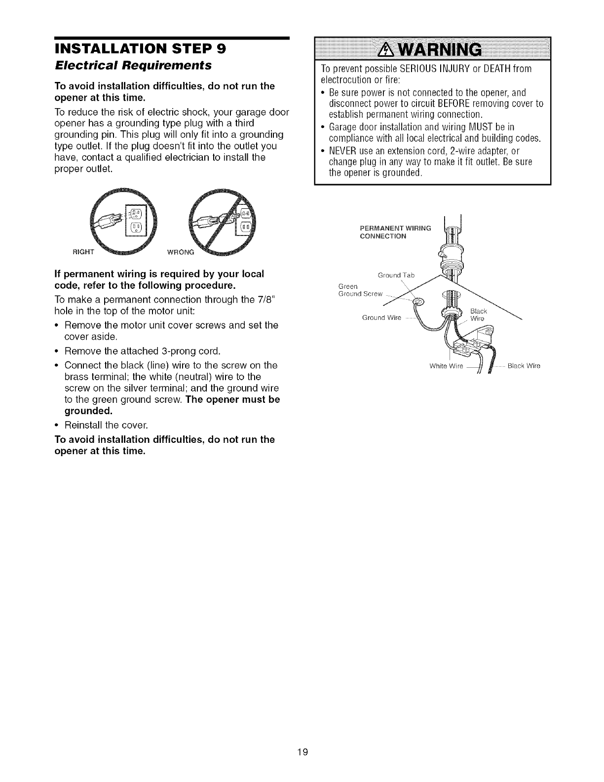
INSTALLATION STEP 9
Electrical Requirements
To avoid installation difficulties, do not run the
opener at this time.
To reduce the risk of electric shock, your garage door
opener has a grounding type plug with a third
grounding pin. This plug will only fit into a grounding
type outlet. If the plug doesn't fit into the outlet you
have, contact a qualified electrician to install the
proper outlet.
WRONG
If permanent wiring is required by your local
code, refer to the following procedure.
To make a permanent connection through the 7/8"
hole in the top of the motor unit:
• Remove the motor unit cover screws and set the
cover aside.
• Remove the attached 3-prong cord.
• Connect the black (line) wire to the screw on the
brass terminal; the white (neutral) wire to the
screw on the silver terminal; and the ground wire
to the green ground screw. The opener must be
grounded.
• Reinstall the cover.
To avoid installation difficulties, do not run the
opener at this time.
To prevent possible SERIOUSINJURYor DEATHfrom
electrocution or fire:
• Besure power is not connected to the opener,and
disconnect power to circuit BEFOREremoving cover to
establish permanentwiring connection.
• Garagedoor installation and wiring MUSTbe in
compliance with all local electrical and building codes.
• NEVERuse an extension cord, 2-wire adapter,or
change plug in any way to makeit fit outlet. Besure
the opener is grounded.
PERMANENT WiRiNG
CONNECTION
Ground Tab
N\
Green
Ground Screw
Black
Ground Wire Wire
White Wire BJack Wire
19
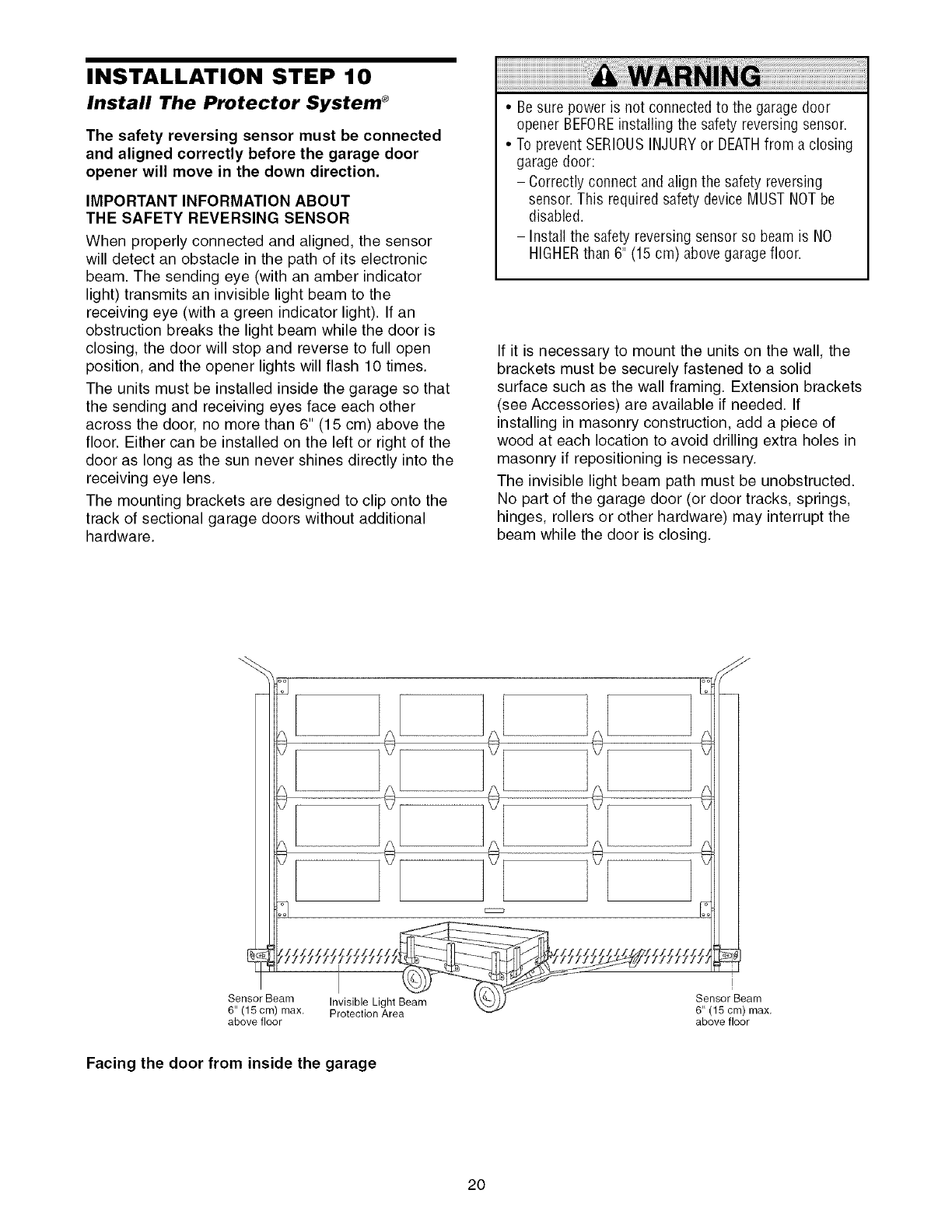
INSTALLATION STEP 10
Install The Protector System ®
The safety reversing sensor must be connected
and aligned correctly before the garage door
opener will move in the down direction.
IMPORTANT INFORMATION ABOUT
THE SAFETY REVERSING SENSOR
When properly connected and aligned, the sensor
will detect an obstacle in the path of its electronic
beam. The sending eye (with an amber indicator
light) transmits an invisible light beam to the
receiving eye (with a green indicator light). If an
obstruction breaks the light beam while the door is
closing, the door will stop and reverse to full open
position, and the opener lights will flash 10 times.
The units must be installed inside the garage so that
the sending and receiving eyes face each other
across the door, no more than 6" (15 cm) above the
floor. Either can be installed on the left or right of the
door as long as the sun never shines directly into the
receiving eye lens.
The mounting brackets are designed to clip onto the
track of sectional garage doors without additional
hardware.
•Be sure power is not connectedto the garage door
opener BEFOREinstalling the safety reversing sensor
•To prevent SERIOUSINJURYor DEATHfrom a closing
garagedoor:
- Correctly connect and align the safety reversing
sensor This requiredsafety device MUST NOTbe
disabled.
- Install the safety reversingsensor so beam is NO
HIGHERthan 6" (15 cm) above garagefloor
If it is necessary to mount the units on the wall, the
brackets must be securely fastened to a solid
surface such as the wall framing. Extension brackets
(see Accessories) are available if needed. If
installing in masonry construction, add a piece of
wood at each location to avoid drilling extra holes in
masonry if repositioning is necessary.
The invisible light beam path must be unobstructed.
No part of the garage door (or door tracks, springs,
hinges, rollers or other hardware) may interrupt the
beam while the door is closing.
Sensor Beam Invisible Light Beam
6" (15 cm) max. Protection Area
above floor
Sensor Beam
6" (15 cm) max.
above floor
Facing the door from inside the garage
2O
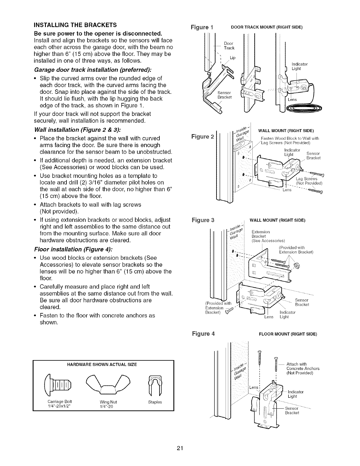
INSTALLING THE BRACKETS
Be sure power to the opener is disconnected.
Install and align the brackets so the sensors will face
each other across the garage door, with the beam no
higher than 6" (15 cm) above the floor. They may be
installed in one of three ways, as follows.
Garage door track installation (preferred):
•Slip the curved arms over the rounded edge of
each door track, with the curved arms facing the
door. Snap into place against the side of the track.
It should lie flush, with the lip hugging the back
edge of the track, as shown in Figure 1.
If your door track will not support the bracket
securely, wall installation is recommended.
Wall installation (Figure 2 & 3):
• Place the bracket against the wall with curved
arms facing the door. Be sure there is enough
clearance for the sensor beam to be unobstructed.
• If additional depth is needed, an extension bracket
(See Accessories) or wood blocks can be used.
• Use bracket mounting holes as a template to
locate and drill (2) 3/16" diameter pilot holes on
the wall at each side of the door, no higher than 6"
(15 cm) above the floor.
• Attach brackets to wall with lag screws
(Not provided).
• If using extension brackets or wood blocks, adjust
right and left assemblies to the same distance out
from the mounting surface. Make sure all door
hardware obstructions are cleared.
Floor installation (Figure 4):
• Use wood blocks or extension brackets (See
Accessories) to elevate sensor brackets so the
lenses will be no higher than 6" (15 cm) above the
floor.
• Carefully measure and place right and left
assemblies at the same distance out from the wall.
Be sure all door hardware obstructions are
cleared.
• Fasten to the floor with concrete anchors as
shown.
Figure DOOR TRACK MOUNT (RIGHT SIDE)
Door
Track
Sensor
Bracket
Indicator
Light
Figure 2
WALL MOUNT (RIGHT SIDE)
Fasten Wood Block to Wall with
_Lag Screws (Not Provided)
Indicator
Light Sensor
Bracket
(Not Provided)
Lens ......
Figure 3iWALL MOUNT (RIGHT SIDE)
Extension
Bracket
i (See Accessories)
i
i (Provided with
0: i Extension Bracket)
i
i :;
i
Sensor
(Provided with _ ............. "_/ "\ Bracket
Extension _.,_¢_" ""'_>_,._ Indicator
Bracket) _"
Lens Light
Figure 4 FLOOR MOUNT (RIGHT SIDE)
HARDWARE SHOWN ACTUAL SIZE
Carriage Bolt Wing Nut
1/4"-20xl/2" 1/4"-20 Staples
l Attach with
Concrete Anchors
;(Not Provided)
Light
Bracket
21
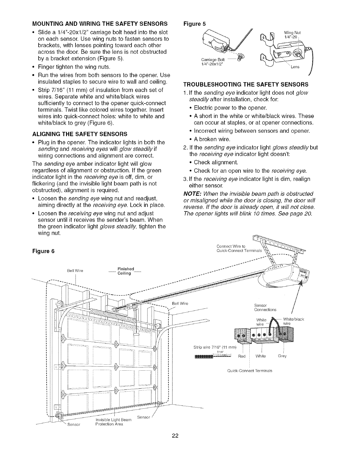
MOUNTING AND WIRING THE SAFETY SENSORS
• Slide a 1/4"-20xl/2" carriage bolt head into the slot
on each sensor. Use wing nuts to fasten sensors to
brackets, with lenses pointing toward each other
across the door. Be sure the lens is not obstructed
by a bracket extension (Figure 5).
• Finger tighten the wing nuts.
• Run the wires from both sensors to the opener. Use
insulated staples to secure wire to wall and ceiling.
• Strip 7/16" (11 mm) of insulation from each set of
wires. Separate white and white/black wires
sufficiently to connect to the opener quick-connect
terminals. Twist like colored wires together. Insert
wires into quick-connect holes: white to white and
white/black to grey (Figure 6).
ALIGNING THE SAFETY SENSORS
• Plug in the opener. The indicator lights in both the
sending and receiving eyes will glow steadily if
wiring connections and alignment are correct.
The sending eye amber indicator light will glow
regardless of alignment or obstruction. If the green
indicator light in the receiving eye is off, dim, or
flickering (and the invisible light beam path is not
obstructed), alignment is required.
• Loosen the sending eye wing nut and readjust,
aiming directly at the receiving eye. Lock in place.
• Loosen the receiving eye wing nut and adjust
sensor until it receives the sender's beam. When
the green indicator light glows steadily, tighten the
wing nut.
Figure 5
CarriageBolt----_
1/4"-20xl/2"
,,_ _ Wing Nut
TROUBLESHOOTING THE SAFETY SENSORS
1. If the sending eye indicator light does not glow
steadily after installation, check for:
• Electric power to the opener.
• A short in the white or white/black wires. These
can occur at staples, or at opener connections.
• Incorrect wiring between sensors and opener.
• A broken wire.
2. If the sending eye indicator light glows steadily but
the receiving eye indicator light doesn't:
• Check alignment.
• Check for an open wire to the receiving eye.
3. If the receiving eye indicator light is dim, realign
either sensor.
NOTE: When the invisible beam path is obstructed
or misaligned while the door is closing, the door will
reverse. If the door is already open, it will not close.
The opener lights will blink 10 times. See page 20.
Figure 6
BelJ Wire
Connect Wire to
Quick-Connect TerminaJs
Finished _
BelJ Wire Sensor
Connections
White
wire
Quick-Connect TerminaJs
wire
i
Grey
Sensor
Sensor
InvisibJe Light Beam
Protection Area
22
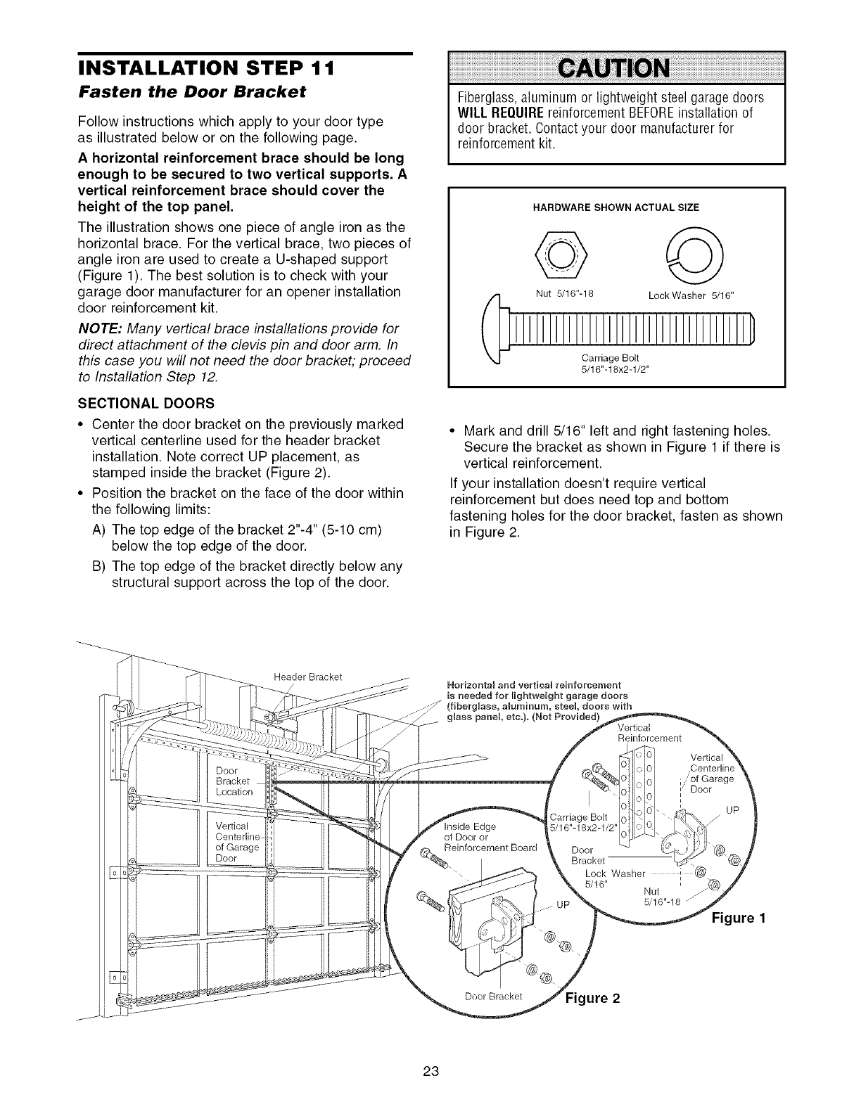
INSTALLATION STEP 1 1
Fasten the Door Bracket
Follow instructions which apply to your door type
as illustrated below or on the following page.
A horizontal reinforcement brace should be long
enough to be secured to two vertical supports. A
vertical reinforcement brace should cover the
height of the top panel.
The illustration shows one piece of angle iron as the
horizontal brace. For the vertical brace, two pieces of
angle iron are used to create a U-shaped support
(Figure 1). The best solution is to check with your
garage door manufacturer for an opener installation
door reinforcement kit.
NOTE: Many vertical brace installations provide for
direct attachment of the clevis pin and door arm. In
this case you will not need the door bracket; proceed
to Installation Step 12.
SECTIONAL DOORS
• Center the door bracket on the previously marked
vertical centerline used for the header bracket
installation. Note correct UP placement, as
stamped inside the bracket (Figure 2).
• Position the bracket on the face of the door within
the following limits:
A) The top edge of the bracket 2"-4" (5-10 cm)
below the top edge of the door.
B) The top edge of the bracket directly below any
structural support across the top of the door.
Fiberglass,aluminum or lightweight steel garage doors
WILL REQUIREreinforcement BEFOREinstallation of
door bracket. Contactyour door manufacturer for
reinforcement kit.
HARDWARE SHOWN ACTUAL SIZE
Nut 5/16"-18 LockWasher 5/16"
Carriage Bolt
5/16"-18x2-1/2"
• Mark and drill 5/16" left and right fastening holes.
Secure the bracket as shown in Figure 1 if there is
vertical reinforcement.
If your installation doesn't require vertical
reinforcement but does need top and bottom
fastening holes for the door bracket, fasten as shown
in Figure 2.
Header Bracket
/
Door
Bracket
Location
Vertical
of Garage
Door
Horizontal and vertical reinforcement
is needed for lightweight garage doors
(fibergUass, amuminum, steeU, doors with
glass panel etc.). (Not Provided) Vertical
Reinforcement
Inside Edge
of Door or
einforcement Board
Carriage Bolt
5/16"-18x2-1/2'
Vertical
."of Garage
Door
UP
Door
Bracket
Lock Washer ,
5/16" Nut
5/16"-18 .......""
Figure 1
Door Bracket Figure 2
23
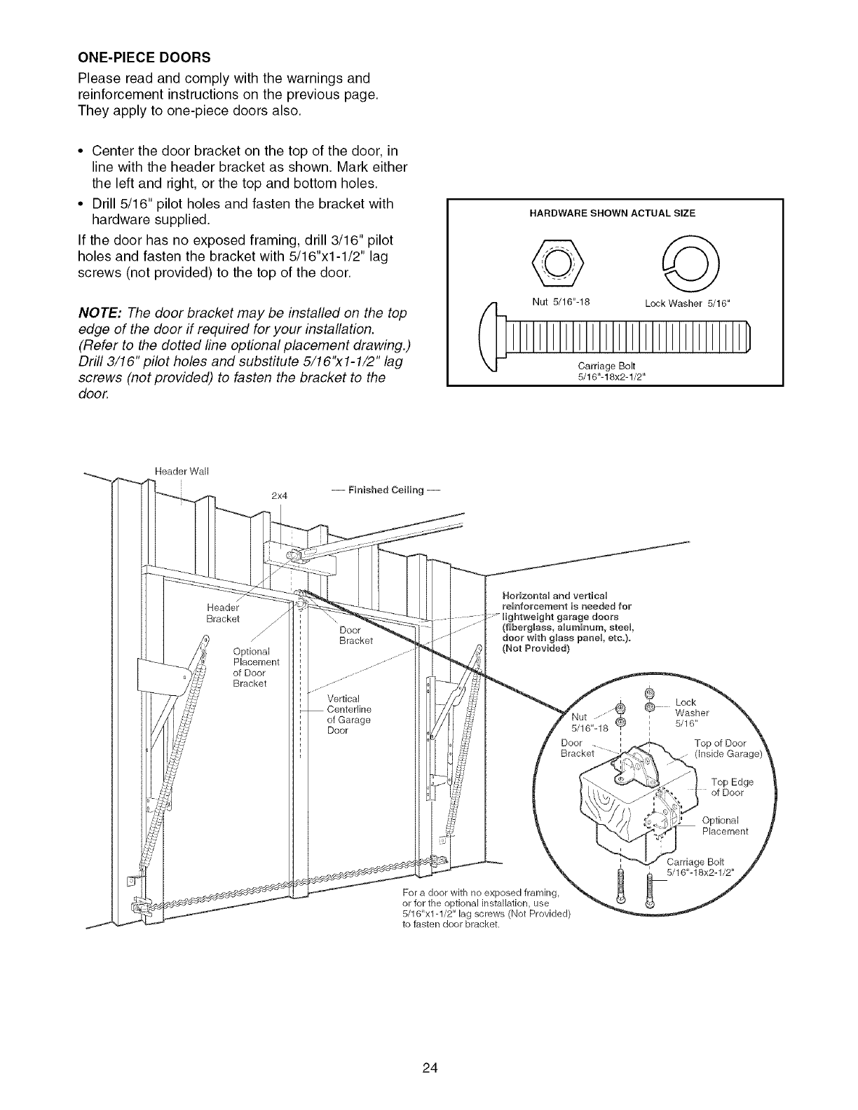
ONE-PIECEDOORS
Please read and comply with the warnings and
reinforcement instructions on the previous page.
They apply to one-piece doors also.
• Center the door bracket on the top of the door, in
line with the header bracket as shown. Mark either
the left and right, or the top and bottom holes.
• Drill 5/16" pilot holes and fasten the bracket with
hardware supplied.
If the door has no exposed framing, drill 3/16" pilot
holes and fasten the bracket with 5/16"x1-1/2" lag
screws (not provided) to the top of the door.
NOTE: The door bracket may be installed on the top
edge of the door if required for your installation.
(Refer to the dotted line optional placement drawing.)
Drill 3/16" pilot holes and substitute 5/16"x1-1/2" lag
screws (not provided) to fasten the bracket to the
door.
HARDWARE SHOWN ACTUAL SIZE
© ©
Nut 5/16"-16 Lock Washer 5/16"
Carriage Bolt
5/16"-18x2-1/2"
Header Wall
2x4
Header
Bracket
Optional
Placement
of Door
Bracket
Door
Bracket
Vertical
Centerline
of Garage
Door
HodzontaU and verticaU
reinforcement is needed for
dOOrS
(fiberglass, aUuminum, steel,
doer with gUass panel etc.).
(Not Prey{tied)
5/16,,_18" _
Door
Bracket
For a door with no exposed framing,
or for the optional installation, use
5/16"x1-1/2" lag screws (Not Provided)
to fasten door bracket.
®Lock
Washer
, 5/16"
i
i
Top of Door
Top Edge
of Door
Optional
Placement
Carriage Bolt
5/16"-18x2-1/2"
24
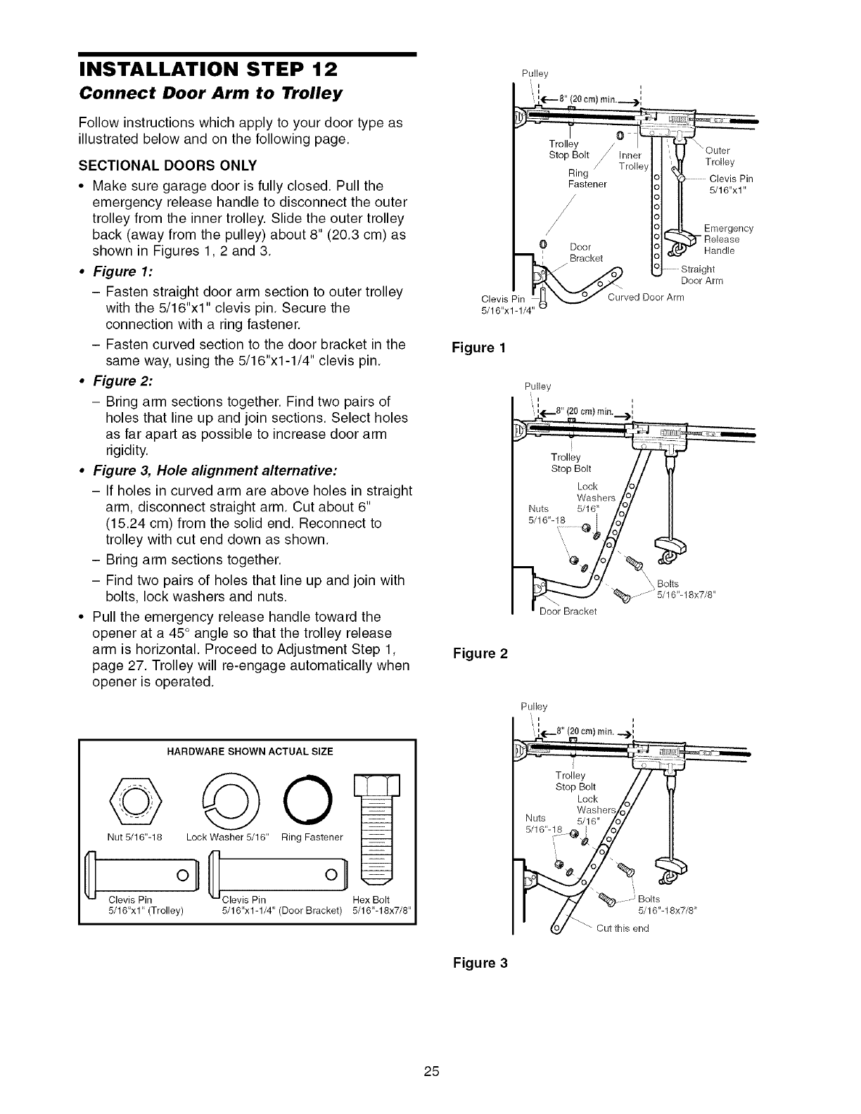
INSTALLATION STEP 12
Connect Door Arm to Trolley
Follow instructions which apply to your door type as
illustrated below and on the following page.
SECTIONAL DOORS ONLY
•Make sure garage door is fully closed. Pull the
emergency release handle to disconnect the outer
trolley from the inner trolley. Slide the outer trolley
back (away from the pulley) about 8" (20.3 cm) as
shown in Figures 1,2 and 3.
•Figure 1:
- Fasten straight door arm section to outer trolley
with the 5/16"x1" clevis pin. Secure the
connection with a ring fastener.
- Fasten curved section to the door bracket in the
same way, using the 5/16"x1-1/4" clevis pin.
•Figure 2:
- Bring arm sections together. Find two pairs of
holes that line up and join sections. Select holes
as far apart as possible to increase door arm
rigidity.
•Figure 3, Hole alignment alternative:
- If holes in curved arm are above holes in straight
arm, disconnect straight arm. Cut about 6"
(15.24 cm) from the solid end. Reconnect to
trolley with cut end down as shown.
- Bring arm sections together.
- Find two pairs of holes that line up and join with
bolts, lock washers and nuts.
• Pull the emergency release handle toward the
opener at a 45° angle so that the trolley release
arm is horizontal. Proceed to Adjustment Step 1,
page 27. Trolley will re-engage automatically when
opener is operated.
HARDWARE SHOWN ACTUAL SIZE
©
Nut 5/16"-18
Clevis Pin
5/16"x1"(Trolley)
LockWasher 5/16" Ring Fastener
Clevis Pin Hex Bolt
5/16"x1-1/4" (Door Bracket) 5/16"-18x7/8"
Pulley
_,'
Trolley _ Outer
Stop Bolt Trolley
Ring Pin
Fastener 5/16"x1"
/
/J Emergency
0 Door - Release
Handle
._ Door Arm
Clevis Fin,,: _ _ Curved Door Arm
5/16"x1-1/4"
Figure 1
Pulley
cm) rain.
Bolts
Door Bracket
Figure 2
Pulley
', i
', 'LS" (20 cm) rain __,,,.
_ _ J
Trolley / /
Stop Bolt / /
Loek /_/
Washers/_7
Nuts 5/16" /O7
5/t6'__s-e! Z°/
I6"-18x7/8"
Figure 3
25
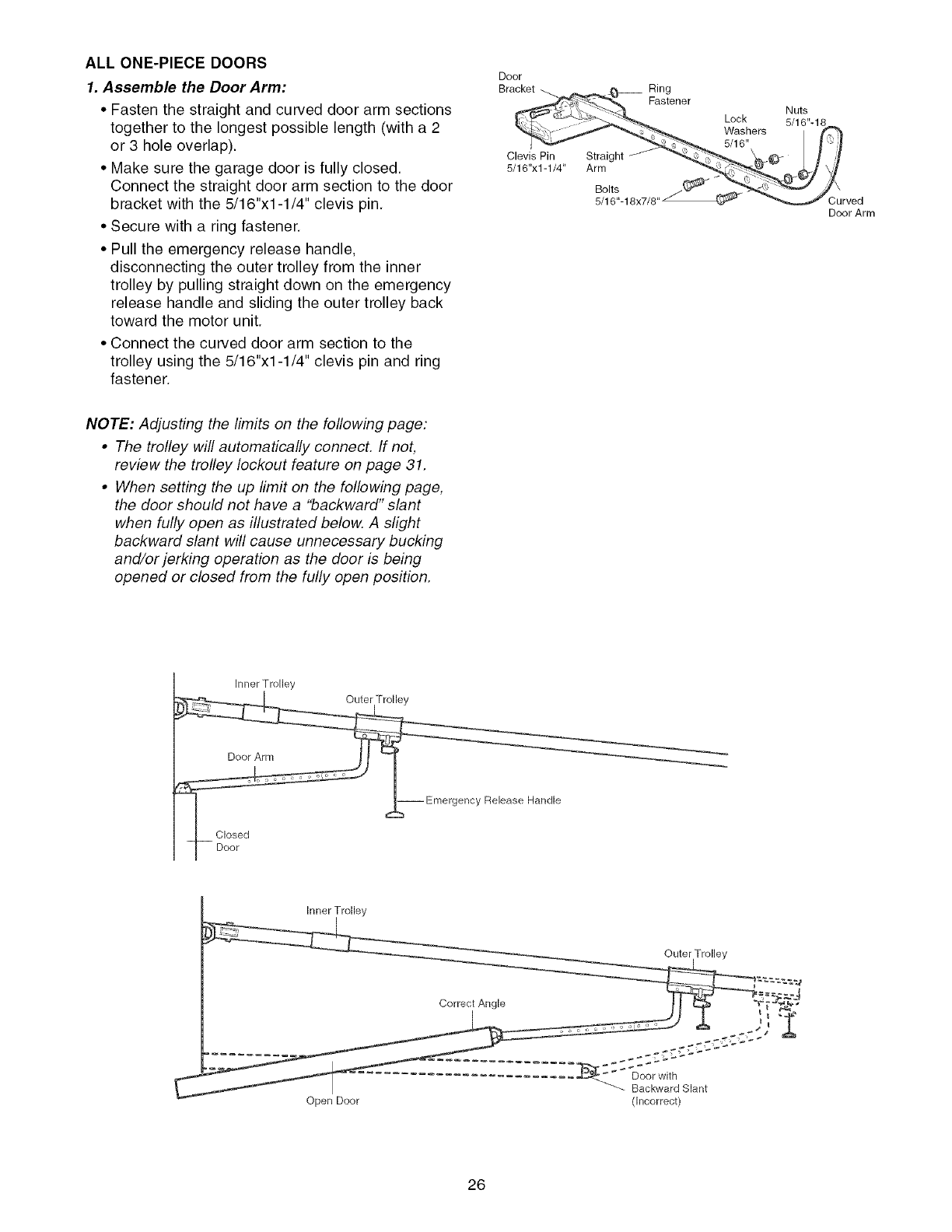
ALLONE-PIECEDOORS
1. Assemble the Door Arm:
• Fasten the straight and curved door arm sections
together to the longest possible length (with a 2
or 3 hole overlap).
• Make sure the garage door is fully closed.
Connect the straight door arm section to the door
bracket with the 5/16"xl-1/4" clevis pin.
• Secure with a ring fastener.
• Pull the emergency release handle,
disconnecting the outer trolley from the inner
trolley by pulling straight down on the emergency
release handle and sliding the outer trolley back
toward the motor unit.
• Connect the curved door arm section to the
trolley using the 5/16"xl-1/4" clevis pin and ring
fastener.
Door
Bracket
Clevis Pin
5/16"x1-1/4" Straight
Arm
Ring
Fastener
Bolts
5/16"-18x7/8
Lock
Washers
5/16"
Nuts
Curved
Door Arm
NOTE: Adjusting the limits on the following page:
•The trolley will automatically connecL If not,
review the trolley lockout feature on page 31.
•When setting the up limit on the following page,
the door should not have a "backward" slant
when fully open as illustrated below. A slight
backward slant will cause unnecessary bucking
and/or jerking operation as the door is being
opened or closed from the fully open position.
Inner Trolley
ncy
Release Handle
Inner Trolley
Outer Trolley
Correct Angle r4_' _'_
........... _............. __.;COCO;C_';'_''C
Backward Slant
Open Door (Incorrect)
26
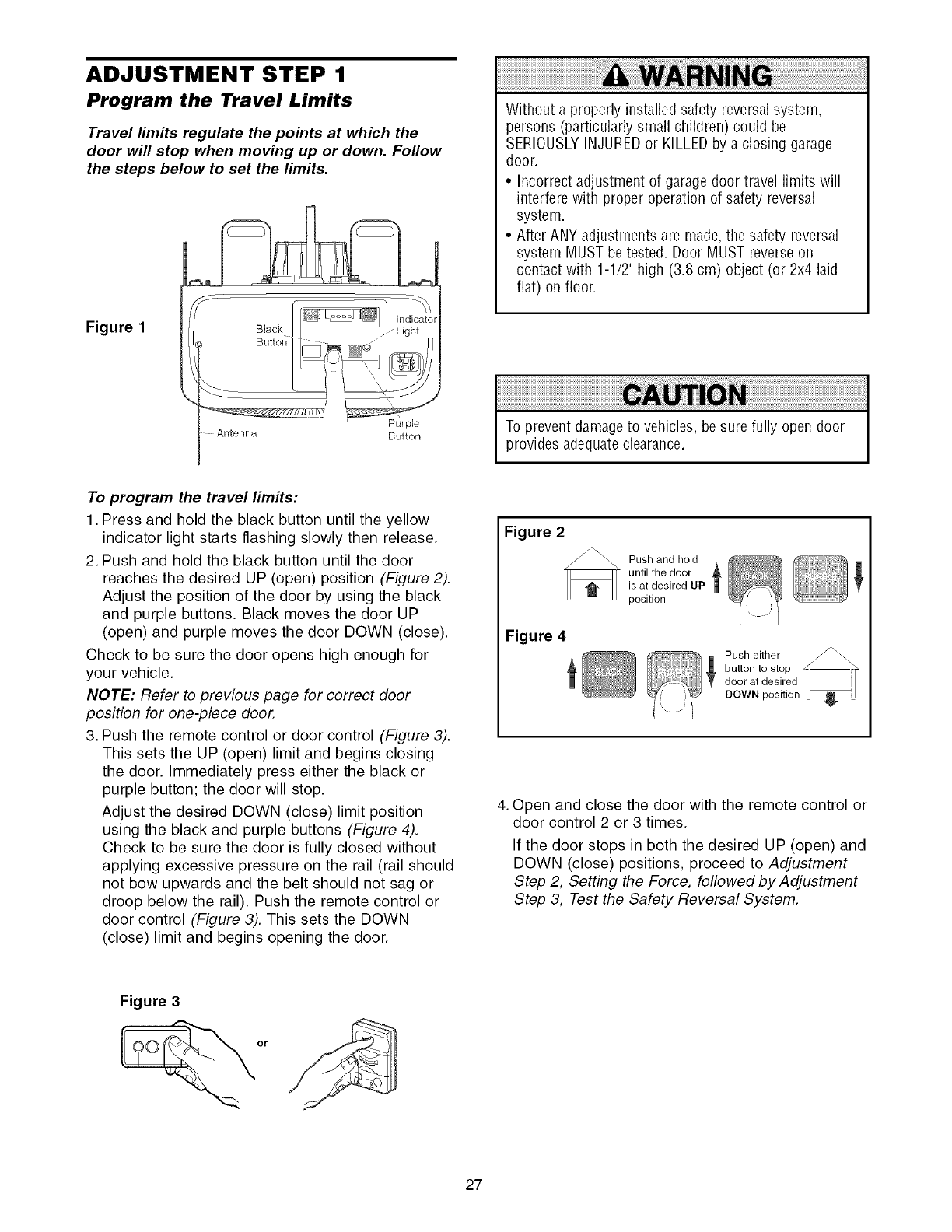
ADJUSTMENT STEP 1
Program the Travel Limits
Travel limits regulate the points at which the
door will stop when moving up or down. Follow
the steps below to set the limits.
Figure 1
Purple
Antenna Button
Without a properly installed safety reversal system,
persons (particularly small children) could be
SERIOUSLYINJUREDor KILLEDby a closing garage
door.
• Incorrect adjustment of garage door travel limits will
interfere with proper operation of safety reversal
system.
• After ANY adjustments are made,the safety reversal
system MUST be tested. Door MUST reverseon
contact with 1-1/2" high (3.8 cm) object (or 2x4 laid
flat) on floor.
To prevent damageto vehicles, besure fully open door
provides adequateclearance.
To program the travel limits:
1. Press and hold the black button until the yellow
indicator light starts flashing slowly then release.
2. Push and hold the black button until the door
reaches the desired UP (open) position (Figure 2).
Adjust the position of the door by using the black
and purple buttons. Black moves the door UP
(open) and purple moves the door DOWN (close).
Check to be sure the door opens high enough for
your vehicle.
NOTE: Refer to previous page for correct door
position for one-piece door.
3. Push the remote control or door control (Figure 3).
This sets the UP (open) limit and begins closing
the door. Immediately press either the black or
purple button; the door will stop.
Adjust the desired DOWN (close) limit position
using the black and purple buttons (Figure 4).
Check to be sure the door is fully closed without
applying excessive pressure on the rail (rail should
not bow upwards and the belt should not sag or
droop below the rail). Push the remote control or
door control (Figure 3). This sets the DOWN
(close) limit and begins opening the door.
Figure 2
Figure 4
Push and hold
until the door
is at desired UP
position
Push either _\_\
button to stop _q-
door at desired i |
DOWN position _/
4. Open and close the door with the remote control or
door control 2 or 3 times.
If the door stops in both the desired UP (open) and
DOWN (close) positions, proceed to Adjustment
Step 2, Setting the Force, followed by Adjustment
Step 3, Test the Safety Reversal System.
Figure 3
or
27
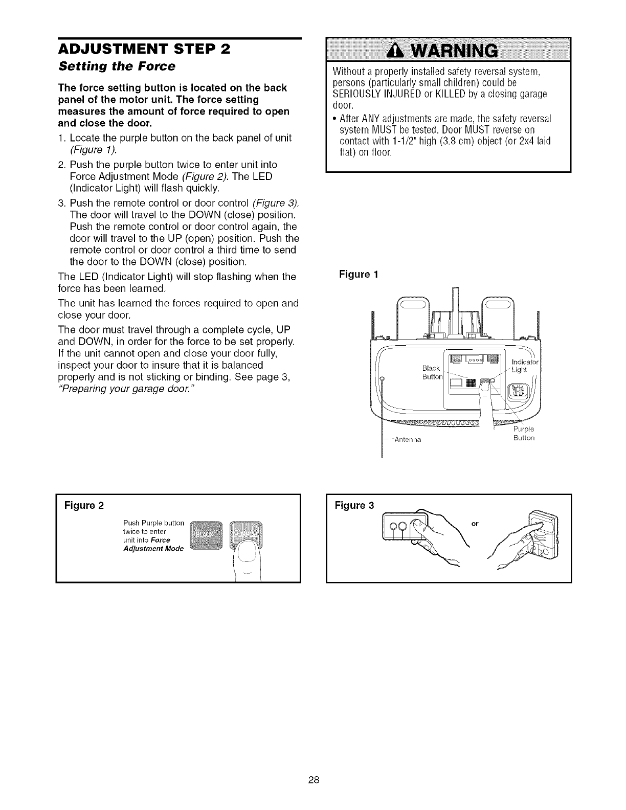
ADJUSTMENT STEP 2
Setting the Force
The force setting button is located on the back
panel of the motor unit. The force setting
measures the amount of force required to open
and close the door.
1. Locate the purple button on the back panel of unit
(Figure 1).
2. Push the purple button twice to enter unit into
Force Adjustment Mode (Figure 2). The LED
(Indicator Light) will flash quickly.
3. Push the remote control or door control (Figure 3).
The door will travel to the DOWN (close) position.
Push the remote control or door control again, the
door will travel to the UP (open) position. Push the
remote control or door control a third time to send
the door to the DOWN (close) position.
The LED (Indicator Light) will stop flashing when the
force has been learned.
The unit has learned the forces required to open and
close your door.
The door must travel through a complete cycle, UP
and DOWN, in order for the force to be set properly.
If the unit cannot open and close your door fully,
inspect your door to insure that it is balanced
properly and is not sticking or binding. See page 3,
"Preparing your garage door."
Without a properly installed safety reversal system,
persons (particularly small children) could be
SERIOUSLYINJUREDor KILLEDby a closing garage
door.
• After ANY adjustments are made,the safety reversal
system MUST be tested. Door MUST reverseon
contact with 1-1/2" high (3.8 cm) object (or 2x4 laid
flat) on floor.
Figure 1
Antenna Button
Figure 2
Push Purple button
twice to enter
unit into Force
Adjustment Mode
Figure 3
28
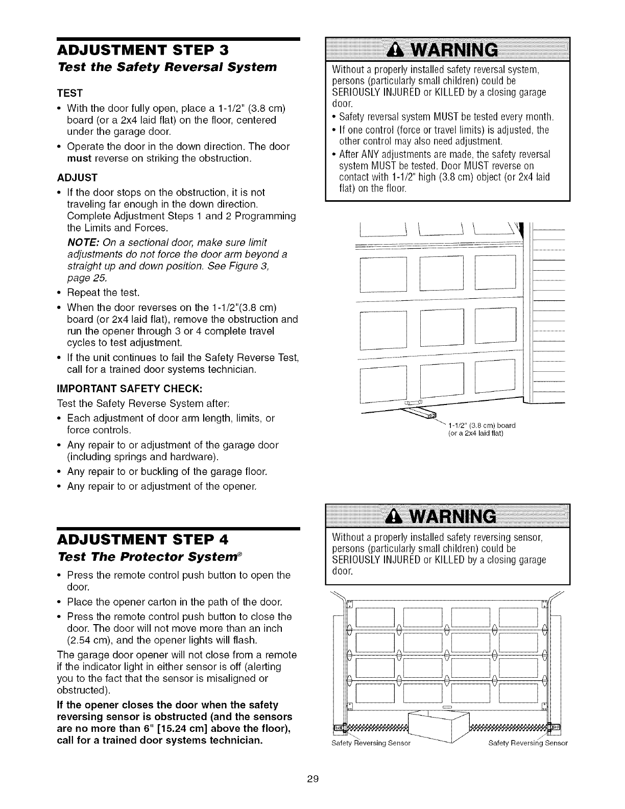
ADJUSTMENT STEP 3
Test the Safety Reversal System
TEST
•With the door fully open, place a 1-1/2" (3.8 cm)
board (or a 2x4 laid flat) on the floor, centered
under the garage door
• Operate the door in the down direction The door
must reverse on striking the obstruction
ADJUST
• If the door stops on the obstruction, it is not
traveling far enough in the down direction.
Complete Adjustment Steps 1 and 2 Programming
the Limits and Forces.
NOTE: On a sectional door, make sure limit
adjustments do not force the door arm beyond a
straight up and down position. See Figure 3,
page 25.
• Repeat the test.
• When the door reverses on the 1-1/2"(3.8 cm)
board (or 2x4 laid flat), remove the obstruction and
run the opener through 3 or 4 complete travel
cycles to test adjustment.
• If the unit continues to fail the Safety Reverse Test,
call for a trained door systems technician.
IMPORTANT SAFETY CHECK:
Test the Safety Reverse System after:
• Each adjustment of door arm length, limits, or
force controls.
• Any repair to or adjustment of the garage door
(including springs and hardware).
• Any repair to or buckling of the garage floor.
• Any repair to or adjustment of the opener.
Without a properly installed safety reversal system,
persons (particularly small children) could be
SERIOUSLYINJUREDor KILLEDby a closing garage
door.
• Safety reversalsystem MUST be tested every month.
• If one control (force or travel limits) is adjusted, the
other control may also needadjustment.
• After ANY adjustments are made,the safety reversal
system MUST be tested. Door MUST reverseon
contact with 1-1/2" high (3.8 cm) object (or 2x4 laid
flat) on the floor.
jl/
(or a 2x4 laid flat)
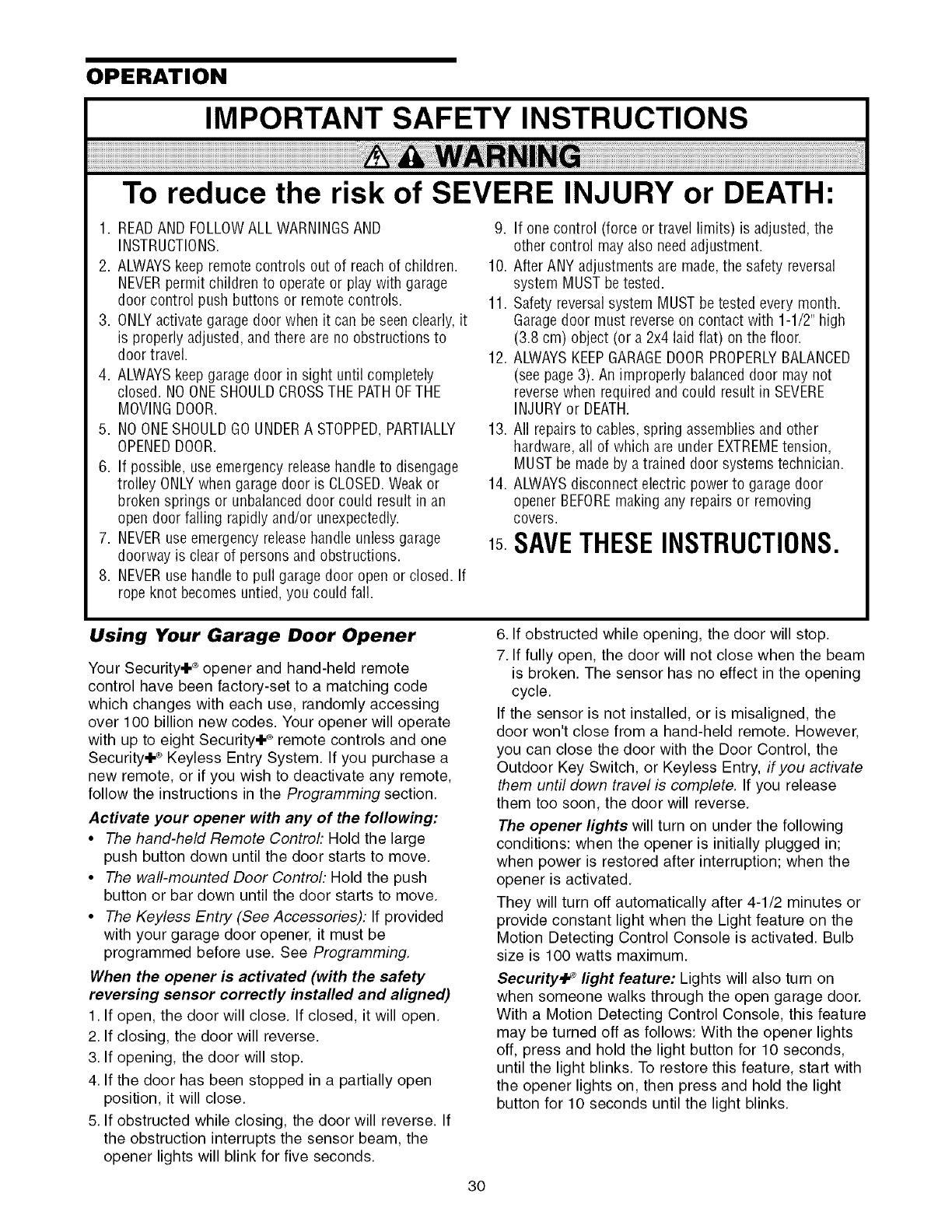
ADJUSTMENT STEP 4
Test The Protector System ®
• Press the remote control push button to open the
door.
• Place the opener carton in the path of the door.
• Press the remote control push button to close the
door. The door will not move more than an inch
(2.54 cm), and the opener lights will flash.
The garage door opener will not close from a remote
if the indicator light in either sensor is off (alerting
you to the fact that the sensor is misaligned or
obstructed).
If the opener closes the door when the safety
reversing sensor is obstructed (and the sensors
are no more than 6" [15.24 cm] above the floor),
call for a trained door systems technician.
Without a properly installed safety reversing sensor,
persons (particularly small children) could be
SERIOUSLYINJUREDor KILLEDby a closing garage
door.
Safety Reversing Sensor
29
OPERATION
IMPORTANT SAFETY INSTRUCTIONS
To reduce the risk of SEVERE INJURY or DEATH:
1. READAND FOLLOWALL WARNINGSAND
INSTRUCTIONS.
2. ALWAYSkeep remote controls out of reach of children.
NEVERpermit children to operate or play with garage
door control push buttons or remote controls.
3. ONLYactivate garagedoor when it can beseen clearly, it
is properly adjusted, and there are no obstructions to
door travel.
4. ALWAYSkeep garage door in sight until completely
closed. NOONESHOULDCROSSTHE PATHOFTHE
MOVINGDOOR.
5. NO ONESHOULDGOUNDERA STOPPED,PARTIALLY
OPENEDDOOR.
6. If possible, use emergency releasehandleto disengage
trolley ONLYwhen garage door is CLOSED.Weak or
broken springs or unbalanceddoor could result in an
open door failing rapidly and/or unexpectedly.
7. NEVERuse emergency releasehandle unless garage
doorway is clear of persons and obstructions.
8. NEVERuse handleto pull garage door open or closed. If
rope knot becomes untied, you could fall.
9. If one control (force or travel limits) is adjusted, the
other control may also needadjustment.
10. After ANY adjustments are made,the safety reversal
system MUST be tested.
11. Safety reversal system MUST be tested every month.
Garagedoor must reverse on contact with 1-1/2" high
(3.8 cm) object (or a 2x4 laid flat) on the floor.
12. ALWAYSKEEPGARAGEDOORPROPERLYBALANCED
(see page 3). An improperly balanced door may not
reversewhen required and could result in SEVERE
INJURY or DEATH.
13. All repairs to cables, spring assembliesand other
hardware, all of which are under EXTREMEtension,
MUST be made by atrained door systems technician.
14. ALWAYSdisconnect electric power to garagedoor
opener BEFOREmaking any repairs or removing
covers.
1sSAVETHESEINSTRUCTIONS.
Using Your Garage Door Opener
Your Security+ ®opener and hand-held remote
control have been factory-set to a matching code
which changes with each use, randomly accessing
over 100 billion new codes. Your opener will operate
with up to eight Security+ ®remote controls and one
Security+ ® Keyless Entry System. If you purchase a
new remote, or if you wish to deactivate any remote,
follow the instructions in the Programming section.
Activate your opener with any of the following:
•The hand-held Remote Control: Hold the large
push button down until the door starts to move.
• The wall-mounted Door Controh Hold the push
button or bar down until the door starts to move.
• The Keyless Entry (See Accessories): If provided
with your garage door opener, it must be
programmed before use. See Programming.
When the opener is activated (with the safety
reversing sensor correctly installed and aligned)
1. If open, the door will close. If closed, it will open.
2. If closing, the door will reverse.
3. If opening, the door will stop.
4. If the door has been stopped in a partially open
position, it will close.
5. If obstructed while closing, the door will reverse. If
the obstruction interrupts the sensor beam, the
opener lights will blink for five seconds.
6. If obstructed while opening, the door will stop.
7. If fully open, the door will not close when the beam
is broken. The sensor has no effect in the opening
cycle.
If the sensor is not installed, or is misaligned, the
door won't close from a hand-held remote. However,
you can close the door with the Door Control, the
Outdoor Key Switch, or Keyless Entry, if you activate
them until down travel is complete. If you release
them too soon, the door will reverse.
The opener lights will turn on under the following
conditions: when the opener is initially plugged in;
when power is restored after interruption; when the
opener is activated.
They will turn off automatically after 4-1/2 minutes or
provide constant light when the Light feature on the
Motion Detecting Control Console is activated. Bulb
size is 100 watts maximum.
Security+ _light feature: Lights will also turn on
when someone walks through the open garage door.
With a Motion Detecting Control Console, this feature
may be turned off as follows: With the opener lights
off, press and hold the light button for 10 seconds,
until the light blinks. To restore this feature, start with
the opener lights on, then press and hold the light
button for 10 seconds until the light blinks.
30
Using the Wall.Mounted
Door Control
THE MOTION DETECTING
CONTROL CONSOLE
Press the lighted push button to
open or close the door. Press
again to reverse the door during
the closing cycle or to stop the
door while it's opening.
This door control contains a
_bl Lighted
_[_- Push Button
_-Lock Button
_Light Button
motion detector that will automatically turn on the
light when it detects a person entering the garage.
This feature can be easily turned off for extended
work light use.
Light feature
Press the Light button to turn the opener light on or
off. It will not control the opener lights when the door
is in motion. If you turn it on and then activate the
opener, the light will remain on for 4-1/2 minutes.
Press again to turn it off sooner. The 4-1/2 minute
interval can be changed to 1-1/2, 2-1/2, or 3-1/2
minutes as follows: Press and hold the Lock button
until the light blinks (about 10 seconds). A single blink
indicates that the timer is reset to 1-1/2 minutes.
Repeat the procedure and the light will blink twice,
resetting the timer to 2-1/2 minutes. Repeat again for
a 3-1/2 minute interval, etc., up to a maximum of four
blinks and 4-1/2 minutes.
When using the opener lights as working lights, we
recommend that you first disable the motion sensor.
See Automatic Light Feature, below.
Automatic Light Feature: The opener light will turn
on automatically when a person enters the garage.
When a person walks in front of the door control, the
light will come on for five minutes, then shut off. This
feature works by detecting body heat and may not
work in temperatures around 100°F (37.7°C).
To disable this feature, slide the Detector Switch on
the right side of the door control down (off).
We recommend that you disable the motion sensor
when using the opener lights as working lights.
Otherwise, they will turn off automatically if you are
working beyond the sensors range.
Lock feature
Designed to prevent operation of the door from
hand-held remote controls. However, the door will
open and close from the Door Control, the Outdoor
Key Switch and the Keyless Entry Accessories.
To activate, press and hold the Lock button for 2
seconds. The push button light will flash as long as
the Lock feature is on.
To turn off, press and hold the Lock button again for
2 seconds. The push button light will stop flashing.
The Lock feature will also turn off whenever the
"learn" button on the motor unit panel is activated.
Additional feature when used with the 3-Function
hand-held remote
To control the opener lights:
In addition to operating the door,
you may program the remote to
operate the lights.
1. With the door closed, press and hold a small
remote button that you want to control the light.
2. Press and hold the Light button on the door
control.
3. While holding the Light button, press and hold the
Lock button on the door control.
4. After the opener lights flash, release all buttons.
To Open the Door Manually
To prevent possible SERIOUSINJURYor DEATHfrom a
falling garage door:
• If possible, useemergency releasehandle to
disengagetrolley ONLYwhen garage door is CLOSED.
Weakor broken springs or unbalanceddoor could
result in an open door falling rapidly and/or
unexpectedly.
• NEVERuse emergency release handle unless garage
doorway is clear of persons and obstructions.
• NEVERuse handleto pull door open or closed. If rope
knot becomes untied, you could fall.
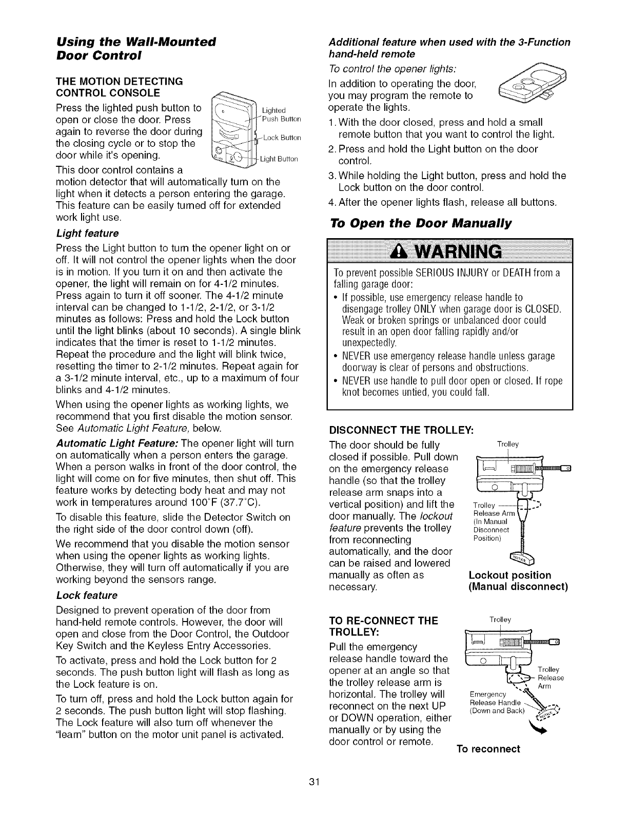
DISCONNECT THE TROLLEY:
The door should be fully
closed if possible. Pull down
on the emergency release
handle (so that the trolley
release arm snaps into a
vertical position) and lift the
door manually. The lockout
feature prevents the trolley
from reconnecting
automatically, and the door
can be raised and lowered
manually as often as
necessary.
Trolley
I
T ,.e
(In Manual
Disconnect
Position)
Lockout position
(Manual disconnect)
TO RE-CONNECT THE Trolley
TROLLEY: _j_
Pull the emergency
release handle toward the
opener at an angle so that
the trolley release arm is '1_ Release
• • Arm
horizontal. The trolley will Emergency ""__
Release Handle _ _, ._
reconnect on the next UP (DownandBack)""'_,_'
or DOWN operation, either
manually or by using the
door control or remote. To reconnect
31
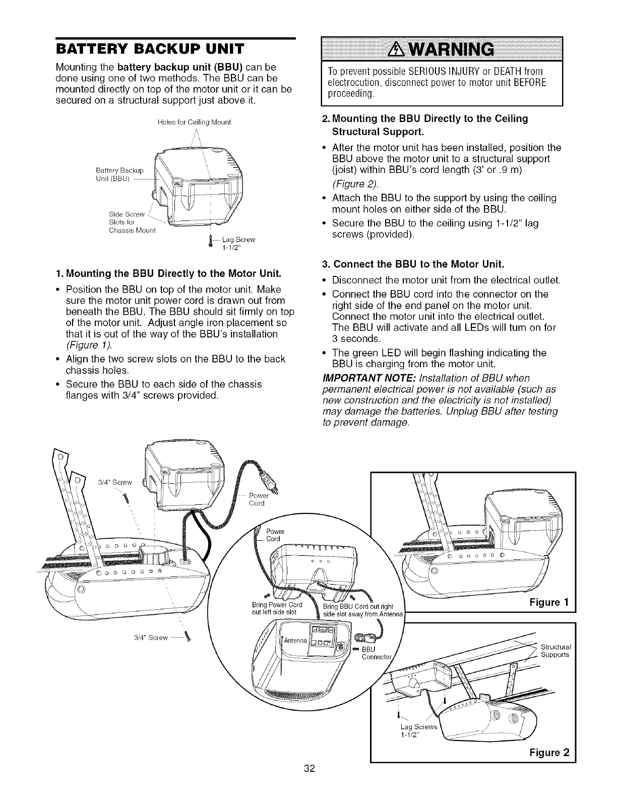
BATTERY BACKUP UNIT
Mounting the battery backup unit (BBU) can be
done using one of two methods. The BBU can be
mounted directly on top of the motor unit or it can be
secured on a structural support just above it.
Holes for Ceiling Mount
Chassis Mount
_Lag Screw
1-1/2"
1. Mounting the BBU Directly to the Motor Unit.
• Position the BBU on top of the motor unit. Make
sure the motor unit power cord is drawn out from
beneath the BBU. The BBU should sit firmly on top
of the motor unit. Adjust angle iron placement so
that it is out of the way of the BBU's installation
(Figure 1).
• Align the two screw slots on the BBU to the back
chassis holes.
• Secure the BBU to each side of the chassis
flanges with 3/4" screws 3rovided.
To prevent possible SERIOUSINJURYor DEATHfrom
electrocution, disconnect power to motor unit BEFORE
proceeding.
2. Mounting the BBU Directly to the Ceiling
Structural Support.
• After the motor unit has been installed, position the
BBU above the motor unit to a structural support
(joist) within BBU's cord length (3' or .9 m)
(Figure 2).
• Attach the BBU to the support by using the ceiling
mount holes on either side of the BBU.
• Secure the BBU to the ceiling using 1-1/2" lag
screws (provided).
3. Connect the BBU to the Motor Unit.
Disconnect the motor unit from the electrical outlet.
Connect the BBU cord into the connector on the
right side of the end panel on the motor unit.
Connect the motor unit into the electrical outlet.
The BBU will activate and all LEDs will turn on for
3 seconds.
• The green LED will begin flashing indicating the
BBU is charging from the motor unit.
IMPORTANT NOTE: Installation of BBU when
permanent electrical power is not available (such as
new construction and the electricity is not installed)
may damage the batteries. Unplug BBU after testing
to prevent damage.
3/4" Screw
Cord
©
OOOOO@@
3/4" Screw
Bring Power Cord
out left side slot Bring BBU Cord out right
side slot away from Antenna
0o o o 0
Figure 1
BBU _ Structural
Connector . Supports
32
Lag Screws
1-1/2"
Figure 2
To reduce the risk of FIREor INJURYto persons use
only Craftsman part #41A5948 for replacement batteries.
OPERATING INSTRUCTIONS
1. Test the installed BBU with the motor unit.
To test the BBU, disconnect the motor unit power
cord from the electrical outlet.
• A solid yellow LED indicates the BBU is operating
on battery power.
• A flashing yellow LED with beep indicates the BBU
is operating on battery power and that the battery
charge is low.
• To test the BBU is functioning properly, open and
close the garage door.
• Re-connect the motor unit power cord back into
the electrical outlet.
• Verify that the green LED is flashing on the BBU
(indicates that the BBU is now charging).
• Test completed.
2. Charge the battery.
• Allow the batteries 24 to 48 hours to fully charge
before using the BBU system.
A fully charged BBU supplies 24V DC to the motor
unit for one to two days of normal operation during
an electrical power outage. If the battery voltage
drops too low, the batteries will disconnect and the
motor unit will no longer operate under battery
power.
After the electrical power has been restored, the
batteries will recharge within 48 hours. Under normal
usage batteries will last 3 to 5 years.
To obtain maximum battery life and prevent damage,
also disconnect the battery backup if you unplug the
motor unit while on vacation or any other extended
period of time.
NOTE: Door operation may be limited until batteries
are fully charged. The motor unit's lights will not turn
on during BBU mode.
Battery Backup Unit (BBU) Diagnostics
(Yellow LED)
(Red LED)X /(Green LED)
\/
\/
od
Selvice BatterylltUse Gllarging
GREEN LED:
All systems are normal
• A solid LED light indicates the batteries are fully
charged.
• A flashing LED indicates the batteries are being
charged.
NOTE: Batteries do not have to be fully charged to
operate the motor unit.
.O
YELLOW LED:
The motor unit has lost power and is operating off of
the BBU.
• A solid LED with beep, sounding approximately
every 2 seconds, indicates the motor unit is
activating the door and is operating off of the BBU.
• A flashing LED with beep, sounding every 30
seconds, indicates batteries are low.
• Once the power is restored the BBU will recharge.
This is indicated by a flashing green LED.
RED LED:
An error has been detected and the BBU will
automatically shut off. The BBU will attempt to restart
by reconnecting to the batteries. If the error is still
present it will shut itself off again. This process will
repeat every 5 minutes or until the error has been
resolved. This is used to prevent further draining of
the batteries.
• If a red LED remains on when the power is
restored, and is accompanied by a beep sounding
every 30 seconds, please call for service.
33
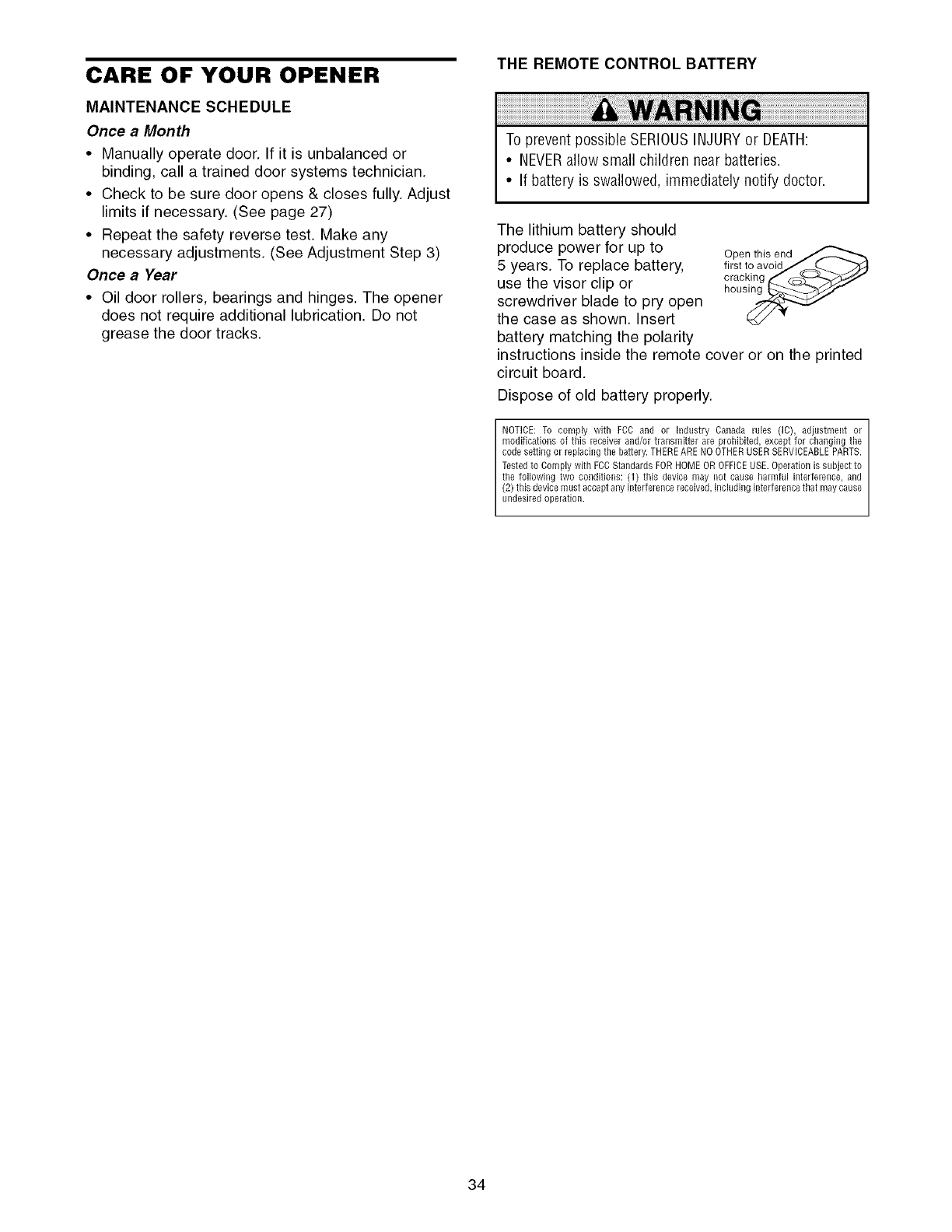
CARE OF YOUR OPENER
MAINTENANCE SCHEDULE
Once a Month
•Manually operate door If it is unbalanced or
binding, call a trained door systems technician
• Check to be sure door opens & closes fully Adjust
limits if necessary (See page 27)
• Repeat the safety reverse test Make any
necessary adjustments (See Adjustment Step 3)
Once a Year
• Oil door rollers, bearings and hinges The opener
does not require additional lubrication Do not
grease the door tracks
THE REMOTE CONTROL BATTERY
To prevent possible SERIOUSINJURYor DEATH:
•NEVERallow small children near batteries
•If battery is swallowed, immediately notify doctor
The lithium battery should
produce power for up to
5 years To replace battery,
use the visor clip or
screwdriver blade to pry open
the case as shown Insert
battery matching the polarity
Open this end
first to avoidJ _...._
cracl_ing _ C_4-,_J_'J
hous_
instructions inside the remote cover or on the printed
circuit board
Dispose of old battery properly
NOTICE: To comply with FCC and or industry Canada rules (iC), adjustment or
modifications of this receiver and/or transmitter are prohibited, except for changing the
code setting or replacing the battery. THERE ARE NO OTHER USER SERVICEABLE PARTS.
Tested to Comply with FCC Standards FOR HOME OR OFFICE USE. Operation is subject to
the following two conditions: (1) this device may not cause harmful interference, and
(2) this device must accept any interference received, including interference that may cause
undesired operation.
34
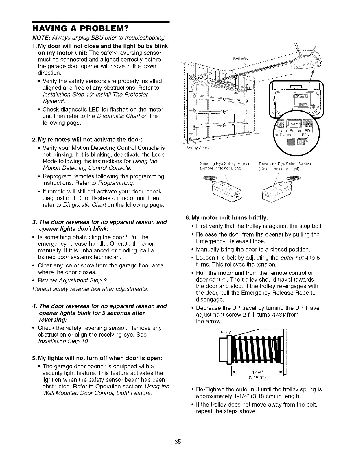
HAVING A PROBLEM?
NOTE: Always unplug BBU prior to troubleshooting
1. My door will not close and the light bulbs blink
on my motor unit: The safety reversing sensor
must be connected and aligned correctly before
the garage door opener will move in the down
direction.
• Verify the safety sensors are properly installed,
aligned and free of any obstructions. Refer to
Installation Step 10: Install The Protector
Systen'P.
• Check diagnostic LED for flashes on the motor
unit then refer to the Diagnostic Chart on the
following page.
2. My remotes will not activate the door:
• Verify your Motion Detecting Control Console is
not blinking. If it is blinking, deactivate the Lock
Mode following the instructions for Using the
Motion Detecting Control Console.
• Reprogram remotes following the programming
instructions. Refer to Programming.
• If remote will still not activate your door, check
diagnostic LED for flashes on motor unit then
refer to Diagnostic Chart on the following page.
3. The door reverses for no apparent reason and
opener lights don't blink:
• Is something obstructing the door? Pull the
emergency release handle. Operate the door
manually. If it is unbalanced or binding, call a
trained door systems technician.
• Clear any ice or snow from the garage floor area
where the door closes.
• Review Adjustment Step 2.
Repeat safety reverse test after adjustments.
4. The door reverses for no apparent reason and
opener lights blink for 5 seconds after
reversing:
• Check the safety reversing sensor. Remove any
obstruction or align the receiving eye. See
Installation Step 10.
5. My lights will not turn off when door is open:
• The garage door opener is equipped with a
security light feature. This feature activates the
light on when the safety sensor beam has been
obstructed. Refer to Operation section; Using the
Wall Mounted Door Control, Light Feature.
Bell Wire
\
Safety Sensor
Sending Eye Safety Sensor Receiving Eye Safety Sensor
(Amber Indicator Light) (Green Indicator Light)
6. My motor unit hums briefly:
• First verify that the trolley is against the stop bolt.
• Release the door from the opener by pulling the
Emergency Release Rope.
• Manually bring the door to a closed position.
• Loosen the belt by adjusting the outer nut 4 to 5
turns. This relieves the tension.
• Run the motor unit from the remote control or
door control. The trolley should travel towards
the door and stop. If the trolley re-engages with
the door, pull the Emergency Release Rope to
disengage.
• Decrease the UP travel by turning the UP Travel
adjustment screw 2 full turns away from
the arrow.
_1_ 1-1/4"
(3.18 cm)
• Re-Tighten the outer nut until the trolley spring is
approximately 1-1/4" (3.18 cm) in length.
• If the trolley does not move away from the bolt,
repeat the steps above.
35
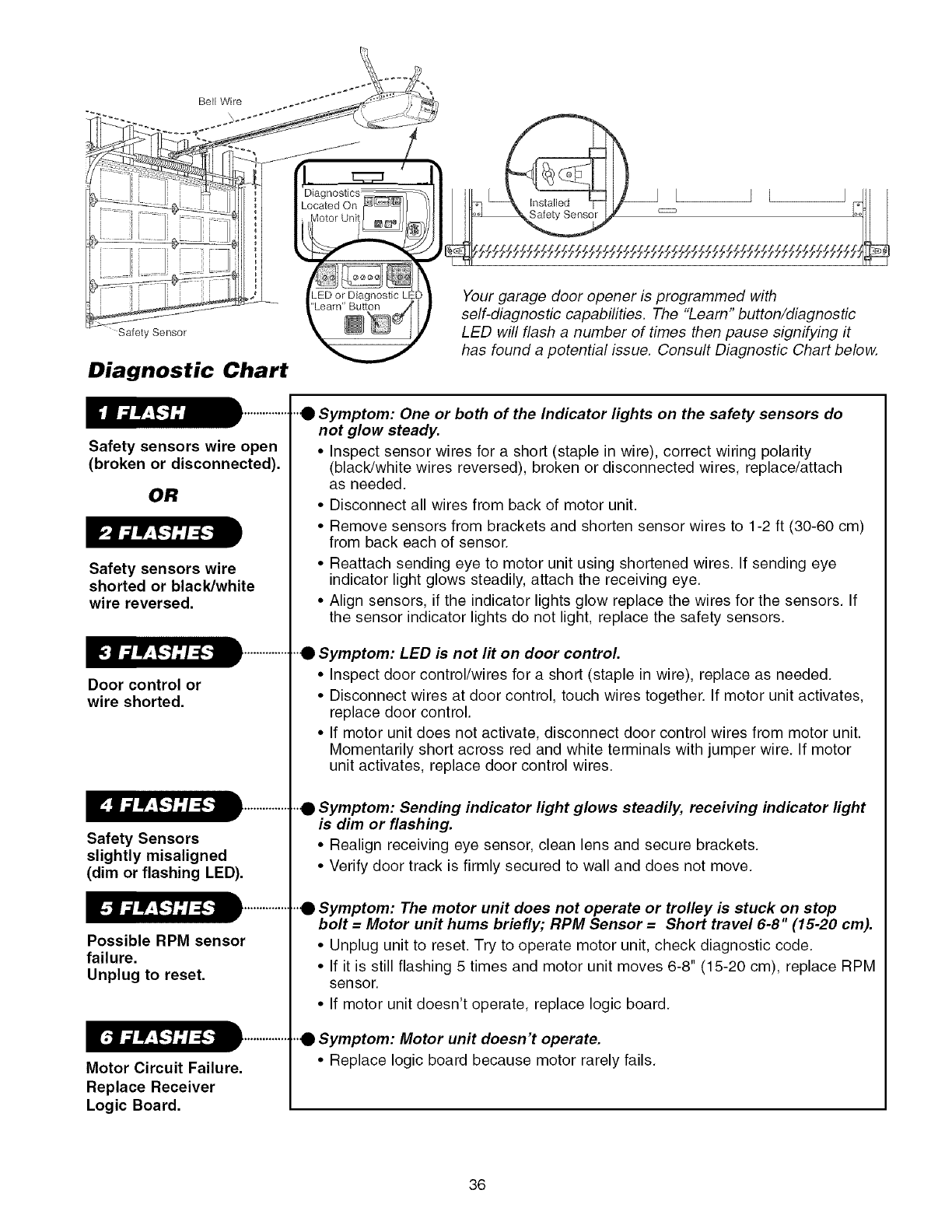
Bell Wire
Safety Sensor
Diagnostic Chart
Safety sensors wire open
(broken or disconnected).
OR
Safety sensors wire
shorted or black/white
wire reversed.
Door control or
wire shorted.
Safety Sensors
slightly misaligned
(dim or flashing LED).
Possible RPM sensor
failure.
Unplug to reset.
Motor Circuit Failure.
Replace Receiver
Logic Board.
Your garage door opener is programmed with
self-diagnostic capabilities. The "Learn" button/diagnostic
LED will flash a number of times then pause signifying it
has found a potential issue. Consult Diagnostic Chart below.
"0 Symptom: One or both of the Indicator lights on the safety sensors do
not glow steady.
• Inspect sensor wires for a short (staple in wire), correct wiring polarity
(black/white wires reversed), broken or disconnected wires, replace/attach
as needed.
• Disconnect all wires from back of motor unit.
• Remove sensors from brackets and shorten sensor wires to 1-2 ft (30-60 cm)
from back each of sensor.
• Reattach sending eye to motor unit using shortened wires. If sending eye
indicator light glows steadily, attach the receiving eye.
• Align sensors, if the indicator lights glow replace the wires for the sensors. If
the sensor indicator lights do not light, replace the safety sensors.
"0 Symptom: LED is not lit on door control.
• Inspect door control/wires for a short (staple in wire), replace as needed.
• Disconnect wires at door control, touch wires together. If motor unit activates,
replace door control.
• If motor unit does not activate, disconnect door control wires from motor unit.
Momentarily short across red and white terminals with jumper wire. If motor
unit activates, replace door control wires.
"0 Symptom: Sending indicator light glows steadily, receiving indicator light
is dim or flashing.
• Realign receiving eye sensor, clean lens and secure brackets.
• Verify door track is firmly secured to wall and does not move.
"0 Symptom: The motor unit does not operate or trolley is stuck on stop
bolt = Motor unit hums briefly; RPM Sensor = Short travel 6-8" (15-20 cm).
• Unplug unit to reset. Try to operate motor unit, check diagnostic code.
• If it is still flashing 5 times and motor unit moves 6-8" (15-20 cm), replace RPM
sensor.
• If motor unit doesn't operate, replace logic board.
"0 Symptom: Motor unit doesn't operate.
• Replace logic board because motor rarely fails.
36
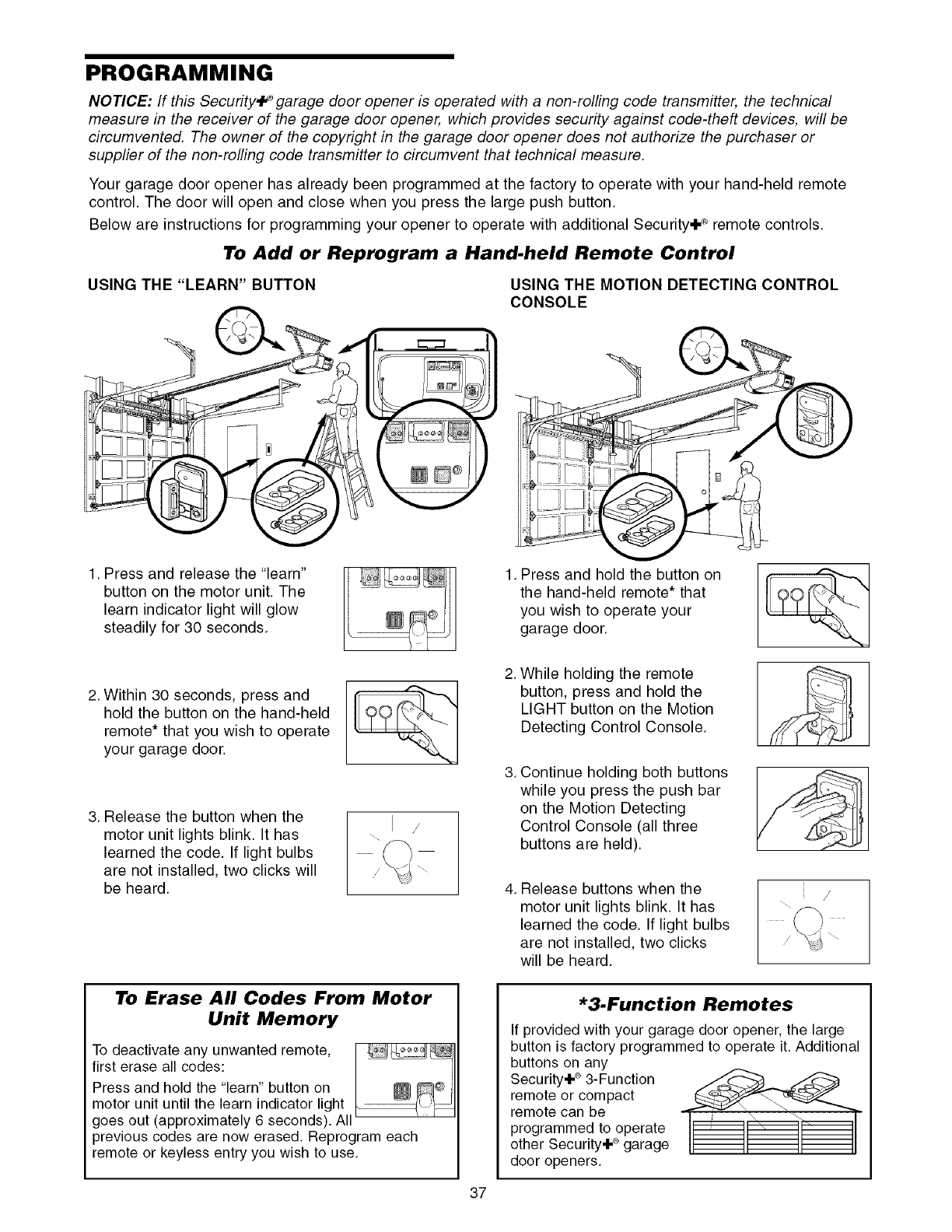
PROGRAMMING
NOTICE: If this Security,l_ garage door opener is operated with a non-rolling code transmitter, the technical
measure in the receiver of the garage door opener, which provides security against code-theft devices, will be
circumvented. The owner of the copyright in the garage door opener does not authorize the purchaser or
supplier of the non-rolling code transmitter to circumvent that technical measure,
Your garage door opener has already been programmed at the factory to operate with your hand-held remote
control. The door will open and close when you press the large push button.
Below are instructions for programming your opener to operate with additional Security÷ ® remote controls.
To Add or Reprogram a Hand-held Remote Control
USING THE "LEARN" BUTTON USING THE MOTION DETECTING CONTROL
CONSOLE
1, Press and release the "learn"
button on the motor unit. The
learn indicator light will glow
steadily for 30 seconds,
2. Within 30 seconds, press and
hold the button on the hand-held
remote* that you wish to operate
your garage door.
3. Release the button when the
motor unit lights blink. It has
learned the code. If light bulbs
are not installed, two clicks will
be heard.
/
To Erase All Codes From Motor
Unit Memory
To deactivate any unwanted remote,
first erase all codes:
Press and hold the "learn" button on
motor unit until the learn indicator light
goes out (approximately 6 seconds). All
previous codes are now erased, Reprogram each
remote or keyless entry you wish to use,
1, Press and hold the button on
the hand-held remote* that
you wish to operate your
garage door,
2.
3.
4.
While holding the remote
button, press and hold the
LIGHT button on the Motion
Detecting Control Console.
Continue holding both buttons
while you press the push bar
on the Motion Detecting
Control Console (all three
buttons are held).
Release buttons when the
motor unit lights blink. It has
learned the code. If light bulbs
are not installed, two clicks
will be heard.
*3.Function Remotes
If provided with your garage door opener, the large
button is factory programmed to operate it. Additional
buttons on any
Security÷ ®3-Function
remote or compact
remote can be
programmed to operate
other Security+ ®garage
door openers.
37
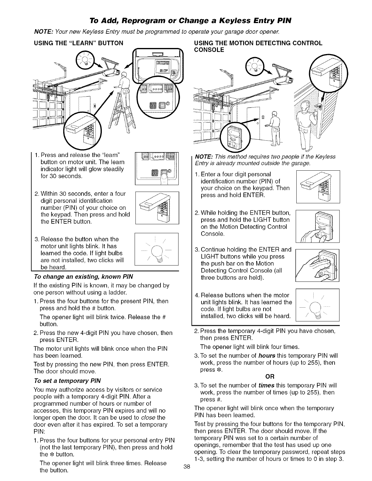
To Add, Reprogram or Change a Keyless Entry PIN
NOTE: Your new Keyless Entry must be programmed to operate your garage door opener.
USING THE "LEARN" BUTTON
1. Press and release the "learn"
button on motor unit. The learn
indicator light will glow steadily
for 30 seconds.
2. Within 30 seconds, enter a four
digit personal identification
number (PIN) of your choice on
the keypad. Then press and hold
the ENTER button.
3. Release the button when the /
motor unit lights blink. It has
learned the code. If light bulbs
are not installed, two clicks will
be heard.
To change an existing, known PIN
If the existing PIN is known, it may be changed by
one person without using a ladder.
1. Press the four buttons for the present PIN, then
press and hold the # button.
The opener light will blink twice. Release the #
button.
2. Press the new 4-digit PIN you have chosen, then
press ENTER.
The motor unit lights will blink once when the PIN
has been learned.
Test by pressing the new PIN, then press ENTER.
The door should move.
To set a temporary PiN
You may authorize access by visitors or service
people with a temporary 4-digit PIN. After a
programmed number of hours or number of
accesses, this temporary PIN expires and will no
longer open the door. It can be used to close the
door even after it has expired. To set a temporary
PIN:
1. Press the four buttons for your personal entry PIN
(not the last temporary PIN), then press and hold
the _=button.
The opener light will blink three times. Release
the button.
)
38
USING THE MOTION DETECTING CONTROL
CONSOLE
NOTE: This method requires two people if the Keyless
Entry is already mounted outside the garage.
1. Enter a four digit personal
identification number (PIN) of
your choice on the keypad. Then
press and hold ENTER.
2. While holding the ENTER button,
press and hold the LIGHT button
on the Motion Detecting Control
Console.
3. Continue holding the ENTER and
LIGHT buttons while you press
the push bar on the Motion
Detecting Control Console (all
three buttons are held).
4. Release buttons when the motor
unit lights blink. It has learned the
code. If light bulbs are not
installed, two clicks will be heard.
2. Press the temporary 4-digit PIN you have chosen,
then press ENTER.
The opener light will blink four times.
3.To set the number of hours this temporary PIN will
work, press the number of hours (up to 255), then
press _=. OR
3.To set the number of times this temporary PIN will
work, press the number of times (up to 255), then
press #.
The opener light will blink once when the temporary
PIN has been learned.
Test by pressing the four buttons for the temporary PIN,
then press ENTER. The door should move. If the
temporary PIN was set to a certain number of
openings, remember that the test has used up one
opening. To clear the temporary password, repeat steps
1-3, setting the number of hours or times to 0 in step 3.
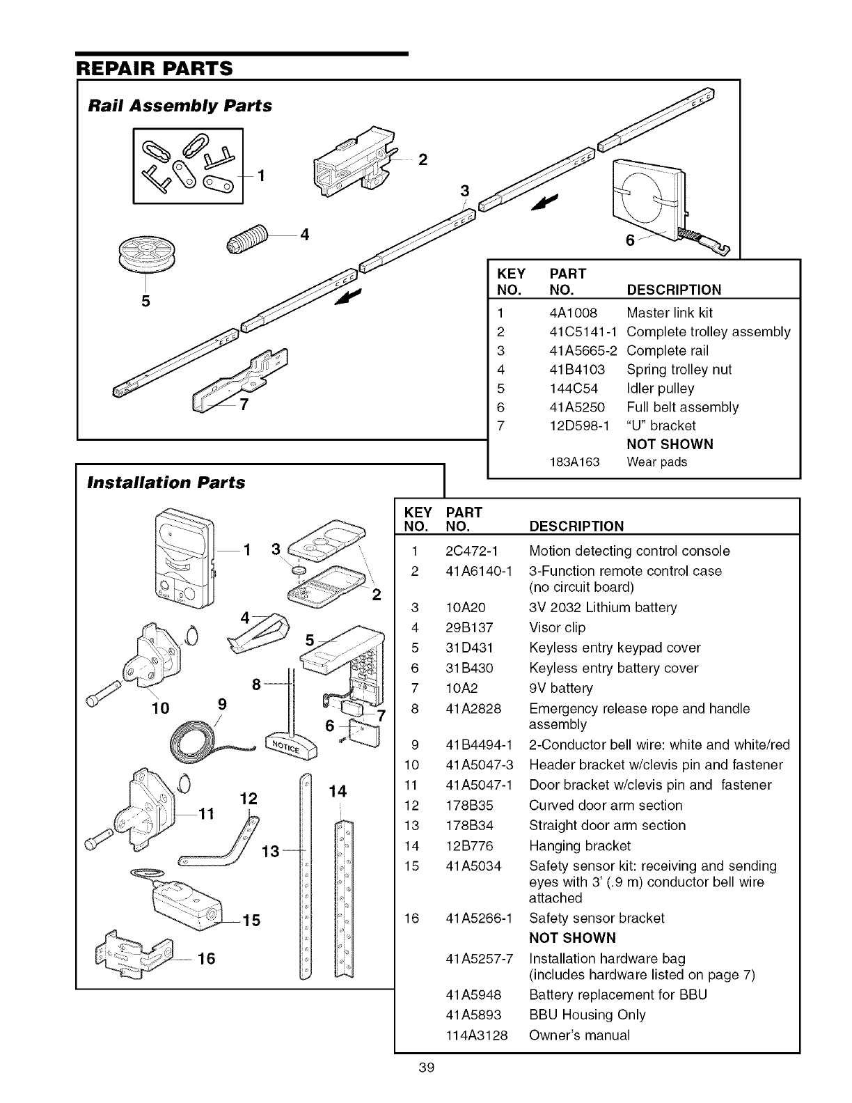
REPAIR PARTS
Rail Assembly Parts
5
Installation Parts
3
!
KEY PART
NO. NO.
1
2
3
4
5
6
7
8
9
10
11
12
13
14
15
16
KEY
NO.
1
2
3
4
5
6
7
6
PART
NO. DESCRIPTION
4A1008 Master link kit
41C5141-1 Complete trolley assembly
41A5665-2 Complete rail
41B4103 Spring trolley nut
144C54 Idler pulley
41A5250 Full belt assembly
12D598-1 "U" bracket
NOT SHOWN
183A163 Wear pads
2C472-1
41 A6140-1
10A20
29B137
31 D431
31 B430
10A2
41 A2828
41 B4494-1
41 A5047-3
41 A5047-1
178B35
178B34
12B776
41 A5034
41 A5266-1
41 A5257-7
41 A5948
41 A5893
114A3128
DESCRIPTION
Motion detecting control console
3-Function remote control case
(no circuit board)
3V 2032 Lithium battery
Visor clip
Keyless entry keypad cover
Keyless entry battery cover
9V battery
Emergency release rope and handle
assembly
2-Conductor bell wire: white and white/red
Header bracket w/clevis pin and fastener
Door bracket w/clevis pin and fastener
Curved door arm section
Straight door arm section
Hanging bracket
Safety sensor kit: receiving and sending
eyes with 3' (.9 m) conductor bell wire
attached
Safety sensor bracket
NOT SHOWN
Installation hardware bag
(includes hardware listed on page 7)
Battery replacement for BBU
BBU Housing Only
Owner's manual
39
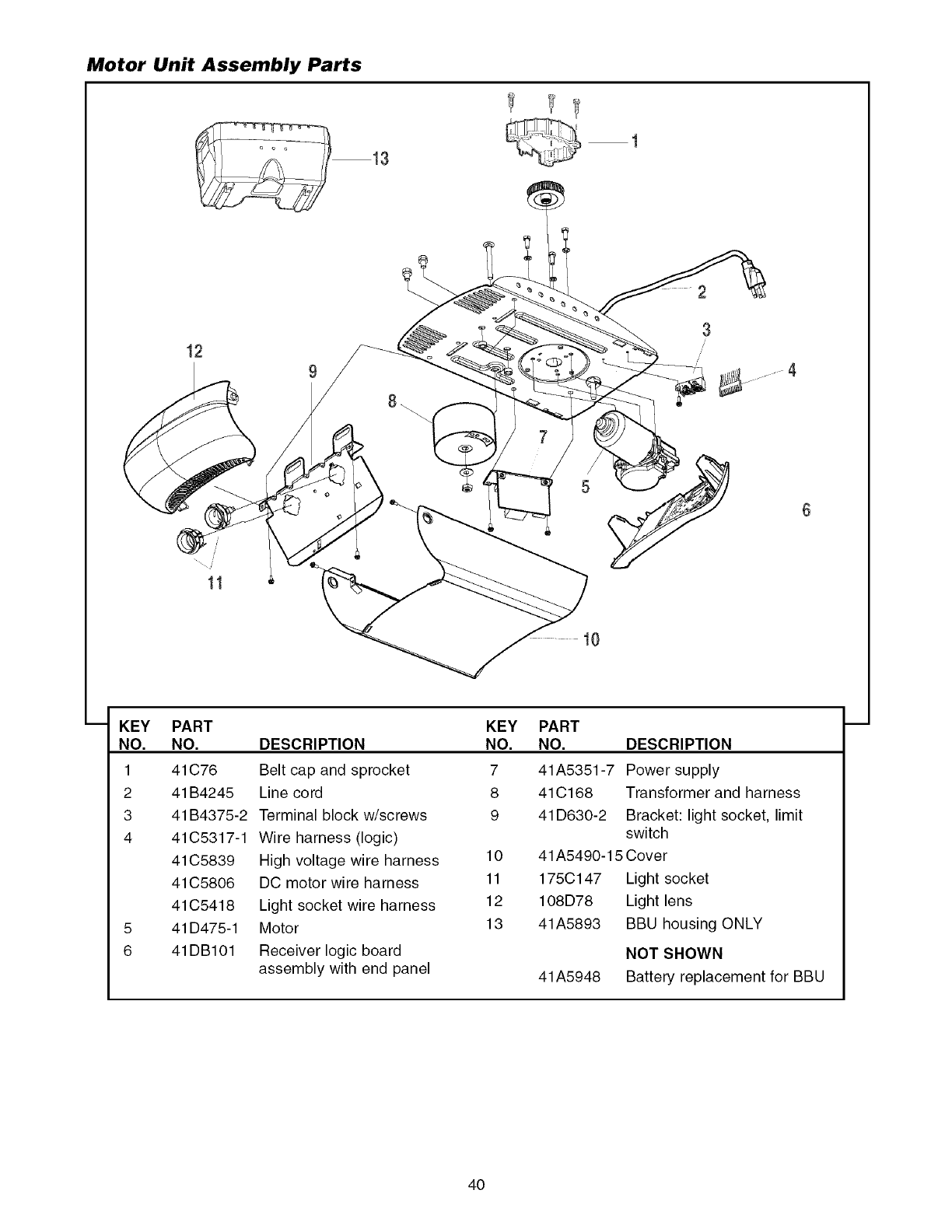
Motor Unit Assembly Parts
12
2
3
4
10
KEY
NO.
1
2
3
4
5
6
PART
NO.
41C76
41B4245
41B4375-2
41C5317-1
41C5839
41C5806
41C5418
41D475-1
41DB101
DESCRIPTION
Belt cap and sprocket
Line cord
Terminal block w/screws
Wire harness (logic)
High voltage wire harness
KEY
NO.
7
8
9
10
PART
NO. DESCRIPTION
41A5351-7 Power supply
41C168 Transformer and harness
41D630-2 Bracket: light socket, limit
switch
41A5490-15 Cover
DC motor wire harness
Light socket wire harness
Motor
Receiver logic board
assembly with end panel
11
12
13
175C147
108D78
41A5893
41A5948
Light socket
Light lens
BBU housing ONLY
NOT SHOWN
Battery replacement for BBU
4O
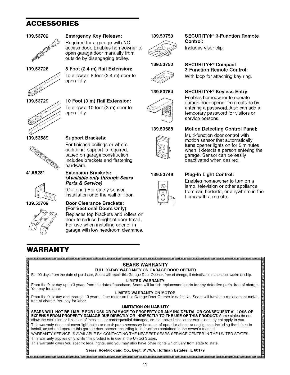
ACCESSORIES
139.53702
139.53728
Emergency Key Release:
Required for a garage with NO
access door. Enables homeowner to
open garage door manually from
outside by disengaging trolley.
8 Foot (2.4 m) Rail Extension:
To allow an 8 foot (2.4 m) door to
open fully.
139.53729 10 Foot (3 m) Rail Extension:
To allow a 10 foot (3 m) door to
open fully.
139.53589
41A5281
139.53709
Support Brackets:
For finished ceilings or where
additional support is required,
based on garage construction.
Includes brackets and fastening
hardware.
Extension Brackets:
(Available only through Sears
Parts & Service)
(Optional) For safety sensor
installation onto the wall or floor.
Door Clearance Brackets:
(For Sectional Doors Only)
Replaces top brackets and rollers on
door to reduce height of door travel.
For use when installing opener in
garage with low headroom clearance.
139.53753
139.53752
139.53754
139.53688
139.53749
SECURITY÷ ®3-Function Remote
Control:
Includes visor clip.
SECURITY÷ ®Compact
3-Function Remote Control:
With loop for attaching key ring.
SECURITY÷ ®Keyless Entry:
Enables homeowner to operate
garage door opener from outside by
entering a password. Also can add a
temporary password for visitors or
service persons.
Motion Detecting Control Panel:
Multi-function door control with
motion sensor that automatically
turns opener lights on for 5 minutes
when it detects a person entering the
garage. Sensor can be easily
deactivated when desired.
Plug-In Light Control:
Enables homeowner to turn on a
lamp, television or other appliance
from car, bedside, or anywhere in the
home with a remote.
WARRANTY
SEARS WARRANTY
FULL 90-DAY WARRANTY ON GARAGE DOOR OPENER
For 90 days from the date of purchase, Sears will repair this Garage Door Opener, free of charge, if defective in material or workmanship.
LIMITED WARRANTY
From the 91st day up to 3 years from the date of purchase, Sears will furnish replacement parts for any defective parts, free of charge.
You pay for labor. LIMITED WARRANTY ON MOTOR
From the 91st day and through 10 years, if the motor oll this Garage Door Opener is defective, Sears will furnish a replacement motor,
free of charge. You pay for labor.
LIMITATION ON LIABILITY
SEARS WILL NOT BE LIABLE FOR LOSS OR DAMAGE TO PROPERTY OR ANY INCIDENTAL OR CONSEQUENTIAL LOSS OR
EXPENSE FROM PROPERTY DAMAGE DUE DIRECTLY OR INDIRECTLY TO THE USE OF THIS PRODUCT. Some states do not
allow the exclusion or limitation of incidental or consequential damages, so the above limitation or exclusion may not apply to you.
This warranty does not cover light bulbs or repair parts necessary because of operator abuse or negligence, including the failure to
install, adjust and operate this garage door opener according to instructions contained in the owner's manual.
WARRANTY SERVICE IS AVAILABLE BY CONTACTING THE NEAREST SEARS SERVICE CENTER IN THE UNITED STATES.
This warranty applies only while this product is in use in the United States.
This warranty gives you specific legal rights, and you may also have other rights which vary from state to state.
Sears, Roebuck and Co., Dept. 817WA, Hoffman Estates, IL 60179
41
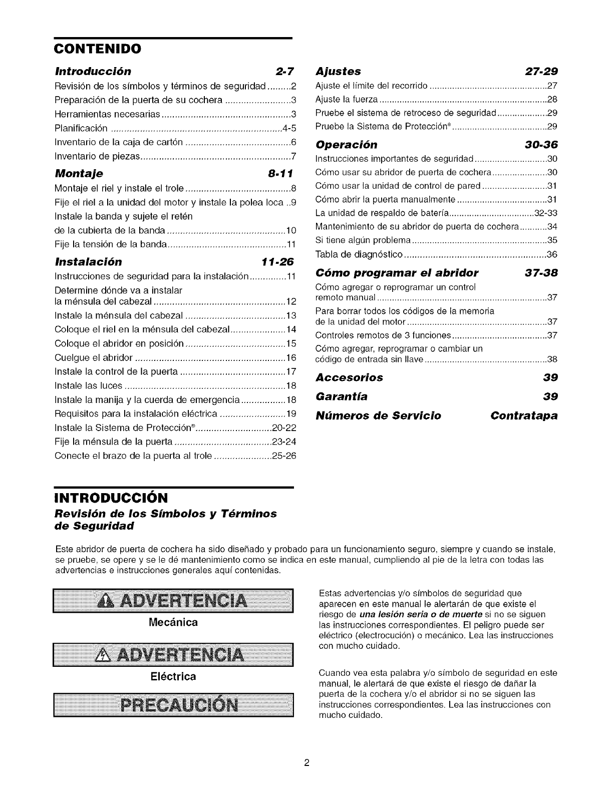
CONTENIDO
Introduccibn 2-7
Revisi6n de los simbolos y t_rminos de seguridad ......... 2
Preparaci6n de la puerta de su cochera ......................... 3
Herramientas necesarias ................................................. 3
Planificacidn ................................................................. 4-5
Inventario de la caja de cartdn ........................................ 6
Inventario de piezas ......................................................... 7
Montaje 8.11
Montaje el riel y instale el trole ........................................ 8
Fije el riel a la unidad del motor y instale la polea Ioca ..9
Instale la banda y sujete el ret_n
de la cubierta de la banda ............................................. 10
Fije la tensidn de la banda ............................................. 11
Instalaci6n 11-26
Instrucciones de seguridad para la instalaci6n .............. 11
Determine d6nde va a instalar
la m_nsula del cabezal .................................................. 12
Instale la m_nsula del cabezal ...................................... 13
Coloque el riel en la m_nsula del cabezal ..................... 14
Coloque el abridor en posici6n ...................................... 15
Cuelgue el abridor ......................................................... 16
Instale la control de la puerta ........................................ 17
Instale las luces ............................................................. 18
Instale la manija y la cuerda de emergencia ................. 18
Requisitos para la instalaci6n el_ctrica ......................... 19
Instale la Sistema de Protecci6n ®............................. 20-22
Fije la m_nsula de la puerta ..................................... 23-24
Conecte el brazo de la puerta al trole ...................... 25-26
Ajustes 27.29
Ajuste el limite del recorrido ............................................... 27
Ajuste la fuerza ................................................................... 28
Pruebe el sistema de retroceso de seguridad .................... 29
Pruebe la Sistema de Protecci6n ®...................................... 29
Operaci6n 30.36
Instrucciones importantes de seguridad ............................. 30
C6mo usar su abridor de puerta de cochera ...................... 30
C6mo usar la unidad de control de pared .......................... 31
C6mo abrir la puerta manualmente .................................... 31
La unidad de respaldo de baterfa .................................. 32-33
Mantenimiento de su abridor de puerta de cochera ........... 34
Si tiene algQn problema ...................................................... 35
Tabla de diagn6stico ...................................................... 36
C6mo programar el abridor 37.38
C6mo agregar o reprogramar un control
remoto manual .................................................................... 37
Para borrar todos los c6digos de la memoria
de la unidad del motor ........................................................ 37
Controles remotos de 3 funciones ...................................... 37
C6mo agregar, reprogramar o cambiar un
c6digo de entrada sin Ilave ................................................. 38
Accesorios 39
Garantia 39
Nbmeros de Servicio Contratapa
INTRODUCClON
Revisi6n de los Simbolos y T_rminos
de Seguridad
Este abridor de puerta de cochera ha sido diseSado y probado para un funcionamiento seguro, siempre y cuando se instale,
se pruebe, se opere y se le de mantenimiento como se indica en este manual, cumpliendo al pie de la letra con todas las
advertencias e instrucciones generales aquf contenidas.
Mecanica
Electrica
Estas advertencias y/o simbolos de seguridad que
aparecen en este manual le alertaran de que existe el
riesgo de una lesion seria o de muerte si no se siguen
las instrucciones correspondientes. El peligro puede ser
electrico (electrocuci6n) o mecanico. Lea las instrucciones
con mucho cuidado.
Cuando vea esta palabra y/o simbolo de seguridad en este
manual, le alertara de que existe el riesgo de daSar la
puerta de la cochera y/o el abridor si no se siguen las
instrucciones correspondientes. Lea las instrucciones con
mucho cuidado.
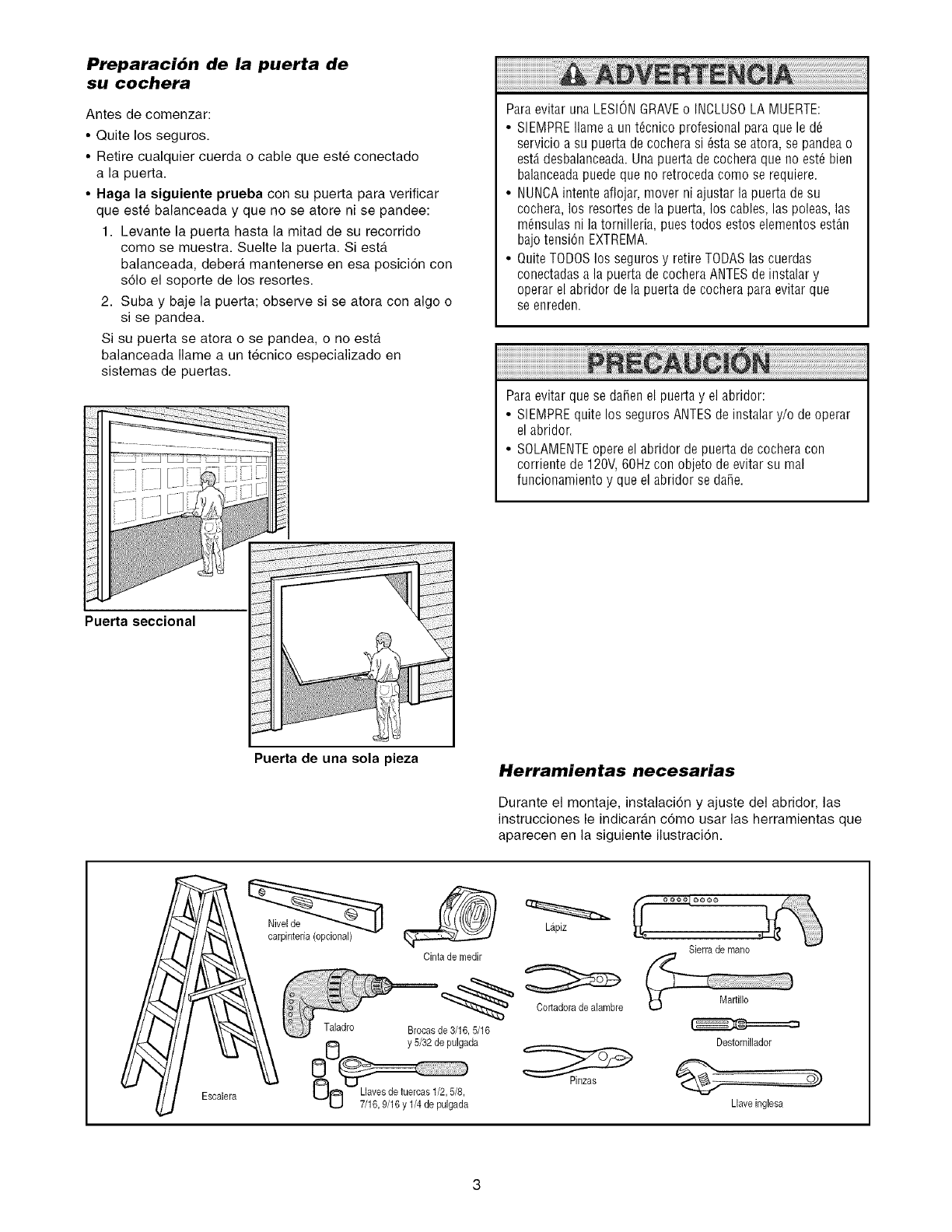
Preparaci6n de la puerta de
su cochera
Antes de comenzar:
•Quite los seguros.
• Retire cualquier cuerda o cable que este conectado
a la puerta.
• Haga la siguiente prueba con su puerta para verificar
que este balanceada y que no se atore ni se pandee:
1. Levante la puerta hasta la mitad de su recorrido
como se muestra. Suelte la puerta. Siesta
balanceada, debera mantenerse en esa posici6n con
s61o el soporte de los resortes.
2. Suba y baje la puerta; observe si se atora con algo o
si se pandea.
Si su puerta se atora o se pandea, o no esta
balanceada Ilame a un tecnico especializado en
sistemas de puertas.
Puerta seccional
Paraevitar una LESIONGRAVEo INCLUSOLA MUERTE:
• SIEMPREIlame a unt_cnico profesional para que le d6
servicio a su puerta de cochera si 6sta se atora, se pandea o
est,. desbalanceada.Una puerta de cochera que no est_ bien
balanceadapuede que no retroceda como se requiere.
• NUNCAintente aflojar, mover ni ajustar la puerta de su
cochera, los resortes de la puerta, los cables, las poleas, las
m6nsulas ni la tornilleria, pues todos estos elementos est_n
bajo tensi6n EXTREMA.
• Quite TODOSlos seguros y retire TODASlas cuerdas
conectadasa la puerta de cochera ANTESde instalar y
operar el abridor de la puerta de cochera paraevitar que
se enreden.
Para evitar que se da_en el puerta y el abridor:
• SIEMPREquite los seguros ANTESde instalar y/o de operar
el abridor.
• SOLAMENTEopere el abridor de puerta de cochera con
corriente de 120V,60Hz con objeto de evitar su real
funcionamiento y que el abridor se dane.
Puerta de una sola pieza Herramientas necesarias
Durante el montaje, instalaci6n y ajuste del abridor, las
instrucciones le indicaran c6mo usar las herramientas que
aparecen en la siguiente ilustraci6n.
Escalera
Cinta de medir
Taladro Brocasde 3/16,5/16
y 5/32 de pulgada
UO 7/16,9/16 y 1/4de pu'lgad'a
Lapiz
Cortadorade alambre
Sierra de mano
Destornillador
Llaveinglesa
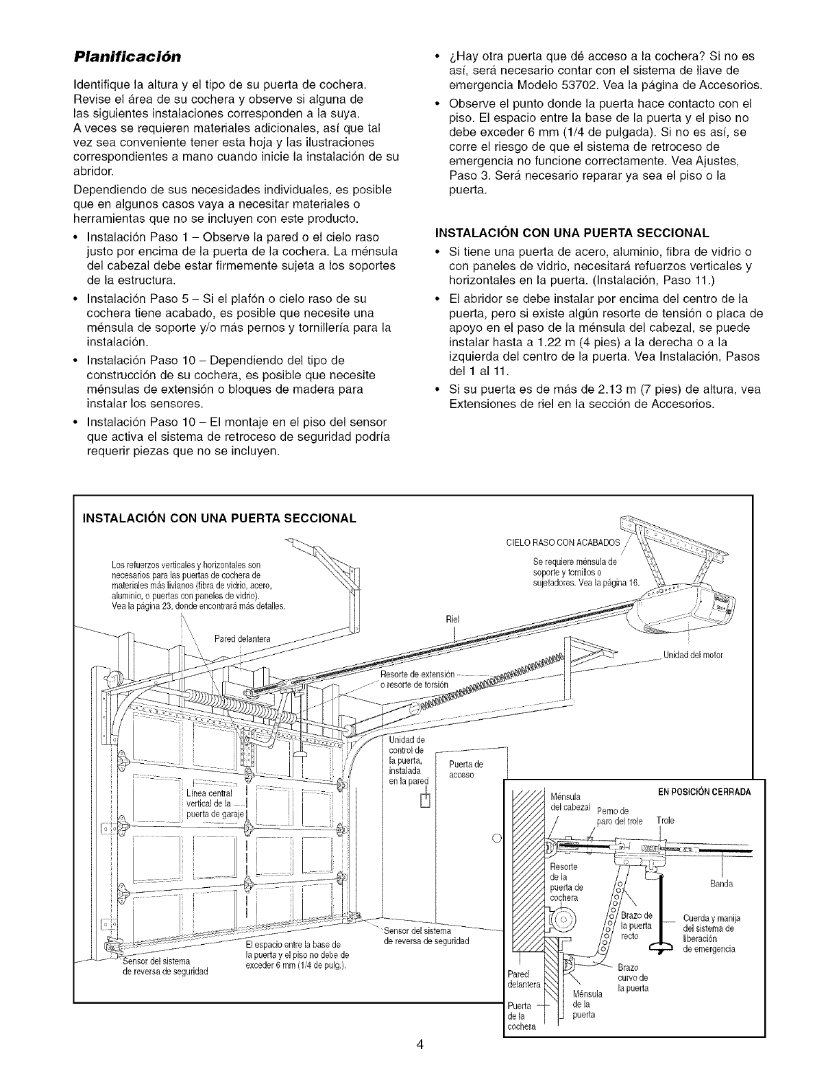
Planificaci6n
Identifique la altura y el tipo de su puerta de cochera.
Revise el Area de su cochera y observe si alguna de
las siguientes instalaciones corresponden a la suya.
A veces se requieren materiales adicionales, asf que tal
vez sea conveniente tenet esta hoja y las ilustraciones
correspondientes a mano cuando inicie la instalaci6n de su
abridor.
Dependiendo de sus necesidades individuales, es posible
queen algunos casos vaya a necesitar materiales o
herramientas que no se incluyen con este producto.
• Instalaci6n Paso 1 - Observe la pared o el cielo raso
justo por encima de la puerta de la cochera. La mensula
del cabezal debe estar firmemente sujeta a los soportes
de la estructura.
• Instalaci6n Paso 5 - Si el plafon o cielo raso de su
cochera tiene acabado, es posible que necesite una
mensula de soporte y/o m_.s pemos y tornillefia para la
instalacion.
• Instalacion Paso 10 - Dependiendo del tipo de
construccion de su cochera, es posible que necesite
mensulas de extensidn o bloques de madera para
instalar los sensores.
• Instalaci6n Paso 10 - El montaje en el piso del sensor
que activa el sistema de retroceso de seguridad podria
requerir piezas que no se incluyen.
_,Hay otra puerta que de acceso a la cochera? Si no es
asf, sera necesario contar con el sistema de Ilave de
emergencia Modelo 53702. Vea la p_.gina de Accesorios.
Observe el punto donde la puerta hace contacto con el
piso. El espacio entre la base de la puerta y el piso no
debe exceder 6 mm (1/4 de pulgada). Si no es asf, se
corre el riesgo de que el sistema de retroceso de
emergencia no funcione correctamente. Vea Ajustes,
Paso 3. Sera necesario reparar ya sea el piso o la
puerta.
INSTALACION CON UNA PUERTA SECCIONAL
• Si tiene una puerta de acero, aluminio, fibra de vidrio o
con paneles de vidrio, necesitar_, refuerzos verticales y
horizontales en la puerta. (Instalacidn, Paso 11.)
• El abridor se debe instalar pot encima del centro de la
puerta, pero si existe algQn resorte de tensidn o placa de
apoyo en el paso de la mensula del cabezal, se puede
instalar hasta a 1.22 m (4 pies) a la derecha o a la
izquierda del centro de la puerta. Vea Instalacidn, Pasos
del 1 a111.
• Si su puerta es de mas de 2.13 m (7 pies) de altura, vea
Extensiones de riel en la seccion de Accesorios.
INSTALAClON CON UNA PUERTA SECClONAL
Los refuerzosverticales _hodzontalesson
necesados para las puertasde cechera de
materialesmas livianes Fibrade vidrie, acero,
aluminie,e puertascon paneles devidrie).
Vea la pagina 23, donde encontraramasdetalles.
i\\,
,, Pared delantera
Riel
...... _o resortede torsi6n
CIELO RASO CONACABADOS
/
Se requiere m6nsulade
soporte y tornilloso
sujetaderes.Vea la pagina 16.
Unidaddelmotor
Unidad de
[: i
Linea central :::] .....
vertical de la ....
puerta degaraje
de reversa de seguridad
Elespacio entre la basede
la puerta y el piso no debe de
exceder6 mm (1/4de pulg.).
de reversade seguddad
Puertade
acceso
0
_red
_lantera_,
_erta
qa
chera
Mensula
delcabezal Pemode
ENP0SIClON CERRADA
Trole
Braze
curvede
la puerta
de la
puerta
Banda
Cuerday manija
del sistemade
liberacion
de emergencia
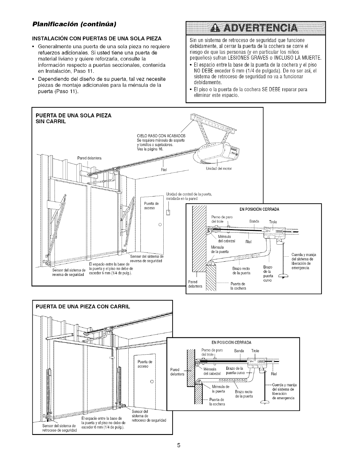
Planificaci6n (continba)
INSTALACION CON PUERTAS DE UNA SOLA PIEZA
•Generalmente una puerta de una sola pieza no requiere
refuerzos adicionales Si usted tiene una puerta de
material liviano y quiere reforzarla, consulte la
informacion respecto a puertas seccionales, contenida
en Instalacion, Paso 11
•Dependiendo del diseSo de su puerta, tal vez necesite
piezas de montaje adicionales para la mensula de la
puerta (Paso 11)
Sinun sistemaderetrocesodeseguridadquefuncione
debidamente, al cerrar la puerta de la cochera se corre el
riesgo de que las personas (y en particular los niSos
pequeSos) sufran LESIONESGRAVESo INCLUSOLA MUERTE.
• El espacio entre la basede la puerta de la cochera y el piso
NODEBEexceder6mm (1/4 depulgada).De noserasi,el
sistema de retroceso de seguridad nova a funcionar
debidamente.
• El piso o la puerta de la cochera SE DEBEreparar para
eliminar este espacio.
PUERTA DE UNA SOLA PIEZA
SIN CARRIL
E
J
Pareddelantera
!
CIELORASO CONACABADOS
Serequiere mensulade soporte
y tomilloso sujetadores.
Vea[a pagina 16.
Puertade
acceso
Unidadde control de la puerta,
instaladaan la pared
Sensor del sistemade
reversa de seguridad
El espacioentre la base de
Sensor del sistema de [a puerta y el piso no debe de
reversa de seguddad exceder6 mm (1/4 de pulg.).
Unidaddel motor
EN POSlClONCERRADA
Perno de paro Banda Trole
Brazo recto Brazo [
de la
de [a puerta puerta
Curve
la cochera
Cuerday manija
de1sistema de
liberacionde
emergencia
PUERTA DE UNA PIEZA CON CARRIL
El es _acioentre la base de
f la puerta y el piso no debede
Sensor del sistema de exceder6 mm (1/4de pulg.).
retroceso de seguridad
Puertade
acceso
o
Sensordel
sistemade
retrocesode seguridad
Pared _/
delantera_
EN POSiCION CERRADA
Pemo de paro Banda Trole
del tro[e_ I
del cabezal P Jl
,/ /
//a_ oooooo,ooooo)_
_ M6nsulade
x_/_ [a puerta Brazo recto
Y/// de [a puerta
////_ Puertade
"//A [acochera
Riel
--Cuerda y manija
del sistema de
liberaci6n
de emergencia
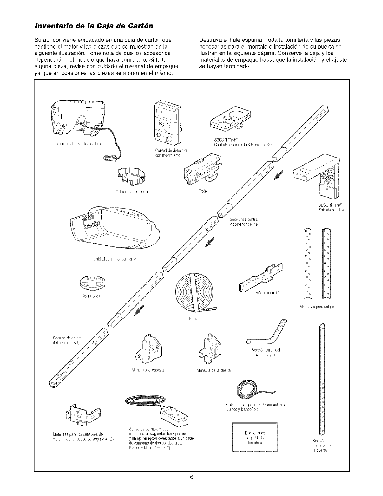
Inventario de la Caja de Cart6n
Su abridor viene empacado en una caja de carton que
contiene el motor y las piezas que se muestran en la
siguiente ilustracion. Tome nota de que los accesorios
dependergm del modelo que haya comprado. Si falta
alguna pieza, revise con cuidado el material de empaque
ya que en ocasiones las piezas se atoran en el mismo.
Destruya el hule espuma. Toda la tornilleria y las piezas
necesarias para el montaje e instalacidn de su puerta se
ilustran en la siguiente pgtgina. Conserve la caja y los
materiales de empaque hasta que la instalacion y el ajuste
se hayan terminado.
Cubierta de la banda
Control de detecd6n
con movimbnto
SECURITY,_,_'
Controbs remotode 3 funciones(2)
Trob
Secciones central
y posteriordel rM
j-
SECURITY+_'
Entrada sin llave
Unidaddel motor con lente
Poba Loca @
Banda
M@suBs para colgar
M6nsulaspara lossensoresdel
sistemade retrocesode seguridad(2)
M@suB del cabeza[
Sensoresde[sistemade
retrocesode seguridad (un ojo emisor
y un ojo receptor}coneoladosa un cable
de campanade dos conductores,
Blancoy Nancoinegro(2)
M@suB de la puerta
Secd6n curva del
brazode [a puerta
Cablede campanade 2 conductores
Blancoy blanco/rojo
Etiquetas de
seguridady
literatura Secci6n recta
de[ brazo de
la puerta
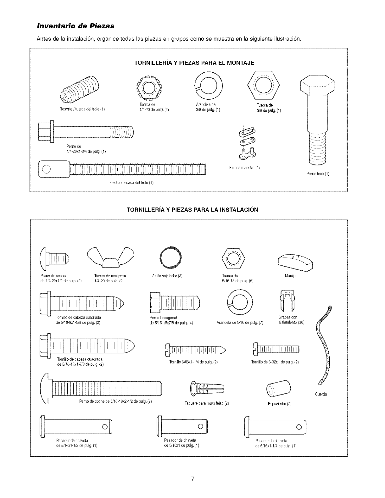
Inventario de Piezas
Antes de la instalaci6n, organice todas las piezas en grupos como se muestra en la siguiente ilustracion.
Resorte/tuerca del trole (1)
Pemo de
1/4-20xl-3/4 de pulg. (1)
TORNILLER|A Y PIEZAS PARA EL MONTAJE
Tuercade Arandela de Tuercade
1/4-20de pulg. (2) 3/8 de pulg. (1) 3/8de pulg. (1)
i
Enlasemaestro (2)
Flecharoscadadel trole (1)
PemoIoco (1)
TORNILLER|A Y PIEZAS PARA LA INSTALACION
Perno decoche
de 1/4-28xl/2 de pulg,(2)
de 5/18-9xl-5/8 de pulg. (2)
Tuercade mariposa
1/4-20de pulg. (2)
Anillo sujetador(3) Tuercade
5/16-18de pulg.(6)
Pemo hexagonal
de 5/16-18x7/8 de pulg. (4) Arandela de 5/16 de pulg. (7)
Manija
Grapas con
aislamiento(80)
de 5/16-18xl-7/8 de pulg.(2) Tornillo6ABx1-1/4 de pulg. (2) Tornillo de6-32xl de pulg.(2)
Pernode coche de 5/16-18x2-1/2de pulg. (2)
Pasador de chaveta
de 5/16x1-1/2 de pulg. (1)
Taquetepara muro falso(2)
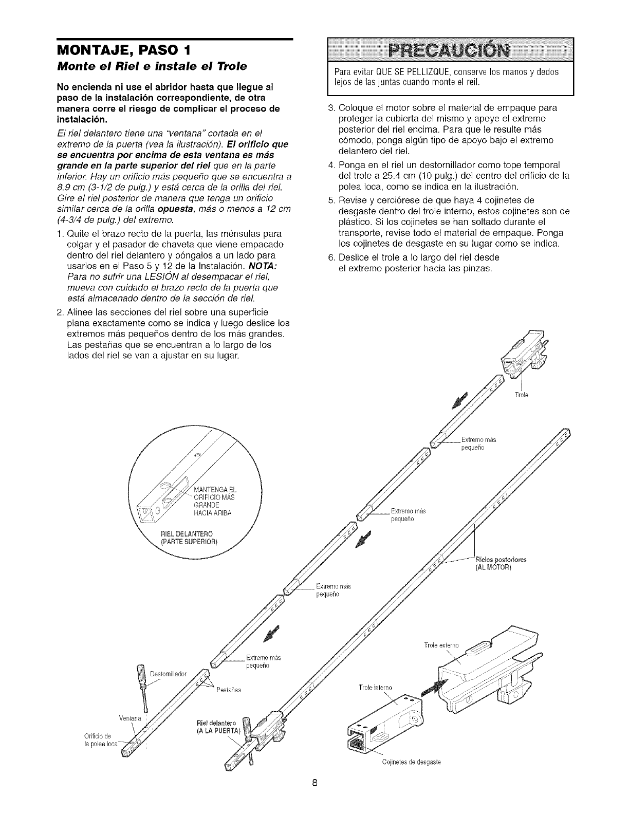
MONTAJE, PASO 1
Monte el Riel e instale el Trole
No encienda ni use el abridor hasta que Ilegue al
paso de la instalacibn correspondiente, de otra
manera corre el riesgo de complicar el proceso de
instalacibn.
El riel delantero tiene una "ventana" cortada en el
extremo de la puerta (vea la ilustracidn). El orificio que
se encuentra per eneima de esta ventana es mas
grande en la parte superior del riel que en /a parte
inferio_ Hay un orificio mas peque_o que se encuentra a
8.9 cm (3-1/2 de pulg.) y esta cerca de la orilla del riel.
Gire el riel posterior de manera que tenga un orificio
similar cerca de la orilla opuesta, mas o menos a 12 cm
(4-3/4 de pulg.) del extremo.
1. Quite el brazo recto de la puerta, las mensulas para
colgar y el pasador de chaveta que viene empacado
dentro del riel delantero y p6ngalos a un lado para
usarlos en el Paso 5 y 12 de la Instalacion. NOTA:
Para no sufrir una LESION al desempacar el riel,
mueva con cuidado el brazo recto de la puerta que
esta almacenado dentro de la seccidn de riel.
2. Alinee las secciones del riel sobre una superficie
plana exactamente como se indica y luego deslice los
extremos ma.s pequefios dentro de los mas grandes.
Las pestaflas que se encuentran a Io largo de los
lados del rie! se van a ajustar en su lugar.
ParaevitarQUESEPELLIZQUE,conservelos manosy ded0s
lejosdelasjuntascuandomonteelreil.
3. Coloque el motor sobre el material de empaque para
proteger la cubierta del mismo y apoye el extremo
posterior del riel encima. Para que le resulte mas
comodo, ponga algQn tipo de apoyo bajo el extremo
delantero del riel.
4. Ponga en el riel un destornillador como tope temporal
del trole a 25.4 cm (10 pulg.) del centro del orificio de la
polea Ioca, como se indica en la ilustraci6n.
5. Revise y cerci6rese de que haya 4 cojinetes de
desgaste dentro del trole interno, estos cojinetes son de
plastico. Si los cojinetes se hart soltado durante el
transporte, revise todo el material de empaque. Ponga
los cojinetes de desgaste en su lugar como se indica.
6. Deslice el trole a Io largo del riel desde
el extremo posterior hacia las pinzas.
Trole
Extremomas
pequefio
Extremomas
pequefio
Extremomas
pequeflo
iieles posteriores
(AL MOTOR)
Orificiode
Ventana
Destornillador
Rie_de_antero
(A LA PUERTA)_
Extremomas
pequefio
Trole interno
Trole externo
\
Cojinetes de desgaste
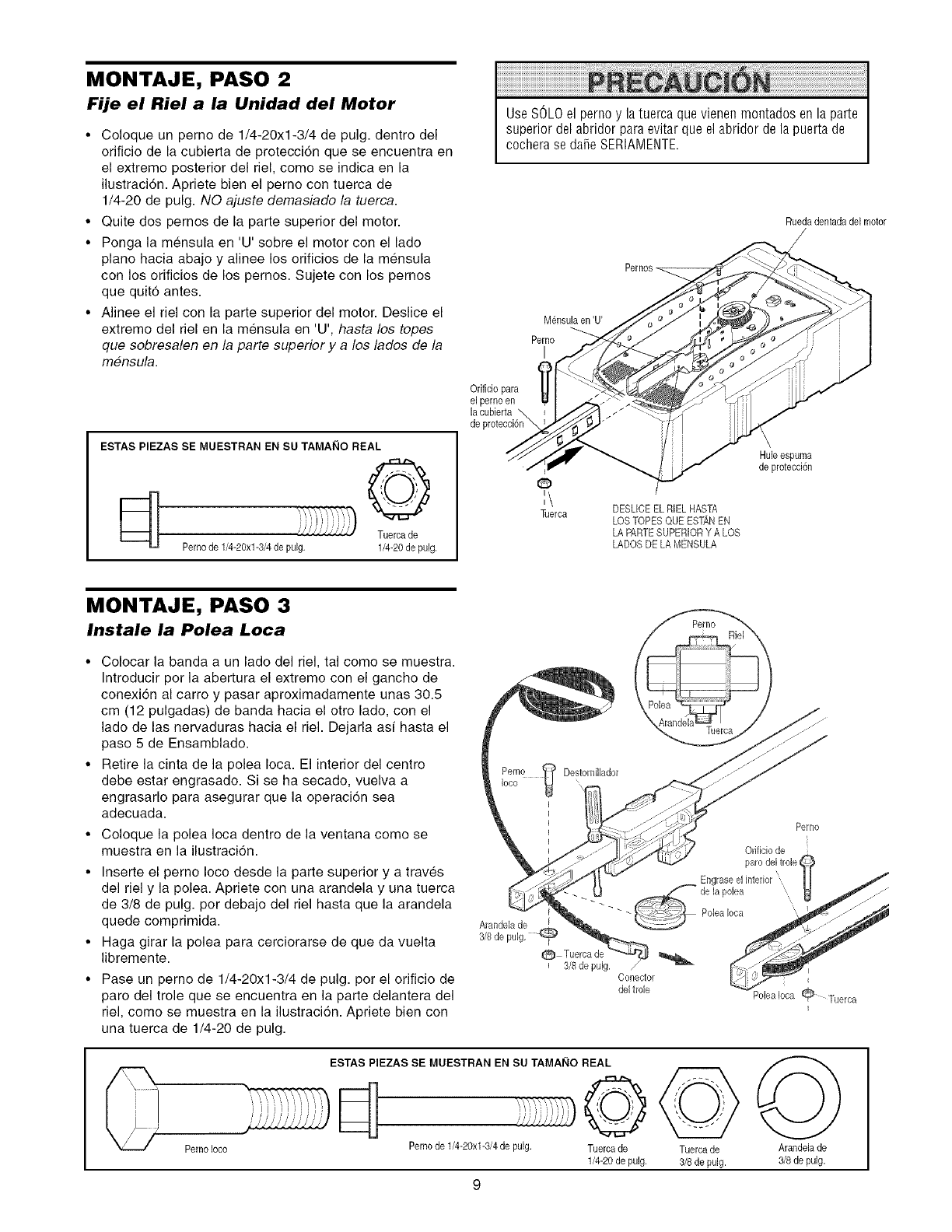
MONTAJE, PASO 2
Fije el Riel a la Unidad del Motor
•Coloque un perno de 1/4-20xl-3/4 de pulg dentro del
orificio de la cubierta de protecci6n que se encuentra en
el extremo posterior del riel, como se indica en la
ilustraci6n Apriete bien el pemo con tuerca de
1/4-20 de pulg NO ajuste demasiado la tuerca
• Quite dos pemos de la parte superior del motor
• Ponga la mensula en 'U' sobre el motor con el lado
piano hacia abajo y alinee los orificios de la mensula
con los orificios de los pernos Sujete con los pemos
que quito antes
• Alinee el riel con la parte superior del motor Deslice el
extremo del riel en la mensula en 'U', hasta los topes
que sobresalen en la parte superior y a los lades de la
mensula
ESTAS PIEZAS SE MUESTRAN EN SU TAI_IAI_IO REAL
Pernode 1/4-20xl-3/4 de pulg
©
Tuerca de
1/4-20de pulg.
Orificiopara
el pernoen
la cubierta
Use SOLOel perno y la tuerca que vienen montados en la parte
superior del abridor para evitar que el abridor de la puerta de
cochera se dare SERIAMENTE.
Rueda dentadadel motor
Perno
I
G
:\
Tuerca DESLICEEL RIELHASTA
LOS TOPESQUE ESTANEN
LA PARTESUPERIORY A LOS
LADOSDE LAMENSULA
Huleespuma
de protecci6n
MONTAJE, PASO 3
Instale la Polea Loca
• Colocar la banda a un lado del riel, tal como se muestra
Introducir por la abertura el extremo con el gancho de
conexion al carro y pasar aproximadamente unas 305
cm (12 pulgadas) de banda hacia el otro lado, con el
lado de las nervaduras hacia el riel Dejarla asi hasta el
paso 5 de Ensamblado
• Retire la cinta de la polea Ioca El interior del centro
debe estar engrasado Si se ha secado, vuelva a
engrasarlo para asegurar que la operacion sea
adecuada
• Coloque la polea Ioca dentro de la ventana como se
muestra en la ilustraci6n
• Inserte el pemo Ioco desde la parte superior y a traves
del riel y la polea Apriete con una arandela y una tuerca
de 3/8 de pulg pot debajo del riel hasta que la arandela
quede comprimida
• Haga girar la polea para cerciorarse de que da vuelta
libremente
• Pase un pemo de 1/4-20xl-3/4 de pulg pot el orificio de
paro del trole que se encuentra en la parte delantera del
riel, como se muestra en la ilustracion Apriete bien con
una tuerca de 1/4-20 de pulg
Arandela de
3/8 de
®
3/8de pulg.
deltrole
Perno Joco
ESTAS PIEZAS SE MUESTRAN EN SU TAMA_IO REAL
©
Perno de 1/4-20xl-3/4 do pulg. Tuercado
1/4-20 de pulg.
Tuercade
3/8 de pulg.
Perno
Orificio de
PoleaIota _/_ Tuerca
I
Arandelade
3/8de pulg.
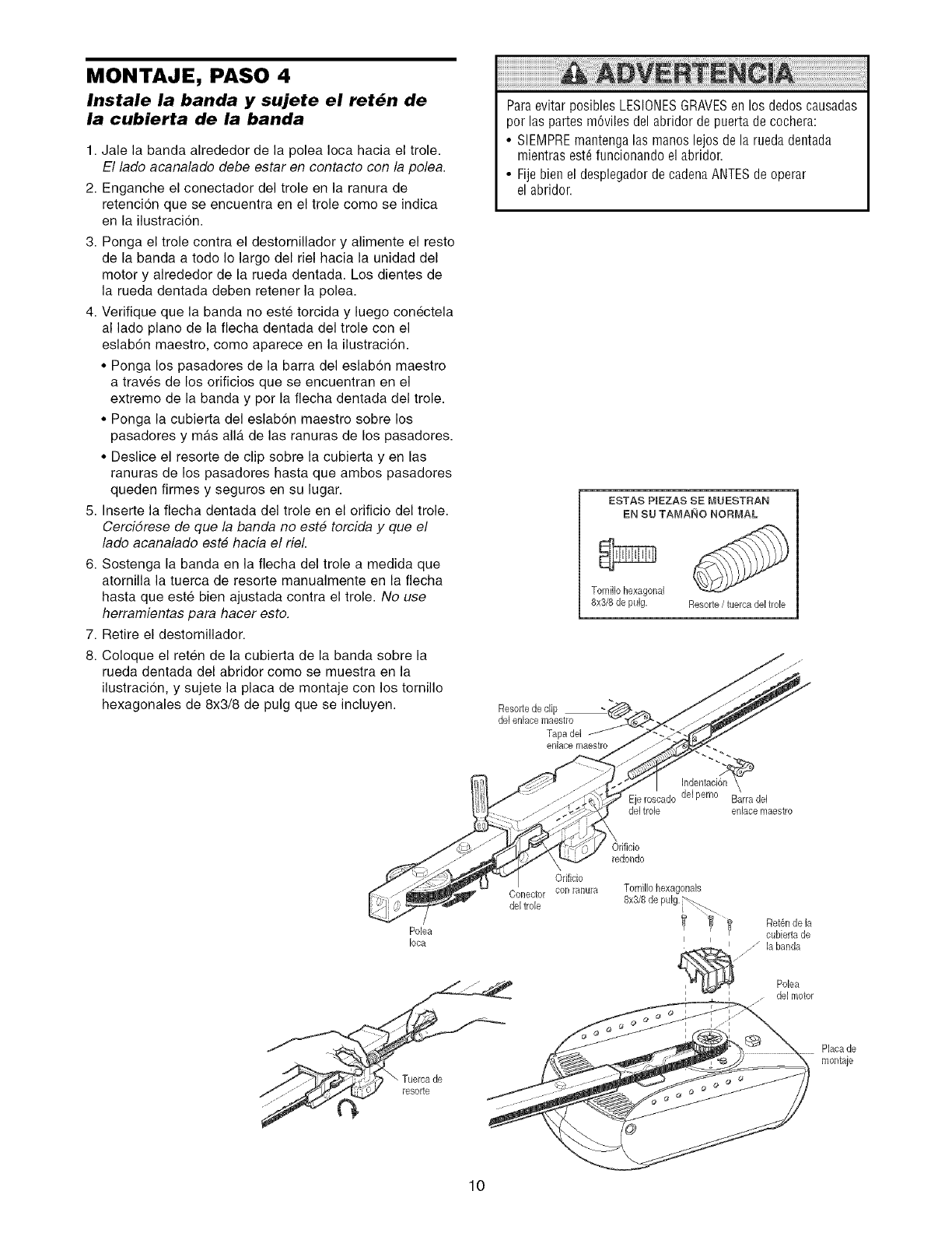
MONTAJE, PASO 4
Instale la banda y sujete el ret_n de
la cubierta de la banda
1. Jale la banda alrededor de la polea Ioca hacia el trole.
El lado acanalado debe estar en contacto con la pole&
2. Enganche el conectador del trole en la ranura de
retenci6n que se encuentra en el trole como se indica
en la ilustracion.
3. Ponga el trole contra el destomiNador y alimente el resto
de la banda a todo Io largo del riel hacia la unidad del
motor y alrededor de la rueda dentada. Los dientes de
la rueda dentada deben retener la polea.
4. Verifique que la banda no este torcida y luego conectela
al lado piano de la flecha dentada del trole con el
eslab6n maestro, como aparece en la Nustraci6n.
• Ponga los pasadores de la barra del eslabon maestro
a traves de los orificios que se encuentran en el
extremo de la banda y por la flecha dentada del trole.
• Ponga la cubierta del eslabon maestro sobre los
pasadores y mas alia de las ranuras de los pasadores.
• Deslice el resorte de clip sobre la cubierta yen las
ranuras de los pasadores hasta que ambos pasadores
queden firmes y seguros en su lugar.
5. Inserte la fiecha dentada del trole en el orificio del trole.
CerciSrese de que la banda no est# torcida y que el
lado acanalado est# hacia el riel.
6. Sostenga la banda en la flecha del trole a medida que
atomilla la tuerca de resorte manualmente en la flecha
hasta que este bien ajustada contra el trole. No use
herramientas para hacer esto.
7. Retire el destornillador.
8. Coloque el reten de la cubierta de la banda sobre la
rueda dentada del abridor como se muestra en la
ilustraci6n, y sujete la placa de montaje con los tornillo
hexagonales de 8x3/8 de pulg que se incluyen.
Paraevitar posibles LESIONESGRAVESen los dedos causadas
pot las partes m6viies del abridor de puerta de cochera:
• SIEMPREmantenga las manos lejos de la rue@ dentada
mientras est6funcionando el abridor.
• Fije bien el desplegador de cadena ANTESde operar
el abridor.
ESTAS PIEZAS SE MUESTRAN
EN SU TAMANO NORMAL
Tornillo hexagonal
8x3/8 de pulg. Resorte/tuerca del trole
Resortede clip
del enlacemaestro
Tapa del
enlace maestro
Ejeroseado del perno Barradel
del trole enlace maestro
Polea
Iota
\
Orifieio
Correcter con ranura
del trele
OrifMo
redondo
Tomillo hexagonals
Ret_,nde [a
eubiertade
la ban@
Polea
del motor
Placade
montaje
10
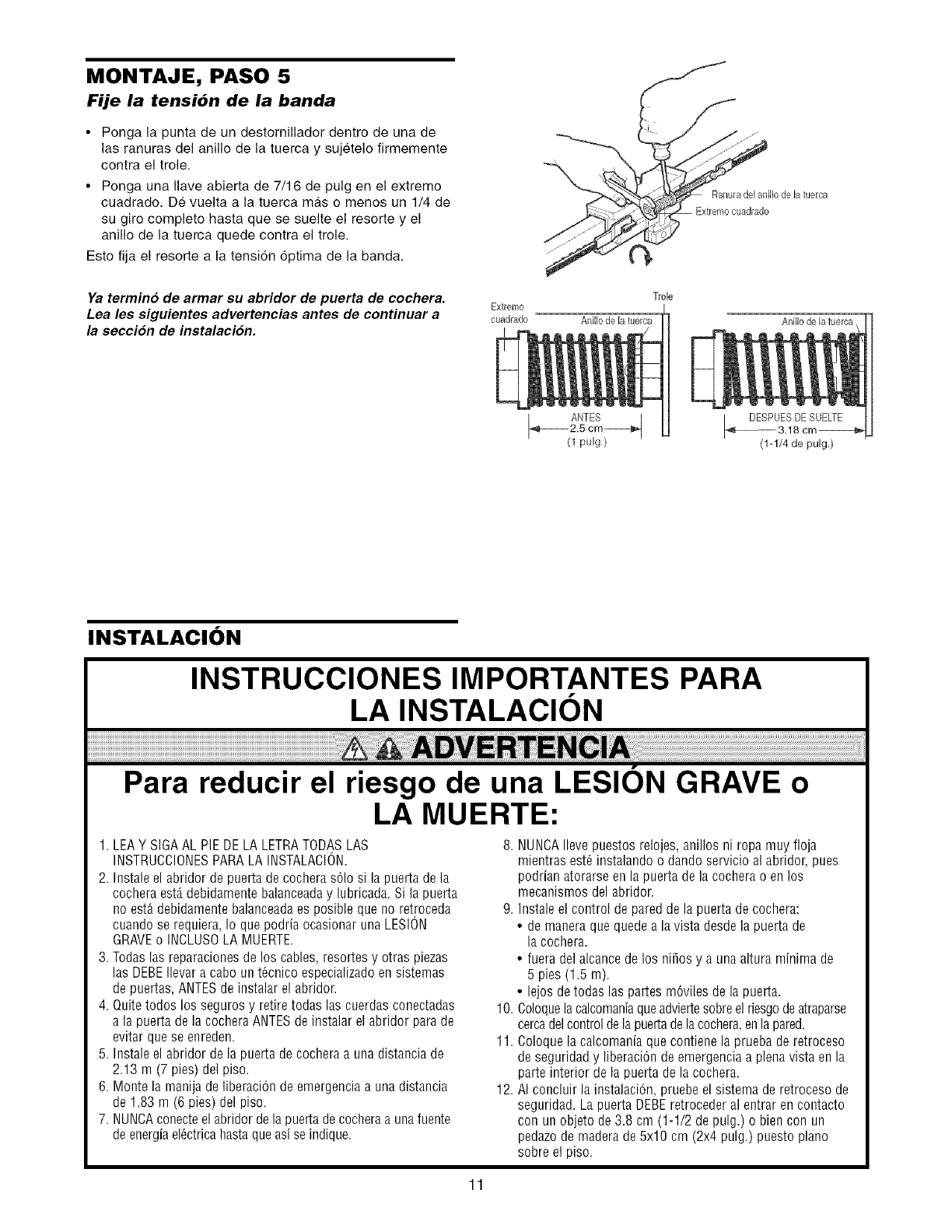
MONTAJE, PASO 5
Fije la tensibn de la banda
•Ponga la punta de un destomiNador dentro de una de
las ranuras del anillo de la tuerca y sujetelo firmemente
contra el trole
• Ponga una Ilave abierta de 7/16 de pulg en el extremo
cuadrado De vuelta a la tuerca mas o menos un 1/4 de
su giro completo hasta que se suelte el resorte y el
aniNo de la tuerca quede contra el trole
Esto fija el resorte a la tensi6n 6ptima de la banda
Ya termino de armar su abridor de puerta de cochera
Lea les siguientes advertencias antes de continuar a
la secciSn de instalacion
ExtPemo
cuadrado
Trole
Anillo de la tuerca
_ ANTES j
2.5 cm|
(1 pulg,)
Anillo de latuerca
(1-1/4 de pulg.)
INSTALACION
INSTRUCCIONES IMPORTANTES PARA
LA INSTALACION
Para reducir el riesgo de una LESION GRAVE o
LA MUERTE:
1.LEAY SIGAAL PIEDELALETRATODASLAS
INSTRUCCIONESPARALAINSTALACION.
2. Instaleel abridordepuertadecocheras61osi la puertadela
cocheraest,.debidamentebalanceaday lubricada.Si lapuerta
noest&debidamentebalanceadaesposiblequenoretroceda
cuandoserequiera,Io quepodriaocasionarunaLESION
GRAVEo INCLUSOLAMUERTE.
3. Todaslasreparacionesdelos cables,resortesy otraspiezas
las DEBEIlevara cabount6cnicoespecializadoensistemas
depuertas,ANTESdeinstalarelabridor.
4. Quitetodoslos segurosy retiretodaslas cuerdasconectadas
a lapuertadelacocheraANTESdeinstalarel abridorparade
evitarqueseenreden.
5. Instaleel abridordelapuertadecocheraa unadistanciade
2.13 m (7 pies)delpiso.
6. Montela manijadeliberaci6ndeemergenciaa unadistancia
de 1.83m (6 pies)delpiso.
7. NUNCAconecteelabridordelapuertadecocheraaunafuente
deenergiael@tricahastaqueasise indique.
8. NUNCAIleve puestos relojes,anillos ni ropa muy floja
mientras est_ instalando odando servicio al abridor, pues
podrian atorarse en la puerta de la cochera o en los
mecanismos del abridor.
9. Instale el control de pared de la puerta de cochera:
• de manera que quede a lavista desdela puerta de
la cochera.
• fuera del alcance de los ni_os y a una altura minima de
5 pies (1.5 m).
• lejos de todas las partes m6viles de la puerta.
10. Coloquelacalcomaniaqueadviertesobreel riesgode atraparse
cercadel controlde lapuertadela cochera,en lapared.
11. Coloque la calcomania que contiene la prueba de retroceso
de seguridad y liberaciOnde emergencia a plena vista en la
parte interior de la puerta de la cochera.
12. AI concluir la instalaci6n, pruebe el sistema de retroceso de
seguridad. La puerta DEBEretroceder al entrar en contacto
con un objeto de 3.8 cm (1-1/2 de pulg.) o bien con un
pedazode madera de 5x10 cm (2x4 pulg.) puesto piano
sobre el piso.
11
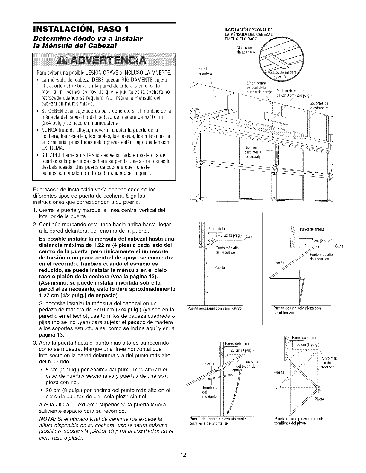
I NSTALACl ON, PASO 1 'NSTALACI6NOPCIONALDE
LA MENSULADEL CABEZAL
EN EL ClELO RASO
Determine d6nde va a instalar
la M_nsula del Cabezal Cieloraso
sin acabado
ParaevitarunaposibleLESIONGRAVEo INCLUSOLAMUERTE:
• Lam6nsuladelcabezalDEBEquedarRiGIDAMENTEsujeta
alsoporteestructuralenla pareddelanterao enelcielo
raso,deno serasies posiblequela puertadelacocherano
retrocedacuandose requiera.NOinstalela m_nsuladel
cabezalen murosfalsos.
• SeDEBENusarsujetadoresparaconcretosi el montajedela
m6nsuladelcabezalo delpedazodemaderade5x10cm
(2x4 pulg.)sehaceenmamposteria.
• NUNCAtratedeaflojar,moverni ajustarlapuertadela
cochera,los resortes,los cables,las poleas,las m_nsulasni
latornilleria,puestodasestaspiezasest_,nbajounatension
EXTREMA.
• SIEMPREIlameaunt_cnicoespecializadoensistemasde
puertassi la puertadecocherase pandea,seatorao siestA
desbalanceada.Unapuertadecocheraquenoest6
balanceadapuedenoretrocedercuandoserequiera.
El proceso de instalaci6n varfa dependiendo de los
diferentes tipos de puerta de cochera. Siga las
instrucciones que correspondan a su puerta.
1. Cierre la puerta y marque la linea central vertical del
interior de la puerta.
2. Contint]e marcando esta linea hacia arriba hasta Ilegar
a la pared delantera, por encima de la puerta.
Es poeible instalar la m6nsula del cabezal hasta una
distancia maxima de 1.22 m(4 pies) a cada lado del
centro de la puerta, pero unicamente ei un reeorte
de torsion o un placa central de apoyo se encuentra
en el recorrido. Tambien cuando el espacio es
reducido, se puede instalar la meneula en el cielo
raso o plafon de la cochera (vea la pagina 13).
(Asimismo, se puede instalar invertida sobre la
pared ei ee neceeario, eeto le dara aproximadamente
1.27 cm [1/2 pulg.] de espacio).
Si necesita instalar la mensula del cabezal en un
pedazo de madera de 5x10 cm (2x4 pulg.) (ya sea en la
pared o en el techo), use tornillos de cabeza cuadrada o
pijas (no se incluyen) para sujetar el pedazo de madera
a los soportes estructurales, come se indica aqui yen la
pagina 13.
3. Abra la puerta hasta el punto mas alto de su recorrido
come se muestra. Marque una linea horizontal que
intersecte en la pared delantera y a del punto mas alto
del recorrido:
• 5 cm (2 pulg.) per encima del punto mas alto en el
caso de puertas seccionales y puertas de una sola
pieza con riel.
• 20 cm (8 pulg.) per encima del punto mgts alto en el
caso de puertas de una sola pieza sin riel.
A esta altura, el extreme superior de la puerta tendrgt
suficiente espacio para su recorrido.
NOTA: Si el nEimero total de cenffmetros excede la
altura disponible en su cochera, use la altura maxima
posible o consulte la pagina 13 para la Instalacidn en el
ciele rase e plafdn.
Pared
delantera
Pareddelantera
cm (2 pulg.) /Carril
Punto mils alto
del recorddo
Puerta
Puertaseccioaal con earril eurvo
Pareddelantera
20 cm (8 pulg.)
Puerta del recerdde
Tornilleria
del
montante
Puertade uaa sola pieza sin carril:
torailleriadel moatante
Linea central
vertical de la
puerta de garaje Pedazode madera
\\ de 5x10 cm (2x4 pulg.)
Soportes de
la estructura
I7
Puert_de unasola piezacon
earril horizontal
Pareddelantera
cm (2 pulg.)
_ Carril
Pareddelantera
20 cm (8 pulg.)
Pivote
Puertade una pieza sin earril:
tornilleriadel pivote
12
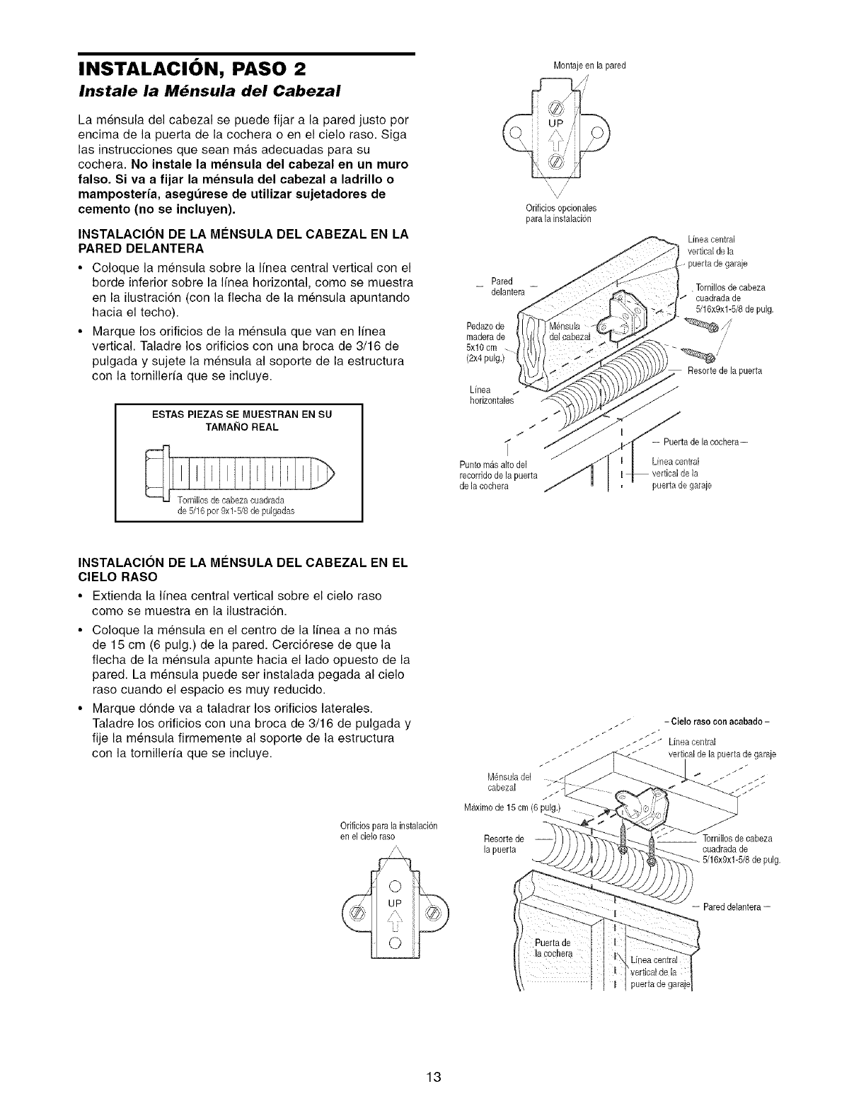
INSTALACION, PASO 2 Montajeenlapared
Instale la M#nsula del Cabezal
La mensula del cabezal se puede fijar a la pared justo por
encima de la puerta de la cochera o en el cielo raso. Siga
las instrucciones que sean mas adecuadas para su
cochera. No instale la mensula del eabezal en un muro
falso. Si va a fijar la mensula del cabezal a ladrillo o
mamposteria, asegt_rese de utilizar sujetadores de
cemento (no se incluyen).
INSTALAClON DE LA M#NSULA DEL CABEZAL EN LA
PARED DELANTERA
•Coloque la mensula sobre la Ifnea central vertical con el
borde inferior sobre la Ifnea horizontal, como se muestra
en la ilustracion (con la flecha de la mensula apuntando
hacia el techo).
• Marque los orificios de la mensula que van en Ifnea
vertical. Taladre los orificios con una broca de 3/16 de
pulgada y sujete la mensula al soporte de la estructura
con la tornillerfa que se incluye.
ESTAS PIEZAS SE MUESTRAN EN SU
TAMAI_IO REAL
de 5/16 pot 9xl-5/8 de pulgadas
,/
Orificiosopcionales
paralainstalacion
Pared
delantera
Pedazode
maderade
5x10 cm
(2x4 pulg.)
Linea ,,_
hodzontales
/
/
/
Punto masalto del
recorddo de la puerta
de la cochera
Lineacentral
vertical de la
puertade garaje
Tornillos decabeza
cuadradade
5/16x9xl-5/8 de pulg.
Resorte de [a puerta
= Puerta de [a cochera--
Linea central
puerta de garaje
INSTALACION DE LA M#NSULA DEL CABEZAL EN EL
CIELO RASO
• Extienda la Ifnea central vertical sobre el cielo raso
como se muestra en la ilustracion.
• Coloque la mensula en el centro de la Ifnea a no mas
de 15 cm (6 pulg.) de la pared. Cerci6rese de que la
fiecha de la mensula apunte hacia el lado opuesto de la
pared. La mensula puede set instalada pegada al cielo
raso cuando el espacio es muy reducido.
• Marque donde va a taladrar los orificios laterales.
Taladre los orificios con una broca de 3/16 de pulgada y
fije la mensula firmemente al soporte de la estructura
con la tornillerfa que se incluye.
Orificiospara la instalacion
en el cielo raso
__ - Cielo raso conacabado -
_ _ _ Linea central
/
__ __ verticalde la puerta de garaje
M_nsuladel _cabezal
M_tximode 15 cm (6 pulg.)
Resortede
la puerta cuadradade
pulg.
-- Pareddelantera--
13
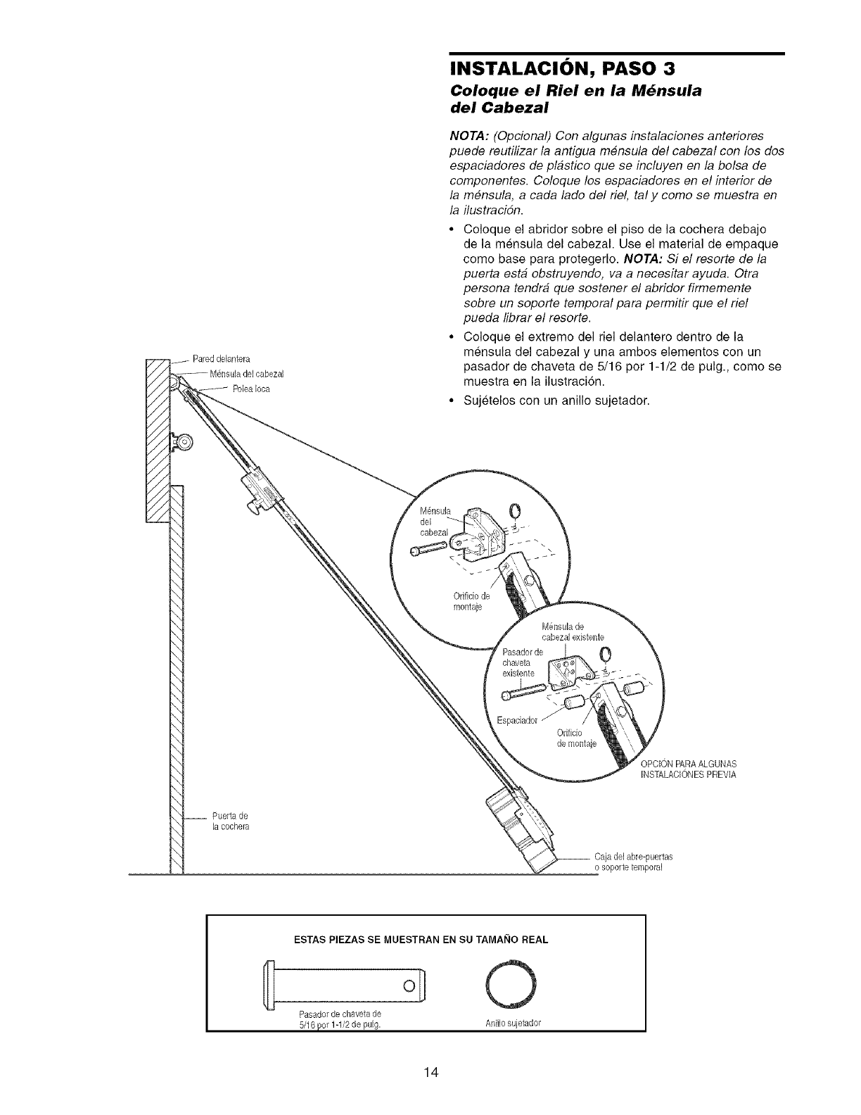
INSTALACION, PASO 3
Coloque el Riel en la M_nsula
del Cabezal
NOTA: (Opcional) Con algunas instalaciones anteriores
puede reutilizar la antigua m#nsula del cabezal con los dos
espaciadores de plastico que se incluyen en la bolsa de
componentes. Coloque los espaciadores en el interior de
la mensula, a cada lado del riel, tal y como se muestra en
la ilustracidn.
•Coloque el abridor sobre el piso de la cochera debajo
de la mensula del cabezal. Use el material de empaque
come base para protegerlo. NOTA: Si el resorte de la
puerta esta obstruyendo, va a necesitar ayuda. Otra
persona tendra que sostener el abridor firmemente
sobre un soporte temporal para permitir que el riel
pueda librar el resorte.
• Coloque el extreme del riel delantero dentro de la
mensula del cabezal y una ambos elementos con un
pasador de chaveta de 5/16 por 1-1/2 de pulg., come se
muestra en la ilustracidn.
• Sujetelos con un anillo sujetador.
MF,nsula
del
cabezal
\
Orifido de
montaje
0
chaveta
existente
M6nsulade
cabezal existente
0
Orifido
de montaje
OPCION PARAALGUNAS
INSTALACIONES PREVIA
Puerta de
lacochera
__ Caja de1abre-puertas
o soporte temporal
ESTAS PIEZAS SE MUESTRAN EN SU TAMAI_IO REAL
I O
Pasadorde chavetade
14
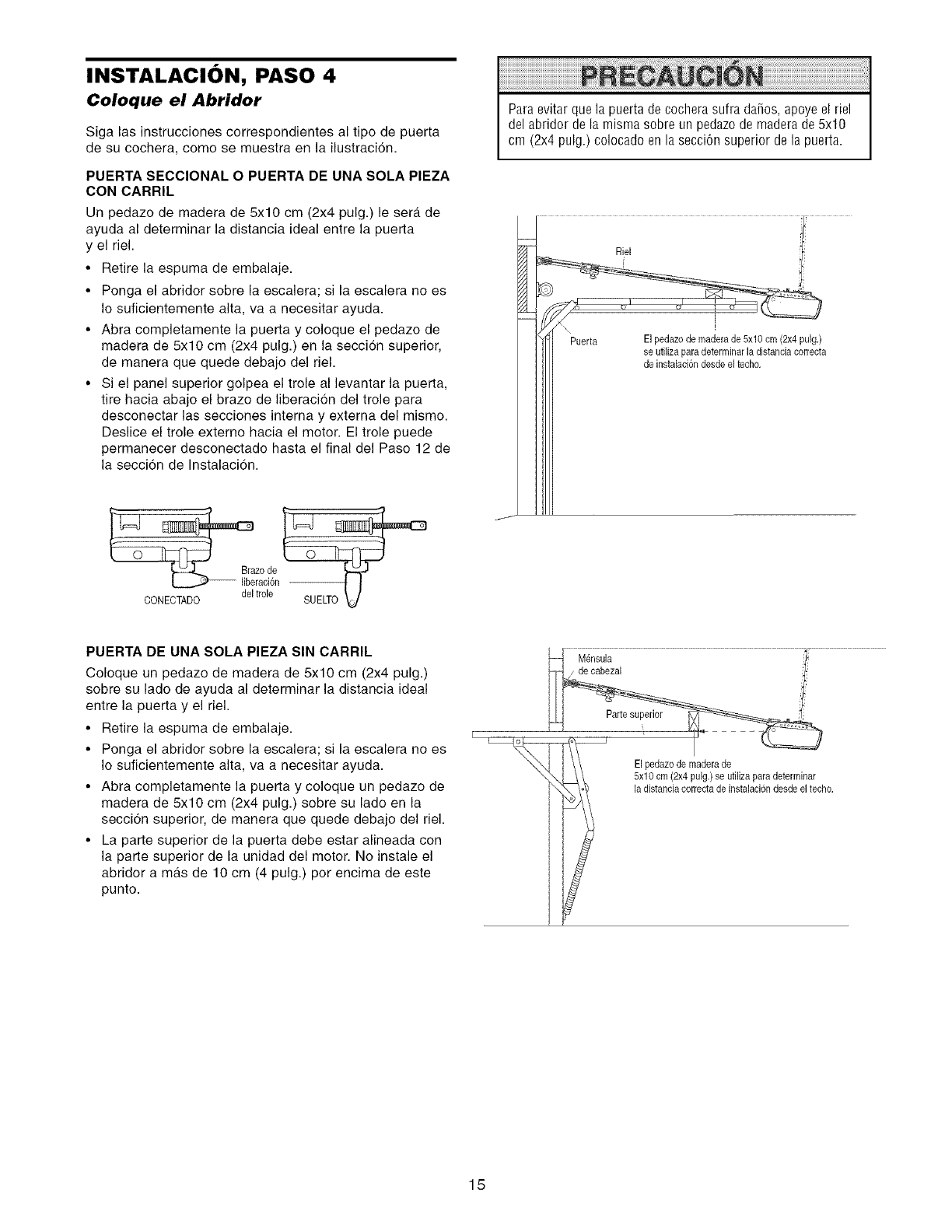
INSTALACION, PASO 4
Coloque el Abridor
Siga las instrucciones correspondientes al tipo de puerta
de su cochera, como se muestra en la ilustraci6n.
PUERTA SECClONAL O PUERTA DE UNA SOLA PIEZA
CON CARRIL
Un pedazo de madera de 5x10 cm (2x4 pulg.) le sera de
ayuda al determinar la distancia ideal entre la puerta
y el riel.
•Retire la espuma de embalaje.
• Ponga el abridor sobre la escalera; si la escalera no es
Io suficientemente alta, va a necesitar ayuda.
• Abra completamente la puerta y coloque el pedazo de
madera de 5x10 cm (2x4 pulg.) en la seccion superior,
de manera que quede debajo del riel.
• Si el panel superior golpea el trole al levantar la puerta,
tire hacia abajo el brazo de liberaci6n del trole para
desconectar las secciones interna y externa del mismo.
Deslice el trole extemo hacia el motor. El trole puede
permanecer desconectado hasta el final del Paso 12 de
la secci6n de Instalaci6n.
Paraevitar que la puerta de cochera sufra da5os, apoye el riel
del abridor de la misma sobre un pedazo de maderade 5x10
cm (2x4 pulg.) colocado en la secci6n superior de la puerta.
o de
con
PUERTA DE UNA SOLA PIEZA SIN CARRIL
Coloque un pedazo de madera de 5x10 cm (2x4 pulg.)
sobre su lado de ayuda al determinar la distancia ideal
entre la puerta y el riel.
• Retire la espuma de embalaje.
• Ponga el abridor sobre la escalera; si la escalera no es
Io suficientemente alta, va a necesitar ayuda.
• Abra completamente la puerta y coloque un pedazo de
madera de 5x10 cm (2x4 pulg.) sobre su lado en la
secci6n superior, de manera que quede debajo del riel.
• La parte superior de la puerta debe estar alineada con
la parle superior de la unidad del motor. No instale el
abridor a ma.s de 10 cm (4 pulg.) por encima de este
punto.
Mensula ,l"
/de cabezal i-
El pedazode maderade
5x10 cm (2x4 pulg.) se ufilizapara determinar
la distanciacorrecta de instalaciondesde el techo.
15
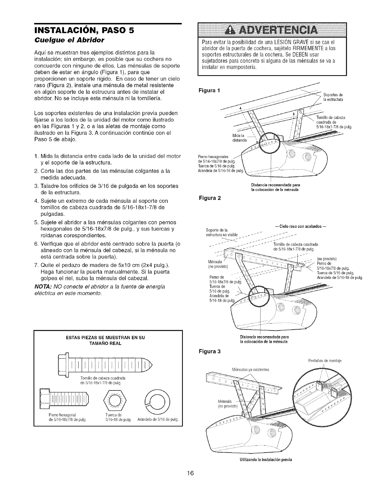
INSTALACION, PASO 5
Cuelgue el Abridor
Aquf se muestran tres ejemplos distintos para la
instalacidn; sin embargo, es posible que su cochera no
concuerde con ninguno de ellos. Las mensulas de soporte
deben de estar en angulo (Figura 1), para que
proporcionen un soporte rfgido. En case de tener un cielo
raso (Figura 2), instale una mensula de metal resistente
en algun soporte de la estrucura antes de instalar el
abridor. No se incluye esta mensula ni la tornillerfa.
Los soportes existentes de una instalacion previa pueden
fijarse a los lades de la unidad del motor como ilustrado
en las Figuras 1 y 2, o alas aletas de montaje como
ilustrado en la Figura 3. A continuacidn continQe con el
Paso 5 de abajo.
Paraevitar la posibilidad de una LESIONGRAVEsi se cae el
abridor de la puerta de co@era, suj6telo FIRMEMENTEa los
soportes estructurales de la cochera. Se DEBENusar
sujetadores para concreto si alguna de las m@sulas se va a
instalar en mamposteria.
Figura 1 Soportes de
la estructura
Mida la _,
distancia
Tomillode cabeza
cuadradade
5/16-18xl-7/8 de pulg.
1. Mida la distancia entre cada lado de la unidad del motor
y el soporte de la estructura.
2. Corte las dos partes de las mensulas colgantes a la
medida adecuada.
3. Taladre los orificios de 3/16 de pulgada en los soportes
de la estructura.
4. Sujete un extremo de cada mensula al soporte con
tornillos de cabeza cuadrada de 5/16-18xl-7/8 de
pulgadas.
5. Sujete el abridor a las mensulas colgantes con pernos
hexagonales de 5/16-18x7/8 de pulg., y sus tuercas y
roldanas corespondientes.
6. Verifique que el abridor este centrado sobre la puerta (o
alineado con la mensula del cabezal, si la mensula no
esta centrada sobre la puerta).
7. Quite el pedazo de madera de 5x10 cm (2x4 pulg.).
Haga funcionar la puerta manualmente. Si la puerta
golpea el riel, suba la mensula del cabezal.
NOTA: NO conecte el abridor a la fuente de energfa
electrica en este momento.
Pernohexagonales
de5/16-18x7/8de pulg.
Tuercade 5/16de pulg.
Arandela de5/16-18 de pul
Figura 2
Distanciarecomendada para
la coloeaeioa de la m_nsula
-- Cielo raso con acabadoe--
Soporte de la
estructurano visible _ _ _- _ " __ -______
__-"_ _ _ _-- _ __ -__ _ Tornillodecabeza cuadrada
de 5/16-18xl-7/8 de pulg.
Mensula
(no provisto)
Pernode :
5/16-18x7/8de pulg.
Tuercade
5/16de pulg.
Arandelade
5/16-18de
(no provisto)
Pernode
5/16-18x7/8de pulg.
Tuercade 5/16 de pulg.
Arandelade 5/16-18de pulg.
ESTAS PIEZAS SE MUESTRAN EN SU
TAMANO REAL
Perno hexagonal
de 5/16-18x7/8de pulg.
Tomillo de cabezacuadrada
de 5/16-18xl-7/8 de pulg.
@
Tuerca de
5/16-18de pulg.
©
Arandelade 5116de pulg.
Figura 3
Distaneiareeomendada para
la colocaci6ade la rnensula
M6nsulasya existentes
M_,nsula
(no provisto)
Pestahasde montaje
Utilizandola iast_laci6n previa
16
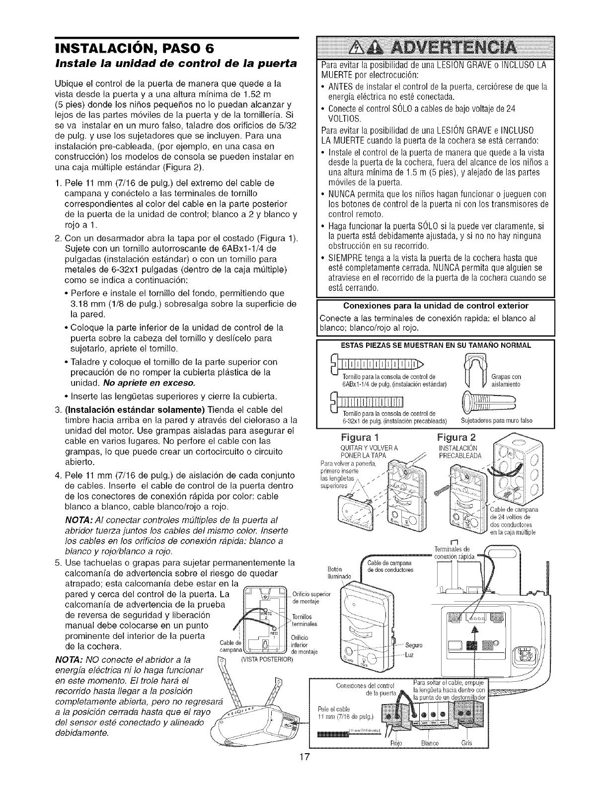
INSTALACION, PASO 6
Instale la unidad de control de la puerta
Ubique el control de la puerta de manera que quede a la
vista desde la puerta y a una altura minima de 1.52 m
(5 pies) donde los nifios pequefios no Io puedan alcanzar y
lejos de las partes m6viles de la puerta y de la tomilleffa. Si
se va instalar en un muro falso, taladre dos ofificios de 5/32
de pulg. y use los sujetadores que se incluyen. Para una
instalaci6n pre-cableada, (por ejemplo, en una casa en
construcci6n) los modelos de consola se pueden instalar en
una caja multiple estandar (Figura 2).
1. Pele 11 mm (7/16 de pulg.) del extremo del cable de
campana y conectelo a las terminales de tomillo
correspondientes al color del cable en la parte posterior
de la puerta de la unidad de control; blanco a 2 y blanco y
rojo a 1.
2. Con un desarmador abra la tapa por el costado (Figura 1).
Sujete con un tomillo autorroscante de 6ABx1-1/4 de
pulgadas (instalaci6n esta.ndar) o con un tomillo para
metales de 6-32xl pulgadas (dentro de la caja mt]ltiple)
como se indica a continuaci6n:
• Perfore e instale el tornillo del fondo, permitiendo que
3.18 mm (1/8 de pulg.) sobresalga sobre la superficie de
la pared.
• Coloque la parte inferior de la unidad de control de la
puerta sobre la cabeza del tornillo y desl/celo para
sujetarlo, apriete el tornillo.
• Taladre y coloque el tomillo de la parte superior con
precauci6n de no romper la cubierta pl&stica de la
unidad. No apriete en exceso.
• Inserte las lengQetas superiores y cierre la cubierta.
3. (Instalaci6n estandar solamente) Tienda el cable del
timbre hacia arriba en la pared y atraves del cieloraso a la
unidad del motor. Use grampas aisladas para asegurar el
cable en varios lugares. No perfore el cable con las
grampas, Io que puede crear un cortocircuito o circuito
abierto.
4. Pele 11 mm (7/16 de pulg.) de aislaci6n de cada conjunto
de cables. Inserte el cable de control de la puerta dentro
de los conectores de conexion rapida pot color: cable
blanco a blanco, cable blanco/rojo a rojo.
NOTA: AI conectar controles m#ltiples de la puerta al
abridor tuerza juntos los cables del mismo colo_ Inserte
los cables en los orificios de conexiSn rapida: blanco a
blanco y rojo/blanco a rojo.
5. Use tachuelas o grapas para sujetar permanentemente la
calcomanfa de advertencia sobre el riesgo de quedar
atrapado; esta calcomanfa debe estar en la
pared y cerca del control de la puerta. La
calcomanfa de advertencia de la prueba
de reversa de seguridad y liberaci6n
manual debe colocarse en un punto
prominente del interior de la puerta
de la cochera.
NOTA: NO conecte el abridor a la
energfa electrica ni Io haga funcionar
en este momento. El trole hara el
recorrido hasta Ilegar a la posiciSn
completamente abierta, pero no regresara
a la posiciSn cerrada hasta que el rayo
del sensor este conectado y alineado
debidamente.
Paraevitar la posibilidad de una LESIONGRAVEo INOLUSOLA
MUERTEpor electrocuciCn:
• ANTESde instalar el control de la puerta, cerciCresede que la
energia elCctricano est6 conectada.
• Conecteel control SOLOa cablesde bajovoltaje de24
VOLTIOS.
Paraevitar la posibilidad de una LESIONGRAVEe INCLUSO
LA MUERTEcuaodo la puerta de la cochera se estAcerrando:
• Instale el control de la puerta de maoera que quede a la vista
desde la puerta de la co@era, fuera del alcaocede los nifios a
una altura minima de 1.5 m (5 pies), y alejadode las partes
mCviles de la puerta.
• NUNCApermita que los nifios hagan funciooar o jueguen coo
los botones de control de la puerta ni con los transmisores de
control remoto.
• Haga funcionar la puerta SOLOsi la puede ver claramente, si
la puerta est,. debidamenteajustada, y si no no hay ninguna
obstrucciCn en su recorrido.
• SIEMPREteoga a la vista la puerta de la cochera hasta que
est_ completamente cerrada. NUNCApermita que alguien se
atraviese en el recorrido dela puerta de la cochera cuando se
estAcerrando.
Conexiones para la unidad de control exterior
Conecte a las terminales de conexiCn rapida: el blanco al
blanco; blanco/rojo al rojo.
ESTAS PIEZASSE MUESTRAN EN SU TAMAI_IONORMAL
°,
6ABx1-1/4de pulg.(instalaciCnestandar)
_de control de
6-32xl de pulg.(instalaci6n precabbada)
Figura !
QUITAR Y VOLVER A
PONERLA TAPA
Para volver a ponefla,
primeroinserte
las bng(ietas ,, _ __
superiores /"/,<
BotCn dedos conductores
Iluminado
_ Grapascon
aislarniento
Sujetadores para murofalso
Figura 2
INSTALACION
PRECABLEADA
Cablede campana
de 24voltios de
dosconductores
en la caja m(Jltiple
r"l
_ Orificio superior
Idomo°,a,o
_2_ _ /'LTorn"los
/ oH'erm'n°'°s
_ I Orificio
Cable d , t.} , _ inferior
campana _ demontaje
VISTAPOSTERIOR)
17
Conexionesdel control
de la puerta
Pele el cable
11mm (7/16 de pulg,)
Parasoltarel cable,empuje
RSjo Blanco Gns
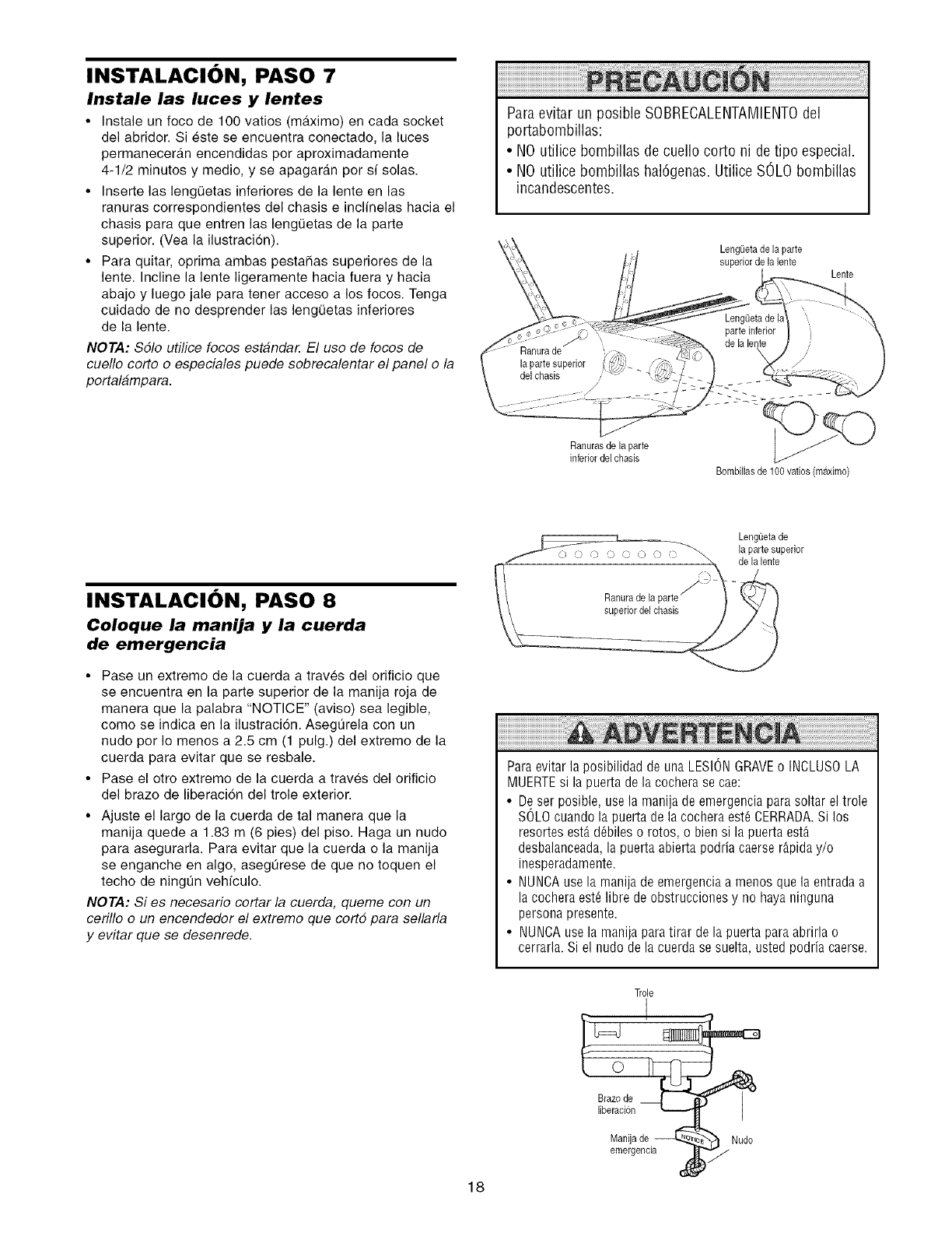
INSTALACION, PASO 7
Instale las luces y lentes
•Instale un foco de 100 vatios (maximo) en cada socket
del abridor Si este se encuentra conectado la luces
permaneceran encendidas pot aproximadamente
4-1/2 minutos y medio y se apagaran pot sf solas
• Inserte las lengQetas inferiores de la lente en las
ranuras correspondientes del chasis e inclfnelas hacia el
chasis para que entren las leng0etas de la parte
superior (Vea la ilustracion)
• Para quitar optima ambas pestaSas superiores de la
lente Incline la lente ligeramente hacia fuera y hacia
abajo y luego jale para tener acceso a los focos Tenga
cuidado de no desprender las lengQetas inferiores
de la lente
NOTA: $61o utilice focos estanda_ El uso de focos de
cueflo corto o especiales puede sobrecalentar el panel o la
portalampara
Paraevitar un posible SOBRECALENTAMIENTOdel
portabombillas:
• NOutilice bombillas de cuello corto ni de tipo especial.
• NO utilice bombillas hal6genas.Utilice SOLObombillas
incandescentes.
LengQetade la parte
superiorde la lente Lente
Ranurasde la parte
inferiordel chasis
de la
Bombillasde 100 vatios (m_tximo)
INSTALACION, PASO 8
Coloque la manija y la cuerda
de emergencia
• Pase un extremo de la cuerda a traves del orificio que
se encuentra en la parte superior de la manija roja de
manera que la palabra 'NOTICE" (aviso) sea legible
como se indica en la ilustracion Aseg0rela con un
nudo por Io menos a 25 cm (1 pulg) del extremo de la
cuerda para evitar que se resbale
• Pase el otro extremo de la cuerda a traves del orificio
del brazo de liberaci6n del trole exterior
• Ajuste el largo de la cuerda de tal manera que la
manija quede a 183 m (6 pies) del piso Haga un nudo
para asegurarla Para evitar que la cuerda o la manija
se enganche en algo asegt_rese de que no toquen el
techo de ningun vehfculo
NOTA: Si es necesario cortar la cuerda, queme con un
cerillo o un encendedor el extremo que cort5 para sellarla
y evitar que se desenrede
LengOetade
la parte superior
delalente
Paraevitar la posibilidad de una LESIONGRAVEo INCLUSOLA
MUERTEsi la puerta de la cochera se cae:
• De ser posible, usela manija de emergencia para soltar el trole
SOLOcuando la puerta de la cochera est_ CERRADA.Si los
resortes est,. dObileso rotos, o bien si la puerta est_
desbalanceada,la puerta abierta podria caerse r&piday/o
inesperadamente.
• NUNCAuse la manija de emergencia a menos que la entrada a
la cochera est_ libre de obstrucciones y no haya ninguna
persona presente.
• NUNCAusela manija paratirar de la puerta para abrirla o
cerrarla. Si el nudo de la cuerda se suelta, usted podria caerse.
Trole
Brazode
liberacion
Manijade Nudo
emergencia
18
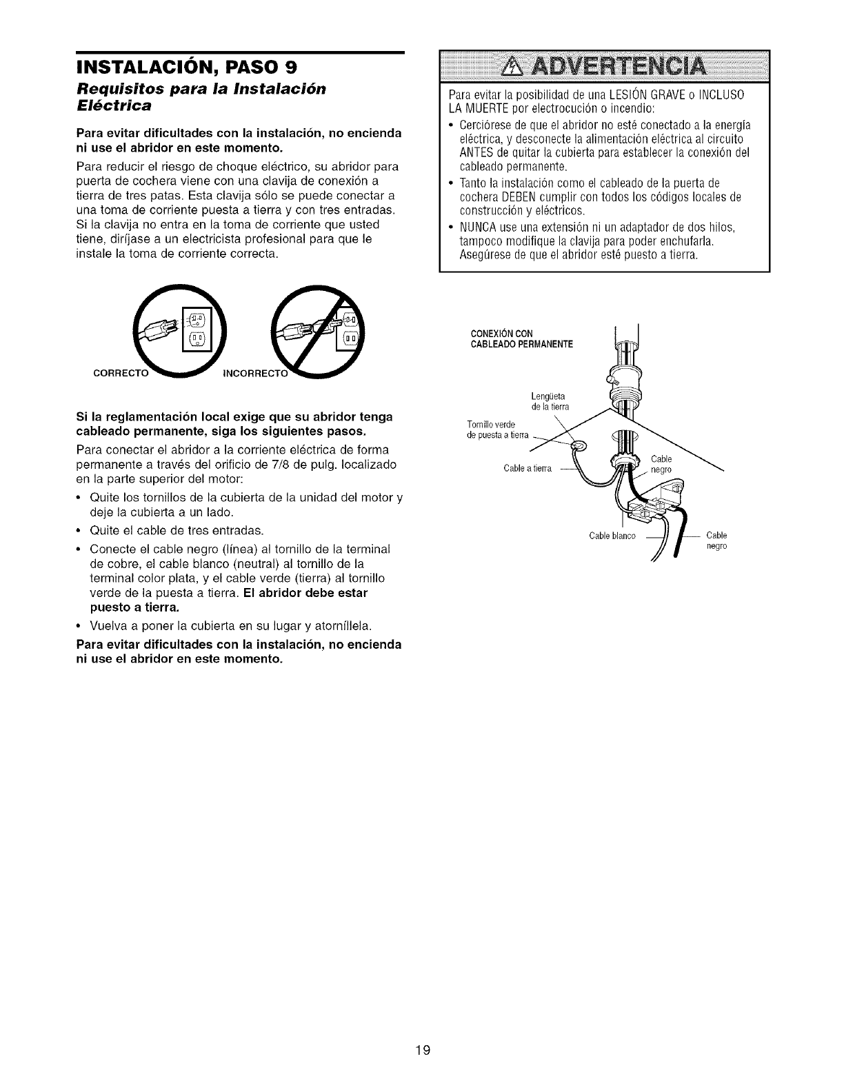
INSTALACION, PASO 9
Requisitos para la Instalaci6n
El6ctrica
Para evitar dificultadee con la instalacion, no encienda
ni use el abridor en este momento.
Para reducir el riesgo de cheque electrico, su abridor para
puerta de cochera viene con una clavija de conexidn a
tierra de tres patas. Esta clavija solo se puede conectar a
una toma de corriente puesta a tierra y con tres entradas.
Si la clavija no entra en la toma de corriente que usted
tiene, dirijase a un electricista profesional para que le
instale la toma de corriente correcta.
cocGcocQ
Si la reglamentacion local exige que su abridor tenga
cableado permanente, siga los siguientes paeos.
Para conectar el abridor a la corriente electrica de forma
permanente a traves del orificio de 7/8 de pulg. Iocalizado
en la parte superior del motor:
• Quite los tornillos de la cubierta de la unidad del motor y
deje la cubierta a un lade.
• Quite el cable de tres entradas.
• Conecte el cable negro (Ifnea) al tornillo de la terminal
de cobre, el cable blanco (neutral) al tornillo de la
terminal color plata, y el cable verde (tierra) al tornillo
verde de la puesta a tierra. El abridor debe eetar
puesto a tierra.
• Vuelva a poner la cubierta en su lugar y atornfllela.
Para evitar dificultades con la instalacion, no encienda
ni use el abridor en este momento.
ParaevitarlaposibilidaddeunaLESIONGRAVEo INCLUSO
LA MUERTEpor electrocuci6n o incendio:
• Cerci6rese de que el abridor no est6 conectado a la energia
el6ctrica, y desconecte la aNmentaci6nel6ctricaal circuito
ANTESde quitar la cubierta para establecer la conexi6n del
cableado permanente.
• Taoto la instalaci6o como el cableado de la puerta de
cochera DEBENcumplir con todos los c6digos locales de
construcciOn y el6ctricos.
• NUNCAuse una extensidn ni un adaptador de dos hilos,
tampoco modifique la clavija para poder eochufarla.
Aseg_iresede que el abridor est6 puesto a tierra.
CONEXlONCON
CABLEADO RERMANENTE
Lengeeta
dela tierra
Tornilloverde
Cablea tierra Cable
/ negro
Cableblanco Cable
negro
19
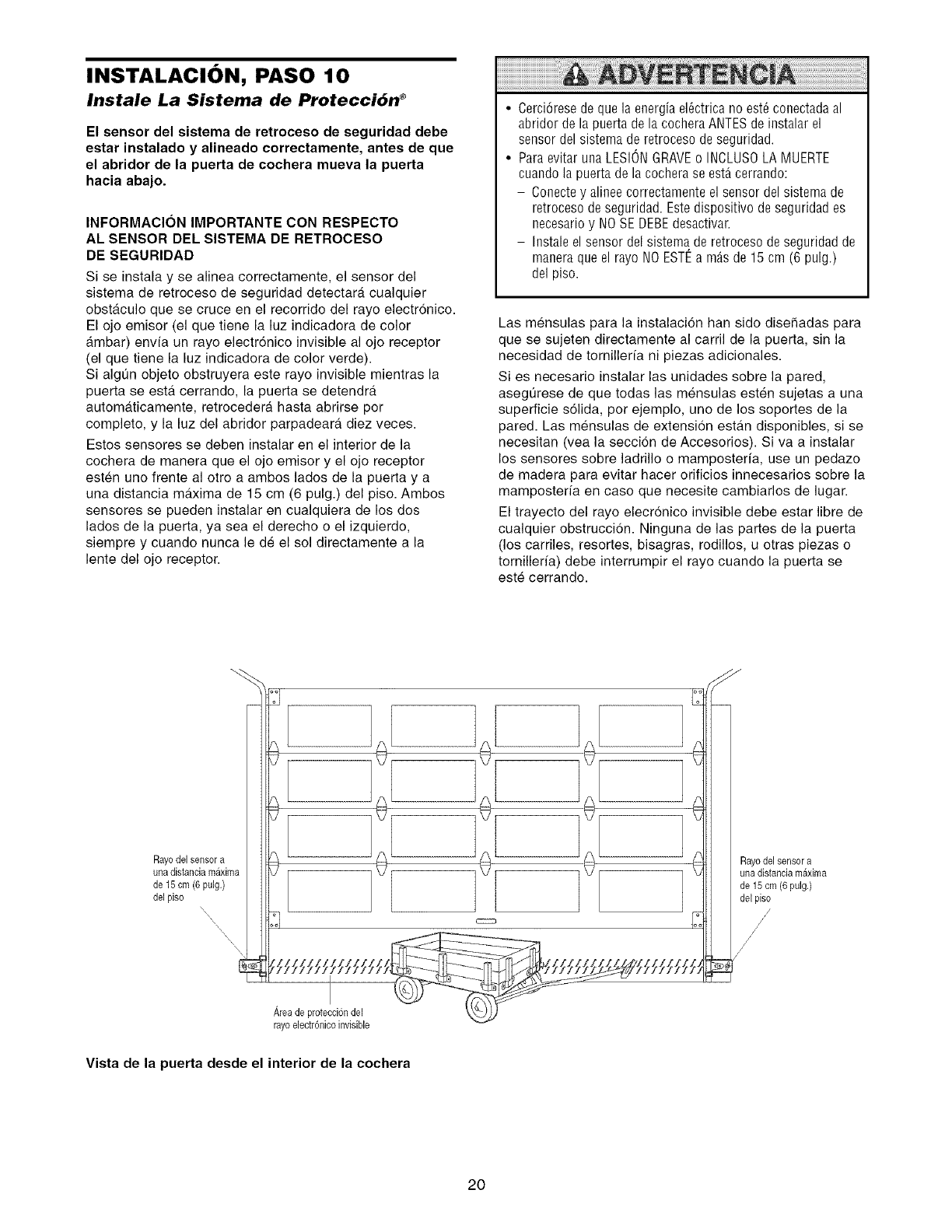
INSTALACION, PASO 10
Instale La Sistema de Protecci6n ®
El sensor del sistema de retroceso de seguridad debe
estar instalado y alineado correctamente, antes de que
el abridor de la puerta de cochera mueva la puerta
hacia abajo.
INFORMACION IMPORTANTE CON RESPECTO
AL SENSOR DEL SISTEMA DE RETROCESO
DE SEGURIDAD
Si se instala y se alinea correctamente, el sensor del
sistema de retroceso de seguridad detectara cualquier
obstaculo que se cruce en el recorrido del rayo electronico.
El ojo emisor (el que tiene la luz indicadora de color
ambar) envfa un rayo electr6nico invisible al ojo receptor
(el que tiene la luz indicadora de color verde).
Si algt]n objeto obstruyera este rayo invisible mientras la
puerta se esta cerrando, la puerta se detendra
automaticamente, retrocedera hasta abrirse pot
completo, y la luz del abridor parpadeara diez veces.
Estos sensores se deben instalar en el interior de la
cochera de manera que el ojo emisor y el ojo receptor
esten uno frente al otto a ambos lados de la puerta y a
una distancia maxima de 15 cm (6 pulg.) del piso. Ambos
sensores se pueden instalar en cualquiera de los dos
lados de la puerta, ya sea el derecho o el izquierdo,
siempre y cuando nunca le de el sol directamente a la
lente del ojo receptor.
• Cerci6rese de que la energia el6ctrica no est_ conectada al
abridor de la puerta de la cochera ANTESde instalar el
sensor del sistema de retroceso de seguridad.
• Para evitar una LESIONGRAVEo INCLUSOLA MUERTE
cuando la puerta de la cochera se estAcerrando:
- Conecte y alinee correctamente el sensor del sistema de
retroceso de seguridad. Este dispositivo de seguridad es
necesario y NO SE DEBEdesactivar.
- Instale el sensor del sistema de retroceso de seguridad de
manera que el rayo NOESTI_a m_,sde 15 cm (6 pulg.)
del piso.
Las mensulas para la instalaci6n han side disehadas para
que se sujeten directamente al carril de la puerta, sin la
necesidad de tornillerfa ni piezas adicionales.
Si es necesario instalar las unidades sobre la pared,
asegt]rese de que todas las mensulas esten sujetas a una
superficie s61ida, por ejemplo, uno de los soportes de la
pared. Las mensulas de extension estan disponibles, si se
necesitan (vea la seccion de Accesorios). Si va a instalar
los sensores sobre ladrillo o mamposteria, use un pedazo
de madera para evitar hacer orificios innecesarios sobre la
mamposteria en caso que necesite cambiarlos de lugar.
El trayecto del rayo elecronico invisible debe estar libre de
cualquier obstrucci6n. Ninguna de las partes de la puerta
(los carriles, resortes, bisagras, rodillos, u otras piezas o
tornilleria) debe interrumpir el rayo cuando la puerta se
este cerrando.
rayo electr6nicoinvisible
Vista de la puerta desde el interior de la cochera
20
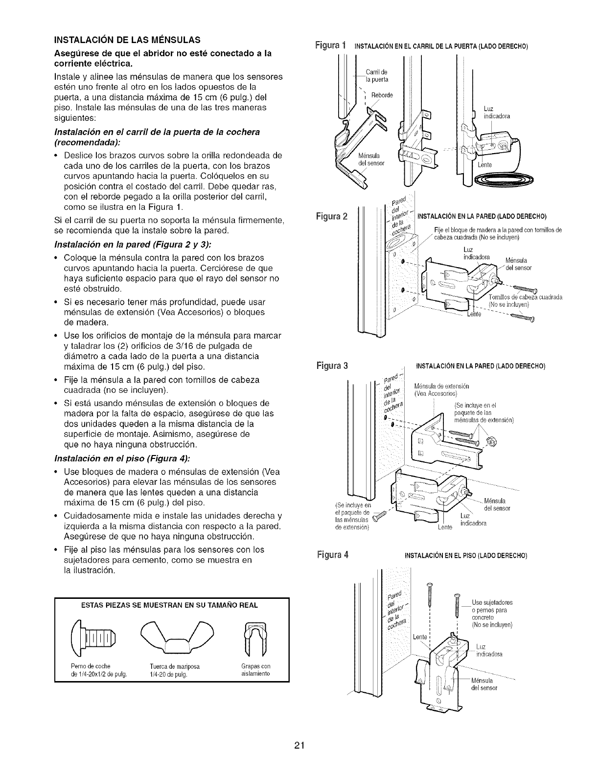
INSTALACION DE LAS MI_NSULAS
Asegurese de que el abridor no este conectado a la
corriente electrica.
Instale y alinee las mensulas de manera que los sensores
esten uno frente al otro en los lados opuestos de la
puerta, a una distancia maxima de 15 cm (6 pulg.) del
piso. Instale las mensulas de una de las tres maneras
siguientes:
Instalacion en el carril de la puerta de la cochera
(recomendada):
• Deslice los brazos curvos sobre la orilla redondeada de
cada uno de los carriles de la puerta, con los brazos
curvos apuntando hacia la puerta. Col6quelos en su
posici6n contra el costado del carril. Debe quedar ras,
con el reborde pegado a la orilla posterior del carril,
como se ilustra en la Figura 1.
Si el carril de su puerta no soporta la mensula firmemente,
se recomienda que la instale sobre la pared.
Instalacion en la pared (Figura 2 y 3):
• Coloque la mensula contra la pared con los brazos
curvos apuntando hacia la puerta. Cerci6rese de que
haya suficiente espacio para que el rayo del sensor no
este obstruido.
• Si es necesario tener mAs profundidad, puede usar
mensulas de extensi6n (Vea Accesorios) o bloques
de madera.
• Use los orificios de montaje de la mensula para marcar
y taladrar los (2) orificios de 3/16 de pulgada de
diAmetro a cada lado de la puerta a una distancia
maxima de 15 cm (6 pulg.) del piso.
• Fije la mensula a la pared con tornillos de cabeza
cuadrada (no se incluyen).
• Siesta usando mensulas de extension o bloques de
madera por la falta de espacio, asegt_rese de que las
dos unidades queden a la misma distancia de la
superficie de montaje. Asimismo, asegQrese de
que no haya ninguna obstrucci6n.
Instalacion en el piso (Figura 4):
• Use bloques de madera o mensulas de extensi6n (Vea
Accesorios) para elevar las mensulas de los sensores
de manera que las lentes queden a una distancia
maxima de 15 cm (6 pulg.) del piso.
• Cuidadosamente mida e instale las unidades derecha y
izquierda a la misma distancia con respecto a la pared.
Asegt]rese de que no haya ninguna obstrucci6n.
• Fije al piso las mensulas para los sensores con los
sujetadores para cemento, como se muestra en
la ilustraci6n.
ESTAS PIEZAS SE MUESTRAN EN SU TAMAI_IO REAL
Perno de coche Tuerea de mariposa Grapascon
de 1/4-20xl/2 de pulg. 1/4-20de pulg. aislamiente
Figura 1 INSTALAClON ENEL CARRIL DE LA PUERTA(LADO DERECHO)
Carril de
\
i Reborde
Mensula
del sensor
Luz
indicadora
Figura 2 INSTALAClON ENLA PARED(LADO DERECHO)
Fije el bloquede maderaala pared con tornillosde
_ cabezaeuadrada(Nose induyen)
Luz
indicadora M_nsula
del sensor
d_ cuadrada
--,>,.z_.Ljt_ _L.ose neL.yen/
--Le'nte ......
Figura 3
(Se incluyeen
el paquetede
las m@sulas
de extensi6n)
INSTALAClONEN LA PARED (LADO DERECHO)
M@sulade extensi6n
(VeaAccesorios)
(Seincluyeen el
paquetede hs
m@sulasde extensi6n)
-- Mensula
del sensor
indieadora
Lente
Figura 4 INSTALAClONENEL PISO(LADO DERECHO)
i sesujetadores
ooPler/1_s para
, (Nose incluyen)
Luz
del sensor
21
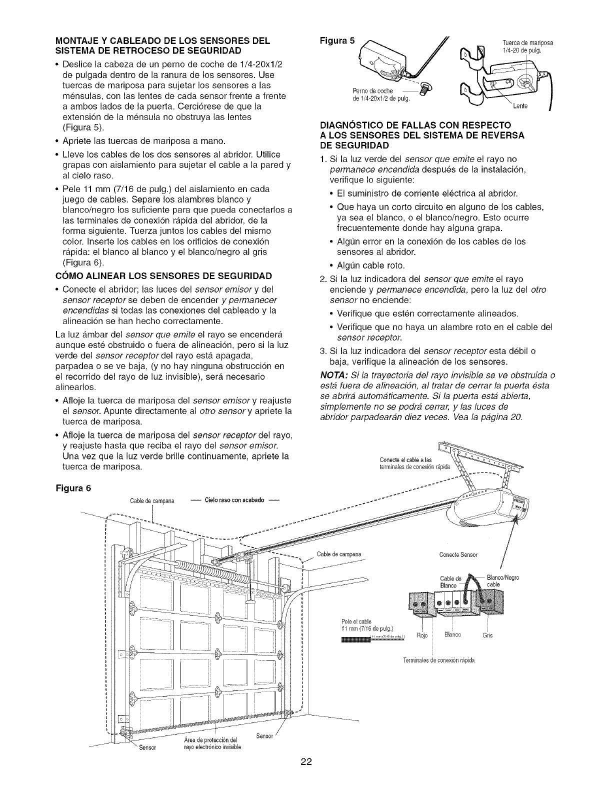
MONTAJE Y CABLEADO DE LOS SENSORES DEL
SISTEMA DE RETROCESO DE SEGURIDAD
• Deslice la cabeza de un pemo de coche de 1/4-20xl/2
de pulgada dentro de la ranura de los sensores. Use
tuercas de mariposa para sujetar los sensores alas
mensulas, con las lentes de cada sensor frente a frente
a ambos lades de la puerta. Cerci6rese de que la
extension de la m6nsula no obstruya las lentes
(Figura 5).
• Apriete las tuercas de mariposa a mane.
• Lleve los cables de los dos sensores al abridor. Utilice
grapas con aislamiento para sujetar el cable a la pared y
al cielo raso.
• Pele 11 mm (7/16 de pulg.) del aislamiento en cada
juego de cables. Separe los alambres blanco y
blanco/negro los suficiente para que pueda conectarlos a
las terminales de conexion rapida del abridor, de la
forma siguiente. Tuerza juntos los cables del mismo
color. Inserte los cables en los orificios de conexi6n
rapida: el blanco al blanco y el blanco/negro al gris
(Figura 6).
COMO ALINEAR LOS SENSORES DE SEGURIDAD
• Conecte el abridor; las luces del sensor emisory del
sensor receptor se deben de encender y permanecer
encendidas si todas las conexiones del cableado y la
alineaci6n se han hecho correctamente.
La luz ambar del sensor que emite el rayo se encendera
aunque este obstruido o fuera de alineaci6n, pete si la luz
verde del sensor receptor del rayo esta apagada,
parpadea o se ve baja, (y no hay ninguna obstrucci6n en
el recorrido del rayo de luz invisible), sera necesario
alinearlos.
• Afloje la tuerca de mariposa del sensor emisory reajuste
el sensor. Apunte directamente al otro sensory apriete la
tuerca de mariposa.
• Afloje la tuerca de mariposa del sensor receptor del rayo,
y reajuste hasta que reciba el rayo del sensor emisor.
Una vez que la luz verde brille continuamente, apriete la
tuerca de mariposa.
Figura 6
Cable de campana
Figura 5
Perao de coche --,,q_
de 1/4-20x1/2de pulg.
Tuercade mariposa
DIAGNOSTICO DE FALLAS CON RESPECTO
A LOS SENSORES DEL SlSTEMA DE REVERSA
DE SEGURIDAD
1. Si la luz verde del sensor que emite el rayo no
permanece encendida despues de la instalaci6n,
verifique Io siguiente:
• El suministro de corriente electrica al abridor.
• Que haya un corto circuito en alguno de los cables,
ya sea el blanco, o el blanco/negro. Esto ocurre
frecuentemente donde hay alguna grapa.
• Algt]n error en la conexi6n de los cables de los
sensores al abridor.
• Algt]n cable roto.
2. Si la luz indicadora del sensor que emite el rayo
enciende y permanece encendida, pero la luz del otro
sensor no enciende:
• Verifique que esten correctamente alineados.
• Verifique que no haya un alambre rote en el cable del
sensor receptor.
3. Si la luz indicadora del sensor receptor esta debil o
baja, verifique la alineacion de los sensores.
NOTA: Si la trayectoria del rayo invisible se ve obstruida o
esta fuera de alineacidn, al tratar de cerrar la puerta esta
se abrira automaticamente. Si la puerta esta abierta,
simplemente no se podra cerrar, y las luces de
abridor parpadearan diez veces. Vea la pagina 20.
.... %_ Cable de carnpana Conecte Sensor
Cable de
Blanco cable
PeJeel cable
11 mm (7/16 de pu[g.) j
_1 r,,r cT,ea__,,__ Rojo BJanco
}
T÷rminales de conexi6n r@ida
"Sensor Area de protecci6n del
rayo electr6nicoinvisible
Sensor '
22
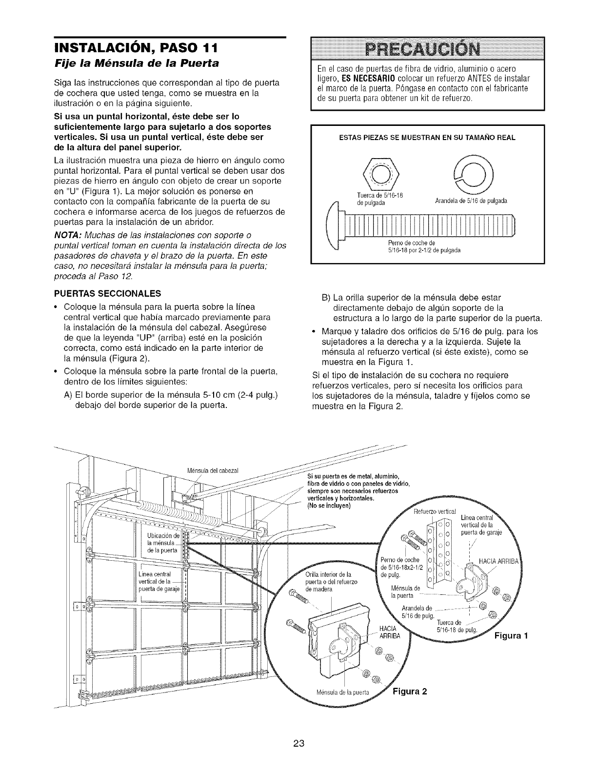
INSTALACION, PASO 11
Fije la M6nsula de la Puerta
Siga las instrucciones que correspondan al tipo de puerta
de cochera que usted tenga, como se muestra en la
ilustracidn o en la pagina siguiente.
Si usa un puntal horizontal, este debe ser Io
suficientemente largo para sujetarlo a dos soportes
verticales. Si usa un puntal vertical, este debe ser
de la altura del panel superior.
La ilustraci6n muestra una pieza de hierro en gtngulo como
puntal horizontal. Para el puntal vertical se deben usar dos
piezas de hierro en gtngulo con objeto de crear un soporte
en "U" (Figura 1). La mejor solucion es ponerse en
contacto con la compaSfa fabricante de la puerta de su
cochera e informarse acerca de los juegos de refuerzos de
puertas para la instalaci6n de un abridor.
NOTA: Muchas de las instalaciones con soporte o
puntal vertical toman en cuenta la instalacidn directa de los
pasadores de chaveta y el brazo de la puerta. En este
caso, no necesitara instalar la mensula para la puerta;
proceda al Paso 12.
PUERTAS SECCIONALES
•Coloque la mensula para la puerta sobre la linea
central vertical que habfa marcado previamente para
la instalacidn de la mensula del cabezal. AsegQrese
de que la leyenda "UP" (arriba) este en la posicidn
correcta, como estgt indicado en la parte interior de
la mensula (Figura 2).
• Coloque la mensula sobre la parte frontal de la puerta,
dentro de los Ifmites siguientes:
A) El borde superior de la mensula 5-10 cm (2-4 pulg.)
debajo del borde superior de la puerta.
Enel caso de puertas de fibra de vidrio, aluminio o acero
ligero, ES NECESARI0colocar un refuerzo ANTES de iostalar
el marco de la puerta. POngaseeo cootacto con el fabricante
de su puerta para obtener un kit de refuerzo.
ESTAS PIEZAS SE MUESTRAN EN SU TAMAI_IO REAL
Tuerca de 5/16-18
de pulgada ©
Arande]ade 5/16 de pulgada
Pernode coche de
5/16-18per2-1/2 de pulgada
B) La orilla superior de la mensula debe estar
directamente debajo de algun soporte de la
estructura a Io largo de la parte superior de la puerta.
• Marque y taladre dos orificios de 5/16 de pulg. para los
sujetadores a la derecha y a la izquierda. Sujete la
mensula al refuerzo vertical (si este existe), como se
muestra en la Figura 1.
Si el tipo de instalacion de su cochera no requiere
refuerzos verticales, pero sf necesita los orificios para
los sujetadores de la mensula, taladre y fijelos como se
muestra en la Figura 2.
Mensuladel cabeza]
Ubicacionde
de la puerta
ineacentral
puerta de garaje
L
Sisu puertaes de metal,a]uminio,
libra devidrio o con paneleede vidrio,
siempreson neceearios refuerzoe
vertiealesy horizontales,
(No se ineluyen)
puerta odel refuerzo
Pemode coche
de 5/16-18x2-1/2
de pulg.
M_nsula de
vertical de la
puerta de garaje
/
F
HACIAARRIBA
5/16 de pulg. Tuercade -- -
5/16-18de pulg.
A
/
Figura 1
M6nsulade la puerta ara 2
23
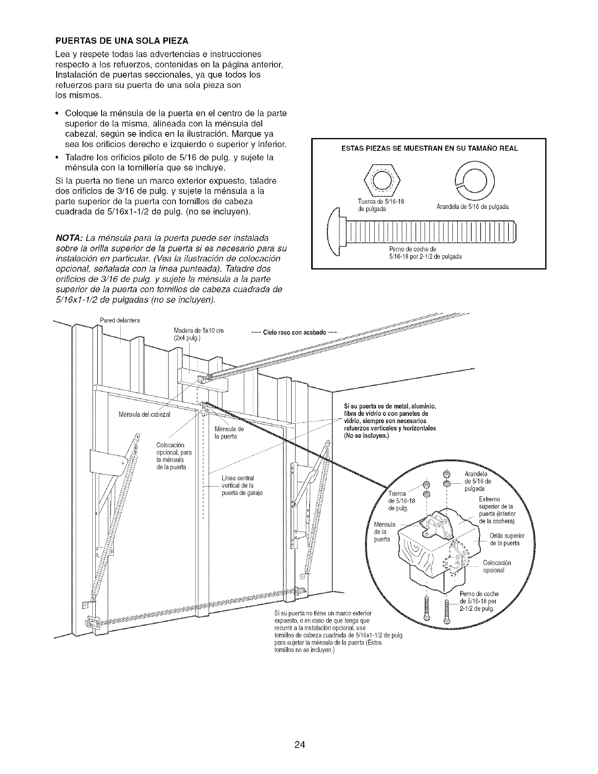
PUERTAS DE UNA SOLA PIEZA
Lea y respete todas las advertencias e instrucciones
respecto a los refuerzos, contenidas en la pa.gina anterior,
Instalaci6n de puertas seccionales, ya que toclos los
refuerzos para su puerta de una sola pieza son
los mismos.
•Coloque la mensula de la puerta en el centro de la parte
superior de la misma, alineada con la mensula del
cabezal, segun se indica en la ilustraci6n. Marque ya
sea los orificios derecho e izquierdo o superior y inferior.
• Taladre los orificios piloto de 5/16 de pulg. y sujete la
mensula con la torniller/a que se incluye.
Si la puerta no tiene un marco exterior expuesto, taladre
dos orificios de 3/16 de pulg. y sujete la mensula a la
parte superior de la puerta con tornillos de cabeza
cuadrada de 5/16x1-1/2 de pulg. (no se incluyen).
NOTA: La mensula para la puerta puede ser instalada
sobre la orilla superior de la puerta si es necesario para su
instalacidn en particular. (Vea la ilustracidn de colocacidn
opcional, sefialada con la Ifnea punteada). Taladre dos
orificios de 3/16 de pulg. y sujete la mensula a la parte
superior de la puerta con tomillos de cabeza cuadrada de
5/16x1-1/2 de pulgadas (no se incluyen).
Pared delantera
Maderade 5x10 cm
(2x4pulg.) -- Cielo race con acabade --
ESTAS PIEZAS SE MUESTRAN EN SU TAMAI_IO REAL
Tuercade 5/16-18
de pulgada ©
Arandelade 5/16 de pulgada
Perno de cochede
5/16-18par 2-1/2de pulgada
Mensuladel cabezal
Colocacion
opcional,para
la mensula
de la puerta
Mensulade
la puerta
Lineacentral
puertade garaje
Si su puert_ es de metal, aluminio,
fibra devidrio o con paneles de
refuerzos vertiealesy horizont_les
(No se incluyen.)
de 5/16-18
de pulg.
Si su puertano fiene un marcoexterior
expuesto,o en caso de que tengaque
recurrir a la instalaci6nopcional,use
tornillos de cabezacuadradade 5/16xl-1/2 de pulg.
para sujetar la mensulade la pueda (Estos
tornillos no seincluyen.)
®
_de 5/16de
pulgada
Extremo
superior de la
puerta (interior
de lacochera)
Orilla superior
de la puerta
Colocaci6n
opcional
Perno de coche
de 5/16-18per
2-1/2de pulg.
24
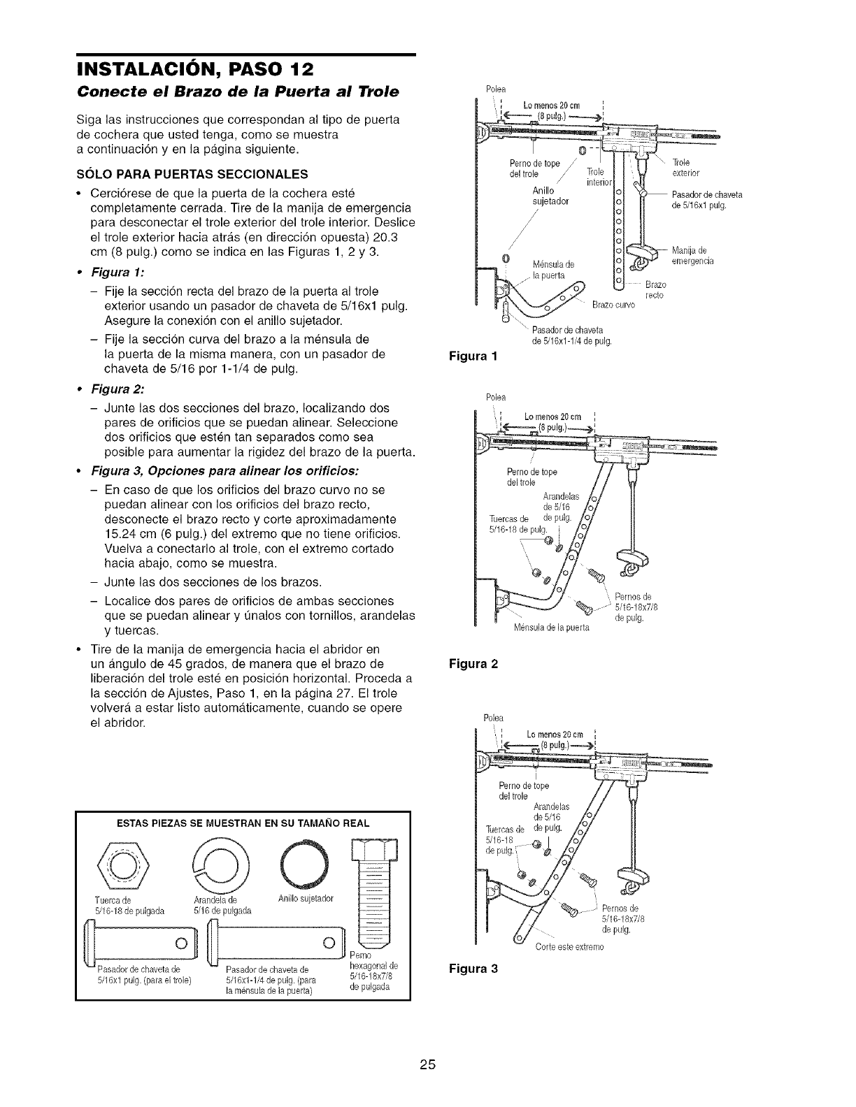
INSTALACION, PASO 12
Conecte el Brazo de la Puerta al Trole
Siga las instrucciones que correspondan al tipo de puerta
de cochera que usted tenga, come se muestra
a continuaci6n yen la pagina siguiente.
SOLO PARA PUERTAS SECClONALES
• Cerci6rese de que la puerta de la cochera este
completamente cerrada. Tire de la manija de emergencia
para desconectar el trole exterior del trole interior. Deslice
el trole exterior hacia atr_.s (en direcci6n opuesta) 20.3
cm (8 pulg.) come se indica en las Figuras 1, 2 y 3.
•Figura 1:
- Fije la secci6n recta del braze de la puerta al trole
exterior usando un pasador de chaveta de 5/16xl pulg.
Asegure la conexi6n con el anillo sujetador.
- Fije la seccion curva del braze a la mensula de
la puerta de la misma manera, con un pasador de
chaveta de 5/16 per 1-1/4 de pulg.
•Figura 2:
- Junte las dos secciones del braze, Iocalizando dos
pares de orificios que se puedan alinear. Seleccione
dos erificios que esten tan separados como sea
posible para aumentar la rigidez del braze de la puerta.
•Figura 3, Opciones para alinear los orificios:
- En case de que los orificios del brazo curve no se
puedan alinear con los orificios del braze recto,
desconecte el braze recto y corte aproximadamente
15.24 cm (6 pulg.) del extreme que no tiene orificios.
Vuelva a conectarlo al trole, con el extreme cortado
hacia abajo, come se muestra.
- Junte las dos secciones de los brazes.
- Localice dos pares de orificios de ambas secciones
que se puedan alinear y unalos con tomillos, arandelas
y tuercas.
• Tire de la manija de emergencia hacia el abridor en
un _.ngule de 45 grades, de manera que el braze de
liberaci6n del trole este en posicion horizontal. Proceda a
la secci6n de Ajustes, Paso 1, en la pa.gina 27. El trole
volvera, a estar listo automaticamente, cuando se opere
el abridor.
ESTAS PIEZAS SE MUESTRAN EN SU TAMAI_IO REAL
©
Tuerca de
5/16-18de pulgada
5/16xl pulg. (para el trole)
Arandela de
5/16 de pulgada
AniJIosujetador
o]
Pasadordechavetade hexagonalde
5/16x1-1/4depulg. (para 5/16-18x7/8
lamoleulade h puerta) de pulgada
Figura 1
Pasadorde chaveta
de 5/16x1-1/4de pulg.
O#
Pemos de
de pulg,
M_nsulade,la puerta
Figura 2
Figura 3
:' Pernosde
5/16-18x7/8
de pulg.
Corte este extremo
25
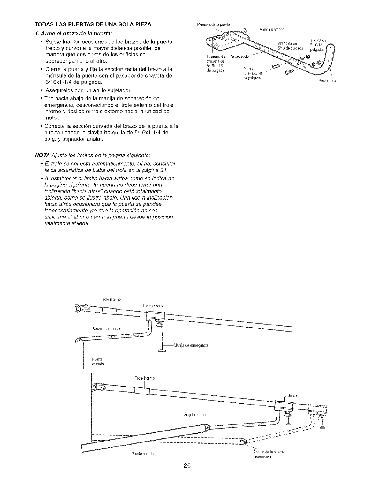
TODAS LAS PUERTAS DE UNA SOLA PIEZA
1. Arme el brazo de la puerta:
• Sujete las dos secciones de los brazes de la puerta
(recto y curvo) a la mayor distancia posible, de
manera que dos o tres de los orificios se
sobrepongan uno al otto.
• Cierre la puerta y fije la secci6n recta del braze a la
mensula de la puerta con el pasador de chaveta de
5/16x1-1/4 de pulgada.
• Asegurelos con un anillo sujetador.
• Tire hacia abajo de la manija de separaci6n de
emergencia, desconectando el trole externo del trole
interno y deslice el trole externo hacia la unidad del
motor.
• Conecte la secci6n curvada del brazo de la puerta a la
puerta usando la clavija horquilla de 5/16xl-1/4 de
pulg. y sujetador anular.
NOTA Ajuste los ffmites en la pagina siguiente:
•El trole se conecta automaticamente. Si no, consultar
la caracterfstica de traba del trole en la pagina 31.
•AI establecer el ffmite hacia arriba como se indica en
la pagina siguiente, la puerta no debe tener una
inclinacidn "hacia arras" cuando este totalmente
abierta, como se ilustra abajo. Una ligera inclinacidn
hacia arras ocasionara que la puerta se pandee
innecesariamente y/o que la operacidn no sea
uniforme al abrir o cerrar la puerta desde la posicidn
totalmente abierta.
M@suB de la puerta
de pulgada Brazoourvo
Trobinterno
Trob interno
Trob extemo
(incorrecto)
26
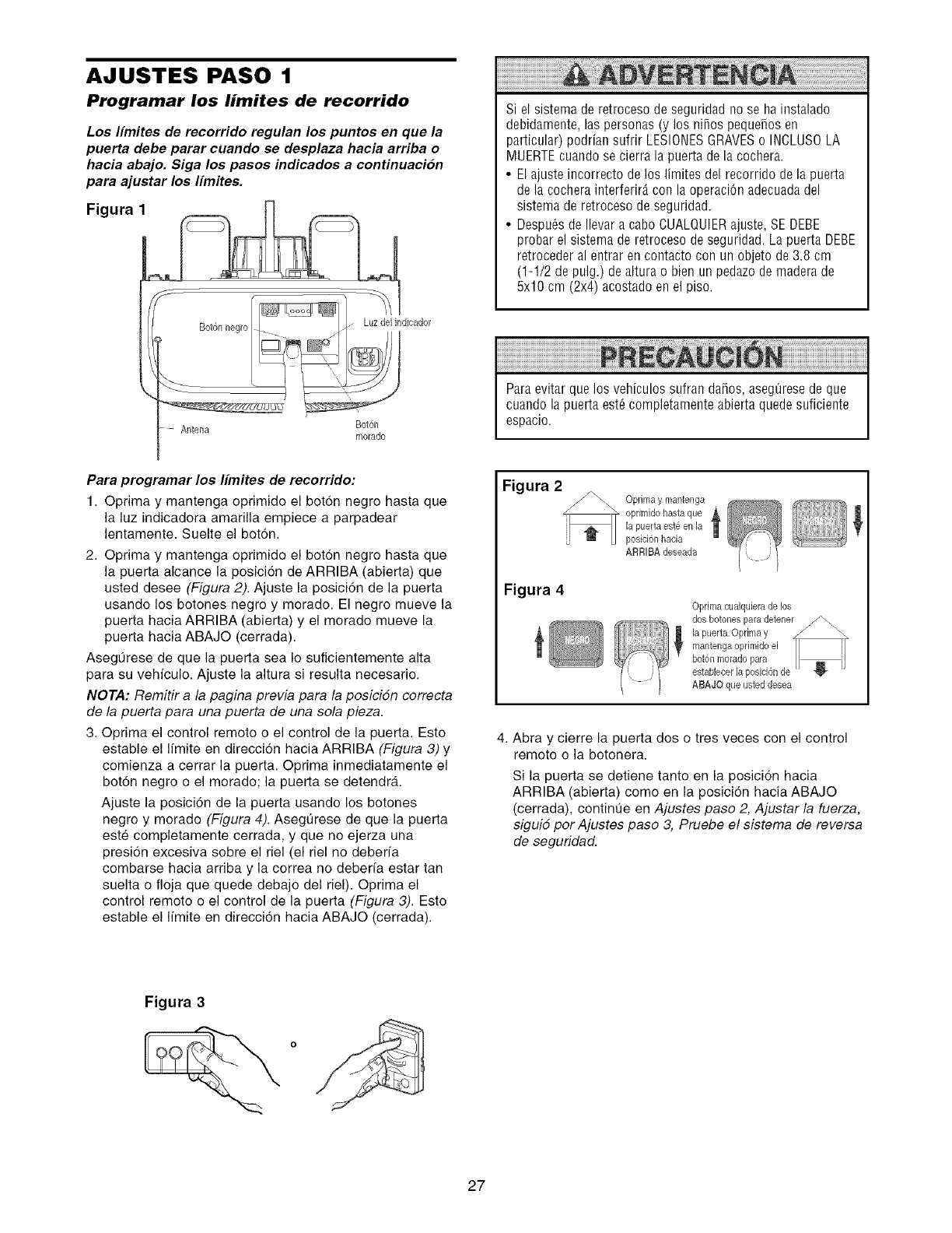
AJUSTES PASO 1
Programar los limites de recorrido
Los Ifmites de recorrido regulan los puntos en que la
puerta debe parar cuando se desplaza hacia arriba o
hacia abajo. Siga los pasos indicados a continuacion
para ajustar los Ifmites.
Figura 1
Si el sistema de retroceso de seguridad no se hainstalado
debidamente, las personas (y los ni_os peque_os en
particular) podrian sufrir LESIONESGRAVESo INCLUSOLA
MUERTEcuando se cierra la puerta de la cochera.
• El ajuste incorrecto de los limites del recorrido de la puerta
de la cochera interferirA con la operaciOnadecuadadel
sistema de retroceso de seguridad.
• Despu6s de Ilevar a cabo CUALQUIERajuste, SE DEBE
probar el sistema de retroceso de seguridad. La puerta DEBE
retroceder al entrar en contacto con un objeto de 3.8 cm
(1-1/2 de pulg.) dealtura o bien un pedazode madera de
5x10 cm (2x4) acostado en el piso.
Antena Bot6n
morado
Paraevitar que los vehiculos sufran da_os, aseg_resede que
cuando la puerta est_ completamente abierta quede suficiente
espacio.
Para programar los Ifmites de recorrido:
1. Oprima y mantenga oprimido el boton negro hasta que
la luz indicadora amarilla empiece a parpadear
lentamente. Suelte el boton.
2. Oprima y mantenga oprimido el boton negro hasta que
la puerta alcance la posicion de ARRIBA (abierta) que
usted desee (Figura 2). Ajuste la posici6n de la puerta
usando los botones negro y morado. El negro mueve la
puerta hacia ARRIBA (abierta) y el morado mueve la
puerta hacia ABAJO (cerrada).
AsegQrese de que la puerta sea Io suficientemente alta
para su vehiculo. Ajuste la altura si resulta necesario.
NOTA: Remitir a la pagina previa para la posicidn correcta
de la puerta para una puerta de una sola pieza.
3. Optima el control remoto o el control de la puerta. Esto
estable el limite en direcci6n hacia ARRIBA (Figura 3) y
comienza a cerrar la puerta. Optima inmediatamente el
boton negro o el morado; la puerta se detendra.
Ajuste la posici6n de la puerta usando los botones
negro y morado (Figura 4). Asegt]rese de que la puerta
este completamente cerrada, y que no ejerza una
presi6n excesiva sobre el riel (el riel no deberia
combarse hacia arriba y la correa no deberfa estar tan
suelta o floja que quede debajo del riel). Oprima el
control remoto o el control de la puerta (Figura 3). Esto
estable el limite en direcci6n hacia ABAJO (cerrada).
Figura 2
Figura 4
Oprimay mantenga "_ _ _
oprimidohasta que _,
la puerta est_ en la
posic[6nhacia
ARR[BAdeseada
Optima cualquierade los
ABAJO que usted desea
4. Abra y cierre la puerta dos o tres veces con el control
remoto o la botonera.
Si la puerta se detiene tanto en la posici6n hacia
ARRIBA (abierta) como en la posici6n hacia ABAJO
(cerrada), contint]e en Ajustes paso 2, Ajustar la fuerza,
siguid por Ajustes paso 3, Pruebe el sistema de reversa
de seguridad.
Figura 3
27
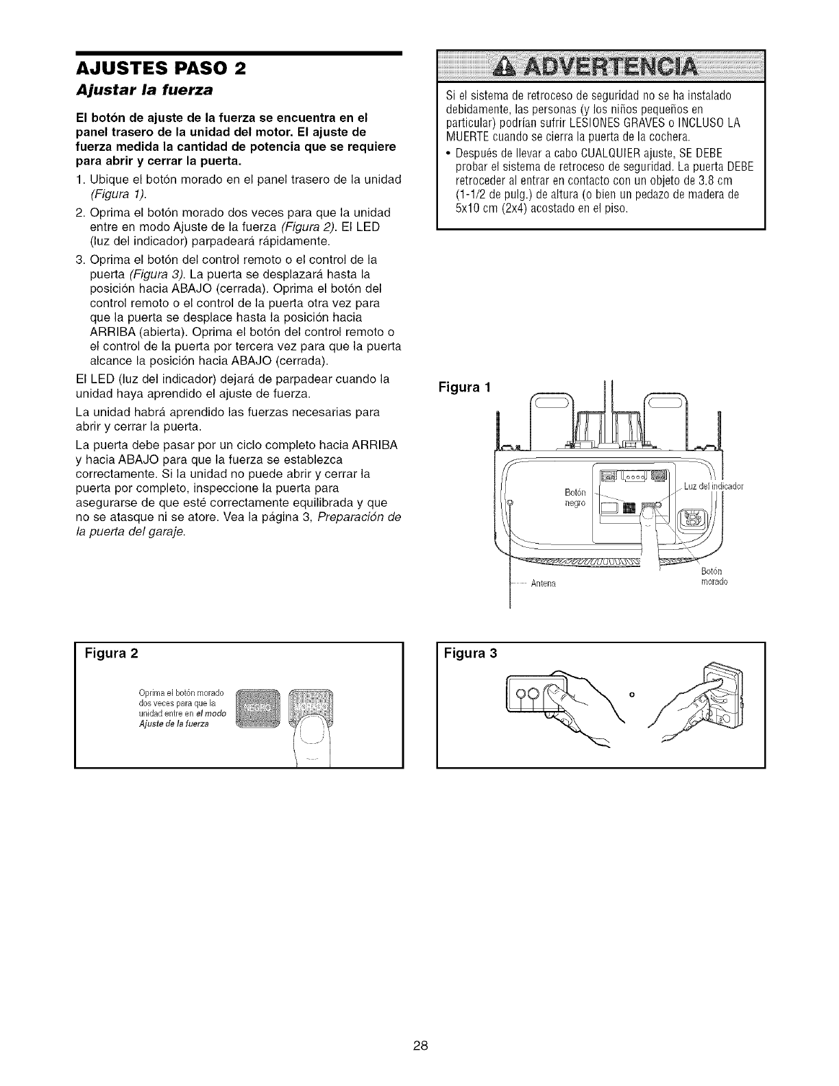
AJUSTES PASO 2
Ajustar la fuerza
El boton de ajuste de la fuerza se encuentra en el
panel trasero de la unidad del motor. El ajuste de
fuerza medida la cantidad de potencia que se requiere
para abrir y cerrar la puerta.
1. Ubique el boton morado en el panel trasero de la unidad
(Figura 1).
2. Oprima el bot6n morado dos veces para que la unidad
entre en mode Ajuste de la fuerza (Figura 2). El LED
(luz del indicador) parpadeara rgtpidamente.
3. Oprima el bot6n del control remote o el control de la
puerta (Figura 3). La puerta se desplazara hasta la
posicion hacia ABAJO (cerrada). Oprima el boton del
control remote o el control de la puerta otra vez para
que la puerta se desplace hasta la posicion hacia
ARRIBA (abierta). Oprima el bot6n del control remote o
el control de la puerta per tercera vez para que la puerta
alcance la posici6n hacia ABAJO (cerrada).
El LED (luz del indicador) dejara de parpadear cuando la
unidad haya aprendido el ajuste de fuerza.
La unidad habra aprendido las fuerzas necesarias para
abrir y cerrar la puerta.
La puerta debe pasar per un ciclo complete hacia ARRIBA
y hacia ABAJO para que la fuerza se establezca
correctamente. Si la unidad no puede abrir y cerrar la
puerta per complete, inspeccione la puerta para
asegurarse de que este correctamente equilibrada y que
no se atasque ni se atore. Vea la pgtgina 3, Preparacidn de
la puerta del garaje.
Si el sistema de retroceso de seguridad no se ha instalado
debidamente, las personas (y los niSos pequeSosen
particular) podrian sufrir LESIONESGRAVESo INCLUS0 LA
MUERTEcuando se cierra la puerta de la cochera.
• Despu6s de Ilevar a cabo CUALQUIERajuste, SE DEBE
probar el sistema de retroceso de seguridad. La puerto DEBE
retroceder al entrar en contacto con un objeto de 3.8 cm
(1-1/2 de pulg.) dealtura (o bien un pedazode madera de
5x10 cm (2x4) acostado en el piso.
Figura 1
Bot6n
negro
Bot6n
Antena morado
Figura 2
Oprimael bot6n morado
dosveces para que la
unidad entreen e/mode
Ajuste de b fuerza
Figura 3
28
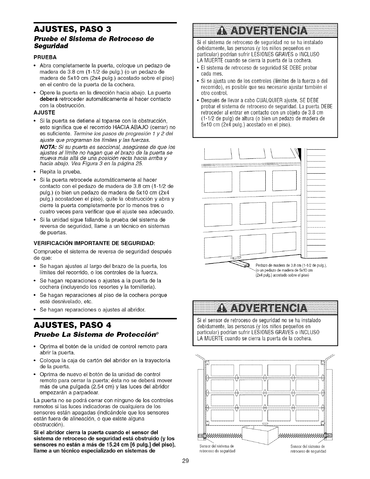
AJUSTES, PASO 3
Pruebe el Sistema de Retroceso de
Seguridad
PRUEBA
•Abra completamente la puerta coloque un pedazo de
madera de 38 cm (11/2 de pulg) (o un pedazo de
madera de 5x10 cm (2x4 pulg) acostado sobre el piso)
en el centre de la puerta de la cochera
• Opere la puerta en la direcci6n hacia abajo La puerta
debera retroceder automaticamente al hacer contacto
con la obstrucci6n
AJUSTE
• Si la puerta se detiene al toparse con la obstruccion
esto significa que el recorride HACIAABAJO (cerrar) no
es suficiente Termine los pasos de progresidn 1y 2 del
ajuste que programan los ffmites y las fuerzas
NOTA: Si su puerta es seccional aseg#rese de que los
ajustes al Ifmite no hagan que el braze de la puerta se
mueva mas alia de una posiciSn recta hacia arriba y
hacia abajo Vea Figura 3 en la pagina 25
• Repita la prueba
• Si la puerta retrocede automaticamente al hacer
contacto con el pedazo de madera de 38 cm (1-1/2 de
pulg) (o bien un pedazo de madera de 5x10 cm (2x4
pulg) acostadoen el piso) quite la obstrucci6n y abra y
cierre la puerta completamente per Io menos tres o
cuatro veces para verificar que el ajuste sea adecuado
• Si la unidad sigue fallando la prueba del sistema de
reversa de seguridad Ilame a un tecnico en sistemas
de puertas
VERIFICAClON IMPORTANTE DE SEGURIDAD:
Compruebe el sistema de reversa de seguridad despues
de que:
• Se hagan ajustes al largo del brazo de la puerta los
limites del recorrido o los controles de la fuerza
• Se hagan reparaciones o ajustes a la puerta de la
cochera (incluyendo los resortes y la tornilleria)
• Se hagan reparaciones al piso de la cochera porque
este desnivelade etc
• Se hagan reparaciones o ajustes al abridor
AJUSTES, PASO 4
Pruebe La Sistema de Protecci6n ®
• Optima el bot6n de la unidad de control remoto para
abrir la puerta
• Coloque la caja de carton del abridor en la trayectoria
de la puerta
• Optima de nuevo el bot6n de la unidad de control
remote para cerrar la puerta; esta no se debera mover
mas de una pulgada (2.54 cm) y las luces del abridor
empezaran a parpadear
La puerta no se podra cerrar con ninguno de los controles
remotos si las luces indicaderas de cualquiera de los
sensores estan apagadas (indicandole que los sensores
estan fuera de alineaci6n o que existe alguna
obstrucci6n)
Si el abridor cierra la puerta cuando el sensor del
sistema de retroceso de seguridad est;_ obstruido (y los
sensores no est;_n a m;_s de 15.24 cm [6 pulg] del piso),
Ilame a un tecnico especializado en sistemas de
29
Si el sistema de retroceso de seguridad no se hainstalado
debidamente, las personas (y los niSospequeSoseo
particular) podrian sufrir LESlONESGRAVESo INCLUSO
LA MUERTEcuando se cierra la puerta de la cochera.
• El sistema de retroceso de seguridad SE DEBEprobar
cada rues.
• Si se ajusta uno de los controles (limites de la fuerza o del
recorrido), es posible que sea necesario ajustar tambi_n el
otro control.
• Despu_s de Ilevar a cabo CUALQUIERajuste, SE DEBE
probar el sistema de retroceso de seguridad. La puerta DEBE
retroceder al entrar en contacto con un objeto de 3.8 cm
(1-1/2 de pulg) de altura (o bien un pedazode maderade
5x10 cm (2x4 pulg.) acostado en el piso).
(2x4 pulg.) acostado sobre el piso)
Si el sensor de retroceso de seguridad no se ha instalado
debidamente, las personas (y los niSospequeSosen
particular) podrian sufrir LESIONESGRAVESo INCLUSO
LA MUERTEcuando se cierra la puerta de la cochera.
E
@
Sensor del sistema de
retrocesode seguridad
Sensordel sistemade
retroeesode seguridad
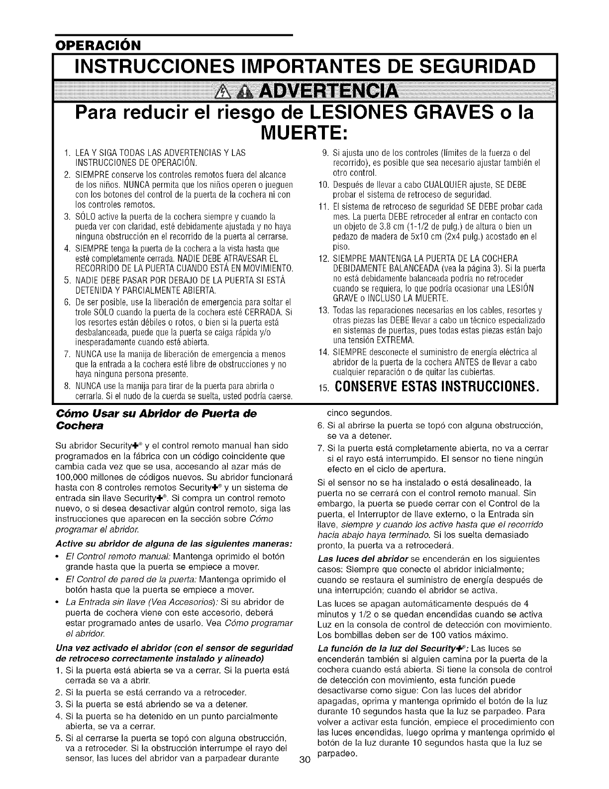
OPERACION
INSTRUCCIONES IMPORTANTES DE SEGURIDAD
Para reducir el riesgo de LESIONES GRAVES o la
MUERTE:
1. LEAY SIGA TODASLAS ADVERTENCIASY LAS
INSTRUCCIONESDE OPERACION.
2. SIEMPREconserve los controles remotos fuera del alcance
delos ni_os. NUNCApermita que los ni_os operen o jueguen
con los botones del control de la puerta dela cochera ni con
los controles remotos.
3. SOLOactive la puerta de la cochera siempre y cuando la
puedaver con claridad, est6 debidamente ajustada y no haya
ninguna obstrucci6n en el recorrido de la puerta al cerrarse.
4. SIEMPREtenga la puerta de la cocheraa la vista hasta que
est6completamente cerrada.NADIEDEBEATRAVESAREL
RECORRIDODELA PUERTACUANDOESTAENMOVIMIENTO.
5. NADIEDEBEPASARPORDEBAJODELA PUERTASIESTA
DETENIDAY PARCIALMENTEABIERTA.
6. Deser posible, use la liberaci6n de emergencia para soltar el
trole SOLOcuando la puerta de la cochera est6 CERRADA.Si
los resortes est_n d6biles o rotos, o bien si la puerta est_
desbalanceada,puede que la puerta se caiga r_piday/o
inesperadamentecuando est6 abierta.
7. NUNCAusela manija de liberaci6n de emergencia a menos
que la entrada a la cochera est6 libre de obstrucciones y no
haya ninguna persona presente.
8. NUNCAusela manija paratirar de la puerta para abrirla o
cerrarla.Si el nudo dela cuerdase suelta, usted podria caerse.
9. Si ajusta uno de los controles (limites de la fuerza o del
recorrido), es posible que sea necesario ajustar tambi_n el
otro control.
10. Despu6s de Ilevar a cabo CUALQUIERajuste, SE DEBE
probar el sistema de retroceso de seguridad.
11. El sistema de retroceso de seguridad SEDEBEprobar cada
rues. La puerta DEBEretroceder al entrar en contacto con
un objeto de 3.8 cm (1-1/2 de pulg.) de altura o bien un
pedazo de maderade 5x10 cm (2x4 pulg.) acostado en el
piso.
12. SIEMPREMANTENGALA PUERTADE LA COCHERA
DEBIDAMENTEBALANCEADA(yea la p_,gina3). Si la puerta
no est_ debidamente balanceadapodria no retroceder
cuando se requiera, Io que podria ocasionar una LESION
GRAVEo INCLUSOLA MUERTE.
13. Todaslas reparaciones necesariasen los cables, resortes y
otras piezaslas DEBEIlevar a cabo un t6cnico especializado
en sistemas de puertas, pues todas estas piezasestAn bajo
una tensi6n EXTREMA.
14. SIEMPRE desconecteel suministro de energia el6ctrica al
abridor de la puerta de la cochera ANTESde Ilevar a cabo
cualquier reparaci6n o de quitar las cubiertas.
15.CONSERVEESTASINSTRUCCIONES.
C6mo Usar su Abridor de Puerta de
Cochera
Su abridor Security÷ ®y el control remoto manual han sido
programados en la fabrica con un codigo coincidente que
cambia cada vez que se usa, accesando al azar mas de
100,000 millones de c6digos nuevos. Su abridor funcionara
hasta con 8 controles remotos Security÷ ® y un sistema de
entrada sin Nave Security÷_L Si compra un control remoto
nuevo, o si desea desactivar algOn control remoto, siga las
instrucciones que aparecen en la seccion sobre Cdmo
programar el abriden
Active su abridor de alguna de las siguientes maneras:
•El Control remote manual: Mantenga oprimido el bot6n
grande hasta que la puerta se empiece a mover.
• El Control de pared de la puerta: Mantenga oprimido el
bot6n hasta que la puerta se empiece a mover.
• La Entrada sin Ilave (Vea Acceserios): Si su abridor de
puerta de cochera viene con este accesorio, debera
estar programado antes de usarlo. Vea Cdmo programar
el abriden
Una vez activado el abridor (con el sensor de seguridad
de retroceso correctamente instalado y alineado)
1. Si la puerta esta abierta se va a cerrar. Si la puerta esta
cerrada se va a abrir.
2. Si la puerta se esta cerrando va a retroceder.
3. Si la puerta se esta abriendo se va a detener.
4. Si la puerta se ha detenido en un punto parcialmente
abierta, se va a cerrar.
5. Sial cerrarse la puerta se top6 con alguna obstrucci6n,
va a retroceder. Si la obstrucci6n interrumpe el rayo del
sensor, las luces del abridor van a parpadear durante 30
cinco segundos.
6. Sial abrirse la puerta se top6 con alguna obstrucci6n,
se va a detener.
7. Si la puerta esta completamente abierta, no va a cerrar
si el rayo esta interrumpido. El sensor no tiene ningOn
efecto en el ciclo de apertura.
Si el sensor no se ha instalado o esta desalineado, la
puerta no se cerrara con el control remoto manual. Sin
embargo, la puerta se puede cerrar con el Control de la
puerta, el Interruptor de Nave externo, o la Entrada sin
Ilave, siempre y cuando los active hasta que el recorrido
hacia abajo haya terminado. Si los suelta demasiado
pronto, la puerta va a retrocedera..
Las luces de/abridor se encendera.n en los siguientes
casos: Siempre que conecte el abridor inicialmente;
cuando se restaura el suministro de energfa despues de
una interrupci6n; cuando el abridor se activa.
Las luces se apagan automa.ticamente despues de 4
minutos y 1/2 o se quedan encendidas cuando se activa
Luz en la consola de control de detecci6n con movimiento.
Los bombillas deben ser de 100 vatios maximo.
La funcion de la luz del Security.l_: Las luces se
encenderan tambien si alguien camina por la puerta de la
cochera cuando est,. abierta. Si tiene la consola de control
de detecci6n con movimiento, esta funci6n puede
desactivarse como sigue: Con las luces del abridor
apagadas, oprima y mantenga oprimido el boton de la luz
durante 10 segundos hasta que la luz se parpadeo. Para
volver a activar esta funci6n, empiece el procedimiento con
las luces encendidas, luego oprima y mantenga oprimido el
boton de la luz durante 10 segundos hasta que la luz se
parpadeo.
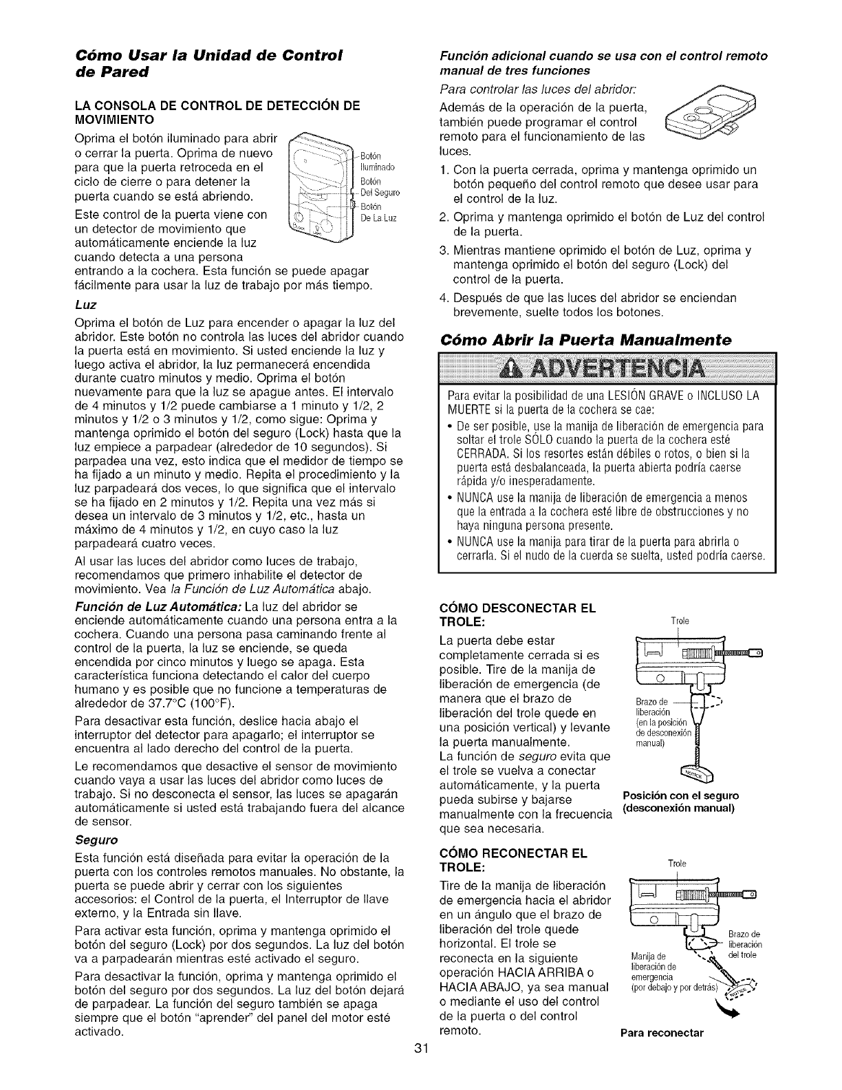
C6mo Usar la Unidad de Control
de Pared
LA CONSOLA DE CONTROL DE DETECCION DE
MOVIMIENTO
Oprima el bot6n iluminado para abrir
o cerrar la puerta. Oprima de nuevo _Bot6n
para que la puerta retroceda en el Iluminado
ciclo de cierre o para detener la Bot6n
puerta cuando se esta abriendo. Del Seguro
Bot6n
Este control de la puerta viene con De La Luz
un detector de movimiento que
automa.ticamente enciende la luz
cuando detecta a una persona
entrando a la cochera. Esta funcion se puede apagar
facilmente para usar la luz de trabajo por mas tiempo.
Luz
Oprima el bot6n de Luz para encender o apagar la luz del
abridor. Este boton no controla las luces del abridor cuando
la puerta esta en movimiento. Si usted enciende la luz y
luego activa el abridor, la luz permanecera, encendida
durante cuatro minutos y medio. Oprima el bot6n
nuevamente para que la luz se apague antes. El intervalo
de 4 minutos y 1/2 puede cambiarse a 1 minuto y 1/2, 2
minutos y 1/2 o 3 minutes y 1/2, como sigue: Oprima y
mantenga oprimido el boton del seguro (Lock) hasta que la
luz empiece a parpadear (alrededor de 10 segundos). Si
parpadea una vez, esto indica que el medidor de tiempo se
ha fijado a un minute y medio. Repita el procedimiento y la
luz parpadeara, dos veces, Io que significa que el intervalo
se ha fijado en 2 minutes y 1/2. Repita una vez ma.s si
desea un intervalo de 3 minutes y 1/2, etc., hasta un
m_.ximo de 4 minutos y 1/2, en cuyo caso la luz
parpadeara cuatro veces.
AI usar las luces del abridor como luces de trabajo,
recomendamos que primero inhabilite el detector de
movimiento. Vea la Funcidn de Luz Automatica abajo.
Funcion de LuzAutomatica: La luz del abridor se
enciende autom&ticamente cuando una persona entra a la
cochera. Cuando una persona pasa caminando frente al
control de la puerta, la luz se enciende, se queda
encendida per cinco minutos y luego se apaga. Esta
caracterfstica funciona detectando el calor del cuerpo
humane y es posible que no funcione a temperaturas de
alrededor de 37.7°C (100°F).
Para desactivar esta funci6n, desNce hacia abajo el
interrupter del detector para apagarlo; el interrupter se
encuentra al lade derecho del control de la puerta.
Le recomendamos que desactive el sensor de movimiento
cuando vaya a usar las luces del abridor come luces de
trabajo. Si no desconecta el sensor, las luces se apagaran
autom&ticamente si usted esta trabajando fuera del alcance
de sensor.
Seguro
Esta funcion esta diseffada para evitar la operaci6n de la
puerta con los centroles remotos manuales. No obstante, la
puerta se puede abrir y cerrar con los siguientes
accesorios: el Control de la puerta, el Interrupter de Nave
extemo, y la Entrada sin Nave.
Para activar esta funci6n, oprima y mantenga oprimido el
bot6n del seguro (Lock) per dos segundos. La luz del boton
va a parpadearan mientras este activado el seguro.
Para desactivar la funci6n, oprima y mantenga eprimido el
bot6n del seguro por dos segundos. La luz del boton dejara
de parpadear. La funci6n del seguro tambien se apaga
siempre que el bot6n "aprender" del panel del motor este
activado.
31
Funcion adicional cuando se usa con el control remoto
manual de tres funciones
Para controlar las luces del abridor.
Ademas de la operaci6n de la puerta,
tambien puede programar el control
remote para el funcionamiento de las
luces.
1. Con la puerta cerrada, optima y mantenga oprimido un
bot6n pequeffo del control remote que desee usar para
el control de la luz.
2. Oprima y mantenga oprimido el boton de Luz del control
de la puerta.
3. Mientras mantiene oprimido el bot6n de Luz, oprima y
mantenga oprimido el boton del seguro (Lock) del
control de la puerta.
4. Despues de que las luces del abridor se enciendan
brevemente, suelte todos los botones.
C6mo Abrir la Puerta Manualmente
Paraevitar la posibilidad de una LESIONGRAVEo INCLUSOLA
MUERTEsi la puerta de la cochera se cae:
• De ser posible, use la manija de liberaci6n de emergencia para
soltar el trole SOLOcuando la puerta de la cochera est_
CERRADA.Si los resortes estAn d6biles o rotos, o bien si la
puerta estAdesbalanceada,la puerta abierta podria caerse
r_,piday/o ioesperadamente.
• NUNCAuse la manija de liberaci6n de emergenciaa menos
que la entrada a la cochera est_ libre de obstrucciones y no
haya ninguna personapresente.
• NUNCAuse la manija paratirar de la puerta para abrida o
cerrarla. Si el nudo de la cuerda se suelta, usted podria caerse.
COMO DESCONECTAR EL
TROLE:
La puerta debe estar
completamente cerrada si es
posible. Tire de la manija de
liberacion de emergencia (de
manera que el braze de
liberacion del trole quede en
una posici6n vertical) y levante
la puerta manualmente.
La funci6n de seguro evita que
el trole se vuelva a conectar
automaticamente, y la puerta
pueda subirse y bajarse
Trole
de desconexi6n
manual)
Posicidncon el seguro
manualmente con la frecuencia (desconexi6nmanual)
que sea necesaria.
COMO RECONECTAR EL
TROLE:
Tire de la manija de liberaci6n
de emergencia hacia el abridor
en un angulo que el braze de
liberacion del trole quede
horizontal. El trole se
reconecta en la siguiente
operaci6n HACIAARRIBA o
HACIAABAJO, ya sea manual
o mediante el use del control
de la puerta o del control
remote.
Trole
I
_ Iiberacidn
Manijade ",.,_,_ del trole
Nberaci6nde __
emergencia _..-
Para reconectar
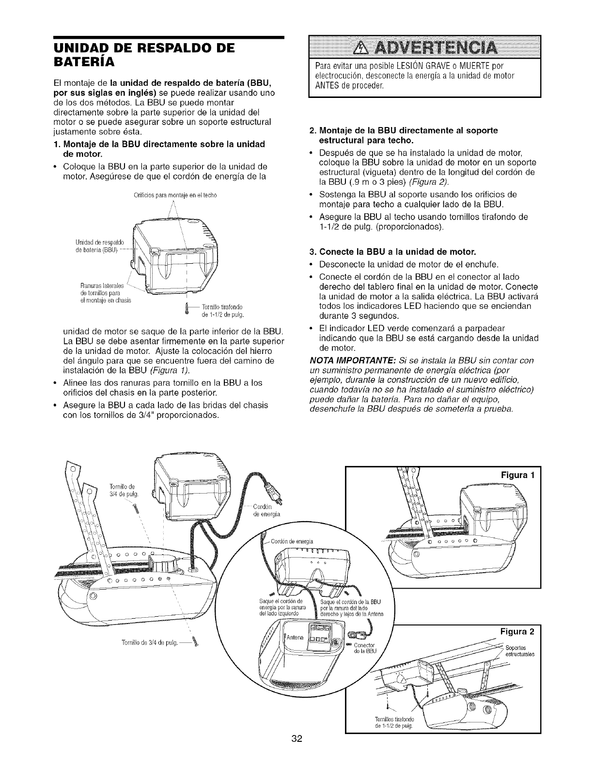
UNIDAD DE RESPALDO DE
BATERJA
El montaje de la unidad de respaldo de bateria (BBU,
por sue siglas en ingles) se puede realizar usando uno
de los dos metodos. La BBU se puede montar
directamente sobre la parte superior de la unidad del
motor o se puede asegurar sobre un soporte estructural
justamente sobre esta.
1. Montaje de la BBU directamente sobre la unidad
de motor.
•Coloque la BBU en la parte superior de la unidad de
motor. Aseg_rese de que el cord6n de energfa de la
Orificiospara montajeen el techo
de tomillospara I
el montajeen @ads _ Tornillotirafondo
de 1-1/2de pulg.
unidad de motor se saque de la parte inferior de la BBU.
La BBU se debe asentar firmemente en la parte superior
de la unidad de motor. Ajuste la colocaci6n del hierro
del angulo para que se encuentre fuera del camino de
instalacion de la BBU (Figura 1).
• Alinee las dos ranuras para tornillo en la BBU a los
orificios del chasis en la parte posterior.
• Asegure la BBU a cada lade de las bridas del chasis
con los tornillos de 3/4" proporcionados.
Paraevitar una posible LESIONGRAVEo MUERTEpor
electrocuci6n, desconecte la energia a la unidad de motor
ANTESde proceder.
2. Montaje de la BBU directamente al soporte
estructural para techo.
• Despues de que se ha instalado la unidad de motor,
coloque la BBU sobre la unidad de motor en un soporte
estructural (vigueta) dentro de la Iongitud del corddn de
la BBU (.9 m o 3 pies) (Figura 2).
• Sostenga la BBU al soporte usando los orificios de
montaje para techo a cualquier lade de la BBU.
• Asegure la BBU al techo usando tornillos tirafondo de
1-1/2 de pulg. (proporcionados).
3. Conecte la BBU a la unidad de motor.
• Desconecte la unidad de motor de el enchufe.
• Conecte el cord6n de la BBU en el conector al lado
derecho del tablero final en la unidad de motor. Conecte
la unidad de motor a la salida electrica. La BBU activara
todos los indicadores LED haciendo que se enciendan
durante 3 segundos.
• El indicador LED verde comenzara a parpadear
indicando que la BBU se esta cargando desde la unidad
de motor.
NOTA IMPORTANTE: Si se instala la BBU sin contar con
un suministro permanente de energfa electrica (per
ejemplo, durante la construccidn de un nuevo edificio,
cuando todavfa no se ha instalado el suministro electrico)
puede dadar la baterfa. Para no dadar el equipo,
desenchufe la BBU despues de someterla a prueba.
Tornillode
3/4de puJg,
de energ[a
- Cord@ de energia
Saque el cord@ de
energia pot la ranura
del lado izqubrdo
Saque el cord@ de la BBU
dPOrla ranuradel lado
erecho y bjos de la Antena
CoRector
de la BBU
Figura 1
Figura 2
32
Tot nillos tirafondo
de 1-1/2 de pulg,
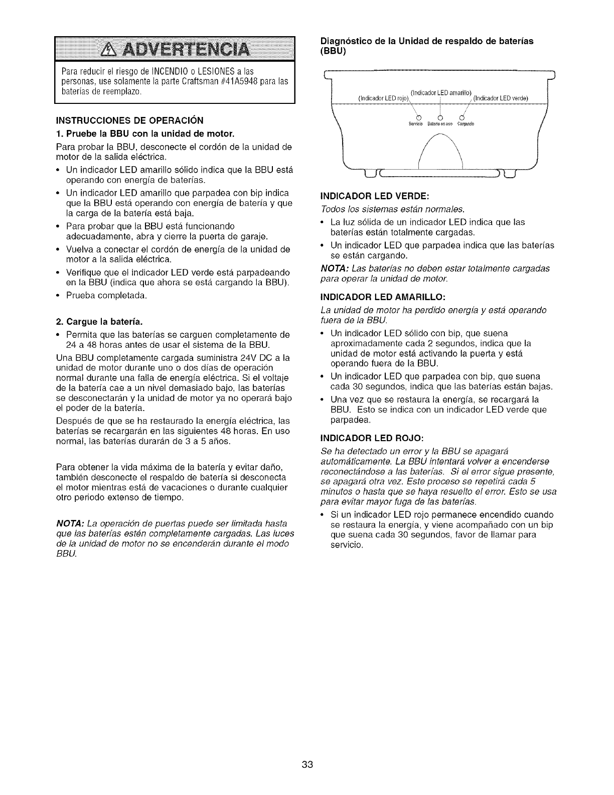
Para reducir el riesgo de INCENDIOo LESIONESa las
personas, use solamente la parte Craftsman #41A5948 para las
baterias de reemplazo.
INSTRUCCIONES DE OPERACION
1. Pruebe la BBU con la unidad de motor.
Para probar la BBU, desconecte el cord6n de la unidad de
motor de la salida electrica.
• Un indicador LED amarillo s61ido indica que la BBU estA
operando con energia de baterias.
• Un indicador LED amarillo que parpadea con bip indica
que la BBU esta operando con energia de bateria y que
la carga de la baterfa esta baja.
• Para probar que la BBU esta funcionando
adecuadamente, abra y cierre la puerta de garaje.
• Vuelva a conectar el cord6n de energia de la unidad de
motor a la salida electrica.
• Verifique que el indicador LED verde esta parpadeando
en la BBU (indica que ahora se esta cargando la BBU).
• Prueba completada.
2. Cargue la bateria.
• Permita que las baterias se carguen completamente de
24 a 48 horas antes de usar el sistema de la BBU.
Una BBU completamente cargada suministra 24V DC a la
unidad de motor durante uno o dos dfas de operacion
normal durante una falla de energia electrica. Si el voltaje
de la bateria cae a un nivel demasiado bajo, las baterias
se desconectaran y la unidad de motor ya no operara bajo
el poder de la baterfa.
Despues de que se ha restaurado la energia electrica, las
baterias se recargaran en las siguientes 48 horas. En uso
normal, las baterias duraran de 3 a 5 aSos.
Para obtener la vida maxima de la bateria y evitar da_o,
tambien desconecte el respaldo de baterfa si desconecta
el motor mientras esta de vacaciones o durante cualquier
otro periodo extenso de tiempo.
NOTA: La operacidn de puertas puede ser limitada hasta
que las baterfas esten completamente cargadas. Las luces
de la unidad de motor no se encenderan durante el modo
BBU.
Diagnostico de la Unidad de respaldo de baterias
(BBU)
C
(Indicador LED amarillo)
(Indicador LED rojo), ' .(indicador LED verde)
b o d
ServMo B_teria_uso C_rgando
/
INDICADOR LED VERDE:
Todos los sistemas estan normales.
• La luz s61ida de un indicador LED indica que las
baterfas estan totalmente cargadas.
• Un indicador LED que parpadea indica que las baterias
se estan cargando.
NOTA: Las baterfas no deben estar totalmente cargadas
para operar la unidad de motor.
INDICADOR LED AMARILLO:
La unidad de motor ha perdido energfa y esta operando
fuera de la BBU.
• Un indicador LED s61ido con bip, que suena
aproximadamente cada 2 segundos, indica que la
unidad de motor esta activando la puerta y esta
operando fuera de la BBU.
• Un indicador LED que parpadea con bip, que suena
cada 30 segundos, indica que las baterias estan bajas.
• Una vez que se restaura la energia, se recargara la
BBU. Esto se indica con un indicador LED verde que
parpadea.
INDICADOR LED ROJO:
Se ha detectado un error y la BBU se apagara
automaticamente. La BBU intentara volver a encenderse
reconectandose alas baterfas. Si el error sigue presente,
se apagara otra vez. Este proceso se repetir& cada 5
minutos o hasta que se haya resuelto el erro_ Esto se usa
para evitar mayor fuga de las baterfas.
• Si un indicador LED rojo permanece encendido cuando
se restaura la energfa, y viene acompaSado con un bip
que suena cada 30 segundos, favor de Ilamar para
servicio.
33
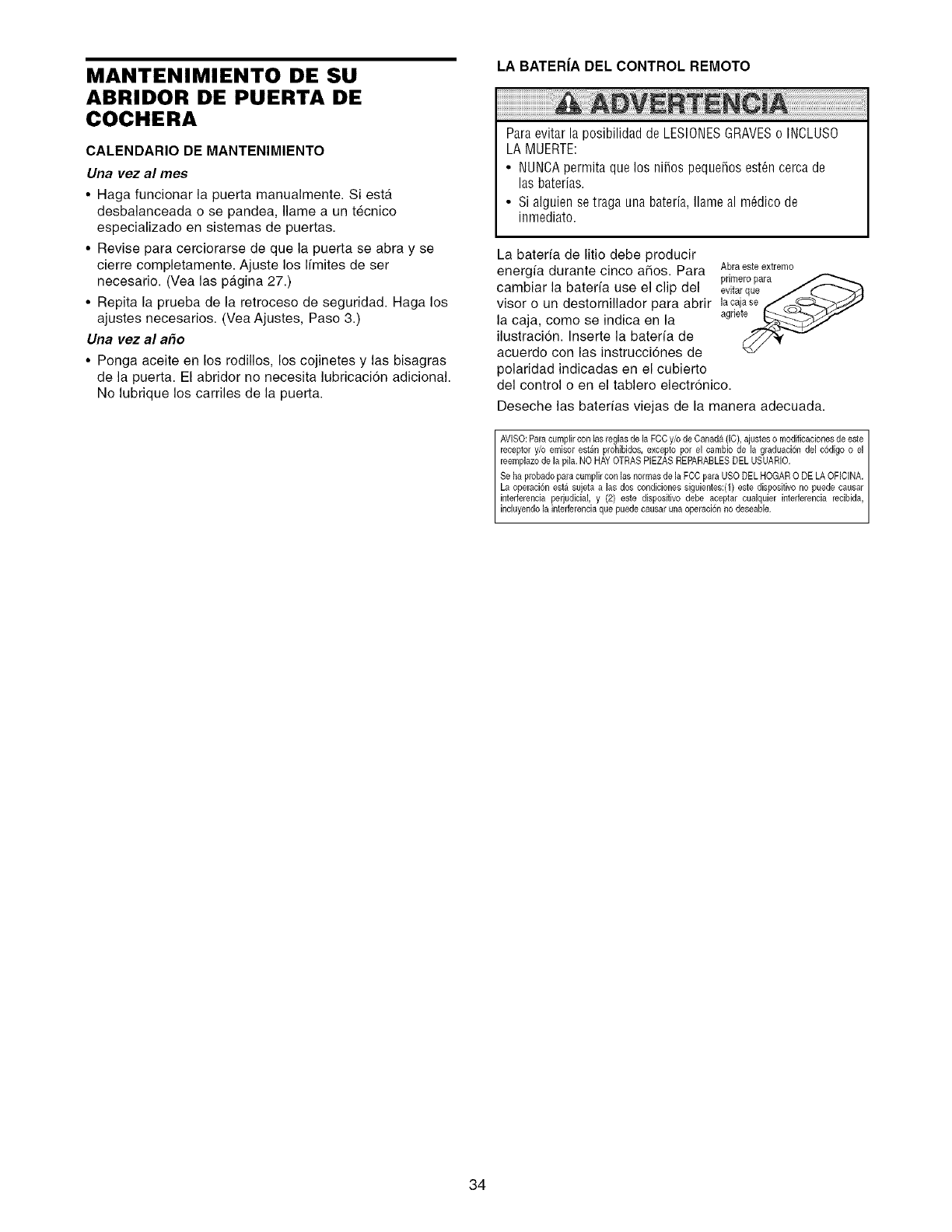
MANTENIMIENTO DE SU
ABRIDOR DE PUERTA DE
COCHERA
CALENDARIO DE MANTENIMIENTO
Una vez al rues
•Haga funcionar la puerta manualmente. Siesta
desbalanceada o se pandea, Name a un tecnico
especializado en sistemas de puertas.
•Revise para cerciorarse de que la puerta se abra y se
cierre completamente. Ajuste los Ifmites de ser
necesario. (Vea las pa.gina 27.)
• Repita la prueba de la retroceso de seguridad. Haga los
ajustes necesarios. (Yea Ajustes, Paso 3.)
Una vez al a_o
• Ponga aceite en los rodillos, los cojinetes y las bisagras
de la puerta. El abridor no necesita lubricaci6n adicional.
No lubrique los carriles de la puerta.
LA BATER|A DEL CONTROL REMOTO
Paraevitar la posibilidad de LESIONESGRAVESo INCLUSO
LA MUERTE:
• NUNCApermita que los nifios pequefios est6n cerca de
las baterias.
• Si alguien se traga una bateria, Nameal m6dico de
inmediato.
La baterfa de litio debe producir
energfa durante cinco afios. Para Abraeste extremo
primeropara
cambiar la baterfa use el clip del evitarque J (_
visor o un destornillador para abrir lacajase /_.,..."--_,,,_t i
la caja, como se indica en la agrle__i_--
ilustracion. Inserte la baterfa de
acuerdo con las instrucci6nes de
polaridad indicadas en el cubierto
del control o en el tablero electronico.
Deseche las baterfas viejas de la manera adecuada.
AVISO: Para cumplir con las reglas de la FCCy/o de Canada (IC), ajustes o modificaciones de este
receptor y/o emisor estan prohibidos, excepto pot el cambio de la graduaci6n del c6di9o o el
reemplazo de la pila. NO HAY OTRAS PIEZAS REPARABLES DEL USUARIO.
Se ha probado para cumplir con las normas de la FCC para USO DEL HOGAR 0 DE LA OFICINA.
La operaci6n esta sujeta alas dos condiciones siguientes:(1) este dispositivo no puede causar
interferencia perjudicial, y (2) este dispositivo debe aceptar cualquier interferencia recibida,
nc uyendo a nter erenc a que puede causar una operac 6n no deseab e.
34
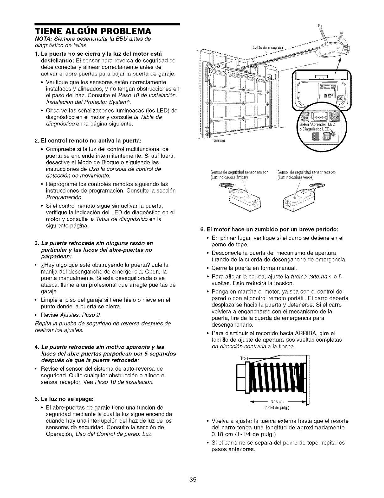
TIENE ALGtJN PROBLEMA
NOTA: Siempre desenchufar la BBU antes de
diagndstico de fallas.
1. La puerta no se cierra y la luz del motor esta
destellando: El sensor para reversa de seguridad se
debe conectar y alinear correctamente antes de
activar el abre-puertas para bajar la puerta de garaje.
•Verifique que los sensores esten correctamente
instalados y alineados, y no tengan obstrucciones en
el paso del haz. Consulte el Paso 10 de Instalacidn.
Instalacidn del Protector Systen'P.
• Observe las seSalizacones luminoasas (los LED) de
diagn6stico en el motor y consulte la Tabla de
diagndstico en la pa.gina siguiente.
2. El control remoto no activa la puerta:
• Compruebe si la luz del control multifuncional de
puerta se enciende intermitentemente. Si asi fuera,
desactive el Modo de BIoque o siguiendo las
instrucciones de Use la consola de control de
deteccidn de movimiento.
• Reprograme los controles remotos siguiendo las
instrucciones de programaci6n. Consulte la seccion
Programacidn.
• Si el control remoto sigue sin activar la puerta,
verifique la indicaci6n del LED de diagnostico en el
motor y consulte la Tabla de diagndstico en la
siguiente pagina.
3. La puerta retrocede sin ninguna razon en
particular y las luces del abre-puertas no
parpadean:
• _,Hay algo que este obstruyendo la puerta? Jale la
manija del desenganche de emergencia. Opere la
puerta manualmente. Siesta desequilibrada o se
atasca, Ilame a un profesional que arregle puertas de
garaje.
• Limpie el piso del garaje si tiene hielo o nieve en el
punto donde la puerta se cierra.
• Revise Ajustes, Paso 2.
Repita la prueba de seguridad de reversa despues de
realizar los ajustes.
4. La puerta retrocede sin motivo aparente y las
luces del abre-puertas parpadean por 5 segundos
despues de que la puerta retroceda:
• Revise el sensor del sistema de auto-reversa de
seguridad. Quite cualquier obstruccion o alinee el
sensor receptor. Vea Paso 10 de instalacidn.
5. La luz no se apaga:
• El abre-puertas de garaje tiene una funci6n de
seguridad mediante la cual la luz sigue encendida
cuando hay una interrupcion del haz de luz de los
sensores de seguridad. Consulte la seccion de
Operaci6n, Use del Control de pared, Luz.
"Sensor
Cable decam
. _ __]
)
Bot6n'Aprender" LED
o Diagn6sticoLED\
Sensor de seguirdad sensoremisor Sensorde seguirdadsensor recepto
(Luz indicadora{_mbar) (Luz indicadoraverde}
6. El motor hace un zumbido por un breve periodo:
• En primer lugar, verifique si el carro se detiene en el
perno de tope.
• Desconecte la puerta del mecanismo de apertura,
tirando de la cuerda de desenganche de emergencia.
• Cierre la puerta en forma manual.
• Para aflojar la correa, ajuste la tuerca extema 4o5
vueltas. Esto reducira la tensi6n.
• Ponga en marcha el motor, ya sea con el control de
pared o con el control remoto portatil. El carro deberia
desplazarse hacia la puerta y detenerse. Si el carro
volviera a engancharse con el mecanismo de la
puerta, tire de la cuerda de emergencia para
desengancharlo.
• Para disminuir el recorrido hacia ARRIBA, gire el
tornillo de ajuste de apertura dos vueltas completas
en direccidn contraria a la flecha.
3,18 cm
(1-1/4 de pulg.}
• Vuelva a ajustar la tuerca extema hasta que el resorte
del carro tenga una Iongitud de aproximadamente
3.18 cm (1-1/4 de pulg.)
• Si el carro no se separa del perno de tope, repita los
pasos anteriores.
35
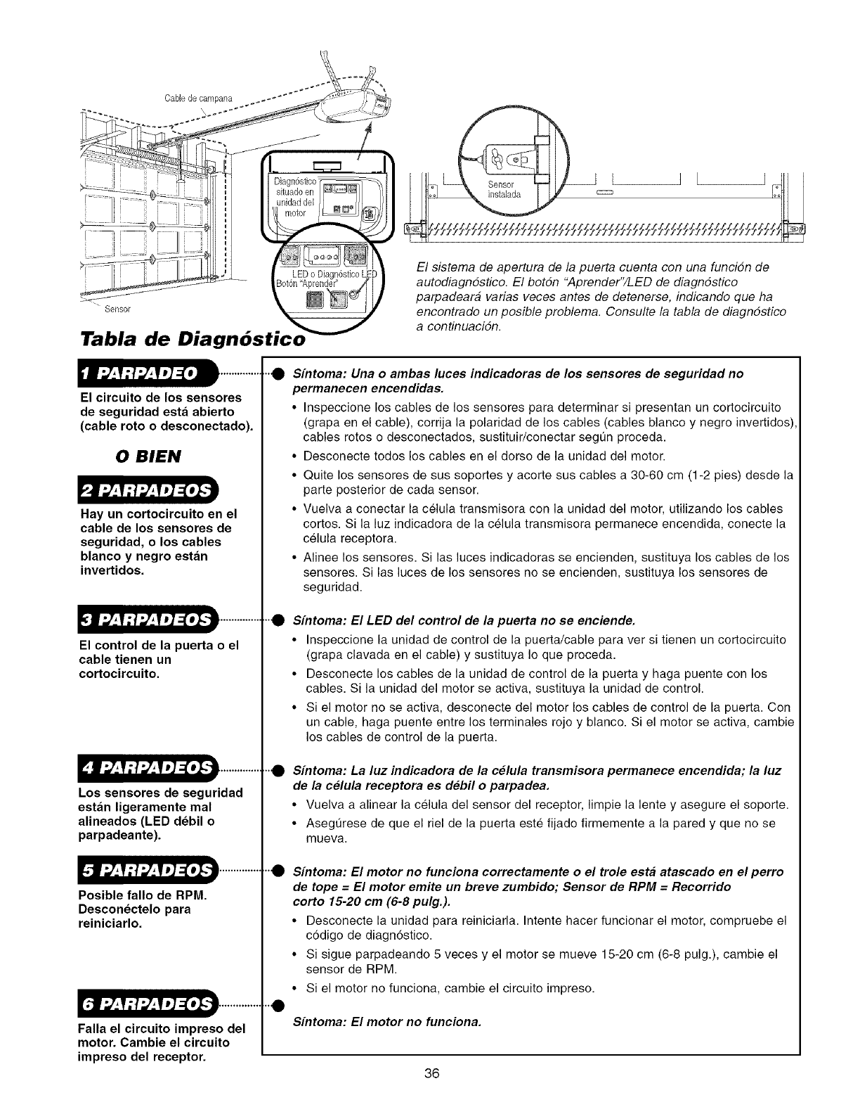
Cable de campana
Tabla de
El circuito de los sensores
de seguridad esta abierto
(cable roto o desconectado).
0 BIEN
Hay un cortocircuito en el
cable de los sensores de
seguridad, o los cables
blanco y negro estan
invertidos.
El control de la puerta o el
cable tienen un
cortocircuito.
Los sensores de seguridad
estan ligeramente mal
alineados (LED debil o
parpadeante).
Posible fallo de RPM.
Desconectelo para
reiniciarlo.
ir._E:.r__V:!:.r__VJ]:( o_.-i .............
Falla el circuito impreso del
motor. Cambie el circuito
impreso del receptor.
'0
0
'0
0
0
El sistema de apertura de la puerta cuenta con una funcidn de
autodiagndstico. El botdn "Aprender"/LED de diagndstico
parpadeara varias veces antes de detenerse, indicando que ha
encontrado un posible problema. Consulte la tabla de diagndstico
a centinuacidn.
Sfntoma: Una o ambas luces indicadoras de los sensores de seguridad no
permanecen encendidas.
• Inspeccione los cables de los sensores para determinar si presentan un cortocircuito
(grapa en el cable), corrija la polaridad de los cables (cables blanco y negro invertidos),
cables rotos o desconectados, sustituir/conectar segt]n proceda.
• Desconecte todos los cables en el dorso de la unidad del motor.
• Quite los sensores de sus soportes y acorte sus cables a 30-60 cm (1-2 pies) desde la
parte posterior de cada sensor.
• Vuelva a conectar la celula transmisora con la unidad del motor, utilizando los cables
cortos. Si la luz indicadora de la celula transmisora permanece encendida, conecte la
celula receptora.
• Alinee los sensores. Si las luces indicadoras se encienden, sustituya los cables de los
sensores. Si las luces de los sensores no se encienden, sustituya los sensores de
seguridad.
Sfntoma: El LED del control de la puerta no se enciende.
• Inspeccione la unidad de control de la puerta/cable para ver si tienen un cortocircuito
(grapa clavada en el cable) y sustituya Io que proceda.
• Desconecte los cables de la unidad de control de la puerta y haga puente con los
cables. Si la unidad del motor se activa, sustituya la unidad de control.
• Si el motor no se activa, desconecte del motor los cables de control de la puerta. Con
un cable, haga puente entre los terminales rojo y blanco. Si el motor se activa, cambie
los cables de control de la puerta.
Sfntoma: La luz indicadora de la celula transmisora permanece encendida; la luz
de la celula receptora es debil o parpadea.
• Vuelva a alinear la celula del sensor del receptor, limpie la lente y asegure el soporte.
• Asegt]rese de que el riel de la puerta este fijado firmemente a la pared y que no se
mueva.
Sfntoma: El motor no funciona correctamente o el trole esta atascado en el perro
de tope = El motor emite un breve zumbido; Sensor de RPM =Recorrido
corto 15-20 cm (6-8 pulg.).
• Desconecte la unidad para reiniciarla. Intente hacer funcionar el motor, compruebe el
c6digo de diagn6stico.
• Si sigue parpadeando 5 veces y el motor se mueve 15-20 cm (6-8 pulg.), cambie el
sensor de RPM.
• Si el motor no funciona, cambie el circuito impreso.
Sfntoma: El motor no funciona.
36
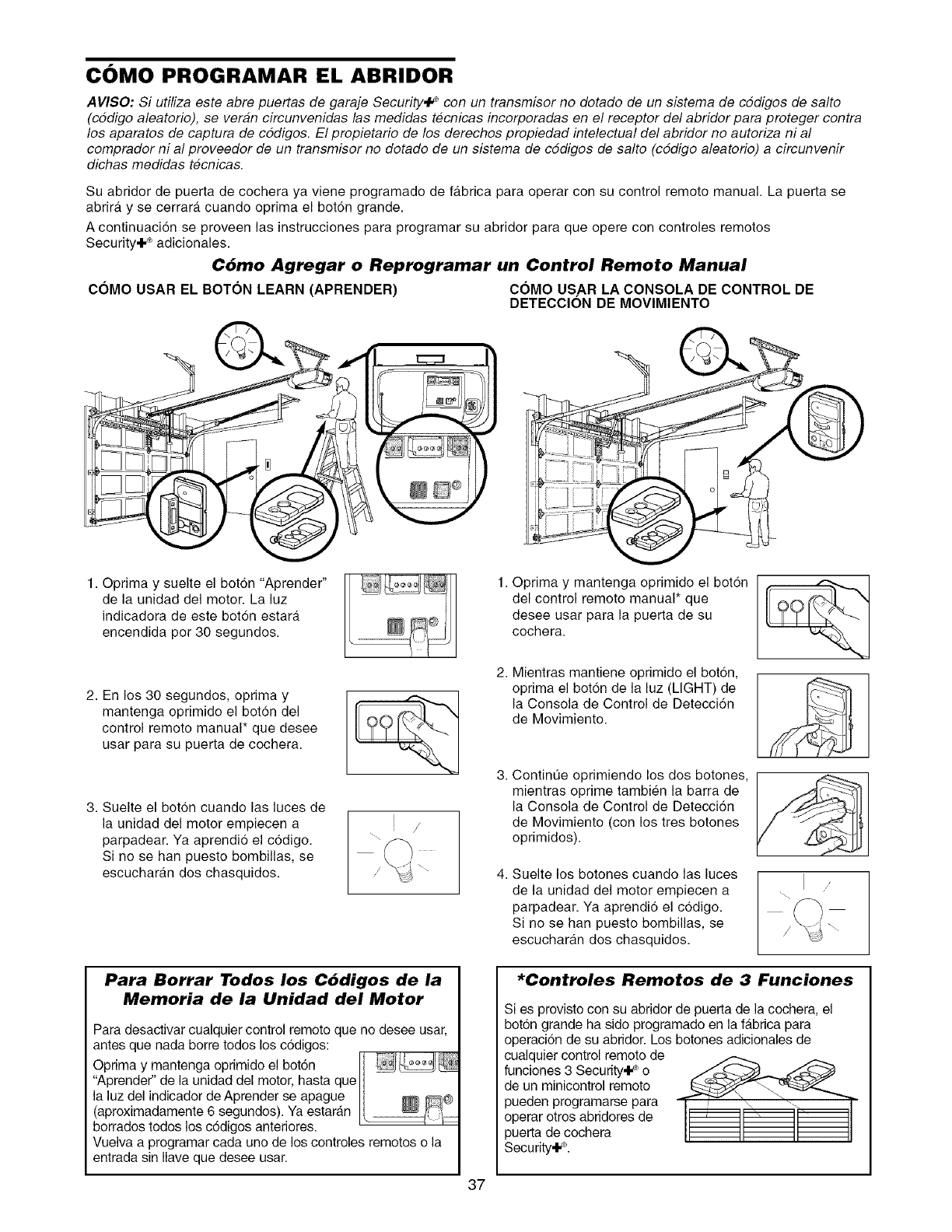
COMO PROGRAMAR EL ABRIDOR
AVISO: Si utiliza este abre puertas de garaje Security,I _con un transmisor no dotado de un sistema de cddigos de salto
(cddige aleatorio), se veran circunvenidas las medidas tecnicas incerperadas en el receptor del abrider para proteger centra
los aparatos de captura de cddigos. El propietario de los derechos propiedad intelectual del abridor no autoriza ni al
cemprader ni al preveeder de un transmiser no detade de un sistema de cddiges de salto (cddige aleatorio) a circunvenir
dichas medidas tecnicas.
Su abridor de puerta de cochera ya viene programado de fa.brica para operar con su control remote manual• La puerta se
abrira y se cerrara cuando oprima el botdn grande.
A continuacion se proveen las instrucciones para programar su abridor para que opere con controles remotos
Security÷ ®adicionales.
C6mo Agregar o Reprogramar un Control Remoto Manual
COMO USAR EL BOTON LEARN (APRENDER) COMO US.AR LA CONSOLA DE CONTROL DE
DETECCION DE MOVIMIENTO
1. Oprima y suelte el bot6n "Aprender"
de la unidad del motor. La luz
indicadora de este boton estara
encendida por 30 segundos.
2. En los 30 segundos, oprima y
mantenga oprimido el boton del
control remoto manual* que desee
usar para su puerta de cochera.
3. Suelte el boton cuando las luces de
la unidad del motor empiecen a
parpadear. Ya aprendio el codigo.
Si no se han puesto bombillas, se
escucharan dos chasquidos.
Para Borrar Todos los C6digos de la
Memoria de la Unidad del Motor
Para desactivar cualquier control remoto que no desee usar,
antes que nada borre todos los c6digos:
.... 7_
Oprlma y mantenga oprlmldo el boton _ _J
<'Aprender"de la unidad del motor, hasta que
la luz del indicador de Aprender se apague ]1 _ _@
(aproximadamente 6 segundos). Ya estaran [. _ 11__
borrados todos los c6digos anteriores. '
Vuelva a programar cada uno de los controles remotos o la
entrada sin Ilave que desee usar.
37
• Oprima y mantenga oprimido el boton
del control remoto manual* que
desee usar para la puerta de su
cochera.
2. Mientras mantiene oprimido el boton,
oprima el bot6n de la luz (LIGHT) de
la Consola de Control de Detecci6n
de Movimiento.
3. Contint]e oprimiendo los dos botones,
mientras oprime tambien la barra de
la Consola de Control de Detecci6n
de Movimiento (con los tres botones
oprimidos).
4. Suelte los botones cuando las luces
de la unidad del motor empiecen a
parpadear. Ya aprendi6 el codigo.
Si no se ban puesto bombillas, se
escucharan dos chasquidos.
*Controles Remotos de 3 Funciones
Si es provisto con su abridor de puerta de la cochera, el
boton grande ha sido programado en la fabrica para
operaci6n de su abridor. Los botones adicionales de
cualquier control remoto de
funciones 3 Security÷ ®o
de un minicontrol remote
pueden programarse para
operar otros abridores de
puerta de cochera
Security÷_L
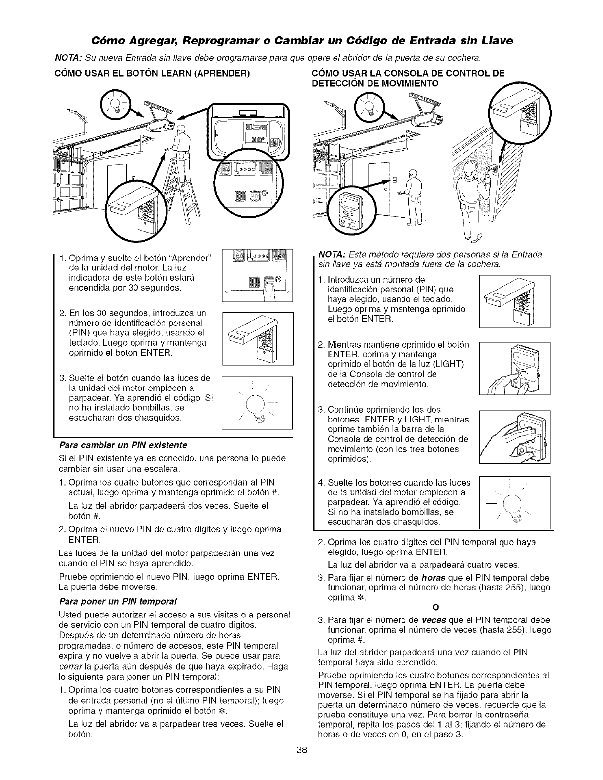
C6mo Agregar, Reprogramar o Cambiar un C6digo de Entrada sin Llave
NOTA: Su nueva Entrada sin Ilave debe programarse para que opere el abridor de la puerta de su cochera.
COMO USAR EL BOTON LEARN (APRENDER) COMO USAR LA CONSOLA DE CONTROL DE
DETECClON DE MOVlMIENTO
1. Oprima y suelte el botdn "Aprender"
de la unidad del motor. La luz
indicadora de este bot6n estara.
encendida por 30 segundos.
2. En los 30 segundos, introduzca un
nt]mero de identificacion personal
(PIN) que haya elegido, usando el
teclado. Luego oprima y mantenga
oprimido el boton ENTER.
3. Suelte el boton cuando las luces de
la unidad del motor empiecen a
parpadear. Ya aprendi6 el codigo. Si
no ha instalado bombillas, se
escuchara.n dos chasquidos.
Para cambiar un PIN existente
Si el PIN existente ya es conocido, una persona Io puede
cambiar sin usar una escalera.
1. Oprima los cuatro botones que correspondan al PIN
actual, luego oprima y mantenga oprimido el boton #.
La luz del abridor parpadear_, dos veces. Suelte el
botdn #.
2. Optima el nuevo PIN de cuatro dfgitos y luego oprima
ENTER.
Las luces de la unidad del motor parpadeara.n una vez
cuando el PIN se haya aprendido.
Pruebe oprimiendo el nuevo PIN, luego oprima ENTER.
La puerta debe moverse.
Para poner un PIN temporal
Usted puecle autorizar el acceso a sus visitas o a personal
de servicio con un PIN temporal de cuatro dfgitos.
Despues de un determinado nt]mero de horas
programadas, o nQmero de accesos, este PIN temporal
expira y no vuelve a abrir la puerta. Se puede usar para
cerrar la puerta at]n despues de que haya expirado. Haga
Io siguiente para poner un PIN temporal:
1. Optima los cuatro botones correspondientes a su PIN
de entrada personal (no el t]ltimo PIN temporal); luego
oprima y mantenga oprimido el bot6n ¢.
La luz del abridor va a parpadear tres veces. Suelte el
botdn.
38
NOTA: Este metodo requiere dos personas si la Entrada
sin Ilave ya esta montada fuera de la cochera.
1. Introduzca un nQmero de
identificacion personal (PIN) que
haya elegido, usando el teclado.
Luego oprima y mantenga oprimido
el botdn ENTER.
Mientras mantiene oprimido el boton
ENTER, oprima y mantenga
oprimido el botdn de la luz (LIGHT)
de la Consola de control de
deteccion de movimiento.
Contint]e oprimiendo los dos
botones, ENTER y LIGHT, mientras
oprime tambien la barra de la
Consola de control de deteccion de
movimiento (con los tres botones
oprimidos).
4. Suelte los botones cuando las luces
de la unidad del motor empiecen a
parpadear. Ya aprendio el cddigo.
Si no ha instalado bombillas, se
escuchara.n dos chasquidos.
2. Optima los cuatro dfgitos del PIN temporal que haya
elegido, luego oprima ENTER.
La luz del abridor va a parpadeara, cuatro veces.
3. Para fijar el nQmero de horae que el PIN temporal debe
funcionar, oprima el nt]mero de horas (hasta 255), luego
oprima ¢. O
3. Para fijar el nQmero de vecee que el PIN temporal debe
funcionar, oprima el nt]mero de veces (hasta 255), luego
oprima #.
La luz del abridor parpadeara una vez cuando el PIN
temporal haya sido aprendido.
Pruebe oprimiendo los cuatro botones correspondientes al
PIN temporal, luego optima ENTER. La puerta debe
moverse. Si el PIN temporal se ha fijado para abrir la
puerta un determinado nt]mero de veces, recuerde que la
prueba constituye una vez. Para borrar la contraseSa
temporal, repita los pasos del 1 al 3; fijando el nQmero de
horas o de veces en 0, en el paso 3.
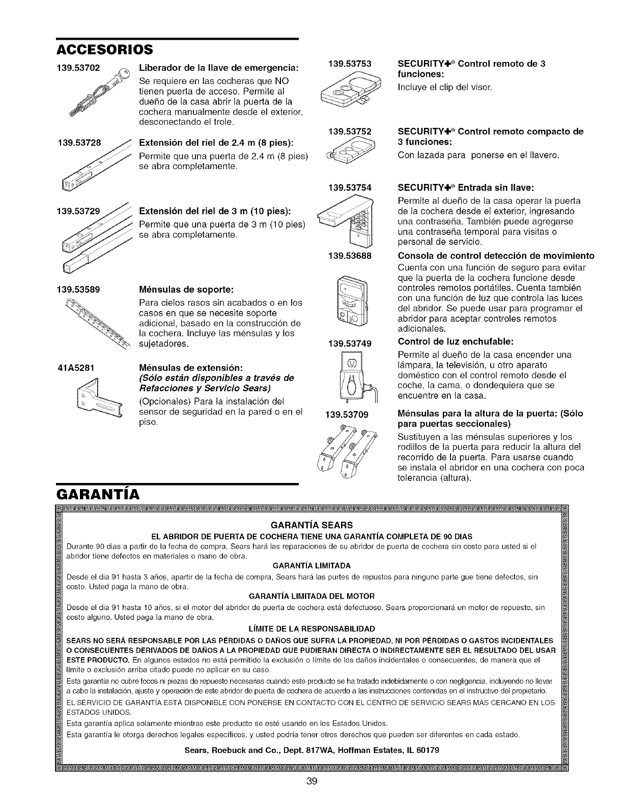
ACCESORIOS
Liberador de la Ilave de emergencia:
Se requiere en las cocheras que NO
tienen puerta de acceso. Permite al
duefio de la casa abrir la puerta de la
cochera manualmente desde el exterior,
desconectando el trole.
139.53728 Extension del riel de 2.4 m (8 pies):
Permite que una puerta de 2.4 m (8 pies)
se abra completamente.
139.53753
139.53752
SECURITY+ ®Control remoto de 3
funciones:
Incluye el clip del visor.
SECURITY+ ®Control remoto compacto de
3funciones:
Con lazada para ponerse en el Ilavero.
139.53729
139.53589
41A5281
Extension del riel de 3 m (10 pies):
Permite que una puerta de 3 m (10 pies)
se abra completamente.
M_nsulas de soporte:
Para cielos rasos sin acabados o en los
casos en que se necesite soporte
adicional, basado en la construccion de
la cochera. Incluye las mensulas y los
sujetadores.
Mensulas de extension:
(Solo estan disponibles a traves de
Refacciones y Servicio Sears)
(Opcionales) Para la instalaci6n del
sensor de seguridad en la pared o en el
piso.
139.53754
139.53688
139.53749
SECURITY+ ®Entrada sin Ilave:
Permite al duefio de la casa operar la puerta
de la cochera desde el exterior, ingresando
una contrasefia. Tambien puede agregarse
una contrasefia temporal para visitas o
personal de servicio.
Consola de control deteccion de movimiento
Cuenta con una funci6n de seguro para evitar
que la puerta de la cochera funcione desde
controles remotos portatiles. Cuenta tambien
con una funci6n de luz que controla las luces
del abridor. Se puede usar para programar el
abridor para aceptar controles remotos
adicionales.
Control de luz enchufable:
Permite al duefio de la casa encender una
lampara, la television, u otro aparato
domestico con el control remoto desde el
coche, la cama, o dondequiera que se
encuentre en la casa.
139.53709 Mensulas para la altura de la puerta: (Solo
para puertas seccionales)
Sustituyen a las mensulas superiores y los
rodillos de la puerta para reducir la altura del
recorrido de la puerta. Para usarse cuando
se instala el abridor en una cochera con poca
tolerancia (altura).
GARANTiA
GARANT|A SEARS
EL ABRIDOR DE PUERTA DE COCHERA TIENE UNA GARANTJA COMPLETA DE 90 DIAS
Durante 90 dias a partir de la fecha de cornpra, Sears har_t las reparaciones de su abridor de puerta de cochera sin costo para usted si el
abridor tiene defectos en materiales o mano de obra,
GARANTiA LIMITADA
Desde el dia 91 hasta 3 afios, apartir de la fecha de compra, Sears hara las purtes de repustos para ninguno parte gue tiene defectos, sin
costo. Usted paga la mano de obra.
GARANTIA LIMITADA DEL MOTOR
Desde el dia 91 hasta 10 aflos, si el motor del abridor de puerta de cochera esta defectuoso, Sears proporcionara un motor de repuesto, sin
costo alguno. Usted paga la mano de obra.
LIMITE DE LA RESPONSABILIDAD
SEARS NO SER. &, RESPONSABLE POR LAS PI_RDIDAS O DAI_IOS QUE SUFRA LA PROPIEDAD, NI POR P#RDIDAS O GASTOS INClDENTALES
O CONSECUENTES DERIVADOS DE DAI_IOS A LA PROPIEDAD QUE PUDIERAN DIRECTA O INDIRECTAMENTE SER EL RESULTADO DEL USAR
ESTE PRODUCTO. En algunos estados no esta permitido la exclusi6n o limite de los dafios incidentales o consecuentes, de manera que el
limite o exclusi6n arriba citado puede no aplicar en su caso.
Esta garantia no cubre focos ni piezas de repuesto necesarias cuando este producto se ha tratado indebidamente o con negligencia, incluyendo no Ilevar
a cabo la instalacion, ajuste y operaci6n de este abridor de puerta de cochera de acuerda alas instrucciones contenidas en el instructivo del propietario.
EL SERVICIO DE GARANTiA ESTA DISPONIBLE CON PONERSE EN CONTACTO CON EL CENTRO DE SERVICIO SEARS MAS CERCANO EN LOS
ESTADOS UNIDOS.
Esta garantia aplica solamente mientras este producto se este usando en los Estados Unidos.
Esta garantia le otorga derechos legales especificos, y usted podria tener otros derechos que pueden ser diferentes en cada estado.
Sears, Roebuck and Co., Dept. 817WA, Hoffman Estates, IL 60179
39
Your Home
For repair-in your home-of all major brand appliances,
lawn and garden equipment, or heating and cooling systems,
no matter who made it, no matter who sold it!
For the replacement parts, accessories and
owner's manuals that you need to do-it-yourself.
For Sears professional installation of home appliances
and items like garage door openers and water heaters.
1-800-4-MY-HOME ®(1-800-469-4663)
Call anytime, day or night (U.S.A. and Canada)
www.sears.com www.sears.ca
Our Home
For repair of carry-in items like vacuums, lawn equipment,
and electronics, call or go on-line for the location of your nearest
Sears Parts & Repair Center.
1-800-488-1222
Call anytime, day or night (U.S.A. only)
www.sears.oom
114A3128B
® Registered Trademark /TMTrademark /sMService Mark of Sears, Roebuck and Co.
® Marca Registrada /TM Mama de Fabrica /sMMarca de Servicio de Sears, Roebuck and Co.
MoMarque de commerce /MDMarque deposee de Sears, Roebuck and Co. © 2005 Sears, Roebuck and Co.
Printed in Mexico
