Craftsman 13953930DM User Manual GARAGE DOOR OPENER Manuals And Guides L0803740
CRAFTSMAN Garage Door Opener Manual L0803740 CRAFTSMAN Garage Door Opener Owner's Manual, CRAFTSMAN Garage Door Opener installation guides
User Manual: Craftsman 13953930DM 13953930DM CRAFTSMAN GARAGE DOOR OPENER - Manuals and Guides View the owners manual for your CRAFTSMAN GARAGE DOOR OPENER #13953930DM. Home:Garage Door & Opener Parts:Craftsman Parts:Craftsman GARAGE DOOR OPENER Manual
Open the PDF directly: View PDF ![]() .
.
Page Count: 76
Owner's Manual/Manual Del Propietario
1/2 HP
315MMz GARAGE DOOR OPENER
ABRIDOR DE PUERTA DE COCHERA
For Residential Use Only
Model, 139.53930DM
315MN=
m
m
Z_
0
Read and follow all safety rules
and operating instructions before
first use of this product.
Fasten the manual near the garage
door after installation.
Periodic checks of the opener are
required to ensure safe operation.
Leer y seguir todas las reglas de
seguridad y las instrucciones de
operacion antes de usar este
producto por primera vez.
Guardar este manual cerca de la
puerta de la cochera.
Se deben realizar revisiones
periodicas del abridor de puertas
para asegurar su operacion
segura.
Sears, Roebuck and Co., Hoffman Estates, IL 60179 U.S.A
www.sears.com/craftsman
TABLE OF CONTENTS
Introduction 2-7
Safety symbol and signal word review .............. 2
Preparing your garage door ...................... 3
Tools needed ................................. 3
Planning .................................. 4-5
Carton inventory ............................... 6
Hardware inventory ............................ 7
Assembly 8.11
Assemble the rail and install the trolley ............. 8
Fasten the rail to the motor unit ................... 9
Install the idler pulley ........................... 9
Install the chain/cable .......................... 10
Tighten the chain ............................. 11
Installation 11.26
Installation safety instructions ................... 11
Determine the header bracket location ............ 12
Install the header bracket ....................... 13
Attach the rail to the header bracket .............. 14
Position the opener ........................... 15
Hang the opener .............................. 16
Install the door control ......................... 17
Install the light ............................... 18
Attach the emergency release rope and handle ..... 18
Electrical requirements ......................... 19
Install The Protector System ®................. 20-22
Fasten the door bracket ..................... 23-24
Connect the door arm to the trolley ............ 25-26
Adjustment 27-29
Adjust the travel limits ......................... 27
Adjust the force .............................. 28
Test the safety reversal system .................. 29
Test The Protector System ®..................... 29
Operation 30-34
Operation safety instructions .................... 30
Using your garage door opener .................. 30
Using the wall-mounted Door Control ............. 31
To open the door manually ...................... 31
Care of your garage door opener ................. 32
Having a problem? ............................ 33
Diagnostic chart .............................. 34
Programming 35-36
To add or reprogram a hand-held remote control .... 35
To erase all codes ............................ 35
3-Function Remotes ........................... 35
To add, reprogram or change
a Keyless Entry PIN ........................... 36
Repair Parts 37.38
Rail assembly parts ........................... 37
Installation parts .............................. 37
Motor unit assembly parts ...................... 38
Accessories 39
Warranty 39
Repair Parts and Service Backcover
INTRODUCTION
Safety Symbol
and Signal Word Review
This garage door opener has been designed and tested to offer safe service provided it is installed, operated,
maintained and tested in strict accordance with the instructions and warnings contained in this manual.
Mechanical
Electrical
When you see these Safety Symbols and Signal Words on
the following pages, they will alert you to the possibility of
serious injury or death if you do not comply with the
warnings that accompany them. The hapard may come
from something mechanical or from electric shock. Read
the warnings carefully.
When you see this Signal Word on the following pages, it
will alert you to the possibility of damage to your garage
door and/or the garage door opener if you do not comply
with the cautionary statements that accompany it. Read
them carefully.
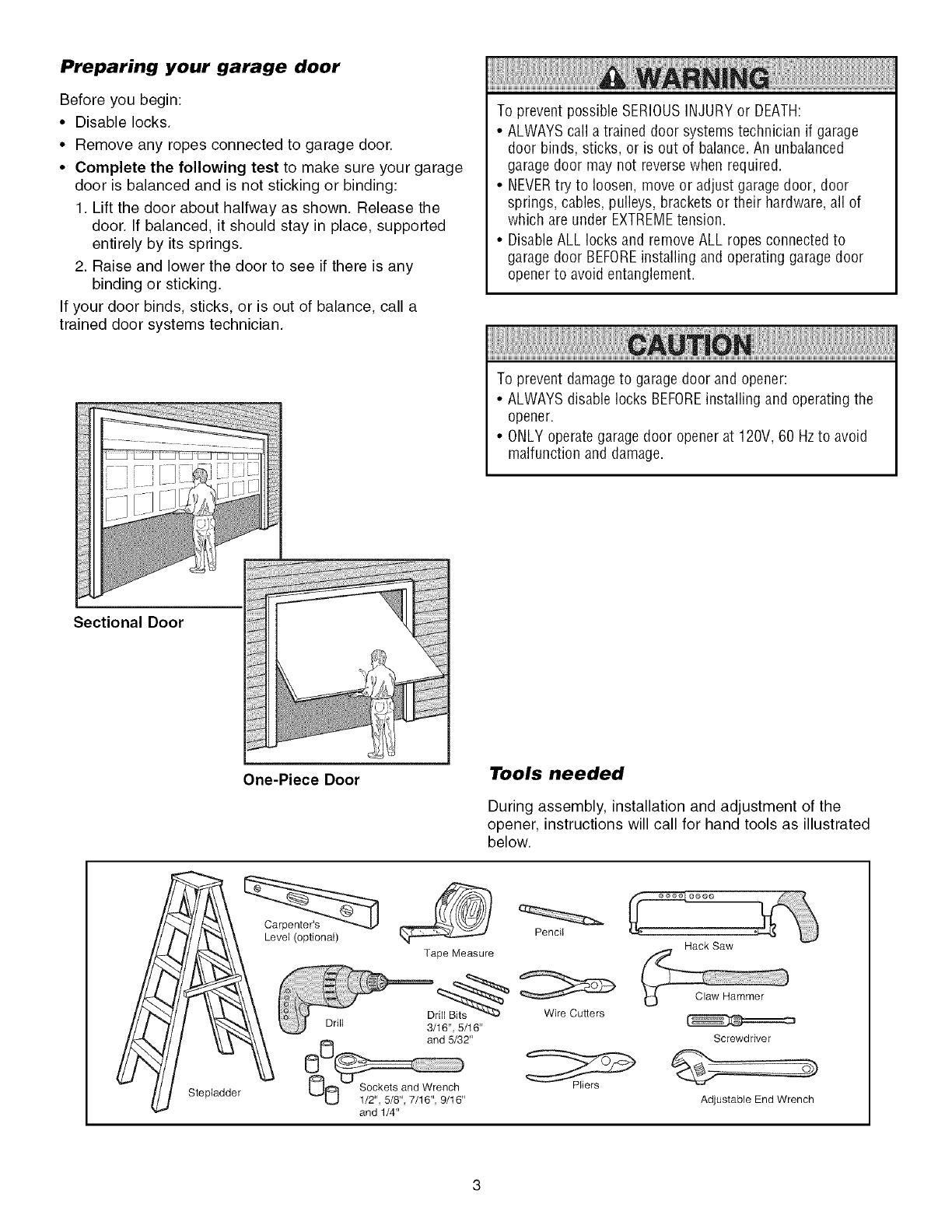
Preparing your garage door
Before you begin:
• Disable locks.
• Remove any ropes connected to garage door.
• Complete the following test to make sure your garage
door is balanced and is not sticking or binding:
1. Lift the door about halfway as shown. Release the
door. If balanced, it should stay in place, supported
entirely by its springs.
2. Raise and lower the door to see if there is any
binding or sticking.
If your door binds, sticks, or is out of balance, call a
trained door systems technician.
Sectional Door
To prevent possible SERIOUSINJURYor DEATH:
•ALWAYScall a trained door systems technician if garage
door binds, sticks, or is out of balance.An unbalanced
garagedoor may not reversewhen required.
• NEVERtry to loosen, move or adjust garagedoor, door
springs, cables, pulleys, brackets or their hardware,all of
which are under EXTREMEtension.
• DisableALL locks and removeALL ropes connectedto
garagedoor BEFOREinstalling and operating garagedoor
openerto avoid entanglement.
To prevent damageto garage door and opener:
•ALWAYSdisable locks BEFOREinstalling and operating the
opener.
•ONLY operategarage door opener at 120V, 60 Hzto avoid
malfunction and damage.
One-Piece Door Tools needed
During assembly, installation and adjustment of the
opener, instructions will call for hand tools as illustrated
below.
Stepladder
Level (optional)
Tape Measure
Drill 3/16", 5/16"
_l_ 0 and 5/32"
1/2" 5/8" 7/16" 9/16"
and 1/4"
Pencil
Wire Cutters
Hack Saw
Screwdriver
AdjustabJe End Wrench
Planning
Identify the type and height of your garage door. Survey
your garage area to see if any of the conditions below
apply to your installation. Additional materials may be
required. You may find it helpful to refer back to this page
and the accompanying illustrations as you proceed with
the installation of your opener.
Depending on your requirements, there are several
installation steps which may call for materials or hardware
not included in the carton.
• Installation Step 1 - Look at the wall or ceiling above
the garage door. The header bracket must be securely
fastened to structural supports.
• Installation Step 5 - Do you have a finished ceiling in
your garage? If so, a support bracket and additional
fastening hardware may be required.
• Installation Step 10- Depending upon garage
construction, extension brackets or wood blocks may be
needed to install sensors.
• Installation Step 10 -Alternate floor mounting of the
safety reversing sensor will require hardware not
provided.
• Do you have an access door in addition to the garage
door? If not, Model 53702 Emergency Key Release is
required. See Accessories page.
• Look at the garage door where it meets the floor. Any
gap between the floor and the bottom of the door must
not exceed 1/4" (6 mm). Otherwise, the safety reversal
system may not work properly. See Adjustment Step 3.
Floor or door should be repaired.
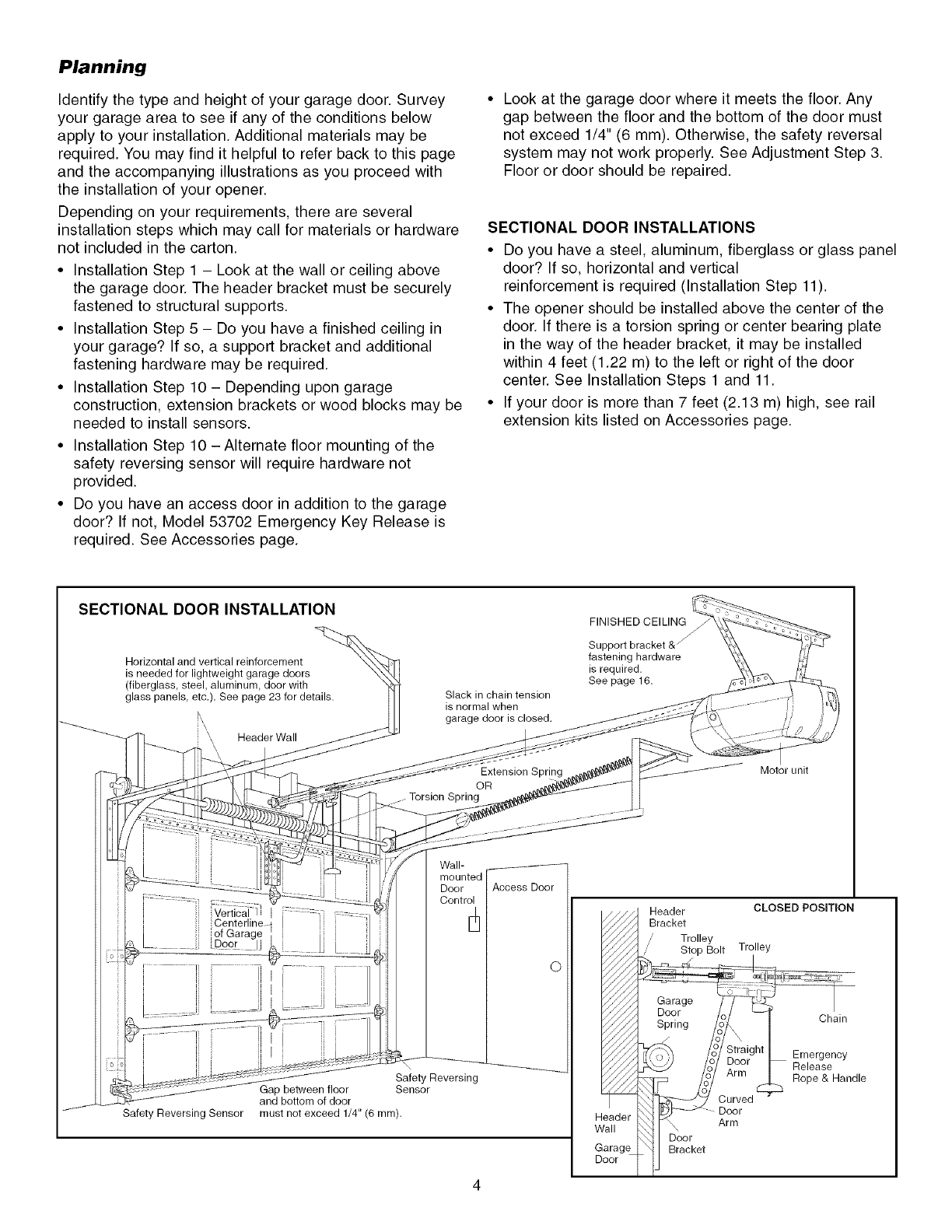
SECTIONAL DOOR INSTALLATIONS
• Do you have a steel, aluminum, fiberglass or glass panel
door? If so, horizontal and vertical
reinforcement is required (Installation Step 11).
• The opener should be installed above the center of the
door. If there is a torsion spring or center bearing plate
in the way of the header bracket, it may be installed
within 4 feet (1.22 m) to the left or right of the door
center. See Installation Steps 1 and 11.
• If your door is more than 7 feet (2.13 m) high, see rail
extension kits listed on Accessories page.
SECTIONAL DOOR INSTALLATION
Horizontal and vertical reinforcement
is needed for lightweight garage doors
(fiberglass, steel, aluminum, door with
glass panels, etc.). See page 23 for details.
k
\ Header Wall
Slack in chain tension
is normal when
garage door is closed.
Extension Spring
OR
Torsion Spring
FINISHED CEILING
fastening hardware
is required.
See page 16.
Motor unit
veriic_-i I ::::
Centerline-d I
of Garage ' J
.......... Door !]L_. ...... IJ
Wall-
Door
Control
Safety Reversing Sensor
Safety Reversing
Gap between floor Sensor
and bottom of door
must not exceed 1/4" (6 ram).
Access Door
©
Header
Wall
Garage
Door
Header CLOSED POSITION
Bracket
/" Trolley
// Stop Bolt Trolley
Garage
Door
Spring Chain
Emergency
Release
Rope & Handle
\ Arm
Door
Bracket
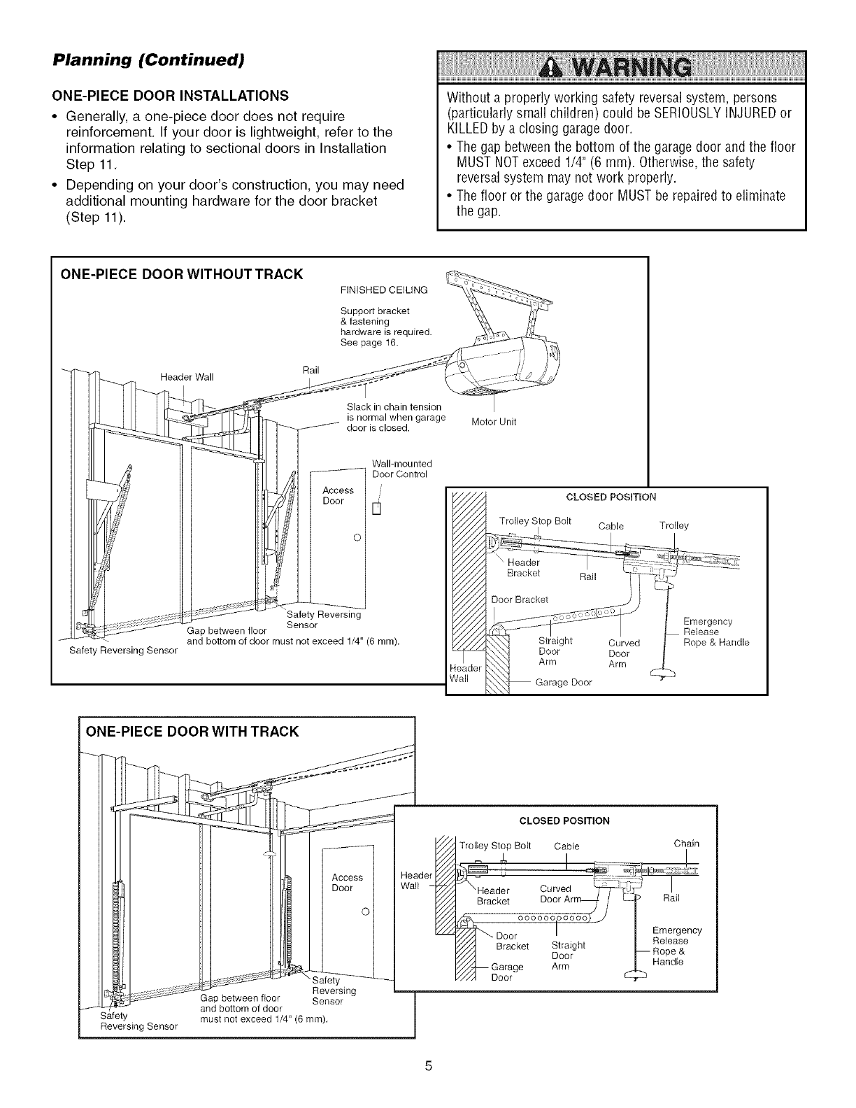
Planning (Continued)
ONE-PIECE DOOR INSTALLATIONS
• Generally, a one-piece door does not require
reinforcement. If your door is lightweight, refer to the
information relating to sectional doors in Installation
Step 11.
• Depending on your door's construction, you may need
additional mounting hardware for the door bracket
(Step 11).
Without a properly working safety reversalsystem, persons
(particularly small children) could be SERIOUSLYINJUREDor
KILLEDby a closing garagedoor.
• Thegap betweenthe bottom of the garage door and the floor
MUST NOTexceed 1/4" (6 mm). Otherwise,the safety
reversal system may not work properly.
• The floor or the garage door MUST be repaired to eliminate
the gap.
ONE-PIECE DOOR WlTHOUTTRACK
Header Wall
FINISHED CEILING
Support bracket
& fastening
hardware is required.
See page 16.
Rail
Slack in chain tension
is normal when garage
door is closed. Motor Unit
Safety Reversing Sensor
[3
Safety Reversing
Sensor
Gap between floor
and bottom of door must not exceed 1/4" (6 ram),
Wall-mounted
Door Control
leader
Call
CLOSED PosmoN
Trolley Stop Bolt Cable Trolley
Emergency
Release
Rope & Handle
ONE-PIECE DOOR WITH TRACK
Reversing
Gap between floor Sensor
J and bottom of door
Safety must not exceed 1/4" (6 ram),
Reversing Sensor
Access I
Door I
CLOSED POSITION
Trolley Stop Bolt Cable
\Header Curved "_.J
Bracket DoorArr_L /L.
_. ..... oooooo) j
"J - Door I
Bracket Straight
Door
,_/,4_ Garage Arm
_A Door
Chain
Rail
Emergency
Release
-- Rope &
Handle
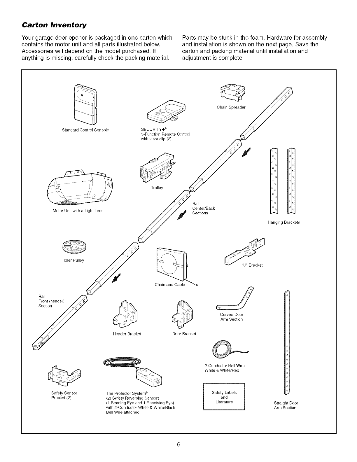
Carton Inventory
Your garage door opener is packaged in one carton which
contains the motor unit and all parts illustrated below.
Accessories will depend on the model purchased. If
anything is missing, carefully check the packing material.
Parts may be stuck in the foam. Hardware for assembly
and installation is shown on the next page. Save the
carton and packing material until installation and
adjustment is complete.
Standard Control Console SECURITY+ ®
3-Function Remote Control
with visor clip (2)
Chain Spreader
Trolley
Motor Unit with a Light Lens
Rail
Center/Back
Sections
Hanging Brackets
Idler Pulley
Rail
Fron! (header) /_ ¢-z2
yHeader Bracket Door Bracket
Curved Door
Arm Section
"U" Bracket
Safety Sensor
Bracket(2)
The Protector System ®
(2) Safety Reversing Sensors
(1 Sending Eye and 1 Receiving Eye)
with 2-Conductor White & White/Black
Bell Wire attached
2-Conductor Bell Wire
White & White/Red
Safety Labels
and
Literature Straight Door
Arm Section
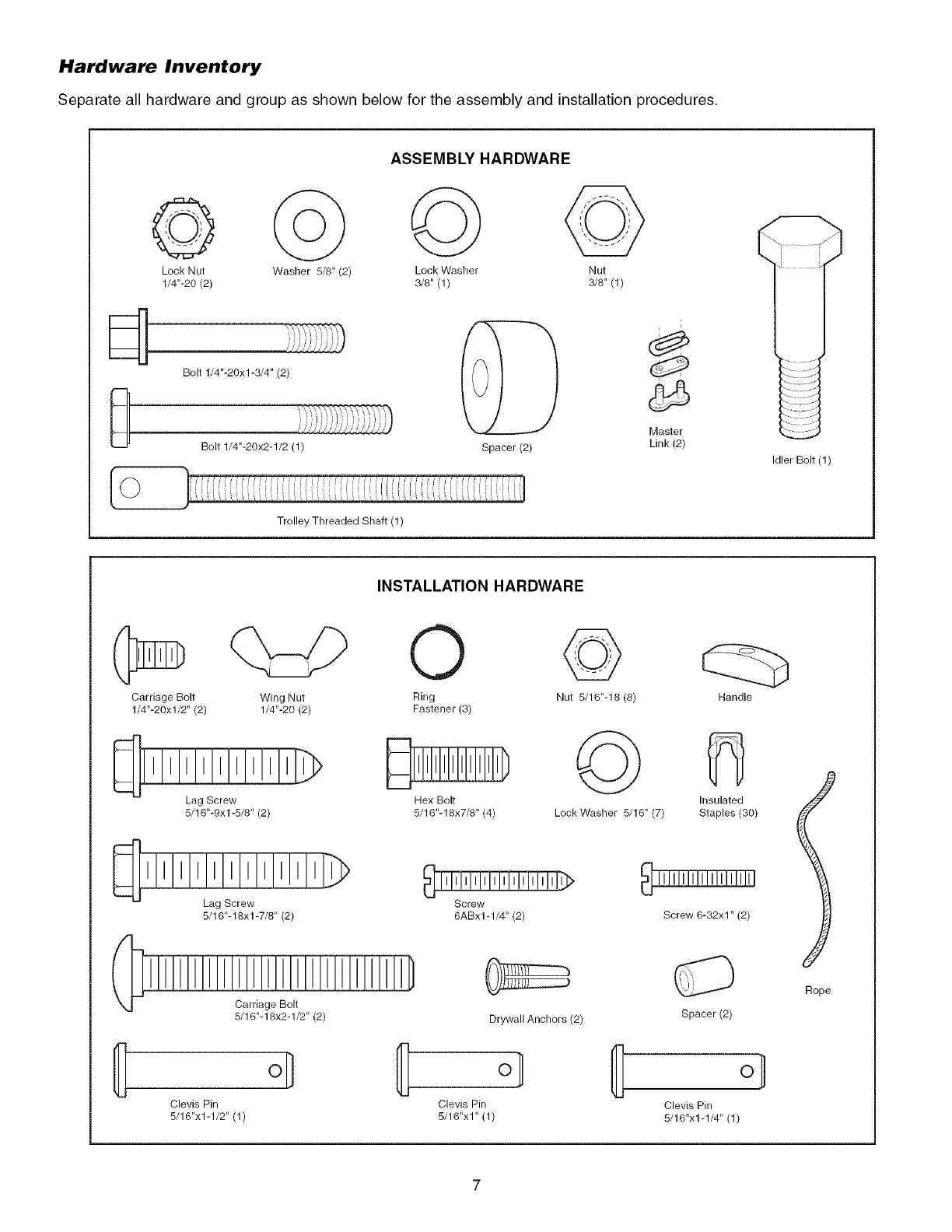
Hardware Inventory
Separate all hardware and group as shown below for the assembly and installation procedures.
ASSEMB_ HARDWARE
Lock Nut Washer 5/8" (2) Lock Washer Nut
1/4"-20 (2) 3/8" (1) 3/8" (1)
d
8Bolt 1/4"-20xl-3/4" (2)
Bolt 1/4"-20x2-1/2 (1)
Trolley Threaded Shaft (1)
Spacer (2)
i
Master
Link (2)
Idler Bolt (1)
INSTALLATION HARDWARE
Carriage Bolt
1/4"-20xl/2" (2)
Wing Nut
1/4"-20 (2)
Lag Screw
5/16"-9xl -5/8" (2)
_TiTITiTiTiT7,_
Lag Screw
5/16"-18xl -7/8" (2)
Carriage Bolt
5/16"-18x2-1/2" (2)
{ oD
Clevis Pin
5/16"x1-1/2" (1)
0
Ring
Fastener (3)
Hex Bolt
5/16"-18x7/8" (4)
©
Nut 5/16"-18 (8)
©
Lock Washer 5/16" (7)
Screw
6ABx1-1/4" (2)
Drywall Anchors (2)
o/
Clevis Pin
5/16"x1" (1)
Handle
Insulated
Staples (30)
Screw 6-32xl" (2)
Spacer (2)
°l
Clevis Pin
5/16"x1-1/4" (1)
Rope
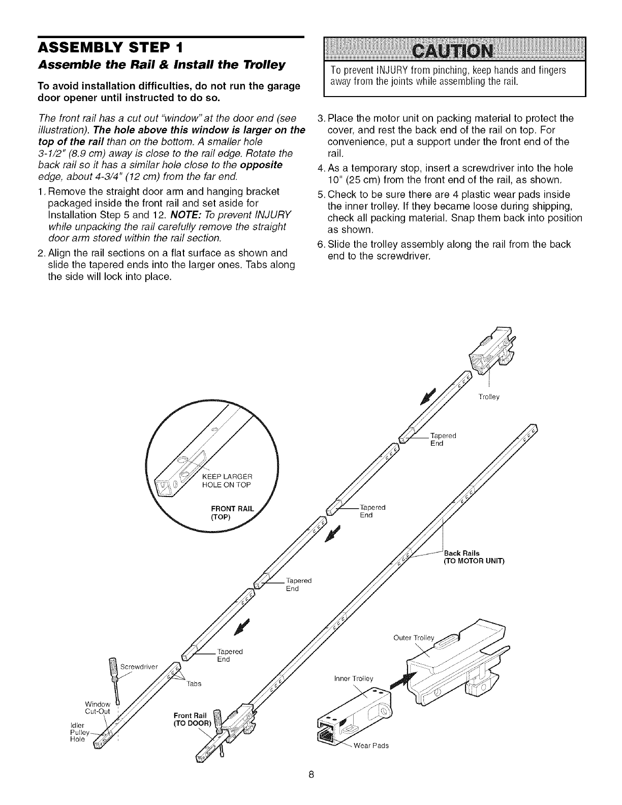
ASSEMBLY STEP 1
Assemble the Rail & Install the Trolley
To avoid installation difficulties, do not run the garage
door opener until instructed to do so.
The front rail has a cut out "window"at the door end (see
illustration). The hole above this window is larger on the
top of the rail than on the bottom. A smaller hole
3-1/2" (8.9 cm) away is close to the rail edge. Rotate the
back raft so it has a similar hole close to the opposite
edge, about 4-3/4" (12 cm) from the far end.
1. Remove the straight door arm and hanging bracket
packaged inside the front rail and set aside for
Installation Step 5 and 12. NOTE: To prevent INJURY
while unpacking the rail carefully remove the straight
door arm stored within the rail section.
2. Align the rail sections on a flat surface as shown and
slide the tapered ends into the larger ones. Tabs along
the side will lock into place.
To prevent iNJURY from pinching, keep hands and fingers
awayfrom the joints while assembling the rail.
3. Place the motor unit on packing material to protect the
cover, and rest the back end of the rail on top. For
convenience, put a support under the front end of the
rail.
4. As a temporary stop, insert a screwdriver into the hole
10" (25 cm) from the front end of the rail, as shown.
5. Check to be sure there are 4 plastic wear pads inside
the inner trolley. If they became loose during shipping,
check all packing material. Snap them back into position
as shown.
6. Slide the trolley assembly along the rail from the back
end to the screwdriver.
Trolley
_ered
End
End
ered
End
_ack Rails
(TO MOTOR UNIT)
/
Window
Cut-Out
Idler
Pulley-
Hote
Screwdriver
Tabs
Front Rail
(TO DOOR)
End
Inner Trolley
Wear Pads
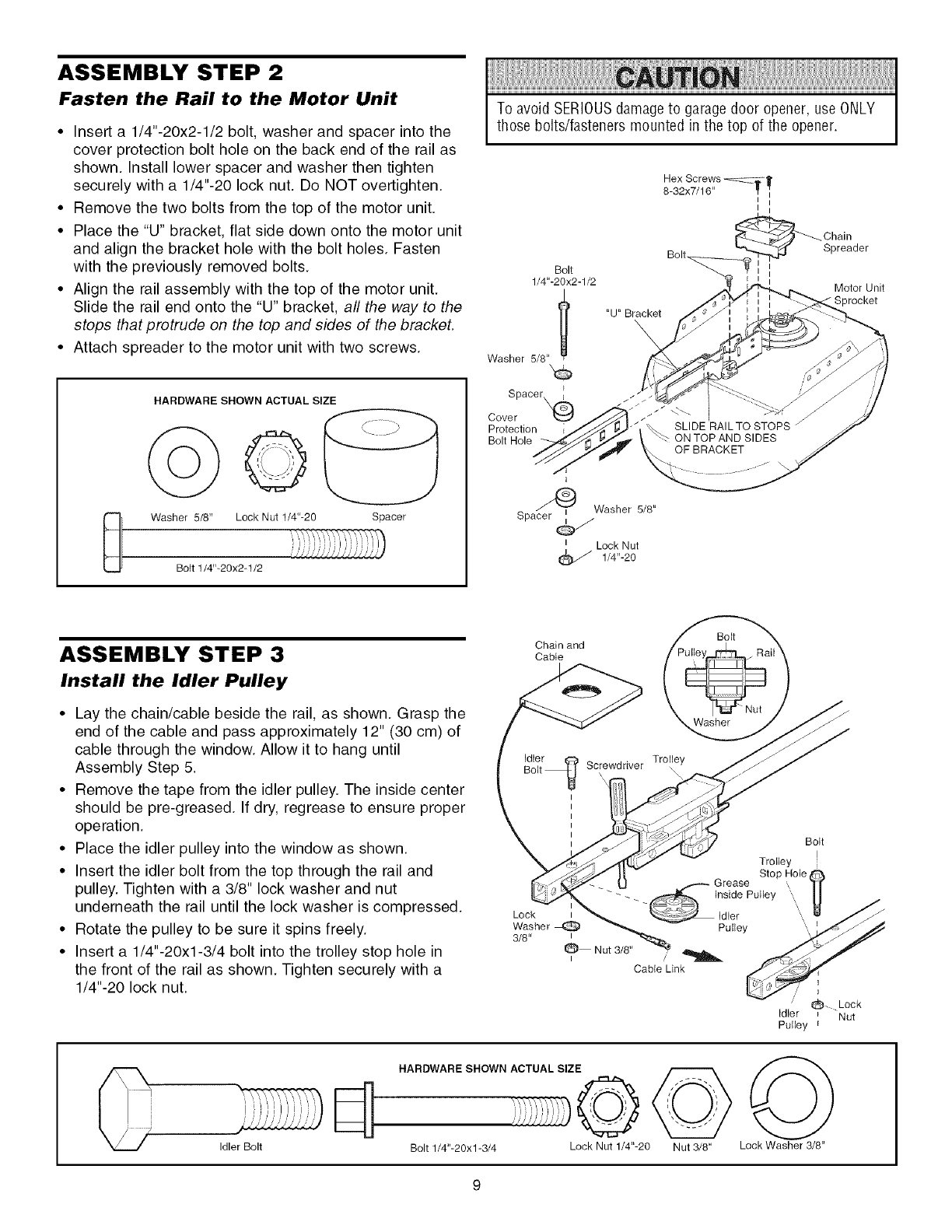
ASSEMBLY STEP 2
Fasten the Rail to the Motor Unit
•Insert a 1/4"-20x2-1/2 bolt, washer and spacer into the
cover protection bolt hole on the back end of the rail as
shown. Install lower spacer and washer then tighten
securely with a 1/4"-20 lock nut. Do NOT overtighten.
• Remove the two bolts from the top of the motor unit.
• Place the "U" bracket, flat side down onto the motor unit
and align the bracket hole with the bolt holes. Fasten
with the previously removed bolts.
• Align the rail assembly with the top of the motor unit.
Slide the rail end onto the "U" bracket, all the way to the
stops that protrude on the top and sides of the bracket.
• Attach spreader to the motor unit with two screws.
0
HARDWARE SHOWN ACTUAL SIZE
oO
Washer 5/8" Lock Nut 1/4"-20 Spacer
Bott 1/4"-20x2-1/2
To avoid SERIOUSdamage to garagedoor opener, use ONLY
those bolts/fasteners mounted in the top of the opener.
Bolt
1/4"-20x2-1/2
Washer 5/8" l
Spacer_._
Cover
Protection
Bolt Hole
"U" Bracket
Hex Screws -_T][
8-32x7/16" _ t
I I
I I
Chain
Spreader
Motor Unit
Sprocket
I
Spa_Washer 5/8"
i Lock Nut
1/4"-20
ASSEMBLY STEP 3
Install the Idler Pulley
• Lay the chain/cable beside the rail, as shown. Grasp the
end of the cable and pass approximately 12" (30 cm) of
cable through the window. Allow it to hang until
Assembly Step 5.
• Remove the tape from the idler pulley. The inside center
should be pre-greased. If dry, regrease to ensure proper
operation.
• Place the idler pulley into the window as shown.
• Insert the idler bolt from the top through the rail and
pulley. Tighten with a 3/8" lock washer and nut
underneath the rail until the lock washer is compressed.
• Rotate the pulley to be sure it spins freely.
• Insert a 1/4"-20xl-3/4 bolt into the trolley stop hole in
the front of the rail as shown. Tighten securely with a
1/4"-20 lock nut.
Chain and
Cable
Bolt
_ Nut
Washer
Bott
Lock
Washer_ Pulley
3/8" i
Nut 3/8"
Cable Link
Idler Bolt
HARDWARE SHOWN ACTUAL SIZE
Bolt 1/4"-20xl-3/4 Lock Nut 1/4"-20 Nut 3/8" Lock Washer 3/8"
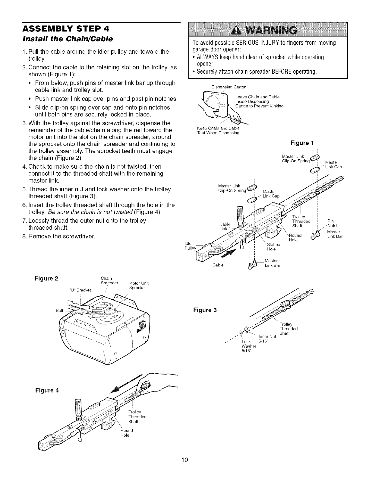
ASSEMBLY STEP 4
Install the Chain/Cable
1. Pull the cable around the idler pulley and toward the
trolley.
2. Connect the cable to the retaining slot on the trolley, as
shown (Figure 1):
• From below, push pins of master link bar up through
cable link and trolley slot.
• Push master link cap over pins and past pin notches.
• Slide clip-on spring over cap and onto pin notches
until both pins are securely locked in place.
3. With the trolley against the screwdriver, dispense the
remainder of the cable/chain along the rail toward the
motor unit into the slot on the chain spreader, around
the sprocket onto the chain spreader and continuing to
the trolley assembly. The sprocket teeth must engage
the chain (Figure 2).
4. Check to make sure the chain is not twisted, then
connect it to the threaded shaft with the remaining
master link.
5. Thread the inner nut and lock washer onto the trolley
threaded shaft (Figure 3).
6. Insert the trolley threaded shaft through the hole in the
trolley. Be sure the chain is not twisted(Figure 4).
7. Loosely thread the outer nut onto the trolley
threaded shaft.
8. Remove the screwdriver.
Figure 2 Chain
Spreader Motor Unit
"U" Bracket Sprocket
To avoid possible SERIOUSINJURYto fingers from moving
garage door opener:
• ALWAYSkeep hand clear of sprocket while operating
opener.
• Securelyattach chain spreader BEFOREoperating.
Dispensing Carton
---"_[]. eave Chain and Cab,e
inside Dispensing
Carton to Prevent Kinking.
Keep Chain and Cable
Taut When Dispensing
Master Link
Clip-On Spring _, Master
Figure 1
i J
i J
Master Link_
Clip-On Spring "_P'_ Master
Link Cap
Idler
Pulley
Cable
Link
hie
Slotted
Hole
_ Master
Link Bar
Trolley
Threaded
\ oS; n i*
Hole
Pin
l/Notch
i
i
i
Link Bar
Figure 3
I/ y
_'_"_--_ Shaft
.-_ _ Inner Nut
•"" Lock 5/16"
Washer
5/16"
Figure 4
Trolley
Threaded
Shaft
Round
Hole
10
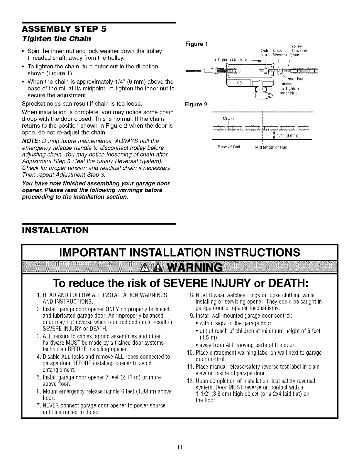
ASSEMBLY STEP 5
Tighten the Chain
•Spin the inner nut and lock washer down the trolley
threaded shaft, away from the trolley.
• To tighten the chain, turn outer nut in the direction
shown (Figure 1).
• When the chain is approximately 1/4" (6 mm) above the
base of the rail at its midpoint, re-tighten the inner nut to
secure the adjustment.
Sprocket noise can result if chain is too loose.
When installation is complete, you may notice some chain
droop with the door closed. This is normal. If the chain
returns to the position shown in Figure 2 when the door is
open, do not re-adjust the chain.
NOTE: During future maintenance, ALWAYS pull the
emergency release handle to disconnect trolley before
adjusting chain. You may notice loosening of chain after
Adjustment Step 3 (Test the Safety Reversal System).
Check for proper tension and readjust chain if necessary.
Then repeat Adjustment Step 3.
You have now finished assembling your garage door
opener. Please read the following warnings before
proceeding to the installation section.
Figure 1 Trolley
Outer Lock Threaded
Nut Washer Shaft
To Tighten Outer Nut ==='_l _ i /
Figure 2
Chain
mm--;--
I
Base of Raft Mid bength of RaiJ
INSTALLATION
IMPORTANT INSTALLATION INSTRUCTIONS
To reduce the risk of SEVERE INJURY or DEATH:
1. READAND FOLLOWALL INSTALLATIONWARNINGS
AND iNSTRUCTiONS.
2. Install garage door opener ONLYon properly balanced
and lubricated garage door. An improperly balanced
door may not reversewhen required and could result in
SEVEREINJURYor DEATH.
3. ALL repairs to cables, spring assemblies and other
hardware MUST be made by a trained door systems
technician BEFOREinstalling opener.
4. DisableALL locks and remove ALL ropes connected to
garage door BEFOREinstalling opener to avoid
entanglement.
5. Install garage door opener 7 feet (2.13 m) or more
above floor.
6. Mount emergency releasehandle 6 feet (1.83 m) above
floor.
7. NEVERconnect garage door openerto power source
until instructed to do so.
8. NEVERwear watches, rings or loose clothing while
installing or servicing opener. They could be caught in
garage door or opener mechanisms.
9. Install wall-mounted garage door control:
• within sight of the garage door.
• out of reach of children at minimum height of 5 feet
(1.5 m).
• awayfrom ALL moving parts of the door.
10. Placeentrapment warning label on wall next to garage
door control.
11. Placemanual release/safetyreversetest label in plain
view on inside of garage door.
12. Upon completion of installation, test safety reversal
system. Door MUST reverseon contact with a
1-1/2" (3.8 cm) high object (or a 2x4 laid flat) on
the floor.
11
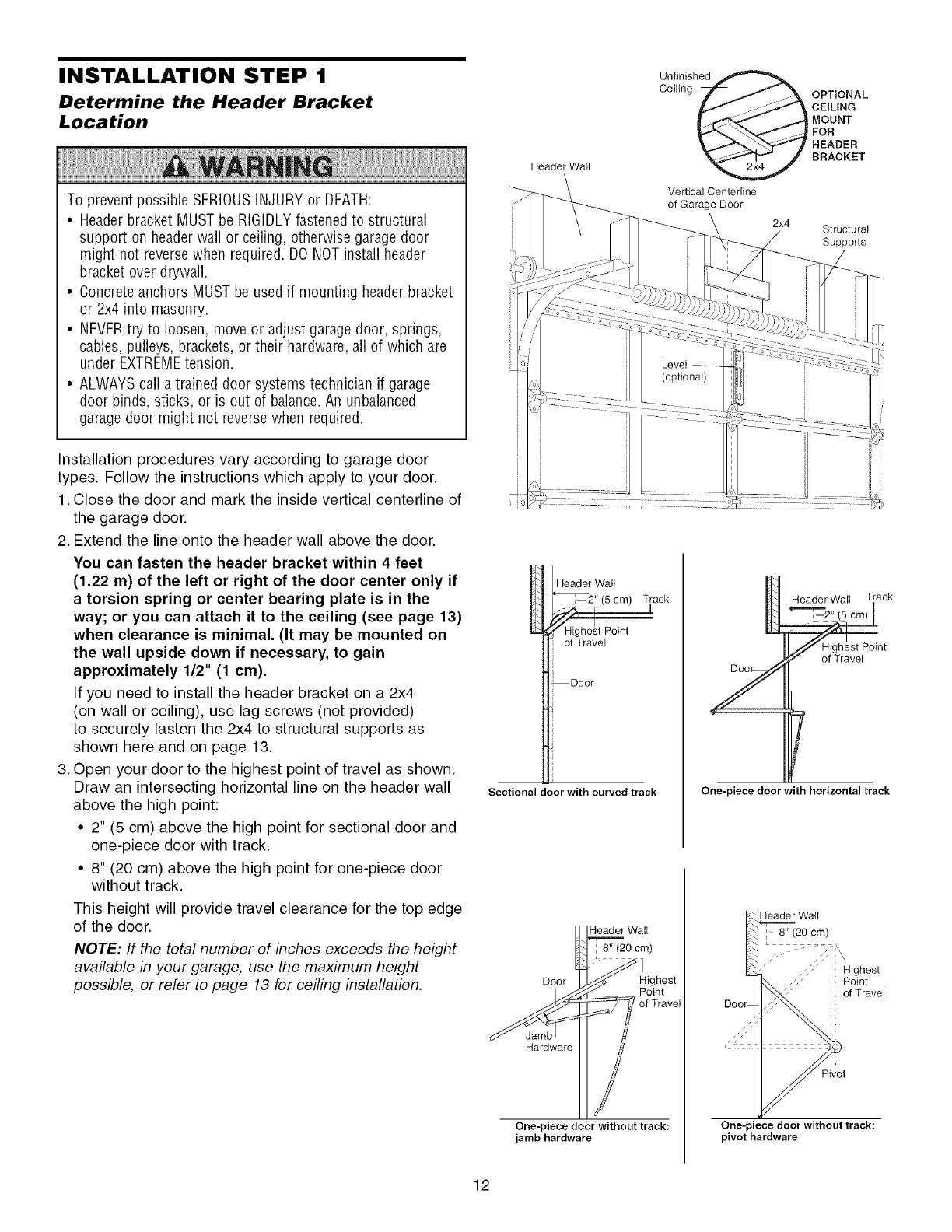
INSTALLATION STEP 1
Determine the Header Bracket
Location
To prevent possible SERIOUSINJURYor DEATH:
•Header bracket MUSTbe RIGIDLYfastenedto structural
support on headerwall or ceiling, otherwise garagedoor
might not reversewhen required. DO NOTinstall header
bracket over drywall.
• Concreteanchors MUSTbe used if mounting header bracket
or 2x4 into masonry.
• NEVERtry to loosen, move or adjust garagedoor, springs,
cables, pulleys, brackets, or their hardware, all of which are
under EXTREMEtension.
• ALWAYScall a trained door systems technician if garage
door binds, sticks, or is out of balance.An unbalanced
garagedoor might not reversewhen required.
Installation procedures vary according to garage door
types. Follow the instructions which apply to your door.
1. Close the door and mark the inside vertical centerline of
the garage door.
2. Extend the line onto the header wall above the door.
You can fasten the header bracket within 4 feet
(1.22 m) of the left or right of the door center only if
a torsion spring or center bearing plate is in the
way; or you can attach it to the ceiling (see page 13)
when clearance is minimal. (It may be mounted on
the wall upside down if necessary, to gain
approximately 1/2" (1 cm).
If you need to install the header bracket on a 2x4
(on wall or ceiling), use lag screws (not provided)
to securely fasten the 2x4 to structural supports as
shown here and on page 13.
3. Open your door to the highest point of travel as shown.
Draw an intersecting horizontal line on the header wall
above the high point:
• 2" (5 cm) above the high point for sectional door and
one-piece door with track.
• 8" (20 cm) above the high point for one-piece door
without track.
This height will provide travel clearance for the top edge
of the door.
NOTE: If the total number of inches exceeds the height
available in your garage, use the maximum height
possible, or refer to page 13 for ceiling installation.
_ Header Wall
:--2" (5 cm) Track
• Highest Point
of Travel
--Door
Sectional door with curved track
Z
One-piece door with horizontal track
Header Wall Track
nt
Header Wall
:8" (20 cm)
Door Highest
Point
Hardware
One-piece door without track:
jamb hardware
Header Wall
8" (20 cm)
:[ Highest
IPoint
:: of Travel
One-piece door without track:
pivot hardware
12
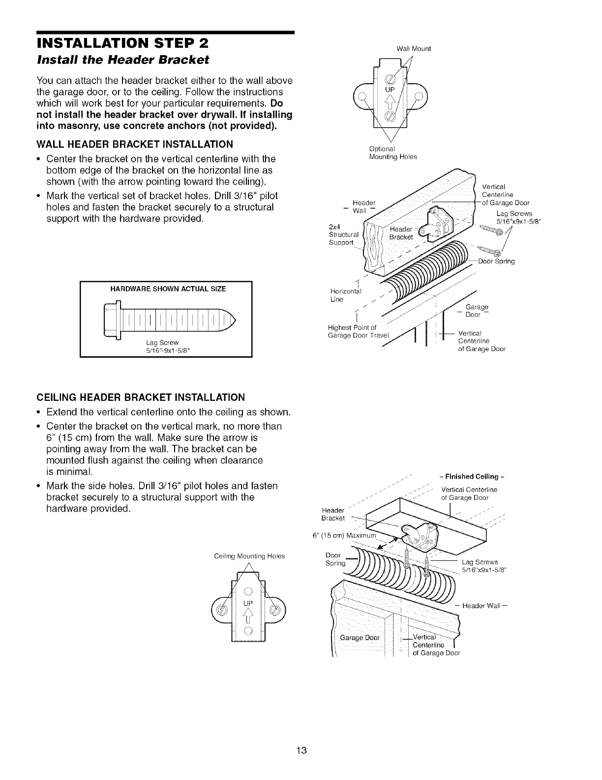
INSTALLATION STEP 2
Install the Header Bracket
You can attach the header bracket either to the wall above
the garage door, or to the ceiling. Follow the instructions
which will work best for your particular requirements. Do
not install the header bracket over drywall. If installing
into masonry, use concrete anchors (not provided).
WALL HEADER BRACKET INSTALLATION
•Center the bracket on the vertical centerline with the
bottom edge of the bracket on the horizontal line as
shown (with the arrow pointing toward the ceiling).
•Mark the vertical set of bracket holes. Drill 3/16" pilot
holes and fasten the bracket securely to a structural
support with the hardware provided.
HARDWARE SHOWN ACTUAL SIZE
Lag Screw
5/16"-9xl -5/8"
Wall Mount
Optional
Mounting Hotes
2x4
Structural
Support
I
Horizontal
Line / /
/
/ j
Highest Point of
Garage Door Travel
Vedical
Centefline
Garage Door
Lag Screws
5/16"x9x1-5/8"
Door Spring
jr
Garage
- Door-
Vedical
Centefline
of Garage Door
CEILING HEADER BRACKET INSTALLATION
• Extend the vertical centerline onto the ceiling as shown.
• Center the bracket on the vertical mark, no more than
6" (15 cm) from the wall. Make sure the arrow is
pointing away from the wall. The bracket can be
mounted flush against the ceiling when clearance
is minimal.
• Mark the side holes. Drill 3/16" pilot holes and fasten
bracket securely to a structural support with the
hardware provided.
Ceiling Mounting Holes
Finished Ceiling
_..I __ Vertical Centefline
.__ of Garage Door
Header "
B racket / __ _
6" (15 cm) Maximum
Door
Spring Lag Screws
5/16"x9x1-5/8"
Centertine
,I ,of Garage Door
13
Idler Pulley
Door
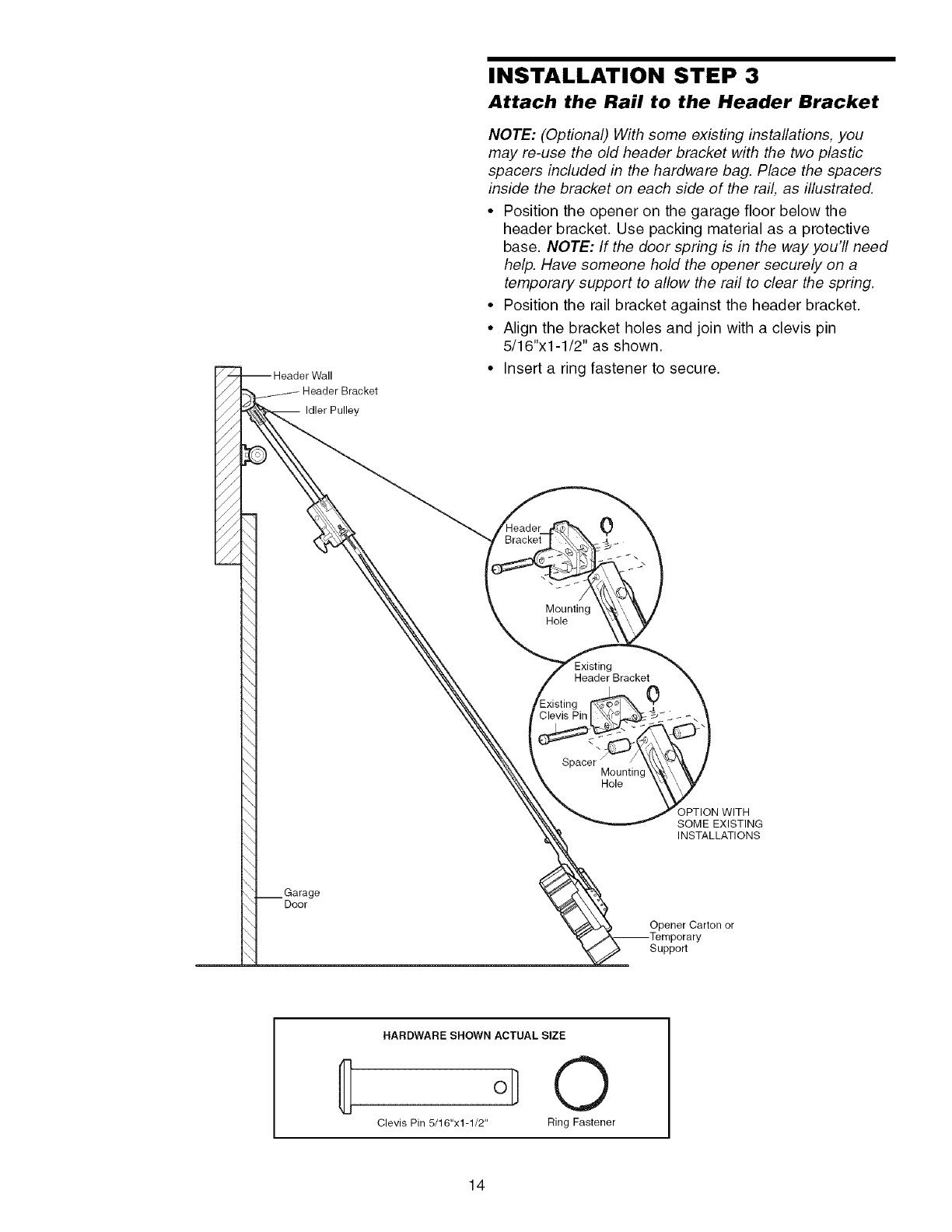
INSTALLATION STEP 3
Attach the Rail to the Header Bracket
NOTE: (Optional) With some existing installations, you
may re-use the old header bracket with the two plastic
spacers included in the hardware bag. Place the spacers
inside the bracket on each side of the rail, as illustrated.
• Position the opener on the garage floor below the
header bracket. Use packing material as a protective
base. NOTE: If the door spring is in the way you'll need
help. Have someone hold the opener securely on a
temporary support to allow the rail to clear the spring.
• Position the rail bracket against the header bracket.
• Align the bracket holes and join with a clevis pin
5/16"x1-1/2" as shown.
• Insert a ring fastener to secure.
0
Mounting
Hole
Header Bracket 0
Spacer /Mounting
Hole
OPTION WITH
SOME EXISTING
INSTALLATIONS
Opener Carton or
Support
HARDWARE SHOWN ACTUAL SIZE
{ O
Clevis Pin 5/16"x1-1/2" Ring Fastener
14
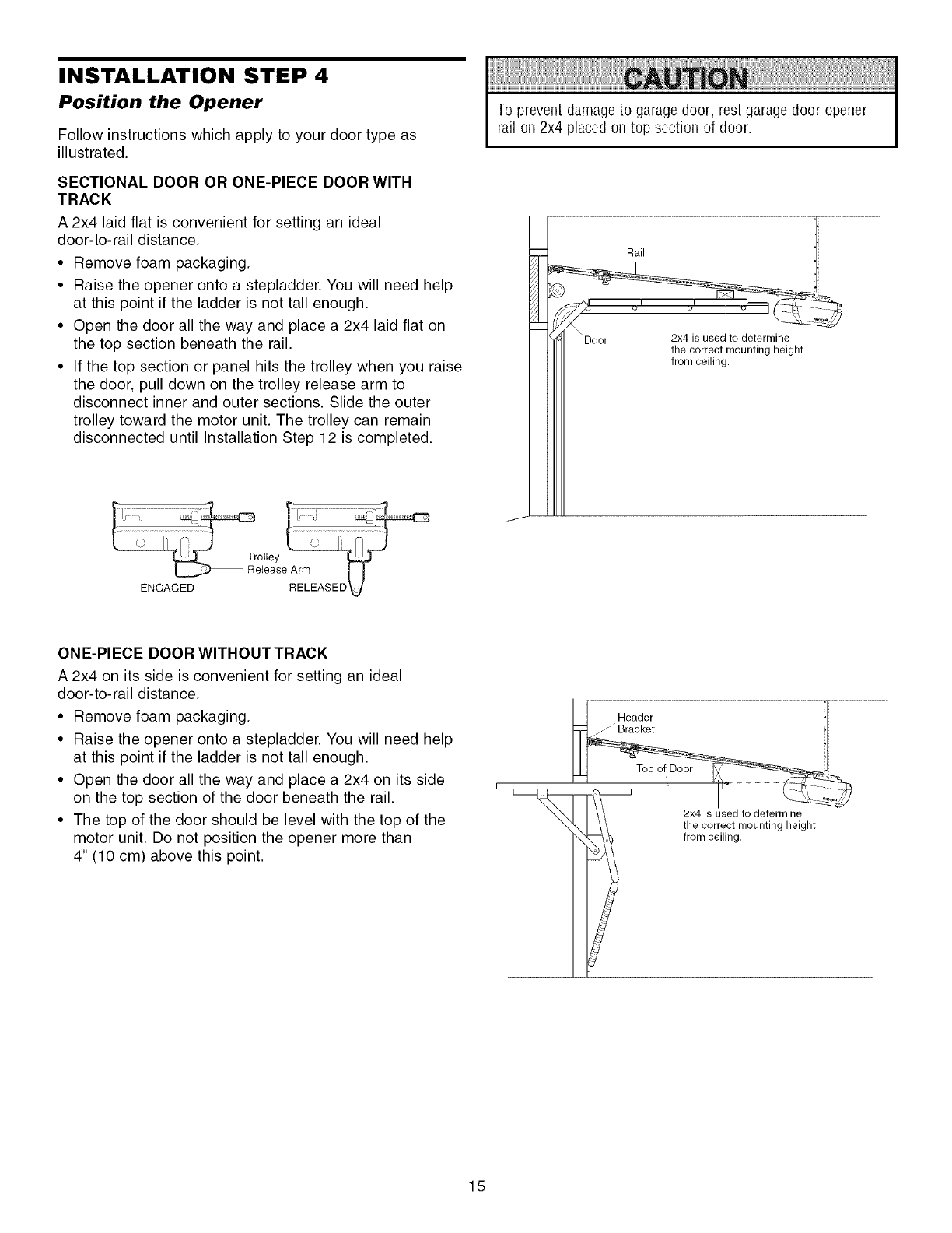
INSTALLATION STEP 4
Position the Opener
Follow instructions which apply to your door type as
illustrated.
SECTIONAL DOOR OR ONE-PIECE DOOR WITH
TRACK
A 2x4 laid flat is convenient for setting an ideal
door-to-rail distance.
• Remove foam packaging.
• Raise the opener onto a stepladder. You will need help
at this point if the ladder is not tall enough.
• Open the door all the way and place a 2x4 laid flat on
the top section beneath the rail.
• If the top section or panel hits the trolley when you raise
the door, pull down on the trolley release arm to
disconnect inner and outer sections. Slide the outer
trolley toward the motor unit. The trolley can remain
disconnected until Installation Step 12 is completed.
To prevent damageto garage door, rest garagedoor opener
rail on 2x4 placed on top section of door.
ENGAGED
ONE-PIECE DOOR WlTHOUTTRACK
A 2x4 on its side is convenient for setting an ideal
door-to-rail distance.
• Remove foam packaging.
• Raise the opener onto a stepladder. You will need help
at this point if the ladder is not tall enough.
• Open the door all the way and place a 2x4 on its side
on the top section of the door beneath the rail.
• The top of the door should be level with the top of the
motor unit. Do not position the opener more than
4" (10 cm) above this point.
I
II Header ;tl
_ i _
2x4 is used to determine
the correct mounting height
from ceiling.
15
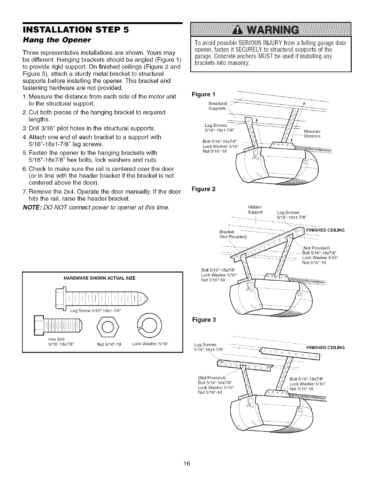
INSTALLATION STEP 5
Hang the Opener
Three representative installations are shown. Yours may
be different. Hanging brackets should be angled (Figure 1)
to provide rigid support. On finished ceilings (Figure 2 and
Figure 3), attach a sturdy metal bracket to structural
supports before installing the opener. This bracket and
fastening hardware are not provided.
1. Measure the distance from each side of the motor unit
to the structural support.
2. Cut both pieces of the hanging bracket to required
lengths.
3. Drill 3/16" pilot holes in the structural supports.
4. Attach one end of each bracket to a support with
5/16"-18xl -7/8" lag screws.
5. Fasten the opener to the hanging brackets with
5/16"-18x7/8" hex bolts, lock washers and nuts.
6. Check to make sure the rail is centered over the door
(or in line with the header bracket if the bracket is not
centered above the door).
7. Remove the 2x4. Operate the door manually. If the door
hits the rail, raise the header bracket.
NOTE: DO NOT connect power to opener at this time.
HARDWARE SHOWN ACTUAL SIZE
Hex Bolt
5/16"-18x7/8"
©
Nut 5/16"-18 Lock Washer 5/16"
To avoid possible SERIOUSINJURY from afailing garage door
opener, fasten it SECURELYto structural supports of the
garage. Concrete anchors MUST be used if installing any
brackets into masonry.
Figure 1
Structural
Supports \
Lag Screws
5/16"-18xl -7/8"
Bolt 5/16"-18x7/8"
Lock Washer 5/16"
Nut 5/16"-18
Measure
/Distance
Figure 2
Bolt 5/16"-18x7/8"
Lock Washer 5/16"
Nut 5/16"-18
FINISHED CEILING
_(Not Provided)
Bolt 5/16"-18x7/8"
Lock Washer 5/16"
Nut 5/16"-18
Figure 3
Lag Screws
5/16"-18xl -7/8"
\
FINISHED CEILING
(Not Provided)
Bolt 5/16"-18x7/8"
Lock Washer 5/16"
Nut 5/16"-18
Bolt 5/16"-18x7/8"
Lock Washer 5/16"
16
INSTALLATION STEP 6
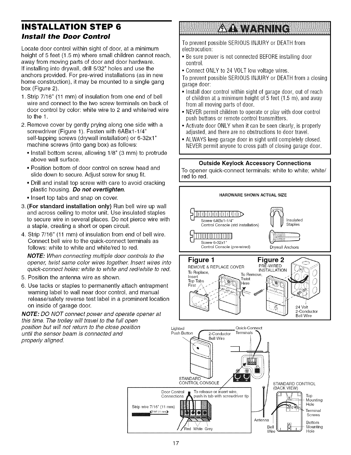
Install the Door Control
Locate door control within sight of door, at a minimum
height of 5 feet (1.5 m) where small children cannot reach,
away from moving parts of door and door hardware.
If installing into drywall, drill 5/32" holes and use the
anchors provided. For pre-wired installations (as in new
home construction), it may be mounted to a single gang
box (Figure 2).
1.Strip 7/16" (11 mm) of insulation from one end of bell
wire and connect to the two screw terminals on back of
door control by color: white wire to 2 and white/red wire
to the 1.
2. Remove cover by gently prying along one side with a
screwdriver (Figure 1). Fasten with 6ABx1-1/4"
self-tapping screws (drywall installation) or 6-32x1"
machine screws (into gang box) as follows:
• Install bottom screw, allowing 1/8" (3 mm) to protrude
above wall surface.
• Position bottom of door control on screw head and
slide down to secure. Adjust screw for snug fit.
• Drill and install top screw with care to avoid cracking
plastic housing. Do not overtighten.
• Insert top tabs and snap on cover.
3. (For standard installation only) Run bell wire up wall
and across ceiling to motor unit. Use insulated staples
to secure wire in several places. Do not pierce wire with
a staple, creating a short or open circuit.
4. Strip 7/16" (11 mm) of insulation from end of bell wire.
Connect bell wire to the quick-connect terminals as
follows: white to white and white/red to red.
NOTE: When connecting multiple door controls to the
opener, twist same color wires together. Insert wires into
quick-connect holes: white to white and red/white to red.
5. Position the antenna wire as shown.
6. Use tacks or staples to permanently attach entrapment
warning label to wall near door control, and manual
release/safety reverse test label in a prominent location
on inside of garage door.
NOTE: DO NOT connect power and operate opener at
this time. The trolley will travel to the full open
position but will not return to the close position
until the sensor beam is connected and
properly aligned.
Lighted
Push Button
STANDARD
To prevent possible SERIOUSINJURYor DEATHfrom
electrocution:
• Besure power is not connected BEFOREinstalling door
control.
• Connect ONLYto 24 VOLT low voltage wires.
To prevent possible SERIOUSINJURYor DEATHfrom a closing
garage door:
• Install door control within sight of garage door, out of reach
of children at a minimum height of 5 feet (1.5 m), and away
from all moving parts of door.
• NEVERpermit children to operate or play with door control
push buttons or remote control transmitters.
• Activatedoor ONLYwhen it can beseen clearly, is properly
adjusted, and there are no obstructions to door travel.
• ALWAYSkeep garagedoor in sight until completely closed.
NEVERpermit anyone to cross path of closing garage door.
Outside Keylock Accessory Connections I
To opener quick-connect terminals: white to white; white/ I
red to red.
HARDWARE SHOWN ACTUAL SIZE
Control Console (std installation)
Control Console (pre-wired)
Insulated
Staples
Drywall Anchors
Figure 1Figure 2
REMOVE & REPLACE COVER PRE-WIRED
INSTALLATION
To Replace, To Remove,
Insert Twist
Top Tabs Here
Quick-Connect
2-Conductor Terminals
11Wire
24 Volt
2-Conductor
Bell Wire
CONTROLCONSOLE
Door Control
Connections
Strip wire 7/16" (11 ram)
7t 16" /11 mm/_
To release or insert wire,
)ush in tab with screwdriver tip
v"
qed White Grey
STANDARD CONTROL
Wire
Top
Mounting
Hole
Terminal
Screws
Bottom
Mounting
Hole
17
INSTALLATION STEP 7
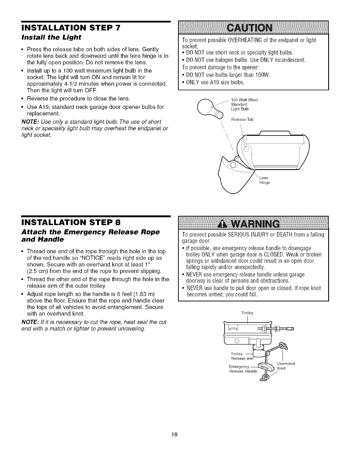
Install the Light
•Press the release tabs on both sides of lens. Gently
rotate lens back and downward until the lens hinge is in
the fully open position. Do not remove the lens.
• Install up to a 100 watt maximum light bulb in the
socket. The light will turn ON and remain lit for
approximately 4-1/2 minutes when power is connected.
Then the light will turn OFE
• Reverse the procedure to close the lens.
• Use A19, standard neck garage door opener bulbs for
replacement.
NOTE: Use only a standard light bulb. The use of short
neck or speciafity light bulb may overheat the endpanel or
light socket.
To prevent possible OVERHEATINGof the endpanelor light
socket,
• DO NOTuse short neck or specialty light bulbs.
• DO NOTuse halogen bulbs. Use ONLYincandescent.
To prevent damageto the opener:
• DO NOTuse bulbs larger than IOOW.
• ONLY use A19 size bulbs.
100 Watt (Max)
Standard
Light Bulb
Release Tab
\\
/
INSTALLATION STEP 8
Attach the Emergency Release Rope
and Handle
• Thread one end of the rope through the hole in the top
of the red handle so "NOTICE" reads right side up as
shown. Secure with an overhand knot at least 1"
(2.5 cm) from the end of the rope to prevent slipping.
• Thread the other end of the rope through the hole in the
release arm of the outer trolley.
• Adjust rope length so the handle is 6 feet (1.83 m)
above the floor. Ensure that the rope and handle clear
the tops of all vehicles to avoid entanglement. Secure
with an overhand knot.
NOTE: If it is necessary to cut the rope, heat seal the cut
end with a match or lighter to prevent unraveling.
To prevent possible SERIOUSINJURYor DEATHfrom a falling
garage door:
• If possible, use emergency releasehandle to disengage
trolley ONLY when garage door is CLOSED.Weak or broken
springs or unbalanceddoor could result in an open door
failing rapidly and/or unexpectedly.
• NEVERuse emergency releasehandle unless garage
doorway is clear of persons and obstructions.
• NEVERuse handleto pull door open or closed. If rope knot
becomes untied, you could fall.
Trolley
!
Tr_,,eaye arm
Emergency _ _. Overhand
Release Handle ,__//Knot
18
INSTALLATION STEP 9
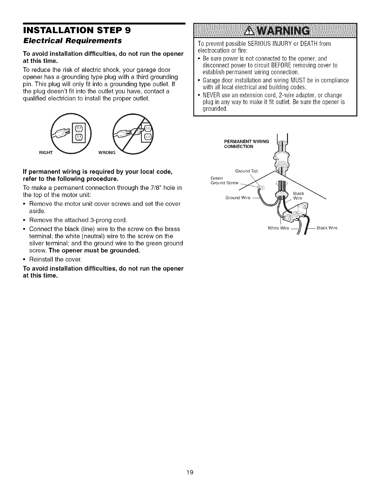
Electrical Requirements
To avoid installation difficulties, do not run the opener
at this time.
To reduce the risk of electric shock, your garage door
opener has a grounding type plug with a third grounding
pin. This plug will only fit into a grounding type outlet. If
the plug doesn't fit into the outlet you have, contact a
qualified electrician to install the proper outlet.
To prevent possible SERIOUSINJURYor DEATHfrom
electrocution or fire:
• Be sure power is not connected to the opener, and
disconnect power to circuit BEFOREremoving cover to
establish permanent wiring connection.
• Garagedoor installation and wiring MUST be in compliance
with all local electrical and building codes.
• NEVERuse an extension cord, 2-wire adapter, or change
plug in any way to makeit fit outlet. Besure the opener is
grounded.
PERMANENT WIRING
CONNECTION
If permanent wiring is required by your local code,
refer to the following procedure.
To make a permanent connection through the 7/8" hole in
the top of the motor unit:
• Remove the motor unit cover screws and set the cover
aside.
• Remove the attached 3-prong cord.
• Connect the black (line) wire to the screw on the brass
terminal; the white (neutral) wire to the screw on the
silver terminal; and the ground wire to the green ground
screw. The opener must be grounded.
• Reinstall the cover.
To avoid installation difficulties, do not run the opener
at this time.
Ground Tab
Green
Ground Screw
Ground Wire Wire
Black Wire
19
INSTALLATION STEP 10
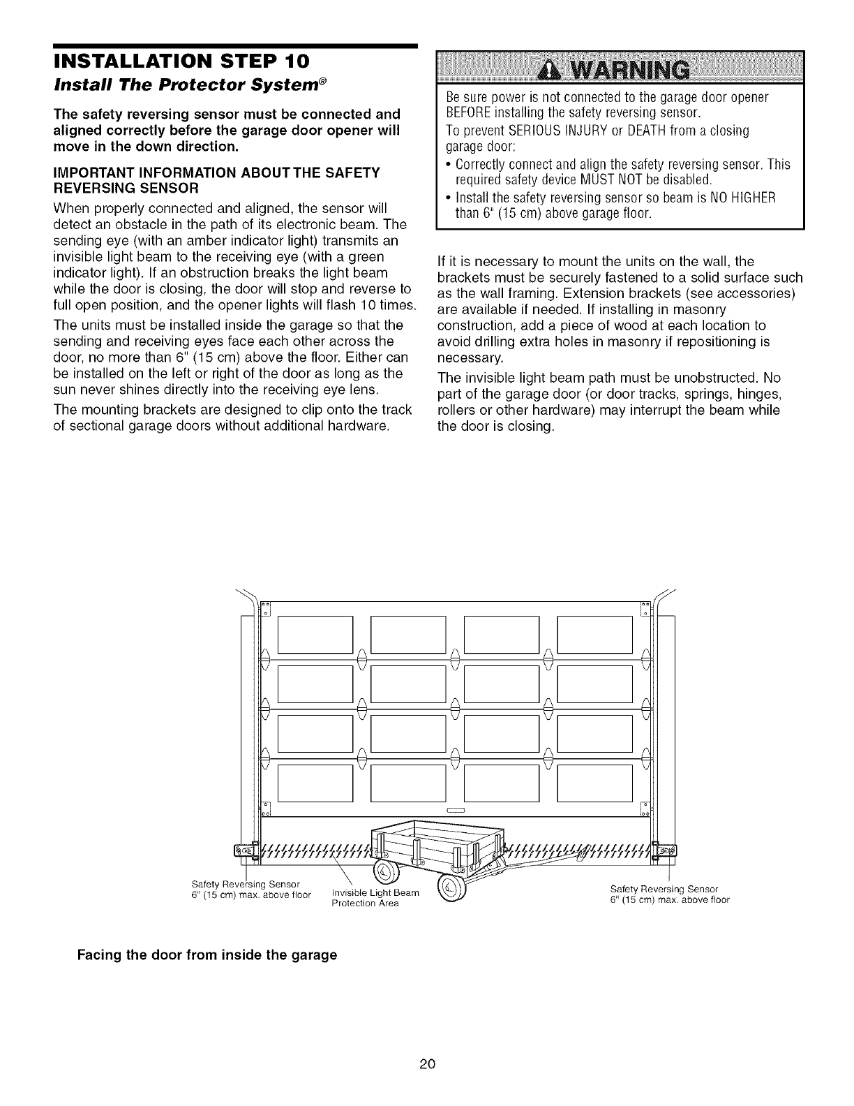
Install The Protector System ®
The safety reversing sensor must be connected and
aligned correctly before the garage door opener will
move in the down direction.
IMPORTANT INFORMATION ABOUTTHE SAFETY
REVERSING SENSOR
When properly connected and aligned, the sensor will
detect an obstacle in the path of its electronic beam. The
sending eye (with an amber indicator light) transmits an
invisible light beam to the receiving eye (with a green
indicator light). If an obstruction breaks the light beam
while the door is closing, the door will stop and reverse to
full open position, and the opener lights will flash 10 times.
The units must be installed inside the garage so that the
sending and receiving eyes face each other across the
door, no more than 6" (15 cm) above the floor. Either can
be installed on the left or right of the door as long as the
sun never shines directly into the receiving eye lens.
The mounting brackets are designed to clip onto the track
of sectional garage doors without additional hardware.
Be sure power is not connected to the garage door opener
BEFOREinstalling the safety reversingsensor.
To prevent SERIOUSINJURY or DEATHfrom a closing
garage door:
• Correctly connect and align the safety reversing sensor. This
required safety device MUST NOTbe disabled.
• Install the safety reversing sensor so beam is NO HIGHER
than 6" (15 cm) above garagefloor.
If it is necessary to mount the units on the wall, the
brackets must be securely fastened to a solid surface such
as the wall framing. Extension brackets (see accessories)
are available if needed. If installing in masonry
construction, add a piece of wood at each location to
avoid drilling extra holes in masonry if repositioning is
necessary.
The invisible light beam path must be unobstructed. No
part of the garage door (or door tracks, springs, hinges,
rollers or other hardware) may interrupt the beam while
the door is closing.
!0! !0!
!0!
!0! 10!
Ill[ ]E JE J!ll
Facing the door from inside the garage
2O
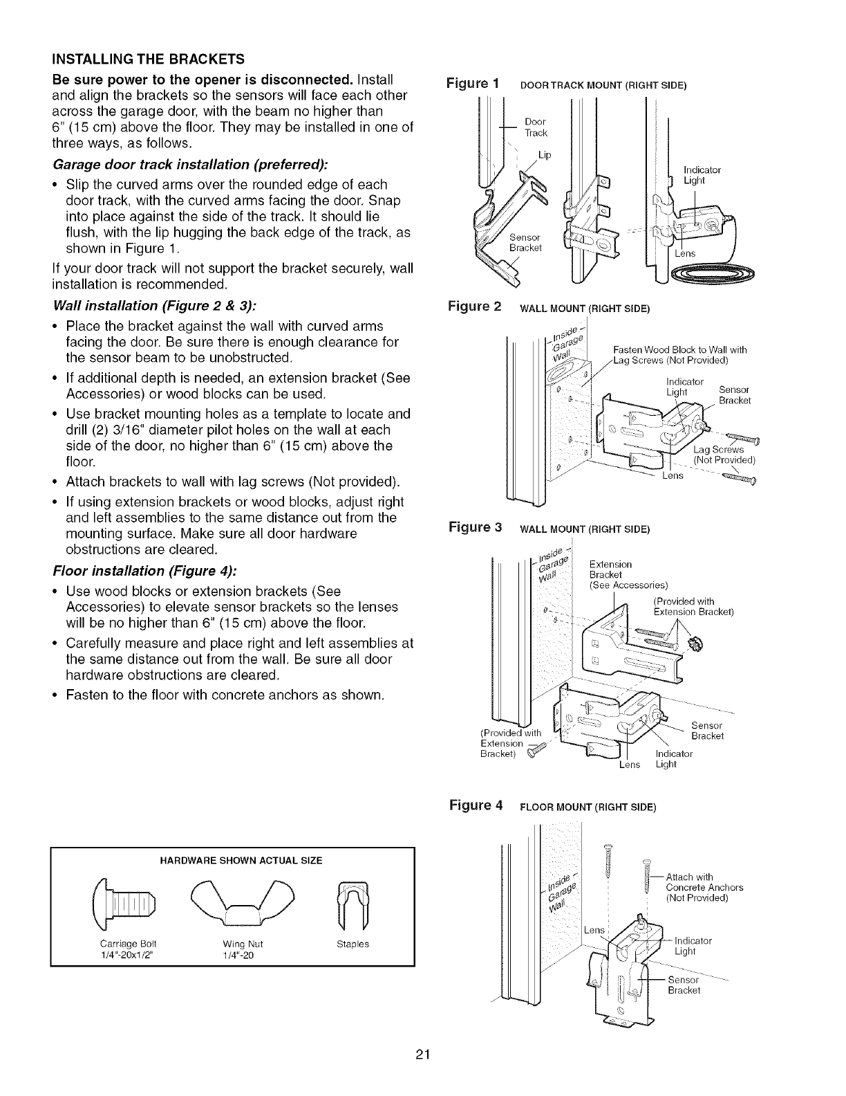
INSTALLING THE BRACKETS
Be sure power to the opener is disconnected. Install
and align the brackets so the sensors will face each other
across the garage door, with the beam no higher than
6" (15 cm) above the floor. They may be installed in one of
three ways, as follows.
Garage door track installation (preferred):
• Slip the curved arms over the rounded edge of each
door track, with the curved arms facing the door. Snap
into place against the side of the track. It should lie
flush, with the lip hugging the back edge of the track, as
shown in Figure 1.
If your door track will not support the bracket securely, wall
installation is recommended.
Wall installation (Figure 2 & 3):
• Place the bracket against the wall with curved arms
facing the door. Be sure there is enough clearance for
the sensor beam to be unobstructed.
• If additional depth is needed, an extension bracket (See
Accessories) or wood blocks can be used.
• Use bracket mounting holes as a template to locate and
drill (2) 3/16" diameter pilot holes on the wall at each
side of the door, no higher than 6" (15 cm) above the
floor.
• Attach brackets to wall with lag screws (Not provided).
• If using extension brackets or wood blocks, adjust right
and left assemblies to the same distance out from the
mounting surface. Make sure all door hardware
obstructions are cleared.
Floor installation (Figure 4):
• Use wood blocks or extension brackets (See
Accessories) to elevate sensor brackets so the lenses
will be no higher than 6" (15 cm) above the floor.
• Carefully measure and place right and left assemblies at
the same distance out from the wall. Be sure all door
hardware obstructions are cleared.
• Fasten to the floor with concrete anchors as shown.
Figure 1 DOOR TRACK MOUNT (RIGHT SIDE)
Door
Track
\\Lip
Sensor
Bracket
Indicator
Light
Figure 2 WALL MOUNT (RIGHT SSDE)
Fasten Wood Block to Wall with
(Not Provided)
Indicator
Light Sensor
Bracket
(Not Provided)
Lens
Figure 3WALL MOUNT (RIGHT SIDE)
Extension
Bracket
(See Accessories)
(Provided with
Extension Bracket)
(Provided with
Extension
Bracket) _"
Lens
Sensor
Bracket
Indicator
Light
Figure 4 FLOOR MOUNT (RIGHT SIDE)
HARDWARE SHOWN ACTUAL SIZE
Carriage Bolt Wing Nut
1/4"-20xl/2" 1/4"-20 Staples
m Attach with
Concrete Anchors
(Not Provided)
Light
Bracket
21
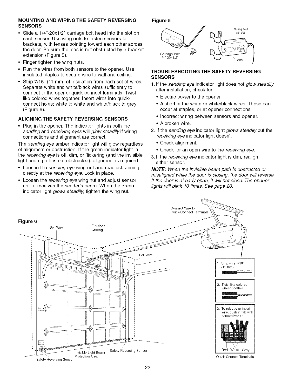
MOUNTING AND WIRING THE SAFETY REVERSING
SENSORS
• Slide a 1/4"-20xl/2" carriage bolt head into the slot on
each sensor. Use wing nuts to fasten sensors to
brackets, with lenses pointing toward each other across
the door. Be sure the lens is not obstructed by a bracket
extension (Figure 5).
• Finger tighten the wing nuts.
• Run the wires from both sensors to the opener. Use
insulated staples to secure wire to wall and ceiling.
• Strip 7/16" (11 mm) of insulation from each set of wires.
Separate white and white/black wires sufficiently to
connect to the opener quick-connect terminals. Twist
like colored wires together. Insert wires into quick-
connect holes: white to white and white/black to grey
(Figure 6).
ALIGNING THE SAFETY REVERSING SENSORS
• Plug in the opener. The indicator lights in both the
sending and receiving eyes will glow steadily if wiring
connections and alignment are correct.
The sending eye amber indicator light will glow regardless
of alignment or obstruction. If the green indicator light in
the receiving eye is off, dim, or flickering (and the invisible
light beam path is not obstructed), alignment is required.
• Loosen the sending eye wing nut and readjust, aiming
directly at the receiving eye. Lock in place.
• Loosen the receiving eye wing nut and adjust sensor
until it receives the sender's beam. When the green
indicator light glows steadily, tighten the wing nut.
Figure 5
CarriageBoltI_
1/4"-20xl/2"
Wing Nut
1/4"-20
TROUBLESHOOTING THE SAFETY REVERSING
SENSORS
1. If the sending eye indicator light does not glow steadily
after installation, check for:
• Electric power to the opener.
• A short in the white or white/black wires. These can
occur at staples, or at opener connections.
• Incorrect wiring between sensors and opener.
• A broken wire.
2. If the sending eye indicator light glows steadily but the
receiving eye indicator light doesn't:
• Check alignment.
• Check for an open wire to the receiving eye.
3. If the receiving eye indicator light is dim, realign
either sensor.
NOTE: When the invisible beam path is obstructed or
misaligned while the door is closing, the door will reverse.
If the door is already open, it will not close. The opener
lights will blink 10 times. See page 20.
Figure 6
Bell Wire
Bell Wire
Invisible Light Beam
Protection Area
Safety Reversing Sensor
Safety Reversing Sensor
22
I
1. Strip wire 7/16"
(11 mm)
2. Twist like colored
wires together
3. To release or insert
wire, push in tab with
screwdriver tip
Red White Grey
Quick-Connect Terminals
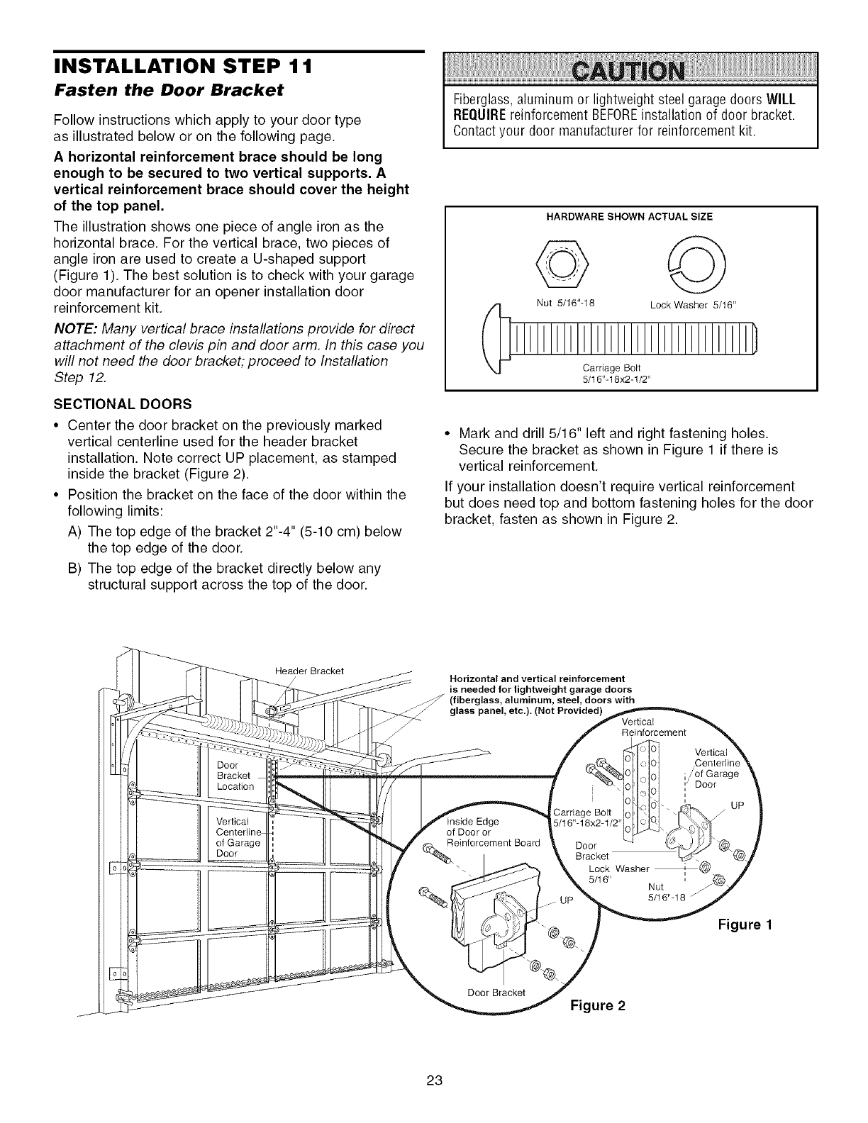
INSTALLATION STEP 1 1
Fasten the Door Bracket
Follow instructions which apply to your door type
as illustrated below or on the following page.
A horizontal reinforcement brace should be long
enough to be secured to two vertical supports. A
vertical reinforcement brace should cover the height
of the top panel.
The illustration shows one piece of angle iron as the
horizontal brace. For the vertical brace, two pieces of
angle iron are used to create a U-shaped support
(Figure 1). The best solution is to check with your garage
door manufacturer for an opener installation door
reinforcement kit.
NOTE: Many vertical brace installations provide for direct
attachment of the clevis pin and door arm. In this case you
will not need the door bracket; proceed to Installation
Step 12.
SECTIONAL DOORS
• Center the door bracket on the previously marked
vertical centerline used for the header bracket
installation. Note correct UP placement, as stamped
inside the bracket (Figure 2).
• Position the bracket on the face of the door within the
following limits:
A) The top edge of the bracket 2"-4" (5-10 cm) below
the top edge of the door.
B) The top edge of the bracket directly below any
structural support across the top of the door.
Fiberglass,aluminum or lightweight steel garage doors WILL
REQUIREreinforcement BEFOREinstallation of door bracket.
Contactyour door manufacturer for reinforcement kit.
HARDWARE SHOWN ACTUAL SIZE
©
Nut 5/16"-18 Lock Washer 5/16"
Carriage Bolt
5/16"-18x2-1/2"
• Mark and drill 5/16" left and right fastening holes.
Secure the bracket as shown in Figure 1 if there is
vertical reinforcement.
If your installation doesn't require vertical reinforcement
but does need top and bottom fastening holes for the door
bracket, fasten as shown in Figure 2.
Header Bracket
Door
Bracket
Location
Vertical
of Garage
Door
Horizontal and vertical reinforcement
is needed for lightweight garage doors
(fiberglass, aluminum, steel, doors with
glass panel, etc.), (Not Provided) Vertical
Reinforcement
ge 5/16"-18x2-1/;
of Door or
(_einforcement Board Door
I Bracket
"., _ _ Lock Washer
Nut
5/16"-18
Door Bracket
Figure 2
Vertical
/of Garage
Door
Figure 1
23
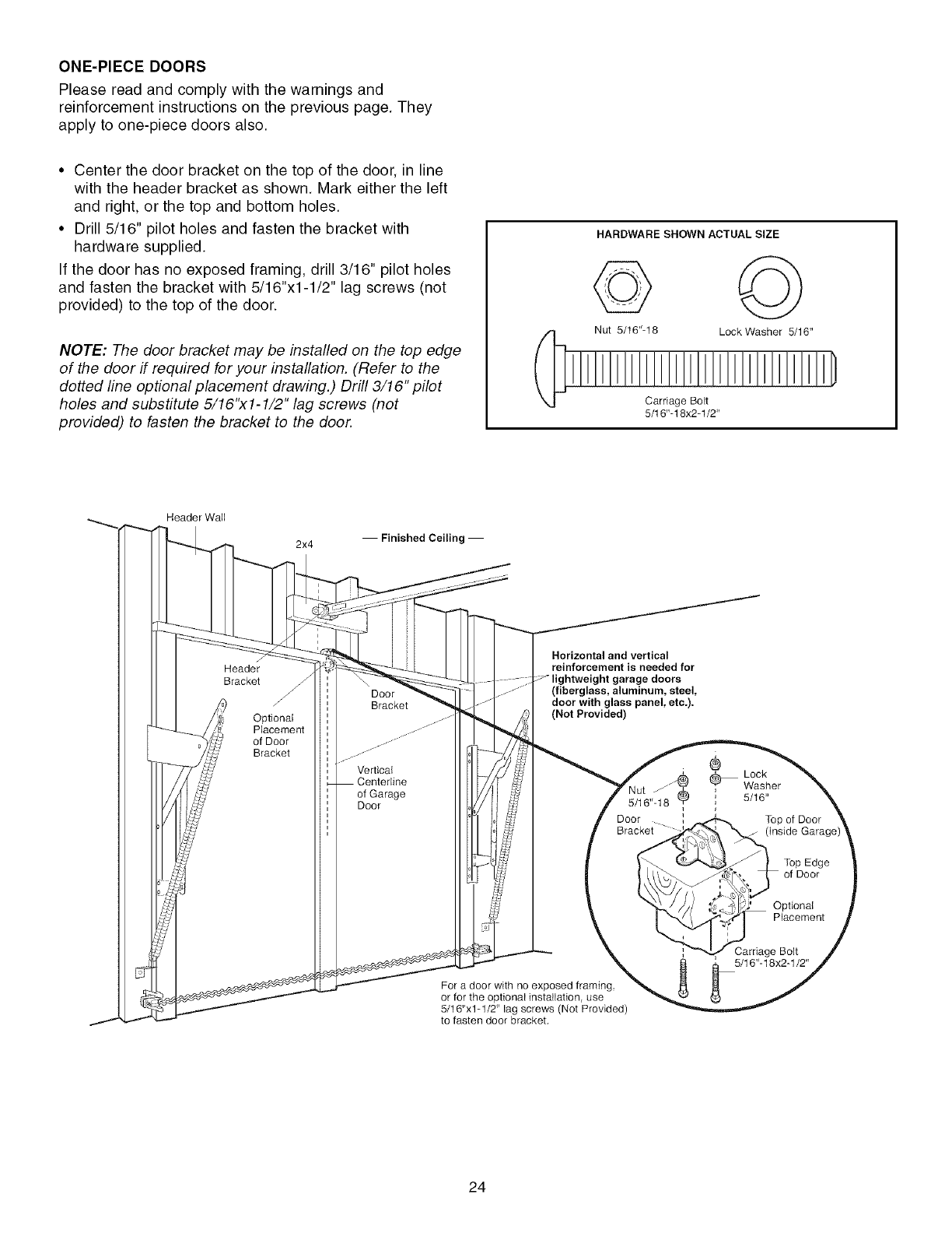
ONE-PIECEDOORS
Please read and comply with the warnings and
reinforcement instructions on the previous page. They
apply to one-piece doors also.
• Center the door bracket on the top of the door, in line
with the header bracket as shown. Mark either the left
and right, or the top and bottom holes.
• Drill 5/16" pilot holes and fasten the bracket with
hardware supplied.
If the door has no exposed framing, drill 3/16" pilot holes
and fasten the bracket with 5/16"x1-1/2" lag screws (not
provided) to the top of the door.
NOTE: The door bracket may be installed on the top edge
of the door if required for your installation. (Refer to the
dotted line optional placement drawing.) Drill 3/16" pilot
holes and substitute 5/16"x1-1/2" lag screws (not
provided) to fasten the bracket to the door.
HARDWARE SHOWN ACTUAL SIZE
Nut 5/t6"-18 Lock Washer 5/16"
Carriage Bolt
5/16"-18x2-1/2"
Header WatJ
2x4 -- Finished Ceiling --
Header
Bracket
Optional
Placement
of Door
Bracket
Door
Bracket
Vertical
of Garage
Door
Horizontal and vertical
reinforcement is needed for
e doors
(fiberglass, aluminum, steel,
door with glass panel, etc.).
(Hot Provided)
jJ_
5/16"-18
Door __
Bracket
For a door with no exposed framing
or for the optional installation, use
5/16"x1-1/2" lag screws (Not Provided)
to fasten door bracket,
®
Lock
Washer
' 5/16"
J
Top of Door
Top Edge
of Door
Optional
PJacement
Carriage Bolt
5/16"-18x2-1/2"
24
INSTALLATION STEP 12
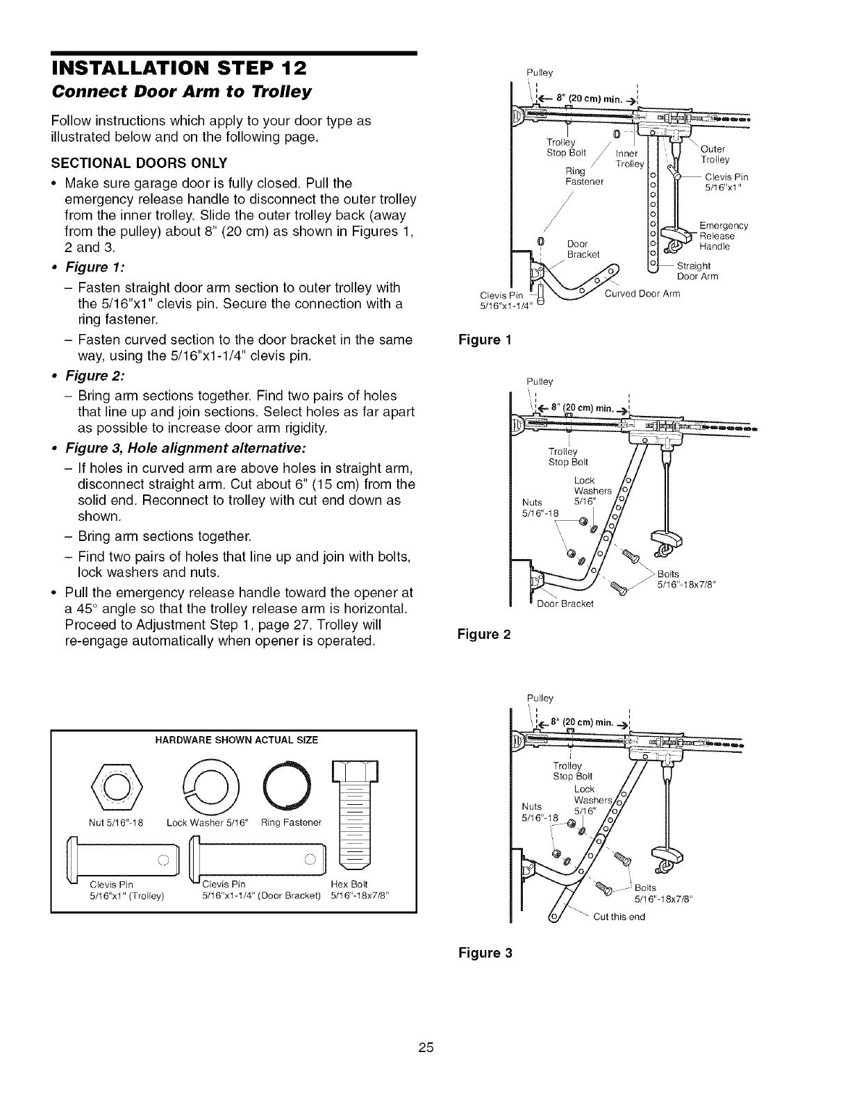
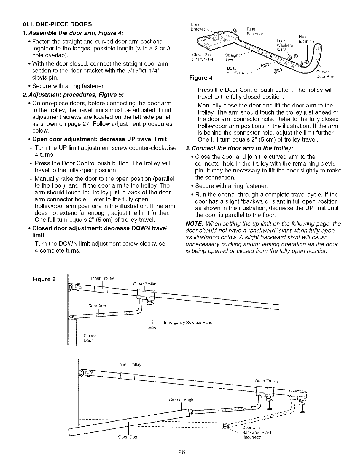
Connect Door Arm to Trolley
Follow instructions which apply to your door type as
illustrated below and on the following page.
SECTIONAL DOORS ONLY
• Make sure garage door is fully closed. Pull the
emergency release handle to disconnect the outer trolley
from the inner trolley. Slide the outer trolley back (away
from the pulley) about 8" (20 cm) as shown in Figures 1,
2 and 3.
•Figure 1:
- Fasten straight door arm section to outer trolley with
the 5/16"x1" clevis pin. Secure the connection with a
ring fastener.
- Fasten curved section to the door bracket in the same
way, using the 5/16"x1-1/4" clevis pin.
•Figure 2:
- Bring arm sections together. Find two pairs of holes
that line up and join sections. Select holes as far apart
as possible to increase door arm rigidity.
•Figure 3, Hole alignment alternative:
- If holes in curved arm are above holes in straight arm,
disconnect straight arm. Cut about 6" (15 cm) from the
solid end. Reconnect to trolley with cut end down as
shown.
- Bring arm sections together.
- Find two pairs of holes that line up and join with bolts,
lock washers and nuts.
• Pull the emergency release handle toward the opener at
a 45° angle so that the trolley release arm is horizontal.
Proceed to Adjustment Step 1, page 27. Trolley will
re-engage automatically when opener is operated.
Clevis Pin
5/16"x1-1/4
Figure 1
Figure 2
Curved Door Arm
Pulley
i i
i i
_ Bolts
"'_./ 5/16'L18X7/8"
Door Bracket
HARDWARE SHOWN ACTUAL SIZE
© O
Nut 5/16"-18 Lock Washer 5/16" Ring Fastener
\J\J
Clevis Pin Clevis Pin
5/I6"xi" (Trofley)
Hex Bolt
5/16"x1-1/4" (Door Bracket) 5/16"-18x7/8"
Figure 3
Pulley
ii
ii
",:_[_8" (20 cm) rain. _._:
Trolley
Stop Bolt //
Lock /o/
., . Washers/n7
Nuts 5i_-_/- ZOy
5/16'L18 _[_ i#
-% Bolts
/Z - 5/16%18X7/8"
o(.0./ _ Cut this end
25
ALL ONE-PIECE DOORS
1.Assemble the door arm, Figure 4:
• Fasten the straight and curved door arm sections
together to the longest possible length (with a 2 or 3
hole overlap).
• With the door closed, connect the straight door arm
section to the door bracket with the 5/16"xl-1/4"
clevis pin.
• Secure with a ring fastener.
2. Adjustment procedures, Figure 5:
• On one-piece doors, before connecting the door arm
to the trolley, the travel limits must be adjusted. Limit
adjustment screws are located on the left side panel
as shown on page 27. Follow adjustment procedures
below.
• Open door adjustment: decrease UP travel limit
- Turn the UP limit adjustment screw counter-clockwise
4 turns.
- Press the Door Control push button. The trolley will
travel to the fully open position.
- Manually raise the door to the open position (parallel
to the floor), and lift the door arm to the trolley. The
arm should touch the trolley just in back of the door
arm connector hole. Refer to the fully open
trolley/door arm positions in the illustration. If the arm
does not extend far enough, adjust the limit further.
One full turn equals 2" (5 cm) of trolley travel.
• Closed door adjustment: decrease DOWN travel
limit
- Turn the DOWN limit adjustment screw clockwise
4 complete turns.
Door
Bracket _.__r_,,_,_ Ring
Fastener Nuts
_ _.v -_,..... : _..._ Lock 5/16"-18
"_1,__ ._:._. Washers I _
Iv-_-_c:_ 5/16" I I '_ I
ClevisPin Straight J e- I I ,t
5/le"xl-1/4" Arm "_<'::"'_- _/V
5'_1'6:- 18x7/8" _ _Curved
Figure 4 DoorArm
- Press the Door Control push button. The trolley will
travel to the fully closed position.
- Manually close the door and lift the door arm to the
trolley. The arm should touch the trolley just ahead of
the door arm connector hole. Refer to the fully closed
trolley/door arm positions in the illustration. If the arm
is behind the connector hole, adjust the limit further.
One full turn equals 2" (5 cm) of trolley travel.
3. Connect the door arm to the trolley:
• Close the door and join the curved arm to the
connector hole in the trolley with the remaining clevis
pin. It may be necessary to lift the door slightly to make
the connection.
• Secure with a ring fastener.
• Run the opener through a complete travel cycle. If the
door has a slight "backward" slant in full open position
as shown in the illustration, decrease the UP limit until
the door is parallel to the floor.
NOTE: When setting the up limit on the following page, the
door should not have a "backward" slant when fully open
as illustrated below. A slight backward slant will cause
unnecessary bucking and/or jerking operation as the door
is being opened or closed from the fully open position.
Figure 5Inner Trolley
cy
ReJease HandJe
Inner Trolley
Outer Trotley
Correct Angle
- ................ ._.:::_r__._ _'_'_''__
Backward SJant
Open Door (Incorrect)
26
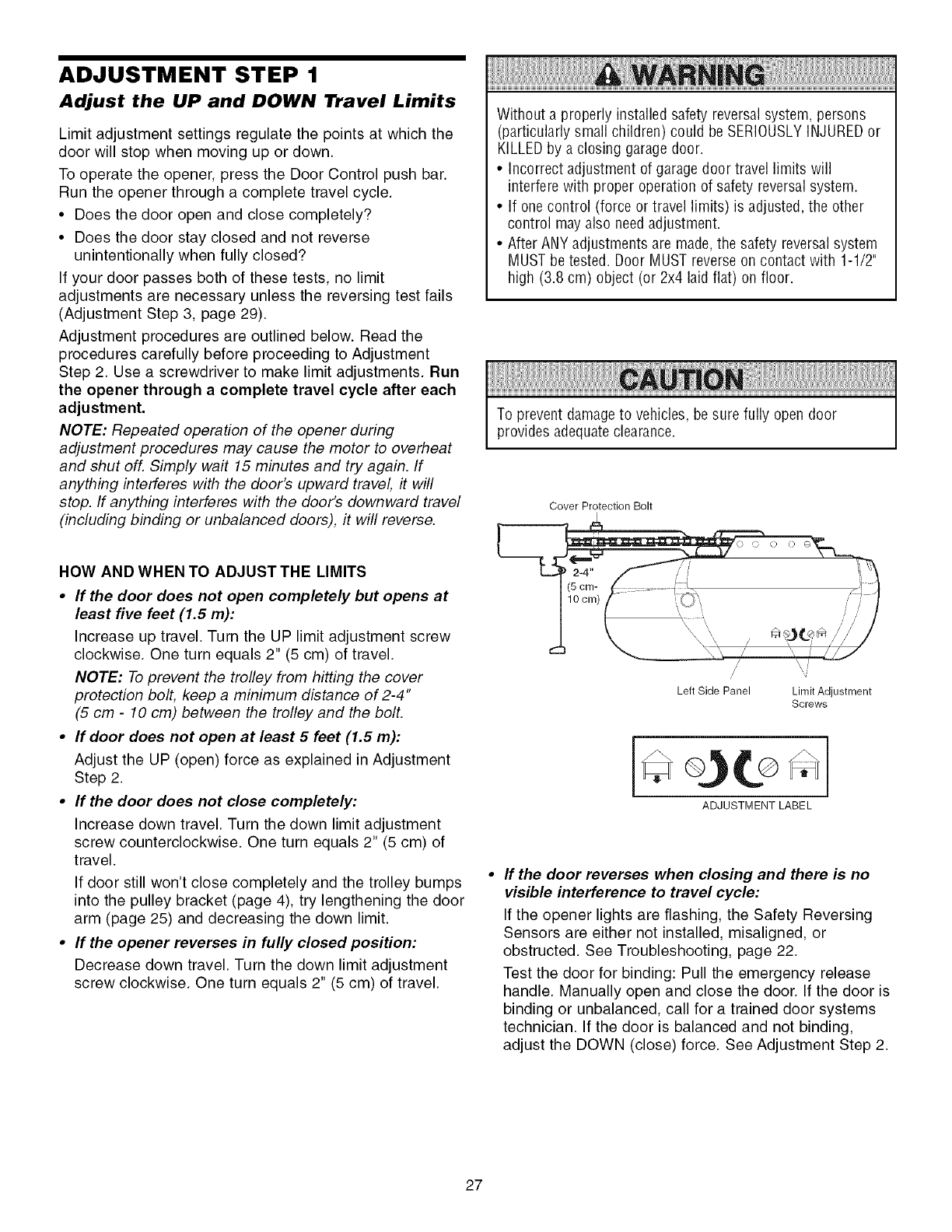
ADJUSTMENT STEP 1
Adjust the UP and DOWN Travel Limits
Limit adjustment settings regulate the points at which the
door will stop when moving up or down.
To operate the opener, press the Door Control push bar.
Run the opener through a complete travel cycle.
• Does the door open and close completely?
• Does the door stay closed and not reverse
unintentionally when fully closed?
If your door passes both of these tests, no limit
adjustments are necessary unless the reversing test fails
(Adjustment Step 3, page 29).
Adjustment procedures are outlined below. Read the
procedures carefully before proceeding to Adjustment
Step 2. Use a screwdriver to make limit adjustments. Run
the opener through a complete travel cycle after each
adjustment.
NOTE: Repeated operation of the opener during
adjustment procedures may cause the motor to overheat
and shut off. Simply wait 15 minutes and try again. If
anything interferes with the door's upward travel it will
stop. If anything interferes with the door's downward travel
(including binding or unbalanced doors), it will reverse.
HOW AND WHEN TO ADJUST THE LIMITS
•If the door does not open completely but opens at
least five feet (1.5 m):
Increase up travel. Turn the UP limit adjustment screw
clockwise. One turn equals 2" (5 cm) of travel.
NOTE: To prevent the trolley from hitting the cover
protection bolt, keep a minimum distance of 2-4"
(5 cm -10 cm) between the trolley and the boll
•If door does not open at least 5 feet (1.5 m):
Adjust the UP (open) force as explained in Adjustment
Step 2.
•If the door does not close completely:
Increase down travel. Turn the down limit adjustment
screw counterclockwise. One turn equals 2" (5 cm) of
travel.
If door still won't close completely and the trolley bumps
into the pulley bracket (page 4), try lengthening the door
arm (page 25) and decreasing the down limit.
•If the opener reverses in fully closed position:
Decrease down travel. Turn the down limit adjustment
screw clockwise. One turn equals 2" (5 cm) of travel.
Without a properly installed safety reversal system, persons
(particularly small children) could be SERIOUSLYINJUREDor
KILLEDby a closing garagedoor.
• Incorrect adjustment of garage door travel limits will
interfere with proper operation of safety reversalsystem.
• If one control (force or travel limits) is adjusted, the other
control may also needadjustment.
• After ANY adjustments are made,the safety reversalsystem
MUST be tested. Door MUST reverse on contact with 1-1/2"
high (3.8 cm) object (or 2x4 laid flat) on floor.
To prevent damageto vehicles, be sure fully open door
provides adequate clearance.
Cover Protection Bolt
2-4" ,"/ it
/foem f,_2_...... "_ l
J. _ \\_, J "T"- /// /
/W
Left Side Panel Limit Adjustment
Screws
ADJUSTMENT LABEL
If the door reverses when closing and there is no
visible interference to travel cycle:
If the opener lights are flashing, the Safety Reversing
Sensors are either not installed, misaligned, or
obstructed. See Troubleshooting, page 22.
Test the door for binding: Pull the emergency release
handle. Manually open and close the door. If the door is
binding or unbalanced, call for a trained door systems
technician. If the door is balanced and not binding,
adjust the DOWN (close) force. See Adjustment Step 2.
27
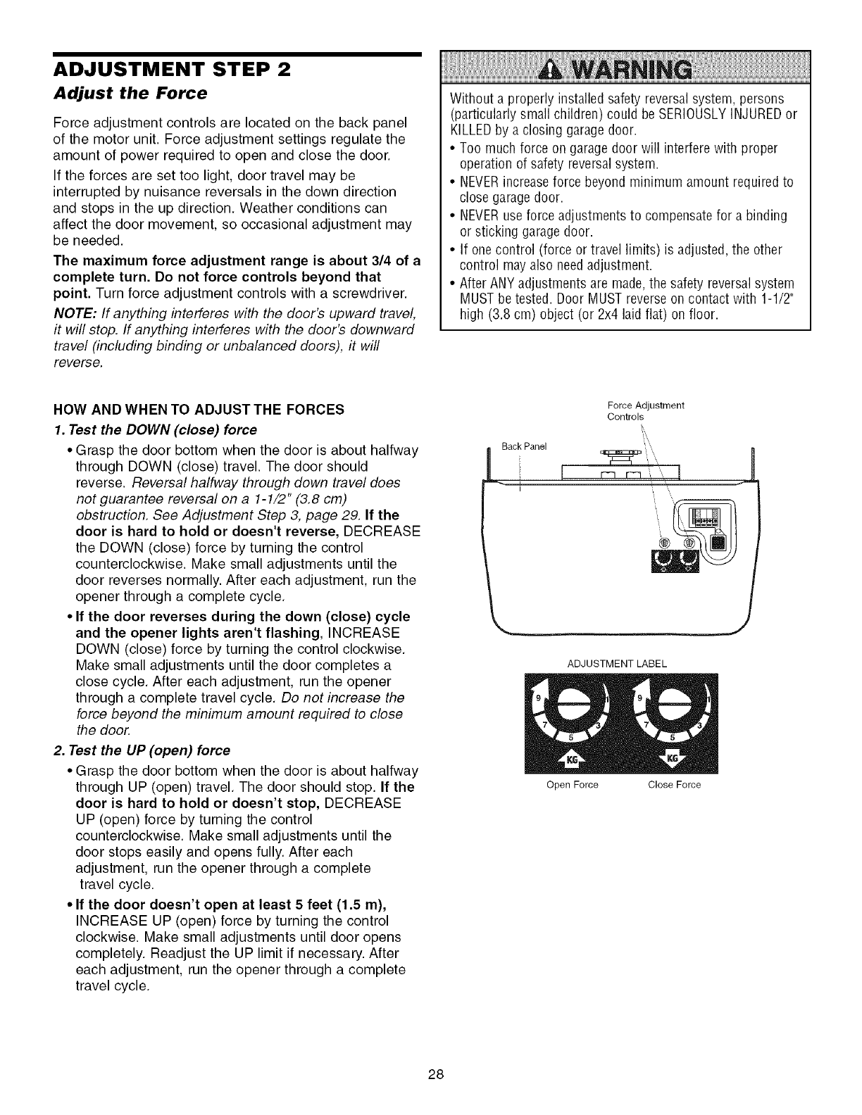
ADJUSTMENT STEP 2
Adjust the Force
Force adjustment controls are located on the back panel
of the motor unit. Force adjustment settings regulate the
amount of power required to open and close the door.
If the forces are set too light, door travel may be
interrupted by nuisance reversals in the down direction
and stops in the up direction. Weather conditions can
affect the door movement, so occasional adjustment may
be needed.
The maximum force adjustment range is about 3/4 of a
complete turn. Do not force controls beyond that
point. Turn force adjustment controls with a screwdriver.
NOTE: If anything interferes with the door's upward travel,
it will stop. If anything interferes with the door's downward
travel (including binding or unbalanced doors), it will
reverse.
Without a properly installed safety reversal system, persons
(particularly small children) could be SERIOUSLYINJUREDor
KILLEDby a closing garagedoor.
• Too much force on garage door will interfere with proper
operation of safety reversalsystem.
• NEVERincreaseforce beyond minimum amount required to
close garage door.
• NEVERuse force adjustments to compensate for a binding
or sticking garage door.
• If one control (force or travel limits) is adjusted, the other
control may also needadjustment.
• After ANY adjustments are made,the safety reversalsystem
MUST be tested. Door MUST reverse on contact with 1-1/2"
high (3.8 cm) object (or 2x4 laid flat) on floor.
HOW AND WHEN TO ADJUST THE FORCES
1. Test the DOWN (close) force
• Grasp the door bottom when the door is about halfway
through DOWN (close) travel. The door should
reverse. Reversal halfway through down travel does
not guarantee reversal on a 1-1/2" (3.8 cm)
obstruction. See Adjustment Step 3, page 29. If the
door is hard to hold or doesn't reverse, DECREASE
the DOWN (close) force by turning the control
counterclockwise. Make small adjustments until the
door reverses normally. After each adjustment, run the
opener through a complete cycle.
•If the door reverses during the down (close) cycle
and the opener lights aren't flashing, INCREASE
DOWN (close) force by turning the control clockwise.
Make small adjustments until the door completes a
close cycle. After each adjustment, run the opener
through a complete travel cycle. Do not increase the
force beyond the minimum amount required to close
the door.
2. Test the UP (open) force
• Grasp the door bottom when the door is about halfway
through UP (open) travel. The door should stop. If the
door is hard to hold or doesn't stop, DECREASE
UP (open) force by turning the control
counterclockwise. Make small adjustments until the
door stops easily and opens fully. After each
adjustment, run the opener through a complete
travel cycle.
• If the door doesn't open at least 5 feet (1.5 m),
INCREASE UP (open) force by turning the control
clockwise. Make small adjustments until door opens
completely. Readjust the UP limit if necessary. After
each adjustment, run the opener through a complete
travel cycle.
Back Panel
i
Force Adjustment
Controls
_,,
J
ADJUSTMENT LABEL
Open Force Close Force
28
ADJUSTMENT STEP 3
Test the Safety Reversal System
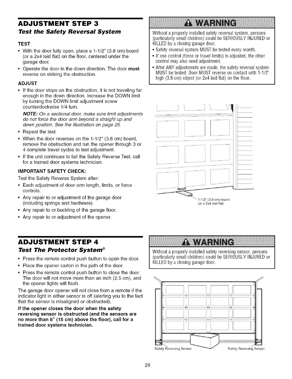
TEST
•With the door fully open, place a 1-1/2" (3.8 cm) board
(or a 2x4 laid flat) on the floor, centered under the
garage door.
• Operate the door in the down direction. The door must
reverse on striking the obstruction.
ADJUST
• If the door stops on the obstruction, it is not traveling far
enough in the down direction. Increase the DOWN limit
by turning the DOWN limit adjustment screw
counterclockwise 1/4 turn.
NOTE: On a sectional door, make sure limit adjustments
do not force the door arm beyond a straight up and
down position. See the illustration on page 25.
• Repeat the test.
• When the door reverses on the 1-1/2" (3.8 cm) board,
remove the obstruction and run the opener through 3 or
4 complete travel cycles to test adjustment.
• If the unit continues to fail the Safety Reverse Test, call
for a trained door systems technician.
IMPORTANT SAFETY CHECK:
Test the Safety Reverse System after:
• Each adjustment of door arm length, limits, or force
controls.
• Any repair to or adjustment of the garage door
(including springs and hardware).
• Any repair to or buckling of the garage floor.
• Any repair to or adjustment of the opener.
Without a properly installed safety reversal system, persons
(particularly small children) could be SERIOUSLYINJUREDor
KILLEDby a closing garagedoor.
• Safety reversal system MUSTbe tested every month.
• If one control (force or travel limits) is adjusted, the other
control may also needadjustment.
• After ANY adjustments are made,the safety reversalsystem
MUST be tested. Door MUST reverse on contact with 1-1/2"
high (3.8 cm) object (or 2x4 laid flat) on the floor.
(or a 2x4 laid fiat)
ADJUSTMENT STEP 4
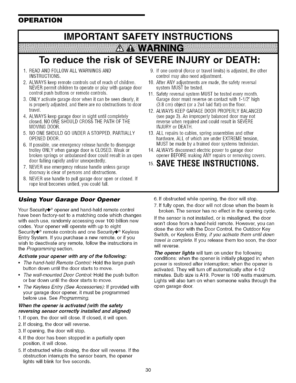
Test The Protector System ®
• Press the remote control push button to open the door.
• Place the opener carton in the path of the door.
• Press the remote control push button to close the door.
The door will not move more than an inch (2.5 cm), and
the opener lights will flash.
The garage door opener will not close from a remote if the
indicator light in either sensor is off (alerting you to the fact
that the sensor is misaligned or obstructed).
If the opener closes the door when the safety
reversing sensor is obstructed (and the sensors are
no more than 6" (15 cm) above the floor), call for a
trained door systems technician.
Without a properly installed safety reversing sensor, persons
(particularly small children) could be SERIOUSLYINJUREDor
KILLEDby a closing garagedoor.
m
--
Safeb Reversing Sensor
29
OPERATION
IMPORTANT SAFETY INSTRUCTIONS
To reduce the risk of SEVERE INJURY or DEATH:
1. READAND FOLLOWALL WARNINGSAND
iNSTRUCTIONS.
2. ALWAYS keep remote controls out of reach of children.
NEVERpermit children to operate or play with garage door
control push buttons or remote controls.
3. ONLYactivate garage door when it can be seen clearly, it
is properly adjusted, and there are no obstructions to door
travel.
4. ALWAYS keepgarage door in sight until completely
closed. NO ONESHOULDCROSSTHEPATHOFTHE
MOVING DOOR.
5. NO ONESHOULDGOUNDERA STOPPED,PARTIALLY
OPENEDDOOR.
6. If possible, use emergency release handleto disengage
trolley ONLYwhen garage door is CLOSED.Weak or
broken springs or unbalanceddoor could result in an open
door failing rapidly and/or unexpectedly.
7. NEVERuse emergency releasehandle unless garage
doorway is clear of persons and obstructions.
8. NEVERuse handleto pull garagedoor open or closed. If
rope knot becomes untied, you could fall.
9. If one control (force or travel limits) is adjusted, the other
control mayalso need adjustment.
10. After ANY adjustments are made,the safety reversal
system MUST be tested.
11. Safety reversal system MUST be tested every month.
Garagedoor must reverseon contact with 1-1/2" high
(3.8 cm) object (or a 2x4 laid fiat) on the floor.
12. ALWAYS KEEPGARAGEDOORPROPERLYBALANCED
(see page 3). An improperly balanced door may not
reversewhen required and could result in SEVERE
INJURY or DEATH.
13. ALL repairs to cables, spring assemblies and other
hardware,ALL of which are under EXTREMEtension,
MUST be made by atrained door systems technician.
14. ALWAYSdisconnect electric power to garage door
opener BEFOREmaking ANY repairs or removing covers.
SAVETHESEINSTRUCTIONS.
Using Your Garage Door Opener
Your Security+ ® opener and hand-held remote control
have been factory-set to a matching code which changes
with each use, randomly accessing over 100 billion new
codes. Your opener will operate with up to eight
Security+ ®remote controls and one Security+ ® Keyless
Entry System. If you purchase a new remote, or if you
wish to deactivate any remote, follow the instructions in
the Programming section.
Activate your opener with any of the following:
•The hand-held Remote Control: Hold the large push
button down until the door starts to move.
• The wall-mounted Door Control: Hold the push button
or bar down until the door starts to move.
• The Keyless Entry (See Accessories): If provided with
your garage door opener, it must be programmed
before use. See Programming.
When the opener is activated (with the safety
reversing sensor correctly installed and aligned)
1. If open, the door will close. If closed, it will open.
2. If closing, the door will reverse.
3. If opening, the door will stop.
4. If the door has been stopped in a partially open
position, it will close.
5. If obstructed while closing, the door will reverse. If the
obstruction interrupts the sensor beam, the opener
lights will blink for five seconds.
6. If obstructed while opening, the door will stop.
7. If fully open, the door will not close when the beam is
broken. The sensor has no effect in the opening cycle.
If the sensor is not installed, or is misaligned, the door
won't close from a hand-held remote. However, you can
close the door with the Door Control, the Outdoor Key
Switch, or Keyless Entry, if you activate them until down
travel is complete. If you release them too soon, the door
will reverse.
The opener lights will turn on under the following
conditions: when the opener is initially plugged in; when
power is restored after interruption; when the opener is
activated. They will turn off automatically after 4-1/2
minutes. Bulb size is A19. Power is 100 watts maximum.
Lights will also turn on when someone walks through the
open garage door.
3O
Using the Wall.Mounted Door Control
Press the lighted push button to open
or close the door. Press again to
reverse the door during the closing
cycle or to stop the door while it's
opening.
To Open the Door Manually
To prevent possible SERIOUSINJURYor DEATHfrom a falling
garage door:
• if possible, use emergency release handleto disengage
trolley ONLYwhen garage door is CLOSED.Weak or broken
springs or unbalanceddoor could result in an open door
failing rapidly and/or unexpectedly.
• NEVERuse emergency releasehandle unless garage
doorway is clear of persons and obstructions.
• NEVERuse handleto pull door open or closed. If rope knot
becomes untied,you could fall.
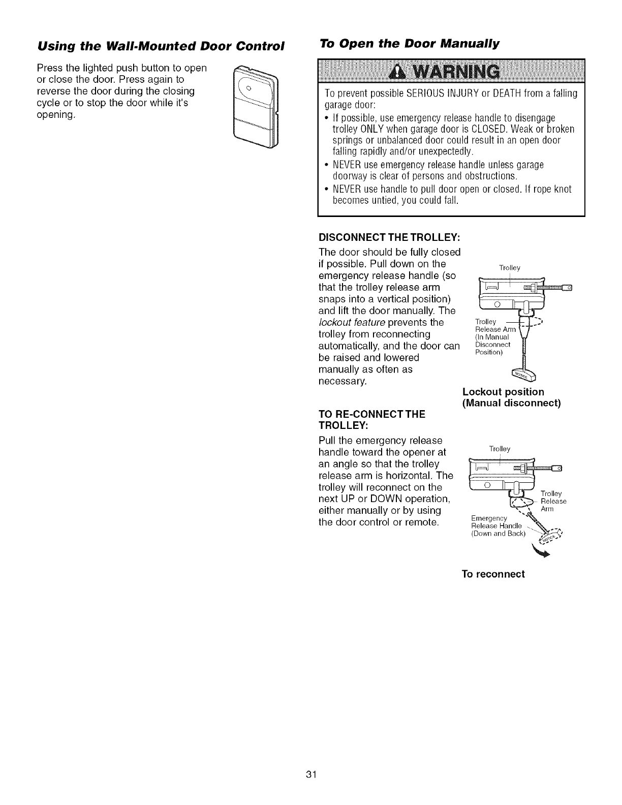
DISCONNECT THE TROLLEY:
The door should be fully closed
if possible. Pull down on the
emergency release handle (so
that the trolley release arm
snaps into a vertical position)
and lift the door manually. The
lockout feature prevents the
trolley from reconnecting
automatically, and the door can
be raised and lowered
manually as often as
necessary.
TO RE-CONNECTTHE
TROLLEY:
Pull the emergency release
handle toward the opener at
an angle so that the trolley
release arm is horizontal. The
trolley will reconnect on the
next UP or DOWN operation,
either manually or by using
the door control or remote.
Trolley
i
Trolley
Release Arm
(In Manual
Disconnect
Position)
Lockout position
(Manual disconnect)
Trolley
Rrenl/ease
Emergency ""_
Release Handle _ _ _
(Down and Back) "'-_'
To reconnect
31
CARE OF YOUR GARAGE DOOR
OPENER
LIMIT AND FORCE FORCECONTROLS
ADJUSTMENTS:
Weather conditions may cause
some minor changes in door
operation requiring some
re-adjustments, particularly
during the first year of operation.
Pages 27 and 28 refer to the
limit and force adjustments Only
a screwdriver is required. Follow
the instructions carefully
Repeat the safety reverse test (Adjustment Step 3,
page 29) after any adjustment of limits or force.
LIMIT CONTROLS
MAINTENANCE SCHEDULE
Once a Month
•Manually operate door. If it is unbalanced or binding, call
a trained door systems technician.
• Check to be sure door opens & closes fully Adjust limits
and/or force if necessary (See pages 27 and 28)
• Repeat the safety reverse test. Make any necessary
adjustments. (See Adjustment Step 3)
Twice a Year
• Check chain tension Disconnect trolley first Adjust if
necessary (See page 11)
Once a Year
• Oil door rollers, bearings and hinges The opener does
not require additional lubrication Do not grease the door
tracks
THE REMOTE CONTROL BATTERY
To prevent possible SERIOUSINJURYor DEATH:
•NEVERallow small children near batteries
•If battery is swallowed, immediately notify doctor
To reduce risk of fire, explosion or chemical burn:
•ReplaceONLYwith 3V2032 coin batteries
•Do NOTrecharge, disassemble, heat above 100°0 (212°F) or
incinerate
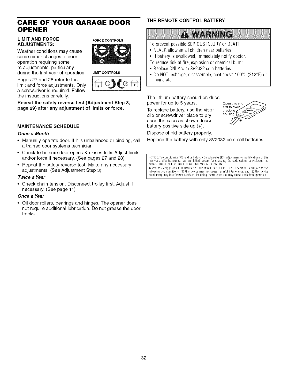
The lithium battery should produce
power for up to 5 years.
To replace battery, use the visor
clip or screwdriver blade to pry
open the case as shown. Insert
battery positive side up (+).
Dispose of old battery properly.
Open this end
first to avoidJ _....._
eracking_ _-_----%z-'fJJ
hous_
Replace the battery with only 3V2032 coin cell batteries.
NOTICE:To comply with FOCand or Industry Oanadarules (IC),adjustment or modifications of this
receiverand/or transmitter are prohibited, except for changing the code setting or replacing the
battery.THEREARENOOTHERUSERSERVICEABLEPARTS.
Tested to Comply with FOBStandards FORHOME OR OFFICEUSE. Operation is subjectto the
following two conditions: (1) this device may not cause harmful interference,and (2) this device
must acceptany interference received,includinginterferencethat may causeundesiredoperation.
32
HAVING A PROBLEM?
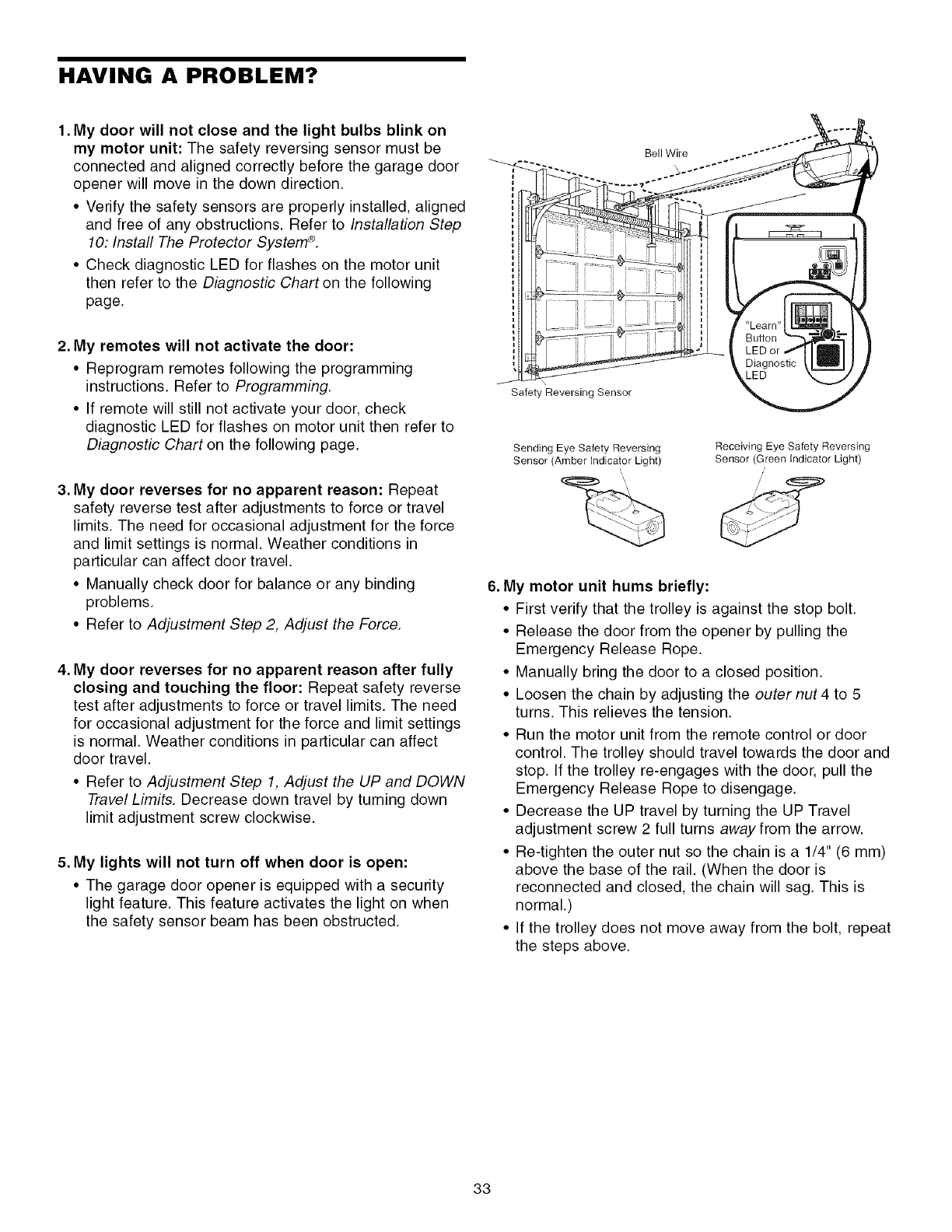
1. My door will not close and the light bulbs blink on
my motor unit: The safety reversing sensor must be
connected and aligned correctly before the garage door
opener will move in the down direction.
• Verify the safety sensors are properly installed, aligned
and free of any obstructions. Refer to Installation Step
10: Install The Protector System ®.
• Check diagnostic LED for flashes on the motor unit
then refer to the Diagnostic Chart on the following
page.
2. My remotes will not activate the door:
• Reprogram remotes following the programming
instructions. Refer to Programming.
• If remote will still not activate your door, check
diagnostic LED for flashes on motor unit then refer to
Diagnostic Chart on the following page.
3. My door reverses for no apparent reason: Repeat
safety reverse test after adjustments to force or travel
limits. The need for occasional adjustment for the force
and limit settings is normal. Weather conditions in
particular can affect door travel.
• Manually check door for balance or any binding
problems.
• Refer to Adjustment Step 2, Adjust the Force.
4. My door reverses for no apparent reason after fully
closing and touching the floor: Repeat safety reverse
test after adjustments to force or travel limits. The need
for occasional adjustment for the force and limit settings
is normal. Weather conditions in particular can affect
door travel.
• Refer to Adjustment Step 1, Adjust the UP and DOWN
Travel Limits. Decrease down travel by turning down
limit adjustment screw clockwise.
5. My lights will not turn off when door is open:
• The garage door opener is equipped with a security
light feature. This feature activates the light on when
the safety sensor beam has been obstructed.
Bell Wire
Safety Reversing Sensor
Sending Eye Safety Reversing
Sensor (Amber indicator Light)
Receiving Eye Safety Reversing
Sensor (Green indicator Light)
/
6. My motor unit hums briefly:
• First verify that the trolley is against the stop bolt.
• Release the door from the opener by pulling the
Emergency Release Rope.
• Manually bring the door to a closed position.
• Loosen the chain by adjusting the outer nut4 to 5
turns. This relieves the tension.
• Run the motor unit from the remote control or door
control. The trolley should travel towards the door and
stop. If the trolley re-engages with the door, pull the
Emergency Release Rope to disengage.
• Decrease the UP travel by turning the UP Travel
adjustment screw 2 full turns away from the arrow.
• Re-tighten the outer nut so the chain is a 1/4" (6 mm)
above the base of the rail. (When the door is
reconnected and closed, the chain will sag. This is
normal.)
• If the trolley does not move away from the bolt, repeat
the steps above.
33
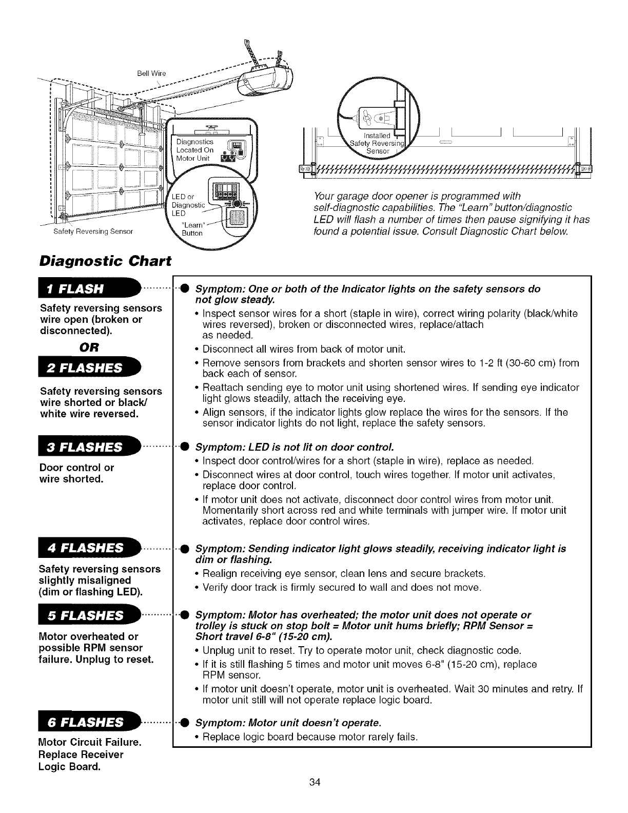
Bell Wire
\
Safety Reversing Sensor
Diagnostic Chart
Safety reversing sensors
wire open (broken or
disconnected).
OR
Safety reversing sensors
wire shorted or black/
white wire reversed.
Door control or
wire shorted.
Safety reversing sensors
slightly misaligned
(dim or flashing LED).
Motor overheated or
possible RPM sensor
failure. Unplug to reset.
Motor Circuit Failure.
Replace Receiver
Logic Board.
Your garage door opener is programmed with
self-diagnostic capabilities. The "Learn" button/diagnostic
LED will flash a number of times then pause signifying it has
found a potential issue. Consult Diagnostic Chart below.
e
e
Symptom: One or both of the Indicator lights on the safety sensors do
not glow steady.
• Inspect sensor wires for a short (staple in wire), correct wiring polarity (black/white
wires reversed), broken or disconnected wires, replace/attach
as needed.
• Disconnect all wires from back of motor unit.
• Remove sensors from brackets and shorten sensor wires to 1-2 ft (30-60 cm) from
back each of sensor.
• Reattach sending eye to motor unit using shortened wires. If sending eye indicator
light glows steadily, attach the receiving eye.
• Align sensors, if the indicator lights glow replace the wires for the sensors. If the
sensor indicator lights do not light, replace the safety sensors.
Symptom: LED is not fit on door control.
• Inspect door control/wires for a short (staple in wire), replace as needed.
• Disconnect wires at door control, touch wires together. If motor unit activates,
replace door control.
• If motor unit does not activate, disconnect door control wires from motor unit.
Momentarily short across red and white terminals with jumper wire. If motor unit
activates, replace door control wires.
--e Symptom: Sending indicator light glows steadily, receiving indicator light is
dim or flashing.
• Realign receiving eye sensor, clean lens and secure brackets.
• Verify door track is firmly secured to wall and does not move.
0Symptom: Motor has overheated; the motor unit does not operate or
trolley is stuck on stop bolt = Motor unit hums briefly; RPM Sensor =
Short travel 6-8" (15-20 cm).
• Unplug unit to reset. Try to operate motor unit, check diagnostic code.
• If it is still flashing 5 times and motor unit moves 6-8" (15-20 cm), replace
RPM sensor.
• If motor unit doesn't operate, motor unit is overheated. Wait 30 minutes and retry. If
motor unit still will not operate replace logic board.
•"0 Symptom: Motor unit doesn't operate.
• Replace logic board because motor rarely fails.
34
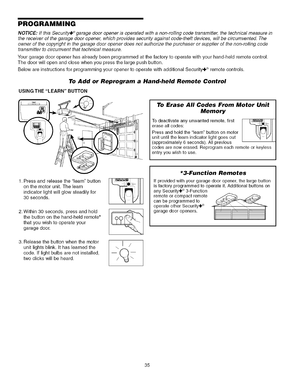
PROGRAMMING
NOTICE: If this Security,F _garage door opener is operated with a non-rolling code transmitter, the technical measure in
the receiver of the garage door opener, which provides security against code-theft devices, will be circumvented, The
owner of the copyright in the garage door opener does not authorize the purchaser or supplier of the non-rolling code
transmitter to circumvent that technical measure,
Your garage door opener has already been programmed at the factory to operate with your hand-held remote control,
The door will open and close when you press the large push button,
Below are instructions for programming your opener to operate with additional Security+ _ remote controls.
To Add or Reprogram a Hand.held Remote Control
USING THE "LEARN" BUTTON
1, Press and release the "learn" button
on the motor unit. The learn
indicator light will glow steadily for
30 seconds,
2. Within 30 seconds, press and hold
the button on the hand-held remote*
that you wish to operate your
garage door.
3. Release the button when the motor
unit lights blink. It has learned the
code. If light bulbs are not installed,
two clicks will be heard.
. I /
To Erase All Codes From Motor Unit
Memory
To deactivate any unwanted remote, first
erase all codes:
Press and hold the "learn" button on motor
unit until the learn indicator light goes out
(approximately 6 seconds), All previous
codes are now erased, Reprogram each
entry you wish to use, iote or keyless
*3-Function Remotes
If provided with your garage door opener, the large button
is factory programmed to operate it. Additional buttons on
any Security÷ e_3-Function
remote or compact remote _ ..._"_
can be programmed to
operate other Security÷ e_
garage door openers.
35
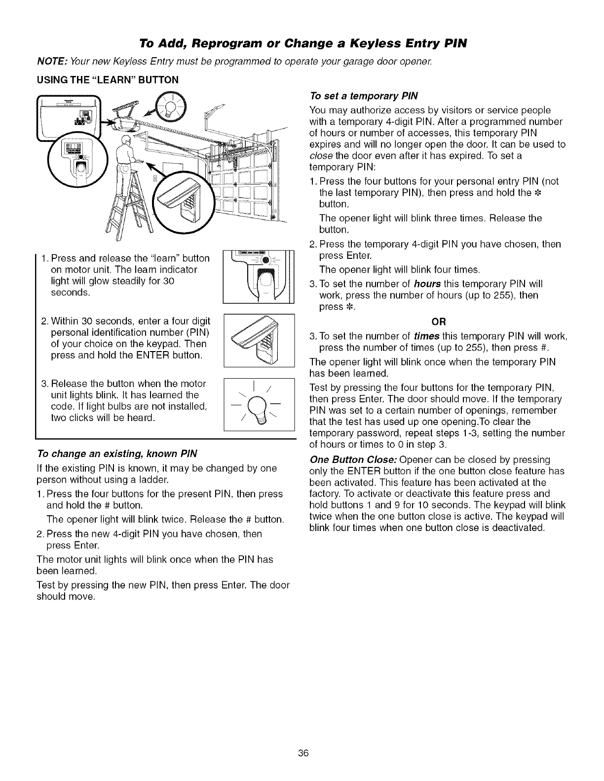
To Add, Reprogram or Change a Keyless Entry PIN
NOTE: Your new Keyless Entry must be programmed to operate your garage door opener.
USING THE "LEARN" BUTTON
1. Press and release the "learn" button
on motor unit. The learn indicator
light will glow steadily for 30
seconds.
2. Within 30 seconds, enter a four digit
personal identification number (PIN)
of your choice on the keypad. Then
press and hold the ENTER button.
3. Release the button when the motor
unit lights blink. It has learned the
code. If light bulbs are not installed,
two clicks will be heard.
\1 /
To change an existing, known PIN
If the existing PIN is known, it may be changed by one
person without using a ladder.
1. Press the four buttons for the present PIN, then press
and hold the # button.
The opener light will blink twice. Release the # button.
2. Press the new 4-digit PIN you have chosen, then
press Enter.
The motor unit lights will blink once when the PIN has
been learned.
Test by pressing the new PIN, then press Enter. The door
should move.
To set a temporary PIN
You may authorize access by visitors or service people
with a temporary 4-digit PIN. After a programmed number
of hours or number of accesses, this temporary PIN
expires and will no longer open the door. It can be used to
close the door even after it has expired. To set a
temporary PIN:
1. Press the four buttons for your personal entry PIN (not
the last temporary PIN), then press and hold the _=
button.
The opener light will blink three times. Release the
button.
2. Press the temporary 4-digit PIN you have chosen, then
press Enter.
The opener light will blink four times.
3. To set the number of hours this temporary PIN will
work, press the number of hours (up to 255), then
press _=.
OR
3. To set the number of times this temporary PIN will work,
press the number of times (up to 255), then press #.
The opener light will blink once when the temporary PIN
has been learned.
Test by pressing the four buttons for the temporary PIN,
then press Enter. The door should move. If the temporary
PIN was set to a certain number of openings, remember
that the test has used up one opening.To clear the
temporary password, repeat steps 1-3, setting the number
of hours or times to 0 in step 3.
One Button Close: Opener can be closed by pressing
only the ENTER button if the one button close feature has
been activated. This feature has been activated at the
factory. To activate or deactivate this feature press and
hold buttons 1 and 9 for 10 seconds. The keypad will blink
twice when the one button close is active. The keypad will
blink four times when one button close is deactivated.
36
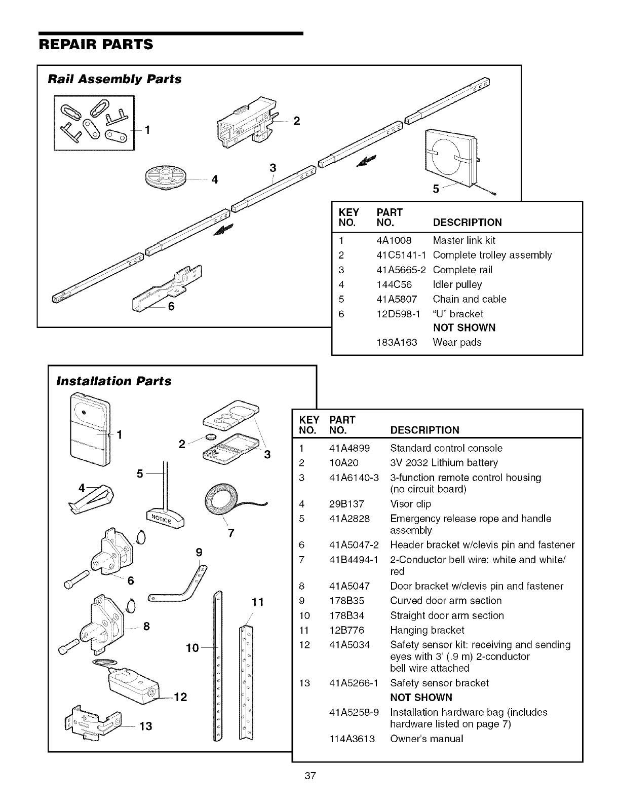
REPAIR PARTS
Rail Assembly Parts
2
4
3
6
Installation Parts
KEY
NO.
1
2
3
4
5
6
PART
NO. DESCRIPTION
4A1008 Master link kit
41C5141-1 Complete trolley assembly
41A5665-2 Complete rail
144C56 Idler pulley
41A5807 Chain and cable
12D598-1 "U" bracket
NOT SHOWN
183A163 Wear pads
o
; j
810
12
13
11
/
/
KEY
NO.
1
2
3
4
5
6
7
8
9
10
11
12
13
PART
NO.
41 A4899
10A20
41 A6140-3
29B137
41A2828
41A5047-2
41B4494-1
41 A5047
178B35
178B34
12B776
41 A5034
41A5266-1
41A5258-9
114A3613
DESCRIPTION
Standard control console
3V 2032 Lithium battery
3-function remote control housing
(no circuit board)
Visor clip
Emergency release rope and handle
assembly
Header bracket w/clevis pin and fastener
2-Conductor bell wire: white and white/
red
Door bracket w/clevis pin and fastener
Curved door arm section
Straight door arm section
Hanging bracket
Safety sensor kit: receiving and sending
eyes with 3' (.9 m) 2-conductor
bell wire attached
Safety sensor bracket
NOT SHOWN
Installation hardware bag (includes
hardware listed on page 7)
Owner's manual
37
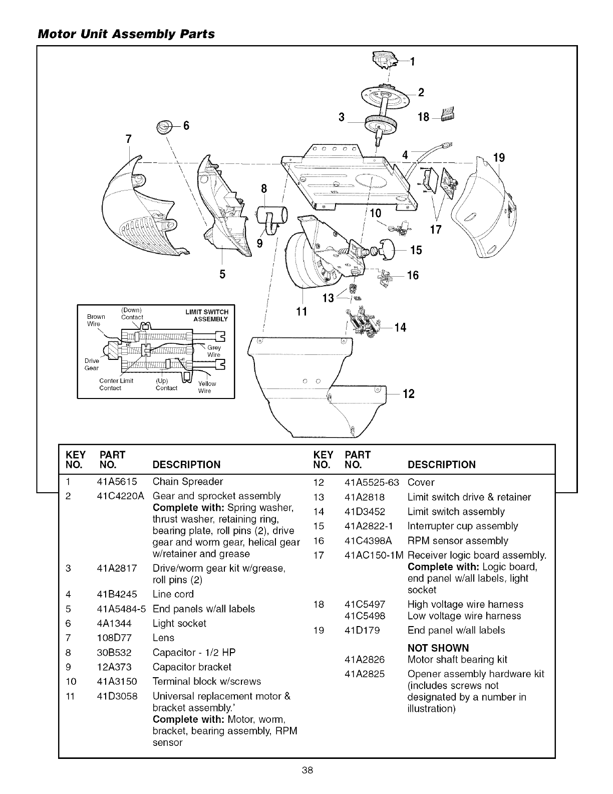
Motor Unit Assembly Parts
_6
7\
\
\\\
\\
(Down) LIMIT SWITCH
Brown Contact ASSEMBLY
Wit\
Center Limit (Up) _ Yellow
Contact Contact Wire
3
' 1
' 14
i
........... •............ _ • 'o 1
KEY PART KEY PART
NO. NO. DESCRIPTION NO. NO. DESCRIPTION
1
2
41A5615
41C4220A
41A2817
4 41 B4245
5 41A5484-5
6 4A1344
7 108D77
8 30B532
9 12A373
10 41A3150
11 41D3058
Chain Spreader
Gear and sprocket assembly
Complete with: Spring washer,
thrust washer, retaining ring,
bearing plate, roll pins (2), drive
gear and worm gear, helical gear
w/retainer and grease
Drive/worm gear kit w/grease,
roll pins (2)
Line cord
End panels w/all labels
Light socket
Lens
Capacitor- 1/2 HP
Capacitor bracket
Terminal block w/screws
Universal replacement motor &
bracket assembly.'
Complete with: Motor, worm,
bracket, bearing assembly, RPM
sensor
12 41 A5525-63
13 41A2818
14 41 D3452
15 41A2822-1
16 41 C4398A
17 41AC150-1M
18 41 C5497
41 C5498
19 41D179
41A2826
41A2825
Cover
Limit switch drive & retainer
Limit switch assembly
Interrupter cup assembly
RPM sensor assembly
Receiver logic board assembly.
Complete with: Logic board,
end panel w/all labels, light
socket
High voltage wire harness
Low voltage wire harness
End panel w/all labels
NOT SHOWN
Motor shaft bearing kit
Opener assembly hardware kit
(includes screws not
designated by a number in
illustration)
38
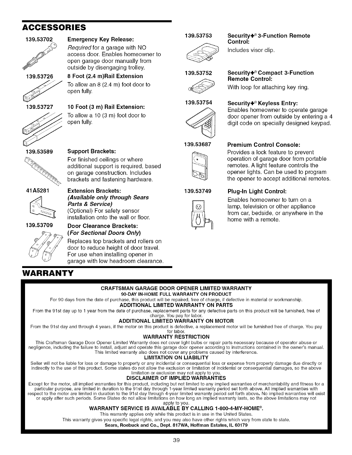
ACCESSORIES
139.53702
139.53726
Emergency Key Release:
Required for a garage with NO
access door. Enables homeowner to
open garage door manually from
outside by disengaging trolley.
8 Foot (2.4 re)Rail Extension
To allow an 8 (2.4 m) foot door to
open fully.
139.53727 10 Foot (3 m) Rail Extension:
To allow a 10 (3 m) foot door to
open fully.
139.53589 Support Brackets:
For finished ceilings or where
additional support is required, based
on garage construction. Includes
brackets and fastening hardware.
41A5281
139.53709
Extension Brackets:
(Available only through Sears
Parts &Service)
(Optional) For safety sensor
installation onto the wall or floor.
Door Clearance Brackets:
(For Sectional Doors Only)
Replaces top brackets and rollers on
door to reduce height of door travel.
For use when installing opener in
garage with low headroom clearance.
WARRANTY
139.53753
139.53752
139.53754
139.53687
139.53749
Secu rity.l.®3-Function Remote
Control:
Includes visor clip.
Security+ ®Compact 3-Function
Remote Control:
With loop for attaching key ring.
Security+ ®Keyless Entry:
Enables homeowner to operate garage
door opener from outside by entering a 4
digit code on specially designed keypad.
Premium Control Console:
Provides a lock feature to prevent
operation of garage door from portable
remotes. A light feature controls the
opener lights. Can be used to program
the opener to accept additional remotes.
Plug-In Light Control:
Enables homeowner to turn on a
lamp, television or other appliance
from car, bedside, or anywhere in the
home with a remote.
CRAFTSMAN GARAGE DOOR OPENER LIMITED WARRANTY
90-DAY IN-HOME FULL WARRANTY ON PRODUCT
For 90 days from the date of purchase, this product will be repaired, free of charge, if defective in material or workmanship.
ADDITIONAL LIMITED WARRANTY ON PARTS
From the 91st day up to 1 year from the date of purchase, replacement parts for any defective parts on this product will be furnished, free of
charge. You pay for labor.
ADDITIONAL LIMITED WARRANTY ON MOTOR
From the 91st day and through 4 years, if the motor on this product is defective, a replacement motor will be furnished free of charge. You pay
for labor.
WARRANTY RESTRICTION
This Craftsman Garage Door Opener Limited Warranty does not cover light bulbs or repair parts necessary because of operator abuse or
negligence, including the failure to install, adjust and operate this garage door opener according to instructions contained in the owner's manual.
This limited warranty also does not cover any problems caused by interference.
LIMITATION ON LIABILITY
Seller will not be liable for loss or damage to property or any incidental or consequential loss or expense from property damage due directly or
indirectly to the use of this product. Some states do not allow the exclusion or limitation of incidental or consequential damages, so the above
limitation or exclusion may not apply to you.
DISCLAIMER OF IMPLIED WARRANTIES
Except for the motor, all implied warranties for this product, including but not limited to any implied warranties of merchantability and fitness for a
particular purpose, are limited in duration to the 91st day through 1-year limited warranty period set forth above. All implied warranties with
respect to the motor are limited in duration to the 91st day through 4-year limited warranty period set forth above. No implied warranties will exist
or apply after such periods. Some States do not allow limitations on how long an implied warranty lasts, so the above limitations may not
apply to you.
WARRANTY SERVICE IS AVAILABLE BY CALLING 1-800-4-MY-HOME ®.
This warranty applies only while this product is in use in the United States.
This warranty gives you specific legal rights, and you may also have other rights which vary from state to state.
Sears, Roebuck and Co., Dept. 817WA, Hoffman Estates, IL 60179
39
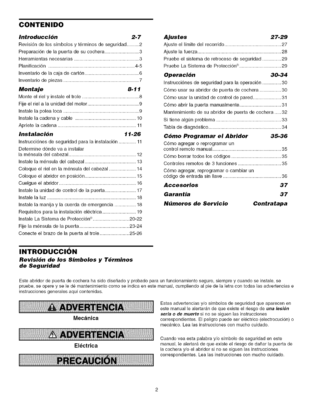
CONTENIDO
Introducci6n 2. 7
Revisi6n de los simbolos y t@minos de seguridad ......... 2
Preparaci6n de la puerta de su cochera ......................... 3
Herramientas necesarias ................................................ 3
Planificaci6n ................................................................ 4-5
Inventario de la caja de cart6n ........................................ 6
Inventario de piezas ........................................................ 7
Montaje 8-11
Monte el riel y instale el trole .......................................... 8
Fije el riel a la unidad del motor ...................................... 9
Instale la polea Ioca ........................................................ 9
Instale la cadena y cable ............................................. 10
Apriete la cadena .......................................................... 11
Instalaci6n 11.26
Instrucci6nes de seguridad para la instalaci6n ............. 11
Determine d6nde va a instalar
la m_nsula del cabezal .................................................. 12
Instale la m_nsula del cabezal ...................................... 13
Coloque el riel en la m_nsula del cabezal .................... 14
Coloque el abridor en posici6n ...................................... 15
Cuelgue el abridor ......................................................... 16
Instale la unidad de control de la puerta ....................... 17
Instale la luz .................................................................. 18
Instale la manija y la cuerda de emergencia ................ 18
Requisitos para la instalaci6n el_ctrica ......................... 19
Instale La Sistema de Protecci6n ®........................... 20-22
Fije la m_nsula de la puerta ..................................... 23-24
Conecte el brazo de la puerta al trole ...................... 25-26
Ajustes 27.29
Ajuste el limite del recorrido .......................................... 27
Ajuste la fuerza .............................................................. 28
Pruebe el sistema de retroceso de seguridad .............. 29
Pruebe La Sistema de Protecci6n®............................... 29
Operaci6n 30.34
Instrucci6nes de seguridad para la operaci6n .............. 30
C6mo usar su abridor de puerta de cochera ................ 30
C6mo usar la unidad de control de pared ..................... 31
C6mo abrir la puerta manualmente ............................... 31
Mantenimiento de su abridor de puerta de cochera ..... 32
Si tiene algun problema ................................................ 33
Tabla de diagn6stico ...................................................... 34
Cbmo Programar el Abridor 35.36
C6mo agregar o reprogramar un
control remoto manual ................................................... 35
C6mo borrar todos los c6digos ..................................... 35
Controles remotos de 3 funciones ................................ 35
C6mo agregar, reprogramar o cambiar un
c6digo de entrada sin Ilave ........................................... 36
Aecesorios 37
Garantia 37
Nbmeros de Servicio Contratapa
INTRODUCCI()N
Revisi6n de los Simbolos y T_rminos
de Seguridad
Este abridor de puerta de cochera ha sido diseSado y probado para un funcionamiento seguro, siempre y cuando se instale, se
pruebe, se opere y se le de mantenimiento como se indica en este manual, cumpliendo al pie de la letra con todas las advertencias e
instrucciones generales aquf contenidas.
Mecanica
Electrica
Estas advertencias y/o simbolos de seguridad que aparecen en
este manual le alertaran de que existe el riesgo de una lesi6n
seria o de muerte si no se siguen las instrucciones
correspondientes. El peligro puede ser electrico (electrocucion) o
mecanico. Lea las instrucciones con mucho cuidado.
Cuando vea esta palabra y/o simbolo de seguridad en este
manual, le alertara de que existe el riesgo de daSar la puerta de
la cochera y/o el abridor si no se siguen las instrucciones
correspondientes. Lea las instrucciones con mucho cuidado.
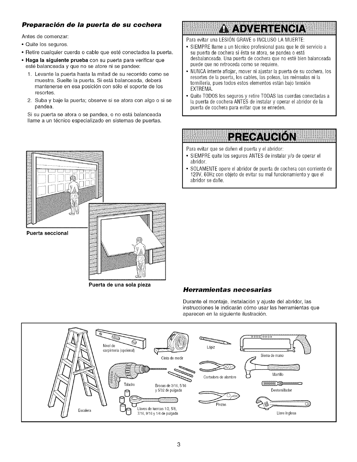
Preparaci6n de la puerta de su cochera
Antes de comenzar:
•Quite los seguros.
• Retire cualquier cuerda o cable que este conectadoa la puerta.
• Haga la siguiente prueba con su puerta para verificar que
este balanceada y que no se atore ni se pandee:
1. Levante la puerta hasta la mitad de su recorrido como se
muestra. Suelte la puerta. Siesta balanceada, debera
mantenerse en esa posicion con solo el soporte de los
resortes.
2. Suba y baje la puerta; observe si se atora con algo o si se
pandea.
Si su puerta se atora o se pandea, o no est& balanceada
Ilame a un tecnico especializado en sistemas de puertas.
Para evitar una LESIONGRAVEo INCLUSOLA MUERTE:
• SIEMPREIlame a un t_cnico profesional para que le d_ servicio a
su puerta de cochera si _sta se atora, se pandea o estA
desbalanceada.Una puerta de cochera que no est_ bien balanceada
puede que no retroceda como se requiere.
• NUNCAintente aflojar, mover ni ajustar la puerta de su cochera, los
resortes de la puerta, los cables, las poleas, las m_nsulas ni la
tornilleria, pues todos estos elementos est_n bajo tension
EXTREMA.
• Quite TODOSIns seguros y retire TODAS las cuerdas conectadas a
la puerta de cochera ANTESde instalar y operar el abridor de la
puerta de cochera para evitar que se enreden.
ParaevitarquesedaOenel puertay el abridor:
• SIEMPREquitelossegurosANTESdeinstalary/o deoperarel
abridor.
• SOLAMENTEopereelabridordepuertadecocheraconcorrientede
120V,60Hzconobjetodeevitarsu malfuncionamientoy queel
abridorsedane.
Puerta seccional
Puerta de una cola pieza Herramientas necesarias
Durante el montaje, instalacion y ajuste del abridor, las
instrucciones le indicaran como usar las herramientas que
aparecen en la siguiente ilustracion.
Escalera
Lapiz
Cinta de medir
Cortadoradealambre
Taladre Brecasde3/16,5/16
y5/32depulgada
L_JO 7/16,9/16 yl/4 de p[_lgad'a
Sierra de mano
Martillo
Destornillador
Llaveinglesa
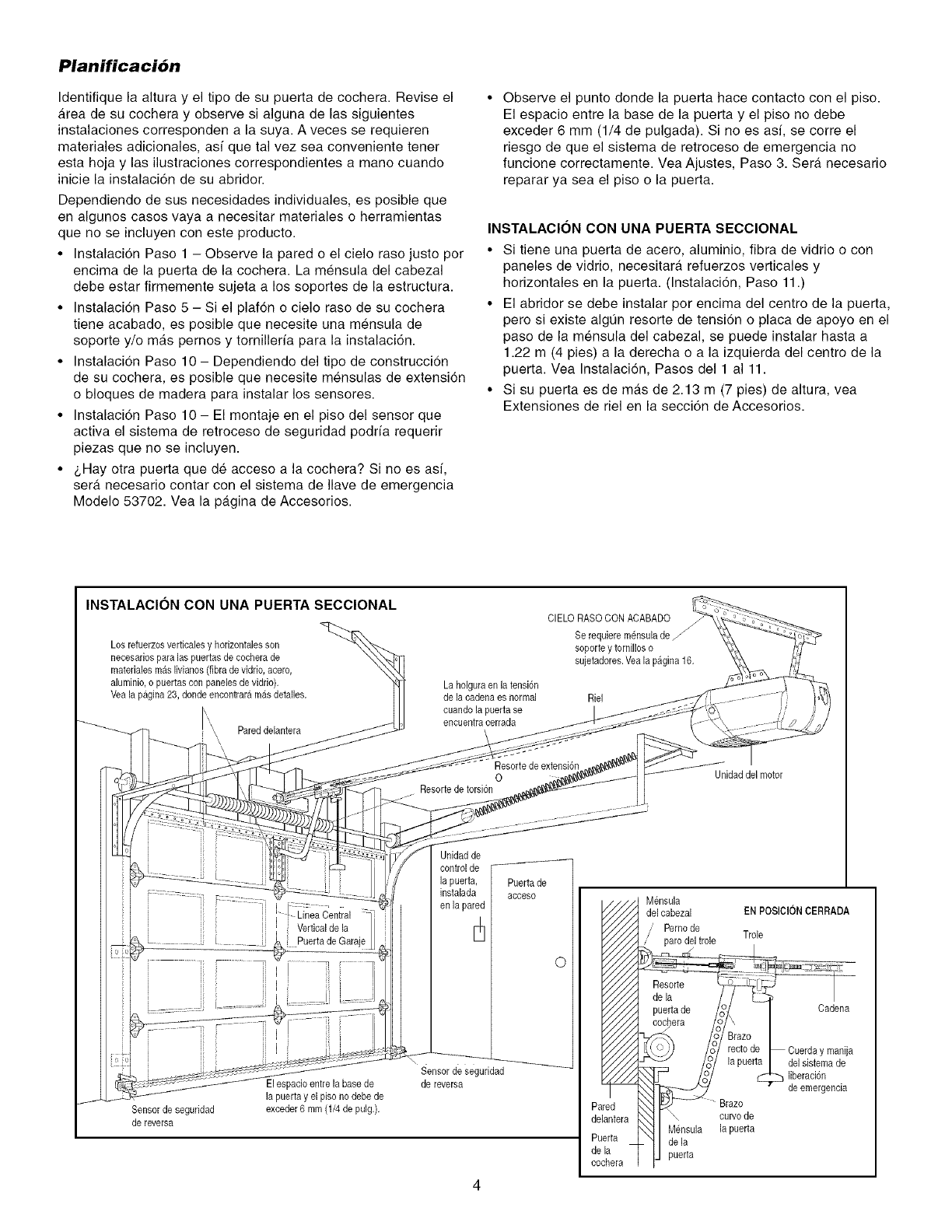
Planificaci6n
Identifique la altura y el tipo de su puerta de cochera. Revise el
a.rea de su cochera y observe si alguna de las siguientes
instalaciones corresponden a la suya. A veces se requieren
materiales adicionales, asf que tal vez sea conveniente tener
esta hoja y las ilustraciones correspondientes a mano cuando
inicie la instalaci6n de su abridor.
Dependiendo de sus necesidades individuales, es posible que
en algunos casos vaya a necesitar materiales o herramientas
que no se incluyen con este producto.
• Instalacion Paso 1 - Observe la pared o el cielo raso justo por
encima de la puerta de la cochera. La mensula del cabezal
debe estar firmemente sujeta a los soportes de la estructura.
• Instalacidn Paso 5 - Si el plaf6n o cielo raso de su cochera
tiene acabado, es posible que necesite una mensula de
soporte y/o mas pernos y tornillerfa para la instalacidn.
• Instalaci6n Paso 10- Dependiendo del tipo de construcci6n
de su cochera, es posible que necesite mensulas de extensi6n
o bloques de madera para instalar los sensores.
• Instalacidn Paso 10- El montaje en el piso del sensor que
activa el sistema de retroceso de seguridad podrfa requerir
piezas que no se incluyen.
• &Hay otra puerta que de acceso a la cochera? Si no es asf,
sera. necesario contar con el sistema de Ilave de emergencia
Modelo 53702. Vea la pagina de Accesorios.
• Observe el punto donde la puerta hace contacto con el piso.
El espacio entre la base de la puerta y el piso no debe
exceder 6 mm (1/4 de pulgada). Si no es asf, se corre el
riesgo de que el sistema de retroceso de emergencia no
funcione correctamente. Vea Ajustes, Paso 3. Sera. necesario
reparar ya sea el piso o la puerta.
INSTALAClON CON UNA PUERTA SECClONAL
• Si tiene una puerta de acero, aluminio, fibra de vidrio o con
paneles de vidrio, necesitar_, refuerzos verticales y
horizontales en la puerta. (Instalaci6n, Paso 11.)
• El abridor se debe instalar pot encima del centro de la puerta,
pero si existe algQn resorte de tensidn o placa de apoyo en el
paso de la mensula del cabezal, se puede instalar hasta a
1.22 m (4 pies) a la derecha o a la izquierda del centro de la
puerta. Vea Instalaci6n, Pasos del 1 a111.
• Si su puerta es de m_.s de 2.13 m (7 pies) de altura, yea
Extensiones de riel en la seccidn de Accesorios.
INSTALAClON CON UNA PUERTA SECClONAL
Los refuerzosverticalesy horizonta]esson
necesariospara las puertas de cocherade
materialesmas livianos(fibra devidrio, acero,
aluminio,o puertas con panelesde vidrio).
Veala pagina 23,donde eneontraramasdetal]es.
Pared delantera
\\
i i LineaCen a
zj I Vertical de la
[J _ PuertadeGaraje
i
i.........
.........
Sensor de seguridad
de reversa
Elespacio entrela basede
la puertay el piso nodebe de
exceder6 mm (1/4 de pulg.).
La holguraen la tensi6n
de lacadena es normal
cuando la puerta se
encuentracerrada
Resorte de extensi6n
0
Resortede torsion
Unidadde
control de
la puerta, Puertade
instalada acceso
en la pared
©
Sensor de seguridad
de reversa
CIELO RASO CONACABADO
Se requiemm_nsulade
soporte y tornillos o
sujetadores.Yea la pagina 16.
Riel ............ "
Unidaddel motor
__dooO dM6nsula
del cabezal ENPOSICIONCERRADA
/Pemo de
,/ pare del trole Trole
esorte I
de la /_ I
puerta de _ /ICadena
cochera /I \ I
BrazoI
/o° rectode _ Cuerday manija
la puerta I del sistemade
liberacion
de emergencia
Pared _ _::J_ Brazo
delantera k__} I \ curvode
,_ I M_nsula lapuerta
Putrta_ _ Idela
dela ]IJ puerta
cochera I F
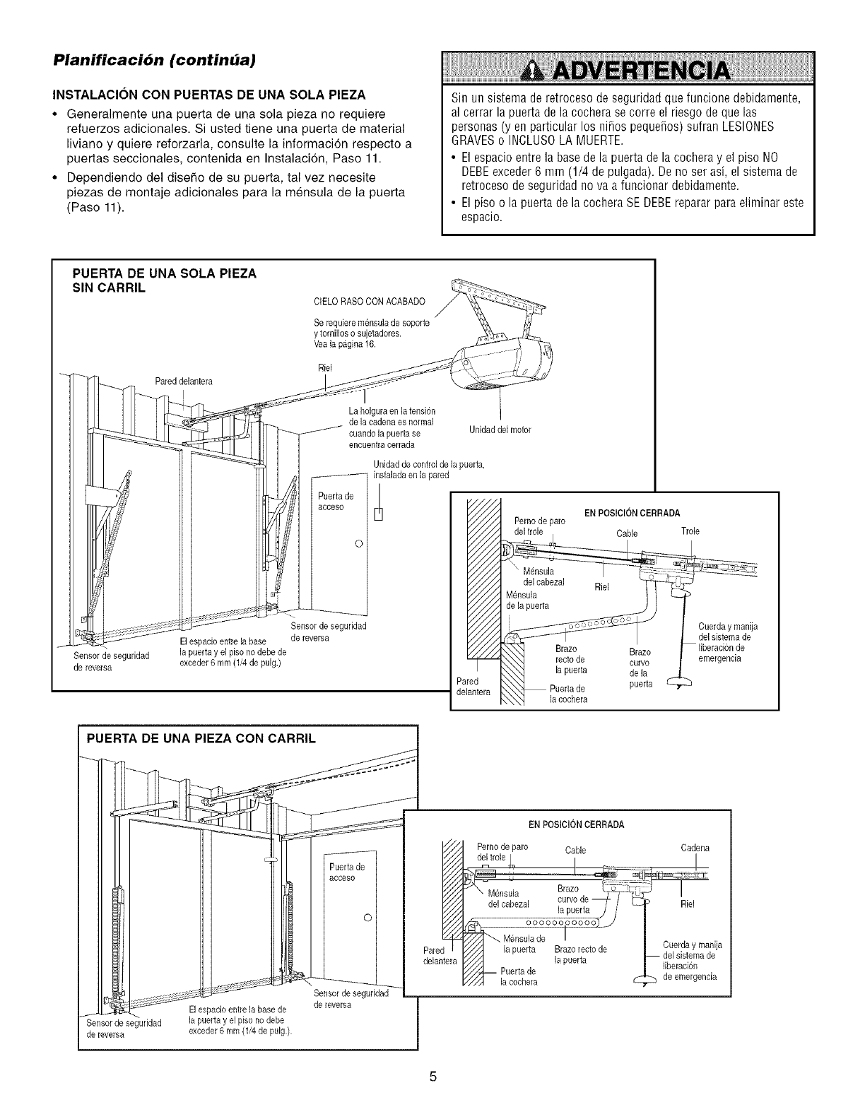
Planificaci6n (continba)
INSTALACION CON PUERTAS DE UNA SOLA PIEZA
•Generalmente una puerta de una sola pieza no requiere
refuerzos adicionales. Si usted tiene una puerta de material
liviano y quiere reforzarla, consulte la informaci6n respecto a
puertas seccionales, contenida en Instalacion, Paso 11.
• Dependiendo del diseSo de su puerta, tal vez necesite
piezas de montaje adicionales para la mensula de la puerta
(Paso 11).
Sin un sistema de retroceso de seguridad que funcione debidamente,
al cerrar la puerta de la cochera se corre el riesgo de que las
personas (y en particular los niSos pequeSos) sufran LESIONES
GRAVESo INCLUSOLA MUERTE.
•El espacio entre la base de la puerta de la cochera y el piso NO
DEBEexceder 6 mm (1/4 de pulgada). De no ser asi, el sistema de
retroceso de seguridad no va a funcionar debidamente.
• El piso o la puerta de la cochera SE DEBEreparar para eliminar este
espacio.
PUERTA DE UNA SOLA PIEZA
SIN CARRIL
_ Pareddelantera
dr1 I
Elespacio entre la base
Sensor de seguridad la puerta yel piso no debede
de reversa exceder6 mm (1/4de pulg.)
CIELO RASOCON ACABADO
Serequiere mensulade soporte
y tornilloso sujetadores.
Veala pagina 16.
La holgura en la tension
de la cadena es normal
cuando la puerfa se
encuentracerrada
Unidaddel motor
Unidadde controlde la puerta,
J
Puertade
acceso
o
Sensor de seguridad
de reversa
instaladaen [a pared
Pernode pare
'ele I
recto de
[a puerta
lacochera
Cable
EN POSICIONCERRADA
Trole
Braze
curvo
de la
puerta
Cuerda y manija
del sistemade
liberacionde
emergeneia
PUERTA DE UNA PIEZA CON CARRIL
El espacioentre la base de
Sensorde se( Jridad la puerta y el piso no debe
de reversa exceder6 mm (1/4de pulg.).
Puertade
acceso
c
Sensor de seguridad
de reversa
Pare
delantera
ENPOSICIONCERRADA
Pernode pare Cable Cadena
Brazorecto de
la puerta
la cochera
Cuerda y manija
][beraci6n
de emergencia
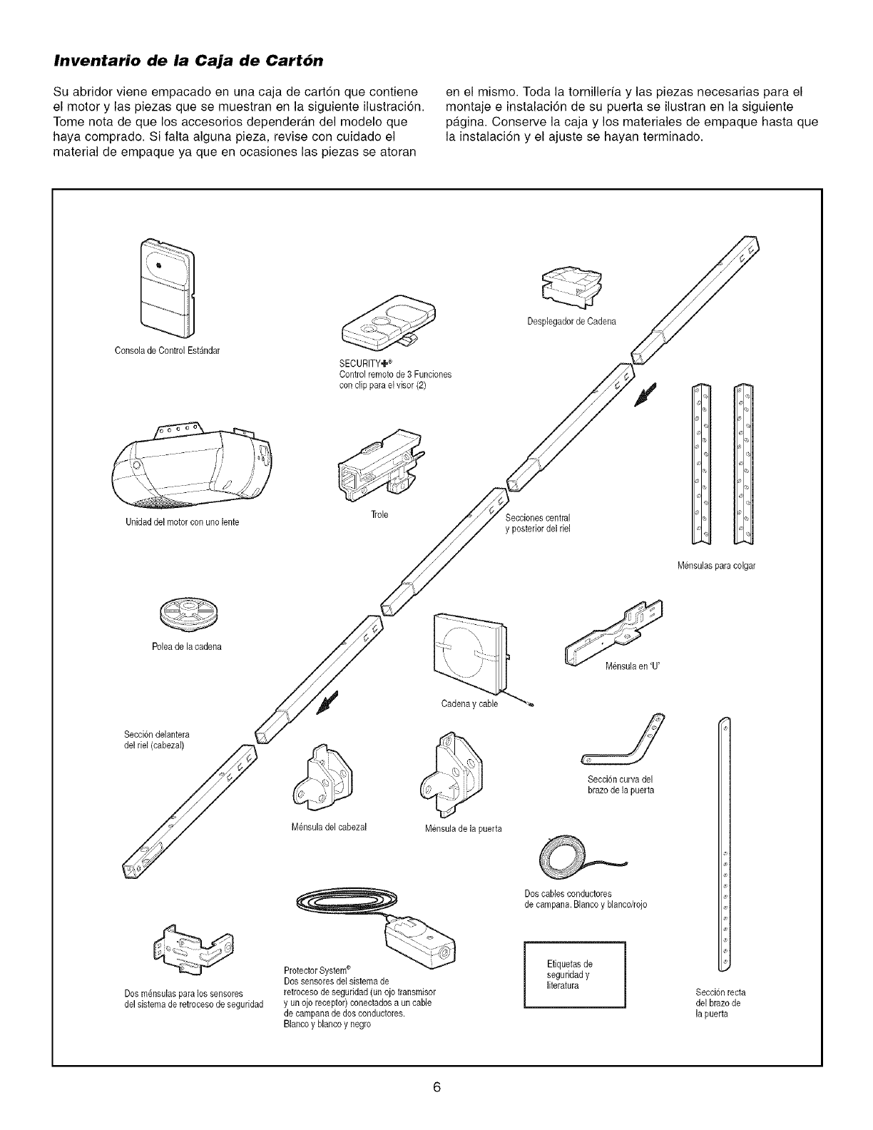
Inventario de la Caja de Cart6n
Su abridor viene empacado en una caja de cart6n que contiene
el motor y las piezas que se muestran en la siguiente ilustraci6n.
Tome nota de que los accesorios dependeran del modelo que
haya comprado. Si falta alguna pieza, revise con cuidado el
material de empaque ya que en ocasiones las piezas se atoran
en el mismo. Toda la torniller[a y las piezas necesarias para el
montaje e instalaci6n de su puerta se ilustran en la siguiente
pagina. Conserve la caja y los materiales de empaque hasta que
la instalaci6n y el ajuste se hayan terminado.
Consola de ControlEstandar
SECURITY,,I.®
Control remotode 3 Funciones
con dip para el visor (2)
Desplegadorde Cadena
Unidaddel motorcon uno lente Trole Seccionescentral
y posteriordel riel
Mensulaspara colgar
Poleade la cadena
Secci6ndelantera
del riel (cabezal)
Dos m_nsulaspara Ice sensores
del sistemade retroceso de seguridad
Cadenay cable
Mensuladel cabezal Mensulade la puerta
ProtectorSysteme
Dossensoresdel sistema de
retrocesode seguridad(un ojo transmisor
y un ojo receptor) conectadosa uncable
de campanade dosconductores.
Blancoy blancoy negro
Mensulaen 'U'
=J
Seccion curvadel
brazode ]a puerta
Dos cablesconductores
de campana.Blancoy blancdrojo
Efiquetasde
seguridady
literatura Seccionrecta
del brazode
]a puerta
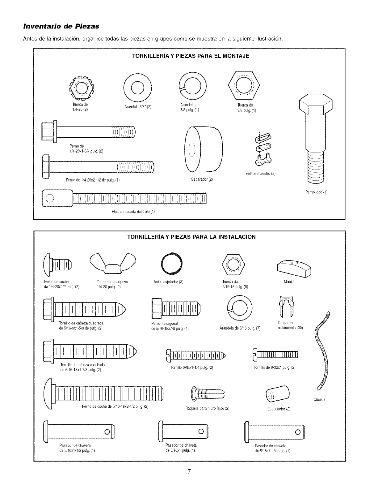
Inventario de Piezas
Antes de la instalaci6n, organice todas las piezas en grupos come se muestra en la siguiente ilustraci6n.
TORNILLERJA Y PIEZAS PARA EL MONTAJE
Tuereade Arandela 5/8"(2) Arandela de Tuercade
1/4-20 (2) 3/8 pulg. (1) 3/8pulg. (1)
Perno de
1/4-20xl-3/4 pulg. (2)
Perno de 1/4-20x2-1/2de pulg.(1)
©
Fieeharoseadadeltrole (1)
Separador(2)
i
i
Enlace maestro (2)
Pemoloco(1)
TORNILLERJA Y PIEZAS PARA LA INSTALACION
Perno decoche
de 1/4-20xl/2 pulg. (2)
Tuereade mariposa
1/4-20puig. (2)
Tornillode cabezacuadrada
de 5/16-9xl-5/8 de pulg.(2)
I I I I I I I I I I I IL_
Torni% de cabezaeuadrada
de 5/16-18xl-7/8 pulg.(2)
Pernode coche de 5/16-18x2-1/2pulg. (2)
Pasadorde chaveta
de 5/16x1-1/2pulg.(1)
0 ©
AniNosujetador(3) Tuercade
5/16-18pulg.(8)
©
Pernohexagonal
de 5/16-18x7/8pulg. (4) Arandelade 5/16 pulg. (7)
TorniNo6ABx1-1/4 pulg. (2)
Taquete para murofalse (2)
Manija
Grapa con
aislamiento(30)
Tornillode 6-32xl pulg. (2)
Espaciador (2)
[I] ol
Pasadorde chaveta Pasadorde chaveta
de 5/16xl pulg. (1) de 5/16x1-1/4pulg. (1)
Cuerda
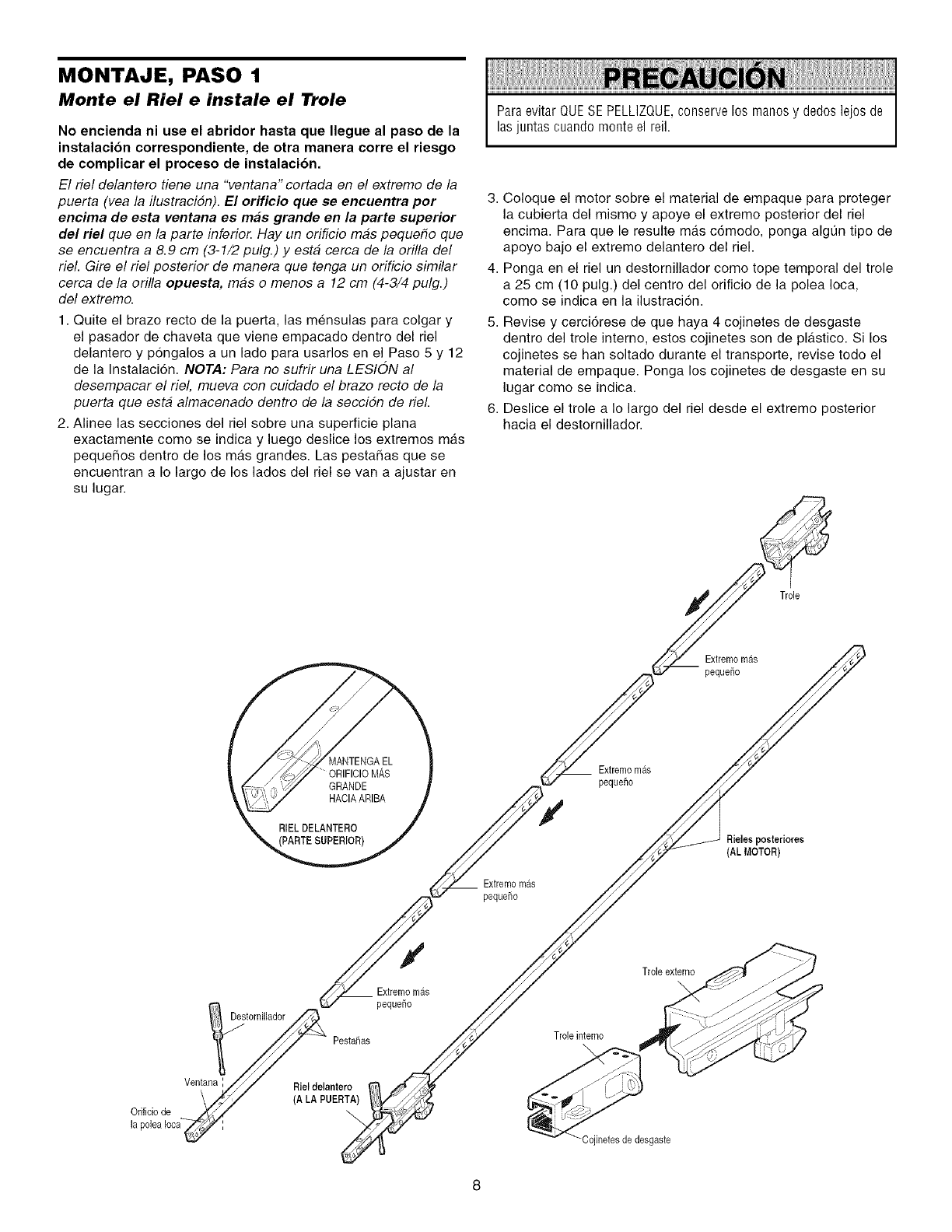
MONTAJE, PASO 1
Monte el Riel e instale el Trole
No encienda ni use el abridor hasta que Ilegue al paso de la
instalacion correspondiente, de otra manera corre el riesgo
de complicar el proceso de instalacion.
El riel delantero tiene una "ventana" cortada en el extremo de la
puerta (vea la ilustracidn). El orificio que se eneuentra por
encima de esta ventana es mas grande en la parte superior
del riel queen la parte inferio_ Hay un orificio mas pequefio que
se encuentra a 8.9 cm (3-1/2 pulg.) y esta cerca de la orilla de/
riel. Gire el riel posterior de manera que tenga un orificio similar
cerca de la orilla opuesta, mas o menos a 12 cm (4-3/4 pulg.)
del extremo.
1. Quite el brazo recto de la puerta, las mensulas para colgar y
el pasador de chaveta que viene empacado dentro del riel
delantero y pongalos a un lade para usarlos en el Paso 5 y 12
de la Instalaci6n. NOTA: Para no sufrir una LESION al
desempacar el riel, mueva con cuidado el brazo recto de la
puerta que esta almacenado dentro de la seccidn de riel.
2. Alinee las secciones del riel sobre una superficie plana
exactamente come se indica y luego deslice los extremes mas
pequeSos dentro de los mas grandes. Las pestaSas que se
encuentran a Io largo de los lades del riel se van a ajustar en
su lugar.
ParaevitarQUESEPELLIZQUE,conservelos manosy dedoslejosde
lasjuntascuandomonteel reil.
3. Coloque el motor sobre el material de empaque para proteger
la cubierta del mismo y apoye el extremo posterior del riel
encima. Para que le resulte mas c6modo, ponga alg0n tipo de
apoyo bajo el extremo delantero del riel.
4. Ponga en el riel un destornillador come tope temporal del trole
a 25 cm (10 pulg.) del centro del orificio de la polea Ioca,
come se indica en la ilustracion.
5. Revise y cerci6rese de que haya 4 cojinetes de desgaste
dentro del trole interne, estos cojinetes son de pla.stico. Si los
cojinetes se hart soltado durante el transporte, revise todo el
material de empaque. Ponga los cojinetes de desgaste en su
lugar come se indica.
6. Deslice el trole a Io largo del riel desde el extremo posterior
hacia el destornillador.
Trole
Extremom&s
pequeSo
Extremomas
pequeho
Extremomas
pequeSo
_ieles posteriores
(AL MOTOR)
Destornillador
PestaSas
Extremomas
pequeSo
Trole interno
Trob externo
Orificiode
Ventana :Riel delantero
(A LA PUERTA)
-Cojinetes de desgaste
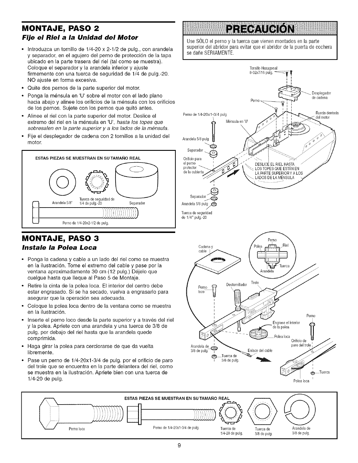
MONTAJE, PASO 2
Fije el Riel a la Unidad del Motor
•Introduzca un tornillo de 1/4-20 x 2-1/2 de pulg, con arandela
y separador, en el agujero del perno de protecci6n de la tapa
ubicado en la parte trasera del riel (tal como se muestra)
Coloque el separador y la arandela inferior y ajuste
firmemente con una tuerca de seguridad de 1/4 de pulg -20
NO ajuste en forma excesiva
• Quite dos pernos de la parte superior del motor
• Ponga la mensula en U sobre el motor con el lado piano
hacia abajo y alinee los orificios de la mensula con los orificios
de los pernos Sujete con los pernos que quit6 antes
• Alinee el riel con la parte superior del motor Deslice el
extremo del riel en la mensula en U, hasta los topes que
sobresalen en la parte superior y a los lados de la m#nsula
• Fije el desplegador de cadena con 2 tornillos a la unidad del
motor.
D
ESTAS PIEZAS SE MUESTRAN EN SU TAMAI_IO REAL
oO
Tuercade seguridadde
Arandela 5/8" 1/4 de pulg.-20 Separador
Pemode 1/4-20x2-1/2de pulg.
MONTAJE, PASO 3
Instale la Polea Loca
• Ponga la cadena y cable a un lado del riel come se muestra
en la ilustracion. Tome el extremo del cable y pase por la
ventana aproximadamente 30 cm (12 pulg.) Dejelo que
cuelgue hasta que Ileque al Paso 5 de Montaje.
• Retire la cinta de la polea Ioca. El interior del centro debe
estar engrasado. Si se ha secado, vuelva a engrasarlo para
asegurar que la operaci6n sea adecuada.
• Coloque la polea Ioca dentro de la ventana como se muestra
en la ilustracion.
• Inserte el perno Ioco desde la parte superior y a traves del riel
y la polea. Apriete con una arandela y una tuerca de 3/8 de
pulg. pot debajo del riel hasta que la arandela quede
comprimida.
• Haga girar la polea para cerciorarse de que da vuelta
libremente.
• Pase un perno de 1/4-20xl-3/4 de pulg. por el orificio de paro
del trole que se encuentra en la parte delantera del riel, como
se muestra en la ilustracion. Apriete bien con una tuerca de
1/4-20 de pulg.
Use SOLOel perno y la tuerca que vienen montados en la parte
superior del abridor para evitar que el abridor de la puerta de co@era
se daSeSERIAMENTE.
Perno_
Pemode 1/4-20xl -3/4 pulg
Mensulaen _U _
Arandela 5/8pulg
Separador_
Orificiopara
elperno
protector
delacubierta
de cadena
1
Rue@ dentada
delmotor
Separado_
Arandela5/8 pulg/C )
/
Tuercade seguddad
de 1/4" pulg.-20
PernoLoco
ESTAS PIEZAS SE MUESTRAN EN SU TAMAI_IO REAL
i i _ '
.emo de 1/4-20xl-3/4 de pulg. Tuerca de
1/4-20 de pulg.
Tuerca de
3/8 de pulg.
0
Arandelade
3/8 de pulg.
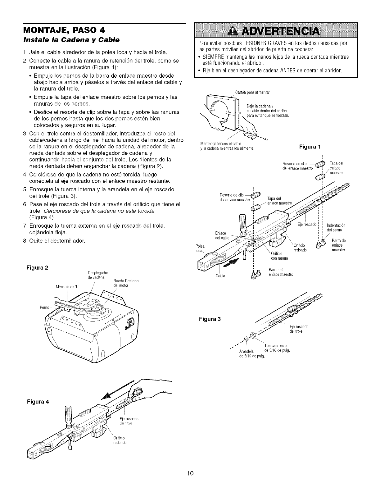
MONTAJE, PASO 4
Instale la Cadena y Cable
1. Jale el cable alrededor de la polea Ioca y hacia el trole.
2. Conecte la cable a la ranura de retenci6n del trole, como se
muestra en la ilustracion (Figura 1):
• Empuje los pernos de la barra de enlace maestro desde
abajo hacia arriba y paselos a traves del enlace del cable y
la ranura del trole.
• Empuje la tapa del enlace maestro sobre los pernos y las
ranuras de los pernos.
• Deslice el resorte de clip sobre la tapa y sobre las ranuras
de los pernos hasta que los dos pernos esten bien
colocados y seguros en su lugar.
3. Con el trole contra el destornillador, introduzca el resto del
cable/cadena a largo del riel hacia la unidad del motor, dentro
de la ranura en el desplegador de cadena, alrededor de la
rueda dentada sobre el desplegador de cadena y
continuando hacia el conjunto del trole. Los dientes de la
rueda dentada deben enganchar la cadena (Figura 2).
4. Cerci6rese de que la cadena no este torcida, luego
conectela al eje roscado con el enlace maestro restante.
5. Enrosque la tuerca interna y la arandela en el eje roscado
del trole (Figura 3).
6. Pase el eje roscado del trole a traves del orificio que tiene el
trole. Cercidrese de que la cadena no este torcida
(Figura 4).
7. Enrosque la tuerca externa en el eje roscado del trole,
dejandola floja.
8. Quite el destornillador.
Figura 2
M@sulaen 'U'
Despbgador
de cadena Rueda Dentada
/del motor
/
Paraevitar posibles LESIONESGRAVESen los dedos causadaspor
las partes m6viles del abridor de puerta de cochera:
• SIEMPREmantenga las manos lejos de la rueda dentadamientras
est6 funcionando el abridor.
• Fije bien el desplegador de cadena ANTESde operar el abridor.
Cart@ para alimentar
De_e_a,ec_de,_aYelcar,On
ese tuerzan.
Mantengatensos el cable
y la cadenamientras los alimente. Figura 1
i
i i
i
Resortede clip _ Tapadel
del enlacemaestro "ff_', /enlace
/rnaestro
, i
i i i i _"
Resorte de clip _:'_ /_j
del eniace maestro_ Tapadel //_
1,..J_,K/ enlace maestro/_._
i i i
cado bdentad6 n
_ "___'_ ; : del perno
Enlace ___ _,,'_ i I __ .....
Iota /_./,"AI£,_ '.. ....,1_', \ redondo - maestro
tr°cable
Figura 3
Eje roscado
del tro[e
Tuerca interna
Arandela de 5/16 de puig.
de 5/16 de puig.
Figura 4
Eje roscado
del trole
Orificio
redondo
10
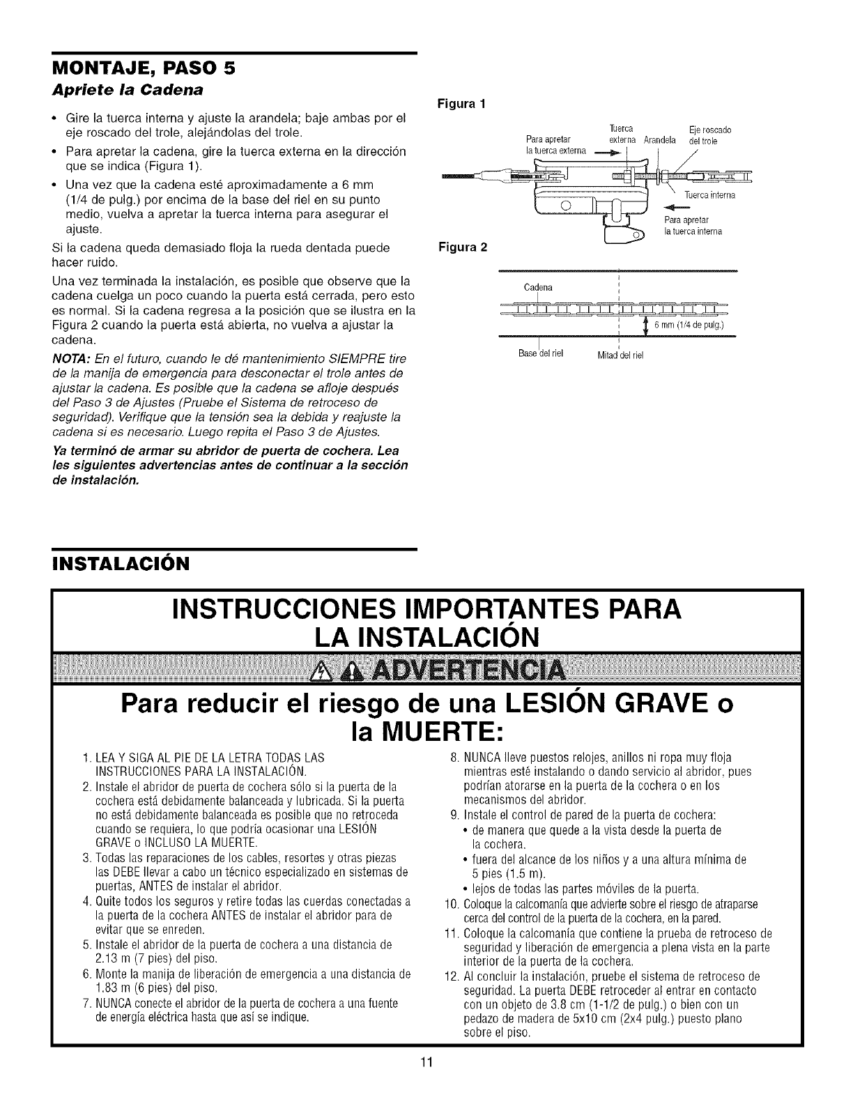
MONTAJE, PASO 5
Apriete la Cadena
•Gire la tuerca interna y ajuste la arandela; baje ambas por el
eje roscado del trole alejandolas del trole
• Para apretar la cadena gire la tuerca extema en la direcci6n
que se indica (Figura 1)
• Una vez que la cadena este aproximadamente a 6 mm
(1/4 de pulg) por encima de la base del riel en su punto
medio vuelva a apretar la tuerca intema para asegurar el
ajuste
Si la cadena queda demasiado floja la rueda dentada puede
hacer ruido
Una vez terminada la instalaci6n es posible que observe que la
cadena cuelga un poco cuando la puerta esta cerrada pero esto
es normal Si la cadena regresa a la posici6n que se ilustra en la
Figura 2 cuando la puerta esta abierta no vuelva a ajustar la
cadena
NOTA: En el futuro, cuando le de mantenimiento SIEMPRE tire
de la manija de emergencia para desconectar el trole antes de
ajustar la cadena Es posible que la cadena se afloje despues
del Paso 3 de Ajustes (Pruebe el Sistema de retroceso de
seguridad) Verifique que la tensiSn sea la debida y reajuste la
cadena si es necesario Luego repita el Paso 3 de Ajustes
Ya termino de armar su abridor de puerta de cochera. Lea
les siguientes advertencias antes de continuar a la secci6n
de instalacion.
Figura 1
Tuerca Ejeroscado
Paraapretar externa Arandela del trole
la tu,ercaextema .--._ _
la tuerca interna
Figura 2
t
Cadena i
I '
i
Basedel riel Mitad del riel
INSTALACION
Para reducir el riesgo de una LESION GRAVE o
la MUERTE:
1. LEAY SIGAAL PIE DE LA LETRATODASLAS
INSTRUCCIONESPARALA INSTALACION.
2. Instale el abridor depuerta de cochera s61osi la puerta de la
cochera est,. debidamente balanceaday lubricada. Si la puerta
no est,. debidamente balanceadaes posible que no retroceda
cuando se requiera, Io que podria ocasionar una LESION
GRAVEo INCLUSOLA MUERTE.
3. Todas las reparacionesde los cables, resortes y otras piezas
las DEBEIlevar a cabo un t6cnico especializadoen sistemas de
puertas, ANTESde instalar el abridor.
4. Quite todos los seguros y retire todas las cuerdas conectadasa
la puertade la cochera ANTES de iostalar el abridor para de
evitar que se enreden.
5. Instale el abridor dela puerta de cochera a una distancia de
2.13 m (7 pies) del piso.
6. Monte la manija de liberaci6n de emergencia a una distancia de
1.83 m (6 pies) del piso.
7. NUNCAconecteel abridor de la puerta decochera a una fuente
de energiael_ctrica hasta queasi se indique.
8. NUNOAIlevepuestosrelojes,anillosni ropamuyfloja
mientrasest_instalandoo dandoservicioalabridor,pues
podrfaoatorarseenla puertadela cocherao enlos
mecanismosdelabridor.
9. Instaleel controldepareddelapuertadecochera:
• demaneraquequedealavista desdela puertade
la cochera.
• fueradelalcancedelos niSosy a unaalturamfnimade
5 pies (1.5m).
• lejosdetodaslas partesm6vilesdela puerta.
10.Coloquelacalcomanfaqueadviertesobreelriesgodeatraparse
cercadelcontroldelapuertadelacochera,enlapared.
11.Coloquelacalcomaniaquecontienelapruebaderetrocesode
seguridady liberaci6ndeemergenciaa plenavistaenla parte
interiordela puertadelacochera.
12.AI concluirlainstalaciOo,pruebeelsistemaderetrocesode
seguridad.LapuertaDEBEretrocederalentrareocontacto
con unobjetode3.8cm (1-1/2depulg.)o biencon un
pedazodemaderade5x10 cm(2x4 pulg.)puestopiano
sobreelpiso.
11
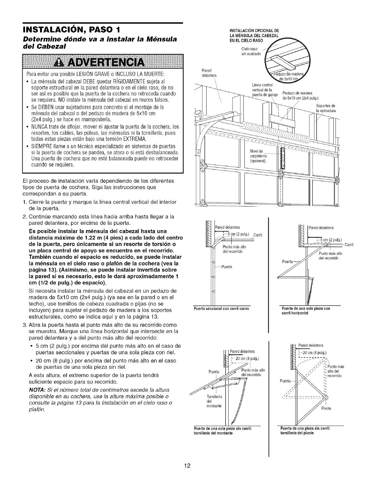
INSTALACI()N, PASO 1
Determine dbnde va a instalar la M6nsula
del Cabezal
INSTALAClON OPClONAL DE
LA Mt_NSULADEL CABEZAL
EN EL ClELO RASO
Cieloraso
sin acabado
Paraevitar unaposible LESIONGRAVEo INCLUSOLAMUERTE:
• La m_nsula del cabezal DEBEquedar RJGIDAMENTEsujeta al
soporte estructural en la pared delantera o enel cielo raso, de no
ser asi es posible que la puerta de la cochera no retroceda cuando
se requiera.NO instale la m_nsula del cabezalen muros falsos.
• Se DEBENusar sujetadores para concreto si el montaje de la
m6nsula del cabezal o del pedazode madera de 5x10 cm
(2x4 pulg.) se hace en mamposteria.
• NUNCAtrate de aflojar, mover ni ajustar la puerta de la cochera, los
resortes, los cables, las poleas, las m_nsulas ni la tornillerfa, pues
todas estas piezasest&n bajo una tensi6n EXTREMA.
• SIEMPREIlame a un t_cnico especializadoen sistemas de puertas
si la puerta de cochera se pandea,se atora o si est,. desbalanceada.
Una puerta de cochera que no est_ balanceadapuede no retroceder
cuando se requiera.
El proceso de instalaci6n varfa dependiendo de los diferentes
tipos de puerta de cochera. Siga las instrucciones que
correspondan a su puerta.
1. Cierre la puerta y marque la linea central vertical del interior
de la puerta.
2. ContinQe marcando esta Ifnea hacia arriba hasta Ilegar a la
pared delantera, por encima de la puerta.
Es posible instalar la mensula del cabezal hasta una
distancia maxima de 1.22 m (4 pies) a cada lado del centro
de la puerta, pero t_nicamente si un resorte de torsion o
un placa central de apoyo se encuentra en el recorrido.
Tambien cuando el espacio es reducido, se puede instalar
la mensula en el cielo raso o plafon de la cochera (vea la
pagina 13). (Asimismo, se puede instalar invertida sobre
la pared si es necesario, esto le dara aproximadamente 1
cm (1/2 de pulg.) de espacio).
Si necesita instalar la mensula del cabezal en un pedazo de
madera de 5x10 cm (2x4 pulg.) (ya sea en la pared o en el
techo), use tornillos de cabeza cuadrada o pijas (no se
incluyen) para sujetar el pedazo de madera a los soportes
estructurales, como se indica aquf yen la pagina 13.
3. Abra la puerta hasta el punto mgts alto de su recorrido como
se muestra. Marque una Ifnea horizontal que intersecte en la
pared delantera y adel punto mas alto del recorrido:
• 5 cm (2 pulg.) por encima del punto mas alto en el caso de
puertas seccionales y puertas de una sola pieza con riel.
• 20 cm (8 pulg.) por encima del punto m&s alto en el caso
de puertas de una sola pieza sin riel.
A esta altura, el extremo superior de la puerta tendra
suficiente espacio para su recorrido.
NOTA: Si el nEimero total de centfmetros excede la altura
disponible en su cochera, use la altura maxima posible o
consulte la pagina 13 para la Instalacidn en el cielo raso o
plafdn.
Pared
delantera
I Pareddelantera
'==='T_,5cm (2 pulg.) Cardl
J
Puntomilealto
delrecorddo
Puerta
Puertaseccioaal con earril eurvo
Puerta
Tornilleria
del
montante
Pareddelantera
20 cm (8 pulg.)
delrecorddo
Puertade una sola piezasin carrih
torailleriadel moatante
Linea central
vertical de la
puerta de garaje
\
Pedazode madera
de 5x10 cm (2x4 pulg.)
Soportes de
la estructura
W
Pareddelantera
V
Puert_ de unasola pieza con
earril horizontal
cm (2pulg.)
- CarriJ
del recorrido
Pareddelantera
20 cm (8 puJg.)
J," ',Punto mAs
',',alto del
',_recorride
Pivote
Puertade una pieza sin earrih
tornilleriadel pivote
12
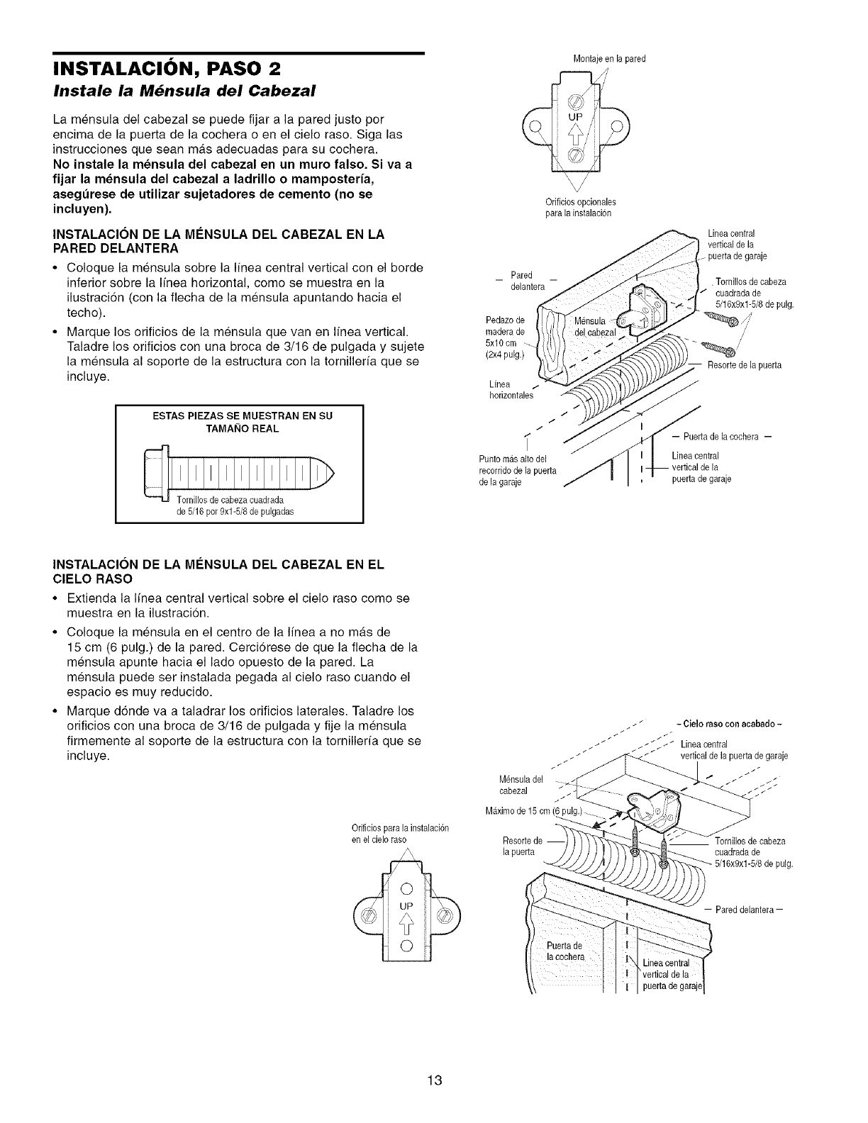
INSTALACI()N, PASO 2
Instale la M6nsula del Cabezal
La mensula del cabezal se puede fijar a la pared justo por
encima de la puerta de la cochera o en el cielo raso. Siga las
instrucciones que sean mas adecuadas para su cochera.
No inetale la mensula del cabezal en un muro falso. Siva a
fijar la mensula del cabezal a ladrillo o mamposteria,
asegurese de utilizar sujetadores de cemento (no se
incluyen).
INSTALAClON DE LA M#NSULA DEL CABEZAL EN LA
PARED DELANTERA
• Coloque la mensula sobre la I[nea central vertical con el borde
inferior sobre la Ifnea horizontal, como se muestra en la
ilustraci6n (con la fiecha de la mensula apuntando hacia el
techo).
• Marque los orificios de la mensula que van en Ifnea vertical.
Taladre los orificios con una broca de 3/16 de pulgada y sujete
la mensula al soporte de la estructura con la torniller/a que se
incluye.
ESTAS PIEZAS SE MUESTRAN EN SU
TAM AI_IO REAL
de 5/16 pot 9xl-5/8 de pulgadas
Montajeen la pared
Odficiosopcionales
para la instalacion
Pared
delantera
Pedazode
maderade
5x10 cm
(2x4 pulg.)
Linea
horizontales
I
/
/
Punto masalto del
recerddode la puerta
de la garaje
Lineacentral
vertical de la
puertade garaje
, Tornillosde cabeza
cuadradade
5/16x9xl-5/8 de pulg.
/'
/'
Resorte de la puerta
-- Puerta de la cochera --
Linea central
puerta de garaje
INSTALACION DE LA M#NSULA DEL CABEZAL EN EL
CIELO RASO
• Extienda la Ifnea central vertical sobre el cielo raso come se
muestra en la ilustracion.
• Coloque la mensula en el centre de la linea a no mas de
15 cm (6 pulg.) de la pared. Cerci6rese de que la flecha de la
mensula apunte hacia el lado opuesto de la pared. La
mensula puede ser instalada pegada al cielo raso cuando el
espacio es muy reducido.
• Marque d6nde va a taladrar los orificios laterales. Taladre los
orificios con una broca de 3/16 de pulgada y fije la mensula
firmemente al soporte de la estructura con la tornilleria que se
incluye.
Orificios para la instalaci6n
en el eieloraso
M_nsula del
cabezal
Maximo de 15 cm
Resortede
la puerta
_i _ -Cieloraeoconacabado-
_ / __ __ _ I _ Lineacentral
__ vertical de la puerta de garaje
cuadrada de
pulg.
- Pared delantera-
13
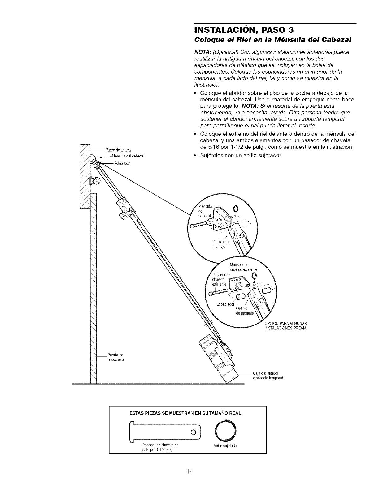
Iooa
INSTALACI()N, PASO 3
Coloque el Riel en la M6nsula del Cabezal
NOTA: (Opcional) Con algunas instalacienes anteriores puede
reutilizar la antigua mensula del cabezal con los dos
espaciaderes de plastice que se incluyen en la belsa de
componentes. Coloque los espaciadores en el interior de la
mensula, a cada lade del riel, tal y come se muestra en la
ilustracidn.
• Coloque el abridor sobre el piso de la cochera debajo de la
mensula del cabezal. Use el material de empaque come base
para protegerlo. NOTA: Si el resorte de la puerta esta
obstruyendo, va a necesitar ayuda. Otra persona tendra que
sostener el abridor firmemente sobre un soporte temporal
para permitir que el riel pueda librar el resorte.
• Coloque el extreme del riel delantero dentro de la mensula del
cabezal y una ambos elementos con un pasador de chaveta
de 5/16 per 1-1/2 de pulg., come se muestra en la ilustracion.
• Sujetelos con un anillo sujetador.
0
\
Orificiode
montaje
M_nsulade
cabezalexistente
0
Espaciador Orificio
demontaj
OPCIONPARAALGUNAS
INSTALAClONESPREVIA
Puerta de
la cochera
Cajadel abridor
o soporte temporal
ESTAS PIEZAS SE MUESTRAN EN SU TAMAI_IO REAL
o,] O
Pasadorde chavetade Anillo sujetador
5/16 per 1-1/2 pulg.
14
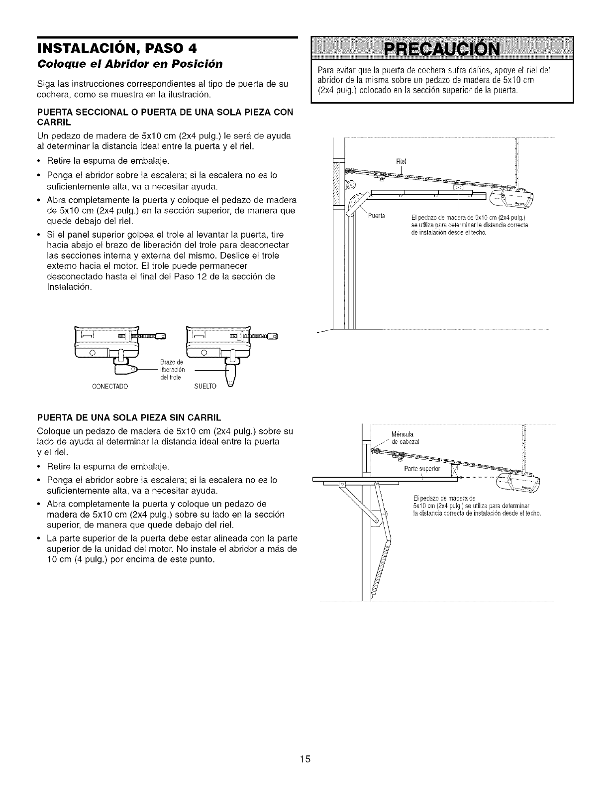
INSTALACI()N, PASO 4
Coloque el Abridor en Posici6n
Siga las instrucciones correspondientes al tipo de puerta de su
cochera, como se muestra en la ilustraci6n.
PUERTA SECClONAL O PUERTA DE UNA SOLA PIEZA CON
CARRIL
Un pedazo de madera de 5x10 cm (2x4 pulg.) le sera de ayuda
al determinar la distancia ideal entre la puerta y el riel.
•Retire la espuma de embalaje.
• Ponga el abridor sobre la escalera; si la escalera no es Io
suficientemente alta, va a necesitar ayuda.
• Abra completamente la puerta y coloque el pedazo de madera
de 5x10 cm (2x4 pulg.) en la secci6n superior, de manera que
quede debajo del riel.
• Si el panel superior golpea el trole al levantar la puerta, tire
hacia abajo el brazo de liberaci6n del trole para desconectar
las secciones interna y extema del mismo. Deslice el trole
extemo hacia el motor. El trole puede permanecer
desconectado hasta el final del Paso 12 de la secci6n de
Instalaci6n.
L'=__azo de
liberaci6n
del trole
CONECTADO
Para evitar que la puerta de cochera sufra daSos, apoye el riel del
abridor de la misma sobre un pedazode madera de 5x10 cm
(2x4 pulg.) colocado en la secci6n superior de la puerta.
/
PUERTA DE UNA SOLA PIEZA SIN CARRIL
Coloque un pedazo de madera de 5x10 cm (2x4 pulg.) sobre su
lado de ayuda al determinar la distancia ideal entre la puerta
y el riel.
• Retire la espuma de embalaje.
• Ponga el abridor sobre la escalera; si la escalera no es Io
suficientemente alta, va a necesitar ayuda.
• Abra completamente la puerta y coloque un pedazo de
madera de 5x10 cm (2x4 pulg.) sobre su lado en la secci6n
superior, de manera que quede debajo del riel.
• La parte superior de la puerta debe estar alineada con la parte
superior de la unidad del motor. No instale el abridor amas de
10 cm (4 pulg.) por encima de este punto.
I
I I Mensula 1"
I_:_ z/" de cabezal I
El pedazode maderade
5x10 cm (2x4 pulg.) se utilizapara determinar
la distanciacorrectade instalaci6ndesdeel techo.
15
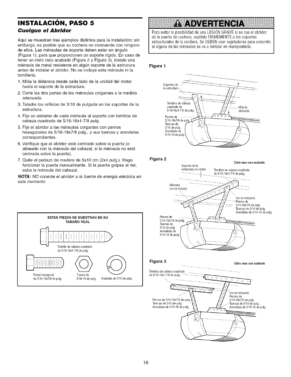
INSTALACI()N, PASO 5
Cuelgue el Abridor
Aquf se muestran tres ejemplos distintos para la instalaci6n; sin
embargo, es posible que su cochera no concuerde con ninguno
de ellos. Las mensulas de soporte deben estar en _.ngulo
(Figura 1), para que proporcionen un soporte rfgido. En caso de
tener un cielo raso acabado (Figura 2 y Figura 3), instale una
mensula de metal resistente en algQn soporte de la estrucura Figura 1
antes de instalar el abridor. No se incluye esta mensula ni la
tornilleria.
1. Mida la distancia desde cada lado de la unidad del motor
hasta el soporte de la estructura.
2. Corte las dos partes de las mensulas colgantes a la medida
adecuada.
3. Taladre los orificios de 3/16 de pulgada en los soportes de la
estructura.
4. Fije un extremo de cada mensula al soporte con tornillos de
cabeza cuadrada de 5/16-18xl-7/8 pulg.
5. Fije el abridor alas mensulas colgantes con pernos
hexagonales de 5/16-18x7/8 pulg., y sus tuercas y arandelas
correspondientes.
6. Verifique que el abridor este centrado sobre la puerta (o
alineado con la mensula del cabezal, si la mensula no esta
centrada sobre la puerta).
7. Quite el pedazo de madera de 5x10 cm (2x4 pulg.). Haga Figura 2
funcionar la puerta manualmente. Si la puerta golpea el riel,
suba la mensula del cabezal.
NOTA: NO conecte el abridor a la fuente de energfa electrica en
este momento.
ESTAS PIEZAS SE MUESTRAN EN SU
TA MAI_IO REAL
Pemohexagonal
de 5/16-18x7/8de pulg.
Tornillo de cabezacuadrada
de 5/16-18xl-7/8 de pulg.
©
Tuerca de
5/16-18de pulg.
©
Arandela de 5/16de pulg.
ParaevitarlaposibilidaddeunaLESIONGRAVEsi secaeelabridor
delapuertadeco@era,suj_teloFIRMEMENTEalos soportes
estructuralesdelacochera.SeDEBENusarsujetadoresparaconcreto
si algunadelas m@sulasseva a instalarenmamposteria.
la estructura,
Tornillosde cabeza
cuadrada de
5/16-18xl-7/8 de pule
Pernosde
5/16-18x7/8de
Tuercasde
5/16de pulg.
Arandelasde
5/16-18de pulg
/
,_ Mida la
distancia
Cielo raeo conacabado
Soporte de la
estructurano visible Tornillosde cabezacuadrada
........... ]...... de 5/!6-18xl-7/8 de pulg.
M@sula ............ __- -
(no se incluye)
Pernosde
5/16-18x7/8de pulg.
Tuercasde
5/16de pulg.
Arandelas de
5/16-18de pulg.
(no se incluyen)
.... Pernosde
_-_-_- 5/16-18x7/8de pulg.
Tuercasde 5/16de pulg.
Arandelasde 5/16-18de pulg.
Figura 3
Tornillosde cabezacuadrada
de 5/16-18xl-7/8 de pulg. _----_-LL"
\\\
\
Pemos de 5/16-18x7/8de pulg
Tuercasde 5/16de pulg.
Arandelasde 5/16-18de pulg.
Cielo raso con aeabado
-(no seincluyen)
Pernosde
5/18-18x7/8de pulg.
/Tuercas de 5/18 de pulg.
Arandelasde 5/16-18de pulg.
16
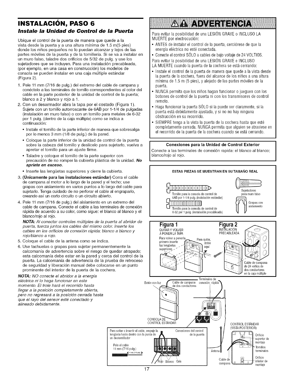
INSTALACI()N, PASO 6
Instale la Unidad de Control de la Puerta
Ubique el control de la puerta de manera que quede a la
vista desde la puerta y a una altura mfnima de 1.5 m(5 pies)
donde los niSos pequeSos no Io puedan alcanzar y lejos de las
partes m6viles de la puerta y de la tornillerfa. Si se va a instalar en
un muro falso, taladre dos orificios de 5/32 de pulg. y use los
sujetadores que se incluyen. Pare una instalaci6n precableada,
(por ejemplo, en una casa en construcci6n) los modelos de
consola se pueden instalar en una caja mt31tiple estandar
(Figura 2)
1. Pele 11 mm (7/16 de pulg.) del extremo del cable de campana y
con_ctelo alas terminales de tornillo correspondientes al color del
cable en la parte posterior de la unidad de control de la puerta;
blanco a 2 y blanco y rojo a 1.
2 Con un desarmador abra la tapa por el costado (Figura 1)
Sujete con un tornillo autorroscante de 6AB por 1-1/4 de pulgadas
(instalaci6n en muro falso) o con un tornillo pare metales de 6-32
por 1 pulg. (dentro de la caja mt31tiple) como se indica a
continuaci6n:
•Instale el tornillo de la parte inferior de manera que sobresalga
por Io menos 3 mm (1/8 de pulg.) de la pared.
• Coloque la parte inferior de la unidad de control de la puerta
sobre la cabeza del tornillo y deslfcelo para sujetarlo, vuelva a
apretar el tornillo pare un ajuste firme.
• Taladre y coloque el tornillo de la parte superior con
precauci6n de no romper la cubierta plAstica de la unidad. No
apriete en exceso.
• Inserte las lengQetas superiores y cierre la cubierta.
3. (0nieamente para las instalaciones estandar) Corra el cable
de campana al motor a Io largo de la pared y el techo; use
grapas con aislamiento en varios puntos a Io largo del cable pare
sujetarlo. Tenga cuidado de no perforar el cable al engraparlo,
creando asi un corto circuito o un circuito abierto.
4. Pele 11 mm (7/16 de pulg.) del aislamiento en un extremo del
cable de campana. Conecte el cable a las terminales de conexi6n
rApida de acuerdo a su color, como sigue: el blanco al blanco y el
blanco/rojo el rojo.
NOTA: AI conectar controles m#ltiples de la puerta al abridor de
puerta, tuerza juntos los cables del mismo color. Inserte los
cables en los orificios de conexidn rapida: blanco a blanco y
rojo/blanco a rojo.
5. Coloque el cable de la antena como se indica.
6. Use tachuelas o grapas pare sujetar permanentemente la
calcomanfa de advertencia sobre el riesgo de quedar atrapado;
esta calcomanfa debe estar en la pared y cerca del control de la
puerta. La calcomanfa de advertencia de la prueba de retroceso
de seguridad y liberaci6n manual debe colocarse en un punto
prominente del interior de la puerta de la cochera.
NOTA: NO conecte el abridor a la energfa
el#ctrica ni Io haga funcionar en este
momento. El trole har# el recorrido haste
flegar a la posicidn completamente abierta,
pete no regresara a la posicidn cerrada hasta
que el rayo del sensor este conectado y
alineado debidamente.
Paraevitar la posibilidad de una LESIONGRAVEo INCLUSOLA
MUERTEpor electrocuci6n:
• ANTESde instalar el control de la puerta, cerci6rese de que la
energia el_ctrica no est_ conectada.
• Conecteel control SOLOa cablesde bajovoltaje de 24 VOLTIOS.
Paraevitar la posibilidad de una LESIONGRAVEe INCLUSO
LA MUERTEcuando la puerta de la cochera se est_ cerrando:
• Instale el control de la puerta de maneraque quede a la vista desde
la puerta de la cochera, fuera del alcance de los niSos a una altura
minima de 1.5 m (5 pies), y alejado de las partes m6viles de la
puerta.
• NUNCApermita que los ni_os hagan funcionar o jueguen con los
botones de control de la puerta ni con los transmisores de control
remoto.
• Haga funcionar la puerta SOLOsi la puede ver claramente, si la
puerta estAdebidamente ajustada, y si no no hay ninguna
obstrucciOn en su recorrido.
• SIEMPREtenga a la vista la puerta de la cochera hastaque est_
completamente cerrada. NUNCApermita que alguien se atraviese en
el recorrido de la puerta de la cochera cuando se est,. cerrando.
Conexiones para la Unidad de Control Exterior
Conecte alas terminales de conexi6n rapida: el blanco al blanco;
blanco/rojo al rojo.
ESTAS PIEZAS SE MUESTRAN EN SU TAMAI_IO REAL
_ol de
6-32por 1pulg.(instalaci6nprecableada)
Sujetadores
paramutefalse
_ rapas con
aislamiento
Figura 1
QUITARY VOWER
A PONERLATAPA
Paravolvera ponerla Paraquitar,
primeroinserte doble
laslengQetas_ / _ aqui
• //
Figura2
INSTALACION
PRECABLEADA
Cable de campana
de 24 voltios de
dos conductores
en la caja moltiple
Terminalesde
Bot6nconiuz _ Cabledecampana conex6n_pda"_
_os conductores I
i
CO
CONTROLESTANDAR _ " CONTROLESTANDAR
Paraseltaro insertirelcable,empujela Conexionesdelcontrol l 'VISTAPOSTERIOR)
lengLietahaciadentreconlapuntade de lapuerta _]]_10rificio
undeetemillador J _ ] 1_superiorde
_i_ montaje
Peleelcable _ _ Tornilios
11mm(7/16puig.)
_ terminales
rrrr( u )
_:_ _P 'g_ I_ IOrificio
_ris Cabled .n mU_inferior de
campana_ montaje
17
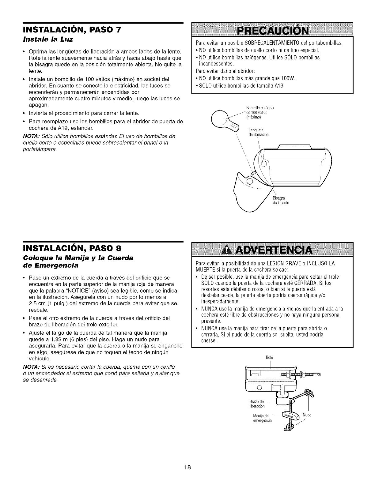
INSTALACI()N, PASO 7
Instale la Luz
•Optima las lengQetas de liberaci6n a ambos lados de la lente
Rote la lente suavemente hacia atras y hacia abajo hasta que
la bisagra quede en la posici6n totalmente abierta No quite la
lente
• Instale un bombillo de 100 vatios (maximo) en socket del
abridor En cuanto se conecte la electricidad las luces se
encenderan y permaneceran encendidas por
aproximadamente cuatro minutos y medio; luego las luces se
apagan
• Invierta el procedimiento para cerrar la lente
• Para reemplazo uso los bombillos para el abridor de puerta de
cochera de A19 estandar
NOTA: Sdlo utilice bombillos est4nda_ El uso de bombiflos de
cuello corto o especiales puede sobrecalentar el panel o la
portalampara
Para evitar un posible SOBRECALENTAMIENTOdel portabombillas:
• NOutilice bombillas de cuello corto ni detipo especial.
• NOutilice bombillas hal6genas.Utilice SOLO bombillas
incandescentes.
Paraevitar da_o al abridor:
• NOutilice bombillas mgs grande que 100W.
• SOLOutilice bombillas de tama_o A19.
Bombilloestandar
C_, ,,,,,_ de 100 vail os
(maximo)
LengQeta
\ de liberaci6n
\,
INSTALACI()N, PASO 8
Coloque la Manija y la Cuerda
de Emergencia
• Pase un extremo de la cuerda a traves del orificio que se
encuentra en la parte superior de la manija roja de manera
que la palabra NOTICE (aviso) sea legible como se indica
en la ilustracion Asegt]rela con un nudo por Io menos a
25 cm (1 pulg) del extremo de la cuerda para evitar que se
resbale
• Pase el otto extremo de la cuerda a traves del orificio del
brazo de liberaci6n del trole exterior
• Ajuste el largo de la cuerda de tal manera que la manija
quede a 183 m (6 pies) del piso Haga un nudo para
asegurarla Para evitar que la cuerda o la manija se enganche
en algo asegQrese de que no toquen el techo de ningt]n
vehiculo
NOTA: Si es necesario cortar la cuerda queme con un cerillo
o un encendedor el extremo que cort5 para sellarla y evitar que
se desenrede
Paraevitar la posibilidad de una LESIONGRAVEo INCLUSOLA
MUERTEsi la puerta de la cochera se cae:
• De ser posible, use la manija de emergenciapara soltar el trole
SOLOcuando la puerta de la cochera est_ CERRADA.Si los
resortes est_d_biles o rotos, o bien si la puerta est,.
desbalanceada,la puerta abierta podria caerser_.piday/o
inesperadamente.
• NUNCAuse la manija de emergencia a menos que la entradaa la
cochera est_ libre de obstrucciones y no haya ninguna persona
presente.
• NUNCAuse la manija para tirar de la puerta paraabrirla o
cerrarla. Si el nudo de la cuerda se suelta, usted podria
caerse.
]role
0
Brazode
liberacion
Manijade _ _udoemergencia
18
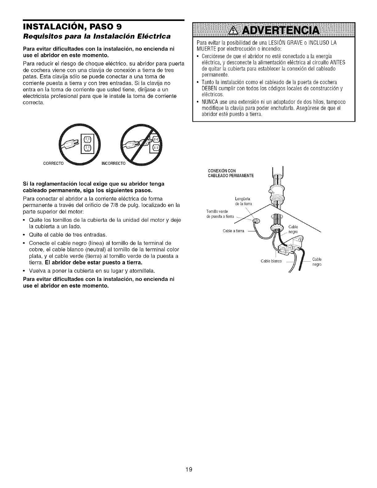
INSTALACI()N, PASO 9
Requisitos para la Instalaci6n El_ctrica
Para evitar dificultades con la instalacion, no encienda ni
use el abridor en este momento
Para reducir el riesgo de choque electrico, su abridor para puerta
de cochera viene con una clavija de conexidn a tierra de tres
patas. Esta clavija s61o se puede conectar a una toma de
corriente puesta a tierra y con tres entradas. Si la clavija no
entra en la toma de corriente que usted tiene, dirfjase a un
electricista profesional para que le instale la toma de corriente
correcta.
Si la reglamentacion local exige que su abridor tenga
cableado permanente, siga los siguientes pasos
Para conectar el abridor a la corriente electrica de forma
permanente a traves del orificio de 7/8 de pulg. Iocalizado en la
parte superior del motor:
• Quite los tornillos de la cubierta de la unidad del motor y deje
la cubierta a un lado.
• Quite el cable de tres entradas.
• Conecte el cable negro (Ifnea) al tornillo de la terminal de
cobre, el cable blanco (neutral) al tornillo de la terminal color
plata, y el cable verde (tierra) al tornillo verde de la puesta a
tierra. El abridor debe estar puesto a tierra.
• Vuelva a poner la cubierta en su lugar y atornfllela.
Para evitar dificultades con la instalacion, no encienda ni
use el abridor en este momento.
ParaevitarlaposibilidaddeunaLESIONGRAVEo INCLUSOLA
MUERTEpor electrocuciOn o inceodio:
•Cerci6rese de que el abridor no est6 conectado a la energfa
el_ctrica, y desconecte la alimentaciOn el_ctrica al circuito ANTES
de quitar la cubierta para establecer la conexi6n del cableado
permanente.
• Tanto la instalaci6n como el cableado de la puerta de cochera
DEBENcumplir con todos los c6digos locales de construcci6n y
el_ctricos.
• NUNCAuse una extension ni un adaptador de dos hilos, tampoco
modifique la clavija para poder enchufarla. AsegOresede que el
abridor est_ puesto a tierra.
CONEXIONCON
CABLEADO PERMANENTE
LengQeta
de la tierra
Torniflo verde
de puestaa fierra
Cable
Cable a fierra negro
Cable blaneo Cable
negro
19
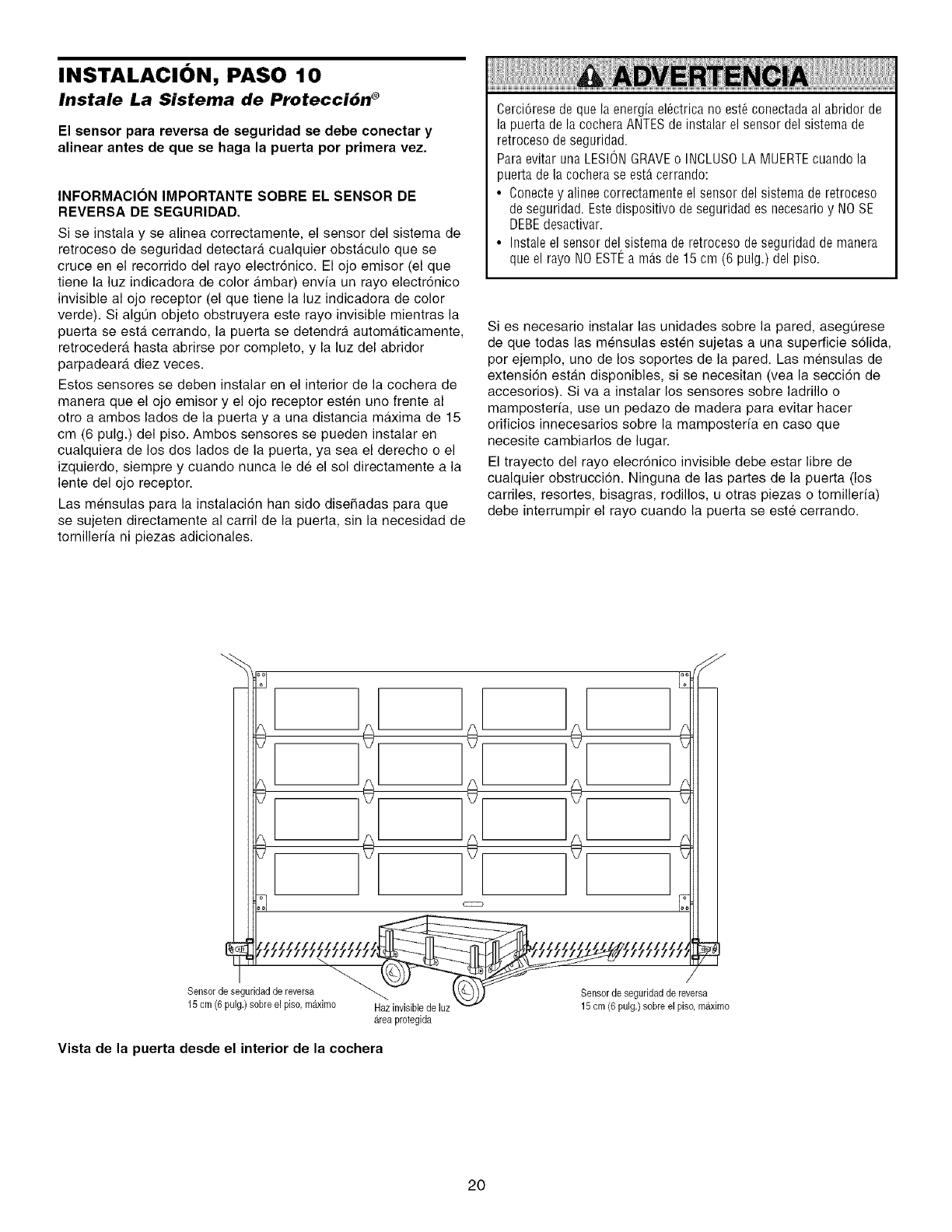
INSTALACI()N, PASO 10
Instale La Sistema de Protecci6n ®
El sensor para reversa de seguridad se debe conectar y
alinear antes de que se haga la puerta por primera vez.
INFORMACION IMPORTANTE SOBRE EL SENSOR DE
REVERSA DE SEGURIDAD.
Si se instala y se alinea correctamente, el sensor del sistema de
retroceso de seguridad detectara cualquier obstaculo que se
cruce en el recorrido del rayo electr6nico. El ojo emisor (el que
tiene la luz indicadora de color ambar) envia un rayo electr6nico
invisible al ojo receptor (el que tiene la luz indicadora de color
verde). Si algQn objeto obstruyera este rayo invisible mientras la
puerta se esta cerrando, la puerta se detendra automaticamente,
retrocedera hasta abrirse por completo, y la luz del abridor
parpadeara diez veces.
Estos sensores se deben instalar en el interior de la cochera de
manera que el ojo emisor y el ojo receptor esten uno frente al
otto a ambos lades de la puerta y a una distancia maxima de 15
cm (6 pulg.) del piso. Ambos sensores se pueden instalar en
cualquiera de los dos lados de la puerta, ya sea el derecho o el
izquierdo, siempre y cuando nunca le de el sol directamente a la
lente del ojo receptor.
Las mensulas para la instalacion han sido disefiadas para que
se sujeten directamente al carril de la puerta, sin la necesidad de
tornillerfa ni piezas adicionales.
Cerci6rese de que la energiael_ctrica no est_ conectadaal abridor de
la puerta de la cochera ANTESde instalar el sensor del sistema de
retroceso de seguridad.
Paraevitar una LESIONGRAVEo INCLUSOLA MUERTEcuando la
puerta de la co@era se est_ cerrando:
• Conectey alinee correctamente el sensor del sistema de retroceso
de seguridad. Estedispositivo de seguridad es necesario y NOSE
DEBEdesactivar.
• Instale el sensor del sistema de retroceso de seguridad de manera
que el rayo NO ESTEa m&sde 15 cm (6 pulg.) del piso.
Si es necesario instalar las unidades sobre la pared, asegQrese
de que todas las mensulas esten sujetas a una superficie s61ida,
per ejemplo, uno de los soportes de la pared. Las mensulas de
extensi6n estan disponibles, si se necesitan (vea la secci6n de
accesorios). Siva a instalar los sensores sobre ladrillo o
mamposterfa, use un pedazo de madera para evitar hacer
orificios innecesarios sobre la mamposterfa en caso que
necesite cambiarlos de lugar.
El trayecto del rayo elecr6nico invisible debe estar libre de
cualquier obstrucci6n. Ninguna de las partes de la puerta (los
carriles, resortes, bisagras, rodillos, u otras piezas o tomilleria)
debe interrumpir el rayo cuando la puerta se este cerrando.
Sensor de seguridadde reversa
15 cm (6 pulg.) sobre el piso, m_tximo Haz invisiblede luz
Areaprotegida
Vista de la puerta desde el interior de la cochera
Sensorde seguridadde reversa
15 cm (6 pulg.)sobre el piso,maximo
2O
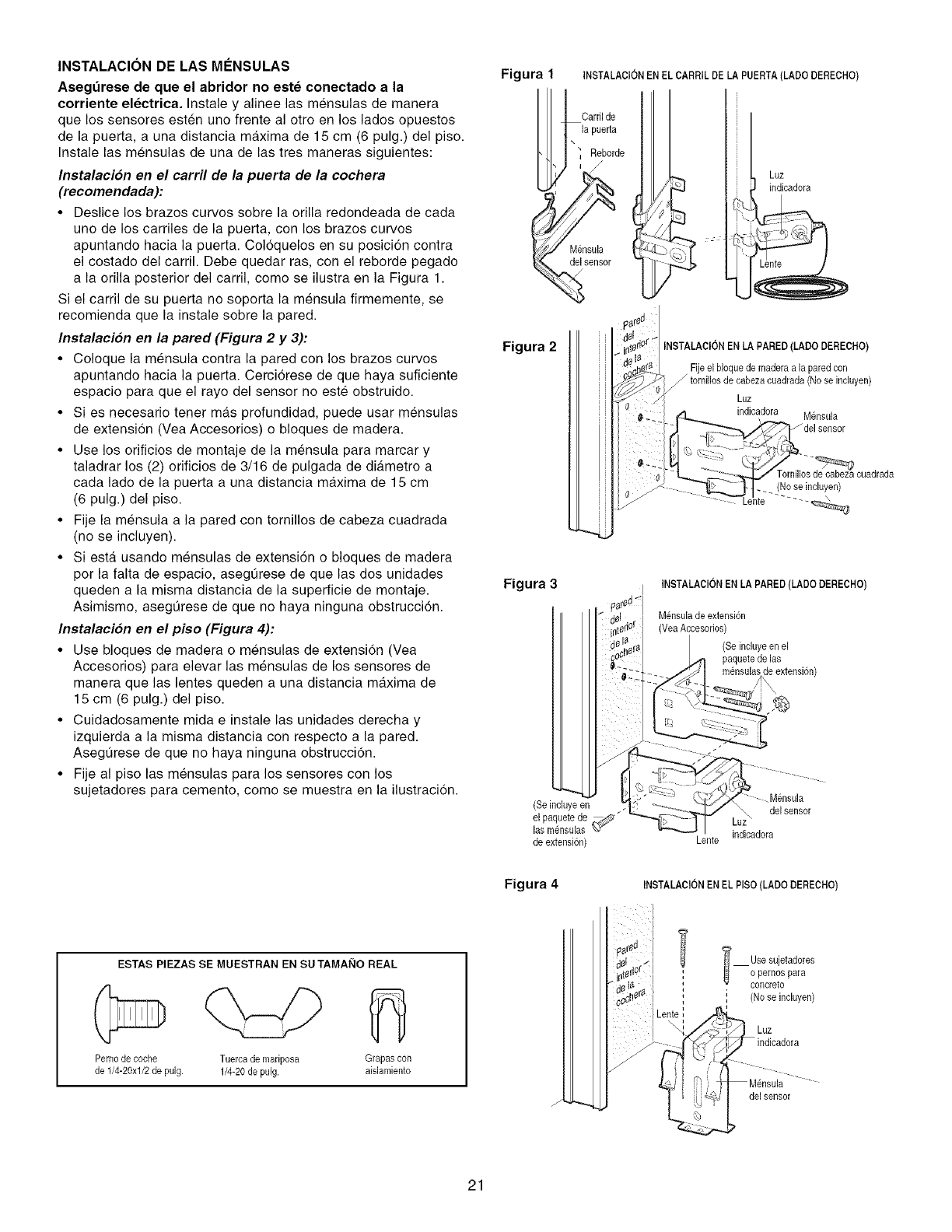
INSTALACION DE LAS MI_NSULAS
Asegt3rese de que el abridor no este conectado a la
corriente electrica. Instaie y aiinee ias mensuias de manera
que los sensores esten uno frente al otro en los lados opuestos
de la puerta, a una distancia maxima de 15 cm (6 pulg.) del piso.
Instale las mensulas de una de las tres maneras siguientes:
Instalacion en el carril de la puerta de la cochera
(recomendada):
• Deslice los brazos curvos sobre la orilla redondeada de cada
uno de los carriles de la puerta, con los brazos curvos
apuntando hacia la puerta. Col6quelos en su posici6n contra
el costado del carril. Debe quedar ras, con el reborde pegado
a la orilla posterior del carril, como se ilustra en la Figura 1.
Si el carril de su puerta no soporta la mensula firmemente, se
recomienda que la instale sobre la pared.
Instalacion en la pared (Figura 2 y 3):
• Coloque la mensula contra la pared con los brazos curvos
apuntando hacia la puerta. Cerci6rese de que haya suficiente
espacio para que el rayo del sensor no este obstruido.
• Si es necesario tener mas profundidad, puede usar mensulas
de extension (Vea Accesorios) o bloques de madera.
• Use los orificios de montaje de la mensula para marcar y
taladrar los (2) orificios de 3/16 de pulgada de diAmetro a
cada lado de la puerta a una distancia maxima de 15 cm
(6 pulg.) del piso.
• Fije la mensula a la pared con tomillos de cabeza cuadrada
(no se incluyen).
• Siesta usando mensulas de extensi6n o bloques de madera
por la falta de espacio, asegOrese de que las dos unidades
queden a la misma distancia de la superficie de montaje.
Asimismo, asegOrese de que no haya ninguna obstrucci6n.
Instalacion en el pi$o (Figura 4):
• Use bloques de madera o mensulas de extension (Vea
Accesorios) para elevar ias mensulas de los sensores de
manera que las lentes queden a una distancia maxima de
15 cm (6 pulg.) del piso.
• Cuidadosamente mida e instale las unidades derecha y
izquierda a la misma distancia con respecto a la pared.
AsegOrese de que no haya ninguna obstruccion.
• Fije al piso las mensulas para los sensores con los
sujetadores para cemento, como se muestra en la ilustraci6n.
Figura 1
Figura 2
Figura 3
INSTALAClON EN EL CARRIL DE LA PUERTA(LADODERECHO)
Carril de
la puerta
\
Reborde
i
Mensula
del sensor
Luz
indicadora
_reCj
lerior_" INSTALAClON ENLA PARED(LADO DERECHO)
I F joe b oqoeaomaderoo oparedcoo
_ tornillosde cabezacuadrada (No se incluyen)
Luz
_...._.. €3 indicadora M_nsula
[ del sensor
s de cabezacuadrada
>_"_._ t--- (No se incluyen)
-"--Le'nte .....
INSTALAClONEN LA PARED (LADO DERECHO)
M_nsulade extension
(VeaAccesorios)
(Seinduye enel
paquetede las
(Se incluyeen
el paquetede _,;_" _
las m_nsulas %7"
de extensi6n) Lente
Mensula
del sensor
indicadora
Figura 4 INSTALAClON ENEL PlSO(LADO DERECHO)
ESTAS PIEZAS SE MUESTRAN EN SU TAMANO REAL
Pemode coche Tuercade mariposa Grapas con
de 1/4-20xl/2 de pulg. 1/4-20 de pulg. aislamiento
Len e,
Usesujetadores
(Nose incluyen)
Luz
delsensor
21
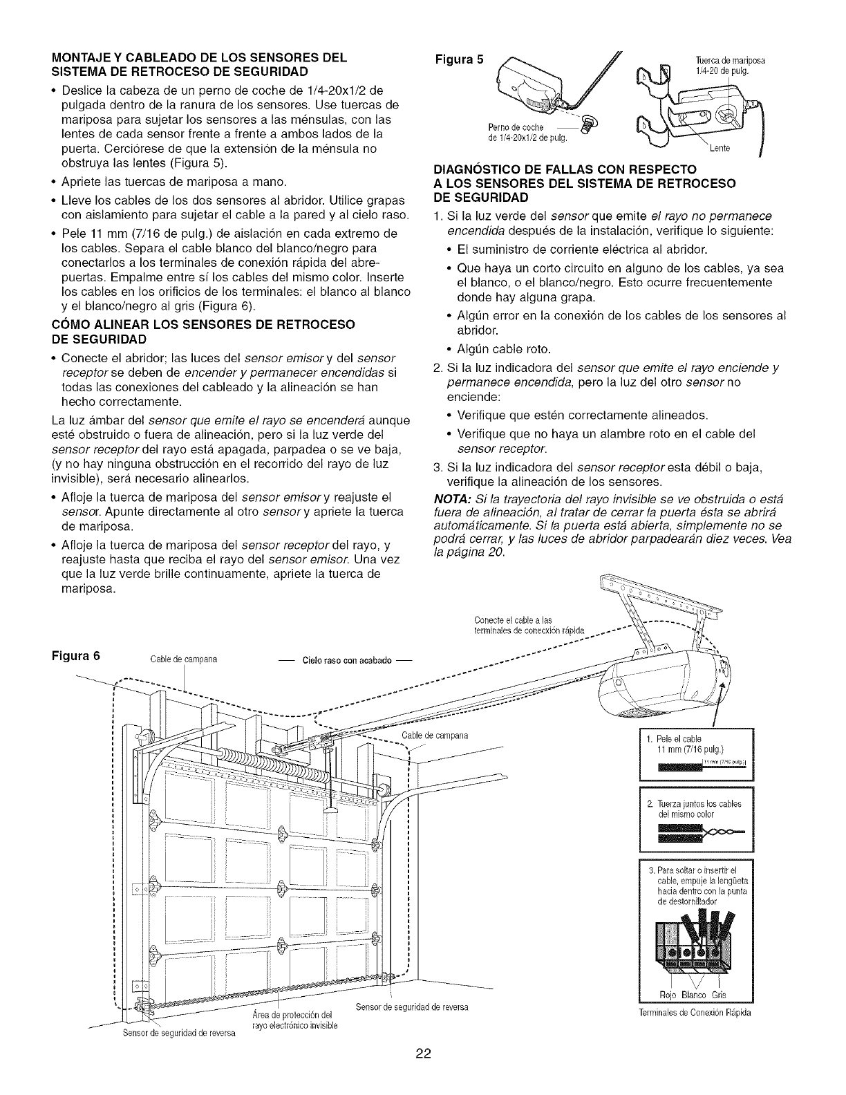
MONTAJE Y CABLEADO DE LOS SENSORES DEL
SISTEMA DE RETROCESO DE SEGURIDAD
• Deslice la cabeza de un perno de coche de 1/4-20xl/2 de
pulgada dentro de la ranura de los sensores. Use tuercas de
mariposa para sujetar los sensores alas mensulas, con las
lentes de cada sensor frente a frente a ambos lades de la
puerta. Cerciorese de que la extension de la mensula no
obstruya las lentes (Figura 5).
• Apriete las tuercas de mariposa a mane.
• Lleve los cables de los dos sensores al abridor. Utilice grapas
con aislamiento para sujetar el cable a la pared y al cielo raso.
• Pele 11 mm (7/16 de pulg.) de aislacion en cada extreme de
los cables. Separa el cable blanco del blanco/negro para
conectarlos a los terminales de conexi6n rapida del abre-
puertas. Empalme entre si los cables del mismo color. Inserte
los cables en los orificios de los terminales: el blanco al blanco
y el blanco/negro al gris (Figura 6).
COMO ALINEAR LOS SENSORES DE RETROCESO
DE SEGURIDAD
• Conecte el abridor; las luces del sensor emisory del sensor
receptor se deben de encender y permanecer encendidas si
todas las conexiones del cableado y la alineacion se hart
hecho correctamente.
La luz ambar del sensor que emite el rayo se encendera aunque
este obstruido o fuera de alineaci6n, pete si la luz verde del
sensor receptordel rayo esta apagada, parpadea o se ve baja,
(y no hay ninguna obstrucci6n en el recorrido del rayo de luz
invisible), sera necesario alinearlos.
• Afloje la tuerca de mariposa del sensor emisery reajuste el
sensor. Apunte directamente al otto sensory apriete la tuerca
de mariposa.
• Afloje la tuerca de mariposa del sensor receptordel rayo, y
reajuste hasta que reciba el rayo del sensor emiser. Una vez
que la luz verde brille continuamente, apriete la tuerca de
mariposa.
Figura 5 Tuercade mariposa
_eerln/_-1%xCl°/'2h(_ePu Ig'" "_i_) _ Lente
DIAGNOSTICO DE FALLAS CON RESPECTO
A LOS SENSORES DEL SISTEMA DE RETROCESO
DE SEGURIDAD
1. Si la luz verde del sensor que emite el rayo no permanece
encendida despues de la instalaci6n, verifique Io siguiente:
• El suministro de corriente electrica al abridor.
• Que haya un corto circuito en alguno de los cables, ya sea
el blanco, o el blanco/negro. Esto ocurre frecuentemente
donde hay alguna grapa.
• Algt]n error en la conexion de los cables de los sensores al
abridor.
• Algt]n cable rote.
2. Si la luz indicadora del sensor que emite el rayo enciende y
permanece encendida, pero la luz del otro sensor no
enciende:
• Verifique que esten correctamente alineados.
• Verifique que no haya un alambre rote en el cable del
sensor receptor.
3. Si la luz indicadora del sensor receptoresta debil o baja,
verifique la alineacidn de los sensores.
NOTA: Si la trayectoria del rayo invisible se ve obstruida o esta
fuera de alineaciSn, al tratar de cerrar la puerta #sta se abrira
automaticamente. Si la puerta esta abierta, simplemente no se
podra cerrar, y las luces de abridor parpadearan diez veces. Vea
la pagina 20.
Figura 6 Cable de eampana
Conecte el cable a las
terminales de conecxi6n r_pida ._--"
-- Cielo raso coo acabado -- ..--'°''''''''""
Cable de eampana
//
I
1. Peie el cane
11 mm (7/16 pulg.}
2. Tuerzajuntos los cables
de[mismocolor
Sensor de seguridadde reversa
Area de protecci6ndel
rayoelectr6nico invisible
Sensor de seguridadde reversa
22
3. Parasoltar o inserfir el
cable, empujela lengQeta
haeia dentrocon la punta
de destornillador
Rojo Blaneo Gris
Terminalesde Conexi6nRapida
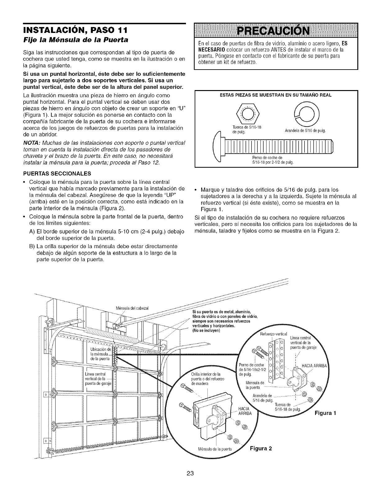
INSTALACI()N, PASO 11
Fije la M6nsula de la Puerta
Siga las instrucciones que correspondan al tipo de puerta de
cochera que usted tenga, come se muestra en la ilustracion o en
la pagina siguiente.
Si usa un puntal horizontal, este debe ser Io suficientemente
largo para sujetarlo a dos soportes verticales. Si usa un
puntal vertical, este debe ser de la altura del panel superior.
La ilustracion muestra una pieza de hierro en angulo come
puntal horizontal. Para el puntal vertical se deben usar dos
piezas de hierro en a.ngulo con objeto de crear un soporte en "U"
(Figura 1). La mejor solucion es ponerse en contacto con la
compaSia fabricante de la puerta de su cochera e informarse
acerca de los juegos de refuerzos de puertas para la instalacion
de un abridor.
NOTA: Muchas de las instalaciones con soporte o puntal vertical
toman en cuenta la instalacidn directa de los pasadores de
chaveta y el braze de la puerta. En este case, no necesitara
instalar la mensula para la puerta; proceda al Paso 12.
PUERTAS SECCIONALES
•Coloque la mensula para la puerta sobre la linea central
vertical que habia marcado previamente para la instalacion de
la mensula del cabezal. AsegQrese de que la leyenda "UP"
(arriba) este en la posici6n correcta, come esta indicado en la
parte interior de la mensula (Figura 2).
• Coloque la mensula sobre la parte frontal de la puerta, dentro
de los limites siguientes:
A) El borde superior de la mensula 5-10 cm (2-4 pulg.) debajo
del borde superior de la puerta.
B) La orilla superior de la mensula debe estar directamente
debajo de algQn soporte de la estructura a Io largo de la
parte superior de la puerta.
Enel case de puertas de fibra de vidrio, aluminio o acero ligero, ES
NECESARI0colocar un refuerzo ANTESde instalar el marco de la
puerta. P6ngase en contacto con el fabricante de su puerta para
obtener un kit de refuerzo.
ESTAS PIEZAS SE MUESTRAN EN SU TAMAI_IO REAL
de pulg. Arandelade 5/16de pulg.
Perno de coche de
5/16-18per 2-1/2 de pulg.
• Marque y taladre dos orificios de 5/16 de pulg. para los
sujetadores a la derecha y a la izquierda. Sujete la mensula al
refuerzo vertical (si este existe), come se muestra en la
Figura 1.
Si el tipo de instalaci6n de su cochera no requiere refuerzos
verticales, pero s[ necesita los orificios para los sujetadores de la
mensula, taladre y fijelos come se muestra en la Figura 2.
M_nsuladel cabezal
Ubicacionde
de la puerta
ineacentral
puerta de garaje
Si eu puerta ee de metal, aluminio,
fibra de vidrio o con paneles de vidrio
siempre son neeeearios refuerzos
verticalee y horizontales,
(No se ineluyen)
vertical de la
puerta de garaje
puerta odel refuerzo
_.e madera
M_nsulade la puerta
Pernode coche
de 5/16-18x2-1/2
de pulg.
Mensula de
Arandela de ...... :
5/16 de pulg. Tuercade
5/16-18de pulg.
\_, _ - ARRIBA
Figura 2
HACIAARRIE
Figura 1
23
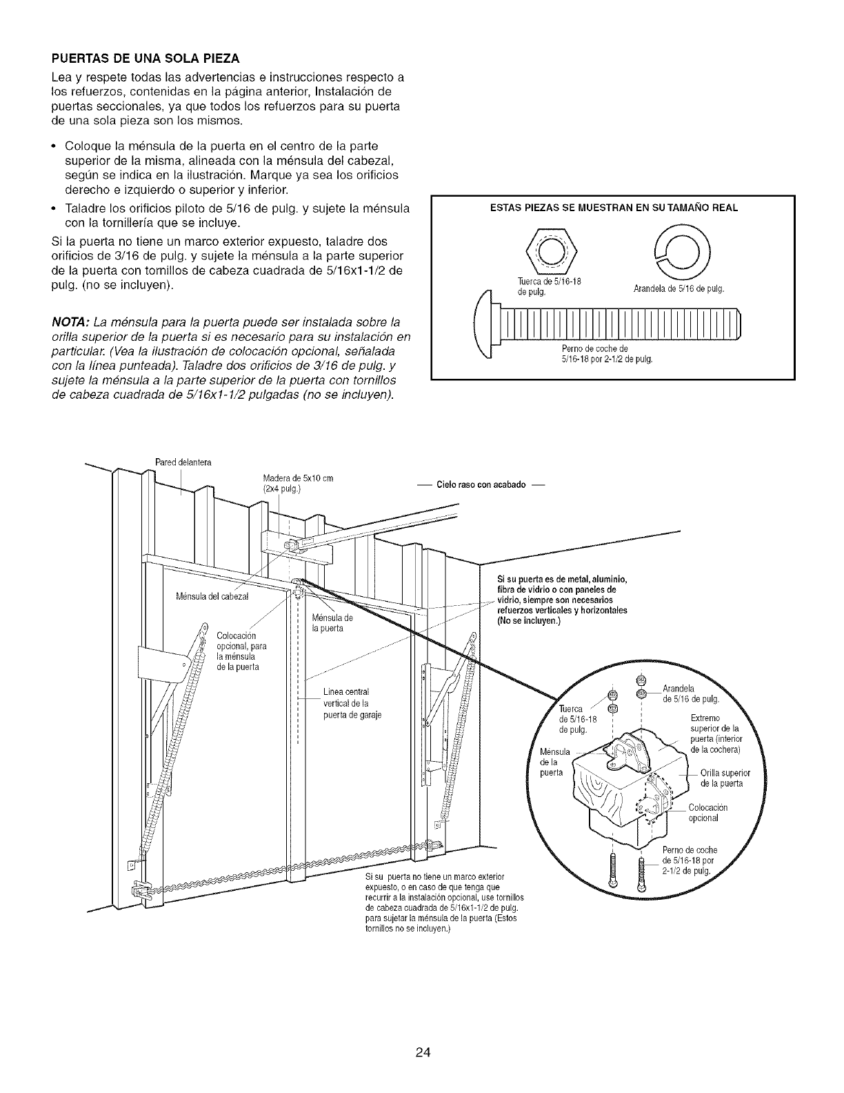
PUERTAS DE UNA SOLA PIEZA
Lea y respete todas las advertencias e instrucciones respecto a
los refuerzos, contenidas en la pa.gina anterior, Instalacion de
puertas seccionales, ya que todos los refuerzos para su puerta
de una sola pieza son los mismos.
• Coloque la mensula de la puerta en el centre de la parte
superior de la misma, aiineada con la mensuia del cabezal,
segQn se indica en la iiustracion. Marque ya sea los orificios
derecho e izquierdo o superior y inferior.
• Taladre los orificios piloto de 5/16 de pulg. y sujete la mensula
con la tornilleria que se incluye.
Si la puerta no tiene un marco exterior expuesto, taladre dos
orificios de 3/16 de puig. y sujete ia mensula a la parte superior
de la puerta con torniiios de cabeza cuadrada de 5/16xl-1/2 de
pulg. (no se incluyen).
NOTA: La mensula para la puerta puede ser instalada sobre la
orilla superior de la puerta si es necesario para su instalacidn en
particula_ (Vea la ilustracidn de colocacidn opcional, se_alada
con la Ifnea punteada). Taladre dos erificios de 3/16 de pulg. y
sujete la mensula a la parte superior de la puerta con tomillos
de cabeza cuadrada de 5/16xl-1/2 pulgadas (no se incluyen).
ESTAS PIEZAS SE MUESTRAN EN SU TAMAI_IO REAL
de pulg. Arandelade 5/16 de pulg.
Pernode coche de
5/16-18per 2-1/2de pulg.
Pared delantera
Maderade 5xlO cm
(2x4 pulg.) -- Cielo raso con acabado --
M_nsulade] cabezal
Colocacion
opcional, para
]a m_nsula
de la puerta
M_nsulade
]a puerta
Linea central
puerta de garaje
Si su paerta es de metal, aluminio,
fibra de vidrio ocon paneles,de
refuerzos vertiealesy horizontales
(No se inclayea.)
4
de 5/16-18
de pulg.
Si su puerta no tieneun marcoexterior
expuesto,o en caso de que tenga que
recurrir a la instalaci6nopcional, usetornillos
de cabezacuadrada de 5/16x1-1/2de pulg.
para sujetar la m_nsula de ]a puerta (Estos
tornillos no se incluyen.)
®Arandela
de 5/16 de pulg.
Extreme
superiorde la
puerta (interior
de la cochera)
de la puerta
Colocacion
opcional
Pernode coche
de 5/16-18per
2-1/2de pulg.
24
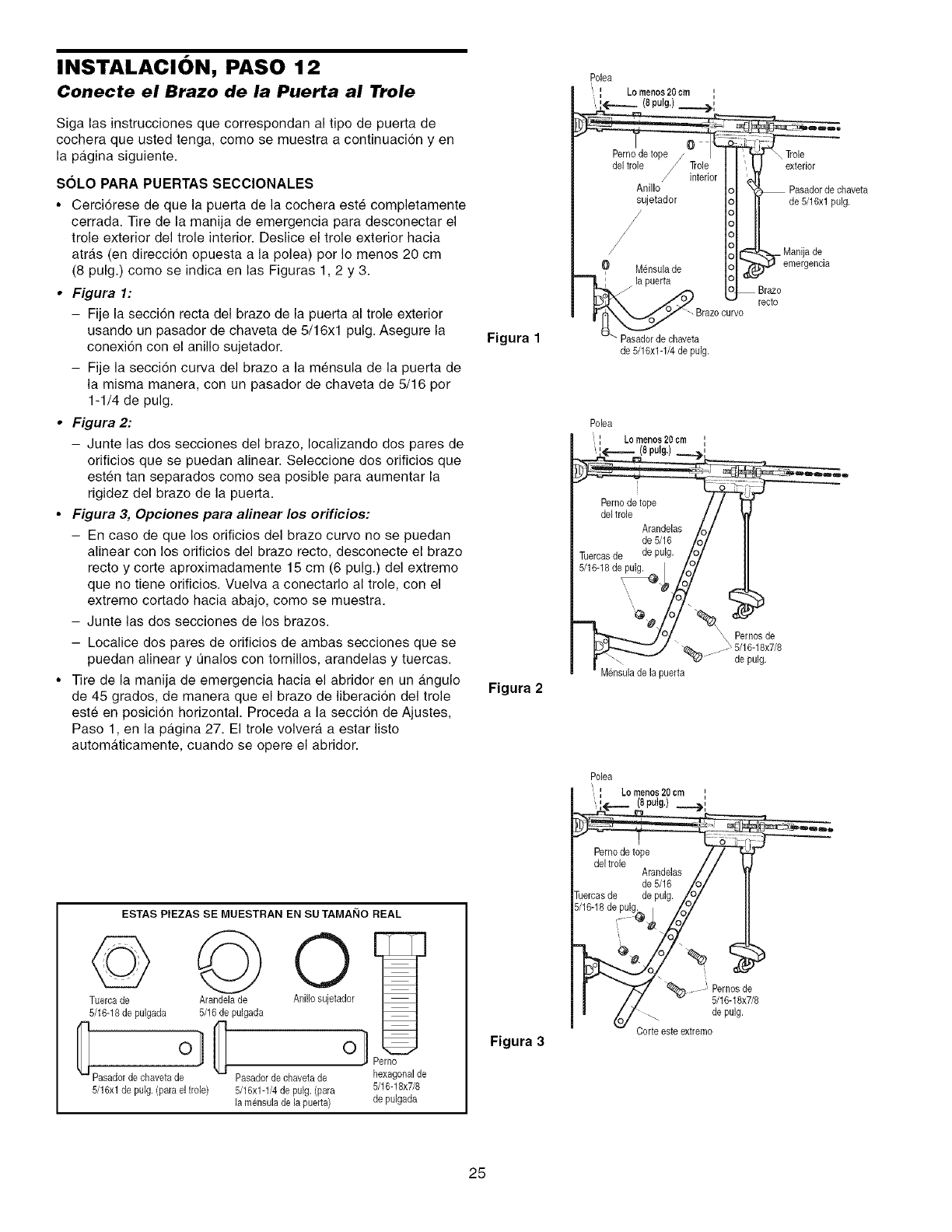
INSTALACI()N, PASO 12
Conecte el Brazo de la Puerta al Trole
Siga las instrucciones que correspondan al tipo de puerta de
cochera que usted tenga, como se muestra a continuacion yen
la pagina siguiente.
SOLO PARA PUERTAS SECClONALES
• Cerciorese de que la puerta de la cochera este completamente
cerrada. Tire de la manija de emergencia para desconectar el
trole exterior del trole interior. Deslice el trole exterior hacia
atras (en direccion opuesta a la polea) per Io menos 20 cm
(8 pulg.) como se indica en las Figuras 1,2 y 3.
•Figura 1:
- Fije la seccion recta del braze de la puerta al trole exterior
usancto un pasador de chaveta de 5/16xl pulg. Asegure la
conexi6n con el anillo sujetador. Figura 1
- Fije la seccion curva del braze a la mensula de la puerta de
la misma manera, con un pasador de chaveta de 5/16 por
1-1/4 de pulg.
• Figura 2:
- Junte las dos secciones del braze, Iocalizando dos pares de
orificios que se puedan alinear. Seleccione dos orificios que
esten tan separados come sea posible para aumentar la
rigidez del braze de la puerta.
•Figura 3, Opciones para alinear los orificios:
- En caso de que los orificios del braze curve no se puedan
alinear con los orificios del braze recto, desconecte el braze
recto y corte aproximadamente 15 cm (6 pulg.) del extreme
que no tiene orificios. Vuelva a conectarlo al trole, con el
extremo cortado hacia abajo, come se muestra.
- Junte las des secciones de los brazos.
- Localice dos pares de orificios de ambas secciones que se
puedan alinear y 0halos con torniNos, arandelas y tuercas.
•Tire de la manija de emergencia hacia el abridor en un a.ngulo Figura 2
de 45 grados, de manera que el braze de liberacion del trole
este en posicion horizontal. Proceda a la seccion de Ajustes,
Paso 1, en la pa.gina 27. El trole volver_, a estar listo
automa.ticamente, cuando se opere el abridor.
ESTAS PIEZAS SE MUESTRAN EN SU TAMAi_IO REAL
© © 0
Tuercade Arandelade Anillo sujetador
5/16-18de pulgada 5/16de pulgada
0 0
i Perno
Pasador de ohaveta de Pasador de ohaveta de hexagonal de
5/16xl de pulg. (para el lrole) 5/16x1-1/4de pulg. (para 5/16-18x7/8
[a mensuJade la puerta) de pulgada
Figura 3
Polea
' Lomenos20cm '
ij
.',,,,<_.__ (8pulg.)__i>,,
del trole /.Trole I I \ _J exterior
/interior I [ _1[
Anillo Io _ k_ Pasadorde chaveta
iujetad°r i I deS/16xlpulg'
/IolL_ Manijade,
M_nsulade I01 _ emergencla
Iol--B.zo
_- Brazocurvo
Pasadorde chaveta
de 5/16x1-1/4de pulg.
Polea
: Lomenos20cm ',
(8 pulg.)
@#
Pernosde
....._ 5/16-18x7/8
- de pulg.
Mensulade la puerta
Polea
Lomenos20cm '
ii
_,,_._..._ (8pulg,) ..__._,,
Perno de tope / / f
del trole / / I
Arandelas / /
de 5/16 Iol
_ercas de de pulg. LO/
'_ Pernosde
// _ 5/16-18x7/8
_/ -_. de pulg.
v Corteesteextremo
25
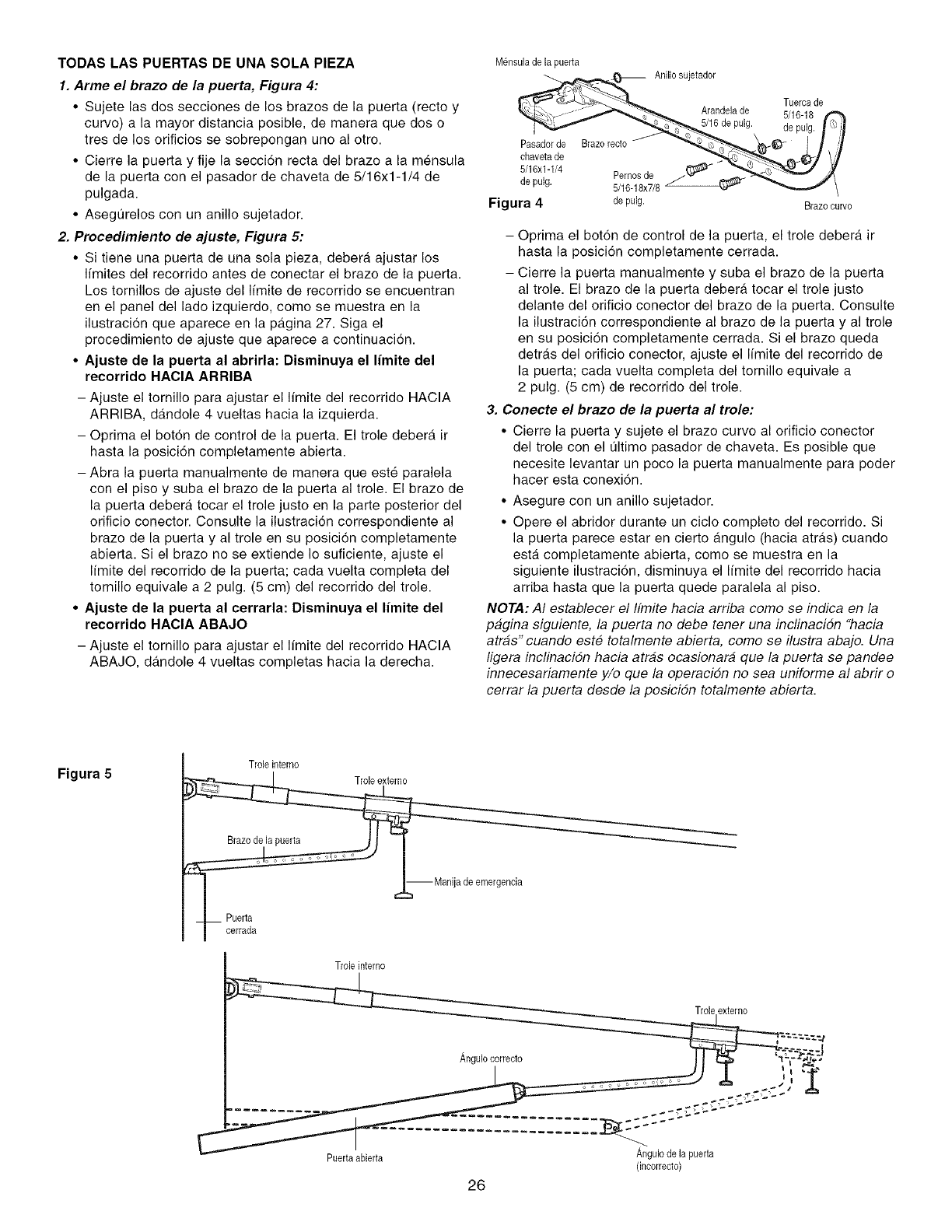
TODAS LAS PUERTAS DE UNA SOLA PIEZA
1. Arme el brazo de la puerta, Figura 4:
•Sujete las dos secciones de los brazes de la puerta (recto y
curve) a la mayor distancia posible, de manera que dos o
tres de los orificios se sobrepongan uno al otro.
• Cierre la puerta y fije la secci6n recta del braze a la mensula
de la puerta con el pasador de chaveta de 5/16x1-1/4 de
pulgada.
• Asegt]relos con un anillo sujetador.
2. Procedimiento de ajuste, Figura 5:
• Si tiene una puerta de una sola pieza, debera ajustar los
Ifmites del recorrido antes de conectar el brazo de la puerta.
Los tornillos de ajuste del Ifmite de recorrido se encuentran
en el panel del lade izquierdo, come se muestra en la
ilustracion que aparece en la pa.gina 27. Siga el
procedimiento de ajuste que aparece a continuacion.
• Ajuste de la puerta al abrirla: Disminuya el limite del
recorrido HACIA ARRIBA
- Ajuste el tornillo para ajustar el limite del recorrido HACIA
ARRIBA, dandole 4 vueltas hacia la izquierda.
- Optima el bot6n de control de la puerta. El trole debera ir
hasta la posici6n completamente abierta.
- Abra la puerta manualmente de manera que este paralela
con el piso y suba el brazo de la puerta al trole. El braze de
la puerta debera tocar el trole justo en la parte posterior del
orificio conector. Consulte la ilustraci6n correspondiente al
brazo de la puerta y al trole en su posicion completamente
abierta. Si el brazo no se extiende Io suficiente, ajuste el
Ifmite del recorrido de la puerta; cada vuelta completa del
tornillo equivale a 2 pulg. (5 cm) del recorrido del trole.
•Ajuste de la puerta al cerrarla: Disminuya el limite del
recorrido HACIA ABAJO
- Ajuste el tornillo para ajustar el limite del recorrido HACIA
ABAJO, dandole 4 vueltas completas hacia la derecha.
M@sulade la puerta
Anillo sujetador
Tuercade
Arandela de U16-18
5/16 de pulg. de pulg.
Pasadorde Brazo recto
chavetade
5/16x1-1/4 Pernosde
de pulg. 5/16-18x7/8
Figura 4 depulg. Brazo curvo
- Oprima el boton de control de la puerta, el trole debera ir
hasta la posici6n completamente cerrada.
- Cierre la puerta manualmente y suba el brazo de la puerta
al trole. El brazo de la puerta debera tocar el trole justo
delante del orificio conector del brazo de la puerta. Consulte
la ilustraci6n correspondiente al braze de la puerta y al trole
en su posici6n completamente cerrada. Si el braze queda
detras del orificio conector, ajuste el limite del recorrido de
la puerta; cada vuelta completa del tornillo equivale a
2 pulg. (5 cm) de recorrido del trole.
3. Conecte el brazo de la puerta al trole:
• Cierre la puerta y sujete el braze curve al orificio conector
del trole con el t]ltimo pasador de chaveta. Es posible que
necesite levantar un poco la puerta manualmente para poder
hacer esta conexi6n.
• Asegure con un anillo sujetador.
• Opere el abridor durante un ciclo completo del recorrido. Si
la puerta parece estar en cierto angulo (hacia atras) cuando
esta. completamente abierta, como se muestra en la
siguiente ilustraci6n, disminuya el Ifmite del recorrido hacia
arriba hasta que la puerta quede paralela al piso.
NOTA: AI establecer el Ifmite hacia arriba come se indica en la
pagina siguiente, la puerta no debe tener una inclinacidn "hacia
atras" cuando este totalmente abierta, come se ilustra abajo. Una
ligera inclinacidn hacia atras ecasionard que la puerta se pandee
innecesariamente y/o que la operacidn no sea uniforme al abrir e
cerrar la puerta desde la posicidn totalmente abierta.
Figura 5 Trole interno
emergencia
Trole interno
Puertaabierta
26
Angulo de la puerta
(incorrecto)
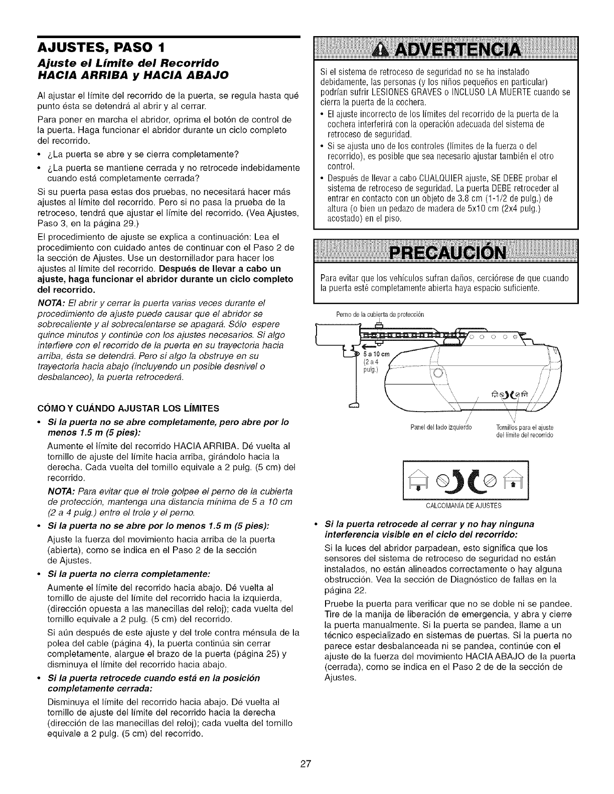
AJUSTES, PASO 1
Ajuste el Limite del Recorrido
HACIA ARRIBA y HACIA ABAJO
AI ajustar el Ifmite del recorrido de la puerta, se regula hasta que
punto esta se detendra al abrir y al cerrar.
Para poner en marcha el abridor, optima el boton de control de
la puerta. Haga funcionar el abridor durante un ciclo completo
del recorrido.
• _,La puerta se abre y se cierra completamente?
• _,La puerta se mantiene cerrada y no retrocede indebidamente
cuando esta completamente cerrada?
Si su puerta pasa estas dos pruebas, no necesitara hacer mas
ajustes al Ifmite del recorrido. Pero si no pasa la prueba de la
retroceso, tendra que ajustar el Ifmite del recorrido. (Vea Ajustes,
Paso 3, en la pagina 29.)
El procedimiento de ajuste se explica a continuaci6n: Lea el
procedimiento con cuidado antes de continuar con el Paso 2 de
la seccion de Ajustes. Use un destomillador para hacer los
ajustes al limite del recorrido. Despues de Ilevar a cabo un
ajuste, haga funcionar el abridor durante un ciclo completo
del recorrido.
NOTA: El abrir y cerrar la puerta varias veces durante el
procedimiento de ajuste puede causar que el abridor se
sobrecaliente y al sobrecalentarse se apagara. Sdlo espere
quince minutos y continue con los ajustes necesarios. Si algo
interfiere con el recorrido de la puerta en su trayectoria hacia
arriba, esta se detendra. Pero si algo la obstruye en su
trayectoria hacia abajo (incluyendo un posible desnivel o
desbalanceo), la puerta retroceder&.
COMO YCUANDO AJUSTAR LOS LIMITES
•Si la puerta no se abre completamente, pero abre por Io
menos 1.5 m (5 pies):
Aumente el limite del recorrido HACIAARRIBA. De vuelta al
tornillo de ajuste del Ifmite hacia arriba, girandolo hacia la
derecha. Cada vuelta del tornillo equivale a 2 pulg. (5 cm) del
recorrido.
NOTA: Para evitar que el trole golpee el perno de la cubierta
de protecciSn, mantenga una distancia mfnima de 5 a 10 cm
(2 a 4 pulg.) entre el trole y el pemo.
• $i la puerta no se abre por Io menos 1.5 m (5 pies):
Ajuste la fuerza del movimiento hacia arriba de la puerta
(abierta), como se indica en el Paso 2 de la secci6n
de Ajustes.
• $i la puerta no cierra completamente:
Aumente el limite del recorrido hacia abajo. De vuelta al
tornillo de ajuste del Ifmite del recorrido hacia la izquierda,
(direcci6n opuesta alas manecillas del reloj); cada vuelta del
tornillo equivale a 2 pulg. (5 cm) del recorrido.
Si at]n despues de este ajuste y del trole contra mensula de la
polea del cable (pAgina 4), la puerta contint]a sin cerrar
completamente, alargue el brazo de la puerta (p&gina 25) y
disminuya el Ifmite del recorrido hacia abajo.
• $i la puerta retrocede cuando esta en la posicion
completamente cerrada:
Disminuya el limite del recorrido hacia abajo. De vuelta al
tornillo de ajuste del Ifmite del recorrido hacia la derecha
(direcci6n de las manecillas del reloj); cada vuelta del tornillo
equivale a 2 pulg. (5 cm) del recorrido.
Si el sistema de retroceso de seguridad no se ha instalado
debidamente, las personas (y los ni_os pequefios en particular)
podr[an sufrir LESIONESGRAVESo INCLUSOLAMUERTEcuando se
cierra la puerta de la cochera.
• El ajuste incorrecto de los I[mites del recorrido de la puerta de la
cochera interferir_ con la operaci6n adecuadadel sistema de
retroceso de seguridad.
• Si se ajusta uno de los controles (limites de la fuerza o del
recorrido), es posible que sea necesario ajustar tambi_n el otro
control.
• Despu_s de Ilevar a cabo CUALQUIERajuste, SE DEBEprobar el
sistema de retroceso de seguridad. La puerta DEBEretroceder al
entrar en contacto con un objeto de 3.8 cm (1-1/2 depulg.) de
altura (o bien un pedazo de madera de 5x10 cm (2x4 pulg.)
acostado) enel piso.
Paraevitar que Ins veh[culos sufran da_os, cerci6rese de que cuando
la puerta est_completamente abierta haya espacio suficiente.
Pernode la cubiertade protecci6n
Paneldel ladoizquierdo Tornillospara el ajuste
del limite del recorrido
CALCOMANiADEAJUSTES
Si la puerta retrocede al cerrar y no hay ninguna
interferencia visible en el ciclo de/recorrido:
Si la luces del abridor parpadean, esto significa que los
sensores del sistema de retroceso de seguridad no estan
instalados, no estan alineados correctamente o hay alguna
obstruccion. Vea la secci6n de Diagnostico de fallas en la
pagina 22.
Pruebe la puerta para verificar que no se doble ni se pandee.
Tire de la manija de liberaci6n de emergencia, y abra y cierre
la puerta manualmente. Si la puerta se pandea, Ilame a un
tecnico especializado en sistemas de puertas. Si la puerta no
parece estar desbalanceada ni se pandea, contint_e con el
ajuste de la fuerza del movimiento HAClAABAJO de la puerta
(cerrada), como se indica en el Paso 2 de de la secci6n de
Ajustes.
27
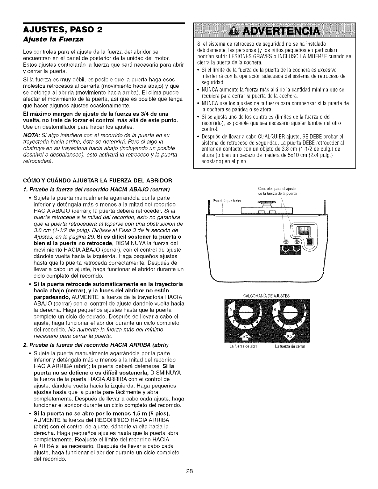
AJUSTES, PASO 2
Ajuste la Fuerza
Los controles para el ajuste de la fuerza del abridor se
encuentran en el panel de posterior de la unidad del motor.
Estos ajustes controlaran la fuerza que sera necesaria para abrir
y cerrar la puerta.
Si la fuerza es muy debil, es posible que la puerta haga esos
molestos retrocesos al cerrarla (movimiento hacia abajo) y que
se detenga al abrirla (movimiento hacia arriba). El clima puede
afectar el movimiento de la puerta, asi que es posible que tenga
que hacer algunos ajustes ocasionalmente.
El maximo margen de ajuste de la fuerza es 3/4 de una
vuelta, no trate de forzar el control mas alia de este punto
Use un destomillador para hacer los ajustes.
NOTA: Si algo interfiere con el recorrido de la puerta en su
trayectoria hacia arriba, esta se detendra. Pero si algo la
obstruye en su trayectoria hacia abajo (incluyendo un posible
desnivel o desbalanceo), esto activara la retroceso y la puerta
retrocedera.
Si el sistema de retroceso de seguridad no se ha instalado
debidamente, las personas (y los niSos pequeSosen particular)
podrfan sufrir LESIONESGRAVESo INCLUS0 LA MUERTEcuando se
cierra la puerta de la co@era.
• Si el Ifmite de la fuerza de la puerta de la cochera es excesivo
interferir_,con la operaciOnadecuadadel sistema de retroceso de
seguridad.
• NUNCAaumente la fuerza m_,sall_,de la ca@dad mfnima que se
requiera para cerrar la puerta de la cochera.
• NUNCAuse los ajustes de la fuerza para compensar si la puerta de
la cochera se pandea o se atora.
• Si se ajusta uno de los controles (limites de la fuerza o del
recorrido), es posible que sea necesario ajustar tambi@ el otro
control.
• Desp@s de Ilevar a cabo CUALQUIERajuste, SE DEBEprobar el
sistema de retroceso de seguridad. La puerta DEBEretroceder al
entrar en contacto con un objeto de 3.8 cm (1-1/2 depulg.) de
altura (o bien un pedazo de madera de 5x10 cm (2x4 pulg.)
acostado) enel piso.
COMO YCU._NDO AJUSTAR LA FUERZA DEL ABRIDOR
1Pruebe la fuerza del recorrido HACIA ABAJO (cerrar)
•Sujete la puerta manualmente agarrandola por la parte
inferior y detengala mas o menos a la mitad del recorrido
HAClAABAJO (cerrar); la puerta debera retroceder. Si la
puerta retrocede a la mitad del recorrido, esto no garantiza
que la puerta retrocedera al toparse con una obstruccidn de
3.8 cm (1-1/2 de pulg). Dirfjase al Paso 3 de la seccidn de
Ajustes, en la pagina 29. Si es dificil soetener la puerta o
bien eila puerta no retrocede, DISMINUYA la fuerza del
movimiento HACIAABAJO (cerrar), con el control de ajuste
dandole vuelta hacia la izquierda. Haga pequeSos ajustes
hasta que la puerta retroceda correctamente. Despues de
Ilevar a cabo un ajuste, haga funcionar el abridor durante un
ciclo completo del recorrido.
•Si la puerta retrocede automaticamente en la trayectoria
hacia abajo (cerrar), y la luces del abridor no estan
parpadeando, AUMENTE la fuerza de la trayectoria HACIA
ABAJO (cerrar) con el control de ajuste dandole vuelta hacia
la derecha. Haga pequehos ajustes hasta que la puerta
complete un ciclo de cerrado. Despues de Ilevar a cabo el
ajuste, haga funcionar el abridor durante un ciclo completo
del recorrido. No aumente la fuerza mas del mfnimo
necesario para cerrar la puerta.
2. Pruebe la fuerza del recorrido HAClA ARRIBA (abrir)
• Sujete la puerta manualmente agarrandola por la parte
inferior y detengala mas o menos a la mitad del recorrido
HAClAARRIBA (abrir); la puerta debera detenerse. Si la
puerta no se detiene o ee dificil eostenerla, DISMINUYA
la fuerza de la puerta HACIAARRIBA con el control de
ajuste, d_.ndole vuelta hacia la izquierda. Haga pequehos
ajustes hasta que la puerta pare facilmente y abra
completamente. Despues de Ilevar a cabo cada ajuste, haga
funcionar el abridor durante un ciclo completo del recorrido.
•Si la puerta no se abre por Io menos 15 m(5 pies),
AUMENTE la fuerza del RECORRIDO HACIAARRIBA
(abrir) con el control de ajuste, dandole vuelta hacia la
derecha. Haga pequehos ajustes hasta que la puerta abra
completamente. Reajuste el Ifmite del recorrido HAClA
ARRIBA si es necesario. Despues de Ilevar a cabo cada
ajuste, haga funcionar el abridor durante un ciclo completo
del recorrido.
Controles para el ajuste
de la fuerza de la puerta
Panelde posterior _q=_==#_ ),,
\
J
CALCOMANiADEAJUSTES
La fuerza deabrir La fuerzade eerrar
28
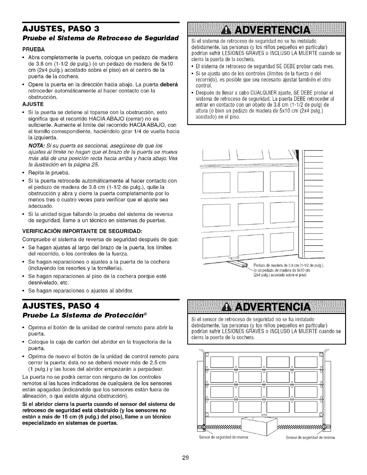
AJUSTES, PASO 3
Pruebe el Sistema de Retroceso de Seguridad
PRUEBA
•Abra completamente la puerta, coloque un pedazo de madera
de 38 cm (1-1/2 de pulg) (o un pedazo de madera de 5x10
cm (2x4 pulg) acostado sobre el piso) en el centre de la
puerta de la cochera
• Opere la puerta en la direcci6n hacia abajo La puerta debera
retroceder automaticamente al hacer contacto con la
obstrucci6n
AJUSTE
• Si la puerta se detiene al toparse con la obstruccion, esto
significa que el recorrido HACIAABAJO (cerrar) no es
suficiente Aumente el I[mite del recorrido HACIAABAJO, con
el tornillo correspondiente, haciendolo girar 1/4 de vuelta hacia
la izquierda
NOTA: Si su puerta es seccional, aseg#rese de que los
ajustes al Ifmite no hagan que el brazo de la puerta se mueva
mas alia de una posiciSn recta hacia arriba y hacia abajo Vea
la ilustraciSn en la pagina 25
• Repita la prueba
• Si la puerta retrocede automaticamente al hacer contacto con
el pedaze de madera de 38 cm (1-1/2 de pulg ), quite la
obstrucci6n y abra y cierre la puerta completamente por Io
menos tres o cuatro veces para verificar que el ajuste sea
adecuado
• Si la unidad sigue fallando la prueba del sistema de reversa
de seguridad, Ilame a un tecnico en sistemas de puertas
VERIFICAClON IMPORTANTE DE SEGURIDAD:
Compruebe el sistema de reversa de seguridad despues de que:
• Se hagan ajustes al largo del brazo de la puerta, los Ifmites
del recorrido, o los controles de la fuerza
• Se hagan reparaciones o ajustes a la puerta de la cochera
(incluyendo los resortes y la tornillerfa)
• Se hagan reparaciones al piso de la cochera porque este
desnivelado, etc
• Se hagan reparaciones o ajustes al abridor
AJUSTES, PASO 4
Pruebe La Sistema de Protecci6n ®
• Oprima el bot6n de la unidad de control remoto para abrir la
puerta
• Coloque la caja de carton del abridor en la trayectoria de la
puerta
• Oprima de nuevo el bot6n de la unidad de control remoto para
cerrar la puerta; esta no se debera mover mas de 25 cm
(1 pulg) y las luces del abridor empezaran a parpadear
La puerta no se podra cerrar con ninguno de los controles
remotos si las luces indicadoras de cualquiera de los sensores
estan apagadas (indicandole que los sensores estan fuera de
alineaci6n, o que existe alguna obstruccion)
Si el abridor cierra la puerta cuando el sensor del sistema de
retroceso de seguridad esta obstruido (y los sensores no
estan a mas de 15 cm (6 pulg.) del piso), Ilame a un tecnico
especializado en sistemas de puertas.
Si el sistema de retroceso de seguridad no se ha instalado
debidamente, las personas (y los nifios peque_os en particular)
podrfan sufrir LESIONESGRAVESo INCLUSOLAMUERTEcuando se
cierra la puerta de la cochera.
• El sistema de retroceso de seguridad SE DEBEprobar cada rues.
• Si se ajusta uno de los controles (limites de la fuerza odel
recorrido), es posible que sea necesario ajustar tambi_n el otro
control.
• Despu_s de Ilevar a cabo CUALQUIERajuste, SE DEBEprobar el
sistema de retroceso de seguridad. La puerta DEBEretroceder al
entrar en contacto con un objeto de 3.8 cm (1-1/2 depulg) de
altura (o bien un pedazo de madera de 5x10 cm (2x4 pulg.)
acostado) enel piso.
L__O de maderade 3 8 em(1 1/2de u
(2x4 pulg.) acostade sobre el piso)
Si el sensor deretroceso de seguridad no se ha instalado
debidamente, las personas (y los ni_os peque_os en particular)
podrfan sufrir LESIONESGRAVESo INCLUSOLA MUERTEcuando se
cierra la puerta de la cochera.
m
}
€
-- _ ,/
Sensor de seguridadde reversa Sensor de seguridadde reversa
29
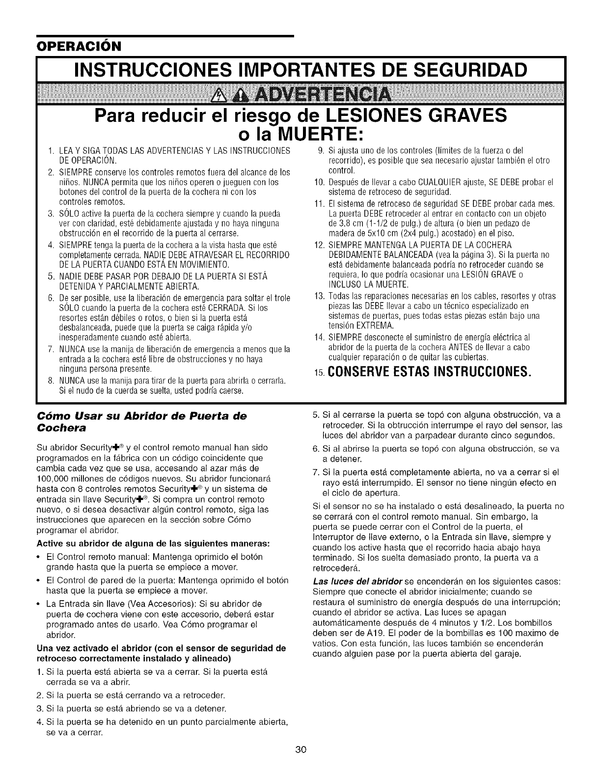
OPERACION
INSTRUCCIONES IMPORTANTES DE SEGURIDAD
Para reducir el riesgo de LESIONES GRAVES
o la MUERTE:
1. LEAY SIGATODAS LASADVERTENCIASY LAS INSTRUCCIONES 9. Si ajusta uno de los controles (limites de la fuerzao del
DEOPERACION. recorrido), es posible que sea necesario ajustar tambi_n el otro
2. SIEMPREconserve los controles remotos fuera del alcance de los
ni_os. NUNCApermita que los ni_os operen o jueguen con los
botones del control de la puerta de la cochera ni coo los
controles remotos.
3. SOLOactive la puerta de la cochera siempre y cuando la pueda
ver con claridad, est6debidamente ajustada y no haya ninguna
obstrucci6n en el recorrido de la puerta al cerrarse.
4. SIEMPREtenga la puerta dela cocheraa lavista hasta que est6
completamente cerrada.NADIEDEBEATRAVESAREL RECORRIDO
DELA PUERTACUANDOESTAENMOVIMIENTO.
5. NADIE DEBEPASARPOR DEBAJODE LA PUERTASI EST',
DETENIDAY PARCIALMENTEABIERTA.
6. De ser posible, use la liberaci6n de emergencia para soltar el trole
SOLOcuando la puerta de la cochera est6 CERRADA.Si los
resortes est_,nd_biles o rotos, o bien si la puerta est_
desbalanceada,puede que la puerta se caiga rApiday/o
inesperadameotecuaodo est_ abierta.
7. NUNCAuse la manija de liberaci6n de emergencia a menos que la
entrada a la cochera est_ libre de obstrucciones y no haya
ninguna persona presente.
8. NUNCAuse la manija paratirar de la puerta paraabrirla o cerrarla.
Si el nudo de la cuerda se suelta, usted podda caerse.
control.
10. Despu_s de Ilevar a cabo CUALQUIERajuste, SE DEBEprobar el
sistema de retroceso de seguridad.
11. El sistema de retroceso de seguridad SE DEBEprobar cada mes.
La puerta DEBEretroceder al entrar en contacto con unobjeto
de 3.8 cm (1-1/2 de pulg.) de altura (o bien un pedazo de
madera de 5x10 cm (2x4 pulg.) acostado) enel piso.
12. SIEMPREMANTENGALA PUERTADE LACOCHERA
DEBIDAMENTEBALANCEADA(vea la p_,gina3). Si la puerta no
est9 debidamente balanceadapodria no retroceder cuando se
requiera, Ioque podria ocasionar una LESIONGRAVEo
INCLUSOLA MUERTE.
13. Todas las reparaciones necesariasen los cables, resortes y otras
piezas las DEBEflevar a cabo un t_cnico especializadoen
sistemas de puertas, pues todas estas piezasest_n bajo una
tensi6n EXTREMA.
14. SlEMPREdesconecte el suministro de energia el6ctrica al
abridor de la puerta de la cochera ANTESde Ilevar a cabo
cualquier reparaci6n o de quitar las cubiertas.
15.CONSERVEESTASINSTRUCCIONES.
C6mo Usar su Abridor de Puerta de
Cochera
Su abridor Security'l "®y el control remoto manual hart sido
programados en la fabrica con un codigo coincidente que
cambia cada vez que se usa, accesando al azar mas de
100,000 millones de c6digos nuevos. Su abridor funcionara
hasta con 8 controles remotos Security'l "®y un sistema de
entrada sin Ilave Security'l "®.Si compra un control remoto
nuevo, o si desea desactivar algt]n control remoto, siga las
instrucciones que aparecen en la seccion sobre C6mo
programar el abridor.
Active su abridor de alguna de las siguientes maneras:
• El Control remoto manual: Mantenga oprimido el boton
grande hasta que la puerta se empiece a mover.
• El Control de pared de la puerta: Mantenga oprimido el bot6n
hasta que la puerta se empiece a mover.
• La Entrada sin Ilave (Vea Accesorios): Si su abridor de
puerta de cochera viene con este accesorio, debera estar
programado antes de usarlo. Vea C6mo programar el
abridor.
Una vez activado el abridor (con el sensor de seguridad de
retroceso correctamente instalado y alineado)
1. Si la puerta esta abierta se va a cerrar. Si la puerta esta
cerrada se va a abrir.
2. Si la puerta se esta cerrando va a retroceder.
3. Si la puerta se esta abriendo se va a detener.
4. Si la puerta se ha detenido en un punto parcialmente abierta,
se va a cerrar.
5. Sial cerrarse la puerta se topo con alguna obstruccion, va a
retroceder. Si la obtruccion interrumpe el rayo del sensor, las
luces del abridor van a parpadear durante cinco segundos.
6. Si al abrirse la puerta se top6 con alguna obstruccion, se va
a detener.
7. Si la puerta esta completamente abierta, no va a cerrar si el
rayo esta interrumpido. El sensor no tiene ningt]n efecto en
el ciclo de apertura.
Si el sensor no se ha instalado o esta desalineado, la puerta no
se cerrara con el control remoto manual. Sin embargo, la
puerta se puede cerrar con el Control de la puerta, el
Interruptor de Ilave externo, o la Entrada sin Ilave, siempre y
cuando los active hasta que el recorrido hacia abajo haya
terminado. Si los suelta demasiado pronto, la puerta va a
retrocedera.
Las luces del abridor se encenderan en los siguientes casos:
Siempre que conecte el abridor inicialmente; cuando se
restaura el suministro de energia despues de una interrupcion;
cuando el abridor se activa. Las luces se apagan
automaticamente despues de 4 minutos y 1/2. Los bombillos
deben ser de A19. El poder de la bombillas es 1O0 maximo de
vatios. Con esta funcion, las luces tambien se encenderan
cuando alguien pase por la puerta abierta del garaje.
30
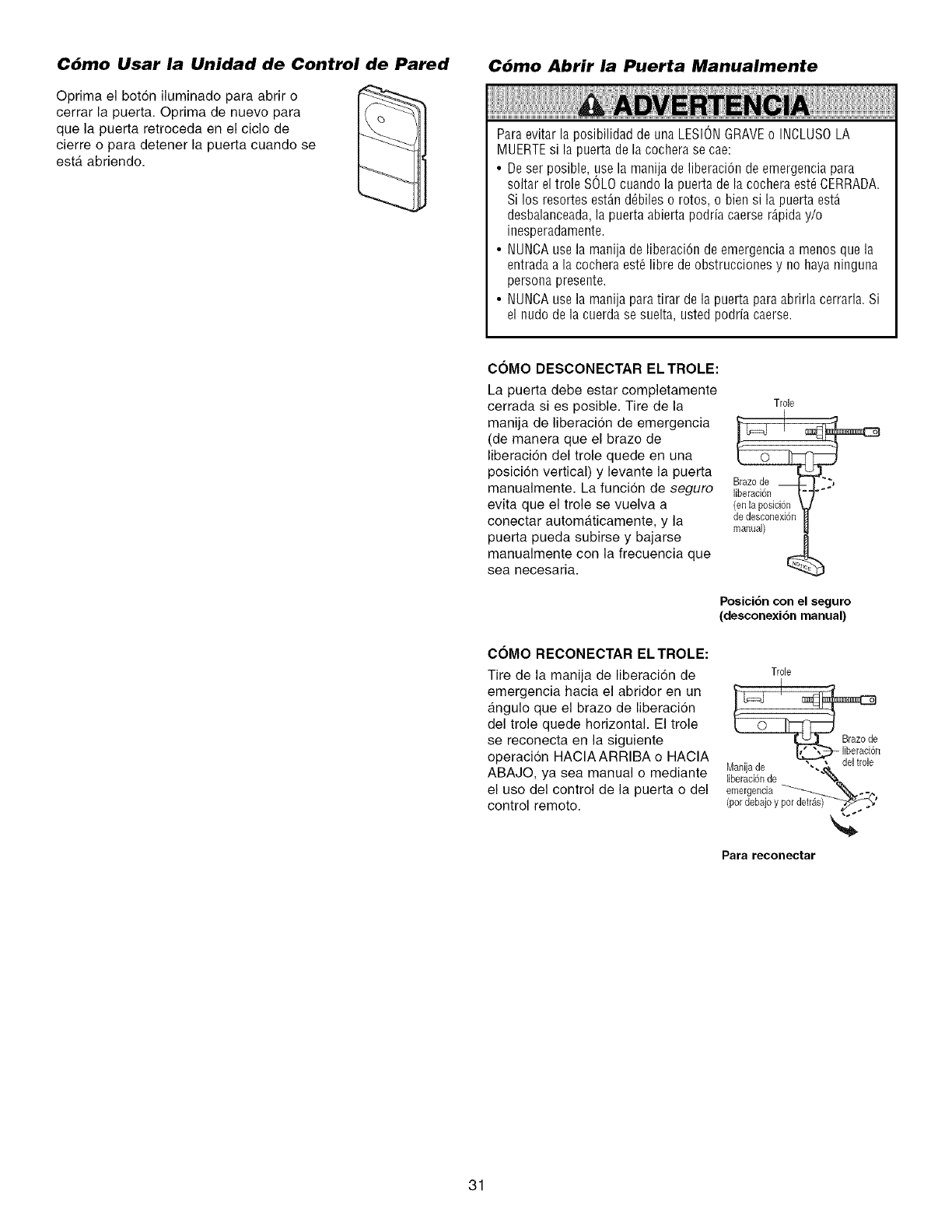
C6mo Usar la Unidad de Control de Pared
Oprima el boton iluminado para abrir o
cerrar la puerta. Optima de nuevo para
que la puerta retroceda en el ciclo de
cierre o para detener la puerta cuando se
esta. abriendo.
C6mo Abrir la Puerta Manualmente
Paraevitar la posibilidad de una LESIONGRAVEo INCLUSOLA
MUERTEsi la puerta de la cochera se cae:
• De ser posible, use la manija de liberaci6n de emergencia para
soltar el trole SOLOcuando la puerta de la cochera est6 CERRADA.
Si los resortes est_n d_biles o rotos, o bien si la puerta est_
desbalanceada,la puerta abierta podria caerse r4.piday/o
inesperadamente.
• NUNCAuse la manija de liberaci6n de emergenciaa menos que la
entrada a la cochera est6 libre de obstrucciones y no haya ninguna
persona presente.
• NUNCAuse la manija para tirar de la puertapara abrirla cerrarla. Si
el nudo de la cuerda se suelta, usted podrfa caerse.
COMO DESCONECTAR EL TROLE:
La puerta debe estar completamente
cerrada si es posible. Tire de la
manija de liberacion de emergencia
(de manera que el brazo de
liberaci6n del trole quede en una
posicion vortical) y levante la puerta
manualmente. La funcion de seguro
evita que el trole se vuelva a
conectar automaticamente, y la
puerta pueda subirse y bajarse
manualmente con la frecuencia que
sea necesaria.
COMO RECONECTAR ELTROLE:
Tire de la manija de liberacidn de
emergencia hacia el abridor en un
angulo que el brazo de liberacidn
del trole quede horizontal. El trole
se reconecta en la siguiente
operacion HACIAARRIBA o HACIA
ABAJO, ya sea manual o mediante
el uso del control de la puerta o del
control remoto.
Trole
Brazode __ .'"_._
liberaci6n
(en la posJcion
de desconexi6n
manual)
Posici6n con el seguro
(desconexi6n manual)
Trole
emergencia _ "_-
(pordebajoypardefray'
Para reconectar
31
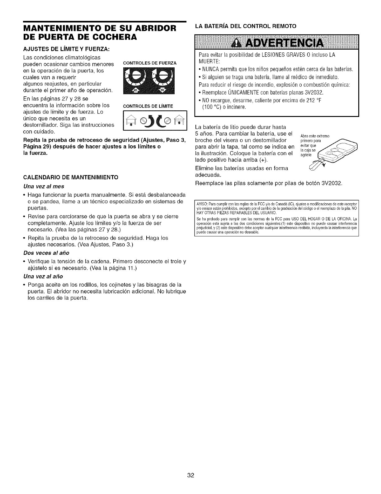
MANTENIMIENTO DE SU ABRIDOR
DE PUERTA DE COCHERA
AJUSTES DE LIMITE Y FUERZA:
Las condiciones climatologicas
pueden ocasionar cambios menores CONTROLESDEFUERZA
en la operaci6n de la puerta, los
cuales van a requerir
algunos reajustes, en particular
durante el primer afio de operacion.
En las paginas 27 y 28 se
encuentra la informacion sobre los CONTROLES DE LIMITE
ajustes de limite y de ,uerza. Lo i*
Qnico que necesita es un
destornillador. Siga las instrucciones
con cuidado.
Repita la prueba de retroceso de seguridad (Ajustes, Paso 3,
Pagina 29) despues de hacer ajustes a los limites o
la fuerza.
CALENDARIO DE MANTENIMIENTO
Una vez al rues
•Haga funcionar la puerta manualmente. Siesta desbalanceada
o se pandea, Ilame a un tecnico especializado en sistemas de
puertas.
• Revise para cerciorarse de que la puerta se abra y se cierre
completamente. Ajuste los Ifmites y/o la fuerza de ser
necesario. (Vea las paginas 27 y 28.)
• Repita la prueba de la retroceso de seguridad. Haga los
ajustes necesarios. (Vea Ajustes, Paso 3.)
Dos veces al a_o
• Verifique la tensi6n de la cadena. Primero desconecte el trole y
ajQstelo si es necesario. (Vea la pagina 11.)
Una vez al a#o
• Ponga aceite en los rodillos, los cojinetes y las bisagras de la
puerta. El abridor no necesita lubricaci6n adicional. No lubrique
los carriles de la puerta.
LA BATER|A DEL CONTROL REMOTO
Para evitar la posibilidad de LESIONESGRAVES0 incluso LA
MUERTE:
• NUNCApermita que los nifios pequefios est_n cerca de las bater[as.
• Si alguien se traga una bateria, Ilame al m6dico de inmediato.
Para reducir el riesgo de incendio, explosi6n o combusti6n quimica:
• Reemplace(JNICAMENTEcon baterias planas 3V2032.
• NO recargue, desarme, caliente por encima de 212 °F
(100 °C) o incinere.
La bateria de litio puede durar hasta
5 afios. Para cambiar la baterfa, use el
broche del visera o un destornillador
para abrir la tapa, tal come se indica en
la ilustracion. Coloque la bateria con el
lade positive hacia arriba (+).
Elimine las baterias usadas en forma
adecuada.
Abraeste extremo
primeropara _.._
evitarque /,1_ ....b_
la £ajase ,,__._ _y
agnet_U
Reemplace las pilas solamente por pilas de boton 3V2032.
AVISO: Para cumplir con las reglas de la FCC y/o de Canada (IC), ajustes o modificaciones de este receptor I
y/o ernisor estan prohibidos, excepto por el carnbio de la graduaci6n del c6digo o el reemplazo de la pila. NO I
HAY OTRAS PIEZAS REPARABLES DEL USUARIO. ]
Se ha probado para cumplir con las normas de la FCC para USO DEL HOGAR 0 DE LA OFICINA. La
operaci6n esta sujeta alas dos condiciones siguientes:(1) este dispositivo no puede causar interferencia
perjudicial, y (2) este dispositivo debe aceptar cualquier interferencia recibida, induyendo la interferencia que
puede causar una operac on no deseab e.
32
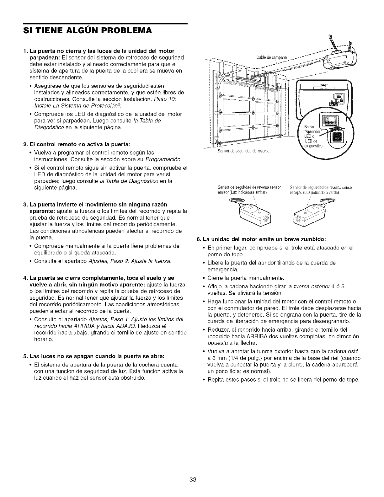
SI TIENE ALGON PROBLEMA
1. La puerta no cierra y las luces de la unidad del motor
parpadean: El sensor del sistema de retroceso de seguridad
debe estar instalado y alineado correctamente para que el
sistema de apertura de la puerta de la cochera se mueva en
sentido descendente.
•Asegt]rese de que los sensores de seguridad esten
instalados y alineados correctamente, y que esten libres de
obstrucciones. Consulte la seccion Instalacion, Paso 10:
Instale La Sistema de ProtecciSn ®.
• Compruebe los LED de diagn6stico de la unidad del motor
para vet si parpadean. Luego consulte la Tabla de
Diagndstico en la siguiente pagina.
2. El control remoto no activa la puerta:
• Vuelva a programar el control remoto segQn las
instruccienes. Consulte la secci6n sobre su ProgramaciSn.
• Si el control remoto sigue sin activar la puerta, compruebe el
LED de diagnostico de la unidad del motor para vet si
parpadea; luego censulte la Tabla de Diagndstico en la
siguiente pagina.
3. La puerta invierte el movimiento sin ninguna razon
aparente: ajuste la fuerza o los Ifmites del recorrido y repita la
prueba de retroceso de seguridad. Es normal tener que
ajustar la fuerza y los Ifmites del recorrido peri6dicamente.
Las condiciones atmosfericas pueden afectar al recorrido de
la puerta.
• Compruebe manualmente si la puerta tiene problemas de
equilibrado o si queda atascada.
• Consulte el apartado Ajustes, Paso 2: Ajuste la fuerza.
4. La puerta se cierra completamente, toca el suelo y se
vuelve a abrir, sin ningt_n motivo aparente: ajuste la fuerza
o los Ifmites del recorrido y repita la prueba de retroceso de
seguridad. Es normal tener que ajustar la fuerza y los Ifmites
del recorrido periodicamente. Las condiciones atmosfericas
pueden afectar al recerrido de la puerta.
• Consulte el apartado Ajustes, Paso 1: Ajuste los ffmites del
recorrido hacia ARRIBA y hacia ABAJO. Reduzca el
recorrido hacia abajo, girando el tornillo de ajuste en sentido
herario.
5. Las luces no se apagan cuando la puerta se abre:
• El sistema de apertura de la puerta de la cochera cuenta
con una funcion de seguridad de luz. Esta funci6n activa la
luz cuando el haz del sensor esta obstruido.
Cable de campana
Sensor de seguridadde reversa
Sensorde seguirdadde reversasensor
emisor (LuzindicadoraAmbar)
\
Sensor deseguirdadde reversasensor
recepto(Luz ,indieadoraverde)
/
6. La unidad del motor emite un breve zumbido:
• En primer lugar, compruebe si el trole esta atascado en el
perno de tope.
• Libere la puerta del abridor tirando de la cuerda de
emergencia.
• Cierre la puerta manualmente.
• Afloje la cadena haciendo girar la tuerca exterior 465
vueltas. Se aliviara la tension.
• Haga funcionar la unidad del motor con el control remote o
con el conmutador de pared. El trole debe desplazarse hacia
la puerta, y detenerse. Si se engrana con la puerta, tire de la
cuerda de liberacion de emergencia para desengranarlo.
• Reduzca el recorrido hacia arriba, girando el tornillo del
recorrido hacia ARRIBA dos vueltas completas, en direccion
opuesta a la flecha.
• Vuelva a apretar la tuerca exterior hasta que la cadena este
a 6 mm (1/4 de pulg.) per encima de la base del riel (cuando
vuelva a conectar la puerta y la cierre, la cadena aparecera
un poco floja; es normal).
• Repita estos pasos si el trole no se libera del perno de tope.
33
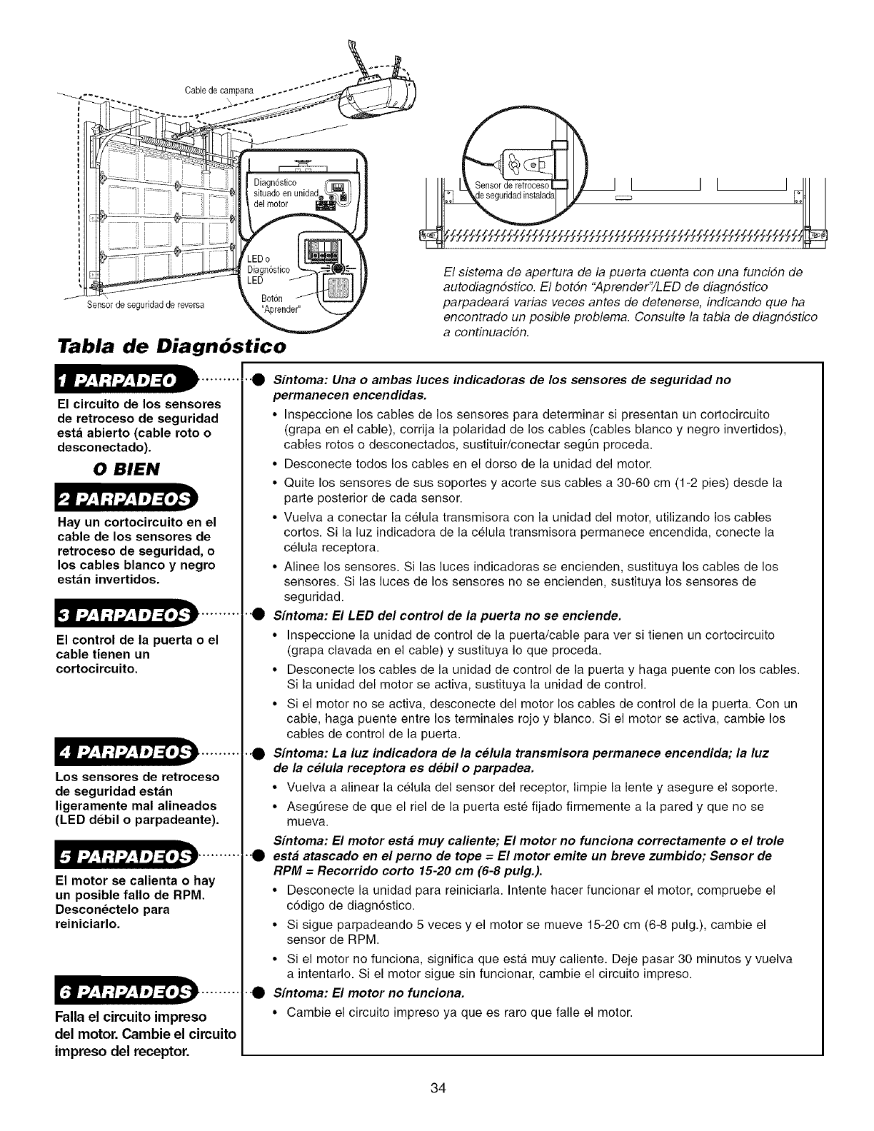
Cable de campana
Sensorde seguridad de reversa
Tabla de Diagn6stico
El circuito de los sensores
de retroceso de seguridad
esta abierto (cable roto o
desconectado).
0 BIEN
Hay un cortocircuito en el
cable de los sensores de
retroceso de seguridad, o
los cables blanco y negro
estan invertidos.
El control de la puerta o el
cable tienen un
cortocircuito.
Los sensores de retroceso
de seguridad estan
ligeramente mal alineados
(LED debil o parpadeante)•
El motor se calienta o hay
un posible fallo de RPM.
Desconectelo para
reiniciarlo.
[.tl_,_V:!_,_VJ]=[oI.'J .........
Falla el circuito impreso
del motor• Cambie el circuito
impreso del receptor.
ZZZZZZZZZZZZZZZ'-ZZZZZZZZ'_ZZZZZ/_ZZfZZZZZZZZZZZZZZZZZZZZZZZ
El sistema de apertura de la puerta cuenta con una funcidn de
autodiagndstico. El botdn "Aprender"/LED de diagndstico
parpadeara varias veces antes de detenerse, indicando que ha
encontrado un posible problema. Consulte la tabla de diagndstico
a centinuacidn.
•"_ Sintoma: Una o ambas luces indicadoras de los sensores de seguridad no
permanecen encendidas.
•Inspeccione los cables de los sensores para determinar si presentan un cortocircuito
(grapa en el cable), corrija la polaridad de los cables (cables blanco y negro invertidos),
cables rotos o desconectados, sustituir/conectar segt]n proceda.
• Desconecte todos los cables en el dorso de la unidad del motor.
• Quite los sensores de sus soportes y acorte sus cables a 30-60 cm (1-2 pies) desde la
parte posterior de cada sensor.
• Vuelva a conectar la celula transmisora con la unidad del motor, utilizando los cables
cortos. Si la luz indicadora de la celula transmisora permanece encendida, conecte la
celula receptora.
• Alinee los sensores. Si las luces indicadoras se encienden, sustituya los cables de los
sensores. Si las luces de los sensores no se encienden, sustituya los sensores de
seguridad.
•"_ Sfntoma: El LED del control de la puerta no se enciende•
• Inspeccione la unidad de control de la puerta/cable para ver si tienen un cortocircuito
(grapa clavada en el cable) y sustituya Io que proceda.
• Desconecte los cables de la unidad de control de la puerta y haga puente con los cables.
Si la unidad del motor se activa, sustituya la unidad de control.
• Si el motor no se activa, desconecte del motor los cables de control de la puerta. Con un
cable, haga puente entre los terminales rojo y blanco. Si el motor se activa, cambie los
cables de control de la puerta.
•._ S[ntoma: La luz indicadora de la celula transmisora permanece encendida; la luz
de la celula receptora es debil o parpadea•
• Vuelva a alinear la celula del sensor del receptor, limpie la lente y asegure el soporte.
• Asegt_rese de que el riel de la puerta este fijado firmemente a la pared y que no se
mueva.
S[ntoma: El motor esta muy caliente; El motor no funciona correctamente o el trole
•"_ esta atascado en el perno de tope = El motor emite un breve zumbido; Sensor de
RPM =Recorrido corto 15-20 cm (6-8 pulg.).
• Desconecte la unidad para reiniciarla. Intente hacer funcionar el motor, compruebe el
c6digo de diagn6stico.
• Si sigue parpadeando 5 veces y el motor se mueve 15-20 cm (6-8 pulg.), cambie el
sensor de RPM.
• Si el motor no funciona, significa que esta muy caliente. Deje pasar 30 minutos y vuelva
a intentarlo. Si el motor sigue sin funcionar, cambie el circuito impreso.
•"_ Sfntoma: El motor no funciona.
• Cambie el circuito impreso ya que es rare que falle el motor.
34
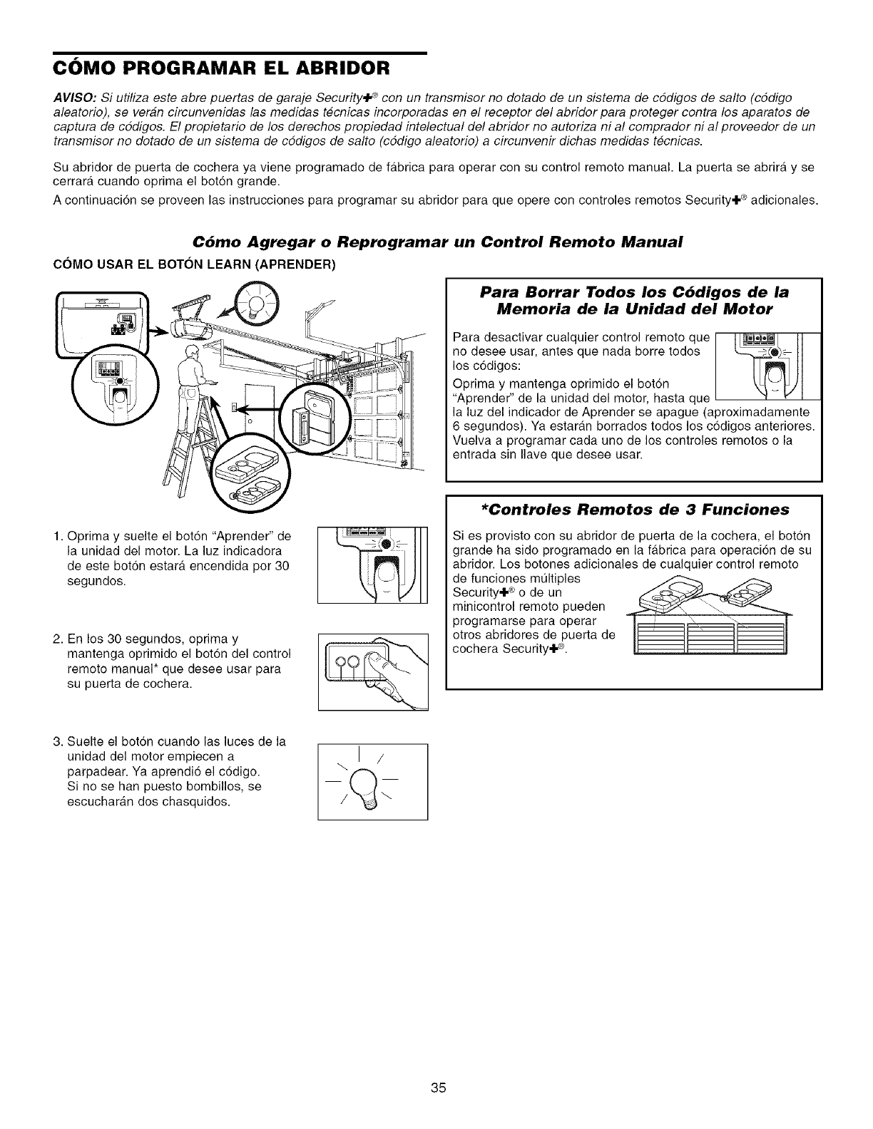
C()MO PROGRAMAR EL ABRIDOR
AVISO: Si utiliza este abre puertas de garaje Security,I .¢ con un transmisor no dotado de un sistema de cddigos de salto (cddigo
aleatorio), se veran circunvenidas las medidas tecnicas incorporadas en el receptor del abridor para proteger contra los aparatos de
captura de cddigos. El propietario de los derechos propiedad intelectual del abridor no autoriza ni al comprador ni al proveedor de un
transmisor no dotado de un sistema de cddigos de salto (cddigo aleatorio) a circunvenir dichas medidas tecnicas.
Su abridor de puerta de cochera ya viene programado de fa.brica para operar con su control remoto manual. La puerta se abrira y se
cerrara cuando optima el botdn grande.
A continuacidn se proveen las instrucciones para programar su abridor para que opere con controles remotos Security÷ ® adicionales.
Cbmo Agregar o Reprogramar un Control Remoto Manual
COMO USAR EL BOTON LEARN (APRENDER)
1. Oprima y suelte el bot6n "Aprender" de
la unidad del motor. La luz indicadora
de este boton estara, encendida por 30
segundos.
2. En los 30 segundos, oprima y
mantenga oprimido el boton del control
remoto manual* que desee usar para
su puerta de cochera.
Para Borrar Todos los Cbdigos de la
Memoria de la Unidad del Motor
Para desactivar cualquier control remote que I_
no desee usar, antes que nada borre todos
los c6digos:
Oprima y mantenga oprimido el bot6n
"Aprender" de la unidad del motor, hasta que
la luz del indicador de Aprender se apague (aproximadamente
6 segundos). Ya estaran borrados todos los codigos anteriores.
Vuelva a programar cada uno de los controles remotos o la
entrada sin Ilave que desee usar.
*Controles Remotos de 3 Funciones
Si es provisto con su abridor de puerta de la cochera, el boton
grande ha sido programado en la fabrica para operaci6n de su
abridor. Los botones adicionales de cualquier control remoto
de funciones mQItiples ___ _
Security÷ ®o de un
minicontrol remoto pueden
programarse para operar
otros abridores de puerta de
cochera Security÷ ®.
3. Suelte el boton cuando las luces de la
unidad del motor empiecen a
parpadear. Ya aprendio el codigo.
Si no se han puesto bombillos, se
escucharan dos chasquidos.
35
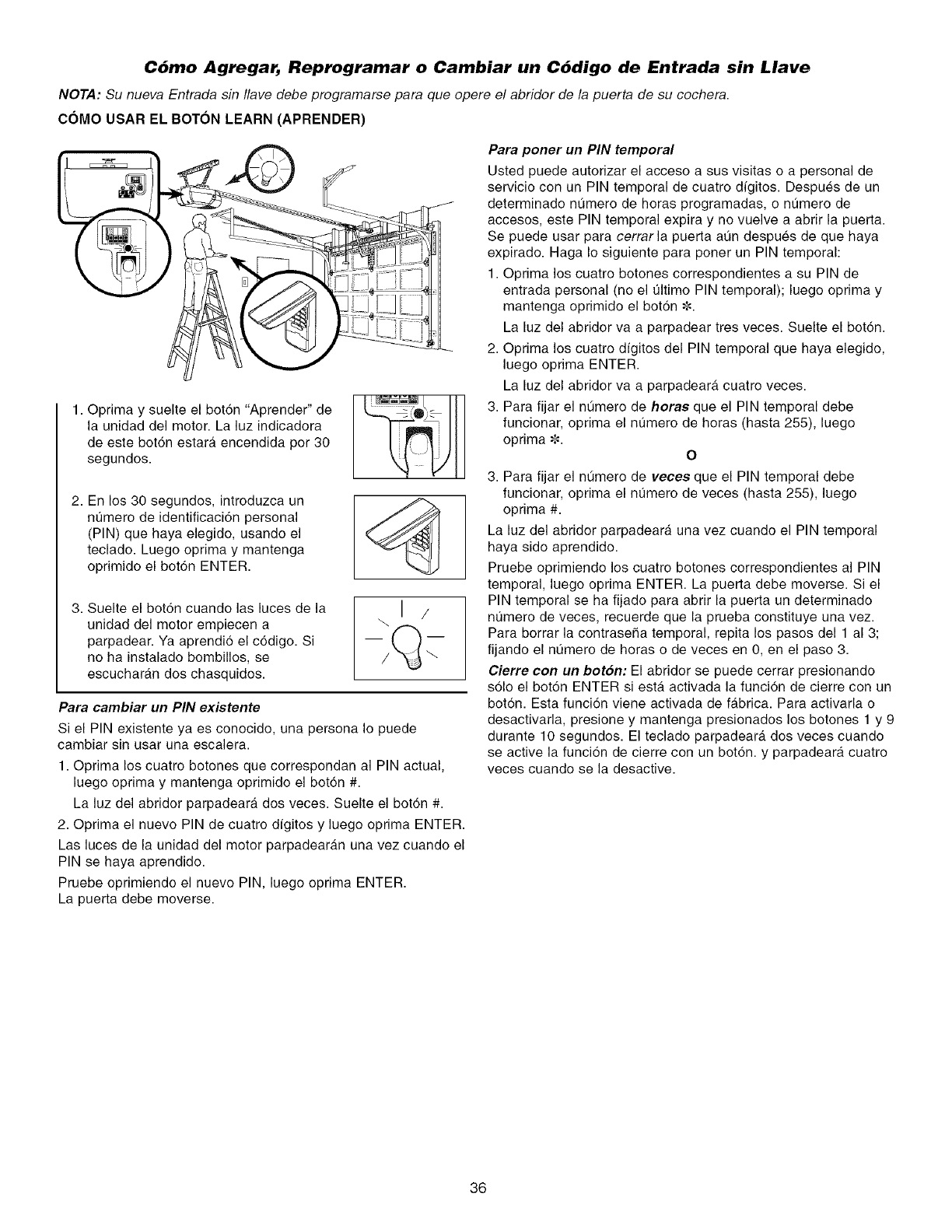
C6mo Agregar, Reprogramar o Cambiar un C6digo de Entrada sin Llave
NOTA: Su nueva Entrada sin Ilave debe programarse para que opere el abridor de la puerta de su cochera.
COMO USAR EL BOTON LEARN (APRENDER)
1. Oprima y suelte el bot6n "Aprender" de
la unidad del motor. La luz indicadora
de este bot6n estara encendida por 30
segundos.
2. En los 30 segundos, introduzca un
nt]mero de identificaci6n personal
(PIN) que haya elegido, usando el
teclado. Luego oprima y mantenga
oprimido el bot6n ENTER.
3. Suelte el bot6n cuando las luces de la
unidad del motor empiecen a
parpadear. Ya aprendio el c6digo. Si
no ha instalado bombillos, se
escucharan dos chasquidos.
\1 /
Para cambiar un PIN exietente
Si el PIN existente ya es conocido, una persona Io puede
cambiar sin usar una escalera.
1. Oprima los cuatro botones que correspondan al PIN actual,
luego oprima y mantenga oprimido el boton #.
La luz del abridor parpadeara, dos veces. Suelte el bot6n #.
2. Oprima el nuevo PIN de cuatro dfgitos y luego oprima ENTER.
Las luces de la unidad del motor parpadearan una vez cuando el
PIN se haya aprendido.
Pruebe oprimiendo el nuevo PIN, luego oprima ENTER.
La puerta debe moverse.
Para poner un PIN temporal
Usted puede autorizar el acceso a sus visitas o a personal de
servicio con un PIN temporal de cuatro digitos. Despues de un
determinado nQmero de horas programadas, o nt]mero de
accesos, este PIN temporal expira y no vuelve a abrir la puerta.
Se puede usar para cerrar la puerta aQn despues de que haya
expirado. Haga Io siguiente para porter un PIN temporal:
1. Optima los cuatro botones correspondientes a su PIN de
entrada personal (no el t]ltimo PIN temporal); luego oprima y
mantenga oprimido el bot6n ¢.
La luz del abridor va a parpadear tres veces. Suelte el bot6n.
2. Optima los cuatro dfgitos del PIN temporal que haya elegido,
luego oprima ENTER.
La luz del abridor va a parpadeara cuatro veces.
3. Para fijar el nt_mero de horas que el PIN temporal debe
funcionar, oprima el nt]mero de horas (hasta 255), luego
oprima ¢.
O
3. Para fijar el nt_mero de vecee que el PIN temporal debe
funcionar, oprima el nt]mero de veces (hasta 255), luego
oprima #.
La luz del abridor parpadeara una vez cuando el PIN temporal
haya sido aprendido.
Pruebe oprimiendo los cuatro botones correspondientes al PIN
temporal, luego optima ENTER. La puerta debe moverse. Si el
PIN temporal se ha fijado para abrir la puerta un determinado
nt]mero de veces, recuerde que la prueba constituye una vez.
Para borrar la contraseha temporal, repita los pasos del 1 al 3;
fijando el nQmero de horas o de veces en 0, en el paso 3.
Cierre con un boton: El abridor se puede cerrar presionando
solo el bot6n ENTER siesta activada la funci6n de cierre con un
boton. Esta funcion viene activada de fabrica. Para activarla o
desactivarla, presione y mantenga presionados los botones 1 y 9
durante 10 segundos. El teclado parpadeara, dos veces cuando
se active la funcion de cierre con un boton, y parpadeara cuatro
veces cuando se la desactive.
36
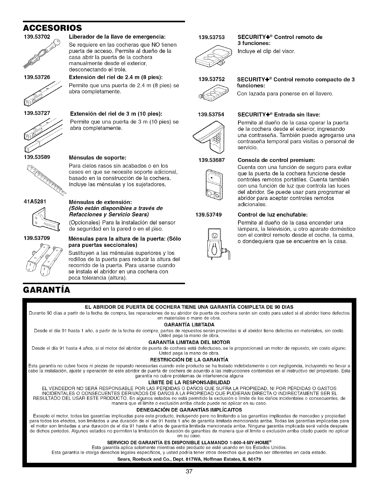
ACCESORIOS
139.53702 Liberador de la Ilave de emergencia:
Se requiere en las cocheras que NO tienen
puerta de acceso. Permite al duefio de la
casa abrir la puerta de la cochera
manualmente desde el exterior,
desconectando el trole.
139.53726 Extensi6n del riel de 2.4 m (8 pies):
Permite que una puerta de 2.4 m (8 pies) se
abra completamente.
139.53753
139.53752
SECURITY+ ®Control remoto de
3funciones:
Incluye el clip del visor.
SECURITY+ ®Control remoto compacto de 3
funciones:
Con lazada para ponerse en el Ilavero.
139.53727 Extension del riel de 3 m (10 pies):
Permite que una puerta de 3 m (10 pies) se
abra completamente.
139.53589 Mensulas de soporte:
Para cielos rasos sin acabados o en los
casos en que se necesite soporte adicional,
basado en la construccion de la cochera.
Incluye las mensulas y los sujetadores.
41A5281 Mensulas de extension:
(Solo estan disponibles a traves de
Refacciones y Servicio Sears)
(Opcionales) Para la instalacion del sensor
de seguridad en la pared o en el piso.
139.53709 Mensulas para la altura de la puerta: (Solo
para puertas seccionales)
Sustituyen a las mensulas superiores y los
redillos de la puerta para reducir la altura del
recorrido de la puerta. Para usarse cuando
se instala el abridor en una cochera con
poca tolerancia (altura).
GARANTJA
139.53754
139.53687
139.53749
SECURITY+ ®Entrada sin Ilave:
Permite al duefio de la casa operar la puerta
de la cochera desde el exterior, ingresando
una contrasefia. Tambien puede agregarse una
contrasefia temporal para visitas o personal de
servicio.
Consola de control premium:
Cuenta con una funcion de seguro para evitar
que la puerta de la cochera funcione desde
controles remotos portatiles. Cuenta tambien
con una funci6n de luz que controla las luces
del abridor. Se puede usar para programar el
abridor para aceptar contreles remotos
adicionales.
Control de luz enchufable:
Permite al duefio de la casa encender una
lampara, la televisi6n, u otro aparato domestico
con el control remote desde el coche, la cama,
e dondequiera que se encuentre en la casa.
EL ABRIDOR DE PUERTA DE COCHERATIENE UNA GARANT|A COMPLETA DE 90 DIAS
Durante 90 dias a partir de la fecha de compra, las reparaciones de su abridor de puerta de cochera serdm sin costo para usted si el abridor tiene defectos
en materiales o mano de obra.
GARANT|A LIMITADA
Desde el dfa 91 hasta 1 aflo, a partir de la fecha de compra, partes de repuestos seran proveidas si el abridor tiene defectos en materiales, sin costo.
Usted paga la mano de obra.
GARANTiA LIMITADA DEL MOTOR
Desde el dfa 91 hasta 4 aflos, si el motor del abridor de puerta de cochera esta defectuoso, se le proporcionara un motor de repuesto, sin costo alguno.
Usted paga la mano de obra.
RESTRICClON DE LA GARANTIA
Esta garanfia no cubre focos ni piezas de repuesto necesarias cuando este producto se ha tratado indebidamente o con negligencia, incluyendo no Ilevar a
cabo la instalaci6n, ajuste y operaci6n de este abridor de puerta de cochera de acuerdo alas instrucciones contenidas en el instructivo del propietario. Eata
garanfia no cubre problemas de interferencia alguna
LIMITE DE LA RESPONSABILIDAD
EL VENDEDOR NO SER,_ RESPONSABLE POR LAS PC:RDIDAS O DAN©S QUE SUFRA LA PROPIEDAD, NI POR PERDIDAS O GASTOS
INCIDENTALES O CONSECUENTES DERIVADOS DE DANOS A LA PROPIEDAD QUE PUDIERAN DIRECTA O INDIRECTAMENTE SER EL
RESULTADO DEL USAR ESTE PRODUCTO. En algunos estados no esta permitido la exclusi6n o Ifmite de los dafios incidentales o consecuentes, de
manera que el Ifmite o exclusi6n arriba citado puede no aplicar en su caso.
DENEGAClON DE GARANT|AS IMPL|CAITOS
Excepto el motor, todas las garanfias implicadas para este producto, incluyendo pero no limitando alas garanfias implicadas de mercadeo y propiedad
para todos los efectos, son limitados a una duraci6n de el dfa 91 hasta 1 aflo de garanfia limitada mencionada arriba. Todas las garantias implicadas para
el motor son limitadas a una duraci6n de el dia 91 hasta 4 aflos de garantia limitada mencionada arriba. Ninguna garantia implicada sera valida despues
de dichos periodos. Algunos estados no permiten la limitaci6n de duraci6n de garantias de manera que el limite o exclusi6n arriba citado puede no aplicar
en su caso.
SERVIClO DE GARANTIA ES DISPONIBLE LLAMANDO 1-800-4-MY-HOME ®
Esta garantia aplica solamente mientras este producto se este usando en los Estados Unidos.
Esta garanfia le otorga derechos legales especificos, y usted podria tener otros derechos que pueden ser diferentes en cada estado.
Sears, Roebuck and Co., Dept. 817WA, Hoffman Estates, IL 60179
37

Your Home
For repair-in your home-of all major brand appliances,
lawn and garden equipment, or heating and cooling systems,
no matter who made it, no matter who sold it!
For the replacement parts, accessories and
owner's manuals that you need to do-it-yourself.
For Sears professional installation of home appliances
and items like garage door openers and water heaters.
1-800-4-MY-HOME ® (1-800-469-4663)
Call anytime, day or night (U.S.A. and Canada)
www.sears,com www.sears.ca
Our Home
For repair of carry-in items like vacuums, lawn equipment,
and electronics, call or go on-line for the location of your nearest
Sears Parts & Repair Center.
1-800-488-1222
Call anytime, day or night (U.S.A. only)
www.sears.com
To purchase a protection agreement (U.S.A.)
or maintenance agreement (Canada) on a product serviced by Sears:
1-800-827-6655 (U.S.A.) 1-800-361-6665 (Canada)
Para pedir servicio de reparaciSn
a domicilio, y para ordenar piezas:
1-888-SU-HOGAR SM
(1-888-784-6427)
Au Canada pour service en fran£_ais:
1-800-LE-FOYER Mc
(1-800-533-6937)
www.sears.ca
® Registered Trademark /TMTrademark /SMService Mark of Sears, Roebuck and Co.
® Marca Registrada /TMMarca de Fabrica /SMMarca de Servicio de Sears, Roebuck and Co.
MCMarque de commerce /MDMarque depos_e de Sears, Roebuck and Co.
114A3613 ©2008 Sears, Roebuck and Co.
