Craftsman 141218331 User Manual SAW TABLE^ Manuals And Guides 1310502L
User Manual: Craftsman 141218331 141218331 CRAFTSMAN SAW TABLE^ - Manuals and Guides View the owners manual for your CRAFTSMAN SAW TABLE^ #141218331. Home:Tool Parts:Craftsman Parts:Craftsman SAW TABLE^ Manual
Open the PDF directly: View PDF ![]() .
.
Page Count: 36

Operator's Manual
1 O"
CONTRACTOR TABLE SAW
Model No.
351.218331
/
CAUTION:
Read and follow all Safety
Rules and Operating
Instructions before First
Use of this Product. Keep
this Manual with Tool.
. Safety
• Unpacking
• Assembly
•Operation
= Maintenance
• Parts List
• Espa_ol
Sears Brands Management Corp., Hoffman Estates, IL 60179 U.S.A.
wv,rw,craftsman.com
36998.01 Draft (05/24113)
Warranty ......................................... 2
Safety Rules .................................... 2-5
Unpacking ...................................... 5-6
Assembly ..................................... 6-13
installation .................................... 13-14
Operation .................................... 14-19
Maintenance .................................... 20
Troubleshooting ............................... 22-23
Repair Protection Agreement ....................... 23
Parts Illustration and List ........................ 24-35
Espaffol ...................................... 36-59
CRAFTSMAN ONE YEAR FULL WARRANTY
FOR ONE YEAR from the date of purchase, this product is
warranted against any defects in material or workmanship.
Defective product will receive free repair or free replacement if
repair is unavailable.
For warranty coverage details to obtain repair or replace-
merit, visit the website: www.craftsman.com
This warranty does not cover the blade or belt, which is an
expendable part that can wear out from normal use within the
warranty period.
This warranty is void if this product is ever used while provid-
ing commerciaI services or if rented to another person.
This warranty gives you specific legal rights, and you may
also have other rights which vary from state to state.
Sears Brands Management Corporation, Hoffman Estates,
IL 60179
WARNING: For your own safety, read all of the instructions
and precautions before operating tool.
PROPOSITION 65 WARNING: Some dust created by using
power tools contain chemicals known to the state of California
to cause cancer, birth defects or other reproductive harm.
Some examples of these chemicals are:
• Lead from lead-based paints.
• Crystalline silica from bricks and cement and other
masonry products.
• Arsenic and chromium from chemically-treated lumber.
Your risk from these exposures vary, depending on how often
you do this type of work. To reduce your exposure to these
chemicals: work in a well ventilated area and work with
approved safety equipment. Always wear OSHA/NIOSH
approved, properly fitting face mask or respirator when using
such tools.
CAUTION: Always follow proper operating procedures as
defined in this manual -- even if you are familiar with use of
this or similar tools. Remember that being careless for even a
fraction of a second can result in severe personal injury.
WARNING: THIS PRODUCT CONTAINS LEAD. A CHEMI-
CAL KNOWN TO THE STATE OF CALIFORNIA TO CAUSE
CANCER AND BIRTH DEFECTS OR OTHER REPRODUC-
TIVE HARM. WASH HANDS AFTER HANDLING.
BE PREPARED FOR JOB
• Wear proper apparel. Do not wear loose clothing, gloves,
neckties, rings, bracelets or other jewelry which may get
caught in moving parts of machine.
Sears Brands Management Corporation
• Wear protective hair covering to contain long hair.
• Wear safety shoes with non-slip soles.
° Wear safety glasses complying with United States ANSI
Z87.1. Everyday glasses have only impact resistant lens-
es. They are NOT safety glasses.
° Wear face mask or dust mask if operation is dusty.
° Be alert and think clearly. Never operate power tools when
tired, intoxicated or when taking medications that cause
drowsiness.
PREPARE WORK AREA FOR JOB
* Keep work area clean. Cluttered work areas invite acci-
dents,
,Do not use power tools in dangerous environments. Do not
use power tools in damp or wet locations. Do not expose
power tools to rain.
oWork area should be properly lighted.
° Keep visitors at a safe distance from work area.
°Keep children out of workplace. Make workshop childproof.
Use padlocks, master switches or remove switch keys to
prevent any unintentional use of power tools.
°Keep power cords from coming in contact with sharp
objects, oil, grease and hot surfaces.
TOOL SHOULD BE MAINTAINED
°Always unplug tool prior to inspection.
.Consult manual for specific maintaining and adjusting pro-
cedures.
-Keep tool lubricated and clean for safest operation.
° Remove adjusting tools. Form habit of checking to see that
adjusting tools are removed before switching machine on.
. Keep al! parts in working order. Check to determine that
the guard or other parts will operate properly and perform
their intended function.
. Check for damaged parts. Check for alignment of moving
parts, binding, breakage, mounting and any other condi-
tion that may affect a tool's operation.
°A guard or other part that is damaged should be properly
repaired or replaced. Do not perform makeshift repairs.
(Use parts list provided to order replacement parts.)
•Maintain proper adjustment of rip fence and blade guard.
° Never adjust saw while running. Disconnect power to avoid
accidental start-up.
-Have damaged or worn power cords replaced immediately.
.Keep blade sharp for efficient and safest operation.
KNOW HOWTO USE TOOL
.Use right tool for job. Do not force too] or attachment to do
a job for which it was not designed.
.Disconnect tool when changing blade.
° Avoid accidental start-up. Make sure that the tool is in the
"off" position before plugging in, turning on safety discon-
nect or activating breakers.
°Do not force tool. It will work most efficiently at the rate for
which it was designed.
o Keep hands away from blade and moving parts and cutting
surfaces.
.Never leave tool running unattended. Turn the power off
and do not leave tool until it comes to acomplete stop.
° Do not overreach. Keep proper footing and balance.
. Never stand on tool. Serious injury could occur if tool is
tipped or if blade is unintentionally contacted.
o Know yourtoo]. Learn the tool's operation, application and
specific limitations.
° Handle workpiece correctly. Press firmly against table.
Protect hands from possible injury.
• Turn machine off if it jams. Blade jams when it digs too
deeply into workpiece. (Motor force keeps it stuck in the
work.)
• Feed work into the blade only as recommended in
"Operation"
WARNING; For your own safety, do not operate your saw until it
is completely assembled and installed according to instructions.
STABILITY OF SAW
If there is any tendency for the saw to tip over or move during
certain cutting operations, such as cutting extremely heavy
panels or long heavy boards, the saw should be bolted down.
tf you attach any kind of extensions over 24" wide to either
end of the saw, make sure you either bolt the saw to the floor,
as appropriate, or support the outer end of the extension from
the bench or floor, as appropriate.
LOCATION
The saw should be positioned so neither the operator nor a
casual observer is forced to stand in line with the saw blade.
KICKBACKS
A kickback occursduringa rip-typeoperationwhena part or
allof workpieceis thrownback violentlytowardoperator.
Keepyourface and bodyto one sideof the saw blade,outof
linewitha possible kickback.
Kickbacksand possibleinjuryfrom them can usuallybe avoid-
ed by:
•Maintainingripfence parallel to saw blade.
°Keepingsaw bladesharp.Replace or sharpen anti-kick-
backpawlswhenpointsbecomedull.
• Keepingsaw blade guard, spreader,andanti-kickback
pawls in placeand operatingproperly.The spreader must
be in alignmentwiththe saw bladeand the pawlsmust
stopa kickbackonceit hasstarted. Checktheir action
beforeripping.
• Not ripping workthatis twistedor warpedor doesnot
have a straight edge to guidealongthe rip fence.
• Not releasing workuntil youhave pushedit allthe way
pastthe saw blade.
•Usinga push stick for rippingwidthslessthan6 inches.
•Not confiningthe cutoffpiecewhen ripping orcrosscutting.
PROTECTION: EYES, HANDS, FACE, BODY, EARS
• If any part of yoursaw is missing, malfunctioning, or has
beendamaged orbroken(such asthe motor switch, elec-
troniccontrols,otheroperatingcontrol,a safety device or
powercord),cease operatingimmediately until the partic-
ular part is properly.repairedorreplaced.
•Wear safety gogglesthat complywithUnitedStatesANSI
Z87.1 anda face shield or dustmask if operationis dusty.
Wear ear plugsor muffsduringextendedperiodsof oper-
ation.
• Small loose pieces of wood or other objects that contact
the rear of the revolving blade can be thrown back at the
operator at excessive speed. This can usually be avoided
by keeping the guard and spreader in place for all thru-
sawing operations (sawing entirely thru work) and by
removing all loose pieces from the table with a long stick
of wood immediately after they are cut off.
• Use extra caution when the guard assembly is removed for
resawing, dadoing, or rabbeting--replace guard as soon
as that operation is completed.
°Never turn the saw ON before clearing the table of all
tools, wood scraps, etc., except the workpiece and related
feed or support devices for the operation planned.
°Never place your face or body in line with the cutting tool.
°Never place your fingers or hands in path of saw blade or
other cutting tool.
° For rip or rip-type cuts, the following end of a workpiece to
which a push stick or push board is applied must be
square (perpendicular to the fence) in order that feed
pressure applied to the workpiece by the push stick or
block does not cause the workpiece to come away from
the fence, and possibly cause a kickback.
•During rip and rip-type cuts, workpiece must be held down
on table and against fence with a push stick, push block,
or featherboards, as applicable (see Figures la and l b,
page 4).
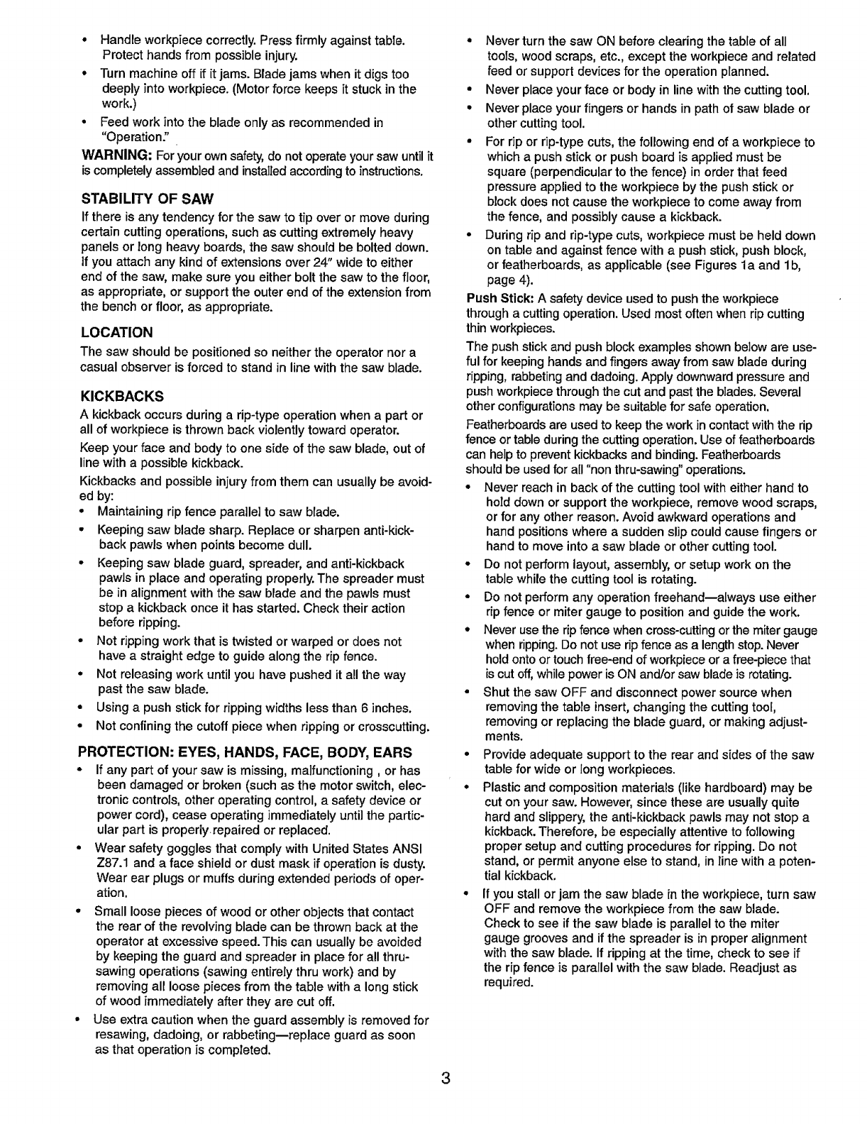
Push Stick: A safety device used to push the workpiece
through a cutting operation. Used most often when rip cutting
thin workpieces.
The push stick and push block examples shown below are use-
ful for keeping hands and fingers away from saw blade during
ripping, rabbeting and dadoing. Apply downward pressure and
push workpiece through the cut and past the blades. Several
other configurations may be suitable for safe operation.
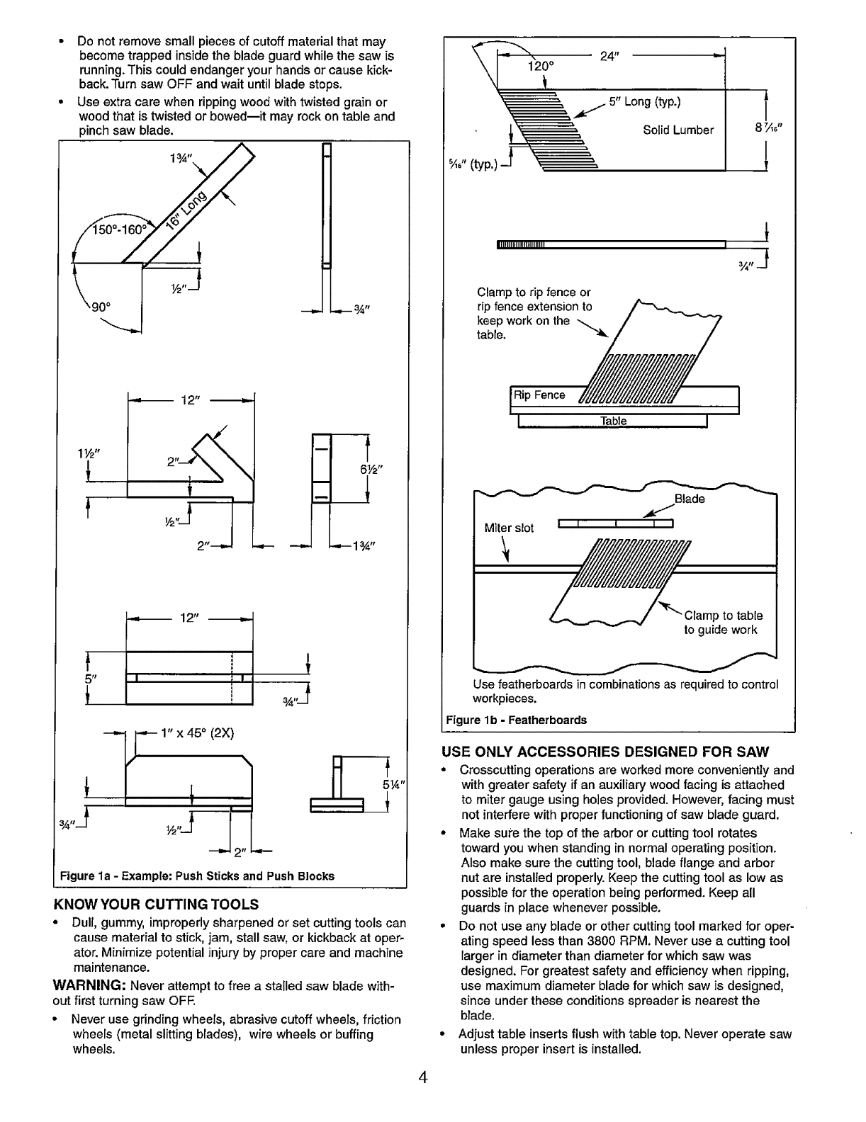
Featherboards are used to keep the work in contact with the rip
fence or table during the cutting operation. Use of featherboards
can help to prevent kickbacks and binding. Featherboards
should be used for all "non thru-sawing" operations.
•Never reach in back of the cutting tool with either hand to
hold down or support the workpiece, remove wood scraps,
or for any other reason. Avoid awkward operations and
hand positions where a sudden slip could cause fingers or
hand to move into a saw blade or other cutting tool.
°Do not perform layout, assembly, or setup work on the
table while the cutting tool is rotating.
•Do not perform any operation freehand--always use either
rip fence or miter gauge to position and guide the work.
°Never use the rip fence when cross-cutting or the miter gauge
when ripping. Do not use rip fence as a length stop. Never
hold onto or touch free-end of workpiece or a free-piece that
is cut off, while power is ON and/or saw blade is rotating.
•Shut the saw OFF and disconnect power source when
removing the table insert, changing the cutting tool,
removing or replacing the blade guard, or making adjust-
ments.
o
3
Provide adequate support to the rear and sides of the saw
table for wide or long workpieces.
Plastic and composition materials (like hardboard) may be
cut on your saw. However, since these are usually quite
hard and slippery, the anti-kickback pawls may not stop a
kickback. Therefore, be especially attentive to following
proper setup and cutting procedures for ripping. Do not
stand, or permit anyone else to stand, in line with a poten-
tial kickback.
If you stall or jam the saw blade in the workpiece, turn saw
OFF and remove the workpiece from the saw blade.
Check to see if the saw blade is parallel to the miter
gauge grooves and if the spreader is in proper alignment
with the saw blade. If ripping at the time, check to see if
the rip fence is parallel with the saw blade. Readjust as
required.
Donotremovesmallpiecesofcutoffmaterialthatmay
becometrappedinsidethebladeguardwhilethesawis
running.Thiscouldendangeryourhandsorcausekick-
back.TurnsawOFFandwaituntilbladestops.
Useextracarewhenrippingwoodwithtwistedgrainor
woodthatistwistedorbowed--itmayrockontableand
pinchsawblade.
/ °77 i
11/2 t_
i
l
_ 12" _
i f
6½"
• I
._-1¾"
#
5"
i
Figure la - Example: Push Sticks and Push Blocks
KNOW YOUR CUTTING TOOLS
• Dull, gummy, improperly sharpened or set cutting tools can
cause material to stick, jam, stall saw, or kickback at oper-
ator. Minimize potential injury by proper care and machine
maintenance.
WARNING: Never attempt to free a stalled saw blade with-
out first turning saw OFR
•Never use grinding wheels, abrasive cutoff wheels, friction
wheels (metal slitting blades), wire wheels or buffing
wheels.
4
5/_6tt
24"
5" Long (typ.)
. i__ Solid Lumber
(typ.)J ', '. I
IIit1IIIIIII1|111111IIII I
Clamp to rip fence or
rip fence extension to
keep work on the
table.
rip Fence ........
ITable I
Miter slot
Blade
i i _ l I
)to table
to guide work
Use featherboards in combinations as required to control
workpieces.
Figure lb - Fealherboards
USE ONLY ACCESSORIES DESIGNED FOR SAW
• Crosscutting operationsare workedmore convenientlyand
withgreatersafety if an auxiliarywoodfacing is attached
to miter gauge usingholesprovided. However,facing must
notinterferewith properfunctioning of saw blade guard.
°Make su£e the top of the arboror cuttingtool rotates
towardyouwhenstandingin normaloperatingposition.
Also makesure the cuttingtool,bladeflange and arbor
nutare installedproperly.Keepthe cuttingtool as lowas
possibleforthe operationbeingperformed. Keep all
guardsin placewheneverpossible.
•Do notuse any blade or othercuttingtool markedfor oper-
ating speed less than3800 RPM. Neveruse acuttingtool
larger in diameter than diameter for whichsaw was
designed.For greatestsafetyand efficiencywhen ripping,
use maximum diameter blade for whichsaw is designed,
since underthese conditionsspreader is nearest the
blade.
°Adjust tableinsertsflush withtable top. Never operate saw
unlessproperinsertis installed.
• Never feed materiaI into the cutting tool from the rear of
the saw. An accident and serious injury could result.
THINK SAFETY
Safetyis acombinationof operatorcommonsense and alert-
ness at alltimes whenthe sawis beingused.
Neveruse another personas asubstitutefor a tableexten-
sion,or asadditionalsupportfor a workpiecethat is longeror
widerthanbasicsaw table,or to assistinfeeding, supporting
orpullingthe workpiece.
Do notpullthe workpiecethroughthe saw blade--position
your bodyat the infeedside of the guard;start and complete
the cutfrom that same side.This wil]require addedtablesup-
portfor longor wideworkpiecesthatextendbeyond the
lengthorwidthof the sawtable.
CAUTION: Followsafetyinstructionsthat appear onthe front
of your saw.
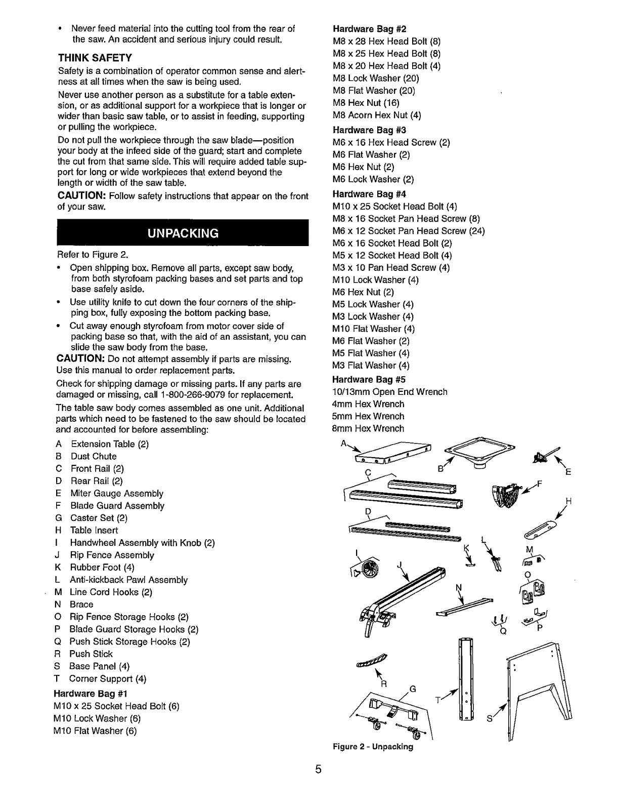
Refer to Figure 2.
•Open shipping box. Remove all parts, except saw body,
from both styrofoam packing bases and set parts and top
base safely aside.
• Use utility knife to cut down the four corners of the ship-
ping box, fulIy exposing the bottom packing base.
• Cut away enough styrofoam from motor cover side of
packing base so that, with the aid of an assistant, you can
slide the saw body from the base.
CAUTION; Do not attempt assembly if parts are missing.
Use this manual to order replacement parts.
Check for shipping damage or missing parts. If any parts are
damaged or missing, call 1-800-266-9079 for replacement.
The table saw body comes assembled as one unit. Additional
parts which need to be fastened to the saw should be located
and accounted for before assembling:
A Extension Table (2)
B Dust Chute
C Front Rail (2)
D Rear Rail (2)
E Miter Gauge Assembly
F Blade Guard Assembly
G Caster Set (2)
H Table Insert
I Handwheel Assembly with Knob (2)
J Rip Fence Assembly
K Rubber Foot (4)
L Anti-kickback Pawl Assembly
M Line Cord Hooks (2)
N Brace
O Rip Fence Storage Hooks (2)
P Blade Guard Storage Hooks (2)
Q Push Stick Storage Hooks (2)
R Push Stick
S Base Panel (4)
T Corner Support (4)
Hardware Bag #1
M10 x 25 Socket Head Bolt (6)
M10 Lock Washer (6)
M10 Fiat Washer (6)
Hardware Bag #2
M8 x 28 Hex Head Bolt (8)
M8 x 25 Hex Head Bolt (8)
M8 x 20 Hex Head Bolt (4)
M8 Lock Washer (20)
M8 Flat Washer (20)
M8 Hex Nut (16)
M8 Acorn Hex Nut (4)
Hardware Bag #3
M6 x 16 Hex Head Screw (2)
M6 Flat Washer (2)
M6 Hex Nut (2)
M6 Lock Washer (2)
Hardware Bag #4
MIO x 25 Socket Head Bolt (4)
M8 x 16 Socket Pan Head Screw (8)
M6 x 12 Socket Pan Head Screw (24)
M6 x 16 Socket Head Bolt (2)
M5 x 12 Socket Head Bolt (4)
M3 x 10 Pan Head Screw (4)
M10 Lock Washer (4)
M6 Hex Nut (2)
M5 Lock Washer (4)
M3 Lock Washer (4)
M10 Flat Washer (4)
M6 Flat Washer (2)
M5 Flat Washer (4)
M3 Flat Washer (4)
Hardware Bag #5
10/13mm Open End Wrench
4ram Hex Wrench
5mm Hex Wrench
8mm Hex Wrench
D
E
H
J
L
• O
R
Figure 2 -Unpacking
T7" o
o
5
IMPORTANT: Table is coated with a protectant. To ensure
proper fit and operation, remove coating. Coating is easily
removed with mild solvents, such as mineral spirits, and a soft
cloth. Avoid getting solution on paint or any of the rubber or
plastic parts. Solvents may deteriorate these finishes. Use
soap and water on paint, plastic or rubber components. After
cleaning, cover all exposed surfaces with a light coating of oil.
Paste wax is recommended for table top.
WARNING; Never use highly volatile solvents. Non flamma-
ble solvents are recommended to avoid possibte fire hazard.
Refer to Figures 3-34.
CAUTION: Do not attempt assembly if parts are missing.
Use this manual to order replacement parts.
Be certain all parts are clean and free of shipping preserva-
tive. Also, completely remove all parts of packing. Saw cabinet
should be directly on the floor.
SAW INSTALLATION
Positioning the saw on a level surface will improve stability
and accuracy and prevent warpage and failure of cast
components and welds.
WARNING: Make certain that the saw is disconnected from
the power source.
INSTALL HANDWHEELS
Refer to Figure 3.
•Remove saw cabinet and place upside down on cardboard
box or cardboard on floor.
•Place one of the handwheels onto the blade raise!lower
shaft located on the front of the cabinet. Align the groove
in the back of the handwheel with the pin.
•Thread the washer and ]ocking knob onto the threaded end
of the shaft.
•Repeat the steps above to assemble the remaining hand-
wheel and locking knob onto the blade tilt shaft located on
the side of the cabinet.
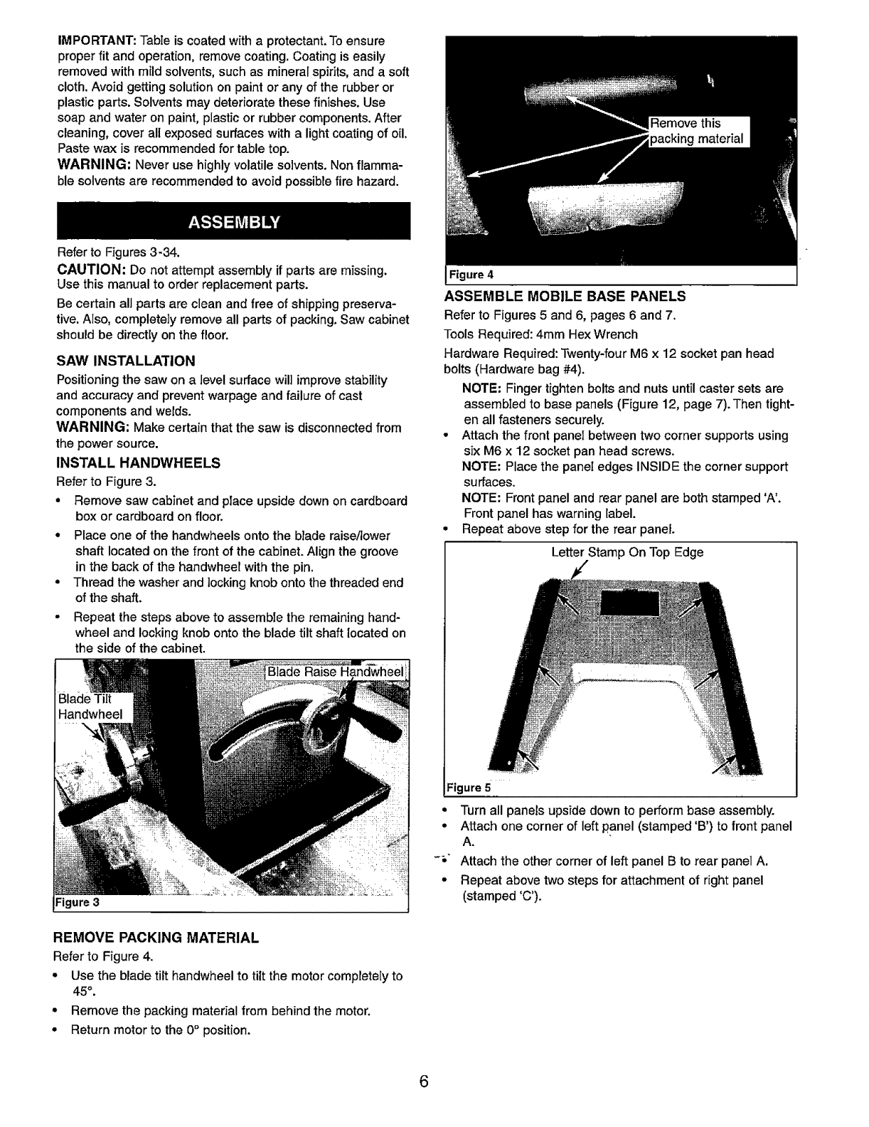
Figure 4
ASSEMBLE MOBILE BASE PANELS
Refer to Figures 5 and 6, pages 6 and 7.
Tools Required: 4ram Hex Wrench
Hardware Required: Twenty-four M6 x 12 socket pan head
bolts (Hardware bag #4).
NOTE: Finger tighten bolts and nuts until caster sets are
assembled to base panels (Figure 12, page 7). Then tight-
en all fasteners securely.
•Attach the front panel between two corner supports using
six M6 x 12 socket pan head screws.
NOTE: Place the paneI edges INSIDE the corner support
surfaces.
NOTE: Front panel and rear panel are both stamped 'A'.
Front panel has warning label.
° Repeat above step for the rear panel
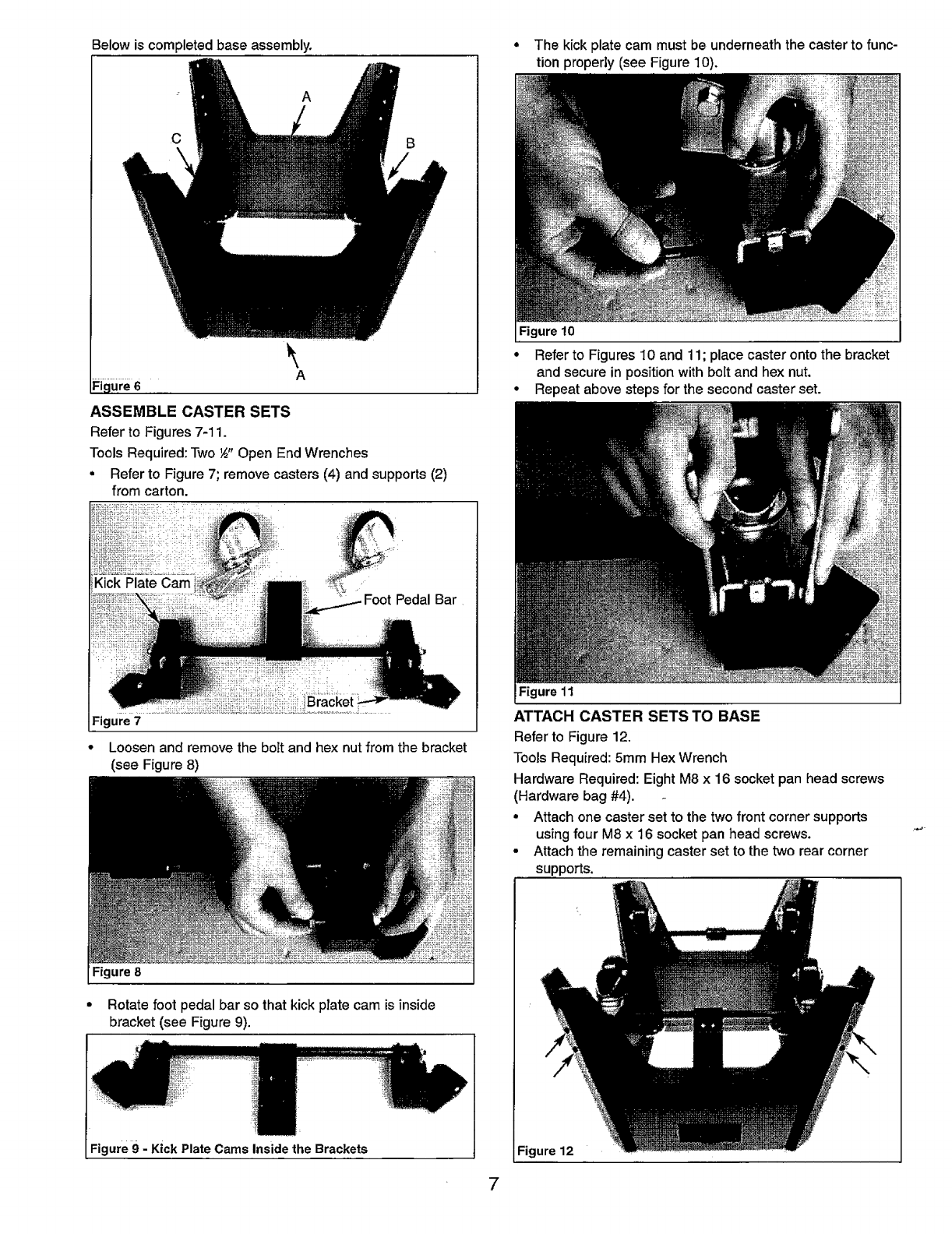
Letter Stamp On Top Edge
Figure 5....
•Turn all panels upside down to perform base assembly.
• Attach one corner of left panel (stamped 'B') to front panel
A.
-_ Attach the other corner of left panel B to rear panel A.
•Repeat above two steps for attachment of right panel
(stamped 'C').
REMOVE PACKING MATERIAL
Referto Figure4.
•Use the bladetilt handwheel to tiltthe motorcompletelyto
45°.
• Removethe packing material from behindthe motor.
•Returnmotorto the 0° position.
6
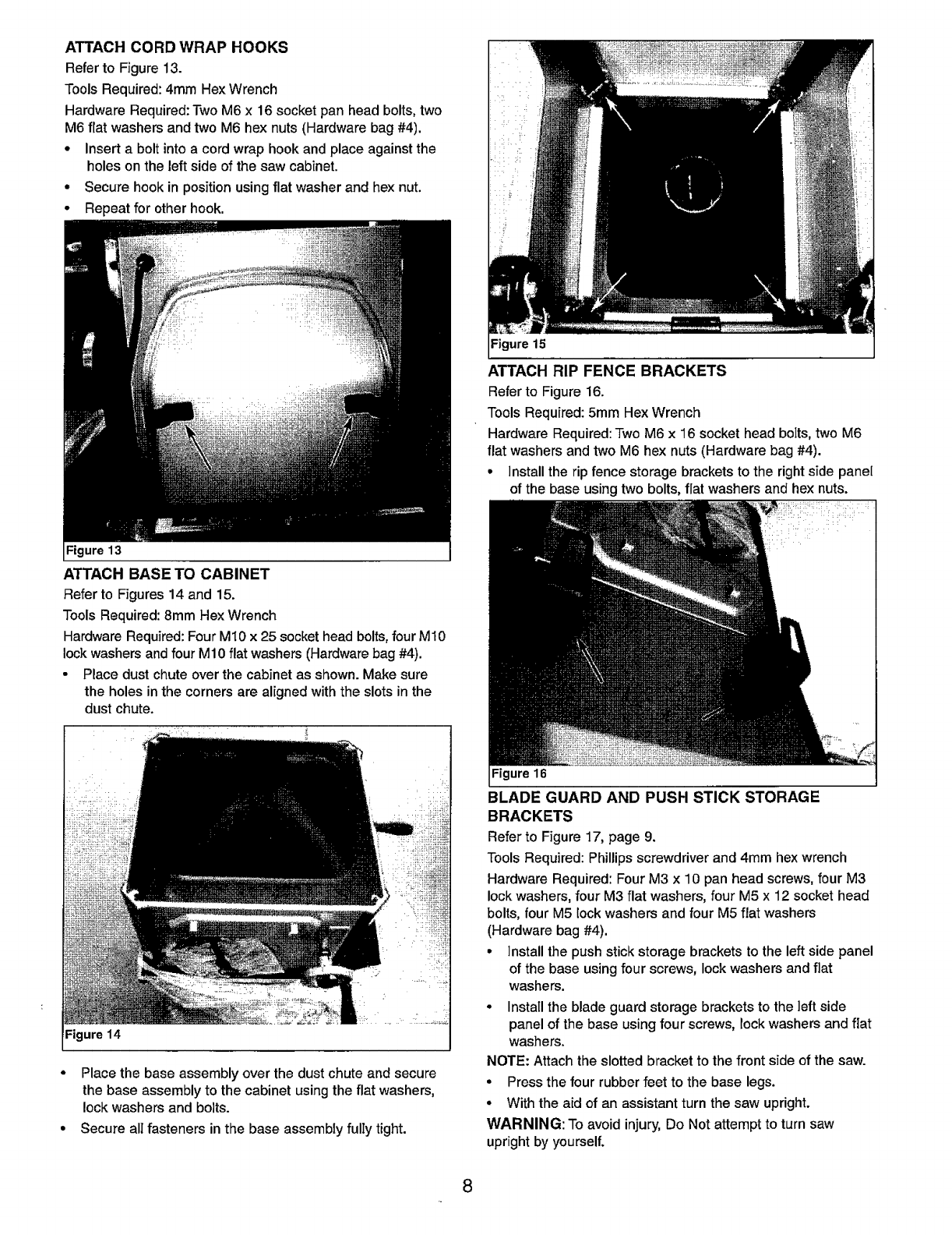
Below is completed base assembly.
A
CB
A
ASSEMBLE CASTER SETS
Refer to Figures 7-11.
Tools Required: Two _" Open End Wrenches
Refer to Figure 7; remove casters (4) and supports (2)
from carton.
Figure 7
* Loosen and remove the bolt and hex nut from the bracket
(see Figure 8)
Figure 8
•Rotate foot pedal bar so that kick plate cam is inside
bracket (see Figure 9).
Figure 9 - Kick Plate Cams Inside the Brackets
•The kick plate cam must be underneath the caster to func-
tion properly (see Figure 10).
Figure 10
• Refer to Figures 10 and 11; place caster onto the bracket
and secure in position with bolt and hex nut.
=Repeat above steps for the second caster set.
Figure11
ATTACH CASTER SETS TO BASE
Refer to Figure 12.
ToolsRequired:5ram HexWrench
HardwareRequired: EightM8 x 16 socket pan head screws
(Hardwarebag #4).
• Attach onecaster setto the two front cornersupports
using four M8 x 16 socketpan headscrews.
• Attach the remaining caster setto the two rearcorner
supports.
Figure 12
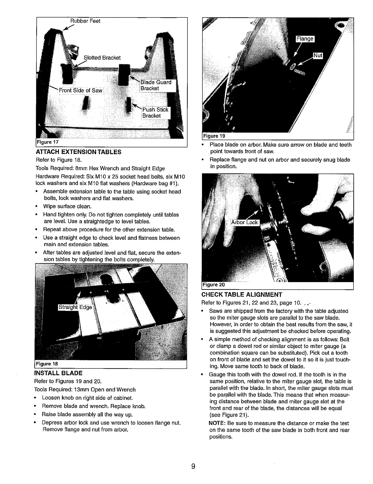
ATTACH CORD WRAP HOOKS
Refer to Figure 13.
Tools Required: 4mm Hex Wrench
Hardware Required: Two M6 x 16 socket pan head bolts, two
M6 flat washers and two M6 hex nuts (Hardware bag #4).
•Insert a bolt into a cord wrap hook and place against the
holes on the left side of the saw cabinet.
° Secure hook in position using flat washer and hex nut.
° Repeat for other hook.
Figure 13
ATTACH BASE TO CABINET
Refer to Figures 14 and 15.
Tools Required: 8mm Hex Wrench
Hardware Required: Four Mt0 x 25 socket head bolts,four M10
lock washers and four M10 flat washers (Hardware bag #4).
•Place dust chute over the cabinet as shown. Make sure
the holes in the corners are aligned with the slots in the
dust chute.
Figure 14
• Place the base assembly over the dust chute and secure
the base assembly to the cabinet using the flat washers,
lock washers and bolts.
• Secure all fasteners in the base assembly fully tight.
Figure 15
ATTACH RIP FENCE BRACKETS
Refer to Figure 16.
Tools Required: 5mm Hex Wrench
Hardware Required: Two M6 x 16 socket head bolts, two M6
flat washers and two M6 hex nuts (Hardware bag #4).
° Install the rip fence storage brackets to the right side panel
of the base using two bolts, fiat washers and hex nuts.
Figure 16
BLADE GUARD AND PUSH STICK STORAGE
BRACKETS
Refer to Figure 17, page 9.
Tools Required: Phillips screwdriver and 4ram hex wrench
Hardware Required: Four M3 x 10 pan head screws, four M3
lock washers, four M3 flat washers, four M5 x12 socket head
bolts, four M5 lock washers and four M5 fiat washers
(Hardware bag #4).
• Install the push stick storage brackets to the left side panel
of the base using four screws, lock washers and flat
washers.
•Install the blade guard storage brackets to the ]eft side
panel of the base using four screws, lock washers and flat
washers.
NOTE: Attach the slotted bracket to the front side of the saw.
•Press the four rubber feet to the base legs.
•With the aid of an assistant turn the saw upright.
WARNING: To avoid injury, Do Not attempt to turn saw
upright by yourself.
8
Rubber Feet
Slotted Bracket
Figure 17
ATTACH EXTENSION TABLES
Referto Figure I8.
ToolsRequired:8ram HexWrench andStraightEdge
HardwareRequired:Six M10 x 25 socketheadbolts,six M10
lockwashersandsix MI0 flat washers(Hardwarebag#1).
• Assemble extension tableto the table usingsockethead
bolts,lockwashersandflat washers.
•Wipe surfaceclean.
•Hand tightenonly.Do nottightencompletelyuntil tables
are level. Use a straightedge to leveltables.
°Repeataboveprocedure for the other extensiontable.
°Use a straight edgeto checklevelandflatnessbetween
main and extension tables.
° After tables are adjusted level and flat, secure the exten-
sion tables by tightening the bolts completely.
Figure 18
INSTALL BLADE
Referto Figures19 and 20.
ToolsRequired:13ram Open end Wrench
- Loosen knob on right side of cabinet.
• Remove blade and wrench. Replace knob.
• Raise blade assembly all the way up.
• Depress arbor lock and use wrench to loosen flange nut.
Remove flange and nut from arbor.
Figure19
° Place blade on arbor. Make sure arrow on blade and teeth
point towards front of saw.
•Replaceflange and nut on arbor and securely snug blade
in position.
Figure 20
CHECK TABLE ALIGNMENT
Refer to Figures 21, 22 and 23, page 10. _.-
• Saws are shipped from the factory withthe tableadjusted
so the mitergaugeslotsare parallel to the saw blade.
However,in orderto obtainthe best resultsfrom the saw, it
is suggested thisadjustmentbe checkedbeforeoperating.
•A simple method of checkingalignment isas follows: Bolt
orclampa dowelrod or similar objectto mitergauge (a
combinationsquarecan be substituted). Pick outa tooth
onfront of bla_leand setthe dowel to it so it isjusttouch-
ing.Move sametoothto backof blade.
•Gauge thistoothwiththe dowel rod. If the tooth is in the
same position,relative to the miter gauge slot, the tableis
paral]elwiththe blade. In short, the mitergauge slots must
be parallelwiththe blade. This means that whenmeasur-
ing distancebetween blade and mitergauge slot atthe
front and rear of the blade,the distanceswillbe equal
(see Figure21).
NOTE: Be sure to measure the distance ormake the test
onthe same toothof the saw blade in both front and rear
positions.
9
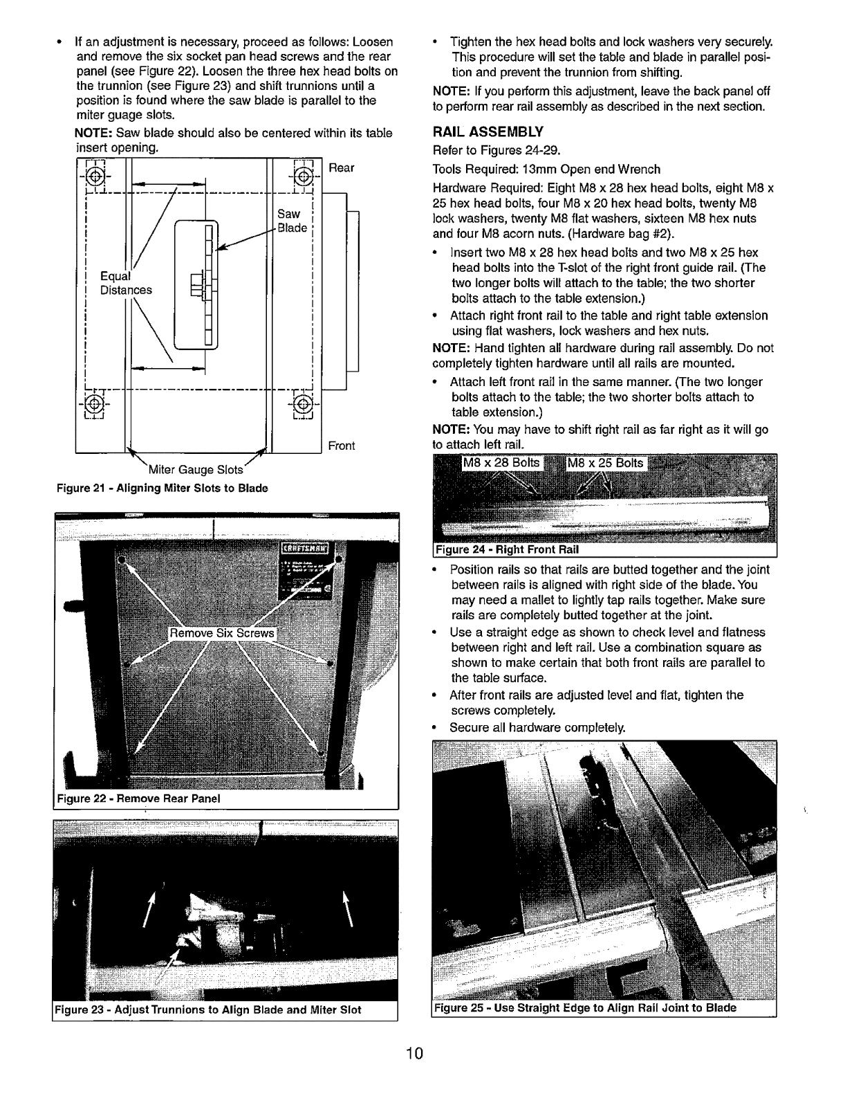
°If an adjustment is necessary, proceed as follows: Loosen
and remove the six socket pan head screws and the rear
panel (see Figure 22). Loosen the three hex head bolts on
the trunnion (see Figure 23) and shift trunnions until a
position is found where the saw blade is parallel to the
miter guage slots.
NOTE: Saw blade should also be centered within its table
insert opening.
'r_l Rear
Saw !
.Blade }
I
i
i
I
!
ii I
L. ........ 1._1
-N- -@-
Front
_"Miter Gauge Slotsf
Figure 21 - Aligning Miter Blots to Blade
Figure 22 -Remove Rear Panel
Figure 23 -Adjust Trunnions to Align Blade and Miter Slot
, Tighten the hex head bolts and lock washers very securely.
This procedure will set the table and blade in parallel posi-
tion and prevent the trunnion from shifting.
NOTE: If you perform this adjustment, leave the back panel off
to perform rear rail assembly as described in the next section.
RAIL ASSEMBLY
Referto Figures24-29.
ToolsRequired:13ramOpen endWrench
HardwareRequired: EightM8 x 28 hex head bolts, eight M8 x
25 hex head bolts,four M8 x 20 hex headbolts, twenty M8
lockwashers,twentyM8 flat washers,sixteenM8 hex nuts
andfour M8 acorn nuts.(Hardwarebag#2).
•insert two M8 x 28 he)(headbotts and two M8 x 25 hex
head boltsinto the T-slotof the right front guide rail.(The
two longerboltswillattach to the table;the two shorter
bolts attachto the tableextension.)
• Attach rightfront railto the tableand right table extension
using flat washers,lockwashersand hex nuts.
NOTE: Hand tightenallhardwareduring rail assembly.Do not
completelytightenhardwareuntil ail railsare mounted.
° Attach leftfront rail inthe same manner.(The two longer
bolts attachto the table;the two shorter bolts attach to
table extension.)
NOTE:You may have to shiftrightrail as far rightas it will go
to attach left rail.
Figure 24 -Right Front Rail
,Position rails so that rails are butted together and the joint
between rails is aligned with right side of the blade. You
may need amallet to lightly tap rails together. Make sure
rails are completely butted together at the joint.
°Use a straight edge as shown to check level and flatness
between right and left rail. Use a combination square as
shown to make certain that both front rails are parallel to
the table surface.
• After front rails are adjusted leveI and flat, tighten the
screws completely.
°Secure all hardware completely.
Figure 25 -Use Straight Edge to Align Rail Joint to Blade
10
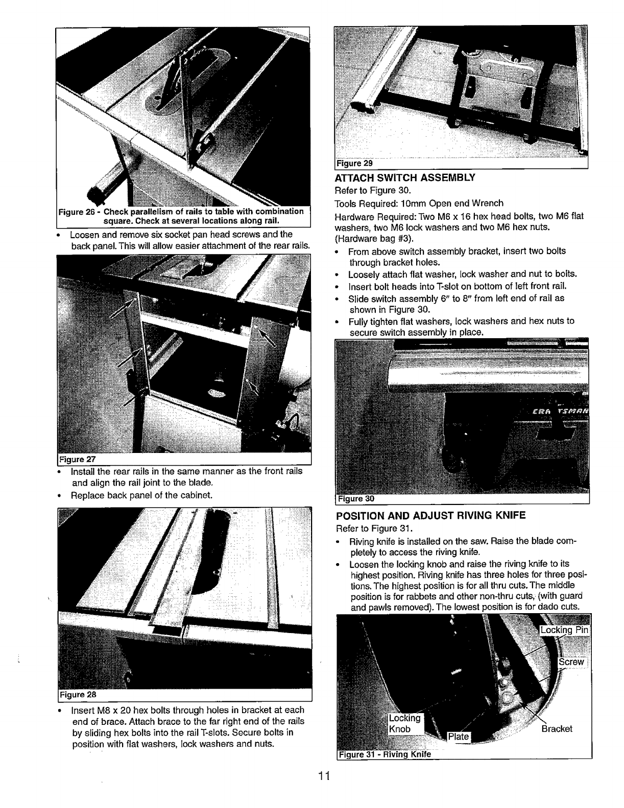
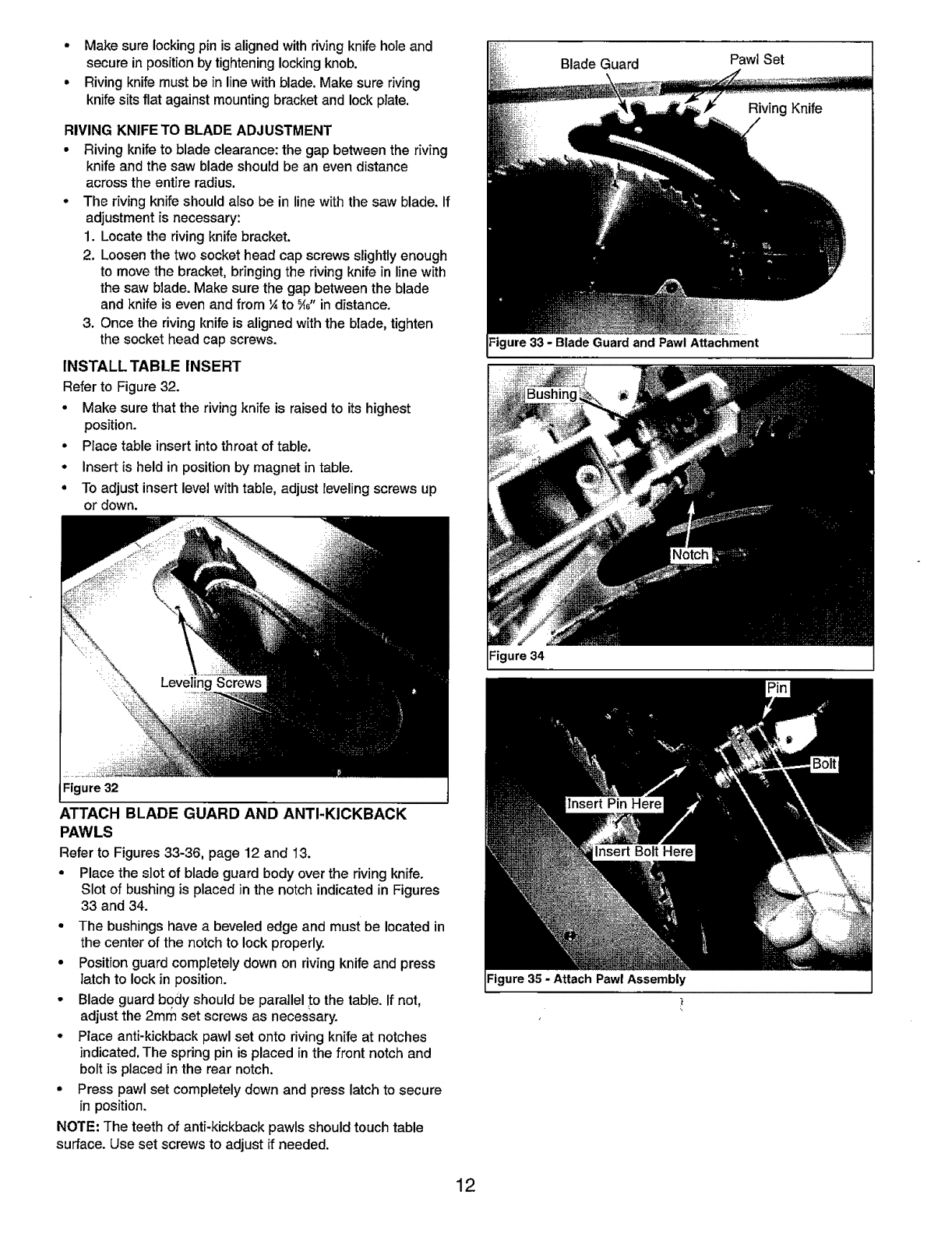
Figure 26 - Check parallelism of rails to table with combination
square. Check at several locations along rail.
Loosen and remove six socket pan head screws and the
back panel, This will allow easier attachment of the rear rails.
Figure 27
•Install the rear rails in the same manner as the front rails
and align the rail joint to the blade,
• Replace back panel of the cabinet.
Figure 28
•Insert M8 x 20 hex bolts through holes in bracket at each
end of brace. Attach brace to the far right end of the rails
by sliding hex bolts into the railT-slots. Secure bolts in
position with fiat washers, lock washers and nuts.
i!:_i: , _ :
IiZZLIIL i:...........................ii ii :_ '_•
Figure 29
ATTACH SWITCH ASSEMBLY
Refer to Figure 30.
Tools Required: 10mm Open end Wrench
Hardware Required: Two M6 x I6 hex head bolts, two M6 flat
washers, two M6 lock washers and two M6 hex nuts.
(Hardware bag #3).
• From above switch assembly bracket, insert two bolts
through bracket holes.
° Loosely attach flat washer, lock washer and nut to bolts.
•Insert bolt heads into T-slot on bottom of left front rail.
•Slide switch assembly 6" to 8" from left end of rail as
shown in Figure 30.
•Fully tighten flat washers, lockwashers and hex nuts to
secure switch assembly in place.
Figure 30
POSITION AND ADJUST RIVING KNIFE
Refer to Figure 31.
•Riving knife is installed on the saw. Raise the blade com-
pletely to access the riving knife.
° Loosen the locking knob and raise the riving knife to its
highest position. Riving knife has three holes for three posi-
tions. The highest position is for all thru cuts, The middle
position is for rabbets and other non-thru cuts, _(with guard
and pawls removed). The lowest position is for dado cuts.
Figure 31 -Riving Knife
Bracket
11
• Make sure locking pin is aligned with riving knife ho]e and
secure in position by tightening locking knob.
° Riving knife must be in line with blade. Make sure riving
knife sits flat against mounting bracket and lock plate.
RIVING KNIFE TO BLADE ADJUSTMENT
•Riving knife to blade clearance: the gap between the riving
knife and the saw blade should be an even distance
across the entire radius.
• The riving knife should also be in line with the saw blade. If
adjustment is necessary:
1. Locate the riving knife bracket.
2. Loosen the two socket head cap screws slightly enough
to move the bracket, bringing the riving knife in line with
the saw blade. Make sure the gap between the blade
and knife is even and from ¼ to _" in distance.
3. Once the riving knife is aligned with the blade, tighten
the socket head cap screws.
INSTALL TABLE INSERT
Refer to Figure 32.
° Make sure that the riving knife is raised to its highest
position.
• Place table insert into throat of table.
• Insert is held in position by magnet in table.
° To adjust insert level with table, adjust leveling screws up
or down.
Figure 32
ATTACH BLADE GUARD AND ANTI-KICKBACK
PAWLS
Refer to Figures 33-36, page 12 and 13.
• Place the slot of blade guard body over the riving knife.
Slot of bushing is placed in the notch indicated in Figures
33 and 34.
° The bushings have a beveled edge and must be located in
the center of the notch to lock properly.
° Position guard completely down on riving knife and press
latch to lock in position.
° Blade guard body should be parallel to the table, if not,
adjust the 2mm set screws as necessary.
° Place anti-kickback pawl set onto riving knife at notches
indicated. The spring pin is placed in the front notch and
bolt is placed in the rear notch.
• Press pawl set completely down and press latch to secure
in position.
NOTE: The teeth of anti-kickback pawls should touch table
surface. Use set screws to adjust if needed.
Blade Guard Pawl Set
Figure 33 -Blade Guard and Pawl Attachment
Figure 34
Insert Bolt Here
Figure 35 -Attach Paw! Assembly
12
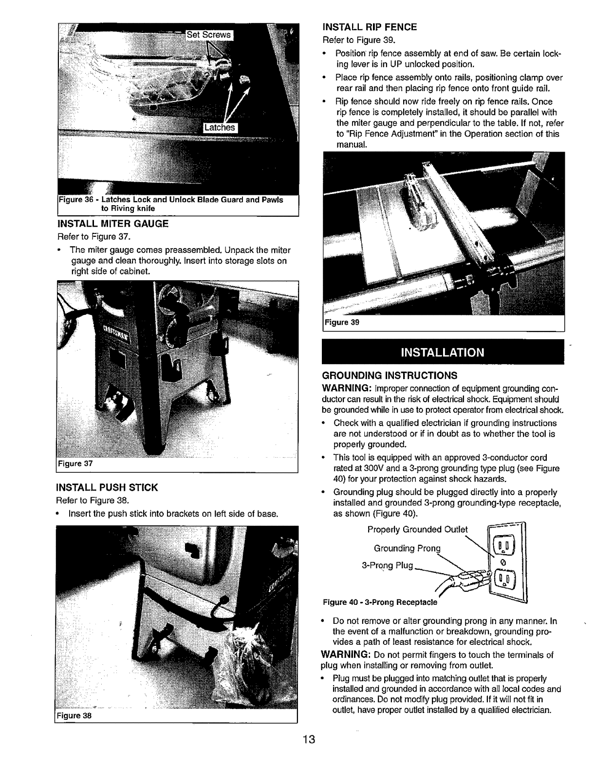
Figure 36 -Latches Lock and Unlock Blade Guard and Pawls
to Riving knife
INSTALL MITER GAUGE
Refer to Figure 37.
• The miter gauge comes preassembled. Unpack the miter
gauge and clean thoroughly. Insert into storage slots on
right side of cabinet.
Figure 37
INSTALL PUSH STICK
Refer to Figure38.
•Insertthe pushstickintobracketson leftside of base.
!
INSTALL RIP FENCE
Refer to Figure 39.
•Position rip fence assembly at end of saw. Be certain lock-
ing lever is in UP unlocked position.
= Place rip fence assembly onto rails, positioning clamp over
rear rail and then placing rip fence onto front guide rail.
• Rip fence should now ride freely on rip fence rails. Once
rip fence is completely installed, it should be parallel with
the miter gauge and perpendicular to the table. If not, refer
to "Rip Fence Adjustment" in the Operation section of this
manual.
Figure 39
GROUNDING INSTRUCTIONS
WARNING: Improper connection of equipment grounding con-
ductor can result in the risk of electrical shock. Equipment should
be grounded while in use to protect operator from electrical shock.
•Check with a qualified electrician if grounding instructions
are not understood or if in doubt as to whether the tool is
properly grounded.
This too] is equipped with an approved 3-conductor cord
rated at 300V and a 3-prong grounding type plug (see Figure
40) for your protection against shock hazards.
Grounding plug should be plugged directly into a properly
installed and grounded 3-prong grounding-type receptacle,
as shown (Figure 40).
Figure 40 - 3-Prong Receptacle
PG PoeudnYd1_g; rnode_0utlet.,. \ _ _iP{'P"-----_-':'_
3-P,onoP,uo ....
•Do not remove or alter grounding prong in any manner. In
the event of a malfunction or breakdown, grounding pro-
vides a path of least resistance for electrical shock.
WARNING: Do not permit fingers to touch the terminals of
plug when installing or removing from outlet.
°Plug must be plugged into matching outlet that is properly
installed and grounded in accordance with all local codes and
ordinances. Do not modify plug provided. If it will not fit in
outlet, have proper outlet installed by a qualified electrician.
13
• Inspect tool cords periodically and if damaged, have them
repaired by an authorized service facility.
• Green (or green and yellow) conductor in cord is the
grounding wire. If repair or replacement of the electric cord
or plug is necessary, do not connect the green (or green
and yellow) wire to a live terminal.
• Where a 2-prong wall receptacle is encountered, it must be
replaced with a properly grounded 3-prong receptacle
installed in accordance with National Electric Code and
local codes and ordinances.
WARNING: This work should be performed by a qualified
electrician.
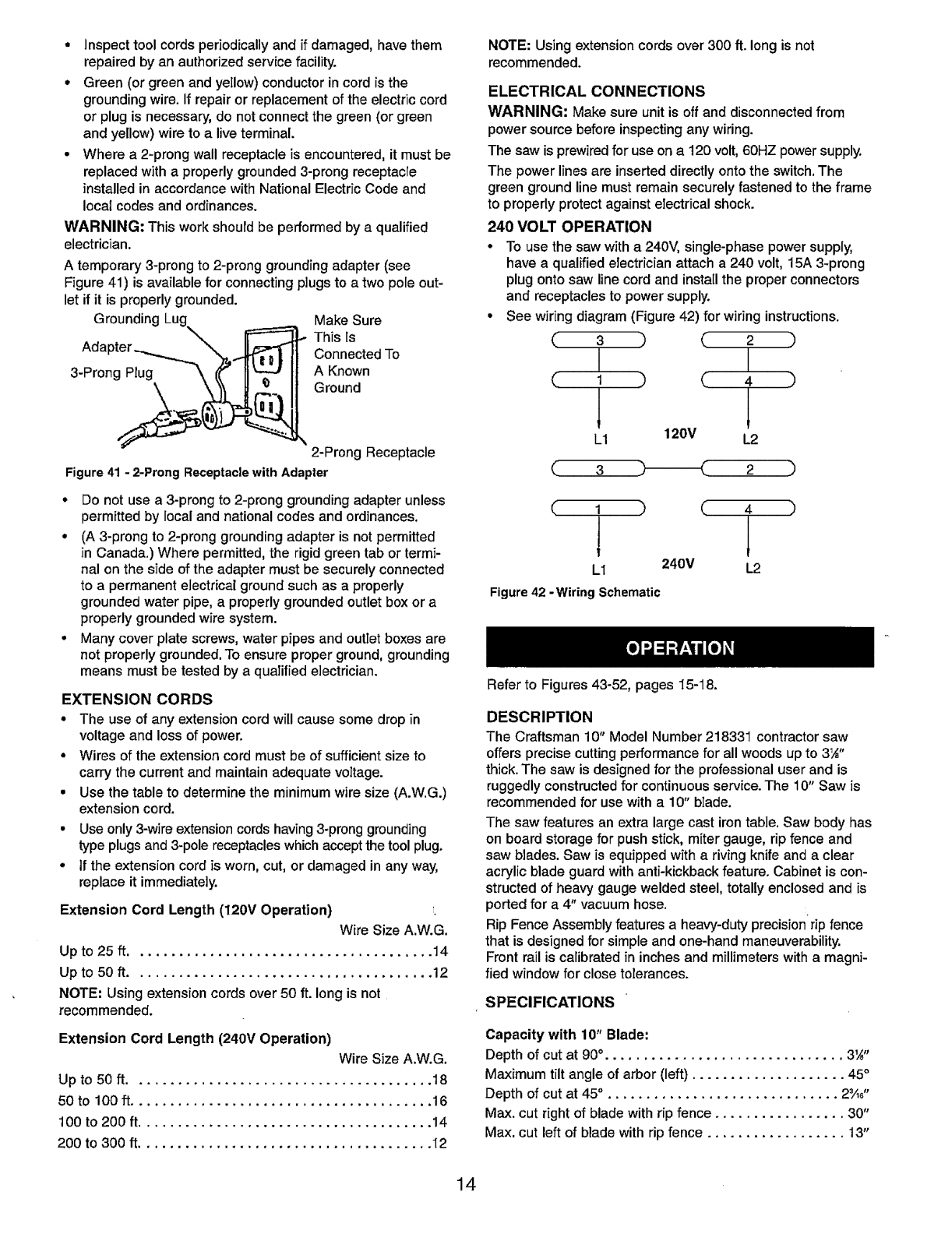
A temporary 3-prong to 2-prong grounding adapter (see
Figure 41) is available for connecting plugs to a two pole out-
let if it is properly grounded.
Grounding Make Sure
This Is
Ad_ Connected To
3-Prong Plug A Known
Ground
2-Prong Receptacle
Figure 41 -2-Prong Receptacle with Adapter
• Do not use a 3-prong to 2-prong grounding adapter unless
permitted by local and national codes and ordinances.
• (A 3-prong to 2-prong grounding adapter is not permitted
in Canada.) Where permitted, the rigid green tab or termi-
nal on the side of the adapter must be securely connected
to a permanent electrical ground such as a properly
grounded water pipe, a properly grounded outlet box or a
properly grounded wire system.
• Many cover plate screws, water pipes and outlet boxes are
not properly grounded. To ensure proper ground, grounding
means must be tested by a qualified electrician.
EXTENSION CORDS
• The use of any extension cord will cause some drop in
voltage and loss of power.
° Wires of the extension cord must be of sufficient size to
carry the current and maintain adequate voltage.
• Use the table to determine the minimum wire size (A.W.G.)
extension cord.
• Use only 3-wire extension cords having 3-prong grounding
type plugs and 3-pole receptacles which accept the tool plug.
° tf the extension cord is worn, cut, or damaged in any way,
replace it immediately.
Extension Cord Length (120V Operation) :.
Wire Size A.W.G.
Up to 25 ft ....................................... 14
Up to 50 ft....................................... 12
NOTE: Using extension cords over 50 ft. long is not
recommended.
Extension Cord Length (240V Operation)
Wire Size A.W.G.
Up to 50 ft ....................................... 18
50 to 100 ft....................................... 16
100 to 200 ft...................................... 14
200 to 300 ft...................................... I2
NOTE: Using extension cords over 300 ft. long is not
recommended.
ELECTRICAL CONNECTIONS
WARNING: Make sure unit is off and disconnected from
powersource beforeinspectingany wiring.
Thesaw isprewiredfor use ona 120volt,60HZ powersupply.
The power linesare inserteddirectlyontothe switch. The
green groundlinemustremainsecurely fastened to the frame
to properlyprotect againstelectrical shock.
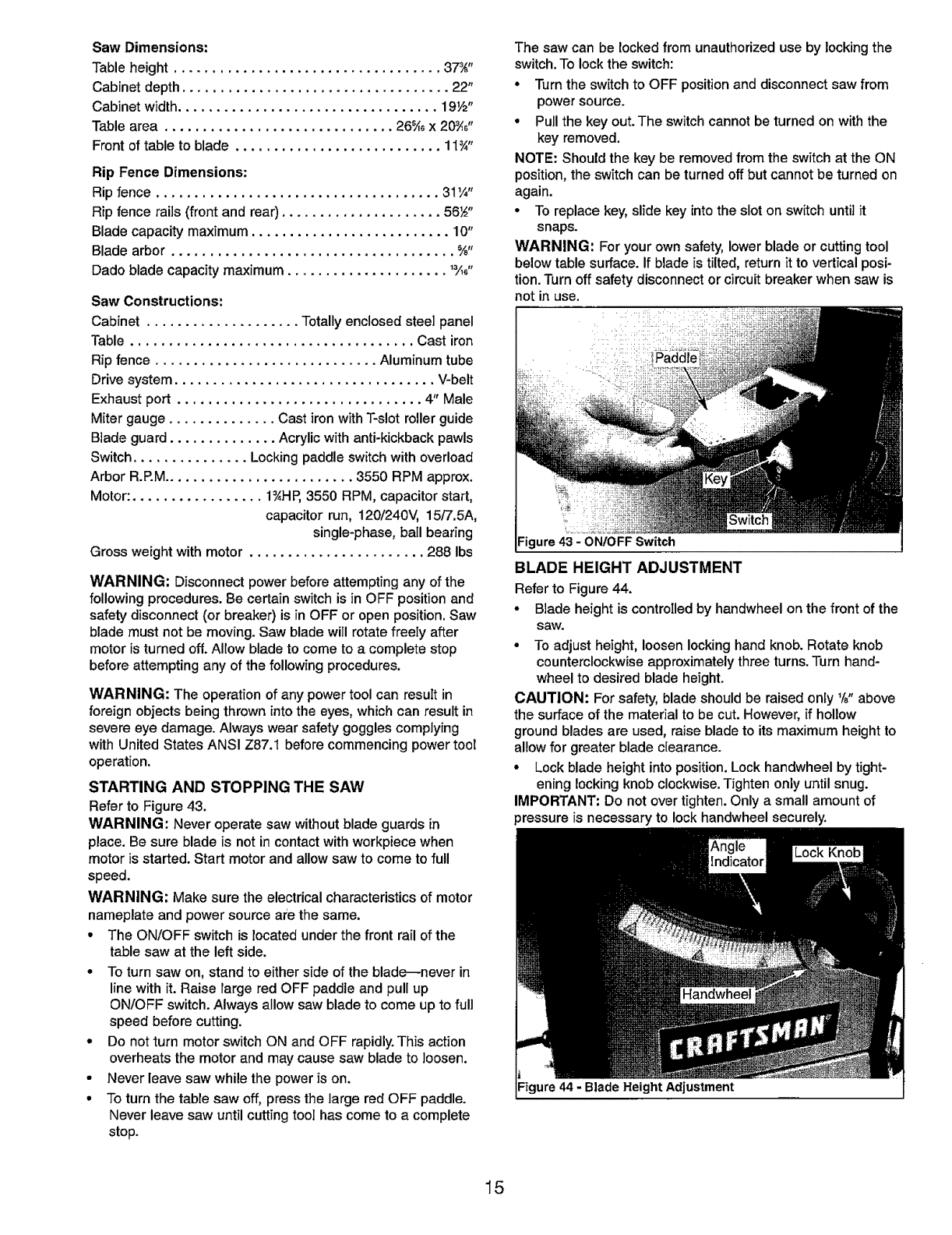
240 VOLT OPERATION
•To use the saw with a 240V, single-phase power supply,
have a qualified electrician attach a 240 volt, 15A 3-prong
plug onto saw line cord and install the proper connectors
and receptacles to power supply.
•See wiring diagram (Figure 42) for wiring instructions.
( 3 ) ( 2 )
1 1
( 1 ) ( 4 )
1 ;
L1 120V L2
(_ 32 _)
( 1 ) ( 4 )
L1 240V 1.2
Figure 42 -Wiring Schematic
Refer to Figures 43-52, pages 15-18.
DESCRIPTION
The Craftsman 10" Model Number 218331 contractor saw
offers precise cutting performance for all woods up to 31,_"
thick. The saw is designed for the professional user and is
ruggedly constructed for continuous service. The 10" Saw is
recommended for use with a 10" blade.
The saw features an extra large cast iron table. Saw body has
on board storage for push stick, miter gauge, rip fence and
saw blades. Saw is equipped with a riving knife and a clear
acrylic blade guard with anti-kickback feature. Cabinet is con-
structed of heavy gauge welded steel, totally enclosed and is
ported for a 4" vacuum hose.
Rip Fence Assembly features a heavy-duty precision rip fence
that is designed for simple and one-hand maneuverability.
Front rail is calibrated in inches and millimeters with a magni-
fied window for close tolerances.
SPECIFICATIONS
Capacity with 10" Blade:
Depth of cut at 90 °. .............................. 3%"
Maximum tilt angle of arbor (left) .................... 45°
Depth of cut at 45 ° .............................. 23/_"
Max. cut right of blade with rip fence ................. 30"
Max. cut left of blade with rip fence .................. 13"
14
Saw Dimensions:
Table height ................................... 37_"
Cabinet depth ................................... 22"
Cabinet width .................................. 19½"
Table area .............................. 26_6 x 20_6"
Front of table to blade ........................... 1I¾"
Rip Fence Dimensions:
Rip fence ..................................... 31¼"
Rip fence rails (front and rear) ..................... 56_"
Blade capacity maximum .......................... 10"
Blade arbor ..................................... %"
Dado blade capacity maximum ..................... '_,_"
Saw Constructions:
Cabinet .................... Totally enclosed steel panel
Table ..................................... Cast iron
Rip fence ............................. Aluminum tube
Drive system .................................. V-belt
Exhaust port ................................ 4" Male
Miter gauge .............. Cast iron with T-slot roller guide
Blade guard .............. Acrylic with anti-kickback pawls
Switch ............... Locking paddle switch with overload
Arbor R.P.M......................... 3550 RPM approx.
Motor: ................. 1¾HP,3550 RPM, capacitor start,
capacitor run, 120/240V, 15/7.5A,
single-phase, bail bearing
Gross weight with motor ....................... 288 Ibs
WARNING: Disconnect power before attempting any of the
following procedures. Be certain switch is in OFF position and
safety disconnect (or breaker) is in OFF or open position. Saw
blade must not be moving. Saw blade will rotate freely after
motor is turned off. Altow blade to come to a complete stop
before attempting any of the following procedures.
WARNING: The operation of any power tool can result in
foreign objects being thrown into the eyes, which can result in
severe eye damage. Always wear safety goggles complying
with United States ANSI Z87.1 before commencing power tool
operation.
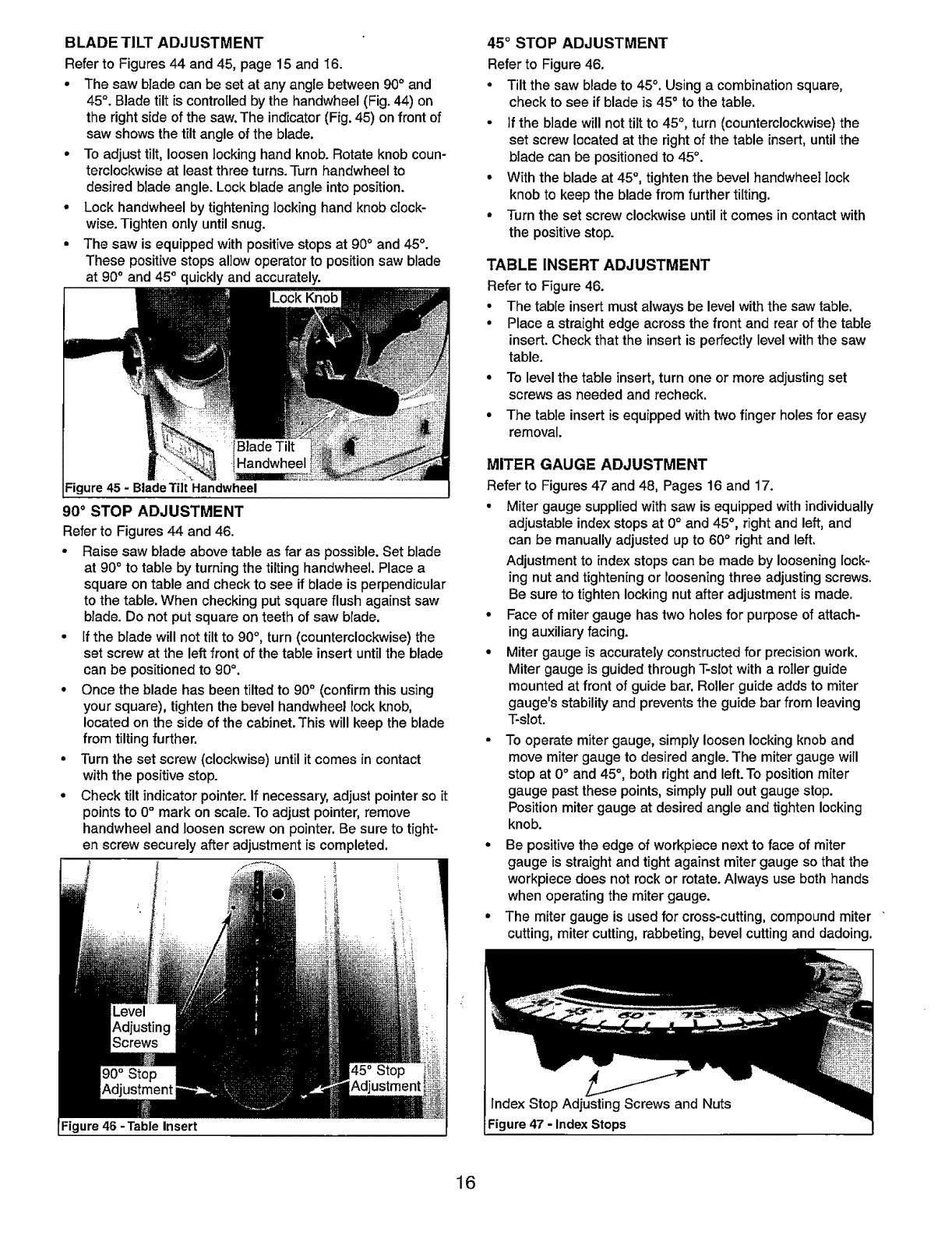
STARTING AND STOPPING THE SAW
Refer to Figure 43.
WARNING: Neveroperatesaw withoutblade guardsin
place. Be sure blade is not incontactwithworkpiecewhen
motor is started. Start motor andallowsawto cometo full
speed.
WARNING: Make sure the electricalcharacteristicsof motor
nameplateand powersoumeare the same.
•The ON/OFF switchis located underthe front rail ofthe
tablesaw at the left side.
•Toturn saw on, stand to eitherside of the blade---never in
line withit. Raise large red OFF paddleand pull up
ON/OFF switch. Always allow saw blade to come upto full
speed before cutting.
-Do not turn motorswitch ON and OFF rapidly.This action
overheatsthe motorand may causesaw bladeto loosen.
•Neverleave saw whilethe power is on.
• Toturn the table saw off,pressthe large redOFF paddle.
Never leave saw until cuttingtool has cometo acomplete
stop.
The saw can be locked from unauthorized use by locking the
switch. To lock the switch:
° Turn the switch to OFF position and disconnect saw from
power source.
°Pull the key out.The switch cannot be turned on with the
key removed.
NOTE: Should the key be removed from the switch at the ON
position, the switch can be turned off but cannot be turned on
again.
•To replace key, slide key into the slot on switch until it
snaps.
WARNING: For your own safety, lower blade or cutting tool
below table surface. If blade is tilted, return it to vertical posi-
tion. Turn off safety disconnect or circuit breaker when saw is
not in use.
BLADE HEIGHT ADJUSTMENT
Refer to Figure 44.
-Blade height is controlled by handwheel on the front of the
saw.
•To adjust height, loosen locking hand knob. Rotate knob
counterclockwise approximately three turns. Turn hand-
wheel to desired blade height.
CAUTION: For safety, blade should be raised only 1/8"above
the surface of the material to be cut. However, if hollow
ground blades are used, raise blade to its maximum height to
allow for greater blade clearance.
°Lock blade height into position. Lock handwheel by tight-
ening locking knob clockwise. Tighten only until snug.
IMPORTANT: Do not over tighten. Only a small amount of
pressure is necessary to lock handwheel securely.
Figure 44 -Blade Height Adjustment
I5
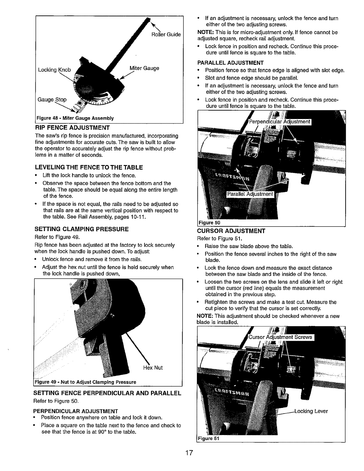
BLADE TILT ADJUSTMENT
Refer to Figures 44 and 45, page 15 and 16.
•The saw blade can be set at any angle between 90° and
45°. Blade tilt is controlled by the handwheel (Fig. 44) on
the right side of the saw. The indicator (Fig. 45) on front of
saw shows the tilt angle of the blade.
• To adjust tilt, loosen locking hand knob. Rotate knob coun-
terclockwise at least three turns. Turn handwheel to
desired blade angle. Lock blade angle into position.
•Lock handwheel by tightening locking hand knob clock-
wise. Tighten only until snug.
= The saw is equipped with positive stops at 90°and 45°.
These positive stops aUow operator to position saw blade
at 90° and 45 ° quickly and accurately.
Figure 45 -Blade Tilt Handwheel
90 ° STOP ADJUSTMENT
Refer to Figures 44 and 46.
•Raise saw blade above table as far as possible. Set blade
at 90°to table by turning the tilting handwheel. Place a
square on table and check to see if blade is perpendicular
to the table. When checking put square flush against saw
blade. Do not put square on teeth of saw blade.
• If the blade will not tilt to 90°, turn (counterclockwise) the
set screw at the left front of the table insert until the blade
can be positioned to 90 °.
•Once the blade has been tilted to 90° (confirm this using
your square), tighten the bevel handwheel lock knob,
located on the side of the cabinet. This will keep the blade
from tilting further.
• Turn the set screw (clockwise) until it comes in contact
with the positive stop.
• Check tilt indicator pointer. If necessary, adjust pointer so it
points to 0° mark on scale. To adjust pointer, remove
handwheel and loosen screw on pointer. Be sure to tight-
en screw securely after adjustment is completed.
Figure 46 -Table Insert
45 ° STOP ADJUSTMENT
Refer to Figure 46.
• Tilt the saw blade to 45°. Usinga combinationsquare,
checkto see if blade is 45°to the table.
•If the bladewillnottiltto 45°, turn (counterclockwise) the
set screw locatedat the rightof the table insert, untilthe
blade can be positionedto 45°.
•With the blade at 45°, tightenthe bevel handwheel lock
knob to keepthe blade from further tilting.
• Turnthe set screwclockwiseuntilit comesin contactwith
the positivestop.
TABLE INSERT ADJUSTMENT
Refer to Figure 46.
°The table insert must always be level with the saw table.
° Place a straight edge across the front and rear of the table
insert. Check that the insert is perfectly level with the saw
table.
• To level the table insert, turn one or more adjusting set
screws as needed and recheck.
° The table insert is equipped with two finger holes for easy
removal.
MITER GAUGE ADJUSTMENT
Refer to Figures 47 and 48, Pages 16 and 17.
° Miter gauge supplied with saw is equipped with individually
adjustable index stops at 0° and 45 °, right and left, and
can be manually adjusted up to 60 °right and left.
Adjustment to index stops can be made by loosening lock-
ing nut and tightening or loosening three adjusting screws.
Be sure to tighten locking nut after adjustment is made.
•Face of miter gauge has two holes for purpose of attach-
ing auxiliary facing.
•Miter gauge is accurately constructed for precision work.
Miter gauge is guided through T-slot with a roller guide
mounted at front of guide bar. Roller guide adds to miter
gauge's stability and prevents the guide bar from leaving
T-slot.
•To operate miter gauge, simply loosen locking knob and
move miter gauge to desired angle. The miter gauge will
stop at 0° and 45 °, both right and left. To position miter
gauge past these points, simply pull out gauge stop.
Position miter gauge at desired angle and tighten locking
knob.
• Be positive the edge of workpiece next to face of miter
gauge is straight and tight against miter gauge so that the
workpiece does not rock or rotate. Always use both hands
when operating the miter gauge.
• The miter gauge is used for cross-cutting, compound miter
cutting, miter cutting, rabbeting, bevel cutting and dadoing.
Index Stop Adjusting Screws and Nuts
Figure 47 - Index Stops
16
Roller Guide
Locking Miter Gauge
Figure 48 - Miter Gauge Assembly
RIP FENCE ADJUSTMENT
The saw's rip fence is precision manufactured, incorporating
fine adjustments for accurate cuts. The saw is built to allow
the operator to accurately adjust the rip fence without prob-
lems in a matter of seconds.
LEVELING THE FENCE TO THE TABLE
• Lift the lock handle to unlock the fence.
•Observe the space between the fence bottom and the
table. The space should be equal along the entire length
of the fence.
•If the space is not equal, the rails need to be adjusted so
that rails are at the same vertical position with respect to
the table. See Rail Assembly, pages 10-11.
SETTING CLAMPING PRESSURE
Refer to Figure 49.
Rip fence has been adjusted at the factory to locksecurely
when the lock handle is pusheddown. Toadjust:
*Unlockfence and removeit fromthe rails.
° Adjust the hex nutuntilthe fence is held securelywhen
the lockhandle is pushed down,
Hex Nut
SETTING FENCE PERPENDICULAR AND PARALLEL
Refer to Figure 50.
PERPENDICULAR ADJUSTMENT
• Position fence anywhere on table and lock it down.
°Place a square on the table next to the fence and check to
see that the fence is at 90 ° to the table.
°If an adjustment is necessary, unlock the fence and turn
either of the two adjusting screws.
NOTE: This is for micro-adjustment only. If fence cannot be
adjusted square, recheck rail adjustment.
° Lock fence in position and recheck. Continue this proce-
dure until fence is square to the table.
PARALLEL ADJUSTMENT
• Position fence so that fence edge is aligned with slot edge.
• Slot and fence edge should be paralIel.
•If an adjustment is necessary, unlock the fence and turn
either of the two adjusting screws.
° Lock fence in position and recheck. Continue this proce-
dure until fence is square to the table.
Figure 50
CURSOR ADJUSTMENT
Refer to Figure 51.
•Raise the saw blade above the table.
• Position the fence several inches to the right of the saw
blade.
• Lock the fence down and measure the exact distance
between the saw blade and the inside of the fence.
• Loosen the two screws on the lens and slide it left or right
until the cursor (red line) equals the measurement
obtained in the previous step.
°Retighten the screws and make a test cut. Measure the
cut piece to verify that the cursor is set correctly.
NOTE: This adjustment should be checked whenever a new
blade is installed.
g Lever
Figure 51
17
RIP FENCE OPERATION
Refer to Figure 51.
• Unlock the fence by lifting the locking lever. Using the
scale for placement, position the rip fence. Lock the rip
fence into position by placing the locking lever in the down
position.
•The rip fence is used for the following operations: ripping,
bevel ripping, ploughing, resawing, rabbeting and dadoing.
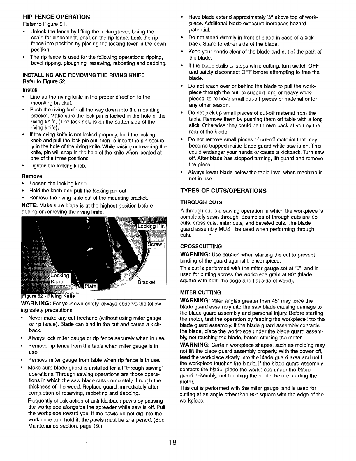
INSTALLING AND REMOVING THE RIVING KNIFE
Refer to Figure 52.
Install
•Line up the riving knife in the proper direction to the
mounting bracket.
•Push the riving knife all the way down into the mounting
bracket. Make sure the lock pin is locked in the hole of the
riving knife. (The lock hole is on the button side of the
riving knife).
• If the riving knife is not locked properly, hold the locking
knob and pull the lock pin out; then re-insert the pin secure-
ly in the hole of the riving knife. While raising or lowering the
knife, pin will snap in the hole of the knife when located at
one of the three positions.
• Tighten the locking knob.
Remove
•Loosen the locking knob.
•Holdthe knob and pullthe lockingpin out.
•Removethe rivingknife outof the mountingbracket.
NOTE: Make sure bladeis at the highest position before
adding or removingthe rivingknife.
Bracket
Figure 52 -Riving Knife
WARNING: For your own safety, always observe the follow-
ing safety precautions.
•Never make any cut freehand (without using miter gauge
or rip fence). Blade can bind in the cut and cause a kick-
back.
• Always lock miter gauge or rip fence securely when in use.
•Remove rip fence from the table when miter gauge is in
use.
• Remove miter gauge from table when rip fence is in use.
• Make sure blade guard is installed for all "through sawing"
operations. Through sawing operations are those opera-
tions in which the saw blade cuts completely through the
thickness of the wood. Replace guard immediately after
completion of resawing, rabbeting and dadoing.
Frequently check action of anti-kickback pawls by passing
the workpiece alongside the spreader while saw is off. Pull
the workpiece toward you. If the pawls do not dig into the
workpiece and hold it, the pawls must be sharpened. (See
Maintenance section, page 19.)
•Have blade extend approximately 1/_,above top of work-
piece. Additional blade exposure increases hazard
potential.
• Do not stand directly in front of blade in case of a kick-
back. Stand to either side of the blade.
• Keep your hands clear of the blade and out of the path of
the blade.
• If the blade stalls or stops while cutting, turn switch OFF
and safety disconnect OFF before attempting to free the
blade.
• Do not reach over or behind the blade to pull the work-
piece through the cut, to support long or heavy work-
pieces, to remove small cut-off pieces of material or for
any other reason.
• Do not pick up small pieces of cut-off material from the
table. Remove them by pushing them off table with a long
stick. Otherwise they could be thrown back at you by the
rear of the blade.
• Do not remove small pieces of cut-off material that may
become trapped inside blade guard while saw is on. This
could endanger your hands or cause a kickback. Turn saw
off. After blade has stopped turning, lift guard and remove
the piece.
• Always lower blade below the table level when machine is
not in use.
TYPES OF CUTS/OPERATIONS
THROUGH CUTS
A through cut is a sawing operation in which the workpiece is
completely sawn through. Examples of through cuts are rip
cuts, cross cuts, miter cuts, and beveled cuts. The blade
guard assembly MUST be used when performing through
cuts.
CROSSCUTTING
WARNING: Use caution when starting the cut to prevent
binding of the guard against the workpiece.
This cut is performed with the miter gauge set at "0", and is
used for cutting across the workpiece grain at 90 °(blade
square with both the edge and flat side of wood).
MITER CUTTING
WARNING: Miter angles greater than 45" may force the
blade guard assembly into the saw blade causing damage to
the blade guard assembly and personal injury. Before starting
the motor, test the operation by feeding the workpiece into the
blade guard assembly. If the blade guard assembly contacts
the blade, place the workpiece under the blade guard assem-
bly, not touching the blade, before starting the motor.
WARNING: Certain workpiece shapes, such as molding may
not lift the blade guard assembly properly. With the power off,
feed the workpiece slowly into the blade guard area and until
the workpiece touches the blade. If the blade guard assembly
contacts the blade, place the workpiece under the blade
guard assembly, not touching the blade, before starting the
motor.
This cut is performed with the miter gauge, and is used for
cutting at an angle other than 90 °square with the edge of the
workpiece.
-18
BEVEL CROSSCUTTING
WARNING: When possible, use the right miter gauge slot
whenbeveIcrosscuttingso that the bladetiltsaway from the
miter gaugeandyour hands.
WARNING: Use cautionwhenstartingthe cut to prevent
bindingof the guardagainstthe workpiece.
This cut is performedwiththe miter gauge,and is the same
as crosscutting,exceptthat the workpieceis alsocut at an
angleotherthan90°squareto the flat sideof the wood(blade
is at an angle).
COMPOUND MITER CUTTING
Thiscut is performedwith the miter gauge, and is a combina-
tionof miter cuttingand bevel crosscutting.The cut is made at
angleotherthan90° to both the edgeand flat side of wood.
RIPPING
WARNING: When bevel ripping and whenever possible,
place the fence on the side of the blade so that the blade is
tilted away from the fence and hands. Keep hands clear of the
blade and use a push stick to feed the workpiece if there is
less than 6" between the fence and the blade.
This cut is performed with the rip fence, and is used to cut the
workpiece lengthwise with the grain. Position the fence to the
desired width of rip and lock in piace. When ripping long
boards or large panels, always use a work support.
BEVEL RIPPING
WARNING: Before connecting the table saw to the power
source or operating the saw, always inspect the blade guard
assembly and riving knife for proper alignment and clearance
with saw blade. Check alignment after each change of bevel
angle.
WARNING: When possible, place the fence on the right side
of the blade so that the blade is tilted away from the fence
and hands. Keep your hands clear of the blade and use a
pushstick to feed the workpiece if there is less than 6"
between the fence and the blade.
This cut is performed with the rip fence, and is the same as
ripping, except that the blade is set at an angle other than 90 °.
RESAWlNG
This cut is performed with the rip fence, and is used to rip a
workpiece through its thickness rather than across its flat
width. Do not attempt to resaw bowed or warped material.
NOTE: It may be necessary to remove blade guard and use
work supports as weII as push blocks when performing this
operation.
WARNING: Install blade guard immediately upon completion
of resawing operation.
PLOUGHING
This cut is performed with the rip fence, and is used to make
a groove lengthwise with the grain of the workpiece. Use
proper hold downs and feed devices.
RABBETING
This cut is performed with either the miter gauge or rip fence.
Rabbeting is used to cut out a section of the corner of a
workpiece, across an end or along an edge. To make a rabbet
requires cuts which do not go all the way through the materi-
al. Therefore, blade guard must be removed. Install blade
guard immediately upon completion of rabbeting operation.
Rabbet cuts can also be made using dado head.
DADOING
This cut is performed with either the miter gauge or rip fence.
Dadoing is done with a set of blades (dado set) rather than
standard saw blades. The dado set is used to groove wood
similar to ploughing and rabbeting. However, the dado set
allows operator to remove more material in one pass. The
operator, with a dado set, can Vary width of cut up to _0".
Instructions for operating dado set are contained in owner's
manual furnished with dado set. Dadoing requires cuts which
do not go all the way through material. Therefore, blade guard
must be removed. Dado sets have different characteristics
than saw blades. As a result, saw must be fitted with special
parts that are not furnished with saw (Dado Insert, Part No.
31158.00).
The maximum dado blade set that can be used on this saw is
%" I.D. x 8" O.D. x '_" Wide.
IMPORTANT: Always use correct insert. When using the
dado set, use caution. Use featherboards and push sticks as
applicable.
WARNING: Always immediately replace the standard blade,
blade guard and blade insert when you are finished dadoing.
FREEHAND
Freehand is a very dangerous operation of making a cut with-
out using the miter gauge or rip fence. Freehand cuts must
never be performed on a Table Saw.
CUTTING OVERSIZED WORKPIECES
When cutting long workpieces or large panels, always support
workpiece that is not on table. Use adjustable roller stand or
make simple support by clamping a piece of plywood to saw
horse. Add facings to miter gauge or rip fence as needed.
IMPORTANT: Do not allow facings to interfere with operation
of blade guard.
DUST COLLECTING
• Saw is fitted with a 4" male exhaust port.
•Before starting saw, see that all adjustments are properly
made and guards in place. With power disconnected, turn
pulley by hand to make sure everything is correct before
connecting power and starting saw.
BLADE SELECTION
Bladeselectionis basedon type of materialbeingcut and
howit willbe cut.There are three genera] types of saw
blades:ripsaw bladescut withgrain of wood,cut-offsaw
bladescutacrossgrain,and combinationsaw bladescutwith
grain,across grainand any angleto grain.
Blades vary inmany aspects.When selecting ablade, the fol-
lowingbladecharacteristicsshould matchup withoperationto
be performedand type of material to be cut:type of steel;
qualityof steeI; toothstyle; toothset;carbidetipped;grind;
number of teeth and size.
IMPORTANT:Your saw is only as accurate and efficientas
blade or cuttingtool used. :
First,be certainto use the appropriatetype of cuttingtoolfor
the operationto be performed. Second, it is stronglyrecom-
mendedthat high-quaIityblades andcuttingtoolsbe used.Be
certain blades and cuttingtools are kept sharp and ingood
workingorder.Check blades periodically and replaceor
sharpen if necessary.
19
WARNING: Do not attempt under any circumstances, to
service,repair,dismantle, or disassemble any mechanical
or electrical componentswithoutphysicallydisconnecting all
power soumes.
CLEANING
Clean off any preservative on bright (machined) parts with
appropriate solvent (mineral spirits). Avoid getting cleaning
fluid on any rubber parts as they tend to deteriorate
rubber.
• Use soap and soft water on rubber and plastic parts.
°After cleaning, lubricate unpainted surfaces with a light
application of medium consistency machine oil. This lubri-
cation should be repeated at least once every six months.
NOTE: Instead of oil, a good quality paste wax can be applied
to rip fence and table surface. Paste wax will enhance move-
ment of workpieces. In addition to providing lubrication, paste
wax will help prevent rusting.
= Keep your machine and your workshop clean. Do not allow
sawdust to accumulate on saw or inside cabinet.
Frequently vacuum or blow out any sawdust that may
accumulate within cabinet.
• Be certain motor and internal mechanisms are clean and
are frequently vacuumed or blown free of any dirt.
LUBRICATION
All bearings on the arbor are shielded ball bearings. These
bearings are permanently lubricated at the factory.
• As needed, clean the grease off the rack and worm gears
of height and tilt mechanism. Lubricate rack and gears
with a medium viscosity machine oil.
• Be sure to lubricate trunnion ways and all bushings.
• Occasionally oil all other bearing points, including bIade
guard assembly, miter gauge and rip fence.
SERVICE
• Replacebeltsandworn parts as needed.If power cords
are worn,cut, ordamaged in any way,havethem
replaced immediately.
° Make sureteeth of anti-kickbackpawlsare always sharp.
• Sharpendull teeth usinga few lightstrokesof a smooth
cutflat file.
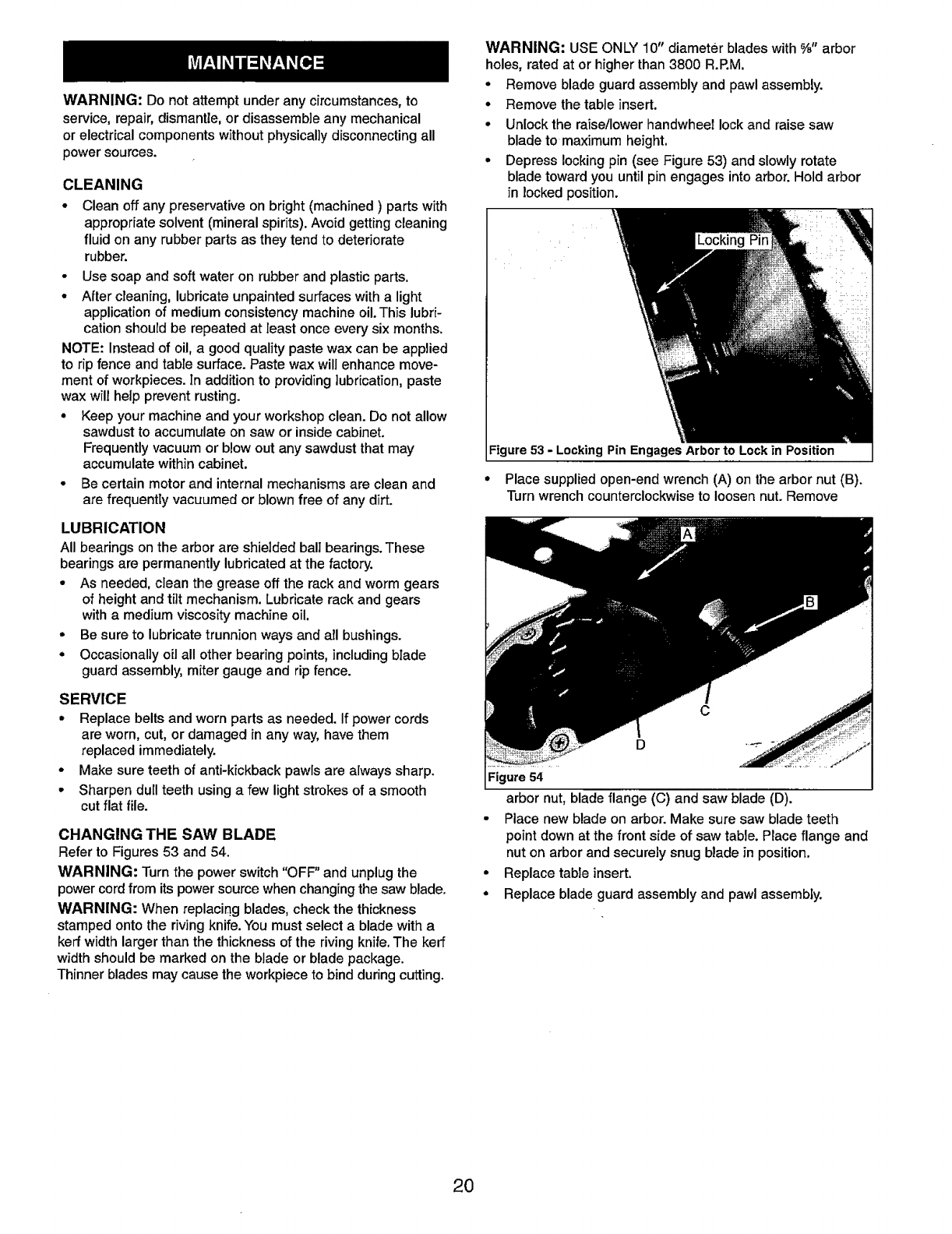
CHANGING THE SAW BLADE
Refer to Figures 53 and 54.
WARNING: Turnthe power switch"OFF" and unplug the
powercordfrom its powersource whenchangingthe saw blade.
WARNING: When replaciqg blades, checkthe thickness
stamped ontothe rivingknife.You mustselect a bladewitha
kerf widthlargerthanthe thicknessof the rivingknife.The kerf
widthshouldbe marked onthe blade orblade package.
Thinnerblades may causethe workpieceto bind duringcutting.
WARNING: USE ONLY 10" diameter blades with %" arbor
holes, rated at or higher than 3800 R.RM.
• Remove blade guard assembly and pawl assembly.
• Remove the table insert.
• Unlock the raise!lower handwheel lock and raise saw
blade to maximum height.
° Depress locking pin (see Figure 53) and slowly rotate
blade toward you until pin engages into arbor. Hold arbor
in locked position.
Figure 53 -Locking Pin Engages Arbor to Lock in Position
°Place supplied open-end wrench (A) on the arbor nut (B).
Turn wrench counterclockwise to loosen nut. Remove
C
D
Figure54
arbor nut,blade flange (C) and saw blade (D).
• Place new blade on arbor.Make sure sawblade teeth
pointdown at the front side of sawtable.Place flange and
nut onarborandsecurely snugblade in position.
°Replacetableinsert.
•Replacebladeguard assembly and pawlassembly.
2O
Service Record
Craftsman 10" Contractor Table Saw
DATE MAINTENANCE PERFORMED REPLACEMENT PARTS REQUIRED 1
21
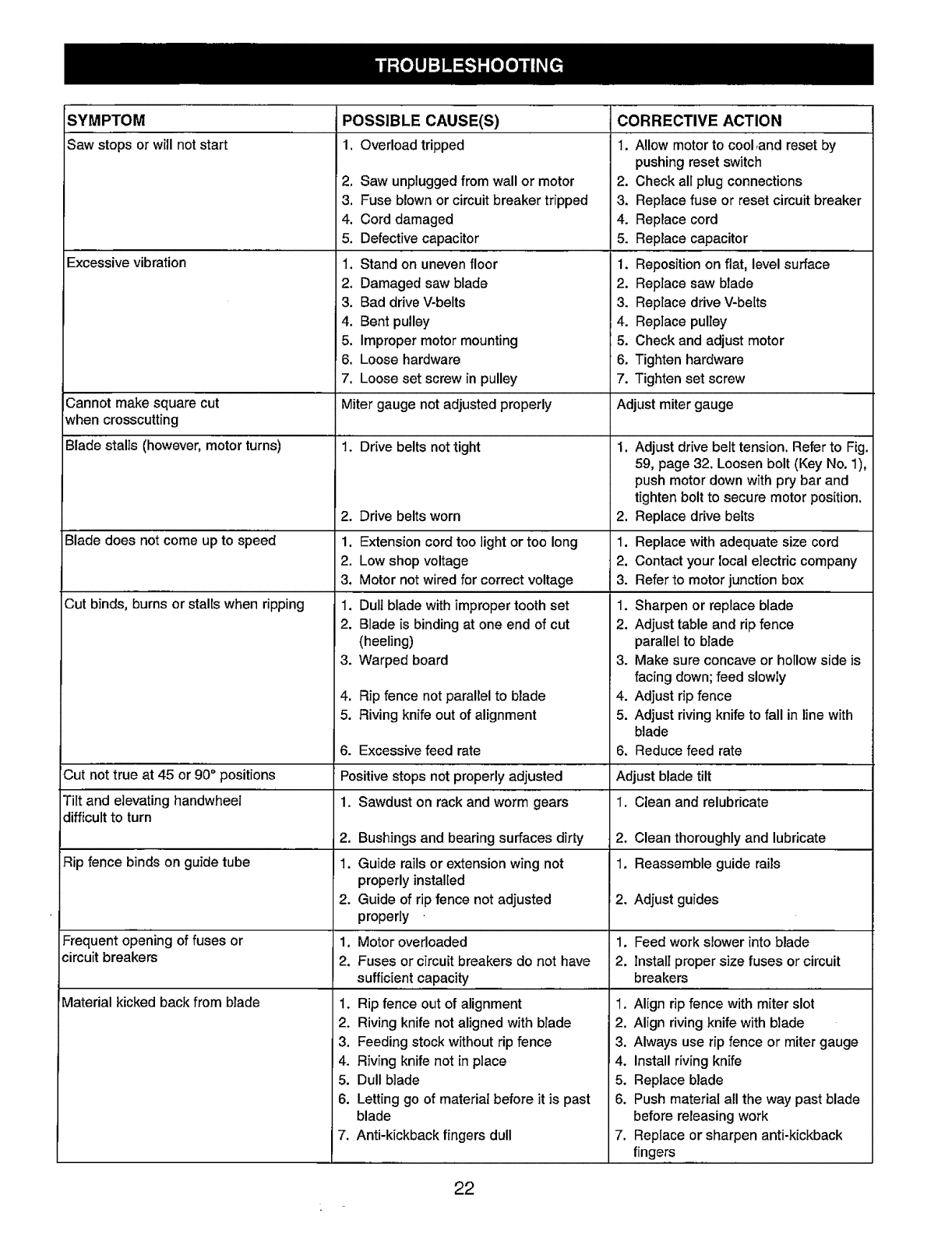
SYMPTOM CORRECTIVE ACTION
Saw stopsor will not start
Excessive vibration
Cannot make square cut
when crosscutting
POSSIBLE CAUSE(S)
1. Overload tripped 1.
2. Saw unplugged from wall or motor 2.
3. Fuse blown or circuit breaker tripped 3.
4. Cord damaged 4.
5. Defective capacitor 5.
1. Stand on uneven floor 1.
2. Damaged saw blade 2.
Blade stalls (however, motor turns)
Biade does not come up to speed
cut binds, burns or stalls when ripping
Cut not true at 45 or 90° positions
Tilt and elevating handwheet
difficult to turn
Rip fence binds on guide tube
Frequent Opening of fuses or
circuit breakers
Material kicked back from blade
3. Bad drive V-belts
4. Bent pulley
5. Improper motor mounting
6. Loose hardware
7. Loose set screw in pulley
Miter gauge not adjusted properly
1. Drive belts not tight
2.
1.
2.
3.
1.
2.
3.
4. Rip fence not parallel to blade
5. Riving knife out of alignment
6. Excessive feed rate
Positive stops not properly adjusted
1. Sawdust on rack and worm gears
2.
1.
2.
1,
2.
.
2.
3.
4.
5.
6.
,
Allow motor to cool ,and reset by
pushing reset switch
Check all plug connections
Replace fuse or reset circuit breaker
Replace cord
Replace capacitor
Reposition on flat, level surface
Replace saw bIade
3. Replace drive V-belts
4. Replace pulley
5. Check and adjust motor
6. Tighten hardware
7. Tighten set screw
Adjust miter gauge
,
Drive belts worn 2.
Extension cord too light or too long 1.
Low shop voltage 2.
Motor not wired for correct voltage 3.
Dull blade with improper tooth set 1.
Blade is binding at one end of cut 2.
(heeling)
Warped board 3.
4.
5.
Bushings and bearing surfaces dirty' 2.
Guide rails or extension wing not
properly installed
Guide of rip fence not adjusted
properly
Motor overloaded 1.
Fuses or circuit breakers do not have 2.
sufficient capacity
Rip fence out of alignment 1.
Riving knife not aligned with blade 2.
Feeding stock without rip fence 3.
Riving knife not in place 4.
Dull blade 5.
Letting go of material before it is past 6.
blade
Anti-kickback fingers dull 7.
Adjust drive belt tension. Refer to Fig.
59, page 32. Loosen bolt (Key No. 1),
push motor down with pry bar and
tighten bolt to secure motor position.
Replace drive belts
Replace with adequate size cord
Contact your local electric company
Refer to motor junction box
Sharpen or replace blade
Adjust table and rip fence
parallel to blade
Make sure concave or hollow side is
facing down; feed slowly
Adjust rip fence
Adjust riving knife to fall in line with
blade
6. Reduce feed rate
Adjust blade tilt
1. Clean and relubricate
Clean thoroughly and lubricate
1. Reassemble guide rails
2. Adjust guides
Feed work slower into blade
Install proper size fuses or circuit
breakers
Align rip fence with miter slot
Align riving knife with blade
Always use rip fence or miter gauge
Install riving knife
Replace blade
Push material all the way past blade
before releasing work
Replace or sharpen anti-kickback
fingers
22
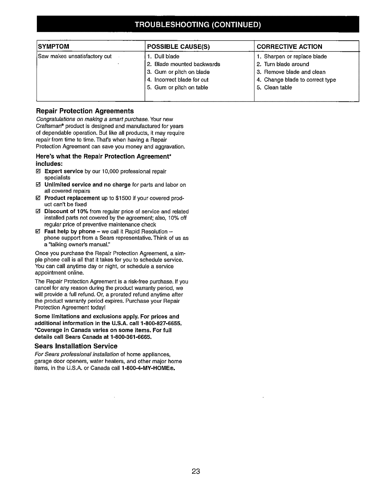
SYMPTOM
Saw makes unsatisfactory cut
POSSIBLE CAUSE(S)
1. Dullblade
2. Blade mountedbackwards
3. Gum or pitchon blade
4. Incorrectblade for cut
5. Gum or pitchon table
CORRECTIVE ACTION
1. Sharpenor replaceblade
2. Turnbladearound
3. Removeblade and clean
4. Changebladeto correcttype
5. Cleantable
Repair Protection Agreements
Congratulations on making a smart purchase. Your new
Craftsman ®product is designed and manufactured for years
of dependable operation. But like all products, it may require
repair from time to time. That's when having a Repair
Protection Agreement can save you money and aggravation.
Here's what the Repair Protection Agreement*
includes:
[] Expert service by our 10,000 professional repair
specialists
I--4 Unlimited service and no charge for parts and labor on
all covered repairs
[] Product replacement up to $1500 if your covered prod-
uct can't be fixed
[] Discount of 10% from regular price of service and related
installed parts not covered by the agreement; also, 10% off
regular price of preventive maintenance check
[] Fast help by phone -we call it Rapid Resolution -
phone support from a Sears representative. Think of us as
a "talking owner's manual"
Once you purchase the Repair Protection Agreement, a sim-
ple phone call is all that it takes for you to schedule service.
You can call anytime day or night, or schedule a service
appointment online.
The Repair Protection Agreement is a risk-free purchase. If you
cancel for any reason during the product warranty period, we
will provide a full refund. Or, a prorated refund anytime after
the product warranty period expires. Purchase your Repair
Protection Agreement today[
Some limitations and exclusions apply. For prices and
additional information in the U,S,A. call 1-800-827-6655,
*Coverage in Canada varies on some items. For full
details call Sears Canada at 1-800-361-6665.
Sears Installation Service
For Sears professional installation of home appliances,
garage door openers, water heaters, and other major home
items, in the U.S.A. or Canada call 1-800-4-MY-HOME®,
23
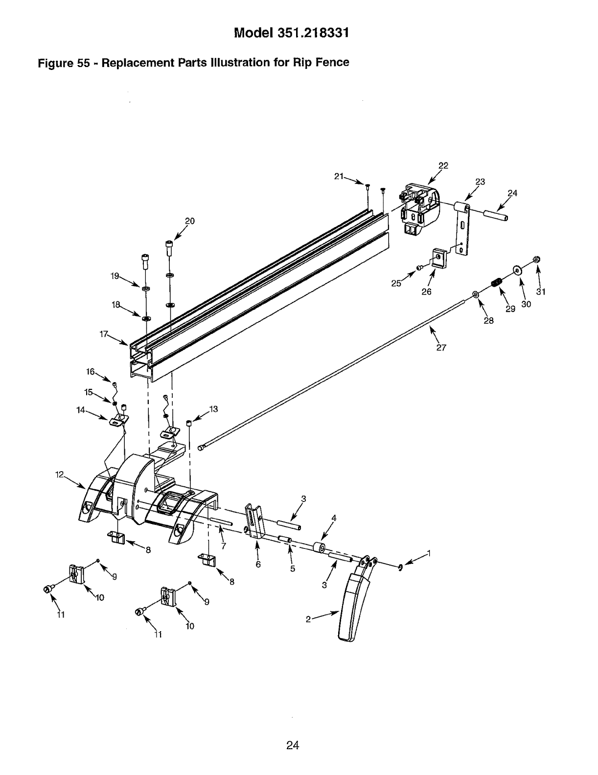
Model 351.218331
Figure 55 - Replacement Parts Illustration for Rip Fence
24
I 1
I I
t
8
11
7
10
6
24

KEY"'
NO,
1
2
3
4
5
6
7
8
9
10
I1
12
13
14
15
16
17
I8
19
20
21
22
23
24
25
26
27
28
29
30
31
PART NO,
09845.00
31107.00
31108.00
31109.00
3I 110.00
3I 111.00
01923,00
31112.00
01203.00
31113.00
31114.00
31115.00
31116.00
31117.00
STD851004
06177.00
31118.00
STD851008
STD852008
STD870820
311 I9.00
31120.00
31121.00
18782.00
STD863510
31122.00
31123.00
STD851006
31124.00
00652.00
STD840610
DESCRIPTION
3CMI-6 E-Ring
Locking Handle
8 x 50mm Spring Pin
Bushing
Shaft
Cam
5 x 30mm Spring Pin
Adjusting Plate
3CMI-5 E-Ring
Adjusting Plate
Adjusting Screw
Base
Nylon Screw
Lens
4mm Flat Washer*
4-0.7 x 8mm Flat Head Screw
Fence
8mm Flat Washer*
8mm Lock Washer*
8-1.25 x 20mm Socket Head Bolt*
3.5-1.3 x 10mm Threadforming Screw
Cap
Latch
10 x 50mm Spring Pin
5-0.8 x 10mm Pan Head Screw*
Clamp
Rod
6mm Fiat Washer*
Spring
6mm Flat Washer (W)
6-1.0mm Hex Nut*
* Standard hardware item available locally.
QTY.
2
1
2
1
1
1
1
2
2
2
2
1
2
2
2
2
1
2
2
2
2
1
1
1
1
1
1
1
1
1
1
25
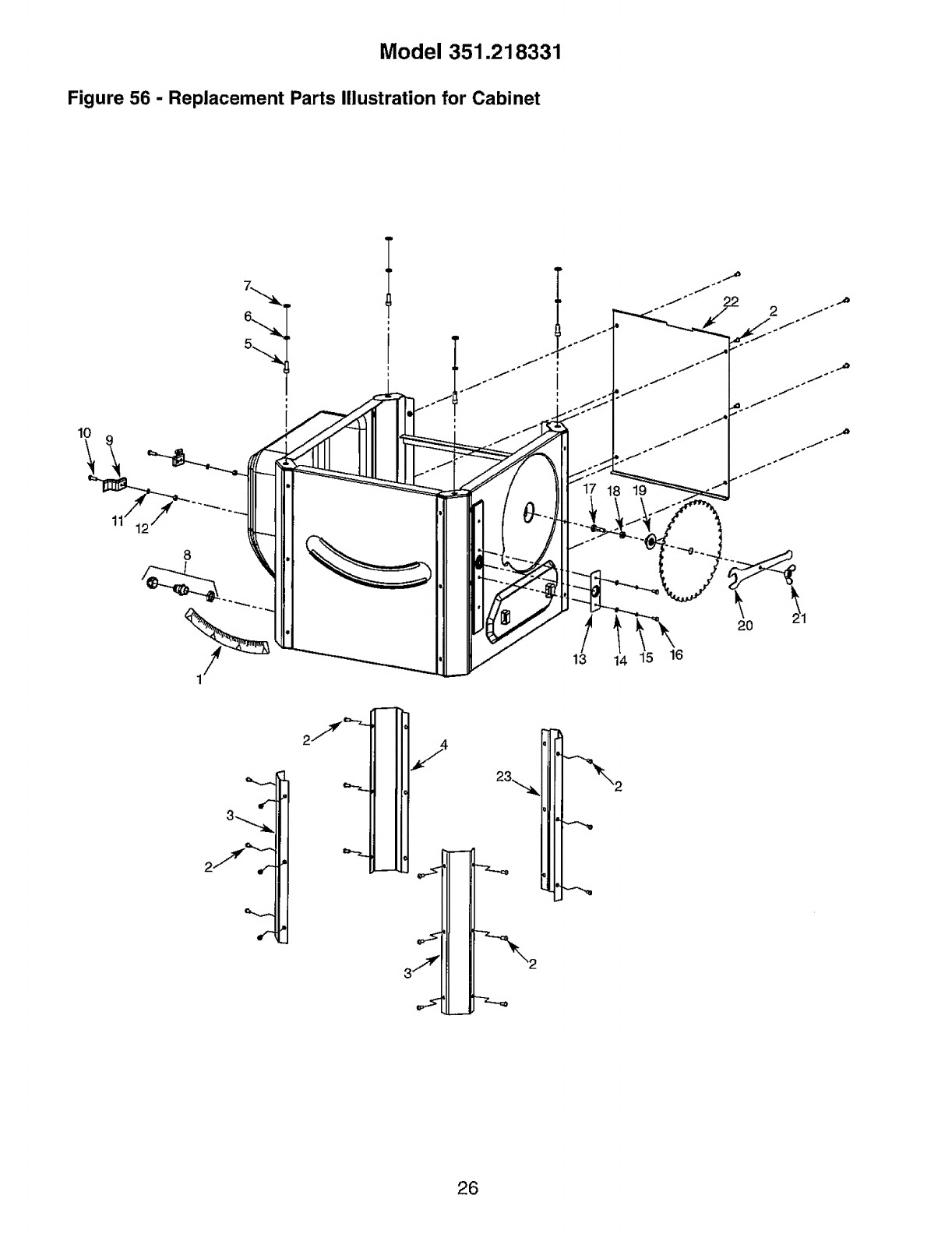
Model 351.21 8331
Figure 56 - Replacement Parts Illustration for Cabinet
10
18 19
13 14 516
2O
26
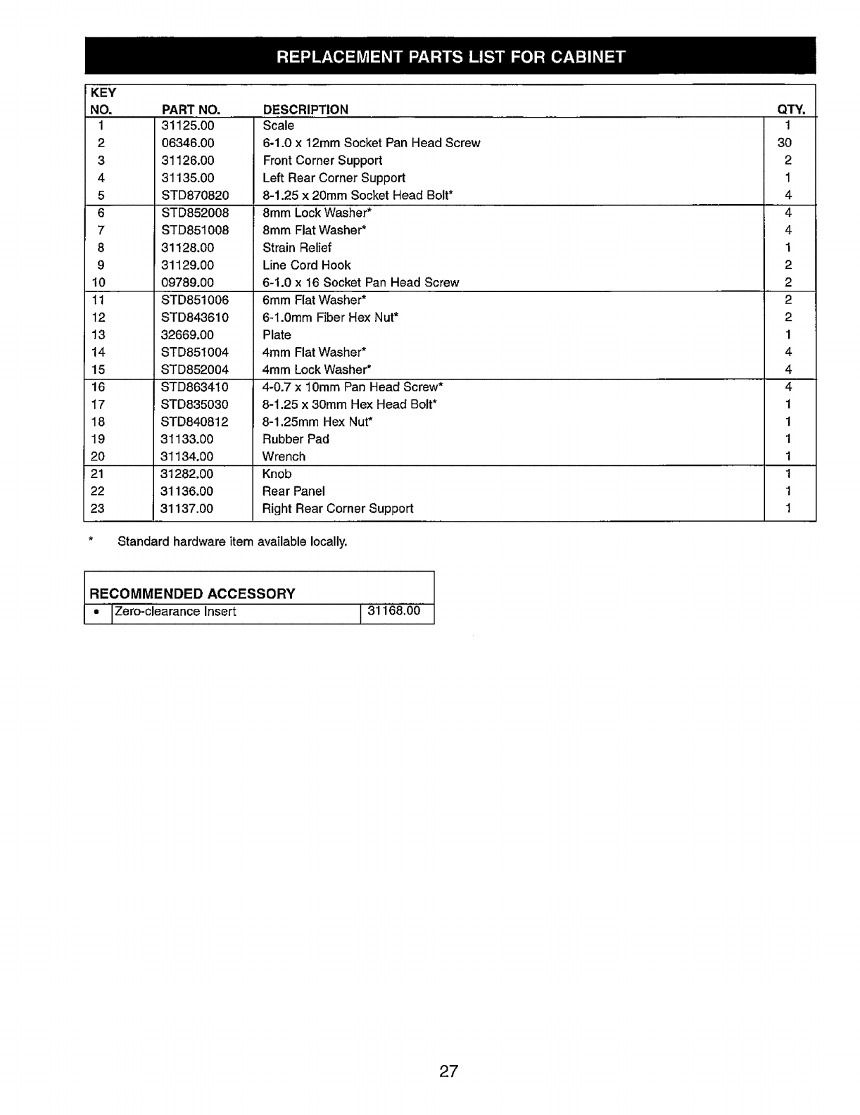
KEY
NO.
1
2
3
4
5
6
7
8
9
!0
11
12
13
14
15
16
17
18
19
20
21
22
23
PART NO.
31125.OO
06346.00
31126.00
31135.00
STD870820
STD852008
STD851008
31128.00
31129.00
09789.00
STD851006
STD843610
32669.00
STD851004
STD852004
STD863410
STD835030
STD840812
31133.00
31134.00
31282.00
31136.00
31137.00
DESCRIPTION
Scale
6-1.0 x 12mm Socket Pan Head Screw
Front Corner Support
Left Rear Corner Support
8-1.25 x 20mm Socket Head Bolt*
8ram Lock Washer*
8mm Flat Washer*
Strain Relief
Line Cord Hook
6-1.0 x 16 Socket Pan Head Screw
6ram Flat Washer*
6-1.0mm Fiber Hex Nut*
Plate
4mm Flat Washer*
4mm Lock Washer*
4-0.7 x lOmm Pan Head Screw*
8-1.25 x 30mm Hex Head Bolt*
8-1,25mm Hex Nut*
Rubber Pad
Wrench
Knob
Rear Panel
Right Rear Corner Support
Standard hardware item available locally.
QTY,
1
30
2
1
4
4
4
1
2
2
2
2
1
4
4
4
1
1
1
1
1
1
1
31168.00
27
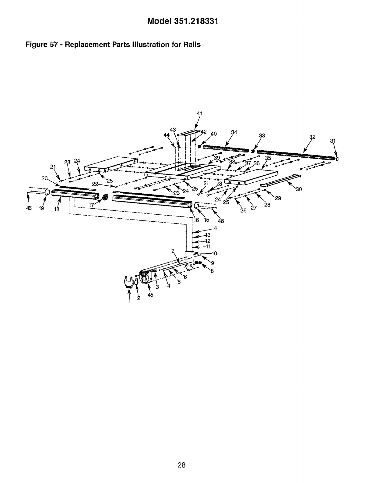
Model 351.218331
Figure 57 - Replacement Parts Illustration for Rails
43
41
/34
46 19 1_ 26 27 28
45
i
28
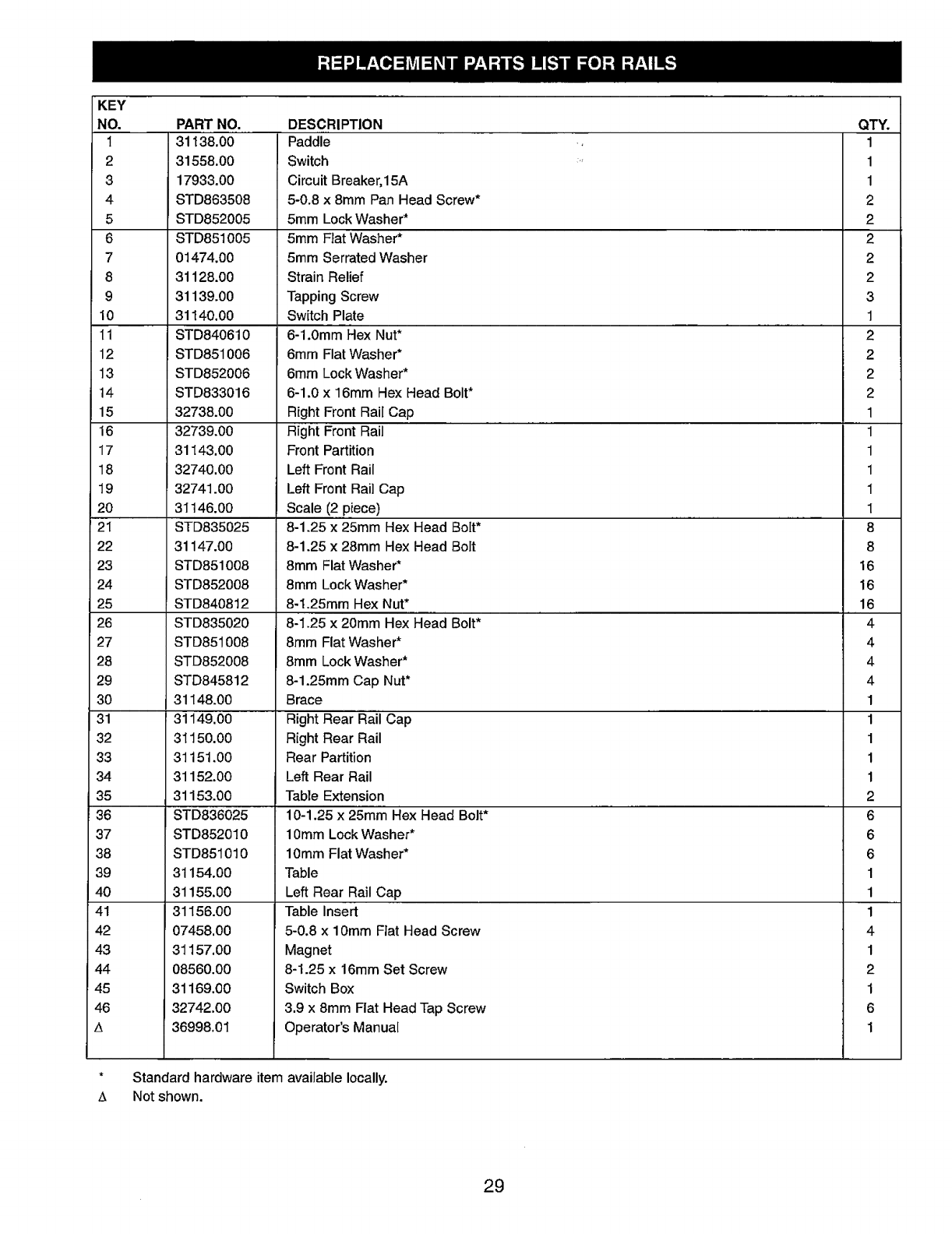
KEY
NO.
1
2
3
4
5
6
7
8
9
10
11
12
13
14
15
16
17
18
19
20
2I
22
23
24
25
26
27
28
29
3O
31
32
33
34
35
36
37
38
39
40
41
42
4_3
44
45
46
A
PART NO.
31138.00
31558.00
17933.00
STD863508
STD852005
STD851005
01474.00
31128.00
31139.00
31140.00
STD840610
STD851006
STD852006
STD833016
32738.00
32739.00
31143.00
32740.00
32741.00
31146.00
STD835025
31147.00
STD851008
STD852008
STD840812
STD835020
8TD851 OO8
STD852008
STD845812
31148.00
31149.00
31150.00
31151.00
31152.00
31153.00
STD836025
STD852010
STD851010
31154.00
31155.00
31156.00
07458.00
31157.00
08560.00
31169.00
32742.00
36998.01
DESORIPTION
Paddle
Switch
Circuit Breaker,15A
5-0.8 x 8mm Pan Head Screw*
5mm Lock Washer*
5mm Flat Washer*
5mm Serrated Washer
Strain Relief
Tapping Screw
Switch Plate
6-1.0mm Hex Nut*
6mm Flat Washer*
6mm Lock Washer*
6-1.0 x 16mm Hex Head Bolt*
Right Front RaiI Cap
Right Front Rail
Front Partition
Left Front Rail
Left Front Rail Cap
Scale (2 piece)
8-1.25 x 25mm Hex Head Bolt*
8-1.25 x 28mm Hex Head BoIt
8mm Flat Washer*
8ram Lock Washer*
8-1.25mm Hex Nut*
8-1.25 x 20mm Hex Head Bolt*
8ram Flat Washer*
8mm Lock Washer*
8-1.25mm Cap Nut*
Brace
Right Rear Rail Cap
Right Rear Rail
Rear Partition
Left Rear Rail
Table Extension
10-1.25 x 25mm Hex Head Bolt*
10mm Lock Washer*
10mm Flat Washer*
Table
Left Rear Rail Cap
Table Insert
5-0.8 x 10mm Flat Head Screw
Magnet
8-1.25 x 16mm Set Screw
Switch Box
3.9 x 8mm Flat Head Tap Screw
Operator's Manual
QTY.
1
1
1
2
2
2
2
2
3
1
2
2
2
2
1
1
1
1
1
1
8
8
16
16
16
4
4
4
4
1
1
1
1
1
2
6
6
6
1
1
1
4
1
2
1
6
1
* Standard hardware item available locally.
A Not shown.
29
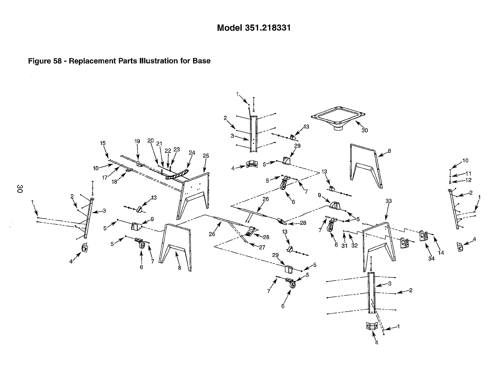
\
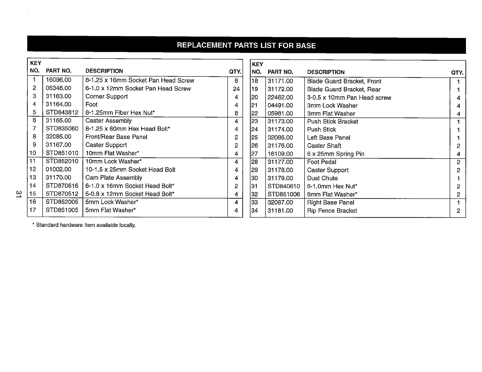
O3
=,-L
KEY
NO.
1
2
3
4
5
6
7
8
9
10
11
12
13
14
15
16
17
PART NO.
16096.00
06346.00
31163.00
31164.00
STD843812
31165.00
STD835060
32085.00
31167.00
STD851010
STD852010
01002.00
31170.00
STD870616
STD870512
STD852005
STD851005
DESCRIPTION
8-1.25 X 16rnm Socket Pan Head Screw
6-1.0 x 12mm Socket Pan Head Screw
Corner Support
Foot
8-1.25mm Fiber Hex Nut*
Caster Asso"mbly
8-1.25 x 60turn Hex Head Bolt*
Front/Rear Base Panel
Caster Support
10mm Flat Washer*
! 0rnm Lock Washer*
10-I .5 x 25mm Socket Head Bolt
Cam Plate Assembly
6-1.0 x 16mrn Socket Head Bolt*
5-0.8 x 12ram Socket Head Bolt*
5mm Lock Washer*
5mm Fiat Washer*
* Standard hardware item available locally.
QTY.
8
24
4
4
8
4
4
2
2
4
4
4
4
2
4
4
4
KEY
NO.
18
19
2O
21
22
23
24
25
26
27
28
29
3O
31
32
33
34
PART NO.
31171.00
31172.00
22462.00
04491.00
05981.00
31173.0O
31174.00
32086.00
31176.00
16109.00
31177.00
31178.00
31179.00
STD840610
STD851006
32087.00
31181.00
DESCRIPTION
Blade Guard Bracket, Front
Blade Guard Bracket, Rear
3-0.5 x 10mm Pan Head screw
3mm Lock Washer
3ram Flat Washer
Push Stick Bracket
Push Stick
Left Base Panel
Caster Shaft
6 x 25mm Spring Pin
Foot Pedal
Caster Support
Dust Chute
6-1.0mm Hex Nut*
6mm Flat Washer*
Right Base Panel
Rip Fence Bracket
QTY.
1
1
4
4
4
1
1
1
2
4
2
2
1
2
2
!
2
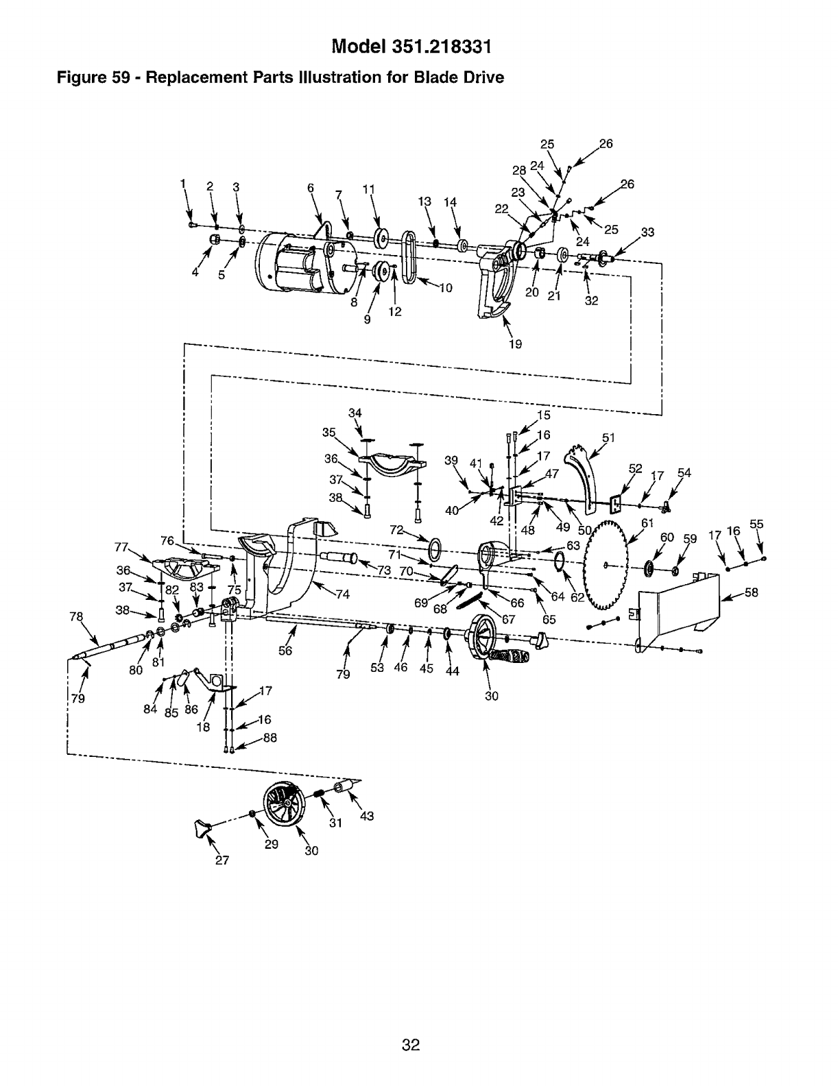
Model 351.218331
Figure 59 - Replacement Parts Illustrationfor Blade Drive
6 11
812
9
34
28
22
19
42
25
51
52
61
54
17 16 5i
79
'67
45
30
65
32
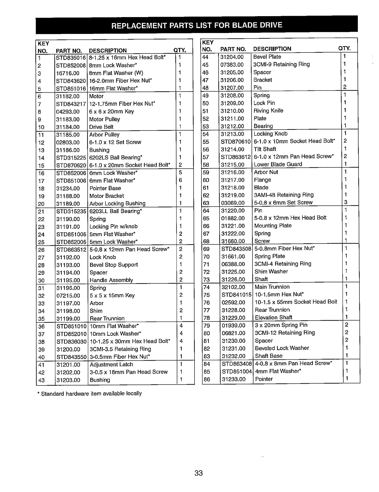
KEY
NO. PART NO,
1 iSTD835016
2 STD852008
3 16716.00
4 STD843620
5 STD851016
6 31182.00
7 STD843217
8 04293.00
9 31183.00
10 31184.00
11 31185.00
12 02803,00
13 31186.00
14 STD315225
15 ST D870620
16 STD852006
I7 STD851006
18 31234.00
19 31188.00
20 31189.00
21 STD315235
22 31190.00
23 31191.00
24 STD851005
25 STD852005
26 STD863512
27 31192.00
28 31193.00
29 31194,00
30 31195.00
31 31196.00
32 07215.00
33 31197.00
34 31198.00
35 31199.OO
36 STD851010
37 STD852010
38 STD836030
39 31200.00
40 STD843550
41 31201.00
42 3I 202.0O
43 31203.00
DESCRIPTION
8-1.25 x 16mm Hex Head Bolt*
8mm Lock Washer*
8mm Flat Washer (W)
16-2.0mm Fiber Hex Nut*
16mm Flat Washer*
Motor
12-1.75mm Fiber Hex Nut*
6 x 6 x 20mm Key
Motor Pulley
Drive Belt
Arbor Pulley
6-1.0 x 12 Set Screw
Bushing
6202LS Ball Bearing*
6-1.0 x 20mm Socket Head Bolt*
6mm Lock Washer*
6mm Flat Washer*
Pointer Base
Motor Bracket
Arbor Locking Bushing
6203LL Bali Bearing*
Spring
Locking Pin w/knob
5mm Flat Washer*
5mm Lock Washer*
5-0,8 x 12mm Pan HeadScrew*
Lock Knob
Bevel Stop Support
Spacer
Handle Assembly
Spring
5 x 5 x 15mm Key
Arbor
Shim
Rear Trunnion
10mm Flat Washer*
10mm Lock Washer*
10-1.25 x 30mm Hex Head Bolt*
3CMI-3.5 Retaining Ring
3-0.5mm Fiber Hex Nut*
Adjustment Latch
3-0.5 x 18ram Pan Head Screw
Bushing
*Standard hardware item available locally
QTY.
1
1
1
1
1
I
1
1
1
1
1
1
KEY
NO,
44
45
46
47
48
49
5O
51
52
53
54
55
1 56
1 57
2 58
5 59
6 60
1 61
1 62
1 63
1 64
1 65
1 66
2 67
2 68
2 69
2 70
1 71
2 72
2 73
1 74
2 75
1 76
2 77
1 78
4 79
4 8O
4 81
1 82
1 83
1 84
1 85
186
PART NO.
31204.00
07383.00
31205.00
31206.00
31207.00
31208.00
31209.00
31210.00
31211.00
31212.00
31213.00
STD870610
31214,00
STD863612
31215.00
31216.00
31217.00
31218.00
31219.00
03069.00
31220.00
01882,00
31221.00
31222.00
31660.0O
STD843508
31661.00
06388.00
31225.00
31226.00
32102.00
STD841015
02592.00
31228.00
31229.00
01939,00
06821,00
31230.00
31231.00
31232.00
STD863408
STD851004
31233.00
DESCRIPTION QTY.
Bevel Plate 1
3CMI-9 Retaining Ring 1
Spacer I
Bracket 1
Pin 2
Spring 1
Lock Pin 1
Riving Knife 1
Plate 1
Bearing 1
Locking Knob 1
6-1.0 x 10mm Socket Head Bolt* 2
Tilt Shaft 1
6-1.0 x 12mm Pan Head Screw* 2
Lower Blade Guard 1
Arbor Nut 1
Flange 1
Blade 1
3AMI-48 Retaining Ring 1
5-0.8 x 6ram Set Screw 3
Pin 1
5-0.8 x 12mm Hex Head Bolt 1
Mounting Plate 1
Spring 1
Screw 1
5-0.8mm Fiber Hex Nut* 1
Spring Plate 1
3CMI-4 Retaining Ring 1
Shim Washer 1
Shaft 1
Main Trunnion 1
10-1,5mm Hex Nut* 1
10-1.5 x 55mm Socket Head Bolt 1
Rear Trunnion 1
Elevation Shaft 1
3 x 20mm Spring Pin 2
3CM1-12 Retaining Ring 2
Spacer 2
Beveled Lock Washer 1
Shaft Base 1
4-0.8 x 8mm Pan Head Screw* 1
4mm Flat Washer* 1
Pointer 1
33
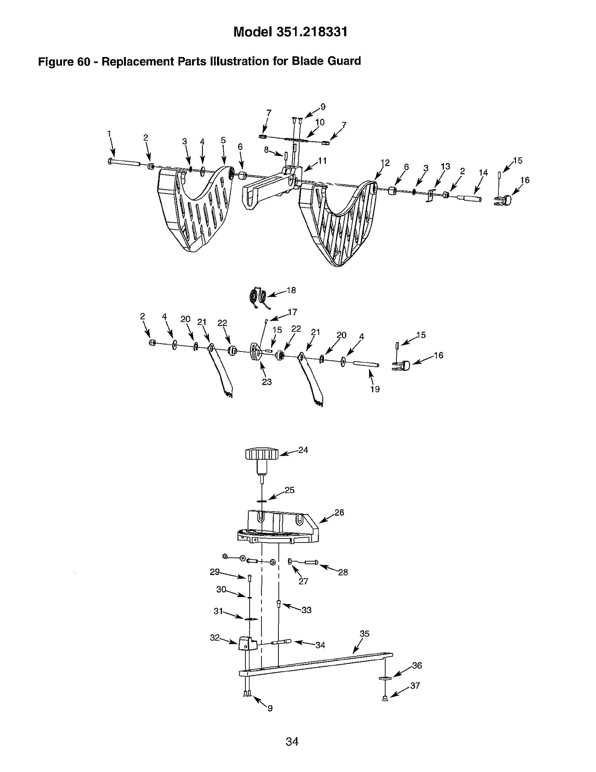
Model 351.218331
Figure 60 - Replacement Parts Illustration for Blade Guard
1
f11. 12 6 3 13 o ;4__16
2 4 20--! "k''17
,2 2_2 /15 22 21 ?0 4- __j15
27
35
34
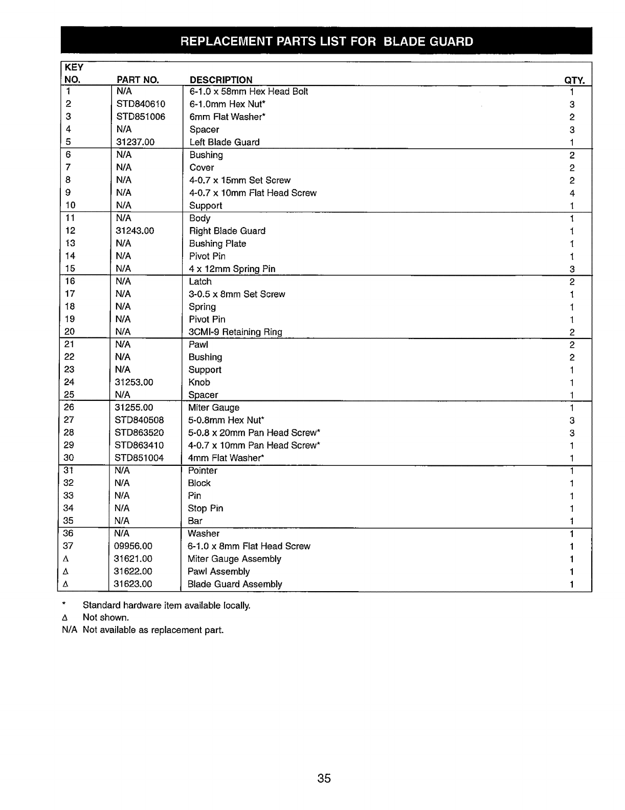
KEY
NO,
1
2
3
4
5
6
7
8
9
10
11
12
13
14
15
16
17
18
19
20
21
22
23
24
25
26
27
28
29
3O
31
32
33
34
35
36
37
A
PART NO.
NIA
STD840610
STD85I 006
N/A
31237.00
NiA
NIA
N/A
N/A
N/A
NiA
31243.00
N/A
N!A
N/A
NiA
N!A
N!A
NiA
N/A
NiA
N!A
NiA
31253.00
N!A
31255.00
STD840508
STD863520
STD863410
STD851004
DESORIPTION
6-1.0 x 58ram Hex Head Bolt
6-1.0mm Hex Nut*
6mm Flat Washer*
Spacer
Left Blade Guard
Bushing
Cover
4-0.7 x 15mm Set Screw
4-0.7 x 10mm Flat Head Screw
Support
Body
Right Blade Guard
Bushing Plate
Pivot Pin
4 x 12mm Spring Pin
Latch
3-0.5 x 8mm Set Screw
Spring
Pivot Pin
3CM1-9 Retaining R!n.g .......
Pawl
Bushing
Support
Knob
Spacer
Miter Gauge
5-0.8mm Hex Nut*
5-0.8 x 20mm Pan Head Screw*
4-0.7 x 10mm Pan Head Screw*
4mm Flat Washer*
NiA
N!A
N/A
NiA
NiA
N/A
O9956.00
31621.00
31622.00
31623.00
Pointer
Block
Pin
Stop Pin
Bar
Washer
6-1.0 x 8mm Flat Head Screw
Miter Gauge Assembly
Pawl Assembly
Blade Guard Assembly
* Standard hardware item available locally.
z_ Not shown.
N/A Not available as replacement part.
QTY.
1
3
2
3
1
2
2
2
4
1
1
I
1
1
3
2
1
1
1
2
2
2
1
1
1
1
3
3
1
1
1
1
1
1
1
1
1
1
1
1
35

I i
! !
]
[
Get it " , at your home or ours!
Your Home
For troubleshooting, product manuals and expert advice:
managemylife
www.managemylife.com
For repair - in your home - of all major brand appliances,
lawn and garden equipment, or heating and cooling systems,
no matter who made it, no matter who sold it!
For the replacement parts, accessories and
owner's manuals that you need to do-it-yourself.
For Sears professional installation of home appliances
and items like garage door openers and water heaters.
1-800-4-MY'-HOME ®(1-800,-469-4663)
Call anytime, day or night (U.S.A. and Canada)
www.sears.com www.sears.ca
Our Home
For repair of carry-in items like vacuums, lawn equipment,
and electronics, call anytime for the location of your nearest
Sears Parts & Repair Service Center
1-800-488-1222 (U.S.A.) 1-800-469-4663 (Canada)
www.sears.com www.sears.ca
To purchase a protection agreement on a product serviced by Sears:
1-800-827-6655 (U.S.A.) 1-800-361-6665 (Canada)
Para pedir servicio de reparaci6n
a domicilio, y para ordenar piezas:
1-888-SU-HOGAR ®
(1-888-784-6427)
Au Canada pour service en frangais:
1-800-LE-FOYER Mc
(1-800-533-6937)
www.sears.ca
www.sears.com sears
, i
i
z i
® Registered Trademark t "ruTrademark of KCD IP, LLC in the United States, or Sears Brands, LLC in other countries
® Marca Registrada 1TMMarca de F_brica de KCD IP, LLC en Estados Unidos, o Sears Brands, LLC in otros paises
MD
MCMarque de commerce IMarque d6posCe de Sears Brands, LLC
