Craftsman 15130383 User Manual TRIMMER Manuals And Guides 1506061L
User Manual: Craftsman 15130383 15130383 CRAFTSMAN TRIMMER - Manuals and Guides View the owners manual for your CRAFTSMAN TRIMMER #15130383. Home:Lawn & Garden Parts:Craftsman Parts:15130383 Craftsman Grass trimmer (weed wacker) Manual
Open the PDF directly: View PDF ![]() .
.
Page Count: 31

OPERATOR'S MANUAL
MANUAL DEL USUARIO
15-inch 5.5A ELECTRIC
LiNE TRIMMER
ORILLADORA EL#CTRICA
deModej15pulgadasNo.5.5A _(__I
151.30383
ModeJo no
151.30383
_ WARNING: Toreduce the
risk of injury, the user must read and
understand the operator's manual
before using this product,
_IL ADVERTENCIA: Para reducir
el riesgo de lesiones, et usuario debe
leer y comprender el manual antes de
utilizar este producto.
Sears Brands Management Corporation, Hoffman Estates, IL 60179 USA
Visit the Craftsman web page: www.craftsman.com
Visite el sitio Web de Craftsman: www.craftsman.com
Save this manual for future reference
Conserve este manual para futura referencia. @
ENGLISH
[] Warranty ................................................................... 2
[] Introduction ............................................................... 2
[] Important safety instructions ................................. 3-4
[] Symbols ................................................................. 5-6
[] Features ................................................................... 7
[] Electrical information ................................................ 8
[] Assembly .................................................................. 9
[] Operation ................................................................ 10
[] Care and maintenance ........................................... 11
[] Troubleshooting ...................................................... 12
[] Illustrated parts list ............................................ 13-14
SPANISH
[] Garantia .............................. Secci6n de Ingles pgg. 2
[] Introducci6n ......................... Secci6n de Ingles pgg. 2
[] Importantes instrucciones de seguridad ................ 3-4
[] Simbolos ............................................................... 5-6
[] Caracteristicas ......................................................... 7
[] Informaci6n electrica ................................................ 8
[] Armado ..................................................................... 9
[] Funcionamiento ...................................................... 10
[] Cuidado y mantenimiento ....................................... 11
[] Resoluci6n de probiemas ....................................... 12
[] Lista de piezas, ilustrada ................................... 13-14
[] Figura numeras (ilustraciones) .............................. i-iv
CRAFTSMAN LIMITED WARRANTY
FOR 2 YEARS from the date of sale, this product is warranted against defects in material or workmanship.
WITH PROOF OF SALE, a defective product will be replaced free of charge.
For warranty coverage details to obtain free replacement, visit the web page: www.craftsman.com/warranty
This warranty does not cover the spool of trimmer line or trimmer head spool cover, which are expendable parts
that can wear out from normal use within the warranty period.
This warranty is void if this product is ever used while providing commercial services or if rented to another
person.
This warranty gives you specific legal rights, and you may also have other rights which vary from state to state.
Sears Brands Management Corporation, Hoffman Estates, IL 60179
GARANT(A LtMmTADA CRAFTSMAN
DURANTE 2 AltOS a contar de la fecha de venta, este producto est& garantizado contra defectos en sus
materiales o fabricacion.
Un producto defectuoso puede reemplazarse por uno nuevo, de manera gratuita, considerando que se presente
una PRUEBA DE VENTA.
Para conocer la cobertura de la garantia y obtener un reemplazo gratuito, visite el sitio Web www.craftsman.com/
warranty
Esta garantia no cubre el carrete del hilo de la orilladora ni la tapa del cabezal del carrete, las cuales son piezas
desechables que pueden desgastarse debido al uso normal dentro del periodo de garantia.
La garantia de un are se anula si el producto se usa para proporcionar servicios comerciales o si se le arrienda a
otra persona.
Esta garantia le entrega derechos legales especificos que pueden vadar segL]n su estado (podria tener otros
derechos adicionales).
Sears Brands Management Corporation, Hoffman Estates, IL 60179
This tool has many features for making its use more pleasant and enjoyable. Safety, performance, and
dependability have been given top priority in the design of this product making it easy to maintain and operate.
Esta herramienta tiene muchas fanciones para hacerla m&s agradable y comoda de usar. Se ha dado m&xima
prioridad a la seguridad, rendimiento y confiabilidad en las etapas de dise5o de este producto para qae sea f&cil
de utilizar y mantener.
2 -- English
IMPORTANT SAFETY mNSTRUCTmONS
_,IIVIPORTANT! When using electric
gardening appliance, basic safety precautions should
always be followed to reduce the risk of fire, electric
shock and personal injury. For your own safety and
bystanders please read these instructions before
operating the line trimmer. Do not use the line trimmer
without reading the instruction sheet. Please keep the
instructions safe for later use.
READ ALL INSTRUCTIONS
[] This line trimmer is designed for cutting grass and
similar soft vegetation and for trimming grass edges
in private and hobby garden areas which are not
accessible with a line trimmer.
[] The device is not allowed to be used in public
gardens, parks, sports centers or at roadsides as well
as in agriculture and forestry.
[] This line trimmer is not allowed to be used for cutting
or chopping, otherwise, there is a risk of injury:
- Hedges, shrubs and bushes,
- Flowers,
- In terms of composting.
[] This line trimmer is not intended for use by persons
(including children) with reduced physical, sensory
or mental capabilities, or lack of experience and
knowledge, unless they have been given supervision or
instruction concerning use of the appliance by a person
responsible for their safety.
[] Children should be supervised to ensure that they do
not ptay with the appliance.
[] If the supply cord is damaged, stop using the unit.
Take the unit to a qualified service dealer for inspection
and possible repair using identical replacement parts.
[] Wear protective glasses or goggles.
[] Never allow children or people unfamiliar with the
instructions to use the line trimmer.
[] Stop using the line trimmer while people, especially
children, or pets are nearby.
[] Only use the line trimmer in daylight or good artificial
light.
[] Before using the line trimmer and after any impact,
check for signs of wear or damage and repair as
necessary.
[] Never operate the line trimmer with damaged guards
or without the guards in place.
[] Keep hands and feet away from the cutting means at
all times and especially when switching on the motor.
[] Take care against injury from any device fitted for
trimming the filament tine length. After extending new
cutter line always return the line trimmer to its normal
operating position before switching on.
[] Never fit metal cutting elements.
[] Never use replacement parts or accessories not
provided or recommended by the manufacturer.
See the Parts List in this manual for identical
replacement parts.
[] Disconnect the line trimmer from the power supply
before checking, cleaning or working on the line
trimmer and when it is not in use.
[] Always ensure that ventilation openings are kept
clear of debris.
ADDmTmONAL SAFETY mNSTRUCTIONS FOR YOUR
LINE TRIMMER
[] Do not expose to moisture.
[] Use only on AC mains supply voltage shown on the
product rating label.
[] Avoid operating your trimmer in wet grass, where
feasible.
[] Take care in wet grass, you may lose your footing.
[] On slopes, be extra careful of your footing and wear
nonslip footwear.
[] Do not walk backwards when trimming, you could
trip. Walk never run.
[] Switch off before pushing the trimmer over surfaces
other than grass.
[] Never pick up or carry a trimmer by the cable.
[] Do not lean over the trimmer guard. Objects may be
thrown by the cutting line.
[] Keep all nuts, bolts and screws tight to be sure the
trimmer is in safe working condition.
[] To avoid the risk of injury, keep fingers and hands
clear of the line cut-off blade on the leading edge of the
guard.
[] Don't Force Appliance - It will do the job better and
with less likelihood of a risk of injury at the rate for
which it was designed; Don't Overreach - Keep proper
footing and balance at all times; Stay Atert - Watch
what you are doing. Use common sense. Do not
operate appliance when you are tired.
3 -- English

MAINTENANCE
[] After use, disconnect the machine from the mains
and check for damage,
[] When not in use store the machine out of the reach
of children,
[] Electric powered trimmers should only be repaired by
a qualified service dealer using identical replacement
parts,
[] Use only identical replacement parts as listed in the
Parts List of this manual.
,_ WARNINGt
- Cutting elements continue to rotate after the motor is
switched off;
- Keep extension cords away from cutting elements;
- It is recommended that appliances should be supplied
via a residual current device (RCD) with a tripping
current of not more than 30mA.
The preparation for use, operation and maintenance of
the appliance:
- Read the instructions carefully;
- Be familiar with the controls and proper use of the
equipment;
- Before use check the supply and extension cord for
signs of damage or ageing;
- If the cord becomes damaged during use, disconnect
the cord from the power supply immediately:
DO NOT TOUCH THE CORD BEFORE
DISCONNECTING THE SUPPLY.
- Do not use the tawn trimmer (edge trimmer), if the
cords are damaged or worn.
SAVE THESE INSTRUCTIONS
4-- English

Some of the fo!lowing symbois may be used on this product, Please study them and tearn their meaning.
Proper interpretation of these symbols will allow you to operate the product better and safer.
SYMBOL NAME DESIGNATION/EXPLANATION
V Volts Voltage
A Amperes Current
Hz Hertz Frequency (cycles per second)
W Watt Power
rain Minutes Time
Alternating Current Type of current
Direct Current Type or a characteristic of current
] Class II Construction Double-insulated construction
_ib Safety Aiert Symbol Indicates a potential personal injury hazard.
To reduce the risk of injury user must read and understand
Read The Operator's Manual operator's manual before using this product.
Q Always wear eye protection with side shields marked to
Eye and Hearing Protection comply with ANSI Z87.1, along with hearing protection.
Wet Conditions Alert Do not expose to rain or use in damp locations.
Keep Bystanders Away Keep all bystanders at least 50 ft. away.
O Wear non-slip, heavy-duty protective gloves when handling
Gloves the hedge trimmer and the blade.
Safety Footwear Wear non-slip safety footwear when using this equipment,
Failure to use in dry conditions and to observe safe
Electric Shock practices can result in electric shock,
Failure to keep tong hair away from the air inlet could result
Long Hair in personal injury.
Failure to keep loose clothing from being drawn into air
Loose Clothing intake could result in personal injury.
_,, J
5-- English
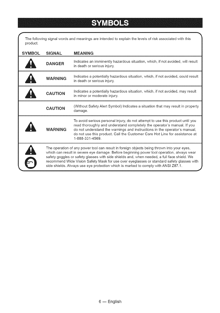
The following signal words and meanings are intended to explain the levels of risk associated with this
product.
SYMBOL SIGNAL MEANING
,_ Indicates an imminently hazardous situation, which, if not avoided, will result
DANGER in death or serious injury.
Indicates a potentially hazardous situation, which, if not avoided, could result
WARNING in death or serious injury.
Indicates a potentially hazardous situation, which, if not avoided, may result
CAUTION in minor or moderate injury.
CAUTION (Without Safety Alert Symbol) Indicates a situation that may result in property
damage.
To avoid serious personal injury, do not attempt to use this product until you
,_ read thoroughly and understand completely the operator's manual. If you
WARNING do not understand the warnings and instructions in the operator's manual,
do not use this product. Call the Customer Care Hot Line for assistance at
1-888-331-4569.
The operation of any power toot can result in foreign objects being thrown into your eyes,
which can result in severe eye damage. Before beginning power tool operation, always wear
safety goggles or safety glasses with side shields and, when needed, a futl face shield. We
_ recommend Wide Vision Safety Mask for use over eyeglasses or standard safety glasses with
_.- _ side shields. Always use eye protection which is marked to comply with ANSI Z87.1. ..,j
6 -- English
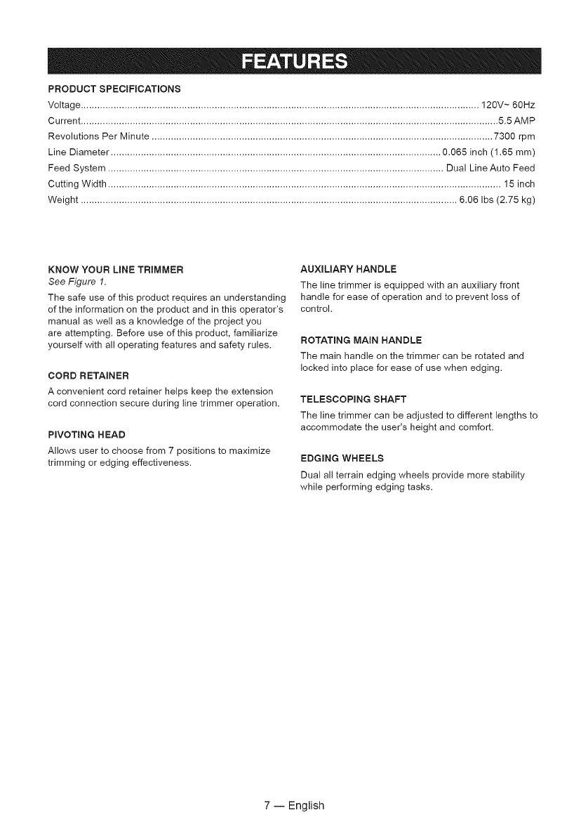
PRODUCT SPECIFICATmONS
Voltage .................................................................................................................................................. 120V ~ 60Hz
Current ......................................................................................................................................................... 5.5 AMP
Revolutions Per Minute ............................................................................................................................. 7300 rpm
Line Diameter ......................................................................................................................... 0,065 inch (1.55 mm)
Feed System ........................................................................................................................... Dual Line Auto Feed
Cutting Width ................................................................................................................................................ 15 inch
Weight .......................................................................................................................................... 6.05 Ibs (2,75 kg)
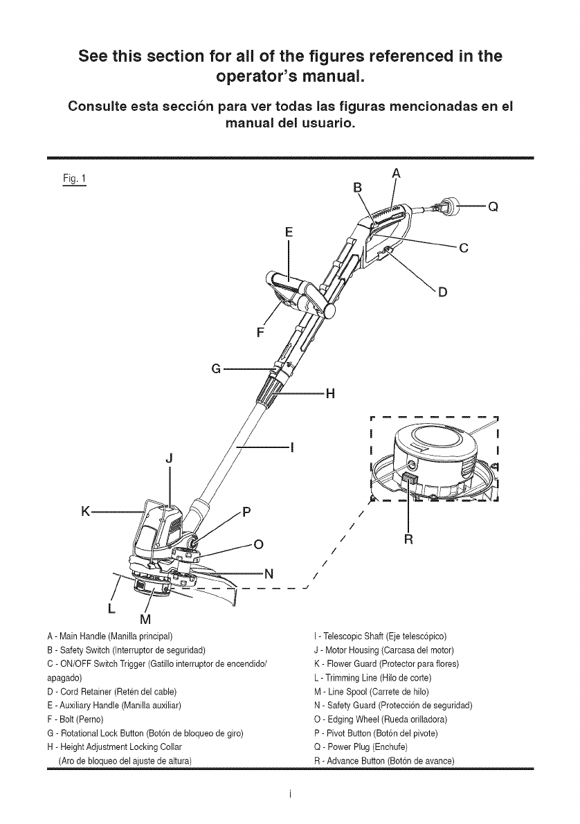
KNOW YOUR LINE TRIMMER
See Figure 1.
The safe use of this product requires an understanding
of the information on the product and in this operator's
manual as well as a knowledge of the project you
are attempting. Before use of this product, familiarize
yourself with all operating features and safety rules.
CORD RETAINER
A convenient cord retainer helps keep the extension
cord connection secure during line trimmer operation.
PIVOTING HEAD
Allows user to choose from 7 positions to maximize
trimming or edging effectiveness.
AUXmLIARY HANDLE
The line trimmer is equipped with an auxiliary front
handle for ease of operation and to prevent loss of
control.
ROTATING MAIN HANDLE
The main handle on the trimmer can be rotated and
locked into place for ease of use when edging.
TELESCOPmNG SHAFT
The line trimmer can be adjusted to different lengths to
accommodate the user's height and comfort.
EDGmNG WHEELS
Dual all terrain edging wheels provide more stability
while performing edging tasks.
7 -- EngJish
_b, WARN(NG! To avoid electrical hazards,
fire hazards, or damage to the toot, use proper circuit
protection. Your line trimmer is wired at the factory for
120 v operation. Connect to a 120 v, 15 a circuit, and
use a 15 a time-delayed fuse or circuit breaker. To
avoid shock or fire, if the extension cord is worn, cut or
damaged in any way, replace it immediately.
DOUBLE INSULATION
See Figure 2.
The line trimmer is double insulated to provide a
double thickness of insulation between you and the
tool's electrical system. All exposed metal parts are
isolated from the internal metal motor components with
protective insulation.
_ WARNING!
[] ALTHOUGH THIS TOOL IS DOUBLE INSULATED,
THE EXTENSION CORD AND RECEPTACLE MUST
STILL BE GROUNDED WHILE IN USE TO PROTECT
THE OPERATOR FROM ELECTRICAL SHOCK.
[] DOUBLE INSULATION DOES NOT TAKE THE
PLACE OF NORMAL SAFETY PRECAUTIONS WHEN
OPERATING THIS LINE TRIMMER.
,_WARNING! TOAVOID ELECTROCUTION:
[] Use only identical replacement parts when servicing
a too! with double insulation. Servicing should be
performed by a qualified technician.
[] Do not use in wet or damp areas or expose to rain.
GROUNDING INSTRUCTIONS
IN THE EVENT OFA MALFUNCTION OR
BREAKDOWN, grounding provides the path of least
resistance for electric current, and reduces the risk of
electric shock. This too! is equipped with a POLARIZED
plug. The plug MUST be plugged into a matching
grounded extension cord in accordance with All local
codes and ordinances. DO NOT MODIFY THE PLUG
PROVIDED. If it will not fit the properly grounded
extension cord, have the proper outlet installed by a
qualified electrician.
_IL CAUTION! ALWAYS MAKE SURE THAT
YOUR OUTLET IS PROPERLY GROUNDED. IF
UNCERTAIN, HAVE IT CHECKED BYACERTIFIED
ELECTRICIAN.
_1_ WARNING! THIS LINE TRIMMER IS FOR
OUTDOOR USE ONLY. DO NOT EXPOSE TO RAIN
OR USE IN DAMP LOCATIONS.
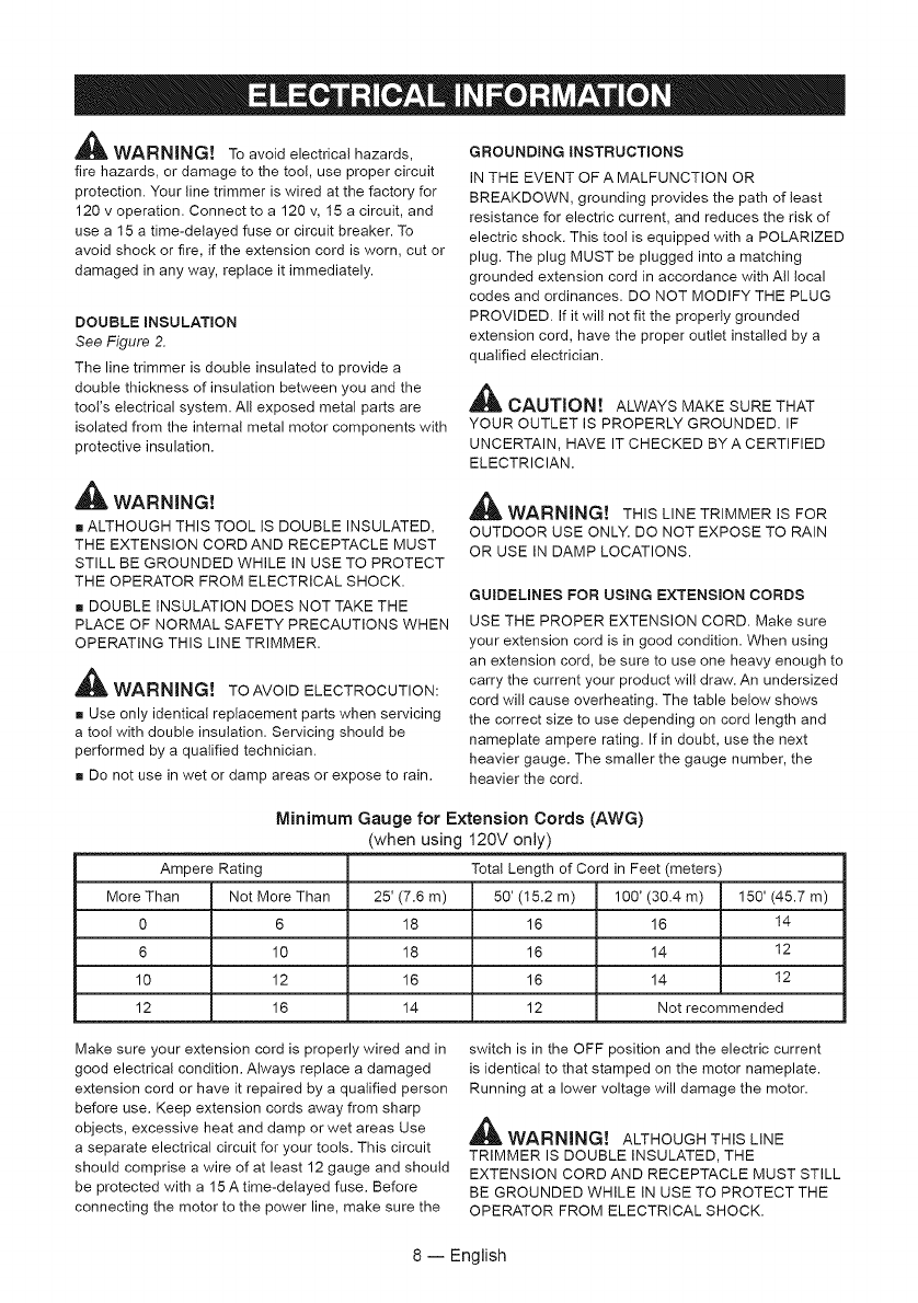
GUIDELINES FOR USING EXTENSION CORDS
USE THE PROPER EXTENSION CORD. Make sure
your extension cord is in good condition. When using
an extension cord, be sure to use one heavy enough to
carry the current your product will draw. An undersized
cord will cause overheating. The table below shows
the correct size to use depending on cord length and
nameplate ampere rating. If in doubt, use the next
heavier gauge. The smaller the gauge number, the
heavier the cord.
Minimum Gauge for Extension Cords (AWG)
(when using 120V only)
Ampere Rating Total Length of Cord in Feet (meters)
More Than Not More Than 25' (7.6 m) 50' (15.2 m) 100' (30.4 m) 150' (45.7 m)
0 6 18 16 16 14
6 10 18 16 14 12
10 12 16 16 14 12
12 16 14 12 Not recommended
Make sure your extension cord is properly wired and in
good electrical condition. Always replace a damaged
extension cord or have it repaired by a qualified person
before use. Keep extension cords away from sharp
objects, excessive heat and damp or wet areas Use
a separate electrical circuit for your tools. This circuit
should comprise a wire of at least 12 gauge and should
be protected with a 15 A time-delayed fuse. Before
connecting the motor to the power line, make sure the
switch is in the OFF position and the electric current
is identical to that stamped on the motor nameplate.
Running at a lower voltage will damage the motor.
,_WARNINGt ALTHOUGH THIS LINE
TRIMMER IS DOUBLE INSULATED, THE
EXTENSION CORD AND RECEPTACLE MUST STILL
BE GROUNDED WHILE IN USE TO PROTECT THE
OPERATOR FROM ELECTRICAL SHOCK.
8-- English
UNPACKING
This product requires assembly.
[] Carefully remove the product and any accessories
from the box. Make sure that all items listed in the
packing tist are included.
[] Inspect the product carefully to make sure no
breakage or damage occurred during shipping.
[] Do not discard the packaging material until you have
carefully inspected and satisfactorily operated the
product.
[] If any parts are damaged or missing, do not operate
the trimmer. Return it for replacement to the retailer
from which it was purchased.
FITTING THE AUXILIARY HANDLE
See Figure 5-6.
[] Loosen and remove the bolt from the handle.
[] Place the handle on the line trimmer as shown.
[] Adjust the handle to the most comfortable position.
[] Pass the bolt through the auxiliary handle and
the main handle. Tighten the nut to secure. Do not
overtighten the bolt.
FITTING THE EDGING WHEEL
See Figure 7.
[] Slide the edging wheel into the slot located on the
side of the motor housing. It will lock into place.
PACKING LIST
Line Trimmer
Flower Guard
Safety Guard with Screws
Auxiliary Handle Assembly with Bolt and Nut
Edging Wheel
Operator's Manual
,_ WARNING! Before assembly, make sure
that the line trimmer is switched off and unplugged.
FITTING THE SAFETY GUARD
See Figure 3-4.
The Safety Guard prevents cut debris from flying back
at the operator.
[] Fit the safety guard into the slots on the trimmer
housing and line up the screw hole in the safety guard
with the screw hole in the trimmer head.
[] Install supplied screw and tighten by turning
clockwise with a Phillips screwdriver.
_. WARNING! The tine cut-off blade on the
safety guard is sharp. Avoid contact with the blade.
Failure to avoid contact can result in serious personal
injury. Never use the line trimmer unless the guard is
properly fitted.
PREPARING THE TRIMMER FOR USE
See Figure 8-9.
[] Press the rotational lock button and rotate the main
handle counterclockwise. Release button when main
handle has been rotated 180 °.
[] Turn the adjustment collar clockwise to unlock. You
can slide the telescopic tube up or down to achieve the
most comfortable working height.
[] Turn the adjustment collar counterclockwise till the
shaft lock into place.
_WARNING! If any parts are damaged or
missing, do not operate this product until the parts are
replaced. Failure to heed this warning could result in
serious personal injury.
_1_ WARNING! Do not connect to power supply
untit assembly is complete. Failure to comply could
resutt in accidental starting and possible serious
personal injury.
_1_ _VARNING! Never attempt to lock the switch
trigger in the ON position.
9 -- English

STARTING/STOPPING THE TRIMMER
See Figure 10-11.
[] Attach the outlet end of an extension cord to the p(ug
on the rear of the line trimmer.
NOTE: Use only approved outdoor extension cords.
[] Route the extension cord through the slot located
on the rear of the line trimmer housing and p(ace
underneath the cord retainer.
[] To start the line trimmer, squeeze the safety switch,
then press the switch trigger.
[] To stop the line trimmer, release the switch trigger.
OPERATING THE TRIMMER
See Figure 12.
[] Hold the line trimmer as shown.
[] Gently swing the trimmer from side to side.
[] In order to achieve optimum cutting results, only cut
dry grass.
[] When cutting long or thick grass, start at the top
of the grass blades and gradually work down to the
bottom.
[] If the line trimmer starts running slowly, reduce the
amount of material you are trying to cut.
IF GRASS BECOMES WRAPPED AROUND LINE
HEAD SHAFT:
[] Stop trimmer.
[] Unplug the (ine trimmer.
[] Remove the grass.
ADJUSTING TRIMMER HEAD ANGLE
See Figure 13.
The trimmer head can be pivoted to seven different
positions.
[] Unplug the line trimmer.
[] Push the pivot button and move the trimmer head up
or down to one of the seven positions indicated by the
notches.
NOTE: Adjust the trimmer head to the first, second and
third notches for trimming and notches four, five, six
and seven for edging, based on preferred trimming and
edging position.
[] Make sure the trimmer head is securely locked into
place before resuming work.
USING THE FLOWER GUARD
See Figure 14.
NOTE: The flower guard provides a visual indicator of
the maximum reach of the trimming line.
When the flower guard is swung down, it can be used
as a distance guide for use around plants, poles and
fence posts.
ADVANCING LINES USING AUTO FEED
NOTE: The trimmer is equipped with an auto-feed
head. DO NOT bump the head to try to advance the
(ine as this wil( damage trimmer and void warranty.
[] With the trimmer running but NOT trimming, release
the switch trigger.
[] Wait two seconds, and press the switch trigger.
NOTE: The line wil( extend approximately 3/16 in. with
each stop and start of the switch trigger until the line
reaches the length of the line cut-off blade.
[] Resume trimming.
ADVANCING THE LINES MANUALLY
See Figure 1.
NOTE: If lengthy line advancement is required, use the
Advance Button found on the side of the trimmer head.
[] Release the ON/OFF Switch Trigger to stop the unit.
and unplug the trimmer.
[] Depress the manual advance button, and pull one or
both of the two lines. The lines will advance 3/16 inch
and stop. Push the button again to advance more line.
[] Push the button and pull lines out as many times as
it takes to reach the line cut-off blade. Always advance
both lines to the same length.
ROTATING MAIN HANDLE
See Figure 15.
NOTE: The best method of edging is performed with
the main handle rotated.
[] Unplug the line trimmer.
[] Press the rotational lock button and rotate the main
handle clockwise.
[] Release button when main handle has been rotated
180 ° to the edging position.
EDGING
See Figure 16-17.
[] The edging wheel provides stability and easier
hand(ing when using the trimmer to edge. Simp(y
swing the edging wheel down from its storage position
into edging position.
10 -- Engl(sh
Your line trimmer has been designed to operate over
a long period of time with a minimum of maintenance.
Continuous satisfactory operation depends upon proper
tool care and regular cleaning.
_WARNING! Before performing any
maintenance, switch off and unplug the toot.
[] Regularly clean the ventilation slot in your line
trimmer using a soft brush or dry cloth.
[] Regularly clean the cutting line and spool using a soft
brush or dry cloth.
[] Regularly use a blunt scraper to remove grass and
dirt from the underside of the guard.
_ WARNING! When servicing, use only
identical replacement parts. Use of any other parts may
create a hazard or cause product damage.
SPOOL REPLACEMENT
See Figure 18.
[] Use only round .065" diameter monofilament line.
Use original manufacturer's replacement line for best
performance.
[] Unplug the line trimmer.
[] Push in tabs on side of spool cover.
[] Pull spool cover up to remove.
[] Remove spool.
[] To install the new spool, make sure the two lines
are captured in the slots opposite each other on the
new spool. Make sure the end of each line is extended
approximately 6 in. beyond each slot.
[] Install the new spool so that the lines and slots align
with the eyelets in the line head. Thread the lines into
the eyelets.
[] Pull the lines extending from the tine head so the line
releases from the slots in the spool.
[] Reinstall the spool cover by depressing tabs into
slots in the tine head and pushing down until spool
cover clicks into place.
NOTE: Replacement spool is available at SEARS;
item # 71.99006
LINE REPLACEMENT
See Figure 19.
[] Unplug the line trimmer.
[] Remove the spool from the tine head.
NOTE: Remove any old tine remaining on the spool.
Cut two pieces of line, each being approximately 9 ft.
(2.7 m)long. Use only .065 in. (1.65 mm) diameter
monofitament line.
[] Insert the first tine into the anchor hole in the upper
part of the spool. Wind the first tine around the upper
part of the spool clockwise, as shown by the arrows on
the spool. Place line in the slot on upper spool flange,
leaving about 6 in. (152 mm) extended beyond the slot.
Do not overfill. After winding the line, there should be
at least 1/4 in. (6 mm) between the wound line and the
outside edge of the spool.
[] Repeat above step with second line, using the bottom
part of spool and the lower anchor hole. Do not overfill.
[] Install the spool in the tine head and replace the
spool cover as described in Spool Replacement.
_IL WARNING! Only use the appropriate type of
cutting line.
STORNNG TNE TRNMMER
[] Clean all foreign material from the trimmer.
[] Store it in a place that is inaccessible to children.
[] Keep away from corrosive agents such as garden
chemicals and de-icing salts.
11 -- English
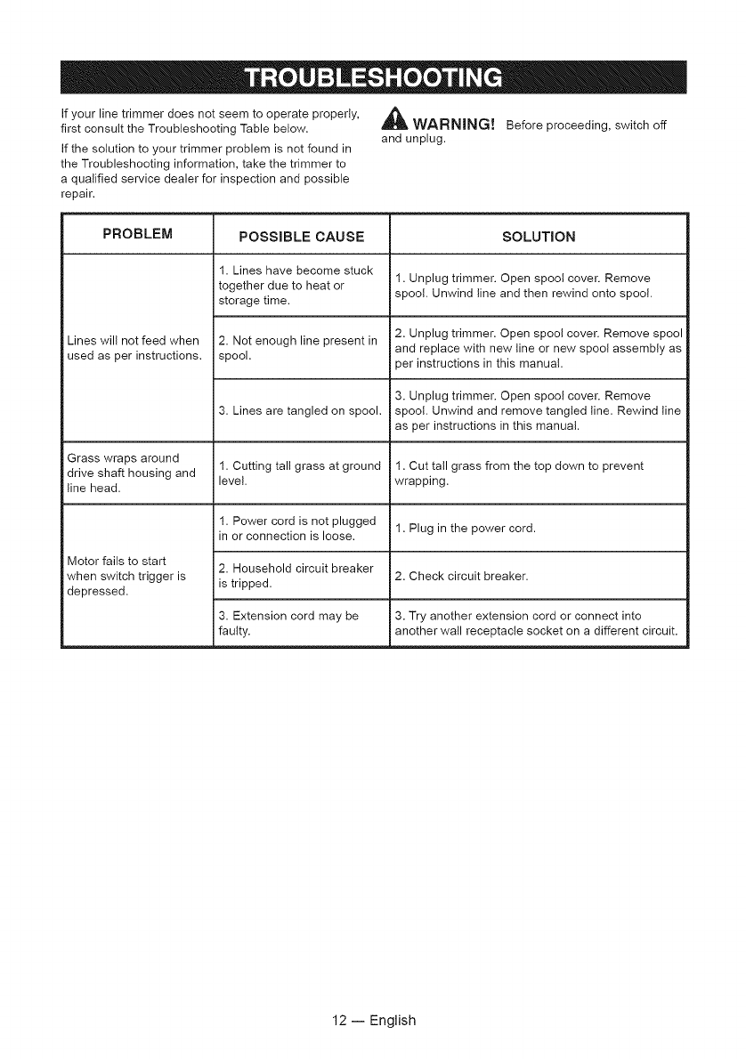
If your line trimmer does not seem to operate properly,
first consult the Troubleshooting Table below.
If the solution to your trimmer problem is not found in
the Troubleshooting information, take the trimmer to
a qualified service dealer for inspection and possible
repair.
,_ WARNING!
and unplug. Before proceeding, switch off
PROBLEM POSSIBLE CAUSE SOLUTION
1. Lines have become stuck
together due to heat or 1. Unplug trimmer. Open spool cover. Remove
storage time. spool. Unwind line and then rewind onto spool.
Lines will not feed when 2. Not enough line present in 2. Unplug trimmer. Open spool cover. Remove spool
used as per instructions, spool, and replace with new tine or new spoo! assembly as
ser instructions in this manual.
3. Unplug trimmer. Open spool cover. Remove
3. Lines are tangled on spool, spool. Unwind and remove tangled line. Rewind line
as per instructions in this manual.
Grass wraps around 1. Cutting tall grass at ground 1. Cut tall grass from the top down to prevent
drive shaft housing and level, wrapping.
line head.
1. Power cord is not plugged 1. Plug in the power cord.
in or connection is loose.
Motor fails to start 2. Household circuit breaker
when switch trigger is is tripped. 2. Check circuit breaker.
depressed.
3. Extension cord may be 3. Try another extension cord or connect into
faulty, another wall receptacle socket on a different circuit.
12 -- English
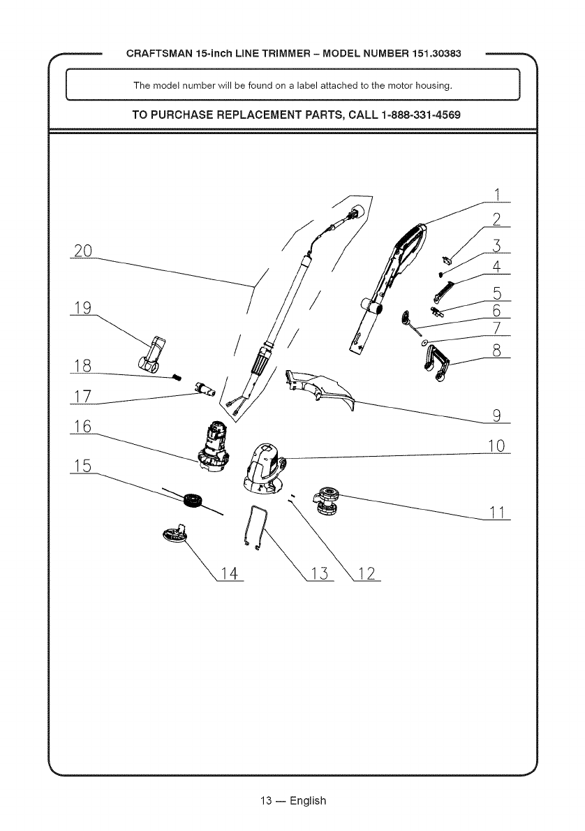
CRAFTSMAN 15-inch LiNE TRIMMER - MODEL NUMBER 151.30383
The model number will be found on a label attached to the motor housing.
TO PURCHASE REPLACEMENT PARTS, CALL 1=888=331=4569
)
2O
19
/
16
15
/
/
1
2
10
11
12
13 -- English

,,_ CRAFTSMAN15-inchLiNE TRIMMER - MODEL NUMBER 151,30383 _._
I The model number will be found on a label attached to the motor housing. }
TO PURCHASE REPLACEMENT PARTS, CALL 1=888=331=4569
iTEM NO, PART NO, DESCRiPTiON QTY
1 GT80FM.50.00.X1.01 Main Handle Assembly 1
2 WODQ10.01.11 Switch 1
3 TOTHYY. 16.08 Spring 1
4 GE50DC.10.01 Switch Button 1
5 GE50DC.A0.12 Anti-lock Button Assembly 1
6 TGQTXN.03.11.X2.01 Handle Knob Assembly 1
7 GF01BL.10.24 Washer 1
8 GT45FM.60.00 Auxilliary Handle Assembly 1
9 GT80FM.40.00 Safty Guard Assembly incl/line cut-off blade 1
10 GT80FM.10.00.X1.01 Motor Housing Assembly 1
11 GT80FM.30.00 Edge Wheel 1
12 GT30FM.00.07 Rubber Pad 2
13 GT80FM.00.01 Flower Guard 1
14 GT45FM.70.02 Spool Cover 1
15 GT80FM.60.10 Trimmer Spool w/line 1
16 TM6560.00.00.X1.01 Motor Assembly 1
17 GE61DC.00.05 Pivot Actuator Button 1
18 TOTHYY.03.12 Pivot Actuator Spring 1
19 GE61DC.10.01.X1.01 Pivoting Neck Support Assembly 1
20 GE50DC.10.05.X3.01 Connecting Tube Assembly 1
14 -- English
See this section for all of the figures referenced in the
operator's manual.
Consulte esta secci6n para vet todas las figuras mencionadas en el
manual del usuario.
Fig. 1
E
B
\
A
C
D
L -J
M
A- Main Handle (Manilla principal)
B- Safety Switch (Interruptor de seguridad)
C - ON/OFF Switch Trigger (Gatillo interruptorde encendido/
apagado)
D-Cord Retainer (Reten del cable)
E- Auxiliary Handle (Manilla auxiliar)
F- Bolt (Perno)
G - Rotational Lock Button (Bot6n de bloqueo de giro)
H-Height Adjustment Locking Collar
(Arc de bloqueo del ajuste de altura)
/
/
/R
/
/
/
J
I-Telescopic Shaft (Ejetelescopico)
J- Motor Housing (Carcasa del motor)
K - Flower Guard (Protectorpara flores)
L- Trimming Line (Hilo de corte)
M-Line Spool (Carrete de hilo)
N- Safety Guard (Proteccion de seguridad)
O- Edging Wheel (Rueda orilladora)
P- Pivot Button (Bot6ndel pivote)
Q- Power Plug (Enchufe)
R-Advance Button (Bot6n de avance)
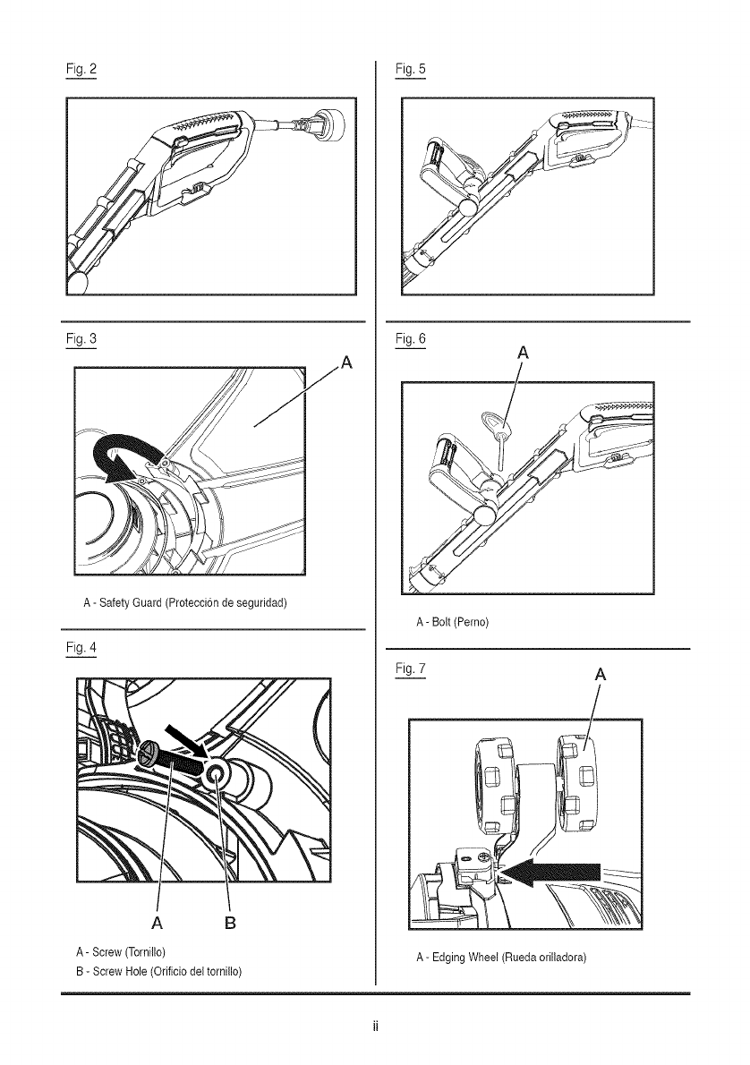
Fig. 2 Fig. 5
Fig. 3
A- Safety Guard (Proteccion de seguridad)
Fig. 4
A B
A- Screw (Tornillo)
B-Screw Hole (Orificio del tornillo)
Fig. 6
Fig. 7
A
A-Bolt (Pemo)
A
A-Edging Wheel (Rueda orilladora)
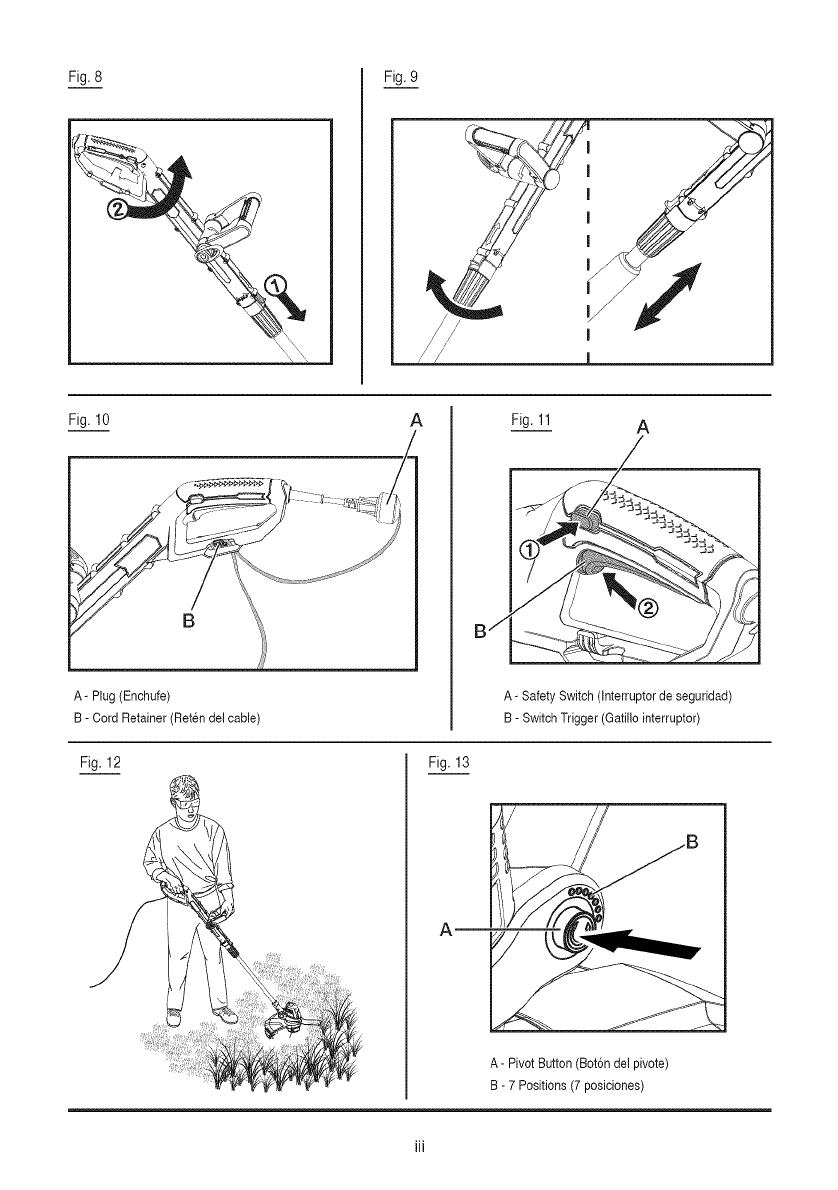
Fig. 8 Fig. 9
Fig. 10
A- Plug (Enchufe)
B- Cord Retainer (Reten del cable)
AFig. 11 A
A-Safety Switch (Interruptor de seguridad)
B- Switch Trigger (Gatillo interruptor)
Fig. 12 Fig. 13
A
A-Pivot Button (Bot6ndel pivote)
B- 7 Positions (7 posiciones)
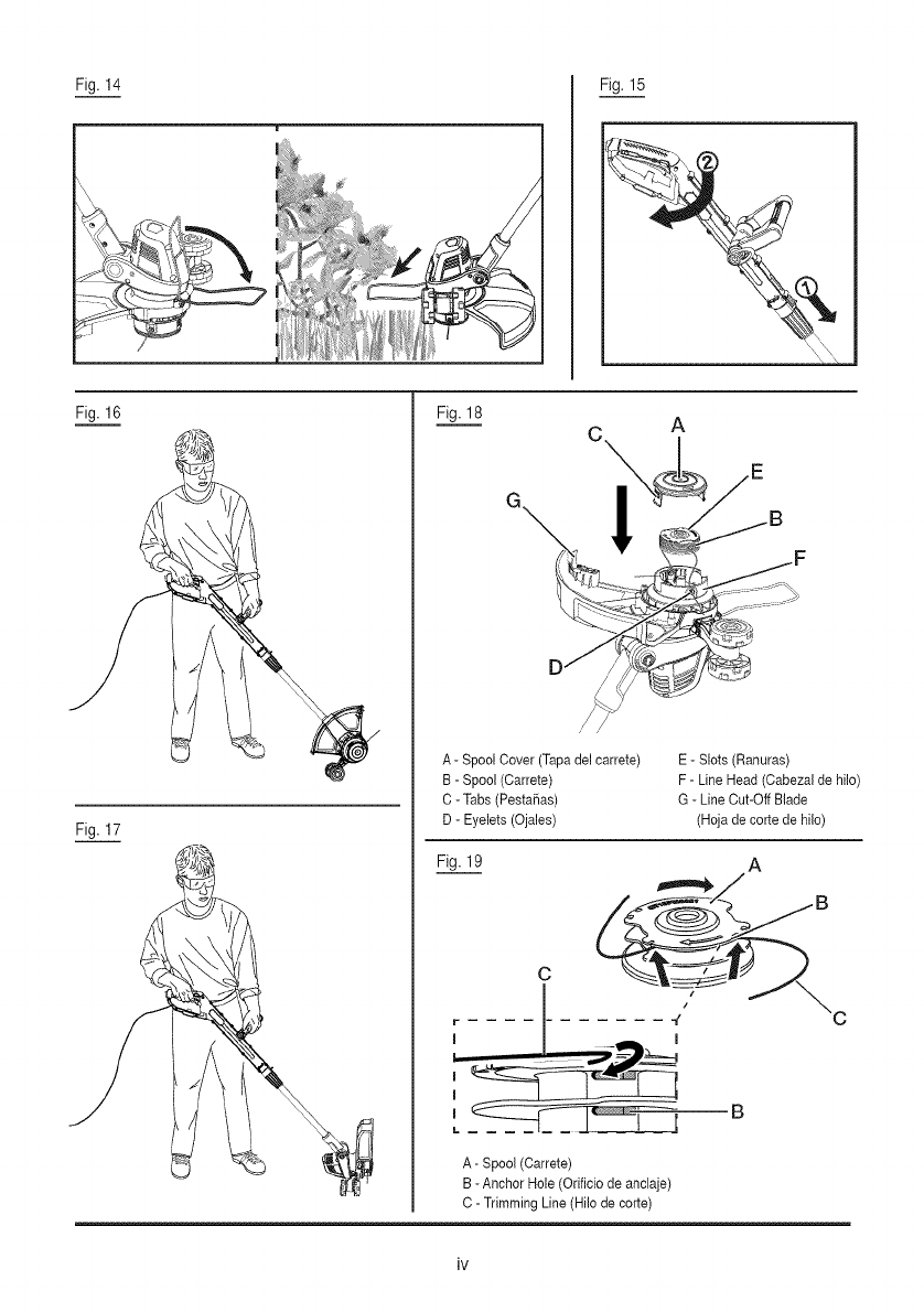
Fig. 14 Fig. 15
Fig. 16
Fig. 17
\
Fig. 18 c\ t
!
A - Spool Cover (Tapadel carrete)
B- Spool (Carrete)
C - Tabs(PestaSas)
D - Eyelets (Ojales)
E - Slots (Ranuras)
F- Line Head (Cabezal de hilo)
G - Line Cut-Off Blade
(Hojade cortede hilo)
Fig. 19 A
C
B
A- Spool (Carrete)
B - Anchor Hole (Orificio de anclaje)
C- Trimming Line(Hilo de corte)
iNSTRUCC(ONESDE SEGUR(DAD IMPORTANTES
_ IMPORTANTE AI utilizar el producto de
jardineria electrico, se deben seguir siempre las
precauciones de seguridad basicas a fin de reducir
el riesgo de incendios, descarga electrica y lesiones
personales. Per su propia seguridad y la de tas
personas cercanas, lea estas instrucciones antes
de usar la orilladora. No utilice la orilladora sin antes
leer (as instrucciones. Guarde (as instrucciones para
usadas a futuro.
LEA TODAS LAS INSTRUCCiONES
[] Esta orilladora est_ disefiada para cortar paste,
vegetaci6n suave y para cortar bordes de pastes en
zonas privadas y de jardines alas que no se puede
acceder con una orilladora.
[] Este producto no se debe usar en jardines pOblicos,
parques, centros de deportes o caminos, ni tampoco
en actividades agricolas ni forestales.
[] Esta orilladora no se debe usar para cortar o picar,
ya que estas actividades general riesgo de iesiones:
- Setos, arbustos, 9rboles pequeSos,
- Fiores,
- En casos de compostaje.
[] Esta orilladora no est_ diseSada para que ta usen
personas (incluyendo nidos) con capacidades fisicas,
sensoriales o mentales reducidas, o que no tengan ia
experiencia y conocimiento necesarios, a menos que
hayan recibido supervisi6n e instrucci6n en relaci6n
con el uso del aparato per parte de una persona
responsable de su seguridad.
[] Debiera supervisarse a los nidos para asegurarse de
que no jueguen con este aparato.
[] Si el cable de alimentaci6n est9 daSado, deje de
usar el producto. Lieve el producto a un concesionario
de servicio calificado para que Io inspeccione y repare,
en caso de ser necesario.
[] Utilice lentes protectores o antiparras.
[] Jamgs permita que nifios o personas que no
conozcan ias instrucciones utilicen la orilladora.
[] Deje de usar la orilladora cuando haya personas,
especialmente nidos, cerca.
[] Utilice la orilladora solo durante e! dia o bajo una
buena iluminaci6n artificial.
[] Antes de usar la orilladora y despues de cuaiquier
impacto, revise que no haya sedales de desgaste o
daSos y repare segt_n sea necesario.
[] Jam_s utilice la orilladora si las protecciones est_n
daSadas o no estgn puestas.
[] Mantenga sus manes y pies alejados del sistema de
corte en todo memento y especialmente al encender el
motor.
[] Tenga cuidado de no lesionarse con los dispositivos
equipados para recortar e( largo de! filamento. Tras
extender e( nuevo hi(o de corte, devuelva siempre
(a orilladora a su posici6n de uso normal antes de
encendeda.
[] Jam_s co(oque elementos de corte hechos de metal.
[] Jam_s utilice piezas de repuesto o accesorios que
no hayan sido suministrados o recomendados por el
fabricante. Consulte la Lista de piezas de este manual
para encontrar piezas de repuesto identicas.
[] Desconecte (a orilladora de la alimentaci6n antes de
revisarla, limpiarla, trabajar con ella y cuando no este
en use.
[] Asegt_rese de que (as aberturas de ventilaci6n esten
(ibres de sedimentos.
INSTRUCC(ONES DE SEGURIDAD ADNClONALES
PARA SU ORmLLADORA
[] No exponer a (a humedad.
[] Utilice solo el voltaje de entrada CA indicado en (a
etiqueta de clasificaci6n del producto.
[] Evite usar su orilladora en pastes mojados, cuando
sea posibie.
[] Tenga cuidado al trabajar en pastes mojados, ya que
podria perder la estabilidad.
[] En pendientes, preste atenci6n adiciona( a sus pies y
use caizado antideslizante.
[] No camine hacia atras al cortar pasto, ya que podr(a
tropezarse. Camine, no corra.
[] Apague antes de mover (a orilladora sobre superficies
que no sean paste.
[] Jam_s (evante o transporte una orilladora tomandola
desde e( cable de a(imentaci6n.
[] No se incline sobre (a protecci6n de (a odlladora. Los
objetos poddan sa(ir disparados per (a acci6n del hilo
de corte.
[] Mantenga redes los pernos, tuercas y tornillos
apretados, para asegurarse de que (a orilladora est_
en condiciones operativas seguras.
[] Para evitar el riesgo de tesiones, mantenga sus
dedos y manos alejados de la hoja de corte en el borde
de (a protecci6n.
[] No fuerce el aparato, har_ el trabajo de mejor
manera y con menos riesgos de lesiones si Io utiliza de
ia forma para ta cual fue diseSado; no se extralimite,
mantenga sus pies firmes y su equilibrio en todo
momento; mantengase aierta, este atento a Io que
hace. Haga uso de su sentido comOn. No utilice e!
producto cuando este cansado.
3--Espa_ol
MANTENtMIENTO
[] Luego de usar, desconecte la m_quina de la
alimentaci6n y verifique que no haya recibido da_os.
[] Cuando no la este usando, guarde la maquina lejos
del alcance de los ni_os.
[] Las orilladoras electricas se deben reparar solo
mediante un concesionario de servicio calificado,
utilizando piezas de repuesto identicas,
[] Utilice solo tas piezas de repuesto originales
indicadas en la Lista de piezas de este manual,
Preparaci6n para el uso, operaci6n y mantenimiento
del aparato:
- Lea las instrucciones detenidamente.
- Familiaricese con los controles y uso correcto de!
equipo,
- Antes de usar, revise el suministro de alimentaci6n y
el cable en bQsqueda de da_os o desgaste.
- Si se da_a el cable durante el uso, descon&ctelo de
la alimentaci6n inmediatamente:
NO TOQUE EL CABLE ANTES DE DESCONECTARLO
DE LAALIMENTAClON,
- No utilice la orilladora si los hilos est_n da_ados o
gastados.
,_ jADVERTENCIAt
- Los elementos cortantes siguen girando despues de
que el motor se detiene,
- Mantenga los alargadores alejados de los elementos
de corte.
- Se recomienda que los productos se alimenten
mediante un dispositivo de corriente residual (RCD)
con corriente de disparo no mayor a 30mA.
GUARDE ESTAS INSTRUCCIONES
4--Espa_ol
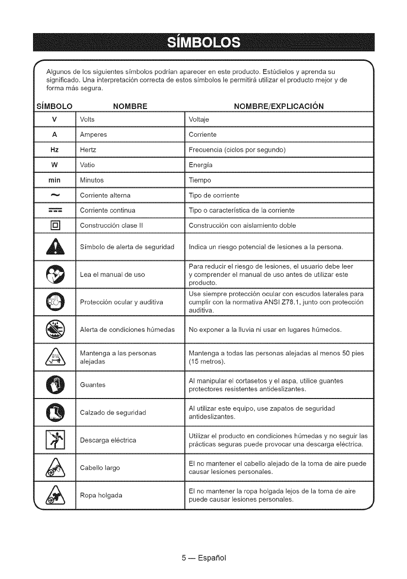
Atgunos de los siguientes simbolos podrian aparecer en este producto. Estt_dielos y aprenda su
significado. Una interpretaci6n correcta de estos simbo!os le permitira utilizar el producto mejor y de
forma mas segura.
_,iMBOLO NOMBRE NOMBRE/EXPLICACI6N
V Volts Voltaje
A Amperes Corriente
Hz Hertz Frecuencia (ciclos por segundo)
W Vatio Energia
rain Minutos Tiempo
Corriente altema Tipo de corriente
Corriente continua Tipo o caracteristica de ta corriente
] Construcci6n ciase II Construcci6n con aislamiento doble
,_ Simbolo de alerta de seguridad Indica un riesgo potencial de lesiones a la persona.
i_ Para reducir el riesgo de lesiones, el usuario debe leer
Lea e! manual de uso y comprender el manual de use antes de utilizar este
producto.
O Use siempre protecci6n ocular con escudos laterales para
Protecci6n ocular y auditiva cumplir con la normativa ANSI Z78.1, junto con protecci6n
auditiva.
Alerta de condiciones ht_medas No exponer a la ltuvia ni usar en lugares h_medos.
Mantenga alas personas Mantenga a todas las personas alejadas al menos 50 pies
alejadas (15 metros).
Guantes AI manipular el cortasetos y el aspa, utilice guantes
protectores resistentes antideslizantes.
AI utilizar este equipo, use zapatos de seguridad
Calzado de seguridad antideslizantes.
[_ Utilizar el producto en condiciones hOmedas y no seguir lasDescarga electrica pr_cticas seguras puede provocar una descarga electrica.
El no mantener el cabello alejado de la toma de aire puede
Cabello largo causar lesiones personales.
El no mantener la ropa holgada lejos de la toma de aireRopa holgada puede causar lesiones personales.
5--EspaSol
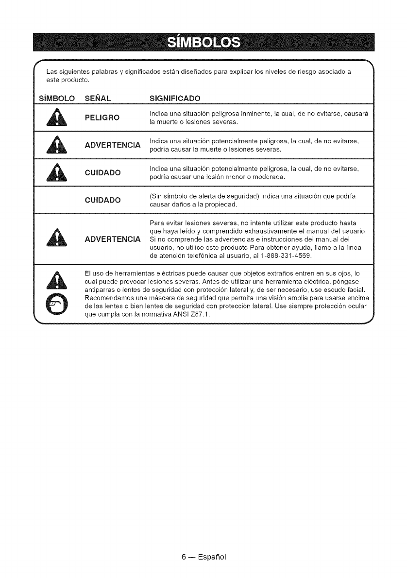
Las siguientes palabras y significados estgn dise_ados para explicar los niveles de riesgo asociado a
este producto.
SiMBOLO SENAL SIGNIFICADO
,_ Indica una situaci6n peligrosa inminente, ia cual, de no evitarse, causaraPELIGRO la muerte o lesiones severas.
Indica una situaci6n potencialmente peligrosa, la cual, de no evitarse,
ADVERTENCIA podria causar la muerte o lesiones severas.
,_ Indica una situaci6n potencialmente peligrosa, la cual, de no evitarse,
CUIDADO podria causar una lesi6n menor o moderada.
CUIDADO (Sin simbolo de alerta de seguridad) Indica una situaci6n que podria
causar daSos a la propiedad.
Para evitar lesiones severas, no intente utilizar este producto hasta
que haya leido y comprendido exhaustivamente el manual del usuario.
ADVERTENCIA Si no comprende tas advertencias e instrucciones del manual del
usuario, no utilice este producto Para obtener ayuda, flame a la linea
de atenci6n tetef6nica al usuario, al 1-888-33t-4569.
El uso de herramientas electricas puede causar que objetos extrados entren en sus ojos, Io
cual puede provocar lesiones severas. Antes de utilizar una herramienta electrica, p6ngase
antiparras o lentes de seguridad con protecci6n lateral y, de ser necesario, use escudo facial.
Recomendamos una mascara de seguridad que permita una visi6n amplia para usarse encima
de las lentes o bien lentes de seguridad con protecci6n lateral. Use siempre protecci6n ocular
que cumpla con la normativa ANSI Z87.1. ._
6--EspaSol
ESPECIFICACmONES DEL PRODUCTO
Voltaje ................................................................................................................................................... 120V ~ 60Hz
Corriente ...................................................................................................................................................... 4,2 AMP
Revoluciones por minuto ........................................................................................................................... 8300 rpm
Di_metro de{ hilo ..................................................................................................................... 0,065 inch (1,65 mm)
Sistema de alimentaci6n ............................................................................ Atimentaci6n automatica con hilo doble
Ancho de corte .................................................................................................................................... 13 pulgadas
Peso ............................................................................................................................................. 2,25 kg (5,51 lbs)
CONOZCA SU OR_LLADORA
Consulte la Figura 1.
El uso seguro de este producto requiere que conozca
la informaci6n de la herramienta y la que aparece
en este manual asi come tambien el proyecto en el
que est_ trabajando. Antes de usar este producto,
familiaricese con todas las funciones operativas y
reglas de seguridad.
CONTENEDOR DEL CABLE
Un practice contenedor para el cable ayuda a mantener
el alargador seguro mientras se usa la sopladora.
CABEZAL PIVOTANTE
Permite al usuario seleccionar una de las 7 posiciones,
para maximizar la efectividad de corte.
MANmLLA AUXmLmAR
La orilladora est_ equipada con una manitla frontal
auxiliar que facilita el uso y evita la perdida de! control.
MANmLLA PRINCmPAL GIRATORIA
La manilla principal de la orilladora se puede girar y
fijar para facilitar el uso.
EJE TELESCOPmCO
La orilladora se puede ajustar a diferentes targos para
alcanzar la altura y comodidad del usuario.
RUEDAS ORILLADORAS
Las ruedas orilladoras todo terreno offecen mayor
estabilidad al cortar bordes.
7--EspaSol
_IL iADVERTENClA! Para evitar peligros
electricos, peligros de incendio o dar_os a la
herramienta, utilice una protecci6n de circuitos
adecuada. Su orilladora viene cabteada de fabrica
para funcionar con 120 v. Conectela a un circuito de
120 v, 15a y utilice un fusible con retardo temporal o
automatico. Para evitar el riesgo de incendios, en caso
de estar desgastado et alargador, cortado o daSado de
manera alguna, reemplgce!o inmediatamente.
DOBLE AISLANTE
Consulte la Figura 2.
La orilladora tiene doble aislante para proporcionar un
dobte grosor en ta aislaci6n entre usted y el sistema
electrico de la herramienta. Todas las piezas met_licas
expuestas est_n aisladas de los componentes internos
met_licos del motor mediante una aislaci6n protectora.
_ jADVERTENCIA!
[] SI BIEN ESTA HERRAMIENTA TIENE DOBLE
AISLACION, EL CABLE DE EXTENSION Y SU
RECEPTACULO DEBEN TENER CONEXION
AL TIERRA PARA PROTEGER AL USUARIO DE
DESCARGAS ELECTRICAS.
[] LA DOBLE AISLACION NO REEMPLAZA LAS
PRECAUCIONES DE SEGURIDAD NORMALES AL
USAR ESTA ORILLADORA.
_ iADVERTENCIA! PARA EVlTAR LA
ELECTROCUCION:
[] A la hora de hacer cualquier tarea de mantenimiento
a una herramienta con dobte aislante, utilice siempre
piezas identicas de recambio. Las reparaciones se
deben realizar mediante un tecnico calificado.
[] No la utilice en zonas hOmedas ni mojadas ni la
exponga a la Iluvia.
INSTRUCClONES PARA LA TOMA A TIERRA
EN CASO DE MALFUNCIONAMIENTO O FALLA,
el cabteado a tierra representa ta ruta de menor
resistencia para ta corriente y reduce el riesgo de
descarga electrica. Esta herramienta posee un
enchufe POLARIZADO. Et enchufe DEBE conectarse
a un alargador con conexiTn a tierra que cumpla
con todos los cTdigos y ordenanzas locales. NO
MODIFIQUE EL ENCHUFE SUMINISTRADO. Si no
calza en e! alargador con conexi6n a tierra, haga que
un electricista calificado instale una toma de corriente
adecuada.
_IL jPRECAUCI6N! ASEGORESE SIEMPRE
DE QUE SU TOMA DE CORRIENTE ESTE BIEN
CONECTADAATIERRA. SI NO EST/k SEGURO, HAGA
QUE UN ELECTRICISTA CERTIFICADO LO REVISE,
,_ iADVERTENCIA! ESTA ORILLADORA ES
SOLO PARA USO EN EXTERIORES. NO EXPONER
A LA LLUVlA NI USAR EN LUGARES HOMEDOS.
PAUTAS PARA UTILIZAR ALARGADORES
USE EL ALARGADOR ADECUADO AsegOrese de que
su alargador este en buenas condiciones. AI utilizar un
alargador, asegt_rese de utilizar uno Io suficientemente
potente como para ttevar ta corriente necesaria que el
producto necesita. Un cable de menor tamafio causar_
sobrecalentamiento. La tabla que aparece a continuaci6n
muestra el tamafio correcto dependiendo del largo del
cable y clasificaci6n del amperaje. Si tiene dudas, utilice
e! calibre mas alto que le siga. Mientras menor sea el
nOmero del calibre, mAs fuerte ser9 el cable.
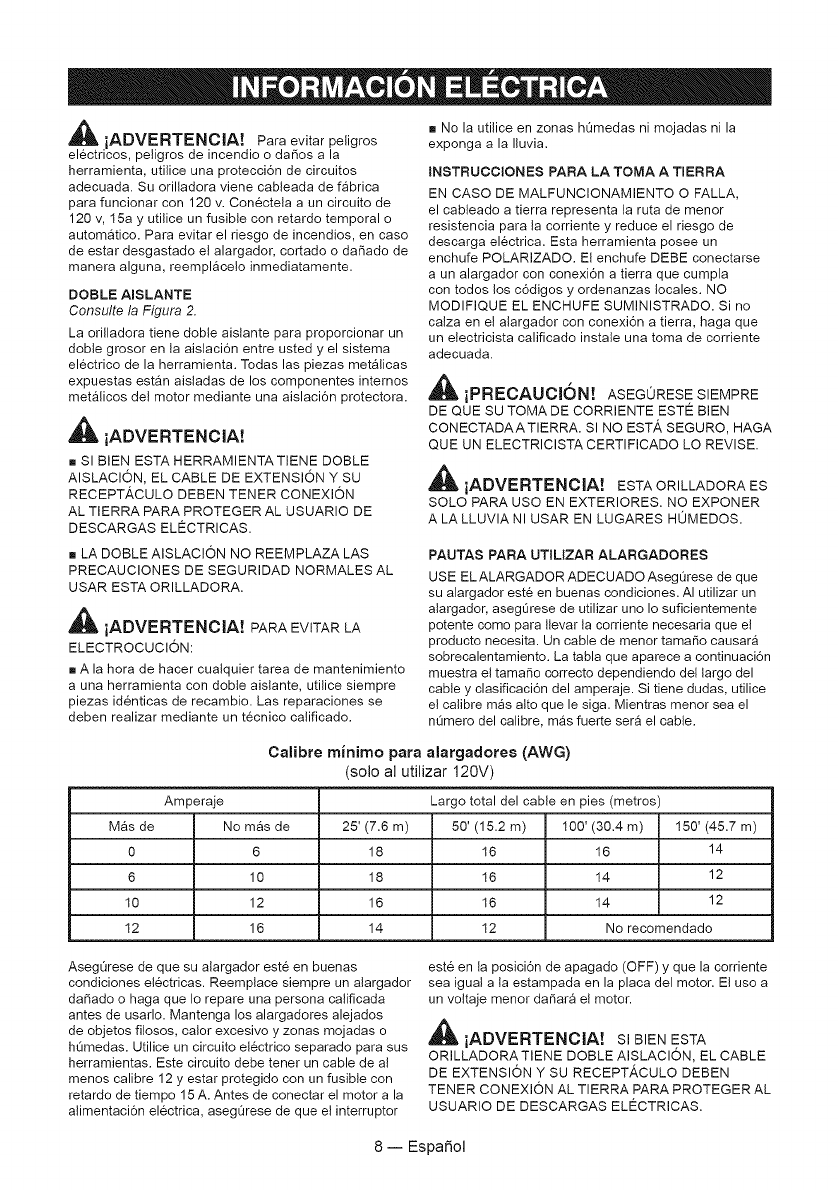
Calibre minimo para alargadores (AWG)
(solo al utilizar 120V)
Amperaje Largo total del cable en pies (metros)
Mgs de No mas de 25' (7.6 m) 50' (15.2 m) 100' (30.4 m) 150' (45.7 m)
0 6 18 16 16 14
6 10 18 16 14 12
10 12 16 16 14 12
12 16 14 12 No recomendado
AsegOrese de que su alargador este en buenas
condiciones electricas. Reemptace siempre un atargador
dadado o haga que Io repare una persona calificada
antes de usarlo. Mantenga los alargadores alejados
de objetos fitosos, calor excesivo y zonas mojadas o
hQmedas. Utilice un circuito el&ctrico separado para sus
herramientas. Este circuito debe tener un cable de al
menos calibre 12 y estar protegido con un fusible con
retardo de tiempo 15 A. Antes de conectar el motor a la
alimentaci6n electrica, asegQrese de que e! interruptor
este en la posici6n de apagado (OFF) y que la corriente
sea igual a la estampada en la placa del motor. Et uso a
un vottaje menor daSar_ e! motor.
_iADVERTENCIA! sl BIENESTA
ORILLADORA TIENE DOBLE AISLACION, EL CABLE
DE EXTENSION Y SU RECEPT,&CULO DEBEN
TENER CONEXION AL TIERRA PARA PROTEGER AL
USUARIO DE DESCARGAS ELECTRICAS.
8--Espa_ol
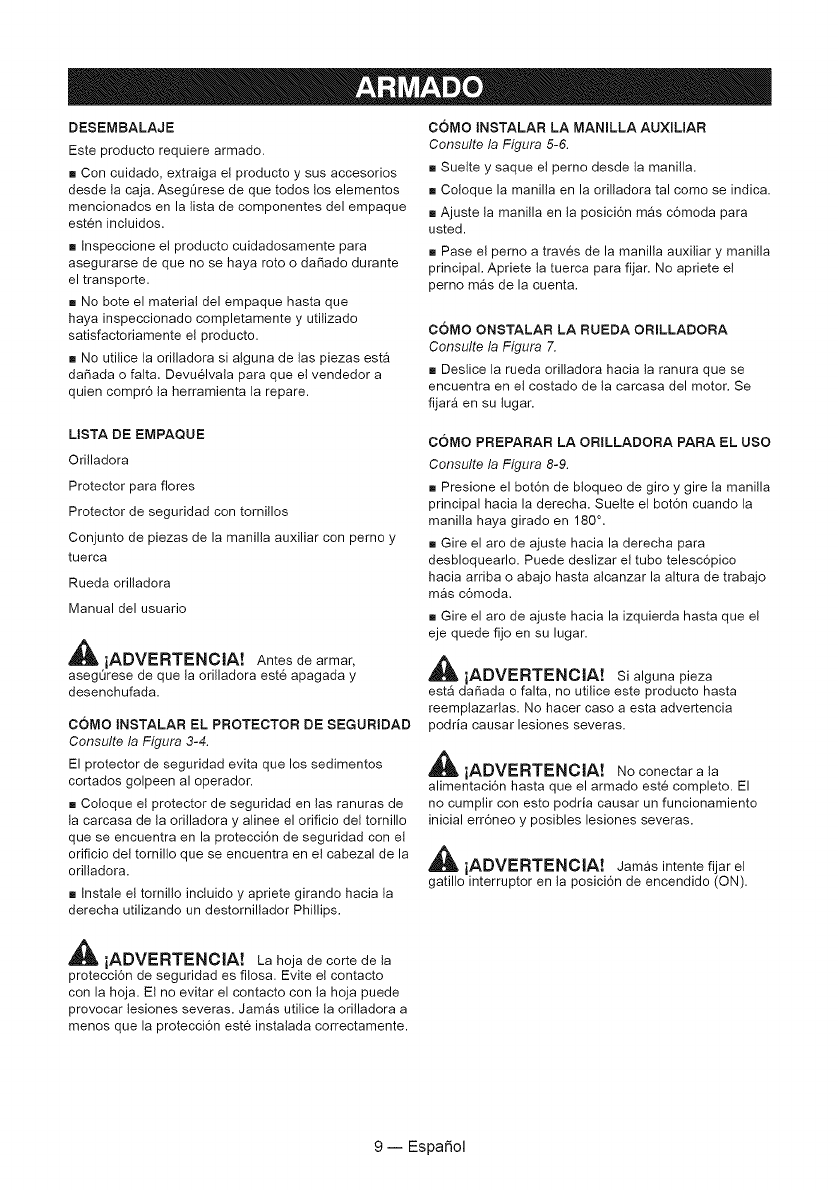
DESEMBALAJE
Este producto requiere armado.
[] Con cuidado, extraiga el producto y sus accesorios
desde ta caja. AsegL_rese de que todos tos elementos
mencionados en la lista de componentes del empaque
esten incluidos.
[] Inspeccione el producto cuidadosamente para
asegurarse de que no se haya roto o da_ado durante
el transporte.
[] No bote el material del empaque hasta que
haya inspeccionado completamente y utilizado
satisfactoriamente el producto.
[] No utilice ta orilladora si alguna de tas piezas est_
da_ada o falta. Devuelvala para que el vendedor a
quien compr6 la herramienta la repare.
COMO INSTALAR LA MANILLA AUXNLIAR
Consulte la Figura 5-6.
[] Suette y saque el perno desde ta manilla.
[] Co!oque la manilla en la orilladora tal como se indica.
[] Ajuste la manilla en la posici6n mgs c6moda para
usted.
[] Pase el perno a traves de la manilla auxiliary manilla
principal. Apriete ta tuerca para fijar. No apriete el
perno mgs de la cuenta.
COMO ONSTALAR LA RUEDA ORNLLADORA
Consulte la Figura 7.
[] Deslice la rueda orilladora hacia la ranura que se
encuentra en et costado de la carcasa del motor. Se
fijar9 en su lugar.
LISTA DE EMPAQUE
Orilladora
Protector para fiores
Protector de seguridad con tornillos
Conjunto de piezas de la manilla auxiliar con perno y
tuerca
Rueda orilladora
Manual del usuario
_IL iADVERTENClA! Antes de armar,
asegOrese de que la orilladora este apagada y
desenchufada.
COMO INSTALAR EL PROTECTOR DE SEGURIDAD
Consulte la Figura 3-4.
El protector de seguridad evita que los sedimentos
cortados golpeen al operador.
[] Coloque et protector de seguridad en las ranuras de
la carcasa de la orilladora y alinee el orificio del tornillo
que se encuentra en la protecci6n de seguridad con et
orificio del tornillo que se encuentra en el cabezal de la
orilladora.
[] Instale el tornillo inctuido y apriete girando hacia la
derecha utilizando un destornillador Phillips,
COMO PREPARAR LA ORILLADORA PARA EL USO
Consulte la Figura 8-9.
[] Presione el bot6n de btoqueo de giro y gire ta manilla
principal hacia la derecha. Suelte e! bot6n cuando la
manilla haya girado en 180 °.
[] Gire el aro de ajuste hacia la derecha para
desbloquearlo. Puede deslizar e! tubo telesc6pico
hacia arriba o abajo hasta alcanzar la altura de trabajo
mas c6moda.
[] Gire el aro de ajuste hacia la izquierda hasta que e!
eje quede fijo en su lugar.
,_ iADVERTENOIA! si algunapieza
est_ dadada o falta, no utilice este producto hasta
reemplazarlas. No hacer caso a esta advertencia
podria causar lesiones severas.
_l_ iADVERTENCIA! No conectar a ta
alimentaci6n hasta que el armado este completo. El
no cumptir con esto podria causar un funcionamiento
inicial err6neo y posibles lesiones severas.
_IIL iADVERTENClA! Jamas intente fijar el
gatillo interruptor en la posici6n de encendido (ON).
_ iADVERTENCIA! La hoja de corte de ta
protecci6n de seguridad es filosa. Evite el contacto
con la hoja. Et no evitar el contacto con la hoja puede
provocar lesiones severas. Jam_s utilice ta orilladora a
menos que la protecci6n este instalada correctamente.
9--Espa_ol
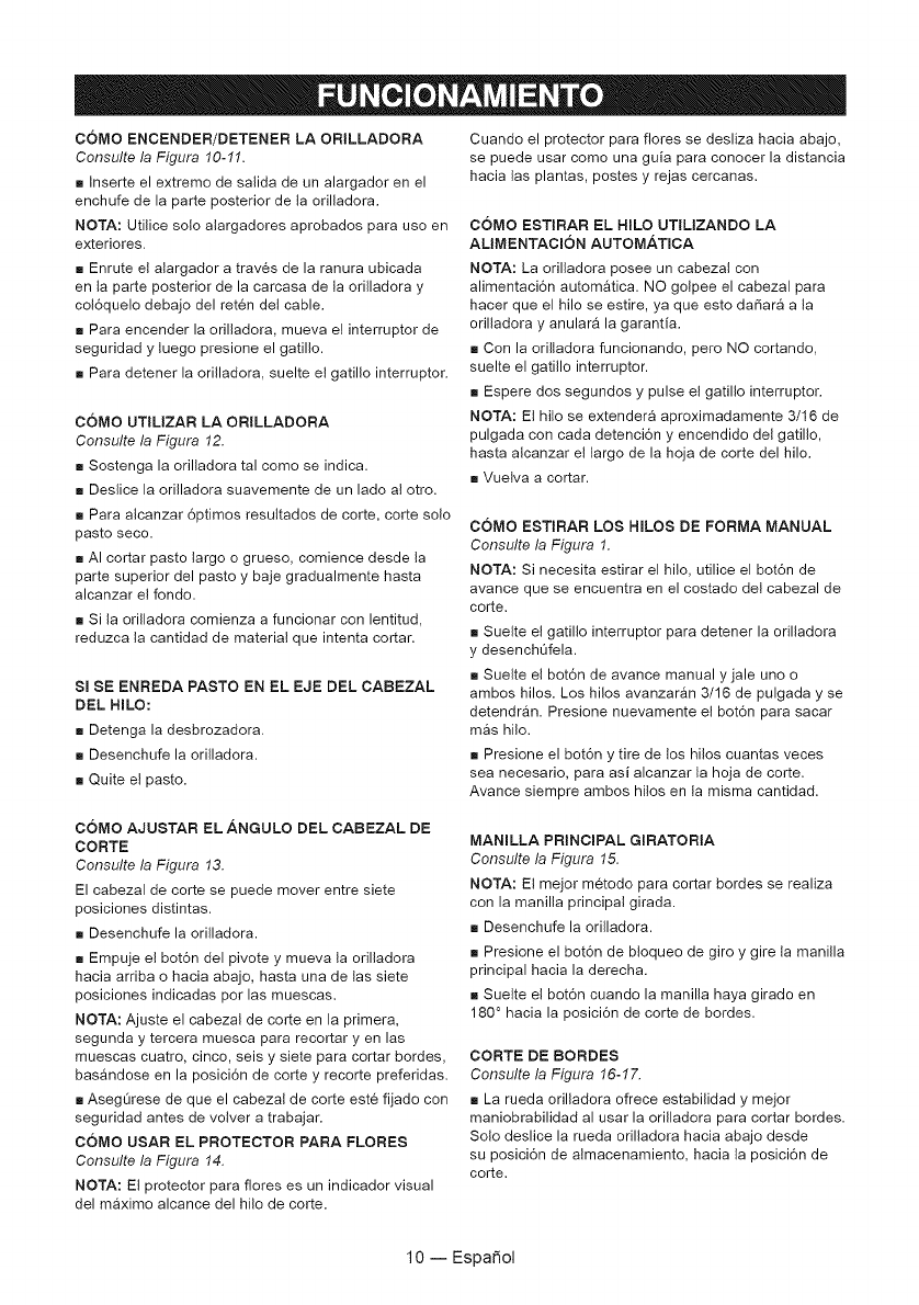
COMO ENCENDER/DETENER LA ORILLADORA
Consulte la Figura 10-11.
[] Inserte el extreme de salida de un alargador en el
enchufe de la parte posterior de ta orilladora.
NOTA: Utilice solo alargadores aprobados para use en
exteriores.
[] Enrute el alargador a traves de la ranura ubicada
en ta parte posterior de la carcasa de la orilladora y
colSquelo debajo del reten det cable.
[] Para encender la orilladora, mueva el interruptor de
seguridad y tuego presione el gatillo.
[] Para detener la orilladora, suelte el gatillo interruptor.
COMO UTILIZAR LA ORILLADORA
Consulte la Figura 12.
[] Sostenga la orilladora tal come se indica.
[] Deslice la orilladora suavemente de un lado al otro.
[] Para alcanzar 6ptimos resuttados de corte, corte solo
pasto seco.
[] AI cortar paste largo o grueso, comience desde ta
parte superior del pasto y baje gradualmente hasta
alcanzar el fondo.
[] Si la orilladora comienza a funcionar con lentitud,
reduzca la cantidad de material que intenta cortar.
Sl SE ENREDA PASTO EN EL EJE DEL CABEZAL
DEL HILO:
[] Detenga la desbrozadora.
[] Desenchufe la orilladora.
[] Quite e! pasto.
Cuando el protector para flores se desliza hacia abajo,
se puede usar come una guia para conocer la distancia
hacia las plantas, postes y rejas cercanas.
COMO ESTIRAR EL HILO UTILIZANDO LA
ALtMENTACION AUTOMATICA
NOTA: La orilladora posee un cabezal con
alimentaci6n autom_tica. NO golpee el cabezal para
hacer que el MIo se estire, ya que esto da_ara a la
orilladora y anular_ la garantia.
[] Con la oriltadora funcionando, pero NO cortando,
suelte el gatillo interruptor.
[] Espere dos segundos y pulse et gatillo interruptor.
NOTA: Et hito se extendera aproximadamente 3/16 de
pulgada con cada detenci6n y encendido del gatillo,
hasta alcanzar el largo de la hoja de corte del hilo.
[] Vuelva a cortar.
COMO ESTIRAR LOS HILOS DE FORMA MANUAL
Consulte la Figura 1.
NOTA: Si necesita estirar el hilo, utilice el bot6n de
avance que se encuentra en el costado del cabezal de
corte.
[] Suelte el gatillo interrupter para detener la orilladora
y desenchefela.
[] Suelte el bot6n de avance manual y jale uno o
ambos hilos. Los hilos avanzargn 3/16 de pulgada y se
detendr_n. Presione nuevamente el bot6n para sacar
mas hilo.
[] Presione el bot6n y tire de los hilos cuantas veces
sea necesario, para asi alcanzar ta hoja de corte.
Avance siempre ambos hilos en la misma cantidad.
COMO AJUSTAR EL ANGULO DEL CABEZAL DE
CORTE
Consulte la Figura 13.
El cabezal de corte se puede mover entre siete
posiciones distintas.
[] Desenchufe la orilladora.
[] Empuje el bot6n del pivote y mueva ta orilladora
hacia arriba o hacia abajo, hasta una de las siete
posiciones indicadas por las muescas.
NOTA: Ajuste el cabezal de corte en la primera,
segunda y tercera muesca para recortar y en las
muescas cuatro, cinco, seis y siete para cortar bordes,
basAndose en la posici6n de corte y recorte preferidas.
[] Asegt_rese de que el cabezal de corte este fijado con
seguridad antes de votver a trabajar.
COMO USAR EL PROTECTOR PARA FLORES
Consulte la Figura 14.
NOTA: Et protector para fiores es un indicador visual
del maximo alcance del hilo de corte.
MANmLLA PRINCIPAL GIRATORIA
Consulte la Figura 15.
NOTA: Et mejor metodo para cortar bordes se realiza
con la manilla principal girada.
[] Desenchufe la orilladora.
[] Presione el bot6n de btoqueo de giro y gire la manilla
principal hacia la derecha.
[] Suelte el bot6n cuando la manilla haya girado en
180 ° hacia la posici6n de corte de bordes.
CORTE DE BORDES
Consulte la Figura 16-17.
[] La rueda orilladora ofrece estabilidad y mejor
maniobrabilidad al usar la orilladora para cortar bordes.
Solo deslice la rueda orilladora hacia abajo desde
su posici6n de almacenamiento, hacia la posici6n de
corte.
lO--Espa_ol
Su orilladora ha sido disefiada para funcionar durante
un largo periodo de tiempo, con un minimo de
mantenimiento. La operaci6n continua satisfactoria
depende de un cuidado adecuado de la herramienta y
una timpieza regular.
_, iADVERTENCIA! Antes de realizar
mantenimiento, apague y desenchufe la herramienta.
[] Limpie regularmente la ranura de ventitaci6n de su
orilladora, utilizando un cepillo suave o patio seco.
[] Limpie regularmente el hilo de corte y carrete,
utilizando un cepillo suave o patio seco.
[] Utilice regutarmente una esp_tula lisa para sacar el
pasto y suciedad desde la parte inferior del protector.
_IL iADVERTENC[A! At realizar
mantenimiento, utilice solo piezas de repuesto
identicas. Et uso de otras piezas podria generar un
peligro o dafiar al producto.
CAMBIO DEL CARRETE
Consulte la Figura 18.
[] Utilice solo hilo monofilamento redondo de .065" de
di_metro. Para obtener el mejor desempefio, utilice el
hilo de repuesto original del fabricante.
[] Desenchufe la orilladora.
[] Empuje las pestafias de! costado de la tapa del
carrete.
[] Jale la tapa del carrete para quitarla.
[] Saque el carrete.
[] Para instalar el nuevo carrete, asegOrese de que
los dos hilos esten cotocados en las ranuras opuestas
entre si. AsegOrese de que cada hilo se extienda
aproximadamente a 6 putgadas de carla ranura.
[] Instale e! nuevo carrete de manera tal que los hilos
y tas ranuras se alineen con los ojales del cabezal de
hilo. Pase los hilos por tos ojales.
[] Jale los hilos extendiendolos desde el cabezal, de
manera tal que e! hilo se salga de las ranuras de!
carrete.
[] Co!oque la tapa del carrete presionando las pestafias
hacia tas ranuras del cabezal de hilo y empujando
el carrete hasta que la tapa haga "clic" y calce en su
lugar.
NOTA: El carrete de respuesto est_ disponibte en
SEARS, bajo el nQmero de pieza 71.99006
CAMBIO DEL HILO
Consulte la Figura 18.
[] Desenchufe la orilladora.
[] Saque el carrete desde el cabezal de hilo.
NOTA: Saque cualquier resto de hilo antiguo desde
el carrete. Corte dos trozo de hilo, cada uno de
aproximadamente 2,7 m (9 pies) de largo. Utilice solo
hilo monofilamento de 1,65 mm (.065 pulgadas) de
di_metro.
[] Inserte el primer hilo en el orificio de anclaje que se
encuentra en la parte superior del carrete. Enrotle el
primer hilo en ta parte superior del carrete en direcci6n
a la derecha, como Io indican las fiechas de! carrete.
Coloque el hilo en ta ranura de la brida superior del
carrete, dejando unos 152 mm (6 pulgadas) extendidos
mas all_ de la ranura. No coloque mas de ta cuenta.
Despues de enrollar el hilo, debe haber al menos 6
mm (1/4 de pulgada) entre e! hilo bobinado y el borde
externo del carrete.
[] Repita el paso anterior con el segundo hilo, utilizando
la parte inferior del carrete y el orificio de anclaje
inferior. No cotoque m_s de la cuenta.
[] Instale el carrete en el cabezal de hilo y cotoque la
tapa del carrete segt_n se indica en Cambio del carrete.
,_ iADVERTENCIA! Utilice solo el tipo
adecuado de hilo de corte.
ALIVlACENAJE DE LA ORILLADORA
[] Limpie todos los materiales externos de la orilladora.
[] Atmacene en un lugar alejado del alcance de los
nifios.
[] Mantengalo alejado de agentes corrosivos como
los productos quimicos para el jardin y las sales
descongelantes.
11 -- Espafiol
Si su orilladora no funciona correctamente, consulte
primero ta siguiente tabla de resoluci6n de problemas.
Si la soluci6n al problema de su orilladora no aparece
en la informaci6n de resoluci6n de problemas, tleve la
orilladora con un concesionario de servicio calificado
para que la inspeccione y repare, de ser necesario.
_ iADVERTENCIA! Antes de proceder,
apague y desenchufe,
PROBLEMA POSIBLE CAUSA SOLUCI6N
1. Los hilos se han atascado 1. Desenchufe ta orilladora. Abra ta tapa del carrete.
debido al calor o tiempo de Saque el carrete. Saque el hilo y enr611elo en el
almacenamiento, carrete.
2. Desenchufe ta orilladora. Abra ta tapa del carrete.
Los hilos no se alargan al 2. No hay suficiente hilo en el Saque el carrete y coloque hilo nuevo o un carrete
carrete.
seguir las instrucciones, nuevo, siguiendo las instrucciones de este manual.
3. Desenchufe ta orilladora. Abra ta tapa del
3. Los hilos estgn enredados carrete. Saque el carrete. Desenro!le y saque et
en e! carrete, hilo enredado. Desenrolle el hilo siguiendo las
instrucciones de este manual.
Se enrotla pasto en la 1. C6mo cortar pasto alto a 1. Corte el pasto desde la parte superior hacia
carcasa del eje motriz y nivel del suelo, abajo, a fin de evitar que se enrede.
en el cabezal del hilo.
1. Et cable de alimentaci6n no
est_ conectado o la conexi6n 1. Conecte e! cable de alimentaci6n.
est_ suelta.
El motor no enciende al 2. Et automgtico de la casa
presionar el gatillo, est9 activado. 2. Revise el diferencial del circuito.
3. El alargador podria estar 3. Pruebe con otro alargador o conecte otro
defectuoso, receptgculo en un circuito diferente.
12--Espa_ol
(
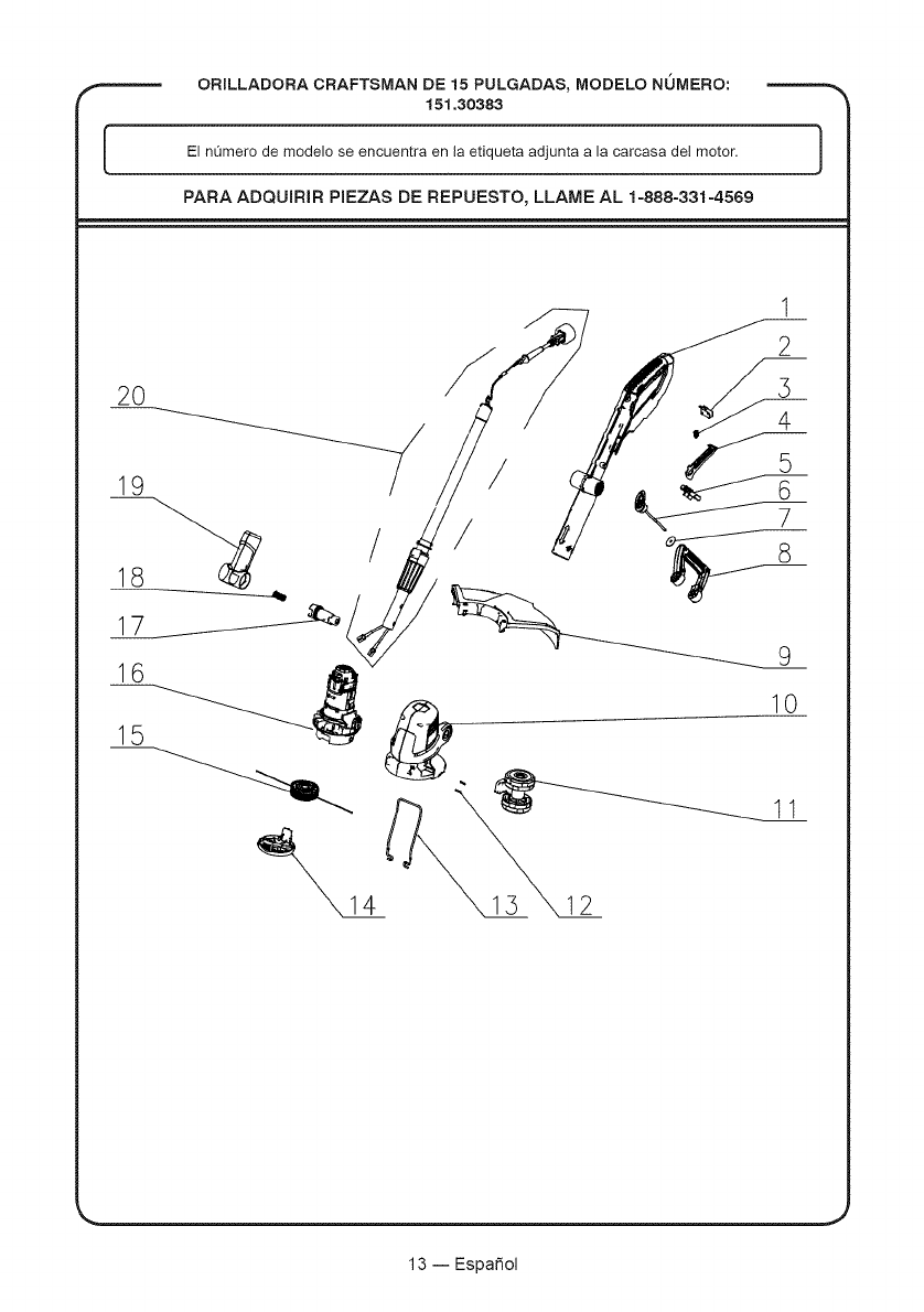
ORILLADORA CRAFTSMAN DE 15 PULGADAS, MODELO NUMERO:
151.30383
El nOmerode modelo se encuentra en la etiqueta adjunta a la carcasa del motor.
PARA ADQUIRIR PIEZAS DE REPUESTO, LLAME AL 1=888-331=4569
]
2O
19
/
16
15
/
/
1
2
10
11
12
13--Espa_ol

ORILLADORA CRAFTSMAN DE 15 PULGADAS, MODELO NOMERO:
151.30383
El nOmerode modelo se encuentra en la etiqueta adjunta a la carcasa del motor. }
PARA ADQUIRIR PIEZAS DE REPUESTO, LLAME AL 1-888-331-4569
N° DE N°
ARTiCULO DE PIEZA DESCRIPCION CANT.
1 GT80FM.50.00.X1.01 Conjunto de piezas de la manilla principal 1
2 WODQ10.01.11 Interruptor 1
3 TOTHYY. 16.08 Resorte 1
4 GE50DC.10.01 Bot6n interruptor 1
5 GE50DC.A0.12 Conjunto de piezas del bot6n anti bloqueo 1
6 TGQTXN.03.11.X2.01 Conjunto de piezas de la perilla de la manilla 1
7 GF01BL.10.24 Golilla 1
8 GT45FM.60.00 Conjunto de piezas de la manilla auxiliar 1
9 GT80FM.40.00 Conjunto de piezas del protector de seguridad, 1
incluyendo hoja de corte de hilo
10 GT80FM.10.00.X1.01 Conjunto de piezas de la carcasa del motor 1
11 GT80FM.30.00 Rueda orilladora 1
12 GT30FM.00.07 AImohadilla de goma 2
13 GT80FM.00.01 Protector para fiores 1
14 GT45FM.70.02 Tapa del carrete 1
15 GT80FM.60.10 Carrete de corte con hilo 1
16 TM6560.00.00.X1.01 Conjunto de piezas del motor 1
17 GE61DC.00.05 Bot6n accionador del pivote 1
18 TOTHYY.03.12 Resorte accionador del pivote 1
19 GE61DC.10.01.X1.01 Conjunto de piezas de soporte del cuello pivotante. 1
20 GE50DC.10.05.X3.01 Conjunto de piezas del tubo conector. 1
J
14--Espa_ol

11" °
Product questions or problems?
1-888-3 1-4569
Customer Care Hot Line
Get answers to questions, troubleshoot problems,
order parts, or schedule repair service.
Para respuestas a preguntas o probtemas, y ordenar
piezas o pedir servicio para la reparaci6n de su equipo.
To help us help you, register your product at www.craftsman.com/registration
Para poderte ayudar mejor, registra tu producto en www.craftsman.com/registration
Join the Craftsman Club today!
www.craftsman.com/sign up
Receive exclusive member benefits including special pricing and offers,
project sharing, expert advice, and SHOP YOUR WAY REWARDS!
Como miembro exclusivo, recibe diversos beneficios como ofertas, precios especiales, proyectos
nuevos, consejos de expertos y nuestro programa de puntos SHOP YOUR WAY REWARDS!
(9 Registered Trademark /TM Trademark of KCD IP, LLC in the United States, or Sears Brands, LLC in other countries
(9 Marca Registrada /Tr_ Marca de F&brica de KCD IP, LLC eR Estados Unidos, o Sears Brands, LLC in otros paises
