Craftsman 152211240 User Manual BENCH GRINDER Manuals And Guides 1008321L
User Manual: Craftsman 152211240 152211240 CRAFTSMAN BENCH GRINDER - Manuals and Guides View the owners manual for your CRAFTSMAN BENCH GRINDER #152211240. Home:Tool Parts:Craftsman Parts:Craftsman BENCH GRINDER Manual
Open the PDF directly: View PDF ![]() .
.
Page Count: 32
Manual
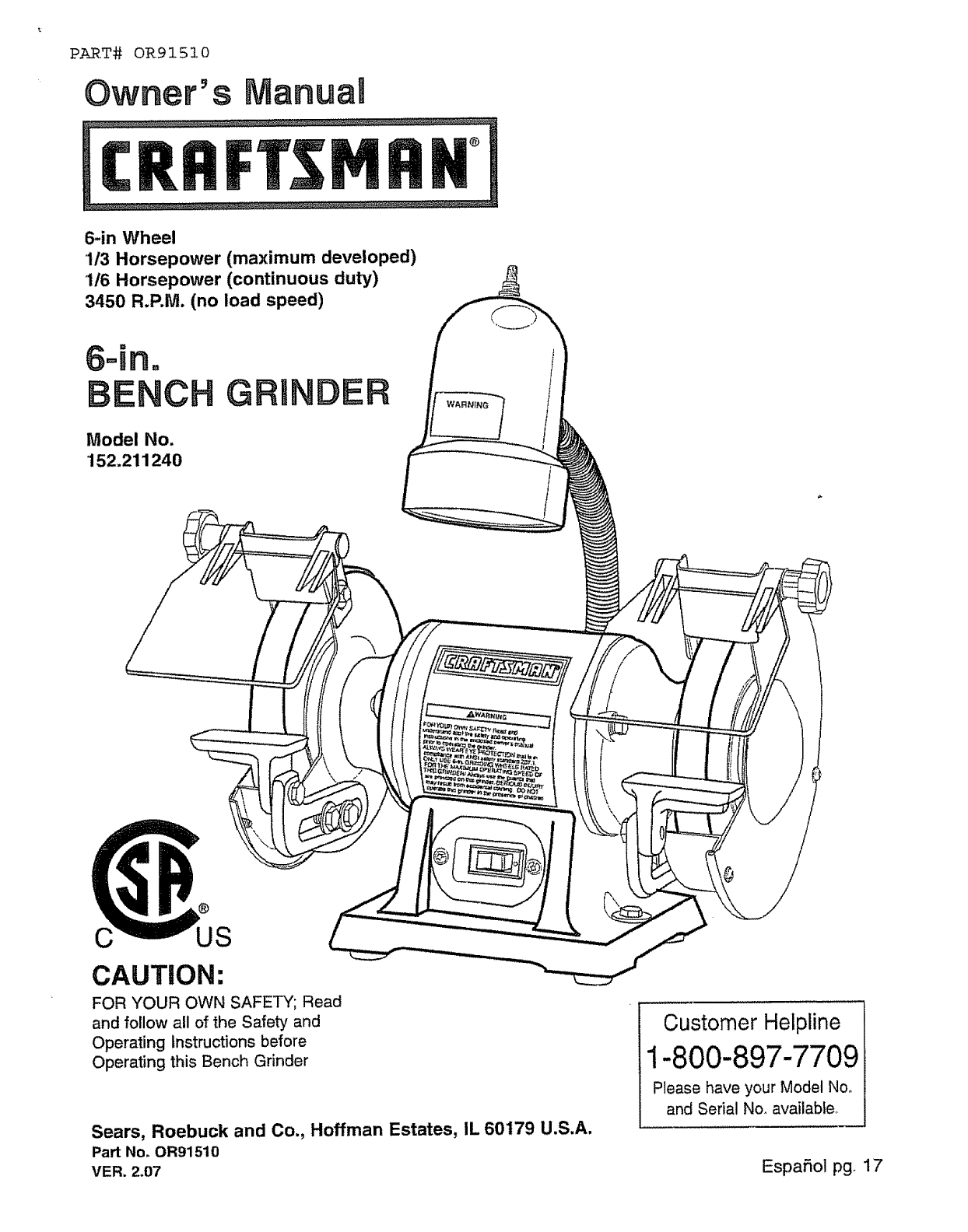
6-in Wheel
1/3 Horsepower (maximum developed)
1/6 Horsepower (continuous duty)
3450 R.P.M. (no load speed)
Model No.
152.211240
DER WARNING
JS
CAUTION:
FOR YOUR OWN SAFETY; Read
and follow all of the Safety and
Operating Instructions before
Operating this Bench Grinder
Sears, Roebuck and Co., Hoffman Estates, IL 60179 U.S.A.
Part Noo OR91510
VER. 2.07
Customer Helpline
1-800-897-7709
Please have your Model No,
and Serial No_available,
Espafiolpg. 17
SECTION PAG E
Product Specifications ................................................................................................................................................... 2
Safety Instructions ......................................................................................................................................................... 3
Grounding Instructions ................................................................................................................................................... 4
Specific Safety instructions for Bench Grinders ........................................................................................................ 5
Accessories and Attachments ........................................................................................................................................ 6
Carton Contents ............................................................................................................................................................. 6
Know Your Bench Grinder .............................................................................................................................................. 7
Assembly Instructions ................................................................................................................................................... 8
Operating the Bench Grinder ....................................................................................................................................... 10
Maintenance .................................................................................................................................................................. 12
Troubleshooting Guide ................................................................................................................................................ 16
Parts List ....................................................................................................................................................................... 13
Service Information ...................................................................................................................................... Back Cover
FULL ONE YEAR VVARRANTY
If this product fails due to a defect in material or workmanship within one year from the date of purchase, RETURN
IT TO THE NEAREST SEARS STORE OR CRAFTSMAN OUTLET, and it will be replaced, free of charge..
This warranty gives you specific legal rights, and you may also have other rights, which vary, from state to state.
Sears, Roebuck and Co., Dept.. 817 WA, Hoffman Estates, IL 60179
Motor
Maximum HP developed
Continuous Duty HP
Volts
Hertz
RPM
Grinding Wheel Size
Grinding Wheel Grit
Lamp
Tool Rests
Eye Shield Assemblies
Spark Arrestors
'I/3
1/6
120
60
3450 RoPM.
(no toad speed)
6" x 3/4" x 1/2"
60, 36
120V, 40 watt or less Track
Light Bulb, Type R20,
medium base or equivalent
(not included)
Left and Right, Cast Iron
Clear Lexan Left and Right
Left and Right
To avoid electrical shock to yourself and damage to the
Bench Grinder, use proper circuit protection.
The Bench Grinder is factory wired for t20V, 60 Hz,
operation. Connect to a 120V, 15 amp branch circuit
and use a 15 amp time delay fuse or circuit breaker..
The electrical circuit cannot have any wire size less
than #14. To avoid shock or fire, replace power cord
immediately if it is damaged in any way..
GENERAL SAFETY INSTRUCTIONS
Operating a Bench Grinder can be dangerous if safety
and common sense are ignored. The operator must be
familiar with the operation of the tool Read this manual
to understand this Bench Grinder.. DO NOT operate this
Bench Grinder if you do not fully understand the limita-
tions of this tool DO NOT modify this Bench Grinder in
any way°
BEFORE USING THE BENCH GRINDER
To avoid serious injury and damage to the tool, read
and follow all of the Safety and Operating instructions
before operating the Bench Grinder..
1.. Some dust created by using power tools contains
chemicals known to the State of California to cause
cancer, birth defects, or other reproductive harm.
Some examples of these chemicals are:
o Lead from lead-based paints.
• Crystalline silica from bricks, cement, and other
masonry products.
o Arsenic and chromium from chemically treated
lumber..
Your risk from these exposures varies, depending
on how often you do this type of work_ To reduce
your exposure to these chemicals: work in a well-
ventilated area, and work with approved safety
equipment, such as those dust masks that are
specially designed to filter out microscopic particles°
2.. READ the entire Owner's Manual.. LEARN how to
use the tool for its intended applications.
3,. GROUND ALL TOOLS. If the toot is supplied with
a 3-prong plug, it must be plugged into a 3-contact
electrical receptacle,. The 3rd prong is used to
ground the tool and provide protection against acci-
dental electric shock.. DO NOT remove the 3rd
prong.. See Grounding Instructions on page 4.
4., AVOID A DANGEROUS WORKING ENVIRON-
MENT. DO NOT use electrical tools in a damp
environment or expose them to rain..
5. DO NOT use electrical tools in the presence of
flammable liquids or gases..
6, ALWAYS keep the work area clean, welt lit, and
organized.. DO NOT work in an environment with
floor surfaces that are slippery from debris, grease,
and wax..
7_ KEEP VISITORS AND CHILDREN AWAY. DO NOT
permit people to be in the immediate work area,
especially when the electrical tool is operating_
9_
10.
1t.
!2o
13.
14
15.
DO NOT FORCE THE TOOL to perform an opera-
tion for which it was not designed. It will do a safer
and higher quality job by only performing operations
for which the tool was intended.
WEAR PROPER CLOTHING. DO NOT wear loose
clothing, gloves, neckties, or jewelry', These items
can get caught in the machine during operations
and pul! the operator into the moving parts,. The
user must wear a protective cover on their hair, if
the hair is long, to prevent it from contacting any
moving parts°
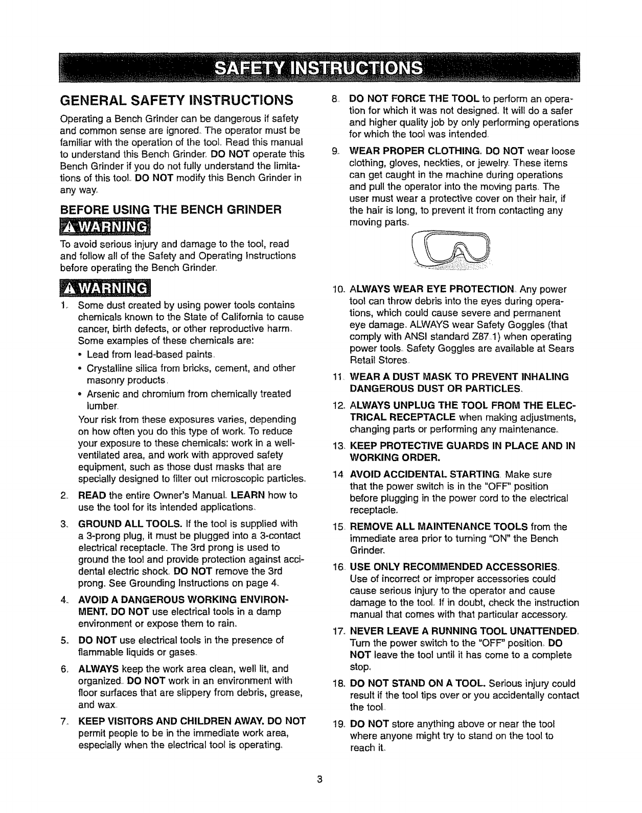
ALWAYS WEAR EYE PROTECTION, Any power
tool can throw debris into the eyes during opera-
tions, which could cause severe and permanent
eye damager ALWAYS wear Safety Goggfes (that
comply with ANSI standard Z87..1) when operating
power tools,.Safety Goggles are available at Sears
Retail Stores
WEAR A DUST MASK TO PREVENT INHALING
DANGEROUS DUST OR PARTICLES,
ALWAYS UNPLUG THE TOOL FROM THE ELEC-
TRICAL RECEPTACLE when making adjustments,
changing parts or performing any maintenance._
KEEP PROTECTIVE GUARDS IN PLACE AND IN
WORKING ORDER.
AVOID ACCIDENTAL STARTING, Make sure
that the power switch is in the "OFF" position
before piugging in the power cord to the electrical
receptacle.
REMOVE ALL MAINTENANCE TOOLS from the
immediate area prior to turning "ON" the Bench
Gdnder_
16. USE ONLY RECOMMENDED ACCESSORIES,
Use of incorrect or improper accessories could
cause serious injury to the operator and cause
damage to the tool. If in doubt, check the instruction
manual that comes with that particular accessory°
17. NEVER LEAVE A RUNNING TOOL UNATTENDED°
Turn the power switch to the "OFF" position, DO
NOT leave the too!unti_ it has come to a complete
stop°
18, DO NOT STAND ON A TOOL. Serious injury could
result if the tool tips over or you accidentally contact
the tool..
19_ DO NOT store anything above or near the tool
where anyone might try to stand on the tool to
reach it..
20 MAINTAINYOURBALANCE.DONOTextend
yourselfoverthetool.WearoilresistantpJbber-
soledshoes.Keepfloorclearofddebris,grease,
andwax
21.MAINTAIN TOOLS WITH CARE. Always keep tools
clean and in good working order Keep all blades
and tool bits sharp°
22° EACH AND EVERY TIME, CHECK FOR DAM_
AGED PARTS PRIOR TO USING THE TOOL.
Carefully check all guards to see that they operate
properly, are not damaged, and perform their
intended functions, Check for alignment, binding or
breaking of moving parts, A guard or other part that
is damaged should be immediately repaired or
replaced.
23. CHILDPROOF THE WORKSHOP AREA by remov-
ing switch keys, unplugging tools from the electrical
receptacles, and using padlocks.
24 DO NOT OPERATE TOOL IF UNDER THE IN-
FLUENCE OF DRUGS OR ALCOHOL.
25, SECURE ALL WORK. Use clamps or jigs to secure
the workpiece. This is safer than attempting to hold
the workpiece with your hands.
26 USE APROPER EXTENSION CORD IN GOOD
CONDITION. When using an extension cord, be
sure to use one hearty enough to carry the current
your product will draw. The table at right shows the
correct size to use depending on cord length and
nameplate amperage rating_ If in doubt, use the
next heavier gauge The smaller the gauge number,
the larger diameter of the extension cord. If in doubt
of the proper size of an extension cord, use a short-
er and thicker cord, An undersized cord will cause
and overheating USE ONLY A 3-WIRE EXTENo
SlON CORD THAT HAS A 3-PRONG GROUND-
ING PLUG AND A 3-POLE RECEPTACLE THAT
ACCEPTS THE TOOUS PLUG.
GUIDELINES FOR
EXTENSION CORDS
If you are using an extension cord outdoors, be sure
it is marked with the suffix "W-A" ('_V'_in Canada) 1o
indicate that it is acceptable for outdoor user
Be sure your extension cord is properly sized, and
in good electrical condition_Always replace adamaged
extension cord or have it repaired by a qualified person
before using it.
Protect your extension cords from sharp objects,
excessive heat, and damp or wet areas,
0 to 6 Arnps
6 to I0 Arnps
I0 to 12Amps
120VOLTOPERATIONONLY
25' LONG
18AWG
18AWG
t6AWG
50' LONG 100' LONG
16AWG 16AWG
16AWG 14AWG
16AWG 14AWG
150'LONG
14AWG
12AWG
t2 AWG
IN THE EVENT OF A MALFUNCTION OR BREAK-
DOWN, grounding provides the path of least resistance
for electric current and reduces the riskof electric
shock. This tool is equipped with an electric cord that
has an equipment grounding conductor and a ground-
ing plug. The plug MUST be plugged into a matching
electrical receptacle that is properlyinstalled and
grounded in accordance with ALL local codes and ordi-
nances°
DO NOT MODIFY THE PLUG PROVIDED. If it will not
fit the electrical receptacle, have the proper electrical
receptacle installed by a qualified electrician
IMPROPER ELECTRICAL CONNECTION of the equip-
ment grounding conductor can result in risk of electric
shock. The conductor with the green insulation (with or
without yellow stripes) is the equipment grounding con-
ductor. DO NOT connect the equipment grounding con-
ductor to a live terminal if repair or replacement of the
electric cord or plug is necessary_
CHECK with a qualified electrician or service personnel
if you do not completely understand the grounding
instnJctions, or if you are not sure the tool is properly
grounded.
USE ONLY A3-WIRE EXTENSION CORD THAT HAS
A3-PRONG GROUNDING PLUG AND A3-POLE
RECEPTACLE THAT ACCEPTS THE TOOL'S PLUG.
REPLACE ADAMAGED OR WORN CORD IMMEDI-
ATELY.
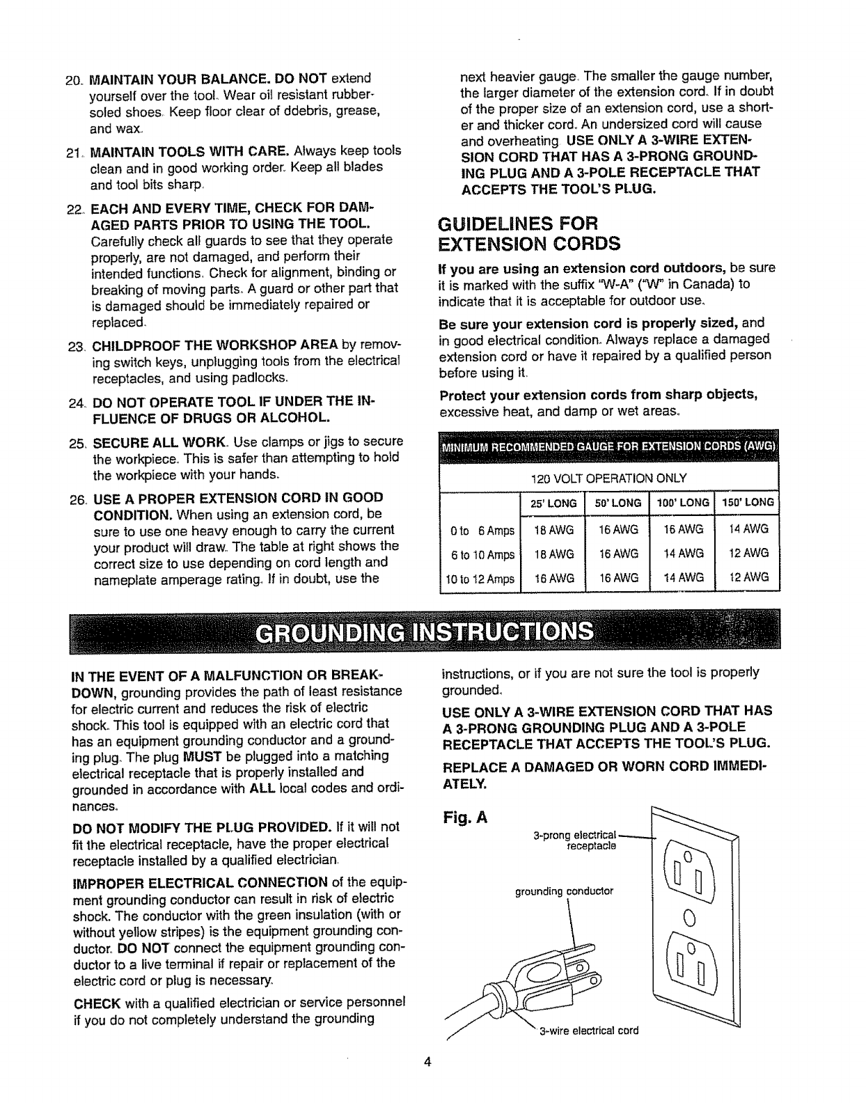
Fig. A
3-prong electdca_.--..-._
receptacle
grounding conductor
at cord
4
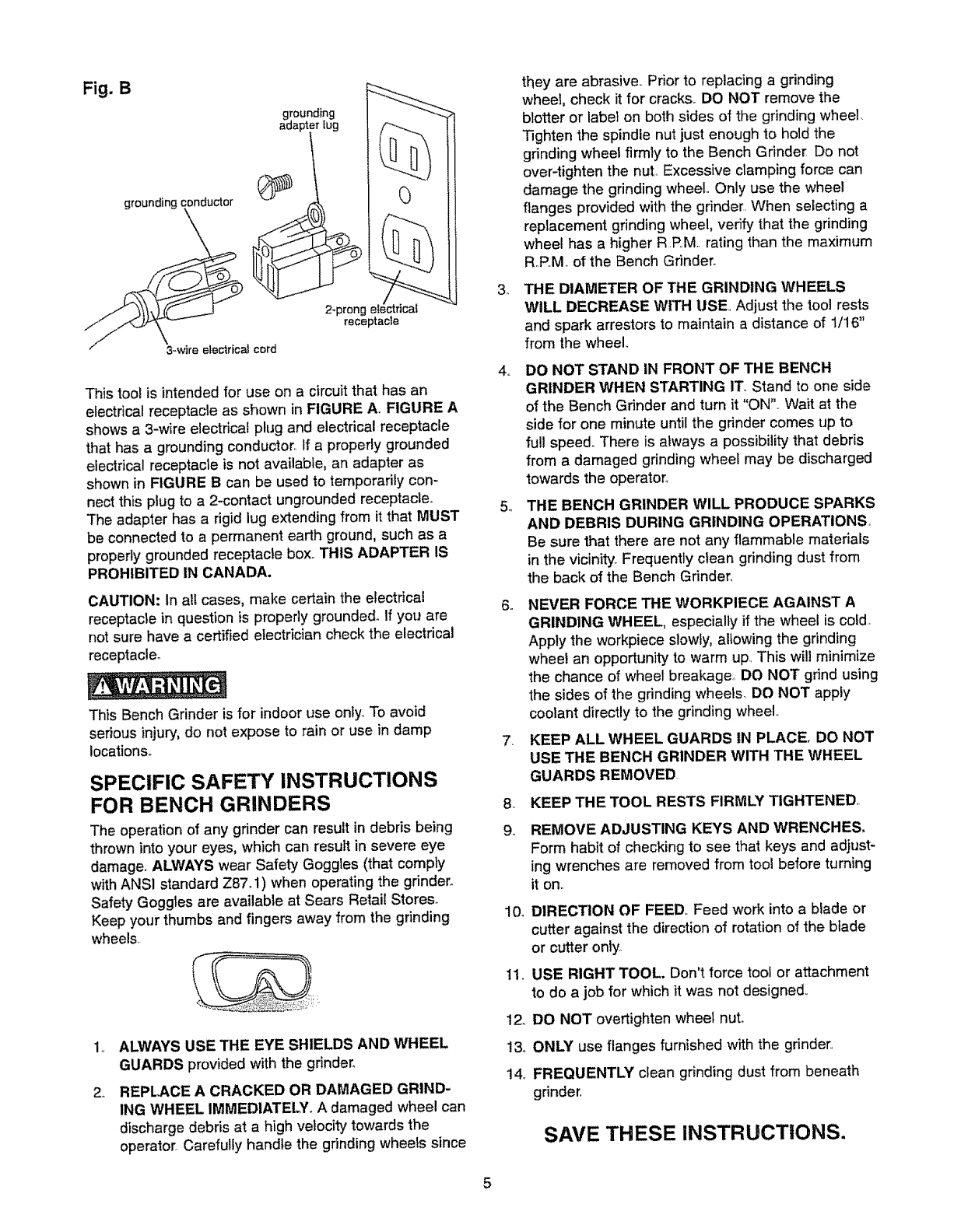
Fig. B
grounding
lug
grounding conductor
2-prong electrical
receptacle
This tool is intended for use on a circuit that has an
electrical receptacle as shown in FIGURE AmFIGURE A
shows a 3-wire electrical plug and electrical receptacle
that has a grounding conductor,, if a properly grounded
electrical receptacle is not available, an adapter as
shown in FIGURE B can be used to temporarily con-
nect this plug to a 2-contact ungrounded receptacle.
The adapter has a rigid lug extending from it that MUST
be connected to a permanent earth ground, such as a
properly grounded receptacle box,, THIS ADAPTER IS
PROHIBITED IN CANADA.
CAUTION: In all cases, make certain the electrical
receptacle in question is properly grounded° If you are
not sure have a certified electrician check the electrical
receptacle_
This Bench Grinder is for indooruse only. To avoid
serious injury, do not expose to rain or use in damp
locations=
SPECIFIC SAFETY INSTRUCTIONS
FOR BENCH GRINDERS
The operation of any grinder can result in debris being
thrown into your eyes, which can result in severe eye
damage. ALWAYS wear Safety Goggles (that comply
with ANSI standard Z87.1) when operating the gdnder.
Safety Goggles are available at Sears Retail Stores.
Keep your thumbs and fingers away from the grinding
wheels,
.,
ALWAYS USE THE EYE SHIELDS AND WHEEL
GUARDS provided with the grinder°
REPLACE A CRACKED OR DAMAGED GRIND-
ING WHEEL IMMEDIATELY Adamaged wheel can
discharge debris at a high velocity towards the
operator Carefully handle the grinding wheels since
3_
they are abrasives, Prior to replacing a grinding
wheel, check it for cracks,, DO NOT remove the
blotter or label on both sides of the grinding wheel_
Tighten the spindle nut just enough to hold the
grinding wheel firmly to the Bench Grinder Do not
over-tighten the nut, Excessive clamping force can
damage the grinding wheel,, Only use the wheel
flanges provided with the grinder, When selecting a
replacement grinding wheel, verify that the grinding
wheel has a higher R,PM,, rating than the maximum
R_P.M,of the Bench Grinder°
THE DIAMETER OF THE GRINDING WHEELS
WILL DECREASE WITH USE Adjust the tool rests
and spark arrestors to maintain a distance of 1/16"
from the wheel
4,, DO NOT STAND IN FRONT OF THE BENCH
GRINDER WHEN STARTING ITo Stand to one side
of the Bench Grinder and turn it "ON"., Wait at the
side for one minute until the grinder comes up to
full speed. There is always a possibility that debris
from a damaged grinding wheel may be discharged
towards the operator_
5THE BENCH GRINDER WILL PRODUCE SPARKS
AND DEBRIS DURING GRINDING OPERATIONS
Be sure that there are not any flammable materials
in the vicinity. Frequently clean grinding dust from
the back of the Bench Grinder.
.,
7_
am
9o
NEVER FORCE THE WORKPIECE AGAINST A
GRINDING WHEEL, especially if the wheel is cold
Apply the workpiece slowly, allowing the grinding
wheel an opportunityto warm up This will minimize
the chance of wheel breakage_ DO NOT grind using
the sides of the grinding wheets_ DO NOT apply
coolant directly to the grinding wheel,,
KEEP ALL WHEEL GUARDS IN PLACE, DO NOT
USE THE BENCH GRINDER WITH THE WHEEL
GUARDS REMOVED
KEEP THE TOOL RESTS FIRMLY TIGHTENED
REMOVE ADJUSTING KEYS AND WRENCHES.
Form habit of checking to see that keys and adjust-
ing wrenches are removed from tool before turning
it on,,
10o DIRECTION OF FEED,, Feed work into a blade or
cutter against the direction of rotation of the blade
or cutter only,
1t,, USE RIGHT TOOL. Don't force tool or attachment
to do a job for which it was not designed,,
12o DO NOT overtighten wheel nut.
13,, ONLY use flanges furnished with the grinder_,
14, FREQUENTLY clean grinding dust from beneath
grinder,
SAVE THESE INSTRUCTIONS.
5
AVAILABLE ACCESSORIES
Visit your Sears Hardware Department or see the
Sears Power and Hand Tool Catalog for the following
accessories_
ITEM
Replacement grinding wheels
Wire and Buffing wheels
Spacers
Universal stand
STOCK NUMBER
See catalog or store
See catalog or store
See catalog or store
See catalog or store
Sears may recommend other accessories not listed in
this manual.,
See your nearest Sears Hardware Department or Sears
Power and Hand Tool Catalog for other accessories,,
Do not use any accessory unless you have completely
read the Owner's Manual for that accessory.,
Use only accessories recommended for this Bench
Grinder_ Using other accessories may cause serious
injury and cause damage to the Bench Grinder.
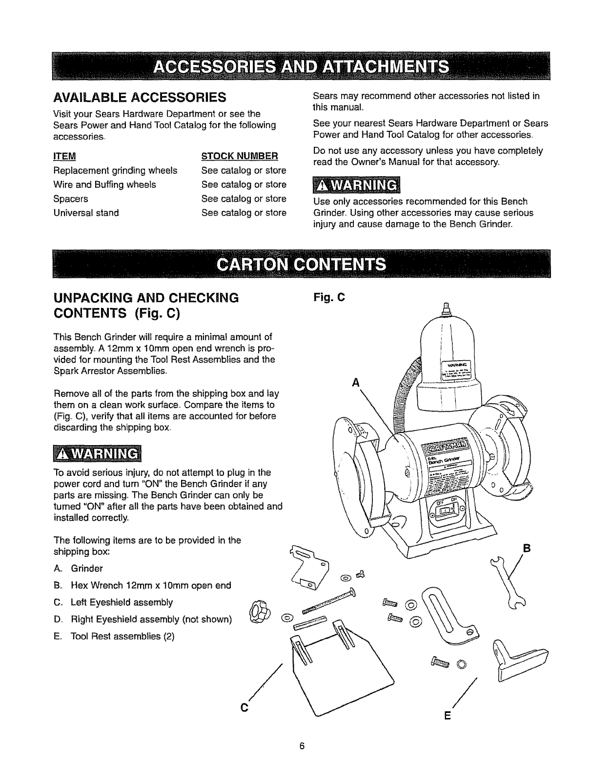
UNPACKING AND CHECKING
CONTENTS (Fig. C)
This Bench Grinder will require a minimal amount of
assembly° A 12mm x 10mm open end wrench is pro-
vided for mounting the Tool Rest Assemblies and the
Spark Arrestor Assemblies°
Remove ail of the parts from the shipping box and lay
them on a clean work surface,, Compare the items to
(Fig,, C), verify that all items are accounted for before
discarding the shipping box,.
Fig. C
A
To avoid serious injury, do not attempt to plug in the
power cord and turn "ON" the Bench Grinder if any
parts are missing. The Bench Grinder can only be
turned "ON" after all the parts have been obtained and
installed correctly.
The following items are to be provided in the
shipping box:
Am Grinder
B,. Hex Wrench 12ram x 'I0mm open end
C. Left Eyeshield assembly
Do Right Eyeshield assembly (not shown)
Eo Tool Rest assemblies (2)
C
B
65
715
16
8
3
11B
11A
10
/
9
12 4t3
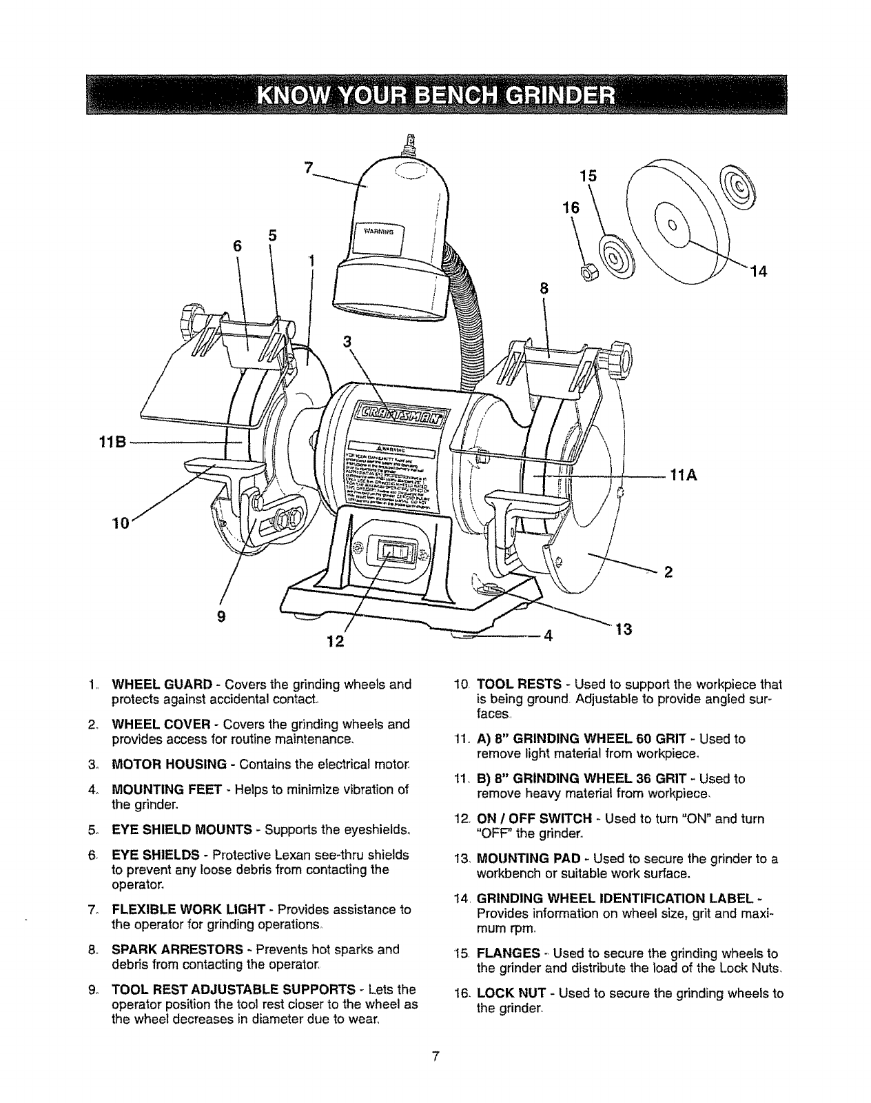
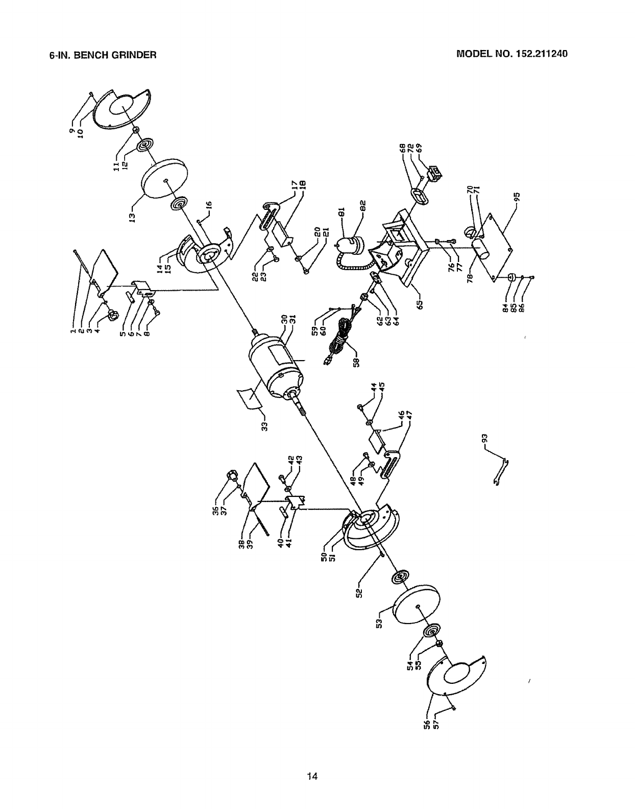
1WHEEL GUARD - Covers the grinding wheels and
protects against accidental contact
2, WHEEL COVER - Covers the grinding wheels and
provides access for routine maintenance.
3o MOTOR HOUSING - Contains the electrical motor
4_ IVIOUNTING FEET -Helps to minimize vibration of
the grinder°
5o EYE SHIELD MOUNTS - Supports the eyeshieldso
6. EYE SHIELDS - Protective Lexan see-thru shields
to prevent any loose debris from contacting the
operator.
7o FLEXIBLE WORK LIGHT - Provides assistance to
the operator for grinding operations°
8. SPARK ARRESTORS - Prevents hot sparks and
debris from contacting the operator.
9. TOOL REST ADJUSTABLE SUPPORTS - Lets the
operator position the tool rest closer to the wheel as
the wheel decreases in diameter due to wear_
10 TOOL RESTS - Used to support the workpiece that
is being ground Adjustable to provide angled sur -
faces
11. A) 8" GRINDING WHEEL 60 GRIT - Used to
remove light material from workpieceo
11_B) 8" GRINDING WHEEL 36 GRIT -Used to
remove heavy material from workpiece,
12. ON /OFF SWITCH - Used to turn "ON" and turn
"OFF" the grinder.
13, MOUNTING PAD - Used to secure the grinder to a
workbench or suitabte work surface.
14
15
16,
GRINDING WHEEL IDENTIFICATION LABEL -
Provides information on wheel size, grit and maxi-
mum rpm.
FLANGES - Used to secure the grinding wheels to
the grinder and distribute the load of the Lock Nuts_
LOCK NUT - Used to secure the grinding wheels to
the grinder.
A 12mmx 10mmopenendwrenchisprovidedfor
mountingtheToolRestAssembliesandtheSpark
ArrestorAssemblies,.
1, DONOTassembletheBenchGrinderunti!youare
surethetoolISNOTpluggedin.
2, DONOTassembletheBenchGrinderuntilyouare
surethepowerswitchisinthe"OFF"position,
3., DONOTassembletheBenchGrinderuntilyouare
surethegrindingwheelsarefirmlytightenedtothe
BenchGrinder,,
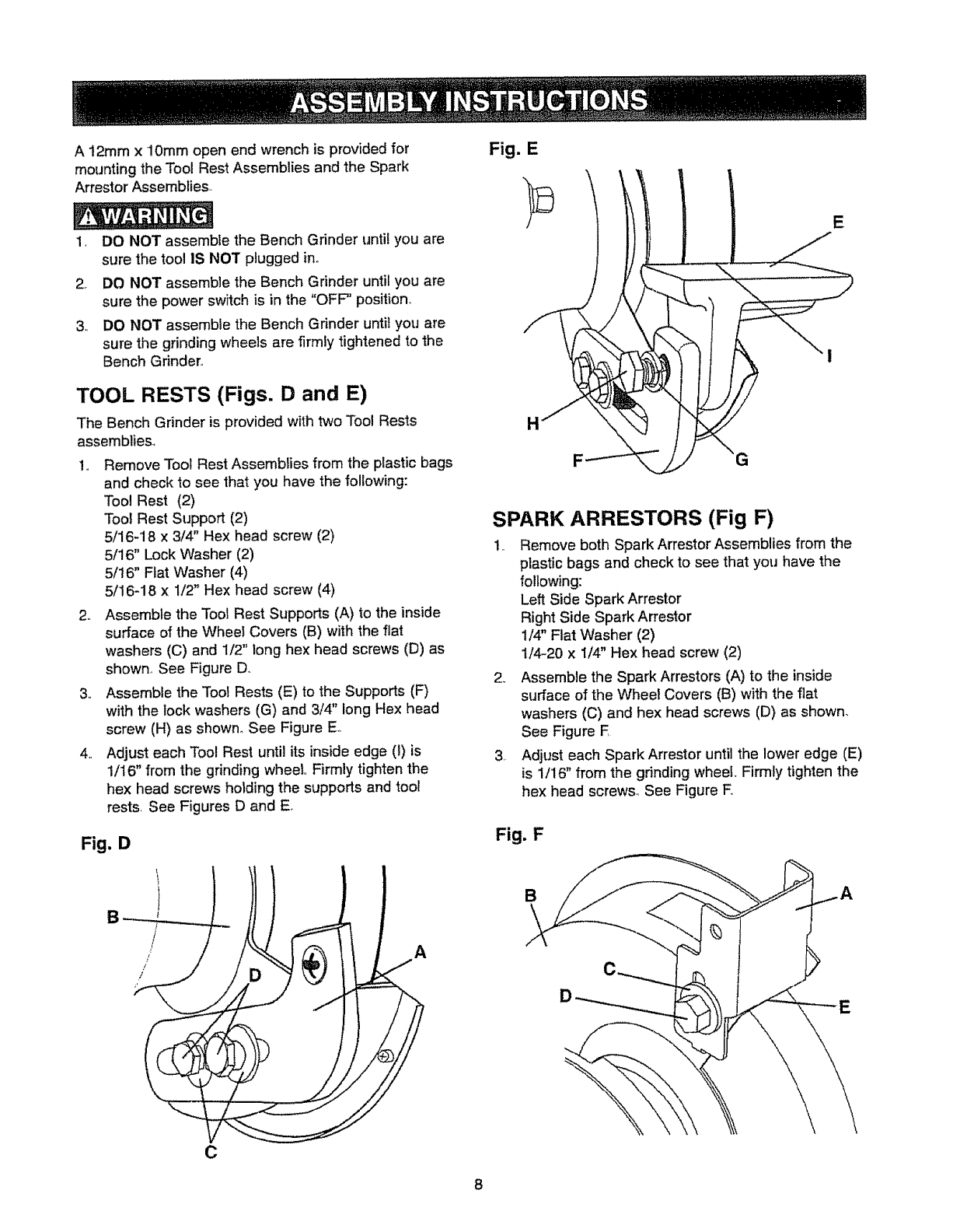
TOOL RESTS (Figs. D and E)
The Bench Grinder is provided with two Tool Rests
assemblies,,
1,, Remove Tool Rest Assemblies from the plastic bags
and check to see that you have the following:
Tool Rest (2)
Tool Rest Support (2)
5/16-18 x 3/4" Hex head screw (2)
5/16" Lock Washer (2)
5/16" Flat Washer (4)
5/16-18 x 1/2" Hex head screw (4)
2,. Assemble the Tool Rest Supports (A) to the inside
surface of the Wheel Covers (B) with the flat
washers (C) and 1/2" long hex head screws (D) as
shown° See Figure D,.
3., Assemble the Tool Rests (E) to the Supports (F)
with the lock washers (G) and 3/4" long Hex head
screw (H) as shown. See Figure Eo
4,, Adjust each Tool Rest until its inside edge (1)is
1/16" from the grinding wheel Firmly tighten the
hex head screws holding the supports and tool
rests, See Figures D and E
Fig. D
Fig. E
SPARK ARRESTORS (Fig F)
1 Remove both Spark Arrestor Assemblies from the
plastic bags and check to see that you have the
following:
Left Side Spark Arrestor
Right Side Spark Arrestor
1/4" Flat Washer (2)
t/4-20 x I/4" Hex head screw (2)
2,, Assemble the Spark Arrestors (A) to the inside
surface of the Wheel Covers (B) with the flat
washers (C) and hex head screws (D) as shown.
See Figure F
3, Adjust each Spark Arrestor until the lower edge (E)
is 1/16" from the grinding wheel. Firmly tighten the
hex head screws_ See Figure E
Fig. F
B
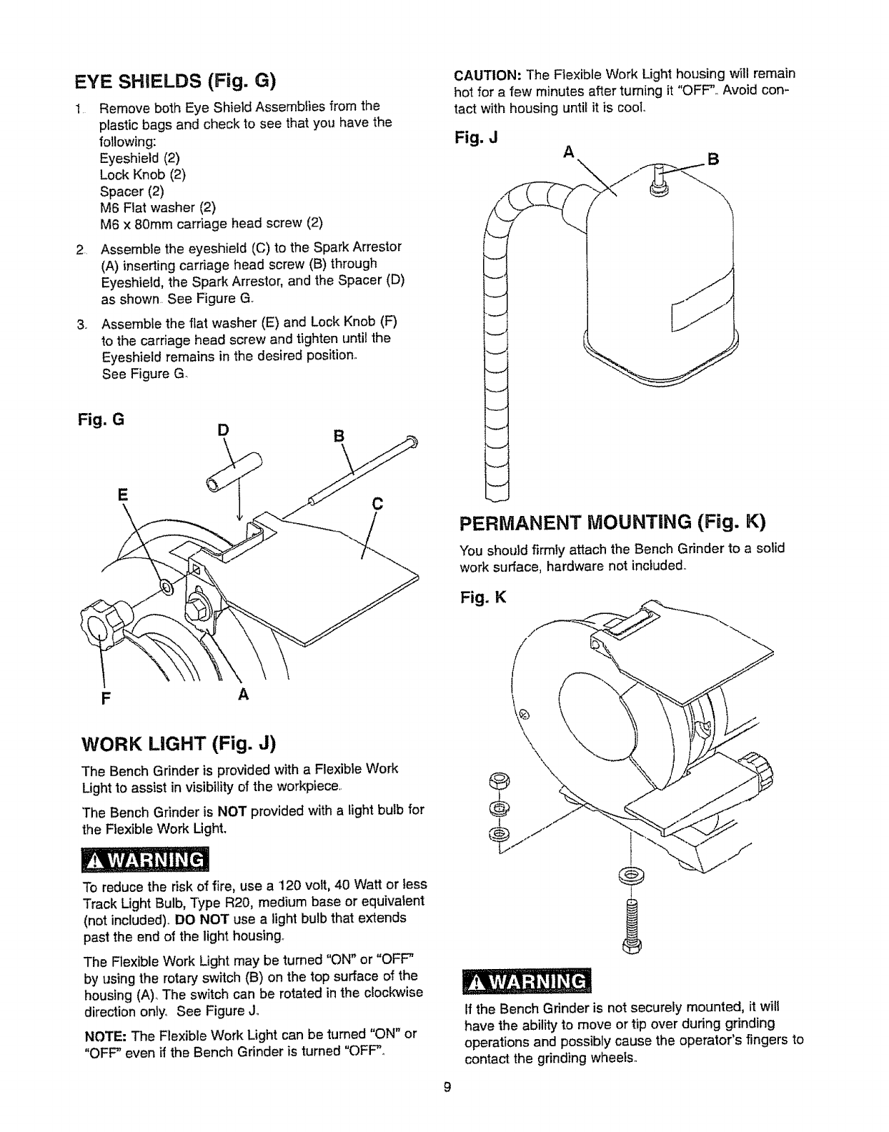
EYE SHIELDS (Fig. G)
1 Remove both Eye Shield Assemblies from the
plastic bags and check to see that you have the
following:
Eyeshield (2)
Lock Knob (2)
Spacer (2)
M6 Flat washer (2)
M6 x 80ram carriage head screw (2)
2. Assemble the eyeshield (C) to the Spark Arrestor
(A) inserting carriage head screw (B) through
Eyeshield, the Spark Arrestor, and the Spacer (D)
as shown. See Figure G.
3_ Assemble the flat washer (E) and Lock Knob (F)
to the carriage head screw and tighten until the
Eyeshieid remains in the desired position..
See Figure G.
CAUTION: The Flexible Work Lighthousing will remain
hot for a few minutes after turning it "OFF".. Avoid con-
tact with housing until it is cool.
Fig, J A\ ,B
Fig. G
E
DB
C
PERMANENT MOUNTING (Fig. K)
You should firmly attach the Bench Grinder to a sotid
work s[Jrface, hardware not inc_udedo
Fig. K
A
WORK LIGHT (Fig. J)
The Bench Grinder is provided with a Flexible Work
Light to assist in visibilityof the workpiece..
'The Bench Grinder is NOT provided with a tight bulb for
the Flexible Work Light.
\f
\\
®
®
To reduce the risk of fire, use a 120 volt, 40 Watt or tess
Track Light Bulb, Type R20, medium base or equivalent
(not included). DO NOT use a light bulb that extends
past the end of the light housing.
The Ftexible Work Light may be turned "ON" or "OFF"
by using the rotary switch (B) on the top surface of the
housing (A).,The switch can be rotated in the clockwise
direction only. See Figure J,.
NOTE: The Flexible Work Light can be tumed "ON" or
"OFF" even if the Bench Grinder is turned "OFF"°
9
If the Bench Grinder is not securely mounted, it will
have the ability to move or tip over during grinding
operations and possibly cause the operator's fingers to
contact the grinding wheels..
(
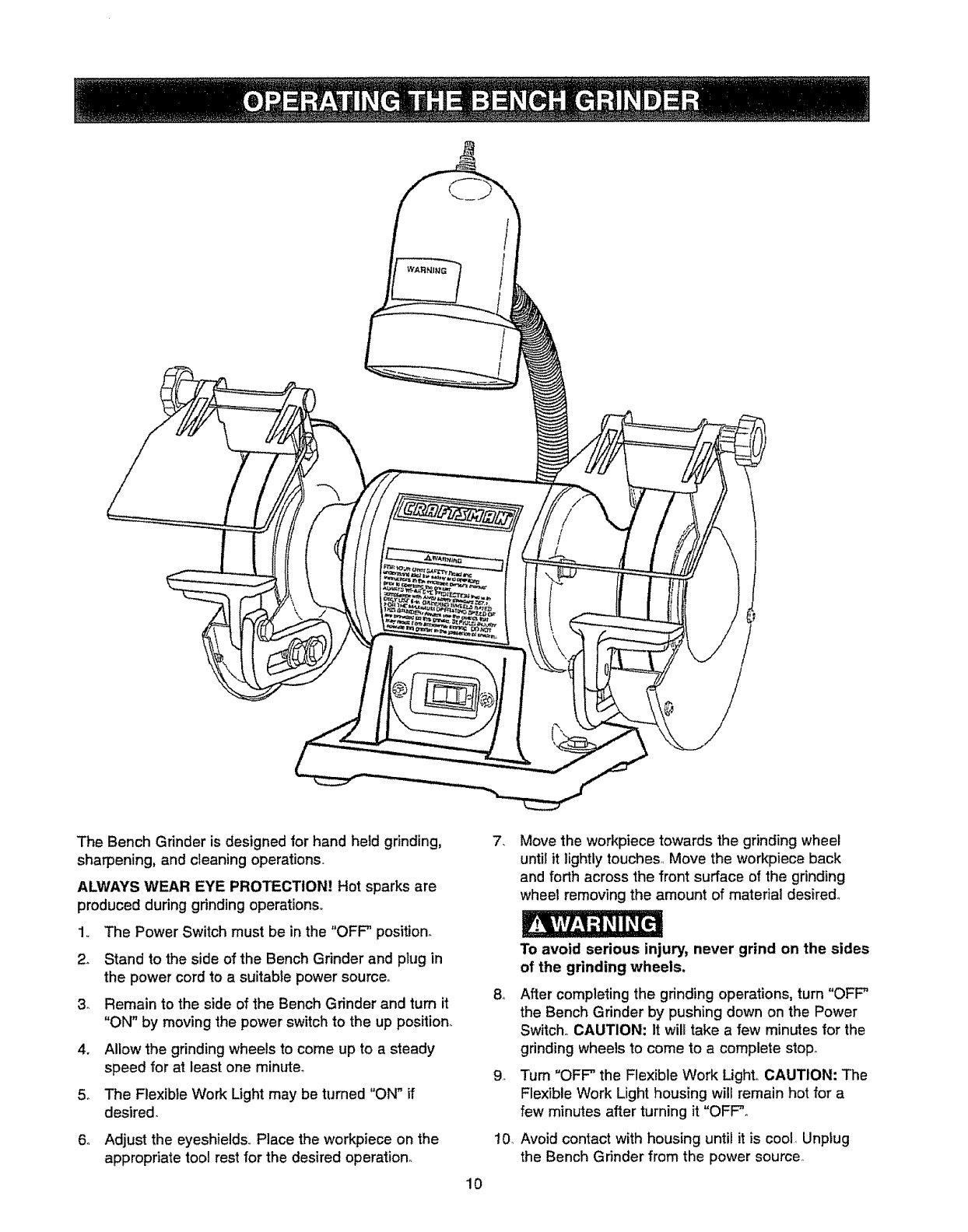
The Bench Grinder is designed for hand held grinding,
sharpening, and cleaning operations.,
ALWAYS WEAR EYE PROTECTION! Hot sparks are
produced during grinding operations,.
1,. The Power Switch must be in the "OFF" position.
2. Stand to the side of the Bench Grinder and plug in
the power cord to a suitable power source..
3_ Remain to the side of the Bench Grinder and turn it
"ON" by moving the power switch to the up position_
4. Allow the grinding wheels to come up to a steady
speed for at least one minute°
5.. The Flexible Work Light may be turned "ON" if
desired.
6o Adjust the eyeshields.. Place the workpiece on the
appropriate tool rest for the desired operation_
10
7_ Move the workpiece towards the grinding wheel
until it lightly touches1 Move the workpiece back
and forth across the front surface of the grinding
wheel removing the amount of material desired_
8_
10
To avoid serious injury, never grind on the sides
of the grinding wheels.
After completing the gdnding operations, turn "OFF"
the Bench Grinder by pushing down on the Power
Switch,. CAUTION: It will take a few minutes for the
grinding wheels to come to a complete stop_
Tum "OFF" the Flexible Work LighL CAUTION: The
Flexible Work Light housing will remain hot for a
few minutes after turning it "OFF".
Avoid contact with housing until it is cool Unplug
the Bench Grinder from the power source
CHANGING THE GRiNDiNG WHEEL (Fig. N)
Fig. N
G
M
\KL
H
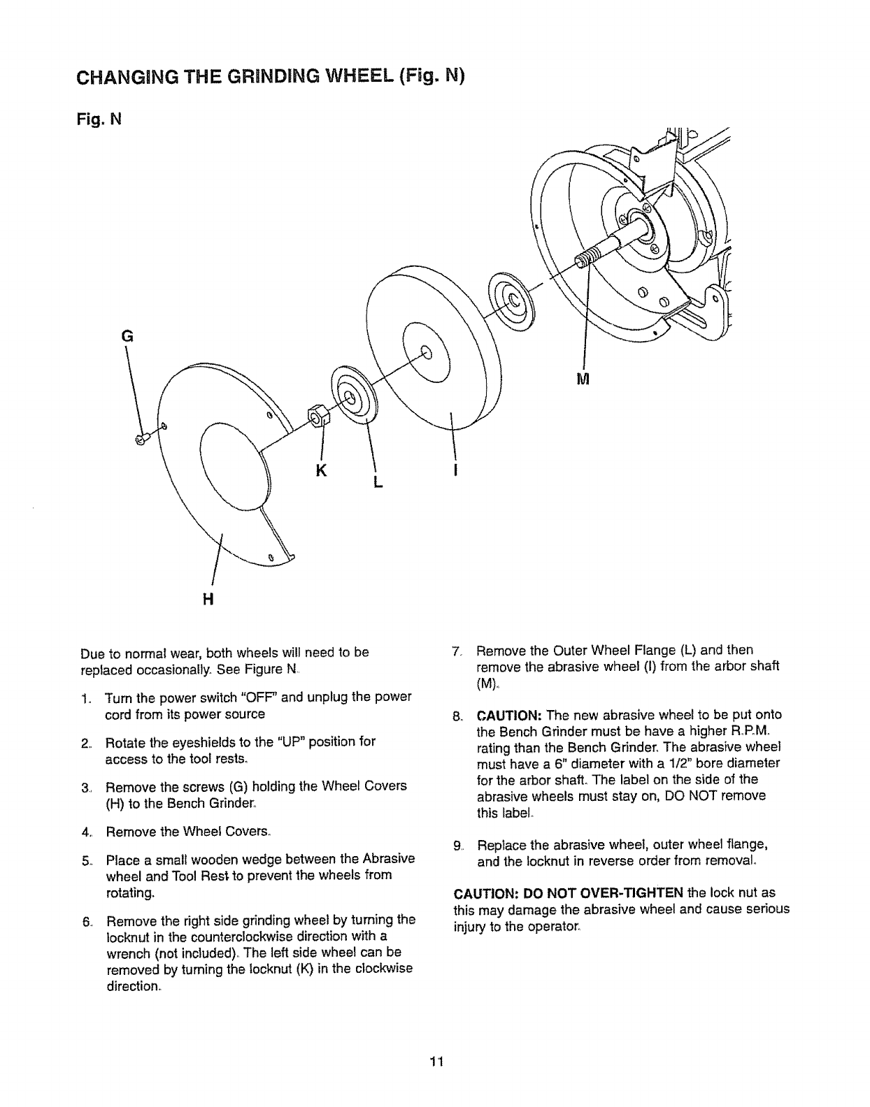
Due to normal wear, both wheels will need to be
replaced occasionally. See Figure N
1o Turn the power switch "OFF" and unplug the power
cord from its power source
2.. Rotate the eyeshields to the "UP" position for
access to the toot rests°
3, Remove the screws (G) holding the Wheel Covers
(H) to the Bench Grinder+.
4.+ Remove the Wheei Covers°
5+ Place a small wooden wedge between the Abrasive
wheel and Tool Rest to prevent the wheels from
rotating.
., Remove the right side grinding wheel by turning the
locknut in the counterclockwise direction with a
wrench (not included).. The left side wheel can be
removed by turning the !ocknut (K) in the clockwise
direction..
7+ Remove the Outer Wheel Flange (L) and then
remove the abrasive wheel (I) from the arbor shaft
(M)..
,, CAUTION: The new abrasive wheel to be put onto
the Bench Grinder must be have a higher R_PoMo
rating than the Bench Grinder° The abrasive wheel
must have a 6" diameter with a 1/2" bore diameter
for the arbor shaft+The label on the side of the
abrasive wheels must stay on, DO NOT remove
this label..
9+ Replace the abrasive wheel, outer wheel flange,
and the locknut in reverse order from removal+
CAUTION: DO NOT OVER-TIGHTEN the lock nut as
this may damage the abrasive wheel and cause serious
injury to the operator_
1+1
Turnthepowerswitch"OFF"andunplugthepower
cordfromitspowersourcepriortoanymaintenance,,
LUBRICATION
The Bench Grinder has sealed lubricatedbearings in
the motor housing that do not require any additional
lubrication from the operator,,
CLEANING
With the Bench Grinder unplugged, rotate the abrasive
wheels slowly and inspect for any damage or trapped
shavings,,
CAUTION: REPLACE the abrasive wheels if there is
amy damage at all FAILURE to reptace a damaged
wheel can cause serious injury to the operator,
CAUTION: DO NOT USE FLAMMABLE MATERIALS
to clean the Bench Grinder, A ctean dry rag or brush is
all that is needed to remove dust and debris buildup,,
Repairs to the Bench Grinder should be performed by
trained personnel only Contact your nearest Sears
Canada Inc, outlet for authorized service° Unauthorized
repairs or replacement with non-factorj parts could
cause serious injury to the operator and damage to the
Bench Gfinde[,
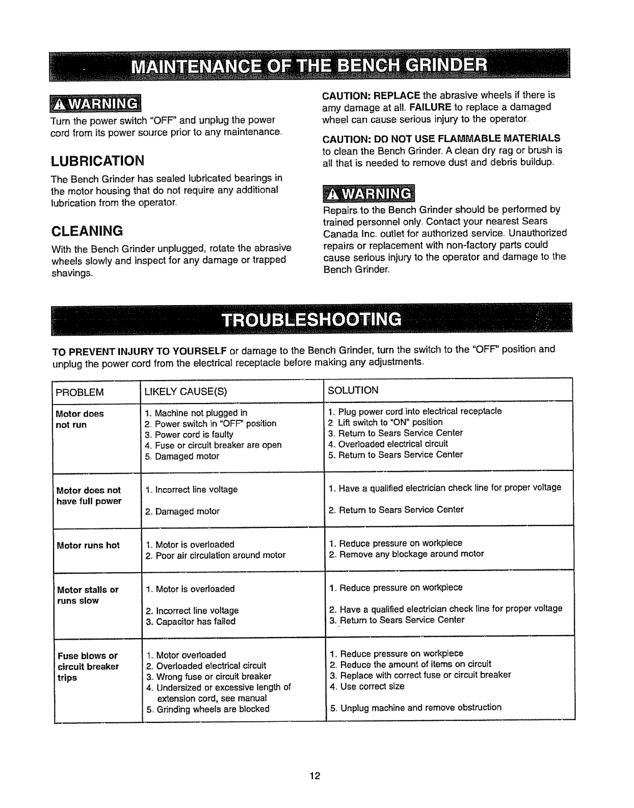
TO PREVENT INJURY TO YOURSELF or damage to the Bench Grinder, turn the switch to the "OFF" position and
unplug the power cord from the electrical receptacle before making any adjustments°
PROBLEM LIKELY CAUSE(S) SOLUTION
Motor does 1oMachine not plugged in 1,, Plug power cord into electrical receptacle
not run 2,, Power switch in "OFF" position 2 Lift switch to "ON" position
3. Power cord is faulty 3_ Return to Sears Service Center
4.,Fuse or circuit breaker are open 4. Overloaded electrical circuit
5. Damaged motor 5. Return to Sears Service Center
,, ,,,,,,,,,.....
Motor does not
have full power
Motor stalls or
runs slow
Fuse blows or
circuit breaker
trips
1.,Incorrect line voltage
2. Damaged motor
I., Motor is overloaded
2. Poor air circulation around motor
1.,Motor is overloaded
2oIncorrect line voltage
3. Capacitor has failed
t., Motor overloaded
2,,Overloaded electdcal circuit
3. Wrong fuse or circuit breaker
4. Undersized or excessive length of
extension cord, see manual
5,,Grinding wheels are blocked
1oHave aqualified electrician check line for proper voltag
2_ Retum to Sears Service Center
I. Reduce pressure on workpiece
2_ Remove any blockage around motor
1.,Reduce pressure on workpiece
2o Have a qualified electrician check line for proper volta_
3oRetum to Sears Service Center
1o Reduce pressure on workpiece
2_,Reduce the amount of items on circuit
3o Replace with correct fuse or circuit breaker
4,, Use correct size
5,,Unplug machine and remove obstruction
12
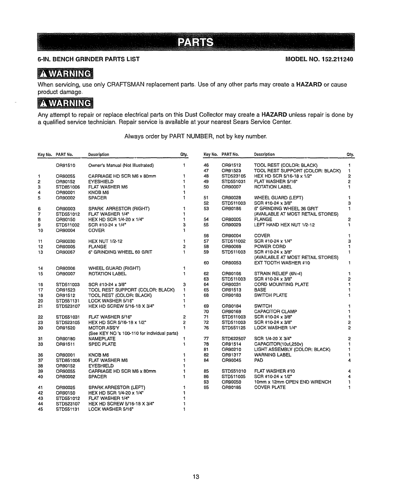
6-IN. BENCH GRINDER PARTS LIST MODEL NO. 152.211240
When servicing, use onty CRAFTSMAN replacement parts, Use of any other parts may create aHAZARD or cause
product damage.
Any attempt to repair or replace electrical parts on this Dust Collector may create a HAZARD unless repair is done by
a qualified service technician, Repair service is available at your nearest Sears Service Center.
Always order by PART NUMBER, not by key number,.
Key No. PART No. Description Qty. Key No. PART No, D_scriptfon
OR91510 Owner's Manual (Not Illustrated) 1 46 OR91512
47 OR91523
4B STD523105
49 STD551031
50 OR90007
t
2
3
4
5
6
7
8
9
10
11
12
13
t4
15
16
I7
18
20
21
22
23
30
31
33
36
37
38
39
40
41
42
43
44
45
OR90055 CARRIAGE HD SCR M6 x8Dram
OR90152 EYESHIELD
STD851006 FLAT WASHER M6
OR90001 KNOB M6
OR90002 SPACER
OR90003 SPARK ARRESTOR (RIGHT)
STD551012 FLAT WASHER 1t4"
OR90t50 HEX HD SDR t14-20 x1/4"
STD511002 SCR #!O-24 x 1/4"
ORVJO004 COVER
OR90030 HF..X NUT ti2-12
0R90005 FLANGE
OR90067 6" GRINDING WHEEL 60 GRIT
OR90006 WHEEL GUARD (RIGHT)
0R90007 ROTATION LABEL
STD511003
OR9152;3
OR9t512
STD55t13t
STD523t07
ST055103t
ST0523I 05
0R91520
ORD180
OR915tl
OR90O01
STD851oo6
OR90t52
OR90055
OR90002
OR90025
OR90t 50
STD551012
ST0523t 07
ST055!131
1
1
!
t
1
t
1
1
3
t
1
2
1
SCR #t0-24 x 3/8" 3
TOOL REST SUPPORT (COLOR; BLACK') 1
TOOL REST (COLOR: BLACK) 1
LOCK WASHER ,5116" 1
HEX HD SCREW 5t16_18 X 3/4" 1
FLAT WASHER 5/16" 2
HEX HD SCR 5/16-18 x1/2" 2
MOTOR ASS'Y 1
(See KEY NO's t00-110 for individual parts)
NAMEPLATE 1
SPEC PLATE t
KNOB M6
FLAT WASHER M6
EYESHIELD
CARRIAGE HD SCR M6 x 8Dram
SPACER
SPARK ARRESTOR (LEFT)
HEX HD SCR 114_20 x 1t4"
FLAT WASHER 1/4"
HEX HD SCREW 5/16-18 X 3/4"
LOCK WASHER 5!16'
1
1
1
1
1
t
1
1
t
1
51 OR90028
52 ST051!003
53 OR90186
54 OR90BOS
55 OR90029
56 OR90004
57 STD511002
58 OR90069
59 STD511003
60 OR90053
62 OR90166
63 STD51t003
64 OR90031
65 OR9t513
68 OR90183
69 0R90184
70 OR90!69
71 STD51t003
72 ST0511003
76 STD55t125
77 STD622507
78 OR91514
81 OR902t0
82 OR9t317
84 0R90045
85 ST0551010
86 STD511005
93 OR90050
95 OR90185
Qty.
TOOL REST (COLOR: BLACK) 1
TOOL REST SUPPORT (COLOR: BLACK) 1
HEX HD SCR 5/t6-18 x 1/2" 2
FLAT WASHER 5/I6" 2
ROTATION LABEL 1
WHEEL GUARD (LEFT) t
SCR 010-24 x 3/8" 3
6" GRINDING WHEEL 36 GRiT 1
(AVAILABLE AT MOST RETAIL STORES)
FLANGE 2
LEFT HAND HEX NUT 1/2-12 1
COVER 1
SCR 010-24 X 1/4" 3
POWER CORD 1
SCR 010-24 x3/8" 1
(AVAILABLE AT MOST RETAIL STORES)
EXT TOOTH WASHER #10 1
STRAIN RELIEF (6N_4)
SCR i110-24 x 3/8"
CORD MOUNrTING PLATE
BASE
SWiTCH PLATE
SWITCH
CAPACITOR CLAMP
SCR f_10"24 x 3/8"
SCR 4110-24 x 318"
LOCK WASHER t/4"
SCR 1t4-20 X 3/4"
CAPACFFOR(10ui,250v)
LIGHT ASSEMBLY (COLOR: BLACK)
WARNING LABEL
PAD
FLAT WASHER #10
SCR #10-24 x 1/2"
10ram x 12ram OPEN END WRENCH
COVER PLATE
1
2
1
1
1
1
1
1
2
2
2
1
1
1
4
4
4
1
1
13
6-IN. BENCH GRINDER MODEL NO. 152.211240
\
ruo'J
u')
,_or_
u'_ it)
t4

÷ NOYE$ ÷
15

16

ManuaU del Proprietario
Rueda de 6 puig.
113 caballo de fuerza (mdximo desarrollado)
1/6 cabalio de fuerza (servicio continuo)
3450 R.P.IVl. (velocidad sin carga)
WARN|NG
No. de Modelo
152.211240
®
US
PRECAUCION:
PARA SU SEGURIDAD PERSONAL;
Lea y obedezca todas las
tnstruccionesde Seguridad y
Funcionamiento antes de accionar
esta Rectificadora de Banco.
[Jnea de Ayuda al Cliente
1-800-897-7709
Sirvase tener listo su
Noode Modelo y No. de Serie
Sears, Roebuck and Co., Hoffman Estates, IL 60179 U.S.A.
No. de Pieza OR91510 VER. 2.07
17
SECC!ON PAGINA
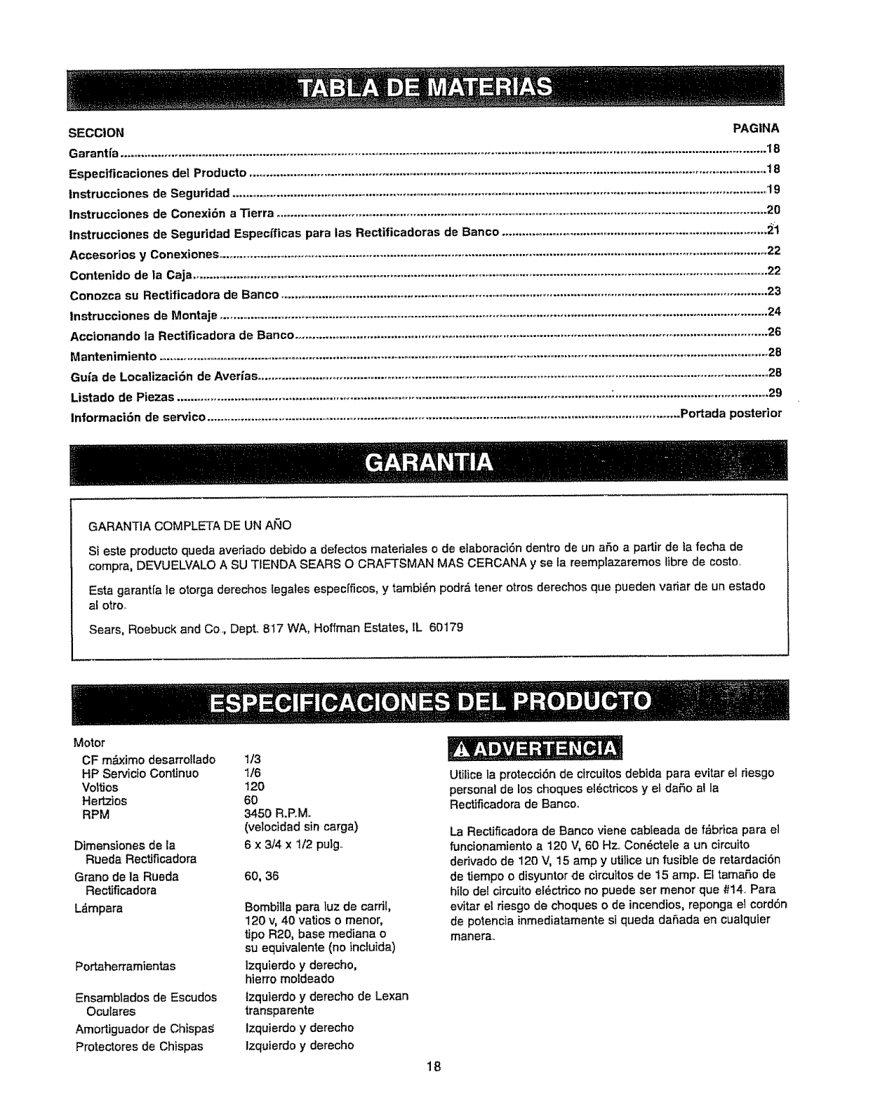
Garantfa ....................................................................................................................................................................................................... 18
Especificaciones del Producto .................................................................................................................................................................. 18
lnstrucciones de Seguridad ............................................................................................................................................................................19
Instrucciones de Conexi6n a Tierra ..............................................................................................................................................................20
Instrucciones de Seguridad Especfficas para tas Rectificadoras de Banco .....................................................................................2i
Accesorios y Conexiones ......................................................................................................................................................................... 22
Contenido de la Caja ..................................................................................................................................................................................... 22
Conozca su Rectificadora de Banco ...................................................................................................................................................................23
instrucciones de Montaje ........................................................................................................................................................................... 24
Accionando la Rectificadora de Banco ........................................................................................................................................................26
Mantenimiento .......................................................................................................................................................................................................28
Gufa de Localizaci_n de Aver_as.................................................................................................................................................................. 28
Listado de Piezas .................................................................................................................................... '............................................... 29
lnformaciSn de servico ............................................................................................................................................... Portada posterior
GARANTIA COMPLETA DE UN AI_tO
Si este producto queda averiado debido adefectos materiales o de elaboraci6n dentro de un aSo a partir de ta fecha de
compra, DEVUELVALO A SU TIENDA SEARS O CRAFTSMAN MAS CERCANA y se la reemplazaremos libre de costo.
Esta garantfa le otorga derechos legales especfficos, y tambi6n podrd tener otros derechos que pueden variar de un estado
al otroo
Sears, Roebuck and Co, Depto 817 WA, Hoffman Estates, IL 60179
Motor
OF m_.ximo desarrotlado 1/3
HP Servicio ContJnuo 1/6
Vottios !20
Hertzios 60
RPM 3450 R.PMo
(velocidad sin carga)
Dimensiones de la 6 x3/4 x 1/2 pulg.
Rueda Rectificadora
Grano de la Rueda 60, 36
Rectificadora
Ldmpara Bombitla para luz de card!,
120 v, 40 vatios o menor,
tipo R20, base mediana o
su equivalente (no incluida)
lzquierdo y derecho,
hierro moldeado
Izquierdo y derecho de Lexan
transparente
Izquierdo y derecho
Izquierdo y derecho
Portaherramientas
Ensambtados de Escudos
Oculares
Amortiguador de Chispa_
Protectores de Chispas
Utilice la protecci6n de circuitos debida para evitar el riesgo
personal de los choques el_ctricos ye! daSo al la
Rectificadora de Baneoo
La Rectificadora de Banco viene cableada de f_brica para el
funcionamiento a 120 V, 60 Hz. Con6ctete a un circuito
dedvado de 120 V, t5 amp y utilice un fusible de retardaci6n
de tiempo o disyuntor de circuitos de 15 amp. El tamaSo de
hilo del circuito el_ctrico no puede ser menor que #14 Para
evitar el riesgo de choques o de incendios, reponga el cordon
de potencia inmediatamente si queda daSada en cualquier
manera
18
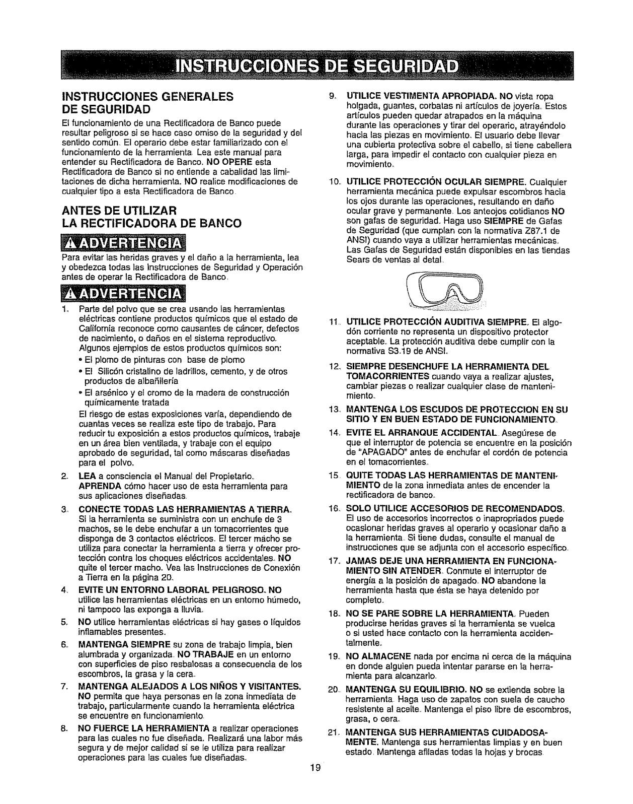
INSTRUCCIONES GENERALES
DE SEGURIDAD
E{ funcionamiento de una Rectificadora de Banco puede
resuftar peligroso si se hace caso orniso de la seguridad y del
sentido cornL_n_El operario debe estar farniliadzado con el
funcionamiento de la herramienta, Lea este manual para
entender su Rectificadora de Banco,. NO OPERE esta
Rectificadora de Banco si no entiende a cabalidad las limi_
taciones de dicha herrarnienta. NO realice modificaciones de
cuaiquier tipo a esta Rectificadora de Banco.
ANTES DE UTILIZAR
LA RECTIFICADORA DE BANCO
Para evitar tas heridas graves yel daSo a ta herramienta, lea
y obedezca todas tas tnstrucciones de Seguddad y Operaci6n
antes de operar la Rectificadora de Banco,
1o Parte del polvo que se crea usando las herramientas
el6ctricas contiene productos qufmicos queet estado de
California reconoce como causantes de c_ncer, defectos
de nacimiento, o daSos en el sisterna reproductivo,
Algunos ejernptos de estos productos qufmicos son:
= Et plomo de pinturas con base de plomo
o El Silic6n cdstalino de ladrilios0 cernento, y de otros
productosde albaSiler_a
. E] ars6nico y el cromo de la madera de construcci6n
qu_micamente tratada
El riesgo de estas exposiciones varfa, dependiendo de
cuantas veces se realiza este tipo de trabajo. Para
reducir tu exposici6n a estos productos qufrnicos, trabaje
en un &rea bien ventilada, y trabaje con el equipo
aprobado de seguridad, tal como rn&scaras diseSadas
para el polvo.
2. LEA aconsciencia el Manual del Propietario,,
APRENDA c6mo hacer uso de esta herramienta para
sus aplicaciones diseSadas,
3., CONECTE TODAS LAS HERRAMIENTAS ATIERRAo
Si ta herramienta se suministra con un enchufe de 3
machos, se le debe enchufar a un tornacorrientes que
disponga de 3 contactos et_ctricos_ Ei tercer macho se
utiliza para conectar la herramienta a tierra y ofrecer pro-
tecci6n contra los choques el_ctricos accidentaleso NO
quite el tercer macho. Vea las lnstrucciones de Conexi6n
a Tierra en la p_gina 20.,
4, EVITE UN ENTORNO LABORAL PEUGROSO° NO
utiiice las herramientas e!6ctdcas en un entorno hSmedo,
ni tampoco las exponga a ituviao
5,, NO utilice herramientas el_c_ricas si hay gases o Ifquidos
inflamables presentes,,
6,, MANTENGA SIEMPRE su zona de trabajo lirnpia, bien
alumbrada y organizada NO TRABAJE en Un entorno
con superficies de piso resbalosas a consecuencia de los
escornbros, la grasa y la cera,,
7. MANTENGA ALEJADOS A LOS NII_IOS Y VtSITANTES_
NO perrnita que haya personas en la zona inrnediatade
trabajo, particularmente cuando la herramienta el_ctrica
se encuentre en funcionamiento.
8. NO FUERGE LA HERRAMIENTA a realizar operaciones
para las cuales no fue diseSada. Realizar_ una labor m&s
segura y de major calidad si sete utiliza para realizar
operaciones para las cuales fue disefadaso
94
"I0,.
19
1"{,,
12o
1 3._
t4,
15_
UTlUCE VESTIMENTA APROPIADA. NO vista ropa
holgada, guantes, corbatas ni artfculos de joyeria,, Estos
artfcutos pueden quedar atrapados en la m&quina
durante las operaciones y tirar del operafio, atray6ndolo
hacia tas piezas en movimiento° El usuario debe llevar
una cubierta protectiva sobre el cabeklo, si tiene cabe!lera
larga, para impedir el contacto con cuatquier pieza en
rnovimientoo
UTILICE PROTECCION OCULAR SIEMPRE. Cua[quier
herrarnienta rnecdnica puede expulsar escornbros hacia
fos ojos durante las operaciones, resuttando en daSo
ocular grave y permanente, Los anteojos cotidianos NO
son gafas de seguddad., Haga uso SlEMPRE de Gafas
de Seguridad (que cumplan con la norrnativa Z87.1 de
ANSI) cuando vaya a utilizar herramientas mec&nicas.,
Las Galas de Seguddad est,_n disponibles en las tiendas
Sears de ventas al detal,,
UTtLICE PROTECCION AUDITiVA SIEMPRE,, Ef algo-
d6n corriente no representa un dispositivoprotector
aceptable,, La protecci6n auditiva debe cumplir con la
normativa $3.19 de ANSL
SIEMPRE DESENCHUFE LA HERRAMIENTA DEL
TOMACORRIENTES cuando vaya a realizar ajustes,
cambiar plazas o reaiizar cualquier clase de rnanteni-
rniento.
MANTENGA LOS ESCUDOS DE PROTECCION EN SU
SITIO Y EN BUEN ESTADO DE FUNCIONAMIENTOr,
EVITE EL ARRANQUE ACCIDENTAL. Aseg_rese de
qua el interruptor de potencia se encuentre en Eaposici6n
de "APAGADO" antes de enchufar el cord6n de potencia
en el tomacorrienteso
QUITE TODAS LAS HERRAMIENTAS DE MANTENF
MIENTO de la zona inmediata antes de encender la
rectificadora de banco.
16, SOLO UTILICE ACCESORIOS DE RECOMENDADOS,
Et uso de accesorios incorrectos oinapropriados puede
ocasfonar heddas graves al operario y ocasionar dafio a
la herramienta. Si tiene dudas, consulte e[ manual de
instrucciones que se adjunta con el accesofio especffico,
17,, JAMAS DEJE UNA HERRAMIENTA EN FUNCIONA-
MIENTO SIN ATENDERo Conmute el interruptor de
energt'a a la posici6n de apagado,, NO abandone la
herramienta hasta que _sta se haya detenido por
completo,
18o NO SE PARE SOBRE LA HERRAMIENTA, Pueden
producirse heridas graves si la herramienta se vueLca
o si usted hace contacto con Faherrarnienta acciden-
talmente_
19,, NO ALMACENE nada por encima ni cerca de la m_.quina
en donde alguien pueda intentar pararse en la herra-
rnienta para alcanzarlo,
20, MANTENGA SU EQUILIBR10. NO se extienda sobre [a
herramienta. Haga uso de zapatos con suela de caucho
resistente al aceite,. Mantenga el piso libre de escombros,
grasa, o cera.
21_ MANTENGA SUS HERRAMIENTAS CUIDADOSA-
MENTE. Mantenga sus herramientas iirnpias yen buen
estado, Mantenga afifadas todas la hojas y brocas
22 REVISE Si HAY PIEZAS DAI_IADAS ANTES DE CADA
use DE LA HERRAMIENTA. Revise redes los protec-
totes cuidadosamente para eomprobar que funcionan
correctamente y que no est_n daSados, y q[Je realizan
sus funciones diseSadas correctamenteo Revise el alinea-
miento, fa fijaci6n ota ruptura de las piezas on movimien-
to. Cualquier protector u otra pieza que se encuentre
daSada debe repararse o reemplazarse inmediatamente..
23. HAGA SU TALLER A PRUEBA DE NII_IOS quitando las
|laves de1 interrupter, desenchufando las herramientas de
ios tomacorrientes y mediante el use de candados
24. NO OPERE LA HERRAMIENTA BAJO LA INFLUENCIA
DE LAS DROGAS ODEL ALCOHOL.
25, AFIANCE TODO EL MATERIAL. UtiLice abrazaderas o
plantillas para asegurar el materia!., Esto ofrece mayor
seguridad que intentar sujetar ef material con sus propias
manos,
26, UTILICE UNA EXTENSION ELECTRICA CORRECTA Y
EN BUEN ESTADO,, Cuando vaya ahacer use de una
extensi6n el_etrica, aseg_rese de utifizar una que sea _o
suficientemente fuerte come para transportar la corriente
a ser utilizada per su herramienta. La siguiente tab_apre-
senta tas dimensiones correctas a uti[izarse de acuerdo
con tas dimensiones de la extensi6n y ta clasificaciSn de
amperaje en la placa de notaciones. Si tiene dudas,
utitice la siguiente extensiSn de mayor calibre.. Mientras
menor sea el n0mero de calibre, mayor serd el didmetro
de la extensi6n etdctrica. Si tiene dudas sobre las dimen-
siones correctas de una extensi6n et_.ctrica, utitice un
cord6n m,_s corto y m&s grueso. Una extensi6n de
dimensiones insuficientes producir& una cafda en el
vo)taje de Ifnea, resultando en una p_rdida de potencia y
el sobrecaientamiento. SOLO UTILICE UNA EXTEN-
SION ELECTRICA DE 3 HILOS QUE DISPONGA DE UN
ENCHUFE DE CONEXION A TIERRA DE 3 MACHOS, Y
UN RECEPTACULO DE 3 POLOS QUE ACEPTE EL
ENCNUFE DE LA MAQUINA.
DIRECTRICES PARA LAS
EXTENSlONES ELECTRICAS
St est.1 haciendo use de una extensidn eldctrica a la
intemperie, est_ seguro de que la extensi6n se encuentre
marcada con °W-A" ("V¢'en el CanadA), lo que indica que su
use a ia intempefie es aceptable_
Estd seguro de! dimensionamiento correcto de su exten-
si6n et6ctrica, y que se encuentre en buen estado ei_ctrico.
Repare siempre una extensi6n el6ctrica daSada, o procure
que una persona experta la repare antes del use,,
Proteja sus extensiones et_ctricas contra los objetos
filosos, et taler on exceso y los tugares mojades o hOmedos_
FUNCIONAMIENTO A 120 VOLTIOS SOLAMENTE
P,ES loopIES
DE LARGO DE LARGO
I
0 to 6AmpeSos!
6 toI0 Amperios
10to 12Amperios
18 AWG
18AWG
16 AWG
50 PIES
DE LARGO
16 AWG
16AWG
t6 AWG
16 AWG
I4 AWG
14 AWG
' PSES
DE LARGO
14AWG
t2 AWG
12AWG
EN EL CASe DE UN MALFUNCIONAMIENTO OAVERIA, |a
conexi6n a tierra ofrece el trecho de menor resistencia para _a
corriente el_ctrica y reduce el riesgo de los cheques e]_ctri-
cos. Esta herramienta viene equipada con un cord6n ef6ctrico
que dispone de un conductor de conexi6n a tierra para el
equipo asf come un enchufe de conexiSn a tierra.. El enchufe
DEBE estar enchufado aun tomacordentes adaptado que
haya side correctamente instalado yconectado a tierra de
acuerdo con TODOS los c6digos y ordenanzas municipales..
NO MODIFIQUE EL ENCHUFE SUMINISTRADOo Haga que
un electricista calificado instale el tomacorrientes apropiado si
e] enchufe no cabe en el tomacorfientes,,
LA CONEXION ELECTRICA INDEBIDA de_ conductor de
conexiSn atierra para el equipo puede resultar en el riesgo
de cheques ei6ctricos. El conductor con el aistamiento verde
(con o sin rayas amarillas) es el conductor do conexi6n a
tierra para el equipo., NO conecte el conductor de conexi6n a
tierra para el equipo auna terrninaci6n viva si resuita nece-
sario reparar o reemplazar el cord6n et6ctdco oe] enchufe,,
CONSULTE con un etectricis_ calificado o personal de servi-
cio si no entiende las instrucciones de conexi6n a t_erra com-
pletamente, o si no est_ seguro que la herra-mienta est_
debidamente conectada a tierra.
SOLO UT1LICE UNA EXTENSION ELECTRICA DE 3 HILOS
QUE DISPONGA DE UN ENCHUFE DE CONEXION ATIER-
RA DE 3 MACHOS, Y UN RECEPTACULO DE 3 POLOS
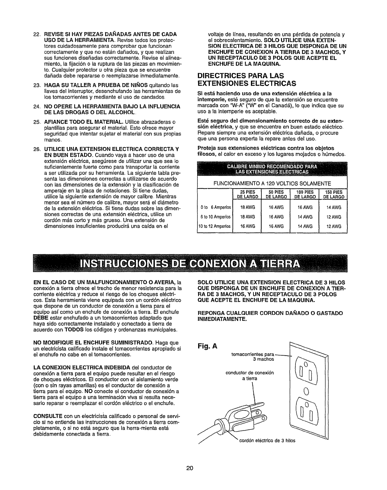
QUE ACEPTE EL ENCHUFE DE LA MAQUINA.
REPONGA CUALQUIER CORDON DA_IADO O GASTADO
INMEDIATAMENTE.
Fig. A
tomacorrientes para
3machos
conductor de conexi6n
a tierra
2O
Q
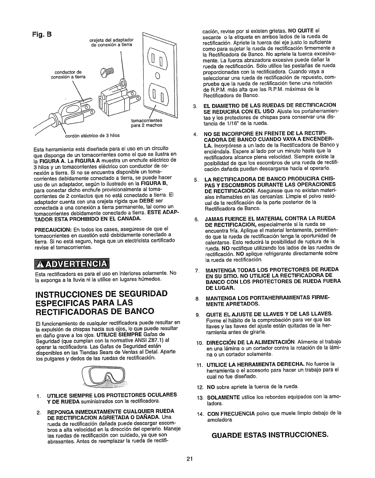
Fig. B
conductor de
conexi6n a tierra
orejeta det adaptador
de cone×iSn a tierra
tomacor_entes
para 2 machos
cord6n ei_ctrico de 3hilos
Esta herramienta est_ diseSada para el uso en un circuito
que disponga de un tomacorrientes como el que se ifustra on
la FIGURA A. La FIGURA Amuestra un enchufe ef_ctrico de
3 hi_osy un tomacorrientes el6ctrico con conductor de coo
nexi6n a tierra,, Si no se encuentra disponible un toma-
corrientes debidamente conectado a tierra, se puede hacer
uso de un adaptador, sedan Io i]ustrado en |a FIGURA B,
para conectar dicho enchufe provisionalmente a[ tomm
corrientes de 2 contactos que no est& conectado a tierra_ El
adaptador cuenta con una orejeta rigida que DEBE ser
conectada auna conexi6n atierra permanente, tal como un
tomacordentes debidamente conectado a tierra,, ESTE ADAP-
TADOR ESTA PROHIBIDO EN EL CANADA,
PRECAUCION: En todos toscases, aseg_Jrese de que el
tomacorrientes on cuesti6n est_ debidamente conectado a
tierra. Si no est_ seguro, haga que un electdcista certificado
revise el tomacorrientes..
Esta rectificadora es para el uso en intefiores solamente, No
la exponga a la lluvia ni la utilice en tugares h0medos.,
INSTRUCCIONES DE SEGURIDAD
ESPECIFICAS PARA LAS
RECTIFiCADORAS DE BANCO
El funcionamtento de cualquier rectificadota puede resuitar en
la expuisi6n de chispas hacia sus ojos, Io que puede resultar
en daSo grave alos ojoso UTILICE SIEMPRE Gafas de
Seguridad (que cumplan con la normative ANSt Z87,,t) al
operar la rectificadorao Las Galas de Seguridad est_n
disponibies en las Tiendas Sears de Ventas al DetaL Aparte
los pulgares y dedos de las ruedas de rectificaci6n.
Io UTILICE StEMPRE LOS PROTECTORES OCULARES
Y DE RUEDA suminlstrados con ta rectificadora.
2_ REPONGA INMEDIATAMENTE CUALQUtER RUEDA
DE RECTIFICACION AGRIETADA O DA_ADA, Una
rueda de rectificaci6n da_ada puede descargar escom-
bros a alia velocidad en la direcci6n del operado,, Maneje
las ruedas de rectificaci6n con cuidado, ya que son
abrasantes,, Antes de reempiazar la rueda de rectifi-
3,
4_
5,
8.
g,,
t0o
11.
caci6n, revise por si existen gdetas. NO QUITE el
secante o la etiqueta en ambos lados de Is rueda de
rectificaci6n_ Apriete la tuerca del eje justo Io suficlente
como para sujetar la rueda de rectificaciSn firmemente a
fa Rectificadora de Banco,, No apriete la tuerca excesiva-
mente.. La fuerza abrazadora excesive puede dafiar la
rueda de rectificaci6no $61o utilice las pestaSas de rueda
proporcionadas con la rectificadora, Cuando vaya a
seleccionar una rueda de rectificaci6n do repuesto, com-
pruebe que [a rueda de rectificaciSn tiene una notaci6n
de R.,P.M,,m&s alta que las RP,M. m_.ximas de la
Rectificadora de Banco.,
EL DIAMETRO DE LAS RUEDAS DE RECTIFtCACION
SE REDUCIRA CON EL USO. Ajuste los portaherramien-
tas y tos protectores do chispas para conservar una dis-
tancia de 1/16" de la rueda.,
NO SE INCORPORE EN FRENTE DE LA RECTIR-
CADORA DE BANCO CUANDO VAYA A ENCENDER-
LA. Incorp6rese aun lado do la Rectfflcadora de Banco y
enci6ndala. Espere al lado por un minuto hasta que la
rectificadora alcance ptena velocidad,, Siempre existe la
posibilidad de que los escornbros de una rueda de rectifF
cac_6n daF1adapuedan descargarse hacia et operado,
LA RECTIFICADORA DE BANCO PRODUCIRA CHIS-
PAS Y ESCOMBROS DURANTE LAS OPERACIONES
DE RECTIFICACION Asegurese que no existan materi-
ales inflamables en tas cercanfas,,Limpie el polvo resid-
ual de la rectificaci6n de la parte posterior de la
Rectificadora de Banco_
JAMAS FUERCE EL MATERIAL CONTRA LA RUEDA
DE RECTIFICACION, especiaLmente si fa rueda se
encuentra frfa. Aplique el matedai lentamente, permitien-
do que la rueda de rectificaciSn tonga la oportunidad de
caTentarse_Esto reducird la posibilidad de ruptura de ia
rueda., NO rectifique utifizando los lados de las ruedas de
rectificaci6n. NO aptique refrigerante directamente sobre
Ia _Jeda do rectificaciSn,
MANTENGA TODAS LOS PROTECTORES DE RUEDA
EN SU SITIO, NO UTILICE LA RECTIFICADORA DE
BANCO CON LOS PROTECTORES DE RUEDA F(JERA
DE LUGAR.
MANTENGA LOS PQRTAHERRAMtENTAS FIRME-
MENTE APRETADOS°
QUITE EL AJUSTE DE LLAVES Y DE LAS LLAVES.
Forme el h_bito de _acomprobaci6n para vet que las
Itaves y Ias ILavesdel ajuste estdn quitadas de la her-
ramfenta antes de girafla,,
DIRECCI6N DE LA ALIMENTACION. Atimente ei trabajo
en una l_mina o un cortador contra Ia rotaci6n de ia _mi-
na o un cortador sofamente_
u'rILICE LA HERRAMIENTA DERECHA. No fuerce ia
herramienta o el accesofio para hacer un trabajo para el
cual no fue diseSado_
12. NO sobre apriete la tuerca de la rueda_
13. SOLAMENTE utilice _os rebordes equipados con Laamo-.
tadora.
14_ CON FRECUENCIA polvo que muele limpio debajo de la
amoladora
GUARDE ESTAS INSTRUCClONES,
21
ACCESORIOS DISPONIBLES
V_site su Departamento de Ferreter_a de Sears o consuite el
Cat&logo de Herramientas Mec_nicas y de Mane para los
siguientes accesorios:
ARTICULO
Ruedas de rectificaci6n do
repuesto
Ruedas de alambre y pulido
Espaciadores
Estante universal
NUMERO DE EXISTENCIA
Ver cat&logo o tienda
Ver cat&logo of3enda
Ver cata'logoo tienda
Ver cat&logo o tienda
Sears podr_ recomendar otros accesorios que no aparecen
listados on ese manual°
Consulte con su Departamento de Ferreterfa de Sears o con-
su?te el Cat, logo de Herramientas Mec_nicas y de Mane para
otros accesorios:
No utitice ninglJn accesorio a menos que haya lefdo el
manual del Propietado para dicho accesorio,
S6Io uUlicelos accesodos recomendados para esta
Rectificadora de Banco,, El use de otros accesorios podr&
ocasionar tesionamientos graves y dafiar la Rectificadora de
Banco,.
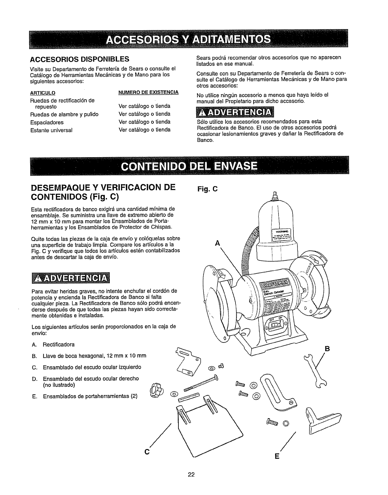
DESEMPAQUE Y VERIFICACION DE
CONTENIDOS (Fig. C)
Esta rectificadora de banco exigir& una cantidad mfnima de
ensamblaje,. Se suministra una Have de extreme abierto de
12 mmx 10 mm para montar fos Ensamblados de Porta-
herramientas y los Ensamblados de Protector de Chispas.
Quite todas las piezas de ta caja de envfo y col6quetas sobre
una supe_cie de trabajo limpia., Compare los artfculos a la
Fig° C y verifique que redes los artfculos est_n contabitizados
antes de descartar la caja de envioo
Fig. C
A
Para evitar heridas graves, no intente enchufar el cordSn de
potencia y encienda la Rectificadora de Banco si fatta
cualquier pieza. La Rectificadora de Banco s61o podr& encen -
derse despu6s de que todas las plezas hayan side correcta-
mente obtenidas einstatadas,.
Los siguientes art[culosser_n proporcionados en la caja de
envio:
A.. RectJficadora
Be Uave de boca hexagonal, 12 mm x 10 mrn
C. Ensambiado del escudo ocular izquierdo
D. Ensamblado de?escudo ocular derecho
(no ilustrado)
Eo Ensamblados de portaherramientas (2)
B
C/
E
22
65
8
15
16
4
3
11B
_11A
10
/
9
12 413
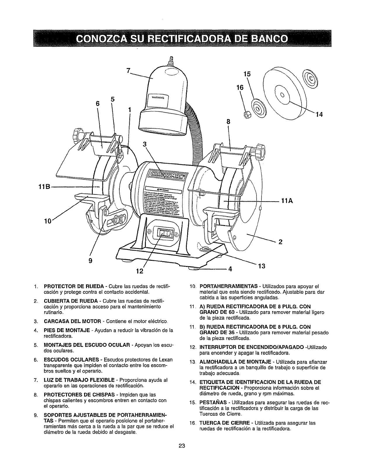
1., PROTECTOR DE RUEDA - Cubre las ruedas de rectifi-
caci6n y protege contraet contacto accidental°
2o CUBIERTA DE RUEDA - Cubre las ruedas de rectifi-
caci6n y proporciona acceso para et mantenimiento
rutinario.,
4.
5_
6,,
7.
9,,
CARCASA DEL MOTOR - Contiene e?motor el6ctfico.
PIES DE MONTAJE - Ayudan a reducir ?avibraci6n de la
rectificadorao
MONTAJES DEL ESCUDO OCULAR - Apoyan los escu_
dos ocuiares.,
ESCUDOS OCULARES - Escudos protectores de Lexan
transparente que impiden el contacto entre los escom-
bros sueltos y el operario.
LUZ DE TRABAJO FLEXIBLE _Proporciona ayuda al
operado en tas operaciones de rectificaci6n.
PROTECTORES DE CHISPAS - Impiden que las
chispas calientes y escombros entren en contacto con
el operafio.
SOPORTES AJUSTABLES DE PORTAHERRAMIEN-
TAS - Permiten que el operario posicione el portaher-
ramientas m,Sscerca a la rueda a la par que se reduce el
di_,metrode la rueda debido al desgaste,
11,
1!.
12,
13.
PORTAHERRAMIENTAS - Utilizados para apoyar el
material que esta siendo rectificado. Ajustable para dar
cabida alas superficies anguladas.
A) RUEDA RECTIFICADORA DE 8 PULG. CON
GRANO DE 60 - UtiEizadopara remover material ligero
de la pieza rectJflcadao
B) RUEDA RECTIFICADORA DE 8 PULG. CON
GRANO DE 36 - Utilizado para remover material pesado
de la pieza rectificada.
INTERRUPTOR DE ENCEND1DO/APAGADO -UtiFizado
para encender yapagar la rectificadora_
ALMOHADILLA DE MONTAJE - Utilizada para afianzar
la rectJficadoraaun banquillo de trabajo o superficie de
trabajo adecuada_
14. ETIQUETA DE IDENTIFICACION DE LA RUEDA DE
RECTIFtCACION - Proporciona informaci6n sobre eE
didmetro de meda, grano y rpm mdximaso
15, PESTA_AS -Utilizadas para asegurar las ruedas de rec-
tificaci6n a ia rectificadora y distribuir la carga de las
Tuercas de Cierre.
TUERCA DE CIERRE - Utilizada para asegurar las
ruedas de rectiflcaci6n a la rectificadora.
23
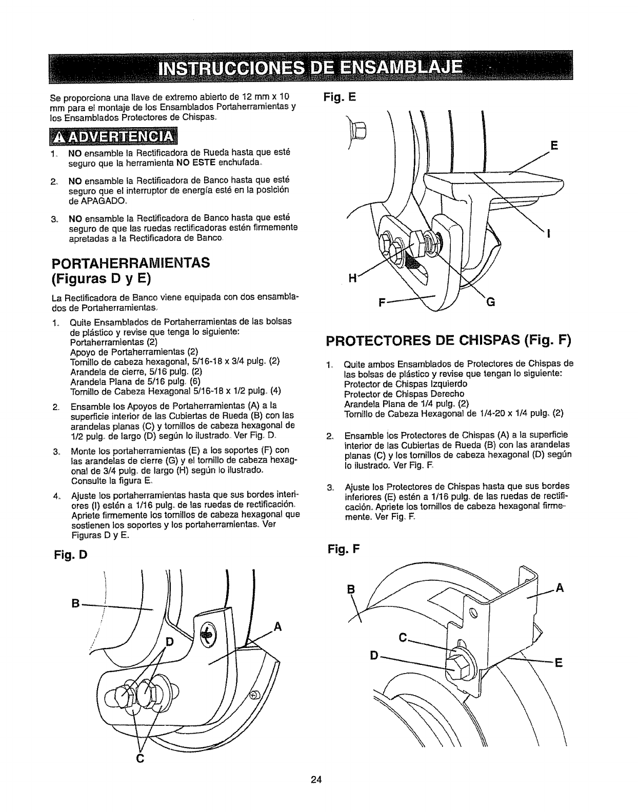
Se proporciona una ltave de extremo abierto de 12 mmx 10
mrn para el montaje de los Ensamblados Portaherramientas y
los Ensamblados Protectores de Chispas,,
2_
3_
NO ensamble la Rectificadora de Rueda hasta que est6
seguro que la herramienta NO ESTE enchufadao
NO ensambte la Rectificadora de Banco hasta que est6
seguro que el interruptor de energfa est8 en la posici6n
de APAGADO.,
NO ensamble la Rectificadora de Banco hasta que est6
seguro de que las ruedas rectificadoras est6n firmemente
apretadas a la Rectiflcadora de Banco.
PORTAH ER RAM IENTAS
(Figuras D y E)
La Rectificadora de Banco viene equipada con dos ensambla-
dos de Portaherramientas..
1. Quite Ensamblados de Portaherramientas de las bofsas
de pt&sUcoy revise que tenga Io siguiente:
Portaherramientas (2)
Apoyo de Portaherramientas (2)
Tomillo de cabeza hexagonal. 5/16-18 x 3/4 pulg,, (2)
Arandela de cierre, 5/16 pulg. (2)
Arandela Plana de 5/16 pulg. (6)
Tomillo de Cabeza Hexagonal 5/16-18 x 1/2 pulg. (4)
2. Ensamble los Apoyos de Portaherramientas (A) a la
superficie interior de las Cubiertas de Rueda (B) con las
arandelas planas (C) y tomillos de cabeza hexagonal de
1/2 pulgo de largo (D) seg_n Io ilustrado.. Vet Fig,,Do
3., Monte los portaherramientas (E) a los soportes (F) con
las arandelas de cierre (G) y el tornilto de cabeza hexag-
onal de 3/4 pulg.,de largo (H) seg_n to ilustradoo
Consulte ta figura E,.
4,, Ajuste los portaherramientas hasta que sus bordes interi-
ores (I) est_n a 1t16 pulg,, de las ruedas de rectificaci6no
Apriete firmemente los tomiflos de cabeza hexagonal que
sostienen los soportes y los portaherramientas_, Vet
Figuras D y E.
Fig. D
Fig. E
H
PROTECTORES DE CHISPAS (Fig. F)
Quite ambos Ensambfados de Protectores de Chispas de
las botsas de pl_sticoy revise que tengan Io siguiente:
Protector de Chispas Izquierdo
Protector de Chispas Derecho
Arandela Piana de 1/4 putg. (2)
Tomilto de Cabeza Hexagonal de 1/4-20 x 1/4 pulgo (2)
24 Ensamble los Protectores de Chispas (A) a la superficie
interior de las Cubiertas de Rueda (B) con las arandelas
planas (C) y los tomillos de cabeza hexagonal (D) segL_n
Io itustrado,,Ver Fig, E
3,, Ajuste los Protectores de Chispas hasta que sus bordes
infer_ores(E) est_n a 1/16 pulg. de las ruedas de recfJfi-
caciSno Apdete los tomillos de cabeza hexagonal firme-
menteo Ver Fig_ E
Fig. F
B
24
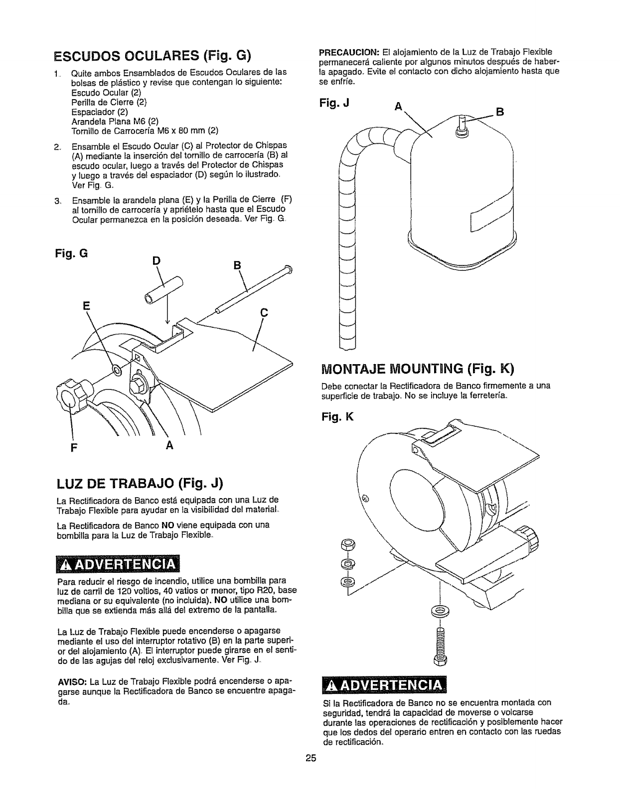
ESCUDOS OCULARES (Fig. G)
t., Quite ambos Ensamblados de Escudos Oculares de tas
bolsas de pf_stico y revise que contengan Io siguiente:
Escudo Ocular (2)
Perilla de Cierre (2)
Espaciador (2)
Arandela Plana M6 (2)
Tomillo de Carrocer[a M6 x 80 mm (2)
2. Ensambte el Escudo Ocular (C) al Protector de Chispas
(A) mediante la inserciSn del tornilfo de carrocerfa (B) al
escudo ocular, luego a trav_s de1Protector de Chispas
y luego a trav6s de! espaciador (D) segSn Io ilustrado..
Ver Fig. Go
3, Ensambte ta arandela plana (E) y la Pedlla de Cierre (F)
a! tornillo de carroceffa y apfi_tefo hasta que el Escudo
Ocular permanezca en ta posici6n deseada.. Ver Fig. G.
PRECALICION: El alojamiento de la Luz de Trabajo Flexible
permanecer& caliente per algunos minutes despu_s de haber-
la apagado.. Evite el contacto con dicho alojamiente hasta que
se enfrfe.
Fig. J A\ B
Fig, G
E
MONTAJE MOUNTING (Fig. K)
Debe conectar la Rectificadora de Banco firmemente a una
superficie de trabajo.. No se incluye la ferreter[a..
Fig. K
F A
LUZ DE TRABAJO (Fig. J)
La Rectificadora de Banco est_ equipada con una Luz de
Trabajo Flexible para ayudar en ta visibilidad del material.
La Rectificadora de Banco NO viene equipada con una
bombilta para ta Luz de Trabajo Flexible.
Para reducir el riesgo de incendio, utilice una bombilla para
luz de carril de 120 vottios, 40 varies or menor, tipo R20, base
mediana or su equivalente (no incluida). NO utilice una bom-
billa que se extienda m&s all_ del extreme de la pantaltao
La Luz de Trabajo Flexible puede encenderse oapagarse
mediante el use del interrupter rotativo (B) en la parte superi-
or del alojamiento (A). El interrupter puede girarse en el senti-
do de ias agujas del reloj exclusivamenteo Ver Fig,,J_
AVISO" La Luz de Trabajo Rexible podr_ encenderse o apa-
garse aunque la Rectificadora de Banco se encuentre apaga-
da._
25
\\
®
I
@
I
Si la Rectificadora de Bar]co no se encuentra montada con
seguridad, tendr& la capacidad de moverse o votcarse
durante las operaciones de rectificaci6n y posiblemente hacer
que los dedos del operario entrenen contacto con las ruedas
de rectificaciSno
/
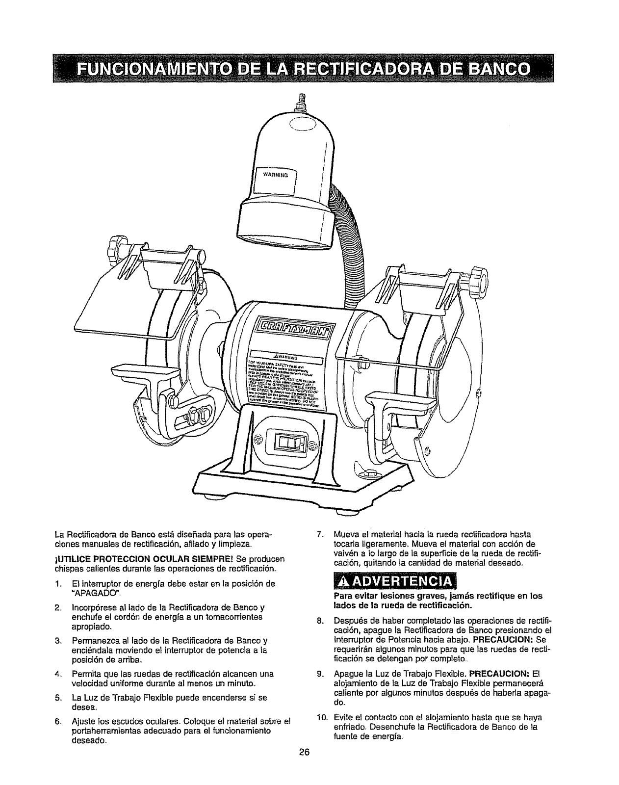
La Rectificadora de Banco est_ disefiada para las opera-
ciones manuales de rectificaci6n, afitado y limpieza_
iUTILICE PROTECCION OCULAR SIEMPRE! Se producen
chispas calientes durante las operaciones de rectificacf6no
1. El interruptorde energfa debe estar en la posici6n de
"APAGADO",,
2 Incorpbrese at lado de la Rectificadora de Banco y
enchufe el cord6n de energfa aun tomacorrientes
apropiado.
3_ Permanezca al lado de la Rectificadora de Banco y
enci_nclala moviendo el interruptorde potencia a ta
posiciOn de arriba.
4o Permita que las ruedas de rectificaci6n alcaneen una
velocidad uniforme durante al menos un minuto.,
5.. La Luz de Trabajo Flexible puede encenderse si se
desea,,
6. Ajuste tos escudos oculares. Coloque el material sobre el
portaherramientas adecuado para el funcionamiento
deseadoo
26
7_ Mueva el material hacia la raeda rectificadora hasta
tocarla ligeramente,, Mueva el material con accibn de
vaiv6n aIo largo de ta superficie de ta rueda de rectifi-
caciSn, quitando la cantidad de material deseado_
8.
94
10_
Para evitar lesiones graves, jamds rectifique en los
lados de la rueda de rectificacidn.
Despu6s de haber completado las operaciones de rectifi-
caci6n, apague la Rectificadora de Banco presionando el
Interruptor de Potencia hacia abajo,, PRIECAUCION: Se
requerir&n algunos minutos para que las ruedas de recti-
ficaciOn se detengan por completo,,
Apague la Luz de Trabajo Flexible. PRECAUCION: El
alojamiento de la Luz de Trabajo Flexible permanecerd
caliente pot algunos minutos despuds de habeda apaga-
do,
Evite el contacto con e! alojamiento hasta que se haya
enfriado. Desenchufe la Rectificadora de Banco de la
fuente de energia.
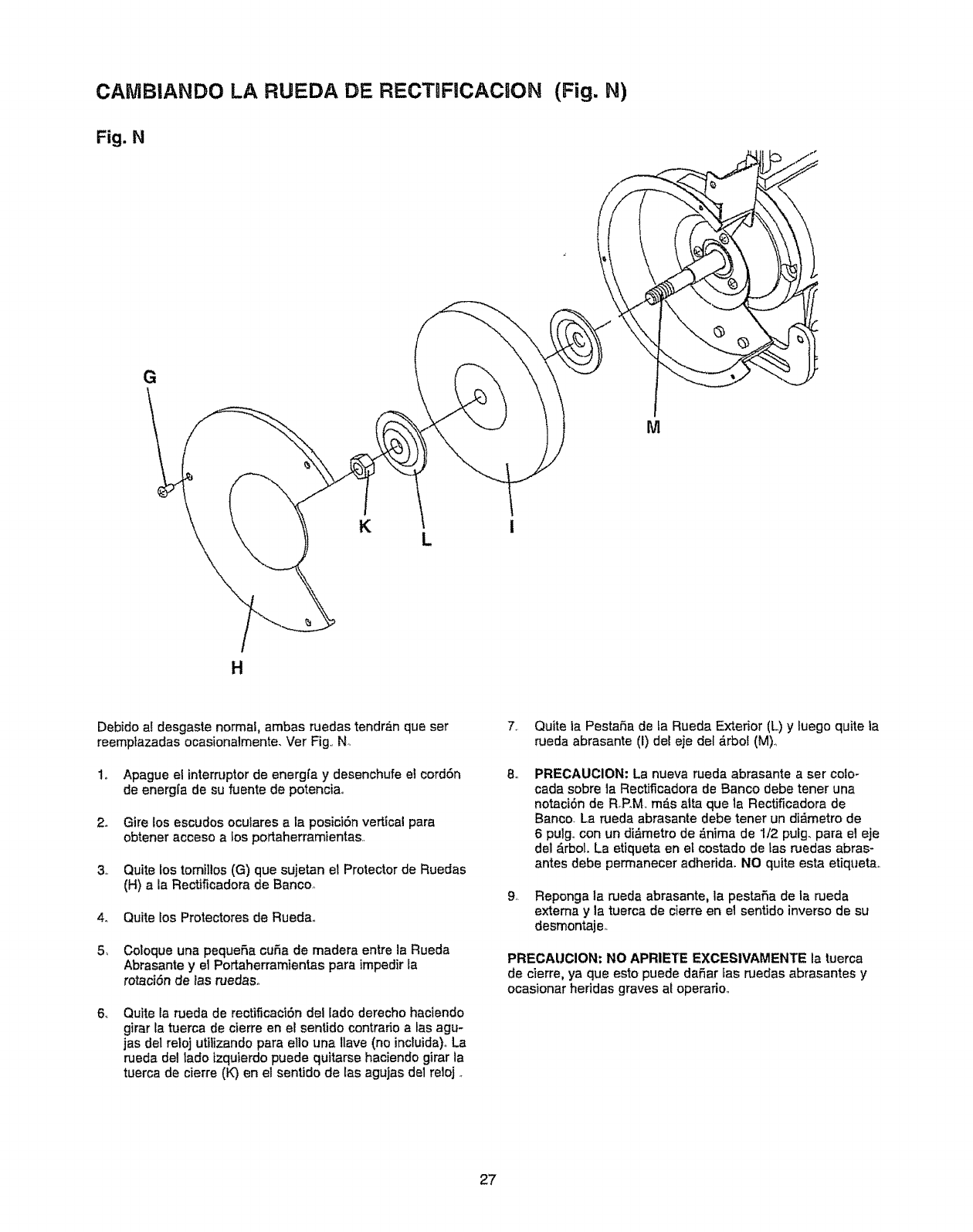
CAtUIBIANDO LA RUEDA DE RECT FiCACION (Fig. N)
Fig. N
G
M
K
H
Debido a! desgaste normal, ambas ruedas tendr_n qua ser
reemptazadas ocasionalmente. Ver Fig., N,
to Apague el interruptorde energfa y desenchufe el eord6n
de energ[a de su fuente de potenciao
2. Gire los escudos oculares a la posici6n vertical para
obtener acceso a los portaherramientas,,
3,, Quite los tomii!os(G) que sujetan et Protector de Ruedas
(H) s Is Rectificadora de Banco,
4o Quite los Protectores de Rueda,,
5_ Coloque una pequeSs cuSa de madera entre la Rueda
Abrasante y 81Portaherramientas para impedir la
rotaciSn de las ruedaso
64 Quite la rueda de reetificaci6n del lado derecho haciendo
girar ta tuerca de cierre en el sentido contrado alas agu-
jas del reloj utitizando para ello una Ilave (no inctuida)., La
rueda del lado izquierdo puede quitarse haciendo girar la
tuerca de cierre (K) en el sentido de tas agujas de1reloj.,
7. Quite ia PestaSa de la Rueda Exterior (L) y luego quite la
rueda abrasante (I) deeeje det _.rbol (M).,
8,, PRECAUCION: La nueva rueda abrasante aser cofo-
cada sobre la Rectificadora de Banco debe tener una
notaci6n de R_P.M mf_s atta que la Rectificadora de
Baneo. La rueda abrasante debe tener un di_metro de
6 pulg., con un di&metro de &nima de 1/2 pufg_ para el eje
del _rbol. La etiqueta en et costado de tas ruedas abras-
antes debe permanecer adheddao NO quite esta etiquetao
9,. Reponga la rueda abrasante, la pestafia de Is rueda
extema y la tuerca de cierre en el sentido inverso de su
desmontaje_
PRECAUCION: NO APRIETE EXCESIVAMENTE Is tuerca
de cierre, ya que esto puede daSar tas ruedas abrasantes y
ocasionar heridss graves at operario,_
27
Apague el interruptor de energfa y desenchufe e! cordon de
energfa de su fuente de potencia antes de realizar cuatquier
mantenimiento_
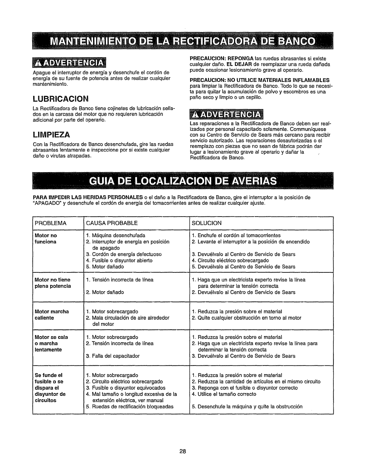
LUBRICAC|ON
La Rectificadora de Banco tiene cojinetes de lubricaciOn sella-
dos en la carcasa del motor que no requieren fubricaciOn
adicional por parte del operario.
LIMPIEZA
Con fa Reotif_cadora de Banco desenchufada, gire las ruedas
abrasantes lentamente e inspeccione por si existe cualquier
da5o o virutas atrapadas.
PRECAUCION: REPONGA las ruedas abrasantes si existe
cua_quier dafio,, EL DEJAR de reemplazar una rueda dafiada
puede ocasionar lesionamiento grave al operario.
PRECAUCION: NO UTILICE MATERIALES INFLAMABLES
para limpiar la Rectificadora de BancooTodo 1oque se necesi-
ta para quitar la acumulaciOnde poivo y escombros es una
patio seco y limpio o un eepitloo
Las reparaciones a la Rectificadora de Banco deben ser real-
izados pot personal capacitado solamente,, Commun_quese
con su Centro de Servicio de Sears m&s cercano para recibir
servicio autorizado, Las reparaciones desautorizadas o el
reemplazo con piezas que no sean de f_brica podr_n dar
lugar alesionamiento grave af operario y daOar ia
Rectificadora de Banco,
PARA IMPEDIR LAS HERIDAS PERSONALES o el da5o ala Rectificadora de Banco, gire el interruptor a la posieiOn de
"APAGADO" y desenchufe el cordon de energfa del tomacorrientes antes de realizar cualquier ajuste,
PROBLEMA CAUSA PROBABLE SOLUCION
,, ,,,,,, , ,,, , ,,,,__,_L ....... •_,....
Motor no 1., M_quina desenchufada 1. Enchufe el cord6n al tomacorrientes
funciona 2, Interruptor de energfa en posiciOn 2. Levante el intemJptora la posiciOn de encendido
Motor no tiene
ptena potencia
b
Motor marcha
caiiente
Motor se cala
Eo marcha
lentamente
Se funde el
fusible o se
dispara el
disyuntor de
circuttos
4.
5o
1. Tensi6n incorrecta de lfnea
de apagado
Cord6n de energfa defectuoso 3,
Fusible o disyuntor abierto 4o
Motor dafado 5.,
2.,Motor dafiado
1,,Motor sobrecargado
2oMala circulaciOn de aire alrededor
del motor
1oMotor sobrecargado
2. TensiOn incorrecta de Ifnea
3. Fa!la del capacitador
DevuOlvato al Centro de Servicio de Sears
Circuito elOctrico sobrecargado
DevuOlvalo al Centro de Servioio de Sears
t. Motor sobrecargado
2. Circuito elOctrico sobrecargado
3. Fusible o disyuntor equivocados
4o Mal tamafio o Iongitud excesiva de la
extension elOctrica, ver manual
5. Ruedas de rectificaciOn bloqueadas
1. Haga que un electricista experto revise la Ifnea
para determinar la tension correcta
2,.Devu_tvato af Centro de Servicio de Sears
1, Reduzca la presi6n sobre e! material
2_Quite cualquier obstrucciOn en tomo at motor
1. Reduzca la presiOn sobre et mateda_
2. Haga que un etectricista experto revise la Ifnea para
determinar ta tension correcta
3oDevuOlvalo al Centro de Servicio de Sears
1. Reduzca la presiOn sobre el material
2.,Reduzca ta cantidad de art[culos en el mismo circuito
3o Reponga con el fusible o disyuntor correcto
4. Utilice el tama5o correcto
5. Desenchufe la m&quina y quite la obstrucciOn
28

LISTADO DE PIEZAS PARA LA RECTtFICADORA DE BANCO DE 6 PULG, NO, DE MODELO 152.2'11240
Cuando vaya a rendir servicio, s61outilice piezas de repuesto CRAFTSMAN.. El uso de cua[quierotro tipo de pieza puede con-
stituir un PELIGRO u ocasionar daSo at producto,
Cualquier intento de reparar o reempiazar tas piezas el6ctricas en esta Rectificadora de Banco puede representar un PELIGRO a
menos que tab reparaciones hayan sido reatizadas por un t6cnico de servicio experto. El ser¢icio de reparaciones se encuentra
disponibte en su Centro de Servicio Sears m6s cercano..
Haga su pedido por NUMERO DE PIEZA siempre, en vez de por nt]mero de clave.
No, No, No, No,
Clave dePF/A D_cHpcl6n Cantldad Clave de P[EZA
OR915t0 Manu;a_del Propteta_io(no ilust_ad) 1 46 OR91512
47 OR91523
48 STD523105
4_ STD55!031
50 OR90007
1
2
3
4
5
OR90055 TORNILLO DE CARROCERIA M5 x 80 mm
OR90I 52 ESCUDO OCULAR
STD8510D6 ARANDELAPLANAM6
ORgDoDI PERtLLA M5
OR,30002 ESPACIADOR
1
1
1
1
t
6
7
8
9
10
OR9D003
STD551012
OR90150
STD511062
OR90004
SUPRESOR DE CHtSPAS(DERECHO)
ARANDELA PLANA, 1/4 pulg
TORNILLO DE CABF-.ZAHEXAGONAL. 1/4-2[}x 1/4 pulg
TORNILLO #10,24 X _/4 pulg
CUB1ERTA
1
l
1
3
t
ti
12
13
14
15
t5
17
18
2O
21
22
23
3O
31
33
OR90O3o
OR900o5
OR9O057
ORg0005
OR£OD07
STD5110[:,3
OR_1523
OR91512
STD55t131
STD523107
STD551031
STD523105
OR91520
OR90t80
OR91511
TUERCA HEXAGONAL. 1/2-12
PESTAt_A
RUEDA DE RECTtFICAC{_)NDE 5 PULG, CON
GRANO DE 60 (D_SPONtBLEEN LA MAYORIA
DE LAS TiENDAS DETALLISTAS)
PROTECTOR DE RUEDA (DERECHO)
ETIQUETA DE ROTACI()N
1
2
!
TORNILLO #10-24 X 3/8 pul93
SOPORTE DEL PORTAHERRAMIENTAS(COLOR: NEGRO) !
PORTAHERRAMtENTAS (COLOR: NEGRO) 1
ARANDELA DE C1ERRE,5/15 PULG 1
TORNtLLO DE CABF--.ZAHEXAGONAL, 5116-18x3/4 pulg 1
ARANDELA PLANA, 5116pulg. 2
TORNILLO DE CABEZA HEXAGONAL, 5t16,,18 x "!/2 pulg 2
ENSAMBLADO DEL MOTOR _l
(Cons,jltar NUMEROS DE CLAVEt00,110
paralos nOmerosde ptezaindMdua_ea)
PLACA DE NOMCRE 1
PLACA DE NOTACtONES 1
38
3'/
38
39
40
ORgD00t
STD85t008
OR90152
OR90055
ORg0D02
PER1LLAM6
ARANDELA PLANA M6
ESCUDO OCULAR
TORNILLO DE CARROCER{AM6 X 80 mm
ESPACIADOR
t
1
l
t
1
41
42
43
44
45
ORgD025
ORg015O
STD551012
STD523107
STD55t131
SUPRESOR DE CHISPAS (IZQU_ERDO) 1
TORN[LLO DE CABEZAHEXAGONAL, t/4_20x 1/4 puig 1
ARANDELA PLANA, i/4 pulg 1
TORNILLO DE CABEZA HEXAGONAL, 5t16-t8 x3!4 pufg 1
ARANDELA PLANA.5/16 pulgo
Descripddn Canttd_.,d
PORTAHERRAMIEN-rAS (COLOR; NEGRO) 1
SOPORTE DE PORTAHERRAMIENTAS(COLOR: NEGRO) 1
TORNILLO DE CABEZA HEXAGONAL. 5/16-18 x 1/2 putg 2
ARANDELA PLANA, 5f16 pulg 2
ETIQUETA DE ROTACK_N 1
51 ORgO{)2B
52 STD51t003
53 OR9_3185
54
55
56
57
58
59
6O
62
63
64
65
58
OR90005
ORgOD29
OR90004
STD51t002
OR90059
STD511003
OR90053
OR90165
STD511003
OR9003t
OR91513
OR90183
PROTECTOR DE RUEDA (IZOUIERDD) 1
TORNILLO ft10,24 x 3/8 pulg 3
RUEDA DE RECTtFtCAC]ON DE 6 PULG..CON I
GRANO DE 35 (DfSPONIBLE EN LA MAYORfA
DE LASTIENDAS DETALLISTAS)
PESTANA 2
TUERCA HEXAGONAL DE MANO 17QUIERDA, 1/2-12 1
CUBIERTA
TORNILLO #_0-24 X 1/4 pulg
CORDON DE POTENCIA
TORNILLO #10_24 x 3/8 putg,
ARANDELA CON D1ENTES EXTERNOS _IG
ALIVIO DETENSION (6N.4)
TORNILLO _t10,24 x 328 pulg
PLACA DE MONTAJE DEL CORD(_N
BASE
PLACA DEL 1NTERRUPTOR
1
3
1
1
1
1
2
1
1
1
69
7O
71
72
76
77
78
8I
82
84
0R£{_184
OR90169
5TD511003
STD511003
STD581125
STD622507
OR91514
OR90210
OR91317
OR90045
INTERRUPTOR
ABRAZADERA DEL CAPACITADOR
TORNtLLO 10.-24x3/B pu_g
TORNILLO 10.-24x 3/8 pulg
ARANDELA DE C1ERRE, 1/4 pulg
TORNILLO 114-20X3/4 pulg
CAPACITAOOR (10 ul, 25{)V)
ENSAMBLADO DE LUCES (COLOR: NEGRO)
ET1QUETADE ADVERTENC[A
ALMOHADILLA
1
1
1
2
2
2
1
I
t
4
85
85
83
95
STD55t010
5TD5t1005
ORgO050
OR90185
ARANDELA PLANA #t0
TORNILLO 10..24x 1/2 pulg
LLAVE DE BOCA DE 10 mmx 12 mm
PLACA DE CUBIERTA
4
4
1
29
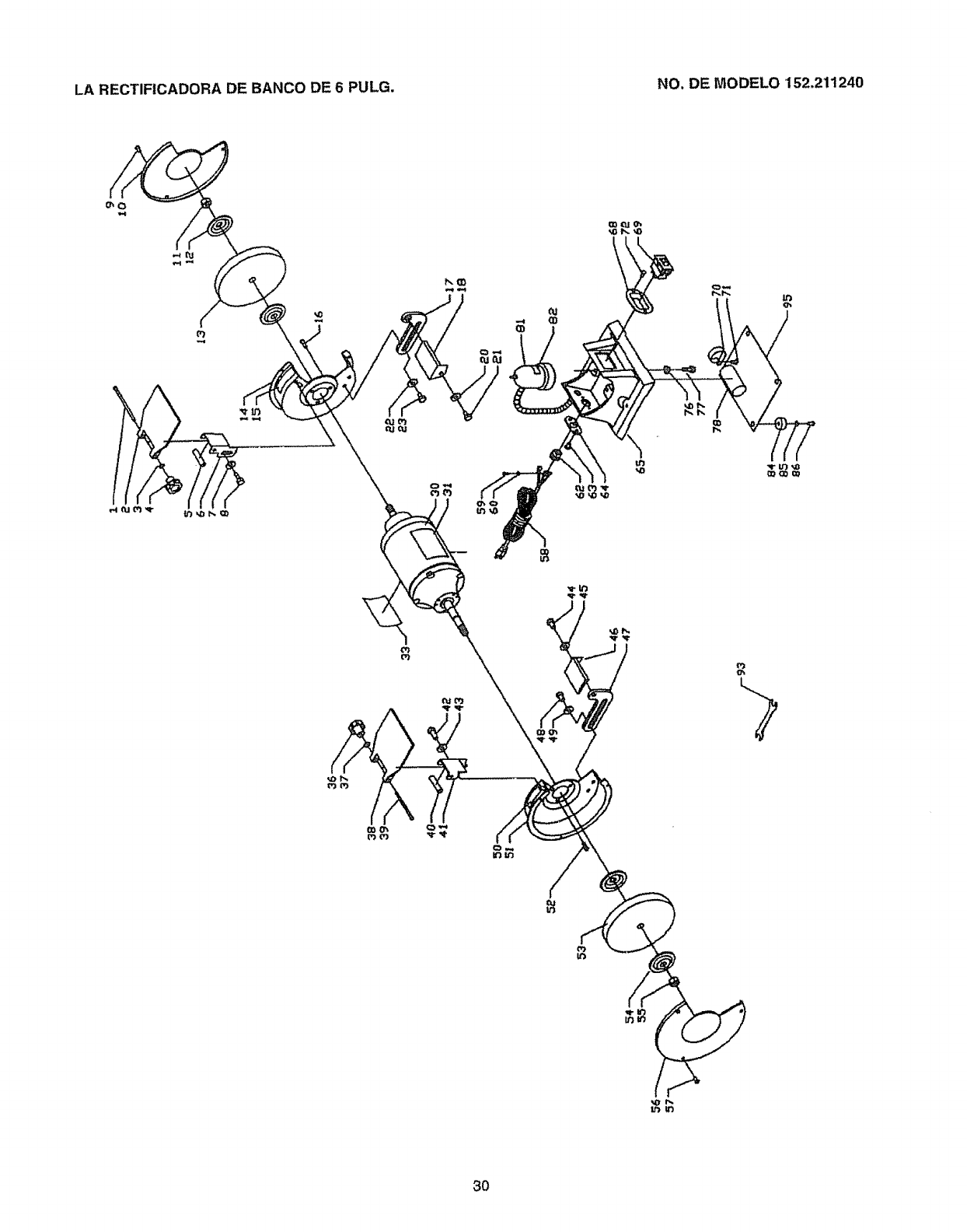
LA RECTIFICADORA DE BANCO DE 6 PULG. NO. DE MODELO '152.211240
\
tr_u3
3O

÷ NOTAS ÷
31

Your Home
For repair - in your home - of all major brand appliances,
lawn and garden equipment, or heating and cooling systems,
no matter who made it, no matter who sold it!
For the replacement parts, accessories and
owner's manuals that you need to do-it-yourself.
For Sears professional installation of home appliances
and items like garage door openers and water heaters.
1-800-4-MY-HOME ® (1-800-469-4663)
Call anytime, day or night (UoSA_ and Canada)
www.sears,com www.sears.ca
For expert home solutions advice: www.managemyhome.com
Our Home
For repair of carry-in items like vacuums, lawn equipment,
and electronics, call or go on-line for the location of your nearest
Sears Parts & Repair Service Center
1=800-488=1222 (U,SoA.) 1=800-469-4663 (Canada)
Call anytime, day or night
www.sears,com www,sears.ca
To purchase a protection agreement on a product serviced by Sears:
1-800=827-6655 (UoS.Ao) 1-800-361-6665 (Canada)
Pare pedir servicio de reparaciSn
a domicitio, y pare ordenar piezas:
1-888-SU-HOGAR ®
(1-888-784-6427)
Au Canada pour service en fran£ais:
1-800-LE-FOYER Mc
(1-800-533-6937)
wwwsears,ca
®RegisteredTrademark 1T_Trademark Is_ Service Mark of Sears Brands, LLC
@Marca Registrada/-n,_Marca de F_br_catsMMarca de Servicio de Sears Brands_LLC
_c Marque de commerce 1MDMarque dbpos_e de Sears Brands, LLC ©Sears Brands. LLC
