Craftsman 152217060 User Manual JOINTER PLANER Manuals And Guides L0901080
CRAFTSMAN Jointer/Planer Manual L0901080 CRAFTSMAN Jointer/Planer Owner's Manual, CRAFTSMAN Jointer/Planer installation guides
User Manual: Craftsman 152217060 152217060 CRAFTSMAN JOINTER PLANER - Manuals and Guides View the owners manual for your CRAFTSMAN JOINTER PLANER #152217060. Home:Tool Parts:Craftsman Parts:Craftsman JOINTER PLANER Manual
Open the PDF directly: View PDF ![]() .
.
Page Count: 52

Owner's Manual
iCRnFrSMnN'i
iPROFESSIONAI
6-1/8-in. Wide
1 Horsepower (continuous duty)
5000 Cutterhead R.P.M. (no load speed)
6-1/8-in.
JOINTER-PLANER
Model No.
152.217060
c
CAUTION:
FOR YOUR OWN SAFETY read
and follow all of the Safety and
Operating Instructions before
operating this Jointer/Planer.
Customer Helpline
1-800-897-7709
Please have your Model No.
and Serial No. available.
Sears, Roebuck and Co., Hoffman Estates, IL 60179 U.S.A.
Part No. OR90365
Revised 6-13-03 Espa_ol, p. 27

SECTION PAGE
Warranty ........................................................................................................................................ 2
Product Specifications ................................................................................................................ 2
Safety Instructions ....................................................................................................................... 3
Grounding Instructions ............................................................................................................... 4
Specific Safety Instructions for Jointer/Planer ......................................................................... 5
Accessories and Attachments .................................................................................................... 6
Carton Contents ........................................................................................................................... 6
Know Your Jointer/Planer ........................................................................................................... 8
Assembly Instructions ................................................................................................................. 9
Operating the Jointer/Planer ..................................................................................................... 14
Maintenance ............................................................................................................................... 18
Troubleshooting Guide .............................................................................................................. 19
Part List ....................................................................................................................................... 20
EspaSol ....................................................................................................................................... 27
Service Information .................................................................................................... Back Cover
FULL ONE YEAR WARRANTY
If this product fails due to a defect in material or workmanship within one year from the date of purchase, return it to
the nearest Sears Service Center for repair, free of charge.
This warranty gives you specific legal rights, and you may also have other rights, which vary, from state to state.
Sears, Roebuck and Co., Dept 817 WA, Hoffman Estates, IL 60179
Motor
Continuous Duty HP 1
Volts 120
Hertz 60
RPM 3450 R.P.M.
(no load speed)
Infeed table dimension: 22-inch
Outfeed table dimension: 22-3/8-inch
Fence: 29-1/2 x 4-1/2-inch
Fence Tilt: 45 Degrees in and out
Fence Positive Stops: 90, 45 Degrees in and out
Cutterhead RPM: 5000 RPM
r!Vivhl _1_II _[€'ll
To avoid electrical shock to yourself and damage to the
Jointer/Planer, use proper circuit protection.
The Jointer/Planer is factory wired for 120V, 60 Hz,
operation. Connect to a 120V, 15 amp branch circuit and
use a 15 amp time delay fuse or circuit breaker. The
electrical circuit cannot have any wire size less than #12.
To avoid shock or fire, replace power cord immediately if
it is damaged in any way.
2

GENERAL SAFETY INSTRUCTIONS
Operating a Jointer/Planer can be dangerous if
safety and common sense are ignored. The
operator must be familiar with the operation of the
tool. Read this manual to understand this Jointeri
Planer. DO NOT operate this Jointer/Planer if you
do not fully understand the limitations of this tool.
DO NOT modify this Jointer/Planer in any way.
BEFORE USING THE JOINTER/PLANER
_!Vivlzl t,_l_II _[e'll
To avoid serious injury and damage to the tool, read and
follow all of the Safety and Operating Instructions before
operating the Jointer/Planer.
1. READ the entire Owner's Manual. LEARN how to
use the tool for its intended applications.
.GROUND ALL TOOLS. If the tool is supplied with a
3-prong plug, it must be plugged into a 3-contact
electrical receptacle. The 3rd prong is used to
ground the tool and provide protection against
accidental electric shock. DO NOT remove the 3rd
prong. See Grounding Instructions on page 4.
3. AVOID A DANGEROUS WORKING
ENVIRONMENT. DO NOT Use electrical tools in a
damp environment or expose them to rain.
4. DO NOT use electrical tools in the presence of
flammable liquids or gasses.
.ALWAYS keep the work area clean, well lit, and
organized. DO NOT work in an environment with
floor surfaces that are slippery from debris, grease
or wax.
.
.
.
KEEP VISITORS AND CHILDREN AWAY. DO NOT
permit people to be in the immediate work area,
especially when the electrical tool is operating.
DO NOT FORCE THE TOOL to perform an
operation for which it was not designed. It will do a
safer and higher quality job by only performing
operations for which the tool was intended.
WEAR PROPER CLOTHING. DO NOT wear loose
clothing, gloves, neckties, or jewelry. These items
can get caught in the machine during operations and
pull the operator into the moving parts. The user
must wear a protective cover on their hair, if the hair
is long, to prevent it from contacting any moving
parts.
.ALWAYS WEAR EYE PROTECTION. Any power
tool can throw debris into the eyes during
operations, which could cause severe and
permanent eye damage. ALWAYS Wear Safety
Goggles (that comply with ANSI standard Z87.1)
when operating power tools. Safety Goggles are
available at Sears Retail Stores.
10.
11.
12.
13.
14.
15.
16.
17.
18.
19.
20.
WEAR A DUST MASK TO PREVENT INHALING
DANGEROUS DUST OR PARTICLES.
ALWAYS UNPLUG THE TOOL FROM THE ELEC-
TRICAL RECEPTACLE when making adjustments,
changing parts or performing any maintenance.
KEEP PROTECTIVE GUARDS IN PLACE AND IN
WORKING ORDER.
AVOID ACCIDENTAL STARTING. Make sure that
the power switch is in the "OFF" position before
plugging in the power cord to the electrical
receptacle.
REMOVE ALL MAINTENANCE TOOLS from the
immediate area prior to turning "ON" the Jointer/Planer.
USE ONLY RECOMMENDED ACCESSORIES. Use
of incorrect or improper accessories could cause
serious injury to the operator and cause damage to
the tool. If in doubt, check the instruction manual
that comes with that particular accessory.
NEVER LEAVE A RUNNING TOOL
UNATTENDED. Turn the power switch to the "OFF"
position. DO NOT leave the tool until it has come to
a complete stop.
DO NOT STAND ON A TOOL. Serious injury could
result if the tool tips over or you accidentally contact
the tool.
DO NOT store anything above or near the tool
where someone might try to stand on the tool to
reach it.
MAINTAIN YOUR BALANCE. DO NOT extend yourself
over the tool. Wear oil resistant, rubber-soled shoes.
Keep floor clear of debris, grease, and wax.
MAINTAIN TOOLS WITH CARE. Always keep tools
clean and in good working order. Keep all blades
and tool bits sharp.
SAVE THESE INSTRUCTIONS.
3
21.EACHAND EVERY TIME, CHECK FOR
DAMAGED PARTS PRIOR TO USING THE TOOL.
Carefully check all guards to see that they operate
properly, are not damaged, and perform their
intended functions. Check for alignment, binding or
breaking of moving parts. A guard or other part that
is damaged should be immediately repaired or
replaced.
22. CHILDPROOF THE WORKSHOP AREA by
removing switch keys, unplugging tools from the
electrical receptacles, and using padlocks.
23. DO NOT OPERATE TOOL IF UNDER THE INFLU-
ENCE OF DRUGS OR ALCOHOL.
24. SECURE ALL WORK. When it is possible, use
clamps or jigs to secure the workpiece. This is safer
than attempting to hold the workpiece with your
hands.
25. USE A PROPER EXTENSION CORD IN GOOD
CONDITION. When using an extension cord, be sure
to use one heavy enough to carry the current your
product will draw. The table below shows the correct
size to use depending on cord length and nameplate
amperage rating. If in doubt, use the next heavier
gauge. The smaller the gauge number, the larger
diameter of the extension cord. If in doubt of the
proper size of an extension cord, use a shorter and
thicker cord. An undersized cord will cause a drop in
line voltage resulting in a loss of power and
overheating. USE ONLY A 3-WIRE EXTENSION
CORD THAT HAS A 3-PRONG GROUNDING PLUG
AND A 3-POLE RECEPTACLE THAT ACCEPTS
THE TOOL'S PLUG.
GUIDELINES FOR
EXTENSION CORDS
If you are using an extension cord outdoors, be sure
it is marked with the suffix "W-A" ("W" in Canada) to
indicate that it is acceptable for outdoor use.
Be sure your extension cord is properly sized, and in
good electrical condition. Always replace a damaged
extension cord or have it repaired by a qualified person
before using it.
Protect your extension cords from sharp objects,
excessive heat, and damp or wet areas.
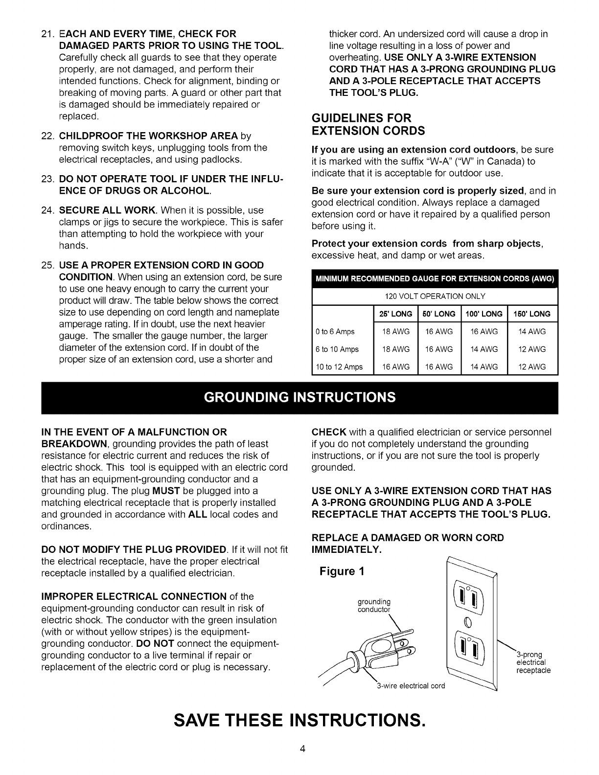
0 to 6 Amps
6 to 10 Amps
10 to 12 Amps
120 VOLT OPERATION ONLY
25' LONG
18 AWG
18 AWG
16 AWG
60' LONG
16 AWG
16 AWG
16 AWG
100' LONG
16 AWG
14 AWG
14 AWG
150' LONG
14 AWG
12 AWG
12 AWG
IN THE EVENT OF A MALFUNCTION OR
BREAKDOWN, grounding provides the path of least
resistance for electric current and reduces the risk of
electric shock. This tool is equipped with an electric cord
that has an equipment-grounding conductor and a
grounding plug. The plug MUST be plugged into a
matching electrical receptacle that is properly installed
and grounded in accordance with ALL local codes and
ordinances.
DO NOT MODIFY THE PLUG PROVIDED. If it will not fit
the electrical receptacle, have the proper electrical
receptacle installed by a qualified electrician.
IMPROPER ELECTRICAL CONNECTION of the
equipment-grounding conductor can result in risk of
electric shock. The conductor with the green insulation
(with or without yellow stripes) is the equipment-
grounding conductor. DO NOT connect the equipment-
grounding conductor to a live terminal if repair or
replacement of the electric cord or plug is necessary.
CHECK with a qualified electrician or service personnel
if you do not completely understand the grounding
instructions, or if you are not sure the tool is properly
grounded.
USE ONLY A 3-WIRE EXTENSION CORD THAT HAS
A 3-PRONG GROUNDING PLUG AND A 3-POLE
RECEPTACLE THAT ACCEPTS THE TOOL'S PLUG.
REPLACE A DAMAGED OR WORN CORD
IMMEDIATELY.
Figure 1
grounding
conductor
3-wire electrical cord
0
3-prong
electrical
receptacle
SAVE THESE INSTRUCTIONS.
4
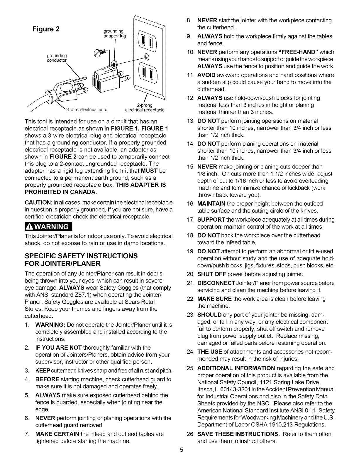
Figure 2 grounding
adapter lug
grounding
conductor
__m _trical cord
2-prong
electrical receptacle
This tool is intended for use on a circuit that has an
electrical receptacle as shown in FIGURE 1. FIGURE 1
shows a 3-wire electrical plug and electrical receptacle
that has a grounding conductor. If a properly grounded
electrical receptacle is not available, an adapter as
shown in FIGURE 2 can be used to temporarily connect
this plug to a 2-contact ungrounded receptacle. The
adapter has a rigid lug extending from it that MUST be
connected to a permanent earth ground, such as a
properly grounded receptacle box. THIS ADAPTER IS
PROHIBITED IN CANADA.
CAUTION: In all cases, make certain the electrical receptacle
in question is properly grounded. If you are not sure, have a
certified electrician check the electrical receptacle.
F'!,vlv/:1;3 _11_[ell
This Jointer/Planer isfor indoor use only. To avoid electrical
shock, do not expose to rain or use in damp locations.
SPECIFIC SAFETY INSTRUCTIONS
FOR JOINTER/PLANER
The operation of any Jointer/Planer can result in debris
being thrown into your eyes, which can result in severe
eye damage. ALWAYS wear Safety Goggles (that comply
with ANSI standard Z87.1) when operating the Jointeri
Planer. Safety Goggles are available at Sears Retail
Stores. Keep your thumbs and fingers away from the
cutterhead.
,WARNING: Do not operate the Jointer/Planer until it is
completely assembled and installed according to the
instructions.
2. IF YOU ARE NOT thoroughly familiar with the
operation of Jointers/Planers, obtain advice from your
supervisor, instructor or other qualified person.
3. KEEP cutterhead knives sharp and freeof all rustand pitch.
4. BEFORE starting machine, check cutterhead guard to
make sure it is not damaged and operates freely.
5. ALWAYS make sure exposed cutterhead behind the
fence is guarded, especially when jointing near the
edge.
6. NEVER perform jointing or planing operations with the
cutterhead guard removed.
7. MAKE CERTAIN the infeed and outfeed tables are
tightened before starting the machine.
5
,
9.
10.
11.
12.
13.
14.
NEVER start the jointer with the workpiece contacting
the cutterhead.
ALWAYS hold the workpiece firmly against the tables
and fence.
NEVER perform any operations "FREE-HAND" which
means using your hands to support orguide the workpiece.
ALWAYS use the fence to position and guide the work.
AVOID awkward operations and hand positions where
a sudden slip could cause your hand to move into the
cutterhead.
ALWAYS use hold-down/push blocks for jointing
material less than 3 inches in height or planing
material thinner than 3 inches.
DO NOT perform jointing operations on material
shorter than 10 inches, narrower than 3/4 inch or less
than 1/2 inch thick.
DO NOT perform planing operations on material
shorter than 10 inches, narrower than 3/4 inch or less
than 1/2 inch thick.
15. NEVER make jointing or planing cuts deeper than
1/8 inch. On cuts more than 1 1/2 inches wide, adjust
depth of cut to 1/16 inch or less to avoid overloading
machine and to minimize chance of kickback (work
thrown back toward you).
16. MAINTAIN the proper height between the outfeed
table surface and the cutting circle of the knives.
17. SUPPORT the workpiece adequately at all times during
operation; maintain control of the work at all times.
18. DO NOT back the workpiece over the cutterhead
toward the infeed table.
19. DO NOT attempt to perform an abnormal or little-used
operation without study and the use of adequate hold-
down/push blocks, jigs, fixtures, stops, push blocks, etc.
20. SHUT OFF power before adjusting jointer.
21. DlSCONNECTJointer/Planerfrom powersource before
servicing and clean the machine before leaving it.
22. MAKE SURE the work area is clean before leaving
the machine.
23. SHOULD any part of your jointer be missing, dam-
aged, or fail in any way, or any electrical component
fail to perform properly, shut off switch and remove
plug from power supply outlet. Replace missing,
damaged or failed parts before resuming operation.
24. THE USE of attachments and accessories not recom-
mended may result in the risk of injuries.
25. ADDITIONAL INFORMATION regarding the safe and
proper operation of this product is available from the
National Safety Council, 1121 Spring Lake Drive,
Itasca, IL60143-3201 inthe Accident Prevention Manual
for Industrial Operations and also in the Safety Data
Sheets provided by the NSC. Please also refer to the
American National Standard Institute ANSI 01.1 Safety
Requirements for Woodworking Machinery and the U.S.
Department of Labor OSHA 1910.213 Regulations.
26. SAVE THESE INSTRUCTIONS. Refer to them often
and use them to instruct others.
AVAILABLE ACCESSORIES
Visit your Sears Hardware Department or see the Sears
Power and Hand Tool Catalog for the following
accessories.
ITEM
Replacement Knives
Replacement Push Blocks
Dust Collection Reducer Kit
4" to 21/2''
STOCK NUMBER
See catalog or store
See catalog or store
OR90376
Sears may recommend other accessories not listed in
this manual.
See your nearest Sears Hardware Department or Sears
Power and Hand Tool Catalog for other accessories.
Do not use any accessory unless you have completely
read the Owner's Manual for that accessory.
r!q, viV_,1:_1_II _[€'ll
Use only accessories recommended for this Jointer/
Planer. Using other accessories may cause serious
injury and cause damage to the Jointer/Planer.
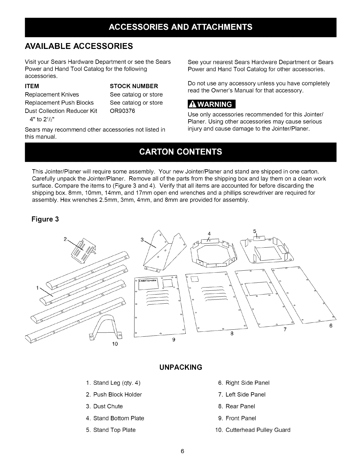
This Jointer/Planer will require some assembly. Your new Jointer/Planer and stand are shipped in one carton.
Carefully unpack the Jointer/Planer. Remove all of the parts from the shipping box and lay them on a clean work
surface. Compare the items to (Figure 3 and 4). Verify that all items are accounted for before discarding the
shipping box. 8mm, 10mm, 14mm, and 17mm open end wrenches and a phillips screwdriver are required for
assembly. Hex wrenches 2.5mm, 3mm, 4mm, and 8mm are provided for assembly.
Figure 3
10
5
UNPACKING
1. Stand Leg (qty. 4)
2. Push Block Holder
3. Dust Chute
4. Stand Bottom Plate
5. Stand Top Plate
6. Right Side Panel
7. Left Side Panel
8. Rear Panel
9. Front Panel
10. Cutterhead Pulley Guard
6
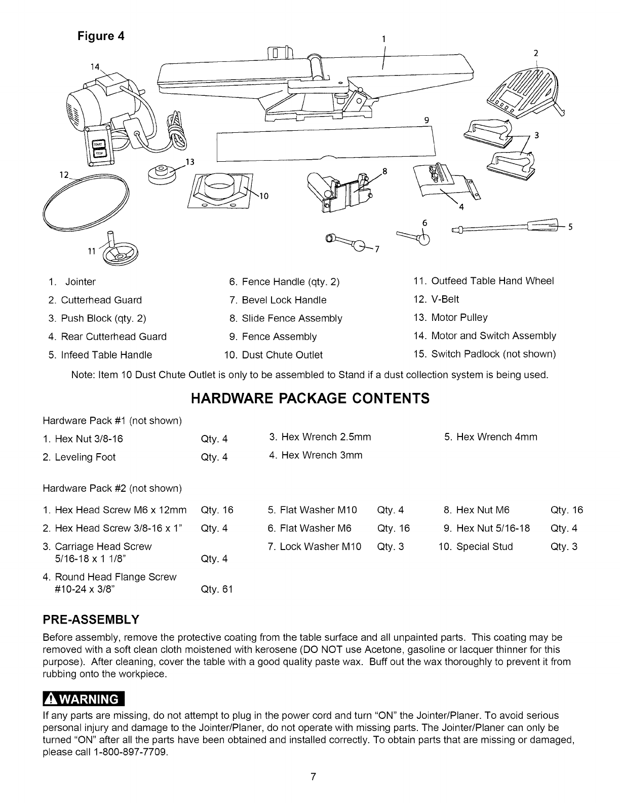
Figure 4 1
6
1. Jointer
2. Cutterhead Guard
6. Fence Handle (qty. 2)
7. Bevel Lock Handle
11. Outfeed Table Hand Wheel
12. V-Belt
3. Push Block (qty. 2)
4. Rear Cutterhead Guard
5. Infeed Table Handle
8. Slide Fence Assembly
9. Fence Assembly
10. Dust Chute Outlet
13. Motor Pulley
14. Motor and Switch Assembly
15. Switch Padlock (not shown)
Note: Item 10 Dust Chute Outlet is only to be assembled to Stand if a dust collection system is being used.
HARDWARE PACKAGE CONTENTS
Hardware Pack #1 (not shown)
1. Hex Nut 3/8-16 Qty. 4
2. Leveling Foot Qty. 4
3. Hex Wrench 2.5mm
4. Hex Wrench 3mm
5. Hex Wrench 4mm
Hardware Pack #2 (not shown)
1. Hex Head Screw M6 x 12mm Qty. 16
2. Hex Head Screw 3/8-16 x 1" Qty. 4
3. Carriage Head Screw
5/16-18 x 1 1/8" Qty. 4
4. Round Head Flange Screw
#10-24 x 3/8" Qty. 61
5. Flat Washer M10 Qty. 4
6. Flat Washer M6 Qty. 16
7. Lock Washer M 10 Qty. 3
8. Hex Nut M6 Qty. 16
9. Hex Nut 5/16-18 Qty. 4
10. Special Stud Qty. 3
PRE-ASSEMBLY
Before assembly, remove the protective coating from the table surface and all unpainted parts. This coating may be
removed with a soft clean cloth moistened with kerosene (DO NOT use Acetone, gasoline or lacquer thinner for this
purpose). After cleaning, cover the table with a good quality paste wax. Buff out the wax thoroughly to prevent it from
rubbing onto the workpiece.
r'!q?ivhl _1_II _[€'ll
If any parts are missing, do not attempt to plug in the power cord and turn "ON" the Jointer/Planer. To avoid serious
personal injury and damage to the Jointer/Planer, do not operate with missing parts. The Jointer/Planer can only be
turned "ON" after all the parts have been obtained and installed correctly. To obtain parts that are missing or damaged,
please call 1-800-897-7709.
7
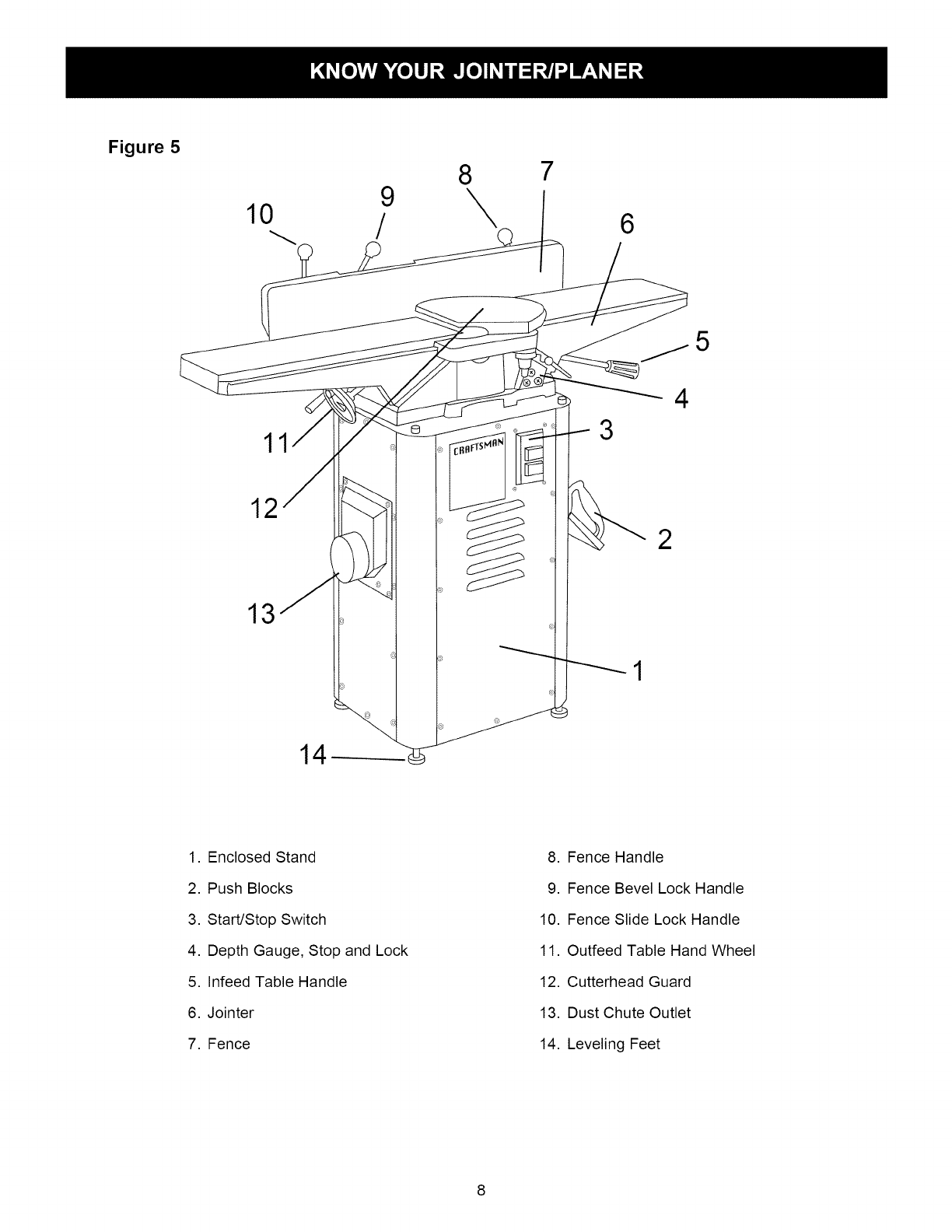
Figure 5
9
10 /
8
\7
6
12
13
11 3
5
4
2
1. Enclosed Stand
2. Push Blocks
3. Start/Stop Switch
4. Depth Gauge, Stop and Lock
5. Infeed Table Handle
6. Jointer
7. Fence
8. Fence Handle
9. Fence Bevel Lock Handle
10. Fence Slide Lock Handle
11. Outfeed Table Hand Wheel
12. Cutterhead Guard
13. Dust Chute Outlet
14. Leveling Feet
8
F'!q,vlvhl_1_ii _[cll
TO AVOID SERIOUS INJURY AND DAMAGE TO THE
JOINTER/PLAN ER:
,
,
,
DO NOT assemble the Jointer/Planer until you are
sure the tool IS NOT plugged in.
DO NOT assemble the Jointer/Planer until you are
sure the power switch is in the "OFF" position.
DO NOT assemble the Jointer/Planer until you have
read and understood the entire Owner's Manual.
4. DO NOT assemble Jointer/Planer if any parts are
missing or damaged.
STAND ASSEMBLY
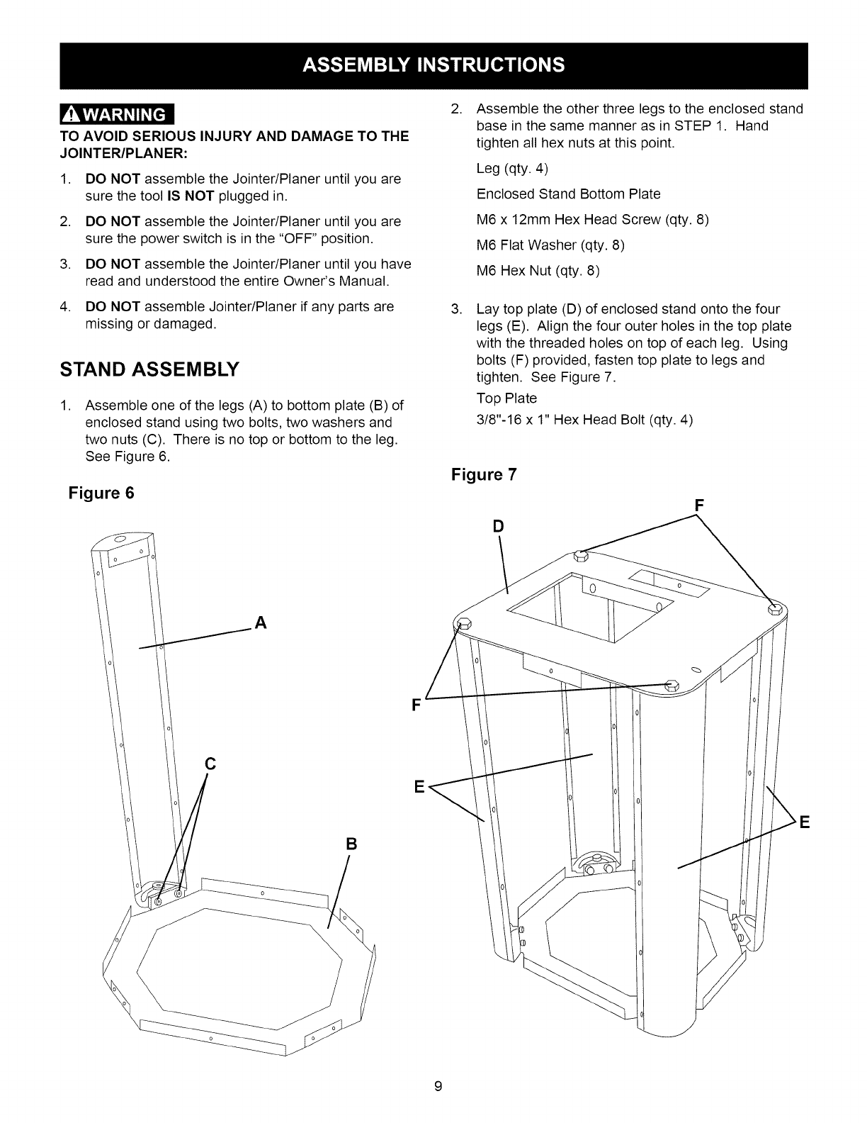
,Assemble one of the legs (A) to bottom plate (B) of
enclosed stand using two bolts, two washers and
two nuts (C). There is no top or bottom to the leg.
See Figure 6.
Figure 6
A
F
E
B
,
,
Assemble the other three legs to the enclosed stand
base in the same manner as in STEP 1. Hand
tighten all hex nuts at this point.
Leg (qty. 4)
Enclosed Stand Bottom Plate
M6 x 12mm Hex Head Screw (qty. 8)
M6 Flat Washer (qty. 8)
M6 Hex Nut (qty. 8)
Lay top plate (D) of enclosed stand onto the four
legs (E). Align the four outer holes in the top plate
with the threaded holes on top of each leg. Using
bolts (F) provided, fasten top plate to legs and
tighten. See Figure 7.
Top Plate
3/8"-16 x 1" Hex Head Bolt (qty. 4)
Figure 7
D
F
E
9
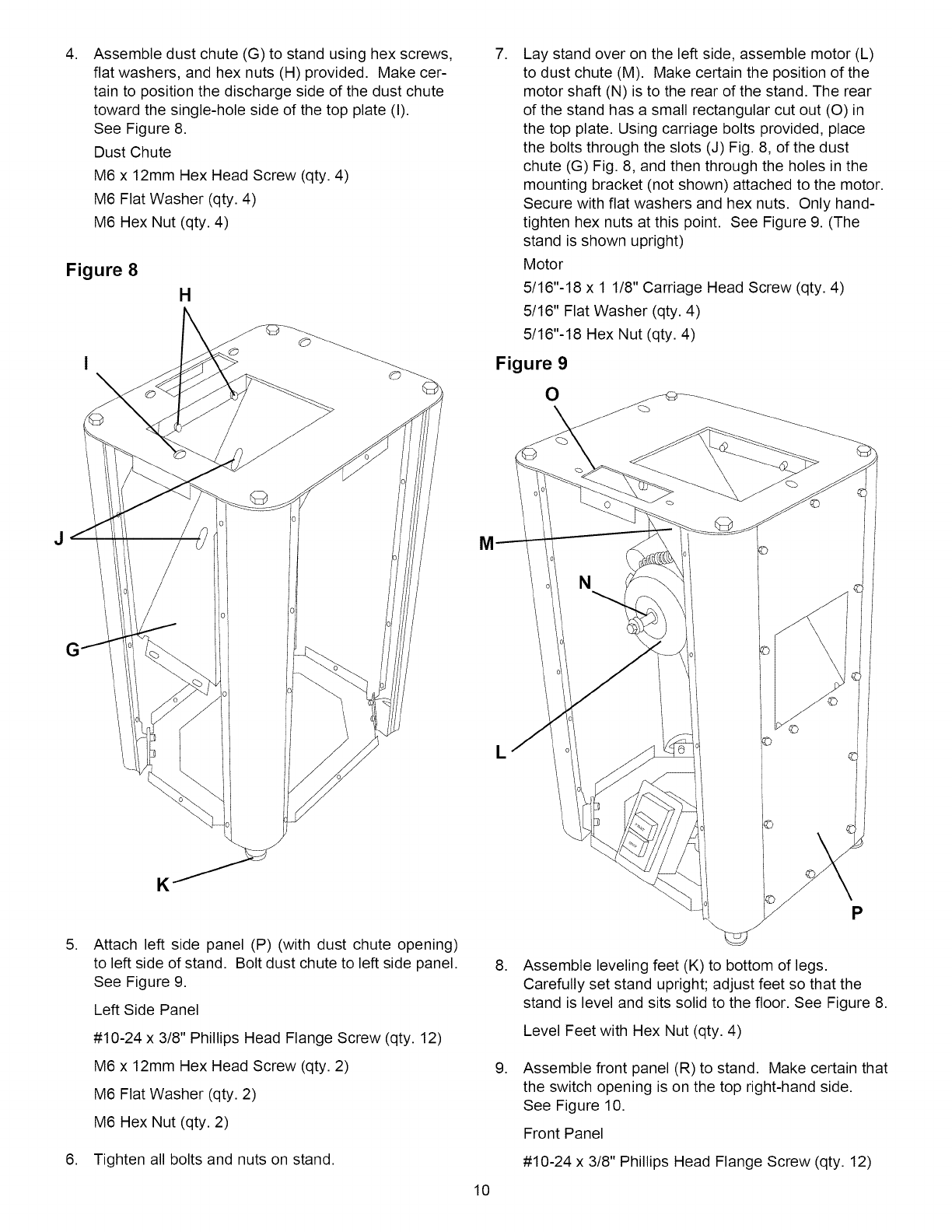
,Assemble dust chute (G) to stand using hex screws,
flat washers, and hex nuts (H) provided. Make cer-
tain to position the discharge side of the dust chute
toward the single-hole side of the top plate (I).
See Figure 8.
Dust Chute
M6 x 12mm Hex Head Screw (qty. 4)
M6 Flat Washer (qty. 4)
M6 Hex Nut (qty. 4)
Figure 8
H
,Lay stand over on the left side, assemble motor (L)
to dust chute (M). Make certain the position of the
motor shaft (N) is to the rear of the stand. The rear
of the stand has a small rectangular cut out (O) in
the top plate. Using carriage bolts provided, place
the bolts through the slots (J) Fig. 8, of the dust
chute (G) Fig. 8, and then through the holes in the
mounting bracket (not shown) attached to the motor.
Secure with flat washers and hex nuts. Only hand-
tighten hex nuts at this point. See Figure 9. (The
stand is shown upright)
Motor
5/16"-18 x 1 1/8" Carriage Head Screw (qty. 4)
5/16" Flat Washer (qty. 4)
5/16"-18 Hex Nut (qty. 4)
Figure 9
O
,
K
Attach left side panel (P) (with dust chute opening)
to left side of stand. Bolt dust chute to left side panel.
See Figure 9.
Left Side Panel
#10-24 x 3/8" Phillips Head Flange Screw (qty. 12)
M6 x 12mm Hex Head Screw (qty. 2)
M6 Flat Washer (qty. 2)
M6 Hex Nut (qty. 2)
6. Tighten all bolts and nuts on stand.
10
L©
P
,
,
Assemble leveling feet (K) to bottom of legs.
Carefully set stand upright; adjust feet so that the
stand is level and sits solid to the floor. See Figure 8.
Level Feet with Hex Nut (qty. 4)
Assemble front panel (R) to stand. Make certain that
the switch opening is on the top right-hand side.
See Figure 10.
Front Panel
#10-24 x 3/8" Phillips Head Flange Screw (qty. 12)
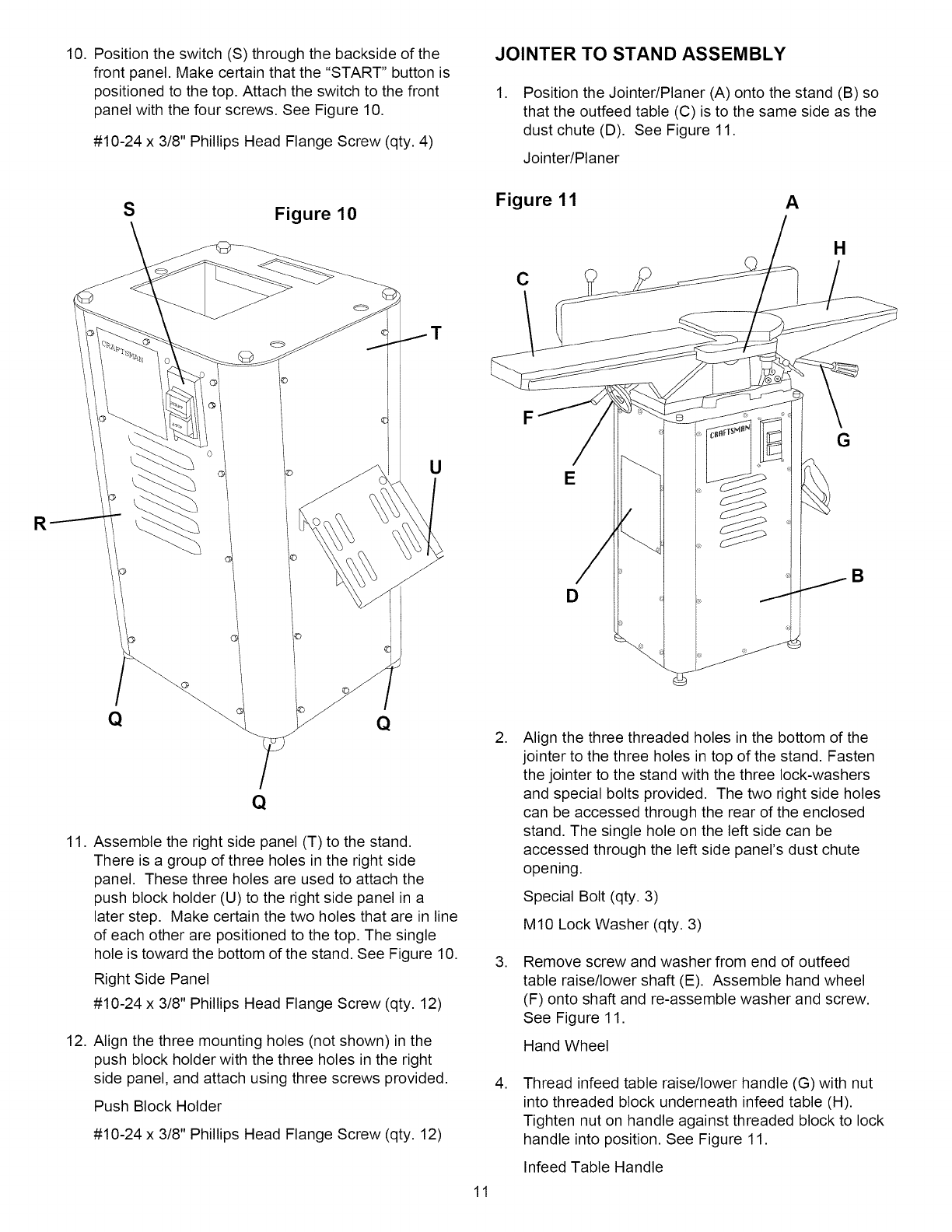
10.Positiontheswitch(S)throughthebacksideofthe
frontpanel.Makecertainthatthe"START"buttonis
positionedtothetop.Attachtheswitchtothefront
panelwiththefourscrews.SeeFigure10.
#10-24x 3/8"PhillipsHeadFlangeScrew(qty.4)
JOINTER TO STAND ASSEMBLY
,Position the Jointer/Planer (A) onto the stand (B) so
that the outfeed table (C) is to the same side as the
dust chute (D). See Figure 11.
Jointer/Planer
R
SFigure 10
T
U
Figure 11 A
C
F
E
D
H
G
B
11.
12.
Assemble the right side panel (T) to the stand.
There is a group of three holes in the right side
panel. These three holes are used to attach the
push block holder (U) to the right side panel in a
later step. Make certain the two holes that are in line
of each other are positioned to the top. The single
hole is toward the bottom of the stand. See Figure 10.
Right Side Panel
#10-24 x 3/8" Phillips Head Flange Screw (qty. 12)
Align the three mounting holes (not shown) in the
push block holder with the three holes in the right
side panel, and attach using three screws provided.
Push Block Holder
#10-24 x 3/8" Phillips Head Flange Screw (qty. 12)
11
,Align the three threaded holes in the bottom of the
jointer to the three holes in top of the stand. Fasten
the jointer to the stand with the three lock-washers
and special bolts provided. The two right side holes
can be accessed through the rear of the enclosed
stand. The single hole on the left side can be
accessed through the left side panel's dust chute
opening.
Special Bolt (qty. 3)
M10 Lock Washer (qty. 3)
,Remove screw and washer from end of outfeed
table raise/lower shaft (E). Assemble hand wheel
(F) onto shaft and re-assemble washer and screw.
See Figure 11.
Hand Wheel
,Thread infeed table raise/lower handle (G) with nut
into threaded block underneath infeed table (H).
Tighten nut on handle against threaded block to lock
handle into position. See Figure 11.
Infeed Table Handle
MOTOR PULLEY ASSEMBLY
To assemble motor pulley to motor shaft, back off the
two set screws in pulley so that pulley can slide onto
motor shaft. Make certain that the set screw side is
toward the motor body. Align the key in the motor shaft
with the key way in pulley. Slide pulley onto shaft until
end of shaft is flush with face of pulley.
Motor Pulley
Figure 12 A_
D
BELT ASSEMBLY AND
PULLEY ALIGNMENT
,
,
,
Place V-belt in groove of cutterhead pulley and
motor pulley.
Belt
To properly align motor pulley to the cutterhead
pulley, place a straight edge on the outside face of
the cutterhead pulley. The motor and motor pulley
can be moved in or out and up or down until the
outside face of the motor pulley is vertically aligned
with the cutterhead pulley.
After proper alignment, tighten all bolts that attach
motor to dust chute.
4. Tighten both set screws.
BELT TENSIONING
,
,
,
Proper belt tension is achieved when there is
approximately 1" deflection at the center of the belt
span using light finger pressure.
To achieve proper belt tension, loosen the four
motor attachment bolts. The motor can be moved
up or down to gain proper tension.
After achieving proper tension, check that there is
proper alignment of the pulleys. Then tighten all
bolts attaching the motor to the dust chute.
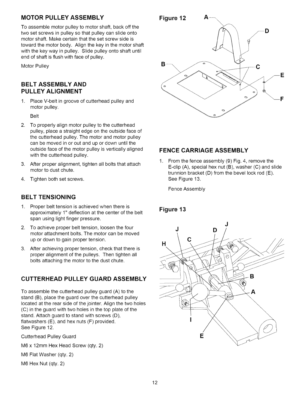
CUTTERHEAD PULLEY GUARD ASSEMBLY
To assemble the cutterhead pulley guard (A) to the
stand (B), place the guard over the cutterhead pulley
located at the rear side of the jointer. Align the two holes
(C) in the guard with two holes in the top plate of the
stand. Attach guard to stand with screws (D),
flatwashers (E), and hex nuts (F) provided.
See Figure 12.
Cutterhead Pulley Guard
M6 x 12mm Hex Head Screw (qty. 2)
M6 Flat Washer (qty. 2)
M6 Hex Nut (qty. 2)
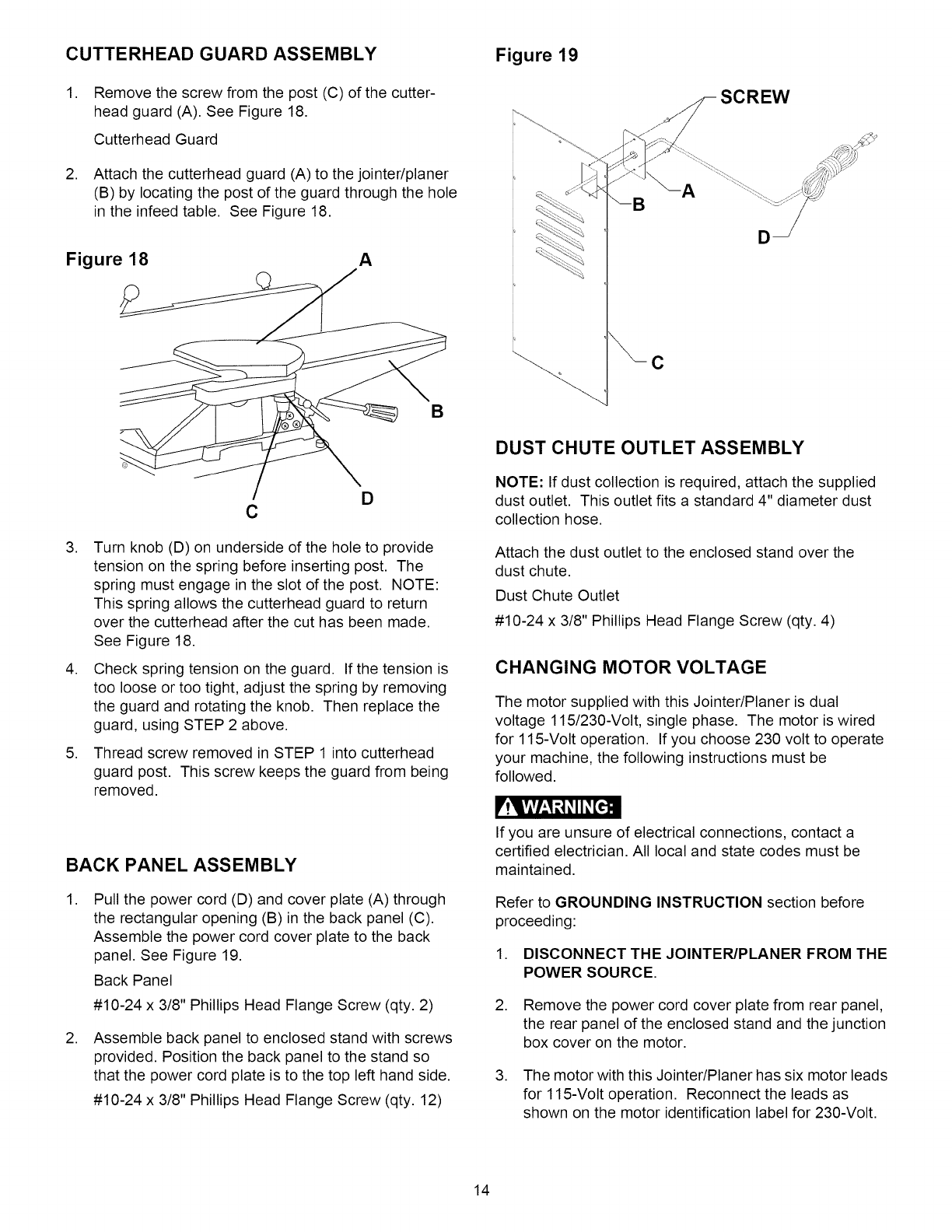
FENCE CARRIAGE ASSEMBLY
,From the fence assembly (9) Fig. 4, remove the
E-clip (A), special hex nut (B), washer (C) and slide
trunnion bracket (D) from the bevel lock rod (E).
See Figure 13.
Fence Assembly
Figure 13
J
HC
J
D
B
A
E
12

,Slide the slide trunnion bracket down into the
dovetail (F) of the slide fence assembly (G).
See Figure 14.
Slide Fence Assembly
Figure 14
Figure 15 J_ p
LM
O
,
,
F
G
Position the bevel lock rod on the back of the fence
assembly through the hole in the slide trunnion
bracket and the slot (H) in the slide fence assembly.
Assemble the washer and special hex nut onto the
bevel lock rod. Make certain the threaded end of the
special hex nut is to the rear of the bevel lock rod.
Place bevel lock handle (I) onto special hex nut.
Re-assemble the E-clip to the bevel lock rod,
removed in an earlier step.
See Figure 13.
Position the fence against the 90-degree positive
stops (J) on the slide fence assembly. Tighten the
bevel lock handle to hold the fence at 90 degrees.
See Figure 13.
NK
FENCE TO JOINTER ASSEMBLY
,Remove the two hex nuts and the washer from the
clamp bolt (O) Fig. 15. Carefully lay the fence
assembly (M) Fig. 15 onto the Jointer/Planer outfeed
table (A) Fig. 16. Align the key (B) Fig. 16 in the
outfeed table with the keyway groove (N) Fig. 15 in
the bottom of the slide fence assembly (Q) Fig. 15.
Position the clamp bolt through the slot (C) Fig. 16
in the outfeed table.
2. Assemble the washer and one of the hex nuts onto
the clamp bolt. Tighten the hex nut until there is only
one-quarter turn of the cam lock handle. This sets
the locking mechanism for the fence.
3. Check that the fence locks and unlocks. Make cer-
tain that the fence can move across the table width
without excessive drag from the locking mechanism.
4. Lock the fence; assemble the second hex nut
against the first hex nut. Make certain that the first
nut does not move while tightening the second nut.
Figure 16 C B
A
,Remove two screws (D) from slide fence assembly
(E). Assemble the rear cutterhead guard (F) using
screws that were removed, and tighten. See
Figure 17.
Figure 17
13
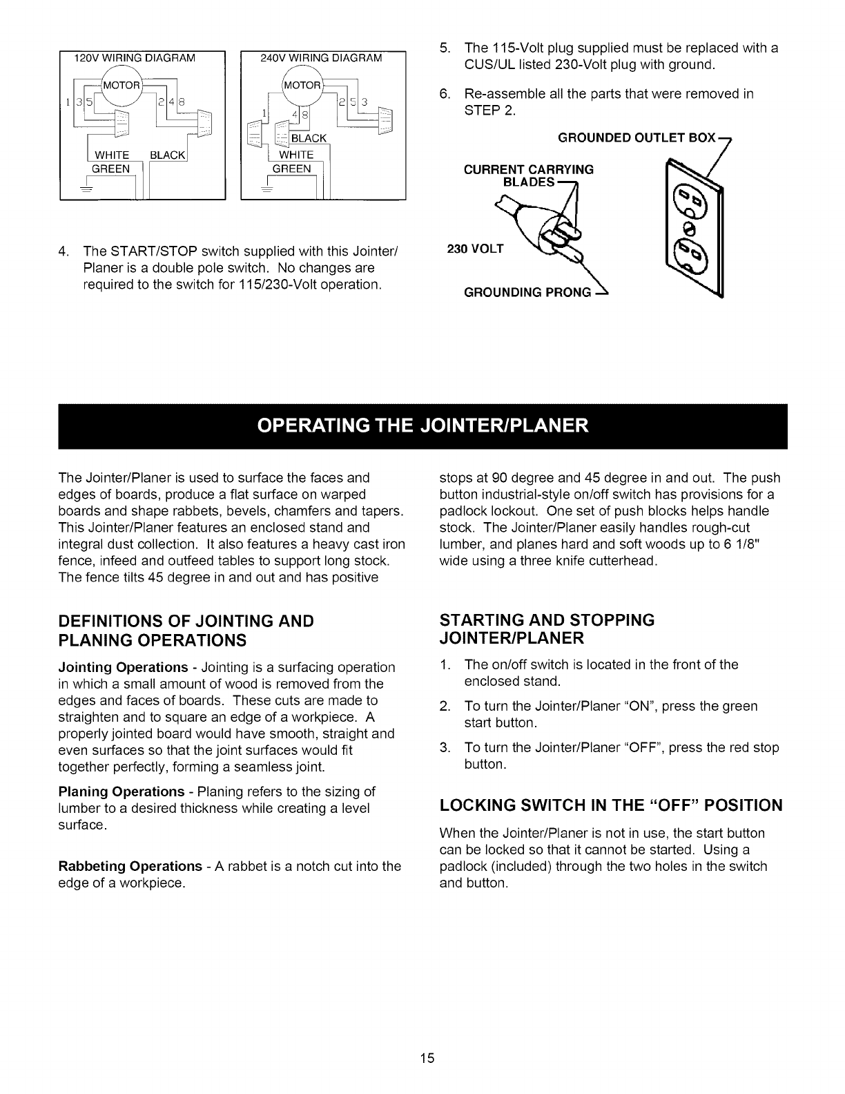
CUTTERHEAD GUARD ASSEMBLY Figure 19
1. Remove the screw from the post (C) of the cutter-
head guard (A). See Figure 18.
Cutterhead Guard
2. Attach the cutterhead guard (A) to the jointer/planer
(B) by locating the post of the guard through the hole
in the infeed table. See Figure 18.
Figure 18 A
C
A
SCREW
B
,
,
,
D
C
Turn knob (D) on underside of the hole to provide
tension on the spring before inserting post. The
spring must engage in the slot of the post. NOTE:
This spring allows the cutterhead guard to return
over the cutterhead after the cut has been made.
See Figure 18.
Check spring tension on the guard. If the tension is
too loose or too tight, adjust the spring by removing
the guard and rotating the knob. Then replace the
guard, using STEP 2 above.
Thread screw removed in STEP 1 into cutterhead
guard post. This screw keeps the guard from being
removed.
BACK PANEL ASSEMBLY
,Pull the power cord (D) and cover plate (A) through
the rectangular opening (B) in the back panel (C).
Assemble the power cord cover plate to the back
panel. See Figure 19.
Back Panel
#10-24 x 3/8" Phillips Head Flange Screw (qty. 2)
,Assemble back panel to enclosed stand with screws
provided. Position the back panel to the stand so
that the power cord plate is to the top left hand side.
#10-24 x 3/8" Phillips Head Flange Screw (qty. 12)
DUST CHUTE OUTLET ASSEMBLY
NOTE: If dust collection is required, attach the supplied
dust outlet. This outlet fits a standard 4" diameter dust
collection hose.
Attach the dust outlet to the enclosed stand over the
dust chute.
Dust Chute Outlet
#10-24 x 3/8" Phillips Head Flange Screw (qty. 4)
CHANGING MOTOR VOLTAGE
The motor supplied with this Jointer/Planer is dual
voltage 115/230-Volt, single phase. The motor is wired
for 115-Volt operation. If you choose 230 volt to operate
your machine, the following instructions must be
followed.
r!lVlVl_,1 _3_II _[e.]cB
If you are unsure of electrical connections, contact a
certified electrician. All local and state codes must be
maintained.
Refer to GROUNDING INSTRUCTION section before
proceeding:
1. DISCONNECT THE JOINTER/PLANER FROM THE
POWER SOURCE.
2. Remove the power cord cover plate from rear panel,
the rear panel of the enclosed stand and the junction
box cover on the motor.
3. The motor with this Jointer/Planer has six motor leads
for 115-Volt operation. Reconnect the leads as
shown on the motor identification label for 230-Volt.
14
120V WIRING DIAGRAM
GREEN
240V WIRING DIAGRAM
GREEN 1
I--
4. The START/STOP switch supplied with this Jointer/
Planer is a double pole switch. No changes are
required to the switch for 115/230-Volt operation.
5. The 115-Volt plug supplied must be replaced with a
CUS/UL listed 230-Volt plug with ground.
6. Re-assemble all the parts that were removed in
STEP 2.
GROUNDED OUTLET
CURRENT CARRYING
230 VOLT __
GROUNDING PRONG
The Jointer/Planer is used to surface the faces and
edges of boards, produce a flat surface on warped
boards and shape rabbets, bevels, chamfers and tapers.
This Jointer/Planer features an enclosed stand and
integral dust collection. It also features a heavy cast iron
fence, infeed and outfeed tables to support long stock.
The fence tilts 45 degree in and out and has positive
stops at 90 degree and 45 degree in and out. The push
button industrial-style on/off switch has provisions for a
padlock lockout. One set of push blocks helps handle
stock. The Jointer/Planer easily handles rough-cut
lumber, and planes hard and soft woods up to 6 1/8"
wide using a three knife cutterhead.
DEFINITIONS OF JOINTING AND
PLANING OPERATIONS
Jointing Operations - Jointing is a surfacing operation
in which a small amount of wood is removed from the
edges and faces of boards. These cuts are made to
straighten and to square an edge of a workpiece. A
properly jointed board would have smooth, straight and
even surfaces so that the joint surfaces would fit
together perfectly, forming a seamless joint.
Planing Operations - Planing refers to the sizing of
lumber to a desired thickness while creating a level
surface.
Rabbeting Operations - A rabbet is a notch cut into the
edge of a workpiece.
STARTING AND STOPPING
JOINTER/PLANER
1. The on/off switch is located in the front of the
enclosed stand.
2. To turn the Jointer/Planer "ON", press the green
start button.
3. To turn the Jointer/Planer "OFF", press the red stop
button.
LOCKING SWITCH IN THE "OFF" POSITION
When the Jointer/Planer is not in use, the start button
can be locked so that it cannot be started. Using a
padlock (included) through the two holes in the switch
and button.
15
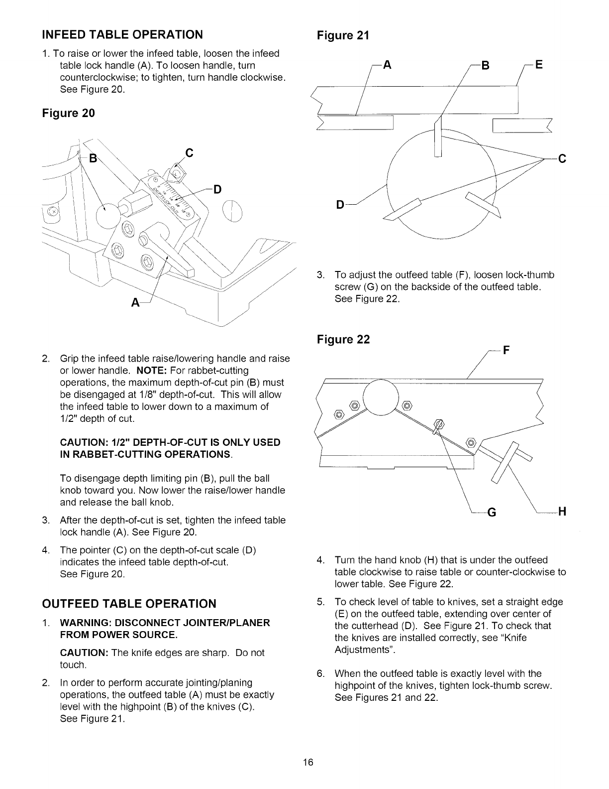
INFEED TABLE OPERATION
1. To raise or lower the infeed table, loosen the infeed
table lock handle (A). To loosen handle, turn
counterclockwise; to tighten, turn handle clockwise.
See Figure 20.
Figure 20
C
D
Figure 21
D
! <
,
,
,
Grip the infeed table raise/lowering handle and raise
or lower handle. NOTE: For rabbet-cutting
operations, the maximum depth-of-cut pin (B) must
be disengaged at 1/8" depth-of-cut. This will allow
the infeed table to lower down to a maximum of
1/2" depth of cut.
CAUTION: 1/2" DEPTH-OF-CUT IS ONLY USED
IN RABBET-CUTTING OPERATIONS.
To disengage depth limiting pin (B), pull the ball
knob toward you. Now lower the raise/lower handle
and release the ball knob.
After the depth-of-cut is set, tighten the infeed table
lock handle (A). See Figure 20.
The pointer (C) on the depth-of-cut scale (D)
indicates the infeed table depth-of-cut.
See Figure 20.
OUTFEED TABLE OPERATION
1. WARNING: DISCONNECT JOINTER/PLANER
FROM POWER SOURCE.
CAUTION: The knife edges are sharp. Do not
touch.
,In order to perform accurate jointing/planing
operations, the outfeed table (A) must be exactly
level with the highpoint (B) of the knives (C).
See Figure 21.
3. To adjust the outfeed table (F), loosen lock-thumb
screw (G) on the backside of the outfeed table.
See Figure 22.
Figure 22
@
,
,
,
Turn the hand knob (H) that is under the outfeed
table clockwise to raise table or counter-clockwise to
lower table. See Figure 22.
To check level of table to knives, set a straight edge
(E) on the outfeed table, extending over center of
the cutterhead (D). See Figure 21. To check that
the knives are installed correctly, see "Knife
Adjustments".
When the outfeed table is exactly level with the
highpoint of the knives, tighten lock-thumb screw.
See Figures 21 and 22.
16
FENCE OPERATION
The fence can be moved across the infeed and outfeed
tables. The fence can be positioned to 90 degrees to the
table or can be tilted at 45 degrees in or out to the table.
MOVING AND TILTING
,To move the fence across the table, loosen the cam
lock handle one-quarter turn. The fence is now free
to move back and forth across the table width.
When the proper position is achieved, re-tighten the
cam lock handle, securing the fence in position.
,To tilt the fence in or out, loosen the bevel lock
handle, pull both 90 degree indexing pins out and
rotate the 90 degree positive stops back. The fence
can now tilt in or out to 45 degrees. Re-tighten
bevel lock handle when proper position is achieved.
FENCE POSITIVE STOPS
5. Loosen jam nut (B) of the stop screw (C) that you
want to adjust. See Figure 23.
6. Adjust stop screws to in or out.
7. Retighten bevel lock handle.
8. Check fence. If more adjustments are required, repeat
this process until the proper angle is achieved.
9. Re-tighten jam nuts that were loosened during
adjustments. Make certain that the stop screws do
not move.
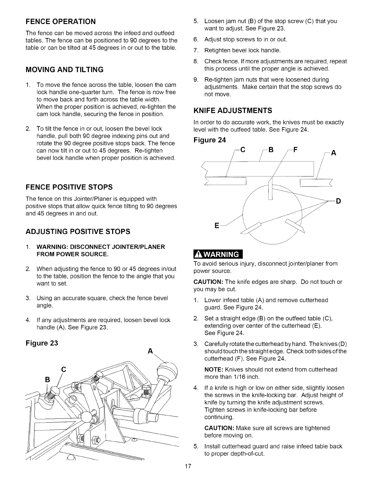
KNIFE ADJUSTMENTS
In order to do accurate work, the knives must be exactly
level with the outfeed table. See Figure 24.
Figure 24
7F
The fence on this Jointer/Planer is equipped with
positive stops that allow quick fence tilting to 90 degrees
and 45 degrees in and out.
ADJUSTING POSITIVE STOPS
1. WARNING: DISCONNECT JOINTER/PLANER
FROM POWER SOURCE.
2. When adjusting the fence to 90 or 45 degrees in/out
to the table, position the fence to the angle that you
want to set.
,
,
Using an accurate square, check the fence bevel
angle.
If any adjustments are required, loosen bevel lock
handle (A). See Figure 23.
Figure 23 A
C
B
D
E
_!q&vhl r,,1_II _[€-!
To avoid serious injury, disconnect jointer/planer from
power source.
CAUTION: The knife edges are sharp. Do not touch or
you may be cut.
,
,
,
Lower infeed table (A) and remove cutterhead
guard. See Figure 24.
Set a straight edge (B) on the outfeed table (C),
extending over center of the cutterhead (E).
See Figure 24.
Carefully rotate the cutterhead by hand. The knives (D)
should touch the straight edge. Check both sides of the
cutterhead (F). See Figure 24.
NOTE: Knives should not extend from cutterhead
more than 1/16 inch.
,
,
If a knife is high or low on either side, slightly loosen
the screws in the knife-locking bar. Adjust height of
knife by turning the knife adjustment screws.
Tighten screws in knife-locking bar before
continuing.
CAUTION: Make sure all screws are tightened
before moving on.
Install cutterhead guard and raise infeed table back
to proper depth-of-cut.
17
CAUTION:Toavoidcuttingyourself,beverycareful
whenremoving,replacingandresettingknives.
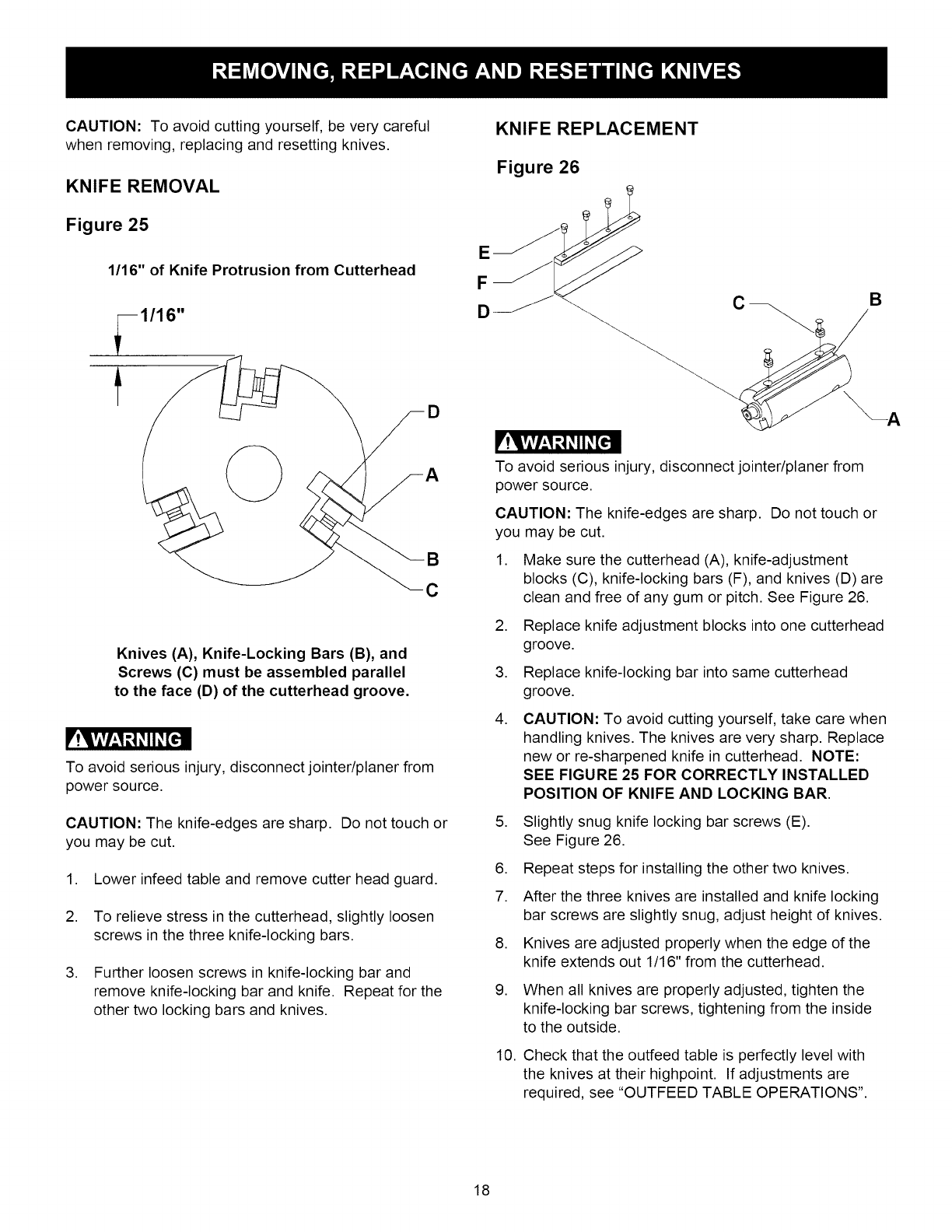
KNIFE REMOVAL
Figure 25
1/16" of Knife Protrusion from Cutterhead
1/16"
D
B
C
Knives (A), Knife-Locking Bars (B), and
Screws (C) must be assembled parallel
to the face (D) of the cutterhead groove.
F'!q,vlvg_,1_1_ii _[€.ll
To avoid serious injury, disconnect jointer/planer from
power source.
CAUTION: The knife-edges are sharp. Do not touch or
you may be cut.
1. Lower infeed table and remove cutter head guard.
2. To relieve stress in the cutterhead, slightly loosen
screws in the three knife-locking bars.
3. Further loosen screws in knife-locking bar and
remove knife-locking bar and knife. Repeat for the
other two locking bars and knives.
KNIFE REPLACEMENT
Figure 26
B
--A
_!Vivl_,1 r,,1_II _[e-!
To avoid serious injury, disconnect jointer/planer from
power source.
CAUTION: The knife-edges are sharp. Do not touch or
you may be cut.
1. Make sure the cutterhead (A), knife-adjustment
blocks (C), knife-locking bars (F), and knives (D) are
clean and free of any gum or pitch. See Figure 26.
2. Replace knife adjustment blocks into one cutterhead
groove.
3. Replace knife-locking bar into same cutterhead
groove.
,CAUTION: To avoid cutting yourself, take care when
handling knives. The knives are very sharp. Replace
new or re-sharpened knife in cutterhead. NOTE:
SEE FIGURE 25 FOR CORRECTLY INSTALLED
POSITION OF KNIFE AND LOCKING BAR.
5. Slightly snug knife locking bar screws (E).
See Figure 26.
6. Repeat steps for installing the other two knives.
7. After the three knives are installed and knife locking
bar screws are slightly snug, adjust height of knives.
8. Knives are adjusted properly when the edge of the
knife extends out 1/16" from the cutterhead.
9. When all knives are properly adjusted, tighten the
knife-locking bar screws, tightening from the inside
to the outside.
10. Check that the outfeed table is perfectly level with
the knives at their highpoint. If adjustments are
required, see "OUTFEED TABLE OPERATIONS".
18
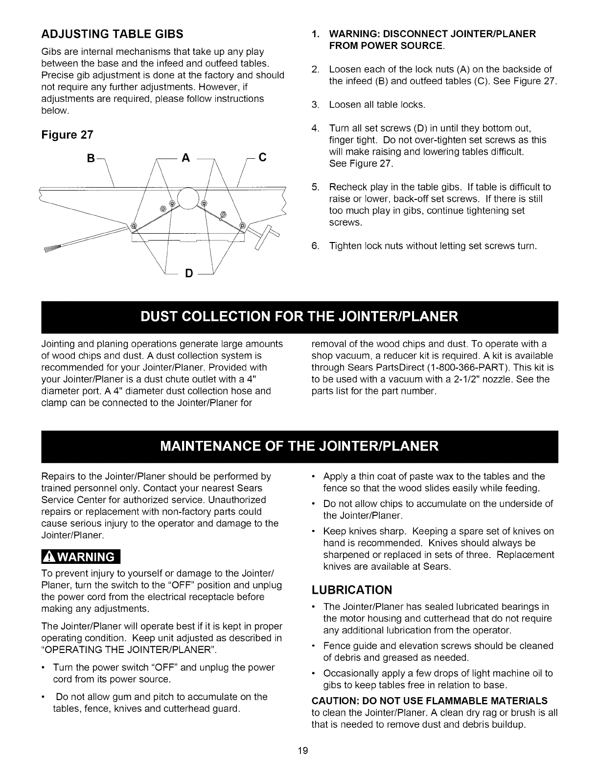
ADJUSTING TABLE GIBS
Gibs are internal mechanisms that take up any play
between the base and the infeed and outfeed tables.
Precise gib adjustment is done at the factory and should
not require any further adjustments. However, if
adjustments are required, please follow instructions
below.
Figure 27
1. WARNING: DISCONNECT JOINTER/PLANER
FROM POWER SOURCE.
2. Loosen each of the lock nuts (A) on the backside of
the infeed (B) and outfeed tables (C). See Figure 27.
3. Loosen all table locks.
,Turn all set screws (D) in until they bottom out,
finger tight. Do not over-tighten set screws as this
will make raising and lowering tables difficult.
See Figure 27.
,Recheck play in the table gibs. If table is difficult to
raise or lower, back-off set screws. If there is still
too much play in gibs, continue tightening set
screws.
6. Tighten lock nuts without letting set screws turn.
Jointing and planing operations generate large amounts
of wood chips and dust. A dust collection system is
recommended for your Jointer/Planer. Provided with
your Jointer/Planer is a dust chute outlet with a 4"
diameter port. A 4" diameter dust collection hose and
clamp can be connected to the Jointer/Planer for
removal of the wood chips and dust. To operate with a
shop vacuum, a reducer kit is required. A kit is available
through Sears PartsDirect (1-800-366-PART). This kit is
to be used with a vacuum with a 2-1/2" nozzle. See the
parts list for the part number.
Repairs to the Jointer/Planer should be performed by
trained personnel only. Contact your nearest Sears
Service Center for authorized service. Unauthorized
repairs or replacement with non-factory parts could
cause serious injury to the operator and damage to the
Jointer/Planer.
r'!q,vlvl_,1_1_II _[ell
To prevent injury to yourself or damage to the Jointer/
Planer, turn the switch to the "OFF" position and unplug
the power cord from the electrical receptacle before
making any adjustments.
The Jointer/Planer will operate best if it is kept in proper
operating condition. Keep unit adjusted as described in
"OPERATING THE JOINTER/PLANER".
Turn the power switch "OFF" and unplug the power
cord from its power source.
Do not allow gum and pitch to accumulate on the
tables, fence, knives and cutterhead guard.
• Apply a thin coat of paste wax to the tables and the
fence so that the wood slides easily while feeding.
• Do not allow chips to accumulate on the underside of
the Jointer/Planer.
Keep knives sharp. Keeping a spare set of knives on
hand is recommended. Knives should always be
sharpened or replaced in sets of three. Replacement
knives are available at Sears.
LUBRICATION
• The Jointer/Planer has sealed lubricated bearings in
the motor housing and cutterhead that do not require
any additional lubrication from the operator.
• Fence guide and elevation screws should be cleaned
of debris and greased as needed.
• Occasionally apply a few drops of light machine oil to
gibs to keep tables free in relation to base.
CAUTION: DO NOT USE FLAMMABLE MATERIALS
to clean the Jointer/Planer. A clean dry rag or brush is all
that is needed to remove dust and debris buildup.
19
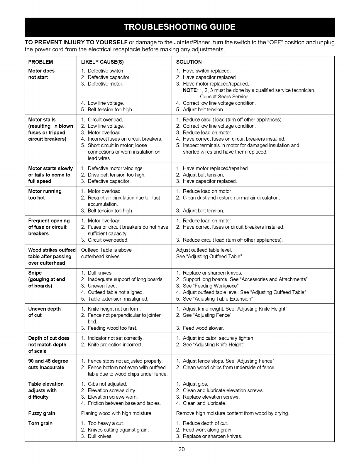
TO PREVENT INJURY TO YOURSELF or damage to the Jointer/Planer, turn the switch to the "OFF" position and unplug
the power cord from the electrical receptacle before making any adjustments.
PROBLEM
Motor does
not start
Motor stalls
(resulting in blown
fuses or tripped
circuit breakers)
Motor starts slowly
or fails to come to
full speed
Motor running
too hot
Frequent opening
of fuse or circuit
breakers
Wood strikes ouffeed
table after passing
over cutterhead
Snipe
(gouging at end
of boards)
Uneven depth
of cut
Depth of cut does
not match depth
of scale
90 and 45 degree
cuts inaccurate
LIKELY CAUSE(S)
1. Defective switch
2. Defective capacitor.
3. Defective motor.
4. Low linevoltage.
5. Belt tensiontoo high.
1. Circuit overload.
2. Low linevoltage.
3. Motor overload.
4. Incorrect fuses on circuit breakers.
5. Short circuit in motor; loose
connections or worn insulation on
lead wires.
1. Defective motor windings.
2. Drive belt tension too high.
3. Defective capacitor.
1. Motor overload.
2. Restrict air circulation due to dust
accumulation.
3. Belt tension too high.
1. Motor overload.
2. Fuses or circuit breakers do not have
sufficient capacity.
3. Circuit overloaded.
Outfeed Table is above
cutterhead knives.
SOLUTION
1. Have switch replaced.
2. Have capacitor replaced.
3. Have motor replaced/repaired.
NOTE: 1,2, 3 must be done by a qualified service technician.
Consult Sears Service.
4. Correct low linevoltage condition.
5. Adjust belt tension.
1. Reduce circuit load (turn off other appliances).
2. Correct low line voltage condition.
3. Reduce load on motor.
4. Have correct fuses on circuit breakers installed.
5. Inspect terminals in motor for damaged insulation and
shorted wires and have them replaced.
1. Have motor replaced/repaired.
2. Adjust belt tension.
3. Have capacitor replaced.
1. Reduce load on motor.
2. Clean dust and restore normal air circulation.
3. Adjust belt tension.
1. Reduce load on motor.
2. Have correct fuses or circuit breakers installed.
3. Reduce circuit load (turn off other appliances).
Adjust outfeed table level.
See "Adjusting Outfeed Table"
1. Dull knives.
2. Inadequate support of long boards.
3. Uneven feed.
4. Outfeed table not aligned.
5. Table extension misaligned.
1. Knife height not uniform.
2. Fence not perpendicular to jointer
bed.
3. Feeding wood too fast.
1. Indicator not set correctly.
2. Knife projection incorrect.
1. Fence stops not adjusted properly.
2. Fence bottom not even with outfeed
table due to wood chips under fence.
1. Replace or sharpen knives.
2. Support long boards. See "Accessories and Attachments"
3. See"Feeding Workpiece"
4. Adjust outfeed table level. See "Adjusting Outfeed Table"
5. See "Adjusting Table Extension"
1. Adjust knife height. See "Adjusting Knife Height"
2. See "Adjusting Fence"
3. Feed wood slower.
1. Adjust indicator, securely tighten.
2. See "Adjusting Knife Height"
1. Adjust fence stops. See "Adjusting Fence"
2. Clean wood chips from underside of fence.
Table elevation 1. Gibs not adjusted. 1. Adjust gibs.
adjusts with 2. Elevation screws dirty. 2. Clean and lubricate elevation screws.
difficulty 3. Elevation screws worn. 3. Replace elevation screws.
4. Friction between base and tables. 4. Clean and lubricate.
Fuzzy grain Planing wood with high moisture. Remove high moisture content from wood by drying.
Torn grain 1. Too heavy a cut. 1. Reduce depth of cut.
2. Knives cutting against grain. 2. Feed work along grain.
3. Dull knives. 3. Replace or sharpen knives.
2O
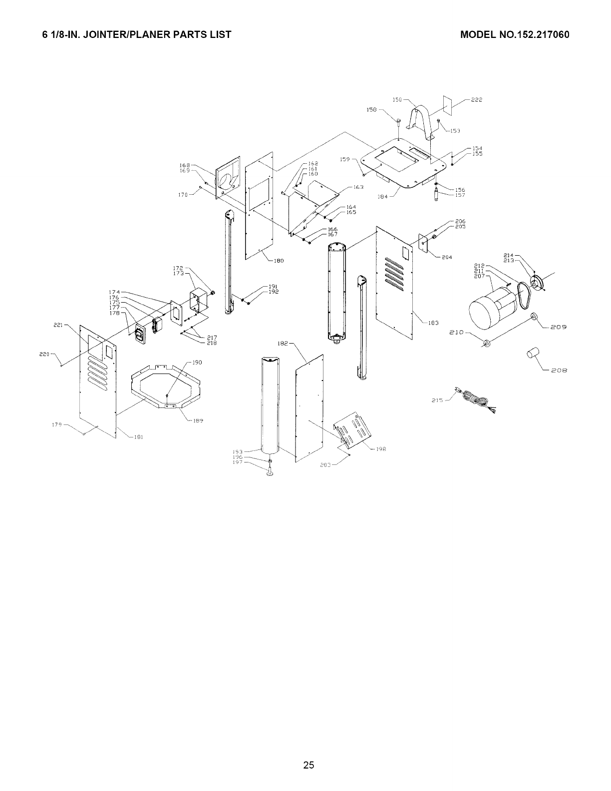
6 1/8-1N. JOINTER/PLANER PARTS LIST MODEL NO.152.217060
F'!q,vlvl_,1_1_ii _[€.ll
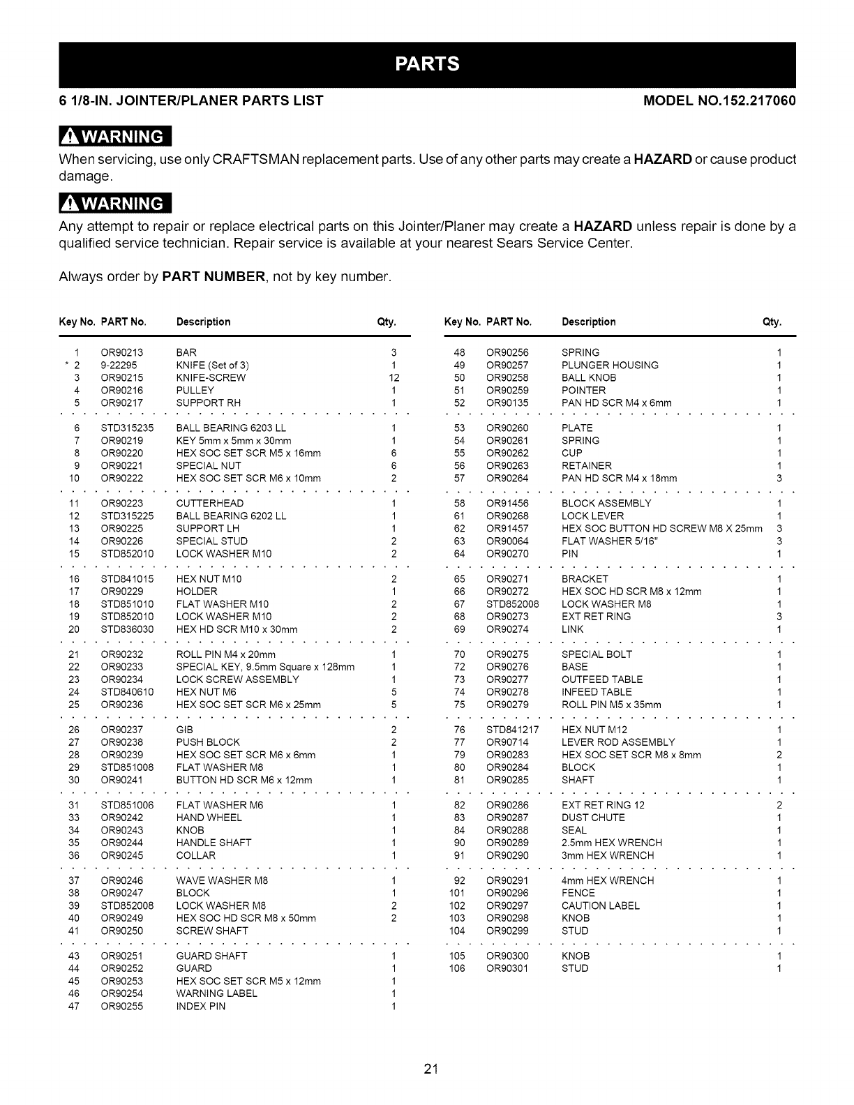
When servicing, use only CRAFTSMAN replacement parts. Use of any other parts may create a HAZARD or cause product
damage.
F'!q,vlv/_,1_1_ii _[€.ll
Any attempt to repair or replace electrical parts on this Jointer/Planer may create a HAZARD unless repair is done by a
qualified service technician. Repair service is available at your nearest Sears Service Center.
Always order by PART NUMBER, not by key number.
Key No, PART No. Description Qty, Key No, PART No. Description Qty,
1 OR90213 BAR 3
* 2 9-22295 KNIFE (Set of 3) 1
3 OR90215 KNIFE-SCREW 12
4 OR90216 PULLEY 1
5 OR90217 SUPPORT RH 1
6 STD315235 BALL BEARING 6203 LL 1
7 OR90219 KEY 5mm x 5mm x 30mm 1
8 OR90220 HEX SOC SET SCR M5 x 16mm 6
9 OR90221 SPECIAL NUT 6
10 OR90222 HEX SOC SET SCR M6 x 10mm 2
11 OR90223 CUTTERHEAD 1
12 STD315225 BALL BEARING 6202 LL 1
13 OR90225 SUPPORT LH 1
14 OR90226 SPECIAL STUD 2
15 STD852010 LOCK WASHER M10 2
16 STD841015 HEX NUT M10 2
17 OR90229 HOLDER 1
18 STD851010 FLAT WASHER M10 2
19 STD852010 LOCK WASHER M10 2
20 STD836030 HEX HD SCR M10 x 30mm 2
21 OR90232 ROLL PIN M4 x 20mm 1
22 OR90233 SPECIAL KEY, 9.5mm Square x 128mm 1
23 OR90234 LOCK SCREW ASSEMBLY 1
24 STD840610 HEX NUT M6 5
25 OR90236 HEX SOC SET SCR M6 x 25mm 5
26 OR90237 GIB 2
27 OR90238 PUSH BLOCK 2
28 OR90239 HEX SOC SET SCR M6 x 6mm 1
29 STD851008 FLAT WASHER M8 1
30 OR90241 BUTTON HD SCR M6 x 12mm 1
31 STD851006 FLAT WASHER M6 1
33 OR90242 HAND WHEEL 1
34 OR90243 KNOB 1
35 OR90244 HANDLE SHAFT 1
36 OR90245 COLLAR 1
37 OR90246 WAVE WASHER M8 1
38 OR90247 BLOCK 1
39 STD852008 LOCK WASHER M8 2
40 OR90249 HEX SOC HD SCR M8 x 50mm 2
41 OR90250 SCREW SHAFT
43 OR90251 GUARD SHAFT 1
44 OR90252 GUARD 1
45 OR90253 HEX SOC SET SCR M5 x 12mm 1
46 OR90254 WARNING LABEL 1
47 OR90255 INDEX PIN 1
48 OR90256 SPRING 1
49 OR90257 PLUNGER HOUSING 1
50 OR90258 BALL KNOB 1
51 OR90259 POINTER 1
52 OR90135 PAN HD SCR M4 x 6mm 1
53 OR90260 PLATE 1
54 OR90261 SPRING 1
55 OR90262 CUP 1
56 OR90263 RETAINER 1
57 OR90264 PAN HD SCR M4 x 18mm 3
58 OR91456 BLOCK ASSEMBLY 1
61 OR90268 LOCK LEVER 1
62 OR91457 HEX SOC BUTTON HD SCREW M8 X 25mm 3
63 OR90064 FLAT WASHER 5/16" 3
64 OR90270 PIN 1
65 OR90271 BRACKET 1
66 OR90272 HEX SOC HD SCR M8 x 12mm 1
67 STD852008 LOCK WASHER M8 1
68 OR90273 EXT RET RING 3
69 OR90274 LINK 1
70 OR90275 SPECIAL BOLT 1
72 OR90276 BASE 1
73 OR90277 OUTFEED TABLE 1
74 OR90278 INFEED TABLE 1
75 OR90279 ROLL PIN M5 x 35mm 1
76 STD841217 HEX NUT M12 1
77 OR90714 LEVER ROD ASSEMBLY 1
79 OR90283 HEX SOC SET SCR M8 x 8mm 2
80 OR90284 BLOCK 1
81 OR90285 SHAFT 1
82 OR90286 EXT RET RING 12 2
83 OR90287 DUST CHUTE 1
84 OR90288 SEAL 1
90 OR90289 2,5mm HEX WRENCH 1
91 OR90290 3mm HEX WRENCH 1
92 OR90291 4mm HEX WRENCH 1
101 OR90296 FENCE 1
102 OR90297 CAUTION LABEL 1
103 OR90298 KNOB 1
104 OR90299 STUD 1
105 OR90300 KNOB 1
106 OR90301 STUD 1
21
6 1/8-1N. JOINTER/PLANER PARTS LIST MODEL NO.152.217060
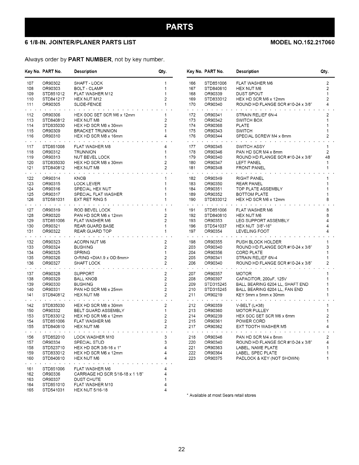
Always order by PART NUMBER, not by key number.
Key No, PART No. Description Qty,
107 OR90302 SHAFT -LOCK 1
108 OR90303 BOLT - CLAMP 1
109 STD851012 FLAT WASHER M12 1
110 STD841217 HEX NUT M12 2
111 OR90305 SLIDE-FENCE 1
112 OR90306 HEX SOC SET SCR M6 x 12mm 1
113 STD840812 HEX NUT M8 2
114 STD835030 HEX HD SCR M8 x 30mm 2
115 OR90309 BRACKET TRUNNION 1
116 OR90310 HEX HD SCR M8 x 16mm 4
117 STD851008 FLAT WASHER M8 4
118 OR90312 TRUNNION 1
119 OR90313 NUT BEVEL LOCK 1
120 STD835030 HEX HD SCR M8 x 30mm 2
121 STD840812 HEX NUT M8 2
122 OR90314 KNOB 1
123 OR90315 LOCK LEVER 1
124 OR90316 SPECIAL HEX NUT 1
125 OR90317 SPECIAL FLAT WASHER 1
126 STD581031 EXT RET RING 5 1
127 OR90319 ROD BEVEL LOCK 1
128 OR90320 PAN HD SCR M6 x 12mm 2
129 STD851006 FLAT WASHER M6 2
130 OR90321 REAR GUARD BASE 1
131 OR90322 REAR GUARD TOP 1
132 OR90323 ACORN NUT M6 2
133 OR90324 BUSHING 2
134 OR90325 SPRING 1
135 OR90326 O-RING <DIAl.9 x OD:8mm> 2
136 OR90327 SHAFT LOCK 2
137 OR90328 SUPPORT 2
138 OR90329 BALL KNOB 2
139 OR90330 BUSHING 2
140 OR90331 PAN HD SCR M6 x 25mm 2
141 STD840812 HEX NUT M8 2
142 STD835030 HEX HD SCR M8 x 30mm 2
150 OR90332 BELT GUARD ASSEMBLY 1
153 STD833012 HEX HD SCR M6 x 12mm 2
154 STD851006 FLAT WASHER M6 2
155 STD840610 HEX NUT M6 2
156 STD852010 LOCK WASHER M10 3
157 OR90334 SPECIAL STUD 3
158 STD523710 HEX HD SCR 3/8-16 x 1" 4
159 STD833012 HEX HD SCR M6 x 12mm 4
160 STD840610 HEX NUT M6 4
161 STD851006 FLAT WASHER M6 4
162 OR90336 CARRIAGE HD SCR 5/16-18 x 1 1/8" 4
163 OR90337 DUST CHUTE 1
164 STD851010 FLAT WASHER M10 4
165 STD541031 HEX NUT 5/16-18 4
Key No. PART No. Description Qty.
166 STD851006 FLAT WASHER M6 2
167 STD840610 HEX NUT M6 2
168 OR90339 DUST SPOUT 1
169 STD833012 HEX HD SCR M6 x 12mm 2
170 OR90340 ROUND HD FLANGE SCR #10-24 x 3/8" 4
172 OR90341 STRAIN RELIEF 6N-4 2
173 OR90342 SWITCH BOX 1
174 OR90368 PLATE 1
175 OR90343 SWITCH 1
176 OR90344 SPECIAL SCREW M4 x 8mm 2
177 OR90345 SWITCH ASSY 1
178 OR90346 PAN HD SCR M4 x 8mm 2
179 OR90340 ROUND HD FLANGE SCR #10-24 x 3/8" 48
180 OR90347 LEFT PANEL 1
181 OR90348 FRONT PANEL 1
182 OR90349 RIGHT PANEL 1
183 OR90350 REAR PANEL 1
184 OR90351 TOP PLATE ASSEMBLY 1
189 OR90352 BOTTOM PLATE 1
190 STD833012 HEX HD SCR M6 x 12mm 8
191 STD851006 FLAT WASHER M6 8
192 STD840610 HEX NUT M6 8
193 OR90353 LEG SUPPORT ASSEMBLY 4
196 STD541037 HEX NUT 3/8"-16" 4
197 OR90354 LEVELING FOOT 4
198 OR90355 PUSH BLOCK HOLDER 1
203 OR90340 ROUND HD FLANGE SCR #10-24 x 3/8" 3
204 OR90356 CORD PLATE 1
205 OR90341 STRAIN RELIEF 6N-4 1
206 OR90340 ROUND HD FLANGE SCR #10-24 x 3/8" 2
207 OR90357 MOTOR 1
208 OR90397 CAPACITOR, 200uF, 125V 1
209 STD315245 BALL BEARING 6204 LL, SHAFT END 1
210 STD315245 BALL BEARING 6204 LL, FAN END 1
211 OR90219 KEY 5mm x 5mm x 30mm 1
212 OR90359 V-BELT (L=38) 1
213 OR90360 MOTOR PULLEY 1
214 OR90239 HEX SOC SET SCR M6 x 6mm 2
215 OR90361 POWER CORD 1
217 OR90362 EXT TOOTH WASHER M5 4
218 OR90346 PAN HD SCR M4 x 8mm 2
220 OR90340 ROUND HD FLANGE SCR #10-24 x 3/8" 4
221 OR90363 LABEL, NAME PLATE 1
222 OR90364 LABEL, SPEC PLATE 1
223 OR90375 PADLOCK & KEY (NOT SHOWN) 1
* Available at most Sears retail stores
22
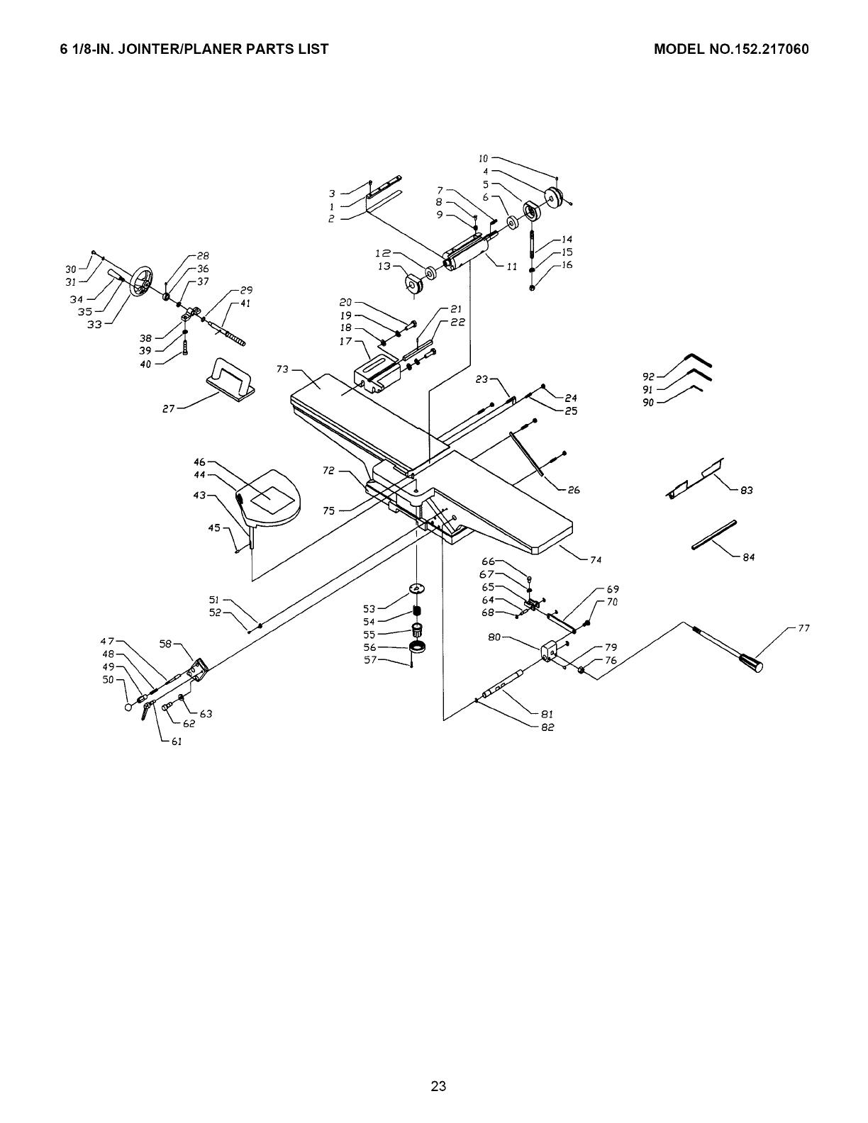
6 1/8-1N. JOINTER/PLANER PARTS LIST MODEL NO.152.217060
73
25
74
77
82
23
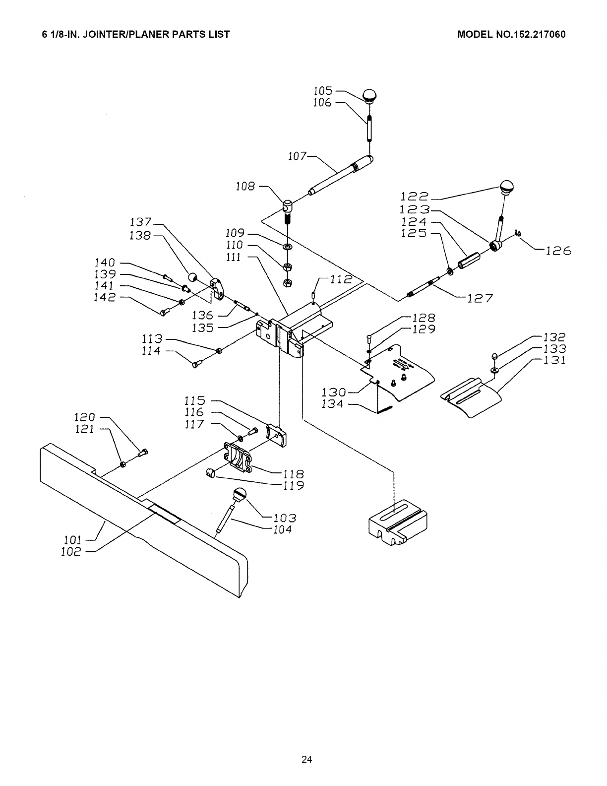
6 1/8-1N. JOINTER/PLANER PARTS LIST MODEL NO.152.217060
140
139
141
142
13
138
136
135
115
116
24
6 1/8-1N.JOINTER/PLANERPARTSLIST MODELNO.152.217060
221 \
]79
176
I77-_
173- I ]8o
217
218 182_
192 --_J
196_
197 _.
159
150--\
]58
<
\_- ]98
206
205
_804
_183
213
211 _
<20E_
25

NOTES
26

Manual del Propietario
iCRnFrSMnN'i
iPROFESSIONAI
6-1/8 pulg. de ancho
1 caballo de fuerza (servicio continuo)
Cabezal de corte de 5000 R.P.M. (sin velocidad de carga)
MACHIMBRADORA/CEPILLADORA
DE 6-1/8 pulg.
No. de Modelo
152.217060
c
PRECAUCION:
PARA SU SEGURIDAD PERSONAL:
Lea y obedezca todas las Instrucciones
de Seguridad y Funcionamiento antes de
accionar esta Machimbradora/Cepilladora.
Linea de Ayuda al Cliente
1-800-897-7709
Sirvase tener listo su No. de
Modelo y No. de Serie
Sears, Roebuck and Co., Hoffman Estates, IL 60179 U.S.A.
No. de Pieza OR90365
Revisado el 13 de junio de 2003
27
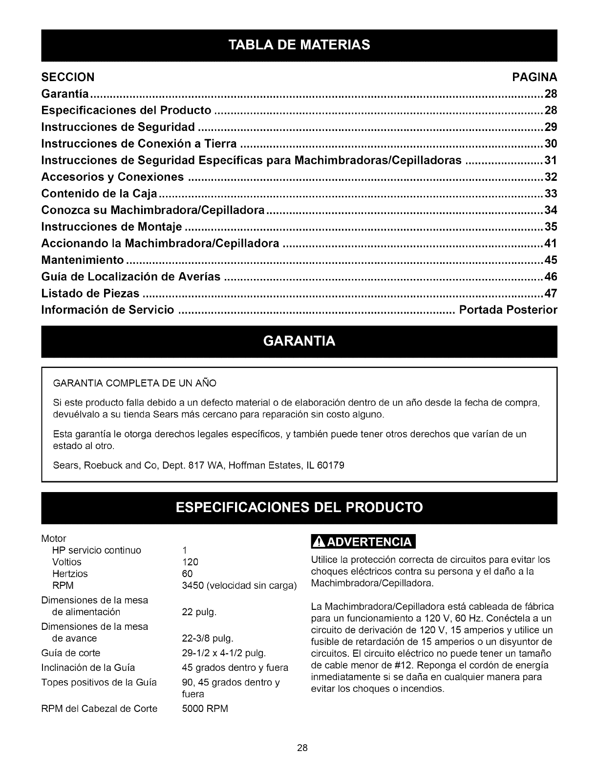
SECCION PAGINA
Garantia ........................................................................................................................................... 28
Especificaciones del Producto ..................................................................................................... 28
Instrucciones de Seguridad .......................................................................................................... 29
Instrucciones de Conexibn a Tierra ............................................................................................. 30
Instrucciones de Seguridad Especificas para Machimbradoras/Cepilladoras ........................ 31
Accesorios y Conexiones ............................................................................................................. 32
Contenido de la Caja ...................................................................................................................... 33
Conozca su Machimbradora/Cepilladora ..................................................................................... 34
Instrucciones de Montaje .............................................................................................................. 35
Accionando la Machimbradora/Cepilladora ................................................................................ 41
Mantenimiento ................................................................................................................................ 45
Guia de Localizacibn de Averias .................................................................................................. 46
Listado de Piezas ........................................................................................................................... 47
Informacibn de Servicio ..................................................................................... Portada Posterior
GARANTIA COMPLETA DE UN ANO
Si este producto falla debido a un defecto material o de elaboraci6n dentro de un afio desde la fecha de compra,
devuelvalo a su tienda Sears mas cercano para reparaci6n sin costo alguno.
Esta garantia le otorga derechos legales especificos, y tambien puede tener otros derechos que varian de un
estado al otro.
Sears, Roebuck and Co, Dept. 817 WA, Hoffman Estates, IL 60179
Motor
HP servicio continuo
Voltios
Hertzios
RPM
Dimensiones de la mesa
de alimentaci6n
Dimensiones de la mesa
de avance
Guia de corte
Inclinaci6n de la Guia
Topes positivos de la Guia
RPM del Cabezal de Corte
1
120
60
3450 (velocidad sin carga)
22 pulg.
22-3/8 pulg.
29-1/2 x 4-1/2 pulg.
45 grados dentro y fuera
90, 45 grados dentro y
fuera
5000 RPM
lit!l_,1 mlv1:1ill / :1_[_]I'_,1
Utilice la protecci6n correcta de circuitos para evitar los
choques el6ctricos contra su persona y el dafio a la
Machimbradora/Cepilladora.
La Machimbradora/Cepilladora esta cableada de fabrica
para un funcionamiento a 120 V, 60 Hz. Con6ctela a un
circuito de derivaci6n de 120 V, 15 amperios y utilice un
fusible de retardaci6n de 15 amperios o un disyuntor de
circuitos. El circuito el6ctrico no puede tener un tamafio
de cable menor de #12. Reponga el cord6n de energia
inmediatamente si se dafia en cualquier manera para
evitar los choques o incendios.
28
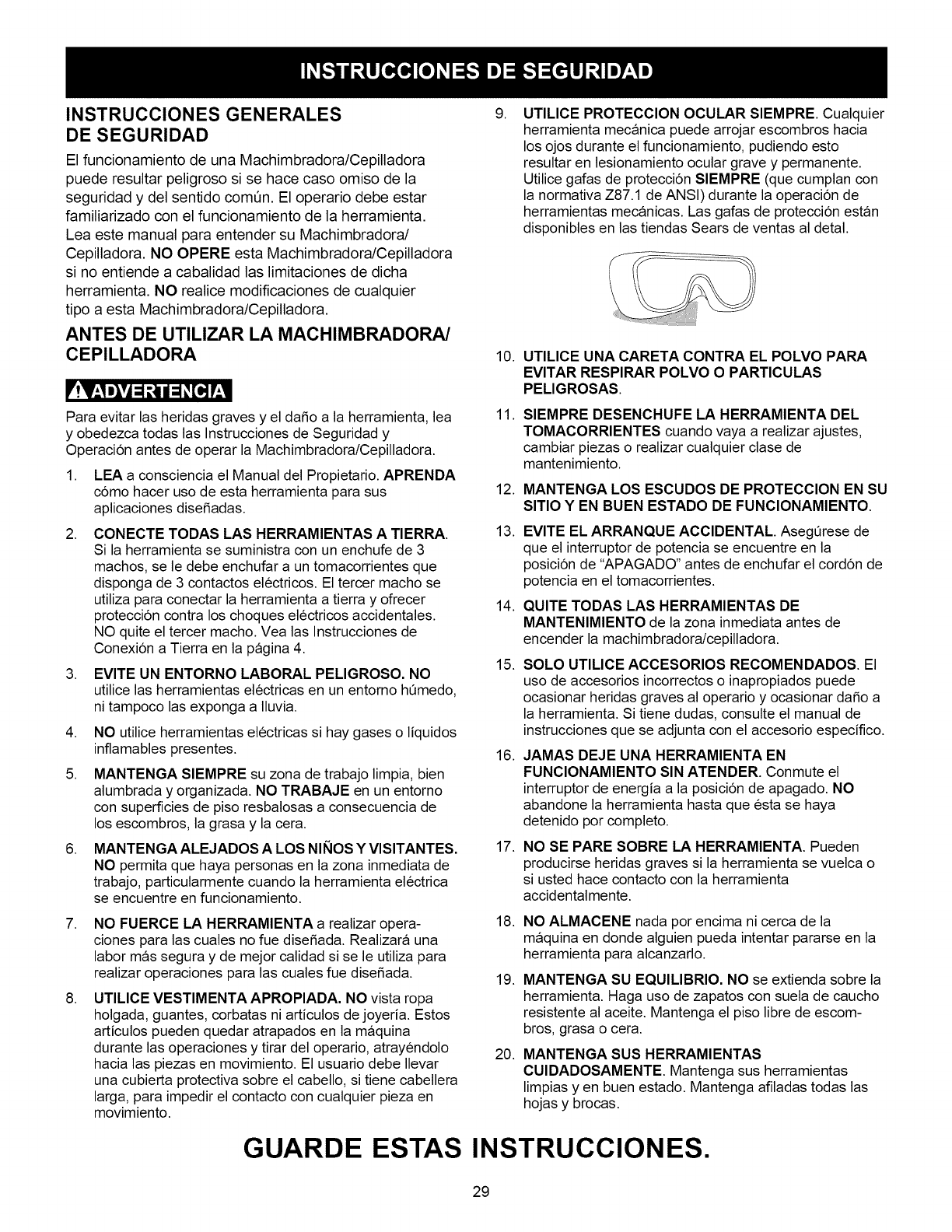
INSTRUCCIONES GENERALES
DE SEGURIDAD
El funcionamiento de una Machimbradora/Cepilladora
puede resultar peligroso si se hace caso omiso de la
seguridad y del sentido comQn. El operario debe estar
familiarizado con el funcionamiento de la herramienta.
Lea este manual para entender su Machimbradora/
Cepilladora. NO OPERE esta Machimbradora/Cepilladora
si no entiende a cabalidad las limitaciones de dicha
herramienta. NO realice modiflcaciones de cualquier
tipo a esta Machimbradora/Cepilladora.
ANTES DE UTILIZAR LA MACHIMBRADORA/
CEPILLADORA
_'!Vzl Dl*l =1l_//=1 _[o] l'zl
Para evitar las heridas graves y el dafio a la herramienta, lea
y obedezca todas las Instrucciones de Seguridad y
Operacion antes de operar la Machimbradora/Cepilladora.
1. LEA a consciencia el Manual del Propietario. APRENDA
como hacer uso de esta herramienta para sus
aplicaciones disefiadas.
.
.
.
5.
.
.
.
CONECTE TODAS LAS HERRAMIENTAS A TIERRA.
Si la herramienta se suministra con un enchufe de 3
machos, se le debe enchufar a un tomacorrientes que
disponga de 3 contactos electricos. El tercer macho se
utiliza para conectar la herramienta a tierra y ofrecer
protecci6n contra los choques electricos accidentales.
NO quite el tercer macho. Vea las Instrucciones de
Conexi6n a Tierra en la pagina 4.
EVITE UN ENTORNO LABORAL PELIGROSO. NO
utilice las herramientas electricas en un entorno hQmedo,
ni tampoco las exponga a Iluvia.
NO utilice herramientas electricas si hay gases o liquidos
inflamables presentes.
MANTENGA SIEMPRE su zona de trabajo limpia, bien
alumbrada y organizada. NO TRABAJE en un entorno
con superficies de piso resbalosas a consecuencia de
los escombros, la grasa y la cera.
MANTENGA ALEJADOS A LOS NINOS Y VlSlTANTES.
NO permita que haya personas en la zona inmediata de
trabajo, particularmente cuando la herramienta electrica
se encuentre en funcionamiento.
NO FUERCE LA HERRAMIENTA a realizar opera-
ciones para las cuales no fue disefiada. Realizara una
labor mas segura y de mejor calidad si se le utiliza para
realizar operaciones para las cuales fue disefiada.
UTILICE VESTIMENTA APROPIADA. NO vista ropa
holgada, guantes, corbatas ni articulos de joyed& Estos
articulos pueden quedar atrapados en la maquina
durante las operaciones y tirar del operario, atrayendolo
hacia las piezas en movimiento. El usuario debe Ilevar
una cubierta protectiva sobre el cabello, si tiene cabellera
larga, para impedir el contacto con cualquier pieza en
movimiento.
g. UTILICE PROTECClON OCULAR SlEMPRE. Cualquier
herramienta mecanica puede arrojar escombros hacia
los ojos durante el funcionamiento, pudiendo esto
resultar en lesionamiento ocular grave y permanente.
Utilice gafas de protecci6n SlEMPRE (que cumplan con
la normativa Z87.1 de ANSI) durante la operaci6n de
herramientas mecanicas. Las gafas de protecci6n estan
disponibles en las tiendas Sears de ventas al detal.
10.
11.
12.
13.
14.
15.
16.
17.
18.
19.
20.
UTILICE UNA CARETA CONTRA EL POLVO PARA
EVITAR RESPIRAR POLVO OPARTICULAS
PELIGROSAS.
SIEMPRE DESENCHUFE LA HERRAMIENTA DEL
TOMACORRIENTES cuando vaya a realizar ajustes,
cambiar piezas o realizar cualquier clase de
mantenimiento.
MANTENGA LOS ESCUDOS DE PROTECCION EN SU
SITIO Y EN BUEN ESTADO DE FUNCIONAMIENTO.
EVlTE EL ARRANQUE ACCIDENTAL. AsegQrese de
que el interruptor de potencia se encuentre en la
posici6n de "APAGADO" antes de enchufar el cord6n de
potencia en el tomacorrientes.
QUITE TODAS LAS HERRAMIENTAS DE
MANTENIMIENTO de la zona inmediata antes de
encender la machimbradora/cepilladora.
SOLO UTILICE ACCESORIOS RECOMENDADOS. El
uso de accesorios incorrectos o inapropiados puede
ocasionar heridas graves al operario y ocasionar dafio a
la herramienta. Si tiene dudas, consulte el manual de
instrucciones que se adjunta con el accesorio especifico.
JAMAS DEJE UNA HERRAMIENTA EN
FUNCIONAMIENTO SIN ATENDER. Conmute el
interruptor de energia a la posici6n de apagado. NO
abandone la herramienta hasta que esta se haya
detenido pot completo.
NO SE PARE SOBRE LA HERRAMIENTA. Pueden
producirse heridas graves si la herramienta se vuelca o
si usted hace contacto con la herramienta
accidentalmente.
NO ALMACENE nada por encima ni cerca de la
maquina en donde alguien pueda intentar pararse en la
herramienta para alcanzarlo.
MANTENGA SU EQUILIBRIO. NO se extienda sobre la
herramienta. Haga uso de zapatos con suela de caucho
resistente al aceite. Mantenga el piso libre de escom-
bros, grasa o cera.
MANTENGA SUS HERRAMIENTAS
CUIDADOSAMENTE. Mantenga sus herramientas
limpias y en buen estado. Mantenga afiladas todas las
hojas y brocas.
GUARDE ESTAS INSTRUCCIONES.
29
21. REVISE SI HAY PIEZAS DAglADAS ANTES DE CADA
USO DE LA HERRAMIENTA. Revise todos los
protectores cuidadosamente para comprobar que
funcionan correctamente y que no estan dafiados, y que
realizan sus funciones disefiadas correctamente. Revise
el alineamiento, la fijaci6n o la ruptura de las piezas en
movimiento. Cualquier protector u otra pieza que se
encuentre dafiada debe repararse o reemplazarse
inmediatamente.
22. HAGA SU TALLER A PRUEBA DE NINOS quitando las
Ilaves del interruptor, desenchufando las herramientas
de los tomacorrientes y mediante el uso de candados.
23. NO OPERE LA HERRAMIENTA BAJO LA
INFLUENClA DE LAS DROGAS O DEL ALCOHOL.
24. AFIANCE TODO EL MATERIAL. Siempre que resulte
posible, utilice abrazaderas o plantillas para asegurar el
material. Esto ofrece mayor seguridad que intentar
sujetar el material con sus propias manos.
25. UTILICE UNA EXTENSION ELECTRICA CORRECTA
Y EN BUEN ESTADO. Cuando vaya a hacer uso de una
extensi6n electrica, asegQrese de utilizar una que sea Io
suficientemente fuerte como para transportar la corriente
a set utilizada por su herramienta. La siguiente tabla
presenta las dimensiones correctas a utilizarse de
acuerdo con las dimensiones de la extensi6n y la
clasificaci6n de amperaje en la placa de notaciones. Si
tiene dudas, utilice la siguiente extensi6n de mayor
calibre. Mientras menor sea el nQmero de calibre, mayor
sera el diametro de la extensi6n electrica. Si tiene dudas
sobre las dimensiones correctas de una extensi6n
electrica, utilice un cord6n mas corto y mas grueso. Una
extensi6n de dimensiones insuficientes producira una
caida en el voltaje de linea, resultando en una pcrdida
de potencia y el sobrecalentamiento. SOLO UTILICE
UNA EXTENSION ELECTRICA DE 3 HILOS QUE
DISPONGA DE UN ENCHUFE DE CONEXlON A
TIERRA DE 3 MACHOS, Y UN RECEPTACULO DE
3 POLOS QUE ACEPTE EL ENCHUFE DE LA
MAQUlNA.
DIRECTRICES PARA LAS EXTENSlONES
ELECTRICAS
Si est& haciendo uso de una extensibn eldctrica a la
intemperie, este seguro de que la extension se encuentre
marcada con "W-A" ("W" en el Canada), Io que indica que su
uso a la intemperie es aceptable.
Est_ seguro del dimensionamiento correcto de su
extensibn el_ctrica, y que se encuentre en buen estado
electrico. Repare siempre una extensi6n electrica dafiada, o
procure que una persona experta la repare antes del uso.
Proteja sus extensiones el_ctricas contra los objetos
filosos, el calor en exceso y los lugares mojados o hQmedos.
FUNCIONAMIENTO A 120 VOLTIOS SOLAMENTE
0 a 6 Amperios
6 a 10 Amperios
10 a 12 Amperios
25 PIES
DE LARGO
18 AWG
18 AWG
16 AWG
50 PIES
DE LARGO
16 AWG
16 AWG
16 AWG
100 PIES
DE LARGO
16 AWG
14 AWG
14 AWG
160 PIES
DE LARGO
14 AWG
12 AWG
12 AWG
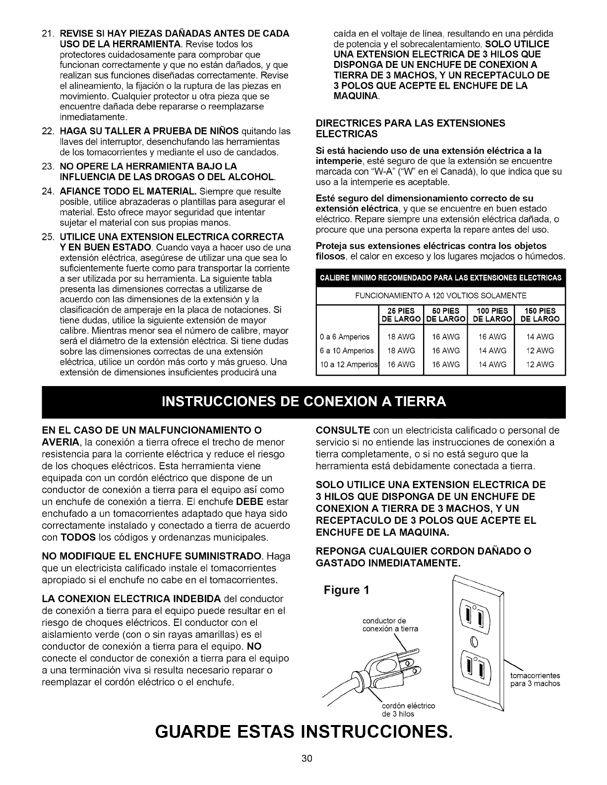
EN EL CASO DE UN MALFUNCIONAMIENTO O
AVERIA, la conexi6n a tierra ofrece el trecho de menor
resistencia para la corriente electrica y reduce el riesgo
de los choques electricos. Esta herramienta viene
equipada con un cord6n electrico que dispone de un
conductor de conexi6n a tierra para el equipo asi como
un enchufe de conexi6n a tierra. El enchufe DEBE estar
enchufado a un tomacorrientes adaptado que haya sido
correctamente instalado y conectado a tierra de acuerdo
con TODOS los c6digos y ordenanzas municipales.
NO MODIFIQUE EL ENCHUFE SUMINISTRADO. Haga
que un electricista calificado instale el tomacorrientes
apropiado si el enchufe no cabe en el tomacorrientes.
LA CONEXlON ELECTRICA INDEBIDA del conductor
de conexi6n a tierra para el equipo puede resultar en el
riesgo de choques el6ctricos. El conductor con el
aislamiento verde (con o sin rayas amarillas) es el
conductor de conexi6n a tierra para el equipo. NO
conecte el conductor de conexi6n a tierra para el equipo
a una terminaci6n viva si resulta necesario reparar o
reemplazar el cord6n electrico o el enchufe.
CONSULTE con un electricista califlcado o personal de
servicio si no entiende las instrucciones de conexi6n a
tierra completamente, o si no esta seguro que la
herramienta esta debidamente conectada a tierra.
SOLO UTILICE UNA EXTENSION ELECTRICA DE
3 HILOS QUE DISPONGA DE UN ENCHUFE DE
CONEXlON A TIERRA DE 3 MACHOS, Y UN
RECEPTACULO DE 3 POLOS QUE ACEPTE EL
ENCHUFE DE LA MAQUlNA.
REPONGA CUALQUIER CORDON DANADO O
GASTADO INMEDIATAMENTE.
Figure 1
conductorde
conexi6na tierra
corddn electrico
de 3 hilos
0
tomacorrientes
para3 machos
GUARDE ESTAS INSTRUCCIONES.
30
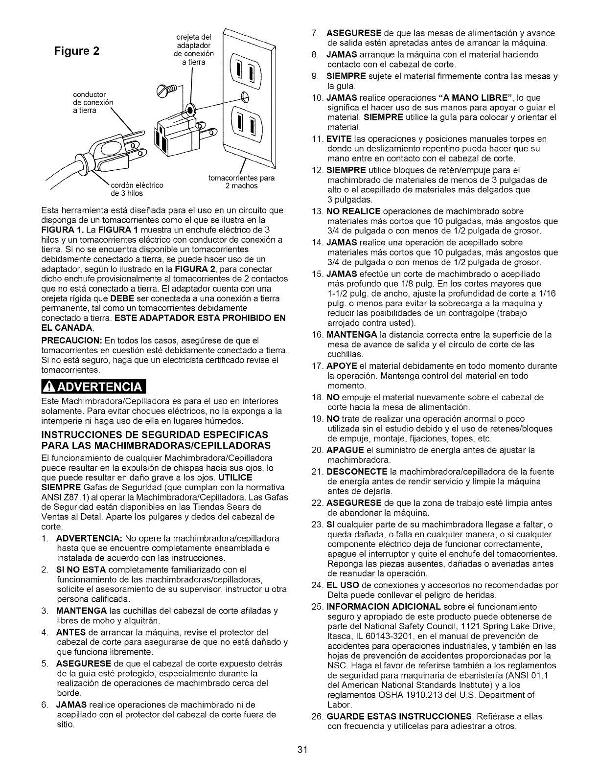
Figure 2
orejeta del
adaptador
de conexi6n
a tierra
conductor
de conexi6n
_/ " cord6n electrico
de 3 hilos
tomacorrientes para
2 machos
Esta herramienta esta disefiada para el uso en un circuito que
disponga de un tomacorrientes como el que se ilustra en la
FIGURA 1. La FIGURA 1 muestra un enchufe electrico de 3
hitos y un tomacorrientes electrico con conductor de conexi6n a
tierra. Si no se encuentra disponible un tomacorrientes
debidamente conectado a tierra, se puede hacer uso de un
adaptador, segen Io itustrado en la FIGURA 2, para conectar
dicho enchufe provisionalmente al tomacorrientes de 2 contactos
que no esta conectado a tierra. El adaptador cuenta con una
orejeta rigida que DEBE ser conectada a una conexi6n a tierra
permanente, tal como un tomacorrientes debidamente
conectado a tierra. ESTE ADAPTADOR ESTA PROHIBIDO EN
EL CANADA.
PRECAUCION: En todos los casos, asegerese de que el
tomacorrientes en cuesti6n este debidamente conectado a tierra.
Si no esta seguro, haga que un electricista certificado revise el
tomacorrientes.
Este Machimbradora/Cepittadora es para el uso en interiores
sotamente. Para evitar choques electricos, no ta exponga a la
intemperie ni haga uso de ella en lugares hemedos.
INSTRUCClONES DE SEGURIDAD ESPEClFICAS
PARA LAS MACHIMBRADORAS/CEPILLADORAS
Et funcionamiento de cualquier Machimbradora/Cepilladora
puede resultar en la expulsi6n de chispas hacia sus ojos, to
que puede resultar en dafio grave a los ojos. UTILICE
SIEMPRE Gafas de Seguridad (que cumplan con la normativa
ANSI Z87.1 ) al operar la Machimbradora/Cepiltadora. Las Gafas
de Seguridad estan disponibles en las Tiendas Sears de
Ventas al Detal. Aparte los pulgares y dedos del cabezal de
corte.
1. ADVERTENCIA: No opere ta machimbradora/cepittadora
hasta que se encuentre completamente ensamblada e
instalada de acuerdo con las instrucciones.
2. SI NO ESTA completamente famitiarizado con el
funcionamiento de tas machimbradoras/cepiltadoras,
solicite el asesoramiento de su supervisor, instructor u otra
persona calificada.
3. MANTENGA tas cuchittas del cabezal de corte afiladas y
libres de moho y alquitran.
4. ANTES de arrancar ta maquina, revise el protector del
cabezal de corte para asegurarse de que no esta dafiado y
que funciona libremente.
5. ASEGURESE de que el cabezal de corte expuesto detras
de ta guia este protegido, especialmente durante ta
realizaci6n de operaciones de machimbrado cerca del
borde.
6. JAMAS realice operaciones de machimbrado ni de
acepillado con el protector del cabezal de corte fuera de
sitio.
7. ASEGURESE de que tas mesas de alimentaci6n y avance
de salida esten apretadas antes de arrancar la maquina.
8. JAMAS arranque ta maquina con el material haciendo
contacto con el cabezal de core.
9. SIEMPRE sujete el material firmemente contra las mesas y
ta guia.
10. JAMAS realice operaciones "A MANO LIBRE", to que
significa el hacer uso de sus manos para apoyar o guiar el
material. SIEMPRE utilice la guia para colocar y orientar el
material.
11. EVlTE tas operaciones y posiciones manuales torpes en
donde un deslizamiento repentino pueda hacer que su
mano entre en contacto con el cabezal de corte.
12. SIEMPRE utilice bloques de reten/empuje para el
machimbrado de materiales de menos de 3 pulgadas de
alto o el acepillado de materiales mas delgados que
3 pulgadas.
13. NO REALICE operaciones de machimbrado sobre
materiales mas cortos que 10 pulgadas, mas angostos que
3/4 de pulgada o con menos de 1/2 pulgada de grosor.
14. JAMAS realice una operaci6n de acepittado sobre
materiales mas cortos que 10 pulgadas, mas angostos que
3/4 de pulgada o con menos de 1/2 pulgada de grosor.
15. JAMAS efectee un corte de machimbrado o acepittado
mas profundo que 1/8 pulg. En los cortes mayores que
1-1/2 pulg. de ancho, ajuste la profundidad de corte a 1/16
pulg. o menos para evitar la sobrecarga a la maquina y
reducir tas posibitidades de un contragolpe (trabajo
arrojado contra usted).
16. MANTENGA ta distancia correcta entre la superficie de la
mesa de avance de salida y el circulo de corte de las
cuchitlas.
17. APOYE el material debidamente en todo momento durante
la operaci6n. Mantenga control del material en todo
momento.
18. NO empuje el material nuevamente sobre el cabezal de
corte hacia la mesa de alimentaci6n.
19. NO trate de realizar una operaci6n anormal o poco
utitizada sin el estudio debido y el uso de retenes/bloques
de empuje, montaje, fijaciones, topes, etc.
20. APAGUE el suministro de energia antes de ajustar ta
machimbradora.
21. DESCONECTE ta machimbradora/cepittadora de ta fuente
de energia antes de rendir servicio y limpie la maquina
antes de dejarla.
22. ASEGURESE de que ta zona de trabajo este limpia antes
de abandonar ta maquina.
23. SI cualquier parte de su machimbradora ltegase a faltar, o
queda dafiada, o falla en cualquier manera, o si cualquier
componente electrico deja de funcionar correctamente,
apague el interruptor y quite el enchufe del tomacorrientes.
Reponga las piezas ausentes, dafiadas o averiadas antes
de reanudar la operaci6n.
24. EL USO de conexiones y accesorios no recomendadas por
Delta puede conllevar el peligro de heridas.
25. INFORMACION ADICIONAL sobre el funcionamiento
seguro y apropiado de este producto puede obtenerse de
parte del National Safety Council, 1121 Spring Lake Drive,
Itasca, IL 60143-3201, en el manual de prevenci6n de
accidentes para operaciones industriales, y tambien en las
hojas de prevenci6n de accidentes proporcionadas por ta
NSC. Haga el favor de referirse tambien a los reglamentos
de seguridad para maquinaria de ebanisteria (ANSI 01.1
del American National Standards Institute) y a los
regtamentos OSHA 1910.213 del U.S. Department of
Labor.
26. GUARDE ESTAS INSTRUCCIONES. Refierase a elias
con frecuencia y utilicelas para adiestrar a otros.
31
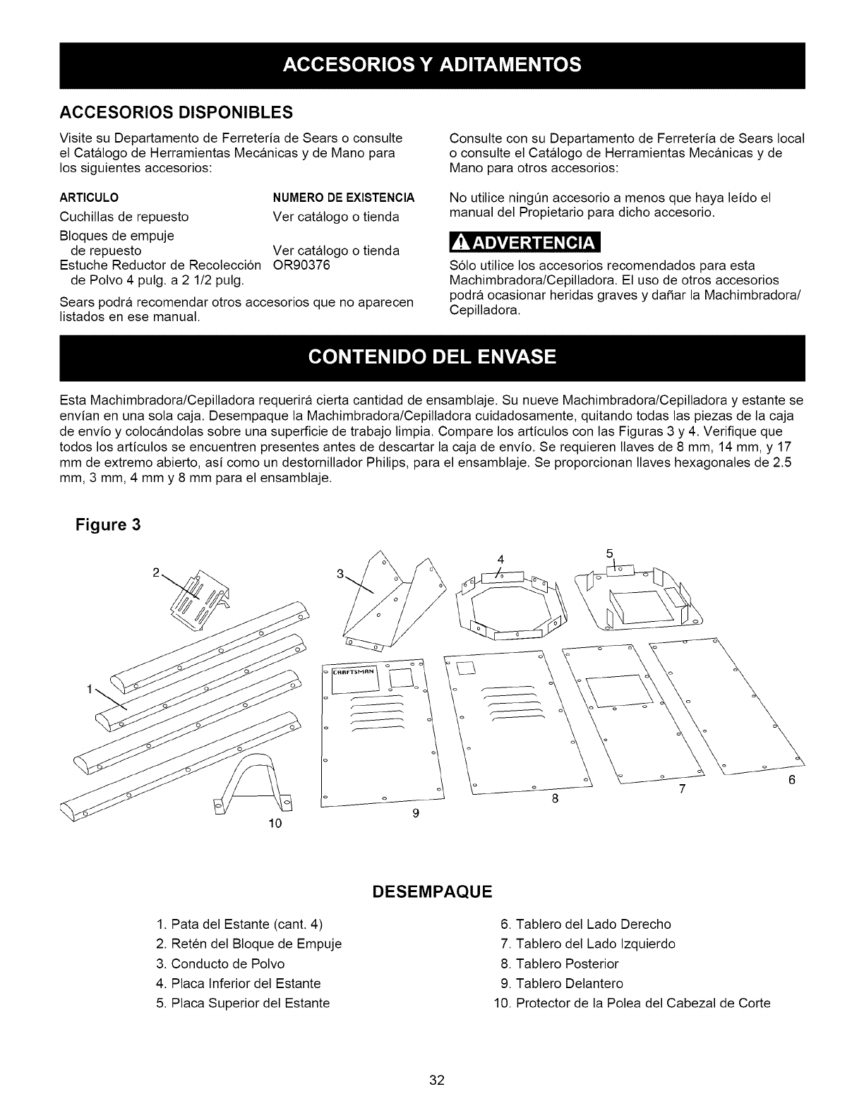
ACCESORIOS DISPONIBLES
Visite su Departamento de Ferreteria de Sears o consulte
el Catalogo de Herramientas Mecanicas y de Mano para
los siguientes accesorios:
ARTICULO NUMI=RO DE I=XlSTENClA
Cuchillas de repuesto Ver catalogo o tienda
Bloques de empuje
de repuesto Ver catalogo o tienda
Estuche Reductor de Recoleccion OR90376
de Polvo 4 pulg. a 2 1/2 pulg.
Sears podra recomendar otros accesorios que no aparecen
listados en ese manual.
Consulte con su Departamento de Ferreteria de Sears local
o consulte el Catalogo de Herramientas Mecanicas y de
Mano para otros accesorios:
No utilice ningen accesorio a menos que haya leido el
manual del Propietario para dicho accesorio.
Solo utilice los accesorios recomendados para esta
Machimbradora/Cepilladora. El uso de otros accesorios
podra ocasionar heridas graves y da5ar la Machimbradora/
Cepilladora.
Esta Machimbradora/Cepilladora requerira cierta cantidad de ensamblaje. Su nueve Machimbradora/Cepilladora y estante se
envian en una sola caja. Desempaque la Machimbradora/Cepilladora cuidadosamente, quitando todas las piezas de la caja
de envio y colocandolas sobre una superficie de trabajo limpia. Compare los articulos con las Figuras 3 y 4. Verifique que
todos los articulos se encuentren presentes antes de descartar la caja de envio. Se requieren Ilaves de 8 mm, 14 mm, y 17
mm de extremo abierto, asi como un destornillador Philips, para el ensamblaje. Se proporcionan Ilaves hexagonales de 2.5
mm, 3 mm, 4 mm y 8 mm para el ensamblaje.
Figure 3
10
1. Pata del Estante (cant. 4)
2. Reten del Bloque de Empuje
3. Conducto de Polvo
4. Placa Inferior del Estante
5. Placa Superior del Estante
DESEMPAQUE
6. Tablero del Lado Derecho
7. Tablero del Lado Izquierdo
8. Tablero Posterior
9. Tablero Delantero
10. Protector de la Polea del Cabezal de Corte
32
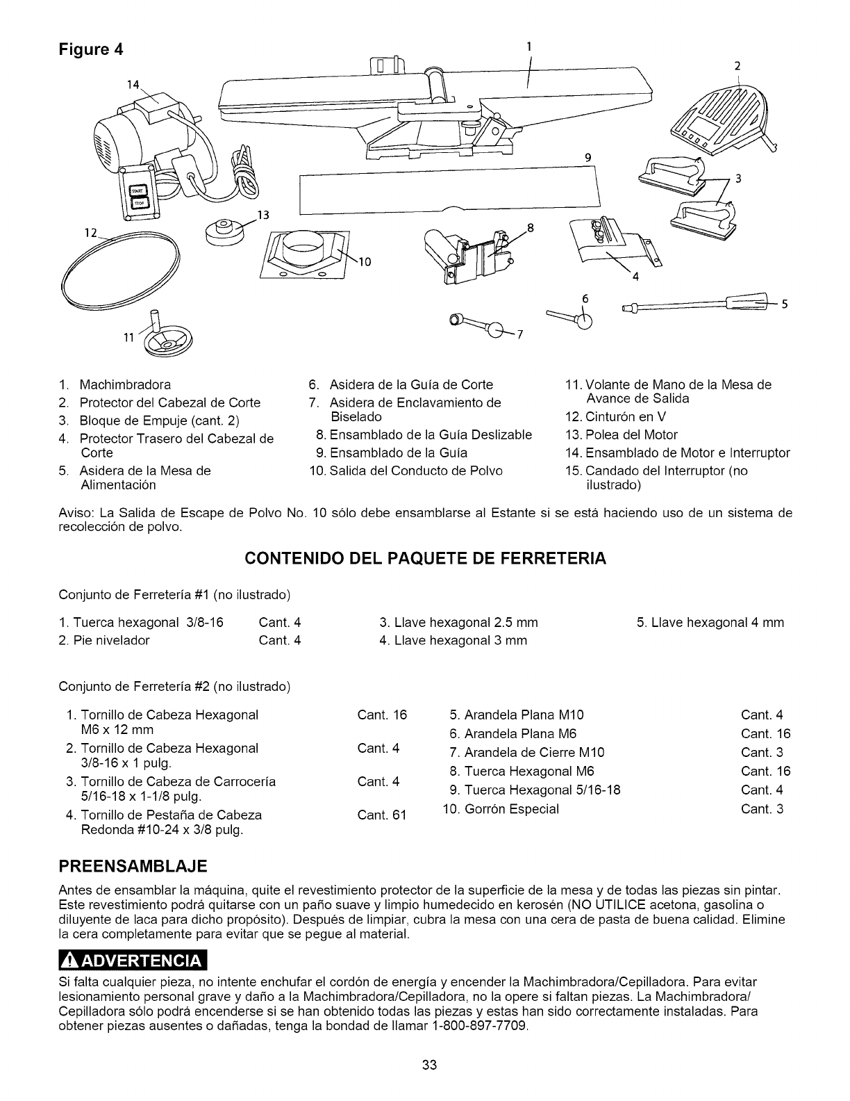
1. Machimbradora
2. Protector del Cabezal de Corte
3. Bloque de Empuje (cant. 2)
4. Protector Trasero del Cabezal de
Corte
5. Asidera de la Mesa de
Alimentacion
6. Asidera de la Guia de Corte
7. Asidera de Enclavamiento de
Biselado
8. Ensamblado de la Guia Deslizable
9. Ensamblado de la Guia
10. Salida del Conducto de Polvo
11. Volante de Mano de la Mesa de
Avance de Salida
12. Cinturon en V
13. Polea del Motor
14. Ensamblado de Motor e Interruptor
15. Candado del Interruptor (no
ilustrado)
Aviso: La Salida de Escape de Polvo No. 10 solo debe ensamblarse al Estante si se esta haciendo uso de un sistema de
recoleccion de polvo.
CONTENIDO DEL PAQUETE DE FERRETERIA
Conjunto de Ferreteria #1 (no ilustrado)
1. Tuerca hexagonal 3/8-16 Cant. 4
2. Pie nivelador Cant. 4
3. Llave hexagonal 2.5 mm
4. Llave hexagonal 3 mm
5. Llave hexagonal 4 mm
Conjunto de Ferreteria #2 (no ilustrado)
1. Tornillo de Cabeza Hexagonal
M6 x 12 mm
2. Tornillo de Cabeza Hexagonal
3/8-16 x 1 pulg.
3. Tornillo de Cabeza de Carroceria
5/16-18 x 1-1/8 pulg.
4. Tornillo de Pesta_a de Cabeza
Redonda #10-24 x 3/8 pulg.
Cant. 16 5. Arandela Plana M10 Cant. 4
6. Arandela Plana M6 Cant. 16
Cant. 4 7. Arandela de Cierre M10 Cant. 3
8. Tuerca Hexagonal M6 Cant. 16
Cant. 4 9. Tuerca Hexagonal 5/16-18 Cant. 4
Cant. 61 10. Gorron Especial Cant. 3
PREENSAMBLAJE
Antes de ensamblar la maquina, quite el revestimiento protector de la superficie de la mesa y de todas las piezas sin pintar.
Este revestimiento podra quitarse con un paso suave y limpio humedecido en kerosen (NO UTILICE acetona, gasolina o
diluyente de laca para dicho proposito). Despues de limpiar, cubra la mesa con una cera de pasta de buena calidad. Elimine
la cera completamente para evitar que se pegue al material.
! *lit 3 *
Si falta cualquier pieza, no intente enchufar el cordon de energia y encender la Machimbradora/Cepilladora. Para evitar
lesionamiento personal grave y da_o a la Machimbradora/Cepilladora, no la opere si faltan piezas. La Machimbradora/
Cepilladora solo podra encenderse si se han obtenido todas las piezas y estas han sido correctamente instaladas. Para
obtener piezas ausentes o da_adas, tenga la bondad de Ilamar 1-800-897-7709.
33
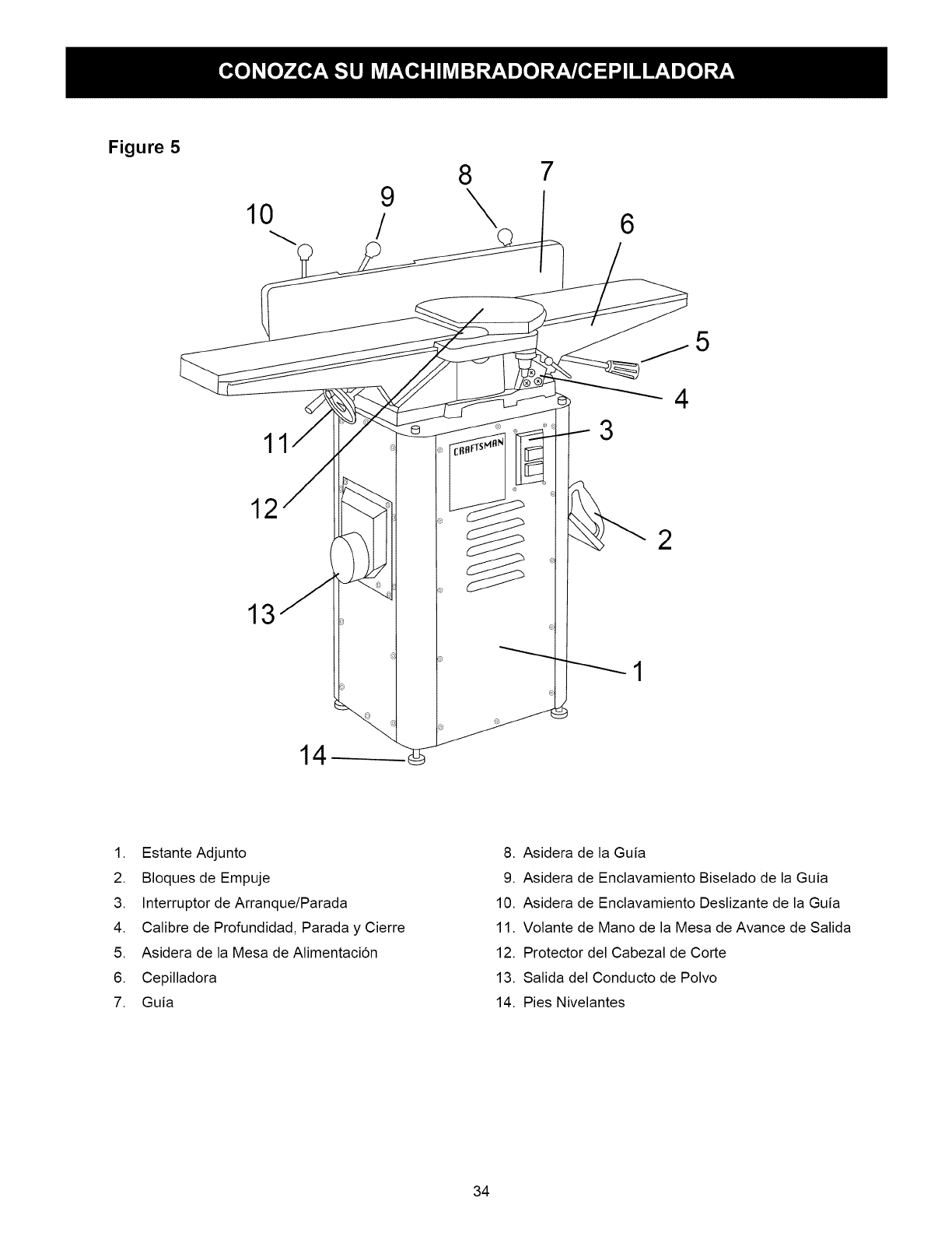
Figure 5
9
10 /
8
\7
6
5
12
13
11 3
4
2
1. Estante Adjunto
2. Bloques de Empuje
3. Interruptor de Arranque/Parada
4. Calibre de Profundidad, Parada y Cierre
5. Asidera de la Mesa de Alimentaci6n
6. Cepilladora
7. Guia
8. Asidera de la Guia
9. Asidera de Enclavamiento Biselado de la Guia
10. Asidera de Enclavamiento Deslizante de la Guia
11. Volante de Mano de la Mesa de Avance de Salida
12. Protector del Cabezal de Corte
13. Salida del Conducto de Polvo
14. Pies Nivelantes
34
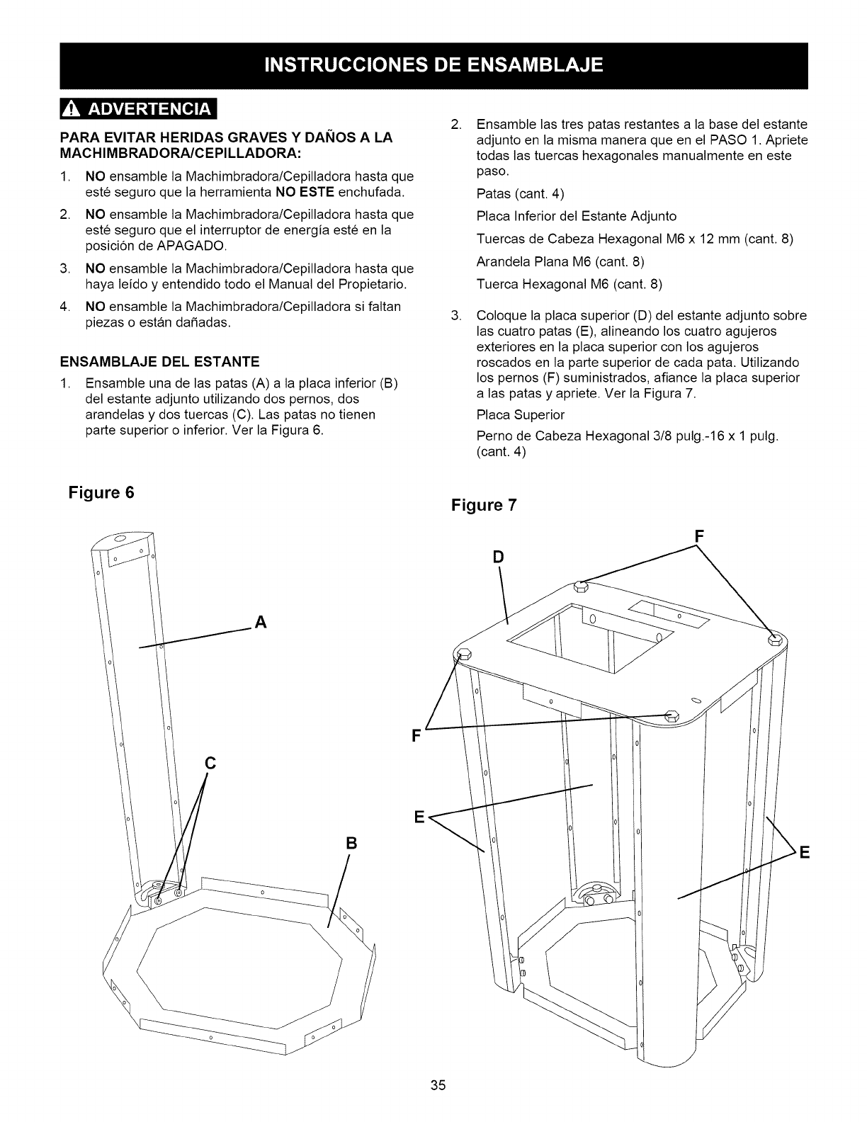
PARA EVITAR HERIDAS GRAVES Y DANOS A LA
MACHIMBRADORA/CEPILLADORA:
1. NO ensamble la Machimbradora/Cepilladora hasta que
este seguro que la herramienta NO ESTE enchufada.
2. NO ensamble la Machimbradora/Cepilladora hasta que
este seguro que el interruptor de energia este en la
posicion de APAGADO.
3. NO ensamble la Machimbradora/Cepilladora hasta que
haya leido y entendido todo el Manual del Propietario.
4. NO ensamble la Machimbradora/Cepilladora si faltan
piezas o estan dafiadas.
ENSAMBLAJE DEL ESTANTE
.Ensamble una de las patas (A) a la placa inferior (B)
del estante adjunto utilizando dos pernos, dos
arandelas y dos tuercas (C). Las patas no tienen
parte superior o inferior. Ver la Figura 6.
.Ensamble las tres patas restantes a la base del estante
adjunto en la misma manera que en el PASO 1. Apriete
todas las tuercas hexagonales manualmente en este
paso.
Patas (cant. 4)
Placa Inferior del Estante Adjunto
Tuercas de Cabeza Hexagonal M6 x 12 mm (cant. 8)
Arandela Plana M6 (cant. 8)
Tuerca Hexagonal M6 (cant. 8)
.Coloque la placa superior (D) del estante adjunto sobre
las cuatro patas (E), alineando los cuatro agujeros
exteriores en la placa superior con los agujeros
roscados en la parte superior de cada pata. Utilizando
los pernos (F) suministrados, afiance la placa superior
alas patas y apriete. Ver la Figura 7.
Placa Superior
Perno de Cabeza Hexagonal 3/8 pulg.-16 x 1 pulg.
(cant. 4)
Figure 6
A
F
E
B
Figure 7
D
F
E
35
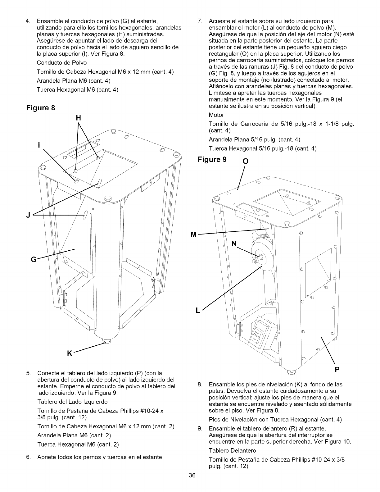
.Ensamble el conducto de polvo (G) al estante,
utilizando para ello los tornillos hexagonales, arandelas
planas y tuercas hexagonales (H) suministradas.
Asegerese de apuntar el lado de descarga del
conducto de polvo hacia el lado de agujero sencillo de
la placa superior (I). Ver Figura 8.
Conducto de Polvo
Tornillo de Cabeza Hexagonal M6 x 12 mm (cant. 4)
Arandela Plana M6 (cant. 4)
Tuerca Hexagonal M6 (cant. 4)
Figure 8
H
J
.Conecte el tablero del lado izquierdo (P) (con la
abertura del conducto de polvo) al lado izquierdo del
estante. Emperne el conducto de polvo al tablero del
lado izquierdo. Ver la Figura 9.
Tablero del Lado Izquierdo
Tornillo de Pesta5a de Cabeza Phillips #10-24 x
3/8 pulg. (cant. 12)
Tornillo de Cabeza Hexagonal M6 x 12 mm (cant. 2)
Arandela Plana M6 (cant. 2)
Tuerca Hexagonal M6 (cant. 2)
6. Apriete todos los pernos y tuercas en el estante.
.
M
L
36
Acueste el estante sobre su lado izquierdo para
ensamblar el motor (L) al conducto de polvo (M).
AsegQrese de que la posicion del eje del motor (N) este
situada en la parte posterior del estante. La parte
posterior del estante tiene un peque_o agujero ciego
rectangular (O) en la placa superior. Utilizando los
pernos de carroceria suministrados, coloque los pernos
a traves de las ranuras (J) Fig. 8 del conducto de polvo
(G) Fig. 8, y luego a traves de los agujeros en el
soporte de montaje (no ilustrado) conectado al motor.
Afiancelo con arandelas planas y tuercas hexagonales.
Limitese a apretar las tuercas hexagonales
manualmente en este momento. Ver la Figura 9 (el
estante se ilustra en su posicion vertical).
Motor
Tornillo de Carroceria de 5/16 pulg.-18 x 1-1/8 pulg.
(cant. 4)
Arandela Plana 5/16 pulg. (cant. 4)
Tuerca Hexagonal 5/16 pulg.-18 (cant. 4)
Figure 90
@----_
"\\_j_ P
8. Ensamble los pies de nivelacion (K) al fondo de las
patas. Devuelva el estante cuidadosamente a su
posicion vertical; ajuste los pies de manera que el
estante se encuentre nivelado y asentado solidamente
sobre el piso. Ver Figura 8.
Pies de Nivelacion con Tuerca Hexagonal (cant. 4)
9. Ensamble el tablero delantero (R) al estante.
AsegQrese de que la abertura del interruptor se
encuentre en la parte superior derecha. Ver Figura 10.
Tablero Delantero
Tornillo de Pesta_a de Cabeza Phillips #10-24 x 3/8
pulg. (cant. 12)
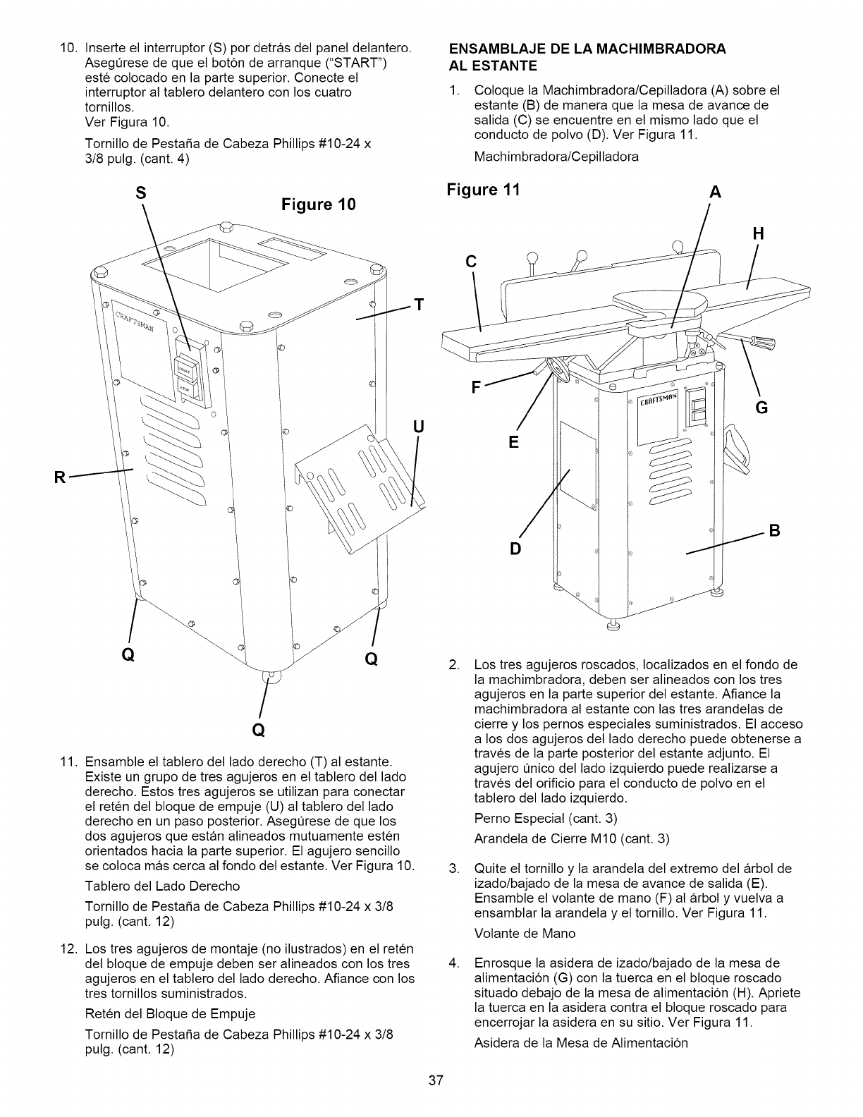
10.Inserteelinterruptor(S)pordetrasdelpaneldelantero.
AsegOresedequeelbotondearranque("START")
estecolocadoenlapartesuperior.Conecteel
interruptoraltablerodelanteroconloscuatro
tornillos.
VerFigura10.
TornillodePestafiadeCabezaPhillips#10-24x
3/8pulg.(cant.4)
SFigure 10
U
ENSAMBLAJE DE LA MACHIMBRADORA
AL ESTANTE
.Coloque la Machimbradora/Cepilladora (A) sobre el
estante (B) de manera que la mesa de avance de
salida (C) se encuentre en el mismo lado que el
conducto de polvo (D). Ver Figura 11.
Machimbradora/Cepilladora
Figure 11 A
C
H
E
D
G
B
Q
11. Ensamble el tablero del lado derecho (T) al estante.
Existe un grupo de tres agujeros en el tablero del lado
derecho. Estos tres agujeros se utilizan para conectar
el reten del bloque de empuje (U) al tablero del lado
derecho en un paso posterior. AsegOrese de que los
dos agujeros que estan alineados mutuamente esten
orientados hacia la parte superior. El agujero sencillo
se coloca mas cerca al fondo del estante. Ver Figura 10.
Tablero del Lado Derecho
Tornillo de Pestafia de Cabeza Phillips #10-24 x 3/8
pulg. (cant. 12)
12. Los tres agujeros de montaje (no ilustrados) en el reten
del bloque de empuje deben ser alineados con los tres
agujeros en el tablero del lado derecho. Afiance con los
tres tornillos suministrados.
Reten del Bloque de Empuje
Tornillo de Pestafia de Cabeza Phillips #10-24 x 3/8
pulg. (cant. 12)
.
.
.
Los tres agujeros roscados, Iocalizados en el fondo de
la machimbradora, deben ser alineados con los tres
agujeros en la parte superior del estante. Afiance la
machimbradora al estante con las tres arandelas de
cierre y los pernos especiales suministrados. El acceso
a los dos agujeros del lado derecho puede obtenerse a
traves de la parte posterior del estante adjunto. El
agujero Onico del lado izquierdo puede realizarse a
traves del orificio para el conducto de polvo en el
tablero del lado izquierdo.
Perno Especial (cant. 3)
Arandela de Cierre M10 (cant. 3)
Quite el tornillo y la arandela del extremo del arbol de
izado/bajado de la mesa de avance de salida (E).
Ensamble el volante de mano (F) al arbol y vuelva a
ensamblar la arandela y el tornillo. Ver Figura 11.
Volante de Mano
Enrosque la asidera de izado/bajado de la mesa de
alimentacion (G) con la tuerca en el bloque roscado
situado debajo de la mesa de alimentacion (H). Apriete
la tuerca en la asidera contra el bloque roscado para
encerrojar la asidera en su sitio. Ver Figura 11.
Asidera de la Mesa de Alimentacion
37
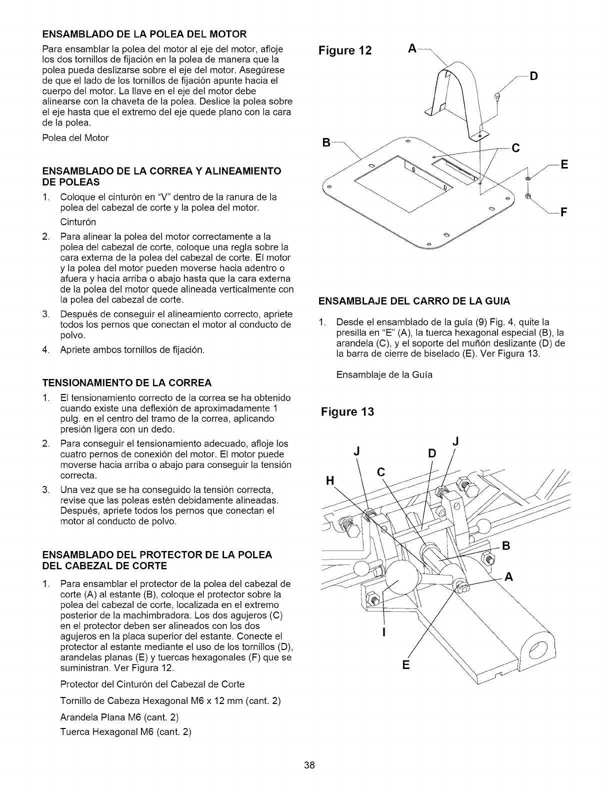
ENSAMBLADO DE LA POLEA DEL MOTOR
Para ensamblar la polea del motor al eje del motor, afloje
los dos tornillos de fijacion en la polea de manera que la
polea pueda deslizarse sobre el eje del motor. AsegOrese
de que el lado de los tornillos de fijacion apunte hacia el
cuerpo del motor. La Ilave en el eje del motor debe
alinearse con la chaveta de la polea. Deslice la polea sobre
el eje hasta que el extremo del eje quede piano con la cara
de la polea.
Polea del Motor
ENSAMBLADO DE LA CORREA Y ALINEAMIENTO
DE POLEAS
1. Coloque el cinturon en "V" dentro de la ranura de la
polea del cabezal de corte y la polea del motor.
Cinturon
2. Para alinear la polea del motor correctamente a la
polea del cabezal de corte, coloque una regla sobre la
cara externa de la polea del cabezal de corte. El motor
y la polea del motor pueden moverse hacia adentro o
afuera y hacia arriba o abajo hasta que la cara externa
de la polea del motor quede alineada verticalmente con
la polea del cabezal de corte.
3. Despues de conseguir el alineamiento correcto, apriete
todos los pernos que conectan el motor al conducto de
polvo.
4. Apriete ambos tornillos de fijacion.
TENSIONAMIENTO DE LA CORREA
1. El tensionamiento correcto de la correa se ha obtenido
cuando existe una deflexion de aproximadamente 1
pulg. en el centro del tramo de la correa, aplicando
presion ligera con un dedo.
2. Para conseguir el tensionamiento adecuado, afloje los
cuatro pernos de conexion del motor. El motor puede
moverse hacia arriba o abajo para conseguir la tension
correcta.
.Una vez que se ha conseguido la tension correcta,
revise que las poleas esten debidamente alineadas.
Despues, apriete todos los pernos que conectan el
motor al conducto de polvo.
ENSAMBLADO DEL PROTECTOR DE LA POLEA
DEL CABEZAL DE CORTE
.Para ensamblar el protector de la polea del cabezal de
corte (A) al estante (B), coloque el protector sobre la
polea del cabezal de corte, Iocalizada en el extremo
posterior de la machimbradora. Los dos agujeros (C)
en el protector deben ser alineados con los dos
agujeros en la placa superior del estante. Conecte el
protector al estante mediante el uso de los tornillos (D),
arandelas planas (E) y tuercas hexagonales (F) que se
suministran. Ver Figura 12.
Protector del Cinturon del Cabezal de Corte
Tornillo de Cabeza Hexagonal M6 x 12 mm (cant. 2)
Arandela Plana M6 (cant. 2)
Tuerca Hexagonal M6 (cant. 2)
Figure 12 A_
D
ENSAMBLAJE DEL CARRO DE LA GUIA
.Desde el ensamblado de la guia (9) Fig. 4, quite la
presilla en "E" (A), la tuerca hexagonal especial (B), la
arandela (C), y el soporte del mufion deslizante (D) de
la barra de cierre de biselado (E). Ver Figura 13.
Ensamblaje de la Guia
Figure 13
HC
DJ
B
E
38
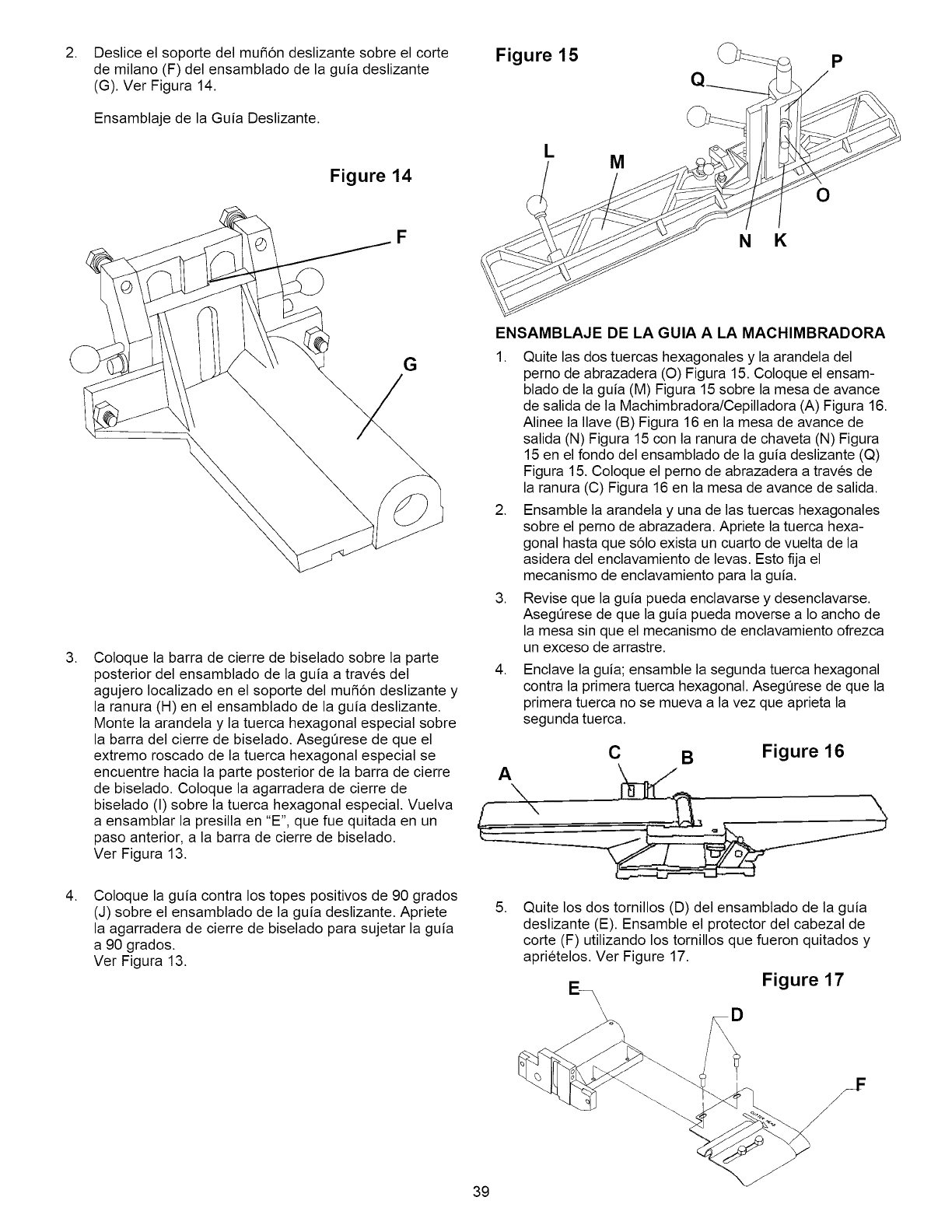
.Deslice el soporte del mufi6n deslizante sobre el corte
de milano (F) del ensamblado de la guia deslizante
(G). Ver Figura 14.
Ensamblaje de la Guia Deslizante.
Figure 14
Figure 15 J'_ p
LM
O
.
F
G
Coloque la barra de cierre de biselado sobre la parte
posterior del ensamblado de la guia a traves del
agujero Iocalizado en el soporte del mufion deslizante y
la ranura (H) en el ensamblado de la guia deslizante.
Monte la arandela y la tuerca hexagonal especial sobre
la barra del cierre de biselado. Aseg0rese de que el
extremo roscado de la tuerca hexagonal especial se
encuentre hacia la parte posterior de la barra de cierre
de biselado. Coloque la agarradera de cierre de
biselado (I) sobre la tuerca hexagonal especial. Vuelva
a ensamblar la presilla en "E", que fue quitada en un
paso anterior, a la barra de cierre de biselado.
Ver Figura 13.
NK
ENSAMBLAJE DE LA GUIA A LA MACHIMBRADORA
1. Quite las dos tuercas hexagonales y la arandela del
perno de abrazadera (O) Figura 15. Coloque el ensam-
blado de la guia (M) Figura 15 sobre la mesa de avance
de salida de la Machimbradora/Cepilladora (A) Figura 16.
Alinee la Ilave (B) Figura 16 en la mesa de avance de
salida (N) Figura 15 con la ranura de chaveta (N) Figura
15 en el fondo del ensamblado de la guia deslizante (Q)
Figura 15. Coloque el perno de abrazadera a traves de
la ranura (C) Figura 16 en la mesa de avance de salida.
2. Ensamble la arandela y una de las tuercas hexagonales
sobre el perno de abrazadera. Apriete la tuerca hexa-
gonal hasta que solo exista un cuarto de vuelta de la
asidera del enclavamiento de levas. Esto fija el
mecanismo de enclavamiento para la guia.
3. Revise que la guia pueda enclavarse y desenclavarse.
Aseg0rese de que la guia pueda moverse a Io ancho de
la mesa sin que el mecanismo de enclavamiento ofrezca
un exceso de arrastre.
.Enclave la guia; ensamble la segunda tuerca hexagonal
contra la primera tuerca hexagonal. Aseg0rese de que la
primera tuerca no se mueva a la vez que aprieta la
segunda tuerca.
C
A\\
B Figure 16
.Coloque la guia contra los topes positivos de 90 grados
(J) sobre el ensamblado de la guia deslizante. Apriete
la agarradera de cierre de biselado para sujetar la guia
a 90 grados.
Ver Figura 13.
.Quite los dos tornillos (D) del ensamblado de la guia
deslizante (E). Ensamble el protector del cabezal de
corte (F) utilizando los tornillos que fueron quitados y
aprietelos. Ver Figure 17.
Figure 17
39
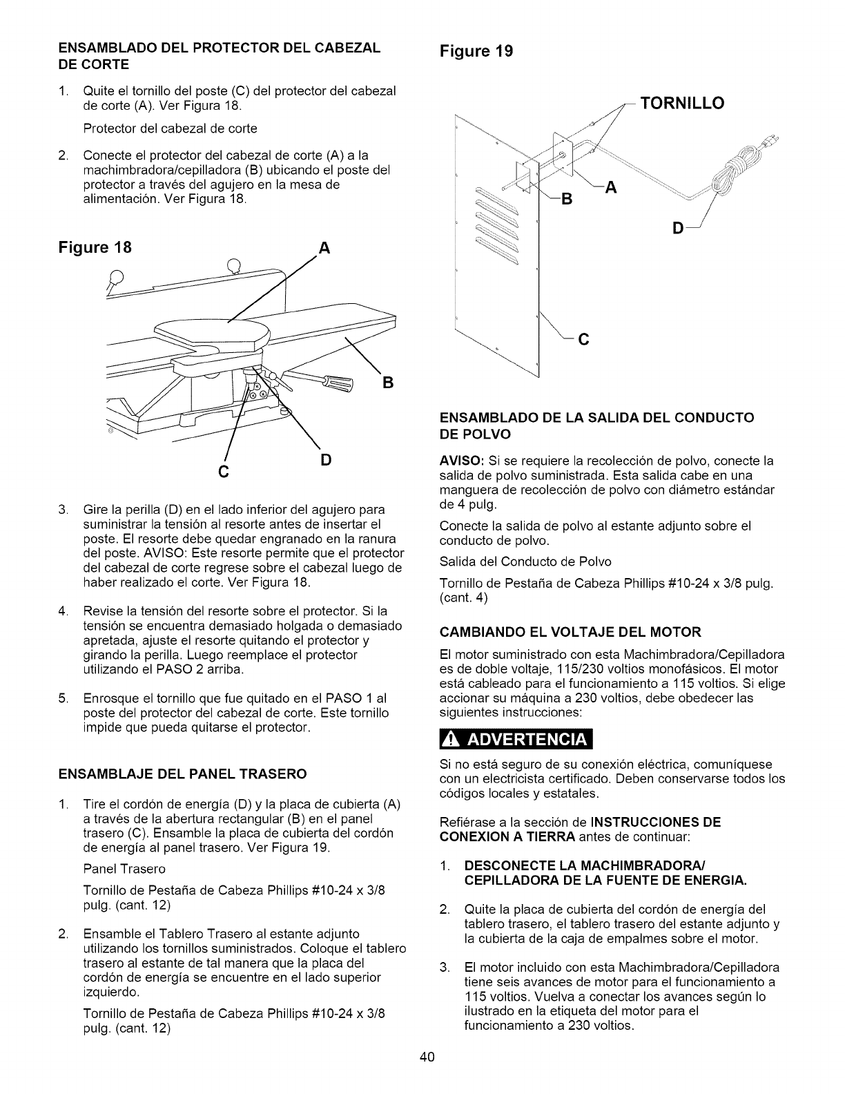
ENSAMBLADO DEL PROTECTOR DEL CABEZAL
DE CORTE
1. Quite el tornillo del poste (C) del protector del cabezal
de corte (A). Ver Figura 18.
Protector del cabezal de corte
.Conecte el protector del cabezal de corte (A) a la
machimbradora/cepilladora (B) ubicando el poste del
protector a traves del agujero en la mesa de
alimentacion. Ver Figura 18.
Figure 18 A
Figure 19
C
A
TORNILLO
B
D
C
.
.
.
Gire la perilla (D) en el lado inferior del agujero para
suministrar la tension al resorte antes de insertar el
poste. El resorte debe quedar engranado en la ranura
del poste. AVISO: Este resorte permite que el protector
del cabezal de corte regrese sobre el cabezal luego de
haber realizado el corte. Ver Figura 18.
Revise la tension del resorte sobre el protector. Si la
tension se encuentra demasiado holgada o demasiado
apretada, ajuste el resorte quitando el protector y
girando la perilla. Luego reemplace el protector
utilizando el PASO 2 arriba.
Enrosque el tornillo que fue quitado en el PASO 1 al
poste del protector del cabezal de corte. Este tornillo
impide que pueda quitarse el protector.
ENSAMBLAJE DEL PANEL TRASERO
.Tire el cordon de energia (D) y la placa de cubierta (A)
a traves de la abertura rectangular (B) en el panel
trasero (C). Ensamble la placa de cubierta del cordon
de energia al panel trasero. Ver Figura 19.
Panel Trasero
Tornillo de Pestafia de Cabeza Phillips #10-24 x 3/8
pulg. (cant. 12)
.Ensamble el Tablero Trasero al estante adjunto
utilizando los tornillos suministrados. Coloque el tablero
trasero al estante de tal manera que la placa del
cordon de energia se encuentre en el lado superior
izquierdo.
Tornillo de Pestafia de Cabeza Phillips #10-24 x 3/8
pulg. (cant. 12)
ENSAMBLADO DE LA SALIDA DEL CONDUCTO
DE POLVO
AVISO: Si se requiere la recoleccion de polvo, conecte la
salida de polvo suministrada. Esta salida cabe en una
manguera de recoleccion de polvo con diametro estandar
de 4 pulg.
Conecte la salida de polvo al estante adjunto sobre el
conducto de polvo.
Salida del Conducto de Polvo
Tornillo de Pestafia de Cabeza Phillips #10-24 x 3/8 pulg.
(cant. 4)
CAMBIANDO EL VOLTAJE DEL MOTOR
El motor suministrado con esta Machimbradora/Cepilladora
es de doble voltaje, 115/230 voltios monofasicos. El motor
esta cableado para el funcionamiento a 115 voltios. Si elige
accionar su maquina a 230 voltios, debe obedecer las
siguientes instrucciones:
_'!11'_,Im_vj=1t,_lI1=1_[_ I'_,1
Si no esta seguro de su conexion electrica, comuniquese
con un electricista certificado. Deben conservarse todos los
codigos locales y estatales.
Refierase a la seccion de INSTRUCClONES DE
CONEXION A TIERRA antes de continuar:
1. DESCONECTE LA MACHIMBRADORA/
CEPILLADORA DE LA FUENTE DE ENERGIA.
.
.
Quite la placa de cubierta del cordon de energia del
tablero trasero, el tablero trasero del estante adjunto y
la cubierta de la caja de empalmes sobre el motor.
El motor incluido con esta Machimbradora/Cepilladora
tiene seis avances de motor para el funcionamiento a
115 voltios. Vuelva a conectar los avances segOn Io
ilustrado en la etiqueta del motor para el
funcionamiento a 230 voltios.
40
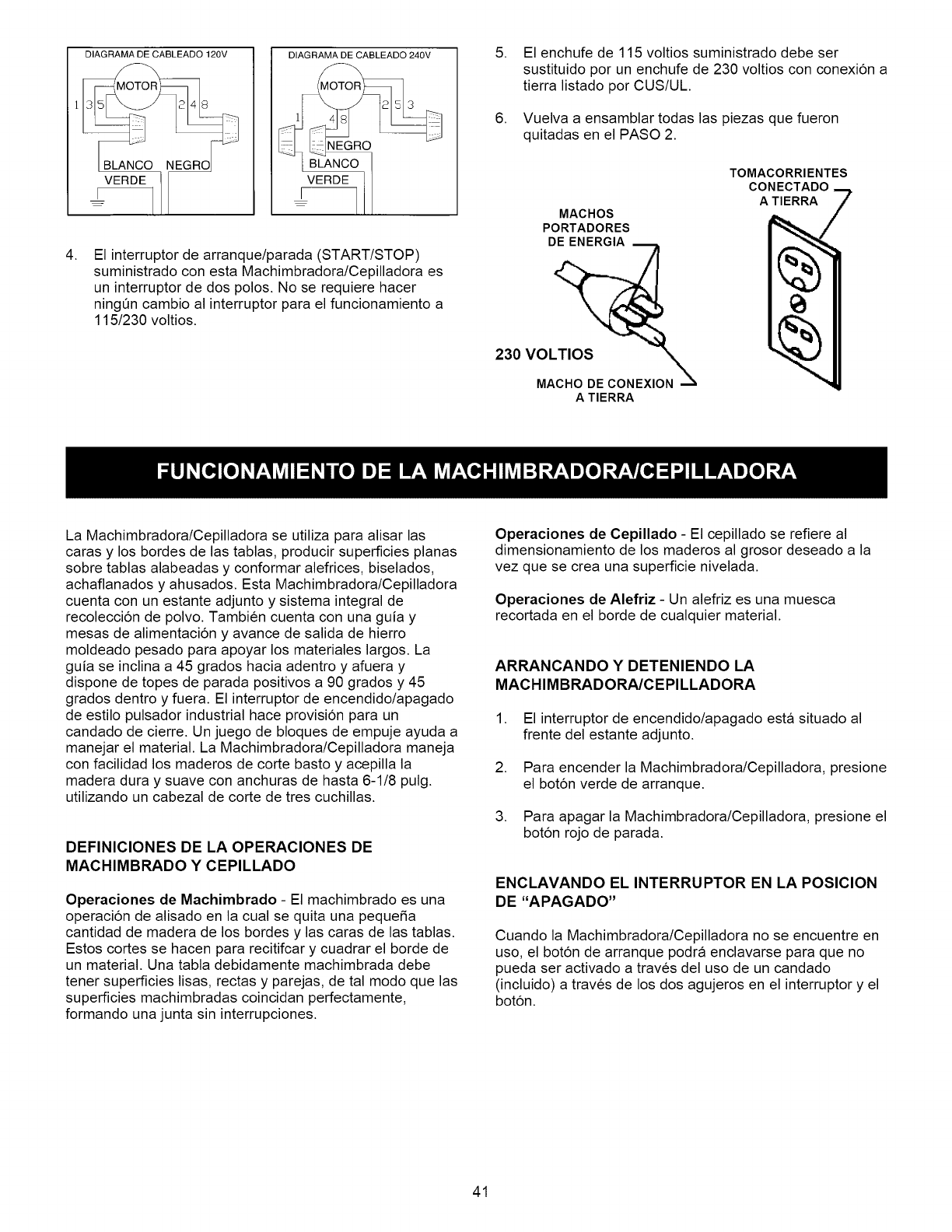
DIAGRAMA DE CABLEADO 120V
VERDE
DIAGRAMA DE CABLEADO 240V
VERDE 1
I--
.El interruptor de arranque/parada (START/STOP)
suministrado con esta Machimbradora/Cepilladora es
un interruptor de dos polos. No se requiere hacer
ningQn cambio al interruptor para el funcionamiento a
115/230 voltios.
.
.
El enchufe de 115 voltios suministrado debe ser
sustituido por un enchufe de 230 voltios con conexion a
tierra listado por CUS/UL.
Vuelva a ensamblar todas las piezas que fueron
quitadas en el PASO 2.
MACHOS
PORTADORES
230 VOLTIOS XION_
MACHO DE CONE
A TIERRA
TOMACORRIENTES
CONECTADO
ATIERRA
La Machimbradora/Cepilladora se utiliza para alisar las
caras y los bordes de las tablas, producir superficies planas
sobre tablas alabeadas y conformar alefrices, biselados,
achaflanados y ahusados. Esta Machimbradora/Cepilladora
cuenta con un estante adjunto y sistema integral de
recoleccion de polvo. Tambien cuenta con una guia y
mesas de alimentacion y avance de salida de hierro
moldeado pesado para apoyar los materiales largos. La
guia se inclina a 45 grados hacia adentro y afuera y
dispone de topes de parada positivos a 90 grados y 45
grados dentro y fuera. El interruptor de encendido/apagado
de estilo pulsador industrial hace provision para un
candado de cierre. Un juego de bloques de empuje ayuda a
manejar el material. La Machimbradora/Cepilladora maneja
con facilidad los maderos de corte basto y acepilla la
madera dura y suave con anchuras de hasta 6-1/8 pulg.
utilizando un cabezal de corte de tres cuchillas.
DEFINIClONES DE LA OPERAClONES DE
MACHIMBRADO Y CEPILLADO
Operaciones de Machimbrado - El machimbrado es una
operacion de alisado en la cual se quita una peque5a
cantidad de madera de los bordes y las caras de las tablas.
Estos cortes se hacen para recitifcar y cuadrar el borde de
un material. Una tabla debidamente machimbrada debe
tener superficies lisas, rectas y parejas, de tal modo que las
superficies machimbradas coincidan perfectamente,
formando una junta sin interrupciones.
Operaciones de Cepillado - El cepillado se refiere al
dimensionamiento de los maderos al grosor deseado a la
vez que se crea una superficie nivelada.
Operaciones de Alefriz - Un alefriz es una muesca
recortada en el borde de cualquier material.
ARRANCANDO Y DETENIENDO LA
MACHIMBRADORA/CEPILLADORA
1. El interruptor de encendido/apagado esta situado al
frente del estante adjunto.
2. Para encender la Machimbradora/Cepilladora, presione
el boton verde de arranque.
3. Para apagar la Machimbradora/Cepilladora, presione el
boton rojo de parada.
ENCLAVANDO EL INTERRUPTOR EN LA POSlClON
DE "APAGADO"
Cuando la Machimbradora/Cepilladora no se encuentre en
uso, el boton de arranque podra enclavarse para que no
pueda ser activado a traves del uso de un candado
(incluido) a traves de los dos agujeros en el interruptor y el
boton.
41
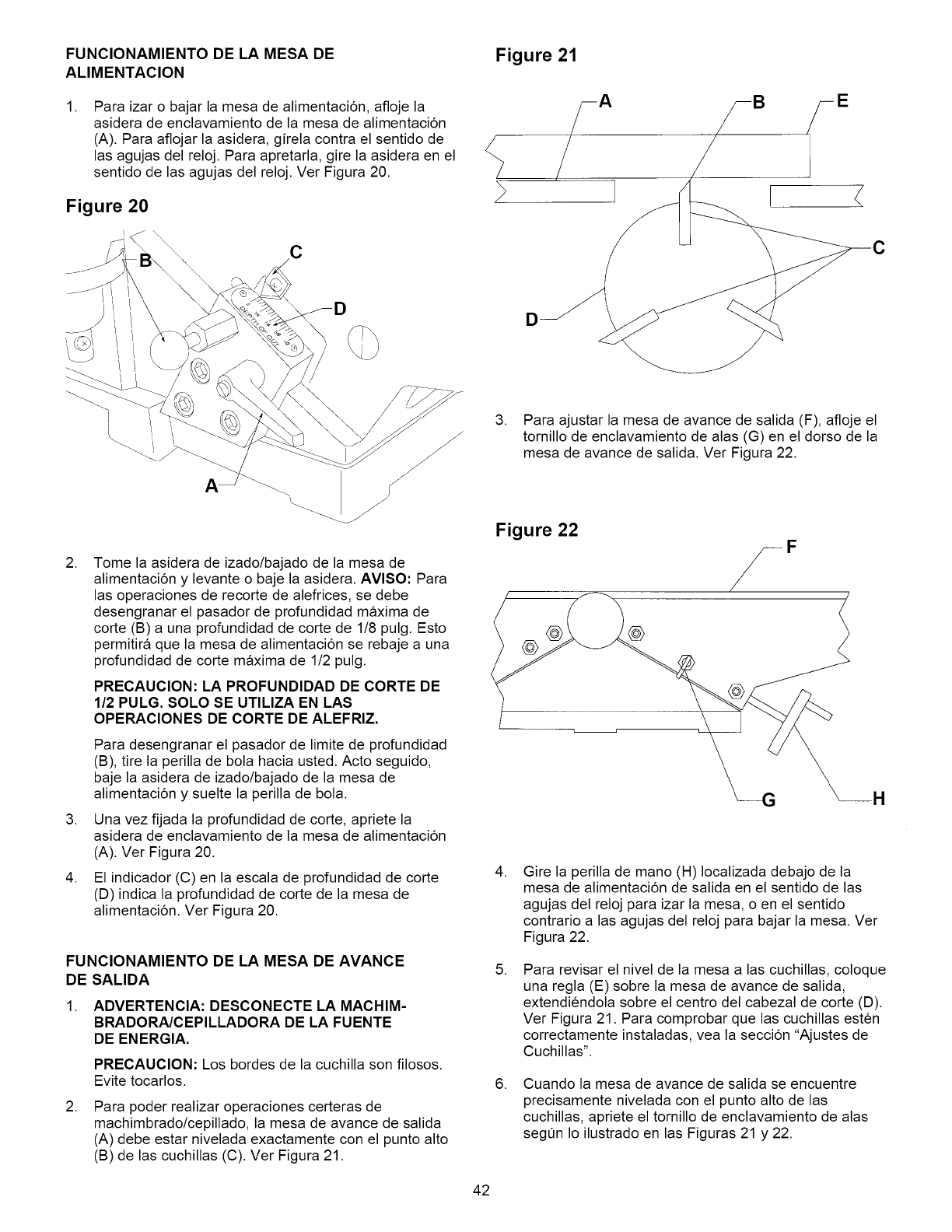
FUNClONAMIENTODELA MESA DE
ALIMENTAClON
,Para izar o bajar la mesa de alimentacion, afloje la
asidera de enclavamiento de la mesa de alimentacion
(A). Para aflojar la asidera, girela contra el sentido de
las agujas del reloj. Para apretarla, gire la asidera en el
sentido de las agujas del reloj. Ver Figura 20.
Figure 20
C
D
Figure 21
D
A
,
,
,
Tome la asidera de izado/bajado de la mesa de
alimentacion y levante o baje la asidera. AVlSO: Para
las operaciones de recorte de alefrices, se debe
desengranar el pasador de profundidad maxima de
corte (B) a una profundidad de corte de 1/8 pulg. Esto
permitira que la mesa de alimentacion se rebaje a una
profundidad de corte maxima de 1/2 pulg.
PRECAUCION: LA PROFUNDIDAD DE CORTE DE
1/2 PULG. SOLO SE UTILIZA EN LAS
OPERACIONES DE CORTE DE ALEFRIZ.
Para desengranar el pasador de limite de profundidad
(B), tire la perilla de bola hacia usted. Acto seguido,
baje la asidera de izado/bajado de la mesa de
alimentacion y suelte la perilla de bola.
Una vez fijada la profundidad de corte, apriete la
asidera de enclavamiento de la mesa de alimentacion
(A). Ver Figura 20.
El indicador (C) en la escala de profundidad de corte
(D) indica la profundidad de corte de la mesa de
alimentacion. Ver Figura 20.
FUNCIONAMIENTO DE LA MESA DE AVANCE
DE SALIDA
1. ADVERTENCIA: DESCONECTE LA MACHIM-
BRADORA/CEPILLADORA DE LA FUENTE
DE ENERGIA.
PRECAUCION: Los bordes de la cuchilla son filosos.
Evite tocarlos.
,Para poder realizar operaciones certeras de
machimbrado/cepillado, la mesa de avance de salida
(A) debe estar nivelada exactamente con el punto alto
(B) de las cuchillas (C). Ver Figura 21.
3. Para ajustar la mesa de avance de salida (F), afloje el
tornillo de enclavamiento de alas (G) en el dorso de la
mesa de avance de salida. Ver Figura 22.
Figure 22
@
,
,
,
Gire la perilla de mano (H) Iocalizada debajo de la
mesa de alimentacion de salida en el sentido de las
agujas del reloj para izar la mesa, o en el sentido
contrario alas agujas del reloj para bajar la mesa. Ver
Figura 22.
Para revisar el nivel de la mesa a las cuchillas, coloque
una regla (E) sobre la mesa de avance de salida,
extendiendola sobre el centro del cabezal de corte (D).
Ver Figura 21. Para comprobar que las cuchillas esten
correctamente instaladas, vea la seccion "Ajustes de
Cuchillas".
Cuando la mesa de avance de salida se encuentre
precisamente nivelada con el punto alto de las
cuchillas, apriete el tornillo de enclavamiento de alas
segQn Io ilustrado en las Figuras 21 y 22.
42
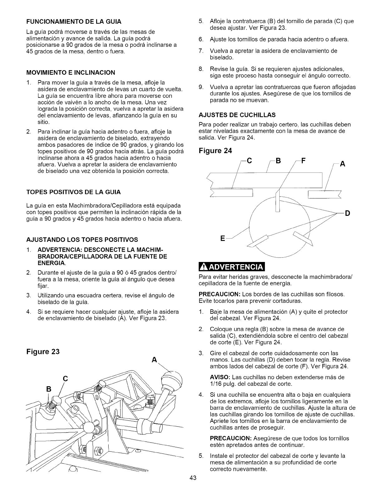
FUNCIONAMIENTO DE LA GUIA
La guia podra moverse a traves de las mesas de
alimentacion y avance de salida. La guia podra
posicionarse a 90 grados de la mesa o podra inclinarse a
45 grados de la mesa, dentro o fuera.
MOVIMIENTO E INCLINACION
,Para mover la guia a traves de la mesa, afloje la
asidera de enclavamiento de levas un cuarto de vuelta.
La guia se encuentra libre ahora para moverse con
accion de vaiven a Io ancho de la mesa. Una vez
Iograda la posicion correcta, vuelva a apretar la asidera
del enclavamiento de levas, afianzando la guia en su
sitio.
,Para inclinar la guia hacia adentro o fuera, afloje la
asidera de enclavamiento de biselado, extrayendo
ambos pasadores de indice de 90 grados, y girando los
topes positivos de 90 grados hacia atras. La guia podra
inclinarse ahora a 45 grados hacia adentro o hacia
afuera. Vuelva a apretar la asidera de enclavamiento
de biselado una vez obtenida la posicion correcta.
TOPES POSITIVOS DE LA GUIA
La guia en esta Machimbradora/Cepilladora esta equipada
con topes positivos que permiten la inclinacion rapida de la
guia a 90 grados y 45 grados hacia adentro o hacia afuera.
5. Afloje la contratuerca (B) del tornillo de parada (C) que
desea ajustar. Ver Figura 23.
6. Ajuste los tornillos de parada hacia adentro o afuera.
7. Vuelva a apretar la asidera de enclavamiento de
biselado.
,
g,
Revise la guia. Si se requieren ajustes adicionales,
siga este proceso hasta conseguir el angulo correcto.
Vuelva a apretar las contratuercas que fueron aflojadas
durante los ajustes. AsegQrese de que los tornillos de
parada no se muevan.
AJUSTES DE CUCHILLAS
Para poder realizar un trabajo certero, las cuchillas deben
estar niveladas exactamente con la mesa de avance de
salida. Ver Figura 24.
Figure 24
D
AJUSTANDO LOS TOPES POSITIVOS
1. ADVERTENCIA: DESCONECTE LA MACHIM-
BRADORNCEPILLADORA DE LA FUENTE DE
ENERGIA.
2. Durante el ajuste de la guia a 90 6 45 grados dentro/
fuera a la mesa, oriente la guia al angulo que desea
fijar.
3. Utilizando una escuadra certera, revise el angulo de
biselado de la guia.
4. Si se requiere hacer cualquier ajuste, afloje la asidera
de enclavamiento de biselado (A). Ver Figura 23.
Figure 23 A
C
B
43
E
Para evitar heridas graves, desconecte la machimbradora/
cepilladora de la fuente de energia.
PRECAUCION: Los bordes de las cuchillas son filosos.
Evite tocarlos para prevenir cortaduras.
1. Baje la mesa de alimentacion (A) y quite el protector
del cabezal. Ver Figura 24.
2. Coloque una regla (B) sobre la mesa de avance de
salida (C), extendiendola sobre el centro del cabezal
de corte (E). Ver Figura 24.
3. Gire el cabezal de corte cuidadosamente con las
manos. Las cuchillas (D) deben tocar la regla. Revise
ambos lados del cabezal de corte (F). Ver Figura 24.
AVISO: Las cuchillas no deben extenderse mas de
1/16 pulg. del cabezal de corte.
,Si una cuchilla se encuentra alta o baja en cualquiera
de los extremos, afloje los tornillos ligeramente en la
barra de enclavamiento de cuchillas. Ajuste la altura de
las cuchillas girando los tornillos de ajuste de cuchillas.
Apriete los tornillos en la barra de enclavamiento de
cuchillas antes de proseguir.
PRECAUCION: AsegQrese de que todos los tornillos
esten apretados antes de continuar.
5. Instale el protector del cabezal de corte y levante la
mesa de alimentacion a su profundidad de corte
correcto nuevamente.
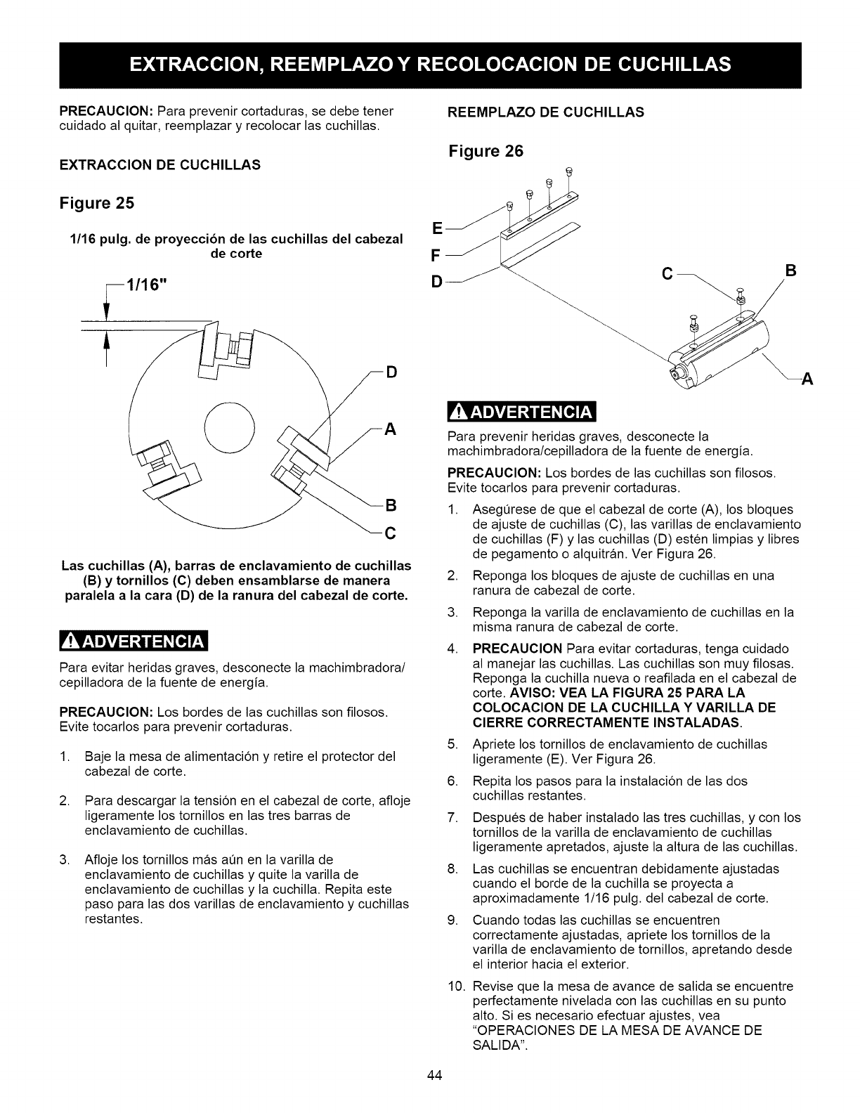
PRECAUClON:Paraprevenircortaduras,sedebetener
cuidadoalquitar,reemplazary recolocarlascuchillas.
EXTRACCION DE CUCHILLAS
Figure 25
1/16 pulg. de proyeccibn de las cuchillas del cabezal
de corte
1/16"
D
B
C
Las cuchillas (A), barras de enclavamiento de cuchillas
(B) y tornillos (C) deben ensamblarse de manera
paralela a la cara (D) de la ranura del cabezal de corte.
_'!V_,I m_vi=1t,_| =1_[=,]I'_,II
Para evitar heridas graves, desconecte la machimbradora/
cepilladora de la fuente de energia.
PRECAUCION: Los bordes de las cuchillas son filosos.
Evite tocarlos para prevenir cortaduras.
1. Baje la mesa de alimentacion y retire el protector del
cabezal de corte.
2. Para descargar la tension en el cabezal de corte, afloje
ligeramente los tornillos en las tres barras de
enclavamiento de cuchillas.
.Afloje los tornillos mas aQn en la varilla de
enclavamiento de cuchillas y quite la varilla de
enclavamiento de cuchillas y la cuchilla. Repita este
paso para las dos varillas de enclavamiento y cuchillas
restantes.
REEMPLAZO DE CUCHILLAS
Figure 26
Para prevenir heridas graves, desconecte la
machimbradora/cepilladora de la fuente de energia.
PRECAUClON: Los bordes de las cuchillas son filosos.
Evite tocarlos para prevenir cortaduras.
1. AsegQrese de que el cabezal de corte (A), los bloques
de ajuste de cuchillas (C), las varillas de enclavamiento
de cuchillas (F) y las cuchillas (D) esten limpias y libres
de pegamento o alquitran. Ver Figura 26.
Reponga los bloques de ajuste de cuchillas en una
ranura de cabezal de corte.
.
3.
4.
.
6.
7.
.
g.
10.
Reponga la varilla de enclavamiento de cuchillas en la
misma ranura de cabezal de corte.
PRECAUCION Para evitar cortaduras, tenga cuidado
al manejar las cuchillas. Las cuchillas son muy filosas.
Reponga la cuchilla nueva o reafilada en el cabezal de
corte. AVlSO: VEA LA FIGURA 25 PARA LA
COLOCAClON DE LA CUCHILLA Y VARILLA DE
ClERRE CORRECTAMENTE INSTALADAS.
Apriete los tornillos de enclavamiento de cuchillas
ligeramente (E). Ver Figura 26.
Repita los pasos para la instalacion de las dos
cuchillas restantes.
Despues de haber instalado las tres cuchillas, y con los
tornillos de la varilla de enclavamiento de cuchillas
ligeramente apretados, ajuste la altura de las cuchillas.
Las cuchillas se encuentran debidamente ajustadas
cuando el borde de la cuchilla se proyecta a
aproximadamente 1/16 pulg. del cabezal de corte.
Cuando todas las cuchillas se encuentren
correctamente ajustadas, apriete los tornillos de la
varilla de enclavamiento de tornillos, apretando desde
el interior hacia el exterior.
Revise que la mesa de avance de salida se encuentre
perfectamente nivelada con las cuchillas en su punto
alto. Si es necesario efectuar ajustes, vea
"OPERAClONES DE LA MESA DE AVANCE DE
SALIDA".
44
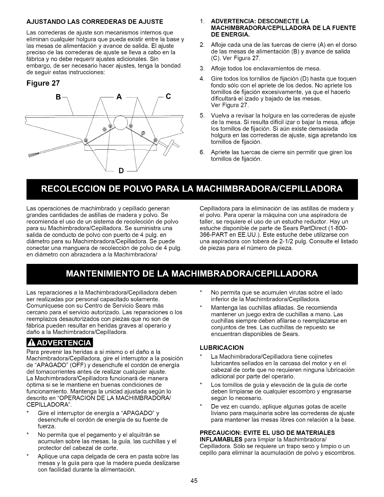
AJUSTANDO LAS CORREDERAS DE AJUSTE
Las correderas de ajuste son mecanismos internos que
eliminan cualquier holgura que pueda existir entre la base y
las mesas de alimentacion y avance de salida. El ajuste
preciso de las correderas de ajuste se Ileva a cabo en la
fabrica y no debe requerir ajustes adicionales. Sin
embargo, de ser necesario hacer ajustes, tenga la bondad
de seguir estas instrucciones:
Figure 27
.
.
.
4.
.
.
ADVERTENCIA: DESCONECTE LA
MACHIMBRADORA/CEPILLADORA DE LA FUENTE
DE ENERGIA.
Afloje cada una de las tuercas de cierre (A) en el dorso
de las mesas de alimentacion (B) y avance de salida
(C). Ver Figura 27.
Afloje todos los enclavamientos de mesa.
Gire todos los tornillos de fijacion (D) hasta que toquen
fondo solo con el apriete de los dedos. No apriete los
tornillos de fijacion excesivamente, ya que el hacerlo
dificultara el izado y bajado de las mesas.
Ver Figura 27.
Vuelva a revisar la holgura en las correderas de ajuste
de la mesa. Si resulta dificil izar o bajar la mesa, afloje
los tornillos de fijacion. Si aOn existe demasiada
holgura en las correderas de ajuste, siga apretando los
tornillos de fijacion.
Apriete las tuercas de cierre sin permitir que giren los
tornillos de fijacion.
Las operaciones de machimbrado y cepillado generan
grandes cantidades de astillas de madera y polvo. Se
recomienda el uso de un sistema de recoleccion de polvo
para su Machimbradora/Cepilladora. Se suministra una
salida de conducto de polvo con puerto de 4 pulg. en
diametro para su Machimbradora/Cepilladora. Se puede
conectar una manguera de recoleccion de polvo de 4 pulg.
en diametro con abrazadera a la Machimbradora/
Cepilladora para la eliminacion de las astillas de madera y
el polvo. Para operar la maquina con una aspiradora de
taller, se requiere el uso de un estuche reductor. Hay un
estuche disponible de parte de Sears PartDirect (1-800-
366-PART en EE.UU.). Este estuche debe utilizarse con
una aspiradora con tobera de 2-1/2 pulg. Consulte el listado
de piezas para el nQmero de pieza.
Las reparaciones a la Machimbradora/Cepilladora deben
ser realizadas por personal capacitado solamente.
Comuniquese con su Centro de Servicio Sears mas
cercano para el servicio autorizado. Las reparaciones o los
reemplazos desautorizados con piezas que no son de
fabrica pueden resultar en heridas graves al operario y
da_o a la Machimbradora/Cepilladora.
LIP'.vv_,1D_vj:1_ii:1_[o,]p,_,l
Para prevenir las heridas a si mismo o el da_o a la
Machimbradora/Cepilladora, gire el interruptor a la posicion
de "APAGADO" (OFF) y desenchufe el cordon de energia
del tomacorrientes antes de realizar cualquier ajuste.
La Machimbradora/Cepilladora funcionara de manera
optima si se le mantiene en buenas condiciones de
funcionamiento. Mantenga la unidad ajustada segQn Io
descrito en "OPERACION DE LA MACHIMBRADORA/
CEPILLADORA'.
* Gire el interruptor de energia a "APAGADO" y
desenchufe el cordon de energia de su fuente de
fuerza.
* No permita que el pegamento y el alquitran se
acumulen sobre las mesas, la guia, las cuchillas y el
protector del cabezal de corte.
* Aplique una capa delgada de cera en pasta sobre las
mesas y la guia para que la madera pueda deslizarse
con facilidad durante la alimentacion.
No permita que se acumulen virutas sobre el lado
inferior de la Machimbradora/Cepilladora.
Mantenga las cuchillas afiladas. Se recomienda
mantener un juego extra de cuchillas a mano. Las
cuchillas siempre deben afilarse o reemplazarse en
conjuntos de tres. Las cuchillas de repuesto se
encuentran disponibles de Sears.
LUBRICAClON
*La Machimbradora/Cepilladora tiene cojinetes
lubricantes sellados en la carcasa del motor yen el
cabezal de corte que no requieren ninguna lubricacion
adicional por parte del operario.
* Los tornillos de guia y elevacion de la guia de corte
deben limpiarse de cualquier escombro y engrasarse
segQn Io necesario.
* De vez en cuando, aplique algunas gotas de aceite
liviano para maquinaria sobre las correderas de ajuste
para mantener las mesas libres con relacion a la base.
PRECAUClON: EVlTE EL USO DE MATERIALES
INFLAMABLES para limpiar la Machimbradora/
Cepilladora. Solo se requiere un trapo seco y limpio o un
cepillo para eliminar la acumulacion de polvo y escombros.
45
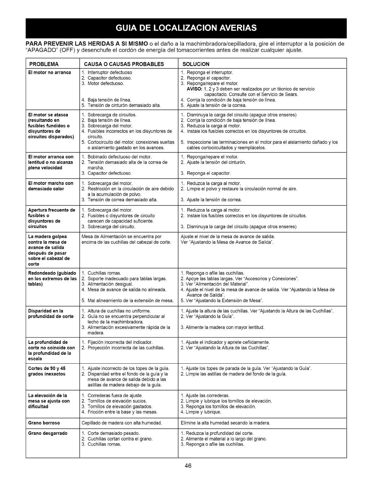
PARA PREVENIR LAS HERIDAS A Sl MISMO o el da5o a la machimbradora/cepilladora, gire el interruptor a la posicion de
"APAGADO" (OFF) y desenchufe el cordon de energia del tomacorrientes antes de realizar cualquier ajuste.
PROBLEMA CAUSA OCAUSAS PROBABLES SOLUCION
El motorno arranca
El motor se atasca
(resultando en
fusibles fundidos o
disyuntores de
circuitos disparados)
El motor arranca con
lentitud o no alcanza
plena velocidad
El motor marcha con
demasiado calor
Apertura frecuente de
fusibles o
disyuntores de
circuitos
La madera golpea
contra la mesa de
avance de salida
despu_s de pasar
sobre el cabezal de
corte
Redondeado (gubiado
en los extremos de las
tablas)
Disparidad en la
profundidad de corte
La profundidad de
corte no coincide con
la profundidad de la
escala
Cortes de 90 y 45
grados inexactos
La elevacion de la
mesa se ajusta con
dificultad
1. Interruptor defectuoso
2. Capacitor defectuoso.
3. Motor defectuoso.
4. Baja tensi6n de linea.
5. Tensi6n de cintur6n demasiado alta.
1. Sobrecarga de circuitos.
2. Baja tensi6n de linea.
3. Sobrecarga del motor.
4. Fusibles incorrectos en los disyuntores de
circuito.
5. Cortocircuito del motor; conexiones sueltas
o aislamiento gastado en los avarices.
1.
2.
3.
1.
2.
3.
1.
2.
Bobinado defectuoso del motor.
Tensi6n demasiado alta de la correa de
marcha.
Capacitor defectuoso.
Sobrecarga del motor.
Restricci6n en la circulaci6n de aire debido
a la acumulaci6n de polvo.
Tensi6n de correa demasiado alta.
Sobrecarga del motor.
Fusibles o disyuntores de circuito
carecen de capacidad suficiente.
Sobrecarga del circuito.
Mesa de Alimentaci6n se encuentra por
encima de las cuchillas del cabezal de corte.
1. Cuchillas romas.
2. Soporte inadecuado para tablas largas.
3. Alimentaci6n desigual.
4. Mesa de avarice de salida no alineada.
5. Mal alineamiento de la extensi6n de mesa.
1. Altura de cuchillas no uniforme.
2. Guia no se encuentra perpendicular al
lecho de la machimbradora.
3. Alimentaci6n excesivamente rapida de la
madera.
1. Fijaci6n incorrecta del indicador.
2. Proyecci6n incorrecta de las cuchillas.
1. Ajuste incorrecto de los topes de la guia.
2. Disparidad entre el fondo de la guia y la
mesa de avance de salida debido alas
astillas de madera debajo de la guia.
1. Correderas fuera de ajuste.
2. Tomillos de elevaci6n sucios.
3. Tomillos de elevaci6n gastados.
4. Fricci6n entre la base y las mesas.
1. Reponga el interruptor.
2. Reponga el capacitor.
3. Reponga/repare el motor.
AVI80: 1, 2 y 3 deben ser realizados por un tecnico de servicio
capacitado. Consulte con el Servicio de Sears.
4. Corfija la condici6n de baja tensi6n de linea.
5. Ajuste la tensi6n de la correa.
1. Disminuya la carga del circuito (apague otros enseres)
2. Corfija la condici6n de baja tensi6n de linea.
3. Reduzca la carga al motor.
4. Instale los fusibles correctos en los disyuntores de circuitos.
5,
1.
2.
Inspeccione las terminaciones en el motor para el aislamiento da_ado y los
cables cortocircuitados y reemplacelos.
Reponga/repare el motor.
Ajuste la tensi6n del cintur6n.
3. Reponga el capacitor.
1. Reduzca la carga al motor.
2. Limpie el polvo y restaure la circulaci6n normal de aire.
3. Ajuste la tensi6n de correa.
1. Reduzca la carga al motor.
2. Instale los fusibles correctos en los disyuntores de circuitos.
3. Disminuya la carga del circuito (apague otros enseres)
Ajuste el nivel de la mesa de avarice de salida.
Ver "Ajustando la Mesa de Avance de Salida".
1. Reponga o afile las cuchillas.
2. Apoye las tablas largas. Ver "Accesorios y Conexiones'.
3. Ver "Alimentaci6n del Material".
4. Ajuste el nivel de la mesa de avance de salida. Ver "Ajustando la Mesa de
Avance de Salida".
5. Ver "Ajustando la Extensi6n de Mesa".
1. Ajuste la altura de las cuchillas. Ver "Ajustando la Altura de las Cuchillas'.
2. Ver "Ajustando la Guia'.
3. Alimente la madera con mayor lentitud.
1. Ajuste el indicador y apriete ceSidamente.
2. Ver "Ajustando la AItura de las Cuchillas".
1. Ajuste los topes de parada de la guia. Ver "Ajustando la Guia".
2. Limpie las astillas de madera del fondo de la guia.
1. Ajuste las correderas.
2. Limpie y lubrique los tomillos de elevaci6n.
3. Reponga los tomillos de elevaci6n.
4. Limpie y lubrique.
Grano borroso Cepillado de madera con alta humedad. Elimine la alta humedad secando la madera.
Grano desgarrado 1. Corte demasiado pesado. 1. Reduzca la profundidad del corte.
2. Cuchillas cortan contra el grano. 2. Alimente el material a Io largo del grano.
3. Cuchillas romas. 3. Reponga o afile las cuchillas.
46
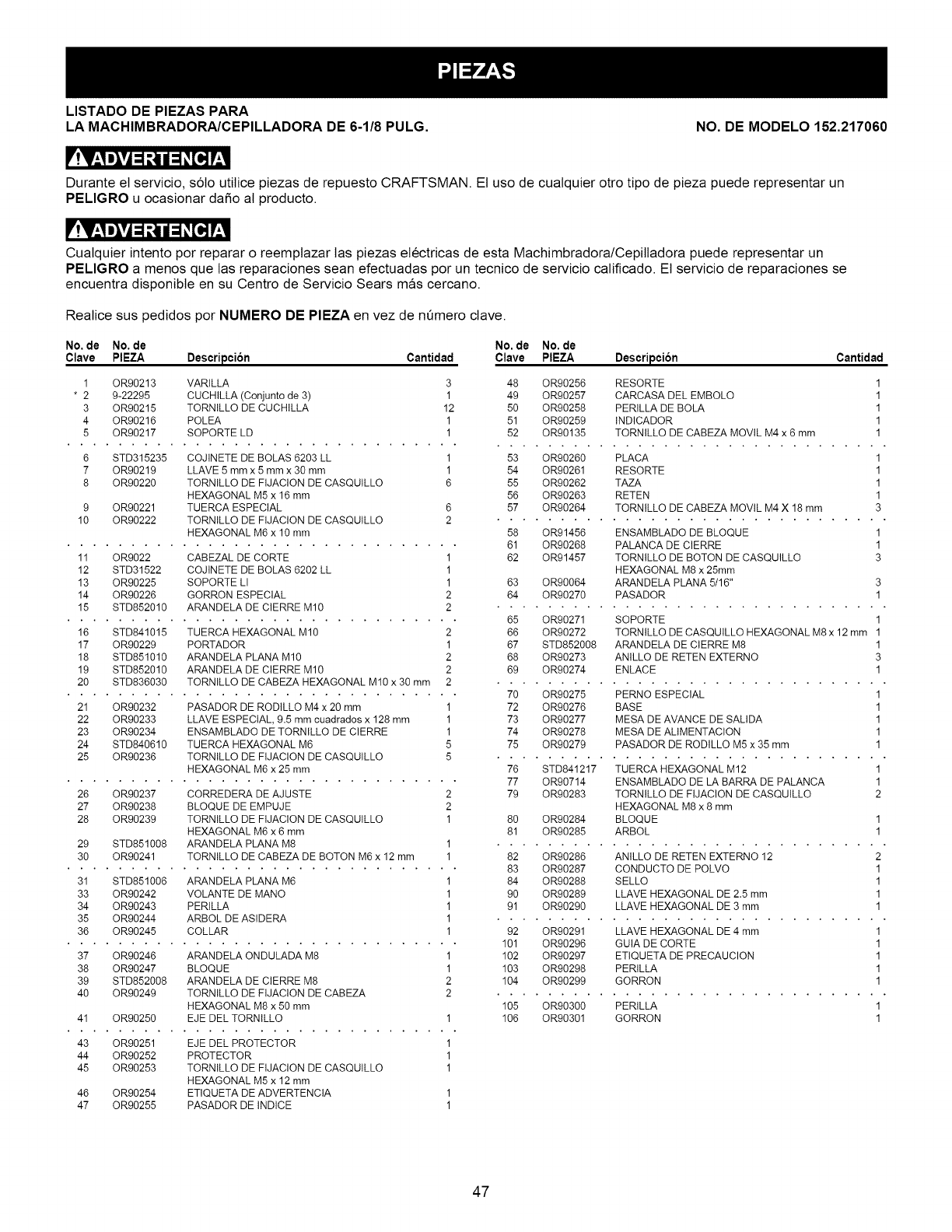
LISTADO DE PIEZAS PARA
LA MACHIMBRADORA/CEPILLADORA DE 6-1/8 PULG. NO. DE MODELO 152.217060
_I'_,I m_ =1_ | =1_[H I'_,1
Durante el servicio, s6to utitice piezas de repuesto CRAFTSMAN. El uso de cualquier otro tipo de pieza puede representar un
PELIGRO u ocasionar daSo al producto.
Cualquier intento por reparar o reemplazar tas piezas electricas de esta Machimbradora/Cepitladora puede representar un
PELIGRO a menos que las reparaciones sean efectuadas por un tecnico de servicio calificado. El servicio de reparaciones se
encuentra disponible en su Centro de Servicio Sears mas cercano.
Realice sus pedidos por NUMERO DE PIEZA en vez de nQmero clave.
No. de No. de No. de No. de
Clave PIEZA Descripcion Cantidad Clave PIEZA Descripcion
1 OR90213 VARILLA 3
* 2 9-22295 CUCHILLA (Conjunto de 3) 1
3 OR90215 TORNILLO DE CUCHILLA 12
4 OR90216 POLEA 1
5 OR90217 SOPORTE LD 1
6 STD315235 COJINETE DE BOLAS 6203 LL 1
7 OR90219 LLAVE 5 mm x 5 mm x 30 mm 1
8 OR90220 TORNILLO DE FIJACION DE CASQUILLO 6
HEXAGONAL M5 x 16 mm
9 OR90221 TUERCA ESPECIAL 6
10 OR90222 TORNILLO DE FIJACION DE CASQUILLO 2
HEXAGONAL M6 x 10 mm
11 OR9022 CABEZAL DE CORTE 1
12 STD31522 COJINETE DE BOLAS 6202 LL 1
13 OR90225 SOPORTE LI 1
14 OR90226 GORRON ESPECIAL 2
15 STD852010 ARANDELA DE CIERRE M10 2
16 STD841015 TUERCA HEXAGONAL M10 2
17 OR90229 PORTADOR 1
18 STD851010 ARANDELA PLANA M10 2
19 STD852010 ARANDELA DE CIERRE M10 2
20 STD836030 TORNILLO DE CABEZA HEXAGONAL M10 x 30 mm 2
21 OR90232 PASADOR DE RODILLO M4 x 20 mm 1
22 OR90233 LLAVE ESPECIAL, 9.5 mm cuadrados x 128 mm 1
23 OR90234 ENSAMBLADO DE TORNILLO DE CIERRE 1
24 STD840610 TUERCA HEXAGONAL M6 5
25 OR90236 TORNILLO DE FIJACION DE CASQUILLO 5
HEXAGONAL M6 x 25 mm
26 OR90237 CORREDERA DE AJUSTE 2
27 OR90238 BLOQUE DE EMPUJE 2
28 OR90239 TORNILLO DE FIJACION DE CASQUILLO 1
HEXAGONAL M6 x 6 mm
29 STD851008 ARANDELA PLANA M8 1
30 OR90241 TORNILLO DE CABEZA DE BOTON M6 x 12 mm 1
31 STD851006 ARANDELA PLANA M6 1
33 OR90242 VOLANTE DE MANO 1
34 OR90243 PERILLA 1
35 OR90244 ARBOL DE ASlDERA 1
36 OR90245 COLLAR 1
37 OR90246 ARANDELA ONDULADA M8 1
38 OR90247 BLOQUE 1
39 STD852008 ARANDELA DE CIERRE M8 2
40 OR90249 TORNILLO DE FIJACION DE CABEZA 2
HEXAGONAL M8 x 50 mm
41 OR90250 EJE DEL TORNILLO 1
43 OR90251 EJE DEL PROTECTOR 1
44 OR90252 PROTECTOR 1
45 OR90253 TORNILLO DE FIJACION DE CASQUILLO 1
HEXAGONAL M5 x 12 mm
46 OR90254 ETIQUETA DE ADVERTENCIA 1
47 OR90255 PASADOR DE INDICE 1
Cantidad
48 OR90256 RESORTE 1
49 OR90257 CARCASA DEL EMBOLO 1
50 OR90258 PERILLA DE BOLA 1
51 OR90259 INDICADOR 1
52 OR90135 TORNILLO DE CABEZA MOVlL M4 x 6 mm 1
53 OR90260 PLACA 1
54 OR90261 RESORTE 1
55 OR90262 TAZA 1
56 OR90263 RETEN 1
57 OR90264 TORNILLO DE CABEZA MOVlL M4 X 18 mm 3
58 OR91456 ENSAMBLADO DE BLOQUE 1
61 OR90268 PALANCA DE CIERRE 1
62 OR91457 TORNILLO DE BOTON DE CASQUILLO 3
HEXAGONAL M8 x 25mm
63 OR90064 ARANDELA PLANA 5/16" 3
64 OR90270 PASADOR 1
65 OR90271 SOPORTE 1
66 OR90272 TORNILLO DE CASQUILLO HEXAGONAL M8 x 12 mm 1
67 STD852008 ARANDELA DE CIERRE M8 1
68 OR90273 ANILLO DE RETEN EXTERNO 3
69 OR90274 ENLACE 1
70 OR90275 PERNO ESPECIAL 1
72 OR90276 BASE 1
73 OR90277 MESA DE AVANCE DE SALIDA 1
74 OR90278 MESA DE ALIMENTACION 1
75 OR90279 PASADOR DE RODILLO M5 x 35 mm 1
76 STD841217 TUERCA HEXAGONAL M12 1
77 OR90714 ENSAMBLADO DE LA BARRA DE PALANCA 1
79 OR90283 TORNILLO DE FIJACION DE CASQUILLO 2
HEXAGONAL M8 x 8 mm
80 OR90284 BLOQUE 1
81 OR90285 ARBOL 1
82 OR90286 ANILLO DE RETEN EXTERNO 12 2
83 OR90287 CONDUCTO DE POLVO 1
84 OR90288 SELLO 1
90 OR90289 LLAVE HEXAGONAL DE 2.5 mm 1
91 OR90290 LLAVE HEXAGONAL DE 3 mm 1
92 OR90291 LLAVE HEXAGONAL DE 4 mm 1
101 OR90296 GUIA DE CORTE 1
102 OR90297 ETIQUETA DE PRECAUCION 1
103 OR90298 PERILLA 1
104 OR90299 GORRON 1
105 OR90300 PERILLA 1
106 OR90301 GORRON 1
47
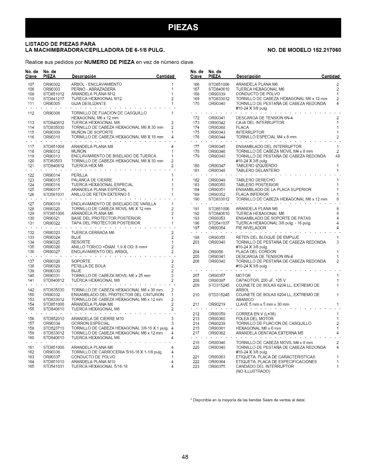
LISTADO DE PIEZAS PARA
LA MACHIMBRADORA/CEPILLADORA DE 6-1/8 PULG. NO. DE MODELO 152.217060
Realice sus pedidos por NUMERO DE PIEZA en vez de n_mero clave.
No. de No. de
Clave PIEZA Descripcion Cantidad
107 OR00302 ARBOL - ENCLAVAMIENTO 1
108 OR90303 PERNO - ABRAZADERA 1
109 STD851012 ARANDELA PLANA M12 1
110 STD841217 TURECA HEXAGONAL M12 2
111 OR90305 GUIA DESLIZANTE 1
112 OR90306 TORNILLO DE FIJACION DE CASQUILLO 1
HEXAGONAL M6 x 12 mm
113 STD840812 TUERCA HEXAGONAL M8 2
114 STD835030 TORNILLO DE CABEZA HEXAGONAL M8 X 30 mm 2
115 OR90309 MUNON DE SOPORTE 1
116 OR90310 TORNILLO DE CABEZA HEXAGONAL M8 X 16 mm 4
117 STD851008 ARANDELA PLANA M8 4
118 OR90312 MUNON 1
119 OR90313 ENCLAVAMIENTO DE BISELADO DE TUERCA 1
120 STD83503 TORNILLO DE CABEZA HEXAGONAL M8 X 30 mm 2
121 STD840812 TUERCA HEX M8 2
122 OR90314 PERILLA 1
123 OR90315 PALANCA DE CIERRE 1
124 OR90316 TUERCA HEXAGONAL ESPECIAL 1
125 OR90317 ARANDELA PLANA ESPECIAL 1
126 STD581031 ANILLO DE RETEN EXTERNO 5 1
127 OR90319 ENCLAVAMIENTO DE BISELADO DE VARILLA 1
128 OR90320 TORNILLO DE CABEZA MOVlL M6 X 12 mm 2
129 STD851006 ARANDELA PLANA M6 2
130 OR90321 BASE DEL PROTECTOR POSTERIOR 1
131 OR90322 TAPA DEL PROTECTOR POSTERIOR 1
132 OR90323 TUERCA CERRADA M6 2
133 OR90324 BUJE 2
134 OR90325 RESO RTE 1
135 OR90326 ANILLO TORICO <DIAM. 1.9 X OD: 8 mm> 2
136 OR90327 ENCLAVAMIENTO DEL ARBOL 2
137 OR90328 SOPORTE 2
138 OR90329 PERILLA DE BOLA 2
139 OR90330 BUJE 2
140 OR90331 TORNILLO DE CABEZA MOVIL M6 x 25 mm 2
141 STD840812 TUERCA HEXAGONAL M8 2
142 STD835030 TORNILLO DE CABEZA HEXAGONAL M8 x 30 mm 2
150 OR90332 ENSAMBLADO DEL PROTECTOR DEL CINTURON 1
153 STD833012 TORNILLO DE CABEZA HEXAGONAL M6 x 12 mm 2
154 STD851006 ARANDELA PLANA M6 2
155 STD840610 TUERCA HEXAGONAL M6 2
156 STD852010 ARANDELA DE CIERRE M10 3
157 OR90334 GORRON ESPECIAL 3
158 STD523710 TORNILLO DE CABEZA HEXAGONAL 3/8-16 X 1 pulg. 4
159 STD833012 TORNILLO DE CABEZA HEXAGONAL M6 x 12 mm 4
160 STD840610 TUERCA HEXAGONAL M6 4
161 STD851006 ARANDELA PLANA M6 4
162 OR90336 TORNILLO DE CARROCERIA 5/16-18 X 1-1/8 puIg. 4
163 OR90337 CONDUCTO DE POLVO 1
164 STD851010 ARANDELA PLANA M10 4
165 STD541031 TUERCA HEXAGONAL 5/16-18 4
No. de No. de
Clave PIEZA
166 STD851006
167 STD840610
168 OR90339
169 STD833012
170 OR90340
Descripcion Cantidad
ARANDELA PLANA M6 2
TUERCA HEXAGONAL M6 2
CONDUCTO DE POLVO 1
TORNILLO DE CABEZA HEXAGONAL M6 x 12 mm 2
TORNILLO DE PESTANA DE CABEZA REDONDA 4
#10-24 X 3/8 pulg.
172 OR90341 DESCARGA DE TENSION 6N-4 2
173 OR90342 CAJA DEL INTERRUPTOR 1
174 OR90368 PLACA 1
175 OR90343 INTERRUPTOR 1
176 OR90344 TORNILLO ESPECIAL M4 x 8 mm 2
177 OR90345 ENSAMBLADO DEL INTERRUPTOR 1
178 OR90346 TORNILLO DE CABEZA MOVIL M4 x 8 mm 2
179 OR90340 TORNILLO DE PESTANA DE CABEZA REDONDA 48
#10-24 X 3/8 pulg.
180 OR90347 TABLERO IZQUIERDO 1
181 OR90348 TABLERO DELANTERO 1
182 OR90349 TABLERO DERECHO 1
183 OR90350 TABLERO POSTERIOR 1
184 OR90351 ENSAMBLADO DE LA PLACA SUPERIOR 1
189 OR90352 PLACA INFERIOR 1
190 STD833012 TORNILLO DE CABEZA HEXAGONAL M6 x 12 mm 8
191 STD851006 ARANDELA PLANA M6 8
192 STD840610 TUERCA HEXAGONAL M6 8
193 OR90353 ENSAMBLADO DE SOPORTE DE PATAS 4
196 STD541037 TUERCA HEXAGONAL 3/8 pulg. - 16 pulg. 4
197 OR90354 PIE NIVELADOR 4
198 OR90355 RETEN DEL BLOQUE DE EMPUJE 1
203 OR90340 TORNILLO DE PESTANA DE CABEZA REDONDA 3
#10-24 X 3/8 pulg.
204 OR9056 PLACA DEL CORDON 1
205 OR90341 DESCARGA DE TENSION 6N-4 1
206 OR90340 TORNILLO DE PESTANA DE CABEZA REDONDA 2
#10-24 X 3/8 pulg.
207 OR90357 MOTOR 1
208 OR90397 CAPACITOR, 200 uF, 125 V 1
209 STD315245 COJINETE DE BOLAS 6204 LL, EXTREMO DE 1
ARBOL
210 STD315245 COJINETE DE BOLAS 6204 LL, EXTREMO DE 1
ABANICO
211 OR90219 LLAVE 5 mmx 5 mm x 30 mm 1
212 OR90359 CORREA EN V (L=38) 1
213 OR90360 POLEA DEL MOTOR 1
214 OR90239 TORNILLO DE FIJACION DE CASQUILLO 2
215 OR90361 HEXAGONAL M6 x 6 mm 1
217 OR90362 ARANDELA DENTADA EXTERNA M5 4
218 OR90346 TORNILLO DE CABEZA MOVIL M4 x 8 mm 2
220 OR90340 TORNILLO DE PESTANA DE CABEZA REDONDA 4
#10-24 X 3/8 pulg.
221 OR90363 ETIQUETA, PLACA DE CARACTERISTICAS 1
222 OR90364 ETIQUETA, PLACA DE ESPECIFICACIONES 1
223 OR90375 CANDADO DEL INTERRUPTOR 1
(NO ILLUSTRADO)
* Disponible en la mayoria de las tiendas Sears de ventas al detal.
48
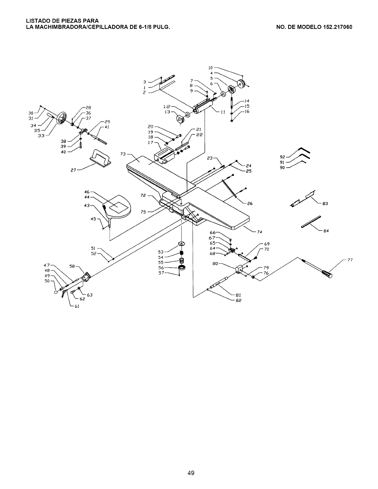
LISTADO DE PIEZAS PARA
LA MACHIMBRADORA/CEPILLADORA DE 6-1/8 PULG. NO. DE MODELO 152.217060
73
25
44_ \
5!
52--
74
77
82
49
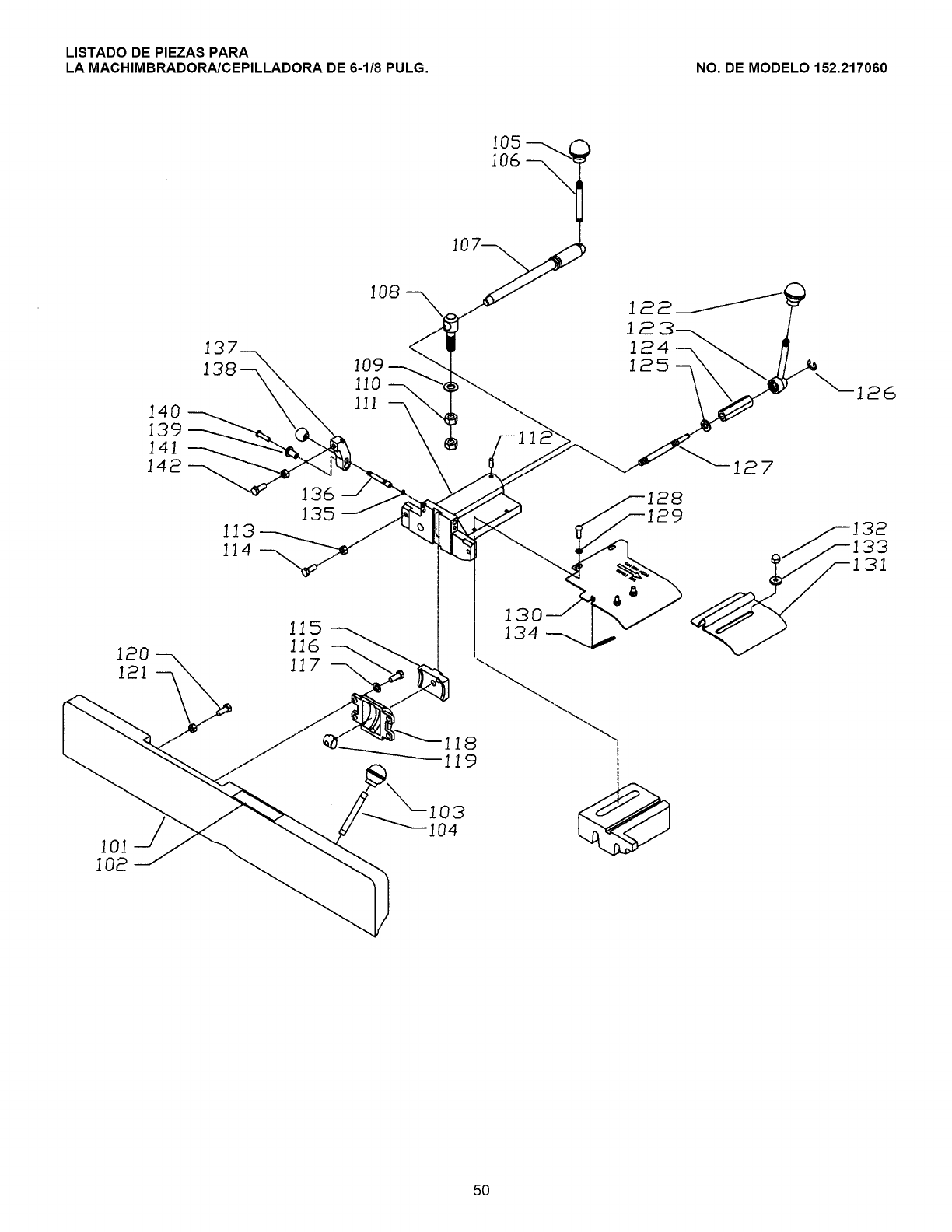
LISTADO DE PIEZAS PARA
LA MACHIMBRADORA/CEPILLADORA DE 6-1/8 PULG. NO. DE MODELO 152.217060
]08
I01
I02
13
138 109
110
140 ]ll --_
139
]41
142
136
135
115
116
5O
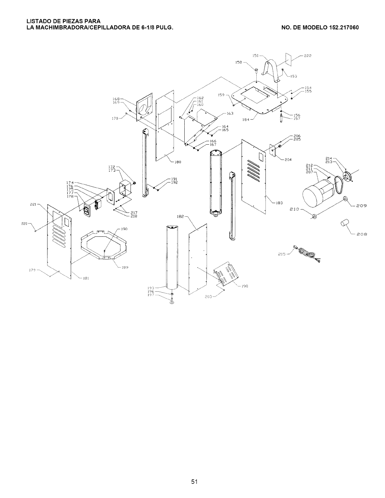
LISTADO DE PIEZAS PARA
LA MACHIMBRADORA/CEPILLADORA DE 6-1/8 PULG. NO. DE MODELO 152.217060
--162
176
175_
177--
178 -
I72
173 -
2!7
218
\\\
_189
180
182_
!84
164
165
51

Your Home
For repair - in your home - of all major brand appliances,
lawn and garden equipment, or heating and cooling systems,
no matter who made it, no matter who sold it!
For the replacement parts, accessories and
owner's manuals that you need to do-it-yourself.
For Sears professional installation of home appliances
and items like garage door openers and water heaters.
1-800-4-MY-HOME ®(1-800-469-4663)
Call anytime, day or night (U.S.A. and Canada)
www.sears.com www.sears.ca
Our Home
For repair of carry-in items like vacuums, lawn equipment,
and electronics, call or go on-line for the location of your nearest
Sears Parts & Repair Center.
1-800-488-1222
Call anytime, day or night (U.S.A. only)
www.sears.com
To purchase a protection agreement on a product serviced by Sears:
1-800-827-6655 (U.S.A.) 1-800-361-6665 (Canada)
Para pedir servicio de reparaci6n
a domicilio, y para ordenar piezas:
1-888-SU-HOGAR SM
(1-888-784-8427)
Au Canada pour service en fran£ais:
1-800-LE-FOYER Mo
(1-800-533-6937)
www.sears.ca
SEARS
TM SM
® Registered Trademark /' Trademark /' Service Mark of Sears, Roebuck and Co.
SM
® Marca Registrada/TM Marca de Fabrica /Marca de Servicio de Sears, Roebuck and Co.
MC MD
Marque de commerce /' Marque d6posee de Sears, Roebuck and Co. © Sears, Roebuck and Co.
