Craftsman 17125450 User Manual INDUSTRIAL DOVETAIL FIXTURE Manuals And Guides L0807067
CRAFTSMAN Router Accessory Manual L0807067 CRAFTSMAN Router Accessory Owner's Manual, CRAFTSMAN Router Accessory installation guides
User Manual: Craftsman 17125450 17125450 CRAFTSMAN INDUSTRIAL DOVETAIL FIXTURE - Manuals and Guides View the owners manual for your CRAFTSMAN INDUSTRIAL DOVETAIL FIXTURE #17125450. Home:Tool Parts:Craftsman Parts:Craftsman INDUSTRIAL DOVETAIL FIXTURE Manual
Open the PDF directly: View PDF ![]() .
.
Page Count: 48
Model No,
171.25450
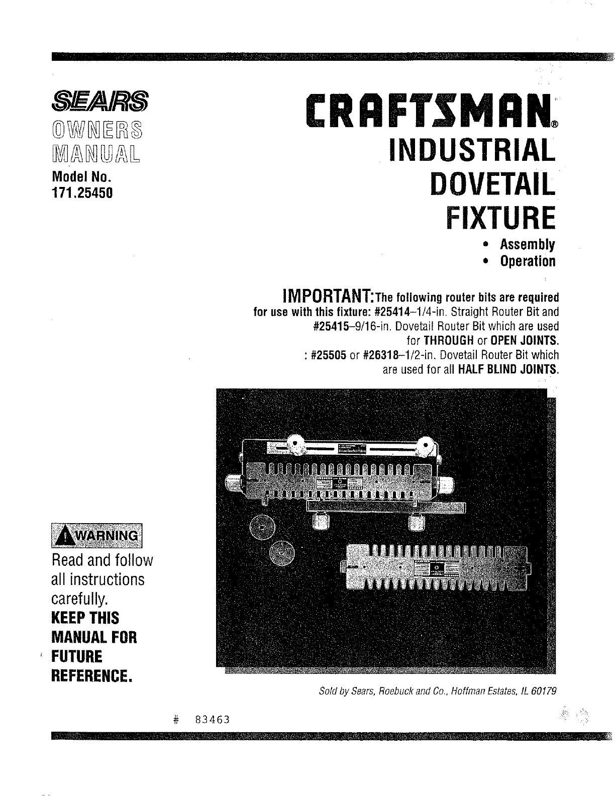
CRAFT$1VlAK
INDUSTRIAL
DOVETAIL
FIXTURE
• Assembly
• Operation
iMPORTANT;Thefollowingrouterbitsarerequired
for usewith this fixture:#25414-1/4-in. Straight Router Bit and
#25415-9/16-in. Dovetail Router Bit which are used
for THROUGHor OPENJOINTS.
: #25505 or #26318-1/2-in. DovetailRouterBit which
are usedfor a!l HALFBLINDJOINTS.
Readandfollow
all instructions
carefully.
KEEPTHIS
MANUALFOR
'FUTURE
REFERENCE,
Sold by Sears,Roebuck and Co,, Hoffman Estates,IL 60179
# 83463
, i i
FAILURETO HEEDALLSAFETYANDOPERATINGINSTRUCTIONS
ANDWARNINGSREGARDINGUSEOF THISPRODUCTCANRESULT
IN SERIOUSBODILYINJURY
1) KNOWYOURPOWERTOOL
Readtheowner'smanualcarefully.Learnitsapplicationsand
Iimitatlonsaswell asthe specificpotentialhazardsparticularto
thistool.
2) GROUNDALLTOOLS(UNLESSDOUBLEINSULATED)
Iftool is equippedwithanapproved3-conductorcordanda3-
pronggroundingtypeplug,it shouldbepluggedinto athreehole
electricalreceptaute.It adapteris usedto accommodateatwo-
prongreceptacle,the adapterwire mustbeattachedto known
ground,(usuallythescrewsecuringreceptaclecoverplate).
Neverremovethird prong.Neverconnectgreengroundwireto a
terminal.
3) KEEPGUARDSINPLACE
--in workingorder,andinproperadjustmentandalignment.
4) REMOVEADJUSTINGKEYSANDWRENCHES
Forma habitof checkingto seethatkeysandadjustingwrenches
areremovedfromtool beforeturningit on.
5) KEEPWORKAREACLEAN
Clutteredareasandbenchesinviteaccidents.Floormustnot be
slipperydoeto waxor sawdust.
6} AVOIDDANGEROUSENVIRONMENT
Donot usepowertoolsindamporwetlocationsorexposethornto
rain.KeepworkareawelIlighted.Provideadequatesurrounding
workspace.
7) KEEPCHILDRENAWAY
All visitorsshooktbekeptata safedistancefromworkarea.
B) MAKEWORKSHOPCHILD-PROOF
--with padlocks,masterswitches,or by removingstarterkeys.
9) DONOTFORCETOOL
It will dothejob betterandsaferatthe ratefor whichit was
designed.
10)USEAPPROPRIATETOOL
Donotforcetool or attachmentto doajob for whichitwasnot
designed.
11)WEARAPPROPRIATEAPPAREL
Donotwearlooseclothing,gloves,necktiesorjewelry(rings,
wristwatches)to getcaughtin movingparts.Nonslipfootwearis
recommended.Wearprotectivehaircoveringto containlonghair.
Rolllongsleevesel;Dyetheelbow.
12)USESAFETYGOGGLES(HeadProtection)
WearSafetyGoggles(mustcomptywith ANSIZ87.1) at alltimes.
Also,usefaceordustmaskif cuttingoperationis dusty,andear
protectors(plugsor muffs)duringextendedperiodsof operation.
13)SECUREWORK
Useclampsora viseto holdworkwhenpractical,it's saferthan
usingyour handandfreesbothhandsto operatetool.
14)DONOTOVERREACH
Keepproperfootingandbalanceat alltimes.
15)MAINTAINTOOLSWITHCARE
Keeptools sharpandc]eanfor bestandsafestperformance.Follow
instructionsfor lubricatingandchangingaccessories.
16)DISCONNECTTOOLSBEFORESERVICING
-when changingaccessoriessuchas blades,bits,cutters,etc.
17)AVOIDACCIDENTALSTARTING
Makesureswitchisin OFFpositionbeforepluggingin.
18)USERECOMMENDEDACCESSORIES
Consulttheowner'smanualfor recommendedaccessories.Follow
the instructionsthataccompanytheaccessories.Theuseof
improperaccessoriesmaycausehazards.
19)NEVERSTANDONTOOL
Seriousinjurycouldoccur;fthetool Istipped orthecuttingtool is
accidentallycontacted.0o notstorematerialsaboveor nearthe tool
thatwouldmakeit necessaryto standon thetoolto reachthem.
20)CHECKDAMAGEDPARTS
Beforefurtheruseof thetooI, aguardor otherpartthatis damaged
shouldbecarefullycheckedto ensurethatit will operateproperly
andperformitsintendedfunction.Checkfor alignmentof racy(rig
parts,bindingof movingparts,breakageof parts,mounting,andany
otherconditionsthat mayaffectits operation.Aguardorotherpart
thatisdamagedshouldbeproperlyrepairedorreplaced.
21)DIRECTIONOFFEED
Feedworkintoabladeor cutteronly againstthedirectionof rotation
of the bladeor cutter.
22)NEVERLEAVETOOLRUNNINGUNA'n'ENDED
Turnpoweroff. Do notleavetool until it comesto a completestop.
23)KEEPHANDSAWAYFROMCUT(1NGAREA
24)STOREIDLETOOLS
Whennot in use,toolsshouldbestoredindry,highor Iocked-up
place---outof reachof children.
25)O0HOTABUSECORD
Keepcordawayfrom heat,oil, andsharpedges.
28)OUTDOOREXTENSIONCORDS
Whentoo!is usedoutdoors,useonlyextensioncordssuitablefor
useoutdoors,andso marked.
27)NEVERUSEINANEXPLOSIVEATMOSPHERE
Normalsparkingof the motorcouldignitefumes,flarnmab;eliquids,
or combustibleitems.
28)DRUGS,ALCOHOL,MEDICATION
Do notoperatetool while underthe influenceof drags,alcohol,or
anymedication.
READANDUNDERSTANDTHISCOMPLETEINSTRUCTIONBOOK
BEFOREUSINGTHISPRODUCT
2
ADDITIONALSAFETYINSTRUCTIONSFORYOUR
INDUSTRIALDOVETAILFIXTURE
1) Alwaysweareyeprotectionthatcomplieswith currentANSI
StandardZ78A.
2) Noiselevelsvarywidely.Toavoidpossiblehearingdamage,wear
earpIugsor muffswhenusingthe DovetailFixturefor hoursata
time.
3) Wearadust maskalongwiththesafetygoggles.
4) Donot usethis DovetailFixturewith routerbitsor guide
bushingsotherthanthosespecifiedfor thecuts beingmade.
5) FollowtheinstructionsinyourRouterOwnersManual.
6) Vibrationscausedbytherouterduringusecancausefasteners
to becomeloose.Beforeuseandperiodicallyduringusecheckall
fastenersto makesurethattheyareagtightandsecure.
7) Donot usethis productuntil allassemblyinstallationstepshave
beencompleted,andyouhavereadandunderstandnit safetyand
operationalinstructionsinthis manual,andtheRouterOwners
ManuaL
8) Makesurethattherouterbit is properlypositionedin therouter
so thatit doesnot contactthe guidebushingorthetemplatewhen
cutting.
9) TheDovetailFixturemustbesecurelymountedto aworkbench
or otherstablesurfacewheninuse.Thefrontof the baseshould
overhangthe frontof theworkbenchbynomerethan1/4"to provide
clearancewhenclampingworkpiecesto theDovetailFixture.
10) Donot usethe DovetailFixtureas aworksurface.Doingso may
causedamageto theDovetailFixture,whichcancauseit to beunsafe
to use.Aworkbenchshouldbeusedfor thispurpose.
11)Thisproductis designedto cutflatworkpieces.Donotcutor
attempttocutworkpiecesthatarenotflat orthatareirregularly
shaped.
12)Thisproductis to beusedfor cuttingwoodworkpiecesonly.Do
not usethisproducttocutmetaloranyothernon-woadmaterial.
13)Thisproducthasbeendesignedto cutworkpieceshaving
thicknessesof 3/8"to 1".Donot usefor workpiecesof anyother
thicknesses.
14)Donotclampanyworkpiecesto the DovetailFixtureor makeany
adjustmentsto theDovetailFixtureunlessthe routerhasbeenturned
off, the routerbit is notturning,andthe Routerhasbeen
disconnectedfromtheelectricaloutlet.
15)Whensetting"lhe-dopth-ot-cut"of the routerbit,makesurethat
theworkplaceis clampedto the DovetailFixturein sucha.manner
thattherouterbitdoesnotcutinto the Dovetailbasecausing
damageto it orpassibleseriousinjurytoyou.
16) ALWAYSUNPLUGTHEROUTERFROMTHE
ELECTRICALOUTLETBEFOREINSTALLINGORREMOVINGROUTER
BITSFROMTHEROUTERANDWHENADJUSTINGTHECUTTING
DEPTHOFTHEROUTERBIT;ORWHENINSTALLINGORCHANGING
GUIDEBUSHINGS,
17)NEVERLiFTTHEROUTERUPWARDSWHENTHEROUTERiS
"ON",THEROUTERBITISROTATING,ANDTHEGUIDEBUSHINGiS
NEARORTOUCHINGTHETEMPLATE,BECAUSETHISWILLCAUSE
THEROUTERBITTOCUTINTOTHETEMPLATEANDDAMAGEIT.
INTRODUCTION
o Your Sears/Craftsmanindustrial Dovetail Fixture is an accessory used with your Routerto allow you to make drawers, chests, and the like
where dovetail joints are used to join the front, back,and sides of the workpiece.
TheDovetail Fixturewig allow you to make 1" spacedflush and flush offset and 318"rabbeted haif-bfind dovetail joints, in addition you can
make 1" spaced (or open) dovetail joints.
• Workplace widths up to 16" can beaccommodated.
Workplacethicknesses between318"and 1" can beaccommodated,
The Dovetail Basehas six pockets molded into its front which are gauges to aid you in setting the "depth-of-cut" for commonly used
depths: 3/8", 1/2", 5/8", 3/4'1,7/8", and 1".
The Dovetail Fixture comes with two templates andtwo guide bushings for making bait-blind and through or open joints.
Sears/Craftsman router bits, #25414 and#25415, WHICH MUST BE PURCHASEDSEPARATELY,are required to make the THROUGHor
OPENjoints.
Sears/Craftsman router bit, #25505 or #26318, WHICH MUST BE PURCHASEDSEPARATELY,is required for making the haIf-bIind joints.
• Eachtemplate has a label, describing the joint that can becut, along with set up information, the bit and guide bushing required, and the
stop block setting for a particular joint.
The Dovetail Fixture can be used with al! Sears/Craftsman Routers.
With a separately purchasedSears/Craftsman#25326, Universal Router Adapter,the DovetagFixture can be usedwith many non-
Craftsman Routers, such as, Black & Decker,Makita, and SkiL
UNPACKINGANDCHECKINGCONTENTS
in order to simplify handIingand to minimize any damagethat may occur during shipping, your Industrial Dovetail Fixtureis packaged
unassembled,
Separate all parts from the packing materials and check each onewith the igustrations and list of parts at the endof this manuaIto make
sure that ag parts are present before discarding any packaging material.
•If any parts are missing or cannot be accounted for, do not attempt to assemble,install, or usethe industrial Dovetail Fixture
until the missing parts havebeen obtained and the product has beenassembled correctly.
Contact your localSearsRetail Outletfor a repIacement product or for the missing parts.
3
ASSEMBLYINSTRUCTIONS
Thefollowingtoolsare requiredforassembly:
1) AmediumsizedPhillipsscrewdriver,
2) Asmallor mediumsizedadjustablewrench.
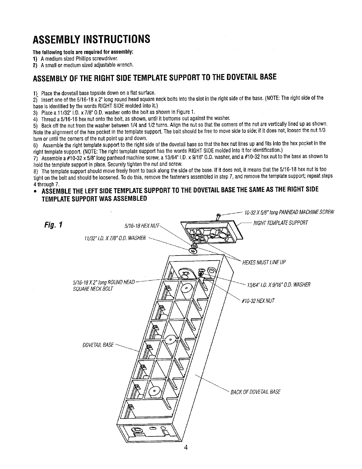
ASSEMBLYOFTHERIGHTSIDETEMPLATESUPPORTTOTHEDOVETAILBASE
1). Placethe dovetailbasetopsidedownonaflat surface.
2) insertoneof the5/16-18x 2" longroundheadsquareneckboltsinto thes!ot inthe rightsideof thebase.(NOTE:Therightsideof the
baseis identifiedbythewordsRIGHTSIDEmoldedinto it.)
3) Placea11/32"I.D_x 7/8"O.D.washerontothe bolt asshownin Figure1,
4) Threada5/16-18hexnut ontothe bolt,asshown,until it bottomsout againstthe washer,
5) Backoffthe nutfromthe washerbetween1/4 and1/2turns. Nigh the nut sothatthecornersof the nutareverticallYlineduPasshown.
Notethe alignmentof the hexpocketinthetemplatesupport.Thebolt shouldbefreeto movesideto side;if it doesnot, loosenthenut 1/3
turn or untilthe cornersof thenut pointupanddown.
8) Assembletheright templatesupportto theright side of thedovetailbaseso thatthe hexoutlinesupandf ts into thehexpocketinthe
right templatesupport,(NOTE:TherighttemplatesupporthasthewordsRIGHTSIDEmoldedinto it for identification.)
7) Assemblea #10-32x 5/8°tongpanheadmachinescrew,a 13/64"!.D.x 9/16"O.D.washer,anda#10"32hexnutt° thebaseassh°wn t°
holdthetemplatesupportin place.Securelytightenthe nut andscrew_
8) Thetemplatesupportshouldmovefreelyfrontto backalongthe sideof the base,If it doesnot,it meansthatthe 5/16-18hexnut is too
tight onthebolt andshouldbeloosened.Todo this, removethefastenersassembledinstepT,andremovethetemplatesupport;repeatsteps
4 through7.
•ASSEMBLE THE LEFT SIDE TEMPLATE SUPPORT TO THE DOVETAIL BASETHE SAME AS THE RIGHT SIDE
TEMPLATE SUPPORT WAS ASSEMBLED
Fig. 1
"/8"longPANHEADMACHINESCREW
11/32"LO.XT/8"O.D.WASHER
MUSTLINEUP
5/16-18X2"tongROUNDHEAD
SQUARENECKBOLT
?HEXNUT
_.D.WASHER
DOVETAILBASE
_BACKOFDOVETAILBASE
ASSEMBLYOFTHETOPCLAMPINGBARTOTHEDOVETAILBASE
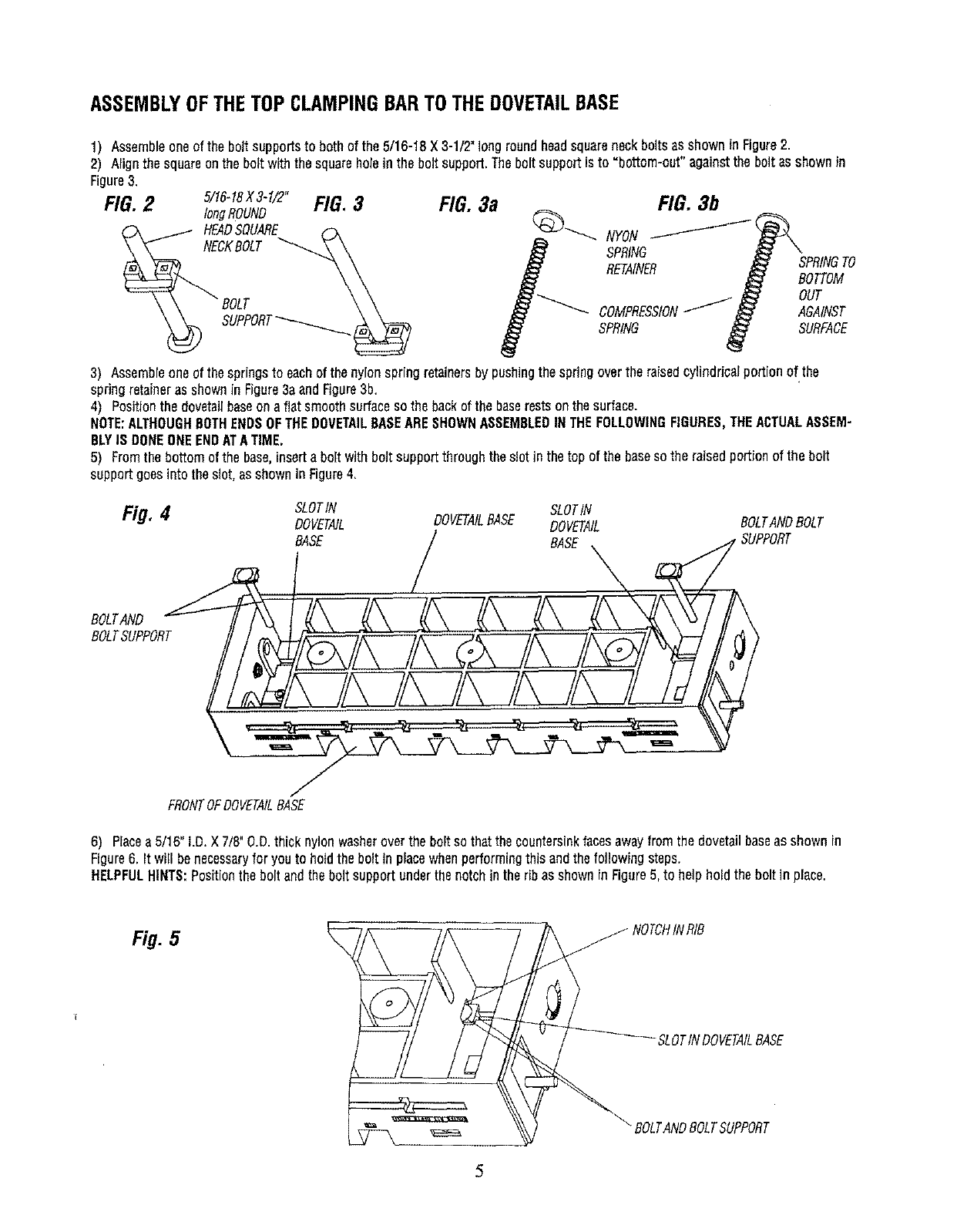
1) Assembleoneof the boltsupportsto bothof the 5/16-18X3-1/2"longroundheadsquareneckboltsas showninFigure2.
2) Alignthe squareonthe boltwiththe squareholein the boltsupport.Theboltsupportisto =bottom-out"againstthe bolt asshownin
Figure3.
FIG.2 5/16-18X3-1/2"FIG.3
longROUND
HEADSQUARE _-x
,o,, FIG. 3a
3) Assembleoneofthespringsto eachof thenylonspring retainersby pushingthespringoverthe raisedcylindricalportionof the
springretaineras shownin Figure3aandFigure3b,
4) Positionthe dovetailbaseonafiat smoothsurfaceso the backof the baserestsonthesurface.
NOTE:ALTHOUGHBOTHENDSOFTHEDOVETAILBASEARESHOWNASSEMBLEDINTHEFOLLOWINGFIGURES,THEACTUALASSEM-
BLYIS DONEONEENDATATIME.
5) Fromthe bottomof the base,inserta boltwithbolt supportthroughtheslotin the top of the basesothe raisedportionof the bolt
supportgoesinto theslot, asshownin Figure4,
Fig, 4SLOTIN SLOTIN
DOVETAIL DOVETAILEASE DOVETAIL BOLTANDBOLT
EASE / BASE
BOLTAND
BOLTSUPPORT
FRONTOFDOVETAILBASE
6) Placea5/16" I.D.X 7/8"O.D.thick nylonwasheroverthe boltso thatthecountersinkfacesawayfromthe dovetailbaseas shownin
Figure6. It will benecessaryfor youto holdthe bolt in placewhenperformingthis andthe followingsteps.
HELPFULHINTS:Positionthe bolt andthe boltsupportunderthe notchin the ribas shownin Figure5, to helpholdthebolt in place,
Fig. 5_NOTCHINRIB
SLOTINDOVETAILBASE
BOLTANDBOLTSUPPORT
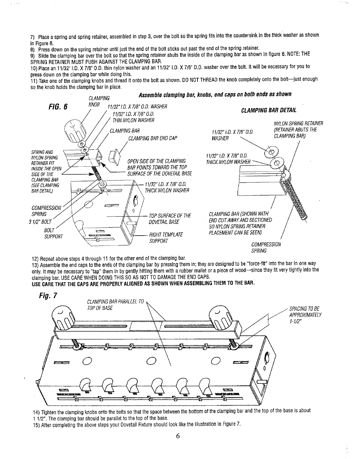
7) Placeaspringandspringretainer,assembledinstep3, overthe bolt sothespringfits intothe countersinkin thethick washerasshown
In Figure6.
8) Pressdownonthespringretaineruntiljustthe endof the bolt sticksout pastthe endof the springretainer.
9) Slidethe clampingbaroverthe bolt sothatthe springretainerabutstheinsideof theclampingbarasshownin figure6. NOTE:THE
SPRINGRETAINERMUSTPUSHAGAINSTTHECLAMPNGBAR.
10)Placean11/32"I.D.X 7/8"O.D.thin nylonwasherandan 11/3Z I.D.X7/8" O.D.washerover the bolt.It will benecessaryfor youto
pressdownonthe dampingbarwhiledoingthis.
11)Takeoneofthe clampingknobsandthreadit ontothe bolt asshown.DONOTTHREADthe knobcompletelyontothe bolt--just enough
sothe knobholdsthe clampingbarin place.
SPRINGAND
NYLONSPRING
RETAINERFIT
INSIDETHEOPEN
SIDEOFTHE
CLAMPINGBAR
(SEECLAMPING
BARDETAIL) \
CLAMPING Assembleclampingbar, knobs,endcaps on bothends asshown
t f/32"LD.X 7/B"O.D.WASHER
11/32"LD.X T/8"O.D.
THINNYLONWASHER
SPRING
31/2"BOLT
BOLl
SUPPORT
FIG. 6 KNOB
CLAMPINGBAR
CLAMPINGBARENDCAP
OPENSIDEOFTHECLAMPING
BARPOINTSTOWARDTHETOP
SURFACEOFTHEDOVETAILBASE
11/32"LD.X 7/8"O,D.
t THICKNYLONWASHER
/ TOPSURFACEOFTHE
DOVETAILBASE
-- RIGHTTEMPLATE
SUPPORT
CLAMPINGBARDETAIL
NYLONSPRINGRETAINER
11/32"LD.X7/8"O.D. (RETAINERABUTSTHE
WASHER LAMPING SAR)
/
CLAMPINGBAR(SHOWNWITH /
ENDCUTAWAYANDSECT!ONED /
SONYLONSPRINGRETAINER /
PLACEMENTCANBESEEN) /
COMPRESSION
SPRING
12)Repeatabovesteps4through11for theotherendof the clampingbar.
13)Assembletheendcapsto the endsof the clampingbarby pressingthemin; theyaredesignedto be"force-fit"intothe barin oneway
only.It maybenecessaryto "tap"themin by gentlyhittingthemwitha rubbermatletora pieceof wood--since theyfit verytightly intothe
clampingbar,USECARE WHEN DOINGTHISSO AS NOT TO DAMAGE THEEND CAPS,
USECARETHATTHE CAPSAREPROPERLYALIGNEDAS SHOWN WHEN ASSEMBLINGTHEM TO THEBAR.
fig.7CLAMPINGBARPARALLELTO
TOPOFBASE JSPACINGTOBE
APPROXIMATELY
1-1/2"
0 0 0
14)Tightenthe clampingknobsontothe boltssothatthespacebetweenthebottomof theclampingbarandthetop of the baseis about
1 1/2".Theciampingbar shouldbeparalletto the top of the base.
15)Aftercompletingthe abovestepsyour DovetailFixtureshouldlooklikethe illustrationin Figure7.
6
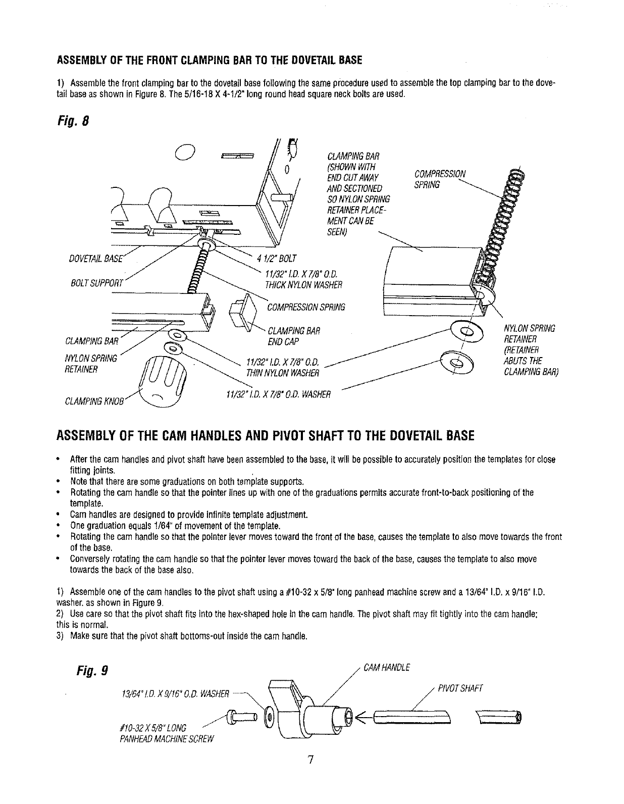
ASSEMBLYOFTHEFRONTCLAMPINGBARTOTHEDOVETAILBASE
1) Assemblethe front clampingbarto the dovetailbasefollowingthesameprocedureusedto assemblethetop clampingbartothe dove-
tail baseas shownin Figure8. The5/16-18X4-1/2"longroundheadsquareneckboltsareused,
Fig. 8
BOLT
0
4 I/2" BOLT / ""
11/32"1.D.X7/8"O.D,
THICKNYLONWASHER
COMPRESSIONSPRING
CLAMPINGBAR
ENDCAP
1!/32"LD.X7/B"O.D,
RETAINER THINNYLONWASHER
CLAMPINGBAR
(SHOWNWITH
ENDCUTAWAY
ANDSECTIONED
SONYLONSPRING
RETAINERPLACE-
MENTCANBE
SEEN)
COMPRESSION
SPRING
NYLONSPRING
RETAINER
(RETAINER
ABUTSTHE
CLAMPINGBAR)
11/32"I.D.X 7/8"O.D.WASHER
ASSEMBLYOFTHECAMHANDLESAND PIVOTSHAFTTOTHEDOVETAILBASE
Afterthe camhandlesandpivotshafthavebeenassembledto thebase,it will bepossibleto accuratelypositionthetemplatesfor close
fitting joints,
Notethattherearesomegraduationsonbothtemplatesupports.
•Rotatingthe camhandlesothat thepointerlinesup withoneof thegraduationspermitsaccuratefront-to-backpositioningof the
template.
• Camhandlesaredesignedto provideinfinitetemplateadjustment.
Onegraduationequals1/64"of movementof thetemplate.
• Rotatingthe camhandlesothat thepointerlevermovestowardthe frontof thebase.causesthetemplateto alsomovetowardsthefront
of the base.
• Converselyrotatingthecamhandlesothatthepointerlevermovestowardthe backof the base,causesthetemplateto alsomove
towardsthe backof the basealso.
1) Assembleoneof the camhandlesto the pivotshaftusinga #10-32x5/8"longpanheadmachinescrewanda 13/64"I.D.x 9/16" LD.
washer,asshownin Figure9,
2) Usecareso thatthe pivotshaftfits intothe hex-shapedholein thecamhandle.Thepivotshaftmayfit tightly intothe camhandle;
this is normal.
3) Makesurethatthepivotshaftbottoms*outinsidethe camhandle.
Fig. 9/ CAMHANDLE
13/64"t.D.X9/16°0.O,WASHER--_,,,,_ _ PIVOTSHAFT
7
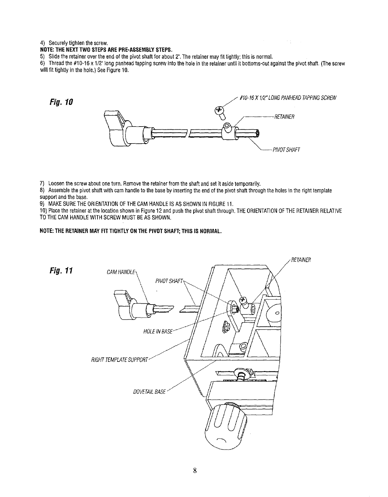
4) Securelytightenthe screw,
NOTE:THENEXTTWOSTEPSAREPRE-ASSEMBLYSTEPS.
5) Sgdetheretainerovertheendof thepivotshaftfor about2".Theretainermayfit tightly;thisis normal
6) Threadthe#1_`16x1/2"_ngpanheadtappingscrewint_theh_eintheretainerunti_itbott_ms-_tagain_tthepiv_tsha_.(Thescrew
will fit tightlyin the hole.)SeeFigure10.
Fig. 10 _#!0-16X 1/2"LONGPANHEADTAPPINGSCREW
7) Loosenthescrewaboutoneturn.Removethe retainerfromthe shaftandsetit asidetemporarily.
8) Assemblethe pivotshaftwith camhandleto the basebyinsertingtheendof thepivotshaftthroughthe holestnthe righttemplate
supportandthebase.
9) MAKESURETHEORIENTATIONOFTHECAMHANDLEISASSHOWNINFIGURE11.
10)Placethe retainerat thelocationshowninFigure12endpushthe pivotshaftthrough.THEORIENTATIONOFTHERETAINERRELAT]VE
TOTHECAMHANDLEWITHSCREWMUSTBEASSHOWN.
NOTE:THERETAINERMAYFITTIGHTLYONTHEPIVOTSHAFT;THISIS NORMAL.
Fig. 11
DOVETAILBASE
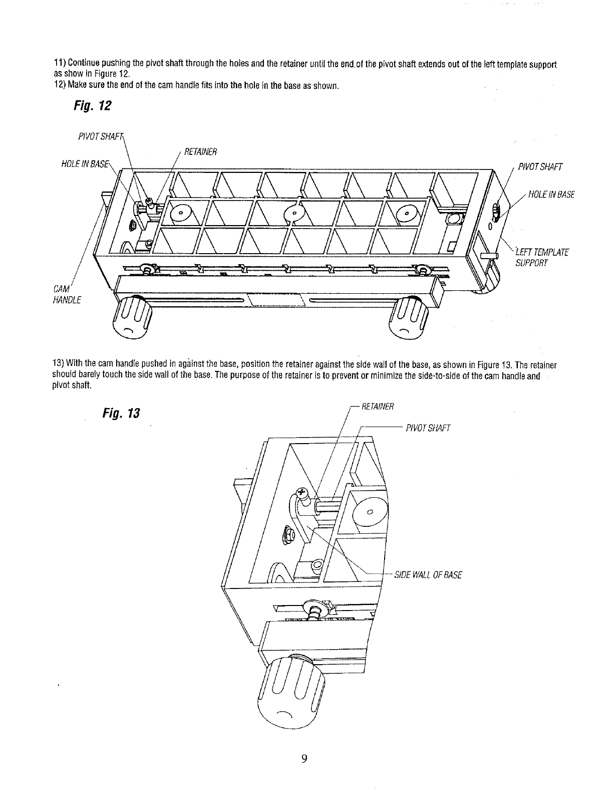
11)Continuepushingthepivotshaftthroughthe holesandtheretaineruntilthe endof the pivotshaftextendsout ofthe lefttemplatesupport
asshowin Figure12.
12)Makesurethe endof thecamhandlefits intothe holein thebaseasshown,
Fig. 12
PIVOT,
HOLEINBASE, PtVOTSHAFT
SUPPORT
CAM
HANDLE _"
13)Withthe camhandlepushedin againstthe base,positionthe retaineragainstthesidewallof the base,asshownin Figure13.Theretainer
shouldbarelytouchthesidewall ofthe base.Thepurposeof the retaineris to preventor minimizethe side-to-sideof thecamhandleand
pivotshaft.
Fig. 13
RVOTSHAFT
-SIDEWALLOFBASE
9
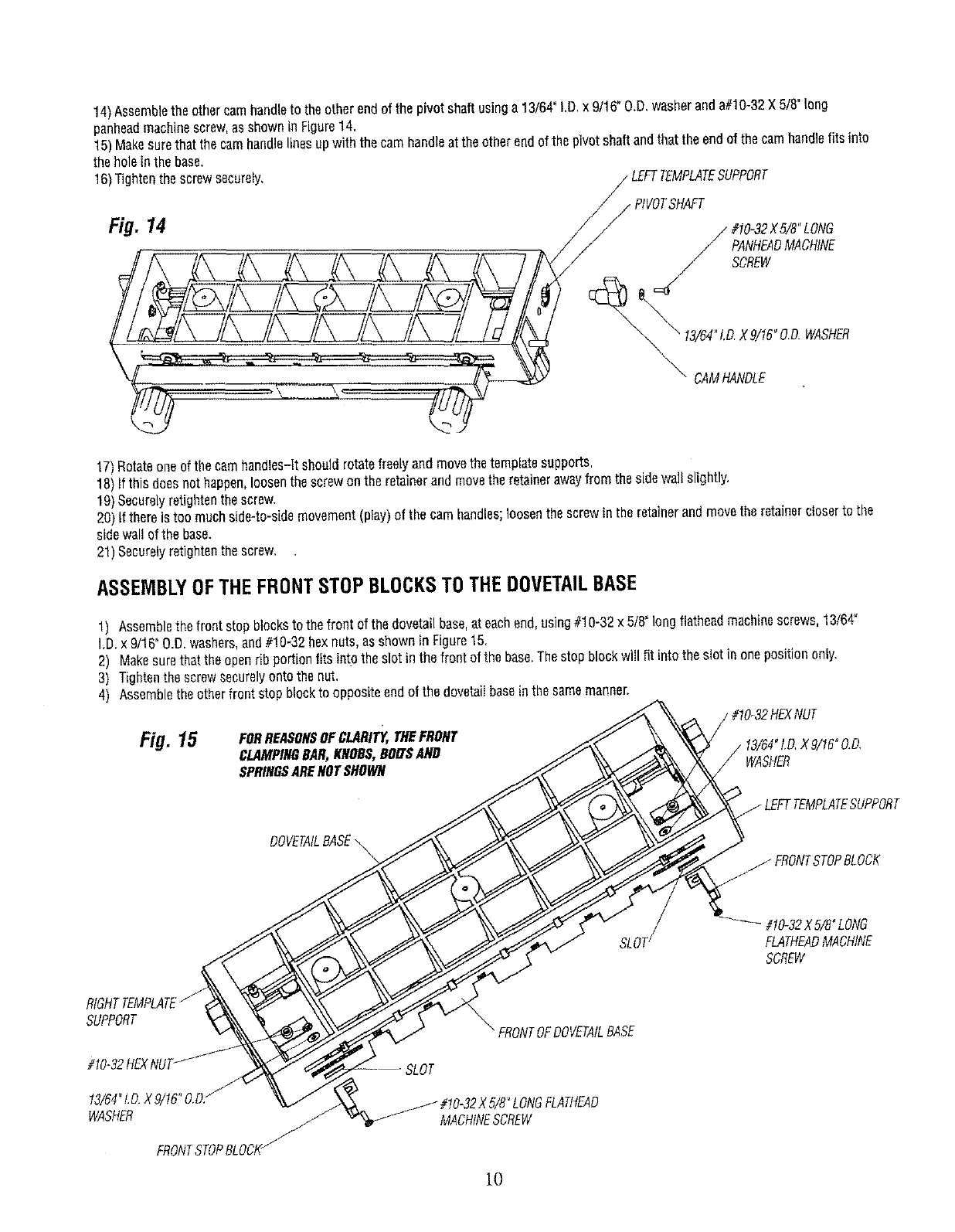
14)Assemblethe othercamhandleto theotherendof the pivotshaftusinga 13/64"I,D.x 9/16"O.D,washeranda#10-32X 5/8"long
penheadmachinescrew,asshownin Figure14.
15)Makesurethatthecamhandlelinesupwiththe camhandleat theotherendofthe pivotshaftandthat theendofthe camhandlefits into
the holein thebase.
16)Tightenthe screwsecurely, LEFTTEMPLATESUPPORT
Fig. 14 /_ #10-32X5/8"LONG
PANHEADMACHINE
SCREW
_" DAMHANDLE
17)Rotateoneof thecamhandtes-ltshoutdrotatefreelyand movethetemplatesupports,
18)Ifthis doesnot happen,loosenthescrewon the retainerandmovetheretainerawayfrom thesidewall slightly,
19)Securelyretightenthescrew.
20)If thereis too muchside-to-sidemovement(play)of the camhandles;loosenthescrewin theretainerandmovetheretainerc/oserto the
sidewaltof the base.
21)Securelyretightenthescrew,
ASSEMBLYOFTHEFRONTSTOPBLOCKSTOTHEDOVETAILBASE
1) Aseemblethe frontstopblockstothefront of thedovetailbase,at eachend,using#10-32x 5/8"longflatheadmachinescrews,13/64_
I.D.x 9/16"O.D.washers,and#!0-32 hexnuts,as shownin Figure15.
2) Makesurethattheopenrib portionfits intothe slotin the frontof the base.Thestopblockwglfit intothe slotin onepositiononly,
3) Tightenthe screwsecurelyontothenut.
4) Assembletheotherfrontstopblockto oppositeendo1the dovetagbaseinthe samemanner.
Fig. 15 FORREASONSOFCLARITY,THEFRONT
CLAMPINGBAR,KNOBS,BOLTSAND
SPRINGSARENOTSHOWN WASHER
DOVETAILBASE\
SLOT_#10_32XB/8OLONG
FLATHEADMACHINE
SCREW
SUPPORT
#10-32HEX
13/64_LD.X9/16°O.D/
WASHER J
FRONTSTOPBLOCI_
_FRONTOFDOVETAtLBASE
5/8"LONGFLATHEAD
MACHINESCREW
10
ASSEMBLYOFTHETOPSTOPBLOCKSTOTHEDOVETAILBASE
•Thetop stopblocksareassembledto thetop of thedovetailbasein oneof twowaysdependinguponwhichstyleof dovetailjoint is
to becut:
a) HALF-BLINDFLUSHJOINTS--The"A" onthestopblockfacestowardthe "middleof the base".
b) HALF-BUNDRABBETJOINTS_The"B"onthestopblockfacestowardthe"middleof the base".
c) THROUGHJOINTS--The"A" onthestopblockfacestowardthe"middleof the base".
• Sincetheflushjoint is themorecommonlyusedjoint,thefollowinginstructionsapplyto theassemblyof the stopblocksfor this
stylejoint.
1) Positionthedovetailfixturerightsideuponaflat surface.
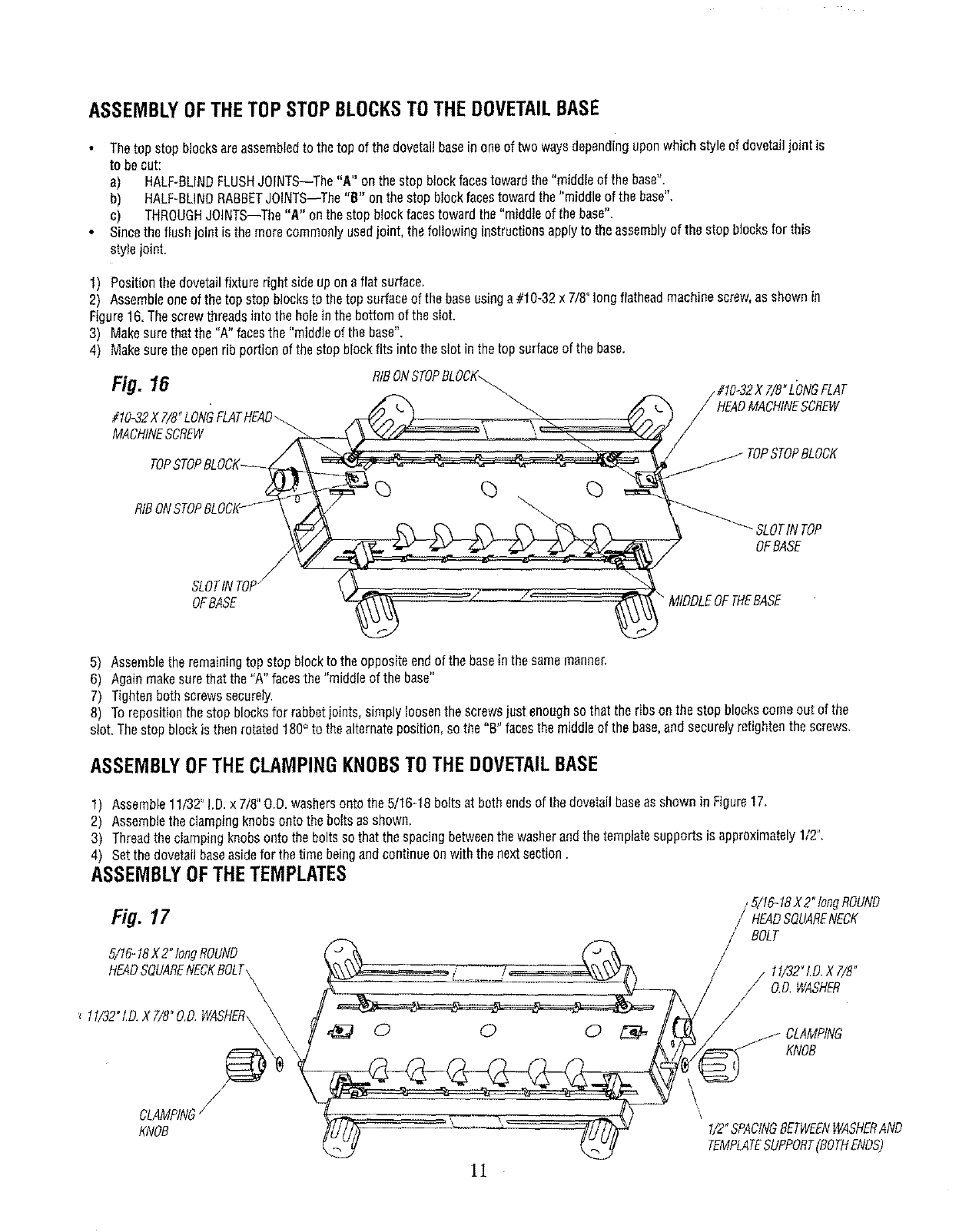
2) Assembleoneof thetop stopblocksto thetop surfaceof the baseusinga#10-32x 7/8"longflatheadmachinescrew,as shownin
Figure16.Thescrewthreadsintothe holeinthe bottomof thesIot.
3) Makesurethatthe "A" facesthe "middleof the base".
4) Makesuretheopenribportionof the stopblockfits intotheslot in thetop surfaceof thebase.
Fig. 16 RfBONSTOPBLOCK_
#10_32X 7/8_LONG \
MACHINESCREW
#t0-32X7/8"L'ONGFLAT
HEADMACHINESCREW
TOPSTOPBLOCK
SLOTINTOP/
OFBASE
SLOTIN TOP
OFBASE
MIDDLEOFTHEBASE
5) Assembletheremainingtopstopblockto the oppositeendofthe baseinthesamemanner.
6) Againmakesurethatthe "A" facesthe"middleof the base"
7) Tightenbothscrewssecurely.
8) Torepositionthestopblocksfor rabbetjoints,simplyloosenthescrewsjustenoughso thatthe ribsonthe stopblockscomeout of the
slot,Thestopblockisthenrotated180° to thealternateposition,sothe "B"facesthe middleof thebase,andsecurelyretightenthe screws.
ASSEMBLYOFTHECLAMPINGKNOBSTOTHEDOVETAILBASE
1) Assemb_e1_/32"_D.x 7/8"____was_ers_ntot_e_/1_-18b_itsat b_thends_f t_ed__etai__aseassh__n in Figure17_
2) Assemblethe clampingknobsontothe boItsasshown.
3) Threadtheclampingknobsontothe boltsso thatthespacingbetweenthewasherandthetemplatesupportsis approximately1/2".
4) Setthe dovetailbaseasidefor thetime beingandcontinueon withthe nextsection.
ASSEMBLYOFTHETEMPLATES
/ 5/16-18X2" longROUND
Fig. 17 / HEADSQUARENECK
BOLT
5/t6-t8 X2°tongROUND
HEADSQUARENECKBOLT\
\11/32"I.D.XT/8"
// O.D,WASHER
KNOB
CLAMPING/
KNOB
11
!/2"SPACING8ETWEFNWASHERAND
TEMPLATESUPPORT(BOTHENOS)
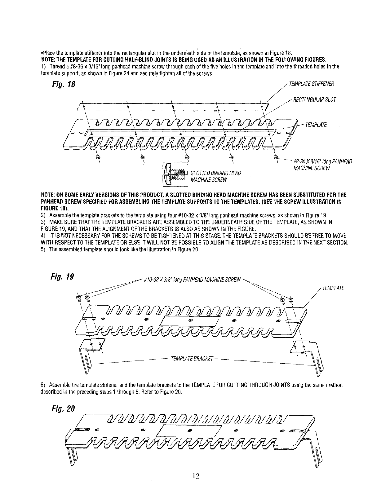
•Placethetemplatestiffenerinto therectangularslotin the underneathsideof thetemplate,asshowninFigure18.
NOTE:THETEMPLATEFORCUTTINGHALF-BLINDJOINTSISBEINGUSEDASANILLUSTRATIONINTHEFOLLOWIHGFIGURES.
1) Threada #8-36x 3/16"longpanheadmachinescrewthrougheachof the fiveholesinthetemplateandinto thethreadedholesin the
templatesupport,asshowninFigure24andsecurelytightenallof thescrews.
Fig. 18 _TEMPLATESTIFFENER
\ _ _ _ J jRECTANGULARSLOT
TEMPLATE
_ _ MACHINESCREwSLOTTEDBINDINGHEAD_ _MA#&3gX3!!6"t°ngPANHEADcHINESCREW
NOTE:ONSOMEEARLYVERSIONSOFTHISPRODUCT,A SLOTTEDBINDINGHEADMACHINESCREWHASBEENSUBSTITUTEDFORTHE
PANHEADSCREWSPECIFIEDFORASSEMBLINGTHETEMPLATESUPPORTSTOTHETEMPLATES.(SEETHESCREWILLUSTRATIONIN
FIGURE18),
2) Assemblethetemplatebracketsto thetemplateusingfour #10-32x 3/8°longpanheadmachinescrews_as shownin Figure19.
3) MAKESURETHATTHETEMPLATEBRACKETSAREASSEMBLEDTOTHEUNDERNEATHSIDEOFTHETEMPLATE,ASSHOWNIN
FIGURE19,ANDTHATTHEAL]GNMENTOFTHEBRACKETSIS ALSOASSHOWNINTHEFIGURE.
4) ITIS NOTNECESSARYFORTHESCREWSTOBETIGHTENEDATTHISSTAGE;THETEMPLATEBRACKETSSHOULDBEFREETOMOVE
WITHRESPECTTOTHETEMPLATEORELSEITWILLNOTBEPOSSIBLETOALIGNTHETEMPLATEASDESCRIBEDINTHENEXTSECTION.
5) Theassembledtemplateshouldlookliketheillustrationin Figure20.
Fig. 19 #10-32X3/8"tongPANHEADMACHINESCREW
TEMPLATE
'\
_- TEMPLATEBRACKET....
6) Assemblethetemplatestiffenerandthetemplatebracketsto the TEMPLATEFORCUTTINGTHROUGHJOINTSusingthesamemethod
describedinthe precedingsteps1through5, Referto Figure20.
Fig. 20
lg
ALIGNMENTOFTHETEMPLATES
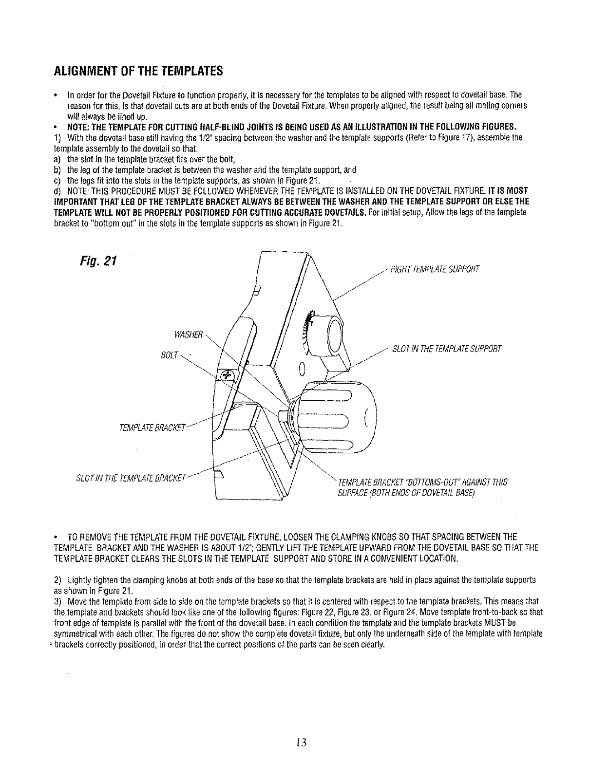
In orderfor the DovetailFixtureto functionproperly,it is necessaryfor thetemplatesto bealignedwithrespectto dovetailbase.The
reasonfor this, isthatdovetailcutsareat both endsof the DovetailFixture.Whenproperlyaligned,the resultbeingall matingcorners
will alwaysbelinedup.
NOTE:THETEMPLATEFORCUTTINGHALF-BLINDJOINTSIS BEINGUSEDASANILLUSTRATIONINTHEFOLLOWINGFIGURES,
1) Withthe dovetailbasesti!l havingthe 1/2"spacingbetweenthewasherandthetemplatesupports(Referto Figure17),assemblethe
templateassemblyto thedovetailso that:
a) theslotin the templatebracketfits overthebolt,
b) thelegof the templatebracketis betweenthe washerandthetemplatesupport,and
c) thelegsfit intothe slotsinthetemplatesupports,asshownin Figure21.
d) NOTE:THISPROCEDUREMUSTBEFOLLOWEDWHENEVERTHETEMPLATEISINSTALLEDONTHEDOVETAILFIXTURE.ITISMOST
IMPORTANTTHATLEGOFTHETEMPLATEBRACKETALWAYSBEBETWEENTHEWASHERANDTHETEMPLATESUPPORTORELSETHE
TEMPLATEWILLNOTBEPROPERLYPOSITIONEDFORCUTTINGACCURATEDOVETAILS.Forinitialsetup,Allowthelegsofthe template
bracketto "bottomout" inthe slotsinthe tempiatesupportsasshownin Figure21.
Fig. 21
WASHER
BOLT_
TEMPLATEBRACKET
SLOTIN THETEMPLATEBRACKET
_RtGHTTEMPLATESUPPORT
jSLOTINTHETEMPLATESUPPORT
0
"_TEMPLATEBRACKET"BOTTOMS-OUT"AGAINSTTHIS
SURFACE(BOTHENDSOFDOVETAILBASE)
TOREMOVETHETEMPLATEFROMTHEDOVETAILFIXTURE,LOOSENTHECLAMPINGKNOBSSOTHATSPACINGBETWEENTHE
TEMPLATEBRACKETANDTHEWASHERISABOUT1/2";GENTLYLiFTTHETEMPLATEUPWARDFROMTHEDOVETAILBASESOTHATTHE
TEMPLATEBRACKETCLEARSTHESLOTSINTHETEMPLATESUPPORTANDSTOREINACONVENIENTLOCATION,
2) LightIytightentheclampingknobsat bothendsof the baseso thatthetemplatebracketsareheldin placeagainstthetemplatesupports
asshowninFigure21.
3) Movethetemplatefrom sideto sideonthe templatebracketsso thatit is centeredwith respectto the templatebrackets,Thismeansthat
thetemplateandbracketsshouldlookIikeoneof the followingfigures:Figure22,Figure23,or Figure24,Movetemplatefront-to-backsothat
front edgeof templateis parallelwith thefrontof the dovetailbase.In eachconditionthetemplateandthetemplatebracketsMUSTbe
symmetricalwith eachother.Thefiguresdonot showthe completedovetailfixture,butonlytheunderneathsideof thetemplatewithtemplate
bracketscorrectlypositioned,in orderthatthecorrectpositionsof the partscanbeseenclearly.
]3
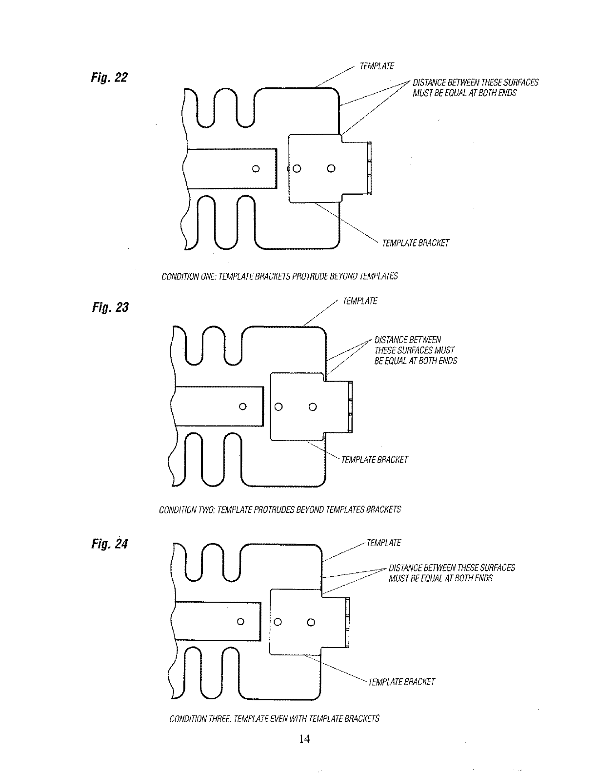
Fig. 22
I
TEMPLATE
_"DISTANCEBETWEENTHESESURFACES
MUSTBEEQUALATBOTHENDS
TEMPLATEBRACKET
CONDITIONONE."TEMPLATEBRACKETSPROTRUDEBEYONDTEMPLATES
Fig. 23
o
jTEMPLATE
J
F
THESESURFACESMUST
BEEQUALATBOTHENDS
_0 0 TEMPLATEBRACKET
CONDITIONTWO;TEMPLATEPROTRUDESBEYONDTEMPLATESBRACKETS
.24
o00
MUSTBEEQUALATBOTHENDS
TEMPLATEBRACKET
CONDITIONTHREE.TEMPLATEEVENWITHTEMPLATEBRACKETS
14
4) Afterthetemplatebracketshavebeencorrectlypositionedonthetemplatesecurelytightenthefourscrewsholdingthetemptatebrackets
to thetemplate.
5) Removethetemplateassemblyfromthe baseandsetit asidefor now.
6) Aligntheothertemplateassemblyin thesamemanner,
ITSHOULDBENOTEDTHATYOUMAYFIND,THATAFTERMAKINGSOMESAMPLECUTS,SLIGHTADJUSTMENTSMAYBEREQUIRED.
HOWTOMAKETHESEADJUSTMENTSIS EXPLAINEDINTWOOFTHEFOLLOWINGSECTIONS:"MAKINGADJUSTMENTSFORHALFBLIND
JOINTS"or "MAKINGADJUSTMENTSFOROPEN(THROUGH)JOINTS".
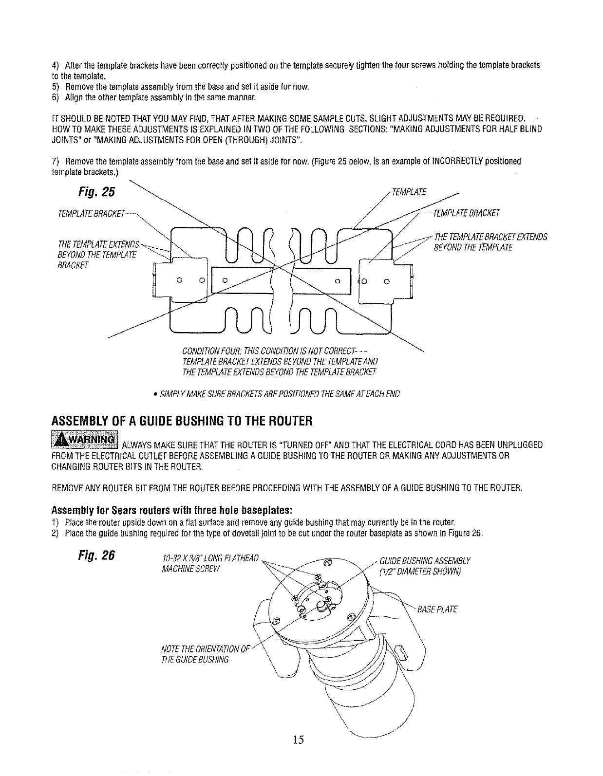
7) Removethetemplateassemblyfromthe baseandsetit asidefor now.(Figure25 below,is anexampleof INCORRECTLYpositioned
templatebrackets,)
CKET
BEYONDTHETEMPLATE
BRACKET
0o!o 0
THETEMPLATEBRACKETEXTENDS
tEMPLATE
CONDITIONFOUR:THISCONDITIONISNOTCORRECT---
TEMPLATEBRACKETEXTENDSBEYONDTHETEMPLATEAND
THETEMPLATEEXTENDSBEYONDTHETEMPLATEBRACKET
• StMPLYMAKESUREBRACKETSAREPOSITIONEDTHESAMEATEACHEND
ASSEMBLYOFA GUIDEBUSHINGTOTHEROUTER
ALWAYSMAKESURETHATTHEROUTERIS "TURNEDOFF"ANDTHATTHEELECTRICALCORDHASBEENUNPLUGGED
FROMTHEELECTRICALOUTLETBEFOREASSEMBLINGAGUIDEBUSHINGTOTHEROUTERORMAKINGANYADJUSTMENTSOR
CHANGINGROUTERBITSINTHEROUTER.
REMOVEANYROUTERBITFROMTHEROUTERBEFOREPROCEEDINGWITHTHEASSEMBLYOFA GUIDEBUSHINGTOTHEROUTER.
Assembly for Sears routers with three hole baseplates:
1) Placethe'router upsidedawnonaflat surfaceandremoveanyguidebushingthatmaycurrentlybein the router,
2) Placethe guidebushingrequiredforthetypeof dovetagjoint to becutundertherouterbaseplateasshownin Figure26.
Fig. 26 10-32X 3/8°LONGFLATHEAD
MACHINESCREW (1/2"DIAMETERSHOWN)
NOTETHEORIENTATIONOF"
THEGUIDEBUSHING

3) MAKESURETHATTHEORIENTATIONOFTHEGUIDEBUSHINGIS ASSHOWN,
4) Positiontheguidebushingsothatthethreethreadedholesinthe guidebushinglineupwiththe countersunkholesinthe baseplate.
5) Threada#10-32x 3/8"longflatheadmachinescrewinte eachonthe holes.
6) SecureIytightenthescrews.
Assemblyfor Soars 1/2" Shank Industrial Routers Modal Nos. 27504, 27505 and 27506 or equivalent:
1) Placethe routerupsideonaflatsurfaceandremoveanyguidebushingthat maycurrentlybeinthe router.
2) Placethe guidebushinginthe recessedportionof the routerbaseasshownin Figure27.
3) Alignthe cutoutsintheguidebushingwiththe threadedhoIesinthe base.
4) Threadthetwo roundheadscrews,thatcamewiththe router,intothetwo threadedholesinthe base.
5) Tightenthescrewssecurdy.
B) FORADDITIONALINFORMATIONCONCERNINGTHISMATTER,CONSULTYOURROUTEROWNERSMANUAL.
MAKESURETHATTHEROUTER
BITISALIGNEDWITHORCENTEREDIN THEHOLE
INTHEGUIDEBUSHING.TODOTHIS,LOOSEN
SCREWSHOLDINGBASEPLATEORADAPTER
PLATETOROUTER,CENTERGUIDEBUSHINGHOLE
WITHRESPECTTOROUTERBITANDRETIGHTEN
SCREWSSECURELY
Fig, 27 _ - ROUTERBIT
I i I
',,@,
I I
TEMPLATEGUIDE--
ROUTERBA_
Assembly for other brands of routers:
INORDERTOUSETHEDOVETAILFIXTUREWiTHOTHERBRANDSOFROUTERS,ITWILLBENECESSARYFORYOUTOPURCHASEA
CRAFTSMANUNIVERSALROUTERADAPTERPLATE,MODELNO.25326,FROMSEARS,ANDREPLACETHEBASEPLATEONYOURROUTER
WITHTHEADAPTERPLATE.
1) Placethe routerupsideon aflatsurfaceandremoveanyguidebushingthatmaycurrentlybeinthe router,
2) Placetheguidebushingrequiredfor thetypeof dovetailjointto becutundertherouterbaseplateas showninFigure2&
3) MAKESURETHATTHEORIENTATIONOFTHEGUIDEBUSHINGIS ASSHOWN,
Fig. 28
NOTETHEORIENTATIONOF
THEGUIDEBUSHING
MACHINESCREW
(t/2" DIAMETERSIlOWN)
MAKESURETHATTHEROUTER
BITtSALIGNEDWITHORCENTEREDINTHEHOLE
IN THEGUIDEBUSHING.TODOTHIS,LOOSEN
SCREWSHOLDINGBASEPLATEORADAPTER
PLATETOROUTER,CENTERGUIDEBUSHING
HOLEWITHRESPECTTOROUTERBITAND
RETIGHTENSCREWSSECURELY
16
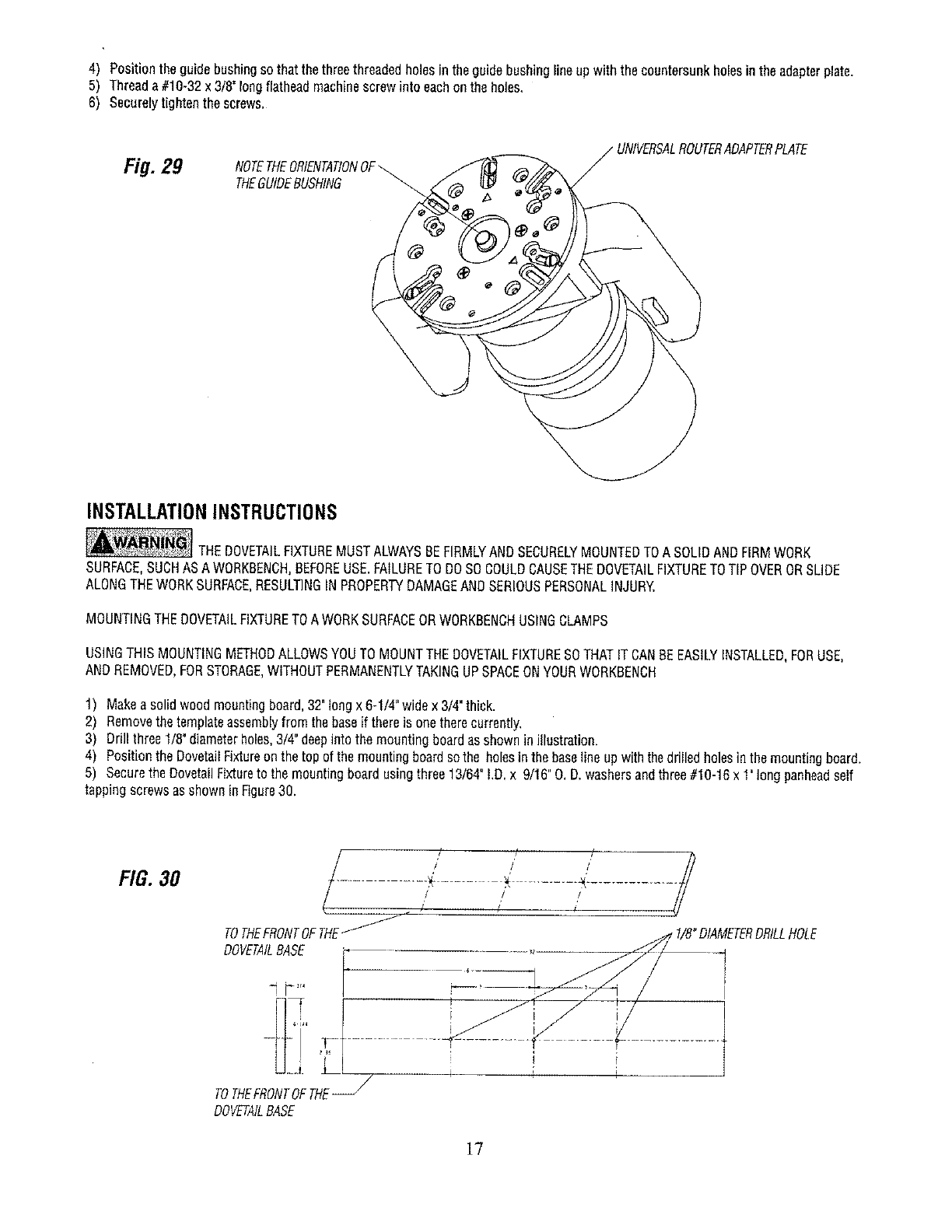
4) Positiontheguidebushingsothatthethreethreadedholesintheguidebushinglineupwiththe countersunkholesinthe adapterplate.
5) Threada #10-32x 3/8"longflatheadmachinescrewinto eachontheholes,
6) Securelytightenthescrews.
Fig. 29 NOTETHEORIENTATIONOF
THEGUIDEBUSHING
_PLATE
INSTALLATIONINSTRUCTIONS
THEDOVETAILFIXTUREMUSTALWAYSBEFIRMLYANDSECURELYMOUNTEDTOA SOLIDANDFIRMWORK
SURFACE,SUCHASAWORKBENCH,BEFOREUSE.FAILURETODOSOCOULDCAUSETHEDOVETAILFIXTURETOTIPOVERORSLIDE
ALONGTHEWORKSURFACE,RESULTINGINPROPERTYDAMAGEANDSERIOUSPERSONALINJURY.
MOUNTINGTHEDOVETAILFIXTURETOA WORKSURFACEORWORKBENCHUSINGCLAMPS
USINGTHISMOUNTINGMETHODALLOWSYOUTOMOUNTTHEDOVETAILFIXTURESOTHATITCANBEEASILYINSTALLED,FORUSE,
ANDREMOVED,FORSTORAGE,WITHOUTPERMANENTLYTAKINGUPSPACEONYOURWORKBENCH
1) Makeasolidwoodmountingboard,32"longx 6-1/4"widex 3t4"thick.
2) Rem°vethetemplateassemblyfr°m thebaseif thereis °no therecurrently'
3) Drill three1/8"diameterholes,3t4"deepinto themountingboardasshownin illustration.
4) PositiontheDovetailFixtureonthe topof the mountingboardsothe holesinthebaselineupwiththedrilledholesinthe mountingboard.
5) Securethe DovetailFixtureto themountingboardusingthree13164"!.D.x 9/16"O.D.washersandthree#10-16x 1"longpanheadself
tappingscrewsasshowninFigure30.
FIG. 30
/
THEFRONTOFTHE
TO _1/8"DIAMETERDRILLHOLE
iI
/
TOTHEFRONTOFTHE_
DOVETAILBASE
17
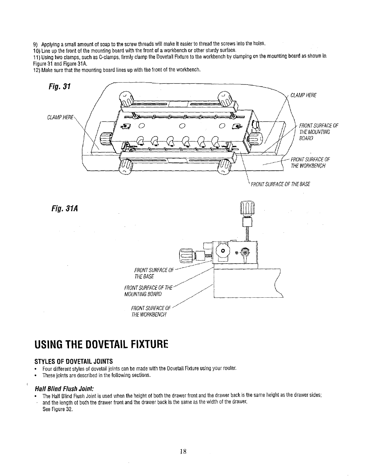
9) Applyinga smallamountof soapto the screwthreadswill makeit easierto threadthescrewsintothe holes.
10)Lineupthefront of themountingboardwiththe frontof a workbenchor othersturdysurface,
11)Usingtwo clamps,suchasC-clamps,firmly clampthe DovetailFixtureto theworkbenchbyclampingonthe mountingboardasshownIn
Figure31andFigure31A.
12)Makesurethatthe mountingboardlinesupwiththe frontof the workbench.
Fig. 31
CLAMPHERE\\k• FRONTSURFACEOF
THEMOUNTtNG
BOARD
;URFACEOF
THEWORKBENCH
FRONTSURFACEOFTHEBASE
Fig. 31,4
FRONTSURFACEOF -]
THEBASE
FRONTSURFACEOFTHE/
MOUNTINGBOARD
FRONTSURFACEOF/
THEWORKBENCH
USINGTHEDOVETAILFIXTURE
STYLES OF DOVETAIL JOINTS
Fourdifferentstylesof dovetadjointscanbemadewiththe DovetailFixtureusingyour router.
• Thesejointsaredescribedinthefollowingsections.
Half Blind Flush Joint:
• TheHalfBlindFlushJointis usedwhentheheightof boththe drawerfront andthe drawerbackisthe sameheightasthedrawersides;
andthe lengthof boththedrawerfrontandthedrawerbackis the sameasthewidthofthe drawer.
SeeFigure32.
18
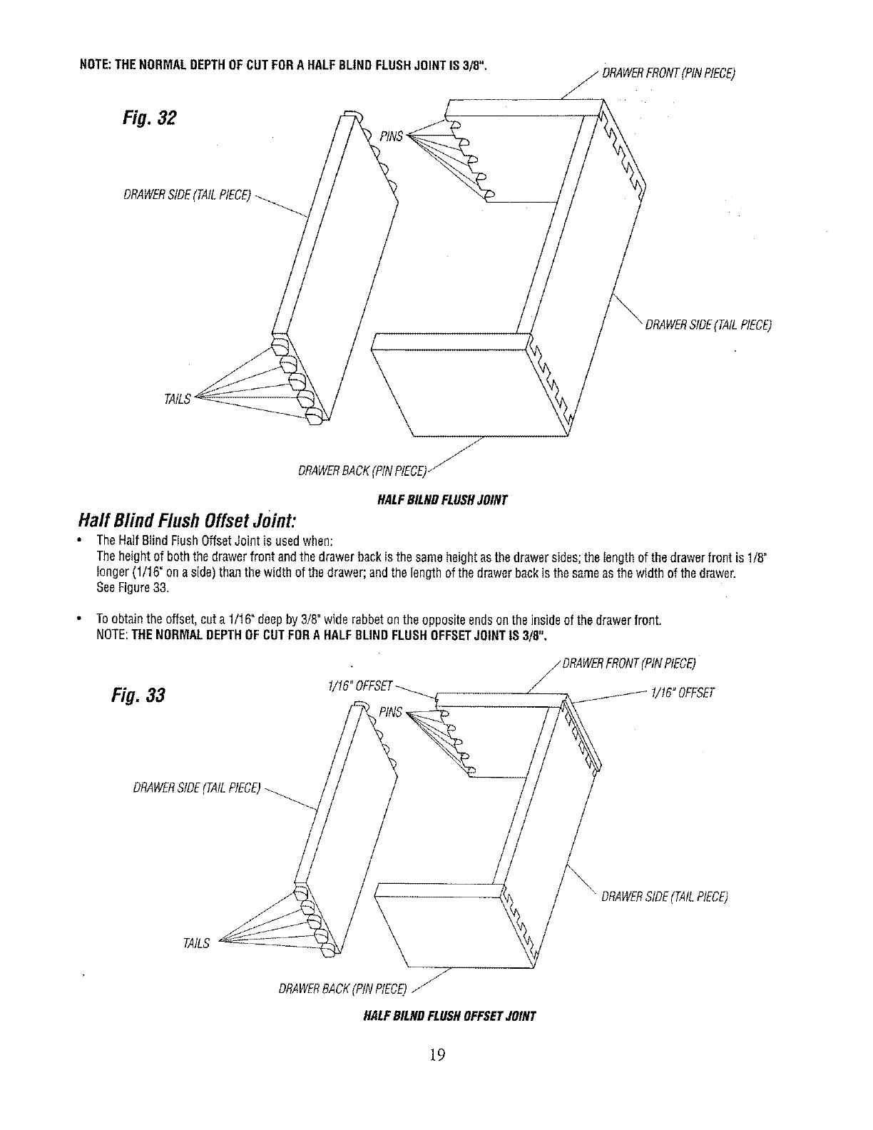
NOTE:THENORMALDEPTHOFCUTFORA HALFBLINDFLUSHJOINTIS3/8". _DRAWERFRONT(PtNPtECE)
Fig. 32
DRAWERSIDE(TAILPIECE)
J
DRAWERBACK(PiNPIECE)_
SIDE(TAILPIECE)
HALFBILHDFLUSHJOINT
Half BlindFlushOffsetJoint:
TheHaftBlindFlushOffsetJointis usedwhen:
Theheightof boththedrawerfrontandthe drawerbackis the sameheightasthe drawersides;the tengthof thedrawerfrontis 1/8"
longer(1/16"onaside)thanthewidth of thedrawer;andthe lengthof thedrawerbackis the sameasthewidth of thedrawer.
SeeFigure33.
Toobtainthe offset,cuta 1t16"deepby 3/8"widerabbetontheoppositeendsonthe insideof thedrawerfront.
NOTE:THENORMALDEPTHOFCUTFORA HALFBLINDFLUSHOFFSETJOINTIS 3/8",
Fig. 33 _DRAWERFRONT(PINPIECE)
DRAWERSIDE(TAILPIECE)
DRAWERStDE(TAILPIECE)
TAILS
J
DRAWERBACK(PINPIECE)J_
HALFBILNDFLUSHOFFSETJOINT
19
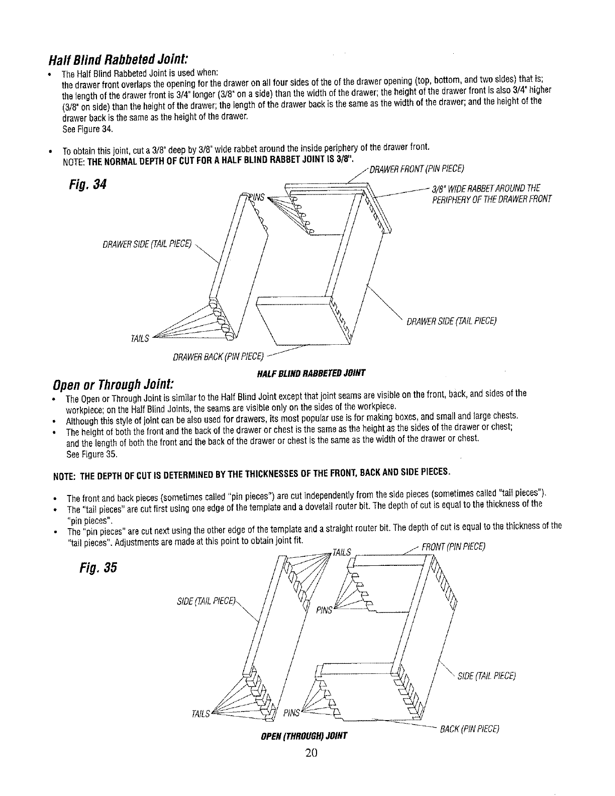
Half BlindRabbetedJoint:
TheHalfBlindRabbetedJointis usedwhen:
thedrawerfrontoverlapsthe openingfor the draweron allfour sidesof theofthe draweropening(top bottom andtwosides)thatis;
thelengthof thedrawerfrontis3/4 longer(3/8"on aside)thanthe widthof thedrawer;the heightof the drawerfrontis also3/4"higher
(3/8°onside)thanthe heightof the drawer;the tengthof the drawerbackis thesameas thewidthof thedrawer;andtheheightof the
drawerbackis thesameasthe heightof the drawer
SeeFigure34
Toobtainthisjointcuta3/8"deepby3/8"wide rabbetaroundthe insideperipheryof thedrawerfront
NOTE:THENORMALDEPTHOFCUTFORAHALFBLINDRABBETJOINTIS 3/8",
/DRAWERFRONT(PiNPIECE)
Fig.34 "WIDERABBETAROUNDTHE
PERIPHERYOFTHEDRAWERFRONT
DRAWERSIDE(TAILPIECE)\\
DRAWERSIDE(TAILPIECE)
TAILS
DRAWERBACK(PINPIECE)
HALFBLINDRABBETEDJOINT
Openor ThroughJoint:
• TheOpenorThroughJointis similarto theHalfB{indJoint exceptthatjoint seamsarevisibieonthe front, back,andsidesof the
workpiece;on theHalfBlindJoints,the seamsarevisibleonlyonthe sidesof theworkpiece,
•Althoughthisstyleof jointcanbealso usedfor drawersits mostpopularuseisfor makingboxes,andsmallandfargochests
•Theheightof boththefrontandthe backof the draweror chestis the sameasthe heightasthesidesof thedraweror chest;
andthe lengthof boththefrontandthebackof the draweror chestIsthesameasthe widthof the drawerorchest
SeeFigure35
NOTE:THEDEPTHOFCUTIS DETERMINEDBYTHETHICKNESSESOFTHEFRONT,BACKANDSIDEPIECES,
• Thefrontandbackpieces(sometimescalledpin pieces")arecut independentlyfrom the sidepieces(sometimescalledtail pieces)
• The'tail pieces arecutfirst usingoneedgeof thetemplateanda dovetailrouterbit Thedepthof cutis equalto thethicknessof the
pin pieces
The'pin pieces'arecutnextusingtheotheredgeof thetemplateanda straightrouterbit Thedepthof cutis equa{to the thicknessof the
taiI pieces Adjustmentsaremadeat thispoint to obtainjoint fit
Fig.35 _TAILS ii FRONT(PtNPtECE)
TAILS --____ I \ RIDE(TAILPIECE)
OPEN(THROUGH)JOINT _-_-_ BACK(PtNPIECE)
2O
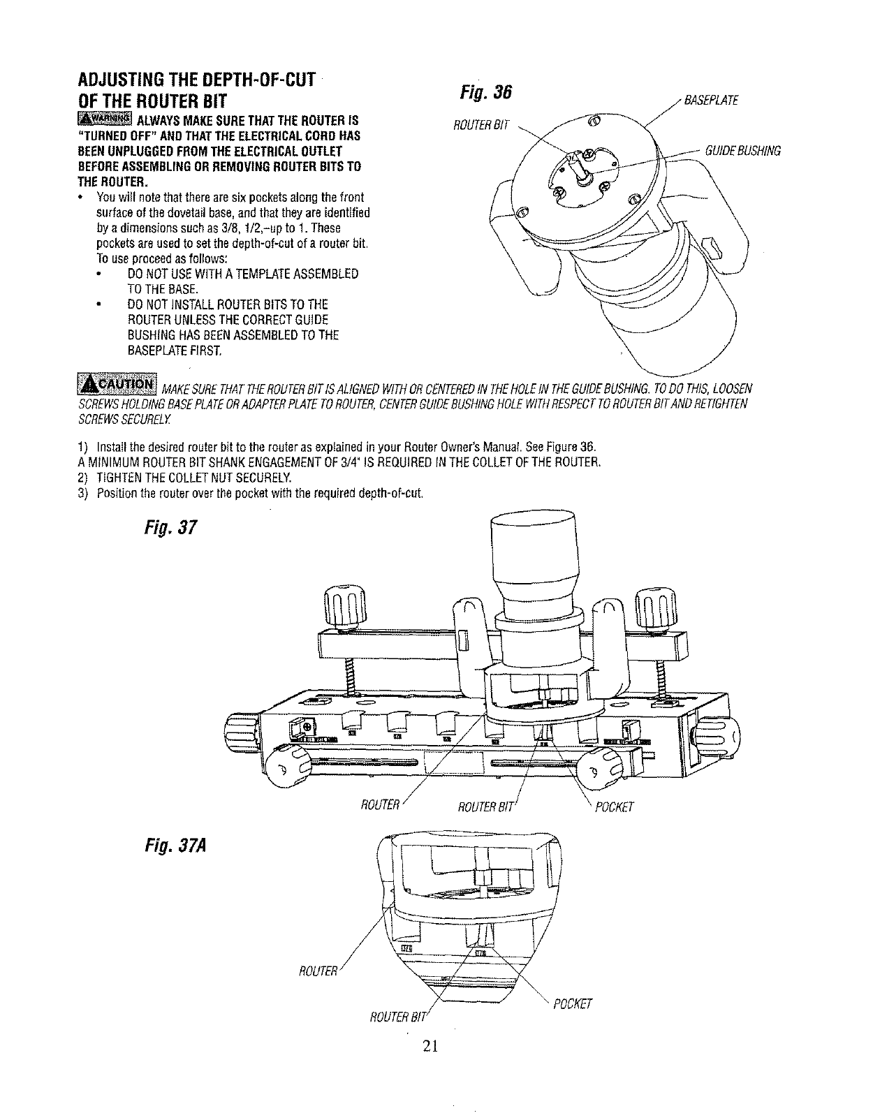
ADJUSTINGTHEDEPTH-OF-CUT
OFTHEROUTERBIT
ALWAYSMAKESURETHATTHEROUTERIS
"TURNEDOFF"ANDTHATTHEELECTRICALCORDHAS
BEENUNPLUGGEDFROMTHEELECTRICALOUTLET
BEFOREASSEMBLINGORREMOVINGROUTERBITSTO
THEROUTER,
•Youwill notethattherearesix pocketsalongthefront
surfaceof thedovetailbase,andthattheyareidentified
bya dimensionssuchas3/8, I/2,-up to 1. These
pocketsareusedto setthe depth-of-cutof a routerbit.
Touseproceedasfollows:
DONOTUSEWITHATEMPLATEASSEMBLED
TOTHEBASE.
• DONOTINSTALLROUTERBITSTOTHE
ROUTERUNLESSTHECORRECTGUIDE
BUSHINGHASBEENASSEMBLEDTOTHE
BASEPLATEFIRST.
Fig. 36
ROUTERBIT
GUIDEBUSHING
_MAKESURETHATTHEROUTERBITISALIGNEDWITHORCENTEREDtNTHEHOLEINTHEGUIDEBUSHING.TODOTHIS,LOOSEN
SCREWSHOLDINGBASEPLATEORADAPTERPLATETOROUTER,CENTERGUIDEBUSHINGHOLEWITHflESPECTTOROUTERBITANDRETIGHTEN
SCREWSSECUREDf
1) InstaIIthe desiredrouterbitto therouterasexp{ainedinyour RouterOwner'sManual SeeFigure3B.
A M{NIMUMROUTERBITSHANKENGAGEMENTOF3/4"IS REQUIREDINTHECOLLETOFTHEROUTER,
2) TIGHTENTHECOLLETNUTSECURELY.
3) Positionthe routeroverthepocketwiththe requireddepth-of-cut,
Fig. 37
Fig.37A
POCKET
2]
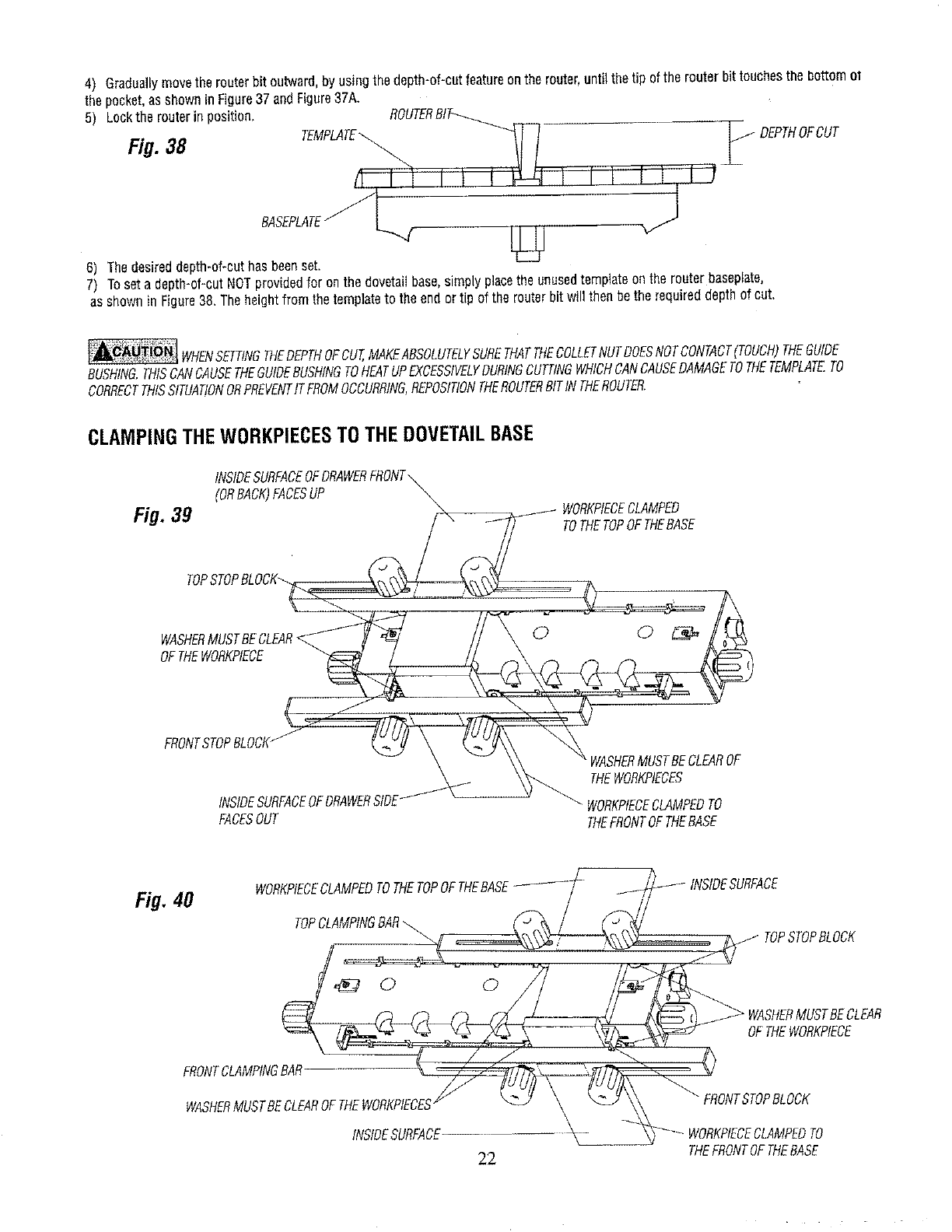
4) Graduallymovethe routerbit outward,by usingthe depth-of-cutfeatureonthe router,untilthetip of the routerbit touchesthe bottomot
the pocket,as showninFigure37 andFigure37A.
5) Lockthe routerin position,
Fig. 38 ?FOOT
6) Thedesireddepth-of-cuthasbeenset.
7) Toseta depth-of-cutNOTprovidedfor onthe dovetailbase,simplypJacetheunusedtemplateenthe routerbaseplate,
as shownin Figure38,Theheightfromthe templateto the endortip of the routerbit will thenbethe requireddepthof cut,
WHENSETTINGTHEDEPTHOFcuT,MAKEABSOLUTELYSURETHATTHECOLLETNUTDOESNOTCONTACT(TOUCH)THEGUIDE
BUSHING.THISCANCAUSETHEGUIDEBUSHINGTOHEATUPEXCESSIVELYDURINGCUTTINGWHICHCANCAUSEDAMAGETOTHETEMPLATE.TO
CORRECTTHISSITUATIONORPREVENTtTFROMOCCURRING,REPOSITIONTHEROUTERBITINTHEROUTER.
CLAMPINGTHEWORKPIECESTOTHEDOVETAILBASE
(ORBACK)FACESUP
Fig. 39 TOTHETOPOFTHEBASE
TOP,
OFTHEWORKPIECB
FRONTSTOPBLOCK-
FACESOUT
rBECLEAROF
THEWORKPIECES
WORKPtECECLAMPEDTO
THEFRONTOFTHEBASE
Fig, 40 WORKPIECECLAMPEDTOTHETOPOFTHEBASE--_-_-/ __i_-_- INSIDESURFACE
TOPC.MPINGB,
TOPSTOPRLOBK
ERO_TOLAMPINGBAR-__
WASHER,_,fUSTBE_ORKP_CES¢_ \ __J_ "_TSTOPBLOCK
INStOESUREADE _- '_-'--WORKPIEOECLAMPEOTO
2,2, THEFRONTOF THEBASE
•Theclampingbarshavebeenspeciallydesignedto allowtheclampingforcestobeappliednextto theworkpiecesfor moreefficient
clamping.Thisisaccomplishedbybeingableto positionthe clampingknobsincloseproximityornextto theworkpieces.
• Figure39 illustratesthepositioningof theclampingbarsandtheclampingknobswhentheworkpiecesareclampedto the LEFTSIDEof
theDovetailFixture,
Figure40 illustratesthe positioningof theclampingbarsandtheclampingknobswhentheworkpiecesareclampedto the RIGHTSIDEof
the DovetailFixture.
*Notethe closenessofthe clampingknobsto the workpieces.Whennot inuseclampingknobsandthe supportingboltsandspringsare
freeto bemovedalongthe slots inthe base,
• CAUTION:WHENCLAMPING,MAKESURETHATTHECLAMPINGKNOBSARENOTPOSITIONEDSOCLOSETOTHEWORKPtECESTHAT
THEWASHERSBECOMETRAPPEDUNDERTHEWORKPIECES.
• FORACCURATEJOINTS,THEWORKPIECESMUST"Bu]-r-uP"AGAINSTBOTHTHETOPANDTHEFRONTSTOPBLOCKSTOENSURE
THEEXACTPOSITIONINGOFTHEWORKPIECES.
*TOENSUREACCURATEJOINTSANDSAFEOPERATION,WOODSHAVINGSANDACCUMULATEDDUSTMUSTBEREMOVEDFROMTHE
DOVETAILFIXTUREBEFOREEACHSETUP,EITHERBYUSINGABRUSHOR BYVACUUMING.
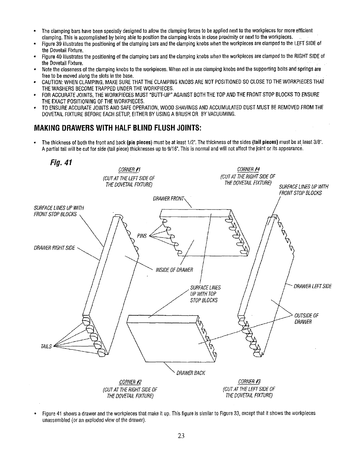
MAKINGDRAWERSWITHHALFBLINDFLUSHJOINTS:
•Thethicknessof boththe frontandback(pin pieces)mustbeat least1/2".Thethicknessofthe sides(tail pieces)mustbeat least3/8".
A partialtail will becatfor side(tail piece)thicknessesupto 9/16".Thisisnormalandwill notaffectthejointor its appearance.
Fig. 41
SURFACELINESUPWITH
FRONTSTOPBLOCKS
DRAWERRIGHTSIDE
CORNER#1
(CUTATTHELEFTSIDEOF
THEDOVETAILFIXTURE)
CORNER#4
(CUTATTHERIGHTSIDEOF
THEDOVETAILFIXTURE)
DRAWERFRONT_
PINS_/
INSIDEOFDRAWER
STOPBLOCKS
_DRAWERBACK
CORNER#2
(CUTATTHERIGHTSIDEOF
THEDOVETAILFIXTURE)
CORNER#3
(CUTATTHELEFTSIDEOF
THEDOVETAtLFIXTURE)
SURFACELINESUPWITH
FRONTSTOPBLOCKS
OUTSIDEOF
DRAWER
•Figure41 showsa drawerandthe workpiecesthatmakeit up. Thisfigureis similarto Figure33, exceptthatit showsthe workpieces
unassembled(or anexplodedviewof thedrawer).
23
• Inaddition,thefigure showswherethefour cornersof the drawerarecutonthe DovetailFixture:
CORNERS1AND3 arecotontheLEFTSIDEof the DovetailFixture,
CORNERS2 AND4 areoutontheRIGHTSiDEofthe DovetailFixture.
• Trialcutsarestronglyrecommendedusingscrapwoodto ensurethatthefinalworkpieceeareofthe desiredquaIity,
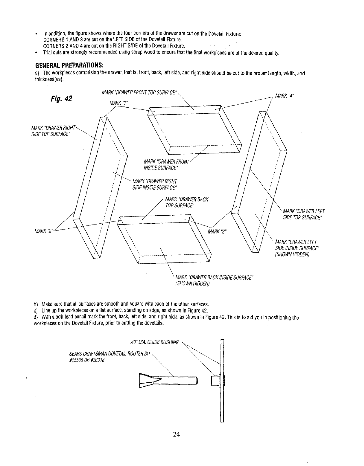
GENERALPREPARATIONS:
a) Theworkpiecescomprisingthedrawer,that is,front,back,left side,andrightsideshouldbeoutto the properlength,width,and
thickness(es),
Ei#. 42 MARK"1"
MARK°DRAWERRIOHT_/_ _",,
_MARK"DRAWERRACKINSIDESURFACE"
_HOWN_DDEN)
MARK"4"
SIDETOPSURFACE"
MARK"DRAWERLEFT
SIDEINSIDESURFACE"
(SHOWNHIDDEN)
b) Makesurethatallsurfacesaresmoothandsquarewith eachofthe othersurfaces,
c) Lineuptheworkpiecesonaflatsurface,standingonedge,asshownin Figure42.
d) Withasoftleadpencilmarkthefront, back,leftside,andright side,asshownInFigure42. Thisis to aidyou
workpiecesonthe DovetailFixture,priorto cuttingthedovetails• positioningthe
•40"DIA.GUIDEBUSHING
SEARSCRAFTSMANDOVETAILROUTERBIT\ _
#25505OR#26318
24
e) Assemblethe.40"guidebushingto therouterbaseplate,asdescribedin aprevioussection.Thisthesmallerof thetwoguidebushings
furnishedwiththis product.
f) _nsta__Searsd_vetai_r_uterbit_#255_5_r#26318_t_ther_uterasdescribed_ny_urR__ter_wner_sManuaLShankengagement
shouldbea minimumof 3/4%
_MAKESURETHATTHEROUTERBITtSALIGNEDWITHORCENTEREDINTHEHOLEtNTHEGUIDEBUSHING.TODOTHIS,LOOSEN
SCREWSHOLDtNGBASEPLATEORADAPTERPLATETOROUTER,CENTERGUIDEBUSHINGHOLEWITHRESPECTTOROUTERBtTANDRETtGHTEN
SCREWSSECURELY.
_WHENSETTINGTHEDEPTHOFCUT,MAKEABSOLUTELYSURETHATTHECOLLETNUTDOESNOTCONTACT(TOUCH)THEGUIDE
BUSHING.THISCANCAUSETHEGUIDEBUSHINGTOHEATUPEXCESSIVELYDURINGCUTTINGWHICHCANCAUSEDAMAGETOTHETEMPLATE,TO
CORRECTTHISSITUATIONORPREVENTITFROMOCCURRING,REPOStTtONTHEROUTERBITINTHEROUTER.
Fig. 43 'LEFTTOPSTOPBLOCK
/"A"FACESTOWARDMIDDLE
jOFBASE RIGHTTOPSTOPBLOCK
j POINTERPOINTS
TOCENTER
GRADUATION
LEFTFRONTSTOPBLOCK STOPBLOCK
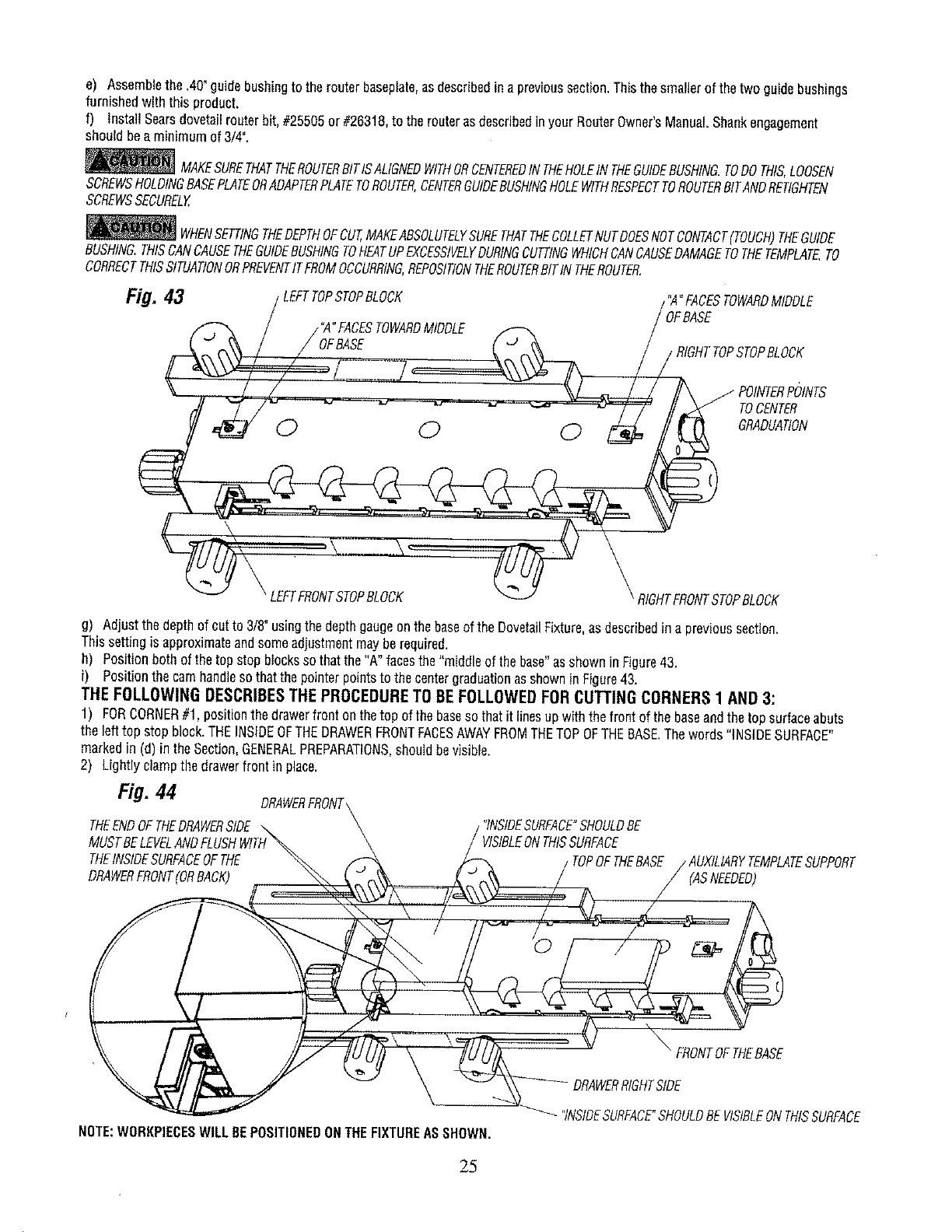
g) Adjustthedepthof cutto 3/8"usingthe depthgaugeonthe baseof the DovetailFixture,asdescribedina previoussection.
Thissettingis approximateandsomeadjustmentmayberequired.
h) Positionboth of thetop stopbIocksso thatthe"A" facesthe "middleof the base"asshowninFigure43.
i) Positionthe camhandlesothatthepointerpointsto thecentergraduationasshowninFigure43.
THE FOLLOWING DESCRIBESTHE PROCEDURE TO BE FOLLOWED FOR CUTTING CORNERS 1 AND 3:
1) FORCORNER#1, positionthe drawerfronton thetop of thebaseso thatit linesupwiththefrontof thebaseandthetop surfaceabuts
the lefttop stopblock.THEINSIDEOFTHEDRAWERFRONTFACESAWAYFROMTHETOPOFTHEBASE.Thewords"INSIDESURFACE"
markedin (d)in theSection,GENERALPREPARATIONS,shouldbevisible.
2) Lightlyclampthe drawerfront inplace.
Fig. 44 DRAWERFRONT
THEENDOFTHEDRAWERSIDE
MUSTBELEVELANDF
THEINSIDESURFACEOFTHE
DRAWERFRONT(ORBACK)
"INSIDESURFACE"SHOULDBE
VIStBLEONTHISSURFACE
TOPOFTHEBASE _MPLATESUPPORT
(ASNEEDED)
FRONTOFTHEBASE
NOTE:WORI(PIECESWILL BEPOSITIONEDONTHEFIXTUREASSHOWN.
"INSIDESURFACE"SHOULDBE VISIBLEONTHISSURFACE
25
3) PositionthedrawerRIGHTsideagainstthefront ofthe basesothatthetop surfaceabutstheleftfrontstopblock.THEINSIDEOFTHE
DRAWERSIDEFACESAWAYFROMTHEFRONTOFTHEBASE.
Thewords"INSIDESURFACE"markedin (d) Inthe Section,GENERALPREPARATIONS,shouldbevisible.
4) Lineupthe workpieeesso thattheendof the drawersidelinesupwiththedrawerfront asshownin Figure44.
5) Securelyclampthe drawersideto the base,
6) Securelyclampthe drawerfrontto thebase.
7) Makesurethatthe partsremaingnedup.
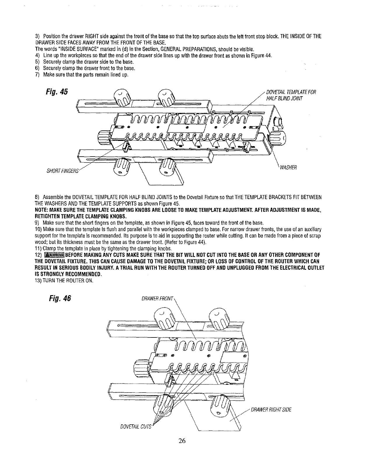
Fig. 45 HALFBLINDJOINT
SHORTFINGERSjWASHER
8) AssembLethe DOVETAILTEMPLATEFORHALFBLINDJOINTSto the DovetagFixturesothatTHETEMPLATEBRACKETSFITBETWEEN
THEWASHERSANDTHETEMPLATESUPPORTSasshownFigure45.
NOTE:MAKESURETHETEMPLATECLAMPINGKNOBSARELOOSETOMAKETEMPLATEADJUSTMENT,AFTERADJUSTMENTISMADE,
RETIGHTENTEMPLATECLAMPINGKNOBS.
9) Makesurethattheshortfingersonthetemplate,as shownin Figure45, facestowardthefrontof the base.
10)Makesurethatthetemplateis flushandparallelwiththe workpiecesclampedto base.Fornarrowdrawerfronts,the useof anauxifiary
supportfor thetemplateis recommended.Its purposeis toaidin supportingtherouterwhilecutting.It canbemadefroma pieceof scrap
wood;butits thicknessmustbethe sameasthe drawerfront. (Referto Figure44).
1!) Clampthe templatein placeby tighteningtheclampingknobs.
12) _ BEFDREMAKINGANYCUTSMAKESURETHATTHEBITWILLNOTCUTINTOTHEBASEORANYOTHERCOMPONENTOF
THEDOVETAILFIXTURE.THISCANCAUSEDAMAGETOTHEDOVETAILFIXTURE;ORLOSSOFCONTROLOFTHEROUTERWHICHCAN
RESULTINSERIOUSBODILYINJURY.ATRIALRUNWITHTHEROUTERTURNEDOFFANDUNPLUGGEDFROMTHEELECTRICALOUTLET
IS STRONGLYRECOMMENDED,
13)TURNTHEROUTERON,
Fig. 46
jDRAWERRIGHTSIDE
DOVETAILCUTS
26
14)Cutthedovetailby movingthe routerfromLEFTTORIGHT,with theguidehushingfollowingthetemplate,DONOTFORCEANYTHING;
MOVETHEROUTERINSLOWANDSMOOTHFASHION.
15)Toensureasmoothanduniformjoint,retracethe previouscutby movingtherouterfrom RIGHTTOLEFTwith theguidebushingagain
followingthe template.
16)_ NEVERLIFTTHEROUTERUPWARDSWHENTHEROUTERIS ONANDTHEROUTERBITROTATINGORWHENTHEGUIDE
BUSHINGIS NEARTOORTOUCHINGTHETEMPLATE.THISCANCAUSEDAMAGETOTHEDOVETAILFIXTURE;ORLOSSOFCONTROLOF
THEROUTERWHICHCANRESULTINSERIOUSBODILYINJURY,
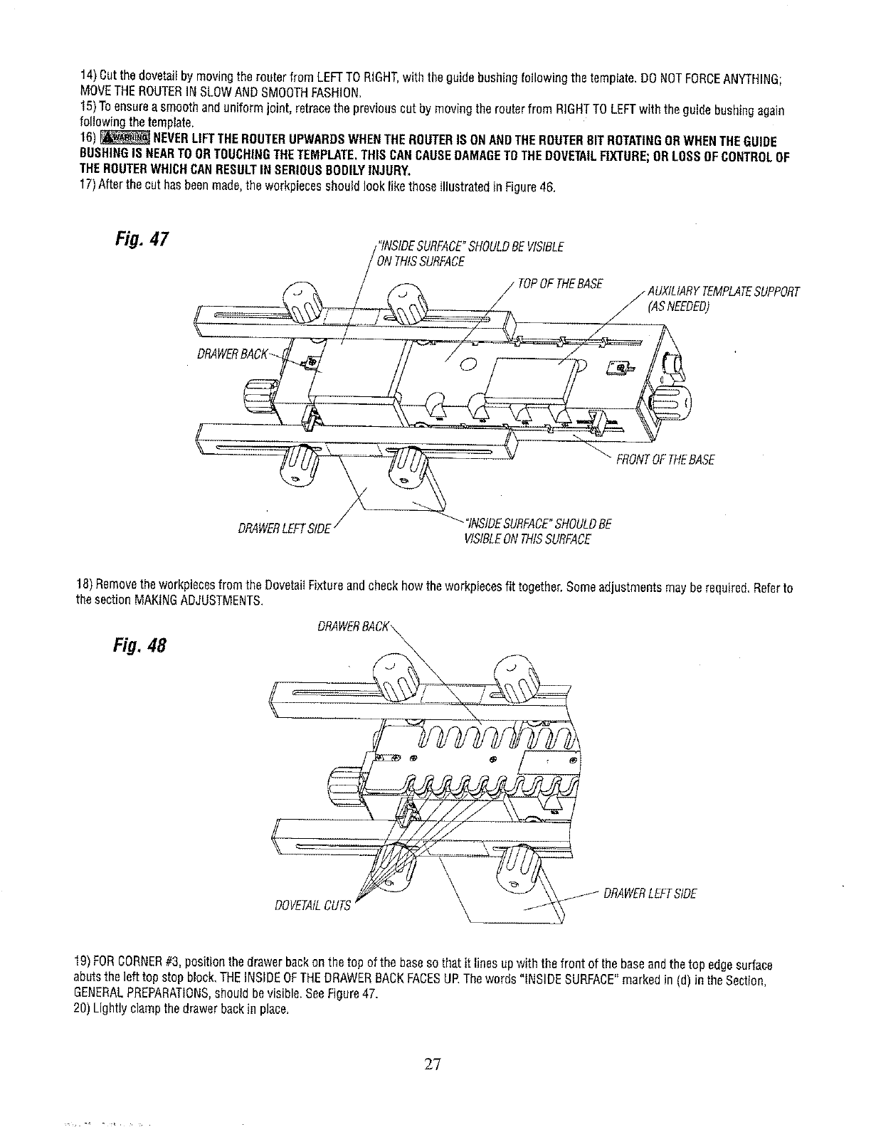
17)Afterthecut hasbeenmade,the workpiecesshouldlooklikethoseIllustratedin Figure46.
Fig. 47 /"INSIDESURFACE"SHOULDBEVISIBLE
_/(,_ /ONTHISSURFADE
TOPOFTHEBASE / AUXILIARYTEMPLATESUPPORT
(ASNEEDED)
DRAWERBACK -_"
SE
VISIBLEONTHISSURFACE
18)Removetheworkpiecesfromthe DovetailFixtureandcheckhowtheworkpiecesfit together.Someadjustmentsmayberequired,Referto
thesectionMAKINGADJUSTMENTS.
Fig. 48
DOV_A£__ DRAWERLEFTSIDE
19)FORCORNER#3,positionthedrawerbackonthe top ofthe baseso thatit linesupwiththe front of the baseandthetop edgesurface
abutstheleft topstopblock.THEINSIDEOFTHEDRAWERBACKFACESUP.Thewords"iNSIDESURFACE"markedin (d) inthe Section,
GENERALPREPARATIONS,shouldbevisible,SeeFigure47.
20)Lightlyclampthedrawerbackin place.
g?
21)Positionthe drawerLEFTsideagainstthefront of the baseso thatthetop surfaceabutsthe leftfront stop block.THEINSIDEOFTHE
DRAWERSIDEFACESUP.Thewords"INSIDESURFACE"markedin (d)in the Section,GENERALPREPARATIONS,shouIdbevisible.
22)Lineupthe workpiecesso thatthe endof the drawersidelinesup withthedrawerbackasshownin Figure47.
23)Continueas inSteps5 through16above.
24)Afterthe cut hasbeenmade,the workpiecesshouldlooklike thoseillustratedin Figure48.
25)Removethe workpiecesfromthe DovetailFixtureandcheckhowtheworkpiecesfit together.Someadjustmentsmayberequired.
Referto the sectionMAKINGADJUSTMENTS.
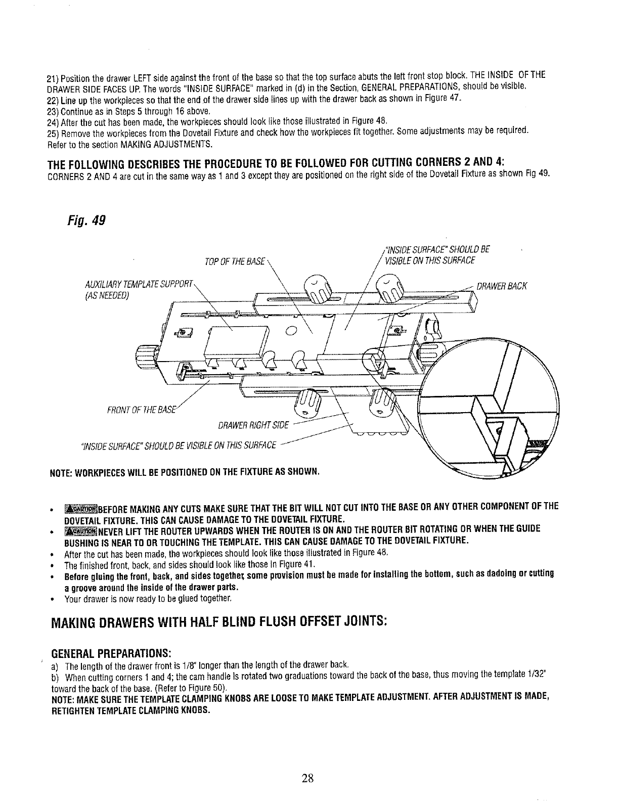
THE FOLLOWING DESCRIBES THE PROCEDURE TO 8E FOLLOWED FOR CUTTING CORNERS 2 AND 4:
CORNERS2 AND4 arecut in thesamewayas 1and3 excepttheyarepositionedonthe rightsideof the DovetailFixtureas shownFig49.
Fig. 49
AUXtLIARYTEMPLATESUPPORT
(ASNEEDED)
tNTHISSURFACE
/
FRONTOFTHEBASE/
ORAWERRtGHTSIDE
"INSIDESURFACE"SHOULDBEVISIBLEONTHISSURFACE
NOTE:WORKPIECESWILLBEPOSITIONEDONTHEFIXTUREASSHOWN.
_BEFORE MAKINGANYCUTSMAKESURETHATTHEBITWILLNOTCUTINTOTHEBASEORANYOTHERCOMPONENTOFTHE
DOVETAILFIXTURE.THISCANCAUSEDAMAGETOTHEDOVETAILFIXTURE.
_NEVER LIFTTHEROUTERUPWARDSWHENTHEROUTERIS ONANDTHEROUTERBITROTATINGORWHENTHEGUIDE
BUSHINGISNEARTOORTOUCHINGTHETEMPLATE.THISCANCAUSEDAMAGETOTHEDOVETAILFIXTURE.
Afterthecut hasbeenmade,theworkpieeesshouldlooklikethoseillustratedin Figure45.
Thefinishedfront, back,andsidesshouldlooklikethosein Figure41.
Beforegluingthefront,back,andsidestogethez;somepmvisienmustbe madeforinstallingthebottom,suchasdadoingorcatting
egroovearoundtheinsideofthedrawerparts.
Yourdraweris nowreadyto begluedtogether,
MAKINGDRAWERSWITHHALFBLINDFLUSHOFFSETJOINTS:
GENERALPREPARATIONS:
a) Thelengthof thedrawerfront {s1/8_longerthanthe lengthof the drawerbeck.
b) Whencuttingcornersl and4;thecam handleis rotatedtwo graduationstowardthebackof the base,thus movingthe template1/32"
towardthebackof thebase.(Referto Figure50).
NOTE:MAKESURETHETEMPLATECLAMPINGKNOBSARELOOSETOMAKETEMPLATEADJUSTMENT.AFTERADJUSTMENTIS MADE,
RETIGHTENTEMPLATECLAMPINGKNOBS.
28
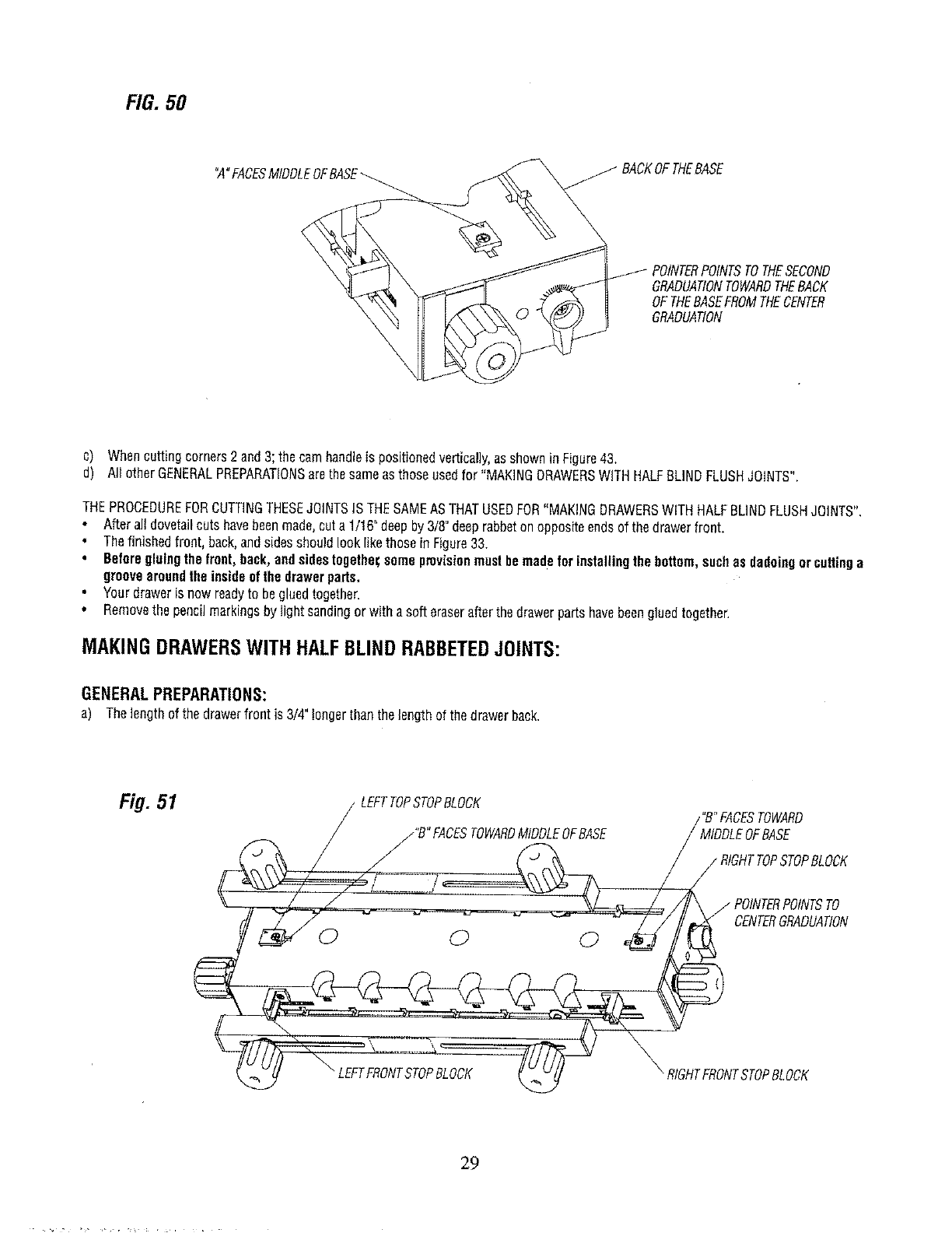
FIG.50
°A"FACESMfDDLEOFEASE
GRADUAtiONTOWARDTHEBACK
OFTHEBASEFROMTHECENTER
GRADUAtiON
c) Whencuttingcorners2and3;the camhandleis positionedvertically,asshowninFigure4&
d) All otherGENERALPREPARATIONSarethesameasthoseusedfor "MAKINGDRAWERSWITHHALFBLINDFLUSHJOINTS",
THEPROCEDUREFORCUTTINGTHESEJOINTSISTHESAMEASTHATUSEDFOR"MAKINGDRAWERSWITHHALFBLINDFLUSHJOINTS".
Afteralldovetailcutshavebeenmade,cuta 1/16"deepby3/8"deeprabbetonoppositeendsof thedrawerfront.
• Thefinishedfront, back,andsidesshouldlook likethoseinFigure33.
Beforegluingthefront,back,andsidestogethez;someprovisionmustbemadeforinstallingthebottom,suchasdadoingorcuttinga
groovearoundtheinsideofthedrawerpads.
Yourdraweris now readyto begluedtogether.
•Removethe pencilmarkingsby lightsandingor witha softeraserafterthedrawerpartshavebeengluedtogether.
MAKINGDRAWERSWITHHALFBLINDRABBETEDJOINTS:
GENERAL PREPARATIONS:
a) Thelengthof thedrawerfront is 3/4"longerthanthelengthof thedrawerback.
Fig. 51 LEFTTOPSTOPBLOCK
/_"B" FACESTOWARDMIDDLEOFBASE
/ POINTERPOINTSTO
CENTERGRADUAtiON
29
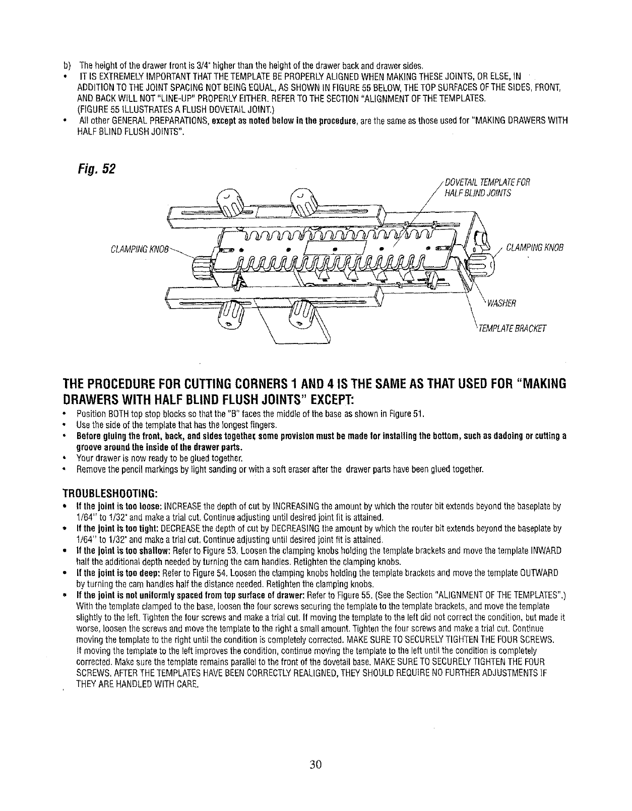
b) Theheightof the drawerfrontis 3/4"higherthanthe heightof the drawerbackanddrawersides.
ITIS EXTREMELYIMPORTANTTHATTHETEMPLATEBEPROPERLYALIGNEDWHENMAKINGTHESEJOINTS,ORELSE,IN
ADDITIONTOTHEJOINTSPACINGNOTBEINGEQUAL,ASSHOWNINFIGURE55BELOW,THETOPSURFACESOFTHESIDES,FRONT,
ANDBACKWILLNOT"LINE-UP"PROPERLYEITHER.REFERTOTHESECTION"ALIGNMENTOFTHETEMPLATES.
(FIGURE55 ILLUSTRATESA FLUSHDOVETAILJOINT.)
AgotherGENERALPREPARATIONS,exceptasnotedbelowinthe procedure,arethe sameasthoseusedfor "MAKINGDRAWERSWITH
HALFBLINDFLUSHJOINTS".
Fi#. 52 / DOVETAILTEMPLATEFOR
LFBLINDJOINTS
THEPROCEDUREFORCUTTINGCORNERS1 AND4 IS THESAMEASTHATUSEDFOR"MAKING
DRAWERSWITH HALFBLINDFLUSHJOINTS"EXCEPT:
PositionBOTHtop stopblocksso thatthe "B" facesthe middieof thebaseasshownin Figure51,
Usethe sideof thetemplatethathasthelongestfingers,
BeforegluingtheIront, back,andsidestogethez;someprovisionmustbe madefor installingthebottom,suchasdadoingor cuttinga
groovearoundtheinsideofthedrawerparts.
Yourdraweris nowreadyto begluedtogether.
Removethe pencilmarkingsby light sandingorw!tha soft eraserafterthe drawerpartshavebeengluedtogether.
TROUBLESHOOTING:
• If thejoint istooloose:iNCREASEthe depthof cut by INCREASINGtheamountbywhichtherouterbit extendsbeyondthe basepiateby
1164"to 1/32"andmakea trialcut.Continueadjustinguntil desiredjoint fit is attained,
*Ifthe jointis too tight: DECREASEthedepthof cutby DECREASINGtheamountby whichthe routerbit extendsbeyondthe baseplateby
1/64" to 1/32"andmakeatriaI cut.Continueadjustinguntildesiredjoint fit is attained.
• If the joint is too shallow:Referto Figure53. Loosenthe clampingknobsholdingthetemplatebracketsandmovethetemplateINWARD
halfthe additionaldepthneededby turningthe camhandles.Retightenthe clampingknobs.
• It the joint is too deep:Referto Figure54.Loosenthe clampingknobsholdingthetemplatebracketsandmovethetemplateOUTWARD
by turningthecamhandleshalfthedistanceneeded.Retightenthe dampingknobs.
•If the jnint is notunilormly spacedtramtop surfaceofdrawer:Referto Figure55. (Seethe Section"ALIGNMENTOFTHETEMPLATES",)
Withthe templateclampedto the base,loosenthefour screwssecuringthetemplateto thetemplatebrackets,andmovethetemplate
slightlyto the Iuft.Tightenthe fourscrewsandmakeatrial cut.If movingthetemplateto the leftdidnotcorrectthe condition,butmadeit
worse,loosenthe screwsandmovethetemplateto the rightasmallamount.Tightenthefour screwsandmakeatriai cut.Continue
movingthetemplateto the rightuntilthe conditionis completeIycorrected,MAKESURETOSECURELYTIGHTENTHEFOURSCREWS.
it movingthe templateto theleftimprovesthecondition,continuemovingthe templateto the leftuntiltheconditionis completeiy
corrected.Makesurethetemplateremainsparagelto thefront of thedovetailbase.MAKESURETOSECURELYTIGHTENTHEFOUR
SCREWS.AFTERTHETEMPLATESHAVEBEENCORRECTLYREALIGNED,THEYSHOULDREQUIRENOFURTHERADJUSTMENTSIF
THEYAREHANDLEDWITHCARE.
3O
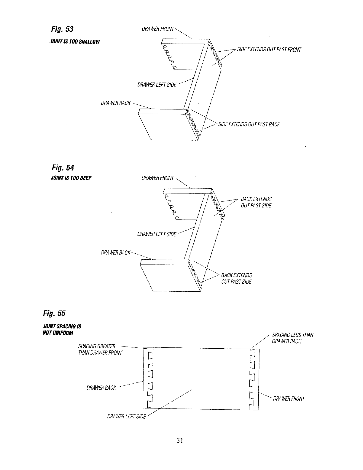
Fig. 53
JOINTIS TOOSHALLOW
DRAWERFRONT_
FRONT
DRAWERLEF:
DRAWERBA
\
Fig. 54
JOINTIS TOODEEP
BACKEXTENDS
OUTPASTSIDE
DRAWERLEFT
DRAWERRA
OUTPASTS_E
Fig.55
JOINTSPACINGIS
NOTUNIFORM
DRAWERBACKz- L_I_ jJ
DRAWERLEFTSIDEj_
J
J
_,/ SPACINGLESSTHAN
DRAWERBACK
31
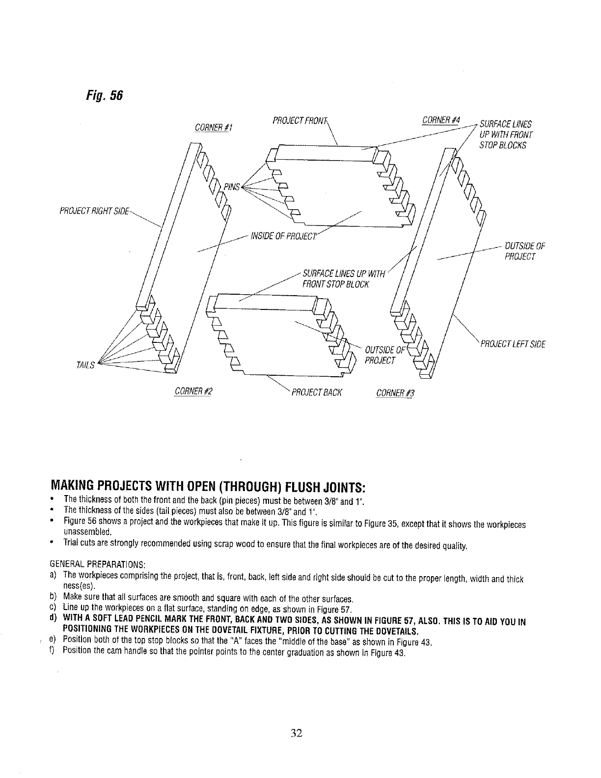
Fig. 58
CORNER#1 PROJECTFRONA_
CORNER#4 SURFACELINES
UPWITHFRONT
STOPBLOCKS
PROJECTRtGHTSIDE_._
_SURFACE
FRONTSTOPBLOCK
OUTSIDEOF
PROJECT
TAtL_
CORNER#2 "" PROJECTBACK
PROJECT
CORNER#3
SIDE
MAKINGPROJECTSWITHOPEN(THROUGH)FLUSHJOINTS:
• Thethicknessof boththefront andtheback(pinpieces)must bebetween3/8" and1".
Thethicknessof the sides(tail pieces)mustalso bebetween3/8"and1".
Figure56showsaprojectandthe workpiecesthatmakeit up.Thisfigureis similarto Figure35, exceptthatit showstheworkpieces
unassembled.
Trialcutsarestronglyrecommendedusingscrapwoodto ensurethatthefinalworkpiecesareof the desiredquality.
GENERALPREPARATIONS:
a) Theworkpiecescomprisingthe project,thatis,front, back,Ieftsideandrightsideshouldbecutto the properlength,widthandthick
ness(es).
b) Makesurethat allsurfacesaresmoothandsquarewith eachof the othersurfaces.
c) Lineupthe workpiecesona flatsurface,standingon edge,asshownin Figure57,
d) WITHA SOFTLEADPENCILMARKTHEFRONT,BACKANDTWOSIDES,ASSHOWNIN FIGURE57, ALSO,THISISTOAIDYOUIN
POSITIONINGTHEWORKPIECESONTHEDOVETAILFIXTURE,PRIORTOCUTTINGTHEDOVETAILS,
e) Positionbothof thetop stopblocksso thatthe "A" facesthe "middleof the base"asshownin Figure43.
f) Positionthecamhandlesothatthe pointerpointsto the centergraduationasshownin Figure43.
32
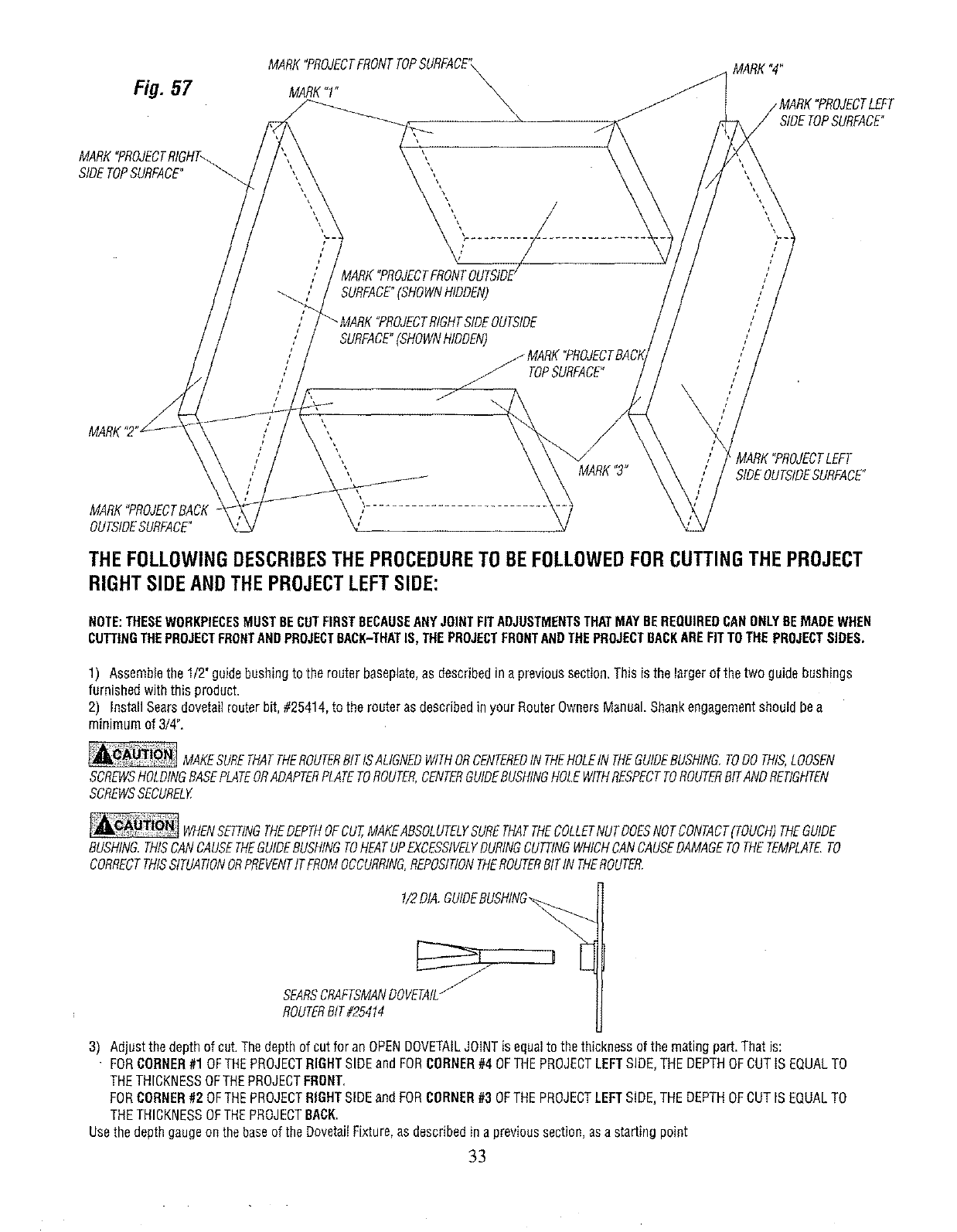
Fig. 57
MARK"PROJECTRIGHT_
SIDETOPSURFACE°
MARK"PROJECTFRONTTOPSURFACE"\
MARK"!" \,,\\
%
l
--_. SURFACE"(SHOWNHIDDEN)
SURFACE"(SHOWNHIDDEN)
TOPSURFACE"
MARK"4"
TLEFT
SIDETOPSURFACE"
MARK
MARK"PROJECTBACK
OUTSIDESURFACE"
MARK"3" MARK"PROJECTLEFT
SIDEOUTSIDESURFACE"
THEFOLLOWINGDESCRIBESTHEPROCEDURETOBEFOLLOWEDFORCUTTINGTHEPROJECT
RIGHTSIDEANDTHEPROJECTLEFTSIDE:
NOTE:THESEWORKPIECESMUST BECUTFIRSTBECAUSEANYJOINTFITADJUSTMENTSTHATMAYBEREQUIREDCANONLYBEMADEWHEN
CUTTINGTHEPROJECTFRONTANDPROJECTSACK-THATIS, THEPROJECTFRONTANDTHEPROJECTBACKAREFITTOTHE PROJECTSIDES,
1) Assemblethe 1/2_guidebushingto therouterbaseplate,as describedina previoussection,Thisis thelargerof thetwo guidebushings
furnishedwiththis product.
2) InstallSearsdovetailrouterbit,#25414,to the routerasdescribedinyour RouterOwnersManual.Shankengagementshouldbea
minimumof 3/4".
MAKESURETHATTHEROUTERBITISALIGNEDWITHORCENTEREDINTHEHOLEINTHEGUIDEBUSHING.TODOTHIS,LOOSEN
SCREWSHOLDINGBASEPLATEORADAPTERPLATETOROUTER,CENTERGUIDEBUSHINGHOLEWITHRESPECTTOROUTERBITANDRETIGHTEN
SCREWSSECURELY
WHENSETTINGTHEDEPTHOFCUT,MAKEABSOLUTELYSURETHATTHECOLLETNUTDOESNOTCONTACT(TOUCH)THEGUIDE
BUSHING.THISCANCAUSETHEGUIDEBUSHINGTOHEATUPEXCESSIVELYDURINGCUTTINGWHICHCANCAUSEDAMAGETOTHETEMPLATE.TO
CORRECTTHISSITUATIONORPREVENTITFROMOCCURRING,REPOStTIONTHEROUTERBITIN THEROUTER.
1/2DIA.GUtDEBUSHtNG_
SEARSCRAFTSMANDOVETAtL_
ROUTERBIT#25414
3) Adjust the depth of cut. The depth of cut for an OPENDOVETAILJOINTis equal to the thickness of the mating part, That is:
FORCORNER#1 OFTHEPROJECTRIGHTSIDE and FORCORNER#4 OFTHEPROJECTLEFTSIDE,THE DEPTHOFCUT IS EQUALTO
THETHICKNESSOFTHEPROJECTFRONT.
FORCORNER#2 OFTHEPROJECTRIGHTSIDE and FORCORNER#3 OFTHE PROJECTLEFT SIDE,THE DEPTHOFCUT IS EQUALTO
THETHICKNESSOFTHEPROJECTBACK.
Use the depth gaugeon the baseof the DovetaiIFixture, as described in a previous section, asa starting point
33
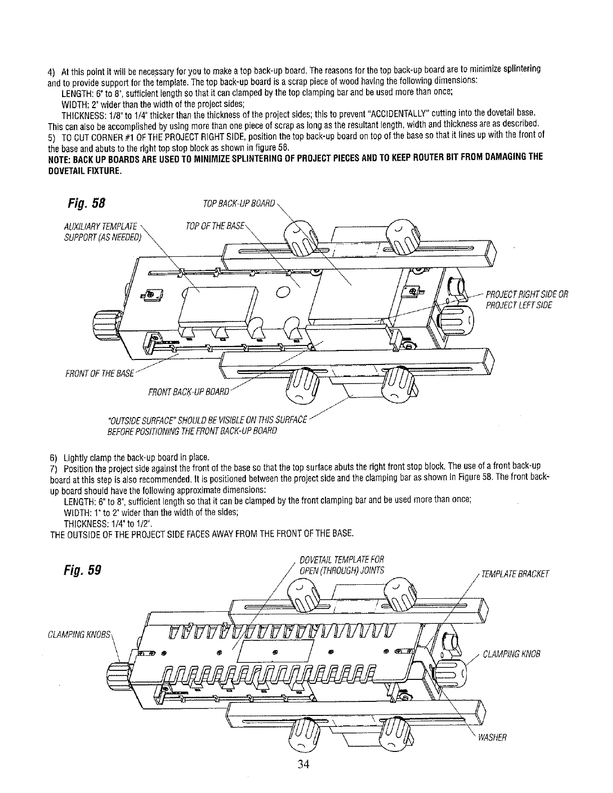
4) Atthis pointit will benecessaryforyou to makeatop back-upboard.Thereasonsfor thetop back-upboardareto minimizesplintering
andto providesupportfor thetemplate.Thetop back-upboardis ascrappieceof woodhavingthefollowingdimensions:
LENGTH:6"to 8",sufficientlengthso thatit canclampedbythe topclampingbarandbeusedmorethanonce;
WIDTH;2"widerthanthe widthof the projectsides;
THICKNESS:1/8"to 1/4"thickerthanthethicknessof theprojectsides;thisto prevent"ACCIDENTALLY"cuttinginto thedovetailbase,
Thiscanalsobeaccomplishedby usingmorethan onepieceof scrapas longasthe resultantlength,widthandthicknessareasdescribed.
5) TOCUTCORNER#10F THEPROJECTRIGHTSIDE,positionthetop back-upboardontopofthebasesothatitlinesopwiththe frontof
the baseandabutsto theright topstopblockasshowninfigure58.
NOTE:BACKUPBOARDSAREUSEDTOMINIMIZESPLINTERINGOFPROJECTPIECESANDTOKEEPROUTERBITFROMDAMAGINGTHE
DOVETAILFIXTURE,
Fig, 58 TOPBACK-UPBOARD\\
AUXILIARYTEMPLATE\TOPOFTHEBASE\ _ .
SUPPORT(ASNEEDED)\ _ _ _ _\_ /_ "_','-._
// \ ....\ ,., v
'k ,J
FRONTOFTHEBASE_ (( _._ .- _ _,L ,
FRONTIACK'UPBOARD_ __
"OUTSIDESURFACE'SHOULDBEVtSIBLEONTHISSURFACEI-
BEFOREPOSITIONINGTHEFRONTBACK-UPBOARD
6) Lightlyclampthe back-upboardin place,
7) Positionthe projectsideagainstthefront of thebasesothatthetop surfaceabutsthe rightfrontstopblock.Theuseof afrontback'up
boardat thisstepis alsorecommended.It is positionedbetweenthe projectsideandthe clampingbaras shownin Figure58.Thefront back-
upboardshouldhavethefollowingapproximatedimensions:
LENGTH:6"to 8",sufficientlengthsothatit canbeclampedbythefront clampingbarandbeusedmorethanonce;
WIDTH:1"to 2"widerthanthewidthof thesides;
THICKNESS:1/4"to 1/2".
THEOUTSIDEOFTHEPROJECTSIDEFACESAWAYFROMTHEFRONTOFTHEBASE.
TEMPLATEFOR
Fig. 59 TEMPLATEBRACKET
CLAMPINGKNOBSI
jCLAMPINGKNOB
\
WASHER
34
Thewords"OUTSIDESURFACE"markedin(d) in the Section,GENERALPREPARATIONS,shouldhavebeenvisiblebeforethefront back-up
boardwasput in place.
8) Lineuptheworkpiecessothatthe endof the projectsideandback-upboardsDineupasshowninFigure58.
9) Securelyclampthe projectsideandthe front back-upboardto the frontof thebase.
10)Secureiydamp the topback-upboardto the top of the base.
11)Makesurethatthe partsremainlinedup.
12)Assemblethe DOVETAILTEMPLATEFOROPEN(THROUGH)JOINTSto theDovetaiIFixtureso thatTHETEMPLATEBRACKETSFIT
BETWEENTHEWASHERSANDTHETEMPLATESUPPORTSas shownFigure59; it will benecessaryto loosentheclampingknobsat theends
of the baseto dothis•
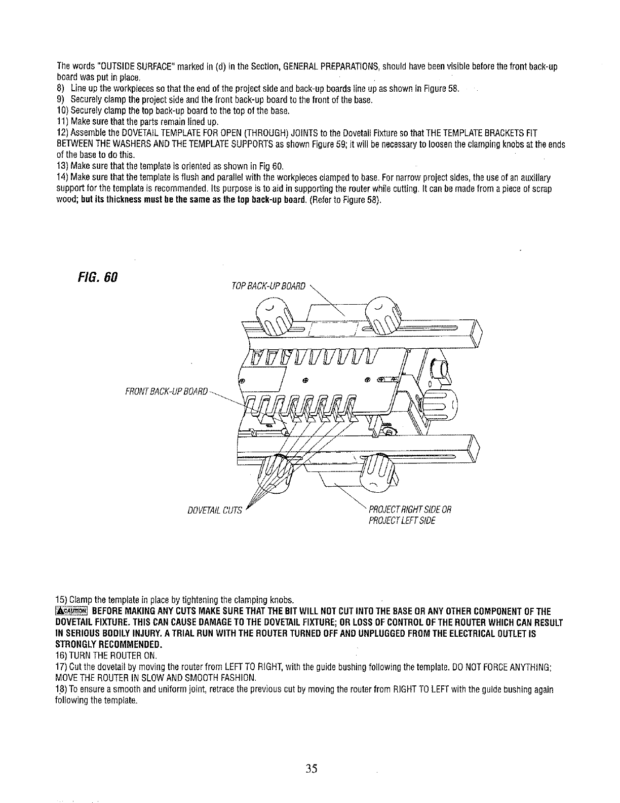
13)Makesurethatthe templateis orientedasshownin Fig60.
14)Makesurethatthetemplateisflushandparailelwiththe workpiecesclampedto base.Fornarrowprojectsides,the useof anauxiliary
supportfor the templateis recommended.Its purposeis to aid insupportingthe routerwhilecutting,Itcanbemadefromapieceof scrap
wood;butitsthicknessmustbethesameasthetopback-upboard.(Referto Figure58).
FIG. 60
TOPB,4CK-UPBOARD___
• _ e0
FRONTBACK-UPBOARD
DOVETAILCU RIGHTSIDEOR
PROJECTLEFTSIDE
<>
15)Ciampthetemplateinplaceby tighteningthe clampingknobs.
_BEFOREMAKINGANYCUTSMAKESURETHATTHEBITWILLNOTCUTINTOTHEBASEORANYOTHERCOMPONENTOFTHE
DOVETAILFIXTURE.THISCANCAUSEDAMAGETOTHEDOVETAILFIXTURE;ORLOSSOFCONTROLOFTHEROUTERWHICHCANRESULT
IN SERIOUSBODILYINJURY.ATRIALRUNWITHTHEROUTERTURNEDOFFANDUNPLUGGEDFROMTHEELECTRICALOUTLETIS
STRONGLYRECOMMENDED,
16)TURNTHEROUTERON.
17)Cutthe dovetaiIby movingthe routerfrom LEFTTORIGHT,withthe guidebushingfoIIowiflgthetemplate.DONOTFORCEANYTHING;
MOVETHEROUTERINSLOWANDSMOOTHFASHION.
18)Toensureasmoothanduniformjoint, retracethe previouscutby movingtherouterfromRIGHTTOLEFTwiththeguidebushingagain
followingthetemplate.
35
NEVERLIFTTHEROUTERUPWARDSWHENTHEROUTERIS ONANDTHEROUTERBITROTATINGORWHENTHEGUIDE
BUSHINGIS NEARTOORTOUCHINGTHETEMPLATE.THISCANCAUSEDAMAGETOTHEDOVETAILFIXTURE;ORLOSSOFCONTROLOF
THEROUTERWHICHCANRESULTIN SERIOUSBODILYINJURY.
19)Afterthecut hasbeenmade,the workpiecesshouldlooklikethoseillustratedin Figure60.
20)Removetheworkpieceandback-upboardsfromthe DovetailFixture.
21)Theback-upboardscanbereusedif thecut portionsof boardsarecutoff.AFTERBEINGREUSEDUNTILTHEYNOLONGERSERVE
THEIRINTENDEDFUNCTION,NEWBACK-UPBOARDSMUSTBEMADE.
22)TOCUTCORNER#3OFTHEPROJECTLEFTSIDE,positionthe top back-upboardontop of the basesothat it lineswiththe frontof the
baseandabutsthe righttop stopblockas shownin Figure58.
23)ContinueasSteps6through20.
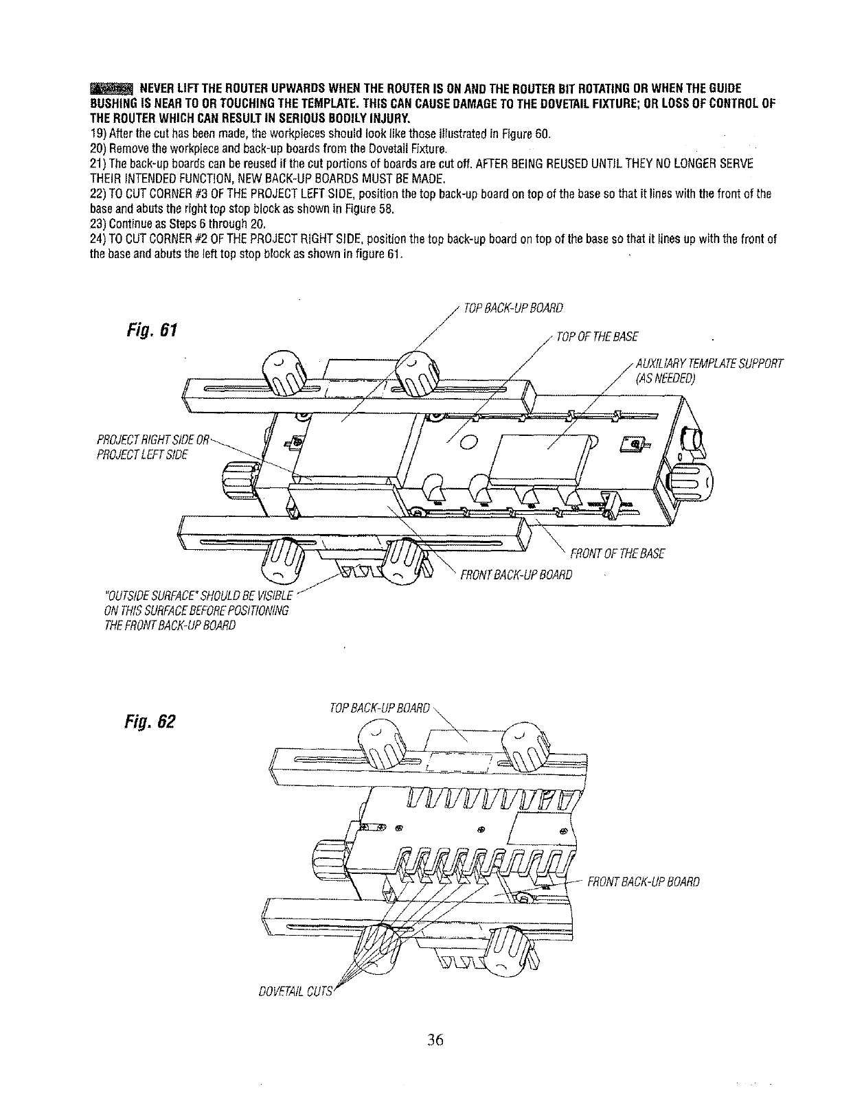
24)TOCUTCORNER#2 OFTHEPROJECTRIGHTSIDE,positionthe top back-upboardontop of the baseso thatit linesupwiththefront of
thebaseandabutsthe lefttop stopblockasshowninfigure 61.
TOPBACK-UPBOARD
Fig. 61 / / TOPOFTHEBASE .
f / AU,I ,AR TE , T SU,PBR
.....=. ,./ ., V
,RO,EDT ,ETSIDE..... //.-. --.-./ 7/ --"t%
"OUTSIDESURFACE_SHOULDBEVISIBLE/
ONTHtSSURFACEBEFOREPOSITtONING
THEFRONTBACK-UPBOARD
Fig. 62 TOPBACK-UPBOARD,
FRONTBACK-UPBOARD
DOVETAIL
36
25) Lightly clamp the back-up board in place.
26) Position the project side against the front of the base so that the top surface abuts the left front stop bIock, The useof a front back-up
board at this step is also recommended. It is positioned between the project side and the cIamping bar as shown in Figure 61. The front
back-up board is described in Step 7 above.
27) Continueas in Steps 8 through 19 above.
28) After the cuts have been made,the workpieces should look like those illustrated in Figure 62.
29) Remove the workpiece and the back-up boards from the Dovetail Fixture.NOTE:THE BACK-UP BOARDSAREREUSABLE.
30) TOCUT CORNER#4 OFTHEPROJECTLEFTSIDE, position the top back-up board on top of the base so that it fines up with the front of
the baseand abuts the left top stop block as shown is Figure 6!.
31) Continueas Steps 27 through 32 above.
32) At this stage the project sides should look like those iIfustrated in Figure 56,
THEFOLLOWINGDESCRIBESTHEPROCEDURETO BEFOLLOWEDFORCUTTINGTHEPROJECT
FRONTAND BACK:
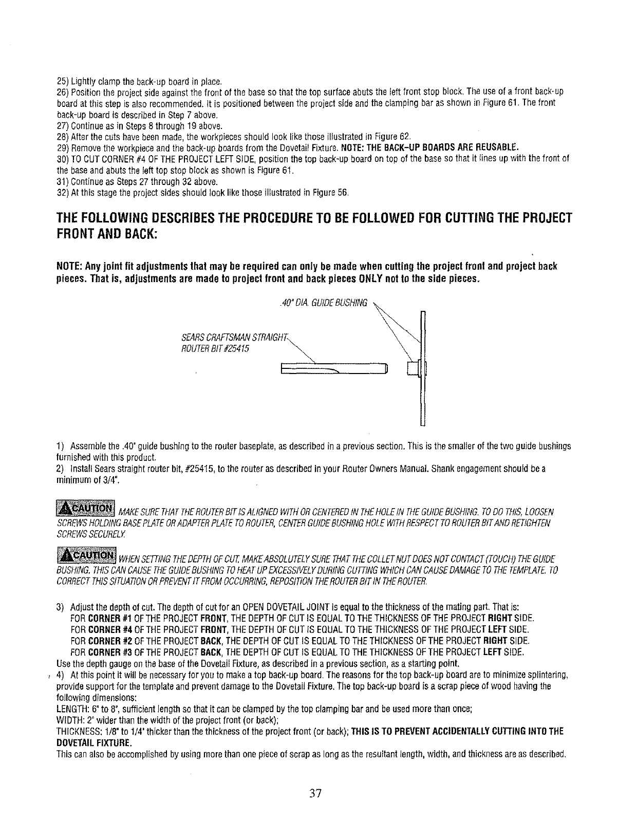
NOTE:Anyjoint fit adjustmentsthat may be required can only be made when cuttingthe projectfront and projectback
pieces. That is, adjustmentsare made to projectfront end backpieces ONLYnotto the side pieces,
.40"DIA,GUIDEBUSHING
SEARSCRAFTSMANSTRAIGHT\ _
ROUTERBIT#25415 _
1) Assemblethe .40"guidebushingto the routerbaseplate,asdescribedin aprevioussection.Thisis thesmallerof thetwo guidebushings
furnishedwiththis product,
2) InstallSearsstraightrouterbit,#25415,to therouterasdescribedinyour RouterOwnersManualShankengagementshouldbea
minimumof 3/4".
_i MAKESURETHATTHEROUTERBITfSALIGNEDWITHORCENTEREDtNTHEHOLEtNTHEGUIDEBUSHfNG.TODOTHIS,LOOSEN
SCREWSHOLDINGBASEPLATEORADAPTERPLATETOROUTER,CENTERGUIDEBUSHINGHOLEWITHRESPECTTOROUTERBfTANDRETIGHTEN
SCREWSSECURELY
_WHENSETTINGTHEDEPTHOFCUT,MAKEABSOLUTELYSURETHATTHECOLLETNUTDOESNOTCONTACT(TOUCH)THEGUIDE
BUSHING.THISCANCAUSETHEGUIDEBUSHtNGTOHEATUPEXCESSIVELYDURINGCUTTINGWHICHCANCAUSEDAMAGETOTHETEMPLATE.TO
CORRECTTHfSSITUATIONORPREVENTITFROMOCCURRING,REPOSITtONTHEROUTERBITtNTHEROUTER.
3) Adjustthedepthof cut. Thedepthof cutfor anOPENDOVETAILJOINTis equalto thethicknessof the matingpart,Thatis:
FORCORNER#1OFTHEPROJECTFRONT,THEDEPTHOFCUTIS EQUALTOTHETHICKNESSOFTHEPROJECTRIGHTSIDE.
FORCORNER#40FTHE PROJECTFRONT,THEDEPTHOFCUTIS EQUALTOTHETHICKNESSOFTHEPROJECTLEFTSIDE.
FORCORNER#2 OFTHEPROJECTBACK,THEDEPTHOFCUTIS EQUALTOTHETHICKNESSOFTHEPROJECTRIGHTSIDE.
FORCORNER#3 OFTHEPROJECTBACK,THEDEPTHOFCUTIS EQUALTOTHETHICKNESSOFTHEPROJECTLEFTSIDE,
Usethedepthgaugeonthebaseof theDovetailFixture,as describedin aprevioussection,asa startingpoint.
,4) Atthisp_intitwi__benecess_ryf_ry_ut_makeat_pb_ck_upb_ard_Thereas_nsf_rthet_pback_upb_ard_ret_minimizesp_intering_
providesupportfor thetemplateandpreventdamageto the DovetailFixlure,Thetop back-upboardis ascrappieceof wood havingthe
followingdimensions:
LENGTH:6"to 8",sufficientlengthso thatit canbeclampedbythe top clampingbarandbeusedmorethan once;
WIDTH:2"widerthanthewidthof theprojectfront(or back);
THICKNESS:1/8"to 1/# thickerthanthethicknessof the projectfront (orback);THISIS TOPREVENTACCIDENTALLYCUTI'INGINTOTHE
DOVETAILFIXTURE.
Thiscanalsobeaccomplishedby usingmorethanonepieceof scrapas longas the resultantlength,width, andthicknessareas described,
3?
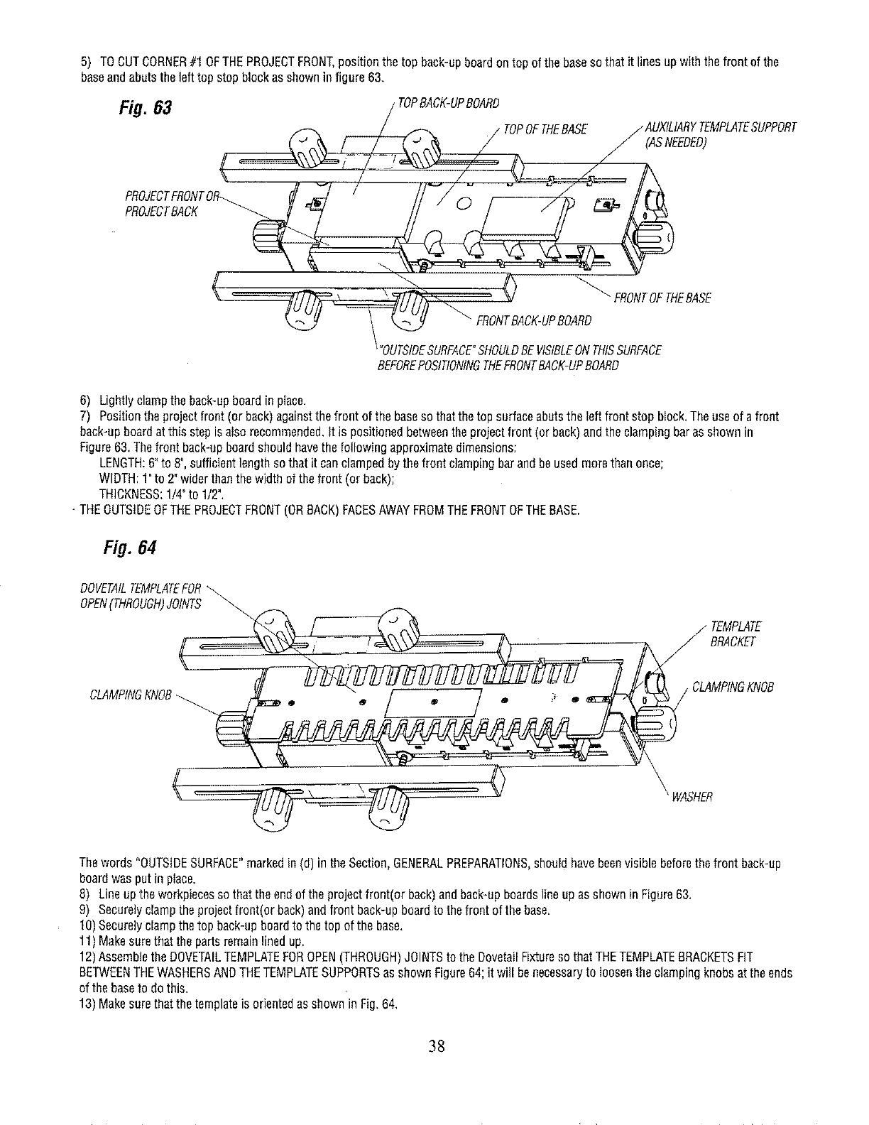
5) TOCUTCORNER#1 OFTHEPROJECTFRONT,positionthe top back-upboardontop of thebasesothat it lines upwiththe frontof the
baseandabutsthe lefttop stopblockasshowninfigure 63.
Fig.83 /TOPBACKUPBOARD
_/ TOPOFTHEBASE /'AUXILIARY TEMPLATESUPPORT
/CASNEEOEO,
( .... /
PROJECTBACK _ __
<> FRONTOFTNERASE
BEFOREPOSITIONINGTHEFRONTBACK-UPBOARD
6) Lightlyclampthe back-upboardin place.
7) Positiontheprojectfront(or back)againstthe frontof the baseso thatthetop surfaceabutsthe leftfrontstop bIock.Theuseof afront
back-upboardat thisstepisaIsorecommended.It is positionedbetweenthe projectfront(or back)andthedampingbaras shownin
Figure63.Thefrontback-upboardshouldhavethefollowingapproximatedimensions:
LENGTH:6"to 8",sufficientlengthso thatit canclampedbythe frontclampingbarandbeusedmorethanonce;
WIDTH:1"to 2"widerthanthe wJdthof thefront (orback);
THICKNESS:1/4"to 1/2",
-THEOUTSIDEOFTHEPROJECTFRONT(ORBACK)FACESAWAYFROMTHEFRONTOFTHEBASE,
Fig. 84
___( CLATEMPMTE
BRACKET
MPINGKNOB
_WASHER
Thewords"OUTSIDESURFACE"markedin (d)in theSection,GENERALPREPARATIONS,shouldhavebeenvisiblebeforethefront back-up
boardwasput inplace.
8) Lineupthe workpiecessothattheendof theprojectfront(orback)andback-upboardslineupasshowninFigure63.
9) Securelyclamptheprojectfront(orback)andfrontback-upboardto thefrontof the base.
10)Securelyclampthetop back-upboardto the top of the base,
11)Makesurethatthepartsremainlinedup.
12)AssembletheDOVETAILTEMPLATEFOROPEN(THROUGH)JOINTSto theDovetailFixtureso thatTHETEMPLATEBRACKETSFIT
BETWEENTHEWASHERSANDTHETEMPLATESUPPORTSasshownFigure64;it will benecessaryto loosentheclampingknobsat theends
of the baseto dothis.
13)Makesurethatthe templateis orientedasshownin Fig,64,
38
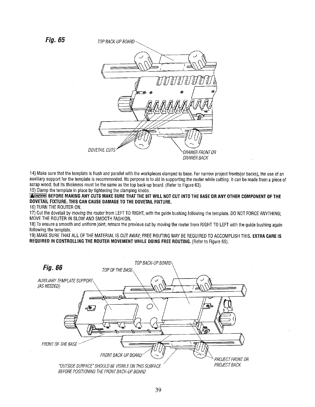
Fig.65 TOPBACK-UPBOARD_
DOVETAILC
DRAWERBACK
14)Makesurethatthetemplateis flushandparallelwiththeworkptecesdampedto base,Fornarrowprojectfronts(orbacks),the useof an
auxiliarysupportfor the templateis recommended.Its purposeis to aidin supportingthe routerwhilecutting,it canbemadefroma pieceof
scrapwood;butits thicknessmustbethe sameasthetop back-upboard,(Referto Figure63).
15)Clampthetemplatein placebytighteningthe clampingknobs.
BEFOREMAKINGANYCUTSMAKESURETHATTHEBITWILLNOTCUTINT0THEBASEORANYOTHERCOMPONENTOFTHE
DOVETAILFIXTURE.THISCANCAUSEDAMAGETOTHEDOVETAILFIXTURE,
16)TURNTHEROUTERON.
17)Cutthe dovetailby movingtherouterfromLEFFTORIGHT,withthe guidebushingfollowingthe template.DONOTFORCEANYTHING;
MOVETHEROUTERINSLOWANDSMOOTHFASHION.
18)Toensureasmoothanduniformjoint,retracethe previouscutby movingtherouterfrom RIGHTTOLEFTwiththe guidebushingagain
followingthetemplate.
19)MAKESURETHATALLOFTHEMATERIALISCUTAWAY;FREEROUTINGMAYBEREQUIREDTOACCOMPLISHTHIS.EXTRACARE18
REQUIREDINCONTROLLINGTHEROUTERMOVEMENTWHILEDOINGFREEROUTING,(Referto Figure65).
Fig. 66 TOPOFTHEBAsE_PBACK-UPBOARD_/_._
A.XILIARYT .PLATESU PORT, \
:ASNEEDED \ , -i -: 0
FRONTOETHEBASE_ /' \
/v -_PROJECTFRONTOR
/
"OUTSIDESURFACE"SHOULDBEVISIBLEONTHISSURFACE PROJECTBACK
BEFOREPOSITIONINGTHEFRONTBACK-UPBOARD
39
NEVERLIFT THEROUTERUPWARDSWHENTHE ROUTERIS ONAND THEROUTERBIT ROTATINGORWHEN THEGUIDEBUSH-
ING iS NEARTO OR TOUCHINGTHETEMPLATE.
20) After the cut bas been made, the workpiecesshould look like thoseillustrated in Figure 65,
21) Removethe workpiece and back-up boards from the Dovetail Fixture.
22) The back-up boards can bereused if the cut portions of boards are cut off. AFTERBEINGREUSEDUNTIL THEY NOLONGERSERVE
THEIR INTENDEDFUNCTION,NEW BACK-UPBOARDSMUST BE MADE,
23) TO CUT CORNER#3 OFTHEPROJECTBACK,position the top back-up board on top of the baseso that it lines with the front of the base
and abuts the left top stop block as shown in Figure 63.
24) Continue as Steps 6 through 24.
25) TO CUT CORNER#4 OFTHEPROJECTFRONT,position the top back-up beard on top of the baseso that it lines up with the front of the
baseand abuts the right top stop block as shown in figure 66.
26) Lightly clamp the back-up board in place,
27) Position the project front (or back) against the front of the baseso that the top surface abuts the right front stop block. The use of a fronl
back-up boardal this step is also recommended,It is positioned betweenthe drawer front (or back) and the clamping bar as shown in
Figure 66. The front back-up board is described in Step 7above,
28) Continue as in Steps 8 through 20 above.
29) After the cuts have made,the workpieces should Iook like those illustrated in Figure65.
30) Remove the workpiece and the back-up boards from the Dovetail Fixture. NOTE:THEBACK-UPBOARDSARE REUSABLE.
31) TO CUT CORNER#2 OFTHE PROJECTBACK,position the top back-up board on top of the base so that it lines up with the front of the
base and abuts the right top stop block as shown is Figure 66.
32) Continue as Steps 28 through 32 above.
33) The finished project front, back,and sides should look like those illustrated in Figure 56.
34) Check how the workpieces fit together_Some adjustments may be necessary. Referto the Section, MAKINGADJUSTMENTSFOROPEN
(THROUGH)FLUSHJOINTS
Your project is now readyto be gIuedtogether,
Removethe pencil markings by light sanding or with a soft eraserafter the parts have been glued together.
TROUBLESHOOTING:
*If thejointis too loose:Thisadjustmentcan onlybemadewhencuttingeitherthe front ortheback(pinpieces).Loosentheclamping
knobsholdingthetemplatebracketsandmovethetemplateOUTWARDbyturningthe camhandles,Continueadjustinguntildesiredjoint
fit is attained.Retightenthe clampingknobs.
= tt the joint is too tight: Thisadjustmenttoo canonly bemadewhencuttingeitherthefront orthe back(pin pieces).Loosenthe clamping
knobsholdingthetemplatebracketsandmovethetemplateINWARDbyturningthecamhandles.Continueadjustingunti!desiredjoint fit
is attained.Retightenthe clampingknobs.
• If the joint is too shallow:Referto Figure67,INCREASEthe depthof cutof therouterbit.Thisadjustmentcanbe madewhencuttingthe
front, theback,(pin pieces)andthesides(taiIpieces),
o If the joint is too deep:Referto Figure68. DECREASEthe depthof cut of the routerbit,Thisadjustmenttoo can bemadewhencutting
the front, the back,(pinpieces)andthesides(tailpieces).
,If the jointis not uniformlyspacedfromtop surfaceof drawer:Referto Figure69.(Seethe Section"ALIGNMENTOFTHETEMPLATES".)
Withthe templateclampedto the base,loosenthefour screwssecuringthe templateto the templatebrackets,andmovethetemplate
slightlyto theleft. Tightenthe four screwsandmakea trialcut. If movingthetemplateto the leftdid not correctthe condition,but madeit
worse,loosenthe screwsandmovethetemplateto the right aemalIamount.Makesurethetemp[ateremainsparallelto the front of the
dovetailbase.Tightenthefour screwsandmakea trial cut, Continuemovingthetemplateto the right untgthe conditionis completely
corrected.PROPERALIGNMENTOFTHETEMPLATESTOTHETEMPLATEBRACKETSISCRITICALFORJOINTUNIFORMITY.ONCETHiS
iSACCOMPLISHEDCORRECTLY,tTSHOULDNOTNEEDADJUSTMENTSAGAIN.MAKESURETOSECURELYTIGHTENTHEFOUR
SCREWS.AFTERTHETEMPLATESHAVEBEENCORRECTLYREALIGNED,THEYSHOULDREQUIRENOFURTHERADJUSTMENTSIF
THEYAREHANDLEDWITHCARE.
4O
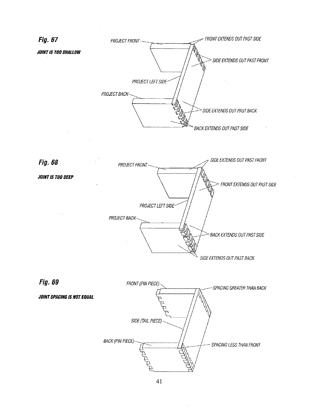
Fig. 67
JOINTIS TOOSHALLOW
PROJECTFRONT__ __.
PROJECTLEFTSlOE/
PROJECTBACI__
/
FRONTEXTENDSOUTPASTSIDE
_SIDEEXTENDSOUTPASTFRONT
Fi#.68 SIDEEXTENDSOUTPASTFRONT
JOINTIS TOODEEP
_FRONTEXTENDSOUTPASTSIDE
SIDEEXTENDSOUTPASTBACK
Fig. 69
JOINTSPACINGISNOTEQUAL
FRONT(PINPIECE)
SIDE(TAILPIECE)
BAOK(PINPIECE)
_SPACtNGGREATERTHANBACK
SPACINGLESSTHANFRONT
41

PARTS LIST for #171.25450 INDUSTRIAL DOVETAIL FIXTURE
KEY OTY PART NO.
I I 29LD-879
2 I 29LD-880
3 I 29LD-8BI
4 I 29LD-882
5 I 29LD-883
6 2 29LD-884
72 29LD-885
8 2 29LD-886
9 4 29LD-887
I 0 I 29LD-888
I! 4 29LD-889
12 6 29LD-890
13 2 29LD-891
14 I 29LD-892
15 4 29LD-895
16 2 29LD-896
17 I 29LD-899
!8 I 29LD-900
I9 4 29LD-901
20 I 45A-350
21 I 45A-351
22 I45A-352
23 I 45A-353
I 49LD-50
I NONE
24 4 29L-469-13
25 8 29L-469-14
26 I0 29L-469-15
27 2 29LD-841 -2
28 2 29LD-841 -3
29 3 29LD-841-4
30 I29L-684-6
31 3 29L-684-7
32 2 29A-310-15
33 2 29A-310-16
34 2 29A-310-17
35 4 29A-242-12
36 2 29A-242-I3
37 9 29A-306-37
38 8 29A-306-40
39 4 29LD-930
40 4 29LD-969
4! 4 29LCN-IO05
DESCRIPTION
DOVETAIL BASE
DOVETAIL TEMPLATE HALF BLIND JOINT
DOVETAIL TEMPLATE OPEN (THROUGH) JOINT
TEMPLATE SUPPORT (RIGHT SIDE)
TEMPLATE SUPPORT (LEFT SIDE)
CAM HANDLE
FRONT STOP BLOCK
TOP STOP BLOCK
CLAMPING BAR END CAP
RETAINER
BOLT SUPPORT
ICLAMPING KNOB
CLAMPING BAR
PIVOT SHAFT
TEMPLATE BRACKET
TEMPLATE STIFFENER
GUIDE BUSHING ASSEMBLY (.40" DIAMETER)
GUIDE BUSHING ASSEMBLY (I12" DIAMETER)
COMPRESSION SPRING
PRODUCT LABEL (CLAMPING BAR)
LABEL (TEMPLATE-BL IND)
LABEL (TEMPLATE-OPEN
WARNING LABEL (CLAMPING BAR)
INSTRUCTION MANUAL
BAGGED FASTENERS-CONSISTING OF :
#10-32 X 518" Ig. PANHEAD MACHINE SCREW
#I0-32 X 318" Ig. PANHEAD MACHINE SCREW
#8-36 X 3/16" Ig. PANHEAD MACHINE SCREW
#I0-32 X 518" Ig. FLAT HEAD MACHINE SCREW
#I0-32 X 7/8" Ig. FLAT HEAD MACHINE SCREW
_10-32 X 3/8" Ig. FLAT HEAD MACHINE SCREW
#IO-16 X I12" Ig. PANHEAD TAPPING SCREW
#I0-16 X I" 19. PANHEAD TAPPING SCREW
5/16-18 X 4-1/2" Ig. ROUND HEAD SQUARE NECK BOLT
5/16-18 X 3-I/2" Ig. ROUND HEAD SQUARE NECK BOLT
,5/16-18 X 2" Ig. ROUND HEAD SQUARE NECK BOLT
#I0-32 HEX MACHINE SCREW NUT
5ll6-18 HEX MACHINE SCREW NUT
3/64"1.D. X 9/I6"0,D. X 3/64"fhick WASHER
1/32"I.D. X 7/8"0,D. X 1/I6"thick WASHER
1/32"I,D. X 7/8"0,D. THIN NYLON WASHER
5/16"I,D, X 7/8"0.D. THICK NYLON WASHER
NYLON SPRING RETAINER
42
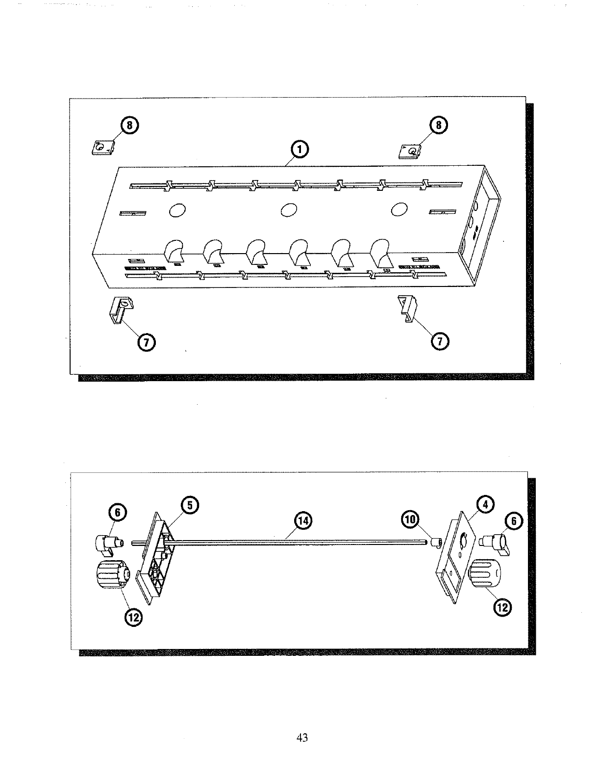
43
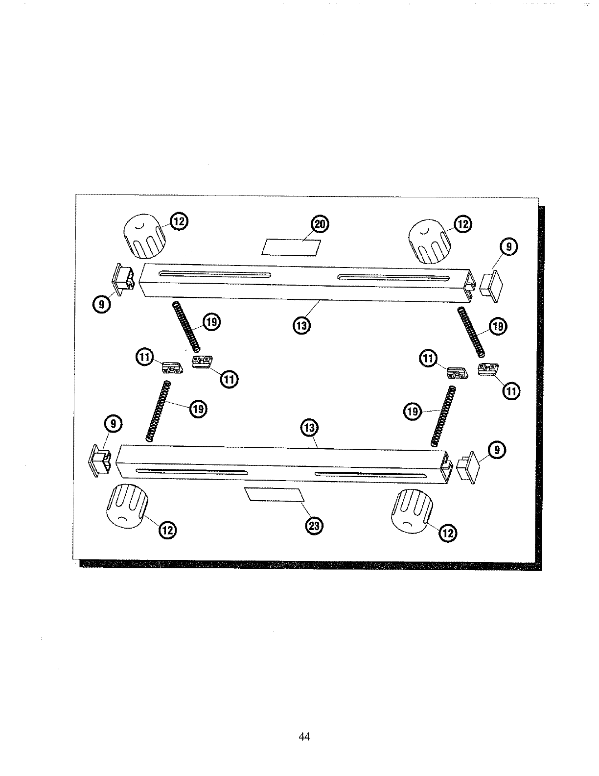
%
44
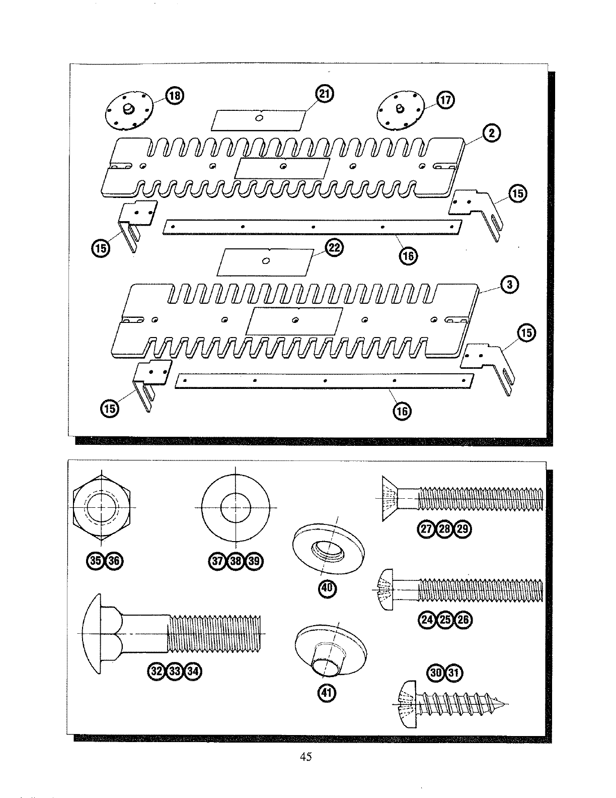
!
1
/ o /_®"/
L
. . ®
®
@
45

Notes
46

Notes
47

IIIII IIitII
49LD-60
MANUAL
Printed in U,S.A.
9/96
29LMD-50
When corresponding,alwaysgivethe following
informationas showninthe list.
1. The PARTNUMBER
2. The PARTDESCRIPTION
3. TheMODEL#171.25450
4. TheITEM NAME-iNDUSTRIALDOVETAILFIXTURE
