Craftsman 17125481 User Manual ROUTER TABLE Manuals And Guides L0909496
CRAFTSMAN Router Accessory Manual L0909496 CRAFTSMAN Router Accessory Owner's Manual, CRAFTSMAN Router Accessory installation guides
User Manual: Craftsman 17125481 17125481 CRAFTSMAN ROUTER TABLE - Manuals and Guides View the owners manual for your CRAFTSMAN ROUTER TABLE #17125481. Home:Tool Parts:Craftsman Parts:Craftsman ROUTER TABLE Manual
Open the PDF directly: View PDF ![]() .
.
Page Count: 16
CRAFr.3
_xeRouter Table
:CAUTION!_ReadAllInstructionsCarefully
(RouterNotIncluded)
i
i
Pa_No.49LCN:59
Solday:
SEARS,ROEBUCKAndCO.
3333 BeverlyRoad,
HoffmanEstates,IL 60179
Made In U,S.A.
Printed h7U,S.A.

FAILURETO HEEDALLSAFETYAND OPERATINGINSTRUCTIONS
ANDWARNINGSREGARDINGUSEOFTHIS PRODUCTCANRESULT
IN SERIOUS80DILY INJURY.
GENERALSAFETYINSTRUCTIONSFORPOWERTOOLS
1. KNOWYOURPOWERTOOL
Readthe owner's manualcarefully.Learnits applicationand
limitationsas well asthe specific potentialhazardspeculiarto this
toot.
2. GROUNDALLTOOLS(UNLESSDOUBLEINSULATED)
If tool is equippedwith anapproved3-conductor cord and a3-
prong groundingtype plug, it should bepluggedintoathreehole
electricalreceptacle,If adapteris usedto accommodatea two-
prong receptacle,theadapterwire must be attachedto known
ground, (usuaflythe screw securing receptaclecover plate).Never
removethird prong.Neverconnectgreen ground wire to a
terminal.
3. KEEPGUARDSIN PLACE
In working order,andin properadjustmentand alignment,
4. REMOVEADJUSTINGKEYSANDWRENCHES
Forma habit of checkingto seethat keys andadjusting wrenches
areremovedfrom too! beforeturning it on.
5. KEEPWORKAREACLEAN
Clutteredareasandbenchesinvite accidents,Floor must not be
slipperydue to wax or sawdust.
6. AVOIDDANGEROUSENVIRONMENT
Don't usepower tools in damp or wet locationsor exposetllem to
rain. Keepwork areawel!lighted: Provideadequatesurrounding
work space.
7. KEEPCHILDRENAWAY
All visitors should be kepta safedistancefrom work area.
8. MAKEWORKSHOPKID-PROOF
Usepadlocks,masterswitches, or removestarter keys.
9, DON'TFORCETOOLS
It wilt do the job betterand saferat the rate for which it was
designed,
10. USERIGHTTOOL
Don'tforcetoot or attachmentto do a job it was not designedfor.
11. WEARRIGHTAPPAREL
Do not wear loose clothing,gloves, necktiesor jewelry (rings,
wrist watches)to get caugt]tin moving parts, Nonslipfootwear is
recommended,Wear protectivehair coveringto contain long flair.
Roll long sleevesabovethe elbow.
12. USESAFETYGOGGLES(HeadProtection)
WearSafetygoggles(mustcomplywith ANSI'Z87,1)at alltimes.
Also, use faceor dust mask,if cutting operationis dusty,andear
protectors (plugs or muffs) during extendedperiodsof operation.
13. SECUREWORK
Useclamps or a viseto hold work when practical, It's saferthan
using your hands,andit frees both handsto operatetool,
14. DON'TOVERREACH
Keepproper footing and balanceat atftimes.
i5. MAINTAINTOOLSWITHCARE
Keeptools sharp and cleanfor bestand safestperformance.
Follow instructions for lubricatingand changingaccessories.
16. DISCONNECTTOOLS
Before servicing,when changingaccessoriessuch as blades,bits,
cutters, etc.
17. AVOIDACCIDENTALSTARTING
Make sure switch is in "OFF"position before pluggingin.
18. USERECOMMEND_EDACCESSORIES
Consult the owner's manualfor recommendedaccessoriesand
follow the instructions,The use of improper accessoriesmay
causehazards.
19. NEVERSTANDONTOOL
Serious injury could occur if the tool is tippedor if the cutting tool
is accidenta!lycontacted. Do not store materials aboveor nearthe
tool makingit necessaryto stand onthe tool to reachthem.
20. CHECKDAMAGEDPARTS
Beforefurther use of the tool, any guardor other part that is
damagedshould becarefullycheckedto ensure that it will operate
properly and perform its intendedfunction. Checkforalignmentof
moving parts, binding of moving parts, breakageof parts,
mounting, andany other conditions that may affect its operation.A
guard or any other part that is damagedshould be properly
repairedor replaced.
21. DIRECTIONOF FEED
Feedwork into a bladeor cutter againstthe direction of rotation of
the bladeor cutter only.
22. NEVERLEAVETOOLRUNNINGUNATTENDED
Turn power off. Don't leavetool until it comes to a completestop,
ENERALSAFETYI UCTI THE
LEWITH UNITIZEDFENCE.
1. ALWAYSUSEEYEPROTECTION
Theoperationof any powertoo!can result inforeign objects being
throwninto the eyes,which can result in severeeyedamage.
Alwayswear safetygoggles beforecommencingpower tool
operation,Safetygoggles areavailableat Searsretail or catalog
stores,
2. KEEPHANDSCLEAROF BITSANDWORKINGAREA
3. MAKEANOUSEA PUSHSTICKTOMOVESMALL
WORKPIECESACROSSTHECUTTINGAREA.
4, KEEPROUTERCLEANAFTEREVERYUSE,CLEANSAWDUST
OFFTHEROUTER.
5. YOURROUTERTABLEiS PROVIDEDWITHA DUST
COLLECTINGATTACHMENTALWAYSUSESHOPVACFORALL
ROUTINGOPERATIONSREQUIRINGUSEOF FRONTSIDEOF
UNITIZEDFENCE.(FRONTSiDEtS THESIDEWITHTHE
CRAFTSMANLABEL).
NOTE:Motors usedon wood-working tools areparticularly
susceptibleto the accumulationof sawdustandwood chips and
should be"vacuumed" frequently to preventinterferencewith
normal motor ventilation.
6. CHECKFUNCTIONOFGUARDBEFOREEACHUSE.REMOVE
ALLDUSTANDCHIPSFROMGUARDAREAASNEEDEDTO
MAINTAINGUARDFUNCTION.
7. NEVERPUTYOURFINGERSUNDERTHEGUARDWHENTHE
ROUTERIS PLUGGEDIN.
8, ALWAYSUSETHEROUTERTABLEFENCETO GUIDETHE
WORK.DONOTWORKFREEHAND.
When using pilot type bits, keepthe fences as closeto the pilot as
possibleto provideadditional backupand additionalguidanceand
to avoid chancesof an accidentandpossiLllepersonalinjury, ,
9. ALWAYSFEEDAGAINSTTHEROTATIONOFTHECUTTER
WHENROUTINGON THEROUTERTABLE.FEEDWORKPIECESIN
THEDIRECTIONOFTHEARROWAS SHOWNONTHELABELON
THESIDEOFTHEFENCEBEINGUSED(WHENFACINGTHE
TABLEFRONT).
10. FORALLEDGECUTTINGANDENDCUTrlNGOPERATIONS,
USEFRONTSIDEOF UNITIZEDFENCE.USEBACKSIDEOF
FENCEONLYFORROUTINGOPERATIONSAWAYFROMEDGEON
THEUNDERSIDEOFWORKPtECESUCHAS GROOVING,
FLUTING,VEINING,CROWNMOLDING,ETC.
11. WHENENDCUTTINGONWORKPIECES'4"WIDEOR LESS,
CLAMPAND HOLDAND FEEDTHEWORKPIECEWITHTHEPUSH
BLOCKUSINGBOTHHANDS,AS SHOWNiN FIG. #23. KEEP
FINGERSCLEAROF BITWHENMOVINGWORKPIECEACROSS
THECUTTINGAREA.NEVERPLACEYOURHANDSLOWERTHAN
THETOPOFRETRACTABLEGUARD.
12. ROUTERBITSARE_:_rREMELYSHARP.
Beextracarefulwhen working around them.
13, SOMEROUTERS,WHENUSEDIN AN UPSIDEDOWN
POSITION(SUCHAS ONA ROUTERTABLE),WILLFALL(OR
DROP)OUTOFTHEROUTERBASEWHENTHEBASECLAMPIS
LOOSENED+IT IS THEREFOREABSOLUTELYNECESSARYTO
SUPPORTTHEROUTERMOTORFROMBELOWWHENTHEBASE
CLAMPIS LOOSENEDTO MAKEADJUSTMENTS,OR FORANY
OTHERREASON.
t4. ALWAYSLOOKUNDERTHETABLEATTHESWITCHWHEN
TURNINGTHEROUTERON!OFFANDTOUCHNOTHINGBUTTHE
SWITCH,NEVERREACHUNDERTHETABLEWHENROUTERtS
RUNNINGFORANYOTHERREASON.
NOTE:It is far more safeand convenientto usea "Craftsman
+25183 RouterTableSwitch package".This switch providesa key
o 1
peratedON/OFFbutton-whichallowsfast andeasyaccesswhen
and if it becomesnecessaryto turn the router "OFF"quickly,The
keycan beremovedto renderthe switch inoperableto
unauthorizedpeople.
15. MOUNTROUTERTABLEFIRMLYAND SECURELYTOA
WORKSURFACEBEFOREUSE.FAILURETO DOSOCOULD
CAUSETABLETOTiP OVEROR SLIDEDURINGOPERATION
RESULTINGIN PROPERTYDAMAGEAND/ORSERIOUSBOOILY
INJURY.
16. BEFOREMAKINGANYCUT,UNPLUG
ROUTERAND RETRACTGUARDTO
MAKEABSOLUTELYSURETHATRETRACTABLEGUARDCLEARS
THEROUTERBIT,ANDTHEGUARDIS FUNCTIONING
NORMALLY.SEEFIG. #16.
17. WARNING:ROUTERVIBRATIONS
SOMETIMESCANCAUSEFASTENERS
FORTHETABLE,THEROUTERANDTHEUNITIZEDFENCETO
GETLOOSErPERIODICALLYCHECKFASTENERSTOMAKESURE
THEYARETIGHTAND SECURE,
INTRODUCTION
Howoften haveyou neededa largeguiding surfaceon a router table? YourCraftsmanRouterTablewith UnitizedFencecomes with ttle
following:
• A unique4" high unitizedfencedesignedto assist end grain
routing for makingtenons, sliding dovetailsandtongue and
groovejoints along with most edgeand facecutting operations.
•A speciallydesignedpush blockwith quick clamp for back up
and clampingboards up to 4"width for endgrain routing.
• An accurateand quick adjustingjointing fenceadjustableto
properjointing depth of cut.
• Reversingfeatureof unitizedfencedesignedto enablerouting
operationslike grooving,fluting, veining andcrown molding etc.
up to 2_" awayfrom the edgetowards the mid,die of the board.
• Twoguardsfor operationon either side of ihe unitizedfence.
• Dust co!lectingattachmentfor most sllop vacuum hook ups,
•Extensionsthat providea largework surface.
If orderto facilitatehandlingand minimizeany damagethat might occur during shipment,your new router table is packaged
unassembled.We knowyou are anxiousto seewhat yOurnew too! wil! do, but a few minutes spent now carefullyreadingthe following
instructionswill result in lessfrustration and more enjoyableoperation later,
Startby checking andaccountingfor all the loose parts, If any partsare missing,contact your local Craftsmanretail or hardwarestore
outletfor replacement.
OPTIONALROUTERTABLEACCESSORIES
#25326CRAFTSMANUNIVERSALADAPTERPLATE,for mounting non-Craftsman1/4" shank routersto Craftsmanrouter accessories.
#25183CRAFTSMANROUTERTABLEPOWERSWITCH,for turning router and other accessories"on" and"off" from the front of the
router table, i
#25468CRAFTSMANGUIDEMASTERRouterTablePush Shoe,aids in push shoe and hold down operations,accuratemeasurementand
router table setup,transforms into a miter gauge,and givesquick set up for 1/2"sliding dovetailjoints.
#25489CRAFTSMANROUTERTABLEFLOORSTAND,placesrouter tablesat convenientworking height,has adjustablefloor levelers,
andtwo steelshelvesfor storage,
UNPACKINGANDCHECKINGCONTENTS
Referto PartsList on Page16
YOUMUST READANDUNDERSTANDALLTHEINSTRUCTIONSCOMPLETELYBEFOREATTEMPTINGTO
ASSEMBLEANDOPERATEYOURROUTER/ROUTERTABLE,
TOOLSREQUIRED
, A smalland medium sizescrewdriver.
•A small or medium sizeadjustablewrench,
•An electricalor hand drill with 1/8"drill bit,
• Hammer
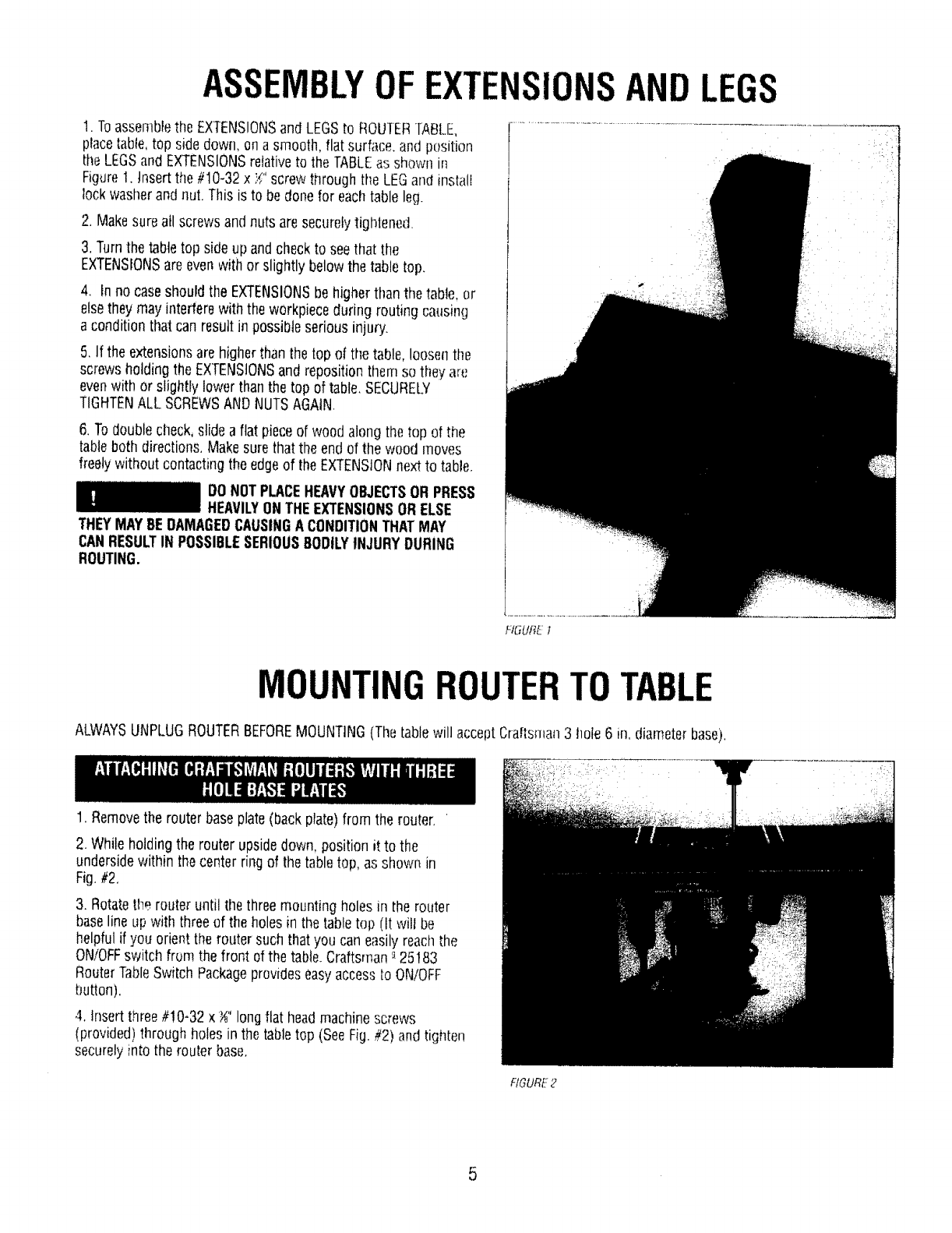
ASSEMBLYOF EXTENSIONSAND LEGS
t. Toassemblethe EXTENSIONSand LEGSto ROUTERTABLE,
placetable,top side down, on a smooth, flat surfi_ce,and position
the LEGSand EXTENSIONSrelativeto the TABLEas shown in
Figure1. htsert the #10-32 xYi'screwthrough the LEGand install
lock washerandnut. This is to bedone for eachtable leg.
2, Makesure all screws andnuts aresecurelytightened,
3. Turnthe tabletop side up andcheckto see that tfm
EXTENSIONSare evenwith or slightly belowthe table top.
4, In no caseshould the EXTENSIONSbehigher thanthe table, or
elsetheymay interferewith the workpieceduring routing causing
a conditionthat can resultin possibleserious injury.
5. If the extensionsarehigherthan the top of the table, loosenthe
screwsholding the EXTENSIONSand repositionthem so they art;
evenwith or slightly lower than the top of table, SECURELY
TIGHTENALL SCREWSANDNUTSAGAIN,
6. To doublecheck,slide a flat pieceof wood along the top of the
tableboth directions,Makesurethat the end of the wood moves
freelywithout contactingthe edgeof the EXTENSIONnextto table,
DO NOTPLACEHEAVYOBJECTSOR PRESS
HEAVILYONTHEEXTENSIONSORELSE
THEYMAYBEDAMAGEDCAUSINGA CONDITIONTHATMAY
CANRESULTIN POSSIBLESERIOUS80DtLYINJURYDURING
ROUTING.
FIGURE 1
MOUNTINGROUTERTO TABLE
ALWAYSUNPLUGROUTERBEFOREMOUNTING(The tablewill acceptCraftsman3 hole 6 in. diameterbase).
, i:f •
1. Removethe router baseplate(back plate)from the router. '
2. While holding the router upsidedown, position it to the
undersidewithin the centerring of the table top, as shown in
Fig.#2,
3. Rotatethe router until the three mountingholes in the router
baselineup with threeof the holes in the table top (It will be
helpfulif you orient the router suchthat you can easilyreach the
ON/OFFswitch from the front of the table.Craftsman_-25183
RouterTableSwitch Packageprovideseasyaccessto ON/OFF
button).
4. Insert three #!0-32 x _" longflat headmachinescrews
(provided) through holes in the tabletop (SeeFig,#2) and tighten
securelyinto the router base.
FIGURE2
5

SELECTINGANDINSTALLING[ABLEINSERTS
1.With the desiredbit in the router,selectatable insertwhich has a
centerholeslightly largerthanthe diameterof the router [)it. Note:
Forbits largerthan approximately!_;" diameter,do not usean
insert,
2, Thetable insertsare designedto besnappedinto the router table.
Stidethe largetang under the edgeof the largehole in the router
tableas shownin Fig.#3. Usingyour thumb, pressdown on the
insertuntil the smalltang snaps into position
3, Toremovethe insert, placethe bladeof asmall screwdriverinto
the slot (with the smalltang) and pry the insert out of [he router
table.
BEFOREASSEMBLINGANDATTACHING
UNITIZEDFENCETOTABLE,MAKESURE
THATROUTERIS UNPLUGGEDANDTHEBIT IS BELOWTHETOP
SURFACEOFTHETABLE.
HGURE3
ASSEMBLYOFUNITIZEDFENCE
1, Slidejointing fencethrough rectangularopeningin the cavity
providedon the unitizedfence(ribs on the unitizedfencewill slide
in the grooveson the undersideof jointing fence). SeeFig.#4a &
#4b.
2, Insert ;./.-20x t" tong hex headbolt through the hole in the
unitizedfence (from the underside)and the slot in the jointing
fence,
3. While holdingthe headof the bolt in the hex recesson the
undersideof unitized[ence,placea flat washerover the bolt and
screwsmall _-20 knob on bolt.
Whenknob is loosened,the jointing fencecanslide backand forth
in the cavityfor proper iointing adjustment.
FIGURe."4a
FIGURE4b
6

1. Placethe unitizedfenceupsidedown on a flat surface as shown
in Fig.#5a &#Sb.
2. Orient the retractableguardas shown in Fig,#5a b.
Positionand hold the spring over its hub such that formed end of
spring wrapsover the guard as shown in Fig.#So& #5b.
3. While holdingthe spring overthe hub, and formed end over the
guard, positionand pressthe straight legof spring againstsurface
'X' to align holein hubover bosson unitizedfence(see Fig.#5a &
#5b). Slipthe guardover the boss, Spring wil! now betrapped
betweenthe guardand the fence.(Spring diameteris biggerthan
the hub diameter.Youwill needto use both handsto hold spring
in proper position,).
4, Tightly secureretractableguardin placeusing set! threading #8-
10 x _" long panheadptasformscrew anda flat washer as shown
in Fig.#5a b,
5, Swing guarda few times in the direction of arrow to see that it
retractsout freelyby itself and returnsto its normal positionover
the routertable hole. SeeFig.#5a b.
NOTE:If the guarddoes not retractout freely, loosenscrew just
enoughuntil it does retract out freelyand snapsback to normal
forward position by itself,
6. Turn the unitizedfenceright side up.
f.'K._URE5a
FIGURE5b
ATTACHMENTOFUNITIZEDFENCEASSEMBLY
TOTABLE
FROMTABLE.
ALWAYSUNPLUGROUTERBEFORE
ATTACHINGFENCETOAND REMOVING
1. Assembleunitizedfenceassemblyto table as shown in Fig.#6.
2. Insert oneof the _-20 x 1_" long hex headbolts through the
holein the tabletop (from the underside)and the slot in the fence.
3. While holding the headof the bolt in the hex recesson the
undersideof the tabletop,placea flat washerover the bolt and
installa large'_-20 knob onto the bolt to looselysecurethe fen_:e.
4, Repeatfor tile other slot,
NOTE:The unitizedfenceassemblycan be attachedto bible with
either sidefacingthe front, Touse other side,justremovethe
knobsandturn the fencearound.
RGURE6
7
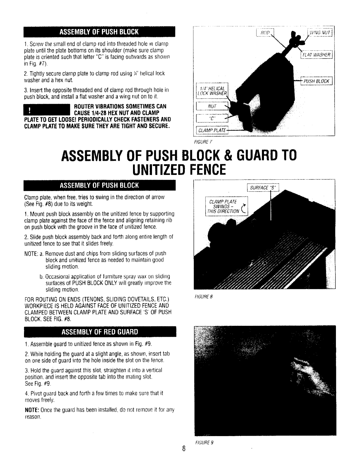
!, Screwthe small endof clamp rod into threadedhole m clamp
ptateuntil the platebottoms on its shoulder (makesure clamp
plate is orientedsuch that letter "C" is facing outwardsas shown
in Fig,//7).
2. Tightlysecureclamp plateto clamp rod using _" helical lock
washerand a hex nut.
3, Insert the oppositethreadedendof clamp rod through hole in
pushblock, and installa flat washeranda wing nut on to it.
ROUTERVIBRATIONSSOMETIMESCAN
CAUSE1/4-28 HEXNUTANOCLAMP
PLATETOGETLOOSEtPERIODICALLYCHECKFASTENERSAND
CLAMPPLATETO MAKESURETHEYARETIGHTANDSECURE.
,NUT
i[ CLAMPPLATE-
RGURE F
i
'FLAT WASHER
"PUSH BLOCK
ASSEMBLYOF BLOCK& GUARDTO
UNITIZED
Clampplate,whenfree,tries to swing in the directionof arrow
(SeeFig.#8) due to its weight.
t. Mount push blockassemblyon the unitizedfenceby supporting
clampplateagainstthe face of the fenceand aligning retaining rib
on push blockwith the groove in the faceof unitizedfence,
2. Slide push blockassemblybackand forth alongentire length of
unitizedfenceto seethat it slidesfreely.
NOTE:a, Removedustand chips from sliding surfacesof push
blockand unitizedfenceas neededto maintaingood
sliding motion.
b, Occasionalapplicationof furniturespray wax on sliding
surfacesof PUSHBLOCKONLYwilt greatly in]provethe
sliding motion,
FORROUTINGON ENDS(TENONS,SLIDINGDOVETAILS,ETC,)
WORKPIECEIS HELDAGAINSTFACEOFUNITIZEDFENCEAND
CLAMPEDBETWEENCLAMPPLATEANDSURFACE'S'OFPUSH
BLOCK.SEEFIG.#8.
FIGURE8
1. Assembleguardto unitizedfenceas shown in Fig,#9,
2. While holdingthe guardat a slight angle,as shown, inserttab
on oneside of guardinto the holeinside the slot on the fence.
3, Hold the guard againstthis slot, straighten it into avertical
position,and insert the oppositetab into the matingslot.
SeeFig,#9.
4, Pivotguardbackand forth a fewtimes to makesure that it
movesfreely.
NOTE:Oncethe guard has beeninstalled,do nol removeit for any
reason,
FIGURE9
8

THEROUTERTABLEMUSTALWAYSBEFIRMLYANDSECURELY
MOUNTEDTOA WORKSURFACEBEFOREUSE.FAILURETO DO
SOCOULDCAUSETABLETOTIP OVERORSLIDE,RESUL.TINGIN
PROPERTYDAMAGEANDIORSERIOUSPERSONA[.INJURY,
Eachleghas (4} lloles at the bottom for mounting. Firmly secure
router table to work surface usingappropriate fasteneis(not
provided)as shownin Fig,#10.
Attach 1"x 6"or 2" x 6"skids to bottom of legs as shown in Fig.
#10. then securetable firmly to work surface.
FIGUREI0
Unitizedfenceis providedwith a hookup for most Craftsman2_"
and 1¼"hose diameterwet!drj vats.
FORALL OPERATIONSREQUIRINGUSEOFFRONT-SIDEOF
UNITIZEDFENCE,connectwet/dry vacas follows:
1. Raiseguardand leanit againstthe fence,
2. Attach2_" hosediameternozzleas shown in Fig.#'! 1.
3. Attach 17" hosediameternozzleas shown in Fig. #12,
4. Lowerguard andlet it rest on the vac hose.
NOTE'.Formaximum suction efficiency,stick a pieceof tape or use
a pieceOfscrapwood to cover upthe openingin the rear of the
fenceas shownin Figures1! and 12. Uncoveropeningafter use,
FOROPERATIONSREQUIRINGUSEOFBACKSIDEOF
UNITIZEDFENCE,DONOTCONNECTWET/DRYVACAS IT
WILL HINDEROPERATION,THEBACKSIDEOFFENCE1SONLY
FORCUTTINGOPERATIONSONTHEUNDERSIDEOF
WORKPIECETHEWORKPIECEDURINGSUCHOPERATIONS
COMPLETELYCOVERSTHEROUTERBITAND THEDUST
CANNOTBEVACUUMED.
OPERATINGROUTERTABLEWITHOUTUSE
OFWET/DRYVACMAYRESULTtN
EXCESSIVECOLLECTIONOFSAWDUSTAND CHIPSUNDERTHE
FENCEANDTHERETRACTABLEGUARDAREA,
FORYOUROWNSAFETY,ALWAYSUNPLUGTHE ROUTERAND
CHECKFUNCTIONOFGUARDBEFOREEACHUSE REMOVE
DUSTANDCHIPSFROMGUARDAREAASNEEDEDTO
MAINTAINGUARDFUNCTION,KEEPWORKAREACLEAN.
REMOVEUNITIZEDFENCEFROMTABLE(MAKESUREROUFEr_
tS UNPLUGGED)TO CLEAROUSTANDCHIPSTRAPPED
BElWEENFENCEANDTABLETOE
FIGURE11
FIGURE 12
9
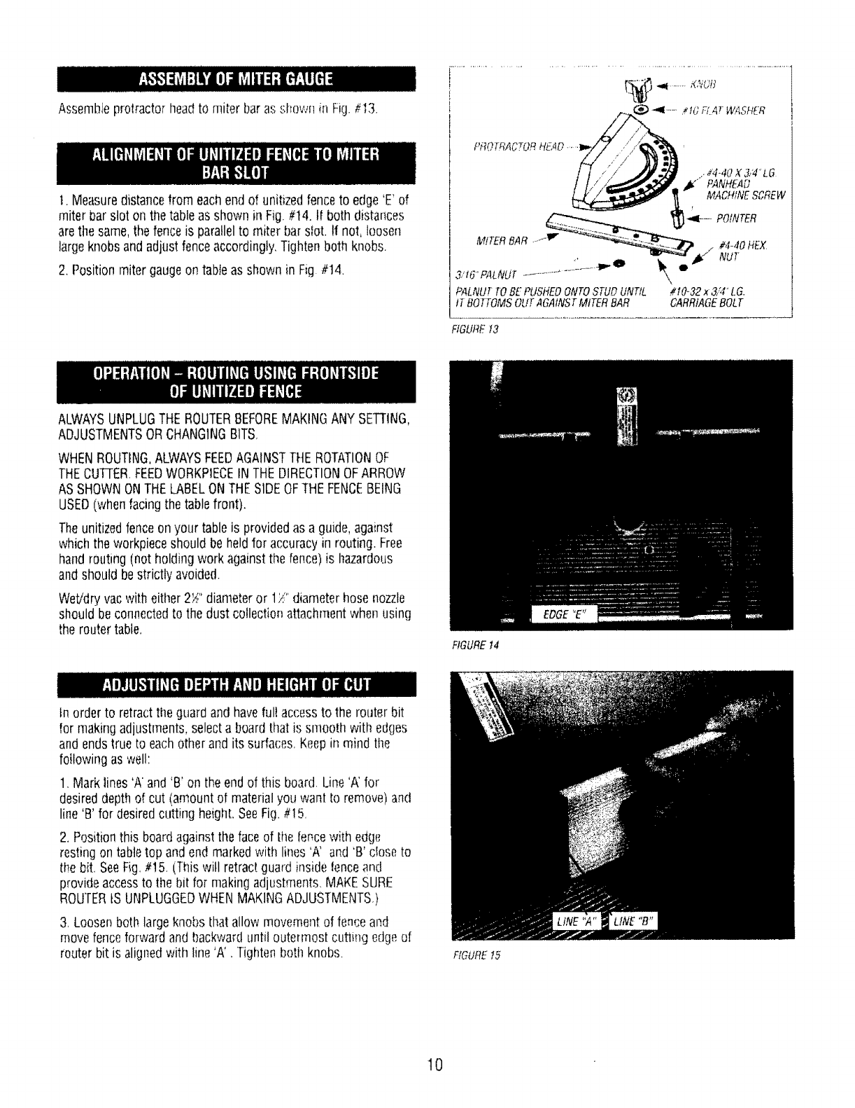
Assembleprotractor headtOmiter baras shown in Fig.#13.
1. Measuredistancefrom each endof unitizedfenceto edge'E' of
miter barslot on thetable as shownin Fig.#t4. If both distances
arethe same,the fenceis parallelto miter barsfot. !t not, loosen
largeknobs andadjust fenceaccordingly,Tightenboth knobs.
2. Position miter gaugeon tableas shown in Fig #14.
.. _4-417X 3/4 LG
,_" PANHEAD
MACHINESCREW
__"t¢"*......._ -_-- POtNTER
HEX
/
3,'t6'f'ALNUT............... \,
PALNU_TOBE PU,S'HEOONTOSTUDUNTIL #t0-32 x 3,;4"LG.
tT BOTTOMSOUT AGAINSTMtTER BAR CARRtAGEBOLT
FIGURE13
ALWAYSUNPLUGTHEROUTERBEFOREMAKINGANY SETTING,
ADJUSTMENTSORCHANGINGBITS,
WHENROUTING,ALWAYSFEEDAGAINSTTHEROTATIONOF
THECUFrER FEEDWORKPIECEIN THEDIRECTIONOFARROW
AS SHOWNONTHELABELONTHESIDEOFTHEFENCEBEING
USED(when facingthe table front).
Theunitizedfenceon your table is providedas a guide, against
whichthe workpieceshould be heldfor accuracyin routing. Free
handrouting (not holding work againstthe fence)is hazardous
andshould bestrictly avoided.
Wet/dryvacwith eitller 2S" diameteror 1/" diameterhose nozzle
should be connectedto the dust collectionattachmentwhen using
the router table,
FIGUREt4
tn orderto retractthe guardand haveful! accessto the router bit
for makingadjustments,select a boardthat is smooth with edges
and endstrue to eachother and its surfaces,Keepin mind the
foi!owing as wel!:
1. Mark lines 'A and 'B' on the endof this board. Line'A' for
desireddepth of cut (amount of materialyou want Io remove)and
line'B' for desiredcutting heighLSeeFig.#I 5,
2. Positionthis boardagainsttheface of tile fencewith edge
restingon tabletop and endmarkedwith lines 'A' and 'B' dose to
the bit. SeeFig,#t5. (Thiswill retractguard inside tenceand
provideaccessto the bit for makingadjustments,MAKESURE
ROUTERtS UNPLUGGEDWHENMAKINGADJUSTMENTS.)
3, Loosen both largeknobs thatallow movementof fence and
movefenceforwardand backwarduntil outermostcutting edgeef
router bit is alignedwith line 'A'. Tightenboth knobs. FfGUREt5
t0

4. Raiseor lower the _outeruntil top cutting edg(_cf bd _,.__f!:(m,}d
with line 'B. (Referto your router ownel's !rla,llual hji' adjusliq_ I
your router proper}y).AFTERMAKINGTHISAOJUS:rMENT,i-3E:
SURETHATROUTERIS SECURELYTIGHTENEDtN ]HE ROUTER
BASE,BITtS SECURELYTIGHTENEDIN THEROUTEF_CHUCK,
ANDROUTERBASEIS 1tGHTLYSECUREDTO TABLETOK
5, Removethe boardflora the fence,
WHENADJUSTINGHEIGHTOF ROUTER
BITFORANYDESIREDCUT,MAKE
ABSOLUTELYCERTAINTHATTOPOF BITIS BELOWTHEINSIDE
SURFACEOFRETRACTABLEGUARD,ASSHOWNIN FIG. #16,
CHECKTO SEETHATGUARDRETRACTSFREELYIN ANDOUTOF
FENCETOITS NORMALPOSITIONOVERTHEROUTERTABLE
HOLE, DONOTOPERATEROUTERIF ANYPARTOFTHEBIT
CONTACTSTHEGUARD.
NOTE:The proceduredescribedaboveis intendedto provide a
wayof retractingand holdingthe guard to havefull accessto the
_outerbit for makingadjustment&Workpieceto be routed could
besubstituted for the scrap boardfor makingadjustmertts.
For maximumstrength and accuracy,boards to be joinedtogether
should be smooth andtrue. Theedgesshould be true to the (90°)
workpiecesurface,You cantrue the edgesof workpieceon your
router table using a straight bit.
!, Checkto see if faceof jointing fence is flush with the faceof
unitizedfence, If not, loosensmall knob on jointing fenceand
push jointing fenceinside the cavity in unitizedfence.Tightenknob
on jointiag fence.
NOTE:The jointing fenceprovidesa continuous support for the
workpiece,as it is fed beyondthe router bit, tt compensatesfor
the amount of materialremovedby the router bit,
2. Adjustdepth of cut (materialyou want to remove)and router bit
l]eightas describedbeforefor Fig,#!5, Tightly securethe fence
andthe router as describedbefore.(MAKESUREROUTERIS
UNPLUGGEDWHENMAKINGADJUSTMENTS.)
3. Checkyour adjustmentsby turning the router 'ON'and feeding
a pieceof scrapwood a few inchesbeyondrouter b_t.Thenstop
andturn router 'OFF',
NOTE:Feedwork in the directionof arrow shown on labelon the
frontside of unitizedfence(whenfacingtable front).
4, Loosenknob on jointing fenceandmove it out flush againsti:l]e
finishededgeof scrapwood, Retightenthe knob SeeFig _17.
5. Repealthe test cut on the scrapwood.
6. Therouter table is now readyfor use,
NOTE:For bestjointing results,takevery shallowcuts _--/;:,"or
less.
1. Positionthe jointing fence suchthat its faceis flush with the
faceof unitizedfence.Tightensmall knob on jointing fence.See
Fig,#! 8,
fIGUREt6
FIGURE17
RGURE t8
11
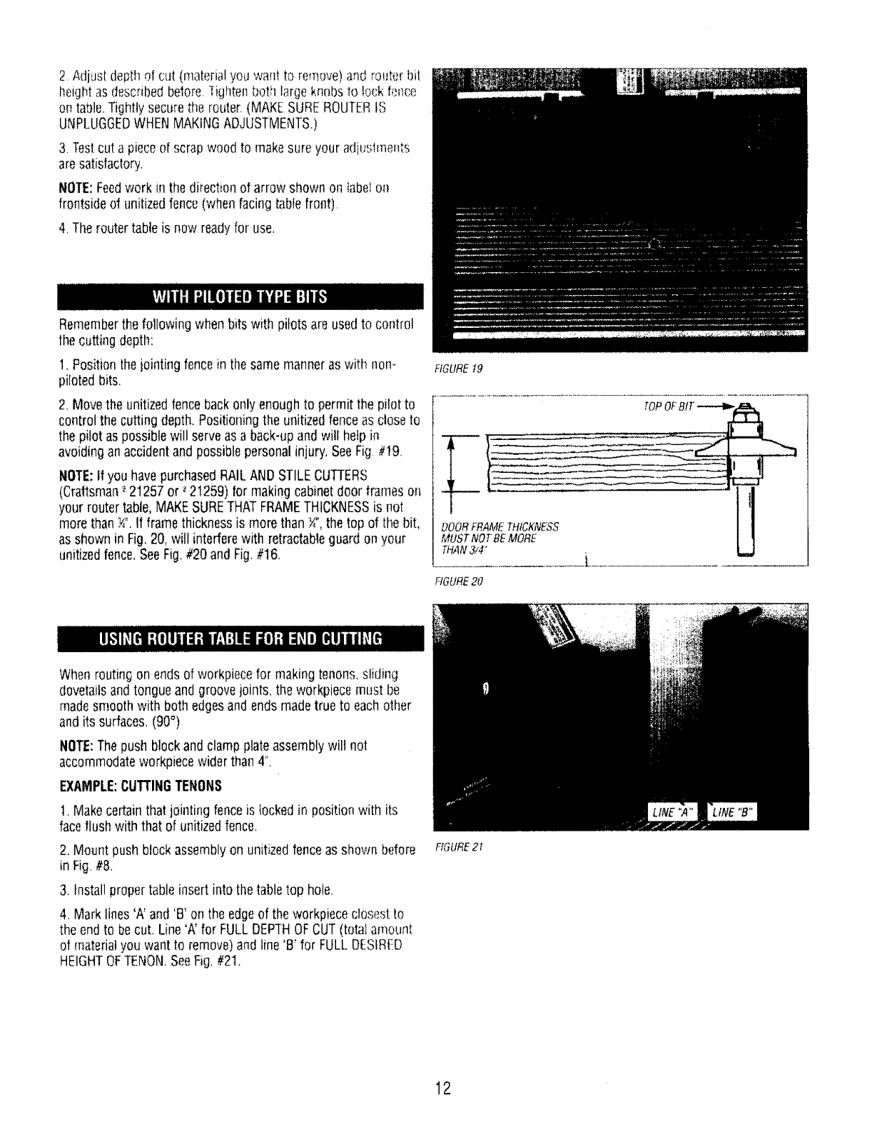
2_Adjusldepthof(;ut(materialyouwanttoremove)and routerbit
Ileight as d_,scribedbefore.Tightenboth largeknobs to lock fence
on table.Tightly securethe router,(MAKE SUREROUTERtS
UNPLUGGEDWHENMAKINGADJUSTMENTS,)
3. Testcut a piece of scrap wood to makesure your adjuslments
aresatisfactory.
NOTE:Feedwork in the direction of arrow shown on label on
frontside of unitizedfence(when facing tablefront),
4, The router table is now readyfor use,
Rememberthe following when bits with pilots are usedto control
the cutting depth:
1. Positionthe jointing fencein the samemanner as with non-
piloted bits.
2, Movethe unitizedfencebackonly enoughto permit the pilot to
controlthe cutting depth.Positioningthe unitizedfenceas close to
the pilot as possiblewill serveas a back-upand will help in
avoidingan accidentand possiblepersonalinjury, SeeFig.#!9.
NOTE:if you havepurchasedRAILAND STILECUTFERS
(Craftsman-_21257 or _21259) for makingcabinetdoor frames on
your router table,MAKESURETHATFRAMETHICKNESSis not
more than _". II frame thicknessis more than _", the top of i[f_ebit,
as shown in Fig.20, will interferewith retractableguard onyour
unitizedfence, SeeFig.#20 and Fig.#16,
When routing on endsof workpiecefor making tenons,sliding
dovetailsandtongue andgroove joints, the workpiecemust be
madesmooth with both edgesandends madetrue to eachother
and its surfaces. (90°)
NOTE:Thepush blockand clampplate assemblywilt not
accommodateworkpiecewider than 4".
EXAMPLE:CUTTINGTENONS
1. Makecertainthatjointing fenceis lockedin position with its
faceflush with that of unitizedfence.
2. Mount push blockassemblyon unitizedfence as shown before
in Fig.#8.
3. Install propertable insert into the table top hole,
4, Marklines 'A' and'B' on the edgeof the workpiece closest to
the endto becut. Line'A' for FULLDEPTHOFCUT (totalamount
of materialyou want to remove)andline 'B' for FULLOEStRED
HEIGHTOFTENON.SeeFig.#2t.
FIGURE_19
THAN3/4"
FIGURE20
[
FfGURE21
12

DONOTSETDEPTHOF CUTMORETHAN
_" (FIG. #23). IF DEPTHOFCUTIS MORE
THAN %",THEEDGE'E' OFWORKPIECEWHENSLIOtNG
ACROSSWILL INTERFEREWITHPORTION'P' OFGUARD.THE
GUARDTHENWILLNOTRETRACTINSIDEFENCE,ANDYOU
WILLNOTBEABLETOSLIDEWORKPIECEACROSSTHEBIT TO
MAKETHECUT,SEEFIG. #24.
5. POsitionworkpiecebetweenclampplate andpush block such
that its side is held flushagainstfaceof the unitizedfence,el_(ito
becut is restingon the edgeof the table top hole andedge
markedwith lines 'A' and 'B' is facingthe router bit. Clamp
workpiecein this position by snuglytightening the wing nut on
clamp rod while makingsure that clamp platestays orientedon
workpieceas shownin Fig.#21. (This will retract guard inside the
fenceandprovideaccessto the bit for making adjustments.MAKE
SUREROUTERIS UNPLUGGEDWHENPOSITIONINGAND
CLAMPINGWORKPIECEAND MAKINGADJUSTMENTS)
NOTE:Tightenwing nut just enoughto clamp workpiece in
position. OVERTIGHTENINGwing nut could causebinding in tim
sliding motion of push block, which in turn may resultin variations
andlor steps in thefinishedtenon surface when cut. SeeFig, #25.
6. Slideworkpiececloseto the bit andadjust unitizedfenceand
the router as describedbefore,so that outer-most cutting edgeof
bit is alignedwith line'A' and top cutting edgeof bit is alignedwith
line 'B'. SeeFig,#21. Tightly securethe fenceand the router, as
describedbefore in ADJUSTINGDEPTHANDHEIGHTOFCUT.
7. Slidepush blockandworkpiece backto let guard swing out to
its normal positionas shown in Fig. #14.
8. Turn router and wet/dryvac 'ON'. While holding push biock
GUIDEWORKPIECEAGAINSTFENCEWITH BOTHHANDS(Fig.
#23 ) and FINGERSATSAFEDISTANCEABOVEGUARD
ANDSPINNINGBIT.Feedworkpieceacross the bit to makeFULL
DEPTHOFCUTtN ONEPASS(DONOTSTOPFEEDUNTIL
WORKPIECEIS FARENOUGHBEYONDSPINNINGBITTOALLOW
GUARDTO RETRACTOUTFULLYTO ITSNORMALPOSITION).
NOTE:Clampand test cut a pieceof scrapwood Io ci:leckyour
adjustmentsbeforemakingyour finishedcut.
9. Turnrouter and wet/dry vac 'OFF'.Unclampworkpieceand slide
push blockback,
10. Positionand clampthe oppositeskJeof workpiece in tile same
manneras describedin Step #5 (makesure the wing nut is tight
just enoughto clamp workpiecein position and end to becut is
restingon the edgeof table top hole.} Repeatslops #7. #8, and
#9.
11, Tocut endsof the tenon, positionand clamp workpiecein the
samemanrmras in step#5 above,exceptedgeof workpiece
should be hetdflush againstfaceof fenceand end to becut
should be restingon edgeof table top hole, SeeFig.#24, Repeat
steps#7, #8, #9, and#10.
•" ' " , 3,"8' MAX.DEPTH
f
3,'8"&'lAX.DEPTH
o_-CUr
FIGURE22
HGURE23
EDGE "E"
_ i ¸ i :' ¸¸ ?
#IGURE24
13

NOTE:When cutting tenons,alwaysclamp work[)ic(:_,_,_.Ati,(:nd to
becut restingon edgeof tabletop hote,1his will inmnuizeste_s m
finishedtenor]surface (Fig.#25) dueto w.triationsin lhe tabletop
flatness,
ALWAYSCUTFULLDEPTHON ALL4 SIDES
OFTENONIN ONEPASSACROSSTHE6IT,
ONCETHESIDESARECUTANDIF STEPSOROTHER
IMPERFECTIONSARENOTICEDON FINISHEDTENONSURFACE,
CLEANTHEMWITHWOO0CHISEL,SANDPAPERORFILE,ETC.
DONOTTRYTO CLEANTHEMBY RE-SETTINGWORKPIECEON
ROUTERTABLEAND FENCE,WORKPIECEMAYINTERFERE
WITHGUARD(SEEFIG. #21) WHICHiN TURNWILLPREVENTIT
FROMSLIDINGACROSSTHEBIT.
STEPStNFINISHED
TENONSURFACE
FIGURE25
OPERATION ROUTINGUSINGBACKSIDEOF
UNITIZEDFENCE
USEBACKSIDEOFFENCEONLYFORROUTINGOPERATIONS
AWAYFROMEDGEONTHEUNDERSIDEOFWORKPIECE,SUCH
AS GROOVING,FLUTING,VEINING,CROWNMOLDING,ETC,
ALWAYSUNPLUGTHEROUTERBEFOREMAKINGANY SETTING,
ADJUSTMENTS,ORCHANGINGBITS.
WHENROUTING,ALWAYSFEEDAGAINSTTHEROTATIONOF
THECUTi'ER.FEEDWORKPtECEINTHE DIRECTIONOFARROW
ASSHOWNON LABELONTHESIDEOFFENCEBEINGUSED
(when facingthe table front),
DO NOTCONNECTWET/DRYVACWHENUSINGBACKSIDEOF
FENCE,THEHOSEWILL HINDEROPERATION.
t. Removeboth largeknobsand k._-20x 1_" lg. hex headbotts,
turn the unitizedfence aroundandattach it backto table with
backsideof fencefacingthe table front. SeeFig.#26. (MAKE
SUREROUTERIS UNPLUGGEDWHENREMOVINGAND
ATTACHINGFENCETOTABLE).
2. Raiseguardand let it leanagainst,the fence.
3. Positionthe fencebehindthe router bit for the desiredcutting.
depth (the distanceof the cut from the edgeof the workpiece,as
shown in Fig.#27).
FIGURE26
FIGURE27
14

4. S(;cureivllgh!(!n br}thkn(}b::_andi i)WER ll-fi} f_lJ_&iq_:_,_');.;_:t:_
THEBIT
5. Make,die cut fly sli(lmg,shai[,hi _,,_I!j-;_'o! wo_kpiecea:lamStt!]e
fence.(For eachsucc_ssve cut, the fencewould needto bc
readjtJsted.)
NOTE:Testcol a pieceof scrapwood before makingyotir finish(!d
cut. Feedworkpiecein the directiondarrow shownon _er_c__,label
(Fig.//28).
NOTE:When routing deepcuts (conboiled by router bit) in a
workpie(,e,removematerialin incrementsto preventyour router
from overloading.Repeatoperationwith severalpassesuntil the
desireddepth is achieved.
F!GLIR_28
PROTRACTOR
Yourprotractorwill serveas a !landyaidwhen extrasupportis
neededfor routing smallworkpiecesor endsoi' largeworkpiec:e,s.
SeeFig.#29.
NOTE:FORALL ROUTINGOPERATIONSREQUIRINGUSI!:OF
MITERGAUGEALONGWITHTHEFENCE.BESURETOALIGN
FENCEwrrH MITERBARSLOTBEFOREMAKINGANY CU]S
SEEFIG.#14,
FIGURE29
NOTES
15
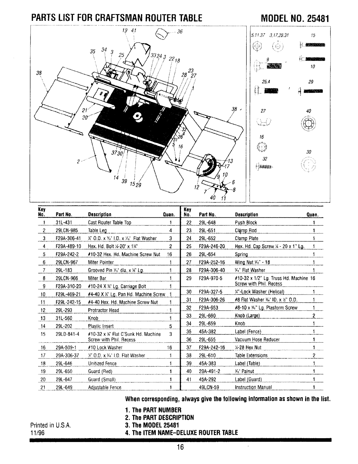
PARTSLIST FORCRAFTSMANROUTERTABLE
!-_ 4t _'_.._ ..... 36
Key
No. PartNO,
! 31L-431
2 29LCN-985
3 F29A*306-41
4 F29A-489-10
5 F29A-242-2
6 2gLeN-967
7 29L-183
8 29LCN-966
9 F29A-310-20
tO F29L-469-21
I1 F29L-242-15
t2 29L-293
13 31L-560
14 29L-202
15 29LDo841-4
16 29A-509-1
17 29A-306-37
18 29L-645
19 29L-650
20 29L-647
2_ ...... 2__:6_9._....... AAdjustableFence
t
,/
J
14 39
/
/
/
29
Description Quan,
CastRouterTableTop 1
TableLeg_ 4
Y_"O.D.x ?d' !O, x/,_" FiatWasher 3
Hex.Hd, Bolt ¼-2(YxI:Y,' 2
#10-32Hex. Hd,MachineScrewNut 16
Miter Pointer 1
GroovedPinY¢ dia,x _"_LL_
Miter Bar 1
#!0-24 X ¾"Lg_CarnageBolt t
#4-40 x ¾"Lfl, PanHd. MachineScrew !
#4-40 Hex.Hd. MachineScrewNut 1
ProtractorHead '1
Knob 1
PlasticInsert 5
#!0-32 x _" FlatC'SunkHd. Machine 3
Screwwith Phil. Recess
#10 LockWasher 16
_" O,D.x _" I.O.FlatWasher 1
UnitizedFence I
Guard(Red) 1
Guard(Small) 1
Key
No,
22
23
24
25
26
27
28
29
MODELNO. 25481
5.I .3_ 3,t7.28.31 lb
'_,_-h ' {t[Lt&WaIIIiMB
25,4 29
27 40
t6
-';'i;'_ 30
J[" :__
Parl No. Oescrtlltlon Quan.
29L-648 PushBlock 1
29L-65t Ct_m£Rod 1
29L-652 C]am_Plate t
F29A-246-20 Hex.Hd. CaPScrew¼- 20 x 1" Lg, 1
29L-654 Spring 1
F29A-252-16 Wing.Nut _" - ! 8 ....... 1
F29A-306-40 W' FlatWasher 1
F29A-970-5 #10-32x1/2" Lg.TrussHd. Machine t6
Screwwith Phi!.Recess
30 F29A-327-5 _"-Lock Washer(He!ica!) 1
31 F29A-306-26 #8 FlatWasher¾_"IO. x _" 0.0. 1
32 F29A-653 #8-10 x _" Lg. PlasformScrew 1
33 29L-660 Knob£Lar__ 2
34 29L-659 Knob 1
35 45A-382 Label(Fence) 1
36 29L-655 VacuumHoseReducer 1
37 F29A-242-16 _4-28HexNut 1
38 29L-610 TableExtensions 2
39 45A-383 Label(Table_]. 1
40 29A-491*2 Y,"Palnut !
41 45A-292 Label6___.uard__ 1
49LCN-59 instruction Manual 1
Printed in U.S.A,
11/96
I]1111!11 ........
Whencorresponding,alwaysgivethefollowing informalionas shownin thelist.
1. The PART NUMBER
2. The PART DESCRIPTION
3. The MODEL 25481
4. The ITEM NAME-DELUXE ROUTER TABLE
16
