Craftsman 183172520 User Manual ROUTER Manuals And Guides L0209317
CRAFTSMAN Router Manual L0209317 CRAFTSMAN Router Owner's Manual, CRAFTSMAN Router installation guides
User Manual: Craftsman 183172520 183172520 CRAFTSMAN ROUTER - Manuals and Guides View the owners manual for your CRAFTSMAN ROUTER #183172520. Home:Tool Parts:Craftsman Parts:Craftsman ROUTER Manual
Open the PDF directly: View PDF ![]() .
.
Page Count: 26
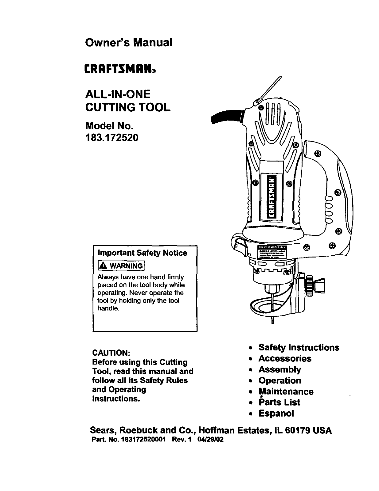
Owner's Manual
rRRFTSMAN®
ALL-IN-ONE
CUTTING TOOL
Model No.
183,172520
Important Safety Notice
[& WARNING I
Always have one hand firmly
placed on the tool body while
operating, Never operate the
tool by holding only the tool
handle.
®
CAUTION:
Before using this Cutting
Tool, read this manual and
follow all its Safety Rules
and Operating
Instructions.
• Safety Instructions
•Accessories
• Assembly
• Operation
• _aintenance
• Parts List
•Espanol
Seam, Roebuck and Co., Hoffman Estates, IL 60179 USA
Part. No. 183172520001 Rev. 1 04/29102
SECTION PAGE
Warranty ..... 2
ProductSpec_lcations 2
PowerTool Safety . .. 3
CuttmgToolSafety ...... 4
ElectricalRequirements& Safety 5
Accessooes 6
SECTION PAGE
Carton Contents 6, 7
Know Your Cutting Tool ..... 8
Assembly & Operation 9 - 18
Mamtenance .... 18
Repatr Parts .. 19 - 25
Parts &Servtce Avaiiabtl_ .... 26
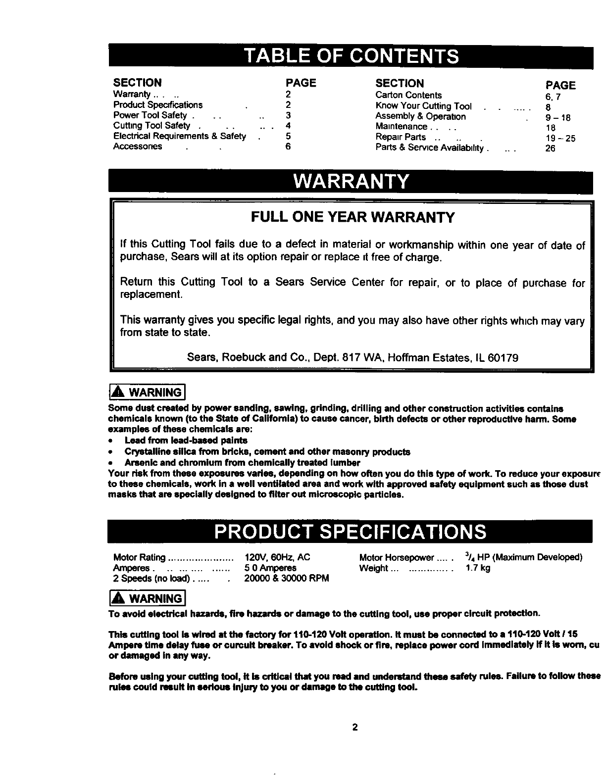
FULL ONE YEAR WARRANTY
If this Cutting Tool fails due to a defect in material or workmanship within one year of date of
purchase, Sears will at its option repair or replace tt free of charge.
Return this Cutting Tool to a Sears Service Center for repair, or to place of purchase for
replacement.
This warranty gives you specific legal rights, and you may also have other rightswhich may vary
from state to state.
Seam, Roebuck and Co., Dept. 817 WA, Hoffman Estates, IL 60179
IA WARNINGI
Some dust created by power sanding, sawing, grinding, drilling and other construction activities contains
chemicals known (to the State of California) to cause cancer, birth defects or other reproductive harm. Some
examples of these chemicals ere:
•Lead from lead-based paints
•Crystalline silica from bricks, cement and other masonry products
•Arsenic and chromium from chemically treated lumber
Your risk from these exposures vadsa, depending on how often you do this type of work. To reduce your exposur_
to these chemicals, work in a well ventilated area and work with approved safety equipment such as these dust
masks that are specially designed to filter out microscopic particles.
Motor Rating...................... 120V, 60Hz, AC
Amperes ................ 5 0 Amperes
2 Speeds (noload) ..... 20000 & 30000 RPM
Motor Horsepower ..... 3/4HP (Maximum Developed)
Weight ................. 1.7 kg
IAWARNINGI
To avoid electrical hazards, fire hazards or damage to the cutting tool, usa proper circuit protection.
This cutting tool Is wired st the factory for 1t0-t20 Volt operation. It must be connected to a t10-120 Volt 115
Ampere Ume delay fuse of ourcult breaker. To avoid shock or fire, replace power cord Immedistaly ff It Is worn, cu
or damaged In any way.
Before using your cuffing tool, it Is critical that you reed and understand these safety rules. Failure to follow these
rules could result in serious Injury to you or damage to the cutting tool.
2

IA WARNING I
Before using your cutting tool, it is critical that you read and understand these safety rules.
Failure to follow these rules could result in serious injury to you or damage to the cutting tool.
Good safety practices are a combination of common
sense, staying alert and understanding how to use your
power tool To avoid mistakes that could cause senous
inJury,do not plug in your cutting tool until you have read
and understood the following safety rules:
1 READ and become famikar with this entire Owner's
Manual LEARN the tool's applications, hmttahons and
possible hazards.
2 I& WARNINGI
Lookforthtssymbolthat identtfies importantsafety
precautionsIt means CAUTIONI BECOME ALERT!
YOUR SAFETY IS INVOLVED!
15
16
17.
18
REMOVE ADJUSTING KEYS AND WRENCHES
Form the habit of checking to see that keys and
adjusting wrenches are removed from the tool before
turning "ON"
NEVER LEAVE TOOL RUNNING UNAI"rENDED.
TURN THE POWER "OFF" Do not leave the tool
before it comes to a complete stop
NEVER STAND ON TOOL Serious injury could occur
if the tool is tipped or if the cutting tool ts
unintenhonally contacted
DO NOT OVER REACH Keep properfoohngand
balance at all times
3
4.
5
6
7.
8.
9
KEEP GUARDS IN PLACE and in workingorder
DO NOT USE IN A DANGEROUS ENVIRONMENT
such as damp or wet locations or exposure to ram
Keep work area well lighted
DO NOT usa power tools mthe presence of
flammable hquJdsor gases.
KEEP WORK AREA CLEAN Clutteredareas and
workbenchesmwteacozdents
KEEP CHILDREN AWAY All visitorsshouldbe kept
at a safe d_stancefromthe workarea
DO NOT FORCE THE TOOL It will do thejob better
and safer at the rate for which it was desHgned
USE THE RIGHT TOOL. Do not forcethe toolor
attachmentto do a job for whichit is notdesigned
19 MAINTAIN TOOLS WITH CARE Keep tools sharp
and clean for most effioient and safest performance
Follow mstruchons for lubricating and changing
accessories
20. CHECK FOR DAMAGED PARTS Before further use
of the tool, a guard or other part that is damaged
should be carefully checked to ensure it wdl operate
properly and perform its intended function Check for
alignment of mowng paris, binding of moving parts,
mounting and any other condihons that may affect its
safe operation. A guard or other part that Is damaged
should be properly repaired or replaced
21 MAKE WORKSHOP CHILD PROOF wdhpadlocks,
master switchesor by remowngstarterkeys
22. DO NOT operate the tool if you are under the
influence of any drugs, alcohol or medicehon that
could impair your ability to usa the tool safely
10. WEAR PROPER APPAREL. DO NOT wear loose
clothing,gloves,neckttes,nngs,braceletsor other
jewelrythat mayget caught in movingparts Non-skp
footwearis recommended Wear protectivehatr
coveringto containlonghair.
23 USE DUST COLLECTION SYSTEM wherever
posstble Dustgeneratedfrom certain materialscan
be hazardousto your healthand in some cases,a fire
hazard Alwaysoperate the powertool =na well
ventilatedarea with adequate dustremoval.
11. WEAR A FACE MASK OR DUST MASK. Sawing,
cutting,dnllingand sandingoperationsproduce
hazardousdust
12. DISCONNECT TOOLS FROM THE POWER
SOURCE before servicing and when changing
accessones such as blades, bits, cutters, etc
13 REDUCE THE RISK OF UNINTENTIONAL
STARTING Make sure the switch is _nthe "OFF"
position before plugging into the power source
14 USE ONLY RECOMMENDED ACCESSORIES
Consultthe Owner's Manualfor recommended
accesaones The use of =mproperaccessonesmay
cause inJuryto youor damage to the tool.
24. ALWAYS WEAR EYE PROTECTION Any power tool
can throw foreign objects into
your eyes which could cause
permanent eye damage.
ALWAYS wear safety goggles
(not glasses) that comply with
ANSI safety standard Z87 1 Everyday glasses have
only =mpact res=stant lenses They ARE NOT safety
glasses Safety goggles are available at Sears.
iAWARNINGI
Glasses or goggles not in compliance with ANSI
Z87.1 could cause serious injury when they break.
SAVE THESE INSTRUCTIONS FOR REFERENCE
3

For your safety, do not plug in your cutting tool or try
to use any accessory until It Is completely assembled
and installed according to these instructions, and
until you have read and understood this Owner's
Manual.
Failure to follow these safety rules will result in risk of
serious injury.
1 WEAR EYE PROTECTION This hnghspeed tool wnll
throw particles from the workpnece during operatnon
Make sure safety glasses have sfde shields
2 USE FACE OR DUST MASK along wtth safety
goggles If cutting or reutmg operatnon nsdusty Make
sure work area _swell venhlatad
3 USE HEARING PROTECTION, particularly dunng
extended periods of operahon
4NEVER USE DULL OR DAMAGED BITS Damaged
bits can break without warning Dull bits may ovedoad
the motor, cut slowly and are difficult to control They
will also overheat and possrbly break
5 ALWAYS MAKE SURE THE WORKPIECE IS FREE
OF NAILS AND OTHER FOREIGN OBJECTS If the
butstrikesa nail it wnlljump sudewaysand possibly
break
6 DO NOT USE THIS TOOL FOR DRILLING HOLES
It usNOT intended to be used as a droll
7ALLOW CLEARANCE UNDER WORKPIECE for bit
to travel Never placeworkpnecaon hard surfaces
suchas concreteetc The bitmay jump or breakwhen
contactinga surfaceotherthan the one beingcut
ALWAYS SET THE DEPTH GUIDE TO THE
APPROPRIATE DEPTH Use tool wnththe depth
guide fiat agaunst the work surface for better control of
the tool
9 NEVER USE THE TOOL WITHOUT THE SOLE
PLATE, PRECISION HANDLE OR ROUTER BASE
attachedand apprepnatelyadjusted
10 ALWAYS CLAMP WORKPIECE TO HOLD IT
STEADY WHEN CUTTING Thts wnllfree both hands
for oberatnngthe tool
11. NEVER HOLD THE WORKPIECE IN ONE HAND
whale operating the tool wnththe other hand
12 NEVER PLACE HANDS iN THE PATH OF THE
CUTTER AND UNDER THE WORKPIECE.
13 NEVER START THE TOOL WHEN THE BIT IS
TOUCHING THE WORKPIECE. The butmay catch
the workpaece causing loss of control.
14 ALWAYS HOLD THE TOOL WITH TWO HANDS
DURING START-UP AND OPERATION When
starting, motor torque w=llcause the tool to twist
15 TURN OFF ALL CIRCUIT BREAKERS AND
REMOVE ALL FUSES =nthe work area when cutting
unto walls or blind areas
16 ALWAYS HOLD THE TOOL BY THE INSULATED
GRIPPING SURFACES ON THE BODY OF THE
TOOL where there usany possnbnhtyof the cutting but
contacting hidden electrncalworesor the cord of the
tool Contact wth "live"wureswill make exposed meta
parts of the tool "lave"causing an electrical shock to
the operator.
17 WHEN CUTTING DRYWALL ELECTRICAL OUTLET
OPENINGS usnngthe outlet as a guile, always cut =n
a counter clockwise darectlon.The natural tendency o_
the tool to pull to the left wdl cause a "huggnng"acbon
toward the outlet box, resulting =na nearer cut.
18 NEVER LAY THE TOOL DOWN UNTIL THE
CUTrING BIT COMES TO A COMPLETE STOP A
spnnnmgbit can come m contactwiththe surfaceand
pullItout of yourcontrol
19 NEVER TOUCH THE CUTTING BIT IMMEDIATELY
AFTER USE. The bit will be too hot to be handled wltt
bare hands and wnllburn your fingers
2O ALWAYS RE-TIGHTEN COLLET AND ALL
ADJUSTMENTS before starting the tool after a cuttan_
bd or accessory has been changed Loose batsand
adjustments can cause unexpected shdtmg of the tool
resuitung m loss of control and unluryfrom the butor
cutting tool being thrown
SAVE THESE INSTRUCTIONS FOR REFERENCE
4
BZo)gl :! N:il_ k.'l_gliF_,1II[o] _
This cutting tool is double insulated to protect you from
electrical shock
IA WARNING I
Double insulated tools are equipped with a polarized
plug (one blade is wider than the other). This plug will
fit into a polarized outlet only one way. if the plug
does not fit fully into the outlet, reverse the plug. If it
still does not fit, contact a qualified electrician to
install a polarized outlet. Do not alter the plug in any
way. Double insulation ehmmates the need for the three
wire grounded power cord and grounded power supply
system
Avoid body contact with grounded surfaces such as
pipes, radiators, ranges and refrigerators. There is an
increased risk of electric shock if your body is grounded
Do not expose power tools to rain or wet conditions.
Water entenng a power tool will increase the nsk of
electric shock
Do not abuse the cord. Never use the cord to carry the
tool or pull the plug from the outleL Keep cord away
from heat, oil, sharp edges and moving parts.
Replace damaged cords immediately. Damaged cords
increase the risk of electnc shock
When operating a power tool outdoors, use an
outdoor extension cord marked "W-A" or "W". These
cords are rated for outdoor use and reduce the risk of
electric shock
IA WARNING I
Always make sure the receptacle is polarized. If you
are not sure, have a qualified electrician check the
receptacle.
I[Clli I"] :1III _,I:kl ;[o] :l _;,q 1:1_i,.-![el _I[o[e] _,|-,_
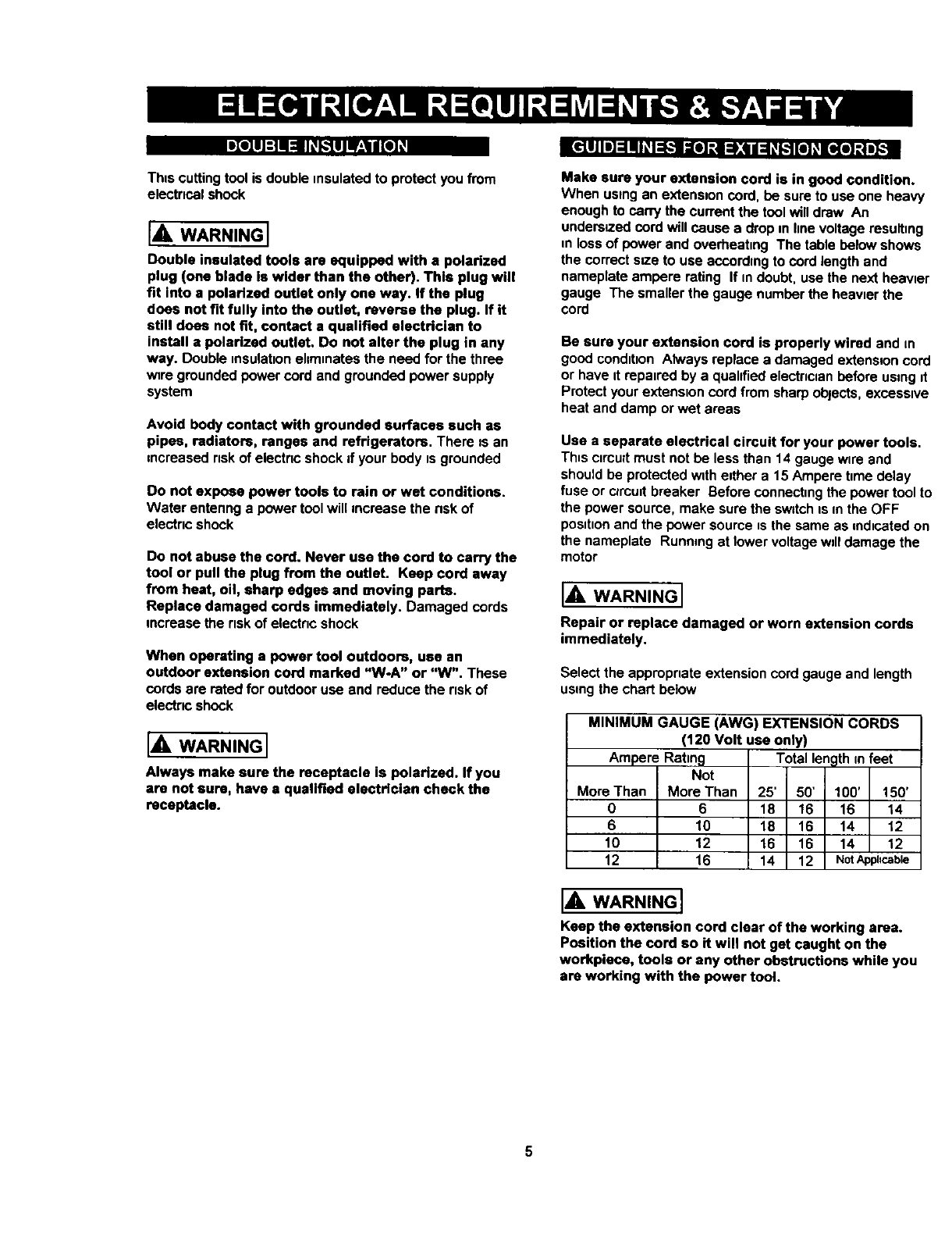
Make sure your extension cord is in good condition.
When using an extenslon cord, be sure to use one heavy
enough to can_ the current the tool will draw An
undersized cord will cause a drop m llne voltage resulbng
=nloss of power and overheahng The table below shows
the correct s_.e to usa eccordmg to cord length and
nameplate ampere rating If m doubt, use the next heawer
gauge The smaller the gauge number the heavier the
cord
Be sure your extension cord is properly wired and m
good conditton Always replace a damaged extension cord
or have it repatred by a quahfied electnclan before using it
Protect your extanston cord from sharp objects, excesstve
heat and damp or wet areas
Use a separate electrical circuit for your power tools.
Th=sctrcult must not be less than 14 gauge wlra and
should be protected wtth either a 15 Ampere hme delay
fuse or clroutt breaker Before connecting the power tool to
the power source, make sure the switch ts m the OFF
pos_honand the power source _sthe same as mdtcated on
the nameplate Running at lower voltage wdl damage the
motor
IA WARNING I
Repair or replace damaged or worn extension cords
immediately.
Select the appropriate extension cord gauge and length
using the chart below
MINIMUM GAUGE (AWG) EXTENSION CORDS
(120 Volt use only)
Ampere Rating
Not
More Than More Than
0 6
6 10
10 12
12 16
Totallength m feet
25' 50' 100' 150'
18 16 16 14
18 16 14 12
16 16 14 12
14 12 NotApphcable
IA WARNINGI
Keep the extension cord clear of the working area,
Position the cord so it will not get caught on the
workpiece, tools or any other obstructions while you
are working with the power tool.
5
:le[o,]:l,,"[,,,_o];,11:1_
AVAILABLE ACCESSORIES
I,A, WARNINGI
Use only accessories recommended for this cutting
tool. Follow instructions that accompany accessories.
Use of improper accessories may cause injury to the
operator or damage to the cutting tool.
Visit your Sears Hardware Department or see the Sears
Power and Hand Tool Catalog for an assortment of
accessornes recommended for use wuththis cuttnngtool
• Flex Dnve
• Rip Gunde
• I/e" Cutting Bnts
• I/s" Hobby Rotary Tool Accessones
Cutters
_" Polishers
Sanders
_' Gnndem
•Most ¼" Shank Router Bds
Use only accessories designed for this cutting tool to
avoid severe injury or tool damage.
Do not use any accessory unless you have completely
read the instructions or Owner's Manual for that
accessory.
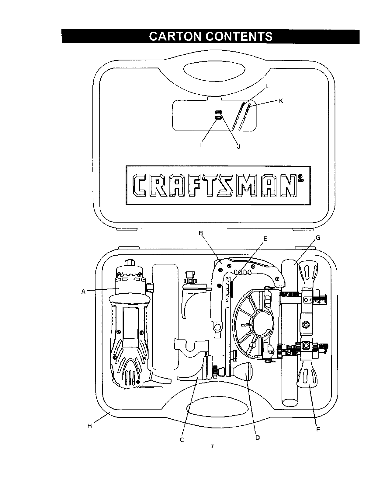
UNPACKING AND CHECKING CARTON CONTENTS
IA WARNING I
If any part is missing or damaged, do not plug the
cutting tool into the power source until the missing or
damaged part is replaced and assembly is complete.
Carefully unpack the cuttmg too! and all its components
Compare against the "Cutting Tool Components" chart
below
NOTE: See Page 7 for illustration of components
I_, WARNING I
To avoid fire or toxic reaction, never use gasoline,
naphtha, acetone, lacquer thinner or similar highly
volatile solvents to clean the cutting tool.
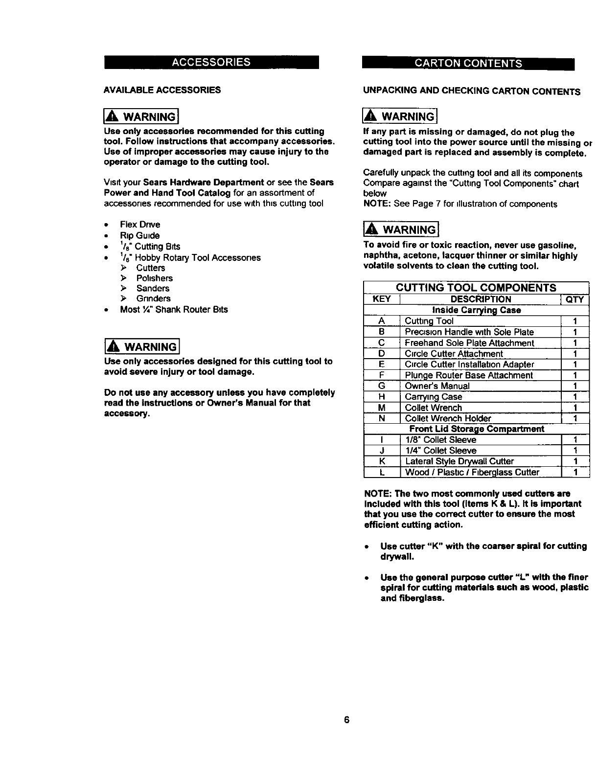
CUTTING TOOL COMPONENTS
KEY I DESCRIPTION ] QTY
Inside Carrying Case
A Cutting Tool
B PrecJsuonHandle with Sole Plate
C Freehand Sole Plate Attachment
D Circle Cutter Attachment
E CnrcleCutter Installahon Adapter
F Plunge Router Base Attachment
G Owner's Manual
Hi Carrying Case
M Collet Wrench
N Collet Wrench Holder
Front Lid Storage Compartment
I 1/8" Collet Sleeve
J 114" Collet Sleeve
K Lateral Style Drywall Cutter
L Wood /Plastic /Fiberglass Cutter
1
1
1
1
1
1
1
1
1
1
1
1
1
1
NOTE: The two most commonly used cutters are
Included with this tool (items K & L). It is important
that you use the correct cutter to ensure the most
efficient cutting action.
•Use cutter "K" with the coarser spiral for cuffing
drywall.
•Use the general purpose cutter "L" with the finer
spiral for cutting materials such as wood, plastic
and fiberglass.
/
f
f_
[] E
H
D
F
c
7
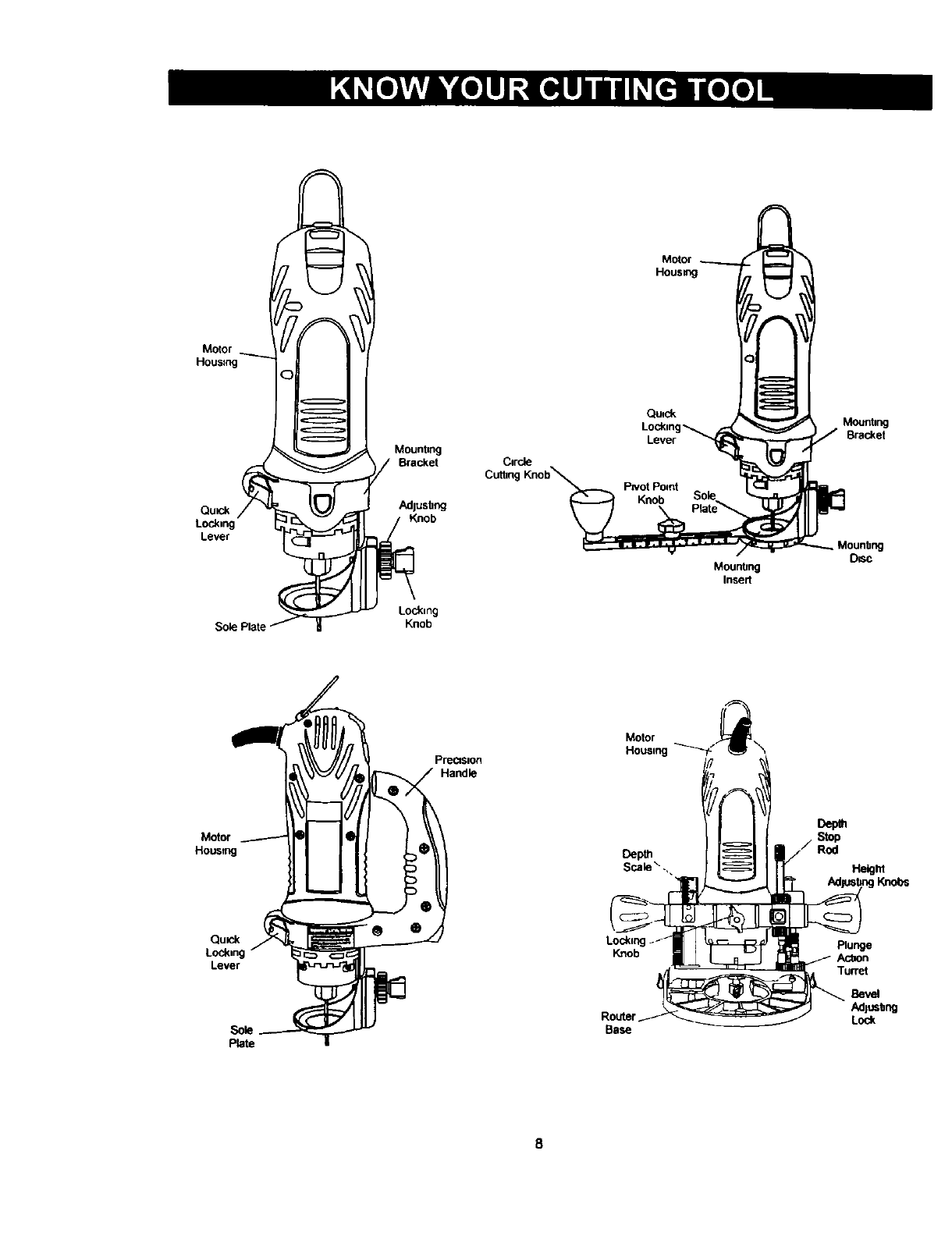
Motor
Housing
Qu_k
Locking
Level
Mounting
/Bracket
Adlushng
Knob
Locking
Knob
C1r_
Cuthn(
Motor
HOUSIng
Qu_k
Lever
Mounhng
Insed
Mounta_
Bracket
D_sc
Motor
Housqng
Pma_on
Handle
Motor
Hous,ng--_-" \
Depth
Scale" ..
Depth
Rod
He,hi
Knobs
Qumk
Lockm
Lever
Plate
Lockm
Knob
Router
Base
plunge
Ac_on
Turret
Bevel
Adlushng
Lock
IA WARNINGI
INSTALLING CUTTING BITS - Cont'd
Remove the plug from the power source before
assembly, changing accessories or cutters and
making adjustments. This safety action will help
prevent accidental starting of the tool which could
result in serious injury.
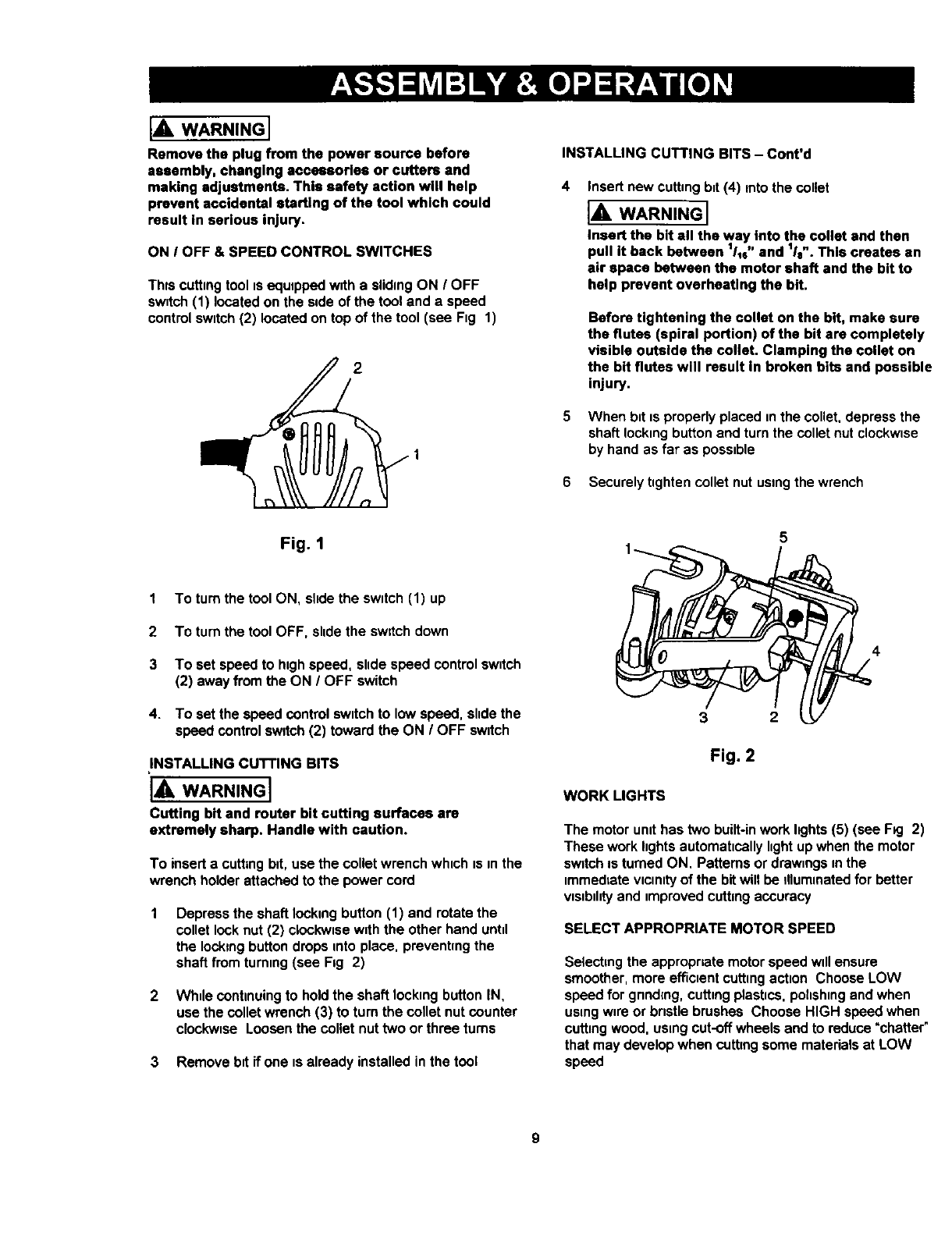
ON IOFF & SPEED CONTROL SWITCHES
Thrs cutting tool is equipped w=th a sliding ON /OFF
switch (1) located on the side of the tool and a speed
control switch (2) located on top of the tool (see Fig 1)
2
Fig. 1
1 To turn the tool ON, slide the switch (1) up
2To turn the tool OFF, slide the swltch down
3 To set speed to high speed, slide speed control switch
(2) away from the ON /OFF switch
4. To set the speed control switch to low speed, slide the
speed control sw_tch (2) toward the ON IOFF switch
INSTALLING CUTTING BITS
IA WARNINGI
Cutting bit and router bit cutting surfaces are
extremely sharp. Handle with caution.
To insert a cutting btt, use the collet wrench which IS in the
wrench holder attached to the power cord
Depress the shaft locking button (1) and rotate the
collet look nut (2) clookwme with the other hand until
the locking button drops into place, preventing the
shaft from turning (see Fig 2)
2 Whdecontmuingto holdthe shaft lockingbuttonIN,
use the colletwrench(3) to turn the collet nutcounter
clockwise Loosenthe collet nuttwo or three turns
3 Removebit if one is already installedinthe tool
Insert new cutting bit (4) into the collet
IA WARNING I
Insert the bit all the way into the collet and then
pull it back between 111e"and 1Is". This creates an
air space between the motor shaft and the bit to
help prevent overheating the bit.
Before tightening the collet on the bit, make sure
the flutes (spiral portion) of the bit are completely
visible outside the colleL Clamping the collet on
the bit flutes will result In broken bits and possible
injury.
When bit is properly placed in the collet, depress the
shaft locking button and turn the collet nut clockwise
by hand as far as possible
6 Securely tighten collet nut using the wrench
5
Fig. 2
WORK LIGHTS
The motor umt has two built-in work 1_3hts(5) (see F_g 2)
These work hghts automatically hght up when the motor
switch m turned ON. Patterns or drawings m the
immedtate vicinity of the bit will be dlummated for better
vtstbthtyand tmproved cutting accuracy
SELECT APPROPRIATE MOTOR SPEED
Selectingthe appropriatemotorspeedwdlensure
smoother,more efficientcuttingaction ChooseLOW
speed forgnndmg,cuttingplastics,polishingandwhen
usingw_reor bristlebrushes Choose HIGH speedwhen
cuttingwood. usingcut-offwheelsand to reduce"chatter"
that maydevelopwhen cuttingsome materialsat LOW
speed
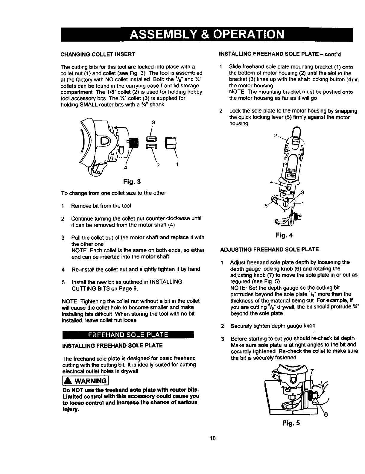
CHANGING COLLET INSERT INSTALLING FREEHAND SOLE PLATE - cont'd
The cutting bits for this tool are locked into ptace with a
collet nut (1) and collet (see Fig 3) The tool is assembled
at the factory with NO collet insta!led Both the l/s" and ¼"
collets can be found in the carrying case front lid storage
compartment The 1/8" collet (2) is used for holding hobby
tool accessory bits The ¼" collet (3) is supplied for
holding SMALL router bits with a ¼" shank
3
4 2 1
Fig. 3
To change from one collet s=ze to the other
1 Remove bit from the tool
2 Continue turning the collet nut counter clockwise untd
it can be removed from the motor shaft (4)
3 Pull the collet out of the motor shaft and replace it with
the other one
NOTE Each collet is the same on beth ends, so either
end can be inserted into the motor shaft
4 Re-install the collet nut and slightly tighten it by hand
5. Install the new bit as outhned in INSTALLING
CUTTING BITS on Page 9.
NOTE Tightening the collet nut without a bit in the collet
will cause the collet hole to become smaller and make
installing bits difficult When storing the tool with no bit
installed, leave collet nut loose
Shde freehand sole plate mounting bracket (1) onto
the bottom of motor housing (2) untilthe slot in the
bracket (3) lines up with the shaft locking button (4) in
the motor housing
NOTE The mounting bracket must be pushed onto
the motor housing as far as it wdl go
Lock the sole plate to the motor housing by snapping
the quick locking lever (5) firmly against the motor
housing
2
4
3
5
Fig. 4
ADJUSTING FREEHAND SOLE PLATE
Adjust freehand sole plate depth by loosening the
depth gauge locking knob (6) and rotating the
adjusting knob (7) to move the sole plate in or out as
required (see FK3 5)
NOTE" Set the depth gauge so the cutting bit
protrudes beyond the sole plate 1Is more than the
thickness of the material being cut For example, if
you are cutting 5/8"drywall, the bit should protrude %"
beyond the sole plate
2 Securely tighten depth gauge knob
_1;.|=1=1-"F_.I_10_F,._[e]N=11_1W_,III
INSTALLING FREEHAND SOLE PLATE
The freehand sole plate is designed for basic freehand
cutting with the cutting bit. It is ideally suited for cutting
electrmal outlet holes in dr/wall
IA WARNINGI
Do NOT use the freehand sole plate with router bits.
Umlted control with this accessory could cause you
to loose control end Increase the chance of serious
injury.
Before starting to cut you should re-check bitdepth
Make sure sole plate is at right angles to the bit and
securely tightened Re-check the collet to make sure
the bit is securely fastened
Fig. 5
10
IA wAR.I.GI
Have you read =POWER TOOL SAFETY",
"cuTrlNG TOOL SAFETY" and "ELECTRICAL
SAFETY" on pages 3, 4 and 5 of this Manual? If
not, please do it now before you operate this
cutting tool. Your safety depends on Itl
Evew time you use the cutting tool you should
verify the following:
1. Cutting tool cord is not damaged.
2. Bit is correct type for the material being cut.
3. Bit is sharp, in good condition, properly
installed and securely tightened.
4. Safety glasses and dust mask are being worn.
Failure to adhere to these safety rules can greatly
increase your chances of Injury.
PRACTICE CUTS USING FREEHAND SOLE PLATE
Before attempting to work on an actual proJect, take the
time to make s few practuce cuts with your cutting tool
Use some scraps of matenal that are the same maternal as
used nnyour actual project.
1. Draw a patternsumularto your firstprojecton a scrap
p_eceof material
2. Installfreehandsoleplateas shownin Fig 4
3 Installcuttingb=tin thecolletas shownin Fig 2
4 Adjust depth of freehand sole plate as shown in Fng 5
5Rest the edge of the sole plateon the workpiecevath
the bntat an angle of about 45° (see Fug 6).
NOTE DO NOT let the bitcontactthe workpleceuntil
switchnsturnedON and the tool is up to full speed.
IAWARNINGI
Before tuming the tool switch ON, make sure you
hold the tool firmly with both hands. Starting
torque will cause the tool to twlsL
L
Fig. 6
PRACTICE CUTS USING FREEHAND SOLE PLATE
6 Set the speed control switch to the appropriate speed
7 Turn the swntch ON
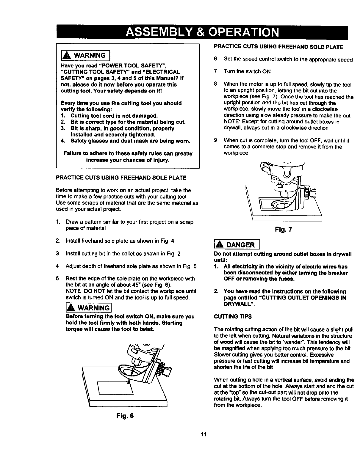
When the motornsupto fullspeed, slowiyttp the tool
to an upnghtposttnon,lettnngthe bitcut nntothe
workpnece(see F=g 7) Once the toolhas reached the
uprightpesubonand the bithas cutthroughthe
workplece,slowlymove the tool in a clockwise
dnrectionusnngslow steadypressureto make the cut
NOTE" Exceptfor cuttnngaroundoutletboxes in
drywall,alwayscut ma clockwise durectlon
9 When cut nscomplete, turn the tool OFF, want untd it
comes to a complete stop and remove it from the
workpuece
Fig. 7
IADANGER I
Do not attempt cutting around outlet boxes in drywall
until:
t. All electricity in the vicinity of electric wires has
been disconnected by either turning the breaker
OFF or removing the fuses.
2. You have read the Instructions on the following
page entitled "CUTTING OUTLET OPENINGS IN
DRYWALL".
cUTrlNG TIPS
The rotatingcuttungactionof the bitvailcausea skghtpull
to the left when cutting.Naturalvariationsinthe structure
of woodwill cause the 10ftto "wander'.This tendencywill
be magnifiedwhen applyingtoo muchpressureto the bit
Slowercuttinggivesyou bettercontrol. Excessive
pressureor fast cuttingwill increasebittemperatureand
shortenthe hfeof the bit
When cuttinga hole ina verticalsurface,avo_lendingthe
cut at the bottomof the hole AJwaysstartand endthe cut
at the "top"so the cut-out part will notdropontothe
rotatingbit.Alwaystum the tool OFF before removingd
fromthe workpisce,
11
CUTTING OUTLET OPENINGS IN DRYWALL
I,_ DANGER I
Do not attempt to use this tool to make cut-outs
around any fixture or opening which has live electrical
wires or on any wall which may have electrical wiring
behind it. If a live wire is contacted, the bit could
conduct the electric current to the tool, creating an
electrocution hazard for the operator. Turn OFF
breakers or remove fuses to disconnect the electric
circuit in the area of work. Always hold the tool by its
insulated housing when working in areas where there
is a possibility of contacting electric wires. Always
wear eye pretection when operating this tool.
Before mstalhng drywall, push the electncel wires to
the back of the box as far as possible so they will not
be cut by the bit when cutting the opening
2Before fastening the drywall sheet over the electncal
box, mark the sheet as close as possible to the center
of the box opening Mark should be on the side of the
dr/wall facing you
When fastening the drywall In place, do not place nads
or screws closer than 12" from the box Thsswilt
prevent the drywall from becoming deformed under
pressure
4Insert cutbng b_tand install freehand sole plate as
outlined on Pages 9 & 10 of this Owner's Manual
AdJustdepth of cut so the bit wdl protrude _/8"beyond
the thickness of the drywall
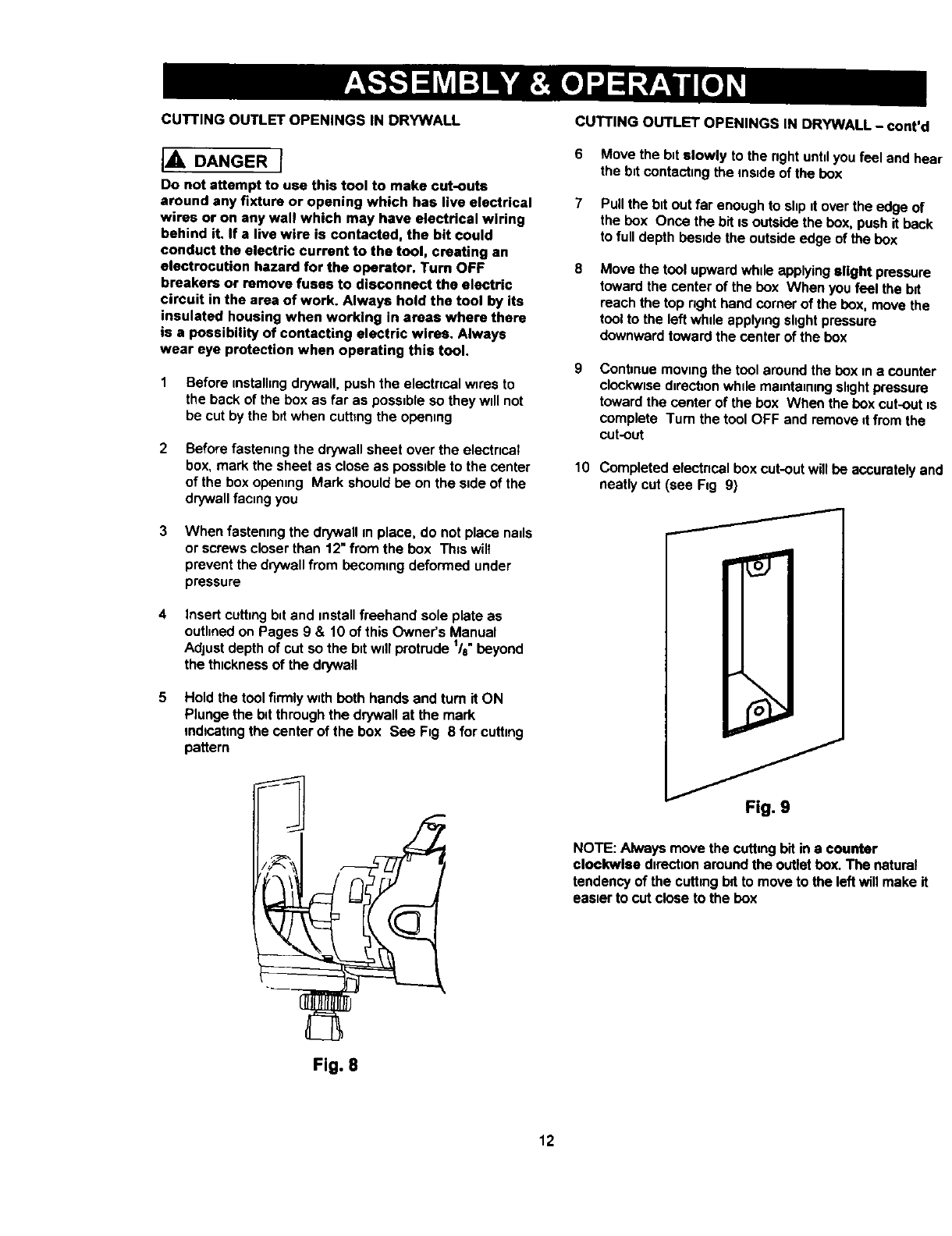
Hold the tool firmly with both hands and turn it ON
Plunge the bd through the drywall at the mark
mdlcahng the center of the box See Fig 8 for cutting
pattern
Fig. 8
CUTTING OUTLET OPENINGS IN DRYWALL - cont'd
6 Move the bit slowly to the nght until you feel and he;
the bit contacting the mstde of the box
7 Pull the btt out far enough to shp tt over the edge of
the box Once the bit is outside the box, push it back
to full depth bestde the outside edge of the box
8Move the tool upward whde applying alight pressure
toward the center of the box When you feel the bit
reach the top nght hand comer of the box. move the
tool to the left whde applying shght pressure
downward toward the center of the box
Continue moving the tool around the box in scounter
clockwtse d=rocbonwhde maintaining shght pressure
toward the center of the box When the box cut-out t._
complete Turn the tool OFF and remove d from the
cut-out
10 Completedelectricalboxcut-outwill be acouratelya_
neatlycut (see Fag9)
\
Fig. 9
NOTE: Alwaysmove the cuttingbitina counter
clockwise directionaround the outletbox.The natural
tendencyof the cuthngba to move to the leftwillmake it
eas_erto cutclose to the box
12
INSTALLING PRECISION HANDLE
The prectslon handle is desogned for use when prec0sion
control over the tool movement 0sdesired The
comfortable handle can be used with either the right or left
hand
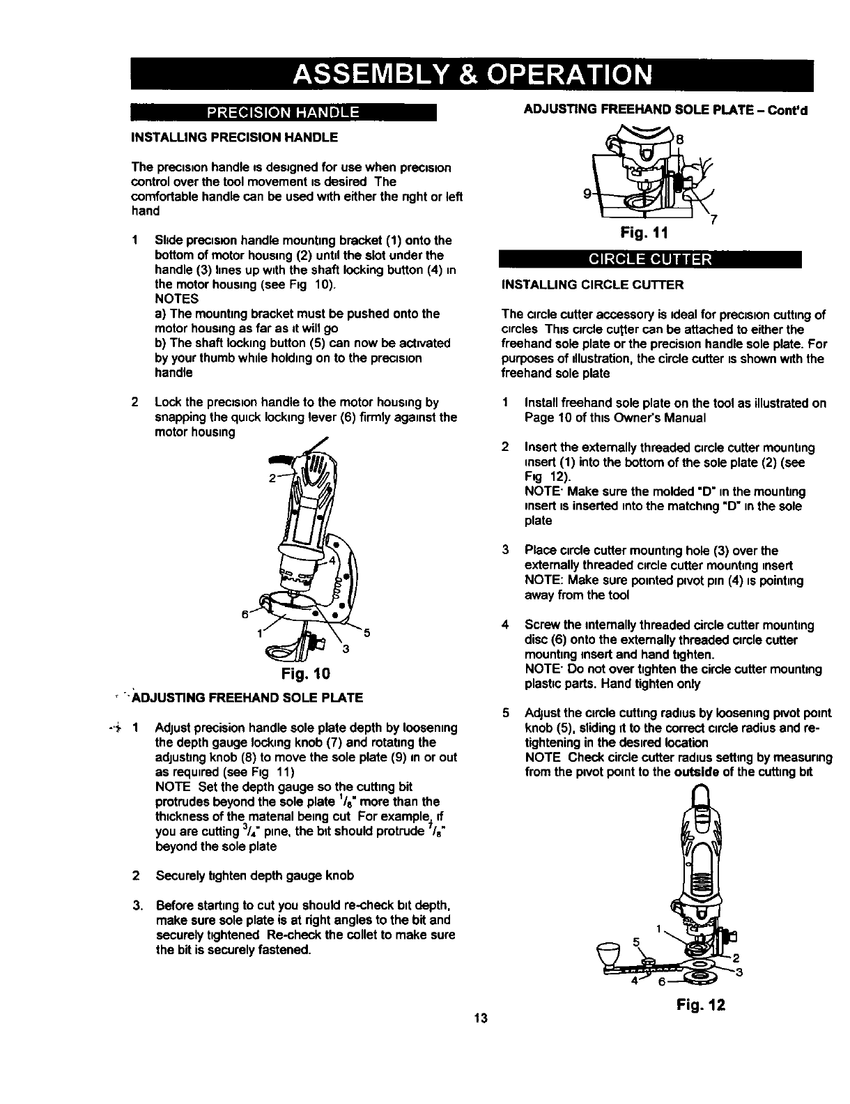
1 Shde precls0on handle mounting bracket (1) onto the
bottom of motor housmg (2) until the slot under the
handle (3) hnes up with the shaft locking button (4) in
the motor housing (see Fig 10).
NOTES
a) The mounting bracket must be pushed onto the
motor housing as far as it will go
b) The shaft locking button (5) can now be activated
by your thumb while holding on to the precision
handle
ADJUSTING FREEHAND SOLE PLATE - Cont'd
Fig. l l
::::(ql= [141111:1;
INSTALLING CIRCLE CUTTER
The circle cutter accessory is ideal for precision cuttmg of
clmles Th=s circle cutter can be attached to either the
freehand sole plate or the precision handle sole plate. For
purposes of dlustration, the circle cutter is shown with the
freehand sole plate
2 Lockthe precisionhandleto the motorhousingby
snappingthe quncklockinglever (6) firmlyagainst the
motor housing
2
6 4
5
Fig, 10
'ADJUSTING FREEHAND SOLE PLATE
AdJustprecision handle sole plate depth by loosening
the depth gauge locking knob (7) and rotating the
adjusting knob (8) to move the sole plate (9) in or out
as required (see Fig 11)
NOTE Set the depth gauge so the cuttmg bit
protrudes beyond the sole plate 1/8"more than the
thtckness of the matenal being cut For example} d
you are cutting 3/4"pine, the bit should protrude /e
beyond the sole plate
2 Securely tighten depth gauge knob
3. Beforestartingto cut you shouldre-checkbitdepth,
make suresole plate is at rightangles to the bit and
securelytightened Re-check the colletto make sure
the bit is securelyfastened.
1
2
13
Install freehand sole plate on the tool as illustrated on
Page 10 of this Owner's Manual
Insert the extemally threaded circle cutter mounting
insert (1) into the bottom of the sole plate (2) (see
Fog 12).
NOTE' Make sure the molded "D" in the mounting
insert is inserted into the matching "D" in the sole
plate
Place circle cutter mountmg hole (3) over the
externally threaded circle cutter mounting nnsert
NOTE: Make sure pointed ptvot pm (4) is pointing
away from the tool
Screw the internally threaded circle cutter mounting
disc (6) onto the externally threaded circle cutter
mounting insert and hand t0ghten.
NOTE" Do not over tighten the circle cutter mounting
plasbc parts. Hand tighten only
Adjustthe circle cuttingradiusby looseningpivotpoint
knob (5), slidingit to the correctcircle radiusand re-
tighteninginthe desired location
NOTE Check circlecutterradiussettingby measuring
from the ptvotpomtto the outside of the cuttmgbit
1
5 2
Fig. 12
s]I_-{qil _[_eil illi1"_:
CIRCLE CUTTER OPERATION
IA WARNINGI
Unplug the tool from the power source I_fore
changing accessories, changing bits and making
adjustments.
Before turning the tool ON, check to make sure bit
and all accessory fasteners are securely tightened.
1 Mark the center of the circle you wish to cut on the
workplece and dntt a 6 mm or _s/e4"pdot hole
2 AdJuStcutting b=tdepth to l/s" longer than the
thickness of the matenal being cut (see Fig 5)
3Adjust the circle cutting radtus by loosening pivot point
knob. shdmg ttto the correct circle radius and re-
tightemng in the deaoredlocation
NOTE Check circle cutter radius setting by measuring
from the p=votpoint to the outside of the sptral bR
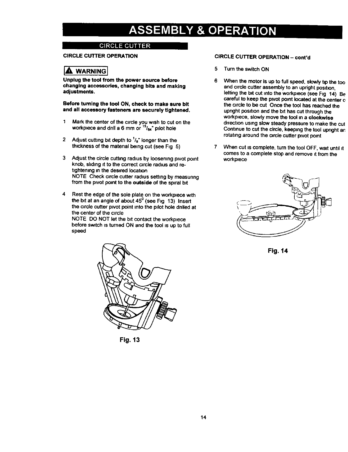
4Rest the edge of the sole plate on the workptece with
the btt at an angle of about 450 (see Fog 13) Insert
the circle cutter pivot point into the pilot hole dnlled at
the center of the ctrcle
NOTE DO NOT let the b_tcontact the workptece
before swttch ts turned ON and the tool is up to full
speed
CIRCLE CUTTER OPERATION - cont'd
5 Turn the switch ON
When the motor is up to full speed, slowly hp the t_
and clrole cutter assembly to an upright posdlon,
letting the bit cut into the workpiece (see Fig 14) I
careful to keep the pivot point located at the centel
the circle to be cut Once the tool has reached the
upnght posttton and the b=thas cut through the
workplace, slowly move the tool m a clockwise
d_rection using slow steady pressure to make the c_
Continue to cut the circle, keaplng the tool upright
rotating around the circle cutter pivot point
7When cut fs complete, turn the tool OFF, wait untd
comes to a complete stop and remove it from the
workptece
\
Fig. 14
Fig. 13
14
_tLIJ_[¢]=l I='TO]IInlI;:I,41:Y,JI.']
The router accessory converts your cuttnngtool Into a
small hobby plunge router that uscapable of handling
small '/," shank router butsas well as the spiral cutting but
The tnltnngbase is ideal for bevel cutting The plunge
feature allows you to pre-set up to three ddferent cuttnng
depths
IA WARNINGI
Unplug the tool from the power source before
changing accessories, changing bits and making
adjustments.
Before turning the tool ON, check to make sure the bit
and all accessory fasteners are securely tightened.
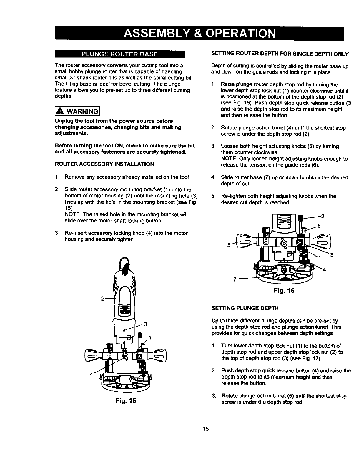
ROUTER ACCESSORY INSTALLATION
1 Remove any accessory already unstalled on the tool
Slide router accessory mounting bracket (1) onto the
bottom of motor housnng(2) until the mounting hole (3)
hnes up wuththe hole nnthe mountung bracket (see Fig
15)
NOTE The raised hole in the mounting bracket will
shde over the motor shaft locking button
3 Re-nnsert accessory locking knob (4) into the motor
housnngand securely tighten
1
Fig. 15
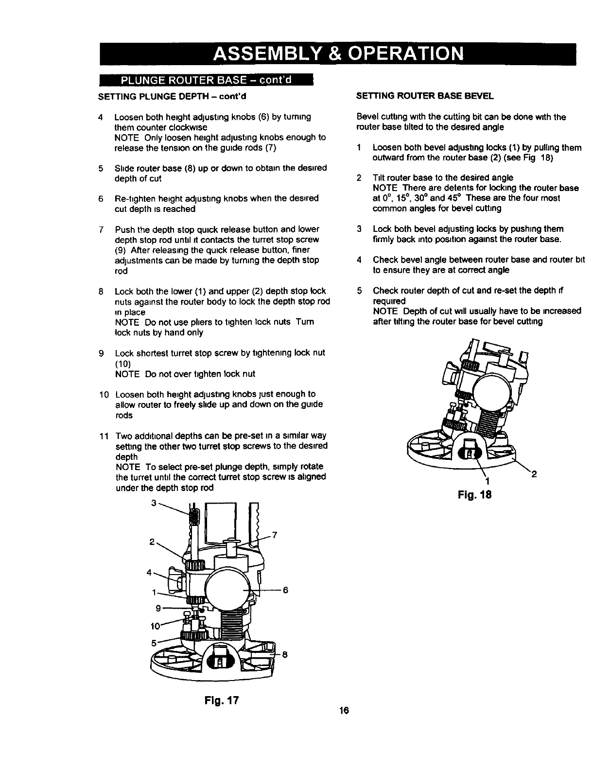
SETTING ROUTER DEPTH FOR SINGLE DEPTH ONLY
Depth of cutting os controlled by sliding the router base up
and down on the gutde rods and locking dun place
Rause plunge router depth stop rod by turning the
lower depth stop lock nut (1) counter clockwise untul=t
is posutnonedat the bottom of the depth stop rod (2)
(see Fig 16) Push depth stop quick release button (3
and reuse the depth stop rod to Its maximum height
and then release the button
2 Rotate plunge actuonturret (4) untilthe shortest stop
screw usunder the depth stop rod (2)
3Loosen both height adjushng knobs (5) by turning
them counter clockwtse
NOTE" Only loosen height edjustmg knobs enough to
release the tension on the guide rods (6).
4 Shde muter base (7) up or down to obtannthe desured
depth of cut
5 Re-hghtenboth heughtadjustnngknobswhenthe
desiredcut depth tsreached.
Fig. 16
SETTING PLUNGE DEPTH
Up to three different plunge depths can be preset by
using the depth stop rod and plunge action turret This
provides for qutck changes between depth setbngs
Turn lowerdepth stop locknut (1) to the bottomof
depth stop rodand upperdepthstoplocknut(2) to
the top of depth stoprod (3) (see Fig 17)
2. Pushdepth stopquick releasebutton(4) and raisethe
depth stoprodto its maximumheightandthen
releasethe button.
3. Rotate plungeactionturret (5) untilthe shorteststop
screw is underthe depth stoprod
15
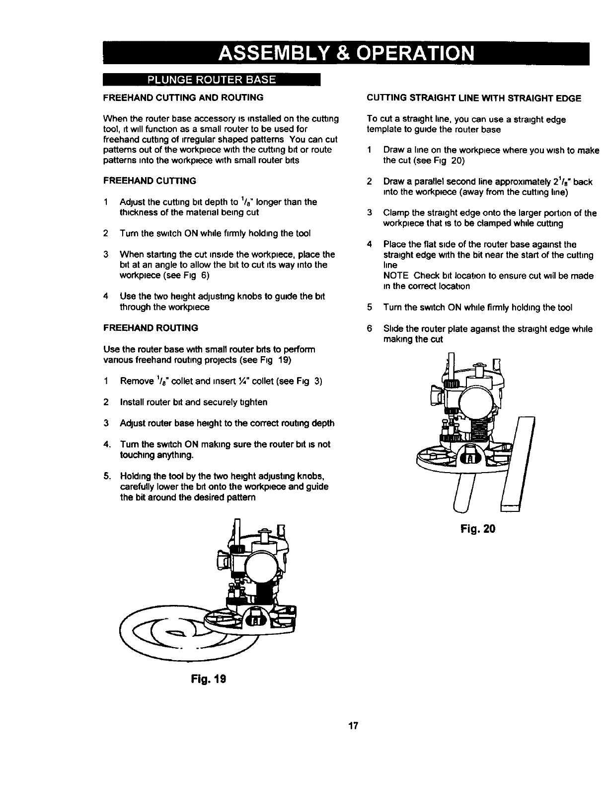
SETTING PLUNGE DEPTH - cont'd
Loosen both height adjust=ng knobs (6) by tummg
them counter clockw=se
NOTE Only loosen height adjushng knobs enough to
release the tens=on on the gutde rods (7)
5 Shde router base (8) up or down to obta=nthe des=red
depth of cut
6 Re-hghten he=ghtadjusting knobs when the desfred
cut depth is reached
Push the depth stop qu=ck release button and lower
depth stop rod untd it contacts the turret stop screw
(9) After releas=ng the qu=ckrelease button, finer
adjustments can be made by turning the depth stop
rod
Lock both the lower (1) and upper (2) depth stop lock
nuts against the router body to lock the depth stop rod
m place
NOTE Do not use pliers to hghten lock nuts Turn
lock nuts by hand only
9 Lock shortest turret stop screw by t_ghtenlng lock nut
(10)
NOTE Do not over tighten lock nut
10 Loosen both he=ght adjusting knobs just enough to
allow router to freely sltde up and down on the guide
rods
11 Two add=t=onaldepths can be pre-set =na s=milarway
setting the other two turret stop screws to the desired
depth
NOTE To select pre-set plunge depth, simply rotate
the turret until the correct turret stop screw is aligned
under the depth stop rod
SETTING ROUTER BASE BEVEL
Bevel cutting with the cutting bit can be done with the
router base tilted to the desired angle
1 Loosen both bevel adjustmg locks (1) by pulhng them
outward from the router base (2) (see Fig 18)
Tilt router base to the desired angle
NOTE There are detents for Iockmg the router base
at 0°, 15°, 30° and 45° These are the four most
common angles for bevel cutt=ng
3 Lock both bevel adjusting locks by pushing them
firmly back into pos=hon agamst the router base.
4 Check bevel angle between router base and router bit
to ensure they are at correct angle
5Check routerdepth of cut and re-setthe depthif
required
NOTE Depth of cut w=llusuallyhave to be increased
after bitingthe routerbase for bevelcutt=ng
Fig. 18
Fig. 17 16
|lUJ _,[l'] :11=|o]ll 1:1:| I:T'_
FREEHAND CUTTING AND ROUTING
When the router base accessory is installed on the cutting
tool, it will function as a small router to be used for
freehand cutting of irregular shaped patterns You can cut
patterns out of the workpnese with the cutting bit or route
pettems into the workplece with small router bvts
FREEHAND CUI-I'ING
1 Adjust the cutting batdepth to lie" longer then the
thickness of the material being cut
2 Turn the switch ON while firmly holding the tool
3 When starting the cut ms=dethe workplece, place the
bit at an angle to allow the bit to cut its way into the
workpuece (see Fig 6)
4 Use the two height adjusting knobs to guide the bit
through the workplece
FREEHAND ROUTING
Use the routerbase w0thsmall routerbitsto perform
variousfreehandroutingprojects(see Fig 19)
1 Remove 1/8"collet and insert ¼" collet (see Fig 3)
2Install router bit and securely tighten
3 Adjust router base height to the con'ect routing depth
4. Turn the swutchON making surethe routerbutis not
touchinganything.
5. Holding the tool by the two height adjusting knobs,
carefully lower the bit onto the workplece and guide
the bit around the desired pattern
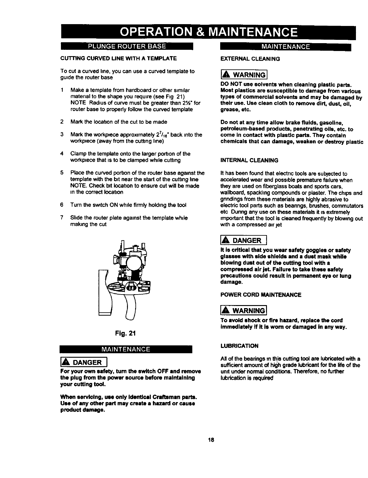
CU'I-rlNG STRAIGHT LINE WITH STRAIGHT EDGE
To cut a straightline,youcan use a straightedge
templateto guidethe routerbase
1
2
Draw a hne on the workplece where you wushto make
the cut (see Fig 20)
Draw a parallel second line approxtmately 21/e"back
into the workpaeco (away from the cutting line)
3 Clamp the straight edge onto the larger portion of the
workpuece that msto be clamped while cutting
Place the fiat side of the router base against the
straight edge with the bit near the start of the cutting
line
NOTE Check bit Iocateonto ensure cut wnllbe made
in the correct Iocabon
5 Turn the switch ON whde firmly holding the tool
6 Slidethe routerplateagainstthe stra=ghtedge whde
makingthe cut
Fig. 20
Fig. 19
17
iii[IJ_,[€.]1 Z(o]II I :l:i I:Y:I-_ IZff._1l_i_l_ _a]l_l
CUTTING CURVED LINE WITH A TEMPLATE
To cut a curved line, you can use a curved template to
guide the router base
Make a template from hardboard or other similar
material to the shape you require (see Fig 21)
NOTE Radius of curve must be greater than 2½" for
router base to propedy follow the curved template
2 Mark the location of the cut to be made
3 Mark the workplece approximately 27/1e"back into the
workplece (away from the cutting line)
4 Clamp the template onto the larger port_onof the
workplece that is to be clamped while cutting
5Place the curved portion of the router base against the
template with the b_tnear the start of the cutting line
NOTE. Check bit Iocatnonto ensure cut will be made
in the correct location
6 Turn the switch ON while firmly holding the tool
7 Slndethe router plate against the template while
making the cut
Fig. 21
IvN:lI _I l =1_r:l _[11
IADANGER I
For your own safety, turn the switch OFF and remove
the plug from the power source before maintaining
your cutting tool.
When servicing, use only Identical Craftsman parts.
Use of any other part may create a hazard or cause
product damage.
EXTERNAL CLEANING
IA WARNING I
DO NOT use solvents when cleaning plastic parts.
Most plastics are susceptible to damage from various
types of commercial solvents and may be damaged by
their use. Usa clean cloth to remove dirt, dust, oil,
grease, etc.
Do not at any time allow brake fluids, gasoline,
petroleum-based products, penetrating oils, etc. to
come in contact with plastic parts. They contain
chemicals that can damage, weaken or destroy plastic
INTERNAL CLEANING
It has been foundthat electnctoolsare subjectedto
acceleratedwear and possibleprematurefailure when
they are usedonfiberglassbeats and sportscars,
wallboard,spacklingcompoundsor plaster.The chipsand
gnndingsfrom these materialsare highlyabrasiveto
electrictoolpartssuch as beanngs,brushes,commutators
etc Dunngany use on these matedalsit is extremely
importantthat the tool is cleaned frequently by blowingout
witha compressed anrJet
IADANGERI
it is critical that you wear safety goggles or safety
glasses with side shields and adust mask while
blowing dust out of the cutting tool with a
compressed air jet. Failure to take these safety
precautions could result in permanent eye or lung
damage.
POWER CORD MAINTENANCE
IAWARNINGI
To avoid shock or fire hazard, replace the cord
immediately If it Is wom or damaged In any way.
LUBRICATION
All of the bearingsIn thiscuttingtoolare lubricatedwitha
sufficientamountof highgrade lubricantforthe lifeof the
undundernom_l conditions.Therefore,nofurther
lubricationis required
18
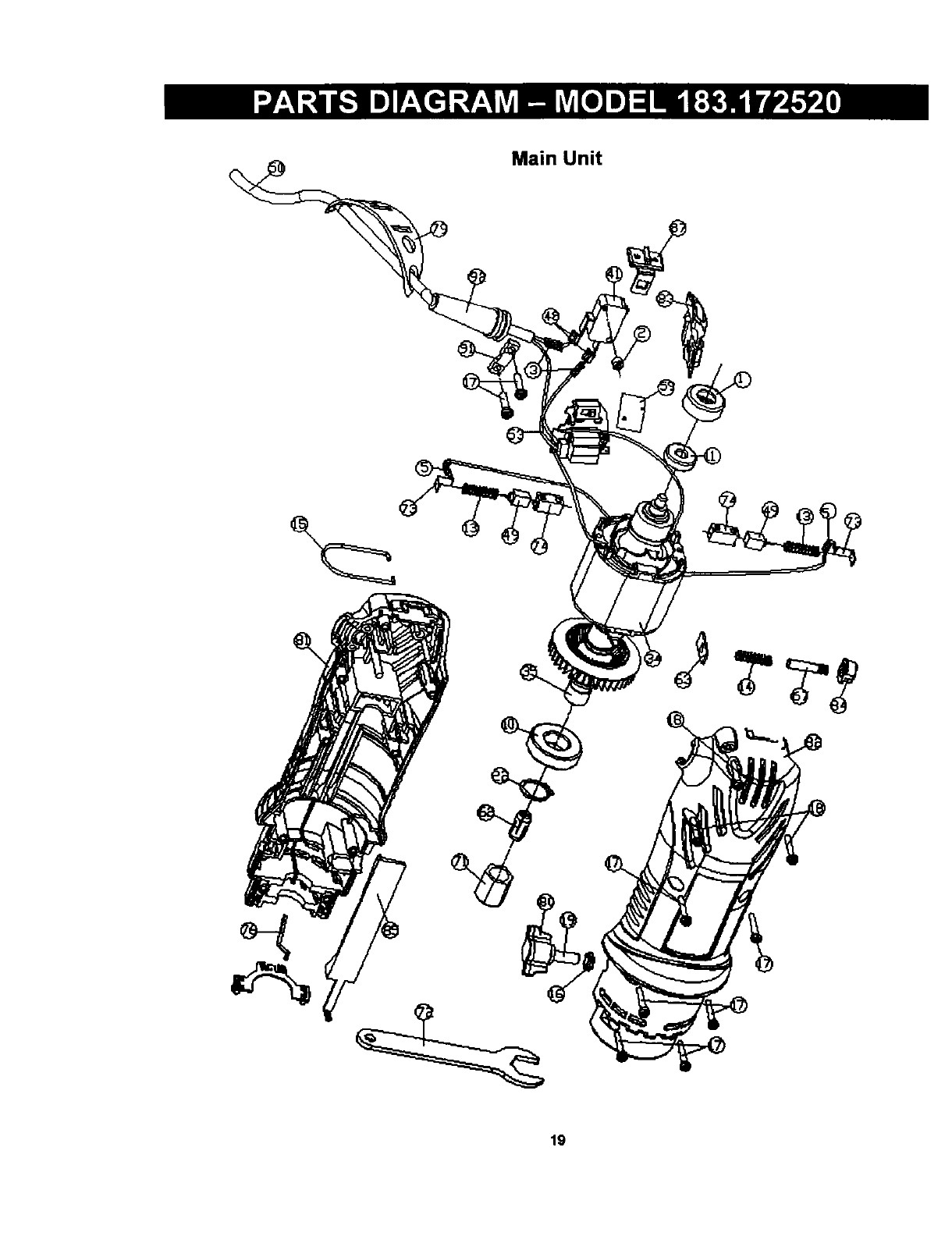
Main Unit
19

I_, WARNING I
When servicing use only CRAFTSMAN replacement parts. Use of any other parts may create a HAZARDor cause
damage to your Cutting Tool.
Any attempt to repair or replace electrical parts on this Cutting Tool may create a hazard unless repair is
performed by a qualified technician, Repair service is available by contacting your nearest Seam Service Center.
Always order by PART NUMBER, not by key number.
Main Unit
Key# Part# Part Name
1 01AR-000032-00 BeanngSleeve
2 01AR-000035-00 Switchpresser
3 01AT-000014-A0 Bushingtube
5 01AT-000031-00 Bushingtube
10 02AE-000060-00 Frontbeanng
11 02AE-000061-00 Rear beanng
12 02AK-000022-00 Rivet
13 02AH-000088-00 Brushspring
14 02AH-000089-00 Spindlespdng
15 02AH-000112-00 Hanger
16 02AN-000012-00 Screw nut
17 02AS-000199-A0 Case screw
18 02AS-O00201-A0 Screw
19 02AS-000260-00 Machinescrew
19 02AS-000260-10 Machinescrew
22 02AW-000055-00 Retainingring
22 02AW-000055-10 Retainingring
23 03AA-000279-00 Transformer
24 03AC-00001l-F0 Capacity
25 03AC-000043-00 Capacity
28 03AD-000009-A0 Diode
29 03AD-000040-00 Dlac
29 03AD-000040-10 Diac
30 03AD-000074-00 LED
31 03AD-000075-00 Tnac
34 03AM-000104-00 Stator
35 03AM-000105-00 Rotor
36 03AP-000073-00 i PCB
36 03AP-000073-10 PCB
37 03AP-000076-00 PCB
37 03AP-000076-10 PCB
38 03AR-000013-AO Resistor
39 03AR-000015-D0 Resistor
40 03AR-000109-A0 R_=_i_tnr
Qty Key# Part#
141 03AS-000135-00
142 03AS-000140-00
2 44 03AT-000033-00
2 48 03AT-000040-00
1 49 03AT-000046-00
1 50 03AW-000131-00
4 50 or03AW-000131-10
2 53 03AY-000020-00
1 55 03AY-000073-00
1 56 03AY-000074-00
1 59 04AP-000068-00
8 62 2203-MA0003-00
3 62 2203-MA0004-00
1 63 2203-MA0007-00
1 67 2207-MA0003-00
1 70 2213-MA0002-00
1 71 2213-MA0005-00
1 72 2213-MA0006-00
1 * 2213-SAM001-00
1 73 2213-MA0011-00
4 74 2213-MA0012-00
1 76 2213-MA0014-00
1 76 2213-MA0014-01
2 79 2203-PA0008-00
1 80 2207-PA0007-00
1 81 2213-PA0022-00
1 82 2213-PA0023-00
1 83 2213-PA0024-00
1 84 2213-PA0025-O0
1 85 2213-PA0026-00
1 87 2213-PA0028-00
1 91 9866-PA0004-00
1 92 9920-PA0011-00
3
Part Name
Microswdch
Switch
Termmalblock
Terminal(female)
Carbonbrush
: Powercord
Powercord
W_re
Wire
Wire
Fibra
1/4"collet
1/8"collet
Lock plate
Spindlelock
Conductor
Chuck cap
Spanner
Brushassembly
Metal conductor
Brushcase
Wire cover
Wire cover
Spannerbelt
ScrewlockB
Bottomcabinet
Top cabinet
Switchcover
Lockbutton
Cover
2P-Switch
Press plata
Cord Sleeve
at,/
1
1
1
2
2
1
1
1
2
2
1
1
1
1
1
2
1
1
2
2
2
1
1
1
1
1
1
1
1
1
1
1
1
20
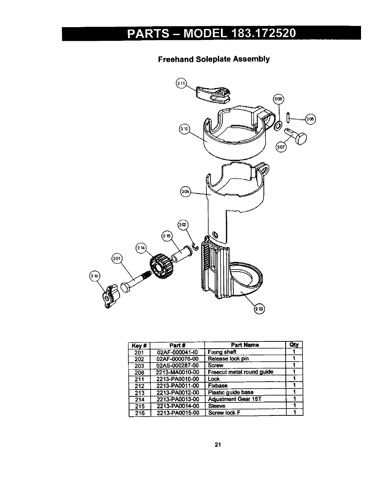
Freehand Soleplate Assembly
Key # Part #
201 02AF-000041-10
202 02AF-000076-00
203 02AS-000287-00
208 2213-MA0010-00
211 2213-PA0010-00
212 2213-PA0011-00
213 2213-PA0012-00
214 2213-PA0013-00
215 2213-PA0014-00
216 2213-PA0015-00
Part Name
F[xlngshaft
Releaselock pin
Screw
Freecutmetal round guide
Lock
Fixbase
Piast=cguide base
AdjustmentGear 15T
Sleeve
Sclew lockF
Qty
1
1
1
1
1
1
1
1
1
1
21
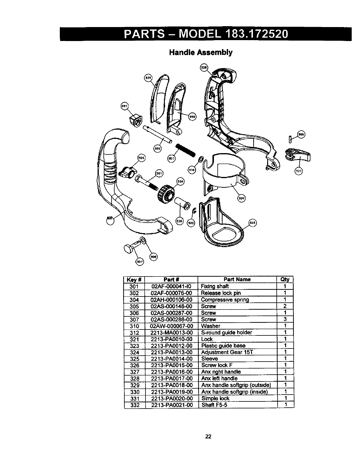
Handle Assembly
Key # Part #
301 02AF-000041-10
302 02AF-000076-00
304 02AH-000106-00
305 02AS-000148-00
306 02AS-000287-00
307 02AS-000288-00
310 02AW-000067-00
312 2213-MA0013-00
321 2213-PA0010-00
323 2213-PA0012-00
324 2213-PA0013-00
325 2213-PA0014-00
326 2213-PA0015-00
327 2213-PA0016-00
328 2213-PA0017-00
329 2213-PA0018-00
330 2213-PA0019-00
331 2213-PA0020-00
332 2213-PA0021-00
Part Name Qty
Fixingshaft 1
Releaselockpin 1
Compressivespnng 1
Screw 2
Screw 1
Screw 3
Washer 1
S-roundguide holder 1
Lock 1
Plasbcguidebase 1
AdjustmentGear 15T 1
Sleeve 1
Screw lockF 1
Anx righthandle 1
Anx left handle 1
Anx handlesoftgrip(outs=de) 1
Anx handlesoftgnp(inside) 1
Simplelock 1
Shaft F5-5 1
22
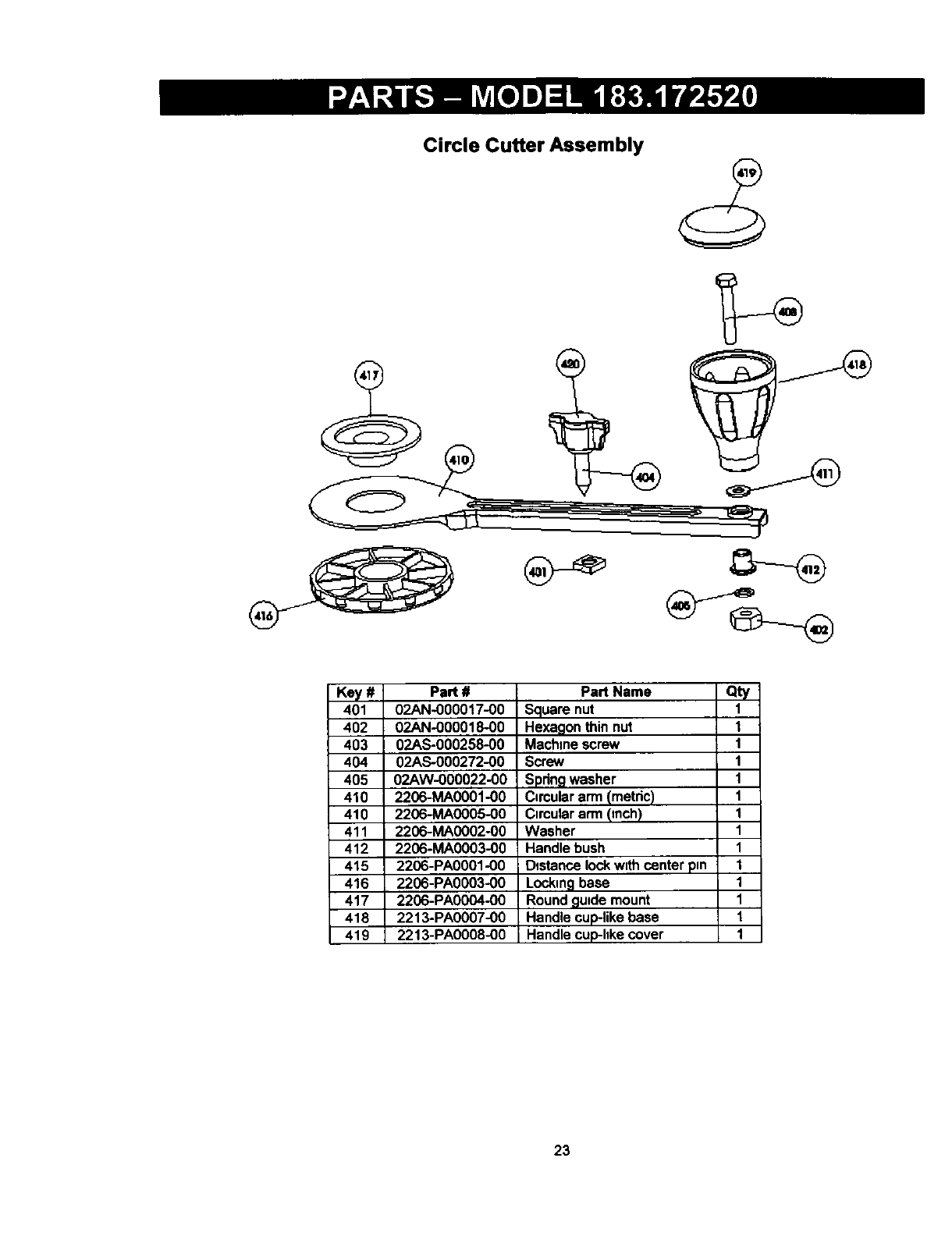
Circle Cutter Assembly
Key # Part #
401 02AN-000017-00
402 02AN-000018-00
403 02AS-000258-00
404 02AS-000272-00
405 02AW-000022-00
410 2206-MA0001-00
410 2206-MA0005-00
411 2206-MA0002-00
412 2206-MA0003-00
415 2206-PA0001-00
416 2206-PA0003-00
417 2206-PA0004-00
418 2213-PA0007-00
419 2213-PA0008-00
Part Name Qty
ISquare nut 1
Hexagon thin nut 1
Machine screw 1
Screw 1
Spdng washer 1
Cimular arm (metric) 1
Cimular arm (inch) 1
Washer 1
Handle bush 1
Dgstance lock w=thcenter pin 1
Locking base 1
Round guide mount 1
Handle cuplike base 1
Handle cuplike cover 1
23
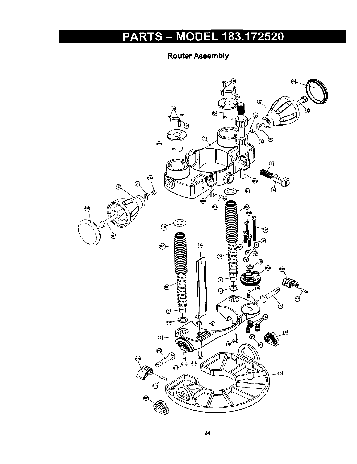
Router Assembly
24

Router Assembly
Key # Part #
101 02AF-000041-10
102 02AF-000077-00
103 02AF-000078-00
104 02AG-000145-.00
105 02AJ-000016-00
107 02AH-000107-00
108 02AH-000108-00
109 02AH-000109-00
111 02AN-000001-A0
112 02AN-000013-00
113 02AN-000019-00
115 02AQ-000001-A0
117 02AS-000020-A0
118 02AS-000048-A0
119 02AS-000276-00
120 02AS-000258-00
121 02AS-000238-00
122 02AS-000290-00
123 02AS-000291-00
124 02AS-000292-00
128 02AW-000068-00
129 02AW-000070-00
131 2213-MA0001-00
133 2213-MA0003-00
134 2213-MA0004-00
138 2213-MA0007-00
139 2213-MA0008-00
151 2213-PA0001-00
152 2213-PA0002-00
153 2213-PA0003-00
154 2213-PA0004-00
155 2213-PA0005-00
156 2213-PA0006-00
157 2213-PA0007-00
158 2213-PA0008-00
159 2213-PA0009-00
164 2205-PA0004-00
165 2205-PA0007-00
Part Name
Fixingshaft
Base release lockpin
; Heightrod
Guide bush
Routertile base
Spring
Spring
Spring
Screw nut
Square nut
M4 fixing nut
Steel ball
Screw
Machinescrew
Base screw
Machinescrew
Screw
Screw
Screw
Screw
Wave washer
Externalretainingdngs
Guide rod
Knockhead
Indexguide
Washer plate 1
Washer plate2
Routerfix base
Routermovablebase
Routerquick heightlock
Memorypostdial
Lock
Bellow
Handlecuplike base
Handlecuplike cover
Heightadjustknob
Lens
Locking disc
aty
2
2
1
2
1
2
2
1
5
2
3
1
1
3
6
2
1
1
1
1
1
2
2
2
1
2
2
1
1
1
1
2
2
2
2
2
1
2
25

For repair of major brand appliances in your own home... _
no matter who made it, no matter who sold it! _
1-800.4-MY-HOME ® Anybrne,dayornight
(1-800-469-4663) (U S.A. and Canada) _,-_
www.sears.com www.sears.ca _;
For repair of carry-in products like vacuums, lawn equipment,
and electronics, call for the location of your nearest ?:"
Sears Parts and Repair Center. _
1-800-488-1222 Any_me,dayornight(USA one)
www.sears.com _-_
For the replacement parts, accessories and owners manuals _\
that you need to do-it-yourself, call Sears PartsDirectSM! :
1-800-366-PART 6a m - 11 p rn. CST, 7 days a week --
(1-800-366-7278) (U.S.A. only) _:
www.sears.comlpartsdirect
To purchase or inquire about a Sears Service Agreement
or Sears Maintenance Agreement:
1-800-827-6655 (us A.) 1-800-361-6665 (Canada)
7 a m. -5 p.m CST, Mon- Sat. 9am.-8p.m. EST, M-F, 4 p.m Sat
Para ped=rserwciode reparacibna
domzcilio,y para ordenarpiP_s
1-888-SU-HOGAR sM
(1-888-784-6427)
Au Canada pourse_ce en franqais
1-800-LE-FOYER _'_c
(1-800-533-6937)
wwwsearsca
®Regmtmed Trademark I_Trademark Im Se_'k_ Mark of Sea_, RoebuCk andco
®Marca Rel_sVada I_Marca de F_d:=ric=Im Mama de Setvido de See#l, Roebuck and Co
UCMm de commeme Im Marque d_ de Sun=, Roet_ck and Co O Seam,Roebucklind Co
26
