Craftsman 24723000 User Manual REAR TINE TILLER Manuals And Guides 1103070L
User Manual: Craftsman 24723000 24723000 CRAFTSMAN REAR TINE TILLER - Manuals and Guides View the owners manual for your CRAFTSMAN REAR TINE TILLER #24723000. Home:Lawn & Garden Parts:Craftsman Parts:Craftsman REAR TINE TILLER Manual
Open the PDF directly: View PDF ![]() .
.
Page Count: 72
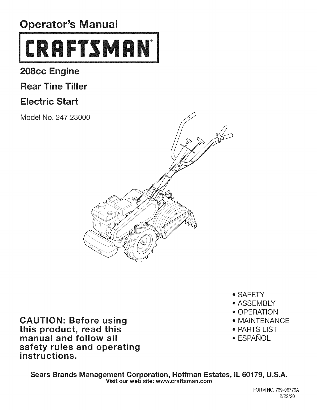
Operator's Manual
CRRFrSMRH
208cc Engine
Rear Tine Tiller
Electric Start
Model No. 247.23000
CAUTION: Before using
this product, read this
manual and follow all
safety rules and operating
instructions.
o SAFETY
ASSEMBLY
OPERATION
MAINTENANCE
PARTS LIST
o ESPANOL
Sears Brands Management Corporation, Hoffman Estates, IL 60179, U.S.A.
Visit our web site: www.craftsman.com
FORMNO.769-06779A
2/22/2011
WarrantyStatement..................................Pac
Safetyinstructions....................................Pac
SafetyLabels............................................Pac
Assembly..................................................Pac
Operation..................................................Pac
ServiceandMaintenance.........................Pac
Off-SeasonStorage..................................Pac
e2
es3-6
e7
es8-10
es11-17
es18-22
e23
Troubleshooting........................................Page24
PartsList...................................................Page26-31
LabelMap.................................................Page42
RepairProtectionAgreement...................Page45
Espa_ol.....................................................Page46
ServiceNumbers......................................BackCover
CRAFTSMAN TWO YEAR FULL WARRANTY
FORTWOYEARSfromthe dateof purchase,this productiswarrantedagainstanydefectsinmaterialor workmanship.Defectiveproductwill
receivefree repairor free replacementif repairis unavailable.
For warranty coverage details to obtain repair or replacement, visit the web site: www.craftsman.com
This warranty covers ONLY defects in material and workmanship. Warranty coverage does NOT include:
• Expendableitemsthatcan wearoutfromnormalusewithinthewarrantyperiod,suchas blades,tines,or belts.
Productdamageresultingfromuserattemptsat productmodificationor repairorcausedby productaccessories.
Repairsnecessarybecauseof accidentorfailureto operateor maintainthe productaccordingto all suppliedinstructions.
Preventivemaintenance,or repairsnecessarydueto improperfuelmixture,contaminatedor stalefuel.
Thiswarrantyis void if thisproductis ever usedwhileprovidingcommercialservicesor if rentedto anotherperson.
Thiswarrantygivesyou specificlegalrights,andyou mayalso haveotherrightswhichvaryfromstateto state.
Sears Brands Management Corporation, Hoffman Estates, IL 60179
EngineSeries: 208cc
EngineOilType: 10w30
EngineOilCapacity: 20ounces
Fuel: UnleadedGasoline
SparkPlug: F6RTC
SparkPlugGap: .030"
Model Number.................................................................
Serial Number .................................................................
Dateof Purchase.............................................................
Recordthe modelnumber,serialnumber
anddateof purchaseabove
©SearsBrands,LLC 2
Thissymbolpointsout importantsafetyinstructionswhich,if not
followed,couldendangerthe personalsafetyand/orpropertyof
yourselfandothers. Readandfollowall instructionsin thismanual
beforeattemptingto operatethismachine.Failureto complywith
theseinstructionsmayresultin personalinjury.Whenyou seethis
symbol,HEEDITSWARNING!
CALIFORNIA PROPOSITION 65
EngineExhaust,someof itsconstituents,andcertainvehicle
componentscontainoremitchemicalsknownto Stateof California
to causecancerandbirthdefectsorother reproductiveharm.Bat-
tery posts,terminals,andrelatedaccessoriescontainleadand lead
compounds,chemicalsknownto the Stateof Californiato cause
cancerandreproductiveharm.Washhandsafterhandling.
Thismachinewasbuilt to beoperatedaccordingto the safeopera-
tion practicesin thismanual.As withany typeof powerequipment,
carelessnessorerroronthe part of the operatorcan resultin
seriousinjury.Thismachineis capableof amputatingfingers,hands,
toesandfeetandthrowingdebris.Failureto observethe following
safetyinstructionscouldresultin seriousinjuryordeath.
Your Responsibility=Restrict the useof this powermachineto
personswho read,understandandfollowthewarningsand instruc-
tionsin thismanualandon the machine.
SAVETHESEINSTRUCTIONS!
TRAINING
•Read,understand,andfollowall instructionson the machineand
in themanual(s)beforeattemptingto assembleandoperate.
Keepthis manualina safeplacefor futureand regularreference
andfor orderingreplacementparts.
• Readthe Operator'sManualand followallwarningsand safety
instructions.Failureto doso can resultin seriousinjuryto the
operatorand/or bystanders.Forquestions,call 1-800-4MY-HOME.
• Befamiliarwithall controlsandtheir properoperation.Knowhow
to stopthe machineanddisengagethemquickly.
• Neverallowchildrenunder14yearsof ageto operatethis
machine.Children14andover shouldreadandunderstandthe
instructionsandsafeoperationpracticesin thismanualandon
the machineandbe trainedandsupervisedby anadult.
• Neverallowadultsto operatethis machinewithoutproper
instruction.
• Keepbystanders,pets,andchildrenat least75feetfromthe
machinewhile it is in operation.Stopmachineif anyoneenters
the area.
• Neverrunanengineindoorsor ina poorlyventilatedarea.Engine
exhaustcontainscarbonmonoxide,anodorlessanddeadlygas.
PREPARATION
•Thoroughlyinspecttheareawherethe equipmentis to beused.
Removeall rocks,bottles,cans,or otherforeignobjectswhich
could bepickedupor thrownandcausepersonalinjuryor
damageto the machine.
• Alwayswear safetyglassesor safetygogglesduringoperation
andwhile performingan adjustmentor repair,to protectyour
eyes.Thrownobjectswhichricochetcan causeseriousinjuryto
the eyes.
• Wearsturdy,rough-soledworkshoesandclose-fittingslacksand
shirts.Loosefittingclothesor jewelrycan becaughtin movable
parts.Neveroperatethismachineinbarefeetorsandals.
• Beforestarting,checkallboltsandscrewsfor propertightnessto
besurethe machineis insafeworkingcondition.Also,visually
inspectmachinefor any damageat frequentintervals.
• Disengageclutchleversandshift (if provided)into neutral("N")
beforestartingtheengine.
• Neverleavethismachineunattendedwiththe enginerunning.
• Neverattemptto makeanyadjustmentswhilethe engineis
running,exceptwherespecificallyrecommendedinthe operator's
manual.
• Maintainor replacesafetyandinstructionslabels,as necessary.
3

Safe Handling of Gasoline:
Toavoidpersonalinjuryor propertydamageuseextremecare in
handlinggasoline.Gasolineis extremelyflammableandthe vaporsare
explosive.Seriouspersonalinjurycan occurwhengasolineis spilled
onyourselfor yourclotheswhichcan ignite.Washyour skinand
changeclothesimmediately.
• Useonlyan approvedgasolinecontainer.
• Neverfill containersinsidea vehicleor ona truckor trailerbed
witha plasticliner.Alwaysplacecontainersonthe groundaway
fromyour vehiclebeforefilling.
• Whenpractical,removegas-poweredequipmentfromthe truck
ortrailerand refuelitonthe ground.Ifthisis notpossible,then
refuelsuchequipmenton a trailerwitha portablecontainer,rather
thanfroma gasolinedispensernozzle.
• Keepthe nozzleincontactwiththe rimof the fuel tankor
containeropeningat alltimes untilfuelingis complete.Do not use
a nozzlelock-opendevice.
• Extinguishallcigarettes,cigars,pipesandother sourcesof
ignition.
• Neverfuel machineindoors.
• Neverremovegas capor addfuel whilethe engineishot or run-
ning.Allowengineto cool at leasttwo minutesbeforerefueling.
• Neveroverfill fueltank. Fill tankto nomorethan1/2inchbelow
bottomof filler neckto allowspacefor fuel expansion.
• Replacegasolinecapandtightensecurely.
• Ifgasolineisspilled,wipe itoff theengineandequipment.Move
unitto anotherarea.Wait5 minutesbeforestartingthe engine.
• To reducefire hazards,keepmachinefreeof grass, leaves,or
otherdebrisbuild-up.Cleanupoil orfuel spillageand removeany
fuel soakeddebris.
• Neverstorethe machineorfuel containerinsidewherethereis an
openflame,sparkor pilotlightas on awaterheater,spaceheater,
furnace,clothesdryer orothergas appliances.
OPERATION
•Do not puthandsorfeetnear rotatingparts.Contactwiththe
rotatingpartscan amputatehandsand feet.
• Do notoperatemachinewhileunderthe influenceof alcoholor
drugs.
• Neveroperatethismachinewithoutgoodvisibilityor light.Always
be sureof yourfootingandkeepa firmholdonthe handles.
• Keepbystandersawayfromthe machinewhileit isinoperation.
Stopthe machineif anyoneentersthe area.
• Becarefulwhentilling inhardground.Thetines maycatchinthe
groundandpropelthe tillerforward.Ifthis occurs,let goof the
handlebarsanddo not restrainthe machine.
• Exerciseextremecautionwhenoperatingonor crossinggravel
surfaces.Stayalert for hiddenhazardsortraffic. Do notcarry
passengers.
• Neveroperatethe machineat hightransportspeedson hardor
slipperysurfaces.
• Exercisecautionto avoidslippingor falling.
• Lookdownand behindandusecare whenin reverseor pulling
machinetowardsyou.
• Startthe engineaccordingto the instructionsfoundinthis manual
and keepfeetwell awayfromthe tinesat all times.
• Afterstrikingaforeignobjector ifyour machineshouldstart mak-
inganunusualnoiseor vibration,immediatelyshutthe engineoff.
Disconnectthe sparkplugwire,grounditagainstthe engineand
performthe followingsteps:
a. Inspectfor damage.
b. Repairor replaceanydamagedparts.
c. Checkfor anyloose partsandtightento assurecontinued
safeoperation.
• Disengageall clutchlevers(if fitted)and stopenginebeforeyou
leavethe operatingposition(behindthe handles).Waituntil
the tinescometo a completestopbeforeuncloggingthe tines,
makingany adjustments,or inspections.
• Neverrunanengineindoorsorina poorlyventilatedarea.Engine
exhaustcontainscarbonmonoxide,an odorlessanddeadlygas.
• Mufflerandenginebecomehot andcancausea burn.Do not
touch.
• Usecautionwhentillingnearfences,buildingsandunderground
utilities.Rotatingtinescan causepropertydamageor personal
injury.
• Donot overloadmachinecapacityby attemptingto till soil too
deepat too fastof a rate.
• Ifthe machineshouldstart makinganunusualnoiseor vibration,
stopthe engine,disconnectthe sparkplugwire andgroundit
againstthe engine.Inspectthoroughlyfor damage.Repairany
damagebeforestartingandoperating.
• Keepallshields,guards,and safetydevicesinplaceandoperat-
ing properly.
• Neverpick uporcarrymachinewhilethe engineis running.
• Useonly attachmentsandaccessoriesapprovedby the manu-
factureras listedin the PartsListpagesof thisoperator'smanual.
Failureto doso can resultin personalinjury.
• Ifsituationsoccurwhichare notcoveredinthis manual,use care
andgoodjudgement.ContactCustomerSupportat 1-800-4MY-
HOMEfor assistanceandthe nameof thenearestservicedealer
MAINTENANCE & STORAGE
•Keepthe machine,attachmentsandaccessoriesin safeworking
order.
•Allowthe machineto coolat leastfiveminutesbeforestoring.
Nevertamperwithsafetydevices.Checktheirproperoperation
regularly.
•Checkboltsandscrewsfor propertightnessat frequentintervals
to keepthe machineinsafeworkingcondition.Also,visually
inspectmachineforany damage.
• Beforecleaning,repairing,or inspecting,stopthe engineand
makecertainthetinesandall movingpartshavestopped.
Disconnectthe sparkplugwireandgrounditagainstthe engineto
preventunintendedstarting.
4
• Do notchangethe enginegovernorsettingsor over-speedthe
engine.Thegovernorcontrolsthemaximumsafeoperatingspeed
of engine.
Maintainor replacesafetyandinstructionlabels,as necessary.
Followthis manualfor safeloading,unloading,transporting,and
storageof thismachine.
Alwaysreferto theoperator'smanualfor importantdetailsif the
machineis to bestoredforan extendedperiod.
If thefuel tankhasto be drained,do thisoutdoors.
Observeproperdisposallawsandregulationsfor gas,oil, etc.to
protectthe environment.
Accordingto the ConsumerProductsSafetyCommission(CPSC)
andthe U.S.EnvironmentalProtectionAgency(EPA),thisproduct
hasan AverageUsefulLifeof seven(7)years,or 130hoursof
operation.At the endof theAverageUsefulLifehavethe machine
inspectedannuallyby anauthorizedservicedealerto ensurethat
allmechanicalandsafetysystemsareworkingproperlyandnot
wornexcessively.Failureto do so can resultinaccidents,injuries
ordeath.
DO NOT MODIFY ENGINE
Toavoidseriousinjuryordeath,donot modifyenginein anyway.
Tamperingwiththe governorsettingcan leadto a runawayengineand
causeit to operateat unsafespeeds.Nevertamperwithfactorysetting
of enginegovernor.
NOTICE REGARDING EMISSIONS
EngineswhicharecertifiedtocomplywithCaliforniaandfederal
EPAemissionregulationsfor SORE(SmallOff RoadEquipment)are
certifiedto operateon regularunleadedgasoline,and mayinclude
the followingemissioncontrolsystems:EngineModification(EM),
OxidizingCatalyst(CO),SecondaryAirInjection(SAI)and ThreeWay
Catalyst(TWO)if so equipped.
SPARK ARRESTOR
Thismachineis equippedwithan internalcombustionengineand
shouldnotbe usedonor nearanyunimprovedforest-covered,
brushcoveredor grass-coveredlandunlessthe engine'sexhaust
systemis equippedwitha sparkarrestormeetingapplicablelocal or
statelaws(if any)
Ifa sparkarrestoris used,it shouldbe maintainedin effectiveworking
orderby theoperator.Inthe Stateof Californiathe aboveis required
bylaw (Section4442of the CaliforniaPublicResourcesCode).Other
statesmayhavesimilarlaws. Federallawsapplyonfederallands.
A sparkarrestorfor the muffleris availablethroughyournearestSears
PartsandRepairServiceCenter.

SAFETY SYMBOLS
Thispagedepictsanddescribessafetysymbolsthatmayappearonthisproduct. Read,understand,andfollowall instructionson the machine
beforeattemptingto assembleandoperate.
ii
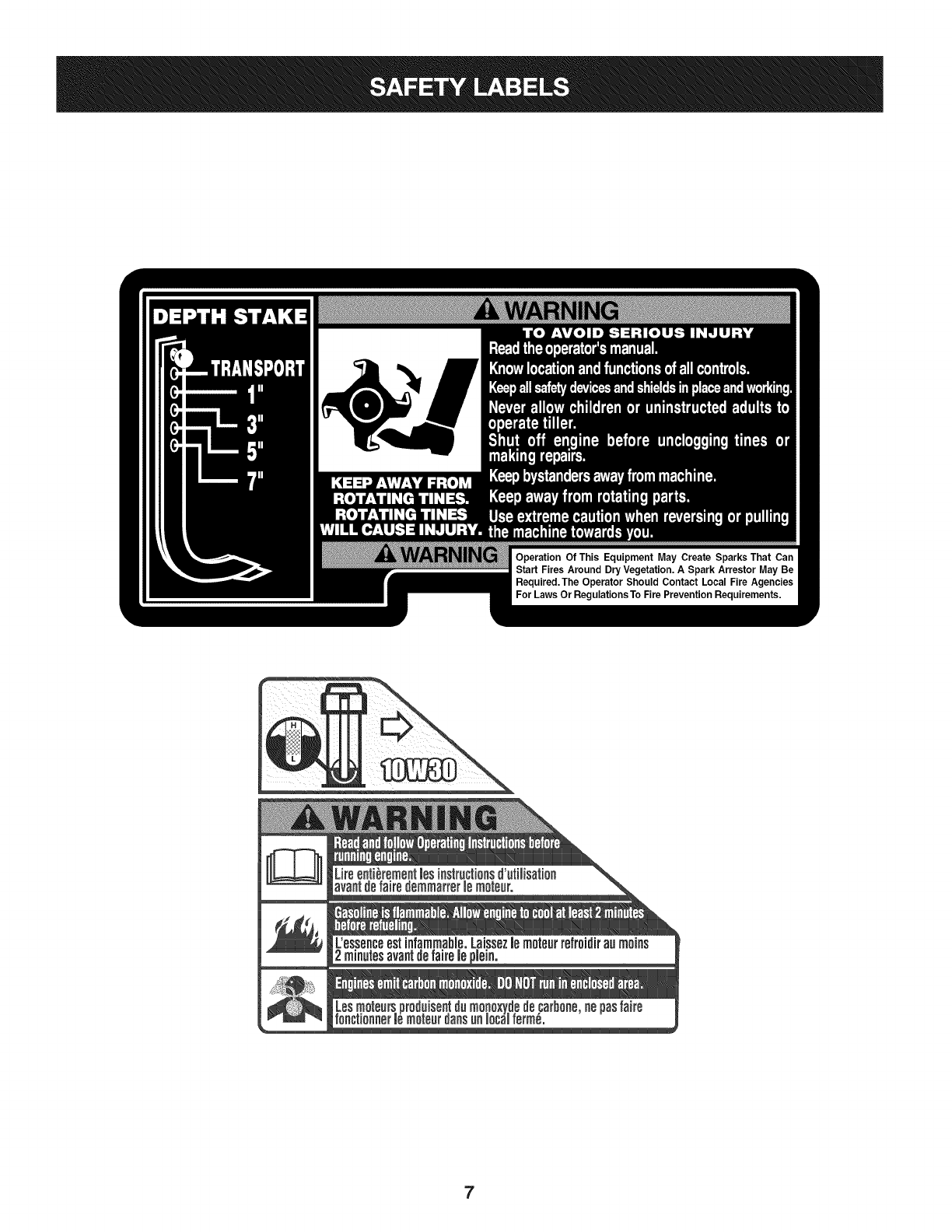
READ THE OPERATOR'S MANUAL(S)
Read, understand, and follow all instructions in the manual(s) before attempting to assemble and
operate
WARNING-- ROTATING TINES
Do not put hands or feet near rotating parts. Contact with the rotating parts can amputate
hands and feet.
WARNING-- ROTATING TINES
Do not put hands or feet near rotating parts. Contact with the rotating parts can amputate
hands and feet.
WARNING--GASOLINE IS FLAMMABLE
Allow the engine to cool at least two minutes before refueling.
WARNING-- CARBON MONOXIDE
Never run an engine indoors or in a poorly ventilated area. Engine exhaust contains carbon
monoxide, an odorless and deadly gas.
WARNING-- HOT SURFACE
Engine parts, especially the muffler, become extremely hot during operation. Allow engine
and muffler to cool before touching.
WARNING: YourResponsibility--Restrictthe use of thispowermachineto personswho read,understandandfollowthe
warningsand instructionsinthis manualandonthe machine.
SAVETHESEINSTRUCTIONS!
6
7
NOTE:Thisunitis shippedwithoutgasolineor oil inthe engine.Be
certainto serviceenginewithgasolineandoil as instructedin the
Operationsectionof this manualbeforeoperatingyourmachine.
NOTE:Referenceto rightand lefthandsideof the Tilleris observed
fromthe operatingposition.
OPENING CARTON
1. Removethe staples,breakthe glueonthe top flaps,orcut the
tapeat the endof the cartonand peelit alongthe top flapto open.
2. Removeall looseparts.
3. Cutthe cornersandlaythe cartondown fiat.
4. Removeloosepackingmaterial.
REMOVING UNIT FROM CARTON
1. Usethe handlebracketto lift andpullthe tillerbackwardsto a flat
area.Checkthecartonthoroughlyfor looseparts.
2. Extendthe controlcableandlay it on thefloor.Becardul not to
bendor kinkthe controlcable.
LOOSE PARTS IN CARTON
• UpperHandlebarAssembly
• HandleTubeAssembly
• Tiller
• EngineOil
• Operator'sManual
• EngineOperator'sManual
• ShiftRod
• HandleSwivelRod
• DepthStake
Beforeassembly,disconnectthe sparkplugwireandgroundit
againstthe engineto preventunintendedstarting.
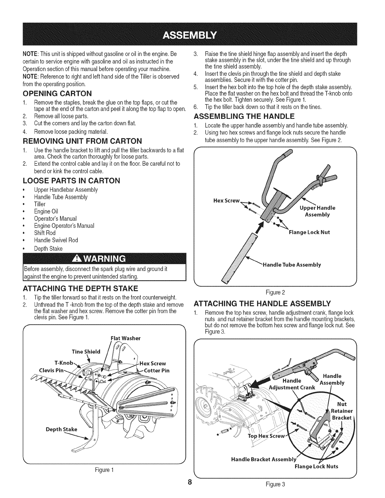
ATTACHING THE DEPTH STAKE
.
2. Tipthe tiller forwardso thatit restson thefrontcounterweight.
Unthreadthe T -knobfromthe topof the depth stakeand remove
theflat washerand hexscrew.Removethe cotter pinfromthe
clevispin.See Figure1.
Flat Washer
Clevis
Tine Shield
.He× Screw
Depth Stake
Figure1
3. Raisethefine shieldhingeflapassemblyand insertthe depth
stakeassemblyinthe slot, underthe fineshieldandup through
the tine shieldassembly.
4. Insertthe clevispinthroughthe fineshieldanddepthstake
assemblies.Secureit withthe cotterpin.
5. Insertthe hex bolt intothe top holeof the depthstakeassembly.
Placethe flatwasheronthe hex boltandthreadthe T-knobonto
the hex bolt.Tightensecurely.SeeFigure1.
6. Tip the tiller backdownso thatit restsonthe tines.
ASSEMBLING THE HANDLE
1. Locatethe upperhandleassemblyandhandletube assembly.
2. Usingtwohexscrewsandflangelocknutssecurethe handle
tube assemblyto the upperhandleassembly.SeeFigure2.
Hex
UpperHandle
Assembly
Figure2
ATTACHING THE HANDLE ASSEMBLY
Removethe top hexscrew,handleadjustmentcrank,flangelock
nuts and nut retainerbracketfromthe handlemountingbrackets,
but do not removethe bottomhex screwandflange locknut.See
Figure3.
Top He× Screw"
Handle Bracket Assembl
Flange Lock Nuts
8 Figure3
2. Placethehandleassemblyinpositionbetweenthehandle
mountingbrackets.
3. Lineuptheholesinthehandlewiththeholesinthebracketand
securewiththehardwarepreviouslyremoved.
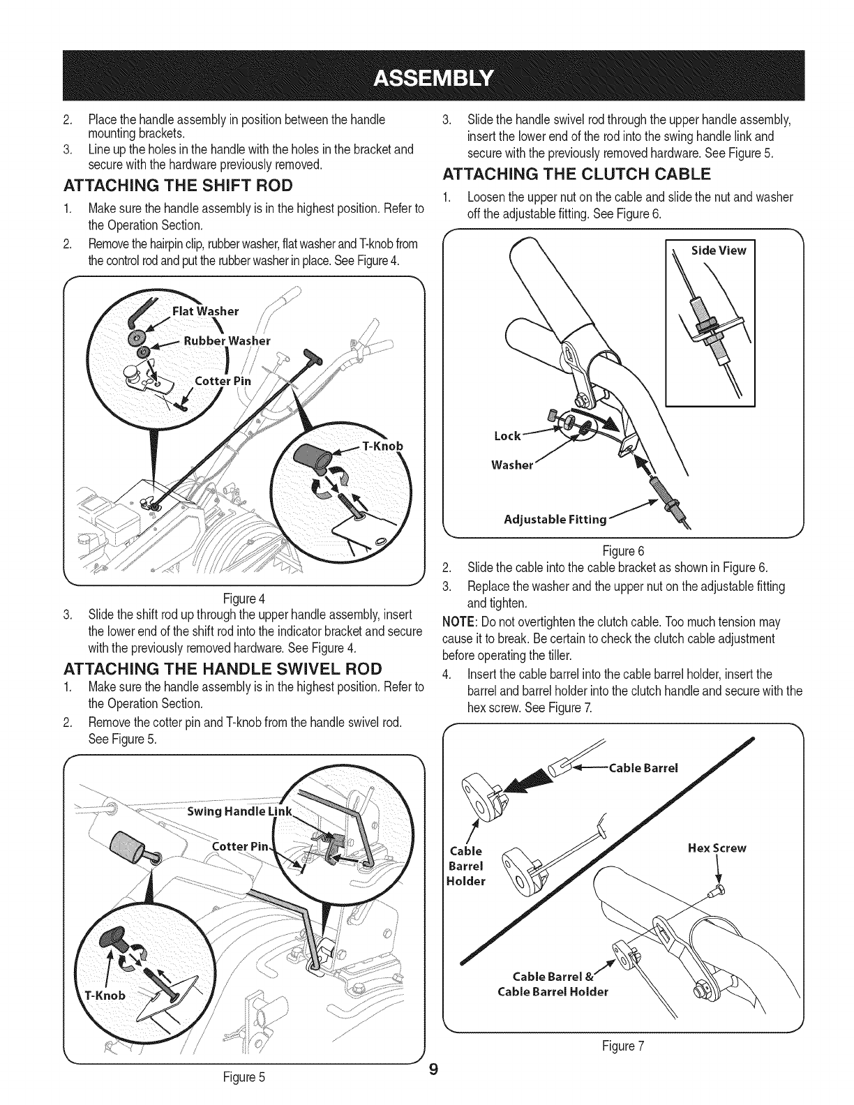
ATTACHING THE SHIFT ROD
1. Makesurethe handleassemblyis inthe highestposition.Referto
the OperationSection.
2. Removethehairpinclip,rubberwasher,flatwasherandT-knobfrom
thecontrolrodandputtherubberwasherinplace.SeeFigure4.
F
Washer
Washer
Figure4
3. Slidetheshift rodup throughthe upperhandleassembly,insert
the lowerendof the shift rodinto the indicatorbracketandsecure
withthe previouslyremovedhardware.SeeFigure4.
ATTACHING THE HANDLE SWIVEL ROD
1. Makesurethe handleassemblyis inthe highestposition.Referto
the OperationSection.
2. Removethecotterpin andT-knobfromthe handleswivelrod.
SeeFigure5.
3. Slidethe handleswivelrodthroughthe upperhandleassembly,
insertthe lowerendof the rodintothe swinghandlelinkand
securewiththe previouslyremovedhardware.See Figure5.
ATTACHING THE CLUTCH CABLE
1. Loosenthe uppernuton the cableandslidethe nut andwasher
off the adjustablefitting.SeeFigure6.
Side View
Washer
Adjustable Fitting J
Figure6
2. Slidethe cableintothe cable bracketas shownin Figure6.
3. Replacethe washerand theuppernuton the adjustablefitting
andtighten.
NOTE:Donot overtightentheclutchcable.Toomuchtensionmay
causeit to break.Becertainto checkthe clutchcableadjustment
beforeoperatingthe tiller.
4. Insertthe cable barrelintothe cablebarrelholder,insertthe
barrelandbarrelholderintothe clutchhandleandsecurewiththe
hexscrew.SeeFigure7.
__Cable Barrel
Cable Hex Screw
Barrel 1
Holder
Cable Barrel
Cable Barrel Holder
Figure5 9
Figure7

5. Whentheclutchcableisinplace,securethecableontothehandle
withtheprovidedcabletiesinthelocationsshowninFigure8.
Figure8
ADJUSTMENTS
Clutch Cable
Checkthe adjustmentof the clutchcableas follows:
1. Positionthe tiller so thefrontcounterweightis againsta solid
object,suchas a wall.
2. Withthe gearselectionleverin NEUTRAL,startthe engine.Refer
to Startingthe Engineinthe Operationsection.
3. Standingonthe right sideof the tiller,examinethe belt(insidethe
beltcover).It shouldnotbe turning.
4. Ifthe beltturnswithoutthe clutchcontrolengaged,unthread
the uppernut andadjustit byunthreadinglowernut a fewturns
clockwise(whenstandingin the operator'sposition)andthen
retightenthe uppernutagainstthe cablebracket.SeeFigure9.
5. Nowmovethe shift leverto the FORWARDposition.
6. Carefullyengagethe clutchby squeezingclutchleveragainstthe
handle.The wheelsshouldspin.
7. Ifthe wheelsdo notspin withthetiller in forward,loosenthe
uppernutandadjustby tighteningthe cablea fewturnscounter-
clockwise(whenstandingin theoperator'sposition)andthen
retightenthe uppernut againstcable bracket.See Figure9.
8. Recheckbothadjustments,and readjustas necessary.
NOTE:A secondarycableadjustmentis availableif you reachthe
point thatadditionaladjustmentis needed.Movethe nutsat theother
endof the cabletowardsthe endof the casing.Thenreadjustthe nuts
at the cable bracket.
Idler Pulley Rod
Checkthe adjustmentof the idlerpulleyrodas follows:
1. Disconnectandgroundthe sparkplugwireagainstthe engine.
2. Withthe engineoffand theclutch leverdisengaged,shiftthe shift
leverto eachforwardmode.
3. Confirmthatthe shift leverindicatorbracketdoes not touchthe
idlerpulleyrodwiththe clutchleverdisengaged.
4. To readjustthe idlerpulleyrod, removethe beltcoveras de-
scribedunderBelt Replacementinthe Serviceand Maintenance
section.
5. Removethe cotterpinandspringwasherfromtheidlerpulleyrod.
See Figure10.
Cotter Pin "_ /
idler PulleyS!
Rod-_
Spring
Washer Upper Hole
Lower Hole
Figure10
6. Movetheidlerpulleyrodout of the upperholeandinto the lower
holein the idlerbracket.
7. Replacethe springwasherandcotter pin.
8. Checkthe clearanceof the idlerpulleyrodto the indicatorbracket
by shiftingto eachforwardmode.
Figure9 10
Air Filter._
Fuel Cap_
Oil Fill Cap
& Di|
Front
Counterweight
HandleAdjult rnent
Shift indicator\
Bracket _/_
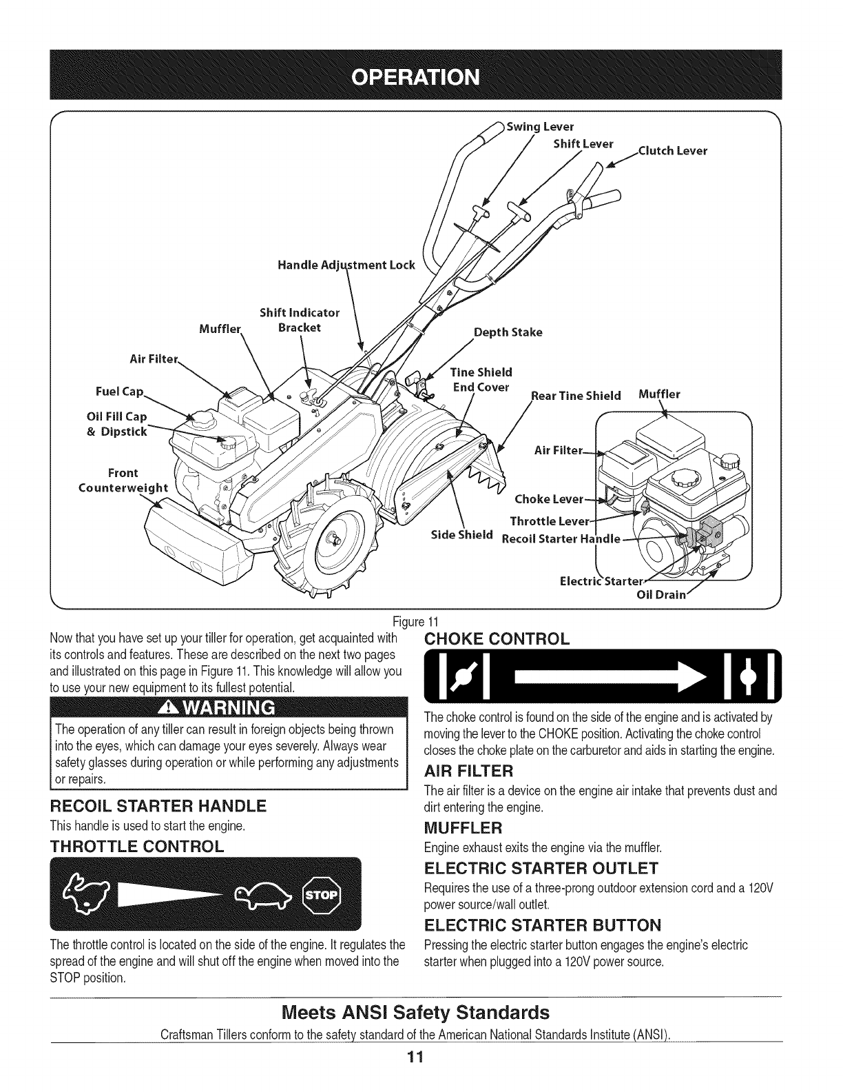
Nowthat youhavesetup yourtillerfor operation,get acquaintedwith
itscontrolsandfeatures.Thesearedescribedon the nexttwopages
andillustratedon thispagein Figure11.Thisknowledgewill allowyou
to useyour newequipmentto itsfullestpotential.
Theoperationof anytiller can resultin foreignobjectsbeingthrown
intothe eyes,whichcan damageyoureyesseverely.Alwayswear
I safetyglassesduringoperationor whileperforminganyadjustments
[or repairs.
RECOIL STARTER HANDLE
Thishandleis usedto startthe engine.
THROTTLE CONTROL
Thethrottlecontrolis locatedon the sideof the engine.Itregulatesthe
spreadof the engineandwill shutoff theenginewhen movedintothe
STOPposition.
Lock
)Swing Lever
/_Leve_.jClutch Lever
/
Depth Stake
TineShield
End Cover
Side Shield
RearTine Shield Muffler
Air Filter--
ChokeLever-
Throttle Lever-
RecoilStarter H_
Electr rter-
Oil Drain /
Figure11
CHOKE CONTROL
Thechokecontrolisfoundon thesideof theengineandisactivatedby
movingthe leverto theCHOKEposition.Activatingthe chokecontrol
closesthe chokeplateonthecarburetorandaidsinstartingtheengine.
AIR FILTER
The airfilteris a deviceon the engineairintakethatpreventsdustand
dirt enteringthe engine.
MUFFLER
Engineexhaustexitsthe enginevia the muffler.
ELECTRIC STARTER OUTLET
Requiresthe useof a three-prongoutdoorextensioncordanda 120V
powersource/walloutlet.
ELECTRIC STARTER BUTTON
Pressingtheelectricstarterbuttonengagesthe engine'selectric
starterwhenpluggedintoa 120Vpowersource.
Meets ANSi Safety Standards
CraftsmanTillersconformto the safetystandardof the AmericanNationalStandardsInstitute(ANSI).
11

OiL FiLL CAP & DIPSTICK
Engineoil levelcan becheckedand oiladdedthroughtheoil fill.
NOTE:ThisunitwasshippedWITHOUToil inthe engine.Oilis
includedin the plasticbag packedwiththe manualin withthe unit.
Addtheoil as directedin theGas & OilFill Up section.Checkthe oil
levelbeforeeachoperationto ensureadequateoil is inthe engine.
Forfurtherinstructions,referto the stepsin the EngineMaintenance
sectionof thismanual.
SHIFT LEVER/SHIFT LEVER INDICATOR
BRACKET
Theshift leveris locatedonthe handleassembly,it is usedto select
NEUTRAL,REVERSE,oroneof the three FORWARDmodesby
pullingupor pushingdownon the shiftleverandplacingthe shiftlever
indicatorbracketinthe desiredposition.
The gear positions are:
WheelsForward(No TineAction)_' -- Thewheelsmoveforward,but
the tinesare stationary.
WheelsForward/TinesReverse_"_ -- Thewheelsmoveforward
andthe tinesrotatein reverse(backwards).Thisgearsettingis for
ground-breakingtillingandhardsoil.
WheelForward/TinesForward_ -- Thewheelsmoveforwardandthe
tinesmoveforward.Thisgearsettingisforcultivatingandtillingsoftsoil.
Neutral[_ -- All movement(wheelsandtines)is stopped.Thisgear
is for startingandpushingthe tiller.
Reverse[_-- Thewheelsmoveinreverse,butthe tinesarestationary.
CLUTCH LEVER
Theclutchleveris locatedon thelefthandle.Squeezingtheclutchlever
againstthehandleengagesthewheelandthe drivemechanisms.
DEPTH STAKE
Thislevercontrolsthe tillingdepthof the tines.Pullthecotter pinout
fromtheclevis pinto adjustthe tillingdepthto fivedifferentsettings.
SWING LEVER
Thesteeringhandlecan beswivelledin eitherdirection.Thisenables
the tillerto beguidedto the nextrow.Releasethesteeringhandle
by pullingupon the swinglever.Swivelthe handleintothe desired
positionandreleasethe handleto lockinto place.
HANDLE ADJUSTMENT LOCK
Thehandlemaybe adjustedto the heightdesiredby unlockingthe
HandleAdjustmentLock,then movingthe handlebars to thedesired
positionandthen re-lockingthe HandleAdjustmentLock.Thehandle
shouldbeadjustedsothatwhenthe tiller is digging3 to 4 inchesinto
the soil,the handlefallsto aboutwaist-high.
REAR TINE SHIELD
The rearfine shieldprotectsthe operatorfromflyingdebriswhilealso
smoothingoutfreshlytilled soil.
SIDE SHIELD
The side shieldis usedto maintaincleareven rowsandmaybe
adjustedto oneof fivedifferentpositions.
TINES
Yourfiller's tinesarea seriesof bladesarrangedona revolving
power-drivenshaft.
GAS AND OIL FILL-UP
Oil (one bottle shipped with unit)
FirstTime Use
1. Removeoilfilldipstick.
2. Withthe tilleron levelground,use a funnelto emptyentire
contentsof oil bottleprovidedinto theengine.
3. Replaceoil fill dipstickandtighten.
SubsequentUses
Onlyusehighqualitydetergentoil ratedwithAPI serviceclassifica-
tion SF,or SG.Selectthe oil's SAEviscositygradeaccordingto the
expectedoperatingtemperature.Followthechartbelow.
1. SingleViscosity
2. MultiViscosity
=row lOw
__ 20w
=m_ 20
®
mmm30
4o_
20w40, 20w50 m=== _ _ _
I
15w40, 15w50 '=g kl=== ===_= _a='= =='=m=''=b_
I
10w40 ==mm _m== m=_ ==m_ =======_h=,,,,
N
10w30 ==w_ ,_ mm_= _ _mm _
(°C)-30 ° -200 -100 0o 100 200 300 400
(°F)-20 ° 0° 200 400 600 800 100°
AmbientTemperature
J
Althoughmulti-viscosityoils (5W30,10W30,etc.)improvestarting
incoldweather,theywill resultin increasedoilconsumptionwhen
usedabove32°E Checkyourengineoil levelmorefrequentlyto avoid
possibleenginedamagefromrunninglow onoil.
1. Checkthe oillevel makingcertainnotto rubthedipstickalong
the insidewallsof theoil fill tube.Thiswould resultina false
dipstickreading.Wipe dipstickcleanwithcloth.Replacedipstick
intothe oilfiller neck,butdo not screwit in. Removeandcheck
oil level.Refillto FULLmarkondipstick,if necessary.Capacityis
approximately20oz. Overfillingwill causethe engineto smoke
profuselyandwill resultin poorengineperformance.
2. Replaceoil fill dipstickandtighten.
3. Keepoillevelat FULL.Runningthe enginewithtoo littleoil can
resultin permanentenginedamage.
12
Gasoline
Useextremecarewhenhandlinggasoline.Gasolineisextremely
flammableandthe vaporsareexplosive.Neverfuel machineindoors
orwhile theengineishotor running.Extinguishcigarettes,cigars,
pipes,andother sourcesof ignition.
Alcoholblendedfuels(calledgasoholor usingethanolor methanol)
canattractmoisturewhichleadsto separationandformationof acids
duringstorage.Acidicgas can damagethe fuel systemof anengine
whileinstorage.
Toavoidengineproblems,the fuel systemshouldbeemptied
beforestoragefor 30daysor longer.Drainthegas tankby starting
the engineandlettingit rununtilthe fuel linesandcarburetorare
empty.Usefreshfuel nextseason.SeeSTORAGEInstructionsfor
_addt one nformaton.
Neveruseengineor carburetorcleanerproductsinthe fuel tankor
permanentdamagemayoccur.
1. Removefuelcap fromthefuel tank.
2. Makesurethecontainerfromwhichyouwill pourthe gasolineis
cleanandfreefrom rustorforeignparticles.Neveruse gasoline
thatmaybestalefromlongperiodsof storageinitscontainer.
Gasolinethathas beensittingfor any periodlongerthan four
weeksshouldbeconsideredstale.
3. Fill fueltankwithclean,fresh,unleadedregulargasolineonly.
Replacefuelcap.
NOTE:Checkthefuel levelperiodicallyto avoidrunningoutof
gasolinewhileoperatingthe tiller.
TO START ENGINE
Electric Starter
Determinethatyour home'swiringis a three-wiregroundedsystem.
Aska licensedelectricianifyouare notcertain.
If you havea groundedthree-prongreceptacle,proceedas follows:
1. Attachsparkplugwire andrubberbootto sparkplug.
2. Placethe gearselectionleverinNEUTRAL.
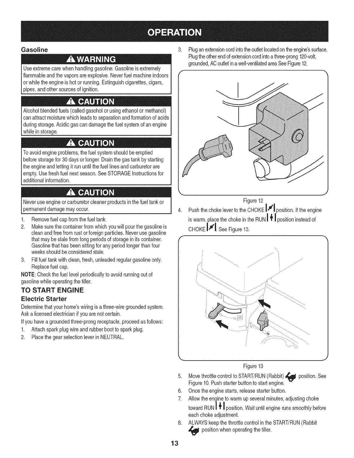
.Pluganextensioncordintotheoutletlocatedontheengine'ssurface.
Plugtheotherendof extensioncordintoa three-prong120-volt,
grounded,ACoutletinawell-ventilatedareaSeeFigure12.
k,,,._.j
Figure12
4. Pushthe chokeleverto the CHOKEI Jl position.If theengine
is warm,placethe chokeinthe RUNi _ I positioninsteadof
CHoKElllSeeFigure13.
f'i ................................ ............
13
Figure13
5. Movethrottlecontrolto START/RUN(Rabbit)_ position.See
Figure10.Pushstarterbuttonto startengine.
6. Once theenginestarts,releasestarterbutton.
7. Allowthe engineto warmupseveralminutes,adjustingchoke
towardRUN| _1 position.Waituntilenginerunssmoothlybefore
eachchokeadjustment.
8. ALWAYSkeepthe throttlecontrolinthe START/RUN(Rabbit
_1I positionwhenoperatingthe tiller.
9. Whendisconnectingtheextensioncord,alwaysunplugtheend
atthethree-prongwalloutletbeforeunpluggingtheoppositeend
fromthetiller.
RecoilStarter
1. Attachsparkplugwireandrubberboottosparkplug.
2. PlacethegearselectionleverinNEUTRAL.
3. MovethechokeleverontheenginetoCHOKEI",1pos t on.<A
warmenginemaynot requirechoking.)SeeFigure10.
4. Movethrottlecontrolto START/RUN(Rabbit)_ position.See
Figure10.
5. Standingonthe sideof the unit,graspthe recoilstarterhandle
andpull ropeout untilyou feela drag.
6. Pullthe ropewitha rapid,continuous,full arm stroke.Keepafirm
griponthe starterhandle.Letthe roperewindslowly.
7. Repeat,if necessary,untilenginestarts.Whenenginestarts,
movechokecontrolgraduallytowardthe RUNI _tI position..
8. Ifenginefalters,movechokecontrolbacktowardthe CHOKE
I'_1 positionand repeatsteps5 though8.
9. ALWAYSkeepthe throttlecontrolinthe START/RUN(Rabbit
_ll positionwhenoperatingthe tiller.
TO STOP ENGINE
1. Tostopthe wheelsandtines,releasethe ClutchLever.
2. Movethrottlecontrolleverto slow(turtle)'_ position.
Wheneverpossible,graduallyreduceenginespeedbefore
stoppingengine.
3. Movethrottlecontrolleverto STOP_ orOFFposition.
4. Disconnectsparkplugwireandgroundit againsttheengineto
preventaccidentalstartingwhilethe equipmentis unattended.
TO ENGAGE DRIVE & TINES
Do not pushdownonthe handlebarsto try to makethe tiller till more
deeply.Thistakesweightoff the wheels,whichallow thetinesto
rapidlypropelthe tiller,whichcould resultin lossof control,property
[damage,orpersona njury.
1. Placethe ShiftLeverinthe desiredforwardtillingpositionandpress
the ClutchLeverdownagainstthehandleto begintilling.
2. Whentilling,letthewheelspullthe machinewhilethetinesdig.
Walkslowlybehindthetillerallowingit tomoveat itsownpacewhile
keepingasecuregriponthehandlebarwithyourelbowsflexed.
3. Releasethe ClutchLeverto stopthewheelsandtines.
To move in reverse: (Do not till in reverse)
a. Releasethe ClutchLever.Then liftthe handlebaruntil the
tinesareoff the ground.
b. Placethe ShiftLeverin the reversepositionandthen press
the ClutchLeverdownagainstthe handlebarandwalk
backwardswiththe machine.
NOTE:In reversemode,thetineswill not rotate.
TURNING THE TILLER
Manually
1. Practiceturningthe tillerin a level,openarea. Beverycarefulto
keepyourfeetandlegs awayfromthetines.
2. Tobegina turn,lift the handlebarsuntilthe tinesareoutof the
groundandthe engineandtinesare balancedoverthe wheels.
3. Withthe tiller balanced,pushsidewaysonthe handlebarto steer
inthe directionof the turn.Afterturning,slowlylowerthe tinesinto
thesoil to resumetilling.
Using the Swing Lever
Thetiller handlecan beswivelledineitherdirection.The SwingLever
enablesthe tillerto be guidedsidewaysto the nextrow.SeeFigureX.
1. Pulluponthe SwingLeverto releasethe handle.
2. Swivelthe handleintothe desiredposition.
3. Releasethe SwingLeverto securethe handlein place.
SETTING THE DEPTH
Becertainsparkplugwire is disconnectedandgroundedagainstthe
enginewhen performingany adjustments.
Tillingdepthiscontrolledbythedepthstakewhichcanbeadjustedtofive
differentsettings.Adjustthesideshieldsasyouadjustthedepthstake.
• Whenusingthe tiller forthe first time,usethe secondadjustment
holefromthe top (1"of tillingdepth).
• Whenbreakingupsodandfor shallowcultivation,usethe setting
whichgives1"of tillingdepth(secondholefromthetop). Place
theside shieldsin theirlowestposition.
• Forfurtherdepth,raisethe depthstakeandsideshieldsandalso
makeoneortwo morepassesoverthe area.
• Whentilling loosesoil,thedepth stakemaybe raisedto its
highestposition(usebottomadjustmenthole)to givethe deepest
tillingdepth.Raisethe side shieldsto their highestposition.
• Totransporttiller,lowerthe depthstake(usetop adjustmenthole).
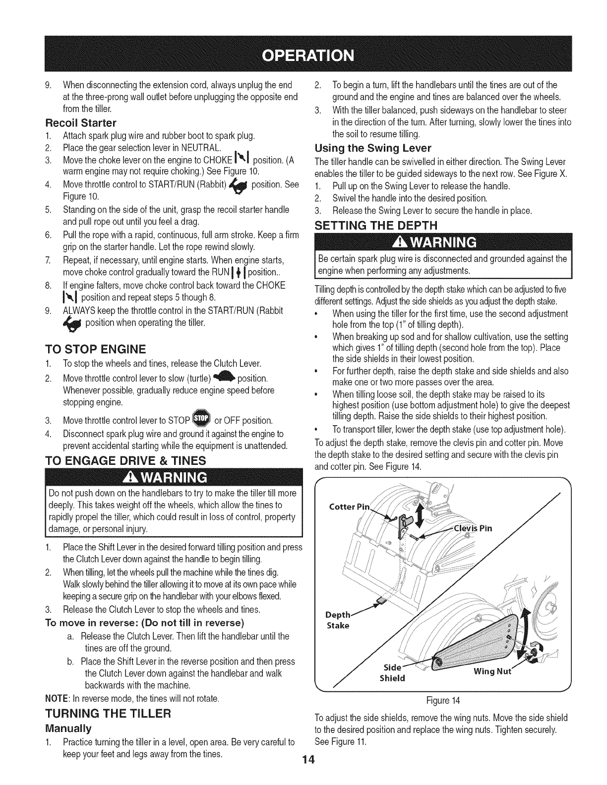
Toadjustthe depthstake,removethe clevispinandcotter pin.Move
thedepth staketo the desiredsettingandsecurewiththe clevispin
andcotterpin. SeeFigure14.
Figure14
Toadjustthe side shields,removethe wingnuts. Movethe sideshield
to thedesiredpositionandreplacethe wing nuts.Tightensecurely.
SeeFigure11.
14
TiLLiNG TIPS & TECHNIQUES
Beforetilling,contactyour telephoneor utilitiescompanyandinquire
lifundergroundequipmentor linesareusedonyour property.Do not
_tillnearburiedelectriccables,telephonelines,pipesor hoses.
Tilling Depth
•Don'toverloadthe engine,but digas deeplyas possibleoneach
pass.Onlater passes,the wheelsmaytendto spin inthe soft dirt.
Helpthemalongby liftingup slightlyonthe handlebar(onehand,
palmup,worksmosteasily).
• Avoidthe temptationto pushdownon the handlebarsinan
attemptto forcethe tillerto digdeeper.Doingso takestheweight
offthe poweredwheels,causingthemto losetraction.Without
thewheelsto holdthetiller back,the tineswillattemptto propel
towardsthe operatororawayfromthe operator.
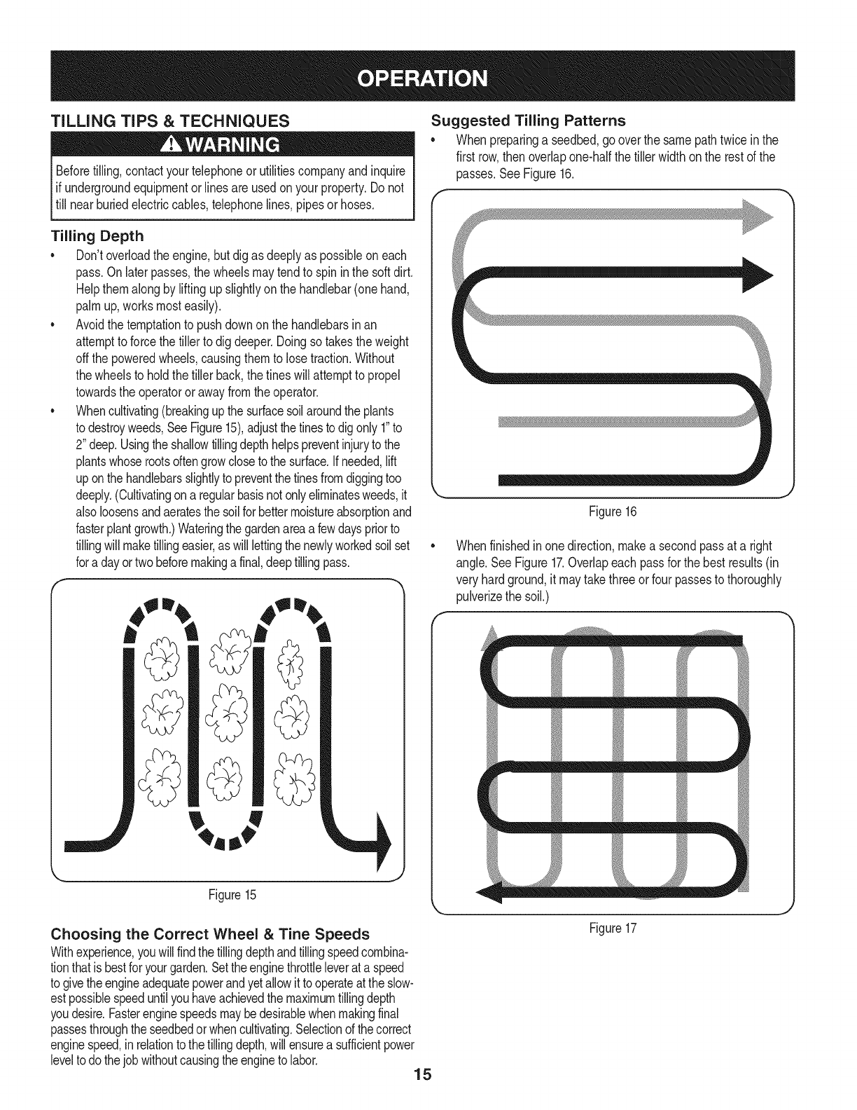
• Whencultivating(breakingupthe surfacesoilaroundtheplants
to destroyweeds,SeeFigure15),adjustthetinesto digonly 1"to
2"deep.Usingthe shallowtillingdepthhelpspreventinjuryto the
plantswhoserootsoftengrowclosetothe surface.If needed,lift
uponthe handlebarsslightlyto preventthetinesfromdiggingtoo
deeply.(Cultivatingona regularbasisnotonlyeliminatesweeds,it
alsoloosensandaeratesthe soilforbettermoistureabsorptionand
fasterplantgrowth.)Wateringthegardenareaa fewdayspriorto
tillingwill maketillingeasier,as will lettingthenewlyworkedsoil set
fora dayortwobeforemakinga final,deeptillingpass.
,J
Figure15
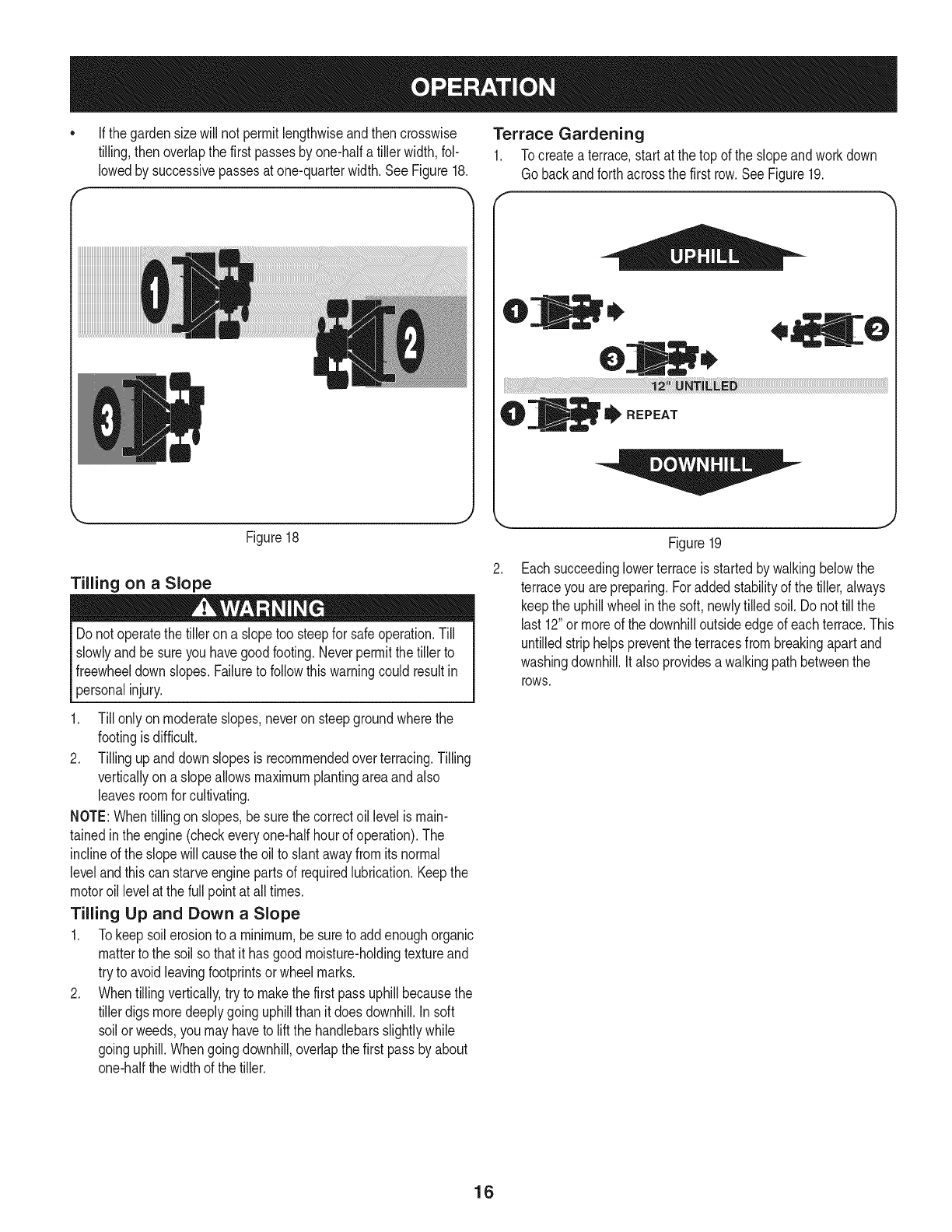
Suggested Tilling Patterns
• Whenpreparinga seedbed,gooverthe samepathtwicein the
first row,then overlapone-halfthe tillerwidthon the restofthe
passes.SeeFigure16.
Figure16
Whenfinishedin onedirection,makea secondpassat a right
angle.SeeFigure17.Overlapeachpassfor the bestresults(in
veryhardground,it maytakethreeor fourpassesto thoroughly
pulverizethe soil.)
_mm
Choosing the Correct Wheel &Tine Speeds
Withexperience,youwillfindthe tillingdepthandtillingspeedcombina-
tionthatis bestforyourgarden.Settheenginethrottleleverata speed
to givethe engineadequatepowerandyetallowit tooperateat theslow-
estpossiblespeeduntilyouhaveachievedthe maximumtillingdepth
youdesire.Fasterenginespeedsmaybedesirablewhenmakingfinal
passesthroughthe seedbedorwhencultivating.Selectionof thecorrect
enginespeed,inrelationtothe tillingdepth,will ensurea sufficientpower
levelto dothejobwithoutcausingthe engineto labor. 15
Figure17
Ifthegardensizewillnotpermitlengthwiseandthencrosswise
tilling,thenoverlapthefirstpassesbyone-halfatillerwidth,fol-
lowedbysuccessivepassesatone-quarterwidth,SeeFigure18.
k_ .w J
Figure18
Tilling on a Slope
Donot operatethe tilleron a slopetoo steepfor safeoperation.Till
slowlyand besureyou havegoodfooting.Neverpermitthetiller to
freewheeldown slopes.Failureto followthiswarningcouldresultin
personalinjury.
Till onlyon moderateslopes,neveronsteepgroundwherethe
footingis difficult.
2. Tillingupanddownslopesis recommendedoverterracing.Tilling
verticallyon a slopeallowsmaximumplantingareaandalso
leavesroomforcultivating.
NOTE:Whentilling onslopes,besurethe correctoil levelis main-
tainedinthe engine(checkeveryone-halfhourof operation).The
inclineof the slopewillcausethe oilto slantawayfromits normal
levelandthiscan starveenginepartsof requiredlubrication.Keepthe
motoroil levelat thefull pointat all times.
Tilling Up and Down a Slope
1. Tokeepsoil erosionto a minimum,be sureto addenoughorganic
matterto the soilso thatit hasgoodmoisture-holdingtextureand
tryto avoidleavingfootprintsor wheelmarks.
2. Whentillingvertically,try to makethe first passuphillbecausethe
tillerdigs moredeeplygoinguphillthanit doesdownhill,insoft
soil orweeds,you mayhaveto liftthe handlebarsslightlywhile
goinguphill.Whengoingdownhill,overlapthe first passbyabout
one-halfthe widthof the tiller.
Terrace Gardening
1. Tocreateaterrace,startat the top of the slopeandworkdown
Go backandforthacrossthe first row.SeeFigure19.
0
0
ii_[[_i_i!iiiiiiiiii_i_i_ii;iiiiii_iii_ii_!!iiiiiiiiiiiiiiiiiiii_ii_!i!i!!!i_i_i_i_i_i_i_i_i_i_i_!_ii_ii_iii_!!i_iiiiiii!i_!_!_!_!_i_!iiiiiiiiiiiiiiiiiiliii!!ii!!ii__ii_ii_ii_ii_ii_ii_ii_i_i__iiiiiiiiiiiiiiiiiiiiiiiiiiiiiiiiiiiiiiiiiiiiiiiiiiiiiiiiiiiiiiiiiiiiiiiiiiiiiiiiiiiiiiiilii,!iii_i_i__i_i_i__i_i_i_!i_'_'_ii____i!i!i!i!i!i!i!i!i!i!i!i!i!i!i!i!i!i!i!i!i!i!i!i!i!i!i!i!i!i!i!i!i!i!i!i!i!i!i!i!i!i!i!i!i!i!i!i!i!i!i!i!i!i!i!i!i!i!i!i!i!i!i!i!i!i!i!i!i!i!i!i!i!i!i!i!i!i!i!i!i!i!i!i!i!i!i!i!i!i!i!i!i!i!i!i!i!i!i!i!i!i!i!i!i!i!i!i!i!i!i!i!i!i!i!i!i!i!i!i!i!i!i!i!i!i!i!i!i!ii!iliii!i
_REPEAT
J
Figure19
Eachsucceedinglowerterraceis startedbywalkingbelowthe
terraceyou arepreparing.Foraddedstabilityof the tiller,always
keepthe uphillwheelinthe soft,newlytilled soil.Do nottill the
last12"or moreof the downhilloutsideedgeof eachterrace.This
untilledstriphelpspreventthe terracesfrombreakingapartand
washingdownhill,it also providesa walkingpathbetweenthe
rOWS,
16

Loading & Unloading the Tiller
Loadingandunloadingthe tiller intoa vehicleis potentiallyhazard-
ous anddoingso is not recommendedunlessabsolutelynecessary,
as this couldresultin personalinjuryor propertydamage.
you mustloador unloadthetiller,followthe guidelinesgivenbelow:
• Beforeloadingor unloadingthe tiller,stopthe engine,waitfor all
partsto stopmoving,disconnectthe sparkplugwireand letthe
engineandmufflercool.
• Thetiller is too heavyandbulkyto be safelyliftedby oneperson.
Twoor morepeopleshouldsharethe load.
• Usesturdyrampsandmanually-- withthe engineshutoff -- roll
thetiller into andout of the vehicle.Twoor morepeopleare
neededto dothis.
• The rampsmustbestrongenoughto supportthecombined
weightof the tillerandany handlers.The rampsshouldprovide
goodtractionto preventslipping;theyshouldalso haveside rails
to guidethe tiller alongthe ramps;andtheyshouldhavea locking
deviceto securethemto the vehicle.
• The handlersshouldwearsturdyfootwearthatwill helpto prevent
slipping.
• Positionthe loadingvehicleso thatthe rampangleis as flat
as possible(theless inclineto the ramp,the better).Turnthe
vehicle'sengineoff andapplythe parkingbrake.
• Whengoingup the ramps,standinthe normaloperatingposition
andpushthe tilleraheadof you.Havea personat eachside to
turnthe wheels.
• Whengoingdownthe ramps,walkbackwardwiththe tiller
followingyou.Keepalert forany obstaclesbehindyou. Positiona
personat each wheelto controlthe speedof the tiller.Nevergo
downthe rampstiller-first,as the tillercould tip forward.
• Placewoodenblocksonthe downhillside of thewheelsif you
needto stopthe tillerfrom rollingdownthe ramp.Also,use the
blocksto temporarilykeepthe tillerin placeonthe ramps(if
necessary),andto chockthewheelsinplaceafterthe tilleris in
thevehicle.
• Afterloadingthe tiller,preventit from rollingbychockingthe
wheelswithblocks,andsecurelytie the tillerdown.
CLEARING THE TINES
Beforeclearingthe tinesby hand,stoptheengine,allowall moving
partsto stopanddisconnectthe sparkplugwire.Failureto followthis
warningcouldresultin personalinjury.
Thetineshavea self-clearingactionwhicheliminatesmostof the
tanglingof debris.However,occasionallydry grass,stringystalksor
toughvinesmaybecometangled.Followtheseproceduresto help
avoidtanglingandto clearthe tines,if necessary.
• Toreducetangling,setthe depthstakedeepenoughto get
maximum"chopping"actionas the tineschopthe materialagainst
theground.Also,try to till undercrop residuesorcovercrops
whiletheyaregreen,moistandtender.
• Whiletilling,try swayingthe handlebarsfromsideto side (about
6" to 12").This"fishtailing"actionoftenclearsthetinesof debris. 17

MAINTENANCE SCHEDULE
Beforeperforminganytypeof maintenance/service,disengageall
controlsandstoptheengine.Waituntilallmovingpartshavecometo
acompletestop.Disconnectsparkplugwireandgrounditagainstthe
enginetopreventunintendedstarting.Alwayswearsafetyglassesduring
operationor whileperforminganyadjustmentsor repairs.
Followthe maintenanceschedulegivenbelow.Thischartdescribes
serviceguidelinesonly.Usethe ServiceLogcolumnto keeptrackof
completedmaintenancetasks.To locate the nearest Sears Service
Centeror to scheduleservice,simplycontactSears at
1-800-4-MY-HOME®.
EachUse
1st2 hours
1st5 hours
Every10hours
Every25 hours
Every30 hours
Every50 hours
Every100hours
BeforeStorage
.
2.
3.
4.
1.
2.
1.
1.
2.
1.
2.
3.
1.
1.
2.
1.
Engineoillevel
Looseormissinghardware
Engineandaroundmuffler
Aircleaner
Drivebelt tension
Nutsand Bolts
Engineoil
Drivebelt tension
Unit
Sparkplug
Tinesfor wear
Tirepressure
Engineoill-
Aircleaner
SparkPlug
Fuelsystem
= =
1. Check
2. Tightenor_place
3. Clean
4. Check
1. Check
2. Check
1. Change
1. Check
2. Lubricate
1. Check
1. Check
2. Check
1. Change
1. Change
2. Change
1. Runengineuntilit stopsfromlackof
fuel oradda gasolineadditiveto the
gas in thetank.
Changeoileverytwentyfivehourswhenoperatingengineunderheavyloadorin hightemperatures.
Alwaysstopengineanddisconnectsparkplugwirebeforeperforming
lany maintenanceor adjustments.Alwayswearsafetyglassesduring
_operationorwhile performingany adjustmentsor repairs.
GENERAL RECOMMENDATIONS
•Alwaysobserveallsafetyrulesfoundonproductlabelsandin
thisoperator'smanualwhenperformingany maintenance.Safety
rulescan befoundonthe productlabelsandin thisOperator's
Manualbeginningon page3.
• Thewarrantyon thistillerdoes notcoveritemsthathavebeen
subjectedto operatorabuseor negligence.Toreceivefull value
fromwarranty,operatormust maintainthe equipmentas
instructedhere.
• Someadjustmentswillhaveto be madeperiodicallyto maintain
yourunit properly.
• Periodicallycheckall fastenersand makesurethesearetight.
ENGINE MAINTENANCE
DO NOTcheckfor sparkwithsparkplugremoved.DO NOTcrank
enginewithsparkplug removed.
Ifthe enginehas beenrunning,the mufflerwill beveryhot. Becareful
notto touchthe muffler.
Thesparkplugmustbesecurelytightened.Animproperlytightened
sparkplugcan becomeveryhot andmaydamagethe engine.
Checking the Spark Plug
Toensureproperengineoperation,the sparkplugmustbeproperly
gappedandfree of deposits.Checkthe sparkplugevery25hoursand
replaceitevery100hours.
18
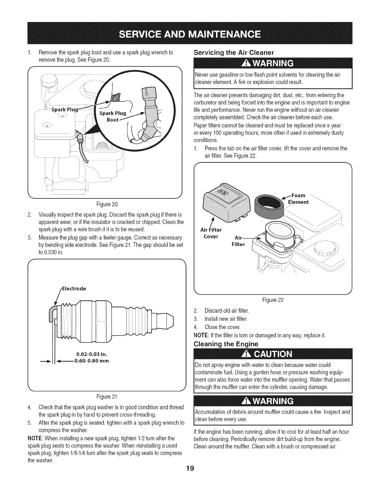
1. Removethesparkplugbootanduse a sparkplugwrenchto
removethe plug.See Figure20.
Figure20
2. Visuallyinspectthe sparkplug.Discardthe sparkplugif thereis
apparentwear,orif the insulatoris crackedor chipped.Cleanthe
sparkplugwitha wirebrush if it is to be reused.
3. Measurethe pluggapwitha feelergauge.Correctas necessary
by bendingsideelectrode.SeeFigure21.The gapshouldbeset
to 0.030in.
F
Figure21
4. Checkthatthe sparkplugwasheris ingoodconditionandthread
the sparkplugin by handto preventcross-threading.
5. Afterthesparkplugis seated,tightenwitha sparkplugwrenchto
compressthe washer.
NOTE:Wheninstallinga newsparkplug,tighten1/2turn afterthe
sparkplugseatsto compressthe washer.Whenreinstallinga used
sparkplug,tighten1/8-1/4turnafterthe sparkplugseatsto compress
the washer.
Servicing the Air Cleaner
Neverusegasolineor lowflashpoint solventsfor cleaningtheair
cleanerelement.A fireor explosioncould result.
The aircleanerpreventsdamagingdirt,dust,etc.,fromenteringthe
carburetorandbeingforcedintothe engineandis importantto engine
lifeandperformance.Neverrunthe enginewithoutanair cleaner
completelyassembled.Checkthe air cleanerbeforeeachuse.
Paperfilterscannotbecleanedand mustbereplacedoncea year
or every100operatinghours;moreoftenif usedinextremelydusty
conditions.
1. Pressthetab onthe air filtercover,liftthe coverand removethe
air filter.SeeFigure22.
Air Filter
Cover
Filter
Figure22
2. Discardoldair filter.
3. Installnewair filter.
4. Closethe cover.
NOTE:Ifthe filteris tornor damagedinany way,replaceit.
Cleaning the Engine
Do notsprayenginewithwaterto cleanbecausewatercould
contaminatefuel.Usinga gardenhoseor pressurewashingequip-
mentcan alsoforcewaterintothe muffleropening.Waterthatpasses
throughthe mufflercan enterthe cylinder,causingdamage.
Accumulationof debrisaroundmufflercouldcausea fire. Inspectand
clean beforeeveryuse.
Ifthe enginehas beenrunning,allow it to coolfor at leasthalf anhour
beforecleaning.Periodicallyremovedirt build-upfromthe engine.
Cleanaroundthe muffler.Cleanwith a brushor compressedair.
19
Check Engine Oil
1. Checkoil beforeeachuse.Stopengineandwaitseveralminutes
beforecheckingoil level.Withengineon levelground,the oilmust
beto FULLmarkon dipstick.
2. Removeoil fill dipstickandwipe cleanwithcloth.
3. Replacedipstickintothe oilfiller neck,but donot screwitin.
Removeandcheckoil level.Levelshouldbeat FULLmark.
4. If needed,addoil slowly- recheck.Do not overfill.
5. Wipedipstickclean,replacebut donot tighten.Removeand
checkoil level.Oillevelshouldbeat FULLlineondipstick.
6. Replaceandtightendipstickfirmlybeforestartingengine.
DO NOTuse non-detergentoilor 2-strokeengineoil. Itcould shorten
the engine'sservicelife.
Change Engine Oil
•SAE10W-30is recommendedforgeneral,all temperatureuse.
Whenaddingoilto the engine,referto viscositychart inthe
operationsection.Usea 4-stroke,oranequivalenthighdeter-
gent,premiumqualitymotoroil certifiedto meetor exceedU.S.
automobilemanufacturer'srequirementsfor serviceclassification
SG,SR MotoroilsclassifiedSG,SF will showthisdesignationon
thecontainer.
• Changeengineoil afterthefirst fiveto eight hoursof operation,
andeveryfifty hoursoreveryseasonthereafter.Changeoil every
twentyfivehourswhenoperatingengineunderheavyloadorin
hightemperatures.
Beforetippingengineor equipmentto drainoil, drainfuel fromtank by
runningengineuntilfuel tankisempty.
Usedmotoroil maycauseskincancerifrepeatedlyleftincontactwith
the skinfor prolongedperiods.Althoughthis isunlikelyunlessyou
handleusedoil ona daily basis,itis stilladvisableto thoroughlywash
yourhandswithsoapandwateras soonas possibleafter handling
usedoil.
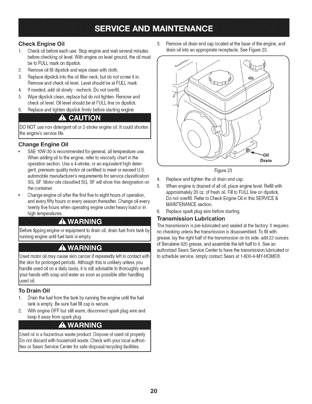
3. Removeoil drainendcap locatedat the baseof the engine,and
drainoil intoanappropriatereceptacle.See Figure23.
f
Figure23
4. Replaceandtightenthe oildrainendcap.
5. Whenengineisdrainedof all oil, placeenginelevel.Refillwith
approximately20oz.of freshoil. Fillto FULLlineondipstick.
Donot overfill.Referto CheckEngineOil inthis SERVICE&
MAINTENANCEsection.
6. Replacesparkplugwire beforestarting.
Transmission Lubrication
The transmissionis pre-lubricatedandsealedat thefactory.It requires
no checkingunlessthe transmissionisdisassembled.Tofill with
grease,lay the righthalfof thetransmissionon itsside,add22ounces
of Benalene920grease,andassemblethe lefthalf to it. Seean
authorizedSearsServiceCenterto havethe transmissionlubricatedor
to scheduleservice,simplycontactSearsat 1-800-4-MY-HOME®.
To Drain Oil
1. Drainthe fuelfromthe tankby runningthe engineuntil thefuel
tankisempty.Besurefuel fill cap issecure.
2. WithengineOFFbutstillwarm,disconnectsparkplugwire and
keepitawayfromsparkplug.
Usedoilisa hazardouswasteproduct.Disposeof usedoil properly
IDonot discardwithhouseholdwaste.Checkwithyourlocalauthori-
_tiesor SearsServiceCenterfor safedisposal/recyclingfacilities.
2O
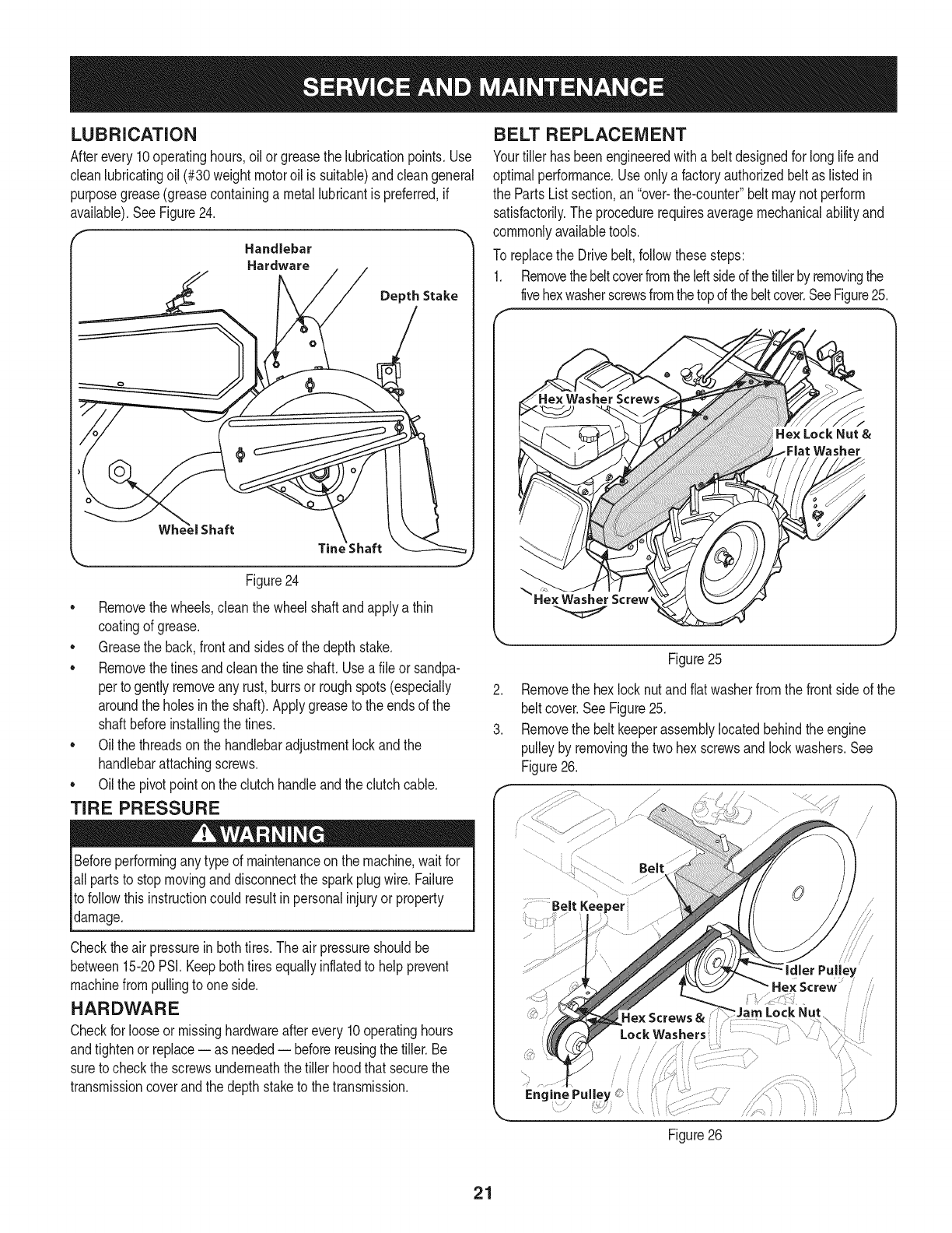
LUBRiCATiON
Afterevery10operatinghours,oilor greasethe lubricationpoints.Use
cleanlubricatingoil (#30weightmotoroil is suitable)andcleangeneral
purposegrease(greasecontaininga metallubricantis preferred,if
available).SeeFigure24.
Handlebar
Hardware
Depth Stake
Tim
L
Figure24
•Removethewheels,clean thewheelshaft andapplya thin
coatingof grease.
•Greasethe back,frontandsidesof the depth stake.
•Removethetinesandcleanthe fine shaft.Usea file or sandpa-
perto gentlyremoveany rust,burrsor roughspots(especially
aroundthe holesinthe shaft).Applygreaseto the endsof the
shaftbeforeinstallingthe tines.
•Oilthe threadsonthe handlebaradjustmentlockandthe
handlebarattachingscrews.
•Oilthe pivotpointonthe clutchhandleandthe clutchcable.
TiRE PRESSURE
Beforeperformingany typeof maintenanceonthe machine,waitfor
all partsto stopmovinganddisconnectthe sparkplugwire.Failure
to followthis instructioncouldresultinpersonalinjuryor property
damage.
Checktheair pressureinbothtires.The airpressureshouldbe
between15-20PSI.Keepbothtiresequallyinflatedto helpprevent
machinefrompullingto one side.
HARDWARE
Checkfor looseor missinghardwareafterevery10operatinghours
andtightenor replace-- as needed-- beforereusingthe tiller.Be
sureto checkthe screwsunderneaththe tillerhoodthatsecurethe
transmissioncoverandthe depthstaketo thetransmission.
BELT REPLACEMENT
Yourtiller hasbeenengineeredwith a beltdesignedfor longlife and
optimalperformance.Useonly a factoryauthorizedbeltas listedin
the PartsListsection,an"over-the-counter"belt maynot perform
satisfactorily.The procedurerequiresaveragemechanicalabilityand
commonlyavailabletools.
To replacethe Drivebelt,followthesesteps:
1. Removethebeltcoverfromtheleftsideofthetillerbyremovingthe
fivehexwasherscrewsfromthetopof thebeltcover.SeeFigure25.
He× Lock Nut &
Washer
J
Figure25
2. Removethe hexlock nutandflatwasherfromthe frontsideof the
beltcover.SeeFigure25.
3. Removethe belt keeperassemblylocatedbehindthe engine
pulleyby removingthe twohex screwsand lockwashers.See
Figure26.
Lock Washers
/
_JarnLockNut
Figure26
/\
21

4. Removethe idlerpulleyby removingthe hexscrewandjam lock
nut.SeeFigure26.
5. Removethe old beltandinstallthe newbelt.Followthe instruc-
tionsin reverseorderto re-installthe belt keeperandbelt cover.
SeeFigure26.
NOTE:Uponreassembly,makecertainthe beltis routedoverthe idler
pulleyandinsideof the beltkeepersbythe enginepulley.
TINES
Thetineswill wearwithuseand shouldbe inspectedat the beginning
of eachtillingseasonandafterevery30 operatinghours.Thetines
can bereplaced.Referto the PartsListsectionof thismanualfor part
numbers.
Tine Inspection
Withuse,the tineswill becomeshorter,narrowerandpointed.Badly
worntineswill resultina lossof tillingdepth,andreducedeffective-
nesswhen choppingupandturningunderorganicmatter.
Removing/Installing aTine Assembly
1. Removethetineshieldendcoversandsideshieldsby removingthe
threewingnutsoneachsidethatsecurethem.Referto Figure11.
2. Afine assemblyconsistsof a eightarticulatingtines.
NOTE:Notethe positionof the tinesfor reinstallationof the newtine
assemblies.
3. To removeafine assembly,simplyremovethe bow-tiecotterpin
securingthe clevispin. SeeFigure27.
.
5.
.
Clevis Pin
/
7
Bow=Tie
Cotter Pin j
Figure27
Removethe clevispin andslidethe assemblyto the outsideof
the unitandoff of the fine shaft.
Beforereinstallingthe fineassembly,inspectthe tine shaftfor
rust, roughspotsorburrs.Lightlyfile or sand,as needed.Applya
thincoatof greaseto the shaft.
Securethe fine assemblyto the tine shaftusingthe clevispinand
bow-tiecotterpin.
ADJUSTMENTS
Handle
The handlemaybeadjustedto thedesiredheight.Referto the Opera-
tion sectionfordetails.
Clutch Cable
Referto theAssemblysectionfor instructionson adjustingthe clutch
cable.
Idler Pulley Rod
Referto theAssemblysectionfor instructionson adjustingthe idler
pulleyrod.
22
Neverstoretiller withfuel in tankindoorsor in poorlyventilatedareasI
wherefuel fumesmayreachanopenflame,spark,or pilotlightas on
a furnace,waterheater,c othesdryer,orgas app ance. 1
Neverleaveengineunattendedwhileit is running.
PREPARING THE ENGINE
Enginesstoredbetween30and 90daysneedto betreatedwitha
gasolinestabilizerandenginesstoredover90daysneedto bedrained
of fuel to preventdeteriorationandgumfromforminginfuel systemor
on essentialcarburetorparts.Ifthe gasolineinyourenginedeterio-
ratesduringstorage,you mayneedto havethecarburetor,andother
fuel systemcomponents,servicedor replaced.
1. Removeallfuel fromtankby runningengineuntilit stopsfrom
lackof fuel.
2. Changethe oil. SeeChangeEngineOil inSERVICEAND
MAINTENANCEsection.
3. Removesparkplugand pourabouta 1/2ounceof engineoilinto
the cylinder.Replacesparkplug.Pullout slowlyon the recoil
starterhandleslowlyto distributeoil.
4. Cleandebrisfromaroundtheengineandthe muffler.Touchup
any damagedpaint,andcoatotherareasthatmayrustwitha light
filmof oil.
5. Storein a clean,dry andwellventilatedareaawayfromany ap-
pliancethatoperateswitha flameorpilot light,suchas a furnace,
waterheater,orclothesdryer.Alsoavoidany areawitha spark
producingelectricmotor,orwherepowertoolsare operated.
6. Ifpossible,avoidstorageareaswith highhumidity,becausethat
promotesrustandcorrosion.
7. Keeptheenginelevelinstorage.Tiltingcan causefuel or oil
leakage.
PREPARING THE TILLER
Whenthe tillerwon't be usedfor an extendedperiod,prepareit for
storageas follows:
1. Cleanthe tillerandengine.
2. Followthe lubricationrecommendationsandcheckfor looseparts
and hardware.
3. Storethe tiller ina clean,dry area.
4. Neverstorethe tillerwithfuel inthe fuel tankinan enclosedarea
wheregas fumescould reachan openflameor spark,or where
ignitionsourcesare present(spaceheaters,hot waterheaters,
furnaces,etc.).
23
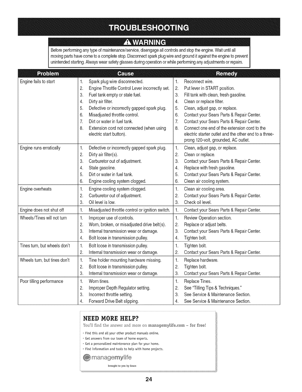
Beforeperforminganytypedmaintenance/service,disengageallcontrolsandstoptheengine.Waituntilall
movingpartshavecometo acompletestop.Disconnectsparkplugwireandgroundit againsttheengineto prevent
unintendedstarting.Alwayswearsafetyglassesduringoperationorwhileperforminganyadjustmentsorrepairs.
Enginefailsto start 1.
Enginerunserratically
Engineoverheats
Enginedoesnot shutoff
Wheels/Tineswill notturn
Tinesturn, butwheelsdon't
Wheelsturn,buttinesdon't
Poortilling performance
Sparkplugwire disconnected.
2. EngineThrottleControlLeverincorrectlyset.
3. Fueltankemptyor stalefuel.
4. Dirtyairfilter.
5. Defectiveor incorrectlygappedsparkplug.
6. Misadjustedthrottlecontrol.
7. Dirtorwaterinfuel tank.
8. Extensioncord not connected(whenusing
electricstartbutton).
1. Defectiveor incorrectlygappedsparkplug.
2. Dirtyairfilter(s).
3. Carburetorout of adjustment.
4. Stalegasoline.
5. Dirtorwaterinfuel tank.
6. Enginecoolingsystemclogged.
1. Enginecoolingsystemclogged.
2. Carburetorout of adjustment.
3. Oillevelis low.
1. Misadjustedthrottlecontrolor ignitionswitch.
1. Improperuse of controls.
2. Worn,broken,or misadjusteddrive belt(s).
3. Internaltransmissionwearor damage.
4. Bolt looseintransmissionpulley.
1. Bolt looseintransmissionpulley.
2. Internaltransmissionwearor damage.
1. Tine holdermountinghardwaremissing.
2. Bolt looseintransmissionpulley.
3. Internaltransmissionwearor damage.
1. Worntines.
2. ImproperDepthRegulatorsetting.
3. Incorrectthrottlesetting.
4. ForwardDriveBeltslipping.
1. Reconnectwire.
2. Putleverin STARTposition.
3. Filltankwithclean,freshgasoline.
4. Cleanor replacefilter.
5. Clean,adjustgap,or replace.
6. Contactyour SearsParts& RepairCenter.
7. Contactyour SearsParts& RepairCenter.
8. Connectoneendof the extensioncord to the
electric starteroutletandthe otherendto athree-
prong120-volt,grounded,AC outlet.
1. Clean,adjustgap,or replace.
2. Cleanor replace.
3. Contactyour SearsParts& RepairCenter.
4. Replacewithfreshgasoline.
5. Contactyour SearsParts& RepairCenter.
6. Cleanair coolingsystem.
1. Cleanair coolingarea.
2. Contactyour SearsParts& RepairCenter.
3. Checkoil level.
1. Contactyour SearsParts& RepairCenter.
1. ReviewOperationsection.
2. Replaceor adjustbelts.
3. Contactyour SearsParts& RepairCenter.
4. Tightenbolt.
1. Tightenbolt.
2. Contactyour SearsParts& RepairCenter.
1. Replacehardware.
2. Tightenbolt.
3. Contactyour SearsParts& RepairCenter.
1. ReplaceTines.
2. See"TillingTips& Techniques."
3. SeeService& MaintenanceSection.
4. SeeService& MaintenanceSection.
24

This page intentionally left blank. Use this page to make any notes regarding your tiller.
25
23 15
53
34 31
51 34
/
/
57 /
I
55
58
58
26

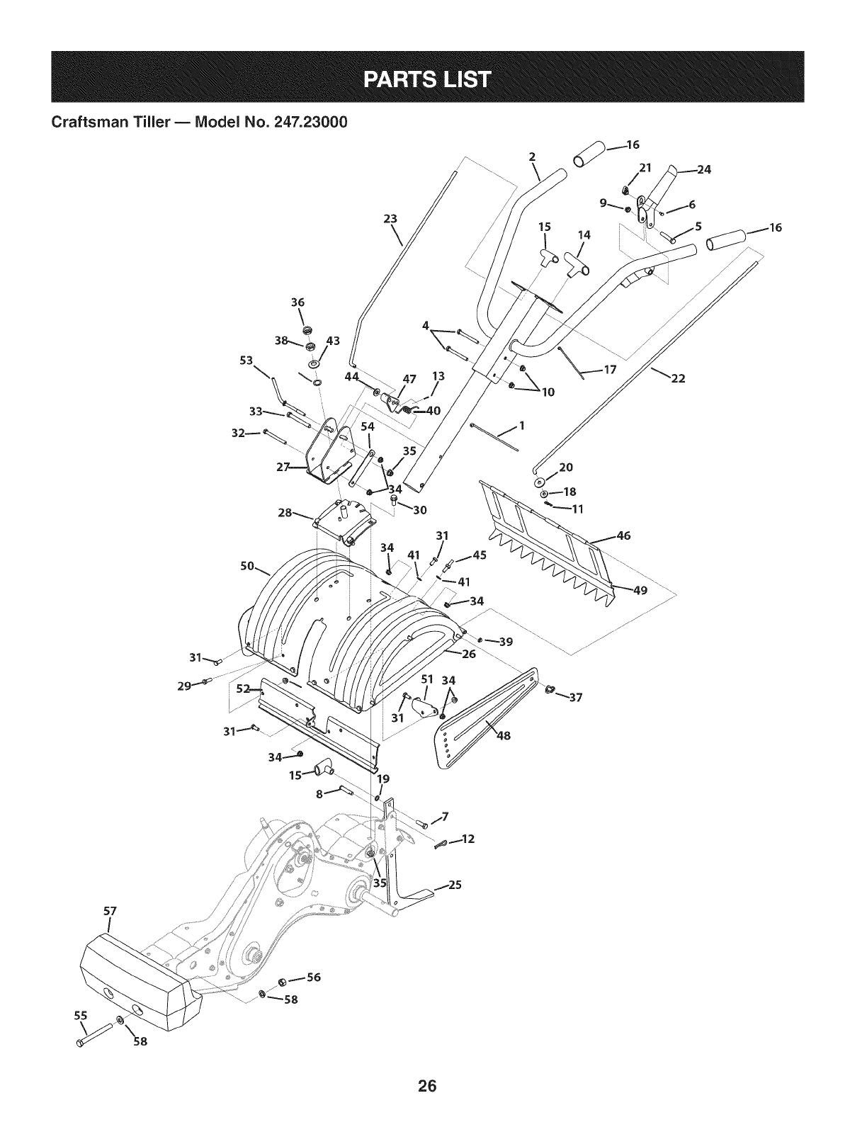
Craftsman Tiller BIViodel No. 247.23000
2725 CableTie
2 649-04101-0691 UpperHandleAssembly
3 649-04102-0691 SwingHandleTubeAssembly
4 710-0189 HexScrew,5/16-18x 3.00
5 710-0859 HexScrew,3/8-16x 2.50 34 712-04063
6 710-0919 HexScrew,#10-16x 0.440 35 712-04065
7 710-3005 HexScrew,3/8-16x 1.25 36 912-0413
8 911-0415 ClevisPin,3/8 x 1.75 37 712-0421
9 712-04065 FlangeLockNut,3/8-16 38 712-3056
10 712-04063 FlangeLockNut,5/16-18 39 926-0106
11 914-0104 CotterPin,.072x 1.13 40 732-0493
12 714-04043 Bow-TieCotterPin 41 736-0204
13 914-0507 CotterPin,3/32 x .750 42 736-0167
14 720-0209 T-Knob 43 736-0317
15 720-0210A T-Knob 44 936-3004
16 720-04083 RoundGrip 45 938-0849
17 725-0157 CableTie,3/16 x .05x 7.4 46 747-0432
18 735-0127 RubberWasher,.33x.87x.125 47 748-0375
19 936-0117 FlatWasher,.385x.620x.033 48 786-0090A-0691
20 936-0133 FlatWasher,.411x 1.25x .100 49 786-0113A-0691
21 946-0605 CableBarrelHolder 50 786-0178A-0691
22. 747-0664 ClutchRod 51 786-0179-0637
23 747-0666 ClutchRod 52 786-0180-0637
24 984-0202B ClutchAssemblyLever 53 786-0340B
25 786-0120-0637 TillerDepthControl 54 786-04358
26 686-0044B EndCoverAssembly 55 710-0382
27 686-04141-0691 HandlePivotBracketAssembly 56 712-3083
28 686-04142-0691 HandlePivotBaseBracketAssembly 57 723-0381
29 710-0376 HexScrew,5/16-18x 1.00 58 936-0326
710-04482 HexWasherScrew,3/8-16x .875
31 710-0376 HexScrew,5/16-18x 1.00
32 710-3056 HexScrew,5/16-18x 3.25
33 710-3130 HexScrew,3/8-16x 3.25
FlangeLockNut,5/16-18
FlangeLockNut,3/8-16
JamLockNut,5/8-18
Wing Nutw/Bell Washer,5/16-18
JamNut,5/8-18
Cap SpeedNut, 1/4
TorsionSpring,.415x.95
FlatWasher,.344x.62x.033
FlatWasher,.656x 1.25x .02
BellWasher,.63x 1.25x .18
FlatWasher,.406x.875x.105
HexScrew,5/16-18x .75
Tiller FlapRod
SwingHandleLink
SideShield
RearTine Shield
Tine Shield
FrontTine ShieldBracket
FrontTine ShieldScraperBracket
HandleAdjustmentCrank
HexFlangeRetainerBracket
HexScrew,1/2-13x 5.00
HexLockNut, 1/2-13
40 lb. Counterweight
FlatWasher,.510x 1.000x .125
27

Craftsman Tiller- Model No. 247.23000
\
10
o\
\\°
2 21
12
46
27 11
24
m
7
28

Craftsman Tiller BIViodel No. 247.23000
686-0191B-0691 Belt KeeperAssemblyBracket
2 686-04044A-0691BeltCoverAssemblyBracket
3 710-0170 HexLockScrew,5/16-24x .625
4 710-0513 HexScrew,1/4-28x .625 29 786-0193-0637
5 710-0502A HexWasherScrew,3/8-16x 1.250 30 786-0238
6 710-1652 HexWasherScrew,1/4-20x 0.625 31 686-0109A
7 710-1039 HexScrew,3/8-24 x 1.00 32 710-1652
8 710-3005 HexScrew,3/8-16x 1.25 33 712-04064
9 712-0266A Jam LockNut, 3/8-16 34 915-0120
10 712-04063 HexNut,5/16-18 35 726-3054
11 914-0104 CotterPin,.072x 1.13 36 731-07556
12 784-0160-0637 Tine AdapterAssembly 37 710-05289
13 634-04654 CompleteWheel,16x 4.6 x 8 38 786-0345B-0691
14 936-0176 FiatWasher,.265x.938x.120 39 786-04436-0691
15 936-0271 SpringWasher,.317x.625x.020 40 911-0415
16 742-0305A-0637 ArticulatingTine 41 714-04043
17 936-0452 BellWasher,.396x 1.140x .095 42 984-0205A-0637
18 738-0876A ShoulderNut,7/16-20 43 712-3054
19 946-1118A SwingClutchCable 44 936-0169
20 747-1159 IdlerPulleyRod 45 936-0208
21 750-0565 Spacer,.372x.260x.44 46 936-0253
22 954-0434 Belt:4x 58.16 47 938-0688
23 756-0405 FiatIdlerw/Flanges3.75 48 938-0689
24 756-0971 EngineinnerHalfPulley 49 952Z270-VO
25 756-0972 EngineOuterHalfPulley
756-1162 input Pulley,4 x 8.594
27 786-0064A Idler PulleyBracket
28 786-0187-0637 ShiftCoverBracket
Idler BeltKeeper
PositionerGearBracket
ShiftCrankAssembly
HexWasherScrew,1/4-20x 0.625
HexLockNut, 1/4-20
SpirolPin,3/16x 1.00
U-ClipNut, 1/4-20
ShiftCrankCap
HexScrew,1/4-20x 1.50
Belt Cover
ShiftCover
ClevisPin,.375x 1.75
CotterPin
ArticulatingTine Assembly
HexLockNut,3/8-24
LockWasher,3/8
FiatWasher,.51x 1.5x .07
BellWasher,.525x 1.00x .050
ShoulderScrew,3/8-24 x 1/2x .325
ShoulderScrew,3/8-24 x 1/2x .180
ReplacementEngine
29
Craftsman Tiller BIViodel No. 247.23000
16
29\ 37
11
5O
46
18
/
44
38
/
16
30
29
/
40
12
/
/
16
30
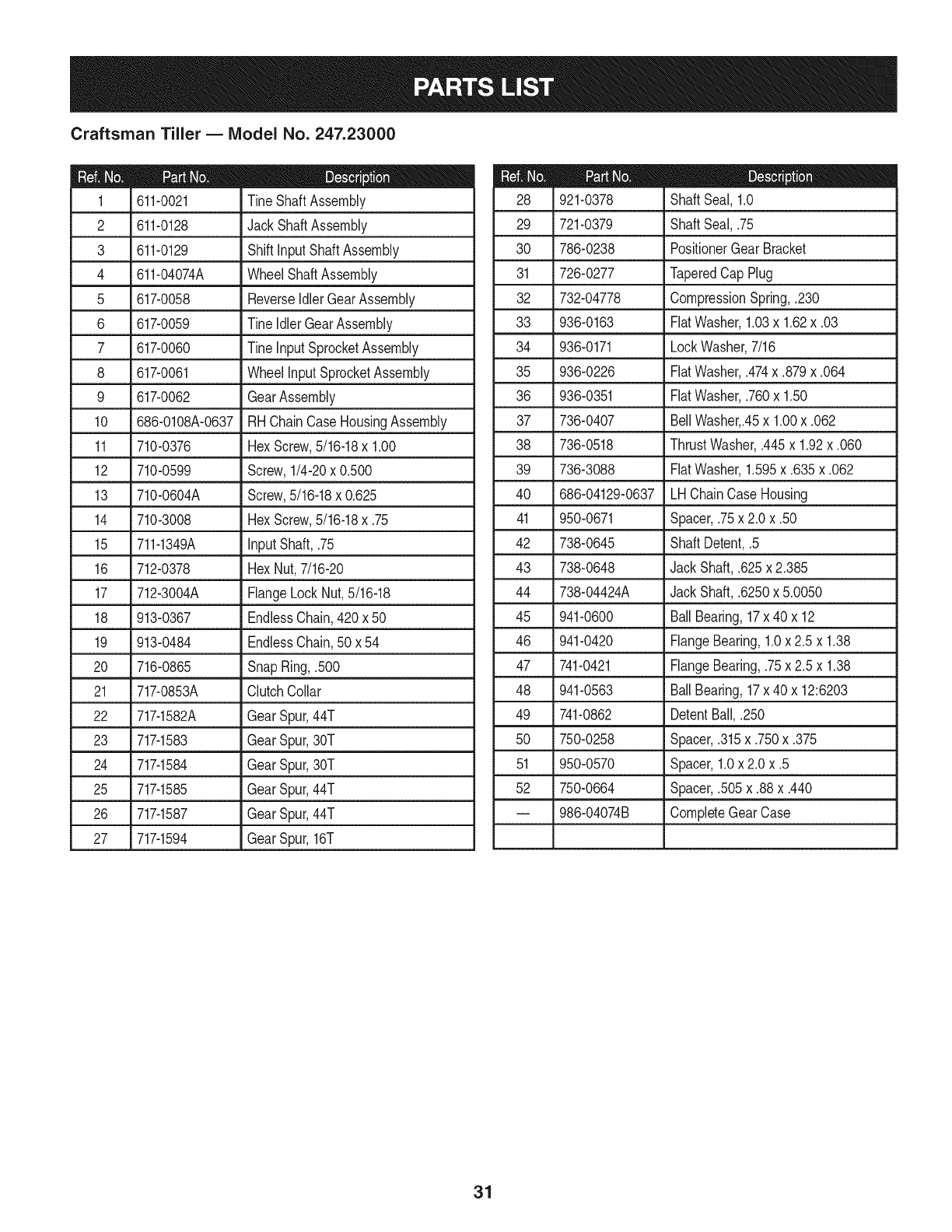
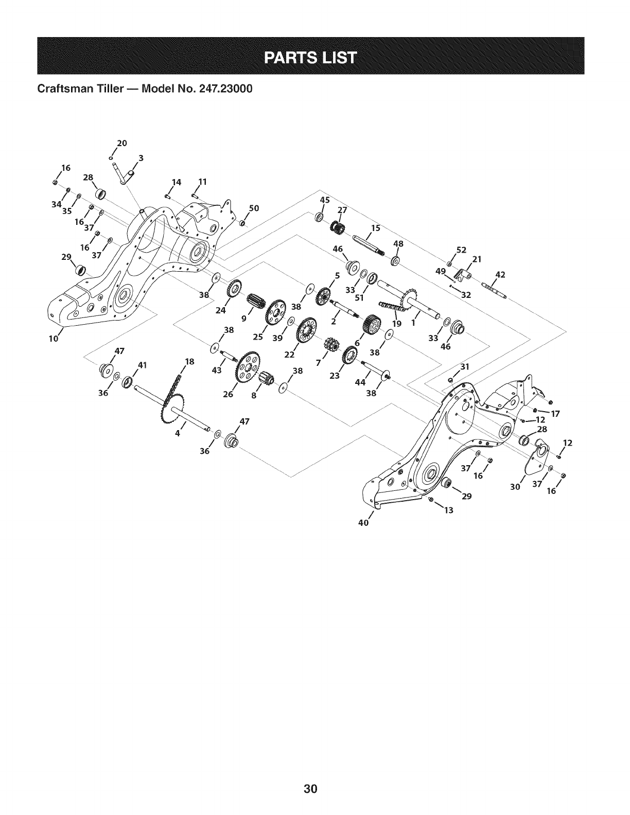
Craftsman Tiller BIViodel No. 247.23000
611-0021 TineShaftAssembly
2 611-0128 JackShaftAssembly 29
3 611-0129 ShiftinputShaftAssembly 30
4 611-04074A WheelShaftAssembly 31
5 617-0058 ReverseIdlerGearAssembly 32
6 617-0059 TineIdler GearAssembly 33
7 617-0060 Tineinput SprocketAssembly 34
8 617-0061 WheelinputSprocketAssembly 35
9 617-0062 GearAssembly 36
10 686-0108A-0637 RHChainCaseHousingAssembly 37
11 710-0376 HexScrew,5/16-18x 1.00 38
12 710-0599 Screw,1/4-20x 0.500 39
13 710-0604A Screw,5/16-18x 0.625 40
14 710-3008 HexScrew,5/16-18x .75 41
15 711-1349A input Shaft,.75 42 738-0645
16 712-0378 HexNut,7/16-20 43 738-0648
17 712-3004A FlangeLockNut,5/16-18 44 738-04424A
18 913-0367 EndlessChain,420x 50 45 941-0600
19 913-0484 EndlessChain,50 x 54 46 941-0420
20 716-0865 SnapRing,.500 47 741-0421
21 717-0853A ClutchCollar 48 941-0563
22 717-1582A GearSpur,44T 49 741-0862
23 717-1583 GearSpur,30T 50 750-0258
24 717-1584 GearSpur,30T 51 950-0570
25 717-1585 GearSpur,44T 52 750-0664
26 717-1587 GearSpur,44T
27 717-1594 GearSpur,16T
921-0378 ShaftSeal, 1.0
721-0379 ShaftSeal,.75
786-0238 PositionerGearBracket
726-0277 TaperedCap Plug
732-04778 CompressionSpring,.230
936-0163 FiatWasher,1.03x 1.62x .03
936-0171
936-0226
936-0351
736-0407
736-0518
736-3088
686-04129-0637
950-0671
LockWasher,7/16
FiatWasher,.474x.879x.064
FiatWasher,.760x 1.50
BellWasher,.45x 1.00x .062
ThrustWasher,.445x 1.92x .060
FiatWasher,1.595x .635x.062
LHChainCaseHousing
Spacer,.75x 2.0 x .50
ShaftDetent,.5
Jack Shaft,.625x 2.385
Jack Shaft,.6250x 5.0050
BallBearing,17x 40 x 12
FlangeBearing,1.0x 2.5 x 1.38
FlangeBearing,.75x 2.5 x 1.38
BallBearing,17x 40 x 12:6203
DetentBall,.250
Spacer,.315x.750x.375
Spacer,1.0x 2.0x .5
Spacer,.505x.88x.440
-- 986-04074B CompleteGearCase
31
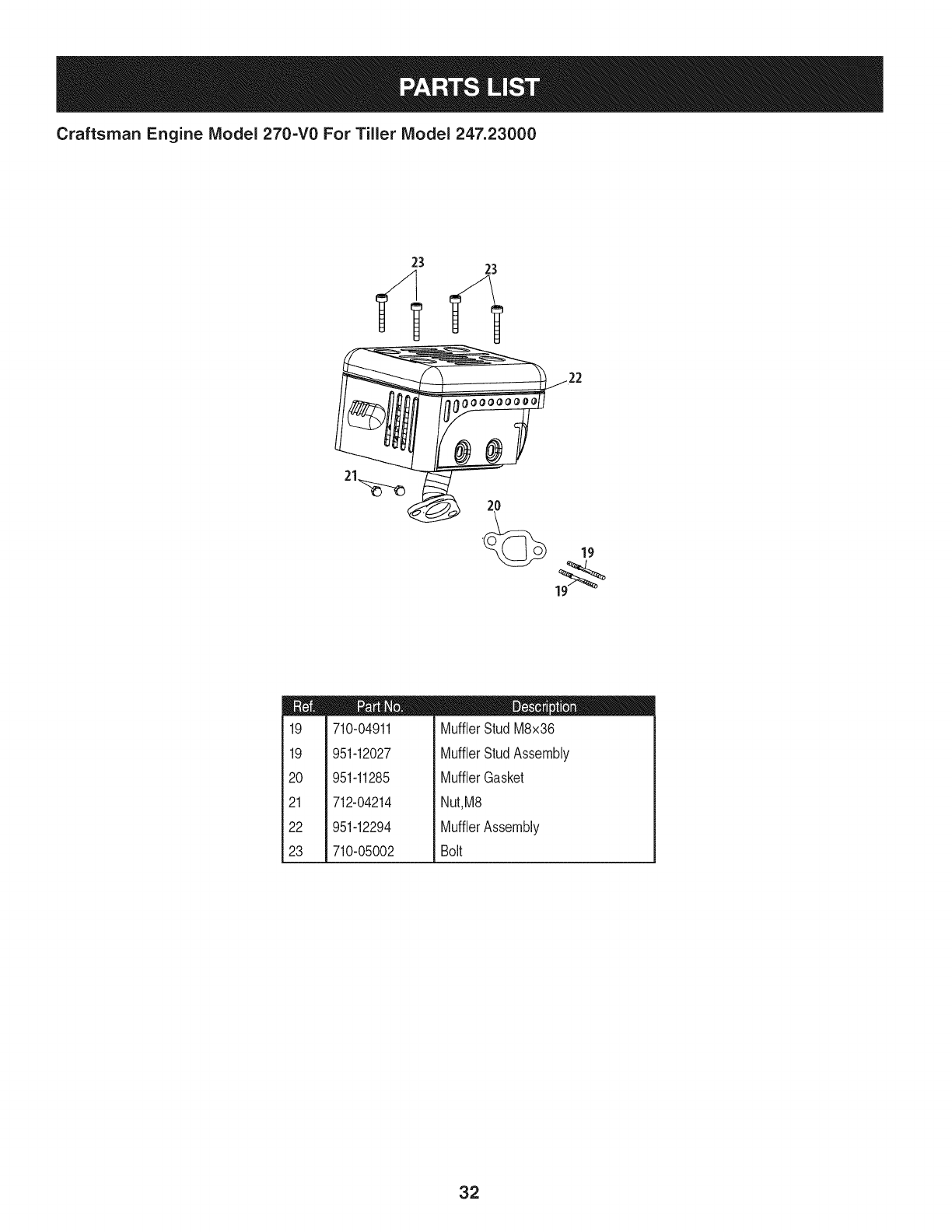
Craftsman Engine IViodel 270=V0 For Tiller IViodel 247.23000
23 23
m
19
19
20
21
22
23
710-04911
951-12027
951-11285
712-04214
951-12294
710-05002
m = O O
MufflerStudM8x36
MufflerStudAssembly
MufflerGasket
Nut,M8
MufflerAssembly
Bolt
32
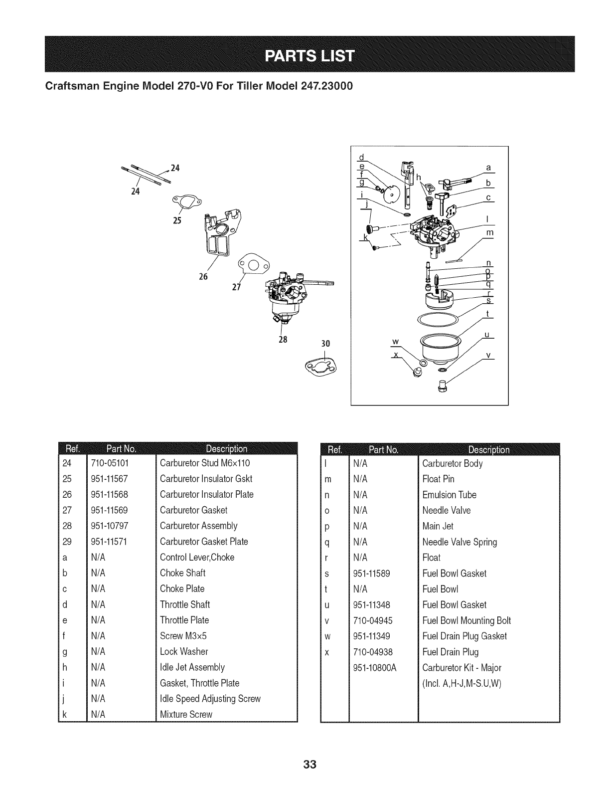
Craftsman Engine IViodel 270=V0 For Tiller IViodel 247.23000
24
24
26 27__
28 30
d
f h
m
24
25
26
27
28
29
a
b
C
d
e
f
g
h
I
J
k
710-05101
951-11567
951-11568
951-11569
951-10797
D = O
CarburetorStud M6x110
CarburetorInsulatorGskt
CarburetorInsulatorPlate
CarburetorGasket
CarburetorAssembly
951-11571
N/A
N/A
N/A
N/A
N/A
N/A
N/A
N/A
N/A
N/A
N/A
CarburetorGasketPlate
ControlLever,Choke
ChokeShaft
ChokePlate
ThrottleShaft
ThrottlePlate
ScrewM3x5
LockWasher
IdleJetAssembly
Gasket,ThrottlePlate
IdleSpeedAdjustingScrew
MixtureScrew
m
I
m
n
0
P
q
r
s
t
U
V
W
X
N/A
N/A
N/A
N/A
N/A
N/A
N/A
951-11589
N/A
951-11348
710-04945
951-11349
710-04938
951-10800A
I = O 0
CarburetorBody
FloatPin
EmulsionTube
NeedleValve
MainJet
NeedleValveSpring
Float
FuelBowlGasket
FuelBowl
FuelBowlGasket
FuelBowlMountingBolt
FuelDrainPlugGasket
FuelDrainPlug
CarburetorKit- Major
(Incl. A,H-J,M-S.U,W)
33
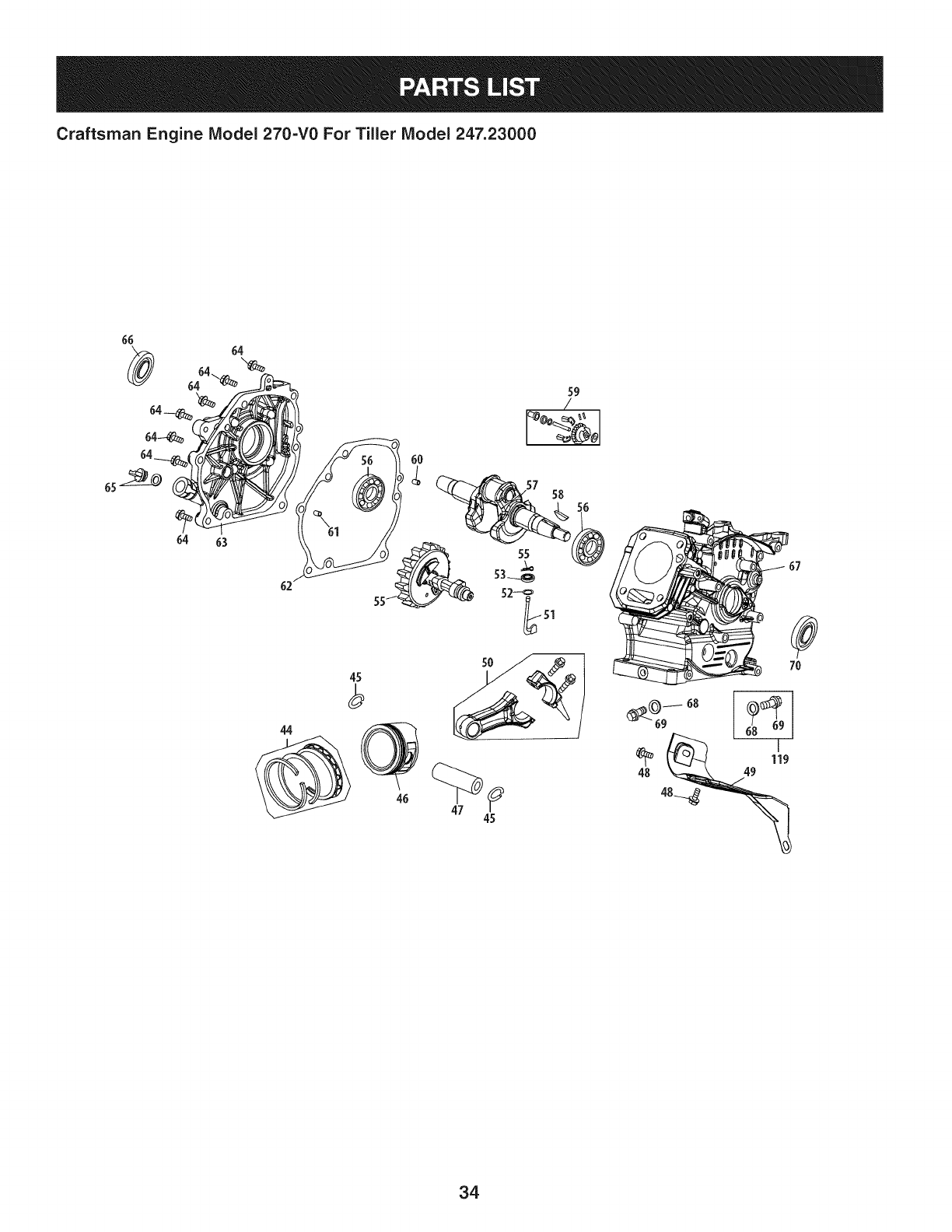
Craftsman Engine IViodel 270=V0 For Tiller IViodel 247.23000
6O
62 55
55 52-_
5O
45
59
/
58
51
67
7O
_ 119
48_
34
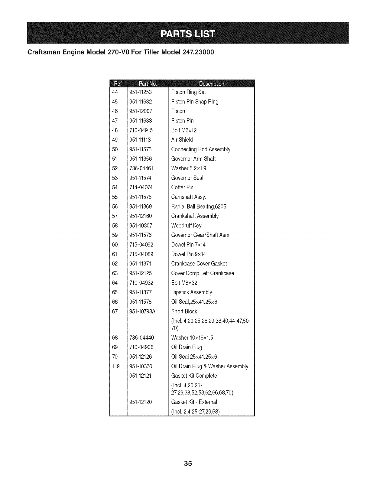
Craftsman Engine IViodel 270=V0 For Tiller IViodel 247.23000
m
44
45
46
47
48
49
5O
51
52
53
54
55
56
57
58
59
6O
61
62
63
64
65
66
67
68
69
7O
119
951-11253
951-11632
951-12007
951-11633
710-04915
951-11113
951-11573
951-11356
736-04461
951-11574
714-04074
951-11575
951-11369
951-12160
951-10307
951-11576
715-04092
715-04089
951-11371
951-12125
710-04932
951-11377
951-11578
951-10798A
736-04440
710-04906
951-12126
951-10370
951-12121
951-12120
D = I! IJ
PistonRingSet
PistonPinSnapRing
Piston
PistonPin
Bolt M6x12
AirShield
ConnectingRodAssembly
GovernorArm Shaft
Washer5.2xl.9
GovernorSeal
CotterPin
CamshaftAssy.
RadialBallBearing,6205
CrankshaftAssembly
WoodruffKey
GovernorGear/ShaftAsm
DowelPin7x14
DowelPin9x14
CrankcaseCoverGasket
CoverComp,LeftCrankcase
Bolt M8x32
DipstickAssembly
OilSeal,25x41.25x6
Short Block
(Incl.4,20,25,26,29,38,40,44-47,50-
70)
Washer10x16x1.5
Oil DrainPlug
OilSeal25x41.25x6
Oil DrainPlug& WasherAssembly
GasketKitComplete
(Incl.4,20,25-
27,29,38,52,53,62,66,68,70)
GasketKit- External
(Incl.2,4,25-27,29,68)
35

Craftsman Engine IViodel 270=V0 For Tiller IViodel 247.23000
118
4
1
17
10
\
5
36

Craftsman Engine IViodel 270=V0 For Tiller IViodel 247.23000
m
1
2
3
3a
4
5
6
7
8
9
10
11
12
13
14
15
16
17
18
38
39
4O
41
42
43
118
710-04968
951-11054
731-07059
726-04101
951-11565
951-11892
751-11124
751-11123
951-11893
710-04902
951-11895
951-12000
951-12002
951-12003
951-12004
951-11894
710-04933
951-10799
951-10292
951-11572
951-10648
951-11899
715-04090
951-10647A
951-10647A
951-11063
951-10819
951-12120
951-12121
m = W O
Bolt M6x16
ValveCover
BreatherHose
HoseClamp
ValveCoverGasket
RockerArm Assembly
Nut,PivotLocking
AdjustingNut,Valve
RockerArm
Bolt,Pivot
PushRodGuide
Retainer,in.ValveSpring
Adjuster,ExhValve
Retainer,Ex.ValveSpring
ValveSpring
IntakeValveSeal
Bolt M8x55
CylinderHeadAssembly
(Incl.4,6-10,12-17,20,25,26,38,41-
43)
SparkPlug
Gasket,CylinderHead
PushRod Kit
Tappet
DowelPin 10x16
ValveKit
ValveKit
ValveCoverKit
CylinderHeadServiceKit
(Incl.4,15,16,38)
GasketKit-- External
(Incl.2,4,25-27,29,68)
GasketKitComplete
(Incl.4,20,25-
27,29,38,52,53,62,66,68,70)
37
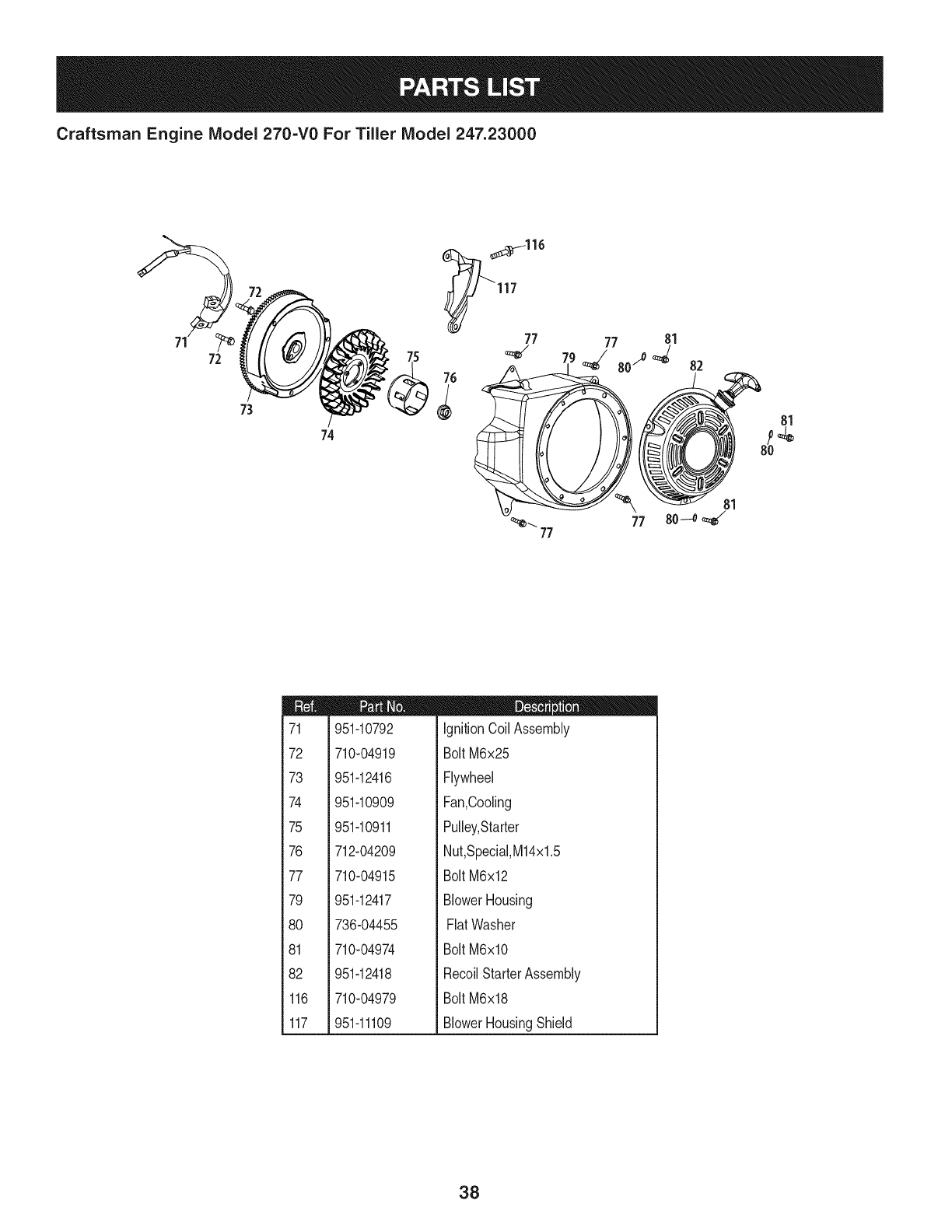
Craftsman Engine IViodel 270=V0 For Tiller IViodel 247.23000
72
74
117
76
77 77 81
_--. 77
77
82
81
8o--o _
81
m
71
72
73
74
75
76
77
79
80
81
82
116
117
951-10792
710-04919
951-12416
951-10909
951-10911
712-04209
710-04915
951-12417
736-04455
710-04974
951-12418
710-04979
951-11109
D = O O
ignitionCoil Assembly
BoltM6x25
Flywheel
Fan,Cooling
Pulley,Starter
Nut,SpeciaI,M14x1.5
BoltM6x12
BlowerHousing
FiatWasher
BoltM6xlO
RecoilStarterAssembly
BoltM6x18
BlowerHousingShield
38
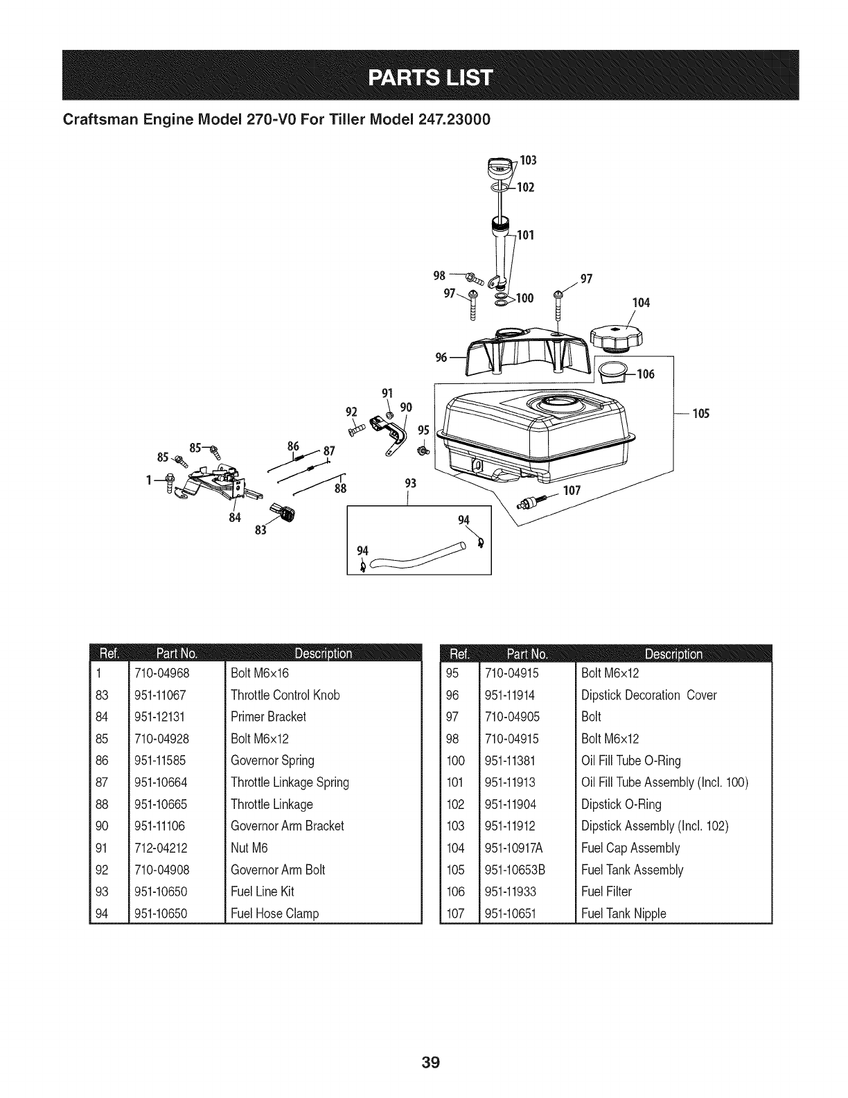
Craftsman Engine Model 270=V0 For Tiller Model 247.23000
94
I05
m
1
83
84
85
86
87
88
9O
91
92
93
94
710-04968
951-11067
951-12131
710-04928
951-11585
951-10664
951-10665
951-11106
712-04212
710-04908
951-10650
951-10650
D = O
BoltM6x16
ThrottleControlKnob
PrimerBracket
BoltM6x12
GovernorSpring
ThrottleLinkageSpring
ThrottleLinkage
GovernorArmBracket
NutM6
GovernorArmBolt
FuelLineKit
FuelHoseClamp
95
96
97
98
1CO
101
102
103
104
105
106
107
710-04915
951-11914
710-04905
710-04915
951-11381
951-11913
951-11904
951-11912
951-10917A
951-10653B
951-11933
951-10651
m = I! O
Bolt M6x12
DipstickDecorationCover
Bolt
Bolt M6x12
Oil FillTubeO-Ring
Oil FillTubeAssembly(Incl. 100)
DipstickO-Ring
DipstickAssembly(Incl. 102)
FuelCapAssembly
FuelTankAssembly
FuelFilter
FuelTankNipple
39
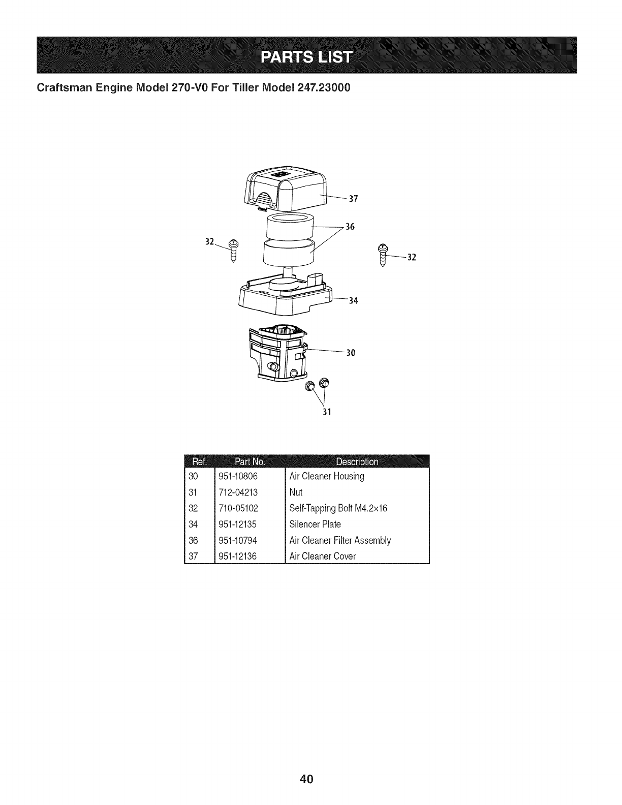
Craftsman Engine IViodel 270=V0 For Tiller IViodel 247.23000
30
31
m
30
31
32
34
36
37
951-10806
712-04213
710-05102
951-12135
951-10794
951-12136
D = O
Air CleanerHousing
Nut
Self-TappingBolt M4.2x16
SilencerPlate
Air CleanerFilterAssembly
Air CleanerCover
4O
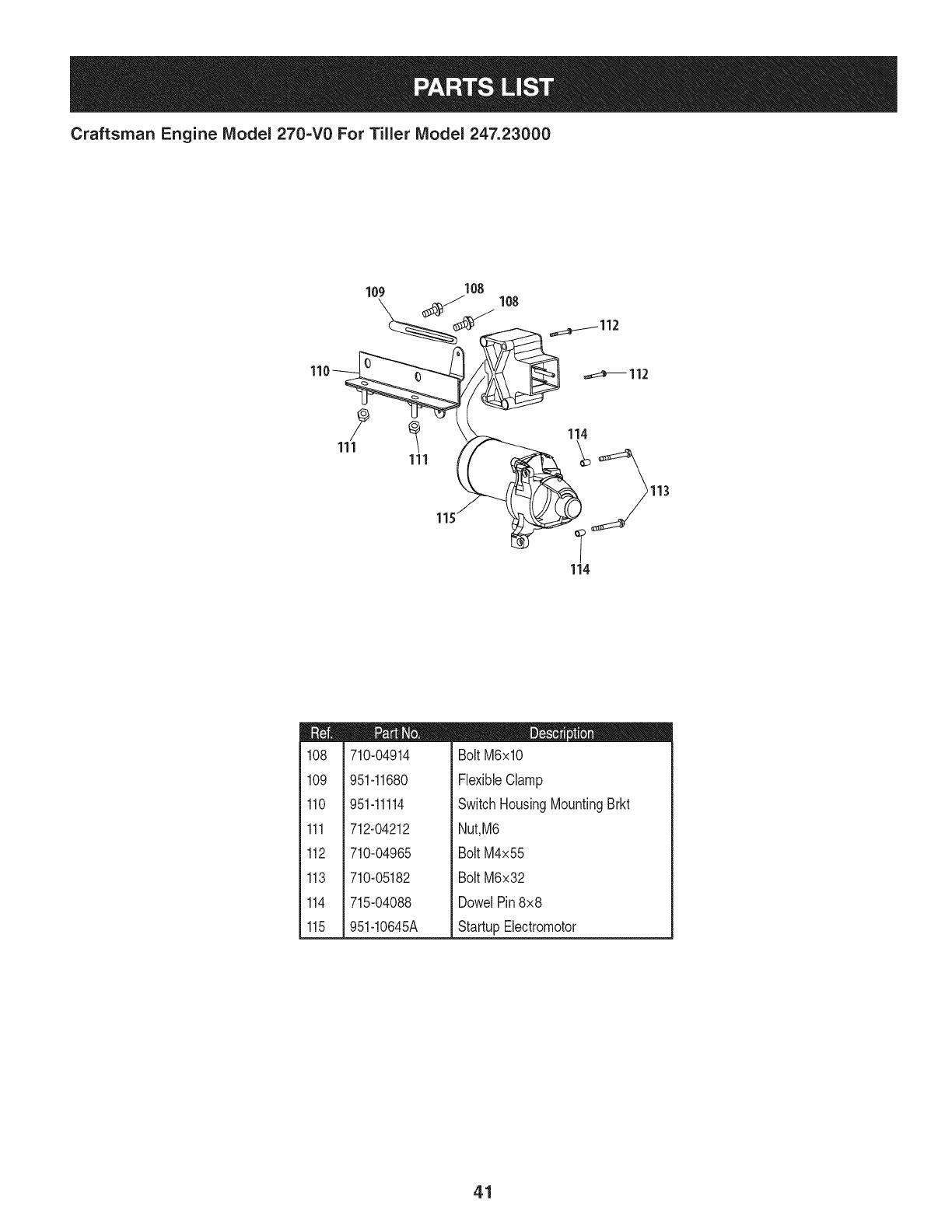
Craftsman Engine Model 270-V0 For Tiller Model 247.23000
_112
_112
114
113
114
m
108
109
110
111
112
113
114
115
710-04914
951-11680
951-11114
712-04212
710-04965
710-05182
715-04088
951-10645A
m = O
Bolt M6xlO
FlexibleClamp
SwitchHousingMountingBrkt
Nut,M6
Bolt M4x55
Bolt M6x32
DowelPin8x8
StartupElectromotor
41
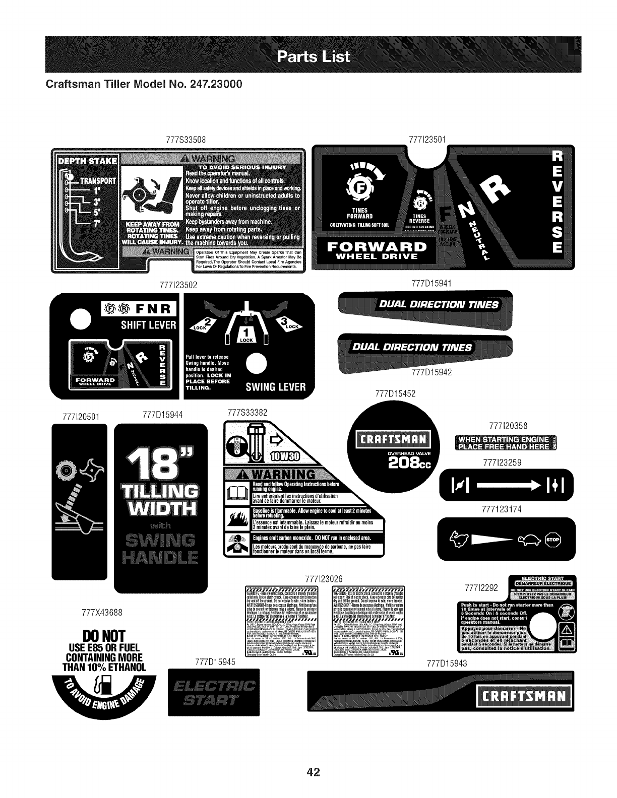
Craftsman Tiller IViodel No. 247.23000
777S33508 777123501
777120501
777123502 777D15941
_FNR
777D15944 777S33382
777D15452
777D15942
777120358
777123259
777X43688
DONOT
USEE85 ORFUEL
CONTAININGMORE
THANIO%ETHANOL 777D15945
777123174
77712292
777D15943
42
(Thispageapplicableinthe U.S.A.and Canadaonly.)
Sears Brands Management Corporation (Sears), the California Air Resources Board (CARD)
and the United States Environmental Protection Agency (U.S. EPA)
Emission Control System Warranty Statement (Owner's Defect Warranty Rights and Obligations)
EMISSIONCONTROLWARRANTYCOVERAGEISAPPLICABLETOCERTI-
FIEDENGINESPURCHASEDINCALIFORNIAIN1995ANDTHEREAF-
TER,WHICHARE USEDINCALIFORNIA,ANDTOCERTIFIEDMODEL
California and United States Emission
The CaliforniaAir ResourcesBoard(CARD),U.S.EPAand Searsare pleased
to explainthe EmissionControlSystemWarrantyon your modelyear2000and
latersmalloff-roadengine(SORE).InCalifornia,newsmall off-roadengines
mustbe designed,builtand equippedto meettheState'sstringentanti-smog
standards.Elsewherein theUnitedStates, newnon-road,spark-ignition
enginescertifiedfor modelyear 1997and latermustmeetsimilarstandardsset
forthbythe U.S.EPA.Searsmustwarranttheemissioncontrolsystemonyour
YEAR1997ANDLATERENGINESWHICHARE PURCHASEDANDUSED
ELSEWHEREINTHEUNITEDSTATES(ANDAFTERJANUARY1,2001 IN
CANADA).
Control Defects Warranty Statement
enginefor theperiodsoftime listedbelow,providedtherehasbeen noabuse,
neglector impropermaintenanceof your smalloff-roadengine.Youremis-
sion controlsystemincludespartssuch as thecarburetor,aircleaner,ignition
system,mufflerand catalyticconverter.Also includedmaybeconnectorsand
otheremissionrelatedassemblies.Wherea warrantableconditionexists,Sears
will repairyour smalloff-roadengineat nocostto you includingdiagnosis,parts
and labor.
Sears Emission Control Defects Warranty Coverage
Smalloff-roadenginesarewarrantedrelativeto emissioncontrolpartsdefects
fora periodof one year,subjectto provisionsset forth below.Ifanycovered
Owner's Warranty
Asthe smalloff-roadengineowner,you are responsiblefor theperformanceof
therequiredmaintenancelistedin yourOperatingand MaintenanceInstruc-
tions.Searsrecommendsthatyou retainallyourreceiptscoveringmaintenance
onyoursmalloff-roadengine,butSearscannotdenywarrantysolelyfor the
lackof receiptsorfor yourfailureto ensuretheperformanceof allscheduled
maintenance.As the smalloff-roadengineowner,youshouldhoweverbe
awarethat Searsmaydenyyouwarrantycoverageif your smalloff-roadengine
ora parthasfaileddueto abuse,neglect,impropermaintenanceor unap-
parton yourengineis defective,the partwillbe repairedorreplacedbySears.
Responsibilities
provedmodifications.Youare responsiblefor presentingyour smalloff-road
engineto an AuthorizedSearsServiceDealeras soonas a problemexists.The
undisputedwarrantyrepairsshouldbecompletedina reasonableamountof
time,notto exceed30days.Ifyou haveanyquestionsregardingyourwarranty
rightsand responsibilities,you shouldcontacta SearsService Representative
at 1-800-469-4663.The emissionwarrantyis a defectswarranty.Defectsare
judgedon normalengineperformance.Thewarrantyis notrelatedto an in-use
emissiontest.
Sears Emission Control Defects Warranty Provisions
ThefollowingarespecificprovisionsrelativetoyourEmissionControlDefectsWarrantyCoverage.ItisinadditiontotheSearsenginewarrantyfornon-regulated
enginesfoundin theOperatingand MaintenanceInstructions.
1. WarrantedParts
Coverageunderthis warrantyextendsonly to the parts listedbelow(the
emissioncontrolsystemsparts)to the extentthese partswere presenton
the enginepurchased.
a. FuelMeteringSystem
•Cold start enrichmentsystem
•Carburetorand internalparts
•FuelPump
b. AirlnductionSystem
•Aircleaner
•Intakemanifold
c. IgnitionSystem
•Sparkplug(s)
•Magnetoignitionsystem
d. CatalystSystem
•Catalyticconverter
•Exhaustmanifold
•Air injectionsystemor pulsevalve
e. MiscellaneousItemsUsedin AboveSystems
•Vacuum,temperature,position,timesensitivevalves
andswitches
•Connectorsandassemblies
2. Lengthof Coverage
Searswarrantsto the initialownerand eachsubsequentpurchaserthat
the WarrantedParts shallbe free fromdefects in materialsandworkman-
shipwhich causedthefailure of the WarrantedPartsfor a periodof one
yearfromthe datethe engineis deliveredto a retailpurchaser.
3. NoCharge
Repairor replacementof anyWarrantedPartwill beperformedat no
chargeto the owner,includingdiagnosticlabor whichleadsto the
determinationthata WarrantedPartis defective,ifthe diagnosticworkis
performedat an AuthorizedSears ServiceDealer.For emissionswarranty
servicecontact yournearestAuthorizedSearsServiceDealeras listed in
the "YellowPages"under"Engines,Gasoline,""GasolineEngines,""Lawn
Mowers,"orsimilarcategory.
4. Claimsand CoverageExclusions
Warrantyclaimsshall be filed in accordancewiththe provisionsof the
SearsEngineWarrantyPolicy.Warrantycoverageshall be excludedfor
failuresof WarrantedPartswhichare notoriginalSears partsor because
of abuse,neglector impropermaintenanceas setforth inthe Sears
EngineWarrantyPolicy.Searsis notliableto coverfailuresof Warranted
Partscausedby theuseof add-on,non-original,or modifiedparts.
5. Maintenance
Any WarrantedPart whichis notscheduledfor replacementas required
maintenanceor whichis scheduledonly for regularinspectionto the effect
of "repairor replaceas necessary"shallbe warrantedasto defectsfor the
warrantyperiod.Any WarrantedPartwhich is scheduledfor replacement
as requiredmaintenanceshallbe warrantedasto defectsonly forthe
periodof time up to the first scheduledreplacementfor that part.Any
replacementpart that isequivalentin performanceand durabilitymay
be usedin the performanceof any maintenanceor repairs.The owneris
responsibleforthe performanceof allrequiredmaintenance,as definedin
the SearsOperatingand MaintenanceInstructions.
6. ConsequentialCoverage
Coveragehereundershallextend to thefailure of any enginecomponents
caused bythe failureof any WarrantedPartstill underwarranty.
Inthe USAandCanada,a 24 hourhotline, 1-800-469-4663,has a menuof pre-recordedmessagesofferingyou enginemaintenanceinformation.
GD0C-100188Rev.B
43
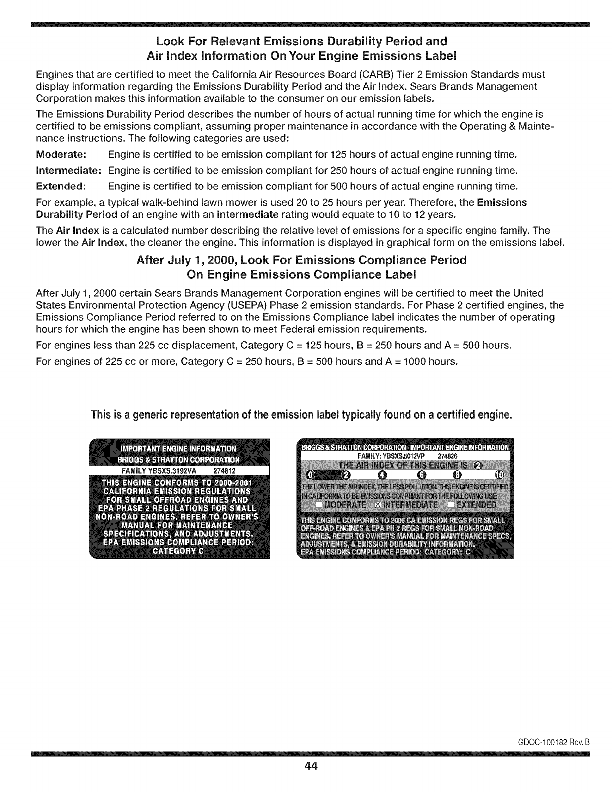
Look For Relevant Emissions Durability Period and
Air index information On Your Engine Emissions Label
Engines that are certified to meet the California Air Resources Board (CARB) Tier 2 Emission Standards must
display information regarding the Emissions Durability Period and the Air Index. Sears Brands Management
Corporation makes this information available to the consumer on our emission labels.
The Emissions Durability Period describes the number of hours of actual running time for which the engine is
certified to be emissions compliant, assuming proper maintenance in accordance with the Operating & Mainte-
nance Instructions. The following categories are used:
Moderate: Engine is certified to be emission compliant for 125 hours of actual engine running time.
Intermediate: Engine is certified to be emission compliant for 250 hours of actual engine running time.
Extended: Engine is certified to be emission compliant for 500 hours of actual engine running time.
For example, a typical walk-behind lawn mower is used 20 to 25 hours per year. Therefore, the Emissions
Durability Period of an engine with an intermediate rating would equate to 10 to 12 years.
The Air index is a calculated number describing the relative level of emissions for a specific engine family. The
lower the Air Index, the cleaner the engine. This information is displayed in graphical form on the emissions label.
After July 1,2000, Look For Emissions Compliance Period
On Engine Emissions Compliance Label
After July 1, 2000 certain Sears Brands Management Corporation engines will be certified to meet the United
States Environmental Protection Agency (USEPA) Phase 2 emission standards. For Phase 2 certified engines, the
Emissions Compliance Period referred to on the Emissions Compliance label indicates the number of operating
hours for which the engine has been shown to meet Federal emission requirements.
For engines less than 225 cc displacement, Category C = 125 hours, B = 250 hours and A = 500 hours.
For engines of 225 cc or more, Category C = 250 hours, B = 500 hours and A = 1000 hours.
This is ageneric representation of the emission label typically found on a certified engine.
FAMILYYBSXS.3192VA 274812
GDOC-100182Rev.B
44
Congratulationson makinga smartpurchase.YournewCraftsman@
productis designedandmanufacturedfor yearsof dependableopera-
tion.But likeall products,it mayrequirerepairfromtimeto time.That's
whenhavinga RepairProtectionAgreementcansaveyoumoneyand
aggravation.
Here'swhatthe RepairProtectionAgreement*includes:
* Expert service byour 10,000professionalrepairspecialists
oUnlimitedserviceand no chargefor partsand laboron all
coveredrepairs
o Product replacementupto $1500if yourcoveredproductcan't be
fixed
•Discountof 10%from regularprice of serviceand relatedinstalled
partsnotcoveredby theagreement;also,10%off regularpriceof
preventivemaintenancecheck
• Fast help by phone- we call it RapidResolution- phonesupport
froma Searsrepresentative.Thinkof usas a "talkingowner's
manual."
Onceyou purchasethe Agreement,a simplephonecall is all thatit
takesfor youto scheduleservice.Youcan call anytimedayor night,or
schedulea serviceappointmentonline.
The RepairProtectionAgreementis a risk-freepurchase.If youcancel
for any reasonduringthe productwarrantyperiod,wewill provideafull
refund.Or,a proratedrefundanytimeafterthe productwarrantyperiod
expires.Purchaseyour RepairProtectionAgreementtoday!
Somelimitationsand exclusionsapply. For pricesand additional
informationin the U.S.A.call 1-800-827-6655.
*Coverage inCanadavaries on some items.Forfull details call
Sears Canadaat 1-800-361-6665.
Sears Installation Service
ForSearsprofessionalinstallationof homeappliances,garagedoor
openers,waterheaters,andothermajorhomeitems,in the U.S.A.or
Canadacall 1-800-4-MY-HOME®.
45
Declaraci6n de garantia ........................ Pb,gina 36
Medidas importantes de seguridad ..... Pb,ginas 47-50
Armado ................................................. Pb,ginas 51-53
Funcionamiento .................................... Pb,ginas 54-60
Servicio y Mantenimiento ..................... P_.ginas 61-65
Almacenamiento fuera de temporada.. Pb,gina 66
Soluci6n de problemas ......................... P_,gina 67
Acuerdo de protecci6n para reparaciones Pb,g ina 70
NQmero de servicio ............................... Cubierta posterior
CRAFTSMAN DE DOS AI_IOS DE GARANTiA
PORDOSAnOS apartir dela fechade compra,esteproductoest_garantizadocontracualquierdefectode materialo manode obra.El
productodefectuosorecibir_la reparaci6no lasustituci6ngratuitasi la reparaci6nnoest_disponible.
Para detalies sobre la garantia de cobertura para obtener la reparaci6n o reernplazo, visite el sitio web: www.
craftsman.corn
Esta garantia cubre los defectos SOLO de rnateriales y fabricaci6n. Cobertura de la garantia
NO incluye:
• Elementosreutilizablesquepuedengastarseporel uso normaldentrodel periododegarantia,talescomo
• cuchillas,dientes,o cinturones.
• Productoda_osresultantesde los intentosdelusuariodemodificaci6ndelproducto,reparaci6no causadospot accesoriosdeproductos.
• Reparacionesnecesariasdebidoal accidenteo pot nooperaro mantenerel productosegQnlas instruccionesprovistas.
• El mantenimientopreventivoo reparacionesnecesariasdebidoa unamezclaincorrectade combustible,combustiblecontaminadoo
pasado.
Estagarantiaes inv_lidasi esteproductose utilizaai mismotiempola prestaci6nde servicioscomerciaieso si sealquilaaotra persona.
Estagaranfialeotorgaderechoslegaiesespedficos,y ustedtambi_npuedetenetotrosderechosquevariandeestadoa estado.
Sears Brands Management Corporation, Hoffman Estates, IL 60179
Seriedel motor: 208cc
Tipodeaceitedelmotor: 10W30
Capacidadde aceitedel motor: 20onzas
Combustible: Gasolinasin plomo
Bujia: F6RTC
Separaci6ndelas bujias: .030"
N_mero de modelo ..........................................................
N_merode serie..............................................................
Fechade eompra.............................................................
Registreel nQmerodemodelo,nQmerode serie
y fechade compram_sarriba
©SearsBrands,LLC 46

Lapresenciadeestesimboloindicaquesetratadeinstruccionesde
seguridadimportantesquesedebenrespetarparaevitarponerenpeligro
suseguridadpersonaly/omaterialyladeotraspersonas.Leaycumpla
todaslasinstruccionesdeestemanualantesdeintentaroperaresta
m&quina.Sinorespetaestasinstruccionespuedeprovocarlesiones
personales.Cuandoveaestesimbolo,ipresteatenci6nalaadvertencia!
Estam&quinaest&diseSadaparaserutilizadarespetandolasnormas
deseguridadcontenidasenestemanual.AIigualqueconcualquiertipo
deequipomotorizado,undescuidooerrorporpartedeloperadorpuede
producirlesionesgraves.Estam_quinaescapazdeamputardedos,
manosypiesydearrojarresiduos.Denorespetarlasinstruccionesde
seguridadsiguientessepuedenproducirlesionesgravesolamuerte.
PROPOSICION 55 DE CALIFORNIA
Elescapedel motorde esteproducto,algunosde suscomponentesy
algunoscomponentesdel vehiculocontieneno liberansustanciasquimicas
que el estadode Californiaconsideraque puedenproducirc_ncer,
defectosdenacimientouotrosproblemasreproductivos.Los homesdela
bateriay los accesoriosalinescontienenplomoy compuestosde plomo,
sustanciasquimicasquesegQnIo establecidopor el Estadode California
causanc&ncery daSosen el sistemareproductivo.L&veselas manos
despuesdeestarencontactoconestoscomponentes.
Su responsabilidad--Lirnite el usodeestarn_.quinarnotorizada
alas personasque lean,cornprendany curnplanlas advertenciase
instruccionesqueaparecenenestemanualyen la rn_.quina.
i6UARDEESTASINSTRUCCIONES!
CAPACITACION
• Lea,cornprenday respetetodaslas instruccionesquefiguranen
la rn_.quinayen el o los rnanualesantesde procedera arrnarlay
hacerlafuncionar.Guardeestemanualen unlugarseguropara
consultasfuturasy peri6dicas,asi cornoparasolicitarrepuestos.
• Leael manualdeloperadory sigatodaslas advertenciase
instruccionesdeseguridad.Deno hacerlo,puedeocasionar
heridasde gravedadal operadory/o alos observadores.Ante
cualquierduda,Ilarneal 1-800-4MY-HOME.
• Farniliarfcesecontodoslos controlesy su correcto
funcionarniento.Sepac6rnodetenerla rn_.quinay c6rno
desconectarloscontrolesr_.pidarnente.
• No perrnitanuncaque los ni_osrnenoresde 14a_osutilicen
estarn_.quina.Los ni_osde 14a_osen adelantedebenleery
entenderlas instruccionesde operaci6ny norrnasdeseguridad
contenidaseneste manualyen larn_.quinay debenser
entrenadosy supervisadospor unadulto.
• Nuncaperrnitaquelos adultosoperenestarn_.quinasin recibir
antesla instrucci6napropiada.
• Mantengaa losobservadores,rnascotasy ni_osal rnenosa 25
metrosde la rn_.quinarnientrasest,.en funcionarniento.Detenga
la rn_.quinasi alguiense acerca.
• Nuncaenciendael motorenespacioscerradoso en unazona
con pocaventilaci6n.Elescapedelmotorcontienernon6xidode
carbono,un gas inodoroy letal.
PR EPARATIVO S
•Reviserninuciosarnenteel &readondese va a usarel equipo.
Retiretodaslas piedras,botellas,latasy otrosobjetosextra_os
que puedanser levantadoso arrojadoscausandolesiones
personaleso da_osa la rn_.quina.
• Paraprotegerselosojos,utilicesiernpregalas o anteojosde
seguridadrnientrasoperalarn_.quinao rnientraslaajustao
repara.Losobjetosarrojadosquerebotanpuedenproducir
lesionesocularesgraves.
• Utilicezapatosde trabajoresistentes,desuelafuerte,y
pantalonesy carnisasajustados.Las prendassueltasy las
alhajasse puedenengancharen laspiezasrn6viles.Nuncaopere
estarn_.quinaestandodescalzoo consandalias.
• Antesdeencenderla rn_quinacontrolequetodoslos pernosy
tornillosest_nbienajustadosparagarantizarquela rn_.quinase
encuentraen condicionessegurasdeoperaci6n.Adern_.s,realice
unainspecci6nvisualde la rn_.quinaa intervalosfrecuentespara
controlarsi la rnisrnaest,.da_ada.
• Antesdearrancarel motor,desenganchelas palancasdel
ernbraguey despl_.celas(en casode haber)a la posici6nneutral
("N").
• Nuncadeje larn_.quinaenfuncionarnientosin vigilancia.
• Nuncaintenterealizarajustesrnientrasel motorest,.enrnarcha,
exceptoen los casosespecificarnenterecornendadosen el
manualdeloperador.
• Mantengao reernplacelas etiquetasdeseguridade instrucciones
segQnsea necesario.
47
Manejo seguro de la gasolina:
Paraevitarlesionespersonalesy da_os materialestengamuchocuidadoal
manipularla gasolina.Lagasolinaes sumamenteinflamableysus vapores
puedencausarexplosiones.Si se derramagasolinaencimao sobrela ropa
se puedelesionargravementeya quese puedeincendiar. Lavesela piely
c_mbiesede ropade inmediato.
• Utilices61olos recipientesparagasolinaautorizados.
• NuncaIlenelosrecipientesen el interiorde unveh[culoo cami6no
caja de remolquecon un recubrimientopl&stico.Coloquesiemprelos
recipientesenel pisoy lejos delveh[culoantesde Ilenarlos.
• Cuandosea factible,retireel equipo a gasolinadel cami6no remolquey
Ileneloen el suelo.Siesto no es posible,Ileneelequipoen unremolque
concontenedorport_til,envez dedesde una boquilladispensadorade
gasolina.
• Mantengala boquillaen contactocon el hordedel tanquede
combustibleo de laaberturadel recipienteen todo momento,hasta
terminarde cargar.No utiliceundispositivoparaabrir/cerrarla boquilla.
• Apaguetodos los cigarrillos,cigarros,pipasyotras fuentesde
combusti6n.
• Nuncacarguecombustibleen lam&quinaenun espaciocerrado.
• Nuncasaquela tapa dela gasolinani agreguecombustiblemientrasel
motorest&calienteo en marcha.Permitaque el motorse enfr[epot Io
menosdos minutosantesde volvera cargar combustible.
• Nuncalleneenexcesoeltanquede combustible.Lleneel tanqueno
m&sdeY2pulgadapordebajode la basedel cuello del tap6ndecarga,
paradejar espacioparalaexpansi6ndel combustible.
• Vuelvaa colocar la tapadel combustibley ajL]stelabien.
• Limpiela gasolinaquese puedahaberderramadosobreel motoro el
equipo.Trasladela m_quinaa otra zona.Espere5 minutosantesde
encenderel motor.
• Parareducirel riesgode incendio,mantengala m&quinalimpiade
pasto,hojasy deacumulaci6nde otrosescombros.Limpielosderrames
deaceiteo combustibley saquetodos los escombrosembebidosde
combustible.
• Nuncaguardela m_quinao el recipientede combustibleenun espacio
cerradodondehayafuego,chispaso luz piloto,como por ejemplode
calentadoresde agua,calefactoresdeambientes,hornos,secadoresde
ropau otrosaparatosa gas.
FUNCIONANIIENTO
•Nocoloquelas manosni los piescerca depiezasgiratorias.Elcontacto
conlas piezasgiratoriaspuedeocasionaren la amputaci6nde manos
o pies.
• No utilicela m_quinabajola influenciadel alcoholo lasdrogas.
• Nuncaopereestam_quinasi no haybuenavisibilidado iluminaci6n.
Siempredebeestar segurodeque est_bien afirmadoysujetando
firmementelas manijas.
• Mantengaa lostranseL]ntesalejadosde la m&quinamientrasla misma
est&enfuncionamiento.Detengala m_quinasi alguiense acerca.
• Tengacuidadoal labrarunterrenoduro.Losdientespuedenclavarseen
latierra e impulsarlacultivadorahaciaadelante.Si estoocurre,suelteel
manubrioy dejela m_quinalibre.
• Seasumamenteprecavidocuandoopere la m&quinasobreuna
superficiecongravao al cruzarla.Mantengasealerta porsi se
presentanpeligrosocultoso tr&nsito.No transportepasajeros.
• Nuncautilicela m&quinaa altasvelocidadesdedesplazamientosobre
superficiesduraso resbaladizas.
• Tengacuidadoparaevitarresbalaro caerse.
• Mire haciaabajo y haciaatr&sy tengacuidadocuandose desplaceen
marchaatr&so cuandojale de la m_quinahaciausted.
• Arranqueel motorde acuerdocon lasinstruccionesdel manualy aleje
los piesde losdientesentodo momento.
•Si golpeaalgOnunobjeto extraSoo si la m&quinacomienzaa emitir
un sonidopococomOno a vibrar,apagueel motordeinmediato.
Desconecteel cablede la buj[a,p6ngalohaciendomasacontrael motor
y siga los pasossiguientes:
a. Inspeccionela m&quinaparaversi est_daSada.
b. Repareo reemplacelas piezasdaSadas.
c. Controlesi haypiezasflojasy ajQstelasparaasegurarque la
m&quinafuncionedemaneraseguray continua.
• Desenganchetodas las palancasdeembrague(si las hay)y detengael
motorantes de dejarla posici6nde operaci6n(detr&sde las manijas).
Esperehasta quelosdientes se detengancompletamenteantesde
limpiarlos,haceralgQnajusteo inspeccionarlos.
• Nuncaenciendael motoren espacioscerradoso en unazonaconpoca
ventilaci6n.Elescape del motorcontienemon6xidode carbono,ungas
inodoroy letal.
• Elsilenciadory el motorse calientany puedencausarquemaduras.No
los toque.
• Tengaprecauci6ncuandolabreterrenocerca devallas,edificiosy
serviciossubterr_neos.LosdientesrotatoriospuedencausardaSos
materialeso lesionespersonales.
• No sobrecarguela capacidadde la m_quinaintentandolabrarel sueloa
un niveldemasiadoprofundoo a unavelocidaddemasiador@ida.
• Si la m&quinaarrancahaciendoun sonidoo unavibraci6nrata, detenga
el motor,desconecteel cable de la buj[ay conecteloa masacontrael
motor.Inspeccionelam&quinaminuciosamenteparaver si est&daSada.
Reparetodoslos daSosantesde encendery operarla m&quina.
• Mantengatodos los escudos,protectoresy dispositivosde seguridaden
su lugary encorrectofuncionamiento.
• Nuncalevanteo transportela m_quinacuandoel motorest_ encendido.
• Utilice s61odispositivosdesujeci6no accesoriosaprobadospor el
fabricanteque figuranenlas paginasde lalista depiezasdeeste
manualdel operador.Si no Io hace,puedenproducirselesiones
personales.
• Si se presentansituacionesque noest&nprevistasen estemanual,sea
cuidadosoy useel sentido comL]n.P6ngaseen contactocon Asistencia
al Clienteparasolicitarayuday el hombredeldistribuidordeservicio
m_s cercano.
MANTENINIIENTO Y ALMACENANIIENTO
•Mantengala m_quina,losaditamentosy accesoriosen condicionesde
funcionamientoseguro.
• Dejeque la m_quinase enfr[epor Io menoscincominutosantes
de guardarla.Nuncaalterelos dispositivosdeseguridad.Controle
peri6dicamentequefuncionancorrectamente.
• Verifiquefrecuentementeque lospernosytornillosestenajustados
correctamenteparaasegurarsede que la m_quinaestetrabajandode
manerasegura.Adem_s,haga unainspecci6nvisualde la m_quinapara
verificarsiest_daSada.
• Antesde limpiar,repararo revisar,detengael motoryasegOresedeque
los dientesytodas laspartesm6vilesse handetenido.Desconecteel
cabledela buj[ay p6ngalohaciendomasacontrael motorparaevitarque
se enciendaaccidentalmente.
• No cambielaconfiguraci6ndel reguladordel motorni Io hagafuncionar
a demasiadavelocidad.Elreguladordel motorcontrolala velocidad
m_ximade funcionamientosegurodel motor.
• Mantengao reemplacelasetiquetasde seguridady de instrucciones
segOnsea necesario.
• Sigalas instruccionesdeestemanualparacargar,descargar,transportar
y almacenarde maneraseguraestam_quina.
• Si la m_quinase vaa almacenarpor un per[odoprolongado,consulte
siempreel manualdeloperadorparaobtenerinformaci6nimportante.
• Si debevaciareltanquedecombustible,h_galoal airelibre.
48
,, Observelareglamentaci6nylasnormasrespectoalaeliminaci6n
correctadegasolina,aceite,etc.paraprotegerelmedicambiente.
• SegOnlaComisi6ndeSeguridaddeProductosparaelConsumidorde
losEstadosUnidos(CPSC)ylaAgenciadeProtecci6nAmbientaldelos
EstadosUnidos(EPA),esteproductotieneunavidaOtilmediadesiete
(7)a_os6130horasdefuncionamiento.AIfinalizarlavidaQtilmedia
hagainspeccionaranualmenteestaunidadporundistribuidordeservicio
autorizadoparacerciorarsedequetodoslossistemasmec_nicosyde
seguridadfuncionancorrectamenteynotienenexcesivodesgaste.Sino
Iohace,puedenproducirseaccidentes,lesionesolamuerte.
NO MODIFIQUE EL MOTOR
Paraevitar lesionesgraveso la muerte,no modifiqueel motorbajo ninguna
circunstancia.Si alteralaconfiguraci6ndel regulador,el motorse puede
desbocaryfuncionaravelocidadesqueno son seguras.Nuncamodifiquela
configuraci6nde f_bricadel reguladordel motor.
AVISO REFERIDO AEMISIONES
Losmotoresque est_ncertificadosycumplenconlas regulacionesde
emisionesfederalesEPAy de Californiapara SORE (EquiposSmallOff Road
Equipment)est&ncertificadosparaoperarcongasolinacomL]nsin plomoy
puedenincluirlos siguientessistemasde controlde emisiones:Modificaci6n
de motor(EM), catalizadoroxidante(OC),inyecci6ndeairesecundaria(SAI)
y catalizadorde tresvias (TWO)si est&nequipadosdeesa manera.
AMORTIGUADOR DE CHISPAS
Estam&quinaest&equipadaconun motorde combusti6ninternay no
debe set utilizadaen unterrenoagrestecubiertopot bosque,malezaso
hierbani cercadel mismoexceptoque el sistemade escapedel motor
esteequipadoconunamortiguadordechispasquecumplaconlas leyes
localeso estatalescorrespondientes(encasode existir).
Si se utilizaunamortiguadordechispasel operadorIo debe manteneren
condicionesde usoadecuadas.Enel Estadode Californialas medidas
anteriormentemencionadasson exigidaspor ley (Arficulo4442del C6digode
RecursosPQblicosde California).Esposibleque existanleyessimilaresen
otrosestados.Lasleyesfederalesse aplicanen territoriosfederales.
Podr&obtenerunamortiguadorde chispasparael silenciadoren el centrode
serviciode piezasy reparacionesSearsm_scercano.
49
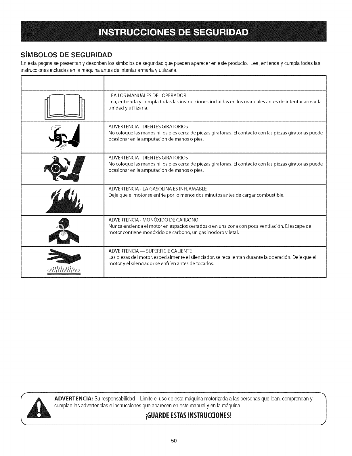
SiIVIBOLOS DE SEGURIDAD
Enestap_ginase presentany describenlos simbolosdeseguridadquepuedenaparecerenesteproducto. Lea,entienday cumplatodaslas
instruccionesincluidasen la m_quinaantesdeintentararmarlay utilizarla.
J'?i
LEA LOS MANUALES DEL OPERADOR
Lea, entienda y cumpla todas las instrucciones incluidas en los manuales antes de intentar armar la
unidad y utilizarla.
ADVERTENCIA- DIENTES GIRATORIOS
No coloque las manos ni los pies cerca de piezas giratorias. El contacto con las piezas giratorias puede
ocasionar en la amputaci6n de manos o pies.
ADVERTENCIA- DIENTES GIRATORIOS
No coloque las manos ni los pies cerca de piezas giratorias. El contacto con las piezas giratorias puede
ocasionar en la amputaci6n de manos o pies.
ADVERTENCIA- LA GASOLINA ES INFLAMABLE
Deje que el motor se enfrie por Io menos dos minutos antes de cargar combustible.
ADVERTENCIA - MONOXIDO DE CARBONO
Nunca encienda el motor en espacios cerrados o en una zona con poca ventilaci6n. El escape del
motor contiene mon6xido de carbono, un gas inodoro y letal.
ADVERTENCIA -- SUPERFICIECALIENTE
Las piezas del motor, especialmente el silenciador, se recalientan durante la operaci6n. Deje que el
motor y el silenciador se enfrien antes de tocarlos.
ADVERTENCIA: Suresponsabilidad--Limiteel usode estam&quinamotorizadaalas personasquelean,comprendany
cumplanlasadvertenciase instruccionesque aparecenen estemanualyen lam&quina.
iGUARI)EESTASINSTRUCCIONES!
50
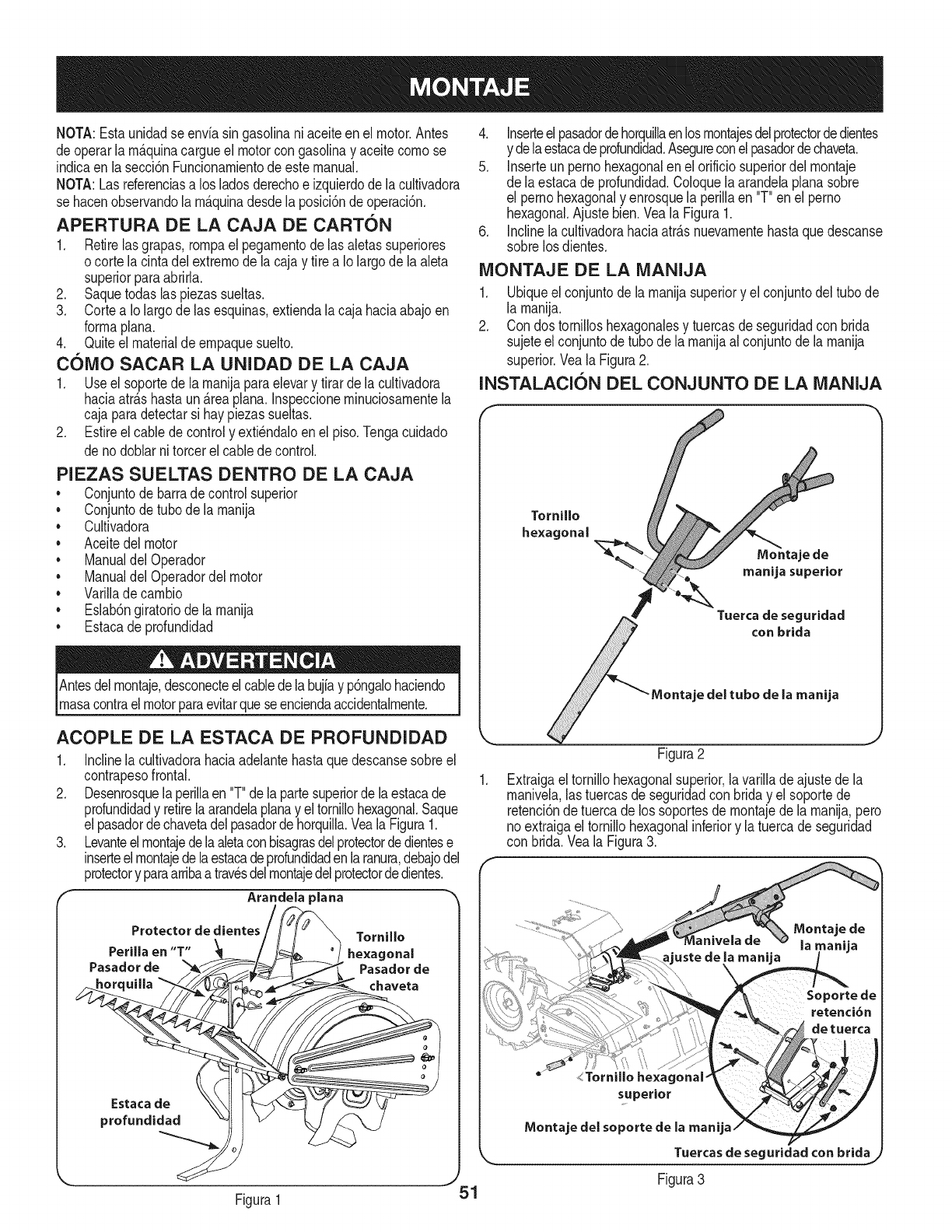
NOTA:Estaunidadse envia singasolinaniaceiteen el motor.Antes
deoperarlam_.quinacargueel motorcongasolinay aceitecomose
indicaen lasecci6nFuncionamientode estemanual.
NOTA:Lasreferenciasa los ladosderechoe izquierdodela cultivadora
se hacenobservandola m_.quinadesdela posici6ndeoperaci6n.
APERTURA DE LA CAJA DE CARTON
1. Retirelas grapas,rompael pegamentodelas aletassuperiores
ocorte lacintadelextremodela cajay tire a Io largode la aleta
superiorparaabrirla.
2. Saquetodaslaspiezassueltas.
3. Cortea Iolargodelas esquinas,extiendalacaja haciaabajoen
formaplana.
4. Quiteel materialdeempaquesuelto.
COMO SACAR LA UNIDAD DE LA CAJA
1. Useel soportede la manijaparaelevary tirarde la cultivadora
haciaatr_.shastaun_.reaplana.Inspeccioneminuciosamentela
caja paradetectarsi haypiezassueltas.
2. Estireel cablede controly exti_ndaloenel piso.Tongacuidado
de nodoblarni torcerel cabledecontrol.
PIEZAS SUELTAS DENTRO DE LA CAJA
• Conjuntode barradecontrolsuperior
• Conjuntode tubode lamanija
• Cultivadora
• Aceitedel motor
• Manualdel Operador
• Manualdel Operadordelmotor
• Varillade cambio
• Eslab6ngiratoriode lamanija
• Estacade profundidad
Antesdelmontaje,desconecteelcabledela bujiay p6ngalohaciendo
masacontraelmotorparaevitarquese enciendaaccidentalmente.
4. Inserteel pasadordehorquillaenlosmontajesdelprotectordedientes
y delaestacadeprofundidad.Asegureconelpasadordechaveta.
5. Inserteun pernohexagonalenel orificiosuperiordelmontaje
de laestacade profundidad.Coloquela arandelaplanasobre
el pernohexagonaly enrosquela perillaen "T"en el perno
hexagonal.Ajustebien.Veala Figura1.
6. Inclinelacultivadorahaciaatr_.snuevamentehastaquedescanse
sobrelos dientes.
MONTAJE DE LA iVIANIJA
1. Ubiqueelconjuntode lamanijasuperiory el conjuntodel tubode
la manija.
2. Con dostornilloshexagonalesy tuercasde seguridadcon brida
sujeteel conjuntodetubode la manijaal conjuntode la manija
superior.Veala Figura2.
INSTALACION DEL CONJUNTO DE LA MANIJA
Tornillo
hexagonal
Montaje de
manija superior
Tuerca de seguridad
con brida
=je del tubo de la manija
ACOPLE DE LA ESTACA DE PROFUNDIDAD
1. Inclinela cultivadorahaciaadelantehastaquedescansesobreel
contrapesofrontal.
2. Desenrosquela perillaen "T"dela partesuperiorde laestacade
profundidady retirelaarandelaplanay el tornillohexagonal.Saque
elpasadordechavetadelpasadorde horquilla.Veala Figura1.
3. Levanteelmontajedelaaletaconbisagrasdelprotectordedientese
inserteelmontajedelaestacadeprofundidadenlaranura,debajodel
protectory paraarribaa travesdelmontajedelprotectordedientes.
Arandela _lana
Protector de diente Tornillo
Perilla en "T" _[ jj_ hexagonal
Pasadorde _ Pasadorde
_orquilla _9 _k_" __ chaveta
Estacade
profundidad
Figura2
Extraigael tornillohexagonalsuperior,lavarillade ajustede la
manivela,las tuercasde seguridadcon briday el soportede
retenci6nde tuercade los soportesde montajede la manija,pero
no extraigaeltornillohexagonalinferiory latuercade seguridad
con brida.Veala Figura3.
Tuercas de
Figura 3
uridad con brida
Figura1 ,51

2. Posicionelaunidaddelamanijaentrelossoportesdemontajede 2.
lamanija.
3. Alineelosorificiosenlamanijaconlosorificiosdelsoportey 3.
fijelosconlosherrajesqueacabadeextraer.
ACOPLE DE LA VARILLA DE CAIVIBIO
,
2.
AsegQresede quela unidadde larnanijaestaenla posici6nm_.s
alta.Remitasea la Secci6nde Funcionarniento.
Extraigaelpasadorde horquilla,laarandela,laarandelaplanay la
perillaenT delavarilladecontroly coloquelaarandeladegomaen
sulugar.Veala Figura4.
Arandela ..........
)lana // J,
//
Figura4
3. Deslicela varilladecambiohaciaarribaa travesdelconjunto
dela manijasuperior,inserteel extremeinferiorde lavarilla
decambiodentrodel soportedel indicadory suj_telocon los
herrajesqueextrajoanteriormente.Veala Figura4.
ACOPLE DEL ESLABON GIRATORIO
DE LA MANIJA
1. AsegQresede quela unidadde lamanijaestaenla posici6nm_.s
alta.Remitasea la Secci6nde Funcionamiento.
/
Figura5
Extraigael pasadorde chavetay la perillaen "T"deleslab6n
giratoriode la manija.Veala Figura5.
Desliceeleslab6ngiratoriode lamanijaa trav_sdelconjunto
de la manijasuperior,inserteel extremeinferiordel eslab6nen
el enlacegiratoriodela manijay suj_telosconlos herrajesque
extrajoanteriormente.Veala Figura5.
Traba
Arandela
Accesorio ajustable J
Figura6
ACOPLE DEL CABLE DEL EMBRAGUE
1. Aflojela tuercasuperiordel cabley deslicelatuercay laarandela
parasacarlasdel accesorioajustable.Veala Figura6.
2. Desliceelcabledentrodesusoportecomese indicaen laFigura6.
3. Vuelvaa colocarlaarandelay la tuercasuperioren elaccesorio
ajustable,y apri_telas.
NOTA:No ajustedemasiadoelcable deembrague.Demasiada
tensi6npodriaromperlo.AsegQresedecomprobarel ajustedelcable
de embragueantesdehacerfuncionarlacultivadora.
4. Inserteel tubedelcable dentrodel soportedeltube,inserteel
tube y el soporteenla palancadel embraguey sujeteconel
tornillohexagonal.Veala Figura7.
Soporte
del tube
del cable
Tube del cable
Tornillohexagonal
Tube del cable ysoporte
del tube del cable
52 Figura7

.Cuandoel cabledelernbragueest_ensu sitio,suj_te{oa {arnanija
conlos precintossurninistradosen {asubicacionesqueseindican
en{aFigura8.
Figura8
AJUSTES
Cable del Embrague
Cornpruebeel ajustede{cablede{ernbraguede{asiguienteforrna:
1. Posicione{acultivadoraparaqueelcontrapesofrontalquede
contraunobjetos6{ido,ta{cornounapared.
2. Con{apalancaselectoradecarnbiosen NEUTRAL,arranqueel
motor.Rernitasea ArranquedelMotoren{aSecci6nFuncionarniento.
3. Desdee{{adoderechode{acultivadora,examinela correa
(dentrode lacubiertadela correa).No debeestargirando.
4. Si {acorreagirasin queelcontroldelernbragueest_conectado,
desenrosquela tuercasuperiory ajustedesenroscandounos
girosla tuercainferioren el sentidode las agujasdel reloj(parado
en laposici6nde{operador)y luegoreajustelatuercasuperior
contrael soportede{cable.Veala Figura9.
5. Muevaahoralapa{ancade carnbiosa {aposici6nFORWARD
(Marchadirecta).
6. Engancheconcuidadoelernbragueapretando{apalancade{
ernbraguecontra{arnanija.Las ruedasdebengirar.
7. Si {asruedasnogirancuando{acultivadoraest,.enrnarchahacia
adelante,afloje latuercasuperiory ajusteapretandoelcable
a{gunasvue{tasen sentidocontrarioalas agujasdel reloj(parado
en la posici6nde{operador)y luegoajustenuevarnentela tuerca
superiorcontrae{soportede{cable.Vea{aFigura9.
8. Vuelvaa cornprobarlos ajustesy repitasi es necesario.
NOTA:Sedisponedeun ajustedecable secundariosi Ilegaa un
puntodondehacefa{taunajusteadicional.Mueva}astuercasque
est_.nenel otroextrernode{cablehaciael finalde {acarcasa.Luego,
reajustelas tuercasdel soportede{cable.
Varilla de la polea Ioca
Cornpruebeelajustedelavarillade {apolea{ocade{asiguienteforrna:
1. Descon_ctelosy hagarnasacon elcablede{abujiacontraelmotor.
2. Con el motorapagadoy lapalancadelernbrague
desenganchada,pasela palancade carnbiosportodas{as
posicionesdernarchadirecta.
3. Verifiquequeel soportede{indicadorde lapalancadecarnbios
no toquelavarillade la po{eaIocacon la pa{ancade{ernbrague
desenganchada.
4. Parareajustarla varilladela po{eaIoca,retirela cubiertade la
correacornosedescribeen Reernplazode Correaenla Secci6n
de Servicioy Mantenirniento.
po,odor /Sopor,ede
chaveta _/polea iota
Varilla de la_
polea Iota /
Arandela
de resorte
Figura 9
perior
Orific{o inferior
Figura10
5. Retireel pasadorde chavetay la arandelade resortede {avarilla
de la po{ea{oca.Veala Figura10.
6. Saque{avarillade {apo{ea{ocafuerade{orificiosuperiory hacia
el interiordel orificioinferiorde{arn_nsulainterrnedia.
7. Vue{vaa colocar{aarandelade resortey elpasadorde chaveta.
8. Cornpruebeelespacio{ibreentre {avarilladela polea{ocay
el soportede{indicadorcarnbiandoa cada unade {asrnarchas
directas.
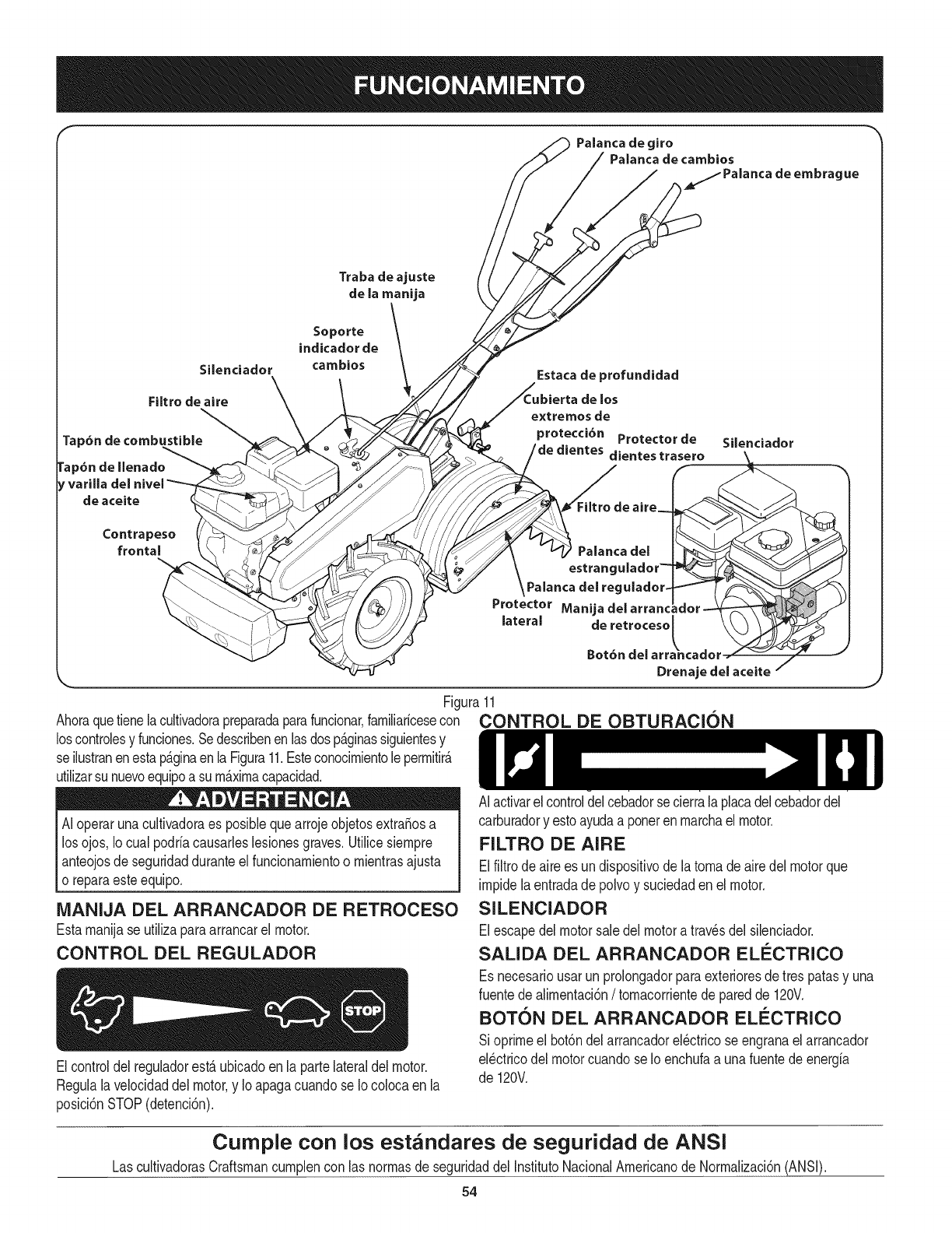
Traba de ajuste
de la manija
Palanca de giro
Palanca de cambios
/_/( _ __ Palanca
de embrague
Silenciador
Filtro de aire
rap6n de combustible
rap6n de llenado
,varilla
de aceite
Contrapeso
frontal
Soporte
indicador de
cambios Estacade profundidad
ubierta de los
xtremosde
protecci6n Protectorde Silenciador
._. /dedientes dientestrasero _ __
_Fi/Itro de ai[e_
\Palanca del regulador-
Protector Manija del arranc
Drenajedelaceite /
Figura11
Ahoraquetienelacultivadorapreparadaparafuncionar,familiaricesecon CONTROL DE OBTURACI(DN
loscontrolesy funciones.SedescribenenlasdospAginassiguientesy
se ilustranenestap_.ginaenla Figura11.Esteconocimientolepermitir_.
utilizarsunuevoequipoasu maximacapacidad.
IAI operaruna es posiblequearrojeobjetos a
cultivadora extraSos
losojos,Io cualpodriacausarleslesionesgraves.Utilicesiempre
anteojosdeseguridadduranteel funcionamientoo mientrasajusta
o reparaesteequipo.
iVlANIJA DEL ARRANCADOR DE RETROCESO
Estamanijase utilizaparaarrancarel motor.
CONTROL DEL REGULADOR
Elcontroldel reguladorest,.ubicadoen la partelateraldel motor.
Regulalavelocidaddel motor,y Io apagacuandose Iocolocaen la
posici6nSTOP(detenci6n).
AI activarel controldelcebadorsecierralaplacadelcebadordel
carburadory estoayudaa ponerenmarchaelmotor.
FILTRO DE AIRE
Elfiltrodeairees undispositivodela tomade airedelmotorque
impidela entradade polvoy suciedaden el motor.
SILENCIADOR
Elescapedelmotorsaledel motoratravesdelsilenciador.
SALIDA DEL ARRANCADOR ELi_CTRICO
Esnecesariousarunprolongadorparaexterioresdetres patasy una
fuentede alimentaci6n/tomacorrientede paredde 120V.
BOTON DEL ARRANCADOR ELC:CTRICO
Si oprimeel bot6ndel arrancadorel_ctricose engranaelarrancador
el_ctricodelmotorcuandose Ioenchufaa unafuentede energia
de 120V.
Cumple con los estandares de seguridad de ANSI
LascultivadorasCraftsmancumplencon las normasde seguridaddel InstitutoNacionalAmericanode Normalizaci6n(ANSi).
54
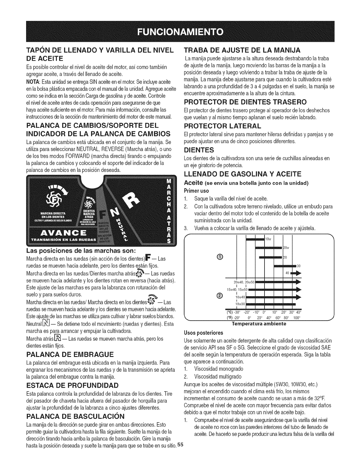
TAPON DE LLENADO YVARILLA DEL NIVEL
DE ACEITE
Es posiNecontrolarel niveldeaceitedel motor,asi comotambi6n
agregaraceite,a travesdel Ilenadode aceite.
NOTA:EstaunidadseentregaSINaceiteenelmotor.Seinduyeaceite
enlabolsapl_.sticaempacadaconel manualde launidad.Agregueaceite
comose indicaenla secci6nCargadegasolinay deaceite.Controle
elniveldeaceiteantesdecadaoperaci6nparaasegurarsedeque
hayaaceitesuficienteenel motor.Param&sinformaci6n,consultelas
instruccionesdelasecci6ndemantenimientodelmotordeestemanual.
PALANCA DE CAMBIOS/SOPORTE DEL
INDICADOR DE LA PALANCA DE CAMBIOS
La palancadecambiosest,.ubicadaenel conjuntode la manija.Se
utilizaparaseleccionarNEUTRAL,REVERSE(Marchaatr_.s),o uno
delos tresmodosFORWARD(marchadirecta)tirandoo empujando
la palancadecambiosy colocandoel soportedelindicadorde la
palancade cambiosenla posici6ndeseada.
Las posiciones de las marchas son:
Marchadirectaen las ruedas(sinacci6nde losdientes)_'-- Las
ruedasse muevenhaciaadelante,perolosdientesest_.nfijos.
Marchadirectaen las ruedas/Dientesmarchaatr_.s_ -- Las ruedas
se muevenhaciaadelantey losdientesrotanen reversa(haciaatr_.s).
Esteajustedelas marchases parala labranzacon roturaci6ndel
sueloy parasuelosduros. ,,,%
Marchadirectaenlasruedas/Marchadirectaenlosdientes_ -- Las
ruedasse muevenhaciaadelantey losdientessemuevenhaciaadelante.
Esteajustedelasmarchasseutilizaparacultivary labrarsuelosblandos.
Neutral[_ -- Sedetienetodoel movimiento(ruedasy dientes).Esta
marchaes paraarrancary empujarla cultivadora.
Marchaatr_.s_ -- Lasruedassemuevenmarchaatr_.s,perolos
dientesest_.nfijos.
PALANCA DE EIVlBRAGUE
La palancadelembragueest,. ubicadaenla manijaizquierda.Para
engranarlos mecanismosdelas ruedasy de latransmisi6nse aprieta
la palancadelembraguecontrala manija.
ESTACA DE PROFUNDIDAD
Estapalancacontrolala profundidadde labranzade losdientes.Tire
delpasadorde chavetahaciaafueradel pasadorde horquillapara
ajustarla profundidadde la labranzaacincoajustesdiferentes.
PALANCA DE BASCULACION
Lamanijade ladirecci6nsepuedegirarenambasdirecciones.Esto
permiteguiarlacultivadorahastalailiasiguiente.Sueltelamanijadela
direcci6ntirandohaciaarribalapalancadebasculaci6n.Girelamanija
TRABA DE AJUSTE DE LA IVIANIJA
Lamanijapuedeajustarsea laalturadeseadadestrabandolatraba
de ajustede lamanija,luegomoviendolas barrasde la manijaa la
posici6ndeseaday luegovolviendoa trabarla trabadeajustedela
manija.Lamanijadebeajustarseparaquecuandola cultivadoraest6
labrandoa unaprofundidadde3 a 4 pulgadasen el suelo,la manijase
encuentreaproximadamentea laalturade lacintura.
PROTECTOR DE DIENTES TRASERO
Elprotectorde dientestraseroprotegeal operadorde los deshechos
quevuelany al mismotiempoaplananelsuelo reci6nlabrado.
PROTECTOR LATERAL
Elprotectorlateralsirveparamantenerhilerasdefinidasy parejasy se
puedeajustarenunade cincoposicionesdiferentes.
DIENTES
Losdientesdela cultivadorason unaseriedecuchillasalineadasen
unejegiratoriode potencia.
LLENADO DE GASOUNA Y ACEITE
Aceite (se envia una botella junto con la unidad)
Primer uso
1. Saquelavarilladelnivelde aceite.
2. Conlacultivadorasobreterrenonivelado,utiliceunembudopara
vaciardentrodel motortodoel contenidode labotelladeaceite
suministradaconla unidad.
3. Vuelvaa colocarlavarillade Ilenadode aceitey ajQstela.
=m_,,m10w
__ 20w
m_ m'j 20
m
20w40, 20w50 _ _ _ _
I
15w40, 15w50 _ wmJ_ m'l'_ wmm _ _
®10w40
110w30 _lwm _ _ _ q
(°C)-30° -200 -100 0o 10° 200 300 400
, (°F)-20 ° 0o 200 400 600 800 1000 j
Temperatura arnbiente
Usos posteriores
Usesolamenteunaceitedetergentedealta calidadcuyaclasificaci6n
de servicioAPIsea SFo SG. Seleccioneel gradode viscosidadSAE
del aceitesegQnlatemperaturade operaci6nesperada.Sigalatabla
queapareceacontinuaci6n.
1. Viscosidadmonogrado
2. Viscosidadmultigrado
Aunquelos aceitesde viscosidadmQltiple(5W30,10W30,etc.)
mejoranel encendidocuandoel climaest,.frio, los mismos
incrementanel consumodeaceitecuandose usana m_.sde32°F.
Compruebeel niveldeaceiteconmayorfrecuenciaparaevitardaSos
debidoa queel motortrabajecon unnivelde aceitebajo.
1. Compruebeelniveldeaceiteasegur_.ndosequelavarilladelnivel
deaceitenoroceconlasparedesinterioresdeltubodeIlenadode
aceite.Dehacerlose puedeproducirunalecturafalsadelavarilladel
hastalaposici6ndeseaday sueltela manijaparaquesetrabeensu sitio.55
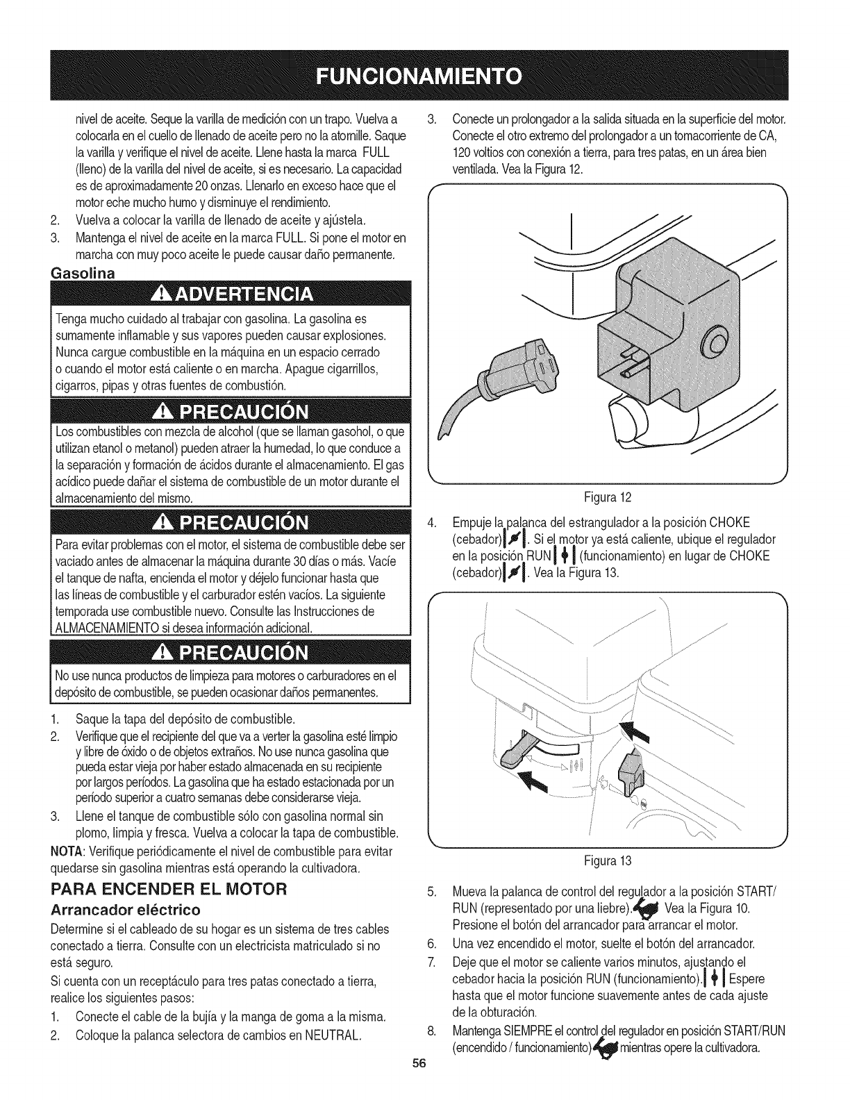
niveldeaceite.Sequelavarilladernedici6nconuntrapo.Vuelvaa
colocarlaenelcuellodeIlenadodeaceiteperonolaatornille.Saque
lavarillayverifiqueelniveldeaceite.LlenehastalarnarcaFULL
(lleno)delavarilladelniveldeaceite,siesnecesario.Lacapacidad
esdeaproxirnadarnente20onzas.Llenarloenexcesohacequeel
motorechernuchohurnoydisrninuyeelrendirniento.
2. VuelvaacolocarlavarilladeIlenadodeaceiteyajQstela.
3. MantengaelniveldeaceiteenlarnarcaFULL.Siponeelmotoren
rnarchaconrnuypocoaceitelepuedecausarda_operrnanente.
Gasoiina
Tengarnuchocuidadoal trabajarcongasolina.Lagasolinaes
surnarnenteinflarnabley susvaporespuedencausarexplosiones.
Nuncacarguecombustibleenla rn_.quinaen unespaciocerrado
ocuandoel motorest,.calienteo enrnarcha.Apaguecigarrillos,
cigarros,pipasy otrasfuentesde cornbusti6n.
Loscombustiblescon rnezcladealcohol(queseIlarnangasohol,oque
utilizanetanolo rnetanol)puedenatraerla hurnedad,Ioqueconducea
laseparaci6ny forrnaci6nde_.cidosduranteelalrnnacenarniento.Elgas
addicopuededa_arelsisternadecombustiblede unmotorduranteel
alrnacenarnientodelrnisrno.
Paraevitarproblernasconel motor,el sisternadecombustibledebeser
vaciadoantesde alrnacenarlarn_.quinadurante30diaso rn_.s.Vacie
el tanquedenafta,enciendaelmotory d6jelofuncionarhastaque
laslineasdecombustibley elcarburadorest6nvacios.Lasiguiente
ternporadausecombustiblenuevo.ConsultelasInstruccionesde
ALMACENAMIENTOsi deseainforrnaci6nadicional.
Nousenuncaproductosdelirnpiezapararnotoresocarburadoresenel
dep6sitodecombustible,sepuedenocasionarda_osperrnanentes.
1. Saquela tapadeldep6sitode combustible.
2. Verifiquequeelrecipientedelquevaaverterlagasolinaest6lirnpio
y librede6xidoodeobjetosextra_os.Nousenuncagasolinaque
puedaestarviejapothaberestadoalrnacenadaensurecipiente
porlargosperiodos.Lagasolinaquehaestadoestacionadapot un
periodosuperiora cuatrosernanasdebeconsiderarsevieja.
3. Lleneeltanquedecombustibles61ocon gasolinanormalsin
plorno,lirnpiay fresca.Vuelvaacolocarla tapa decombustible.
NOTA:Verifiqueperi6dicarnenteel nivelde combustibleparaevitar
quedarsesin gasolinarnientrasest,.operandola cultivadora.
PARA ENCENDER EL MOTOR
Arrancador el_ctrico
Determinesiel caNeadode su hogares un sisternade trescables
conectadoa tierra.Consultecon unelectricistarnatriculadosi no
est,.seguro.
Si cuentacon unrecept_.culoparatrespatasconectadoa tierra,
realicelos siguientespasos:
1. Conecteel cablede labujfay la rnangadegornaa la rnisrna.
2. Coloquela palancaselectoradecarnbiosen NEUTRAL.
.Conecteunprolongadoralasalidasituadaenlasuperficiedelmotor.
ConecteelottoextrernodelprolongadorauntornacorrientedeCA,
120voltiosconconexi6natierra,paratrespatas,enun_.reabien
ventilada.VealaFigura12.
Figura12
4. Ernpujelapalancadelestranguladora laposici6nCHOKE
(cebador)l,_q. Sie[ motorya est,.caliente,ubiqueel regulador
enlaposici6nRUN! _,I (funcionarnientoen lugar deCHOKE
(cebador)llI. Veala Figura13.
fJ
ffi ..................
/
Figura13
5. Muevala palancade controldelregu!adora la posici6nSTART/
RUN(representadopor unaliebre)._ Veala Figura10.
Presioneel bot6ndelarrancadorparaarrancarel motor.
6. Unavezencendidoel motor,suelteel bot6ndelarrancador.
7. Dejequeel motorsecalientevariosrninutos,ajustandoel
cebadorhaciala posici6nRUN(funcionarniento).i { I Espere
hastaqueel motorfuncionesuavernenteantesdecadaajuste
de laobturaci6n.
8. MantengaSIEMPREelcontroldelreguladorenposici6nSTART/RUN
(encendido/funcionarniento),_'!_l|rnientrasoperelacultivadora.
56

9. Cuandodesconecteelprolongador,desenchufesiernpreel
extrernoqueest,.eneltornacorrientesdetrespatasdelapared
antesdedesenchufarelextrernoopuestodelacultivadora.
Arrancador de retroceso
1. Conecteelcabledelabujiaylarnangadegornaalarnisrna.
2. ColoquelapalancaselectoradecarnbiosenNEUTRAL.
3. Muevalapalancadelcebadordelmotoralaposici6nCHOKE.I'°,I(Si
elmotorest,.tibiopuedenosernecesariocebarlo).VealaFigura10.
4. Muevalapalancadecontroldelregu!adoralaposici6nSTART/
RUN(representadoporunaliebre)._ VealaFigura10.
5. Situadoalladodelaunidad,tomelarnanijadelarrancadorde
retrocesoytiredelacuerdahaciaafuerahastaquesientauntir6n.
6. Tiredelacuerdaconungolper_.pidoycontinuodetodoelbrazo.
Mantengaunajustefirrnesobrelarnanijadelarrancador.Deje
quelacuerdaseenrollelentarnente.
7. Repita,siesnecesario,hastaqueelmotorarranque.Cuandose
poneenrnarchaelmotor,rnuevaelcontroldelc@adprgradualrnente
hacialaposici6ndeFUNCIONAMIENTO(RUN).|_I
8. Sielmotorfalla,vuelvaelcontroldelcebadoralaposici6n
CHOKE(CEBADOR)I'_I yrepitalospasos5a8.
9. MantengaSIEMPREelcontroldelreguladorenposici6nSTART/RUN
(encendido/funcionarniento)_ rnientrasoperelacultivadora.
PARA DETENER EL MOTOR
1. Paradetenerlas ruedasy losdientes,sueltelarnanijadelernbrague.
2. Muevalapalancadecontroldelreguladorhastalaposici6nSLOW
(lento,representadopotunatortuga)._ Siernprequeseaposible,
reduzcagradualrnentelavelocidaddelmotorantesdedetenerlo.
3. Muevala palancadecontroldel reguladora la posici6nSTOP
(detenci6n)_ u OFF(apagado).
4. Desconecteel-dabledelabujfay hagarnasaconelmotorparaevitar
quese enciendaaccidentalrnenteelequipoaldejarlosinvigilancia.
PARA ENGRANAR LA TRANSiVlISION
Y LOS DIENTES
Noernpujehaciaabajosobrelosrnanillaresparaintentarhacerquela
cultivadoralabrern_.sprofundo.Estoquitapesoalas ruedas,Ioque |
perrnitequelosdientespropulsenlacultivadorar_.pidarnente,Ioquepodria_
ocasionarlaperdidadecontrol,da_osrnaterialeso lesionespersonales.|
1. ColoquelaPalancadecarnbiosenlaposici6nde rnarchadirecta
dela cultivadoraquese deseey oprirnalapalancadelernbrague
haciaabajocontrala rnanijaparacornenzara cultivar.
2. Cuandorealicelalabranza,dejequelasruedastirendelarn_.quina
rnientraslosdientescavan.Carninelentarnentedetr_.sdela
cultivadoraperrnitiendoquesernuevaa supropioritrnornanteniendo
labarradecontrolbiensujetaconloscodosflexionados.
3. Sueltelarnanijadelernbragueparadetenerlasruedasy losdientes.
Para conducir hacia atr_s: (No labre la tierra operando
en marcha atr_s.)
a. Liberelapalancadel ernbrague.Luegolevantela barrade
controlhastaquelos dientesse separendel suelo.
b. Coloquelapalancadecarnbiosenlaposici6ndernarchaatr_.s
y luegooprirnalapalancadelernbraguehaciaabajocontrala
barradecontroly carninehaciaatr_.scon larn_.quina.
NOTA:Enrnodornarchaatr_.s,los dientesnorotar_.n.
DAR LA VUELTA CON LA CULTIVADORA
Manualrnente
1. Practiquedarla vueltacon lacultivadoraenun &teaabiertay
nivelada.Tengacuidadopararnantenerlos piesy las piernas
lejosde losdientes.
2. Paracornenzaravoltear,levantelas barrasde controlhastaque
losdientesseseparendel sueloy el motory losdientesest_n
balanceadospot encirnade las ruedas.
3. Conla cultivadoraequilibrada,ernpujehaciael costadosobrela
barradecontrolenla direcci6nen quese est,.volteando.Luego
dedarla vuelta,introduzcalentarnentelos dientesenel suelo
parareiniciarla labranza.
Uso de la palanca de basculaci6n
Larnanijadela cultivadorase puedegiraren arnbasdirecciones.La
palancade basculaci6nperrniteguiarla cultivadoralateralrnentehasta
lailia siguiente.Veala FiguraX.
1. Tirehaciaarribadelapalancadebasculaci6nparasoltarla rnanija.
2. Girelarnanijahastala posici6ndeseada.
3. Sueltelapalancade basculaci6nparasujetarla rnanijaen sulugar.
AJUSTE DE LA PROFUNDIDAD
Cerci6resede queelcable dela bujfaest,.desconectadoy
haciendornasacontrael motorantesde realizarcualquierajuste.
Laprofundidaddelabranzaest,.controladapotlaestacade profundidad
quesepuederegularencincoposicionesdiferentes.Ajustelos
protectoreslateralesal regularlaestacadeprofundidad.
+ Cuandouse lacultivadorapor prirneravez,utiliceel segundo
orificiodeajustede arriba(1"de profundidadde labranza).
+ Parafracturarel c_spedy paracultivosuperficial,utilicela posici6n
queofrece1"deprofundidaddelabranza(segundoorificiode
arriba).Coloquelos protectoreslateralesensu posici6nrn_.sbaja.
+ Paramayorprofundidad,levantelaestacay los protectores
lateralesy tarnbi_nhagaunao dospasadasrn_.ssobreel_.rea.
+ Paralabrartierrasuelta,puedelevantarla estacade profundidad
a su posici6nrn_.salta (utiliceel orificiode regulaci6ninferior)
paraobtenerlamayorprofundidadde labranza.Subalos
protectoreslateralesa suposici6nrn_.salta.
/
Pasador de
chaveta
Estaca de
profundidad
lateral Tuerca de
rnariposa J
57 Figura14
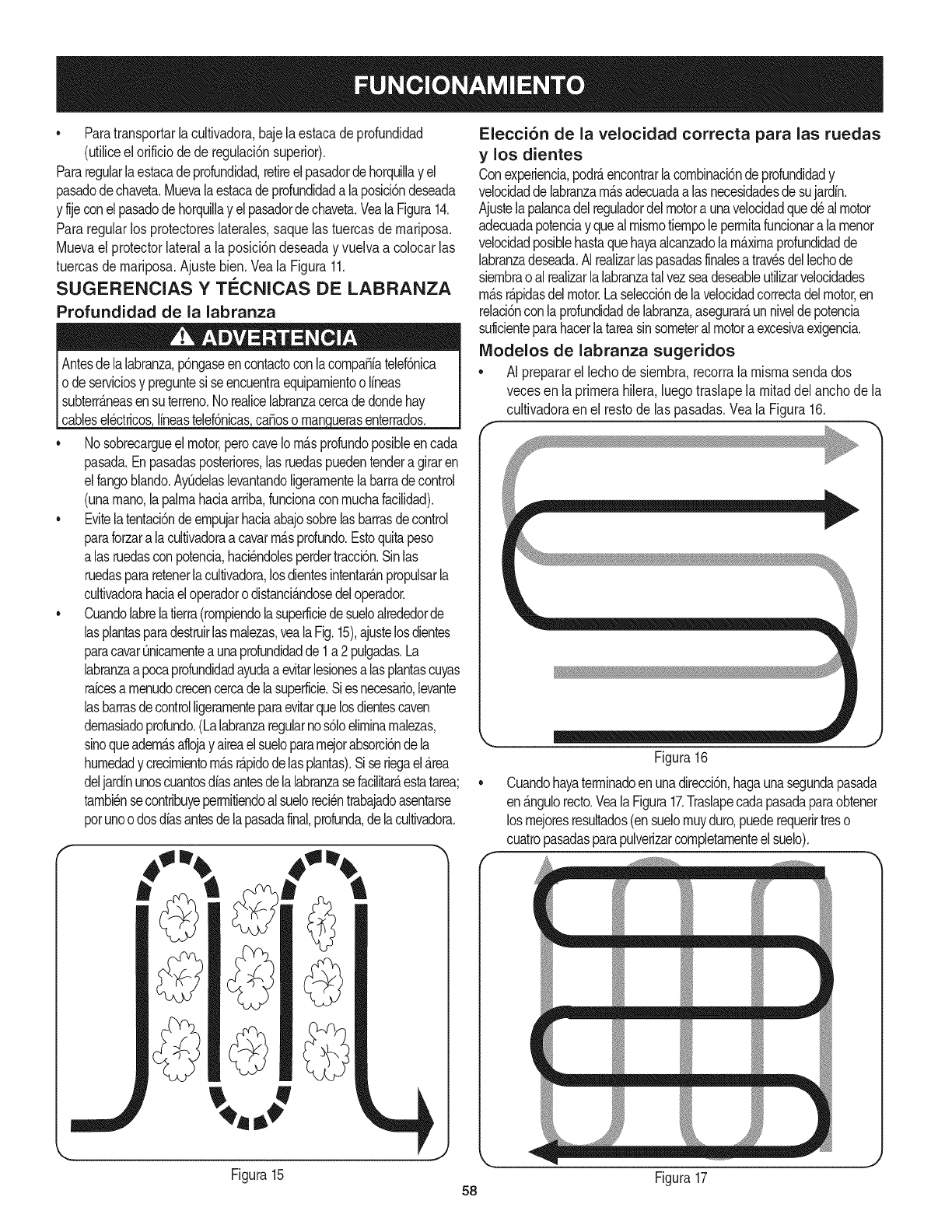
• Paratransportarlacultivadora,bajelaestacadeprofundidad
(utiliceelorificiodederegulaci6nsuperior).
Pararegularlaestacadeprofundidad,retireelpasadordehorquillayel
pasadodechaveta.Muevalaestacadeprofundidadalaposici6ndeseada
yfijeconelpasadodehorquillayelpasadordechaveta.VealaFigura14.
Pararegularlosprotectoreslaterales,saquelastuercasdernariposa.
Muevaelprotectorlateralalaposici6ndeseadayvuelvaacolocarlas
tuercasdernariposa.Ajustebien.VealaFigura11.
SUGERENClAS Y TECNICAS DE LABRANZA
Profundidad de la labranza
Antesdelalabranza,p6ngaseencontactoconlacornpaSiatelef6nica
o deserviciosy preguntesi seencuentraequiparnientoo lineas
subterr_.neasensu terreno.Norealicelabranzacercadedon@hay
cabese6ctricos ineasteef6ncas caSosoman uerasenterrados.
• Nosobrecargueelmotor,perocaveIorn_.sprofundoposibleencada
pasada.Enpasadasposteriores,lasruedaspuedentendera giraren
elfangoblando.AyQdelaslevantandoligerarnentelabarradecontrol
(unarnano,lapalrnahadaarriba,funcionaconrnuchafacilidad).
• Evitelatentaci6ndeernpujarhaciaabajosobrelasbarrasdecontrol
paraforzaralacultivadoraa cavarrn_.sprofundo.Estoquitapeso
alasruedasconpotencia,haci6ndolesperdertracci6n.Sinlas
ruedaspararetenerlacultivadora,losdientesintentar_.npropulsarla
cultivadorahaciaeloperadorodistanci&ndosedeloperador.
• Cuandolabrelatierra(rornpiendolasuperficiedesueloalrededorde
lasplantasparadestruirlasrnalezas,vealaFig.15),ajustelosdientes
paracavarQnicarnenteaunaprofundidadde1a 2pulgadas.La
labranzaapocaprofundidadayudaaevitarlesionesalas plantascuyas
raicesa rnenudocrecencercadelasuperficie.Siesnecesario,levante
lasbarrasdecontrolligerarnenteparaevitarquelosdientescaven
dernasiadoprofundo.(Lalabranzaregularnos61oelirninarnalezas,
sinoqueadern_.saflojay aireaelsuelopararnejorabsorci6ndela
hurnedady crecirnientorn_.sr@idodelasplantas).Siseriegael_rea
deljardinunoscuantosdiasantesdelalabranzasefacilitate,estatarea;
tarnbi6nsecontribuyeperrnitiendoalsueloreci6ntrabajadoasentarse
porunoo dosdiasantesdelapasadafinal,profunda,delacultivadora.
Elecci6n de la velocidad correcta para las ruedas
ylos dientes
Conexperiencia,podr_,encontrarlacornbinaci6ndeprofundidady
velocidaddelabranzarn_.sadecuadaalas necesidadesdesujardin.
Ajustelapalancadelreguladordelmotora unavelocidadquedealmotor
adecuadapotenciay quealrnisrnotiernpolepermitafuncionara larnenor
velocidadposiblehastaquehayaalcanzadolarn_.xirnaprofundidadde
labranzadeseada.AIrealizarlaspasadasfinalesa travesdellechode
siernbraoal realizarlalabranzatalvezseadeseableutilizarvelocidades
rn_.sr@idasdelmotor.Laselecci6ndelavelocidadcorrectadelmotor,en
relaci6nconlaprofundidaddelabranza,asegurar_,unniveldepotencia
suficienteparahacerlatareasinsorneteralmotoraexcesivaexigencia.
IViodelos de labranza sugeridos
•AI prepararel lechode siernbra,recorralarnisrnasendados
vecesen laprirnerahilera,luegotraslapela rnitaddelanchode la
cultivadoraen el restode las pasadas.Veala Figura16.
Figura16
Cuandohayaterrninadoenunadirecci6n,hagaunasegundapasada
en_.ngulorecto.VealaFigura17.Traslapecadapasadaparaobtener
losrnejoresresultados(ensuelornuyduro,puederequerirtreso
cuatropasadasparapulverizarcornpletarnenteelsuelo).
m m
Figura15 Figura17
58
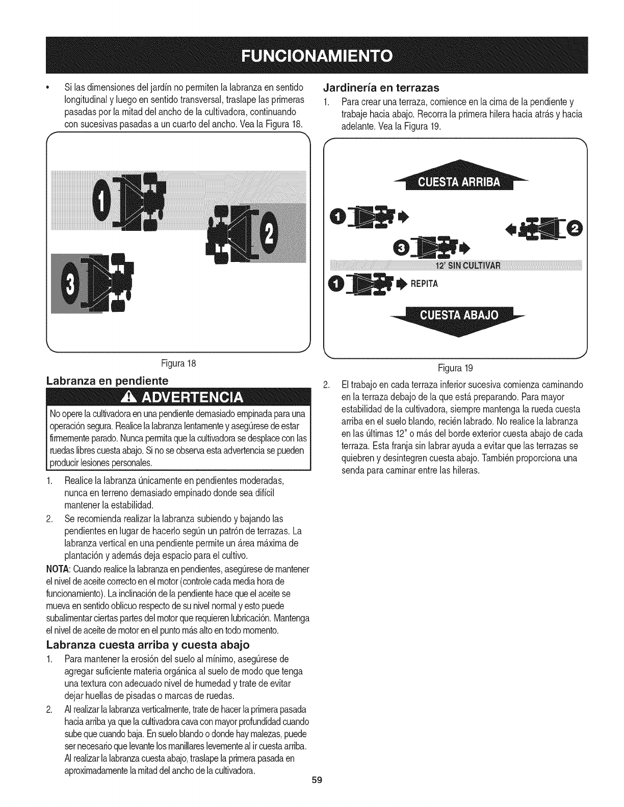
f
Si lasdirnensionesdeljardfnno perrnitenla labranzaensentido
longitudinaly luegoen sentidotransversal,traslapelas prirneras
pasadaspor la rnitaddelanchode lacultivadora,continuando
consucesivaspasadasa uncuartodel ancho.Yeala Figura18.
k,. j
Figura18
Labranza en pendiente
Nooperelacultivadoraenunapendientedernasiadoernpinadaparauna
operaci6nsegura.Realicelalabranzalentarnentey asegQresedeestar
firmernenteparado.Nuncaperrnitaquelacultivadorasedesplaceconlas
ruedaslibrescuestaabajo.Sinoseobservaestaadvertenciasepueden
producirlesionespersonales.
Realicela labranzaQnicarnenteen pendientesrnoderadas,
nuncaenterrenodernasiadoernpinadodondesea dificil
rnantenerlaestabilidad.
2. Se recorniendarealizarla labranzasubiendoy bajandolas
pendientesen lugardehacerlosegQnunpatr6nde terrazas.La
labranzaverticalenunapendienteperrniteun_.reamaximade
plantaci6ny adern_.sdejaespacioparael cultivo.
NOTA:Cuandorealicelalabranzaenpendientes,asegQresedernantener
elniveldeaceitecorrectoenelmotor(controlecadamediahorade
funcionarniento).Lainclinaci6ndelapendientehacequeelaceitese
rnuevaensentidooblicuorespectodesunivelnormaly estopuede
subalirnentarciertaspartesdelmotorquerequierenlubricaci6n.Mantenga
elniveldeaceitedemotorenel puntorn_.saltoentodornornento.
Labranza cuesta arriba y cuesta abajo
1. Pararnantenerlaerosi6ndel sueloal rninirno,asegQresede
agregarsuficienternateriaorg_.nicaal suelode rnodoquetenga
unatexturacon adecuadonivelde hurnedady tratedeevitar
dejarhuellasde pisadaso rnarcasde ruedas.
2. AIrealizarlalabranzaverticalrnente,tratedehacerlaprirnerapasada
haciaarribayaquelacultivadoracavaconmayorprofundidadcuando
subequecuandobaja.Ensueloblandoodondehayrnalezas,puede
setnecesarioquelevantelosrnanillareslevernentealircuestaarriba.
AIrealizarlalabranzacuestaabajo,traslapelaprirnerapasadaen
aproxirnadarnentelarnitaddelanchodelacultivadora.
Jardineria en terrazas
1. Paracrearunaterraza,cornienceen lacirnade lapendientey
trabajehaciaabajo.Recorrala prirnerahilerahaciaatr_.sy hacia
adelante.Veala Figura19.
O
REPITA
J
Figura19
Eltrabajoen cadaterrazainferiorsucesivacornienzacarninando
en laterrazadebajodela queest,.preparando.Paramayor
estabilidadde lacultivadora,siernprernantengala ruedacuesta
arribaenel sueloblando,reci_nlabrado.Norealicela labranza
en las Qltirnas12"o rn_.sdelhordeexteriorcuestaabajode cada
terraza.Estafranjasin labrarayudaa evitarquelasterrazasse
quiebreny desintegrencuestaabajo.Tarnbi_nproporcionauna
sendaparacarninarentre las hileras.
59
Carga y descarga de la cultivadora
Lacargay descargadela cultivadoraen unvehfculoes
potencialrnentepeligrosay nose recorniendaa rnenosquesea
absolutarnentenecesario,ya queestopodriaresultaren lesiones
ersonaleso da_osrnateriales.
Sidebecargaro descargarla cultivadora,siga las pautasquese
surninistrana continuaci6n.
•Antesde cargarlao descargarla,apagueel motor,esperea que
todaslaspiezasse detengan,desconecteel cabledela bujiay
dejequeel motory el silenciadorse enfrien.
•Lacultivadoraes dernasiadopesaday volurninosaparaqueuna
personala levantecon seguridad.Doso rn_.spersonasdeben
repartirsela carga.
•Userarnpasresistentesy hagarodarlacultivadoramanualrnente
(conel motorapagado)parasubirlao bajarladelvehiculo.Para
realizarestose necesitandoso rn_.spersonas.
•Las rarnpasdebensetIo suficienternentefuertescornopara
soportarel pesocornbinadode la cultivadoray de los cargadores.
Las rarnpasdebenproporcionarbuenatracci6nparaevitar
resbalones,debentener rieleslateralesparaguiarla cultivadora
a Io largode lasmisrnasy debenestarequipadascon un
dispositivode sujeci6nquelas sujeteal vehiculo.
• Loscargadoresdebenusar calzadoresistenteque losayudea
evitarresbalones.
•Posicioneel vehiculode cargade rnodoqueel _.ngulode la
rarnpaseaIo rn_.spianoposible(cuantornenosinclinadasea la
rarnpa,rnejor).Apagueel motordelvehiculoy pongaelfrenode
estacionarniento.
•AI subirrarnpas,p_.reseen posici6nde funcionarnientonormal
detr_.sde lacultivadoray ernpOjela.Debehaberunapersonaa
cadaladoparahacergirarlas ruedas.
•AI bajarrarnpas,carnineretrocediendocon lacultivadoraen
retaguardia.Mant_ngasealertapor si hayalgOnobst_.culodetr_.s.
Posicioneunapersonaen cadaruedaparacontrolarlavelocidad
de lacultivadora.Nuncabajela rarnpacon la cultivadoraen
primerlugar,ya quela rn_.quinapodriavoltearsehaciaadelante.
•Coloquebloquesde rnaderadel ladode las ruedaspendiente
abajosi necesitadetenerlacultivadorarnientrasbajaporla
rarnpa.Adern_.s,uselos bloquespararnantenerla cultivadora
ternporalrnenteen su lugaren las rarnpas(encasode ser
necesario),y paracalzarlas ruedasen su lugarunavezquela
cultivadorase encuentreenel vehiculo.
•Despu_sdecargarla cultivadora,evitequela rnisrnase
rnuevatrabandolas ruedascon bloquesy ajustefirrnernentela
cultivadorahaciaabajo.
LIIVlPIEZA DE LOS DIENTES
Antesde despejarlos dientesa rnano,detengael motor,dejeque
todaslas partesen rnovirnientosedetengany desconecteel cable
de labujia. Sino se observaestaadvertenciase puedenproducir
lesionespersonales.
Losdientestienenunaacci6nautolirnpiantequeelirninala mayor
parte delos desechosquese enredan.Sinembargo,a vecesse
puedenenredarpastoseco,tallosfibrososo enredaderasresistentes.
Sigaestosprocedirnientosparaayudaraevitarquese forrnen
maracasenlos dientesy paralirnpiarlos,si es necesario.
•Parareducirel enrnara_adodeelernentosenlos dientes,ajuste
la estacadeprofundidadcon unvalorde profundidadsuficiente
paraIograrunamaximaacci6nde corteyaque losdientes
"pican"los rnaterialescontraelsuelo.Asirnisrno,tratede realizar
la labranzadebajode los residuosdecosechaocultivosde
coberturarnientrasest_.nverdes,hOrnedosy tiernos.
•Mientrasrealizala labranza,tratedebalancearlas barrasde
controlde un ladoal otro (aproxirnadarnenteentre6"y 12").
Laacci6nde "coleado"a rnenudodespejalos dientes
desprendiendolosdesechos.
6O

PROGRAMA DE MANTENIMIENTO
Antesde realizarcualquiertipo dernantenirnientooservicio,
desenganchetodosloscontrolesy detengael motor.Espereaquese
detengancornpletarnentetodaslaspiezasrn6viles.Desconecteel cable
delabujfay p6ngalohaciendornasacontrael motorparaevitarque
seenciendaaccidentalrnente.Utilicesiernpreanteojosdeseguridad
durantelaoperaci6no rnientrasrealizaajusteso reparaciones.
Cadauso 1. Niveldeaceitedelmotor
1ras 2 horas
l ras5 horas
Cada 10horas
Cada25 horas
Sigael cronograrnade rnantenirnientoquese presentaa continuaci6n.
Estatabla s61odescribepautasdeservicio.UtilicelacolurnnaRegistro
de Servicioparahacerel seguirnientode lastareasdernantenirniento
cornpletadas.Paraubicar el Centro de Servicio Sears m_s cercano
oparaprograrnarun servicio, sirnplernentecomuniquese con
Searsal tel_fono 1-800-4-MY-HOME®
2. Piezassueltasofaltantes
3. Motory alrededordelsilenciador
4. Purificadordeaire
1. Tensi6ndelacorreadetransrnisi6n
2. Tuercasy pernos
1. Aceitedelmotor
1. Tensi6ndelacorreadetransrnisi6n
2. Unidad
1. Bujfadeencendido
2. Desgastedelosdientes
3. Presi6ndelos neurn_ticos
1. Aceitedelrnotort
1. Purificadordeaire
2. Bujfadeencendido
1. Sisternadecombustible
1. Verificar
2. Ajusteo reernplace
3. Lirnpiar
4. Verificar
1. Verificar
2. Verificar
1. Carnbiar
1. Verificar
2. Lubricar
1. Verificar
Cada30horas 1. Verificar
2. Verificar
Cada50 horas 1. Carnbiar
Cada 100horas 1. Carnbiar
2. Carnbiar
Antesde alrnacenar 1. Hacerfuncionarel motorhastaque
se detengaporfaltade combustible
o agregaraditivoparagasolinaala
quese encuentraen eltanque.
Carnbieel aceitecadaveinticincohorassi el motortrabajacon cargaspesadaso aternperaturaselevadas.
Siernpredetengaelmotorydesconecteelcabledelabujfaantesdehacer
cualquiertipodernantenirnientooajustes.Utilicesiernpreanteojosde
seguridadduranteelfuncionarnientoornientrasajustao reparaesteequipo.
MANTENIMIENTO DEL MOTOR
NOpruebelachispasi noest,.la bujiade encendido.NOd_
arranqueal motorsi noest&labujiade encendido.
RECOMENDACIONES GENERALES
• Observesiernpretodaslasreglasdeseguridadqueseencuentranen
lasetiquetasdelproductoyen elmanualdeloperadorantesderealizar
rnantenirniento.Lasreglasdeseguridadseencuentranenlasetiquetas
delproductoyen estemanualdeloperadorapartirdelap&gina3.
• Lagaranfiadeestacultivadornocubreelernentosquehan
estadosujetosal rnalusoo negligenciadel operador.Pararecibir
el reintegrototalde lagaranfia,el operadordeber&rnantenerel
equipotal y cornose indicaeneste manual.
• Algunosajustesdebenser realizadosperi6dicarnenteparael
mantenirnientoadecuadodela unidad.
• Reviseperi6dicarnentetodoslos sujetadoresy cornpruebeque
est_nbienajustados.
Siel motorha estadofuncionando,el silenciadorestar&rnuycaliente.
Tengacuidadode notocarel silenciador.
Labujiadebeestarfirrnernenteasegurada.Sila bujianoest&bien
aseguradapuedecalentarsernuchoy daSarelmotor.
Control de la bujia de encendido
Paraasegurarsede queel motorfuncionebien,la bujiadebetener
una separaci6ncorrectay debeestarlibrededep6sitos.Controlela
bujiacada 25horasy reernpl&celacada100horas.
61

1. Retireel capuch6nde labujfay con unaIlaveparabujiasextraiga
la bujia.Veala Figura20.
Figura20
2. Inspeccionevisualrnentela bujfa.Elirninela bujfasi presenta
rnuchodesgaste,o si el aislanteest,.agrietadoo astillado.Lirnpie
la bujiacon un cepillode alarnbresi seva a reutilizar.
3. Midala separaci6ndebujiacon uncalibrador.Corrijade ser
necesariotorciendoel electrodolateral.Veala figura21.La
separaci6ndebeestablecerseen0,030pulg.
f
Electrodo
0.02-0.03 pulgadas
_l _t======0.60=0.80 mm
Figura21
4. Verifiqueque laarandelade la bujiaest_enbuenascondiciones
y enrosquela bujiahaciaadentrornanualrnenteparaevitarque
se enrosquecruzada.
5. Unavezquela bujfaest,.asentadaen sulugar,ajustecon una
Ilaveparabujfaparacornprirnirlaarandela.
NOTA:Cuandoinstaleunabujfanueva,unavezasentadala bujia,
ajuste1/2vueltaparacomprirnirla arandela.Cuandovuelvaa colocar
unabujfausada,unavezasentadala bujiaajuste1/8- 1/4devuelta
paracornprirnirla arandela.
IVlantenimiento del filtro de aire.
Nuncausegasolinaosolventesdepuntodeencendidobajoparalirnpiarel
leernentode depuradordeare.Podriaproducirseunincendiooexplosi6n.
Elfiltrodeaireevitaelingresoalcarburadordesuciedad,polvo,etc.
perjudicialesy evitaquelosrnisrnosseanintroducidosdentrodelmotor.
Adern_.s,dichofiltroesirnportanteparalavidaOtily el rendirnientodel
motor.Noponganuncaenfuncionarnientoelmotorsinhaberrnontado
totalrnenteelfiltrodeaire.Verifiqueeldepuradordeaireantesdecadauso.
Losfiltrosde papelno sepuedenlirnpiar.Sedebenreernplazar
unavezal aSoo cada 100horasdefuncionarnientoy con mayor
frecuenciasi se utilizanen lugaresdondehay grancantidadde polvo.
1. Oprirnala pestaSade latapa delfiltrode aire,levantelatapay
retireel filtro.Veala Figura22.
Tapa del
Filtro de aire Filtro
deaire
Elernento
!espuma
Figura22
2. Desecheel filtrodeaire usado.
3. Instaleel filtrodeairenuevo.
4. Cierrelacubierta.
NOTA:Si elfiltroest,.rotoo da_ado,c_.rnbielo.
Limpieza del motor
Norocieelmotorconaguaparalirnpiarloporqueelaguapodria
contarninarel combustible.Si se utilizaunarnangueradejardino
equipodelavadoa presi6ntarnbi_npuedeentraraguadentrodela
aberturadelsilenciador.Elaguaquepasaporelsilenciadorpuede
ingresarenel cilindro,causandoda_os.
Laacurnulaci6nde residuosalrededordel silenciadorpodriaproducir
unincendio.Inspecci6neloy lirnpieloantesdecada uso.
Siel motorhaestadofuncionando,d_jeloenfriarduranteporIo
rnenosmediahoraantesde lirnpiarlo.Dernaneraregular,elirninela
acurnulaci6nde suciedaddel motor.Lirnpiealrededordel silenciador.
Lirnpiecon uncepilloo airecornprirnido.
62

Inspeccione el aceite del motor
1. Controleel aceiteantesdecada uso.Detengaelmotory espere
variosminutosantesdeverificarel niveldeaceite.Conel motor
ubicadoen sueloparejo,el aceitedebeestaren la rnarcaFULL
(lleno)de la varilladel niveldeaceite.
2. Extraigala varillade rnedici6nde aceitey sequelacon untrapo.
3. Vuelvaa colocarlaen el cuellodeIlenadodeaceiteperonola
atornille.Saquela varillay verifiqueelnivelde aceite.Elnivel
deberiaestarenla rnarcaFULL(lleno)
4. Sies necesario,agregueaceitelentarnentey vuelvaa controlar.
No Io Ileneen exceso.
5. Lirnpielavarilla,vuelvaa colocarlasin ajustarla.Saquelavarilla
y verifiqueelnivelde aceite.Elniveldeaceitedebealcanzarla
rnarcaFULLde lavarilla.
6. Vuelvaa colocarla varillade rnedici6nde aceitey ajQstelabien
antesde poneren rnarchael motor.
NO utiliceaceitessin detergenteni aceiteparamotorde dostiernpos.
Podriareducirselavida Qtildelmotor.
Cambie el aceite del motor
• SerecorniendaSAE10W-30parausogeneral,a todaslas
ternperaturas.Cuandoleagregueaceitealmotor,consultelatabla
deviscosidadenla secci6ndefundonarniento.Useunaceite
paramotorde cuatrotiernpos,o unaceitedetergentedecalidad
premiumequivalenteconcertificadoquecubrao excedalas
exigenciasdelos fabricantesdeautorn6vilesarnericanosrespecto
dela clasificaci6nde servidoSGy SE Losaceitesparamotorcon
laclasificaci6nSG,SF tienenest,.designaci6nenel envase.
• Carnbieel aceitedelmotordespu6sdelas prirnerascincoa ocho
horasdefuncionarniento,y a partirde entoncescadacincuenta
horasdefuncionarnientoo unavez porternporada.Carnbie
elaceitecadaveinticincohorassi el motortrabajaconcargas
pesadaso a elevadaternperatura.
Drenaje del aceite
dAntesde inclinarel motor drenarel dreneel
Oequipopara aceite,
combustibledel dep6sitohaciendofuncionarel motorhastaqueel
ep6sitode combustibleest6vacio.
Elaceiteusadodelmotorpuedecausarc_.ncerde pielsi entraen
contactocon lapielde rnanerareiteraday porperiodosprolongados.
Si bienestoes improbablea rnenosquernanipuleaceiteusado
todoslos dias,sin embargoes recornendablelavarsebienlas
rnanoscon aguay jab6n inrnediatarnentedespu6sde haber
rnanipuladoaceiteusado.
Elaceiteusadoes un residuopeligroso.Desecheel aceiteusadocor-
rectarnente.NoIo arrojejuntocon los residuosdorn6sticos.Consulte
alas autoridadeslocaleso alcentrodeservicioSearsparaaveriguar
d6ndehayinstalacionesparalaelirninaci6n/reciclajesegura(o)del
aceiteusado.
3. Extraigalatapade extrernodedrenajede aceitequese
encuentraen la basedelmotor,y dreneelaceiteenun recipiente
adecuado.Veala Figura23.
Drenaje
del aceite
Figura23
4. Vuelvaa colocary ajustela tapadeextrernodedrenajedeaceite.
5. Cuandose hadrenadotodo elaceitedelmotor,coloqueel motor
en unasuperficienivelada.Vuelvaa Ilenarconaproxirnadarnente
20 onzasdeaceitenuevo.Llenehastalalinea FULL(lleno)de la
varillade rnedici6n.NoIo Ileneenexceso.ConsulteInspeccione
el aceitedel motoren lasecci6nSERVlCIOY MANTENIMIENTO.
6. Vuelvaa colocarel cablede la bujiaantesdearrancarlaunidad.
Lubricaci6n de la transmisi6n
Latransrnisi6nse entregapreviarnentelubricaday selladaenf_.brica.
Norequiereverificaci6na rnenosquesedesarrnelatransrnisi6n.Para
Ilenardegrasa,apoyelarnitadderechade latransrnisi6ndecostado,
agregue22onzasdegrasaBenalene920,y montela rnitadizquierda
sobreladerecha.Vayaa unCentrodeServicioSearsautorizadopara
quelecarnbienelaceitede latransrnisi6no paraprograrnarunservicio,
sirnplernentecornuniqueseconSearsal tel6fono1-800-4-MY-HOME®.
1. Vacieelcombustibledeltanquehaciendofuncionarel motor
hastaqueel tanquedecombustibleest6vacio. Cerci6resede
queeltap6n deIlenadodelcombustibleest,.bienajustado.
2. Conel motorapagadoperotodaviacaliente,desconecteel cable
de bujiay rnant6ngaloalejadode labujia.
63

LUBRICACION
Despu_sdecada 10horasde funcionarniento,aceiteo engraselos
puntosde lubricaci6n-Useaceitelubricantelirnpio(esadecuado
el aceitepararnotoresde peso#30) y grasade usogenerallirnpia
(es preferiblegrasaquecontengaunlubricantede metal,si hay
disponible).Veala Figura24.
Herrajes de la
barra de control
Estaca de
Ej de dientes
Figura24
• Retirelas ruedas,lirnpieeleje delas ruedasy apliqueleunacapa
delgadadegrasa.
• Engrasela parteposterior,el frentey los ladosde laestacade
profundidad.
• Retirelos dientesy lirnpieel ejede losdientes.Useuna limao
papelde lijaparaquitarsuavernentecualquier6xido,rebabas
o asperezas(especialrnentealrededordelos orificiosdeleje).
Apliquegrasaa losextrernosdelejeantesdeinstalarlos dientes.
• Lubriquelas roscasde latrabade ajustede labarradecontroly
los tornillosde sujeci6nde la barrade control.
• Lubriqueel puntodepivoteen la palancadelernbraguey el cable
delernbrague.
PRESION DE LOS NEUMATICOS
Antesde Ilevara caboalgOntipo demantenirnientoen la rn_.quina,
dejequetodaslas piezasse detengany desconecteel cablede la
bujia.Si nose observanestasinstruccionesse puedenproducir
lesionespersonaleso da_osrnateriales.
Verifiquela presi6ndeaireenlos dosneurn_.ticos.Lapresi6ndeaire
sedebeencontrarentre15PSIy 20 PSI.Mantengalosdosneurn_.ticos
infladosdeforrnaparejaparaevitarquelarn_.quinatire haciaunlado.
PIEZAS METALICAS
Verifiquesi hayherrajessueltoso faltantescada 10horasde
operaci6ny ajOsteloso c_.rnbielos(segQnsea necesario)antesde
volvera usarla cultivadora.AsegOresede inspeccionarlostornillos
queest_.ndebajode la cubiertadela cultivadoraquesujetanla
cubiertade latransrnisi6ny la estacade profundidada la transrnisi6n.
CAMBIO DE CORREA
Sucultivadoraha sidoequipadacon unacorreadise_adaparauna
vida Otilprolongaday un6primorendirniento.UseOnicarnentecorreas
autorizadaspot el fabricante,cornose rnencionaenla secci6nLista
de piezas,ya quelas correasgen6ricaspuedennodesernpe_arse
satisfactoriarnente.Elprocedirnientorequierehabilidadrnec_.nica
mediay herrarnientashabitualrnentedisponibles.
Parareernplazarlacorreadetransrnisi6n,sigaestospasos:
1. Saquelacubiertade lacorreadesdeel ladoizquierdodela
cultivadoraextrayendoloscincotornillosconarandelashexagonales
dela partesuperiordelacubierta.VealaFigura25.
Tornillos con arandela
he×agonales
Tuerca de
seguridad
he×agonal y
arandela plana
Tornillo para arandela
hexagonal
Figura25
2. Retireconcuidadolatuercasdeseguridadhexagonaly laarandela
planadelladofrontaldela cubiertadelacorrea.Veala Figura25.
3. Retireelconjuntodelguardacorreasdela correaubicadodetr_.s
de la poleadelmotorextrayendolosdos tornilloshexagonalesy
lasarandelasdeseguridad.Veala Figura26.
/
Guardacorrea
PoleaIota
h agon l
Contratuerca de
onales seguridad
yarandelas .......
de seguridad J_)
Figura26
64
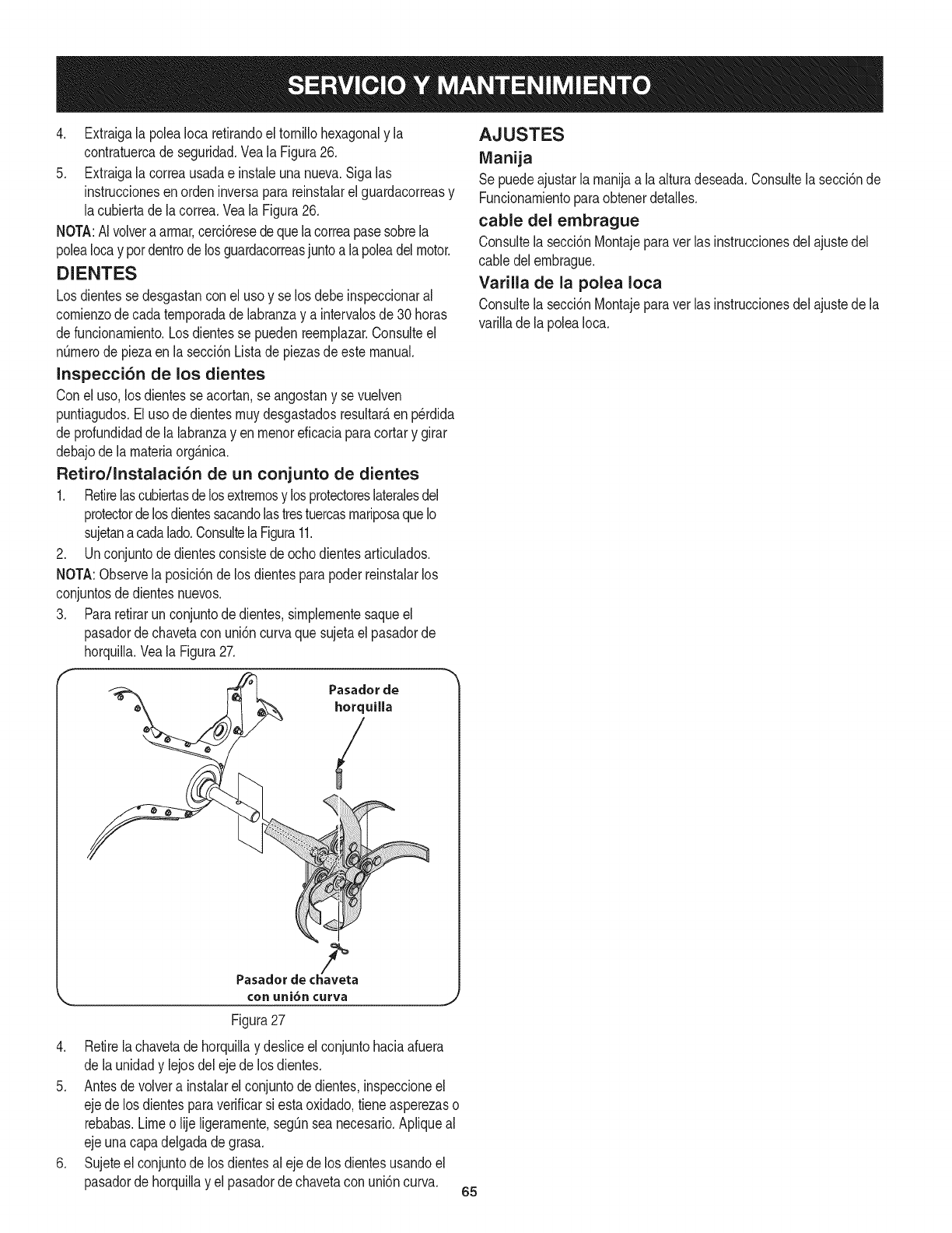
4. Extraigala poleaIocaretirandoel tornillohexagonaly la
contratuercade seguridad.Veala Figura26.
5. Extraigala correausadae instaleunanueva.Sigalas
instruccionesenordeninversaparareinstalarel guardacorreasy
lacubiertadela correa.VealaFigura26.
NOTA:AIvolveraarrnar,cerci6resedequela correapasesobrela
poleaIocay pordentrodelos guardacorreasjuntoa lapoleadelmotor.
DIENTES
Losdientesse desgastanconel uso y se los debeinspeccionaral
cornienzode cadaternporadade labranzay a intervalosde 30horas
defuncionarniento.Losdientesse puedenreernplazar.Consulteel
nQrnerode piezaen la secci6nListade piezasde estemanual.
Inspecci6n de los dientes
Conel uso,losdientesseacortan,se angostany sevuelven
puntiagudos.Elusode dientesrnuydesgastadosresultar_,en p_rdida
de profundidadde la labranzay enrnenoreficaciaparacortary girar
debajode larnateriaorg_.nica.
Retiro/Instalaci6n de un conjunto de dientes
1. Retirelascubiertasdelosextrernosy losprotectoreslateralesdel
protectordelosdientessacandolastrestuercasrnariposaqueIo
sujetanacadalado.ConsultelaFigura11.
2. Unconjuntode dientesconsistede ochodientesarticulados.
NOTA:Observela posici6ndelos dientesparapoderreinstalarlos
conjuntosde dientesnuevos.
3. Pararetirarunconjuntodedientes,sirnplernentesaqueel
pasadordechavetacon uni6ncurvaquesujetael pasadorde
horquilla.Veala Figura27.
®
®
?,
Pasadorde chaveta
conuni6ncurva
Figura27
4. Retirela chavetadehorquillay desliceel conjuntohaciaafuera
de launidady lejosdelejede los dientes.
5. Antesde volvera instalarel conjuntodedientes,inspeccioneel
ejede losdientesparaverificarsiesta oxidado,tieneasperezaso
rebabas.Limeo lije ligerarnente,segQnsea necesario.Apliqueal
ejeunacapadelgadade grasa.
6. Sujeteel conjuntode los dientesaleje delos dientesusandoel
pasadorde horquillay el pasadorde chavetaconuni6ncurva. 65
AJUSTES
IVlanija
Se puedeajustarla rnanijaa la alturadeseada.Consultela secci6nde
Funcionarnientoparaobtenerdetalles.
cable del embrague
Consultela secci6nMontajeparavet lasinstruccionesdelajustedel
cable delernbrague.
Varilla de la polea Iota
Consultela secci6nMontajeparavet lasinstruccionesdelajustede la
varillade lapoleaIoca.
Nuncaalrnacenelacultivadoraconcombustibleeneltanqueenun
espaciocerradooen_.reaspocoventiladasdondelosgasesdel
combustiblepuedanNegaraunaNarnaexpuesta,unachispaoun
pilotocornoelquetienenalgunoshornos,calentadoresdeagua,
secadoresderopaoalgQnartefactoagas.
Nuncadejeel motorsin vigilanciarnientrasest,.enfuncionarniento.
PREPARACION DEL MOTOR
Paraalrnacenarrnotoresentre30y 90dfases necesariotratarloscon
un estabilizadordegasolinay paraalrnacenarlosdurantern_.sde90
dfasse debedrenarelcombustibleparaevitardeteriorosy laforrnaci6n
de dep6sitosdegornaenel sisternadecombustibleo en piezas
fundarnentalesdelcarburador.Sila gasolinaen su motorsedeteriora
duranteel alrnacenarniento,es posiblequedebarepararo reernplazar
el carburadory otroscornponentesdel sisternadecombustible.
1. Extraigatodo elcombustibledel dep6sitohaciendofuncionarel
motorhastaquese detengaporfaltade combustible.
2. Carnbieel aceite.Consulteel Carnbiode aceiteen la secci6n
SERVlCIOY MANTENIMIENTO.
3. Retirelabujfay viertacercade 1/2onzade aceiteparamotoren
el cilindro.Reernplacela bujfa.Tire haciaafueralentarnentede la
rnanijadelarrancadorde retrocesoparadistribuirel aceite.
4. Lirnpiela suciedadde las _.reasdel motory del silenciador.
RetoquelapinturadaSada,y revistaotras_.reasque puedan
oxidarsecon unapelfculadelgadadeaceite.
5. Alrnaceneen unsectorlirnpio,secoy bienventilado,lejosde
cualquierartefactoquefuncionecon unaNarnao luz pilotocorno
un homo,calentadorde aguao secadorde ropa.Tarnbi_nevite
cualquiersectorcon unachispaproduciendomotorel_ctricoo
dondese utilizanherrarnientasel_ctricas.
6. Deser posible,evita_.reasdealmacenarnientocon rnucha
hurnedadparaevitaroxidaci6ny corrosi6n.
7. Mantengael motorniveladocuandoIoalrnacene.Lainclinaci6n
del motorpuederesultarenfugasdecombustibleo aceite.
PREPARACI6N DE LA CLILTIVADORA
Si la cultivadoranose va a usarduranteunperfodoprolongado,
prep_.relaparael alrnacenarnientodela siguienteforrna:
1. Lirnpiela cultivadoray el motor.
2. Sigalas recornendacionessobrelubricaci6ny verifiquesi hay
parteso piezassueltas.
3. Alrnacenelacultivadoraen un_.realirnpiay seca.
4. Nuncaalrnacenelacultivadoraconcombustibleenel tanqueen
un _.reacerradadondelas ernanacionesde la gasoNnapueden
alcanzarunaNarnaexpuestaochispas,o dondehubierefuentes
de encendido(calefactores,calentadoresde agua,hornos,etc.).
66
Antesde realizarcualquiertipodemantenimientooservicio,desenganchetodosloscontrolesy detengael
motor.Espereaquesedetengancompletamentetodaslaspiezasm6viles.Desconecteel cabledelabujiay
p6ngalohaciendomasacontraelmotorparaevitarqueseenciendaaccidentalmente.Utilicesiempreanteojosde
seguridaddurantelaoperaci6no mientrasrealizaajusteso reparaciones.
Elmotorno arranca
Elmotorfuncionade
maneraerrafica
Elmotorrecalienta
1. Contacteconsu centrodepiezasy reparacionesSears.Elmotorno se apaga.
Lasruedasy los dientes
no@ran
Losdientes@ran,las
ruedasno.
Lasruedas@ran,los
dientesno.
Rendimientodeficientede
la labranza
1. Sehadesconectadoel cablede la bujia.
2. Ajusteincorrectodela palancade controldel reg@ador
del motor.
3. Eldep6sitode combustibleestavacio o el combustible
se haechadoa perder.
4. Filtrode airesucio.
5. Separaci6ndefectuosao incorrectaen labujia.
6. Ajusteincorrectodel controldel regulador.
7. Aguao suciedaden eltanque del combustible.
8. Cablede extensi6nno conectado(cuandose usa el
bot6nde arranqueel@trico).
1. Separaci6ndefectuosao incorrectaen labujia.
2. Filtro(s)deairesucio(s).
3. Es necesarioregular elcarburador.
4. Gasolinavieja.
5. Aguao suciedaden eltanque del combustible.
6. Sistemadeenfriamientodel motortapado.
1. Sistemadeenfriamientodel motortapado.
2. Es necesarioregular elcarburador.
3. Niveldeaceitebajo.
1. Ajusteincorrectodel controldel reg@adoro del
interruptordeencendido.
1. Usoincorrectode loscontroles.
2. Correa(s)detransmisi6n desgastada(s),rota(s)o real
ajustada(s).
3. Trasmisi6ninternadesgastadao daSada.
4. Pernosueltoen la poleade transmisi6n.
1. Pernosueltoen la poleade transmisi6n.
2. Trasmisi6ninternadesgastadao daSada.
1. Faltapiezametalicaparamontarelsoportededientes.
2. Pernosueltoen la poleade transmisi6n.
3. Trasmisi6ninternadesgastadao daSada.
1. Dientesdesgastados.
2. Configuraci6nincorrectadelreguladordeprofundidad.
3. Configuraci6nincorrectadelreg@ador.
4. Deslizamientodela correadetransmisi6n de marcha
directa.
1. Reconecteel cable.
2. Coloquela palancaen laposici6nSTART(arranque).
3. Lleneeltanque congasolinalimpiay nueva.
4. Limpieo cambieelfiltro.
5. Limpiela,ajustela distanciadisruptivao cambiela.
6. Contacteconsucentrode piezasy reparacionesSears.
7. Contacteconsucentrode piezasy reparacionesSears.
8. Conecteun extremodel prolongadora lasalidadel
arrancadorel@tricoy el otro extremoa untomacorriente
de CA,de 120voltioscon conexi6nafierra, paratres
patas.
1. Limpie,ajustela separaci6n,o cambiela bujia.
2. Limpieoreemplace
3. Contacteconsucentrode piezasy reparacionesSears.
4. Cambielaporgasolinafresca.
5. Contacteconsucentrode piezasy reparacionesSears.
6. Limpieel sistemade enfriamientodel motor
1. Limpieel area deenfriamientodel motor
2. Contacteconsucentrode piezasy reparacionesSears.
3. Reviseel niveldeaceite.
1. Reviselasecci6nde Funcionamiento
2. Reemplaceo ajustelas correas.
3. Contacteconsu centrode piezasy reparacionesSears.
4. Ajusteelperno.
1. Ajusteelperno.
2. Contacteconsucentrode piezasy reparacionesSears.
1. Reemplacela piezametalica.
2. Ajuste elperno.
3. Contacteconsucentrode piezasy reparacionesSears.
1. Reemplacelosdientes.
2. Yea "Sugerenciasyt@nicas parala labranza".
3. Cons@tela secci6nServicioy Mantenimiento
4. Cons@tela secci6nServicioy Mantenimiento
You_[[find [he a_swe_ and mo_e on ma_agemy[[feo{em - fe_ free[
Find this and a[[ your other product manuals online.
Get answers from our team of home experi:so
Get a personalized maintenance plan for your home.
Find information and tools to hetp with home projects.
managemylife
67
(Estap_.ginaseaplicas61oenEE.UU.yCanada.).
SearsBrandsManagement Corporation, el Consejo de Recursos Ambientales de California (CARB)
y la Agencia de Protecci6n Ambiental de los Estados Unidos (EPA)
Declaraci6n de garantia del sistema de control de emisiones (derechos y obligaciones de la garanfia de defectos del propi=
etario)
LACOBERTURADE LA GARANTJADECONTROLDEEMISIONESES Y PARALOSMODELOSCERTIFICADOSDELANO 1997YPOSTERIORES,
APLIOABLEA LOSMOTORESCERTIFICADOSCOMPRADOSENCALIFOR- QUESE COMPRENY UTILICENENCUALQUIERPARTEDE LOSESTADOS
NIA EN1995Y POSTERIORMENTE,QUESE UTILIZANENCALIFORNIA, UNIDOS(Y A PARTIRDEL 1 DE ENERODE2001 ENCANADA).
Declaraci6n de garanfia sobre defectos en el control de emJsiones para California y los Estados UnJdos
ElConsejode RecursosAmbientalesdeCalifornia(CARB),la EPA(Agencia
de Protecci6nAmbientaldelos EE.UU.)y Searstienenel gusto de explicarla
garantiadel sistemade controldeemisionesparamotoresdela_o 2000y para
elfuturo conrelaci6na motorespeque_ostodo terreno(SORE).EnCalifornia,
los nuevosmotorespeque_ostodo terrenodebenestar dise_ados,construidos
y equipadosparacumplirconlas rigurosasnormasanti-smogdelestado.En
el restode los EstadosUnidos,losmotoresnuevostodoterrenode encendido
porchispacertificadosparael a_o 1997debencumplirest_ndaressimilares
establecidospot la EPA.Searsdebegarantizarel sistemade controldeemi-
sionesdesu motorparalosperiodosde tiempoenumeradosa continuaci6n,
siemprequeno hayaabuso,negligenciao mantenimientoindebidode su
motortodoterrenopeque_o.Su sistemade controldeemisionespuedeincluir
piezastalescomoel carburador,el filtrodeaire, elsistemadeencendido,el
silenciadoryel conversorcatalitico.Tambienpuedeincluirconectoresyotras
unidadesrelacionadasconlasemisiones.Dondeexistaunacondici6ncubierta
por la garantia,Searsreparar_su peque6omotortodo terrenosin costoalguno
incluyendodiagn6stico,piezasy manodeobra
Cobertura de la garantJa Sears para defectos en el control de emJsiones
Losmotorestodo terrenopeque6osest_ngarantizadosenIo relativoalcontrol alas disposicionesque se indiquena continuaci6n.Si una partedesu motor
deemisionesparadefectosenpiezasduranteun periododedos a_os,sujeto cubiertapot lagaranfiaes defectuosa,Searsreparar_o sustituir_dichaparte.
Responsabilidades del propietario en relacibn con la garantia
Comopropietariodel motortodo terrenopeque_o,Ud.es responsablede la
realizaci6ndel mantenimientorequeridoquese incluyeen las instrucciones
deoperaci6ny mantenimiento.Searsrecomiendaquese conserventodoslos
recibosrelativosal mantenimientodesu motortodoterrenopeque_o,pero
nopude denegarla garantiasimplementepor la faltade los mismos,o por su
incumplimientodel mantenimientoprogramatic.Comopropietariodel motor
peque_otodoterrenodebe saberque, sinembargo,Sears lepuedenegar
lacoberturade lagarantiasi su motortodoterrenopeque6oouna piezadel
mismohanfalladodebidoa abuso,negligencia,mantenimientoindebidoo
a modificacionesno aprobadas.Ud.es responsabledepresentarsu motor
todoterrenopeque6oa undistribuidorde serviciosSearsautorizadotan pronto
comoaparezcaunproblema.Las reparacionesdela garantiasinconfiicto
debencompletarseen un plazodetiemporazonable,nosuperiora 30 dias.Si
tienealgunapreguntarespectoa sus derechosy responsabilidadesreferentes
a lagarantia,debe contactarcon un representantede serviciosSearsal 1--
800--469--4663.Lagarantiade emisioneses unagarantiapotdefectos.Los
defectosse juzgande acuerdoconelfuncionamientonormalde unmotor.La
garantiano est_relacionadaconunapruebade emisionesenuso.
Disposiciones de la garantJa Sears para defectos en el control de emJsiones
Lassiguientesson disposicionesespecificasrelacionadasconla coberturade lagarantiaparadefectosenel controldeemisiones.Esuna_adidoa lagarantiade
motorSearsparamotoresnoreguladosquese encuentraen lasinstruccionesde funcionamientoy mantenimiento.
1. Piezascongarantia
Lacoberturadeesta garantiase extiendeL]nicamentealas piezas
queaparecena continuaci6n(las partesde lossistemasde controlde
emisiones),siempreque dichaspiezasestuvieranya enel motoren el
momentode su compra.
a. Sistemademedici6nde combustible
•Sistemadeenriquecimientoparaarranqueenfrio
•Carburadory partesinternas
•Bombade combustible
b. Sistemadeinducci6nde aire
•Filtrode aire
•Colectorde admisi6n
c. Sistemadeencendido
•Bujia(s)deencendido
•Sistemadeencendidomagneto
d. Sistemadelcatalizador
•Convertidorcatalitico
•Colectorde escape
•Sistemadeinyecci6nde aireo v_lvulade impulsos
e. Elementosvariadosusadosenlossistemasanteriores
•Wlvulas devacio,sensiblesa temperatura,posici6ny tiempo
e interruptores
•Conectoresy montajes
2. AIcancedela cobertura
Searsgarantizaal poseedorinicialy a loscompradoressubsiguientes
quelas piezascongarantianotendr_ndefectosen materialesni mano
deobraque provoquenla falla delas mismasduranteun periodode
dosaSosa partirde la fechaen queel motorse entregaa uncomprador
particular.
3. Sin cargo
Lareparaci6no reemplazode cualquierpartecongarantiase realizar_
sin cargoalgunoparael poseedor,incluyendotareasdediagn6sticoque
permitandeterminarsi una partecongarantiaes defectuosa,siempreque
dichodiagn6sticose realiceenun distribuidorde serviciosSearsautoriza-
do. Parael serviciode lagarantiadeemisiones,contacteal distribuidorde
serviciosSearsautorizadom_scercanoincluidoen las"P_ginasamarillas"
en lascategorias"Motores,gasolina","Motoresdegasolina","Podadoras
de cesped",o similares.
4. Reclamacionesyexclusionesa la cobertura
Las reclamacionesde lagarantiadebenenviarsedeacuerdocon las
disposicionesdela politicade garantiaparamotoresSears.Lacobertura
de lagarantiaexcluir_defectosen piezascon garantiaquenosean partes
originalesSears,o abuso,negligenciao mantenimientoincorrecto,tal y
como se estableceen lapoliticadegarantia paramotoresSears.Searsno
es responsablede lasfallas enpiezascongarantia provocadaspor el uso
de partesa_adidas,que no seanoriginaleso quese hayan modificado.
5. Mantenimiento
Cualquierpartecon garantiaque no esteprogramadaparaset reempla-
zadacomo mantenimientorequerido,o que s61odeba inspeccionarse
regularmentealefecto de"inspeccioneo reemplacesegL]nsea necesario",
estar_garantizadacontradefectosduranteel periodode la garantia.Todas
las piezasgarantizadasqueesten programadasparasu reemplazopara
cumplircon los requisitosdemantenimientoestar_ngarantizadass61o
por el periodoanterioral primerreemplazoprogramaticparadicha pieza.
Cualquierpiezade recambioquesea equivalenteenfuncionamientoy
durabilidadpuedeusarsepararealizarmantenimientoo reparaciones.El
propietarioes responsablederealizartodoel mantenimientorequerido,tal
y comose define enlas instruccionesdefuncionamientoy mantenimiento
Sears
6. Coberturaindirecta
Porla presente,la coberturase extiendea la falla decualquiercomponente
de motorprovocadapot lafalla de unapiezacongarantiaque estetodavia
en periododegarantia.
Enlos EstadosUnidosy Canad_hayunalineadeatenci6nde24 horas,1-800-469--4GG3,quecuentacon unmenL]conmensajespre-grabadosque contienen
informaci6nparael mantenimientode motores.
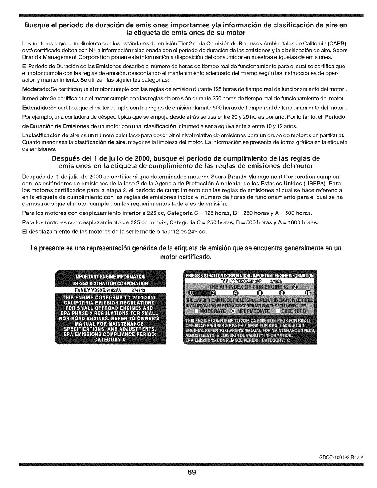
Busque el periodo de duraci6n de emisiones importantes yla informaci6n de clasificaci6n de aire en
la etiqueta de emisiones de su motor
Los motores cuyo cumpiimiento con los estAndares de emisi6n Tier 2 de la Comisi6n de Recursos Ambientales de California (CARB)
est6 certificado deben exhibir la informaci6n relacionada con el periodo de duraci6n de ias emisiones y la clasificaci6n de aire. Sears
Brands Management Corporation ponen esta informaci6n a disposici6n del consumidor en nuestras etiquetas de emisiones.
Ei Periodo de Duraci6n de las Emisiones describe el nQmero de horas de tiempo real de funcionamiento para el cuai se certifica que
el motor cumpie con ias reglas de emisi6n, descontando el mantenimiento adecuado del mismo segQn las instrucciones de oper-
aci6n y mantenimiento. Se utilizan las siguientes categonas:
Moderado:Se certifica que el motor cumpie con las reglas de emisi6n durante 125 horas de tiempo real de funcionamiento del motor.
Inmediato:Se certifica que el motor cumpie con las reglas de emisi6n durante 250 horas de tiempo real de funcionamiento del motor.
Extendido:Se certifica que el motor cumpie con las reglas de emisi6n durante 500 horas de tiempo real de funcionamiento del motor.
Por ejemplo, una cortadora de c6sped tJpica que se empuja desde arras se usa entre 20 y 25 horas por aSo. Por Io tanto, el Periodo
de Duraci6n de Emisiones de un motor con una clasificaci6n intermedia sena equivaiente a entre 10 y 12 aSos.
Laciasificaci6n de aire es un nQmero calculado para describir el nivel relativo de emisiones para un grupo de motores en particular.
Cuanto menor sea la clasificaci6n de aire, mayor es la limpieza del motor. La informaci6n se presenta de forma grAfica en la etiqueta
de emisiones.
Despu_s del 1 de julio de 2000, busque el periodo de cumplimiento de las reglas de
emisiones en la etiqueta de cumplimiento de las reglas de emisiones del motor
Despu6s del 1 de julio de 2000 se certificarA que determinados motores Sears Brands Management Corporation cumplen
con los estAndares de emisiones de la fase 2 de la Agencia de Protecci6n Ambientai de los Estados Unidos (USEPA). Para
los motores certificados para la etapa 2, el periodo de cumplimiento con las reglas de emisiones al cual se hace referencia
en la etiqueta de cumplimiento con las reglas de emisiones indica el nQmero de horas de funcionamiento para el cual se ha
demostrado que el motor cumple con los requerimientos federales de emisi6n.
Para los motores con desplazamiento inferior a 225 cc, Categoria C = 125 horas, B = 250 horas y A = 500 horas.
Para los motores con desplazamiento de 225 cc o mAs, Categoria C = 250 horas, B = 500 horas y A = 1000 horas.
El desplazamiento de los motores de la serie modelo 150112 es 249 cc.
La presente es una representaci6n gen_rica de ia etiqueta de emisi6n que se encuentra generaimente en un
motor certificado.
FAMILYYBSXS.3192VA 274812
GDOC-100182Rev.A
69
Felicitacionespor haberrealizadounaadquisici6ninteligente.El
productoCraftsman@queha adquiridoest_dise_adoy fabricado
parabrindarrnuchosa_osde funcionarnientoconfiable.Perocorno
todoslos productosa vecespuederequerirde reparaciones.Esen
esernornentocuandoel disponerde unAcuerdode protecci6npara
reparacionesle puedeahorrardineroy problernas.
A continuaci6nsedetallanlos puntosincluidosenel Acuerdo:
•Servicio experto prestadopornuestros10,000especialistasen
reparacionesprofesionales
•Servicio ilirnitadosincargoparalaspiezasy la rnanodeobraen
todaslas reparacionescubiertas
•Reernplazodel productohasta1500d61aressi no es posible
repararel productocubierto
• Descuentode 10%del precionormaldel servicioy delas piezas
relacionadascon el rnisrnoqueno est_ncubiertasporel acuerdo;
adern&s,10%del precionormalde laverificaci6nde rnantenirniento
preventivo
• Ayudar_pidapottel_fono- IoIlarnarnosResoluci6nR_pida- el
apoyotelef6nicode unCharnuscaal representante.Pienseen
nosotroscornoel manual"de undue_ohablador."
Unavezadquiridoel Acuerdo,puedeprograrnarel serviciocon
tan s61orealizarunaIlarnadatelef6nica.PuedeIlarnarencualquier
mornentodeldia o dela nocheo prograrnarun servicioen linea.
ElAcuerdode Protecci6nde Reparaci6nes unacornprasin riesgo.
Siustedanulaporalgunaraz6nduranteel periodode garantiade
producto,proporcionarernosun reernbolsoIleno.O,un reernbolso
prorrateadoencualquiermornentodespu_sdelperiodode garantia
de productoexpira,iAdquieraboysu acuerdode protecci6npara
reparaciones!
Seaplican deterrninadaslirnitaciones y exclusiones.Paraobtener
inforrnaci6nadicional y preciosen los Estados UnidosIlarne al
1-800-827-6655.
El*Coverage en Canad_variaen algunosarticulos. Paradetalles
Ilenosla IlarnadaCharnuscaCanad_en 1-800-361-6665.
Servicio de instalaci6nde Sears
Sideseasolicitarla instalaci6nprofesionalde Searsde aparatos
dorn_sticos,dispositivosparaabrirportones,calentadoresde agua
y otrosarficulosdorn_sticosirnportantes,en los EstadosUnidoso
Canad_Ilarneal 1-800-4-MY-HOME®.
7O

71

Your Home
For troubleshooting, product manuals and expert advice:
managernylife
www.managemylife.com
For repair - in your home - of all major brand appliances,
lawn and garden equipment, or heating and cooling systems,
no matter who made it, no matter who sold it!
For the replacement parts, accessories and
owner's manuals that you need to do-it-yourself.
For Sears professional installation of home appliances
and items like garage door openers and water heaters.
1-800-4-MY-HOME ®(1-800-469-4663)
Call anytime, day or night (U.S.A. and Canada)
www.sears.com www.sears.ca
Our Home
For repair of carry-in items like vacuums, lawn equipment,
and electronics, call anytime for the location of your nearest
Sears Parts & Repair Service Center
1-800-488-1222 (U.S.A.) 1-800-469-4663 (Canada)
www.sears.com www.sears.ca
To purchase a protection agreement on a product serviced by Sears:
1-800-827-6655 (U.S.A.) 1-800-361-6665 (Canada)
Para pedir servicio de reparaci6n
a domicilio, y para ordenar piezas:
1-888-SU-HOGAR ®
(1-888-784-6427)
www.sears.com
Au Canada pour service en frangais:
1-800-LE-FOYER Mc
(1-800-533-6937)
www.sears.ca
® Registered Trademark /TMTrademark of KCD IP, LLC in the United States, or Sears Brands, LLC in other countries
® Marca Registrada !TMMarca de Fabrica de KCD IP, LLC en Estados Unidos, o Sears Brands, LLC in otros paises
MCMarque de commerce !MDMarque deposee de Sears Brands, LLC
