Craftsman 247270200 User Manual RIDING MOWER Manuals And Guides L0305313
CRAFTSMAN Lawn, Riding Mower Rear Engine Manual L0305313 CRAFTSMAN Lawn, Riding Mower Rear Engine Owner's Manual, CRAFTSMAN Lawn, Riding Mower Rear Engine installation guides
User Manual: Craftsman 247270200 247270200 CRAFTSMAN RIDING MOWER - Manuals and Guides View the owners manual for your CRAFTSMAN RIDING MOWER #247270200. Home:Lawn & Garden Parts:Craftsman Parts:Craftsman RIDING MOWER Manual
Open the PDF directly: View PDF ![]() .
.
Page Count: 72

Owner's Manual
Riding Mower
Model No.
247.27020
CAUTION: Before
using this product,
read this manual and
follow all safety rules
and operating
instructions.
• Safety
• Operation
• Maintenance
• Storage
• Espanbl
For answers to your questions about this product, call:
1-800-659-5917
Sears Craftsman Help Line
(5 am. - 5 pm., Mon. - Sat.)
Sears, Roebuck And Co., Hoffman Estates, IL 60179 U.S.A.
Visit our website: www.sears.com/craftsman FORM NO. 769-00624
Printed in U.S.A. (1/2003)

Content Page
Warranty Information ................................ 2
Safe Operation Practices .......................... 3
Slope Gauge ............................................ 6
Assembly ................................................. 7
Operation ................................................. 9
Service & Adjustment ............................... 15
Content Page
Maintenance ............................................... 20
Off-Season Storage .................................... 23
Trouble-Shooting ........................................ 23
Parts List ..................................................... 25
Espan_)l ...................................................... 46
Customer Support ...................................... 72
LIMITED WARRANTY ON RIDING MOWER: For two (2) years from the date of purchase, if this Craftsman Riding Equipment is
maintained, lubricated and tuned up according to the instructions in the owner's manual, Sears will repair or replace free of
charge any parts that are found 1obe defective in material or workmanship according to the guidelines of coverage listed below.
Sears will also provide free labor for these applicable warranted parts for the two full years. During first 30 days of purchase,
there will be no charges to service the product at your home for issues covered by this warranty. (See exclusions below).
For your convenience, IN HOME warranty service will still be available after the first 30 days of purchase, but a trip charge will
apply. This charge will be waived if the product is dropped off at an authorized Sears location. For the nearest authorized Sears
location, please call 1-800-4-MY-HOME®. This warranty applies only while this product is within the United States.
EXCLUSIONS
This Warranty does not cover:
Expendable items which become worn during normal use, including but not limited to blades, spark plugs, air cleaners,
belts, and oil filters.
Standard Maintenance Servicing, oil changes or tune-ups
Tire replacement or repair caused by punctures from outside objects, such as nails, thorns, stumps, or glass.
Repairs necessary because of operator abuse, including but not limited 1o,damage caused by towing objects beyond the
capability of the riding equipment, impacting objects that bend the frame or crankshaft, or over-speeding the engine.
Repairs necessary because of operator negligence, including but not limited to, electrical and mechanical damage caused
by improper storage, failure to use the proper grade and amount of engine oil, failure to keep the deck clear of flammable
debris, or failure to maintain the equipment according 1othe instructions contained in the owner's manual.
Engine (fuel system) cleaning or repairs caused by fuel determined to be contaminated or oxidized (stale). In general, fuel
should be used within 30 days of its purchase date.
Normal deterioration and wear of the exterior finishes, or product label replacement.
Riding equipment used for commercial or rental purposes.
LIMITED WARRANTY ON BATTERY
For ninety (90) days from date of purchase, if any battery included with this riding equipment proves defective in material or
workmanship and our testing determines the battery will not hold charge, Sears will replace the battery at no charge. During the
first 30 days of purchase, there will be no charges to replace the battery at your home. After the first 30 days, for your
convenience, IN-HOME warranty service will still be available but a trip charge will apply. This charge will be waived if the
Craftsman product is dropped of at an authorized Sears location. For the nearest authorized Sears location, please call 1-800-4-
MY-HOME®. This battery warranty applies only while this product is within the United States. This warranty gives you specific
legal rights, and you may also have other rights, which vary, from state to state.
Sears, Roebuck and Co.,Dept.817WA, Hoffman Estates, IL 60179
Horsepower: ............................... 9.0
Engine Oil ................................... 36 oz. or 1.1 liters
Fuel ............................................ Unleaded Regular
Spark Plug: ................................. P/N 802592
Engine: ........................................ 198707-0141
Ignition Key (Std.) ........................ P/N 725-0201
Model Number ........................... 247.27020
Serial Number ...........................................................
Date of Purchase ......................................................
Record both serial number and date of purchase and keep
in a safe place for future reference.
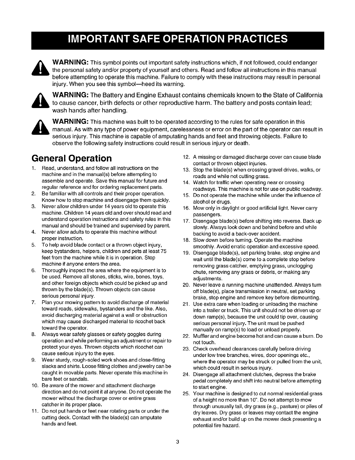
WARNING: This symbol points out important safety instructions which, if not followed, could endanger
the personal safety and/or property of yourself and others. Read and follow all instructions in this manual
before attempting to operate this machine. Failure to comply with these instructions may result in personal
injury. When you see this symbol--heed its warning.
WARNING: The Battery and Engine Exhaust contains chemicals known to the State of California
to cause cancer, birth defects or other reproductive harm. The battery and posts contain lead;
wash hands after handling.
WARNING: This machine was built to be operated according to the rules for safe operation in this
manual. As with any type of power equipment, carelessness or error on the part of the operator can result in
serious injury. This machine is capable of amputating hands and feet and throwing objects. Failure to
observe the following safety instructions could result in serious injury or death.
General Operation
1. Read, understand, and follow all instructions on the
machine and in the manual(s) before attempting to
assemble and operate. Save this manual for future and
regular reference and for ordering replacement parts.
2. Be familiar with all controls and their proper operation.
Know how to stop machine and disengage them quickly.
3. Never allow children under 14 years old to operate this
machine. Children 14 years old and over should read and
understand operation instructions and safety rules in this
manual and should be trained and supervised by parent.
4. Never allow adults to operate this machine without
proper instruction.
5. To help avoid blade contact or a thrown object injury,
keep bystanders, helpers, children and pets at least 75
feet from the machine while it is in operation. Stop
machine if anyone enters the area.
6. Thoroughly inspect the area where the equipment is to
be used. Remove all stones, sticks, wire, bones, toys,
and other foreign objects which could be picked up and
thrown by the blade(s). Thrown objects can cause
serious personal injury.
7. Plan your mowing pattern to avoid discharge of material
toward roads, sidewalks, bystanders and the like. Also,
avoid discharging material against a wall or obstruction
which may cause discharged material to ricochet back
toward the operator.
8. Always wear safety glasses or safety goggles during
operation and while performing an adjustment or repair to
protect your eyes. Thrown objects which ricochet can
cause serious injury to the eyes.
9. Wear sturdy, rough-soled work shoes and close-fitting
slacks and shirts. Loose fitting clothes and jewelry can be
caught in movable parts. Never operate this machine in
bare feet or sandals.
10. Be aware of the mower and attachment discharge
direction and do not point it at anyone. Do not operate the
mower without the discharge cover or entire grass
catcher in its proper place.
11. Do not put hands or feet near rotating parts or under the
cutting deck. Contact with the blade(s) can amputate
hands and feet.
12. A missing or damaged discharge cover can cause blade
contact or thrown object injuries.
13. Stop the blade(s) when crossing gravel drives, walks, or
roads and while not cutting grass.
14. Watch for traffic when operating near or crossing
roadways. This machine is not for use on public roadway.
15. Do not operate the machine while under the influence of
alcohol or drugs.
16. Mow only in daylight or good artificial light. Never carry
passengers.
17. Disengage blade(s) before shifting into reverse. Back up
slowly. Always look down and behind before and while
backing to avoid a back-over accident.
18. Slow down before turning. Operate the machine
smoothly. Avoid erratic operation and excessive speed.
19. Disengage blade(s), set parking brake, stop engine and
wait until the blade(s) come to a complete stop before
removing grass catcher, emptying grass, unclogging
chute, removing any grass or debris, or making any
adjustments.
20. Never leave a running machine unattended. Always turn
off blade(s), place transmission in neutral, set parking
brake, stop engine and remove key before dismounting.
21. Use extra care when loading or unloading the machine
into a trailer or truck. This unit should not be driven up or
down ramp(s), because the unit could tip over, causing
serious personal injury. The unit must be pushed
manually on ramp(s) to load or unload properly.
22. Mufflerandenginebecomehotandcancauseabum. Do
not touch.
23. Check overhead clearances carefully before driving
under low tree branches, wires, door openings etc.,
where the operator may be struck or pulled from the unit,
which could result in serious injury.
24. Disengage all attachment clutches, depress the brake
pedal completely and shift into neutral before attempting
to start engine.
25. Your machine is designed to cut normal residential grass
of a height no more than 10". Do not attempt to mow
through unusually tall, dry grass (e.g., pasture) or piles of
dry leaves. Dry grass or leaves may contact the engine
exhaust and/or build up on the mower deck presenting a
potential fire hazard.
26.Useonlyaccessoriesandattachmentsapprovedforthis
machinebythemachinemanufacturer.Read,
understandandfollowallinstructionsprovidedwiththe
accessoryorattachment.
27.Dataindicatesthatoperators,age60yearsandabove,
areinvolvedinalargepercentageoftractor-related
injuries.Theseoperatorsshouldevaluatetheirabilityto
operatethetractorsafelyenoughtoprotectthemselves
andothersfromseriousinjury.
28.Ifsituationsoccurwhicharenotcoveredinthismanual,
usecareandgoodjudgment.ContactSearsservice
centerforassistance.
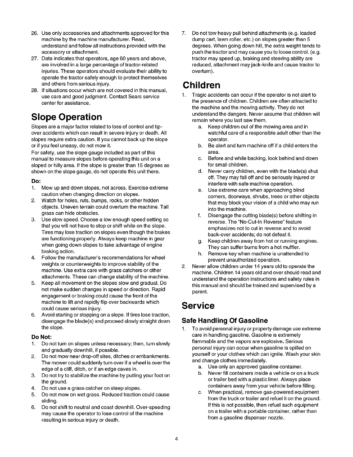
Slope Operation
Slopes are a major factor related to loss of control and tip-
over accidents which can result in severe injury or death. All
slopes require extra caution. If you cannot back up the slope
or if you feel uneasy, do not mow it.
For safety, use the slope gauge included as part of this
manual to measure slopes before operating this unit on a
sloped or hilly area. If the slope is greater than 15 degrees as
shown on the slope gauge, do not operate this unit there.
Do:
1. Mow up and down slopes, not across. Exercise extreme
caution when changing direction on slopes.
2. Watch for holes, ruts, bumps, rocks, or other hidden
objects. Uneven terrain could overturn the machine. Tall
grass can hide obstacles.
3. Use slow speed. Choose a low enough speed setting so
that you will not have to stop or shift while on the slope.
Tires may lose traction on slopes even though the brakes
are functioning properly. Always keep machine in gear
when going down slopes to take advantage of engine
braking action.
4. Follow the manufacturer's recommendations for wheel
weights or counterweights to improve stability of the
machine. Use extra care with grass catchers or other
attachments. These can change stability of the machine.
5. Keep all movement on the slopes slow and gradual. Do
not make sudden changes in speed or direction. Rapid
engagement or braking could cause the front of the
machine to lift and rapidly flip over backwards which
could cause serious injury.
6. Avoid starting or stopping on a slope. If tires lose traction,
disengage the blade(s) and proceed slowly straight down
the slope.
Do Not:
1. Do not turn on slopes unless necessary; then, turn slowly
and gradually downhill, if possible.
2. Do not mow near drop-off sites, ditches or embankments.
The mower could suddenly turn over if a wheel is over the
edge of a cliff, ditch, or if an edge caves in.
3. Do not try to stabilize the machine by putting your foot on
the ground.
4. Do not use a grass catcher on steep slopes.
5. Do not mow on wet grass. Reduced traction could cause
sliding.
6. Do not shift to neutral and coast downhill. Over-speeding
may cause the operator to lose control of the machine
resulting in serious injury or death.
7. Do not tow heavy pull behind attachments (e.g. loaded
dump cart, lawn roller, etc.) on slopes greater than 5
degrees. When going down hill, the extra weight tends to
push the tractor and may cause you to loose control. (e.g.
tractor may speed up, braking and steering ability are
reduced, attachment may jack-knife and cause tractor to
overturn).
Children
1. Tragic accidents can occur ifthe operator is not alert to
the presence of children. Children are often attracted to
the machine and the mowing activity. They do not
understand the dangers. Never assume that children will
remain where you last saw them.
a. Keep children out of the mowing area and in
watchful care of a responsible adult other than the
operator.
b. Be alert and turn machine off if a child enters the
area.
c. Before and while backing, look behind and down
for small children.
d. Never carry children, even with the blade(s) shut
off. They may fail off and be seriously injured or
interfere with safe machine operation.
e. Use extreme care when approaching blind
corners, doorways, shrubs, trees or other objects
that may block your vision of a child who may run
into the machine.
f. Disengage the cutting blade(s) before shifting in
reverse. The "No-Cut-In Reverse" feature
emphasizes not to cut in reverse and to avoid
back-over accidents; do not defeat it.
g. Keep children away from hot or running engines.
They can suffer burns from a hot muffler.
h. Remove key when machine is unattended to
prevent unauthorized operation.
2. Never allow children under 14 years old to operate the
machine. Children 14 years old and over should read and
understand the operation instructions and safety rules in
this manual and should be trained and supervised by a
parent.
Service
Safe Handling Of Gasoline
1. To avoid personal injury or property damage use extreme
care in handling gasoline. Gasoline is extremely
flammable and the vapors are explosive. Serious
personal injury can occur when gasoline is spilled on
yourself or your clothes which can ignite. Wash your skin
and change clothes immediately.
a. Use onlyan approved gasoline container.
b. Never fill containers inside a vehicle or on a truck
or trailer bed with a plastic liner. Always place
containers away from your vehicle before filling.
c. When practical, remove gas-powered equipment
from the truck or trailer and refuel it on the ground.
If this is not possible, then refuel such equipment
on a trailer with a portable container, rather than
from a gasoline dispenser nozzle.

d. Keepthenozzleincontactwiththerimofthefuel
tankorcontaineropeningatalltimesuntilfueling
iscomplete.DOnotuseanozzlelock-open
device.
e. Extinguishallcigarettes,cigars,pipesandother
sourcesofignition.
f. Neverfuelmachineindoors.
g. Neverremovegascaporaddfuelwhilethe
engineishotorrunning.Allowenginetocoolat
leasttwominutesbeforerefueling.
h. Neveroverfillfueltank.Filltanktonomorethan
Y_inchbelowbottomoffillernecktoallowspace
forfuelexpansion.
i. Replacegasolinecapandtightensecurely.
j. Ifgasolineisspilled,wipeitofftheengineand
equipment.Moveunittoanotherarea.Wait5
minutesbeforestartingtheengine.
k. Toreducefirehazards,keepmachinefreeof
grass,leaves,orotherdebrisbuild-up.Cleanup
oilorfuelspillageandremoveanyfuelsoaked
debris.
L Neverstorethemachineorfuelcontainerinside
wherethereisanopenflame,sparkorpilotlight
asonawaterheater,spaceheater,furnace,
clothesdryerorothergasappliances.
m. Allowamachinetocoolatleast5minutesbefore
storing.
General Service
1. Never run an engine indoors or in a poorly ventilated
area. Engine exhaust contains carbon monoxide, an
odorless, and deadly gas.
2. Before cleaning, repairing, or inspecting, make certain
the blade(s) and all moving parts have stopped.
Disconnect the spark plug wire and ground against the
engine to prevent unintended starting.
3. Periodically check to make sure the blades come to
complete stop within approximately (5) five seconds after
operating the blade disengagement control. If the blades
do not stop within the this time frame, your unit should be
serviced professionally by an authorized dealer.
4. Check brake operation frequently as it is subjected to
wear during normal operation. Adjust/service as required.
5. Check the blade(s) and engine mounting bolts at
frequent intervals for proper tightness. Also, visually
inspect blade(s) for damage (e.g., excessive wear, bent,
cracked).
Replace the blade(s) with the original equipment
manufacturer's (O.E.M.) blade(s) only, listed in this
manual. "Use of parts which do not meet the original
equipment specifications may lead to improper
performance and compromise safety!"
6. Mower blades are sharp. Wrap the blade or wear gloves,
and use extra caution when servicing them.
7. Keep all nuts, bolts, and screws tight to be sure the
equipment is in safe working condition.
8. Never tamper with the safety interlock system or other
safety devices. Check their proper operation regularly.
9. After striking a foreign object, stop the engine, disconnect
the spark plug wire(s) and ground against the engine.
Thoroughly inspect the machine for any damage. Repair
the damage before starting and operating.
10. Never attempt to make adjustments or repairs to the
machine while the engine is running.
11. Grass catcher components and the discharge cover are
subject to wear and damage which could expose moving
parts or allow objects to be thrown. For safety protection,
frequently check components and replace immediately
with original equipment manufacturer's (O.E.M.) parts
only, listed in this manual. "Use of parts which do not
meet the original equipment specifications may lead to
improper performance and compromise safety!"
12. Do not change the engine governor settings or over-
speed the engine. The governor controls the maximum
safe operating speed of the engine.
13. Maintain or replace safety and instruction labels, as
necessary.
14. Observe proper disposal laws and regulations for gas,
oil, etc. to protect the environment.
Your Responsibility
Restrict the use of this power machine to persons who
read, understand and follow the warnings and instructions
in this manual and on the machine.
Z
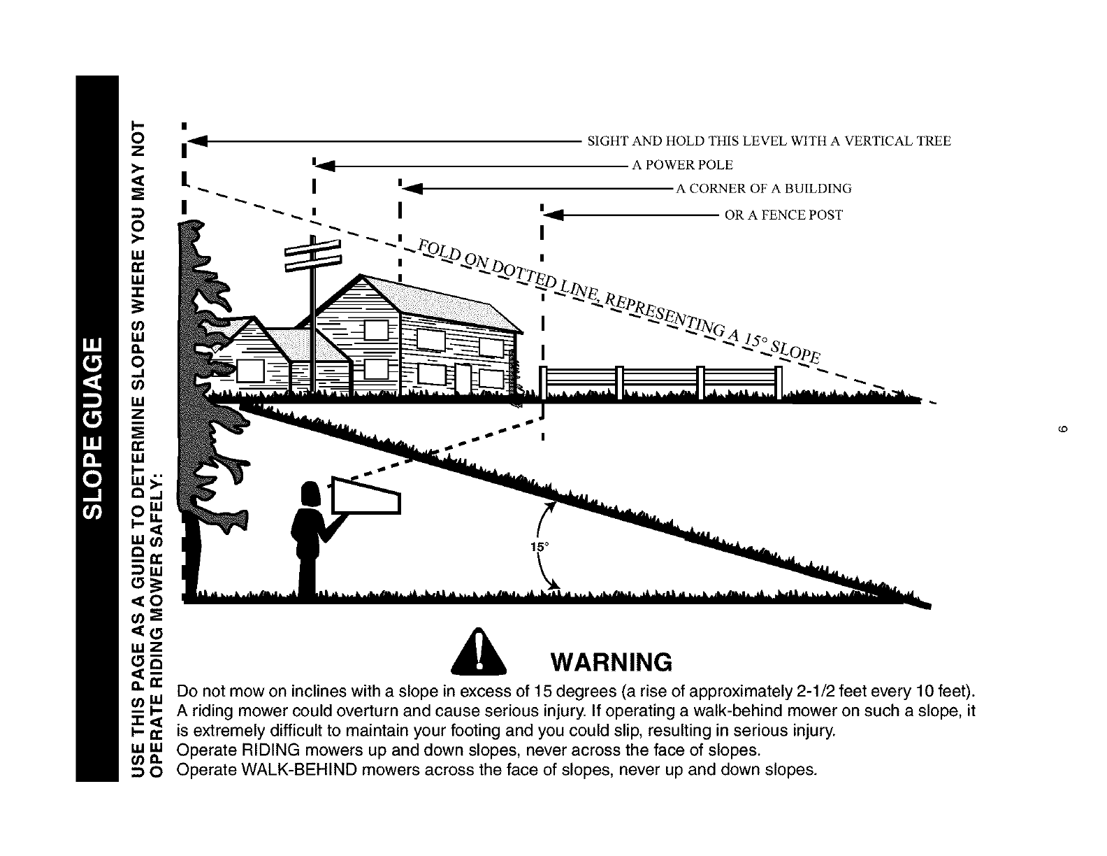
SIGHT AND HOLD THIS LEVEL WITH A VERTICAL TREE
,,,Z WARNING
_ Do not mow on inclines with a slope in excess of 15 degrees (a rise of approximately 2-1/2 feet every 10 feet).
t_ _. A riding mower could overturn and cause serious injury. If operating a walk-behind mower on such a slope, it
_ is extremely difficult to maintain your footing and you could slip, resulting in serious injury.
w w Operate RIDING mowers up and down slopes, never across the face of slopes.
O Operate WALK-BEHIND mowers across the face of slopes, never up and down slopes.
t.O
Unpacking
1. Remove ait screws and staples from the crate.
2. Holding sides of the crate firmly, lift top of the crate
up and set it aside. Avoid tire punctures.
3. Remove and discard plastic bag covering the unit.
4. Lift the rear of the mower and clear the bottom of
the crate. Repeat for the front.
5. Be sure the parking brake is disengaged. See
Figure 6 for location of the parking brake.
6. Roll unit out of the crate.
Loose Parts
Remove loose parts from the grass catcher and/or the
crate very carefully. Compare with list and illustration
(Figure 1) below.
i. Mulching plug & side-discharge chute
iL Oil drain sleeve
iii. Ignition keys (not shown)
iv. Operator's manual (not shown)
Side-Discharge z_
Mulching
plug
Oil Drain Sleeve
Figure 1
NOTE: Reference to RIGHT or LEFT side of the tractor
in this manual is observed from operator's position.
• Your riding mower is shipped with motor oil in the
engine. However, you must check the oil level
before operating. Be careful not to overfill.
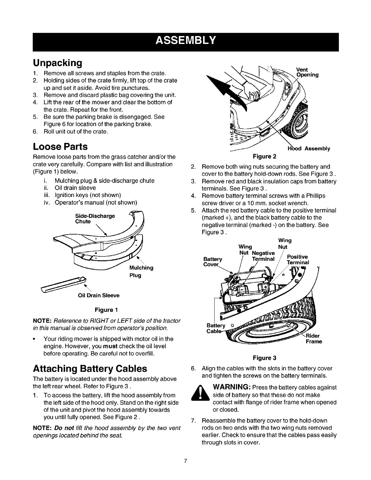
Attaching Battery Cables
The battery is located under the hood assembly above
the left rear wheel. Refer to Figure 3.
1. To access the battery, lift the hood assembly from
the left side of the hood only. Stand on the right side
of the unit and pivot the hood assembly towards
you until fully opened. See Figure 2.
NOTE: Do not lift the hood assembly by the two vent
openings located behind the seat.
Vent
Assembly
Figure 2
2. Remove both wing nuts securing the battery and
cover to the battery hold-down rods. See Figure 3.
3. Remove red and black insulation caps from battery
terminals. See Figure 3.
4. Remove battery terminal screws with a Phillips
screw driver or a 10 mm. socket wrench.
5. Attach the red battery cable to the positive terminal
(marked +), and the black battery cable to the
negative terminal (marked -) on the battery. See
Figure 3.
Battery
Cove_
Wing
Wing Nut
Nut Negative
Terminal Positive
Battery
Rider
Frame
Figure 3
6. Align the cables with the slots in the battery cover
and tighten the screws on the battery terminals.
WARNING: Press the battery cables against
side of battery so that these do not make
contact with flange of rider frame when opened
or closed.
7, Reassemble the battery cover to the hold-down
rods on two ends with the two wing nuts removed
earlier. Check to ensure that the cables pass easily
through slots in cover.
8. Placerighthandontheleftsideoftheseatand
slowlylowerthehoodassemblyuntitlfullyclosed.
NOTE:Do not place your hand around the bottom
edge of the hood assembly; it may get pinched between
the hood assembly and grass catcher or the frame rail.
Attaching Side-Discharge Chute
_k WARNING: Battery posts, terminals and
related accessories contain lead and lead
compounds. Wash hands after handling.
Your riding mower is shipped to you with the grass
catcher fully assembled on the unit. A side-discharge
chute and a mulching plug are included as loose parts.
Follow the instructions below to attach the side-
discharge chute.
WARNING: Do not operate the mower if any
one or more of the grass catcher, discharge
chute or mulching plug is not firmly installed on
the mower.
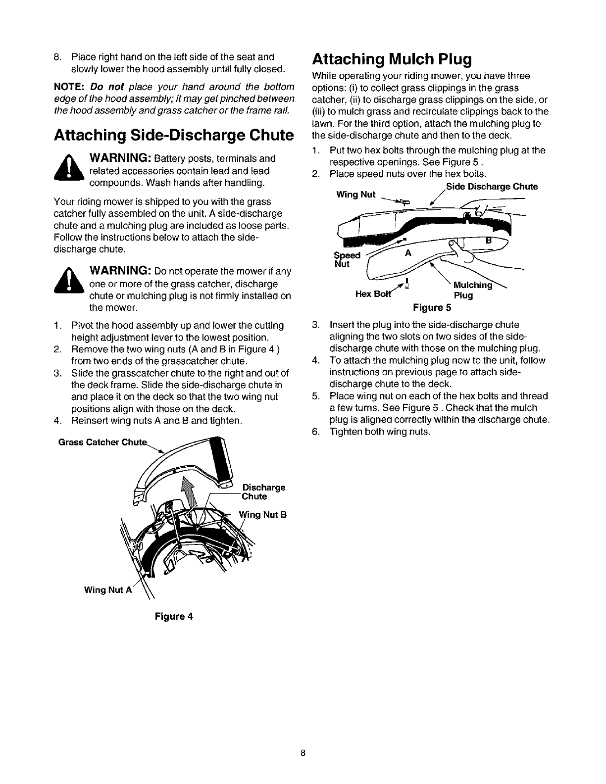
1. Pivot the hood assembly up and lower the cutting
height adjustment lever to the lowest position.
2. Remove the two wing nuts (A and B in Figure 4 )
from two ends of the grasscatcher chute.
3. Slide the grasscatcher chute to the right and out of
the deck frame. Slide the side-discharge chute in
and place it on the deck so that the two wing nut
positions align with those on the deck.
4. Reinsert wing nuts A and B and tighten.
Grass Catcher Chute_
Attaching Mulch Plug
While operating your riding mower, you have three
options: (i) to collect grass clippings in the grass
catcher, (ii) to discharge grass clippings on the side, or
(iii) to mulch grass and recirculate clippings back to the
lawn. For the third option, attach the mulching plug to
the side-discharge chute and then to the deck.
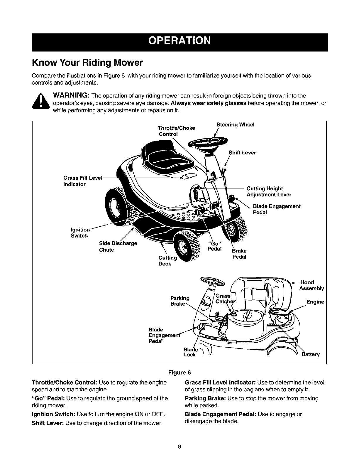
1. Put two hex bolts through the mulching plug at the
respective openings. See Figure 5.
2. Place speed nuts over the hex bolts.
Nut jSide Discharge Chute
Wing
A
Hex Bo_ _Plug
Figure 5
3. Insert the plug into the side-discharge chute
aligning the two slots on two sides of the side-
discharge chute with those on the mulching plug.
4. To attach the mulching plug now to the unit, follow
instructionson previous page to attach side-
discharge chute to the deck.
5. Place wing nut on each of the hex bolts and thread
a few turns. See Figure 5. Check that the mulch
plug is aligned correctly within the discharge chute.
6. Tighten both wing nuts.
Discharge
ring Nut B
Wing Nut A"
Figure 4
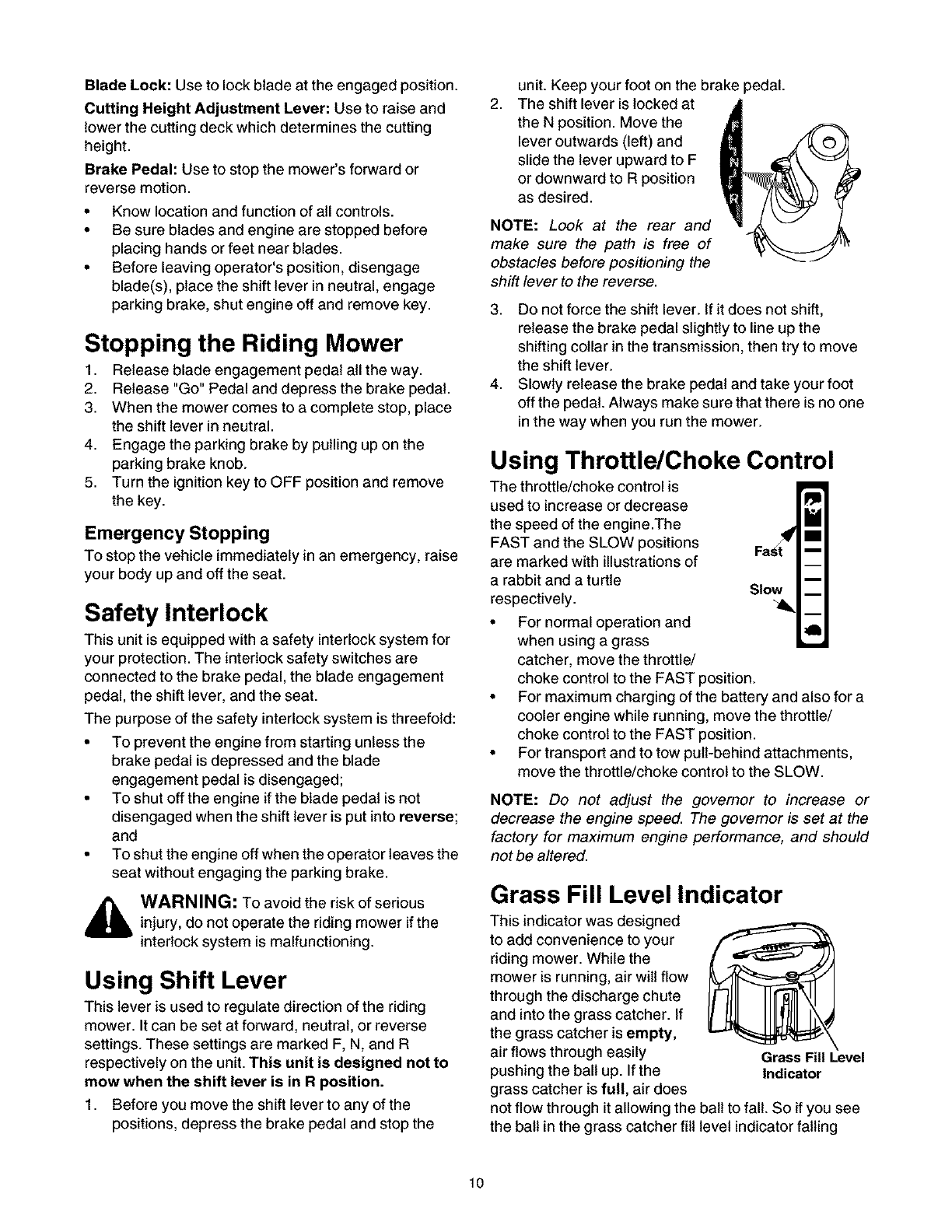
Know Your Riding Mower
Compare the illustrations in Figure 6 with your riding mower to familiarize yourself with the location of various
controls and adjustments.
,_ WARNING: The operation of any riding mower can result in foreign objects being thrown into theoperator's eyes, causing severe eye damage. Always wear safety glasses before operating the mower, or
while performing any adjustments or repairs on it.
Throttle/Choke
Control
Steering Wheel
Shift Lever
Indicator g Height
Adjustment Lever
Blade Engagement
Pedal
Ignition
Switch
Side Discharge
Chute
Cutting
Deck
Pedal Brake
Pedal
Blade
En
Pedal
Parking
Lock
Figure 6
Throttle/Choke Control: Use to regulate the engine
speed and to start the engine.
"Go" Pedal: Use to regulate the ground speed of the
riding mower.
Ignition Switch: Use to turn the engine ON or OFF.
Shift Lever: Use to change direction of the mower.
Grass Fill Level Indicator: Use to determine the level
of grass clipping in the bag and when to empty it.
Parking Brake: Use to stop the mower from moving
while parked.
Blade Engagement Pedal: Use to engage or
disengage the blade.
BladeLock:Usetolockbladeattheengagedposition.
CuttingHeightAdjustmentLever:Usetoraiseand
lowerthecuttingdeckwhichdeterminesthecutting
height.
BrakePedal:Usetostopthemower'sforwardor
reversemotion.
• Knowlocationandfunctionofallcontrols.
• Besurebladesandenginearestoppedbefore
placinghandsorfeetnearblades.
• Beforeleavingoperator'sposition,disengage
blade(s),placetheshiftleverinneutral,engage
parkingbrake,shutengineoffandremovekey.
Stopping the Riding Mower
1. Release blade engagement pedal all the way.
2. Release "Go" Pedal and depress the brake pedal.
3. When the mower comes to a complete stop, place
the shift lever in neutral.
4. Engage the parking brake by pulling up on the
parking brake knob.
5. Turn the ignition key to OFF position and remove
the key.
Emergency Stopping
To stop the vehicle immediately in an emergency, raise
your body up and off the seat.
Safety Interlock
This unit is equipped with a safety interlock system for
your protection. The interlock safety switches are
connected to the brake pedal, the blade engagement
pedal, the shift lever, and the seat.
The purpose of the safety interlock system is threefold:
• To prevent the engine from starting unless the
brake pedal is depressed and the blade
engagement pedal is disengaged;
• To shut off the engine if the blade pedal is not
disengaged when the shift lever is put into reverse;
and
• To shut the engine off when the operator leaves the
seat without engaging the parking brake.
,_ WARNING: To avoid the risk of seriousinjury, do not operate the riding mower if the
interlock system is malfunctioning.
Using Shift Lever
This lever is used to regulate direction of the riding
mower. It can be set at forward, neutral, or reverse
settings. These settings are marked F, N, and R
respectively on the unit. This unit is designed not to
mow when the shift lever is in R position.
1. Before you move the shift lever to any of the
positions, depress the brake pedal and stop the
2,
unit. Keep your foot on the brake
The shift lever is locked at
the N position. Move the
lever outwards (left) and
slide the lever upward to F
or downward to R position
as desired.
NOTE: Look at the rear and
make sure the path is free of
obstacles before positioning the
shift lever to the reverse.
_edal.
3. Do not force the shift lever. If it does not shift,
release the brake pedal slightly to line up the
shifting collar in the transmission, then try to move
the shift lever.
4. Slowly release the brake pedal and take your foot
off the pedal. Always make sure that there is no one
in the way when you run the mower.
Using Throttle/Choke Control
The throttle/choke control is II_II__
used to increase or decrease
the speed of the engine.The
FAST and the SLOW positions
are marked with illustrations of
a rabbit and a turtle
respectively.
• For normal operation and
when using a grass
catcher, move the throttle/
choke control to the FAST position.
• For maximum charging of the battery and also for a
cooler engine while running, move the throttle/
choke control to the FAST position.
• For transport and to tow pull-behind attachments,
move the throttle/choke control to the SLOW.
NOTE: Do not adjust the governor to increase or
decrease the engine speed. The governor is set at the
factory for maximum engine performance, and should
not be altered.
Grass Fill Level Indicator
This indicator was designed
to add convenience to your
riding mower. While the
mower is running, air will flow
through the discharge chute
and into the grass catcher. If
the grass catcher is empty,
air flows through easily
pushing the ball up. If the
grass catcher is full, air does
not flow through it allowing the
the ball in the grass catcher fill
Grass Fill Level
Indicator
ball to fall. So if you see
level indicator falling
10
down,youshouldstopthemowerandemptythebag.
Engine Model
This is a single cylinder, L-head, air-cooled engine. It is
a low emissions engine.
NOTE: In the state of California, the 190000 series
engines covered in this manual are certified by the
California Air Resources Board to meet emissions
standards for 125 hours. Such certification does not
grant the purchaser, owner or operator of this engine
any additional warranties with respect to the
performance or operational life of this engine. This
engine is warranted solely according to the product and
emissions warranties stated elsewhere in this manual
Bore 3 in. (76.20 mm)
Stroke 2-3/4 in. (69.85 mm)
Displacement 19.44 cu. in. (318.5 cc)
IMPORTANT: For practical operation, the horsepower
loading should not exceed 85% of rated horsepower.
Engine power will decrease 3-1/2% for each 1,000 feet
(300 meters) above sea level and 1% for each 10 F (5.6
C) above 77 F (25 C). Engine will operate satisfactorily
at an angle up to 15 degrees.
Tune-up Specifications
Armature air gap 0.010 - 0.014 in. (0.25 - 0.36 mm)
Spark plug gap 0.030 in. (0.76 mm)
Valve clearance with valve springs installed and piston
1/4 inch (6 mm) past top dead center (check when
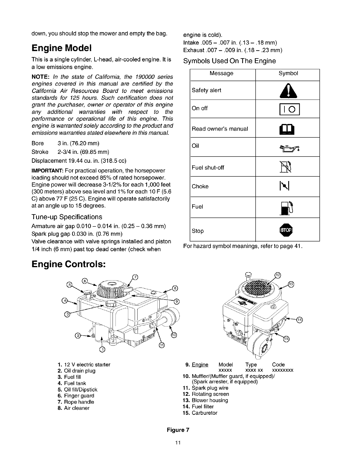
Engine Controls:
engine is cold).
Intake .005 - .007 in. (.13 - .18 mm)
Exhaust .007- .009 in. (.18- .23 mm)
Symbols Used On The Engine
Stop
For hazard symbol meanin(
Message Symbol
Safety alert ,_
On off
Read owner's manual
Fuel shut-off _,
Choke I",1
Fuel =_
O
s, refer to page 41.
®
1. 12 V electric starter
2. Oil drain plug
3. Fuel fill
4. Fuel tank
5. Oil fill/Dipstick
6. Finger guard
7. Rope handle
8. Air cleaner
9. _ Model Type Code
xxxxx xxxx xx xxxxxxxx
10. Muffled(Muffler guard, if equipped)/
(Spark arrester, if equipped)
11. Spark plug wire
12. Rotating screen
13. Blower housing
14. Fuel filter
15. Carburetor
Figure 7
11
Using Parking Brake
To engage
1. Completely push the brake pedal down and stop
the unit.
2. With your right foot on the brake pedal, move the
shift lever to the neutral position.
3. Continuing to hold down the brake pedal with your
right foot, pull up the parking brake knob. Make
sure the parking brake holds the unit.
4. Release the brake pedal. Stop engine and remove
ignition key. Now your riding mower is parked.
To release
5. Depress the brake pedal. The parking brake will be
automatically disengaged.
Before Starting
Filling Up Oil
Check oil level in the engine oil sump before starting the
engine. (Oil sump capacity: 36 oz./1.1 liter)
1. Place the mower on level ground and flip the hood
assembly up to access the engine.
NOTE: Do not lift the hood assembly by the two vent
openings located behind the seat.
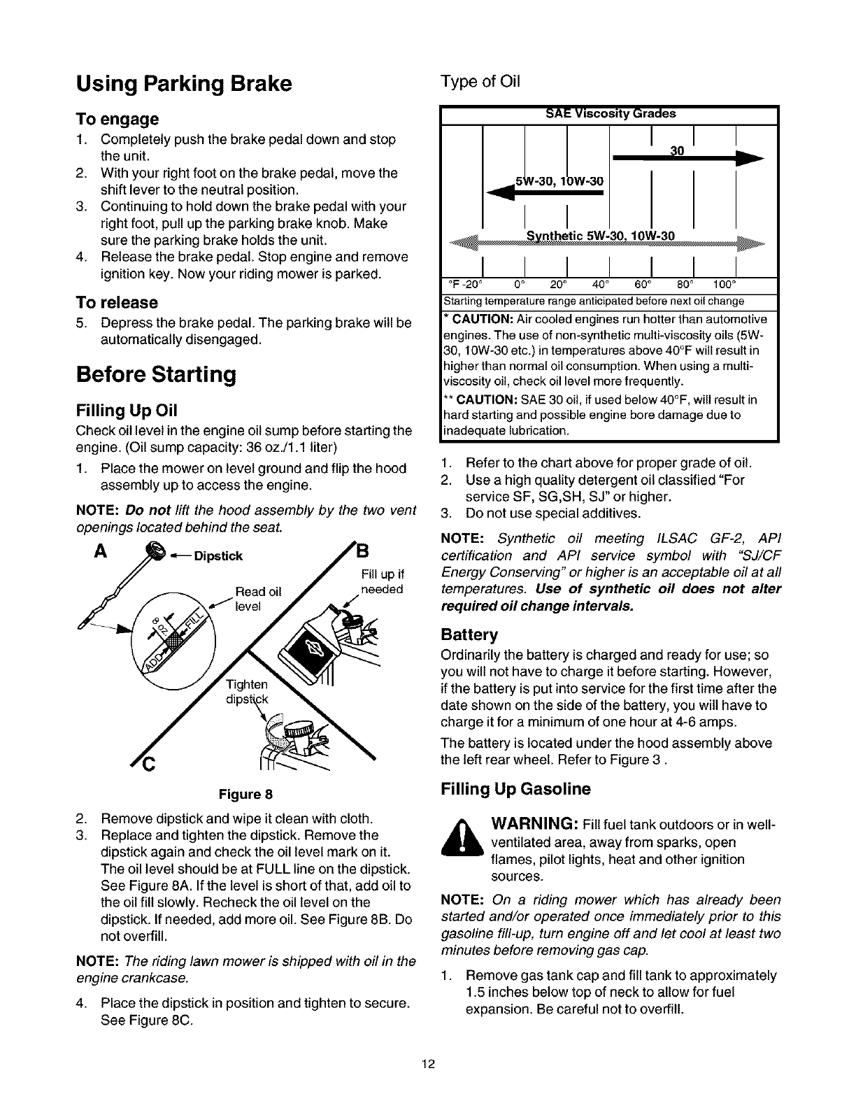
A_Dipstick
Fill up if
Read oil needed
/level /
2,
3.
Figure 8
Remove dipstick and wipe it clean with cloth.
Replace and tighten the dipstick. Remove the
dipstick again and check the oil level mark on it.
The oil level should be at FULL line on the dipstick.
See Figure 8A. If the level is short of that, add oil to
the oil fill slowly. Recheck the oil level on the
dipstick. If needed, add more oil. See Figure 8B. Do
not overfill.
NOTE: The riding lawn mower is shipped with oil in the
engine crankcase.
4. Place the dipstick in position and tighten to secure.
See Figure 8C.
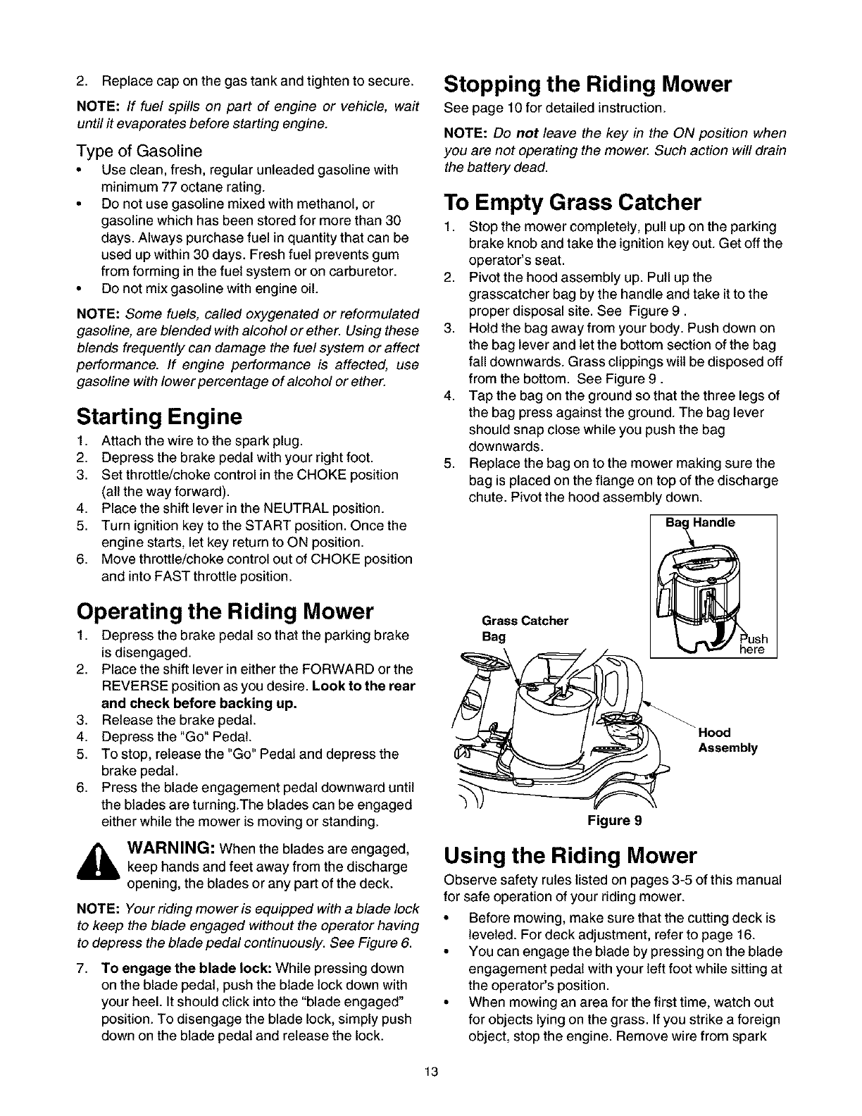
Type of Oil
SAE Viscosity Grades
I:0
_,==5' V-30, 1 JW-30
I I
I I
I I I I I
°F -20 ° 0 ° 20 ° 40 °60 °80 ° 100 °
Starting temperature range anticipated before next oil change
*CAUTION: Air cooled engines run hotter than automotive
engines. The use of non-synthetic multi-viscosity oils (5W-
30, 10W-30 etc.) in temperatures above 40°F will result in
higherthan normal oil consumption. When using a multi-
viscosity oil, check oil level more frequently.
** CAUTION: SAE 30 oil, if used below 40°F, will result in
hardstarting and possible engine bore damage due to
inadequate lubrication.
1. Refer to the chart above for proper grade of oil.
2. Use a high quality detergent oil classified "For
service SF, SG,SH, SJ" or higher.
3. Do not use special additives.
NOTE: Synthetic oil meeting ILSAC GF-2, API
certification and API service symbol with "SJ/CF
Energy Conserving" or higher is an acceptable oil at all
temperatures. Use of synthetic oil does not alter
required oil change intervals.
Battery
Ordinarily the battery is charged and ready for use; so
you will not have to charge it before starting. However,
if the battery is put into service for the first time after the
date shown on the side of the battery, you wilt have to
charge it for a minimum of one hour at 4-6 amps.
The battery is located under the hood assembly above
the left rear wheel. Refer to Figure 3.
Filling Up Gasoline
WARNING: Fill fuel tank outdoors or in well-
ventilated area, away from sparks, open
flames, pilot lights, heat and other ignition
sources.
NOTE: On a riding mower which has already been
started and/or operated once immediately prior to this
gasoline fill-up, turn engine off and let cool at least two
minutes before removing gas cap.
1. Remove gas tank cap and fill tank to approximately
1.5 inches below top of neck to allow for fuel
expansion. Be careful not to overfill.
12
2. Replace cap on the gas tank and tighten to secure. Stopping the Riding Mower
NOTE: If fuel spills on part of engine or vehicle, wait
until it evaporates before starting engine.
Type of Gasoline
• Use clean, fresh, regular unleaded gasoline with
minimum 77 octane rating.
• Do not use gasoline mixed with methanol, or
gasoline which has been stored for more than 30
days. Always purchase fuel in quantity that can be
used up within 30 days. Fresh fuel prevents gum
from forming in the fuel system or on carburetor.
• Do not mix gasoline with engine oil.
NOTE: Some fuels, called oxygenated or reformulated
gasoline, are blended with alcohol or ether. Using these
blends frequently can damage the fuel system or affect
performance. If engine performance is affected, use
gasoline with Iower percentage of alcohol or ether.
Starting Engine
1. Attach the wire to the spark plug.
2. Depress the brake pedal with your right foot.
3. Set throttle/choke control in the CHOKE position
(all the way forward).
4. Place the shift lever in the NEUTRAL position.
5. Turn ignition key to the START position. Once the
engine starts, let key return to ON position.
6. Move throttle/choke control out of CHOKE position
and into FAST throttle position.
Operating the Riding Mower
1. Depress the brake pedal so that the parking brake
is disengaged.
2. Place the shift lever in either the FORWARD or the
REVERSE position as you desire. Look to the rear
and check before backing up.
3. Release the brake pedal.
4. Depress the "Go" Pedal.
5. To stop, release the "Go" Pedal and depress the
brake pedal.
6. Press the blade engagement pedal downward until
the blades are turning.The blades can be engaged
either while the mower is moving or standing.
_ ARNING: When the blades are engaged,keep hands and feet away from the discharge
opening, the blades or any part of the deck.
NOTE: Your riding mower is equipped with a blade lock
to keep the blade engaged without the operator having
to depress the blade pedal continuously. See Figure 6.
7. To engage the blade lock: While pressing down
on the blade pedal, push the blade lock down with
your heel. It should click into the "blade engaged _
position. To disengage the blade lock, simply push
down on the blade pedal and release the lock.
See page 10 for detailed instruction.
NOTE: Do not leave the key in the ON position when
you are not operating the mower. Such action will drain
the battery dead.
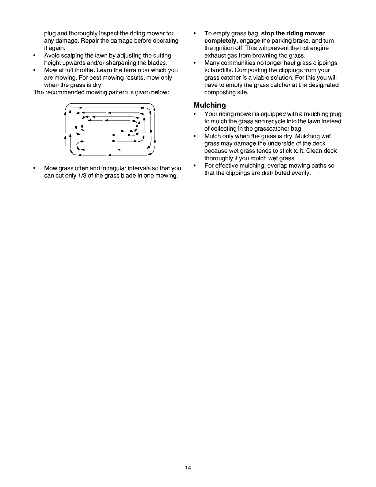
To Empty Grass Catcher
1. Stop the mower completely, pull up on the parking
brake knob and take the ignition key out. Get off the
operator's seat.
2. Pivot the hood assembly up. Pull up the
grasscatcher bag by the handle and take it to the
proper disposal site. See Figure 9.
3. Hold the bag away from your body. Push down on
the bag lever and let the bottom section of the bag
fall downwards. Grass clippings wilt be disposed off
from the bottom. See Figure 9.
4. Tap the bag on the ground so that the three legs of
the bag press against the ground. The bag lever
should snap close while you push the bag
downwards.
5. Replace the bag on to the mower making sure the
bag is placed on the flange on top of the discharge
chute. Pivot the hood assembly down.
Grass Catcher
Bag ush
re
Assembly
Figure 9
Using the Riding Mower
Observe safety rules listed on pages 3-5 of this manual
for safe operation of your riding mower.
• Before mowing, make sure that the cutting deck is
leveled. For deck adjustment, refer to page 16.
• You can engage the blade by pressing on the blade
engagement pedal with your left foot while sitting at
the operator's position.
• When mowing an area for the first time, watch out
for objects lying on the grass. If you strike a foreign
object, stop the engine. Remove wire from spark
13
plugandthoroughlyinspecttheridingmowerfor
anydamage.Repairthedamagebeforeoperating
itagain.
• Avoidscalpingthelawnbyadjustingthecutting
heightupwardsand/orsharpeningtheblades.
• Mowatfullthrottle.Learntheterrainonwhichyou
aremowing.Forbestmowingresults,mowonly
whenthegrassisdry.
Therecommendedmowingpatternisgivenbelow:
f ._D
tr-
q
• Mow grass often and in regular intervals so that you
can cut only 1/3 of the grass blade in one mowing.
To empty grass bag, stop the riding mower
completely, engage the parking brake, and turn
the ignition off. This wilt prevent the hot engine
exhaust gas from browning the grass.
Many communities no longer haul grass clippings
to landfills. Composting the clippings from your
grass catcher is a viable solution. For this you will
have to empty the grass catcher at the designated
composting site.
Mulching
• Your riding mower is equipped with a mulching plug
to mulch the grass and recycle into the lawn instead
of collecting in the grasscatcher bag.
• Mulch only when the grass is dry. Mulching wet
grass may damage the underside of the deck
because wet grass tends to stick to it. Clean deck
thoroughly if you mulch wet grass.
• For effective mulching, overlap mowing paths so
that the clippings are distributed evenly.
14
Adjustments
_WARNING: Do not make any adjustment tothe riding mower without first stopping engine
and disconnecting spark plug wire.
Brake Pedal
During normal operation of the riding mower, the brake
is subject to wear and tear. Check the brake
periodically by carrying out the following test:
1. Release the parking brake and place the riding
mower in neutral. Depress the brake pedal and try
to roll the riding mower. The tractor should not
move. If the tractor moves, adjust the brake.
WARNING: Do not adjust the brake while
the engine is running. Be sure to block the
wheels of the riding mower before making any
adjustments on the brake cable.
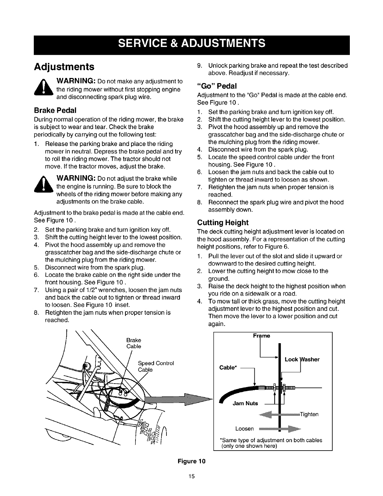
Adjustment to the brake pedal is made at the cable end.
See Figure 10.
2. Set the parking brake and turn ignition key off.
3. Shift the cutting height lever to the lowest position.
4. Pivot the hood assembly up and remove the
grasscatcher bag and the side-discharge chute or
the mulching plug from the riding mower.
5. Disconnect wire from the spark plug.
6. Locate the brake cable on the right side under the
front housing. See Figure 10.
7. Using a pair of 1/2_wrenches, loosen the jam nuts
and back the cable out to tighten or thread inward
to loosen. See Figure 10 inset.
8. Retighten the jam nuts when proper tension is
reached.
Brake
Cable
;ontrol
Figure 10
9. Unlock parking brake and repeat the test described
above. Readjust if necessary.
"Go" Pedal
Adjustment to the "Go" Pedal is made at the cable end.
See Figure 10.
1. Set the parking brake and turn ignition key off.
2. Shift the cutting height lever to the lowest position.
3. Pivot the hood assembly up and remove the
grasscatcher bag and the side-discharge chute or
the mulching plug from the riding mower.
4. Disconnect wire from the spark plug.
5. Locate the speed control cable under the front
housing. See Figure 10.
6. Loosen the jam nuts and back the cable out to
tighten or thread inward to loosen as shown.
7. Retighten the jam nuts when proper tension is
reached.
8. Reconnect the spark plug wire and pivot the hood
assembly down.
Cutting Height
The deck cutting height adjustment lever is located on
the hood assembly. For a representation of the cutting
height positions, refer to Figure 6.
1. Pull the lever out of the slot and slide it upward or
downward to the desired cutting height.
2. Lower the cutting height to mow close to the
ground.
3. Raise the deck height to the highest position when
you ride on a sidewalk or a road.
4. To mow tait or thick grass, move the cutting height
adjustment lever to the highest position and cut.
Then move the lever to a lower position and cut
again.
Cable*
Loosen
asher
*Same type of adjustment on both cables
(only one shown here)
15
Seat Position
The seat position on the riding mower can be adjusted
to maximize the operator's convenience.
1. Stop the mower completely and engage the parking
brake. Turn ignition off.
2. Pivot the hood assembly up.
3. Loosen the four self-tapping screws on the bottom
of the seat.
4. Slide the seat forward or backward in the slot, and
position it as desired. Retighten the four screws.
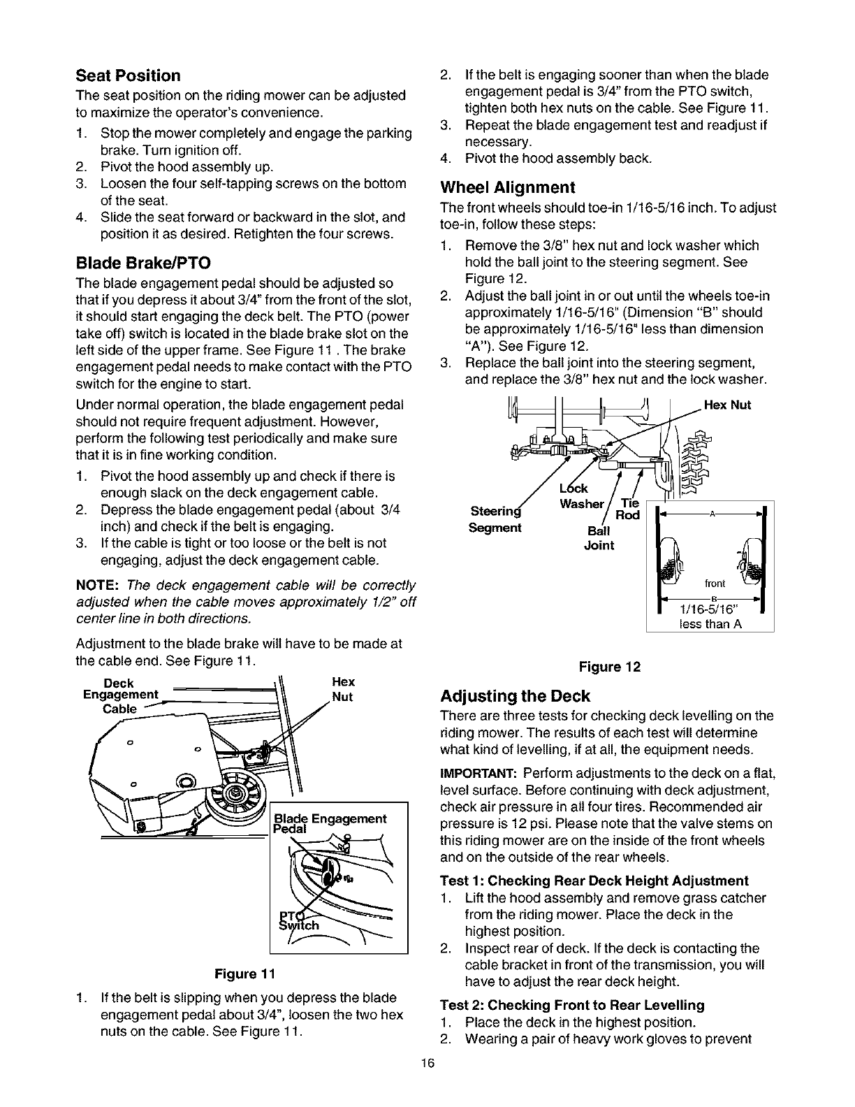
Blade Brake/PTO
The blade engagement pedal should be adjusted so
that if you depress it about 3/4" from the front of the slot,
it should start engaging the deck belt. The PTO (power
take off) switch is located in the blade brake slot on the
left side of the upper frame. See Figure 11. The brake
engagement pedal needs to make contact with the PTO
switch for the engine to start.
Under normal operation, the blade engagement pedal
should not require frequent adjustment. However,
perform the following test periodically and make sure
that it is in fine working condition.
1. Pivot the hood assembly up and check if there is
enough slack on the deck engagement cable.
2. Depress the blade engagement pedal (about 3/4
inch) and check if the belt is engaging.
3. If the cable is tight or too loose or the belt is not
engaging, adjust the deck engagement cable.
NOTE: The deck engagement cable will be correctly
adjusted when the cable moves approximately 1/2" off
center line in both directions.
Adjustment to the blade brake wilt have to be made at
the cable end. See Figure 11.
Deck Hex
Engagement Nut
Cable
1,
Blade Engagement
Pedal
n
Figure 11
If the belt is slipping when you depress the blade
engagement pedal about 3/4", loosen the two hex
nuts on the cable. See Figure 11.
16
2. If the belt is engaging sooner than when the blade
engagement pedal is 3/4" from the PTO switch,
tighten both hex nuts on the cable. See Figure 11.
3. Repeat the blade engagement test and readjust if
necessary.
4. Pivot the hood assembly back.
Wheel Alignment
The front wheels should toe-in 1/16-5/16 inch. To adjust
toe-in, follow these steps:
1. Remove the 3/8" hex nut and lock washer which
hold the ball joint to the steering segment. See
Figure 12.
2. Adjust the ball joint in or out until the wheels toe-in
approximately 1/16-5/16" (Dimension "B" should
be approximately 1/16-5/16" less than dimension
"A'). See Figure 12.
3. Replace the ball joint into the steering segment,
and replace the 3/8" hex nut and the lock washer.
Hex Nut
Steering Washer
Segment Ball
Joint
1/16-5/16"
less than A
Figure 12
Adjusting the Deck
There are three tests for checking deck levelling on the
riding mower. The results of each test will determine
what kind of levelling, if at all, the equipment needs.
IMPORTANT: Perform adjustments to the deck on a flat,
level surface. Before continuing with deck adjustment,
check air pressure in nit four tires. Recommended air
pressure is 12 psi. Please note that the valve stems on
this riding mower are on the inside of the front wheels
and on the outside of the rear wheels.
Test 1: Checking Rear Deck Height Adjustment
1. Lift the hood assembly and remove grass catcher
from the riding mower. Place the deck in the
highest position.
2. Inspect rear of deck. If the deck is contacting the
cable bracket in front of the transmission, you will
have to adjust the rear deck height.
Test 2: Checking Front to Rear Levelling
1. Place the deck in the highest position.
2. Wearing a pair of heavy work gloves to prevent
injury,rotatethecuttingbladesothatit ispointed
fronttobackandparalleltotherider.Depressand
lockthedeckengagementpedal.
3. Measurethedistancefromthefrontandtherear
tipsofthebladetotheground.Thefrontshouldbe
approximately1/4"to3/8"lowerthantherear.
4. Ifthedistanceishigher,levelthedeckfronttorear.
Test 3: Checking Side to Side Levelling
1. Place the deck in the highest position.
2. Wearing a pair of heavy work gloves to prevent
injury, rotate the cutting blade so that it is pointed
side to side and perpendicular to the rider. Depress
and lock the deck engagement pedal.
3. Measure the distance from the tips of the blade to
the ground.
4. If the two distances are unequal, level the deck
side to side.
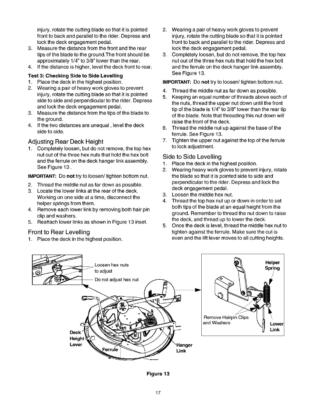
Adjusting Rear Deck Height
1. Completely loosen, but do not remove, the top hex
nut out of the three hex nuts that hold the hex bolt
and the ferrule on the deck hanger link assembly.
See Figure 13.
IMPORTANT: Do not try to loosen/tighten bottom nut.
2. Thread the middle nut as far down as possible.
3. Locate the lower links at the rear of the deck.
Working on one side at a time, disconnect the
helper springs from them.
4. Remove each lower link by removing both hair pin
clip and washers.
5. Reattach lower links as shown in Figure 13 inset.
Front to Rear Levelling
1. Place the deck in the highest position.
2. Wearing a pair of heavy work gloves to prevent
injury, rotate the cutting blade so that it is pointed
front to back and parallel to the rider. Depress and
lock the deck engagement pedal.
3. Completely loosen, but do not remove, the top hex
nut out of the three hex nuts that hold the hex bolt
and the ferrule on the deck hanger link assembly.
See Figure 13.
IMPORTANT: Do not try to loosen/tighten bottom nut.
4. Thread the middle nut as far down as possible.
5. Keeping an equal number of threads above each of
the nuts, thread the upper nut down until the front
tip of the blade is 1/4" to 3/8" lower than the rear tip
of the blade. Note that threading this nut down will
raise the front of the deck.
6. Thread the middle nut up against the base of the
ferrule. See Figure 13.
7. Tighten the upper nut against the top of the ferrule
to lock adjustment.
Side to Side Levelling
1. Place the deck in the highest position.
2. Wearing heavy work gloves to prevent injury, rotate
the blade so that it is pointed side to side and
perpendicular to the rider. Depress and lock the
deck engagement pedal.
3. Loosen the middle hex nut.
4. Thread the top hex nut up or down in order to set
both tips of the blade at an equal height from the
ground. Remember to thread the nut down to raise
the deck, and thread up to lower the deck.
5. Once the deck is level, thread the middle hex nut to
tighten against the ferrule. Make sure the cut is
even and the lift lever moves to all cutting heights.
Deck"
Lever
Loosen hex nuts
to adjust
)t adjust hex nut
'Hanger
Link
Remove Hairpin Clips
and Washers
Helper ]
Figure 13
17
Adjusting the Carburetor
Differences in fuel, temperature, altitude or load may
require minor carburetor adjustments. The carburetor
on this engine is equipped with an idle mixture valve
with a limiter which allows some adjustment, and an
idle speed adjustment screw. Remember that the air
cleaner and its cover must be assembled to the
carburetor before re-starting the engine. Refer to page
22 for details.
NOTE: Engines, operated at approximately 3000 to
5000 feet above sea level, may require a high altitude
carburetor nozzle. If your riding mower performs
erratically, contact Sears service center for the nozzle.
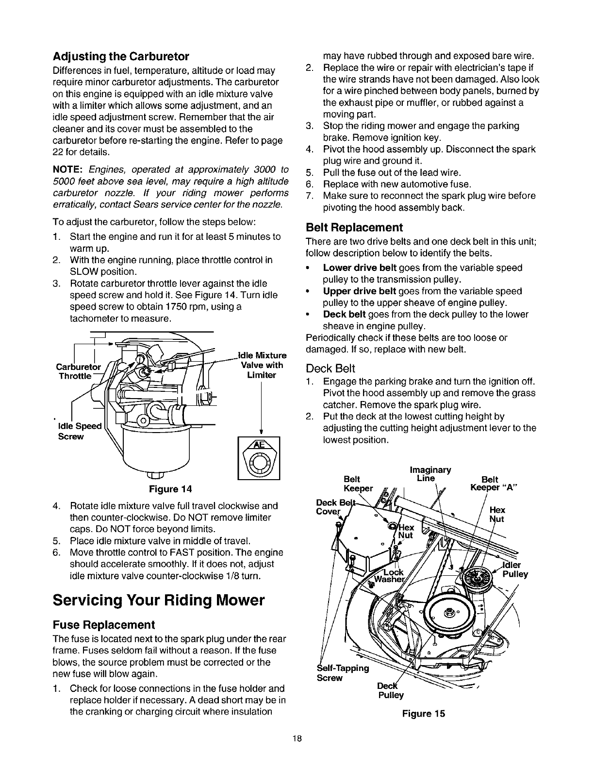
To adjust the carburetor, follow the steps below:
1. Start the engine and run it for at least 5 minutes to
warm up.
2. With the engine running, place throttle control in
SLOW position.
3. Rotate carburetor throttle lever against the idle
speed screw and hold it. See Figure 14. Turn idle
speed screw to obtain 1750 rpm, using a
tachometer to measure.
Valve with
Limiter
Idle Speed
Screw
4,
5,
6.
Figure 14
Rotate idle mixture valve full travel clockwise and
then counter-clockwise. Do NOT remove limiter
caps. Do NOT force beyond limits.
Place idle mixture valve in middle of travel.
Move throttle control to FAST position. The engine
should accelerate smoothly. If it does not, adjust
idle mixture valve counter-clockwise 1/8 turn.
may have rubbed through and exposed bare wire.
2. Replace the wire or repair with electrician's tape if
the wire strands have not been damaged. Also look
for a wire pinched between body panels, burned by
the exhaust pipe or muffler, or rubbed against a
moving part.
3. Stop the riding mower and engage the parking
brake. Remove ignition key.
4. Pivot the hood assembly up. Disconnect the spark
plug wire and ground it.
5. Pull the fuse out of the lead wire.
6. Replace with new automotive fuse.
7. Make sure to reconnect the spark plug wire before
pivoting the hood assembly back.
Belt Replacement
There are two drive belts and one deck belt in this unit;
follow description below to identify the belts.
• Lower drive belt goes from the variable speed
pulley to the transmission pulley.
•Upper drive belt goes from the variable speed
pulley to the upper sheave of engine pulley.
•Deck belt goes from the deck pulley to the lower
sheave in engine pulley.
Periodically check if these belts are too loose or
damaged. If so, replace with new belt.
Deck Belt
1. Engage the parking brake and turn the ignition off.
Pivot the hood assembly up and remove the grass
catcher. Remove the spark plug wire.
2. Put the deck at the lowest cutting height by
adjusting the cutting height adjustment lever to the
lowest position.
Imaginary
Belt Line Belt
Keeper Keeper "A"
Pulley
Servicing Your Riding Mower
Fuse Replacement
The fuse is located next to the spark plug under the rear
frame. Fuses seldom fail without a reason. If the fuse
blows, the source problem must be corrected or the
new fuse will blow again.
1. Check for loose connections in the fuse holder and
replace holder if necessary. A dead short may be in
the cranking or charging circuit where insulation
Self-Tapping
Screw Decl(
Pulley
Figure 15
18
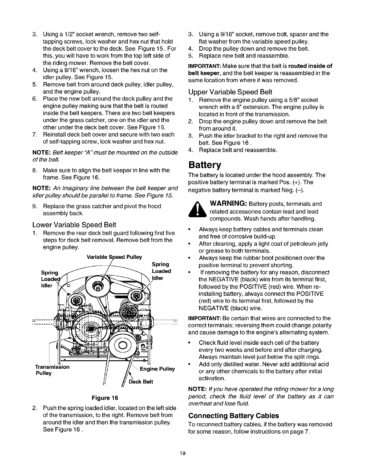
3. Usinga1/2"socketwrench,removetwoself-
tappingscrews,lockwasherandhexnutthathold
thedeckbeltcovertothedeck.SeeFigure15.For
this,youwillhavetoworkfromthetopleftsideof
theridingmower.Removethebeltcover.
4. Usinga9/16"wrench,loosenthehexnutonthe
idlerpulley.SeeFigure15.
5. Removebeltfromarounddeckpulley,idlerpulley,
andtheenginepulley.
6. Placethenewbeltaroundthedeckpulleyandthe
enginepulleymakingsurethatthebeltisrouted
insidethebeltkeepers.Therearetwobeltkeepers
underthegrasscatcher,oneontheidlerandthe
otherunderthedeckbeltcover.SeeFigure15.
7. Reinstalldeckbeltcoverandsecurewithtwoeach
ofself-tappingscrew,lockwasherandhexnut.
NOTE:Belt keeper "A" must be mounted on the outside
of the belt.
8. Make sure to align the belt keeper in line with the
frame. See Figure 16.
NOTE: An imaginary line between the belt keeper and
idler pulley should be parallel to frame. See Figure 15.
9. Replace the grass catcher and pivot the hood
assembly back.
Lower Variable Speed Belt
1. Remove the rear deck belt guard following first five
steps for deck belt removal. Remove belt from the
engine pulley.
Variabh
Spring
Spring Loaded
Idler
Transmission _Engine Pulley
Pulley
2,
Figure 16
Push the spring loaded idler, located on the left side
of the transmission, to the right. Remove belt from
around the idler and then the transmission pulley.
See Figure 16.
3. Using a 9/16" socket, remove bolt, spacer and the
flat washer from the variable speed pulley.
4. Drop the pulley down and remove the belt.
5. Replace new belt and reassemble.
IMPORTANT:Make sure that the belt is routed inside of
belt keeper, and the belt keeper is reassembled in the
same location from where it was removed.
Upper Variable Speed Belt
1. Remove the engine pulley using a 5/8" socket
wrench with a 6" extension. The engine pulley is
located in front of the transmission.
2. Drop the engine pulley down and remove the belt
from around it.
3. Push the idler bracket to the right and remove the
belt. See Figure 16.
4. Replace belt and reassemble.
Battery
The battery is located under the hood assembly. The
positive battery terminal is marked Pos. (+). The
negative battery terminal is marked Neg. (-).
,_ WARNING: Battery posts, terminals and
related accessories contain lead and lead
compounds. Wash hands after handling.
• Always keep battery cables and terminals clean
and free of corrosive build-up.
• After cleaning, apply a light coat of petroleum jelly
or grease to both terminals.
• Always keep the rubber boot positioned over the
positive terminal to prevent shorting.
• If removing the battery for any reason, disconnect
the NEGATIVE (black) wire from its terminal first,
followed by the POSITIVE (red) wire. When re-
installing battery, always connect the POSITIVE
(red) wire to its terminal first, followed by the
NEGATIVE (black) wire.
IMPORTANT: Be certain that wires are connected to the
correct terminals; reversing them could change polarity
and cause damage to the engine's alternating system.
• Check fluid level inside each cell of the battery
every two weeks and before and after charging.
Always maintain level just below the split rings.
• Add only distilled water. Never add additional acid
or any other chemicals to the battery after initial
activation.
NOTE: If you have operated the riding mower for a long
period, check the fluid level of the battery as it can
overheat and lose fluid.
Con necti ng Battery Cables
To reconnect battery cables, if the battery was removed
for some reason, follow instructions on page 7.
19

General Recommendations
,_ WARNING: Always stop engine and disconnect spark plug wire before any maintenance or adjustments.Always maintain safety and follow instructions given below closely for smooth completion of job.
The warranty on this riding mower does not cover items that have been subjected to operator abuse or
negligence• To receive full value from the warranty, operator must maintain the riding mower as instructed in
this manual. Refer to the Maintenance Schedule below•
We do not recommend the use of pressure washers or garden hose to clean your unit• These may cause
damage to electrical components, spindles, pulleys, bearings or the engine• The use of water may shorten life
of your riding mower and reduce its serviceability
Maintenance Schedule
Check blade
Lubepivot pl
Lubedeck lir
Change engi
Service air cl
Service spark plug
Check battery fluid
Blade Care
WARI
heavy !
blade.,
Removal
1. Remove th_
blade to the
2. Remove bl_
Sharpening
Lube pivot points, steering shaft, gear
Lube deck linkage, front wheels
Change engine oil
Service air cleaner in engine
Remove the 5/8" hex flange nut which holds the
blade to the blade spindle.
Remove blade from the spindle. See Figure 17.
WARNING: Protect your hands by wearing
heavy gloves or using a rag to grasp the cutting
blade. Avoid personal injury.
Spindle
When sharpening the blade, follow original angle of
First 5 hrs. 25 hours 50 hours 100hrs. Season Reassembly
•/4
•/./
,/
,/
Reassembly
Deck /f//aI_ _
Flange Nut-_'3" Blade
2,
grind as a guide• It is extremely important to grind
each cutting edge equally to prevent an
unbalanced blade•
Test the blade by balancing it on a round shaft
screwdriver• Remove metal from the heavy side
until it balances evenly.
_lb WARNING: Unbalanced blade may cause
excessive vibration at high speeds, may damage
the riding mower and/or cause personal injury.
Figure 17
1. Before reassembling the blade to the unit, lubricate
the spindle with light oil (or engine oil).
2. Align "star" fitting on new blade with the "star" on
the spindle•
3. Install the blade with the side of the blade marked
"Bottom" (or with part number) facing the ground
when the riding mower is in the operating position•
4. Tighten the flange nut securely• See Figure 17.
2O
Blade Mounting Torque: 70/90 ft.-tbs, maximum.
NOTE: To ensure safe operation, all nuts and bolts
must be checked periodically for correct tightness.
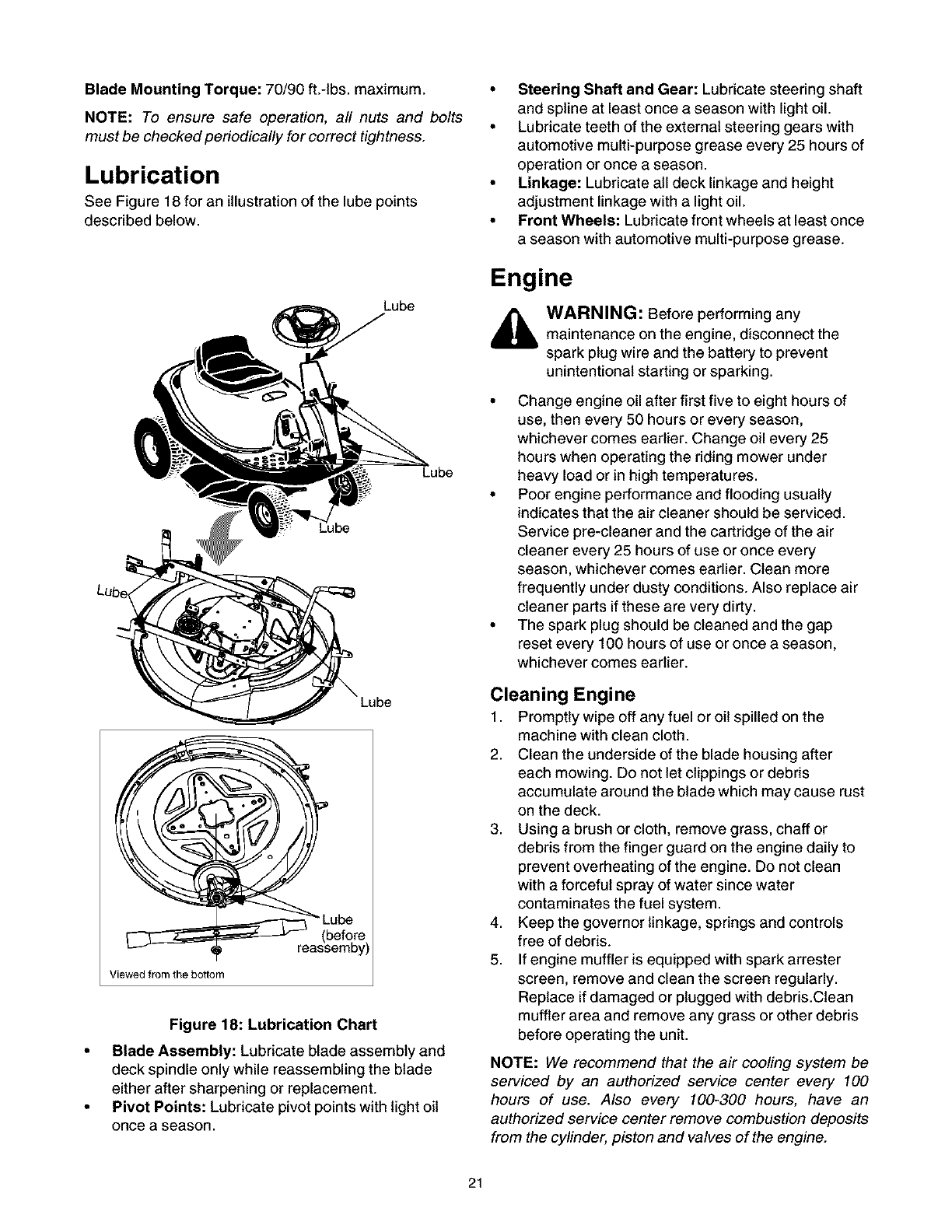
Lubrication
See Figure 18 for an illustration of the lube points
described below.
Lube
Lube
Viewed from the bottom
be
Figure 18: Lubrication Chart
•Blade Assembly: Lubricate blade assembly and
deck spindle only while reassembling the blade
either after sharpening or replacement.
• Pivot Points: Lubricate pivot points with light oil
once a season.
•Steering Shaft and Gear: Lubricate steering shaft
and spline at least once a season with light oil.
• Lubricate teeth of the external steering gears with
automotive multi-purpose grease every 25 hours of
operation or once a season.
•Linkage: Lubricate all deck linkage and height
adjustment linkage with a light oil.
• Front Wheels: Lubricate front wheels at least once
a season with automotive multi-purpose grease.
Engine
WARNING: Before performing any
maintenance on the engine, disconnect the
spark plug wire and the battery to prevent
unintentional starting or sparking.
• Change engine oil after first five to eight hours of
use, then every 50 hours or every season,
whichever comes earlier. Change oil every 25
hours when operating the riding mower under
heavy load or in high temperatures.
• Poor engine performance and flooding usually
indicates that the air cleaner should be serviced.
Service pre-cleaner and the cartridge of the air
cleaner every 25 hours of use or once every
season, whichever comes earlier. Clean more
frequently under dusty conditions. Also replace air
cleaner parts if these are very dirty.
• The spark plug should be cleaned and the gap
reset every 100 hours of use or once a season,
whichever comes earlier.
Cleaning Engine
1. Promptly wipe off any fuel or oil spilled on the
machine with clean cloth.
2. Clean the underside of the blade housing after
each mowing. Do not let clippings or debris
accumulate around the blade which may cause rust
on the deck.
3. Using a brush or cloth, remove grass, chaff or
debris from the finger guard on the engine daily to
prevent overheating of the engine. Do not clean
with a forceful spray of water since water
contaminates the fuel system.
4. Keep the governor linkage, springs and controls
free of debris.
5. If engine muffler is equipped with spark arrester
screen, remove and clean the screen regularly.
Replace if damaged or plugged with debris.Clean
muffler area and remove any grass or other debris
before operating the unit.
NOTE: We recommend that the air cooling system be
serviced by an authorized service center every 100
hours of use. Also every 100-300 hours, have an
authorized service center remove combustion deposits
from the cylinder, piston and valves of the engine.
21
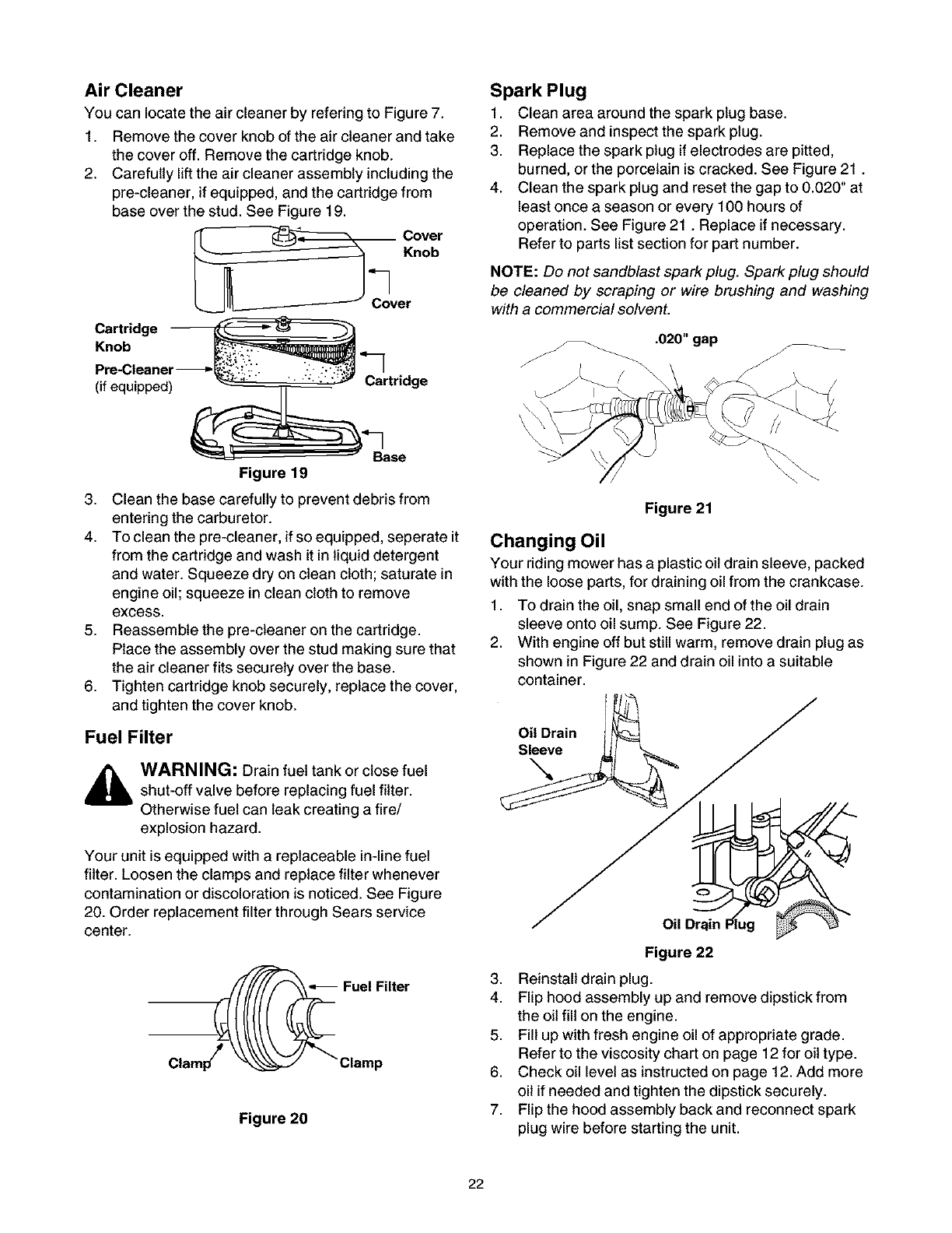
Air Cleaner
You can locate the air cleaner by refering to Figure 7.
1. Remove the cover knob of the air cleaner and take
the cover off. Remove the cartridge knob.
2. Carefully lift the air cleaner assembly including the
pre-cleaner, if equipped, and the cartridge from
base over the stud. See Figure 19.
Cover
"_] Knob
Cover
Cartridge
Knob _,"___.
Pre-Cleaner -_," __ "_
(if equipped) _ "" _ _ _:;_" Cartridge
___" _Base
Figure 19
3. Clean the base carefully to prevent debris from
entering the carburetor.
4. To clean the pre-cleaner, if so equipped, seperate it
from the cartridge and wash it in liquid detergent
and water. Squeeze dry on clean cloth; saturate in
engine oil; squeeze in clean cloth to remove
excess.
5. Reassemble the pre-cleaner on the cartridge.
Place the assembly over the stud making sure that
the air cleaner fits securely over the base.
6. Tighten cartridge knob securely, replace the cover,
and tighten the cover knob.
Fuel Filter
WARNING: Drain fuel tank or close fuel
shut-off valve before replacing fuel filter.
Otherwise fuel can leak creating a fire/
explosion hazard.
Your unit is equipped with a replaceable in-line fuel
filter. Loosen the clamps and replace filter whenever
contamination or discoloration is noticed. See Figure
20. Order replacement filter through Sears service
center.
Figure 20
Spark Plug
1. Clean area around the spark plug base.
2. Remove and inspect the spark plug.
3. Replace the spark plug if electrodes are pitted,
burned, or the porcelain is cracked. See Figure 21.
4. Clean the spark plug and reset the gap to 0.020" at
least once a season or every 100 hours of
operation. See Figure 21. Replace if necessary.
Refer to parts list section for part number.
NOTE: Do not sandblast spark plug. Spark plug should
be cleaned by scraping or wire brushing and washing
with a commercial solvent.
Figure 21
Changing Oil
Your riding mower has a plastic oil drain sleeve, packed
with the loose parts, for draining oil from the crankcase.
1. To drain the oil, snap small end of the oil drain
sleeve onto oil sump. See Figure 22.
2. With engine off but still warm, remove drain plug as
shown in Figure 22 and drain oil into a suitable
container.
Oil Drain
Sleeve
Figure 22
3. Reinstall drain plug.
4. Flip hood assembly up and remove dipstick from
the oil fill on the engine.
5. Fill up with fresh engine oil of appropriate grade.
Refer to the viscosity chart on page 12 for oil type.
6. Check oil level as instructed on page 12. Add more
oil if needed and tighten the dipstick securely.
7. Flip the hood assembly back and reconnect spark
plug wire before starting the unit.
22
If the machine is to be inoperative for a period longer
than 30 days, prepare for storage as follows.
Battery
1. Charge battery fully. The battery loses some of its
charge each day when the unit is not used. NEVER
store battery without a full charge. Recharge
battery before returning to service or every two
months, whichever occurs first.
2. When storing unit for extended periods, disconnect
battery cables and remove the battery from the unit.
3. Clean dirt and chaff from cylinder, cylinder head
fins, blower housing, rotating screen and muffler.
Engine
Engines, stored over 30 days, need special attention to
prevent gum formation in the fuel system or on the
carburetor.
1. If fuel tank contains oxygenated or reformulated
gasoline, that is gasoline blended with alcohol or
ether, run engine until dry.
2. If fuel tank contains gasoline, either run engine till
dry or add an additive to the gas. If you are using
additive, run the engine for several minutes to
circulate the additive through the carburetor.
3. Change oil on a warm engine.
4. Remove spark plug and pour about one ounce of
engine oil into cylinder. Replace the spark plug and
crank engine slowly to distribute the oil.
5. Clean engine of debris, chaff or grass clippings.
6. Store engine and riding mower in a clean, dry area
far away from stove, furnace, water heater or
similar appliances using a pilot light or any other
sparking device.
Riding Mower
1. Clean the engine and the entire unit thoroughly.
2. Lubricate all pivot points. Wipe the entire machine
with an oiled rag to protect the surfaces.
3. Store unit in a clean, dry area. Do not store next to
corrosive materials, such as fertilizer.
4. When storing any type of power equipment in an
unventilated or metal storage shed, care should be
taken to rustproof the equipment. Using a light oil or
silicone, coat the equipment, especially any chains,
springs, bearings and cables.
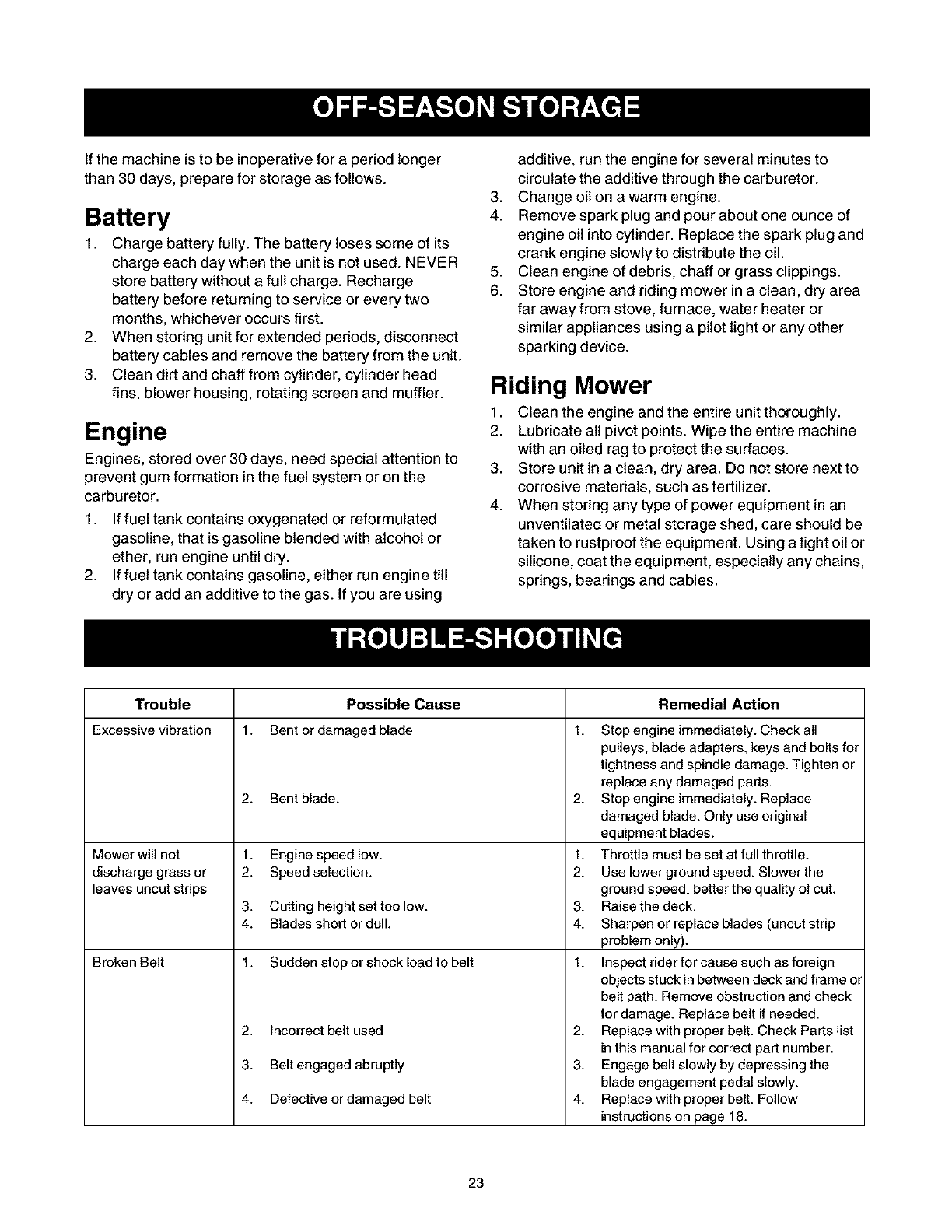
Trouble
Excessivevibration
Mower will not
discharge grass or
leaves uncut strips
Broken Belt
t.
Possible Cause
Bent or damaged blade
2. Bent blade.
1. Engine speed low.
2. Speed selection.
3. Cutting height set too low.
4. Blades short or dull.
1. Sudden stop or shock load to belt
2. Incorrect belt used
3. Belt engaged abruptly
4. Defective or damaged belt
Remedial Action
1. Stop engine immediately. Check all
pulleys, blade adapters, keys and bolts for
tightness and spindle damage. Tighten or
replace any damaged parts.
2. Stop engine immediately. Replace
damaged blade. Only use original
equipment blades.
1. Throttle must be set at full throttle.
2. Use lower ground speed. Slower the
ground speed, better the quality of cut.
3. Raise the deck.
4. Sharpen or replace blades (uncut strip
problem only).
1. Inspect rider for cause such as foreign
objects stuck in between deck and frame or
belt path. Remove obstruction and check
for damage. Replace belt if needed.
2. Replace with proper belt. Check Parts list
in this manual for correct part number.
3. Engage belt slowly by depressing the
blade engagement pedal slowly.
4. Replace with proper belt. Follow
instructions on page 18.
23
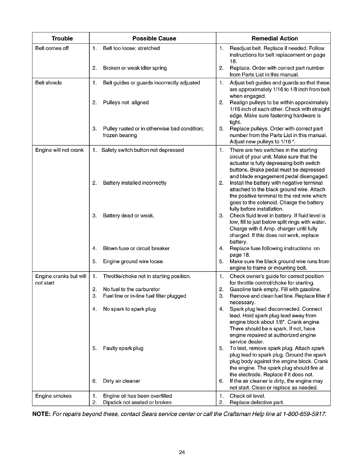
Trouble Possible Cause Remedial Action
Belt comes off 1. Belt too loose; stretched Readjust belt. Replace ifneeded. Follow
instructionsfor belt replacement on page
18.
2. Broken or weak idlerspring Replace. Order with correct part number
from Parts List in this manual.
Belt shreds 1. Belt guides or guards incorrectly adjusted
Engine will not crank
Engine cranks but will
not start
2. Pulleys not aligned
3. Pulley rusted or inotherwise bad condition;
frozen bearing
1. Safety switch button not depressed
2. Battery insta]ied incorrectly
3. Battery dead or weak.
4. Blown fuse or circuit breaker
5. Engine ground wire loose.
1. Throttle/choke not in starting position.
2. No fuel to the carburetor
3. Fuel line or in-line fuel filter plugged
4. No sparkto spark plug
5. Faulty spark plug
1,
2.
1.
2.
6. Dirty air cleaner
1.
2.
3,
1.
Adjust belt guides and guards so that these
are approximately 1/16 to 1/8 inch from belt
when engaged.
Realign pulleys to be within approximately
1/16 inch of each other. Check with straight
edge. Make sure fastening hardware is
tight.
Replace pulleys. Order with correct part
number from the Parts List in this manual.
Adjust new pulleys to 1/16 ".
There are two switches in the starting
circuit of your unit. Make sure that the
actuator is fully depressing both switch
buttons. Brake pedal must be depressed
and blade engagement pedal disengaged.
2. Install the battery with negative terminal
attached to the black ground wire. Attach
the positive terminal to the red wire which
goes to the solenoid. Charge the battery
fully before installation.
3. Check fluid level in battery. If fluid level is
low, fill to just below split rings with water.
Charge with 6 Amp. charger until fully
charged. If this does not work, replace
battery.
4. Replace fuse following instructions on
page 18.
5. Make sure the black ground wire runs from
engine to frame or mounting bolt.
1. Checkowner's guide for correct position
for throttle control/choke for starting.
2. Gasoline tank empty. Fill with gasoline.
3. Remove and clean fuel line. Replace filter if
necessary.
4. Spark plug lead disconnected. Connect
lead. Hold spark plug lead away from
engine block about 1/8". Crank engine.
There should be a spark. If not, have
engine repaired at authorized engine
service dealer.
5. To test, remove spark plug. Attach spark
plug lead to spark plug. Ground the spark
plug body against the engine block. Crank
the engine. The spark plug should fire at
the electrode. Replace if itdoes not.
If the air cleaner is dirty, the engine may
not start. Clean or replace as needed.
6,
1.
2.
Engine smokes Engine oil has been overfilled Check oil level.
Dipstick not seated or broken Replace defective part.
NOTE: For repairs beyond these, contact Sears service center or call the Craftsman Help line at 1-800-659-5917.
24
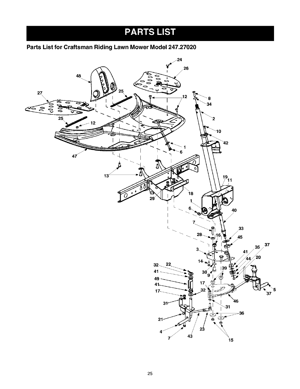
Parts List for Craftsman Riding Lawn Mower Model 247.27020
27\
\\
48
7
4O
/
/
41
37
/
32_ 22
41
37
15
25

Parts List for Craftsman Riding Lawn Mower Model 247.27020
Key No. PartNo.
1. 17962
2. 650-0007
3. 683-0033A
4. 683-0178A
5. 683-0179A
6. 710-0224
7. 710-0459A
8. 710-0643
9. 710-0689
10. 710-0837
11. 710-0958
12. 710-1017
13. 710-1611B
14. 710-3008
15. 712-0116
16. 712-0206
17. 712-0241
18. 712-0267
19. 712-0324
20. 712-0411
21. 712-0711
22. 714-0470
23. 723-0156
24. 726-3046
25. 731-0511
Description Key No, Part No.
Switch Plate 26. 735-0674
Steering Tube Assembly 27. 735-0266A
Steering Support Bracket 28. 736-0105
Front Axle Assembly: RH 29. 736-0119
Front Axle Assembly: LH 30. 736-0160
HexScrewAB 31. 736-0169
Hex Screw 3/8-24 x 1.5" Gr.5 Sp. 32. 736-0187
Lock Screw 5/16-18 x 1.0" Gr.5 33. 736-0196
Hex Screw 1/2-13 x 0.75" 34. 736-0242
Oval C-Sunk Screw #10-16 x 0.625" 35. 736-0272
Hex Screw 1/4-20 x 1.25 Gr.5 Sp. 36. 736-0320
AB Screw 1/4-14 x 0.625" 37. 736-3078
Self-Tapping Screw 5/16-18 x 0.75" 38. 737-3007
Hex Screw 5/16-18 x 0.75" 39. 738-0541
Lock Nut 3/8-24 40. 738-3089A
Hex Nut 1/2-13 41. 741-0225
Hex Nut 42. 741-0356
Hex Nut 43. 747-0955
Lock Nut 1/4-20 44. 748-0290
Description
Floor Pad: LH
Floor Pad: RH
Bell Washer
Lock Washer
Flat Washer
Lock Washer
Flat Washer
Flat Washer
BellevilleWasher
Flat Washer
Flat Washer
Flat Washer
Grease
Spacer
Steering Adapter
Hex Flange Bearing
Bearing: Steedng Column
Tie Rod
Pinion Gear
Lock Nut 45. 750-0532
Jam Nut 46. 783-0411
Cotter Pin 47. 783-0565C
Ball Joint 48. 783-0566A
Ratchet Clip 49. 731-1649
Trim Strip
Spacer
Gear: Steering Segment
Upper Frame Cover
Lift Plate
Axle Cap
26
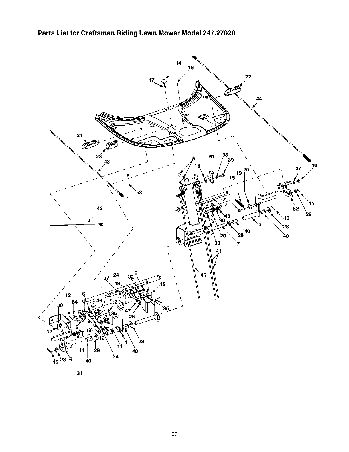
Parts List for Craftsman Riding Lawn Mower Model 247.27020
\
14 16
/22
44
21
23 /
43 J
/ i
i i
x \
\42 \
\,J \
x \
\)
\/
\/
\/
)/
//
/
/ /
/</ 37 24\ 3_28\
31
\
\
51 \
\
\
41
i
10
52 29
27

Parts List for Craftsman Riding Lawn Mower Model 247.27020
Key No.
1.
2.
3.
4.
5.
6.
7.
8.
9.
10.
11,
12,
13.
14,
15.
16,
17,
18.
19.
20.
21,
22,
23.
24,
25.
26,
27,
Pad No.
683-0155A
683-0161
683-0275A
683-0310A
710-1017
711-0701
711-1156
712-0287
712-0324
712-3017
714-0104
714-0111
714-0470
720-0166
726-0100
726-0450
731-0405
731-1913
732-0815A
732-0865
735-0261
735-0262
735-0263
736-0117
736-0133
736-0159
736-0169
Description Key No. Part No.
Brake Pedal Assembly 28. 736-0187
SHft Cam Assembly 29. 736-0262
Deck Pedal Assembly 30. 736-0272
Variable Pedal Assembly 31. 736-0300
Ab Screw 1/4-14 X .625 32. 736-0329
Description
Flat Washer
Flat Washer
Flat Washer .510 X 1.00 X .060
Flat Washer
Lock Washer
Clevis Pin 33. 736-0608
Shaft 34. 736-3000
Hex Nut 1/4-20 35. 736-3019
Lock Nut 1/4-20 36. 736-3020
Hex Nut 3/8-16 37. 738-0255
Internal Cotter Pin 38. 738-0373
Hairpin Clip 39. 738-0974
Hairpin Clip 40. 741-0591
Ball Knob 41. 746-0935A
Push Cap 42. 746-0936
Plug Cap 43. 746-0937
Snap-on Bushing 44. 746-0940
Stop Lever 45. 746-0964
Extension Spring 46. 747-0963A
Torsion Spring 47. 747-0964
Drive Pad 48. 750-0736
Deck Pad 49. 783-0473
Brake Pad 50. 783-0525
Flat Washer 3/8 X .620 X .033 51. 783-0593A
Flat Washer.411 x 1.25" x .100 52. 783-0794
5/16 Washer 53. 726-0157
Lock Washer 54. 736-0270
Spring Washer
Flat Washer
Flat Washer .531 X 1.062 X .134
Flat Washer .271 X.630 X.065
Shoulder Screw .375 Dia X .18
Shoulder Screw
Shoulder Screw .375 X.380 X 1/4-20
Flange Bearing
Shift Cable
Variable Drive Cable
Brake Cable
Deck Cable
ThrottleChoke Cable: 67"
Brake Rod
Brake Lock Out Rod
Shoulder Spacer
Brake Lock Out Bracket
Self-Propelled Pedal Link
Shift Lever
Bracket: Lock-Out Pedal
Cable Tie
Bell Washer
28
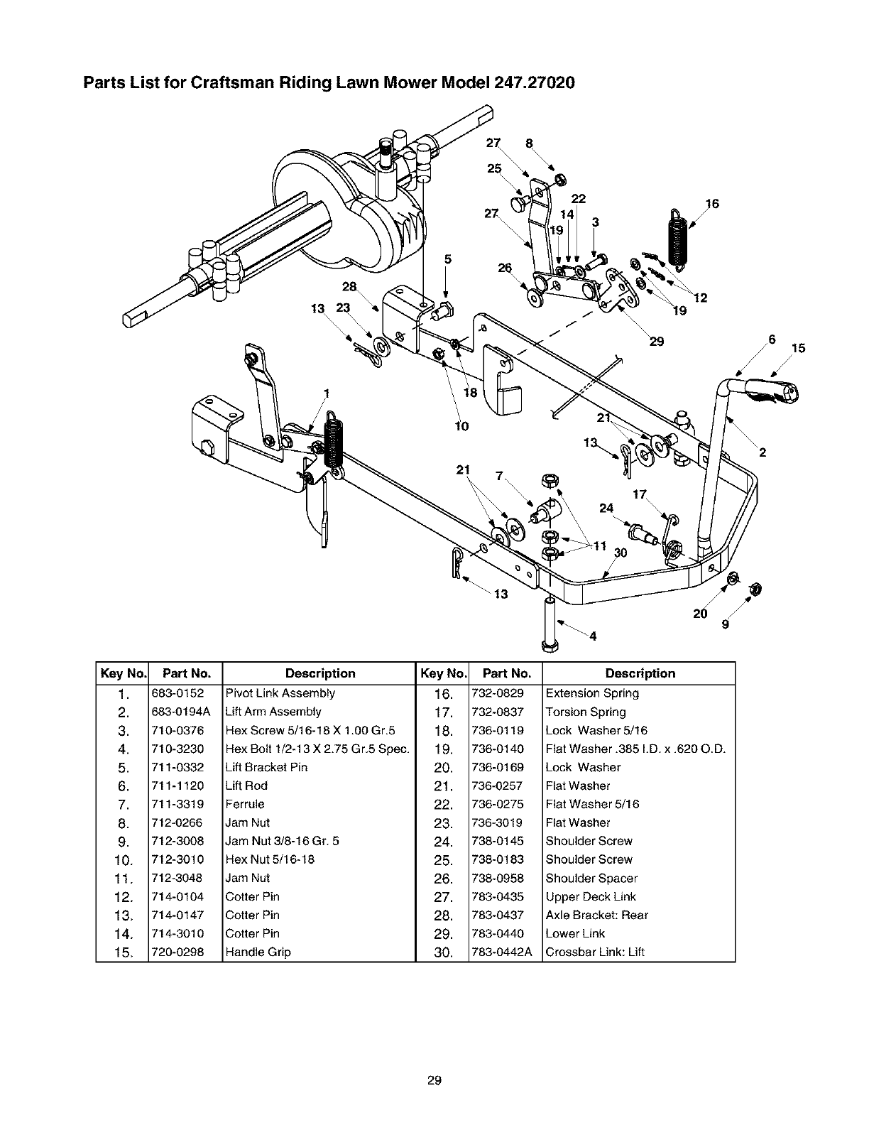
Parts List for Craftsman Riding Lawn Mower Model 247.27020
5
25
27 22
3
/6 15
/
9
Key No.
1.
2.
3.
4.
5.
6.
7.
8.
9.
10.
11.
12.
13.
14.
15.
Pa_ No.
683-0152
683-0194A
710-0376
710-3230
711-0332
711-1120
711-3319
712-0266
712-3008
712-3010
712-3048
714-0104
714-0147
714-3010
720-0298
Description Key No. Part No.
Pivot Link Assembly 16. 732-0829
Uft Arm Assembly 17. 732-0837
Hex Screw 5/16-18 X 1.00 Gr.5 18. 736-0119
Hex Bolt 1/2-13 X 2.75 Gr.5 Spec. 19. 736-0140
Lift Bracket Pin 20. 736-0169
Lift Rod 21. 736-0257
Ferrule 22. 736-0275
Jam Nut 23. 736-3019
Jam Nut 3/8-16 Gr. 5 24. 738-0145
Hex Nut 5/16-18 25. 738-0183
Jam Nut 26. 738-0958
Cotter Pin 27. 783-0435
Cotter Pin 28. 783-0437
Cotter Pin 29. 783-0440
Handle Grip 30. 783-0442A
Description
Extension Spring
Torsion Spring
Lock Washer 5/16
Flat Washer .385 I.D. x .620 O.D.
Lock Washer
Flat Washer
Flat Washer 5/16
Flat Washer
Shoulder Screw
Shoulder Screw
Shoulder Spacer
Upper Deck Link
Axle Bracket: Rear
Lower Link
Crossbar Link: Lift
29
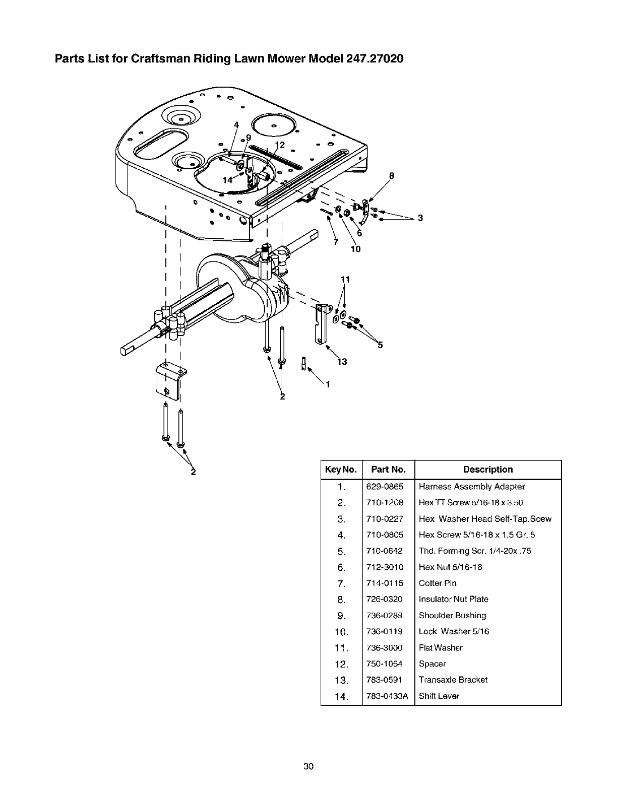
Parts List for Craftsman Riding Lawn Mower Model 247.27020
8
10
11
\
Part No.
629-0865
710-1208
710-0227
710-0805
710-0642
712-3010
714-0115
726-0320
736-0289
736-0119
736-3000
750-1064
783-0591
783-0433A
Description
Harness Assembly Adapter
Hex TT Screw 5/16-18 x 3.50
Hex Washer Head Self-Tap.Scew
Hex Screw 5/16-18 x 1.5 Gr. 5
Thd. Forming Scr. 1/4-20x .75
Hex Nut 5/16-18
Cotter Pin
Insulator Nut Plate
Shoulder Bashing
Lock Washer 5/16
Flat Washer
Spacer
Transaxle Bracket
Shift Lever
3O
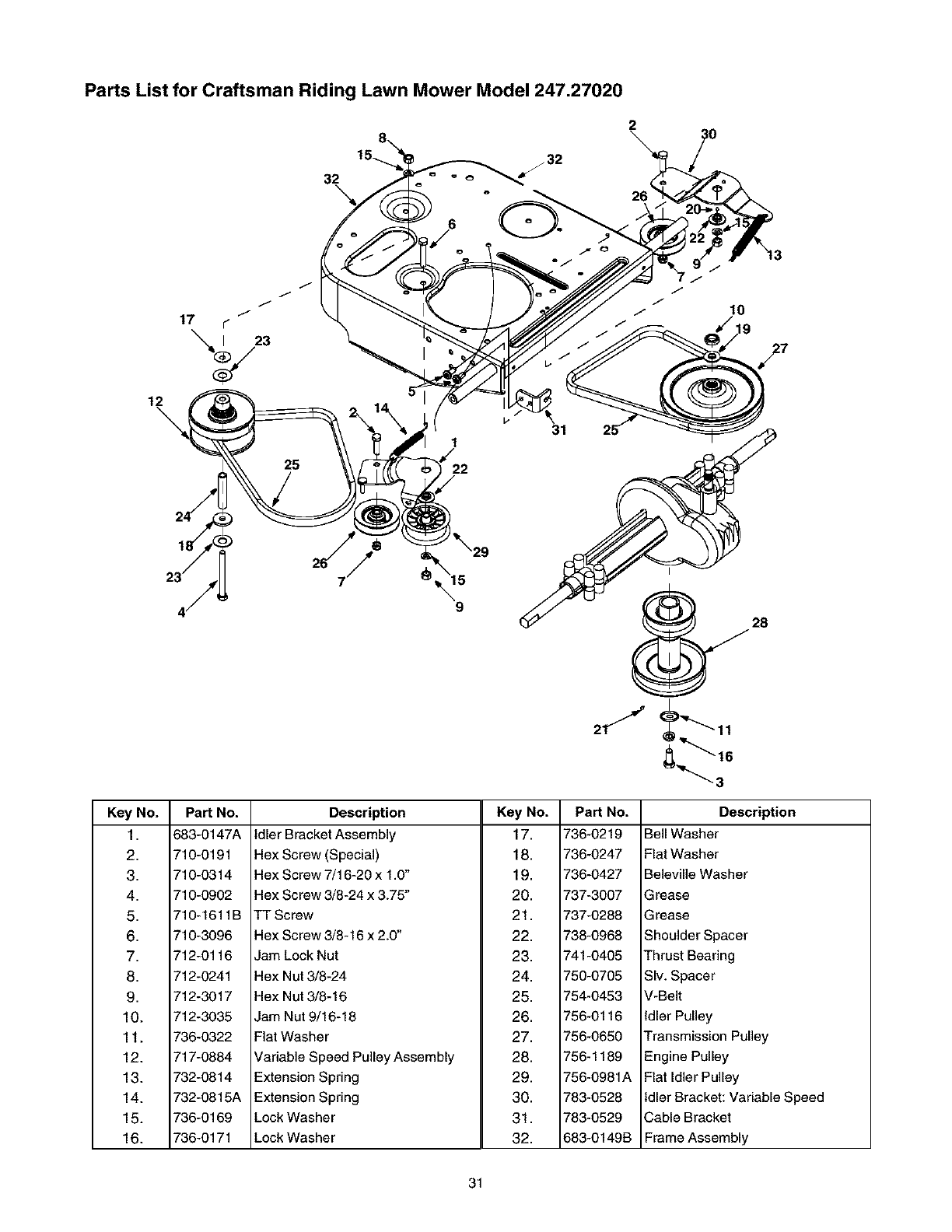
Parts List for Craftsman Riding Lawn Mower Model 247.27020
12
\
Key No.
1.
2.
3.
4.
5.
6.
7.
8.
9.
10.
11.
12.
13.
14.
15.
16.
PaN No.
683-0147A
710-0191
710-0314
710-0902
710-1611B
710-3096
712-0116
712-0241
712-3017
712-3035
736-0322
717-0884
732-0814
732-0815A
736-0169
736-0171
9
28
16
Description
Idler Bracket Assembly
Hex Screw (Special)
Hex Screw 7/16-20 x 1.0"
Hex Screw 3/8-24 x 3.75"
TT Screw
Hex Screw 3/8-16 x 2.0"
Jam Lock Nut
Hex Nut 3/8-24
Hex Nut 3/8-16
Jam Nut 9/16-18
Flat Washer
Variable Speed Pulley Assembly
Extension Spring
Extension Spring
Lock Washer
Lock Washer
Key No.
17.
18.
19.
20.
21.
22.
23.
24.
25.
26.
27.
28.
29.
30.
31.
32.
PaN No.
736-0219
736-0247
736-0427
737-3007
737-0288
738-0968
741-0405
750-0705
754-0453
756-0116
756-0650
756-1189
756-0981A
783-0528
783-0529
683-0149B
Description
Bell Washer
Flat Washer
Beleville Washer
Grease
Grease
Shoulder Spacer
Thrust Bearing
SIv. Spacer
V-Belt
Idler Pulley
Transmission Pulley
Engine Pulley
Flat Idler Pulley
Idler Bracket: Variable Speed
Cable Bracket
Frame Assembly
31
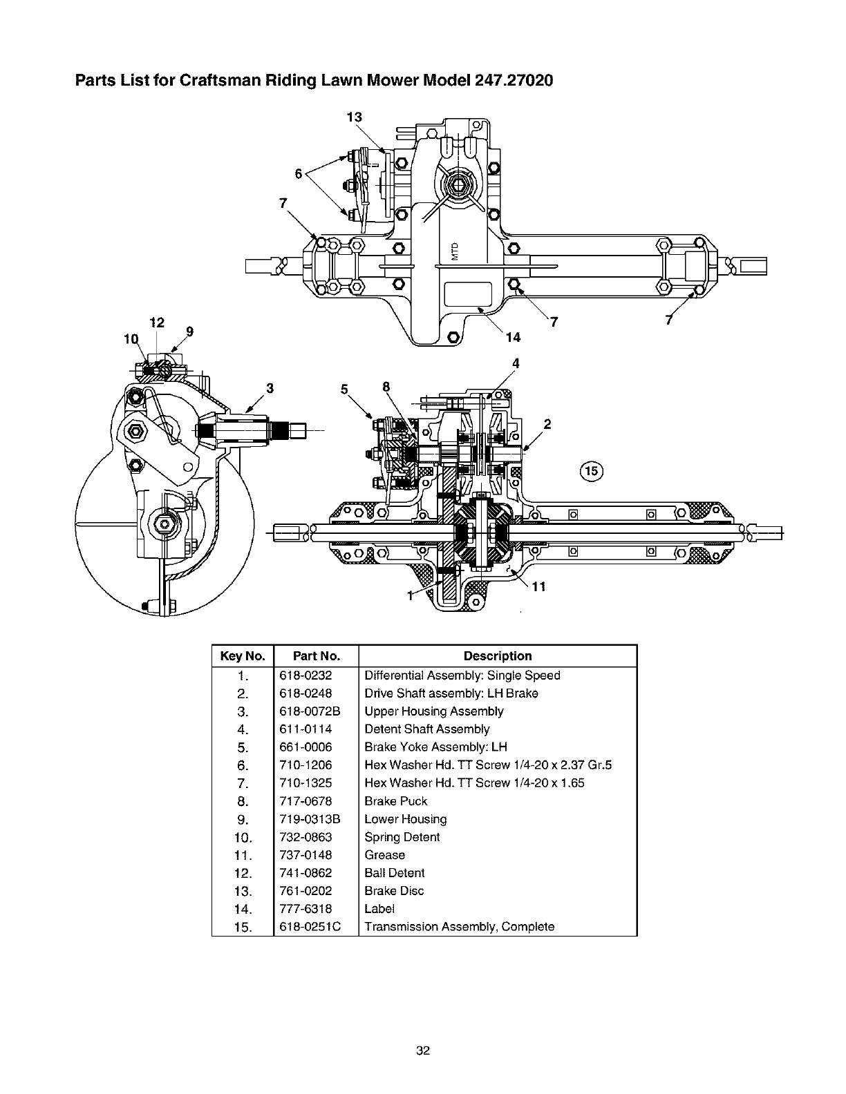
Parts List for Craftsman Riding Lawn Mower Model 247.27020
13
12
3
/58
\
4
2
®
iol
Key No.
1.
2.
3.
4.
5.
6.
7.
8.
9.
10.
11.
12.
13.
14.
15.
Pa_ No.
618-0232
618-0248
618-0072B
611-0114
661-0006
710-1206
710-1325
717-0678
719-0313B
732-0863
737-0148
741-0862
761-0202
777-6318
618-0251C
Description
Differential Assembly: Single Speed
Drive Shaft assembly: LH Brake
Upper Housing Assembly
Detent Shaft Assembly
Brake Yoke Assembly: LH
Hex Washer Hd. TT Screw 1/4-20 x 2.37 G r.5
Hex Washer Hd. TT Screw 1/4-20 x 1.65
Brake Puck
Lower Housing
Spring Detent
Grease
Ball Detent
Brake Disc
Label
Transmission Assembly, Complete
32
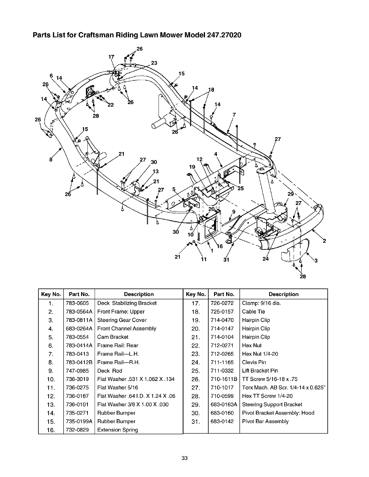
17
6
Parts List for Craftsman Riding Lawn Mower Model 247.27020
_._26 23
15
14 8
14
l 7
26
27
Key No.
1.
2.
3.
4.
5.
6.
7.
8.
9.
10.
11,
12,
13.
14,
15.
16.
21 11
28
PaN No.
783-0605
783-0564A
783-0811A
683-0264A
783-0554
783-0414A
783-0413
783-0412B
747-0985
736-3019
736-0275
736-0187
736-0101
735-0271
735-0199A
732-0829
Description
Deck Stabilizing Bracket
Front Frame: Upper
Steering Gear Cover
Front Channel Assembly
Cam Bracket
Frame Rail: Rear
Frame RaiI--L.H.
Frame RaiI--R.H.
Deck Rod
Flat Washer .531 X 1.062 X. 134
Flat Washer 5/16
Flat Washer .64 I.D. X 1.24 X .06
Flat Washer 3/8 X 1.00 X .030
Rubber Bumper
Rubber Bumper
Extension Spring
Key No.
17.
18.
19.
20.
21.
22.
23.
24.
25.
26.
27.
28.
29.
30.
31.
Part No.
726-0272
725-0157
714-0470
714-0147
714-0104
712-0271
712-0265
711-1165
711-0332
710-1611B
710-1017
710-0599
683-0163A
683-0160
683-0142
Description
Clamp: 9/16 dia.
Cable Tie
Hairpin Clip
Hairpin Clip
Hairpin Clip
Hex Nut
Hex Nut 1/4-20
Clevis Pin
Lift Bracket Pin
TT Screw 5/16-18 x .75
Torx Mach. AB Scr. 1/4-14 x 0.625"
Hex TT Screw 1/4-20
Steering Support Bracket
Pivot Bracket Assembly: Hood
Pivot Bar Assembly
33
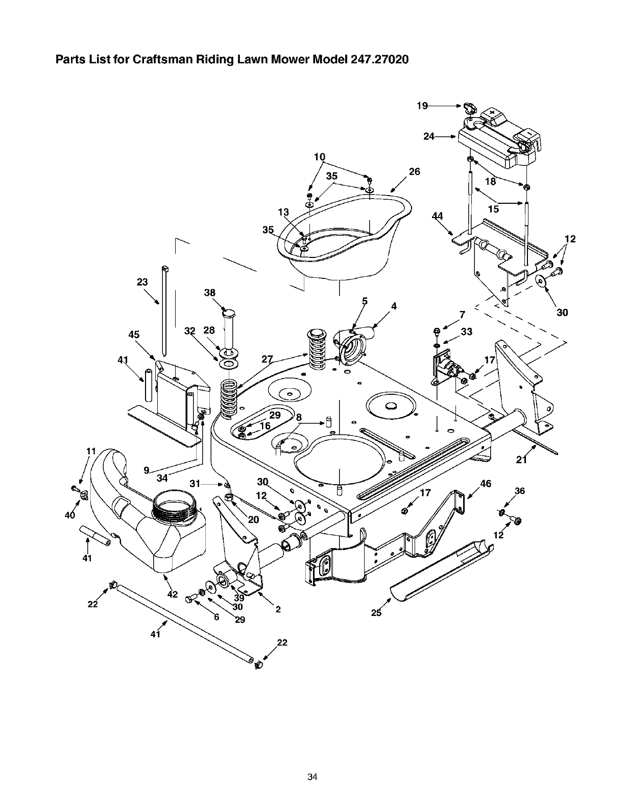
Parts List for Craftsman Riding Lawn Mower Model 247.27020
23
\
45
38
4
12
41
2
34
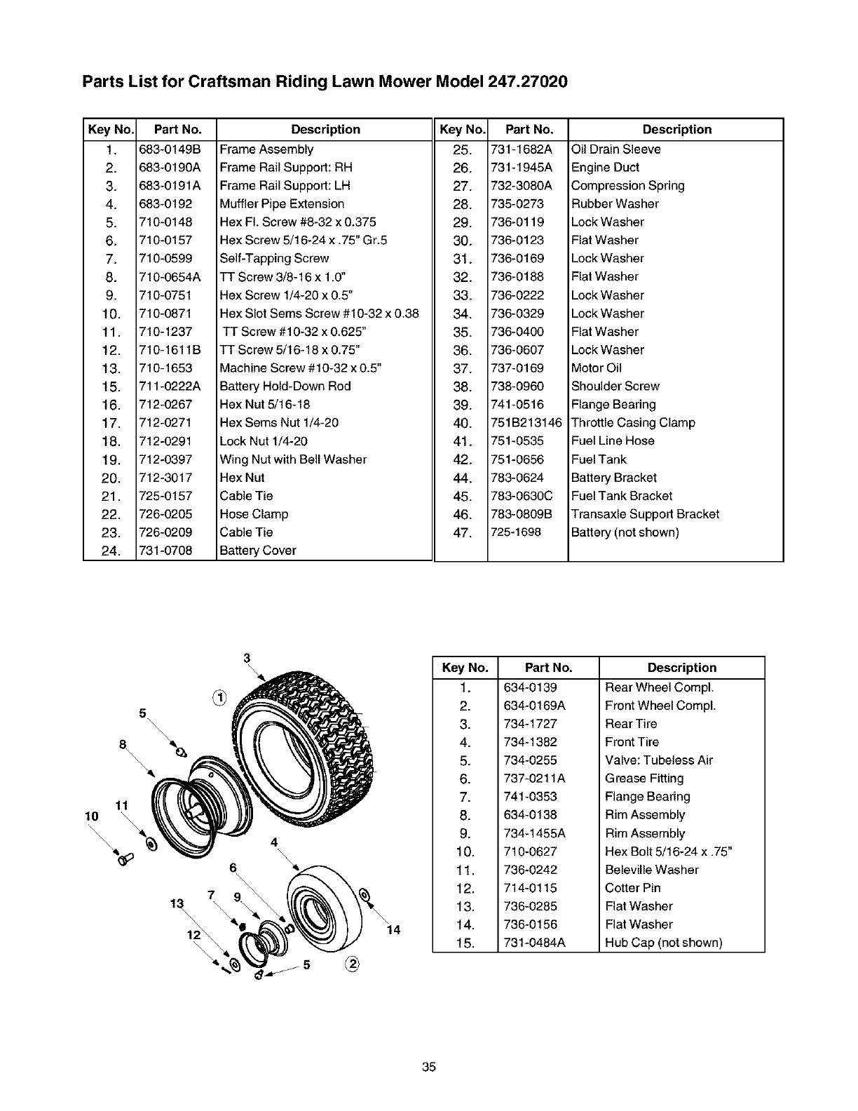
Parts List for Craftsman Riding Lawn Mower Model 247.27020
Key No. Part No.
1. 683-0149B
2. 683-0190A
3. 683-0191A
4. 683-0192
5. 710-0148
6. 710-0157
7. 710-0599
8. 710-0654A
9. 710-0751
10. 710-0871
11. 710-1237
12. 710-1611B
13. 710-1653
15. 711-0222A
16. 712-0267
17. 712-0271
18. 712-0291
19. 712-0397
20. 712-3017
21. 725-0157
22. 726-0205
23. 726-0209
24. 731-0708
Description
Frame Assembly
Frame Rail Support: RH
Frame Rail Support: LH
Muffler Pipe Extension
Hex FI. Screw #8-32 x 0.375
Hex Screw 5/16-24 x .75" Gr.5
Self-Tapping Screw
TT Screw 3/8-16 x 1.0"
Hex Screw 1/4-20 x 0.5"
Hex Slot Sems Screw #10-32 x 0.38
TT Screw #10-32 x 0.625"
TT Screw 5/16-18 x 0.75"
Machine Screw #10-32 x 0.5"
Battery Hold-Down Rod
Hex Nut 5/16-18
Hex Sems Nut 1/4-20
Lock Nut 1/4-20
Wing Nut with Bell Washer
Hex Nut
Cable Tie
Hose Clamp
Cable Tie
Battery Cover
Key No. Part No.
25. 731-1682A
26. 731-1945A
27. 732-3080A
28. 735-0273
29. 736-0119
30. 736-0123
31. 736-0169
32. 736-0188
33. 736-0222
34. 736-0329
35. 736-0400
36. 736-O6O7
37. 737-0169
38. 738-0960
39. 741-0516
40. 751B213146
41. 751-0535
42. 751-0656
44. 783-0624
45. 783-0630C
46. 783-0809B
47. 725-1698
Description
Oil Drain Sleeve
Engine Duct
Compression Spring
Rubber Washer
Lock Washer
Flat Washer
Lock Washer
Flat Washer
Lock Washer
Lock Washer
Flat Washer
Lock Washer
Motor Oil
Shoulder Screw
Flange Bearing
Throttle Casing Clamp
Fuel Line Hose
Fuel Tank
Battery Bracket
Fuel Tank Bracket
Transaxle Support Bracket
Battery (not shown)
5
\\\\
11
10 \
\\\\\
l:t\\
6
Part No.
634-0139
634-0169A
734-1727
734-1382
734-0255
737-0211A
741-0353
634-0138
734-1455A
710-0627
736-0242
714-0115
736-0285
736-0156
731-0484A
Description
Rear Wheel CompL
Front Wheel CompL
Rear Tire
Front Tire
Valve: Tubeless Air
Grease Fitting
Flange Bearing
Rim Assembly
Rim Assembly
Hex Bolt 5/16-24 x .75"
Beleville Washer
Cotter Pin
Flat Washer
Flat Washer
Hub Cap (not shown)
35
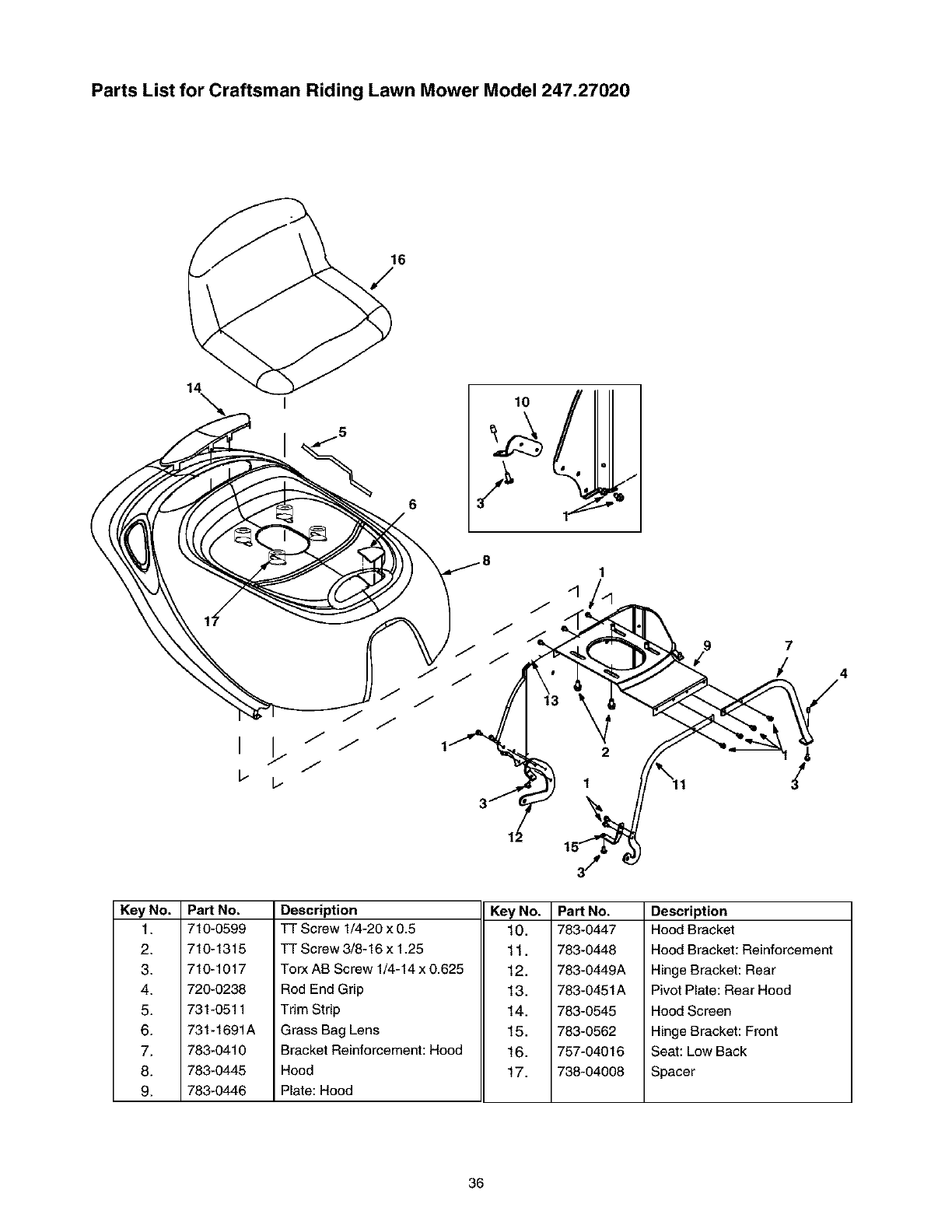
Parts List for Craftsman Riding Lawn Mower Model 247.27020
14 10
97
/
Key No.
1.
2.
3.
4.
5.
6.
7.
8.
9.
Part No.
710-0599
710-1315
710-1017
720-0238
731-0511
731-1691A
783-0410
783-0445
783-0446
Description
TT Screw 1/4-20 x 0.5
TT Screw 3/8-16 x 1.25
Torx AB Screw 1/4-14 x 0.625
Rod End Grip
Trim Strip
Grass Bag Lens
Bracket Reinforcement: Hood
Hood
Plate: Hood
Key No.
10.
11.
12.
13.
14.
15.
16.
17.
Part No.
783-0447
783-0448
783-0449A
783-0451A
783-0545
783-0562
757-04016
738-04008
Description
Hood Bracket
Hood Bracket: Reinforcement
Hinge Bracket: Rear
Pivot Plate: Rear Hood
Hood Screen
Hinge Bracket: Front
Seat: Low Back
Spacer
36
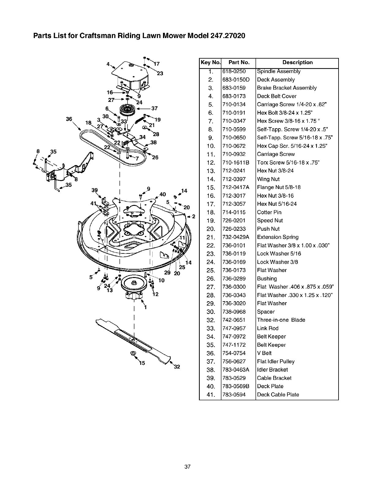
Parts List for Craftsman Riding Lawn Mower Model 247.27020
8
36\
Key No. Part No.
1. 618-0250
2. 683-0150D
3. 683-0159
4. 683-0173
5. 710-0134
6. 710-0191
7. 710-0347
8. 710-0599
9. 710-0650
10. 710-0672
11. 710-0932
12. 710-1611B
13. 712-0241
14. 712-0397
15. 712-0417A
14 16. 712-3017
17. 712-3057
18. 714-0115
19. 726-0201
20. 726-0233
21. 732-0429A
22. 736-0101
23. 736-0119
24. 736-0169
25. 736-0173
26. 736-0289
27. 736-0300
28. 736-0343
29. 736-3020
30. 738-0968
32. 742-0651
33. 747-O957
34. 747-0972
35. 747-1172
36. 754-O754
37. 756-0627
38. 783-0463A
39. 783-O529
40. 783-0569B
41. 783-O594
Description
Spindle Assembly
Deck Assembly
Brake Bracket Assembly
Deck Belt Cover
Carriage Screw 1/4-20 x .62"
Hex Bolt 3/8-24 x 1.25"
Hex Screw 3/8-16 x 1.75"
Self-Tapp. Screw 1/4-20 x .5"
Self-Tapp. Screw 5/16-18 x .75"
Hex Cap Scr. 5/16-24 x 1.25"
Carriage Screw
Torx Screw 5/16-18 x .75"
Hex Nut 3/8-24
Wing Nut
Flange Nut 5/8-18
Hex Nut 3/8-16
Hex Nut 5/16-24
Cotter Pin
Speed Nut
Push Nut
Extension Spring
Flat Washer 3/8 x 1.00 x .030"
Lock Washer 5/16
Lock Washer 3/8
Flat Washer
Bushing
Flat Washer .406 x .875 x .059"
Flat Washer .330 x 1.25 x.120"
Flat Washer
Spacer
Three-in-one Blade
Link Rod
Belt Keeper
Belt Keeper
V Belt
Flat idler Pulley
Idler Bracket
Cable Bracket
Deck Plate
Deck Cable Plate
37
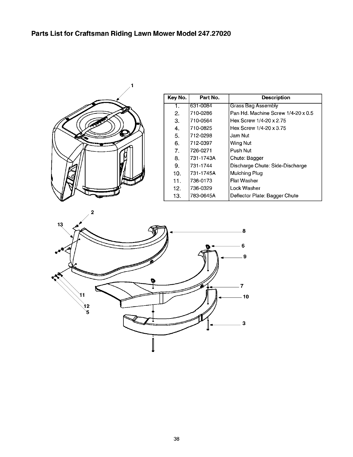
Parts List for Craftsman Riding Lawn Mower Model 247.27020
Key No.
1.
2.
3.
4.
5.
6.
7.
8.
9.
10.
11.
12.
13.
Part No.
631-0084
710-0286
710-0564
710-0825
712-0298
712-0397
726-0271
731-1743A
731-1744
731-1745A
736-0173
736-0329
783-0645A
Description
Grass Bag Assembly
Pan Hd. Machine Screw 1/4-20 x 0.5
Hex Screw 1/4-20 x 2.75
Hex Screw 1/4-20 x 3.75
Jam Nut
Wing Nut
Push Nut
Chute: Bagger
Discharge Chute: Side-Discharge
Mulching Plug
Flat Washer
Lock Washer
Deflector Plate: Bagger Chute
2
/
4
0
i q
i-
8
6
9
7
10
3
38
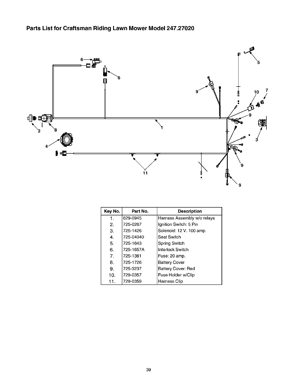
Parts List for Craftsman Riding Lawn Mower Model 247.27020
10
\
%/
11
9
Key No.
1.
2.
3.
4.
5.
6.
7.
8.
9.
10.
11,
Part No.
629-0945
725-0267
725-1426
725-04040
725-1643
725-1657A
725-1381
725-1726
725-3237
729-0357
729-0359
Description
Harness Assembly w/o relays
Ignition Switch: 5 Pin
Solenoid: 12 V. 100 amp.
Seat Switch
Spring Switch
Interlock Switch
Fuse: 20 amp.
Battery Cover
Battery Cover: Red
Fuse Holder w/Clip
Harness Clip
39
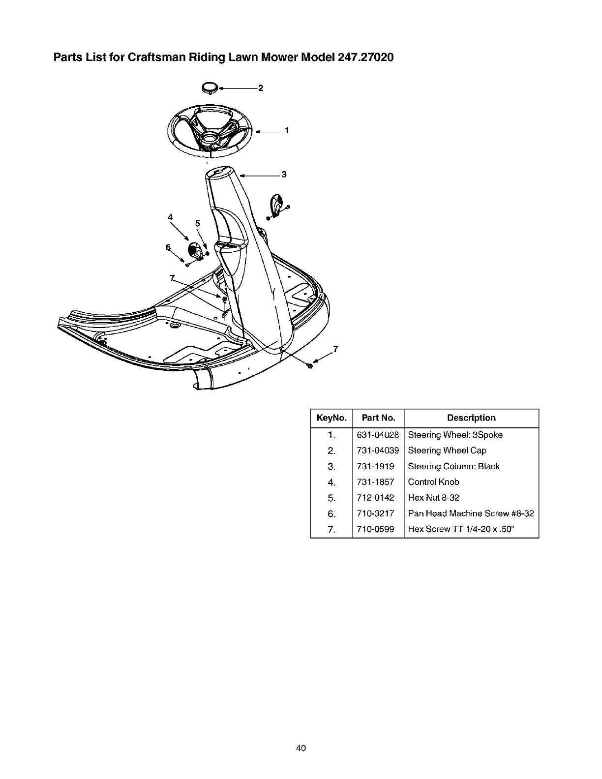
Parts List for Craftsman Riding Lawn Mower Model 247.27020
7
J
KeyNo.
1.
2.
3.
4.
5.
6.
7.
Part No.
631-04028
731-04039
731-1919
731-1857
712-0142
710-3217
710-0599
Description
Steering Wheel: 3Spoke
Steering Wheel Cap
Steering Column: Black
Control Knob
Hex Nut 8-32
Pan Head Machine Screw #8-32
Hex Screw TT 1/4-20 x .50"
4O
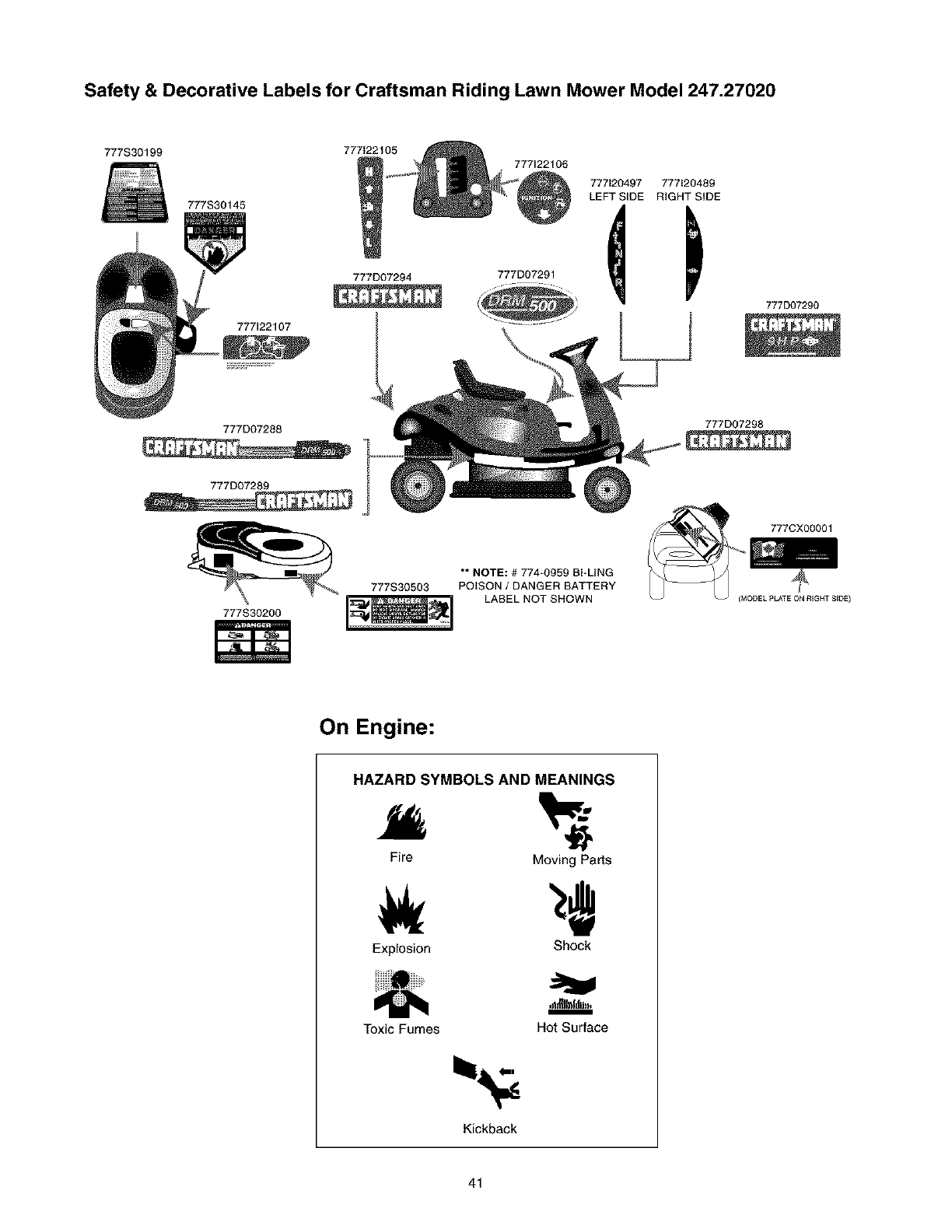
Safety & Decorative Labels for Craftsman Riding Lawn Mower Model 247.27020
777S30199 77712210
777S30145
777D07294
777122107
777D07288
777D07289
777122106
777120497 777120489
LEFT SIDE RIGHT SIDE
777D07290
777D07298
777CX00001
777S30200
777S30503
** NOTE: # 774-0959 BFLING
POISON /DANGER BATTERY
LABEL NOT SHOWN IMODEL pLATE ON REGNT S_DE I
On Engine:
HAZARD SYMBOLS AND MEANINGS
Fire Moving Parts
Explosion Shock
Toxic Fumes
Kickback
Hot Surface
41
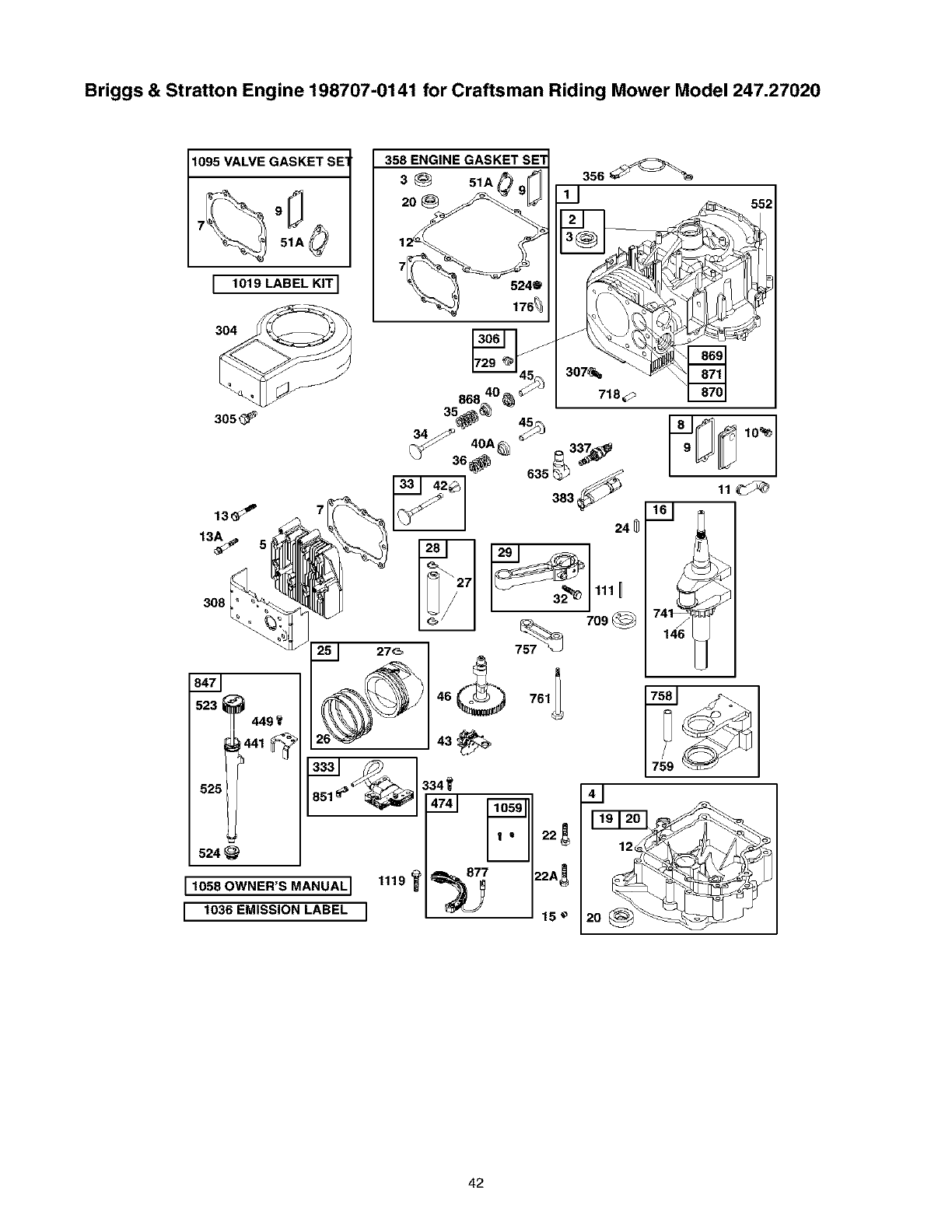
Briggs & Stratton Engine 198707-0141 for Craftsman Riding Mower Model 247.27020
t095 VALVE GASKET SE
[ lO1_LABELKIT]
304
308
523 _449
52_
524
1058 OWNER'S MANUAL I 1119
1036 EMISSION LABEL J
42
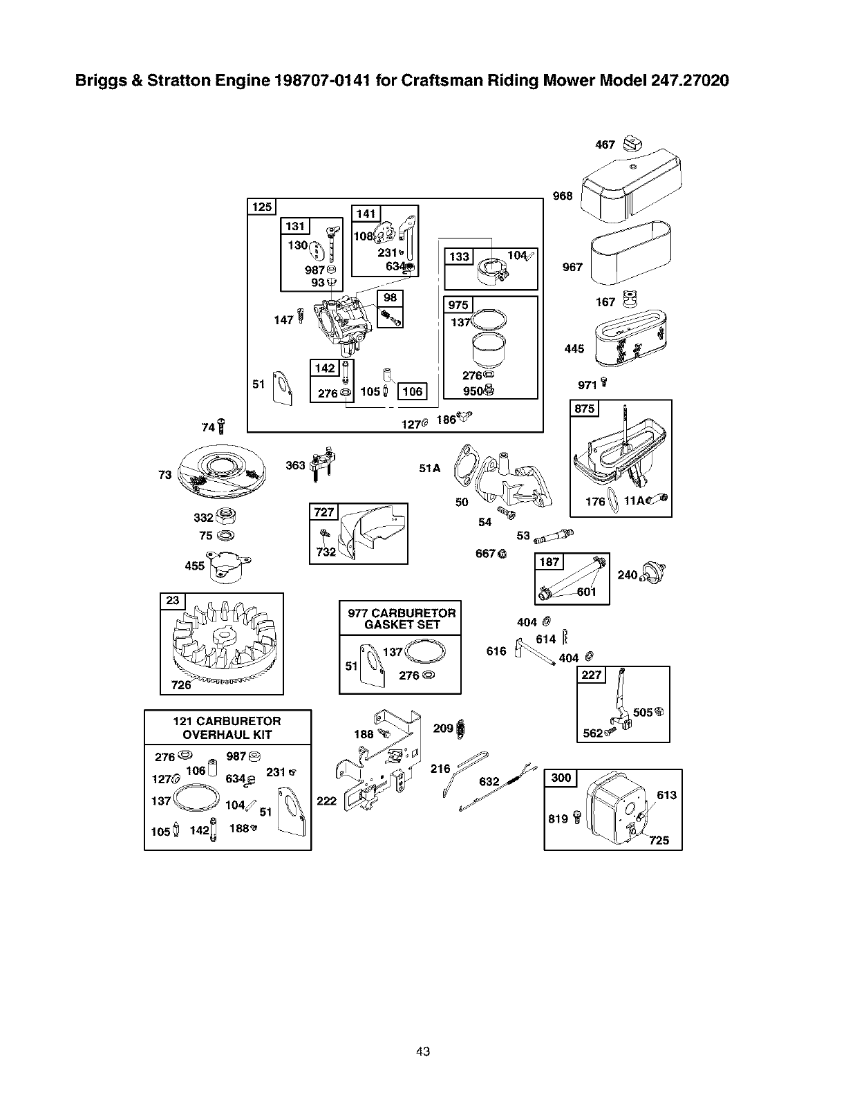
Briggs & Stratton Engine 198707-0141 for Craftsman Riding Mower Model 247.27020
467
51
332
75
455_
121 CARBURETOR
OVERHAUL KIT
276_ 987_
127elo6u 634@231
105_ 142_ 188_
1270 186_P
130
276_
9so_
363 _51A
968
167
445
971
977 CARBURETOR
GASKET SET
L_ 276
222
209
404
_614
616 LJ _,_404
505_ I
I
43
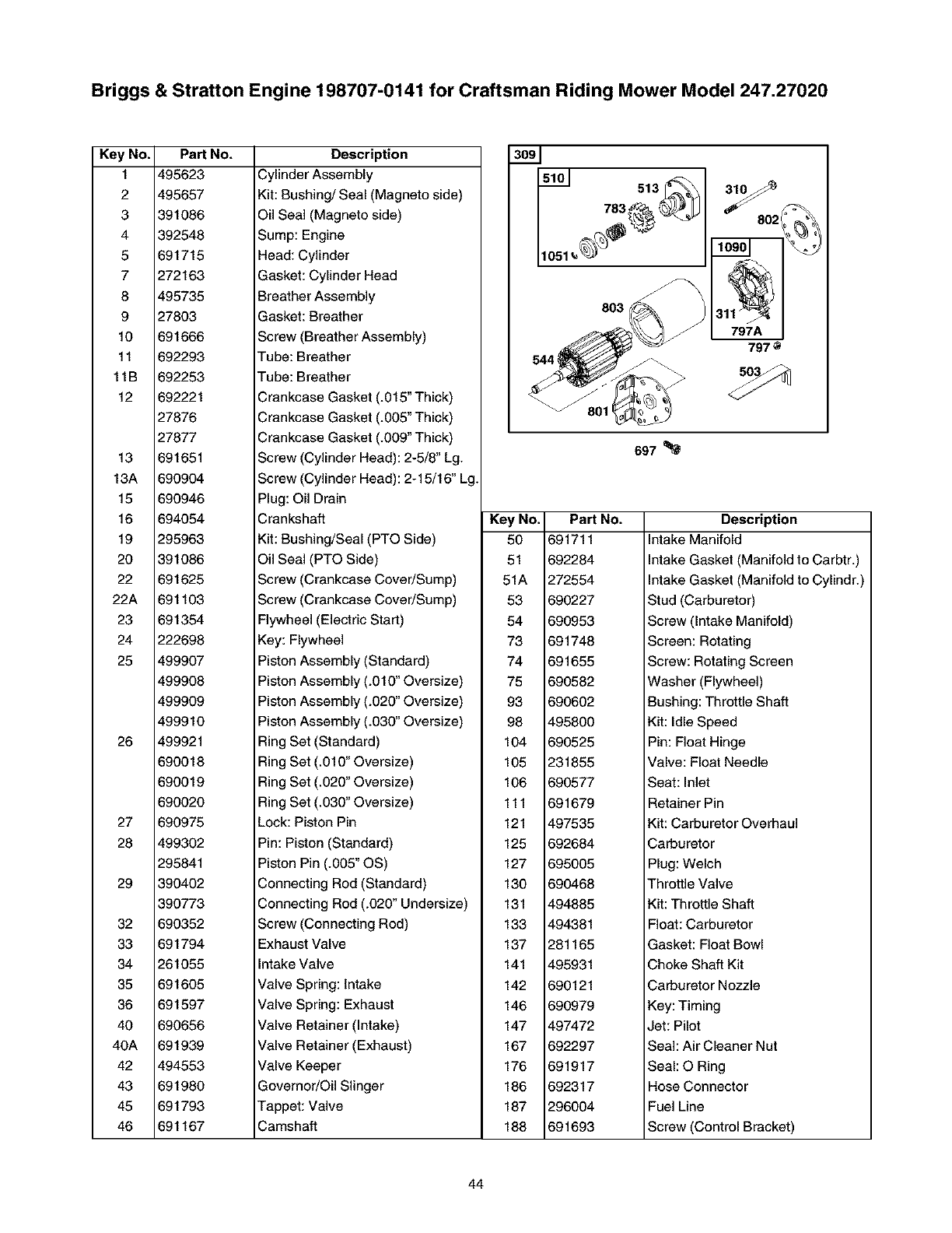
Briggs & Stratton Engine 198707-0141 for Craftsman Riding Mower Model 247.27020
Key No.
1
2
3
4
5
7
8
9
10
11
11B
12
13
13A
15
16
19
20
22
22A
23
24
25
26
27
28
29
32
33
34
35
36
40
40A
42
43
45
46
PaN
495623
495657
391086
392548
691715
272163
495735
27803
691666
692293
692253
692221
27876
27877
691651
690904
690946
694054
295963
391086
691625
691103
691354
222698
499907
499908
499909
499910
499921
690018
690019
690020
690975
499302
295841
390402
390773
690352
691794
261055
691605
691597
690656
691939
494553
691980
691793
691167
NO. Description
Cylinder Assembly
Kit: Bushing/Seal (Magneto side)
Oil Seal (Magneto side)
Sump: Engine
Head: Cylinder
Gasket: Cylinder Head
Breather Assembly
Gasket: Breather
Screw (Breather Assembly)
Tube: Breather
Tube: Breather
Crankcase Gasket (.015" Thick)
Crankcase Gasket (.005" Thick)
Crankcase Gasket (.009" Thick)
Screw (Cylinder Head): 2-5/8" Lg.
Screw (Cylinder Head): 2-15/16" Lg.
Plug: Oil Drain
Crankshaft
Kit: Bushing/Seal (PTO Side)
Oil Sea] (PTO Side)
Screw (Crankcase Cover/Sump)
Screw (Crankcase Cover/Sump)
Flywheel (Electric Start)
Key: Flywheel
Piston Assembly (Standard)
Piston Assembly (.010" Oversize)
Piston Assembly (.020" Oversize)
Piston Assembly (.030" Oversize)
Ring Set (Standard)
Ring Set (.010" Oversize)
Ring Set (.020" Oversize)
Ring Set (.030" Oversize)
Lock: Piston Pin
Pin: Piston (Standard)
Piston Pin (.005" OS)
Connecting Rod (Standard)
Connecting Rod (.020" Undersize)
Screw (Connecting Rod)
Exhaust Valve
Intake Valve
Valve Spring: intake
Valve Spring: Exhaust
Valve Retainer (Intake)
Valve Retainer (Exhaust)
Valve Keeper
Governor/Oil Slinger
Tappet: Valve
Camshaft
513
803
Y802
797A
797
697
PaN No.
6917_
692284
272554
690227
690953
691748
691655
690582
690602
495800
690525
231855
690577
691679
497535
692684
695005
690468
494885
494381
281165
495931
690121
690979
497472
692297
691917
692317
296004
691693
Description
Intake Manifold
Intake Gasket (Manifold to Carbtr.)
Intake Gasket (Manifold to Cylindr.)
Stud (Carburetor)
Screw (Intake Manifold)
Screen: Rotating
Screw: Rotating Screen
Washer (Flywheel)
Bushing: Throttle Shaft
Kit: Idle Speed
Pin: Float Hinge
Valve: Float Needle
Seat: Inlet
Retainer Pin
Kit: Carburetor Overhaul
Carburetor
Plug: Welch
Throttle Valve
Kit: Throttle Shaft
Float: Carburetor
Gasket: Float Bowl
Choke Shaft Kit
Carburetor Nozzle
Key: Timing
Jet: Pilot
Seal: Air Cleaner Nut
Seal: O Ring
Hose Connector
Fuel Line
Screw (Control Bracket)
44

Briggs & Stratton Engine 198707-0141 for Craftsman Riding Mower Model 247.27020
Key No. PaN
209 690480
216 690573
222 694042
227 691374
231 691636
240 298090
276 692255
300 393010
304 496832
305 692198
306 496797
307 691003
308 691201
309 693054
310 690323
311 497608
332 690662
333 398811
334 691061
337 802592
356 690799
358 299577
363 19165
383 89838
404 691691
441 690593
445 691667
449 690664
450 691261
455 691173
467 691668
474 696578
480 690664
503 691532
505 691251
510 497606
513 692024
523 691387
524 281370
525 692963
544 692034
552 491986
562 691119
601 95162
613 691632
614 691620
NO. Description
Spring: Governor
Link: Choke
Bracket: Control
Lever: Governor Control
Screw (Choke Valve)
Fuel Filter
Washer: Sealing
Muffler (Round Lo Tone)
Blower Housing
Screw (Blower Housing)
Cylinder Shield
Screw: Cylinder Shield
Cover: Cylinder Head
Starter Motor
Bolt: Starter Motor
Brush Set
Nut: Flywheel
Magneto Armature
Screw: Magneto Armature
Spark Plug
Wire: Stop
Gasket Set: Engine
Flywheel Puller
Wrench: Spark Plug
Washer: Governor Crank
Oil Fill Bracket
Filter: Air Cleaner Cartridge
Screw: Oil Fill Bracket
Washer: Fuel Tank Bracket
Cup: Flywheel (Straight side)
Knob: Air Cleaner
Alternator
Screw (Tube Clamp)
Strap: Starter
Nut (Governor Control Lever)
Drive: Starter
Drive Clutch
Dipstick
Seal: Dipstick Tube
Dipstick Tube
Armature: Starter
Bushing: Governor Crank
Bolt: Governor Control Lever
Hose Clamp
Screw (Muffler)
Cotter Pin
Key No. PaN
616 692012
632 693663
634 690802
635 66538
667 690958
697 690372
709 691268
718 690959
725 690433
726 399676
727 395405
729 690603
732 691097
741 691288
757 691714
758 690619
759 691239
761 690346
783 693059
797 693167
797A 693167
801 691429
802 691286
803 693757
819 690810
847 392066
851 493880
868 692036
869 691703
870 691844
871 261961
875 693670
877 393814
950 691657
967 272477
968 691324
975 495933
977 494385
987 691326
1019 696491
1036 695697
1051 691265
1059 698516
1090 691293
1095 498536
1119 691183
NO. Description
Crank: govemnor
Spring/Link: Mech. Governor
Spring/Seal Assy. (Choke A Matic)
Spark Plug Boot
Nut (Air Cleaner Base)
Screw: Drive Cap
Eccentric
Pin: Locating
Heat Shield (Super Lo Tone)
Gear Ring
Starter Drive Cover
Wire Clip
Screw (Starter Drive Cover)
Timing Gear
Link: Counterweight
Counterweight
Pin: Counterweight
Screw: Counterweight
Pinion Gear
Nut (Brush Retainer)
Nut (Brush Retainer)
Cap: Drive
End Cap
Starter Housing
Screw: Muffler Bracket
Dipstick
Spark Plug Terminal
Seal: Valve
Valve Seat: intake
Valve Seat: exhaust
Bushing: Valve Guide
Air Cleaner Base
Wire/Connector-Alternator (DC)
Screw: Float Bowl
Filter: Pre-Cleaner
Cover: Air Cleaner
Float Bowl
Carburetor Gasket Set
Throttle Shaft Seal
Label Kit
Label: Emission
Retaining Ring
Kit-Screw/Washer
Retainer
Gasket Set: Valve
Screw (Alternator)
45
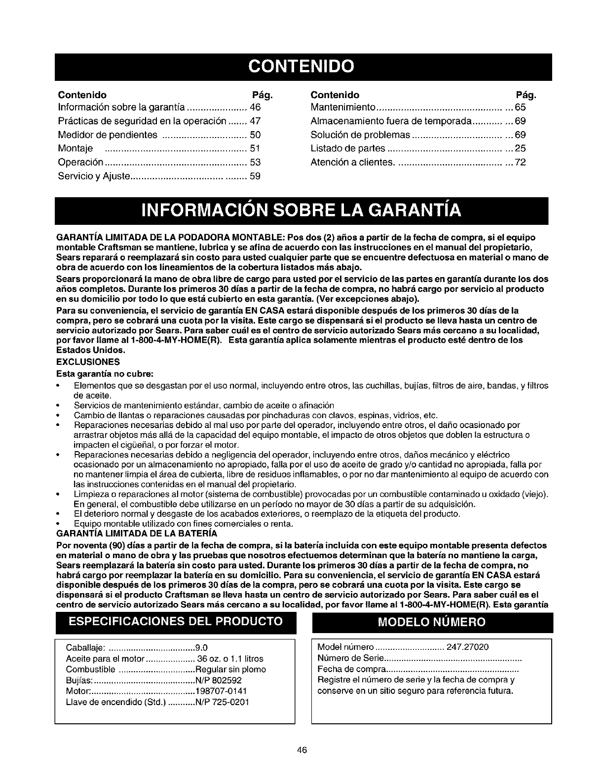
Contenido pdg.
Informaci6n sobre la garantia ...................... 46
Pr&cticas de seguddad en la operaciSn ....... 47
Medidor de pendientes ............................... 50
Montaje .................................................... 51
Operaci6n .................................................... 53
Servicio yAjuste .......................................... 59
Contenido Pdg.
Mantenimiento ................................................. 65
Almacenamiento fuera de temporada .............. 69
Soluci6n de problemas .................................... 69
Listado de partes ............................................. 25
Atenci6n a clientes .......................................... 72
GARANT|A LIMITADA DE LA PODADORA MONTABLE: Pos dos (2) afios a partir de la fecha de compra, si el equipo
montable Craftsman se mantiene, lubrica y se afina de acuerdo con las instrucciones en el manual del propietario,
Sears reparar6 o reemplazar6 sin costo para usted cuatquier parte que se encuentre defectuosa en material o mano de
obra de acuerdo con los lineamientos de la cobertura listados m6s abajo.
Sears proporcionar_ la mano de obra libre de cargo para usted per el servicio de las partes en garantia durante los dos
a_os completos. Durante los primeros 30 dias a partir de la fecha de compra, no habrd cargo por servicio al producto
en su domicilio por todo Io que estd cubierto en esta garantia. (Ver excepciones abajo).
Para su conveniencia, el servicio de garantia EN CASA estar6 disponible despu6s de los primeros 30 dias de la
compra, pero se cobrar6 una cuota por la visita. Este cargo se dispensar6 si el producto se Ileva hasta un centre de
servicio autorizado per Sears. Para saber cudl es el centro de servicio autorizado Sears m6s cercano a su Iocalidad,
por favor Ilame al 1-800-4-MY-HOME(R), Esta garantia aplica solamente mientras el producto est6 dentro de los
Estados Unidos.
EXCLUSIONES
Esta garantia no cubre:
Eiementos que se desgastan por el uso normal, incluyendo entre otros, las cuchiilas, bujias, filtros de aire, bandas, y filtros
de aceite.
Servicios de mantenimiento est6ndar, cambio de aceite oafinaci6n
Cambio de Ilantas o reparaciones causadas por pinchaduras con clavos, espinas, vidrios, etc.
Reparaciones necesarias debido al mal uso por parte del operador, incluyendo entre otros, el daSo ocasionado por
arrastrar objetos mas alia de la capacidad del equipo montable, el impacto de otros objetos que doblen la estructura o
impacten el cigQe£_al,o por forzar el motor.
Reparaciones necesarias debido a negligencia del operador, incluyendo entre otros, da£_osmec_,nico y el_ctrico
ocasionado por un almacenamiento no apropiado, falla por el uso de aceite de grado y/o cantidad no apropiada, falla por
no mantener limpia el _rea de cubierta, libre de residuos inflamables, o por no dar mantenimiento al equipo de acuerdo con
las instrucciones contenidas en el manual del propietario.
Limpieza o reparaciones al motor (sistema de combustible) provocadas por un combustible contaminado u oxidado (viejo).
En general, el combustible debe utilizarse en un periodo no mayor de 30 dias a partir de su adquisiciSn.
El deterioro normal y desgaste de los acabados exteriores, oreemplazo de la etiqueta del producto.
• Equilqo montable utilizado con fines comerciales o renta.
GARANT|A LIMITADA DE LA BATERIA
Por noventa (90) dias a partir de la fecha de compra, si la bateria incluida con este equipo montable presenta defectos
en material o mano de obra y las pruebas que nosotros efectuemos determinan que la bateria no mantiene la carga,
Sears reemplazar6 la bateria sin costo para usted. Durante los primeros 30 dias a partir de la fecha de compra, no
habr6 cargo por reemplazar la bateria en su domicilio. Para su conveniencia, el servicio de garantia EN CASA estar6
disponible despu6s de los primeros 30 dias de la compra, pero se cobrar6 una cuota por la visita. Este cargo se
dispensar_ si el product{) Craftsman se Ileva hasta un centro de servicio autorizado por Sears. Para saber cu6t es el
centre de servicio autorizado Sears m6s cercano a su Iocalidad, per favor flame al 1-800-4-MY-HOME(R). Esta garantia
Caballaje: ................................... 9.0
Aceite para el motor .................... 36 oz. o 1.1 litros
Combustible ............................... Regular sin plomo
Bujias: ......................................... N/P 802592
Motor: .......................................... 198707-0141
Llave de encendido (Std.) ........... N/P 725-0201
Model numero ............................ 247.27020
Nemero de Serie ........................................................
Fecha de compra ......................................................
Registre el nemero de serie y la fecha de compra y
conserve en un sitio seguro para referencia futura.
46
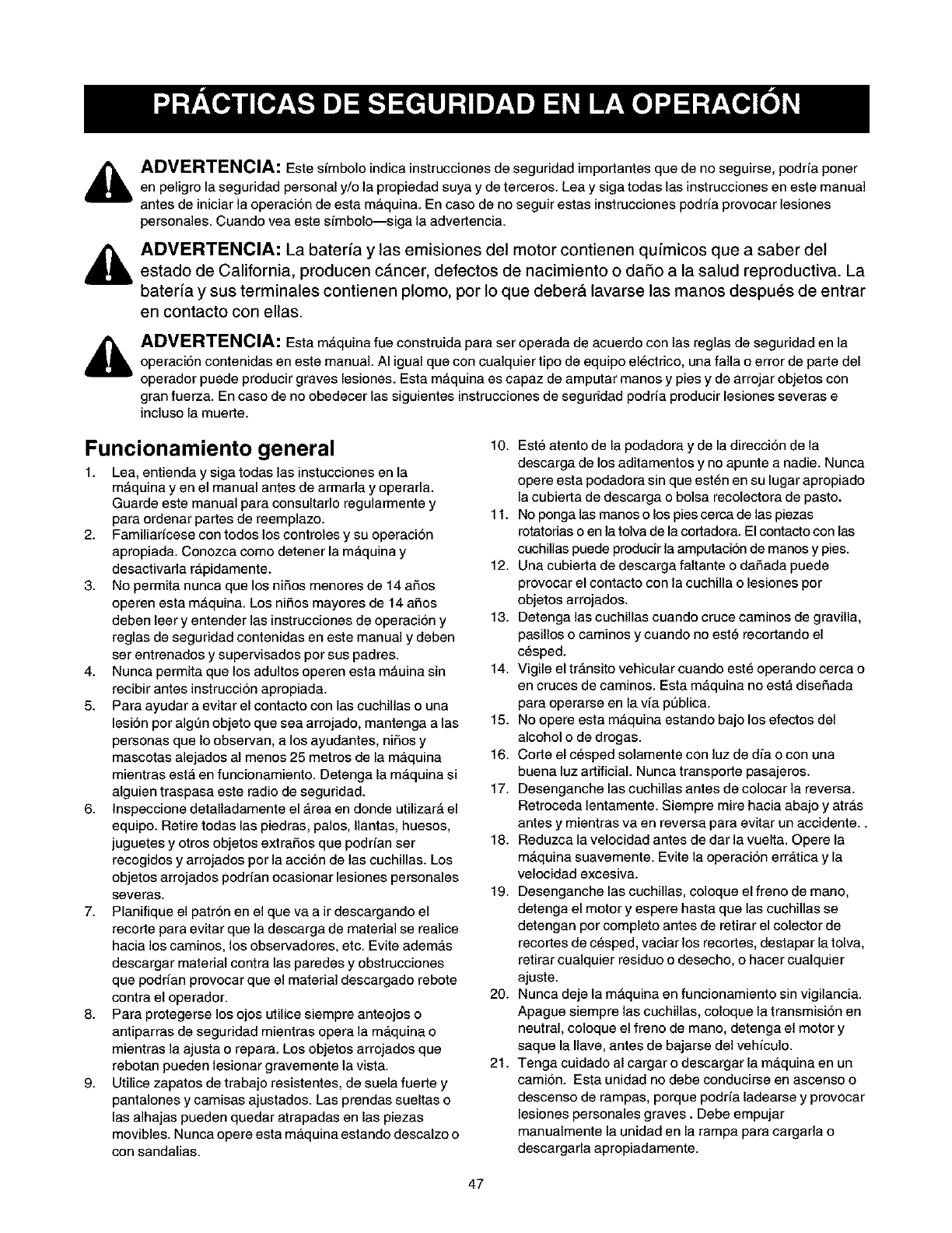
ADVERTENCIA: Este simbolo indica instrucciones de seguridad importantes que de no seguirse, podrfa poner
en peligro la seguridad personal y/o la propiedad suya y de terceros. Lea y siga todas las instrucciones en este manual
antes de iniciar la operacion de esta m_quina. En caso de no seguir estas instrucciones podrfa provocar lesiones
personales. Cuando yea este simbolo--siga la advertencia.
ADVERTENCIA: La baterfa y las emisiones del motor contienen qufmicos que a saber del
estado de California, producen cancer, defectos de nacimiento o daSo a la salud reproductiva. La
baterfa y sus terminales contienen plomo, por Io que deberA lavarse las manos despues de entrar
en contacto con elias.
ADVERTENCIA: Esta mAquina fue construida para ser operada de acuerdo con las reglas de seguridad en la
operaci6n contenidas en este manual. AI igual que con cualquier tipo de equipo el_ctrico, una falla o error de parte del
operador puede producir graves lesiones. Esta mAquina es capaz de amputar manos y pies y de arrojar objetos con
gran fuerza. En caso de no obedecer las siguientes instrucciones de seguridad podrfa producir lesiones severas e
incluso la muerte.
Funcionamiento general
1. Lea, entienda y siga todas las instucciones en la
m_quina yen el manual antes de armada y operarla.
Guarde este manual para consultarlo regularmente y
para ordenar partes de reemplazo.
2. Familiarfcese con todos los controles y su operacion
apropiada. Conozca como detener la maquina y
desactivada r_pidamente.
3. No permita nunca que los niSos menores de 14 a£_os
operen esta m_quina. Los niSos mayores de 14 a£_os
deben leer y entender las instrucciones de operacion y
reglas de seguridad contenidas en este manual y deben
ser entrenados y supervisados por sus padres.
4. Nunca permita que los adultos operen esta m_uina sin
recibir antes instruccion apropiada.
5. Para ayudar a evitar el contacto con las cuchillas ouna
lesi6n por alg0n objeto que sea arrojado, mantenga alas
personas que Io observan, a los ayudantes, niSos y
mascotas alejados al menos 25 metros de la m_,quina
mientras esta en funcionamiento. Detenga la maquina si
alguien traspasa este radio de seguridad.
6. lnspeccione detalladamente el _,rea en donde utilizar_ el
equipo. Retire todas las piedras, palos, Ilantas, huesos,
juguetes y otros objetos extraSos que podrfan ser
recogidos y arrojados por la acci6n de las cuchillas. Los
objetos arrojados podrfan ocasionar lesiones personales
severas.
7. Planifique el patron en el que va air descargando el
recorte para evitar que la descarga de material se realice
hacia los caminos, los observadores, etc. Evite adem_,s
descargar matedal contra las paredes y obstrucciones
que podrfan provocar que el material descargado rebote
contra el operador.
8. Para protegerse los ojos utilice siempre anteojos o
antiparras de seguridad mientras opera la m_,quina o
mientras la ajusta orepara. Los objetos arrojados que
rebotan pueden lesionar gravemente la vista.
9. Utilice zapatos de trabajo resistentes, de suela fuerte y
pantalones y camisas ajustados. Las prendas sueltas o
las alhajas pueden quedar atrapadas en las piezas
movibles. Nunca opere esta maquina estando descalzo o
con sandalias.
10. Est_ atento de la podadora y de la direccion de la
descarga de los aditamentos y no apunte a nadie. Nunca
opere esta podadora sin que est_n en su lugar apropiado
la cubierta de descarga o bolsa recolectora de pasto.
11. No ponga las manos o los pies cerca de las piezas
rotatorias o en la tolva de la cortadora. El contacto con las
cuchillas puede producir la amputaci6n de manos y pies.
12. Una cubierta de descarga faltante o da£_adapuede
provocar el contacto con la cuchilla o lesiones por
objetos arrojados.
13. Detenga las cuchillas cuando cruce caminos de gravilla,
pasillos o caminos y cuando no est_ recortando el
c_sped.
14. Vigile el tr_nsito vehicular cuando est_ operando cerca o
en cruces de caminos. Esta m_,quina no esta dise£_ada
para operarse en la via p0blica.
15. No opere esta mAquina estando bajo los efectos del
alcohol o de drogas.
16. Corte el c_sped solamente con luz de dia o con una
buena luz artificial. Nunca transporte pasajeros.
17. Desenganche las cuchillas antes de colocar la reversa.
Retroceda lentamente. Siempre mire hacia abajo y atr_s
antes y mientras va en reversa para evitar un accidente..
18. Reduzca la velocidad antes de dar la vuelta. Opere la
m_quina suavemente. Evite la operacion erratica y la
velocidad excesiva.
19. Desenganche las cuchillas, coloque el freno de mano,
detenga el motor y espere hasta que las cuchillas se
detengan por completo antes de retirar el colector de
recortes de c_sped, vaciar los recortes, destapar la tolva,
retirar cualquier residuo odesecho, ohacer cualquier
ajuste.
20. Nunca deje la m_quina en funcionamiento sin vigilancia.
Apague siempre las cuchillas, coloque la transmision en
neutral, coloque el freno de mano, detenga el motor y
saque la Ilave, antes de bajarse del vehiculo.
21. Tenga cuidado al cargar o descargar la m_,quina en un
camion. Esta unidad no debe conducirse en ascenso o
descenso de rampas, porque podrfa ladearse y provocar
lesiones personales graves. Debe empujar
manualmente la unidad en la tampa para cargada o
descargarla apropiadamente.
47
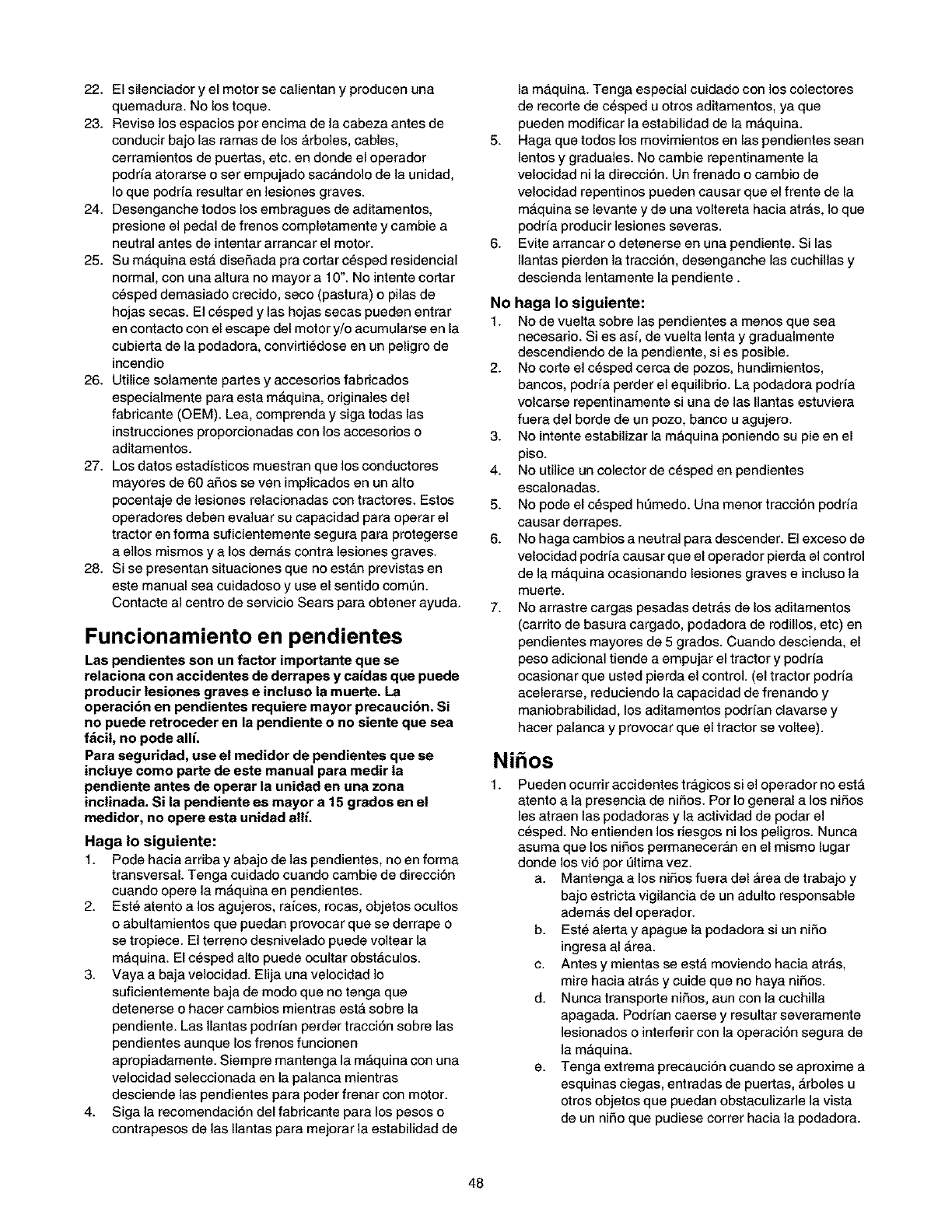
22.Elsilenciadoryelmotorseca]ientanyproducenuna
quemadura.Nolostoque.
23.Reviselosespaciosporencimadelacabezaantesde
conducirbajolasramasdelos_,rboles,cables,
cerramientosdepuertas,etc.endondeeloperador
podffaatorarseoserempujadosac_,ndolodelaunidad,
Ioquepodrfaresultarenlesionesgraves.
24.Desenganchetodoslosembraguesdeaditamentos,
presioneelpedaldefrenoscompletamenteycambiea
neutralantesdeintentararrancarelmotor.
25.SumAquinaestAdisefiadapracortarc_spedresidencial
normal,conunaalturanomayora10".Nointentecortar
c_speddemasiadocrecido,seco(pastura)opilasde
hojassecas.Elc_spedylashojassecaspuedenentrar
encontactoconelescapedelmotory/oacumularseenla
cubiertadelapodadora,convirli_doseenunpeligrode
incendio
26.Utilicesolamentepartesyaccesoriosfabricados
especialmenteparaestamAquina,origina]esdel
fabricante(OEM).Lea,comprendaysigatodaslas
instruccionesproporcionadasconlosaccesorioso
aditamentos.
27.Losdatosestadisticosmuestranquelosconductores
mayoresde60afiosseyenimplicadosenunalto
pocentajedelesionesrelacionadascontractores.Estos
operadoresdebenevaluarsucapacidadparaoperarel
tractorenformasuficientementeseguraparaprotegerse
aellosmismosyalosdem_,scontralesionesgraves.
28.Sisepresentansituacionesquenoest_,nprevistasen
estemanualseacuidadosoyuseelsentidocomen.
ContactealcentrodeservicioSearsparaobtenerayuda.
Funcionamiento en pendientes
Las pendientes son un factor importante que se
relaciona con accidentes de derrapes y caidas que puede
producir lesiones graves e incluso la muerte. La
operaei6n en pendientes requiere mayor preeauei6n. Si
no puede retroceder en la pendiente o no siente que sea
fdcil, no pode allL
Para seguridad, use el medidor de pendientes que se
ineluye como parte de este manual para medir la
pendiente antes de operar la unidad en una zona
inclinada. Si la pendiente es mayor a 15 grados en el
medidor, no opere esta unidad allL
Haga Io siguiente:
1. Pode hacia arriba y abajo de las pendientes, no en forma
transversal. Tenga cuidado cuando cambie de direcci6n
cuando opere la mAquina en pendientes.
2. Est_ atento a los agujeros, ra/ces, rocas, objetos ocultos
o abultamientos que puedan provocar que se derrape o
se tropiece. E] terreno desnivelado puede voltear la
mAquina. El c_sped alto puede ocu]tar obstAculos.
3. Vaya a baja velocidad. Elija una velocidad ]o
suficientemente baja de modo que no tenga que
detenerse o hacer cambios mientras estA sobre la
pendiente. Las Ilantas poddan perder tracci6n sobre las
pendientes aunque los frenos funcionen
apropiadamente. Siempre mantenga la mAquina con una
velocidad seleccionada en la pa]anca mientras
desciende las pendientes para poder frenar con motor.
4. Siga la recomendaci6n del fabricante para los pesos o
contrapesos de las Ilantas para mejorar la estabilidad de
la m_,quina. Tenga especial cuidado con los colectores
de recorte de c_sped u otros aditamentos, ya que
pueden modificar la estabilidad de la mAquina.
5. Haga que todos los movimientos en las pendientes sean
lentos y graduales. No cambie repentinamente la
velocidad ni la direcci6n. Un frenado o cambio de
velocidad repentinos pueden causar que el frente de la
mAquina se levante y de una voltereta hacia arras, Io que
podria producir lesiones severas.
6. Evite arrancar o detenerse en una pendiente. Si las
Ilantas pierden la tracci6n, desenganche las cuchii]as y
descienda lentamente la pendiente.
No haga Io siguiente:
1. No de vuelta sobre las pendientes a menos que sea
necesario. Si es as{, de vuelta lenta y gradualmente
descendiendo de la pendiente, si es posible.
2. No corte el c_sped cerca de pozos, hundimientos,
bancos, podffa perder el equilibdo. La podadora podffa
volcarse repentinamente si una de las Ilantas estuviera
fuera del borde de un pozo, banco u agujero.
3. No intente estabilizar la mAquina poniendo su pie en el
piso.
4. No utilice un colector de c_sped en pendientes
escalonadas.
5. No pode el c_sped hemedo. Una menor tracci6n podffa
causar derrapes.
6. No haga cambios a neutral para descender. El exceso de
velocidad podda causar que el operador pierda el control
de la mAquina ocasionando lesiones graves e incluso la
muerte.
7. No arrastre cargas pesadas detr_,s de los aditamentos
(carrito de basura cargado, podadora de rodillos, etc) en
pendientes mayores de 5 grados. Cuando descienda, el
peso adicional tiende a empujar el tractor y podda
ocasionar que usted pierda el control. (el tractor podffa
acelerarse, reduciendo la capacidad de frenando y
maniobrabilidad, los aditamentos podrfan clavarse y
hacer palanca y provocar que el tractor se voltee).
Nihos
Pueden ocurrir accidentes tr_,gicos si el operador no estA
atento a la presencia de nifios. Por Io general a los nifios
les atraen las podadoras y la actividad de podar el
c_sped. No entienden los riesgos ni los peligros. Nunca
asuma que los nifios permaneceran en el mismo lugar
donde los vi6 por eltima vez.
a. Mantenga a los nifios fuera del Area de trabajo y
bajo estricta vigilancia de un adulto responsable
ademas del operador.
b. Est_ alerta y apague la podadora si un nifio
ingresa al Area.
c. Antes y mientas se est,, moviendo hacia arras,
mire hacia atrAs y cuide que no haya nifios.
d. Nunca transporte nifios, aun con la cuchilla
apagada. Poddan caerse y resultar severamente
]esionados o interferir con la operaci6n segura de
la mAquina.
e. Tenga extrema precauci6n cuando se aproxime a
esquinas ciegas, entradas de puertas, Arboles u
otros objetos que puedan obstaculizade la vista
de un nifio que pudiese correr hacia la podadora.
1+
48
f. Desenganche las cuchillas antes de colocar la
reversa. La funciOn de "No-Cortar-En Reversa"
evita accidentes, no trate de hacer que funcione
de otro modo.
g. Mantenga alejados a los niOos de los motores en
marcha o calientes. Pueden sufrir quemaduras
con un silenciador caliente.
h. Retire la Ilave cuando deje la m_.quina sin
atenciOn para prevenir el funcionamiento no
autorizado.
2. No permita nunca que los niOos menores de 14 aOos
operen esta m_.quina. Los niOos mayores de 14 a£_os
deben leer y entender las instrucciones de operacion y
reglas de seguridad contenidas en este manual y deben
ser entrenados y supervisados por sus padres.
Servicio
Manejo seguro de la gasolina
1. Para evitar lesiones o da_os sea sumamente cuidadoso
al manipular la gasolina. La gasolina es altamente
inflamable y los vapores son explosivos.. Se puede
lesionar gravemente si derrama gasolina sobre usted o
sobre la ropa ya que se puede encender. Lave la piel y
cambiese de ropa de inmediato..
a. Utilice solo recipientes para gasolina autorizados.
b. Nunca Ilene los contenedores en el interior de un
vehiculo o camion o caja de camioneta con
recubrimientos pl_.sticos. Coloque siempre los
contenedores en el piso lejos del vehiculo antes
de Ilenados.
c. Cuando sea pr_.ctico, retire el equipo a gasolina
del camion o remolque y II_nelo en el piso. Si esto
no es posible, Ilene el equipo en un remolque con
contenedor port_,til, en vez de desde un
dispensador de gasolina.
d. Mantenga la boquilla de Ilenado en contacto con
el borde de la entrada del tanque de gasolina o
contenedor en todo momento hasta que est_
]leno. No utilice un dispositivo para abrir/cerrar la
boquilla.
e. Apague todos los cigarriUos, cigarros, pipas y
otras fuentes de combustion.
f. Nunca cargue combustible en la m_quina en un
espacio cerrado.
g. Nunca saque la tapa del gas ni agregue
combustible mientras el motor est_ caliente o en
marcha. Deje que el motor se enfrie por lo menos
dos minutos antes de volver a cargar combustible.
h. Nunca recargue el tanque de combustible. Llene
el tanque no m_s de 112pulgada por debajo de la
base del cuel]o del filtro para dejar espacio para la
dilataciOn del combustible..
i. VueIva a colocar la tapa de la gasolina y aj_3stela
bien.
j. Limpie la gasolina derramada sobre el motor y el
equipo. Traslade la m_quina a otra zona. Espere
5 minutos antes de encender el motor.
k. Para reducir el riesgo de incendio mantenga la
m_,quina limpia de pasto, hojas y de acumulaciOn
de otros escombros. Limpie los derrames de
aceite o combustible y saque todos los
escombros embebidos con combustible..
L Nunca almacene la m_quina o el recipiente de
combustible en un espacio cerrado donde haya
fuego, chispas o luz piloto como por ejemplo,
calentadores de agua, homos, secadores de
ropa, otros aparatos a gas, etc.
m. Deje que la maquina se enfrie 5 minutos por Io
menos antes de almacenada.
Servicio general
1. Nunca encienda un motor en espacios cerrados o en una
zona con poca ventilaciOn. El escape del motor contiene
mon6xido de carbono, un gas inodoro y letaL.
2. Antes de limpiar, reparar o inspeccionar la m_.quina,
compruebe que la cuchilla y todas las partes que se
mueven se hallan detenido. Desconecte el cable de la
bujia y pOngalo de manera que haga masa contra el
motor para evitar que se encienda de manera accidental.
3. Revise peri0dicamente paraasegurarse de que las
cuchillas se detengan por completo en aproximadamente
cinco (%) segundos despu_s de accionar el control de
desenganche. Si las cuchinas no se detienen en este
tiempo, su unidad debe ser reparada por un profesional
en un centro de servicio autorizado.
4. Revise con frecuencia el funcionamiento del sistema de
frenos ya que est,. sujeto a desgaste por la operaci6n
normal. Ajuste/de servicio segpun se requiera.
5. Revise los pemos de montaje de la cuchilla y del motor a
intervalos frecuentes para verificar que est_n bien
apretados. Adem_,s, inspeccione visualmente la cuchilla
en busca de daOos (desgaste excesivo, abonaduras,
cuarteaduras, etc)
Reemplace las cuchillas s01ocon partes de los
fabricantes de equipos originales (O.E.M) listadas en
este manual. "La utilizaci0n de partes que no cumplan
con las especificaciones de equipos originales podria
tener como resultado un rendimiento incorrecto y
ademas la seguridad podria estar comprometida"
6. Las cuchillas de las podadoras son muy afiladas y
podrian cortado. Envuelva la cuchilla o utilice guantes y
extreme precauciones cuando le de servicio.
7. Mantenga todos los pernos, tuercas ytomillos bien
ajustados para asegurarse que la m_,quina se encuentra
en condiciones seguras de operacion
8. Nunca intente violar el sistema de bloqueo de seguridad
u otros mecanismos de seguridad. Verifique
regularmente si funciona de manera correcta.
9. Despu_s de golpear con algun objeto extraOo, detenga el
motor, desconecte el cable de la bujia y conecte el motor
a masa. Inspeccione minuciosamente para ver si la
m_quina esta daOada. Repare el daOo antes de arrancar
y operar.
10. Nunca trate de hacer ajustes o reparaciones a la
m_.quina mientras el motor estA en marcha.
11. Los componentes de la tolva para recorte y la cubierta de
descarga, estAn sujetos a desgaste y da£_osque podria
dejar expuestas partes que se mueven o permitir que se
arrojen objetos. Para proteger su seguridad, verifique
frecuentemente todos los componentes y reempl_.celos
s01o con partes de los fabricantes de equipos odginales
(O.E.M.) listadas en este manual. "La utilizaci6n de
partes que no cumplan con las especificaciones de
equipos originales podria tener como resultado un
rendimiento incorrecto y ademAs la seguridad podria
estar comprometida"
49
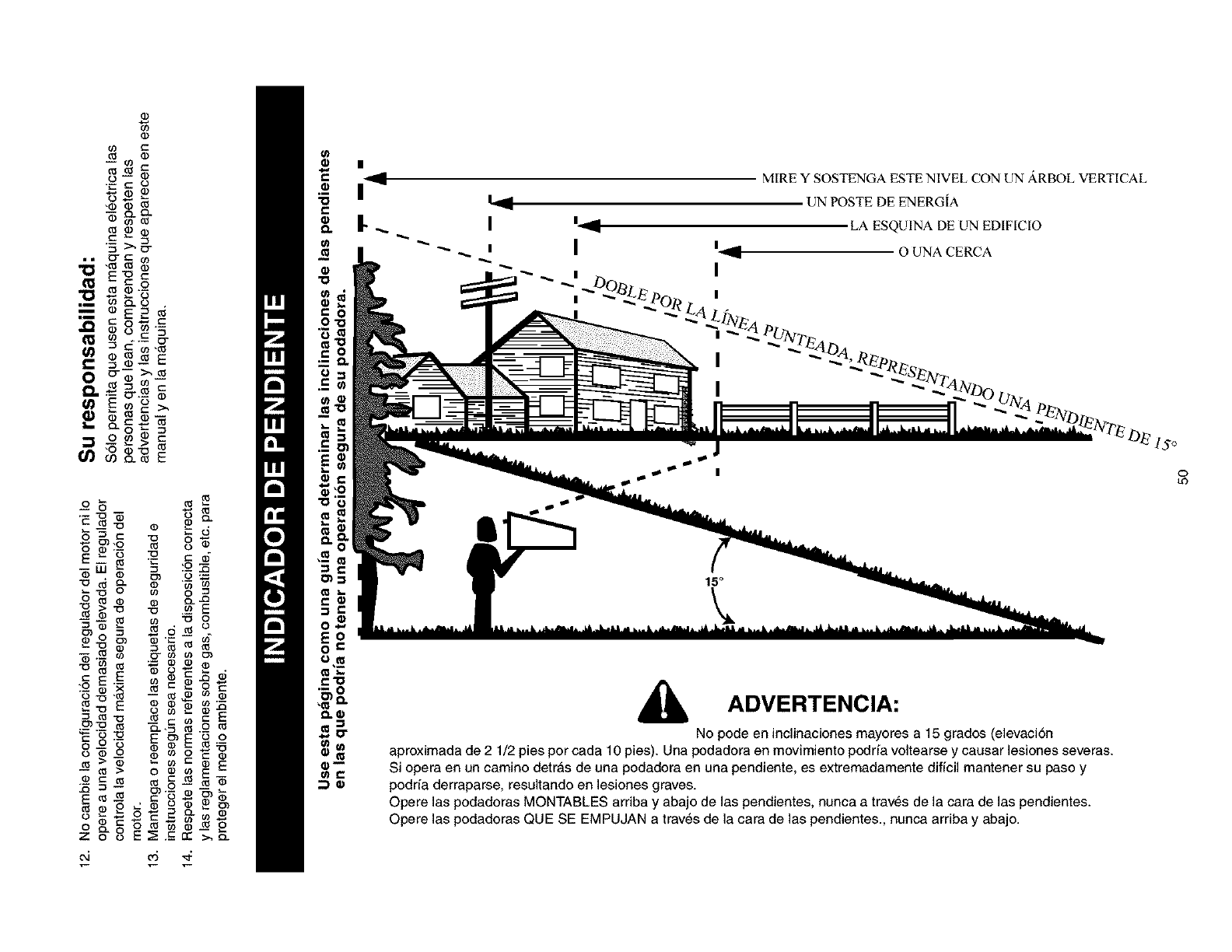
03
03
e3 03
-- 69
o_ cm 03
-,d_ .¢
-03 03
03_
_0303
03" C qj
03
m.-°
co 03.o
c_c
Q. ,- _.__ 03
_ 03_ 03N
0 _ 03 _
0_ 03
-o __.__E
--_ "o o
_d_ o
.-_ o-_
0
--_> ooeEE
03 c'5_ m _ _ o
o cz o
Z o o E:_.-err >._-
o_ 05 ,_
m
c
c
&
|
I
I
MIRE Y SOSTENGA ESTE NIVEL CON UN ARBOL VERTICAL
UN POSTE DE ENERGIA
LA ESQUINA DE UN EDIFICIO
O UNA CERCA
ADVERTENCIA:
No pode en inclinaciones mayores a 15 grados (elevaci6n
aproximada de 2 1/2 pies pot cada 10 pies). Una podadora en movimiento podda voltearse y eausar lesiones severas.
Si opera en un camino detras de una podadora en una pendiente, es extremadamente difieil mantener su paso y
podria derraparse, resultando en lesiones graves.
Opere las podadoras MONTABLES arriba y abajo de las pendientes, nunca a traves de la cara de las pendientes.
Opere las podadoras QUE SE EMPUJAN a trav_s de la cara de las pendientes., nunca arriba y abajo.
15o
0
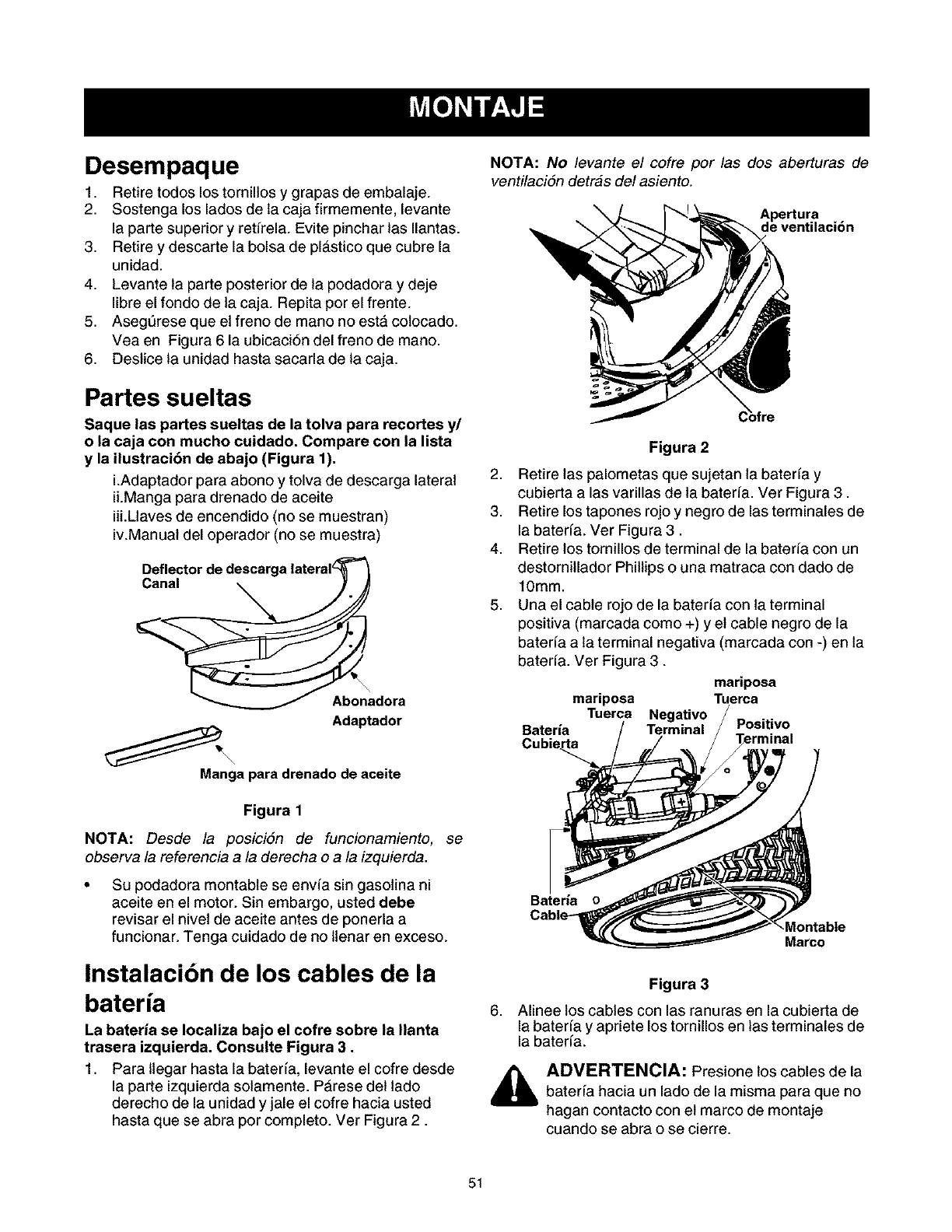
Desempaque
1. Retire todos los tornillos y grapas de embalaje.
2. Sostenga los lados de la caja firmemente, levante
la parte superior y retffela. Evite pinchar las Ilantas.
3. Retire y descarte la bolsa de plastico que cubre la
unidad.
4. Levante la parte posterior de la podadora y deje
libre el fondo de la caja. Repita por el frente.
5. Asegt_rese que et freno de mano no estA colocado.
Vea en Figura 6 la ubicaci6n del freno de mane.
6. Deslice la unidad hasta sacarla de la caja.
Partes sueltas
Saque las partes sueltas de la tolva para recortes y/
o la caja con mucho cuidado. Compare con la lista
y la ilustracibn de abajo (Figura 1).
i.Adaptador para abono y tolva de descarga lateral 2.
iLManga para drenado de aceite
iii.Llaves de encendido (no se muestran) 3.
iv.Manual del operador (no se muestra) 4.
Deflector de descarga lateral_ "_
Canal _/_
Abonadora
Adaptador
Manga para drenado de aceite
Figura 1
NOTA: Desde la posici6n de funcionamiento, se
observa la referencia a la derecha oa la izquierda.
Su podadora montable se envfa sin gasolina ni
aceite en el motor. Sin embargo, usted debe
revisar el nivet de aceite antes de ponerla a
funcionar. Tenga cuidado de no ltenar en exceso.
Instalacibn de los cables de la
bateria
La bateria se Iocaliza bajo el cofre sobre la Ilanta
trasera izquierda. Consulte Figura 3.
1. Para ltegar hasta la baterfa, levante el cofre desde
la parte izquierda solamente. PArese det lade
derecho de la unidad y jale el cofre hacia usted
hasta que se abra per completo. Ver Figura 2.
NOTA: No levante el cofre por las dos aberturas de
ventilaci6n detras del asiento.
Apertura
de ventilacibn
5,
Figura 2
Retire las palometas que sujetan la baterfa y
cubierta alas varillas de la baterfa. Ver Figura 3.
Retire los tapones rojo y negro de las terminales de
la bater[a. Ver Figura 3.
Retire los tornillos de terminal de la bateda con un
destornitlador Phillips o una matraca con dado de
10mm.
Una el cable rojo de la bateda con la terminal
positiva (marcada como +) y et cable negro de la
baterfa a la terminal negativa (marcada con -) en la
baterfa. Ver Figura 3.
mariposa
mariposa Tuerca
Tuerca Negativo
Bateria Terminal Positivo
Cubie_.._
Bateria o
Montable
Marco
,
Figura 3
Alinee los cables con las ranuras en la cubierta de
la baterfa y apriete los tornillos en las terminales de
la baterfa.
ADVERTENCIA: Presione los cables de la
bater[a hacia un lado de la misma para que no
hagan contacto con et marco de montaje
cuando se abra o se cierre.
51
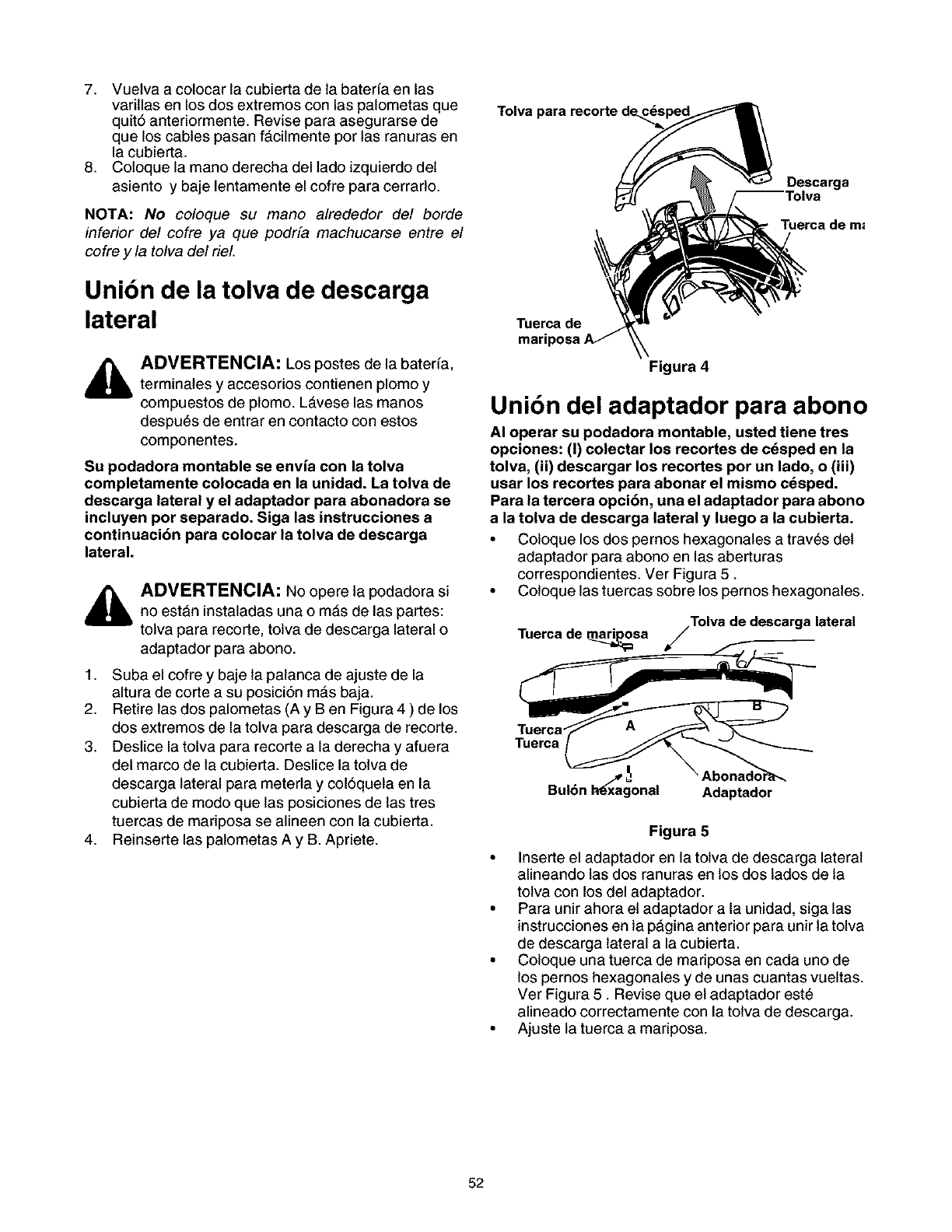
7. Vuetva a colocar la cubierta de la baterfa en las
varillas en los dos extremos con las palometas que
quit6 anteriormente. Revise para asegurarse de
que los cables pasan facilmente por las ranuras en
la cubierta.
8. Coloque la mano derecha del lado izquierdo det
asiento y baje lentamente el cofre para cerrarlo.
NOTA: No coloque su mano alrededor del borde
inferior del cofre ya que podrfa machucarse entre el
cofre y la tolva del rieL
Unibn de la tolva de descarga
lateral
Tolva para recorte de
Tuerca de
Descarga
Tuerca de m=
ADVERTENCIA: Los postes de la baterfa,
terminales y accesorios contienen plomo y
compuestos de plomo. La.vese las manos
despu_s de entrar en contacto con estos
componentes.
Su podadora montable se envia con la tolva
completamente colocada en la unidad. La tolva de
descarga lateral y el adaptador para abonadora se
incluyen por separado. Siga las instrucciones a
continuacibn para colocar la tolva de descarga
lateral.
1.
2.
3.
4,
ADVERTENCIA: No opere la podadora si
no est&n instaladas una o m&s de las partes:
tolva para recorte, tolva de descarga lateral o
adaptador para abono.
Suba el cofre y baje la palanca de ajuste de la
altura de corte a su posici6n ma.s baja.
Retire las dos palometas (A y Ben Figura 4 ) de los
dos extremos de la tolva para descarga de recorte.
Destice la tolva para recorte a la derecha y afuera
del marco de la cubierta. Deslice la tolva de
descarga lateral para meterla y col6queta en la
cubierta de modo que las posiciones de las tres
tuercas de madposa se alineen con la cubierta.
Reinserte las palometas A y B. Apriete.
Figura 4
Unibn del adaptador para abono
AI operar su podadora montable, usted tiene tres
opciones: (I) colectar los recortes de c_sped en la
tolva, (ii) descargar los recortes por un lado, o (iii)
usar los recortes para abonar el mismo cdsped.
Para la tercera opcibn, una el adaptador para abono
a la tolva de descarga lateral y luego a la cubierta.
•Coloque los dos pemos hexagonales a tray,s det
adaptador para abono en las aberturas
correspondientes. Ver Figura 5.
• Coloque las tuercas sobre los pernos hexagonales.
Tuerca de mari_osa /Tolva de descarga lateral
Tuerca_ _ f_---'_
uerca
Bul6n I-_xagonal Adaptado"_ _ _°°naa°rra_
Figura 5
• Inserte el adaptador en la tolva de descarga lateral
alineando las dos ranuras en los dos lados de la
tolva con los del adaptador.
• Para unir ahora et adaptador a la unidad, siga las
instrucciones en la pAgina anterior para unir la tolva
de descarga lateral a la cubierta.
• Coloque una tuerca de madposa en cada uno de
los pernos hexagonales y de unas cuantas vueltas.
Ver Figura 5. Revise que et adaptador est_
alineado correctamente con la tolva de descarga.
• Ajuste la tuerca a mariposa.
52
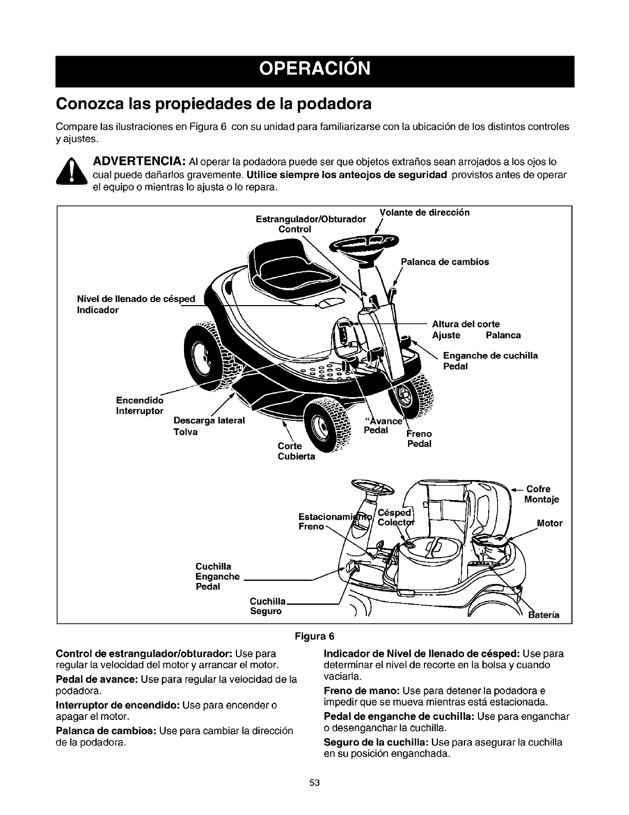
Conozca las propiedades de la podadora
Compare las ilustraciones en Figura 6 con su unidad para famitiarizarse con la ubicaci6n de los distintos controles
y ajustes.
_lb ADVERTENCIA: AI operar la podadora puede ser que objetos extra_os sean arrojados a los ojos 1ocual puede da_arlos gravemente. Utilice siempre los anteojos de seguridad provistos antes de operar
el equipo o mientras 1oajusta o Io repara.
Volante de direcci6n
Estrangulador/Obturador
Control
Palanca de cambios
Nivel de Ilenado de c_sped
Indicador
corte
Ajuste Palanca
Enganche de cuchilla
Pedal
Encendido
Interrupter Descarga lateral
Tolva
Corte
Cubierta
Pedal Freno
Pedal
Estacionami
Freno
•-- Cofre
Montaje
Motor
Cuchilla
Enganche
Pedal
Segum
Figura 6
Control de estrangulador/ebturador: Use para
regular la velocidad det motor y arrancar el motor.
Pedal de avance: Use para regular la vetocidad de la
podadora.
Interrupter de encendido: Use para encender o
apagar el motor.
Palanca de cambios: Use para cambiar la direcci6n
de la podadora.
Indicador de Nivel de Ilenado de c_sped: Use para
determinar el nivel de recorte en la bolsa y cuando
vaciarla.
Frene de mane: Use para detener la podadora e
impedir que se mueva mientras esta estacionada.
Pedal de enganche de cuchilla: Use para enganchar
o desenganchar la cuchilla.
Seguro de la cuchilla: Use para asegurar la cuchitla
en su posici6n enganchada.
53
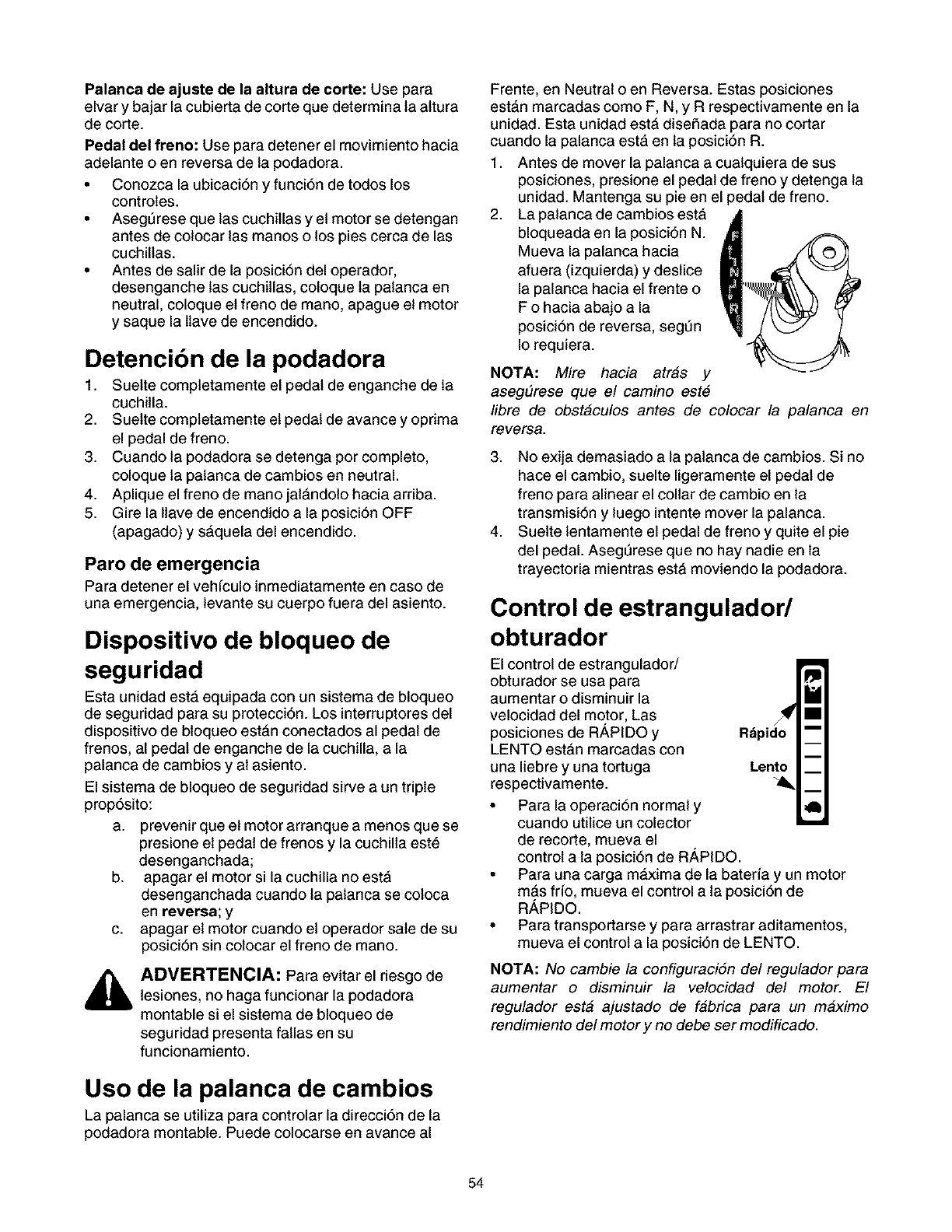
Palanca de ajuste de la altura de corte: Use para
elvar y bajar la cubierta de corte que determina la altura
de corte.
Pedal del freno: Use para detener el movimiento hacia
adelante o en reversa de la podadora.
• Conozca la ubicaci6n y funci6n de todos los
controles.
• Asegt_rese que las cuchitlas y et motor se detengan
antes de colocar las manos o los pies cerca de las
cuchillas.
• Antes de salir de la posici6n del operador,
desenganche tas cuchitlas, coloque la palanca en
neutral, coloque et freno de mano, apague et motor
y saque la ltave de encendido.
Detencibn de la podadora
1. Suette completamente el pedal de enganche de la
cuchilla.
2. Suette completamente et pedal de avance y opdma
el pedal de freno.
3. Cuando la podadora se detenga por completo,
coloque la palanca de cambios en neutral.
4. Aplique el freno de mano jala.ndolo hacia arriba.
5. Gire la llave de encendido a la posici6n OFF
(apagado) y sAquela del encendido.
Paro de emergencia
Para detener el vehfculo inmediatamente en caso de
una emergencia, levante su cuerpo fuera del asiento.
Dispositivo de bloqueo de
seguridad
Esta unidad esta. equipada con un sistema de bloqueo
de seguridad para su protecci6n. Los interruptores del
dispositivo de bloqueo esta.n conectados al pedal de
frenos, al pedal de enganche de la cuchilla, a la
palanca de cambios y al asiento.
El sistema de bloqueo de seguridad sirve a un triple
prop6sito:
a. prevenir que et motor arranque a menos que se
presione et pedal de frenos y la cuchilla este
desenganchada;
b. apagar el motor si la cuchilla no esta
desenganchada cuando la palanca se coloca
en reversa; y
c. apagar et motor cuando et operador sale de su
posici6n sin colocar el freno de mano.
ADVERTENCIA: Para evitar el riesgo de
lesiones, no haga funcionar la podadora
montable si el sistema de bloqueo de
seguridad presenta fallas en su
funcionamiento.
Uso de la palanca de cambios
La palanca se utiliza para controlar la direcci6n de la
podadora montable. Puede colocarse en avance al
Frente, en Neutral o en Reversa. Estas posiciones
esta.n marcadas como F, N, y R respectivamente en la
unidad. Esta unidad estA diseSada para no cortar
cuando la palanca esta. en la posici6n R.
1. Antes de mover la palanca a cualquiera de sus
posiciones, presione el pedal de freno y detenga la
unidad. Mantenga su pie en el pedal de freno.
2. La palanca de cambios esta.
bloqueada en la posici6n N.
Mueva la palanca hacia
afuera (izquierda) y destice
la palanca hacia el frente o
F o hacia abajo a la
posici6n de reversa, segt_n
Io requiera.
NOTA: Mire hacia atras y
aseg#rese que el camino est6
libre de obstaculos antes de colocar la palanca en
reversa.
3. No exija demasiado a la palanca de cambios. Si no
hace el cambio, suelte ligeramente el pedal de
freno para alinear el collar de cambio en la
transmisi6n y luego intente mover la palanca.
4. Suette lentamente el pedal de freno y quite el pie
del pedal. Asegt_rese que no hay nadie en la
trayectoria mientras estA moviendo la podadora.
Control de estrangulador/
obturador
El control de estrangulador/
obturador se usa para
aumentar o disminuir la
velocidad del motor, Las
posiciones de R,_,PIDO y
LENTO estan marcadas con
una Iiebre y una tortuga
respectivamente.
• Para la operaci6n normal y
cuando utilice un colector
de recorte, mueva el
control a la posici6n de R,_,PIDO.
• Para una carga m&xima de la bateda y un motor
mas fifo, mueva el control a la posici6n de
RAPIDO.
• Para transportarse y para arrastrar aditamentos,
mueva el control a la posici6n de LENTO.
NOTA: No cambie la configuraci6n de/regulador para
aumentar odisminuir la velocidad del motor. El
regulador esta ajustado de fabrica para un maximo
rendimiento del motor y no debe ser modificado.
54
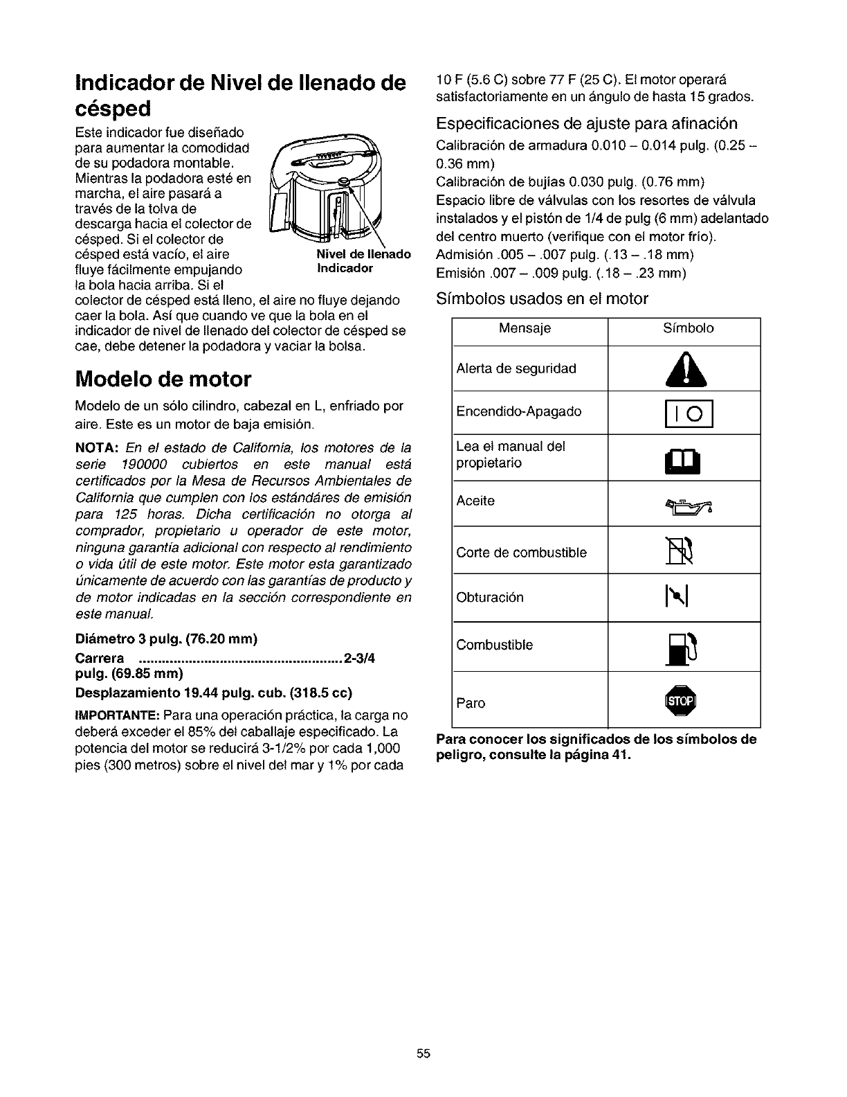
Indicador de Nivel de Ilenado de
cdsped
Este indicador fue diseSado
para aumentar la comodidad
de su podadora montable.
Mientras la podadora est_ en
marcha, el aire pasarA a
trav_s de la tolva de
descarga hacia et colector de
cesped. Si el colector de
cesped esta. vacfo, et aire
fluye fa.cilmente empujando
la bola hacia ardba. Si et
Nivel de Ilenado
|ndicador
colector de cesped estA Ileno, el aire no fluye dejando
caer la bola. As[ que cuando ve que la bola en el
indicador de nivel de Ilenado del colector de cesped se
cae, debe detener la podadora y vaciar la bolsa.
Modelo de motor
Modelo de un s61o cilindro, cabezal en L, enfriado por
aire. Este es un motor de baja emisi6n.
NOTA: En el estado de California, los motores de la
serie 190000 cubiertos en este manual esta
certificados por la Mesa de Recursos Ambientales de
California que cumplen con los estandares de emision
para 125 horas. Dicha certificacidn no otorga al
comprador, propietario u operador de este motor,
ninguna garantfa adicional con respecto al rendimiento
o vida #til de este motor. Este motor esta garantizado
#nicamente de acuerdo con las garantfas de producto y
de motor indicadas en la secci6n correspondiente en
este manual
Didmetro 3 pulg. (76.20 mm)
Carrera ..................................................... 2-3/4
pulg. (69.85 ram)
Desplazamiento 19.44 pulg. cub. (318.5 cc)
IMPORTANTE: Para una operaci6n pr_ctica, la carga no
debera exceder el 85% det caballaje especificado. La
potencia del motor se reducirA 3-1/2% por cada 1,000
pies (300 metros) sobre el nivel det mar y 1% por cada
10 F (5.6 C) sobre 77 F (25 C). El motor operarA
satisfactoriamente en un Angulo de hasta 15 grados.
Especificaciones de ajuste para afinaci6n
Calibraci6n de armadura 0.010 - 0.014 pulg. (0.25 -
0.36 mm)
Calibraci6n de bujias 0.030 pulg. (0.76 mm)
Espacio libre de valvulas con los resortes de vMvula
instalados y el pist6n de 1/4 de pulg (6 mm) adelantado
del centro muerto (verifique con el motor frio).
Admisi6n .005 - .007 pulg. (.13 -. 18 mm)
Emisi6n .007 - .009 pulg. (. 18 - .23 ram)
Sfmbolos usados en el motor
Mensaje Sfmbolo
Alerta de seguridad ,_
Encendido-Apagado
Lea et manual del
propietario _[_
Aceite
Corte de combustible ]_,
Obturaci6n I_kl
Combustible ._
Paro @
Para conocer los significados de los simbolos de
peligro, consulte la pdgina 41.
55
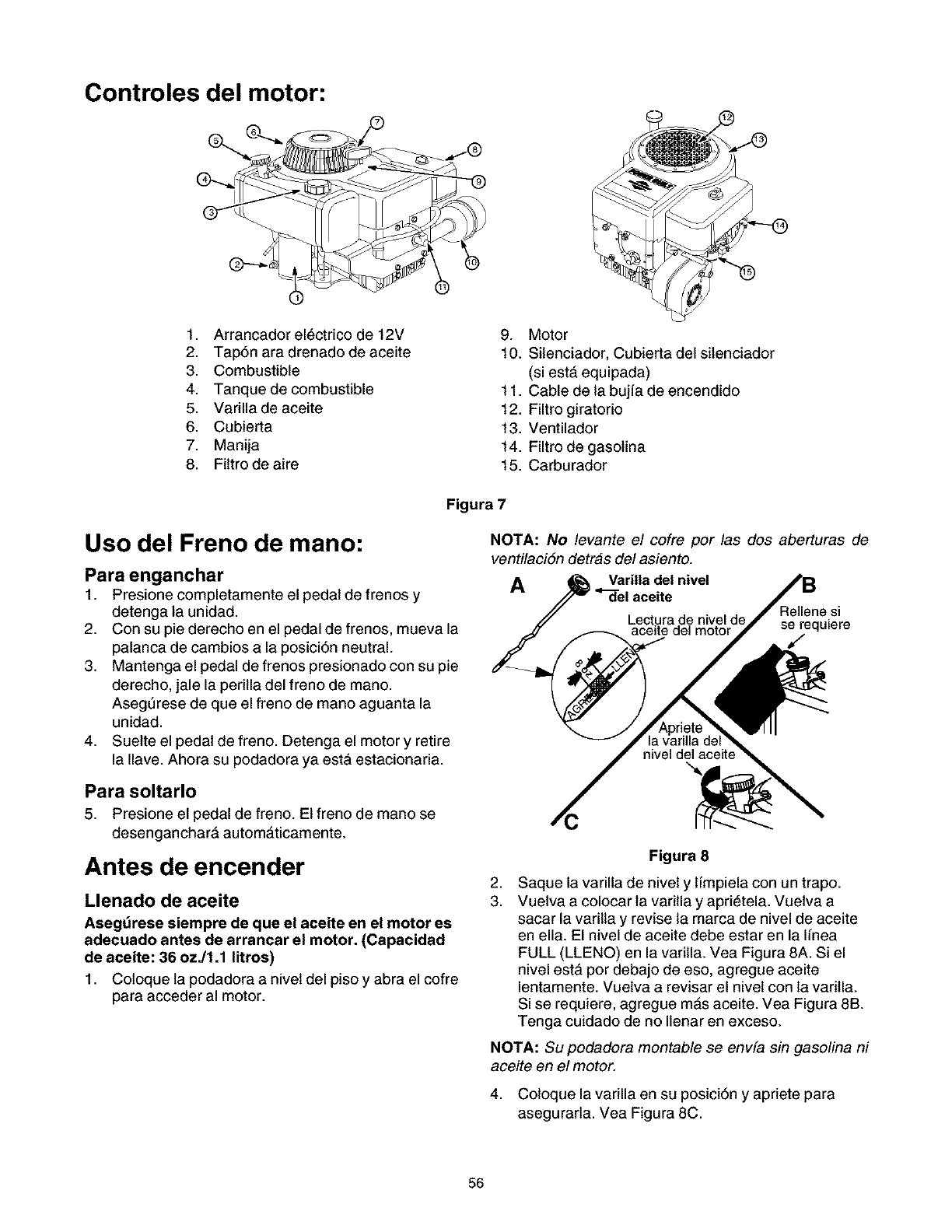
Controles del motor:
1. Arrancador el_ctrico de 12V
2. Tap6n ara drenado de aceite
3. Combustible
4. Tanquede combustible
5. Varilla de aceite
6. Cubierta
7. Manija
8. Fittro de aire
9. Motor
10. Silenciador, Cubierta del sitenciador
(siesta. equipada)
11. Cable de la bujfa de encendido
12. Filtro giratorio
13. Ventilador
14. Filtro de gasolina
15. Carburador
Uso del Freno de mano:
Para enganchar
1. Presione completamente el pedal de frenos y
detenga la unidad.
2. Con su pie derecho en el pedal de frenos, mueva la
palanca de cambios a la posici6n neutral.
3. Mantenga el pedal de frenos presionado con su pie
derecho, jale la peritla del freno de mano.
AsegtJrese de que el freno de mano aguanta la
unidad.
4. Suette el pedal de freno. Detenga el motor y retire
la Ilave. Ahora su podadora ya esta estacionaria.
Para soltarlo
5. Presione el pedal de freno. El freno de mano se
desengancharA automaticamente.
Antes de encender
Llenado de aceite
Asegdrese siempre de que el aceite en el motor es
adecuado antes de arrancar el motor. (Capacidad
de aceite: 36 ozJ1.1 litros)
1. Coloque la podadora a nivet del piso y abra el cofre
para acceder al motor.
Figura 7
NOTA: No levante el cofre por las dos aberturas de
ventilaci6n detras del asiento.
AVarilla del nivel
aceite Rellene si
se requiere
J
2,
3.
Figura 8
Saque la varilla de nivet y l[mpiela con un trapo.
Vuetva a colocar la varitla y aprietela. Vuetva a
sacar la varilta y revise ta marca de nivel de aceite
en ella. El nivel de aceite debe estar en la Ifnea
FULL (LLENO) en la varitla. Vea Figura 8A. Si el
nivel esta. por debajo de eso, agregue aceite
lentamente. Vuetva a revisar el nivet con la varitla.
Si se requiere, agregue m&s aceite. Vea Figura 8B.
Tenga cuidado de no Ilenar en exceso.
NOTA: Su podadora montable se envfa sin gasolina ni
aceite en el motor.
4. Coloque la varilla en su posici6n y apriete para
asegurarla. Vea Figura 8C.
56
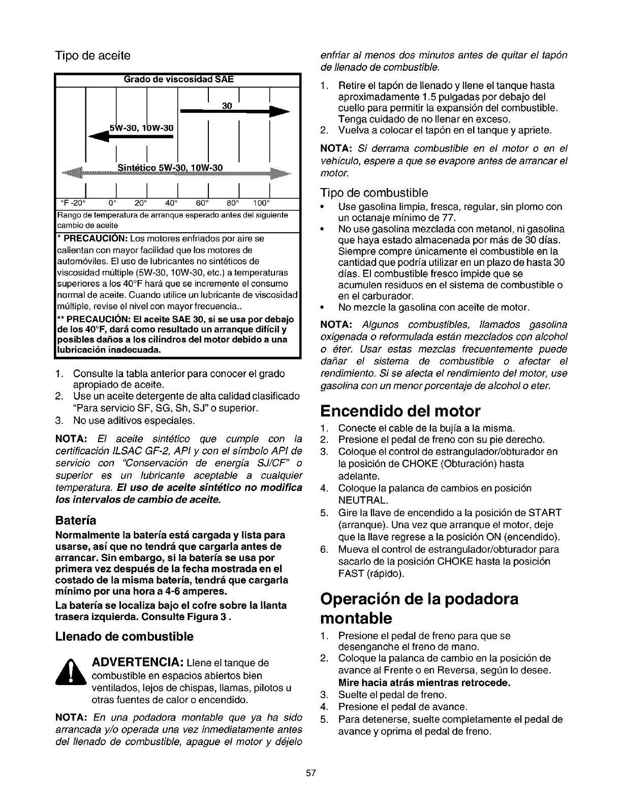
Tipo de aceite
Grado de viscosidad SAE
I30
_=5 N-30, 1)W-30
I I
I I
Y
I I I I I
°F -20 ° 0 ° 20 °40 °60 °80 ° 1O0°
:_ango de temperatura de arranque esperado antes del siguiente
.-arnbio de aceite
PRECAUCION: Los motores enfriados por aire se
;alientan con mayor facilidad que los motores de
]utom6viles. El uso de lubricantes no sint_ticos de
Jiscosidad multiple (5W-30, 10W-30, etc.) a temperaturas
_uperiores a los 40°F har_, que se incremente el consumo
_ormal de aceite. Cuando utilice un lubricante de viscosidad
"neltiple, revise el nivel con mayor frecuencia..
'* PRECAUCI(_N: El aceite SAE 30, si se usa por debajo
:le los 40°F, dark como resultado un arranque dificil y
,osibles da£=os alos cilindros del motor debido a una
iubricaci6n inadecuada.
1. Consulte la tabla anterior para conocer el grado
apropiado de aceite.
2. Use un aceite detergente de alta calidad clasificado
"Para servicio SF, SG, Sh, SJ" o superior.
3. No use aditivos especiales.
NOTA: El aceite sint6tico que cumple con la
certificacion ILSAC GF-2, API y con el sfmbolo API de
servicio con "Conservacion de energfa SJ/CF" o
superior es un lubricante aceptable a cualquier
temperatura. El uso de aeeite sint#tieo no modifiea
los intervalos de cambio de aceite.
Ba_rm
Normalmente la bateria estd cargada y lista para
usarse, asi que no tendrd que cargarla antes de
arrancar. Sin embargo, si la bateHa se usa por
primera vez despu_s de la fecha mostrada en el
costado de la misma bateHa, tendrd que cargarla
minimo pot una hora a 4-6 amperes.
La bateria se Iocaliza bajo el cofre sobre la Ilanta
trasera izquierda. Consulte Figura 3.
Llenado de combustible
ADVERTENCIA: Ltene el tanque de
combustible en espacios abiertos bien
ventilados, lejos de chispas, llamas, pilotos u
otras fuentes de calor o encendido.
NOTA: En una podadora montable que ya ha side
arrancada y/o operada una vez inmediatamente antes
del Ilenado de combustible, apague el motor y d6jelo
enfriar al menos dos minutes antes de quitar el tapon
de Ilenado de combustible.
1. Retire el tap6n de Itenado y Ilene et tanque hasta
aproximadamente 1.5 pulgadas por debajo det
cuetlo para permitir la expansi6n del combustible.
Tenga cuidado de no Ilenar en exceso.
2. Vuetva a colocar el tap6n en el tanque y apriete.
NOTA: Si derrama combustible en el motor oen el
vehfculo, espere a que se evapore antes de arrancar el
motor.
Tipo de combustible
• Use gasolina limpia, fresca, regular, sin plomo con
un octanaje mfnimo de 77.
• No use gasolina mezclada con metanol, ni gasolina
que haya estado atmacenada por mas de 30 dfas.
Siempre compre Qnicamente et combustible en la
cantidad que podrfa utilizar en un plazo de hasta 30
dias. El combustible fresco impide que se
acumulen residuos en et sistema de combustible o
en el carburador.
• No mezcle la gasolina con aceite de motor.
NOTA: Algunos combustibles, Ilamados gasolina
oxigenada o reformulada estan mezclados con alcohol
o eter. Usar estas mezclas frecuentemente puede
dahar el sistema de combustible o afectar el
rendimiento. Si se afecta el rendimiento del motor, use
gasolina con un menor porcentaje de alcohol o eter.
Encendido del motor
1. Conecte et cable de la buj[a a la misma.
2. Presione el pedal de freno con su pie derecho.
3. Coloque et control de estrangulador/obturador en
la posici6n de CHOKE (Obturaci6n) hasta
adelante.
4. Coloque la palanca de cambios en posici6n
NEUTRAL.
5. Gire la ltave de encendido a la posici6n de START
(arranque). Una vez que arranque et motor, deje
que la Ilave regrese a la posici6n ON (encendido).
6. Mueva et control de estrangulador/obturador para
sacarlo de la posici6n CHOKE hasta la posici6n
FAST (rApido).
Operacibn de la podadora
montable
1. Presione el pedal de freno para que se
desenganche et freno de mano.
2. Coloque la palanca de cambio en la posici6n de
avance al Frente o en Reversa, segen Io desee.
Mire hacia atr&s mientras retrocede.
3. Suette el pedal de freno.
4. Presione el pedal de avance.
5. Para detenerse, suelte completamente et pedal de
avance y oprima el pedal de freno.
57
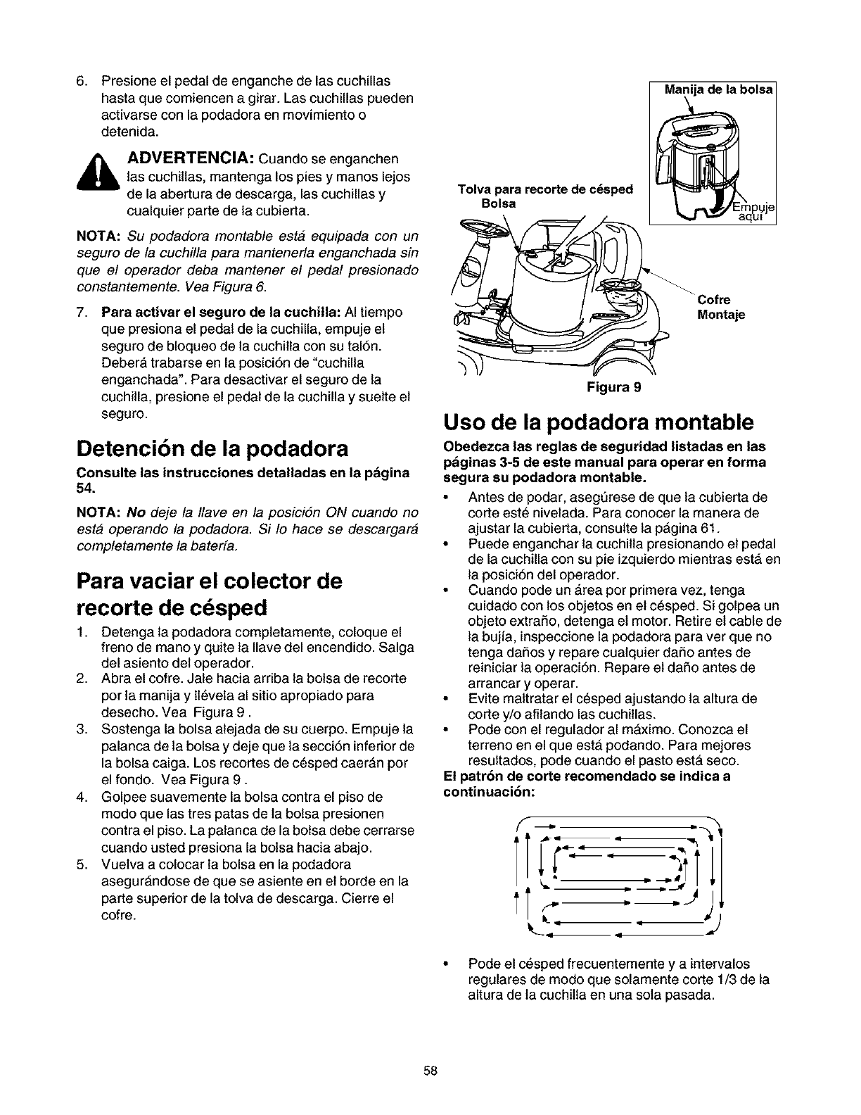
,Presione el pedal de enganche de las cuchillas
hasta que comiencen a girar. Las cuchillas pueden
activarse con la podadora en movimiento o
detenida.
ADVERTENCIA: Cuando se enganchen
las cuchitlas, mantenga los pies y manos lejos
de la abertura de descarga, las cuchillas y
cualquier parte de la cubierta.
NOTA: Su podadora montable esta equipada con un
seguro de la cuchilla para mantenerla enganchada sin
que el operador deba mantener el pedal presionado
constantemente. Vea Figura 6.
7, Para activar el seguro de la cuchilla: AI tiempo
que presiona el pedal de la cuchilla, empuje et
seguro de bloqueo de la cuchilta con su tal6n.
Debera trabarse en la posici6n de "cuchilla
enganchada". Para desactivar el seguro de la
cuchitla, presione el pedal de la cuchilla y suette et
seguro.
Detencibn de la podadora
Consulte las instrucciones detalladas en la pAgina
54.
NOTA: No deje la Ilave en la posici6n ON cuando no
esta operando la podadora. Si Io hace se descargara
completamente la bated&
Para vaciar el colector de
recorte de c sped
1. Detenga la podadora completamente, coloque el
freno de mano y quite la Ilave del encendido. Salga
del asiento det operador.
2. Abra el cofre. Jale hacia arriba la bolsa de recorte
por la manija y lt_veta al sitio apropiado para
desecho. Vea Figura 9.
3. Sostenga la bolsa alejada de su cuerpo. Empuje la
palanca de la bolsa y deje que la secci6n inferior de
la bolsa caiga. Los recortes de c_sped caerAn por
el fondo. Vea Figura 9.
4. Golpee suavemente la bolsa contra el piso de
modo que las tres patas de la bolsa presionen
contra el piso. La palanca de la bolsa debe cerrarse
cuando usted presiona la bolsa hacia abajo.
5. Vuetva a colocar la bolsa en la podadora
asegurAndose de que se asiente en et borde en la
parte superior de la tolva de descarga. Cierre el
cofre.
Tolva para recorte de c_sped
Bolsa
Manija de la bolsa
_ar_gl_J e
Montaje
Figura 9
Uso de la podadora montable
Obedezca las reglas de seguridad listadas en las
pAginas 3-5 de este manual para operar en forma
segura su podadora montable.
• Antes de podar, aseg6rese de que la cubierta de
corte est_ nivetada. Para conocer la manera de
ajustar la cubierta, consulte la pAgina 61.
• Puede enganchar la cuchilta presionando et pedal
de la cuchilla con su pie izquierdo mientras estA en
la posici6n del operador.
• Cuando pode un Area por primera vez, tenga
cuidado con los objetos en et c_sped. Si golpea un
objeto extrafio, detenga et motor. Retire et cable de
la bujia, inspeccione la podadora para ver que no
tenga dafios y repare cualquier dafio antes de
reiniciar la operaci6n. Repare et dafio antes de
arrancar y operar.
• Evite maltratar el c_sped ajustando la altura de
corte y/o afitando las cuchitlas.
• Pode con el regulador al mAximo. Conozca el
terreno en el que esta podando. Para mejores
resultados, pode cuando el pasto esta seco.
El patr6n de corte recomendado se indica a
continuacibn:
• Pode el c_sped frecuentemente y a intervalos
regulares de modo que solamente corte 1/3 de la
altura de la cuchitla en una sola pasada.
58
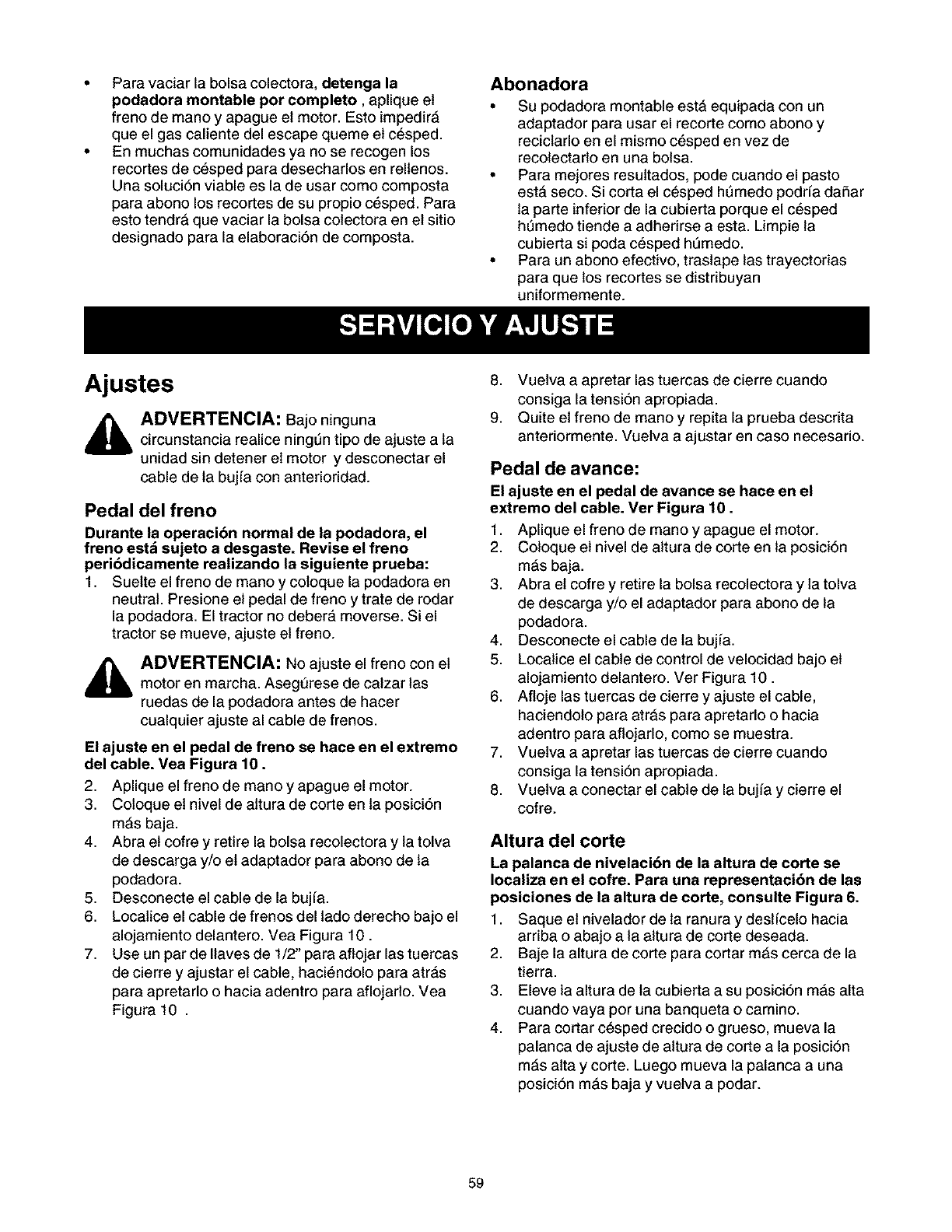
Paravaciarlabolsacolectora,detenga la
podadora montable per completo, aplique et
freno de mano y apague et motor. Esto impedir&
que el gas caliente del escape queme et c_sped.
En muchas comunidades ya no se recogen los
recortes de cesped para desecharlos en rellenos.
Una soluci6n viable es la de usar como composta
para abono los recortes de su propio c_sped. Para
esto tendrA que vaciar la bolsa colectora en et sitio
designado para la elaboraci6n de composta.
Abonadora
•Su podadora montable estA equipada con un
adaptador para usar el recorte como abono y
reciclarlo en el mismo c_sped en vez de
recolectarlo en una bolsa.
• Para mejores resultados, pode cuando el pasto
esta. seco. Si corta el c_sped hQmedo podrfa dafiar
la parte inferior de la cubierta porque el c_sped
hQmedo tiende a adherirse a esta. Limpie la
cubierta si poda cesped hQmedo.
• Para un abono efectivo, trastape las trayectorias
para que los recortes se distdbuyan
uniformemente.
Ajustes
ADVERTENCIA: Bajo ninguna
circunstancia realice ningt_ntipo de ajuste a la
unidad sin detener et motor ydesconectar el
cable de la bujfa con anterioridad.
Pedal del freno
Durante la operaci6n normal de la podadora, el
freno estd sujeto a desgaste. Revise el freno
peri6dicamente realizando la siguiente prueba:
1. Suette el freno de mano y coloque la podadora en
neutral. Presione et pedal de freno y trate de rodar
la podadora. El tractor no debera, moverse. Si el
tractor se mueve, ajuste et freno.
_ADVERTENCIA: No ajuste el freno con et
motor en marcha. Asegt_rese de calzar las
ruedas de la podadora antes de hacer
cualquier ajuste al cable de frenos.
El ajuste en el pedal de freno se hace en el extremo
del cable. Vea Figura 10.
2. Aplique el freno de mano yapague el motor.
3. Coloque et nivel de altura de corte en la posici6n
mAs baja.
4. Abra et cofre y retire la bolsa recolectora y la tolva
de descarga y/o et adaptador para abono de la
podadora.
5. Desconecte el cable de la bujfa.
6. Localice el cable de frenos del lado derecho bajo el
alojamiento delantero. Vea Figura 10.
7. Use un par de Ilaves de 1/2" para aflojar las tuercas
de cierre y ajustar el cable, haci_ndolo para atrAs
para apretarlo o hacia adentro para aflojarlo. Vea
Figura 10 .
8. Vuetva a apretar las tuercas de cierre cuando
consiga la tensi6n apropiada.
9. Quite et freno de mano y repita la prueba descrita
anteriormente. Vuetva a ajustar en caso necesario.
Pedal de avance:
El ajuste en el pedal de avance se hace en el
extremo del cable. Ver Figura 10.
1. Aplique el freno de mano yapague el motor.
2. Coloque et nivel de altura de corte en la posici6n
mAs baja.
3. Abra et cofre y retire la bolsa recolectora y la tolva
de descarga y/o el adaptador para abono de la
podadora.
4. Desconecte el cable de la bujfa.
5. Localice el cable de control de velocidad bajo et
alojamiento delantero. Ver Figura 10.
6. Afloje las tuercas de cierre y ajuste el cable,
haciendolo para atrAs para apretarlo o hacia
adentro para aflojarlo, como se muestra.
7. Vuetva a apretar las tuercas de cierre cuando
consiga la tensi6n apropiada.
8. Vuetva a conectar el cable de la bujfa y cierre el
cofre.
Altura del corte
La palanca de nivelacibn de la altura de corte se
Iocaliza en el cofre. Para una representaci6n de las
posiciones de la altura de corte, consulte Figura 6.
1. Saque et nivelador de la ranura y destfcelo hacia
arriba o abajo a la altura de corte deseada.
2. Baje la altura de corte para cortar mAs cerca de la
tierra.
3. Eleve la altura de la cubierta a su posici6n mAs alta
cuando vaya por una banqueta o camino.
4. Para cortar c_sped crecido o grueso, mueva la
palanca de ajuste de altura de corte a la posici6n
mAs alta y corte. Luego mueva la palanca a una
posici6n mas baja y vuetva a podar.
59
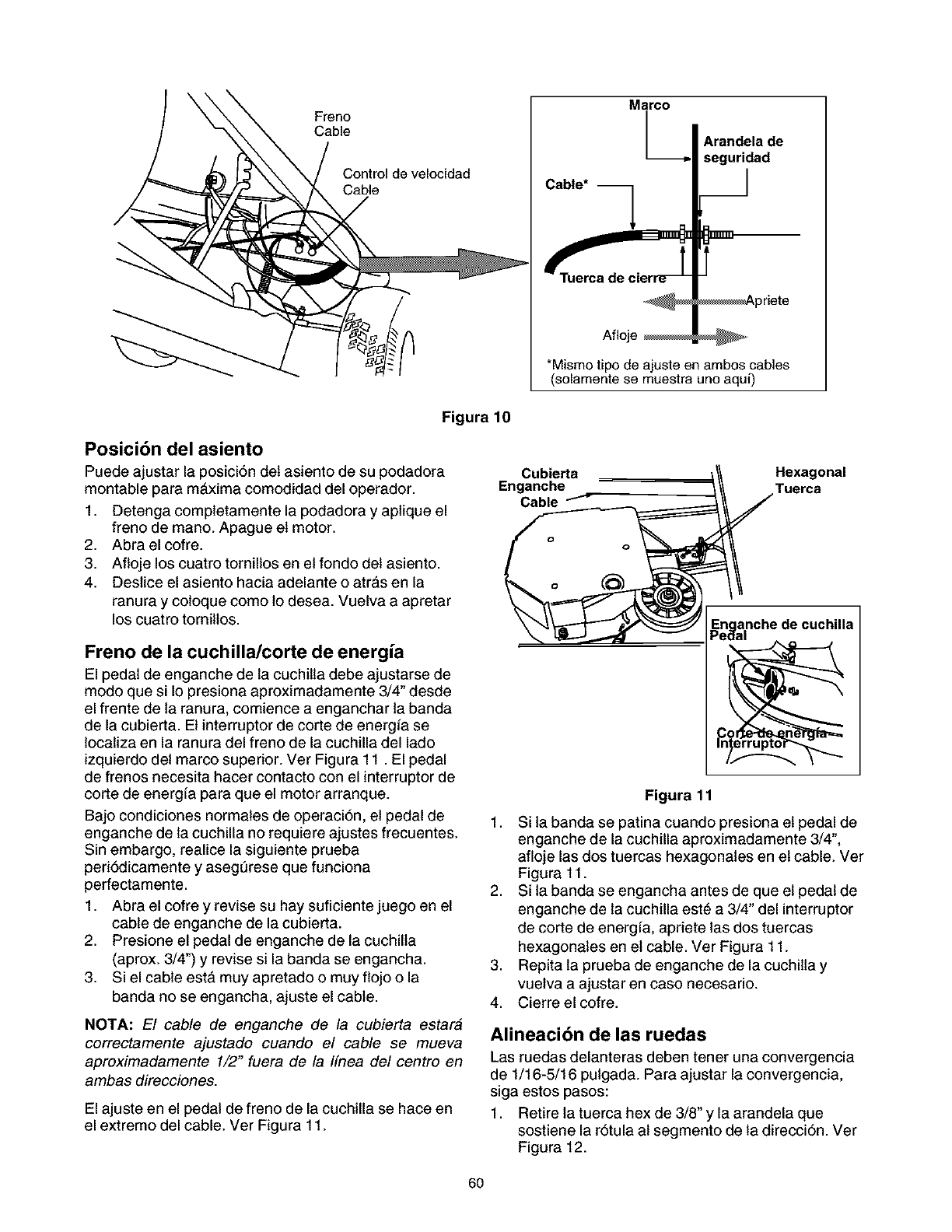
Freno
Cable
Control de velocidad
Marco
Cable*
Afloje
Arandela de
seguridad
__1
F
_priete
*Mismo tipo de ajuste en ambos cables
(solamente se muestra uno aqui)
Figura 10
Posici6n del asiento
Puede ajustar la posici6n det asiento de su podadora
montable para maxima comodidad del operador.
1. Detenga completamente la podadora y aplique el
freno de mano. Apague et motor.
2. Abraelcofre.
3. Afloje los cuatro tornillos en et fondo det asiento.
4. Destice el asiento hacia adelante o atras en la
ranura y coloque como lo desea. Vuelva a apretar
los cuatro tornitlos.
Freno de la cuchilla/corte de energia
El pedal de enganche de la cuchitla debe ajustarse de
modo que si Io presiona aproximadamente 3/4" desde
el frente de la ranura, comience a enganchar la banda
de la cubierta. Et interruptor de corte de energfa se
localiza en la ranura del freno de la cuchilla del lado
izquierdo det marco superior. Ver Figura 11. El pedal
de frenos necesita hacer contacto con el interruptor de
corte de energfa para que el motor arranque.
Bajo condiciones normales de operaci6n, et pedal de
enganche de la cuchilla no requiere ajustes frecuentes.
Sin embargo, realice la siguiente prueba
peri6dicamente y aseg6rese que funciona
perfectamente.
1. Abra el cofre y revise su hay suficiente juego en el
cable de enganche de la cubierta.
2. Presione el pedal de enganche de la cuchilla
(aprox. 3/4") y revise si la banda se engancha.
3. Si el cable esta. muy apretado o muy flojo o la
banda no se engancha, ajuste el cable.
NOTA: El cable de enganche de la cubierta estara
correctamente ajustado cuando el cable se mueva
aproximadamente 1/2" fuera de la Ifnea del centro en
ambas direcciones.
El ajuste en el pedal de freno de la cuchilla se hace en
el extremo del cable. Ver Figura 11.
Cubierta /// Hexagonal
Enganche _\\ Tuerca
\ "-4_ _,_'_J Enclanchede cuchilla
_L--J ,....,_ _ Pedal
1,
2,
,
4.
Figura 11
Si la banda se patina cuando presiona et pedal de
enganche de la cuchilla aproximadamente 3/4",
afloje las dos tuercas hexagonales en et cable. Ver
Figura 11.
Si la banda se engancha antes de que et pedal de
enganche de la cuchilla est_ a 3/4" del interruptor
de corte de energfa, apriete las dos tuercas
hexagonales en et cable. Ver Figura 11.
Repita la prueba de enganche de la cuchilta y
vuetva a ajustar en caso necesario.
Cierre el cofre.
Alineacibn de las ruedas
Las ruedas delanteras deben tener una convergencia
de 1/16-5/16 pulgada. Para ajustar la convergencia,
siga estos pasos:
1. Retire la tuerca hex de 3/8" y la arandela que
sostiene la r6tula al segmento de la direcci6n. Ver
Figura 12.
6O
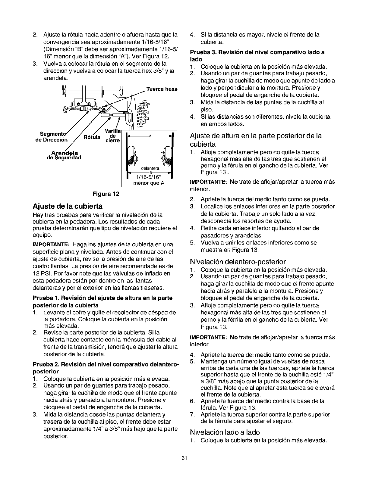
2. Ajustelar6tulahaciaadentrooafuerahastaquela
convergenciaseaaproximadamente1/16-5/16"
(Dimensi6n"B"debeseraproximadamente1/16-5/
16"menorqueladimensi6n"A").VerFigura12.
3. Vuetvaacolocarlar6tulaenelsegmentodela
direcci6nyvuetvaacolocarlatuercahex3/8"y la
arandela.
Tuerca hexa
de
de Direcci6n cmrre
de Seguridad
Figura 12
1/16-5/16"
menor que A
Ajuste de la cubierta
Hay tres pruebas para vedficar la nivelaci6n de la
cubierta en la podadora. Los resultados de cada
prueba determinarAn que tipo de nivelaci6n requiere el
equipo.
IMPORTANTE: Haga los ajustes de la cubierta en una
superficie plana y nivetada. Antes de continuar con et
ajuste de cubierta, revise la presi6n de aire de las
cuatro Ilantas. La presi6n de aire recomendada es de
12 PSI. Por favor note que las v&lvulas de inflado en
esta podadora esta.n por dentro en las Ilantas
delanteras y por el exterior en las ltantas traseras.
Prueba 1. Revisibn del ajuste de altura en la parte
posterior de la cubierta
1. Levante el cofre y quite et recolector de c_sped de
la podadora. Coloque la cubierta en la posici6n
mAs elevada.
2. Revise la parte posterior de la cubierta. Si la
cubierta hace contacto con la m_nsula del cable al
frente de la transmisi6n, tendra que ajustar la altura
posterior de la cubierta.
Prueba 2. Revisibn del nivel comparativo delantero-
posterior
1. Coloque la cubierta en la posici6n mAs elevada.
2. Usando un par de guantes para trabajo pesado,
haga girar la cuchitla de modo que et frente apunte
hacia atrAs y paraleto a la montura. Presione y
bloquee et pedal de enganche de la cubierta.
3. Mida la distancia desde las puntas detantera y
trasera de la cuchilta al piso, et frente debe estar
aproximadamente 1/4" a 3/8" mAs bajo que la parte
posterior.
4. Si la distancia es mayor, nivele et frente de la
cubierta.
Prueba 3. Revisibn del nivel comparativo lado a
lado
1. Coloque la cubierta en la posici6n m&s elevada.
2. Usando un par de guantes para trabajo pesado,
haga girar la cuchitla de modo que apunte de lado a
lado y perpendicular a la montura. Presione y
bloquee et pedal de enganche de la cubierta.
3. Mida la distancia de las puntas de la cuchilla al
piso.
4. Si las distancias son diferentes, nivele la cubierta
en ambos lados.
Ajuste de altura en la parte posterior de la
cubierta
1. Afloje completamente pero no quite la tuerca
hexagonal ma.s alta de las tres que sostienen et
pemo y la f_rula en el gancho de la cubierta. Ver
Figura 13.
IMPORTANTE: No trate de aflojar/apretar la tuerca mAs
inferior.
2. Apriete la tuerca det medio tanto como se pueda.
3. Localice los enlaces inferiores en la parte posterior
de la cubierta. Trabaje un solo lado a la vez,
desconecte los resortes de ayuda.
4. Retire cada enlace inferior quitando el par de
pasadores y arandelas.
5. Vuetva a unir los enlaces inferiores como se
muestra en Figura 13.
Nivelaci6n delantero-posterior
1. Coloque la cubierta en la posici6n m&s elevada.
2. Usando un par de guantes para trabajo pesado,
haga girar la cuchitla de modo que et frente apunte
hacia atr&s y paraleto a la montura. Presione y
bloquee et pedal de enganche de la cubierta.
3. Afloje completamente pero no quite la tuerca
hexagonal mas alta de las tres que sostienen et
pemo y la f_rrila en el gancho de la cubierta. Ver
Figura 13.
IMPORTANTE: No trate de aflojar/apretar la tuerca mAs
inferior.
4. Apriete la tuerca det medio tanto como se pueda.
5. Mantenga un nQmero igual de vueltas de rosca
arriba de cada una de las tuercas, apriete la tuerca
superior hasta que et frente de la cuchilla este 1/4"
a 3/8" ma.s abajo que la punta posterior de la
cuchilla. Note que al apretar esta tuerca se etevara
el frente de la cubierta.
6. Apriete la tuerca det medio contra la base de la
ferula. Ver Figura 13.
7. Apriete la tuerca superior contra la parte superior
de la f_rrula para ajustar el seguro.
Nivelaci6n lado a lado
1. Coloque la cubierta en la posici6n mAs elevada.
61
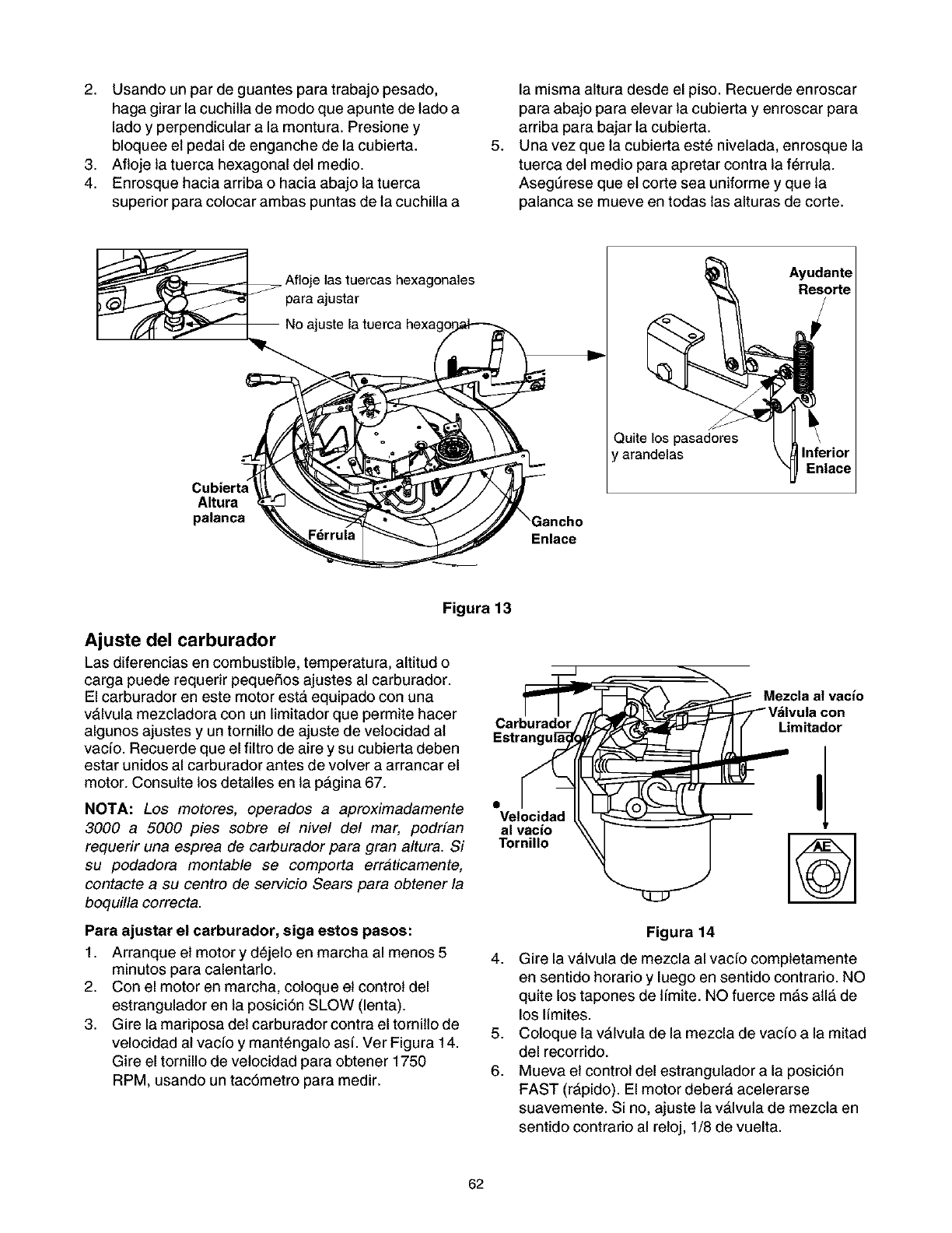
2. Usando un par de guantes para trabajo pesado,
haga girar la cuchilla de modo que apunte de lado a
lado y perpendicular a la montura. Presione y
bloquee et pedal de enganche de la cubierta.
3. Afloje la tuerca hexagonal det medio.
4. Enrosque hacia arriba o hacia abajo la tuerca
superior para colocar ambas puntas de la cuchilla a
la misma altura desde el piso. Recuerde enroscar
para abajo para elevar la cubierta y enroscar para
arriba para bajar la cubierta.
5. Una vez que la cubierta est_ nivelada, enrosque la
tuerca det medio para apretar contra la f_rrula.
Asegt3rese que et corte sea uniforme y que la
palanca se mueve en todas las alturas de corte.
las tuercas hexagona]es
para ajustar
Quite los pasadores
arandelas
Altura
palanca
Eniace
Figura 13
Ajuste del carburador
Las diferencias en combustible, temperatura, altitud o
carga puede requerir pequeSos ajustes al carburador.
El carburador en este motor esta. equipado con una
vAIvula mezcladora con un limitador que permite hacer
algunos ajustes y un tornillo de ajuste de vetocidad al
vac/o. Recuerde que el filtro de aire y su cubierta deben
estar unidos al carburador antes de volver a arrancar el
motor. Consulte los detalles en la pAgina 67.
NOTA: Los motores, operados a aproximadamente
3000 a 5000 pies sobre el nivel de/ mar, podrfan
requerir una esprea de carburador para gran altura. Si
su podadora montable se comporta erraticamente,
contacte a su centro de servicio Sears para obtener la
boquilla correcta.
__i_ Mezcla at vacio
I I _ I\_'_ Vdlvula con
Carburad_/_ /1 (" Limita- r
Estrangul_gNf ._ "_ //11 ao
Para ajustar el carburador, siga estos pasos:
1. Arranque et motor y dejeto en marcha al menos 5
minutes para calentarlo.
2. Con el motor en marcha, coloque et control del
estrangulador en la posici6n SLOW (lenta).
3. Gire la mariposa det carburador contra el tornilto de
velocidad al vacfo y mant_ngalo asf. Ver Figura 14.
Gire el tornillo de vetocidad para obtener 1750
RPM, usando un tac6metro para medir.
Figura 14
4. Gire la va.lvula de mezcla al vacfo completamente
en sentido horario y luego en sentido contrario. NO
quite los tapones de l[mite. NO fuerce mAs all& de
los I[mites.
5. Coloque la vAIvula de la mezcla de vac[o a la mitad
del recorrido.
6. Mueva et control del estrangulador a la posici6n
FAST (rApido). El motor deberA acelerarse
suavemente. Si no, ajuste la va.lvula de mezcla en
sentido contrado al retoj, 1/8 de vuelta.
62
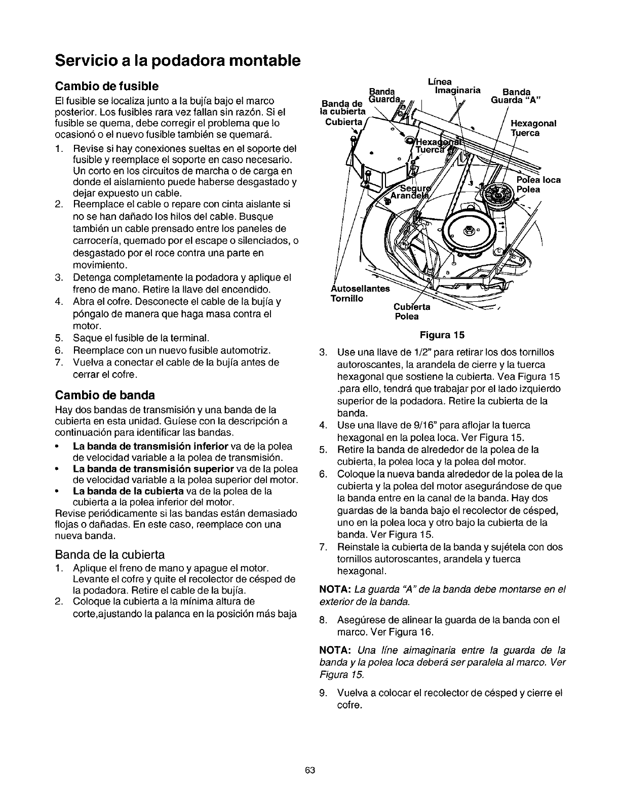
Servicio a la podadora montable
Cambio de fusible
El fusible se localiza junto a la bujfa bajo et marco
posterior. Los fusibles rara vez fallan sin raz6n. Si el
fusible se quema, debe corregir et problema que Io
ocasion6 o et nuevo fusible tambi_n se quemara.
1. Revise si hay conexiones sueltas en el soporte det
fusible y reemplace et soporte en caso necesario.
Un corto en los circuitos de marcha o de carga en
donde el aislamiento puede haberse desgastado y
dejar expuesto un cable.
2. Reemplace et cable o repare con cinta aislante si
no se han daSado los hitos del cable. Busque
tambi_n un cable prensado entre los panetes de
carrocerfa, quemado por el escape o sitenciados, o
desgastado por el roce contra una parte en
movimiento.
3. Detenga completamente la podadora y aplique el
freno de mano. Retire la llave del encendido.
4. Abra el cofre. Desconecte el cable de la bujfa y
p6ngalo de manera que haga masa contra el
motor.
5. Saque et fusible de la terminal.
6. Reemplace con un nuevo fusible automotriz.
7. Vuetva a conectar el cable de la bujfa antes de
cerrar el cofre.
Cambio de banda
Hay dos bandas de transmisi6n y una banda de la
cubierta en esta unidad. Gufese con la descripci6n a
continuaci6n para identificar las bandas.
• La banda de transmisi6n inferior va de la polea
de velocidad variable a la polea de transmisi6n.
• La banda de transmisi6n superior va de la polea
de velocidad variable a la polea superior del motor.
•La banda de la cubierta va de la polea de la
cubierta a la polea inferior det motor.
Revise peri6dicamente si las bandas estan demasiado
flojas o daSadas. En este caso, reemplace con una
nueva banda.
Banda de la cubierta
1. Aplique el freno de mano y apague el motor.
Levante et cofre y quite el recolector de c_sped de
la podadora. Retire et cable de la bujfa.
2. Coloque la cubierta a la mfnima altura de
corte,ajustando la palanca en la posici6n mAs baja
Banda de
la cubierta
Cubierta
Linea
Imaginaria Banda
Guarda "A"
Polea
Autosellantes
Tornillo
Polea
Figura 15
3. Use una Ilave de 1/2" para retirar los dos tornillos
autoroscantes, la arandela de cierre y la tuerca
hexagonal que sostiene la cubierta. Vea Figura 15
.para ello, tendra que trabajar por el lado izquierdo
superior de la podadora. Retire la cubierta de la
banda.
4. Use una Ilave de 9/16" para aflojar la tuerca
hexagonal en la polea loca. Ver Figura 15.
5. Retire la banda de alrededor de la polea de la
cubierta, la polea Ioca y la polea del motor.
6. Coloque la nueva banda alrededor de la polea de la
cubierta y la polea del motor asegur&ndose de que
la banda entre en la canal de la banda. Hay dos
guardas de la banda bajo et recolector de c_sped,
uno en la polea Ioca y otro bajo la cubierta de la
banda. Ver Figura 15.
7. Reinstale la cubierta de la banda y suj_teta con dos
tornillos autoroscantes, arandela y tuerca
hexagonal.
NOTA: La guarda "A" de la banda debe montarse en el
exterior de la banda.
8. Aseg6rese de alinear la guarda de la banda con el
marco. Ver Figura 16.
NOTA: Una Ifne aimaginaria entre la guarda de la
banda y la polea Ioca debera ser paralela al marco. Ver
Figura 15.
9. Vuetva a colocar el recolector de cesped y cierre et
cofre.
63
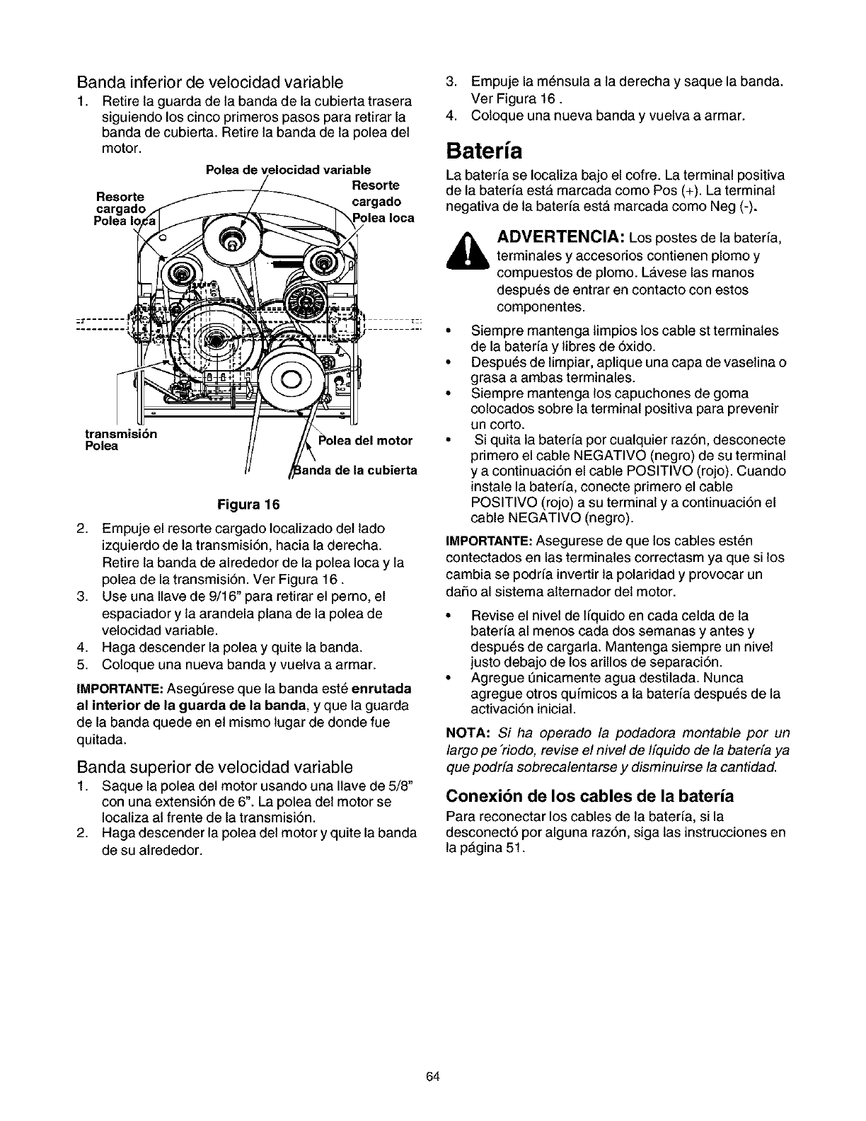
Banda inferior de velocidad variable
1. Retirelaguardadelabandadelacubiertatrasera
siguiendoloscincoprimerospasospararetirarla
bandadecubierta.Retirelabandadelapoleadet
motor.
Polea de \
Resorte
Resorte
transmisi6n
Polea _Polea del motor
anda de la cubierta
Figura 16
2. Empuje el resorte cargado localizado det lado
izquierdo de la transmisi6n, hacia la derecha.
Retire la banda de alrededor de la polea Ioca y la
polea de la transmisi6n. Ver Figura 16.
3. Use una Ilave de 9/16" para retirar et perno, el
espaciador y la arandela plana de la polea de
velocidad variable.
4. Haga descender la polea y quite la banda.
5. Coloque una nueva banda y vuelva a armar.
IMPORTANTE:Aseg_rese que la banda est_ enrutada
al interior de la guarda de la banda, y que la guarda
de la banda quede en et mismo lugar de donde fue
quitada.
Banda superior de velocidad variable
1. Saque la polea det motor usando una Ilave de 5/8"
con una extensi6n de 6". La polea det motor se
Iocaliza al frente de la transmisi6n.
2. Haga descender la polea det motor y quite la banda
de su alrededor.
3. Empuje la m_nsula a la derecha y saque la banda.
Ver Figura 16.
4. Coloque una nueva banda y vuelva a armar.
Bateria
La baterfa se Iocaliza bajo el cofre. La terminal positiva
de la baterfa est& marcada como Pos (+). La terminal
negativa de la baterfa esta marcada come Neg (-).
ADVERTENCIA: Los postes de la bater[a,
terminales y accesorios contienen plomo y
compuestos de plomo. La.vese las manos
despu_s de entrar en contacto con estos
componentes.
•Siempre mantenga limpios los cable st terminales
de la baterfa y libres de 6xido.
• Despu_s de limpiar, aplique una capa de vasetina o
grasa a ambas terminales.
• Siempre mantenga los capuchones de goma
colocados sobre la terminal positiva para prevenir
un corto.
• Si quita la baterfa por cualquier raz6n, desconecte
primero el cable NEGATIVO (negro) de su terminal
y a continuaci6n el cable POSITIVO (rojo). Cuando
instale la baterfa, conecte primero et cable
POSITIVO (rojo) a su terminal y a continuaci6n el
cable NEGATIVO (negro).
IMPORTANTE:Asegurese de que los cables esten
contectados en las terminales correctasm ya que si los
cambia se podrfa invertir la polaridad y provocar un
daSo al sistema alternador det motor.
• Revise el nivet de lfquido en cada cetda de la
baterfa al menos cada dos semanas y antes y
despu_s de cargarla. Mantenga siempre un nivet
justo debajo de los arillos de separaci6n.
• Agregue _nicamente agua destilada. Nunca
agregue otros qufmicos a la baterfa despues de la
activaci6n inicial.
NOTA: Si ha operado /a podadore montable por un
/argo pe "riodo, revise el nivel de Ifquido de/a baterfa ya
que podrfa sobreca/entarse ydisrninuirse /a cantidad.
Conexibn de los cables de la bateria
Para reconectar los cables de la baterfa, si la
desconect6 por alguna raz6n, siga las instrucciones en
la p&gina 51.
64
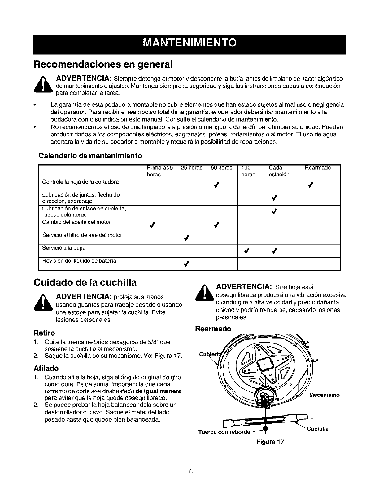
Recomendaciones en general
,_ ADVERTENCIA: Siempre detenga el motor y desconecte la bujfa antes de limpiar o de hacer algt_ntipo
de mantenimiento o ajustes. Mantenga siempre la seguridad y siga las instrucciones dadas a continuaci6n
para completar la tarea.
La garantfa de esta podadora montable no cubre etementos que han estado sujetos al mal uso o negligencia
det operador. Para recibir el reembolso total de la garantfa, et operador deber& dar mantenimiento a la
podadora como se indica en este manual. Consulte el calendario de mantenimiento.
No recomendamos el uso de una limpiadora a presi6n o manguera de jardfn para Iimpiar su unidad. Pueden
producir daSos a los componentes electricos, engranajes, poleas, rodamientos o al motor. El uso de agua
acortar& la vida de su podador a montable y reducira la posibilidad de reparaciones.
Calendario de mantenimiento
Primeras 5 25 horas 50 horas 100 Cada Rearmado
horas horas estaci6n
Controle la hoja de la cortadora ,_
Lubricacion de juntas, flecha de
direcci6n, engranaje
Lubricacion de enlace de cubierta,
ruedas deianteras
Cambio del aceite del motor _ ,_
Servicio al filtro de aire del motor ,_
Servicio a la buj_a ,/
Revision del liquido de baterfa ,_
Cuidado de la cuchilla
ADVERTENCIA: proteja sus manos
usando guantes para trabajo pesado o usando
una estopa para sujetar la cuchilla. Evite
lesiones personales.
Retiro
1. Quite la tuerca de brida hexagonal de 5/8" que
sostiene la cuchilla al mecanismo.
2. Saque la cuchilla de su mecanismo. Ver Figura 17.
Afilado
1. Cuando afile la hoja, siga el &ngulo original de giro
como gufa. Es de suma importancia que cada
extremo de corte sea desbastado de igual manera
para evitar que la hoja quede desequilibrada.
2. Se puede probar la hoja balanceandola sobre un
destornitlador o clavo. Saque et metal del lado
pesado hasta que quede bien balanceada.
ADVERTENCIA: Si la hoja estA
desequilibrada producir& una vibraci6n excesiva
cuando gire a alta velocidad y puede daSar la
unidad y podrfa romperse, causando lesiones
personales.
Rearmado
\
Mecanismo
Tuerca con reborde
Figura 17
"Cuchilla
65
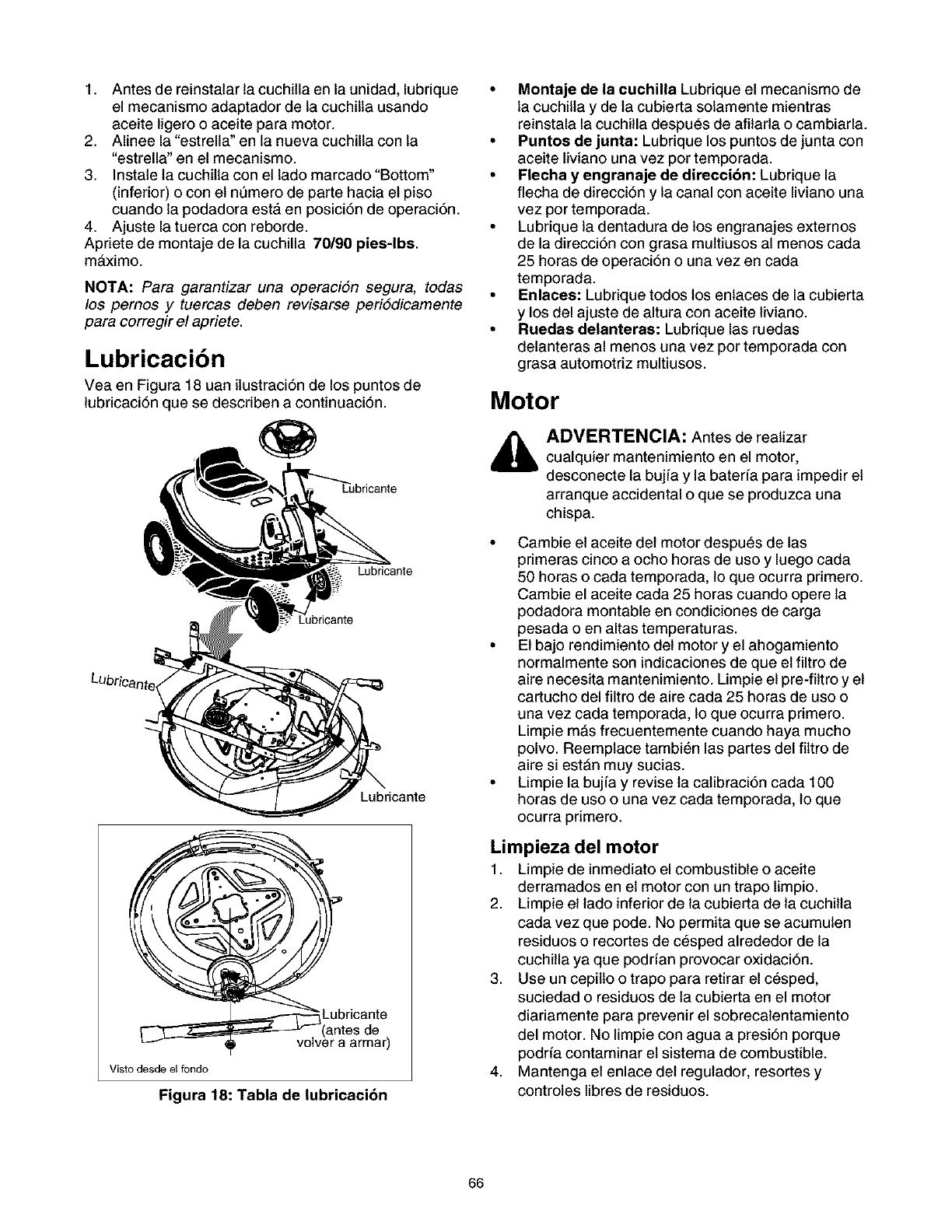
1. Antesdereinstalarlacuchillaenlaunidad,lubrique
elmecanismoadaptadordelacuchiltausando
aceiteligerooaceiteparamotor.
2. Alineela"estrella"en la nueva cuchilla con la
"estrella" en el mecanismo.
3. Instale la cuchitla con et lado marcado "Bottom"
(inferior) o con et n6mero de parte hacia et piso
cuando la podadora esta en posici6n de operaci6n.
4. Ajuste la tuerca con reborde.
Apdete de montaje de la cuchilla 70190 pies-lbs.
maximo.
NOTA: Para garantizar una operaci6n segura, todas
los pernos y tuercas deben revisarse peri6dicamente
para corregir el apriete.
Lubricacibn
Vea en Figura 18 uan itustraci6n de los puntos de
lubricaci6n que se describen a continuaci6n.
Lubricante
Lubricante
ricante
es de
_ volver a armar)
Visto desde el fondo
Figura 18: Tabla de lubricacibn
•Montaje de la cuchilla Lubrique el mecanismo de
la cuchilta y de la cubierta solamente mientras
reinstala la cuchitla despues de afitarla o cambiarla.
• Puntos de junta: Lubrique los puntos de junta con
aceite liviano una vez por temporada.
•Flecha y engranaje de direcci6n: Lubrique la
flecha de direcci6n y la canal con aceite liviano una
vez por temporada.
• Lubrique la dentadura de los engranajes extemos
de la direcci6n con grasa multiusos al menos cada
25 horas de operaci6n o una vez en cada
temporada.
•Enlaces: Lubrique todos los enlaces de la cubierta
y los del ajuste de altura con aceite liviano.
• Ruedas delanteras: Lubrique las ruedas
delanteras al menos una vez por temporada con
grasa automotdz multiusos.
Motor
ADVERTENCIA: Antes de realizar
cualquier mantenimiento en el motor,
desconecte la bujfa y la baterfa para impedir et
arranque accidental o que se produzca una
chispa.
• Cambie et aceite det motor despues de las
primeras cinco a ocho horas de uso y luego cada
50 horas o cada temporada, lo que ocurra primero.
Cambie el aceite cada 25 horas cuando opere la
podadora montable en condiciones de carga
pesada o en altas temperaturas.
• El bajo rendimiento det motor y el ahogamiento
normalmente son indicaciones de que et filtro de
aire necesita mantenimiento. Limpie et pre-filtro y et
cartucho del filtro de aire cada 25 horas de uso o
una vez cada temporada, 1oque ocurra pdmero.
Limpie m&s frecuentemente cuando haya mucho
polvo. Reemplace tambi_n las partes del fittro de
aire si est&n muy sucias.
• Limpie la bujfa y revise la calibraci6n cada 100
horas de uso ouna vez cada temporada, lo que
ocurra primero.
Limpieza del motor
1. Limpie de inmediato el combustible o aceite
derramados en et motor con un trapo limpio.
2. Limpie et lade inferior de la cubierta de la cuchilla
cada vez que pode. No permita que se acumulen
residuos o recortes de cesped alrededor de la
cuchilla ya que podrfan provocar oxidaci6n.
3. Use un cepilto o trapo para retirar el c_sped,
suciedad o residuos de la cubierta en el motor
diariamente para prevenir el sobrecalentamiento
del motor. No limpie con agua a presi6n porque
podda contaminar et sistema de combustible.
4. Mantenga et enlace det regulador, resortes y
controles libres de residuos.
66
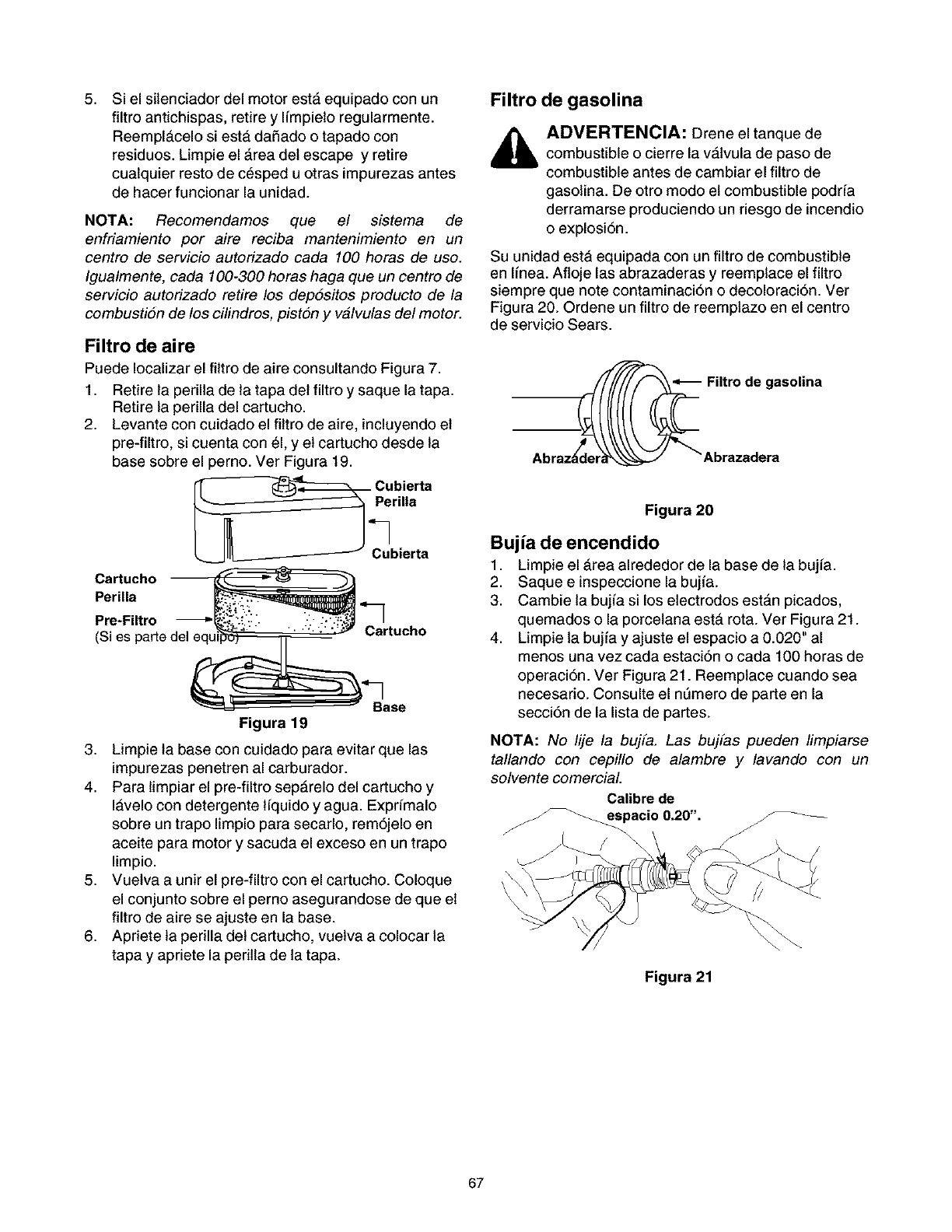
5, Si el sitenciador del motor estA equipado con un
filtro antichispas, retire y Ifmpieto regularmente.
ReemplAcelo siestA daSado o tapado con
residuos. Limpie el Area det escape y retire
cualquier resto de cesped u otras impurezas antes
de hacer funcionar la unidad.
NOTA: Recomendamos que el sistema de
enfriamiento por aire reciba mantenimiento en un
centro de servicio autorizado cada 100 horas de uso.
Igualmente, cada 100-300 horas haga que un centro de
servicio autorizado retire los depositos producto de la
combustion de los cilindros, piston y valvulas del motor.
Filtro de aire
Puede Iocalizar el fittro de aire consultando Figura 7.
1. Retire la perilla de la tapa det filtro y saque la tapa.
Retire la perilla del cartucho.
2. Levante con cuidado el filtro de aire, incluyendo et
pre-filtro, si cuenta con 61,y et cartucho desde la
base sobre el perno. Ver Figura 19.
_. Cubierta
rilla
Cubierta
Cartucho
Perilla
Pre-Filtro Cartucho
(Si es parle del equ
Figura 19
3. Limpie la base con cuidado para evitar que las
impurezas penetren al carburador.
4. Para limpiar el pre-filtro sepArelo del cartucho y
IAvelo con detergente l[quido y agua. Exprfmalo
sobre un trapo limpio para secarlo, rem6jelo en
aceite para motor y sacuda el exceso en un trapo
limpio.
5. Vuetva a unir el pre-filtro con el cartucho. Coloque
el conjunto sobre el perno asegurandose de que et
filtro de aire se ajuste en la base.
6. Apriete la perilla det cartucho, vuetva a colocar la
tapa y apriete la peritla de la tapa.
Filtro de gasolina
ADVERTENCIA: Drene el tanque de
combustible o cierre la vAlvula de paso de
combustible antes de cambiar el filtro de
gasolina. De otro modo et combustible podr[a
derramarse produciendo un riesgo de incendio
o explosi6n.
Su unidad estA equipada con un filtro de combustible
en I[nea. Afloje las abrazaderas y reemplace el filtro
siempre que note contaminaci6n o decoloraci6n. Ver
Figura 20. Ordene un filtro de reemplazo en el centro
de servicio Sears.
_4_ Filtro de gasolina
Abraza_d__"_ Abrazadera
Figura 20
Bujia de encendido
1. Limpie el Area alrededor de la base de la bujfa.
2. Saque e inspeccione la bujfa.
3. Cambie la bujfa si los etectrodos estan picados,
quemados o la porcetana esta rota. Ver Figura 21.
4. Limpie la buj[a y ajuste el espacio a 0.020" al
menos una vez cada estaci6n o cada 100 horas de
operaci6n. Ver Figura 21. Reemplace cuando sea
necesario. Consulte el ntJmero de parte en la
secci6n de la lista de partes.
NOTA: No lije la bujfa. Las bujfas pueden limpiarse
tallando con cepillo de alambre y lavando con un
solvente comerciaL
Calibre de
_pacio\ 0.20". F_
Figura 21
67
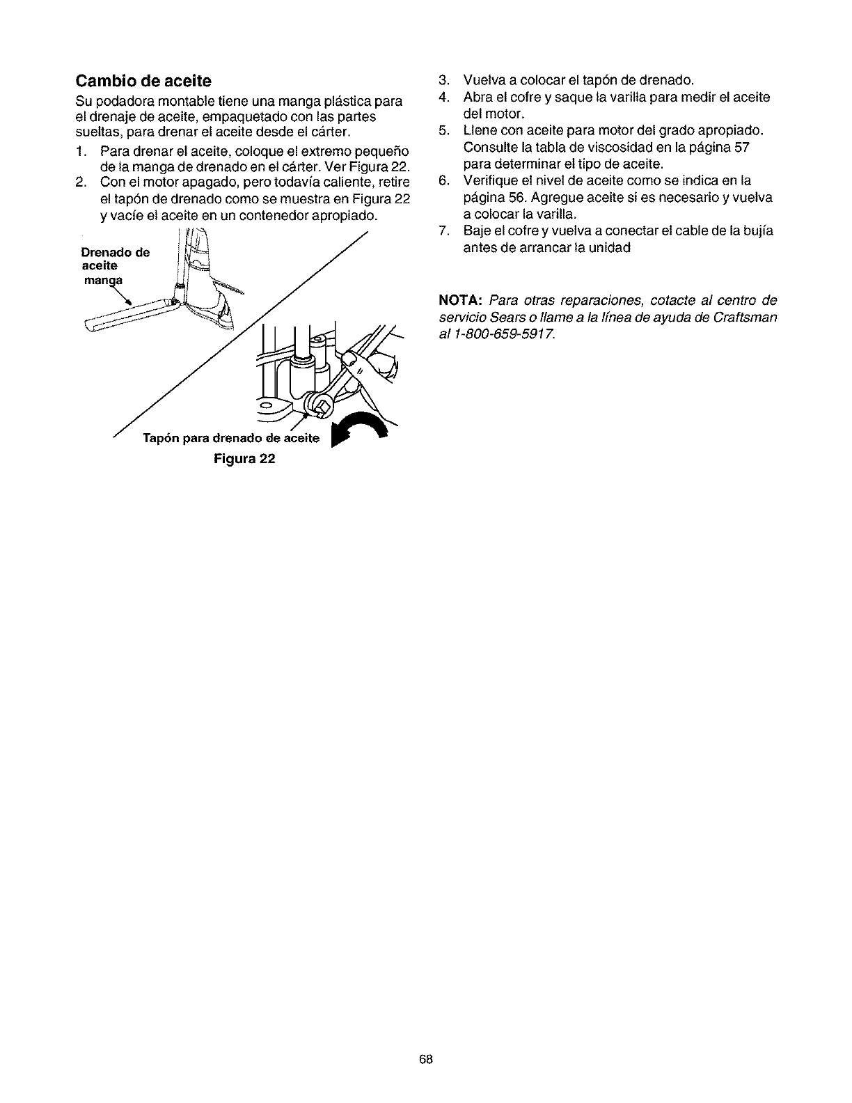
Cambio de aceite
Su podadora montable tiene una manga plAstica para
el drenaje de aceite, empaquetado con las partes
suettas, para drenar el aceite desde el carter.
1. Para drenar et aceite, coloque el extremo pequeSo
de la manga de drenado en et carter. Ver Figura 22.
2. Con el motor apagado, pero todavfa caliente, retire
el tap6n de drenado como se muestra en Figura 22
y vacfe et aceite en un contenedor apropiado.
Drenado de
aceite
Tap6n para drenado de aceite
Figura 22
3. Vuetva a colocar el tapSn de drenado.
4. Abra el cofre y saque la varitla para medir el aceite
del motor.
5. Llene con aceite para motor del grado apropiado.
Consulte la tabla de viscosidad en la pagina 57
para determinar et tipo de aceite.
6. Verifique et nivet de aceite como se indica en la
pAgina 56. Agregue aceite si es necesario y vuetva
a colocar la varilla.
7. Baje el cofre y vuetva a conectar et cable de la bujfa
antes de arrancar la unidad
NOTA: Para otras reparaciones, cotacte al centro de
servicio Sears o Ilame a la Ifnea de ayuda de Craftsman
al 1-800-659-5917.
68
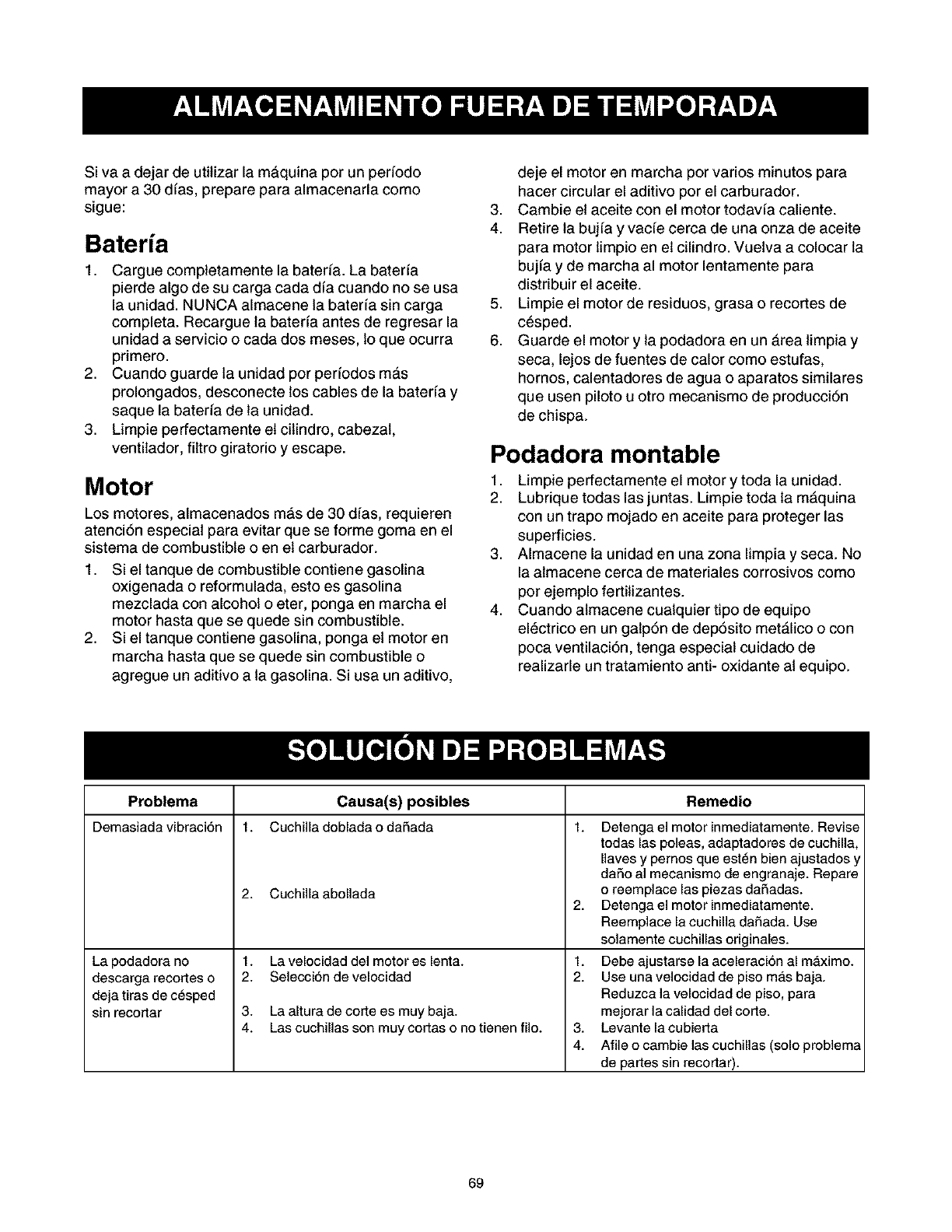
SivaadejardeutilizarlamAquinaporunperfodo
mayora30dfas,prepareparaalmacenarlacomo
sigue:
Bateria
1. Cargue completamente la baterfa. La baterfa
pierde algo de su carga cada dfa cuando no se usa
la unidad. NUNCA almacene la baterfa sin carga
completa. Recargue la baterfa antes de regresar la
unidad a servicio o cada dos meses, lo que ocurra
primero.
2. Cuando guarde la unidad per perfodos mAs
prolongados, desconecte los cables de la baterfa y
saque la baterfa de la unidad.
3. Limpie perfectamente et citindro, cabezal,
ventilador, filtro giratorio y escape.
Motor
Los motores, almacenados mAs de 30 dfas, requieren
atenci6n especial para evitar que se forme goma en el
sistema de combustible o en et carburador.
1. Si el tanque de combustible contiene gasolina
oxigenada o reformulada, esto es gasolina
mezclada con alcohol o eter, ponga en marcha el
motor hasta que se quede sin combustible.
2. Si el tanque contiene gasolina, ponga et motor en
marcha hasta que se quede sin combustible o
agregue un aditivo a la gasolina. Si usa un aditivo,
deje el motor en marcha por varios minutos para
hacer circular el aditivo por el carburador.
3. Cambie et aceite con el motor todavfa caliente.
4. Retire la bujfa y vacfe cerca de una onza de aceite
para motor limpio en et cilindro. Vuetva a colocar la
bujfa y de marcha al motor lentamente para
distribuir el aceite.
5. Limpie el motor de residuos, grasa o recortes de
c_sped.
6. Guarde el motor y la podadora en un Area limpia y
seca, lejos de fuentes de calor como estufas,
homos, calentadores de agua o aparatos similares
que usen piloto u otro mecanismo de producci6n
de chispa.
Podadora montable
1. Limpie perfectamente el motor y toda la unidad.
2. Lubrique todas las juntas. Limpie toda la mAquina
con un trapo mojado en aceite para proteger las
superficies.
3. Almacene la unidad en una zona limpia y seca. No
la almacene cerca de materiales corrosivos como
por ejemplo fertitizantes.
4. Cuando almacene cualquier tipo de equipo
electrico en un galp6n de dep6sito metAlico o con
poca ventilaci6n, tenga especial cuidado de
realizarle un tratamiento anti- oxidante al equipo.
Problema Causa(s) posibles Remedio
Demasiada vibraci6n 1. Cuchilla doblada o daSada 1.
La podadora no
descarga recortes o
deja tiras de c_sped
sin recortar
2. Cuchilla abollada
t. Lavelocidad del motor es lenta.
2. Selecci6n de velocidad
3. La altura de cortees muy baja.
4. Las cuchillas son muy codas o no tienen filo.
Detenga el motor inmediatamente. Revise
todas las poleas, adaptadores de cuchilla,
Ilaves y pemos que est_n bien ajustados y
daSo a] mecanismo de engranaje. Repare
o reemplace las piezas daSadas.
2. Detengael motorinmediatamente.
Reemplace la euchilla daSada. Use
solamente cuchillas originales.
1. Debe ajustarse la aceleracion al mb,ximo.
2. Use una velocidad de piso m_,s baja.
Reduzca la velocidad de piso, para
mejorar la calidad del corte.
3. Levantelacubierta
4. Afile o cambie las cuchillas (solo problema
de partes sin recortar).
69
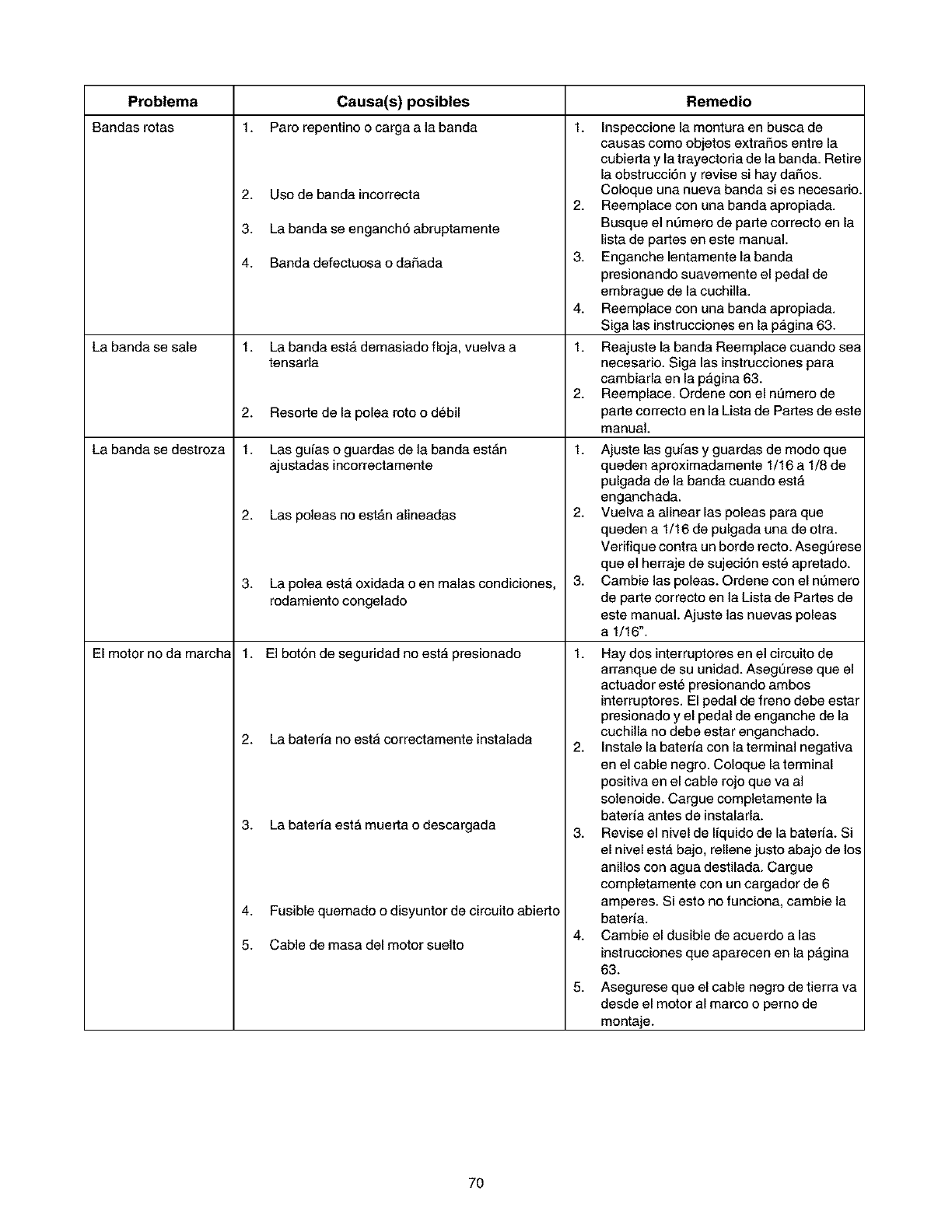
Problema Causa(s) posibles Remedio
Bandas rotas 1. Paro repentino ocarga a la banda 1.
La banda se sale
La banda se destroza
El motor no da march_
2. Usode bandaincorrecta
3. La banda se enganch6 abruptamente
4. Banda defectuosa o da£_ada
1. La banda esta demasiado floja, vuelva a
tensarla
2. Resorte de la polea roto o d_bil
1. Las guias oguardas de la banda estAn
ajustadas incorrectamente
2. Las poleas no estan alineadas
3. La polea est,, oxidada oen malas condiciones,
rodamiento congelado
1. El bot6n de seguridad no esta presionado
2. La bateria no esta correctamente instalada
3. La bateria est_ muerta o descargada
Fusible quemado odisyuntor de circuito abierto
4+
5. Cable de masa del motor suelto
2,
3.
4.
1.
2.
1.
2,
3,
Inspeccione la montura en busca de
causas como objetos extraSos entre la
cubierta y la trayectoria de la banda. Retire
la obstrucci6n y revise si hay da£_os.
Coloque una nueva banda si es necesario.
Reemplace con una banda apropiada.
Busque el nL_merode parte correcto en la
lista de partes en este manual.
Enganche lentamente la banda
presionando suavemente el pedal de
embrague de la cuchilla.
Reemplace con una banda apropiada.
Siga las instrucciones en la pagina 63.
Reajuste la banda Reemplace cuando sea
necesario. Siga las instrucciones para
cambiarla en la p_,gina 63.
Reemplace. Ordene con el nemero de
parte correcto en la Lista de Partes de este
manual.
Ajuste las guias y guardas de modo que
queden aproximadamente 1/16 a 1/8 de
pulgada de la banda cuando esta
enganchada.
Vuelva a alinear las poleas para que
queden a 1/16 de pulgada una de otra.
Verifique contra un borde recto. Asegurese
que el herraje de sujeci6n est_ apretado.
Cambie las poleas. Ordene con el nL_mero
de parte correcto en la Lista de Partes de
este manual. Ajuste las nuevas poleas
a 1/16".
1. Hay dos interruptores en el circuito de
arranque de su unidad. Asegurese que el
actuador est_ presionando ambos
interruptores. El pedal de freno debe estar
presionado y el pedal de enganche de la
cuchilla no debe estar enganchado.
2. Instale la bateria con la terminal negativa
en el cable negro. Coloque la terminal
positiva en el cable rojo que va al
solenoide. Cargue completamente la
bateria antes de instalarla.
3. Revise el nivel de liquido de la bateria. Si
el nivel est', bajo, renene justo abajo de los
anillos con agua destilada. Cargue
completamente con un cargador de 6
amperes. Si esto no funciona, cambie la
bateria.
4. Cambie el dusible de acuerdo alas
instrucciones que aparecen en la pagina
63.
5. Asegurese que el cable negro de tierra va
desde el motor al marco o perno de
montaje.
7O
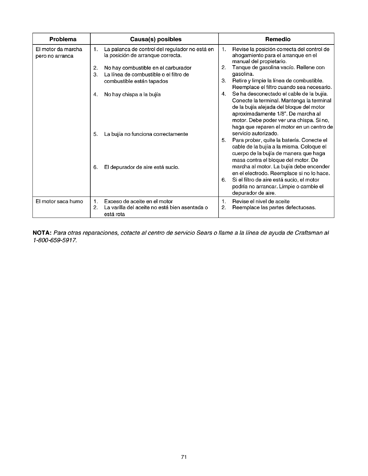
Problema
El motor da marcha
pero no arranca
Remedio
1. 1.
Causa(s) posibles
La palanca de control del regulador no esta en
]a posicion de arranque correcta.
2. No hay combustible en el carburador
3. La linea de combustible oel filtro de
combustible estan tapados
4. No hay chispa a la bujia
5. La bujia no funciona correctamente
6. El depurador de aire esta sucio.
Revise la posicion correcta del control de
ahogamiento para el arranque en el
manual del propietario.
2. Tanque de gasolinavacfo. Rellene con
gasolina.
3. Retire y limpie la linea de combustible.
Reemplace el filtro cuando sea necesario.
4. Se ha desconectado el cable de la bujia.
Conecte la terminal. Mantenga la terminal
de la bujia alejada del bloque del motor
aproximadamente 1/8". De marcha al
motor. Debe poder ver una chispa. Si no,
haga que reparen el motor en un centro de
servicio autorizado.
5. Para probar, quite la baterfa. Conecte el
cable de la bujia a la misma. Coloque el
cuerpo de la bujia de manera que haga
masa contra el bloque del motor. De
marcha al motor. La bujia debe encender
en el electrodo. Reemplace si no Io hace.
Si el filtro de aire est_ sucio, el motor
podria no arrancar. Limpie o cambie el
depurador de aire.
6.
1.
2.
El motor saca humo 1. Exceso de aceite en el motor Revise el nivel de aceite
2. La varilla del aceite no esta bien asentada o Reemplace las partes defectuosas.
esta rota
NOTA: Para otras reparaciones, cotacte al centro de servicio Sears o Ilame a la Ifnea de ayuda de Craftsman al
1-800-659-5917.
71

Get it fixed, at your home or ours!
Your Home
For repair-in your home-of all major brand appliances,
lawn and garden equipment, or heating and cooling systems,
no matter who made it, no matter who sold it!
For the replacement parts, accessories and
owner's manuals that you need to do-it-yourself.
For Sears professional installation of home appliances
and items like garage door openers and water heaters.
1-800-4-MY-HOME ®(1-800-469-4663)
Call anytime, day or night (U.S.A. and Canada)
www.sears.com www.sears.ca
Our Home
For repair of carry-in items like vacuums, lawn equipment,
and electronics, call or go on-line for the location of your nearest
Sears Parts & Repair Center.
1-800-488-1222
Call anytime, day or night (U.S.A. only)
www.sears.com
To purchase a protection agreement on a product serviced by Sears:
t-800-827-6655 (U.S.A.) 1-800-361-6665 (Canada
Para pedir servic=o de reparacion
a domicdio, y para ordenar piezas:
1-888-SU-HOGAR sM
(1-888-784-6427)
Au Canada pour service en fran(_a=s:
1-800-LE-FOYER Mc
(1-800-533-6937)
www.sears ca
TF _F
A,Registered Trademark /"_Trademark / "'_Serv=ce Mark of Sears Roebuck and Co
Trl Fabrlca /-TI
A, Marca Reg_strada /Marca de = Marca de Servlclo de Sears, Roebuck and Co
rT 10
•c Marque de commerce /_ Marque deposee de Sears Roebuck and Co _, Sears, Roebuck and Co
