Craftsman 247770131 User Manual YARD VACUUM Manuals And Guides 1206437L
User Manual: Craftsman 247770131 247770131 CRAFTSMAN YARD VACUUM - Manuals and Guides View the owners manual for your CRAFTSMAN YARD VACUUM #247770131. Home:Lawn & Garden Parts:Craftsman Parts:Craftsman YARD VACUUM Manual
Open the PDF directly: View PDF ![]() .
.
Page Count: 64
Operator's Manual
CRRFr MRN
POWER PROPELLED YARD VACUUM
Model No. 247.770131
CAUTION" Before using this
product, read this manual and
follow all safety rules and operating
instructions.
,, SAFETY
o ASSEMBLY
OPERATION
MAINTENANCE
PARTS LIST
o ESPANOL
Sears Brands Management Corporation, Hoffman Estates, IL 60179, U.S.A.
Visit our website: www.craftsman.com FormNo. 769-05107C
(June 12,2012)
Warranty Statement .................................. Page 2
Safe Operation Practices .......................... Page 3
Safety Labels ............................................ Page 7
Assembly .................................................. Page 8
Operation .................................................. Page 12
Service and Maintenance ......................... Page 16
Off-Season Storage .................................. Page 22
Trouble Shooting ....................................... Page 23
Parts List ................................................... Page 24
Repair Protection Agreement ................... Page 38
Espa_ol ..................................................... Page 39
Service Numbers ...................................... Back Cover
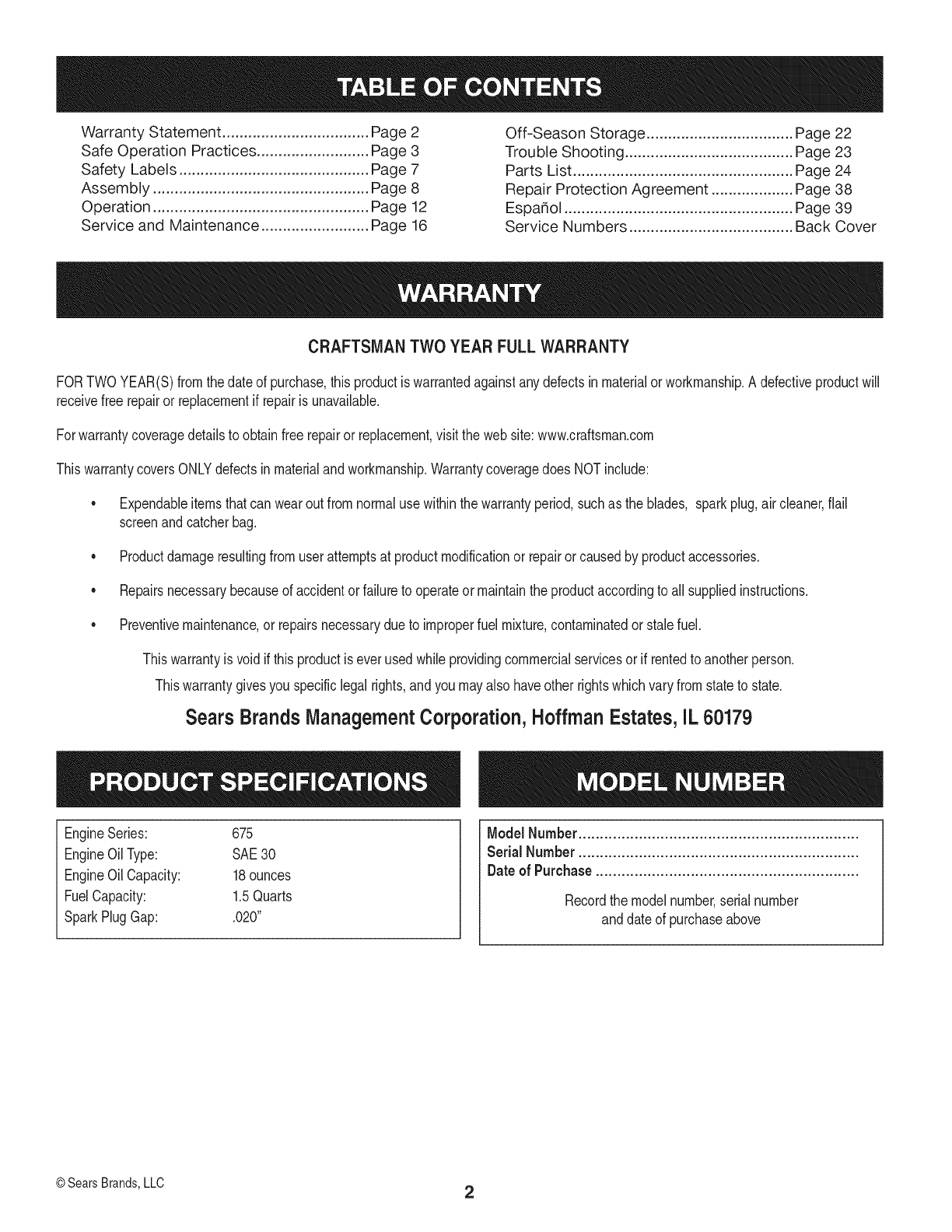
CRAFTSMAN TWO YEAR FULL WARRANTY
FORTWOYEAR(S)fromthe dateof purchase,thisproductiswarrantedagainstanydefectsinmaterialorworkmanship.A defectiveproductwill
receivefree repairor replacementif repairis unavailable.
Forwarrantycoveragedetailsto obtainfree repairor replacement,visitthe web site:www.craftsman.com
ThiswarrantycoversONLYdefectsin materialandworkmanship.Warrantycoveragedoes NOTinclude:
• Expendableitemsthatcan wearout fromnormaluse withinthe warrantyperiod,suchas the blades, sparkplug,aircleaner,flail
screenand catcherbag.
• Productdamageresultingfromuserattemptsat productmodificationor repairor causedby productaccessories.
• Repairsnecessarybecauseof accidentor failureto operateormaintainthe productaccordingto all suppliedinstructions.
• Preventivemaintenance,or repairsnecessarydueto improperfuel mixture,contaminatedor stalefuel.
Thiswarrantyis voidif this productis everusedwhileprovidingcommercialservicesorif rentedto anotherperson.
Thiswarrantygivesyouspecificlegal rights,andyoumayalso haveother rightswhichvaryfromstateto state.
Sears Brands Management Corporation, Hoffman Estates, IL 60179
EngineSeries: 675
EngineOilType: SAE30
EngineOilCapacity: 18ounces
FuelCapacity: 1.5Quarts
SparkPlugGap: .020"
Model Number.................................................................
Serial Number.................................................................
Dateof Purchase .............................................................
Recordthe modelnumber,serialnumber
anddateof purchaseabove
©Sears Brands,LLC 2
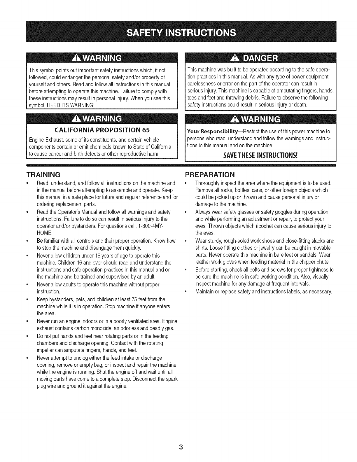
Thissymbolpointsout importantsafetyinstructionswhich,if not
followed,couldendangerthe personalsafetyand/orpropertyof
yourselfandothers. Readandfollowall instructionsin thismanual
beforeattemptingto operatethismachine.Failureto complywith
theseinstructionsmayresultin personalinjury.Whenyou seethis
symbol,HEEDITSWARNING!
CALIFORNIA PROPOSITION 65
EngineExhaust,someof itsconstituents,andcertainvehicle
componentscontainoremitchemicalsknownto Stateof California
to causecancerandbirthdefectsorother reproductiveharm.
Thismachinewasbuilt to beoperatedaccordingto the safeopera-
tion practicesin thismanual.As withany typeof powerequipment,
carelessnessorerroronthe part of the operatorcan resultin
seriousinjury.Thismachineis capableof amputatingfingers,hands,
toesandfeetandthrowingdebris.Failureto observethe following
safetyinstructionscouldresultin seriousinjuryordeath.
Your Responsibility--Restrictthe use of thispowermachineto
personswho read,understandandfollowthewarningsand instruc-
tionsin thismanualandon the machine.
SAVETHESEINSTRUCTIONS!
TRAINING
•Read,understand,andfollowall instructionson the machineand
in themanualbeforeattemptingto assembleandoperate.Keep
thismanualina safeplacefor futureandregularreferenceandfor
orderingreplacementparts.
• Readthe Operator'sManualand followallwarningsand safety
instructions.Failureto doso can resultin seriousinjuryto the
operatorand/orbystanders.Forquestionscall, 1-800-4MY-
HOME.
• Befamiliarwithall controlsandtheir properoperation.Knowhow
to stopthe machineanddisengagethemquickly.
• Neverallowchildrenunder16yearsof ageto operatethis
machine.Children16andovershouldreadandunderstandthe
instructionsandsafeoperationpracticesin thismanualandon
the machineandbe trainedandsupervisedby anadult.
• Neverallowadultsto operatethis machinewithoutproper
instruction.
• Keepbystanders,pets,andchildrenat least75feetfromthe
machinewhile it is in operation.Stopmachineif anyoneenters
the area.
• Neverrunanengineindoorsor ina poorlyventilatedarea.Engine
exhaustcontainscarbonmonoxide,anodorlessanddeadlygas.
• Do not puthandsandfeetnearrotatingpartsor inthe feeding
chambersanddischargeopening.Contactwiththe rotating
impellercan amputatefingers,hands,andfeet.
• Neverattemptto unclogeitherthe feed intakeordischarge
opening,removeor emptybag,or inspectand repairthe machine
whilethe engineis running.Shutthe engineoff andwaituntilall
movingpartshavecometo a completestop.Disconnectthe spark
plugwireandgroundit againstthe engine.
PREPARATION
•Thoroughlyinspecttheareawherethe equipmentis to beused.
Removeall rocks,bottles,cans,or otherforeignobjectswhich
could bepickedupor thrownandcausepersonalinjuryor
damageto the machine.
• Alwayswear safetyglassesor safetygogglesduringoperation
andwhile performingan adjustmentor repair,to protectyour
eyes.Thrownobjectswhichricochetcan causeseriousinjuryto
the eyes.
• Wearsturdy,rough-soledworkshoesandclose-fittingslacksand
shirts.Loosefittingclothesor jewelrycan becaughtin movable
parts.Neveroperatethismachineinbarefeetorsandals.Wear
leatherworkgloveswhenfeedingmaterialinthe chipperchute.
• Beforestarting,checkallboltsandscrewsfor propertightnessto
besurethe machineis insafeworkingcondition.Also,visually
inspectmachinefor any damageat frequentintervals.
• Maintainor replacesafetyandinstructionslabels,as necessary.
3
Safe Handling of Gasoline:
Toavoidpersonalinjuryor propertydamageuseextremecare in
handlinggasoline.Gasolineis extremelyflammableandthe vaporsare
explosive.Seriouspersonalinjurycan occurwhengasolineis spilled
onyourselfor yourclotheswhichcan ignite.Washyour skinand
changeclothesimmediately.
• Useonlyan approvedgasolinecontainer.
• Neverfill containersinsidea vehicleor ona truckor trailerbed
witha plasticliner.Alwaysplacecontainersonthe groundaway
fromyour vehiclebeforefilling.
• Whenpractical,removegas-poweredequipmentfromthe truck
ortrailerand refuelitonthe ground.Ifthisis notpossible,then
refuelsuchequipmenton a trailerwitha portablecontainer,rather
thanfroma gasolinedispensernozzle.
• Keepthe nozzleincontactwiththe rimof the fuel tankor
containeropeningat alltimes untilfuelingis complete.Do not use
a nozzlelock-opendevice.
• Extinguishallcigarettes,cigars,pipesandother sourcesof
ignition.
• Neverfuel machineindoors.
• Neverremovegas capor addfuel whilethe engineishot or run-
ning.Allowengineto cool at leasttwo minutesbeforerefueling.
• Neveroverfill fueltank. Fill tankto nomorethan1/2inchbelow
bottomof filler neckto allowspacefor fuel expansion.
• Replacegasolinecapandtightensecurely.
• Ifgasolineisspilled,wipe itoff theengineandequipment.Move
unitto anotherarea.Wait5 minutesbeforestartingthe engine.
• To reducefire hazards,keepmachinefreeof grass, leaves,or
otherdebrisbuild-up.Cleanupoil orfuel spillageand removeany
fuel soakeddebris.
• Neverstorethe machineorfuel containerinsidewherethereis an
openflame,sparkor pilotlightas on awaterheater,spaceheater,
furnace,clothesdryer orothergas appliances.
OPERATION
•Do not puthandsandfeetnearrotatingpartsor in thefeeding
chambersanddischargeopening.Contactwiththe rotating
impellercan amputatefingers,hands,andfeet.
• Beforestartingthe machine,makesurethe chipperchute,feed
intake,andcuttingchamberare emptyandfreeof all debris.
•Thoroughlyinspectall materialto be shreddedandremoveany
metal,rocks,bottles,cans,or otherforeignobjectswhichcould
causepersonalinjuryor damageto the machine.
• Ifthe impellerstrikesa foreignobjector if yourmachineshould
start makinganunusualnoiseorvibration,immediatelyshut
the engineoff. Allowthe impellerto cometoa completestop.
Disconnectthe sparkplugwire,grounditagainstthe engineand
performthe followingsteps:
a. Inspectfor damage.
b. Repairor replaceanydamagedparts.
c. Checkfor anyloose partsandtightento assurecontinued
safeoperation.
•Donot allowanaccumulationof processedmaterialto buildupin
the dischargearea.Thiscan preventproperdischargeandresult
inkickbackof materialthroughthe feedopening.
•Donot attemptto shredorchip materiallargerthanspecified
on the machineor inthis manual.Personalinjuryor machine
damagecould result.
•Neverattemptto unclogeitherthe feedintakeor discharge
openingwhilethe engineis running.Shuttheengineoff,waituntil
all movingpartshavestopped,disconnectthe sparkplugwireand
grounditagainsttheenginebeforeclearingdebris.
•Neveroperatewithoutvacuumbaganddischargechuteproperly
attachedtothe machine.Neveremptyor changevacuumbag
whilethe engineisrunning.Vacuumbagmustbe keptclosedat
all timesduringoperation.
•Neveroperatewithouteitherthe inletnozzleor optionalhose
attachment(if applicable)properlyattachedto the machine.
Neverattemptto attachor changeeitherattachmentwhile the
engineis running.
•Keepallguards,deflectorsand safetydevicesin placeand
operatingproperly.
•Keepyourfaceandbodybackandto the sideof the chipper
chutewhilefeedingmaterialintothe machineto avoidaccidental
kickbackinjuries.
•Neveroperatethis machinewithoutgoodvisibilityorlight.Always
be sureof yourfootingand keepa firmholdon the handles.
•Donot operatethismachineona paved,gravelor non-level
surface.
•Donot operatethismachinewhileunderthe influenceof alcohol
or drugs.
•Mufflerandenginebecomehot andcancausea burn.Do not
touch.
•Neverpick uporcarry machinewhilethe engineis running.
•Ifsituationsoccurwhichare notcoveredinthis manual,use care
andgoodjudgement.ContactCustomerSupportforassistance
andthe nameof the nearestservicedealer.
4
MAINTENANCE &STORAGE
•Nevertamperwithsafetydevices.Checktheirproperoperation
regularly.
• Checkboltsand screwsfor propertightnessat frequentintervals
to keepthe machinein safeworkingcondition.Also,visually
inspectmachinefor anydamageand repair,if needed.
Beforecleaning,repairing,or inspecting,stopthe engineand
makecertainthe impellerand allmovingpartshavestopped.
Disconnectthe sparkplugwire andgroundit againstthe engine
to preventunintendedstarting.
Do notchangetheenginegovernorsettingsor overspeedthe
engine.Thegovernorcontrolsthe maximumsafeoperatingspeed
of the engine.
Maintainor replacesafetyandinstructionlabels,as necessary.
Followthismanualfor safeloading,unloading,transporting,and
storageof thismachine.
Neverstorethe machineorfuel containerinsidewherethereis an
openflame,sparkorpilot lightsuchas a waterheater,furnace,
clothesdryer,etc.
Allowmachineto cool at least5 minutesbeforestoring.
• Alwaysreferto the operator'smanualfor properinstructionson
off-seasonstorage.
• If thefuel tankhasto bedrained,do thisoutdoors.
• Observeproperdisposallawsand regulationsfor gas,oil,etc. to
protectthe environment.
• Accordingto the ConsumerProductsSafetyCommission(CPSC)
andthe U.S.EnvironmentalProtectionAgency(EPA),thisproduct
hasan Average UsefulLifeof seven(7)years,or 60hoursof
operation.At the endof theAverageUsefulLifehavethe machine
inspectedannuallybyan authorizedservicedealerto ensurethat
allmechanicalandsafetysystemsareworkingproperlyand not
wornexcessively.Failureto do so can resultinaccidents,injuries
ordeath.
DO NOT MODIFY ENGINE
Toavoidseriousinjuryordeath,donot modifyenginein anyway.
Tamperingwiththe governorsettingcan leadto a runawayengineand
causeit to operateat unsafespeeds.Nevertamperwithfactorysetting
of enginegovernor.
NOTICE REGARDING EMISSIONS
EngineswhicharecertifiedtocomplywithCaliforniaandfederal
EPAemissionregulationsfor SORE(SmallOff RoadEquipment)are
certifiedto operateon regularunleadedgasoline,and mayinclude
the followingemissioncontrolsystems:EngineModification(EM),
OxidizingCatalyst(OC),SecondaryAirInjection(SAI)and ThreeWay
Catalyst(TWO)if so equipped.
SPARK ARRESTOR
Thismachineis equippedwithan internalcombustionengineand
shouldnotbe usedonor nearanyunimprovedforest-covered,
brushcoveredor grass-coveredlandunlessthe engine'sexhaust
systemis equippedwitha sparkarrestormeetingapplicablelocal or
statelaws(if any).
Ifa sparkarrestoris used,it shouldbe maintainedin effectiveworking
orderby theoperator.Inthe Stateof Californiathe aboveis required
bylaw (Section4442of the CaliforniaPublicResourcesCode).Other
statesmayhavesimilarlaws. Federallawsapplyonfederallands.
A sparkarrestorfor the muffleris availablethroughyournearestSears
PartsandRepairServiceCenter.
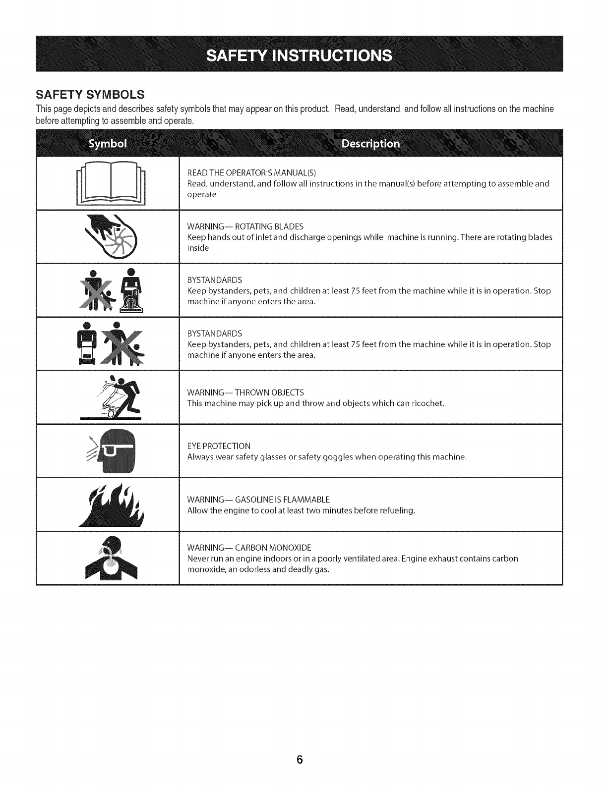
SAFETY SYMBOLS
Thispagedepictsanddescribessafetysymbolsthatmayappearonthisproduct. Read,understand,andfollowall instructionson the machine
beforeattemptingto assembleandoperate.
ii
• ®
® •
llm
il
READ THE OPERATOR'S MANUAL(S)
Read, understand, and follow all instructions in the manual(s) before attempting to assemble and
operate
WARNING-- ROTATING BLADES
Keep hands out of inlet and discharge openings while machine is running. There are rotating blades
inside
BYSTANDARDS
Keep bystanders, pets, and children at least 75 feet from the machine while it is in operation. Stop
machine if anyone enters the area.
BYSTANDARDS
Keep bystanders, pets, and children at least 75 feet from the machine while it is in operation. Stop
machine if anyone enters the area.
WARNING-- THROWN OBJECTS
This machine may pick up and throw and objects which can ricochet.
EYEPROTECTION
Always wear safety glasses or safety goggles when operating this machine.
WARNING-- GASOLINE IS FLAMMABLE
Allow the engine to cool at least two minutes before refueling.
WARNING-- CARBON MONOXIDE
Never run an engine indoors or in a poorly ventilated area. Engine exhaust contains carbon
monoxide, an odorless and deadly gas.
6

Thispageleftintentionallyblank.
7
IMPORTANT:Thisunit isshippedwithoutgasolineoroil inthe engine.
Becertainto serviceenginewithgasolineandoilas instructedinthe
Operationsectionof this manualbeforeoperatingyourmachine.
NOTE:Referenceto rightand lefthandsideof the YardVacuumis
observedfromthe operatingpositionlookingforwardto the frontof the
machine.
OPENING CARTON
1. Cuteachcornerof the cartonverticallyfromtop to bottom.
2. Removeall looseparts.
3. Removeloosepackingmaterial.
REMOVING UNIT FROM CARTON
1. Liftunit fromthe rearto detachit fromunderlyingcartonmaterial
androllunit out of carton.
2. Checkcartonthoroughlyfor anyotherlooseparts.
NOTE:Makesurenot to crimpcableswhile removingloosepartsor
theentire unitfromthecarton.
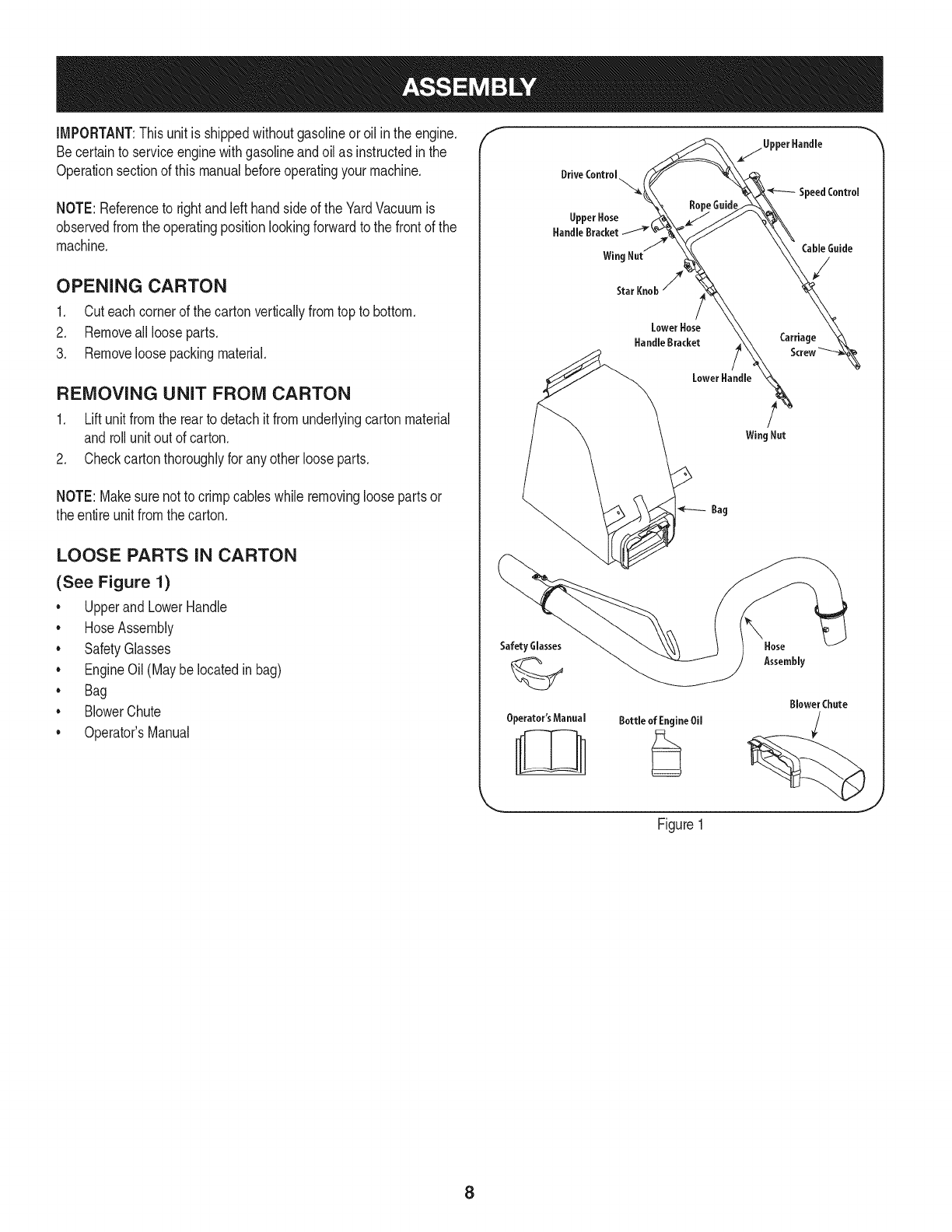
LOOSE PARTS IN CARTON
(See Figure 1)
* Upperand LowerHandle
. HoseAssembly
* SafetyGlasses
. EngineOil(Maybelocatedinbag)
* Bag
. BlowerChute
* Operator'sManual
f
Safety Glasses
Operator'sManual Bottle of EngineOil
Figure1
\Hose
Assembly
Blower Chute
J
8
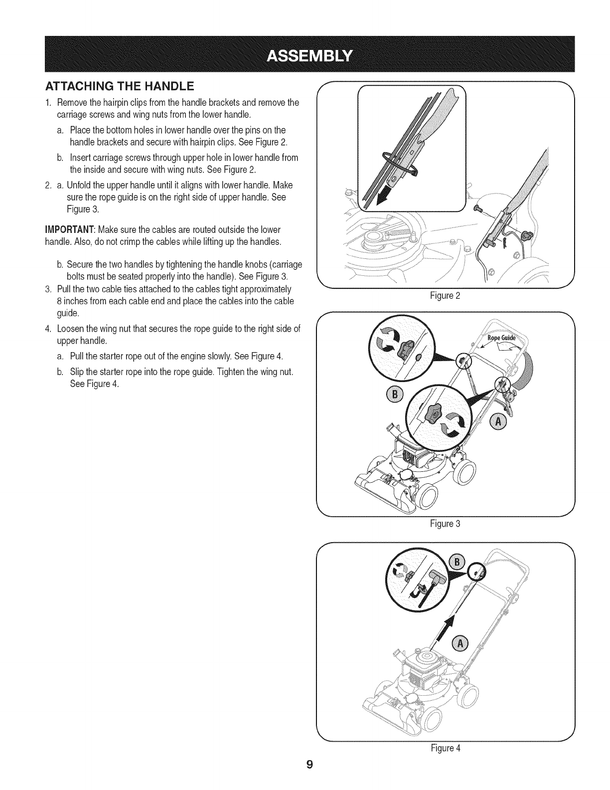
ATTACHING THE HANDLE
1. Removethehairpinclipsfromthe handlebracketsand removethe
carriagescrewsandwingnutsfromthe lowerhandle.
a. Placethe bottomholesinlowerhandleoverthe pinson the
handlebracketsand securewith hairpinclips. SeeFigure2.
b. insertcarriagescrewsthroughupperholeinlowerhandlefrom
the insideandsecurewithwingnuts.SeeFigure2.
2. a. Unfoldthe upperhandleuntil italignswithlowerhandle.Make
surethe ropeguideis onthe rightside of upperhandle.See
Figure3.
IMPORTANT:Makesurethe cablesareroutedoutsidethe lower
handle.Also,donot crimpthe cableswhile liftingupthe handles.
.
.
b. Securethe two handlesbytighteningthe handleknobs(carriage
boltsmustbeseatedproperlyintothe handle).See Figure3.
Pullthetwo cabletiesattachedto the cablestightapproximately
8 inchesfromeachcableendandplacethe cablesintothe cable
guide.
Loosenthe wingnut thatsecuresthe ropeguideto the rightsideof
upperhandle.
a. Pullthe starterropeout of the engineslowly.SeeFigure4.
b. Slipthe starterropeinto the ropeguide.Tightenthe wingnut.
SeeFigure4.
Figure2
Figure3
J
9
Figure4
J
f
Figure5
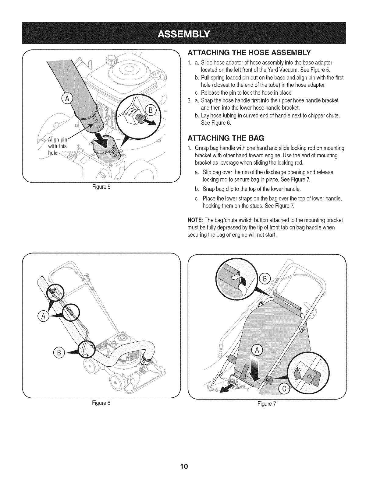
_, ATTACHING THE HOSE ASSEMBLY
1. a. Slidehoseadapterof hoseassemblyintothe baseadapter
locatedon the leftfrontof theYardVacuum.SeeFigure5.
b. Pullspringloadedpinout on the baseandalignpinwiththe first
hole(closestto the endof the tube) inthe hoseadapter.
c. Releasethe pinto lockthe hosein place.
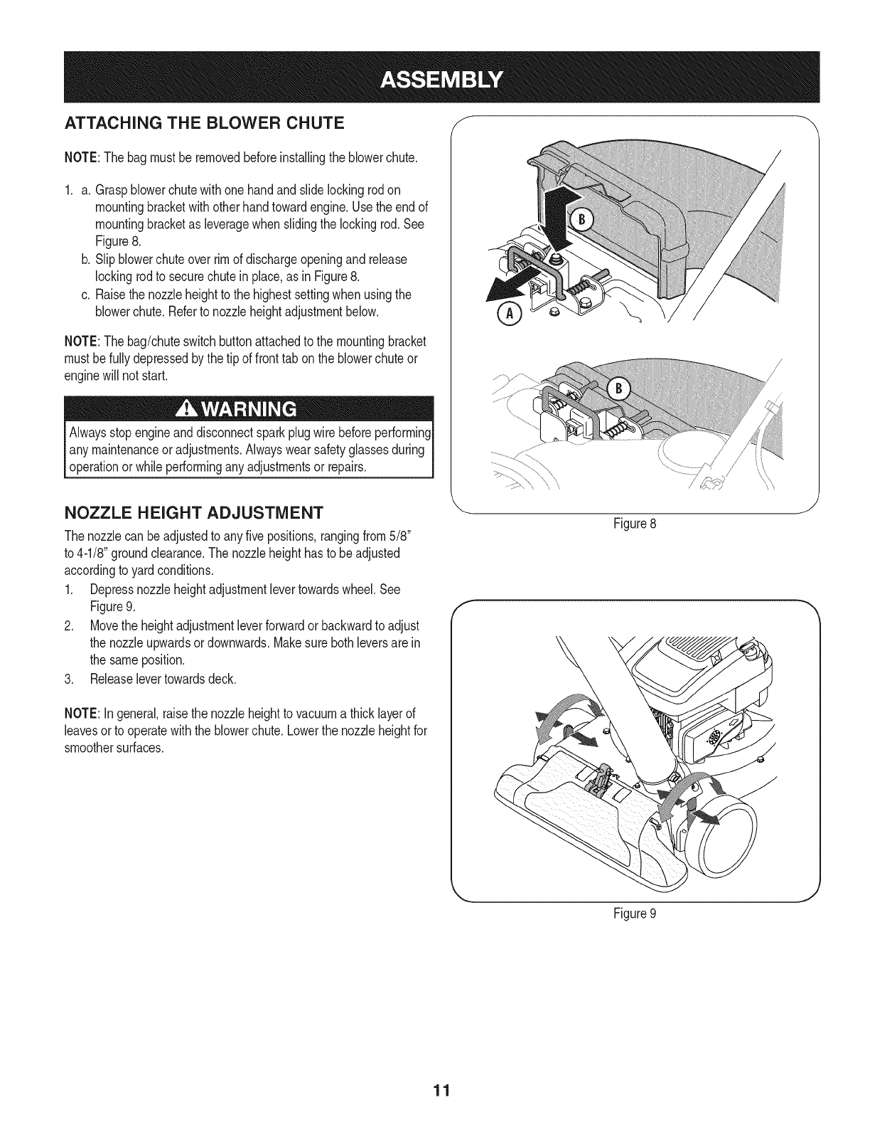
2. a. Snapthe hosehandlefirst intothe upperhose handlebracket
andthen intothe lowerhosehandlebracket.
b. Layhosetubingincurvedendof handlenextto chipperchute.
SeeFigure6.
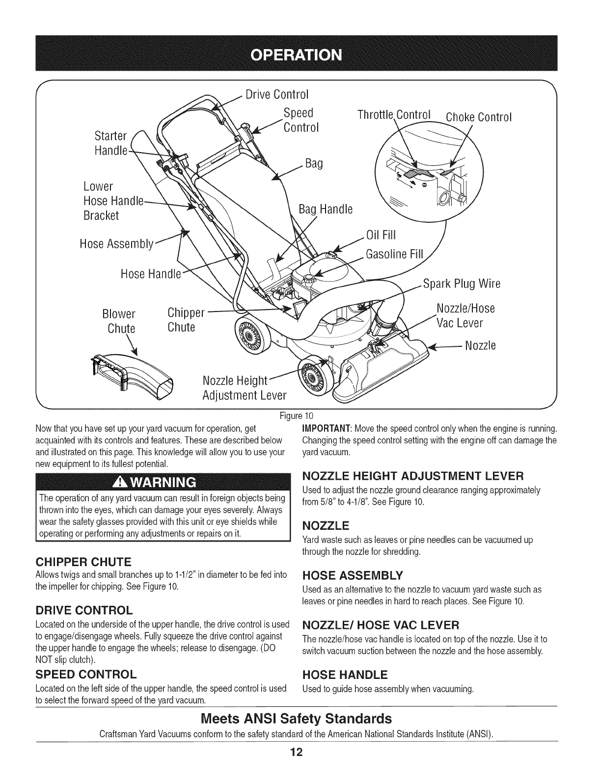
ATTACHING THE BAG
Graspbaghandlewithonehandandslide lockingrodonmounting
bracketwith otherhandtowardengine.Usethe endof mounting
bracketas leveragewhenslidingthe lockingrod.
a. Slipbagoverthe rim of the dischargeopeningandrelease
lockingrodto securebagin place.SeeFigure7.
b. Snapbagclipto the topof the lowerhandle.
c. Placethe lowerstrapson the bagoverthe topof lowerhandle,
hookingthemon the studs.SeeFigure7.
NOTE:The bag/chuteswitchbuttonattachedto the mountingbracket
must befullydepressedby thetip of fronttab on baghandlewhen
securingthe bagorenginewill not start.
Figure6 Figure7
10
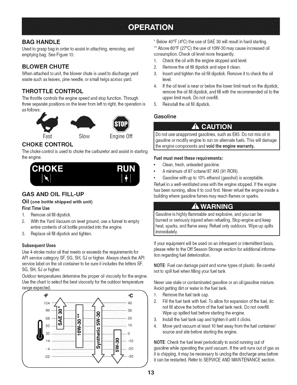
ATTACHING THE BLOWER CHUTE f
NOTE:Thebagmust beremovedbeforeinstallingthe blowerchute.
1. a. Graspblowerchutewithone handandslide lockingrodon
mountingbracketwithotherhandtowardengine.Usethe endof
mountingbracketas leveragewhenslidingthe lockingrod.See
Figure8.
b. Slipblowerchuteoverrimof dischargeopeningandrelease
lockingrodto securechutein place,as in Figure8.
c. Raisethe nozzleheightto the highestsettingwhen usingthe
blowerchute.Referto nozzleheightadjustmentbelow.
NOTE:Thebag/chuteswitchbuttonattachedto the mountingbracket
mustbefullydepressedbythe tip of front tab onthe blowerchuteor
enginewill not start.
Alwaysstopengineanddisconnectsparkplugwire beforeperforming
any maintenanceoradjustments.Alwayswear safetyglassesduring
operationor whileperformingany adjustmentsor repairs.
NOZZLE HEIGHT ADJUSTMENT
Thenozzlecan beadjustedto anyfive positions,rangingfrom5/8"
to 4-1/8"groundclearance.The nozzleheighthasto be adjusted
accordingto yardconditions.
1. Depressnozzleheightadjustmentlevertowardswheel.See
Figure9.
2. Movethe heightadjustmentleverforwardor backwardto adjust
the nozzleupwardsordownwards.Makesure bothleversarein
the sameposition.
3. Releaselevertowardsdeck.
NOTE:In general,raisethe nozzleheightto vacuuma thicklayerof
leavesorto operatewiththeblowerchute.Lowerthe nozzleheightfor
smoothersurfaces.
f
\\
Figure8
J
Figure9
J
11
fDrive Control
Speed Thr( Control Choke Control
Starter
Lower
Hose
Bracket
HoseAssembl'
Hose
Blower Chipper
Chute Chute
Bag
Bag Handle
Oil Fill
GasolineFill
)ark Plug Wire
Nozzle/Hose
Lever
Nozzle
Nowthat youhavesetup youryardvacuumfor operation,get
acquaintedwith itscontrolsandfeatures.Thesearedescribedbelow
andillustratedon thispage.Thisknowledgewill allowyou to useyour
newequipmentto its fullestpotential.
Theoperationof anyyard vacuumcan resultinforeignobjectsbeing
thrownintothe eyes,whichcan damageyoureyesseverely.Always
I wearthe safetyglassesprovidedwiththisunit oreye shieldswhile
[operatingor performinganyadjustmentsor repairson it.
NozzleHeig
Adjustment Lever
Figure10
iMPORTANT:Movethe speedcontrolonly whenthe engineis running.
Changingthe speedcontrolsettingwiththeengineoff can damagethe
yardvacuum.
CHIPPER CHUTE
Allowstwigsandsmallbranchesupto 1-1/2"in diameterto be fed into
the impellerfor chipping.SeeFigure10.
DRIVE CONTROL
Locatedon the undersideof the upperhandle,the drivecontrolis used
to engage/disengagewheels.Fullysqueezethe drivecontrolagainst
the upperhandleto engagethe wheels;releaseto disengage.(DO
NOTslip clutch).
SPEED CONTROL
Locatedon the leftside of the upperhandle,the speedcontrolis used
to selectthe forwardspeedof the yardvacuum.
NOZZLE HEIGHT ADJUSTMENT LEVER
Usedto adjustthe nozzlegroundclearancerangingapproximately
from5/8" to 4-1/8".See Figure10.
NOZZLE
Yardwastesuchas leavesorpineneedlescan bevacuumedup
throughthe nozzlefor shredding.
HOSE ASSEMBLY
Usedas analternativeto thenozzleto vacuumyardwastesuchas
leavesor pineneedlesin hardto reachplaces.SeeFigure10.
NOZZLE/HOSE VAC LEVER
The nozzle/hosevachandleis locatedon topof the nozzle.Useit to
switchvacuumsuctionbetweenthe nozzleandthe hoseassembly.
HOSE HANDLE
Usedto guidehoseassemblywhenvacuuming.
Meets ANSI Safety Standards
CraftsmanYardVacuumsconformto the safetystandardof the AmericanNationalStandardsinstitute(ANSi).
12
BAG HANDLE
Usedto grasp baginorderto assistinattaching,removing,and
emptyingbag.SeeFigure10.
BLOWER CHUTE
Whenattachedto unit,the blowerchuteisusedto dischargeyard
wastesuchas leaves,pineneedle,or smalltwigsacrossyard.
THROTTLE CONTROL
Thethrottlecontrolsthe enginespeedandstopfunction.Through
threeseparatepositionson the leverfromleftto right,the operationis
as follows:
Fast Slow Engine Off
CHOKE CONTROL
Thechokecontrolis usedto chokethe carburetorandassistinstarting
the engine.
GAS AND OiL FILL-UP
Oil (one bottle shipped with unit)
First TimeUse
1. Removeoilfill dipstick.
2. WiththeYardVacuumon levelground,usea funnelto empty
entirecontentsof oil bottleprovidedintothe engine.
3. Replaceoilfill dipstickandtighten.
* Below40°F(4°C)the useof SAE30will resultinhardstarting.
**Above80°F (27°C)the useof 10%30 maycauseincreasedoil
consumption.Checkoillevelmorefrequently.
1. Checkthe oilwiththe enginestoppedandlevel.
2. Removethe oilfill dipstickandwipeitclean.
3. Insertandtightentheoil fill dipstick.Removeitto checktheoil
level.
4. Ifthe oil levelisnearor belowthe lowerlimitmarkonthe dipstick,
removethe oilfill dipstick,andfill withthe recommendedoilto the
upperlimitmark.Do notoverfill.
5. Reinstallthe oil fill dipstick.
Gasoline
Do not useunapprovedgasolines,suchas E85.Donot mixoil in
I gasolineor modifyengineto runonalternatefuels.Thiswilldamage
[the enginecomponentsandvoid the engine warranty.
Fuel must meetthese requirements:
•Clean,fresh, unleadedgasoline.
• A minimumof 87octane/87AKI (91RON).
• Gasolinewithup to 10%ethanol(gasohol)is acceptable.
Refuelina well-ventilatedareawiththe enginestopped.If theengine
hasbeenrunning,allowitto cool first.Neverrefueltheengineinsidea
buildingwheregasolinefumesmayreachflamesor sparks.
Gasolineis highlyflammableand explosive,andyou can be
burnedor seriouslyinjuredwhen rdueling. Stopengineandkeep
heat,sparks,andflameaway.Refuelonlyoutdoors.Wipeup spills
immediately.
Subsequent Uses
Use4-strokemotoroil thatmeetsor exceedsthe requirementsfor
APIservicecategorySF,SG, SH,SJor higher.Alwayscheckthe API
servicelabelon the oilcontainerto besureit includesthe lettersSF,
SG,SH, SJor higher.
Outdoortemperaturesdeterminethe properoilviscosityfor the engine.
Usethechartto selectthe bestviscosityfor the outdoortemperature
r_..ge #xpected.
68 20
so _o
=_[_ 1._ [ o
s2,,
14 C _ '"t'x '_10
,°° I,
Ifyourequipmentwill be usedon an infrequentor intermittentbasis,
pleasereferto the Off SeasonStoragesectionfor additionalinforma-
tion regardingfuel deterioration.
NOTE:Fuelcan damagepaintandsometypesof plastic.Becareful
notto spill fuelwhenfillingyourfuel tank.
Neverusestaleorcontaminatedgasolineor anoil/gasolinemixture.
Avoidgettingdirt or waterin thefuel tank.
1. Removethe fueltankcap.
2. Fillthe fueltankwithfuel.Toallowfor expansionof the fuel,do
notfill abovethe bottomof the fueltank neck.Do notoverfill.
Wipe upspilledfuelbeforestartingthe engine.
3. Installthe fuel tankcap andtightenit untilit clicks.
4. Moveyard vacuumat least10feetawayfromthe fuel container/
sourceand sitebeforestartingthe engine.
NOTE:Checkthe fuellevel periodicallyto avoidrunningout of
gasolinewhile operatingthe yardvacuum.Ifthe unit runsout of gas as
it is chipping,it maybenecessaryto unclogthe dischargeareabefore
it can berestarted.Referto SERVICEAND MAINTENANCEsection.
13
TopView
iiii FrontTab i i
BagYC_hutei/
Switch:Wire /
/
/
Figure11
Choke Control
Figure12
f
;/
TO START ENGINE
Besurenooneotherthan theoperatoris standingnearthe yard
vaccumwhilestartingengineoroperatingvacuum.Neverrunengine
indoorsorin enclosed,poorlyventilatedareas.Engineexhaust
containscarbonmonoxide,an odorlessanddeadlygas.Keephands,
feet, hairand looseclothingawayfromany movingpartson engine
andyardvacuum.
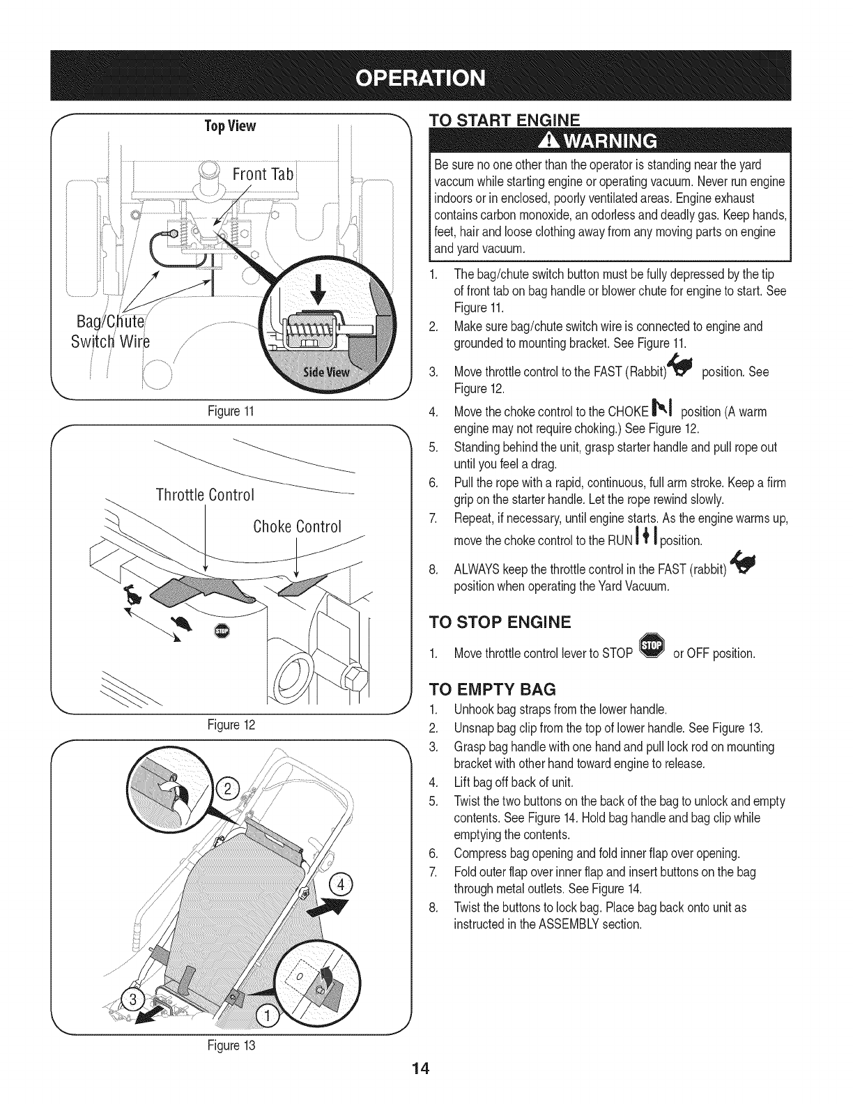
1. The bag/chuteswitchbuttonmustbefullydepressedbythe tip
of fronttab on baghandleor blowerchutefor engineto start.See
Figure11.
2. Makesurebag/chuteswitchwire is connectedto engineand
groundedto mountingbracket.SeeFigure11.
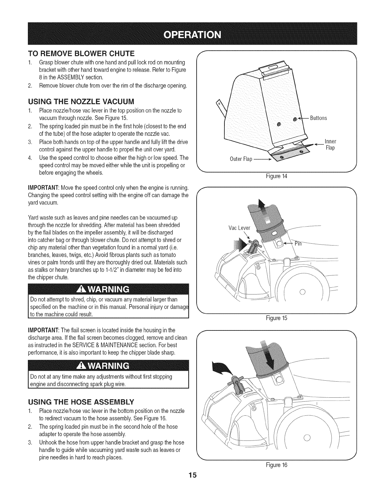
3. Movethrottlecontrolto the FAST(Rabbit)4_ position.See
Figure12.
4. Movethechokecontrolto the CHOKE_,1 position(Awarm
enginemaynot requirechoking.)SeeFigure12.
5. Standingbehindthe unit,graspstarterhandleandpull ropeout
until youfeel adrag.
6. Pullthe ropewitha rapid,continuous,full arm stroke.Keepa firm
gripon the starterhandle.Letthe roperewindslowly.
7. Repeat,if necessary,untilenginestarts.As the enginewarmsup,
movethechokecontrolto the RUNI _' I position.
8. ALWAYSkeepthe throttlecontrolinthe FAST(rabbit)
positionwhenoperatingthe YardVacuum.
TO STOP ENGINE
1. Movethrottlecontrolleverto STOP or OFFposition.
TO EMPTY BAG
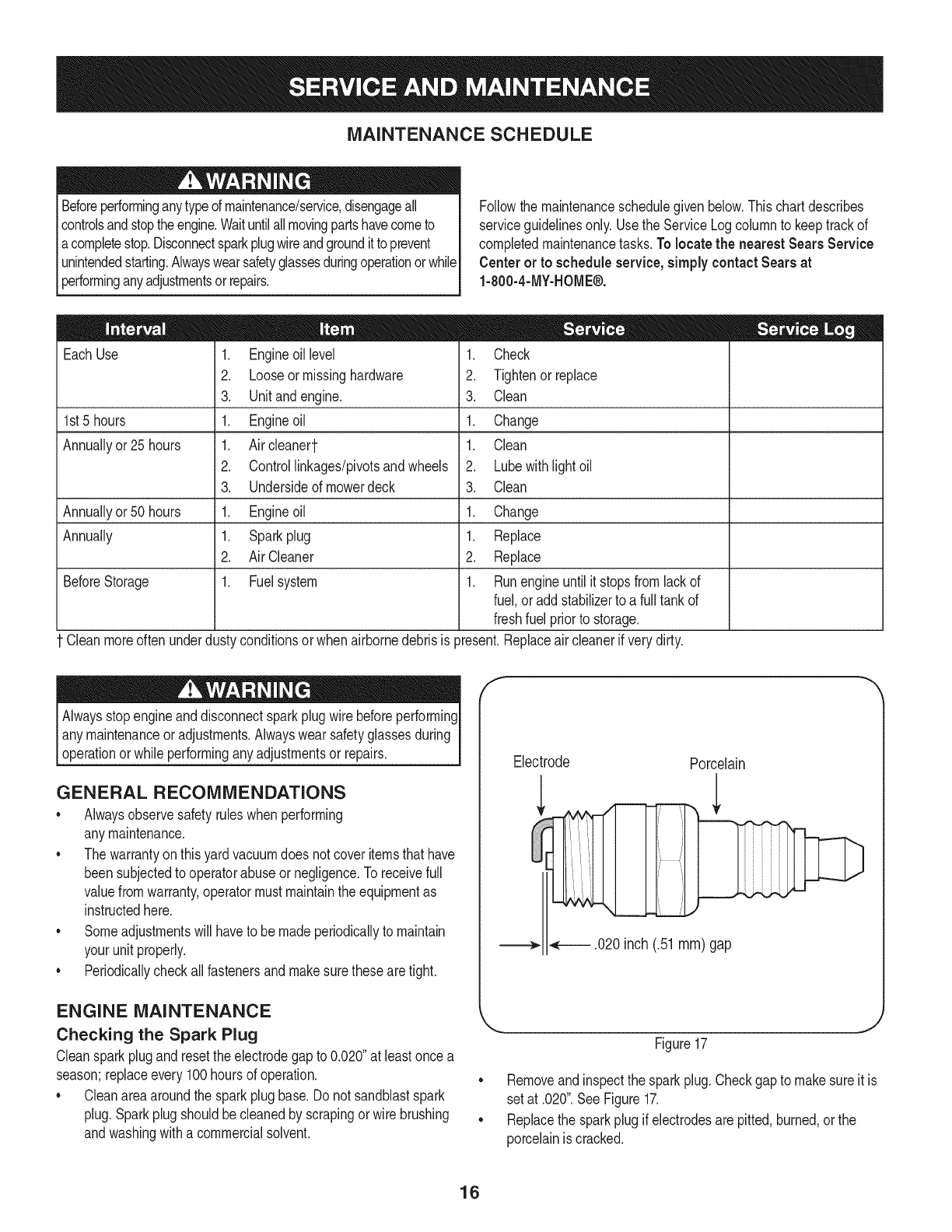
1. Unhookbagstrapsfromthe lowerhandle.
2. Unsnapbagclip fromthetop of lowerhandle.See Figure13.
3. Graspbaghandlewithonehandandpulllock rodonmounting
bracketwith otherhandtowardengineto release.
4. Liftbagoffbackof unit.
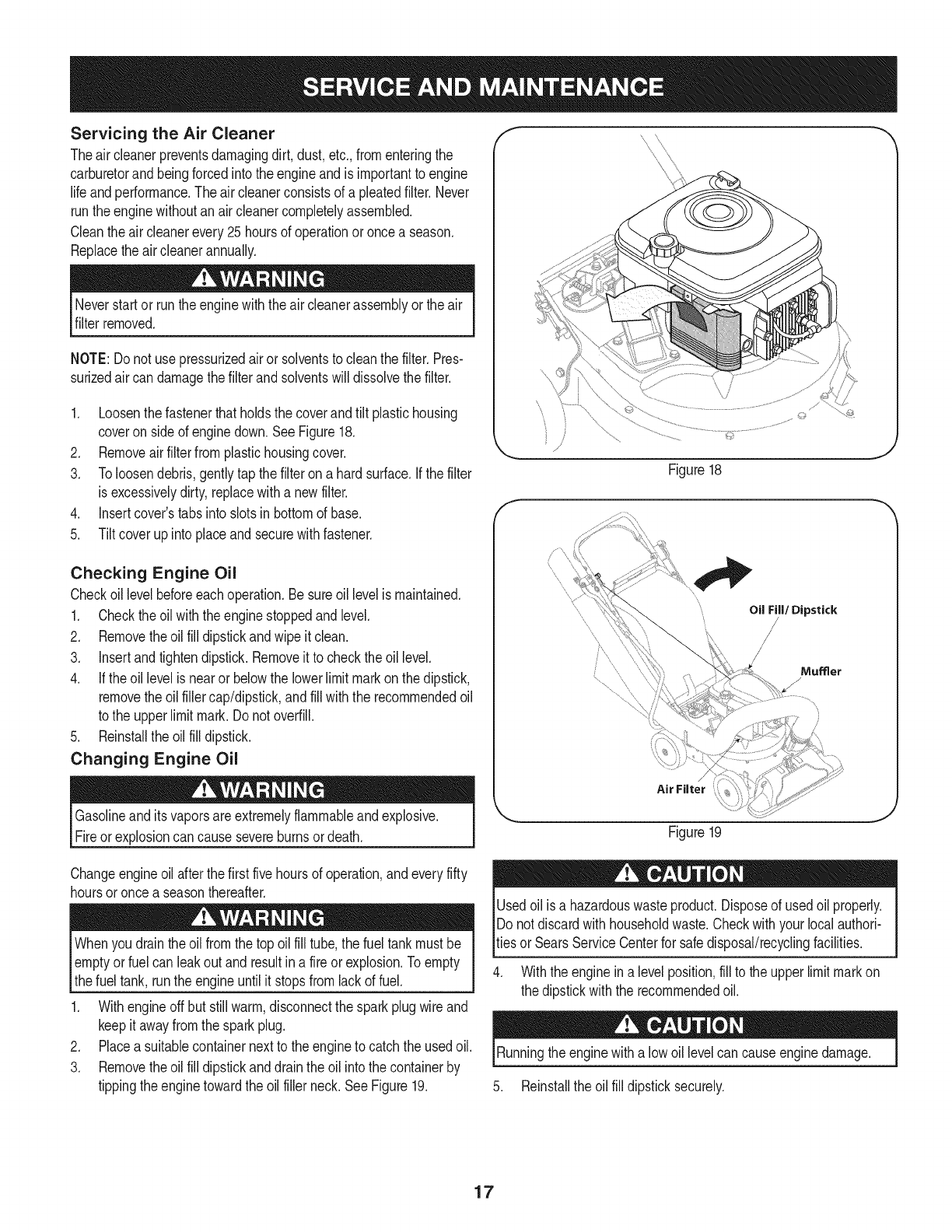
5. Twistthe twobuttonsonthe backof the bagto unlockandempty
contents.SeeFigure14.Holdbaghandleandbagclip while
emptyingthe contents.
6. Compressbagopeningandfold innerflap overopening.
7. Foldouter flapoverinnerflapand insertbuttonsonthe bag
throughmetaloutlets.SeeFigure14.
8. Twistthe buttonsto lockbag.Placebagbackonto unitas
instructedinthe ASSEMBLYsection.
Figure13
TO REMOVE BLOWER CHUTE
1. Graspblowerchutewithone handandpull lockrodonmounting
bracketwithotherhandtowardengineto release.Referto Figure
8 inthe ASSEMBLYsection.
2. Removeblowerchutefromoverthe rim of the dischargeopening.
USING THE NOZZLE VACUUM
1. Placenozzle/hosevacleverinthe top positionon the nozzleto
vacuumthroughnozzle.SeeFigure15.
2. Thespringloadedpinmustbein the first hole(closestto the end
of the tube)of the hoseadapterto operatethe nozzlevac.
3. Placebothhandsontop of the upperhandleandfullyliftthe drive
controlagainstthe upperhandleto propelthe unitoveryard.
4. Usethe speedcontrolto chooseeitherthe highor low speed.The
speedcontrolmaybemovedeitherwhilethe unitis propellingor
beforeengagingthewheels.
IMPORTANT:Movethe speedcontrolonlywhenthe engineis running.
Changingthe speedcontrolsettingwiththe engineoff candamagethe
yardvacuum.
Yardwastesuchas leavesandpineneedlescan bevacuumedup
throughthe nozzlefor shredding.Aftermaterialhas beenshredded
by theflail bladesonthe impellerassembly,it will bedischarged
intocatcherbagorthroughblowerchute.Do notattemptto shredor
chipany materialotherthan vegetationfoundin a normalyard(i.e.
branches,leaves,twigs,etc.)Avoidfibrousplantssuchas tomato
vinesor palmfrondsuntiltheyare thoroughlydriedout. Materialssuch
as stalksor heavybranchesupto 1-1/2"indiametermaybe fed into
the chipperchute.
specifiedonthe machineorin thismanual.Personalinjuryor
to the machinecould result.
IMPORTANT:Theflail screenis locatedinsidethe housinginthe
dischargearea. Ifthe flail screenbecomesclogged,removeandclean
as instructedin the SERVICE&MAINTENANCEsection.Forbest
performance,it is alsoimportantto keepthe chipperbladesharp.
Do notat any timemakeanyadjustmentswithoutfirststopping
engineanddisconnectingsparkplugwire.
USING THE HOSE ASSEMBLY
1. Placenozzle/hosevacleverinthe bottompositionon the nozzle
to redirectvacuumto the hoseassembly.SeeFigure16.
2. Thespringloadedpinmustbein the secondholeof the hose
adapterto operatethe hoseassembly.
3. Unhookthe hosefromupperhandlebracketandgraspthe hose
handleto guidewhilevacuumingyardwastesuchas leavesor
pineneedlesin hardto reachplaces.
15
Inner
Flap
Outer Flap
Figure14
Vac Lever
Figure15
F
Figure16
MAINTENANCE SCHEDULE
Beforeperforminganytypeofmaintenance/service,disengageall
controlsandstoptheengine.Waituntilallmovingpartshavecometo
acompletestop.Disconnectsparkplugwireandgroundit toprevent
unintendedstarting.Alwayswearsafetyglassesduringoperationorwhile
performinganyadjustmentsorrepairs.
Followthe maintenanceschedulegiven below.Thischartdescribes
serviceguidelinesonly.Usethe ServiceLogcolumnto keeptrackof
completedmaintenancetasks.To locate the nearest Sears Service
Centeror to scheduleservice,simplycontactSearsat
1-800-4-MY-HOME®.
EachUse
1st5 hours
Annuallyor 25hours
Annuallyor 50hours
Annually
BeforeStorage
.
2.
3.
1.
1.
2.
3.
1.
1.
2.
1.
Engineoillevel
Looseormissinghardware
Unitandengine.
Engineoil
Aircleaned-
Controllinkages/pivotsandwheels
Undersideof mowerdeck
Engineoil
Sparkplug
AirCleaner
Fuelsystem
Cleanmoreoftenunderdustyconditionsor whenairbornedebrisis
1. Check
2. Tightenor replace
3. Clean
1. Change
1. Clean
2. Lubewithlight oil
3. Clean
1. Change
1. Replace
2. Replace
1. Runengineuntil it stopsfromlackof
fuel,oraddstabilizerto a full tankof
freshfuel priorto storage.
_resent.Replaceaircleanerif verydirty.
Alwaysstopengineanddisconnectsparkplugwire beforeperforming
I anymaintenanceoradjustments.Alwayswear safetyglassesduring
_operationor whileperforminganyadjustmentsor repairs.
GENERAL RECOMMENDATIONS
•Alwaysobservesafetyruleswhenperforming
anymaintenance.
• Thewarrantyon thisyardvacuumdoes notcoveritemsthat have
beensubjectedto operatorabuseor negligence.To receivefull
valuefromwarranty,operatormustmaintaintheequipmentas
instructedhere.
• Someadjustmentswillhaveto be madeperiodicallyto maintain
yourunit properly.
• Periodicallycheckall fastenersand makesurethesearetight.
ENGINE MAINTENANCE
Checking the Spark Plug
Cleansparkplugandresettheelectrodegapto 0.020"at leastonce a
season;replaceevery100hoursof operation.
Cleanareaaroundthe sparkplugbase.Do not sandblastspark
plug.Sparkplugshouldbecleanedby scrapingorwire brushing
andwashingwitha commercialsolvent.
f
Electrode Porcelain
.020 inch (.51 ram) gap
J
Figure17
Removeandinspectthe sparkplug.Checkgapto makesureit is
setat .020".SeeFigure17.
• Replacethe sparkplugif electrodesare pitted,burned,or the
porcelainis cracked.
16
Servicing the Air Cleaner
Theair cleanerpreventsdamagingdirt, dust,etc.,fromenteringthe
carburetorand beingforcedintothe engineandis importantto engine
life andperformance.Theair cleanerconsistsof a pleatedfilter. Never
runthe enginewithoutan aircleanercompletelyassembled.
Cleantheair cleanerevery25hoursof operationoronce a season.
Replacetheaircleanerannually.
Neverstartor runthe enginewiththe aircleanerassemblyor theair
filterremoved.
NOTE:Do notuse pressurizedairor solventsto cleanthe filter.Pres-
surizedair can damagethefilterandsolventswill dissolvethefilter.
1. Loosenthe fastenerthatholdsthe coverandtilt plastichousing
coveron sideof enginedown.SeeFigure18.
2. Removeairfilterfromplastichousingcover.
3. Toloosendebris,gentlytap the filterona hardsurface.Ifthe filter
is excessivelydirty, replacewitha newfilter.
4. Insertcover'stabsinto slotsin bottomof base.
5. Tiltcoverupinto placeand securewithfastener.
Checking Engine Oil
Checkoillevelbeforeeachoperation.Be sureoillevelis maintained.
1. Checktheoil withthe enginestoppedandlevel.
2. Removetheoil fill dipstickandwipe it clean.
3. Insertandtightendipstick.Removeit to checktheoil level.
4. If theoil levelis nearor belowthe lowerlimitmarkon the dipstick,
removethe oil fillercap/dipstick,andfill withthe recommendedoil
to the upperlimitmark. Donotoverfill.
5. Reinstallthe oilfill dipstick.
Changing Engine Oil
Gasolineanditsvaporsareextremelyflammableandexplosive.
Fireor explosioncancausesevereburnsordeath.
Oil Fill/Dipstick
/
Mumer
/
Figure19
Changeengineoil afterthe first fivehoursof operation,andeveryfifty
hoursoronce a seasonthereafter.
Whenyou draintheoil fromthe top oil fill tube,the fuel tankmustbe
I emptyor fuel can leakoutand resultin afire or explosion.Toempty
Ithe fuel tank, runthe engineuntilit stopsfromlackof fuel.
1. Withengineoffbut stillwarm,disconnectthe sparkplugwire and
keepit awayfromthe sparkplug.
2. Placea suitablecontainernextto theengineto catchthe usedoil.
3. Removetheoil fill dipstickanddraintheoil intothe containerby
tippingtheenginetowardthe oil fillerneck.See Figure19.
Usedoil is a hazardouswasteproduct.Disposeof usedoil properly.
IDo notdiscardwithhouseholdwaste.Checkwithyour localauthori-
_tiesorSearsServiceCenterfor safedisposal/recyclingfacilities.
4. Withthe enginein a levelposition,fill to the upperlimitmarkon
the dipstickwiththe recommendedoil.
Runningtheenginewitha low oil levelcan causeenginedamage.
5. Reinstallthe oil fill dipsticksecurely.
17
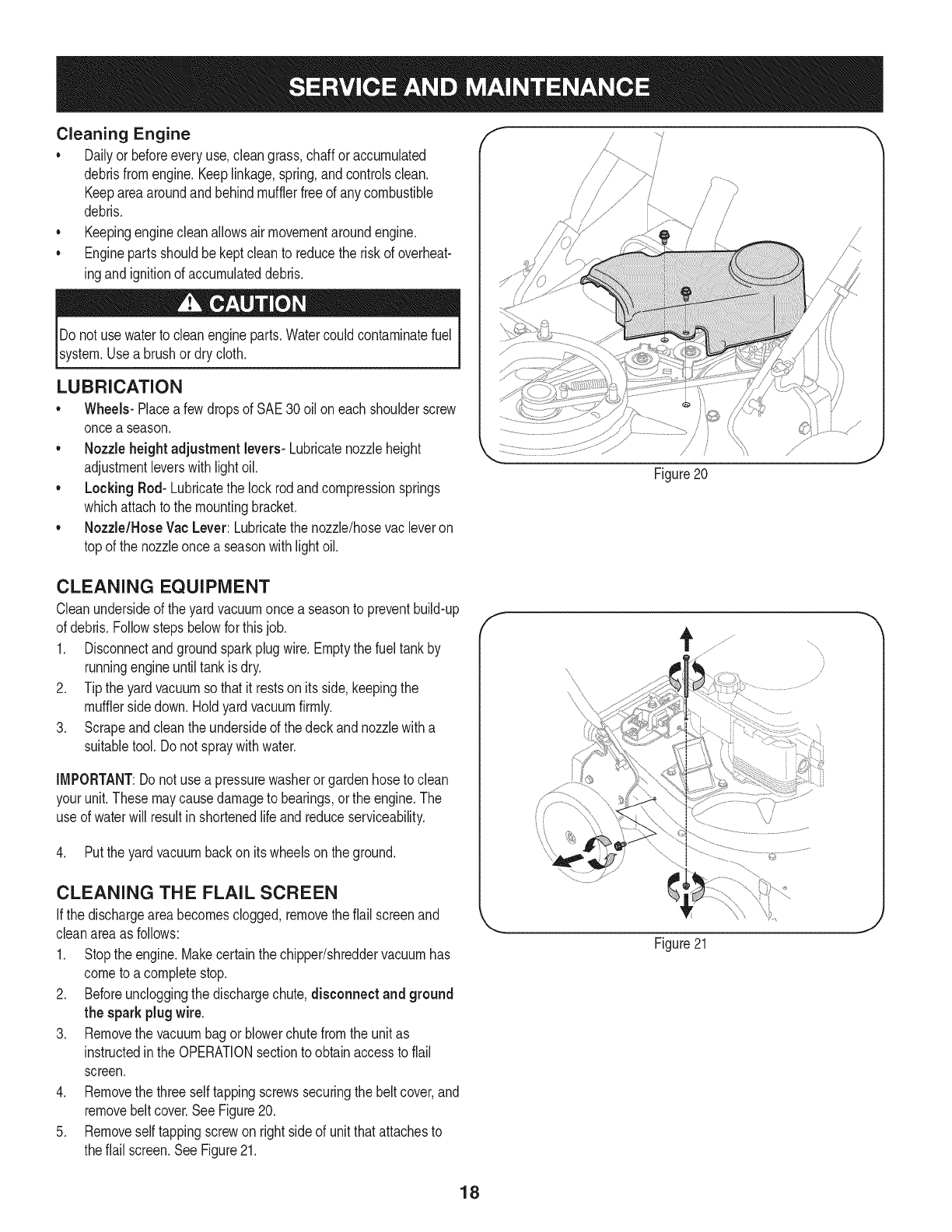
Cleaning Engine
•Dailyor beforeeveryuse,cleangrass,chaffor accumulated
debrisfromengine.Keeplinkage,spring,andcontrolsclean.
Keepareaaroundandbehindmufflerfreeof any combustible
debris.
• Keepingenginecleanallowsairmovementaroundengine.
• Enginepartsshouldbe keptcleanto reducethe riskof overheat-
ingandignitionof accumulateddebris.
Do not usewaterto cleanengineparts.Watercouldcontaminatefuel
system.Usea brushor drycloth.
LUBRICATION
*Wheels- Placea fewdropsof SAE30 oilon eachshoulderscrew
oncea season.
, Nozzle heightadjustment levers-Lubricatenozzleheight
adjustmentleverswith lightoil.
, Locking Rod- Lubricatethe lock rodandcompressionsprings
whichattachto the mountingbracket.
, Nozzle/HoseVac Lever: Lubricatethe nozzle/hosevacleveron
topof the nozzleonce a seasonwithlightoil.
Figure20
CLEANING EQUIPMENT
Cleanundersideof theyardvacuumonce a seasonto preventbuild-up
of debris.Followstepsbelowfor thisjob.
1. Disconnectandgroundsparkplugwire.Emptythe fueltankby
runningengineuntiltankis dry.
2. Tipthe yard vacuumso thatit restson itsside,keepingthe
mufflersidedown.Holdyardvacuumfirmly.
3. Scrapeandcleanthe undersideof the deckandnozzlewitha
suitabletool.Donot spraywithwater.
IMPORTANT:Donot usea pressurewasherorgardenhoseto clean
yourunit.Thesemaycausedamageto bearings,orthe engine.The
useof waterwill resultin shortenedlife andreduceserviceability.
4. Putthe yardvacuumbackon itswheelson theground.
CLEANING THE FLAIL SCREEN
Ifthe dischargeareabecomesclogged,removetheflail screenand
cleanareaas follows:
1. Stopthe engine.Makecertainthe chipper/shreddervacuumhas
cometo a completestop.
2. Beforeuncloggingthe dischargechute,disconnect and ground
the spark plugwire.
3. Removethe vacuumbagor blowerchutefromthe unitas
instructedin the OPERATIONsectionto obtainaccessto flail
screen.
4. Removethe three selftappingscrewssecuringthebelt cover,and
removebeltcover.SeeFigure20.
5. Removeselftappingscrewon rightsideof unitthatattachesto
theflail screen.SeeFigure21.
f
/
Figure21
J
18
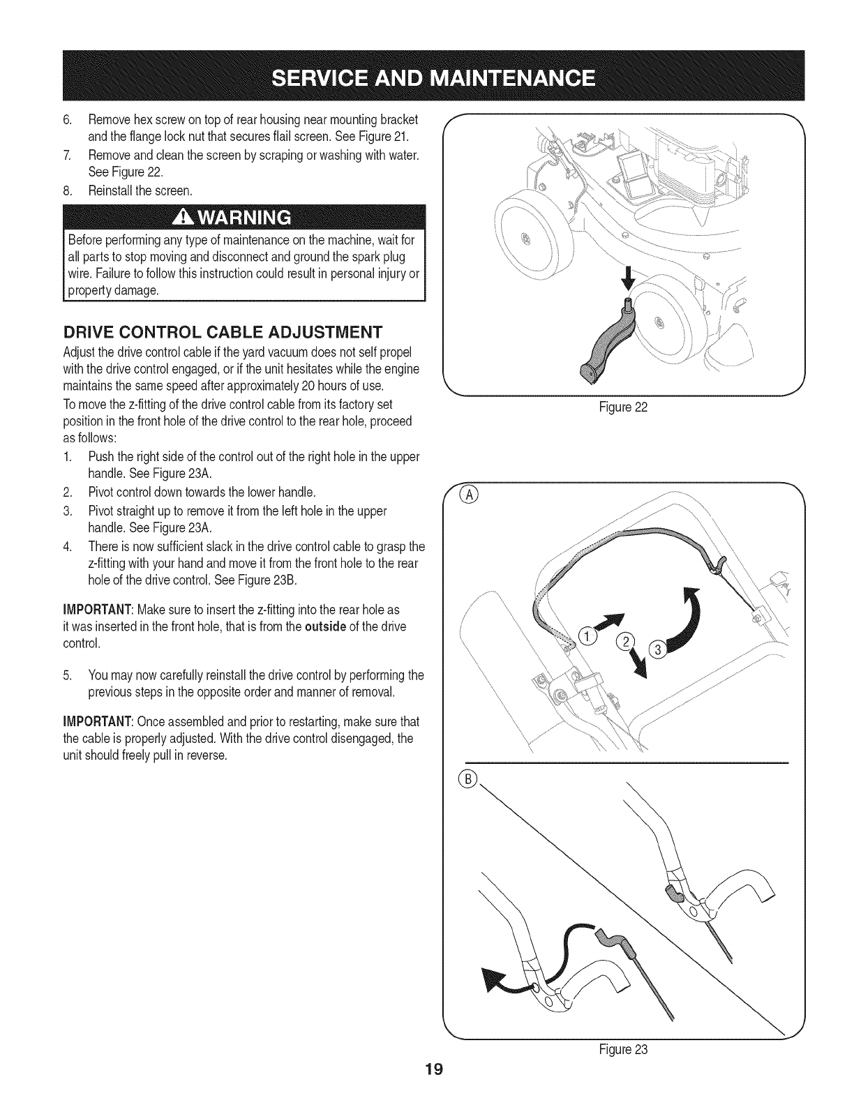
6. Removehexscrewontop of rearhousingnearmountingbracket
andthe flangelocknutthatsecuresflail screen.SeeFigure21.
7. Removeandcleanthe screenby scrapingorwashingwithwater.
SeeFigure22.
8. Reinstallthe screen.
Beforeperforminganytypeof maintenanceon the machine,waitfor
all partsto stopmovinganddisconnectandgroundthe sparkplug
wire. Failureto followthisinstructioncould resultin personalinjuryor
propertydamage.
DRIVE CONTROL CABLE ADJUSTMENT
Adjustthe drivecontrolcableif theyard vacuumdoes not selfpropel
withthe drivecontrolengaged,orif the unithesitateswhilethe engine
maintainsthe samespeedafterapproximately20 hoursof use.
Tomovethe z-fittingof the drivecontrolcablefromitsfactoryset
positioninthe frontholeof the drivecontrolto the rearhole,proceed
as follows:
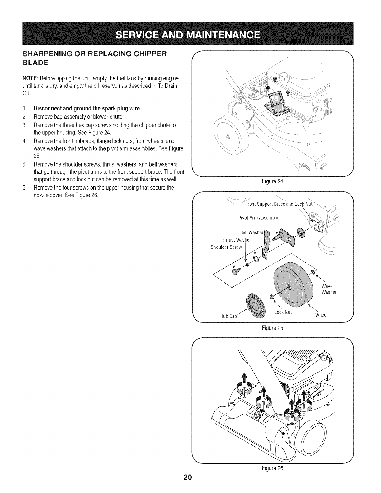
1. Pushthe rightsideof thecontroloutof the rightholeinthe upper
handle.SeeFigure23A.
2. Pivotcontroldowntowardsthe lowerhandle.
3. Pivotstraightupto removeit fromthe leftholein the upper
handle.SeeFigure23A.
4. Thereis nowsufficientslackinthe drivecontrolcableto graspthe
z-fittingwithyourhandandmoveit fromthe frontholeto the rear
holeof the drivecontrol.SeeFigure23B.
IMPORTANT:Makesureto insertthe z-fittingintothe rearholeas
it wasinsertedinthe fronthole,thatis fromthe outside of the drive
control.
5. Youmaynowcarefullyreinstallthe drivecontrolby performingthe
previoussteps inthe oppositeorderandmannerof removal.
IMPORTANT:Onceassembledand priorto restarting,makesurethat
the cableis properlyadjusted.Withthe drivecontroldisengaged,the
unit shouldfreelypullin reverse.
f
\
Figure22
\
19
Figure23
SHARPENING OR REPLACING CHIPPER
BLADE
NOTE:Beforetippingthe unit,emptythefuel tankby runningengine
untiltankisdry,andemptythe oil reservoiras describedinTo Drain
Oil.
1. Disconnectand groundthe sparkplugwire.
2. Removebagassemblyor blowerchute.
3. Removethe three hexcap screwsholdingthe chipperchuteto
the upperhousing.SeeFigure24.
4. Removethe fronthubcaps,flangelocknuts,frontwheels,and
wavewashersthatattachto the pivotarm assemblies.SeeFigure
25.
5. Removethe shoulderscrews,thrustwashers,andbellwashers
thatgothroughthe pivotarmsto the frontsupportbrace.The front
supportbraceandlocknut can beremovedat thistimeas well.
6. Removethe four screwson the upperhousingthat securethe
nozzlecover.SeeFigure26. f
Figure24
x/
..........................Front support Braceand Lock Nui
Pivot Arm Assembl'
J
Bell Washer
Thrust Washer
Shoulder Screw
Wave
Washer
Lock Nut
Hub Ca[ Wheel
J
Figure25
f
2O
Figure26
J
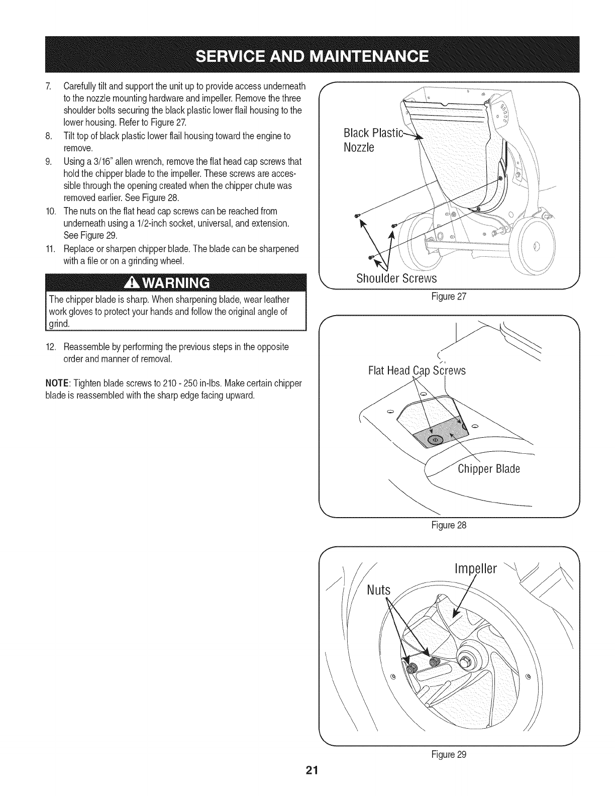
7. Carefullytilt andsupportthe unit upto provideaccessunderneath
to the nozzlemountinghardwareandimpeller.Removethe three
shoulderboltssecuringthe blackplasticlowerflail housingto the
lowerhousing.Referto Figure27.
8. Tilttop of blackplasticlowerflail housingtowardthe engineto
remove.
9. Usinga 3/16"allenwrench,removetheflat headcap screwsthat
holdthe chipperbladeto the impeller.Thesescrewsareacces-
siblethroughtheopeningcreatedwhenthechipperchutewas
removedearlier.SeeFigure28.
10. Thenutsonthe flat headcap screwscan bereachedfrom
underneathusinga 1/2-inchsocket,universal,andextension.
SeeFigure29.
11. Replaceorsharpenchipperblade.The bladecan be sharpened
witha fileor ona grindingwheel.
The chipperbladeis sharp.Whensharpeningblade,wear leather
workglovesto protectyourhandsandfollowthe originalangleof
grind.
12. Reassembleby performingthe previousstepsin theopposite
orderand mannerof removal.
NOTE:Tightenbladescrewsto 210- 250in-lbs.Makecertainchipper
bladeis reassembledwiththe sharpedgefacingupward.
Black
Nozzle
\
f
Shoulder Screws
Figure27
C
Flat Head Ca Screws
Chipper Blade
Figure28
J
Impeller
21
Figure29
J
Neverstoreyardvacuumwithfuel intankindoorsor inpoorly
ventilatedareaswherefuel fumesmayreachanopenflame,spark,
or pilotlight as ona furnace,waterheater,clothesdryer,or gas
appliance.
PREPARING THE ENGINE
Forenginesstoredover30 days:
1. To preventgumfromforminginfuel systemor oncarburetor
parts, runengineuntilit stopsfromlackof fuelor adda gasoline
additiveto the gas inthe tank. Ifyou usea gas additive,runthe
enginefor severalminutesto circulatethe additivethroughthe
carburetor--afterwhichthe engineandfuel can bestoredup to
six months.
2. Whileengineis stillwarm,changethe oil.
3. Cleanengineof surfacedebris.
PREPARING THE YARD VACUUM
•Whenstoringthe yardvacuumin an unventilatedor metalstorage
shed,careshouldbetakento rustproofthe non-paintedsurfaces.
Usinga lightoil orsilicone,coatthe equipment,especiallyany
springs,bearings,andcables.
• Cleanandlubricatemowerthoroughlyas describedinthe lubrica-
tion instructions.
• Donot usea pressurewasheror gardenhoseto cleanyour unit.
• Store mowerin a dry,cleanarea. Do notstorenextto corrosive
materials,suchas fertilizer.
22
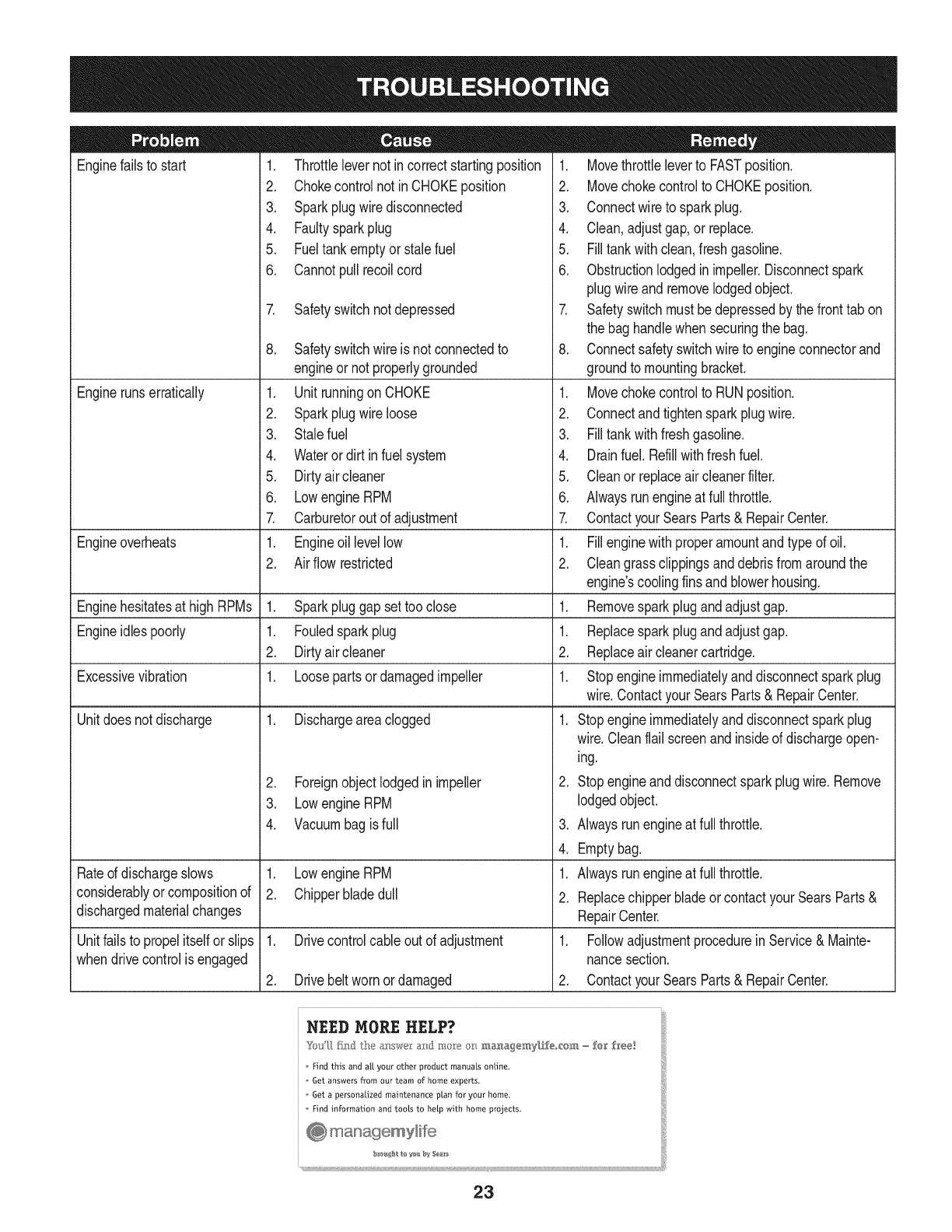
Enginefailsto start
Enginerunserratically
1. Throttlelevernot incorrectstartingposition
2. Chokecontrolnot inCHOKEposition
3. Sparkplugwire disconnected
4. Faultysparkplug
5. Fueltank emptyorstalefuel
6. Cannotpullrecoilcord
7. Safetyswitchnotdepressed
Engineoverheats
Enginehesitatesat high RPMs 1. Sparkpluggap settoo close
Engineidlespoorly 1. Fouledsparkplug
2. Dirtyair cleaner
Excessivevibration 1. Loosepartsor damagedimpeller
Unitdoesnot discharge 1. Dischargeareaclogged
Rateddischargeslows
considerablyor compositionof
dischargedmaterialchanges
Unitfailsto propelitself orslips
whendrivecontrolisengaged
8. Safetyswitchwire is not connectedto
engineor notproperlygrounded
1. Unitrunningon CHOKE
2. Sparkplugwire loose
3. Stalefuel
4. Wateror dirt in fuel system
5. Dirtyair cleaner
6. Lowengine RPM
7. Carburetorout of adjustment
1. Engineoil levellow
2. Air flowrestricted
2. Foreignobjectlodgedin impeller
3. Lowengine RPM
4. Vacuumbagis full
1. Lowengine RPM
2. Chipperbladedull
1. Drivecontrolcableout of adjustment
2. Drivebeltworn ordamaged
1. Movethrottleleverto FASTposition.
2. Movechokecontrolto CHOKEposition.
3. Connectwire to sparkplug.
4. Clean,adjustgap,or replace.
5. Filltankwithclean,freshgasoline.
6. Obstructionlodgedin impeller.Disconnectspark
plugwire andremovelodgedobject.
7. Safetyswitchmustbedepressedby thefronttab on
the bag handlewhen securingthe bag.
8. Connectsafetyswitchwireto engineconnectorand
groundto mountingbracket.
1. Movechokecontrolto RUNposition.
2. Connectandtightensparkplugwire.
3. Filltankwithfreshgasoline.
4. Drainfuel. Refillwithfreshfuel.
5. Cleanor replaceair cleanerfilter.
6. Alwaysrunengineat full throttle.
7. ContactyourSearsParts& RepairCenter.
1. Fillenginewith properamountandtype of oil.
2. Cleangrassclippingsanddebrisfromaroundthe
engine'scoolingfinsandblowerhousing.
1. Removesparkplugandadjustgap.
1. Replacesparkplugandadjustgap.
2. Replaceair cleanercartridge.
1. Stopengineimmediatelyanddisconnectsparkplug
wire.ContactyourSearsParts& RepairCenter.
1. Stopengineimmediatelyanddisconnectsparkplug
wire.Cleanflail screenandinsideof dischargeopen-
ing.
2. Stopengineanddisconnectsparkplugwire.Remove
lodgedobject.
3. Alwaysrunengineat full throttle.
4. Emptybag.
1. Alwaysrunengineat full throttle.
2. Replacechipperbladeor contactyourSearsParts&
RepairCenter.
1. Followadjustmentprocedurein Service& Mainte-
nancesection.
2. ContactyourSearsParts& RepairCenter.
Find this and all your other product manuals online.
Get answers from our team of home experts.
Get a personalized maintenance plan for your home.
Find information and tools to heLp with home projects.
23
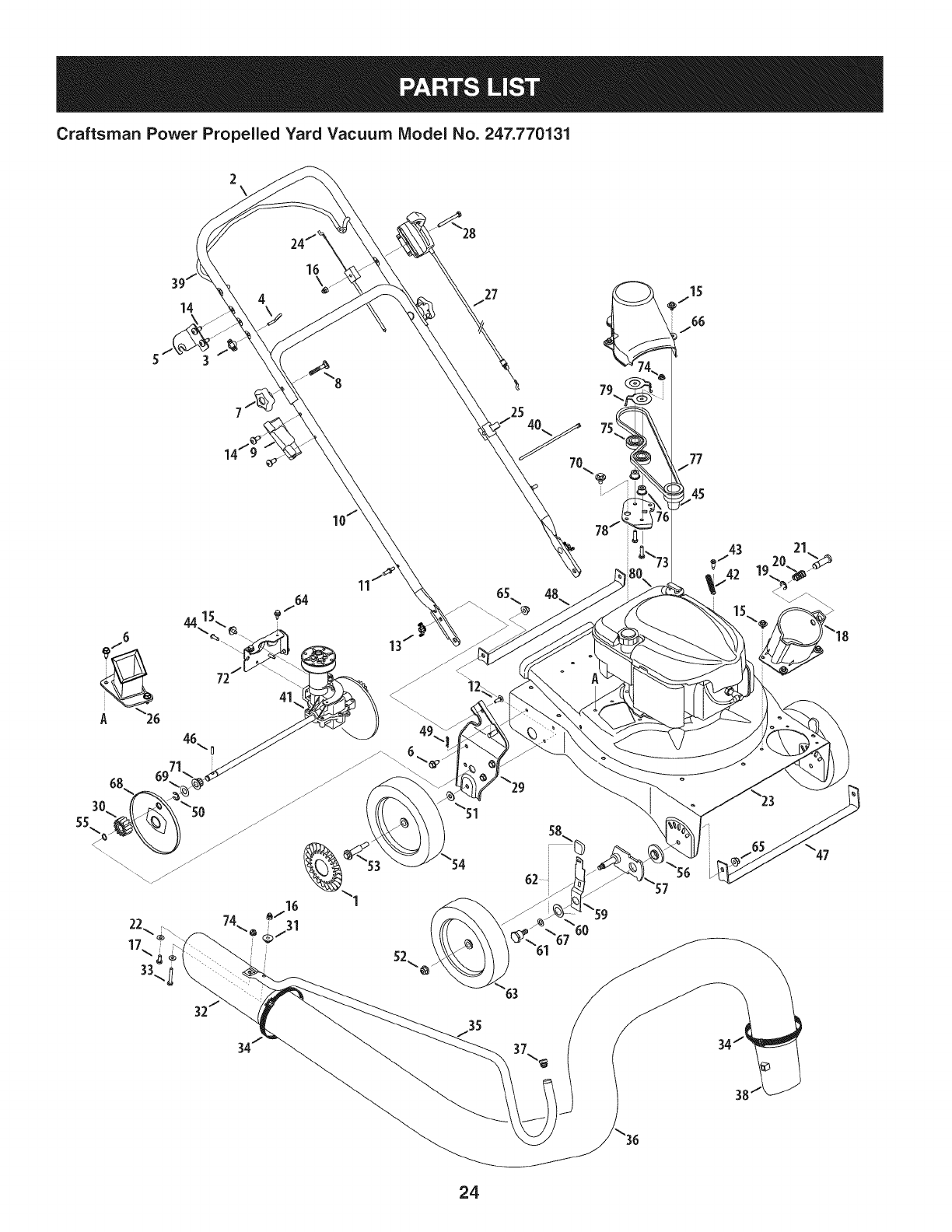
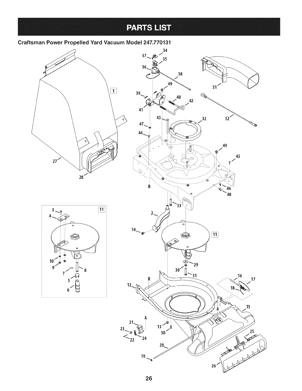
Craftsman Power Propelled Yard Vacuum Model No. 247.770131
14
44
41
54
63
38
24
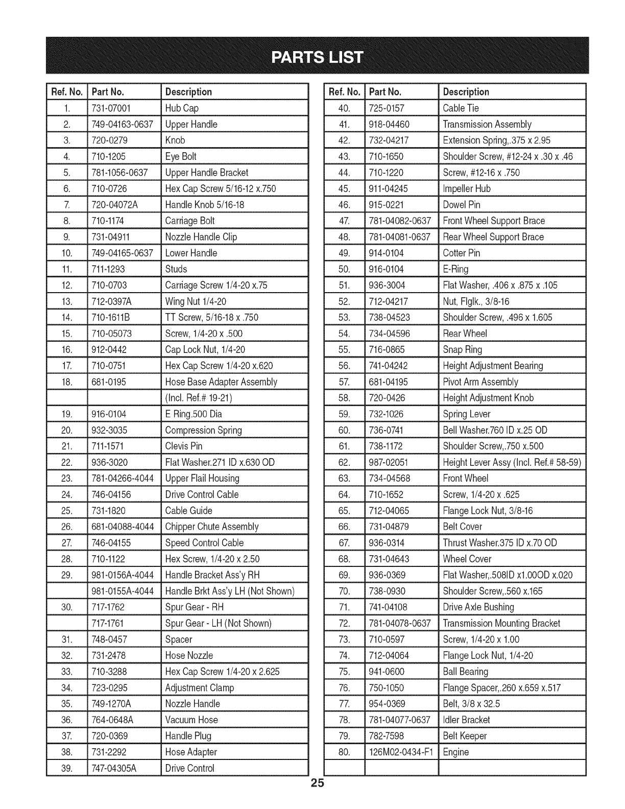
Ref. No. Part No. Description
1. 731-07001 HubCap
2. 749-04163-0637 UpperHandle
3. 720-0279 Knob
4. 710-1205 EyeBolt
5. 781-1056-0637 UpperHandleBracket
6. 710-0726 HexCapScrew5/16-12x.750
7. 720-04072A HandleKnob5/16-18
8. 710-1174 CarriageBolt
9. 731-04911 NozzleHandleClip
10. 749-04165-0637 LowerHandle
11. 711-1293 Studs
12. 710-0703 CarriageScrew1/4-20x.75
13. 712-0397A Wing Nut1/4-20
14. 710-1611B TT Screw,5/16-18x .750
15. 710-05073 Screw,1/4-20x .500
16. 912-0442 CapLockNut, 1/4-20
17. 710-0751 HexCapScrew1/4-20x.620
18. 681-0195 HoseBaseAdapterAssembly
(Incl.Ref.#19-21)
19. 916-0104 E Ring.500Dia
20. 932-3035 CompressionSpring
21. 711-1571 ClevisPin
22. 936-3020 FiatWasher.271IDx.630OD
23. 781-04266-4044 UpperFlailHousing
24. 746-04156 DriveControlCable
25. 731-1820 CableGuide
26. 681-04088-4044 ChipperChuteAssembly
27. 746-04155 SpeedControlCable
28. 710-1122 HexScrew,1/4-20x 2.50
29. 981-0156A-4044 HandleBracketAss'yRH
981-0155A-4044 HandleBrktAss'y LH(NotShown)
30. 717-1762 SpurGear- RH
717-1761 SpurGear- LH (NotShown)
31. 748-0457 Spacer
32. 731-2478 HoseNozzle
33. 710-3288 HexCapScrew1/4-20x 2.625
34. 723-0295 AdjustmentClamp
35. 749-1270A NozzleHandle
36. 764-0648A VacuumHose
37. 720-0369 HandlePlug
38. 731-2292 HoseAdapter
39. 747-04305A DriveControl
Ref.No. Part No. Description
40. 725-0157 CableTie
41. 918-04460 TransmissionAssembly
42. 732-04217 ExtensionSpring,.375x 2.95
43. 710-1650 ShoulderScrew,#12-24x .30x.46
44. 710-1220 Screw,#12-16x .750
45. 911-04245 ImpellerHub
46. 915-0221 DowelPin
47. 781-04082-0637 FrontWheelSupportBrace
48. 781-04081-0637 RearWheelSupportBrace
49. 914-0104 CotterPin
50. 916-0104 E-Ring
51. 936-3004 FiatWasher,.406x.875x.105
52. 712-04217 Nut, Flglk.,3/8-16
53. 738-04523 ShoulderScrew,.496x 1.605
54. 734-04596 RearWheel
55. 716-0865 SnapRing
56. 741-04242 HeightAdjustmentBearing
57. 681-04195 PivotArm Assembly
58. 720-0426 HeightAdjustmentKnob
59. 732-1026 SpringLever
60. 736-0741 BellWasher.760IDx.25OD
61. 738-1172 ShoulderScrew,.750x.500
62. 987-02051 HeightLeverAssy(Incl. Ref.#58-59)
63. 734-04568 FrontWheel
64. 710-1652 Screw,1/4-20x .625
65. 712-04065 FlangeLockNut,3/8-16
66. 731-04879 Belt Cover
67. 936-0314 ThrustWasher.375IDx.70OD
68. 731-04643 WheelCover
69. 936-0369 FiatWasher,.5081Dxl .O00Dx.020
70. 738-0930 ShoulderScrew,.560x.165
71. 741-04108 DriveAxle Bushing
72. 781-04078-0637 TransmissionMountingBracket
73. 710-0597 Screw,1/4-20x 1.00
74. 712-04064 FlangeLockNut,1/4-20
75. 941-0600 Ball Bearing
76. 750-1050 FlangeSpacer,.260x.659x.517
77. 954-0369 Belt,3/8 x 32.5
78. 781-04077-0637 Idler Bracket
79. 782-7598 Belt Keeper
80. 126MO2-O434-F1Engine
25
Craftsman Power Propelled Yard Vacuum Model 247.770131
[]
45
7
6
30/i_31
[]
25
26
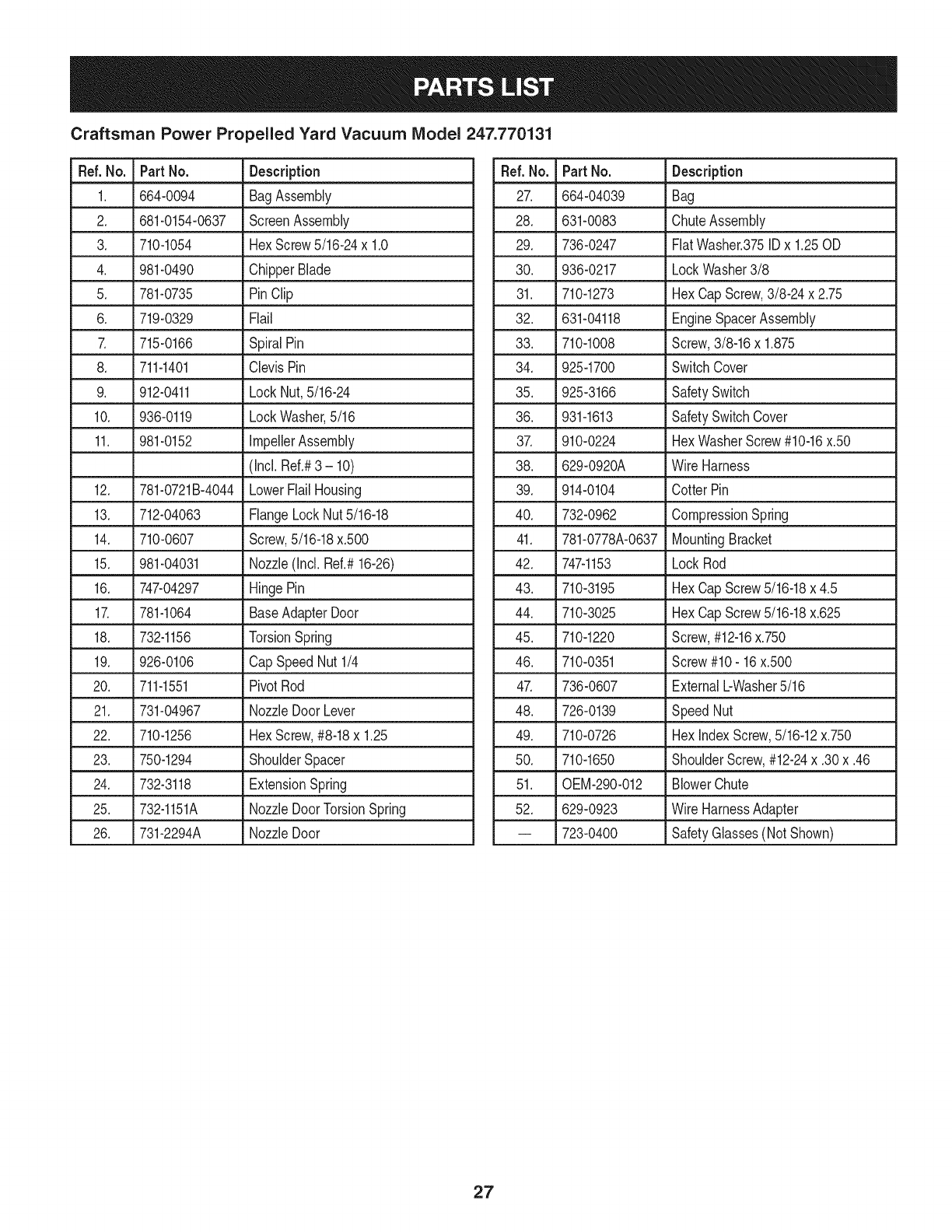
Craftsman Power Propelled Yard Vacuum IViodel 247.770131
Ref. No. Part No. Description
1. 664-0094 BagAssembly
2. 681-0154-0637 ScreenAssembly
3. 710-1054 HexScrew5/16-24x 1.0
4. 981-0490 ChipperBlade
5. 781-0735 PinClip
6. 719-0329 Flail
7. 715-0166 SpiralPin
8. 711-1401 ClevisPin
9. 912-0411 LockNut,5/16-24
10. 936-0119 LockWasher,5/16
11. 981-0152 ImpellerAssembly
(Incl.Ref.#3 - 10)
12. 781-0721B-4044 LowerFlailHousing
13. 712-04063 FlangeLockNut5/16-18
14. 710-0607 Screw,5/16-18x.500
15. 981-04031 Nozzle(Incl. Ref.#16-26)
16. 747-04297 HingePin
17. 781-1064 BaseAdapterDoor
18. 732-1156 TorsionSpring
19. 926-0106 CapSpeedNut1/4
20. 711-1551 PivotRod
21. 731-04967 NozzleDoor Lever
22. 710-1256 HexScrew,#8-18x 1.25
23. 750-1294 ShoulderSpacer
24. 732-3118 ExtensionSpring
25. 732-1151A NozzleDoorTorsionSpring
26. 731-2294A NozzleDoor
Ref.No. Part No. Description
27. 664-04039 Bag
28. 631-0083 ChuteAssembly
29. 736-0247 FiatWasher.375IDx 1.25OD
30. 936-0217 LockWasher3/8
31. 710-1273 HexCap Screw,3/8-24 x 2.75
32. 631-04118 EngineSpacerAssembly
33. 710-1008 Screw,3/8-16x 1.875
34. 925-1700 SwitchCover
35. 925-3166 SafetySwitch
36. 931-1613 SafetySwitchCover
37. 910-0224 HexWasherScrew#10-16x.50
38. 629-0920A Wire Harness
39. 914-0104 CotterPin
40. 732-0962 CompressionSpring
41. 781-0778A-0637 MountingBracket
42. 747-1153 LockRod
43. 710-3195 HexCap Screw5/16-18x 4.5
44. 710-3025 HexCap Screw5/16-18x.625
45. 710-1220 Screw,#12-16x.750
46. 710-0351 Screw#10- 16x.500
47. 736-0607 ExternalbWasher5/16
48. 726-0139 SpeedNut
49. 710-0726 HexindexScrew,5/16-12x.750
50. 710-1650 ShoulderScrew,#12-24x .30x.46
51. 0EM-290-012 BlowerChute
52. 629-0923 Wire HarnessAdapter
-- 723-0400 SafetyGlasses(NotShown)
27
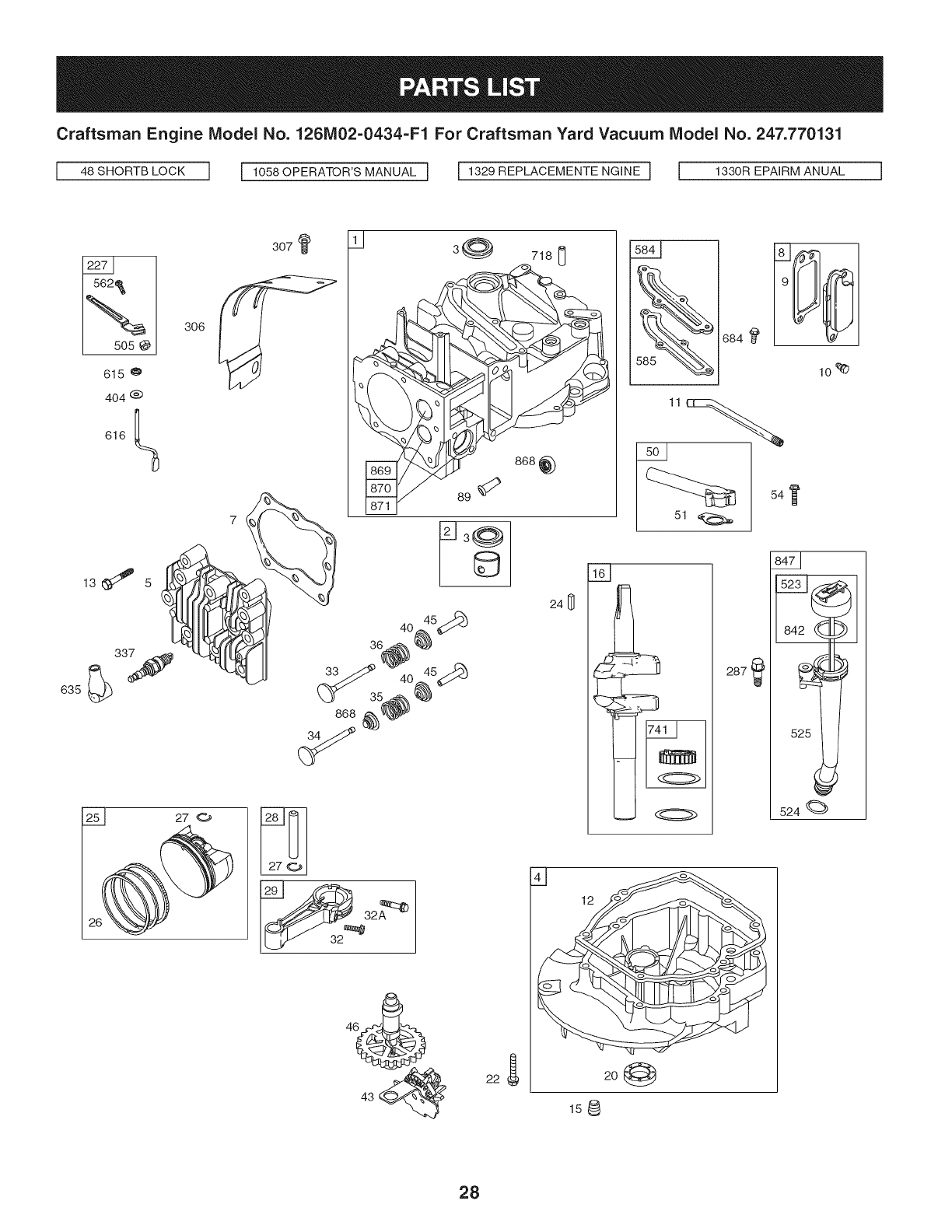
Craftsman Engine Model No. 126M02=0434=F1 For Craftsman Yard Vacuum Model No. 247.770131
I%
15o5
615
635
306
404 @
616
7_
307 3@ 718 [_
©
241_
36_0_ 5_
33/.._ 40 45_:9d_
(_ 35_
868 _) _._
54
I}
524
287
4--]
20
158
28
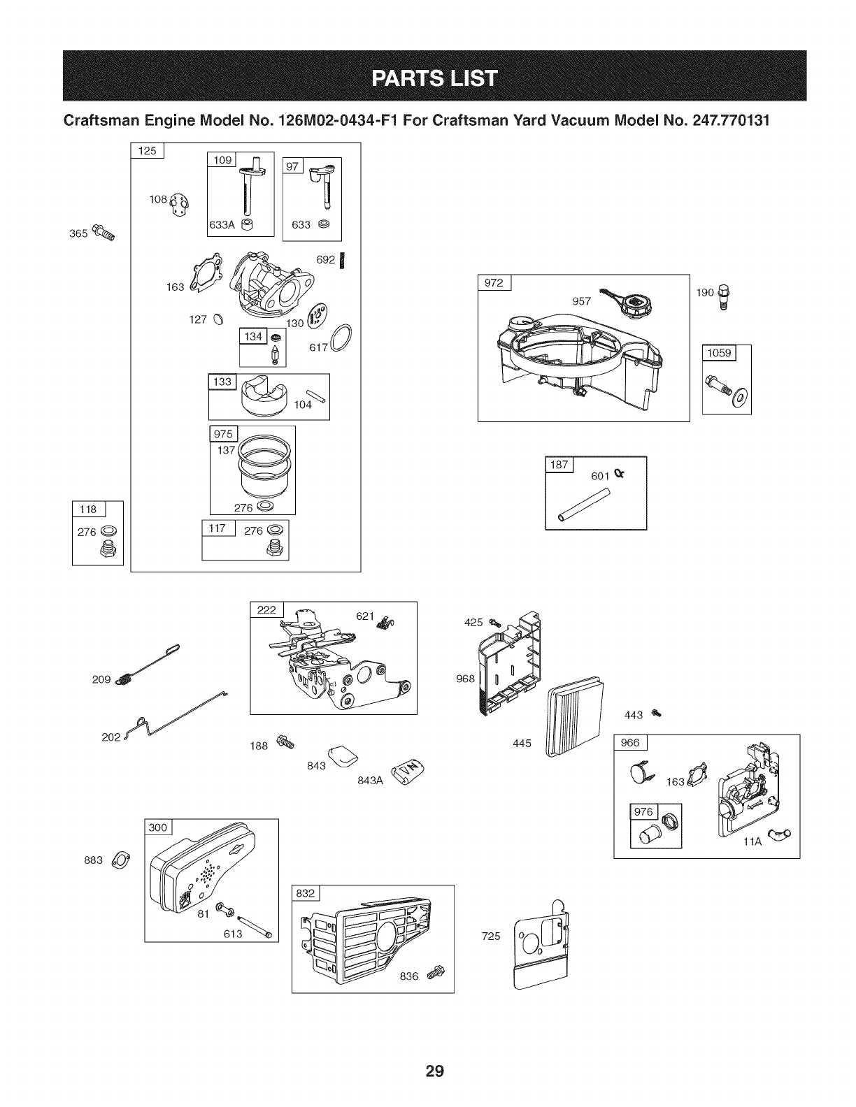
Craftsman Engine IVlodel No. 1261V102-0434-F1 For Craftsman Yard Vacuum IViodel No. 247.770131
3_s
108 @
163
@ _3 ®
692 I
130
I 276 @
276 @
4_
190
2221 621_
188
843 843A _
883
968
445
443 '_
29
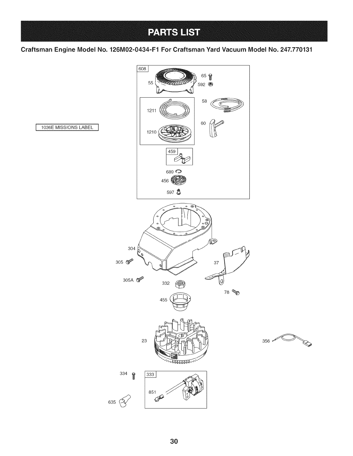
Craftsman Engine Model No. 126M02=0434=F1 For Craftsman Yard Vacuum Model No. 247.770131
1036E MISSIONS LABEL ]
6s
55
1211 (__
1210
689 0
456 _
597
304
305
305A (_
23
332
455
78
30
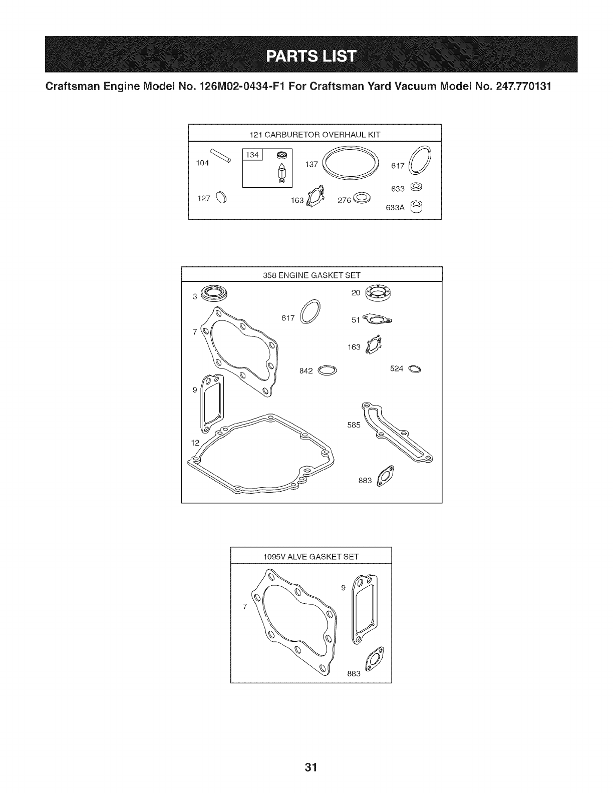
Craftsman Engine Model No. 126M02=0434=F1 For Craftsman Yard Vacuum Model No. 247.770131
121 CARBURETOR OVERHAUL KiT
127 (_
137 O 617 (_
633 @
163 276Q 633A
358 ENGINE GASKET SET
3
617
842 O
2o1_
163 _!_
524
883
1095V ALVE GASKET SET
31
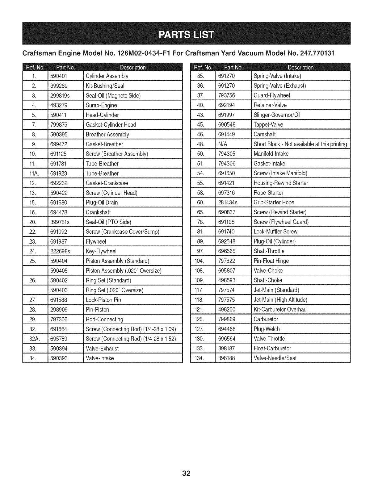
Craftsman Engine Model No. 126MO2=O434-F1 For Craftsman Yard Vacuum Model No. 247.770131
D = = O e
590401 CylinderAssembly
2. 399269 Kit-Bushing/Seal
3. 299819s Seal-Oil(MagnetoSide)
4. 493279 Sump-Engine
5. 590411 Head-Cylinder
7. 799875 Gasket-CylinderHead
8. 590395 BreatherAssembly
9. 699472 Gasket-Breather
10. 691125 Screw(BreatherAssembly)
11. 691781 Tube-Breather
11A. 691923 Tube-Breather
12. 692232 Gasket-Crankcase
13. 590422 Screw(CylinderHead)
15. 691680 Plug-OilDrain
16. 694478 Crankshaft
20. 399781s Seal-Oil(PTOSide)
22. 691092 Screw(CrankcaseCover/Sump)
23. 691987 Flywheel
24. 222698s Key-Flywheel
25. 590404 PistonAssembly(Standard)
590405 PistonAssembly(.020"Oversize)
26. 590402 RingSet (Standard)
590403 RingSet (.020"Oversize)
27. 691588 Lock-PistonPin
28. 298909 Pin-Piston
29. 797306 Rod-Connecting
32. 691664 Screw(ConnectingRod) (1/4-28x 1.09)
32A. 695759 Screw(ConnectingRod) (1/4-28x 1.52)
33. 590394 Valve-Exhaust
34. 590393 Valve-Intake
D = O
691270 Spring-Valve(Intake)
36. 691270 Spring-Valve(Exhaust)
37. 793756 Guard-Flywheel
40. 692194 Retainer-Valve
43. 691997 Slinger-Governor/Oil
45. 690548 Tappet-Valve
46. 691449 Camshaft
48. N/A Short Block- Notavailableat thisprinting
50. 794305 Manifold-Intake
51. 794306 Gasket-Intake
54. 691650 Screw(IntakeManifold)
55. 691421 Housing-RewindStarter
58. 697316 Rope-Starter
60. 281434s Grip-StarterRope
65. 690837 Screw(RewindStarter)
78. 691108 Screw(FlywheelGuard)
81. 691740 Lock-MufflerScrew
89. 692348 Plug-Oil(Cylinder)
97. 696565 Shaft-Throttle
104. 797622 Pin-FloatHinge
108. 695807 Valve-Choke
109. 498593 Shaft-Choke
117. 797574 Jet-Main(Standard)
118. 797575 Jet-Main(HighAltitude)
121. 498260 Kit-CarburetorOverhaul
125. 799869 Carburetor
127. 694468 Plug-Welch
130. 696564 Valve-Throttle
133. 398187 Float-Carburetor
134. 398188 Valve-Needle/Seat
32
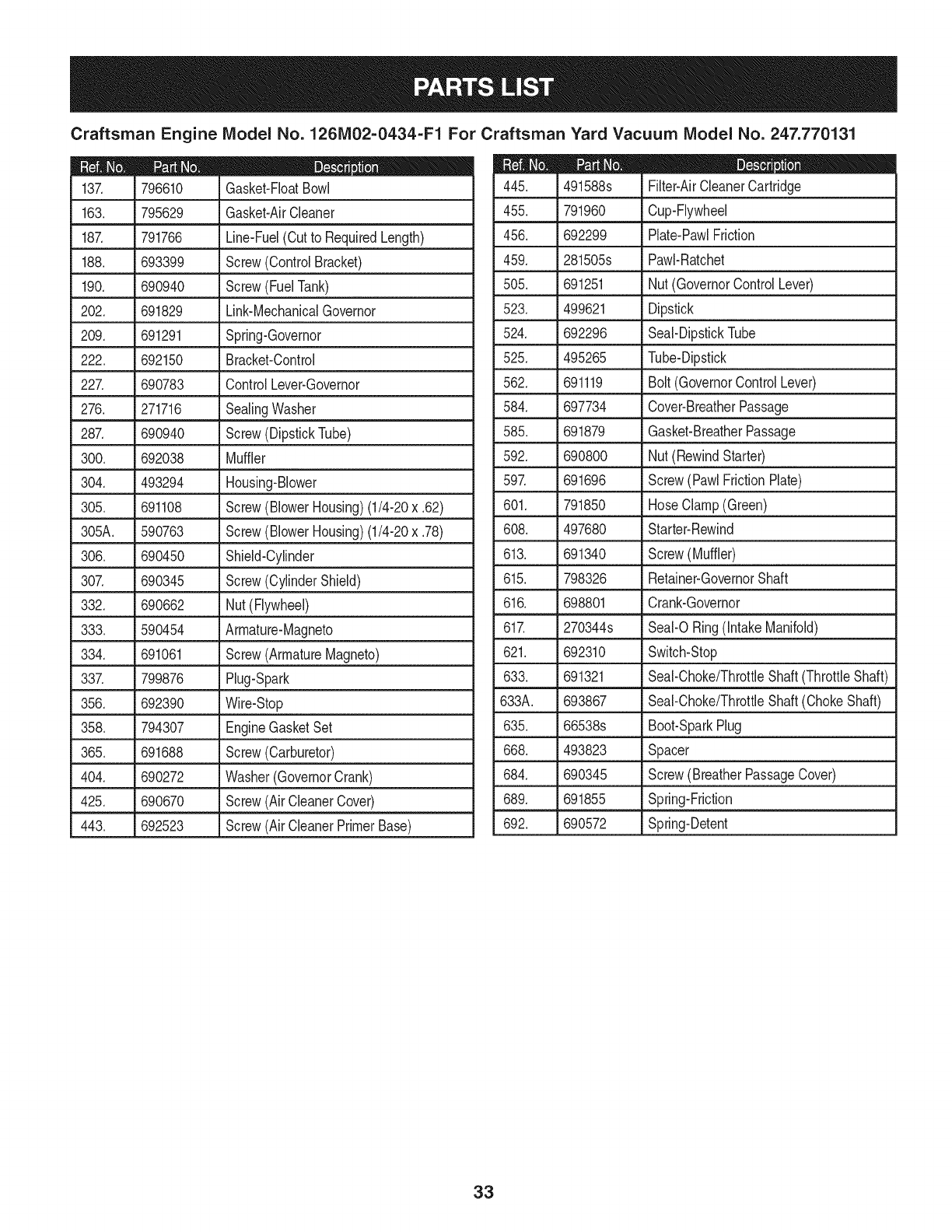
Craftsman Engine IViodel No. 126MO2=O434=F1 For Craftsman Yard Vacuum IViodel No. 247.770131
D = O
491588s Filter-AirCleanerCartridge
455. 791960 Cup-Flywheel
456. 692299 Plate-PawlFriction
459. 281505s PawI-Ratchet
505. 691251 Nut(GovernorControlLever)
523. 499621 Dipstick
524. 692296 Seal-DipstickTube
525. 495265 Tube-Dipstick
562. 691119 Bolt (GovernorControlLever)
584. 697734 Cover-BreatherPassage
585. 691879 Gasket-BreatherPassage
592. 690800 Nut(RewindStarter)
597. 691696 Screw(PawlFrictionPlate)
601. 791850 HoseClamp(Green)
608. 497680 Starter-Rewind
613. 691340 Screw(Muffler)
615. 798326 Retainer-GovernorShaft
616. 698801 Crank-Governor
617. 270344s SeaI-ORing(IntakeManifold)
621. 692310 Switch-Stop
633. 691321 Seal-Choke/ThrottleShaft(ThrottleShaft)
633A. 693867 Seal-Choke/ThrottleShaft(ChokeShaft)
635. 66538s Boot-SparkPlug
668. 493823 Spacer
684. 690345 Screw(BreatherPassageCover)
689. 691855 Spring-Friction
692. 690572 Spring-Detent
D = O
796610 Gasket-FloatBowl
163. 795629 Gasket-AirCleaner
187. 791766 Line-Fuel(Cutto RequiredLength)
188. 693399 Screw(ControlBracket)
190. 690940 Screw(FuelTank)
202. 691829 Link-MechanicalGovernor
209. 691291 Spring-Governor
222. 692150 Bracket-Control
227. 690783 ControlLever-Governor
276. 271716 SealingWasher
287. 690940 Screw(DipstickTube)
300. 692038 Muffler
304. 493294 Housing-Blower
305. 691108 Screw(BlowerHousing)(1/4-20x .62)
305A. 590763 Screw(BlowerHousing)(1/4-20x .78)
306. 690450 Shield-Cylinder
307. 690345 Screw(CylinderShield)
332. 690662 Nut(Flywheel)
333. 590454 Armature-Magneto
334. 691061 Screw(ArmatureMagneto)
337. 799876 Plug-Spark
356. 692390 Wire-Stop
358. 794307 EngineGasketSet
365. 691688 Screw(Carburetor)
404. 690272 Washer(GovernorCrank)
425. 690670 Screw(AirCleanerCover)
443. 692523 Screw(AirCleanerPrimerBase)
33
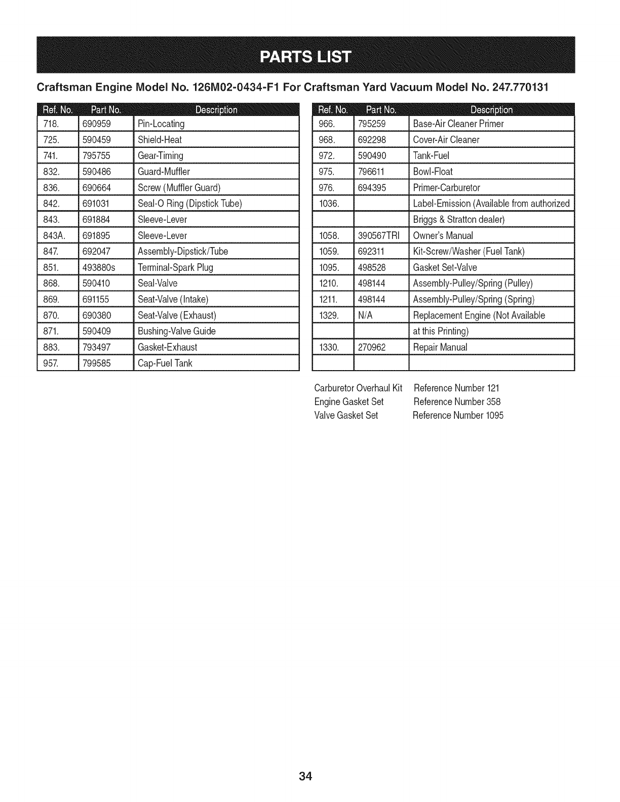
Craftsman Engine Model No. 126MO2=O434=F1 For Craftsman Yard Vacuum Model No. 247.770131
D = W O
690959 Pin-Locating
725. 590459 Shield-Heat
741. 795755 Gear-Timing
832. 590486 Guard-Muffler
836. 690664 Screw(MufflerGuard)
842. 691031 Seal-ORing(DipstickTube)
843. 691884 Sleeve-Lever
843A. 691895 Sleeve-Lever
847. 692047 Assembly-Dipstick/Tube
851. 493880s Terminal-SparkPlug
868. 590410 Seal-Valve
869. 691155 Seat-Valve(Intake)
870. 690380 Seat-Valve(Exhaust)
871. 590409 Bushing-ValveGuide
883. 793497 Gasket-Exhaust
957. 799585 Cap-FuelTank
795259
968. 692298
972. 590490
975. 796611
976. 694395
1036.
1058. 390567TRI
1059. 692311
1095. 498528
1210. 498144
1211. 498144
1329. N/A
1330. 270962
D = O O
Base-AirCleanerPrimer
Cover-AirCleaner
Tank-Fuel
Bowl-Float
Primer-Carburetor
Label-Emission(Availablefromauthorized
Briggs& Strattondealer)
Owner'sManual
Kit-Screw/Washer(FuelTank)
GasketSet-Valve
Assembly-Pulley/Spring(Pulley)
Assembly-Pulley/Spring(Spring)
ReplacementEngine(NotAvailable
at this Printing)
RepairManual
CarburetorOverhaulKit ReferenceNumber121
EngineGasketSet ReferenceNumber358
ValveGasketSet ReferenceNumber1095
34
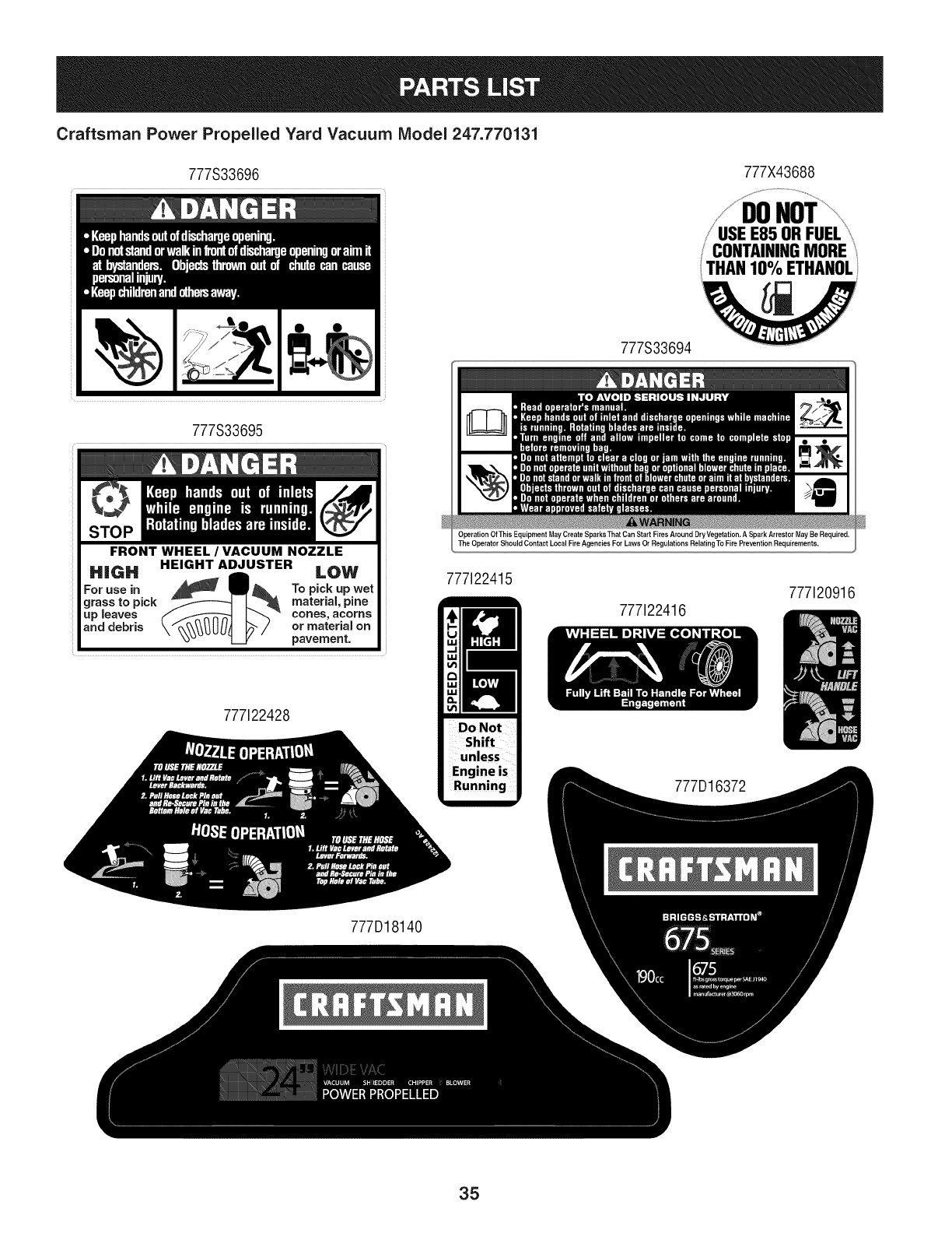
Craftsman Power Propelled Yard Vacuum IViodel 247.770131
777S33696 777X43688
ITHANIO%ETHANOL
777S33694
777S33695
FRONT WHEEL /VACUUM NOZZLE
HiGH HEIGHT ADJUSTER LOW
For use in To pick up wet
grass to pick material, pine
Lip Jeaves cones, acorns
and debris or material on
pavement.
777122428
Operation Of This Equipment May Create Sparks ThatCan Start Fires Around DryVegetation. A Spark Arrestor May Be Required,
The Operator Should Contact Local Fire Agencies For Laws Or Regulations Relating To Fire Prevention Requirements.
777122415
Do Not
Shift
unless
Engine is
Running
777122416
3372
777120916
777D18140
35
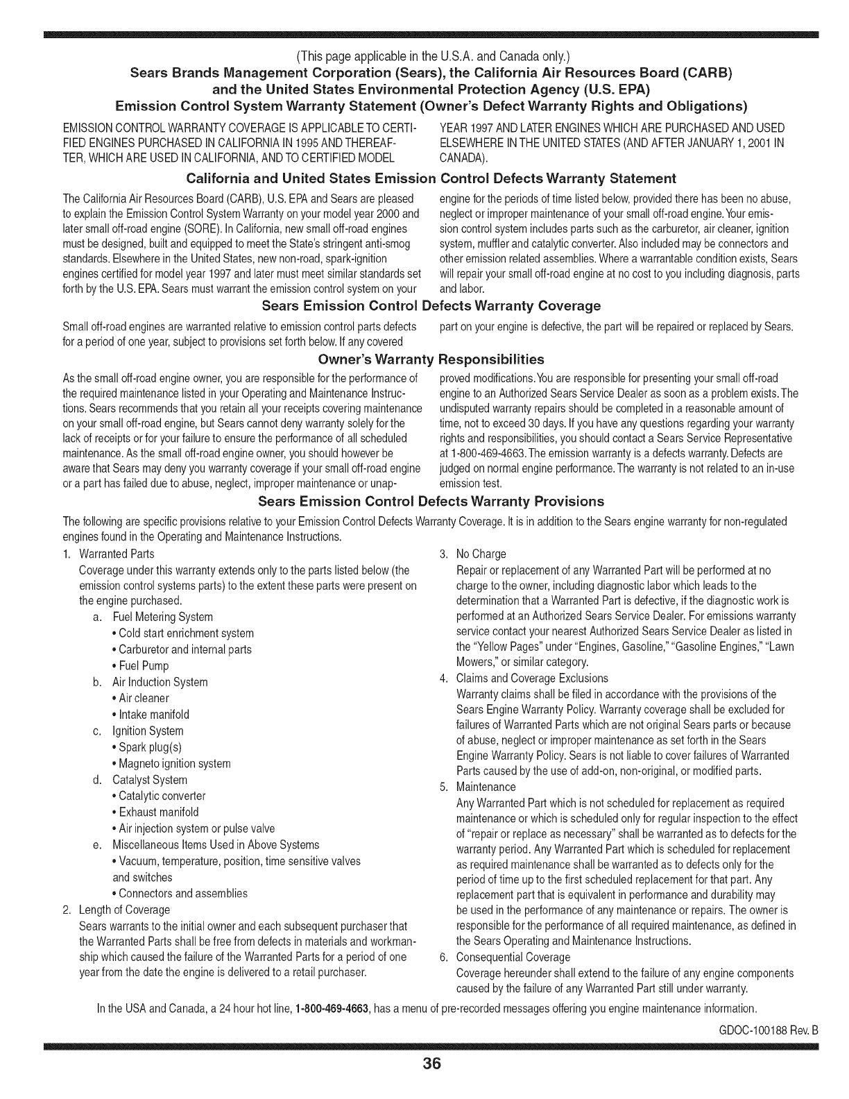
(Thispageapplicableinthe U.S.A.and Canadaonly.)
Sears Brands Management Corporation (Sears), the California Air Resources Board (CARD)
and the United States Environmental Protection Agency (U.S. EPA)
Emission Control System Warranty Statement (Owner's Defect Warranty Rights and Obligations)
EMISSIONCONTROLWARRANTYCOVERAGEISAPPLICABLETOCERTI-
FIEDENGINESPURCHASEDINCALIFORNIAIN1995ANDTHEREAF-
TER,WHICHARE USEDINCALIFORNIA,ANDTOCERTIFIEDMODEL
California and United States Emission
The CaliforniaAir ResourcesBoard(CARD),U.S.EPAand Searsare pleased
to explainthe EmissionControlSystemWarrantyon your modelyear2000and
latersmalloff-roadengine(SORE).InCalifornia,newsmall off-roadengines
mustbedesigned,builtand equippedto meettheState'sstringentanti-smog
standards.Elsewherein theUnitedStates,newnon-road,spark-ignition
enginescertifiedfor modelyear 1997and latermustmeetsimilarstandardsset
forthbythe U.S.EPA.Searsmustwarranttheemissioncontrolsystemonyour
YEAR1997AND LATERENGINESWHICHARE PURCHASEDANDUSED
ELSEWHEREINTHEUNITEDSTATES(ANDAFTERJANUARY1,2001 IN
CANADA).
Control Defects Warranty Statement
enginefor theperiodsoftime listedbelow,providedtherehasbeen noabuse,
neglector impropermaintenanceof your smalloff-roadengine.Youremis-
sion controlsystemincludespartssuchas the carburetor,air cleaner,ignition
system,mufflerand catalyticconverter.Also includedmaybe connectorsand
otheremissionrelatedassemblies.Wherea warrantableconditionexists,Sears
will repairyour smalloff-roadengineat no costto you includingdiagnosis,parts
and labor.
Sears Emission Control Defects Warranty Coverage
Smalloff-roadenginesarewarrantedrelativeto emissioncontrolpartsdefects
fora periodof one year,subjectto provisionsset forthbelow.Ifanycovered
Owner's Warranty
Asthe smalloff-roadengine owner,youare responsiblefor theperformanceof
therequiredmaintenancelistedin yourOperatingand MaintenanceInstruc-
tions.Searsrecommendsthatyouretainallyourreceiptscoveringmaintenance
onyoursmalloff-roadengine,butSears cannotdenywarrantysolelyfor the
lackof receiptsorfor yourfailureto ensuretheperformanceof all scheduled
maintenance.As the smalloff-roadengineowner,you shouldhoweverbe
awarethat Searsmaydenyyou warrantycoverageifyour smalloff-roadengine
ora part hasfaileddueto abuse,neglect,impropermaintenanceor unap-
parton yourengineis defective,the part willbe repairedorreplacedbySears.
Responsibilities
provedmodifications.Youare responsiblefor presentingyour smalloff-road
engineto anAuthorizedSearsServiceDealeras soonas a problemexists.The
undisputedwarrantyrepairsshouldbe completedina reasonableamountof
time,notto exceed30days.Ifyou haveany questionsregardingyourwarranty
rightsand responsibilities,you shouldcontacta SearsService Representative
at 1-800-469-4663.The emissionwarrantyisa defectswarranty.Defectsare
judgedon normalengineperformance.The warrantyis notrelatedto an in-use
emissiontest.
Sears Emission Control Defects Warranty Provisions
ThefollowingarespecificprovisionsrelativetoyourEmissionControlDefectsWarrantyCoverage.ItisinadditiontotheSearsenginewarrantyfornon-regulated
enginesfoundin theOperatingand MaintenanceInstructions.
1. WarrantedParts
Coverageunderthis warrantyextendsonly to the parts listedbelow(the
emissioncontrolsystemsparts)to the extentthese partswere presenton
theenginepurchased.
a. FuelMeteringSystem
•Cold start enrichmentsystem
•Carburetorand internalparts
•FuelPump
b. AirlnductionSystem
•Aircleaner
•Intakemanifold
c. IgnitionSystem
•Sparkplug(s)
•Magnetoignitionsystem
d. CatalystSystem
•Catalyticconverter
•Exhaustmanifold
•Air injectionsystemor pulsevalve
e. MiscellaneousItemsUsedin AboveSystems
•Vacuum,temperature,position,timesensitivevalves
andswitches
• Connectorsandassemblies
2. Lengthof Coverage
Searswarrantsto the initialownerand eachsubsequentpurchaserthat
theWarrantedPartsshallbefree fromdefectsin materialsandworkman-
shipwhich causedthefailure of the WarrantedPartsfor a periodof one
yearfromthe datethe engineis deliveredtoa retailpurchaser.
3. NoCharge
Repairor replacementof anyWarrantedPartwill be performedat no
chargeto the owner,includingdiagnosticlabor whichleadsto the
determinationthata WarrantedPartis defective,ifthe diagnosticworkis
performedat an AuthorizedSears ServiceDealer.For emissionswarranty
servicecontact yournearestAuthorizedSearsServiceDealeras listed in
the "YellowPages"under"Engines,Gasoline,""GasolineEngines,""Lawn
Mowers,"orsimilarcategory.
4. Claimsand CoverageExclusions
Warrantyclaimsshall be filed in accordancewiththe provisionsof the
SearsEngineWarrantyPolicy.Warrantycoverageshall beexcludedfor
failuresof WarrantedPartswhichare notoriginal Searspartsor because
of abuse,neglector impropermaintenanceas setforth inthe Sears
EngineWarrantyPolicy.Sears is notliableto coverfailuresof Warranted
Partscausedby theuse of add-on,non-original,or modifiedparts.
5. Maintenance
Any WarrantedPart whichis notscheduledfor replacementas required
maintenanceor whichis scheduledonly for regularinspectionto the effect
of "repairor replaceas necessary"shallbe warrantedas to defectsfor the
warrantyperiod.Any WarrantedPartwhich is scheduledfor replacement
as requiredmaintenanceshallbe warrantedas to defectsonly forthe
periodof time up to the first scheduledreplacementfor that part.Any
replacementpart that is equivalentin performanceand durabilitymay
be usedin the performanceof anymaintenanceor repairs.The owneris
responsibleforthe performanceof all requiredmaintenance,as definedin
the SearsOperatingand MaintenanceInstructions.
6. ConsequentialCoverage
Coveragehereundershallextend to thefailure of anyengine components
caused bythe failureof any WarrantedPartstill underwarranty.
Inthe USAandCanada,a 24hour hotline, 1-800-469-4663,hasa menu of pre-recordedmessagesofferingyouenginemaintenanceinformation.
GDOC-100188Rev.B
36
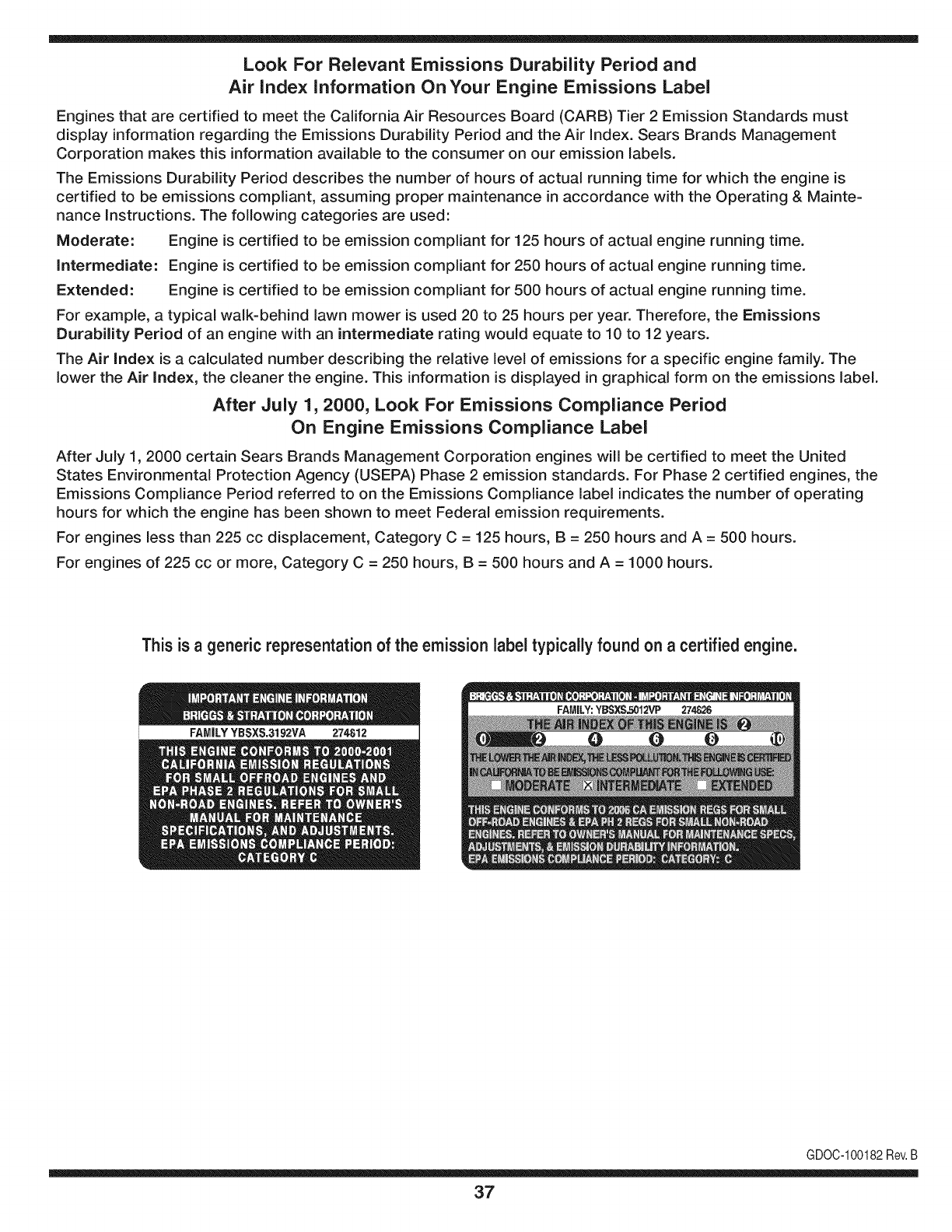
Look For Relevant Emissions Durability Period and
Air index information On Your Engine Emissions Label
Engines that are certified to meet the California Air Resources Board (CARB) Tier 2 Emission Standards must
display information regarding the Emissions Durability Period and the Air Index. Sears Brands Management
Corporation makes this information available to the consumer on our emission labels.
The Emissions Durability Period describes the number of hours of actual running time for which the engine is
certified to be emissions compliant, assuming proper maintenance in accordance with the Operating & Mainte-
nance Instructions. The following categories are used:
Moderate: Engine is certified to be emission compliant for 125 hours of actual engine running time.
Intermediate: Engine is certified to be emission compliant for 250 hours of actual engine running time.
Extended: Engine is certified to be emission compliant for 500 hours of actual engine running time.
For example, a typical walk-behind lawn mower is used 20 to 25 hours per year. Therefore, the Emissions
Durability Period of an engine with an intermediate rating would equate to 10 to 12 years.
The Air index is a calculated number describing the relative level of emissions for a specific engine family. The
lower the Air Index, the cleaner the engine. This information is displayed in graphical form on the emissions label.
After July 1,2000, Look For Emissions Compliance Period
On Engine Emissions Compliance Label
After July 1, 2000 certain Sears Brands Management Corporation engines will be certified to meet the United
States Environmental Protection Agency (USEPA) Phase 2 emission standards. For Phase 2 certified engines, the
Emissions Compliance Period referred to on the Emissions Compliance label indicates the number of operating
hours for which the engine has been shown to meet Federal emission requirements.
For engines less than 225 cc displacement, Category C = 125 hours, B = 250 hours and A = 500 hours.
For engines of 225 cc or more, Category C = 250 hours, B = 500 hours and A = 1000 hours.
This is ageneric representation of the emission label typically found on a certified engine.
FAMILYYBSXS.3192VA 274812
GDOC-100182Rev.B
37
Congratulations on making a smart purchase. Your new Craftsman® product is designed and
manufactured for years of dependable operation. But like all products, it may require repair
from time to time. That's when having a Repair Protection Agreement can save you money and
aggravation.
Here's what the Repair Protection Agreement* includes:
[] Expert service by our 10,000 professional repair specialists
[] Unlimited service and no charge for parts and labor on all covered repairs
[] Product replacement up to $1500 if your covered product can't be fixed
[] Discount of 25% from regular price of service and related installed parts not covered by the
agreement; also, 25% off regular price of preventive maintenance check
[] Fast help by phone - we call it Rapid Resolution - phone support from a Sears representative.
Think of us as a "talking owner's manual."
Once you purchase the Repair Protection Agreement, a simple phone call is all that it takes for you
to schedule service. You can call anytime day or night, or schedule a service appointment online.
The Repair Protection Agreement is a risk-free purchase. If you cancel for any reason during the
product warranty period, we will provide a full refund. Or, a prorated refund anytime after the
product warranty period expires. Purchase your Repair Protection Agreement today!
Some limitations and exclusions apply. For prices and additional information in the U.S.A.
call 1=800=827=6655.
*Coverage in Canada varies on some items. For full details call Sears Canada at 1=800=361=
6665.
Sears Installation Service
For Sears professional installation of home appliances, garage door openers, water heaters, and
other major home items, in the U.S.A. or Canada call 1=800=4=MY=HOME®.
38
Declaraci6n de garantia ....................... Pagina 39
Practicas operaci6n seguras ............... Pagina 40
Montaje ................................................ Pagina 44
Operaci6n ............................................ Pagina 48
Servicio y Mantenimiento .................... Pagina 52
Almacenamiento fuera de temporada .... Pagina 58
Soluci6n de problemas ...................... Pagina 59
Etiquetas de seguridad ....................... Pagina 7
Lista de piezas ........................................ Pagina 24
Acuerdo de Protecci6n Para
Reparaciones ....................................... Pagina 63
NOmero de servicio ..................... Cubierta posterior
ARTESANO DE DOSANOS DE GARANTJA
PORDOSANOS(S)apartirdelafechadecompra,esteproductoest&garantizadocontracualquierdefectodematerialo manode obra.Un
productodefectuosorecibir&la reparaci6no la sustituci6nsi la reparaci6nnoestAdisponible.
Paraobtenerinformaci6ndetalladacoberturade lagaranfiaparaobtenerla reparaci6no sustituci6ngratuita,visiteel sitioweb:www.craftsman.com
EstagarantiacubrelosdefectosSOLOde materialesy fabricaci6n.Lagarantianoincluye:
• Elementosreutilizablesquepuedengastarseporel uso normaldentrodel periododegarantia,talescomolascuchillas,bujias,filtrode
aire,pantallade desgranadoy unabolsa.
• ProductodaSosresultantesde los intentosdelusuariodemodificaci6ndelproducto,reparaci6no causadosporaccesoriosde
productos.
• Reparacionesnecesariasdebidoal accidenteo por nooperaro mantenerel productosegOnlas instruccionesprovistas.
• El mantenimientopreventivoo reparacionesnecesariasdebidoa unamezclaincorrectade combustible,combustiblecontaminadoo
pasado.
Estagaranfiaes inv&lidasi esteproductose utilizaal mismotiempola prestaci6nde servicioscomercialeso si sealquilaaotra persona.
Estagarantialeotorgaderechoslegalesespecificos,y ustedtambi_npuedetenerotrosderechosquevariandeestadoa estado.
Sears Brands Management Corporation, Hoffman Estates, IL 60179
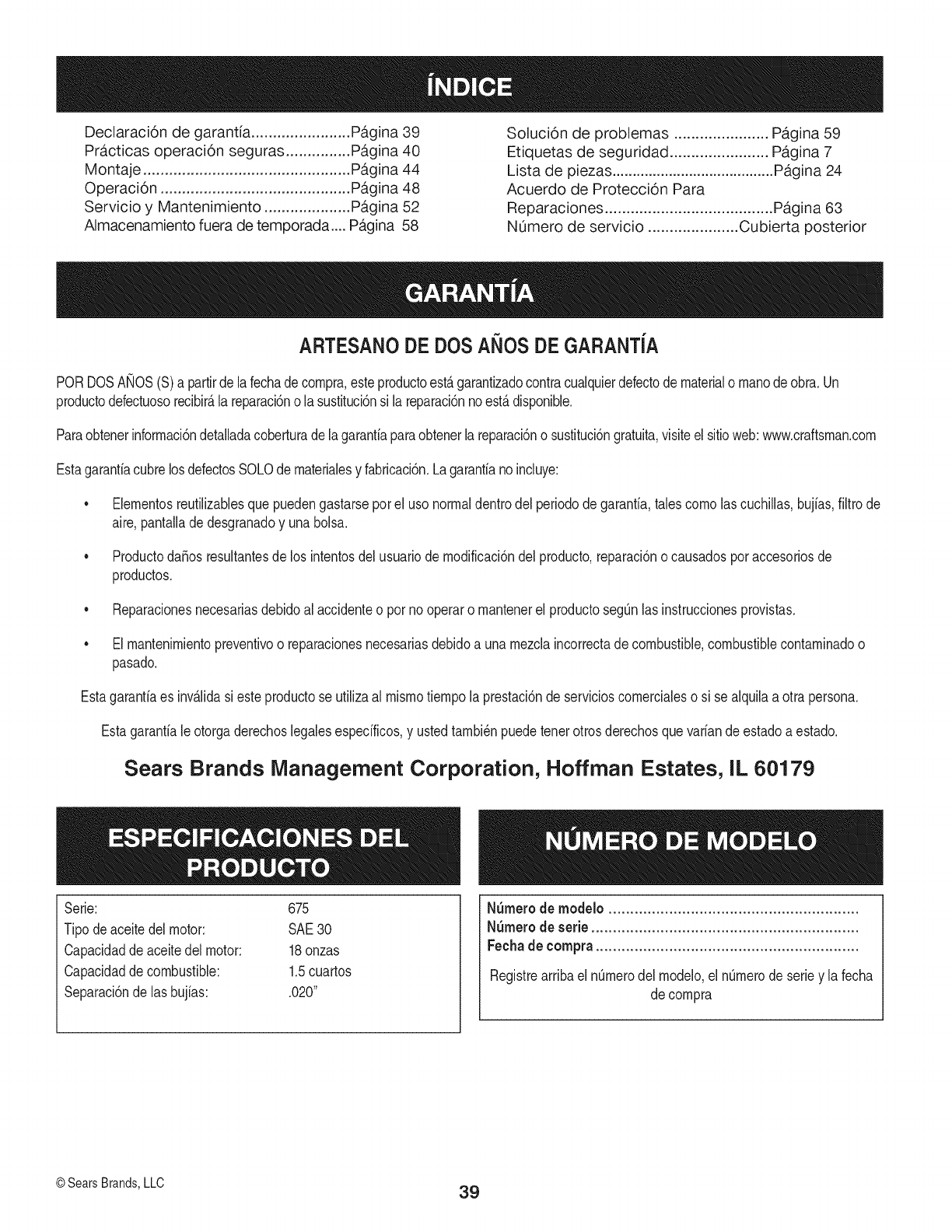
Serie: 675
Tipode aceitedelmotor: SAE30
Capacidaddeaceitedel motor: 18onzas
Capacidaddecombustible: 1.5cuartos
Separaci6nde lasbujias: .020"
NSmerode modelo ..........................................................
N_merode serie ..............................................................
Fechade compra .............................................................
RegistrearribaelnOmerodel modelo,elnOmerode seriey lafecha
decompra
©Sears Brands,LLC 39
Lapresenciade estesirnboloindicaque se tratade instrucciones
irnportantesde seguridadquese debenrespetarparaevitar
ponerenpeligrosu seguridadpersonaly/o materialy lade otras
personas.Leay sigatodaslasinstruccionesdeestemanualantes
de poneren funcionarnientoestarn_.quina.Si no respetaestas
instruccionespodriaprovocarlesionespersonales.Cuandoveaeste
sirnbolo,ipresteatenci6na la advertencia!
PROPOSICION 65 DE CALIFORNIA
Elescapedel motorde esteproducto,algunosde suscornponentes
y algunoscornponentesdelvehiculocontieneno liberansustancias
quirnicasqueelestadode Californiaconsideraque puedenproducir
c_.ncer,defectosde nacirnientouotrosproblernasreproductivos.
Estarn_.quinarueconstruidaparaseroperadadeacuerdocon
las reglasde seguridadcontenidasenestemanual.AI igualque
concualquiertipo deequipornotorizado,undescuidoo errorpor
partedeloperadorpuedeproducirlesionesgraves.Estarn_.quina
es capazde arnputarrnanosy piesy dearrojarobjetoscon gran
fuerza.De norespetarlas instruccionesde seguridadsiguientesse
puedenproducirlesionesgraveso la rnuerte.
Su responsabilidad--Restrinja el usode estarn_.quina
rnotorizadaa las personasque lean,cornprendany respetenlas
advertenciase instruccionesqueaparecenenestemanualy en la
rn_.quina.
iGUARI)E ESTASINSTRUCCIONES!
CAPACITACION
•Lea,entienday curnplatodaslas instruccionesincluidasen
la rnAquinayen los rnanualesantesde rnontarlay utilizarla.
Guardeestemanualenun lugarseguroparaconsultasfuturasy
regulares,asi cornoparasolicitarrepuestos.
•Leael ManualdelOperadory sigatodaslas advertenciase
instruccionesdeseguridad.El fracasode hacerasi puedecausar
la heridaseriaal operadory/o personaspresentes.ParaIlarnada
de preguntas,1-800-659-5917.
•Farniliaricesecontodoslos controlesy su operaci6nadecuada.
Sepac6rnodetenerla rn_.quinay c6rnodesengranarloscontroles
r_.pidarnente.
• No perrnitanuncaque losniffos rnenoresde 16afrosutilicen
estarn_.quina.Los niffosde 16afrosy rn_.srnayoresdeben
leery cornprenderlas instruccionesde operaci6ny las reglas
de seguridadcontenidasen estemanual,y tarnbi_ndebenser
capacitadosy estarsupervisadosporunode los padres.
• Nuncaperrnitaquelos adultosoperenestarn_.quinasin recibir
antesla instrucci6napropiada.
• Mantengaa los transeQntes,ayudantes,rnascotasy niffosal
rnenosa 75piesde la rn_.quinarnientrasest,.operando.Detenga
la rn_.quinasi alguienentraenla zona.
• Nuncaenciendaun motorenespacioscerradoso enunazona
con pocaventilaci6n.Elescapedel motorcontienernon6xidode
carbono,un gasinodoroy letal.
• No pongalas rnanoso los piescercadelas piezasrotatoriaso
en lasc_.rnarasde alirnentaci6nnien laaberturade descarga.El
contactocon el motorrotatoriopuedeproducirla arnputaci6nde
dedos,rnanoso pies.
• Nuncatratededestapar[atornade alirnentaci6no la aberturade
descarga,nitratede sacaro vaciarla bolsade laaspiradora,ni
de revisary repararlarn_.quinarnientrasel motorest,.enrnarcha.
Apagueel motory esperehastaquetodaslas piezasrn6vilesse
hayandetenidoporcornpleto.Desconecteel cablede labujiay
p6ngalode rnaneraquehagarnasacontrael motor.
PREPARATIVOS
•Inspeccionerninuciosarnenteel _.readondeutilizar_,el equipo.
Retiretodaslas piedras,botellas,latasu otrosobjetosextra_os
que puedanserlevantadoso arrojadoscausandolesiones
personaleso da_osa larn_.quina.
• Paraprotegerselosojos utilicesiernpreanteojoso antiparras
de seguridadrnientrasoperala rn_.quinao rnientrasla ajusta
o repara.Losobjetosarrojadosquerebotanpuedenlesionar
gravernentelavista.
• Utilicezapatosde trabajoresistentes,desuelafuerte,asi corno
pantalonesy carnisasajustados.Las prendassueltaso las
alhajaspuedenquedaratrapadasen las piezasrn6viles.Nunca
utilicela rn_.quinadescalzoo con sandalias.Utiliceguantesde
trabajodecuerocuandoalirnentematerialporelcanal dela
cortadora.
• Antesde encenderla rn_.quinacontrolequetodoslos pernosy
tornillosest_nbienajustadosparacornprobarquela rn_.quinase
encuentraen condicionessegurasdeoperaci6n.Adern_.s,realice
una inspecci6nvisualde la rn_.quinaa intervalosfrecuentespara
controlarsi la rnisrnaest,.da_ada.
• Mantengao reernplacelas etiquetasdeseguridade instrucciones
segQnsea necesario.
Manejo segurode la gasolina
Paraevitarlesionespersonaleso da_osrnaterialesseasurnarnente
cuidadosoal rnanipularlagasolina.Lagasolinaes altarnenteinfiarn-
abley susvaporespuedencausarexplosiones.Sepuedelesionar
gravernentesi derrarnagasolinasobreustedo sobrela ropaya quese
puedeencender.L_.vesela piely c_.rnbiesede ropade inrnediato.
• Utilices61orecipientesparagasolinaautorizados.
4O
• NuncaIlenelos contenedoresen elinteriordeun vehiculo
o carni6nocaja decarnionetacon recubrirnientospl_.sticos.
Coloquesiernprelos recipientesenel pisoy lejosdelvehiculo
antesde Ilenarlos.
Retireel equipoa gasolinadelcarni6no rernolquey II_neloen
el piso.Si estonoes posible,entoncesIlenedichoequipoenun
rernolqueconun recipienteport_.til,en vezdedesdeun dispen-
sadordegasolina.
Mantengala boquillade llenadoencontactoconel hordedela
entradadeltanquedegasolinao contenedorentodo rnornento
hastaqueest_Ileno.Noutiliceundispositivoparaabrir/cerrarla
boquilla.
Apaguetodoslos cigarrillos,cigarros,pipasy otrasfuentesde
cornbusti6n.
Nuncacarguecombustibleen la rn_.quinaen unespaciocerrado.
Nuncasaquelatapa delgas ni agreguecombustiblernientrasel
motorest,.calienteo enrnarcha.Dejequeel motorseenfrie por
Io rnenosdosrninutosantesdevolvera cargarcombustible.
Nuncarecargueel tanquede combustible.Lleneel tanqueno
rn_.sde 1/2 pulgadapordebajode la basedelcuellodelfiltro
paradejarespacioparala dilataci6ndelcombustible.
• Vuelvaa colocarla tapade lagasolinay ajOstelabien.
• Lirnpielagasolinaderrarnadasobreelmotory elequipo.Traslade
la rn_.quinaa otra zona.Espere5rninutosantesdeencenderel
motor.
• Nuncaalrnacenela rn_.quinao el recipientede combustibleen
unespaciocerradodondehayafuego,chispaso luz piloto(por
ejernplo,hornos,calentadoresdeagua,calefactores,secadores
de ropa,etc.)
• Parareducirel riesgodeincendiornantengalarn_.quinalirnpia
depasto,hojasy de acurnulaci6nde otrosdesechos.Lirnpielos
derrarnesdeaceiteo combustibley saquetodoslos desechos
ernbebidosconcombustible.
OPERACION
• No pongalas rnanoso los piescercadelas piezasrotatoriaso
enlas c_.rnarasdealirnentaci6nni en laaberturade descarga.El
contactocon el motorrotatoriopuedeproducirla arnputaci6nde
dedos,rnanoso pies.
• Antesdeencenderlarn_.quinacornpruebequeel canaldela
cortadora,latornade alirnentaci6ny lac_.rnarade corteest_.n
vadas y sin desechos.
• Inspeccionerninuciosarnentetodoel materialquedeseatriturar
y saquelos objetosrnet_Jicos,piedras,botellas,latasuotros
objetosextra_osquepuedenocasionarlesionesoda_arla
rn_.quina.
Sielmotorgolpeaunobjetoextra_oo si la rn_.quinaernpiezaa pro-
ducirunsonidopococornOnounavibraci6n,apagueelmotorde
inrnediato.Dejequeelmotorse detengaporcornpleto.Desconecte
el cablede labujia,p6ngalode rnaneraquehagarnasacontrael
motory sigaestospasos:
a. Inspeccionela rn_.quinaparaver si est,.da_ada.
b. Repareo reernplacelaspiezasda_adas.
c. Controlesi hay piezasflojasy ajQstelasparaasegurarquela
rn_.quinafuncionede rnaneraseguray continua.
• Noperrnitaquese acurnulematerialprocesadoen lazonade
descarga.El rnisrnopuedeobstaculizarla descargaadecuada
y provocarel retornodel materiala travesde laaberturade
alirnentaci6n.
• Nointentetriturarni picarmaterialdemayortarna_oal espe-
cificadoen larn_.quinao enestemanual.Sepodrianproducir
lesioneso da_os.
• Nuncatratede destaparla tornade alirnentaci6no laabertura
de descargarnientrasel motorest,.en rnarcha.Apagueel motor
y esperehastaquetodaslaspiezasque sernuevense hayan
detenidopor cornpleto,desconecteel cablede labujfay p6ngalo
de rnaneraquehagarnasacontraelmotorantesde sacarlos
escombros.
• Nuncaoperela rn_.quinasinque labolsade laaspiradoray el
canalde descargaest_nconectadosa larn_.quinacornocorre-
sponde.Nuncavade ni carnbiela bolsade la aspiradorarnientras
el motorest,.en rnarcha.Elextrernocon cierrede labolsade la
aspiradoradebequedarcerradotodoel tiernpornientrasla opera.
• Nuncaoperela rn_.quinasi el picode ingresoo la uni6nopcional
parala rnangueranoest_.nconectadosa la rn_.quinaadecu-
adarnente.Nuncaintenteconectarocarnbiarningunadeestas
unionesrnientrasel motorest,.en rnarcha.
•Mantengatodoslos protectores,desviadoresy dispositivosde
seguridadensu lugaryen buenascondiciones.
• Mientrasalirnentamaterialdentrode la rn_.quinarnantengasu
rostroy su cuerpodetr_.sy haciaun costadodelcanalde la
cortadoraparaevitarlesionesporretrocesosaccidentales.
• Nuncaopereestarn_.quinasin buenavisibilidado ilurninaci6n.
Siernpredebeestarsegurode queest,.bienafirrnadoy sostenga
bienlas rnanijas.
• Noopereestarn_.quinaen superficiescon grava.
• Noopereestarn_.quinaestandobajolos efectosdelalcoholo de
drogas.
•Elsilenciadory el motorse calientany puedenproducirquerna-
duras.Nolos toque.
• Nuncalevanteo transportela rn_.quinacuandoel motorest,.
encendido.
Sise presentansituacionesquenoest_.nprevistaseneste
manualseacuidadosoy useel sentidocornQn.Marquepara
contactareldepartarnentodeatenci6nalclientey obtenerel
nornbredesu distribuidorrn_.scercano.
41
MANTENIMIENTO Y ALMACENAMIENTO
•Nuncarnanipulelos dispositivosde seguridadde rnanera
irnprudente.Controleperi6dicarnentequefuncionende forrna
adecuada.
•Controlefrecuenternentequetodoslospernosy tornillosest_n
bienajustadosparacornprobarquela rn_.quinase encuentraen
condicionessegurasdefuncionarniento.Adern_.s,realiceuna
inspecci6nvisualde larn_.quinaparacontrolarsi larnisrnaest,.
da_aday rep_.reladeser necesario.
•Antesde lirnpiar,repararo inspeccionarla rn_.quina,detengael
motory cornpruebequeel rnisrnoy quetodaslas piezasrn6viles
se hallandetenido.Desconecteel cablede labujiay p6ngalo
de rnaneraquehagarnasacontrael motorparaevitarquese
enciendade rnaneraaccidental.
•Nocarnbielaconfiguraci6ndel reguladordel motorni acelere
dernasiadoel rnisrno.El reguladorcontrolalavelocidadrn_.xirna
segurade operaci6ndelmotor.
•Mantengao reernplacelasetiquetasde seguridade instrucciones
segQnseanecesario.
•Sigalas instruccionesde estemanualparacargar,descargar,
transportary alrnacenardernaneraseguraestarn_.quina.
•Nuncaalrnacenela rn_.quinao el recipientedecombustibleenun
espaciocerradodondehayafuego,chispaso luzpilotocornopor
ejernplo,calentadoresde agua, hornos,secadoresde ropa,etc.
•Dejequela rn_.quinase enfriepot Io rnenos5 rninutosantesde
guardarla.
•Consultesiernpreel manualdel operadorparaconocerlas
instruccionesadecuadasparael alrnacenarnientofuerade
ternporada.
•Seg_nla Cornisi6ndeSeguridadde Productosparael Consu-
rnidorde los EstadosUnidos(CPSC)y laAgenciade Proteccidn
Arnbientalde los EstadosUnidos(EPA),esteproductotieneuna
vida Otilmediade siete(7)a_os,6 60horasde funcionarniento.
AI finalizarla vida Otilmedia,adquieraunarn_.quinanuevao
hagainspeccionaranualrnente_staporundistribuidorde servicio
autorizadoparacerciorarsede quetodoslos sisternasrnec_.nicos
y de seguridadfuncionancorrectarnentey no tienenexcesivo
desgaste.Si noIo hace,puedenproducirseaccidentes,lesiones
o rnuerte
•Sidebevaciarel tanquedecombustible,h_.galoal airelibre.
•Respetelas norrnasreferentesa ladisposici6ncorrectay las
reglarnentacionessobregas,combustible,etc. paraprotegerel
medicarnbiente.
NO MODIFIQUE EL MOTOR
Paraevitarlesionesgraveso larnuerte,nornodifiqueel motorbajo
ningunacircunstancia.Si carnbialaconfiguracidndel reguladorel
motorpuededescontrolarsey operara velocidadesinseguras.Nunca
carnbiela configuracidndef_.bricadel reguladordelmotor.
AVISO REFERIDO AEMISIONES
Losrnotoresqueest&ncertificadosy curnplencon las regulaciones
de ernisionesfederalesEPAy de CaliforniaparaSORE(Equipos
peque_ostodoterreno)est_.ncertificadosparaoperarcongasolina
cornOnsin plornoy puedenincluirlos siguientessisternasde control
de ernisiones:Modificacidnde motor(EM) y catalizadorde tresvias
(TWO)siest_.nequipadosde esa rnanera.
GUARDACHISPAS
Estarn&quinaest,.equipadacon unmotorde cornbusti6ninternay
nodebeser utilizadaen o cercade unterrenoagrestecubiertopor
bosque,rnalezaso hierbaexceptosi el sisternade escapedelmotor
est,.equipadocon unarnortiguadorde chispasque curnplaconlas
leyeslocaleso estatalescorrespondientes,encasode habedas.
Si se utilizaunarnortiguadorde chispasel operadorIo debernantener
en condicionesde usoadecuadas.Enel Estadode Californialas
rnedidasanteriorrnenternencionadassonexigidasporIcy (Arficulo
4442del Cddigode RecursosPOblicosde California).Esposible
queexistanleyessirnilaresenotrosestados.Lasleyesfederalesse
aplicanenterritoriosfederales.
Puedeconseguirelarnortiguadordechispasparael silenciadora
travesdesu distribuidorautorizadode rnotoreso poni_ndoseen
contactoconel departarnentodeservicios.
42
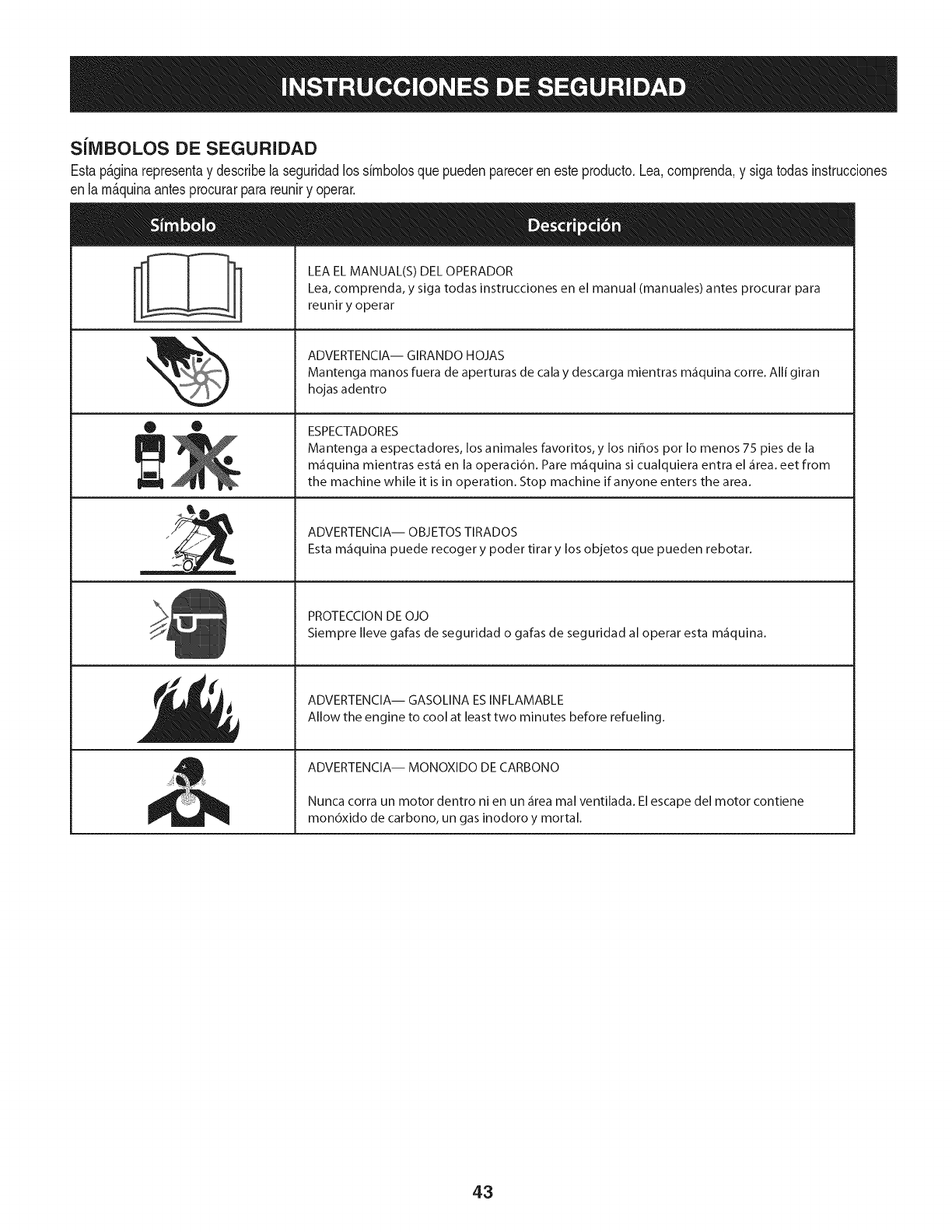
SilVIBOLOS DE SEGURIDAD
Estap&ginarepresentay describelaseguridadlos simbolosquepuedenpareceren esteproducto.Lea,comprenda,y sigatodasinstrucciones
enla m_quinaantesprocurarparareuniry operar.
O O
I-ml
llm
LEA EL MANUAL(S) DEL OPERADOR
Lea, comprenda, y siga todas instrucciones en el manual (manuales) antes procurar para
reunir y operar
ADVERTENCIA-- GIRANDO HOJAS
Mantenga manos fuera de aperturas de cala y descarga mientras m_fiquina corre. Alli giran
hojas adentro
ESPECTADORES
Mantenga a espectadores, los animales favoritos, y los ni_os pot Io menos 75 pies de la
m_iquina mientras est,1 en la operaci6n. Pare m_iquina si cualquiera entra el _irea. eet from
the machine while it is in operation. Stop machine if anyone enters the area.
ADVERTENCIA-- OBJETOS TIRADOS
Esta m_iquina puede recoger y poder tirar y los objetos que pueden rebotar.
PROTECCION DE OJO
Siempre Ileve gafas de seguridad o gafas de seguridad al operar esta m_fiquina.
ADVERTENCIA-- GASOLINA ESINFLAMABLE
Allow the engine to cool at least two minutes before refueling.
ADVERTENCIA-- MONOXIDO DE CARBONO
Nunca corra un motor dentro ni en un _irea mal ventilada. El escape del motor contiene
mon6xido de carbono, un gas inodoro y mortal.
43
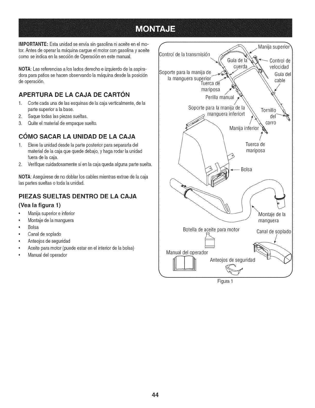
IMPORTANTE:Estaunidadse enviasin gasolinaniaceiteenel mo-
tor.Antesdeoperarlam_.quinacargueel motorcongasolinay aceite
comose indicaen la secci6nde Operaci6nen estemanual.
NOTA:Lasreferenciasa los ladosderechoe izquierdodela aspira-
doraparapatiosse hacenobservandola m_.quinadesdela posici6n
deoperaci6n.
APERTURA DE LA CAJA DE CARTON
1. Cortecada unade lasesquinasde la cajaverticalmente,de la
partesuperiora la base.
2. Saquetodaslaspiezassueltas.
3. Quiteel materialdeempaquesuelto.
COIVlO SACAR LA UNIDAD DE LA CAJA
1. Elevelaunidaddesdela parteposteriorparasepararladel
materialde la cajaquequededebajo,y hagarodarla unidad
fuerade lacaja.
2. Verifiquecuidadosamentesi enla cajaquedaalgunapartesuelta.
NOTA:AsegQresede nodoblarloscablesmientrasextraede lacaja
las partessueltaso toda la unidad.
PIEZAS SUELTAS DENTRO DE LA CAJA
(Yea la figura 1)
• Manijasuperiore inferior
• Montajede la manguera
• Bolsa
• Canaldesoplado
• Anteojosde seguridad
• Aceiteparamotor(puedeestarenel interiorde la bolsa)
• Manualdeloperador
f
Control de la transmisi6n
Soporte parala manija de
la manguera superior
Tuerca
mariposa /7'
Perilla manual
j Manija superio_r
Guia de I Control de
cuerda velocidad
Guiadel
cable
Soporte para la manija de la
manguera inferiort
Manija
Tornillo
carro
Tuercade
mariposa
Bolsa
\Montaje de la
manguera
Botella de aceite paramotor Canalde soplado
Manual del operador d_ _
__ Anteojos de segurida
Figura 1
44
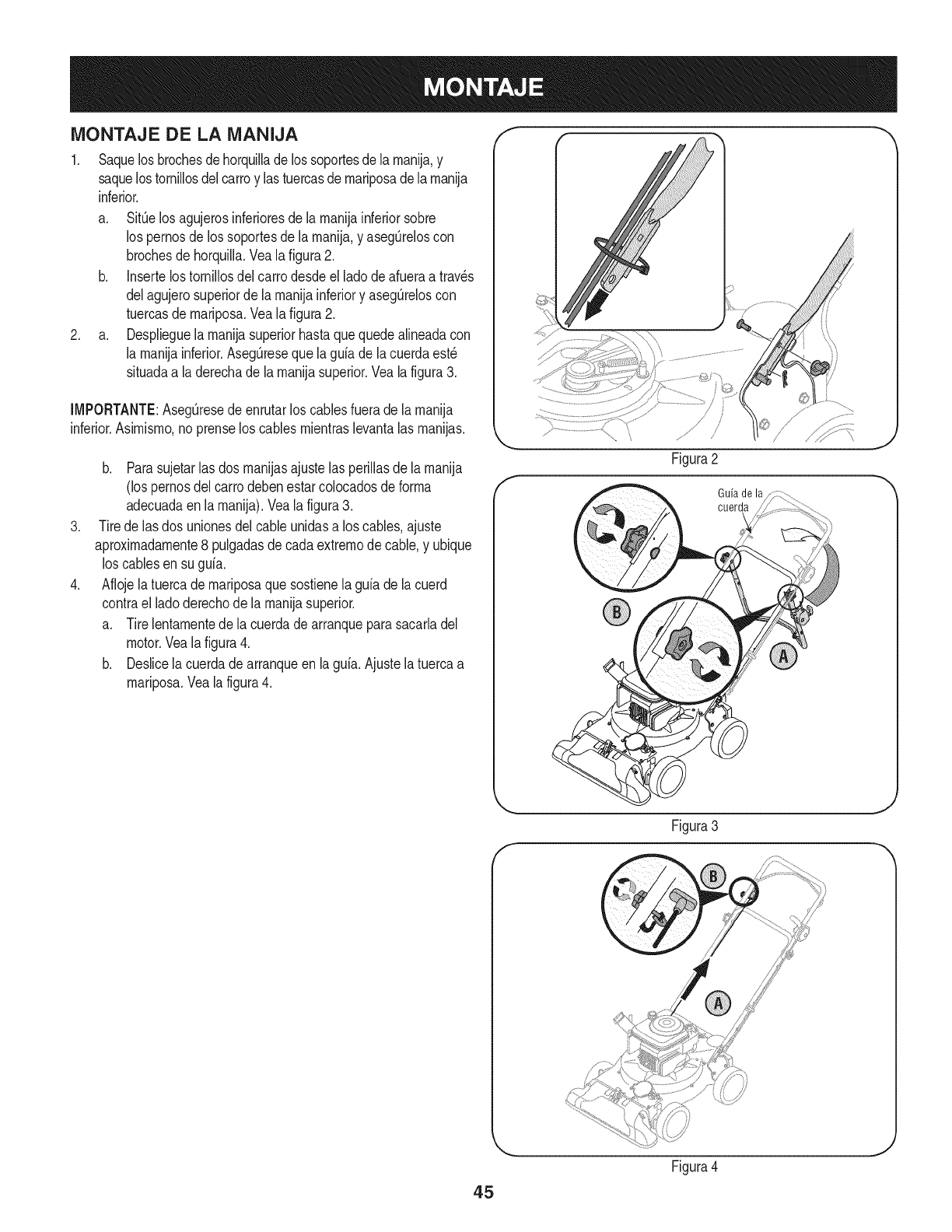
MONTAJE DE LA iVIANIJA
1. Saquelosbrochesdehorquillade lossoportesde larnanija,y
saquelostornillosdelcarroy lastuercasdernariposadelarnanija
inferior.
a. SitOelos agujerosinferioresde larnanijainferiorsobre
los pernosde los soportesde larnanija,y asegOreloscon
brochesdehorquilla.Vealafigura2.
b. Insertelostornillosdelcarrodesdeel ladodeafueraa trav_s
delagujerosuperiorde larnanijainferiory asegOreloscon
tuercasde rnariposa.Veala figura2.
2. a. Desplieguelarnanijasuperiorhastaquequedealineadacon
la rnanijainferior.AsegQresequela guiade lacuerdaest_
situadaa laderechade la rnanijasuperior.Veala figura3.
[MPORTANTE:AsegQresedeenrutarlos cablesfuerade larnanija
inferior.Asirnisrno,no prenselos cablesrnientraslevantalas rnanijas.
.
.
b. Parasujetar[asdos rnanijasajustelas periiiasde [arnanija
(los pernosdel carrodebenestarcolocadosde forrna
adecuadaen[a rnanija).Vea[a figura3.
Tirede las dos unionesdelcableunidasa los cables,ajuste
aproxirnadarnente8 pulgadasdecadaextrernode cable,y ubique
loscablesen su guia.
Aflojela tuercade rnariposaquesostienela guiade lacuerd
contrael ladoderechode la rnanijasuperior.
a. Tirelentarnentede la cuerdade arranqueparasacarladel
motor.Vealafigura4.
b. Deslicela cuerdadearranqueen la guia.Ajustela tuercaa
rnariposa.Vealafigura4.
Guiade la
cuerda
45
Figura4
J
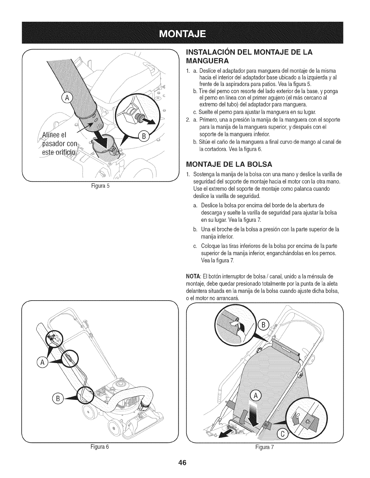
/
i' !i ee el \\\
Figura5
fINSTALACI6N DEL iVIONTAJE DE LA
iVlANGUERA
1. a. Desliceeladaptadorpararnangueradel rnontajede la rnisrna
haciael interiordeladaptadorbaseubicadoa la izquierday al
frentedela aspiradoraparapatios.Veala figura5.
b. Tire delpernocon resortedel ladoexteriorde la base,y ponga
el pernoen Nneaconel primeragujero(elrn_.scercanoal
extrernodel tubo)deladaptadorpararnanguera.
c. Suelteelpernoparaajustarlarnangueraensu lugar.
2. a. Prirnero,unaa presi6nla rnanijade larnangueraconel soporte
parala rnanijade la rnanguerasuperior,y despu6scon el
soportede la rnanguerainferior.
b. SitQeel ca_ode la rnangueraa finalcurvode mangoal canalde
lacortadora.Vealafigura6.
iViONTAJE DE LA BOLSA
Sostengalarnanijadela bolsacon unarnanoy deslicela variNade
seguridaddel soportede rnontajehaciaelmotorcon la otra rnano.
Useel extrernodelsoportede rnontajecornopalancacuando
deslicelavarillade seguridad.
a. Deslicela bolsapot encirnadel bordedela aberturade
descargay sueltelavariNade seguridadparaajustarla bolsa
en su lugar.Vealafigura 7.
b. Unael brochede labolsaa presi6nconla partesuperiorde la
rnanijainferior.
c. Coloquelastirasinferioresde la bolsaporencirnade laparte
superiordela rnanijainferior,enganch_.ndolasen lospernos.
Vealafigura 7.
NOTA:El bot6ninterruptorde bolsa/canal,unidoa la rn6nsulade
rnontaje,debequedarpresionadototalrnenteporla puntadela aleta
delanterasituadaenla rnanijadela bolsacuandoajustedichabolsa,
o el motorno arrancar_..
Figura6
J
Figura7
46
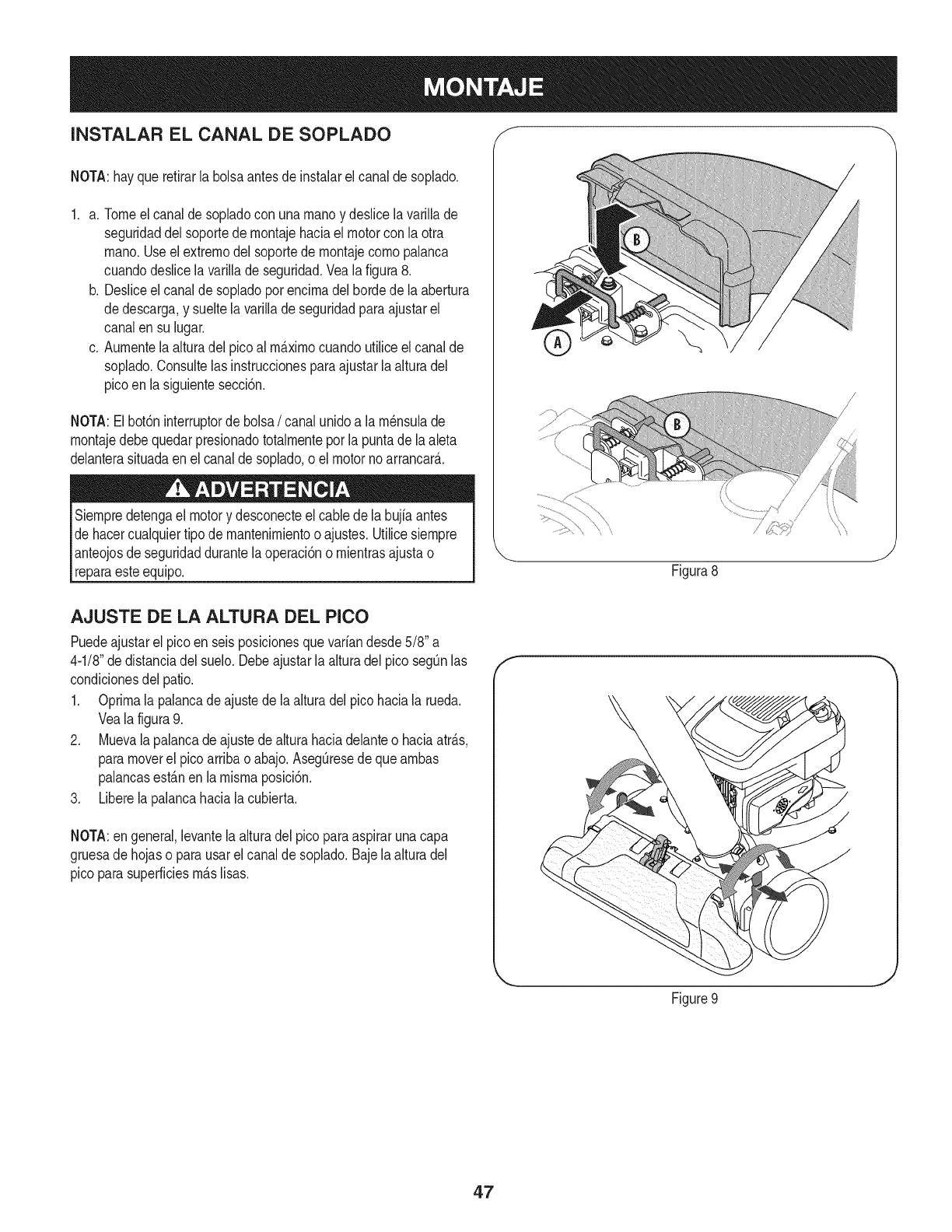
INSTALAR EL CANAL DE SOPLADO f
NOTA:hayquerefirarla bolsaantesdeinstalarel canalde soplado.
1. a. Tomeelcanalde sopladocon unarnanoy deslicela varillade
seguridaddel soportede rnontajehaciael motorcon laotra
rnano.Useelextrernodelsoportede rnontajecornopalanca
cuandodeslicelavarillade seguridad.Vealafigura 8.
b. Desliceel canalde sopladoporencirnadel hordede laabertura
dedescarga,y sueltelavarillade seguridadparaajustarel
canalen su lugar.
c. Aurnentela alturadel picoal rrn_.xirnocuandoutiliceelcanalde
soplado.Consultelas instruccionesparaajustarlaalturadel
picoen la siguientesecci6n.
NOTA:Elbot6ninterruptorde bolsa/canalunidoa la rn_nsulade
rnontajedebequedarpresionadototalrnenteporla puntade laaleta
delanterasituadaen el canaldesoplado,oel motornoarrancar&
Siernpredetengael motory desconecteelcable dela bujiaantes
dehacercualquiertipode mantenirnientoo ajustes.Utilicesiernpre
anteojosde seguridaddurantelaoperaci6no rnientrasajustao
reparaesteequip&
/
Figura8
J
AJUSTE DE LA ALTURA DEL PICO
Puedeajustarel picoen seisposicionesquevariandesde5/8"a
4-1/8"dedistanciadel suelo.Debeajustarla alturadelpico segOnlas
condicionesdel patio.
1. Oprirnala palancade ajustede laalturadel picohaciala rueda.
Veala figura9.
2. Muevalapalancadeajustede alturahaciadelanteo haciaatr_.s,
paramoverel pico arribao abajo.AsegOresede quearnbas
palancasest_.nenla misrnaposici6n.
3. Liberela palancahaciala cubierta.
NOTA:en general,levantelaalturadel picoparaaspirarunacapa
gruesade hojaso parausarelcanalde soplado.Bajelaalturadel
pico parasuperficiesrn_.slisas.
f
Figure9
J
47
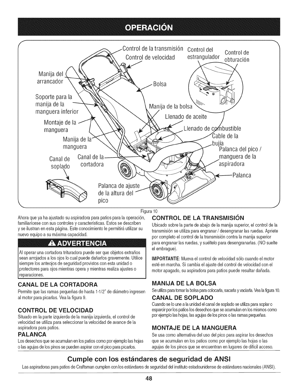
f
de latransmisi6n Controldel Control de
Control de velocidad estrangulador obturaci6n
Manija del
arrancador
Soporte para la
manija de la
manguera inferior
Montaje de la
manguera
Manija de
manguera
Canalde Canaldel_
soplado cortadora
Bolsa
ija de la bolsa
Llenado de aceite
Llenado de
de la
la del pico /
manguera de la
aspiradora
Palancade ajuste
de laaltura del
pico
Ahoraqueya haajustadosu aspiradoraparapatiosparala operaci6n,
famiNarfcesecon suscontrolesy caracterfsticas.Estosse describen
y se ilustranenesta p_.gina.Esteconocimientole permitir_,utilizarsu
nuevoequipoa sum_.ximacapacidad.
Ai operarunacortadoratrituradorapuedeser queobjetosextra_os
seanarrojadosa los ojos Iocual puededa_arlosgravemente.Utilice
siemprelos anteojosde seguridadprovistosconesta unidado
protectoresparaojos mientrasoperay mientrasrealizaajusteso
reparaciones.
lJ
Figura10
CONTROL DE LA TRANSMISION
Ubicadosobrela partedeabajodela manijasuperior,elcontroldela
transmisi6nse utilizaparaengranar/desengranarlas ruedas.Apriete
pot completoel controlde latransmisi6ncontralamanijasuperior
paraengranarlas ruedas,y su_lteloparadesengranarlas.(NO suelte
el embrague).
IMPORTANTE: Mueva el control de velocidad s61ocuando el motor
est_ en marcha. Si cambia el ajuste dei control de velocidad con el
motor apagado, su aspiradora para patios puede resultar daSada.
CANAL DE LA CORTADORA
Permiteque las ramaspequeSasde hasta1-1/2"de di&metroingresen
al motorparapicarlas.Yeala figura9.
CONTROL DE VELOCIDAD
Situadoen laparte izquierdade la manijaizquierda,el controlde
velocidadse utilizaparaseleccionarlavelocidadde avancedela
aspiradoraparapatios.
PALANCA
Losdesechosqueseacumulanen lospatioscomoporejemplolashojas
olasagujasdelos pinossepuedenaspirarconelpicoparapicarlos.
MANIJA DE LA BOLSA
Seutilizaparatomarlabolsaparacolocarla,sacarlayvaciarla.Vealafigura10.
CANAL DE SOPLADO
Cuandose Iounea launidadelcanaldesopladoseutilizaparasoplaro
esparcirpotlospatioslosdesechosqueseacumulanenlosmismoscomo
potejemplolashojas,lasagujasdelospinosolasramaspeque_as.
MONTAJE DE LA MANGUERA
Se usacomoalternativadel usodelpico paraaspirarlos desechos
que seacumulanen los patioscomoporejemplolas hojaso las
agujasde los pinosquese encuentranen lugaresdediffcilacceso.
Cumple con los estandares de seguridad de ANSI
LasaspiradorasparapatiosdeCraftsmancumplenconlosest&ndaresdeseguridaddelinstitutoestadounidensedeest&ndaresnacionales(ANSI).
48
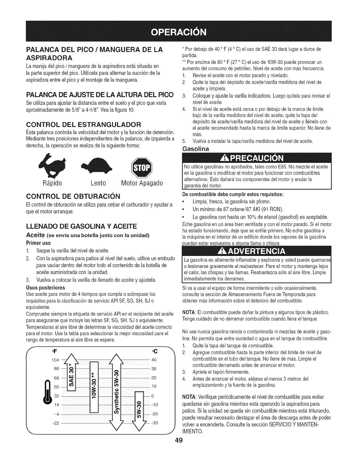
PALANCA DEL PICO /MANGUERA DE LA
ASPIRADORA
La rnanija del pico /manguera de la aspiradora est,. situada en
la parte superior del pico. Utilicela para alternar la succi6n de la
aspiradora entre el pico y el montaje de la manguera.
PALANCA DE AJUSTE DE LA ALTURA DEL PICO
Se utiliza para ajustar la distancia entre el suelo y el pico que varia
aproximadamente de 5/8" a 4-1/8". Vea la figura 10.
CONTROL DEL ESTRANGULADOR
Esta palanca controla la velocidad del motor y la funci6n de detenci6n.
Mediante tres posiciones independientes de la palanca, de izquierda a
derecha, la operaci6n se realiza de la siguiente forma:
* Pot debajode 40 o F (4o C) el uso de SAE 30 dara.lugar a duros de
partida.
** Per encima de 80 o F (27 oC) el uso de 10W-30puede provocar un
aumento dei consume de petr61eo.Nivelde aceite con ma.sfrecuencia.
1. Reviseel aceite con ei motor parade y nivelado.
2. Quite ia tapa del dep6sito de aceite/varilla medidoradel nivel de
aceite y limpiela.
3. Coloque y ajuste la varilla indicadora. Luego quitela pararevisar el
nivei deaceite.
4. Siel nivel de aceite esta.cerca o pot debajo de la marca de limite
bajode la varilla medidora del nivel de aceite, quite la tapa del
dep6sito de aceite/varilia medidora dei nivei de aceite y ilenelo con
el aceite recomendadohasta la marca de limite superior.No Ilenede
ma.s.
5. Vueiva a instaiar latapa/varilla medidora del nivel de aceite.
Gasolina
R;_pido Lento Motor Apagado
CONTROL DE OBTURACION
El control de obturaci6n se utiliza para cebar el carburador y ayudar a
que el motor arranque.
LLENADO DE GASOLINA Y ACEITE
Aceite (se envia una botella junto con la unidad)
Primer uso
1. Saque la varilla del nivel de aceite.
2. Con la aspiradora para patios al nivel del suelo, utilice un embudo
para vaciar dentro del motor todo el contenido de la botella de
aceite suministrada con la unidad.
3. Vuelva a colocar la varilla de llenadode aceite y ajOstela.
Usos posteriores
Use aceite para motor de 4 tiempos que cumpla o sobrepase los
requisitos para la clasificaci6n de servicio API SE SG, SH, SJ o
equivalente.
Compruebesiempre ia etiqueta de servicio API en el recipiente del aceite
para asegurarseque incluyeias ietras SE SG, SH, SJ o equivaiente.
Temperaturasai aire libre de determinar la viscosidad dei aceite correcto
para ei motor. Use ia tabla paraseleccionar la mejor viscosidad para el
rango de temperatura ai aire libre se espera. 4o
s_; so
20
50 _ _o
o ; o
s2 .
_22 30
'_., j/
No utilice gasolinas no aprobados, tabs como E85. No mezcleel aceite
en ia gasolina o modificar el motor para funcionarcon combustibles
alternatives. Estoda_ara,los componentesdel motor y anular la
garanfia del motor.
De combustible debe cumplir estos requisitos:
*Limpia, fresca, la gasolina sin plomo.
. Un minimo de 87 octane/87 AKI (91 RON).
. La gasolina con hasta un 10% de etanol (gasohol) es aceptable.
Echegasolina en un a.reabien ventiladay con el motor parade. Siel motor
haestado funcionando, deje que se enfrie primero. No eche gasolina a
la ma.quinaen ei interior de unedificio donde los vapores de la gasolina
uedan estar ex uestos a ai una llama o chis a.
Lagasolina es aitamente inflamable y explosiva y usted puede quemarse
o iesionarse gravemente ai reabastecer. Pareel motor y mantenga iejos
el calor, las chispas y las llamas. Reabastezcas61oal aire libre. Limpie
inmediatamentelos derrames.
Siva a usar ei equipo de forma intermitenteo s61oocasionaimente,
consulte ia secci6n de Aimacenamiento Fuera deTemporada para
obtener ma.sinformaci6n sobre el deterioro del combustible.
NOTA: El combustiblepuede dahar la pintura y aigunos tipos de plastico.
Tenga cuidado de no derramar combustible cuando Ilenael tanque.
No usenunca gasolina rancia o contaminada ni mezclas deaceite y gaso-
lina. No permita que entre suciedad o agua en el tanque de combustible.
1. Quite ia tapa del tanque de combustible.
2. Agregue combustible hasta ia parte inferior del iimite de nivel de
combustible en ei tube del tanque. No iiene de ma.s.Limpie el
combustible derramado antes de arrancar el motor.
3. Aprieteeltap6n firmemente.
4. Antes de arrancar el motor,alejese al menos3 metros del
emplazamiento y la fuente de la gasolina.
NOTA:Verifiqueperi6dicamenteel nivelde combustibleparaevitar
quedarsesin gasolinamientrasest,.operandola aspiradorapara
patios.Si launidadsequedasincombustiblemientrasest,.triturando.
puederesultarnecesariodestaparel _.readedescargaantesdepoder
volvera encenderla.Consultela secci6nSERVlCIOY MANTEN-
IMIENTO.
49
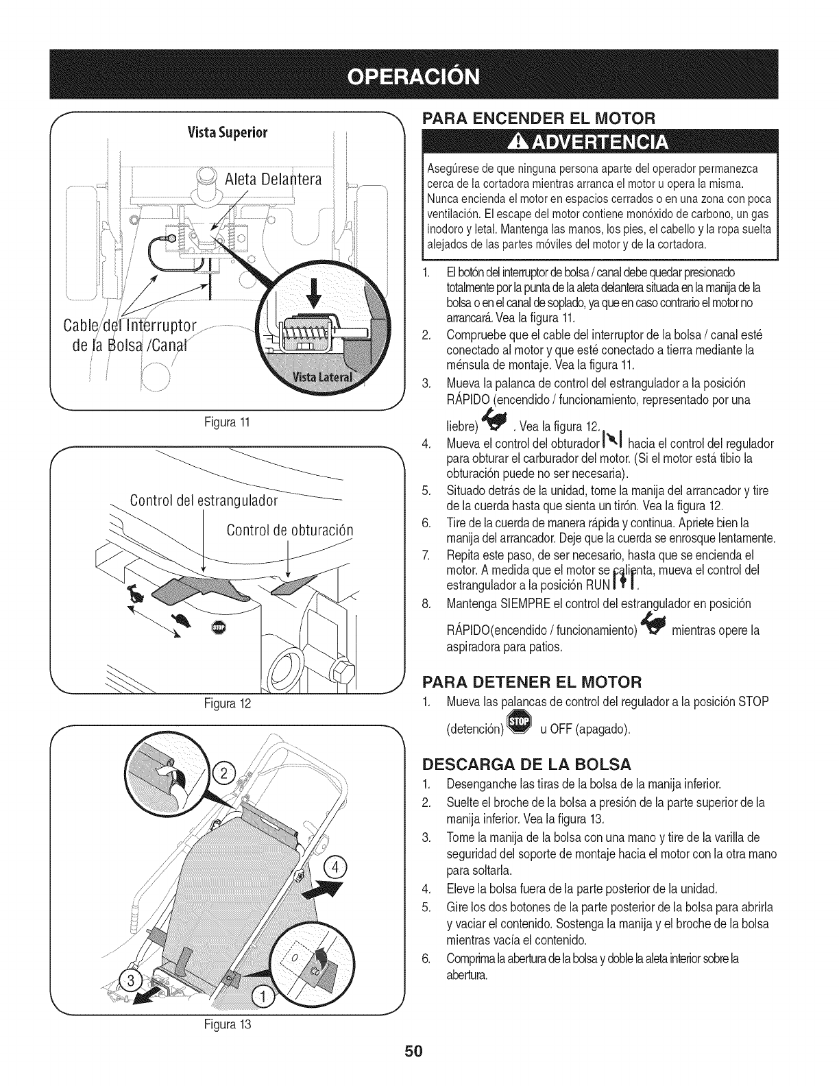
Vista Superior
Cable/d{ ptor
de JaBols_/Canal ..........
i/
Figura11
Controldelestrangulador _
Controlde obturaci6n
PARA ENCENDER EL MOTOR
AsegQresede que ninguna persona aparte dei operador permanezca
cerca de ia cortadora mientras arranca el motor u opera la misma.
Nunca encienda el motor en espacios cerrados o en una zona con poca
ventilaci6n. El escape del motor contiene mon6xido de carbono, un gas
inodoro y ietai. Mantenga ias manos, los pies, el cabello y la ropa suelta
alejados de las partes m6viles del motor y de la cortadora.
1. Elbot6ndelinterruptordebolsa/canaldebequedarpresionado
totalmenteporlapuntadelaaletadelanterasituadaenlamaniadeia
bolsaoenelcanaldesoplado,yaqueencasocontrarioelmotorno
arrancar_..Vealafigura 11.
2. Compruebequeel cabledelinterruptorde iaboisa/canalest_
conectadoal motory queest_conectadoa tierramediantela
m_nsulade montaje.Vealafigura 11.
3. Muevala palancade controldelestranguladora la posici6n
RAPIDO(encendido/funcionamiento,representadoporuna
liebre)'_ .Vealafigura 12.
4. Muevael controldelobturadorl'°-I haciaelcontroldel regulador
paraobturarel carburadordel motor.(Siel motorest,.tibio la
obturaci6npuedenoser necesaria).
5. Situadodetr_.sde launidad,tomela manijadel arrancadory tire
de lacuerdahastaquesientauntir6n.Vealafigura 12.
6. Tirede iacuerdademanerar_.piday continua.Aprietebienla
manijadelarrancador.Dejequelacuerdaseenrosquelentamente.
7. Repitaestepaso,deser necesario,hastaquese enciendael
motor.A medidaqueel motorse_a_ii_nta,muevaelcontroldel
estranguladora la posici6nRUNIT |.
8. MantengaSIEMPREel controldelestranguladoren posici6n
RAPIDO(encendido/funcionamiento)_ mientrasoperela
aspiradoraparapatios.
Figura12
f
PARA DETENER EL MOTOR
1. Muevalas palancasde controldel reguladora laposici6nSTOP
(detenci6n) u OFF(apagado).
DESCARGA DE LA BOLSA
1. Desenganchelastirasde la bolsadela manijainferior.
2. Suelteel brochede la bolsaa presi6nde lapartesuperiorde la
manijainferior.Vealafigura 13.
3. Tomela manijade la bolsaconunamanoy tire de la varillade
seguridaddel soportede montajehaciaelmotorcon la otra mano
parasoltarla.
4. Elevela bolsafueradela parteposteriorde la unidad.
5. Girelos dos botonesde la parteposteriorde labolsa paraabrirla
y vaciarel contenido.Sostengala manijay el brochede labolsa
mientrasvaciael contenido.
6. Comprimalaaberturadelabolsay doblelaaletainteriorsobrela
abertura.
Figura13
5O
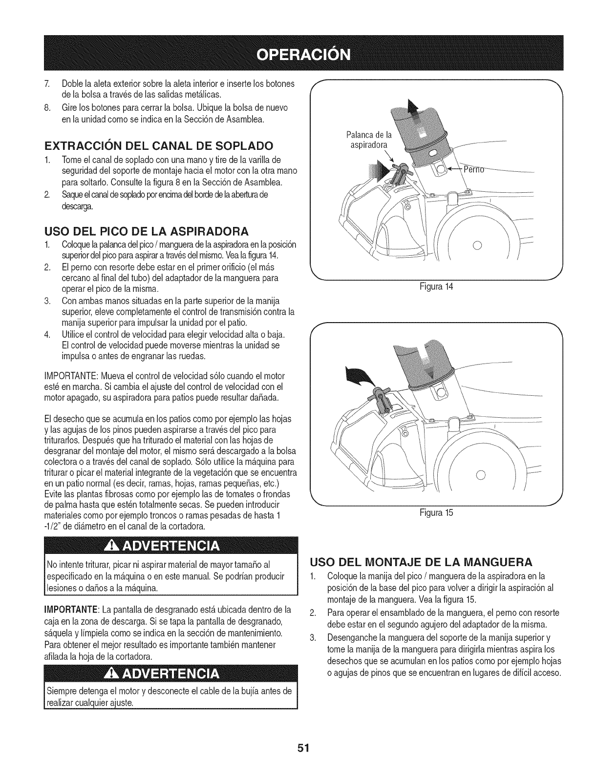
7. Doblela aletaexteriorsobrelaaleta interiore insertelos botones
dela bolsaa travesde las salidasrnet_.licas.
8. Girelos botonesparacerrarla bolsa.Ubiquelabolsade nuevo
enla unidadcornose indicaenla Secci6ndeAsarnblea.
EXTRACCION DEL CANAL DE SOPLADO
1. Tomeel canalde sopladocon unarnanoy tire de lavarillade
seguridaddel soportedernontajehaciael motorcon laotra rnano
parasoltado.Consultelafigura8 en laSecci6nde Asarnblea.
2. Saqueelcanaldesopladoporencirnadelhordedelaaberturade
descarga.
USO DEL PICO DE LA ASPIRADORA
1. Coloquelapalancadelpico/rnangueradelaaspiradoraenlaposici6n
superiordelpicoparaaspiraratravesdelrnisrno.Vealafigura14.
2. Elpernocon resortedebeestarenel primerorificio(el rn_.s
cercanoalfinal deltubo)del adaptadorde larnanguerapara
operarel picode la rnisrna.
3. Conarnbasrnanossituadasenla partesuperiorde larnanija
superior,elevecornpletarnenteel controlde transrnisi6ncontrala
rnanijasuperiorparairnpulsarla unidadporel patio.
4. Utiliceelcontroldevelocidadparaelegirvelocidadaltao baja.
Elcontrolde velocidadpuedernoversernientrasla unidadse
irnpulsaoantesdeengranarlas ruedas.
IMPORTANTE:Muevaelcontrolde velocidads61ocuandoel motor
est_enrnarcha.Sicarnbiael ajustedelcontrolde velocidadcon el
motorapagado,suaspiradoraparapatiospuederesultarda_ada.
Eldesechoquese acurnulaen los patioscornoporejernplolas hojas
y las agujasde los pinospuedenaspirarsea travesdel pico para
triturarlos.Despu_squehatrituradoel materialcon las hojasde
desgranardel rnontajedel motor,el rnisrnoser_.descargadoa la bolsa
colectorao atrav_sdelcanalde soplado.$61outilicela rn_.quinapara
trituraro picarel materialintegrantede lavegetaci6nquese encuentra
enun pationormal(esdecir,rarnas,hojas,rarnaspeque_as,etc.)
Evitelasplantasfibrosascornoporejernplolas de tornateso frondas
depalrnahastaque est_ntotalrnentesecas.Se puedenintroducir
rnaterialescornoporejernplotroncoso rarnaspesadasde hasta1
-1/2"de di_.rnetroenel canalde lacortadora.
Palancade la
aspiradora
Figura14
E
_. ,J
Figura15
Nointentetriturar,picar niaspirarmaterialde mayortarnaSoal
especificadoen larn_.quinao enestemanual.Sepodrianproducir
lesioneso daSosa la rn_.quina.
IMPORTANTE:Lapantalladedesgranadoest,.ubicadadentrode la
cajaen lazonade descarga.Sise tapa la pantalladedesgranado,
s_.quelay lirnpielacornose indicaenla secci6nde rnantenirniento.
Paraobtenerelrnejorresultadoes irnportantetarnbi_nrnantener
afiladalahojade lacortadora.
Siernpredetengael motory desconecteelcablede la bujiaantesde
realizarcualquierajuste.
USO DEL MONTAJE DE LA MANGUERA
1. Coloquelarnanijadelpico/rnangueradela aspiradoraen la
posici6nde la basedelpico paravolvera dirigirlaaspiraci6nal
rnontajede larnanguera.Vealafigura 15.
2. Paraoperarel ensarnbladode larnanguera,el pernocon resorte
debeestarenel segundoagujerodeladaptadorde la rnisrna.
3. Desenganchela rnangueradel soportede la rnanijasuperiory
tomela rnanijade la rnangueraparadirigirlarnientrasaspiralos
desechosquese acurnulanen los patioscornoporejernplohojas
o agujasdepinosque seencuentranen lugaresdedificilacceso.
51
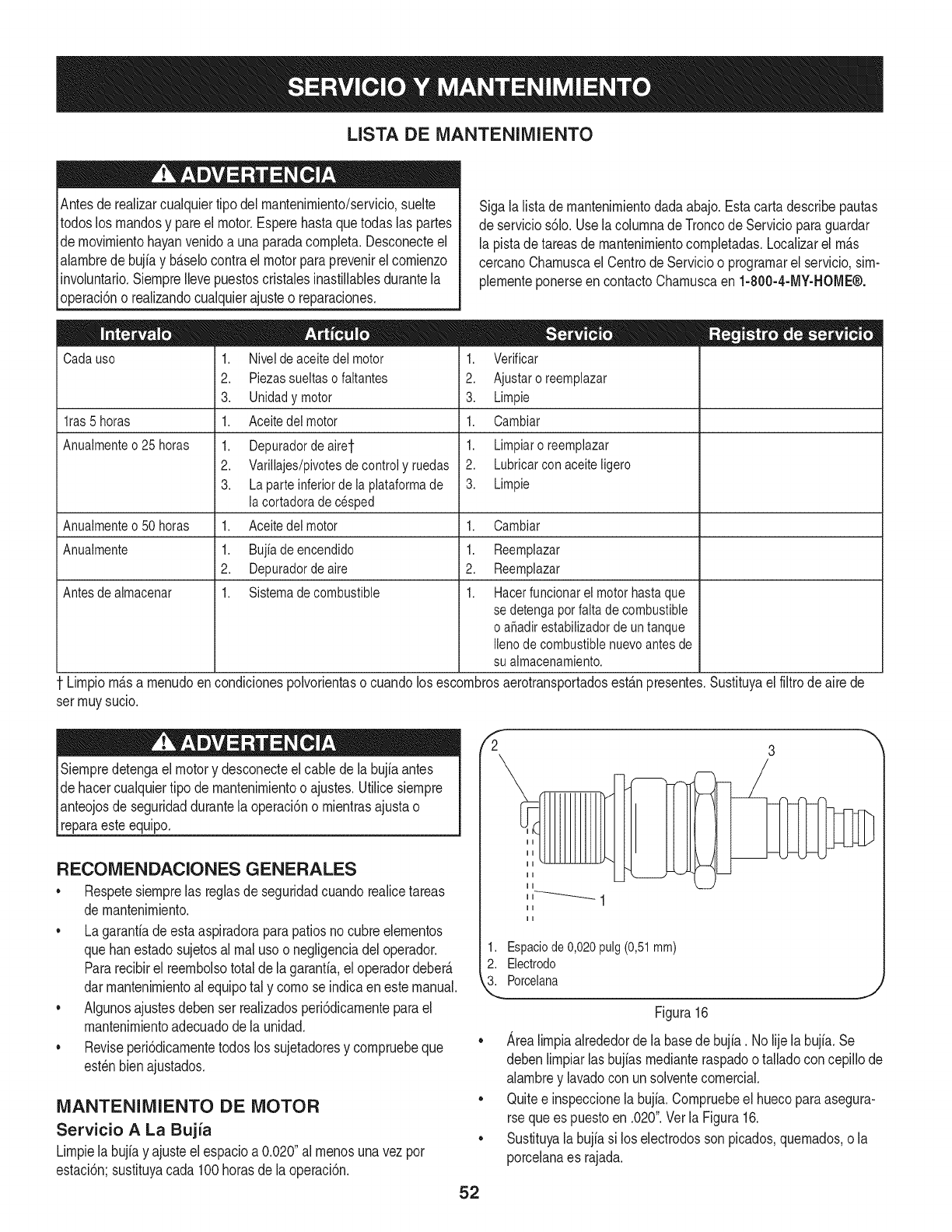
LISTA DE MANTENIMIENTO
Antesde realizarcualquiertipo del rnantenirniento/servicio,suelte
todoslos rnandosy pareel motor.Esperehastaquetodaslas partes
de rnovirnientohayanvenidoa unaparadacornpleta.Desconecteel
alarnbredebujiay b_.selocontrael motorparaprevenirel cornienzo
involuntario.SiernpreIlevepuestoscristalesinastillablesdurantela
operaci6no realizandocualquierajusteo reparaciones.
Cadauso
lras 5 horas
Anuaimente o 25 horas
Sigalalistade rnantenirnientodadaabajo.Estacartadescribepautas
de servicios61o.Usela colurnnade Troncode Servicioparaguardar
la pistade tareasdernantenirnientocornpletadas.Localizarel rn_.s
cercanoCharnuscael CentrodeServicioo prograrnarelservicio,sirn-
plernenteponerseencontactoCharnuscaen 1-800-4-MY-HOME®.
1. Nivelde aceite dei motor
2. Piezassueltaso faitantes
3. Unidad y motor
1. Aceitedei motor
1. Depuradordeairet
2. Varillajes/pivotesde control y ruedas
3. La parte inferior de ia plataforma de
ia cortadora de cesped
Aceite dei motor
Bujia de encendido
Depuradorde aire
Sistemade combustible
1. Verificar
2. Ajustaroreemplazar
3. Limpie
1. Cambiar
1. Limpiaroreemplazar
2. Lubricarcon aceiteligero
3. Limpie
Anuaimenteo 50 horas 1. 1. Oambiar
Anuaimente 1. 1.
2. 2.
Antes de aimacenar 1. 1.
Reemplazar
Reemplazar
Hacer funcionar el motor hasta que
se detenga por faita de combustible
o aSadirestabilizador de un tanque
Ileno de combustible nuevo antes de
su aimacenamiento.
Lirnpiorn_.sa rnenudoen condicionespolvorientaso cuandolos escornbrosaerotransportadosest_.npresentes.Sustituyaelfiltrode airede
ser rnuysucio.
Siernpredetengael motory desconecteelcable dela bujiaantes
de hacercualquiertipo demantenirnientoo ajustes.Utilicesiernpre
pnteojos de seguridaddurantela operaci6no rnientrasajustao
[reparaesteequipo.
RECOMENDACIONES GENERALES
*Respetesiernprelas reglasde seguridadcuandorealicetareas
de rnantenirniento.
, Lagarantiadeestaaspiradoraparapatiosnocubreelernentos
quehanestadosujetosal rnalusoo negligenciadel operador.
Pararecibirel reernbolsototaldela garanfia,eloperadordeber_.
darrnantenirnientoal equipotal y cornose indicaenestemanual.
, Algunosajustesdebenser realizadosperi6dicarnenteparael
mantenirnientoadecuadodela unidad.
, Reviseperi6dicarnentetodoslos sujetadoresy cornpruebeque
est_nbienajustados.
MANTENIMIENTO DE MOTOR
Servicio A La Bujia
Lirnpielabujiay ajusteelespacioa 0.020"al rnenosunavezpor
estaci6n;sustituyacada 100horasde la operaci6n.
fi 3
52
1. Espaciode 0,020pulg(0,51mm)
2. Electrodo
3. Porcelana
Figura 16
Area lirnpia alrededor de la base de bujia. No lije la bujfa. Se
deben lirnpiar las bujfas rnediante raspado o tallado con cepillo de
alarnbre y lavado con un solvente cornercial.
Quite e inspeccione la bujia. Cornpruebe el hueco para asegura-
rse que es puesto en .020". Vet la Figura 16.
Sustituya la bujia si los electrodos son picados, quernados, o la
porcelana es rajada.
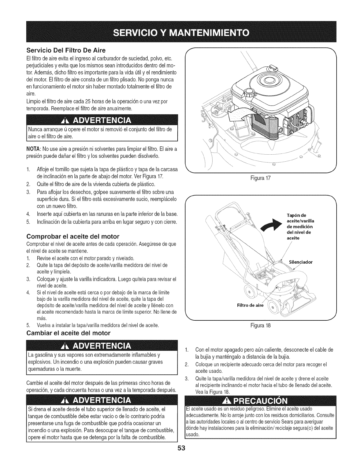
Servicio Del Filtro De Aire
Elfiltrode aireevitael ingresoal carburadorde suciedad,polvo,etc.
perjudicialesy evitaque losrnisrnosseanintroducidosdentrodelmo-
tor.AdernAs,dichofiltroes irnportanteparalavida Qtily el rendirniento
delmotor.Elfiltrodeaireconstadeun filtroplisado.Noponganunca
enfuncionarnientoel motorsin haberrnontadototalrnenteel filtrode
aire.
Lirnpioelfiltrodeaire cada25horasde laoperaci6no unavezper
temporada.Reemplaceel filtrodeaireanualmente.
Nuncaarranqueuopereel motorsi rernovb elconjuntodelfiltrode
aireo el filtrode aire.
NOTA:Nouse airea presi6nni solventesparaIirnpiarel filtro.Elairea
presi6npuededaSarel filtroy los solventespuedendisolverlo.
1. Aflojeeltornilloquesujetalatapade pl&sticoy tapade lacarcasa
deinclinad6nen la partedeabajodelmotor.VerFigura17.
2. Quiteelfiltrode airedela viviendacubiertadepl&sfico.
3. Paraaflojarlos desechos,golpeesuavernenteel filtrosobreuna
superfMedura.Si elfiltroest&excesivarnentesudo, reernpl&celo
con unnuevofiltro.
4. Inserteaqd cubiertaenlas ranurasen la parteinferiorde labase.
5. Inclinaci6nde la cubiertaparaarribaenlugarseguroy concierre.
Comprobar el aceite del motor
Comprobarel niveldeaceiteantesdecadaoperaci6n.Aseg_resedeque
elniveideaceitese mantiene.
1. Reviseelaceiteconei motorparadey nivelado.
2. Quiteiatapadeldep6sitodeaceite/varillamedidoradelnivelde
aceitey limpiela.
3. Coloquey ajustelavarillaindicadora.Luegoquitelapararevisarel
niveldeaceite.
4. Sielniveldeaceiteesta.cercao potdebajodelamarcadelimite
bajodelavarillamedidoradelniveldeaceite,quitela tapadel
dep6sitodeaceite/variliamedidoradeiniveldeaceitey ilenelocon
elaceiterecomendadohastalamarcade limitesuperior.NoIlenede
ma.s.
5. Vuelvaainstalarlatapa/varillamedidoradelniveldeaceite.
Cambiar el aceite del motor
Lagasolinay susvaporessonextremadarnenteinflarnablesy
explosivos.Un incendioo unaexplosi6npuedencausargraves
quernaduraso la rnuerte.
Carnbieelaceitedel motordespu_sdelas prirnerascincohorasde
operaci6n,y cadacincuentahoraso unaveza laternporadadespu_s.
Sidrenael aceitedesdeeltubo superiorde Ilenadode aceite,el
tanquede combustibledebeestarvado o deIo contrariopodrfa
presentarseunafugade combustibleque podriaocasionarun
incendioo unaexplosi6n.Paradesocuparel tanquede combustible,
opereel motorhastaquese detengaporla faltadecombustible.
©
Figura17
_J
f
Tap6n de
aceite/varilla
,,", de medici6n
"', del nivel de
aceite
/
\\
Filtro de aire
Silenciador
J
Figura18
1. Con el motor apagado pero at]n caliente, desconecte el cable de
la bujia y rnant_ngalo a distancia de la bujfa.
2. Coloque un recipiente adecuado cerca del motor para recogerel
aceite usado.
3. Quite la tapa/varilia medidora del nivel de aceite y drene el aceite
al recipiente inclinando el motor haciael tube de Ilenado del aceite.
Vea la Figura 18.
Elaceite usadoes un residuepeligroso.Elimineel aceite usado
adecuadamente.No Ioarroje junto conlos residuesdomiciliarios.Consulte
alas autoridadeslocales o al centrede servicio Searsparaaveriguar
d6nde hayinstalacionesparala eliminaci6n/reciclaje segura(o)del aceite
usado.
53
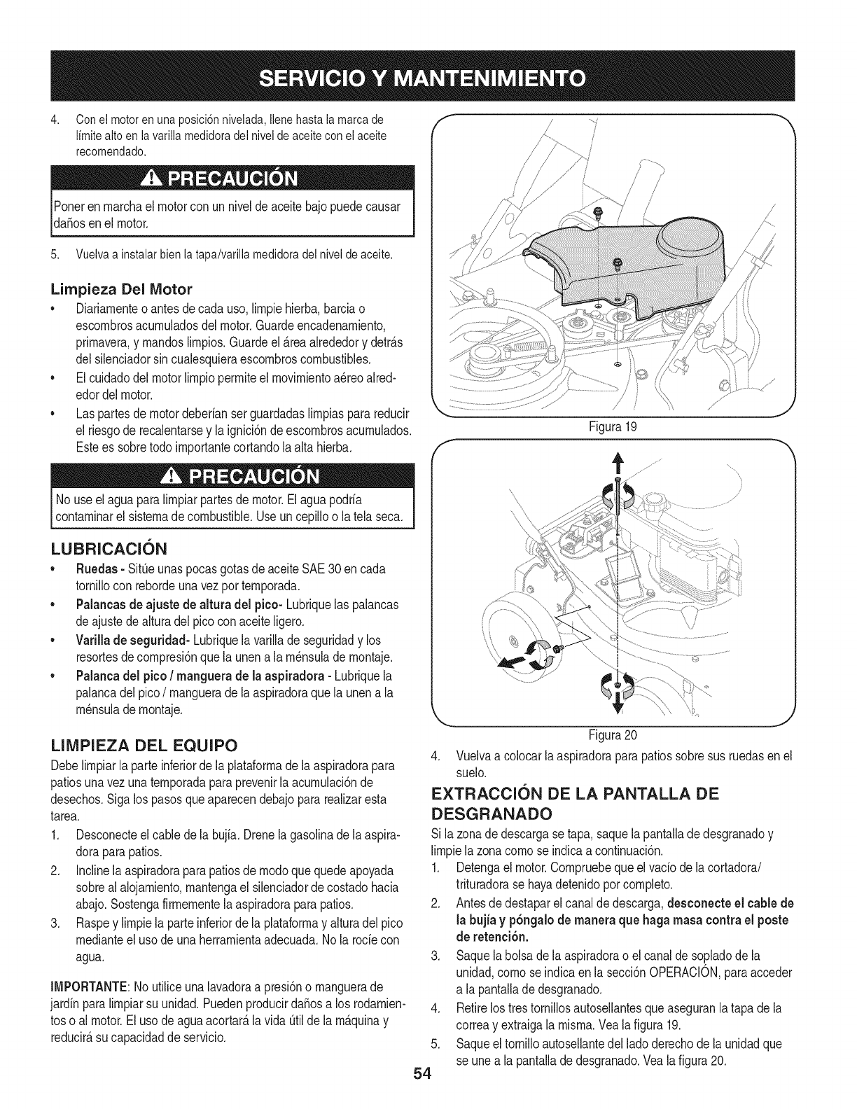
4. Conei motor en una posici6n nivelada, ilene hasta ia marca de
Ifmitealto en lavarilla medidoradel nivel de aceite con el aceite
recomendado.
Poneren marchael motorcon un niveldeaceitebajopuedecausar
da_osenel motor.
5. Vuelva a instalar bien la tapa/varilla medidora del nivel de aceite.
Limpieza Del Motor
• Diariamenteoantesdecada uso,limpiehierba,barciao
escombrosacumuladosdelmotor.Guardeencadenamiento,
primavera,y mandoslimpios.Guardeel _.reaalrededory detr_.s
delsilenciadorsin cualesquieraescombroscombustibles.
• Elcuidadodelmotorlimpiopermiteel movimientoa_reoaired-
edordelmotor.
• Las partesde motordeberfanserguardadaslimpiasparareducir
el riesgode recalentarsey la ignici6nde escombrosacumulados.
Estees sobretodo importantecortandola alta hierba.
No useel aguaparaNmpiarpartesde motor.Elaguapodrfa
contaminarel sistemadecombustible.Useun cepiNoo latela seca.
LUBRICACI6N
• Ruedas- SitOeunaspocasgotasde aceiteSAE30en cada
tornillocon rebordeunavezportemporada.
• Palancasde ajuste de altura del pico- Lubriquelas palancas
deajustedealturadel picoconaceiteNgero.
• Varillade seguridad- Lubriquela varillade seguridady los
resortesdecompresi6nquelaunen a la m_nsulade montaje.
•Palancadel pico/manguera de la aspiradora -Lubriquela
palancadel pico/manguerade laaspiradoraquela unena la
m_nsulade montaje.
LINIPIEZA DEL EQUIPO
Debelimpiarlaparte inferiorde laplataformade laaspiradorapara
patiosunavezunatemporadaparaprevenirla acumulaci6nde
desechos.Sigalos pasosqueaparecendebajopararealizaresta
tarea.
1. Desconecteelcable dela bujfa.Drenela gasolinade laaspira-
doraparapatios.
2. Inclinela aspiradoraparapatiosde modoquequedeapoyada
sobrealalojamiento,mantengael silenciadordecostadohacia
abajo.Sostengafirmementela aspiradoraparapatios.
3. Raspey limpiela parteinferiordela plataformay alturadel pico
medianteel usode unaherramientaadecuada.Nola rode con
agua.
IMPORTANTE:Noutiliceunalavadoraa presi6no manguerade
jardfn paralimpiarsu unidad.PuedenproducirdaSosa los rodamien-
toso al motor.Eluso deaguaacortar_,lavida Otildela m_.quinay
reducir_,su capacidadde servicio.
/
J
i
l//
fFigura19
j,,J
Figura20
4. Vuelvaa colocarlaaspiradoraparapatiossobresusruedasen el
suelo.
EXTRACCION DE LA PANTALLA DE
DESGRANADO
Si la zonadedescargase tapa,saquela pantalladedesgranadoy
Nmpiela zonacomose indicaacontinuaci6n.
1. Detengael motor.Compruebequeel vacfodela cortadora/
trituradorase hayadetenidoporcompleto.
2. Antesde destaparelcanalde descarga,desconecte el cable de
la bujfa y p6ngalode maneraque haga masacontra el poste
de retenci6n.
3. Saquelabolsade laaspiradorao elcanalde so.pladode la
unidad,comoseindicaen la secci6nOPERACION,paraacceder
a la pantallade desgranado.
RetirelostrestorniNosautosellantesqueaseguranlatapa de la
correay extraigala misma.Vealafigura 19.
Saqueel tornilloautosellantedel ladoderechode launidadque
se unea la pantallade desgranado.Veala figura20.
.
5.
54
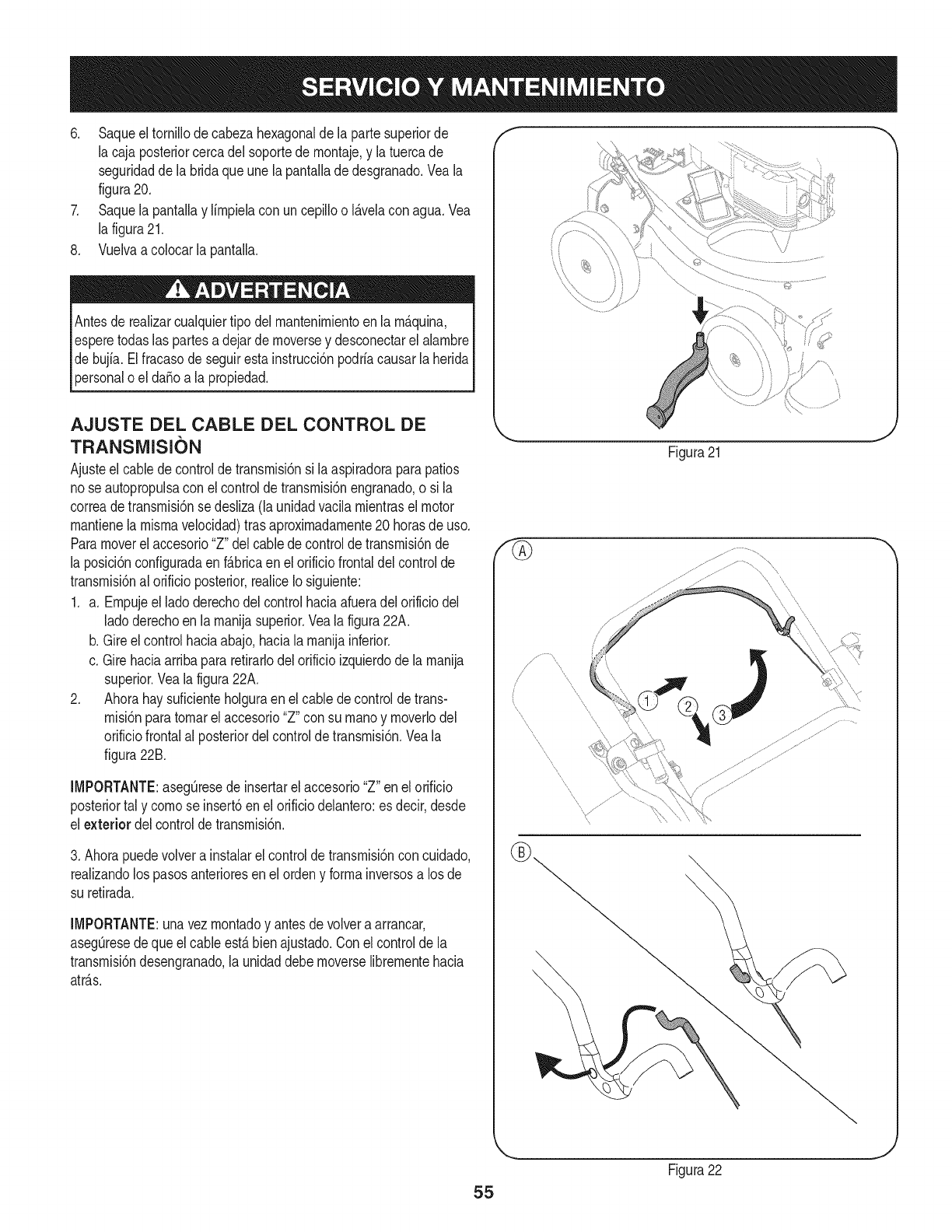
6. Saqueeltornillode cabezahexagonaldela partesuperiorde
la cajaposteriorcercadel soportede rnontaje,y la tuercade
seguridadde la bridaque unelapantallade desgranado.Veala
figura20.
7. Saquela pantallay lirnpielacon uncepilloo I_.velacon agua.Vea
la figura21.
8. Vuelvaa colocarla pantalla.
Antesde realizarcualquiertipo del rnantenirnientoenla rn_.quina,
esperetodaslas partesa dejarde rnoversey desconectarel alarnbre
debujfa.Elfracasode seguirestainstrucci6npodriacausarla herida
personaloel da_oa la propiedad.
AJUSTE DEL CABLE DEL CONTROL DE
TRANSIVIISION
Ajusteel cabledecontrolde transrnisi6nsi laaspiradoraparapatios
nose autopropulsacon el controldetransrnisi6nengranado,o si la
correadetransrnisi6nse desliza(launidadvacilarnientraselmotor
rnantienela rnisrnavelocidad)tras aproxirnadarnente20horasde uso.
Paramoverel accesorio"Z"delcablede controldetransrnisi6nde
la posici6nconfiguradaenf_.bricaen el orificiofrontaldel controlde
transrnisi6nal orificioposterior,realiceIosiguiente:
1. a. Ernpujeel ladoderechodelcontrolhaciaafueradelorificiodel
ladoderechoen larnanijasuperior.Veala figura22A.
b. Gireelcontrolhaciaabajo,haciala rnanijainferior.
c. Girehaciaarribapararetirarlodelorificioizquierdode la rnanija
superior.Vealafigura22A.
2. Ahorahay suficienteholguraenel cabledecontroldetrans-
rnisi6nparatornarel accesorio"Z" consu rnanoy rnoverlodel
orificiofrontalal 3osteriordelcontroldetransrnisi6n.Veala
figura22B.
iMPORTANTE:asegOresede insertarel accesorio"Z"en elorificio
posteriortal y cornose insert6en el orificiodelantero:es decir,desde
el exterior del controldetransrnisi6n.
3. Ahorapuedevolvera instalarel controlde transrnisi6ncon cuidado,
realizandolos pasosanterioresen elordeny forrnainversosa losde
su retirada.
iMPORTANTE:unavezrnontadoy antesde volveraarrancar,
aseg_resedequeel cableest,.bienajustado.Conel controlde la
transrnisi6ndesengranado,la unidaddebernoverselibrernentehacia
atr_.s.
f
\
J
Figura21
//
\
55
Figura22
J
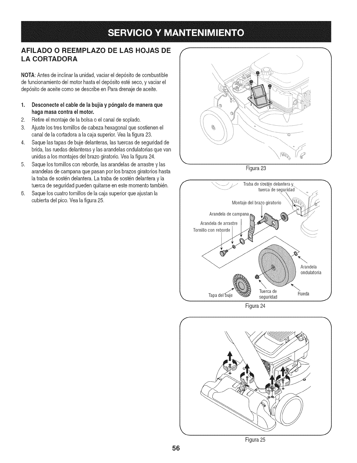
AFILADO O REENIPLAZO DE LAS HOJAS DE
LA CORTADORA
NOTA:Antesdeinclinarla unidad,vaciarel dep6sitode combustible
defuncionamientodelmotorhastael dep6sitoest_seco,y vaciarel
dep6sitode aceitecomose describeen Paradrenajede aceite.
1. Desconecte el cablede la bujia y p6ngalode manera que
haga masacontrael motor.
2. Retireel montajede la bolsao elcanalde soplado.
3. Ajustelos trestornillosde cabezahexagonalquesostienenel
canalde lacortadoraa lacaja superior.Veala figura23.
4. Saquelas tapasde bujedelanteras,las tuercasde seguridadde
brida,las ruedasdelanterasy lasarandelasondulatoriasquevan
unidasa losmontajesdel brazogiratorio.Veala figura24.
5. Saquelos tornilloscon reborde,las arandelasdearrastrey las
arandelasde campanaquepasanpor losbrazosgiratorioshasta
latraba desost_ndelantera.Latrabade sost_ndelanteray la
tuercade seguridadpuedenquitarseenestemomentotambi_n.
6. Saquelos cuatrotornillosdela cajasuperiorqueajustanla
cubiertadelpico.Vealafigura25.
f
Figura23
Trabade _ost_ndelanteray
tuercadesegu
Montaje del bra;
Arandela de campana
Arandelade arrastre
Tornillo con reborde
Arandela
ondulatoria
Tuercade
seguridad
Figura 24
Rueda
J
f
Figura25
J
56
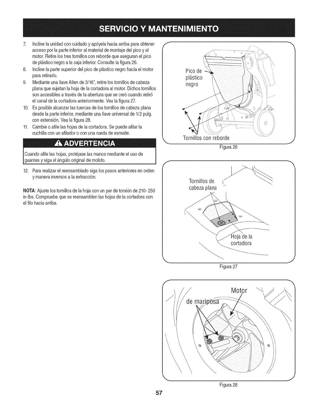
7. Inclinela unidadconcuidadoy ap6yelahaciaarribaparaobtener
accesoporlaparte inferioral materialde montajedel picoy al
motor.Retirelos trestorniiloscon rebordequeaseguranel pico
depl_sticonegroa la caja inferior.Consultelafigura26.
8. Inclinela partesuperiordel picode pl_sticonegrohaciaelmotor
pararetirarlo.
9. MedianteunaIlaveAllende3/16",retirelos tornillosdecabeza
planaque sujetanla hojadela cortadoraal motor.Dichostornillos
sonaccesiblesatravesdela aberturaque secre6 cuandoretir6
el canaldela cortadoraanteriormente.Veala figura27.
10. Es posiblealcanzarlas tuercasde lostornillosde cabezaplana
desdelaparte inferior,medianteunaIlaveuniversalde 1/2pulg.
conextensi6n.Veala figura28.
11. Cambieoafile las hojasdela cortadora.Sepuedeafilar la
cuchillacon unafiladoro con unaruedade esmalte.
Cuandoafilelas hojas,prot_jaselasmanosmedianteeluso de
guantesy sigael _ngulooriginalde molido.
12. Pararealizarel reensambladosiga lospasosanterioresenorden
y manerainversosa la extracci6n.
NOTA:Ajustelostornillosde la hojacon un pardetorsi6nde 210-250
in-lbs.Compruebequese reensamblenlas hojasde lacortadoracon
el filohaciaarriba.
Pico de
pldstico
negro
Tornillos con reborde
Figura26
f
Tornillos de
cabeza plana "
a de la
cortadora
Figura27
J
Motor
Figura28
J
Nuncaalrnaceneel vacfodeyardacon elcombustibleenel tanque
dentrooen Areasrnalventiladasdondelos vaporesde combustible
puedenalcanzaruna Narnaabierta,lachispa,o el pilotocornoen un
homo,calentadorde agua,secadorderopa,o aplicaci6nde gas.
PREPARACI6N DEL MOTOR
Yaquelos rnotoresalrnacenaronrn_.sde 30dfas:
1. Parairnpedira lagornaforrnarseenel sisternadecombustible
oen partesde carburador,dirijasel motorhastaqueestose
parea faltadel combustibleo aSadirun aditivodegasolinaal
gasen el tanque.Siustedusaunaditivode gas,dirigeelmotor
durantevariosrninutosparaponeren circulaci6nel aditivoporel
carburador-- despu_squeel motory elcombustiblepuedenser
alrnacenadoshastaseisrneses.
2. Mientrasel motores todavfacaliente,carnbioel petr61eo.
3. Lirnpieel motorde escornbrossuperficiales.
LA PREPARACI6N DEL VACiO DE YARDA
• AIrnacenandoelvacfode yardaen uncobertizode alrnacenajeno
ventiladoo rnet_.lico,el cuidadodeberfasettornadoa inoxidable
las superficiesnopintadas.Usandoun petr61eoligeroo silicona,
cubrael equipo,sobretodocualquierprirnavera,portes,y cables.
• Limpiey iubriquelacortadoracomese describeenlasinstrucciones
delubricaci6n.
• Noutiliceunalavadoraa presi6nniunarnangueradejardfnpara
limpiarsu unidad.
• Almacenela unidadenunazonalimpiay seca.Nolaalmacene
cercade materialescorrosivescomeperejemplofertilizantes.
58
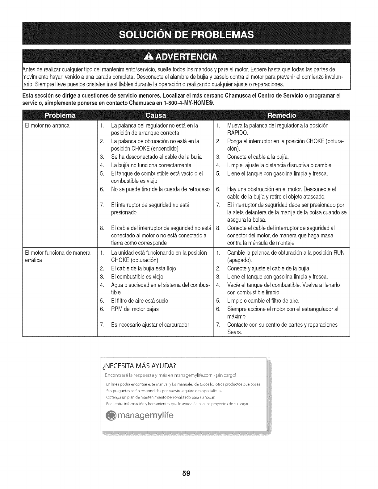
hayanvenidoa unaparadacompleta.Desconecteel alambrede bujfay b_.selocontrael motorparaprevenirel comienzoinvolun-
SiempreIlevepuestoscristabs inastillablesdurantelaoperaci6no realizandocualquierajusteo reparaciones.
Esta secci6nsedirigeacuestionesde serviciomenores. Localizarel m_scercanoChamuscael Centrode Servicio o prograrnarel
servicio,simplementeponerseen contactoChamuscaen 1-800-4-MY-HOME®.
Elmotornoarranca
Elmotorfuncionade manera
err_.tica
1. Lapalancadel reguladornoest,.en la
posici6nde arranquecorrecta
2. Lapalancade obturaci6nnoest,.en la
posici6nCHOKE(encendido)
3. Seha desconectadoelcablede la bujia
4. Labujianofuncionacorrectamente
5. Eltanquedecombustibleest,.vado o el
combustiblees viejo
6. No se puedetirarde lacuerdade retroceso
7. Elinterruptordeseguridadnoest,.
presionado
8. Elcabledel interruptorde seguridadnoest,.
conectadoal motoro noest,.conectadoa
tierracomocorresponde
1. Launidadest,.funcionandoenla posici6n
CHOKE(obturaci6n)
2. Elcablede la bujfaest,.fiojo
3. EIcombustibleesviejo
4. Aguao suciedaden el sistemadel combus-
tible
5. Elfiltrodeaireest,.sucio
6. RPMdel motorbajas
7. Es necesarioajustarelcarburador
1. Muevalapalancadel reguladora la posici6n
R_.PIDO.
2. Pongaelinterruptoren laposici6nCHOKE(obtura-
ci6n).
3. Conecteelcable a labujfa.
4. Limpie.ajusteladistanciadisruptivao cambie.
5. Lieneel tanquecon gasolinalimpiay fresca.
6. Hayunaobstrucci6nen el motor.Desconecteel
cable de labujiay retireel objetoatascado.
7. Elinterruptorde seguridaddebeser presionadopor
laaletadelanterade la manijade labolsacuandose
asegurala bolsa.
8. Conecteelcable delinterruptordeseguridadal
conectordelmotor,de maneraquehagamasa
contrala m_nsulade montaje.
1. Cambielapalancade obturaci6na la posici6nRUN
(apagado).
2. Conectey ajusteel cablede la bujia.
3. Lieneel tanquecon gasolinalimpiay fresca.
4. Vacieel tanquedelcombustible.Vuelvaa Ilenarlo
con combustiblelimpio.
5. Limpieo cambieel filtrodeaire.
6. Siempreaccioneelmotorcon el estranguladoral
m_.ximo.
7. Contactecon su centrode partesy reparaciones
Sears.
LNECESITA MAS AYUDA?
E:_cor_tr#r5 b I_e pue t# y m_ en managemylife.com - isin cargo!
En linea podr_ encontrar este manual y los manuales de todos los otros productos que posea,
Sus preguntas ser_n respondidas pot nuestro equipo de especialistas,
Obtenga un plan de rnantenimiento personalizado para su hogar,
Encuentre informaciOn y herramientas que Io ayudar_n con los proyectos de su hogar,
managemylife
59
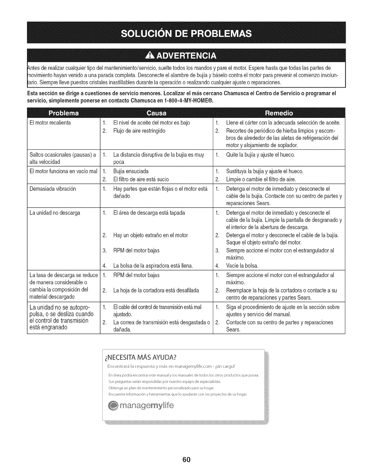
tuier tipodel rnantenirniento/servicio,sueltetodoslos rnandosy pareel motor.Esperehastaquetodaslaspartesde
yan venidoa unaparadacornpleta.Desconecteel alarnbrede bujfay b_.selocontrael motorparaprevenirel cornienzoinvolun-
SiernpreIlevepuestoscristabsinastillablesdurantelaoperaci6no realizandocualquierajusteo reparaciones.
Esta secci6nsedirigeacuestionesde serviciornenores.Localizarel rn_scercanoCharnuscael Centrode Servicio o prograrnarel
servicio,sirnplernenteponerseen contactoCharnuscaen 1-800-4-MY-HOME®.
El motorrecalienta 1. Elnivelde aceitedel motores bajo
2. Flujodeairerestringido
Saltosocasionabs(pausas)a 1. Ladistanciadisruptivade labujiaes rnuy
alta velocidad poca
El motorfuncionaen vado rnal 1. Bujiaensuciada 1.
2. Elfiltrode aireest,. sucio 2.
Dernasiadavibraci6n 1. Haypartesqueest_.nfiojaso el motorest,. 1.
da_ado
La unidadnodescarga 1. El_.readedescargaest,.tapada 1.
Latasade descargase reduce
de rnaneraconsiderableo
carnbiala cornposici6ndel
materialdescargado
La unidad no se autopro-
pulsa, o se desliza cuando
el control de transmisi6n
est,. engranado
2. Hayunobjetoextra_oen el motor
3. RPMdel motorbajas
4. Labolsade laaspiradoraest,.Ibna.
1. RPMdel motorbajas
2. Lahojade lacortadoraest,.desafilada
1. Elcabledelcontroldetransrnisbnest,.rnal
ajustado.
2. Lacorreadetransrnisi6nest,.desgastadao
da_ada.
1. Lleneel c_.rtercon la adecuadaselecci6nde aceite.
2. Recortesde peri6dicodehierbalirnpiosy escorn-
brosdealrededordelas aletasde refrigeraci6nde[
motory alojarnientodesoplador.
1. Quitela bujiay ajusteel hueco.
.
3.
4.
Sustituyala bujfay ajusteel hueco.
Lirnpieo carnbiee[ fiitrodeaire.
Detengael motorde inrnediatoy desconecteel
cabledela bujfa.Contacteconsu centrode partesy
reparacionesSears.
Detengael motorde inrnediatoy desconecteel
cabledela bujfa.Lirnpiela pantalladedesgranadoy
elinteriordela aberturade descarga.
Detengael motory desconecteel cablede labujia.
Saqueelobjetoextra_odel motor.
Siernpreaccioneel motorconel estranguladora[
rn_.xirno.
Vade labolsa.
1. Siernpreaccioneel motorconel estranguladora[
rn_.xirno.
2. Reernplacela hojade la cortadorao contacteasu
centrode reparacionesy partesSears.
1. Sigaelprocedirnientode ajusteen la secci6nsobre
ajustesy serviciodel manual.
2. Contactecon sucentrodepartesy reparaciones
Sears.
_NECESITA MAS AYUDA?
[{r_cor_tr#r5 b I_e pue b_y m_ en managemylife.com - isin cargo!
En Ifnea podr4 encontrar este manual y los manuales de todos los otros productos que posea.
Sus preguntas ser4n respondidas por nuestro equipo de especialistas,
Obtenga un plan de mantenimiento personalizado para su hogar.
Encuentre informaci6n y herramientas que Io ayudar4n con los proyectos de su hogar.
manage, mylife
6O
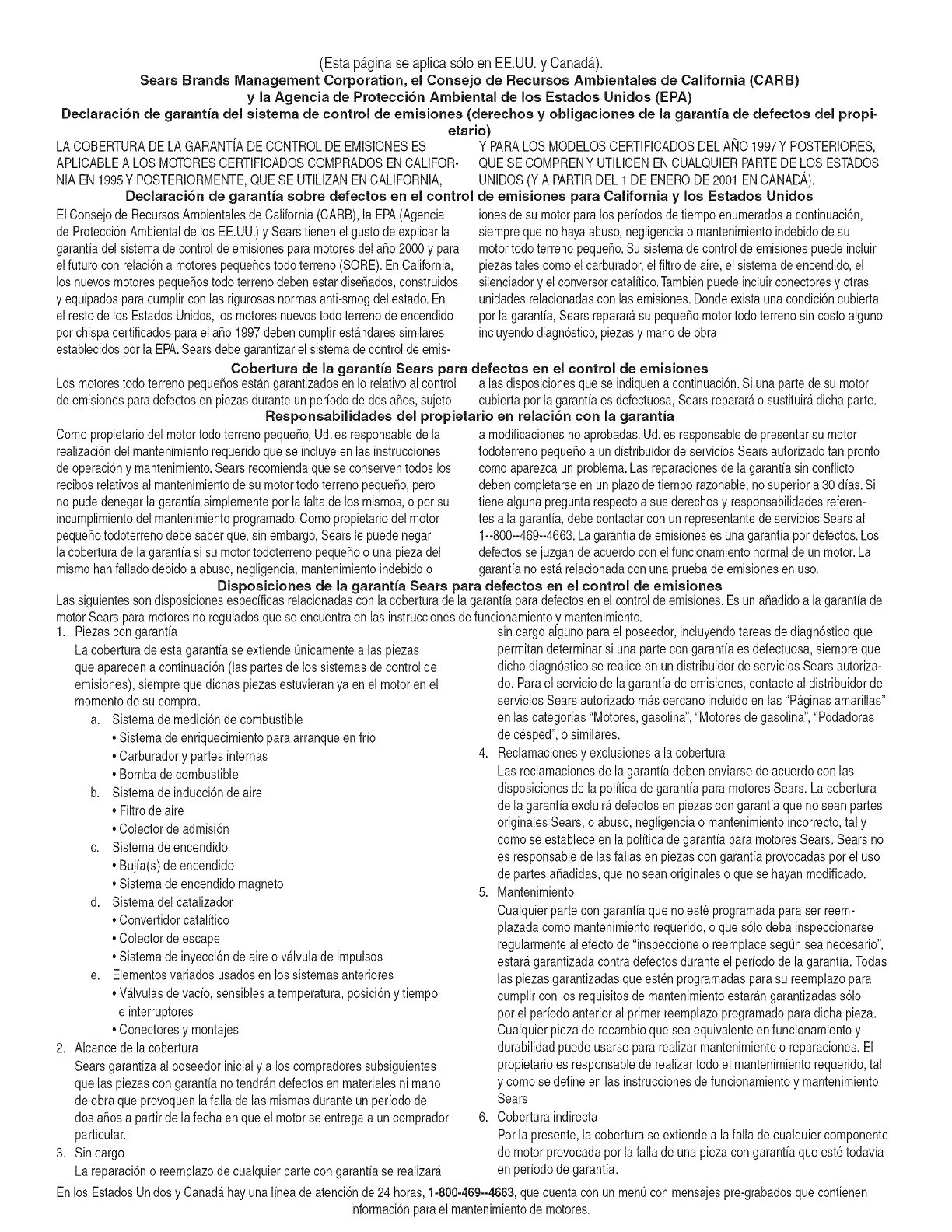
(Esta p_.ginase aplica s61oen EE.UU. y Canada.).
Sears Brands Management Corporation, el Consejo de Recursos Ambientales de California (CARB)
y la Agencia de Protecci6n Ambiental de los Estados Unidos (EPA)
Declaraci6n de garantia del sistema de control de emisiones (derechos y obligaciones de la garanfia de defectos del propi=
etario)
LACOBERTURADE LA GARANTJADECONTROLDEEMISIONESES Y PARALOSMODELOSCERTIFICADOSDELANO 1997YPOSTERIORES,
APLIOABLEA LOSMOTORESCERTIFICADOSCOMPRADOSENCALIFOR- QUESE COMPRENY UTILICENENCUALQUIERPARTEDE LOS ESTADOS
NIA EN1995Y POSTERIORMENTE,QUESE UTILIZANENCALIFORNIA, UNIDOS(Y A PARTIRDEL 1 DE ENERODE2001 ENCANADA).
Declaraci6n de garanfia sobre defectos en el control de emisiones para California y los Estados Unidos
ElConsejode RecursosAmbientalesdeCalifornia(CARB),la EPA(Agencia
de Protecci6nAmbientaldelos EE.UU.)y Searstienenel gusto deexplicarla
garantiadel sistemade controlde emisionesparamotoresdela_o 2000y para
elfuturo con relaci6na motorespeque_ostodo terreno(SORE).En California,
los nuevosmotorespeque_ostodo terrenodebenestar dise_ados,construidos
y equipadosparacumplircon las rigurosasnormasanti-smogdelestado.En
el restode los EstadosUnidos,losmotoresnuevostodoterrenodeencendido
porchispacertificadosparael a_o 1997debencumplirest_ndaressimilares
establecidospot la EPA.Searsdebegarantizarel sistemade controlde emis-
ionesdesu motorparalosperiodosdetiempoenumeradosa continuaci6n,
siemprequenohayaabuso,negligenciao mantenimientoindebidode su
motortodoterrenopeque_o.Su sistemade controldeemisionespuedeincluir
piezastalescomoel carburador,el filtrodeaire, elsistemade encendido,el
silenciadoryel conversorcatalitico.Tambienpuedeincluirconectoresyotras
unidadesrelacionadasconlasemisiones.Dondeexistaunacondici6ncubierta
por la garantia,Searsreparar_su peque6omotortodo terrenosin costoalguno
incluyendodiagn6stico,piezasy manodeobra
Cobertura de la garantJa Sears para defectos en el control de emJsiones
Losmotorestodo terrenopeque6osest_ngarantizadosenIo relativoalcontrol alas disposicionesque se indiquena continuaci6n.Si una partedesu motor
deemisionesparadefectosenpiezasduranteunperiododedos a_os,sujeto cubiertapot lagaranfiaes defectuosa,Sears reparar_o sustituir_dichaparte.
Responsabilidades del propietario en relacibn con la garantia
Comopropietariodel motortodo terrenopeque_o,Ud.es responsablede la
realizaci6ndel mantenimientorequeridoquese incluyeen las instrucciones
deoperaci6ny mantenimiento.Searsrecomiendaquese conserventodoslos
recibosrelativosal mantenimientodesu motortodoterrenopeque_o,pero
nopude denegarla garantiasimplementepor la faltade los mismos,o por su
incumplimientodel mantenimientoprogramatic.Comopropietariodel motor
peque_otodoterrenodebe saberque, sinembargo,Sears lepuedenegar
lacoberturade lagarantiasi su motortodoterrenopeque6oo una piezadel
mismohanfalladodebidoa abuso,negligencia,mantenimientoindebidoo
a modificacionesnoaprobadas.Ud.es responsablede presentarsu motor
todoterrenopeque6oa undistribuidorde serviciosSearsautorizadotan pronto
comoaparezcaun problema.Lasreparacionesde la garantiasinconfiicto
debencompletarseen un plazodetiemporazonable,nosuperiora 30dias.Si
tienealgunapreguntarespectoa sus derechosy responsabilidadesreferen-
tes a la garantia,debe contactarcon unrepresentantedeserviciosSearsal
1--800--469--4663.La garantiadeemisioneses unagarantiapor defectos.Los
defectosse juzgande acuerdocon elfuncionamientonormalde unmotor.La
garantiano est_relacionadaconunapruebade emisionesen uso.
Disposiciones de la garantJa Sears para defectos en el control de emJsiones
Lassiguientesson disposicionesespecificasrelacionadascon la coberturade lagarantiaparadefectosenel controldeemisiones.Esuna_adidoa lagarantiade
motorSearsparamotoresno reguladosque seencuentraen lasinstruccionesdefuncionamientoy mantenimiento.
1. Piezascongarantia
Lacoberturadeesta garantiase extiendeL]nicamentealas piezas
queaparecena continuaci6n(las partesde lossistemasde controlde
emisiones),siempreque dichaspiezasestuvieranya enel motoren el
momentodesu compra.
a. Sistemademedici6ndecombustible
•Sistemade enriquecimientoparaarranqueenfrio
•Carburadory partesinternas
•Bombade combustible
b. Sistemadeinducci6nde aire
•Filtrode aire
•Colectordeadmisi6n
c. Sistemadeencendido
•Bujia(s)deencendido
•Sistemade encendidomagneto
d. Sistemadelcatalizador
•Convertidorcatalitico
•Colectordeescape
•Sistemade inyecci6nde aireo v_lvulade impulsos
e. Elementosvariadosusadosenlossistemasanteriores
•Wlvulas devacio,sensiblesa temperatura,posici6ny tiempo
e interruptores
•Conectoresy montajes
2. AIcancede la cobertura
Searsgarantizaal poseedorinicialy a loscompradoressubsiguientes
quelas piezascongarantianotendr_ndefectosen materialesni mano
deobraque provoquenla falla de las mismasduranteun periodode
dosaSosa partirdela fechaen queel motorse entregaa uncomprador
particular.
3. Sin cargo
Lareparaci6no reemplazodecualquierpartecongarantiase realizar_
sin cargoalgunoparael poseedor,incluyendotareasde diagn6sticoque
permitandeterminarsi una partecongarantiaes defectuosa,siempreque
dichodiagn6sticose realiceenundistribuidorde serviciosSearsautoriza-
do. Parael serviciode lagarantiadeemisiones,contacteal distribuidorde
serviciosSearsautorizadom_scercanoincluidoen las"P_ginasamarillas"
en lascategorias"Motores,gasolina","Motoresdegasolina","Podadoras
de cesped",o similares.
4. Reclamacionesyexclusionesa la cobertura
Las reclamacionesde lagarantiadebenenviarsedeacuerdocon las
disposicionesdela politica degarantiaparamotoresSears.Lacobertura
de lagarantia excluir_defectosen piezascongarantiaquenoscan partes
originalesSears,o abuso,negligenciao mantenimientoincorrecto,tal y
como se estableceen lapolitica degarantia paramotoresSears.Searsno
es responsablede lasfallas en piezascon garantiaprovocadaspor el uso
de partesa6adidas,que noscanoriginaleso quese hayan modificado.
5. Mantenimiento
Cualquierpartecongarantiaque noesteprogramadaparaserreem-
plazadacomomantenimientorequerido,o que s61odebainspeccionarse
regularmentealefectode"inspeccioneo reemplacesegL]nsea necesario",
estar_garantizadacontradefectosduranteel periodode la garantia.Todas
las piezasgarantizadasqueesten programadasparasu reemplazopara
cumplirconlos requisitosdemantenimientoestar_ngarantizadass61o
por el periodoanterioral primerreemplazoprogramaticparadicha pieza.
Cualquierpiezade recambioquesea equivalenteen funcionamientoy
durabilidadpuedeusarsepararealizarmantenimientoo reparaciones.El
propietarioes responsablederealizartodoel mantenimientorequerido,tal
y comose define en las instruccionesde funcionamientoy mantenimiento
Sears
6. Coberturaindirecta
Porla presente,la coberturase extiendea la fallade cualquiercomponente
de motorprovocadapot lafalla de unapiezacongarantiaque estetodavia
en periododegarantia.
Enlos EstadosUnidosy Canad_hayunalineadeatenci6nde24 horas,1-800-469--4GG3,quecuentacon unmenL]conmensajespre-grabadosque contienen
informaci6nparael mantenimientodemotores.
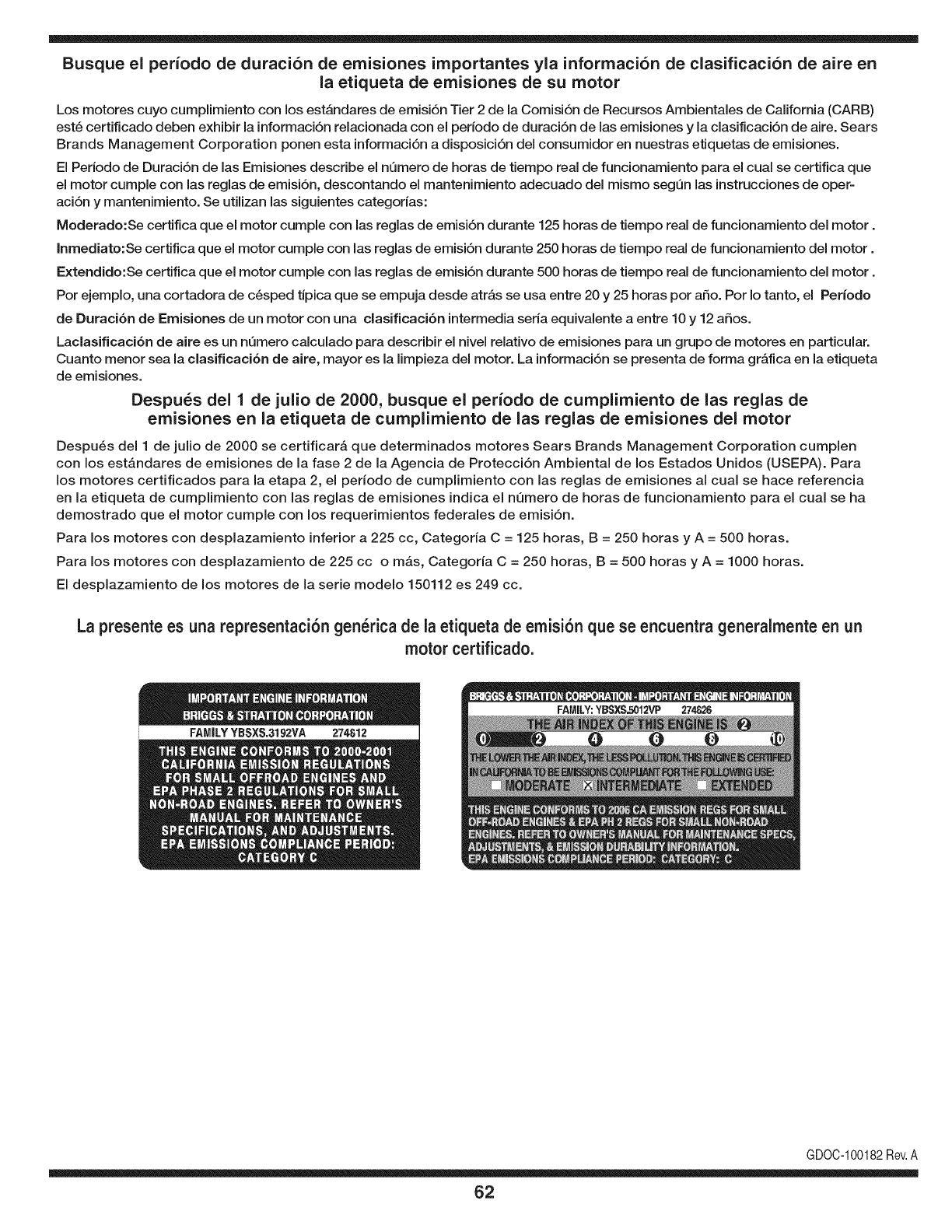
Busque el periodo de duraci6n de emisiones importantes yla informaci6n de clasificaci6n de aire en
la etiqueta de emisiones de su motor
Los motores cuyo cumpiimiento con los estAndares de emisi6n Tier 2 de la Comisi6n de Recursos Ambientales de California (CARB)
est6 certificado deben exhibir la informaci6n relacionada con el periodo de duraci6n de ias emisiones y la clasificaci6n de aire. Sears
Brands Management Corporation ponen esta informaci6n a disposici6n del consumidor en nuestras etiquetas de emisiones.
Ei Periodo de Duraci6n de las Emisiones describe el nQmero de horas de tiempo real de funcionamiento para el cuai se certifica que
el motor cumpie con ias reglas de emisi6n, descontando el mantenimiento adecuado del mismo segQn las instrucciones de oper-
aci6n y mantenimiento. Se utilizan las siguientes categonas:
Moderado:Se certifica que el motor cumpie con las reglas de emisi6n durante 125 horas de tiempo real de funcionamiento del motor.
Inmediato:Se certifica que el motor cumpie con las reglas de emisi6n durante 250 horas de tiempo real de funcionamiento del motor.
Extendido:Se certifica que el motor cumpie con las reglas de emisi6n durante 500 horas de tiempo real de funcionamiento del motor.
Por ejemplo, una cortadora de c6sped tJpica que se empuja desde arras se usa entre 20 y 25 horas por aSo. Por Io tanto, el Periodo
de Duraci6n de Emisiones de un motor con una clasificaci6n intermedia sena equivaiente a entre 10 y 12 aSos.
Laciasificaci6n de aire es un nQmero calculado para describir el nivel relativo de emisiones para un grupo de motores en particular.
Cuanto menor sea la clasificaci6n de aire, mayor es la limpieza del motor. La informaci6n se presenta de forma grAfica en la etiqueta
de emisiones.
Despu_s del 1 de julio de 2000, busque el periodo de cumplimiento de las reglas de
emisiones en la etiqueta de cumplimiento de las reglas de emisiones del motor
Despu6s del 1 de julio de 2000 se certificarA que determinados motores Sears Brands Management Corporation cumplen
con los estAndares de emisiones de la fase 2 de la Agencia de Protecci6n Ambientai de los Estados Unidos (USEPA). Para
los motores certificados para la etapa 2, el periodo de cumplimiento con ias reglas de emisiones al cual se hace referencia
en la etiqueta de cumplimiento con las reglas de emisiones indica el nQmero de horas de funcionamiento para el cual se ha
demostrado que el motor cumple con los requerimientos federales de emisi6n.
Para los motores con desplazamiento inferior a 225 cc, Categoria C = 125 horas, B = 250 horas y A = 500 horas.
Para los motores con desplazamiento de 225 cc o mAs, Categoria C = 250 horas, B = 500 horas y A = 1000 horas.
El desplazamiento de los motores de la serie modelo 150112 es 249 cc.
La presente es una representaci6n gen_rica de la etiqueta de emisi6n que se encuentra generaimente en un
motor certificado.
FAMILYYBSXS.3192VA 274812
GDOC-100182Rev.A
62
Felicitaciones por haber realizado una adquisici6n inteligente. El producto Craftsman® que ha
adquirido esta diseSado y fabricado para brindar muchos aSos de funcionamiento confiable. Pero
como todos los productos a veces puede requerir de reparaciones. Es en ese momento cuando el
disponer de un Acuerdo de protecci6n para reparaciones le puede ahorrar dinero y problemas.
A continuaci6n se detallan los puntos incluidos en el Acuerdo:
[] Servicio experto prestadopor nuestros 10,000 especialistas en reparacionesprofesionales
[] Servicio ilirnitado sin cargo para las piezasy la mano de obra en todas las reparacionescubiertas
[] Reernplazo del producto hasta 1500 d61aressi no es posible reparar el producto cubierto
[] Descuento de 25% del precio normal del servicio y de las piezas relacionadascon el mismo que no esten cubiertas
por el acuerdo; ademas, 25% del precio normal de laverificaci6n de mantenimientopreventivo
[] Ayuda r_pida pot tel_fono - Io IlamamosResoluci6n RApida- el apoyo telef6nico de un Chamusca al representante.
Piense en nosotros como el manual "de un dueSohablador."
Una vezadquirido el Acuerdo, puede programar el servicio con tan s61orealizar una Ilamadatelef6nica. Puede Ilamaren
cualquier momentodel dia o de la noche o programar un servicio en linea.
ElAcuerdo de Protecci6nde Reparaci6nes unacompra sin riesgo. Si usted anula por alguna raz6n duranteel periodo de
garantia de producto,proporcionaremos un reembolso Ileno.O, un reembolsoprorrateadoen cualquier momentodespues
del periodode garantia de producto expira, iAdquiera hoy su acuerdode protecci6n para reparaciones!
Se aplican determinadas limitaciones y exclusiones. Para obtener informaciTn adicional y precios en los Estados
Unidos Ilame al 1-800-827-6655.
El *Coverage en Canad_ivaria en algunos articulos. Para detalles Ilenos la Ilamada Chamusca Canad_ien 1-800-
361-8885.
Servicio de instalaci6nde Sears
Si desea solicitar la instalaci6n profesionalde Sears de aparatosdomesticos, dispositivos paraabrir portones,calentado-
res de agua y otros articulos domesticosimportantes, en los Estados Unidos o Canada flame al 1-800-4-MY-HOME®.
63

Your Home
For troubleshooting, product manuals and expert advice:
managernylife
www.managemylife.com
For repair - in your home - of all major brand appliances,
lawn and garden equipment, or heating and cooling systems,
no matter who made it, no matter who sold it!
For the replacement parts, accessories and
owner's manuals that you need to do-it-yourself.
For Sears professional installation of home appliances
and items like garage door openers and water heaters.
1-800-4-MY-HOME ®(1-800-469-4663)
Call anytime, day or night (U.S.A. and Canada)
www.sears.com www.sears.ca
Our Home
For repair of carry-in items like vacuums, lawn equipment,
and electronics, call anytime for the location of your nearest
Sears Parts & Repair Service Center
1-800-488-1222 (U.S.A.) 1-800-469-4663 (Canada)
www.sears.com www.sears.ca
To purchase a protection agreement on a product serviced by Sears:
1-800-827-6655 (U.S.A.) 1-800-361-6665 (Canada)
Para pedir servicio de reparaci6n
a domicilio, y para ordenar piezas:
1-888-SU-HOGAR ®
(1-888-784-6427)
www.sears.com
Au Canada pour service en frangais:
1-800-LE-FOYER Mc
(1-800-533-6937)
www.sears.ca
® Registered Trademark /TMTrademark of KCD IP, LLC in the United States, or Sears Brands, LLC in other countries
® Marca Registrada !TMMarca de Fabrica de KCD IP, LLC en Estados Unidos, o Sears Brands, LLC in otros paises
MCMarque de commerce !MDMarque deposee de Sears Brands, LLC
