Craftsman 247774660 User Manual LOG SPLITTER Manuals And Guides L0602282
CRAFTSMAN Log Splitter Manual L0602282 CRAFTSMAN Log Splitter Owner's Manual, CRAFTSMAN Log Splitter installation guides
User Manual: Craftsman 247774660 247774660 CRAFTSMAN LOG SPLITTER - Manuals and Guides View the owners manual for your CRAFTSMAN LOG SPLITTER #247774660. Home:Lawn & Garden Parts:Craftsman Parts:Craftsman LOG SPLITTER Manual
Open the PDF directly: View PDF ![]() .
.
Page Count: 44
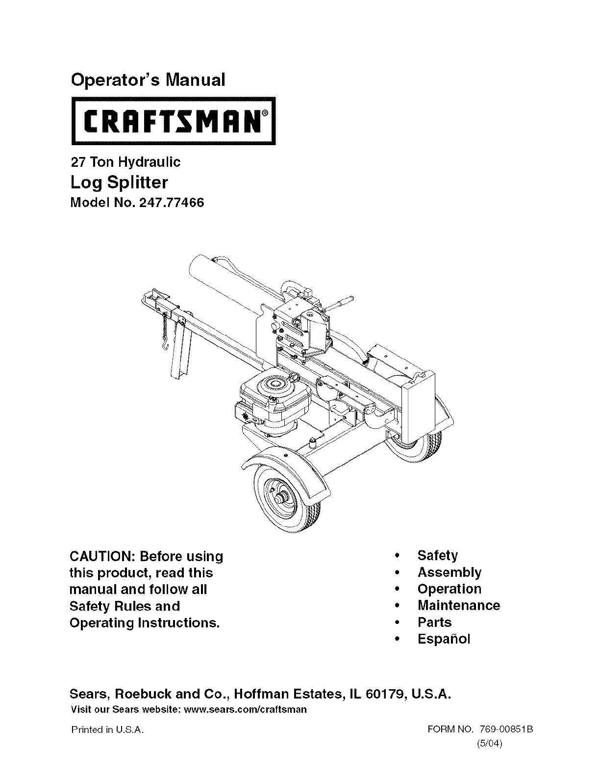
Operator's Manual
IRA
27 Ton Hydraulic
Log Splitter
MAN 1
Model No. 247.77466
CAUTION: Before using
this product, read this
manual and follow all
Safety Rules and
Operating Instructions.
• Safety
•Assembly
• Operation
•Maintenance
•Parts
•Espa_ol
Sears, Roebuck and Co., Hoffman Estates, IL 60179, U.S.A.
Visit our Sears website: www.sears.com/craftsman
Printed in U.S.A. FORM NO. 769-00851B
(5/04)
Content Page Content Page
Warranty 2 Service and Adjustments 12
Safety 3 Storage 14
Assembly 5 Troubleshooting 15
Operation 7 Parts List 18
Maintenance 10 Espahol 27
Limited Warranty on Craftsman Log Splitter
For one (1) year from the date of purchase, if tills Craftsman Equipment is maintained, lubricated, and tuned up
according to the instructions to the operator's manual, Sears will repair or replace free of charge any parts found
to be defective in material or workmanship. Warranty service is available free of charge by returning Craftsman
equipment to your nearest Sears Service Center. In-home warranty service is available but a trip charge will
apply. This Warranty applies only while this product is in the United States.
This Warranty does not cover:
Expendable items which become worn during normal use, such as spark plugs, air cleaners, belts, and oil
filters.
Tire replacement or repair caused by punctures from outside objects, such as nails, thorns, stumps, or glass.
Repairs necessary because of operator abuse, including but not limited to, damage caused by objects, such
as stones or metal debris, oversized stock, impacting objects that bend the frame or crankshaft, or over-
speeding the engine.
Repairs necessary because of operator negligence, including but not limited to, electrical and mechanical
damage caused by improper storage, failure to use the proper grade and amount of engine oil, or failure to
maintain the equipment according to the instructions contained in the operator's manual.
Engine (fuel system) cleaning or repairs caused by fuel determine to be contaminated or oxidized (stale). In
general, fuel should be used within 30 days of its purchase date.
Equipment used for commercial or rental purposes.
TO LOCATE THE NEAREST SEARS SERVICE CENTER OR TO SCHEDULE SERVICE, SIMPLY CONTACT
SEARS AT 1-80O-4-MY-HOME.
This warranty gives you specific legal rights and you may also have other rights, which vary from state to state.
PRODUCT SPECIFICATION
Horsepower:
Engine 0il Type
Engine Oil Capacity
Fuel Capacity:
Spark Plug (.030" Gap)
Hydraulic Fluid
6.5 HP
SAE 30
20 Ounces
1.5 Quarts
Champion RJ-19LM
Dexron III /3.0 gal
Model N u robe r......._47z'_77_6_ .............................
Serial Number ...........................................................
Date of Purchase ......................................................
Record both serial number and date of purchase and
keep in a safe place for future reference.
WARNING: This symbol points out important safety instructions which, if not followed, could
endanger the personal safety and/or property of yourself and others. Read and follow all
instructions in this manual before attempting to operate this machine. Failure to comply with these
instructions may result in personal injury. When you see this symbol - heed its warning.
_ ARNING: Engine Exhaust, some of its constituents, and certain vehicle
components contain or emit chemicals known to State of California to cause cancer
and birth defects or other reproductive harm.
DANG ER: This machine was built to be operated according to the rules for safe operation inthis
manual. As with any type of power equipment, carelessness or error on the part of the operator can
result in serious injury. This machine is capable of amputating hands and feet and throwing objects.
Failure to observe the following safety instructionscould result in serious injury or death.
TRAINING
1. Read, understand, and follow all instructions on
the machine and in the manual(s) before
attempting to assemble and operate. Keep this
manual in a safe place for future and regular
reference and for ordering replacement parts.
2. Be familiar with all controls and their proper
operation. Know how to stop the machine and
disengage them quickly.
3. Never allow children under 14 years old to
operate this machine. Children 14 years old and
over should read and understand the operation
instructions and safety rules in this manual and
should be trained and supervised by a parent.
4. Never allow adults to operate this machine
without proper instruction.
5. Many accidents occur when more than one
person operates the machine. If a helper is
assisting in loading logs, never activate the
control until the helper is a minimum of 10 feet
from the machine.
6. Keep bystanders, helpers, pets, and children at
least 20 feet from the machine while it is in
operation.
7. Never allow anyone to ride on this machine.
8. Never transport cargo on this machine.
9. Hydraulic log splitters develop high fluid
pressures during operation. Fluid escaping
through a pin hole opening can penetrate your
skin and cause blood poisoning, gangrene, or
death. Give attention to the following instructions
at all times:
a. Do not check for leaks with your hand.
b. Do not operate machine with frayed,
kinked, cracked, or damaged hoses, fitting,
or tubing.
c. Stop the engine and relieve hydraulic
system pressure before changing or
adjusting fittings, hoses, tubing, or other
system components.
d. Do not adjust the pressure settings of the
pump or valve.
10. Leaks can be detected by passing cardboard or
wood, while wearing protective gloves and safety
glasses, over the suspected area. Look for
discok)ration of cardboard or wood.
11. If injured by escaping fluid, see a doctor
immediately. Serious infection or reaction can
develop if proper medical treatment is not
administered immediately.
12. Keep the operator zone and adjacent area clear
for safe, secure footing.
13. If your machine is equipped with an internal
combustion engine and it is intended for use near
any unimproved forest, brush, or grass covered
land, the engine exhaust should be equipped with
a spark attester. Make sure you comply with
applicable local, state, and federal codes. Take
appropriate fire fighting equipment with you.
14. This machine should be used for splitting wood
only, do not use it for any other purpose.
15. Follow the instructions in the manual(s) provided
with any attachment(s) for this machine.
PREPARATION
1. Always wear safety shoes or heavy boots.
2. Always wear safety glasses or safety goggles
during operating this machine.
3. Never wear jewelry or loose clothing that [flight
become entangled in moving or rotating parts of
the machine.
4. Make sure this machine is on level surface before
operating.
5. Always block the machine as required to prevent
unintended movement, and lock in either the
horizontal or vertical posgk)n.
6. Always operate this machine from the operator
zone(s) specified in the manual.
7. Logs should be cut with square ends prk)r to
splitting.
8,
9.
Use your log splitter in daylight or under good
artificial light.
To avoid personal injury or property damage use
extreme care in handling gasoline. Gasoline is
extremely flammable and the vapors are explosive.
Serk)us personal injury can occur when gasoline is
spilled on yourself or your clothes which can ignite.
Wash your skin and change immediately.
a. Use only an approved gasoline container.
b. Extinguish all cigarettes, cigars, pipes, and
other sources of ignition.
c. Never fuel machine indoors.
d. Never remove gas cap or add fuel while the
engine is hot or running.
e. AIk)w engine to cool at least two minutes
before refueling.
f. Never overfill the fuel tank. Fill tank to no
more than 1/2 inch below bottom of filler neck
to provide space for fuel expansk)n.
g. Replace gasoline cap and tighten securely.
h. If gasoline is spilled, wipe it off the engine
and equipment, move machine to another
area. Wait 5 minutes before starting the
engine.
Never store the machine or fuel container
inside where there is an open flame, spark or
pilot light as on a water heater, space heater,
furnace, clothes dryer or other gas
appliances.
Allow machine to cool at least 5 minutes
before storing.
10. For logs which are not cut square, the least square
end and the longest portion of the log should be
placed toward the beam and wedge, and the
square end placed toward the end plate.
11. When splitting in the vertical position, stabilize the
log before moving the control. Split as follows:
a. Place log on the end plate and turn until it
leans against the beam and is stable.
b. When splitting extra large or uneven logs, the
log must be stabilized with wooden shims or
split wood between the log and the end plate
or ground.
12. Always keep fingers away from any cracks that
open in the k)g while splitting. They can quickly
close and pinch or amputate your fingers.
13. Keep your work area clean. Immediately remove
split wood around the machine so that you do not
stumble over it.
14. Never move this machine while the engine is
running.
15. This machine should not be towed on any street,
highway or public road without checking the
existing federal, state, or local vehicle
requirements. Any licensing or modifications such
as taillights, etc., needed to comply, is the sole
responsibility of the purchaser. If a "Statement of
Origin" is required in your state, see your local
dealer.
16. See the towing section in this manual for proper
towing instructions once all federal, local, or state
requirements are met.
OPERATION
1. Before starting this machine, review the "Safety
Instructions". Failure to follow these rules may
result in serious injury to the operator or
bystanders.
2. Never leave this machine unattended with the
engine running.
3. Do not operate machine while under the influence
of alcohol, drugs, or medication.
4. Never allow anyone to operate this machine
without proper instruction.
5. Always operate this machine with all safety
equipment in place and working. Make sure all
controls are properly adjusted for safe operation.
6. Do not change the engine governor settings or
overspeed the engine. The governor controls the
maximum safe operating speed of the engine.
7. When loading a log, always place your hands on
the sides of the log, not on the ends, and never use
your foot to help stabilize a log. Failure to do so,
may result in crushed or amputated fingers, toes,
hand, or foot.
8. Use only your hand to operate the controls.
9. Never attempt to split more than one log at a time
unless the ram has fully extended and a second log
is needed to complete the separation of the first log.
MAINTENANCEANDSTORAGE
1. Stop the engine, disconnect the spark plug and
ground it against the engine before cleaning, or
inspecting the machine.
2. Stop the engine and relieve hydraulic system
pressure before repairing or adjusting fittings,
hoses, tubing, or other system components.
3. To prevent fires, clean debris and chaff from the
engine and muffler areas. If the engine is equipped
with a spark attester muffler, clean and inspect it
regularly according to manufacturers instructions.
Replace if damaged.
4. Periodically check that all nuts and bolts, hose
clamps, and hydraulic fittings are tight to be sure
equipment is in safe working condition.
5. Check all safety guards and shields to be sure they
are in the proper position. Never operate with
safety guards, shields, or other protective features
removed.
6. The pressure relief valve is preset at the factory. Do
not adjust the valve.
7. Never attempt to move this machine over hilly or
uneven terrain without a tow vehicle or adequate
help.
IMPORTANT:Yourlogsplitterisshippedwithmotoroil
intheengine•However,youMUSTchecktheoillevel
beforeoperating•Becarefulnottooverfill.
NOTE:Reference to right or left hand side of the log
splitter is observed from the operating position.
RemovingUnitFromCarton
Pry the top, sides, and ends off crate•
Set panels aside to avoid tire punctures or
personal injury.
Remove and discard plastic bag that covers unit.
Remove any loose parts if included with unit (i.e.,
operator's manual, etc.)
Cut and remove straps which secure parts to
bottom of crate• Unbolt any remaining parts which
may be bolted to the bottom of the crate•
WARNING: Use extreme caution unpack-
ing this machine. Some components are
very heavy and will require additional
people or mechanical handling
equipment.
LoosePartsInCarton
Tongue Assembly
WARNING: Disconnect the spark plug
wire and ground against the engine to
prevent unintended starting.
AssemblingTheTongue
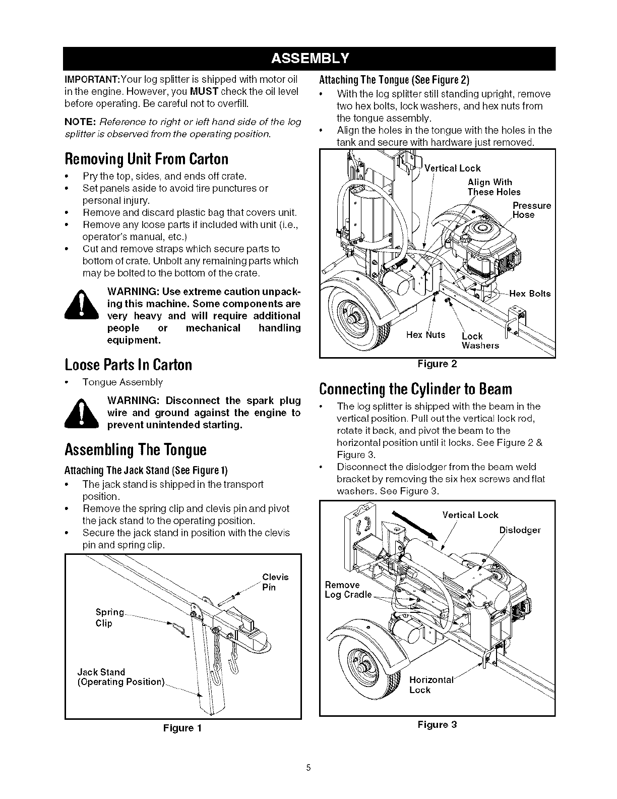
AttachingTheJack Stand (See Figure1)
The jack stand is shipped in the transport
position•
Remove the spring clip and clevis pin and pivot
the jack stand to the operating position•
Secure the jack stand in position with the clevis
pin and spring clip•
_. Clevis
.......... Pin
--._-_.. ---_. _'_
Srin _" '-._
Pg-
Jack Stand _ ' ' '
(Operating Position) i _!
i_ '
Figure 1
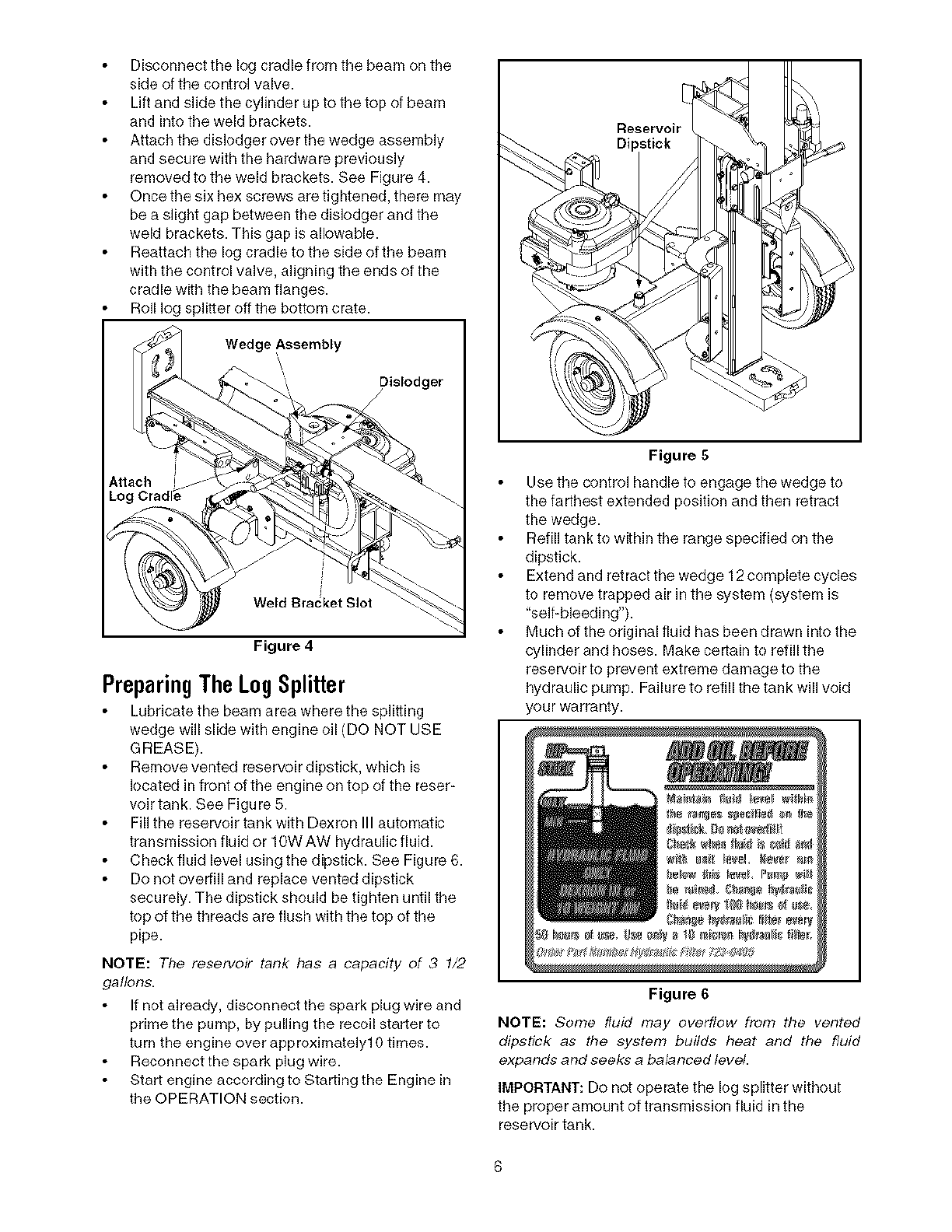
AttachingTheT0ague (SeeFigere2)
With the log splitter still standing upright, remove
two hex bolts, lock washers, and hex nuts from
the tongue assembly.
Align the holes in the tongue with the holes in the
tank and secure with hardware just removed.
Vertical Lock
Align With
These Holes
Pressure
Hose
Hex Nuts Lock
Washers
Figure 2
ConnectingtheCylinderto Beam
The log splitter is shipped with the beam in the
vertical positk)n. Pull out the vertical lock rod,
rotate it back, and pivot the beam to the
horizontal position until it locks• See Figure 2 &
Figure 3.
Disconnect the dislodger from the beam weld
bracket by removing the six hex screws and flat
washers• See Figure 3.
Medical Lock
Dislodger
Figure 3
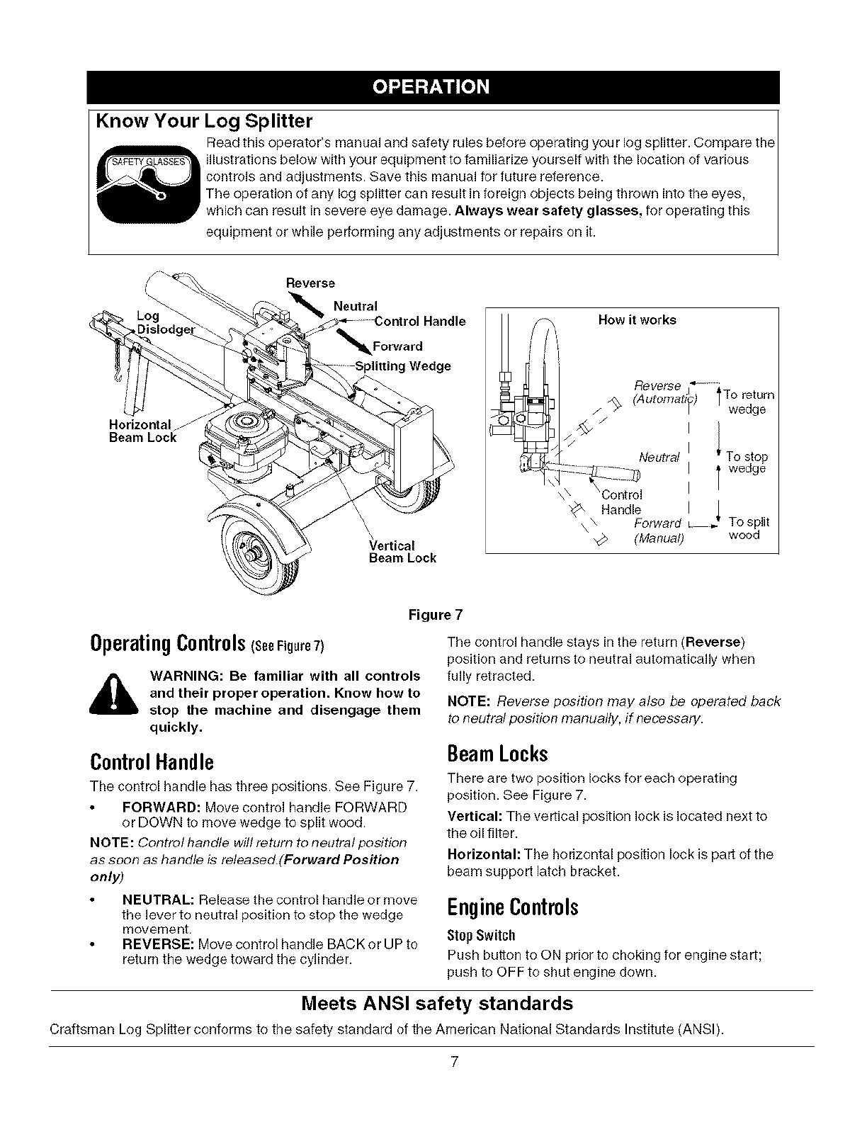
Disconnect the log cradle from the beam on the
side of the control valve.
Lift and slide the cylinder up to the top of beam
and into the weld brackets.
Attach the dislodger over the wedge assembly
and secure with the hardware previously
removed to the weld brackets. See Figure 4.
Once the six hex screws are tightened, there may
be a slight gap between the dislodger and the
weld brackets. This gap is allowable.
Reattach the log cradle to the side of the beam
with the control valve, aligning the ends of the
cradle with the beam flanges.
Roll log splitter off the bottom crate.
Wedge Assembly
Dislodger
Weld Bracket Slot
Figure 4
PreparingTheLog Splitter
Lubricate the beam area where the splitting
wedge will slide with engine oil (DO NOT USE
GREASE).
Remove vented reservoir dipstick, which is
located in front of the engine on top of the reser-
voir tank. See Figure 5.
Fill the reservoir tank with Dexron III automatic
transmission fluid or 10W AW hydraulic fluid.
Check fluid level using the dipstick. See Figure 6.
Do not ovedill and replace vented dipstick
securely. The dipstick should be tighten until the
top of the threads are flush with the top of the
pipe.
NOTE: The reservoir tank has a capacity of 3 1/2
gallons.
If not already, disconnect the spark plug wire and
prime the pump, by pulling the recoil starter to
turn the engine over approximately1 g times.
Reconnect the spark plug wire.
Start engine according to Starting the Engine in
the OPERATION section.
Figure 5
Use the control handle to engage the wedge to
the farthest extended position and then retract
the wedge.
Refill tank to within the range specified on the
dipstick.
Extend and retract the wedge 12 complete cycles
to remove trapped air in the system (system is
"self-bleeding').
Much of the original fluid has been drawn into the
cylinder and hoses. Make certain to refill the
reservoir to prevent extreme damage to the
hydraulic pump. Failure to refill the tank will void
your warranty.
Figure 6
NOTE: Some fluid may overflow from the vented
dipstick as the system builds heat and the fluid
expands and seeks a balanced level.
IMPORTANT: Do not operate the log splitter without
the proper amount of transmission fluid in the
reservoir tank.
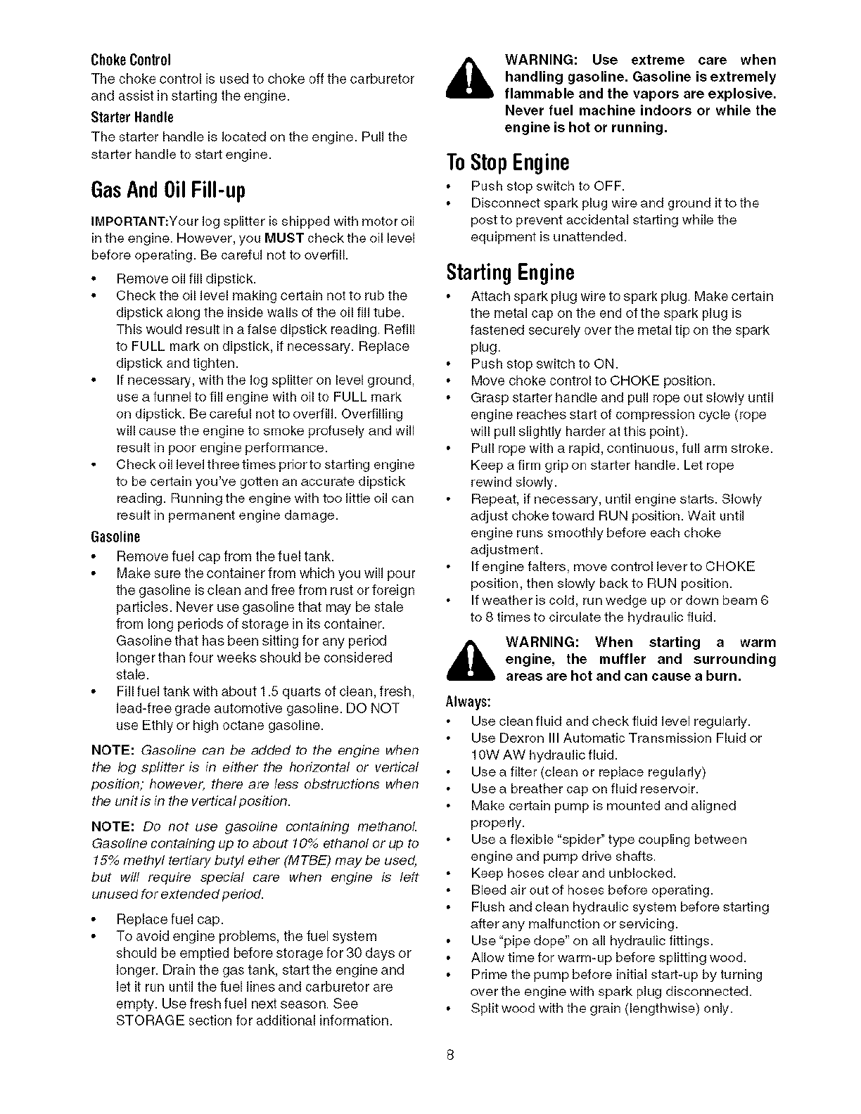
Know Your Log Splitter
Read this operator's manual and safety rules before operating your log splitter. Compare the
illustrations below with your equipment to familiarize yourself with the location of various
controls and adjustments. Save this manual for future reference.
The operation of any log splitter can result in foreign objects being thrown into the eyes,
which can result in severe eye damage. Always wear safety glasses, for operating this
equipment or while performing any adjustments or repairs on it.
,,_.'"_%
Dislodge_
i
J
Horizontal
Beam Lock
Reverse
Neutral
._._-Control Handle
_Forward
_S_ing Wedge
Vertical
Beam Lock
How it works
Reverse
(Automatip) ITo return
/ -4_ / wedge
/
Neutral I
\\ \Control
"_x Handle I J
\Forward _ To split
\wood
Figure 7
OperatingControls(seeFigure7)
,_ WARNING: Be familiar with all controls
and their proper operation. Know how to
stop the machine and disengage them
quickly.
The control handle stays in the return (Reverse)
position and returns to neutral automatically when
fully retracted.
NOTE: Reverse position may also be operated back
to neutral position manually, if necessary.
ControlHandle
The control handle has three positions. See Figure 7.
FORWARD: Move control handle FORWARD
or DOWN to move wedge to split wood.
NOTE: Control handle will return to neutral position
as soon as handle is released.(Forward Position
only)
BeamLocks
There are two position locks for each operating
position. See Figure 7.
Vertical: The vertical position lock is located next to
the oil filter.
Horizontal: The horizontal position lock is pail of the
beam support latch bracket.
NEUTRAL: Release the control handle or move
the lever to neutral position to stop the wedge
movement.
REVERSE: Move control handle BACK or UP to
return the wedge toward the cylinder.
EngineControls
Stop Switch
Push button to ON prior to choking for engine start;
push to OFF to shut engine down.
Meets ANSI safety standards
Craftsman Log Splitter conforms to the safety standard of the American National Standards Institute (ANSI).
7
Choke Control
The choke control is used to choke off the carburetor
and assist in starting the engine.
Starter Handle
The starter handle is located on the engine. Pull the
starter handle to start engine.
GasAnd0il Fill-up
IMPORTANT:Your log splitter is shipped with motor oil
in the engine. However, you MUST check the oil level
before operating. Be careful not to overfill.
Remove oil fill dipstick.
Check the oil level making certain not to rub the
dipstick along the inside walls of the oil tiff tube.
This would result in a false dipstick reading. Refill
to FULL mark on dipstick, if necessary. Replace
dipstick and tighten.
If necessary, with the log splitter on level ground,
use a funnel to fill engine with oil to FULL mark
on dipstick. Be careful not to overfill. Overfilling
will cause the engine to smoke profusely and will
result in poor engine performance.
Check oil level three times prior to starting engine
to be certain you've gotten an accurate dipstick
reading. Running the engine with too little oil can
result in permanent engine damage.
Gasoline
Remove fuel cap from the fuel tank.
Make sure the container from which you will pour
the gasoline is clean and free from rust or foreign
particles. Never use gasoline that may be stale
from long periods of storage in its container.
Gasoline that has been sitting for any period
longer than four weeks should be considered
stale.
Fill fuel tank with about 1.5 quarts of clean, fresh,
lead-free grade automotive gasoline. DO NOT
use Ethly or high octane gasoline.
NOTE: Gasoline can be added to tbe engine when
the log splitter is in eitber the horizontal or vertical
position; however, there are less obstructions when
the unit is in the vertical position.
NOTE: Do not use gasoline containing metbanoL
Gasofine containing up to about 10% ethanol or up to
15% methyl tertiary butyl ether (MTBE) may be used,
but will require special care when engine is left
unused for extended pedod.
Replace fuel cap.
To avoid engine problems, the fuel system
should be emptied before storage for 30 days or
longer. Drain the gas tank, start the engine and
let it run until the fuel lines and carburetor are
empty. Use fresh fuel next season. See
STORAGE section for additional information.
,_ WARNING: Use extreme care when
handling gasoline. Gasoline is extremely
flammable and the vapors are explosive.
Never fuel machine indoors or while the
engine is hot or running.
ToStopEngine
Push stop switch to OFF.
Disconnect spark plug wire and ground it to the
post to prevent accidental starting while the
equipment is unattended.
Starting Engine
Attach spark plug wire to spark plug. Make certain
the metal cap on the end of the spark plug is
fastened securely over the metal tip on the spark
plug.
Push stop switch to ON.
Move choke control to CHOKE position.
Grasp starter handle and pull rope out slowly until
engine reaches start of compression cycle (rope
will pull slightly harder at this point).
Pull rope with a rapid, continuous, full arm stroke.
Keep a firm grip on starter handle. Let rope
rewind slowly.
Repeat, if necessary, until engine starts. Slowly
adjust choke toward RUN position. Wait until
engine runs smoothly before each choke
adjustment.
If engine falters, move control lever to CHOKE
position, then slowly back to RUN position.
If weather is cold, run wedge up or down beam 6
to 8 tknes to circulate the hydraulic fluid.
,_ WARNING: When starting a warm
engine, the muffler and surrounding
areas are hot and can cause a burn.
Always:
Use clean fluid and check fluid level regularly.
Use Dexron III Automatic Transmission Fluid or
10W AW hydraulic fluid.
Use a filter (clean or replace regularly)
Use a breather cap on fluid reservoir.
Make certain pump is mounted and aligned
properly.
Use a flexible "spider" type coupling between
engine and pump drive shafts.
Keep hoses clear and unblocked.
Bleed air out of hoses before operating.
Flush and clean hydraulic system before starting
after any malfunction or servicing.
Use "pipe dope" on all hydraulic fittings.
Allow time for warm-up before splitting wood.
Prime the pump before initial start=up by turning
over the engine with spark plug disconnected.
Split wood with the grain (lengthwise) only.
Nevnr:
Use when fluid is below 20 ° F or above 150 ° F.
Use a solid engine/pump coupling.
Operate through relief valve for more than
several seconds.
Attempt to adjust unloading or relief valve
settings without pressure gauges.
Operate with air in hydraulic system.
Use teflon tape on hydraufic fittings.
Attempt to cut wood across the grain.
Attempt to remove partially split wood from the
wedge with your hands. Fully retract wedge to
dislodge wood with Jogdislodger.
UsingTheLog Splitter
Place the log splitter on level, dry, and solid
ground.
Place the beam in either the horizontal or vertical
position and lock in place with the appropriate
locking rod.
Block the front and back of both wheels.
Place the log against the end plate and only split
wood in the direction of the grain.
When necessary to stabilize the log, place your
hand only on sides of log. NEVER place hand on
the end between the log and splitting wedge.
Only one adult should stabilize the k)g and
operate the control handle, so the operator has
fun control over stabilizing the log and movement
of the splitting wedge.
ControlHandlePositions
Move control handle FORWARD or DOWN to
split wood.
Release the control handle to stop the wedge
movement.
Move control handle BACK or UP to return the
wedge.
Log Oislodger
The log dislodger is designed to remove any
partially split wood from the wedge. This may
occur while splitting large diameter wood or
freshly cut wood.
WARNING: Never remove partially split wood
from the wedge with your hands. Fingers may
become trapped between split wood.
To remove partially split wood from wedge, move
control handle to REVERSE position until wedge
is fully retracted to allow split wood portion to
contact the log dislodger.
Once removed from wedge with log dislodger,
split wood from opposite end or in another
k)cation.
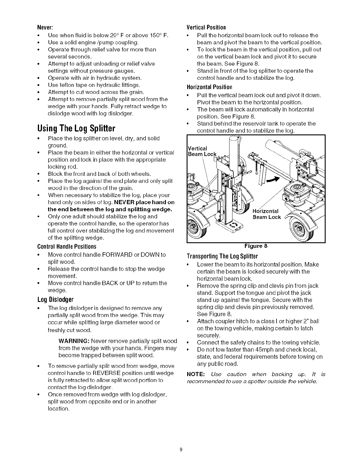
Vertical Position
Pull the horizontal beam lock out to release the
beam and pivot the beam to the vertical position.
To lock the beam in the vertical position, pull out
on the vertical beam lock and pivot it to secure
the beam. See Figure 8.
Stand in front of the log splitter to operate the
control handle and to stabilize the log.
Horizootnl Position
Pull the vertical beam lock out and pivot it down.
Pivot the beam to the horizontal position.
The beam win lock automaticaNy in horizontal
position. See Figure 8.
Stand behind the reservoir tank to operate the
control handle and to stabilize the Jog.
_/ertical
Beam Lock
Beam Lock
Figure 8
TransportingThe Log Splitter
Lower the beam to its horizontal position. Make
certain the beam is locked securely with the
horizontal beam lock.
Remove the spring clip and clevis pin from jack
stand. Support the tongue and pivot the jack
stand up against the tongue. Secure with the
spring clip and clevis pin previously removed.
See Figure 8.
Attach coupler hitch to a class I or higher 2" ball
on the towing vehicle, making certain to latch
securely.
Connect the safety chains to the towing vehicle.
Do not tow faster than 45mph and check local,
state, and federal requirements before towing on
any public road.
NOTE: Use caution when backing up. It is
recommended to use a spotter outside tbe vehicle.
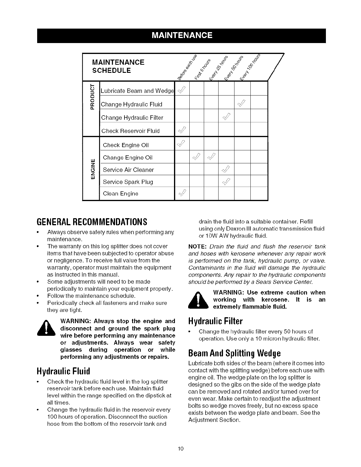
MAINTENANCE
SCHEDULE "_
_ _ubdcate Beam and Wedg_
_ Change Hydraulic Fluid
Change Hydraulic Filter
Check Reservoir Fluid
Check Engine Oil
Lu Change Engine Oil
ZService Air Cleaner
Z
uJ Service Spark Plug
Clean Engine
GENERALREC0MMENDATIONS
Always observe safety rules when performing any
maintenance.
The warranty on this log splitter does not cover
items that have been subjected to operator abuse
or negligence. To receive full value from the
warranty, operator must maintain the equipment
as instructed in this manual.
Some adjustments will need to be made
periodically to maintain your equipment properly.
Follow the maintenance schedule.
Periodically check all fasteners and make sure
they are tight.
WARNING: Always stop the engine and
disconnect and ground the spark plug
wire before performing any maintenance
or adjustments. Always wear safety
glasses during operation or while
performing any adjustments or repairs.
HydraulicFluid
Check the hydraulic fluid level in the log splitter
reservoir tank before each use. Maintain fluid
level within the range specified on the dipstick at
all times.
Change the hydraulic fluid in the reservoir every
100 hours of operation. Disconnect the suction
hose from the bottom of the reservoir tank and
drain the fluid into a suitable container. Refill
using only Dexron III automatic transmission fluid
or 10W AW hydraulic fluid.
NOTE: Drain the fluid and flush the reservoir tank
and hoses with kerosene whenever any repair work
is performed on the tank, hydraulic pump, or valve.
Contaminants in the fluid will damage the hydraulic
components. Any repair to the hydraulic components
should be performed by a Sears Service Center.
_lb WARNING: Use extreme caution when
working with kerosene. It is an
extremely flammable fluid.
HydraulicFilter
Change the hydraulic filter every 50 hours of
operation. Use only a 10 micron hydraulic filter.
BeamAndSplittingWedge
Lubricate both sides of the beam (where it comes into
contact with the splitting wedge) before each use with
engine oil. The wedge plate on the log splitter is
designed so the gibs on the side of the wedge plate
can be removed and rotated and/or turned over for
even wear. Make certain to readjust the adjustment
bolts so wedge moves freely, but no excess space
exists between the wedge plate and beam. See the
Adjustment Section.
lO
EngineMaintenance
CheckEngineOil
Stop engine and wait several minutes before
checking oil level.
Remove oil fill dipstick.
Check oil level on dipstick. With engine on level
ground, the oil must be to FULL mark on dipstick.
Replace dipstick and tighten.
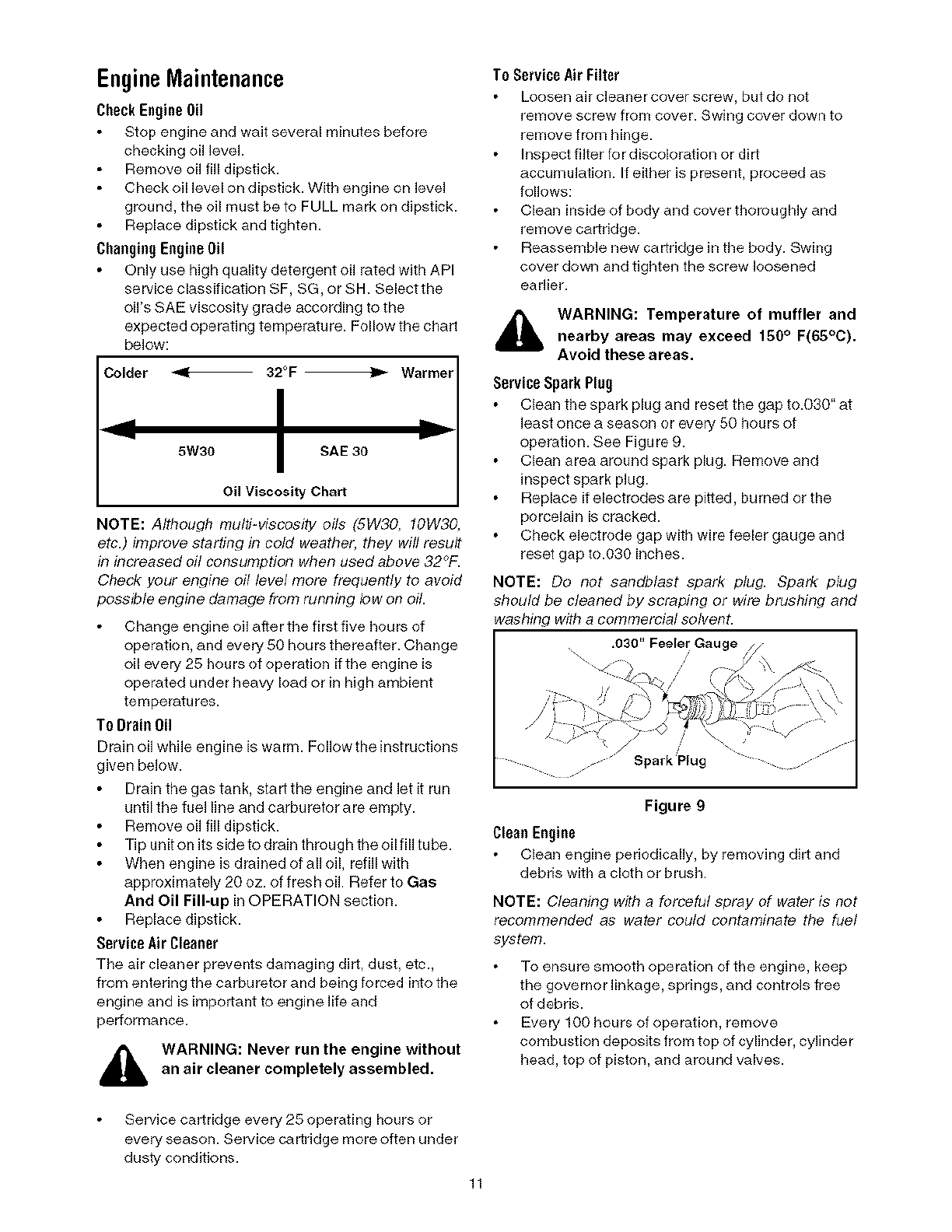
ChaegiagEegiaeOil
Only use high quality detergent oil rated with API
service classification SF, SG, or SH. Select the
oil's SAE viscosity grade according to the
expected operating temperature. Follow the chart
below:
Colder < 32°F -)_ Warmer
5W30 ISAE 30
Oil Viscosity Chart
NOTE: Afihough multi-viscosity oils (SW30, 10W30,
etc.) improve starting in cold weather, they wiff resuff
in increased oil consumption when used above 32_'F.
Check your engine oil level more frequently to avoid
possible engine damage from running low on oil.
Change engine oil after the first five hours of
operation, and every 50 hours thereafter. Change
oil every 25 hours of operatk)n if the engine is
operated under heavy load or in high ambient
temperatures.
To Draie Oil
Drain oil while engine is warm. Follow the instructions
given bek)w.
Drain the gas tank, start the engine and let it run
until the fuel line and carburetor are empty.
Remove oil fill dipstick.
Tip unit on its side to drain through the oil fill tube.
When engine is drained of all oil, refill with
approximately 20 oz. of fresh oil Refer to Gas
And Oil Fill-up in OPERATION section.
Replace dipstick.
Service Air Cleaner
The air cleaner prevents damaging dirt, dust, etc.,
from entering the carburetor and being forced into the
engine and is important to engine life and
performance.
WARNING: Never run the engine without
an air cleaner completely assembled.
To ServiceAir Filter
Loosen air cleaner cover screw, but do not
remove screw from cover. Swing cover down to
remove from hinge.
Inspect filter for discoloration or dirt
accumulation. If either is present, proceed as
follows:
Clean inside of body and cover thoroughly and
remove cartridge.
Reassemble new cartridge in the body. Swing
cover down and tighten the screw loosened
earlier.
WARNING: Temperature of muffler andnearby areas may exceed 150° F(65°C).
Avoid these areas.
ServiceSparkPlug
Clean the spark plug and reset the gap to.030" at
least once a season or every 50 hours of
operation. See Figure 9.
Clean area around spark plug. Remove and
inspect spark plug.
Replace if electrodes are pitted, burned or the
porcelain is cracked.
Check electrode gap with wire feeler gauge and
reset gap to.030 inches.
NOTE: Do not sandblast spark plug. Spark plug
should be cleaned by scraping or wire brushing and
washing with a commercial sohvent.
,030" Feeler Gauge
.... . . "SparkPlug "
Figure 9
Clean Engine
Clean engine periodically, by removing dirt and
debdswgh a cloth or brush.
NOTE: Cleaning with a forceful spray of water is not
recommended as water could contaminate the fuel
system.
To ensure smooth operation of the engine, keep
the governor linkage, springs, and controls free
of debris.
Every 100 hours of operation, remove
combustion deposits from top of cylinder, cylinder
head, top of piston, and around valves.
Service cartridge every 25 operating hours or
every season. Service cartridge more often under
dusty conditions.
11
WARNING: Do not at any time make any
adjustments without first stopping
engine, disconnecting spark plug wire,
and grounding it against the engine.
Always wear safety glasses during
operation or while performing any
adjustments or repairs.
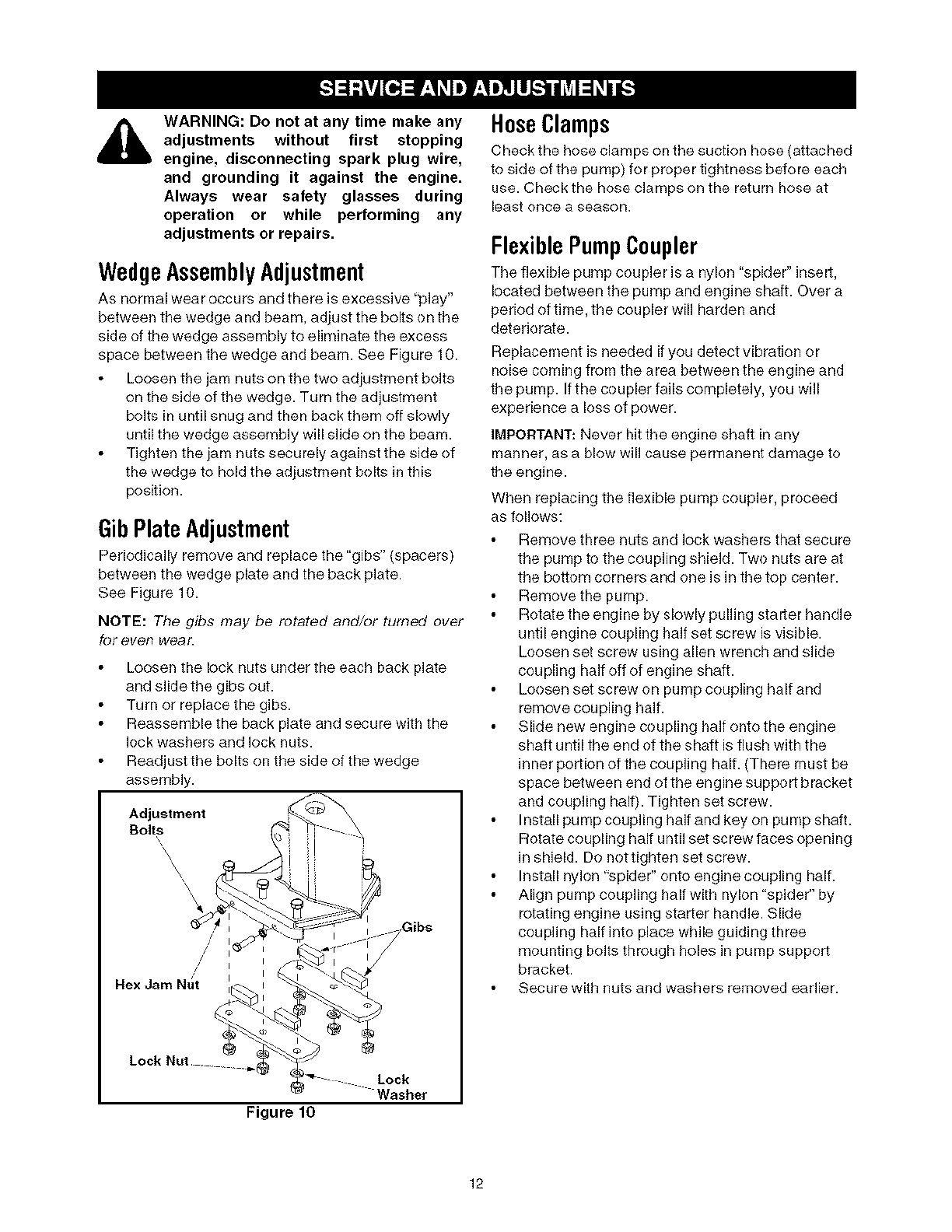
WedgeAssemblyAdjustment
AS normal wear occurs and there is excessive _'play"
between the wedge and beam, adjust the bolts on the
side of the wedge assembly to eliminate the excess
space between the wedge and beam. See Figure 10.
Loosen the jam nuts on the two adjustment bolts
on the side of the wedge. Turn the adjustment
bolts in until snug and then back them off slowly
until the wedge assembly will slide on the beam.
Tighten the jam nuts securely against the side of
the wedge to hold the adjustment bolts in this
position.
GibPlateAdjustment
Periodically remove and replace the "gibs" (spacers)
between the wedge plate and the back plate.
See Figure 10.
NOTE: The gibs may be rotated and/or turned over
for ever wear.
Loosen the lock nuts under the each back plate
and slide the gibs out.
Turn or replace the gibs.
Reassemble the back plate and secure with the
lock washers and lock nuts.
Readjust the bolts on the side of the wedge
assembly.
Adjustment
Bolts\\ i
\\
\
I
/i
/// i
/II
Nex Jam Ntlt I
Lock
Washer
Figure 10
HoseClamps
Check the hose clamps on the suction hose (attached
to side of the pump) for proper tightness before each
use. Check the hose clamps on the return hose at
least once a season.
FlexiblePumpCoupler
The flexible pump coupler is a nylon "spider" insert,
located between the pump and engine shaft. Over a
period of time, the coupler will harden and
deteriorate.
Replacement is needed if you detect vibration or
noise coming from the area between the engine and
the pump. If the coupler fails completely, you will
experience a loss of power.
IMPORTANT: Never hit the engine shaft in any
manner, as a blow will cause pemlanent damage to
the engine.
When replacing the flexible pump coupler, proceed
as follows:
Remove three nuts and lock washers that secure
the pump to the coupling shield. Two nuts are at
the bottom corners and one is in the top center.
Remove the pump.
Rotate the engine by slowly pulling starter handle
until engine coupling half set screw is visible.
Loosen set screw using allen wrench and slide
coupling half off of engine shaft.
Loosen set screw on pump coupling half and
remove coupling half.
Slide new engine coupling half onto the engine
shaft until the end of the shaft is flush with the
inner portion of the coupling half. (There must be
space between end of the engine support bracket
and coupling half). Tighten set screw.
Install pump coupling half and key on pump shaft.
Rotate coupling half until set screw faces opening
in shield. Do not tighten set screw.
Install nylon "spider" onto engine coupNng half.
Align pump coupling half with nylon "spider" by
rotating engine using starter handle. Slide
coupNng half into place while guiding three
mounting bolts through holes in pump support
bracket.
Secure with nuts and washers removed earlier.
12
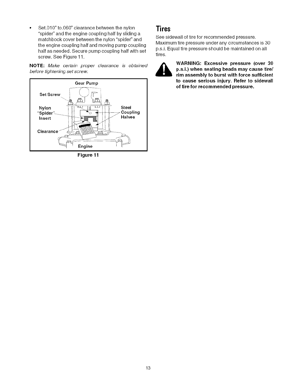
Set.010"to.060"clearancebetweenthenylon
"spider"andtheenginecouplinghalfbyslidinga
matchbookcoverbetweenthenylon"spider"and
theenginecouplinghalfandmovingpumpcoupling
halfasneeded.Securepumpcouplinghalfwithset
screw.SeeFigure11.
NOTE: Make certain proper clearance is obtained
before tighteningsetscrew.
Gear Pump
Tires
See sidewall of tire for recommended pressu re.
Maximum tire pressure under any circumstances is 30
p.s.i. Equal tire pressure should be maintained on all
tires.
,_ WARNING: Excessive pressure (over 30
p.s.i.) when seating beads may cause tire/
rim assembly to burst with force sufficient
to cause serious injury. Refer to sidewall
of tire for recommended pressure.
Figure 11
13
Prepare your log splitter for storage at the end of the
season or if the log splitter will not be used for 30 days
or more.
WARNING: Never store machine with fuel
in the fuel tank inside of building where
fumes may reach an open flame or spark
or where ignition sources are present
such as hot water and space heaters,
furnaces, clothes dyers, stoves, electric
motors, etc.
NOTE: Yearly check-up by your local Sears service
center is a good way to ensure your log spfitter will
provide maxJfT_um performance next season.
Log Splitter
Clean the log splitter thoroughly.
Wipe unit with an oiled rag to prevent rust,
especially on the wedge and the beam.
Engine
IMPORTANT: It is important to prevent gum deposits
from forming in essential fuel system parts such as
carburetor, fuel filter, fuel hose, or tank du ring
storage. Also, alcohol blended fuels (called gasohol or
using ethanol or methanol) can attract moisture which
leads to separation and formation of acids during
storage. Acidic gas can damage the fuel system of an
engine while in storage.
Drain the fuel tank. Always drain fuel into
approved container outdoors away from open
flame. Be sure the engine is cool. Do not smoke
while handling the fuel.
Start the engine and let it run until the fuel lines
and carburetor are empty.
Never use engine or carburetor cleaner products
in the fuel tank or permanent damage may
occur. Use fresh fuel next season.
Remove spark plug, pour approximately 1/2 oz.
of engine oil into cylinder and crank slowly to
distribute oil.
Replace spark plug.
NOTE: Fuel stabilizer is an acceptable alternative in
minimizing for formation of fuel gum deposits during
storage.
Please follow the instructions below for storing your
log splitter with fuel and stabilizer in the engine.
Add stabilizer to gasoline in fuel tank or storage
container.
Always follow the mix ratio found on stabilizer
container.
Run engine at least 10 minutes after adding
stabilizer to allow the stabilizer to reach the
carburetor.
Do not drain the gas tank and carburetor if using
fuel stabilizer. Drain all the oil from the
crankcase (this should be done after the engine
has been operated and is still warm) and refill the
crankcase with fresh oil.
Other
Do not store gasoline from one season to
another.
Replace your gasoline can if it starts to rust.
Store unit in a clean, dry area. Do not store next
to corrosive materials, such as fertilizer.
Wipe equipment with an oiled rag to prevent rust.
14

Problem Possible Cause Corrective Action
Cylinder rod will not move 1. Broken drive shaft.
2. Shipping plugs left in hydraulic
hoses.
3. Set screws incoupling not adjusted
properly.
4. Loose shaft coupling.
5. Gear sections damaged.
6. Damaged relief valve.
7. Hydraulic lines blocked.
8. Incorrect oi]leveL
9. Damaged or blocked directional
valve.
Cylinder shaft speed slow while
extending and retracting
Engine runs but wood will not split, or
splits too slowly
1. Gear sections damaged.
2. Excessive pump inlet vacuum.
3. Slow engine speed.
4. Damaged relief valve.
5. Incorrect oil level.
6. Contaminated oil.
7. Directional valve leaking internally.
8. Intarnally damaged cylinder.
1. Smallgear section damaged.
2. Pump check valve leaking.
3. Excessive vacuum in pump inlet.
4. Incorrect oi]level.
5. Contaminated oil.
6. Directional valve leaking internally.
7. Internally damaged cylinder.
8. Overloaded cylinder.
Engine stalls during splitting wood 1. Low horsepower/weak engine.
2. Overloaded cylinder
Engine will not turn or stalls under low 1. Engine/pump misaligned.
load 2. Frozen or seized pump.
3. Weak engine.
4. Hydraulic lines blocked.
5. Blocked directional valve.
Leaking pump shaft seal 1. Broken drive shaft.
2. Engine/pump misaligned.
3. Gear sections damaged.
4. Poorly positioned shaft seal.
5. Oil breather plugged.
1. Return unit to Sears service center.
2. Disconnect hydraulic hose, remove
shipping plugs, and reconnect hose.
3. Refer to adiustment section of this
manual and adiust the couplers.
4. Correct engine/pumpalignment.
5. Return unit to Sears service center.
6. Return unit to Sears service center.
7. Flush and clean hydraulic system.
8. Check oil level. Refill if necessary.
9. Return unit to Sears service center.
1. Return unit to Sears service center.
2. Make certain that the pump inlet
hoses are clear and unb]ocked. Use
short, large diameter inlet hoses.
3. Return unit to Sears service center.
4. Return unit to Sears service center.
5. Check oil level. Refill if necessary.
6. Drain oil, clean reservoir, and refill.
7. Return unit to Sears service center.
8. Return unit to Sears service center.
1. Return unit to Sears service center.
2. Return unit to Sears service center.
3. Make certain that the pump inlet
hoses are clear and unb]ocked. Use
short, large diameter inlet hoses.
4. Check oil level. Refill if necessary.
5. Drain oil, clean reservoir, refill, make
certain oil return tube is below oil
level.
6. Return unit to Sears service center.
7. Return unit to Sears service center.
8. Do not attempt to split wood against
the grain.
1. Return unit to Sears service center.
2. Do not attempt to split wood against
the grain. If engine stalls repeatedly,
contact Sears service center.
1. Correct alignment.
2. Return unit to Sears service center.
3. Return unit to Sears service center.
4. Flush and clean hydraulic system.
5. Return unit to Sears service center
1. Return unit to Sears service center.
2. Correct alignment.
3. Return unit to Sears service center.
4. Return unit to Sears service center.
5. Make certain reservoir is properly
vented.
15
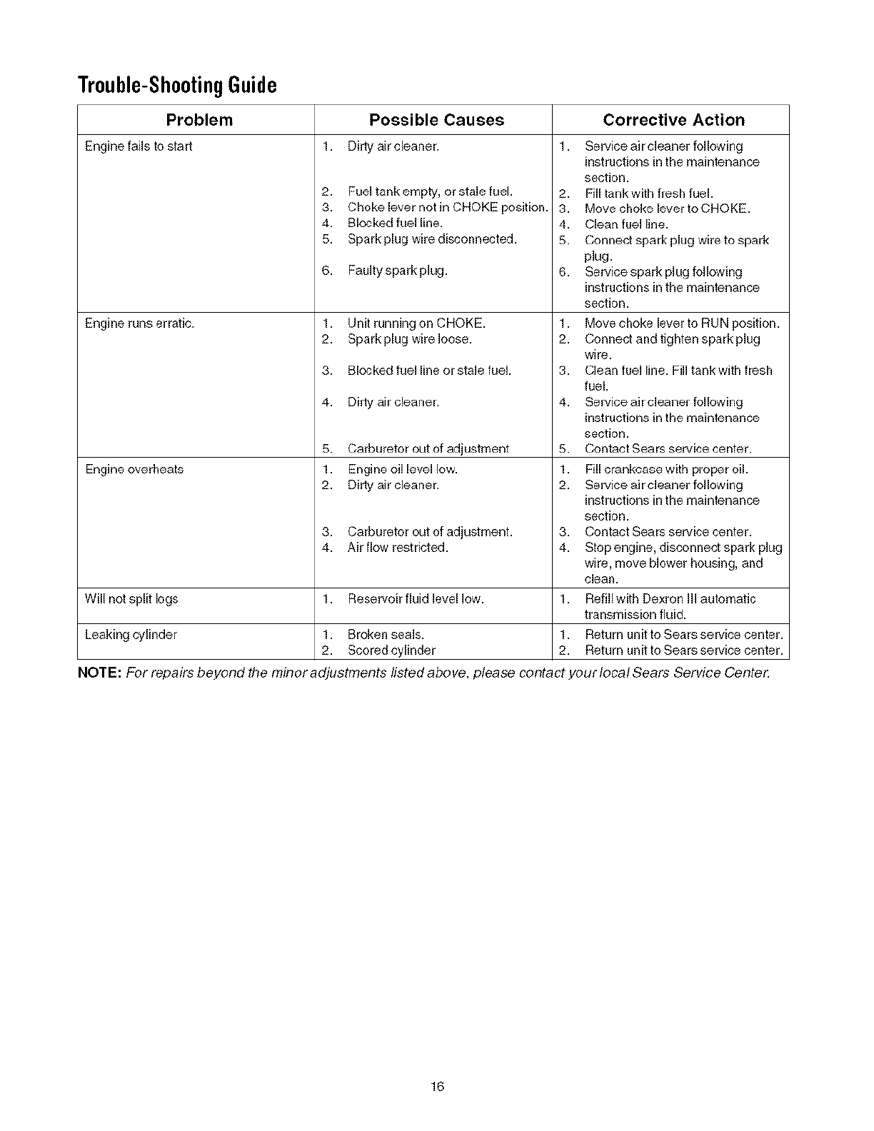
Trouble-ShootingGuide
Problem Possible Causes
Engine fails to start 1. Dirty air cleaner.
2. Fuel tank empty, or stale fuel
3. Choke lever not in CHOKE position.
4. Blocked fuel line.
5. Spark plug wire disconnected.
6. Faulty spark plug.
Engine runs erratic. 1. Unit running on CHOKE.
2. Spark plug wire loose.
3. Blocked fuel line or stale fuel.
4. Dirty air cleaner.
5. Carburetor out of adjustment
Engine overheats 1. Engine oil level low.
2. Dirty air cleaner.
3. Carburetor out of adjustment.
4. Air flow restricted.
Will not split logs 1. Reservoir fluid levellow.
Corrective Action
1. Service air cleaner following
instructionsin the maintenance
section.
2. Fill tank with fresh fuel.
3. Move choke lever to CHOKE.
4. Clean fuel line.
5. Connect spark plug wire to spark
plug.
6. Service spark plug following
instructionsin the maintenance
section.
1. Move choke lever to RUN position.
2. Connect and tighten spark plug
wire.
3. Clean fuel line. Fill tank with fresh
fuel.
4. Service air cleaner following
instructionsin the maintenance
section.
5. Contact Sears service center.
1. Fill crankcase with proper oil.
2. Service air cleaner following
instructions in the maintenance
section.
3. Contact Sears service center.
4. Stop engine, disconnect spark plug
wire, move blower housing, and
cleal_.
1. Refillwith Dexron III automatic
transmission fluid.
Leaking cylinder 1. Broken seals. 1. Return unit to Sears service center.
2. Scored cylinder 2. Return unit to Sears service center.
NOTE: For repairs beyond the minor adjustments listed above, please contact your locat Sears Service Cente_
16
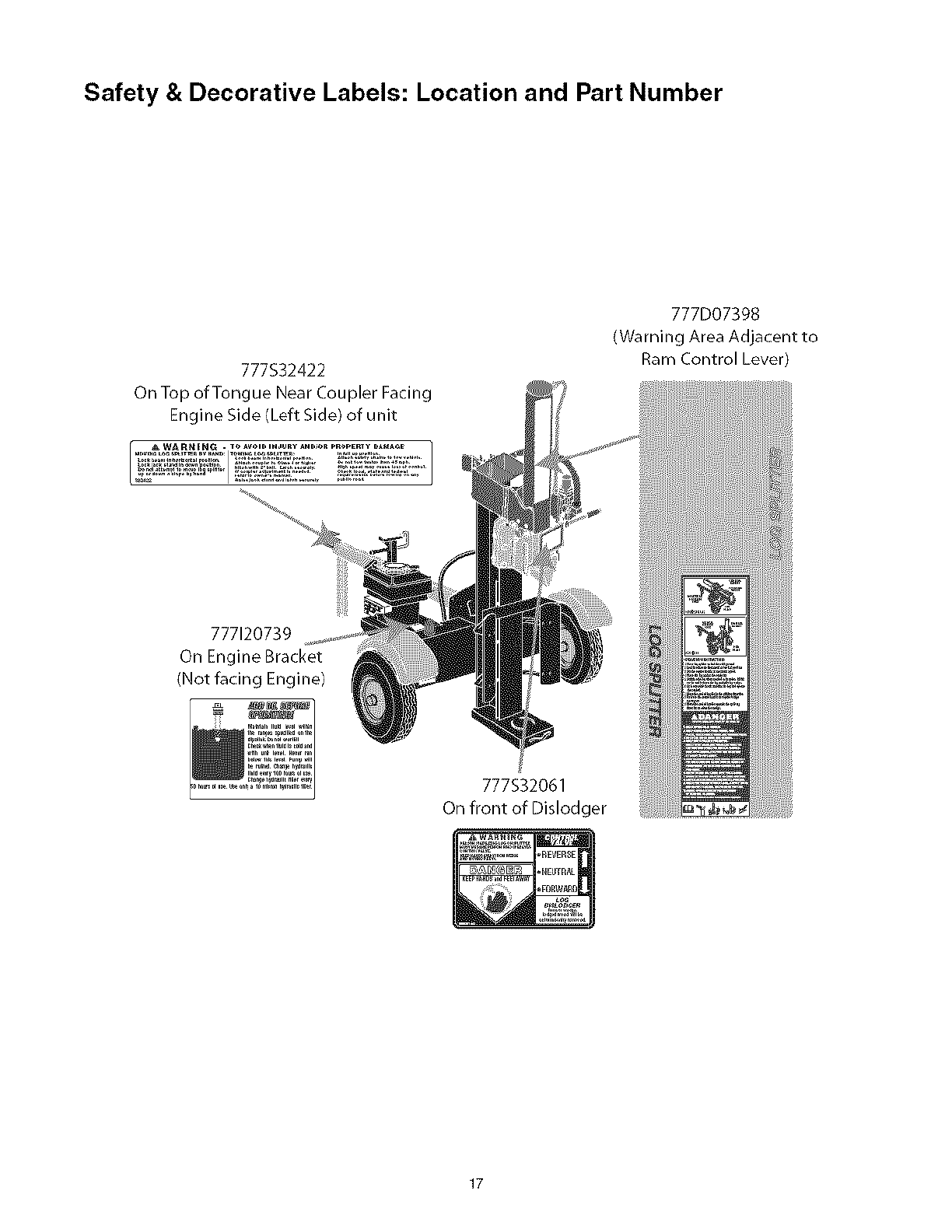
Safety & Decorative Labels: Location and Part Number
777S32422
On Top of Tongue Near Coupler Facing
Engine Side (Left Side) of unit
777D07398
(Warning Area Adjacent to
Ram Control Lever)
777120739
On Engine Bracket
{Not facing Engine)
777S32061
On front of Dislodger
17
82
I
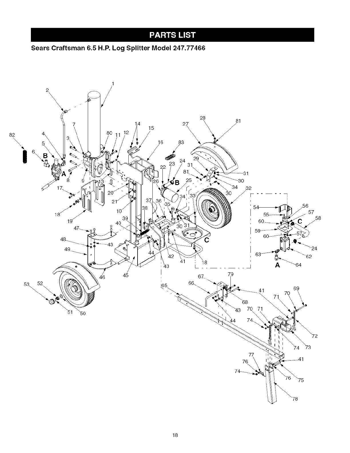
Sears Craftsman 6.5 H.P. Log Splitter Model 247.77466
2\\\\\
1
/
/
!1 _2 15
16 83
81
53 52
ld
47
48
49
/
/
45
41
I
: 18
79
66.
32
i
41 69
71
_56
57
/58
62
5O
74 _73
77
76
74
75
18

Sears Craftsman 6.5 H.P. Log Splitter Model 247.77466
Re/.
No.
1.
2.
3.
4.
5.
6.
7.
8.
9.
18.
11.
12.
13.
14.
15.
16.
17.
18.
19.
20.
21.
22.
23.
24.
25.
26.
27.
28.
29.
30.
31.
32.
33.
34.
35.
36.
37.
38.
39.
40.
41.
Part No.
718-0769
727-0634
710-1018
737-0192
718-0481
737-0153
737-0238
710-1806
719-0550
712-0239
712-0711
710-0459A
781-0351
710-1260A
781-1054
681-0162
736-0300
710-0654A
781-1048
781-0790
736-0921
737-0312
727-0443
726-0132
723-0405
737-0316
731-2496
710-1238
781-1024
712-3010
736-0119
634-0186
710-1338
710-3038
737-0348A
781-0690
711-1587
714-0470
732-0583
726-0214
710-0521
Re/.
Part Description No.
Hydraulic Cylinder 42.
Hydraulic Tube 43.
Hex Cap Screw 1/2-20 x 2.75 44.
90 Degree Solid Adapter 45.
Control Valve 46.
Return Elbow 47.
Nipple Pipe 1/2-14 48.
Hex Cap Screw 1/2-13 x 3.25 49.
Wedge Assembly 50.
Lock Nut 1/2-20 51.
Hex Jam Nut 3/8-24 52.
Hex Cap Screw 3/8-24 x 1.5 53.
Adjustable Gib 54.
Hex Washer Screw 5/16-18 x.75 55.
Cylinder Support Bracket 58.
Beam Assembly 57.
Flat Washer.406 ID x.875 QD 58.
Hex Washer Screw 3/8-16 x 1.0 59.
Dislodger 60.
Back Plate 62.
Lock Washer 1/2 63.
Adapter 3/4-14 64.
Return Hose 3/4" ID x 44" Lg. 65.
Hose Clamp 5/8" 66.
Oil Filter 67.
Filter Housing 68.
Black Fender 69.
Hex Washer Screw 5/16-18 x.875 70.
Fender Mounting Bracket 71.
Hex Nut 5/16-18 72.
Lock Washer 5/16 73.
Wheel Assembly 74.
Hex Screw 5/16-24 x 3.25 75.
Hex Cap Screw 5/16-18 x.875 76.
Vented Dipstick 77.
Lock Rod 78.
Clevis Pin 79.
Cotter Pin 80.
Compression Spring 81.
Push Cap 82.
Hex Bolt 3/8-16 x 3" 83.
Part No.
736-0116
736-0169
712-0798
681-0161
781-0686
710-3097
712-0798
781-0682
736-0351
714-0162
712-0359
734-0873
719-0353
714-0122
718-0686
712-0123
727-0638
781-0097
736-0119
718-0683
737-0329
727-0502
781-0788
747-1261
781-1045
732-3127
710-0944
736-0262
750-0497
713-0433
681-04030
712-0375
711-0813
736-0185
732-0194
781-0789
715-0120
712-3022
736-0371
781-0538
781-0526
Part Description
Flat Washer.635 ID x.93 OD
L-Washer 3/8"
Hex Nut 3/8-16
Frame Assembly
Log Tray Bracket
Carriage Bolt 3/8-16 x 1.o
Lock Nut 3/8-16
Log Tray
Flat Washer.760 ID x.50o OD
Cotter Pin
Slotted Nut 3/4-16
Hub Cap
Coupling Shield
Square Key 3/16" x.75
Flexible Coupling
Hex Nut 5/16-24
Hose
Rear Coupling Support Bracket
Lock Washer 5/16" ID
Gear Pump (1 lgpm)
45 Degree Elbow
High Pressure Hydraulic Hose
Tube Assembly
Latch Rod
Latch
Compression Spring
Hex Cap Screw 3/8-16 x 4.25
Flat Washer.385 ID x.870 QD
Spacer.375 ID x.625 OD
Chain
Hitch Coupling
Hex Lock Nut 3/8-16
Clevis Pin
Flat Washer.375 ID x.738 QD
Spring Pin
Jack Stand
Spiral Pin
Hex Lock Nut 1/2-13
Flat Washer.343 x.880 x.062
Hose Guard
Hose Guard
19
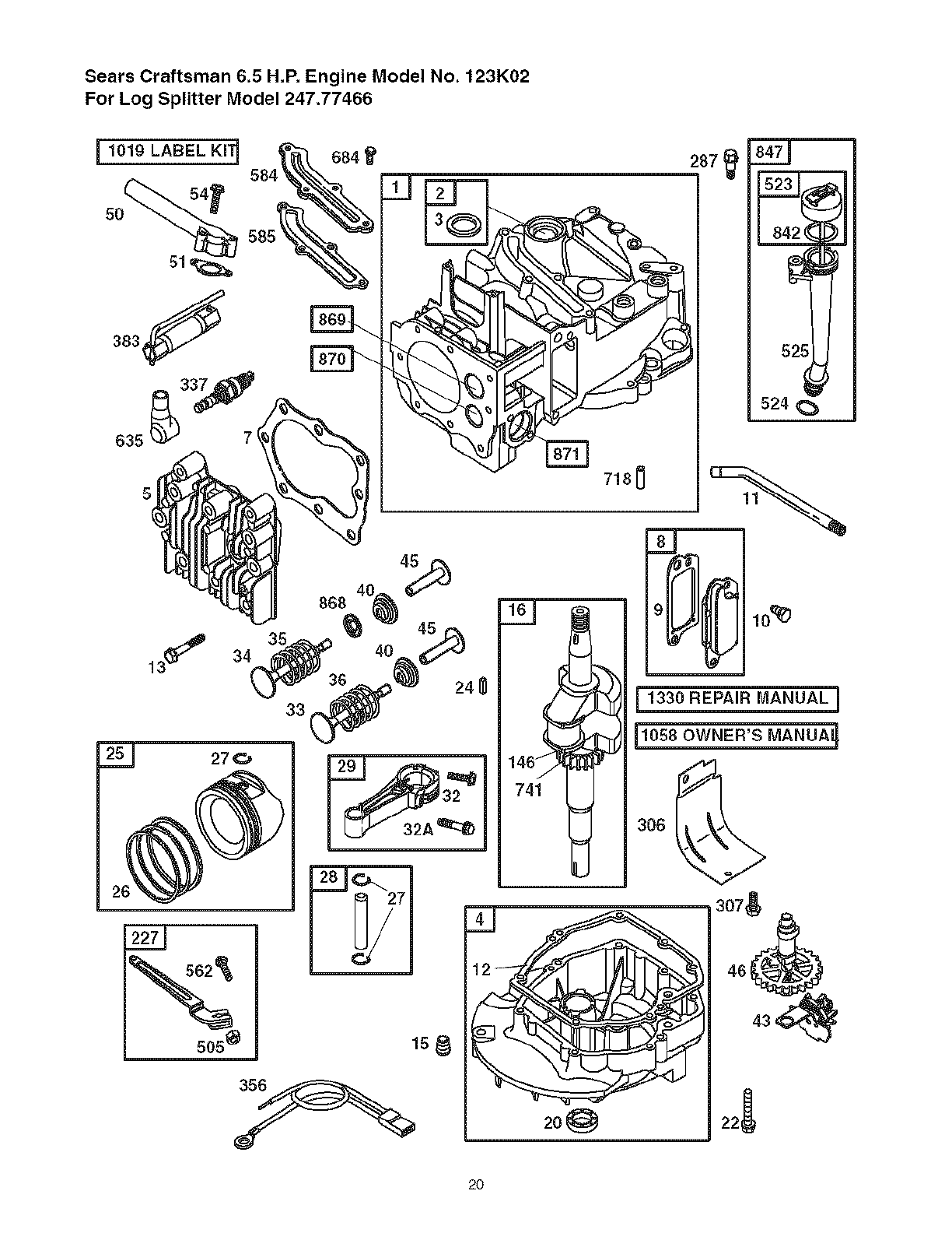
Sears Craftsman 6.5 H,P, Engine Model No. 123K02
For Log Splitter Model 247.77466
[I019 LABEL KIT] G84
ts@
25_
-!
542,====_(
525
524 C
i 1330 REPAIR MANUALJ
{to50OWNER'SMANUA_
306
2O
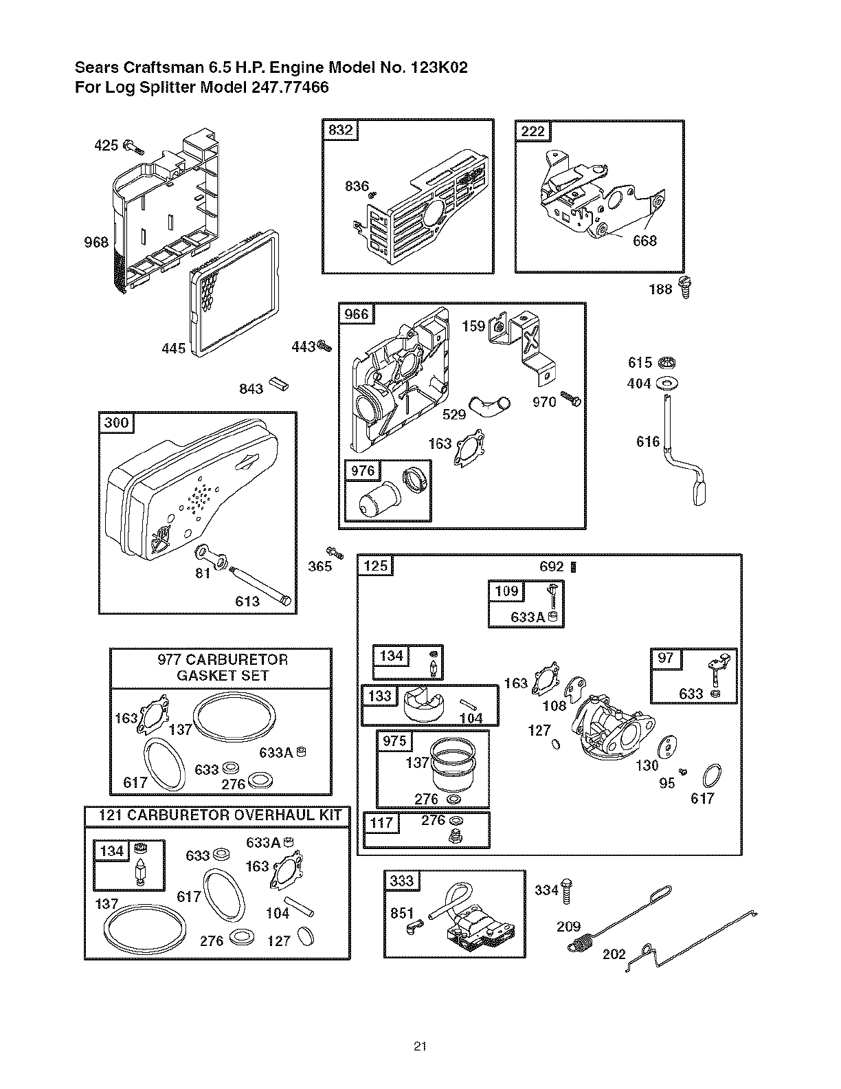
Sears Craftsman 6.5 H,P, Engine Model No. 123K02
For Log Splitter Model 247.77466
968
445
843
443_
/- 163_
188
615
404 @
616_
977 CARBURETOR
GASKET SET
7_ 633A
633 @
61 276@
121 CARBURETOR OVERHAUL KIT
633A8
633 G
lo4%_
276@ 127
692 |
104
276
,27
130 _ 0
95 617
333 334_ .,_
21
Sears Craftsman 6.5 H,P, Engine Model No. 123K02
For Log Splitter Model 247.77466
358 ENGINE GASKET SET
3_ 20_ 842_ s24_ /_. 6680
585
5
i,329 REPLACEMENT ENGINE I627 _ 939
347
23
1005
66
592_ 58_
689 _'_
456
597
22

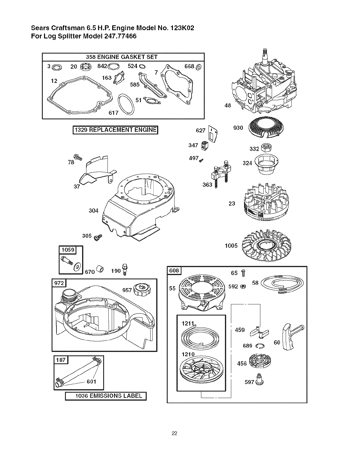
Sears Craftsman 6.5 H,P, Engine Model No. 123K02
For Log Splitter Model 247.77466
Ref.
No.
1.
2.
3.
4.
5.
7.
8.
9.
19.
11.
12.
13.
15.
16.
20.
22.
23.
24.
25.
26.
27.
26.
29.
32.
32A.
33.
34.
35.
36.
37.
40.
43.
45.
46.
48.
50.
51.
54.
55.
56.
60.
65.
78.
81.
95.
97.
104.
108.
109.
117.
121.
125.
127.
130.
Part No.
697322
399269
299819t
493279
691160
692249t
695250
699472
591125
691260
592232_
690912
591680
691455
399781t
691092
591992
222698
597339
697341
499425
499427
691866
499423
499424
591664
695759
262651
262652
591270
591270
594086
592194
691997
590548
691449
498828
497465
272199t
691650
591421
697316
281434
690837
691108
691740
691636
493267
691242tt
591182
498593
498978
498260
499059
594468€1
691203
Ref.
Part Description No.
Cylinder Assembly 133.
Kit-Bushing/Seal 194.
Seal-Oil (Magneto Side) 197.
Sump-Engine 146.
Head-Cylinder 159.
Gasket-CyJinder Head 163.
Breather Assembly 187.
Gasket-Breather 188.
Screw (Breather Assembly) 190.
Tube-Breather 202.
Gasket-Crankcase 209.
Screw (Cylinder Head) 222.
Plug-Oil Drain 227.
Crankshaft 276.
Seal-Oil (PTO Side) 287.
Screw (Engine Sump) 300.
Flywheel 304.
Key-Flywheel 305.
Piston Assembly (Standard) 306.
Piston Assembly (.020" Oversize) 307.
Ring Set-Piston (Standard) 324.
Ring Set-Piston (.020" Oversize) 392.
Lock-Piston Pin 393.
Pin-Piston 334.
Rod-Connecting 337.
Screw (Connecting Rod) 347.
Screw (Connecting Rod) 356.
Valve-Exhaust 358.
Valve-intake 363.
Spring-Valve (Intake) 365.
SpringWalve (Exhaust) 383.
Guard-Flywheel 404.
Retainer-Valve 425.
Stinger-Governor/Oil 443.
TappeEValve 445.
Camshaft 456.
Short Block 459.
Manifold-Intake 497.
Gasket-Intake 505.
Screw (Intake Manifold) 523.
Housing-Rewind Starter 524.
Rope-Starter (Cut to Required 525.
Length) 529.
Gdp-Startar Rope 562.
Screw (Rewind Starter) 584.
Screw (Flywheel Guard) 585.
Lock-Muffler Screw 592.
Screw (Throttle Valve) 597.
Shaft-Throttle 601.
Pin-Float Hinge 608.
Valve-Choke 613.
Shaft-Choke 615.
Jet-Main (Standard) 616.
Kit-Carburetor Overhaul 617.
Carburetor 627.
Plug-Welch 633.
Valve-Throttle 633A.
Part No.
398187
398188tf
593981tt*
690979
691753
272653t*tf
691050
693399
690940
691829
691864
692982
690783
271715_t*
690940
692038
493294
691108
690450
690345
695161
690662
802574
691061
802592
691396
693010
497316
19069
692524
89838
690272
690670
692529
491588
692299
281505
690664
691251
495264
692296_
495265
691923
92613
697734
691879t
690800
691696
95162
497680
691340
690340
698801
270344t*tf
692872
691321tt*
593867tt*
Part Description
Float-Carburetor
Valve-Needle/Seat
Gasket-Float Bowl
Key-Timing
Bracket-Air Cleaner Primer
Gasket-Air Cleaner
Line-Fuel (Cut to Required Length)
Screw (Control Bracket)
Screw (Fuel Tank)
Link-Mechanical Governor
Spring-Governor
Bracket-Control
Control Lever-Governor
Seating Washer
Screw (Dipstick Tube)
Muffler
Housing-Blower
Screw (Blower Housing)
Shield-Cylinder
Screw (Cylinder Shield)
Cup/Screen Assembly
Nut (FJywheel)
Armature-Magneto
Screw (Armature Magneto)
Plug-Spark
Switch-Rocker
Wire-Stop
Engine Gasket Set
Flywheel Puller
Screw (Carburetor)
Wrench-Spark Plug
Washer (Governor Crank)
Screw (Air Cleaner (}over)
Screw (Air Cleaner Primer Base)
Filter-Air Cleaner Cartridge
Piate-Pawl Friction
PawbRatchet
Screw (Stopswitch)
Nut (Governor Control Lever)
Dipstick
Seal-Dipstick Tube
Tube-Dipstick
Grommet
Bolt (Governor Control Lever)
Cover-Breather Passage
Gasket-Breather Passage
Nut (Rewind Starter)
Screw (Pawl Friction Plate)
Clamp-Hose
Starter-Rewind
Screw (Muffler)
Retainer-Governor Shaft
Crank-Governor
SeaI-O Ring (intake Manifold)
Bracket-Stopswitch
Seal-Choke/Throttle Shaft
Seal-Choke/Throttle Shaft
23
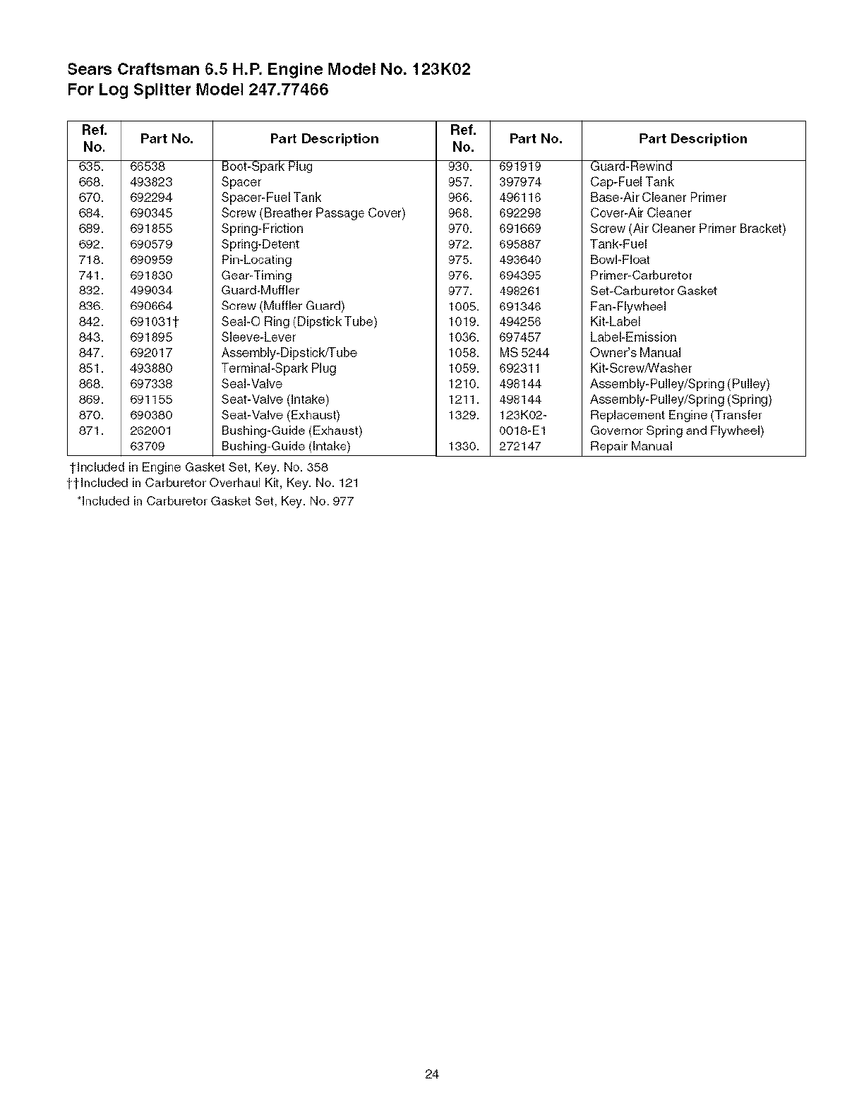
Sears Craftsman 6.5 H.P. Engine Model No. 123K02
For Log Splitter Model 247.77466
Ref.
No.
635.
668.
670.
684.
689.
692.
718.
741.
832.
836.
842.
843.
847.
851.
868.
869.
870.
871.
Part No.
56538
493823
692294
690345
591855
690579
690959
691830
499034
690664
691031t
591895
692017
493888
697338
591155
690380
262001
63709
Ref.
Part Description No. Part No.
Boot-Spark Plug 930. 691919
Spacer 957. 397974
Spacer-Fuel Tank 966. 496116
Screw (Breather Passage Cover) 968. 692298
Spring-Friction 970. 691669
Spring-Detent 972. 695887
Pin-Locating 975. 493640
Gear-Timing 976. 694395
Guard-Muffler 977. 498261
Screw (Muffler Guard) 1005. 691346
SeaI-O Ring (Dipstick Tube} 1019. 494256
Sleeve-Lever 1036. 697457
Assembly-Dipstick/Tube 1058. MS 5244
Terminal-Spark Plug 1059. 692311
Seal-Valve 1210. 498144
Seat-Valve(Intake) 1211. 498144
Seal-Valve (Exhaust) 1329. 123KO2-
Bushing-Guide (Exhaust) 0018-E1
Bushing-Guide (Intake) 1330. 272147
Part Description
Guard-Rewind
Cap-Fuel Tank
Base-Air Cleaner Primer
Cover-Air Cleaner
Screw (Air Cleaner Primer Bracket)
Tank-Fuel
Bowl-Float
Primer-Carburetor
Set-Carburetor Gasket
Fan-Flywheel
Kit-Label
Label-Emission
Owner's Manual
Kit-Screw/Washer
Assembly-Pulley/Spring (Pulley)
Assembly-Pulley/Spring (Spring)
Replacement Engine (Transfer
Governor Spring and Flywheel)
Repair Manual
tlncluded in Engine Gasket Set, Key. No. 358
ttlncluded in Carburetor Overhaul Kit, Key. No. 121
*included in Carburetor Gasket Set, Key. No. 977
24
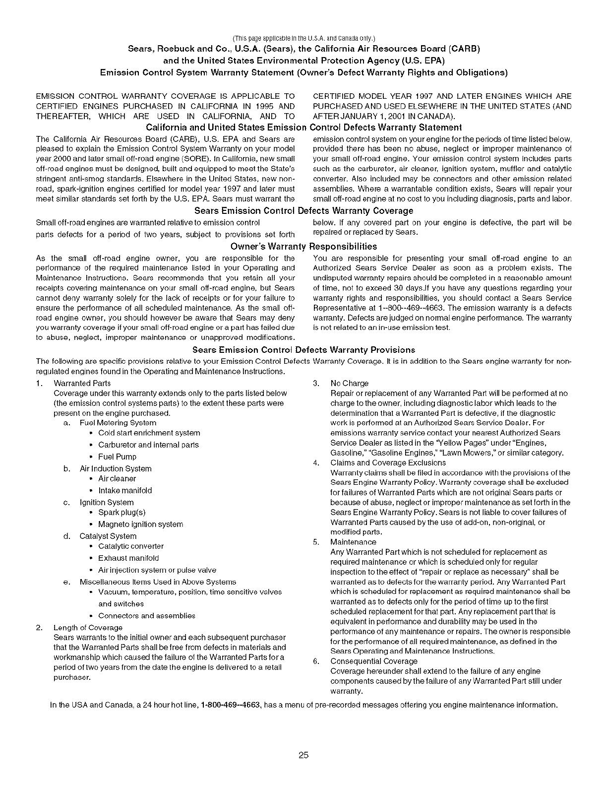
(ThispageapplicableIntheUSAa[idCanada0nly)
Sears,RoebuckandCo., U.S.A. (Sears), the California Air Resources Board (CARB)
and the United States Environmental Protection Agency (U.S. EPA)
Emission Control System Warranty Statement (Owner's Defect Warranty Rights and Obligations)
EMISSION CONTROL WARRANTY COVERAGE IS APPUCABLE TO CERTIFIED MODEL YEAR 1997 AND LATER ENGINES WHICH ARE
CERTIFIED ENGINES PURCHASED IN CAUFORNIA IN 1995 AND PURCHASED AND USED ELSEWHERE IN THE UNITED STATES (AND
THEREAFTER, WHICH ARE USED IN CALIFORNIA, AND TO AFTERJANUARYt,20011NCANADA).
California and United States Emission Control Defects Warranty Statement
The California Air Resources Board (CARD), U.S. EPA and Sea_s are
pleased to explain the Emission Control System Warranty on your model
year 2000 and later small off-road engine (SORE). In California, new small
off-road engines must be designed, built and equipped to meet the State's
stringent anti-smog standards. Elsewhere in the United States, new non-
_oad, spark-ignition engines certified for model year 1997 and later must
meet similar standards set forth by the U.S. EPA. Sears must warrant the
emission control system on your engine for the periods of tEme listed below,
provided there has b_en no P_use, neglec_ or iiT_proper maintenance of
your small off-road engine. Your emission control system includes parts
such as the carburetor, air cleaner, ignition system, muffler and catatyiic
converter. Also included may be connectors and other emission re_ated
assemblies. Where a warrantable condition exists, Sears will repair your
small off-road engine at no cost to you including diagnosis, parts and labor.
Sears Emission Control Defects Warranty Coverage
Small off-road engines are warranted relative to emission o)ntrol below. If any o)vered part on you_ engine is defective, the part will be
parts defects for a period of two yea_s, subject to provisions set forth repaired or replaced by Sears.
Owner's Warranty Responsibilities
AS the small off-road engine owner, you are responsil31e lot the
performance of the required maintenance listed in your Operating arid
Maintenance Instructions. Sears recommends that you retain all your
[eceipts covering maintenance on you[ small off-road engine, but Sears
cannot deny warranty solely for the lack of receipts or for your failure to
ensure the performance of all scheduled maintenance. As the small off-
road engine owner, you should however be aware that Sears may deny
you warranty coverage if your small off-road engine or a part has failed due
to abuse, neglect, improper maintenance or unapproved modifications.
YOU are responsible lot presenting your small off-road engine to an
Authorized Sears Service Dealer as soon as a problem exists. The
undisputed warranty repairs should be completed in a reasonable amount
of time, not to exceed 30 days.If you have any questions regarding your
warranty rights and responsibilities, you should o)ntact a Sears Service
Representative at t --800--469--4663. The emission warranty is a defects
warranty. Defects are iudged on normal engine performance. The warranty
is not related to an in-use emission test.
Sears Emission Control Defects Warranty Provisions
The following are specific provisions relative to your Emission Control Defects Warranty Coverage. It is in addition to the Sears engine warranty fo_ non-
regulated engines found in the Operating and Maintenance Inst_uctiens.
1. Warranted Parts
Coverage under this warranty extends only to the parts listed below
(the emission control systems parts) to the exient these parts were
present on _he engine purchased.
a. FuelMetering System
• Cold start enrichment system
• Carburetor and in_rnal parts
• Fuel Pump
b. Air Induction System
• Air e_eaner
• Intake manifold
c. Ignition System
• Spark plug(s)
• Magneto ignition system
d. Catalyst System
• Catalytic converter
• Exhaust manifold
• Air injection system or pulse valve
e. Miscellaneous Items Used in Above Systems
• Vacuum, _empera_ure, position, time sensitive valves
and switches
• Connectors and assemblies
2. Length of Coverage
Sears warrants to _he initia_ owner and each subsequent purchaser
that the Warranted Parts shall be free from defects in materials and
workmanship which caused the failure of the Warranted Parts for a
period of two years from the da_ the engine is delivered to a retail
purchaser.
3. No Charge
Repair or replacement of any Warranted Part wdl be performed at no
charge to the owner, including diagnostic labor which leads to the
determination that a Warranted Part is defective, if the diagnostic
work is performed at an Authorized Sears Service Dealer. For
emissions warranty _ervice contact youl nearest Authorized Sears
Service Dealer as listed in the '_/ellow Pages" under "Engines,
Gasoline," ¸'Gasoline Engines," "Lawn Mowers," or similar category.
4. Claims and Coverage Exclusions
Warranty claims shall be filed in aco)rdance with the provisions of the
Sears Engine Warranty Policy. War rarity coverage shall be excluded
for failures of Warranted Parts which are not original Sears parts or
because of abuse, neglect or iITbprope r [naintenan_ a8 set lerth in the
Sears Engine Warranty Policy. Sears is not liable to o)ver failures of
Warranted Pa_ts caused by the use of add-on, non-original, o_
modified parts.
5. Maintenance
Any Warranted Part which is not scheduled for replacement as
required maintenance or which is scheduled only for regular
inspection to the effect of "repai_ or replace as necessary" shah be
warranted as to defects for the warranty period. Any Warranted Part
which is scheduled for replacement as _quired maintenance shall be
warranted as to defects only for the period of time up to the first
scheduled replacement for that part. Any replacement part that is
equivalent in performance and durability may be used in the
perlorrnance ol any maintenance or repairs. The owner is responsible
for the performance of all required maintenance, as defined in the
Sears Operating and Main_nance instructions.
6. Consequential Coverage
Coverage hereunder shall extend to the failure of any engine
o) mponents caused by the failure of any Warranted Part still under
warranty.
In the USA and Canada, a 24 hour hot line, 1-800-469--4663, has a menu of pre-recorded messages offering you engine maintenance infom_ation.
25

NOTES
26
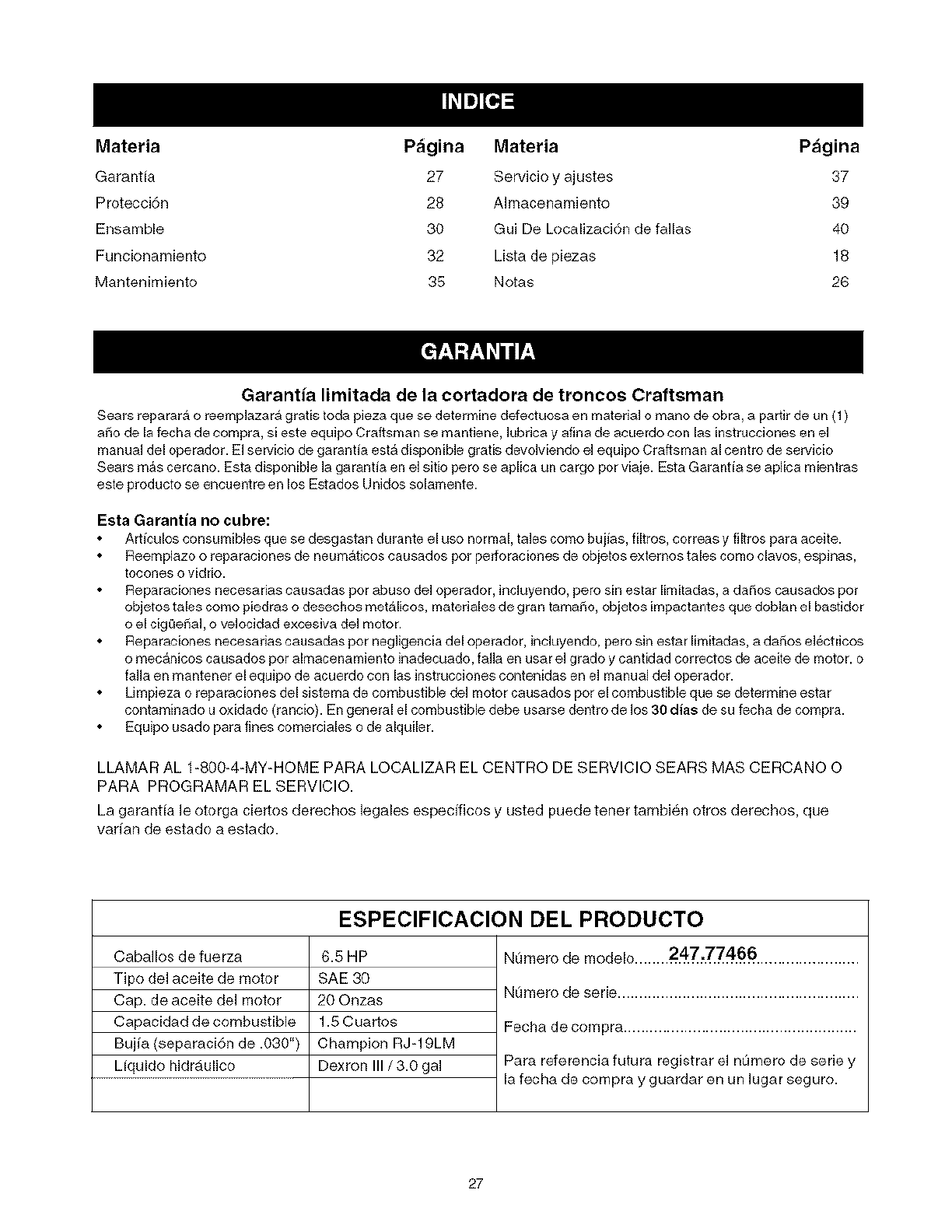
Materia P_gina Materia P_igina
Garantia 27 Servicio y ajustes 37
Protecci6n 28 Almacenamienfo 39
Ensamble 30 Gui De Localizaci6n de faNas 40
Funcionamienfo 32 Lista de piezas 18
Mantenimiento 35 Notas 26
Garantia limitada de la cortadora de troncos Craftsman
Sears reparara o reemplazara gratis toda pieza que se determine ctefectuosa en material o mano de obra, a partir de un (1)
afro de la fecha de cornpra, si este equipo Craftsman se mantiene, lubrica y afina de acuerdo con las instrucciones en el
manual del operador. El sepzicio de garantia est_ disponible gratis devolviendo el equipo Craftsman al centro de servicio
Sears m_s cercano. Esta disponible la ga rantia en el sitio pero se aplica un cargo pot viaje. Esta Garanfia se aplica mientras
este producto se enouentre en los Estados Unidos solamente.
Esta Garantia no cubre:
ArtJculos consumibles que se desgastan durante el uso normal, tales como bujJas, filtros, correas y filtros para aceite.
Reemplazo o reparaciones de neum_tJcos causados pot perforaciones de objetos externos tales como olavos, espinas,
tocones o vidrio.
Reparaciones necesarias causadas por abuso del operador, incluyendo, pero sin estar lingtadas, a da_os causados pot
objetos tales como piedras o desechos metalicos, materiales de gran tamaF_o,objetos impactantes que doblan el bastidor
o el cigOeF_al,o velocidad excesiva del motor.
Reparaciones necesarias causadas pot negligencia del operador, incluyendo, pero sin estar limitadas, a da_os el6ctricos
o mec#,nicos causados pot almacenamiento inadecuado, falla en usar el grado y canfidad correctos de aoeite de motor, o
falla en mantener el equipo de acuerdo con las instrucciones contenidas en el manual del operador.
Limpieza o reparaciones del sistema de combustible del motor causados pot el combustible que se determine estar
contaminado u oxidado (rancio). En general el combustible debe usarse dentro de los 30 dias de su fecha de compra.
Equipo usado para fines comerciales o de alquiler.
LLAMAR AL 1-800-4-MY-HOME PARA LOCALIZAR EL CENTRO DE SERVlClO SEARS MAS CERCANO O
PARA PROGRAMAR EL SERVlClO.
La garantia le otorga ciertos derechos legales especgicos y usted puede tenet tambien otros derechos, que
varfan de estado a estado.
ESPECIFICACION DEL PRODUCTO
Caballos de fuerza
Tipo del aceite de motor
Cap. de aceite del motor
Capacidad de combustible
Bujia (separaci6n de .030")
Liquido hidraulico
6.5 HP
SAE 30
20 Onzas
1.5 Cuartos
Champion RJ-19LM
Dexron III /3.0 gal
Nurnero de modelo........2_'_Z'_4.66 ........................
Numero de serie ........................................................
Fecha de compra ......................................................
Para referencia futura registrar el nt)mero de serie y
la fecha de compra y guardar en un lugar seguro.
27
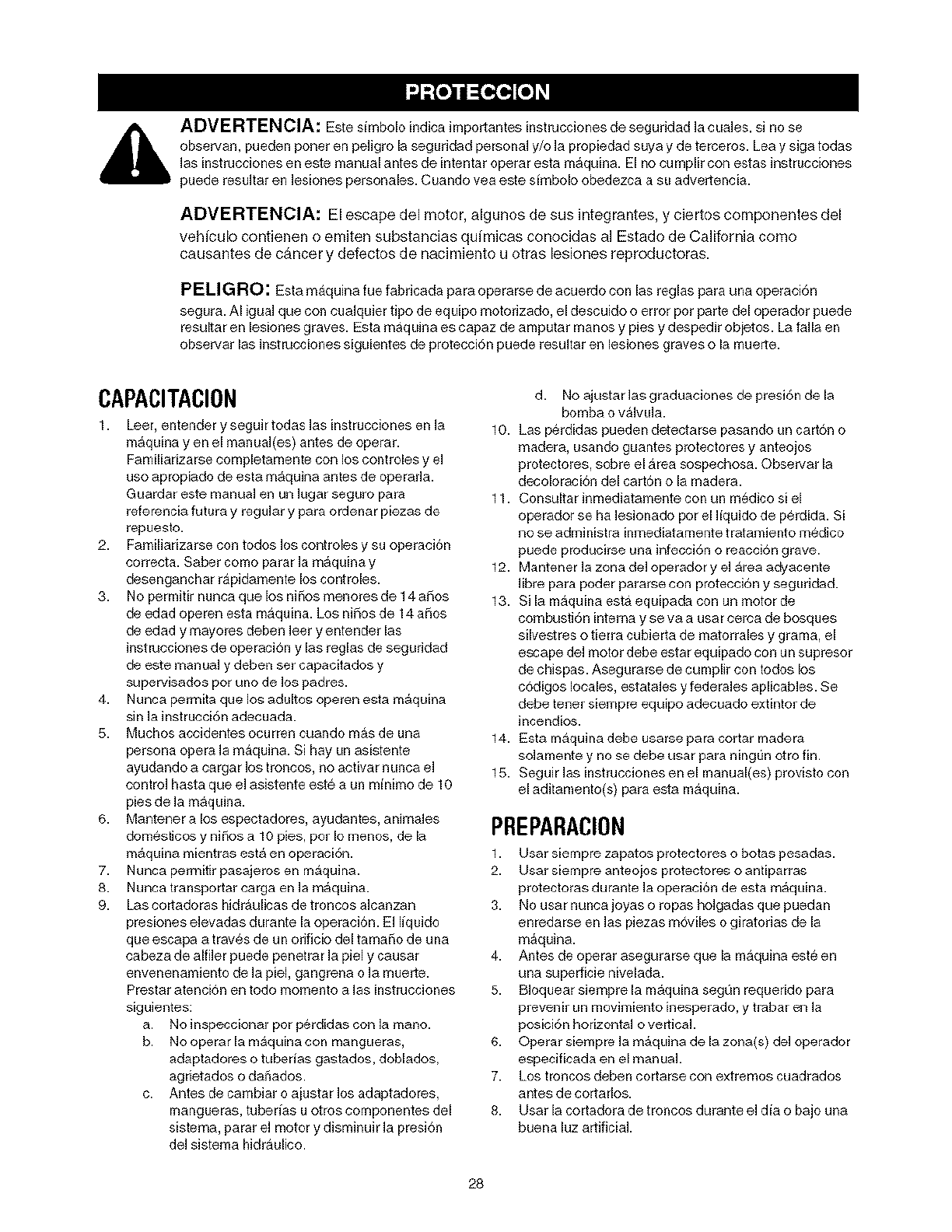
ADVERTENCIA: Este sfmbolo indica importantes instrucciones de segufidad la ¢uales, sl no se
observan, pueden porter en peligro la seguridad personal y/o la propiedad suya y de terceros. Lea y siga todas
las inst rucciones en este manual antes de intentar operar esta m_quina. El no cu mplir con estas inst rucciones
pu@d@ r@suItar en lesiones personales. Cuando vea este simbolo ohedezca a SLI advert@ncia.
ADVERTENClA: El escape del motor, algunos de sus integrantes, y ciertos componentes del
vehfculo contienen o emiten substancias qufmicas conocidas al Estado de California como
causantes de cancer y defectos de nacimiento u otras lesiones reproductoras.
PELIGRO: Esta maquina rue fabricada para operarse de acuerdo con las reglas para una operaci6n
segura. AI igua] que con cualquier tipo de equipo motofizado, el descuido o error pot parte del operador puede
resultar en lesiones graves. Esta m&quina es capaz de amputar Inanos y pies y despedir obietos. La faNa en
observar las instrucciones siguientes de protecci6n puede resultar en lesiones graves o la muerte.
CAPACITACION
1. Leer, entender y seguir todas las instrucciones en la
m&quina yen el manual(es) antes de operar.
Familiarizarse completamente con los controles y el
uso apropiado de esta m&quina antes de operarla.
euardar este manual en un lugar seguro para
referencia futura y regular y para ordenar piezas de
repuesto.
2. Familiarizarse con todos los controles y su operacion
correcta. Saber como parar la m&quina y
desenganchar rapidamente los controles.
3. No permitir nunca que los niSos menores de 14 aSos
de edad operen esta maquina. Los niSos de 14 aSos
de edad y mayores deben leer y entender las
instrucciones de operacion y las reglas de seguridad
de este manual y deben set capacitados y
supervisados por uno de los padres.
4. Nunca permita que los adultos operen esta m&quina
sin la instrucci6n adecuada.
5. Muchos acoidentes ocurren cuando m_,sde una
persona opera la maquina. Si hay un asistente
ayudando a cargar los troncos, no activar nunca el
control hasta que el asistente este a un minimo de 10
pies de la m&qLiina.
6. Mantener a los espectadores, ayudantes, animales
domesticos y niSos a 10 pies, pot Io menos, de la
m&quina mientras est& en operaci6n.
7. Nunca permitir pasajeros en maquina.
8. Nunca transportar carga en la m&quina.
9. Las cortadoras hidraulicas de troncos alcanzan
presiones elevadas durante la operacion. El Ifquido
que escapa a traves de un orificio del tamaSo de una
cabeza de alfiler puede penetrar la piel y causar
envenenamiento de la piel, gangrena o la muerte.
Prestar atencion en todo momento alas instrucciones
s[guientes:
a. No inspeccionar por perdidas con la mano.
b. No operar la maquina con mangueras,
adaptadores o tubedas gastados, doblados,
agrietados o daT_ados.
c. Antes de cambiar o aiustar los adaptadores,
mangueras, tuberlas u otros componentes del
sistema, parar el motor y disminuir la presion
del sistema hidraulico.
d. No ajustar las graduaciones de presibn de la
bomba o valvLi]a.
10. Las perdidas pueden detectarse pasando un carton o
madera, usando guantes protectores y anteojos
protectores, sobre el area sospechosa. Observar la
decoloracion del carton o la madera.
11. Consultar inmediatamente con un m_dico si el
operador se ha lesionado por el Nquido de perdida. Si
no se administra inmediatamente tratamiento medico
puede producirse una infecci6n o reacci6n grave.
12. Mantener ]a zona de] operador y el area adyacente
Nbre para poder pararse con protecci6n y segufidad.
13. Si la maquina esta equipada con un motor de
combusti6n intema y se va a usar cerca de bosques
silvest res o tierra cubierta de matorrales y grama, el
escape del motor debe estar equipado con un supresor
de chispas. Asegurarse de cumplir con todos los
c6digos locales, estatales y federales aplicables. Se
debe tener siempre equipo adecuado extintor de
incendios.
14. Esta maquina debe usarse para cortar madera
solamente y no se debe usar para ning_ln otto fin.
15. Seguir las instrucciones en el manual(es) provisto con
el aditamento(s) para esta maqu[na.
PREPARACION
1. tJsar siempre zapatos protectores o botas pesadas.
2. tJsar siempre anteojos protectores o antiparras
protectoras durante ]a operaci6n de esta m&quina.
3. No usar nunca joyas o ropas ho]gadas que puedan
enredarse en las piezas moviles o giratorias de la
m&quina.
4. Antes de operar asegurarse que la maquina este en
una superficie nivelada.
5. B]oquear siempre la m_quina seggn requerido para
prevenir un movimiento inesperado, y trabar en la
posici6n horizontal o vertical
6. Operar siempre ]a m&quina de la zona(s) del operador
especificada en el manual
7. Los troncos deben cortarse con extremos cuadrados
antes de cortados.
8. Usar la cortadora de troncos durante el dia o bajo una
buena luz artificial.
28
Paraevitarlesionespersonalesodaf_osalapropiedad
sedebesermuyprecavidoalrnanejarlagasolina.La
gasolinaesextrernadamenteinflamableylosvapores
SOn explosives.. Pueden ocu rrir lesiorles p@rsonales
graves cuando se derraRla gasolin_ sobre el operador o
sus ropas ya que puede encenderse. Lavarse la piel y
cambiarse de ropas inmediatamente.
a. Usar un recipiente aprobado de gasolina
solamente.
b. Apagar redes los cigarrillos, cigarros, pipas, y
otras fuentes de combusti6n.
c. Nunca se debe cargar gasolina bajotecho.
d. Nunca extraer la tapa de gasolina o agregar
combustible mientras el motor est& caliente o
funcionando.
e. Antes de oargar gasolina perrnitir que el motor se
enfrie per dos minutes per lo menos.
f. Nunca llenar en exceso el tanque de gasolina.
Llenar el tanque a no m_,s de I/2 pulgada per
debajo de la seccion inferior del cuello del
llenador, para proveer espacio para la expansion
del combustible.
g. Velvet a colocar la tapa del tanque de gasolina y
ajustar bien.
h. Si se derrama gasolina, limpiar con un trap<)la
maquina y el equipo y mover la m_quina aotra &tea.
Esperar 5 minutes antes antes de arrancar el motor.
NOalmacenar nunca la maquina o el recipiente de
combustible bajo techo deride haya una llama
expuesta, ohispas o llama piloto come en
calentadores de agua, calentadores de cuarto,
caldera, secadora de ropa u otros artefactos a gas.
Antes de alrnacenar, permitir que la rnaquina se
enfrie per 5 minutes per lo menos.
OPERACION
1. Antes de arrancar esta maquina, repasar [as "[nstruociones
de Protecci6n". El no seguir esas reglas puede resultar en
[esiones graves al operador o a los espectadores.
2. No dejar nunca [a Inaqu[na desatendida mientras el
motor est& funcionando.
3. No operar [a Inaquina mientras se esta bajo la influencia
de alcohol, drogas o medicaci6n.
4. No permitir nunca que ninguna persona opere esta
maquina sin una instrucci6n adecuada.
5. Operar siempre esta m&quina con todo el equipo de
segufidad en su lugar y funcionando. Asegurarse que
redes los controles est6n bien ajustados para una
operaci6n segura.
6. No cambiar [as graduaciones de[ regulador de[ motor ni
operar el motor a velocidad excesiva. El regulador controla
la velocidad m&xima segu ra de operaci6n de[ motor.
7. AI cargar un tronco, colocar siempre las manes sobre los
lades del tronco, no en los extremes, y I1LInoausar el pie
para estabilizar un tronco. El no haceflo puede resultar
en que los dedos, dedos del pie, mane o pie sean
aplastados o amputados.
8. Usar las manes solamente para operar los controles.
9. No intentar nunca cortar m&s de un tronco per vez, a
menos que el ariete este completamente extendido y se
necesite un segundo tronco para completar la
separaci6n del primer tronco.
10. Para los troncos que no se ban cortado cuadrados, el
extreme menos cuadrado y la porcion m&s larga del
tronco deben colooarse hacia la viga ycu f_a,y el extreme
cuadrado debe colocarse hacia la plaoa del exlremo.
11. AI cortar en la posicion vertical, estabilizar el tronco antes
de nlover el control Cortar come SigLle:
a. Colocar el tronco sobre la plaoa del extreme y
giraffe hasta que se apoye contra la visa yes
estable.
b. AI cortar troncos extra grandes o irregulares, el
tronco debe estabilizarse con cuSas de madera o
madera oortada entre el tronco y la plaoa del
exlrelno o el suelo.
12. Mantener siempre los dedos alejados de grietas que se
abren en el tronco al cortar. Las grietas pueden cerrarse
sLibitamente y aprisionar o amputar los dedos.
13. Mantener limpia el area de trabajo. Extraer
inmediatamente la madera cortada alrededor de la
maquina de manera de no tropezar sobre la misma.
14. Nunca mover la maquina mientras el motor esta
funcionando.
15. Esta maquina no debe remolcarse en ninguna calle,
carretera o camino pLiblico sin verificar pfimero los
req uerimientos existentes locales, estatales y federales
para vehioulos. Toda licencia o modificaciones tales
come luces posteriores, etc., requeridas para cumplir, es
la responsabilidad exclusiva del comprador. Consultar
con el distribuidor local si en el Estado se requiere una
"Declaraci6n de Origen".
16. Consultar la secci6n de remolque en este manual, para
las instrucoiones de remolque una vez que se haya
cumplido con todos los requefimientos federales, locales
o estatales.
MANTENIMIENTOYALMACENAMIENTO
1. Parar el motor, desconectar la bujia y conectar a tierra
contra el motor antes de limpiar o inspeccionar la
maquina.
2. Antes de cambiar o ajustar los adaptadores, mangueras,
tuberias u otros componentes del sistema, parar el motor
y disminuir la presi6n del sistema hidraulico.
3. Para evitar incendios, limpiar los desechos y paja de las
&teas del motor y del silenciador. Si el motor esta equipado
con un silenciador del supresor de chispas, limpiaflo e
inspeccionaflo regularmente de acuerdo con las
instrucciones del fabricante. Reemplazaflo si est,, da_ado.
4. Inspeccionar peri6dicamente que todas las tuercas y
pernos, mordazas de las mangueras y adaptadores
hidraulicos est6n firmes para asegurarse que el equipo
este en buen estado de trabajo.
5. Inspeccionar todas las guardas y protectores de
segufidad para asegurarse que esten en la posici6n
correcta. Nunoa operar sin que las guardas protectoras,
protectores u otras caracteristicas protectoras est6n en
su lugar.
6. La valvula de escape de presi6n esta pregraduada de
f_brica. No ajustar la v_lvula.
7. Nunca intentar mover esta maquina sobre un terreno
escarpado o irregular sin un vehlculo de rernolque o
ayuda adecuada.
29
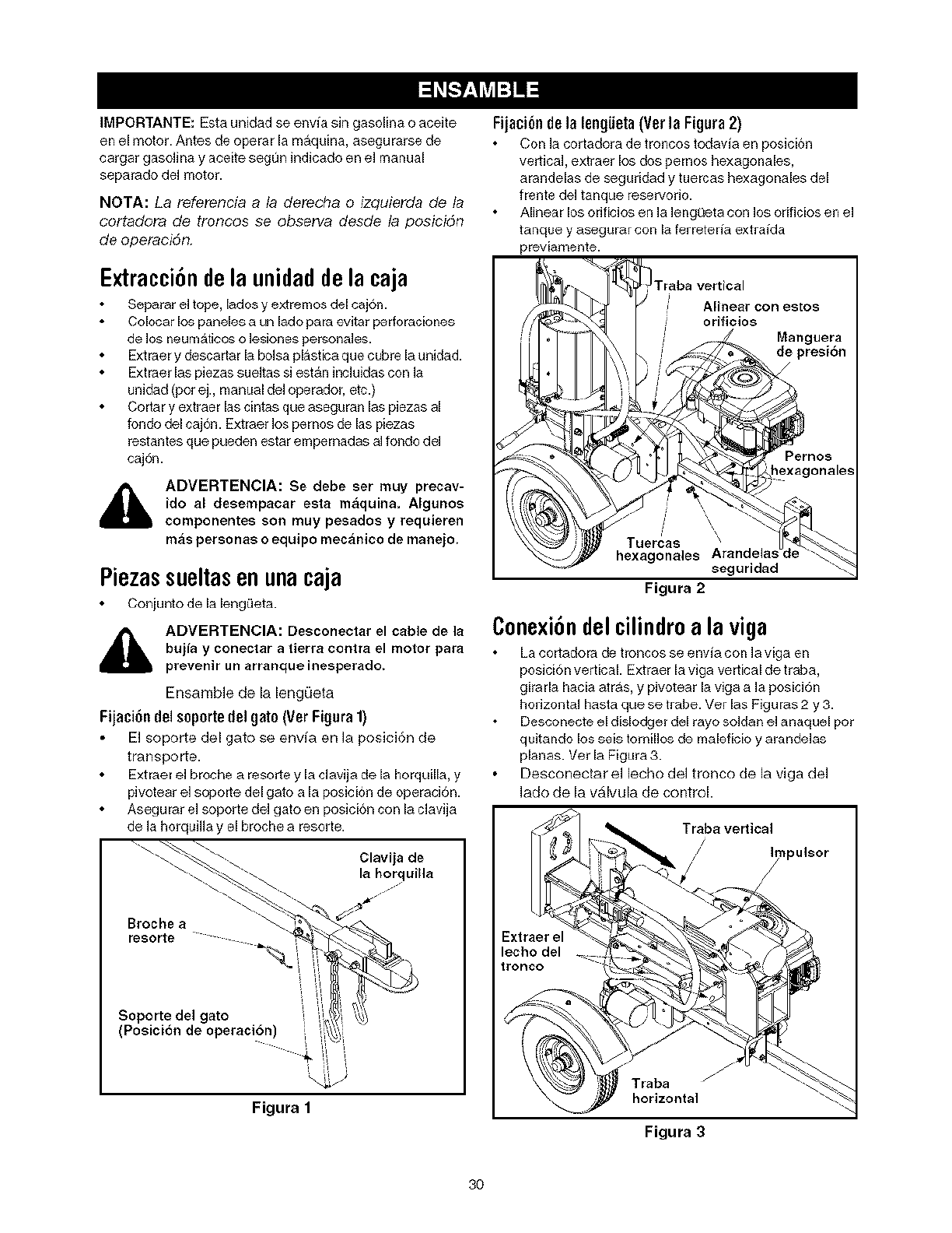
IMPORTANTE:Estaunidadseenviasingasolinaoaceite
enelmotor.Antesdeoperarlamaquina,asegurarsede
cargargasolinayaceiteseg0nindicado en el manual
separado del motor.
NOTA: La referenda a la derecha o izquierda de la
cortadora de troncos se observa desde la posicidn
de operacidn.
Extracci6ndela unidadde la caja
Separar eJtope, lados y extremos del caj6n.
Colocar los paneles a un lado para evitar perforaciones
de los neum&ticos o lesionespersonales.
Extraer y descartar la bolsa pl&stica que cubre la unidad.
Extraer las piezas sueltas si est&n incJuidas con la
unidad (por ej., manual deJoperador, etc.)
Cortar y extraer las cintas que aseguran las piezas al
fondo del caj6n. Exrraer los pernos de las piezas
restantes que pueden estar empernadas al fondo deJ
caj6n.
ADVERTENCIA: Se debe ser muy precav-
ido al desempacar esta maquina, AIgunos
componentes son muy pesados y requieren
mas personas o equipo mecanico de manejo,
Piezassueltasen una caja
Conjunto de la leng0eta.
,_ ADVERTENCIA: Desconectar el came de la
bujia y conectar atierra contra el motor para
prevenir un arranque inesperado.
Ensamble de la lengOeta
Fijaci6n delsoporte del gat0 (Ver Figura 1)
El soporte del gato se envia en Ja posici6n de
transporte.
Extraer el broche a resorte y la clavija de la horquilla, y
pivotear el soporte del gate a la posiciSn de operaci6n.
Asegurar el soporte del gate en posici6n con la clavija
de la horquilla y el broche a resorte.
"\ _% _ \ Clavijade
\ \)_. lahorquilla
Soporte del gato
Posici6n de operaci6n
Figura 1
Fijaci6n de la lengUeta(Vet la Figura 2)
Con ]a cortadora de troncos tedavia en posici6n
vertical, extraer los dos pemos hexagonales,
arandelas de seguddad y tuercas hexagonales del
frente de] tanque reservofio.
Alinear los orificios en ]a ]engQeta con los orificios en el
tanque y asegurar con la ferreteria extraida
previamente.
Traba vertical
Alinear con estos
orificios
Manguera
de presi6n
Tuercas
hexagonales seguridad
Figura 2
Conexi6ndelcilindroala viga
ha cortadora de t roncos se envia con la viga en
posici6n vertical. Extraer la viga vertical de traba,
girada hacia arras, y pivotear la viga a la posici6n
horizontal hasta que se trabe. Ver las Figuras 2 y 3.
Desconecte el dislodger del rayo soJdan eJanaquel pot
quitando los seis ternillos de maleficio y arandelas
planas. Vet la Figura 3.
Desconectar el lecho del tronco de la riga deJ
Jado de la valvula de control.
Trabave_ical
/
/)u_sor
Extraer el
lecho del
tronco
jJ
Traba
horizontal
Figura 3
3O
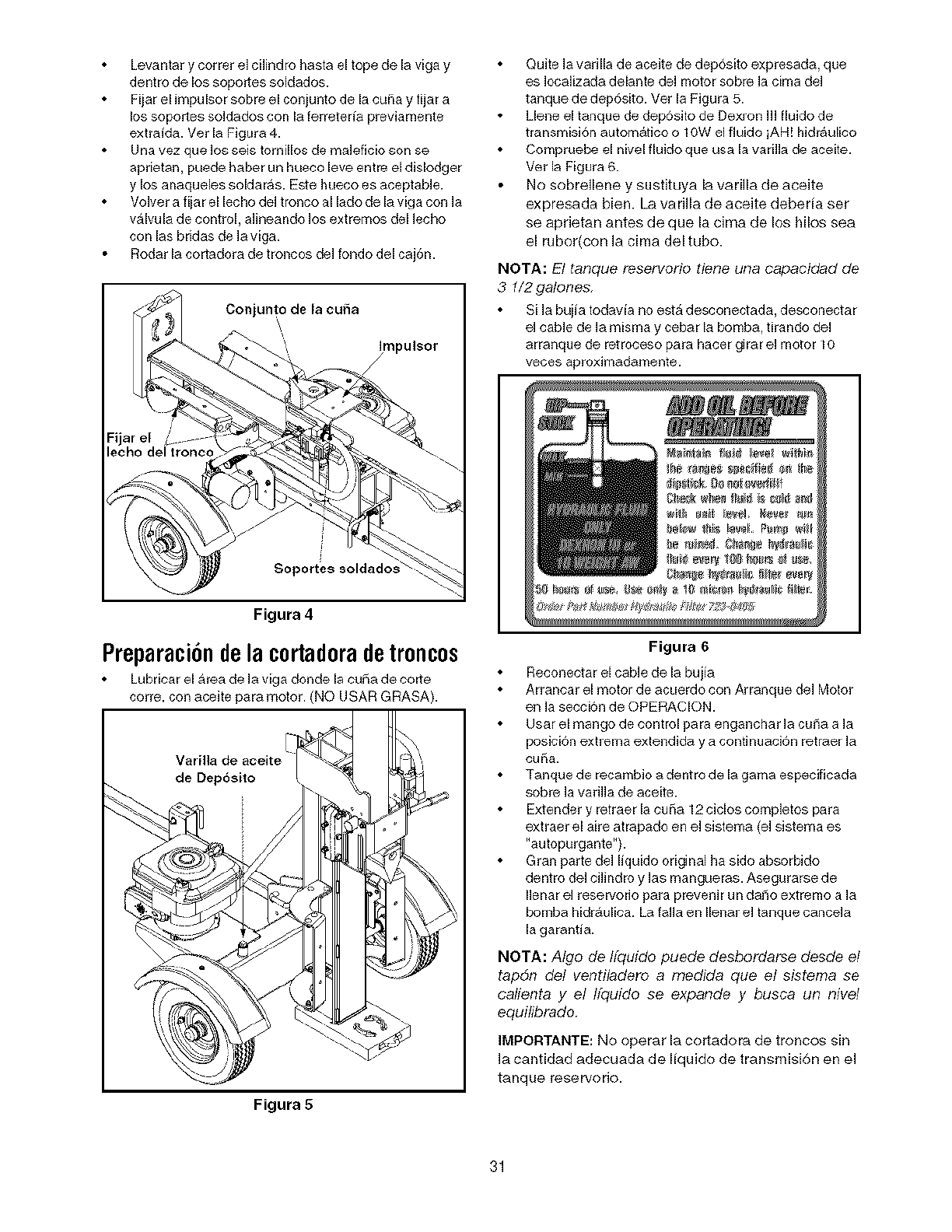
Levantarycorrerelcilindrohastaeltopedelavigay
dentrodelossoportessoldados.
Fijarelimpulsor sobre el con Jnto de la cuSa y fijar a
los soportes soldados con la ferreter_ previamente
extraida. Vet la Figura 4.
Una vez que los seis tornillos de maleficio son se
aprietan, puede haber un hueco leve entre el dislodger
y los anaqueles soldaras. Este hueco es aceptable.
Volver a fijar el lecho del tronco al lado de la viga con la
valvula de control, alineando los extremos del lecho
con las bridas de la viga.
Rodar la cortadora de troncos del rondo del caj6n.
Conjunto de la cuiia
Soportes soldado_
Quite la varilla de aceite de dep6sito expresada, que
es Iocalizada delante del motor sobre la cima del
tanque de dep6sito. Ver la Figura 5.
Llene el tanque de deposito de Dexron Ill fluido de
transmisi6n autom_tico o 10W el fluido iAH! hidr_ulico
Compruebe el nivel fluido que usa la varilla de aceite.
Vet la Figura 6.
No sobrellene y sustituya la varilla de aceite
expresada bien. La varilla de aceite debeda set
se aprietan antes de que la cirna de los hilos sea
el rubor(con la cima del tubo.
NOTA: El tanque reservorio tiene una capacidad de
3 1/2 galones,
Si la buiia todavia no estA desconectada, desconectar
el cable de la misma y cebar la bomba, tirando del
arranque de retroceso para hacer girar el motor 10
veces aproximaciamento.
Figura 4
Preparaci6ndela ¢ortadoradetroncos
Lubricar el Area de la viga donde la cuba de torte
corre, con aceite para motor. (NO USAR GRASA).
de Dep6sito
Figura 5
Figura 6
Reconectar el cable de la bujia
Arrancar el motor de acuerdo con Arranque del Motor
en la seccion de OPERACION.
Usar el mango de control para enganchar la cuSa a la
posicion extrema extondida y a continuacion retraer la
cuSa.
Tanque de recambio a dentro de la gama especificada
sobre la varilla de aceito.
Extender y retraer la cuSa 12 ciclos completos para
extraer el aire atrapado en el sistema (el sistema es
"autopurganto").
Gran parte del liquido original ha sido absorbido
dentro del ci]indro y ]as mangueras. Asegurarse de
I]enar e] reservorio para prevenir un daf_o extremo a ]a
bomba hidraulica. La falla en Ilenar e] tangue cancela
la garantia.
NOTA: Algo de Ifquido puede desbordarse desde el
tapon del ventiladero a medida que el sistema se
calienta y el Ifquido se expande y busca un nivel
equilibrado
IMPORTANTE: No operar la cortadora de troncos sin
la cantidad adecuada de liquido de transmisi6n en el
tanque reservofio.
31
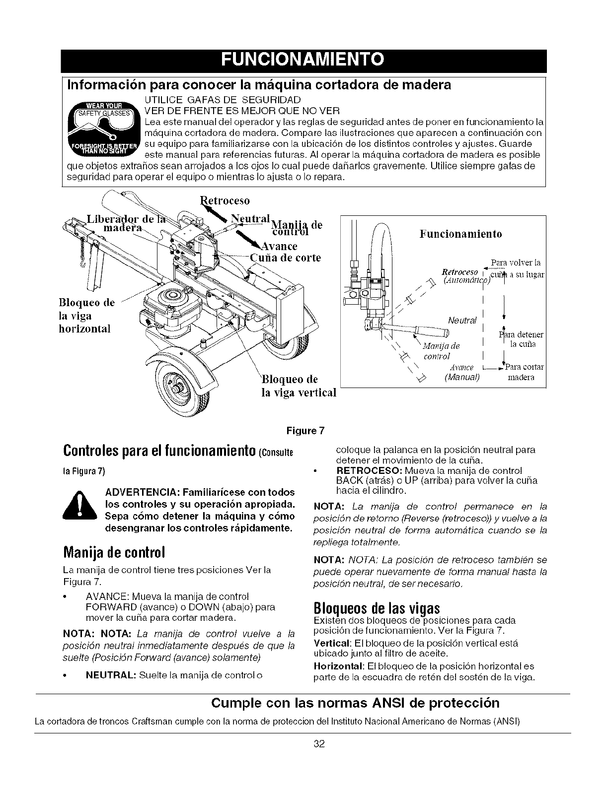
Informacibn para conocer la maquina cortadora de madera
UTILICE GAFAS DE SEGURIDAD
VER DE FRENTE ES MEJOR QUE NOVER
Lea este manual del operador y las reglas de seguridad antes de poner en funcionamiento b
maquina cortadora de madera. Compare las ilustraciones que aparecen a continuaci6n con
su equipo para familiadzarse con la ubicaci6n de los distintos controles y ajustes. Guarde
este manual para referencias futuras. AI operar la maquina cortadora de madera es posible
que objetos extrai_os sean arrojados a los ojos Io cual puede dariarlos gravemente. Utilice siempre gafas de
seguridad para operar el equip<) o mientras Io ajusta o Io repara.
NeutralMa i', de Funcionamiento
]381"_ VO]Vel" I_
Retroceso i"c_ asl_lu_a:
/
Bloqueo (le I
la viga Neutral I
horizontal I_ala (teteilei
\\ / ]a ¢tma
\\ ._ W/IIC8 D •
\
'Bloqueo (|e madel a
la riga vertical
Figure 7
C0ntr01esparaelfunci0namient0(c0._.._
la Figura 7)
ADVERTENCIA: Familiaricese con todos
los controles y su operacibn apropiada.
Sepa c6mo detener la m_quina y c6mo
desengranar los controles r_pidamente.
Manija decontrol
La manija de control tiene tres posiciones Ver la
Figura 7.
AVANCE: Mueva la manija de control
FORWARD (avance) o DOWN (abajo) para
mover la curia para cortar madera.
NOTA: NOTA: La manija de control vuelve a la
posicidn neutral inmediatamente despues de que la
suelte (Posicidn Forward (avance) solamente)
coloque la palanca en la posici6n neutral para
detener el movimiento de la curia.
RETROCESO: Mueva la manija de control
BACK (atrAs) o UP (arriba) para volver la curia
hacia el cilindro.
NOTA: La manlja de control permanece en la
posicidn de retomo (Reverse (retroceso)) y vuelve a la
posicidn neutral de forma automatica cuando se la
repllega totalmente,
NOTA: NOTA: La posicidn de retroceso tambien se
puede operar nuevamente de forrna manual hasta la
posici6n neutral, de set necesario,
BI0que0sdelasvigas
Existen dos bloqueos de posiciones para cada
posici6n de funcionamiento. Ver la Figura 7.
Vertical: El bloqueo de la posici6n vertical esta
ubicado junto al filtro de aceite.
Horizontal: El bloqueo de la posici6n horizontal es
NEUTRAL: Suelte la manija de control o parte de la escuadra de ret@n del sosten de la viga.
Cumple con las normas ANSI de proteccidn
La cortadora de troncos Craftsman cumple con la )_orma de proteccion del Instituto Nacional Americano de Norrnas (ANSI)
32
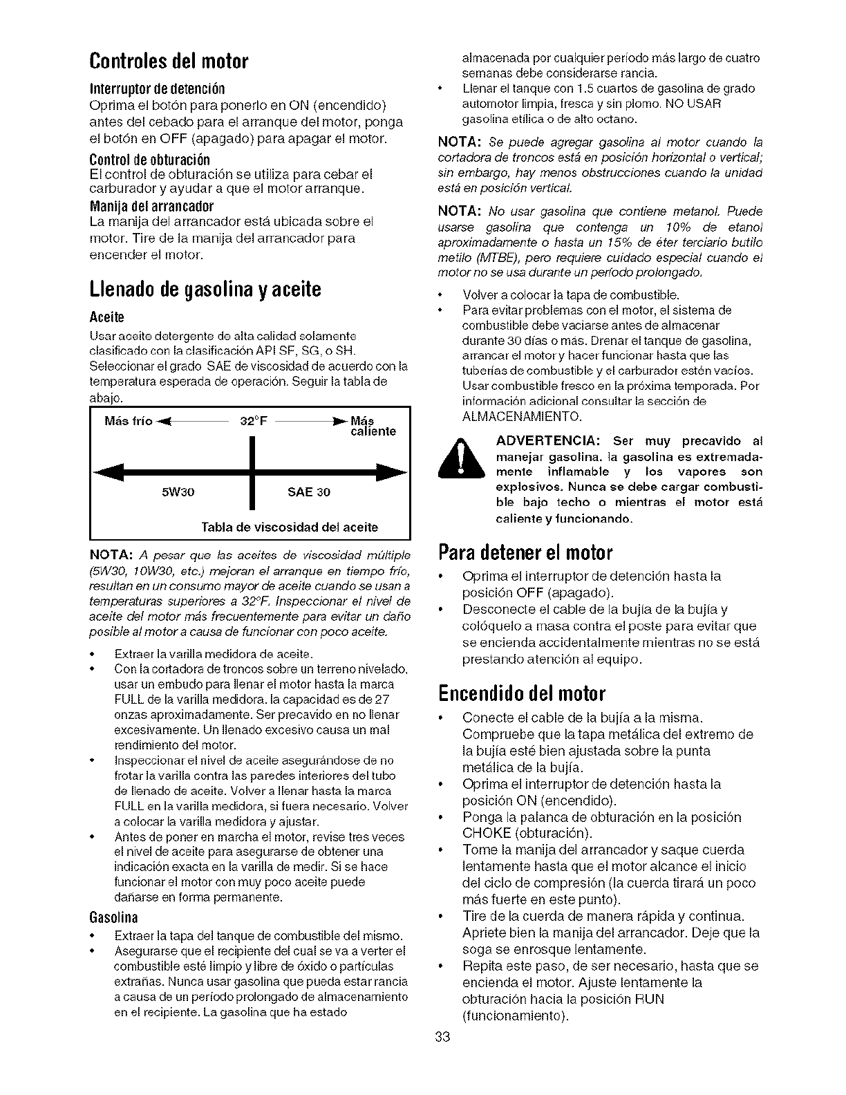
Controles del motor
Interruptorde detencien
Oprima el bot6n para ponerlo en ON (encendido)
antes del cebado para el arranque del motor, ponga
el bot6n en OFF (apagado) para apagar el motor.
Controlde obturacien
El control de obturaci6n se utiliza para cebar el
caP;_urador y ayudar a que el motor arranque.
Manija delarraocador
La manija del arrancador esta ubicada sobre el
motor. Tire de la manija del arrancador para
encender el motor.
Llenadodegasolinay aceite
Aceite
lJsar aceite detergente de alta calidad solamente
clasifioado con la clasificaci6n API SF, SG, o SH.
Se]eocionar el grado SAE de viscosidad de acuerdo con la
temperatura esperada de operaci6n. Seguir la tabla de
abajo.
M_s frio -gF 320 F _M_s
caliente
5W30 SAE 30
Tabla de viscosidad del aceite
NOTA: A pesar que las aceites de viscosidad mQItiple
(5W30, 10W30, etc.) mejoran el arranque en tiempo fifo,
resuItal3 el3 URCOI?sumom_yot" Gin _ceite ou_nc'o ._eUS_13a
temperaturas superinres a 32°F_ Inspeccionar el nivel de
aceite del motor m4s frecuentemente para evitar un dafio
posible a] motor a causa de funcinnar con poco aceite.
Extraer la variiia medidora de aceite.
Con la cortadora de troncos sobre un terreno nivelado,
usar un embudo para Ilenar el motor basra la marca
FULL de [a varilia medidora. [a capaoidad es de 27
onzas aproxhnadamente. Set preoavido en no [lenar
excesivamente. Un Henado excesivo oausa un real
rendimiento de[ motor.
Inspeccionar el nive[ de aceite asegurandose de no
frotar la vafilla contra [as paredes intefiores de[ tubo
de [lenado de aceite. VoJver a ][enar hasta [a marca
FULL en la vafiila medidora, si fuera necesario. Voiver
a co[ocar [a varilia medidora y aiustar.
Antes de poner en marcha el motor, revise tres veces
el nivel de aceite para asegurarse de obtener una
indicaci6n exaota en la varilla de medir. Si se hace
funcionar el motor con muy poco aceite puede
daSarse en forma pernlanente.
Gasolioa
Extraer la tapa del tanque de combustible del mismo.
Asegurarse que el recipiente del cual se va a verter el
combustible est_ limpio y libre de 6xido o parhculas
extraSas. Nunca usar gasolina que pLleda estar rancia
a causa de un periodo prolongado de almacenamiento
en el recipiente. La gasolina que ha estado
aIraacenada pot cualquier periodo mas largo de cuatro
semanas debe considerarse rancia.
Llenar eI tanque con 1.5 cuartos de gasoJina de grado
automotor limpia, fresca y sin plomo. NO USAR
gasolina etiiica o de alto octano.
NOTA: 8e puede agregar gasolina al motor cuando la
cortadora de troncos est4 en posici6n horizontal o vertical;
sin embargo, hay menos obstrucciones cuando la unidad
est4 en posiniSn vertical
NOTA: No usar gasolina que contiene metanoL Puede
usarse gasofina que contenga un 10% de etanol
apreximadamente o basra un 15% de #ter terciarin butilo
metiin (MTBE), pero requiem cuidado especial cuando e]
motor no se usa durante un perfodo proinngado,
VoJver a coJocar la tapa de combustible.
Para evitar problemas con eJmotor, el sistema de
combustible debe vaciarse antes de aimacenar
durante 30 dJas o mas. Drenar el tanque de gasolina,
arrancar el motor y hacer funcionar hasta que las
tubefias de combustible y el carburador esten vacios.
Usar combustible fresco en la pr6xima temporada. Pot
informaci6n adicional consultar la seccien de
ALMACENAMIENTO.
i_ ADVERTENCIA: Ser muy precavido al
manejar gasolina, ]a gasolina es extremada-
mente inflamable y los vapores son
explosivos, Nunca se debe cargar combusti-
ble bajo techo o mientras e[ motor est_
caliente y funcionando.
Paradetenerel motor
Oprima el interruptor de detencien hasta la
posici6n OFF (apagado).
Desconecte el cable de la bujia de la bujia y
colequelo a masa contra el poste para evitar que
se encienda accidentalr'_lente mientras no se esta
prestando atenci6n al equipo.
Encendidodel motor
Conecte el cable de la bujia a la misma.
Compruebe que la tapa metalica del extremo de
Jabujia este bien ajustada sobre la punta
metaflca de la bujia.
Optima el interruptor de detencien hasta la
posici6n ON (encendido).
Ponga la palanca de obturaci6n en la posicion
CHOKE (obturaci6n).
Tome la manija del arrancador y saque cuerda
Jentamente hasta que e] motor alcance el inicio
del ciclo de compresi_)n (la cuerda tirara un poco
mas fuerte en este punto).
Tire de la cuerda de manera rapida y continua.
Apriete bien la manija del arrancador. Deje que la
soga se enrosque lentamente.
Repita este paso, de set necesario, hasta que se
encienda e] motor. Ajuste lentamente Ja
obturaci6n hacia la posici6n RUN
(funcionamiento).
33
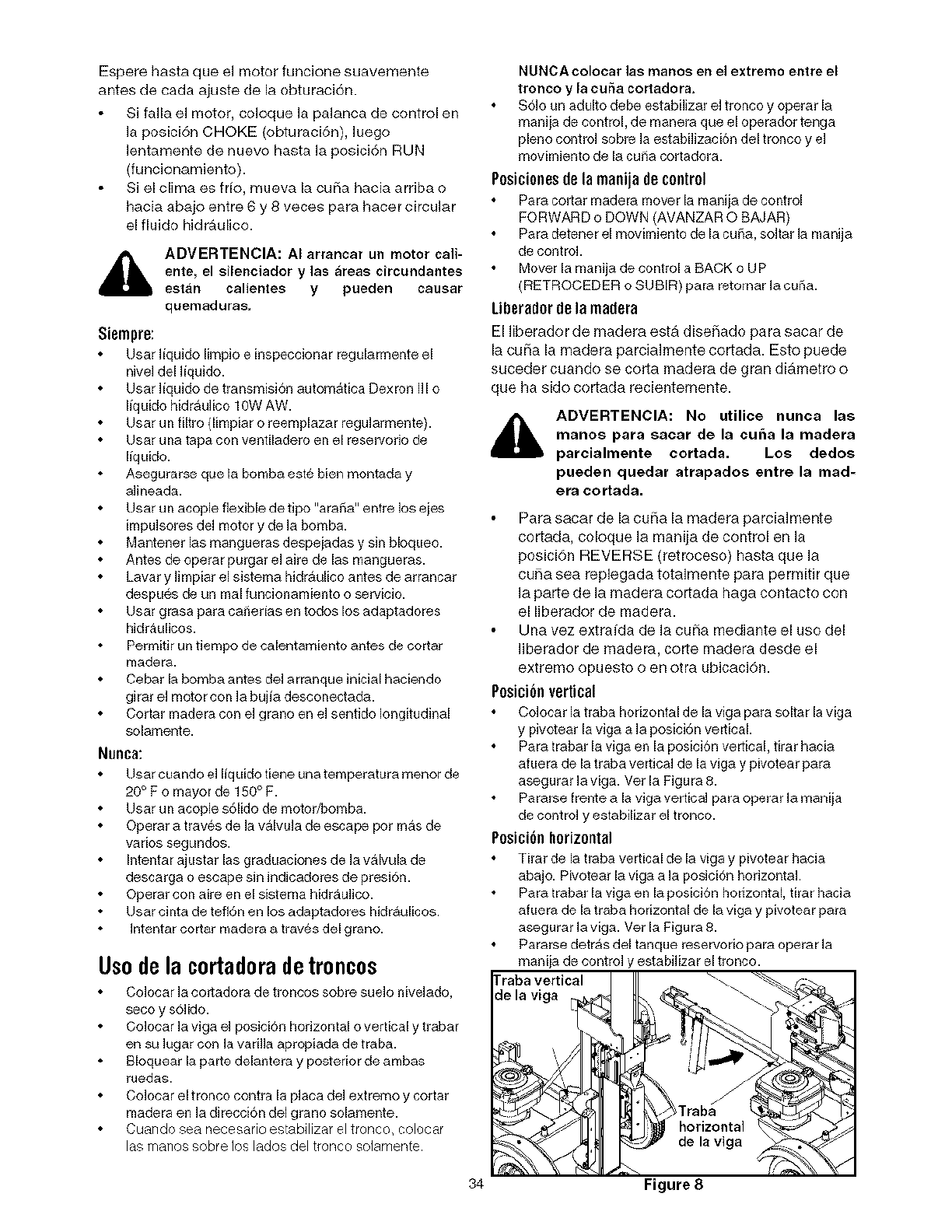
Espere hasta que el raotor funcione suavemente
antes de cada ajuste de la obturaci6n.
Si falla el motor, coloque la palanca de control en
la posici6n CHOKE (obturaci6n), luego
lentamente de nuevo hasta la posici6n RUN
(funcionamiento).
Si el clime es trio, mueva la curia hacia arriba o
hacia abajo entre 6 y 8 veces para hacer circular
el fiuido hidraulico.
ADVERTENCIA: AI arrancar un motor call-
ente, el silenciador y ]as _reas circundantes
estan calientes y pueden causar
quemaduras,
Siempra:
User liquido limpio e inspeccionar reguiarmente el
nivel del liquido.
User liquido de transmisi6n aurora&rice Dexron ill o
liquido hidraulico 10W AW.
User un filtro (limpiar o reemplazar regularmente).
User una tape con ventiladero en el reservorio de
liquido.
Asegurarse qua la bomba este bien montada y
alineada.
User un acople flexible de tipo "eraSe" entre los ejes
impulsores del motor y de la bomba.
Mantener las mangueras despejadas y sin bloqueo.
Antes de operar purger el aire de las mangueras.
Laver y ]impiar el sistema hidraulico antes de arrancar
despues de un real funcionamiento o servicio.
User grasa pare caf_edas en todos los adaptadores
hidraulicos.
Permitir un tiempo de calentamiento antes de cotter
nladera.
Cebar la bomba antes del arranque inicial haciendo
girar el motor con la bujia desconectada.
Cotter madera con el grano en el sentido longitudinal
solamente.
Nunea:
Usar cuando e] liquido tiene una temperature menor de
20°F o mayor de 150 ° F.
User un acople s61ido de motor/bomba.
Operar a traves de la valvula de escape pot mas de
varios segundos.
Intentar ajustar las graduaciones de la valvula de
descarga o escape sin indicadores de presi6n.
Operar con aire en el sistema Mdraulico.
User cinta de tefl6n en los adaptadores hidraulicos.
Intentar cotter madera a traves del grano.
Us0dela c0rtad0radetr0nc0s
Colocar la cortadora de troncos sobre suelo niveJado,
seco y s6Jido.
Colocar la viga eJ posici6n horizontal o vertical y trabar
en su lugar con la varilla apropiada de traba.
Bloquear la parte delantera y posterior de ambas
ruedas.
Colocar el tronco contra la place del extremo y cortar
madera en la direcci6n deJ grano solamente.
Cuando sea necesario estabilizar el tronco, colocar
las marlos sobre los lados del tronco solamente
34
NUNCA colocar ]as manos en el extremo entre el
tronco y la curia cortadora.
S6lo un adulto debe estabilizar el tronco y operar la
manija de control, de manera qua el opemdor tenga
pleno control sobre la estabilizaci6n del tronco y el
movimiento de la curia cortadora.
Poeicioneede la manija de control
Pare cotter Inadera mover la manija de control
FORWARD o DOWN (AVANZAR O BAJAR)
Pare detener el movimiento de la cuSa,soJtarla manija
de control.
Mover la manija de control a BACK o UP
(RETROCEDERo SUBIR) pare retornar la curia.
Liberedor de la madera
El liberador de madera esta diseflado para sacar de
la cui_a la madera parcialmente cortada. Esto puede
suceder cuando se corta madera de gran diametro o
que ha sido cortada recientemente.
ADVERTENCIA: No utilice nunca las
manos para sacar de la cuba la madera
parcialmente cortada. Los dedos
pueden quedar atrapados entre la mad-
era cortada.
Pare sacar de la cui_a la raadera parciaJraente
cortada, coloque la manija de control en la
posici6n REVERSE (ret roceso) haste que la
curia sea replegada totalmente para permitir que
la parte de la madera cortada haga contacto con
el Berador de madera.
Una vez extraida de la cui_a mediante el uso del
liberador de madera, corte madera desde el
extremo opuesto o en otra ubicaciSn.
Poeici6nvertical
Colocar la traba horizontal de la viga pare soltar la viga
y pivotear la viga a la posici6n vertical.
Pare trabar la viga en la posici6n vertical, tirar haoia
afuera de la traba vertical de la viga y pivotear pare
asegurar la viga. Vet la Figure 8.
Paterse frente a la viga vertical pare operar la maniia
de control y estabilizar el tronco.
Poeici6nhorizontal
Tirar de la traba vertical de la viga y pivotear hacia
abajo. Pivotear la viga ala posici6n horizontal
Pare trabar la viga en la posicion horizontal, tirar hacia
afuera de la traba horizontal de la viga y pivotear pare
asegurar la viga. Vet la Figure 8.
Pararse detras del tanque reservorio pare operar la
maniia de control y estabilizar el tronco.
rraba vertical \ --.\\ _"-_._
de la viga
:,
Figure 8
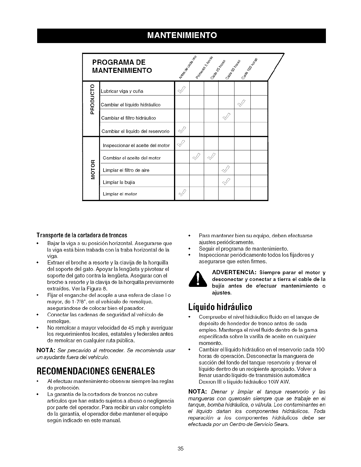
PROGRAMA DE
MANTENIMIENTO _ 4' -_
¢
0
t_ Lubricar viga y cufa
O?-am biar el liquido hidraulioo
3ambiar el filtro Mdrfulico
/2
Cambiar el liquido del reservodo
Inapeccionar el aceite del motor
Cambiar el aceite del motor
_) Limpiar el flltro de aire
Umpiar Ja bujia
Umpiar el motor
Transportede la cortadora de troncos
Bajar la viga a su posici6n horizontal. Asegurarse que
la viga est& bien trabada con la traba horizontal de la
viga.
Extraer el broche a resorte y la elaviia de la horquilla
del soporte del gato. Apoyar la lengQeta y pivotear el
soporte del gato contra la lengQeta. Asegurar con el
broche a resorte y la clavija de la horquilla previamente
extraidos. Vet la Figura 8.
Fijar el enganche del aeople a una esfera de clase I o
mayor, de 1-7/8", en el vehiculo de remolque,
asegurandose de colocar bien el pasador.
Conectar las cadenas de seguddad al vehiculo de
remolque.
No remolca r a mayor velocidad de 45 mph y avedguar
los requerhnientos locales, estatales y federales antes
de remolear en cualquier ruta publica.
NOTA: Set precavido al retroceder, Se recomienda usar
un ayudante fuera del vehfculo.
RECOMENDACIONESGENERALES
AI efectuar mantenimiento observar siempre las reglas
de proteeeion.
La garantia de la cortadora de troncos no cubre
arheulos que han estado sujetos a abuso o negligencia
por parte del operador. Para recibir un valor completo
de la garantia, el operador debe mantener el equipo
segun indicado en este manual
Para mantener bien su equipo, deben efectuarse
aiustes peri6dieamente.
Seguir el programa de mantenhniento.
Inspeccionar peri6dicamente todos los fliadores y
asegurarse que esten firmes.
_IL ADVERTENCIA: Siempre parar el motor y
desconectar y conectar atierra el cable de la
bujia antes de efectuar mantenimiento o
ajustes.
Liquido hidr ulico
Compruebe el nivel hidraulieo fluido en el tanque de
dep6sito de hendedor de tronco antes de cada
empleo. Mantenga el nivel fluido dentro de la gama
especificada sobre la varilla de aceite en cualquier
momento.
Cambiar el liquido hidraulico en el reservorio cada 100
horas de operaci6n. Deseonectar la manguera de
succi6n del rondo del tanque reservorio y drenar el
liquido dentro de un recipiente apropiado. Volver a
Ilenar usando liquido de transmisi6n automatica
Dexron III o liquido hidraulice 10W AW.
NOTA: Drenar y limpiar el tanque reservorio y las
marx3ueras con querosen siempre que se trabaje en el
tanque, bomba hidr4ulica, o v41vula,Los contaminantes en
el hquido dafian los componentes hidr4ulicos, Toda
reparaciSn a los componentes hidr4ulicos debe ser
efectuada por un Centro de Servicio Sears.
35
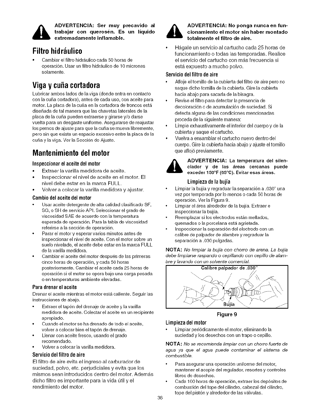
ADVERTENCIA: Ser muy precavido al
trabajar con querosen. Es un liquido
extremadamente inflamable.
Filtrohidr ulico
Cambiar el filtro bidrauiico cada 50 horas de
operaci6R. Usar un filtro hidraulico de 10 micrones
solamente.
Vigaycubacortadora
Lubricar ambos lades de la viga (donde entra en CORtacto
con la cuSa cortadora), antes de coda use, con aceite para
motor• La placa de la curia en la cortadora de troncos esta
diseSada de tal manera que los chavetas lateraJes de la
placa de la cuSa pueden extraerse y girarse y/o darse
vuelta para un desgaste uniforme. Asegurarse de reajustar
los pemos de ajuste para que la curia se mueva libremente,
pore sin que exista un espacio excesivo entre la pJaca de la
curia y la viga. Vet la Seccion de Ajuste.
Mantenimientodelmotor
Iospoccionarel aoeito dol motor
Extraer la varilla medidora de aceite.
Inspeccionar el nivel de aceite en el motor. El
nivel debe estar en la marca FULL•
Velvet a colocar la varilla medidora y ajustar.
Cambio dol oceite dol motor
Usar aceite detergente de alto caiidad clasificado SF,
SG, o SH de servicio APL Seleccionar el grade de
viscosidad SAE de acuerdo con la temperatura
esperada de operaciGn. Para la tabla de viscosidad
referirse a la secci6n de operaci6n.
Parat el motor y esperar va dos nlinutos antes de
inspeccionar el nivel de aceite. Con el motor sobre un
suelo nivelado, el aceite debe estar en la marco FULL
de la varilla medidora.
Cambiar el aceite del motor despues de los primeras
cinco heros de operaciGn, y coda 50 heros
postedormente. Cambiar el aceite coda 25 heros de
operaci6n si el motor se opera bajo una cargo pesada
o en temperatu ras ambiente elevadas.
Para drooor el aoeite
Drenar el aceite mientras el motor est& caliente. Seguir los
instrucciones de abajo.
Extraer eJtapon del drenaie de aceite y la varilla
medidora de aceite. Colectar el aceite en un recipiente
apropiado.
Cuando el motor se ha drenado de rode el aceite,
volver a colocar bien el tap6n de drenaje.
Llenar con aceite fresco, usando el grade
recomendado.
VoJver a colocar la va rilla medidora.
Sorviciodel filtro doafro
El filtro de aire evita el ingreso al carburador de
suciedad, polvo, etc. perjudiciales y evita que los
rnismos sean introducidos dentro del motor• Ademas
dicho filtro es importante para la vida t)til y el
rendimiento del motor•
ADVERTENCIA: No ponga nunca en fun-
cionamiento el motor sin haber montado
totalmente el filtro de afro.
Hagale un servicio al caducho coda 25 heros de
funcionamiento o todas los temporadas. Realice
el servicio del cartucho con mas frecuencia si
esta expuesto a touche polvo.
Sorvicio del filtro do aire
Afioje el tornillo de la cubierta del filtro de aire pero lie
saque dicho tornilla de la cubierta. Gire la cubieria
hacia abajo para sacada de la bisagra.
Revise el filtro para detector la presencia de
decoloraci6n o de acurnulaci6n de suciedad. Si
detecta alguna de Jascondiciones mencionadas
proceda de la siguiente rnanera:
Limpie exhauslivamente el interior del cuerpo y de Ja
cubieria y saque el cariucho.
Vuelva a ensamblar el cartucho nuevo dentro del
cuerpo. Gire la cubierta hacia abajo y ajuste el torniJJo
que afloj6 previarnente.
i_ ADVERTENCIA: La temperatura del silen-
ciador y de los _reas cercanas puede
exceder 150°F (65_C), Evitar esas _reas.
Limpieza de Io bojio
Limpiar la bujia y regraduar la separaci6n a .030" Uila
vez per temporada per Io menos o coda 50 heros de
operaci6n. Ver la Figura 9.
Limpiar el Area alrededor de la buiia. Extraer e
inspeccionar la bujia.
Reemplazar si los electrodes est&n mellados,
quemados o la porcelana esta agrietada.
Inspecciona r la separacion del elect rode con un
calibre de palpador de alambre y regraduar la
separacion a •030 pulgadas.
NOTA: No limpiar la bujfa con cborro de arena, La bujfa
debe lirnpiarse raspar_do o cepiltando con cepiflo de alam-
bre y lavando con un solvente cornercial
Calibre palpador de ,030"
36
\ •
Figure g
Limpioza dol motor
Limpiar peri6dicamente el motor, eliminando la
suciedad y los desechos CORURtrope o cepillo.
NOTA: No se recomienda limpiar con un cborro fuerte de
agua ya que el agua puede contaminar el sistema de
combustible,
Rata asogurar LiRa operaci6R unilormo del motor,
mantener el acople del regulador, rosettes y controJes
libres de desechos.
Coda 100 heros de operacion, extraer los depositos de
cotnbustion del tope del cilindro, cabezal del cilindro,
tope del pist6n y alrededor de los valvulas.
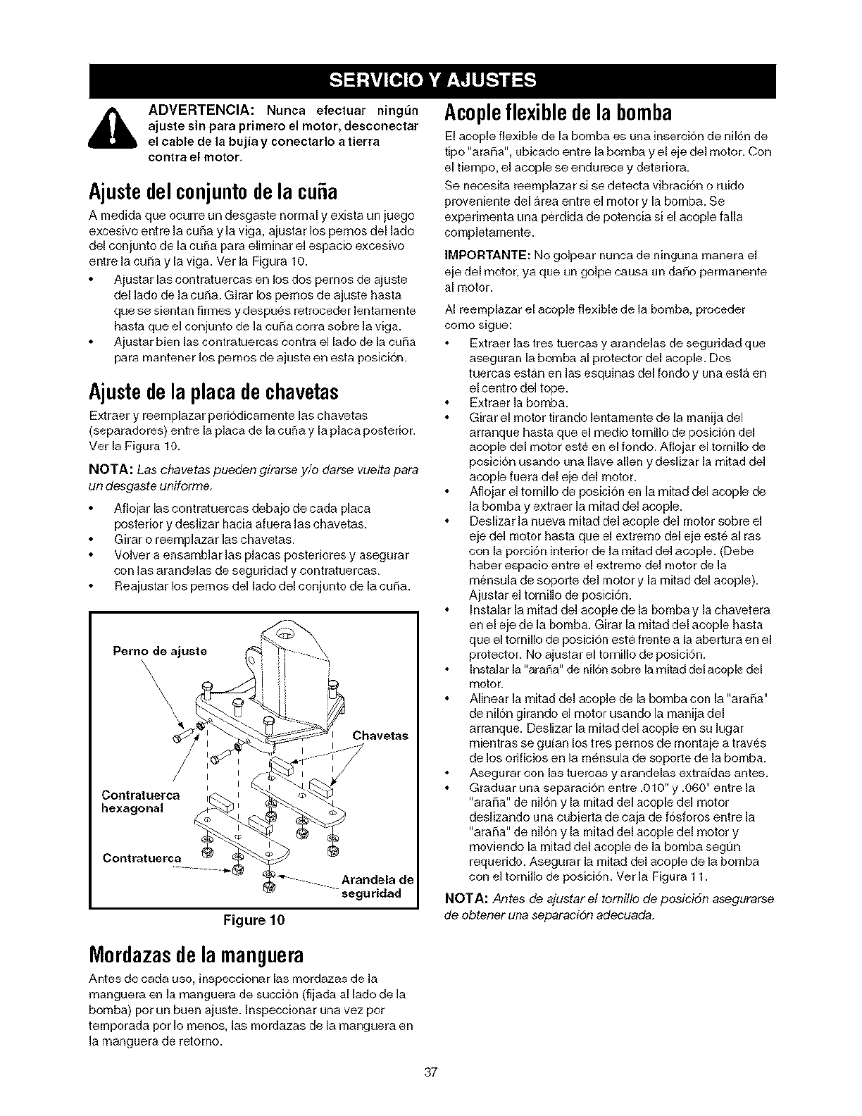
,_ ADVERTENCIA: Nunca efectuar ning_n
ajuste sin para primero el motor, desconectar
el cable de la bujia y conectar]o a tierra
col'_tra el motor.
Ajustedel conjuntode la cu a
A medida que ocurre un desgaste normal y exista un juego
exeesivo entre ]a cuSa y la viga, ajustar los pemos del ]ado
del conjunto de la cuSa para eliminar el espacio excesivo
entre la curia y la viga. Ver la Figura 10.
Aiustar las contratuercas en los dos pemos de ajuste
del lado de la cuSa. Girar los pemos de ajuste hasta
que se sientan firmes y despues retroceder lentamente
hasta que el conjunto de la curia corra sobre la viga.
Aiustar bien las contratuercas contra el lado de la curia
para mantener los pemos de ajuste en esta posicion.
Ajustedela placadechavetas
Extraer y reemplazar peri6dicamente las chavetas
(separadores) entre la placa de la curia y la placa posterior.
Vet la Figura 10.
NOTA: Las chavetas pueden girarse y/o darse vuefa para
un desgaste uniforrne,
Aflojar las eontratuercas debajo de cada placa
posterior y des]izar hacia aluera Jas chavetas.
Girar o reemp]azar ]as chavetas.
Vo]ver a ensamb]ar ]as p]acas posteriores y asegurar
con ]as arande]as de seguddad y eontratuercas.
Reaiustar los pemos de] lado del conjunto de la cuSa.
Pemo de ajuste
\\\\\
Chavetas
I
/I I
I
Contratuerca
hexagonal
Contrat uerca
Arandela de
seguridad
Figure 10
Acopleflexibledela b0mba
El acople flexible de la bomba es una inserci6n de nil6n de
tipo "ara_a", ubicado entre la bombay el eje del motor. Con
el tiempo, el acople se endurece y deteriora.
Se necesita reemplaza r si se detecta vibraci6n o ruido
proveniente del Area entre eJ motor y la bomba. $e
experimenta una perdida de potencia si el acople falla
completamente.
IMPORTANTE: No golpear nunca de ninguna manera el
eje del motor, ya que un go]pe eausa un daSo perrnanente
al motor.
AI reernplazar el acople flexible de la bomba, proceder
como sigu@:
Extraer las tres tuercas y arandelas de seguridad que
aseguran la bomba al protector del acople. Dos
tuercas estAn en las esquJnas del rondo y una est& en
el centre del tope.
Extraer ]a bomba.
Girar el motor tirando ]entanlente de la manila de]
arranque hasta que el medio tomil]o de posici6n del
acople del motor este en el rondo. Aflojar el tornillo de
posici6n usando una Ilave alien y deslizar ]a mitad del
acople fuera del eje del motor.
Afiojar el tornillo de posici6n en la mitad del acople de
la bombay extraer ]a mitad del acop]e.
Deslizar la nueva mitad del acople del motor sobre el
eje del motor hasta que el extreme del eje est_ al ras
con la porci6n interior de ]a mitad del acop]e. (Debe
haber espacio entre el extremo del motor de ]a
mensu]a de soporte de] motor y la mitad del aeop]e).
Ajustar el tornillo de posici6n.
Instalar ]a mitad del acop]e de la bombay ]a chavetera
en el eje de la bomba. Girar la mitad del aeople hasfa
que el tot nillo de posici6n est6 frente a la abertura en el
protector. No ajustar el tomillo de posici6n.
Instalar la "araBa" de nil6n sobre la mitad del acople del
motor.
Alinear la mitad del aeople de la bomba con la "arafia"
de nilon girando el motor usando la manila del
arranque. Deslizar la mitad del acople en su lugar
mientras se guian los tres pernos de montaie a traves
de los orificios en la m6nsula de soporte de la bomba.
Asegurar con las tuercas y arandelas extra[alas antes.
Graduar una separaci6n entre .010" y .060" entre la
"arafla" de nil6n y la mitad del acople del motor
desiizando una eubierta de eaja de f6sforos entre la
"arafa" de nil6n y la mitad del acople del motor y
moviendo la mitad del acople de la bomba seg0n
requerido. Asegurar la mitad del aeople de la bomba
con el tornillo de posici6n. Ver la Figura 11.
NOTA: Antes de ajustar el tomillo de posiciSn asegurarse
de obtener una separaci6n adecuada.
Mordazasdela manguera
Antes de cada uso, inspeccionar las mordazas de la
rnanguera en la manguera de succi6n (fijada al lado de la
bomba) pot un buen ajuste. Inspeccionar una vez pot
temporada pot Io menos, las nlordazas de la fT_aRgueraen
la manguera de retomo.
37
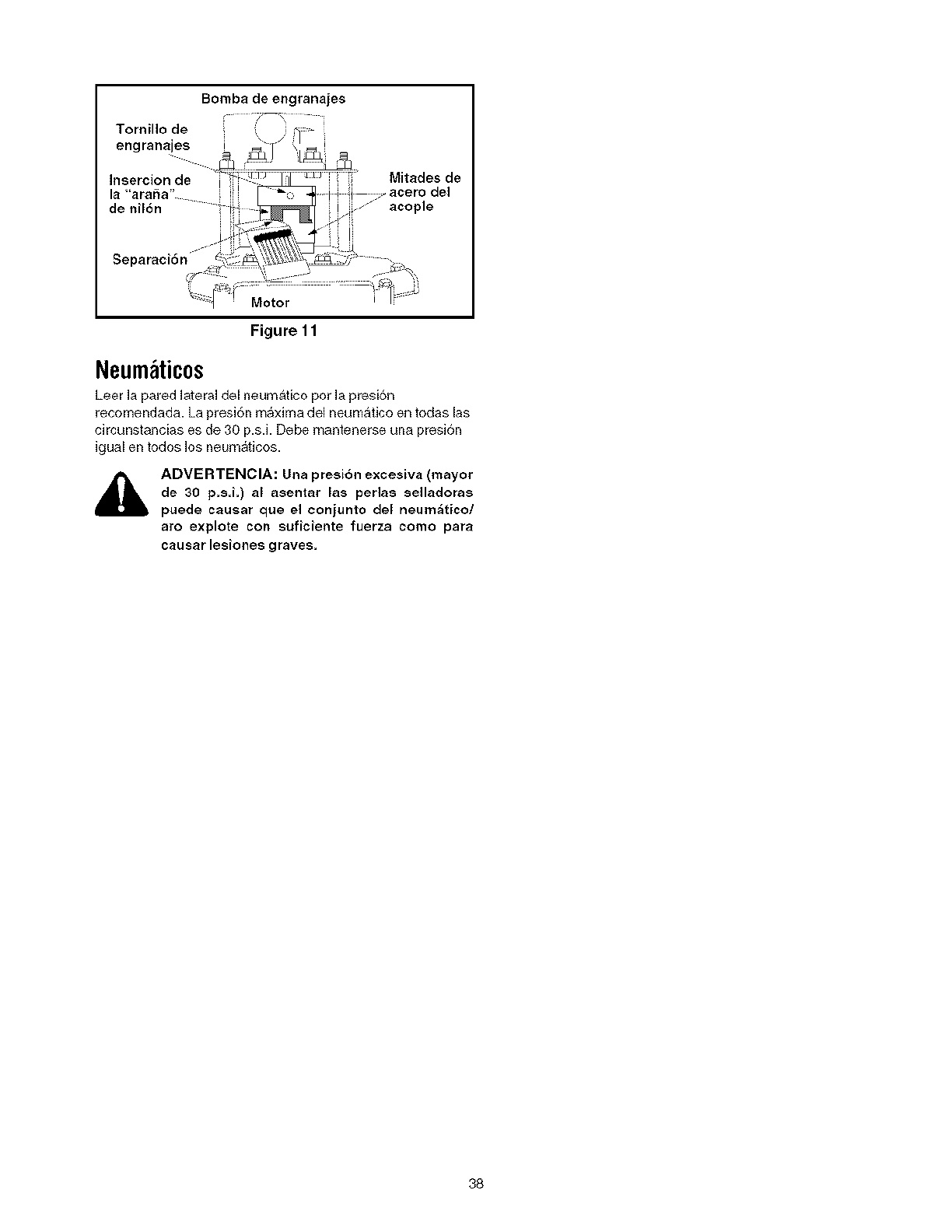
Bombadeengranajes
/x i
Tornillo de
engranajes !
Insercion de Mitades de
la "arabia"
de nil6n acople
Motor
Figure 11
Neum ticos
Leer la pared lateral del neumatico pot la presi6n
recomendada. La presi6n m_xima del neumatico en todas las
circunstancias es de 30 p.s.i. Debe mantenerse una presi6n
igual en todos los neum_ticos.
ADVERTENCIA: Una presi6n excesiva (mayor
de 30 p,s i,) al asentar las perlas selladoras
puede causar que el conjunto del neum_ticot
aro explote con suficiente fuerza como para
causarlesJones graves,
38
AIfinaldelatemporadaosilacortadoradetroncosnoseva
ausarpot30diasomas,prepararlaparaalmacenamiento.
ADVERTENCIA: Nunca almacenar la
m_quina con combustible en el tanque de
combustible dentro de un edificio donde los
humos pueden alcanzar una llama expuesta o
chispa o donde est_n presentes fuentes de
encendido tales como calentadores de agua
caliente y espacio, calderas, secadoras de
ropa_ cocinas_ motores e]_ctricos_ etc,
NOTA: Una buena manera de asegurar que su cortadora
de troncos proporcionar# un rendimiento m#xJmo la
pr6xima temporada es una revisaci6n anual pot su Centro
de Servicio Sears local,
Cortadoradetroncos
Limpiar bien la cortadora de troncos
Frotar la unidad con un trapo aceitado para prevenir la
oxidaci6n, especialmente en la cuSa y viga.
Motor
IMPORTANTE: Es importante prevenir que se [ormen
dep6sitos de goma en las piezas esenciales del sistema de
combustible tales como carburador, filtro de combustible,
manguera de combustible, o tanque, duraste el
almacenamiesto. Tambien, las mezclas de alcohol
(llamadas gasohol o el uso de etanol o metanol) puede
atraer humedad que conduce a la separaci6n y formaci6n
de _cidos durante el almacenamiesto. El gas acidico puede
daSar el sistema de combustible del motor miest ras esta
alma¢@nado.
Drenar el tanque de combustible. Siempre drenar el
combustible dentro de un recipieste aprobado al aire
libre, alejado de llamas expuestas. Asegurarse que el
motor est_ fdo. No fumar miestras se maneja el
combustible.
Arranca r el motor y dejarlo funcionar hasta que las
tuberias de combustible y el carburador esten vacios.
Nunca usar productos limpiadores de motor o
carburador en el tanque de combustible ya que puede
ocurrir un daffo permanente. Usar combustible fresco
[a temporade pr6xima.
Extraer [a bujJa, verier 1/2 oz aproximadamente de
aceite para motor dentro de[ cilindro y hacer girar
lentameste para distribuir el aceite.
Volver a colocar la bui[a.
NOTA: El estabilizador de combustible es una alternativa
aceptable para mfffimizar :a formaciSn de dep6sitos de
goma de combustible durante eJalmacenamiento.
Por favor seguir las instrucciones de abajo para almacenar
su cortadora de troncos con combustible y estabilJzador en
el motor.
Agregar estabi[izador a la gaso[ina en el tanque de
combustible o recipiente de a[macenamiesto.
Seguir sJempre la proporcJ6n de mezc[a indicada en el
recipiente del estabi[izador.
Hacer [uncionar el motor pot 10 minutos pot Io menos
despues de agregar estabilJzador para permJtir que el
estabi[izador Hegue a[ carburador.
No drenar el tanque de gasolina y el carbu rador sJse
usa estabilizador de combustible. Drenar todo el
aceite de[ carter (esto debe hacerse despu6s de
operar el motor y cuando est& todavla caliente) y
Henar el carter con aceite fresco.
Otros
No a[macenar la gaso[ina de una temporada a [a stra.
Reemplazar el recipiente de gasolina si comienza a
oxidarse.
Almacenar la unidad en un Area limpia y seca. No
almacenar ce_ca de materiales corrosivos tales como
[ertilizante.
Frotar el equipo con un trapo aceitado pa ra prevenir la
oxidaci6n.
39
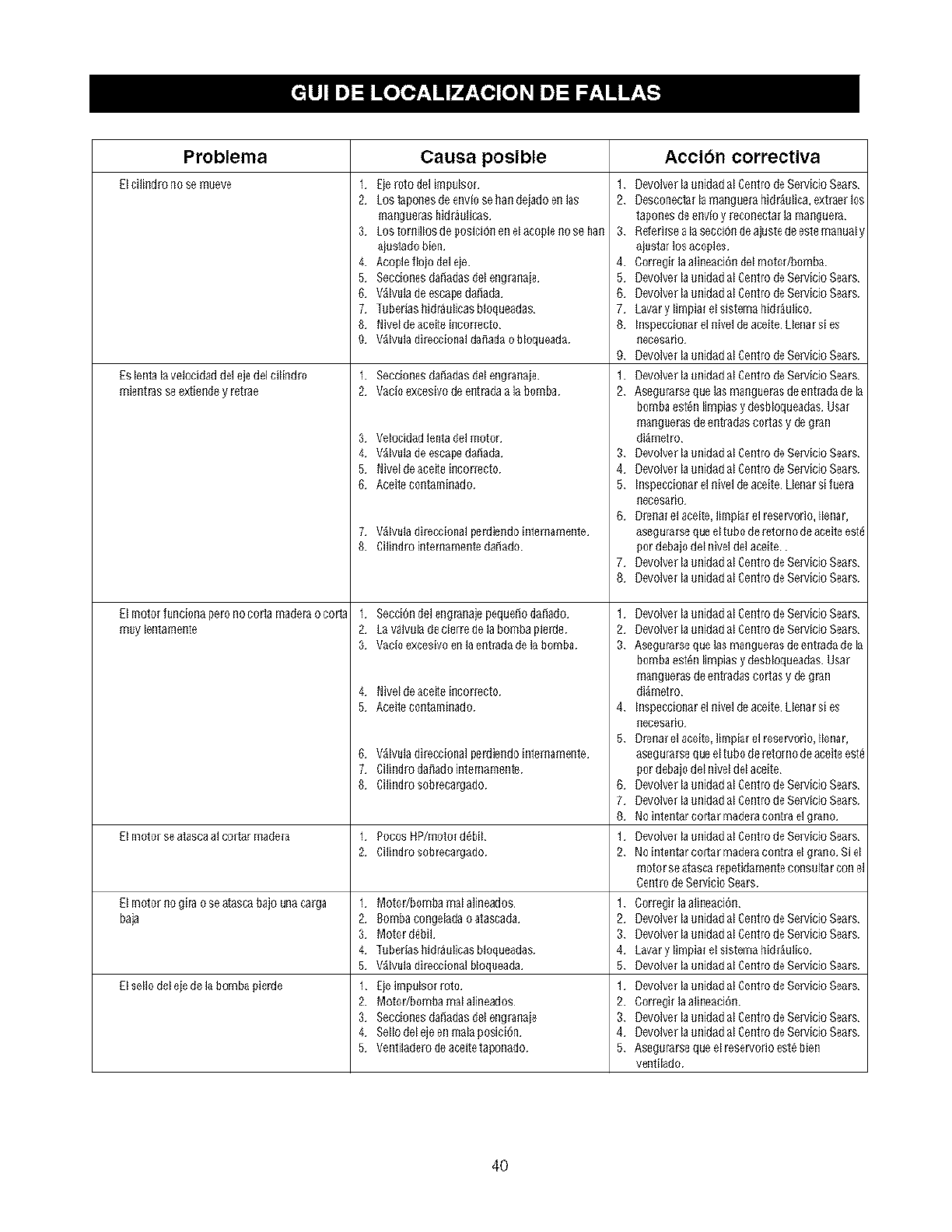
Problema Causa posible
Elcilindmnosemueve 1 Eie_utodelim_lso/
2 Lostapollesdeenvlosehalldeiadoelllas
manguerashidr_licas
3 Lostor_illosdegosici6_enelacople_oseha_
a_stadobien
4 Acoplefloio deleie
5 SeccionesdaEiadasdelengra_aie
6 V_lvuladeescapedaEiada
7 Tuber_sh]d_licas bloqueadas
8 N]veldeace_ incorrecto
9 V_lvuladi_ccionalda_adao bloqueada
Es lenla lavelocidad del ejedel cilindlo
mie£t _s see_xti_iK_8y r_t_e
El EI_o_offunciona pero no corta E_a(fera o coRa
irluy len_amellte
1 Secciones danadas del englanaie
2 V_cIo exc_sivo de e£t_(_a _ la bomba
3 Velocidad lentadel motor
4 V_lvula de escapedanada
5 N]vel deacefie i_corlecto
6 Acei_eco_tami_ado
7 V_lvuladirectionalper_]e_dointemamente
8 Cili_dmi_temame_teda_ado
1 SecciOnde] engranaje pequenodanado
2 La valwla de cierre de la bomba pielde
3 V_cIo exc_sivo e£ lae_t_ad_(_ela _omba
4 N]vel deace_teillcorlecto
5 Aceite coi;tamiimdo
6 V_lvulad]_eccionalpe_t]m_dointemameme
7 Cilindroda_ado]n_ernamente
8 Cilindmsobreca_ado
Elmo_o_seatascaalco,tarmade[a I PocosHP/motord_bil
2 Cilindrosobreca_ado
_1m_or _ogi_ oseatascabajounaca_a I Motodbombareala]ineados
baja 2 8ombacongeladaoatascada
3 Motordebil
4 Tubedashid_l]cas bloqueadas
5 V_lvulad]_ccionalbloq_eada
Elsellodeleiedelabombai_ie_e I Eieimp_lso__o
2 Motodbombarealal]neados
3 Seccionesda_adasdelengra_aie
4 Sellodelejeenmalaposici{_n
5 Ven_ilade_deaceitetaponado
Accibn correctiva
1 _evolverla_nidadalCen_rodeSe_icioSears
2 [}es/:onec_ f I_ in_Rg_e/_ IlitJr_lica, ext[3_ lOS
_a_ones (_ ellvlo y leconec_a[ la i_all_uer_
3 Mferi_sea lasecci6_deajustedees_emanualy
ai_s_a_losaco_les
4 ConegiHaalineaci_ dehnotodbomba
5 Oevolve_launidadalCen_rodeSe_icioSears
OevolverlaunidadalCentrodeSe_icioSe_rs
7 Lawry limpia_elsistemahi(ff_ulico
8 Inspeccionarehliwl deaceiteLlenar si es
Ileces_rlo
9 Oevolve[launidadalCen_rodeSe_icioSe_rs
1 _evolverla_nidadalCen_rodeSe_icioSe_rs
2 Ase_Jr_rse _ue las r_lallguer_s de _lltla(_ (_eI_
bombaest_nlimpiasydesbloqueadasUsa_
inallg]Jer_s de ellt_a(_as cortas i/(_e _raR
di&metro
3 OevolverlaunidadalCen_rodeSe_icioSe_rs
4 Oevolve_launidadalCen_rodeSe_icioSears
5 IRs_eocionar el iliV_l (_eaceite UeRar siluel_
ileces_rlo
O_mm;elaceite,limpia[el rese_orio,Ilenar,
ase_u/_ fse que el tubo (_8I_O/RO (_eactive eS_
pordebajodel niveldelaceite
7 OevolverlaunidadalCen_rodeSe_icioSe_rs
8 Oevolve[launidadalCentrodeSe_icioSears
1 Devolve/la unidad al Centrode Sel_icio Sears
2 _evolver la _n]dad al Cen_rode Servicio Sears
3 As_rse que las Rla£gue_s de _t_a(_ (_eI_
bomba est_n I]mpias y desbloqueadas Usa_
ma_g_er_s do e_t_a(_ascortas i/(_e _EI
di_metro
4 IRs_eocioE]arel £ivel (_eaceite UeRar si es
£ecesarlo
5 Dre_a_el aceite, ]impia_el reservor]o, Ilenar,
ase_u/_fse que el t_bo _Je_oHio (_eacoi_8e_8
_or debajo del niveldel aceite
6 Devolver la _n]dad al Cen_rode SeHicio Sears
7 Devolve_la _n]dad al Cen_rode Sewicio Sears
8 No in_e_t_rcort_[ ma(_elaco_t_aol _Eio
1 Devolve_la _n]dad al Centro deSeHicio Sears
2 No iEl_8£tar cgr[_[ ma_ef_ co_t_a el _o Si el
motor se_s¢_ _eti(_me_te cons_lta r _EI el
Cen_ de Servicio Sears¸
1 Corregi_la alineaci_
2 Devolve_la unidad al Cen_rode Servicio Sears
3 Devolver la _n]dad al Cen_rode Sewicio Sears
4 Lavary I]mpia_el sistema hid_ulico
5 Devolve_la _n]dad al Cen_rode Servicio Sears
1 Devolve_la _n]dad al Cen_rode Sewicio Sears
2 Corregi_la alineaci_
3 Devolve_la unidad al Cen_rode Servicio Sears
4 Devolver la _nidad al Cen_rode Servicio Sears
5 Ase_J_rse que el reservo_o ost_ bier
ven_ilado
40
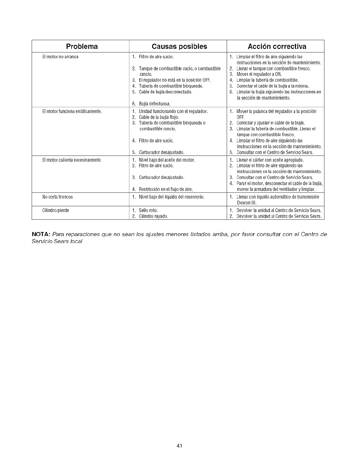
Problema
ElmoloNunciona er{_ticamellte
El EllOlO_CalieRla exeosptalfiellte
NOcosta llOflco$
Cilindlo pieide
Causas posibles
Filtro de aile s_cio
2 Tanque de combustiNe vac% o combustible
raflcio
3 El_gulatJo f no esl_ en laI_osici6n OFF
4 T_berfa (Ie combustible bloqueada
5 Cable(re b_ila desconectado
6 B_iladefectuosa
1 UnidatJfullciollando con el regulador
2 Cablede la buifafloio
3 T_berla (Iecombustible bloqueada o
combustible/aRcio
4
5
1
2
3
4
1
2
Filtro de aile sucio
Carbumdordesaiustado
Nivelbaiodelaceitedelmotor
Filtrodeaires_cio
Carb_mdordesaius_do
Reslricci611en el fluio de aile
Nivel baio del IIquido del reservodo
Selloroto
Cili_ldlor3yado
Acci6n correctiva
1 kimpiar el filtro de aile siguielldo las
]fistf u¢cioEl_$eella Secoio_d_ ma£18R]mieRto
2 Ue£a__1taE]qlJecol_¢onlDifsl]_le l_s¢o
3 M_e_ el regula(fo_a ON
4 Umpia_la luberia de cornbuslible
5 Co_ectarel cable (re la b_i_ a la misma
6 Limpiar la b_ila siguieEidolas i_struccio_es e_
lasecc]_ d_ mSEIlSEI]rlli_EIl0
1 Mover la galancadeh_gulado{ a la posici6n
OFF
2 Cow.tar y aiustar el cablede la buila
3 Limpiar la luberia de coml)ustible kleE_af el
lafl_ue coEicorn_lJsliblo fies¢o
4 Limpiar eUillro (Ieai_ sig_iendo las
iElst[iJc¢ioEles_EIla s_cci{]fl de mal_t_E]imi_EIlO
5 Co_s_llar con el Ce_t_ de Servicio Seals
1 Uenarel ¢_rterco_ aceileapro_iado
2 Umpia_eUillro (Ieai_ sig_ien(Io las
iEISt[IJC¢iOEle__EIla S_CCi_flde ma£t_E]in/iORlO
3 COI_SIIIIa_COn_10_£t_ {]e %rvi¢io %a[$
4 Pa_ r el motor, desco_ectar el cabledela buiia,
rn_ef la armad_ (Iel venlilador y limpiaf
1 Ue_a_con liq_i(Io autom_tico (Ietra_smisi6n
Oex_n IlL
1 Devolver la u_i(fada] Ce_tro (IeSer_icio Seals
2 I)svolver la _nida(I al Cenlro de Servicio Sears
NOTA: Para reparaciones que no sean los ajustes menores fistados arriba, pot favor consultar con el Centro de
Servicio Sears local
41

(Estap_glnaesapllcableQ_flcamen_eenEstadosU_fldosdeAmericay Oanad_)
Senrs, Roebuck and Co., U.S.A. (Sears), Junta de Recursos Am bientales de Califor nin (CARB)
y Agencin de Protection Ambiental de los Estndos Unidos (U.g. EPA)
De¢lnraci6n de la Gnrnntin del Sistemn de Control de Emisiones (Dorechos y Oblignciones del Propi_tnrio de la Gnrantia de Defectos)
LA COSE_TURA DE LA GARANTIA DEL CONTROL DE EMISIONES ES APL_CABLE A CAU FORNIA Y PARA LOSfvIOTOR ESC E RTIFICADOS MODELOS 1997 EN ADELANTE
LOS MOTORES CEI_TIFICADOS QUE HAYAN SFI)O COM PRADOS EN CAU FORNIA A QUE SEAN COMPRADOS Y USADOS EN OTRA PARTE DE LOS ESTADOS UNIDOS (Y
pART_R DE 1995 Y DESPUES DE ESTA gECHA LOS CUALES SEAN USAC)OS EN A PANTIR DE ENERO 1 DE 2001 EN CANADA/
Declarncion de In Gnrantin de Defectos d_l Sistemn de Control de Emisiones de California, Estndos Unidos y Canadli
La Junta de Reour_os Amt J_entaJes (CAF_B) La Ag_Fa de p_oteooi6n Amb_nt al _e _cs E_tados
Un_do_ U_& EPA y_e_ se comp_en en eT_ll_r_es _aGar_fa de_ S_stema deCont_o_
de_ mis_ones de su moor pequeno modelo 2O00 e_ _delante pare u_o en te_reno_ slurpavimento
(_ORE) _ Caflfom_a_ _c_ nuevcs motores pequenos papa use en ter_nc_ sh_ pavm'ento _be_
ser d_se_a_o_ fabnOa_r,s y eq ulpad_ par_ cum_i_ I_ figu ro_os e st_nd_es anti.smog de] _ado_
Err o_qu_e_ ot_a paste de I_ _ados Un_do_los nuev_ motores de encend]do per chisp_ pare re
u_o er_ carl_tem_ modelos 19_7 y posteno_ deben oump_ir est_nda_es simi_ares a Io_
e_ablecl_C_ pol ra Agencl_ de p_Jtecci_n Ambremt al de _os E_tadc_ U_dos (U_& _PA) _e_
debe ga_antiz_ e] s_stema de oo, rt_Olde em_s_ones en su motor per los 13e_fr,dos de t_mpo _ados
abaJo te_iendo el_ _uenta que no hay_ h_bl_o abuse neg_igen_a omantenim_ento no _p_oplado
en _,u motor peque_o p_a use en terrenos sin paviment o_
_u sistem_ de cont_o] de emls_ones mc_uye pa_e_ ta_ come el ca_burado_ el fi]t_ de a_re, e_
sistem_ deencendrdo_ e] merle y e_oonW_dor _at _ ftior,_Tam bi_n pue_ i_ol_r c_,nectores y _,t,_
c_,njunt os _]_elon_d_ co_ el sistema de emis_r_es_
_iemp_e que ex_a une oor_d_Oi0n de gara_rt _a_ Sears _p_a_ sumoto_ peque_o papa use en
te_eno_ s_n pavh_to si_ nl_/_ c_,sto p_a u_ted I_uyendo el d_ag_strc o, la_ pa_es y I_ mane
de c_br&
Coberturn de In Gnrnntia de Defectos del Sisterna de Control de Emisiones Briggs & Strntton
Losmotores pequeno_ para _o en refines sh_p_vimentose gatant_z_ relatrvoa_o_defectorsde prov_ne_ e_t_b_orda_ _baJo S_algun_de 1aspa_e_ ba_ooober_u_aen s_ m_or se encuentm
las parses del _ema de cont_o_de em_ne_ d_mnte un pe_do de dos _nos suJeto a I_ defectLiosa la p_te ser_ repemdaor_ "pp_7_daper Se_s
ResponS.abilidnd_s del Propietario de In Gnrnntia
Oomo p_etado _e un motor peque_o para u_o e_ te_reno_ _n paviment o u_ed e_ te_onsab_e
de que se I_eve a ca_o e_ marrtenim_nto Tequer_do el cua_ se _ndlca en sus _n_uc_nes de
Mantenlmlento _ Operaoi0n_ Sea_ _ re_om_enda guardar todo_ _us _cit_os que _ut_ e_
ma_e_m_ent o en su moto_ pequ_ ]_a_a use en terrer_ slr_pavh_ento, pete 3_ars no _olOl%lede
ne_a_ la gamrrt_a pr,r I_ fa_ta de _dbo_ sine po_ su ornls_,n _1_segura_ _a real]zao_n de todo el
marrt enimient o p_o_ramado_
No obstante_ oomo p_etarlo de un moto_ pequeno para use en te_l_O_ _ pavIme_t o usted
t_ne q_ dar_e cue_a que Sea_ puede ne_arle I_ cot_e_ura de _a g_nt_a si su motor peq_e_o
,ara u_,o en te_reno_ sm pavlmento o _a _e sus pa_es h_ fallado debl_o a _uso
ne_igenci_ mant enimient o_nco_recto omod_floa_ione_ no aprobadas
Usted es _sponsab_e de p_ese_ su motor pequeno para use en te_no_ s_n paviment o a un
Dl_t d budder de Se_V_elo AutOdzado Sea_ tan pronto se p_e_e_te e_ p_blema Las _eparaoro_as
ba_o g_ntfa i_d]Sput abres deben com£_eta_e en un perfodo de trempo r_7on_ble que no se
_ceda de 30 d_& _ uSted t_ne algunas pTegunta_ relaolon_d_s co_ _os derecho_ y
responsab_l_dade_ de I_ _amnt fa det_e oontactar a un Rep_entarrte de _e_io_ _ears marCando
e_te_fono: 1.414 25_5262,
La ga_ant_a de emis_ones es un_ g_rant_e ctedelete& Los defectos soniuzg_dO_ en el de_empeno
normal de _ moto_ La _rantla no e_t_ rel_clonada con u_a p_et_a de emi_one_ e_ uso_
Provisiones de In Garnntin de Defect os del Sistemn de Control de Emisiones Briggs & Strntton
La_s_0u_entesson p_ow_ones espeofhcas _]ativa_ _ taCot_e_uradeGa_a_rtfa de Defectos del $1_tema deCo_t_o__e_mis_unes E<_una ad_¢_ de le _a_ant_ade_motur Sea_spara los moto_esno-re_ulados
enoo, rtmdos en laS _ucolo_e_ de Mant enlmient oy Ope_aol_'n
l_ patze_ Gara_rz_d_
La oo3e _Jra b_o esta g_ant_ se e_l_Je t_lcamel_t e _ las pa_e_listadas aba_o (]_a_tes
de los sl_ema s de oontto_ de em_nes) h_stala e;derrs_n que estas pa_es fue_on
prese_adaS en e_motor come,ado,
_l_tema de Medl_r/n de Combu_lb_e
• Slstema de Enr_uec_m_nto de Arranqu_ e_ Fr_o
(est_g_ad_n suave)
• Carbumdr,r y Pa_es ]_ern_s
• B_,mba de C_,mbu_ble
_istem_ de I_du_]_n de Alre
• F_o de Alre
• ML31t_plec_eAdm_s_n
_l_tem_ de E_cerrdldo
• Bufla_)
• S_tem_ cte Ence_d_do oon M_gneto
& _l_tema CataHza_/
• CorrVe_do_ Cata_f_oo
• M01t_ple _ Escape
• Slst eme _e _nyecc_n de _ re o Vd_Vu_a de pu_saoi0n
I_ems V_O$ U$SdOS en _OS_lstemas Ante_re_
• V_Cfo_Tempem_ra po_oi_n_V_l_ul_Sens_tlvasdeTiempoy
_uiches
2_ Dur_l_n de la Cobe_um
_ea_ gamnt_za el p_Opletado inicl_ y a c_d_ cr,mprado_ subseCue_te que la_ Pa_es
Ga_antiZ_da_ est_n _bres de defeotos enmaier_es y mane de obra I_ cua_ h_ya
o_ionado/a_as C_ela_ P_es G arantlz_da_ per un perfodo de dos a_o_ al_a_lr de ra fect_
en que es entr_a_o el moto_ _ un comprador deta_ist&
3$_n Oostr,
La reparaci6n ooam_o de OUalqu_r patze Garantlzada se _levar_ a o_bo sin oosto _guno
para el ptopiet arlo, Induyendo ta labor de dl_gn_oo _acu_l conduce e _adete_i_ao_n de
que esa patze G_an_zada es _efectu_sa, s_ e_ trabaJo _e d_gn_st_oo es Te_Hzado en un
Oent_o de _ew_c _ Autodzado _ea_ papa se_olo _e gara_tfa de emis_c_e s _c_t_cte su
Oent_o de _e_clo Autodzado Sea_s m_ oercano list ado e_ I_ "p_ina_ Area dlla_ _baJo
_Motor_ G_so_l_ra* _otores _ Gaso_ina'_ "M_qu_na_ Co_tac_sped" o en une o_tegorfa
similar,
4_ Recl_mo_ _ EXOlU_one_ de I_ Cobenura
L_S reclamos _ la _amrrt_a _e oompleta_n cte _ue_do con la_ p_ov_slone_ de la P_iz_ de
Garant_a de_ Me,or _ears, L_ cobe_ura de la garant_a esta_ exc_u_d_ p_m falias de _a_
p_es G a_antrz_da_ las oua_s no _an patzes r,n_na_es Sea_s o po_ abuse, ne_encla o
manten_rn_ento Inco_rect o seg0_ se est ab_e en I_ pr_l]za de Gamnt_a del Motor See_
Se_s r_o se haoe responsable de c_t_Hr fal_a s de parses Gatantizada_ oca_o_d_s po_ el
u_, de _dloi0_ de 13a_te_, parses no.odgh_a_e_ o parses mOdifioada&
& Mantenlm_nto
Cualquler patze gararrt_zad_ la cu_ no est_ p_og_amada pare c_ml_Jo a_ _l_Zar el
manten_entr, rec_uerl_o o la _J est_ p_mmad_ t_n_e_me_te pare una _n_eoc_r_n regular
pr,r e_efecto _ _repa_e o c_mt_e s_ e_ _ece_r_c _ se garant_zar_ po_ defectos durante e_
perlodo de la garantl& Cu_lqu_r paste Gamrrt_zad_ I_ OUal e_ p/ogramada para eatable
pr,r el m_nt en_m_ent o _quendo se gamntlz_ 0n_c_me_te per defeotc_ durante e_pelf ode
de tlempo h_sta e_pnmer c_mt_Jo p_ogtamac_o papa e_a pa_e_ C_a_qu_r _puestr_ que _ea
e_uWale_te en de_empeno y durat4Ndad puede se_ usado a_ Hevar a c_bo toda terea cte
manten_rn_ento o reparaCl_n_ _ prcpJetar_o es responsable de I_ real_zaciO_r de todr, e_
manten_entr, requendo, se_/_ se define en I_ _nstrucc_ones de Ma_tenimiento y
OperaciOn Sea_
& Coberzura Oo_secuente
La co_e_ura aquf _tab_edda _ e;dende r_ h_sta la faJ_ de cu_quJe_a de _s oomponente_
del motor oca_o_d_ 10o_la falla de oua_quier Pa_e Ga_antizada _ue _L/n se er_cuentre ba_o
_amrrt f&
Busque el Periodo de Durabilidad de Emisiones y la Informacibn del indice de Aire Pertinentes en su Etiqueta de
Emisiones del Motor
LC_,motores q_ son ce_tfflcados p_ curnpiir oon _s No#n_s _e Emi_ones _tap_ 2de _a_rrta de R_U rsos Ambient eJes de C_l]f omla (CAF_8) debe_ most_a rlainfo n_l_n refere_ealPer fodode DurabHIdadde
Em_o_es ya_nd_oe de Aire _ears Roebuck and Co U S A nh_e que esta Informa_i_,n est_ d_pon_ble para el oon_idor en _eshas et_quetas de em_lones La etlqueta del motor_ndlcar_ I_ Info_maokln de
ce_flc_e_r_
E_peHodCdeD_ra blgdadd_Emisione_ de_cdbe e_r_me_ de hems de_tlempo_al de ope racir_r papa e_ou_ estd oe_floacto el motor per cu m_l_ oo_ I_ em_slones _umiendo un mante_m_ento apr op]ado de
acuerdo oon la_ En_uco_ne_ de Mant enimient oy Operao_'n _e utl_iZa__as _igu_ent es oat ego#as:
Mode_ado: E_ motor es oe_ fi_a_r,para _u mpl_r con la_ emis_on_ dumnte 125 betas de] _em_o rea_ de operation d_l m_o_
I_er medio: E_ motor es oer_#_c_dr, pare oump_r con la_ em_ones du_ante 25O he,as de] t_em£o rea_ de operao_n del moto_
Prolon_ado: _] rnoto_e_ oe_cado p_a oumpH_oo_las emlSlone_ durar_e 5OObetas del t_mpo _1 de ope moi6_ de_motor¸
Po_ e/emp_o un_ m_quina oor_ac_ped de _ast_a_ t_pic_ es usada d_ 2O _ 25 _ora_10or a_o Po_o tanto el Per_odo de £_urabllid_d deEmislones de ur_moto_ con _n_ o_caoi_n httermedia se IgLlala rfa _e 10
a12 a_os
E_ h_dioe d_Ai_ e_, un n0me_ calculate q_e deSCribe el niv_ relative de em_s_ones p_a un_ taml_i_ especf/_ca de motores M_errha_:q&s b_o sea e_indic*_ deA]re m_s _lm pie se_ e_moto_ Esta info nn_ei_,n es
mostrada en _trTa _r_/_o_ en _aet_q_et_cte emisiones
Despu_s de Julio 1, 2000, Busque el Periodo de Conformidad de Emisiones en la Etiqueta de Conformidad de
Emisiones del Motor
Despu_s de Ju_io _29OO or_rt_oto_e_ _ear& RoebuCk and Co, U&A esta_n ce_#_c _dos po_ oUmpl]r oct ]as _on_s de em_s_on_ F_e 2 de_aAgenoia deproteoo_0n Ambler a_ los Estado_, Un_dos
(U_PA) P_m_c_ moto_s oe_cado_F_se 2, el Perfodo de Con_nn_dad de _misio_e_ al oual se _ef_erela_tlqueta deConfo_idad de _ mislones i_dl_a el nL3me_ode he,as de ope_aol_ pata I_ cuales e_motor
ha demostrado que _mp_e oo_r _o_ req_e rlmietrt osFe_emles cte em_nes_p aramot o_e_,oor_ _ de splaZam_nto Infedo r _ 225 co,Cat ego#a_ 125 heras B_ 250 hor_ yA=_500 homS_pam mote res con un
de sp_azamient o de 225 co o _pe/Iol_ CategodaC _ 250 betas {__5r_0horas y A _ 1000 hera&
E_splaZ_mientodelr'smotr_resModelosSene2_0000es344oc Esta es urta ropresentaci611
EId_P lazamier_tode Ic_ r_tr,res Modelos Sere 280000 es 465 oo¸ eneric_t de urla et i ueta de
E__esplazamientode los motores Modelos _ede 310000 es 501 co g .... q
ewiISIOrleS tlplC_tmente
encolttrad_ en uft motor
certificado,
42
Repair Protection Agreements
Congratulations on making a smart purchase.Your new
Craftsman® product is designed and manufactured for
years of dependable operation. But like all products, it
may require repair from time to time. That's when
having a Repair Protection Agreement can save you
money and aggravation.
Purchase a Repair Protection Agreement now and
protect yourself from unexpected hassle and expense.
Here's what's included in the Agreement:
Expert service by our 12,000 professional repair
specialists
Unlimited service and no charge for parts and
labor on all covered repairs
Product replacement ifyour covered product
can't be fixed
Discount of 10% from regular price of service
and service-related parts not covered by the
agreement; also, 10% off regular price of
preventive maintenance check
Fast help by phone - phone support from a
Sears technician on products requiring in-home repair,
plus convenient repair scheduling
Once you purchase the Agreement, a simple phone call
is all that it takes for you to schedule service. You can
call anytime day or night, or schedule a service
appointment online.
Sears has over 12,000 professional repair specialists,
who have access to over 4.5 million quality parts and
accessories. That's the kind of professionalism you can
count on to help prolong the life of your new purchase
for years to come. Purchase your Repair Protection
Agreement today!
Some limitations and exclusions apply. For prices and
additional information call 1-800-827-6655.
Sears Installation Service
For Sears professional installation of home appliances,
garage door openers, water heaters, and other major
home items, in the U.S.A. call 1-SO0-4-MY-HOME®
Acuerdo De Proteccibn Para Reparaciones
Felicitaciones por haber realizado una adquisici6n
inteligente. El producto Craftsman® que ha adquirido
esta disehado y fabricado para brindar muchos ahos de
funcionamiento confiable. Pero como todos los
productos a veces puede requerir de reparaciones. Es
en ese momento cuando el disponer de un Acuerdo de
protecci6n para reparaciones le puede ahorrar dinero y
problemas. Adquiera ahora un Acuerdo de protecci6n
para reparaciones y protejase de problemas y gastos
inesperados. A continuaci6n se detallan los punfos
incluidos en el Acuerdo:
Servicio experto prestado por nuestros 12.000
especialistas en reparaciones profesionales
Servicio ilimitado sin cargo para las piezas y
la mano de ohra en todas las reparaciones
cubiertas
Reemplazo del producto isi no es posible
reparar el producto cubierto
Descuento de 10% del precio normal del
servicio y de las piezas relacionadas con el
mismo que no esten cubiertas pot el acuerdo;
ademas, 10% del precio normal de la
verificaci6n de mantenimiento preventivo
Ayuda rapida por tel_fono - asistencia telef6nica a
cargo de un tecnico de Sears para los productos que
requieren reparaci6n a domicilio adem&s de una
programaci6n conveniente para la reparaci6n
Una vez adquirido el Acuerdo, puede programar el
servicio con tan s6lo realizar una Namada telef6nica.
Puede Ilamar en cualquier momento del dia o de la
noche o programar un servicio en linea.
Sears dispone de rnas de 12.000 especialistas en
reparaciones profesionales que tienen acceso a mas
de 4.5 miNones de piezas y accesorios de buena
calidad. Este es el tipo de profesionalismo en el que
puede confiar para que le ayude a prok)ngar la vida util
del producto recientemente adquiddo en los ahos pot
venir, iAdquiera hoy su acuerdo de protecci6n para
reparaciones!
Se aplican determinadas limitaciones y exclusiones.
Pot precios e informaci6n adicional Name al 1-800-827-
6655. Sears Installation Service (servicio de
instalaciones de Sears). Si desea soNcitar la instalacion
profesional de Sears de aparatos dom6sticos,
dispositivos para abrir portones, calentadores de agua
y otros articulos domesticos importantes, en los
Estados Unidos Name al 1-SOO-4-MY-HOME®
43

Your Home
For repair-in your home-of all major brand appliances,
lawn and garden equipment, or heating and cooling systems,
no matter who made it, no matter who sold it!
For the replacement parts, accessories and
owner's manuals that you need to do-it-yourself.
For Sears professional installation of home appliances
and items like garage door openers and water heaters,
1-800-4-MY-HOME _(1-800-469-4663)
Call anytime, day or night (U.S.A. and Canada)
www.sears.com www.sears.ca
Our Home
For repair of carry-in items like vacuums, lawn equipment,
and electronics, call or go on-line for the location of your nearest
Sears Parts & Repair Center,
1-800-488-1222
Call anytime_ day or night (U.S.A. onty)
www.sears.com
To purchase a protection agreement (U.S.A.)
or maintenance agreement (Canada) on a product serviced by Sears:
1-800-827-6655 (U.S.A.) 1-800-361-6665 (Canada)
Para pedir servicio de reparacion
a domicitio, y para ordenar piezas:
1-888-SU-HOGAR sM
(1-888-784-6427)
Au Canada pour service en frangais:
1-800-LE-FOYER M°
(1-800-533-8937)
www.sears.ca
, E/AR8
TM Ml
® Registered Trademark _ Tlademark _s Se_/}ce ?Vrark of S_ars Roebl ck and Co
®Ma_caRegstrada _ MarcadeFabr}ca , Marcad_SeHiciodeSears, RoelslckandCo
_c MD
MarqL e de commerce MarqLle dcposee de Sea_s, Roelsuck and Co O Seals Roebuck and Co
