Craftsman 247887790 User Manual SNOW THROWER Manuals And Guides 1008001L
User Manual: Craftsman 247887790 247887790 CRAFTSMAN SNOW THROWER - Manuals and Guides View the owners manual for your CRAFTSMAN SNOW THROWER #247887790. Home:Lawn & Garden Parts:Craftsman Parts:Craftsman SNOW THROWER Manual
Open the PDF directly: View PDF ![]() .
.
Page Count: 60
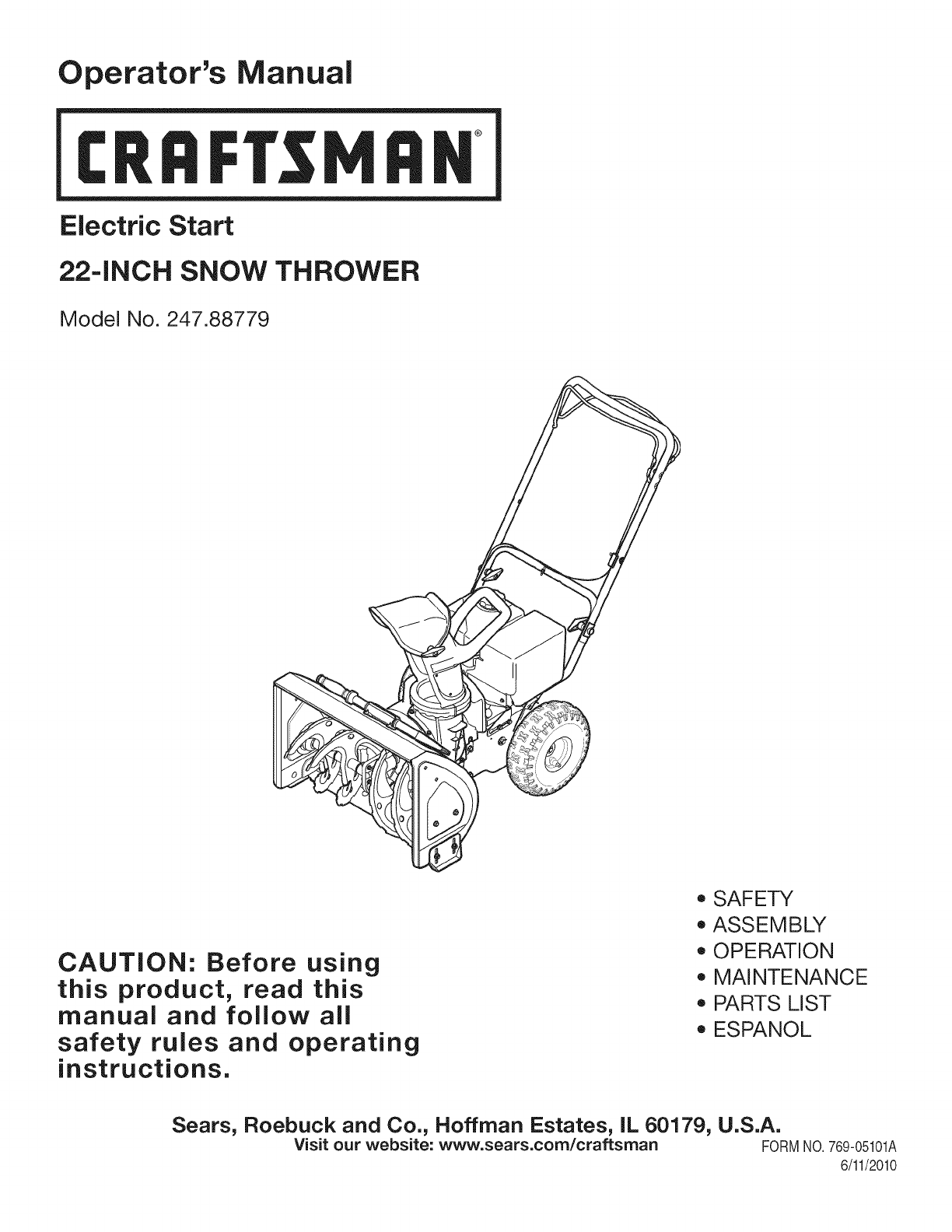
Operator's Manual
CRRFI'$1 1RN
Electric Start
22=INCH SNOW THROWER
Model No. 247.88779
CAUTION: Before using
this product, read this
manual and follow all
safety rules and operating
instructions.
o SAFETY
ASSEMBLY
OPERATION
MAINTENANCE
PARTS LIST
ESPANOL
Sears, Roebuck and Co., Hoffman Estates, IL 60179, U.S.A.
Visit our website: www.sears.com/craftsman FORMNO.769-05101A
6/11/2010
WarrantyStatement.................... Page2
SafeOperationPractices................ Page3
SafetyLabels......................... Page7
Assembly............................ Page8
Operation........................... Page12
Maintenance&Service................. Page16
Off-SeasonStorage................... Page21
Troubleshooting...................... Page22
PartsList............................ Page23
RepairProtectionAgreement............ Page35
Espa_ol............................. Page36
ContactNumbers.................. BackCover
CRAFTSMAN FULL WARRANTY
Whenoperatedand maintainedaccordingto allsuppliedinstructions,ifthis Craftsmansnowthrowerfailsdueto a defectin materialorworkmanshipwithintwo
yearsfromthe dateof purchase,return itto anySearsstore,Sears Parts& RepairServiceCenter,orotherCraftsmanoutlet inthe UnitedStatesforfreerepair(or
replacementifrepairprovesimpossible).
Thiswarrantyappliesfor only90 daysfromthe dateof purchaseifthis chipper-shredderisever usedfor commercialor rentalpurposes.
This warranty covers ONLYdefects inmaterial and workmanship. SearswillNOTpay for:
• Expendableitemsthat becomewornduringnormaluse,includingbutnotlimitedto
augerbladesor paddles,skidshoes,shaveplate,shearpins,sparkplug,air cleaner,belts,andoilfilter.
• Standardmaintenanceservicing,oil changes,ortune-ups.
• Tire replacementor repaircausedbypuncturesfrom outsideobjects,suchas nails,thorns,stumps,orglass.
• Tire orwheelreplacementor repairresultingfrom normalwear,accident,or improperoperationor maintenance.
• Repairsnecessarybecauseof operatorabuse,includingbutnotlimitedto damagecaused byover-speedingthe engine,orfrom impactingobjectsthat bend
theauger,frameor crankshaft.
, Repairsnecessarybecauseof operatornegligence,includingbutnotlimitedto, electricalandmechanicaldamagecausedby improperstorage,failureto use
thepropergradeand amountof engineoil,or failureto maintaintheequipmentaccordingto the instructionscontainedinthe operator'smanual.
• Engine(fuelsystem)cleaningor repairscausedbyfueldeterminedto be contaminatedor oxidized(stale).In general,fuelshouldbe usedwithin30 daysof
itspurchasedate.
• Normaldeteriorationandwearof the exteriorfinishes,or productlabelreplacement.
Thiswarrantyappliesonly whilethis productis withinthe UnitedStates.
Thiswarrantygivesyou specificlegalrights,and you mayalso haveotherrightswhichvaryfromstateto state.
Sears, Roebuck and Co., Hoffman Estates, IL 60179
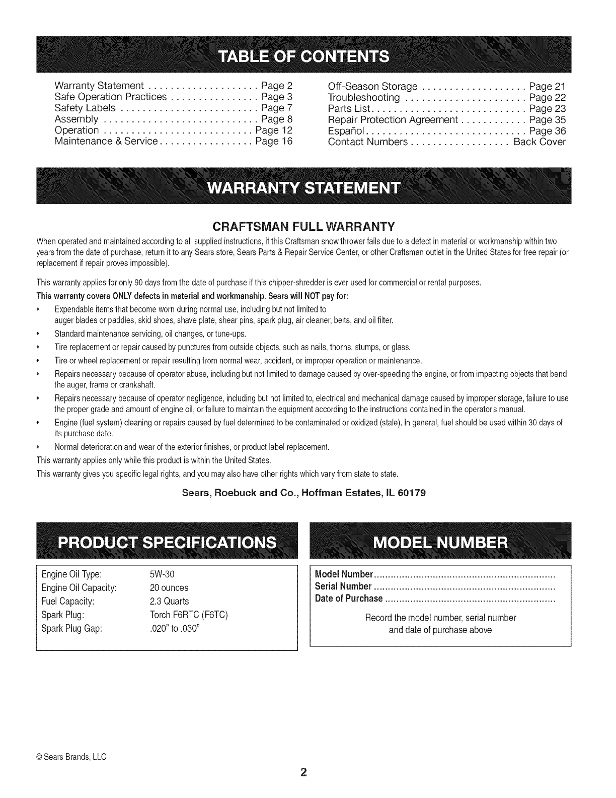
EngineOilType: 5W-30
EngineOilCapacity: 20ounces
FuelCapacity: 2.3Quarts
SparkPlug: TorchF6RTC(F6TC)
SparkPlugGap: .020"to .030"
ModelNumber.................................................................
Serial Number .................................................................
Dateof Purchase.............................................................
Recordthe modelnumber,serialnumber
anddateof purchaseabove
©SearsBrands,LLC
2
Thissymbolpointsout importantsafetyinstructionswhich,if not
followed,couldendangerthepersonalsafetyand/orpropertyof
yourselfandothers. Readandfollowall instructionsin thismanual
beforeattemptingto operatethismachine.Failureto complywith
theseinstructionsmayresultin personalinjury.Whenyou seethis
symbol,HEEDITSWARNING!
CALIFORNIA PROPOSITION 65
EngineExhaust,someof itsconstituents,andcertainvehicle
componentscontainoremitchemicalsknownto Stateof California
to causecancerandbirthdefectsorotherreproductiveharm,
Thismachinewasbuiltto beoperatedaccordingto the safeopera-
tion practicesinthis manual.As withanytypeof powerequipment,
carelessnessorerroron the partof the operatorcan resultin serious
injury.Thismachineis capableof amputatingfingers,hands,toes
andfeetandthrowingdebris.Failureto observethe followingsafety
instructionscouldresultin seriousinjuryor death.
Your Responsibility--Restrict the use of thispowermachineto
personswho read,understandandfollowthewarningsand instruc-
tionsin thismanualandon the machine,
SAVE THESE INSTRUCTIONS!
TRAiNiNG
•Read,understand,andfollowall instructionson the machineand
in themanual(s)beforeattemptingto assembleandoperate.
Failureto do socan resultinseriousinjuryto the operatorand/
orbystanders.Keepthismanualin a safeplaceforfutureand
regularreferenceandfor orderingreplacementparts. Forques-
tionscall,1-800-4MY-HOME.
• Befamiliarwithall controlsandtheir properoperation.Knowhow
to stopthe machineanddisengagethemquickly.
Neverallowchildrenunder14yearsof ageto operatethis
machine.Children14andover shouldreadandunderstandthe
instructionsandsafeoperationpracticesin thismanualandon
the machineandbe trainedandsupervisedby anadult.
Neverallowadultsto operatethis machinewithoutproper
instruction.
• Thrownobjectscan causeseriouspersonalinjury.Planyour
snow-throwingpatternto avoiddischargeof materialtoward
roads,bystandersandthe like.
Keepbystanders,petsandchildrenat least75feetfromthe
machinewhile itisinoperation.Stopmachineifanyoneenters
the area.
Exercisecautionto avoidslippingor falling,especiallywhen
operatinginreverse.
PREPARATION
Thoroughlyinspecttheareawherethe equipmentis to beused.
Removeall doormats,newspapers,sleds,boards,wiresandother
foreignobjects,whichcouldbe trippedoverorthrownby the auger/
impeller.
Alwayswear safetyglassesor eyeshieldsduringoperationand
while performingan adjustmentor repairto protectyoureyes.
Thrownobjectswhichricochetcancauseseriousinjuryto the
eyes.
Donot operatewithoutwearingadequatewinteroutergarments.
Donot wearjewelry,longscarvesorotherlooseclothing,which
could becomeentangledinmovingparts.Wearfootwearwhich
will improvefootingonslipperysurfaces.
Usea groundedthree-wireextensioncordand receptaclefor all
machineswithelectricstartengines.
Disengageall controlleversbeforestartingthe engine.
Adjustcollectorhousingheightto cleargravelorcrushedrock
surfaces.
Neverattemptto makeanyadjustmentswhileengineis running,
exceptwherespecificallyrecommendedinthe operator'smanual.
Letengineandmachineadjustto outdoortemperaturebefore
startingto clearsnow.
3
Safe Handling of Gasoline
Toavoidpersonalinjuryor propertydamageuseextremecare in
handlinggasoline.Gasolineis extremelyflammableandthe vaporsare
explosive.Seriouspersonalinjurycan occurwhengasolineis spilled
onyourselfor yourclotheswhichcan ignite.Washyour skinand
changeclothesimmediately.
• Useonly anapprovedgasolinecontainer.
• Extinguishall cigarettes,cigars,pipesandother sources
of ignition.
• Neverfuelmachineindoors.
• Neverremovegas capor addfuel whilethe engineis hot
or running.
• Allowengineto coolat leasttwo minutesbeforerefueling.
• Neveroverfill fueltank. Filltankto no morethan1/2inch
belowbottomof filler neckto providespacefor fuel
expansion.
• Replacegasolinecap andtightensecurely.
• Ifgasolineis spilled,wipeit offthe engineandequipment.
Movemachineto anotherarea.Wait5 minutesbefore
startingthe engine.
• Neverstorethe machineor fuel containerinsidewhere
thereis anopenflame,sparkor pilotlight (e.g.furnace,
waterheater,spaceheater,clothesdryer etc.).
• Allowmachineto cool at least5 minutesbeforestoring.
• Neverfill containersinsidea vehicleor ona truckor trailer
bedwitha plasticliner.Alwaysplacecontainersonthe
groundawayfromyourvehiclebeforefilling.
• If possible,removegas-poweredequipmentfromthetruck
ortrailerand refuelit on the ground.If thisis not possible,
then refuelsuchequipmentona trailerwitha portable
container,ratherthan fromagasolinedispensernozzle.
• Keepthe nozzleincontactwiththe rimof the fueltankor
containeropeningat alltimesuntil fuelingis complete.Do
notuse a nozzlelock-opendevice.
OPERATION
•Do not puthandsorfeetnear rotatingparts,in the auger/impeller
housingor chuteassembly.Contactwiththe rotatingpartscan
amputatehandsandfeet.
• Theauger/impellercontrolleveris a safetydevice.Neverbypass
itsoperation.Doingso makesthe machineunsafeandmaycause
personalinjury.
• Thecontrolleversmustoperateeasilyin bothdirectionsand
automaticallyreturnto the disengagedpositionwhenreleased.
• Neveroperatewitha missingor damagedchuteassembly.Keep
all safetydevicesin placeandworking.
• Neverrunanengineindoorsor ina poorlyventilatedarea. Engine
exhaustcontainscarbonmonoxide,anodorlessanddeadlygas.
• Do notoperatemachinewhileunderthe influenceof alcoholor
drugs.
• Mufflerandenginebecomehotandcan causea burn.Do not
touch.Keepchildrenaway.
• Exerciseextremecautionwhenoperatingon orcrossinggravel
surfaces.Stayalertfor hiddenhazardsor traffic.
• Exercisecautionwhenchangingdirectionandwhileoperatingon
slopes.
• Planyoursnow-throwingpatternto avoiddischargetowards
windows,walls,carsetc. Thus,avoidingpossibleproperty
damageor personalinjurycausedby a ricochet.
• Neverdirectdischargeat children,bystandersand petsor allow
anyoneinfrontof the machine.
• Donot overloadmachinecapacityby attemptingto clearsnowat
too fastof a rate.
• Neveroperatethis machinewithoutgoodvisibilityorlight.Always
be sureof yourfootingand keepa firmholdon the handles.Walk,
neverrun.
• Disengagepowerto theauger/impellerwhentransportingor not
in use.
• Neveroperatemachineat hightransportspeedson slippery
surfaces.Lookdownand behindand usecare whenbackingup.
• Ifthe machineshouldstart to vibrateabnormally,stopthe engine,
disconnectthe sparkplugwire andgroundit againstthe engine.
Inspectthoroughlyfor damage.Repairanydamagebefore
startingandoperating.
• Disengageall controlleversandstopenginebeforeyouleave
the operatingposition(behindthe handles).Waituntilthe auger/
impellercomesto a completestopbeforeuncloggingthechute
assembly,makingany adjustments,or inspections.
• Neverput yourhandinthe dischargeor collectoropenings.Do
not unclogchuteassemblywhileengineis running.Shutoff
engineand remainbehindhandlesuntilall movingpartshave
stoppedbeforeunclogging.
• Useonly attachmentsandaccessoriesapprovedby the manufac-
turer (e.g.wheelweights,tire chains,cabsetc.).
• Whenstartingengine,pullcord slowlyuntilresistanceis felt, then
pull rapidly.Rapidretractionof startercord(kickback)will pull
handandarmtowardenginefasterthan youcan let go. Broken
bones,fractures,bruisesor sprainscould result.
• Ifsituationsoccurwhichare notcoveredinthis manual,use care
andgoodjudgment.ContactCustomerSupportfor assistance
andthe nameof your nearestservicingdealer.
CLEARING A CLOGGED DISCHARGE CHUTE
Handcontactwiththe rotatingimpellerinsidethe dischargechute
is the mostcommoncauseof injuryassociatedwithsnowthrowers.
Neveruse yourhandto cleanout thedischargechute.
Toclear thechute:
1. SHUTTHEENGINEOFF!
2. Wait 10secondsto be surethe impellerbladeshavestopped
rotating.
3. Alwaysusea clean-outtool,not yourhands.
4
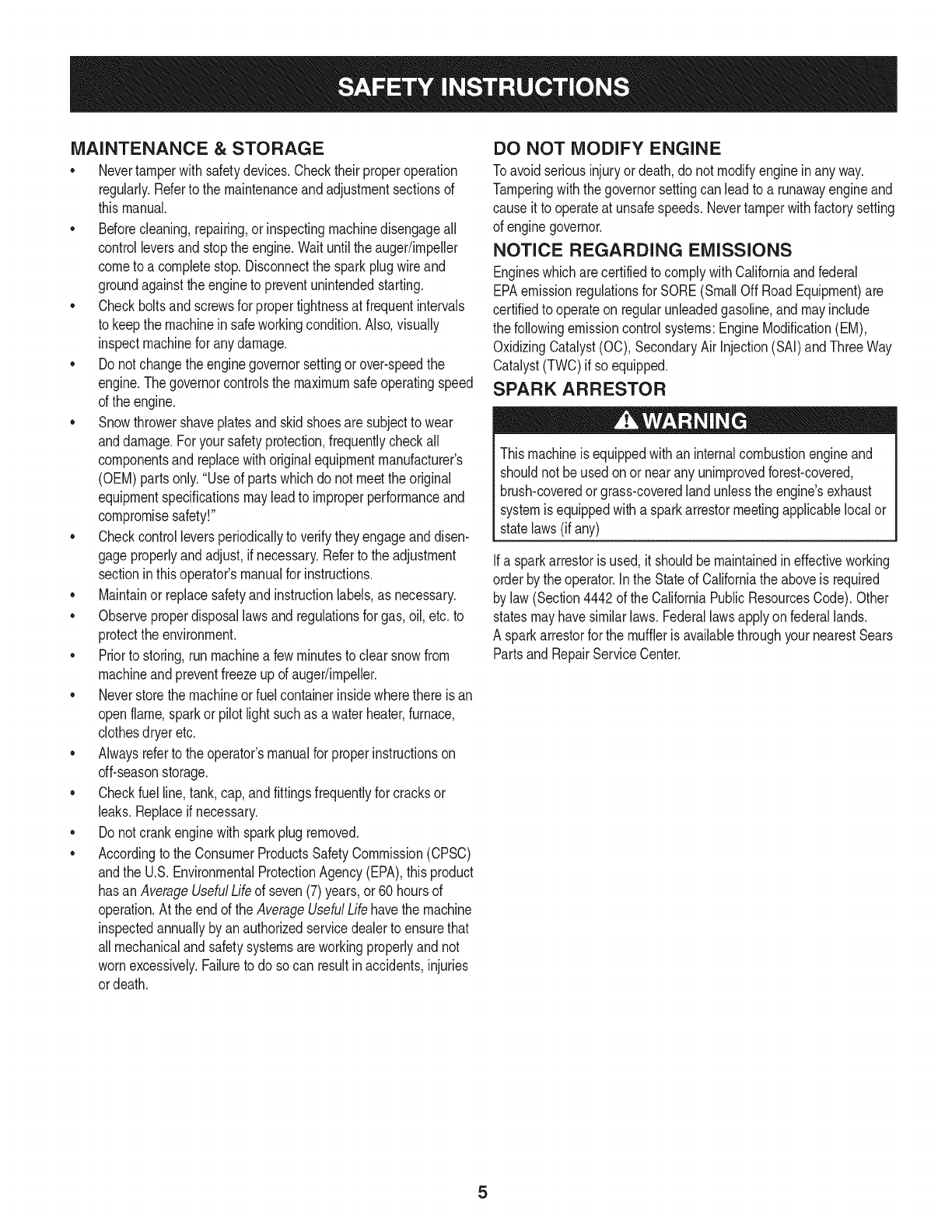
MAINTENANCE & STORAGE
•Nevertamperwithsafetydevices.Checktheirproperoperation
regularly.Referto the maintenanceandadjustmentsectionsof
thismanual.
• Beforecleaning,repairing,or inspectingmachinedisengageall
controlleversandstopthe engine.Waituntilthe auger/impeller
cometo a completestop.Disconnectthe sparkplugwireand
groundagainsttheengineto preventunintendedstarting.
Checkboltsand screwsfor propertightnessat frequentintervals
to keepthe machineinsafeworkingcondition.Also,visually
inspectmachinefor anydamage.
Do notchangetheenginegovernorsettingor over-speedthe
engine.Thegovernorcontrolsthe maximumsafeoperatingspeed
of the engine.
Snowthrowershaveplatesand skidshoesaresubjectto wear
anddamage.Foryoursafetyprotection,frequentlycheckall
componentsand replacewithoriginalequipmentmanufacturer's
(OEM)partsonly."Useof partswhichdo not meetthe original
equipmentspecificationsmayleadto improperperformanceand
compromisesafety!"
Checkcontrolleversperiodicallyto verifytheyengageanddisen-
gageproperlyandadjust,if necessary.Referto the adjustment
sectioninthisoperator'smanualfor instructions.
Maintainor replacesafetyandinstructionlabels,as necessary.
•Observeproperdisposallawsand regulationsfor gas,oil,etc. to
protectthe environment.
Priorto storing,runmachinea few minutestoclear snowfrom
machineand preventfreezeupof auger/impeller.
Neverstorethe machineorfuel containerinsidewherethereisan
openflame,sparkorpilot lightsuchas a waterheater,furnace,
clothesdryer etc.
Alwaysreferto the operator'smanualfor properinstructionson
off-seasonstorage.
Checkfuelline,tank, cap,andfittingsfrequentlyfor cracksor
leaks.Replaceif necessary.
Do notcrankenginewithsparkplugremoved.
Accordingto the ConsumerProductsSafetyCommission(CPSC)
andthe U.S.EnvironmentalProtectionAgency(EPA),thisproduct
hasan AverageUsefulLifeof seven(7)years,or 60 hoursof
operation.At the endof theAverageUsefulLifehavethe machine
inspectedannuallybyan authorizedservicedealerto ensurethat
allmechanicalandsafetysystemsareworkingproperlyand not
wornexcessively.Failureto do so can resultinaccidents,injuries
ordeath.
DO NOT MODIFY ENGINE
Toavoidseriousinjuryor death,do not modifyengineinany way.
Tamperingwiththe governorsettingcanleadto a runawayengineand
causeit to operateat unsafespeeds.Nevertamperwithfactorysetting
of enginegovernor.
NOTICE REGARDING EMISSIONS
EngineswhicharecertifiedtocomplywithCaliforniaandfederal
EPAemissionregulationsfor SORE(SmallOff RoadEquipment)are
certifiedto operateon regularunleadedgasoline,and mayinclude
the followingemissioncontrolsystems:EngineModification(EM),
OxidizingCatalyst(OC),SecondaryAirInjection(SAI)and ThreeWay
Catalyst(TWO)if so equipped.
SPARK ARRESTOR
Thismachineisequippedwithaninternalcombustionengineand
shouldnotbe usedonor nearany unimprovedforest-covered,
brush-coveredorgrass-coveredlandunlessthe engine'sexhaust
systemisequippedwitha sparkarrestormeetingapplicablelocalor
statelaws(if any)
Ifa sparkarrestoris used,it shouldbe maintainedin effectiveworking
orderby theoperator.Inthe Stateof Californiathe aboveis required
bylaw (Section4442of the CaliforniaPublicResourcesCode).Other
statesmayhavesimilarlaws. Federallawsapplyonfederallands.
A sparkarrestorfor the muffleris availablethroughyournearestSears
PartsandRepairServiceCenter.
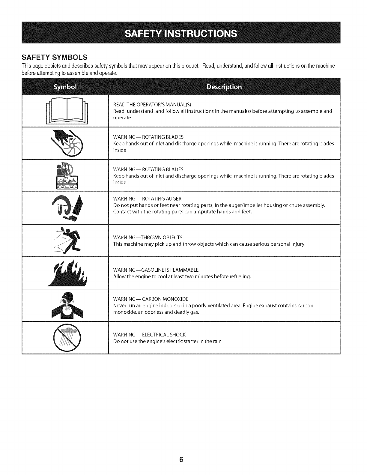
SAFETY SYMBOLS
Thispagedepictsanddescribessafetysymbolsthatmayappearonthisproduct. Read,understand,andfollowall instructionson the machine
beforeattemptingto assembleandoperate.
. +
ii
"JIp
READ THE OPERATOR'S MANUAL(S)
Read, understand, and follow all instructions in the manual(s) before attempting to assemble and
operate
WARNING-- ROTATING BLADES
Keep hands out of inlet and discharge openings while machine is running. There are rotating blades
inside
WARNING-- ROTATING BLADES
Keep hands out of inlet and discharge openings while machine is running. There are rotating blades
inside
WARNING-- ROTATING AUGER
Do not put hands or feet near rotating parts, in the auger/impeller housing or chute assembly.
Contact with the rotating parts can amputate hands and feet.
WARNING--THROWN OBJECTS
This machine may pick up and throw objects which can cause serious personal injury.
WARNING--GASOLINE IS FLAMMABLE
Allow the engine to cool at least two minutes before refueling.
WARNING-- CARBON MONOXIDE
Never run an engine indoors or in a poorly ventilated area. Engine exhaust contains carbon
monoxide, an odorless and deadly gas+
WARNING-- ELECTRICAL SHOCK
Do not use the engine's electric starter in the rain
6
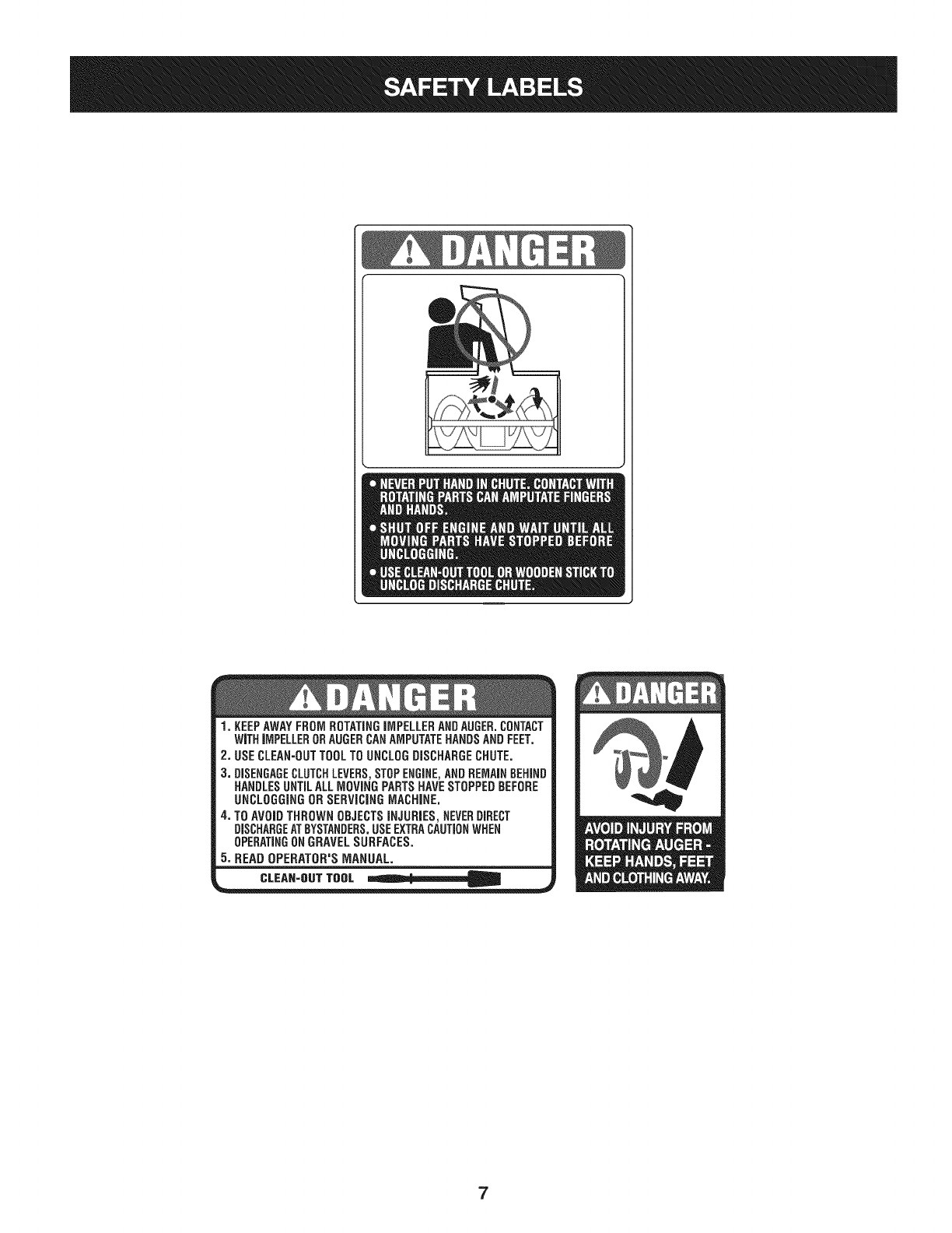
1. KEEPAWAYFROMROTATINGiMPELLERANDAUGER.CONTACT
WiTHiMPELLERORAUGERCANAMPUTATEHANDSANDFEET,
2, USECLEAN=OUTTOOLTOUNCLOGDISCHARGECHUTE.
3. DISENGAGECLUTCHLEVERS,STOPENGINE,ANDREMAINBEHIND
HANDLESUNTILALLMOVINGPARTSHAVESTOPPEDBEFORE
UNCLOGGINGORSERViCiNGMACHINE.
4. TOAVOIDTHROWNOBJECTSiNJURiES,NEVERDIRECT
DISCHARGEATBYSTANDERS.USEEXTRACAUTIONWHEN
OPERATINGONGRAVELSURFACES.
5. READOPERATOR'SMANUAL.
CLEAN-OUTTOOL =mll_li=J__
7
iMPORTANT:Thisunitis shippedwiththeenginefullof oil. After
assembly,see page10for fuel andoildetails.
Removing From Carton
1. Cutthe cornersof thecartonandlay the sidesflaton the ground.
Removeall packinginserts.
2. Movethe snowthrowerout of thecarton.
3. Makecertainthe cartonhas beencompletelyemptiedbefore
discardingit.
DO NOT liftthe snowthrower bythechute handle.
Before Assembly
NOTE: Referenceto right,left, frontor rearof the unit isfromthe
operatingposition,facingforward,unlessotherwisestated.
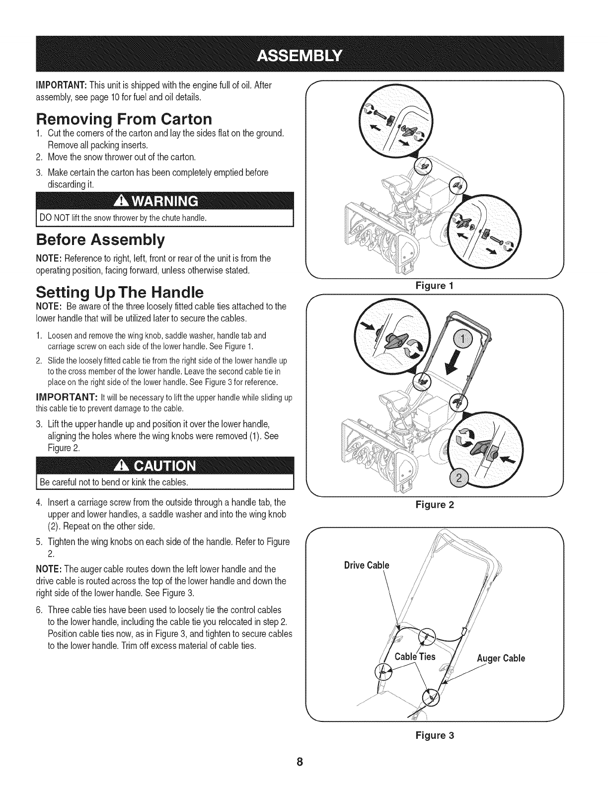
Setting Up The Handle
NOTE: Beawareof the three looselyfitted cabletiesattachedto the
lowerhandlethatwill beutilizedlaterto securethe cables.
1. Loosenand removethe wing knob,saddlewasher,handletab and
carriagescrew oneachside of the lower handle.See Figure1.
2. Slidethe looselyfitted cabletie fromthe rightside ofthe lowerhandleup
to thecross memberof the lowerhandle.Leavethe secondcabletie in
placeon the rightside of the lower handle.See Figure3 for reference.
iMPORTANT: Itwill be necessaryto lift the upper handlewhilesliding up
thiscable tie to preventdamage to thecable.
3. Lift the upper handle up and position it over the lowerhandle,
aligning the holes where the wing knobs were removed (1). See
Figure 2.
Becarefulnot to bendor kinkthe cables.
4. Inserta carriagescrewfromthe outsidethrougha handletab,the
upperand lowerhandles,a saddlewasherandintothe wing knob
(2). Repeatonthe otherside.
5. Tightenthewing knobsoneach sideof the handle.Referto Figure
2.
NOTE:The augercable routesdownthe left lowerhandleandthe
drivecableis routedacrossthe top of the lowerhandleanddownthe
rightside of the lowerhandle.SeeFigure3.
.Threecabletieshavebeenusedto looselytie the controlcables
to the lowerhandle,includingthe cabletie you relocatedinstep2.
Positioncable tiesnow,as inFigure3, andtightento securecables
to the lowerhandle.Trimoffexcessmaterialof cableties.
f
Figure 1
Drive Cable
Figure 2
/get Cable
_js jj
J
Figure 3
8
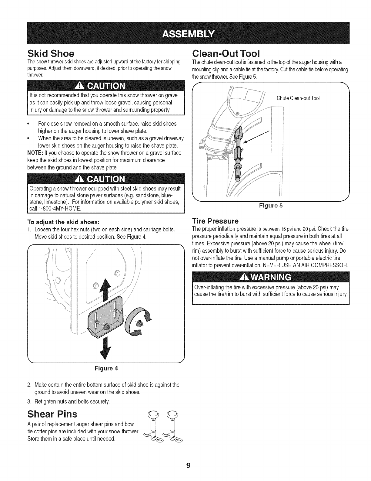
Skid Shoe
Thesnowthrowerskidshoesareadjustedupwardatthefactoryforshipping
purposes.Adjustthemdownward,ifdesired,priortooperatingthesnow
thrower.
It is not recommendedthatyouoperatethis snowthrowerongravel
as it can easilypickup andthrowloosegravel,causingpersonal
injuryordamageto the snowthrowerand surroundingproperty.
• Forclosesnowremovalona smoothsurface,raiseskidshoes
higheronthe augerhousingto lowershaveplate.
• Whentheareato beclearedis uneven,suchas a graveldriveway,
lowerskidshoeson theaugerhousingto raisethe shaveplate.
NOTE: Ifyou chooseto operatethe snowthrowerona gravelsurface,
keepthe skidshoesin lowestpositionfor maximumclearance
betweenthe groundandthe shaveplate.
Operatinga snowthrowerequippedwithsteelskidshoesmayresult
in damageto naturalstonepaversurfaces(e.g.sandstone,blue-
stone,limestone). Forinformationonavailablepolymerskidshoes,
call 1-800-4MY-HOME.
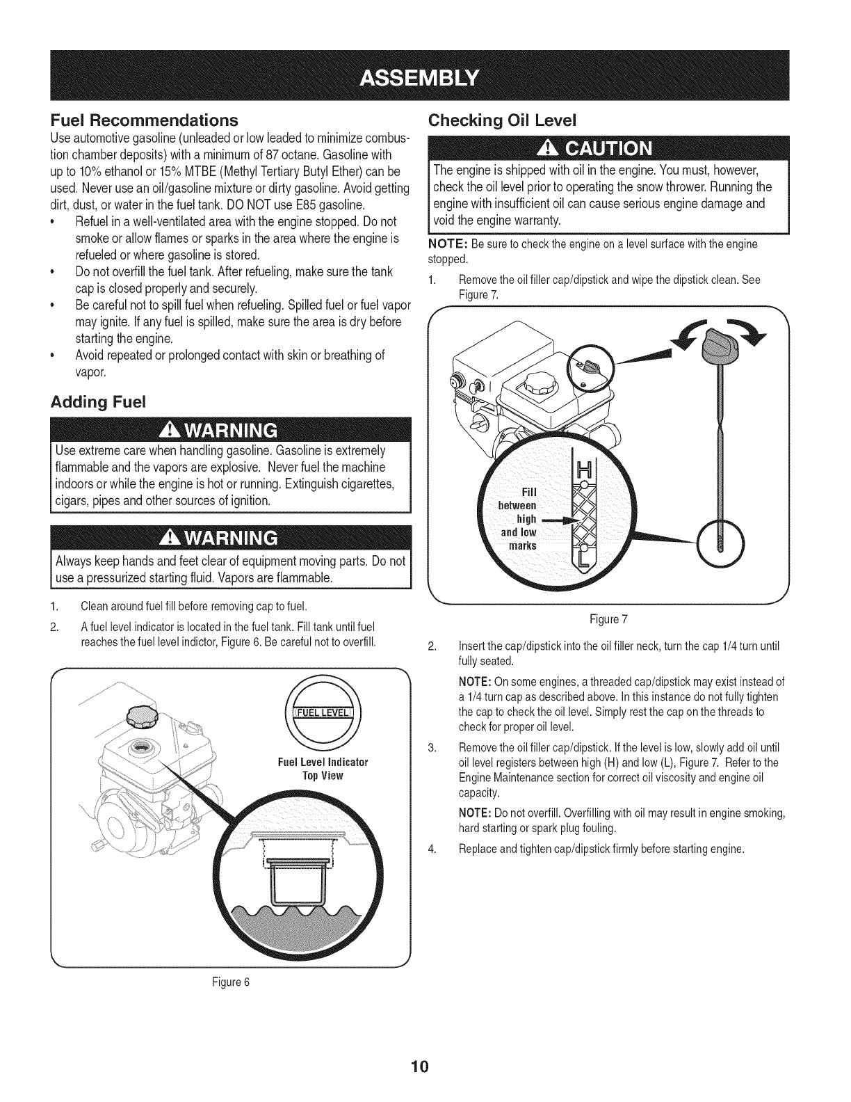
Clean-Out Tool
Thechuteclean-outtoolisfastenedto thetopdtheaugerhousingwitha
mountingclipandacabletieat thefactory.Cutthecabletiebeforeoperating
thesnowthrower.SeeFigure5.
ChuteClean-outTool
Figure 5
To adjust the skid shoes:
1. Loosenthe fourhex nuts(twooneach side)andcarriagebolts.
Moveskidshoesto desiredposition.See Figure4.
/
/,
//
©
Tire Pressure
The properinflationpressureis between15psiand20psi.Checkthe tire
pressureperiodicallyandmaintainequalpressurein bothtiresat all
times.Excessivepressure(above20 psi)maycausethe wheel(tire/
rim)assemblyto burstwithsufficientforceto causeseriousinjury.Do
notover-inflatethe tire.Usea manualpumpor portableelectrictire
inflatorto preventover-inflation.NEVERUSEANAIRCOMPRESSOR.
Over-inflatingthe tirewithexcessivepressure(above20psi) may
causethe tire/rimto burstwithsufficientforceto causeseriousinjury.
Figure 4
2. Makecertaintheentirebottomsurfaceof skidshoeis againstthe
groundto avoidunevenwearonthe skidshoes.
3. Retightennutsandboltssecurely.
Shear Pins
A pairof replacementaugershearpinsandbow
tie cotterpinsare includedwithyoursnowthrower.
Storethemina safeplaceuntilneeded.
9
Fuel Recommendations
Useautomotivegasoline(unleadedor low leadedto minimizecombus-
tionchamberdeposits)witha minimumof 87octane.Gasolinewith
upto 10%ethanolor 15%MTBE(MethylTertiaryButylEther)canbe
used.Neveruseanoil/gasolinemixtureor dirtygasoline.Avoidgetting
dirt,dust,or waterinthefuel tank. DO NOTuse E85gasoline.
*Refuelin awell-ventilatedareawiththe enginestopped.Donot
smokeor allowflamesorsparksinthe areawheretheengineis
refueledor wheregasolineisstored.
*Do notoverfillthe fuel tank.Afterrefueling,makesurethe tank
cap is closedproperlyandsecurely.
*Becarefulnot to spillfuel when refueling.Spilledfuelor fuelvapor
mayignite.Ifany fuel isspilled,makesurethe areaisdry before
startingtheengine.
*Avoidrepeatedor prolongedcontactwithskinor breathingof
vapor.
Adding Fuel
Useextremecarewhenhandlinggasoline.Gasolineis extremely
flammableandthe vaporsareexplosive.Neverfuel the machine
indoorsorwhile the engineishotor running.Extinguishcigarettes,
cigars,pipesandother sourcesof ignition.
Alwayskeephandsandfeetclear of equipmentmovingparts.Do not
usea pressurizedstartingfluid.Vaporsareflammable.
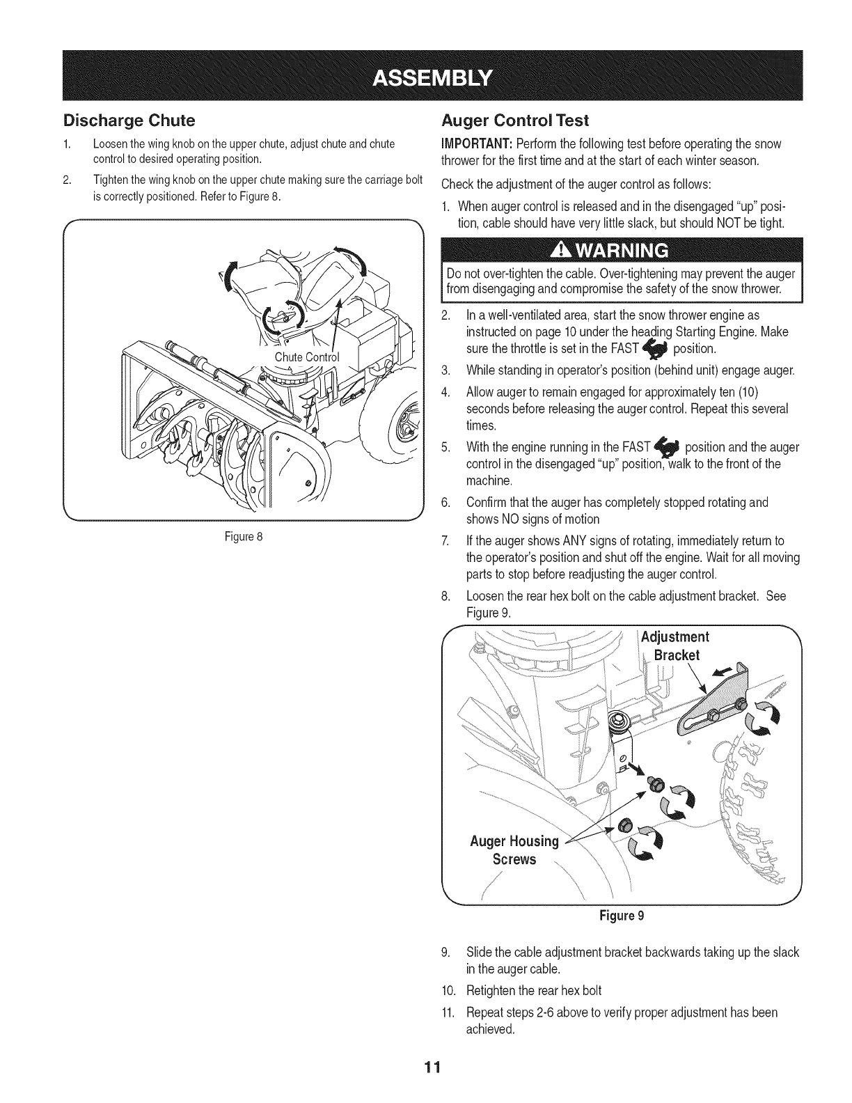
1. Cleanaroundfuel fill beforeremovingcap to fuel.
2. A fuel levelindicatoris located inthefuel tank. Filltankuntil fuel
reachesthe fuel level indictor,Figure6. Be carefulnotto overfill.
FuelLevelIndicator
TopView
Checking Oil Level
The engineis shippedwithoil in theengine.Youmust,however,
checkthe oil levelpriorto operatingthe snowthrower.Runningthe
enginewithinsufficientoil cancauseseriousenginedamageand
void theenginewarranty.
NOTE: Be sureto check the engineon a levelsurfacewiththe engine
stopped.
1. Removetheoil filler cap/dipstickand wipethe dipstickclean.See
Figure7.
f-
)
Figure7
2. Insertthe cap/dipstickinto the oilfiller neck,turn thecap 1/4turn until
fully seated.
NOTE:On someengines,a threadedcap/dipstickmayexistinsteadof
a 1/4turn capas describedabove.In this instancedo notfullytighten
the capto checktheoil level.Simplyrestthe cap onthe threadsto
checkfor properoil level.
3. Removetheoil filler cap/dipstick.Ifthe levelis low,slowlyadd oiluntil
oil levelregistersbetweenhigh(H) andlow(L), Figure7. Referto the
EngineMaintenancesectionfor correctoil viscosityandengineoil
capacity.
NOTE:Do notoverfill.Overfillingwith oil mayresultin enginesmoking,
hardstartingor sparkplugfouling.
4. Replaceandtightencap/dipstickfirmly beforestartingengine.
Figure6
10
Discharge Chute
1. Loosenthewingknobontheupperchute,adjustchuteandchute
controlto desiredoperatingposition.
2. Tightenthewingknobontheupperchutemakingsurethecarriagebolt
iscorrectlypositioned.Referto Figure8.
Auger Control Test
iMPORTANT:Performthefollowingtest beforeoperatingthesnow
throwerfor the firsttimeandat the startof eachwinterseason.
Checkthe adjustmentof theaugercontrolas follows:
1. Whenaugercontrolisreleasedandinthe disengaged"up" posi-
tion,cable shouldhaveverylittleslack,but shouldNOTbetight.
Figure8
J
Donot over-tightenthe cable.Over-tighteningmaypreventthe auger
fromdisengagingandcompromisethe safetyof the snowthrower.
2. Ina well-ventilatedarea,startthe snowthrowerengineas
instructedon page10underthe headingStartingEngine.Make
thethrottleisset inthe FAST
sure position.
3. Whilestandingin operator'sposition(behindunit) engageauger.
4. Allowaugerto remainengagedforapproximatelyten (10)
secondsbeforereleasingthe augercontrol.Repeatthis several
times.
5. Withthe enginerunninginthe FAST_ positionand theauger
controlinthe disengaged"up"position,walkto the frontof the
machine.
6. Confirmthatthe augerhascompletelystoppedrotatingand
showsNO signsof motion
7. Ifthe augershowsANYsignsof rotating,immediatelyreturnto
the operator'spositionandshutoffthe engine.Waitfor allmoving
partsto stopbeforereadjustingthe augercontrol.
8. Loosenthe rearhexbolton the cableadjustmentbracket. See
Figure9.
fAdjustment "
Bracket
Auger Housing
Screws
Figure 9
9. Slidethe cableadjustmentbracketbackwardstakingup the slack
inthe augercable.
10. Retightenthe rearhexbolt
11. Repeatsteps2-6aboveto verifyproperadjustmenthas been
achieved.
11
f
UpperHandle
Drive
AugerControl Control
Chute Assembly
Clean-out Tool
Auger
UpperChute
\
ShavePlate Chute Knob
Skid Shoe
Handle
/f FuelCap
Muffler RecoilStarter
Handle
Oil Cap
Throttle
Control
ElectricStarter
Choke Button
Control OilDrain ElectricStarterOutlet )
,J
Befamiliarwithall the controlson the snowthrowerand theirproperoperation.Knowhowto stopthe machineanddisengagethemquickly.
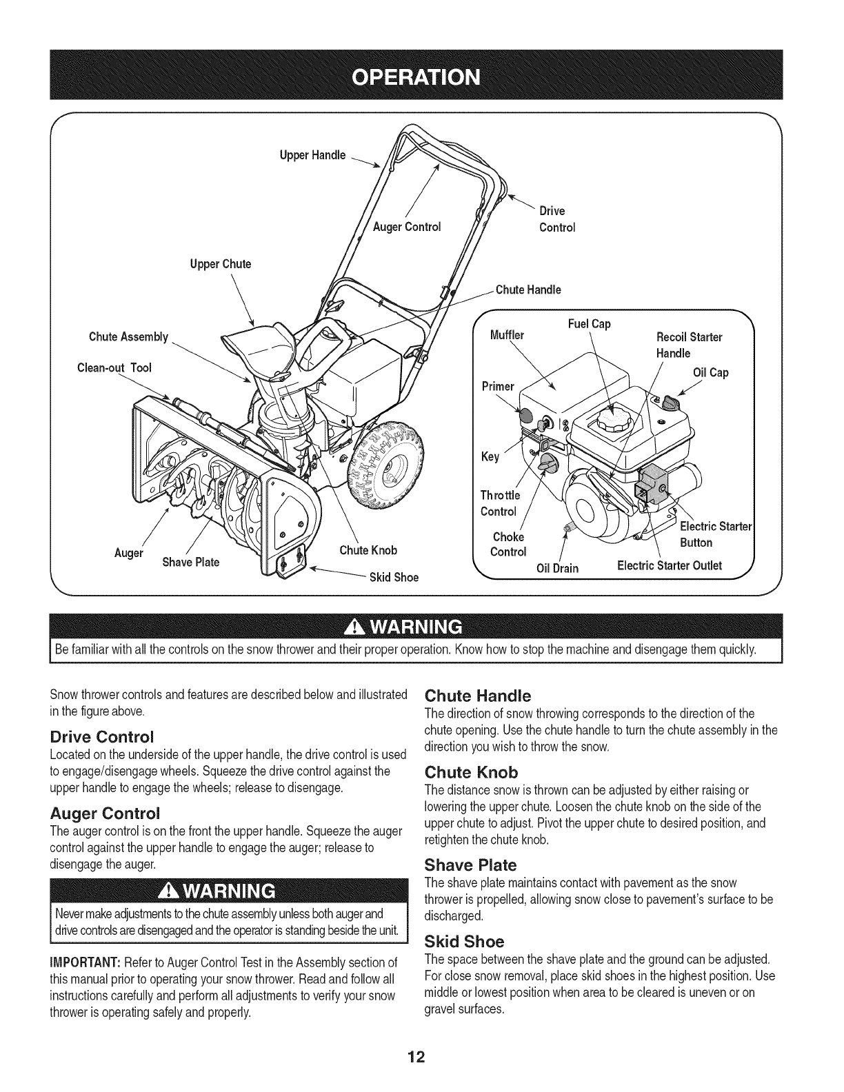
Snowthrowercontrolsandfeaturesaredescribedbelowandillustrated
inthe figureabove.
Drive Control
Locatedon the undersideof the upperhandle,the drivecontrolisused
to engage/disengagewheels.Squeezethe drivecontrolagainstthe
upperhandleto engagethe wheels;releaseto disengage.
Auger Control
Theaugercontrolis onthe frontthe upperhandle.Squeezethe auger
controlagainstthe upperhandleto engagethe auger;releaseto
disengagethe auger.
Nevermakeadjustmentstothechuteassemblyunlessbothaugerand
drivecontrolsaredisengagedandtheoperatorisstandingbesidetheunit.
IMPORTANT:Referto AugerControlTestinthe Assemblysectionof
thismanualpriorto operatingyoursnowthrower.Readandfollowall
instructionscarefullyandperformall adjustmentsto verifyyoursnow
throweris operatingsafelyandproperly.
Chute Handle
The directionof snowthrowingcorrespondsto thedirectionof the
chuteopening.Usethechutehandleto turn thechuteassemblyin the
directionyouwishto throwthe snow.
Chute Knob
The distancesnowis throwncan beadjustedby either raisingor
loweringthe upperchute.Loosenthe chuteknobonthe side of the
upperchuteto adjust.Pivotthe upperchuteto desiredposition,and
retightenthechuteknob.
Shave Plate
The shaveplatemaintainscontactwithpavementas the snow
throweris propelled,allowingsnowcloseto pavement'ssurfaceto be
discharged.
Skid Shoe
The spacebetweenthe shaveplateand thegroundcan beadjusted.
Forclosesnowremoval,placeskidshoesin the highestposition.Use
middleor lowestpositionwhenareato beclearedis unevenor on
gravelsurfaces.
12
Auger
Whenengaged,the augerrotatesanddrawssnowintothe auger
housing.
Chute Assembly
Snowdrawninto theaugerhousingis dischargedout the chute
assembly.
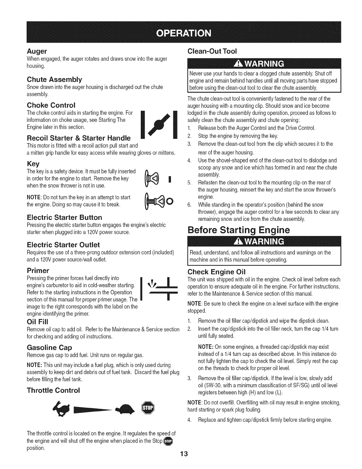
Choke Control
Thechokecontrolaidsin startingthe engine.For
informationonchokeusage,seeStartingThe
Enginelaterin thissection.
Recoil Starter &Starter Handle
Thismotoris fittedwitha recoilactionpullstartand
a mittengriphandlefor easyaccesswhilewearingglovesormittens.
Key
Thekeyis a safetydevice.It mustbefullyinserted _ ,,,,._
in orderfor the engineto start.Removethekey Fe
whenthe snowthroweris not inuse.
NOTE:Do notturn the keyin anattemptto start
the engine.Doingso maycauseit to break.
Electric Starter Button
Pressingthe electricstarterbuttonengagesthe engine'selectric
starterwhenpluggedintoa 120Vpowersource.
Clean=Out Tool
Neveruseyour handsto clear acloggedchuteassembly.Shutoff
engineandremainbehindhandlesuntilall movingpartshavestopped
[before usngthe c can-outtoo to c earthechuteassemby.
The chuteclean-outtool is convenientlyfastenedto the rearof the
augerhousingwitha mountingclip.Shouldsnowand ice become
lodgedinthe chuteassemblyduringoperation,proceedas followsto
safelycleanthe chuteassemblyandchuteopening:
1. Releaseboththe AugerControlandthe DriveControl.
2. Stoptheengineby removingthe key.
3. Removethe clean-outtool fromthe clipwhichsecuresit to the
rearof the augerhousing.
4. Usethe shovel-shapedendof the clean-outtoolto dislodgeand
scoopanysnowandice whichhas formedinand nearthe chute
assembly.
5. Refastenthe clean-outtoolto the mountingclip on the rearof
the augerhousing,reinsertthe keyand startthe snowthrower's
engine.
6. Whilestandingin theoperator'sposition(behindthe snow
thrower),engagethe augercontrolfor a fewsecondsto clearany
remainingsnowand icefromthe chuteassembly.
Before Starting Engine
Electric Starter Outlet
Requiresthe useof athree-prongoutdoorextensioncord(included)
anda 120Vpowersource/walloutlet.
Primer
Pressingthe primerforcesfuel directlyinto
engine'scarburetorto aid incold-weatherstarting, qk_/,..=_,,L.,_
Referto the startinginstructionsin theOperation I
sectionof thismanualfor properprimerusage.The |
imagetothe rightcorrespondswiththe labelon the
engineidentifyingthe primer.
Oil Fill
Removeoilcap to addoil. Referto the Maintenance&Servicesection
for checkingandaddingoil instructions.
Gasoline Cap
Removegascap to addfuel.Unitrunson regulargas.
NOTE:Thisunit mayincludea fuel plug,whichisonly usedduring
assemblyto keepdirt anddebrisout of fueltank. Discardthefuel plug
beforefillingthe fuel tank.
Throttle Control
Read,understand,andfollowallinstructionsandwarningsonthe
machineandinthis manualbeforeoperating.
Check Engine Oil
The unitwas shippedwith oilin the engine.Checkoillevelbeforeeach
operationto ensureadequateoil inthe engine.Forfurtherinstructions,
referto the Maintenance& Servicesectionof this manual.
NOTE:Besureto checkthe engineona levelsurfacewiththeengine
stopped.
1. Removethe oilfiller cap/dipstickandwipe thedipstickclean.
2. Insertthe cap/dipstickintothe oilfiller neck,turn thecap 1/4turn
untilfullyseated.
NOTE:Onsomeengines,a threadedcap/dipstickmayexist
insteadof a 1/4turncap as describedabove.Inthis instancedo
notfullytightenthe capto checktheoil level.Simplyrestthe cap
on the threadsto checkfor properoil level.
Removethe oilfiller cap/dipstick.Ifthe levelis low,slowlyadd
oil (5W-30,witha minimumclassificationofSF/SG)untiloil level
registersbetweenhigh(H) andlow (L).
NOTE:Donot overfill.Overfillingwithoil mayresultin enginesmoking,
hardstartingor sparkplugfouling.
4. Replaceandtightencap/dipstickfirmly beforestartingengine.
Thethrottlecontrolis locatedon the engine.It regulatesthe speedof
the engineandwill shutoff the enginewhenplacedinthe Stop__
position. 13
Gasoline
Useautomotivegasoline(unleadedor low leadedto minimizecombus-
tionchamberdeposits)witha minimumof 87octane.Gasolinewith
upto 10%ethanolor 15%MTBE(MethylTertiaryButylEther)canbe
used.Neveruseanoil/gasolinemixtureor dirtygasoline.Avoidgetting
dirt,dust,or waterinthefuel tank. DO NOTuse E85gasoline.
• Refuelin awell-ventilatedareawiththe enginestopped.Donot
smokeor allowflamesorsparksinthe areawheretheengineis
refueledor wheregasolineisstored.
•Do notoverfillthe fuel tank.Afterrefueling,makesurethe tank
cap is closedproperlyandsecurely.
•Becarefulnot to spillfuel when refueling.Spilledfuelor fuelvapor
mayignite.Ifany fuel isspilled,makesurethe areaisdry before
startingtheengine.
•Avoidrepeatedor prolongedcontactwithskinor breathingof
vapor.
Useextremecarewhenhandlinggasoline.Gasolineis extremely
flammableandthe vaporsareexplosive.Neverfuelthe machine
indoorsor whilethe engineishot or running.Extinguishcigarettes,
cigars,pipes andother sourcesof ignition.
1. Cleanaroundfuelfill beforeremovingcap to fuelto avoiddirt and
debrisfallingintofuel tank.
2. Afuel levelindicatorislocatedinthe fuel tank. Filltankuntilfuel
reachesthe fuel levelindictor.SeeFigure10inset.Becarefulnot
to overfill.
Starting The Engine
Alwayskeephandsandfeetclear of movingparts.Do notuse a
pressurizedstartingfluid.Vaporsareflammable.
NOTE: Forlocationof allthe enginecontrolsreferredto inthis section,
referto Figure9on page12.
NOTE:Allowtheengineto warmupfor a fewminutesafterstarting.
Theenginewill not developfull poweruntil it reachesoperating
temperatures.
1. Makecertainboththe augercontrolanddrivecontrolare inthe
disengaged(released)position.
2. Insertkeyinto slot.Makesureit snapsinto place.Do notattempt
to turnthe key.
NOTE:The enginecannotstart withoutthe keyfullyinsertedintothe
switch.
Electric Starter
Theoptionalelectricstarterisequippedwitha groundedthree-wire
powercord andplug,andisdesignedto operateon 120voltAC
householdcurrent.It mustbeusedwitha properlygroundedthree-
prongreceptacleat alltimesto avoidthe possibilityof electricshock.
Followall instructionscarefullypriorto operatingthe electricstarter.
DO NOTuse electricstarterinthe rain.
Determinethatyourhome'swiringis a three-wiregroundedsystem.
Aska licensedelectricianif you arenotcertain.
Ifyou havea groundedthree-prongreceptacle,proceedas follows.
Ifyou donot havethe properhousewiring,DONOTusethe electric
starterunderanyconditions.
1. Plugthe extensioncord intothe outletlocatedon the engine's
surface.Plugthe otherendof extensioncord intoa three-prong
120-volt,grounded,AC outletina well-ventilatedarea.
2. Movethrottlecontrolto FAST(rabbit)_ position.
3. Movechokecontrolto the CHOKEpositionI,,o'1(coldengine
start). Ifengineiswarm,placechokecontrolinRUNposition.
4. Pushprimerthree(3) times,makingsureto coverventholewhen
pushing.If engineis warm,pushprimeronly once.Alwayscover
ventholewhenpushing.Coolweathermayrequireprimingto be
repeated.
5. Pushstarterbuttonto startengine.Oncetheenginestarts,im-
mediatelyreleasestarterbutton.Electricstarteris equippedwith
thermaloverloadprotection;systemwill temporarilyshutdownto
allow starterto cool if electricstarterbecomesoverloaded.
6. As the enginewarms,slowlyrotatethechokecontrolto RUN
position.Ifthe enginefalters,restartengineand runwith choke
controlat half-chokepositionfor a shortperiodof time,andthen
slowlyrotatethe chokeintoRUNposition.
7. Afterengineis running,disconnectpowercord fromelectric
starter.Whendisconnecting,alwaysunplugthe endat the wall
outletbeforeunpluggingthe oppositeend fromthe engine.
Recoil Starter
Donot pullthe starterhandlewhiletheenginerunning.
1. Movethrottlecontrolto FAST(rabbit)_j_ position.
2. Movechokecontrolto the CHOKEpositionI,,_'l (coldengine
start). Ifengineiswarm,placechokecontrolinRUNposition.
3. Pushprimerthree(3) times,makingsureto coverventholewhen
pushing.If engineis warm,pushprimeronly once.Alwayscover
ventholewhenpushing.Coolweathermayrequireprimingto be
repeated.
4. Pullgentlyonthe starterhandleuntil it beginsto resist,thenpull
quicklyandforcefullyto overcomethe compression.Engineshould
start. Donot releasethe handleandallowit to snapback.Return
ropeSLOWLYto originalposition.If required,repeatthis step.
5. As the enginewarms,slowlyrotatethechokecontrolto RUNposi-
tion. Ifthe enginefalters,restartengineandrunwithchokecontrol
at half-chokepositionfor a shortperiodof time,andthenslowly
rotatethe chokeintoRUNposition.
Toavoidunsupervisedengineoperation,neverleavethe machine
unattendedwiththe enginerunning.Turnthe engineoff afteruseand
removeignitionkey.
4
Stopping The Engine
Runenginefor a fewminutesbeforestoppingto helpdry off any
moistureonthe engine.
1. Movethrottlecontrolto STOP position.
2. Removethekey.Removingthe keywill reducethe possibilityof
unauthorizedstartingof the enginewhileequipmentis notin use.
Keepthe keyina safeplace.The enginecannotstart withoutthe
key.
3. Wipeany moistureawayfromthe controlson theengine..
To Stop The Snow Thrower
1. Tostopthe wheels,releasethe drivecontrol.
2. Tostopthrowingsnow,releasethe augercontrol.
3. Tostopengine,movethrottlecontrolleverto OFF @ and pullout
the key.Donot turn key.
Thetemperatureof mufflerandthe surroundingareasmayexceed
1500F.Avoidtheseareas.
Using Snow Thrower to Clear
Snow
CAUTION:Checktheareato be clearedfor foreignobjects.Remove
foreignobjects,if any.
1. Starttheenginefollowingstartinginstructions.
2. Allowtheengineto warmupfor a fewminutesas the enginewill not
developfull poweruntilit reachesoperatingtemperature.
3. Rotatethe chuteassemblyto the desireddirection,awayfrom
bystandersand/or buildings.
4. Makingcertainno bystandersor obstaclesarein frontof the unit,
squeezethe augercontrolcompletelyagainstthe upperhandleto
fullyengagetheauger.
5. Whiletheaugercontrolis engaged,squeezethe drivecontrol
completelyagainstthe upperhandleto engagethe wheels.Do not
"feather"thedrive control.
6. As the snowthrowerstartsto move,maintaina firmholdon the
handle,andguidethe snowthroweralongthe pathto be cleared.
7. Releasethe augerand drivecontrolsto stopthe snowthrowing
actionandforwardmotion.
NOTE:Yourunit isequippedwitha clutchinthe transmission.If the
wheelsstopturningwhiletryingto dischargelargevolumesof snow,
immediatelydisengagethedrivecontroland allowthe rotatingauger
to dischargesnowfromthe housing.Reducethe clearingwidthand
continueoperation.
8. Oneachsucceedingpass,readjustthe chuteassemblyto the
desiredpositionandslightlyoverlapthe previouslyclearedpath.
Positioning Discharge Chute
Loosenthechuteknobandpivotupperchuteto desiredposition.Tighten
the chuteknobmakingsurethe carriageboltiscorrectlypositioned.
Rotatechutehandleto desiredoperatingposition.
Donot liftthe snowthrowerat any timebythe chutehandle.
Operating Tips
1. Formostdficientsnowremoval,removesnowimmediatelyafteritfalls.
2. Dischargesnowdownwindwheneverpossible.Slightlyoverlap
each previouspath.
3. Setthe skidshoes1/4"belowthe shaveplatefor normalusage.
The skidshoesmaybeadjustedupwardfor hard-packedsnow.
NOTE:It isnot recommendedthatyouoperatethis snowthroweron
gravelas loosegravelcan be easilypickedupand thrownbythe auger
causingpersonalinjuryand/or damageto the snowthrower.
4. Ifyou chooseto operatethe snowthrowerongravel,keepthe skid
shoeinthe lowestpositionfor maximumclearancebetweenthe
groundandthe shaveplate.
5. Cleanthe snowthrowerthoroughlyaftereachuse.
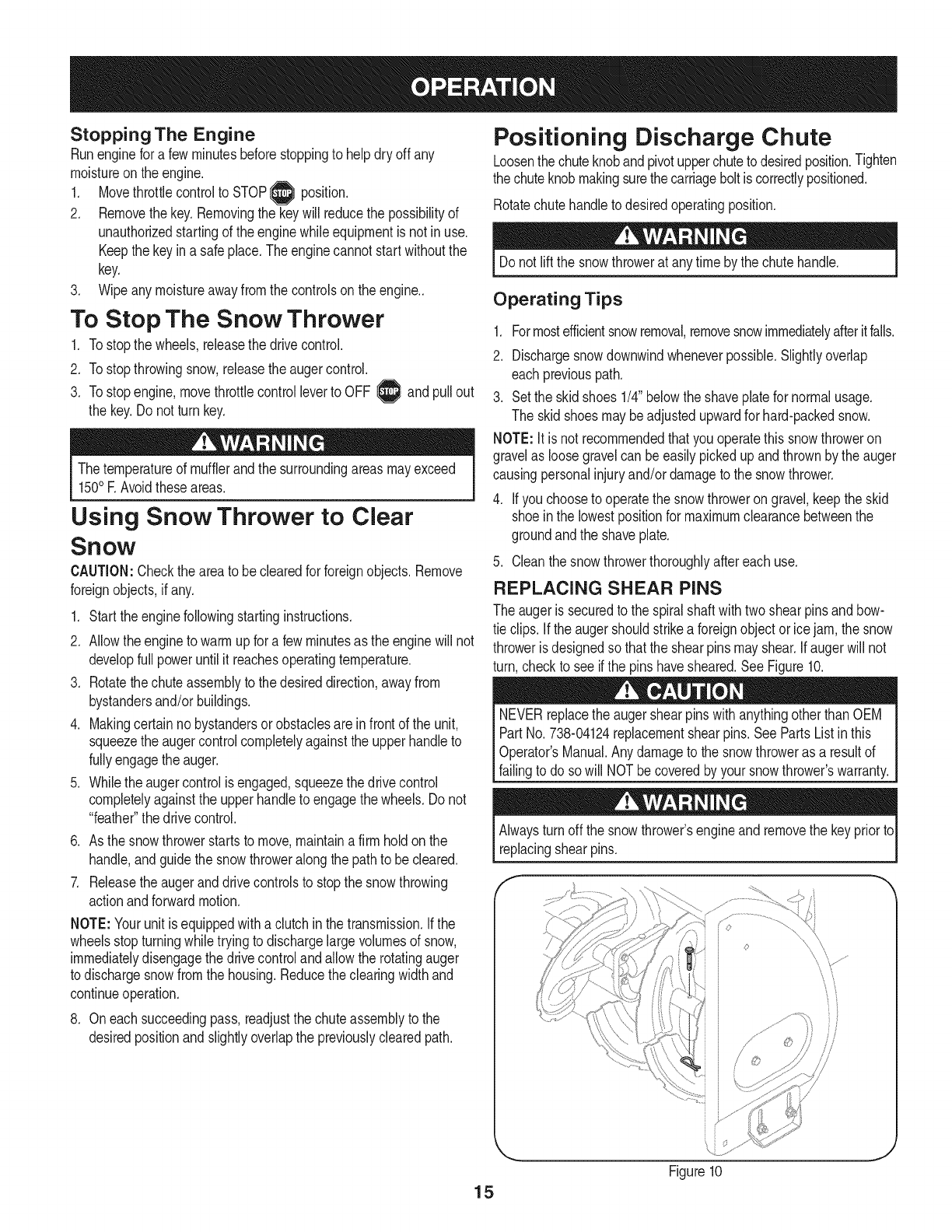
REPLACING SHEAR PINS
The augeris securedto the spiralshaftwithtwo shearpinsandbow-
tie clips. Ifthe augershouldstrikea foreignobjector icejam,the snow
throweris designedso thatthe shearpinsmayshear.Ifaugerwill not
turn,checkto see ifthe pins havesheared.SeeFigure10.
NEVERreplacethe augershearpinswithanythingotherthan OEM
PartNo.738-04124replacementshearpins.SeePartsListinthis
Operator'sManual.Any damageto the snowthroweras a resultof
failingto do sowill NOTbecoveredbyyour snowthrower'swarranty.
Alwaysturn offthe snowthrower'sengineand removethe keypriorto
replacingshearpins.
15 Figure10 J
Beforeservicing,repairing,lubricatingorinspecting,disengageall
controlsandstopengine.Waituntilallmovingpartshavecometoa
completestop.Removethekeytopreventunintendedstarting.Always
wearsafetyglassesduringoperationorwhileperforminganyadjust-
mentsorrepairs.
Followthemaintenanceschedulegivenbelow.Thischartdescribes
serviceguidelinesonly.UsetheServiceLogcolumntokeeptrack
ofcompletedmaintenancetasks.TolocatethenearestSears
ServiceCenteror to scheduleservice,simplycontactSearsat
1-800-4-MY-HOME®.
Maintenance Schedule
EachUseandevery5
hours
1st5 hours
Annuallyor 25hours
= =
1. Engineoillevel
2. Looseormissinghardware
3. Unitandengine.
1. Engineoil
1. Sparkplug
2. Controllinkagesand pivots
3. Wheels
4. Gearshaft andAugershaft
1. Engineoil
1. Sparkplug
Annuallyor 50hours
Annuallyor 100hours
BeforeStorage 1. Fuelsystem 1.
1. Check
2. Tightenor replace
3. Clean
1. Change
1. Check
2. Lubewithlightoil
3. Lubewithmultipurposeautogrease
4. Lubewithlightoil
1. Change
1. Clean,adjustgap,or replaceif
necessary
Runengineuntilit stopsfromlack
of fuel
f
ENGINE MAINTENANCE
Checking Engine Oil
Beforelubricating,repairing,or inspecting,disengageall controls
Iandstopengine.Waituntilall movingpartshavecometo a complete
_stop.
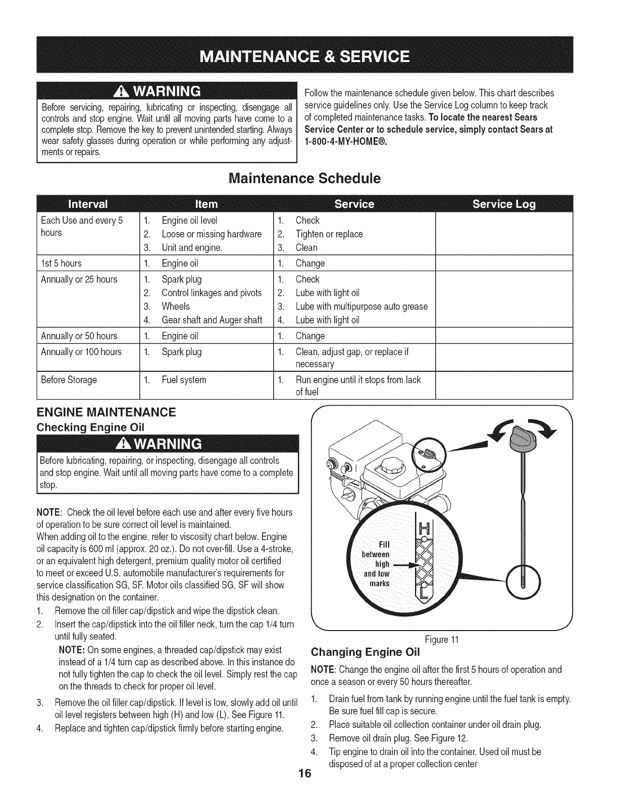
NOTE: Checktheoil levelbeforeeachuseandaftereveryfivehours
of operationto besurecorrectoil levelis maintained.
Whenaddingoilto the engine,referto viscositychart below.Engine
oilcapacityis 600ml (approx.20 oz.). Donot over-fill.Usea 4-stroke,
oran equivalenthighdetergent,premiumqualitymotoroilcertified
to meetorexceedU.S.automobilemanufacturer'srequirementsfor
serviceclassificationSG, SR MotoroilsclassifiedSG, SFwill show
thisdesignationonthe container.
1. Removethe oil fillercap/dipstickandwipethe dipstickclean.
2. Insertthe cap/dipstickintothe oilfiller neck,turnthe cap 1/4turn
untilfullyseated.
NOTE:On someengines,athreadedcap/dipstickmayexist
insteadof a 1/4turn cap as describedabove.In thisinstancedo
not fullytightenthe cap to checkthe oil level.Simplyrestthe cap
onthe threadsto checkfor properoil level.
3. Removethe oil fillercap/dipstick.Iflevelis low,slowlyadd oiluntil
oil levelregistersbetweenhigh(H) andlow (L). SeeFigure11.
4. Replaceandtightencap/dipstickfirmlybeforestartingengine.
j
Figure11
Changing Engine Oil
NOTE:Changethe engineoil afterthefirst 5 hoursof operationand
once a seasonor every50 hoursthereafter.
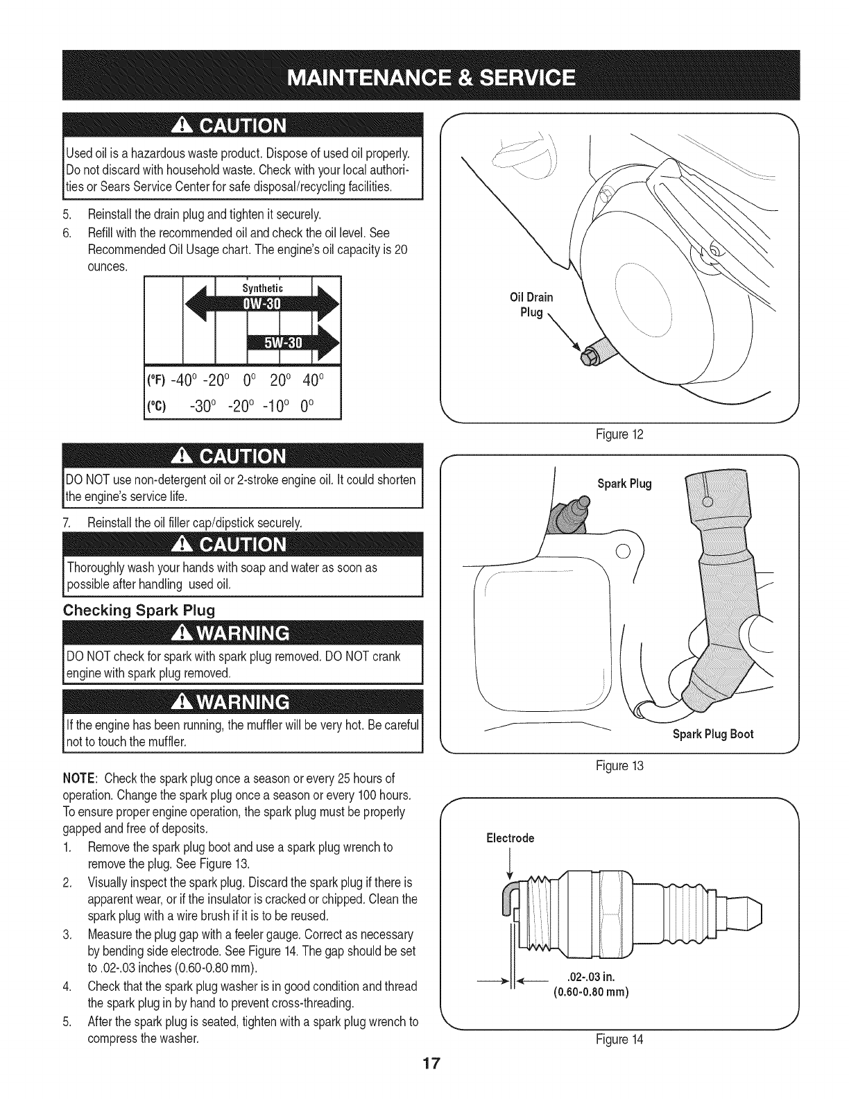
1. Drainfuel fromtankby runningengineuntilthefuel tankis empty.
Besurefuel fill capis secure.
2. Placesuitableoil collectioncontainerunderoil drainplug.
3. Removeoil drainplug.SeeFigure12.
4. Tip engineto drainoil intothe container.Usedoil mustbe
disposedof at a propercollectioncenter
16
f
Usedoil is a hazardouswasteproduct.Disposeof usedoil properly.
Donotdiscardwith householdwaste.Checkwithyourlocalauthori-
tiesor SearsServiceCenterfor safedisposal/recyclingfacilities.
.
6.
Reinstallthe drainplugandtightenit securely.
Refillwiththe recommendedoil andcheckthe oil level.See
RecommendedOil Usagechart.Theengine'soil capacityis 20
ounces.
i i
(%-400 -200 0o 200 400
("c) -30°-20°-10° 0°
Oil Drain
Plug
Figure12
.J
DO NOTuse non-detergentoil or 2-strokeengineoil. Itcould shorten
the engine'sservicelife.
7. Reinstallthe oilfillercap/dipsticksecurely.
Thoroughlywashyour handswithsoapandwateras soonas
possibleafterhandling usedoil.
Checking Spark Plug
DO NOTcheckfor sparkwithsparkplugremoved.DO NOTcrank
enginewithsparkplugremoved.
Ifthe enginehasbeenrunning,the mufflerwill bevery hot.Becareful
notto touchthe muffler.
NOTE: Checkthe sparkplugoncea seasonorevery25hoursof
operation.Changethe sparkplugoncea seasonor every100hours.
Toensureproperengineoperation,the sparkplugmustbe properly
gappedandfreeof deposits.
1. Removethesparkplugbootanduse a sparkplugwrenchto
removethe plug.See Figure13.
2. Visuallyinspectthe sparkplug.Discardthe sparkplugif thereis
apparentwear,orif the insulatoris crackedor chipped.Cleanthe
sparkplugwitha wirebrush if it is to be reused.
3. Measurethe pluggapwitha feelergauge.Correctas necessary
by bendingsideelectrode.SeeFigure14.The gapshouldbeset
to .02-.03inches(0.60-0.80ram).
4. Checkthatthe sparkplugwasheris ingoodconditionandthread
the sparkplugin by handto preventcross-threading.
5. Afterthesparkplugis seated,tightenwitha sparkplugwrenchto
compressthe washer.
SparkPlug
SparkPlug Boot
Figure13
Electrode
___,. ,___ .02-.03in.
(0.60-0.80 ram)
Figure14
17
NOTE:Wheninstallinga newsparkplug,tighten1/2-turnafterthe
sparkplugseatsto compressthe washer.Whenreinstallinga used
sparkplug,tighten1/81to 1/41turnafterthe sparkplugseatsto
compressthe washer.GeneralRecommendations
1. Alwaysobservesafetyruleswhenperformingany maintenance.
2. Thewarrantyon thissnowthrowerdoes notcoveritemsthathave
beensubjectedto operatorabuseor negligence.To receivefull
valuefromthe warranty,operatormustmaintainthe snowthrower
as instructedin thismanual.
3. Periodicallycheckall fastenersand hardwareto makesurethese
aretight.
Replacing the Shave Plate and
Skid Shoes
The shaveplateand skidshoesonthe bottomof the snowthrowerare
subjectto wear.Theseshouldbe checkedperiodicallyandreplaced
whennecessary
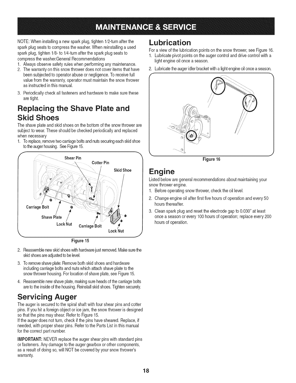
1. Toreplace,removetwocarriageboltsandnutssecuringeachskidshoe
totheaugerhousing.SeeFigure15.
fShearPin CotterPin
Carriage Bolt
Shave Plate /
LockNut
SkidShoe
l
/
CarriageBolt /_
LockNut
Figure15
J
Lubrication
Fora viewof the lubricationpointsonthe snowthrower,see Figure16.
1. Lubricatepivotpointsonthe augercontrolanddrivecontrolwitha
light engineoilonce a season.
2. Lubricatetheaugeridlerbracketwitha lightengineoilonceaseason.
Figure 16
Engine
Listedbelowaregeneralrecommendationsaboutmaintainingyour
snowthrowerengine.
1. Beforeoperatingsnowthrower,checkthe oil level.
2. Changeengineoilafterfirst fivehoursof operationandevery50
hoursthereafter.
3. Cleansparkplugandresetthe electrodegapto 0.030"at least
once a seasonor every100hoursof operation;replaceevery200
hoursof operation.
.
3.
.
Reassemblenewskidshoeswithhardwarejustremoved.Makesurethe
skidshoesareadjustedtobelevel.
Toremoveshaveplate:Removebothskidshoesandhardware
includingcarriageboltsandnutswhichattachshaveplatetothe
snowthrowerhousing.Forlocationof shaveplate,see Figure15.
Reassemblenewshaveplate,makingsureheadsof thecarriagebolts
areto theinsideof thehousing.Reinstallskidshoes.Tightensecurely.
Servicing Auger
Theaugeris securedto the spiralshaftwithfourshearpinsandcotter
pins.Ifyou hit a foreignobjectorice jam,the snowthroweris designed
so thatthe pinsmayshear.Referto Figure15.
Ifthe augerdoesnot turn,check ifthe pinshavesheared.Replace,if
needed,withpropershearpins.Referto the PartsListinthis manual
for thecorrectpart number.
IMPORTANT:NEVERreplacetheaugershearpinswithstandardpins
orfasteners.Anydamageto the augergearboxor othercomponents,
as a resultof doingso,will NOTbe coveredby yoursnowthrower's
warranty.
18
Check V-Belts
Followinstructionsbelowto checkconditionof drivebeltsevery50
hoursof operation.
1. Removetheplasticbelt coveronthe frontof the engineby
removingthe self-tappingscrewand pressingthe plastictabsto
releasethe beltcover.
2. Visuallyinspectfor frayed,cracked,orexcessivelyworn outbelts.
Replace,if necessary,andfollowinstructionsbelow.
Replacing Belts
NOTE:Therearetwobeltson thissnowthrower:an augerbelt and
drivebelt.It isrecommendedthatboth beltsbereplacedat the same
time.
1. Removethesparkplugwirefromsparkplugandgrounditagainst
the engineto preventaccidentalstarting.
2. Runthe engineuntilthe fuel tankisdry to preventgasolineleakage
whenreplacingbelts.
Performbelt maintenanceoutdoorsas somegas maypossiblyleak
fromthe carburetor.
3. Removetheself-tappingscrewshownin Figure17,andpressthe
plastictabsto releasethe beltcover.Pullthe belt coverupand out
fromaroundthe engineandchuteassembly.Set it asideandsave.
Figure17
Auger Belt
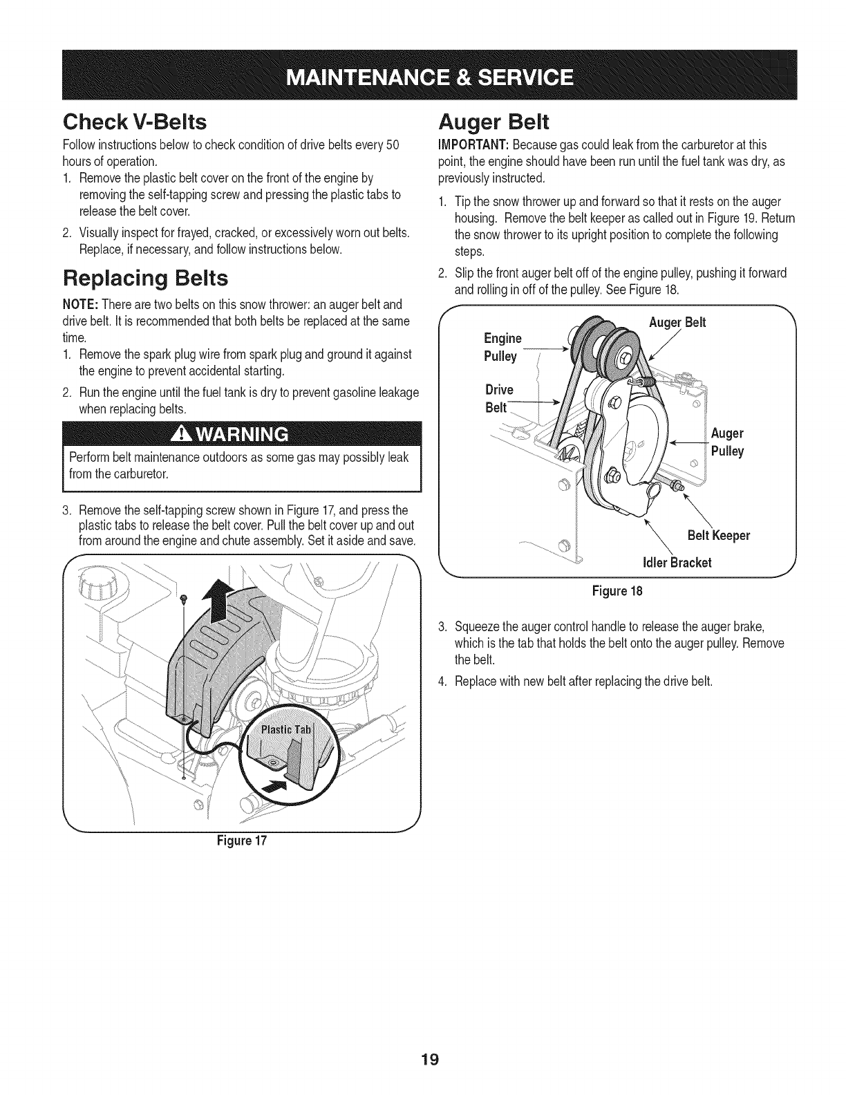
iMPORTANT:Becausegas could leakfromthe carburetorat this
point,the engineshouldhavebeenrununtil thefuel tankwasdry,as
previouslyinstructed.
1. Tip the snowthrowerupandforwardso that it restsonthe auger
housing. Removethe beltkeeperas calledout inFigure19.Return
the snowthrowerto itsuprightpositionto completethe following
steps.
2. Slipthe frontaugerbelt offof theenginepulley,pushingit forward
and rollinginoff of the pulley.SeeFigure18.
Idler Bracket
Figure18
Squeezethe augercontrolhandleto releasetheaugerbrake,
whichisthe tab thatholdsthe beltonto theaugerpulley.Remove
the belt.
4. Replacewithnew beltafterreplacingthedrive belt.
19
Drive Belt
NOTE: Replacethe drivebelt beforereassemblingthe newaugerbelt.
1.Tip the snowthrowerupandforwardsothat it restson theauger
housing.
IMPORTANT:BecauseGascould leakfromthecarburetorat this
point,the engineshouldhavebeenrununtilthe fuel tankwasdry,as
previouslyinstructed.
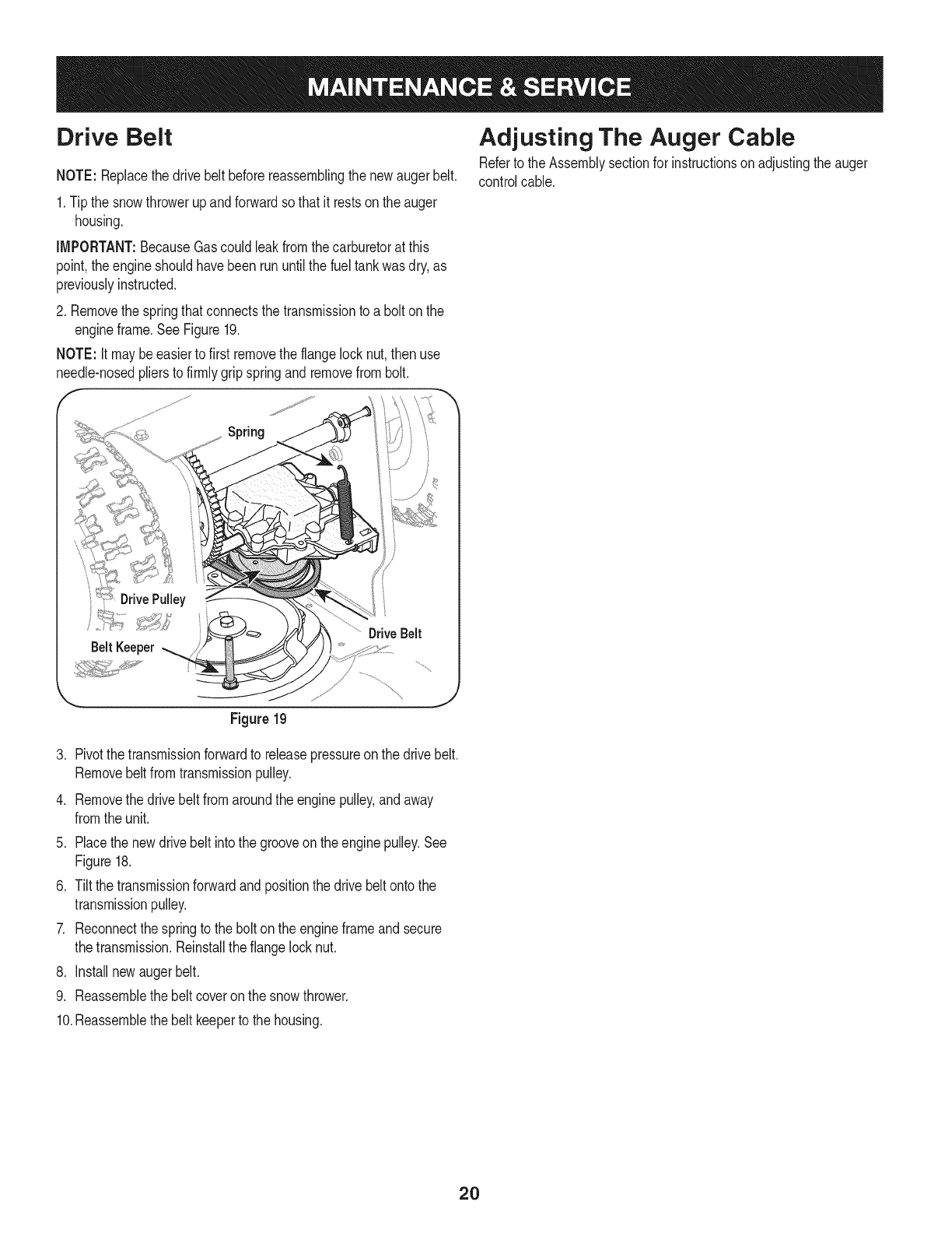
2. Removethe springthatconnectsthe transmissionto abolt onthe
engineframe.SeeFigure19.
NOTE: Itmaybeeasierto first removethe flangelocknut,then use
needle-nosedpliersto firmlygripspringandremovefrombolt.
F
Adjusting The Auger Cable
Referto theAssemblysectionfor instructionson adjustingthe auger
controlcable.
Spring
........ _'*'_:" ...............DriveBelt
BeltKeeper
Figure19
3. Pivotthe transmissionforwardto releasepressureon the drivebelt.
Removebeltfromtransmissionpulley.
4. Removethe drivebelt fromaroundthe enginepulley,andaway
fromthe unit.
5. Placethe newdrivebelt intothe grooveonthe enginepulley.See
Figure18.
6. Tiltthe transmissionforwardandpositionthe drive beltontothe
transmissionpulley.
7. Reconnectthe springto thebolt onthe engineframeandsecure
thetransmission.Reinstalltheflange locknut.
8. Installnewaugerbelt.
9. Reassemblethe belt coveronthe snowthrower.
10.Reassemblethe belt keeperto the housing.
2O
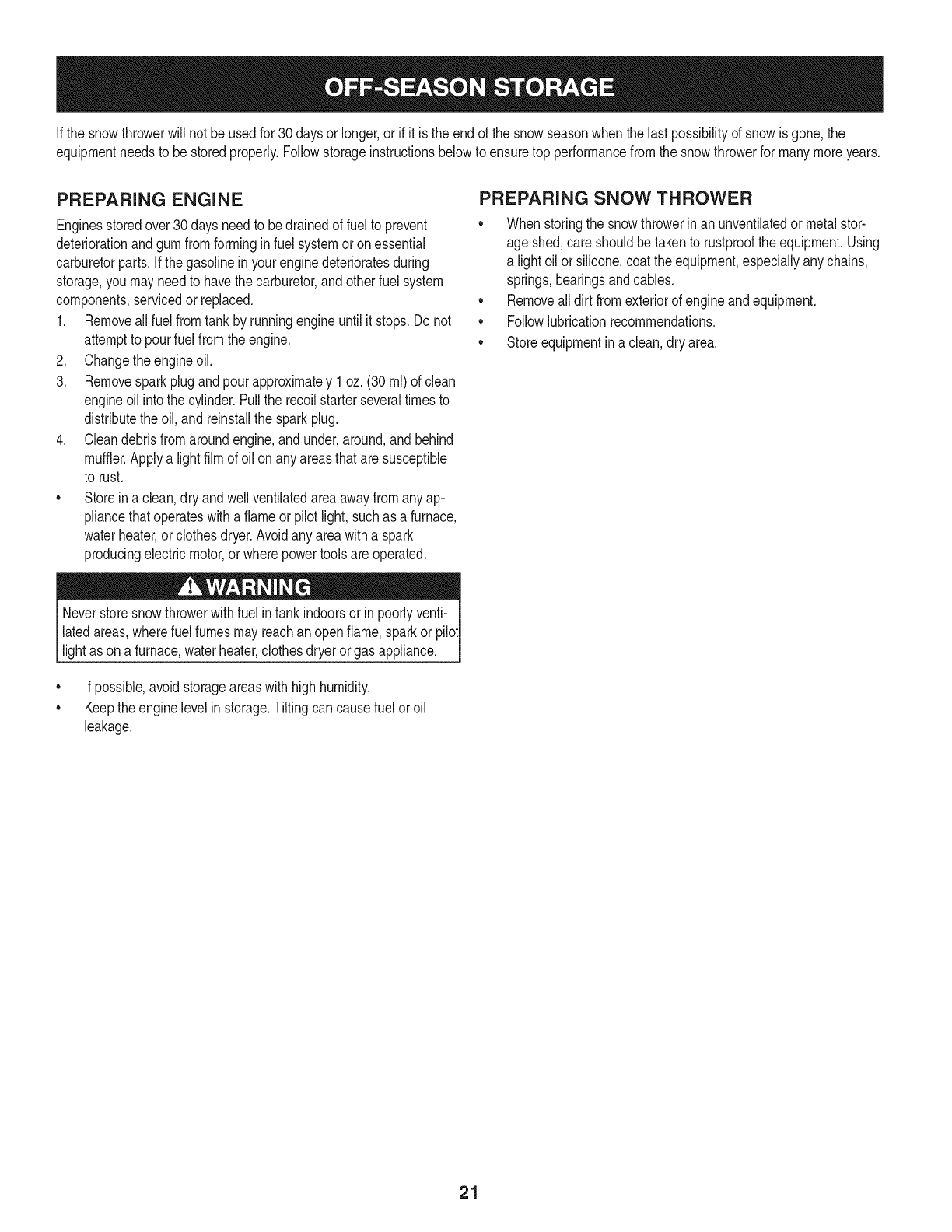
Ifthe snowthrowerwillnot be usedfor30 daysor longer,or if it is the endof the snowseasonwhenthe lastpossibilityof snowis gone,the
equipmentneedsto bestoredproperly.Followstorageinstructionsbelowto ensuretop performancefromthe snowthrowerfor manymoreyears.
PREPARING ENGINE
Enginesstoredover30daysneedto bedrainedof fuel to prevent
deteriorationandgumfromforminginfuel systemor onessential
carburetorparts.If thegasolineinyourenginedeterioratesduring
storage,youmayneedto havethe carburetor,andotherfuel system
components,servicedor replaced.
1. Removeall fuel fromtank by runningengineuntil it stops.Donot
attemptto pourfuel fromthe engine.
2. Changethe engineoil.
3. Removesparkplugandpourapproximately1oz.(30 rnl)of clean
engineoil intothe cylinder.Pullthe recoilstarterseveraltimesto
distributetheoil, and reinstallthe sparkplug.
4. Cleandebrisfromaroundengine,andunder,around,andbehind
muffler.Applya lightfilmof oilon anyareasthatare susceptible
to rust.
• Storeina clean,dry andwellventilatedareaawayfromanyap-
pliancethatoperateswithaflameor pilotlight,suchas a furnace,
waterheater,or clothesdryer.Avoidany areawitha spark
producingelectricmotor,or wherepowertoolsareoperated.
Neverstoresnowthrowerwithfuel intank indoorsor inpoorlyventi-
latedareas,wherefuel fumesmayreachan openflame,sparkor pilol
lightas ona furnace,waterheater,clothesdryer orgas appliance.
• If possible,avoidstorageareaswithhighhumidity.
• Keepthe enginelevelin storage.Tiltingcan causefuel oroil
leakage.
PREPARING SNOW THROWER
Whenstoringthe snowthrowerin anunventilatedormetalstor-
age shed,careshouldbetakento rustprooftheequipment.Using
a light oilor silicone,coattheequipment,especiallyanychains,
springs,bearingsandcables.
• Removealldirt fromexteriorof engineandequipment.
• Followlubricationrecommendations.
• Storeequipmentin a clean,dry area.
21
Beforeperforminganytypeof maintenance/service,disengageall
controlsandstopthe engine.Waituntilallmovingpartshavecometo a
completestop.Removethekeyto preventunintendedstarting.Always
wearsafetyglassesduringoperationorwhileperforminganyadjustments
orrepairs.
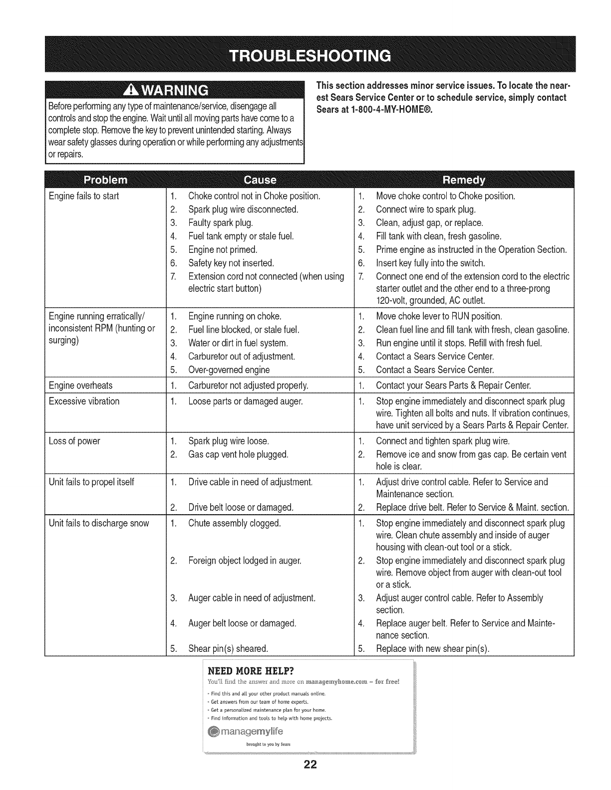
This sectionaddresses minor serviceissues.Tolocate the near-
est Sears Service Centerorto scheduleservice,simplycontact
Searsat 1-800-4-MY-HOME®.
Enginefailsto start
Enginerunningerratically/
inconsistentRPM(huntingor
surging)
1. Chokecontrolnot in Chokeposition.
2. Sparkplugwiredisconnected.
3. Faultysparkplug.
4. Fueltankemptyor stalefuel.
5. Enginenot primed.
6. Safetykeynot inserted.
7. Extensioncord notconnected(whenusing
electricstart button)
.
2.
3.
4.
5.
1.
1.
Engineoverheats
Excessivevibration
Lossof power 1. Sparkplugwireloose.
2. Gascap ventholeplugged.
Unitfailsto propelitself 1. Drivecablein needof adjustment.
2. Drivebeltlooseordamaged.
Unitfailsto dischargesnow 1. Chuteassemblyclogged.
2. Foreignobjectlodgedin auger.
1. Movechokecontrolto Chokeposition.
2. Connectwireto sparkplug.
3. Clean,adjustgap, or replace.
4. Filltankwithclean,freshgasoline.
5. Primeengineas instructedin theOperationSection.
6. Insertkeyfullyintothe switch.
7. Connectoneendof the extensioncordto the electric
starteroutletandthe otherendto a three-prong
120-volt,grounded,AC outlet.
Enginerunningonchoke. 1. Movechokeleverto RUNposition.
Fuelline blocked,or stalefuel. 2. Cleanfuel lineandfill tankwithfresh, cleangasoline.
Wateror dirt infuel system. 3. Runengineuntilit stops.Refillwithfreshfuel.
Carburetoroutof adjustment. 4. Contacta SearsServiceCenter.
Over-governedengine 5. Contacta SearsServiceCenter.
Carburetornotadjustedproperly. 1. ContactyourSearsParts& RepairCenter.
Loosepartsordamagedauger. 1. Stopengineimmediatelyanddisconnectsparkplug
wire.Tightenall boltsandnuts.If vibrationcontinues,
haveunit servicedby a SearsParts& RepairCenter.
1. Connectandtightensparkplugwire.
2. Removeice andsnowfromgas cap.Becertainvent
holeis clear.
1. Adjustdrivecontrolcable.Referto Serviceand
Maintenancesection.
2. Replacedrivebelt.Referto Service&Maint.section.
1. Stopengineimmediatelyanddisconnectsparkplug
wire.Cleanchuteassemblyandinsideof auger
housingwithclean-outtoolor a stick.
2. Stopengineimmediatelyanddisconnectsparkplug
wire.Removeobjectfromaugerwithclean-outtool
or a stick.
Augercable inneedof adjustment. 3. Adjustaugercontrolcable.Referto Assembly
section.
Augerbeltlooseor damaged. 4. Replaceaugerbelt.Referto Serviceand Mainte-
nancesection.
Shearpin(s)sheared. 5. Replacewith newshearpin(s).
NEED MORE HELP?
o Find this and a[[ your other product manuals online.
o 6et answers from our team of home experts.
o 6et a personalized maintenance plan for your home,
o Find information and tools to help with home projects.
.
4.
5.
22
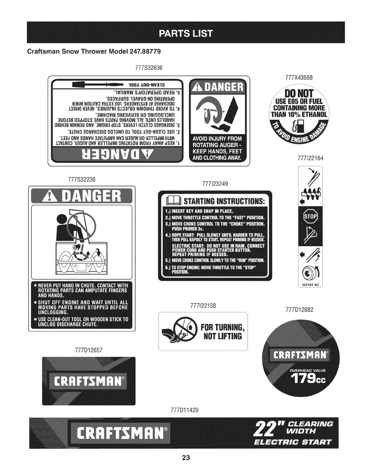
Craftsman Snow Thrower Model 247.88779
777S32636
"lVnNV_ S,UOIVU3dOQV3U"g
"S33VdUnS13AVU9NO_NilVU3dO
N3HMNOJlnV3VHIX33Sn"SU30NVlSA8lV 39HVHOSlO
13_UIGH3A3N'S31UgrNI$133r80 NMOUH1QIOAVOL"_
"3NiHOVW9NIOIAU3SHO9NI9903ON9
3U0:138g:IddOLS3AVHSLUVdONIA0_ITIV'IILNR$3"IQNVH
QNIH_8NiVW3tJONV'3NION]dOlS'SEFIA:FIH31R13_gVON3SJQ"_
"3/RHO39UVHOSIO9013NnO1qO01/OO'NV3lO3Sll "Z
"IBBdQNV SONVHBlVlnd_VNV3UBOnVUOU]ll]dBlHIIAA
IOVINO0"U]OflVONVUB]13d_l 9NIIVIOUWOU__VMVd]B_"L
J
777S32236 777123249
777X43688
........................eeNOT...................
USEE85 ORFUEL
CONTAININGMORE
THAN10% ETHANOL
777122164
i/
777i22138 777D12682
777D12657
777Dl1429
23
Craftsman Snow Thrower IViodel 247.88779
\
/
24
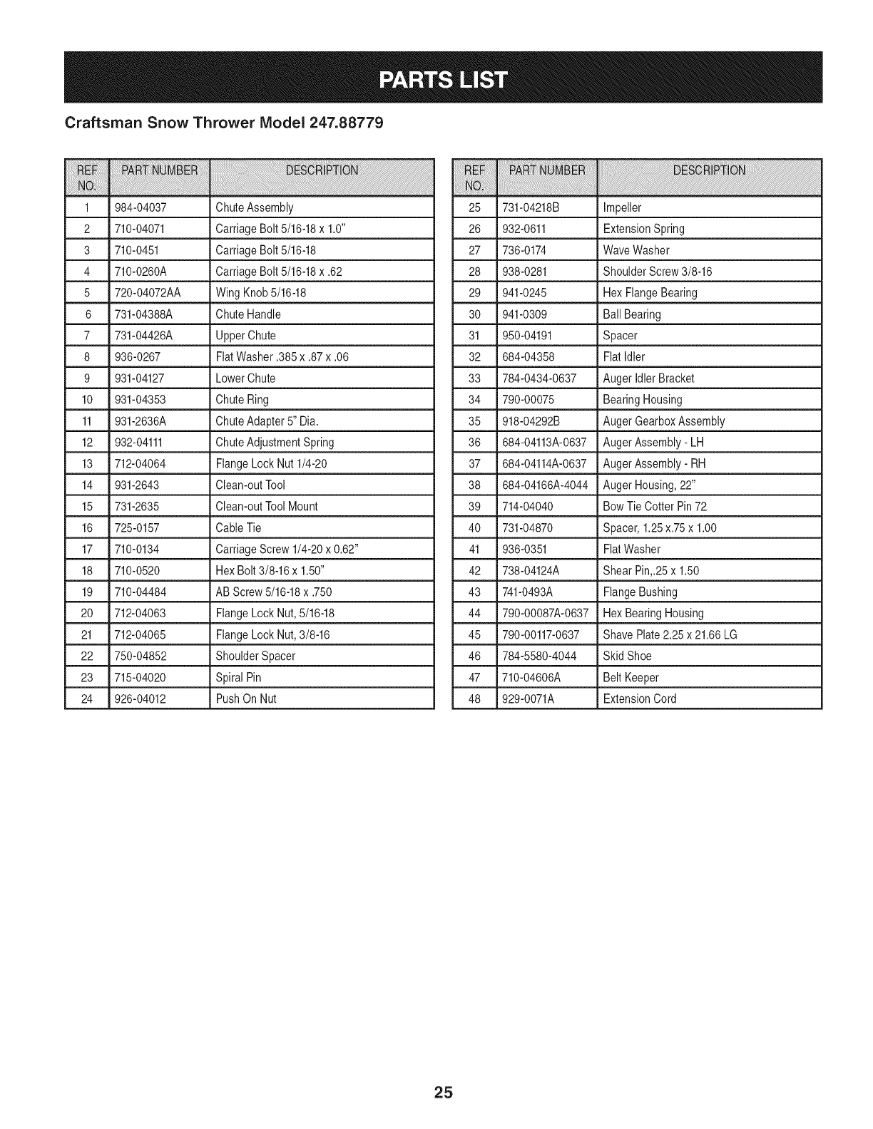
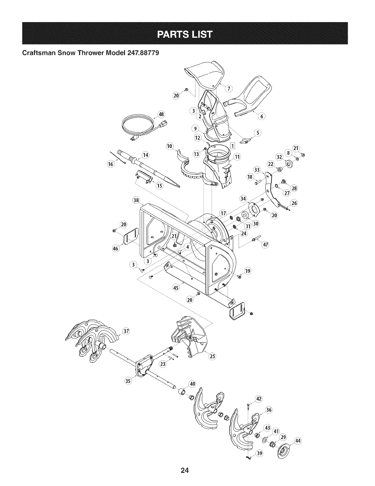
Craftsman Snow Thrower IViodel 247.88779
iiiiii!ii!ii i !i !ililililiiiiiiii!iiiiiiii!!ii i i!!i!ii! ¸i ili !ii !ii i iiiiiiiiiiiiii!ii!ii!i!!!!!!!!!!!!!!!!!!!!!!!!!!!!!!!!!!!!!!! ii i iii!iii!iiiiiiii i iiiiiiiiiiiiiiiiii ii ii ii ii ii ii ii ii ii ii ii iiiii ii i!!!i!! ! ! ! ! iii ! !i i ! ! !i i! ! !i i i iiii i i i iiiiiiiiiiiiiiiiiiiiiiiiiiiiiiiiiiiiiiiiiiiiiiiiiiiiiiiiiiiiiiiiiiiiiiiiiiiiiiiiiiiiiiiiiiiiiiiiiiiiiiiiiiiiiiiiiiiiiiiiiiiiiiiiiiiiiiiiiiiiiiiiii!i i i
1 984-04037 ChuteAssembly 25
2 710-04071 CarriageBolt 5/16-18x 1.0" 26
3 710-0451 CarriageBolt5/16-18 27
4 710-0260A CarriageBolt5/16-18x .62 28
5 720-04072AA WingKnob5/16-18 29
6 731-04388A ChuteHandle 30 941-0309
7 731-04426A UpperChute 31 950-04191
8 936-0267 FiatWasher.385 x .87x .06 32 684-04358
9 931-04127 LowerChute 33 784-0434-0637
10 931-04353 ChuteRing 34 790-00075
11 931-2636A ChuteAdapter5" Dia. 35 918-04292B
12 932-04111 ChuteAdjustmentSpring 36 684-04113A-0637
13 712-04064 FlangeLock Nut 1/4-20 37 684-04114A-0637
14 931-2643 Clean-outTool 38 684-04166A-4044
15 731-2635 Clean-outToolMount 39 714-04040
16 725-0157 CableTie 40 731-04870
17 710-0134 CarriageScrew 1/4-20x 0.62" 41 936-0351
18 710-0520 HexBolt 3/8-16x 1.50" 42 738-04124A
19 710-04484 AB Screw5/16-18x .750 43 741-0493A
20 712-04063 FlangeLock Nut,5/16-18 44 790-00087A-0637
21 712-04065 FlangeLock Nut,3/8-16 45 790-00117-0637
22 750-04852 ShoulderSpacer 46 784-5580-4044
23 715-04020 Spiral Pin 47 710-04606A
24 926-04012 PushOn Nut 48 929-0071A
iiiiiiiiiiiiiiili!:!ili! i i!i!iiii!!iiiiiiii!i!!!iiiiiiii!iiiiiiii!i!i!i_!_!!_!i_!__i__i__i_!_!!!_!___i_!_i_i_i_i!i_!_!_!_i_!_!_!_!_!_!_!_!_!_!_!_!_i_i_i_!_i_i_i!__!_i_i__!!___i!!ii_i!i!i!_!_!___!_!_!_i_ii_i!_i!_i______!___!i_i!_!i!i___!_!!!!!_i!ii!!ii___i__!__i!_!_i_i_i_i!ii__!___!_!__i!_i__i_ii_!_i!i!!ii!!ii!!iiiiiii!ii!!ii!!i!iiiiii!iiiiiiii!iiiiiiiiiiiiii!!ii!!iiii__i_i_!_i_i_i!!_!!!_!!i!i!iiiii!iiii!i!iii!i!iiiiii!ii!!ii!!i!iiiiii!ii!!ii!!i!iiiiii!ii!!ii!!i!iiiiii!ii!!ii!!i!iiiiii!ii!!ii!!i!iiiiii!ii!!ii!!i!iiiiii!ii!!ii!!i!iiiiii!ii!!ii!!i!iiiiii!ii!!ii!!i!iiiiii!ii!!ii!!i!iiiiii!ii!!ii!!i!iiiiii!ii!!ii!!i!iiiiii!ii!!ii!!i!iiiiii!ii!!ii!!i!iiiiii!ii!!ii!!i!iiiiii!ii!!ii!!i!iiiiii!ii!!ii!!i!iiiiii!ii!!ii!!i!iiiiii!ii!!ii!!i!iiiiii!ii!!ii!!i!iiiiii!ii!!ii!!i!iiiiii!ii!!ii!!i!iiiiii!ii!!ii!!i!iiiiii!ii!!ii!i!_i_
731-04218B Impeller
932-0611 ExtensionSpring
736-0174 WaveWasher
938-0281 ShoulderScrew3/8-16
941-0245 Hex FlangeBearing
Ball Bearing
Spacer
FlatIdler
Auger IdlerBracket
BearingHousing
AugerGearboxAssembly
AugerAssembly- LH
AugerAssembly- RH
AugerHousing,22"
Bow TieCotter Pin72
Spacer,1.25x.75x 1.00
FlatWasher
Shear Pin,.25x 1.50
FlangeBushing
Hex BearingHousing
Shave Plate2.25 x21.66 LG
Skid Shoe
Belt Keeper
ExtensionCord
25
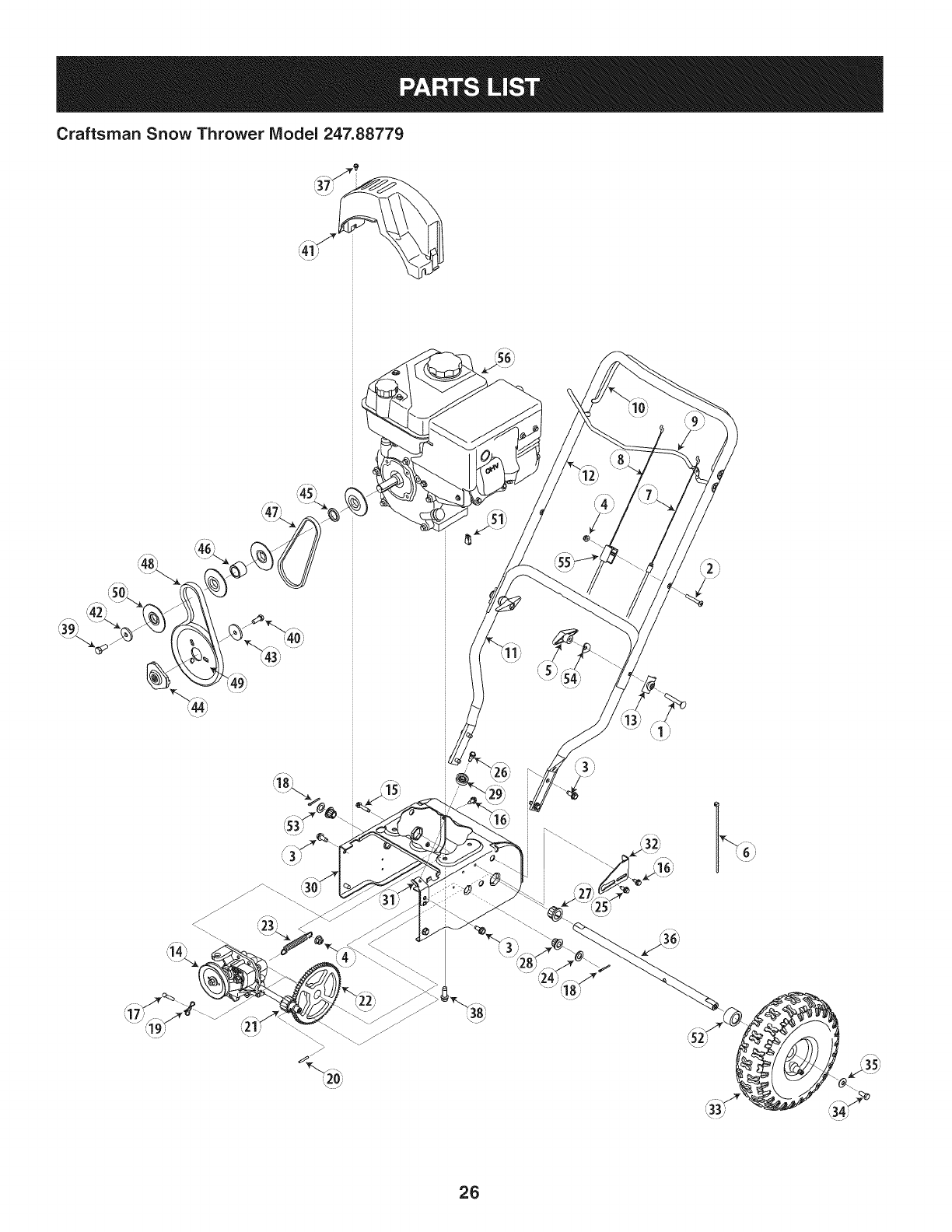
Craftsman Snow Thrower Model 247.88779
26
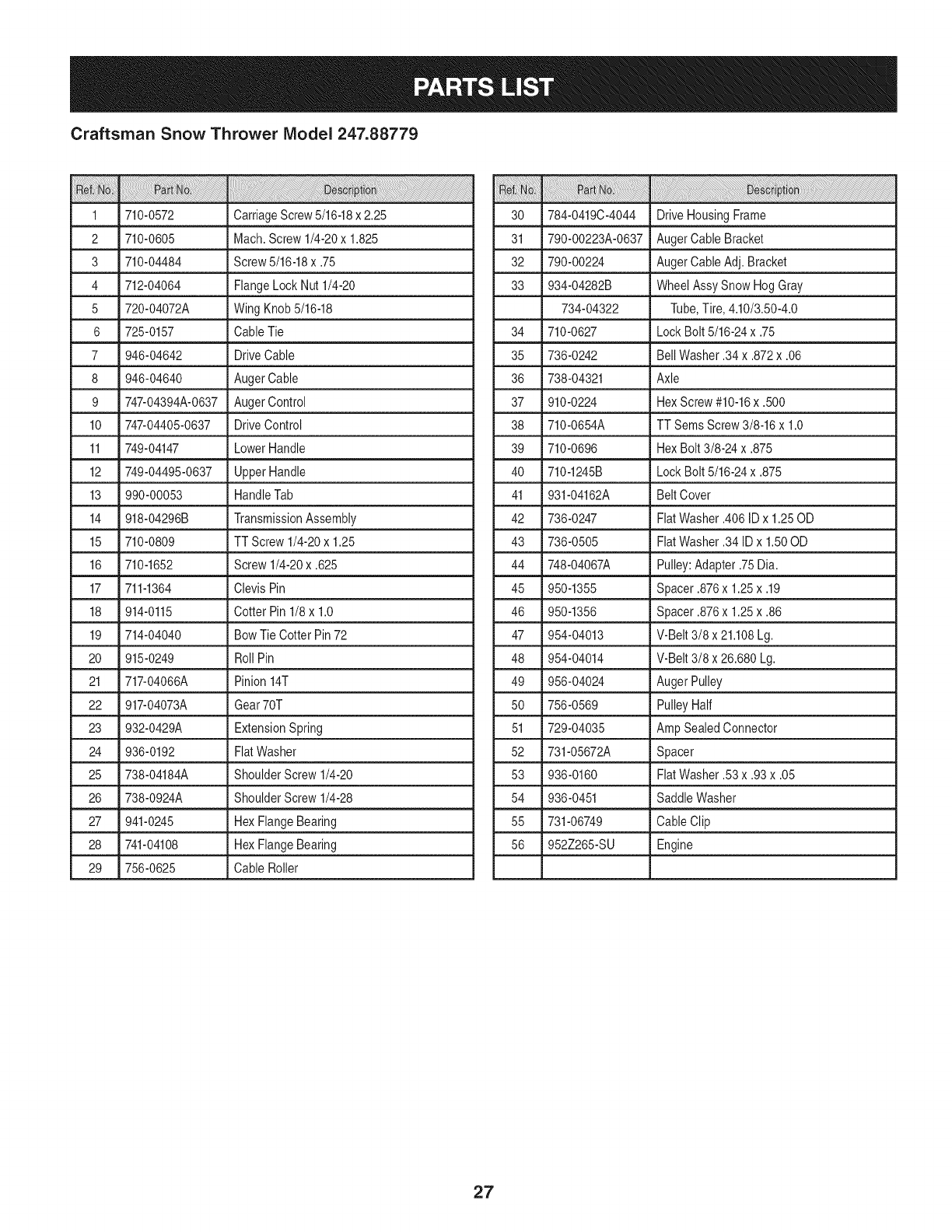
Craftsman Snow Thrower IViodel 247.88779
1 _710-0572 _ CarriageScrew5/16-18x 2.25
2 710-0605 Mach.Screw 1/4-20x 1.825
3 710-04484 Screw5/16-18x .75
4 712-04064 FlangeLockNut 1/4-20
5 720-04072A WingKnob 5/16-18
6 725-0157 CableTie
7 946-04642 DriveCable
8 946-04640 AugerCable
9 747-04394A-0637 AugerControl
10 747-04405-0637 DriveControl
11 749-04147 LowerHandle
12 749-04495-0637 UpperHandle
13 990-00053 HandleTab
14 918-04296B TransmissionAssembly
15 710-0809 TTScrew 1/4-20x 1.25
16 710-1652 Screw1/4-20x .625
17 711-1364 ClevisPin
18 914-0115 Cotter Pin 1/8x 1.0
19 714-04040 Bow TieCotter Pin72
20 915-0249 RollPin
21 717-04066A Pinion14T
22 917-04073A Gear70T
23 932-0429A ExtensionSpring
24 936-0192 FiatWasher
25 738-04184A ShoulderScrew1/4-20
26 738-0924A ShoulderScrew1/4-28
27 941-0245 Hex FlangeBearing
28 741-04108 Hex FlangeBearing
29 756-0625 CableRoller
30 784-0419C-4044 DriveHousingFrame
31 790-00223A-0637 AugerCable Bracket
32 790-00224 AugerCable Adj.Bracket
33 934-04282B Wheel AssySnowHogGray
734-04322 Tube,Tire,4.10/3.50-4.0
34 710-0627 LockBolt 5/16-24x .75
35 736-0242 BellWasher.34x .872x .06
36 738-04321 Axle
37 910-0224 HexScrew#10-16x .500
38 710-0654A TT SemsScrew3/8-16x 1.0
39 710-0696 HexBolt 3/8-24x .875
40 710-1245B LockBolt 5/16-24x .875
41 931-04162A BeltCover
42 736-0247 FlatWasher.406ID x 1.25OD
43 736-0505 FlatWasher.34ID x 1.50OD
44 748-04067A Pulley:Adapter.75Dia.
45 950-1355 Spacer .876x 1.25x .19
46 950-1356 Spacer .876x 1.25x .86
47 954-04013 V-Belt3/8 x 21.108Lg.
48 954-04014 V-Belt3/8 x 26.680Lg.
49 956-04024 Auger Pulley
50 756-0569 PulleyHalf
51 729-04035 Amp SealedConnector
52 731-05672A Spacer
53 936-0160 FiatWasher.53x .93x .05
54 936-0451 SaddleWasher
55 731-06749 CableClip
56 952Z265-SU Engine
27
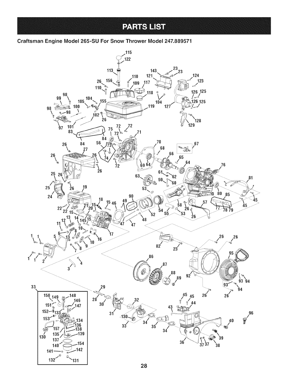
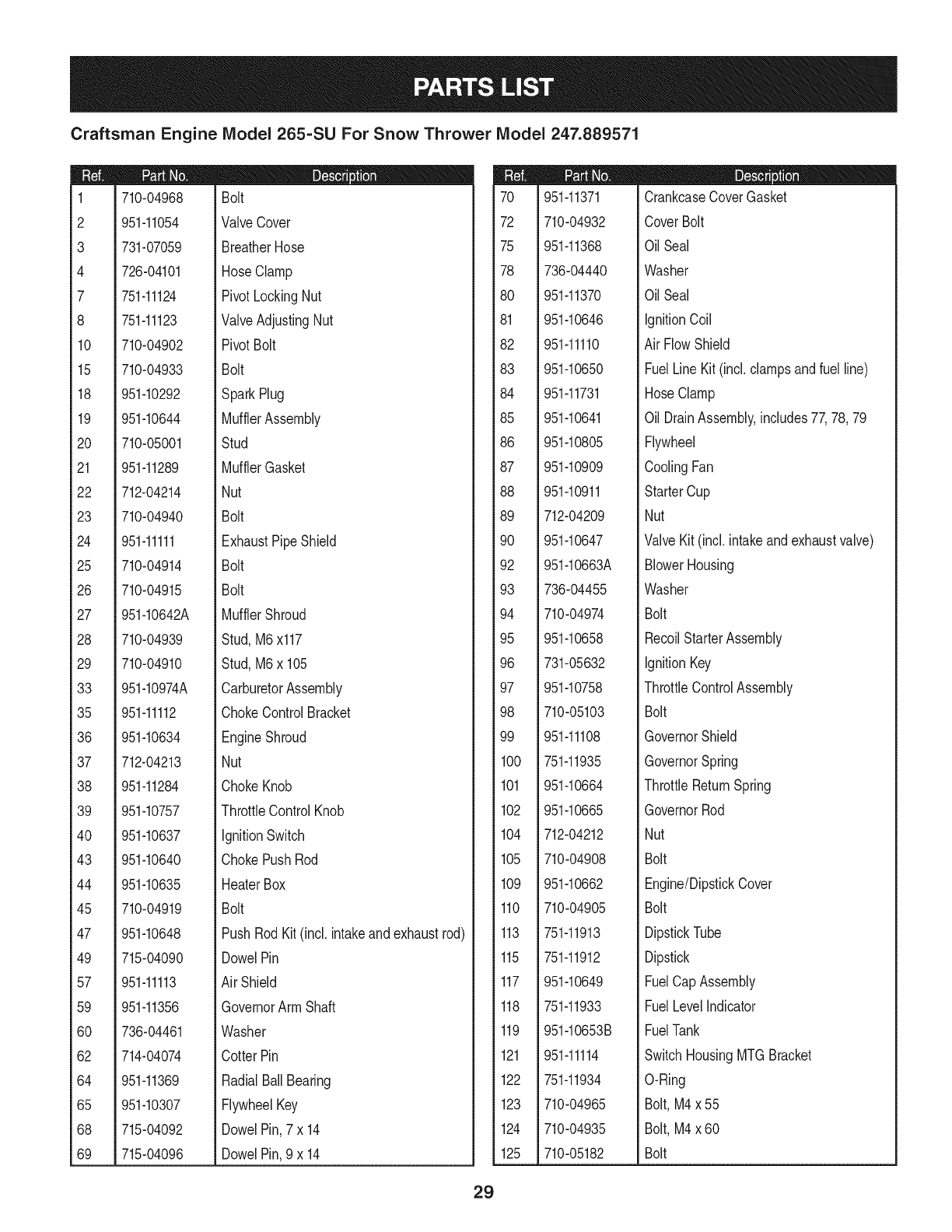
Craftsman Engine Model 265=SU For Snow Thrower Model 247.889571
1/
33
Craftsman Engine IViodel 265=SU For Snow Thrower IViodel 247.889571
m
1
2
3
4
7
8
10
15
18
19
20
21
22
23
24
25
26
27
28
29
33
35
36
37
38
39
40
43
44
45
47
49
57
59
60
62
64
65
68
69
710-04968
951-11054
731-07059
726-04101
751-11124
751-11123
710-04902
710-04933
951-10292
951-10644
710-05001
951-11289
712-04214
710-04940
951-11111
710-04914
710-04915
951-10642A
710-04939
710-04910
951-10974A
951-11112
951-10634
712-04213
951-11284
951-10757
951-10637
951-10640
951-10635
710-04919
951-10648
715-04090
951-11113
951-11356
736-04461
714-04074
951-11369
951-10307
715-04092
715-04096
D = I! O
Bolt
ValveCover
BreatherHose
HoseClamp
PivotLockingNut
ValveAdjustingNut
PivotBolt
Bolt
SparkPlug
MufflerAssembly
Stud
MufflerGasket
Nut
Bolt
ExhaustPipeShield
Bolt
Bolt
MufflerShroud
Stud,M6x117
Stud,M6x 105
CarburetorAssembly
ChokeControlBracket
EngineShroud
Nut
ChokeKnob
ThrottleControlKnob
IgnitionSwitch
ChokePushRod
HeaterBox
Bolt
PushRod Kit(incl. intakeandexhaustrod)
DowelPin
Air Shield
GovernorArm Shaft
Washer
CotterPin
RadialBallBearing
FlywheelKey
DowelPin,7x 14
DowelPin,9 x 14
70
72
75
78
8O
81
82
83
84
85
86
87
88
89
90
92
93
94
95
96
97
98
99
100
101
102
104
105
109
110
113
115
117
118
119
121
122
123
124
125
951-11371
710-04932
951-11368
736-04440
951-11370
951-10646
951-11110
951-10650
951-11731
951-10641
951-10805
951-10909
951-10911
712-04209
951-10647
951-10663A
736-04455
710-04974
951-10658
731-05632
951-10758
710-05103
951-11108
751-11935
951-10664
951-10665
712-04212
710-04908
951-10662
710-04905
751-11913
751-11912
951-10649
751-11933
951-10653B
951-11114
751-11934
710-04965
710-04935
710-05182
D = I! O
CrankcaseCoverGasket
CoverBolt
OilSeal
Washer
OilSeal
ignitionCoil
AirFlowShield
FuelLineKit (incl.clampsandfuel line)
HoseClamp
OilDrainAssembly,includes77,78,79
Flywheel
CoolingFan
StarterCup
Nut
ValveKit (incl.intakeandexhaustvalve)
BlowerHousing
Washer
Bolt
RecoilStarterAssembly
ignitionKey
ThrottleControlAssembly
Bolt
GovernorShield
GovernorSpring
ThrottleReturnSpring
GovernorRod
Nut
Bolt
Engine/DipstickCover
Bolt
DipstickTube
Dipstick
FuelCapAssembly
FuelLevelindicator
FuelTank
SwitchHousingMTGBracket
O-Ring
Bolt,M4x 55
Bolt,M4x 60
Bolt
29
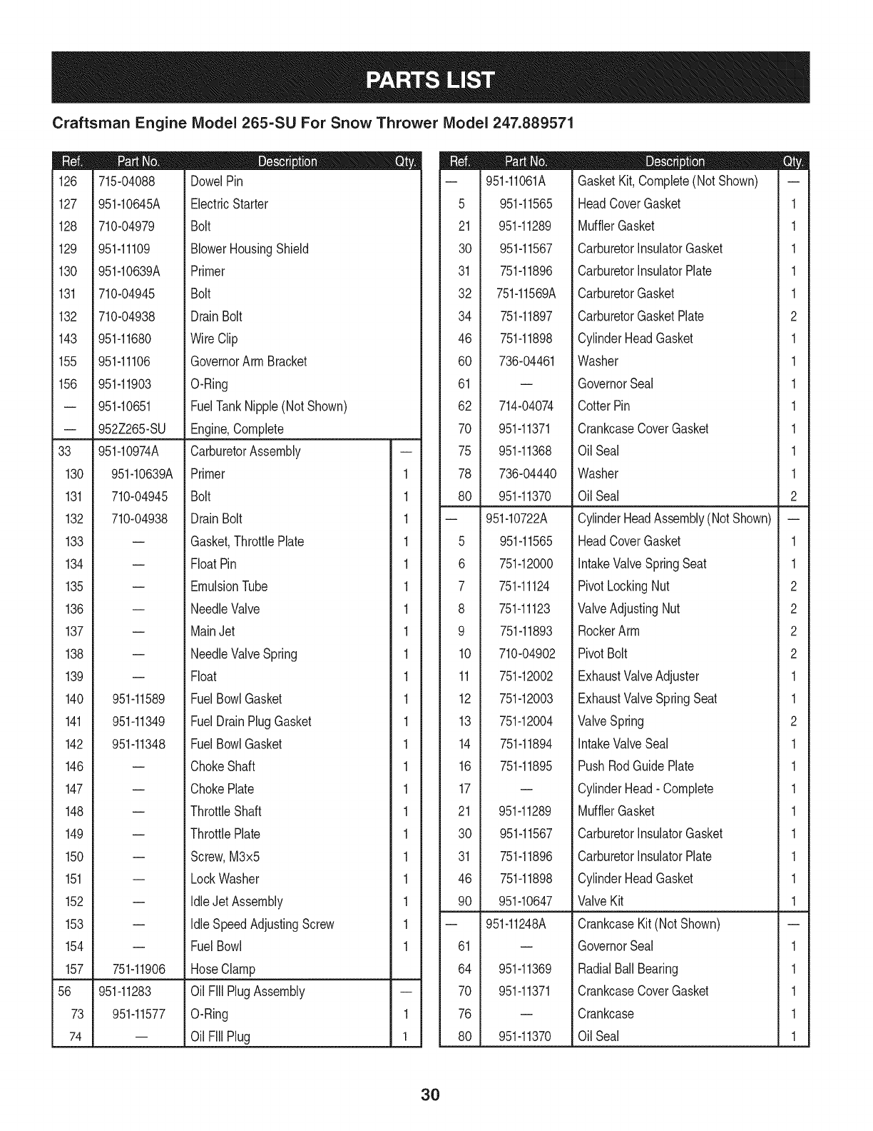
Craftsman Engine Model 265-SU For Snow Thrower Model 247.889571
|- 0 o e
126 715-04088 DowelPin
127 951-10645A ElectricStarter
128 710-04979 Bolt
129 951-11109 BlowerHousingShield
130 951-10639A Primer
131 710-04945 Bolt
132 710-04938 Drain Bolt
143 951-11680 WireClip
155 951-11106 GovernorArm Bracket
156 951-11903 O-Ring
-- 951-10651 FuelTankNipple(NotShown)
-- 952Z265-SU Engine,Complete
33 951-10974A CarburetorAssembly
130 951-10639A Primer 1
131 710-04945 Bolt 1
132 710-04938 Drain Bolt 1
133 = Gasket,ThrottlePlate 1
134 -- FloatPin 1
135 -- EmulsionTube 1
136 = NeedleValve 1
137 = MainJet 1
138 -- NeedleValveSpring 1
139 = Float 1
140 951-11589 FuelBowlGasket 1
141 951-11349 FuelDrain PlugGasket 1
142 951-11348 FuelBowlGasket 1
146 -- ChokeShaft 1
147 = ChokePlate 1
148 = ThrottleShaft 1
149 = ThrottlePlate 1
150 = Screw,M3x5 1
151 -- LockWasher 1
152 -- Idle JetAssembly 1
153 = Idle SpeedAdjustingScrew 1
154 -- Fuel Bowl 1
157 751-11906 HoseClamp
56 951-11283 Oil Fill PlugAssembly
73 951-11577 O-Ring 1
74 -- Oil Fill Plug 1
D = O
-- 951-11061A GasketKit,Complete(NotShown) --
5 951-11565 HeadCoverGasket 1
21 951-11289 MufflerGasket 1
30 951-11567 CarburetorInsulatorGasket 1
31 751-11896 CarburetorInsulatorPlate 1
32 751-11569A CarburetorGasket 1
34 751-11897 CarburetorGasketPlate 2
46 751-11898 CylinderHeadGasket 1
60 736-04461 Washer 1
61 -- GovernorSeal 1
62 714-04074 CotterPin 1
70 951-11371 CrankcaseCoverGasket 1
75 951-11368 OilSeal 1
78 736-04440 Washer 1
80 951-11370 OilSeal 2
-- 951-10722A CylinderHeadAssembly(NotShown) --
5 951-11565 HeadCoverGasket 1
6 751-12000 IntakeValveSpringSeat 1
7 751-11124 PivotLockingNut 2
8 751-11123 ValveAdjustingNut 2
9 751-11893 RockerArm 2
10 710-04902 PivotBolt 2
11 751-12002 ExhaustValveAdjuster 1
12 751-12003 ExhaustValveSpringSeat 1
13 751-12004 ValveSpring 2
14 751-11894 IntakeValveSeal 1
16 751-11895 PushRodGuidePlate 1
17 -- CylinderHead- Complete 1
21 951-11289 MufflerGasket 1
30 951-11567 CarburetorInsulatorGasket 1
31 751-11896 CarburetorInsulatorPlate 1
46 751-11898 CylinderHeadGasket 1
90 951-10647 ValveKit 1
-- 951-11248A CrankcaseKit(NotShown)
61 = GovernorSeal 1
64 951-11369 RadialBallBearing 1
70 951-11371 CrankcaseCoverGasket 1
76 = Crankcase 1
80 951-11370 OilSeal 1
3O
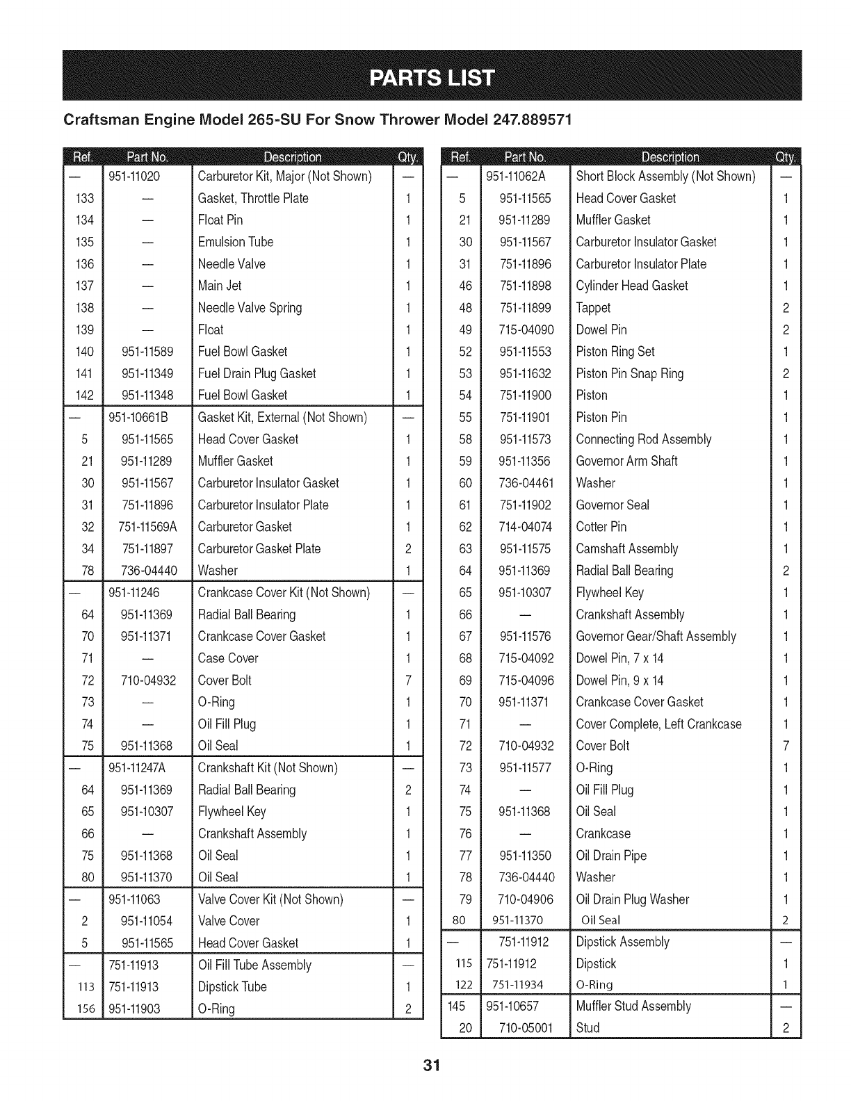
Craftsman Engine IViodel 265-SU For Snow Thrower IViodel 247.889571
|= o= |= 0_
-- 951-11020 CarburetorKit,Major(NotShown) -- -- 951-11062A ShortBlockAssembly(NotShown) --
133 -- Gasket,ThrottlePlate 1 5 951-11565 HeadCoverGasket 1
134 -- FloatPin 1 21 951-11289 MufflerGasket 1
135 -- EmulsionTube 1 30 951-11567 CarburetorinsulatorGasket 1
136 -- NeedleValve 1 31 751-11896 CarburetorinsulatorPlate 1
137 -- MainJet 1 46 751-11898 CylinderHeadGasket 1
138 -- NeedleValveSpring 1 48 751-11899 Tappet 2
139 -- Float 1 49 715-04090 DowelPin 2
140 951-11589 Fuel BowlGasket 1 52 951-11553 PistonRingSet 1
141 951-11349 Fuel DrainPlugGasket 1 53 951-11632 PistonPinSnapRing 2
142 951-11348 Fuel BowlGasket 1 54 751-11900 Piston 1
-- 951-10661B GasketKit,External(Not Shown) -- 55 751-11901 PistonPin 1
5 951-11565 HeadCoverGasket 1 58 951-11573 ConnectingRodAssembly 1
21 951-11289 MufflerGasket 1 59 951-11356 GovernorArm Shaft 1
30 951-11567 CarburetorinsulatorGasket 1 60 736-04461 Washer 1
31 751-11896 CarburetorInsulatorPlate 1 61 751-11902 GovernorSeal 1
32 751-11569A CarburetorGasket 1 62 714-04074 CotterPin 1
34 751-11897 CarburetorGasketPlate 2 63 951-11575 CamshaftAssembly 1
78 736-04440 Washer 1 64 951-11369 RadialBallBearing 2
-- 951-11246 CrankcaseCoverKit (NotShown) -- 65 951-10307 FlywheelKey 1
64 951-11369 RadialBallBearing 1 66 -- CrankshaftAssembly 1
70 951-11371 CrankcaseCoverGasket 1 67 951-11576 GovernorGear/ShaftAssembly 1
71 -- CaseCover 1 68 715-04092 DowelPin,7 x 14 1
72 710-04932 CoverBolt 7 69 715-04096 DowelPin,9 x 14 1
73 -- O-Ring 1 70 951-11371 CrankcaseCoverGasket 1
74 -- Oil Fill Plug 1 71 -- CoverComplete,LeftCrankcase 1
75 951-11368 Oil Seal 1 72 710-04932 CoverBolt 7
-- 951-11247A CrankshaftKit (NotShown) -- 73 951-11577 O-Ring 1
64 951-11369 RadialBallBearing 2 74 -- OilFill Plug 1
65 951-10307 FlywheelKey 1 75 951-11368 OilSeal 1
66 -- CrankshaftAssembly 1 76 -- Crankcase 1
75 951-11368 Oil Seal 1 77 951-11350 OilDrainPipe 1
80 951-11370 Oil Seal 1 78 736-04440 Washer 1
-- 951-11063 ValveCoverKit (NotShown) -- 79 710-04906 OilDrainPlugWasher 1
2 951-11054 ValveCover 1 80 951-11370 OilSeal 2
5 951-11565 HeadCoverGasket 1 -- 751-11912 DipstickAssembly --
-- 751-11913 Oil FilITubeAssembly -- 115 751-11912 Dipstick 1
113 751-11913 DipstickTube 1 122 751-11934 O-Ring 1
156 951-11903 O-Ring 2 145 951-10657 MufflerStud Assembly --
20 710-05001 Stud 2
31
MTD CONSUMER GROUP INC (MTD), the California Air Resources Board (CARB)
and the United States Environment Protection Agency (U. S. EPA)
Emission Control System Warranty Statement
(Owner's Defect Warranty Rights and Obligations)
EMISSIONCONTROLSYSTEMCOVERAGEIS APPLICABLETOCERTIFIEDENGINESPURCHASEDINCALIFORNIAIN2005ANDTHERE-
AFTER,WHICHARE USEDINCALIFORNIA,ANDTO CERTIFIEDMODELYEAR2005ANDLATERENGINESWHICHARE PURCHASEDAND
USEDELSEWHEREINTHEUNITEDSTATES.
Californiaandelsewherein the UnitedStatesEmissionControlDefectsWarrantyCoverage
The CaliforniaAir ResourcesBoard(CARB),U.S. EPAandMTDarepleasedto explaintheemissionscontrolsystemwarrantyonyour modelyear
2006andlatersmalloff-roadengine.In California,new smalloff-roadenginesmustbe designed,builtand equippedto meettheStatesanti-smog
standards.Elsewhereinthe UnitedStates,newnon-road,spark-ignitionenginescertifiedfor model2005and later,mustmeetsimilarstandardsset
forthby the U.S. EPA.MTDmustwarrantythe emissioncontrolsystemonyourenginefor the periodof timelistedbelow,providedtherehasbeen
noabuse,neglector impropermaintenanceof your smalloff-roadengine.
Youremissioncontrolsystemmayincludepartssuchas the carburetor,fuel-injectionsystem,the ignitionsystem,andcatalyticconverter,fueltanks,
fuel lines,fuel caps,valves,canisters,filters,vaporhoses,clamps,connectors,andotherassociatedemission-relatedcomponents.
Wherea warrantableconditionexists,MTDwill repairyoursmalloff-roadengineat nocost to yourincludingdiagnosis,partsand labor.
MANUFACTURER'S WARRANTY COVERAGE:
Thisemissionscontrolsystemis warrantedfor twoyears.If anyemission-relatedpart onyourengineis defective,the part will berepairedor
replacedby MTD.
OWNER'S WARRANTY RESPONSIBILITIES:
As the smalloff-roadengineowner,youare responsibleforthe performanceofthe requiredmaintenancelistedinyour Owner'sManual.MTD
recommendsthatyou retainall yourreceiptscoveringmaintenanceson yoursmalloff-roadengine,but MTDcan not denywarrantysolelyfor the
lackof receiptsor for yourfailureto ensurethe performanceto allscheduledmaintenance.
As the smalloff-roadengineowner,youshouldhoweverbeawarethat MTDmaydenyyour warrantycoverageif yoursmalloff-roadengineorpart
hasfaileddue toabuse,neglect,impropermaintenanceor unapprovedmodifications.
Youare responsiblefor presentingyour smalloff-roadengineto an AuthorizedMTDServiceDealeras soonas a problemexists.Thewarranted
repairsshouldbe completedin a reasonableamountof time,notto exceed30 days.
If youhaveanyquestionsregardingyourwarrantyrightsand responsibilities,you shouldcontacta MTDServiceRepresentativeat 1-800-800-7310
andaddressis MTDCONSUMERGROUP,RO.Box361131,ClevelandOH,44136-0019.
DEFECTS WARRANTY REQUIREMENTS FOR 1995 AND LATER SMALL OFF-ROAD ENGINES:
Thissectionappliesto 1995andlater smalloff-roadengines.The warrantyperiodbeginsonthe datethe engineor equipmentis deliveredto an
ultimatepurchaser.
(a) GeneralEmissionsWarrantyCoverage
MTDmustwarrantto the ultimatepurchaserandeachsubsequentpurchaserthatthe engineis:
(1)Designed,built,andequippedsoas to conformwithallapplicableregulationsadoptedby the AirResourcesBoardpursuantto itsauthorityin
Chapters1and2,Part5, Division26of the HealthandSafetyCode;and
(2) Freefromdefectsin materialsandworkmanshipthatcausethe failureof a warrantedpart to be identicalin all materialrespectsto the partas
describedin theenginemanufacturer'sapplicationfor certificationfora periodof twoyears.
(b)The warrantyonemissions-relatedpartswill be interpretedas follows:
(1)Anywarrantedpart thatis not scheduledfor replacementas requiredmaintenanceinthe writteninstructionsrequiredby Subsection(c)
mustbewarrantedfor the warrantyperioddefinedinSubsection(a)(2). Ifany suchpartfailsduringthe periodof warrantycoverage,it mustbe
repairedor replacedby MTDaccordingto Subsection(4)below.Anysuchpart repairedor replacedunderthewarrantymustbewarrantedfor
the remainingwarrantyperiod.
(2)Any warrantedpartthat is scheduledonlyfor regularinspectioninthe writteninstructionsrequiredby Subsection(c) mustbewarrantedfor
thewarrantyperioddefinedin Subsection(a)(2).A statementinsuchwritteninstructionsto the effectof"repairor replaceas necessary"will
not reducethe periodof warrantycoverage.Anysuchpart repairedor replacedunderwarrantymustbe warrantedforthe remainingwarranty
period.
(3) Anywarrantedpartthat whichis scheduledfor replacementas requiredmaintenancein the writteninstructionsrequiredby Subsection(c)
mustbewarrantedfor the periodof timepriorto the first scheduledreplacementpointforthat part.Ifthe part failspriorto thefirst scheduled
replacement,the part mustbe repairedor replacedby MTDaccordingto Subsection(4) below.Any suchpart repairedor replacedunder
warrantymustbewarrantedfor the remainderof the periodpriorto the first scheduledreplacementpointfor the part.
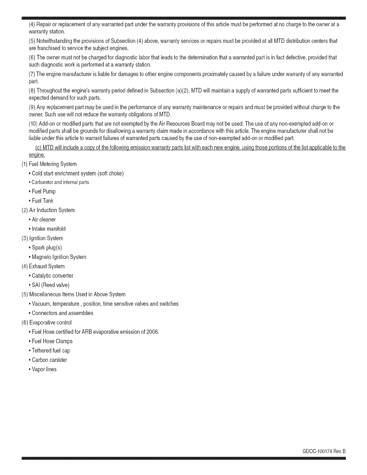
(4)Repairorreplacementofanywarrantedpartunderthewarrantyprovisionsofthisarticlemustbeperformedatnochargetotheownerata
warrantystation.
(5)NotwithstandingtheprovisionsofSubsection(4)above,warrantyservicesorrepairsmustbeprovidedatallMTDdistributioncentersthat
arefranchisedtoservicethesubjectengines.
(6)Theownermustnotbechargedfordiagnosticlaborthatleadstothedeterminationthatawarrantedpartisinfactdefective,providedthat
suchdiagnosticworkisperformedatawarrantystation.
(7)Theenginemanufacturerisliablefordamagestootherenginecomponentsproximatelycausedbyafailureunderwarrantyofanywarranted
part.
(8)Throughouttheengine'swarrantyperioddefinedinSubsection(a)(2),MTDwillmaintainasupplyofwarrantedpartssufficienttomeetthe
expecteddemandforsuchparts.
(9)Anyreplacementpartmaybeusedintheperformanceofanywarrantymaintenanceorrepairsandmustbeprovidedwithoutchargetothe
owner.SuchusewillnotreducethewarrantyobligationsofMTD.
(10)Add-onormodifiedpartsthatarenotexemptedbytheAirResourcesBoardmaynotbeused.Theuseofanynon-exemptedadd-onor
modifiedpartsshallbegroundsfordisallowingawarrantyclaimmadeinaccordancewiththisarticle.Theenginemanufacturershallnotbe
liableunderthisarticletowarrantfailuresofwarrantedpartscausedbytheuseofnon-exemptedadd-onormodifiedpart.
(c) MTDwill includea copyof the followingemissionwarrantypartslistwitheach newengine,usingthoseportionsof the listapplicableto the
e__&gine.
(1)FuelMeteringSystem
• Coldstart enrichmentsystem(soft choke)
,,Carburetorandinternalparts
• Fuel Pump
• FuelTank
(2)Air InductionSystem
• Aircleaner
• Intakemanifold
(3) IgnitionSystem
• Sparkplug(s)
• MagnetoIgnitionSystem
(4)ExhaustSystem
Catalyticconverter
• SAI (Reedvalve)
(5) MiscellaneousItemsUsedin AboveSystem
Vacuum,temperature,position,timesensitivevalvesand switches
Connectorsandassemblies
(6) Evaporativecontrol
• Fuel Hosecertifiedfor ARBevaporativeemissionof 2006.
• Fuel HoseClamps
Tetheredfuel cap
Carboncanister
Vaporlines
GD0C-100174Rev.B
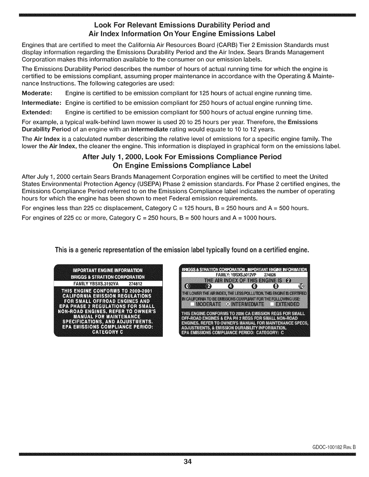
Look For Relevant Emissions Durability Period and
Air index information On Your Engine Emissions Label
Engines that are certified to meet the California Air Resources Board (CARB) Tier 2 Emission Standards must
display information regarding the Emissions Durability Period and the Air Index. Sears Brands Management
Corporation makes this information available to the consumer on our emission labels.
The Emissions Durability Period describes the number of hours of actual running time for which the engine is
certified to be emissions compliant, assuming proper maintenance in accordance with the Operating & Mainte-
nance Instructions. The following categories are used:
Moderate: Engine is certified to be emission compliant for 125 hours of actual engine running time.
Intermediate: Engine is certified to be emission compliant for 250 hours of actual engine running time.
Extended: Engine is certified to be emission compliant for 500 hours of actual engine running time.
For example, a typical walk-behind lawn mower is used 20 to 25 hours per year. Therefore, the Emissions
Durability Period of an engine with an intermediate rating would equate to 10 to 12 years.
The Air index is a calculated number describing the relative level of emissions for a specific engine family. The
lower the Air Index, the cleaner the engine. This information is displayed in graphical form on the emissions label.
After July 1,2000, Look For Emissions Compliance Period
On Engine Emissions Compliance Label
After July 1, 2000 certain Sears Brands Management Corporation engines will be certified to meet the United
States Environmental Protection Agency (USEPA) Phase 2 emission standards. For Phase 2 certified engines, the
Emissions Compliance Period referred to on the Emissions Compliance label indicates the number of operating
hours for which the engine has been shown to meet Federal emission requirements.
For engines less than 225 cc displacement, Category C = 125 hours, B = 250 hours and A = 500 hours.
For engines of 225 cc or more, Category C = 250 hours, B = 500 hours and A = 1000 hours.
This is ageneric representation of the emission label typically found on a certified engine.
FAMILYYBSXS.3192VA 274812
GDOC-100182Rev.B
34
Congratulationson makinga smartpurchase.YournewCraftsman@
productis designedandmanufacturedfor yearsof dependableopera-
tion.But likeall products,it mayrequirerepairfromtimeto time.That's
whenhavinga RepairProtectionAgreementcansaveyoumoneyand
aggravation.
Here'swhatthe RepairProtectionAgreement*includes:
* Expert service byour 10,000professionalrepairspecialists
oUnlimitedserviceand no chargefor partsand laboron all
coveredrepairs
o Product replacementupto $1500if yourcoveredproductcan't be
fixed
•Discountof 10%from regularprice of serviceand relatedinstalled
partsnotcoveredby theagreement;also,10%off regularpriceof
preventivemaintenancecheck
• Fast help by phone- we call it RapidResolution- phonesupport
froma Searsrepresentative.Thinkof usas a "talkingowner's
manual."
Onceyou purchasethe Agreement,a simplephonecall is all thatit
takesfor youto scheduleservice.Youcan call anytimedayor night,or
schedulea serviceappointmentonline.
The RepairProtectionAgreementisa risk-freepurchase.If youcancel
for any reasonduringthe productwarrantyperiod,wewill provideafull
refund.Or,a proratedrefundanytimeafterthe productwarrantyperiod
expires.Purchaseyour RepairProtectionAgreementtoday!
Somelimitationsand exclusionsapply. For pricesand additional
informationin the U.S.A.call 1-800-827-6655.
*Coverage inCanadavaries on some items.Forfull details call
Sears Canadaat 1-800-361-6665.
Sears Installation Service
ForSearsprofessionalinstallationof homeappliances,garagedoor
openers,waterheaters,andothermajorhomeitems,in the U.S.A.or
Canadacall 1-800-4-MY-HOME®.
35
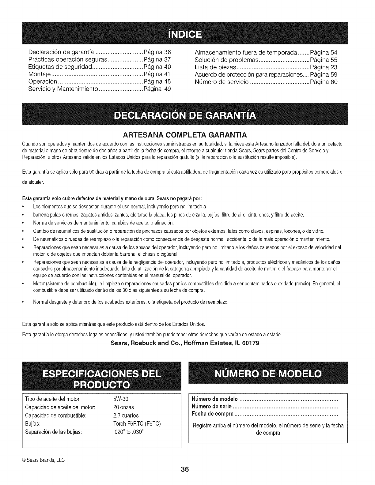
Declaraci6n de garantia ............................ Pagina 36
Practicas operaci6n seguras ..................... Pagina 37
Etiquetas de seguridad .............................. Pagina 40
Montaje ...................................................... Pagina 41
Operaci6n .................................................. Pagina 45
Servicio y Mantenimiento .......................... Pagina 49
Almacenamiento fuera de temporada ....... Pagina 54
Soluci6n de problemas .............................. Pagina 55
Lista de piezas ........................................... Pagina 23
Acuerdo de protecci6n para reparaciones .... Pagina 59
NOmero de servicio ................................... Pagina 60
ARTESANA COIViPLETA GARANTIA
Cuandosonoperadosy mantenidosde acuerdocon lasinstruccionessuministradasen sutotalidad,si la nieveestaArtesanolanzadorfalladebidoa undefecto
dematerialo manodeobradentrodedos a_osa partirdela fechadecompra,el retornoa cualquiertiendaSears,Searspartesdel Centrode Servicioy
Reparaci6n,u otrosArtesanosalidaen los EstadosUnidosparala reparaci6ngratuita(si lareparaci6no la sustituci6nresulteimposible).
Estagaranfiaseaplicas61opara90 d[asa partirdela fechade comprasi estaastilladorade fragmentaci6ncadavez es utilizadoparaprop6sitoscomercialeso
dealquiler.
Estagarantias61ocubre defeetos de material ymano deobra.Searsno pagar_pot:
•Loselementosquese desgastanduranteel uso normal,incluyendoperono limitadoa
,, barrenapalaso remos,zapatosantideslizantes,afeitarselaplaca,los pinesdecizalla,buj[as,filtrode aire,cinturones,yfiltro deaceite.
•Normadeserviciosdemantenimiento,cambiosde aceite,o afinaci6n.
•Cambiode neum_ticosde sustituci6no reparaci6ndepinchazoscausadospotobjetosexternos,talescomoclavos,espinas,tocones,o devidrio.
•De neum_ticoso ruedasde reemplazoo la reparaci6ncomoconsecuenciade desgastenormal,accidente,o de la malaoperaci6no mantenimiento.
•Reparacionesque seannecesariasa causade losabusosdel operador,incluyendoperonolimitadoa losdaSoscausadospot el excesodevelocidaddel
motor,o de objetosqueimpactandoblarla barrena,elchasiso cigQe_al.
•Reparacionesque seannecesariasa causade la negligenciadel operador,incluyendoperono limitadoa, productoselectricosy mecanicosde losda_os
causadosporalmacenamientoinadecuado,faltade utilizaci6ndela categor[aapropiadayla cantidaddeaceitede motor,o el fracasoparamantenerel
equipodeacuerdocon las instruccionescontenidasen el manualdel operador.
•Motor(sistemadecombustible),lalimpiezao reparacionescausadasporloscombustiblesdecididaa set contaminadoso oxidado(rancio).Engeneral,el
combustibledebeset utilizadodentrode los30 d[assiguientesa su fechade compra.
,, Normaldesgastey deteriorodelos acabadosexteriores,o la etiquetadel productodereemplazo.
Estagarantias61ose aplicamientrasqueesteproductoest_dentrode los EstadosUnidos.
Estagarantiale otorgaderechoslegalesespecificos,y ustedtambienpuedetenet otrosderechosquevariande estadoa estado.
Sears, Roebuck and Co., Hoffman Estates, IL 60179
Tipodeaceitedelmotor:
Capacidadde aceitedel motor:
Capacidadde combustible:
Bujias:
Separaci6ndelas bujias:
5W-30
20 onzas
2.3 cuartos
Torch F6RTC (F6TC)
.020" to .030"
N_mero de modelo ..........................................................
N_mero de serie ..............................................................
Fechade compra .............................................................
Registrearribael nOmerodel modelo,el nOmerode seriey la fecha
de compra
©SearsBrands,LLC
36
Lapresenciadeeste sfrnboloindicaque setratade instrucciones
irnportantesde seguridadquese debenrespetarparaevitar
ponerenpeligrosu seguridadpersonaly/o materialy lade otras
personas.Leay siga todaslas instruccionesdeestemanualantes
de poneren funcionarnientoestarn_.quina.Si no respetaestas
instruccionespodrfaprovocarlesionespersonales.Cuandoveaeste
sfrnbolo,ipresteatenci6na la advertencia!
PROPOSICION 65 DE CALIFORNIA
Elescapedel motordeesteproducto,algunosde suscornponentes
y algunoscornponentesdelvehfculocontieneno liberansustancias
qufrnicasqueelestadodeCaliforniaconsideraque puedenproducir
c_.ncer,defectosde nacirnientouotrosproblernasreproductivos.
Estarn_.quinarueconstruidaparaseroperadadeacuerdocon
las reglasde seguridadcontenidasenestemanual.AI igualque
concualquiertipo deequipornotorizado,undescuidoo errorpor
partedeloperadorpuedeproducirlesionesgraves.Estarn_.quina
es capazde arnputarrnanosy piesy dearrojarobjetoscon gran
fuerza.Deno respetarlas instruccionesde seguridadsiguientesse
puedenproducirlesionesgraveso larnuerte.
Su responsabilidad--Restrinja el usode estarn_.quina
rnotorizadaalas personasque lean,cornprendany respetenlas
advertenciase instruccionesqueaparecenen estemanualyen la
rn_.quina.
iGUARDEESTASINSTRUCCIONES!
CAPACITACI6N
• Lea,entienday curnplatodaslas instruccionesincluidasen
la rn_.quinay enlos rnanualesantesdernontarlay utiNzarla.
Guardeestemanualenun lugarseguroparaconsultasfuturasy
peri6dicas,asf cornoparasolicitarrepuestos.
• Leael ManualdelOperadory sigatodaslas advertenciase
instruccionesdeseguridad.Elfracasode hacerasf puedecausar
la heridaseriaal operadory/o personaspresentes.Paraflarnada
depreguntas,1-800-4MY-HOME.
• Farniliarfcesecontodoslos controlesy con el usoadecuado
delos rnisrnos.Sepac6rnodetenerlarn_.quinay desactivarlos
controlesr_.pidarnente.
• No perrnitanuncaque los ni_osrnenoresde 14a_osutilicen
estarn_.quina.Los nifiosde 14afiosen adelantedebenleery
entenderlas instruccionesde operaci6ny norrnasdeseguridad
contenidaseneste manual,yen la rn_.quinaydebenser entrena-
dosy supervisadosporun adulto.
• Nuncaperrnitaquelos adultosoperenestarn_.quinasin recibir
antesla instrucci6napropiada.
• Losobjetosarrojadosporla rn_.quinapuedenproducirlesiones
graves.Planifiqueel patr6nenel queva a irarrojandonievepara
evitarque ladescargade materialse realicehacialos carninos,
los observadores,etc.
• Mantengaa losobservadores,ayudantes,rnascotasy ni_ospor
Io rnenosa 75piesde la rn_.quinarnientrasla rnisrnaest,.en
funcionarniento.Detengala rn_.quinasi alguienseacerca.
• Seaprecavidoparaevitarpatinarseo caerseespecialrnente
cuandooperala rn_.quinaen reversa.
PR EPARATIVO S
Inspeccionerninuciosarnenteel&teadondeutilizar&el equipo.Saque
todoslos felpudos,peri6dicos,trineos,tablas,cablesy otrosobjetos
extra_oscon los quepodrfatropezaro quepodrfanser arrojadospor
labarrena/irnpulsor.
• Paraprotegerselosojos utilicesiernpreanteojosoantiparras
de seguridadrnientrasoperala rn_.quinao rnientrasla ajusta
o repara.Losobjetosarrojadosquerebotanpuedenproducir
lesionesocularesgraves.
• Nooperelarn_.quinasin la vestirnentaadecuadaparaestaral
airelibreen invierno.No utilicealhajas,bufandaslargasu otras
prendassueltasquepodrfanenredarseenlas partesrn6viles.
UtiNceun calzadoespecialparasuperficiesresbaladizas.
• Useun prolongadory untornacorrientedetrescablescon
conexi6na tierraparatodaslas rn_.quinascon rnotoresde
encendidoel_ctrico.
• Ajustelaalturade lacaja deltornacorrienteparaNrnpiarla grava
o las superficiescon piedrastrituradas.
• Desengranetodaslas palancasde controlantesde arrancarel
motor.
• Nuncaintenterealizarajustesrnientrasel motorest,.enrnarcha
exceptoen los casosespecfficarnenterecornendadosen el
manualdeloperador.
• Dejequeelmotory la rn_.quinase adaptena laternperatura
exteriorantesde cornenzara sacarla nieve.
37
Manejo seguro de la gasolina
Paraevitarlesionespersonales0 daSosrnaterialestengarnucho
cuidadocuandotrabajecon gasolina.Lagasolinaes surnarnente
inflarnabley susvaporespuedencausarexplosiones.Si se derrarna
gasolinaencirna0 sobrela ropase puedelesionargravernenteya que
se puedeincendiar. L&vesela piely c&rnbiesede ropade inrnediato.
• Utilices610los recipientesparagasolinaautorizados.
• Apaguetodoslos cigarrillos,cigarros,pipasy otrasfuentesde
cornbusfi6n.
• Nuncacarguecombustibleen larn&quinaen unespaciocerrado.
• Nuncasaquela tapadelcombustibleniagreguecombustible
rnientrasel motorest&caliente0 en rnarcha.
• Dejequeel motorse enfrieporI0 rnenosdos rninutosantesde
volvera cargarcombustible.
• NuncaIleneenexcesoel dep6sitodecombustible.Lleneel
tanquea no rn&sde1/2pulgadapordebajode la basedelcuello
de Ilenadodejandoespacioparaladilataci6ndeIcombustible.
• Vuelvaa colocarla tapade lagasoiinay aj_stelabien.
• Lirnpieel combustiblequese hayaderrarnadosobreel motory el
equipo.Trasladela rn&quinaa otra zona.Espere5 rninutosantes
deencenderel motor.
• Nuncaalrnacenela rn&quina0 el recipientedecombustibleen
unespaciocerradodondehayafuego,chispas0 luz piloto(por
ejernplo,hornos,calentadoresdeagua,calefactores,secadores
de ropa,etc.).
• Dejequela rn_.quinase enfrieporIo rnenos5 rninutosantesde
guardarla.
• NuncaIlenelos recipientesenel interiordeunvehiculoo carni6n
ocaja de rernolquecon recubrirnientospl_.sticos.Coloque
siernprelos recipientesenel pisoy lejosdelvehiculoantesde
Ilenarlos.
• Sies posible,retireel equipoa gasolinadelcarni6no rernolque
y II_neloen el suelo.Siestonoes posible,Ileneel equipoen un
rernolquecon contenedorport_.til,envezdedesdeunaboquilla
dispensadoradegasolina.
• Mantengala boquilladispensadoraen contactocon el hordedel
dep6sitode combustibleo con la aberturadel recipienteentodo
rnornento,hastaterrninarlacarga.No utiliceundispositivode
apertura/cierrede boquilla.
FUNCIONANIIENTO
•No pongalas rnanoso los piescercadelas piezasrotatorias,
en lacajade la barrena/irnpulsoro en el rnontajedelcanalde
descarga.Hacercontactocon piezasgiratoriaspuederesultaren
laarnputaci6ndernanoso pies.
• La palancadecontrolde la barrena/irnpulsores un dispositivo
de seguridad.Nuncaevitesu funcionarniento.De hacerlola
operaci6nde la rn_.quinaes riesgosay puedeocasionarlesiones.
• Las palancasdecontroldebenfuncionarbienen arnbasdirec-
cionesy regresarautorn_.ticarnentea la posici6nde desengrane
cuandose lassuelta.
• Nuncaoperela rn_.quinasi faltaunrnontajedelcanalo si el
rnisrnoest,.daSado.Mantengatodoslosdispositivosde seguri-
daden su lugaryen funcionarniento.
• Nuncaenciendaelmotorenespacioscerradoso en unazona
con pocaventilaci6n.Elescapedel motorcontienernon6xidode
carbono,ungas inodoroy letal.
• Noutilicela rn_.quinabajola influenciadelalcoholo las drogas.
• Elsilenciadory el motorse calientany puedencausarquernadu-
ras.Nolos toque.Mantengaa los niSosalejados.
• Seasurnarnenteprecavidocuandooperelarn_.quinasobreuna
superficiecon gravaocuandola cruce.Mant_ngasealerta porsi
se presentanpeligrosocultoso tr_.nsito.
• Tengacuidadocuandocarnbiede direcci6no cuandooperela
rn_.quinaen pendientes.
• Planifiqueel patr6nenel queva air arrojandonieveparaevitar
que ladescargade materialse produzcahacialas ventanas,
las paredes,losautorn6viles,etc.y evitarasi posiblesdaSos
rnaterialeso lesionesproducidasporlos rebotes.
• Nuncadirijaladescargahacialos niSos,los observadoreso las
rnascotasni dejequenadiese paredelantede la rn_.quina.
• Nosobrecarguelacapacidadde la rn_.quinatratandode sacarla
nievernuyr_.pidarnente.
• Nuncaopereestarn_.quinasin buenavisibilidado ilurninaci6n.
Siernpredebeestarsegurode queest,.bienafirrnadoy su-
jetandofirrnernentelas rnanijas.Carnine,nuncacorra.
• Cortela corrientea la barrena/irnpulsorcuandotransportela
rn_.quinao cuandolarnisrnanoest,.en uso.
• Nuncaoperela rn_.quinaaalta velocidadde desplazarniento
sobresuperficiesresbaladizas.Mirehaciaabajoy haciaatr_.sy
tengacuidadocuandovayarnarchaatr_.s.
• Si la rn_.quinacornenzaraavibrarde rnaneraanorrnal,detengael
motor,desconecteel cablede labujiay p6ngalade rnaneraque
hagarnasacontrael motor.Inspeccionela rn_.quinarninuciosa-
rnenteparaver si est,.daSada.Reparetodoslos daSosantesde
encendery operarla rn_.quina.
• Desengranetodaslas palancasde controly detengaelmotor
antesdedejarla posici6nde operaci6n(detr_.sdelas rnanijas).
Espereaque labarrena/irnpulsorse detengaporcornpleto
antesdedestaparelrnontajedelcanalo realizarajustese
inspecciones.
• Nuncapongalas rnanosenlas aberturasdedescargao de
recolecci6n.Utilicesiernprela herrarnientadelirnpiezaquese
adjuntaparadestaparla aberturadedescarga.Nodestapeel
rnontajedelcanal rnientrasel motorest,.en funcionarniento.
Antesde destaparlo,apagueel motory perrnanezcadetr_.sde las
rnanijashastaque todaslas partesrn6vilesse hayandetenido.
• Uses61ounionesy accesoriosaprobadosporel fabricante(por
ejernplo,pesasparalas ruedas,cadenasparalos neurn_.ticos,
cabinas,etc.).
38
• Paraencenderel motor,jale de lacuerdalentarnentehastaque
sientaresistencia,luegojale r_.pidarnente.Elreplieguer_.pidode
la cuerdade arranque(tensi6nde retroceso)lejalar_,la rnanoy
el brazohaciael motorrn_.sr_.pidodeIo queustedpuedesoltar.
El resultadopuedenserhuesosrotos,fracturas,hernatornaso
esguinces.
• Si se presentansituacionesquenoest_.nprevistasen este
manual,seacuidadosoy use el sentidocornOn.P6ngaseen
contactocon Asistenciaal Clienteparasolicitarayuday el
nornbredeldistribuidorde serviciorn_.scercano.
MANTENIMIENTO Y ALMACENAMIENTO
•Nuncaalterelos dispositivosde seguridad.Controleperi6dica-
rnentequefuncionencorrectarnente.Rernitasealas secciones
demantenirnientoy ajustede estemanual.
• Antesde realizarla lirnpieza,repararo revisarla rn_.quina,
desengranetodaslaspalancasdecontroly detengael motor.
Esperea quela barrena/irnpulsorse detengaporcornpleto.
Desconecteel cabledela bujfay p6ngalohaciendornasacontra
el motorparaevitarquese enciendaaccidentalrnente.
• Controlefrecuenternentequetodoslospernosy tornillosest_n
bienajustadosparacornprobarquela rn_.quinase encuentra
encondicionessegurasde funcionarniento.Adern_.s,hagauna
inspecci6nvisualde larn_.quinaparaverificarsi est,.da_ada.
• No carnbielaconfiguraci6ndel reguladordelmotorni acelere
dernasiadoelrnisrno.Elreguladordelmotorcontrolala velocidad
rn_.xirnaseguradefuncionarnientodelmotor.
• Las placasde raspadoy las zapatasantideslizantesquese
usancon la rn_.quinaquitanievese desgastany se da_an.
Paraprotegersu seguridad,verifiquefrecuenternentetodoslos
cornponentesy reernpl_.celoss61ocon partesde los fabricantes
deequiposoriginales(OEM)."i Elusode piezasquenocurnplen
con lasespecificacionesdelequipooriginalpuederesultaren
rendirnientoinadecuadoadern_.sde poneren riesgola seguri-
dad!"
• Reviselas palancasde controlperi6dicarnenteparaverificar
queengraneny desengranenadecuadarnentey ajOstelossi es
necesario.Consultela secci6nde ajustesdeeste manualdel
operadorparaobtenerinstrucciones.
• Mantengao reernplacelasetiquetasde seguridade instrucciones
segQnseanecesario.
• Respetelas norrnasreferentesa ladisposici6ncorrectay las
reglarnentacionessobregasolina,aceite,etc. paraprotegerel
medicarnbiente.
• Antesdealrnacenarlarn_.quinaenci_ndalaunosrninutospara
sacarla nievequehayaquedadoen larnisrnay paraevitarasi
quese congelela barrena/irnpulsor.
• SegOnlaCornisi6nde Seguridadde Productosparael Consu-
rnidorde los EstadosUnidos(CPSC)y la Agenciade Protecci6n
Arnbientalde los EstadosUnidos(EPA),esteproductotieneuna
vida Qtilmediadesiete(7)a_os,660 horasdefuncionarniento.
AI finalizarlavida Otilmedia,adquieraunarn_.quinanuevao
hagainspeccionaranualrnente_staporun distribuidordeservicio
autorizadoparacerciorarsede quetodoslos sisternasrnec_.nicos
y deseguridadfuncionancorrectarnentey notienenexcesivo
desgaste.Si no Iohace,puedenproducirseaccidentes,lesiones
o rnuerte
• Nuncaalrnacenela rn_.quinao el recipientedecombustibleen un
espaciocerradodondehayafuego,chispaso luz pilotocornopor
ejernplo,calentadoresde agua,hornos,secadoresde ropa,etc.
• Consultesiernpreel manualdeloperadorparaobtener
instruccionesadecuadasparaelalrnacenarnientofuerade
ternporadaVerifiquefrecuenternentelaIfneade combustible,el
tanque,el tap6n,y losaccesoriosbuscandorajaduraso perdidas.
Reernplacede ser necesario.
• Nod_ arranqueal motorsi noest,. labujiade encendido.
NO MODIFIQUE EL MOTOR
Paraevitarlesionesgraveso larnuerte,nornodifiqueel motorbajo
ningunacircunstancia.Si carnbiala configuraci6ndel reguladorel
motorpuededescontrolarsey operara velocidadesinseguras.Nunca
carnbielaconfiguraci6ndef_.bricadel reguladordel motor.
AVISO REFERIDO A EMISIONES
Losrnotoresqueest&ncertificadosy curnplencon las regulaciones
de ernisionesfederalesEPAy de CaliforniaparaSORE(Equipos
peque_ostodoterreno)est_.ncertificadosparaoperarcon gasolina
cornOnsinplornoy puedenincluirlossiguientessisternasde control
de ernisiones:Modificaci6ndemotor(EM) y catalizadorde tresvias
(TWO)si est_.nequipadosde esa rnanera.
GUARDACHISPAS
Estarn&quinaest,.equipadacon unmotorde cornbusti6ninternay
nodebeser utilizadaen o cercade unterrenoagrestecubiertopor
bosque,rnalezaso hierbaexceptosi el sisternade escapedelmotor
est,.equipadocon unarnortiguadorde chispasquecurnplaconlas
leyeslocaleso estatalescorrespondientes,encasodehaberlas.
Sise utilizaun arnortiguadordechispasel operadorIo debernantener
en condicionesde usoadecuadas.Enel Estadode Californialas
rnedidasanteriorrnenternencionadassonexigidasporley (Arficulo
4442del C6digode RecursosPOblicosde California).Es posible
queexistanleyessirnilaresenotrosestados.Lasleyesfederalesse
aplicanenterritoriosfederales.
Puedeconseguirelarnortiguadorde chispasparael silenciadora
travesde sudistribuidorautorizadode rnotoreso poni_ndoseen
contactocon eldepartarnentodeservicios.
39
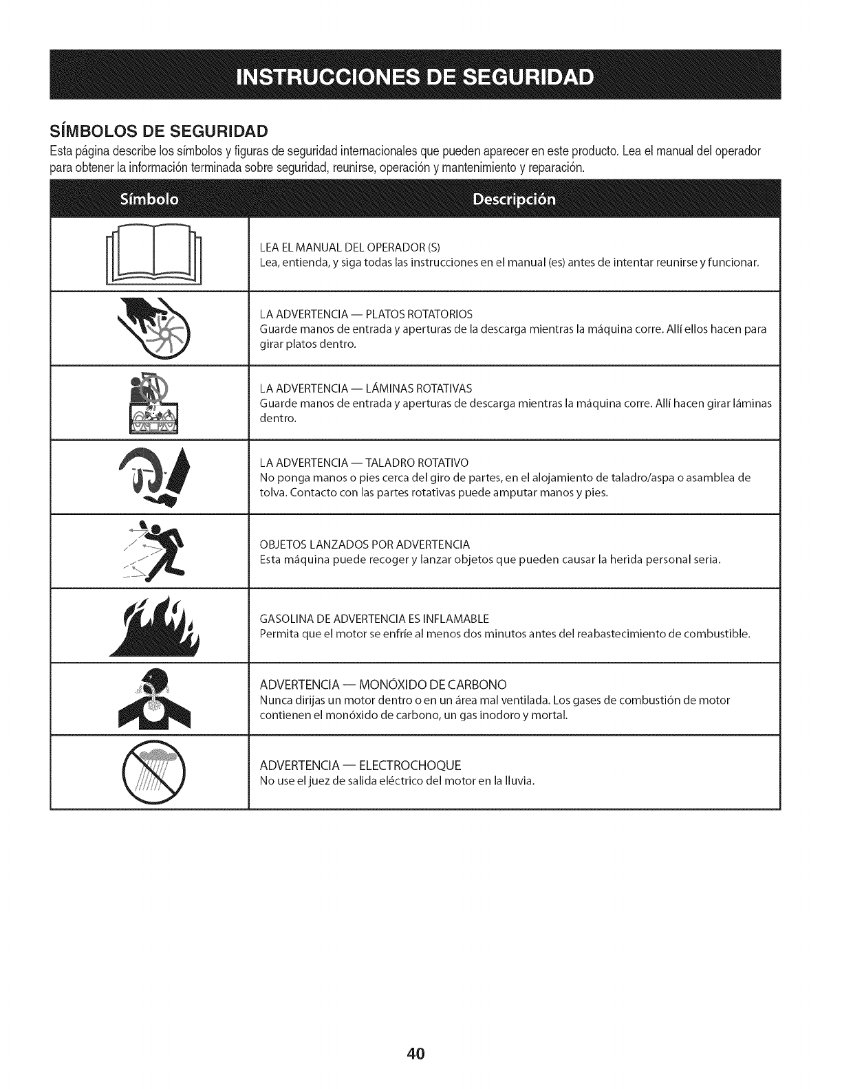
SiMBOLOS DE SEGURIDAD
Estap_ginadescribelossimbolosy figurasde seguridadinternacionalesquepuedenaparecerenesteproducto.Leael manualdeloperador
)araobtenerla informaci6nterminadasobreseguridad,reunirse,operaci6ny mantenimientoy reparaci6n.
ii
LEA EL MANUAL DEL OPERADOR (S)
Lea, entienda, y siga todas las instrucciones en el manual (es) antes de intentar reunirse y funcionar.
LA ADVERTENCIA -- PLATOS ROTATORIOS
Guarde manos de entrada y aperturas de la descarga mientras la m_iquina corre. Alli ellos hacen para
girar platos dentro.
LA ADVERTENCIA- LAMINAS ROTATIVAS
Guarde manos de entrada y aperturas de descarga mientras la m_iquina corre. Alli hacen girar I_iminas
dentro.
LA ADVERTENCIA -- TALADRO ROTATIVO
No ponga manos o pies cerca del giro de partes, en el alojamiento de taladro/aspa o asamblea de
tolva. Contacto con las partes rotativas puede amputar manos y pies.
OBJETOS LANZADOS POR ADVERTENCIA
Esta m_iquina puede recoger y lanzar objetos que pueden causar la herida personal seria.
GASOLINA DE ADVERTENCIA ESINFLAMABLE
Permita que el motor se enfrie al menos dos minutos antes del reabastecimiento de combustible.
ADVERTENCIA -- MONOXIDO DE CARBONO
Nunca dirijas un motor dentro o en un _irea mal ventilada. Los gases de combusti6n de motor
contienen el mon6xido de carbono, un gas inodoro y mortal.
ADVERTENCIA- ELECTROCHOQUE
No use eljuez de salida el_ctrico del motor en la Iluvia.
4O
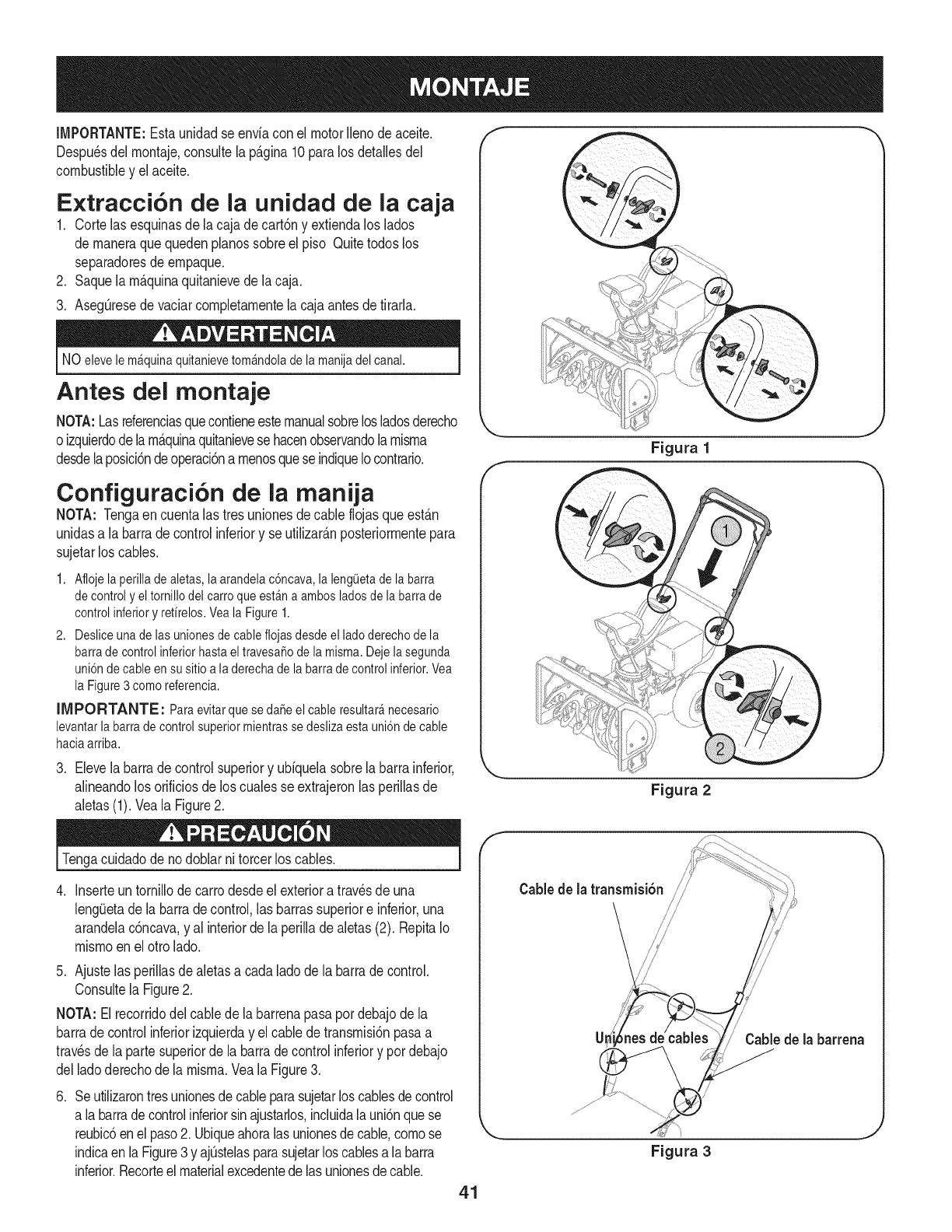
IMPORTANTE:Estaunidadse enviaconel motorIlenode aceite,
Despu_sdelmontaje,consultela p_.gina10paralosdetallesdel
combustibley elaceite,
Extracci6n de la unidad de la caja
1, Cortelasesquinasdela cajade cart6ny extiendaloslados
de maneraquequedenpianossobreel piso Quitetodoslos
separadoresde empaque,
2, Saquela m_.quinaquitanievede lacaja,
3, Aseg@esedevaciarcompletamentela cajaantesdetirarla,
NO elevele mAquinaquitanievetomAndoladela manijadel canal.
Antes del montaje
NOTA:Lasreferenciasquecontieneestemanualsobrelosladosderecho
oizquierdodelam_.quinaquitanievesehacenobservandola misma
desdelaposici6ndeoperaci6na menosqueseindiqueIocontrario,
Configuraci6n de la manija
NOTA: Tengaen cuentalas tresunionesdecable flojasqueest_.n
unidasa labarradecontrolinferiory se utilizarAnposteriormentepara
sujetarlos cables,
1. Afiojela perilladealetas,la arandelac6ncava,la leng0etade la barra
decontroly eltornillodel carroqueestAna ambosladosde la barrade
controlinferiory refirelos.Veala Figure 1.
2. Desliceunade lasunionesde cablefiojasdesdeel ladoderechode la
barrade controlinferiorhasta eltravesaSode la misma.Dejela segunda
uni6ndecable en su sitioa laderecha dela barrade controlinferior.Vea
la Figure3 como referencia.
IIVIPORTANTE: Paraevitarque se daSeel cableresultar_necesario
levantarlabarra de controlsuperiormientrasse deslizaesta uni6ndecable
haciaarriba.
3. Elevelabarradecontrolsuperiory ubiquelasobrelabarrainferior,
alineandolos orificiosde los cualesse extrajeronlas perillasde
aietas(1). Vea[a Figure2.
Figura 1
Figura 2
J
J
Tengacuidadode nodoblarni torcerlos canes.
.Inserteuntornillodecarrodesdeel exterioratravesdeuna
leng_Jetade labarradecontrol,lasbarrassuperiore inferior,una
arandelac6ncava,y al interiorde laperilladealetas(2). RepitaIo
mismoen el otrolado.
5. Ajustelas perillasde aletasa cadaladode la barradecontrol.
Consultela Figure2.
NOTA: Elrecorridodel cablede labarrenapasapordebajodela
barrade controlinferiorizquierday el cablede transmisi6npasaa
travesde la partesuperiorde labarradecontrolinferiory pordebajo
delladoderechode la misma.Veala Figure3.
.Seutilizarontresunionesdecableparasujetarlos canesdecontrol
a labarradecontrolinferiorsinajustarlos,incluidalauni6nquese
reubic6enelpaso2. Ubiqueahoralas unionesdecable,comose
indicaen laFigure3y ajQstelasparasujetarloscablesa labarra
inferior.Recorteelmaterialexcedentedelas unionesdecable.
f
Cable de la transmisi6n /
CaMede [a barrena
Figura 3
41
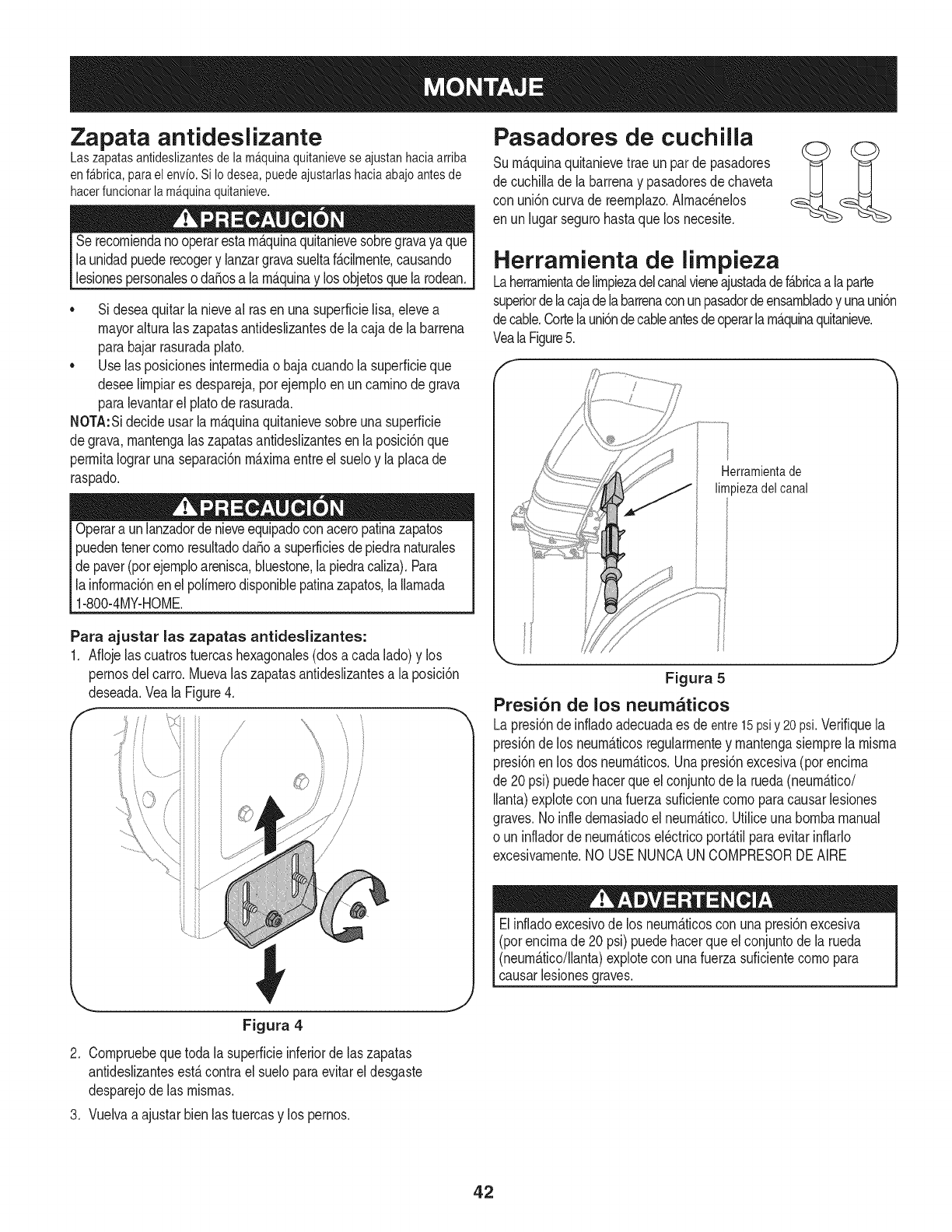
Zapata antideslizante
Laszapatasantideslizantesdelam_quinaquitanieveseajustanhaciaarriba
enf_brica,paraelenvio.SiIodesea,puedeajustarlashaciaabajoantesde
hacerfuncionarlam_quinaquitanieve.
Serecorniendanooperarestarn_.quinaquitanievesobregravaya que
launidadpuederecogery lanzargravasueltaf_.cilrnente,causando
lesionespersonaleso da_osa larn_.quinay losobjetosquelarodean.
•Sideseaquitarla nieveal rasen unasuperficielisa,elevea
mayoralturalaszapatasantideslizantesde la cajade la barrena
parabajarrasuradaplato.
•Uselas posicionesinterrnediao bajacuandola superficieque
deseelirnpiares despareja,porejernploenuncarninodegrava
paralevantarel platode rasurada.
NOTA:Sidecideusarla rn_.quinaquitanievesobreunasuperficie
degrava,rnantengalas zapatasantideslizantesen laposici6nque
perrnitaIograrunaseparaci6nrn_.xirnaentreel sueloy laplacade
raspado.
Operara unlanzadorde nieveequipadocon aceropatinazapatos
puedentenetcornoresultadoda_oa superficiesdepiedranaturales
de paver(porejernploarenisca,bluestone,lapiedracaliza).Para
la inforrnaci6nenelpolirnerodisponiblepatinazapatos,laIlarnada
1-800-4MY-HOME.
Para ajustar las zapatas antideslizantes:
1. Aflojelascuatrostuercashexagonales(dos a cadalado)y los
pernosdel carro.Muevalas zapatasantideslizantesa laposici6n
deseada.Veala Figure4.
f// ',,
/
/
Pasadores de cuchilla
Surn_.quinaquitanievetrae unparde pasadores
de cuchillade labarrenay pasadoresdechaveta
con uni6ncurvade reernplazo.Alrnac_nelos
en unlugarsegurohastaquelos necesite.
Herramienta de limpieza
Laherrarnientadelirnpiezadelcanalvieneajustadadef_.bricaalaparte
superiordelacajadelabarrenaconunpasadordeensarnbladoy unauni6n
decable.Cortelauni6ndecableantesdeoperarlarn_.quinaquitanieve.
VealaFigure5.
Herramientade
limpiezadelcanal
Figura 5
Presi6n de los neum_ticos
Lapresi6nde infladoadecuadaes deentre15psiy 20psi.Verifiquela
presi6ndelos neurn_.ticosregularrnentey rnantengasiernprela rnisrna
presi6nenlos dos neurn_.ticos.Unapresi6nexcesiva(porencirna
de 20psi) puedehacerqueel conjuntode la rueda(neurn_.tico/
Ilanta)explotecon unafuerzasuficientecornoparacausarlesiones
graves.Noinfle dernasiadoel neurn_.tico.Utiliceunabornbamanual
o un infladorde neurn_.ticosel_ctricoport_.tilparaevitarinflarlo
excesivarnente.NO USENUNCAUNCOMPRESORDEAIRE
Elinfladoexcesivode los neurn_.ticoscon unapresi6nexcesiva
(pot encirnade 20 psi)puedehacerqueel conjuntode la rueda
(neurn_.tico/llanta)explorecon unafuerzasuficientecornopara
causarlesionesgraves.
Figura 4
2. Cornpruebequetoda la superficieinferiorde laszapatas
antideslizantesest,.contrael sueloparaevitareldesgaste
desparejode las rnisrnas.
3. Vuelvaa ajustarbienlas tuercasy los pernos.
42
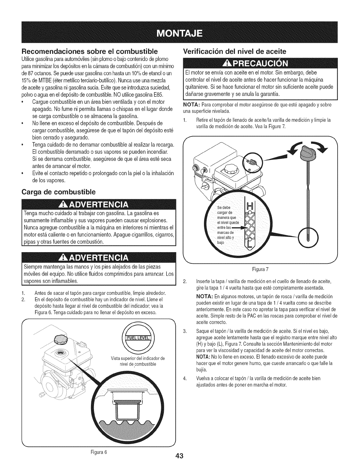
Recomendaciones sobre el combustible
Utilicegasolinaparaautorn6viles(sinplornoo bajocontenidodeplorno
pararninirnizarlosdep6sitosenlac_rnaradecornbusti6n)con unrninirno
de87octanos.Sepuedeusargasolinaconhastaun 10%deetanolo un
15%de MTBE(eterrnetilicoterciario-bufilico).Nuncauseunarnezcla
deaceitey gasolinanigasolinasucia.Evitequeseintroduzcasuciedad,
polvooaguaenel dep6sitodecombustible.NOutilicegasolinaE85.
*Carguecombustibleenun _reabienventiladay conel motor
apagado.Nofumeni perrnitallamasochispasenel lugardonde
se cargacombustibleo se alrnacenalagasolina.
*No Ileneen excesoel dep6sitode combustible.Despu_sde
cargarcombustible,asegQresedeque eltap6ndel dep6sitoest_
biencerradoy asegurado.
*Tengacuidadode noderrarnarcombustibleal realizarla recarga.
Elcombustiblederrarnadoo susvaporesse puedenincendiar.
Si sederrarnacombustible,asegQresede queel_reaest_seca
antesde arrancarel motor.
.Eviteel contactorepetidoo prolongadocon la pielo la inhalaci6n
de losvapores.
Carga de combustible
Tengarnuchocuidadoal trabajarcon gasolina.Lagasolinaes
surnarnenteinfiarnabley susvaporespuedencausarexplosiones.
Nuncaagreguecombustiblea la rn&quinaen interioresni rnientrasel
motorest&calienteoen funcionarniento.Apaguecigarrillos,cigarros,
pipasy otrasfuentesdecornbusti6n.
Verificaci6n del nivel de aceite
Elmotorse enviacon aceiteenel motor.Sinembargo,debe
controlarelnivelde aceiteantesdehacerfuncionarlarn_.quina
quitanieve.Si se hacefuncionarel motorsin suficienteaceitepuede
da_arsegravernentey seanulalagaranfia.
NOTA: Paracomprobarel motorasegOresedeque esteapagadoy sobre
una superficienivelada.
1. Retireel tap6ndeIlenadode aceite/lavarilla de medici6ny limpiela
varillademedici6nde aceite.Veala Figure7.
Siernprernantengalas rnanosy los piesalejadosde las piezas
rn6vilesdelequipo.No utilicefiuidoscornprirnidosparaarrancar.Los
vaporesson inflarnables.
1,
2. Antesde sacar eltap6n paracargar combustible,limpie alrededor.
En el dep6sitode combustiblehay unindicadorde nivel. Lleneel
dep6sitohastaIlegaral nivelde combustibledel indicador;vea la
Figura6. TengacuidadoparanoIlenarel dep6sitoenexceso.
Vista superiordel indicadorde
nivelde combustible
2,
Figura7
Insertela tapa /varilla demedici6nenel cuello de Ilenadodeaceite,
gire latapa 1/4 vuelta hastaque estecompletamenteasentada.
NOTA: En algunosmotores,untap6n derosca/varilla demedici6n
puedenexistiren lugarde unatapa de1 /4 vuelta comose describe
anteriormente.Eneste casonoapretarlatapa paraverificarel nivelde
aceite.Simplerestode la PACen lasroscasparacomprobarel nivelde
aceitecorrecto.
3. Saqueeltap6n/la varillade medici6ndeaceite.Si el niveles bajo,
agregueaceitelentamentehastaque el registromarqueentre nivelalto
(H)y bajo(L), Figura7.Consultela secci6nMantenimientodel motor
paraver laviscosidadycapacidaddeaceitedel motorcorrectas.
NOTA:No IoIleneenexceso. ElIlenadoexcesivodeaceite puede
hacerque el motorgenerehumo,quecuestearrancarloo quefalle la
bujia.
4. Vuelvaa colocarel tap6n/la varilla demedici6nde aceitebien
ajustadosantes deponeren marchael motor.
J
Figura6 43
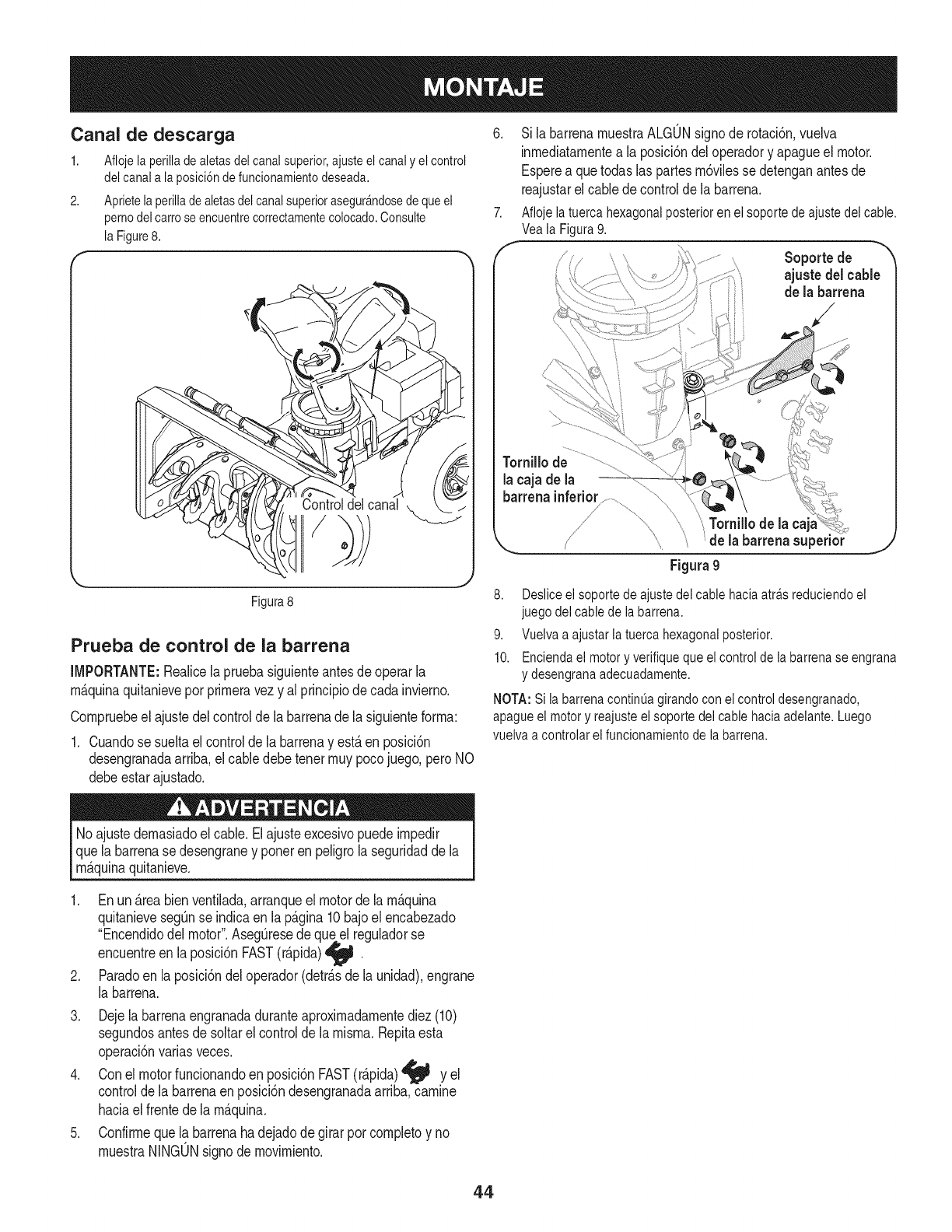
Canal de descarga 6.
1. Aflojelaperilladealetasdelcanalsuperior,ajusteelcanaly elcontrol
delcanalalaposici6ndefuncionamientodeseada.
2. Aprietelaperilladealetasdelcanalsuperiorasegur_ndosedequeel
pernodelcarroseencuentrecorrectamentecolocado.Consulte 7.
laFigure8.
Controldelcanal
Sila barrenamuestraALGONsignode rotaci6n,vuelva
inmediatamentea la posici6ndeloperadory apagueel motor.
Esperea quetodaslas partesm6vilessedetenganantesde
reajustarelcablede controlde la barrena.
Aflojelatuercahexagonalposteriorenelsoportedeajustedelcable.
VealaFigura9.
J Soporte de
ajuste delcable
de la barrena
Tornillo de
la caja de la
barrenainferior..............
_;Tornillode la
X,_ 'de la barrenasuperior _J
Figura9
Figura8
Prueba de control de la barrena
IMPORTANTE:Realicela pruebasiguienteantesdeoperarla
m_.quinaquitanieveporprimeravezy al principiode cadainvierno.
Compruebeel ajustedel controldela barrenadela siguienteforma:
1. Cuandose sueltael controlde la barrenay est,.en posici6n
desengranadaarriba,elcabledebetenetmuypocojuego,peroNO
debeestarajustado.
8. Deslice el soporte de ajuste del cable hacia atra.sreduciendo el
juego del cable de la barrena.
9. Vuelva a ajustar la tuerca hexagonal posterior.
10. Encienda el motor y verifique que el control de la barrena se engrana
y desengrana adecuadamente.
NOTA: Si la barrena continua girando con ei controldesengranado,
apague el motor y reajuste el soporte del cable hacia adelante. Luego
vuelva a controlarel funcionamientode la barrena.
Noajustedemasiadoel cable.Elajusteexcesivopuedeimpedir
que la barrenase desengraney porteren peligrolaseguridaddela
m_.quinaquitanieve.
.
.
3.
.
.
Enun_.reabienventilada,arranqueel motorde lam_.quina
quitanievesegQnse indicaen la p_.gina10bajoel encabezado
"Encendidodel motor".AsegQresede queel reguladorse
encuentreen laposici6nFAST(r_.pida)_j_ w
Paradoen la posici6ndel operador(detr_.sde la unidad),engrane
la barrena.
Dejela barrenaengranadaduranteaproximadamentediez(10)
segundosantesde soltarel controlde la misma.Repitaesta
operaci6nvariasveces.
Conel motorfuncionandoenposici6nFAST(r_.pida)_j_ y el
controlde labarrenaenposici6ndesengranadaarriba,camine
haciael frentedela m_.quina.
Confirmequela barrenahadejadode girarporcompletoy no
muestraNINGONsignodemovimiento.
44
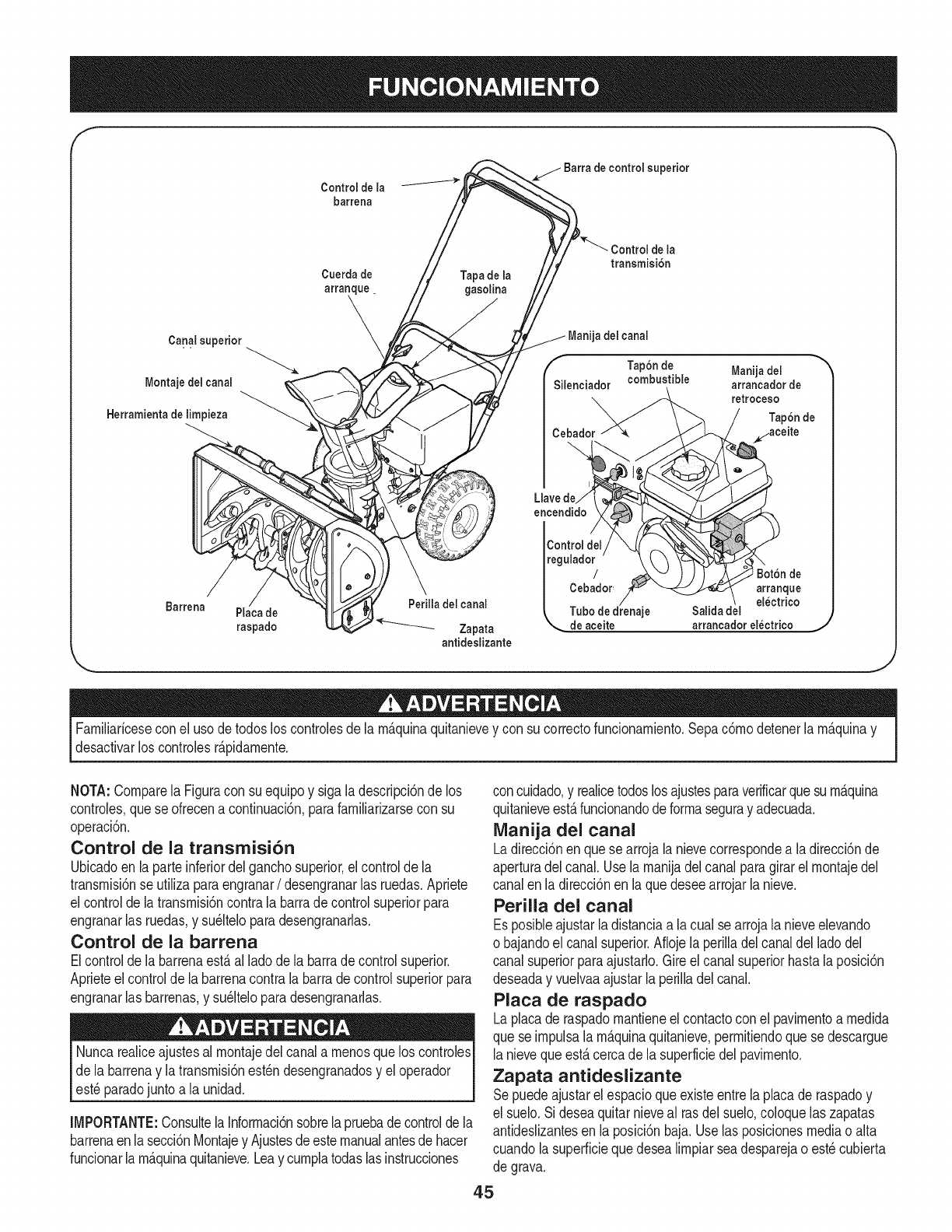
Control de la
barrena
de la
transmisi6n
Cuerda de Tapade la
arranque, gasolina
\
Canal superior _ del canal
Tap6n de Manija del
kf
Montaje del canal Silenciador combustible arrancador de
retroceso
Herramienta de limpieza
Cebador
Llavede
encendido
Barrena Perilla del canal
Placa de
raspado _ Zapata de aceite arrancador electrico
antideslizante
Familiaricesecon el usode todosloscontrolesde la m_.quinaquitanievey con su correctofuncionamiento.Sepac6modetenerla m_.quinay
desactivarloscontrolesr_.pidamente.
NOTA:Comparela Figuracon suequipoy siga ladescripci6nde los
controles,quese ofrecena continuaci6n,parafamiliarizarsecon su
operaci6n.
Control de la transmisi6n
Ubicadoenla parteinferiordel ganchosuperior,el controlde la
transmisi6nse utilizaparaengranar/desengranarlas ruedas.Apriete
el controldela transmisi6ncontrala barradecontrolsuperiorpara
engranarlas ruedas,y su_lteloparadesengranarlas.
Control de la barrena
Elcontrolde la barrenaest&al ladodela barrade controlsuperior.
Aprieteel controlde labarrenacontralabarradecontrolsuperiorpara
engranarlas barrenas,y su_lteloparadesengranarlas.
Nuncarealiceajustesal montajedel canala menosquelos controles
de la barrenay latransmisi6nest_ndesengranadosy el operador
est_ paradojuntoa la unidad.
IMPORTANTE:ConsultelaInformaci6nsobrelapruebadecontroldela
barrenaenlasecci6nMontajey Ajustesdeestemanualantesde hacer
funcionarla m_.quinaquitanieve.Leay cumplatodaslasinstrucciones
concuidado,y realicetodoslos ajustesparaverificarquesu m_.quina
quitanieveest,.funcionandodeformaseguray adecuada.
Manija del canal
Ladirecci6nen quese arrojalanievecorrespondea la direcci6nde
aperturadel canal.Usela manijadel canalparagirarel montajedel
canalen la direcci6nen laquedeseearrojarla nieve.
Perilla del canal
Esposibleajustarladistanciaa lacual se arrojala nieveelevando
o bajandoel canalsuperior.Aflojelaperilladelcanaldel ladodel
canal superiorparaajustarlo.Gireelcanal superiorhastala posici6n
deseaday vuelvaaajustarla perilladelcanal.
Placa de raspado
Laplacade raspadomantieneelcontactocon el pavimentoa medida
que seimpulsala m_.quinaquitanieve,permitiendoque sedescargue
lanievequeest,.cercade la superficiedelpavimento.
Zapata antideslizante
Sepuedeajustarel espacioque existeentrela placade raspadoy
el suelo.Si deseaquitarnieveal rasdelsuelo,coloquelas zapatas
antideslizantesen la posici6nbaja. Uselas posicionesmediao alta
cuandola superficiequedesea limpiarseadesparejao est_cubierta
de grava.
45
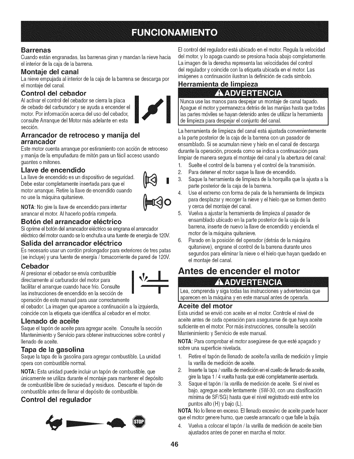
Barrenas
Cuandoest_.nengranadas,las barrenasgirany rnandanlanievehacia
el interiorde lacaja dela barrena.
IVIontaje del canal
La nieveernpujadaal interiorde lacajade la barrenasedescargapor
el rnontajedel canal.
Control del cebador
AIactivarel controldelcebadorsecierrala placa
decebadodelcarburadory se ayudaa encenderel
motor.Porinforrnaci6nacercadel usodelcebador,
consulteArranquedel Motorrn_.sadelanteen esta
secci6n.
Arrancador de retroceso y manija del
arrancador
Estemotorcuentaarranqueporestirarnientoconacci6nde retroceso
y rnanijadela ernpu_aduradernit6nparaunf_.cilaccesousando
guanteso rnitones.
Llave de encendido
La Ilavede encendidoes undispositivodeseguridad.
Debeestarcornpletarnenteinsertadaparaque el
motorarranque.Retirela Ilavede encendidocuando
no usela rn_.quinaquitanieve.
NOTA:Nogire laIlavede encendidoparaintentar
arrancarel motor.AI hacerlopodriarornperla.
Bot6n del arrancador electrico
Sioprirneelbot6ndelarrancadorelectricoseengranaelarrancador
el_ctricodelmotorcuandoseIoenchufaa unafuentedeenergfade 120V.
Salida del arrancador el_ctrico
Es necesariousarun cord6nprolongadorparaexterioresdetres patas
(se incluye)y unafuentedeenergia/tornacorrientede paredde 120V.
Cebador
AI presionarel cebadorse enviacombustible |
directarnenteal carburadordelmotorpara _k_P-
facilitarel arranquecuandohacefrio.Consulte I
las instruccionesde encendidoenla secci6nde Ill
operaci6nde estemanualparausarcorrectarnente
elcebador.Lairnagenqueapareceacontinuaci6na la izquierda,
coincideconla etiquetaqueidentificaal cebadorenel motor.
Llenado de aceite
Saqueel tap6ndeaceiteparaagregaraceite. Consultelasecci6n
Mantenirnientoy Servicioparaobtenerinstruccionessobrecontroly
Ilenadodeaceite.
Tapa de la gasolina
Saquela tapade lagasolinaparaagregarcombustible.Launidad
operacon combustiblenormal.
NOTA: Estaunidadpuedeincluirun tap6ndecombustible,que
Onicarnentese utilizaduranteel rnontajepararnantenerel dep6sito
decombustiblelibredesuciedady residuos. Descarteeltap6nde
combustibleantesdeIlenareldep6sitodecombustible.
Control del regulador
Elcontroldel reguladorest,. ubicadoenel motor.Regulalavelocidad
del motor,y Io apagacuandose presionahaciaabajocornpletarnente.
Lairnagende laderecharepresentalasvelocidadesdel control
del reguladory coincidecon laetiquetaubicadaenel motor.Las
imP.genesa continuaci6nilustranla definici6ndecada sirnbolo.
I i I [ Nuncause las rnanosparadespejarun rnontajede canaltapado.
Apagueelmotory perrnanezcadetr_.sde lasrnanijashastaquetodas
las partesrn6vilessehayandetenidoantesde utilizarla herrarnienta
de lirnpiezaparadespejarelconjuntodelcanal.
Laherrarnientade lirnpiezadel canalest,.ajustadaconvenienternente
a la parteposteriorde la cajade la barrenacon unpasadorde
ensarnblado.Si se acurnulannievey hieloen el canaldedescarga
durantelaoperaci6n,procedacornose indicaa continuaci6npara
lirnpiarde rnanerasegurael rnontajedelcanaly laaberturadel canal:
1. Suelteel controldela barrenay el controlde latransrnisi6n.
(_ 2. Paradetenerel motorsaquela Ilavede encendido.
| 3. Saquelaherrarnientadelirnpiezade la horquillaque laajustaa la
parte posteriorde la caja dela barrena.
4. Useel extrernocon forrnade palade la herrarnientade lirnpieza
(_O paradesplazary recogerla nievey el hieloque seforrnendentro
y cercadel rnontajedel canal.
5. Vuelvaa ajustarla herrarnientade lirnpiezaalpasadorde
ensarnbladoubicadoen la parteposteriorde lacajade la
barrena,insertede nuevolaIlavede encendidoy enciendael
motorde la rn_.quinaquitanieve.
6. Paradoen laposici6ndeloperador(detr_.sde larn_.quina
quitanieve),engraneel controldela barrenaduranteunos
segundosparaelirninarlanieveo el hieloquehayanquedadoen
el rnontajedelcanal.
Antes de encender el motor
Lea,cornprenday sigatodaslas instruccionesy advertenciasque
aparecenen larn_.quinayen estemanualantesde operarla.
Aceite del motor
Estaunidadseenvi6con aceiteen elmotor.Controleel nivelde
aceiteantesde cadaoperaci6nparaasegurarsedeque hayaaceite
suficienteen el motor.Porrn_.sinstrucciones,consultela secci6n
Mantenirnientoy Serviciode estemanual.
NOTA: Paracornprobarel motorasegQresedeque est_apagadoy
sobreuna superficienivelada.
1. Retireel tap6nde Ilenadodeaceite/lavarillade rnedici6ny lirnpie
la varilladernedici6ndeaceite.
2. Insertelatapa/varilladernedici6nenelcuellodellenadodeaceite,
girelatapa1/4 vueltahastaqueest_cornpletarnenteasentada.
3. Saqueel tap6n/la varillade rnedici6nde aceite.Si el niveles
bajo,agregueaceitelentarnente(5W-30,con unaclasificaci6n
minimade SF/SG)hastaqueel nivelregistradoest_entre los
puntosalto (H) y bajo(L).
NOTA:NoIoIleneen exceso.ElIlenadoexcesivodeaceitepuedehacer
queelmotorgenerehurno,quecuestearrancarlooquefallela bujia.
4. Vuelvaa colocarel tap6n/lavarillade rnedici6nde aceitebien
ajustadosantesde poneren rnarchaelmotor.
46
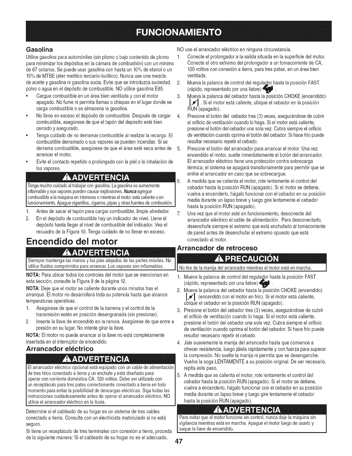
Gasolina
Utiiice gasolina para autom6viles (sin plomo o bajo contenido de plomo
para minimizar los dep6sitos en la ca.marade combusti6n) con un minimo
de 87octanos. Se puede usar gasolina con hasta un 10%de etanoi o un
15%de MTBE (eter metilico terciario-butilico). Nunca use una mezcla
de aceite y gasolina ni gasolina sucia. Eviteque se introduzcasuciedad,
polvo o agua en ei dep6sito de combustible. NO utilice gasolina E85.
Cargue combustible en un a.reabien ventiladay conel motor
apagado. No fume ni permita llamaso chispas en el lugardonde se
carga combustible o se aimacena ia gasolina.
No iiene en exceso el dep6sito de combustible. Despues de cargar
combustible, asegurese de que el tap6n del dep6sito este bien
cerrado y asegurado.
Tenga cuidadode noderramar combustible ai realizar ia recarga. El
combustible derramado o sus vapores se pueden incendiar. Si se
derramacombustible, asegQresede que el a.reaeste seca antes de
arrancarel motor.
Eviteel contacto repetidoo prolongado con la piel o la inhalaci6n de
los vapores.
Tengamuchocuidadoaltrabajarcongasolina.Lagasolinaessumamente
inflamabley susvaporespuedencausarexplosiones.Nuncaagregue
combustiblea lam@uinaen interioreso mientraselmotorestacalienteo en
funcionamiento.Apaguecigarrillos,cigarros,pipasyotrasfuentesdecombusti6n.
1,
2.
Antes de sacar el tap6n paracargar combustible, limpieairededor.
Enei dep6sito de combustible hay un indicador de nivel. Llene el
dep6sito hasta Ilegar ai nivel de combustible del indicador. Veael
recuadro de la Figura 10.Tenga cuidado de no Ilenaren exceso.
Encendido del motor
NO use ei arrancador electrico en ninguna circunstancia.
1. Conecte el prolongadora la salida situada en ia superficie del motor.
Conecte ei otto extremodel prolongador a un tomacorrientede CA,
120voltios con conexi6n a tierra, para tres patas, en un a.reabien
ventiiada.
2. Mueva la palanca de control del regula_o..rhastala posici6n FAST
(r@ido, representado pot una liebre) _ .
3. Mueva la palanca del cebador hasta la posici6n CHOKE (encendido)
I.#'J . Si el motor esta.caliente, ubique el cebadoren la posici6n
RUN (apagado).
4. Presioneel bot6ndel cebadortres (3) veces,asegura.ndosede cubrir
el orificio deventiiaci6n cuandoio haga.Si ei motor esta.caliente,
presione el bot6n del cebador unasola vez. Cubra siempre el orificio
de ventilaci6ncuando optimael bot6ndel cebador.Si hacefrio puede
resultar necesario repetirel cebado.
5. Presioneel bot6n del arrancador para arrancar ei motor. Una vez
encendido el motor, suelte inmediatamente el bot6n del arrancador.
Elarrancador electrico tiene una protecci6n contra sobrecarga
t@mica; el sistema se apagara,transitoriamente para permitir que se
enfrie el arrancador en caso que se sobrecargue.
6. A medida que se calienta el motor, rote lentamente ei control dei
cebador hasta la posici6n RUN(apagado). Si el motorse detiene,
vuelva a encenderlo, ha.galofuncionar conel cebador ensu posici6n
media durante un iapso brevey luego gire lentamente el cebador
hasta la posici6n RUN (apagado).
7. Una vez que el motor este en funcionamiento,desconecte del
arrancador ei@trico ei cable de aiimentaci6n. Para desconectarlo,
desenchufe siempre el extremoque esta.enchufado ai tomacorriente
de pared antes de desenchufarel extremo opuesto que esta.
conectado ai motor.
Arrancador de retroceso
Siempremantengalas manosy los piesalejadosde laspartesm6viles.No
utilicefluidoscomprimidosparaarrancar.Los vaporesson inflamables.
NOTA: Paraubicar todos los controles dei motor que se mencionanen
esta secci6n, consulte ia Figura9 de ia pagina 12.
NOTA: Deje que el motor se caiiente durante unos minutos tras el
arranque. Ei motor no desarrollara,toda su potencia hasta que aicance
temperaturasoperativas.
1. Aseguresede que el control de la barrena y el control de ia
transmisi6nesten en posici6n desengranada (sin presionar).
2. Inserte ia iiavede encendido en la ranura.AsegQresede que entre a
presi6n en su iugar. No intentegirar la Ilave.
NOTA: El motor no puede arrancar si la iiave no esta.completamente
insertada en ei interruptor de encendido.
Arrancador el_ctrico
Elarrancadorel@tricoopcionalest_equipadocon un cablede alimentaci6n
detres hilosconectadoa tierray unenchufey est_dise_adopara
operarcon corrientedomesticaCA, 120voltios.Debeser utilizadocon
unrecept_culoparatres patascorrectamenteconectadoa tierraentodo
momentoparaevitar laposibilidaddedescargaselectricas.Sigatodas las
instruccionescuidadosamenteantesde operarel arrancadorelectrico.NO
utiliceel arrancadorelectricoenla Iluvia.
Determinesi el cableado de su hogar es unsistema de tres cables
conectado a tierra. Consulte con un electricista matriculadosi no esta.
seguro.
Si tiene un recepta.culode tres terminaies con conexi6na tierra, proceda
de la siguiente manera: Si el cableado de su hogar noes el adecuado,
Notire de la manijadel arrancadormientrasel motorest_en marcha.
1. Mueva la palanca de control del regula_orhasta la posici6n FAST
(r@ido, representado pot una liebre) _ .
2. Mueva la palanca del cebador hasta la posici6n CHOKE (encendido)
J,,_'J (encendido con el motor en frio). Si el motor esta.caliente,
ubique el cebadoren la posici6n RUN (apagado).
3. Presioneel bot6n del cebador tres (3) veces, asegurandose de cubrir
el orificio de ventiiaci6n cuando io haga. Siel motor esta.caliente,
presione el bot6n del cebador unasola vez. Cubrasiempre el orificio
de ventiiaci6n cuando optima el bot6n del cebador.Si hace frio puede
resultar necesario repetir el cebado.
4. Jale suavemente la manija del arrancador hasta que comience a
ofrecer resistencia, luego ja.lelar@idamente y con fuerza parasuperar
la compresi6n. No suelte la manija ni permita que se desenganche.
Vuelva la soga LENTAMENTEa su posici6n original. De ser necesario,
repita este paso.
5. A medida que se calienta el motor, rote lentamente ei control dei
cebador hasta la posici6n RUN(apagado). Si el motorse detiene,
vuelva a encenderlo, ha.galofuncionar conel cebador ensu posici6n
media durante un iapso brevey luego gire lentamente el cebador
hasta la posici6n RUN (apagado).
Paraevitarque el motorfuncionesin control,nuncadejela m_quinasin
vigilanciamientrasest_en marcha.Apagueel motorluegode usarloy
saquela Ilavedeencendido.
4.7
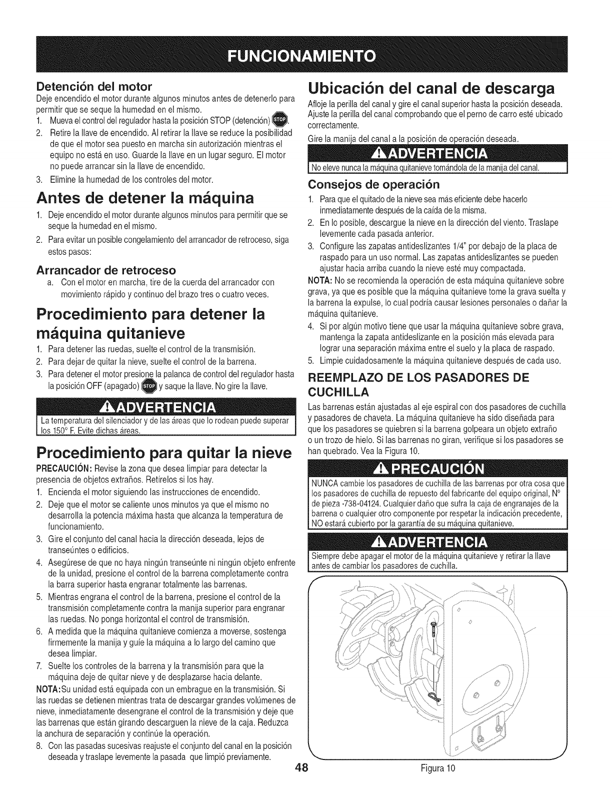
Detenci6n del motor
Deje encendido el motor durante aigunos minutosantes de detenerlo para
permitir que se sequela humedad en el mismo.
1. Muevael controldel reguladorhastala posici6nSTOP(detenci6n)_.
2. Retire ia Ilave de encendido. Ai retirar la ilave se reduce la posibilidad
de que ei motor sea puesto en marcha sin autorizaci6n mientras el
equipo no esta.en uso. Guarde la iiave en un iugar seguro. El motor
no puede arrancar sin la Ilavede encendido.
3. Elimine la humedad de los controles del motor.
Antes de detener la rn quina
1. Deje encendidoel motorduranteaigunosminutospara permitirque se
sequela humedaden el mismo.
2. Para evitar unposible congelamientodel arrancador de retroceso,siga
estospasos:
Arrancador de retroceso
a. Conel motor en marcha, tirede la cuerda del arrancador con
movimientora.pidoy continuo del brazo tres o cuatro veces.
Procedirniento para detener la
m _quina quitanieve
1. Paradetener las ruedas,suelte el control de la transmisi6n.
2. Paradejar de quitar la nieve, suelte el control de la barrena.
3. Paradetenerel motor presio la palancade controldel regulador hasta
la posici6nOFF (apagado)I }y saque la Ilave.No gire la Ilave.
La temperaturadel silenciadory de las_reas que Io rodeanpuedesuperar
los 150oF.Evitedichas_reas.
Procedimiento para quitar la nieve
PRECAUClOI/: Revise la zona que desea limpiar paradetectar la
presencia de objetos extra_os. Refirelos si los hay.
1. Encienda el motor siguiendo ias instrucciones de encendido.
2. Deje que el motor se caliente unos minutosya que el mismo no
desarrolla la potencia ma.ximahasta que aicanza la temperatura de
funcionamiento.
3. Gire el conjunto del canal hacia la direcci6n deseada, lejos de
transeunteso edificios.
4. Asegurese deque no haya ningOntranseunte ni ningOnobjetoenfrente
de ia unidad, presione el control de ia barrena completamentecontra
la barra superior hasta engranartotaimente ias barrenas.
5. Mientras engrana el controlde ia barrena, presione el control de la
transmisi6n completamente contra la manija superior para engranar
las ruedas. No ponga horizontal el control de transmisi6n.
6. A medida que la ma.quinaquitanieve comienza a moverse,sostenga
firmemente la manija y guie la ma.quinaa Io largo del camino que
desea limpiar.
7. Suelte los controles de la barrena y latransmisi6n para que ia
ma.quinadeje de quitar nieve y de desplazarse hacia delante.
I!OTA:Su unidadesta.equipada con un embrague en ia transmisi6n. Si
las ruedas se detienen mientras trata de descargar grandesvolOmenesde
nieve, inmediatamentedesengrane el control de la transmisi6n y deje que
las barrenas que esta.ngirando descarguen la nieve de la caja. Reduzca
la anchura de separaci6ny continue ia operaci6n.
8. Con las pasadassucesivasreajusteel conjuntodel canal en la posici6n
deseaday traslape levementela pasada que limpi6 previamente. 48
Ubicacibn del canal de descarga
Afloje la perilladel canal y gireel canal superior hasta la posici6ndeseada.
Ajuste la perilladel canal comprobandoque el perno decarro este ubicado
correctamente.
Gire la manija del canal a la posici6n de operaci6n deseada.
Noelevenuncala m_uitanieve tom_ndolade la mani_del canal.
Consejos de operaci6n
1. Paraqueel quitadode la nievesea ma.seficientedebe hacerlo
inmediatamentedespuesde lacaidade la misma.
2. Enio posible, descargue la nieve en la direcci6n del viento. Traslape
levementecada pasada anterior.
3. Configure ias zapatasantideslizantes 1/4"pot debajo de ia placade
raspado para un uso normal.Las zapatas antideslizantesse pueden
ajustar hacia arriba cuando la nieve este muy compactada.
I!OTA: No se recomienda ia operaci6nde esta ma.quinaquitanieve sobre
grava, ya que es posible que la ma.quinaquitanieve tome la grava suelta y
la barrena la expulse, Io cual podria causar lesiones personales o dafiar la
ma.quinaquitanieve.
4. Si pot algun motivo tiene que usar ia ma.quinaquitanieve sobre grava,
mantenga la zapataantideslizante en ia posici6n ma.selevada para
Iograr una separaci6n ma.ximaentre el suelo y ia placade raspado.
5. Limpie cuidadosamente la ma.quinaquitanieve despues de cada uso.
REEMPLAZO DE LOS PASADORES DE
CUCHILLA
Lasbarrenas esta.najustadas al eje espirai con dos pasadores de cuchilla
y pasadoresde chaveta. Lamaquina quitanieve ha sido disefiada para
que los pasadores se quiebren si la barrena golpeara unobjeto extra_o
o un trozo de hielo. Si las barrenas nogiran, verifique si los pasadoresse
han quebrado.Vea la Figura 10.
NUNCAcambielos pasadoresde cuchillade lasbarrenaspot otra cosaqueI
los pasadoresdecuchillade repuestodel fabricantedel equipooriginal,No I
de pieza-738-04124.Cualquierda_oque sufra la cajade engranajesde la I
barrenao cualquierotrocomponentepot respetarlaindicaci6nprecedente, I
NOestar_cubierto or la arantiade su m_ ulna uitanieve.
Siempredebe apagarel motorde lam_quinaquitanievey retirarlaIlave
antesde cambiarlospasadoresde cuchilla.
f
O.........
Figura10
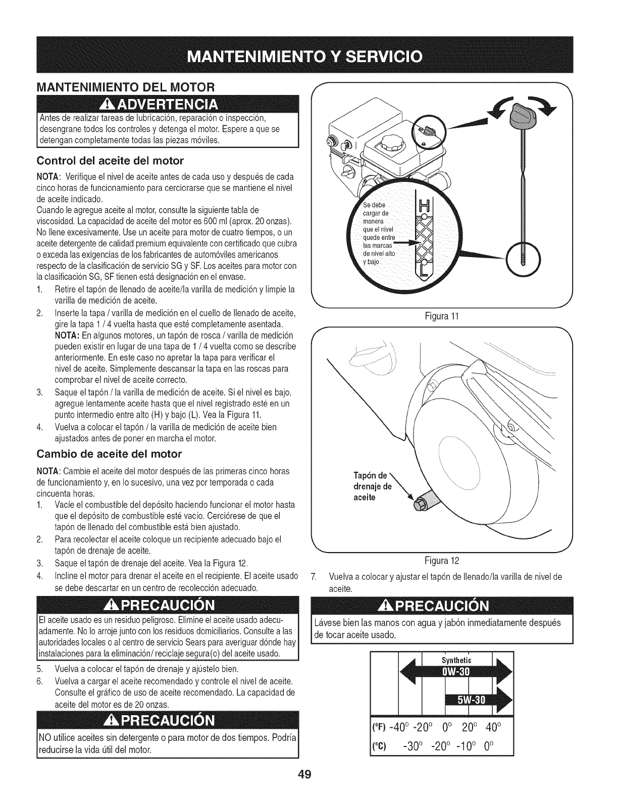
MANTENIMIENTO DEL MOTOR f "_
Antes de realizar tareas de lubricaci6n, reparaci6no inspecci6n,
desengrane todos los controles y detengaei motor. Esperea que se
detengan completamente todas las piezas m6viles.
Control del aceite del motor
NOTA: Verifique ei nivel de aceite antes de cada usoy despues de cada
cinco horasde funcionamiento para cerciorarse que se mantiene el nivel
de aceite indicado.
Cuandole agregueaceite ai motor,consulte ia siguientetabla de
viscosidad. Lacapacidadde aceitedel motores 600 ml (aprox.20 onzas).
No iieneexcesivamente.Use un aceite paramotor decuatro tiempos,o un
aceitedetergentede caiidadpremiumequivalentecon certificadoque cubra
o excedaias exigenciasde los fabricantesde autom6vilesamericanos
respectode la clasificaci6ndeservicio SG y SF.Losaceites para motor con
la clasificaci6nSG, SFtienen esta.designaci6n enel envase.
1. Retire el tap6n de ilenado de aceite/la varillade medici6ny limpiela
variiiade medici6nde aceite.
2. Inserte ia tapa /variiia de medici6n en ei cueilo de ilenado de aceite,
gire la tapa 1/4 vueita hasta que este completamente asentada.
NOTA: En algunos motores, un tap6n de rosca /variiia de medici6n
pueden existir en iugarde una tapa de 1/4 vuelta como se describe
anteriormente. En este caso no apretar la tapa para verificarei
nivel de aceite. Simplementedescansar la tapa en las roscas para
comprobar el nivel de aceite correcto.
3. Saque el tap6n /la varilla de medici6n de aceite. Si el nivel es bajo,
agregue lentamente aceite hasta que el nivel registrado este en un
punto intermedioentre alto (H) y bajo (L). Vea la Figura11.
4. Vueiva a colocar el tap6n /ia varilia de medici6nde aceite bien
ajustados antes de poner en marcha el motor.
Cambio de aceite del motor
NOTA: Cambie ei aceite dei motor despues de ias primeras cinco horas
de funcionamientoy, en Io sucesivo, una vez por temporada o cada
cincuenta horas.
1. Vacieel combustible dei dep6sito haciendo funcionar ei motor hasta
que ei dep6sito de combustible este vacio. Cerci6resede que el
tap6n de Ilenadodel combustible esta.bien ajustado.
2. Pararecolectar el aceite coloque un recipiente adecuado bajo el
tap6n de drenajede aceite.
3. Saque el tap6n de drenaje del aceite. Vea la Figura 12.
4. Incline el motor para drenar el aceite en el recipiente. Elaceite usado
se debe descartar en un centro de recolecci6n adecuado.
El aceite usadoes unresiduo peligroso.Elimineei aceite usadoadecu- i
I
adamente. NoIo arroje juntocon los residuosdomiciliarios.Consultealas
autoridadeslocales o ai centrode servicioSearspara averiguard6nde hay
nstaac ones para a e m nac6n/rec ca e segura(o)de ace teusado, j
5. Vuelva a colocar el tap6n de drenaje y ajQstelobien.
6. Vueiva a cargar el aceite recomendado y controle ei nivel de aceite.
Consulte el gra.ficode uso de aceite recomendado. La capacidad de
aceite del motor es de 20 onzas.
NO utiliceaceitessin detergenteo paramotordedos tiempos.Podria
reducirselavida _til delmotor.
Figura11
J
Tap6n de '_
drenajede _.
aceite '_
Figura 12
Vuelva a colocar y ajustar el tap6n de Ilenado/lavarilla de nivel de
aceite.
L&vesebienlasmanoscon aguay jab6ninmediatamentedespu_s
detocaraceiteusado.
u i
Synthetic
(°F)-40 o-20 o 0o 200 400
("c} -30°-20 °-10 ° 0°
49
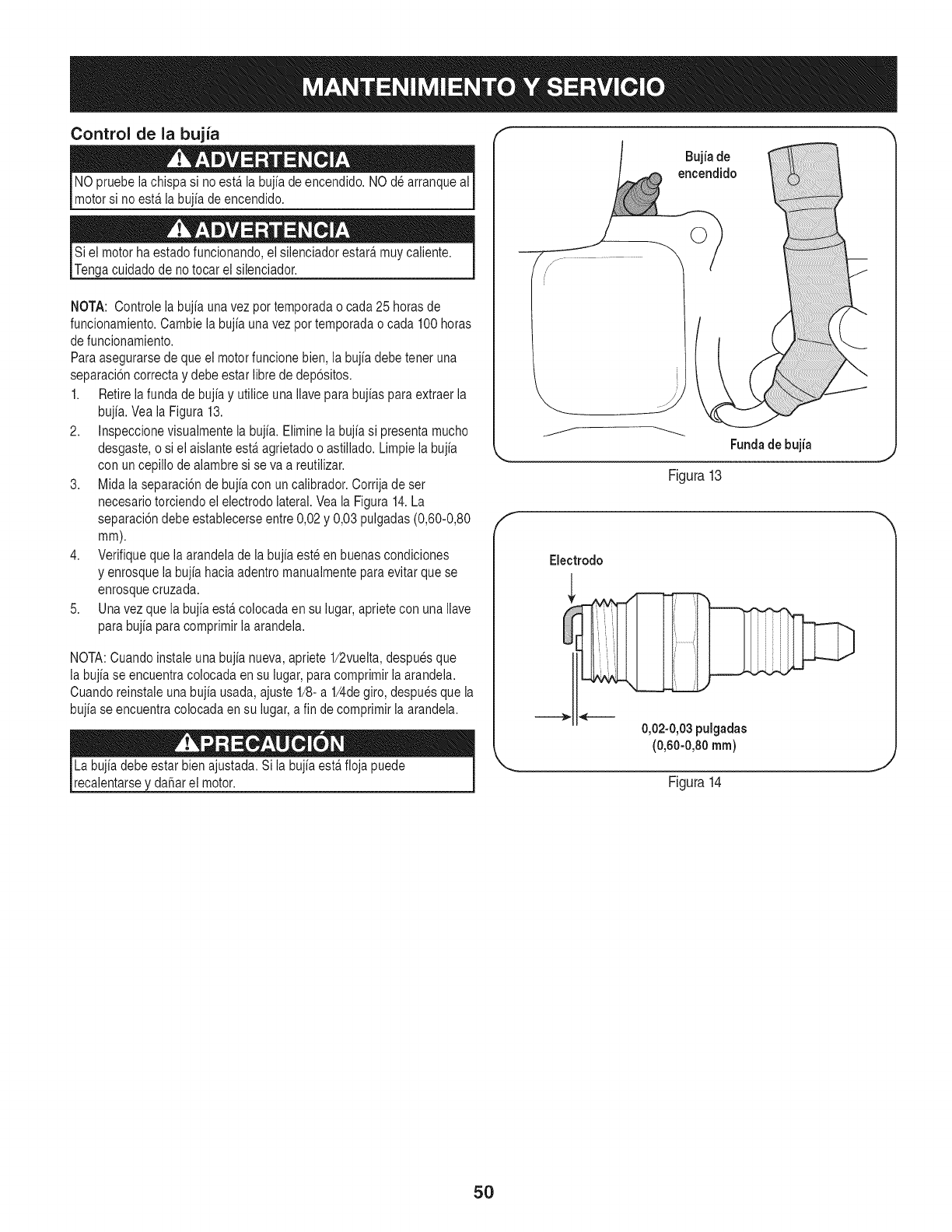
Control de la bujia
NO pruebe lachispa si no estfi la bujia de encendido. NO dearranque al
motor si no estfi la bujia de encendido.
Si el motor ha estado funcionando,el silenciador estarfi muy caiiente.
Tenga cuidadode notocar el silenciador.
NOTA: Controle la bujia una vez por temporada o cada 25 horas de
funcionamiento. Cambie la bujia una vez por temporada o cada 100 horas
de funcionamiento.
Paraasegurarse de que el motor funcione bien, la bujia debe tener una
separaci6n correctay debe estar libre de dep6sitos.
1. Retire la funda de bujia y utilice una Ilave para bujias para extraer la
bujia. Vea la Figura 13.
2. Inspeccionevisualmente la bujia. Elimine la bujia si presenta mucho
desgaste, o si el aislante estfi agrietado o astiilado. Limpie la bujia
con un cepillo de aiambre si se va a reutiiizar.
3. Mida la separaci6n de bujia con un calibrador. Corrija de set
necesario torciendo el electrodo lateral. Vea la Figura 14.La
separaci6ndebe establecerse entre 0,02 y 0,03 pulgadas (0,60-0,80
mm).
4. Verifique que la arandela de la bujiaeste en buenas condiciones
y enrosque la bujia hacia adentro manualmente para evitar que se
enrosque cruzada.
5. Unavez que la bujia estfi colocada en su lugar,apriete con una Ilave
para bujia para comprimir la arandela.
NOTA: Cuando instale una bujia nueva,apriete 1/2vuelta, despues que
la bujia se encuentra colocada en su lugar, paracomprimir laarandela.
Cuando reinstale una bujia usada, ajuste 1/8-a 1/4degiro, despuesque la
bujia se encuentra colocadaen su lugar,a fin de comprimir la arandela.
Labujia debe estar bienajustada. Si la bujiaestfi floja puede I
reca entarse y da_ar e motor. I
Bujia de
encendido
Fundade bujia
Figura13
Electrodo
0,02-0,03pulgadas
(0,60-0,80 ram)
Figura14
5O
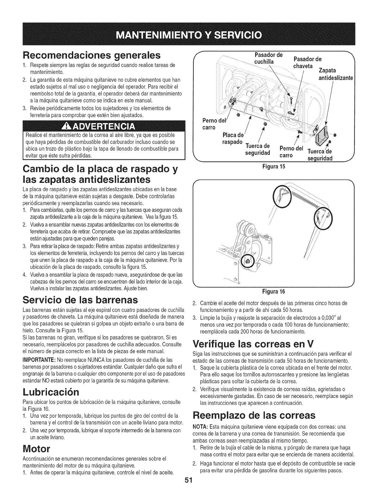
Recomendaciones generales
1. Respete siempre las regias de seguridad cuando reaiice tareas de
mantenimiento.
2. La garantfa de esta ma.quinaquitanieve no cubre elementosque han
estado sujetos al mal useo negligencia del operador. Pararecibir el
reembolso total de la garantfa, ei operador debera,dar mantenimiento
a la ma.quinaquitanieve come se indica en este manual.
3. Revise peri6dicamentetodos los sujetadores y los elementos de
ferreterfa paracomprobar que esten bien ajustados.
Realice el mantenimientode ia correa ai aire iibre, ya que es posible
que haya perdidas de combustible dei carburador incluso cuando se
ubica un trozode pla.sticobajo la tapa de Ilenadode combustible para
evitar que este sulfa perdidas.
Carnbio de la plata de raspado y
las zapatas antideslizantes
La placa de raspadoy ias zapatasantideslizantes ubicadas en ia base
de ia ma.quinaquitanieve esta.nsujetas a desgaste. Debe controlarlas
peri6dicamente y reemplazarlas cuando sea necesario.
1. Paracambiarlas,quitelospernosde carroylastuercasqueasegurancada
zapataantideslizantea iacajade ia ma.quinaquitanieve.Veaiafigura15.
2. Vueivaa ensamblarnuevaszapatasantideslizantescon loselementosde
ferreterfaqueacabade retirar.Compruebequelaszapatasantideslizantes
esta.najustadasparaquequedenparejas.
3. Pararetirarla placaderaspado:Retireambaszapatasantideslizantesy
los elementosde ferreterfa,incluyendolos pernosdel carte y las tuercas
que unenla placade raspado a la caja de la ma.quinaquitanieve.Per la
ubicaci6nde ia placaderaspado,consulteia figura 15.
4. Vueivaa ensamblaria placade raspadonueva,asegura.ndosedeque ias
cabezasde los pernosdel carroseencuentrendel ladeinteriorde la caja.
Vuelvaa instaiarlaszapatasantideslizantes.Ajustebien.
Servicio de las barrenas
Las barrenas esta.nsujetas al eje espiral con cuatro pasadores de cuchilla
y pasadores de chaveta. La ma.quinaquitanieve esta.dise_ada de manera
que los pasadoresse quiebransi golpea unobjeto extra_oo una barra de
hielo. Consulte ia Figura 15.
Si las barrenas no giran, verifique si los pasadores se quebraron. Si es
necesario,reempla.celosper pasadores de cuchiiia adecuados. Consulte
el nOmerode pieza correctoen la lista de piezas de este manual.
IMPORTANTE:NoreemplaceNUNCAlospasadoresde cuchillade las
barrenasper pasadoreso sujetadoresestAndar.CualquierdaSoquesufra el
engranajede la barrenao cualquierotto componentepor el use depasadores
esta.ndarNO estara,cubierto per lagarantfade su ma.quinaquitanieve.
Lubricaci6n
Paraubicar los puntos de lubricaci6n de la ma.quinaquitanieve, consulte
la Figura 16.
1. Una vez pot temporada, lubrique los puntosde giro del control de ia
barrena y ei control de la transmisi6ncon un aceite liviano para motor.
2. Una vezpor temporada,lubriqueel soporteintermediode labarrenacon
unaceiteliviano.
Motor
Acontinuaci6n se enumeran recomendacionesgenerales sobre el
mantenimiento dei motor de su ma.quinaquitanieve.
1. Antes de operar la ma.quinaquitanieve, controle el nivel de aceite.
fPasadorde "_
cuchilla Pasadorde
chaveta
....... Zapata
antideslizante
°°"° /!ii
raspado Tuerca de Perno del Tuel le
seguridad carro
_ seguridad
Figura 15
J
i/
/ /
/
/
Figura 16
2. Cambie el aceite del motor despues de ias primeras cinco horas de
funcionamiento y a partir de ahf cada 50 horas.
3. Limpie la bujfa y reajuste la separaci6n de electrodes a 0,030" al
menos una vez per temporada o cada 100 horas de funcionamiento;
reempla.celacada 200 horas de funcionamiento.
Verifique las correas en V
Siga las instrucciones que se suministran a continuaci6n paraverificar el
estado de ias correas de transmisi6n cada 50 horasde funcionamiento.
1. Saque la cubierta pia.sticade ia correa ubicada en el frente dei motor.
Para elio saque los tornilios autorroscantes y presione las lengOetas
pla.sticasparasoltar ia cubierta de la correa.
2. Verifique visuaimente la existencia de correas rafdas, agrietadas o
excesivamente gastadas. Encase deset necesario,reemplace segOn
las instrucciones que aparecen a continuaci6n.
Reemplazo de las correas
NOTA: Estama.quinaquitanieve viene equipada con dos correas: una
correa de la barrena y una correa de transmisi6n. Se recomienda que
ambas correas sean reemplazadasai mismo tiempo.
1. Retirede labujia el cablede la misma,y p6ngalode maneraque haga
masa contra el motorpara evitarque se encienda de maneraaccidental.
2. Hagafuncionar el motor hasta que el dep6sito de combustible se vacfe
para evitar una perdida de gasolina durante los siguientes pasos.
51
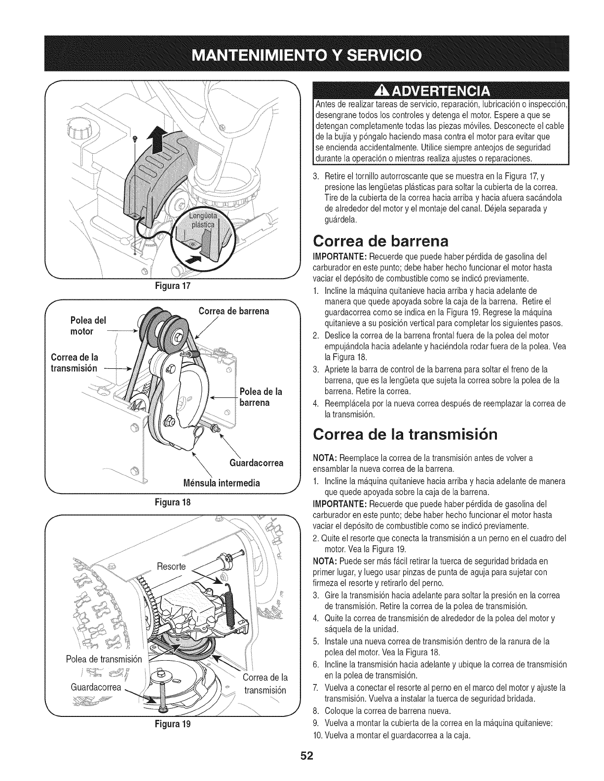
f
Figura 17
fCorreade barrena
Poleadel
motor
Correa de la
transmisi6n t
Poleade la
t_barrena
f
_GuGuardacorrea
\
N_nsuia intermedia
Figura 18
Poleadetransmisi6n
Guardacorrea
Figura19
Antes de realizartareas de servicio, reparaci6n,iubricaci6n o inspecci6n,
desengrane todos los controles y detenga el motor.Espere a que se
detengan completamentetodas ias piezas m6viles. Desconecte el cable
de la bujiay p6ngalo haciendo masa contra el motor para evitar que
se encienda accidentalmente. Utilice siempre anteojosde seguridad
_durante a operac 6n o m entras rea za a usteso reparacones.
Retireel torniilo autorroscante que se muestra en ia Figura 17,y
presione las iengietas pla.sticasparasoltar ia cubierta de la correa.
Tire de ia cubierta de ia correa haciaarriba y hacia afuera saca.ndola
de alrededor del motor y el montaje del canal. Dejela separada y
gua.rdela.
Correa de barrena
IMPORTANTE: Recuerde que puede haber perdida de gasolina del
carburador eneste punto; debe haber hechofuncionar el motor hasta
vaciar el dep6sito de combustiblecomo se indic6 previamente.
1. Incline ia ma.quinaquitanieve hacia arriba y hacia adeiante de
maneraque quede apoyada sobre la caja de la barren& Retire el
guardacorrea como se indica en la Figura 19.Regrese ia ma.quina
quitanieve a su posici6n vertical para completar los siguientes pasos.
2. Deslice la correa de la barrena frontal fuera de la polea del motor
empuja.ndolahacia adelante y haciendola rodar fuera de la polea. Vea
la Figura 18.
3. Apriete la barra de control de ia barrena parasoltar el freno de la
barrena,que es la lengieta que sujeta la correa sobre la polea de la
barrena.Retire la correa.
4. Reempla.celapor la nueva correa despues de reemplazar la correa de
iatransmisi6n.
Correa de la transmisi6n
NOTA: Reemplacela correa de la transmisi6n antes de volver a
ensamblar la nueva correa de la barrena.
1. Incline ia m£quinaquitanieve hacia arriba y hacia adelante de manera
que quede apoyada sobre la caja de la barren&
IMPORTANTE: Recuerde que puede haber perdida de gasolina del
carburador eneste punto; debe haber hechofuncionar el motor hasta
vaciar ei dep6sito de combustiblecomo se indic6 previamente.
2. Quite el resorte que conecta la transmisi6n a un perno en el cuadro del
motor.Vea ia Figura 19.
NOTA: Puedeset m£s fa.ciiretirar la tuerca de seguridad bridada en
primer iugar,y iuego usar pinzasde punta de aguja parasujetar con
firmeza el resortey retirarlodel perno.
3. Gireia transmisi6nhacia adelante parasoltar ia presi6n en la correa
de transmisi6n. Retire ia correa de la polea de transmisi6n.
4. Quite ia correa de transmisi6n de alrededor de la polea del motor y
sa.quelade la unidad.
5. Instale una nueva correa de transmisi6n dentro de la ranura de la
polea del motor.Vea la Figura 18.
6. incline ia transmisi6nhacia adelante y ubique la correa de transmisi6n
en la polea de transmisi6n.
7. Vueiva a conectar el resorteal pemo en el marco del motor y ajuste la
transmisi6n. Vueiva a instaiar la tuerca de seguridad bridada.
8. Coloque la correa de barrena nueva.
9. Vuelva a montar la cubierta de la correa en la ma.quinaquitanieve:
10.Vuelva a montar el guardacorrea a la caja.
52
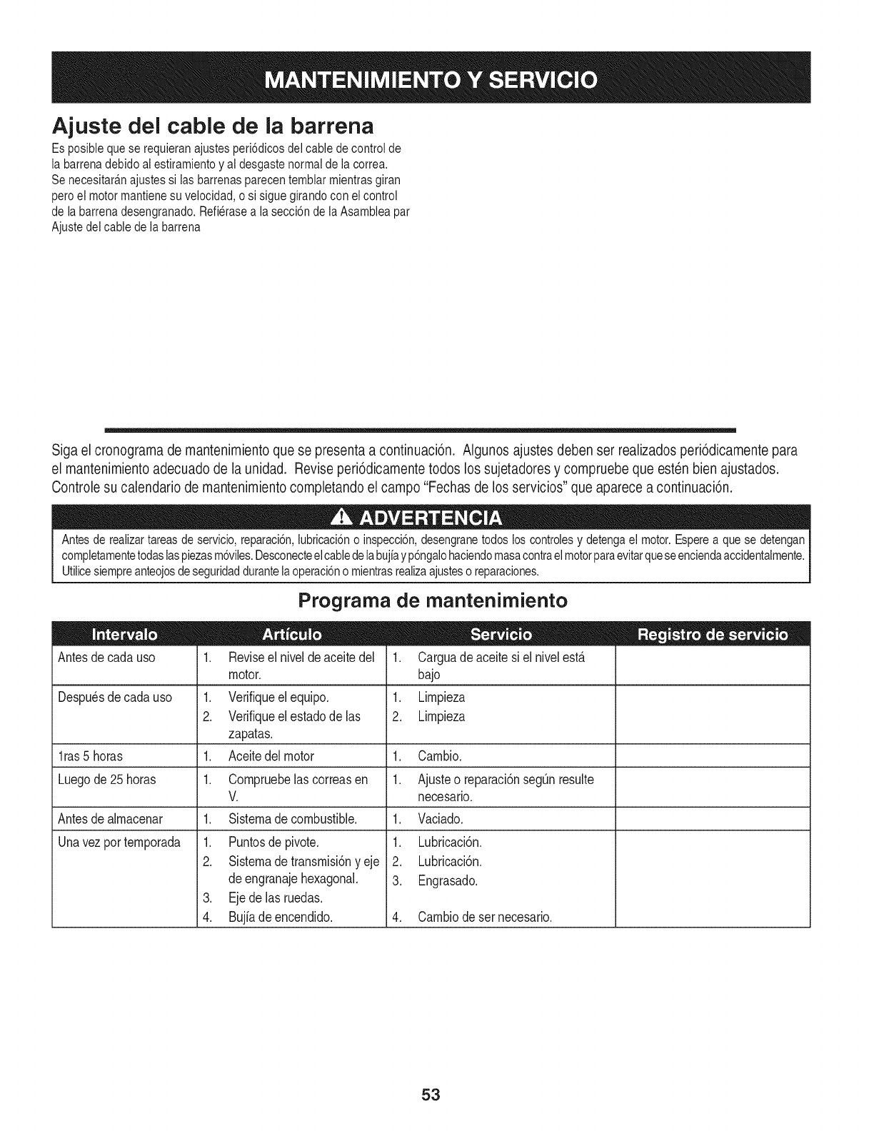
Ajuste del cable de la barrena
Es posible que se requieran ajustes peri6dicos del cable de controlde
la barrena debido ai estiramiento y al desgaste normal de la correa.
Se necesitara.najustes si las barrenas parecen temblar mientras giran
pero el motor mantiene su velocidad, o si sigue girando con ei control
de la barrena desengranado. Refierase a la secci6n de la Asamblea par
Ajuste del cable de la barrena
Siga el cronograma de mantenimiento que se presenta a continuaci6n. Algunos ajustes deben ser realizados peri6dicamente para
el mantenimiento adecuado de la unidad. Revise peri6dicamente todos los sujetadores y compruebe que esten bien ajustados.
Controle su calendario de mantenimiento completando el campo "Fechas de los servicios" que aparece a continuaci6n.
Antes de realizartareasde servicio,reparaci6n,iubricaci6no inspecci6n,desengranetodos los controlesy detengael motor.Esperea que se detengan
completamentetodaslaspiezasm6viles.Desconecteel cabledelabujiayp6ngalohaciendomasacontrael motorparaevitarqueseenciendaaccidentaimente.
Utilicesiempreanteojosdeseguridaddurantelaoperaci6no mientrasrealizaajusteso reparaciones.
Antes de cada uso
Prograrna de rnantenirniento
Despu_sdecada uso
l ras5 horas 1.
Luegode 25horas 1.
Antesde almacenar
Unavezportemporada
1. Revise el nivel de aceite del
motor.
1. Verifiqueelequipo.
2. Verifique el estado de las
zapatas.
1. Aceitedel motor
1. Compruebelascorreasen
V.
1. Sistema de combustible.
1. Puntosde pivote.
2. Sistema de transmisi6n yeje
de engranaje hexagonal.
3. Ejedelasruedas.
4. Bujfadeencendido.
1. Carguade aceitesi elnivelest,.
bajo
1. Limpieza
2. Limpieza
Cambio.
Ajusteo reparaci6nsegQnresulte
necesario.
1. Vaciado.
1. Lubricaci6n.
2. Lubricaci6n.
3. Engrasado.
4. Cambiodesernecesario.
53
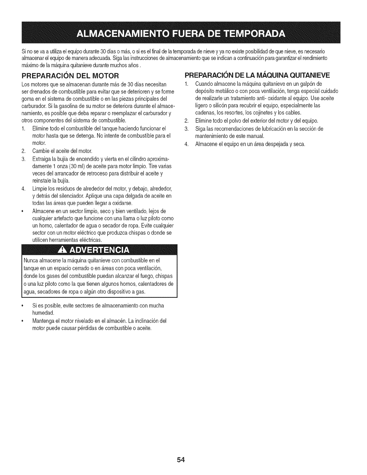
Sinosevaa utilizael equipodurante30dfasorn_.s,o sies elfinaldelaternporadadenievey ya noexisteposibilidaddequenieve,es necesario
alrnacenarelequipode rnaneraadecuada.Sigalasinstruccionesdealrnacenarnientoquese indicanacontinuaci6nparagarantizarelrendirniento
rn_.xirnodelarn_.quinaquitanieveduranternuchosa_os.
PREPARACI6N DEL MOTOR
Losrnotoresquese alrnacenandurantern&sde30 dfasnecesitan
serdrenadosdecombustibleparaevitarquese deterioreny se forrne
gornaenel sisternade combustibleoen las piezasprincipalesdel
carburador.Si lagasoNnade su motorse deterioraduranteel alrnace-
narniento,es posiblequedeba repararo reernplazarelcarburadory
otroscornponentesdel sisternade combustible.
1. Elirninetodoel combustibledel tanquehaciendofuncionarel
motorhastaquese detenga.No intentede combustibleparael
motor.
2. Carnbieel aceitedel motor.
3. Extraigala bujfade encendidoy viertaen elcilindroaproxirna-
darnente1onza(30 rnl)de aceiteparamotorNrnpio.Tire varias
vecesdel arrancadorde retrocesoparadistribuirelaceitey
reinstalela bujfa.
4. Lirnpielos residuosdealrededordel motor,y debajo,alrededor,
y detr_.sdel silenciador.ApNqueunacapa delgadade aceiteen
todaslas _.reasquepuedenNegara oxidarse.
• Alrnaceneenun sectorlirnpio,secoy bienventilado,lejosde
cualquierartefactoquefuncioneconunaNarnao luz pilotocorno
unhomo,calentadordeaguao secadorde ropa.Evitecualquier
sectorcon un motorel_ctricoqueproduzcachispaso dondese
utilicenherrarnientasel_ctricas.
Nuncaalrnacenelarn_.quinaquitanieveconcombustibleenel
tanqueenun espaciocerradooen _.reascon pocaventilaci6n,
dondelosgasesdelcombustiblepuedanalcanzarel fuego,chispas
o unaluz pilotocornola quetienenalgunoshornos,calentadoresde
agua,secadoresde ropao algQnotto dispositivoagas.
PREPARACION DE LA iVlAQUINA QUITANIEVE
1. Cuandoalrnacenelarn&quinaquitanieveen ungalp6nde
dep6sitornet_.licoo con pocaventilaci6n,tengaespecialcuidado
de realizarleuntratarnientoanti- oxidanteal equipo.Useaceite
ligeroo silic6npararecubrirel equipo,especialrnentelas
cadenas,los resortes,loscojinetesy loscables.
2. Elirninetodo el polvodelexteriordelmotory delequipo.
3. Sigalas recornendacionesde lubricaci6nen la secci6nde
mantenirnientodeestemanual.
4. Alrnaceneel equipoen un_.readespejaday seca.
• Sies posible,evitesectoresdealrnacenarnientocon rnucha
hurnedad.
• Mantengael motorniveladoen el alrnac_n.Lainclinaci6ndel
motorpuedecausarperdidasde combustibleo aceite.
54
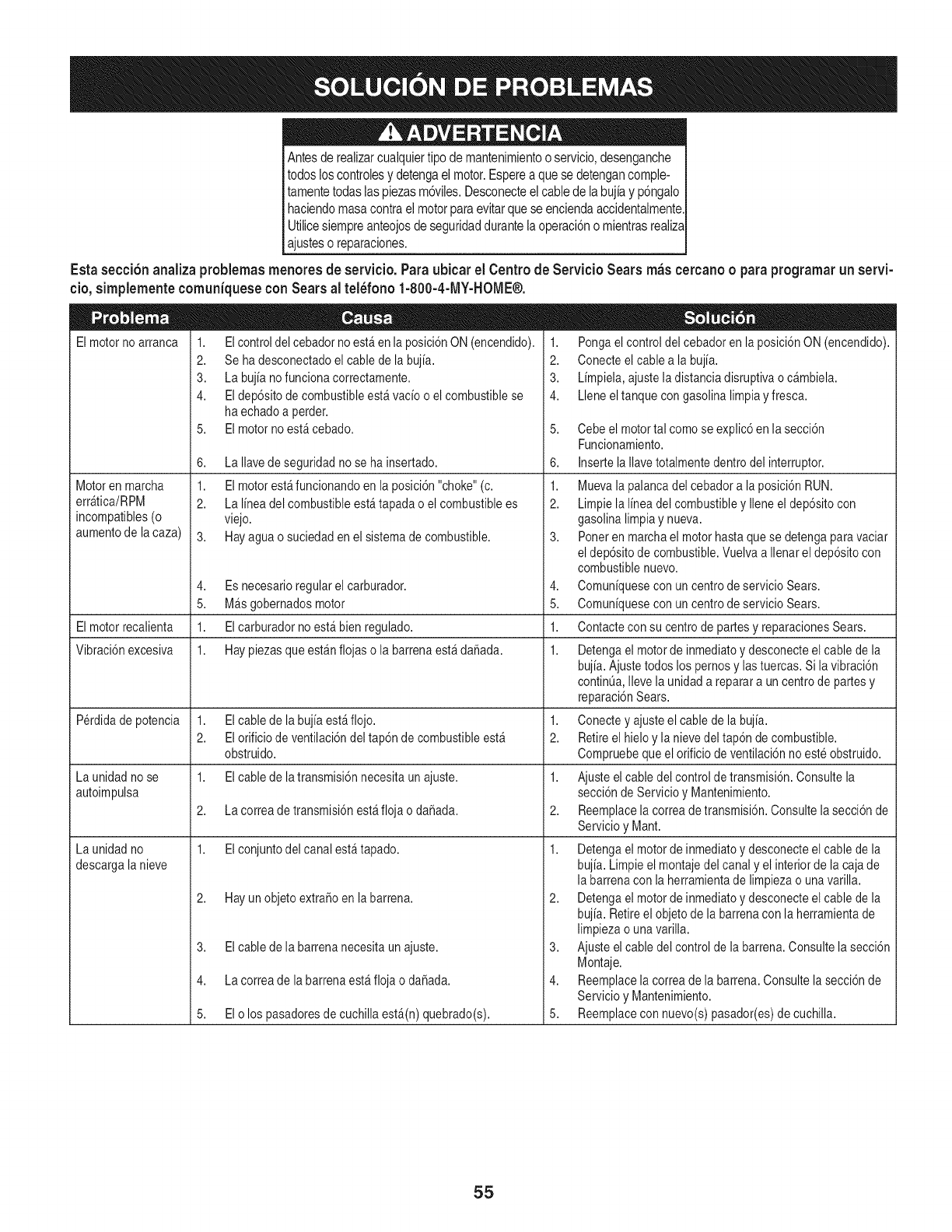
Antesde realizarcuaiquiertipo de mantenimientoo servicio,desenganche
todos loscontrolesy detengael motor.Esperea que se detengancomple-
tamentetodas laspiezasm6viles.Desconecteel cablede la bujh y p6ngalo
haciendomasacontraei motorparaevitarquese enciendaaccidentalmente.
Utilicesiempreanteojosde seguridaddurantela operaci6no mientrasrealiza
ajusteso reparaciones.
Esta secci6nanaliza problemasmenores de servicio.Paraubicar el Centrode Servicio Sears m_scercanooparaprogramarun servi-
eio, simplemente eomuniquese con Sears al tel_fono 1-800-4-MY-HOME®.
Elmotor no arranca 1. Elcontrol del cebador no estfien la posicidn ON (encendido).
2. Se ha desconectado elcable de la bujia.
3. La bujia nofuncionacorrectamente.
4. El depdsitodecombustibleestfi vacio o el combustiblese
haechadoa perder.
El motorno est_cebado.
Motoren marcha
errAtica/RPM
incompatibles(o
aumentode la caza)
5,
6.
1.
2.
3.
1. Pongael control del cebadoren laposici6nON(encendido).
2. Conecteel cablea la bujia.
3. Limpiela,ajustela distanciadisruptivao cambiela.
4. Lleneeltanque congasolinalimpia yfresca.
La Ilavedeseguridadno se hainsertado.
El motorest_funcionandoen la posici6n"choke"(c.
La linea del combustibleest_tapadao el combustiblees
viejo.
Hayagua o suciedaden elsistemade combustible.
Es necesarioregularel carburador.
MAsgobernadosmotor
El carburadornoest_ bienregulado.
Haypiezasqueest_nflojas o la barrenaest_ da_ada.
El cabledela bujiaest_flojo.
El orificiode ventilaci6ndel tap6nde combustibleest_
obstruido.
El cabledela transmisi6nnecesitaunajuste.
La correa detransmisi6nest_floja o da_ada.
El conjuntodel canalest_tapado.
5. Cebeel motortal comose explic6en la secci6n
Funcionamiento.
6. Insertela llavetotalmentedentrodel interruptor.
1,
2.
Muevala palancadel cebadora la posici6nRUN.
Limpiela lineadel combustibley Ileneel dep6sitocon
gasolinalimpiay nueva.
Ponerenmarchael motorhastaque se detengaparavaciar
eldep6sitode combustible.Vuelvaa Ilenarel dep6sitocon
combustiblenuevo.
Comuniquesecon uncentrodeservicioSears.
Comuniquesecon uncentrodeservicioSears.
4, 4,
5. 5.
Elmotorrecalienta 1. 1. Contacteconsu centrodepartesy reparacionesSears.
Vibraci6nexcesiva 1. 1. Detengael motorde inmediatoy desconecteel cablede la
bujia.Ajustetodoslos pernosy lastuercas.Si lavibraci6n
continQa,Ilevela unidada reparara un centrodepartesy
reparaci6nSears.
Perdidade potencia 1. 1. Conectey ajusteel cablede la bujia.
2. 2. Retireel hieloy la nievedel tap6ndecombustible.
Compruebequeel orificiode ventilaci6nnoeste obstruido.
La unidadno se 1. 1. Ajusteelcabledel controlde transmisi6n.Consultela
autoimpulsa secci6nde Servicioy Mantenimiento.
2. 2. Reemplacela correadetransmisi6n.Consultelasecci6nde
Servicioy Mant.
Launidadno 1. 1.
descargala nieve
2. Hayunobjeto extra6oen labarrena.
3. El cablede la barrenanecesitaun ajuste.
4. Lacorrea dela barrenaest_floja o da6ada.
5. El o los pasadoresde cuchillaest,(n) quebrado(s).
Detengael motordeinmediatoydesconecteel cablede la
bujia.Limpieel montajedel canaly el interiorde la cajade
la barrenacon la herramientade limpiezao unavarilla.
2. Detengael motorde inmediatoy desconecteel cablede la
bujia.Retireel objetode la barrenacon laherramientade
limpiezao unavarilla.
3. Ajusteelcabledel controlde la barrena.Consultela secci6n
Montaje.
4. Reemplacela correadela barrena.Consultela secci6nde
Servicioy Mantenimiento.
5. Reemplaceconnuevo(s)pasador(es)de cuchilla.
55
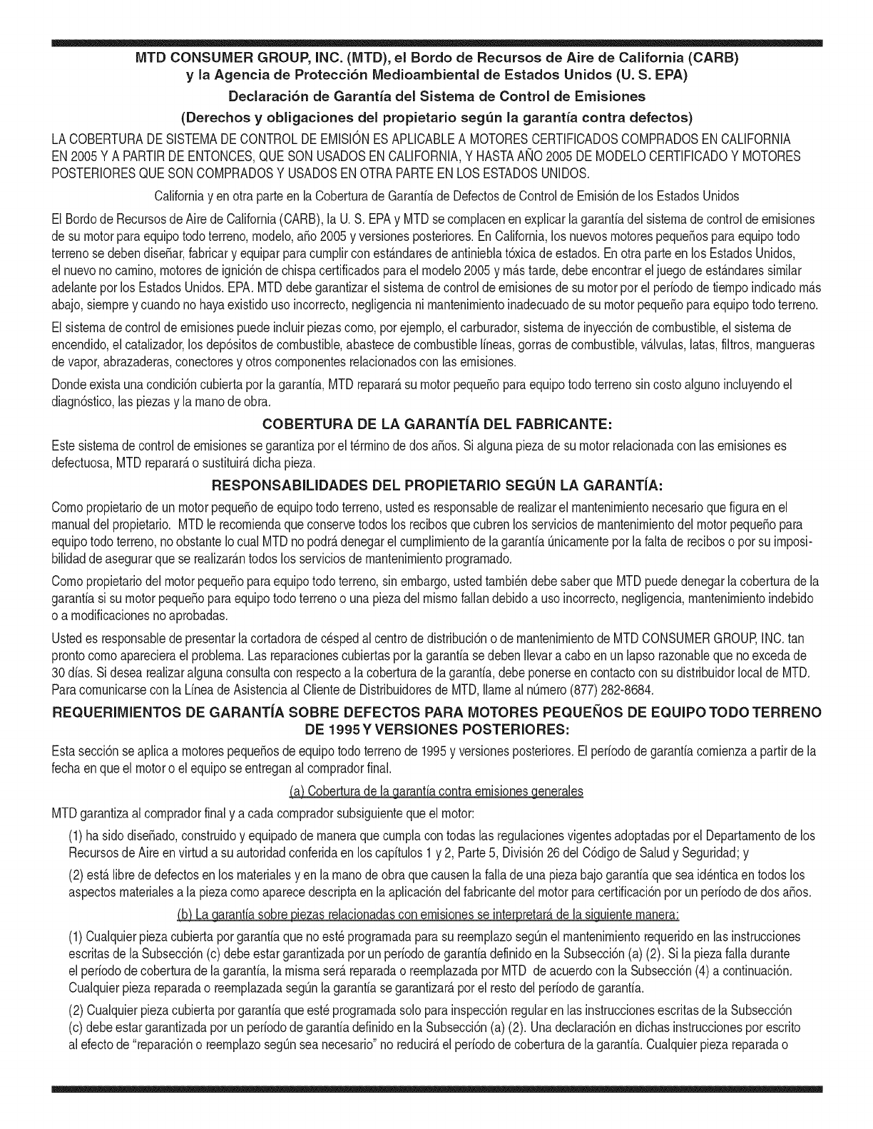
MTD CONSUMER GROUP, iNC. (MTD), el Bordo de Recursos de Aire de California (CARB)
y la Agencia de Protecci6n Medioambiental de Estados Unidos (U. S. EPA)
Declaraci6n de Garantia del Sistema de Control de Emisiones
(Derechos yobligaciones del propietario seg_n la garantia contra defectos)
LACOBERTURADESISTEMADECONTROLDEEMISIONESAPLICABLEA MOTORESCERTIFICADOSCOMPRADOSENCALIFORNIA
EN2005Y A PARTIRDE ENTONCES,QUESON USADOSEN CALIFORNIA,Y HASTAANO2005DE MODELOCERTIFICADOY MOTORES
POSTERIORESQUESON COMPRADOSY USADOSENOTRAPARTEEN LOSESTADOSUNIDOS.
Californiayen otra parteen la Coberturade Garantiade DefectosdeControlde Emisi6nde los EstadosUnidos
El Bordode Recursosde Airede California(CARB),la U.S. EPAy MTDsecomplacenenexplicarla garantiadel sistemade controldeemisiones
de su motorparaequipotodo terreno,modelo,aSo2005y versionesposteriores.EnCalifornia,los nuevosmotorespequeSosparaequipotodo
terrenose debendise5ar,fabricary equiparparacumplirconest_.ndaresde antinieblat6xicade estados.Enotraparteen los EstadosUnidos,
el nuevonocamino,motoresdeignici6ndechispacertificadosparaelmodelo2005y m_.starde,debeencontrareljuegode est_.ndaressimilar
adelanteporlos EstadosUnidos.EPA.MTDdebegarantizarel sistemadecontrolde emisionesdesu motorpor elperiodode tiempoindicadom&s
abajo,siempreycuandono hayaexistidousoincorrecto,negligencianimantenimientoinadecuadode su motorpequeBoparaequipotodoterreno.
El sistemadecontrolde emisionespuedeincluirpiezascomo,porejemplo,el carburador,sistemadeinyecci6ndecombustible,el sistemade
encendido,el catalizador,losdep6sitosdecombustible,abastecedecombustiblelineas,gorrasde combustible,v&lvulas,latas,filtros,mangueras
devapor,abrazaderas,conectoresy otroscomponentesrelacionadoscon lasemisiones.
Dondeexistaunacondici6ncubiertaporla garantia,MTDreparar&su motorpequeBoparaequipotodoterrenosincostoalgunoincluyendoel
diagn6stico,laspiezasy la manode obra.
COBERTURA DE LA GARANTJA DEL FABRICANTE:
Estesistemade controldeemisionesse garantizaporel t@rminodedos a5os.Si algunapiezade su motorrelacionadacon lasemisioneses
defectuosa,MTD reparar&o sustituir&dichapieza.
RESPONSABJLIDADES DEL PROPIETARIO SEGUN LA GARANTJA:
Comopropietariodeun motorpequeSode equipotodoterreno,ustedes responsablede realizarel mantenimientonecesarioquefigura enel
manualdel propietario.MTDle recomiendaqueconservetodoslos recibosquecubrenlos serviciosdemantenimientodel motorpeque5opara
equipotodoterreno,noobstanteIo cual MTDnopodr&denegarel cumplimientodela garantiaQnicamenteporlafaltade reciboso porsu imposi-
bilidaddeasegurarque se realizar_.ntodoslos serviciosde mantenimientoprogramado.
Comopropietariodelmotorpeque5oparaequipotodo terreno,sinembargo,ustedtambi@ndebesaberque MTDpuededenegarlacoberturadela
garantiasi su motorpeque5oparaequipotodoterrenoo unapiezadel mismofallandebidoa usoincorrecto,negligencia,mantenimientoindebido
o a modificacionesnoaprobadas.
Ustedes responsablede presentarlacortadoradecespedal centrode distribuci6no de mantenimientode MTDCONSUMERGROUP,INC.tan
prontocomoaparecierael problem& Lasreparacionescubiertaspor lagarantiasedebenIlevaracabo enun lapsorazonableque noexcedade
30dias.Si desearealizaralgunaconsultacon respectoa la coberturade lagarantia,debeponerseencontactocon su distribuidorlocalde MTD.
Paracomunicarseconla LineadeAsistenciaal Clientede Distribuidoresde MTD,Ilameal nQmero(877)282-8684.
REQUERJMJENTOS DE GARANTJA SOBRE DEFECTOS PARA MOTORES PEQUENOS DE EQUJPO TODO TERRENO
DE 1995YVERSJONES POSTERJORES:
Estasecci6nse aplicaa motorespeque5osdeequipotodo terrenode 1995y versionesposteriores.Elperiododegarantiacomienzaa partirde la
fechaen queel motoro elequiposeentreganal compradorfinal.
(a) Coberturade la garantiacontraemisionesgenerales
MTDgarantizaal compradorfinaly acada compradorsubsiguientequeel motor:
(1)hasido diseSado,construidoy equipadode maneraquecumplacontodaslas regulacionesvigentesadoptadasporel Departamentodelos
RecursosdeAire envirtuda suautoridadconferidaen loscapitulos1y 2, Parte5, Divisi6n26del C6digode Saludy Seguridad;y
(2)est,. librede defectosen los materialesyen la manode obraquecausenlafalla deunapiezabajogarantiaque seaid@nticaentodoslos
aspectosmaterialesa lapiezacomoaparecedescriptaen laaplicaci6ndelfabricantedel motorparacertificaci6npor unperiododedos a5os.
_arantia sobre piezasrelacJonadasconemisJonesse interpretar_,de la sJguientemanera:
(1)Cualquierpiezacubiertaporgarantiaquenoest@programadaparasu reemplazosegQnel mantenimientorequeridoenlas instrucciones
escritasdela Subsecci6n(c) debeestargarantizadapor unperiodode garantiadefinidoen la Subsecci6n(a)(2). Sila piezafalladurante
el periododecoberturadela garantia,lamismaser_.reparadao reemplazadaporMTD de acuerdocon la Subsecci6n(4)a continuaci6n.
Cualquierpiezareparadao reemplazadasegQnlagarantiasegarantizarB,porel restodelperiodode garantia.
(2) Cualquierpiezacubiertaporgarantiaqueest@programadasoloparainspecci6nregularen lasinstruccionesescritasde la Subsecci6n
(c) debeestargarantizadaporun periododegarantiadefinidoenla Subsecci6n(a) (2). Unadeclaraci6nen dichasinstruccionesporescrito
alefectode "reparaci6no reemplazosegQnseanecesario"no reducir_,elperiodode coberturade la garantia.Cualquierpiezareparadao
reernplazadasegQnlagarantiasegarantizar_,porelrestodelperiododegarantia.
(3) Cualquierpiezagarantizadaqueest_prograrnadaparareernplazosegQnelrnantenirnientorequeridodeconforrnidadconlasinstruc-
clonesescritasdelaSubsecci6n(c)segarantizaporelperiododetiernpoanterioralaprirnerafechadereernplazoprograrnadaparaesa
pieza.Silapiezafallaantesdelprimerreernplazoprogramatic,larnisrnaser_.reparadaoreernplazadaporMTDdeacuerdoconlaSubsecci6n
(4)acontinuaci6n.Cualquierpiezareparadaoreernplazadabajogaranfiasegarantizar_,porelrestodelperiodoanterioralprimerreernplazo
programaticpuntualparaesapieza.
(4)Lareparaci6noelreernplazodecualquierpiezagarantizadadeconforrnidadconlasdisposicionesdelagaranfiaqueaquiseestipulase
deberealizarenuncentrodegaranfiasincostoalgunoparaelpropietario.
(5)SinperjuiciodelasdisposicionesdelaSubsecci6n(4)anterior,losserviciosoreparacionescubiertosporlagaranfiadebensersurnin-
istradosportodosloscentrosdedistribuci6ndeMTDquetenganlafranquiciapararealizarreparacionesyrnantenirnientoalosrnotoresen
cuesti6n.
(6)ElpropietarionodebeafrontarningQncargoparatrabajosdediagn6sticoqueIlevenalaconclusi6ndequeunapiezabajogaranfiapresenta
efectivarnentedefectos,siernpreycuandodichodiagn6sticoseaIlevadoacaboenuncentrocubiertoporlagarantia.
(7)Elfabricantedelmotoresresponsableporda_oscausadosaotroscornponentesdernotoresderivadosdelafallabajogaranfiadecualquier
piezagarantizada.
(8)DurantetodoelperiododegaranfiadelmotordefinidoenlaSubsecci6n(a)(2),MTDrnantendr_,unsurninistrodepiezascubiertaspor
garantiasuficienteparasatisfacerladernandaesperadaparatalespiezas.
(9)Cualquierpiezadereernplazosepodr_,usarparaelcurnplirnientodelrnantenirnientooreparacionesbajogaranfia,ysesurninistrar_,sin
cargoalpropietario.Dichousonoreducir_,lasobligacionesdegarantiadeMTD.
(10)Nosepodr_.nusarpiezasadicionalesnirnodificadasquenoest_nexentasdeacuerdoconelDepartarnentodelosRecursosdelAire(Air
ResourcesBoard).Elusodepiezasadicionalesornodificadasnoexentasser_.causasuficienteparaanularunreclarnobajogaranfiarealizado
deacuerdoconestearticulo.Elfabricantedelmotornotendr_,responsabilidad,enconforrnidadconestearticulo,degarantizarfallasdepiezas
garantizadasquefuerencausadasporelusodeunapiezanoexentaadicionalornodificada.
.(c)MTDincluir_,unacopiade lasiguientelistade piezasbajogarantiacontraernisionescon cadanuevomotor,utilizandolaspartesde la lista
a_plicablesal motor.
(1)Sisternadernedici6ndecombustible
• Sisternade rnejoraparainicioenfrio (cebadosuave)
• Carburadory cornponentesinternos
• Bornbade combustible
• Dep6sitodecombustible
(2) Sisternadeinducci6ndeaire
• Filtrode aire
• Colectordeentrada
(3) Sisternadeencendido
• Bujia(s)
• Sisternadeencendidopor magneto
(4)Sisternadeescape
• Catalizador
• SAI (v_Jvulade Ca_a)
(5) Cornponentesvariosutilizadosen el sisternaanterior
• V_Jvulase interruptoresde vado, ternperatura,posici6nsensiblesal tiernpo
• Conectoresy rnontajes
(6)Controlde Evaporative
• Manguerade CombustiblecertificadaparaARB evaporativeernisi6nde 2006.
• Abrazaderasde Manguerade Combustible
• Gorrade combustibleatada
• Latade carb6n
• Lineasdevapor
GD0C-100174Rev.B
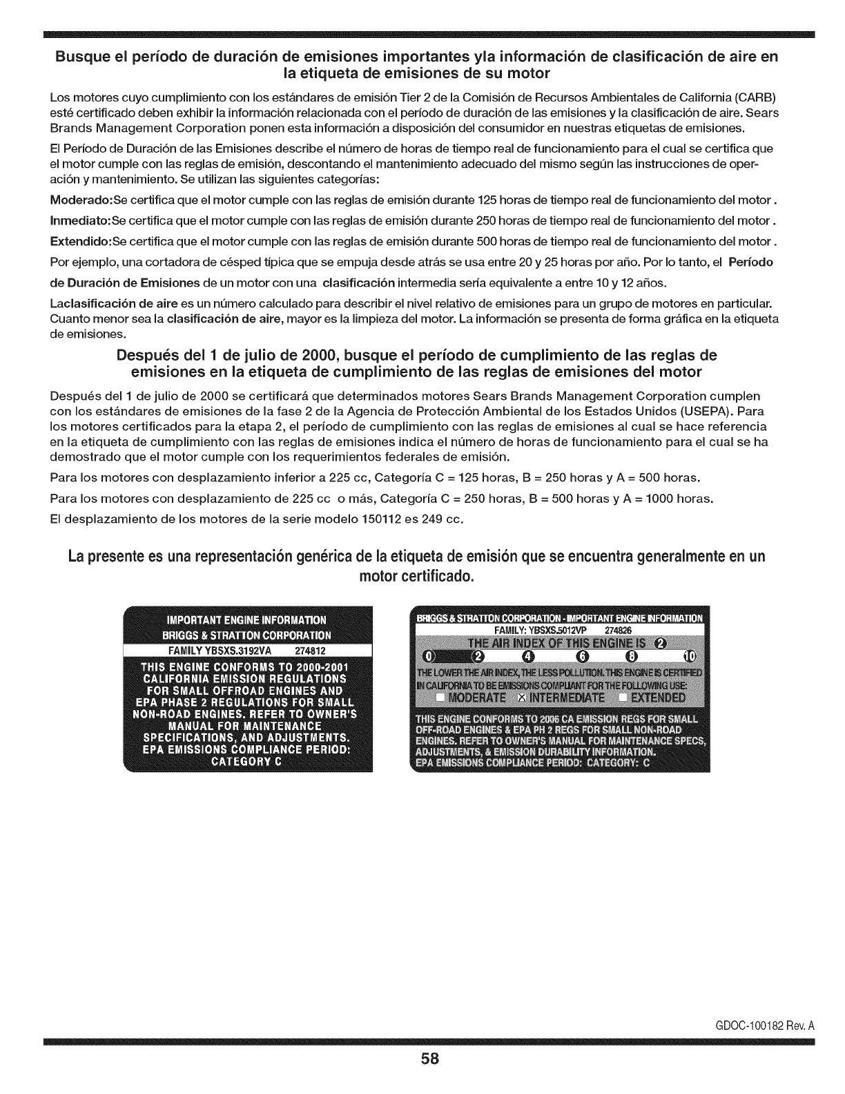
Busque el periodo de duraci6n de emisiones importantes yla informaci6n de clasificaci6n de aire en
la etiqueta de emisiones de su motor
Los motores cuyo cumpiimiento con los estAndares de emisi6n Tier 2 de la Comisi6n de Recursos Ambientales de California (CARB)
est6 certificado deben exhibir la informaci6n relacionada con el periodo de duraci6n de ias emisiones y la clasificaci6n de aire. Sears
Brands Management Corporation ponen esta informaci6n a disposici6n del consumidor en nuestras etiquetas de emisiones.
Ei Periodo de Duraci6n de las Emisiones describe el nQmero de horas de tiempo real de funcionamiento para el cuai se certifica que
el motor cumpie con ias reglas de emisi6n, descontando el mantenimiento adecuado del mismo segQn las instrucciones de oper-
aci6n y mantenimiento. Se utilizan las siguientes categonas:
Moderado:Se certifica que el motor cumpie con las reglas de emisi6n durante 125 horas de tiempo real de funcionamiento del motor.
Inmediato:Se certifica que el motor cumpie con las reglas de emisi6n durante 250 horas de tiempo real de funcionamiento del motor.
Extendido:Se certifica que el motor cumpie con las reglas de emisi6n durante 500 horas de tiempo real de funcionamiento del motor.
Por ejemplo, una cortadora de c6sped tJpica que se empuja desde arras se usa entre 20 y 25 horas por aSo. Por Io tanto, el Periodo
de Duraci6n de Emisiones de un motor con una clasificaci6n intermedia sena equivaiente a entre 10 y 12 aSos.
Laciasificaci6n de aire es un nQmero calculado para describir el nivel relativo de emisiones para un grupo de motores en particular.
Cuanto menor sea la clasificaci6n de aire, mayor es la limpieza del motor. La informaci6n se presenta de forma grAfica en la etiqueta
de emisiones.
Despu_s del 1 de julio de 2000, busque el periodo de cumplimiento de las reglas de
emisiones en la etiqueta de cumplimiento de las reglas de emisiones del motor
Despu6s del 1 de julio de 2000 se certificarA que determinados motores Sears Brands Management Corporation cumplen
con los estAndares de emisiones de la fase 2 de la Agencia de Protecci6n Ambientai de los Estados Unidos (USEPA). Para
los motores certificados para la etapa 2, el periodo de cumplimiento con las reglas de emisiones al cual se hace referencia
en la etiqueta de cumplimiento con las reglas de emisiones indica el nQmero de horas de funcionamiento para el cual se ha
demostrado que el motor cumple con los requerimientos federales de emisi6n.
Para los motores con desplazamiento inferior a 225 cc, Categoria C = 125 horas, B = 250 horas y A = 500 horas.
Para los motores con desplazamiento de 225 cc o mAs, Categoria C = 250 horas, B = 500 horas y A = 1000 horas.
El desplazamiento de los motores de la serie modelo 150112 es 249 cc.
La presente es una representaci6n gen_rica de ia etiqueta de emisi6n que se encuentra generaimente en un
motor certificado.
FAMILYYBSXS.3192VA 274812
GDOC-100182Rev.A
58
Felicitacionespor haberrealizadounaadquisici6ninteligente.El
productoCraftsman@queha adquiridoest_dise_adoy fabricado
parabrindarrnuchosa_osde funcionarnientoconfiable.Perocorno
todoslos productosa vecespuederequerirde reparaciones.Esen
esernornentocuandoel disponerde unAcuerdode protecci6npara
reparacionesle puedeahorrardineroy problernas.
A continuaci6nsedetallanlos puntosincluidosenel Acuerdo:
•Servicio experto prestadopornuestros10,000especialistasen
reparacionesprofesionales
•Servicio ilirnitadosincargoparalaspiezasy la rnanodeobraen
todaslas reparacionescubiertas
•Reernplazodel productohasta1500d61aressi no es posible
repararel productocubierto
• Descuentode 10%del precionormaldel servicioy delas piezas
relacionadascon el rnisrnoqueno est_ncubiertasporel acuerdo;
adern&s,10%del precionormalde laverificaci6nde rnantenirniento
preventivo
• Ayudar_pidapottel_fono- IoIlarnarnosResoluci6nR_pida- el
apoyotelef6nicode unCharnuscaal representante.Pienseen
nosotroscornoel manual"de undue_ohablador."
Unavezadquiridoel Acuerdo,puedeprograrnarel serviciocon
tan s61orealizarunaIlarnadatelef6nica.PuedeIlarnarencualquier
mornentodeldia o dela nocheo prograrnarun servicioen linea.
ElAcuerdode Protecci6nde Reparaci6nes unacornprasin riesgo.
Siustedanulaporalgunaraz6nduranteel periodode garantiade
producto,proporcionarernosun reernbolsoIleno.O,un reernbolso
prorrateadoencualquiermornentodespu_sdelperiodode garantia
de productoexpira,iAdquieraboysu acuerdode protecci6npara
reparaciones!
Seaplican deterrninadaslirnitaciones y exclusiones.Paraobtener
inforrnaci6nadicional y preciosen los Estados UnidosIlarne al
1-800-827-6655.
El*Coverage en Canad_variaen algunosarticulos. Paradetalles
Ilenosla IlarnadaCharnuscaCanad_en 1-800-361-6665.
Servicio de instalaci6nde Sears
Sideseasolicitarla instalaci6nprofesionalde Searsde aparatos
dorn_sticos,dispositivosparaabrirportones,calentadoresde agua
y otrosarficulosdorn_sticosirnportantes,en los EstadosUnidoso
Canad_Ilarneal 1-800-4-MY-HOME®.
59

Your Home
For troubleshooting, product manuals and expert advice:
managernylife
www.managemylife.com
For repair - in your home - of all major brand appliances,
lawn and garden equipment, or heating and cooling systems,
no matter who made it, no matter who sold it!
For the replacement parts, accessories and
owner's manuals that you need to do-it-yourself.
For Sears professional installation of home appliances
and items like garage door openers and water heaters.
1-800-4-MY-HOME ®(1-800-469-4663)
Call anytime, day or night (U.S.A. and Canada)
www.sears.com www.sears.ca
Our Home
For repair of carry-in items like vacuums, lawn equipment,
and electronics, call anytime for the location of your nearest
Sears Parts & Repair Service Center
1-800-488-1222 (U.S.A.) 1-800-469-4663 (Canada)
www.sears.com www.sears.ca
To purchase a protection agreement on a product serviced by Sears:
1-800-827-6655 (U.S.A.) 1-800-361-6665 (Canada)
Para pedir servicio de reparaci6n
a domicilio, y para ordenar piezas:
1-888-SU-HOGAR ®
(1-888-784-6427)
www.sears.com
Au Canada pour service en frangais:
1-800-LE-FOYER Mc
(1-800-533-6937)
www.sears.ca
® Registered Trademark /TMTrademark of KCD IP, LLC in the United States, or Sears Brands, LLC in other countries
® Marca Registrada !TMMarca de Fabrica de KCD IP, LLC en Estados Unidos, o Sears Brands, LLC in otros paises
MCMarque de commerce !MDMarque deposee de Sears Brands, LLC
