Craftsman 2479854 User Manual SNOW THROWER Manuals And Guides 1206514L
User Manual: Craftsman 2479854 2479854 CRAFTSMAN SNOW THROWER - Manuals and Guides View the owners manual for your CRAFTSMAN SNOW THROWER #2479854. Home:Lawn & Garden Parts:Craftsman Parts:Craftsman SNOW THROWER Manual
Open the PDF directly: View PDF ![]() .
.
Page Count: 60
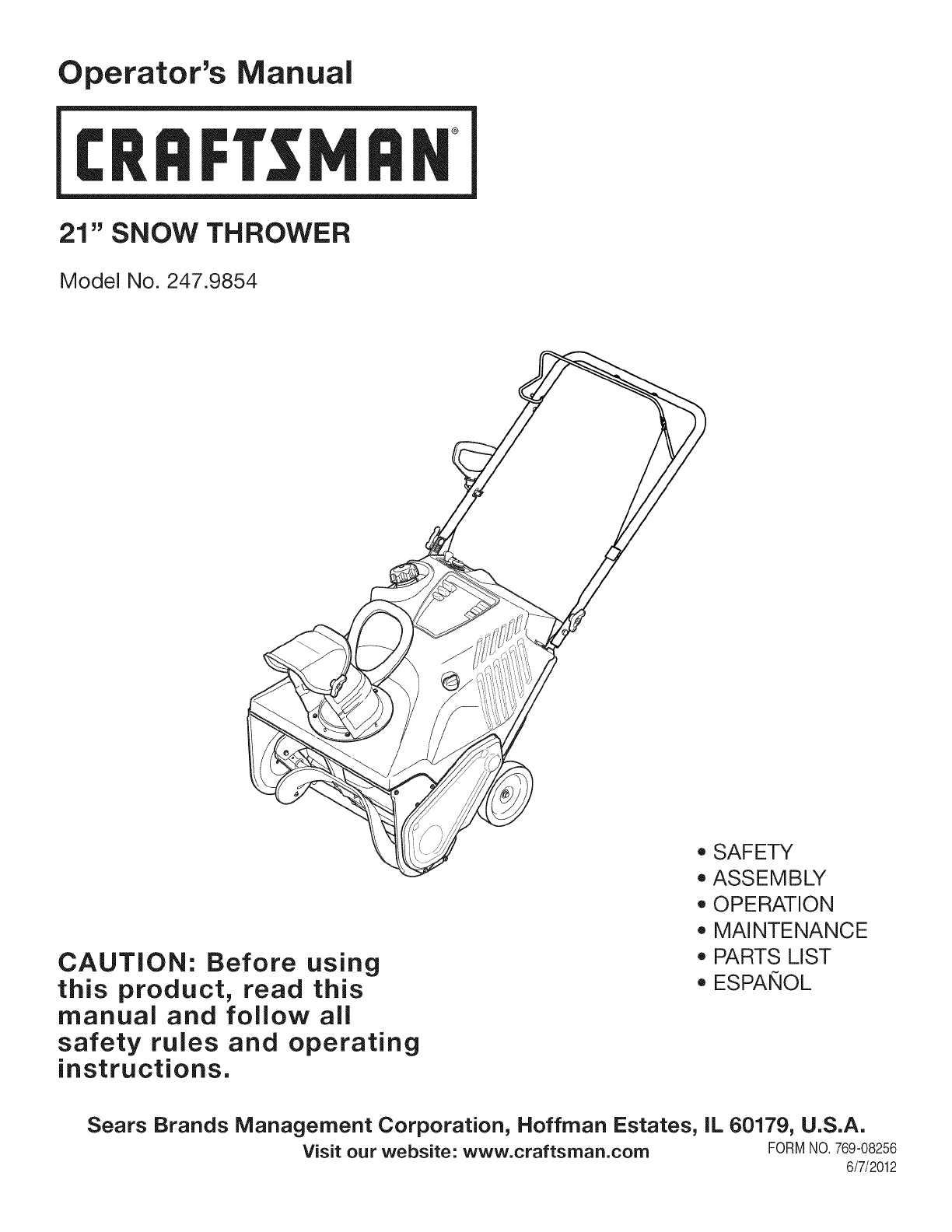
Operator's Manual
CRRFr MRN
21" SNOW THROWER
Model No. 247.9854
CAUTION: Before using
this product, read this
manual and follow all
safety rules and operating
instructions.
o SAFETY
ASSEMBLY
OPERATION
MAINTENANCE
PARTS LIST
o ESPArqOL
Sears Brands Management Corporation, Hoffman Estates, IL 60179, U.S.A.
Visit our website: www.craftsman.com FORM1/0.769-08256
6/7/2012

WarrantyStatement..................................Page2
SafeOperationPractices..........................Pages3-6
Assembly..................................................Pages7-9
Operation..................................................Pages10-12
ServiceandMaintenance.........................Pages13-17
Off-SeasonStorage..................................Page18
TroubleShooting.......................................Page19
PartsList...................................................Pages20-31
Labels.......................................................Page32
RepairProtectionAgreement...................Page36
Espa_ol.....................................................Page37
ServiceNumbers......................................BackCover
CRAFTSMANTWOYEARFULLWARRANTY
FORTWOYEARSfromthedateofpurchase,thisproductiswarrantedagainstanydefectsinmaterialorworkmanship.Defectiveproductwill
receivefreerepairorfreereplacementifrepairisunavailable.
Thiswarrantyisvoidifthisproductiseverusedwhileprovidingcommercialservicesorifrentedtoanotherperson.
Forwarrantycoverage details to obtain repairor replacement,visit the website: www.craftsman.com
This warranty covers ONLYdefects in material andworkmanship. Warranty coverage does NOTinclude:
• Expendableitemsthatcan wearoutfromnormalusewithinthewarrantyperiod,includingbut not limitedto augers,augerpaddles,drift
cutters,skidshoes,shaveplate,shearpins,sparkplug,air cleaner,belts,andoil filter.
• Standardmaintenanceservicing,oilchanges,or tune-ups.
• Tire replacementor repaircausedby puncturesfromoutsideobjects,suchas nails,thorns,stumps,or glass.
Tireor wheelreplacementor repairresultingfromnormalwear,accident,orimproperoperationor maintenance.
Repairsnecessarybecauseof operatorabuse,includingbutnot limitedto damagecausedby over-speedingthe engine,or fromimpacting
objectsthat bendthe frame,augershaft,etc.
• Repairsnecessarybecauseof operatornegligence,includingbut not limitedto,electricalandmechanicaldamagecausedby improper
storage,failureto usethe propergradeandamountof engineoil, or failureto maintainthe equipmentaccordingto the instructionscontained
inthe operator'smanual.
• Engine(fuelsystem)cleaningor repairscausedbyfuel determinedto becontaminatedoroxidized(stale).In general,fuel shouldbeused
within30 daysof itspurchasedate.
Normaldeteriorationandwearof the exteriorfinishes,or productlabelreplacement.
Thiswarrantygivesyou specificlegalrights,andyou mayalso haveotherrightswhichvaryfromstateto state.
Sears Brands Management Corporation, Hoffman Estates, IL 60179
EngineOilType: SAE5W-30
EngineOilCapacity: 20ounces
FuelCapacity: 2 Quarts
SparkPlug: F6RTC
SparkPlugGap: .020"-.030"
Model Number.................................................................
Serial Number .................................................................
Dateof Purchase.............................................................
Recordthe modelnumber,serialnumber
anddateof purchaseabove
©SearsBrands,LLC
2

Thissymbolpointsout importantsafetyinstructionswhich,if not
followed,couldendangerthepersonalsafetyand/orpropertyof
yourselfandothers. Readandfollowall instructionsin thismanual
beforeattemptingto operatethismachine.Failureto complywith
theseinstructionsmayresultin personalinjury.Whenyou seethis
symbol,HEEDITSWARNING!
CALIFORNIA PROPOSITION 65
EngineExhaust,someof itsconstituents,andcertainvehicle
componentscontainoremitchemicalsknownto Stateof California
to causecancerandbirthdefectsorotherreproductiveharm,
Thismachinewasbuiltto beoperatedaccordingto the safeopera-
tion practicesinthis manual.As withanytypeof powerequipment,
carelessnessorerroron the partof the operatorcan resultin serious
injury.Thismachineis capableof amputatingfingers,hands,toes
andfeetandthrowingdebris.Failureto observethe followingsafety
instructionscouldresultin seriousinjuryor death.
Your Responsibility--Restrict the use of thispowermachineto
personswho read,understandandfollowthewarningsand instruc-
tionsin thismanualandon the machine,
SAVE THESE INSTRUCTIONS!
TRAiNiNG
•Read,understand,andfollowall instructionson the machineand
in themanual(s)beforeattemptingto assembleandoperate.
Failureto do socan resultinseriousinjuryto the operatorand/
orbystanders.Keepthismanualin a safeplaceforfutureand
regularreferenceandfor orderingreplacementparts.Toorder
replacementpartscall,1-800-4MY-HOME.
• Befamiliarwithall controlsandtheir properoperation.Knowhow
to stopthe machineanddisengagethemquickly.
• Neverallowchildrenunder14yearsof ageto operatethis
machine.Children14andover shouldreadandunderstandthe
instructionsandsafeoperationpracticesin thismanualandon
the machineandbe trainedandsupervisedby anadult.
Neverallowadultsto operatethis machinewithoutproper
instruction.
• Thrownobjectscan causeseriouspersonalinjury.Planyour
snow-throwingpatternto avoiddischargeof materialtoward
roads,bystandersandthe like.
Keepbystanders,petsandchildrenat least75feetfromthe
machinewhile it is in operation.Stopmachineif anyoneenters
the area.
• Exercisecautionto avoidslippingor falling,especiallywhen
operatingin reverse.
PREPARATION
Thoroughlyinspecttheareawherethe equipmentisto beused.
Removeall doormats,newspapers,sleds,boards,wiresandother
foreignobjects,whichcouldbe trippedoverorthrownby the auger/
impeller.
• Alwayswear safetyglassesor eyeshieldsduringoperationand
while performingan adjustmentor repairto protectyoureyes.
Thrownobjectswhichricochetcancauseseriousinjuryto the
eyes.
Donot operatewithoutwearingadequatewinteroutergarments.
Donot wearjewelry,longscarvesorotherlooseclothing,which
could becomeentangledin movingparts.Wearfootwearwhich
will improvefootingonslipperysurfaces.
Usea groundedthree-wireextensioncordand receptaclefor all
machineswithelectricstartengines.
Disengageall controlleversbeforestartingthe engine.
• Neverattemptto makeanyadjustmentswhileengineis running,
exceptwherespecificallyrecommendedinthe operator'smanual.
Letengineandmachineadjustto outdoortemperaturebefore
startingto clearsnow.
3
Safe Handling of Gasoline
Toavoidpersonalinjuryor propertydamageuseextremecare in
handlinggasoline.Gasolineis extremelyflammableandthe vaporsare
explosive.Seriouspersonalinjurycan occurwhengasolineis spilled
onyourselfor yourclotheswhichcan ignite. Washyour skinand
changeclothesimmediately.
• Useonlyan approvedgasolinecontainer.
• Extinguishallcigarettes,cigars,pipesandother sourcesof
ignition.
• Neverfuel machineindoors.
• Neverremovegas capor addfuel whilethe engineis hot or
running.
• Allowengineto coolat leasttwo minutesbeforerefueling.
• Neveroverfillfuel tank.Filltankto nomorethan1/2inchbelow
bottomof filler neckto providespaceforfuel expansion.
• Replacegasolinecapandtightensecurely.
• Ifgasolineis spilled,wipe it off theengineandequipment.Move
machineto anotherarea.Wait5 minutesbeforestartingthe
engine.
• Neverstorethe machineorfuel containerinsidewherethereis an
openflame,sparkor pilotlight(e.g.furnace,waterheater,space
heater,clothesdryeretc.).
• Allowmachineto cool at least5 minutesbeforestoring.
• Neverfill containersinsidea vehicleor ona truckor trailerbed
witha plasticliner.Alwaysplacecontainersonthe groundaway
fromyour vehiclebeforefilling.
• If possible,removegas-poweredequipmentfromthe truckor
trailerandrefuelit onthe ground.Ifthis is not possible,then refuel
suchequipmenton a trailerwitha portablecontainer,ratherthan
froma gasolinedispensernozzle.
• Keepthe nozzlein contactwiththe rimof the fuel tankor
containeropeningat alltimes untilfuelingis complete.Do not use
a nozzlelock-opendevice.
OPERATION
•Do not puthandsorfeetnear rotatingparts,in the auger/impeller
housingor chuteassembly.Contactwiththe rotatingpartscan
amputatehandsandfeet.
• Theauger/impellercontrolleveris a safetydevice.Neverbypass
itsoperation.Doingso makesthe machineunsafeandmaycause
personalinjury.
• Thecontrolleversmustoperateeasilyin bothdirectionsand
automaticallyreturnto the disengagedpositionwhenreleased.
• Neveroperatewitha missingor damagedchuteassembly.Keep
all safetydevicesin placeandworking.
• Neverrunanengineindoorsor ina poorlyventilatedarea. Engine
exhaustcontainscarbonmonoxide,anodorlessanddeadlygas.
• Do notoperatemachinewhileunderthe influenceof alcoholor
drugs.
• Mufflerandenginebecomehotandcan causea burn.Do not
touch.Keepchildrenaway.
• Exerciseextremecautionwhenoperatingon orcrossinggravel
surfaces.Stayalertfor hiddenhazardsor traffic.
Exercisecautionwhenchangingdirectionandwhileoperatingon
slopes.
Planyoursnow-throwingpatternto avoiddischargetowards
windows,walls,carsetc. Thus,avoidingpossibleproperty
damageor personalinjurycausedby a ricochet.
Preventpossiblepropertydamageorpersonalinjuryfrom
objectricochetby planningyoursnowthrowingpatternto avoid
dischargetowardswindows,walls,cars,etc.
• Donot overloadmachinecapacityby attemptingto clearsnowat
too fastof a rate.
• Neveroperatethis machinewithoutgoodvisibilityorlight.Always
be sureof yourfootingand keepa firmholdon thehandles.Walk,
neverrun.
• Disengagepowerto theauger/impellerwhentransportingor not
in use.
• Neveroperatemachineat hightransportspeedson slippery
surfaces.Lookdownand behindand usecare whenbackingup.
• Ifthe machineshouldstart to vibrateabnormally,stopthe engine,
disconnectthe sparkplugwire andgroundit againstthe engine.
Inspectthoroughlyfor damage.Repairanydamagebefore
startingandoperating.
• Disengageall controlleversandstopenginebeforeyouleave
the operatingposition(behindthe handles).Waituntilthe auger/
impellercomesto a completestopbeforeuncloggingthechute
assembly,makingany adjustments,or inspections.
• Neverput yourhandinthe dischargeor collectoropenings.Do
not unclogchuteassemblywhileengineis running.Shutoff
engineand remainbehindhandlesuntilall movingpartshave
stoppedbeforeunclogging.
• Useonly attachmentsandaccessoriesapprovedby the manufac-
turer (e.g.wheelweights,tire chains,cabsetc.).
• Whenstartingengine,pullcord slowlyuntilresistanceis felt, then
pull rapidly.Rapidretractionof startercord(kickback)will pull
handandarmtowardenginefasterthan youcan let go. Broken
bones,fractures,bruisesor sprainscould result.
• Call 1-800-4MY-HOMEfor the locationof the nearestSearsParts
& RepairServiceCenter.
CLEARING ACLOGGED DISCHARGE CHUTE
Handcontactwiththe rotatingimpellerinsidethe dischargechute
is the mostcommoncauseof injuryassociatedwithsnowthrowers.
Neveruse yourhandto cleanout thedischargechute.
Toclear thechute:
1. SHUTTHEENGINEOFF!
2. Wait 10secondsto be surethe impellerbladeshavestopped
rotating.
3. Alwaysusea clean-outtool,not yourhands.
4
MAINTENANCE & STORAGE
•Nevertamperwithsafetydevices.Checktheirproperoperation
regularly.Referto the maintenanceandadjustmentsectionsof
thismanual.
• Beforecleaning,repairing,or inspectingmachinedisengageall
controlleversandstopthe engine.Waituntilthe auger/impeller
cometo a completestop.Disconnectthe sparkplugwireand
groundagainsttheengineto preventunintendedstarting.
Checkboltsand screwsfor propertightnessat frequentintervals
to keepthe machineinsafeworkingcondition.Also,visually
inspectmachinefor anydamage.
Do notchangetheenginegovernorsettingor over-speedthe
engine.Thegovernorcontrolsthe maximumsafeoperatingspeed
of the engine.
Snowthrowershaveplatesand skidshoesaresubjectto wear
anddamage.Foryoursafetyprotection,frequentlycheckall
componentsand replacewithoriginalequipmentmanufacturer's
(OEM)partsonlyas listedinthe Partspagesof thisOperator's
Manual.Useof partswhichdonot meetthe originalequipment
specificationsmayleadto improperperformanceandcompro-
misesafety!
Checkcontrolleversperiodicallyto verifytheyengageanddisen-
gageproperlyandadjust,if necessary.Referto the adjustment
sectioninthisoperator'smanualfor instructions.
Maintainor replacesafetyandinstructionlabels,as necessary.
Observeproperdisposallawsand regulationsfor gas,oil,etc. to
protectthe environment.
Priorto storing,runmachinea few minutestoclear snowfrom
machineand preventfreezeupof auger/impeller.
Neverstorethe machineorfuel containerinsidewherethereisan
openflame,sparkorpilot lightsuchas a waterheater,furnace,
clothesdryer etc.
Alwaysreferto the operator'smanualfor properinstructionson
off-seasonstorage.
Checkfuelline,tank, cap,andfittingsfrequentlyfor cracksor
leaks.Replaceif necessary.
Do notcrankenginewithsparkplugremoved.
Accordingto the ConsumerProductsSafetyCommission(CPSC)
andthe U.S.EnvironmentalProtectionAgency(EPA),thisproduct
hasan AverageUsefulLifeof seven(7)years,or 60 hoursof
operation.At the endof theAverageUsefulLifehavethe machine
inspectedannuallybyan authorizedservicedealerto ensurethat
allmechanicalandsafetysystemsareworkingproperlyand not
wornexcessively.Failureto do so can resultinaccidents,injuries
ordeath.
DO NOT MODIFY ENGINE
Toavoidseriousinjuryor death,do not modifyengineinany way.
Tamperingwiththe governorsettingcanleadto a runawayengineand
causeit to operateat unsafespeeds.Nevertamperwithfactorysetting
of enginegovernor.
NOTICE REGARDING EMiSSiONS
EngineswhicharecertifiedtocomplywithCaliforniaandfederal
EPAemissionregulationsfor SORE(SmallOff RoadEquipment)are
certifiedto operateon regularunleadedgasoline,and mayinclude
the followingemissioncontrolsystems:EngineModification(EM),
OxidizingCatalyst(OC),SecondaryAirInjection(SAI)and ThreeWay
Catalyst(TWO)if so equipped.
SPARK ARRESTOR
Thismachineisequippedwithaninternalcombustionengineand
shouldnotbe usedonor nearany unimprovedforest-covered,
brush-coveredorgrass-coveredlandunlessthe engine'sexhaust
systemisequippedwitha sparkarrestormeetingapplicablelocalor
statelaws(if any)
Ifa sparkarrestoris used,it shouldbe maintainedin effectiveworking
orderby theoperator.Inthe Stateof Californiathe aboveis required
bylaw (Section4442of the CaliforniaPublicResourcesCode).Other
statesmayhavesimilarlaws. Federallawsapplyonfederallands.
A sparkarrestorfor the muffleris availablethroughyournearestSears
PartsandRepairServiceCenter.
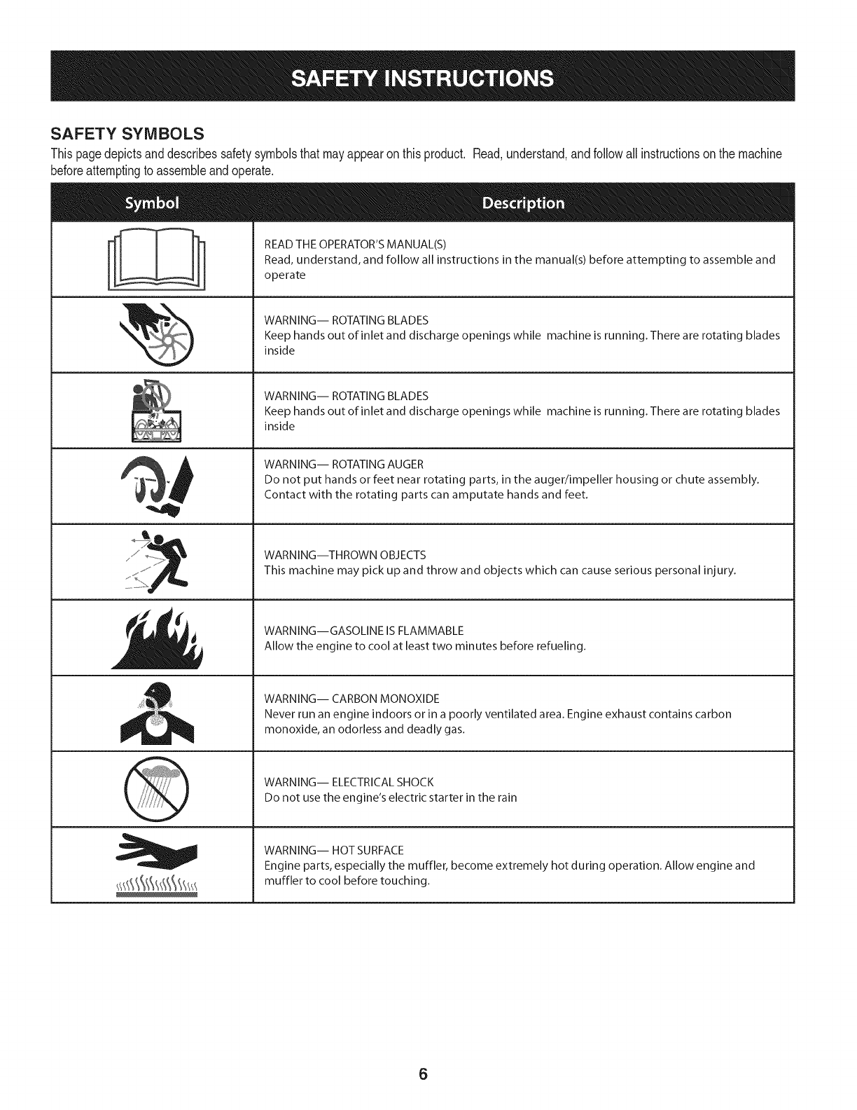
SAFETY SYMBOLS
Thispagedepictsanddescribessafetysymbolsthatmayappearonthisproduct. Read,understand,andfollowall instructionson the machine
beforeattemptingto assembleandoperate.
. +
ii
"JIp
READ THE OPERATOR'S MANUAL(S)
Read, understand, and follow all instructions in the manual(s) before attempting to assemble and
operate
WARNING-- ROTATING BLADES
Keep hands out of inlet and discharge openings while machine is running. There are rotating blades
inside
WARNING-- ROTATING BLADES
Keep hands out of inlet and discharge openings while machine is running. There are rotating blades
inside
WARNING-- ROTATING AUGER
Do not put hands or feet near rotating parts, in the auger/impeller housing or chute assembly.
Contact with the rotating parts can amputate hands and feet.
WARNING--THROWN OBJECTS
This machine may pick up and throw and objects which can cause serious personal injury.
WARNING--GASOLINE IS FLAMMABLE
Allow the engine to cool at least two minutes before refueling.
WARNING-- CARBON MONOXIDE
Never run an engine indoors or in a poorly ventilated area. Engine exhaust contains carbon
monoxide, an odorless and deadly gas+
WARNING-- ELECTRICAL SHOCK
Do not use the engine's electric starter in the rain
WARNING-- HOT SURFACE
Engine parts, especially the muffler, become extremely hot during operation. Allow engine and
muffler to cool before touching.
6
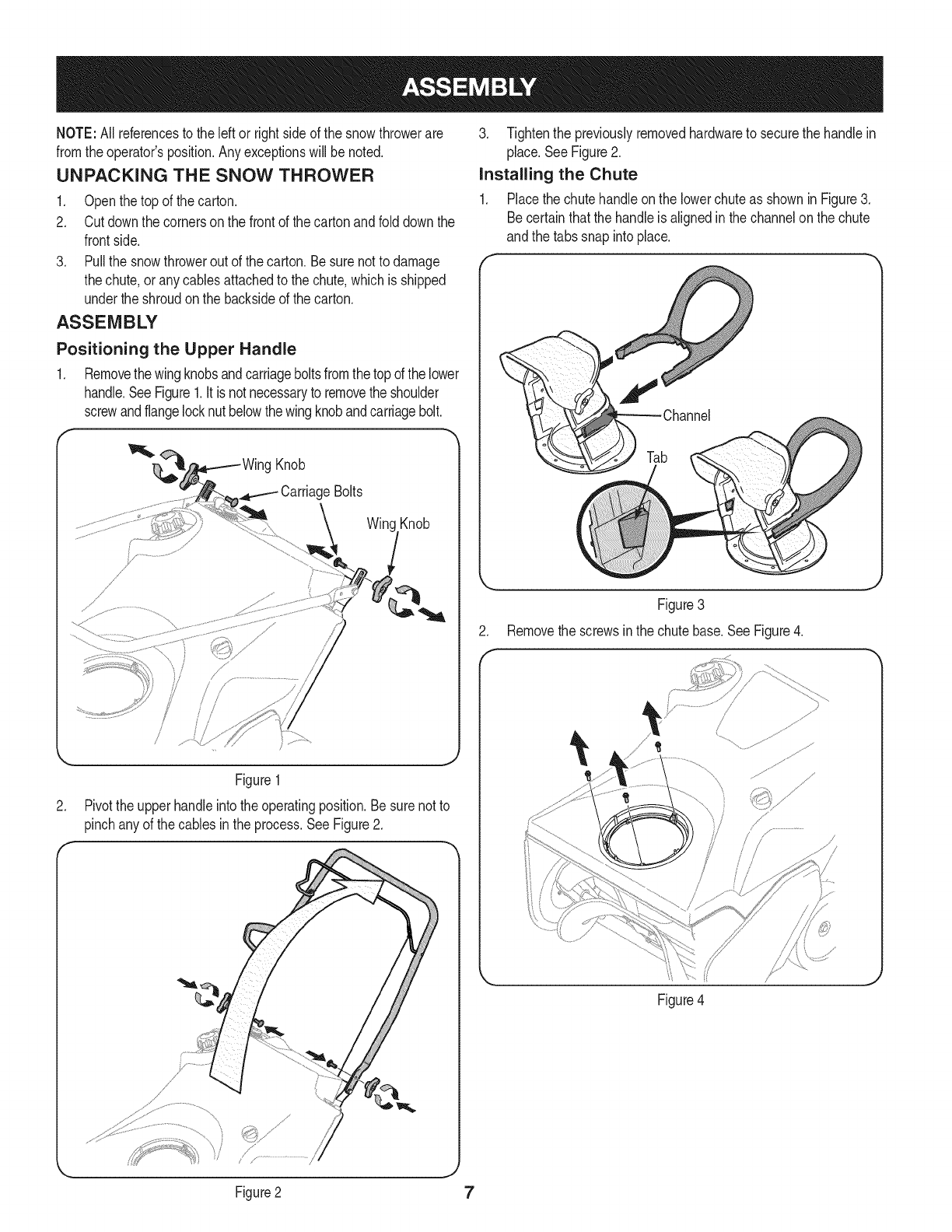
NOTE:All referencesto the leftor rightside of the snowthrowerare
fromthe operator'sposition.Anyexceptionswill be noted.
UNPACKING THE SNOW THROWER
1. Openthe top of the carton.
2. Cutdownthe cornerson the frontof thecartonandfolddown the
frontside.
3. Pullthe snowthroweroutof the carton.Besure notto damage
thechute,or anycablesattachedto the chute,whichis shipped
underthe shroudonthe backsideof the carton.
ASSEMBLY
Positioning the Upper Handle
1. Removethewingknobsandcarriageboltsfromthe topof thelower
handle.SeeFigure1.It isnotnecessaryto removethe shoulder
screwandflangelocknut belowthewingknobandcarriagebolt.
Knob
CarriageBolts
Knob
//
.
i
/
Figure1
Pivotthe upperhandleintothe operatingposition.Besure notto
pinchanyof thecablesinthe process.SeeFigure2.
I' /"............................/
Figure2
J
3. Tightenthe previouslyremovedhardwareto securethe handlein
place.SeeFigure2.
installing the Chute
1. Placethe chutehandleonthe lowerchuteas shownin Figure3.
Becertainthatthe handleis alignedinthe channelonthe chute
andthe tabssnap intoplace.
f
Tab
Figure3
2. Removethe screwsinthe chutebase.SeeFigure4.
Figure4
7
.
f
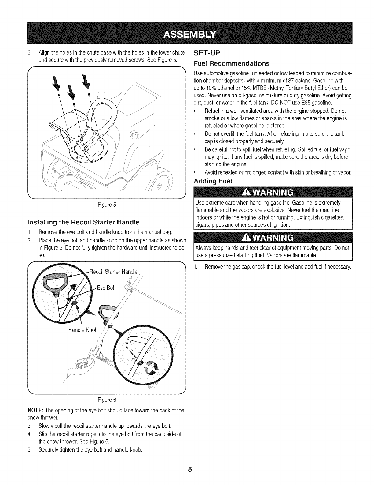
Aligntheholes inthe chutebasewiththe holesinthe lowerchute
andsecurewiththe previouslyremovedscrews.See Figure5.
Figure5
Installing the Recoil Starter Handle
1. Removetheeye boltandhandleknobfromthe manualbag.
2. Placetheeye boltand handleknobonthe upperhandleas shown
inFigure6. Donot fullytightenthe hardwareuntil instructedto do
SO.
HandleKnob
SET-UP
Fuel Recommendations
Useautomotivegasoline(unleadedor lowleadedto minimizecombus-
tion chamberdeposits)with a minimumof 87 octane.Gasolinewith
upto 10%ethanolor 15%MTBE(MethylTertiaryButylEther)can be
used.Neverusean oil/gasolinemixtureordirty gasoline.Avoidgetting
dirt, dust,orwaterinthe fuel tank.DO NOTuse E85gasoline.
• Refuelina well-ventilatedareawiththe enginestopped.Do not
smokeorallowflamesor sparksin the areawherethe engineis
refueledor wheregasolineisstored.
• Donot overfillthe fueltank. Afterrefueling,makesurethe tank
cap is closedproperlyandsecurely.
• Becarefulnotto spillfuel whenrefueling.Spilledfuelor fuel vapor
mayignite.Ifanyfuel isspilled,makesurethe areaisdry before
startingthe engine.
• Avoidrepeatedor prolongedcontactwithskinorbreathingofvapor.
Adding Fuel
Useextremecarewhen handlinggasoline.Gasolineis extremely
flammableandthe vaporsare explosive.Neverfuel the machine
indoorsorwhilethe engineis hotor running.Extinguishcigarettes,
lc gars,p pesandothersourcesof gnt on.
Alwayskeephandsandfeetclearof equipmentmovingparts. Donot
use a pressurizedstartingfluid.Vaporsareflammable.
1. Removethe gascap,checkthefuellevelandaddfuelif necessary.
Figure6
NOTE:The openingof theeye boltshouldfacetowardthe backof the
snowthrower.
3. Slowlypullthe recoilstarterhandleuptowardsthe eye bolt.
4. Slipthe recoilstarterropeintothe eyebolt fromthe backsideof
the snowthrower.SeeFigure6.
5. Securelytightenthe eye boltandhandleknob.
8
Checking and Adding Oil
Theengineis shippedwithoutoil intheengine.Youmustfill the
enginewithoil beforeoperating.Runningthe enginewithinsufficient
_o can causeserous engnedamageandvo d the productwarranty.
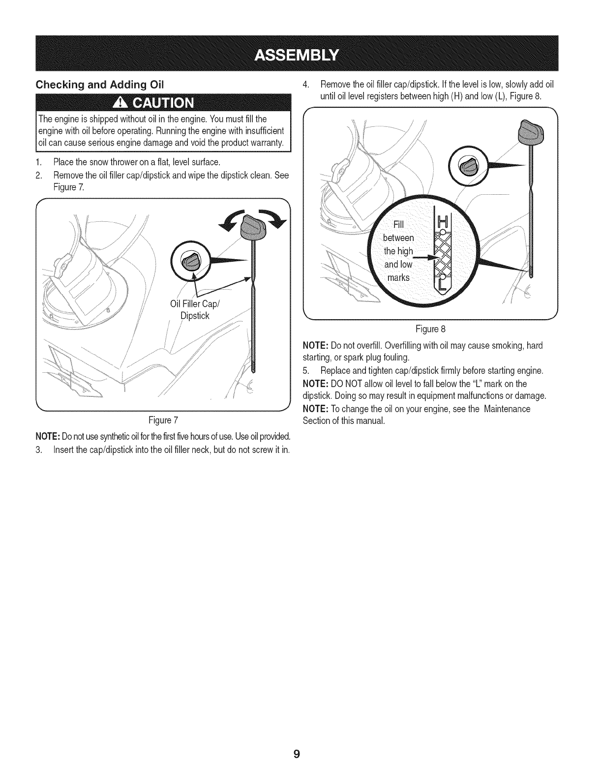
1. Placethe snowthroweron a flat,level surface.
2. Removethe oil fillercap/dipstickandwipethe dipstickclean.See
Figure7.
/
/
Oil FillerCap/
Dipstick
/
//
I
Figure7
NOTE:Donotusesyntheticoilforthefirstfivehoursofuse.Useoilprovided.
3. Insertthe cap/dipstickintothe oilfiller neck,butdo not screwitin.
4. Removethe oilfiller cap/dipstick.If thelevelis low,slowlyaddoil
until oil levelregistersbetweenhigh(H) andlow (L), Figure8.
I/7 /
Figure8
NOTE: Do notoverfill.Overfillingwithoilmaycausesmoking,hard
starting,or sparkplugfouling.
5. Replaceandtightencap/dipstickfirmlybeforestartingengine.
NOTE: DO NOTallowoil levelto fall belowthe "L"markonthe
dipstick.Doingso mayresultinequipmentmalfunctionsor damage.
NOTE: Tochangethe oil onyourengine,seethe Maintenance
Sectionof this manual.
9
Recoil
AugerControl Electric
Button
Outlet
Gas Ca
Control
ChuteAssembl'
ShavePlate
Au(
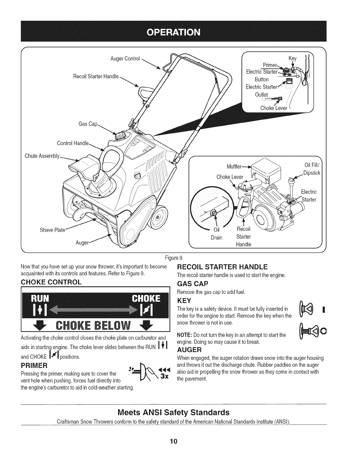
Nowthat youhavesetup yoursnowthrower,it's importantto become
acquaintedwith itscontrolsandfeatures.Referto Figure9.
CHOKE CONTROL
CH8 BELSW
Handle
Figure9
RECOIL STARTER HANDLE
The recoilstarterhandleis usedto startthe engine.
GAS CAP
Removethe gascap to addfuel.
KEY
The keyis a safetydevice.It mustbefullyinsertedin
orderfor theengineto start.Removethe keywhenthe
snowthroweris not inuse.
Activatingthe chokecontrolclosesthe chokeplateoncarburetorand
aidsinstartin_.,lengineThechokeleverslidesbetweentheRUNi_I
andCHOKEI"' I positions.
PRIMER __ 444
Pressingthe primer,makingsureto coverthe
ventholewhen pushing,forcesfueldirectlyinto _,,)kk-_ 3X
theengine'scarburetorto aid incold-weatherstarting.
NOTE: Do notturn the keyinanattemptto startthe
engine.Doingso maycauseit to break.
AUGER
Oil
Whenengaged,the augerrotationdrawssnowintothe augerhousing
andthrowsit out the dischargechute.Rubberpaddleson the auger
also aidin propellingthe snowthroweras theycomein contactwith
the pavement.
Meets ANSI Safety Standards
CraftsmanSnowThrowersconformto the safetystandardof the AmericanNationalStandardsInstitute(ANSi).
10
AUGER CONTROL
Locatedon the upperhandle,the augercontrolhandleis usedto
engageanddisengagedriveto the auger.Squeezethe controlhandle
againstthe upperhandleto engagethe auger;releaseit to disengage.
CHUTE ASSEMBLY
Rotatethe dischargechuteto the leftor rightusingthe controlhandle.
Thepitchof the dischargechutecontrolsthe angleat whichthe snow
is thrown.Loosenthewing knobonthe side of the dischargechute
beforepivotingthe dischargechuteupwardordownward.Retighten
the knoboncethe desiredpositionhasbeenachieved.
SHAVE PLATE
Theshaveplate maintainscontactwiththe pavementas the snow
throweris propelled,allowingsnowclosetothe 3avement'ssurfaceto
bedischarged.
ELECTRIC STARTER OUTLET
Requiresthe useofa three-prongoutdoorextensioncord (notincluded)
anda 120Vpowersource/walloutlet.
ELECTRIC STARTER BUTTON
Pressingthe electricstarterbuttonengagesthe engine'selectric
starterwhenpluggedintoa 120Vpowersource.
OIL FILL/DIPSTICK
Engineoil levelcan becheckedand oiladdedthroughtheoil fill.
OIL DRAIN
Engineoilcan bedrainedthroughthe oil drain.
MUFFLER
Engineexhaustexitsthe enginevia the muffler.
BEFORE STARTING THE ENGINE
machineandin thismanualbefore
STARTING THE ENGINE
3ressurizedstartinc areflammable.
Toavoidcarbonmonoxidepoisoning,makesurethe engineis
outdoorsina well-ventilatedarea.
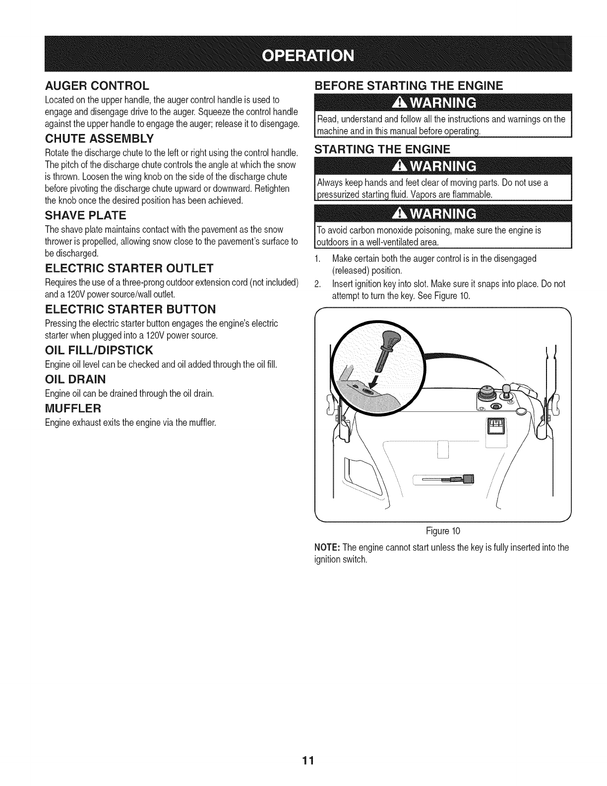
1. Makecertainboththe augercontrolis in thedisengaged
(released)position.
2. Insertignitionkeyinto slot.Makesureit snapsinto place.Do not
attemptto turn the key.See Figure10.
I J /
\ J
\/
Figure10
NOTE:Theenginecannotstartunlessthe keyis fullyinsertedintothe
ignitionswitch.
11

Electric Starter
Determinethatyourhome'swiringis a three-wiregroundedsystem.
Aska licensedelectricianif youarenot certain.
Ifyou havea groundedthree-prongreceptacle,proceedas follows:
1. Plugtheextensioncordintotheoutletlocatedontheengine's
surface.Plugtheotherendofextensioncordintoathree-prong
120-volt,grounded,ACoutletinawell-ventilatedareaSeeFigure11.
Figure11
2. Pushthe chokeleverto the CHOKEI"#1 position.
a ii
3. Ifthe engineis warm,placethe chokeinthe RUN_ I position
insteadofCHOKEIII.
4. Pushthe primerthree (3)times,makingsureto coverthe vent
holewhenpushing.
5. Ifthe engineis warm,pushtheprimerbuttononly once.
6. Pushstarterbuttonto start engine.
7. Oncethe enginestarts,releasestarterbutton.
8. Allowthe engineto warmup severalminutes,adjustingchoke
|+I
towardRUN| _position.Waituntilenginerunssmoothlybefore
eachchokeadjustment.
9. Whendisconnectingtheextensioncord,alwaysunplugthe end
at the three-prongwalloutletbeforeunpluggingthe oppositeend
fromthe snowthrower.
Recoil Starter
1. Pushthe chokeleverto the CHOKEIJl position.
A
2. Ifthe engineis warm,placethe chokein the RUN_ I position
|+l
insteadofCHOKEI"rl.
3. Pushthe primerthree(3) times,makingsureto coverthe vent
holewhen pushing.
4. Ifthe engineis warm,pushthe primerbuttononlyonce.
5. Graspthe recoilstarterhandleandslowlypullthe ropeout.At
the pointwhereit becomesslightlyharderto pullthe rope,slowly
allowthe ropeto recoil.
6. Pullthe starterhandlewitha firm,rapidstroke.Do not release
the handleandallowit to snapback. Keepa firmholdon the
starterhandleandallowit to slowlyrecoil.
7. Allowthe engineto warmupseveralminutes,adjustingchoke
|+I
towardRUN| _position.Waituntilenginerunssmoothlybefore
eachchokeadjustment.
STOPPING THE ENGINE
1. Runtheenginefora fewminutesbeforestoppingto helpdry off
any moistureonthe engine.
2. To stopthe engineremovethe keyand storeit ina safeplace.
3. Wipeall the snowandmoistureawayfromthe enginecontrols
area.
Muffler,engineandsurroundingareasbecomehotandcan causea
burn. Becarefulanddonot touchwhenthe_arehot.
ENGAGING THE AUGER
Engagethe augerby squeezingtheaugercontrolagainstthe upper
handle.Releasethe controlto stopthe auger.
ENGAGING THE DRIVE
Liftupslightlyonthe handleto allowthe rubberpaddiesonthe auger
to contactthe pavementand propelthe snowthrowerforward.Pushing
downwardonthe handlewill raisethe augeroff the groundandstop
the forwardmotion.
NOTE: Excessiveupwardpressureonthe handlewill resultin
prematurewearto the rubberaugerpaddies,whichwillnot becovered
by the warranty.
CLEARING A CLOGGED DISCHARGE CHUTE
Handcontactwiththe rotatingimpellerinsidethe dischargechute
is the mostcommoncauseof injuryassociatedwithsnowthrowers.
Neveruse yourhandto cleanout thedischargechute.
Toclear thechute:
1. SHUTTHEENGINEOFF!
2. Wait 10secondsto be surethe impellerbladeshavestopped
rotating.
3. Alwaysusea clean-outtool or stick,not yourhands.
12
MAINTENANCE SCHEDULE
Beforeperforminganytypeof maintenance/service,disengageall
controlsand stopthe engine.Waituntilall movingpartshavecome
to a completestop.Disconnectsparkplugwireandgroundit against
the engineto preventunintendedstarting.Alwayswearsafetyglasses
duringoperationor whileperforminganyadjustmentsor repairs.
Followthe maintenanceschedulegiven below.Thischartdescribes
serviceguidelinesonly.Usethe ServiceLogcolumnto keeptrackof
completedmaintenancetasks.To locate the nearest Sears Service
Centeror to scheduleservice,simplycontactSearsat
1-800-4-MY-HOME®.
Eachuse .
2.
= =
1. Check
2. Clean
Engineoillevel.
Snowthrowerandexhaust
area.
Engineoil.
Engineoil.
Exhaustarea.
Sparkplug.
Engineoil
Sparkplug
Pivotpoints
Controlhandle
Extensionspring
1st5 hours 1. 1. Change.
Every5hours 1. 1. Check.
2. 2. Clean.
25 hours 1. 2. Check.
Everyseason/50hours 1. 1. Change
Everyseason/100hours 1. 1. Clean,replace,re-gap
Everyseason/Before 1. 1. Lubricate
storage 2. 2. Lubricate
3. 3. Lubricate
ENGINE MAINTENANCE
usedoil.
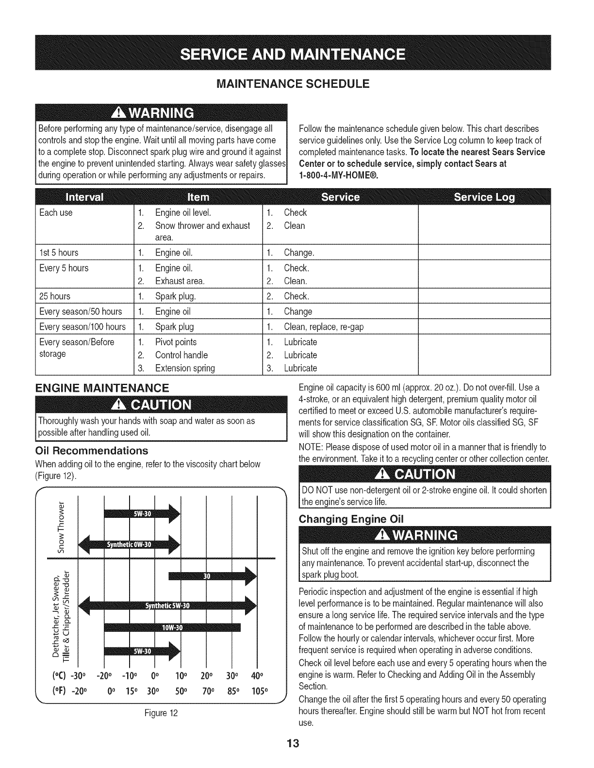
Oil Recommendations
Whenaddingoilto the engine,referto theviscositychartbelow
(Figure12).
200
700
Figure12
m
300
850
400
1050
Engineoil capacityis 600ml (approx.20oz.). Do notover-fill.Usea
4-stroke,oran equivalenthighdetergent,premiumqualitymotoroil
certifiedto meetor exceedU.S.automobilemanufacturer'srequire-
mentsfor serviceclassificationSG, SR Motoroils classifiedSG, SF
will showthis designationon the container.
NOTE:Pleasedisposeof used motoroil ina mannerthatisfriendlyto
the environment.Takeit to a recyclingcenteror othercollectioncenter.
DONOTusenon-detergentoil or2-strokeengineoil. It couldshorten
the engine'sservicelife.
Changing Engine Oil
Shutoffthe engineand removethe ignitionkeybeforeperforming
any maintenance.Topreventaccidentalstart-up,disconnectthe
sparkplugboot.
Periodicinspectionandadjustmentof the engineisessentialif high
level performanceis to bemaintained.Regularmaintenancewill also
ensurea longservicelife.The requiredserviceintervalsandthe type
of maintenanceto be performedaredescribedinthe tableabove.
Followthe hourlyorcalendarintervals,whicheveroccurfirst.More
frequentserviceis requiredwhenoperatinginadverseconditions.
Checkoil levelbeforeeachuse andevery5 operatinghourswhenthe
engineiswarm.Referto CheckingandAddingOilintheAssembly
Section.
Changethe oil afterthe first5 operatinghoursandevery50 operating
hoursthereafter.EngineshouldstillbewarmbutNOThotfrom recent
use.
13

.
2.
Drainfuelfromthe tankby runningtheengineuntilthe fueltankis
empty.Besurethe fuel fill capis secure.
Removethethreescrewsthatsecurethelowerpanel.Removethe
lowerpanelby liftinguponthe panelto freethetabsatthe bottom
of thepanelfromthetab slotsandthenpullback.SeeFigure13.
Figure13
NOTE:The bottomof thepanelhastabsthathelpholdit in place.
NOTE:Anoil drainextensionkitis availableseparately.Contacta
SearsPartsand RepairCenterfor kit#753-06684.
3. Placea suitableoil collectioncontainerunderthe oildrainplug.
4. Removetheoil drainplug,Figure14.
F 1
k,_ Oil DrainPlug" .,,
Figure14
7. Refillwiththe recommendedoiland checktheoil level;referto
CheckingandAddingOil inthe AssemblySection.
8. Reinstallthe oil fillercap/dipsticksecurely.
9. Re-installthe lowerpanelbyplacingthetabs inthe tab slots,
liftingthe panelintoplaceandsecurewiththe threescrews
removedinstep2.
Spark Plug
DONOTcheck fora sparkwiththe sparkplugremoved.DONOT
cranktheenginewiththe sparkplugremoved.
Ifthe enginehas beenrunning,the mufflerwill beveryhot. Becareful
not to touchthemuffler.
The sparkplugshouldbecheckedevery25hoursandchangedonce
a seasonor every100hours.Toensureproperengineoperation,the
sparkplugmustalso beproperlygappedandfreeof deposits.
1. Removethe lowerpanelas instructedintheChangingEngineOil
section.Referto Figure13.
2. Removethe sparkplugbootand usea sparkplugwrenchto
removethe plug,Figure15.
SparkPlug
,J
SparkPlugBoot
Figure15
3. Visuallyinspectthe sparkplug. Discardthe sparkplugif thereis
any apparentwear,or if the insulatoris crackedorchipped.Clean
the sparkplugwitha wire brushif it is to be reused.
NOTE:A resistorsparkplugmust beusedfor replacement.Contact
a Sears PartsandRepairCenterfor a replacementsparkplug(Part#
951-10292).
4. Re-installthe lowerpanel.
5. Tip thesnowthrowerbackto drainoil intothe container.Usedoil
mustbedisposedof at a propercollectioncenter.
6. Reinstallthe drainplugandtightenit securely.
14

.Measurethe pluggapwitha feelergauge.Correctas necessary
by bendingthe side electrode,Figure16.The gapshouldbeset
to .02-.03inches(0.60-0.80turn).
Electrode
.02-.03in.
(0.60-0.80ram)
_J
Figure16
6. Checkthat thesparkplugwasheris ingoodconditionandthread
the sparkplugin by handto preventcross-threading.
7. Afterthe sparkplugis seated,tightenwitha sparkplugwrenchto
compressthe washer.
NOTE:Wheninstallinga newsparkplug,tighten1/2-turnafterthe
sparkplugseatsto compressthe washer.Whenreinstallinga used
sparkplug,tighten1/8-to 1/4-turnafterthe sparkplugseatsto
compressthe washer.
Thesparkplugmustbetightenedsecurely.A loosesparkplugcan
becomeveryhotandcan damagethe engine.
Cleaning the Engine
Ifthe enginehasbeenrunning,allowit to cool for at leasthalfan hour
beforecleaning.Periodicallyremovedirt build-upfromengine.Before
servicingthe engine,removethecarburetorcoverand/orblower
housing.Discardthe dirtand debrisfromthe followingareas:
Do not spraythe enginewithwaterto cleanit becausethewater
couldcontaminatethe fuel.Usinga gardenhoseor pressurewashing
Iequipmentcanalso forcewaterintothe muffleropening.Waterthat
[passesthroughthe muffer can enterthecy nderandcausedamage.]
* CoolingFins
* AirIntakeScreenor RecoilStarter/FlywheelGuardAreas
* SparkPlugConnection
* Levers
* LinkageArea
* Guards
* Carburetor
* EngineHead
Removingdebriswillinsureadequatecooling,correctenginespeed
and reducethe riskof fire.
Accumulationof debrisaroundthe mufflercouldcausea fire.Inspect
andclean beforeeveryuse.
LUBRICATION
Lubricatethe pivotpointson thecontrolhandleandthe extension
springat the endof the controlcablewitha light oilonceeveryseason
and beforethe snowthroweris put intostorageat the endof the
season.
ADJUSTMENTS
Shave Plate
Tocheckthe adjustmentof the shaveplate,placethe machineon a
level surface.Thewheels,shaveplateandaugerpaddlesshouldall
contactthe levelsurface.Notethat if the shaveplateis adjustedtoo
high, snowmayblowunderthe augerhousing.If the shaveplatewears
out excessively,or the snowthrowerdoesnot self-propel,the shave
plate maybetoo low andneedsto beadjusted.
NOTE: Onnewsnowthrowersor machineswitha newshaveplate
installed,the augerpaddlesmaybeslightlyoff the ground.
Toadjustthe shaveplateproceedas follows:
1. Runthe snowthroweruntilthe fueltankis empty.
2. Pullthe startercorduntil resistanceis felt.Then tip the snow
throwerbackuntilit restsonthe handles.To ensurethatthe snow
throwerdoesnot tip forward,it maybe necessaryto securethe
handleto the groundwitha blockorother object.
3. Loosenthefourflangelocknutsandcarriageboltswhichsecure
the shaveplatetothe housing.SeeFigure17.Movethe shaveplate
to the desiredpositionandretightenthe nutsandboltssecurely.
SideView
y
/
i\
Ji
ReversibleShavePlate
J
Figure17
4. Tip the snowthrowerbackto theoperatingpositionandpullthe
starterhandlea fewtimesto see if it is difficultto pull.
15
5, If the starteris difficultto pull, removethe sparkplugandpullthe
handleseveraltimesto ensurethatany oiltrappedinthe engine
headis removed,
Oilmaycomeout of the sparkplugholewhen it is removedandthe
starterhandleis pulled.
6. Inspectthe sparkplug. Ifit is wet,cleanoff anyoil before
re-installing.
Control Cable
As a resultof both thecontrolcableandthe augerdrivebelt stretching
dueto wear,periodicadjustmentsmaybenecessary.Ifthe auger
seemsto hesitatewhenrotating,proceedas follows:
Theupperholeinthe controlhandleprovidesfor anadjustmentin
cabletension.Toadjust,disconnectthe endof controlcablefromthe
bottomholein the controlhandleand reinsertit inthe upperhole.
Insertthe cablefromtheoutsideas shownin Figure18.
\\
Control
/Cable
/
//
Figure18
Testthe snowthrowerto seeif there is a noticeabledifference.If
aftertheadjustmentto the controlcablethe augerstill hesitateswhen
rotating,see BeltReplacementfor instructionson replacingthebelt.
Chute Assembly
Referto the Assemblysectionfor instructionsonadjustingthechute
assembly.
AUGER DRIVE BELT REPLACEMENT
1. Runthe snowthroweruntilthe fueltankisempty.
2. Pullthe recoilstarterhandleuntil resistanceisfelt.Thentip the
snowthrowerbackuntil itrestson thehandles.
3. Slidea boardup throughthe augerandthroughthe chuteto
securethe augerinplace.
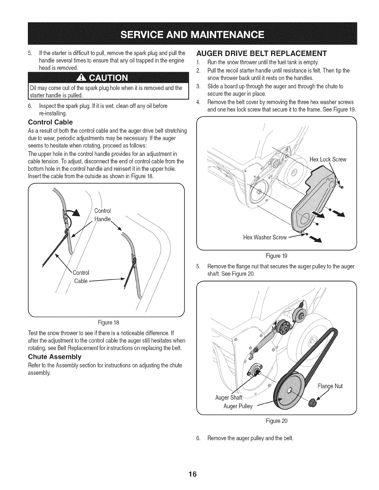
4. Removethe beltcoverby removingthe threehexwasherscrews
andone hexlockscrewthatsecureitto the frame.SeeFigure19.
HexLockScrew
,
HexWasherScrew.............:._o
Figure19
Removethe flangenutthat securestheaugerpulleyto the auger
shaft.SeeFigure20.
/
/
AugerShaft
AugerPulley
FlangeNut
/
J
Figure20
6. Removethe augerpulleyandthe belt.
16
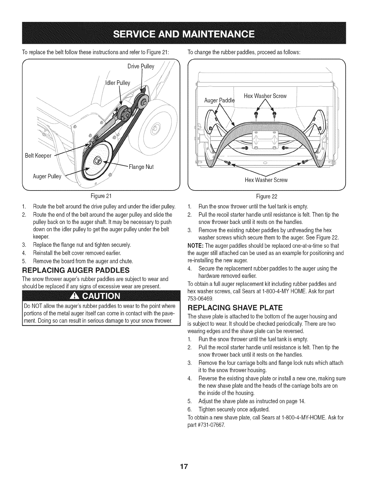
To replacethe belt followtheseinstructionsandreferto Figure21: Tochangethe rubberpaddles,proceedasfollows:
Drive
Paddl_ HexWasherScrew
HexWasherScrew
Figure21
1. Routethe beltaroundthe drivepulleyandunderthe idlerpulley.
2. Routethe endof the beltaroundthe augerpulleyand slidethe
pulleybackon to the augershaft.It maybe necessaryto push
downonthe idlerpulleyto get theaugerpulleyunderthe belt
keeper.
3. Replacethe flangenut andtightensecurely.
4. Reinstallthe beltcoverremovedearlier.
5. Removethe boardfromthe augerandchute.
REPLACING AUGER PADDLES
The snowthrowerauger'srubberpaddlesaresubjectto wearand
shouldbereplacedif any signsof excessiveweararepresent.
Do NOTallowthe auger'srubberpaddlesto wearto the pointwhere
Iportionsof the metalaugeritselfcancomein contactwiththe pave-
[ment.Doingsocan resultin seriousdamageto yoursnowthrower.
Figure22
1. Runthe snowthroweruntilthe fueltankis empty.
2. Pullthe recoilstarterhandleuntil resistanceis felt.Then tip the
snowthrowerbackuntil it restson the handles.
3. Removethe existingrubberpaddlesby unthreadingthe hex
washerscrewswhichsecurethemto the auger.See Figure22.
NOTE: Theaugerpaddlesshouldbereplacedone-at-a-timesothat
the augerstillattachedcan beusedas anexamplefor positioningand
re-installingthe newauger.
4. Securethe replacementrubberpaddlesto the augerusingthe
hardwareremovedearlier.
Toobtaina full augerreplacementkit includingrubberpaddlesand
hex washerscrews,callSearsat 1-800-4-MYHOME.Askfor part
753-06469.
REPLACING SHAVE PLATE
The shaveplateis attachedto the bottomof the augerhousingand
is subjectto wear.Itshouldbecheckedperiodically.Therearetwo
wearingedgesandthe shaveplatecan be reversed.
1. Runthe snowthroweruntilthe fueltankis empty.
2. Pullthe recoilstarterhandleuntil resistanceis felt.Then tip the
snowthrowerbackuntil it restson the handles.
3. Removethe fourcarriageboltsandflangelocknutswhichattach
it to the snowthrowerhousing.
4. Reversethe existingshaveplateor installa newone, makingsure
the new shaveplateandthe headsof the carriageboltsareon
the insideof the housing.
5. Adjustthe shaveplateas instructedon page14.
6. Tightensecurelyonceadjusted.
Toobtaina new shaveplate,call Searsat 1-800-4-MY-HOME.Askfor
part #731-07667.
17
Ifthe snowthrowerwillnot be usedfor30 daysor longer,or if it is the endof the snowseasonwhenthe lastpossibilityof snowis gone,the
equipmentneedsto bestoredproperly.Followstorageinstructionsbelowto ensuretop performancefromthe snowthrowerfor manymoreyears.
PREPARING THE ENGINE
Enginesstoredover30daysneedto bedrainedof fuel to prevent
deteriorationandgumfromforminginthe fuel systemor onessential
carburetorparts.If thegasolineinyourenginedeterioratesduring
storage,youmayneedto havethe carburetor,andotherfuel system
components,servicedor replaced.
1. Removeall fuel fromthe tankby runningtheengineuntilit stops.
2. Changethe engineoil.
3. Removethe sparkplugandpourapproximately1oz.(30 ml)of
cleanengineoil intothe cylinder.Pullthe recoilstarterseveral
timesto distributethe oil,and reinstallthe sparkplug.
4. Cleantheexteriorof the engineby discardingdirt anddebrisfrom
thefollowingareas:
Do not spraythe enginewithwaterto cleanit becausethewater
couldcontaminatethe fuel.Usinga gardenhoseor pressurewashing
Iequipmentcanalso forcewaterintothe muffleropening.Waterthat
[passesthroughthe muffer can enterthecy nderandcausedamage,j
• CoolingFins
• AirIntakeScreenor RecoilStarter/FlywheelGuardAreas
• SparkPlugConnection
• Levers
LinkageArea
Guards
Carburetor
EngineHead
5. Storeina clean,dry andwellventilatedareaawayfromany
appliancethatoperateswitha flameor pilot light,suchas a
furnace,waterheateror clothesdryer.Avoidany areawitha spark
producingelectricmotor,or wherepowertoolsareoperated.
Neverstoresnowthrowerwithfuel intank indoorsor inpoorlyventi-
latedareas,wherefuel fumesmayreachan openflame,sparkor pilol
lightas ona furnace,waterheater,clothesdryer orgas appliance.
6. If possible,avoidstorageareaswithhighhumidity.
7. Keepthe enginelevelin storage.Tiltingthe engine can cause
fuelor oil leakage.
PREPARING SNOW THROWER
Ifthe snowthrowerwill not beusedfor 30daysor longer,followthe
instructionsbelow.
1. Storethe equipmentin aclean,dry area.
2. Wipedownthe snowthrowerwitha ragand removeanydirt or
debris.
3. Ifstoringthe snowthrowerin anunventilatedarea,rustproofthe
metalpartsof the machinewitha lightoil or siliconecoating.
18
Beforeperforminganytypeof maintenance/service,disengageallcontrolsandstopthe engine.Waituntilall
movingpartshavecometo acompletestop.Disconnectsparkplugwireandgrounditagainstthe engineto
Ipreventunintendedstarting.Alwayswearsafetyglassesduringoperationorwhileperforminganyadjustmentsor
[repairs.
This section addresses minor service issues. To locate the nearest Sears Service Centeror to schedule service, simply contact Sears
at 1-800-4-MY-HOME®.
Enginefailsto start 1. Fueltankempty,or stalefuel.
2. Blockedfuel line.
3. Keynot insertedallthe way.
4. Sparkplugwiredisconnected.
5. Faultysparkplug.
6. Enginenot primed.
1. Filltankwithcleanfreshgasoline.
2. Contacta SearsServiceCenter.
3. Insertkeyallthe way.
4. Connectwireto sparkplug.
5. Cleansparkplug,readjustgap,or replace.
6. Pushthe engineprimerbuttonthreetimes.
Enginerunningerratically/
inconsistentRPM(huntingor
surging)
7. Enginefloodedfromexcessivepriming.
1. Enginerunningonchoke.
2. Fuelline blocked,or stalefuel.
3. Wateror dirt infuel system.
4. Carburetoroutof adjustment.
5. Over-governedengine
1. Carburetoroutof adjustment.
1. Sparkplugwireloose.
2. Ventin gascap plugged.
1. Loosepartsordamagedauger.
7.
1.
2.
3.
4.
5.
1.
1.
2.
1.
Waitat leastten minutesbeforestarting.
Movechokecontrolto RUNposition.
Contacta SearsServiceCenter.
Runengineuntilit stops.Refillwithfreshfuel.
Contacta SearsServiceCenter.
Contacta SearsServiceCenter.
Engineoverheats Contacta SearsServiceCenter.
Lossof power Firmlyconnectsparkplugwire.
Clearvent.
Excessivevibration Stopengineimmediatelyandremovekey.Checkfor
possibledamage.Tightenall boltsand nuts.Repair
as needed.Ifproblempersists,take snowthrowerto
a SearsServiceCenter.
Snowthrowerfailsto self- 1. Augercontrolcableoutof adjustment. 1. Adjustaugercontrolcableas shownin Serviceand
propel Maintenancesection.
2. Augerdrive beltlooseor damaged. 2. Replaceaugerdrivebelt.
Augercontinuesto rotate 1. Augercontrolcableoutof adjustment. 1. Adjustaugercontrolcableas shownin Serviceand
Maintenancesection.
Unitfailsto dischargesnow 1. Chuteassemblyclogged. 1.
2. Foreignobjectlodgedin auger.
3. Augercontrolcableoutof adjustment.
4. Augerbeltlooseor damaged.
Stopengineanddisconnectsparkplugwire.Clean
chuteand insideof augerhousingwithclean-outtool
or stick.
2. Stopengineimmediatelyanddisconnectthe spark
plugwire.Removeobjectfromauger.
3. Adjustaugercontrolcable.
4. Replaceaugerbelt.
Find this and all your other product manual.sonl.ine.
Get answers from our team of home experts,
Get a personal.ized maintenance plan for your home.
Find information and tool,s to help with home projects.
_ managemylife
b_ght te ye_ by $ea_:s
i
19
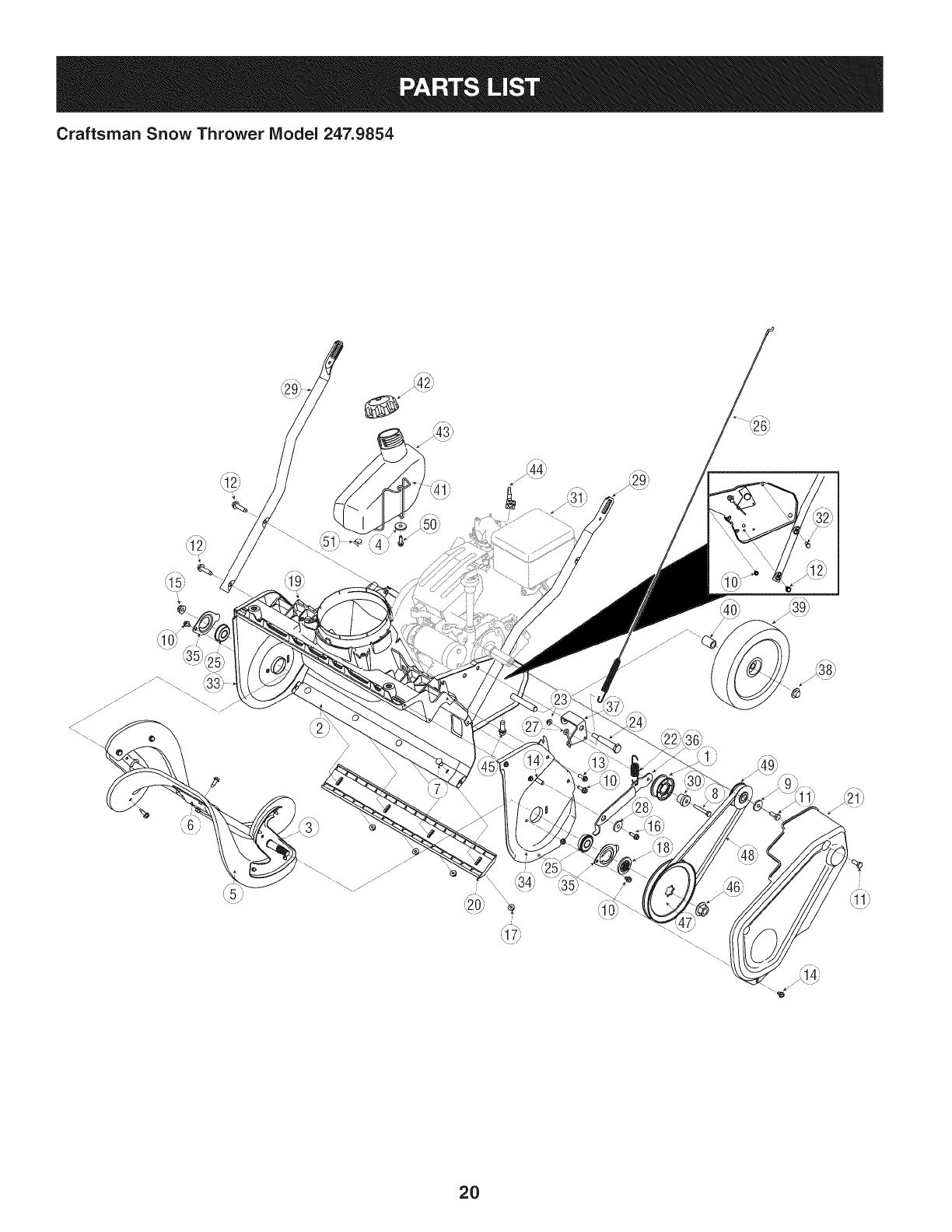
Craftsman Snow Thrower IViodel 247.9854
q_
2O
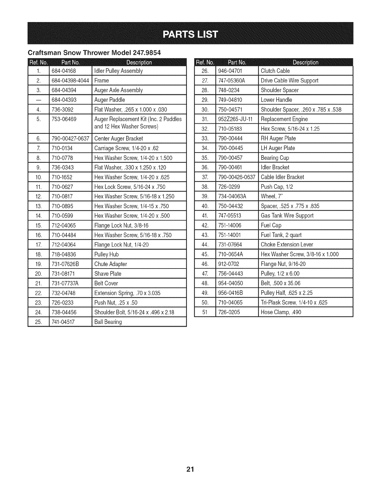
Craftsman Snow Thrower IViodel 247.9854
|= 0 =
684-04168 IdlerPulleyAssembly
2. 684-04398-4044 Frame
3. 684-04394 AugerAxleAssembly
-- 684-04393
4. 736-3092
5. 753-06469
6. 790-00427-0637
710-0134
8. 710-0778
9. 736-0343
AugerPaddle
FiatWasher,.265x 1.000x .030
AugerReplacementKit (Inc.2 Paddles
and12HexWasherScrews)
CenterAugerBracket
CarriageScrew,1/4-20x .62
HexWasherScrew,1/4-20x 1.500
FiatWasher,.330x 1.250x .120
10. 710-1652
11. 710-0627
12. 710-0817
13. 710-0895
14. 710-0599
15. 712-04065
16. 710-04484
1_ 712-04064
HexWasherScrew,1/4-20x .625
HexLockScrew,5/16-24x .750
HexWasherScrew,5/16-18x 1.250
HexWasherScrew,1/4-15x .750
HexWasherScrew,1/4-20x .500
FlangeLockNut,3/8-16
HexWasherScrew,5/16-18x .750
FlangeLockNut, 1/4-20
_ _
18. 718-04836 PulleyHub
19. 731-07626B ChuteAdapter
20. 731-08171 ShavePlate
J
21. 731-07737A BeltCover
22. 732-04748 ExtensionSpring,.70x 3.035
23. 726-0233 PushNut,.25 x.50
24. 738-04456 ShoulderBolt,5/16-24x .496x 2.18
25. 741-04517 BallBearing
D = O 0
946-04701 ClutchCable
27. 747-05360A DriveCableWire Support
28. 748-0234 ShoulderSpacer
29. 749-04810 LowerHandle
30. 750-04571 ShoulderSpacer,.260x.785x.538
31. 952Z265-JU-11 ReplacementEngine
32. 710-05183 HexScrew,5/16-24x 1.25
33. 790-00444 RHAugerPlate
34. 790-00445 LHAugerPlate
35. 790-00457 BearingCup
36. 790-00461 idlerBracket
37. 790-00426-0637 Cable idlerBracket
38. 726-0299 PushCap,1/2
39. 734-04063A Wheel,7"
40. 750-04432 Spacer,.525x.775x.835
41. 747-05513 Gas TankWire Support
42. 751-14006 FuelCap
43. 751-14001 FuelTank,2 quart
44. 731-07664 ChokeExtensionLever
45. 710-0654A HexWasherScrew,3/8-16x 1.000
46. 912-0702 FlangeNut,9/16-20
47. 756-04443 Pulley,1/2 x 6.00
48. 954-04050 Belt,.500x 35.06
49. 956-0416B PulleyHalf,.625x 2.25
50. 710-04065 Tri-PiaskScrew,1/4-10x .625
51 726-0205 HoseClamp,.490
21
Craftsman Snow Thrower Model 247.9854
/
?
/
!
/
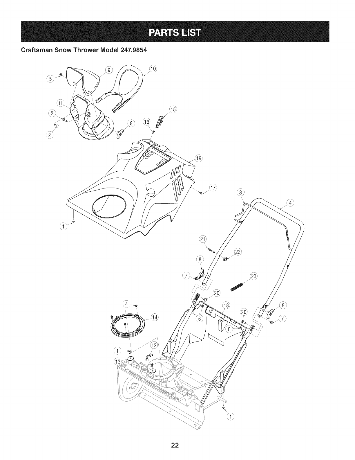
22
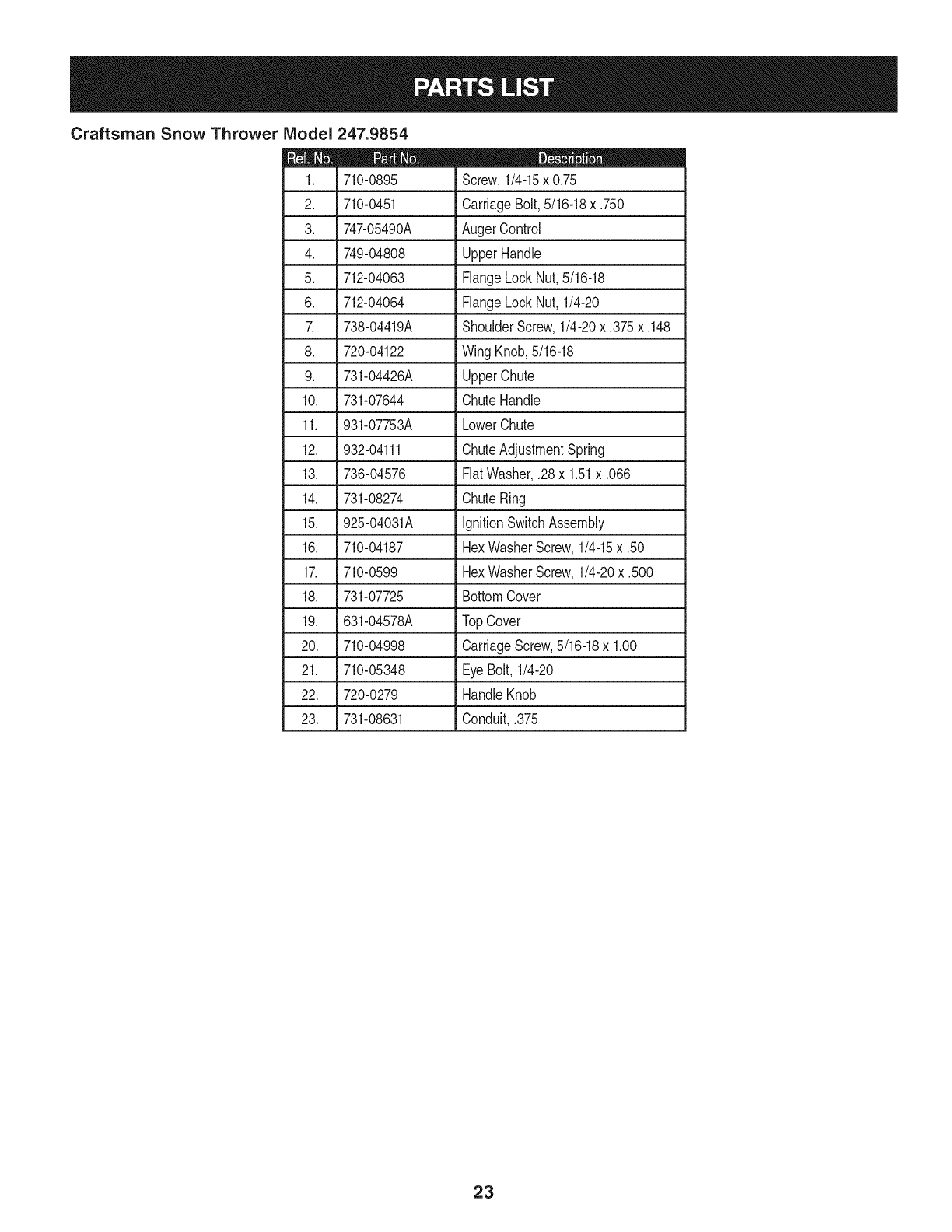
Craftsman Snow Thrower IViodel 247.9854
|= 0 e
710-0895 Screw,1/4-15x 0.75
2. 710-0451 CarriageBolt,5/16-18x .750
3. 747-05490A AugerControl
4. 749-04808 UpperHandle
5. 712-04063 FlangeLockNut,5/16-18
6. 712-04064 FlangeLockNut, 1/4-20
7. 738-04419A ShoulderScrew,1/4-20x .375x.148
8. 720-04122 Wing Knob,5/16-18
9. 731-04426A UpperChute
10. 731-07644 ChuteHandle
11. 931-07753A LowerChute
12. 932-04111 ChuteAdjustmentSpring
13. 736-04576 FiatWasher,.28x 1.51x .066
14. 731-08274 ChuteRing
15. 925-04031A ignitionSwitchAssembly
16. 710-04187 HexWasherScrew,1/4-15x .50
17. 710-0599 HexWasherScrew,1/4-20x .500
18. 731-07725 BottomCover
19. 631-04578A TopCover
20. 710-04998 CarriageScrew,5/16-18x 1.00
21. 710-05348 EyeBolt,1/4-20
22. 720-0279 HandleKnob
23. 731-08631 Conduit,.375
23
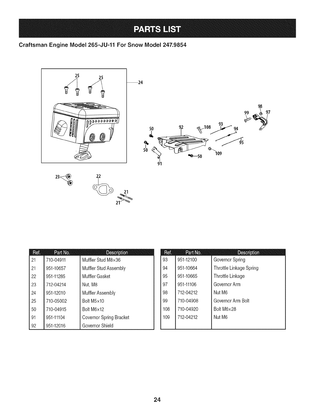
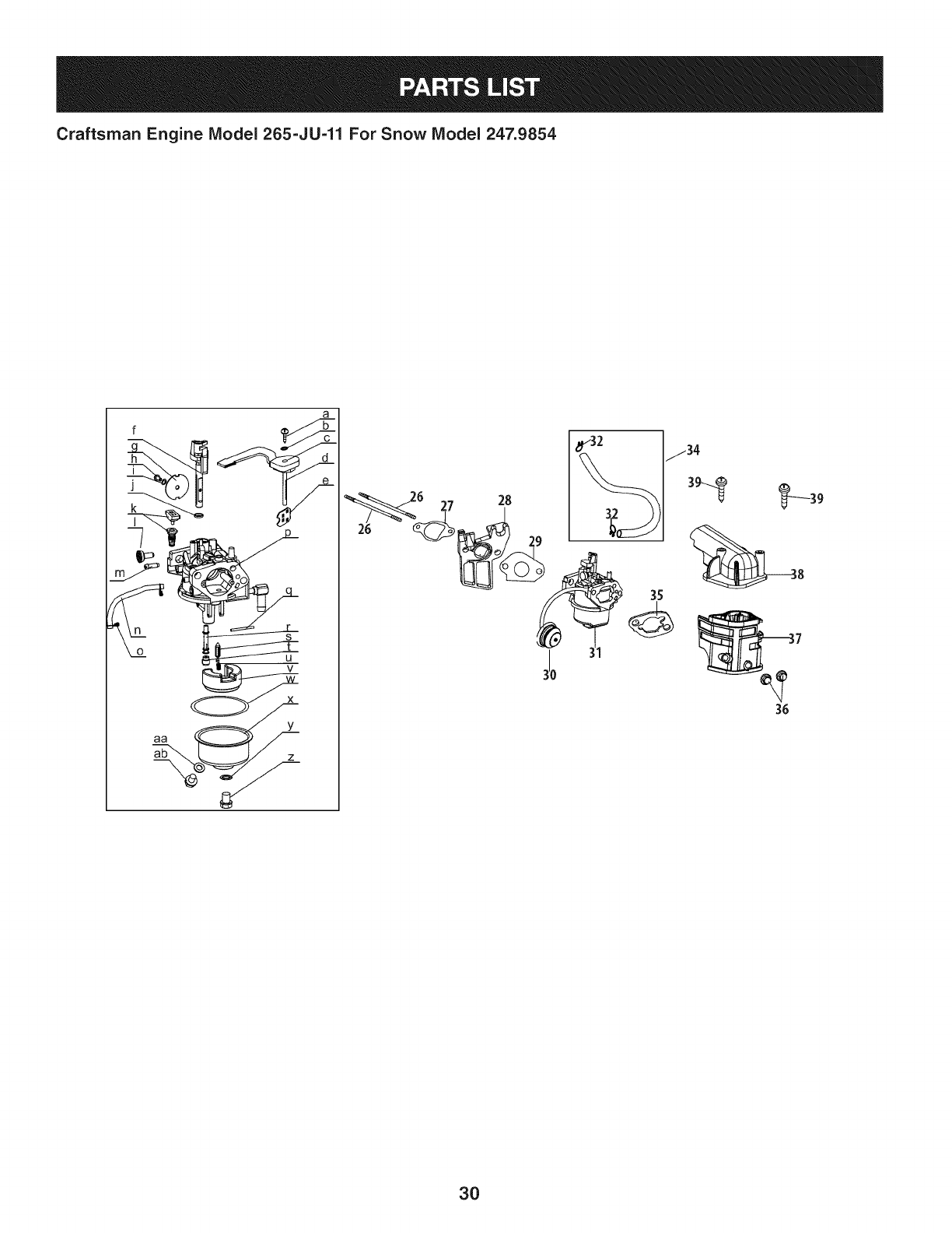
Craftsman Engine IViodel 265=JU=11 For Snow IViodel 247.9854
--24
21
99 ,
91
m
21
21
22
23
24
25
5O
91
92
710-04911
951-10657
951-11285
712-04214
951-12010
710-05002
710-04915
951-11104
951-12016
m = O
MufflerStud M8x36
MufflerStudAssembly
MufflerGasket
Nut,M8
MufflerAssembly
BoltM5xl0
BoltM6x12
CovernorSpringBracket
GovernorShield
m
93
94
95
97
98
99
108
109
951-12100
951-10664
951-10665
951-11106
712-04212
710-04908
710-04920
712-04212
D = O O
GovernorSpring
ThrottleLinkageSpring
ThrottleLinkage
GovernorArm
NutM6
GovernorArm Bolt
BoltM6x28
NutM6
24
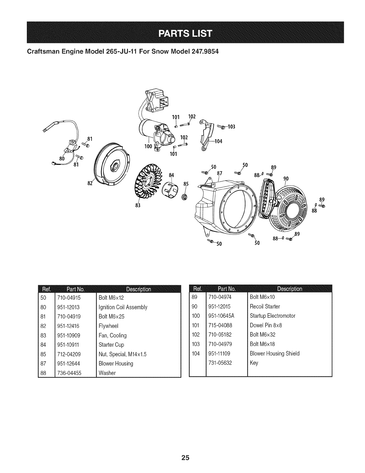
Craftsman Engine IViodel 265=JU=11 For Snow IViodel 247.9854
89
m
5O
8O
81
82
83
84
85
87
88
710-04915
951-12013
710-04919
951-12416
951-10909
951-10911
712-04209
951-12644
736-04455
D = W O
BoltM6x12
IgnitionCoil Assembly
BoltM6x25
Flywheel
Fan,Cooling
StarterCup
Nut,Special,M14x1.5
BlowerHousing
Washer
m
89
9O
1CO
101
102
103
104
710-04974
951-12015
951-10645A
715-04088
710-05182
710-04979
951-11109
731-05632
D = W O
BoltM6xlO
RecoilStarter
StartupElectromotor
DowelPin8x8
BoltM6x32
BoltM6x18
BlowerHousingShield
Key
25
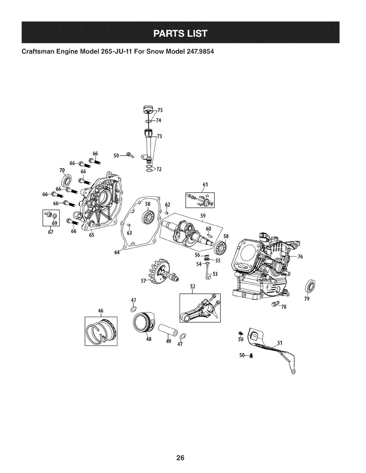
Craftsman Engine IViodel 265=JU=11 For Snow IViodel 247.9854
46
I
47
2
_78
79
26
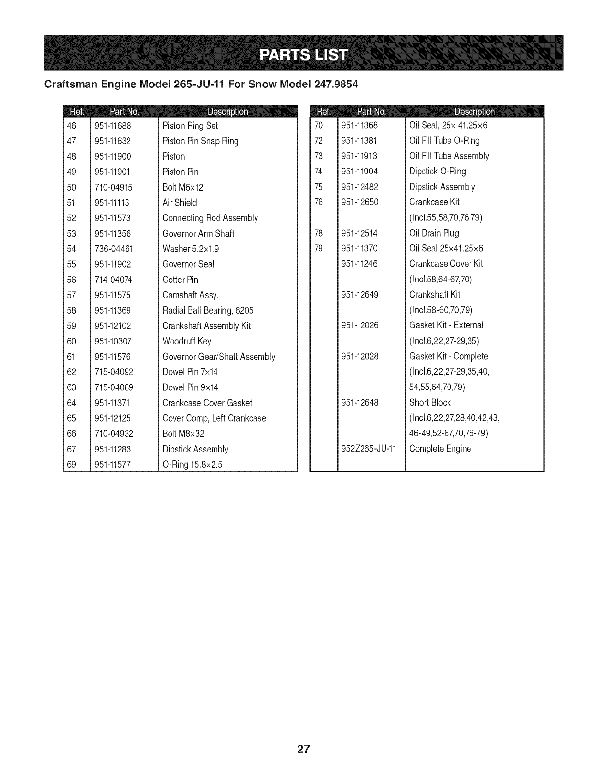
Craftsman Engine IViodel 265=JU=11 For Snow IViodel 247.9854
m
46
47
48
49
5O
51
52
53
54
55
56
57
58
59
6O
61
62
63
64
65
66
67
69
951-11688
951-11632
951-11900
951-11901
710-04915
951-11113
951-11573
951-11356
736-04461
951-11902
714-04074
951-11575
951-11369
951-12102
951-10307
951-11576
715-04092
715-04089
951-11371
951-12125
710-04932
951-11283
951-11577
m = O O
PistonRingSet
PistonPinSnapRing
Piston
PistonPin
Bolt M6x12
AirShield
ConnectingRodAssembly
GovernorArm Shaft
Washer5.2xl .9
GovernorSeal
CotterPin
CamshaftAssy.
RadialBallBearing,6205
CrankshaftAssemblyKit
WoodruffKey
GovernorGear/ShaftAssembly
DowelPin7x14
DowelPin9x14
CrankcaseCoverGasket
CoverComp,LeftCrankcase
Bolt M8x32
DipstickAssembly
O-Ring15.8x2.5
m
7O
72
73
74
75
76
78
79
951-11368
951-11381
951-11913
951-11904
951-12482
951-12650
951-12514
951-11370
951-11246
951-12649
951-12026
951-12028
951-12648
952Z265-JU-11
m = O O
OilSeal,25x 41.25x6
OilFill TubeO-Ring
OilFill TubeAssembly
DipstickO-Ring
DipstickAssembly
CrankcaseKit
(Incl.55,58,70,76,79)
OilDrainPlug
OilSeal25x41.25x6
CrankcaseCoverKit
(Incl.58,64-67,70)
CrankshaftKit
(Incl.58-60,70,79)
GasketKit- External
(Incl.6,22,27-29,35)
GasketKit- Complete
(Incl.6,22,27-29,35,40,
54,55,64,70,79)
ShortBlock
(Incl.6,22,27,28,40,42,43,
46-49,52-67,70,76-79)
CompleteEngine
27
Craftsman Engine IViodel 265=JU=11 For Snow IViodel 247.9854
110
1 1 7
12
19
41 42 _42
28
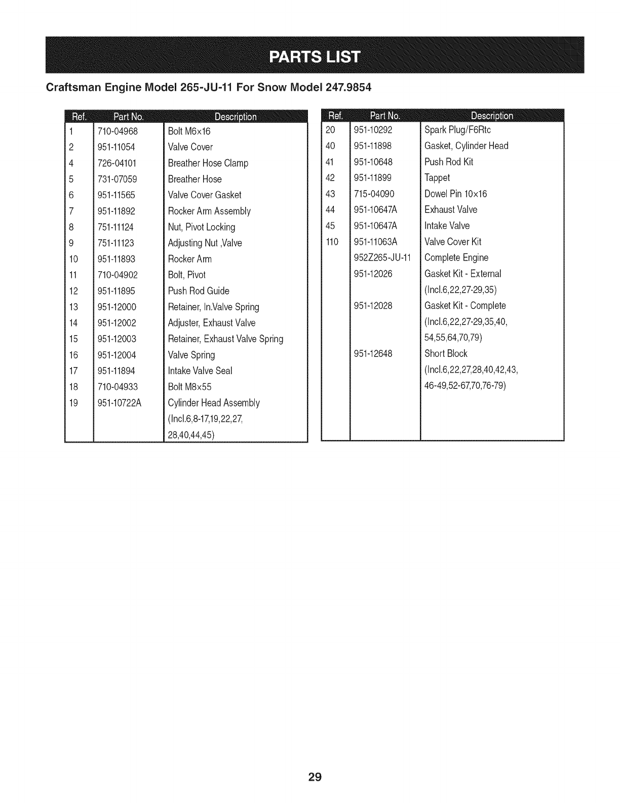
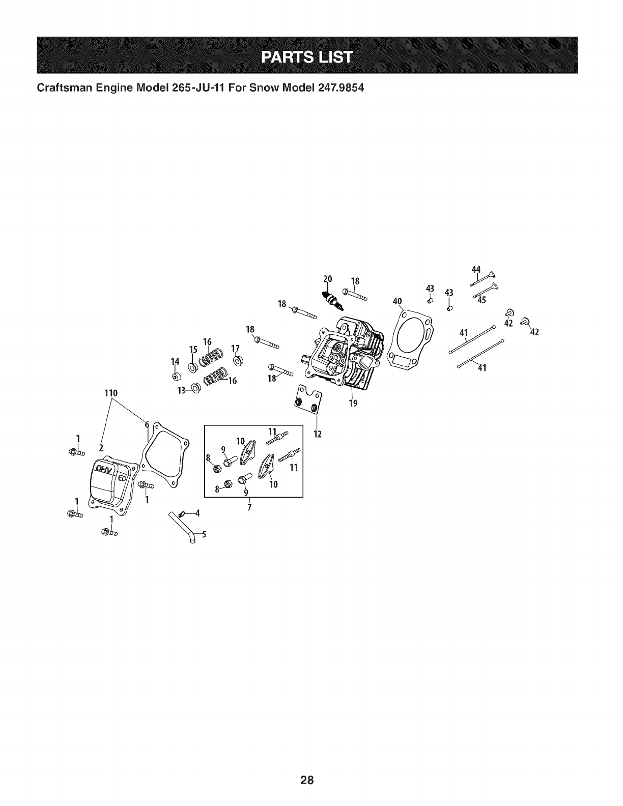
Craftsman Engine IViodel 265=JU-11 For Snow IViodel 247.9854
m
1
2
4
5
6
7
8
9
10
11
12
13
14
15
16
17
18
19
710-04968
951-11054
726-04101
731-07059
951-11565
951-11892
751-11124
751-11123
951-11893
710-04902
951-11895
951-12000
951-12002
951-12003
951-12004
951-11894
710-04933
951-10722A
D = B 0
BoltM6x16
ValveCover
BreatherHoseClamp
BreatherHose
ValveCoverGasket
RockerArmAssembly
Nut,PivotLocking
AdjustingNut,Valve
RockerArm
Bolt,Pivot
PushRodGuide
Retainer,In.ValveSpring
Adjuster,ExhaustValve
Retainer,ExhaustValveSpring
ValveSpring
IntakeValveSeal
BoltM8x55
CylinderHeadAssembly
(Incl.6,8-17,19,22,27,
28,40,44,45)
m
2O
4O
41
42
43
44
45
110
951-10292
951-11898
951-10648
951-11899
715-04090
951-10647A
951-10647A
951-11063A
952Z265-JU-11
951-12026
951-12028
951-12648
m = O O
SparkPlug/F6Rtc
Gasket,CylinderHead
PushRodKit
Tappet
DowelPin10x16
ExhaustValve
IntakeValve
ValveCoverKit
CompleteEngine
GasketKit- External
(Incl.6,22,27-29,35)
GasketKit- Complete
(Incl.6,22,27-29,35,40,
54,55,64,70,79)
ShortBlock
(Incl.6,22,27,28,40,42,43,
46-49,52-67,70,76-79)
29
Craftsman Engine IViodel 265=JU=11 For Snow IViodel 247.9854
n
o
27 28
3O
Craftsman Engine IViodel 265=JU=11 For Snow IViodel 247.9854
m
26
27
28
29
30
31
32
34
35
36
37
38
39
a
b
¢
d
e
f
g
h
I
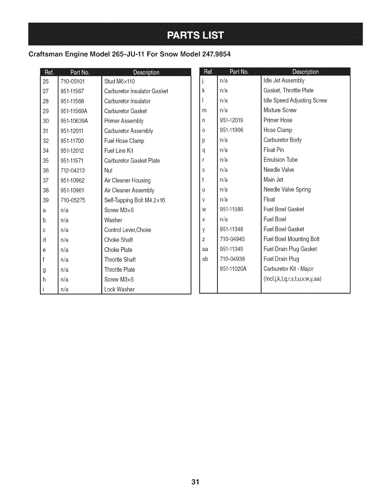
710-05101
951-11567
951-11568
951-11569A
951-10639A
951-12011
951-11700
951-12012
951-11571
712-04213
951-10962
951-10961
710-05275
n/a
n/a
n/a
n/a
n/a
n/a
n/a
n/a
n/a
D = O 0
StudM6x110
CarburetorInsulatorGasket
CarburetorInsulator
CarburetorGasket
PrimerAssembly
CarburetorAssembly
FuelHoseClamp
FuelLineKit
CarburetorGasketPlate
Nut
Air CleanerHousing
Air CleanerAssembly
Self-TappingBoltM4.2x16
ScrewM3x5
Washer
ControlLever,Choke
ChokeShaft
ChokePlate
ThrottleShaft
ThrottlePlate
ScrewM3x5
LockWasher
J
k
I
m
n
0
P
q
r
s
t
U
V
W
X
Y
Z
aa
ab
n/a
n/a
n/a
n/a
951-12019
951-11906
n/a
n/a
n/a
n/a
n/a
n/a
n/a
951-11589
n/a
951-11348
710-04945
951-11349
710-04938
951o11020A
D = O O
IdleJetAssembly
Gasket,ThrottlePlate
IdleSpeedAdjustingScrew
MixtureScrew
PrimerHose
HoseClamp
CarburetorBody
FloatPin
EmulsionTube
NeedleValve
MainJet
NeedleValveSpring
Float
FuelBowlGasket
FuelBowl
FuelBowlGasket
FuelBowlMountingBolt
FuelDrainPlugGasket
FuelDrainPlug
CarburetorKit- Major
(Incl.j,k,l,q,r,s,t,u,v,w,y,aa)
31
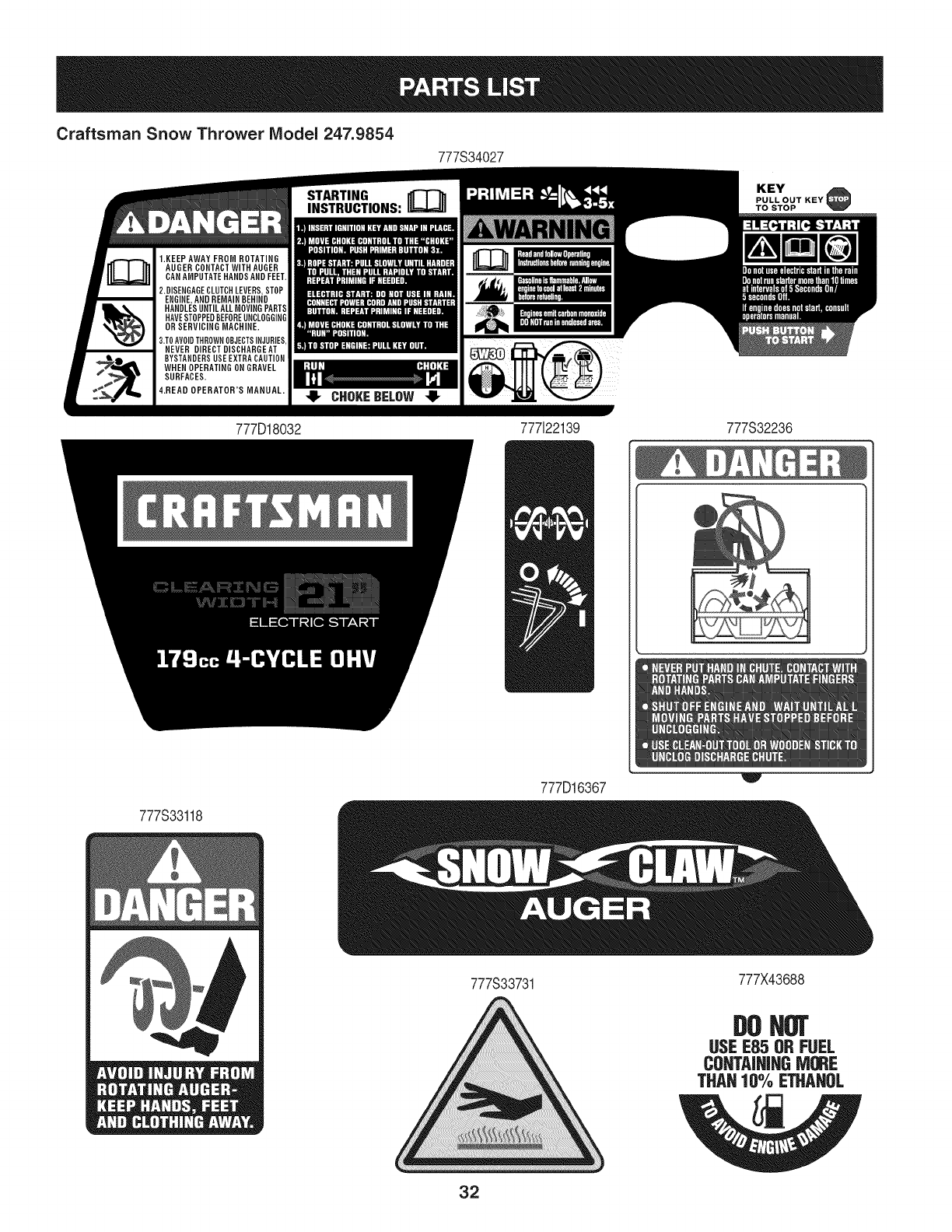
Craftsman Snow Thrower IViodel 247.9854
777S34027
777D18032 777122139 777S32236
777S33118
777D16367
777S33731
!lw
777X43688
DOHOT
USEE85 ORFUEL
CONTAINJHGMORE
THAH10% ETHAHUL
32
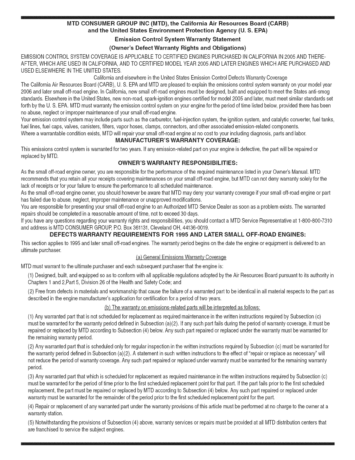
MTD CONSUMER GROUP INC (MTD), the California Air Resources Board (CARB)
and the United States Environment Protection Agency (U. S. EPA)
Emission Control System Warranty Statement
(Owner's Defect Warranty Rights and Obligations)
EMISSIONCONTROLSYSTEMCOVERAGEIS APPLICABLETOCERTIFIEDENGINESPURCHASEDINCALIFORNIAIN2005ANDTHERE-
AFTER,WHICHARE USEDINCALIFORNIA,ANDTO CERTIFIEDMODELYEAR2005ANDLATERENGINESWHICHARE PURCHASEDAND
USEDELSEWHEREINTHEUNITEDSTATES.
Californiaandelsewherein the UnitedStatesEmissionControlDefectsWarrantyCoverage
The CaliforniaAir ResourcesBoard(CARB),U.S. EPAandMTDarepleasedto explaintheemissionscontrolsystemwarrantyonyour modelyear
2006andlatersmalloff-roadengine.In California,new smalloff-roadenginesmustbe designed,builtand equippedto meettheStatesanti-smog
standards.Elsewhereinthe UnitedStates,newnon-road,spark-ignitionenginescertifiedfor model2005and later,mustmeetsimilarstandardsset
forthby the U.S. EPA.MTDmustwarrantythe emissioncontrolsystemonyourenginefor the periodof timelistedbelow,providedtherehasbeen
noabuse,neglector impropermaintenanceof your smalloff-roadengine.
Youremissioncontrolsystemmayincludepartssuchas the carburetor,fuel-injectionsystem,the ignitionsystem,andcatalyticconverter,fueltanks,
fuel lines,fuel caps,valves,canisters,filters,vaporhoses,clamps,connectors,andotherassociatedemission-relatedcomponents.
Wherea warrantableconditionexists,MTDwill repairyoursmalloff-roadengineat nocost to yourincludingdiagnosis,partsand labor.
MANUFACTURER'S WARRANTY COVERAGE:
Thisemissionscontrolsystemis warrantedfor twoyears.If anyemission-relatedpart onyourengineis defective,the part will berepairedor
replacedby MTD. OWNER'S WARRANTY RESPONSIBILITIES:
As the smalloff-roadengineowner,youare responsibleforthe performanceof the requiredmaintenancelistedinyour Owner'sManual.MTD
recommendsthatyou retainall yourreceiptscoveringmaintenanceson yoursmalloff-roadengine,but MTDcan not denywarrantysolelyfor the
lackof receiptsor foryour failureto ensurethe performanceto allscheduledmaintenance.
As the smalloff-roadengineowner,youshouldhoweverbeawarethat MTDmaydenyyour warrantycoverageif yoursmalloff-roadengineorpart
hasfaileddue toabuse,neglect,impropermaintenanceor unapprovedmodifications.
Youare responsiblefor presentingyour smalloff-roadengineto an AuthorizedMTDServiceDealeras soonas a problemexists.Thewarranted
repairsshouldbe completedina reasonableamountof time,notto exceed30 days.
Ifyou haveanyquestionsregardingyourwarrantyrightsand responsibilities,you shouldcontacta MTDServiceRepresentativeat 1-800-800-7310
andaddressis MTDCONSUMERGROUP,RO.Box361131,ClevelandOH,44136-0019.
DEFECTS WARRANTY REQUIREMENTS FOR 1995 AND LATER SMALL OFF-ROAD ENGINES:
Thissectionappliesto 1995andlater smalloff-roadengines.The warrantyperiodbeginsonthe datethe engineor equipmentis deliveredto an
ultimatepurchaser.
(a) GeneralEmissionsWarrantyCoverage_
MTDmustwarrantto the ultimatepurchaserandeachsubsequentpurchaserthatthe engineis:
(1)Designed,built,andequippedsoas to conformwithallapplicableregulationsadoptedby the AirResourcesBoardpursuantto itsauthorityin
Chapters1and2,Part5, Division26of the HealthandSafetyCode;and
(2) Freefromdefectsin materialsandworkmanshipthatcausethe failureof a warrantedpart to beidenticalin all materialrespectsto the partas
describedin theenginemanufacturer'sapplicationfor certificationfora periodof twoyears.
.(b)The warrantyonemissions-relatedpartswill be interpretedas follows:
(1)Anywarrantedpart thatis not scheduledfor replacementas requiredmaintenanceinthe writteninstructionsrequiredby Subsection(c)
mustbewarrantedfor the warrantyperioddefinedinSubsection(a)(2). Ifany suchpartfailsduringthe periodof warrantycoverage,it mustbe
repairedor replacedby MTDaccordingto Subsection(4)below.Anysuchpart repairedor replacedunderthewarrantymustbewarrantedfor
the remainingwarrantyperiod.
(2)Any warrantedpartthat is scheduledonlyfor regularinspectioninthe writteninstructionsrequiredby Subsection(c) must bewarrantedfor
thewarrantyperioddefinedin Subsection(a)(2).A statementinsuchwritteninstructionsto the effectof "repairor replaceas necessary"will
not reducethe periodof warrantycoverage.Anysuchpart repairedor replacedunderwarrantymustbe warrantedforthe remainingwarranty
period.
(3) Anywarrantedpartthat whichis scheduledfor replacementas requiredmaintenancein the writteninstructionsrequiredby Subsection(c)
mustbewarrantedfor the periodof timepriorto the first scheduledreplacementpointforthat part.Ifthe part failspriorto thefirst scheduled
replacement,the part mustbe repairedor replacedby MTDaccordingto Subsection(4) below.Any suchpart repairedor replacedunder
warrantymustbewarrantedfor the remainderof the periodpriorto the first scheduledreplacementpointfor the part.
(4) Repairor replacementof any warrantedpartunderthewarrantyprovisionsof thisarticlemustbe performedat nochargeto the ownerat a
warrantystation.
(5) Notwithstandingthe provisionsof Subsection(4)above,warrantyservicesor repairsmustbe providedat all MTDdistributioncentersthat
arefranchisedto servicethe subjectengines.
(6)Theownermustnotbechargedfordiagnosticlaborthatleadstothedeterminationthatawarrantedpartisinfactdefective,providedthat
suchdiagnosticworkisperformedatawarrantystation.
(7)Theenginemanufacturerisliablefordamagestootherenginecomponentsproximatelycausedbyafailureunderwarrantyofanywarranted
part.
(8)Throughouttheengine'swarrantyperioddefinedinSubsection(a)(2),MTDwillmaintainasupplyofwarrantedpartssufficienttomeetthe
expecteddemandforsuchparts.
(9)Anyreplacementpartmaybeusedintheperformanceofanywarrantymaintenanceorrepairsandmustbeprovidedwithoutchargetothe
owner.SuchusewillnotreducethewarrantyobligationsofMTD.
(10)Add-onormodifiedpartsthatarenotexemptedbytheAirResourcesBoardmaynotbeused.Theuseofanynon-exemptedadd-onor
modifiedpartsshallbegroundsfordisallowingawarrantyclaimmadeinaccordancewiththisarticle.Theenginemanufacturershallnotbe
liableunderthisarticletowarrantfailuresofwarrantedpartscausedbytheuseofnon-exemptedadd-onormodifiedpart.
(c) MTDwill includea copyof the followingemissionwarrantypartslistwitheach newengine,usingthoseportionsof the listapplicableto the
e__&gine.
(1)FuelMeteringSystem
• Coldstart enrichmentsystem(soft choke)
,,Carburetorandinternalparts
• Fuel Pump
• FuelTank
(2)Air InductionSystem
• Aircleaner
• Intakemanifold
(3) IgnitionSystem
• Sparkplug(s)
• MagnetoIgnitionSystem
(4)ExhaustSystem
Catalyticconverter
• SAI (Reedvalve)
(5) MiscellaneousItemsUsedin AboveSystem
Vacuum,temperature,position,timesensitivevalvesand switches
Connectorsandassemblies
(6) Evaporativecontrol
• Fuel Hosecertifiedfor ARBevaporativeemissionof 2006.
• Fuel HoseClamps
Tetheredfuel cap
Carboncanister
• Vaporlines
GD0C-100174Rev.B
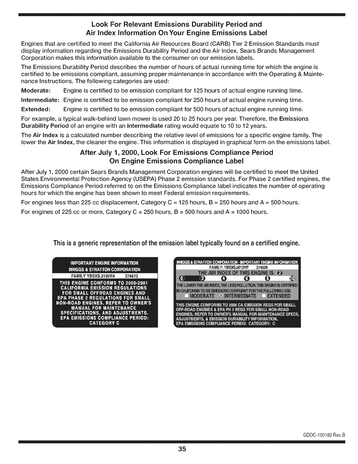
Look For Relevant Emissions Durability Period and
Air index information On Your Engine Emissions Label
Engines that are certified to meet the California Air Resources Board (CARB) Tier 2 Emission Standards must
display information regarding the Emissions Durability Period and the Air Index. Sears Brands Management
Corporation makes this information available to the consumer on our emission labels.
The Emissions Durability Period describes the number of hours of actual running time for which the engine is
certified to be emissions compliant, assuming proper maintenance in accordance with the Operating & Mainte-
nance Instructions. The following categories are used:
Moderate: Engine is certified to be emission compliant for 125 hours of actual engine running time.
Intermediate: Engine is certified to be emission compliant for 250 hours of actual engine running time.
Extended: Engine is certified to be emission compliant for 500 hours of actual engine running time.
For example, a typical walk-behind lawn mower is used 20 to 25 hours per year. Therefore, the Emissions
Durability Period of an engine with an intermediate rating would equate to 10 to 12 years.
The Air index is a calculated number describing the relative level of emissions for a specific engine family. The
lower the Air Index, the cleaner the engine. This information is displayed in graphical form on the emissions label.
After July 1,2000, Look For Emissions Compliance Period
On Engine Emissions Compliance Label
After July 1, 2000 certain Sears Brands Management Corporation engines will be certified to meet the United
States Environmental Protection Agency (USEPA) Phase 2 emission standards. For Phase 2 certified engines, the
Emissions Compliance Period referred to on the Emissions Compliance label indicates the number of operating
hours for which the engine has been shown to meet Federal emission requirements.
For engines less than 225 cc displacement, Category C = 125 hours, B = 250 hours and A = 500 hours.
For engines of 225 cc or more, Category C = 250 hours, B = 500 hours and A = 1000 hours.
This is ageneric representation of the emission label typically found on a certified engine.
FAMILYYBSXS.3192VA 274812
GDOC-100182Rev.B
35
Congratulations on making a smart purchase. Your new Craftsman® product is designed and
manufactured for years of dependable operation. But like all products, it may require repair
from time to time. That's when having a Repair Protection Agreement can save you money and
aggravation.
Here's what the Repair Protection Agreement* includes:
[] Expert service by our 10,000 professional repair specialists
[] Unlimited service and no charge for parts and labor on all covered repairs
[] Product replacement up to $1500 if your covered product can't be fixed
[] Discount of 25% from regular price of service and related installed parts not covered by the
agreement; also, 25% off regular price of preventive maintenance check
[] Fast help by phone - we call it Rapid Resolution - phone support from a Sears representative.
Think of us as a "talking owner's manual."
Once you purchase the Repair Protection Agreement, a simple phone call is all that it takes for you
to schedule service. You can call anytime day or night, or schedule a service appointment online.
The Repair Protection Agreement is a risk-free purchase. If you cancel for any reason during the
product warranty period, we will provide a full refund. Or, a prorated refund anytime after the
product warranty period expires. Purchase your Repair Protection Agreement today!
Some limitations and exclusions apply. For prices and additional information in the U.S.A.
call 1=800=827=6655.
*Coverage in Canada varies on some items. For full details call Sears Canada at 1=800=361=
6665.
Sears Installation Service
For Sears professional installation of home appliances, garage door openers, water heaters, and
other major home items, in the U.S.A. or Canada call 1=800=4=MY=HOME®.
36
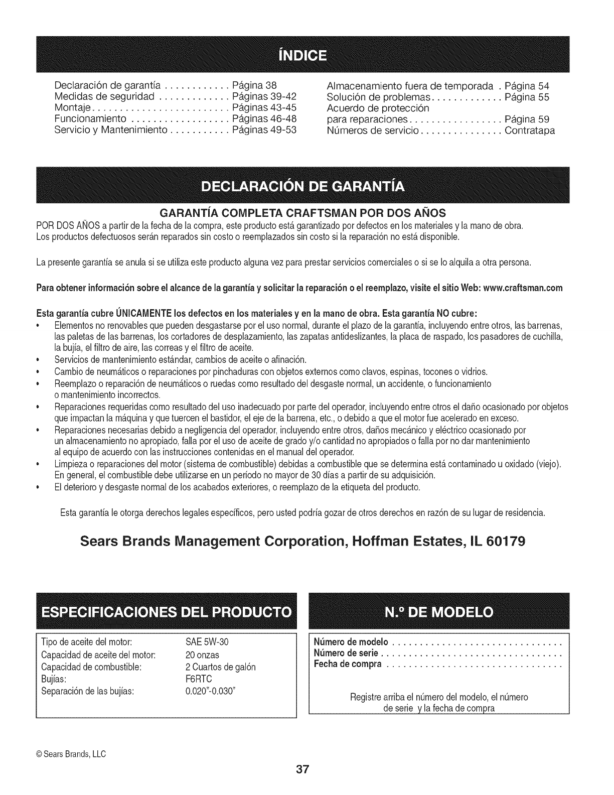
Declaraci6n de garantia ............ Pagina 38
Medidas de seguridad ............. Paginas 39-42
Montaje ......................... Paginas 43-45
Funcionamiento .................. Paginas 46-48
Servicio y Mantenimiento ........... Paginas 49-53
Almacenamiento fuera de temporada .Pagina 54
Solucion de problemas ............. Pagina 55
Acuerdo de protecci6n
para reparaciones ................. Pagina 59
NOmeros de servicio ............... Contratapa
GARANTiA COMPLETA CRAFTSMAN POR DOS AltOS
PORDOSANOSapartir dela fechade lacornpra,esteproductoest_garantizadopot defectosen los rnaterialesy la rnanodeobra.
Los productosdefectuososser_nreparadossin costoo reernplazadossin costosi la reparaci6nnoest_disponible.
La presentegarantiase anulasi se utilizaesteproductoalgunavezparaprestarservicioscornercialeso si se Ioalquilaa otra persona.
Paraobtener informaci6nsobre el alcancede la garantiay solieitar la reparaci6noel reemplazo,visite el sitio Web:www.craftsman.com
Esta garanfia eubre0NiCAMENTElosdefectos en los rnaterialesy en la rnanode obra. Estagaranfia NOcubre:
• Elernentosno renovablesquepuedendesgastarsepor eluso normal,duranteei plazodela garantia,incluyendoentreotros,las barrenas,
las paletasdelas barrenas,los cortadoresde desplazarniento,laszapatasantideslizantes,la placade raspado,lospasadoresdecuchilla,
la bujia,elfiltrode aire,las correasy el filtrodeaceite.
• Serviciosde rnantenirnientoestandar,carnbiosde aceiteo afinaci6n.
• Carnbiode neurn_ticoso reparacionesporpinchadurascon objetosexternoscornoclavos,espinas,toconeso vidrios.
• Reernplazoo reparaci6nde neurn_ticoso ruedascornoresultadodel desgastenormal,unaccidente,o funcionarniento
o rnantenirnientoincorrectos.
• Reparacionesrequeridascornoresultadodel uso inadecuadopot partedeloperador,incluyendoentreotrosel dafioocasionadoporobjetos
queirnpactanla rnaquinay quetuercenel bastidor,el ejede labarrena,etc.,odebidoa queel motorrueaceleradoenexceso.
• Reparacionesnecesariasdebidoa negligenciadeloperador,incluyendoentre otros,dafiosrnec_nicoy el6ctricoocasionadopor
unalrnacenarnientonoapropiado,fallaporel uso deaceitede gradoy/o cantidadnoapropiadoso falla pornodar rnantenirniento
alequipodeacuerdocon las instruccionescontenidasenel manualdel operador.
• Lirnpiezao reparacionesdel motor(sisternade combustible)debidasa combustiblequese deterrninaest_contarninadou oxidado(viejo).
Engeneral,el combustibledebeutilizarseen unperiodono mayorde 30dias a partirde su adquisici6n.
• Eldeterioroy desgastenormalde losacabadosexteriores,o reernplazode laetiquetadelproducto.
Estagarantialeotorgaderechoslegalesespecificos,peroustedpodriagozarde otrosderechosen raz6nde su lugarde residencia.
Sears Brands Management Corporation, Hoffman Estates, IL 60179
Tipodeaceitedelmotor:
Capacidadde aceitedel motor:
Capacidadde combustible:
Bujfas:
Separaci6ndelas bujias:
SAE5W-30
20onzas
2 Cuartosdegai6n
F6RTC
0.020"-0.030"
NSrnerode rnodelo ...............................
N_rnerode serie .................................
Feehade eompra ................................
Registrearribael nQrnerodelrnodeio,el nQrnero
deserie y la fechade cornpra
©SearsBrands,LLC
37
La presenda de este sfmbolo indica que se trata
de instrucdones importantes de seguridad que
se deben respetar para evitar poner en peligro
su seguridad personal y/o matedal y la de otras
personas. Lea y siga todas las instrucdones de
este manual antes de poner en fundonamiento
esta m_quina. Si no respeta estas instrucdones
podria provocar lesiones personales. Cuando
vea este sfmbolo, ipreste atend6n a la
advertenda!
PROPOSICION 65 DE CALIFORNIA
Elescapedel motorde esteproducto,algunosdesuscomponentes
y algunoscomponentesdelvehiculocontieneno liberansustancias
quimicasqueelestadode Californiaconsideraque puedenproducir
cancer,defectosde nacimientouotrosproblemasreproductivos.
Esta m_quina rue construida para ser operada de acuerdo
con las reglas de seguridad contenidas en este manual.
AI igual que con cualquier tipo de equipo motorizado, un
descuido o error por parte del operador puede producir
lesiones graves. Esta m_quina es capaz de amputar manos y
pies y de arrojar objetos con gran fuerza. De no respetar las
instrucdones de seguridad siguientes se pueden produdr
lesiones graves o la muerte.
Su responsabilidad--Restrinja el uso de esta m_iquina
motorizada alas personas que lean, comprendan y respeten
las advertencias e instrucciones que aparecen en este
manual yen la m_iquina.
GUARDEESTASINSTRUCCIONES
CAPAClTAClON
• Leer,entendery seguirtodaslas instruccionesenla mAquina
yen elmanual(s) antesde intentarmontary operar.No
hacerlopuederesultaren lesionesgravesparael operadory /
otranseOntes.Guardeestemanualen unlugarseguroparael
futuroy regularde referenciay parapedirpiezasde repuesto.
ParapreguntasIlameal, 1-800-4MY-HOME.
•Familiaricesecontodoslos controlesy con el usoadecuado
de losmismos.Sepac6modetenerlamAquinay desactivarlos
controlesrApidamente.
• No permitanuncaque losni_os menoresde 14a_osutilicen
estamAquina.Los ni_osde 14a_osenadelantedebenleery
entenderlas instruccionesde operaci6ny normasdeseguridad
contenidasen estemanualy en lamaquinay debenser
entrenadosy supervisadosporun adulto.
• Nuncapermitaquelos adultosoperenestamAquinasin recibir
antesla instrucci6napropiada.
• Losobjetosarrojadosporla mAquinapuedenproducirlesiones
graves.Planifiqueel patr6nenel queva air arrojandonievepara
evitarquela descargade materialse realicehacialos caminos,
los observadores,etc.
Mantengaa los transeOntes,mascotasy ni_osal menosa 75
piesde la mAquinamientrasestAen funcionamiento.Detengala
mAquinasi alguiense acerca.
• Seaprecavidoparaevitarpatinarseo caerseespecialmente
cuandooperala mAquinaen marchaatrAs.
PREPARATIVOS
Inspeccioneminuciosamenteel AreadondeutilizarAel equipo.Saque
todoslos felpudos,peri6dicos,trineos,tablas,cablesy otrosobjetos
extra_oscon los quepodriatropezaro quepodrianser arrojadospor
la barrena/impulsor.
1. Paraprotegerselosojos utilicesiempreanteojoso antiparras
de seguridadmientrasoperala mAquinao mientrasla ajusta
o repara.Losobjetosarrojadosquerebotanpuedenproducir
lesionesocularesgraves.
2. NooperelamAquinasin la vestimentaadecuadaparaestaral
aire libreen invierno.No utilicealhajas,bufandaslargasu otras
prendassueltasquepodrianenredarseenlas partesm6viles.
Utiliceun calzadoespecialparasuperficiesresbaladizas.
3. Useun prolongadory untomacorrientedetrescablescon
conexi6natierra paratodaslas mAquinascon motoresde
encendidoel_ctrico.
4. Desengranetodaslas palancasde controlantesde arrancarel
motor.
5. Nuncaintenterealizarajustesmientrasel motorestAenmarcha
exceptoen los casosespecfficamenterecomendadosenel
manualdel operador.
6. Dejequeel motory la mAquinaseadaptena latemperatura
exteriorantesdecomenzara sacarla nieve.
38
NIANEJO SEGURO DE LA GASOLINA
Para evitar lesiones personales o da_os rnateriales tenga rnucho
cuidado cuando trabaje con gasolina. La gasolina es surnarnente
inflarnable y sus vapores pueden causar explosiones. Si se derrarna
gasolina encirna o sobre la ropa se puede lesionar gravernente ya que
se puede encender. L_.vesela piel y c_.rnbiesede ropa de inrnediato.
• Utilice s61olos recipientes para gasolina autorizados.
• Apague todos los cigarrillos, cigarros, pipas y otras fuentes de
cornbusti6n.
• Nunca cargue combustible en la rn_.quinaen un espacio cerrado.
• Nunca saque la tapa de la gasolina ni agregue combustible
rnientras el motor est,. caliente o en rnarcha.
• Deje que el motor se enfrie por Io rnenos dos rninutos antes de
volver a cargar combustible.
• Nunca Ilene en exceso el dep6sito de combustible. Llene el
tanque a no rn_.sde 1/2pulgada por debajo de la base del cuello
de Ilenado dejando espacio para la dilataci6n del combustible.
• Vuelva a colocar la tapa del combustible y ajQstela bien.
• Lirnpie el combustible que se haya derrarnado sobre el motor y el
equipo. Traslade la rn_.quinaa otra zona. Espere 5 rninutos antes
de encender el motor.
• Nunca alrnacene la rn_.quinao el recipiente de combustible en
un espacio cerrado donde haya fuego, chispas o luz piloto (por
ejernplo, hornos, calentadores de agua, calefactores, secadores
de ropa, etc.).
• Deje que la rn_.quinase enfrie por Io rnenos 5 rninutos antes de
guardarla.
• Nunca Ilene los recipientes en el interior de un vehiculo o carni6n
o caja de rernolque con recubrirniento pl_.stico.Coloque siernpre
los recipientes en el piso y lejos del vehiculo antes de Ilenarlos.
• Si es posible, retire el equipo a gasolina del carni6n o rernolque
y 116neloen el suelo. Si esto no es posible, Ilene el equipo en un
rernolque con un contenedor port_.til,en vez de con una boquilla
dispensadora de gasolina.
• Mantenga la boquilla dispensadora en contacto con el borde del
dep6sito de combustible o con la abertura del recipiente en todo
rnornento, hasta terrninar la carga. No utilice un dispositivo de
apertura/cierre de boquilla.
FUNCIONAIVIIENTO
1. No pongalas manoso lospiescercade las piezasrotatorias,enla
cajade la barrena/impulsoro en el montajedel canalde descarga.El
contactocon laspiezasgiratoriaspuederesultarenla amputaci6nde
manoso pies.
2. Lapalancade controldela barrena/impulsor es un dispositivode
seguridad.Nuncaevitesu funcionamiento.Dehacerlolaoperaci6ndela
m_quinaes riesgosay puedeocasionarlesiones.
3. Laspalancasde controldebenfuncionarbienen ambasdireccionesy
regresarautom_ticamentea laposici6ndedesengranecuandose las
suelta.
4. Nuncaoperela m&quinasi faltaun montajedel canalo si el mismoest&
daSado.Mantengatodos losdispositivosdeseguridadensu lugar yen
funcionamiento.
5. Nuncaenciendael motorenespacioscerradoso en unazonacon poca
ventilaci6n.Elescape del motorcontienemon6xidode carbono,un gas
inodoroy letal.
6. Noutilicela m_quinabajola influenciadelalcoholo las drogas.
7. Elsilenciadory el motorse calientany puedencausarquemaduras.No
lostoque.Mantengaa los niSosalejados.
8. Sea sumamenteprecavidocuandooperela m&quinasobreuna
superficiecongravao cuandolacruce. Mantengasealertapot si se
presentanpeligrosocultoso tr&nsito.
9. Tengacuidadocuandocambiede direcci6no cuandooperela m_quina
en pendientes.Nousela m_quinaenpendientespronunciadas.
10. Planifiqueel patr6nen el queva a ir arrojandonieveparaevitarque
ladescargade materialse produzcahacialasventanas,las paredes,
losautom6viles,etc. y evitarasi posiblesdaSosmaterialeso lesiones
producidaspor los rebotes.
11. Nuncadirijala descargahacialos niSos,losobservadoreso las
mascotasnideje quenadiese paredelantede lam_quina.
12. Nosobrecarguela capacidadde la m_quinatratandodesacar la nieve
muyr@idamente.
13. Nuncaopereesta m_quinasin buenavisibilidado iluminaci6n.Siempre
debeestar segurodequeest&bienafirmadoy sujetandofirmementelas
manijas.Camine,nuncacorra.
14. Corte la corrientea la barrena/impulsorcuandotransportela m_quinao
cuandola mismano est_ enuso.
15. Nuncaoperela m_quinaa altavelocidaddedesplazamientosobre
superficiesresbaladizas.Mire haciaabajoy haciaarrasy tengacuidado
cuandovayamarchaarras.
16. Si la m&quinacomenzaraa vibrardemaneraanormal,detengael motor,
desconecteel cablede labujiay p6ngalade maneraque hagamasa
contrael motor.Inspeccionela m_quinaminuciosamenteparaver si
est&daSada.Reparetodos losdaSosantesde encendery operarla
maquina.
17. Desengranetodas laspalancasde controly detengael motorantesde
dejarla posici6ndeoperaci6n(detr&sdelas manijas).Esperea que la
barrena/impulsorse detengapor completoantesde destaparel montaje
del canalo realizarajustese inspecciones.
18. Nuncapongalas manosen lasaberturasdedescargao de recolecci6n.
Nodestapeel montajedel canal mientrasel motorest&enfunciona-
miento.Antesdedestaparlo,apagueel motory permanezcadetr_sde
lasmanijashastaquetodas las partesm6vilesse hayandetenido.
19. Uses61ounionesyaccesoriosaprobadospor el fabricante(porejemplo,
pesasparalas ruedas,cadenasparalosneum_ticos,cabinas,etc.).
20. Paraencenderel motor,jale dela cuerdalentamentehasta quesienta
resistencia,luegojale r@idamente.Elreplieguer@ido de lacuerda
de arranque(tensi6nderetroceso)le jalar&la manoy el brazohaciael
motorm&sr@ido de Io queusted puedesoltar. Elresultadopuedenset
huesosrotos,fracturas,hematomaso esguinces.
21. Si se presentansituacionesque noest&nprevistasen estemanual,sea
cuidadosoy useel sentido comL]n.P6ngaseencontactocon Asistencia
al Clienteparasolicitarayuday el hombredel distribuidordeservicio
m_scercano.
39
DESPEJE DE UN CANAL DE DESCARGA
OBSTRUIDO
El contacto de las manos con el impulsorrotatorio que est,. dentro del
canal de descarga es la causa m_.scomQnde lesiones asociadas con
las m_.quinasquitanieve. Nunca use su mano para limpiar el canal de
descarga.
Para despejar el canal:
1. iAPAGUEELMOTOR!
2. Espere10segundospara estar segurodeque lascuchillasdel motor
handejadode rotar.
3. Utilicesiempreuna herramientade limpieza,nouselas manos.
MANTENIMIENTO Y ALMACENAMIENTO
1. Nuncaalterelos dispositivosdeseguridad.Controleperi6dicamenteque
funcionencorrectamente.Remitasea lasseccionesde mantenimientoy
ajustede estemanual.
2. Antesde realizarla limpieza,repararo revisarla m_quina,desengrane
todaslas palancasdecontroly detengael motor.Esperea que la bar-
rena/impulsorse detengapor completo.Desconecteel cablede labujia
y p6ngalohaciendomasacontrael motorparaevitarque se encienda
accidentalmente.
3. Controlefrecuentementequetodos los pernosytornillosesten bien
ajustadosparacomprobarque la m_quinase encuentraen condiciones
segurasdefuncionamiento.Adem_s,hagauna inspecci6nvisual dela
m_quinaparaverificarsiest_ dafiada.
4. Nocambie la configuraci6ndel reguladordel motor niacelerede-
masiadoel mismo.Elreguladordel motorcontrolalavelocidadm&xima
segurade funcionamientodel motor.
5. Lasplacasderaspadoy las zapatasantideslizantesquese usancon
la m_quinaquitanievese desgastany se dafian.Para protegersu
seguridad,verifiquefrecuentementetodos loscomponentesy reemp-
I_celoss61oconpartesde losfabricantesde equiposoriginales(OEM).
iEIuso de piezasque nocumplencon lasespecificacionesdel equipo
originalpuederesultaren rendimientoinadecuadoadem_sde poneren
riesgolaseguridad!
6. Reviselaspalancasde controlperi6dicamenteparaverificarque
engranenydesengranenadecuadamentey ajL]stelossi es necesario.
Consultelasecci6n deajustesde estemanualdel operadorpara
obtenerinstrucciones.
7. Mantengao reemplacelasetiquetasdeseguridade instruccionessegQn
seanecesario.
8. Respetelas normasreferentesa la disposici6ncorrectay lasreglamen-
tacionessobregasolina,aceite,etc.paraprotegerel medicambiente.
9. Antesde almacenarla m&quinaenciendalaunosminutosparasacarla
nieveque hayaquedadoen la mismay paraevitarasi que se congelela
barrena/impulsor.
10. Nuncaalmacenela m_quinao el recipientede combustibleen un
espaciocerradodondehayafuego,chispaso luz pilotocomo por
ejemplo,calentadoresdeagua, hornos,secadoresde ropa,etc.
11. Consultesiempreel manualdel operadorpara obtenerinstrucciones
adecuadasparael almacenamientofuerade temporada.
12. Verifiquefrecuentementela linea decombustible,el tanque,eltap6n,
y losaccesoriosbuscandorajaduraso p@didas.Reemplacede set
necesario.
13. Node arranqueal motorsi no est_la bujiadeencendido.
14. SegQnla Comisi6nde Seguridadde Productosparael Consumidorde
los EstadosUnidos(CPSC)y laAgenciade Protecci6nAmbientaldelos
EstadosUnidos(EPA),esteproductotiene unavida dtilmedia desiete
(7)afios 6 60 horasdefuncionamiento.AI finalizarla vida dtilmedia
hagainspeccionaranualmenteestaunidadporundistribuidordeservi-
cio autorizadoparacerciorarsede quetodos lossistemasmec_nicosy
de seguridadfuncionancorrectamentey notienenexcesivodesgaste.Si
no Io hace,puedenproducirseaccidentes,lesioneso la muerte.
NO iVIODIFIQUE EL MOTOR
Para evitar lesiones graves o la muerte, no modifique el motor bajo
ninguna circunstancia. Si cambia la configuracidn del regulador del
motor, _ste puede descontrolarse y operar a velocidades inseguras.
Nunca cambie la configuracidn de f&brica del regulador del motor.
AVISO REFERIDO AEMISIONES
Los motores que estan certificados y cumplen con las regulaciones
de emisiones federales EPA y de California para SORE (Equipos
pequefios todo terreno) est_.ncertificados para operar con gasolina
comOn sin plomo y pueden incluir los siguientes sistemas de control
de emisiones: Modificaci6n de motor (EM), catalizador oxidante (OC),
inyecci6n de aire secundaria (SAI) y catalizador de tres vias (TWO) si
est_.nequipados de esa manera.
Amortiguadordechispas
Estam&quinaest_equipadacon unmotorde combusti6ninternoy
nodebeser utilizadaen ocercade unterrenoagrestecubiertopor
bosque,malezaso hierbaexceptoque elsistemadeescapedel
motorest_equipadocon unamortiguadordechispasquecumpla
con las leyeslocaleso estatalescorrespondientes(encasode
existir)
Si se utilizaunamortiguadorde chispasel operadorIo debemantener
en condicionesde usoadecuadas.Enel Estadode Californialas
medidasanteriormentemencionadassonexigidasporIcy (Arficulo
4442del Cddigode RecursosPOblicosde California).Esposible
queexistanleyessimilaresenotrosestados.Lasleyesfederalesse
aplicanenterritoriosfederales.
Puedeconseguirelamortiguadordechispasparael silenciadora
travesdesu distribuidorde mantenimientode motoresautorizadom&s
cercanoo poni_ndoseencontactocon eldepartamentode servicios,
ApartadoPostal361131Cleveland,Ohio44136-0019.
40
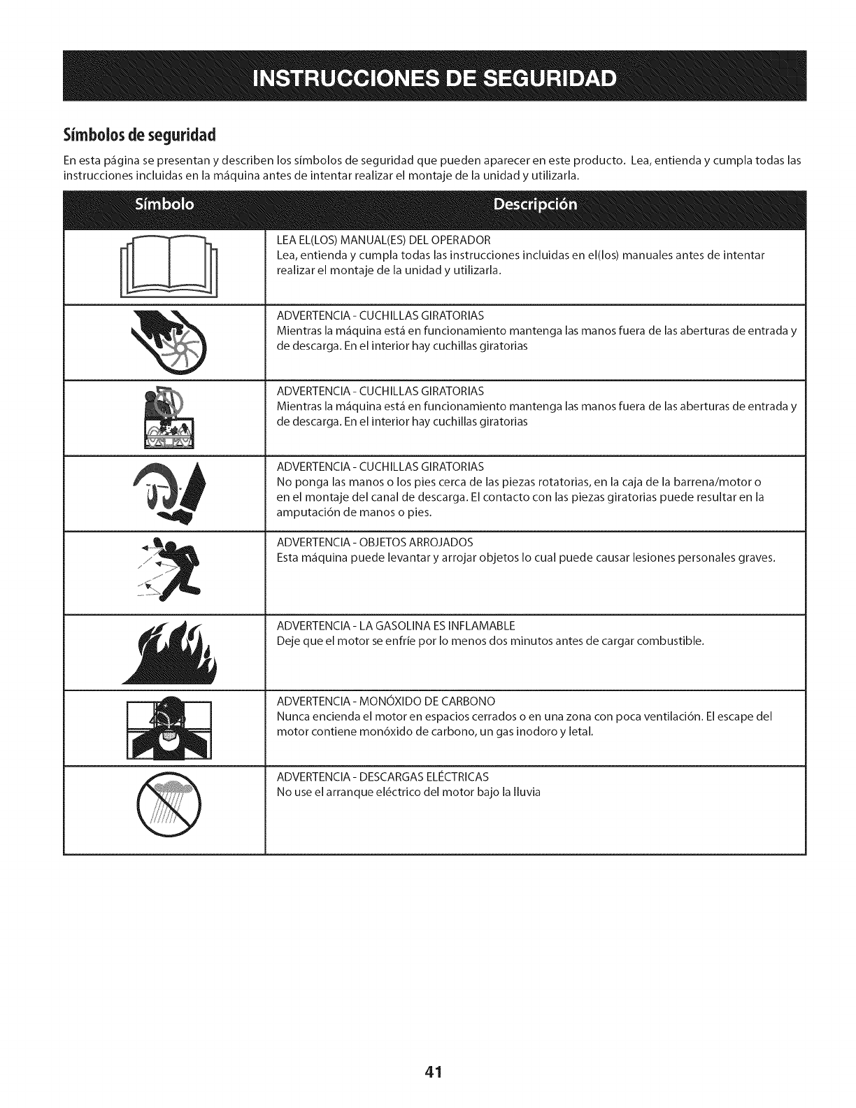
Simbolosde seguridad
En esta p_gina se presentan y describen los simbolos de seguridad que pueden aparecer en este producto. Lea, entienda y cumpla todas las
instrucciones incluidas en la m_quina antes de intentar realizar el montaje de la unidad y utilizarla.
s _ _
LEA EL(LOS) MANUAL(ES) DEL OPERADOR
Lea, entienda y cumpla todas las instrucciones incluidas en el(los) manuales antes de intentar
realizar el montaje de la unidad y utilizarla.
ADVERTENClA- CUCHILLAS GIRATORIAS
Mientras la m_quina est_ en funcionamiento mantenga las manos fuera de las aberturas de entrada y
de descarga. En el interior hay cuchillas giratorias
ADVERTENClA- CUCHILLAS GIRATORIAS
Mientras la m_quina est_ en funcionamiento mantenga las manos fuera de las aberturas de entrada y
de descarga. En el interior hay cuchillas giratorias
ADVERTENClA- CUCHILLAS GIRATORIAS
No ponga las manos o los pies cerca de las piezas rotatorias, en la caja de la barrena/motor o
en el montaje del canal de descarga. El contacto con las piezas giratorias puede resultar en la
amputaci6n de manos o pies.
ADVERTENClA - OBJETOS ARROJADOS
Esta m_quina puede levantar y arrojar objetos Io cual puede causar lesiones personales graves.
ADVERTENClA- LA GASOLINA ESINFLAMABLE
Deje que el motor se enfHe pot Io menos dos minutos antes de cargar combustible.
ADVERTENCIA - MONOXIDO DE CARBONO
Nunca encienda el motor en espacios cerrados o en una zona con poca ventilaci6n. El escape del
motor contiene mon6xido de carbono, un gas inodoro y letal.
ADVERTENClA- DESCARGAS ELIeCTRICAS
No use el arranque el_ctrico del motor bajo la Iluvia
41
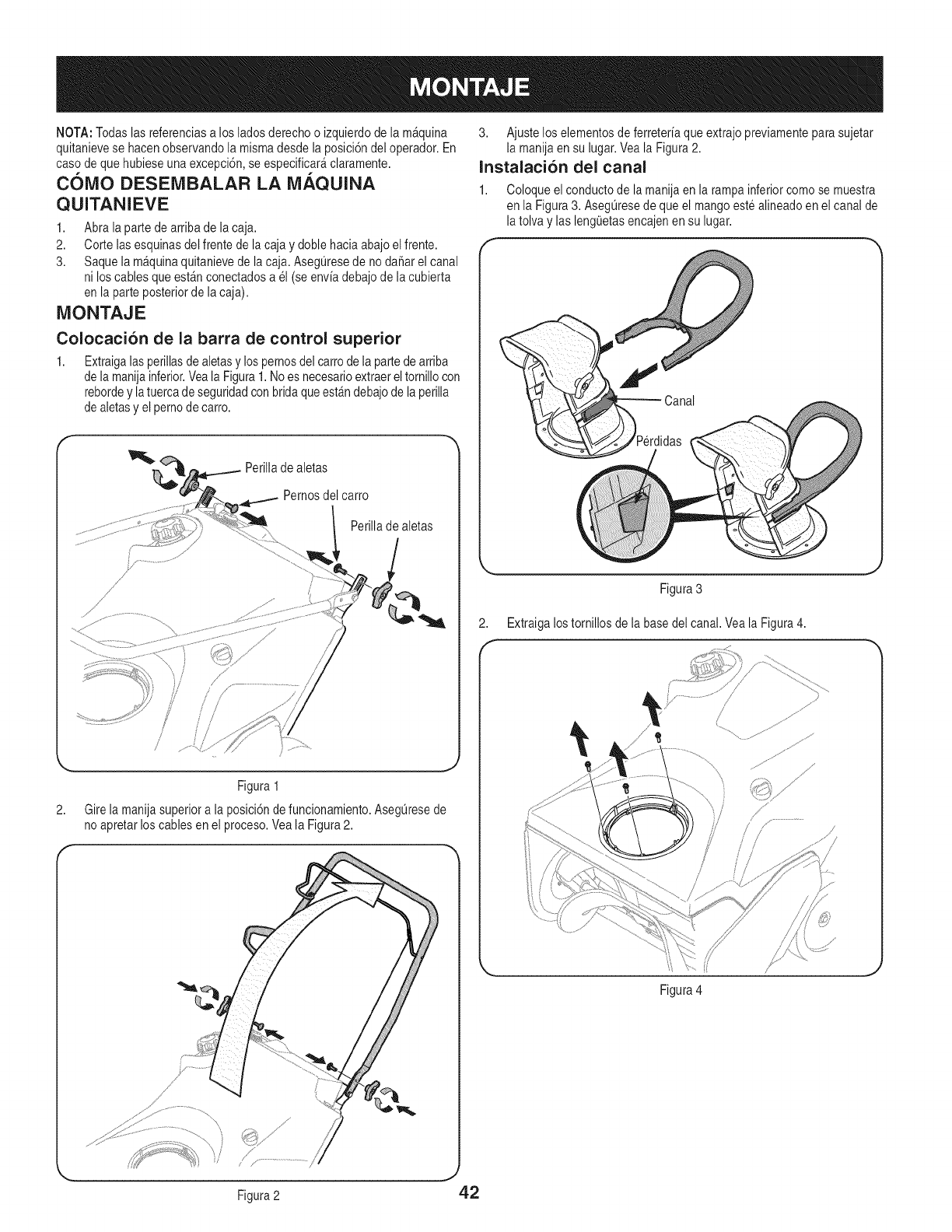
NOTA:Todaslas referenciasa losladosderechoo izquierdode lam_quina
quitanievese hacenobservandola mismadesdela posici6ndel operador.En
casodeque hubieseunaexcepci6n,se especificar&claramente.
COMO DESEMBALAR LA MAQUINA
QUITANIEVE
1. Abrala partedearribade la caja.
2. Corte lasesquinasdel frentede lacaja y doble haciaabajoelfrente.
3. Saquelam&quinaquitanievede lacaja.AsegQresede no daSarel canal
ni loscablesque est_nconectadosa el (seenviadebajodela cubierta
enla parteposteriorde la caja).
MONTAJE
Colocaci6n de la barra de control superior
1. Extraigalasperillasde aletasylos pernosdel carrode lapartede arriba
dela manijainferior.Veala Figura1.Noes necesarioextraerel tornillocon
rebordey latuercadeseguridadconbridaqueest_ndebajodela perilla
dealetasy el pernode carro.
Perilladealetas
Pernosdel carro
Perillade aletas
2,
/
Figura 1
Girela manijasuperiora laposici6ndefuncionamiento.AsegQresede
noapretarlos cablesen el proceso.Veala Figura2.
//'
/
' / ..............................
3. Ajustelos elementosde ferreteriaqueextrajopreviamenteparasujetar
la manijaen su hgar. Veala Figura2.
Instalaci6n del canal
1. Coloqueel conductode lamanijaen la rampainferiorcomose muestra
en la Figura3. AsegQresedeque el mangoestealineadoenel canalde
la tolvay las lengQetasencajenen su lugar.
Figura3
2. Extraigalostornillos dela basedel canal.Veala Figura4.
Figura4
Figura2 42
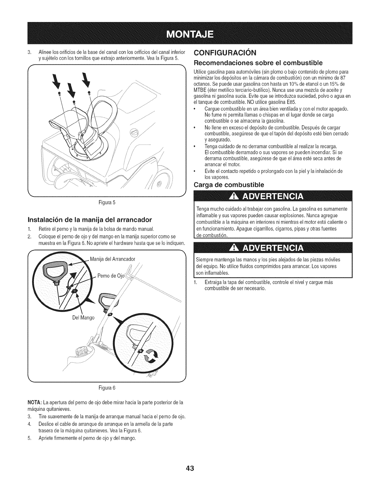
3. Alineelosorificiosdelabasedelcanalconlosorificiosdelcanalinferior
ysujeteloconlostornillosqueextrajoanteriormente.VealaFigura5.
f --
Figura5
Instalaci6n de la manija del arrancador
1. Retireel pernoy la manijade la bolsademandomanual.
2. Coloqueel pernodeojo y del mangoen lamanijasuperiorcomo se
muestraen la Figura6. Noaprieteel hardwarebasraquese Io indiquen.
Manijadel Arrancador
/ /
Del Mango
/
CONFIGURACION
Recomendaciones sobre el combustible
Utilicegasolinaparaautom6viles(sinplomo o bajocontenidodeplomo para
minimizarlosdep6sitosen lac_marade combusti6n)con unminimode87
octanos.Sepuedeusargasolinacon hastaun 10%de etanolo un 15%de
MTBE(eter mefilicoterciario-butilico).Nuncauseuna mezcladeaceitey
gasolinanigasolinasucia. Evitequese introduzcasuciedad,polvoo aguaen
el tanquede combustible.NO utilicegasolinaE85.
• Carguecombustibleen un &teabienventiladay conel motorapagado.
Nofumenipermitallamaso chispasenel lugar dondese carga
combustibleo se almacenala gasolina.
• NoIleneenexcesoel dep6sitode combustible.Despuesde cargar
combustible,aseg@esede queel tap6n del dep6sitoestebiencerrado
y asegurado.
• Tengacuidadode noderramarcombustibleal realizarlarecarga.
Elcombustiblederramadoo susvaporesse puedenincendiar.Si se
derramacombustible,asegOresede queel _reaestesecaantes de
arrancarel motor.
• Eviteel contactorepetidoo prolongadocon lapiel y la inhalaci6nde
losvapores.
Carga de combustible
Tengamuchocuidadoal trabajarcongasolina.Lagasolinaes sumamente
inflamabley susvaporespuedencausarexplosiones.Nuncaagregue
combustiblea la m&quinaen interioresni mientrasel motorest_calienteo
enfuncionamiento.Apaguecigarrillos,cigarros,pipasy otrasfuentes
decombusti6n.
Siempremantengalasmanosy lospies alejadosde laspiezasm6viles
del equipo.No utilicefluidoscomprimidosparaarrancar.Losvapores
son inflamables.
1. Extraigala tapadel combustible,controleel nively carguem_s
combustibledeset necesario.
Figura6
NOTA: La aperturadel pernode ojo debe mirarhaciala parteposteriorde la
m&quinaquitanieves.
3. Tire suavementede la manijade arranquemanualhaciael pernode ojo.
4. Desliceelcablede arranquedearranqueen la armellade la parte
traserade la m_quinaquitanieves.Veala Figura6.
5. Aprietefirmementeel pernode ojo ydel mango.
43

Procedimiento para controlar y agregar aceite
El motorse enviasin aceiteenel motor.Antesde ponerel motoren marcha
debeIlenarlodeaceite.Si se hacefuncionarel motorsinsuficienteaceite
puedecausardaSosgravesa motory anuar a garant a de producto.
1. Coloquela m&quinaquitanieveenunasuperficiefirmey nivelada.
2. Retireeltap6nde Ilenado/varillade medici6ndeaceitey limpie bienla
varilla.Veala Figura7.
\
x i _
/
/
Tap6n de Ilenado de aceite /
Varilla de rnedici6n de aceite
/
/,
/ /
i I /
Figura7
Saqueeltap6n/lavarillade medici6nde aceite.Si el niveles bajo,
agreguelentamenteaceitehastaque el nivelregistradoesteenun
puntointermedioentrealto (H) y bajo(L), Figura8.
Figura8
NOTA: No Io Ileneen exceso.Si se cargademasiadoaceitese puede
generarhumo,problemasdearranqueo suciedaden la bujia.
5. Vuelvaa colocarel tap6n/la varillade medici6nde aceitebien
ajustadosantesde poneren marchael motor.
NOTA: NOpermitaque el niveldeaceitecaiga pordebajodela marca"L"de
la varillademedici6n.Si Io haceel equipopuedefuncionarmalo da_arse.
NOTA: Paracambiarel aceitedel motor,consultela secci6ndeManten-
imientode estemanual.
NOTA:No utiliceaceitesinteticoparalas primerascincohorasde uso.Use
aceitesiempre.
3. Introduzcaeltap6n/la varilla de medici6nde aceitedentro del cuellode
Ilenadodeaceite peronolosatornille.
44
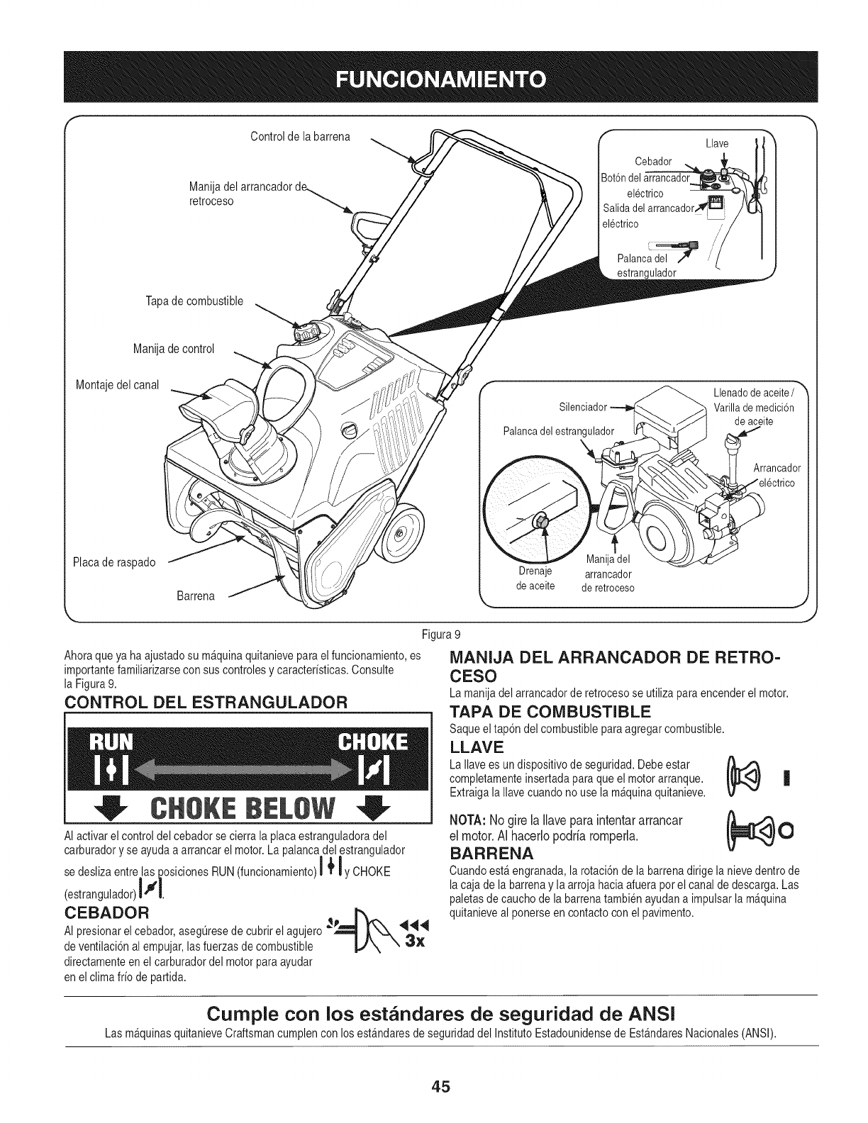
Manijadel
retroceso
Tapede combustible
Controlde la barrena Llave
Cebador
Iot6ndel arrancador
electrico
Salidadel arrancador
electrico
Palanc__ "/
estrangulador
Manijadecontrol
Montajedel canal Llenadode aceite/
Varillademedici6n
deaceite
Arrancador
Placederaspado
Barrena
Drenaje
de aceite
Manijadel
arrancador
de retroceso
Figure9
Ahoraqueya ha ajustadosu m_quinaquitanievepareelfuncionamiento,es
importantefamiliarizarseconsuscontrolesy caracteristicas.Consulte
la Figure9.
CONTROL DEL ESTRANGULADOR
CHOKEBELOW
AI activarelcontroldel cebadorse cierra la place estranguladoradel
carburadory se ayudaa arrancarel motor.La palancadel estrangulador
| |
se deslizaentrelas posicionesRUN(funcionamiento)l l y CHOKE
CEBADOR _
AI presionarel cebador,aseg_resede cubrirel agujero__,, "q_
3x
deventilaci6nal empujar,lasfuerzasdecombustible _,,/_\
directamenteen elcarburadordel motorpareayudar
enel climefrio de partida.
MANIJA DEL ARRANCADOR DE RETRO-
CESO
La manijadel arrancadorde retrocesose utilizepare encenderel motor.
TAPA DE COMBUSTIBLE
Saqueel tap6ndel combustiblepareagregarcombustible.
LLAVE
LaIlavees un dispositivode seguridad.Debeester
completamenteinsertadaparequeel motorarranque. L_[_ |
Extraigala Ilavecuandonouse la m_quinaquitanieve.
NOTA: No gire la Ilave pare intentar arrancar _0
el motor. AI hacerlo podria romperla.
BARRENA
Cuandoest&engranada,la rotaci6nde la barrenadirigela nievedentrode
lacajade la barrenay la arrojahaciaafuerapot el canaldedescarga.Las
paletasde cauchode la barrenatambienayudana impulsarla m_quina
quitanieveal ponerse encontactoconel pavimento.
Cumple con los estandares de seguridad de ANSi
Las mAqu_nasquitanieveCraftsmancumplencon losest_ndaresde seguridaddel InstitutoEstadounidensede EstAndaresNacionales(ANSI).
45
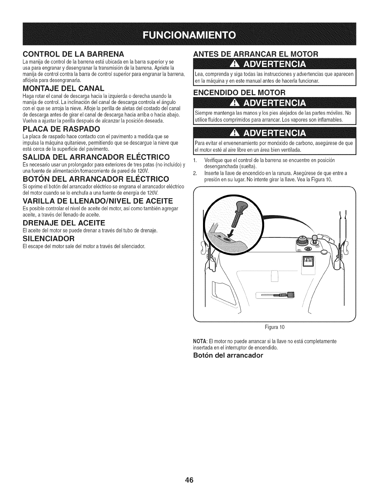
CONTROL DE LA BARRENA
Lamanijade controlde [a barrenaest_ ubicadaen la barrasuperiory se
usaparaengranary desengranarlatransmisi6nde la barrena.Aprietela
manijadecontrolcontrala barrade controlsuperiorparaengranarla barrena,
afl6jelaparadesengranarla.
MONTAJE DEL CANAL
Hagarotarel canaldedescargahaciala izquierdao derechausandola
manijadecontrol.La inclinaci6ndel canaldedescargacontrolael _ngulo
conel quese arroja la nieve.Aflojela perillade aletasdel costadodel canal
dedescargaantesde girar el canaldedescargahaciaarribao haciaabajo.
Vuelvaa ajustarla perilladespuesde alcanzarla posici6ndeseada.
PLACA DE RASPADO
Laplacade raspadohacecontactocon el pavimentoa medidaquese
impulsala m_quinaquitanieve,permitiendoquese descarguela nieveque
est_cercade la superficiedel pavimento.
SALIDA DEL ARRANCADOR ELISCTRICO
Es necesariousar un prolongadorparaexterioresdetres paras(no incluido)y
unafuentede alimentaci6n/tomacorrientede paredde 120V.
BOTON DEL ARRANCADOR ELI_CTRICO
Sioprimeel bot6ndel arrancadorelectricose engranael arrancadorelectrico
del motorcuandose Io enchufaa unafuente de energ[ade 120V.
VARILLA DE LLENADO/NIVEL DE ACEITE
Es posiblecontrolarel nivelde aceitedel motor,as[ comotambienagregar
aceite,a travesdel Ilenadode aceite.
DRENAJE DEL ACEITE
Elaceitedel motorse puededrenara travesdel tubo dedrenaje.
SILENCIADOR
Elescape del motorsale del motora travesdel silenciador.
ANTES DE ARRANCAR EL MOTOR
Lea, comprenday siga todas lasinstruccionesy advertenciasqueaparecen
en la m_quinayen estemanualantesde hacerlafuncionar.
ENCENDIDO DEL MOTOR
Siempremantengalasmanosy lospies alejadosdelas partesm6viles.No
utilicefluidoscomprimidosparaarrancar.Losvaporessoninflamables.
Paraevitar el envenenamientopot mon6xidode carbono,asegOresede que
el motoresteal aire libreen un _reabienventilada.
1. Verifiquequeel controldela barrenase encuentreen posici6n
desenganchada(suelta).
2. Insertela Ilavede encendidoenla ranura.Aseg0resede queentrea
presi6nensu lugar.Nointentegirarla Ilave.Veala Figura10.
/
/
/
/
Figura10
NOTA: Elmotornopuedearrancarsi la Ilavenoest_completamente
insertadaen el interruptordeencendido.
Bot6n del arrancador
46
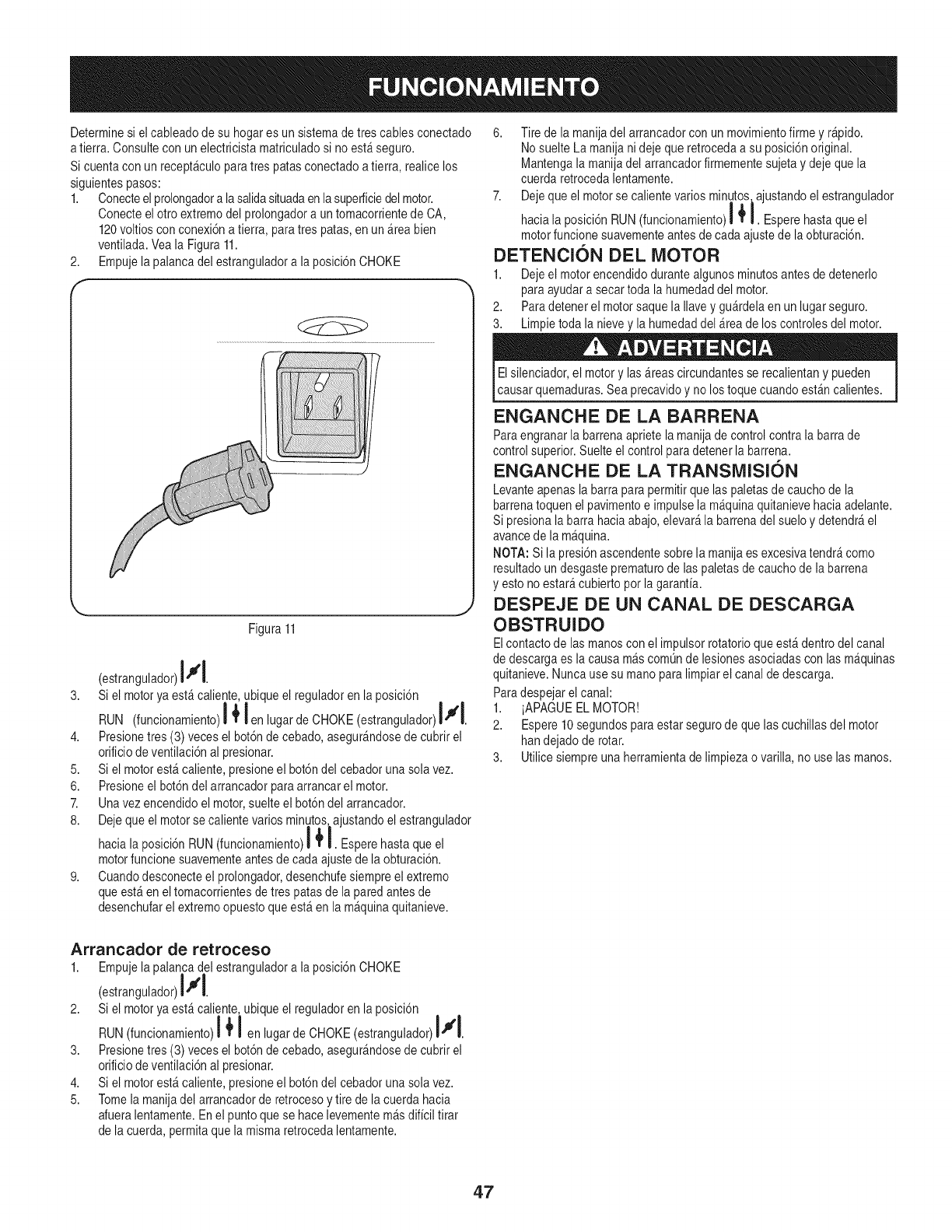
Determinesi elcableadodesu hogares un sistemade tres cablesconectado
a tierra.Consulteconunelectricista matriculadosi noest_seguro.
Si cuentacon un recept_culoparatres parasconectadoa tierra, realicelos
siguientespasos:
1. Conecteel prolongadora lasalidasituadaenlasuperficiedelmotor.
Conecteel otro extremodel prolongadora un tomacorrientede CA,
120voltiosconconexi6na tierra, paratres paras,enun_rea bien
ventilada.Veala Figura 11.
2. Empujela palancadel estranguladora la posici6nCHOKE
f
L _,j
Figura11
(estrangulador)l#l
3. Sielmotoryaest_caliente,ubiqueelreguladorenlaposici6n f
RUN (funcionamiento)l # fenlugardeCHOKE (estrangulador)l I.
4. Presionetres (3) vecesel bot6ndecebado,asegur_ndosede cubrirel
orificiodeventilaci6nal presionar.
5. Si el motorest_ caliente,presioneel bot6ndel cebadoruna solavez.
6. Presioneel bot6ndel arrancadorparaarrancarel motor.
7. Unavez encendidoel motor,suelteel bot6ndel arrancador.
8. Dejeque el motorsecalientevarios minutos_ajustandoel estrangulador
| !
haciala posici6nRUN(funcionamiento)l I. Esperehasta queel
motorfuncionesuavementeantesde cada ajustedela obturaci6n.
9. Cuandodesconecteel prolongador,desenchufesiempreel extremo
queest_ eneltomacorrientesde trespatas dela paredantesde
desenchufarel extremoopuestoqueest_ enla m_quinaquitanieve.
6. Tire de la manijadel arrancadorcon un movimientofirme y r_pido.
NosuelteLamanija nidejeque retrocedaa su posici6noriginal.
Mantengala manijadel arrancadorfirmementesujetaydeje quela
cuerda retrocedalentamente.
7. Dejequeel motorse calientevariosminutos_ajustandoel estrangulador
| I
haciala posici6nRUN(funcionamiento)i I. Esperehastaque el
motorfuncionesuavementeantes de cadaajustede laobturaci6n.
DETENCION DEL MOTOR
1. Dejeel motorencendidodurantealgunosminutosantes dedetenerlo
paraayudara secartoda lahumedaddel motor.
2. Paradetenerel motorsaque la Ilavey gu_rdelaenun lugarseguro.
3. Limpietoda la nievey la humedaddel_reade los controlesdel motor.
Elsilenciador,el motory las _reascircundantesse recalientany pueden
causarquemaduras.Sea precavidoy no lostoquecuandoest_ncalientes.
ENGANCHE DE LA BARRENA
Paraengranarla barrenaaprietela manijadecontrolcontrala barrade
controlsuperior.Suelteel controlparadetenerla barrena.
ENGANCHE DE LA TRANSMISION
Levanteapenaslabarra para permitirquelas paletasde caucho dela
barrenatoquenel pavimentoe impulsela m_quinaquitanievehaciaadelante.
Si presionala barra haciaabajo, elevar_la barrenadel sueloydetendr_el
avancede la m_quina.
NOTA:Si la presi6nascendentesobrela manijaes excesivatendr_ como
resultadoun desgasteprematurode laspaletasde cauchode labarrena
y estonoestar_cubierto por lagarantia.
DESPEJE DE UN CANAL DE DESCARGA
OBSTRUIDO
Elcontactode las manosconel impulsorrotatorioqueest_ dentrodel canal
de descargaes la causam_scomL]nde lesionesasociadascon lasm_quinas
quitanieve.Nuncausesu manoparalimpiarel canaldedescarga.
Paradespejarel canal:
1. iAPAGUEELMOTOR!
2. Espere10 segundosparaestarsegurode quelas cuchillasdel motor
handejadode rotar.
3. Utilicesiempreunaherramientade limpiezao varilla,no uselasmanos.
Arrancador de retrooeso
1. Empujela palancadel estranguladora la posici6nCHOKE
2. Si el motorya estfi caliente, ubique el regulador en la posicidn _
RUN (funcionamiento)l_ I enlugardeCHOKE (estrangulador)l I.
3. Presionetres (3) vecesel bot6ndecebado,asegur_ndosede cubrirel
orificiodeventilaci6nal presionar.
4. Si el motorest_ caliente,presioneel bot6ndel cebadoruna solavez.
5. Tomelamanijadel arrancadorde retrocesoy tire de la cuerdahacia
afueralentamente.En el puntoquese hace levementem_sdificiltirar
dela cuerda,permitaque la mismaretrocedalentamente.
4.7
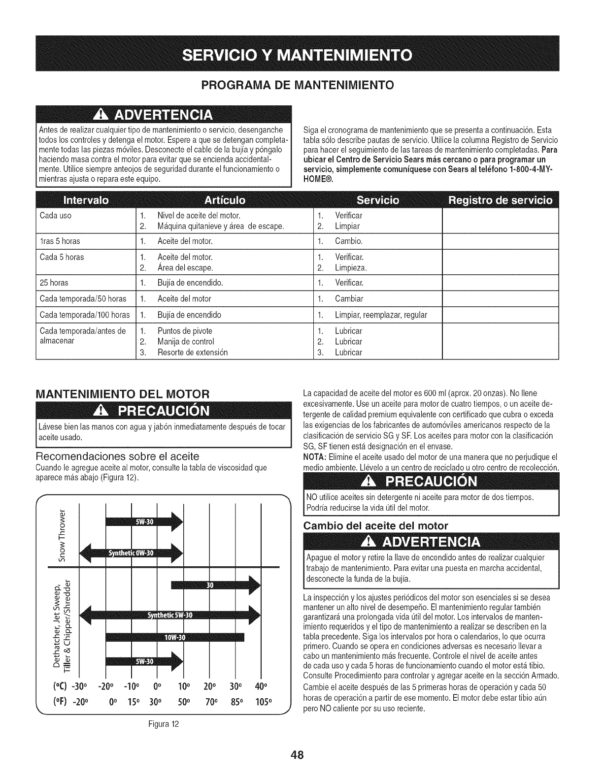
PROGRAMA DE MANTENIMIENTO
Antesde realizarcualquiertipo de mantenimientoo servicio,desenganche
todos loscontrolesydetengael motor.Esperea que sedetengancompleta-
mentetodaslas piezasm6viles.Desconecteel cabledela bujia y p6ngalo
haciendomasacontrael motorparaevitarque seenciendaaccidental-
mente.Utilicesiempreanteojosde seguridadduranteel funcionamientoo
mientrasajustao reparaesteequipo.
Siga elcronogramademantenimientoquese presentaa continuaci6n.Esta
tabla s61odescribepautasdeservicio.Utilice la columnaRegistrodeServicio
parahacerel seguimientodelastareasde mantenimientocompletadas.Para
ubiear el Centrode Servicio Searsm_s cereanoo paraprogramarun
servieio, simplementeeomuniqueseconSears al tel_fono 1-800-4-MY-
HOME®.
Cadauso
lras 5 horas
Cada5 horas
25 horas
Cadatemporada/50horas
Cadatemporada/lO0horas
Cadatemporada/antesde
almacenar
1. Nivelde aceitedel motor.
2. M_quinaquitanievey_rea deescape.
1. Aceitedel motor.
1. Verificar
2. Limpiar
1. Cambio.
1. Aceitedelmotor. 1. Verificar.
2. Areadel escape. 2. Limpieza.
1. Bujiadeencendido. 1. Verificar.
1. Aceitedelmotor 1. Cambiar
1. Bujiade encendido 1. Limpiar,reemplazar,regular
1. Puntosde pivote 1. Lubricar
2. Manijadecontrol 2. Lubricar
3. Resortedeextensi6n 3. Lubricar
MANTENIMIENTO DEL MOTOR
Lavesebienlas manosconagua y jab6ninmediatamentedespuesdetocar
aceiteusado.
Recomendaciones sobre el aceite
Cuandole agregueaceiteal motor,consultela tablade viscosidadque
aparecem&sabajo (Figura12).
o
I.-.
0
b,3
db.m
I--
(°C)
(oF)
-30o
=20o
mm=
m
mm_
-20o -10o0o100
0o150 300 500
20o
70o
Figura 12
m
30o
85o
400
1050
La capacidaddeaceitedel motores 600ml (aprox.20onzas).No Ilene
excesivamente.Use unaceiteparamotordecuatrotiempos,o un aceitede-
tergentede calidadpremiumequivalentecon certificadoque cubrao exceda
las exigenciasde losfabricantesde autom6vilesamericanosrespectode la
clasificaci6ndeservicioSG y SR Los aceitesparamotorconla clasificaci6n
SG,SFtienenest&designaci6nenel envase.
NOTA: Elimineel aceite usadodelmotorde unamaneraque noperjudiqueel
medioambiente.Lleveloa un centrode recicladou otto centrode recolecci6n.
NOutiliceaceitessindetergenteni aceiteparamotordedostiempos.
Podriareducirsela vida Qtildel motor.
Cambio del aceite del motor
Apagueel motory retirela Ilavedeencendidoantesde realizarcualquier
trabajode mantenimiento.Paraevitar unapuestaenmarchaaccidental,
desconecte a fundade a bu a.
La inspecci6ny los ajustesperi6dicosdel motorson esencialessi sedesea
mantenerun alto niveldedesempeSo.Elmantenimientoregulartambien
garantizar&una prolongadavida Otildel motor.Losintervalosdemanten-
imientorequeridosy eltipo demantenimientoa realizarse describenenla
tabla precedente.Siga los intervalospothorao calendarios,Io queocurra
primero.Cuandose operaen condicionesadversases necesarioIlevara
cabo unmantenimientom&sfrecuente.Controleel niveldeaceite antes
de cadausoy cada5 horasdefuncionamientocuandoel motorest_tibio.
ConsulteProcedimientoparacontrolary agregaraceiteenla secci6nArmado.
Cambieel aceitedespuesdelas 5 primerashorasdeoperaci6ny cada50
horasde operaci6na partirde ese momento.El motordebe estar tibio aL]n
peroNOcaliente potsu usoreciente.
48
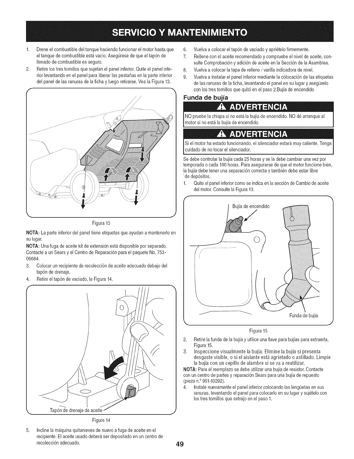
1,
2,
Dreneel combustibledel tanque haciendofuncionarel motorhastaque
eltanque decombustibleest_vacio.AsegL]resede que el tap6nde
Ilenadodecombustiblees seguro.
Retirelostres tornillosquesujetan el panelinferior.Quiteel panelinfe-
rior levantandoen el panelparaliberarlas pesta_asenla parte inferior
del panelde lasranurasdela fichay luegoretirarse.Veala Figura13.
,/' J
_ J
Figura 13
NOTA: Laparteinferiordelpaneltiene etiquetasque ayudana mantenerloen
su lugar.
NOTA: Unafuga deaceitekit de extensi6nest_disponibleporseparado.
Contactea unSearsy el Centrode Reparaci6nparael paqueteNo.753-
06684.
3. Colocarunrecipientederecolecci6nde aceiteadecuadodebajodel
tap6ndedrenaje.
4. Retireeltap6n devaciado,la Figura14.
1
5,
Tap6nde drenajedeaceite
Figure 14
Inclinela m_quinaquitanievesde nuevoa fugade aceiteen el
recipiente.Elaceiteusado deber_set depositadoen un centrode
recolecci6nadecuado.
6. Vuelvaa colocarel tap6ndevaciadoy aprietelofirmemente.
7. Relleneconel aceiterecomendadoy compruebeel nivel deaceite,con-
suiteComprobaci6ny adici6ndeaceiteen la Secci6nde la Asamblea.
8. Vuelvaa colocar latapa de relleno/varillaindicadoradenivel.
9. Vuelvaa instalarel panel inferiormediantelacolocaci6nde lasetiquetas
de lasranurasdela ficha,levantandoel panelen su lugary aseg@elo
con lostrestornillosque quit6en el paso2.Bujiade encendido
Funda de bujia
NO pruebela chispasino est_la bujiadeencendido.NOdearranqueal
motorsi noest_ la bujiade encendido.
Si el motorha estadofuncionando,el silenciadorestar_muycaliente.Tenga
cuidadodenotocar el silenciador.
Sedebe controlarla bujiacada 25 horasy se ladebe cambiarunavez por
temporadao cada 100horas.Paraasegurarsedeque el motorfuncionebien,
labujiadebeteneruna separaci6ncorrectay tambiendebe estar libre
'de dep6sitos.
1. Quiteelpanelinferiorcomose indicaenla secci6ndeCambiodeaceite
del motor.Consultela Figura13.
Bujiade encendido
O
Fundade buj[a
Figura15
2. Retirela fun@ de labujiay utilice unaIlaveparabujiasparaextraerla,
Figura15.
3. Inspeccione visualmente la bujia. Elimine la bujia si presenta
desgaste visible, o si el aislante est,, agrietado o astillado. Limpie
la bujh con un cepillo de alambre si se va a reutilizar.
NOTA:Parael reemplazose debeutilizaruna bujiade resistor.Contacte
con uncentrodepartesy reparaci6nSearsparauna bujiade repuesto
(piezan.°951-10292).
4. Instalenuevamenteel panel inferiorcolocandolas leng0etasen sus
ranuras,levantandoel panelparacolocarloensu lugar y sujetelocon
lostrestornillosque extrajoen el paso1.
49
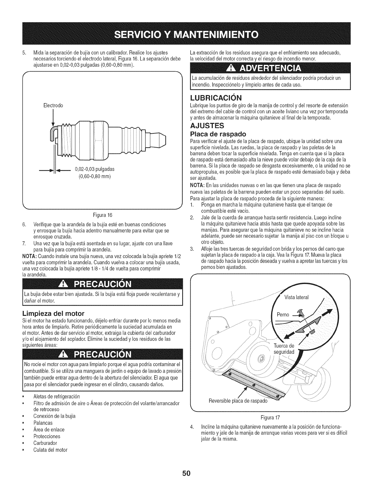
8, Midala separaci6ndebujia con un calibrador.Realicelosajustes
necesariostorciendoel electrodo lateral,Figura 16.Laseparaci6ndebe
ajustarseen 0,02-0,03pulgadas(0,60-0,80mm).
Electrodo
0,02-0,03pulgadas
(0,60-0,80mm)
Figura 16
6. Verifiqueque la arandelade labujiaesteen buenascondiciones
y enrosquela bujiahaciaadentromanualmenteparaevitarquese
enrosquecruzada.
7. Unavez que la bujiaest&asentadaen su lugar,ajustecon unaIlave
parabujiaparacomprimirla arandela.
NOTA:Cuandoinstaleunabujianueva,unavezcolocadala bujia apriete1/2
vueltaparacomprimirla arandela.Cuandovuelvaa colocar una bujiausada,
unavez colocadala bujiaapriete1/8- 1/4devuelta paracomprimir
la arandela.
La extracci6nde losresiduosaseguraqueel enfriamientosea adecuado,
la velocidaddel motorcorrectay el riesgo deincendiomenor.
La acumulaci6nde residuosalrededordel silenciadorpodriaproducirun
incendio.Inspecci6neloy limpieloantesde cada uso.
LUBRICACION
Lubriquelospuntos degiro de la manijade controly del resortede extensi6n
del extremodel cable de controlconunaceiteliviano unavez portemporada
y antesde almacenarla m_quinaquitanieveal finalde latemporada.
AJUSTES
Placa de raspado
Paraverificarel ajustede la placade raspado,ubiquela unidadsobreuna
superficienivelada.Lasruedas,la placade raspadoy laspaletasde la
barrenadebentocarla superficienivelada.Tengaencuentaquesi la placa
de raspadoest&demasiadoaltala nievepuedevolar debajode la cajade la
barrena.Si la placaderaspadose desgastaexcesivamente,o la unidadnose
autopropulsa,es posiblequela placade raspadoestedemasiadobajay deba
ser ajustada.
NOTA: Enlas unidadesnuevaso en lasquetienen unaplacade raspado
nuevalaspaletasde la barrenapuedenestar un pocoseparadasdel suelo.
Paraajustarla placade raspadoprocedade lasiguientemanera:
1. Pongaen marchala m&quinaquitanievehastaque el tanquede
combustibleestevacio.
2. Jale de lacuerdade arranquehastasentir resistencia.Luegoincline
la m_quinaquitanievehaciaatr&shastaque quedeapoyadasobrelas
manijas. Paraasegurarque la m&quinaquitanieveno se incline hacia
adelante,puedeset necesariosujetar la manijaal pisocon un bloqueu
otroobjeto.
3. Afloje lastres tuercasde seguridadcon briday lospernosdel carroque
sujetanla placaderaspadoa lacaja.Veala Figura17.Muevala placa
de raspadohacialaposici6ndeseadayvuelvaa apretarlastuercasy los
pernosbienajustados.
f
Labujiadebe estar bienajustada.Sila bujiaest_floja puederecalentarsey
daSarel motor.
Limpieza del motor
Siel motorha estadofuncionando,dejeloenfriar durantepor Io menos media
horaantesde limpiarlo.Retireperi6dicamentela suciedadacumuladaen
el motor.Antes dedar servicioal motor,extraigala cubiertadelcarburador
y/o el alojamientodel soplador.Eliminela suciedady losresiduosde las
siguientes_reas:
Norocieel motorconaguaparalimpiarloporqueelaguapodriacontaminarel
combustible.Sise utilizaunamanguerade jardino equipode lavadoa presi6n
tambienpuedeentraraguadentrode la aberturadel silenciador.Elaguaque
pasapotel silenciadorpuedeingresarenel cilindro,causandodaSos.
Aletasderefrigeraci6n
• Filtrode admisi6nde aire o Areas de protecci6ndel volante/arrancador
deretroceso
• Conexi6nde la bujia
•Palancas
• Areadeenlace
• Protecciones
• Carburador
• Culatadel motor
Reversibleplacaderaspado
Figura17
4. Inclinela m_quinaquitanievenuevamentea la posici6nde funciona-
mientoyjale de la manijade arranquevariasvecesparavet si es dificil
jalar dela misma.
5O
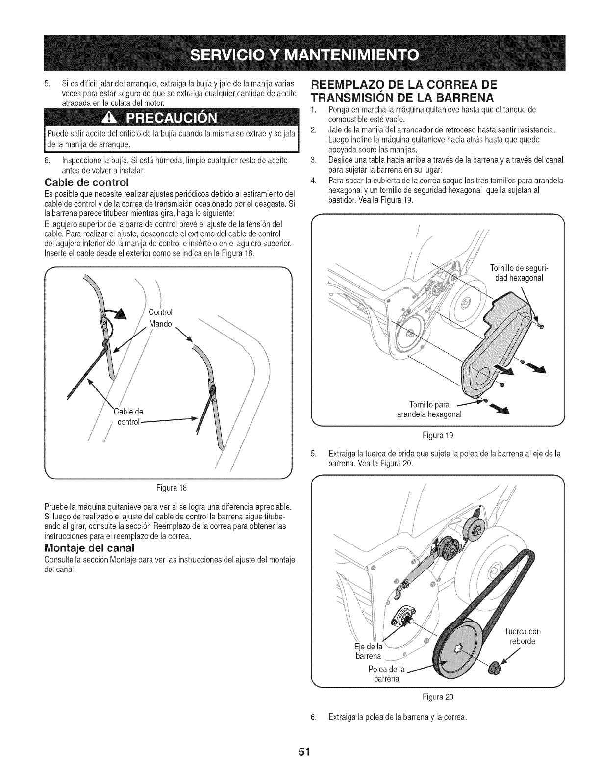
5. Si esdificiljalar del arranque,extraigala buj[ayjale de la manijavarias
vecesparaestar segurodeque se extraigacualquiercantidaddeaceite
atrapadaen la culatadel motor.
Puedesalir aceitedel orificiode la buj[acuandolamismase extraey sejala
dela manijade arranque.
6. Inspeccionela buj[a.Si est_homed& limpiecualquierrestode aceite
antesde volvera instalar.
Cable de control
Es posibleque necesiterealizarajustesperi6dicosdebidoalestiramientodel
cabledecontroly de la correadetransmisi6nocasionadopot eldesgaste.Si
la barrenaparecetitubear mientrasgira, haga Io siguiente:
Elagujerosuperiorde la barrade controlpreveel ajustedela tensi6ndel
cable.Para realizarel ajuste,desconecteelextremodel cabledecontrol
del agujeroinferiordela manijade controle ins@teloenel agujerosuperior.
Inserteel cabledesdeel exteriorcomo se indicaen la Figura18.
\\
Control
Mando
/
/
/!
Figura 18
Pruebela m_quinaquitanieveparavet sise Iograunadiferenciaapreciable.
Si luegoderealizadoel ajustedel cabledecontrolla barrenasiguetitube-
andoalgirar,consultela secci6nReemplazodela correaparaobtenerlas
instruccionesparael reemplazodela correa.
IVlontaje del canal
Consultelasecci6nMontajeparavet las instruccionesdel ajustedel montaje
del canal.
REEMPLAZO DE LA CORREA DE
TRANSMISION DE LA BARRENA
1. Pongaen marcha lam_quinaquitanievehastaque eltanque de
combustibleestevac[o.
2. Jale de la manijadel arrancadorde retrocesohastasentir resistencia.
Luegoincline la m_quinaquitanievehaciaarrashastaque quede
apoyadasobrelasmanijas.
3. Desliceunatabla haciaarribaa travesde la barrenaya traves delcanal
parasujetarla barrenaen su lugar.
4. Parasacarla cubiertade lacorrea saquelostrestornillos paraarandela
hexagonaly untornillode seguridadhexagonalque lasujetan al
bastidor.Veala Figura19.
J/
/ /
/ / Tornillodeseguri-
dad hexagonal
5,
Tornillopara ...__
arandelahexagonal
Figura19
Extraigala tuercade bridaque sujetala poleade labarrenaal eje dela
barrena.Veala Figura20.
/
/ /
................................
.........................:::::::::tb
Ejede la
barrena ...................¢..............
Poleade la
barrena
Tuercacon
reborde
J
Figura20
6. Extraigala poleade la barrenay la correa.
51
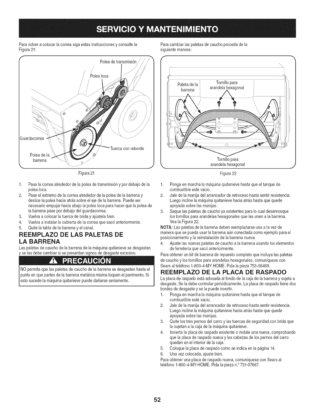
Paravolvera colocar la correasiga estasinstruccionesy consultela
Figura21:
Poleade transmisJOn/
/
/Polealoca
/'
/ /
J
Figura21
Paracambiarlas paletasdecauchoprocedade la
siguientemanera:
Tornillopara
arandelahexagonal _,,,
Figura22
1. Pasela correaalrededorde la poleadetransmisi6ny pot debajode la
poleaIoca.
2. Paseel extremodela correaalrededorde la poleade la barrenay
deslice lapolea haciaatr&ssobreel eje de labarrena. Puedeser
necesarioempujarhaciaabajola poleaIocaparahacerque la poleade
la barrenapasepordebajo del guardacorrea.
3. Vuelvaa colocarla tuercade briday ajL]stelabien.
4. Vuelvaa instalarla cubiertade la correaque sac6anteriormente.
5. Quitelatabla de la barrenay el canal.
REEMPLAZO DE LAS PALETAS DE
LA BARRENA
Laspaletasde cauchode la barrenadela maquinaquitanievese desgastan
y se lasdebecambiarsi se presentansignosde desgasteexcesivo.
NOpermitaque las paletasde cauchode la barrenase desgastenhastael
Ipuntoenquepartesde la barrenamet&licamismatoquen elpavimento.Si
estosucedela m_quinaquitanievepuededaSarseseriamente.
1. Pongaen marchala m&quinaquitanievehastaque el tanquede
combustibleestevac[o.
2. Jale de la manijadel arrancadorde retrocesohastasentir resistencia.
Luegoincline la m&quinaquitanievehaciaarrashastaque quede
apoyadasobrelas manijas.
3. Saquelas paletasde cauchoya existentespara Io cual desenrosque
los tornillosparaarandelashexagonalesque las unena la barrena.
Veala Figura22.
NOTA: Laspaletasde la barrenadeben reemplazarseunaa lavez de
maneraquese puedausar la barrenaaL]nconectadacomoejemploparael
posicionamientoy la reinstalaci6ndela barrenanueva.
4. Ajustelas nuevaspaletasdecaucho a la barrenausandolos elementos
deferreter[aquesac6anteriormente.
Paraobtenerunkitde barrenade repuestocompletoqueincluyalaspaletas
de cauchoy lostornillos paraarandelashexagonales,comun[quesecon
Searsaltelefono 1-800-4-MYHOME.Pidala pieza753-06469.
REEMPLAZO DE LA PLACA DE RASPADO
La placaderaspadoest_ adosadaal fondode lacaja de labarrenay sujetaa
desgaste.Se la debecontrolarperi6dicamente.La placaderaspadotiene dos
hordesde desgastey se la puedeinvertir.
1. Pongaen marchala m&quinaquitanievehastaque el tanquede
combustibleestevac[o.
2. Jale de la manijadel arrancadorde retrocesohastasentir resistencia.
Luegoincline la m&quinaquitanievehaciaarrashastaque quede
apoyadasobrelas manijas.
3. Quitelos tres pernosdel carro y lastuercasdeseguridadcon bridaque
la sujetana lacajade la m_quinaquitanieve.
4. Inviertala placade raspadoexistenteo instaleunanueva,comprobando
que la placaderaspadonuevay las cabezasde los pernosdel carro
quedenen el interiorde la caja.
5. Coloque laplacade raspadocomose indicaen lapagina14.
6. Una vezcolocada,ajustebien.
Paraobtenerunaplacaderaspado nueva,comun[quesecon Searsal
telefono1-800-4-MY-HOME.Pidala piezan.°731-07667.
52
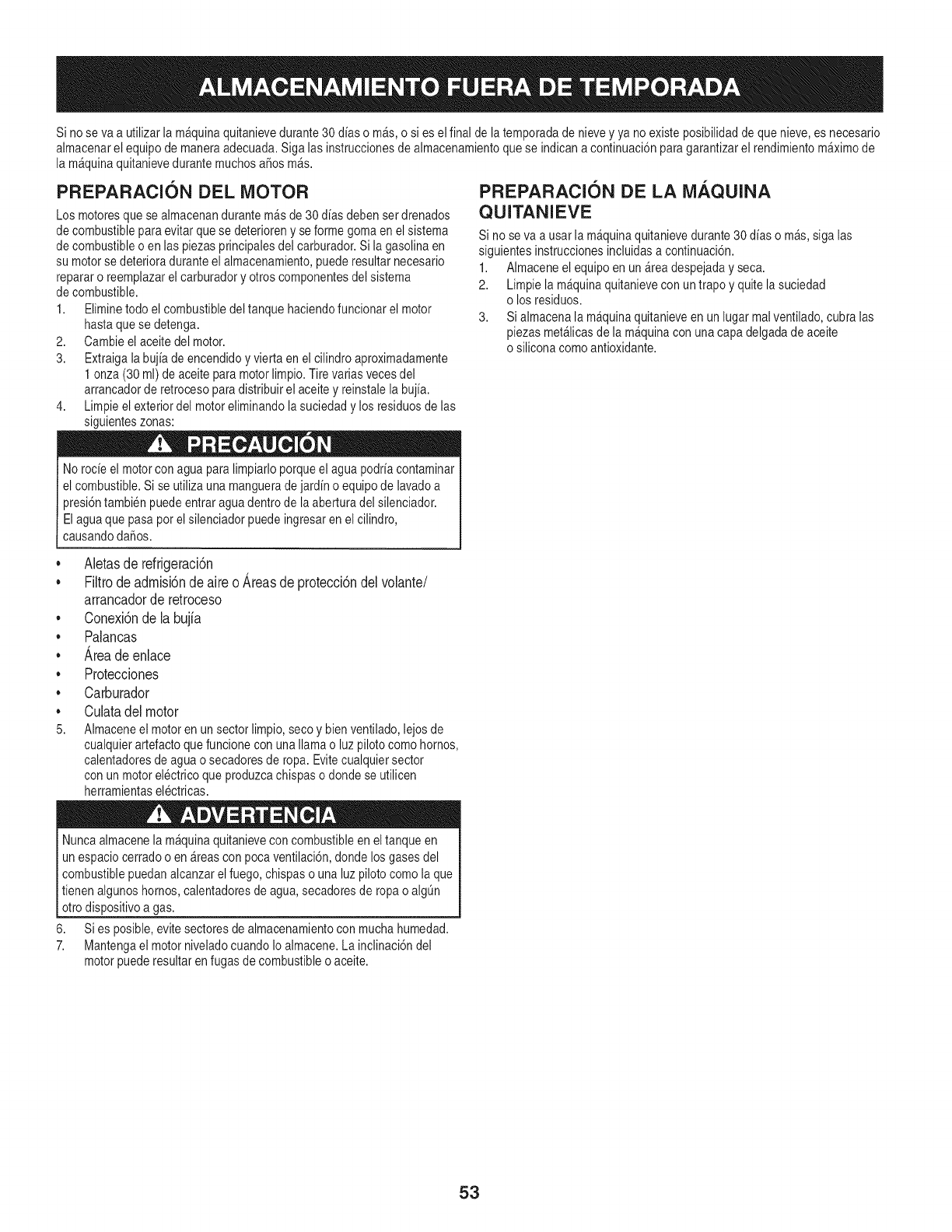
Si no se vaa utilizarla m_quinaquitanievedurante30 dias o m_s,o sies elfinal dela temporadadenieveyya noexisteposibilidadde que nieve,es necesario
almacenarel equipode maneraadecuada.Siga lasinstruccionesdealmacenamientoquese indicana continuaci6nparagarantizarel rendimientom_ximode
la m_quinaquitanievedurantemuchosa_os m_s.
PREPARACION DEL MOTOR
Los motoresquese almacenandurantemAsde 30dias debenset drenados
decombustibleparaevitar quese deterioreny seforme gomaenel sistema
decombustibleo enlas piezasprincipalesdel carburador.Si lagasolinaen
su motorse deterioraduranteel almacenamiento,puederesultarnecesario
repararo reemplazarel carburadory otros componentesdel sistema
decombustible.
1. Eliminetodo el combustibledel tanque haciendofuncionarel motor
hastaque se detenga.
2. Cambieel aceitedel motor.
3. Extraigala bujfade encendidoyvierta en el cilindroaproximadamente
1 onza(30 ml) de aceite paramotorlimpio.Tirevariasvecesdel
arrancadorde retrocesoparadistribuirel aceitey reinstalela bujfa.
4. Limpieel exteriordel motoreliminandolasuciedadylos residuosde las
siguienteszonas:
No rocieel motorcon aguaparalimpiarloporqueel agua podriacontaminar
el combustible.Si se utilizauna mangueradejardin o equipode lavadoa
presi6ntambien puedeentraragua dentrode laaberturadel silenciador.
Elaguaque pasapot el silenciadorpuedeingresarenel cilindro,
causandodaRos.
PREPARACION DE LA MAQUINA
QUITANIEVE
Si no se va a usarla m_quinaquitanievedurante30dias o m_s,siga las
siguientesinstruccionesincluidasa continuaci6n.
1. Almaceneel equipoen un_readespejadayseca.
2. Limpie la m_quinaquitanieveconuntrapo y quitela suciedad
o losresiduos.
3. Si almacenala m_quinaquitanieveen unlugar malventilado,cubralas
piezasmet_licasdela m_quinaconunacapa delgadade aceite
o silicona comoantioxidante.
• Aletas de refrigeraci6n
• Filtro de admisi6n de aire o Areas de protecci6n del volante/
arrancador de retroceso
• Conexi6n de la bujia
• Palancas
• Area de enlace
• Protecciones
• Carburador
• Culata del motor
5. Almaceneel motoren unsector limpio,secoy bienventilado,lejosde
cualquierartefactoquefuncioneconuna llamao luzpilotocomo hornos,
calentadoresde aguao secadoresderopa. Evitecualquiersector
conunmotorelectricoqueproduzcachispaso dondese utilicen
herramientaselectricas.
Nuncaalmacenela m_quinaquitanievecon combustibleen eltanqueen
unespaciocerradoo en_reasconpocaventilaci6n,dondelosgasesdel
combustiblepuedanalcanzarel fuego,chispaso una luzpilotocomola que
tienenalgunoshornos,calentadoresde agua,secadoresde ropao algQn
otrodispositivoa gas.
6. Sies posible,evitesectoresdealmacenamientoconmuchahumedad.
7. Mantengael motorniveladocuandoIo almacene.La inclinaci6ndel
motorpuederesultaren fugas decombustibleo aceite.
53
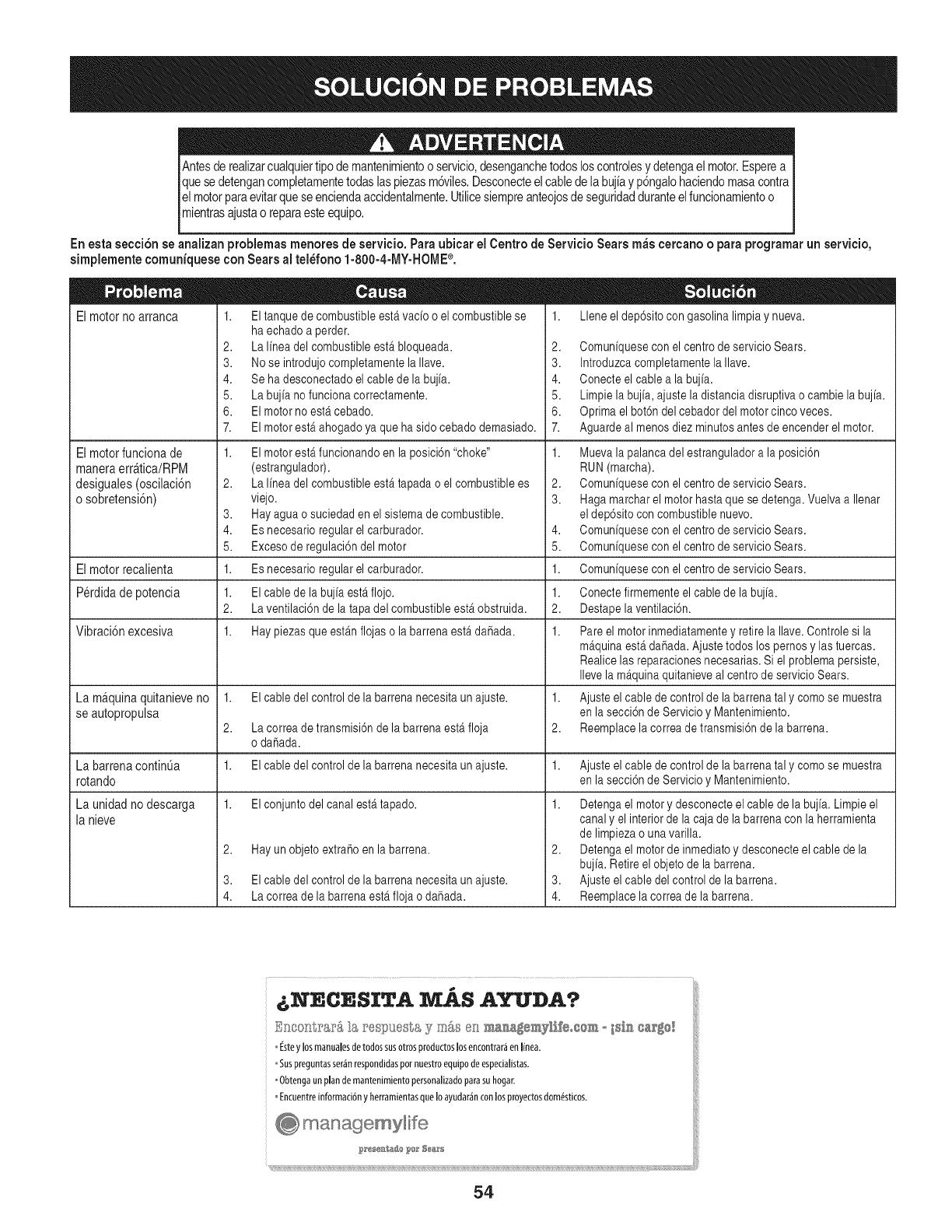
Antesde realizarcualquiertipode mantenimientoo servicio,desenganchetodosloscontrolesydetengael motor.Esperea
quesedetengancompletamentetodaslaspiezasm@iles.Desconecteelcabledelabujiay p6ngalohaciendomasacontra
lelmotorparaevitarqueseenciendaaccidentalmente.Utilicesiempreanteojosde seguridadduranteelfuncionamientoo
mientrasajustao reparaesteequipo.
Enesta secci6n se analizan problemas menores de servicio. Para ubicar el Centro de Servicio Sears m_s eercano oparaprogramarun servicio,
simplemente eomuniquese con Sears al tel_fono 1-800-4-MY-HOME ®.
El motor no arranca 1. El tanque de combustible estfi vado o el combustible se
ha echado a perder.
2. /a Imea del combustible estfi bloqueada.
3. No se introdujo completamente la Ilave.
4. Se ha desconectado el cable de la bujfa.
5. La bujfa no funciona correctamente.
6. El motor no est,. cebado.
7. El motor est,. ahogado ya que ha sido cebado demasiado.
Elmotorfuncionade
maneraerr&tica/RPM
desiguales(oscilaci6n
o sobretensi6n)
2,
3,
4.
5.
1.
1.
2.
1.
El motor est,. funcionando en la posici6n "choke"
(estrangulador).
La Ifnea del combustible est,. tapada o el combustible es
viejo.
Hay agua o suciedad en el sistema de combustible.
Es necesario regular el carburador.
Exceso de regulaci6n del motor
Es necesario regular el carburador.
El cable de la bujfa est,. flojo.
La ventilaci6n de la tapa del combustible est,. obstruida.
Hay piezas que est_.nflojas o la barrena est,. daRada.
t. Llene el dep6sito con gasolina limpia y nueva.
2. Comunfquese con el centro de servicio Sears.
3. Introduzca completamente la Ilave.
4. Conecte el cable a la bujfa.
5. Limpie la bujfa, ajuste la distancia disruptiva ocambie la bujfa.
6. Optima el bot6n del cebador del motor cinco veces.
7. Aguarde al menos diez minutos antes de encender el motor.
t. Mueva la palanca del estrangulador a la posici6n
RUN (marcha).
2. Comunfquese con el centro de servicio Sears.
3. Haga marchar el motor hasta que se detenga. Vuelva a Ilenar
el dep6sito con combustible nuevo.
Comunfquese con el centro de servicio Sears.
Comunfquese con el centro de servicio Sears.
4,
5.
El motor recalienta 1. Comunfquese con el centro de servicio Sears.
Perdida de potencia t. Conecte firmemente el cable de la bujfa.
2. Destape la ventilaci6n.
Vibraci6n excesiva t. Pare el motor inmediatamente y retire la Ilave. Controle si la
m_.quinaest,. daRada.Ajuste todos lospernos y las tuercas.
Realice las reparaciones necesarias. Si el problema persiste,
Ileve la m_.quinaquitanieve al centro de servicio Sears.
La m&quina quitanieve no t. El cable del control de la barrena necesita un ajuste, t. Ajuste el cable de control de la barrena tal y como se muestra
se autopropulsa en la secci6n de Servicio y Mantenimiento.
2. La correa de transmisi6n de la barrena est,. floja 2. Reemplace la correa de transmisi6n de la barrena.
o daRada.
La barrena continOa t. El cable del control de la barrena necesita un ajuste, t. Ajuste el cable de control de la barrena tal y como se muestra
rotando en la secci6n de Servicio y Mantenimiento.
t. El conjunto del canal est,. tapado, t.Launidadnodescarga
la nieve
2. Hay un objeto extraRoen la barrena.
3.
4.
El cable del control de la barrena necesita un ajuste.
La correa de la barrena esta floja o dahada.
Detenga el motor y desconecte el cable de la bujia. Limpie el
canal y el interior de la caja de la barrena con la herramienta
de limpieza o una varilla.
2. Detenga el motor de inmediato y desconecte el cable de la
bujia. Retire el objeto de la barrena.
3. Ajuste el cable del control de la barrena.
4. Reemplace la correa de la barrena.
Snoonl;_'&r& _s re£_}uesta, y m&s es ma_a_smyX£eosem o _s£_ ®a_8_
Esteylosmanualesdetodossusotrosproductoslosencontrar_enline&
Suspreguntasser_nrespondidaspotnuestroequipodeespecialistas.
@btengaunplandemantenimientopersonalizadopai_suhogar.
Encuentreinformaci6nyherramientasqueIoayudar_,nconlosproyectosdomesticos.
54

55
MTD CONSUMER GROUP, iNC. (MTD), el Bordo de Recursos de Aire de California (CARB)
y la Agencia de Protecci6n Medioambiental de Estados Unidos (U. S. EPA)
Declaraci6n de Garantia del Sistema de Control de Emisiones
(Derechos yobligaciones del propietario seg_n la garantia contra defectos)
LACOBERTURADESISTEMADECONTROLDEEMISIONESAPLICABLEA MOTORESCERTIFICADOSCOMPRADOSENCALIFORNIA
EN2005Y A PARTIRDE ENTONCES,QUESON USADOSEN CALIFORNIA,Y HASTAANO2005DE MODELOCERTIFICADOY MOTORES
POSTERIORESQUESON COMPRADOSY USADOSENOTRAPARTEEN LOSESTADOSUNIDOS.
Californiay en otraparteen la Coberturade Garantiade DefectosdeControlde Emisi6nde los EstadosUnidos
El Bordode Recursosde Airede California(CARB),la U.S. EPAy MTDsecomplacenenexplicarla garantiadel sistemade controldeemisiones
de su motorparaequipotodo terreno,modelo,aSo2005y versionesposteriores.EnCalifornia,los nuevosmotorespequeSosparaequipotodo
terrenose debendise5ar,fabricary equiparparacumplirconest_.ndaresde antinieblat6xicade estados.Enotraparteen los EstadosUnidos,
el nuevonocamino,motoresdeignici6ndechispacertificadosparaelmodelo2005y m_.starde,debeencontrareljuegode est_.ndaressimilar
adelanteporlos EstadosUnidos.EPA.MTDdebegarantizarel sistemadecontrolde emisionesdesu motorpor elperiodode tiempoindicadom&s
abajo,siemprey cuandono hayaexistidousoincorrecto,negligencianimantenimientoinadecuadode su motorpequeBoparaequipotodoterreno.
El sistemadecontrolde emisionespuedeincluirpiezascomo,porejemplo,el carburador,sistemadeinyecci6ndecombustible,el sistemade
encendido,el catalizador,losdep6sitosdecombustible,abastecedecombustiblelineas,gorrasde combustible,v&lvulas,latas,filtros,mangueras
devapor,abrazaderas,conectoresy otroscomponentesrelacionadosconlas emisiones.
Dondeexistaunacondici6ncubiertaporla garantia,MTDreparar&su motorpequeBoparaequipotodoterrenosincostoalgunoincluyendoel
diagn6stico,laspiezasy la manode obra.
COBERTURA DE LA GARANTJA DEL FABRICANTE:
Estesistemade controldeemisionesse garantizaporel t@rminodedos a5os.Si algunapiezade su motorrelacionadacon lasemisioneses
defectuosa,MTD reparar&o sustituir&dichapieza.
RESPONSABJLIDADES DEL PROPIETARIO SEGUN LA GARANTJA:
Comopropietariodeun motorpequeSode equipotodoterreno,ustedes responsablede realizarel mantenimientonecesarioquefigura enel
manualdel propietario.MTDle recomiendaqueconservetodoslos recibosquecubrenlos serviciosdemantenimientodel motorpeque5opara
equipotodoterreno,noobstanteIo cual MTDnopodr&denegarel cumplimientodela garantiaQnicamenteporlafaltade reciboso porsu imposibi-
lidadde asegurarquese realizar_.ntodoslos serviciosdemantenimientoprogramado.
Comopropietariodelmotorpeque5oparaequipotodo terreno,sinembargo,ustedtambi@ndebesaberque MTDpuededenegarlacoberturadela
garantiasi su motorpeque5oparaequipotodoterrenoo unapiezadel mismofallandebidoa usoincorrecto,negligencia,mantenimientoindebido
oa modificacionesnoaprobadas.
Ustedes responsablede presentarlacortadoradecespedal centrode distribuci6no de mantenimientode MTDCONSUMERGROUP,INC.tan
prontocomoaparecierael problem& Lasreparacionescubiertaspor lagarantfasedebenIlevaracabo enun lapsorazonableque noexcedade
30dias.Si desearealizaralgunaconsultacon respectoa la coberturade lagarantia,debeponerseencontactocon su distribuidorlocalde MTD.
Paracomunicarseconla LineadeAsistenciaal Clientede Distribuidoresde MTD,Ilameal nQmero(877)282-8684.
REQUERJMJENTOS DE GARANTJA SOBRE DEFECTOS PARA MOTORES PEQUENOS DE EQUJPO TODO TERRENO
DE 1995YVERSJONES POSTERJORES:
Estasecci6nse aplicaa motorespeque5osdeequipotodo terrenode 1995y versionesposteriores.Elperiododegarantiacomienzaa partirde la
fechaen queel motoro elequiposeentreganal compradorfinal.
(a)Coberturade la garantiacontraemisionesgenerales
MTDgarantizaal compradorfinaly acada compradorsubsiguientequeel motor:
(1)hasido diseSado,construidoy equipadode maneraquecumplacontodaslas regulacionesvigentesadoptadasporel Departamentodelos
RecursosdeAire envirtuda suautoridadconferidaen los capitulos1y 2, Parte5, Divisi6n26del C6digode Saludy Seguridad;y
(2)est,. librede defectosen los materialesyen la manode obraquecausenlafalla deunapiezabajogarantiaque seaid@nticaentodoslos
aspectosmaterialesa lapiezacomoaparecedescriptaen laaplicaci6ndelfabricantedel motorparacertificaci6npor unperiododedos a5os.
Lb/Lagarantiasobre piezasrelacJonadasconemisJonesse interpretar_,de la sJguientemanera:
(1)Cualquierpiezacubiertaporgarantiaquenoest@programadaparasu reemplazosegQnel mantenimientorequeridoenlas instrucciones
escritasdela Subsecci6n(c) debeestargarantizadapor unperiodode garantiadefinidoen la Subsecci6n(a)(2). Sila piezafalladurante
el periododecoberturadela garantia,lamismaser_.reparadao reemplazadaporMTD de acuerdocon laSubsecci6n(4)a continuaci6n.
Cualquierpiezareparadao reemplazadasegQnlagarantiasegarantizarB,porel restodelperiodode garantia.
(2) Cualquierpiezacubiertaporgarantiaqueest@programadasoloparainspecci6nregularen las instruccionesescritasde la Subsecci6n
(c) debeestargarantizadaporun periododegarantiadefinidoenla Subsecci6n(a) (2). Unadeclaraci6nen dichasinstruccionesporescrito
alefectode "reparaci6no reemplazosegQnseanecesario"no reducir_,elperiodode coberturade la garantia.Cualquierpiezareparadao
reemplazadasegQnla garantiase garantizar_,porel restodel periodode garantia.
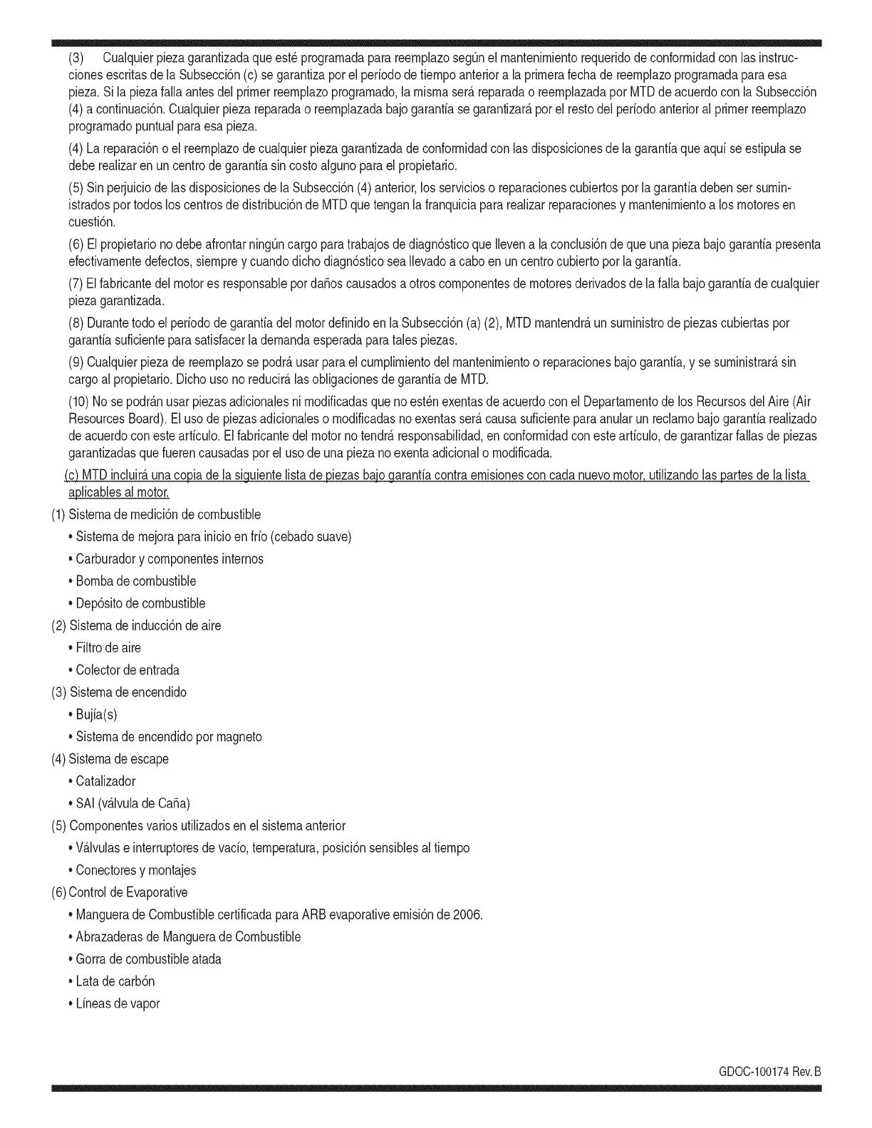
(3) Cualquierpiezagarantizadaqueest_prograrnadaparareernplazosegQnelrnantenirnientorequeridodeconforrnidadconlasinstruc-
clonesescritasdelaSubsecci6n(c)segarantizaporelperiododetiernpoanterioralaprirnerafechadereernplazoprograrnadaparaesa
pieza.Silapiezafallaantesdelprimerreernplazoprogramatic,larnisrnaser_.reparadaoreernplazadaporMTDdeacuerdoconlaSubsecci6n
(4)acontinuaci6n.Cualquierpiezareparadaoreernplazadabajogaranfiasegarantizar_,porelrestodelperiodoanterioralprimerreernplazo
programaticpuntualparaesapieza.
(4)Lareparaci6noelreernplazodecualquierpiezagarantizadadeconforrnidadconlasdisposicionesdelagaranfiaqueaquiseestipulase
deberealizarenuncentrodegaranfiasincostoalgunoparaelpropietario.
(5)SinperjuiciodelasdisposicionesdelaSubsecci6n(4)anterior,losserviciosoreparacionescubiertosporlagaranfiadebensersurnin-
istradosportodosloscentrosdedistribuci6ndeMTDquetenganlafranquiciapararealizarreparacionesyrnantenirnientoalosrnotoresen
cuesti6n.
(6)ElpropietarionodebeafrontarningQncargoparatrabajosdediagn6sticoqueIlevenalaconclusi6ndequeunapiezabajogaranfiapresenta
efectivarnentedefectos,siernpreycuandodichodiagn6sticoseaIlevadoacaboenuncentrocubiertoporlagarantia.
(7)ElfabricantedelmotoresresponsablepordaSoscausadosaotroscornponentesdernotoresderivadosdelafallabajogaranfiadecualquier
piezagarantizada.
(8)DurantetodoelperiododegaranfiadelmotordefinidoenlaSubsecci6n(a)(2),MTDrnantendr_,unsurninistrodepiezascubiertaspor
garantiasuficienteparasatisfacerladernandaesperadaparatalespiezas.
(9)Cualquierpiezadereernplazosepodr_,usarparaelcurnplirnientodelrnantenirnientooreparacionesbajogaranfia,ysesurninistrar_,sin
cargoalpropietario.Dichousonoreducir_,lasobligacionesdegarantiadeMTD.
(10)Nosepodr_.nusarpiezasadicionalesnirnodificadasquenoest_nexentasdeacuerdoconelDepartarnentodelosRecursosdelAire(Air
ResourcesBoard).Elusodepiezasadicionalesornodificadasnoexentasser_.causasuficienteparaanularunreclarnobajogaranfiarealizado
deacuerdoconestearticulo.Elfabricantedelmotornotendr_,responsabilidad,enconforrnidadconestearticulo,degarantizarfallasdepiezas
garantizadasquefuerencausadasporelusodeunapiezanoexentaadicionalornodificada.
.(c)MTDincluir_,unacopiade lasiguientelistade piezasbajogarantiacontraernisionescon cadanuevomotor,utilizandolas partesde la lista
a_plicablesal motor.
(1)Sisternadernedici6ndecombustible
• Sisternade rnejoraparainicioenfrio (cebadosuave)
• Carburadory cornponentesinternos
• Bornbade combustible
• Dep6sitodecombustible
(2) Sisternadeinducci6ndeaire
• Filtrode aire
• Colectordeentrada
(3) Sisternadeencendido
• Bujia(s)
• Sisternadeencendidopor magneto
(4)Sisternadeescape
• Catalizador
• SAI (v_Jvulade CaSa)
(5) Cornponentesvariosutilizadosen el sisternaanterior
• V_Jvulase interruptoresde vado, ternperatura,posici6nsensiblesal tiernpo
• Conectoresy rnontajes
(6)Controlde Evaporative
• Manguerade CombustiblecertificadaparaARB evaporativeernisi6nde 2006.
• Abrazaderasde Manguerade Combustible
• Gorrade combustibleatada
• Latade carb6n
• Lineasdevapor
GD0C-100174Rev.B
Busque el periodo de duraci6n de emisiones importantes yla informaci6n de clasificaci6n de aire en
la etiqueta de emisiones de su motor
Los motores cuyo cumpiimiento con los estAndares de emisi6n Tier 2 de la Comisi6n de Recursos Ambientales de California (CARB)
est6 certificado deben exhibir la informaci6n relacionada con el periodo de duraci6n de ias emisiones y la clasificaci6n de aire. Sears
Brands Management Corporation ponen esta informaci6n a disposici6n del consumidor en nuestras etiquetas de emisiones.
Ei Periodo de Duraci6n de las Emisiones describe el nQmero de horas de tiempo real de funcionamiento para el cuai se certifica que
el motor cumpie con ias reglas de emisi6n, descontando el mantenimiento adecuado del mismo segQn las instrucciones de oper-
aci6n y mantenimiento. Se utilizan las siguientes categonas:
Moderado:Se certifica que el motor cumpie con las reglas de emisi6n durante 125 horas de tiempo real de funcionamiento del motor.
Inmediato:Se certifica que el motor cumpie con las reglas de emisi6n durante 250 horas de tiempo real de funcionamiento del motor.
Extendido:Se certifica que el motor cumpie con las reglas de emisi6n durante 500 horas de tiempo real de funcionamiento del motor.
Por ejemplo, una cortadora de c6sped tJpica que se empuja desde arras se usa entre 20 y 25 horas por aSo. Por Io tanto, el Periodo
de Duraci6n de Emisiones de un motor con una clasificaci6n intermedia sena equivaiente a entre 10 y 12 aSos.
Laciasificaci6n de aire es un nQmero calculado para describir el nivel relativo de emisiones para un grupo de motores en particular.
Cuanto menor sea la clasificaci6n de aire, mayor es la limpieza del motor. La informaci6n se presenta de forma grAfica en la etiqueta
de emisiones.
Despu_s del 1 de julio de 2000, busque el periodo de cumplimiento de las reglas de
emisiones en la etiqueta de cumplimiento de las reglas de emisiones del motor
Despu6s del 1 de julio de 2000 se certificarA que determinados motores Sears Brands Management Corporation cumplen
con los estAndares de emisiones de la fase 2 de la Agencia de Protecci6n Ambientai de los Estados Unidos (USEPA). Para
los motores certificados para la etapa 2, el periodo de cumplimiento con ias reglas de emisiones al cual se hace referencia
en la etiqueta de cumplimiento con las reglas de emisiones indica el nQmero de horas de funcionamiento para el cual se ha
demostrado que el motor cumple con los requerimientos federales de emisi6n.
Para los motores con desplazamiento inferior a 225 cc, Categoria C = 125 horas, B = 250 horas y A = 500 horas.
Para los motores con desplazamiento de 225 cc o mAs, Categoria C = 250 horas, B = 500 horas y A = 1000 horas.
El desplazamiento de los motores de la serie modelo 150112 es 249 cc.
La presente es una representaci6n gen_rica de la etiqueta de emisi6n que se encuentra generaimente en un
motor certificado.
FAMILYYBSXS.3192VA 274812
GDOC-100182Rev.A
58
Felicitaciones por haber realizado una adquisici6n inteligente. El producto Craftsman® que ha
adquirido esta diseSado y fabricado para brindar muchos aSos de funcionamiento confiable. Pero
como todos los productos a veces puede requerir de reparaciones. Es en ese momento cuando el
disponer de un Acuerdo de protecci6n para reparaciones le puede ahorrar dinero y problemas.
A continuaci6n se detallan los puntos incluidos en el Acuerdo:
[] Servicio experto prestadopor nuestros 10,000 especialistas en reparacionesprofesionales
[] Servicio ilirnitado sin cargo para las piezasy la mano de obra en todas las reparacionescubiertas
[] Reernplazo del producto hasta 1500 d61aressi no es posible reparar el producto cubierto
[] Descuento de 25% del precio normal del servicio y de las piezas relacionadascon el mismo que no esten cubiertas
por el acuerdo; ademas, 25% del precio normal de laverificaci6n de mantenimientopreventivo
[] Ayuda r_pida pot tel_fono - Io IlamamosResoluci6n RApida- el apoyo telef6nico de un Chamusca al representante.
Piense en nosotros como el manual "de un dueSohablador."
Una vezadquirido el Acuerdo, puede programar el servicio con tan s61orealizar una Ilamadatelef6nica. Puede Ilamaren
cualquier momentodel dia o de la noche o programar un servicio en linea.
ElAcuerdo de Protecci6nde Reparaci6nes unacompra sin riesgo. Si ustedanula por alguna raz6n duranteel periodo de
garantia de producto,proporcionaremos un reembolso Ileno.O, un reembolsoprorrateadoen cualquier momento despues
del periodode garantia de producto expira, iAdquiera hoy su acuerdode protecci6n para reparaciones!
Se aplican determinadas limitaciones y exclusiones. Para obtener informaciTn adicional y precios en los Estados
Unidos Ilame al 1-800-827-6655.
El *Coverage en Canad_ivaria en algunos articulos. Para detalles Ilenos la Ilamada Chamusca Canad_ien 1-800-
361-8885.
Servicio de instalaci6nde Sears
Si desea solicitar la instalaci6n profesionalde Sears de aparatosdomesticos, dispositivos paraabrir portones,calentado-
res de agua y otros articulos domesticosimportantes, en los Estados Unidos o Canada flameal 1-800-4-MY-HOME®.
59

Your Home
For troubleshooting, product manuals and expert advice:
managernylife
www.managemylife.com
For repair - in your home - of all major brand appliances,
lawn and garden equipment, or heating and cooling systems,
no matter who made it, no matter who sold it!
For the replacement parts, accessories and
owner's manuals that you need to do-it-yourself.
For Sears professional installation of home appliances
and items like garage door openers and water heaters.
1-800-4-MY-HOME ®(1-800-469-4663)
Call anytime, day or night (U.S.A. and Canada)
www.sears.com www.sears.ca
Our Home
For repair of carry-in items like vacuums, lawn equipment,
and electronics, call anytime for the location of your nearest
Sears Parts & Repair Service Center
1-800-488-1222 (U.S.A.) 1-800-469-4663 (Canada)
www.sears.com www.sears.ca
To purchase a protection agreement on a product serviced by Sears:
1-800-827-6655 (U.S.A.) 1-800-361-6665 (Canada)
Para pedir servicio de reparaci6n
a domicilio, y para ordenar piezas:
1-888-SU-HOGAR ®
(1-888-784-6427)
www.sears.com
Au Canada pour service en frangais:
1-800-LE-FOYER Mc
(1-800-533-6937)
www.sears.ca
® Registered Trademark /TMTrademark of KCD IP, LLC in the United States, or Sears Brands, LLC in other countries
® Marca Registrada !TMMarca de Fabrica de KCD IP, LLC en Estados Unidos, o Sears Brands, LLC in otros paises
MCMarque de commerce !MDMarque deposee de Sears Brands, LLC
