Craftsman 315175502 User Manual BISCUIT JOINER Manuals And Guides L0807585
CRAFTSMAN Plate Joiner Manual L0807585 CRAFTSMAN Plate Joiner Owner's Manual, CRAFTSMAN Plate Joiner installation guides
User Manual: Craftsman 315175502 315175502 CRAFTSMAN BISCUIT JOINER - Manuals and Guides View the owners manual for your CRAFTSMAN BISCUIT JOINER #315175502. Home:Tool Parts:Craftsman Parts:Craftsman BISCUIT JOINER Manual
Open the PDF directly: View PDF ![]() .
.
Page Count: 26

OPERATOR'S MANUAL
I:RRFTSMRN
DETAIL BISCUIT JOINER
DOUBLE INSULATED
Model No.
315.1 75502
O O
AWARNING: To reduce the risk of injury,
the user must read and understand the
operator's manual before using this product.
Customer Help Line: 1-800-932-3188
Sears, Roebuck and Co., 3333 Beverly Rd., Hoffman Estates, IL 60179 USA
Visit the Craftsman web page: www.sears.com/craftsman
983000-5t 9
5-05
Save this manual for future reference

•Warranty .......................................................................................................................................................................... 2
•Introduction ..................................................................................................................................................................... 2
• General Safety Rules .................................................................................................................................................... 3-4
• Specific Safety Rules....................................................................................................................................................... 4
• Symbols ........................................................................................................................................................................ 5-6
• Electrical .......................................................................................................................................................................... 7
• Features ........................................................................................................................................................................ 8-9
• Assembly ......................................................................................................................................................................... 9
• Operation .................................................................................................................................................................. 10-t9
• Maintenance ............................................................................................................................................................. 20-22
• Accessories ................................................................................................................................................................... 23
• Troubleshooting ............................................................................................................................................................. 23
• Exploded View and Parts List ................................................................................................................................... 24-25
• Parts Ordering/Service ..................................................................................................................................... Back Page
FULL ONE YEAR WARRANTY ON CRAFTSMAN TOOL
If this CRAFTSMAN tool fails to give complete satisfaction within one year from the date of purchase, RETURN IT TO
THE NEAREST SEARS STORE OR SEARS SERVICE CENTER IN THE UNITED STATES, and Sears will repair it, free
of charge.
If this CRAFTSMAN tool is used for commercial or rental purposes, this warranty applies for only 90 days from the date
of purchase.
This warranty gives you specific legal rights, and you may also have other rights which vary from state to state.
Sears, Roebuck and Co., Dept. 817WA, Hoffman Estates, IL 60179
This tool has many features for making its use more pleasant and enjoyable. Safety, performance, and dependability
have been given top priority in the design of this product making it easy to maintain and operate.

AWARNING: Read and understand all instruc-
tions. Failure to follow all instructions listed below,
may result in electric shock, fire and/or serious
personal injury.
SAVE THESE INSTRUCTIONS
WORK AREA
• Keep your work area clean and well lit. Cluttered
benches and dark areas invite accidents.
•Do not operate power tools in explosive atmo-
spheres, such as in the presence of flammable liq-
uids, gases, or dust. Power tools create sparks which
may ignite the dust or fumes.
•Keep bystanders, children, and visitors away while
operating a power tool. Distractions can cause you to
lose control.
ELECTRICAL SAFETY
•Double insulated tools are equipped with a polar-
ized plug (one blade is wider than the other). This
plug will fit in a polarized outlet only one way. If the
plug does not fit fully in the outlet, reverse the plug.
If it still does not fit, contact a qualified electrician
to install a polarized outlet. Do not change the plug
in any way. Double insulation [] eliminates the need
for the three-wire grounded power cord and grounded
power supply system.
• Avoid body contact with grounded surfaces such
as pipes, radiators, ranges, and refrigerators. There
is an increased risk of electric shock if your body is
grounded.
•Don't expose power tools to rain or wet conditions.
Water entering a power tool will increase the risk of
electric shock.
•Do not abuse the cord. Never use the cord to carry
the tools or pull the plug from an outlet. Keep cord
away from heat, oil, sharp edges, or moving parts.
Replace damaged cords immediately. Damaged
cords increase the risk of electric shock.
•When operating a power tool outside, use an outdoor
extension cord marked "W-A" or "W". These cords
are rated for outdoor use and reduce the risk of electric
shock.
PERSONAL SAFETY
•Stay alert, watch what you are doing and use com-
mon sense when operating a power tool. Do not
use tool while tired or under the influence of drugs,
alcohol, or medication. A moment of inattention while
operating power tools may result in serious personal
injury.
•Dress properly. Do not wear loose clothing or
jewelry. Contain long hair. Keep your hair, clothing,
and gloves away from moving parts. Loose clothes,
jewelry, or long hair can be caught in moving parts.
•Avoid accidental starting. Be sure switch is off
before plugging in. Carrying tools with your finger on
the switch or plugging in tools that have the switch on
invites accidents.
• Remove adjusting keys or wrenches before turning
the tool on. A wrench or a key that is left attached to a
rotating part of the tool may result in personal injury.
•Do not overreach. Keep proper footing and balance
at all times. Proper footing and balance enables better
control of the tool in unexpected situations.
• Use safety equipment. Always wear eye protection.
Dust mask, nonskid safety shoes, hard hat, or hearing
protection must be used for appropriate conditions.
•Do not wear loose clothing or jewelry. Contain long
hair. Loose clothes, jewelry, or long hair can be drawn
into air vents.
•Do not use on a ladder or unstable support. Stable
footing on a solid surface enables better control of the
tool in unexpected situations.
TOOL USE AND CARE
• Use clamps or other practical way to secure and
support the workpiece to a stable platform. Holding
the work by hand or against your body is unstable and
may lead to loss of control.
•Do not force tool. Use the correct tool for your ap-
plication. The correct tool will do the job better and
safer at the rate for which it is designed.
•Do not use tool if switch does not turn it on or off.
Any tool that cannot be controlled with the switch is
dangerous and must be repaired.
•Disconnect the plug from power source before
making any adjustments, changing accessories,
or storing the tool. Such preventive safety measures
reduce the risk of starting the tool accidentally.
• Store idle tools out of the reach of children and
other untrained persons. Tools are dangerous in the
hands of untrained users.
• Maintain tools with care. Keep cutting tools sharp
and clean. Properly maintained tools with sharp cut-
ting edges are less likely to bind and are easier to
control.
• Check for misalignment or binding of moving parts,
breakage of parts, and any other condition that
may affect the tool's operation. If damaged, have
the tool serviced before using. Many accidents are
caused by poorly maintained tools.
• Use only accessories that are recommended by the
manufacturer for your model. Accessories that may
be suitable for one tool, may become hazardous when
used on another tool.
• Keep the tool and its handle dry, clean and free
from oil and grease. Always use a clean cloth when
cleaning. Never use brake fluids, gasoline, petroleum-
based products, or any strong solvents to clean your
tool. Following this rule will reduce the risk of loss of
control and deterioration of the enclosure plastic.

SERVICE
• Tool service must be performed only by qualified
repair personnel. Service or maintenance performed
by unqualified personnel may result in a risk of injury.
When servicing atool, use only identical replace-
ment parts. Follow instructions in the Maintenance
section of this manual. Use of unauthorized parts or
failure to follow Maintenance Instructions may create a
risk of shock or injury.
•Hold tool by insulated gripping surfaces when
performing an operation where the cutting tool may
contact hidden wiring or its own cord. Contact with
a "live" wire will make exposed metal parts of the cut-
ting tool "live" and shock the operator.
• Know your power tool. Read operator's manual
carefully. Learn its applications and limitations, as
well as the specific potential hazards related to this
tool. Following this rule will reduce the risk of electric
shock, fire, or serious injury.
• Always wear safety glasses. Everyday eyeglasses
have only impact-resistant lenses; they are NOT
safety glasses. Following this rule will reduce the risk
of serious personal injury.
•Protect your lungs. Wear a face or dust mask if the
operation is dusty. Following this rule will reduce the
risk of serious personal injury.
• Protect your hearing. Wear hearing protection dur-
ing extended periods of operation. Following this rule
will reduce the risk of serious personal injury.
• Inspect tool cords periodically and, if damaged,
have repaired at your nearest Authorized Service
Center. Constantly stay aware of cord location.
Following this rule will reduce the risk of electric shock
or fire.
•Check damaged parts. Before further use of the
tool, a guard or other part that is damaged should
be carefully checked to determine that it will op-
erate properly and perform its intended function.
Check for alignment of moving parts, binding of
moving parts, breakage of parts, mounting, and
any other conditions that may affect its opera-
tion. A guard or other part that is damaged should
be properly repaired or replaced by an authorized
service center. Following this rule will reduce the risk
of shock, fire, or serious injury.
•Make sure your extension cord is in good condition.
When using an extension cord, be sure to use one
heavy enough to carry the current your product will
draw. A wire gauge size (A.W.G.) of at least 16 is
recommended for an extension cord 50 feet or less
in length. A cord exceeding 100 feet is not recom-
mended. If in doubt, use the next heavier gauge.
The smaller the gauge number, the heavier the
cord. An undersized cord will cause a drop in line volt-
age resulting in loss of power and overheating.
•Inspect for and remove all nails from lumber before
using this tool. Following this rule will reduce the risk
of serious personal injury.
• Save these instructions. Refer to them frequently and
use them to instruct others who may use this tool. If
you loan someone this tool, loan them these instruc-
tions also.
_WARNING: Some dust created by power sanding, sawing, grinding, drilling, and other construction activities
contains chemicals known to cause cancer, birth defects or other reproductive harm. Some examples of these
chemicals are:
• lead from lead-based paints,
• crystalline silica from bricks and cement and other masonry products, and
• arsenic and chromium from chemically-treated lumber.
Your risk from these exposures varies, depending on how often you do this type of work. To reduce your exposure
to these chemicals: work in a well ventilated area, and work with approved safety equipment, such as those dust
masks that are specially designed to filter out microscopic particles.

Someofthefollowingsymbolsmaybeusedonthistool.Pleasestudythemandlearn their meaning. Proper interpreta-
tion of these symbols will allow you to operate the tool better and safer.
SYMBOL NAME DESIGNATION/EXPLANATION
V
A
Hz
W
min
n o
[]
.../min
@
O
A
®
@
@
Volts
Amperes
Hertz
Watt
Minutes
Alternating Current
Direct Current
No Load Speed
Class II Construction
Per Minute
Wet Conditions Alert
Read The Operator's Manual
Eye Protection
Safety Alert
No Hands Symbol
No Hands Symbol
No Hands Symbol
No Hands Symbol
Hot Surface
Voltage
Current
Frequency (cycles per second)
Power
Time
Type of current
Type or a characteristic of current
Rotational speed, at no load
Double-insulated construction
Revolutions, strokes, surface speed, orbits etc., per minute
Do not expose to rain or use in damp locations.
To reduce the risk of injury, user must read and understand
operator's manual before using this product.
Always wear safety goggles, safety glasses with side shields, or
a full face shield when operating this product.
Precautions that involve your safety.
Failure to keep your hands away from the blade will result in
serious personal injury.
Failure to keep your hands away from the blade will result in
serious personal injury.
Failure to keep your hands away from the blade will result in
serious personal injury.
Failure to keep your hands away from the blade will result in
serious personal injury.
To reduce the risk of injury or damage, avoid contact with
any hot surface.

Thefollowingsignalwordsandmeaningsareintendedto explainthelevelsofriskassociatedwiththisproduct.
SYMBOL SIGNAL MEANING
_i, DANGER: Indicates an imminently hazardous situation, which, if not avoided, will
result in death or serious injury.
WARNING: Indicates a potentially hazardous situation, which, if not avoided, could
result in death or serious injury.
,_ CAUTION: Indicates a potentially hazardous situation, which, if not avoided, may
result in minor or moderate injury.
CAUTION: (Without Safety Alert Symbol) Indicates a situation that may result in
property damage.
SERVICE
Servicing requires extreme care and knowledge and
should be performed only by a qualified service tech-
nician. For service we suggest you return the product to
your nearest AUTHORIZED SERVICE CENTER for repair.
When servicing, use only identical replacement parts.
AWARNING: To avoid serious personal injury, do not
attempt to use this product until you read thoroughly
and understand completely the operator's manual.
Save this operator's manual and review frequently for
continuing safe operation and instructing others who
may use this product.
,_k WARNING:
The operation of any power tool can result in foreign objects being thrown into your eyes, which
can result in severe eye damage. Before beginning power tool operation, always wear safety
goggles, safety glasses with side shields, or a full face shield when needed. We recommend Wide
Vision Safety Mask for use over eyeglasses or standard safety glasses with side shields.
Always use eye protection which is marked to comply with ANSI Z87.t.
SAVE THESE INSTRUCTIONS

DOUBLE INSULATION
Double insulation is a concept in safety in electric power
tools, which eliminates the need for the usual three-wire
grounded power cord. All exposed metal parts are
isolated from the internal metal motor components with
protecting insulation. Double insulated tools do not need
to be grounded.
_WARNING: The double insulated system is
intended to protect the user from shock resulting
from a break in the tool's internal insulation. Observe
all normal safety precautions to avoid electrical
shock.
NOTE: Servicing of a tool with double insulation requires
extreme care and knowledge of the system and should
be performed only by a qualified service technician. For
service, we suggest you return the tool to your nearest
authorized service center for repair. Always use original
factory replacement parts when servicing.
ELECTRICAL CONNECTION
This tool has a precision-built electric motor. It should be
connected to a power supply that is 120 volts, 60 Hz,
AC only (normal household current}. Do not operate
this tool on direct current (DC). A substantial voltage drop
will cause a loss of power and the motor will overheat. If
your tool does not operate when plugged into an outlet,
double-check the power supply.
EXTENSION CORDS
When using a power tool at a considerable distance from
a power source, be sure to use an extension cord that has
the capacity to handle the current the tool will draw. An
undersized cord will cause a drop in line voltage, resulting
in overheating and loss of power. Use the chart to deter-
mine the minimum wire size required in an extension cord.
Only round jacketed cords listed by Underwriter's Labora-
tories (UL) should be used.
When working outdoors with a tool, use an extension
cord that is designed for outside use. This type of cord is
designated with "WA" on the cord's jacket.
Before using any extension cord, inspect it for loose or
exposed wires and cut or worn insulation.
**Ampere rating (on tool faceplate)
0-2.0 2.1-3.4 3.5-5.0 5.1-7.0 7.1-12.0 12.1-16.0
Cord Length Wire Size (A.W.G.}
25' t6 t6 t6 t6 t4 t4
50' t6 t6 t6 t4 t4 t2
100' 16 16 14 12 10 --
**Used on 12 gauge -20 amp circuit
NOTE: AWG = American Wire Gauge
AWARNING: Keep the extension cord clear of the
working area. Position the cord so that it will not get
caught on lumber, tools or other obstructions while
you are working with a power tool. Failure to do so
can result in serious personal injury.
AWARNING: Check extension cords before each
use. If damaged replace immediately. Never use tool
with a damaged cord since touching the damaged
area could cause electrical shock resulting in serious
injury.
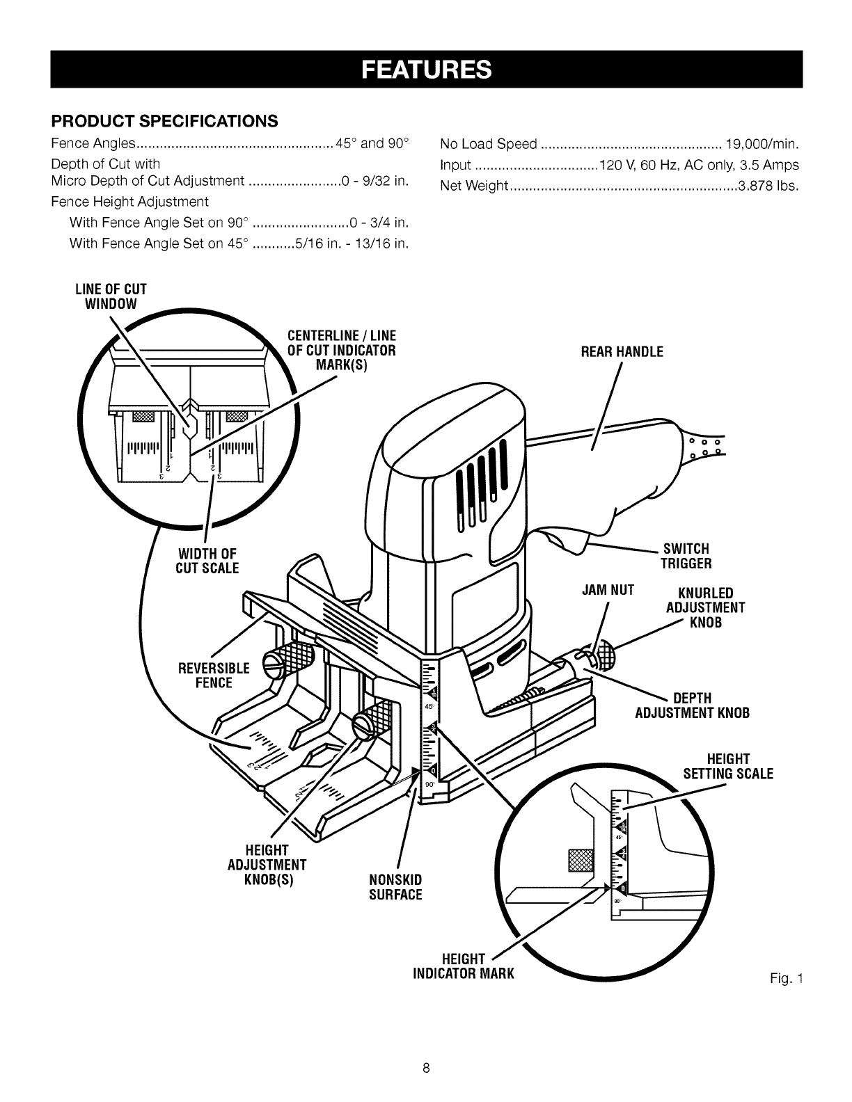
PRODUCT SPECIFICATIONS
Fence Angles ................................................... 45 ° and 90°
Depth of Cut with
Micro Depth of Cut Adjustment ........................ 0 - 9/32 in.
Fence Height Adjustment
With Fence Angle Set on 90° ......................... 0 - 3/4 in.
With Fence Angle Set on 45° ........... 5/16 in. - 13/16 in.
No Load Speed ............................................... 19,000/min.
Input ................................ 120 V, 60 Hz, AC only, 3.5 Amps
Net Weight ........................................................... 3.878 Ibs.
LINEOF CUT
WINDOW
CENTERLINE/LINE
OF CUTINDICATOR
MARK(S) REARHANDLE
0 0
WIDTH OF
CUTSCALE
REVERSIBLE
FENCE
JAM NUT
SWITCH
TRIGGER
KNURLED
ADJUSTMENT
KNOB
DEPTH
ADJUSTMENTKNOB
HEIGHT
SETTINGSCALE
HEIGHT
ADJUSTMENT
KNOB(S) NONSKID
SURFACE
HEIGHT
INDICATORMARK Fig. 1
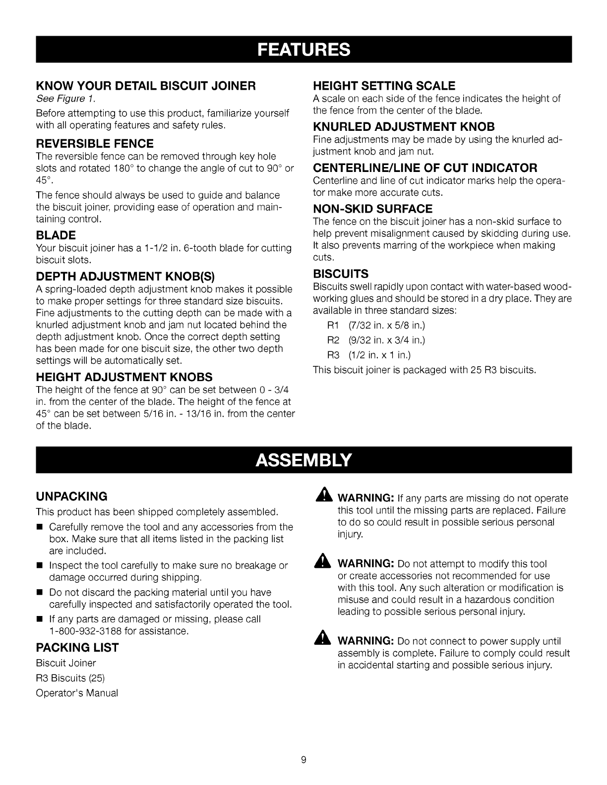
KNOW YOUR DETAIL BISCUIT JOINER
See Figure 1.
Before attempting to use this product, familiarize yourself
with all operating features and safety rules.
REVERSIBLE FENCE
The reversible fence can be removed through key hole
slots and rotated t80 ° to change the angle of cut to 90° or
45° .
The fence should always be used to guide and balance
the biscuit joiner, providing ease of operation and main-
taining control.
BLADE
Your biscuit joiner has a t-1/2 in. 6-tooth blade for cutting
biscuit slots.
DEPTH ADJUSTMENT KNOB(S)
A spring-loaded depth adjustment knob makes it possible
to make proper settings for three standard size biscuits.
Fine adjustments to the cutting depth can be made with a
knurled adjustment knob and jam nut located behind the
depth adjustment knob. Once the correct depth setting
has been made for one biscuit size, the other two depth
settings will be automatically set.
HEIGHT ADJUSTMENT KNOBS
The height of the fence at 90° can be set between 0 - 3/4
in. from the center of the blade. The height of the fence at
45° can be set between 5/16 in. - 13/16 in. from the center
of the blade.
HEIGHT SETTING SCALE
A scale on each side of the fence indicates the height of
the fence from the center of the blade.
KNURLED ADJUSTMENT KNOB
Fine adjustments may be made by using the knurled ad-
justment knob and jam nut.
CENTERLINE/LINE OF CUT INDICATOR
Centerline and line of cut indicator marks help the opera-
tor make more accurate cuts.
NON-SKID SURFACE
The fence on the biscuit joiner has a non-skid surface to
help prevent misalignment caused by skidding during use.
It also prevents marring of the workpiece when making
cuts.
BISCUITS
Biscuits swell rapidly upon contact with water-based wood-
working glues and should be stored in a dry place. They are
available in three standard sizes:
R1 (7/32 in. x 5/8 in.)
R2 (9/32 in. x 3/4 in.)
R3 (1/2 in. x 1 in.)
This biscuit joiner is packaged with 25 R3 biscuits.
UNPACKING
This product has been shipped completely assembled.
• Carefully remove the tool and any accessories from the
box. Make sure that all items listed in the packing list
are included.
• Inspect the tool carefully to make sure no breakage or
damage occurred during shipping.
• Do not discard the packing material until you have
carefully inspected and satisfactorily operated the tool.
• If any parts are damaged or missing, please call
t -800-932-3188 for assistance.
PACKING LIST
Biscuit Joiner
R3 Biscuits (25)
Operator's Manual
a,
A
A
WARNING: If any parts are missing do not operate
this tool until the missing parts are replaced. Failure
to do so could result in possible serious personal
injury.
WARNING: Do not attempt to modify this tool
or create accessories not recommended for use
with this tool. Any such alteration or modification is
misuse and could result in a hazardous condition
leading to possible serious personal injury.
WARNING: Do not connect to power supply until
assembly is complete. Failure to comply could result
in accidental starting and possible serious injury.
• • A
AWARNING: Do not allow familiarity with tools
to make you careless. Remember that a careless
fraction of a second is sufficient to inflict serious
injury.
AWARNING: Always wear safety goggles or safety
glasses with side shields when operating power
tools. Failure to do so could result in objects being
thrown into your eyes resulting in possible serious
injury.
AWARNING: Always use a firm grip with both hands
and clamp your workpiece securely when operating
the biscuit joiner, to avoid loss of control and pos-
sible serious injury.
APPLICATIONS
You may use this tool for the purposes listed below:
•Cutting precise mating oval slots in hard wood, soft wood,
plywood and particle board
SPLINE JOINERY
Spline joinery is one of the strongest methods of joinery
used in woodworking. When glue is properly applied to a
spline and to the joint area of the wood pieces being con-
nected, a large surface area receives the adhesion proper-
ties of the glue. This forms a strong joint.
Traditional spline joinery requires cutting slots with a
router or table saw. Small, thin strips of wood must then
be cut to fit inside the slots and act as splines.
Newer methods of spline joinery use a plate or biscuit
joiner to cut precise mating oval slots in adjoining boards.
This biscuit joiner is a fast, simple, and accurate plunge-
cutting tool that can be used to cut slots in hardwood,
softwood, plywood, particle board, and other pressed
woods.
Football shaped wafers, called biscuits, are then placed
inside the slots with glue and used to help line up ad-
joining surfaces. When a water based glue is used, the
biscuits swell in the joint, making an extremely strong and
firm bond. White glue, yellow glue, carpenters glue, hide
glue, and aliphatic resin glue are examples of water-based
glues. This bonding technique has traditionally been lim-
ited to making edge-to-edge joints. However, with the use
of this biscuit joiner, biscuits can now be easily used to
connect butt, miter, and T-joints. Biscuit joining can be as
strong as mortise and tenon, tongue and groove, stan-
dard spline, and doweled joints. In most cases the mate-
rial around the biscuit will break before the biscuit itself
will break. A greater surface area is exposed to glue in a
biscuit joint, making the seams stronger.
A variety of spline joints can be made using the biscuit
joiner. The number and size biscuits needed for each joint
depends on the thickness of the wood and the length
of the joint. In general, the small #R1 biscuits should be
used for miter cuts in 3/4 in. materials. The larger biscuits
should be used for edge-to-edge joinery.
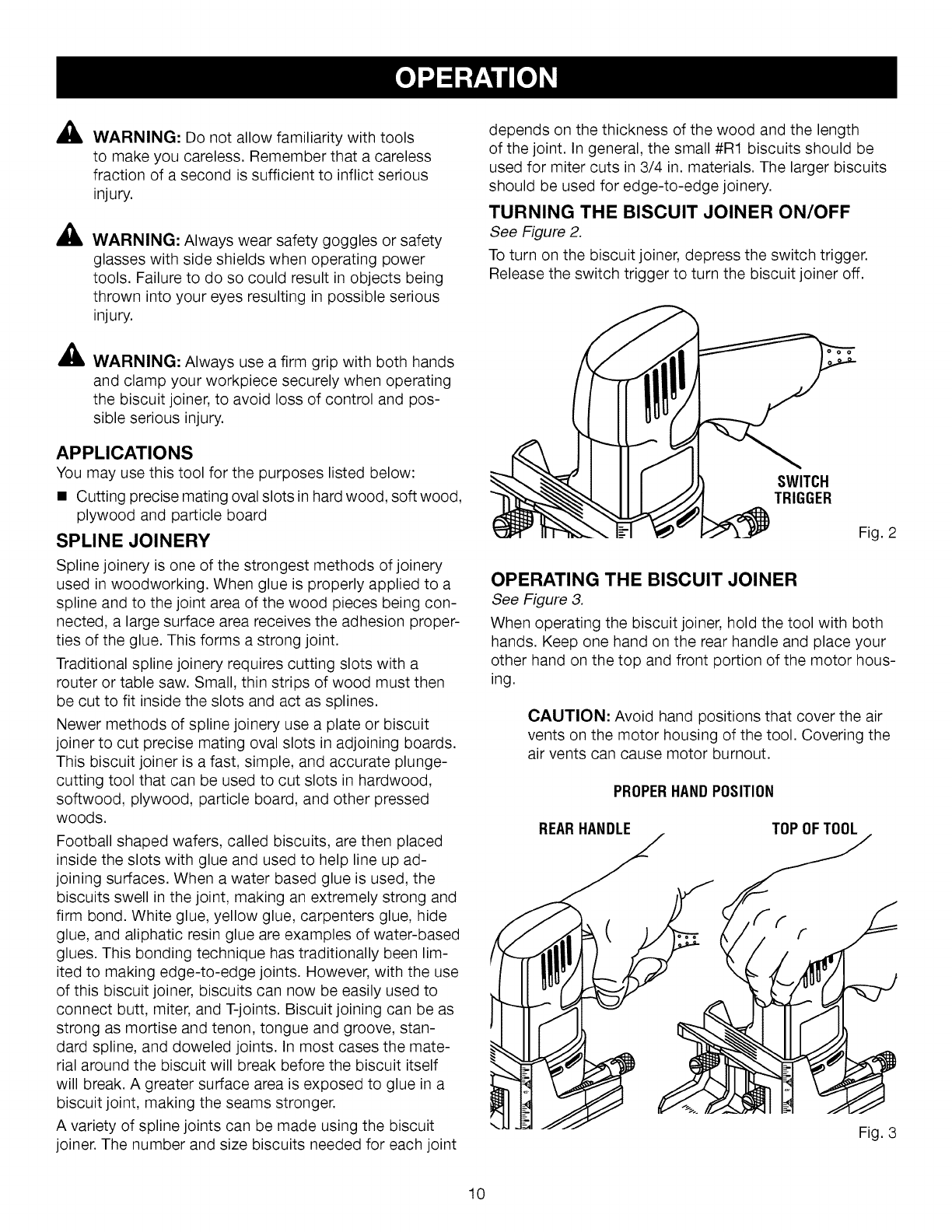
TURNING THE BISCUIT JOINER ON/OFF
See Figure 2.
To turn on the biscuit joiner, depress the switch trigger.
Release the switch trigger to turn the biscuit joiner off.
SWITCH
TRIGGER
Fig. 2
OPERATING THE BISCUIT JOINER
See Figure 3.
When operating the biscuit joiner, hold the tool with both
hands. Keep one hand on the rear handle and place your
other hand on the top and front portion of the motor hous-
ing.
CAUTION: Avoid hand positions that cover the air
vents on the motor housing of the tool. Covering the
air vents can cause motor burnout.
PROPERHANDPOSITION
REARHANDLE TOP OFTOOL
10
AWARNING: Always unplug the tool when chang-
ing operation settings or when the tool is not in use.
Failure to unplug the tool may result in accidental
starting and serious personal injury.
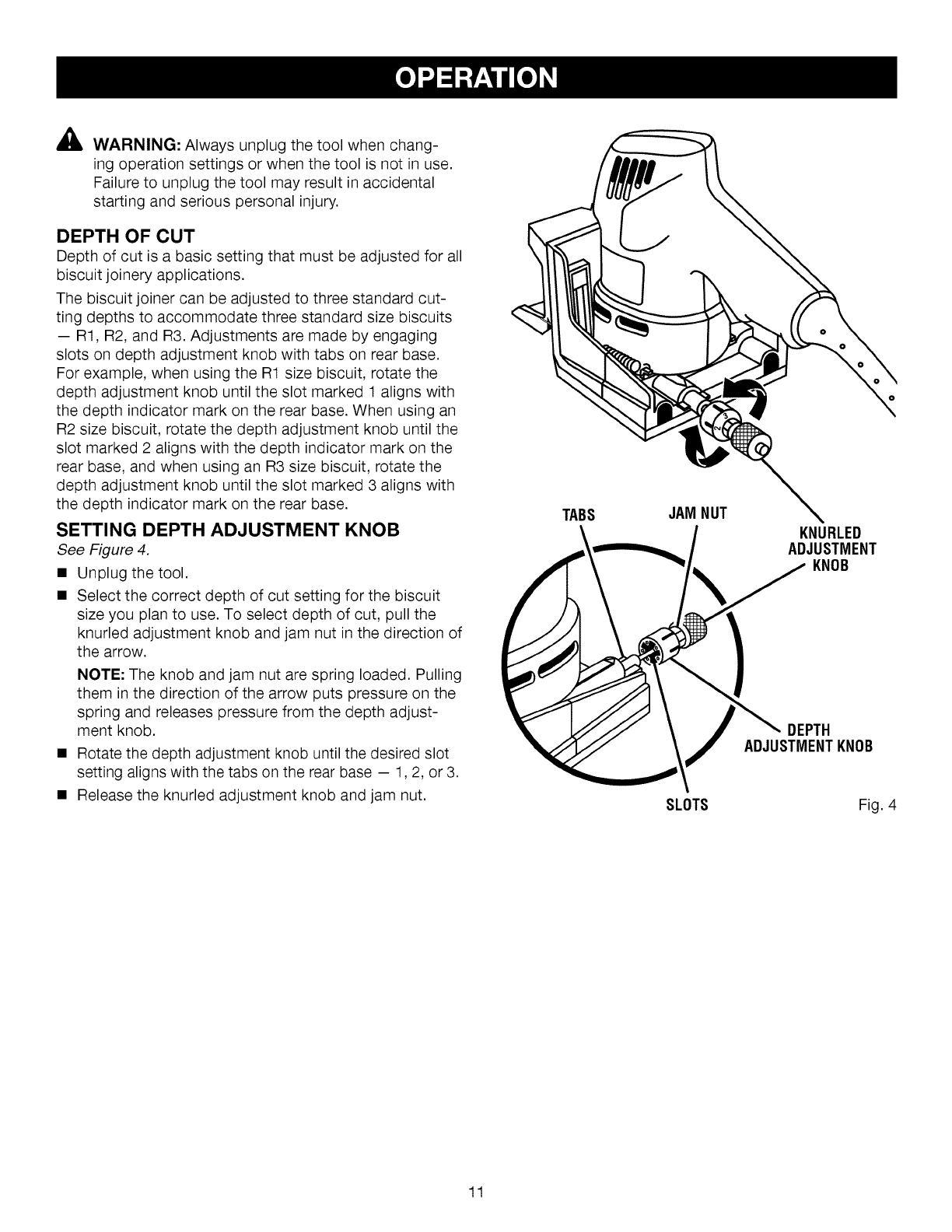
DEPTH OF CUT
Depth of cut is a basic setting that must be adjusted for all
biscuit joinery applications.
The biscuit joiner can be adjusted to three standard cut-
ting depths to accommodate three standard size biscuits
-- Rt, R2, and R3. Adjustments are made by engaging
slots on depth adjustment knob with tabs on rear base.
For example, when using the R1 size biscuit, rotate the
depth adjustment knob until the slot marked 1 aligns with
the depth indicator mark on the rear base. When using an
R2 size biscuit, rotate the depth adjustment knob until the
slot marked 2 aligns with the depth indicator mark on the
rear base, and when using an R3 size biscuit, rotate the
depth adjustment knob until the slot marked 3 aligns with
the depth indicator mark on the rear base.
SETTING DEPTH ADJUSTMENT KNOB
See Figure 4.
• Unplug the tool.
• Select the correct depth of cut setting for the biscuit
size you plan to use. To select depth of cut, pull the
knurled adjustment knob and jam nut in the direction of
the arrow.
NOTE: The knob and jam nut are spring loaded. Pulling
them in the direction of the arrow puts pressure on the
spring and releases pressure from the depth adjust-
ment knob.
• Rotate the depth adjustment knob until the desired slot
setting aligns with the tabs on the rear base - 1,2, or 3.
• Release the knurled adjustment knob and jam nut.
TABS JAM NUT
SLOTS
KNURLED
ADJUSTMENT
KNOB
DEPTH
ADJUSTMENTKNOB
Fig. 4
11
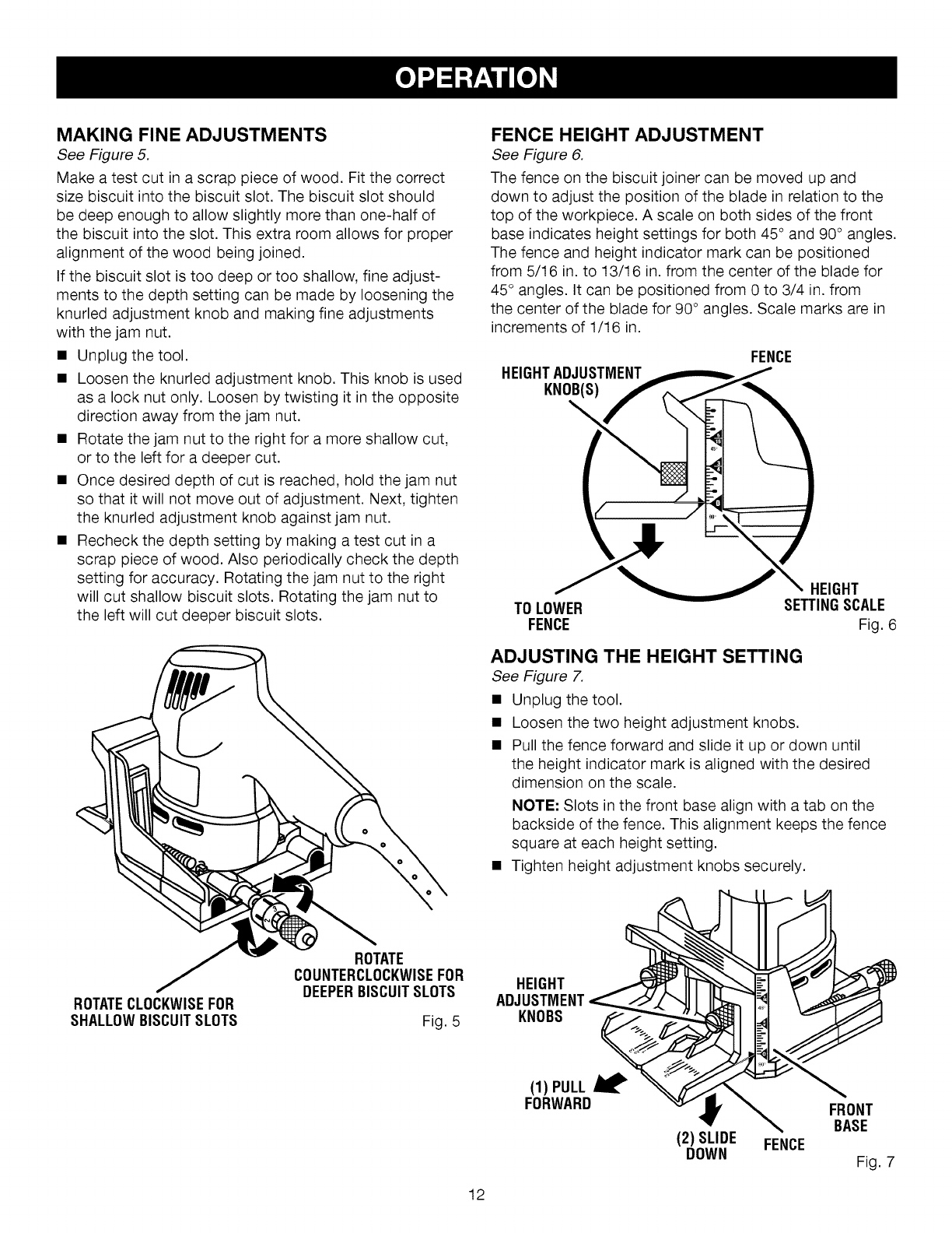
MAKING FINE ADJUSTMENTS
See Figure 5.
Make a test cut in a scrap piece of wood. Fit the correct
size biscuit into the biscuit slot. The biscuit slot should
be deep enough to allow slightly more than one-half of
the biscuit into the slot. This extra room allows for proper
alignment of the wood being joined.
If the biscuit slot is too deep or too shallow, fine adjust-
ments to the depth setting can be made by loosening the
knurled adjustment knob and making fine adjustments
with the jam nut.
• Unplug the tool.
• Loosen the knurled adjustment knob. This knob is used
as a lock nut only. Loosen by twisting it in the opposite
direction away from the jam nut.
• Rotate the jam nut to the right for a more shallow cut,
or to the left for a deeper cut.
• Once desired depth of cut is reached, hold the jam nut
so that it will not move out of adjustment. Next, tighten
the knurled adjustment knob against jam nut.
• Recheck the depth setting by making a test cut in a
scrap piece of wood. Also periodically check the depth
setting for accuracy. Rotating the jam nut to the right
will cut shallow biscuit slots. Rotating the jam nut to
the left will cut deeper biscuit slots.
FENCE HEIGHT ADJUSTMENT
See Figure 6.
The fence on the biscuit joiner can be moved up and
down to adjust the position of the blade in relation to the
top of the workpiece. A scale on both sides of the front
base indicates height settings for both 45 ° and 90° angles.
The fence and height indicator mark can be positioned
from 5/16 in. to 13/16 in. from the center of the blade for
45° angles. It can be positioned from 0 to 3/4 in. from
the center of the blade for 90 ° angles. Scale marks are in
increments of t/16 in.
FENCE
HEIGHTADJUSTMENT
KNOB(S)_'_
HEIGHT
TO LOWER SETTINGSCALE
FENCE Fig. 6
ADJUSTING THE HEIGHT SETTING
See Figure 7.
• Unplug the tool.
• Loosen the two height adjustment knobs,
• Pull the fence forward and slide it up or down until
the height indicator mark is aligned with the desired
dimension on the scale.
NOTE: Slots in the front base align with a tab on the
backside of the fence. This alignment keeps the fence
square at each height setting.
• Tighten height adjustment knobs securely.
ROTATECLOCKWISEFOR
SHALLOWBISCUITSLOTS
ROTATE
COUNTERCLOCKWISEFOR
DEEPERBISCUITSLOTS
Fig. 5
HEIGHT
ADJUSTMENT
KNOBS
12
(1) PULL
FORWARD
(2) SLIDE FENCE
DOWN
FRONT
BASE
Fig. 7
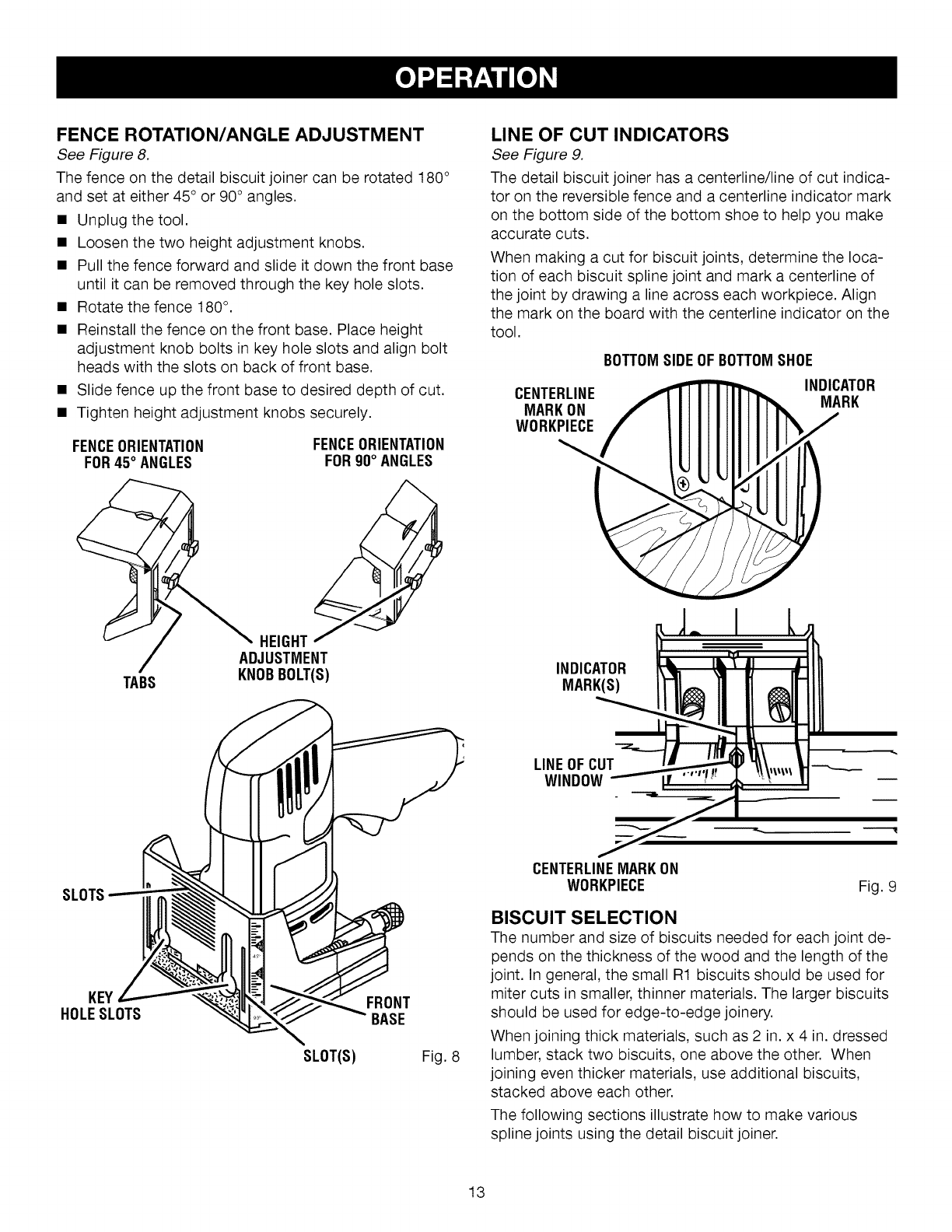
FENCE ROTATION/ANGLE ADJUSTMENT
See Figure 8.
The fence on the detail biscuit joiner can be rotated t80 °
and set at either 45° or 90° angles.
• Unplug the tool.
• Loosen the two height adjustment knobs.
• Pull the fence forward and slide it down the front base
until it can be removed through the key hole slots.
• Rotate the fence t80 °.
• Reinstall the fence on the front base. Place height
adjustment knob bolts in key hole slots and align bolt
heads with the slots on back of front base.
• Slide fence up the front base to desired depth of cut.
• Tighten height adjustment knobs securely.
FENCEORIENTATION
FOR45° ANGLES
TABS
FENCEORIENTATION
FOR90° ANGLES
HEIGHT
ADJUSTMENT
KNOBBOLT(S)
LINE OF CUT INDICATORS
See Figure 9.
The detail biscuit joiner has a centerline/line of cut indica-
tor on the reversible fence and a centerline indicator mark
on the bottom side of the bottom shoe to help you make
accurate cuts.
When making a cut for biscuit joints, determine the loca-
tion of each biscuit spline joint and mark a centerline of
the joint by drawing a line across each workpiece. Align
the mark on the board with the centerline indicator on the
tool.
CENTERLINE
MARKON
WORKPIECE
BOTTOMSIDEOFBOTTOMSHOE
INDICATOR
MARK
INDICATOR
MARK(S)
LINEOF CUT
WINDOW
SLOTS
KEY FRONT
HOLESLOTS BASE
SLOT(S) Fig. 8
CENTERLINEMARKON
WORKPIECE Fig. 9
BISCUIT SELECTION
The number and size of biscuits needed for each joint de-
pends on the thickness of the wood and the length of the
joint. In general, the small R1 biscuits should be used for
miter cuts in smaller, thinner materials. The larger biscuits
should be used for edge-to-edge joinery.
When joining thick materials, such as 2 in. x 4 in. dressed
lumber, stack two biscuits, one above the other. When
joining even thicker materials, use additional biscuits,
stacked above each other.
The following sections illustrate how to make various
spline joints using the detail biscuit joiner.
13
AWARNING: Always use a firm grip with both hands
and clamp your workpiece securely when operating
the biscuit joiner, to avoid loss of control and pos-
sible serious injury.
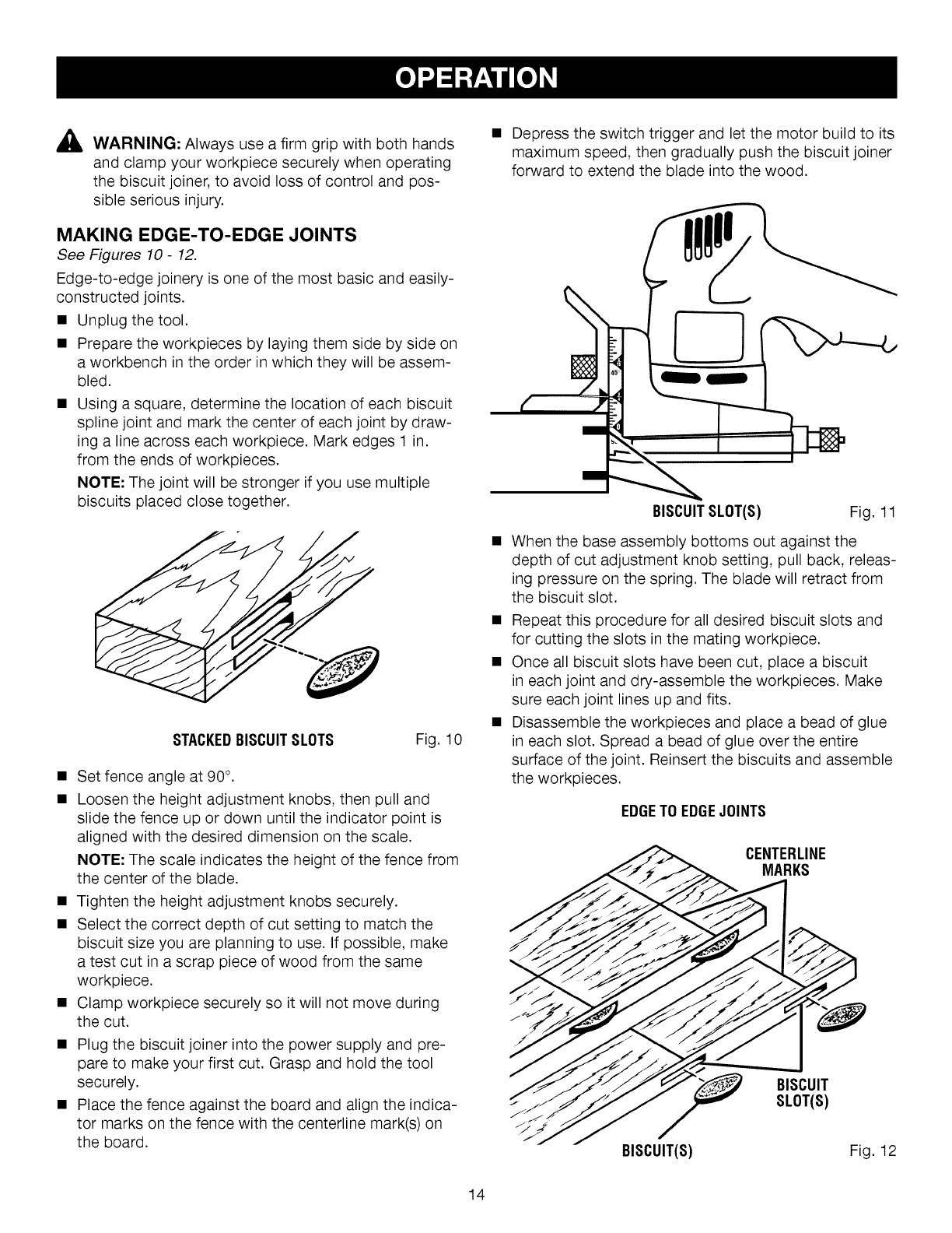
MAKING EDGE-TO-EDGE JOINTS
See Figures 10- 12.
Edge-to-edge joinery is one of the most basic and easily-
constructed joints.
• Unplug the tool.
• Prepare the workpieces by laying them side by side on
a workbench in the order in which they will be assem-
bled.
• Using a square, determine the location of each biscuit
spline joint and mark the center of each joint by draw-
ing a line across each workpiece. Mark edges t in.
from the ends of workpieces.
NOTE: The joint will be stronger if you use multiple
biscuits placed close together.
STACKEDBISCUITSLOTS Fig. 10
• Set fence angle at 90°.
• Loosen the height adjustment knobs, then pull and
slide the fence up or down until the indicator point is
aligned with the desired dimension on the scale.
NOTE: The scale indicates the height of the fence from
the center of the blade.
• Tighten the height adjustment knobs securely.
• Select the correct depth of cut setting to match the
biscuit size you are planning to use. If possible, make
a test cut in a scrap piece of wood from the same
workpiece.
• Clamp workpiece securely so it will not move during
the cut.
• Plug the biscuit joiner into the power supply and pre-
pare to make your first cut. Grasp and hold the tool
securely.
• Place the fence against the board and align the indica-
tor marks on the fence with the centerline mark(s) on
the board.
• Depress the switch trigger and let the motor build to its
maximum speed, then gradually push the biscuit joiner
forward to extend the blade into the wood.
BISCUITSLOT(S) Fig. t 1
• When the base assembly bottoms out against the
depth of cut adjustment knob setting, pull back, releas-
ing pressure on the spring. The blade will retract from
the biscuit slot.
• Repeat this procedure for all desired biscuit slots and
for cutting the slots in the mating workpiece.
• Once all biscuit slots have been cut, place a biscuit
in each joint and dry-assemble the workpieces. Make
sure each joint lines up and fits.
• Disassemble the workpieces and place a bead of glue
in each slot. Spread a bead of glue over the entire
surface of the joint. Reinsert the biscuits and assemble
the workpieces.
EDGETO EDGEJOINTS
CENTERLINE
MARKS
BISCUIT
SLOT(S)
BISCUIT(S) Fig. t2
14
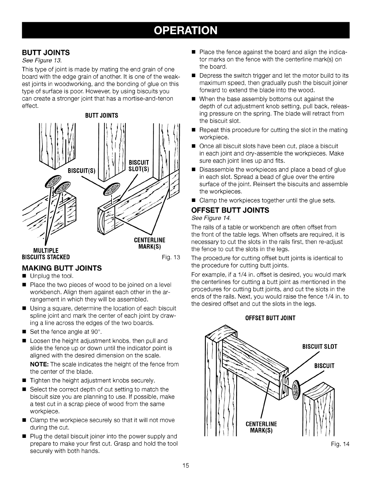
BUTT JOINTS
See Figure 13.
This type of joint is made by mating the end grain of one
board with the edge grain of another. It is one of the weak-
est joints in woodworking, and the bonding of glue on this
type of surface is poor. However, by using biscuits you
can create a stronger joint that has a mortise-and-tenon
effect.
BUTTJOINTS
BISCUIT(S)
BISCUIT
SLOT(S)
CENTERLINE
MARK(S)
MULTIPLE
BISCUITSSTACKED Fig. 13
MAKING BUTT JOINTS
•Unplug the tool.
• Place the two pieces of wood to be joined on a level
workbench. Align them against each other in the ar-
rangement in which they will be assembled.
• Using a square, determine the location of each biscuit
spline joint and mark the center of each joint by draw-
ing a line across the edges of the two boards.
• Set the fence angle at 90°.
• Loosen the height adjustment knobs, then pull and
slide the fence up or down until the indicator point is
aligned with the desired dimension on the scale.
NOTE: The scale indicates the height of the fence from
the center of the blade.
• Tighten the height adjustment knobs securely.
• Select the correct depth of cut setting to match the
biscuit size you are planning to use. If possible, make
a test cut in a scrap piece of wood from the same
workpiece.
• Clamp the workpiece securely so that it will not move
during the cut.
• Plug the detail biscuit joiner into the power supply and
prepare to make your first cut. Grasp and hold the tool
securely with both hands.
• Place the fence against the board and align the indica-
tor marks on the fence with the centerline mark(s) on
the board.
• Depress the switch trigger and let the motor build to its
maximum speed, then gradually push the biscuit joiner
forward to extend the blade into the wood.
• When the base assembly bottoms out against the
depth of cut adjustment knob setting, pull back, releas-
ing pressure on the spring. The blade will retract from
the biscuit slot.
• Repeat this procedure for cutting the slot in the mating
workpiece.
• Once all biscuit slots have been cut, place a biscuit
in each joint and dry-assemble the workpieces. Make
sure each joint lines up and fits.
• Disassemble the workpieces and place a bead of glue
in each slot. Spread a bead of glue over the entire
surface of the joint. Reinsert the biscuits and assemble
the workpieces.
• Clamp the workpieces together until the glue sets.
OFFSET BUTT JOINTS
See Figure 14.
The rails of a table or workbench are often offset from
the front of the table legs. When offsets are required, it is
necessary to cut the slots in the rails first, then re-adjust
the fence to cut the slots in the legs.
The procedure for cutting offset butt joints is identical to
the procedure for cutting butt joints.
For example, if a 1/4 in. offset is desired, you would mark
the centerlines for cutting a butt joint as mentioned in the
procedures for cutting butt joints, and cut the slots in the
ends of the rails. Next, you would raise the fence t/4 in. to
the desired offset and cut the slots in the legs.
OFFSETBUTTJOINT
BISCUITSLOT
BISCUIT
CENTERLINE
MARK(S)
Fig. 14
15
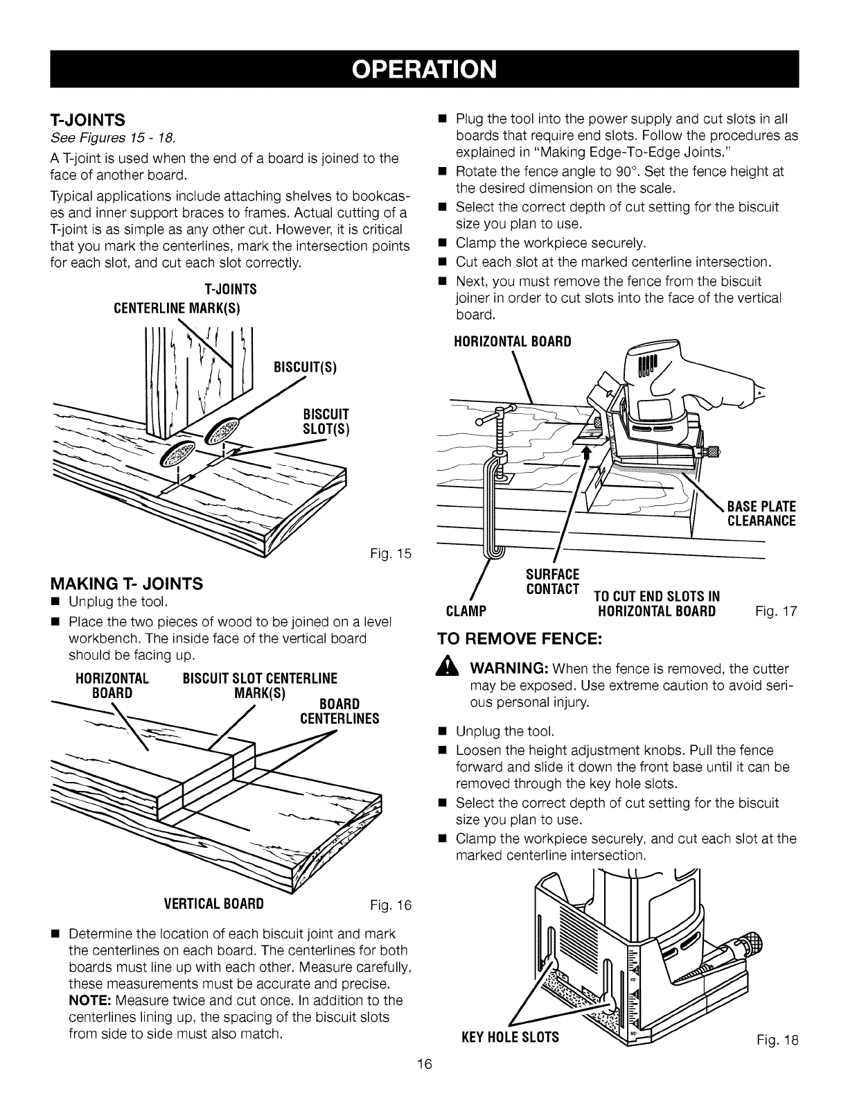
T-JOINTS
See Figures 15- 18.
A T-joint is used when the end of a board is joined to the
face of another board.
Typical applications include attaching shelves to bookcas-
es and inner support braces to frames. Actual cutting of a
T-joint is as simple as any other cut. However, it is critical
that you mark the centerlines, mark the intersection points
for each slot, and cut each slot correctly.
T-JOINTS
CENTERLINEMARK(S)
/(( ! (), | BISCUIT(S)
Fig. t 5
MAKING 1"-JOINTS
• Unplug the tool.
• Place the two pieces of wood to be joined on a level
workbench. The inside face of the vertical board
should be facing up.
HORIZONTAL BISCUITSLOTCENTERLINE
BOARD MARK(S)
"__X_ /BOARD
CENTERLINES
VERTICALBOARD Fig. t6
Determine the location of each biscuit joint and mark
the centerlines on each board. The centerlines for both
boards must line up with each other. Measure carefully,
these measurements must be accurate and precise.
NOTE: Measure twice and cut once. In addition to the
centerlines lining up, the spacing of the biscuit slots
from side to side must also match.
• Plug the tool into the power supply and cut slots in all
boards that require end slots. Follow the procedures as
explained in "Making Edge-To-Edge Joints."
• Rotate the fence angle to 90°. Set the fence height at
the desired dimension on the scale.
• Select the correct depth of cut setting for the biscuit
size you plan to use.
• Clamp the workpiece securely.
• Cut each slot at the marked centerline intersection.
• Next, you must remove the fence from the biscuit
joiner in order to cut slots into the face of the vertical
board.
HORIZONTALBOARD
BASEPLATE
CLEARANCE
SURFACE
CONTACT TO CUTENDSLOTSIN
CLAMP HORIZONTALBOARD Fig. t7
TO REMOVE FENCE:
AWARNING: When the fence is removed, the cutter
may be exposed. Use extreme caution to avoid seri-
ous personal injury.
• Unplug the tool.
• Loosen the height adjustment knobs. Pull the fence
forward and slide it down the front base until it can be
removed through the key hole slots.
• Select the correct depth of cut setting for the biscuit
size you plan to use.
• Clamp the workpiece securely, and cut each slot at the
marked centerline intersection.
16
KEYHOLESLOTS Fig. t8
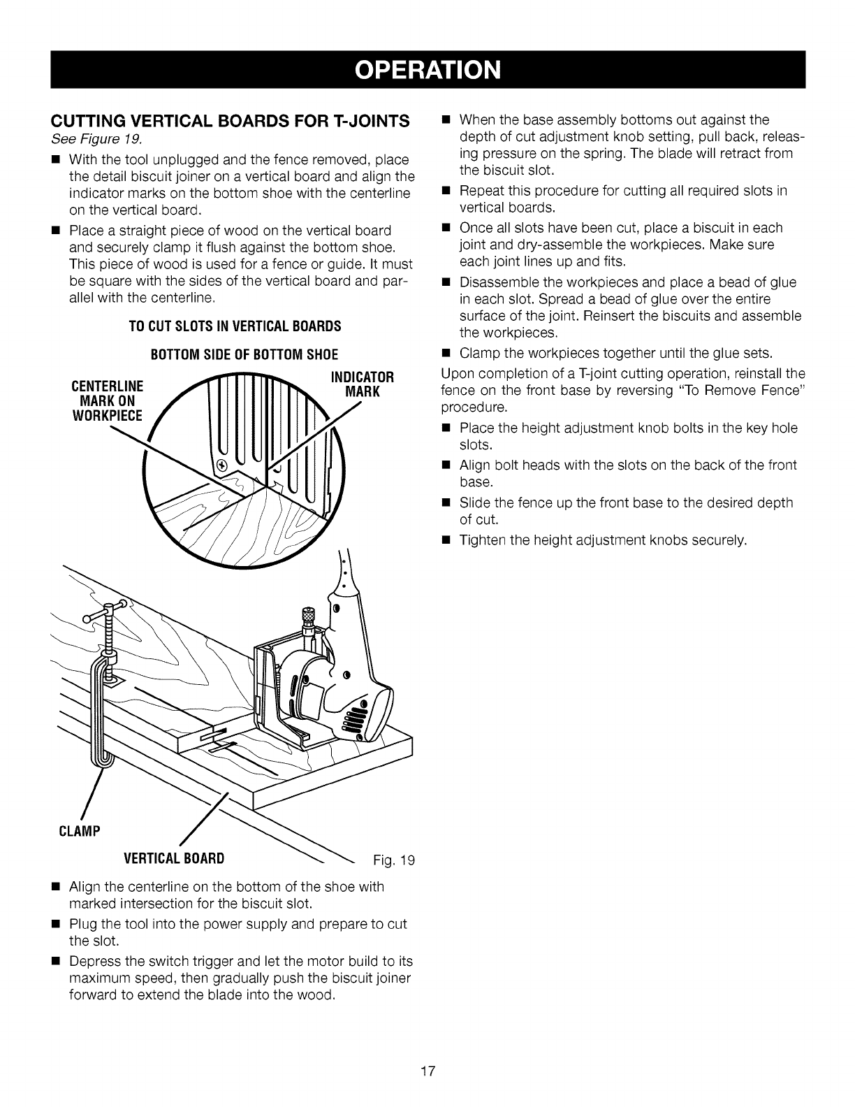
CUTTING VERTICAL BOARDS FOR T-JOINTS
See Figure 19.
• With the tool unplugged and the fence removed, place
the detail biscuit joiner on a vertical board and align the
indicator marks on the bottom shoe with the centerline
on the vertical board.
• Place a straight piece of wood on the vertical board
and securely clamp it flush against the bottom shoe.
This piece of wood is used for a fence or guide. It must
be square with the sides of the vertical board and par-
allel with the centerline.
TO CUTSLOTSIN VERTICALBOARDS
CENTERLINE
MARKON
WORKPIECE
BOTTOMSIDE OFBOTTOMSHOE
INDICATOR
MARK
• When the base assembly bottoms out against the
depth of cut adjustment knob setting, pull back, releas-
ing pressure on the spring. The blade will retract from
the biscuit slot.
• Repeat this procedure for cutting all required slots in
vertical boards.
• Once all slots have been cut, place a biscuit in each
joint and dry-assemble the workpieces. Make sure
each joint lines up and fits.
• Disassemble the workpieces and place a bead of glue
in each slot. Spread a bead of glue over the entire
surface of the joint. Reinsert the biscuits and assemble
the workpieces.
• Clamp the workpieces together until the glue sets.
Upon completion of a T-joint cutting operation, reinstall the
fence on the front base by reversing "To Remove Fence"
procedure.
• Place the height adjustment knob bolts in the key hole
slots.
• Align bolt heads with the slots on the back of the front
base.
• Slide the fence up the front base to the desired depth
of cut.
• Tighten the height adjustment knobs securely.
CLAMP
VERTICALBOARD Fig. t9
• Align the centerline on the bottom of the shoe with
marked intersection for the biscuit slot.
• Plug the tool into the power supply and prepare to cut
the slot.
• Depress the switch trigger and let the motor build to its
maximum speed, then gradually push the biscuit joiner
forward to extend the blade into the wood.
17
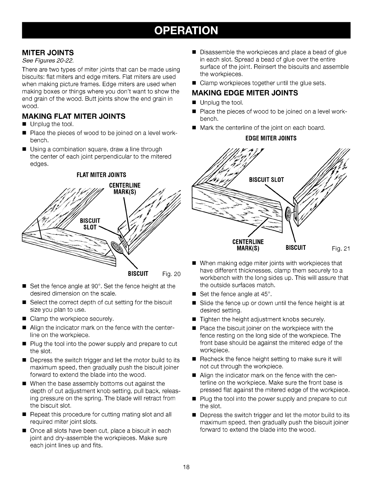
MITER JOINTS
See Figures 20-22.
There are two types of miter joints that can be made using
biscuits: flat miters and edge miters. Flat miters are used
when making picture frames. Edge miters are used when
making boxes or things where you don't want to show the
end grain of the wood. Butt joints show the end grain in
wood.
MAKING FLAT MITER JOINTS
• Unplug the tool.
• Place the pieces of wood to be joined on a level work-
bench.
• Using a combination square, draw a line through
the center of each joint perpendicular to the mitered
edges.
FLATMITERJOINTS
CENTERLINE
MARK(S)
BISCUIT Fig. 20
• Set the fence angle at 90°. Set the fence height at the
desired dimension on the scale.
• Select the correct depth of cut setting for the biscuit
size you plan to use.
• Clamp the workpiece securely.
• Align the indicator mark on the fence with the center-
line on the workpiece.
• Plug the tool into the power supply and prepare to cut
the slot.
• Depress the switch trigger and let the motor build to its
maximum speed, then gradually push the biscuit joiner
forward to extend the blade into the wood.
• When the base assembly bottoms out against the
depth of cut adjustment knob setting, pull back, releas-
ing pressure on the spring. The blade will retract from
the biscuit slot.
• Repeat this procedure for cutting mating slot and all
required miter joint slots.
• Once all slots have been cut, place a biscuit in each
joint and dry-assemble the workpieces. Make sure
each joint lines up and fits.
• Disassemble the workpieces and place a bead of glue
in each slot. Spread a bead of glue over the entire
surface of the joint. Reinsert the biscuits and assemble
the workpieces.
• Clamp workpieces together until the glue sets.
MAKING EDGE MITER JOINTS
• Unplug the tool.
• Place the pieces of wood to be joined on a level work-
bench.
• Mark the centerline of the joint on each board.
EDGEMITERJOINTS
CENTERLINE
MARK(S) BISCUIT Fig. 21
• When making edge miter joints with workpieces that
have different thicknesses, clamp them securely to a
workbench with the long sides up. This will assure that
the outside surfaces match.
• Set the fence angle at 45°.
• Slide the fence up or down until the fence height is at
desired setting.
• Tighten the height adjustment knobs securely.
• Place the biscuit joiner on the workpiece with the
fence resting on the long side of the workpiece. The
front base should be against the mitered edge of the
workpiece.
• Recheck the fence height setting to make sure it will
not cut through the workpiece.
• Align the indicator mark on the fence with the cen-
terline on the workpiece. Make sure the front base is
pressed flat against the mitered edge of the workpiece.
• Plug the tool into the power supply and prepare to cut
the slot.
• Depress the switch trigger and let the motor build to its
maximum speed, then gradually push the biscuit joiner
forward to extend the blade into the wood.
18
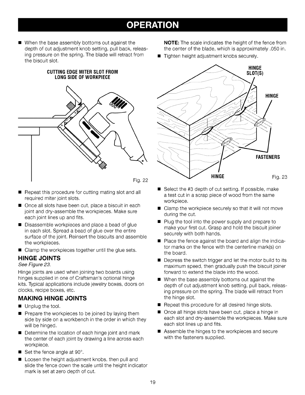
• Whenthebaseassemblybottomsoutagainstthe
depthof cutadjustmentknobsetting,pullback,releas-
ingpressureonthespring.Thebladewillretractfrom
thebiscuitslot.
CUTTINGEDGEMITERSLOTFROM
LONGSIDEOF WORKPIECE
NOTE: The scale indicates the height of the fence from
the center of the blade, which is approximately .050 in.
Tighten height adjustment knobs securely.
HINGE
FASTENERS
Fig. 22
• Repeat this procedure for cutting mating slot and all
required miter joint slots.
• Once all slots have been cut, place a biscuit in each
joint and dry-assemble the workpieces. Make sure
each joint lines up and fits.
• Disassemble workpieces and place a bead of glue
in each slot. Spread a bead of glue over the entire
surface of the joint. Reinsert the biscuits and assemble
the workpieces.
• Clamp the workpieces together until the glue sets.
HINGE JOINTS
See Figure 23.
Hinge joints are used when joining two boards using
hinges supplied in one of Craftsman's optional hinge
kits. Typical applications include jewelry boxes, doors on
clocks, recipe boxes, etc.
MAKING HINGE JOINTS
• Unplug the tool.
• Prepare the workpieces to be joined by laying them
side by side on a workbench in the order in which they
will be hinged.
• Determine the location of each hinge joint and mark
the center of each joint by drawing a line across each
workpiece.
• Set the fence angle at 90°.
• Loosen the height adjustment knobs, then pull and
slide the fence down the scale until the height indicator
mark is set at zero depth of cut.
HINGE Fig. 23
Select the #3 depth of cut setting. If possible, make
a test cut in a scrap piece of wood from the same
workpiece.
Clamp the workpiece securely so that it will not move
during the cut.
Plug the tool into the power supply and prepare to
make your first cut. Grasp and hold the biscuit joiner
securely with both hands.
Place the fence against the board and align the indica-
tor marks on the fence with the centerline mark(s) on
the board.
Depress the switch trigger and let the motor build to its
maximum speed, then gradually push the biscuit joiner
forward to extend the blade into the wood.
When the base assembly bottoms out against the
depth of cut adjustment knob setting, pull back, releas-
ing pressure on the spring. The blade will retract from
the hinge slot.
Repeat this procedure for all desired hinge slots.
Once all hinge slots have been cut, place a hinge in
each slot and dry-assemble the workpieces. Make sure
each slot lines up and fits.
Assemble the hinges to the workpieces and secure
with the fasteners supplied.
19
,&
,&
WARNING: When servicing, use only identical
Craftsman replacement parts. Use of any other parts
may create a hazard or cause product damage.
WARNING: Always wear safety goggles or safety
glasses with side shields during power tool operation
or when blowing dust. If operation is dusty, also wear
a dust mask.
GENERAL MAINTENANCE
Avoid using solvents when cleaning plastic parts. Most
plastics are susceptible to damage from various types of
commercial solvents and may be damaged by their use.
Use clean cloths to remove dirt, dust, oil, grease, etc.
AWARNING: Do not at any time let brake fluids,
gasoline, petroleum-based products, penetrating
oils, etc., come in contact with plastic parts. Chemi-
cals can damage, weaken or destroy plastic which
may result in serious personal injury.
Electric tools used on fiberglass material, wallboard,
spackling compounds, or plaster are subject to accel-
erated wear and possible premature failure because the
fiberglass chips and grindings are highly abrasive to bear-
ings, brushes, commutators, etc. Consequently, we do not
recommended using this tool for extended work on these
types of materials. However, if you do work with any of
these materials, it is extremely important to clean the tool
using compressed air.
LUBRICATION
All of the bearings in this tool are lubricated with a suffi-
cient amount of high grade lubricant for the life of the unit
under normal operating conditions. Therefore, no further
lubrication is required.
Only the parts shown on the parts list are intended to be
repaired or replaced by the customer. All other parts
should be replaced at a Sears Service Center.
BLADE REPLACEMENT
See Figures 24-26.
After extended use, the blade may become dull. If you
accidentally hit a nail or other blunt object, it will dull or
break the blade. These situations require replacing the
blade.
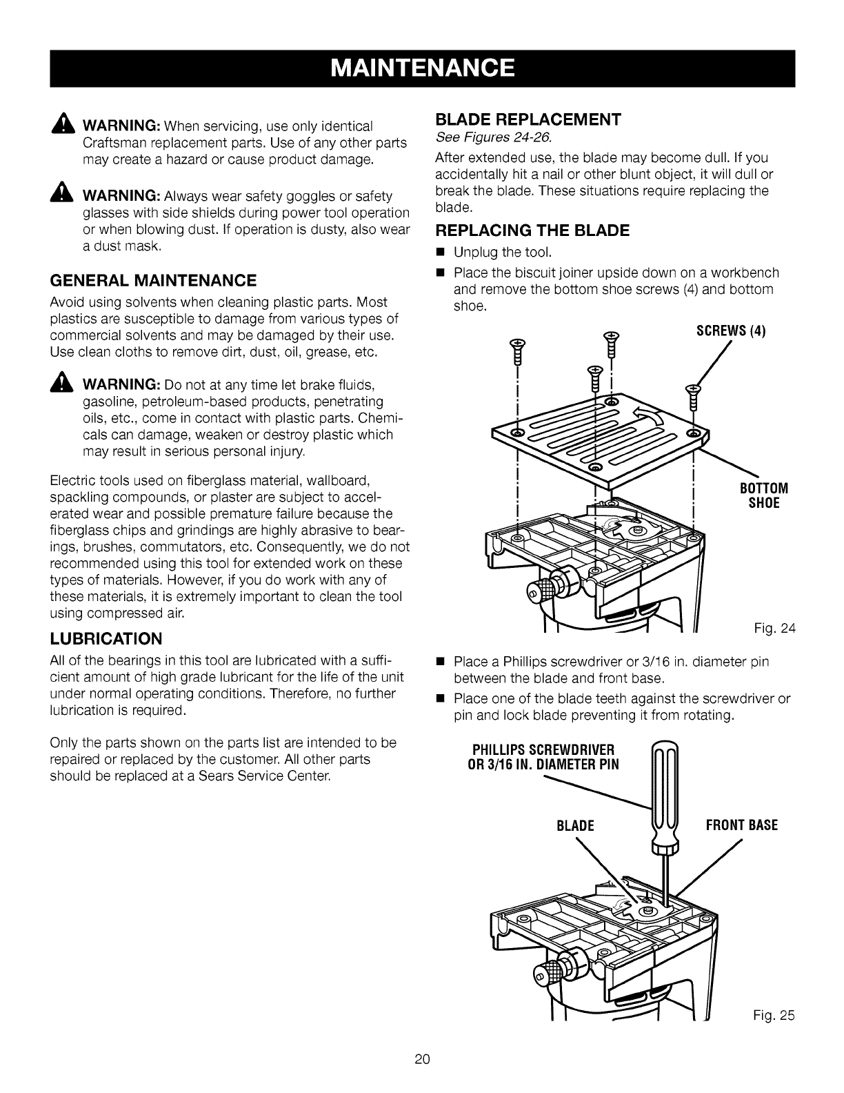
REPLACING THE BLADE
Unplug the tool.
Place the biscuit joiner upside down on a workbench
and remove the bottom shoe screws (4) and bottom
shoe.
i
I
SCREWS(4)
i
I
II
I
BOTTOM
SHOE
Fig. 24
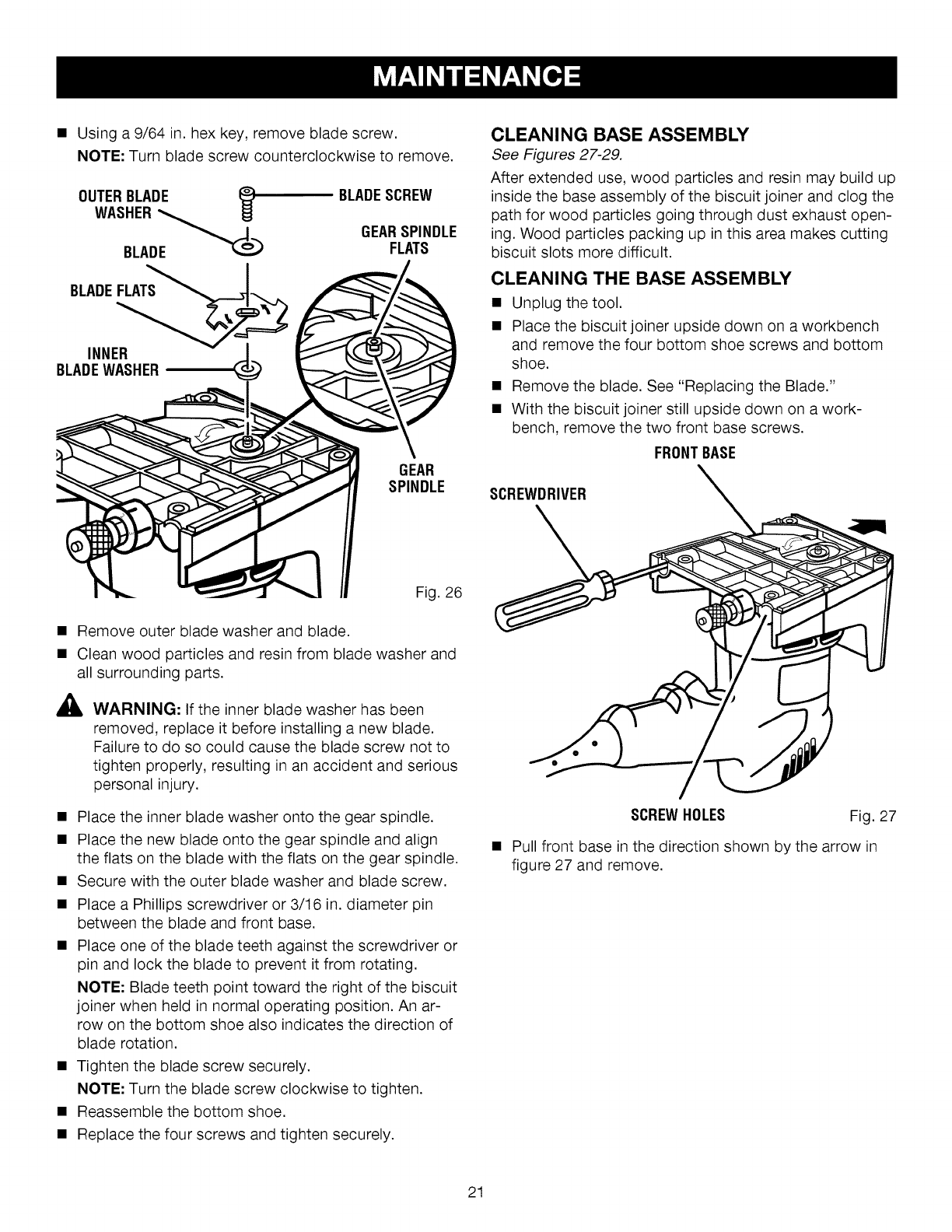
• Place a Phillips screwdriver or 3/16 in. diameter pin
between the blade and front base.
• Place one of the blade teeth against the screwdriver or
pin and lock blade preventing it from rotating,
PHILLIPSSCREWDRIVER
OR3/16 IN. DIAMETERPIN
BLADE FRONTBASE
Fig. 25
20
• Usinga9/64in.hexkey,removebladescrew.
NOTE:Turnbladescrewcounterclockwiseto remove.
OUTERBLADE _)
BLADE
BLADEFLATS_"_,__._
INNER
BLADEWASHER
BLADESCREW
GEARSPINDLE
FLATS
GEAR
SPINDLE
CLEANING BASE ASSEMBLY
See Figures 27-29.
After extended use, wood particles and resin may build up
inside the base assembly of the biscuit joiner and clog the
path for wood particles going through dust exhaust open-
ing. Wood particles packing up in this area makes cutting
biscuit slots more difficult.
CLEANING THE BASE ASSEMBLY
• Unplug the tool.
• Place the biscuit joiner upside down on a workbench
and remove the four bottom shoe screws and bottom
shoe.
• Remove the blade. See "Replacing the Blade."
• With the biscuit joiner still upside down on a work-
bench, remove the two front base screws.
FRONTBASE
SCREWDRIVER
Fig. 26
• Remove outer blade washer and blade.
• Clean wood particles and resin from blade washer and
all surrounding parts.
AWARNING: If the inner blade washer has been
removed, replace it before installing a new blade.
Failure to do so could cause the blade screw not to
tighten properly, resulting in an accident and serious
personal injury.
• Place the inner blade washer onto the gear spindle.
• Place the new blade onto the gear spindle and align
the flats on the blade with the flats on the gear spindle.
• Secure with the outer blade washer and blade screw.
• Place a Phillips screwdriver or 3/16 in. diameter pin
between the blade and front base.
• Place one of the blade teeth against the screwdriver or
pin and lock the blade to prevent it from rotating.
NOTE: Blade teeth point toward the right of the biscuit
joiner when held in normal operating position. An ar-
row on the bottom shoe also indicates the direction of
blade rotation.
• Tighten the blade screw securely.
NOTE: Turn the blade screw clockwise to tighten.
• Reassemble the bottom shoe.
• Replace the four screws and tighten securely.
SCREWHOLES Fig. 27
Pull front base in the direction shown by the arrow in
figure 27 and remove.
21
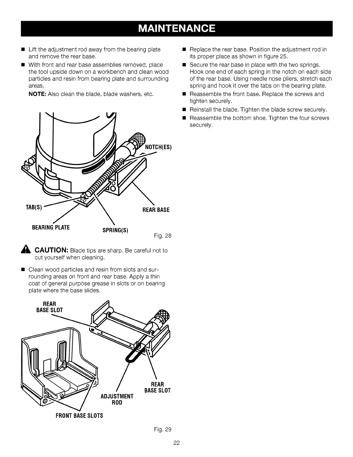
• Lifttheadjustmentrodawayfromthebearingplate
andremovetherearbase.
• Withfrontandrearbaseassembliesremoved,place
thetoolupsidedownonaworkbenchandcleanwood
particlesandresinfrombearingplateandsurrounding
areas.
NOTE:Alsocleantheblade,bladewashers,etc.
• Replacetherearbase.Positiontheadjustmentrodin
itsproperplaceasshowninfigure25.
• Securetherearbaseinplacewiththetwosprings.
Hookoneendof eachspringinthenotchoneachside
oftherearbase.Usingneedlenosepliers,stretcheach
springandhookit overthetabsonthebearingplate.
• Reassemblethefrontbase.Replacethescrewsand
tightensecurely.
• Reinstalltheblade.Tightenthebladescrewsecurely.
• Reassemblethebottomshoe.Tightenthefourscrews
securely.
(ES)
TAB(S) REARBASE
A
BEARINGPLATE SPRING(S) Fig. 28
CAUTION: Blade tips are sharp. Be careful not to
cut yourself when cleaning.
Clean wood particles and resin from slots and sur-
rounding areas on front and rear base. Apply a thin
coat of general purpose grease in slots or on bearing
plate where the base slides.
REAR
BASESLOT
REAR
BASESLOT
ADJUSTMENT
ROD
FRONTBASESLOTS
Fig. 29
22
LookfortheseaccessoriesatSearsretail:
• Biscuits100pieces...............................................................................................................................................SizeR1
• Biscuitst00 pieces...............................................................................................................................................SizeR2
• Biscuitst00 pieces...............................................................................................................................................SizeR3
• BiscuitAssortment..................................................................................................................................400piecestotal
SizeR1.............................................................................................................................................................t00 pieces
SizeR2.............................................................................................................................................................100pieces
SizeR3.............................................................................................................................................................200pieces
_k WARNING" Current attachments and accessories available for use with this tool are listed above. Do not use any
attachments or accessories not recommended by the manufacturer of this tool. The use of attachments or acces-
sories not recommended can result in serious personal injury.
PROBLEM SOLUTION
,Biscuits do not fit the slots. Biscuits
not fitting slots may also cause mis-
alignment of the boards being joined.
A. Biscuit slots are too deep or too shallow. Make fine adjustments to
depth setting. See "Making Fine Adjustments."
B. Biscuit thickness may be out of tolerance. Compress biscuits in a vise
if they are too thick.
C. Check to see if biscuits are the correct size for the size slots that have
been cut: #0, #10, or #20.
D. Check to see if biscuits have gotten wet and have swelled.
2. Wood particles begin to back up on
the front of the unit.
A, The dust port may be clogged, preventing wood particles from being
drawn into the dust bag. Remove the front and rear base assemblies
and clean blade, bearing plate, base assembly slots, and surrounding
areas. See "Cleaning the Base Assembly."
,Blade becomes difficult to push in
when cutting slots. Blade does not
retract properly when cutting slots.
A. Wood particles and resin have built up on base assembly slots and
surrounding areas. Remove front and rear base assemblies and clean
blade, bearing plate, base assembly slots and surrounding areas. Ap-
ply a thin coat of general purpose grease in slots or on bearing plate
where base slides. See "Cleaning the Base Assembly."
4. Cutting performance is poor and there
is a loss of power or stalling of motor
when cutting slots.
A. Blade is dull. Replace the blade. See "Replacing the Blade."
B. Resin has built up on the blade. Remove the blade and clean blade
with gum and pitch remover. See "Replacing the Blade."
23
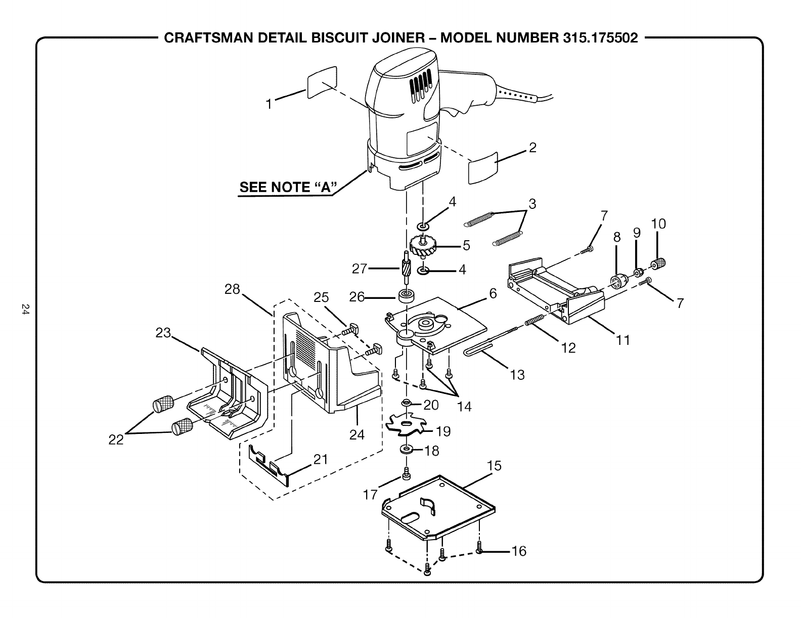
,_ CRAFTSMAN DETAIL BISCUIT JOINER - MODEL NUMBER 315.175502 •
22
SEE NOTE "A'
2
I 4 3
46 810
7

CRAFTSMAN DETAIL BISCUIT JOINER - MODEL NUMBER 315.175502 •
The model number will be found on a plate attached to the motor housing. Always mention the model number in all correspondence regarding your |
DETAIL BISCUIT JOINER or when ordering repair parts. J
SEE BACK PAGE FOR PARTS ORDERING INSTRUCTIONS
PARTS LIST
Key Part
No. Number Description Qty.
t 940078049
2 940051021
3 671541001
4 690202001
5 200287002
6 200294001
7 660328001
8 342806001
9 660106002
t0 671547001
tl 512812001
12 671540001
t3 671538001
t4 660307003
15 640872001
t6 660179002
Data Plate ....................................................... t
Logo Plate ....................................................... t
Tension Spring ................................................ 2
Washer ............................................................ 2
Gear Assembly ............................................... t
Bearing Plate .................................................. 1
* Screw (#10-24 x 3/4 in. Fil. Hd.) ..................... 2
Depth Adjustment Knob ................................. t
* Jam Nut (#8-32) .............................................. 1
Knurled Adjustment Knob ............................... t
Rear Base ....................................................... t
Compression Spring ....................................... 1
Adjustment Rod .............................................. t
* Screw (#8-32 x 1/2 in. Flat Hd, T.C,) .............. 4
Shoe ................................................................ 1
* Screw (#8-32 x 3/8 in, Flat Hd.) ...................... 4
Key Part
No. Number Description Qty.
t7 660169036
18 690200001
19 671539001
20 671548001
2t 570287001
22 671542001
23 342807001
24 342808001
25 660104007
26 6899902
27 610458001
28 200234003
983000519
(REV:0t)
Blade Screw (#8-32 x 3/8 in, Soc. Cap) ........ t
Outer Blade Washer ........................................ 1
Blade ............................................................... 1
Inner Blade Washer ......................................... t
Front Base Pad .............................................. 1
Height Adjustment Knob ................................ 2
Adjustable Fence ........................................... t
Front Base ...................................................... 1
Bolt (1/4-20 x 3/4 in. Sq. Hd.) ......................... 2
Ball Bearing (696 ZZ) ...................................... t
Gear ................................................................ 1
Front Base w/Pad
(Includes Key Nos. 21 And 24) ....................... 1
Operator's Manual (not shown)
NOTE: "A"- The assembly shown represents an important part of the Double Insulated System. To avoid the possibility of alteration or dam-
age to the system, service should be performed by your nearest Sears Repair Center. Contact your nearest Sears Retail Store
for Service Center information.
* Standard Hardware Item -- May Be Purchased Locally

Your Home
For repair-in your home-of all major brand appliances,
lawn and garden equipment, or heating and cooling systems,
no matter who made it, no matter who sold it!
For the replacement parts, accessories and
owner's manuals that you need to do-it-yourself.
For Sears professional installation of home appliances
and items like garage door openers and water heaters.
1-800-4-MY-HOME ®(1-800-469-4663)
Call anytime, day or night (U.S.A. and Canada)
www.sears.com www.sears.ca
Our Home
For repair of carry-in items like vacuums, lawn equipment,
and electronics, call or go on-line for the location of your nearest
Sears Parts & Repair Center.
1-800-488-1222
Call anytime, day or night (U.S.A. only)
www.sears.com
To purchase a protection agreement (U.S.A.)
or maintenance agreement (Canada) on a product serviced by Sears:
1-800-827-6655 (U.S.A.) 1-800-361-6665 (Canada)
Para pedir servicio de reparaci6n
a domicilio, y para ordenar piezas:
1-888-SU-HOGAR SM
(1-888-784-6427)
Au Canada pour service en fran£ais:
1-800-LE-FOYER Mc
(1-800-533-6937)
www.sears.ca
® Registered Trademark /TMTrademark /SM Service Mark of Sears, Roebuck and Co.
SM
® Marca Registrada /TM Marca de Fabrica /Marca de Servicio de Sears, Roebuck and Co.
MD
ac Marque de commerce /Marque depos6e de Sears, Roebuck and Co. © Sears, Roebuck and Co.
