Craftsman 315212350 User Manual 12 COMPOUND MITER SAW Manuals And Guides L0412326
CRAFTSMAN Miter Saw Manual L0412326 CRAFTSMAN Miter Saw Owner's Manual, CRAFTSMAN Miter Saw installation guides
User Manual: Craftsman 315212350 315212350 CRAFTSMAN 12 COMPOUND MITER SAW - Manuals and Guides View the owners manual for your CRAFTSMAN 12 COMPOUND MITER SAW #315212350. Home:Tool Parts:Craftsman Parts:Craftsman 12 COMPOUND MITER SAW Manual
Open the PDF directly: View PDF ![]() .
.
Page Count: 46

OPERATOR'S MANUAL
ICRRFTSMRN" I
PRO FES S i O NAL
12 in. COMPOUND MITER SAW
DOUBLE INSULATED
Model No.
315.212350
_k WARNING: To reduce the riskof injury,
the usermust read and understand the
operator'smanual before usingthis product.
Customer Help Line: 1-800-932-3188
Bears, Roebuck and Co., 3333 Beverly Rd., Hoffman Estates, IL 60179 USA
Visit the Craftsman web page: www.sears.corn/craftsman
983000-550 Save this manual for future reference
9-04
•Warranty............................................................................................................................................................................ 2
mIntroduction....................................................................................................................................................................... 2
•General Safety Rules..................................................................................................................................................... 3-4
•Specific Safety Rules..................................................................................................................................................... 4-5
•Symbols......................................................................................................................................................................... 6-7
•Electrical............................................................................................................................................................................ 8
mmGlossaryof Terms.............................................................................................................................................................. 9
mFsatures..................................................................................................................................................................... 10-12
mmToolsNeeded ................................................................................................................................................................. 12
mmLoose Parts ................... ¢_I ............................................................................................................................................... 13
•Assembly................................................................................................................................................................... 14-23
•Operation................................................................................................................................................................... 23-31
•Adjustments................................................................................................................................................................... 32
•Maintenance.............................................................................................................................................................. 33-35
•Exploded View........................................................................................................................................................... 37-45
•Parts Ordering/Service ...................................................................................................................................... Back Page
ONE YEAR FULL WARRANTY ON CRAFTSMAN TOOL
If thisCraftsman tool fails due to adefect in materialor workmanshipwithinone year from the date of purchase,
CONTACT THE NEAREST OEARS PARTS & REPAIR CENTER at 1-800.-4-MY-HOME_ and Sears wi(fmpafr it, free of
charge.Thiswarranty applies onlywhile this product is In the UnitedStates.
It thistool is used for commercialor rentalpurposes,thiswarranty willapply for only ninety days from the date of
pumhasa.
ThLswarranty gives you specific legal dghte,and you may also have other dghtewhich vary from stateto state.
Seam, Roebuck and Co., Dept. S17WA, Hoffman Estates, IL 60179
This tool has many featuresfor making its use more pleasantand enjoyable.Safety, performance,and dependability
have been giventop pr_orLtyinthe designof this productmaking It easyto maln_ln and operate.
AWARNING: Road and understand all Ir_struc-
tlons. Failure to follow all fnstructions listed below,
may resultin eiectdc shock, fireand/or serious
personal injury,
READ ALL INSTRUCTIONS
•KNOW YOUR POWER TOOL. Read the operator's
manual carefully.Learn the saw's applicationsand
limitationsas well as the specificpotential hazards
retatedto this tool
• GUARD AGAINST ELECTRICAL SHOCK BY PRE-
VENTING BODY CONTACT WITH GROUNDED
SURFACES. For example, pipes, radiators,ranges,
refrigeratorenclosures,
•KEEP GUARDS IN PLACE and ingood working order.
•REMOVE ADJUSTING KEYS AND WRENCHES.
Form habit of checkingto see that keys and adjusting
wrenches are removed fromtoo] beforeturningit on.
•KEEP WORK AREA CLEAN. Clutteredareas and
benches Inviteaccidents. DO NOT leave tools or
pieces of wood on the saw while it is in operation.
=DO NOT USE IN DANGEROUS ENVIRONMENTS,
Do not usa power tools in damp orwet Iocetions or
exposeto rain.Keep the work area well 1il.
•KEEP CHILDREN AND VISITORS AWAY.All visitors
shouldwear safety glassesand be kept a safe
distancefrom work area. 0o not let visitors contacttool
or extensioncord while operating.
•MAKE WORKSHOP CHILDPROOFwith padlocks and
master switches, or by removingstarterkeys.
•DON'T FORCE TOOL. It,w[ll do the Jobbetter and
safer at the feed rate for which "_was designed,
•USE RIGHT TOOL. Don'tforce the tool or attachment
to do a Jobit was notdesigned for. Don't use It for a
purpose notintended.
•USE THE PROPER EXTENSION CORD. Make sure
your extensioncord Is in good condftlon.Usa onlya
cord heavy enoughto carry the currentyour product
witt draw. An undersizedcordwltl cause adropin line
voltage resultingin lossof power and overheating.A
wire gauge size(A.W.G.) of at least 14 is recommended
for an extensioncord 25 feet or less In length. If ]n
doubt, use the next heavier gauge, The smallerthe
gauge number, the heavier the cord.
•DRESS PROPERLY. Do notwear loose clothing,
groves,neckties, orjewelry.They can get caught
and draw you into moving parts. Rubber gloves and
nonskidfootwear are recommendedwhen working
outdoors. Alsowear protective hair coveringto con_in
longhair.
• ALWAYS WEAR SAFETY GLASSES WITH SIDE
SHIELDS. Everydayeyeglasseshave only impact-
resistanttenses,they are NOT safetyglasses.
• SECURE WORK. Use clampsora vise to hold work
when practical it's safer thanuslngyour hand and
frees both handsto operate tool.
•DON'T OVERREACH. Keepproper footing and
balanceat all times.
• MAINTAIN TOOLS WITH CARE. Keep toolssharp
and cleanfor betterand safer performance.Follow
Instructionsfor lubricatingand changingaccessories.
•DISCONNECT TOOLS. When not in use,before
servicing,or when changingattachments, blades, bits,
cutters,etc., alltools shouldbe disconnected.
•AVOID ACCIDENTAL STARTING. Be sure swItch]Soff
when pluggingin any tool.
•USE RECOMMENDED ACCESSORIES. The use of
improperaccessories may riskinjury.
• NEVER STAND ON TOOL. Seriousinjurycouldoccur
if the tool is tipped or If the cuttingtool is unintention-
ally contacted.
•CHECK DAMAGED PARTS. Before furtheruse of
the tool,a guardor other part that is damaged should
be carefullychecked to determinethat it will operate
propedyand performits intendedfunction. Check for
alignment of movingparts, binding of movingparts,
breakage of parts,mounting and any other conditions
that mayaffect _s operation. A guard or otherpart that
is damaged must be properlyrepairedor replacadby
an authorizedservice centerto avoid riskof personal
Injury.
•USE THE RIGHT DIRECTION OF FEED. Feed work
into a blade or cutter against the directionof rotation of
blade or cutteronly,
•NEVER LEAVE TOOL RUNNING UNATrENDED.
TURN THE POWER OFF. Don't leave tool until it
comes to acompfefestop.
•PROTECT YOUR LUNGS. Wear a face or dust mask if
the cuttingoperation is dusty.
•PROTECT YOUR HEARING.Wear hearing protection
dudng extended pededs of operation.
• DO NOT ABUSE CORD. Never yank card to discon-
nect from receptacle,Keep cord from heat, oil and
sharp edges.
•USE OUTDOOR EXTENSION CORDS. When tool is
used outdoors, usa only extension cordswith ap-
provedgroundconnectionthat are intendedfor use
outdoorsand so marked.
•KEEP BLADES CLEAN, SHARP, AND WITH SUF-
RCIENT SET. Sharp blades minimize stalling and
kickback.
•BLADE COASTS AFTER BEING TURNED OFR
•NEVER USE IN AN EXPLOSIVE ATMOSPHERE.
Nom_I sparkingof the motor could ignitefumes.

• INSPECT TOOL CORDS PERIODICALLY. If damaged,
have repairedby aqualifiedservice technician at
an authorized servicefacility,The conductorwith
insulationhavingan outer surfacethat is greenwith
orw_thou_yellow s_pes Is 1heequipment-gTound-
ing conductor.If repairor replacementof the electric
cord or plug tsnecessary,do no'_connectthe equip-
men_-grounding conductorto a liveterminal.Repair
or replace a damaged orwom cord immediately. Stay
constantly aware ol cord location and keep it wall away
fromthe rotatingblade.
•INSPECT EX'FENSION CORDS PERIODICALLY and
replace If damaged.
•POLARIZED PLUGS. Toreduce the riskof electric
shock, thistool has apolar'lzedplug (one blade is
wider than the other).This plug will fit in apolarized
outlet only oneway. if the plug does notf_tfullyinthe
outlet, revemethe plug. If _tstill doesnot fit, contact a
qualifiedelectricianto Instantt'neproper outlet. Do not
change the p_Jgin any way.
•KEEP TOOL DRY, CLEAN, AND FREE FROM OIL
AND GREASE. Alwaysusa a ck_n c4olh when clean-
Ing.Never use brake fluids,gasoline,petroleum-based
products,or any solventsto clean tool.
•STAY ALERT AND EXERCISE CONTROL. Watch
what you are doing and _se common sense. Do not
operate "_octwhen you are tired. DO not rosh.
•DO NOT USE TOOL IF SWITCH DOES NOT TURN IT
ON AND OFF. Have defective switchesreplacedby an
authorizedservicecenter.
•USE ONLY CORRECT BLADES. Do not use blades
with Incorrect size holes.Never use bladewashers or
blade bolts that are defectiveor incorrect.The maxi-
mum blade capacity of your saw is 12 in. (305 ram).
•BEFORE MAKING A CUT, BE SURE ALL ADJUST-
MENTS ARE SECURE.
•BE SURE BLADE PATH IS FREE OF NAILS. (nspect
for and removeall nailsfrom lumberbefore cutting.
•NEVER TOUCH BLADE orother moving parts during
USe.
•NEVER START A TOOLWHEN ANY ROTATING COM-
PONENrT IS IN CONTACT WITH THE WORKPIECE.
•DO NOT OPERATE A TOOL WHILE UNOER THE
INFLUENCE OF DRUGS, ALCOHOL, OR ANY
MEDICATION.
•WHEN SERVICING use only identir._l replacement
parts. Use of any other parts may create ahazard or
_use product damage.
• USE ONLY RECOMMENDED ACCESSORIES listed
in this manuel or sddendums, Use of accessories
that are not listed may cause the risk of personal
injury. Instructions for sate use of accessories are
included with the accessory,
•DOUBLE CHECK ALL SETUPS. Make sure blade is
tight and not making contact with saw or workplace
before connecting to power supply.
•FIRMLY CLAMP OR BOLT your mitersaw to a work-
bench ortable at approximatelyhip height.
•KEEP HANDS AWAY FROM CUTTING AREA. Do not
reachunderneathwork or In blade cuttingpathwith
your hands end fingersfor any reason.Alwaysturn the
power off.
•ALWAYS SUPPORT LONG WORKPIECES while cut-
ting to minimize riskof blade pinchingand kickback.
Saw may slip.walk or sllde while cuttlnglong orheavy
boards.
•ALWAYS USE A CLAMP to securethe workpioce
when possible.
• BE SURE THE BLADE CLEARS THE WORK,PIECE.
Never start the sew with the blade touchingthe
workplace. A,ow motor _come up to full speed
before startingcut.
•MAKE SURE THE MITER TABLE AND SAW ARM
(BEVEL FUNCTION) ARE LOCKED IN POSITION
BEFORE OPERATING YOUR SAW. Lock the miter
table by securely tightening the miter lock levers, Lock
the saw arm (beve_function) by securely tightening the
bevel lock knob.
NEVER USE A LENGTH STOP ON THE FREE SCRAP
END OF A CLAMPED WORKPIECE. NEVER hold
onto or bind the free scrap end of the workpiece in any
operalion. If a work clamp and length stop are used
together, they must both be instal_ed on the same side
of the saw 1able to prevent the saw from catching the
loose end and kickJng up,
NEVER cut more than one piece at a time. DO NOT
STACK more than one workpiece on the saw table at a
tlme.
NEVER PERFORM ANY OPERATION FREEHAND,
Alwayspiece the workpiece1o be cut on_hemiter
table and positioni_t'Lrmlyagainstthe fence as a bach-
stop. AJwaysuse the fence.
• NEVER hand hold aworkplace that is too small to be
clamped. Keep hands clear of the cuttingarea.
•NEVER reachbehind, under,orwithin threeinches
of the blade and its cuttingp_th with your hands and
fingersfor any reason.
•NEVER reachto pick up a workpisce, apiece of scrap,
or anythingelse that is tn or near the cuttingpathof the
blade.
•AVOID AWKWARD OPERATIONS AND HAND
POSITIONS where a suddenslip could cause your
hand to move Intothe blade. ALWAYSmake sureyou
have good balance. NEVER operate your mitersaw
on the flooror in a crouchedposition.
• NEVER stand or have any part ofyour bodyin linewith
the path of the saw blade.
•ALWAYSreleasethe power switch and allow the
saw blade to stop rotatingbefore raisingit out of the
workpieca.
•DO NOT TURN THE MOTOR SWITCH ON AND OFF
RAPIDLY.This could cause the saw blade to loosen
and couldcreate a hazard. Should this ever occur,
stand clear and allow the saw blade to come to a
complete stop, Disconnectyour saw fromthe power
supplyand securelyretightanthe blade bo_t,
•IF ANY PART OF THIS MITER SAW IS MISSING or
shouldbreak, bend, or fail inany way, or shouldany
aisctricalcomponent fadto perform property,shutoff
the power switch, removethe miter saw plugfrom the
power source and have damaged, missing, or failed
parts replacedbefore resumingoperation.
•ALWAYSSTAY ALERT[ Do notallow familiarity(gained
fromfrequent use of your saw)to cause a careless
mistake. ALWAYS REMEMBER that a carelessfraction
of a second is sufficienl lo inflictsevere injury.
•MAKE SURE THE WORK AREA HAS AMPLE LIGHT-
ING to see the work and that no obstructionswill inter-
fere with safeoperationBEFORE perforn_ngany work
usingyour saw.
•ALWAYSTURN OFF THE SAW before disconnecting
it to avoid accidentalstartingwhen reconnectingto
power sup]_ly.NEVER lesve the saw unattendedwhiis
connected to a power scurce.
•THIS TOOL should havethe followingmarkings:
a) Weareye protection.
b) Keep hands out of pathof saw blade
c) Do not operate saw withoutguardsin place.
d) Do not performany operationfreehand.
e) Never reacharound saw blade.
0 Turn off tool and wait for saw blade to stop before
movingworkpieca or changingsettings.
g) Disconnectpower (o_unplug tool as applicabis)
before changingblade or servicing.
h,_ No load speed.
• ALWAYS carry the tool onlyby the carryinghandle.
•AVOID direct eye exposurewhen usingthe laserguide.
•SAVE THEBE INSTRUCTIONS. Referto them
frequently and use to instructother users,if you loan
someone thistool, loan them these instructionsalso.
WARNING: Some dust created by power sanding, saw(r_j, grinding, drilli_j, and other constructionactivities
containschemicals known to cause cancer, birthdefects or other reproductiveharm. Some examplesof these
chemrcalsare:
•lead from leed-besed paints,
•crystallinesilicafrom bricks and cement and other masonry products,and
•arsenic and chromiumfrom chemically-treatedlumber.
Your riskfrom these exposuresvades, dependin_on how often you do thistype of work. To reduceyour exposure
to these chemicals:work ina well ventilatedarea, and work with approved safety equipment,suchas thosedust
masksthat are specially designed to filter out microscopicparticles.
5

Someofthefollowing symbolsmay be used on thistool. Please studythem and learn their meaning, Proper
interpretationof these symbolswill allow you to operate the tool betterand safer,
SYMBOL NAME DESIGNATION/EXPLANATION
V Volts Voltage
A Amperes C_rrest
Hz Hertz Frequency(cyclesper second)
W Watt Power
mln MinUtes Time
Altemat_ogCurrent Type of current
-.--- Direct Current Typeor acharacteristicof current
no NO Load Speed Rotationalspeed, at no load
[] Class IJConstruction Double-Insulatedconstruction
.../rain Per Minute Revolutions,strokes, surfacespeed, orbitsetc., per minute
Wet Conditions/_erf DOnot exposeto rainor use In damp locations.
Read The Operator'sManual To reducethe dsk of Injury,usermust read and understand
operator'smanual before usingthis product.
O Alwayswear safety gogglesor safety glasseswith sideEyeProtection shieldsanda full face shieldwhen operatingthis product.
Alert Precautionsthat invo}ve
Safety your Safety.
I
Failureto keep your hands away from the blade will result in
_o Hands Syrnbo! sedous personalInjury,
Failureto keep yourhands away fromthe bib,de will resultinNo Hands Symbol eadous personalInjury.
No Hands Symbol Failureto keep your handsaway fromthe blade wiltresult In
seriouspersonalinjury.
No Hands Symbol Failureto keep yourhands away from the blads will resu(tin
seriouspersonal_njury,
(_ Hot Surface To reduce the dsk of Inlury or d_m_e, svold contactwith
any hot surface,
6
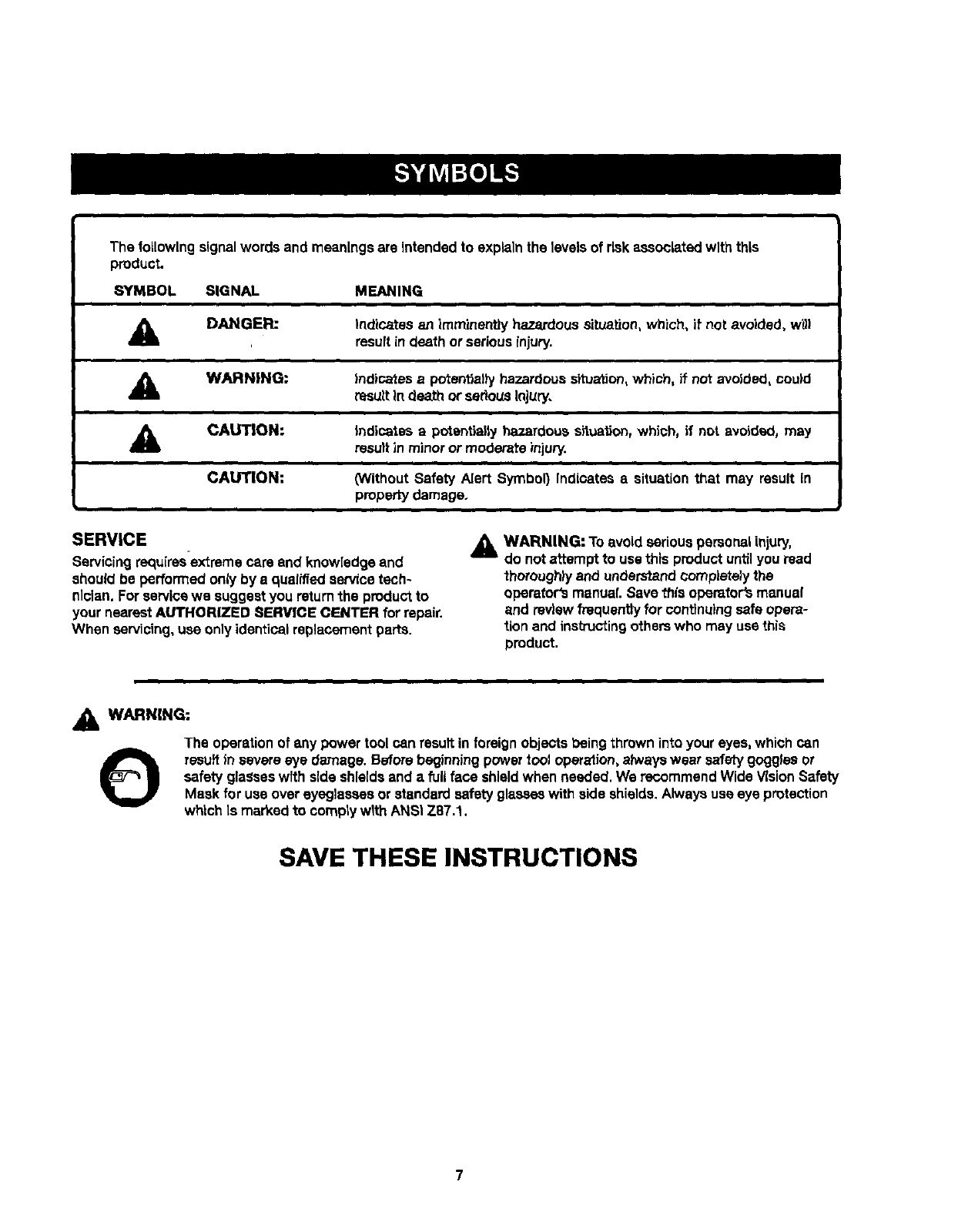
Thefollowingsignalwordsandmeaningsare intendedto explainthe levelsof risk associated with this
product.
SYMBOL SIGNAL MEANING
DANGER: Indicatss an imminently hazardoussituation, Which, if not avoided, w_l
resultin death or seriousinjury.
AWARNING: Indicatesa potentiallyhazardouss_uation, which, if not avoided, could
resultIndeath or seriousInjury.
ACAUTION:
CAUTION:
i
Indicates apotentially hazardoussituation,which, if not avoided, may
resultin minoror moderate injury.
(Without Safety Alert Symbol) Indicates asituation that may result in
propertydamage.
SERVICE
Servicingrequ[rss-extreme care end knowledge and
should be performed only by a qualifiedservice tech-
nician. Forservicewe suggestyou returnthe product to
your nearestAUTHORIZED SERVICE CENTER for repair.
When servicing,use only identicalreplacementparts.
A WARNING: Toavoid seriouspersonalinjury,
do notattempt to use this productuntilyou read
thorough_/and understandcompletelythe
operator'smanual. Savethis operator'smanua!
and review frequentlyfor continuingsafeopers-
tion and instructingotherswho may use this
product.
AWARNING:
The operationof any power tool can resultin foreignobjects beingthrowninto your eyes, which can
Oresult in severe eye damage. Beforebeginningpower tooJoperalion,alwayswear safetygogglesor
safety glasseswfthside shieldsand a full face shieldwhen needed. We recommendWide VisionSafety
Mask for use overeyeglassesor standard safetyglasseswith side shields.Alwaysuse eye protection
which is marked to comptywlthANSI Z87.1.
SAVE THESE INSTRUCTIONS
7
DOUBLEINSULATION
Double insulationis a concept in safetyin electric power
tools,which eliminatesthe need for the usual_ree-wim
grounded power cord, All exposed metal partsare
Isolated from the Internalmetal motor componentswith
protecting{nsu[ation.Double insulatedtools do not need
to be grounded.
WARNING: The double insulatedsystemis
intended to protect the userfrom shockresulting
fromabreakin the tool's Internal Insulation.Observe
all normarsafety precautionsto avoid electdca{
shock.
NOTE: Servicing of a tool with double insulationrequires
extreme cam and knowledge of the systemand should
be performed onlyby a qualifiedservice technician.For
service,we suggestyou returnthe tool to your nearest
authorized servicecenter forrepair.Always use original
factory replacement partswhen servicing.
ELECTRICAL CONNECTION
This tool has a precision-builtelectric motor. It should be
connected to apower supply that is 120 volts, 60 Hz,
AC only (normal household current). Do not operate
this tool on direct current(PC). A substantialvoltage drop
will cause a loss of power and the motor w(lloverheat.If
your tool does not operate when plugged Into an outlet,
double-checkthe power supply.
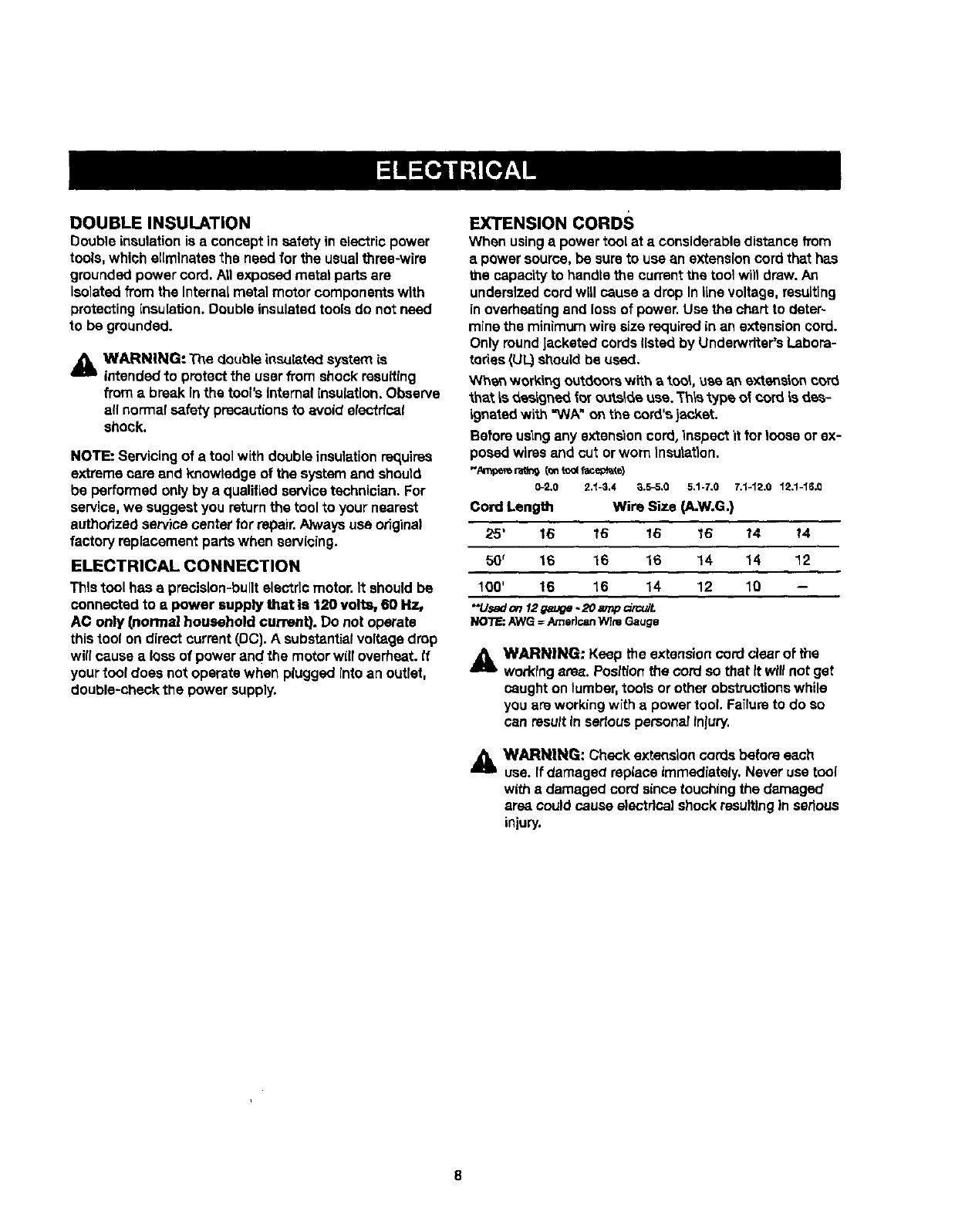
EXTENSION CORDS
When usinga powertool at aconsiderabledistance from
apower source,be sureto use an extensioncord that has
the capacity to handle the currentthe toolwilt draw.An
undersizedcord will cause a drop Inline voltage,resulting
in overheatingand lossof power.Use the chart to deter~
minethe minimum wire sizerequiredinan extensioncord.
Only roundJacketedcordslisted by Underwdter'sLabora-
tories(UL.)should be used.
When working outdoorswith _ too_,use _n extension c_rd
_h_t _s_ealg_ed fo_outsideuse. Th_s'oJpeof cord is des-
igneted with "WA" onthe cord's jacket.
Before us'=ngany extension cord,inspect it tor loose or ex-
posed wires and cut or worn Insulation.
"AIWpe_ r_og (_ tool facepk_e)
0-2.0 2.t -3,4 _.5_,0 5,1-7.0 7.1-12.0 12.1-16.(3
Cord Length Wire Size (A.W.G.)
25' 16 16 16 16 14 !4
50' 16 16 16 14 14 12
100' 16 16 14 12 10 --
*'U_don12_uge.20_o_cuiL
NO_:AWG =Amedc_nWlmGauge
_& WARNING: Keep the extensioncord clearof the
workingarea. Positionthe cord so that It willnot ge_
caught on lumber, tools or other obstructions while
you are working with a power tool. Failure to do so
can result In sedous persona! Injury.
_i= WARNING: Check extension cords before each
use. If damaged replace immediately, Never use tool
with 8 damaged cord since touching the damaged
area could cause electrical shock re.suitingIn serious
injury.
Anti-Rlcld_aok Pawls Irad_al arm and table saws)
A devisewh)ch, when propertyInatalledand ma)ntalned,
is designed to stop the workpiece frombeingkicked back
toward the front of the saw during a rippingoperation.
A.Vbor
The shaft onwhich a blade or cuttingtool Is mounted.
Bevel Cut
Aeating operationmade wlth the blade at any angle
other than 90" to the table surface.
Chamfer
A cut removinga wedge from a block so the end (orpart
of the and) is angled rather than at 90°,
Compound Cut
A crosscut made with both a miter and a bevel angle.
Crosscut
Acutting or shaping operation made across the grainor
the width of the workplace.
Cutter Head (planers and jointers|
A rotatingpiece of adju_able blades.3"hecutterhead
removesmatedal from the workplece.
Dado Cut
Anon-through cut which producesa squara-sidednotch
ortrough in the workpiece (requiresaspecialblade).
Featherboard
A device used to help controlthe workpiese by guidtngit
securelyagainst the table or fence dudng any dpplng
operation.
FPM or SPM
Feet per minute (orstrokes per minute),used in reference
to blade movement.
Freehand
Performingacut without the workplace being guided by a
fence, miter gauge, or other aids.
Gum
A stickT,sap-based residuefrom wood products.
Heel
A_ignmentofthe blade to the fence.
Karl
The matedal removed by the blade in a throughcut orthe
slot producedby the blade in a non-throughor partialcut.
Kickback
A hazardthat can occur when the blade binds or stalls,
throwingthe workpiece back toward operator.
Leading End
The end of the workplace pushedinto the tool first.
Miter Cut
Aeating operationmade with the workplece at any angle
to the blade other than 90°.
Non-Through Cuts
Anycuttingoperationwhere the blade does not extend
completelythroughthe thickness of the workplace.
Push Blocks and Push Sticks
Devices usedto feed the workpiecethroughthe saw
blade dudngcuttingoperations.A pushstick (not a push
block)should be usedfor narrowdppingoperations.
Thsea aids he_pkee_ the operator'e hands we_laway from
the blade.
Pilot Hole (drill presses)
A srnali hole drilled in a workpiece that se_ea ee a guide
for ddlllng large holes accurately.
Reeaw
Acu'_ng opera,ton to rnduP_e'_heth_c_nees of the word-
piece to make thinner pLecas.
Resin
A sticky, esp-based substance that has hardened.
Revolutions Per Minute (RPM)
The n'_mberof'_rnscompleted by a spinningobjeclin
one minute.
Ripping or Rip Cut
A cuttingoperationalongthe length of the wor_p'_aca.
Riving Knife (table saws)
Also known as aspreaderor splitter.A metal piece, slight-
I_Jthinner than the saw blade,which helps keep "thekeff
open and alsohelps to preventkickback.
Saw Blade Path
The area over,under,behind, or in front of the blade.As
It appliesto the workplece, that area which will be or has
been cut by the blade.
Set
The distance that the tip of the saw blade tooth Is bent (or
set) outward from the face of the blade.
Snipe (planers)
Depression made at either end of a workplace by cutter
blades when the workpiece is not properly supported.
Throw-Back
The throwing back of a workplace usually caused by the
workpieca being dropped into the blade or being placed
inadvertectiy incontact with the blade.
Through _dng
Any cut_r_ operaUon where the blade extends comp_tsty
through the thickness of the workpiece.
Workptece or Material
The item on which the oparaUon is being done.
Worktable
Surlzca where the w_rkpleca rests while performing a
cutting, drilling, planing, or sanding operation.
9
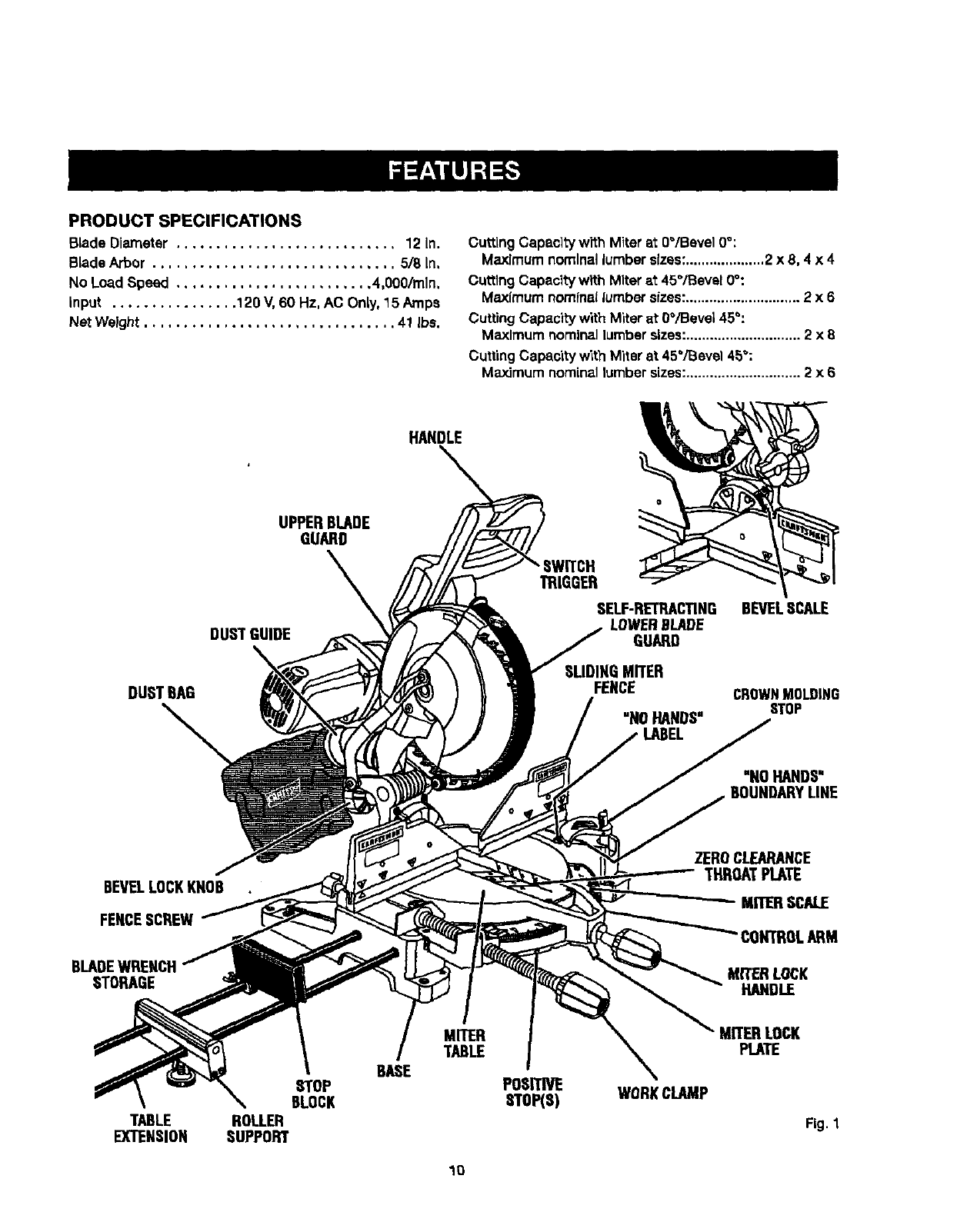
PRODUCTSPECIFICATIONS
BladeDiameter ............................ 12 In.
BLadeArbor ............................... 5/8 in,
No Load Speed ......................... 4,000/rain,
input ................ 120 V, 60 Hz, AC Only,15 Amps
Net Weight ................................ 41 Ibs.
Cutting Capacityw'rthMiter at 0"/Bevel 0°:
Maximum nominal lumber sizes:....................2x8, 4 x 4
Cuttlng Capacltywith Miter at 45°/Bevel 0°:
Maximum nominallumbersizes:............................. 2 x 6
Cuffing Capacity with Miter at 0°/Bevel 45°:
Maximum nominallumbersizes:............................. 2 x 8
Cutting Capacity with Miter at 45°/Bevel 45":
Maximum nominallumbersizes:............................. 2 x 6
HANDLE
DUSTBAG
UPPERBLADE
GUARD
\
DUST GUIDE
TRIGGER
SELF-RETRACTING
LOWERBLADE
GUARD
SLIDINGMITER
FENCE
"N0 HANDS"
LABEL
BEVELSCALE
CROWNMOLDING
STOP
"NOHANDS"
BEVELLOCKKNOB
FENCESCREW
BLADEWRENCH
STORAGE
ZEROCLEARANCE
THROATPLATE
MITERSCALE
CONTROLARM
MITERLOCK
HANDLE
TABLE
EXTENSION
STOP
BLOCK
ROLLER
SUPPORT
BASE
MITER
TABLE
POSprp_
SToP(s) WORKCLAMP
MITER LOCK
PLATE
Fig. 1
1O

KNOW YOUR COMPOUND MITER SAW
See Figure 1,
Before attemptingto use thisproduct,familiarizeyourself
wffh art operatingfeatures and safety rules.
15 AMP MOTOR
Yoursew has e powerful15 amp belt-drivenmotor with
sufficientpower to handletough cuttingjobs. It is made
with art ball bearings, and has externallyaccessible brush-
es forease of servicing.
12 in. BLADE
A12 In. carblde-t/ppedsew blade Is Inc./udedwith your
compoundmiter saw. It will out materials up to 4 in, thick
or 7-7/8 in, wide, dependingupon the angle at which the
cut is beingmade.
CARRYING HANDLE
See Figure2.
For convenience when carryingor tr_nspodingyour
miter saw from one placeto another,acarryinghandie
has been providedontop of the saw arm.To transport,
turn off and unplugyour saw, then lower the saw arm and
lock it inthe down position,Lock sew arm by pushingthe
lock pin to the left.
SAW
ARM
CARRYING
HANDLE
LOCKP1N
BEVEL
KNOB
SPINDLE LOCK BUTTON
See Figure 3.
A spindlelock buttonhas been provided for lockingthe
spindlewhich keeps the blade in your saw from rota_ng.
Depressand holdthe lock buttonwhile installing,chang-
ing, or removingblade.
SWITCH
TRIOOER
SPINDLE
LOCKBUT[ON
Fig.3
SWITCH TRIGGER LOCK
See Figure ,1.
To preventunauthorizeduse of your compoundmiter saw,
we suggest that you disconnectit from the power supply
and lock the switchIn the off position.Tolock the switch,
installa padlock (notincluded)throughthe hole inthe
switchtrigger.A lockwith a longshackleup to 9/32 in.
diameter may be used,When the lock Is installedand
locked, the switchis inoperable.Storethe padlockkey in
anotherlocation.
MITERLOCK
HANDLE
SAWARM
LOCKEDINDOWNPOSITION
Fig. 2
MITER LOCK HANDLE
See Figure2.
The miterlock handlesecurely locksyour saw at desired
miterangles.
SWITCH
TRIGGER
Fig.4
11
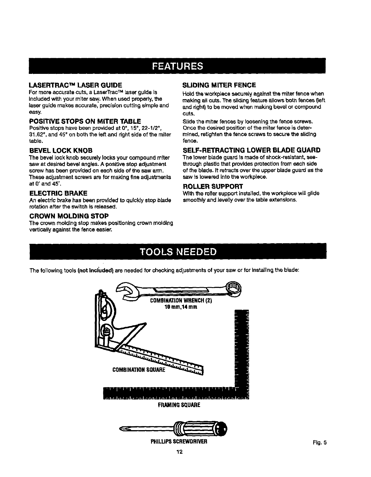
LASERTRACTM LASER GUIDE
For more accurate cuts, a LaserTrecTM laser guide is
includedwith your mitersaw. When used properly,the
laserguide makes accurate, precisioncuttingsimpleand
easy.
POSITWE STOPS ON MITER TABLE
Positivestops have been providedat 0°, 15", 22-1/2 °,
31.62 °, and 45°on both the left and right sideof the miter
table.
BEVEL LOCK KNOB
The bevel lock knob securely locksyour compoundmiter
sew at desired bevel angles.A positivestop adlustment
screw has been providedon each aide of the saw arm.
These adjustmentscrewsaro for making fine adjustments
at O"and 45",
ELECTRIC BRAKE
An electric brake has been prov/dedto quicklystop blade
rotationafter the switchis released.
CROWN MOLDING STOP
The crown molding stop makes positioningcrown molding
verticallyagainst the fence easier.
SLIDING MITER FENCE
Hold the workplace securelyagainst the miter fence when
making all cuts. The s_k_ingfeatureallows both fences 0eft
and right)to be moved when making bevel or compour_d
cuts,
Slide the mltar fences by looseningthe fence screws.
Once the desiredpositionof the miterfence is deter-
mined, retightenthe fence screwsto securethe sliding
lense.
SELF-RETRACTING LOWER BLADE GUARD
The lower blade guardIs made of shock-resistant,see-
throughplasticthat providesprotectionfromeach side
of the blade. It retractsover the upper blade guard as the
saw Is loweredInto the work.piece.
ROLLER SUPPORT
With the rollersupport installed,the workplacewill glide
smoothlyand levellyover the table extensions.
The followingtools/,not Included} are needed for checkingadiustlnentsof yoursaw or for installing the blade:
COMBINATIONWRENCH(2)
10turn,14mm
COMBINATIONSQUARE
FRAMINGSQUARE
PHILLIPSSCREWDRIVER FLg.5
12
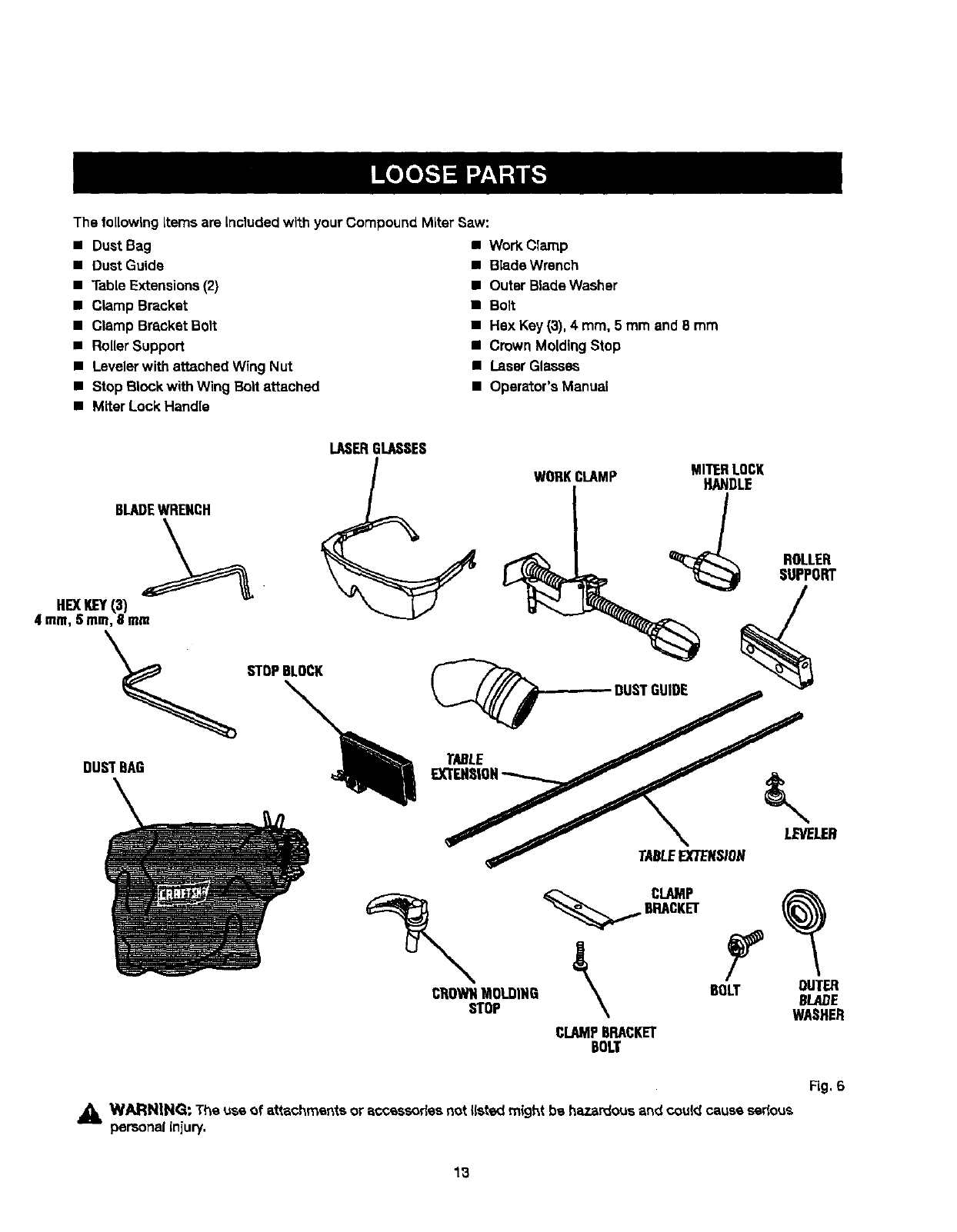
The following Items are included with your Compound Miter Saw:
• Dust Bag
•DustGuide
• Table Extensions (2)
•Clamp Bracket
• Clamp Bracket Bolt
• Roller Support
•Levelerwith attached Wing Nut
• Step Block withWing Bolt attached
• Miter Lock Handle
• Work Clamp
•Blade Wrench
•Outer BladeWasher
• Boit
• Hex Key (3), 4mm, 5 mm and B mm
•Crown MoldingStop
•Laser Glasses
•Operator's Manual
BLADEWRENCH
LASERGLASSES
WORKCLAMP MITERLOCK
HANDLE
ROLLER
SUPPORT
HEXKEY{3)
4 ram,5 ram,8 mm
TABLE //
TABLEEXTENSION
_CLAMP
BRACKET
CI_OWNMOLDING _BOLT_OUTERBLADE
STOP WASHER
CLAMPBRACKET
BOLT
Fig, 6
,_ WARNING: The use of attachments or accessories not I(stedmight bs hazardous and couldcause sedous
personal injury.
13
UNPACKING
This product requiresassembly.
•Carefullyliftsaw from the cartonby the carryinghandle
and the saw base, and place it ona level work surface.
NOTE: This saw is heavy.To avoid back injury,liftwith
your legs, not your back, and get help when needed.
•Thissaw has been shippedwith the saw arm secured
In the down position.To release the saw arm, push
down onthe top of the saw arm, cut the tie-wrap, and
puttout onthe lock pin.
•Liftthe saw arm by the handle. Hand pressureshould
remain on the saw arm to preventsuddenrise upon
releaseof the tie wrap.
•Inspectthe tool carefullyto make sureno breakage or
damage occurred duringshipping.
•Do not discardthe packingmaterial untilyou have
carefullyinspected and satisfactorilyoperated1hetoot.
•The saw is factory set foraccurate cutting.After
assemb)tngit, check for accuracy,tt shippinghas
Influencedthe settings,referto specificprocedures
explainedtn "thismanual.
• If any parts are damaged or missing, please call
1-800-932-31B8 for seslstance.
WARNING: If any parts are miSSing,do not operate
thistool untilthe mlss(ngparts are replaced. Farfure
to do so could resultin posalbteserious personal
injury.
,_1 WARN|NG: Do not attempt to modify thistool
or create accessoriesnot recommended for use
withthis tool.Any suchalterationor modification is
misuseand couldresult In a hazardouscondition
leading to possibleseriouspersonalinjury.
_IL WARNING: Do not connectto power supply until
assemblyis complete. Failure to complycould result
in accidentalstartingand possibleseriouspersonal
Jnluty.
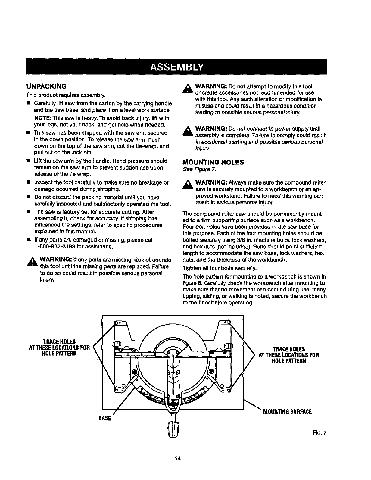
MOUNTING HOLES
SeeFigure7.
,_ WARNING" Alwaysmake surethe compoundmiter
saw Is securelymountedto a workbench or an ap-
provedworkstand. Failureto heed thiswarningcan
res_tt in _,eriouspersonaliniury.
The compound mitersaw shouldbe permanentlymount-
ed to a firm supportingsurface suchas a workbench.
Fourboil holeshave been provided inthe saw base for
thispurpose. Each of the four mountingho]ssshouldbe
bolted securelyusing3/8 in. machine bolts, lockwashers,
and hex nuts(notincluded). Bolts shouldbe of sufficient
lengthto accommodate the saw base, lockwashers, hex
nuts, axedthe thickness of the workbench.
Tightenart four bolts securely.
The hole pattern for mountingto aworkbench Is shownin
figure8. Carefullycheck the workbench after mountingto
make surethat no movementcan occur duringuse. It any
tipping, sliding,or walkingIs noted,securethe workbench
to the floor beforeoperating.
"IRACEHOLES _,
ATTHESELOCATIONSFOR
HOLEPATTERN
/
BASE
TRACEHOLES
ATTHESELOCATIONSFOR
HOLEPA'FrERN
MOUNTINGSURFACE
Fig. 7
14
As mentioned previously,the saw has been factory
assembled and adjusted.
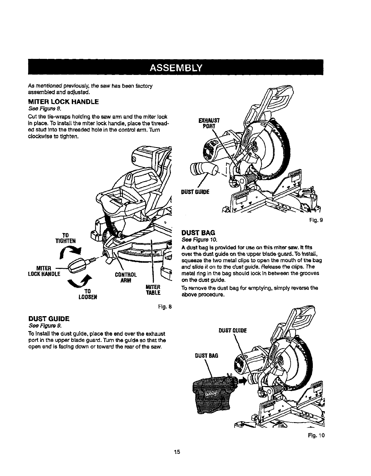
MITER LOCK HANDLE
See Figure 8,
Cut the tie-wraps holding the saw arm and the miter rock
In place. To Instal[ the miter lookhandle, placethe thread~
ed stud into the threadedhole in the controlerm. Turn
clockwiseto tighten.
EXHAUST
PORT
TO
TIGHTEN
TO
LOOSEN
CONTROL
ARM MITER
TABLE
Fig. S
DUST GUIDE
See Figure 9,
To Installthe dust guide, ptace the end overthe exhaust
port in the upper blade guard. rum the guide so that the
open end is facing down ortoward the rearof the saw.
Fig. 9
DUST BAG
See Figure 10.
A duet bag is providedfor use onth_smitersaw. It fits
o'_e_"_h_dustguideor the upper b_adeguam. To Ir,stat_,
squeeze the two metal clips to open the mouth of the bag
and slide it on to the dust guide. Releasethe _ips. The
metal ringin the bag shouldlock in between the grooves
on the dust guide.
To removethe dust bag for emptying,simply reversethe
above procsqure.
DUSTBAG
Fig. 10
15
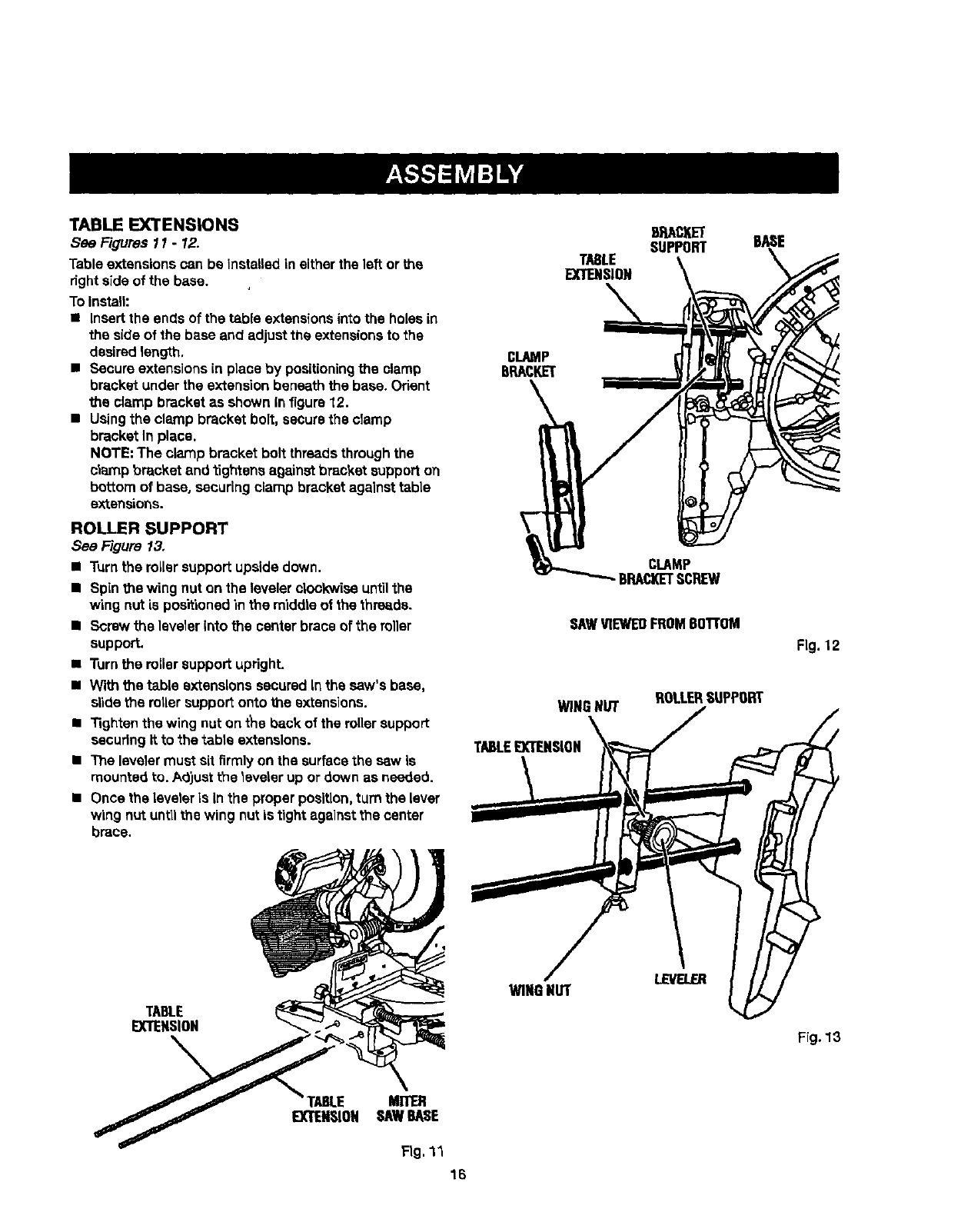
TABLEEXTENSIONS
See Figures 11 -12.
Table extensionscan be Installed in either the left or the
fight side of the base.
To Instalh
• Insertthe ends of the table extensionsintothe holesin
the side of the base and adjustthe extensionsto the
desiredlength.
•Secure extensionsin place by positioningthe clamp
bracket under the extensionbeneath the base. Orient
the clamp bracket as shown infigure 12.
•Usingthe clamp bracket boil, securethe clamp
bracket In place.
NOTE: The clamp bracketbolt threadsthroughthe
clamp bracket and tightensagainst bracket supporton
bottom of base, securing clamp bracketagainst table
extensions.
ROLLER SUPPORT
See Figure 13.
•Turnthe rollersupport upsidedown.
•Spin the wing nuton the leveler clockwiseuntilthe
wing nutis positionedin the middle of the thre=ds.
•Screw the leveler into the center brace of the roller
support.
•Turnthe reliersupport upright.
•With the table extensionssecured Inthe saw's base,
slide the miler support onto the extensions.
•Tighten the wing nut on the back of the rollersupport
secudngIt to the table extensions.
•The levelermust sit firmly on the surfacethe s_w is
mountedto. Adjust the leveler up or down as needed.
•Once the leveleris inthe proper position,turn the lever
wing nut untilthe wing nut is tight agalnstthe center
brace.
TABLE
EXTENSION
BASE
CLAMP
BRACKET
CLAMP
BRACI(ETSCREW
SAWV1EWEDFROMBOTTOM
WINGNUT ROLLERSUPPORT
TABLEEXTENSION
Fig. 12
TABLE
EXTENSION
WINGNUT LEVELER
Frg. 13
FABLE MITER
EXTENSION SAWBASE
Fig. 11
16
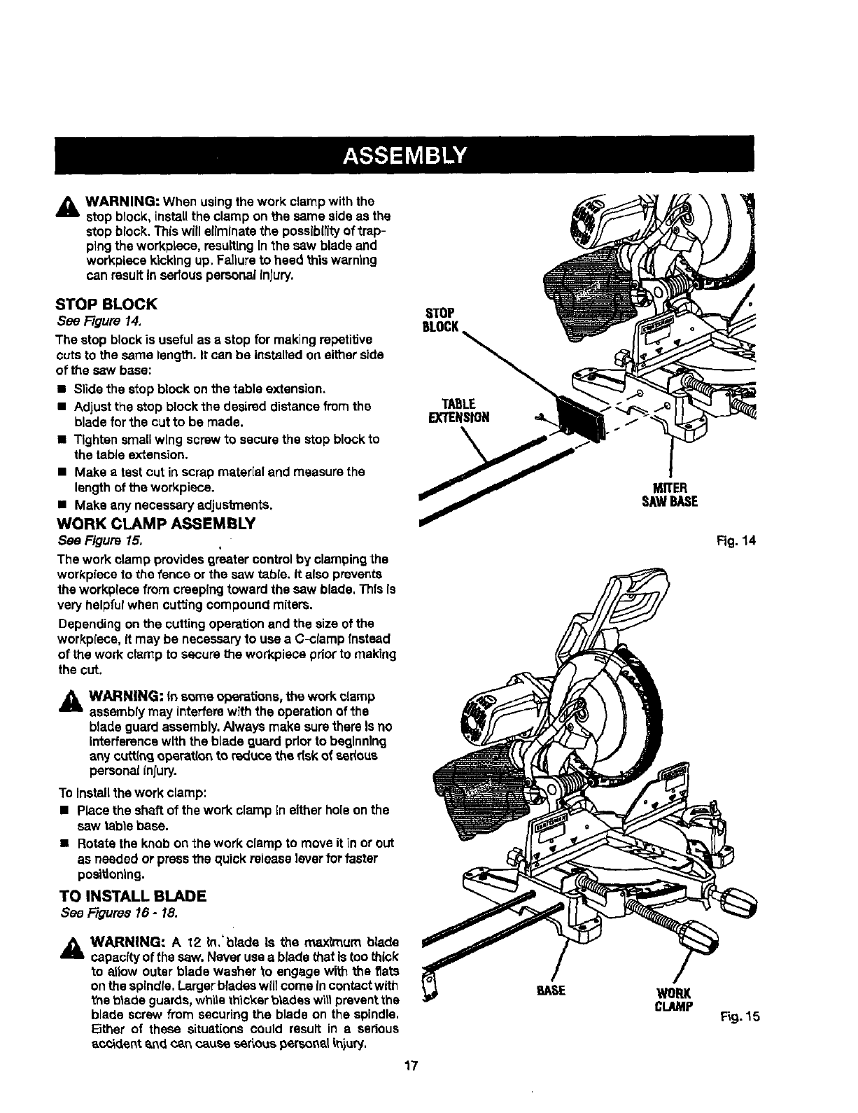
_lb WARNING: When usingthe work clampwith the
stop block, installthe clamp on the same side as the
stop block. Thiswill ellmlnatethe posslb(tityof tmp-
p]ng the workplece, resulting Inthe saw blade and
workpiece kickingup. Failureto heed this warning
can resultin sedous personalInjury,
STOP BLOCK
See Figure 14.
The stop block is usefulas astop for making repetitive
cuts to the same length. It can be instaltedon either side
of the saw base:
•Slide the stop block onthe table extension.
•Adjustthe stop block the desired distance from the
blade for the cut to be made.
•Tighten smallwLngscrew to securethe stop block to
the table extension.
•Make atest cut inscrap material and measure the
lengthof the workpiece.
•Make any necessaryadjusb_enta.
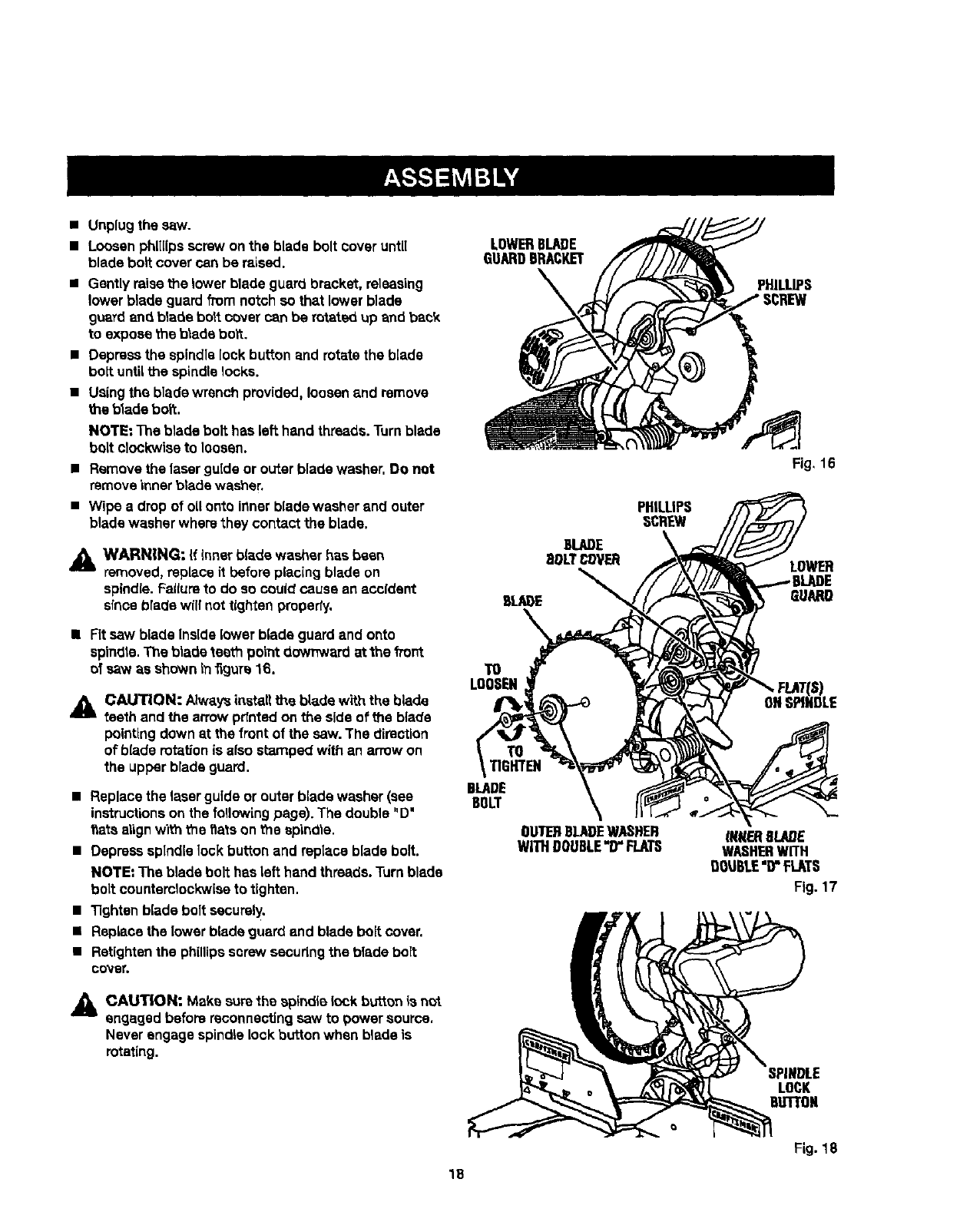
WORK CLAMP ASSEMBLY
See F/gum 15,
The work clamp providesgreater controlby clampingthe
workp_eceto the fence or the saw table. It alsoprevents
the workplecefrom creeping toward the saw blade, This Is
very helpfulwhen cuttingcompound miters.
Dependingon the cuttingoperationand the size of the
workpiece, it may be necessaryto use a C-clamp rnstead
of the work clamp to secure the workpiece priorto ma_ng
the cut.
A WARNING: In s_me operations, the work clamp
assemblymay interferewith the operationof the
blade guardassembly.Always make surethere Is no
interferencewith the blade guard pdor to beginning
any cutt(ncJoperat(on to reduce the dsk of sedous
personalinlury.
To Installthe work clamp:
•Place the shell of the work clamp In eitherhole onthe
saw table base.
•Rotate the knob on the work clamp to move it in or out
as needed or pressthe quick releaselevertot faster
positioning.
TO INSTALL BLADE
See Figures 16 -18,
_l WARNING: A 12 k_.'blade Lsthe rru_xkTtumblade
capacity of the saw. Neveruse a blade that Istoo thick
to allow outer blade washer to engage with the fiats
onthe spindle,Largerblades willcome Incontactwith
the b|ade guards,while thickerbiades w'Lllpreventthe
blade screw from securing the blade on the spindle,
Either of these situations could result in aserious
_sok_,entend can cause serlouspersonaliniury,
17
STOP
BLOCK
TABLE
EXTENSION
MITER
SAWBASE
WORK
CLAMP
Fig. 14
F_9.15
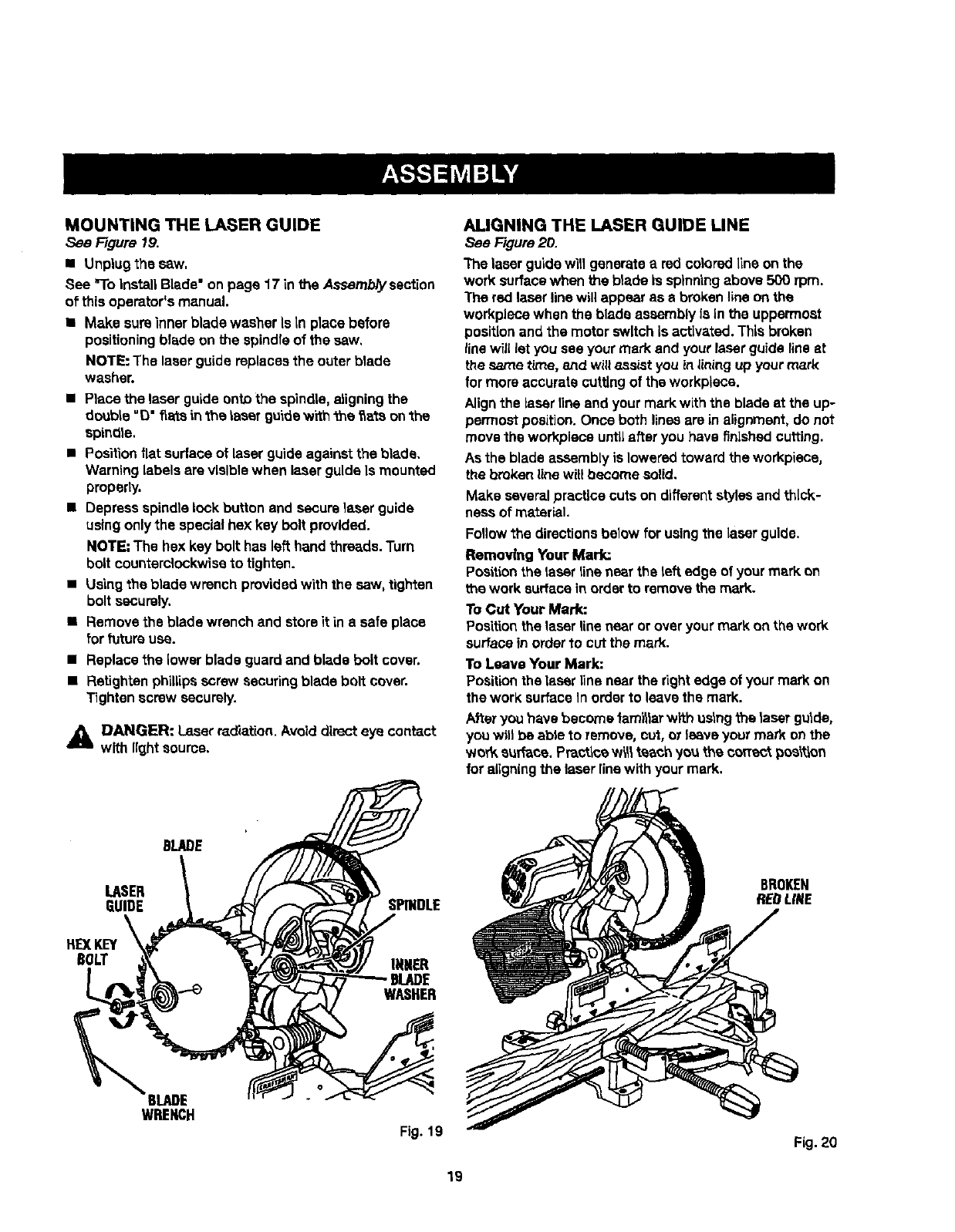
•Unplugthe saw.
•Loosenphillipsscrew on the blade bolt cover until
blade boll cover can be raised.
•Gently raisethe lower blade guard bracket, releasing
lower blade guard from notch so that lower blade
g_xardand blade bolt cover can be rotated up and back
to expose the blade bolt.
•Depress the spindlelock button and rotatethe blade
bolt until Me spindle locks.
• Using the blade wrench provided, loosen and remove
the blade bert.
NOTE: The blade bolt has left hand threads.Turnblade
bolt clockwiseto loosen.
•Removethe laserguide or outer blade washer. Do not
removeinnerbtade washer.
•Wipe a drop of oUonto innerblade washer and outer
blade washer wherethey contact the blade.
AWARNING: If Inner b(ade washer has been
removed, replaceit before placing blade on
spindle.Failureto do so could cause an accident
slnca brede will not tightenproperty.
II Fitsew blade Inside lower blade guardand onto
spindle.The blade teeth point downward at the front
ofsaw as shown in_guTs16.
A CAUTION: Alwaysinstall the blade with the blade
teeth and the arrow pdntedon the sideof the blade
pointingdown at the front of the saw. The direetion
of blade rotationis also stamped with an arrowon
the upperblade guard,
•Replace the laser guide or outer blade washer (sea
instructionson the following page). The double "D"
f_atsalignwiththe flats on the spindle.
•Depressspindle lock button and replace blade bolt.
NOTE: The blade bolt has left hand threads.Turnblade
bolt countemlockwiseto tighten.
•Tightenblade bolt securely,
•Replace the lower blade guard and blade bolt cover.
•Retightenthe phillipsscrew secudngthe blade bolt
COV8_
LOWERBLARE
GUARDBRACKET
TO
LOOSEN
TO
TIGHTEN
BLADE
BOLT
OU'IETIBLADEWASHER
WITHDOUBLE"D"FLATS
PHILLIPS
Fig, 16
LOWER
GUARD
_NRERBLADE
WASHERWITH
DOU6LE"D"FLATS
Fig. 17
,,_& CAUT|ON: Make surethe spindle lock button ia not
engaged before reconnectingsaw to power source.
Neverengage spindle lock button when blade is
rotating.
IPINDLE
LOCK
OLIn'ON
Fig. 18
18
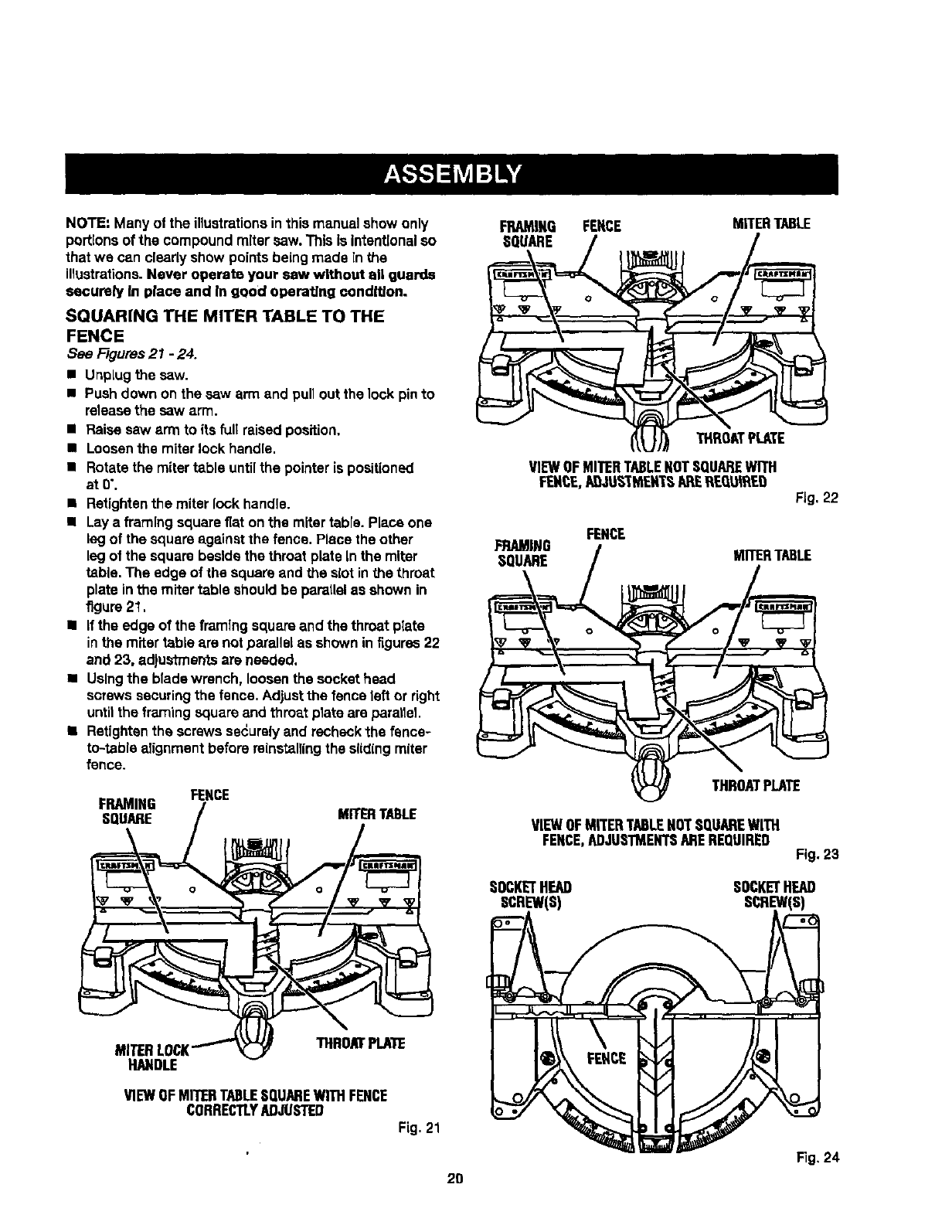
MOUNTING THE LASER GUIDE
See Figure 19.
I Unplug the sew.
See "ToInstallBlade"on page 17 in the Assemb/yssct[on
of thisoperator'smanual.
•Make sureinnerblade washerIs In place before
positioningblade on the spindleof the saw,
NOTE: The laserguide replacesthe outer blade
washer.
•Place the laser guideonto the spindle,aligningthe
double "O" f_ateinthe laser guidew_th"the_a_.sonthe
spindle.
•Positionflat surface of laser guideagainst the blade.
Warninglabels are visible when ia.serguide Is mounted
properly.
• Depress spindlelock button and securelapserguide
usingonly the specialhex key bolt provided.
NOTE"The hex key bolt has left hand threads.Turn
bolt counterclockwiseto tighten.
• Usingthe blade wrench providedwith the saw, tighten
bolt securely,
•Removethe blade wrench and storeit ina safe place
for future use.
•Replacethe lower blade guard and blade bolt cover.
•Retighten phillipsscrew securingblade bolt cover.
Tighten screw securely.
_i DANGER: Laserradiation. Avoiddirect eye contact
with lightsource.
ALIGNING THE LASER GUIDE LINE
See Figure20.
The laserguidewit] generatea red coloredline on the
work surfacewhen the b}adeis spinningabove500 rpm.
The red laserline will appear as ebrokenline on the
workplacewhen the blade assemblyIs in the uppermost
positionand the motor switchIs activated. This broken
line will let you see your mark and your laser guide fineat
the same time, 8ttd will assist youin lining up your mark
lor more accurate cuttingof the workplace.
Alignthe Lasertinsand your mark with the blade at the up-
permost position.Once both linesare inalignment,do not
move the workplaceuntLLafter you have finished cutting.
As the blade assembly is loweredtoward the workplace,
the broken line willbecome solid.
Make severalpractice cuts on differentstylesandthick-
nasa of material.
Foflowthe directionsbelow forusingthe Laserguide.
Removing Your Mark:
Po._ttionthe laser line nearthe left edge of your mark on
the work surfacein orderto removethe mark.
ToCut Your Mark:
Positionthe laserline near or overyour mark on the work
surfaceinorderto cut the mark.
To Leave Your Mark:
Positionthe laserline near the rightedge of your mark on
the work surfaceIn orderto leave the mark.
Afteryou have become fam_larwith ostngthe laser gutde,
youwill be able to remove, cut, or leave your mark onthe
wor_ surface. Practtoew_ teach yo_ the correctpos_'_on
foraligningthe laserlinewith your mark.
BLADE
LASER
GUIDE SPINDLE
BROKEN
REOLtNE
HE)(KEY
BOLT
_BLADE
WRENCH
INNER
BLADE
WASHER
Fig. 19 Fig. 20
19
NOTE:Manyoftheillustrationsinthismanualshowonly
porttonsofthecompoundmitersaw.ThisIsIntantEonalso
thatwecanclearlyshowpointsbeingmade in the
illustrations.Never operate your saw without all guards
securely In grace and rn good operating condition.
SQUARING THE MITER TABLE TO THE
FENCE
See F/gums21 -24.
•UnpLugthe saw.
•Pushdown on the saw arm and pullout the lock pinto
releasethe saw arm.
•Raise saw arm to its full raised position.
•Loosenthe miter lock handle.
•Rotatethe miter table untilthe pointer is positioned
atO'.
•Retightenthe miterlock handle.
•Laya framing square fiat on the miter table. Place one
legof the square againstthe fence. Place the other
legof the square beside the throat plateIn the miter
table. The edge of the square and the slotin the throat
plate inthe mitertable shouldbe parallelas shown in
figure21,
•If the edge of the framlng squareand the throat plate
inthe miter table are notparallel as shown in itgures22
and 23, adjustmentsare needed.
•Usingthe bladewrench, loosenthe sockethead
screws securingthe fence. Adjustthe fence lefl or right
untilthe framingsquareand throat plata am parallel.
•Retigbtanthe screws securelyand recheckthe fence-
to-table alignment before reinstallingthe slidingmiter
fence.
FENCE
FRAMING
SQUARE MITERTABLE
FRAMING FENCE MITERTABLE
SQUARE
THRUATPLATE
VIEWOFMITERTABLENOTSQUAREWITH
FENCE.AQ-tUS-'Th_EXTSAPEREQUWLED Fig,22
FENCE
FRAMING /MITERTABLE
. ,go
VIEWOFMITERTABLEHOTSQUAREWITH
FENCE,ADJUSTMENTSAREREQUIRED Fig. 23
SOCKETHEAD SOCKETHEAD
SCREW(S) SCREW(S)
THROATPLATE
NAPDLE
VIEWOFMITERTABLESQUAREWITHFENCE
CORRECTLYADJUSTED
Fig.21
Fig, 24
2D
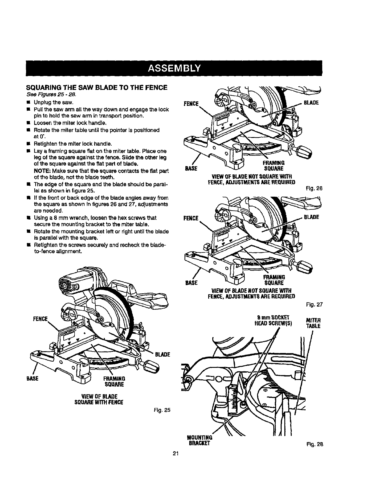
SQUARING THE SAW BLADE TO THE FENCE
See Figures25 - 28,
• Unplugthe saw.
• Pull the saw arm all the way down and engage the look
pin to holdthe saw arm in transportposition,
•Loosenthe miter lock handle,
•Rotatethe miter table untilthe pointer is positioned
at0".
•Retightenthe miterlock handle.
•Lay a framingsquare fiat onthe miter table. Place one
leg of the square againstthe fence, Slide the other leg
ofthe square againstthe flat pad of blade.
NOTE: Make surethat the square contactsthe fiat part
of the blade, nottheblade teeth.
• The edge of the square and the blade shouldbe paral-
lel as shown in figure25.
• If the front or back edge of the blade angles away from
the square as shown in figures 26 and 27, adjustments
are needed.
• Using a 8 mrn wrench, loosenthe hex screwsl_at
securethe mounting bracket to the mlter table.
• Rotate the mounting bracketleft or dght untilthe blade
is parallelwith the square. '
•Retfghtanthe screws secure(yand recheckthe blade-
to-fence alignment.
FENCE
FRAMING
BASE :SQUARE
FENCE
VIEWOFBLADENOTSQUAREWITH
FENCE,A[_JU6I"MENTSAREREQtIIRED
FRAMING
BASE SQUARE
VIEWOFBLADENOTSQUAREWITH
FENCE,ADJUSTMENTHAREREQUIRED
8mmHO_KET
HEADSCREW(S)
BLADE
Fig.26
6LADE
Fig. 27
MITER
TABLE
BASE FRAMING
HQUARE
_EW OFBLADE
SQUAREWITHFENCE
Fig. 25
MOUNTING
BRACKET 2S
21
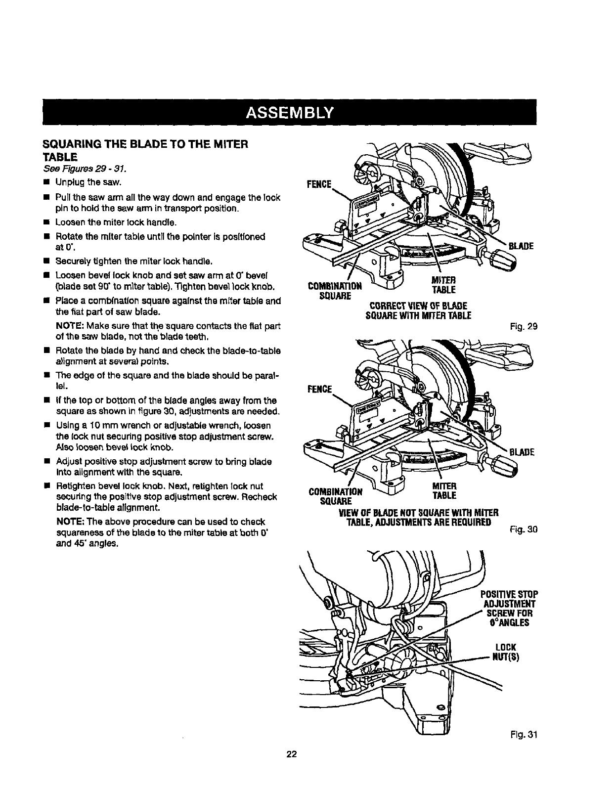
SQUARING THE BLADE TO THE MITER
TABLE
See Figures29 - 31.
•Unplugthe saw.
• Pull the saw arm all the way down and engage the 1ock
pin to hold the saw arm in transport position,
•Loosen the miter lock handle.
•Rotate the mitertable untilthe pointer is positioned
at0",
•Securelytighten the miter lock handle.
•Looeen bevel lock knob and setsaw arm at 0" bevel
(blade set 90' to mltertable}, Tighten bevellock knob,
•Place acomb(nationsquare againstthe mitertable and
the fiat part of saw blade.
NOTE: Make surethat the square contactsthe fiat par_
of the saw blade,not "theblade teeth.
•Rotate the blade by hand and cheCk the blade-to-table
alignment at several points,
•The edge of the square and the blade should be paral-
lel.
• If the top or bottom of the blade angles away from the
square as shownin figure30. adjustmentsare needed.
•Usinga10 mm wrench or adjustable wrench, loosen
the lock nut securingpositivestopadjustmentscrew.
/_eeloosenbevellockknob.
•Adjustpositivestop adjustmentscrew to bring blade
Into alignmentwith the square.
•Retightenbevel lock knob. Next, retightenIook nut
seCuringthe positivestop adjustmentscrew.Recheck
blade-to-table alignment.
NOTE: The above procedure can be used to check
squareness of the blade to the mitertable at both 0"
and 45" angles.
FENCE
MITER
TABLE
CORRECTViEWOFBLADE
SQUAREWITHMITERTABLE
FENCE
MITER
COMBINATION TABLE
SQUARE
VIEWOFBLADENOTSQUAREWITHMITER
TABLE,ADJUSTMENTSAREREQUIRED
Fig. 29
"BLADE
Fig.30
POSITIVESTHP
ADJUSTMENT
SCREWFOR
O°ANGLES
LOCK
NUT(S)
Fig. 31
22
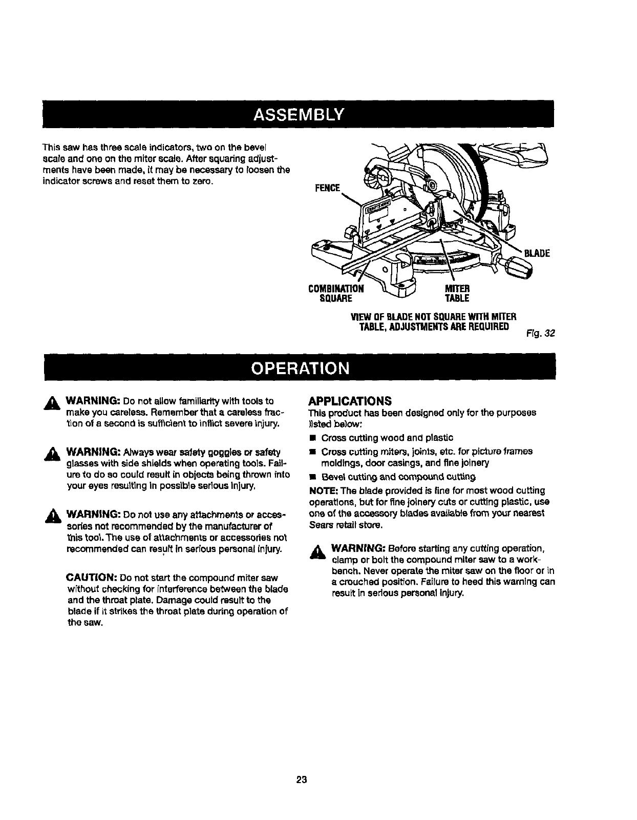
This caw hasthree scale indicators,two on the bevel
scale and one on the miterscale. After squadng adjust-
ments have been made, it may be necessaryto loosenthe
indicatorscrews and reset them to zero. FENCE
•BLADE
COMBINATION
SQUARE MITER
TABLE
VIEWOFflLADENOTSQUAREWITHMITER
TABLE,ADJUSTMENTSAREREQUIRED Fig. 32
_k WARNING: Do notallow familiarity with tools to
make you careless. Remember that acarelessfrac-
tion of e second is sufficient to inflict severeinjury.
_k WARNING: Alwayswsar safety goggFsaor safety
glasseswith side shieldswhen operatingtools. Fail-
um to do so could resultin objects beingthrown _nto
your eyes resultingin possibleseriousInjury.
_, WARNING: Do notuse any attachments oracces-
sories not recommended by the manufacturerof
this tool.The use of attachments or accessoriesnot
recommended can resultin seriouspersonal inlury.
CAUTION: Do not start the compoundmiter caw
without checkingfor interference betweenthe blade
and the throat plate. Damage couidresultto the
blade if it strikesthe throat plate dudng operationof
the saw,
APPLICATIONS
This product hasbeen designedonlyfor the purposes
)}stedbelow:
• Cresscuttingwood and plastic
•Cross cuffing miters, joints,etc. for pictureframes
moldings, doorcasings,and finejolnery
• Beve_cu_.tin9and compouncLcuing
NOTE: The blade providedis fine for most wood cutting
operations,butfor fineJoinerycuts or cuttingplastic, use
one of the accessory blades avaiisb_efromyour nearest
Sears retailstore.
_k WARNING: Beforestartingany cuttingoperation,
clamp or bolt the compoundmitersaw to a work-
bench, Neveroperate the miter saw onthe floor or in
ecrouched posit'ion.Failureto heed thiswarning can
resultIn sedouspersonalinjury.
23
NOTE: Always check for interference between the blade
and the silding miter fence BEFORE attempting to make
a cut. Some compound miter cuts rsquim the sliding miter
fence to be moved or completely removed before making
the cut.
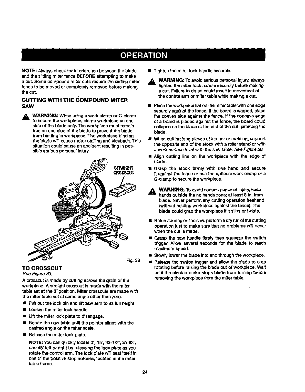
CUTTING WITH THE (_OMPOUND MITER
SAW
_lb WARNING: When usinga work c_mp or C-clamp
to secure the workpiece, clamp workplace on one
side of the blade only.Theworkplece must remain
fTeeon one side of the blade to preventthe blade
from bindingIn workplece.The workplace bindlng
the blade w_llcause mo'torstallingand idckback. "This
situationcould cause an accident resultingin pos-
sible serious personalinjury.
Fig. 33
TO CROSSCUT
See Figure 33.
A crosscutis made by cuffingacrossthe grainof the
workplace. A straightcrosscutis made with the miter
table set at the 0" position.Miter crosscutsare made with
the mitertable set at some angle other than zero.
•Pullout the lock pin and lift sew arm to its fullheight.
• Loosenthe miter lock handle.
•Lift the miter lock plate to disengage.
•Rotate the saw table until the pointer aligns with the
desired angle on the miter scale.
•Release the miter lock plate.
NOTE: You can quicklylocate O',15",22-1/2", 31.62",
and 45" left orfight by releasingthe lockplate as you
rotate the controlarm. The lock platewill seat itself In
one of the positivestopnotches, located _nthe m'_ter
table frame.
•Tighten the miter lock handle securely.
_1. WARNING: To avoid serious personalinjury,always
tightenthe miter lock handle securelybefore making
e cut. Failureto do so couldresultin movementof
the controlarm or mitertablewhile making a cut.
•Placethe workplaceflat onthe miter table withone edge
securelyagainst the fence. If the boardIs warped, place
the convexside againstthe fence. If the concave edge
of a board is placed against the fence,the board could
collapseonbe blade at the end af the cut,jammingthe
blade.
• Wt_tn cutting(ongpieces of lumber or molding, support
the opposite end of the stock wffh a roller stand or wffh
awork surfacelevel with the sawtabJe. Sac Figura 38,
Align cutting line on the workpiece with the edge of
blade.
Grasp the stock firmly with one hand and secure
it against the fence or use the optional work clamp or a
C-clamp to secure the workplace.
WARNING: To avoid eedous personalinjury,keep
hands outsidethe no handszone; at least 3 in. from
blade. Never performany cuttingoperationfreehand
(withoutholdingworkplaceagainst the fence),The
blade could grab the workplace if it slips ortwists.
•Beforo turning on the saw, perform adry run of the cuttJng
operation just to make sure that no problems will occur
when the cut is made,
•Grasp the saw handle firmly then squeeze the switch
tdgger. Allow several seconds for the blade to reach
maximum speed.
•Slowlylower the blade intoand through the workplace.
•Release the switchtrigger and aiidw the blade to stop
rotating before raisingthe bradeout of workplace. WaR
untilthe electric brake stops b_de from '_umingbefore
removingthe workplacefrom the miter tsbie.
24
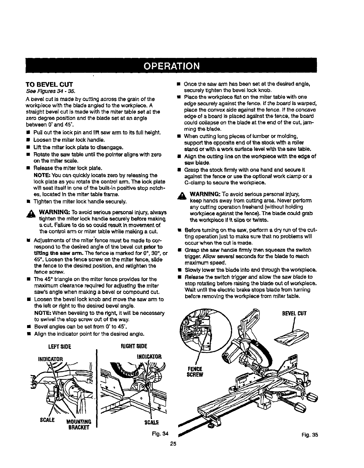
TO BEVEL CUT
See Figures34.35.
Abevel cut is made by cuttingacrossthe grain of the
workpiece with the blade angled to the workpiece. A
straightbevel cut Is made withthe miter tableset at the
zero degree positionand the blade set at an angle
between 0"and 45",
•Pull out the lock pin and riftsaw arm to its full height.
•Loosenthe miterlock handle.
•Liftthe miter lock platsto disengage.
•Rotate the saw table untilthe pointeralignswith zero
on the miter scats.
•Release the miterlock plate.
NOTE: You can quicklylocate zero by releesingthe
lock plate as you rotatethe controlarm. The lock plate
will seat itselfin one of the built-in positivestop notch-
es, located Inthe miter table frame.
•Tighten the miter lockhandle securely.
Jl_ WARNING: To avoid serous personal inju_, always
tighten the miterlock handlesecurely beforemakin_
acut. Failureto do so coutdresu_.In movement of
the control arm or miter tablewhite making a cut,
i
•Adjustments of the miterfence must be made to cop
respondto the desiredangle of the bevel cut prior to
tilting the saw arm. The fence is marked for 0=,30°, or
45°. Loosenthe fence screw onthe miter fence, slide
the fence to the desiredposition,and retlghtanthe
fence screw.
• The 45° triangleon the miterfence providesfor the
maximumclearance required for ad)ustlngthe miter
saw'sangle when makinga bevel orcompound cut.
•Loosenthe bevellock Knoband move the saw arm to
the left ordght to the desiredbevel angle.
NOTE=When bevelingto the right, itwill be necessary
to swivelthe stop screw out of the way.
•Bevelangles can be set from 0"to 45".
•Alignthe indicatorpointfor the desiredangle.
LEFTSIDE RIGHTSIDE
INDICATOR INDICATOR
• Once the saw arm has been set at the desired angle,
securely tighten the bevel lock knob.
•Place the workpiece fiat on the miter table with one
edge saCuTely against the fence, if _hs board is warped,
place the convex side against the fence. _f the concave
edge of a board is placed against the fence, the board
could collapse on the blade at the end of the cut, jam-
ming the blade.
•When cuffing tong pieces of lumber or molding,
support the opposite end of the stock wWn a rotter
stand or with a work sudece level with the saw table.
•Align the cutting line on the workpiece with the edge of
sew blade.
•Grasp the stock firmly with one hand and secure it
against the fence or usa the optional work clamp or a
C-clamp to secure the workpiece.
_1= WARNING: To avoid seriouspersonal Infury,
keep handsaway from cuttingarea. Neverperform
any cutting operation freehand (without holding
workpiece ag_'cnst the fence). The blade could grab
the ,_orkp'_co _fitslips or twists.
•Beforeturningonthe saw. p_rformad_ runof the cut-
ting operationJus_to make sure that no problemswitl
occurwhen the cut is made.
•Graspthe sew handlafirmly then squeeze the switch
trigger,Allow severalsecondsfor the blade to reach
maximum speed.
•S_owlylower the b_de Into and throughthe workplace.
•Releasethe swftchtrigger and allow the sew blade to
stop rotaling before raisingthe bla_e out of workptsce.
Wa_tuntilthe electricbrake stopsblade from turning
before removingthe workplacefrom mitertable.
BEVELCUT
SCALE
Fig,35
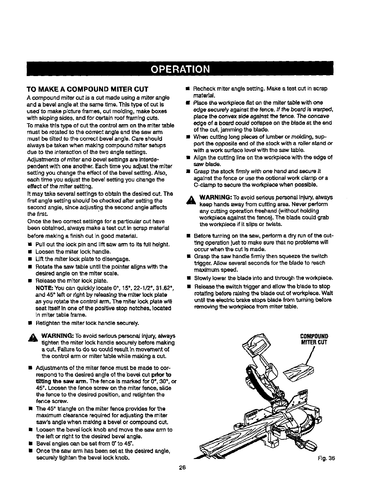
TO MAKE A COMPOUND MITER CUT
A compound mitercut is a cut made usinga miterangle
and abevelangle at the same time, This type of cut Is
used to make pictureframes, cut molding, make boxes
with slopingsides, end for certain roof framfng outs.
To make thistype of cut the control arm on the mitertable
must be rotated to the correct angle and the sew arm
must be dited to the correct bevelangre,Care should
always be taken when making compoundmitersetups
due to the interactionof the two angle settings.
Adjustments of miter and bevel settingsare interde-
pendentwith one another. Each time you adjust the miter
settingyou change the effect of the bevelsa_ng. Also,
each time you edlust the bevelsetting youchange the
effect of the miter settfng.
It may take severalsettings to obtainthe desiredcut. The
firstangresetting should be checkedafter settingthe
second angle, sinceadjustingthe second angle affects
the first.
Once the two correct settingsfor a particular cut have
been obtained,always make atest cut in scrap material
before makinga finish cut in good material.
•Pullout the lock pin and [fitsaw arm to its full height.
•Loosenthe miter lock handle.
•Liftthe miter lock plate to disengage.
• Rotate the sew table untilthe pointer alignswith the
desiredangle onthe miter scale,
•Releasethe miter lock plate.
NOTE: You can quickly locate 0°, 15°, 22-1/2 °, 31.62°,
and 45° left or dght by releasingthe miter lock plate
as you rotatethe control arm.The miter lock platewill
seat ItselfIn one of the positivestop notches,locateq
in mitertable h'ame.
• Retightan the miter lock handle securely.
•Recheckmiter angle setting.Make a test cut in scrap
material.
•PIsce the workplaceflat on the rarer table withone
edge security againstthe fence. It the board is warped,
place the convex sideagainst the fence. The concave
edge of aboardcould coffapea onthe b_adeat the end
ofthe cul, jammingthe blade.
•When cuttinglongpiecesof lumber or molding, sup-
port the opposite end of the stock witharollerstand or
with a work surfacelevelwith the saw table.
•ALignthe cuttingline on theworkpiece with the edge of
saw b_de.
•Graspthe stock firmly with one hand and secure it
against the fence or usethe optional work clamp ora
C-clamp to securethe workplacewhen possible.
_, WARNING: Toavoid sedous personalinjury, always
keep hands away from cuttingarea. Never perform
any cuttingopera_'onfreehand(wRhoutholding
workpiecaagainst the fence),The brada couldgrab
the workpiece if it slipsor twists.
• Before turning on the saw, perform adry run of the cut-
ting operation just to make sure that no problems will
occur when the cut Is made.
•Grasp the saw handle firmly then squeeze the switch
trigger. Allow several seconds for the blade to reach
m_mum spewed.
•Slowly lower the blade into and through the workpiece,
•Release the switch trigger and allow the blade to stop
rotating before raising the blade out of workplace. Walt
u_til the e_ectdc b_ke stops blade from turning before
removing the won_pieee horn miter table.
_, WARNING: To avoid seriouspersonal lnju_/,always
tighten the miter lock handlesecurely before making
aout. Faiturato do so could resell Inmovement of
the control arm or miter table while making a cut.
•Adjustmentsof the miter fence mustbe made to cor-
respondto me desiredangle of the bevel cut prior to
tilting the saw arm. The,fence Is marked for g°, 30°, or
45°, Loosenthe fence screw onthe miterfence, slide
the fence to the desiredposition, and retightenthe
fence screw.
• The 45°triangle on the miter fence providesfor the
maximum clearance required for adjustingthe miter
saw'sangle when making a bevel or compound cut.
•Loosenthe bevellock knob and move the sew arm to
the left or rightto the desiredbevelangle.
•Bevelangles can be set from 0"to 45",
•Once the saw arm has been setat the dsairedangle,
securelytightenthe bevel lock knob.
26
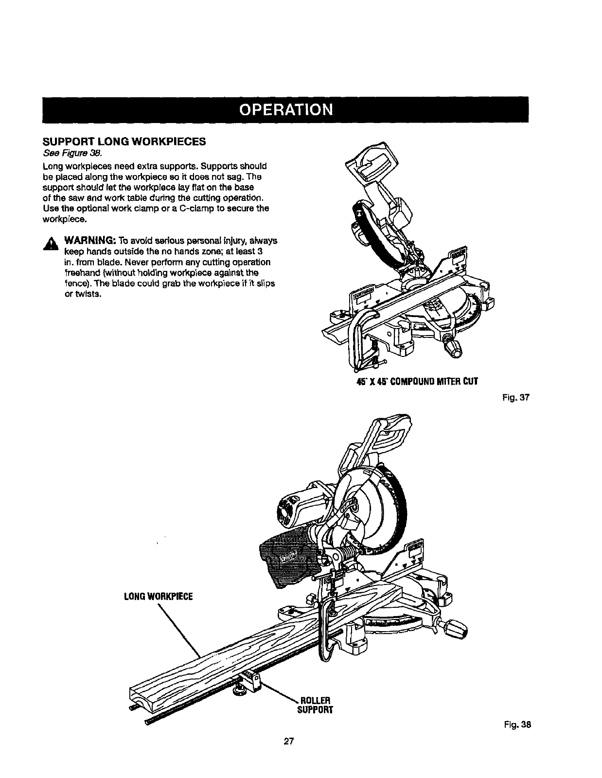
SUPPORT LONG WORKPIECES
See Figure 38.
Longworkpieces need extra supports.Supportsshould
be placed alongthe workpiece so it does not sag. The
support should let the workplece lay f/at on the baee
of the saw and work table dudng the cuttingoperation.
Use the optionalwork clamp or aC-clamp to securethe
workpiece.
_, WARNING: To avoid seriouspersonalinjury,always
keep hands outsidethe no hands zone; at least3
in, from blade. Never performany cuttingoperation
fraehand(withoutholding workplece againstthe
fence), "Theblade coutd grab the wor_piece_fit stips
or twists.
4,5"X48"COMPOUNDMITERCUT
Fig. 37
LONGWORKPIECE
27
ROLLER
SUPPORT
Fig. 38

CUTrlNG COMPOUNDMITERS
To aid inmaking the correct se_ngs, the compoundangle se_ng chart below has been provided.Sincecompoundcuts
are the mo_t difficutt to accuratetyobtain, trfatcuts shourdbe made inscrap materiat, and much thoughtand ptanning
made, priorto making your requiredcut.
NUM-"-L., ,Jr o,_=,=
PITCH
ol=slo 4I 5 6I7I8I9I10
o" M- .oo °M- oo" M-3000"I M-25,71"M-22.50"M-20,00"U-18,00=
B- 0.00=B- 0,00° B-0.00 =B- 0.00°B-0.00 °B- 0.00°B- 0.00=:
5" M-44"89= M'35"90= M-29'gl= M-25'63° M-22"42= M'19"93° M'17"94=
B- 3.53" B- 2.94" iB- 2.50" B- 2,17 =B- 1.91°B- 1.71°B- 1.54=
10°M-44-56 ° M-35.58 °M-29,62°i M-25,37 °M-22.19 °M-19.72 ° M-17.74 °
B- 7,05°B- 5.86" B- 4.98" B- 4.32°B- 3.81°B- 3.40°B- 3.08=
M-44.01 ° M-35,06 °M-29.15 °M-24.95 =M-21.81 °M-19.37 =M-17.42 =
15°B-10.55" B- 8,75°B- 7.44°B- 6.45" B- 5.68" B- 5.08°B- 4.59"
20°M- 43.22" M- 34,32°M- 28.48 ° M- 24.35°M- 21.27 °M- 18.88" M- 16.98°
B-14.00 °B-11.60 °B- 9.85=B- 8.53° B- 7,52" B- 6.72" B- 6.07°
25° M-42.19 °M-33,36 °M-27.62 °M-23.56 °M-20.58 °M- 18.26°M- 16.41°
B- 17.39" B- 14.38°B- 12.20° B- 10.57° B- 9.31° B- 8.31" B- 7.50"
30°M-40-89°IM-32,18 °M-26.57 °M-22.64 °M-19.73° M-17.50 " M-15.72 °
B- 20.70 °B- 17.09°B- 14.48°B- 12.53°B- 11.03°B- 9.85 °B- 8.89°
35°M-39.32 °M-30.76 °M-25.31 °M-21.53 =M-18.74 °M-16.60 =M-14.90 °
B-23.93 =B- 19,70° B- 16.67" B- 14.41° B- 12.68=B- 1!.31 °B- 10.21°
40°M-37.45 ° M-29.10 °M-23,86 =Vl-20,25 °M-17.80 ° M-15,58 °M-13.98 =
B-27.03" B-22.20 =B-18.75" B- 16,19= B- 14.24° B-12.70 °B-11.46 °
45°M-35-26° M-27.19 °M-22,21 °M-18.80 °M-16.32 ° M-14,43 °M-12.94 °
B- 30.00" B-24,56" B-20.70 ° =L-17,87" B- 15,70°B- 14.00°B- 12,62"
iM-32.73 °M-25,03" M-20,36 °M-17.20 °M-14.91 ° M-13.17 ° M-11.80 °
50° B-32_80 °B-26.76 =B- 22.52 °B- 19.41=B- 17.05" B- 15.19=B- 13.69°
55=M-29.84 °M-22.62 °M-18,32 °M-15.44 °M-13.36 °M-11,79 °M-10.56 °
B- 35,40" B-28,78 ° B-24.18 °B- 20,82 ° B- 18,27" B- 16.27°B- 14.66°
M-26.57 =M-19.96 °M-16.10 ° M-13.54 =! M-11.70 °M-10.31 °M- 9.23°
60°B- 37,76°B-30,60" 13-25,66°B- 22,07°E3-19.35" B-17.23" B- 15.52°
M-22.91 =M-17.07 °M-13,71 °M-11.50 =M- 9.93 °M- 8.74=; M- 7.82°
65° B-39.86" B'32.19 ° 8-26,95 ° 18-23.16" B-20.29 °B-18.06 °8-16.26 °
M-18-88 °M-13.95 °M'11.17 °M- 9,35 °M- 8.06°M- 7.10=M- 6.34°
70°B-41.64 °B-33.53 °B-28.02" B-24.06" B-21.08 =B-18.75 °B-16.88 °
75= M-14.51 °M-10.65 °M- 8.50° M- 7.10° M- 6.12°M- 5.38° M- 4.81=
B-43.08 ° B-34.59 °B-28.88" B-24,78 °B-21.69 °B-19.29 =B-17.37 °
80°M- 9.85 =M- 7.19° M- 5.73° M- 4.78°M- 4.11=M- 3.62°M- 3.23"
B- 44.14" B-35.37 =B-29,50 °B-25,30 =B- 22.14" B- 19.68°B- 17.72"
M- 4.98 °M- 3.62°M- 2.88° M- 2.40° M-2.07 =M-1,92 °M- 1.62°
85° B- 44,78=B-35.84" B-29.87 °B-25.61" B-22.41 °B- 19.92" B- 17.93°
90°M- O.00= M- 0,00°M- 0.00°M- 0.go" M- 0,DO°M- 0.00°M- 0,00°
B-45,00" B-38.00 °B-30.00 =B-25.71 °B-22.50 °B-20.00 °B- 18,00"
Each B (Bevel)and M [Miter)Setting Is Givento the Closest0.005=.
COMPOUND-ANGLE SETTINGS FOR POPULAR STRUCTURES
28
CU'I'I'ING CROWN MOLDING
The compoundmiter sew does an excellentJobof cut-
ting crown molding. In general, compound miter eaws do
abetter Jobof cuffingcrown moldingthan any othertool
made,
In orderto fit properly,crown moldingmust be compound
mltaredwith extreme accuracy,
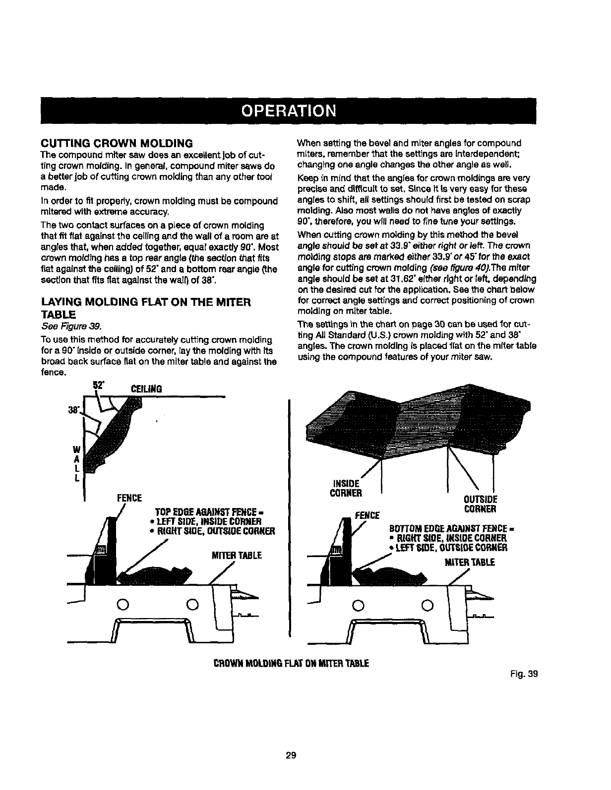
The two contactsurfaces on a piece of crown molding
that fit flat against the ceiling and the wall of a roomare at
anglesthat, when added together,squatexactly g0".Most
crown moldinghas a top rearangle (_e section _at fits
fiat againstthe ceiling}of 52"and a bottom rearangle(the
sectionthat fits fiat against the wail}of 38",
LAYING MOLDING FLAT ON THE MITER
TABLE
See F'tgure39,
Touse this method for accurately cuttingcrown molding
for a 90" insideor outside comer, ray the molding with Its
broad back surfaceflat on the miter table and against the
fence.
62" CEILING
w
A
L
L
FENCE
TOPEDGEAGAINSTFENCE-
•LEFTSIDE,INSIDECORNER
•RIGHTSLOE,OUTSIOECORNER
MITERTABLE
© 0
When settingthe beveland miter angles for compound
miters, rememberthat the settingsare interdependent;
changingone angle changes the other angleas well.
Keep inmind that the angles forcrown moldingsare very
preciseand dl_cult to set. Since it is very easy forthese
angles to shift,all settingsshouldfirstbe tested on scrap
molding. Alsomost waftsdo nothave angles of exactly
90",_erefore, youwlflneed to finetune yoursettings.
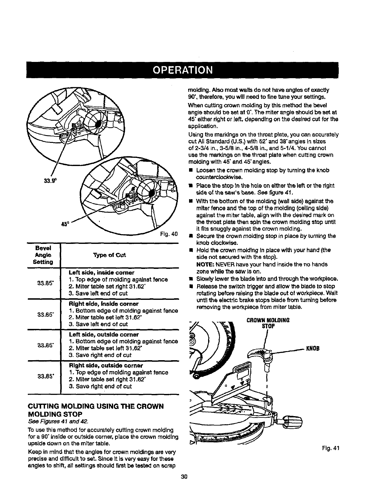
When cuttingcrown moldingby thismethod the bevel
angle shouJdbe set at 33.9"either rightor left. The crown
molding stops are marke_ either33.9"or 45"for the exact
angle forcuffingcrown molding (see _gure 40).The miter
angle shouldbe set at 31.62" either rightor left, depending
on the desirecicut forthe applieation.See the chartbelow
for correctangle settingsand correctpositioningof crown
moldingon miter table.
The settingsinthe charton pegs 39 can be used for cut-
tingAJ]Standard(U.S.) crown molding with 52"and 38"
angles.The crown molding is placed flat on_.hemitertable
usingthe compound features of your mitersaw.
INSIDE
CORNER
FENCE
OUTSIDE
CORNER
BD7"I'DMEDGEAGAINSTFENCE,,
• RIGHTSIDE,[KSIDECORNER
• LEFTSLOE,OUTSIDECORNER
MITERTABLE
CROWNMOLDINGFLATONMITSRTABLE
Fig. 39
29
33.9°
Fig.40
Bevel
Angte Typeof Cut
Setting
Leftside,insidecomer
33.85" 1.Topedgeofmoldingagainstfence
2. MitertablesetrJght31.62"
3.Saveleftendof cut
Right side, Inside corner
1. Bottom edge of moldingagainst fence
33.85" 2. Miter table set left 31.62"
3, Save left end of cut
Left side, outside comer
1. Bottom edge of molding against fence
_,3.65" 2. Miter table set left 31.62"
3. Save right end of cut
Right side, outside corner
33.85" 1. Top edge of molding against fence
2. Miter table set right 31.62"
3, Save right end of out
molding. Also mostwalls do not have angles of exactly
90",therefore,you will needto finetune your settings.
When cuttingcrown molding by thismethod the bevel
angte should be set at 0".The miter angloshouldbe set at
45"either rightor left, dopondingonthe desiredcut for the
sppLLcation.
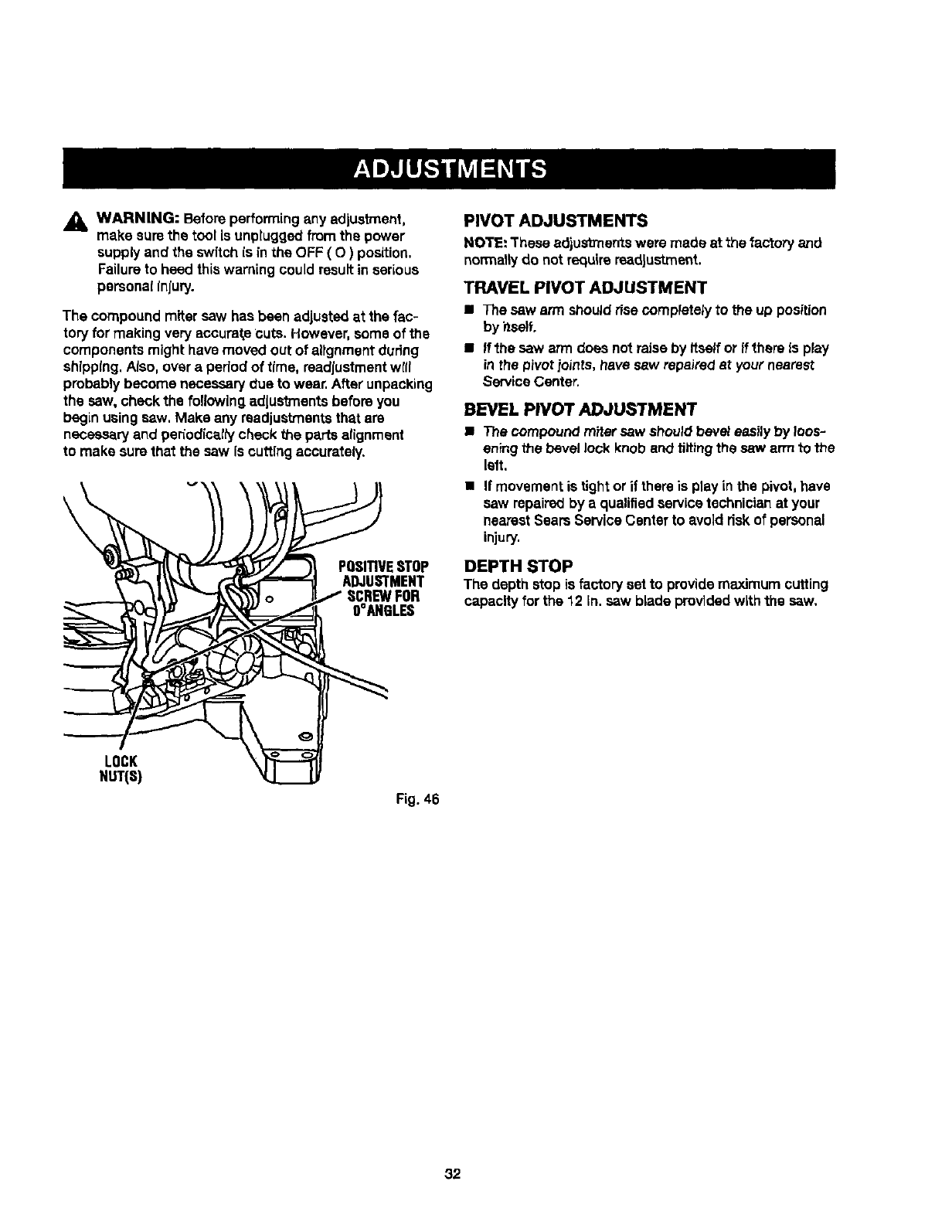
Usingthe markingsonthe throat plata, you can accurately
cut All Standard (U.S.)with 52"and 38"anglesin sizes
of 2-3/4 in.,3-5/8 in., 4-5/8 in.,and 5-1/4. Youcannot
usa the markingson the throat platowhon cuttingcrown
moldingwith 45"and 45"angles.
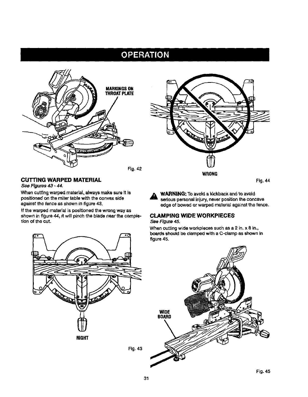
• Loosenthe crown molding stop by turningthe knob
countemlockwlse.
•Placethes_oplntheholeon e1_ertheteflorthadght
s_deof +_hesaw's _es. See figure41.
•With the bottom of the molding (wallaide)against the
miterfence andthe top of the molding(callingaide)
against the mitertable, alignwith the desiredmark on
the throat plate thenspin the crown moldingstop until
it fits snugglyagainst the crown molding.
• Securethe crown moldingstop inplaca by turningthe
knob clockwise.
•Holdthe crown moldinginplace withyour hand(the
side not securedwith the stop).
NOTE: NEVER haveyour hand insidethe no hands
zone while the saw Is on,
• Slowty towerthe blade Into and through the workptece,
•Releasethe switchtriggerand allow the blade to stop
rotat'mgbefore raisingthe blade out of workpiace.Wait
untilthe elactflc brokestopa blade fromturningbefore
removJngthe workplace frommitertable.
CROWNMOLDING
STOP
_._ KNOB
I
!
CUTTING MOLDING USING THE CROWN
MOLDING STOP
See Figures41 and 42.
To use thismethod for accurately cuttingcrown molding
for a 90"insideor outsidecorner,place the crown molding
upsidedown on the mitertable.
Keep in mind that the angles for crown moldingsare very
preciseand d]fficuitto set. Since it is very easy forthese
engtesto shift, el!settingsshoutdfirstbe tested on scrap
3O
Fig. 41
MARIOHGSOH
THROATPLATE
CUTTING WARPED MATERIAL
See Figures 43 -44.
When cuttingwarped material,always make sureIt Is
positionedon the mitertable with the convexside
againstthe fence as shown in f_gure43.
If the warped matedal Is positionedthe wrong way as
shown in f_gum44, it will pinch the blade near the comple-
tion of the cut.
RIGHT
Fig. 43
WRONG
Fig.44
,_ WARN,|NG: To avoid a k_c_d_ack_d to avoid
seriouspersonaliniury,never positionthe concave
edge of bowed or warped material agaLnstthe fence.
CLAMPING WIDE WORKPIECES
see Figure45.
When cuttingwLcleworkpieces suchas a 2 in. x 8 in.,
boardsshouldbe clamped with a C-clamp as shown in
figure 45.
WIDE
BOARD
Fig. 45
31
_, WARNING: Before performingany adjustment,
make surethe tool Is unpluggedfromthe power
supplyand the switchis in the OFF (O) position,
Failureto heed thiswarning could resultin serious
personalInfury.
The compoundmiter saw has been adjustedat the fac-
toryfor making very accuratecuts. However,some of the
componentsmight have moved out of alIgnmentduring
shlpplng,AJso,over a period of time, readjustmentwrit
probablybecome necessarydue to wear.After unpacking
the saw, check the following adjustments before you
beginusingsaw, Make any readjust_ants that are
necessaryand per_odic_l_check the parts alignment
to make surethat the saw is cuffingaccurately.
\
POSITIVESTOP
ADJUSTMENT
SCREWFOR
OOAHBLES
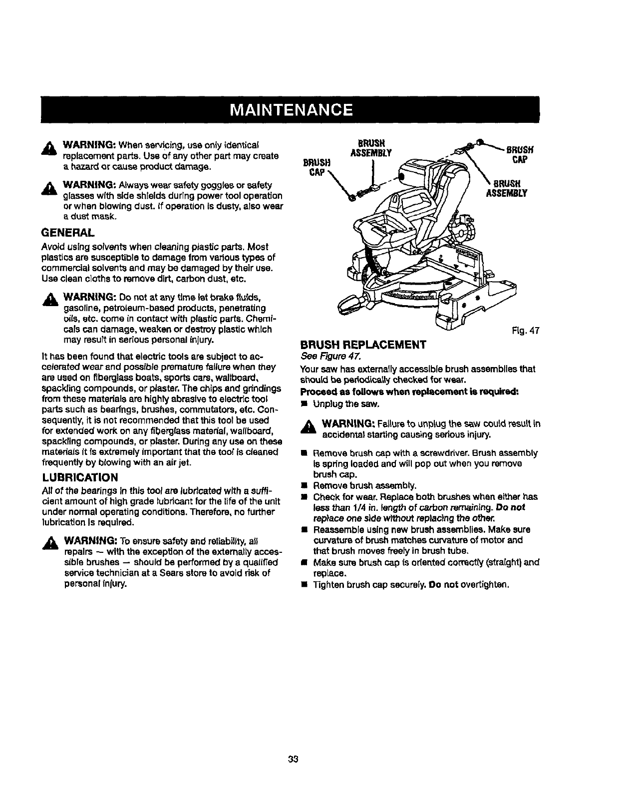
PIVOT ADJUSTMENTS
NOTE: These edjusb'nerrtswere made at the factory and
normal_Jdo not requirereadjustment.
TRAVEL PIVOT ADJUSTMENT
•The saw arm shouldrisecompletelyto the up position
by itself.
• If the saw arm does not raiseby Itselfor if there Is play
inthe pivot.ioints,have sew repairedat yournearest
ServiceCenter.
BEVEL PIVOT ADJUSTMENT
•The compound mitersaw shouldbeveJeasilyby loos-
eningthe bevel lock knob and tiltingthe saw arm to the
left,
•If movementis tightor if thereis play in the pivot,have
saw repairedby aqualifiedservice technicianat your
nearestSears Service Centerto avoid dsk of personal
injury,
DEPTH STOP
The depth stop is factoryset to providemaximum cutting
capacity forthe 12 In. saw blade providedwith the saw,
LOCK
NUT(S)
Fig. 46
32
,i_ WARNING: When serv!oing, use only identical
replacementpar_e.Use of any other part may create
ahazard or causeproductdamage.
_1_ WARNING: Alwayswear cataty gogglesor safety
glasseswith sideshieldsdurlngpower tool operation
or when blowing dust. If operation is dusty, also wear
adust mask.
GENERAL
Avoidusingsolventswhen cleaning ptasticparts. Most
plasticsare susceptibleto damage fromvedous types of
commercialsolventsand may be damaged by their use.
Use clean clothsto removedirt, carbondust, etc.
,_L WARNING: Do not at any time let brake f_ulds,
gasoline,petroleum-based products,penetrating
oils.etc. come in contactwRh plasticparts. Chemi-
cals can damage, weaken or destroyplastic which
may resuRin seriouspersonal injury.
It has been found that elecb'ictools aresubjectto ac-
celerated wear and possibleprematurefailurewhen they
are usedon fiberglassboats, sports cars, wallboard,
spacklingcompounds, or piaster.The chips and gdndings
from these materials are highlyabrasiveto electric tool
partssuchas bearfngs,brushes, commutators,etc. Con-
sequently,it is not recommended that this tool be used
for extended work on any fiberglass material,wallboard,
specklingcompounds, or piaster.Duringany use on these
matedais it [s extrsmely importantthat the tool is cleaned
frequentlyby blowingwith an air jet.
LUBRICATION
All of the bearingsIn this tool are lubricatedwith a suffi-
cient amount ot highgrade lubricantfor the life of the unit
under normaloperatingconditions.Therefore,no further
lubricationIs required.
,_ WARNING: To ensure safetyand reliability, ale
repairs -- with the exception of the externally acces-
sibrebrushes -- should be performed by a qualified
servicetechnicianat aSears storeto avoid riskof
personalinlury.
DRUSFI
FLg,47
BRUSH REPLACEMENT
See Figure 47,
Yoursaw has externally accessible brushassembliesthat
should be periodicallychecked forwear.
Proceed as follow,, when replacement is required:
• Unplugthe saw,
,_ WARN|NG: Falturato un_iug the saw couldresultin
accidentalstartingcausing seriousinjury.
• Remove brushcap with ascrewdriver.Brush assembly
Is springloadedand will pop out when youremove
brushcap.
• Remove brush assembly.
• Check forwear. Replaceboth brusheswhen either has
less than 1/4 in. _engthof ca,,bonremaining.Do not
replace one sidewithoutreplacingthe other,
•Reassembleusingnew brushassemblies.Make sure
curvatureof brushm_tchas curvatureof motor and
that brushmoves freely in brushtube.
•Make sure brush cap is odentedcorrectly(straight}and
repLace.
•"13ghtenbrushcap sscursly.Do not overtighten.
33
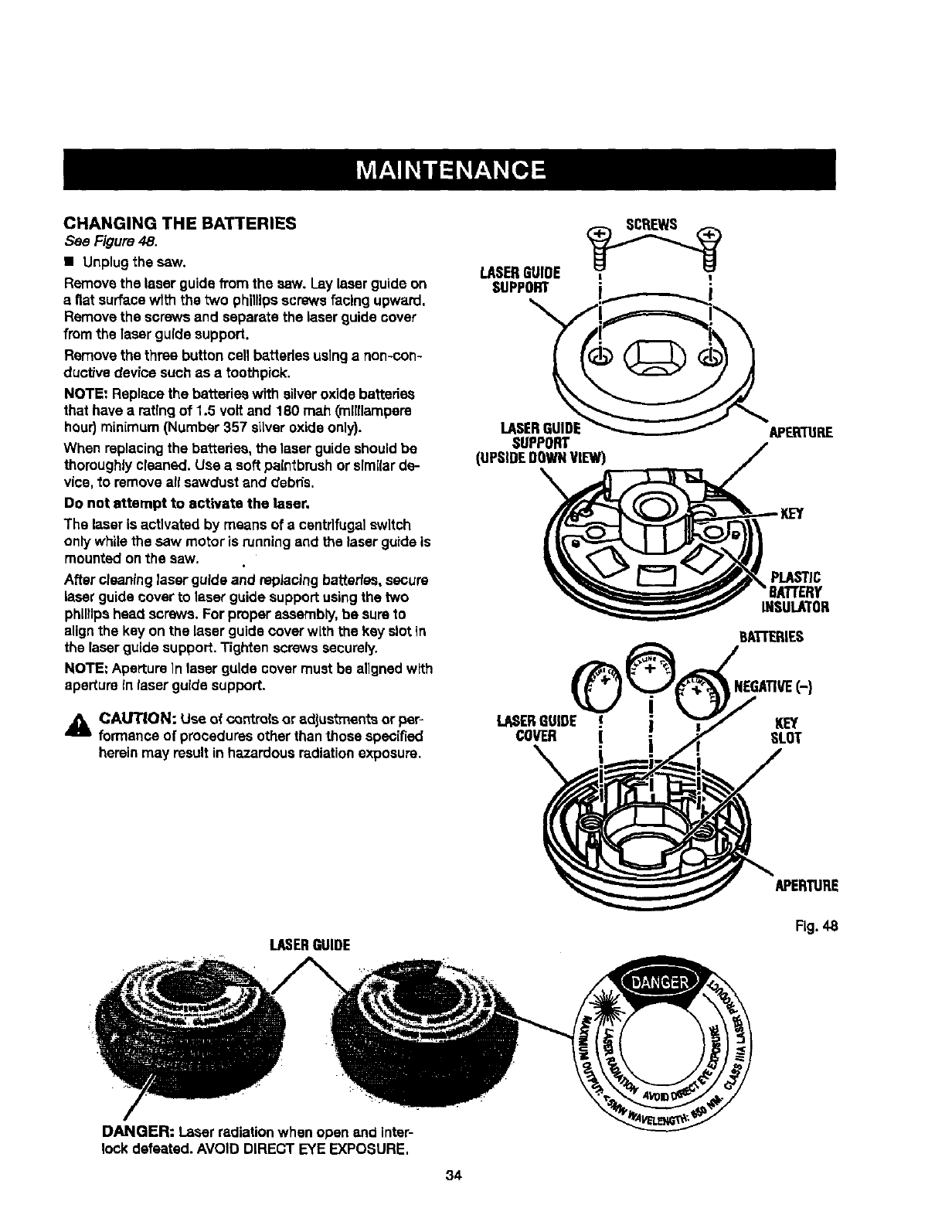
CHANGINGTHE BATTERIES
See Figure 48.
• Unplugthe saw.
Removethe laser guidefrom the saw. Lay laserguideon
a flat surfacewlth the two phillipsscrews facing upward.
Removethe screws and separatethe laser guidecover
fromthe laser guide support.
Removethe three button cell batteries usinga non-con-
ductivedevice such as atoothpick.
NOTE: Replace the batteries with silveroxide batteries
that have aratingof 1.5 voltand 180 mah (milliampere
hour)minimum (Number 357 silver oxide only).
When replacingthe batteries,the laser guideshouldbe
thoroughlycleaned. Use a soft paintbrushor srmilarde-
vice, to removeall sawdustand debds.
Do not attempt to activate the laser,
The laser is activated by means of a centrifugalswitch
only whilethe saw motor is runningend the laserguide is
mounted onthe saw.
After cleaninglaserguide and replacingbatteries,secure
laserguide coverto laserguide support usingthe two
phillipshead screws, For proper assembly,be sureto
alignthe key on the laserguide coverwith the key slotin
the laserguide support.Tighten screws securely.
NOTE: ApertureIn laser guide covermust be aligned with
aperture inlaser guide supDort.
_i CAUTION: Use of c_ntrolsor adjustments or pep
formance of proceduresother thanthose spec[fied
herein may result in hazardous radiation exposure.
LASERGUIDE ,_'_I
SUPPORT
LASERGUIDE APERTURE
SUPPORT
(UPSIDEDOWNVIEW)
PLASTIC
'8ATrERY
INSULATOR
BA'L-rERIES
NEGATIVE(-}
LASERGUIDE € KEY
COVER [ SLOT
APERTURE
LASERGUIDE
Fig.48
DANGER: Laser radiationwhen open and inter-
lock defeated. AVOID DIRECT EYE EXPOSURE.
34
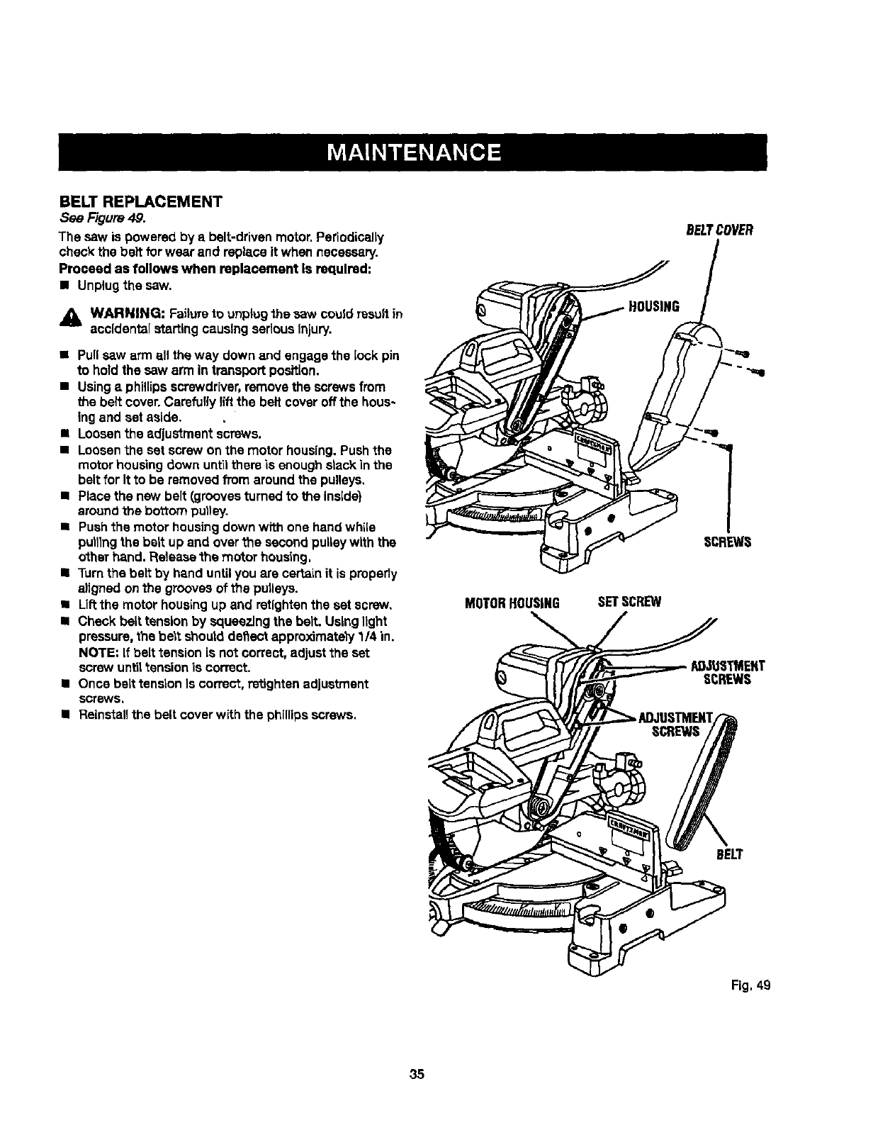
BELT REPLACEMENT
Sea Figure 4,9.
The sew is powered by a belt-drivenmotor.Periodioatly
check the belt for wear and replace it when nscessery.
Proceed as follows when replacement Is required:
•Unplugthe saw.
_IL WARNING: Failureto unplugthe sew couldresultin
accidentalstartingcausingseriousInjury.
•Pullsaw arm all the way down and engage the lock pin
to hold the sew arm in transport position,
•Usingaphillipsscrewdriver,remove the screws from
the belt cover.Carefully lift the belt coveroffthe hous-
ing and set aside.
•Loosenthe adjustment screws.
•Loosenthe set screw on the motor housing,Pushthe
mot_r housing down unt'_lthere "LsenoughstackInthe
beltfor It to be removedfrom around the pulleys,
•Place the new belt (groovesturnedto the Inside)
arouncithe bo'_ompul)ey.
•Pushthe motor housingdown with one hand while
pulllngthe bert up and overfne second pulleywith the
other hand. Releasethemotor housing.
•Turnthe belt by hand untilyou are certainit is properly
a)ignedonthe groovesof the pulleys.
•Liftthe motor housingup and retightenthe set screw,
•Check belttensionby squeezingthe belt. Usinglight
pressure,the beatshoutdde_ect approximately1/4 in.
NOTE=If belttension is not correct, adjust the set
screw untiltension is correct.
•Once belttensionIs correct,retightenadjustment
scr_s,
IReinstall the belt cover with the phillips screws.
MOTORHOUSING SETSCREW
BELTCOVER
Fig. 49
35

36
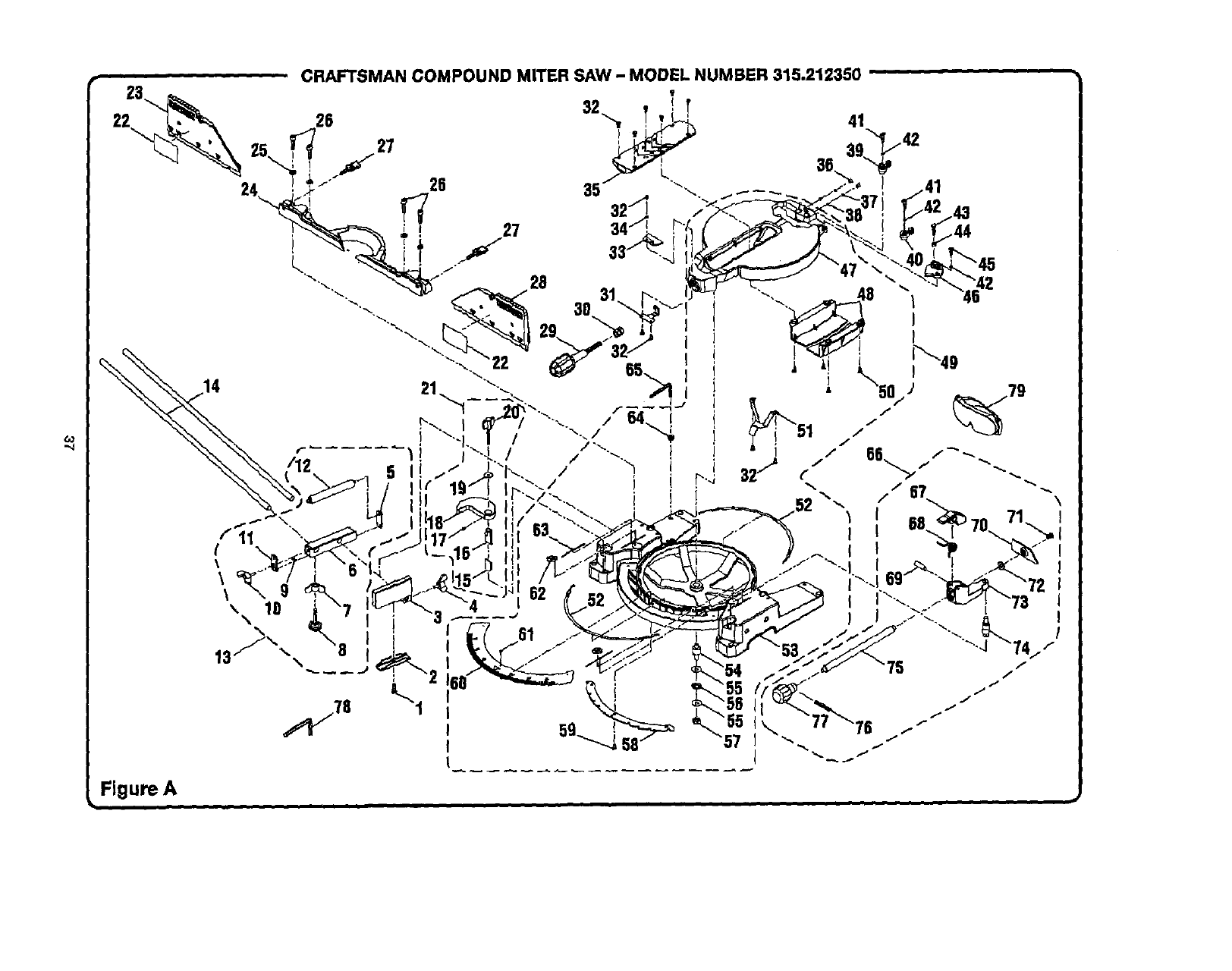
,,,j
Figure A
CRAFTSMAN COMPOUND MITER SAW -MODEL NUMBER 315.212350
3O

CRAFTSMANCOMPOUNDMITERSAW- MODELNUMBER315.212350....
The model numberwill be foundon a plateattachedto the motor housing.Alwaysmention the modelnumberinallcorrespondenceregardingyour |MITER SAW or when orderingrepairparts. I
oo
_o
KEY PART
NO. NUMBER
1 555516000
2 558511100
3 558507200
4 558512100
5545506000
6 545507000
7A33055056000
8 5455090O0
9 A10003040050
10 545511000
11 545505000
12 545508000
13 545A07030
14 545512000
15 565506000
16 565505000
17 A18003040080
18 565504000
19 A35010823020
20 565507000
PARTS LIST FOR FIGURE A
KEY PART
DESCRIPTION QTY. NO. NUMBER
* Wing Nut (M8 x 30 ram)................................... 1
Clamp Bracket ................................................. 1
Stop Block....................................................... 1
* Wing Screw(1/4-20 x 12 ram)......................... 1
RollerSupport FrontBrace.............................. 1
RollerSupport Base........................................ 1
* Wing Nut (5/16 in.)**STD541631 .................... 1
Leveling Screw (5/18 in.) ................................. 1
* Screw(M4 x 5 mm Pan Hd._............................ 4
*Wing Screw (MS x 20 ram) .............................. 1
Roller SupportEnd Brace................................ 1
Roller ............................................................... 1
Roller SupportAssembly
(IncludesKey Nos. 5-12) ................................. 1
Table Ex'tenslon............................................... 2
Lower Tube, Adjustable ................................... 1
Upper Tube, Adjustable ................................... 1
* Set Screw (M4 x 8 ram)................................... 1
CrownMolding Clamp ..................................... 1
FlatWasher (MS x 23 x 2t)............................... 1
Crown Molding Knob ....................................... 1
21 565A07020
22 511113000
23 56511200O
24 565116000
25 A36030814204
26 A07103080200
27 565123000
28 565111000
29 565117000
30 558111109
31 565110000
32 A10003050100
33 565113000
34 A35030501010
35 565106000
36 565119000
37 565120000
38 A59000006000
39 565122000
40 565121000
41 565118000
DESCRIPTION QTY.
Crown Molding_gtopAssembly
(IncludesKey Nos. 15-20) ............................... 1
SlidingMiter Fence Label................................2
SlidingMiter Fence (left).................................. 1
Fence............................................................... 1
* LockWasher(M8) **STD852008 .....................4
* Bolt(M8 x 20 mm Soc. Hd.) ............................4
FenceScrew.................................................... 2
SlidingMiter Fence (right)................................1
Miter Lock Handle ........................................... 1
Clamp Nut ....................................................... 1
Fixed Plate....................................................... 1
* Screw (MS x 10 mm Pan Hd.)..........................6
Miter Indicator ................................................. 1
Rat Washer(M5 x 10 xl t)................................ 1
Throat Plete ..................................................... 1
Set Screw ........................................................ 2
Look Spring..................................................... 2
Ball...................................................................2
Bevel Stop (left) ............................................... 1
Bevel Stop(right) ............................................. 1
*Screw (M6 x 6 ram)..........................................2
* Standard Hardware Item -- May Be Purchased Locally
** Available From DIv, 98 -- Source 980.00
*_' Available At Your Nearest Sears Catalog Order or Retail Store
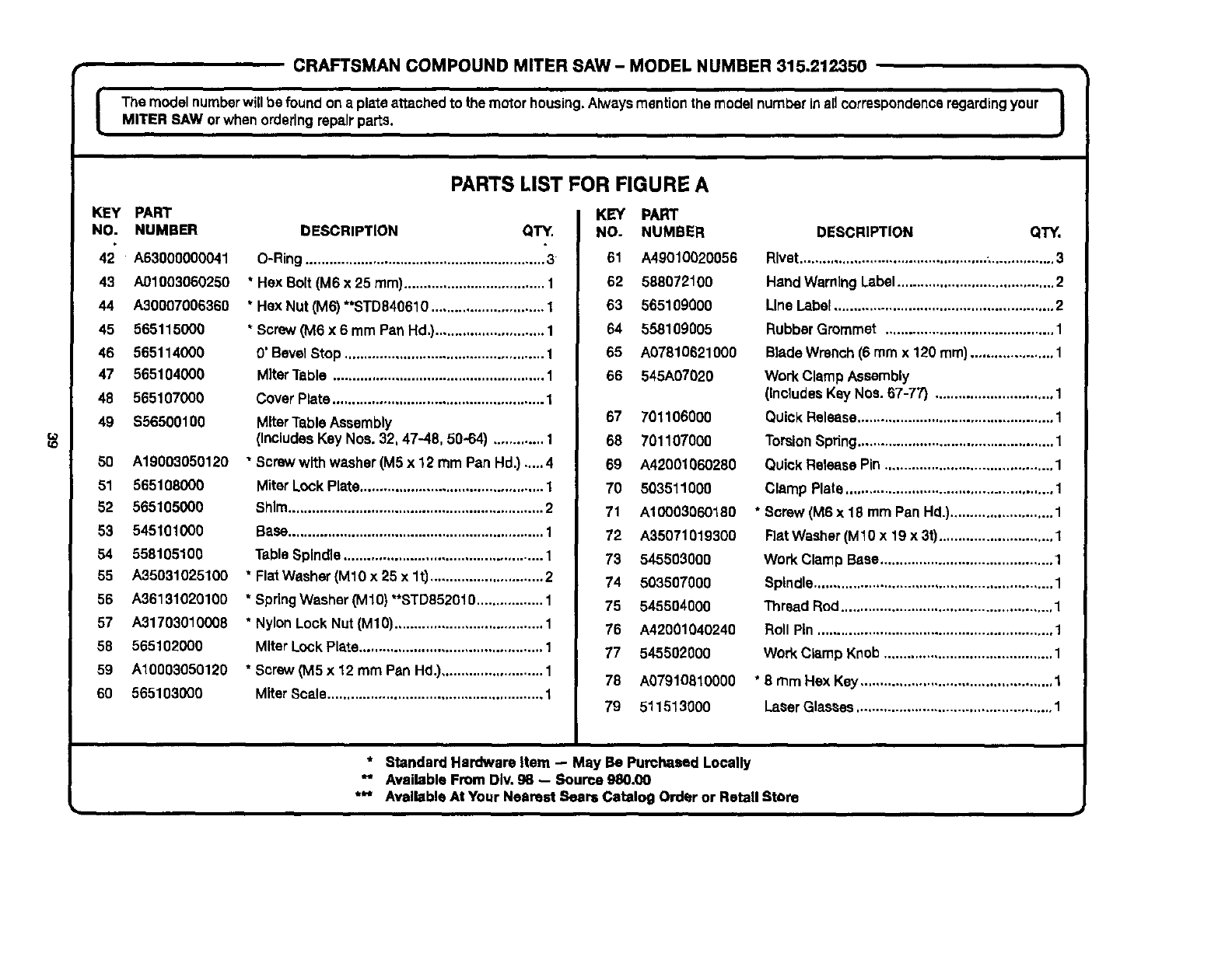
•CRAFTSMAN COMPOUND MITER SAW - MODEL NUMBER 315.212350
IThe model numberwill be foundon a plateattachedto the motorhousing,Alwaysmentionthe modelnumberinaUcorrespondenceregardingyour |
MITER SAW orwhenorderingrepairparts. I
KEy PART
NO. NUMBER
42 A63000000041
43 A01003060250
44 A30007006360
45 565115000
46 565114000
47 565104000
48 565107000
49 $56500100
50 A19003050120
51 565108000
52 565105000
53 545101000
54 558105100
55 A35031025100
56 A36131020100
67 A31703010008
58 565102000
59 A10003050120
60 565103000
PARTS LIST FOR FIGURE A
DESCRIPTION QTY.
O-Ring............................................................. 3
* Hex Bolt (M6 x 25 ram).................................... 1
• Hex Nut (M6) **STD840610............................. 1
* Screw(M6 x 6 mm Pan Hd,}............................1
0' BevelStop ................................................... 1
MiterTable ...................................................... 1
Cover Plate...................................................... 1
MiterTable Assembly
(IncludesKey Nos. 32, 47-48, 50-64) ............. 1
"Screw with washer (M5 x 12 mm Pan Hd.) ....,4
Miter LockPlate............................................... 1
Shim................................................................. 2
Base................................................................. 1
Table Spindle................................................... 1
* FlatWasher(M10 x 25 x lt) ............................. 2
* SpringWasher (M10)"*STD852010................. 1
* NylonLock Nut(M10)...................................... 1
Miter LockPlate............................................... 1
* Screw(M5 x 12 mm Pan Hd.).......................... 1
Miter Scale....................................................... 1
KEY PART
NO. NUMBER
61 A49010020056
62 58807210O
63 565109000
64 558109005
65 A07610621000
66 545A07020
57 701106000
68 701107000
69 A42001060280
70 503511000
71 A10003060180
72 A35071019300
73 545503000
74 503507000
75 545504000
76 A42001040240
77 545502000
78 A07910310000
79 511513000
DESCRIPTION QTY.
Rivet................................................,................3
Hand WarningLabel........................................ 2
Line Label........................................................ 2
RubberGrommet ........................................... 1
Blade Wrench (6 mmx 120 ram)..................... 1
Work Clamp Assembly
(Includes Key Nos. 67-77) .............................. 1
QuickRelease.................................................. 1
Torsion Spring.................................................. 1
Quick Release Pin ........................................... 1
Clamp Plate ..................................................... 1
* Sorew (M6 x 18 mm Pan Hd.).......................... 1
Flat Washer (M10 x 19 x 3t)............................. 1
Work Clamp Base............................................ 1
Spindle............................................................. 1
Thread Rod ...................................................... 1
Roll Pin ............................................................ 1
Work Clamp Knob........................................... 1
*6 turn Hex Key ................................................. 1
LaserGlasses.................................................. 1
* Standard Hardware Item -- May Be Purchased Locally
_' Available From DIv. g8 -- Source 980.00
*** Available At Your Nearest Sears Catalog Order or Retail Storo
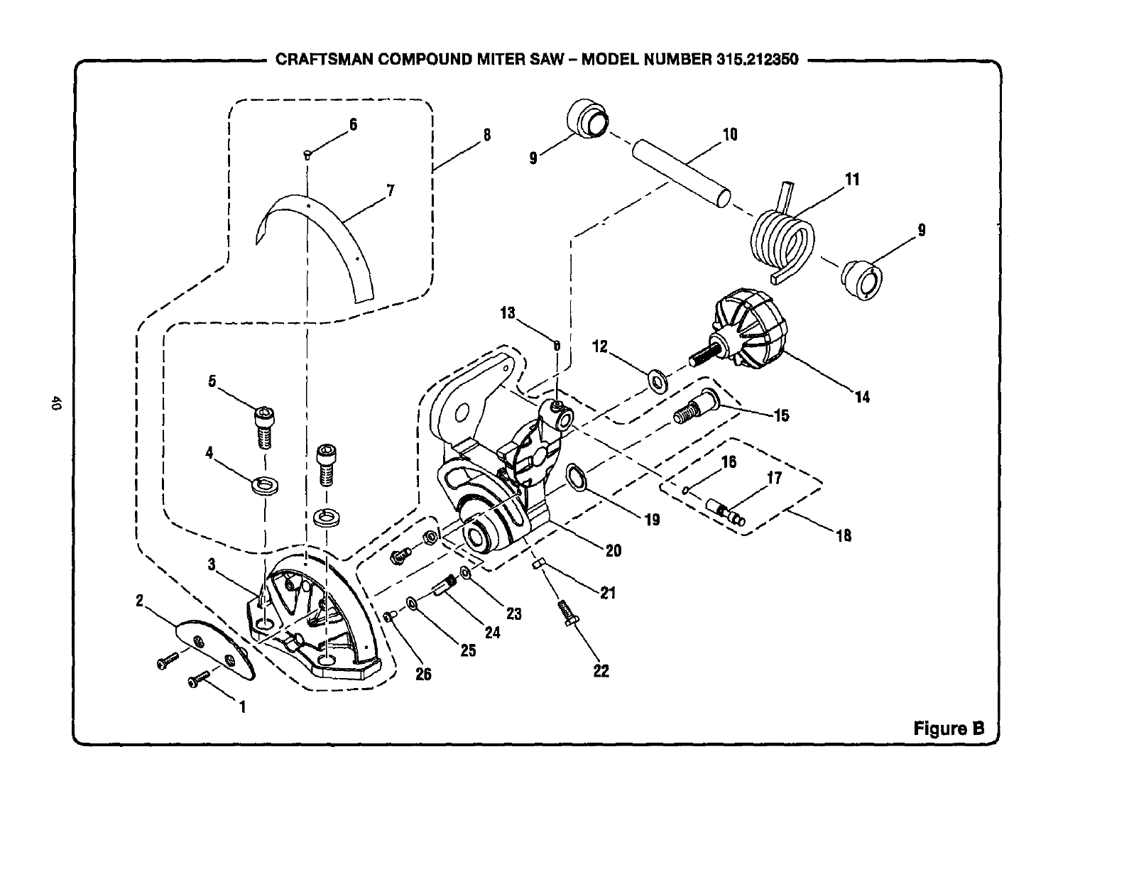
CRAFTSMAN COMPOUND MITER SAW - MODEL NUMBER 315.212350
C_
7
5
I
\
26
1
13
11
23
24
9
Figure B
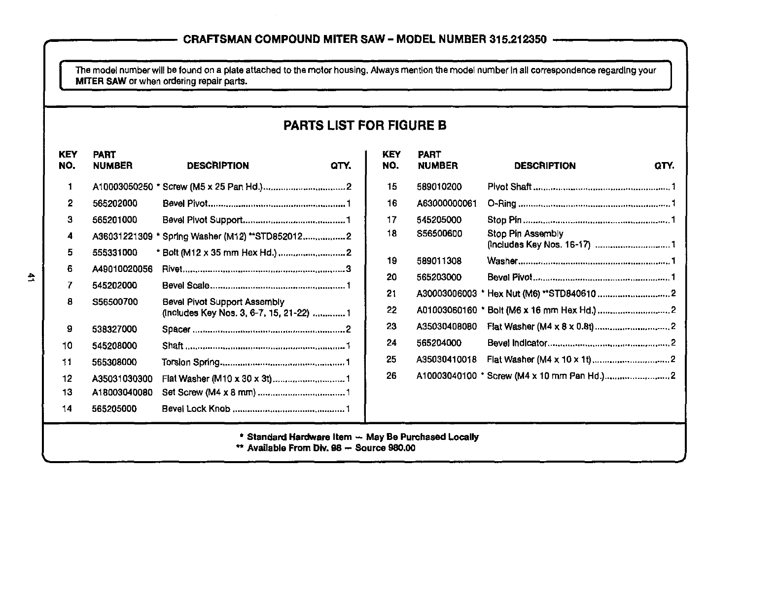
CRAFTSMAN COMPOUND MITER SAW -MODEL NUMBER 315.212350
The modelnumberwJllbe foundona plateattachedto the motorhousing.Alwaysmentton the model numberIn all correspondenceregardingyour I
MITER SAW or whenorderingrepairparts. I
PARTS LIST FOR FIGURE B
KEY PART
NO. NUMBER DESCRIPTION QTY.
1
2
3
4
5
6
7
8
A10003050250 * Screw [MS x 25 Pan Hd.)................................. 2
565202000 BevelPivot....................................................... 1
565201000 Bevel PivotSupport......................................... 1
A36031221309 * SpringWasher (M12) **STD852012................. 2
555331000
A49010020056
545202000
$56500700
9 538327000
10 545208000
11 565308000
12 A35031030300
13 A18003040080
14 565205000
* Bolt(M12 x 35 mm Hex Hd.) ........................... 2
Bivat .................................. ,................... .....,...3
BevelScale...................................................... 1
Bevel PivotSupport Assembly
(IncludesKey Nos. 3, 6-7, 15, 21-22) ............. 1
Spacer............................................................. 2
Shaft ................................................................ 1
TorsionSpring.................................................. 1
FlatWasher(M10 x 30 x 3t)............................. 1
Set Screw (M4 x 8 ram)................................... 1
BevelLock Knob............................................. 1
KEY PART
NO. NUMBER DESCRIPTION OTY.
15 589010200
16 A63000000061
17 545205000
18 $56500600
589011308
565203000
PivotShaft ....................................................... 1
O-Ring............................................................. 1
Stop Pin........................................................... 1
Stop PinAssembly
(IncludesKey Nos. 16-17) .............................. 1
Was_er............................................................. 1
BevelPivot....................................................... 1
19
20
21 A30003006003 * Hex Nut(M6) "*STD840610 ............................. 2
22 A01003060160 * Bolt (M6 x 16 mm Hax Hd.) ............................. 2
23 A35030408080 FlatWasher(M4 x 8 x 0.6t).............................. 2
24 565204000 BevelIndicator................................................. 2
25 A35030410018 FlatWasher(M4 x 10 x lt) ............................... 2
26 A10003040100 * Screw (M4 x 10 rnmPan Hd.).......................... 2
*Standard Hardware Item - May Be Purchased Locally
** Available From Div, 98 - Source 980,00
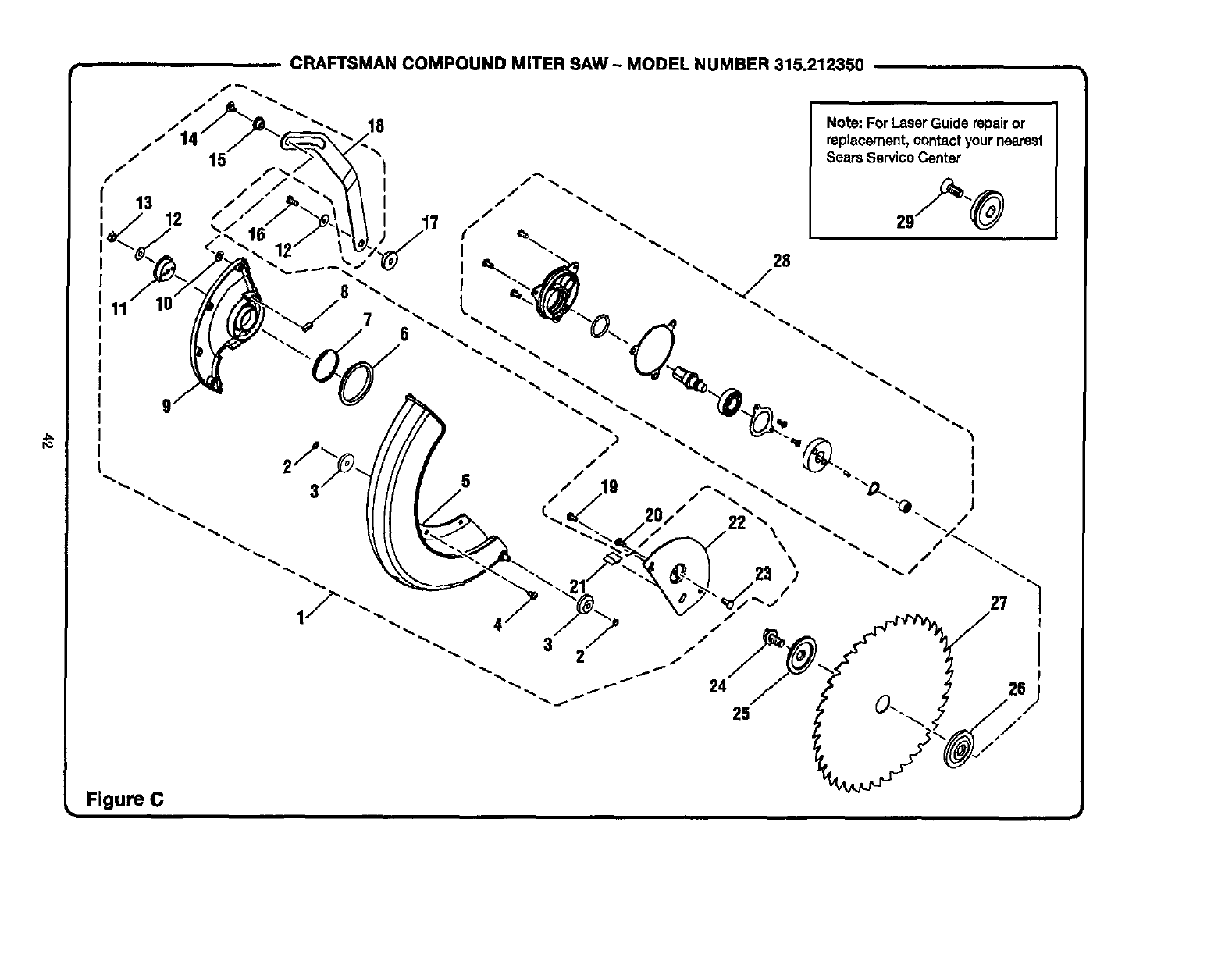
ro
CRAFTSMAN COMPOUND MITER SAW ~ MODEL NUMBER 315.212350
11
I
I
I
7
17
Note: For LaserGuide repairor
replacement,contactyour nearest
Sears ServiceCenter
Figure C

CRAFTSMAN COMPOUND MITER SAW - MODEL NUMBER 315.212350
Ihe model numberwillbe found ona plateattachedto the motorhousing.Alwaysmentionthe model numberinall _orrespondence regardingyour
MITER SAW orwhen orderingrepairparts.
K_Y PART
NO. NUMBER
PARTS LIST FOR FIGURE C
$56500200
2 538417000
3 566407000
4 503402000
5 565404000
6 503413000
7565411000
8 503414000
9 565405000
10 A35031226023
11 503407000
12 A35030616105
13
14
DESCRIPTION Q't_Y.
LowerBlade Guard Assembly
(IncludesKey Nee. 2-15, 18, 21-23)................ 1
RetainingRing................................................. 2
Roller............................................................... 2
* Screw (M5 x 8 mm Pan Hd.)............................4
Lower Blade Guard ......................................... 1
PacJ.................................................................. 1
TensionRing.................................................... 1
Sponge............................................................ 1
LowerGuard Plate ........................................... 1
FlatWasher(M12 x 26 x 2l) ............................. 1
Sleeve.............................................................. 1
FlatWasher (M6 x "t6x lt) .............................. 2
A31703006000 "Lock Nut (M6).................................................. 1
A10003060180 "Screw (M6 x 18 mm Pan Hd.)..........................1
KEY
NO.
15
16
17
18
19
2O
21
22
23
24
25
26
27
28
29
J
PART
NUMBER DESCRIPTION OTY.
558404007 Bushing............................................................ 1
A10003060185 * Screw (M6 x 18 mm Pan Hd.).......................... 1
565407000 Unk Bushing.................................................... 1
565408000 Link.................................................................. 1
A19001050080 * Screw withwasher(M5 x 8 mm Pan Hd.) ....... 1
558407100
545405000
565406000
555410000
558422100
558410100
565409000
ShoulderScrew............................................... 1
Bumper............................................................ 1
Blade BoltCover ............................................. 1
* Bolt (Hex Hd.) .................................................. 1
Blade Bolt ........................................................ 1
Outer BladeWasher ........................................ 1
InnerBlade Washer......................................... 1
Saw Blade ....................................................... 1
ArborAssembly............................................... 1
LaserGuide Bolt .............................................. 1
$56500300
555512000
* Standard Hardware Item - May Be Purchased Locally
*" Available From Div. 98 - Soume 980,00
*** Complete Assortment Available At Your Nearest Seers Catalog Order or Retail Store
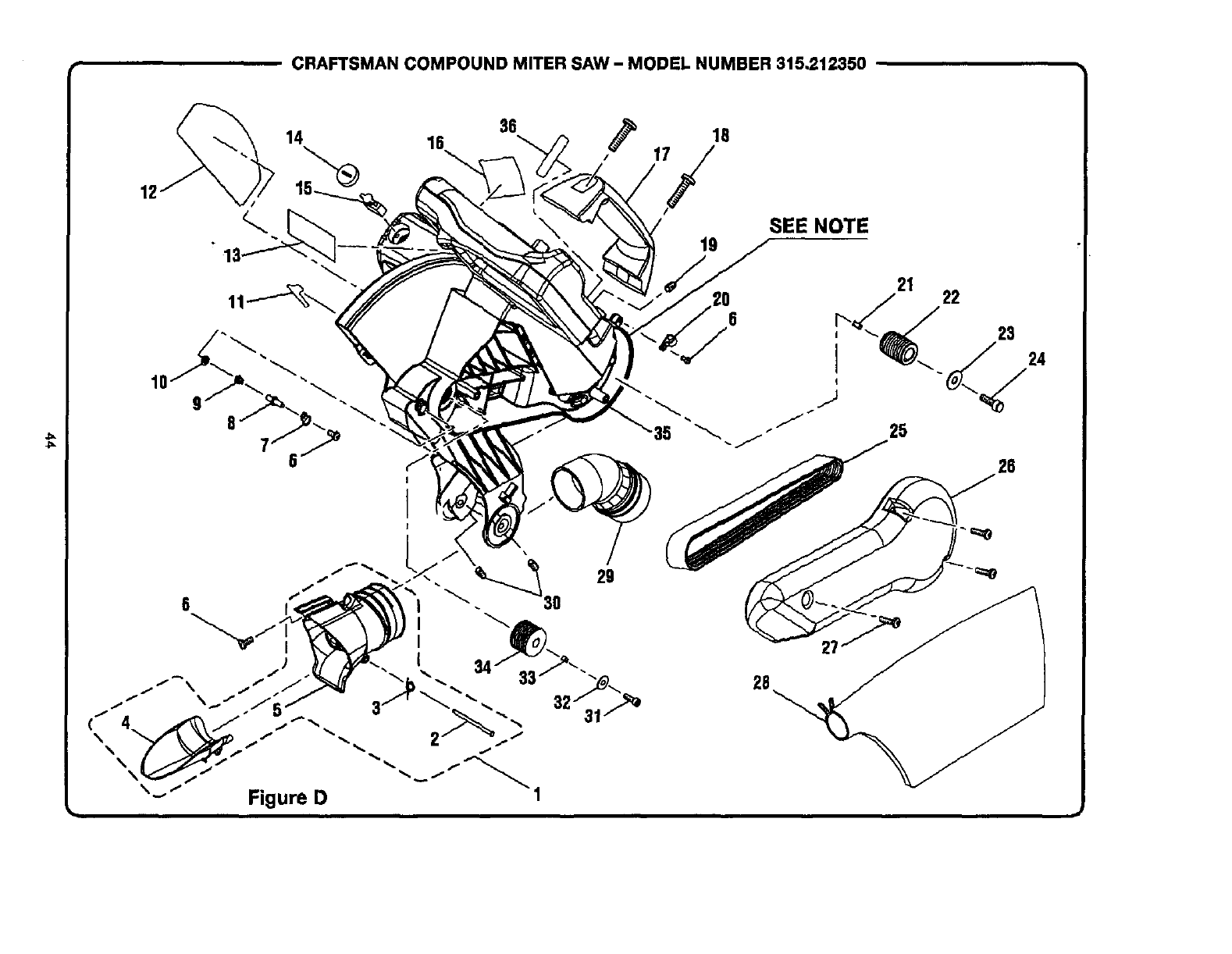
CRAFTSMAN COMPOUND MITER SAW- MODEL NUMBER 315,212350
12
36
14 16 18
\''i/
10
29
6
"-" "" Figure D
19 SEE NOTE
26
26
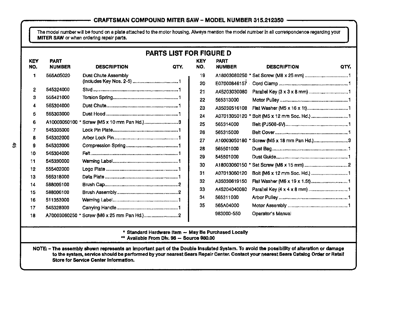
==
CRAFTSMAN COMPOUND MITER SAW- MODEL NUMBER 315.212350
J Themodel numberwillbe foundona plataattached to the motorhousing.Alwaysmentionthe modelnumberInallcorrespondenceregardingyour IMITER SAW or whenorderingrepairparts. I
PARTS LIST FOR FIGURE D
KEY PART KEY PART
NO, NUMBER DESCRIPTION QTY. NO. NUMBER DESCRIPTION QTY.
565A05020
545324000
555421000
565304000
565303000
Dust ChuteAssembly
(IncludesKey Nos. 2-5) ................................... 1
Stud................................................................. 1
TorsionSpring.................................................. 1
DustChute....................................................... 1
Dust Hood....................................................... 1
2
3
4
5
6 A10003050100 "Screw (M5 x 10 mm Pan Hd.)..........................3
7 545305000 LockPin Plate.................................................. 1
8 545302000 Arbor Lock Pin................................................. 1
9 545303000 Compression Spring........................................ 1
10 545304000 Felt................................................................... 1
11 545330000 Weming Label.................................................. 1
12 555402000 LogoPlate ....................................................... 1
13 565318000 Data Plate ........................................................ 1
14 588005100 BrushCap........................................................ 2
15 588006100 BrushAssembly............................................... 2
16 511353000 WarningLabel.................................................. 1
17 545328000 CarryingHandle............................................... 1
18 A70003060250 * Screw (M6 x 25 mm Pan Hd.)..........................2
19
2O
21
22
23
24
25
26
27
28
29
30
31
32
33
34
35
A18003080250 * Set Screw (MS x 25 ram)................................. 1
E07000846157 Cord Clamp ..................................................... 1
A45203030080 Partial Kay (3 x 3 x 8 ram) .............................. 1
565313000 MotorPulley .................................................... 1
A35030516108 FlatWasher (M5 x 16 x lt) ............................... 1
A07013050120 * Bolt (M5 x 12 mm Soo. Hd.) ............................ 1
565314000 Belt (PJ506-6V)................................................ 1
565315000 Belt Cover........................................................ 1
A10003050180 * Screw (M5 x 18 mm Pan Hd.).......................... 3
565501000 Dust Bag.......................................................... 1
545501000 Dust Guide....................................................... 1
A18003060150 * Set Screw (M6 x 15 ram) ................................. 2
A07013060120
A35030619150
A45204040080
565311000
565A04000
983000-550
Bolt 0V16x12 mm Soc. Hd.) ............................ 1
FlatWasher (MS x 19 x 1.5t)............................ 1
PareJlelKey (4x 4 x 8 mm) .............................. 1
ArborPulley..................................................... 1
Motor Assembly.............................................. 1
Operator's Manual
* Standard Hardware Item - May Be Pumhased Locally
** Available From Div. 98 -- Source 980,00
NOTE:- The assembly shown represents an important part of the Double Insulated System. To avoid the possibility of alteration or damage
to the system, service should be performed by your nearest Sears Repair Center.Contact your nearest Sears Catalog Order or Retail
Store for Service Center Information.

Your Home
For repair-in your home-of all major brand appliances,
lawn and garden equipment, or heating and cooling systems,
rio matter who made it, no matter who sold itl
For the replacement parts, accessories and
owner's manuals that you need to do-it-yourself.
For Sears professional installaUon of home appliances
and items like garage door openers and water heaters.
1-800-4-MY-HOME ®(I-80o-469-_63)
Call anytime,day or night (U.S.A. and Canada)
www.sears.com www.sears.ca
Our Home
For repair of carry-in items like vacuums, lawn equipment,
and electronics, call or go on-line for the IocaUon of your nearest
Sears Parts & Repair Center.
1-800-488-1222
Call anytime,day or night(U.S.A. only)
www.sears.com
To purchase aprotection agreement (U.S.A.)
or maintenance agreement (Canada) on a product serviced by Sears:
1-800-827-6655 (U.S.A.) 1-800-361-6665 (Canada)
Para pedir servicio de reparacibn
adornicilio, ypara ordenar piezas:
1-888-SU-HOGAR _
(1-888-784-6427)
Au Canada pour serviceen fran_;ais:
1-800-LE-FOYEI_ c
(1-800-533-6937)
www.saars.ca
6EAR8 zz z
®Registered Tredemm'k 1114Trademark IaM Senqlce M ark dSears, R=_bud_ and Co.
OM arca Reglstrada /_Marca de FI, hdca /SMMarca de SGn,'Iclo de Surs, Roebud( _ _.
McMarque de oommeroe /a_ Marque d_post_e de Sear_ Roebud_ and Co, ©Seans. Roebud_ and Co.
