Craftsman 31522283A User Manual MOBILE BASE/CASTER SET Manuals And Guides L0310399
CRAFTSMAN Leg Sets Manual L0310399 CRAFTSMAN Leg Sets Owner's Manual, CRAFTSMAN Leg Sets installation guides
IRONFORCE IFN03000 L0310399
User Manual: Craftsman 31522283A 31522283A CRAFTSMAN MOBILE BASE/CASTER SET - Manuals and Guides View the owners manual for your CRAFTSMAN MOBILE BASE/CASTER SET #31522283A. Home:Tool Parts:Craftsman Parts:Craftsman MOBILE BASE/CASTER SET Manual
Open the PDF directly: View PDF ![]() .
.
Page Count: 4

OPERATOR'S MANUAL
II:RRFTSMRN'I
MOBILE BASE WITH CASTER SET
fits most Craftsman Radial Arm and Table Saws Leg Stands
Model No.
315.22283A o
f0rH0de1315248300
Save this manual for
future reference.
O
0
_1_ WARNING: To reduce the riskof injury,the
usermust mad and understandthe operator's
manual before usingthis product. • RULES FOR SAFE OPERATION
•ASSEMBLY
Customer Help Line: 1-800-932-3188
Sears, Roebuck and Co., 3333 Beverly Rd., Hoffman Estates, IL 60179 USA
Visil the Craftsman web page: www.sears.com/craftsman
983000-265
5-03

rThe purpose of safety symbols is to attract your attention to possible dangem. The safety symbols, and the
explanations withthem, deserve yourcareful attention and understanding.Thesafetywarningsdonotbythemselves
eliminate any danger. The instructions or warnings they give am not substitutes for prober a_dent prevention
measures,
SYMBOL MEANING
DANGER: Indicatesan imminentlyhazardous situation, which, if not avoided, will result in death or
sedous injury,
WARNING: Indicates a potentiallyhazardoussituation,which,if notavoided, could resultin death or
serious injury.
ACAUTION: Indicates a potentially hazardous situation,which, if not avoided, may result in minoror
moderateinjury.It may also be usedto alertagainst uns_e practicesthef may cause propertydamage,
Important: Advises youof importantinformationor instructionsvitalto the operationor maintenanceof
the equipment.
Note: Advisesyou ofadditional information senceming the operationor maintenanceofthe equipment.
A WARNING: Read and understand all Instructions.
Failure to followall instructionslisted below,may
resultinalectdc shock,fire andlor serious personal
injury.
SAVE THESE INSTRUCTIONS
i Knowyour power tool,Read the operator'smanualfor
your Table Saw or Radial Arm Saw carefully.Learn the
saw's applicationsand limitationsas well as the specific
potential hazardsrelated to thistool.
Safety Instructions For Mobile Base,=
•Never installmobile bass with sew mounted to leg
stand.
•Be careful when moving to avoid any finger pinch
poir_s.
•Removethe dustbag before movingthe tool orwhan
placingthe leg stand on the mobile base.
•Place bass on a level surfaceand adjust levelingfeet
beforeplacing your sew in position.This shouldkeep
sawfrom rocking,while testing it for stability,
• Testfor stabilityin both the UP(on the caster) and the
down positions. Exercisecautionwhen testingthe
stabilityof top heavy machines such as your saw.
•Never liftthe saw onto the leg stand withouthelp.
•Unplugyour sew before moving or rapositioningyour
tool.
•Alwaystest your setup for stabilityand safety after
reposifioningand before pluggingthe saw intoan outlet.
•Care shouldbe taken when planningthe orientationof
yoursaw ontothe mobilebase. Transferof weight off of
the leveling feet to the caster will result in the saw tilting
lY2 in.toward the fixed wheels, When repositleningtop
heavy tools suchas yoursaw, take advantage of the
center of gravity,and positionso that it will remain
stablewhile on caster.
•Never use your sew while it Is suspendedonthe swivel
caster. Always lower saw ontothe nonskidleveling feet
before operating,
•When moving,always pushthe leg stand, nat the saw.
• Think Safety. Safety is a combin=ion of operator
awareness, commonsense and alertness at alltimes.
•Save these instructions.Refer to them frequently and
usethem to instructotherswho may use this tool, Ifyou
loansomeonethistool,loanthem these instructionsalso.
_, WARNING: Secure leg standto mobilebase before
movingthe tool. Failureto securethe legstand could
cause the saw to fallresultinginsedous personal
injury.
•Measure the leg standfromthe leveling foot holesat
one sideto the levelingfoot holeson the otherside.
This measurementis needed to determinewhichholes
inthe lower supportbracket andwheel supportbracket
are to be usedwhen assemblingthe mobilebase, The
holes must align propodyfor the leg stand and mobile
base to be secured.
AWARNING: Do nat engage ordisengagethe
release leverwhile the supportbrace is stillattached
to the leg standand never useyour handto operate
the release lever. Failure to heed thiswarning could
result inserious pemonalinjury.
•Unpack and identifyall componentsand hardware
beforeattemptingto assemblethis unit.

The items included in this kit are:
•Large caster (1)
• Center support (2)
•Lower support bracket (2)
•Wheel support bracket (2)
•Caster bracket (1)
• Release lever (1_
• Wheel (2)
• Hex bolt, 1/4x 1 3/4(2)
•Lack nut, 1/4- 20 (2)
• Large bolt, 3/8 x 4 1/2 (1)
• Washer, 3/8 (1)
• Lock nut, 3/8 - 16 (1)
• Hex bolt, 1/4x 5/8 (24)
• Hex nut, flanged, 1/4 -20 (24)
•Large hex bolt, 5/16 x 3/4 (10)
•Large hex nut, 5/16 - 18 (8)
•Washer, 5/16 (18)
•Leveling feet (2)
•Washer, 318 (4)
•Nut, 3/8- 16 (4)
•Lock nut, 5/15 - 18 (2)
MOSTTABLE
SAWS
MOSTRADIAL
ARMSAWS
CENTER
SUPPORT
WHEEL _..
SUPPORT
BRACKET
WHF._
wHEEL
SUPPORTBRACKEt
CENrEF
RELEASELEVER
BRACKET //_
LEVELINGFEET
Fig. 1
3
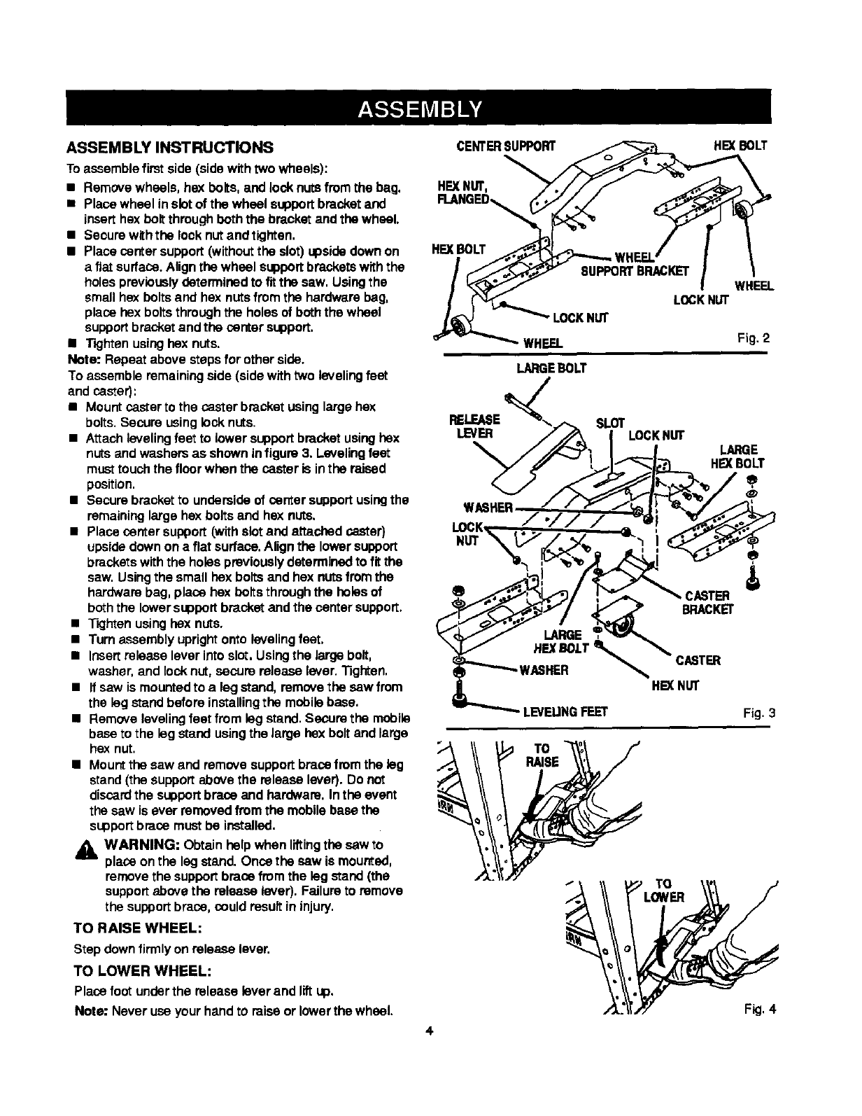
ASSEMBLY INSTRUCTIONS
Toassemble firstside (sidewithtwo wheels):
•Removewheels, hex bolts,and lock nutsfrom the bag.
•Place whsel inslotof the wheel supportbracketand
inserthex bolt through boththe bracket and the wheel.
• Secure withthe lock nut andtighten,
•Place center support (withoutthe slot) upsidedown on
a flat surface.Align the wheel supportbracketswith the
holes previouslydetermined to fit the saw, Usingthe
small hex bolts and hex nutsfromthe hardware bag,
place hex boltsthroughthe holes of boththe wheel
supportbracketand the centersupport.
• Tighten usingflex nuts.
Note: Repeat above steps for other side.
To assemble remainingside (sidewith two levelingfeet
and caster):
•Mount castarts the cestar bracketusing large hex
bolts.Secure using locknuts.
•Attachlevelingfeet to lower supportbracket usinghex
nuts andwashers as shown infigure 3. Levelingfeet
musttouchthe floorwhen the caster is inthe raised
position.
• Secure bracket to undersideof center supportusingthe
remaininglarge hex bolts and hex nuts.
•Place center support(withslot and attached caster)
upsidedown on a flat surface.Align the lower support
brackets withthe holes previouslydeterminedto fit the
saw. Usingthe small hex bolts and hex nutsfromthe
hardwarebag, place hex bolts throughthe holesof
boththe lowersupport bracketand the center support.
•Tightenusinghex nuts.
•Turnassembly uprightonto levelingfeet.
•Insertrelease lever into slot. Usingthe large bolt,
washer, and locknut, secure release lever. "13ghten.
•If saw is mounted to a leg stand, remove the saw from
the leg stand before installingthe mobilebase.
•Remove levelingfeet from leg stand. Secure the mobile
base to the leg stand usingthe large hex boltand large
hex nut.
•Mountthe saw and remove supportbracefrom the leg
stand(the supportabovethe release lever). Do not
discardthe supportbrace and hardware. Inthe event
the sew is ever removedfrom the mobilebase the
supportbrace must be installed.
3_k WARNING: Obtain help when liftingthe saw to
place onthe leg stand. Once the saw is mounted,
removethe supportbrace fromthe leg stand (the
supportabovethe release lever). Failure to remove
the supportbrace, couldresult in injury.
TO RAISE WHEEL:
Step down firmly on release lever.
TO LOWER WHEEL:
CENTERSUPPORT HEXBOLT
HFJ{NUT,
FI.ANGED_
HEX BOLT
8UPPO_BRACKET WHEEL
L_KN_
"_CKN_
WHEEL Fig. 2
LARGEBOLT
RELEASE_SLOT
HE)(NUT
LEVEUNG FEET Fig. 3
TO
TO
Place foot under the release lever and lift up.
Note: Never use your hand to raise or lower the wheel. Fig, 4
4
