Craftsman 315235360 User Manual ACCESSORIES FOR COMPOUND MITER SAW Manuals And Guides 98110088
CRAFTSMAN Miter Saw Manual 98110088 CRAFTSMAN Miter Saw Owner's Manual, CRAFTSMAN Miter Saw installation guides
User Manual: Craftsman 315235360 315235360 CRAFTSMAN ACCESSORIES FOR COMPOUND MITER SAW - Manuals and Guides View the owners manual for your CRAFTSMAN ACCESSORIES FOR COMPOUND MITER SAW #315235360. Home:Tool Parts:Craftsman Parts:Craftsman ACCESSORIES FOR COMPOUND MITER SAW Manual
Open the PDF directly: View PDF ![]() .
.
Page Count: 4

Owner's Manual
CRIIFTSMFIW
AccESSORIES FOR THE
10 in. (254 mm) COMPOUND MITER SAW
Model No.
315.235360
Item No.
_923537
(accessories optional)
_923536
(accessories included)
Save this manual for
future reference.
CAUTION: Read and
followallSafety Rulesand
Operating Instructionsbefore
firstuse ofthisproduct.
•SAFETY
•LOOSE PARTS
•INSTALLATION
•SERVICES
Sears, Roebuck and Co., Hoffman Estates, IL 60179 USA
972000-485
1-98
READ ALL INSTRUCTIONS •
I
...... L,"
•READ THESE INSTRUCTIONS AND THE
-INS_ 315;235360 COM-
._PQI.LNDMLT.EB.._.A.__TJ:!_ROUGHLY before •
using accessories._ .:_::!_ _,
•KNOW YOUR POWER TOQL Read the owner's
m_n_r f0Pthe (3ompo-u-h_'MiterSaw carefully.
•Lear_-tht_w_ and i'mitations as •
we.!! as.thesp._otential hazards related to
this tool.
KEEP THE WORK AREA CLEAN. Cluttered
work areas and work benches invite accidents.
DO NOT leave tools or pieces of wood on the
saw while it is in operation.
ALWAYS WEAR SAFETY GLASSES. Everyday
eyeglasses have only impact-resistant lenses;
they are NOT safety glasses.
ALWAYS DISCONNECT SAW FROM POWER
SUPPLY BEFORE MAKING ADJUSTMENTS
OR ADDING ACCESSORIES. Make sure the
switch is off when reconnecting to power supply.
SAVE THESE INSTRUCTIONS. Refer to them
frequently and use to instruct other users, if you
loan someone this tool, loan them these instruc-
tions also.
_k Look for this symbol to point out important safety precautions. It
means attention!!! Your safety is involved.
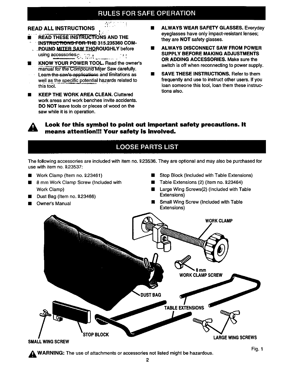
The following accessories are included with item no. _23536. They are optional and may also be purchased for
use with item no. 92.3537:
•Work Clamp (item no. _'23461)
•8 mm Work Clamp Screw (Included with
Work Clamp)
• Dust Bag (Item no. 9-23466)
• Owner's Manual
•Stop Block (Included with Table Extensions)
•Table Extensions (2) (Item no. _23464)
• Large Wing Screws(2) (Included with Table
Extensions)
• Small Wing Screw (Included with Table
Extensions)
WORKCLAMP
_8mm
WORKCLAMPSCREW
LARGEWINGSCREWS
SMALLWINGSCREW
_WARNING: The use of attachments or accessories not listed might be hazardous.
2
Fig, 1
AWARNING: To prevent accidental starting that
could cause possible serious personal injury,
assemble all parts to your saw completely before
connecting it to power supply• Saw should never
be connected to power supply when you are
assembling parts, making adjustments, installing
or removing blades or accessodas, or when not
in use.
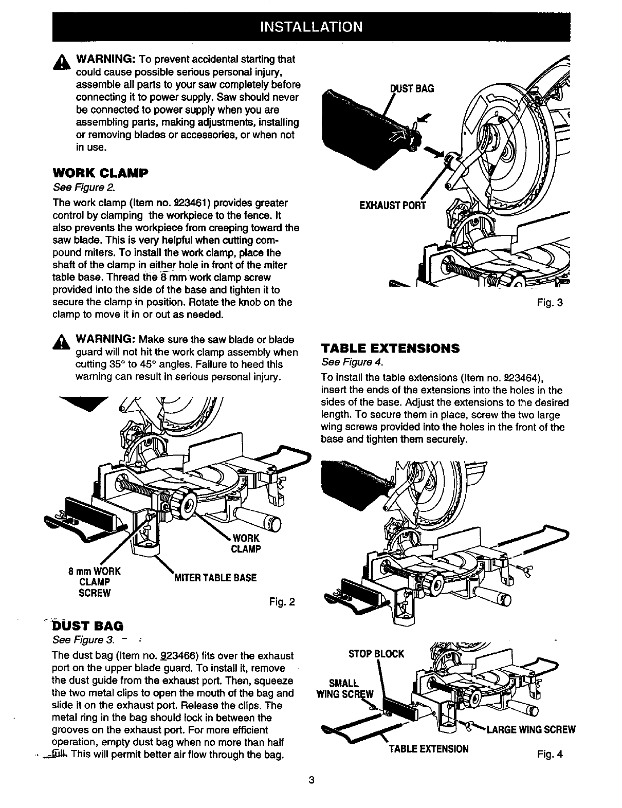
WORK CLAMP
See Figure 2.
The work clamp (Item no. 92.3461) provides greater
control by clamping the workpiece to the fence. It
also prevents the workpiece from creeping toward the
saw blade. This is very helpful when cutting com-
pound miters. To install the work clamp, place the
shaft of the clamp in either hole in front of the miter
table base. Thread the 8 mm work clamp screw
provided into the side of the base and tighten it to
secure the clamp in position. Rotate the knob on the
clamp to move it in or out as needed.
_IL WARNING: Make sure the saw blade or blade
guard will not hit the work clamp assembly when
cutting 35° to 45° angles. Failure to heed this
warning can result in serious personal injury.
EXHAUSTPORT
Fig. 3
TABLE EXTENSIONS
See Figure 4.
To install the table extensions (Item no. _23464),
insert the ends of the extensions into the holes in the
sides of the base. Adjust the extensions to the desired
length. To secure them in place, screw the two large
wing screws provided into the holes in the front of the
base and tighten them securely.
8 mmWORK
CLAMP
SCREW
tVORK
CLAMP
°DUST BAG
See Figure 3. -:
Fig. 2
The dust bag (Item no. 923466) fits over the exhaust
port on the upper blade guard. To install it, remove
the dust guide from the exhaust port. Then, squeeze
the two metal clips to open the mouth of the bag and
slide it on the exhaust port. Release the clips. The
metal ring in the bag should lock in between the
grooves on the exhaust port. For more efficient
operation, empty dust bag when no more than half
•_ This will permit better air flow through the bag.
STOPBLOCK
SMALL
WIN4
TABLEEXTENSION
; SCREW
Fig. 4
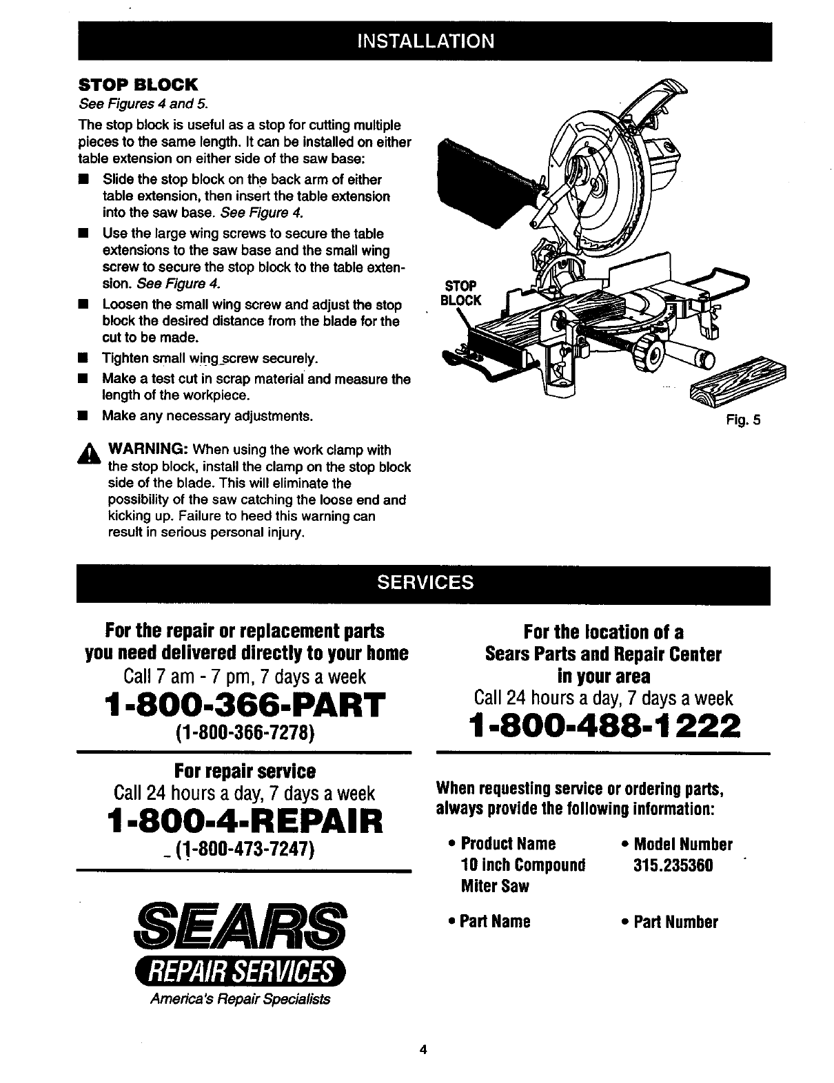
STOP BLOCK
See Figures 4 and 5.
The stop block is useful as a stop for cutting multiple
pieces to the same length. It can be installed on either
table extension on either side of the saw base:
•Slide the stop block on the back arm of either
table extension, then insert the table extension
into the saw base. See Figure 4.
•Use the large wing screws to secure the table
extensions to the saw base and the small wing
screw to secure the stop block to the table exten-
sion. See Figure 4.
•Loosen the small wing screw and adjust the stop
block the desired distance from the blade for the
cut to be made.
•Tighten small wing_screw securely.
•Make a test cut in scrap material and measure the
length of the workpiece.
•Make any necessary adjustments.
_1= WARNING: When using the work clamp with
the stop block, install the clamp on the stop block
side of the blade. This will eliminate the
possibility of the saw catching the loose end and
kicking up. Failure to heed this warning can
result in serious personal injury.
STOP
BLOCK
Fig. 5
Forthe repair orreplacementparts
youneeddelivereddirectlyto yourhome
Call7 am - 7 pm, 7daysaweek
1-8OO-366-PART
(1-800-366-7278)
Forrepairservice
Call24 hours a day,7 daysaweek
1-800-4-REPAIR
_(!-800-473-7247)
SEARS
America's Repair Specialists
Forthe location of a
SearsPads andRepairCenter
inyourarea
Call24 hours aday,7 daysaweek
1-8OO-488-1222
Whenrequestingserviceor orderingparts,
alwaysprovidethe followinginformation:
•ProductName
10 inchCompound
Miter Saw
• ModelNumber
315.235360
•PartName •Part Number
4
