Craftsman 315243000 User Manual 10 COMPOUND MITER SAW Manuals And Guides L0050127
CRAFTSMAN Miter Saw Manual L0050127 CRAFTSMAN Miter Saw Owner's Manual, CRAFTSMAN Miter Saw installation guides
DURA-GLAS IITM P4RAG6C-150 L0050127
User Manual: Craftsman 315243000 315243000 CRAFTSMAN 10 COMPOUND MITER SAW - Manuals and Guides View the owners manual for your CRAFTSMAN 10 COMPOUND MITER SAW #315243000. Home:Tool Parts:Craftsman Parts:Craftsman 10 COMPOUND MITER SAW Manual
Open the PDF directly: View PDF ![]() .
.
Page Count: 38
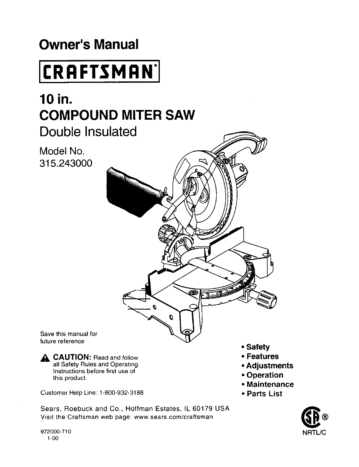
Owner's Manual
CRRFTSMRN'I
10 in.
COMPOUND MITER SAW
Double Insulated
Model No.
315.243000
Save this manual for
future reference
CAUTION: Read and follow
all Safety Rules and Operating
Instructions before first use of
this product.
Customer Help Line: 1-800-932-3188
Sears, Roebuck and Co., Hoffman Estates, IL 60179 USA
Visit the Craftsman web page: www.sears.com/craftsman
972000-710
1-00
• Safety
• Features
• Adjustments
•Operation
•Maintenance
•Parts List
NRTL/C
• Table of Contents ........................................................................................................................................... 2
• Warranty and Introduction .............................................................................................................................. 2
• Rules For Safe Operation ........................................................................................................................... 3-6
• Glossary ......................................................................................................................................................... 6
• Product Specifications and Unpacking .......................................................................................................... 7
• Labels ............................................................................................................................................................. 8
• Loose Parts and Tools Needed ...................................................................................................................... 9
• Features .................................................................................................................................................. 10-12
• Adjustments ............................................................................................................................................. 12-19
• Operation ................................................................................................................................................. 20-26
• Maintenance ............................................................................................................................................ 27-28
• Exploded View and Repair Parts List ...................................................................................................... 30-37
• Parts Ordering /Service ............................................................................................................................... 38
FULL ONE YEAR WARRANTY
If this product fails due to adefect in material or workmanshipwithin one year from the date of purchase,
Sears will repair it free of charge.
Contact a Sears Service Center for repair.
If this product is used for commercial or rental purposes,this warranty applies only for 90 days from the date
of purchase.
This warranty gives you specific legal rights, and you may also have other rightswhich vary from state to state.
Sears, Roebuck and Co., Dept. 817WA, Hoffman Estates, IL 60179
Your saw has many features for making cutting
operations more pleasant and enjoyable. Safety,
performance and dependability have been given top
priority in the design of this saw making it easy to
maintain and operate.
_1, CAUTION: Carefully read through this entire
owner's manual before using your new saw. Pay
close attention to the Rules For Safe Operation,
and all Safety Alert Symbols including Danger,
Warning and Caution. If you use your saw
properly and only for what it is intended, you will
enjoy years of safe, reliable service.
_, Look for this symbol to point out important safety precautions. It means'attention!!!
Your safety is involved.
WARNING:
The operation of any power tool can result in foreign objects being thrown into your eyes,
which can result in severe eye damage. Before beginning power tool operation, always
wear safety goggles or safety glasses with side shields and a full face shield when needed.
We recommend Wide Vision Safety Mask for use over eyeglasses or standard safety
glasses with side shields, available at Sears Retail Stores.
The purpose of safety symbols is to attract your attention to possible dangers, The safety symbols, and
the explanations with them, deserve your careful attention and understanding. The safety warnings do
not by themselves eliminate any danger, The instructions or warnings they give are not substitutes for
proper accident prevention measures.
SYMBOL MEANING
SAFETY ALERT SYMBOL:
Indicates danger, warning or caution. May be used in conjunction with other symbols or picto-
graphs.
ADANGER: Failure to obey a safety warning will result in serious injury to yourself or to others
Always follow the safety precautions to reduce the risk of fire, electric shock and personal injury.
,a, WARNING: Failure to obey a safety warning can result in serious injury to yourself or to others.
Always follow the safety precauttons to reduce the risk of fire, electric shock and personal iniury
ZL CAUTION: Failure to obey a safety warning may result in property damage or personal injury to
yourself or to others. Always follow the safety precautions to reduce the esk of fire, electric shock
and personal injury,
NOTE: Advises you of informatLon or instructions vital to the operation or maintenance of the equipment.
DOUBLE INSULATION
Double insulation =sa concept in safety, in electric
power tools, which eliminates the need for the usual
three-wire grounded power cord All exposed metal
parts are isolated from internal metal motor
components with protecting insulation Double
insulated tools do not need to be grounded.
,_ WARNING: Do not attempt to operate thrs tool
until you have read thoroughly and understand
completely all instructtons, safety rules, etc.
contained in this manual Failure to comply can
result in accidents involving fire. electric shock,
or serious personal injury. Save owner's manual
and review frequently for continuing safe
operation, and instructing others who may use
this tool.
READ ALL INSTRUCTIONS
KNOW YOUR POWER TOOL. Read the owner's
manual carefully. Learn the saw's applications
and limitations as well as the specific potential
hazards related to this tool
•GUARD AGAINST ELECTRICAL SHOCK BY
PREVENTING BODY CONTACT WITH
GROUNDED SURFACES, For example; pipes,
radiators, ranges, refrigerator enclosures.
•KEEP GUARDS IN PLACE and in good working
order.
REMOVE ADJUSTING KEYS AND
WRENCHES. Get in the habit of checking to see
that hex keys and adjusting wrenches are
removed from tool before turning on saw
IMPORTANT
Servicing requires extreme care and knowledge of the
system and should be performed only by a qualified
service technician. For service we suggest you return
the tool to your nearest Sears store for repair. Always
use original factory replacement parts when servicing.
•KEEP THE WORK AREA CLEAN. Cluttered work
areas and work benches invite accidents. DO
NOT leave tools or pieces of wood on the saw
while it is in operation.
•DO NOT USE IN DANGEROUS ENVIRON-
MENTS, Do not use power tools near gasoline or
other flammable liquids, in damp or wet locations,
or expose them to rain Keep the work area well
lit,
KEEP CHILDREN AND VISITORS AWAY. All
visitors should wear safety glasses and be kept a
safe distance from work area Do not let visitors
contact tool or extens=on cord whde operating.
MAKE WORKSHOP CHILD-PROOF w=th pad-
locks and master switches or by removrng starter
keys.
DO NOT FORCE THE TOOL. It will do the job
better and safer at the rate for which it was
designed.
USE THE RIGHT TOOL. Do not force the tool or
attachment to do a job it was not designed for.
Don't use it for a purpose not intended.
RULES FOR SAFE OPERATION (Continued)
USE THE PROPER EXTENSION CORD. Make
sure your extension cord is in good condition.
When using an extension cord, be sure to use
one heavy enough to carry the current your
product will draw. An undersized cord will cause
adrop in line voltage resulting in loss of power
and overheating. Awire gage size (A W.G ) of at
least 14 is recommended for an extension cord
25 feet or less in length. If in doubt, use the next
heavier gage. The smaller the gage number, the
heavier the cord
INSPECT EXTENSION CORDS PERIODI-
CALLY and replace if damaged.
DRESS PROPERLY. Do not wear loose clothing,
gloves, neckties, rings, bracelets, or other
jewelry. They can get caught and draw you into
moving parts Rubber gloves and nonslip foot-
wear are recommended when working outdoors.
Also wear protective hair covering to contain long
hair
ALWAYS WEAR SAFETY GLASSES WITH
SIDE SHIELDS, Everyday eyeglasses have only
impact-resistant lenses; they are NOT safety
glasses,
PROTECT YOUR LUNGS. Wear a face or dust
mask if the cutting operation is dusty,
PROTECT YOUR HEARING. Wear hearing
protection duringextended periods of operation.
SECURE WORK. Use clamps or a vise to hold
work when practical. It's safer than using your
hand and it frees both hands to operate tool,
function. Check for alignment of moving parts,
binding of moving parts, breakage of parts,
mounting and any other conditions that may
affect its operation. A guard or other part that is
damaged must be properly repaired or replaced
by a qualified service technician at a Sears store
to avoid risk of personal injury.
NEVER LEAVE TOOL RUNNING UNAT-
TENDED. TURN THE POWER OFF. Do not
leave tool until it comes to a complete stop.
FIRMLY CLAMP OR BOLT your miter saw to a
workbench or table at approximately hip height.
USE ONLY CORRECT BLADES. Do not use
blades with incorrect size holes. Never use blade
washers or blade bolts that are defective or
incorrect. The maximum blade capacity of your
saw is 10 in.
KEEP BLADES CLEAN, SHARP AND WITH
SUFFICIENT SET, Sharp blades minimize
stalling and kickback.
•DO NOT REMOVE THE SAW'S BLADE
GUARDS. Never operate the saw with any guard
or cover removed. Make sure all guards are
operating properly before each use.
•KEEP HANDS AWAY FROM CUTTING AREA.
Keep hands away from blades. Do not reach
underneath work or around or under the blade
while blade is rotating. Do not attempt to remove
cut material when blade is moving.
A
DO NOT OVERREACH. Keep proper footing and
balance at all times. •
MAINTAIN TOOLS WITH CARE. Keep tools
sharp and clean for better and safer perfor-
mance. Follow instructions for lubricating and
changing accessories.
4
DISCONNECT ALL TOOLS. When not in use,
before servicing, or when changing attachments,
blades, bits, cutters, etc., all tools should be
disconnected.
•AVOID ACCIDENTAL STARTING. Be sure
switch is off when plugging in.
•USE RECOMMENDED ACCESSORIES. The
use of improper accessories may cause risk of
injury.
•NEVER STAND ON TOOL. Serious injury could
occur if the tool is tipped or if the blade is unin-
tentionally contacted.
•CHECK DAMAGED PARTS. Before further use
of the tool, aguard or other part that is damaged
should be carefully checked to determine that it
will operate properly and perform its intended
WARNING: Blade coasts after turn off.
DO NOT ABUSE CORD. Never yank cord to
disconnect it from receptacle. Keep cord from
heat, oil, and sharp edges.
INSPECT TOOL CORDS PERIODICALLY and if
damaged, have repaired by a qualified service
technician at a Sears store. Stay constantly
aware of cord location and keep it well away
from the rotating blade.
USE OUTDOOR EXTENSION CORDS. When
tool is used outdoors, use only extension cords
with approved ground connection that are
intended for use outdoors and so marked.
DO NOT USE TOOL IF SWITCH DOES NOT
TURN IT ON AND OFF. Have defective switches
replaced by a qualified service technician at a
Sears store.
KEEP TOOL DRY, CLEAN, AND FREE FROM
OIL AND GREASE. Always use a clean cloth
when cleaning. Never use brake fluids, gasoline,
petroleum-based products, or any solvents to
clean tool.
RULES FOR SAFE OPERATION (Continued)
•ALWAYS SUPPORT LONG WORKPIECES to •
minimize risk of blade pinching and kickback.
Saw may slip, walk, or slide while cutting long or
heavy boards. •
•BEFORE MAKING A CUT, BE SURE ALL
ADJUSTMENTS ARE SECURE.
•GUARD AGAINST KICKBACK. Kickback occurs
when the blade stalls rapidly and workpiece is
driven back towards the operator. It can pull your
hand into the blade resulting in serious personal
injury. Stay out of blade path and turn switch off
immediately if blade binds or stalls.
•AVOID CUTTING NAILS. Inspect for and
remove all nails from lumber before cutting.
•ALWAYS USE ACLAMP to secure the work-
piece when possible.
• NEVER TOUCH BLADE or other moving parts
during use.
• NEVER START ATOOL WHEN THE BLADE IS
IN CONTACT WITH WORKPIECE. Allow motor
to come up to full speed before starting cut.
•MAKE SURE THE MITER TABLE AND SAW
ARM (BEVEL FUNCTION) ARE LOCKED IN
POSITION BEFORE OPERATING YOUR SAW.
Lock the miter table by securely tightening the
miter lock handle. Lock the saw arm (bevel
function) by securely tightening the bevel lock
knob.
NEVER reach to pick up a workpiece, a piece of
scrap, or anything else that is in or near the
cutting path of the blade.
AVOID AWKWARD OPERATIONS AND HAND
POSITIONS where a sudden slip could cause
your hand to move into the blade. ALWAYS
make sure you have good balance. NEVER
operate your miter saw on the floor or in a
crouched position.
•NEVER stand or have any part of your body in
line with the path of the saw blade.
•ALWAYS release the power switch and allow the
saw blade to stop rotating before raising it out of
the workpiece.
•DO NOT TURN THE MOTOR SWITCH ON AND
OFF RAPIDLY. This could cause the saw blade
to loosen and could create a hazard. Should this
ever occur, stand clear and allow the saw blade
to come to a complete stop. Disconnect your saw
from the power supply and securely retighten the
blade bolt.
•NEVER USE A LENGTH STOP ON THE FREE
SCRAP END OF A CLAMPED WORKPIECE.
NEVER hold onto or bind the free scrap end of
the workpiece in any operation. If a work clamp
and length stop are used together, they must
both be installed on the same side ol the saw
table to prevent the saw from catching the loose
end and kicking up.
• NEVER cut more than one piece at a time. DO
NOT STACK more than one workpiece on the
saw table at a time.
A
NEVER PERFORM ANY OPERATION "FREE-
HAND". Always place the workpiece to be cut on
the miter table and position it firmly against the
fence as a backstop. Always use the fence.
NEVER hand hold a workpiece that is too small
to be clamped. Keep hands clear of the no hands
zone
NEVER reach behind, under, or within three
inches of the blade and its cutting path with your
hands and fingers for any reason.
REPLACEMENT PARTS. All repairs, whether
electrical or mechanical, should be made by
qualified service technician at a Sears store.
WARNING: When servicing use only identical
Craftsman replacement parts. Use of any other
parts may create a hazard or cause product
damage.
NEVER USE IN AN EXPLOSIVE ATMO-
SPHERE. Normal sparking of the motor could
ignitefumes.
NEVER leave the miter saw unattended while
connected to a power source.
POLARIZED PLUGS. To reduce the risk of
electric shock, this tool has a polarized plug (one
blade is wider than the other). This plug will fit in
a polarized outlet only one way. If the plug does
not fit fully in the outlet, reverse the plug. If it still
does not fit, contact a qualified electrician to
install the proper outlet. Do not change the plug
in any way.
IF ANY PART OF THIS MITER SAW IS MISS-
ING or should break, bend, or fail in any way, or
should any electrical component fail to perform
properly, shut off the power switch, remove the
miter saw plug from the power source and have
damaged, missing, or failed parts replaced
before resuming operation.
DO NOT OPERATE THIS TOOL WHILE UN-
DER THE INFLUENCE OF DRUGS, ALCOHOL,
OR ANY MEDICATION.
RULES FOR SAFE OPERATION (Continued)
• ALWAYS STAY ALERT! Do not allow familiarity •
(gained from frequent use of your saw) to cause
a careless mistake. ALWAYS REMEMBER that
a careless fraction of a second is sufficientto
inflict severe injury. •
•STAY ALERT AND EXERCISE CONTROL.
Watch what you are doing and use common
sense. Do not operate tool when you are tired. •
Do not rush.
MAKE SURE THE WORK AREA HAS AMPLE
LIGHTING to see the work and that no obstruc-
tions will interfere with safe operation BEFORE
performing any work usingyour saw.
ALWAYS TURN OFF SAW before disconnecting
it, to avoid accidental starting when re-connect-
ing to power supply.
SAVE THESE INSTRUCTIONS. Refer to them
frequently and use to instructother users. If you
Loansomeone this tool, loan them these instroc-
tions also.
SAVE THESE INSTRUCTIONS
Arbor
The shaft on which ablade or cutting tool is mounted.
Bevel Cut
A cutting operation made with the blade at any angle
other than 90" to the miter table,
Crosscut
A cutting or shaping operation made across the grain
of the workpiece.
Compound Miter Cut
A compound miter cut is a cut made using a miter
angle and a bevel angle at the same time.
Freehand
Performing acut withoutusing a fence, miter gage,
fixture, work clamp, or other proper device to keep the
workpiece from twistingor moving during the cut.
Gum
A sticky, sap based residue from wood products.
Miter Cut
Acuttingoperation made withthe blade at any angle
other than 90" to the fence.
Resin
Asticky,sap base substance that has hardened.
Revolutions Per Minute (RPM)
The number of turns completed by a spinning object
in one minute.
Saw Blade Path
The area over, under, behind, or in front of the blade.
As it applies to the workpiece, that area which will be,
or has been, cut by the blade.
Set
The distance that the tip of the sawblada tooth is bent
(or set) outward from the face of the blade,
Throw-Back
Throwing of a workpiece in amanner similarto a
kickback. Usually associated with a cause other than
the kerf closing, such as a workpiece not being
against the fence, being dropped into the blade, or
being placed inadvertentlyin contact withthe blade.
Through Sawing
Any cutting operation where the blade extends
completely through the thickness of the workpiece.
Workpiece
Theitem on whichthe cu_ing oper_ionis being done.
The surfaces ofa workpiece are commonlyreferredto
asfaces, ends, and edges.
Zero Clearance Throat Plate
A plastic throat plate inserted in the miter table that
allowsfor blade clearance. When you make your first
cut with your compound mitersaw, the saw blade cuts
a slotthroughthe throat plate the exact width of the
blade. This provides for a zero clearance kerrthat
minimizes workpiece tear-out.
No Hands Zone
The area between the marked lines on the left and
rightside of the miter table base. This zone is
identifiedby no hands zone labels placed inside the
marked lines on the miter table base.
Blade Diameter i 0 in.
Blade Arbor 5/8 in.
No Load Speed 5000 RPM
Rating 120 Volts, 60 Hz-AC Only
Input 15 Amperes
Net Weight 32 Ibs.
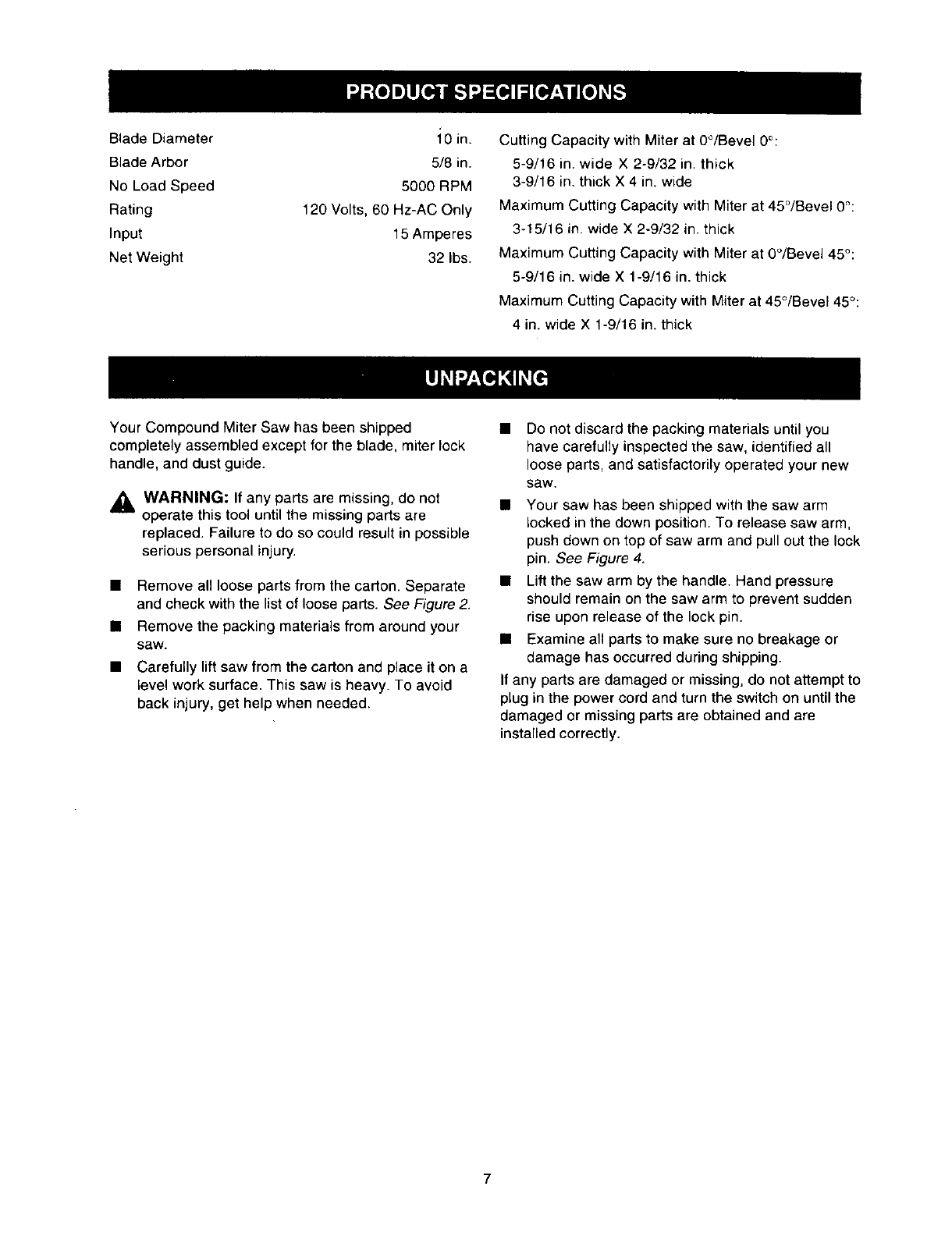
Cutting Capacity with Miter at 0°/Bevel 0°:
5-9/16 in. wide X 2-9/32 in. thick
3-9/16 in. thick X 4 in. wide
Maximum Cutting Capacity with Miter at 45°/Bevel 0°:
3-15/16 in. wide X 2-9/32 in. thick
Maximum Cutting Capacity with Miter at 0°/Bevel 45°:
5-9/16 in. wide X 1-9/16 in. thick
Maximum Cutting Capacity with Miter at 45°/Bevel 45°:
4 in. wide X 1-9/16 in. thick
Your Compound Miter Saw has been shipped
completely assembled except for the blade, miter lock
handle, and dust guide.
WARNING: If any parts are missing, do not
operate this tool until the missing parts are
replaced. Failure to do so could result in possible
serious personal injury.
•Remove all loose parts from the carton. Separate
and check with the list of loose parts. See Figure 2.
• Remove the packing materials from around your
saw.
• Carefully lift saw from the carton and place it on a
level work surface. This saw is heavy. To avoid
back injury, get help when needed.
• Do not discard the packing materials until you
have carefully inspected the saw, identified all
loose parts, and satisfactoriry operated your new
saw.
• Your saw has been shipped with the saw arm
locked in the down position. To release saw arm,
push down on top of saw arm and pull out the lock
pin. See Figure 4.
• Lift the saw arm by the handle. Hand pressure
should remain on the saw arm to prevent sudden
rise upon release of the lock pin.
• Examine all parts to make sure no breakage or
damage has occurred during shipping.
If any parts are damaged or missing, do not attempt to
plug in the power cord and turn the switch on until the
damaged or missing parts are obtained and are
installed correctly.
7
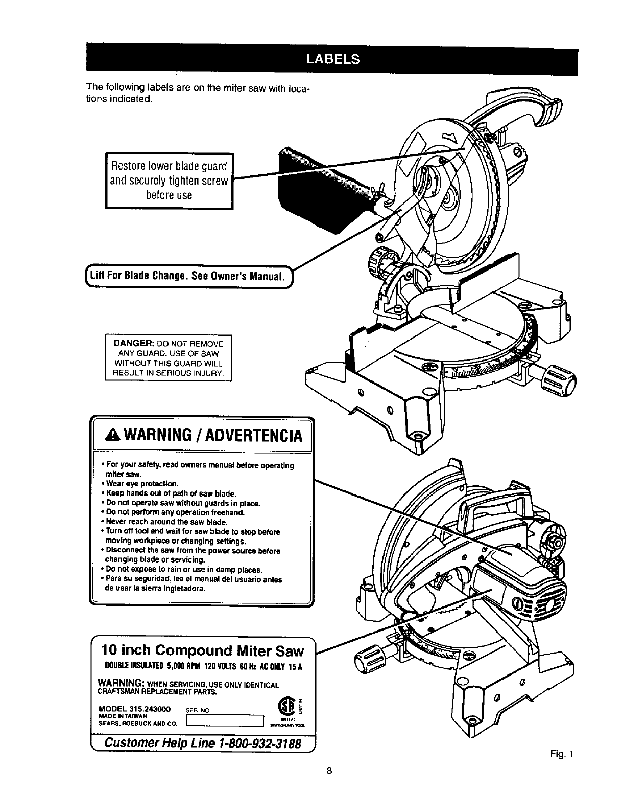
The following labels are on the miter saw withloca-
tions indicated.
Restorelower bladeguard
andsecurely tighten screw
before use
e Change. See Owner's Man
DANGER: DO NOT REMOVE
ANY GUARD. USE OF SAW
WITHOUT THIS GUARD WILL
RESULT IN SERIOUS INJURY.
41WARNING/ADVERTENCIA
• For your safety, read owners manual before operating
miter saw.
•Wear eye protection.
• Keep hands out of path of saw blade,
• Do not operate saw without guards in place,
• Do not perform any operation freehand.
•Never reach around the saw blade.
•Turn off tool and wait for saw blade to stop before
moving workpiece or changing settings.
• Disconnect the saw from the power source before
changing blade or servicing,
• Do not expose to rain or usa in damp places.
•Psra su saguridad, lea el manual del usuario antes
de usar la sierra ingletadora.
10 inch Compound Miter Saw
DOUBLEINSULATED5,OOORPM120VOLTS60Hz ACONLY15A
WARNING: WHEN SERVICING, USE ONLY IDENTICAL
CRAFTSMAN REPLACEMENT PARTS,
MODEL 315,243000 SER NO _i
MADE iN TArWAN []v,m_c
SEARS,ROEBUCKAND CO. rrA_ON_W¢_
•Customer Help Line 1-800-932-3188 Fig. 1
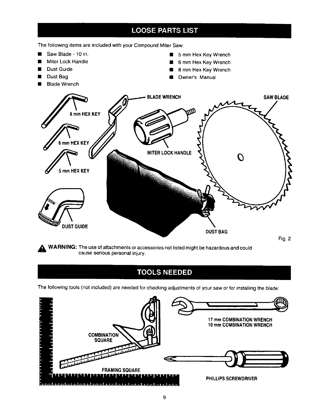
The following items are included with your Compound Miter Saw:
• Saw Blade - 10 in.
• Miter Lock Handle
: D_:tt Gui:e
• Blade Wrench
__HEX KEY
_KEY
• 5 mm Hex Key Wrench
• 6 mm Hex Key Wrench
• 8 mm Hex Key Wrench
• Owner's Manual
BLADEWRENCH SAWBLADE
MITERLOCKHANDLE
DUST BAG
Fig. 2
_, WARNING: The use o! attachments or accessories not listed might be hazardous and could
cause serious personal injury,
The following tools (not included) are needed for checking adjustments of your saw or for installing the blade:
SQUARE
FRAMINGSQUARE
17mmCOMBINATIONWRENCH
10mmCOMBINATIONWRENCH
PHILLIPS SCREWDRIVER
9
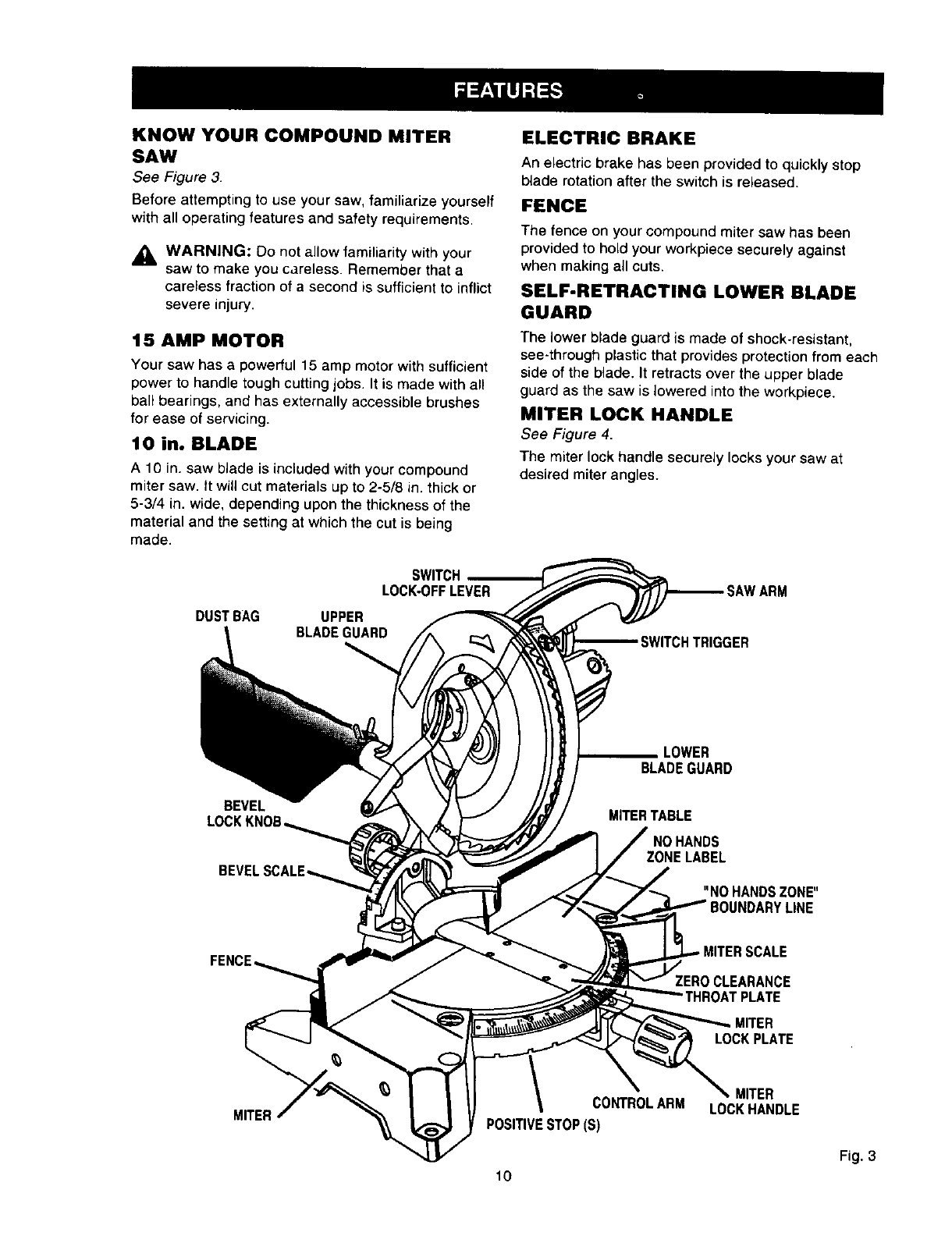
KNOW YOUR COMPOUND MITER
SAW
See Figure 3.
Before attempting to use your saw, familiarize yourself
with all operating features and safety requirements.
,_ WARNING: Do not allow familiarity with your
saw to make you careless. Remember that a
careless fraction of a second is sufficient to inflict
severe injury.
15 AMP MOTOR
Your saw has a powerful 15 amp motor with sufficient
power to handle tough cutting jobs. It is made with all
ball bearings, and has externally accessible brushes
for ease of servicing.
10 in. BLADE
A 10 in. saw blade is included with your compound
miter saw. It will cut materials up to 2-5/8 in. thick or
5-3/4 in. wide, depending upon the thickness of the
material and the setting at which the cut is being
made.
DUSTBAG
SWITCH
LOCK-OFFLEVER
UPPER
BLADE GUARD
ELECTRIC BRAKE
An electric brake has been provided to quickly stop
blade rotation after the switch is released.
FENCE
The fence on your compound miter saw has been
provided to hold your workpiece securely against
when making all cuts.
SELF-RETRACTING LOWER BLADE
GUARD
The lower blade guard is made of shock-resistant,
see-through plastic that provides protection from each
side of the blade. It retracts over the upper blade
guard as the saw is lowered into the workpiece.
MITER LOCK HANDLE
See Figure 4.
The miter lock handle securely locks your saw at
desired miter angles.
SWITCHTRIGGER
BEVEL
BLADEGUARD
MITERTABLE
ZONE LABEL
"NO HANDS ZONE"
LINE
FEN
ZEROCLEARANCE
LOCK PLATE
MITER CONTROLARM
POSITIVESTOP(S) LOCKHANDLE
Fig. 3
10
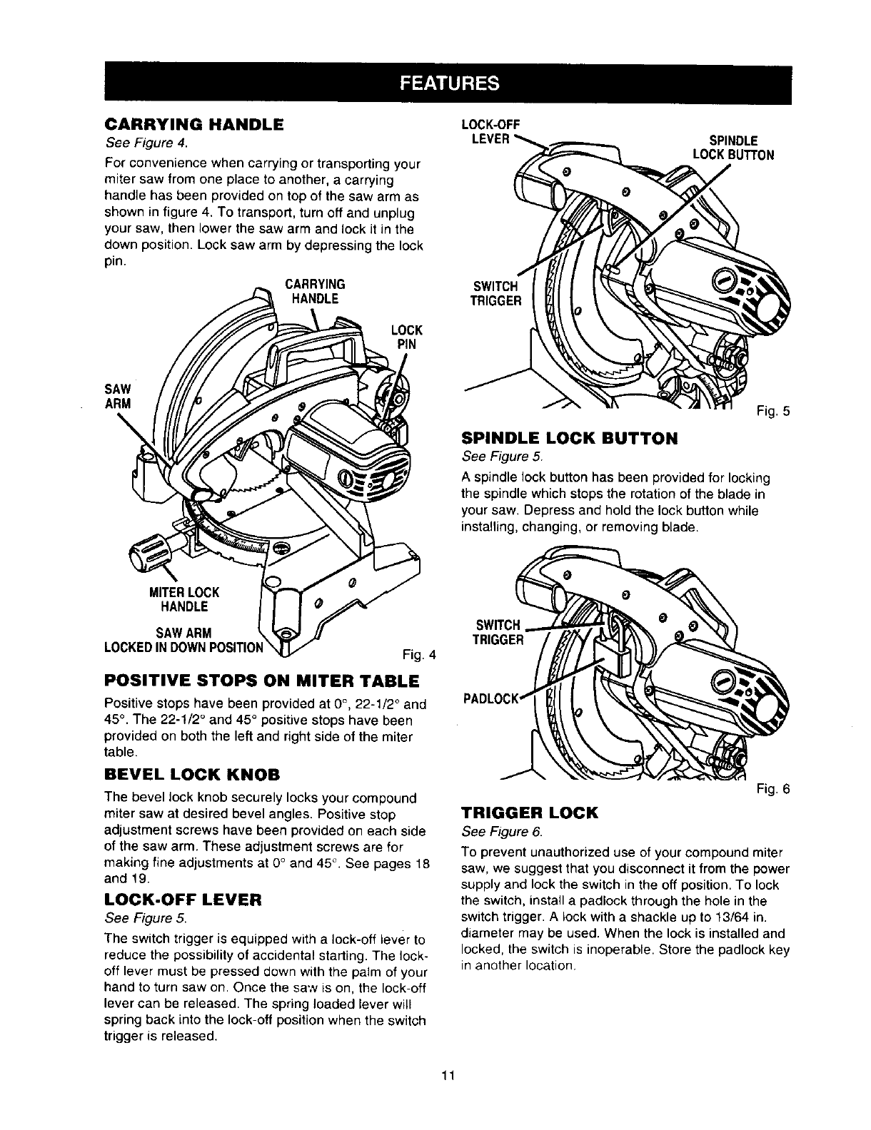
CARRYING HANDLE
See Figure 4.
For convenience when carrying or transporting your
miter saw from one place to another, a carrying
handle has been provided on top of the saw arm as
shown in figure 4. To transport, turn off and unplug
your saw, then lower the saw arm and lock it in the
down position. Lock saw arm by depressing the lock
pin.
CARRYING
HANDLE
LOCK
PIN
LOCK-OFF
LEVER
SWITCH
TRIGGER
SPINDLE
LOCK BUTTON
SAW
ARM Fig. 5
SPINDLE LOCK BUTTON
See Figure 5
A spindle lock button has been provided for locking
the spindle which stops the rotation of the blade in
your saw. Depress and hold the lock button while
installing, changing, or removing blade.
MITERLOCK
HANDLE
SAW ARM
LOCKED IN DOWN POSITION Fig. 4
POSITIVE STOPS ON MITER TABLE
Positive stops have been provided at 0°, 22-1/2 ° and
45° . The 22-1/2 ° and 45° positive stops have been
provided on both the left and right side of the miter
table.
BEVEL LOCK KNOB
The bevel lock knob securely locks your compound
miter saw at desired bevel angles. Positive stop
adjustment screws have been provided on each side
of the saw arm. These adjustment screws are for
making fine adjustments at 0°and 45°. See pages 18
and 19.
LOCK-OFF LEVER
See Figure 5
The switch trigger is equipped with a lock-off lever to
reduce the possibility of accidental starting. The lock-
off lever must be pressed down with the palm of your
hand to turn saw on. Once the saw is on, the lock-off
lever can be released. The spring loaded lever will
spring back into the lock-oft position when the switch
trigger is released.
SWITCH
TRIGGER
Fig. 6
TRIGGER LOCK
See Figure 6
To prevent unauthorized use of your compound miter
saw, we suggest that you disconnect it from the power
supply and lock the switch in the off position To lock
the switch, install apadlock through the hole in the
switch trigger A lock with a shackle up to 13/64 in
diameter may be used. When the lock is installed and
locked, the switch is inoperable. Store the padlock key
in another location.
11
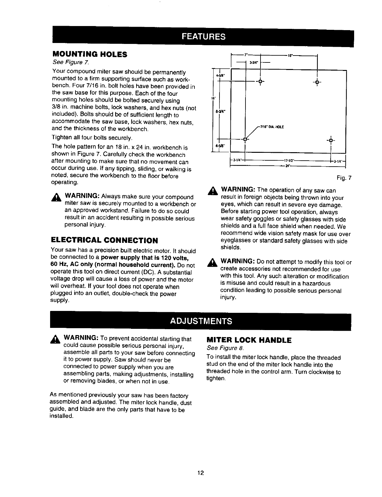
MOUNTING HOLES
See Figure 7.
Your compound miter saw should be permanently
mounted to a firm supporting surface such as work-
bench. Four 7/16 in. bolt holes have been provided in
the saw base for this purpose. Each of the tour
mounting holes should be bolted securely using
3/8 in. machine bolts, lock washers, and hex nuts (not
included). Bolts should be of sufficient length to
accommodate the saw base, lock washers, hex nuts,
and the thickness of the workbench.
Tighten all four bolts securely.
The hole pattern for an 18 in. x 24 in. workbench is
shown in Figure 7. Carefully check the workbench
after mounting to make sure that no movement can
occur during use. If any tipping, sliding, or walking is
noted, secure the workbench to the floor before
operating.
_IL WARNING: Always make sure your compound
miter saw is securely mounted to a workbench or
an approved workstand. Failure to do so could
result in an accident resulting in possible serious
personal injury.
ELECTRICAL CONNECTION
Your saw has a precision built electric motor. It should
be connected to a power supply that is 120 volts,
60 Hz, AC only (normal household current). Do not
operate this tool on direct current (DC). A substantial
voltage drop will cause a loss of power and the motor
will overheat. If your tool does not operate when
plugged into an outlet, double-check the power
supply.
341/4"
I"
1O_-
-9-
I
Fig. 7
,& WARNING: The operation of any saw can
result in foreign objects being thrown into your
eyes, which can result in severe eye damage.
Before starting power tool operation, always
wear safety goggles or safety glasses with side
shields and a full face shield when needed. We
recommend wide vision safety mask for use over
eyeglasses or standard safety glasses with side
shields.
a, WARNING: Do not attempt to modify this tool or
create accessories not recommended for use
with this tool. Any such alteration or modification
is misuse and could result in a hazardous
condition leading to possible serious personal
injury.
_ WARNING: To prevent accidental starting that
could cause possible serious personal injury,
assemble all parts to your saw before connecting
it to power supply. Saw should never be
connected to power supply when you are
assembling parts, making adjustments, installing
or removing blades, or when not in use.
As mentioned previously your saw has been factory
assembled and adjusted. The miter lock handle, dust
guide, and blade are the only parts that have to be
installed.
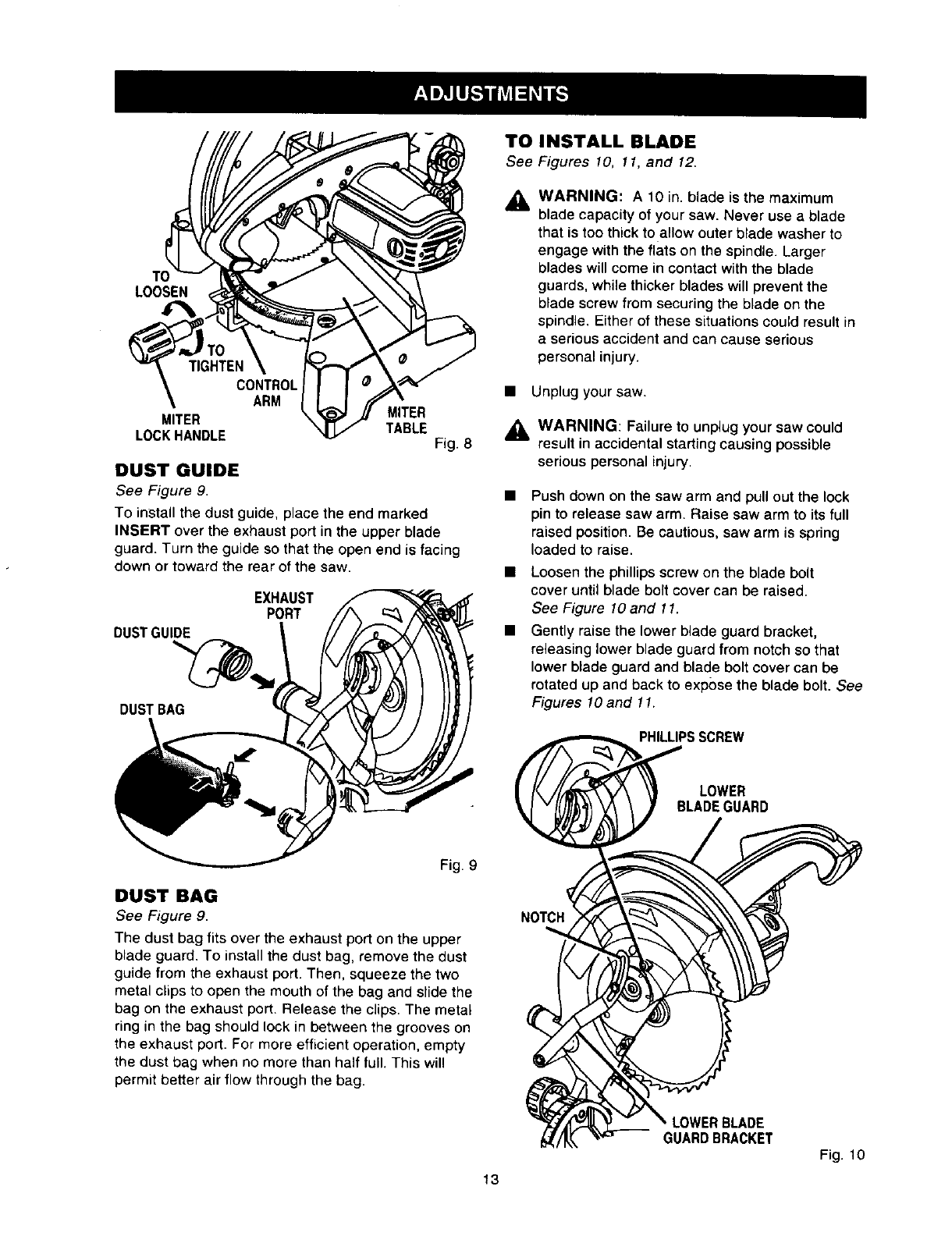
MITER LOCK HANDLE
See _gure 8.
To install the miter lock handle, place the threaded
stud on the end of the miter lock handle into the
threaded hole in the control arm. Turn clockwise to
tighten.
12
LOOSEN
TIGHTEN
CONTROL
ARM
MITER MITER
LOCKHANDLE TABLE Fig. 8
DUST GUIDE
See Figure 9.
To install the dust guide, place the end marked
INSERT over the exhaust port in the upper blade
guard. Turn the guide so that the open end is facing
down or toward the rear of the saw.
EXHAUST
PORT
DUSTGUIDE
DUSTBAG
Fig. 9
DUST BAG
See Figure 9.
The dust bag fits over the exhaust port on the upper
blade guard. To install the dust bag, remove the dust
guide from the exhaust port. Then, squeeze the two
metal clips to open the mouth of the bag and slide the
bag on the exhaust port. Release the clips. The metal
ring in the bag should lock in between the grooves on
the exhaust port. For more efficient operation, empty
the dust bag when no more than half full. This will
permit better air flow through the bag.
TO INSTALL BLADE
See Figures 10, 11, and 12.
AWARNING: A10 in. blade is the maximum
blade capacity of your saw. Never use a blade
that is too thick to allow outer blade washer to
engage with the flats on the spindle. Larger
blades will come in contact with the blade
guards, while thicker blades will prevent the
blade screw from securing the blade on the
spindle. Either of these situations could result in
a serious accident and can cause serious
personal injury.
• Unplug your saw.
_1, WARNING: Failure to unplugyour saw could
result in accidental starting causing possible
serious personal injury.
Push down on the saw arm and pull out the lock
pin to release saw arm. Raise saw arm to its full
raised position. Be cautious, saw arm is spring
loaded to raise.
Loosen the phillips screw on the blade bolt
cover until blade bolt cover can be raised.
See Figure 10 and 11.
Gently raise the lower blade guard bracket,
releasing lower blade guard from notch so that
lower blade guard and blade bolt cover can be
rotated up and back to expose the blade bolt. See
Figures lO and 11.
PHILLIPSSCREW
LOWER
BLADEGUARD
LOWERBLADE
GUARDBRACKET
Fig. 10
13
LOWER PHILLIPS
BLADEGUARD SCREW
B
BOLTCOVER FLAT(S)
ONSPINDLE
INNERBLADE
DOUBLE"D"FLATS
TO
LOOSEN BLADE
TIGHTEN
BLADEBOLT
OUTER BLADE WASHER
WITH DOUBLE "D" FLATS
Fig. 11
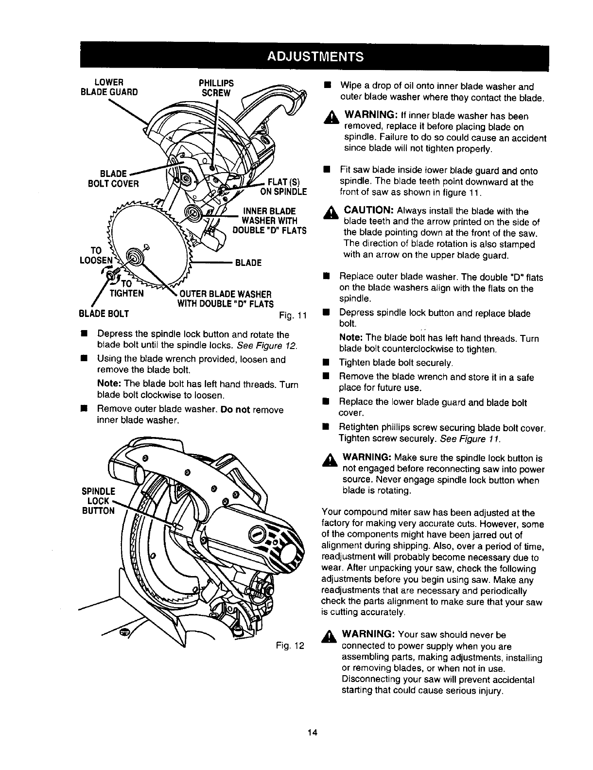
•Depress the spindle lock button and rotate the
blade bolt until the spindle locks. See Figure 12.
• Using the btade wrench provided, _oosen and
remove the blade bolt.
Note: The blade bolt has left hand threads. Turn
blade bolt clockwise to loosen.
• Remove outer blade washer. Do not remove
inner blade washer.
SPINDLE
LOCK'_
BUTTON
Fig. 12
• Wipe a drop of oil onto inner blade washer and
outer blade washer where they contact the blade,
AWARNING: If inner blade washer has been
removed, replace it before placing blade on
spindle. Failure to do so could cause an accident
since blade will not tighten properly.
•Fit saw blade inside lower blade guard and onto
spindle.The blade teeth point downward at the
front of saw as shown in figure 11.
ACAUTION: Always install the blade with the
blade teeth and the arrow printed on the side of
the blade pointing down at the front of the saw.
The direction of b_aderotation is a_so stamped
with an arrow on the upper blade guard.
• Replace outer blade washer. The double "D" flats
on the blade washers align with the flats on the
spindle.
•Depress spindle lock buttonand replace blade
bott.
Note: The blade belt has left hand threads. Turn
blade beltcounterclockwise to tighten.
•Tighten b_adebott securely.
• Remove the blade wrench and store it in a safe
place for future use.
• Replace the lower blade guard and blade bolt
cover.
• Retighten phillips screw securing blade bolt cover.
Tighten screw securely, See Figure 11.
,_ WARNING: Make sure the spindle lock button is
not engaged before reconnecting saw into power
source. Never engage spindle lock button when
blade is rotating,
Your compound miter saw has been adjusted at the
factory for making very accurate cuts. However, some
of the components might have been jarred out of
alignment during shipping. Also, over a period of time,
readjustment will probably become necessary due to
wear. After unpacking your saw, check the following
adjustments before you begin using saw. Make any
readjustments that are necessary and periodically
check the parts a_ignment to make sure that your saw
is cutting accurately.
_, WARNING: Your saw should never be
connected to power supply when you are
assembling parts, making adjustments, installing
or removing blades, or when not in use.
DisconnectLng your saw will prevent accidental
starting that could cause serious injury.
14
Note:Manyoftheillustrationsinthismanualshow
onlyportionsofyourcompoundmitersaw.Thisis
intentionalsothatwecanclearryshowpointsbeing
madeintheillustrations.Neveroperateyoursaw
withoutallguardssecurelyinplaceandingood
operatingcondition.
CUTTING A SLOT IN THE ZERO
CLEARANCE THROAT PLATE
In order to use your compound miter saw, you must
cut a slot through the zero clearance throat plate to
allow for blade clearance. To cut the slot, set your
saw at Odegrees miter, turn saw on and allow the
blade to reach full speed, then carefully make a
straight cut as far as it will go through the throat plate.
Turn your saw off and allow the blade to come to a
complete stop before raising the saw arm.
Next, adjust the bevel angle to 45 degrees, turn your
saw on and allow the blade to reach full speed, then
carefully make another cut through the zero clearance
throat plate. The throat plate will then be wide enough
to allow the blade to pass through it at any angle from
0 to 45 degrees.
SQUARING THE MITER TABLE
TO THE FENCE
See Figures 13 -16.
• Unplug your saw.
_l, WARNING: Failure to unplug your saw could
result in accidental starting causing possible
serious personal injury.
• Push down on the saw arm and pull out the lock
pin to release the saw arm.
• Raise saw arm to its furl raised position.
• Loosen the miter lock handle approximately one-
half turn.
• Depress the miter lock plate and rotate the miter
table until the pointer on the control arm is posi-
tioned at 0°.
• Release the miter lock plate and securely tighten
the miter lock handle.
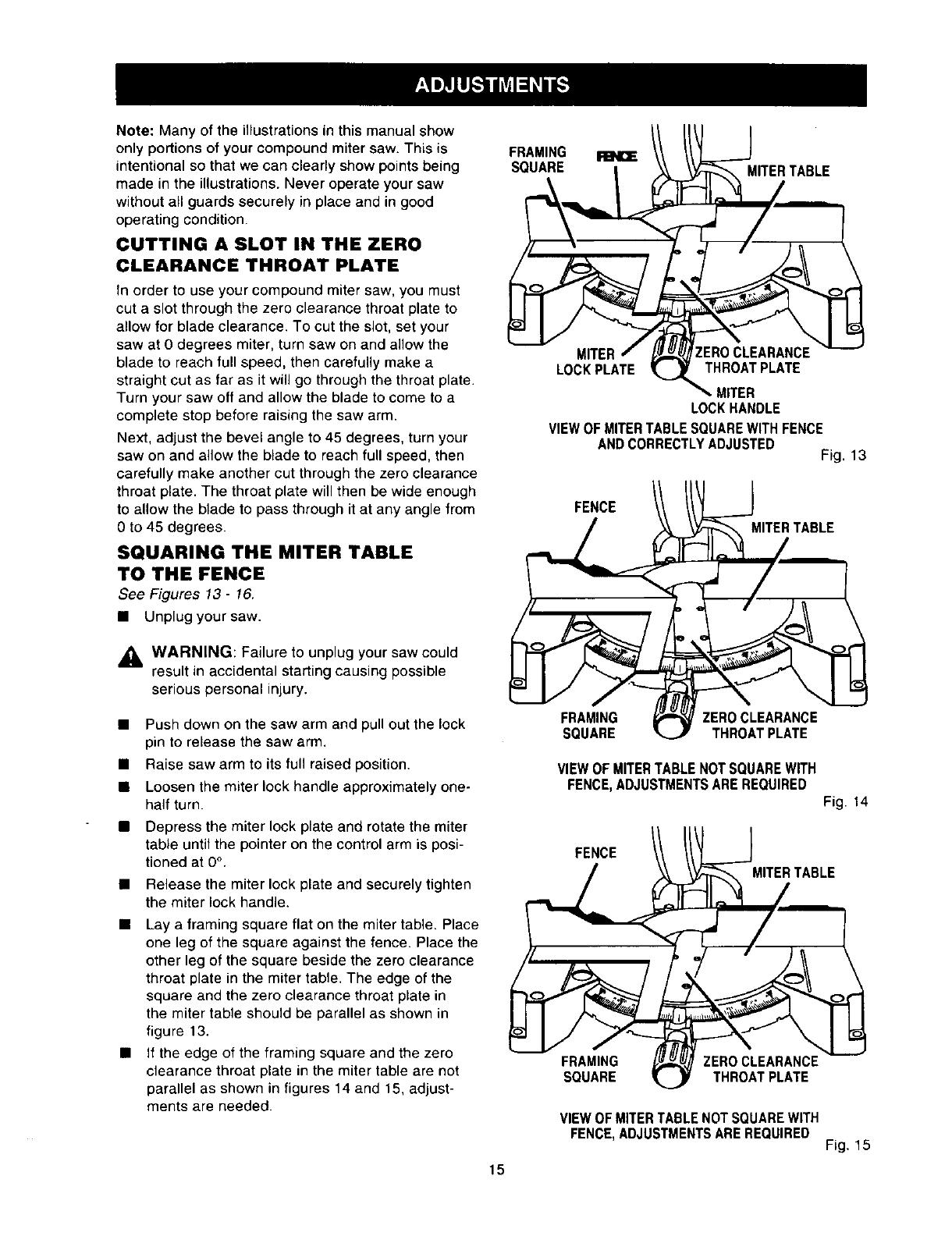
• Lay a framing square flat on the miter table. Place
one leg of the square against the fence. Place the
other leg of the square beside the zero clearance
throat plate in the miter table. The edge of the
square and the zero clearance throat plate in
the miter table should be parallel as shown in
figure 13.
• If the edge of the framing square and the zero
clearance throat plate in the miter table are not
parallel as shown in figures 14 and 15, adjust-
ments are needed.
FRAMING
SQUARE MITERTABLE
MITER
LOCK PLATE THROAT PLATE
MITER
LOCK HANDLE
VIEW OF MITER TABLE SQUARE WITH FENCE
AND CORRECTLYADJUSTED Fig. 13
FENCE // //! _]MIT_/R TABLE
VIEW OF MITERTABLE NOT SQUARE WITH
FENCE, ADJUSTMENTS ARE REQUIRED
Fig. 14
FENCE
MITER TABLE
FRAMING ZERO CLEARANCE
SQUARE THROAT PLATE
VIEWOFMITERTABLENOTSQUAREWITH
FENCE,ADJUSTMENTSAREREQUIRED Fig. 15
15
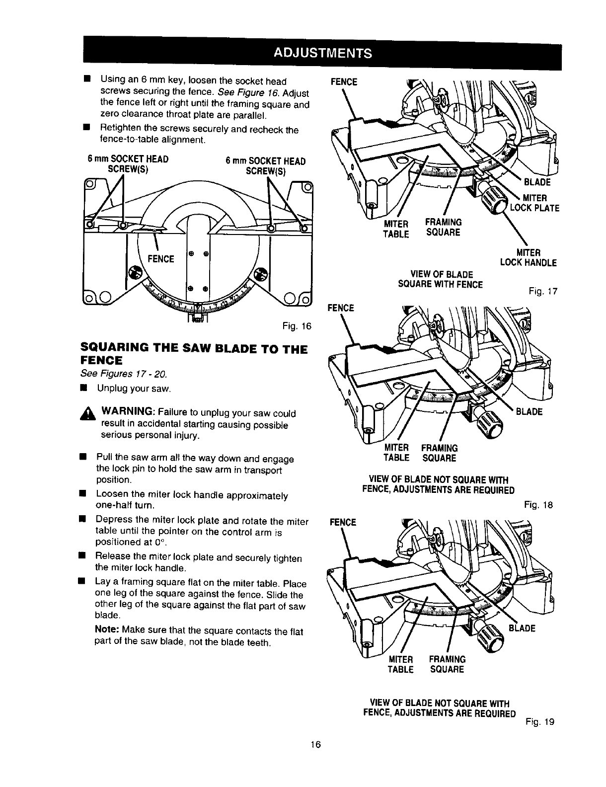
• Using an 6 mm key, loosen the socket head
screws securing the fence. See Figure 16, Adjust
the fence left or right until the framing square and
zero clearance throat plate are parallel.
• Retighten the screws securely and recheck the
fence-to-table alignment.
6 mmSOCKETHEAD
SCREW(S) 6 mmSOCKETHEAD
SCREW(S)
Fig. 16
SQUARING THE SAW BLADE TO THE
FENCE
See Figures 17- 20.
• Unplug your saw,
,_ WARNING: Failure to unplug your saw could
result in accidental starting causing possible
serious personal injury.
Pull the saw arm all the way down and engage
the lock pin to hold the saw arm in transport
position.
Loosen the miter lock handle approximately
one-half turn.
Depress the miter lock plato and rotate the miter
table until the pointer on the control arm is
positioned at 0°.
Release the miter lock plate and securely tighten
the miter lock handle.
Lay a framing square flat on the miter table. Place
one leg ofthe square against the fence. S_{dethe
other leg of the square against the flat part of saw
blade.
Note: Make sure that the square contacts the flat
part of the saw blade, not the blade teeth.
FENCE
FENCE
MITER FRAMING
TABLE SQUARE
VIEW OF BLADE
SQUARE WITH FENCE
LOCK PLATE
MITER
LOCKHANDLE
Fig. 17
BLADE
MITER FRAMING
TABLE SQUARE
VIEWOF BLADENOTSQUAREWITH
FENCE,ADJUSTMENTSAREREQUIRED
Fig. 18
BLADE
MITER FRAMING
TABLE SQUARE
VIEW OF BLADE NOT SQUARE WITH
FENCE, ADJUSTMENTS ARE REQUIRED Fig. 19
16
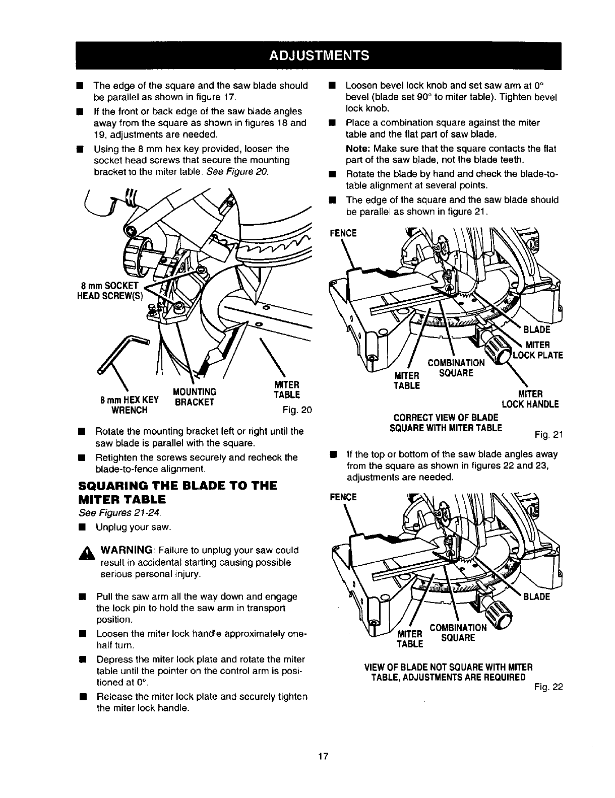
• Theedgeofthesquareandthesawbladeshould
beparallelasshowninfigure17.
• Ifthefrontorbackedgeofthesawbladeangles
awayfromthesquareasshowninfigures18and
19,adjustmentsareneeded.
• Usingthe8mmhexkeyprovided,loosenthe
socketheadscrewsthatsecurethemounting
brackettothemitertable.See Figure 20.
8 mmSOCKET
HEAD€
MITER
MOUNTING TABLE
8 mmHEXKEY BRACKET
WRENCH Fig. 20
•Rotate the mounting bracket left or right untilthe
saw blade is parallel with the square.
• Retighten the screws securely and recheck the
blade-to-fence alignment.
SQUARING THE BLADE TO THE
MITER TABLE
See Figures 21-24.
• Unplug your saw.
_, WARNING: Failure to unplug your saw could
result in accidental starting causing possible
serious personal injury.
Pull the saw arm all the way down and engage
the lock pin to hold the saw arm in transport
position.
Loosen the miter lock handle approximately one-
half turn.
Depress the miter lock plate and rotate the miter
table until the pointer on the control arm is posi-
tioned at 0°.
Release the miter lock plate and securely tighten
the miter lock handle.
•Loosen bevel lock knob and set saw arm at 0°
bevel (blade set 90° to miter table). Tighten bevel
lock knob.
• Place a combination square against the miter
table and the flat part of saw blade.
Note; Make sure that the square contacts the flat
part of the saw blade, not the blade teeth.
• Rotate the blade by hand and check the blade-to-
table alignment at several points.
• The edge of the square and the saw blade should
be parallel as shown in figure21.
FENCE
MITER
COMBINATION
MITER SQUARE
TABLE MITER
LOCKHANDLE
CORRECTVIEWOF BLADE
SQUAREWITHMITERTABLE Fig. 21
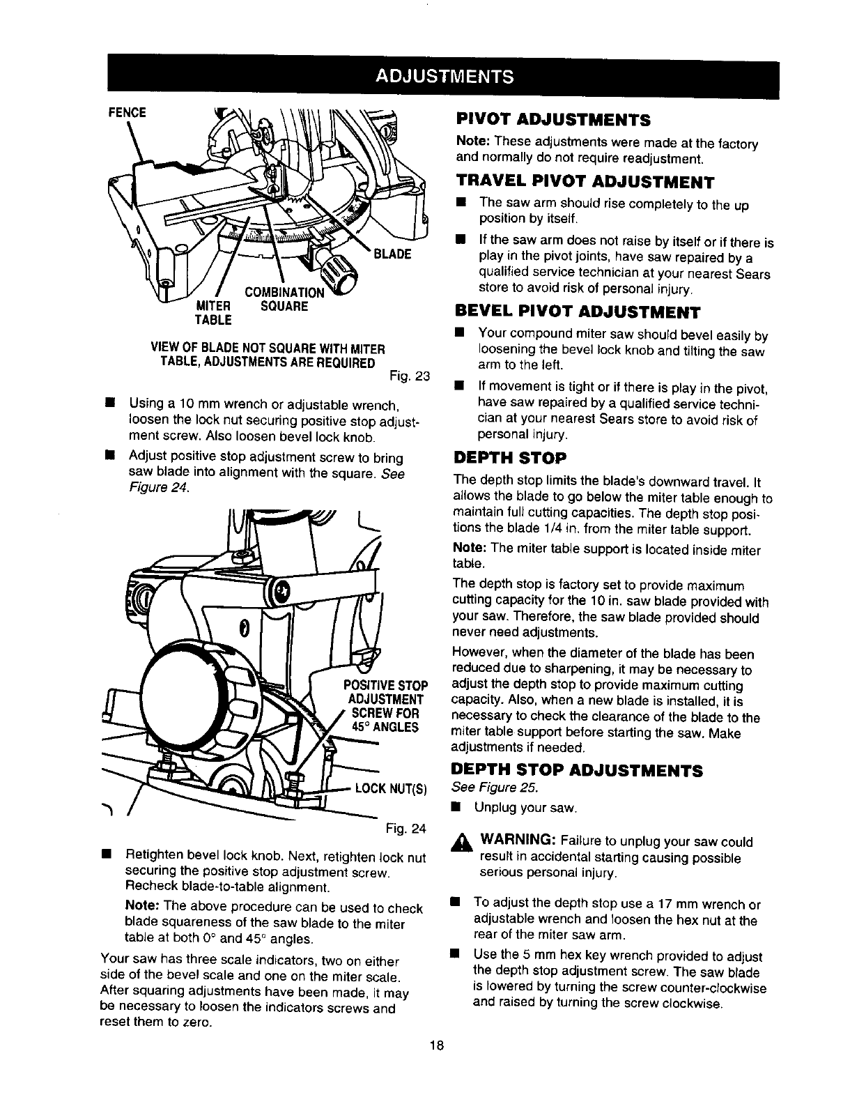
•If the top or bottom of the saw blade angles away
from the square as shown in figures 22 and 23,
adjustments are needed.
FENCE
COMBINATION
!R SQUARE
TABLE
VIEWOFBLADENOTSQUAREWITHMITER
TABLE,ADJUSTMENTSAREREQUIRED Fig. 22
17
FENCE PIVOT ADJUSTMENTS
COMBINATION
MITER SQUARE
TABLE
VIEW OF BLADE NOTSQUARE WITH MITER
TABLE, ADJUSTMENTS ARE REQUIRED Fig. 23
•Using a 10 mm wrench or adiustable wrench,
loosen the lock nut securing positive stop adjust-
ment screw. Also loosen bevel lock knob.
• Adjust positive stop adjustment screw to bring
saw blade into alignment with the square. See
Figure 24.
POSITIVESTOP
ADJUSTMENT
SCREWFOR
45°ANGLES
NUT(S)
Fig. 24
• Retighten bevel lock knob. Next, retighten lock nut
securing the positive stop adjustment screw.
Recheck blade-to-table alignment.
Note: These adjustments were made at the factory
and normally do not require readjustment.
Your saw has three scale indicators, two on either
side of the bevel scale and one on the miter scale.
After squaring adjustments have been made, it may
be necessary to loosen the indicators screws and
TRAVEL PIVOT ADJUSTMENT
• The saw arm should rise completely to the up
position by itself.
If the saw arm does not raise by itself or if there is
play in the pivot joints, have saw repaired by a
qualified service technician at your nearest Sears
store to avoid risk of personal injury.
BEVEL PIVOT ADJUSTMENT
• Your compound miter saw should bevel easily by
loosening the bevel lock knob and tilting the saw
arm to the left.
If movement is tight or if there is play in the pivot,
have saw repaired by a qualified service techni-
cian at your nearest Sears store to avoid risk of
personal injury.
DEPTH STOP
The depth stop limits the blade's downward travel, It
allows the blade to go below the miter table enough to
maintain full cutting capacities. The depth stop posi-
tions the blade 1/4 in. from the miter table support.
Note: The miter table support is located inside miter
table.
The depth stop is factory set to provide maximum
cuttingcapacity for the 10 in. saw blade provided with
your saw. Therefore, the saw blade provided should
never need adjustments.
However, when the diameter of the blade has been
reduced due to sharpening, it may be necessary to
adjust the depth stop to provide maximum cutting
capacity. Also, when a new blade is installed, it is
necessary to check the clearance of the blade to the
miter table support before starting the saw. Make
adjustments if needed.
DEPTH STOP ADJUSTMENTS
See Figure 25.
• Unplug your saw.
_i, WARNING: Failure to unplug your saw could
result in accidental starting causing possible
serious personal injury.
Note: The above procedure can be used to check
blade squareness of the saw blade to the miter
table at both 0°and 45° angles.
reset them to zero.
To adjust the depth stop use a 17 mm wrench or
adjustable wrench and loosen the hex nut at the
rear of the miter saw arm.
Use the 5 mm hex key wrench provided to adjust
the depth stop adjustment screw. The saw blade
is lowered by turning the screw counter-clockwise
and raised by turning the screw clockwise.
18
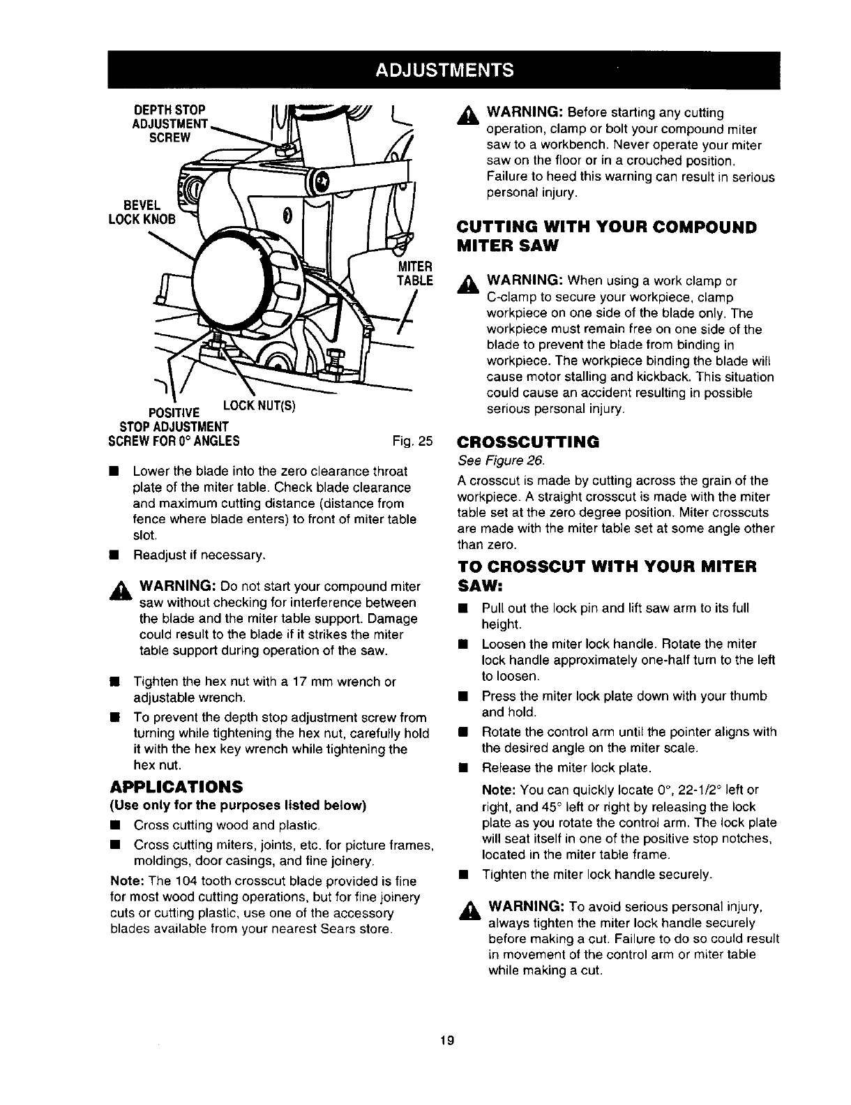
DEPTH STOP L._
ADJUSTMENT
SCREW
BEVEL
LOCKKNOB
MITER
TABLE
POSITIVE LOCKNUT(S)
STOPADJUSTMENT
SCREWFOR0° ANGLES Fig. 25
• Lower the blade into the zero clearance throat
plate of the miter table. Check blade clearance
and maximum cutting distance (distance from
fence where blade enters) to front of miter table
slot.
• Readjust if necessary.
_1= WARNING: Do not start your compound miter
saw without checking for interference between
the blade and the miter table support. Damage
could result to the blade if it strikes the miter
table support during operation of the saw.
• Tighten the hex nut with a 17 mm wrench or
adjustable wrench.
• To prevent the depth stop adjustment screw from
turning while tightening the hex nut, carefully hold
it with the hex key wrench while tightening the
hex nut.
APPLICATIONS
(Use only for the purposes listed below)
• Cross cutting wood and plastic.
• Cross cutting miters, joints, etc. for picture frames,
moldings, door casings, and fine joinery.
Note: The 104 tooth crosscut blade provided is fine
for most wood cutting operations, but for fine joinery
cuts or cutting plastic, use one of the accessory
blades available from your nearest Sears store.
_1, WARNING: Before starting any cutting
operation, clamp or bolt your compound miter
saw to a workbench. Never operate your miter
saw on the floor or in a crouched position.
Failure to heed this warning can result in serious
personal injury.
CUTTING WITH YOUR COMPOUND
MITER SAW
WARNING: When using a work clamp or
C-clamp to secure your workpiece, clamp
workpiece on one side of the blade only. The
workpiece must remain free on one side of the
blade to prevent the blade from binding in
workpiece. The workpiece binding the blade will
cause motor stalling and kickback. This situation
could cause an accident resulting in possible
serious personal injury.
CROSSCUTTING
See Figure 26.
A crosscut is made by cutting across the grain of the
workpiece. A straight crosscut is made with the miter
table set at the zero degree position. Miter crosscuts
are made with the miter table set at some angle other
than zero.
TO CROSSCUT WITH YOUR MITER
SAW:
• Pull out the lock pin and lift saw arm to its full
height.
• Loosen the miter lock handle. Rotate the miter
lock handle approximately one-half turn to the left
to loosen.
• Press the miter lock plate down with your thumb
and hold.
• Rotate the control arm until the pointer aligns with
the desired angle on the miter scale.
• Release the miter lock plate.
Note: You can quickly locate 0°, 22-1/2 ° left or
right, and 45° left or right by releasing the lock
plate as you rotate the control arm. The lock plate
will seat itself in one of the positive stop notches,
located in the miter table frame.
• Tighten the miter lock handle securely.
AWARNING: To avoid serious personal injury,
always tighten the miter lock handle securely
before making a cut, Failure to do so could result
in movement of the control arm or miter table
while making a cut.
19

STRAIGHT
CROSSCUT
Slowly lower the blade into and through the
workpiece. See Figure 26.
Release the switch trigger and allow the saw
blade to stop rotating before raising the blade out
of workpiece. Wait until the electric brake stops
blade from turning before removing the workpiece
from the miter table.
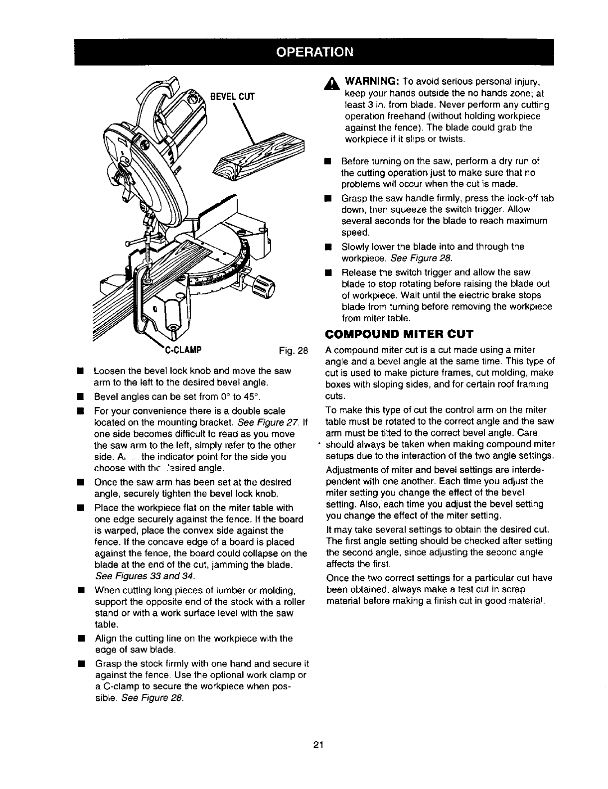
BEVEL CUT
See Figures 27 and 28.
A bevel cut is made by cutting across the grain of the
workpiece with the blade angled to the workpiece. A
straight bevel cut is made with the miter table set at
the zero degree position and the blade set at an angle
between 0° and 45°.
LEFTSIDE RIGHTSIDE
LEFT RIGHT
INDICATOR INDICATOR
POINT POINT
• C-CLAMP Fig. 26
• Place the workpiece flat on the miter table with
one edge securely against the fence. If the board
is warped, place the convex side against the
fence. If the concave edge of a board is placed
against the fence, the board could collapse on the
blade at the end of the cut, jamming the blade.
See Figures 33 and 34.
• When cutting long pieces of lumber or molding,
support the opposite end of the stock with a roller
stand or with a work surface level with the saw
table.
Align cutting line on the workpiece with the edge
of saw blade.
Grasp the stock firmly with one hand and secure
it against the fence. Use the optional work clamp
or a C-clamp to secure the workpiece when
possible. See Figure 26.
WARNING: To avoid serious personal injury,
keep your hands outside the no hands zone; at
least 3 in. from blade. Never perform any cutting
operation freehand (without holding workpiece
against the fence). The blade could grab the
workpiece if it slips or twists.
• Before turning on the saw, perform a dry run of the
cutting operation just to make sure that no
problems will occur when the cut is made.
• Grasp the saw handle firmly, press the lock-off tab
down, then squeeze the switch trigger. Allow
several seconds for the blade to reach maximum
speed.
20
SCALE SCALE
MOUNTINGBRACKET Fig. 27
TO BEVEL CUT WITH YOUR MITER
SAW:
• Pull out the lock pin and lift saw arm to its full
height.
Loosen the miter lock handle. Rotate the miter
lockhandle approximately one-half turn to the left
to loosen.
Press the miter lock plate down with your thumb
and hold.
Rotate the control arm until the pointer aligns with
zero on the miter scale.
Release the miter lock plate.
Note: You can quickly locate zero by releasing
the lock plate as you rotate the control arm. The
lock plate will seat itself in one of the built-in
positive stop notches, located in the miter table
frame.
• Tighten the miter lock handle securely.
AWARNING: To avoid serious personal injury,
always tighten the miter lock handle securely
before making a cut. Failure to do so could result
in movement of the control arm or miter table
while making a cut.
BEVELCUT
:LAMP Fig. 28
•Loosen the bevel lock knob and move the saw
arm to the left to the desired bevel angle.
• Bevel angles can be set from 0° to 45°,
• For your convenience there is a double scale
located on the mounting bracket. See Figure 27. If
one side becomes difficult to read as you move
the saw arm to the left, simply refer to the other
side. A, the indicator point for the side you
choose with the '=.siredangle.
• Once the saw arm has been set at the desired
angle, securely tighten the bevel lock knob.
• Place the workpiece flat on the miter table with
one edge securely against the fence. If the board
is warped, place the convex side against the
fence. If the concave edge of a board is placed
against the fence, the board could collapse on the
blade at the end of the cut, jamming the blade.
See Figures 33 and 34.
When cutting long pieces of lumber or molding,
support the opposite end of the stock with a roller
stand or with a work surface level with the saw
table.
Align the cutting line on the workpiece with the
edge of saw blade.
Grasp the stock firmly with one hand and secure it
against the fence. Use the optional work clamp or
a C-clamp to secure the workpiece when pos-
sible. See Figure 28.
,_, WARNING: To avoid serious personal injury,
keep your hands outside the no hands zone; at
least 3 in. from blade. Never perform any cutting
operation freehand (without holding workpiece
against the fence). The blade could grab the
workpiece if it slips or twists.
• Before turning on the saw, perform a dry run of
the cutting operation just to make sure that no
problems will occur when the cut is made.
• Grasp the saw handle firmly, press the lock-off tab
down, then squeeze the switch trigger. Allow
several seconds for the blade to reach maximum
speed.
• Slowly lower the blade into and through the
workpiece. See Figure 28.
Release the switch trigger and allow the saw
blade to stop rotating before raising the blade out
of workpiece. Wait until the electric brake stops
blade from turning before removing the workpiece
from miter table.
COMPOUND MITER CUT
A compound miter cut is a cut made using a miter
angle and a bevel angle at the same time. This type of
cut is used to make picture frames, cut molding, make
boxes with sloping sides, and for certain roof framing
cuts.
To make this type of cut the control arm on the miter
table must be rotated to the correct angle and the saw
arm must be tilted to the correct bevel angle. Care
should always be taken when making compound miter
setups due to the interaction of the two angle settings.
Adjustments of miter and bevel settings are interde-
pendent with one another. Each time you adjust the
miter setting you change the effect of the bevel
Setting. Also, each time you adjust the bevel setting
you change the effect of the miter setting.
It may take several settings to obtain the desired cut.
The first angle setting should be checked after setting
the second angle, since adjusting the second angle
affects the first.
Once the two correct settings for a particular cut have
been obtained, always make a test cut in scrap
material before making a finish cut in good material.
21
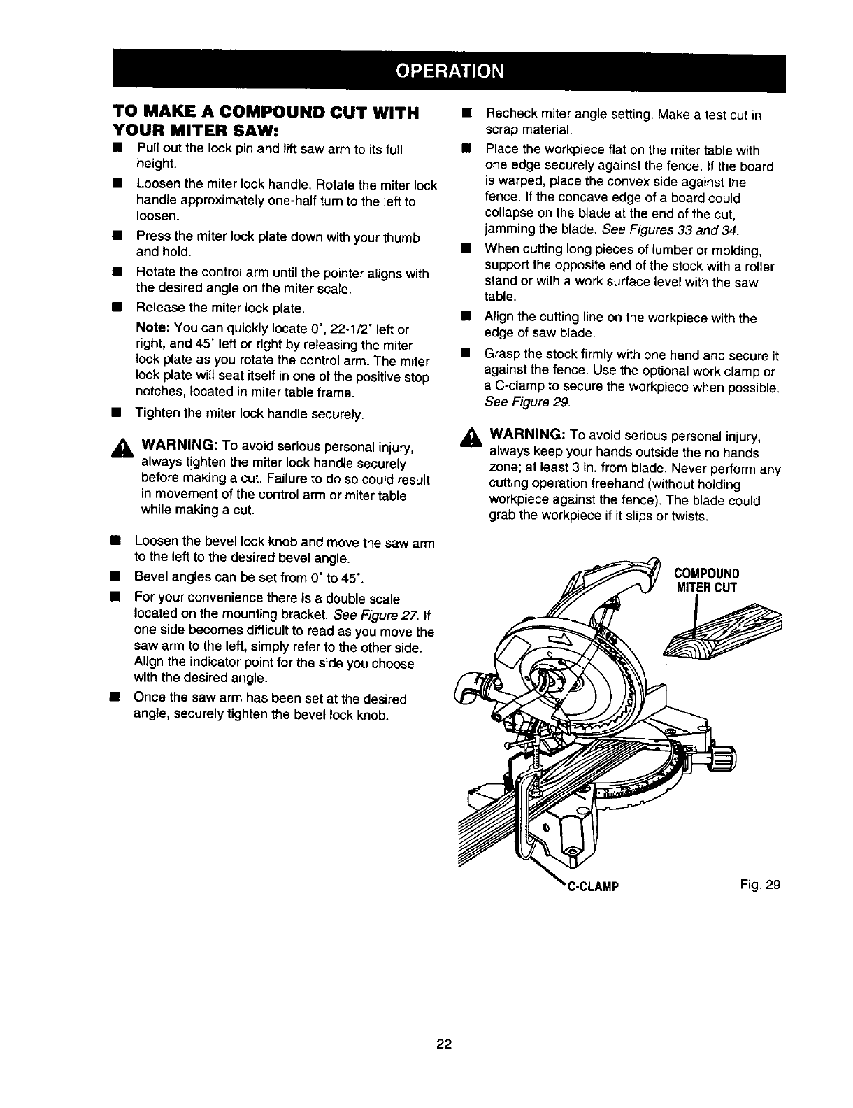
TO MAKE A COMPOUND CUT WITH
YOUR MITER SAW:
• Pull out the lock pin and lift saw arm to its full
height.
• Loosen the miter lock handle. Rotate the miter lock
handle approximately one-half turn to the left to
loosen.
• Press the miter lock plate down with your thumb
and hold.
Rotate the control arm until the pointer aligns with
the desired angle on the miter scale.
Release the miter lock plate.
Note: You can quickly locate 0°, 22-1/2" left or
right, and 45" left or right by releasing the miter
lock plate as you rotate the control arm. The miter
lock plate will seat itself in one of the positive stop
notches, located in miter table frame.
•Tighten the miter lock handle securely.
_i, WARNING: To avoid serious personal injury,
always t!ghten the miter lock handle securely
before making a cut. Failure to do so could result
in movement of the control arm or miter table
while making a cut.
• Loosen the bevel lock knob and move the saw arm
to the left to the desired bevel angle.
• Bevel angles can be set from 0" to 45".
• For your convenience there is a double scale
located on the mounting bracket. See Figure 27. If
one side becomes difficult to read as you move the
saw arm to the left, simply refer to the other side.
Align the indicator point for the side you choose
with the desired angle.
• Once the saw arm has been set at the desired
angle, securely tighten the bevel lock knob.
• Recheck miter angle setting. Make a test cut in
scrap material.
• Place the workpiece flat on the miter table with
one edge securely against the fence. If the board
is warped, place the convex side against the
fence. If the concave edge of a board could
collapse on the blade at the end of the cut,
jamming the blade. See Figures 33 and 34.
• When cutting long pieces of lumber or molding,
support the opposite end of the stock with a roller
stand or with a work surface level with the saw
table.
• Align the cutting line on the workpiece with the
edge of saw blade.
Grasp the stock firmly with one hand and secure it
against the fence. Use the optional work clamp or
a C-clamp to secure the workpiece when possible.
See Figure 29.
AWARNING: To avoid serious personal injury,
always keep your hands outside the no hands
zone; at least 3 in. from blade. Never perform any
cutting operation freehand (without holding
workpiece against the fence). The blade could
grab the workpiece if it slips or twists.
COMPOUND
MITERCUT
C-CLAMP Fig. 29
22

•Before turning on the saw, perform a dry run of the
cutting operation just to make sure that no problems
will occur when the cut is made.
• Grasp the saw handle firmly, press the lock-off tab
down, then squeeze the switch trigger. Allow sev-
eral seconds for the blade to reach maximum speed.
• Slowly lower the blade into and through the
workpiece. See Figures 29 and 30.
• Release the switch trigger and allow the saw blade
to stop rotating before raising the blade out of
workpiece. Wait until the electric brake stops blade
from turning before removing the workpiece from
miter table.
SUPPORT LONG WORKPIECES
See Figure 31.
Long workpieces need extra supports. Supports
should be placed along the workpiece so it does not
sag. The support should let the workpiece lay flat on
the base of the sew and work table during the cutting
operation. Use the optional work clamp or a C-clamp
to secure the workpiece.
_1, WARNING: To avoid serious personal injury,
always keep your hands outside the no hands
zone; at least 3 in. from blade. Never perform
any cutting operation freehand (without holding
workpiece against the fence). The blade could
grab the workpiece if it slips or twists.
45°X 45° COMPOUNDMITERCUT Fig. 30
LONGWORKPIECE
WORKPIECESUPPORTS
23
Fig. 31
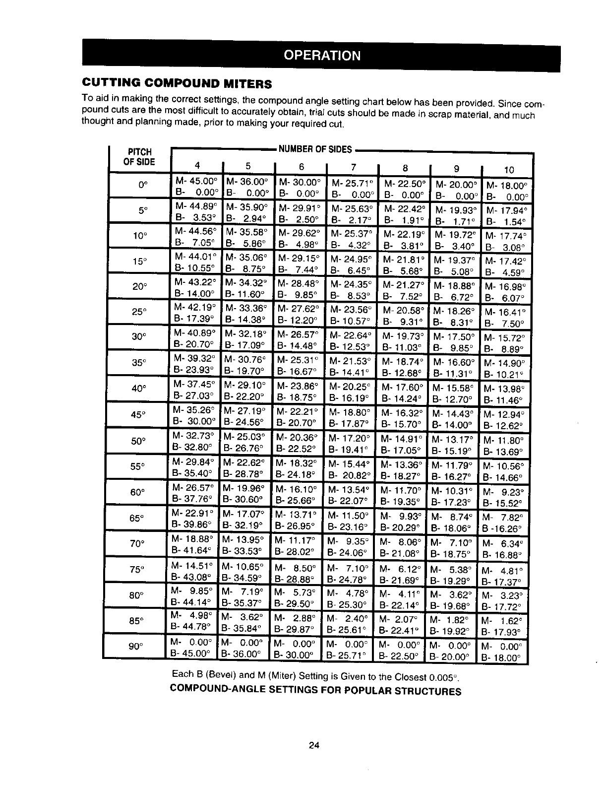
CUTTING COMPOUND MITERS
To aid in making the correct settings, the compound angle setting chart below has been provided. Since com-
pound cuts are the most difficult to accurately obtain, trial cuts should be made in scrap material, and much
thought and planning made, prior to making your required cut.
NUMBEROF SLOES
PITCH
OFSIOE 4I5I6I7I6 9 10
i
0o M-45.00 °M-36.00 ° M-30.00 ° M-25.71 ° M-22.50 ° M-20.00 ° M- 18.00 °
B- 0.00 °B- 0.00 °B- 0.00 ° B- 0.00 ° B- 0.00 ° B- 0.00 ° B- 0.00 °
IM-44.89 ° M-35.90 ° M-29,91 ° M-25.63 ° M-22,42 ° M-19.93 ° M-17.94 °
5 ° I
B- 3.53 °B- 2.94 ° B- 2.50 ° B- 2.17 ° B- 1,91 ° B- 1.71 ° B- 1.54 °
M-44.56 ° M- 35.58 °M-29.62 ° M-25.37 ° M-22.19 ° M- 19.72 ° M- 17.74 °
10° B- 7.05 ° B- 5,86 °B- 4.98 ° B- 4.32 ° B- 3.81 ° B- 3.40 ° B- 3.08 °
M- 44.01 ° M- 35.06 ° M- 29.15 ° M- 24,95 ° M- 21.81 ° M- 19.37 ° M- 17.42 °
15°B-10.55 ° B- 6.75 ° B- 7,44 ° B- 6.45 ° B- 5.68 ° B- 5.08 ° B- 4,59 °
M- 43.22 ° M- 34.32 °M- 28.48 ° M- 24.35 ° M- 21.27 ° M- 18.88 ° M- 16.98 °
20 °B-14.00 ° B-11.60 ° B- 9.85 ° B- 8,53 °B- 7,52 ° B- 6.72 °8- 6.07 °
M-42.19 ° M-33.36 ° M. 27.62 ° M-23,56 ° M-20.58 ° M-18.26 ° M-16.41 o
25 ° 8- 17,39 ° B- 14.38 ° B- 12.20 ° B- 10.57 ° 8- 9.31 °B- 8.31 °B- 7.50 °
30 ° M-40,89 ° M- 32.18 ° M- 26.57 ° M- 22,64 ° M- 19.73 ° M- 17.50 ° M- 15,72 °
B-20.70 ° B- 17.09 ° B- 14.48 °8- 12,53 ° B- 11.03 ° B- 9.85 ° B- 8.89 °
35°M- 39,32 °M- 30.76 °M- 25.31 °M- 21.53 °M- 18,74 ° M- 16.60 ° M- 14.90 °
B- 23,93 ° B- 19.70 ° B- 16,67 ° 8o 14.41 ° B- 12.68 ° B- 11.31 ° B- 10,21 °
M-37.45 ° M-29,10 ° M-23.86 ° M-20.25 ° M- 17.60 ° M- 15.58 ° M- 13.98 °
40° B- 27.03 ° B- 22.20 ° 8- 18.75 ° B- 16.19 ° B- 14.24 ° I B- 12.70 ° I 8- 11.46 °
M-35.26 ° M-27,19 °M-22,21 ° M-18.80 °M-16.32 ° M-14.43 ° !M-12.94 °
45 °B- 30,00 ° B-24.56 °8-20.70 ° B-17.87 °B-15.70 ° IB-14.00° B-12.62 °
M- 32.73 ° M-25.030 M-20.36 ° M- 17,20 ° M- 14.91 ° M- 13.17 ° M- 11.80 °
50° B- 32.80 ° B- 26.76 ° B-22.52 ° Bo 19.41 ° B- 17.05 °B- 15.19 ° B- 13,69 °
M- 29.84 ° M- 22.62 °M- 18.32 ° M- 15,44 ° M- 13,36 ° M- 11.79 ° M- 10.56 °
55°B- 35.40 ° B- 28.78 ° B- 24.18 °B÷ 20.82 ° B- 18.27 ° I B- 16.27 ° B- 14.66 °
I
M- 26.57 ° M- 19.96 ° M- 16.10 ° M- 13.54 ° M- 11,70 ° M- 10.31 ° M- 9.23 °
60 °B- 37,76 °B- 30.60 °B- 25.66 °Bo 22.07 ° B- 19.35 °B- 17,23 ° B- 15.52 `=
M-22.91 °M- 17.07 ° M- 13.71 ° M- 11.50 ° M- 9.93 ° M- 8.74 ° M- 7.82 °
65° B- 39.86 °B- 32.19 ° B- 26.95 ° B÷ 23,16 ° B- 20.29 ° B- 18.06 ° B -16.26 °
M-18.B8 ° M-13.95 ° M-11.17 ° M- 9.35 ° M- 8.06 °M- 7.10 °M- 6.34 °
70° B- 41.64 ° B- 33.53 ° B- 28.02 ° B- 24.06 ° B- 21.08 ° B- 18.75 ° B- 16.88 °
75° M-14.51 ° M-10.65 ° M- 8.50 °M- 7.10 ° M- 6.12 ° M- 5.38 ° M- 4.81 °
B- 43.08 °B- 34.59 ° B- 28.88 ° B- 24.78 ° B- 21.69 ° B- 19,29 ° B- 17,37 °
M- 9.85 ° M- 7.19 ° M- 5.73 ° M- 4.78 °' M- 4.11 ° M- 3.62 ° M- 3,23 °
80 ° B- 44.14 ° B- 35.37 ° B- 29.50 ° B- 25.30 ° 8- 22.14 ° B- 19.68 ° 8- 17.72 °
M- 4,98 ° M- 3.62 ° M- 2.88° !M - 2.40 ° M-2.07 ° M-1.82 ° M- 1.62 °
85° B- 44.78 °B- 35.84 ° B- 29.87 ° B- 25.61 ° B- 22.4t° B- 19,92 ° B- 17.93 °
90° M- 0.00 ° M- 0.00 ° M- 0.00 ° M- 0.00 ° M- 0.00 ° M- 0,00 ° M- 0.00 °
B- 45.00 °B- 36.00 ° B- 30,00 °Bo 25.71 ° B- 22.50 ° 8- 20.00 °B- 18.00 °
Each B (Bevel) and M (Miter) Setting is Given to the Closest 0.005 °.
COMPOUND-ANGLE SETTINGS FOR POPULAR STRUCTURES
24
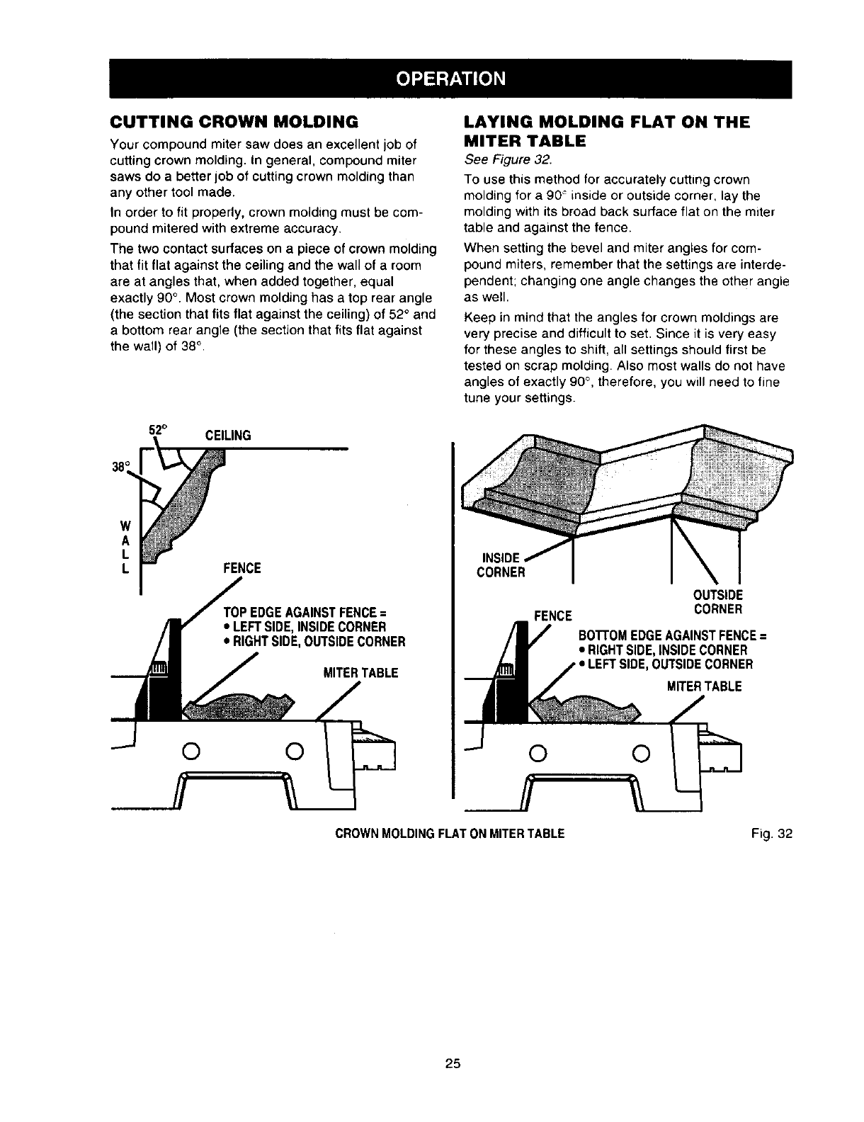
CUTTING CROWN MOLDING
Your compound miter saw does an excellent job of
cutting crown molding. In general, compound miter
saws do a better job of cutting crown molding than
any other tool made.
In order to fit properly, crown molding must be com-
pound mitered with extreme accuracy.
The two contact surfaces on a piece of crown molding
that fit flat against the ceiling and the wall of a room
are at angles that, when added together, equal
exactly 90 °. Most crown molding has a top rear angle
(the section that fits flat against the ceiling) of 52° and
a bottom rear angle (the section that fits flat against
the wall) of 38° .
52° CEILING
W
A
L
LFENCE
AGAINSTFENCE=
•LEFTSIDE,INSIDECORNER
• RIGHTSIDE,OUTSIDECORNER
MITERTABLE
LAYING MOLDING FLAT ON THE
MITER TABLE
See Figure 32.
To use this method for accurately cutting crown
molding for a 90 _inside or outside corner, lay the
molding with its broad back surface flat on the miter
table and against the fence.
When setting the bevel and miter angles for com-
pound miters, remember that the settings are interde-
pendent; changing one angle changes the other angle
as well.
Keep in mind that the angles for crown moldings are
very precise and difficult to set. Since it is very easy
for these angles to shift, all settings should first be
tested on scrap molding. Also most walls do not have
angles of exactly 90 °, therefore, you will need to fine
tune your settings.
INS_
CORNER
OUTSIDE
FENCE CORNER
BOTTOMEDGEAGAINSTFENCE=
•RIGHTSIDE,INSIDECORNER
• LEFTSIDE,OUTSIDECORNER
MITERTABLE
CROWN MOLDINGFLAT ON MITER TABLE Fig. 32
25
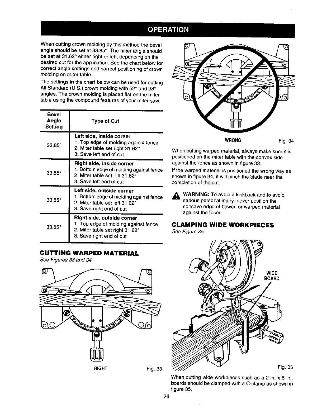
Whencuttingcrownmoldingbythismethodthebevel
angleshouldbesetat33.85°.Themiterangleshould
besetat31.62°eitherrightorleft,dependingonthe
desiredcutfortheapplication.Seethechartbelowfor
correctanglesettingsandcorrectpositioningofcrown
moldingonmitertable.
Thesettingsinthechartbelowcanbeusedforcutting
AllStandard(U.S.)crownmoldingwith52°and38°
angles.Thecrownmoldingisplacedflatonthemiter
tableusingthecompoundfeaturesofyourmitersaw.
Bevel
Angle Type of Cut
Setting
Left side, inside corner
1. Top edge of moldingagainst fence
33"85° 2. Miter table set right31,62 °
3. Save left end of cut
Right side, inside corner
1, Bottomedge of moldingagainst fence
33"85° 2. Miter table set left 31.62 °
3. Save left end of cut
Left side, outside corner
1, Bottom edge of moldingagainstfence
33"85° 2. Miter table set left 31.62 °
3. Save right end of cut
Right side, outside corner
1. Top edge of moldingagainst fence
33"85° 2. Miter table set right 31.62 °
3, Save rightend of cut
WRONG Fig. 34
When cutting warped material, always make sure it is
positioned on the miter table with the convex side
against the fence as shown in figure 33.
If the warped material is positioned the wrong way as
shown in figure 34, it will pinch the blade near the
completion of the cut.
_lh WARNING: To avoid a kickback and to avoid
serious personal injury, never position the
concave edge of bowed or warped material
against the fence.
CLAMPING WIDE WORKPIECES
See Figure 35.
CUTTING WARPED MATERIAL
See Figures 33 and 34.
WIDE
BOARD
RIGHT Fig. 33 Fig. 35
When cutting wide workpieces such as a 2 in. x 6 in.,
boards should be clamped with a C-clamp as shown in
figure 35.
26
WARNING: When servicing, use only identical
Craftsman replacement parts. Use of any other
part may create a hazard or cause product
damage.
GENERAL
Avoid using solvents when cleaning plastic parts.
Most plastics are susceptible to damage from various
types of commercial solvents and may be damaged
by their use. Use clean cloths to remove dirt, carbon
dust, etc.
_I, WARNING: Do not at any time let brake fluids,
gasoline, petroleum-based products, penetrating
oils, etc. come in contact with plastic parts. They
contain chemicals that can damage, weaken or
destroy plastic.
It has been found that electric tools are subject to
accelerated wear and possible premature failure when
they are used on fiberglass boats, sports cars,
wallboard, spackling compounds, or plaster. The
chips and grindings from these materials are highly
abrasive to electric tool parts such as bearings,
brushes, commutators, etc. Consequently, it is not
recommended that this tool be used for extended
work on any fiberglass material, wallboard, spackling
compounds, or plaster. During any use on these
materials it is extremely important that the tool is
cleaned frequently by blowing with an air jet.
LUBRICATION
All of the bearings in this tool are lubricated with a
sufficient amount of high grade lubricant for the life of
the unit under normal operating conditions. Therefore,
no further lubrication is required.
EXTENSION CORDS
The use of any extension cord will cause some loss of
power. To keep the loss to a minimum and to prevent
tool overheating, use an extension cord that is heavy
enough to carry the current the tool will draw.
A wire gage size (A.W.G.) of at least 14 is recom-
mended for an extension cord 25 feet or less in
length. When working outdoors, use an extension
cord that is suitable for outdoor use. The cord's jacket
will be marked WA.
a, CAUTION: Keep extension cords away from the
cutting area and position the cord so that it will
not get caught on lumber, tools, etc., during
cutting operation.
AWARNING: Check extension cords before each
use. If damaged, replace immediately. Never use
tool with a damaged cord since touching the
damaged area could cause electrical shock
resulting in serious injury.
a, WARNING: Always wear safety goggles or
safety glasses with side shields during power
tool operation or when blowing dust. If operation
is dusty, also wear a dust mask.
27
,_ WARNING: To ensure safety and reliability, all
repairs -- withthe exception of the externally
accessible brushes -- should be performed by a
qualified service technician at a Sears store to
avoid risk of personal injury.
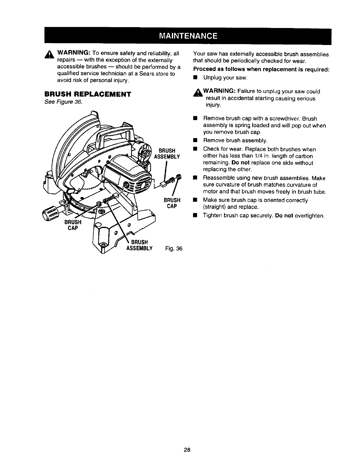
BRUSH REPLACEMENT
See Figure 36.
BRUSH
BRUSH
CAP
BRUSH
CAP
BRUSH
ASSEMBLY Fig. 36
Your saw has externally accessible brush assemblies
that should be periodically checked for wear.
Proceed as follows when replacement is required:
• Unplug your saw.
_WARNING: Failure to unplug your saw could
result in accidental starting causing serious
injury.
• Remove brush cap with a screwdriver. Brush
assembly is spring loaded and will pop out when
you remove brush cap.
• Remove brush assembly.
• Check for wear. Replace both brushes when
either has less than 1/4 in. length of carbon
remaining. Do not replace one side without
replacing the other.
• Reassemble using new brush assemblies. Make
sure curvature of brush matches curvature of
motor and that brush moves freely in brush tube.
• Make sure brush cap is oriented correctly
(straight) and replace.
• Tighten brush cap securely. Do not overtighten.
28

29
G3
O
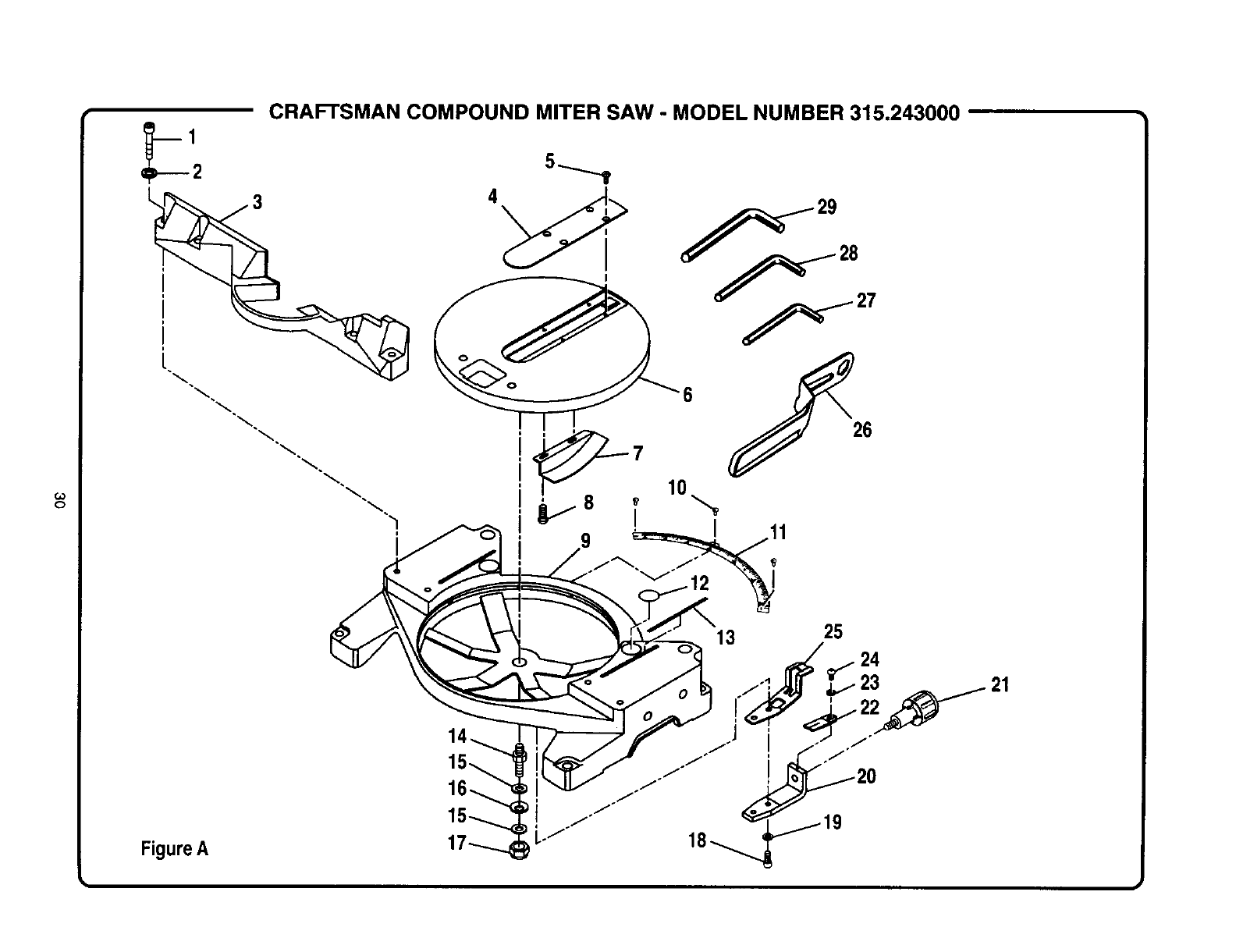
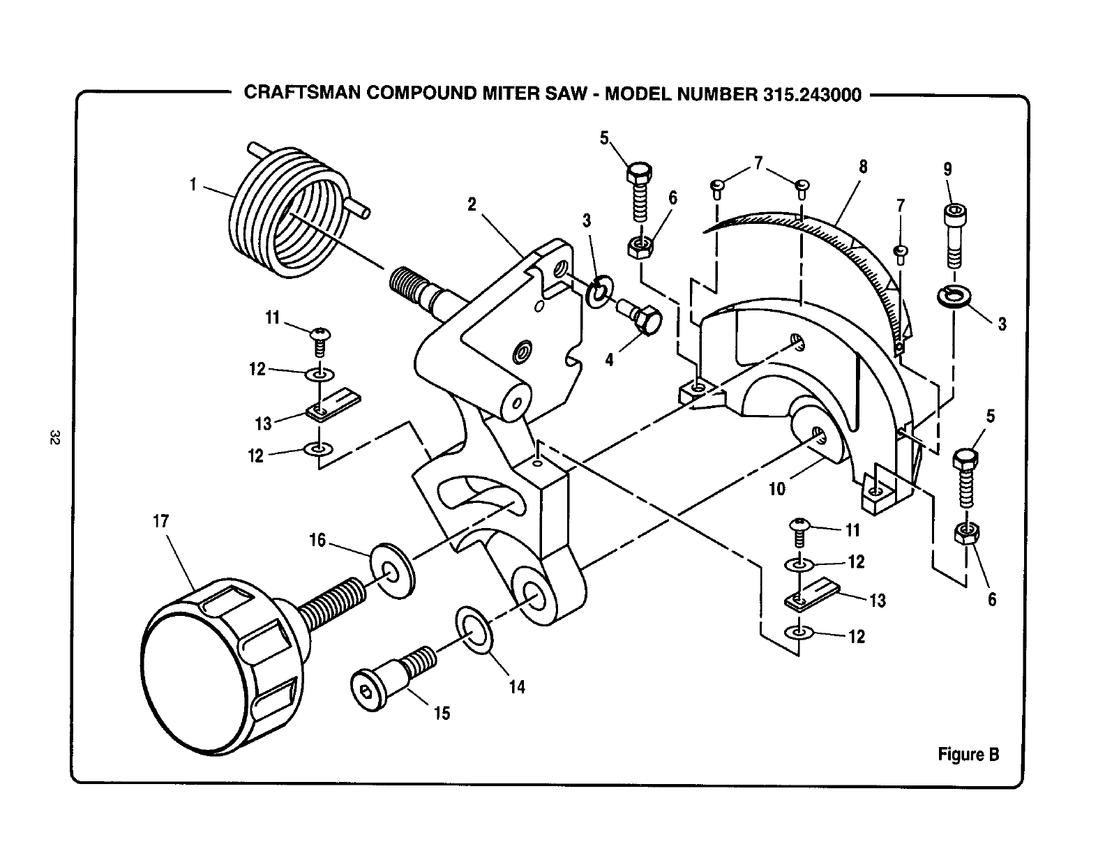
CRAFTSMAN COMPOUND MITER SAW - MODEL NUMBER 315.243000
Figure A
6
26
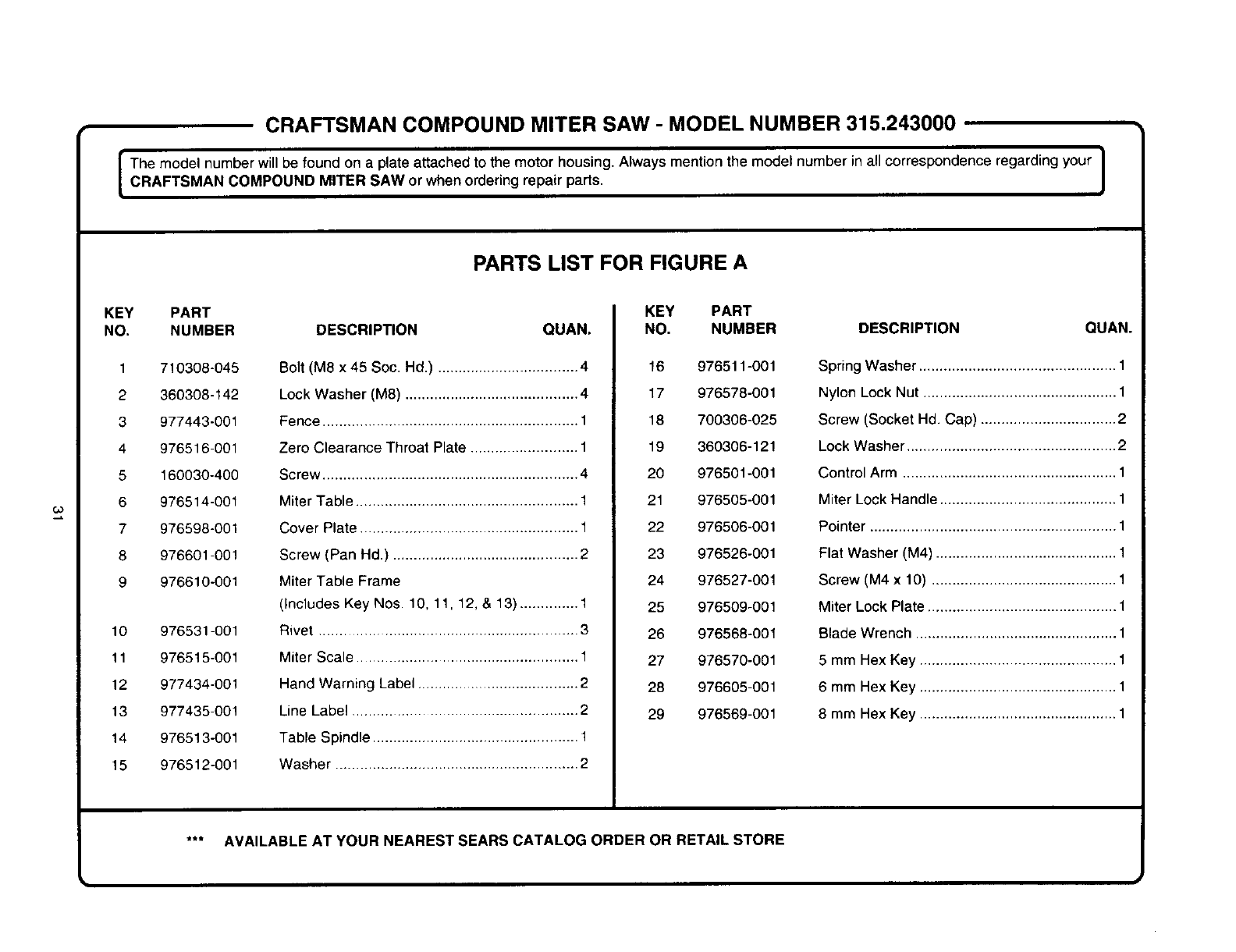
CRAFTSMAN COMPOUND MITER SAW -MODEL NUMBER 315.243000
r i
The model number will be found on a plate attached to the motor housing. Always mention the model number in all correspondence regarding your
CRAFTSMAN COMPOUND MITER SAW or when ordering repair parts.
I
KEY
NO.
1
2
3
4
5
6
7
8
9
10
11
12
13
14
15
PART
NUMBER
710308-045
360308-142
977443-001
976516-001
160030-400
976514-001
976598-001
976601-001
976610-001
976531-001
976515-001
977434-001
977435-001
976513-001
976512-001
PARTS LIST FOR FIGURE A
DESCRIPTION QUAN.
Bolt (M8 x 45 Soc. Hd.) .................................. 4
Lock Washer (M8) .......................................... 4
Fence .............................................................. 1
Zero Clearance Throat Plate .......................... 1
Screw .............................................................. 4
Miter Table ...................................................... 1
Cover Plate ..................................................... 1
Screw (Pan Hd.) ............................................. 2
Miter Table Frame
(Includes Key Nos. 10, 11, 12, & 13) .............. 1
Rivet .............................................................. 3
Miter Scale ................................................ 1
Hand Warning Label ....................................... 2
Line Label ..................................................... 2
Table Spindle ................................................. 1
Washer ........................................................... 2
KEY PART
NO. NUMBER DESCRIPTION
16 976511-001
17 976578-001
18 700306-025
19 360306-121
20 976501-001
21 976505-001
22 976506-001
23 976526-001
24 976527-001
25 976509-001
26 976568-001
27 976570-001
28 976605-001
29 976569-001
AVAILABLE AT YOUR NEAREST SEARS CATALOG ORDER OR RETAIL STORE
QUAN.
Spring Washer ................................................ 1
Nylon Lock Nut ............................................... 1
Screw (Socket Hd. Cap) ................................. 2
Lock Washer ................................................... 2
Control Arm .................................................... 1
Miter Lock Handle ........................................... 1
Pointer ............................................................ 1
Flat Washer (M4) ............................................ 1
Screw (M4 x 10) ............................................. 1
Miter Lock Plate .............................................. 1
Blade Wrench ................................................. 1
5 mm Hex Key ................................................ 1
6 mm Hex Key ................................................ 1
8 mm Hex Key ................................................ 1
II
CRAFTSMAN COMPOUND MITER SAW - MODEL NUMBER 315.243000
GO
PO
17
2\3
6
8 9
I
1_ 4 I
5
6
14
15
FigureB
i
CRAFTSMAN COMPOUND MITER SAW - MODEL NUMBER 315.243000
IThe model number will be found on aplate attached to the motor housing. Always mention the model number in all correspondence regarding your ICOMPOUND MITER SAW or when ordering repair parts. J
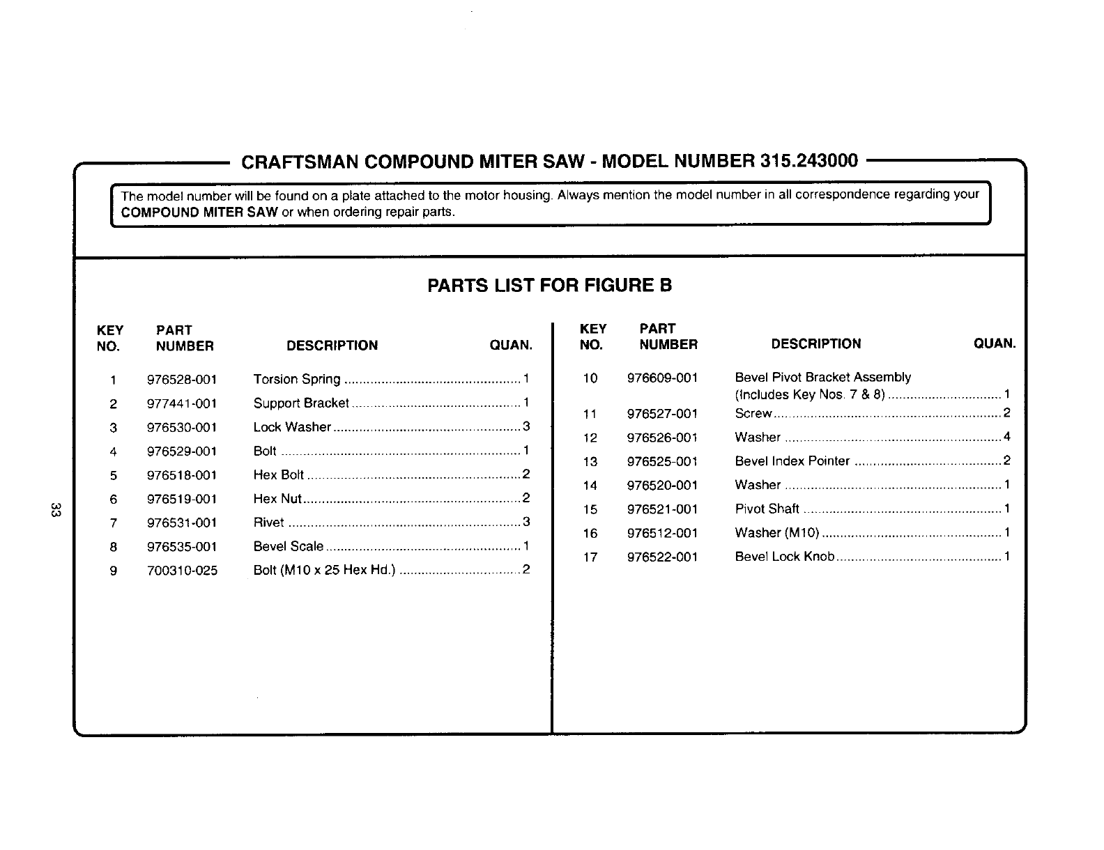
PARTS LIST FOR FIGURE B
co
(,o
KEY PART
NO. NUMBER DESCRIPTION QUAN.
1
2
3
4
5
6
7
8
9
976528-001
977441-001
976530-001
976529-001
976518-001
976519-001
976531-001
976535-001
700310-025
Torsion Spring ................................................ 1
Support Bracket .............................................. 1
Lock Washer ................................................... 3
Bolt ................................................................. 1
Hex Bolt .......................................................... 2
Hex Nut ........................................................... 2
Rivet ............................................................... 3
Bevel Scale ..................................................... 1
Bolt (M10 x 25 Hex Hd.) ................................. 2
KEY PART
NO. NUMBER DESCRIPTION
10 976609-001
11 976527-001
12 976526-001
13 976525-001
14 976520-001
15 976521-001
16 976512-001
17 976522-001
QUAN.
Bevel Pivot Bracket Assembly
(Includes Key Nos. 7 & 8) ............................... 1
Screw .............................................................. 2
Washer ........................................................... 4
Bevel Index Pointer ........................................ 2
Washer ........................................................... 1
Pivot Shaft ...................................................... 1
Washer (MIO) ................................................. 1
Bevel Lock Knob ............................................. 1
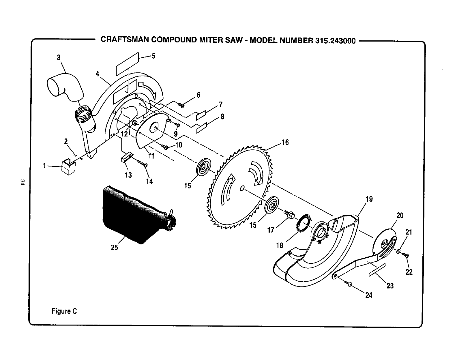
CRAFTSMAN COMPOUND MITER SAW - MODEL NUMBER 315.243000 •
3
4
2
\11
FigureC
13
25
14 15
17
18
19
20
21
22
23
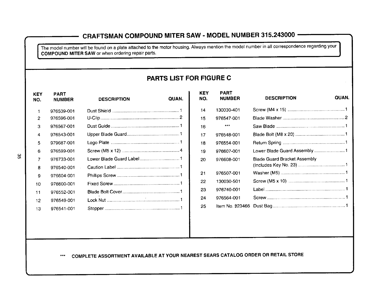
CRAFTSMAN COMPOUND MITER SAW - MODEL NUMBER 315.243000
The model number will be found on a plate attached to the motor housing. Always mention the model number in all correspondence regarding your [
COMPOUND MITER SAW or when ordering repair parts. J
co
ol
KEY PART
NO. NUMBER
1 976539-001
2 976596-001
3 976567-001
4 976543-001
5 979687-001
6 976599-001
7 976733-001
8 976540-001
9 976604-001
10 976600-001
11 976552-001
12 976549-001
13 976541-001
PARTS LIST FOR FIGURE C
DESCRIPTION QUAN.
Dust Shield ..................................................... 1
U-Clip .............................................................. 2
Dust Guide ...................................................... 1
Upper Blade Guard ......................................... 1
Logo Plate ...................................................... 1
Screw (M5 x 12) ............................................. 4
Lower Blade Guard Label ............................... 1
Caution Label ................................................. 1
Phillips Screw ................................................. 1
Fixed Screw .................................................... 1
Blade Bolt Cover ............................................. 1
Lock Nut .............................. "........................... 1
Stopper ........................................................... 1
KEY PART
NO. NUMBER DESCRIPTION
14 130030-401
15 976547-001
16 ***
17 976548-001
18 976554-001
19 976607-001
20 976608-001
21 976507-001
22 130030-501
23 976740-001
24 976564-001
25 Item No._23466
QUAN.
Screw (M4 x 15) ............................................. 1
Blade Washer ................................................. 2
Saw Blade ...................................................... 1
Blade Bolt (M8 x 20) ....................................... 1
Return Spring ................................................. 1
Lower Blade Guard Assembly ........................ 1
Blade Guard Bracket Assembry
(Includes Key No. 23) ..................................... 1
Washer (M5) ................................................... 1
Screw (M5 x 10) ............................................. 1
Label ............................................................... 1
Screw .............................................................. 1
Dust Bag ......................................................... 1
COMPLETE ASSORTMENT AVAILABLE AT YOUR NEAREST SEARS CATALOG ORDER OR RETAIL STORE
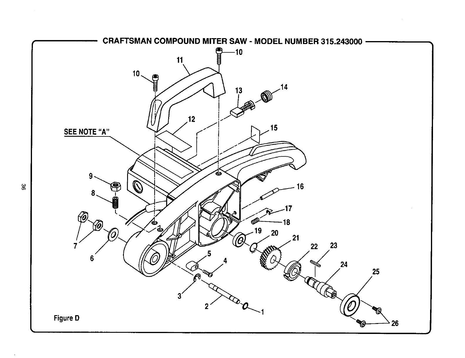
CRAFTSMAN COMPOUND MITER SAW -MODEL NUMBER 315.243000
11
13
SEE NOTE "A" I
Figure D
L
6
-18
20 21
4
22 23
24 25
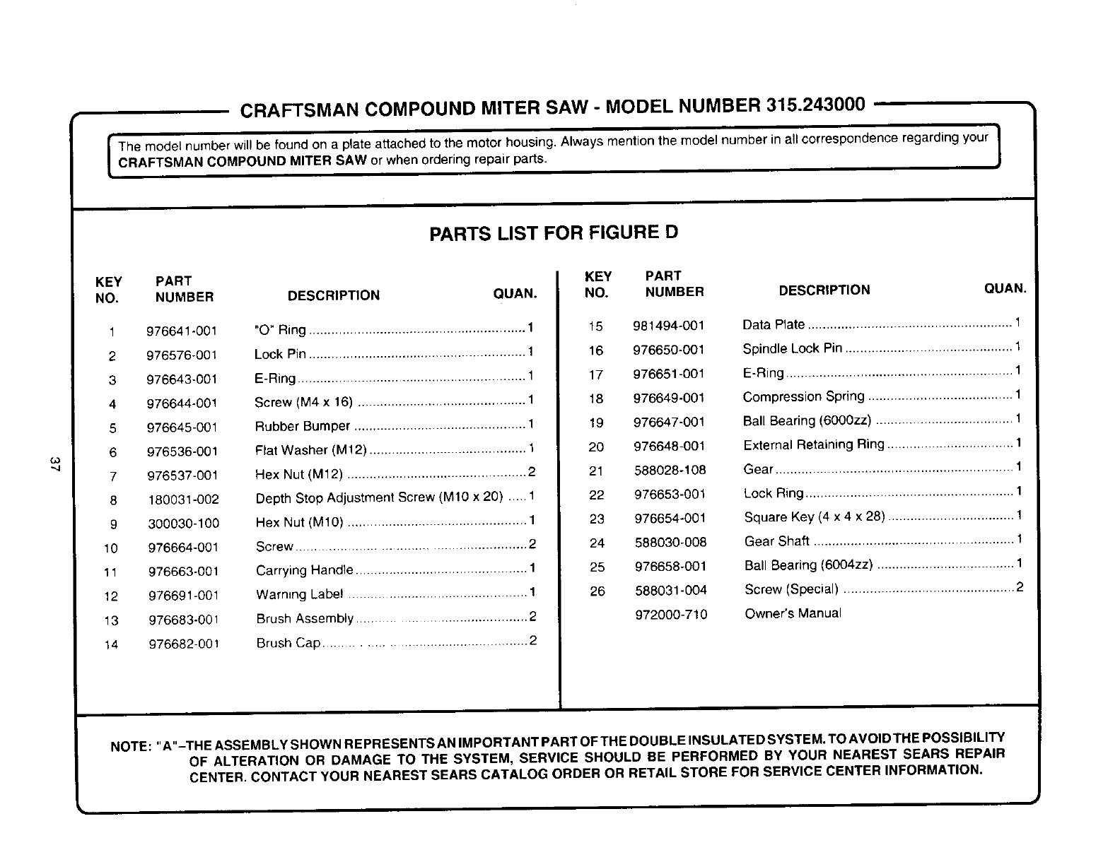
CRAFTSMAN COMPOUND MITER SAW -MODEL NUMBER 315.243000
I The model number will be found on a plate attached to the motor housing. Always mention the model number in all correspondence regarding yourCRAFTSMAN COMPOUND MITER SAW or when ordering repair parts. J
KEY PART
NO. NUMBER
1 976641-001
2 976576-001
3976643-001
4 976644-001
5 976645-001
6 976536-001
7 976537-001
8 180031-002
9 300030-100
10 976664-001
11 976663-001
12 976691-001
13 976683-001
14 976682-001
PARTS LIST FOR FIGURE D
DESCRIPTION QUAN.
"O" Ring .......................................................... 1
Lock Pin .......................................................... 1
E-Ring ............................................................. 1
Screw (M4 x 16) ............................................. 1
Rubber Bumper .............................................. t
Flat Washer (M12) .......................................... 1
Hex Nut (M12) ................................................ 2
Depth Stop Adjustment Screw (M10 x 20) ..... 1
Hex Nut (M10) ................................................ 1
Screw ........................................................ 2
Carrying Handle ............................................. 1
Warning Label .............................................. 1
Brush Assembly ......................................... 2
Brush Cap ............................................. 2
KEY PART
NO. NUMBER DESCRIPTION
15 981494-001
16 976650-001
17 976651-001
18 976649-001
19 976647-001
20 976648-001
21 588028-108
22 976853-001
23 976654-001
24 588030-008
25 976658-001
26 588031-004
972000-710
QUAN.
Data Plate ....................................................... 1
Spindle Lock Pin ............................................. 1
E-Ring ............................................................. 1
Compression Spring ....................................... 1
Ball Bearing (6000zz) ..................................... I
External Retaining Ring .................................. 1
Gear ................................................................ 1
Lock Ring ........................................................ 1
Square Key (4 x 4 x 28) .................................. 1
Gear Shaft ...................................................... t
Ball Bearing (6004zz) ..................................... 1
Screw (Special) .............................................. 2
Owner's Manual
NOTE: "A"-THE ASSEMBLY SHOWN REPRESENTS AN IMPORTANT PART OF THE DOUBLE INSULATED SYSTEM. TO AVOID THE POSSIBILITY
OF ALTERATION OR DAMAGE TO THE SYSTEM, SERVICE SHOULD BE PERFORMED BY YOUR NEAREST SEARS REPAIR
CENTER. CONTACT YOUR NEAREST SEARS CATALOG ORDER OR RETAIL STORE FOR SERVICE CENTER INFORMATION.

For in-home major brand repair service:
Call 24 hours a day, 7 days a week
1-800-4-MY-Horne s,, (1-800-469-4663)
Para pedir servicio de reparaci6n a domicilio - 1-800-676-5811
In Canada for all your service and parts needs call -1-800-665-4455
Au Canada pour tout le service ou les pieces
For the repair or replacement parts you need:
Call 7 am - 7pm, 7days a week
1-800-366-PART (1-800-366-7278)
Para ordenar piezas con entrega a domicilio - 1o800-659-7084
For the location of a Sears Parts and Repair Center in your area:
Call 24 hours a day, 7 days a week
1-800-488-1222
For information on purchasing a Sears Maintenance Agreement
or to inquire about an existing Agreement:
Call 9 am - 5 pm, Monday - Saturday
1-800-827-6655
The Service Side of Sears sM
