Craftsman 316711022 User Manual TRIMMER Manuals And Guides 1501124L
User Manual: Craftsman 316711022 316711022 CRAFTSMAN TRIMMER - Manuals and Guides View the owners manual for your CRAFTSMAN TRIMMER #316711022. Home:Lawn & Garden Parts:Craftsman Parts:316711022 Craftsman Grass trimmer (weed wacker) Manual
Open the PDF directly: View PDF ![]() .
.
Page Count: 40

Operator's Manual
2-Cycle
WEEDWACKER® GAS TRIMMER
Model No. 316.711022
CAUTION: Before using this product,
read this manual and follow all its Safety
Rules and Operating instructions.
o SAFETY
o ASSEMBLY
o OPERATION
o MAINTENANCE
o ESPANOL, R 19
Sears Brands Management Corporation, Hoffman Estates, IL 60179 U.S.A.
Visit our website: www.craftsman.corn
769-10218 /00 09/14
TABLEOFCONTENTS
Safety............................................... 2
Warranty............................................. 5
KnowYourUnit........................................ 6
Specifications......................................... 6
Assembly............................................. 7
OilandFuel........................................... 9
StartingandStopping.................................. 10
Operation............................................ 11
Maintenance......................................... 13
CleaningandStorage.................................. 16
Troubleshooting....................................... 17
RepairProtectionAgreements........................... 18
ServiceNumbers.............................. BackCover
Allinformation,illustrationsandspecificationsinthismanualarebased
onthelatestproductinformationavailableatthetimeofprinting.We
reservetherighttomakechangesatanytimewithoutnotice.
©SeamBrands,LLC
Thepurposeofsafetysymbolsistoattractyourattentionto
possibledangers.Thesafetysymbols,andtheirexplanations,
deserveyourcarefulattentionandunderstanding.Thesafety
warningsdonotbythemselveseliminateanydanger.The
instructionsorwarningstheygivearenotsubstitutesforproper
accidentpreventionmeasures.
i SYMBOL MEANING •
DANGER. Signals an EXTREME hazard.
Failure to obey a safety DANGER signal WILL result in
serious injury or death to yourself or to others.
WAR NING: Signals a SERIOUS hazard.
Failure to obey a safety WARNING signal CAN result in
serious injury to yourself or to others.
.
CAUTION. Signals a MODERATE hazard.
Failure to obey a safety CAUTION signal MAY result in
property damage or injury to yourself or to others.
NOTE: Advises you of information or instructions vital to the
operation or maintenance of the equipment.
SPARK ARRESTOR NOTE
NOTE: For users on U.S. Forest Land and in the states of
California, Maine, Oregon and Washington. All U.S. Forest Land
and the state of California (Public Resources Codes 4442 and
4443), Oregon and Washington require, by law that certain internal
combustion engines operated on forest brush and/or grass-covered
areas be equipped with a spark arrestor, maintained in effective
working order, or the engine be constructed, equipped and
maintained for the prevention of fire. Check with your state or local
authorities for regulations pertaining to these requirements. Failure
to follow these requirements could subject you to liability or a fine.
This unit is factory equipped with a spark arrestor, if it requires
replacement, contact a Sears Parts & Repair Service Center to
install the appropriate muffler assembly.
_ CALIFORNIA PROPOSiTiON 65
WARNING: This product contains a chemical
known to the state of California to cause cancer, birth defects
or other reproductive harm.
Read the operator's manual and follow all warnings and safety
instructions. Failure to do so can result in serious injury to the
operator and/or bystanders.
•iMPORTANT SAFETY iNSTRUCTiONS •
READ ALL iNSTRUCTiONS BEFORE OPERATING
m
WARNING. When using the unit, all safety
rules must be followed. Please read these instructions
before operating the unit in order to ensure the safety of
the operator and any bystanders. Please keep these
instructions for later use.
• Read the instructions carefully. Be familiar with the controls and
proper use of the unit.
Do not operate this unit when tired, ill or under the influence of
alcohol, drugs or medication.
Children must not operate the unit. Teens must be accompanied
and guided by an adult.
All guards and safety attachments must be installed properly
before operating the unit.
Inspect the unit before use. Replace damaged parts. Check for
fuel leaks. Make sure all fasteners are in place and secure.
Replace parts that are cracked, chipped, or damaged in any
way. Do not operate the unit with loose or damaged parts.
Only use the trimming line described in the Specifications section
of this manual. Never use metal-reinforced line, wire, chain or
rope. These can break off and become dangerous projectiles.
Do not replace the cutting head with rigid or metal blades. Doing
so could result in serious injury.
Be aware of risk of injury to the head, hands and feet.
Carefully inspect the area before starting the unit. Remove
rocks, broken glass, nails, wire, string and other objects that
may be thrown or become entangled with the unit.
Clear the area of children, bystanders and pets; keep them
outside a 50-foot (15 m) radius, at a minimum. Even then, they are
still at risk from thrown objects. Encourage bystanders to wear
eye protection. If you are approached, stop the unit immediately.
Squeeze the throttle control and check that it returns
automatically to the idle position. Make all adjustments or
repairs before using the unit.
This unit is intended for occasional, household use only.
SAFETY WARNINGS FOR GAS UNITS
WARNING: Gasoline is highly flammable and
its vapors can explode if ignited. Take the following
precautions:
Store fuel only in containers specifically designed and approved
for the storage of such materials.
Always stop the engine and allow it to cool before filling the
tank. Never remove the fuel tank cap or add fuel when the
engine is hot. Always loosen the fuel tank cap slowly to relieve
any pressure in the tank before fueling.
Always mix and add fuel in a clean, well-ventilated outdoor area
where there are no sparks or flames. DO NOT smoke.
Never operate the unit without the fuel cap securely in place.
Avoid creating a source of ignition for spilled fuel. Wipe up any
spilled fuel from the unit immediately, before starting the unit.
Move the unit at least 30 ft. (9.1 m) from the fueling source and
site before starting the engine. DO NOT smoke.
Never start or run the unit inside a closed room or building.
Breathing exhaust fumes can kill. Operate this unit only in a well
ventilated outdoor area.
3
WHILE OPERATING
Wear safety glasses or goggles that meet current ANSi /ISEA
Z87.1 standards and are marked as such. Wear ear/hearing
protection when operating this unit. Wear a face mask or dust
mask if the operation is dusty.
Wear heavy long pants, boots, gloves and a long sleeve shirt. Do
not wear loose clothing, jewelry, short pants, sandals or go
barefoot. Secure hair above shoulder level.
The cutting head shield must always be in place while operating
the unit. Do not operate the unit without both trimming lines
extended and the proper line installed. Do not extend the
trimming line beyond the length of the shield.
The cutting head should remain stationary when the engine
idles. If it does not, refer to Adjusting the Idle Speed.
Adjust the handle to provide the best grip, if applicable.
Make sure the attachment is not in contact with anything before
starting the unit.
Use the unit only in daylight or good artificial light.
Avoid accidental starting. Be in the starting position whenever
pulling the starter rope. The operator and unit must be in a stable
position while starting. Refer to Starting and Stopping.
Use the right tool. Only use this tool for its intended purpose.
Always hold the unit with both hands when operating. Keep a
firm grip on both handles or grips.
Do not overreach. Always keep proper footing and balance. Take
extra care when working on stairs, steep slopes or inclines. To
avoid serious injury, do not operate the unit while on a ladder or
a roof.
Keep hands, face, and feet away from all moving parts. Do not
touch or try to stop moving parts.
Do not touch the engine, gear housing or muffler. These parts get
extremely hot from operation, even after the unit is turned off.
Do not operate the unit faster than the speed needed to do the job.
Do not run the unit at high speed when not in use.
Do not force the unit. It will do a better, safer job when used at
the intended rate.
Always stop the unit when operation is delayed or when walking
from one location to another.
Before setting the unit down, always make sure the engine is off
and all moving parts have stopped.
If you strike or become entangled with a foreign object, stop the
unit immediately and check for damage. Do not operate the unit
before repairing damage. Do not operate the unit with loose or
damaged parts.
Turn the engine to off and disconnect the spark plug for
maintenance or repair.
Use only original equipment manufacturer (OEM) replacement
parts and accessories for this unit. Use of any other parts or
accessories could lead to serious injury to the user, or damage
to the unit, and void the warranty.
Keep the unit clean. Carefully remove vegetation and other
debris that could block moving parts.
To reduce fire hazard, replace a faulty muffler and spark arrestor.
Keep the engine and muffler free from grass, leaves, excessive
grease or carbon build up.
If the unit starts to vibrate abnormally, stop the unit immediately.
Inspect the unit for the cause of the vibration. Vibration is
generally an indicator of trouble.
OTHER SAFETY WARNINGS
,i, Maintain the unit with care.
All service, other than the maintenance procedures described in
this manual, should be performed by a Sears or other qualified
service dealer.
Never remove, modify or make inoperative any safety device
furnished with the unit.
Before inspecting, servicing, cleaning, storing, transporting or
replacing any parts on the unit:
1. Stop the unit.
2. Make sure all moving parts have stopped.
3. Allow the unit to cool.
4. Disconnect the spark plug wire.
Secure the unit while transporting.
Never store the unit with fuel in the tank, inside a building where
fumes may reach an open flame (pilot lights, etc.) or sparks
(switches, electrical motors, etc.).
Store the unit in a dry place, secured or at a height to prevent
unauthorized use or damage. Keep the unit out of the reach of
children.
Never douse or squirt the unit with water or any other liquid.
Keep handles dry and clean (free from debris, oil and grease).
Clean the unit after each use. Refer to Cleaning and Storage. Do
not use solvents or strong detergents.
Keep these instructions. Refer to them often and use them to
instruct other users. If you loan this unit to others, also loan
them these instructions.
SAVE THESE INSTRUCTIONS
,, SAFETY & iNTERNATiONAL SYMBOLS,
This operator's manual describes safety and international symbols and pictographs that may appear on this product. Read the operator's
manual for complete safety, assembly, operating and maintenance and repair information.
SYMBOL MEANING
, SAFETY ALERT SYMBOL
_ !ndicates danger I Waining or cauti0n: MaY be used in
i ;ira . conjunction with other symbols or pictographs.
O o READ OPERATOR'S MANUAL
WARNING: Readtheoperator's
manual(s) and follow a!! warnings and safety
instructionsl Failure to do so Can reSult in Serious
. injuryto the operator and/or bystanders.
4tii " WEAR EYE AND HEAR'NG PROTECT'ON
oWsiseAccanRcaN!Ngi :!:OuW_ _;:iteS :rid
! n;i ev i Y n] Y cl aing :
Wear eye protection meeting Cur[ent ANSI/ISEA
Z871! standa[ds and ear protection when operating
this unit. Use afull face shield when needed.
%, UNL EDFUEL
AlwaYs use Clean, fresh unleaded fue!:
_,_,# .
.OiL
_L.5/J . Refer to operator S manual for the proper type of Oil.
•DO NOT USE E85 FUELIN THIS UNIT
WARNIN G::"! has been ploven tha;
c_Onmtaaignieng,g[:ate rnethanndlOof_ _thhtnwOlrWilnlt'_.ke!y
SYMBOL MEANING
...... _ 'ON/OFF STOP CONTROL
| oN/START/ RUN
O'ON/OFFSTOP CONTROL
OFF or STOP
' PRIMER BULB
Push primer bulb, fully and slowly, 10 times.
" _ " CHOKE CONTROL
1. " FULL choke position
I 2. • PARTIAL choke position
3. • RUN choke position
,__, , THROWN OBJECTS AND ROTATING CUTTER CAN
_Q
//_ CAUSE SEVERE iNJURY
WARNING: Smaobjectscanbe
propelled at high speed, causing injury. Keep away
.from the rotating rotor.
A, KEEP BYSTANDERS AWAY
WARNING: Keepabystanders
especia ly children and pets, at least 50 feet (15 m)
. from the operating area.
' HOT SURFACE m
WARNING. DOnot touch a hot muffler
0or cylinder. You may get burned. These parts get
extremely hot from operation. When turned off they
remain hot for a short time.
._' SHARP BLADE Sharpb,adeontrimmer
attachment shield. To prevent serious injury,do not
• touch the line cutting blade.

CRAFTSMANLiMiTED WARRANTY
FOR TWO YEARS from the date of sale, this product is warranted against defects in material or workmanship.
WITH PROOF OF SALE, a defective product will receive free repair or replacement at option of seller.
ADDITIONAL LIMITED WARRANTY ON TRIMMER SHAFTS
FOR THE THIRD THROUGH TENTH YEAR from the date of sale, the outer metal housing of the upper and lower trimmer shafts is warranted
against defects in material or workmanship.
WiTH PROOF OF SALE, a new housing will be supplied free of charge. You are responsible for the labor cost of installation. This additional
coverage does not apply to inner trimmer shaft components.
For warranty coverage details to obtain free repair or replacement, visit the web page: www.craftsman.com/warranty
This warranty covers ONLY defects in material and workmanship. Warranty coverage does NOT include:
. Expendable items that can wear out from normal use within the warranty period, such as cutting line, spark plugs, or filters.
• Product damage resulting from user attempts at product modification or repair or caused by product accessories.
• Repairs necessary because of accident or failure to operate or maintain the product according to all supplied instructions.
• Preventive maintenance, or repairs necessary due to improper fuel mixture, contaminated or stale fuel.
This warranty is void if this product is ever used while providing commercial services or if rented to another person.
This warranty gives you specific legal rights, and you may also have other rights which vary from state to state.
Sears Brands Management Corporation, Hoffman Estates, IL 60179
To order parts or schedule service for this product, call 1-888-331-4569.
5
APPLiCATiONS
Asatrimmer:
• Cuttinggrassandlightweeds.
Edging
Decorativetrimmingaroundtrees,fences,etc.
Otheroptionalaccessoriesmaybeusedwiththisunit.
Muffler
Starter
Ro
Shaft Grip
Spark Plug
Choke Lever
ASSEMBLY TOOLS REQUIRED: On/Off Switch Filter
• 3/8" Socket Cover
Handle
Shaft Housing
Throttle
Control
Fuel Cap
Cutting Head
Coupler
Cutting Head
Shield
Line Cutting Blade
Primer Bulb
#
Engine Type ........................................................................................ Air-Cooled, 2-Cycle
Displacement ....................................................................................... 25 cc (1.52 cu. in.)
Spark Plug Gap .................................................................................... 0.025 in. (0.635 mm)
Spark Plug .......................................................................... Champion® RDJ7J or equivalent plug
Lubrication ........................................................................................... Fuel/Oil Mixture
Fuel/Oil Ratio .................................................................................................. 40:1
Fuel Tank Capacity ...................................................................................... 10 oz. (296 ml)
Approximate Unit Weight (No fuel) .................................................................... 10 - 11 Ibs. (4.5 - 5 kg)
Trimmer Mechanism ................................................................................. Hassle FreeTM Head
Trimming Line ................................................ 0.110 in. (2.79 mm) Medium Hassle FreeTM XTRA QUIET Spiral Line
Cutting Path Diameter .................................................................................. 14 in. (35.56 cm)
* All specifications are based on the latest product information available at the time of printing. We reserve the right to make changes at any
time without notice.
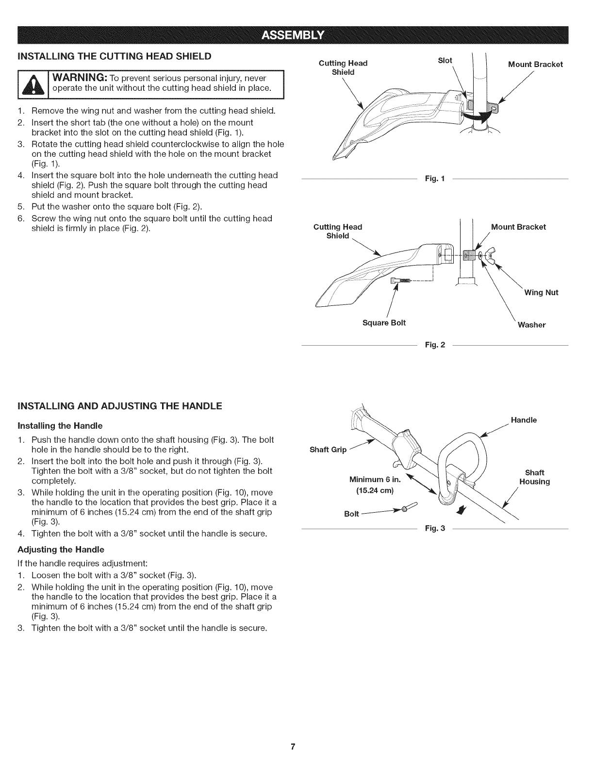
iNSTALLiNG THE CUTTING HEAD SHIELD
_ WARNING: To prevent serious personal injury, never ]
operate the unit without the cutting head shield in place.
Cutting Head Slot Mount Bracket
Shield
1. Remove the wing nut and washer from the cutting head shield.
2. Insert the short tab (the one without a hole) on the mount
bracket into the slot on the cutting head shield (Fig. 1).
3. Rotate the cutting head shield counterclockwise to align the hole
on the cutting head shield with the hole on the mount bracket
(Fig. 1).
4. Insert the square bolt into the hole underneath the cutting head
shield (Fig. 2). Push the square bolt through the cutting head
shield and mount bracket.
5. Put the washer onto the square bolt (Fig. 2).
6. Screw the wing nut onto the square bolt until the cutting head
shield is firmly in place (Fig. 2). Cutting Head
Shield
Fig. 1
Mount Bracket
Square Bolt
Wing Nut
Washer
Fig. 2
iNSTALLiNG AND ADJUSTING THE HANDLE
installing the Handle
1. Push the handle down onto the shaft housing (Fig. 3). The bolt
hole in the handle should be to the right.
2. Insert the bolt into the bolt hole and push it through (Fig. 3).
Tighten the bolt with a 3/8" socket, but do not tighten the bolt
completely.
3. While holding the unit in the operating position (Fig. 10), move
the handle to the location that provides the best grip. Place it a
minimum of 6 inches (15.24 cm) from the end of the shaft grip
(Fig. 3).
4. Tighten the bolt with a 3/8" socket until the handle is secure.
Adjusting the Handle
If the handle requires adjustment:
1. Loosen the bolt with a 3/8" socket (Fig. 3).
2. While holding the unit in the operating position (Fig. 10), move
the handle to the location that provides the best grip. Place it a
minimum of 6 inches (15.24 cm) from the end of the shaft grip
(Fig. 3).
3. Tighten the bolt with a 3/8" socket until the handle is secure.
Shaft Grip
Minimum 6 in.
(15.24 cm)
Bolt
Fig. 3
Handle
Shaft
Housing
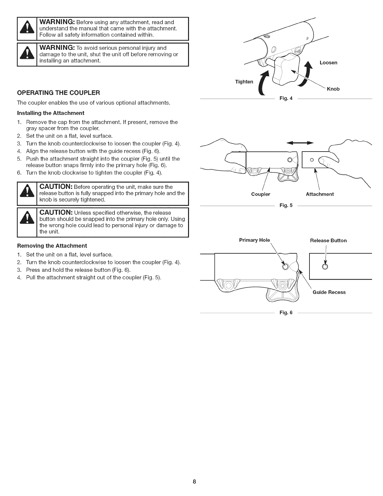
WARNING: Before using any attachment, read and i
understand the manual that came with the attachment. IFollow all safety information contained within.
WARNING: To avoid serious personal injury and i
damage to the unit, shut the unit off before removing or I
installing an attachment.
OPERATING THE COUPLER
The coupler enables the use of various optional attachments.
Installing the Attachment
1. Remove the cap from the attachment. If present, remove the
gray spacer from the coupler.
2. Set the unit on a flat, level surface.
3. Turn the knob counterclockwise to loosen the coupler (Fig. 4).
4. Align the release button with the guide recess (Fig. 6).
5. Push the attachment straight into the coupler (Fig. 5) until the
release button snaps firmly into the primary hole (Fig. 6).
6. Turn the knob clockwise to tighten the coupler (Fig. 4).
CAUTION: Before operating the unit, make sure the
release button is fully snapped into the primary hole and the
knob is securely tightened.
CAUTION: Unless specified otherwise, the release
button should be snapped into the primary hole only. Using
the wrong hole could lead to personal injury or damage to
the unit.
Removing the Attachment
1. Set the unit on a flat, level surface.
2. Turn the knob counterclockwise to loosen the coupler (Fig. 4).
3. Press and hold the release button (Fig. 6).
4. Pull the attachment straight out of the coupler (Fig. 5).
Tighten
Coupler
Primary Hole
Fig. 4
Fig. 5
Loosen
Knob
Attachment
Release Button
Guide Recess
Fig. 6
OiL AND FUEL MiXiNG iNSTRUCTiONS FUELING THE UNiT
The use of old and/or improperly mixed fuel is the most common cause
of performance problems. Use only fresh, clean unleaded gasoline.
Follow the instructions carefully for the proper gasoline/oil mixture.
Definition of Blended Fuels
Today's fuels are often a blend of gasoline and oxygenates such as
ethanol, methanol or MTBE (ether). Alcohol-blended fuel absorbs
water. As little as 1% water in the fuel can make fuel and oil
separate, forming acids when stored. ALWAYS use fresh fuel (less
than 30 days old).
NOTE: Dispose of old fuel according to federal, state and local
regulations.
Using Blended Fuels
If using a blended fuel:
• Always use the fresh fuel mix explained in your operator's manual
Use the fuel additive STA-BIL® or an equivalent
Always agitate the fuel mix before fueling the unit
Drain the tank and run the engine dry before storing the unit
_WARNING: DO NOT USE E85 FUEL iN THiS UNIT. it |
g
has been proven that fuel containing greater than 10% ]
ethanol will likely damage this engine and void the warranty.
Using Fuel Additives
The bottle of 2-cycle oil provided with this unit contains a fuel
additive to help inhibit corrosion and minimize gum deposits.
Always use the brand of 2-cycle oil that came with this unit. If this is
unavailable, use a 2-cycle oil designed for air-cooled engines and
mix it with a fuel additive, such as STA-BIL Fuel Stabilizer or an
equivalent. Add 0.8 oz. (23 ml) of fuel additive per gallon of fuel,
according to the instructions on the container. NEVER add fuel
additives directly to the unit's fuel tank.
WARNING: Gasoline is extremely flammable, ignited
vapors may explode. Always stop the engine and allow it
to cool before filling the fuel tank. Do not smoke while
filling the tank. Keep sparks and open flames at a distance
from the area.
WARNING: Remove the fuel cap slowly to avoid injury
from fuel spray. Never operate the unit without the fuel cap
securely in place.
WARNING: Add fuel in a clean, well ventilated outdoor
area. Wipe up any spilled fuel immediately. Avoid creating
a source of ignition for spilled fuel. Do not start the engine
until fuel vapors dissipate.
1. Position the unit with the fuel cap facing up.
2. Remove the fuel cap.
3. Place the fuel container spout into the fill hole on the fuel tank
and fill the tank.
NOTE: Do not overfill the tank.
4. Wipe up any fuel that may have spilled.
5. Reinstall the fuel cap.
6. Move the unit at least 30 ft. (9.1 m) from the fuel container and
the fueling site before starting the engine.
Mixing the Fuel
NOTE: This unit comes with a 3.2 oz. (95 ml) bottle of 2-cycle oil. To
obtain the correct fuel mixture described below, pour the entire
bottle into one gallon of unleaded gasoline.
CAUTION: For proper engine operation and maximum
reliability, pay strict attention to the gasoline and oil mixing
instructions on the 2-cycle oil bottle. Using improperly
mixed fuel can severely damage the engine.
Thoroughly mix the proper ratio of unleaded gasoline with 2-cycle
engine oil. Do not mix them directly in the unit's fuel tank. Use a
separate fuel can. Use a 40:1 gasoline/oil ratio. See the table below
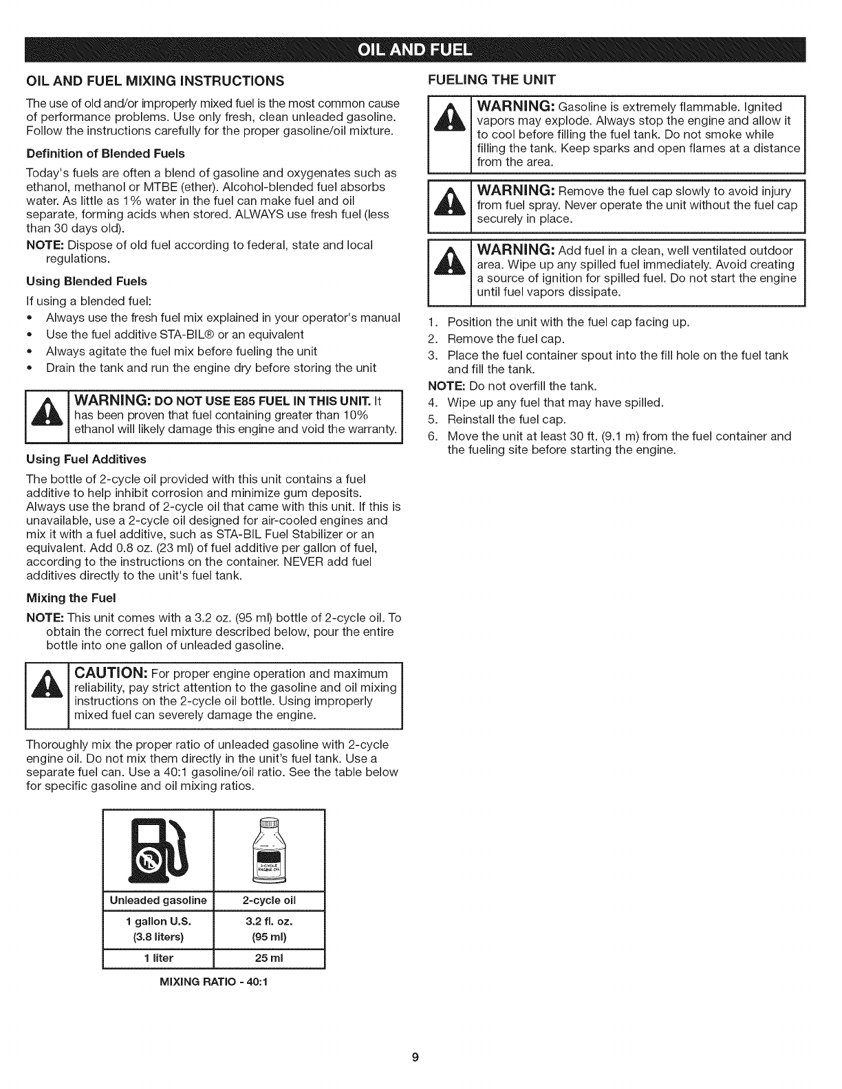
for specific gasoline and oil mixing ratios.
Unleaded gasoline
1 gallon U.S.
(3.8 liters}
1liter
2=cycle oil
3.2 fL oz.
(95 ml}
25 ml
MIXING RATIO =40:1
9
I_ I WARNING: Operate this unit only in a well-ventilated
!outdoor area. Carbon monoxide exhaust fumes can be
lethal in a confined area.
[_J WARNING: Avoid accidentally starting the unit. To avoid
serious injury, the operator and the unit must be in a stable 1
position when pulling the starter rope (Fig. 9).
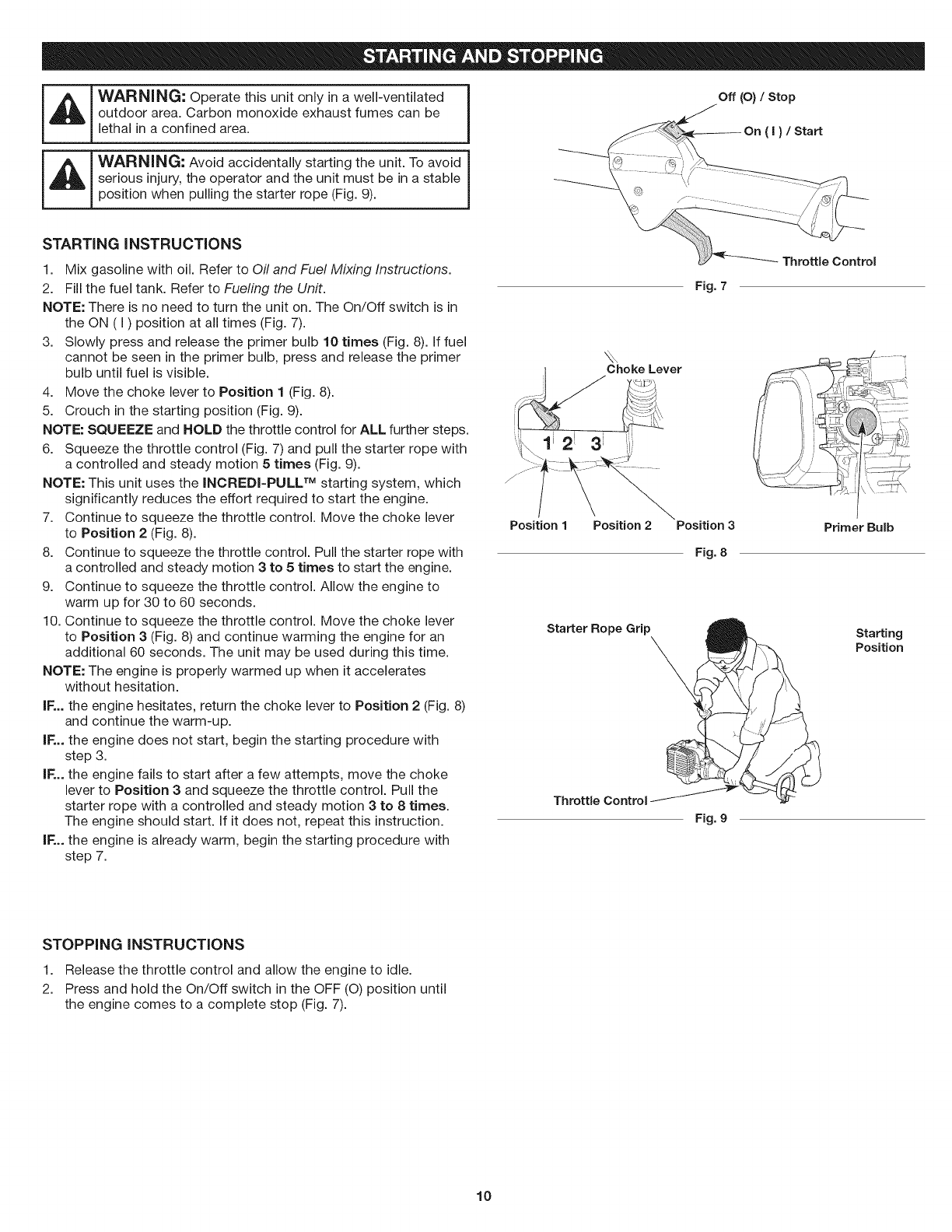
Off (O) /Stop
STARTING iNSTRUCTiONS
1. Mix gasoline with oil. Refer to Oil and Fuel Mixing Instructions.
2. Fill the fuel tank. Refer to Fueling the Unit.
NOTE: There is no need to turn the unit on. The On/Off switch is in
the ON (I) position at all times (Fig. 7).
3. Slowly press and release the primer bulb 10 times (Fig. 8). If fuel
cannot be seen in the primer bulb, press and release the primer
bulb until fuel is visible.
4. Move the choke lever to Position 1 (Fig. 8).
5. Crouch in the starting position (Fig. 9).
NOTE: SQUEEZE and HOLD the throttle control for ALL further steps.
6. Squeeze the throttle control (Fig. 7) and pull the starter rope with
a controlled and steady motion 5 times (Fig. 9).
NOTE: This unit uses the INCREDI-PULL TM starting system, which
significantly reduces the effort required to start the engine.
7. Continue to squeeze the throttle control. Move the choke lever
to Position 2 (Fig. 8).
8. Continue to squeeze the throttle control. Pull the starter rope with
a controlled and steady motion 3 to 5 times to start the engine.
9. Continue to squeeze the throttle control. Allow the engine to
warm up for 30 to 60 seconds.
10. Continue to squeeze the throttle control. Move the choke lever
to Position 3 (Fig. 8) and continue warming the engine for an
additional 60 seconds. The unit may be used during this time.
NOTE: The engine is properly warmed up when it accelerates
without hesitation.
IF... the engine hesitates, return the choke lever to Position 2 (Fig. 8)
and continue the warm-up.
IF... the engine does not start, begin the starting procedure with
step 3.
IF... the engine fails to start after a few attempts, move the choke
lever to Position 3 and squeeze the throttle control. Pull the
starter rope with a controlled and steady motion 3 to 8 times.
The engine should start. If it does not, repeat this instruction.
IF... the engine is already warm, begin the starting procedure with
step 7.
Choke Lever
Position 1Position 2
Starter Rope Grip
Throttle Control
Fig. 7
Position 3
Fig. 8
Fig. 9
/
Primer Bulb
Starting
Position
STOPPING iNSTRUCTiONS
1. Release the throttle control and allow the engine to idle.
2. Press and hold the On/Off switch in the OFF (O) position until
the engine comes to a complete stop (Fig. 7).
10
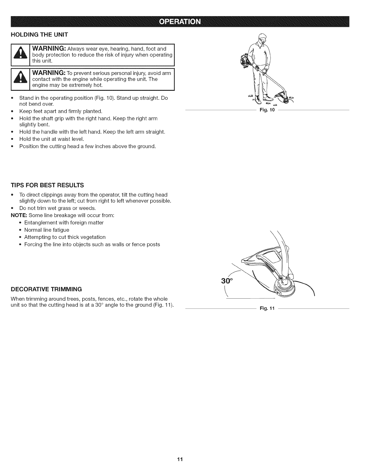
HOLDING THE UNiT
WARNING: Always wear eye, hearing, hand, foot and
thisbodyunit.protection to reduce the risk of injury when operating
WARNING: To prevent serious personal injury, avoid arm I
contact with the engine while operating the unit. The !
engine may be extremely hot.
• Stand in the operating position (Fig. 10). Stand up straight. Do
not bend over.
Keep feet apart and firmly planted.
Hold the shaft grip with the right hand. Keep the right arm
slightly bent.
Hold the handle with the left hand. Keep the left arm straight.
Hold the unit at waist level.
Position the cutting head a few inches above the ground.
o
o
o
o
o
4,
Fig. lo
TiPS FOR BEST RESULTS
= To direct clippings away from the operator, tilt the cutting head
slightly down to the left; cut from right to left whenever possible.
Do not trim wet grass or weeds.
NOTE: Some line breakage will occur from:
Entanglement with foreign matter
Normal line fatigue
Attempting to cut thick vegetation
Forcing the line into objects such as walls or fence posts
\
DECORATIVE TRiMMiNG
When trimming around trees, posts, fences, etc., rotate the whole
unit so that the cutting head is at a 30 ° angle to the ground (Fig. 11).
30 °
Fig. 11
11
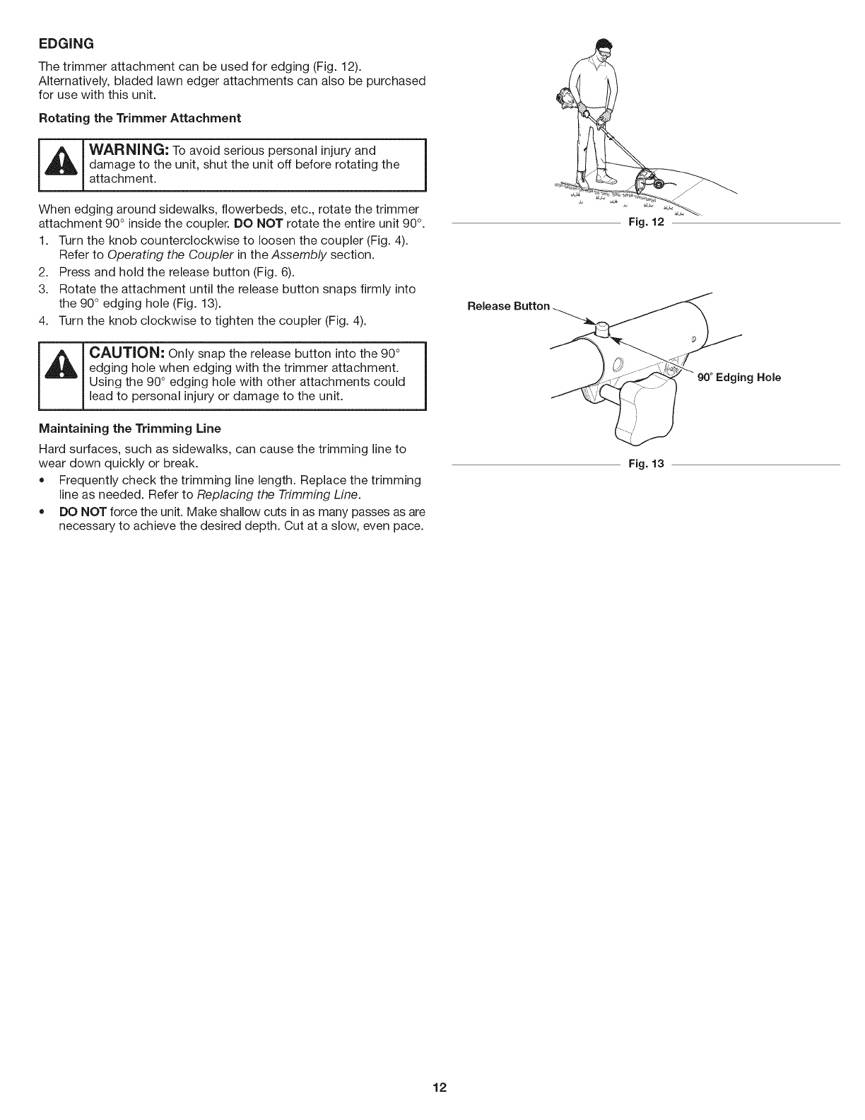
EDGING
The trimmer attachment can be used for edging (Fig. 12).
Alternatively, bladed lawn edger attachments can also be purchased
for use with this unit.
Rotating the Trimmer Attachment
_ WARNING: To avoid serious personal injury and I
I
damage to the unit, shut the unit off before rotating the 1
attachment.
When edging around sidewalks, flowerbeds, etc., rotate the trimmer
attachment 90° inside the coupler. DO NOT rotate the entire unit 90 °.
1. Turn the knob counterclockwise to loosen the coupler (Fig. 4).
Refer to Operating the Coupler in the Assembly section.
2. Press and hold the release button (Fig. 6).
3. Rotate the attachment until the release button snaps firmly into
the 90° edging hole (Fig. 13).
4. Turn the knob clockwise to tighten the coupler (Fig. 4).
CAUTION: Only snap the release button into the 90°
edging hole when edging with the trimmer attachment.
Using the 90 ° edging hole with other attachments could
lead to personal injury or damage to the unit.
Maintaining the Trimming Line
Hard surfaces, such as sidewalks, can cause the trimming line to
wear down quickly or break.
• Frequently check the trimming line length. Replace the trimming
line as needed. Refer to Replacing the Trimming Line.
DO NOT force the unit. Make shallow cuts in as many passes as are
necessary to achieve the desired depth. Cut at a slow, even pace.
Fig. 12
Release
Hole
Fig. 13
12
WARNING: To prevent serious injury, never perform
maintenance or repairs while the unit is running. Always
allow the unit to cool before servicing or repairing the unit.
Disconnect the spark plug wire to prevent the unit from
starting accidentally.
MAINTENANCE SCHEDULE
Perform these required maintenance procedures at the frequency
stated in the table. These procedures should also be a part of any
seasonal tune-up.
NOTE: Some maintenance procedures may require special tools or
skills. If unsure about these procedures, take the unit to a Sears
or other qualified service dealer. Call 1-888-331-4569 for more
information.
NOTE: Maintenance, replacement, or repair of the emission control
devices and system may be performed by a Sears or other qualified
service dealer. Call 1-888-331-4569 for more information.
NOTE: Please read the California/EPA statement that came with the
unit for a complete listing of terms and coverage for the
emissions control devices, such as the spark arrestor, muffler,
carburetor, etc.
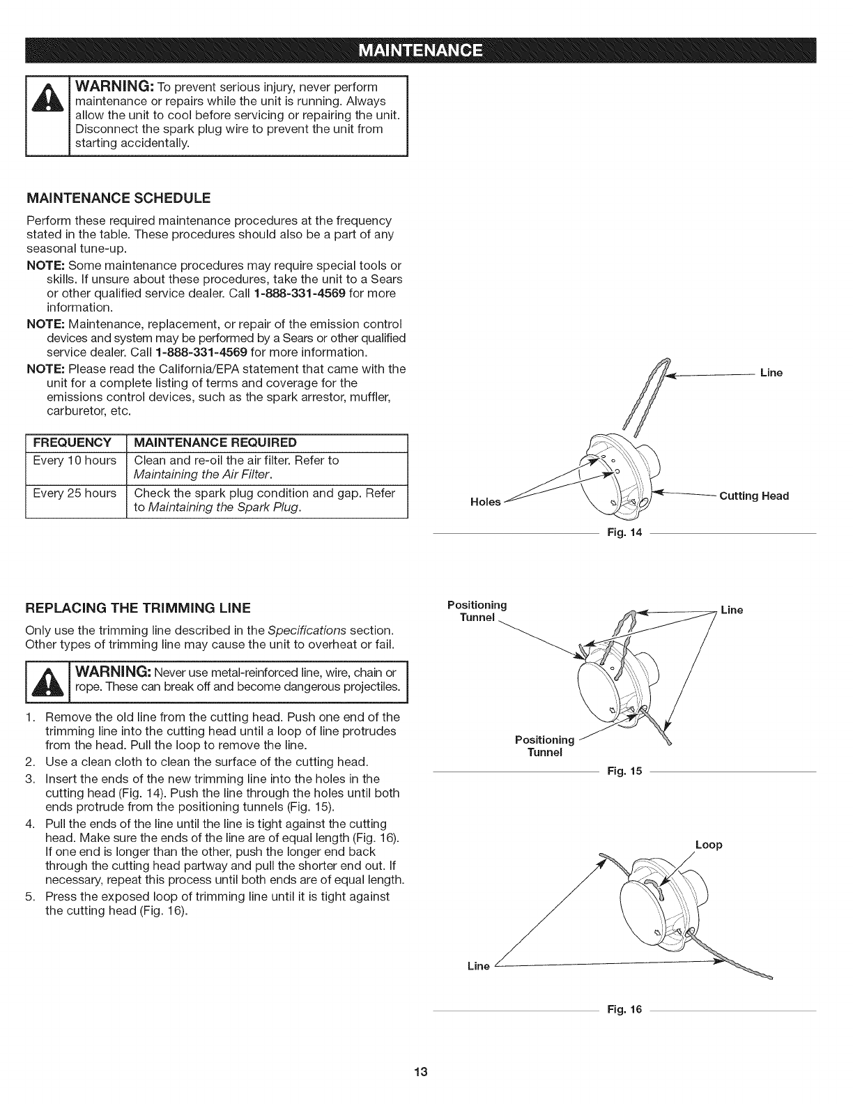
FREQUENCY MAINTENANCE REQUIRED
Every 10 hours Clean and re-oil the air filter. Refer to
Maintaining the Air Filter.
Every 25 hours Check the spark plug condition and gap. Refer
to Maintaining the Spark Plug. Holes
Fig. 14
Line
Cutting Head
REPLACING THE TRiMMiNG LiNE
Only use the trimming line described in the Specifications section.
Other types of trimming line may cause the unit to overheat or fail.
I _ I WARNING: Never use metal-reinforced line, wire, chain or |
!
rope. These can break off and become dangerous projectiles. J
1. Remove the old line from the cutting head. Push one end of the
trimming line into the cutting head until a loop of line protrudes
from the head. Pull the loop to remove the line.
2. Use a clean cloth to clean the surface of the cutting head.
3. Insert the ends of the new trimming line into the holes in the
cutting head (Fig. 14). Push the line through the holes until both
ends protrude from the positioning tunnels (Fig. 15).
4. Pull the ends of the line until the line is tight against the cutting
head. Make sure the ends of the line are of equal length (Fig. 16).
If one end is longer than the other, push the longer end back
through the cutting head partway and pull the shorter end out. If
necessary, repeat this process until both ends are of equal length.
5. Press the exposed loop of trimming line until it is tight against
the cutting head (Fig. 16).
Positioning
Tunnel
Tunnel
Line
Fig. 15
Loop
Line
Fig. 16
13
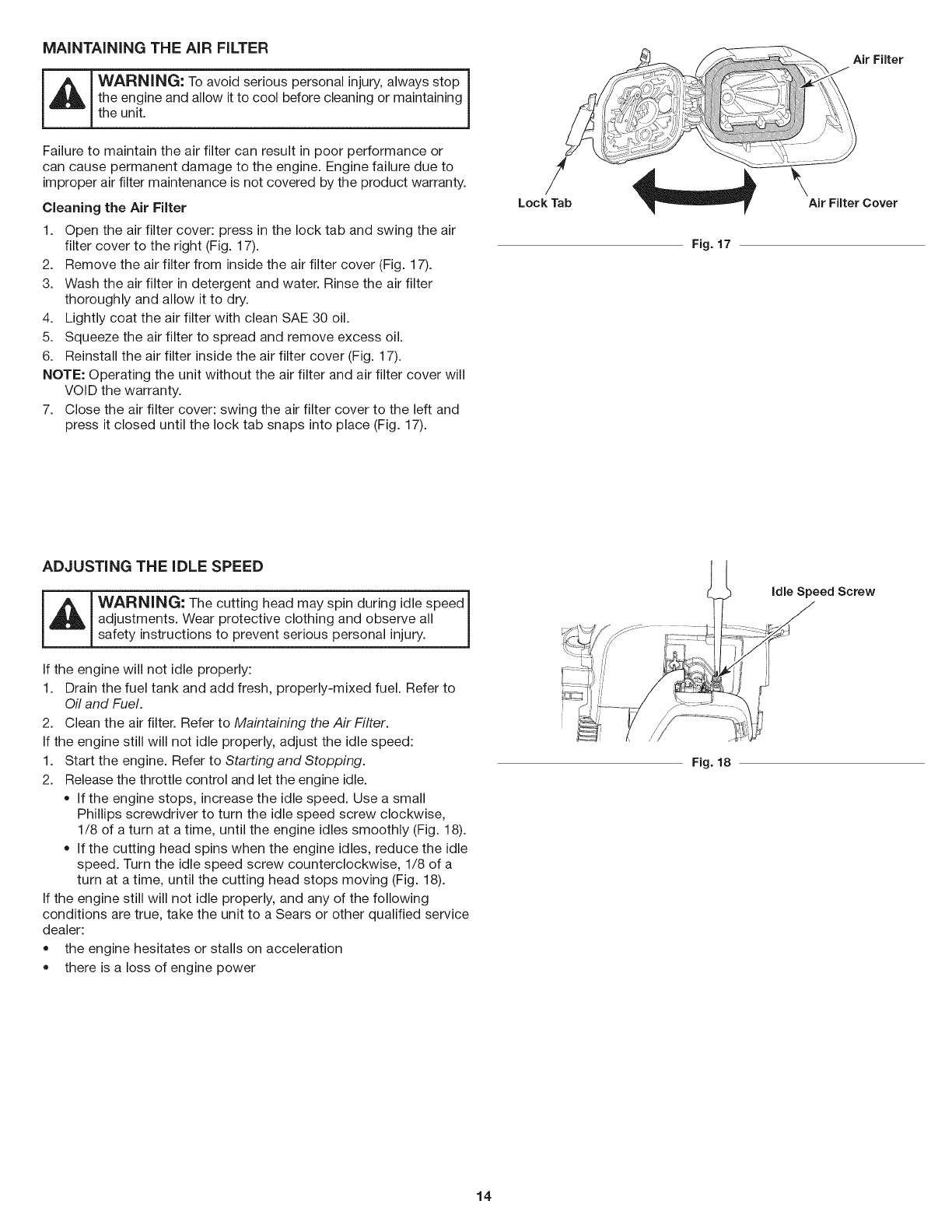
MAiNTAiNiNG THE AIR FILTER
_ WARNING: To avoid serious personal injury, always stop
the engine and allow it to cool before cleaning or maintaining J
the unit.
Failure to maintain the air filter can result in poor performance or
can cause permanent damage to the engine. Engine failure due to
improper air filter maintenance is not covered by the product warranty.
Cleaning the Air Filter
1. Open the air filter cover: press in the lock tab and swing the air
filter cover to the right (Fig. 17).
2. Remove the air filter from inside the air filter cover (Fig. 17).
3. Wash the air filter in detergent and water. Rinse the air filter
thoroughly and allow it to dry.
4. Lightly coat the air filter with clean SAE 30 oil.
5. Squeeze the air filter to spread and remove excess oil.
6. Reinstall the air filter inside the air filter cover (Fig. 17).
NOTE: Operating the unit without the air filter and air filter cover will
VOID the warranty.
7. Close the air filter cover: swing the air filter cover to the left and
press it closed until the lock tab snaps into place (Fig. 17).
Air Filter
i!ii; \_ '\
.......,_jiiiH_jiii!!!iiiiiiii_ }
/
Lock Tab Air Filter Cover
Fig. 17
ADJUSTING THE IDLE SPEED
_ ARNING: The cutting head may spin during idle speed_
adjustments. Wear protective clothing and observe all Jsafety instructions to prevent serious personal injury.
If the engine will not idle properly:
1. Drain the fuel tank and add fresh, properly-mixed fuel. Refer to
Oil and Fuel.
2. Clean the air filter. Refer to Maintaining the Air Filter.
If the engine still will not idle properly, adjust the idle speed:
1. Start the engine. Refer to Starting and Stopping.
2. Release the throttle control and let the engine idle.
• If the engine stops, increase the idle speed. Use a small
Phillips screwdriver to turn the idle speed screw clockwise,
1/8 of a turn at a time, until the engine idles smoothly (Fig. 18).
If the cutting head spins when the engine idles, reduce the idle
speed. Turn the idle speed screw counterclockwise, 1/8 of a
turn at a time, until the cutting head stops moving (Fig. 18).
If the engine still will not idle properly, and any of the following
conditions are true, take the unit to a Sears or other qualified service
dealer:
the engine hesitates or stalls on acceleration
there is a loss of engine power
Fig. 18
idle Speed Screw
14
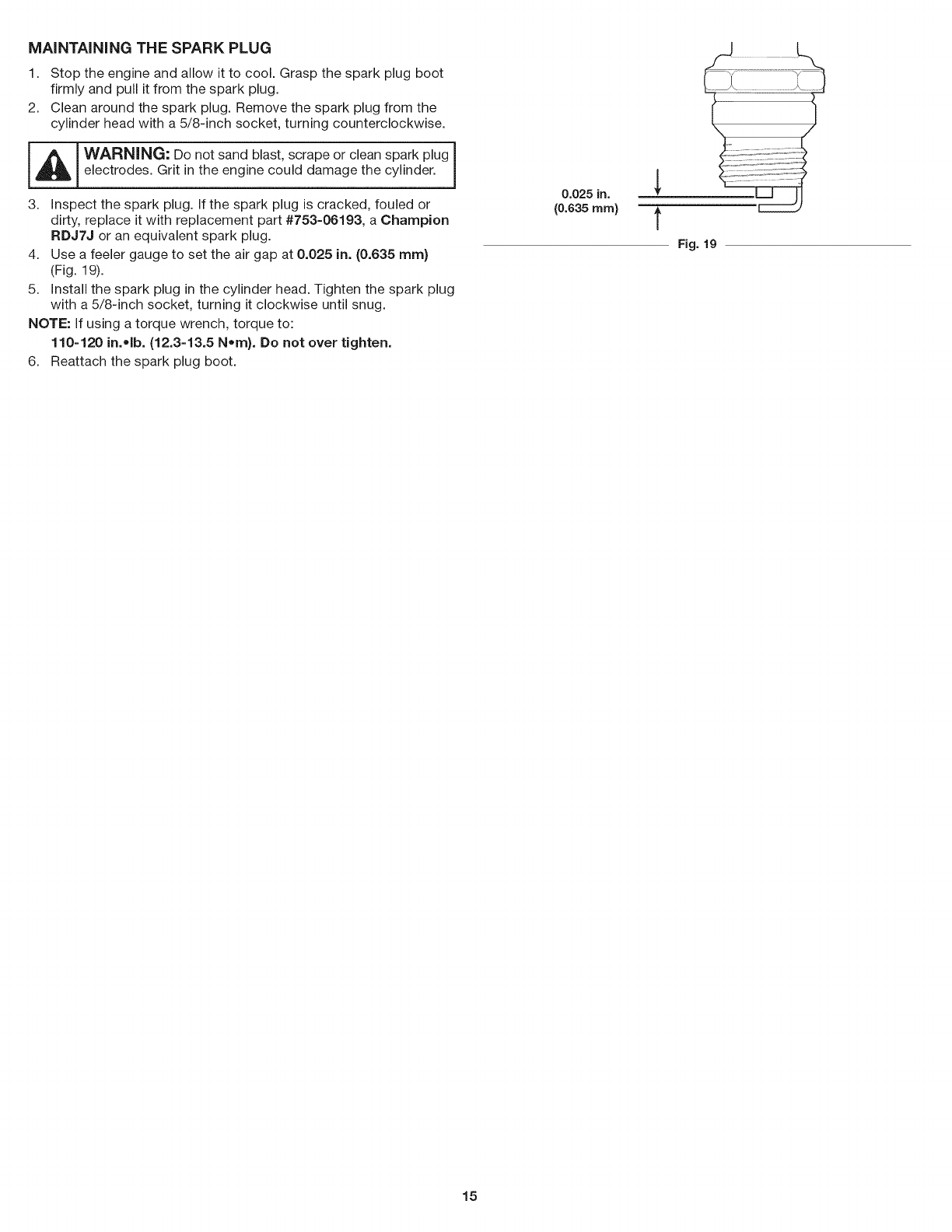
MAiNTAiNiNG THE SPARK PLUG
1. Stop the engine and allow it to cool. Grasp the spark plug boot
firmly and pull it from the spark plug.
2. Clean around the spark plug. Remove the spark plug from the
cylinder head with a 5/8-inch socket, turning counterclockwise.
I _ib ! WARNING: Do not sand blast, scrape or clean spark plug I
electrodes. Grit in the engine could damage the cylinder.
3. Inspect the spark plug. If the spark plug is cracked, fouled or
dirty, replace it with replacement part #753-06193, a Champion
RDJ7J or an equivalent spark plug.
4. Use a feeler gauge to set the air gap at 0.025 in. (0.635 ram}
(Fig. 19).
5. Install the spark plug in the cylinder head. Tighten the spark plug
with a 5/8-inch socket, turning it clockwise until snug.
NOTE: If using a torque wrench, torque to:
110=120 in.olb. (12.3=13.5 Nora). Do not over tighten.
6. Reattach the spark plug boot.
0.025 in.
(0.635 rnrn}
Fig. 19
15
CLEANING STORAGE
_ WARNING" To avoid serious personal injury, always stop
the engine and allow it to cool before cleaning or maintaining J
the unit.
Use a small brush to clean the outside of the unit. Do not use strong
detergents. Household cleaners that contain aromatic oils such as
pine and lemon, and solvents such as kerosene, can damage
plastic. Wipe off any moisture with a soft cloth.
• Never store a fueled unit where fumes may reach an open flame
or spark.
Allow the engine to cool before storing.
Lock up the unit to prevent unauthorized use or damage.
Store the unit in a dry, well-ventilated area.
Store the unit out of the reach of children.
Short-term Storage (1-2 weeks)
1. Store the unit in a horizontal position. If this is not possible, store
the unit vertically with the engine at the top.
Long-term Storage
1. Remove the fuel cap, tip the unit and drain the fuel into an
approved container. Reinstall the fuel cap.
2. Start the engine and allow it to run until it stalls. This ensures
that all fuel has been drained from the carburetor.
3. Allow the engine to cool. Remove the spark plug and put 5
drops of any high-quality motor oil or 2-cycle oil into the
cylinder. Pull the starter rope slowly to distribute the oil. Reinstall
the spark plug.
4. Thoroughly clean the unit and inspect it for any loose or
damaged parts. Repair or replace damaged parts and tighten
loose screws, nuts or bolts.
Preparing the Unit for Use after Long-term Storage
1. Remove the spark plug and drain all of the oil from the cylinder.
NOTE: Do not use fuel that has been stored for more than 30 days.
Dispose of old fuel according to federal, state and local regulations.
16

PROBLEM
The fuel tank is empty
The engine is flooded
The spark plug is fouled
SOLUTION
Fill the fuel tank with properly mixed fuel
,,,,,,,,,, ,,,,, } ....
Move the choke lever to Position 3, squeeze the throttle control and
pull the starter rope
Replace the spark plug
The air filter is dirty
The idle speed is incorrect
The fuel is old (over 30 days) and/or improperly mixed
The air filter is dirty
The fuel is old (over 30 days) and/or improperly mixed
The spark plug is fouled
Clean or replace the air filter
Adjust the idle speed
Drain the fuel tank and add fresh, properly-mixed fuel
Clean or replace the air filter
Drain the fuel tank and add fresh, properly-mixed fuel
Replace the spark plug
o Find information and tools to help with home projects.
brought to you by Sears
17

Congratulations on making a smart purchase. Your new Craftsman@ product is designed and manufactured for years of dependable
operation. But like all products, it may require repair from time to time. That's when having a Repair Protection Agreement can save you
money and aggravation.
Here's what the Repair Protection Agreement* includes:
[] Expert service by our 10,000 professional repair specialists
[] Unlimited service and no charge for parts and labor on all covered repairs
[] Product replacement up to $1500 if your covered product can't be fixed
[] Discount of 25% from regular price of service and related installed parts not covered by the agreement; also, 25% off regular price of
preventive maintenance check
[] Fast help by phone - we call it Rapid Resolution - phone support from a Sears representative. Think of us as a "talking owner's manual."
Once you purchase the Repair Protection Agreement, a simple phone call is all that it takes for you to schedule service. You can call anytime
day or night, or schedule a service appointment online.
The Repair Protection Agreement is a risk-free purchase. If you cancel for any reason during the product warranty period, we will provide a
full refund. Or, a prorated refund anytime after the product warranty period expires. Purchase your Repair Protection Agreement today!
Some limitations and exclusions appJy. For prices and additional information in the U.S.A. call 1-800-827-6655.
*Coverage in Canada varies on some items. For full details call Sears Canada at 1-800-361-6665.
Sears installation Service
For Sears professional instaflation of home appliances, garage door openers, water heaters, and other major home items, in the U.S.A. or
Canada call 1-800-4-MY-HOME.
18

Manual del Operador
Motor de 2tiernpos
RECORTADOR WEEDWACKER_ A GASOLINA
Modelo No. 316.711022
PRECAUCION: Antes de utilizar, este
producto lea este manual y siga todas
las reglas de seguridad einstrucciones
de operaci6n.
*SEGURIDAD
*ENSAMBLAJE
.OPERACION
*MANTENIMIENTO
Sears Brands Management Corporation, Hoffman Estates, iL 60179 U.S.A.
Visite nuestro sitio web: www.craftsman.com
769-10218 /00 09/14
TABLA DE CONTENIDO
Seguridad ........................................... 20
Garantia ............................................. 24
Conozca su unidad .................................... 25
Especificaciones ...................................... 25
Ensamblaje .......................................... 26
Aceite y combustible ................................... 28
Arranque y parada ..................................... 29
Operaci6n ........................................... 30
Mantenimiento ........................................ 32
Limpieza y almacenamiento ............................. 35
Localizaci6n y soluci6n de problemas ..................... 36
Convenio de protecci6n de reparaci6n ..................... 37
NQmeros de servicio ......................... Contraportada
Toda la informaci6n, las ilustraciones y especificaciones que contiene
este manual se basan en la informaci6n mas reciente del producto,
existente en el momento de la impresi6n. Nos reservamos el derecho
de hacer cambios en cualquier momento, sin previo aviso.
© Seam Brands, LLC
El objetivo de los simbolos de seguridad es dirigir su atenci6n hacia
posibles peligros. Los simbolos de seguridad, asi como sus
explicaciones, necesitan su atenci6n y comprensi6n completas. Las
advertencias de seguridad no eliminan por si mismas ningQn
peligro. Las instrucciones o advertencias que contienen no
reemplazan alas medidas adecuadas de prevenci6n de accidentes.
SJMBOLOS SlGNIFICADO
PELIGRO: Indica un peligro EXTREMO.
Si no se cumple una advertencia de seguridad de
PELIGRO usted mismo u otras personas sufrirAn lesiones
graves o la muerte.
ADVERTENCIA: Indica un peligro
GRAVE.
Si no se cumple una ADVERTENClA de seguridad usted
mismo u otras personas PUEDEN sufrir lesiones graves.
r n v,,: ,odioaoope,i0rode
GRAVEDAD MODERADA.
Si no se cumple una sedal de seguridad de PRECAUCION
usted mismo o a otras personas PUEDEN sufrir lesiones o
se PUEDEN producir dados materiales.
NOTA: Proporciona informaci6n o instrucciones de vital importancia
para el funcionamiento o el mantenimiento del equipo.
NOTA SOBRE EL AMORTIGUADOR DE CHISPAS
NOTA: Para usuarios de los territorios de bosques de EE. UU. y
de los estados de California, Maine, Oregon y Washington.
Todos los territorios de bosques de EE. UU. y los estados de
California (C6digos de Recursos POblicos 4442 y 4443), Oregon y
Washington exigen pot ley, que determinados motores de
combusti6n interna que se operan en zonas cubiertas pot malezas
de bosque y/o hierbas cuenten con un amortiguador de chispas
que se debera mantener en condiciones de uso adecuadas o que el
motor se dise5e, equipe y mantenga para prevenir incendios.
Corrobore con las autoridades estatales o locales cuales son las
normativas correspondientes a dichas exigencias. El
incumplimiento de dichos requerimientos podria generarle una
responsabilidad o una multa. La presente unidad se equipa en la
f_brica con un amortiguador de chispas. Si requiere reemplazo,
p6ngase en contacto con un Centro de Servicio de Reparaciones y
Piezas Sears para instalar el con junto de silenciador adecuado.
_j ROPOSICI6N 65 DEL ESTADO DE CALIFORNIA
ADVERTENCIA: Este producto
contiene una sustancia quimica que segOn el Estado de
California puede producir cancer, defectos de nacimiento
u otros problemas reproductivos.
Lea el manual del operador y siga todas las advertencias e
instrucciones de seguridad. Si no Io hace, el operador y/o los
observadores pueden sufrir lesiones graves.
20

•INSTRUCCIONES DE SEGURIDAD IMPORTANTES •
LEA TODAS LAS INSTRUCCIONES ANTES DE USAR LA
UNIDAD
ADVERTENCIA: Sedebenrespetar
todas las normas de seguridad al usar la unidad. Por favor,
lea estas instrucciones antes de utilizar la unidad para
garantizar la seguridad del operador y los observadores.
Por favor, guarde estas instrucciones para su uso posterior.
• Lea las instrucciones con atenci6n. Debe familiarizarse con los
controles y con el uso apropiado de la unidad.
No opere esta unidad si esta cansado, enfermo o bajo la
influencia de alcohol, drogas o medicamentos.
La unidad no debe ser utilizada por ni_os. Los adolescentes
deben contar con la compa_ia y guia de un adulto.
Se deben instalar correctamente todos los protectores y
accesorios de seguridad antes de operar la unidad.
Inspeccione la unidad antes de usarla. Reemplace las piezas
da_adas. Compruebe si hay perdidas de combustible.
Compruebe que todas las sujeciones esten en su lugar y bien
ajustadas. Reemplace las piezas que esten agrietadas,
astilladas o da_adas de cualquier manera. No utilice la unidad si
hay piezas sueltas o da_adas.
Use Qnicamente el hilo de recorte que se describe en la secci6n
Especificaciones de este manual. Nunca use un hilo, un cable,
una cadena o una cuerda de metal reforzados. Podrian
separarse y convertirse en proyectiles peligrosos.
No cambie el cabezal de corte por cuchillas rigidas o de metal.
Si Io hace, podria provocar lesiones graves.
Tenga en cuenta el riesgo de lesiones en la cabeza, las manos y
los pies.
Inspeccione el Area con atenci6n antes de arrancar la unidad.
Extraiga las rocas, los vidrios rotos, los clavos, los cables,
cordeles y demas objetos que podrian ser arrojados o enredarse
en la unidad.
Despeje la zona de ni_os, observadores y mascotas;
mantengalos fuera de un radio de 50 pies (15 m), como minimo.
Incluso a esa distancia, sigue el riesgo de ser alcanzados por
los objetos arrojados pot el aire. Sugierales a los observadores
que usen protecci6n ocular. Si alguien se le aproxima, detenga
la unidad de inmediato.
Apriete el control del acelerador y verifique que vuelva
automaticamente a la posici6n de ralenti. Realice todos los
ajustes o las reparaciones antes de usar la unidad.
Esta unidad esta dise_ada para uso ocasional, para el hogar
Qnicamente.
ADVERTENCIAS DE SEGURIDAD PARA LAS UNIDADES
A GASOUNA
ADVERTENCIA: La gasolina es
sumamente inflamable y sus vapores pueden explotar si se
encienden. Adopte las siguientes precauciones:
Almacene el combustible Qnicamente en recipientes dise_ados
especificamente y aprobados para el almacenamiento de dichos
materiales.
Detenga siempre el motor y dejelo enfriar antes de Ilenar el
dep6sito. Nunca retire la tapa del dep6sito de combustible ni
agregue combustible cuando el motor este caliente. Afloje siempre
lentamente la tapa del dep6sito de combustible para descargar la
presi6n que haya en el dep6sito antes de recargar combustible.
Mezcle o eche siempre el combustible en un Area exterior bien
ventilada y limpia, donde no haya chispas ni llamas. NO fume.
Nunca opere la unidad si la tapa del combustible no esta bien
sujeta en su lugar.
Evite que se genere una fuente de encendido para el
combustible derramado. Limpie de inmediato el combustible
derramado de la unidad, antes de encenderla. Mueva la unidad
al menos 30 pies (9.1m) de la fuente de combustible y del sitio
antes de arrancar el motor. NO fume.
Nunca arranque ni use la unidad dentro de una habitaci6n o de
una construcci6n cerrada. La inhalaci6n de humos de escape
puede ser mortal. Opere esta unidad Qnicamente en una zona
bien ventilada, al aire libre.
DURANTE LA OPERACI(_N
Utilice anteojos o antiparras de seguridad que cumplan con las
normas ANSI /ISEA Z87.1 vigentes y que tengan la
identificaci6n correspondiente. Utilice una protecci6n auditiva al
operar esta unidad. Utilice una mascara facial o para polvos si la
maquina levanta polvo durante su funcionamiento.
Use pantalones largos y gruesos, botas, guantes y camisa de
mangas largas. No use ropa holgada, alhajas, pantalones
cortos, sandalias ni ande descalzo. Sujetese el cabello a nivel de
los hombros.
El protector del cabezal de corte siempre debe estar colocado
mientras se opera la unidad. No utilice la unidad si no estan
extendidos ambos hilos de recorte y si no esta instalado el hilo
adecuado. No extienda el hilo de recorte mas alia de la Iongitud
del protector.
El cabezal de corte debe permanecer fijo cuando el motor
funciona al ralenti. Si no funciona, consulte Ajuste de la
velocidad de ralentL
Ajuste la manija para que brinde el mejor agarre, si corresponde.
Compruebe que el accesorio no este en contacto con nada
antes de poner en marcha la unidad.
Use la unidad solamente con luz de dia o con una buena luz artificial.
Evite arranques accidentales. Permanezca en la posici6n de
arranque siempre que tire de la cuerda de arranque. El operador
y la unidad deben estar en una posici6n estable durante el
arranque. Consulte Arranque y Parada.
Utilice la herramienta apropiada. Use esta herramienta s61o para
el prop6sito para el que fue dise_ada.
Sostenga siempre la unidad con ambas manos durante la
operaci6n. Sostenga firmemente ambas manijas o empu_aduras.
21
• Noseextiendademasiado.Siempredebeestarbienafirmadoy
mantenerelequilibrioadecuado.Tengacuidadoaltrabajar
sobreescalinatas,cuestasempinadasopendientes.Paraevitar
lesionesgraves,nohagafuncionarlaunidaddesdeunaescalera
demanoountecho.
Mantengalasmanos,elrostroy lospiesalejadosdetodaslas
piezasm6viles.Notoqueniintentedetenerlaspiezasm6viles.
Notoqueelmotor,elalojamientodelengranajenielsilenciador.
Estaspartesseponenextremadamentecalientesporel
funcionamiento,inclusodespuesdequeseapagalaunidad.
Nooperelaunidadaunavelocidadmayoralanecesariaparala
tarea.Nohagafuncionarlaunidadaaltavelocidadcuandono
estaenuso.
Noexijademasiadoalaunidad.Siseusaalavelocidadparala
quefuedise_ada,realizarauntrabajomaseficienteyseguro.
Detengasiemprelaunidadcuandolaoperaci6nestedemorada
ocuandocaminedeunlugaraotro.
Antesdeapoyarlaunidad,siempreaseg@esedequeelmotor
esteapagadoy quetodaslaspiezasm6vilessehayandetenido.
Sigolpeaunobjetoextra_oosiesteseenganchaenlaunidad,
detengaladeinmediatoycontrolesiseprodujeronda_os.No
utilicelaunidadhastahaberreparadoelda_o.Noutilicela
unidadsihaypiezassueltasoda_adas.
Apagueelmotory desconectelabujiapararealizartareasde
mantenimientooreparaci6n.
Utilicesolamentelaspiezasderepuestoy accesoriosdel
fabricanteoriginal(OEM).Siusacualquierotrapiezao
accesorio,elusuariopodrialesionarsegravementeolaunidad
podriada_arseyseanularialagarantia.
Mantengalimpialaunidad.Quiteconcuidadocualquierrestode
vegetaci6nuotrosresiduosquepuedanbloquearlaspiezasm6viles.
Afindereducirelriesgodeincendio,reemplaceelsilenciadory
elamortiguadordechispassiestanaveriados.Mantengael
motory elsilenciadorlibresdehierbas,hojasydela
acumulaci6nexcesivadegrasaodecarbono.
Silaunidadcomienzaavibrarenformaanormal,detengalade
inmediato.Inspeccionelaunidadparadeterminarlacausadela
vibraci6n.Lavibraci6nporIogeneralindicaquehayalgQn
problema.
OTRAS ADVERTENCIAS DE SEGURIDAD
El mantenimiento de la unidad debe ser minucioso.
Todos los servicios, que no sean los procedimientos de
mantenimiento descritos en este manual, deberan realizarse por
un centro de Sears u otro centro de servicio calificado.
Nunca extraiga, modifique o deje inoperativo ningQn dispositivo
de seguridad que venga con la unidad.
Antes de inspeccionar, limpiar, guardar o transportar la unidad, o
de hacer tareas de reparaci6n o mantenimiento o reemplazar
alguna de sus piezas:
1. Detenga la unidad.
2. AsegQrese de que se hayan detenido todas las piezas m6viles.
3. Deje que la unidad se enfrie.
4. Desconecte el cable de la bujia.
Sujete la unidad durante el transporte.
Nunca almacene la unidad con combustible en el dep6sito, en el
interior de una construcci6n donde las emanaciones puedan
alcanzar una llama abierta (luces piloto, etc.) o chispas
(interruptores, motores electricos, etc.).
Almacene la unidad en un lugar seco, asegurada o a una altura
que evite que se la use sin autorizaci6n o se la da_e. Mantenga
la unidad lejos del alcance de los ni_os.
Nunca rocie ni arroje chorros de agua ni de ningQn otto liquido a la
unidad. Mantenga las manijas secas y limpias (sin residuos, aceite
ni grasa). Limpie la unidad luego de cada uso. Consulte Limpieza y
almacenamiento. No utilice solventes o detergentes fuertes.
Guarde estas instrucciones. ConsQltelas con frecuencia y Qselas
para capacitar a otros usuarios. Si le presta esta unidad a otras
personas, tambien debe prestarles estas instrucciones.
GUARDE ESTAS
INSTRUCCIONES
22
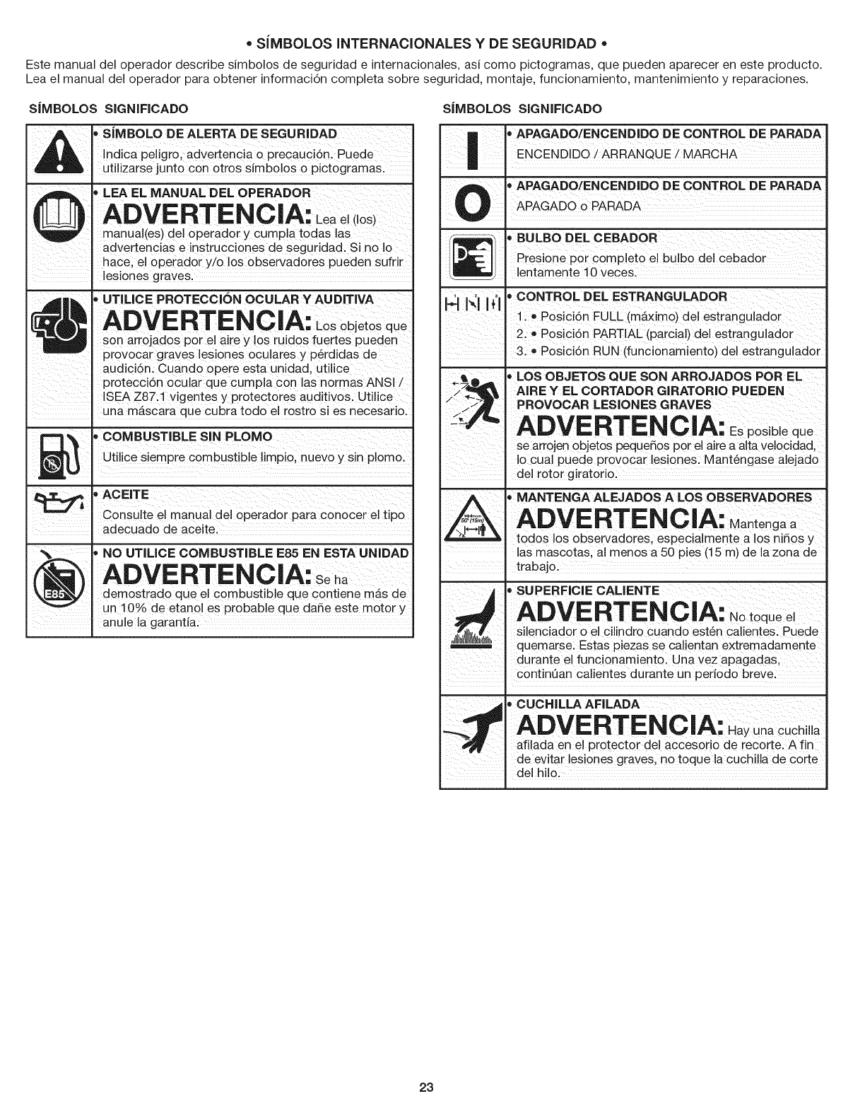
• SiMBOLOSINTERNACIONALES YDE SEGURIDAD •
Este manual del operador describe simbolos de seguridad eintemacionales, asi como pictogramas, que pueden aparecer en este producto.
Lea el manual del operador para obtener informaci6n completa sobre seguridad, montaje, funcionamiento, mantenimiento y reparaciones.
SIMBOLOS SIGNIFICADO
,sJMBOLODEALERTADESEGUR,DAD
A _ _ !ndica peligro, adveitenc!a o precauci6n: Puede
I,,_. ut zarse junto con 0b0s s!mb0 os op ctogramas.
_ LEA EL MANUAL DEL OPERADOR
manua!(es) de! operador y cumpla todas las
advertenciaS e instrucciones de Seguridad. Si no Io
hace; el operador y/o los observadores pueden sufrir
. !esiones grave&
_ ' UTIL'CE PROTECC'6N OCULAR ¥ AUD'TiVA', Ai'_lkl,l_ D. I_ h, f'_, A
m
• n. L,,, objo,os
son arrojados porel aire y !os ruid0s fuertes pueden
provocar graves lesiones ocuiares y p6rdidas de
audici6n. Cuand0 opere esta unidad, util!ce
protecci6n ocular que cump!a Con las normas ANS!/
ISEA Z87:1 Vigentes y protectores aUditivos, utilice
' una mascara que cubratodo el rostro si es necesario,
u_ "COMBUST'BLES'NPLOMO
Utilice SiemPre c0mbUstible limpio, nuevo y Sin p!0mo:
,ACEITE
consUite ei manual del operador para Conocer el tip0
. adecuado de aceite:
___ NOUTlUCECOMBUSTIBLEE85ENESTAUNIDAD
.em t e U ! q " emis
Un 10% de etanoi es probable que da_e este motor y
.anule !a garant!a:
SJMBOLOS SIGNIFICADO
' APAGADO/ENCENDIDO DE CONTROL DE PARADA
APAGADO o PARADA
g
I_i 'BULBO DEL CEBADOR
Presione por completo ei bulbo del cebador
lentamente 10 veces.
H I'q I{'1' CONTROL DEL ESTRANGULADOR
1. •Posici6n FULL (mb,ximo) del estrangulador
2. o Posici6n PARTIAL (parcial) del estrangulador
3. • Posici6n RUN (funcionamiento) del estrangulador
' LOS OBJETOS QUE SON ARROJADOS POR EL
AIRE Y EL CORTADOR GIRATORIO PUEDEN
PROVOCAR LESIONES GRAVES •
ADVERTENCIA: Espos,beque
se arrojen objetos peque_os por el aire a alta velocidad,
Io cual puede provocar lesiones. Mant6ngase alejado
. del rotor giratorio.
,MANTENGA ALEJADOS A LOS OBSERVADORES
toAdo£osVob_bsR TEesNs£ [Ae'nM aantoengnaaos
a r p i m Is i5 y
las mascotas, al menos a 50 pies (15 m) de la zona de
trabajo.
' SUPERFICIE CAUENTE
ADVERTENCIA. Notoque el
,, silenciador o el cilindro cuando est6n calientes. Puede
quemarse. Estas piezas se calientan extremadamente
durante ei funcionamiento. Una vez apagadas,
continean calientes durante un periodo breve.
._!_, CUCHiLLA AFILADA []
ADVERTENCIA: Hay una cuchi a
afilada en el protector del accesorio de recorte. A fin
de evitar lesiones graves, no toque la cuchilla de corte
del hilo.
23
GARANTiA LIMITIDA DE CRAFTSMAN
POR DOS ANOS a partir de la fecha de la compra, este producto esta garantizado por defectos en los materiales o la mano de obra.
CON EVIDENCIA DE COMPRA, un producto defectuoso recibira una reparaci6n gratuita o un reemplazo a opci6n del vendedor.
GARANTJA LIMITADA ADICIONAL PARA LOS EJES DEL CORTADOR
A PARTIR DEL TERCER Y HASTA EL DE_CIMOANO desde la fecha de compra, el cuerpo externo de metal de los ejes superior e inferior del
cortador estan garantizados contra defectos de materiales o fabricaci6n.
Se proporcionara un cuerpo nuevo gratis con la presentaci6n del COMPROBANTE DE COMPRA. Es su responsabilidad cubrir el costo de
mano de obra de instalaci6n. Esta cobertura adicional no se aplica a los componentes internos del eje de la cortadora.
Para conocer los detalles de la cobertura de garantia para la reparaci6n o reemplazo gratuitos, visite el sitio web:
www.craftsman.com/wa rranty
Esta garantia cubre SOLAMENTE defectos de materiales o mano de obra. La cobertura de garant{a NO incluye:
• Los componentes consumibles que se desgasten debido al uso normal dentro del periodo de garantia como lineas de corte, bujias o filtros.
• Los dados al producto a consecuencia de intentos de modificaci6n o reparaci6n del usuario u ocasionados por accesorios del producto.
• Las reparaciones necesarias por un accidente o por no operar o mantener el producto de acuerdo con todas las instrucciones suministradas.
• El mantenimiento preventivo ni las reparaciones necesarias debido a una mezcla incorrecta de combustible o a al uso de un combustible
viejo o contaminado.
Esta garantia se anula si el producto en algL_nmomento se utiliza para prestar servicios comerciales o se alquila a otra persona.
Esta garantia le confiere a usted derechos legales especificos y usted puede tener, ademas, otros derechos que difieren de un estado a otro.
Sears Brands Management Corporation, Hoffman Estates, IL 60179
Para ordenar refacciones o agendar mantenimiento para este producto, llame a 1-888-331-4569.
24
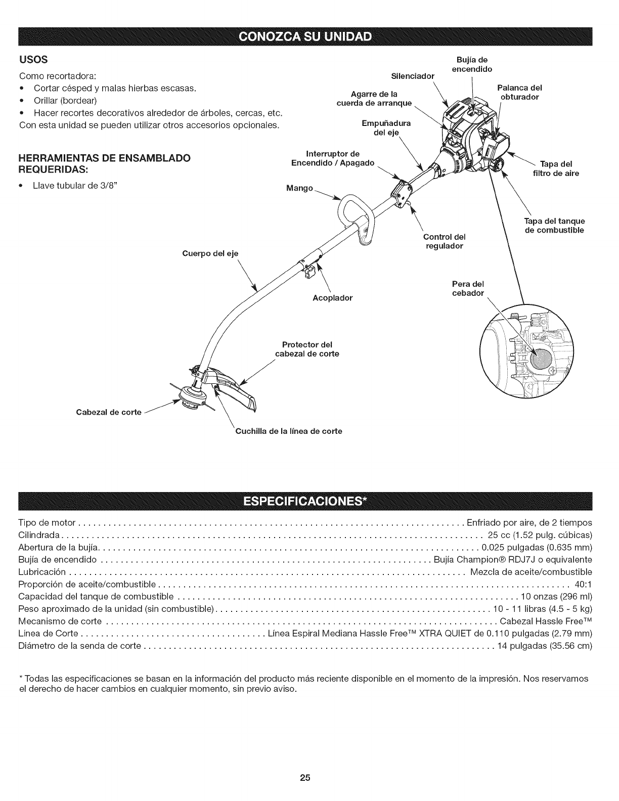
usos
Como recortadora:
• Cortar cesped y malas hierbas escasas.
Orillar (bordear)
Hacer recortes decorativos alrededor de arboles, cercas, etc.
Con esta unidad se pueden utilizar otros accesorios opcionales.
Silenciador
Agarre de la
cuerda de arranque
Empufiadura
del eje
Bujia de
encendido
Palanca del
obturador
HERRAMIENTAS DE ENSAMBLADO
REQUERIDAS:
Llave tubular de 3/8"
Interruptor de
Encendido /Apagado Tapa del
filtro de aire
Cuerpo del eje
\Control del
regulador
Tapa del tanque
de combustible
Cabezal de corte
Acoplador
Protector del
cabezal de corte
Cuchilla de la I{nea de corte
Pera del
cebador \
i i '_t L
Tipo de motor ............................................................................. Enfriado pot aire, de 2 tiempos
Cilindrada .................................................................................... 25 cc (1.52 pulg. cQbicas)
Abertura de la bujia ............................................................................ 0.025 pulgadas (0.635 mm)
Bujia de encendido .................................................................. Bujia Champion® RDJ7J o equivalente
Lubricaci6n ............................................................................... Mezcla de aceite/combustible
Proporci6n de aceite/combustible .................................................................................. 40:1
Capacidad del tanque de combustible .................................................................... 10 onzas (296 ml)
Peso aproximado de la unidad (sin combustible) ....................................................... 10 - 11 libras (4.5 - 5 kg)
Mecanismo de corte .............................................................................. Cabezal Hassle FreeTM
Linea de Corte ..................................... Linea Espiral Mediana Hassle Free TM XTRA QUIET de 0.110 pulgadas (2.79 mm)
Diametro de la senda de corte ...................................................................... 14 pulgadas (35.56 cm)
* Todas las especificaciones se basan en la informaci6n del producto mas reciente disponible en el momento de la impresi6n. Nos reservamos
el derecho de hacer cambios en cualquier momento, sin previo aviso.
25
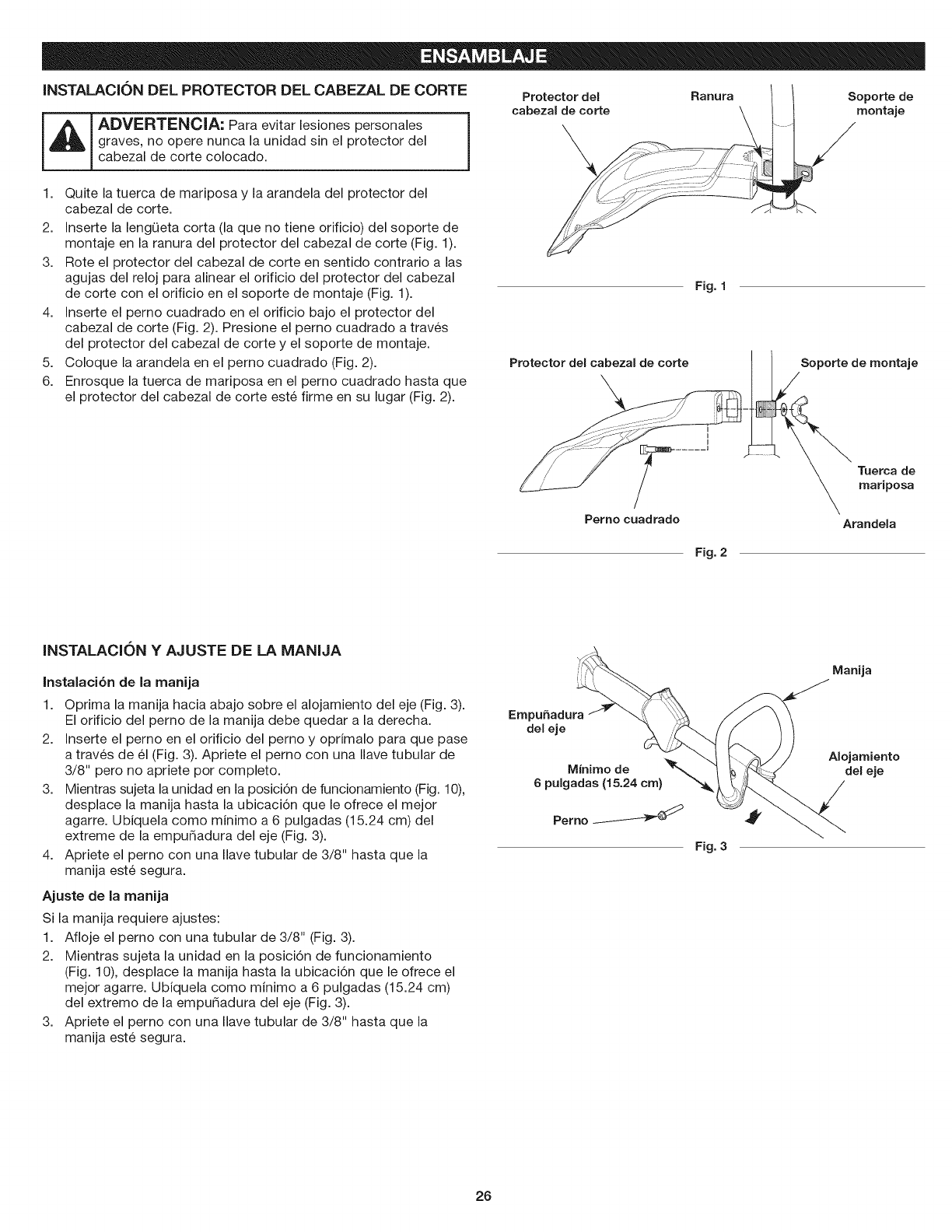
INSTALACK)N DEL PROTECTOR DEL CABEZAL DE CORTE
iAi,ov,o,,oc,,= a aevitar'esiones,e'sona'es1
graves, no opere nunca la unidad sin el protector del
cabezal de corte colocado.
1. Quite la tuerca de mariposa y la arandela del protector del
cabezal de corte.
Protector del
cabezal de corte
\
Rarlura Soporte de
montaje
2. Inserte la lengQeta corta (la que no tiene orificio) del soporte de
montaje en la ranura del protector del cabezal de corte (Fig. 1).
3. Rote el protector del cabezal de corte en sentido contrario alas
agujas del reloj para alinear el orificio del protector del cabezal
de corte con el orificio en el soporte de montaje (Fig. 1).
4. Inserte el perno cuadrado en el orificio bajo el protector del
cabezal de corte (Fig. 2). Presione el perno cuadrado a traves
del protector del cabezal de corte y el soporte de montaje.
5. Coloque la arandela en el perno cuadrado (Fig. 2).
6. Enrosque la tuerca de mariposa en el perno cuadrado hasta que
el protector del cabezal de corte este firme en su lugar (Fig. 2).
Protector del cabezal de corte
Fig. 1
Soporte de montaje
Perno cuadrado
Tuerca de
mariposa
Arandela
Fig. 2
INSTALACION YAJUSTE DE LA MANIJA
Instaiaci6n de ia manija
1. Oprima la manija hacia abajo sobre el alojamiento del eje (Fig. 3).
El orificio del perno de la manija debe quedar a la derecha.
2. Inserte el perno en el orificio del perno y oprimalo para que pase
a traves de 61 (Fig. 3). Apriete el perno con una Ilave tubular de
3/8" pero no apriete por completo.
3. Mientras sujeta la unidad en la posici6n de funcionamiento (Fig. 10),
desplace la manija hasta la ubicaci6n que le ofrece el mejor
agarre. Ubiquela como minimo a 6 pulgadas (15.24 cm) del
extreme de la empuSadura del eje (Fig. 3).
4. Apriete el perno con una Ilave tubular de 3/8" hasta que la
manija este segura.
Ajuste de la manija
Si la manija requiere ajustes:
1. Afloje el perno con una tubular de 3/8" (Fig. 3).
2. Mientras sujeta la unidad en la posici6n de funcionamiento
(Fig. 10), desplace la manija hasta la ubicaci6n que le ofrece el
mejor agarre. Ubiquela como minimo a 6 pulgadas (15.24 cm)
del extremo de la empudadura del eje (Fig. 3).
3. Apriete el perno con una Ilave tubular de 3/8" hasta que la
manija este segura.
MinJmo de
6pulgadas (15.24 cm)
Perno
Fig. 3
Manija
AlojamJento
del eje
26
ADVERTENClA: Antes de comenzar a utilizar
cualquiera de los accesorios, lea y comprenda el manual
que viene con dicho accesorio. Tenga en cuenta toda la
informaci6n de seguridad que incluye.
ADVERTENOIA: A fin de evitar lesiones personales
graves y dar_os a la unidad, apa.guela antes de extraer o
instalar un accesorio.
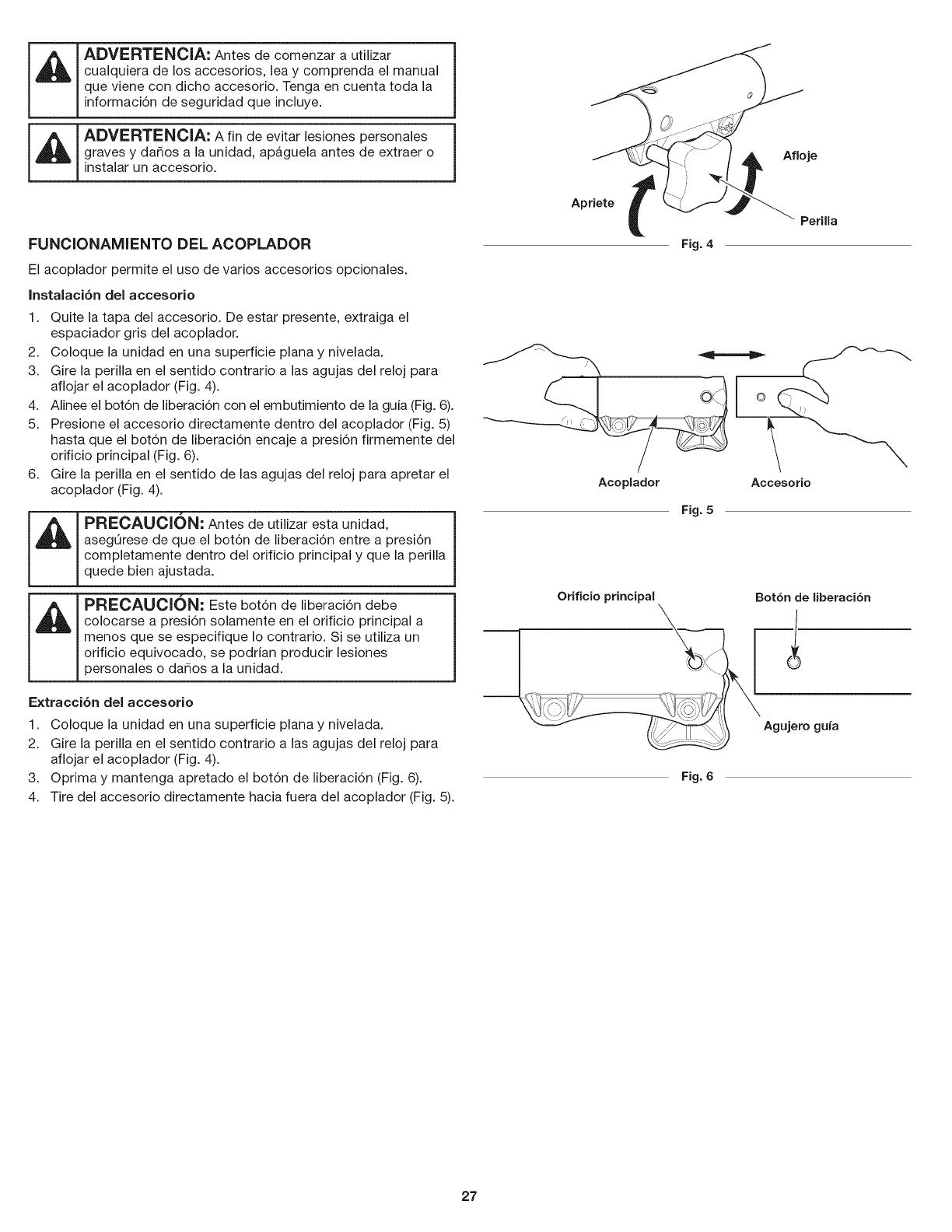
FUNCIONAMIENTO DEL ACOPLADOR
El acoplador permite el use de varies accesorios opcionales.
Instalaci6n del accesorio
1. Quite la tapa del accesorio. De estar presente, extraiga el
espaciador gris del acoplador.
2. Coloque la unidad en una superficie plana y nivelada.
3. Gire la perilla en el sentido contrario alas agujas del reloj para
aflojar el acoplador (Fig. 4).
4. Alinee el bot6n de liberaci6n con el embutimiento de la guia (Fig. 6).
5. Presione el accesorio directamente dentro del acoplador (Fig. 5)
hasta que el bot6n de liberaci6n encaje a presi6n firmemente del
orificio principal (Fig. 6).
6. Gire la perilla en el sentido de las agujas del reloj para apretar el
acoplador (Fig. 4).
PRECAUCION: Antes de utilizar esta unidad,
asegOrese de que el bot6n de liberaci6n entre a presi6n
completamente dentro del orificio principal y que la perilla
quede bien ajustada.
PRECAUClON: Este bot6n de liberaci6n debe
colocarse a presi6n solamente en el orificio principal a
menos que se especifique Io contrario. Si se utiliza un
orificio equivocado, se podrian producir lesiones
personales o dar_os a la unidad.
Extracci6n del accesorio
1. Coloque la unidad en una superficie plana y nivelada.
2. Gire la perilla en el sentido contrario alas agujas del reloj para
aflojar el acoplador (Fig. 4).
3. Oprima y mantenga apretado el bot6n de liberaci6n (Fig. 6).
4. Tire del accesorio directamente hacia fuera del acoplador (Fig. 5).
Apriete t
Fig. 4
Afloje
PeriUa
Acoplador Accesorio
Fig. 5
Orificio principal Botbn de liberacibn
Agujero guia
Fig. 6
27
INSTRUCCIONES PARA MEZCLAR EL ACEITE YEL
COMBUSTIBLE
El uso de un combustible viejo y/o mal mezclado es la causa mas
comQn de problemas de funcionamiento. Utilice solamente
gasolina fresca, limpia y sin plomo. Siga atentamente las
instrucciones para mezclar adecuadamente el aceite/combustible.
Definici6n de combustibles mezclados
Los combustibles actuales son con frecuencia una mezcla de
gasolina e hidrocarburos oxigenados como el etanol, metanol o
MTBE (eter). El combustible mezclado con alcohol absorbe agua.
Un 1% de agua es suficiente para separar la mezcla de aceite y
alcohol o formar acidos al estar guardado. Utilice SlEMPRE
combustible fresco (con menos de 30 dias).
NOTA: Deseche el aceite viejo, de conformidad con las regulaciones
federales, estatales y locales.
Uso de combustibles mezclados
Si utiliza un combustible mezclado:
• Utilice siempre la mezcla fresca de combustible indicada en su
manual del operador
Use el aditivo STA-BIL® o un equivalente
Agite siempre la mezcla de combustible antes de abastecer la
unidad
Vacie el tanque y eche a andar el motor en seco antes de
guardar la unidad
ADVERTENCIA: NO USE COMBUSTIBLE E85 EN
ESTA UNIDAD. Se ha comprobado que es probable que el
combustible con mas de 10% de etanol daSe este motor, Io
que anulara la garantia.
Uso de aditivos para combustible
La botella de aceite para motor de 2 tiempos que viene con esta
unidad contiene un aditivo que ayudara a inhibit la corrosi6n y
minimizara los dep6sitos de goma. Utilice siempre la marca de aceite
para motor de 2 tiempos que viene con esta unidad. Si no es posible,
utilice un buen aceite para motores de 2 tiempos enfriados por aire y
mezclelo con un aditivo como el estabilizador de gasolina STA-BIL o
un equivalente. Eche 0.8 onzas (23 ml) de aditivo por gal6n de
combustible segQn las instrucciones del recipiente. No eche NUNCA
los aditivos directamente en el tanque de combustible de la unidad.
Mezclar el combustible
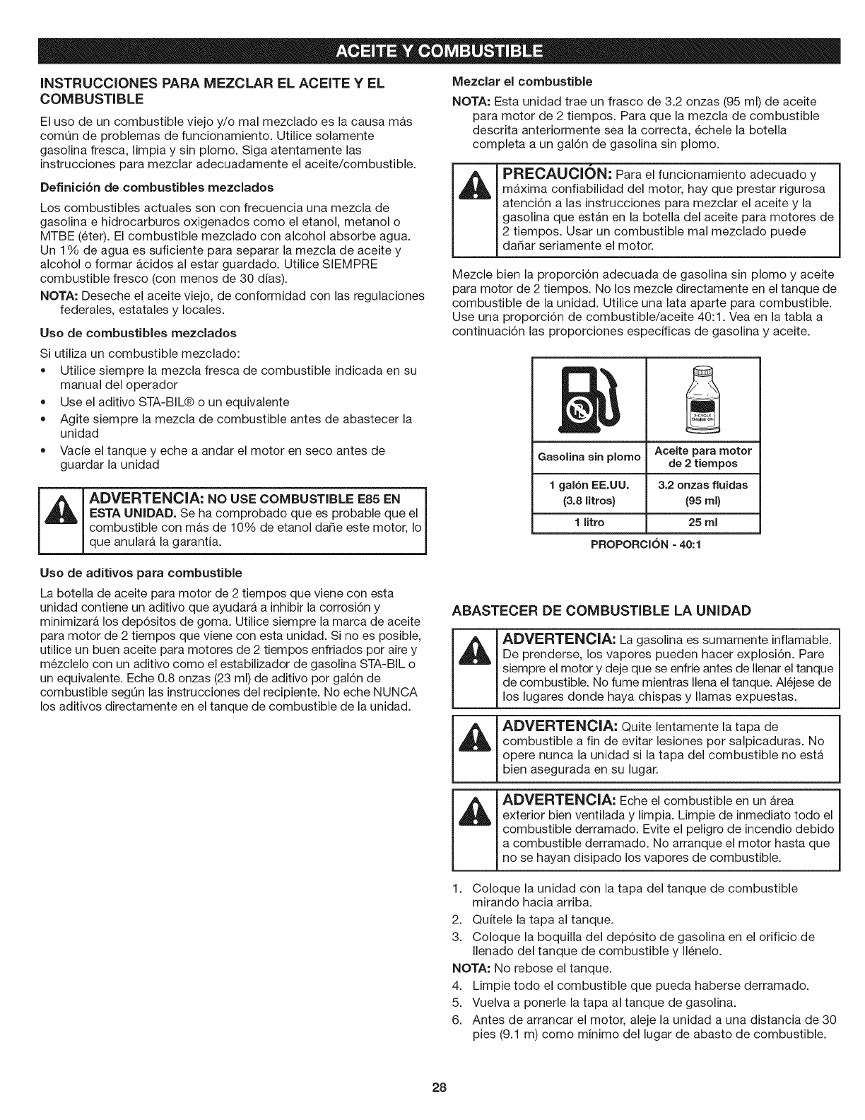
NOTA: Esta unidad trae un frasco de 3.2 onzas (95 ml) de aceite
para motor de 2 tiempos. Para que la mezcla de combustible
descrita anteriormente sea la correcta, echele la botella
completa a un gal6n de gasolina sin plomo.
_mA_HAm_
I'_HI"L;AUL;IUN: Para el funcionamiento adecuado y
maxima confiabilidad del motor, hay que prestar rigurosa
atenci6n alas instrucciones para mezclar el aceite y la
gasolina que estan en la botella del aceite para motores de
2 tiempos. Usar un combustible real mezclado puede
da5ar seriamente el motor.
Mezcle bien la proporci6n adecuada de gasolina sin plomo y aceite
para motor de 2 tiempos. No los mezcle directamente en el tanque de
combustible de la unidad. Utilice una lata aparte para combustible.
Use una proporci6n de combustible/aceite 40:1. Vea en la tabla a
continuaci6n las proporciones especificas de gasolina y aceite.
Gasolina sin plomo
1 gal6n EE.UU.
(3.8 litros}
1 litro
PROPORClON =40:1
Aceite para motor
de 2 tiempos
3.2 onzas fluidas
(95 ml}
25 ml
ABASTECER DE COMBUSTIBLE LA UNIDAD
I'1
I'1
1.
2.
3.
ADVERTENClA: La gasolina es sumamente inflamable.
De prenderse, los vapores pueden hacer explosi6n. Pare
siempre el motor y deje que se enfrie antes de Ilenar el tanque
de combustible. No fume mientras Ilena el tanque. Alejese de
los lugares donde haya chispas y llamas expuestas.
ADVERTENClA: Quite lentamente la tapa de
combustible a fin de evitar lesiones por salpicaduras. No
opere nunca la unidad si la tapa del combustible no esta
bien asegurada en su lugar.
ADVERTENClA: Eche el combustible en un Area
exterior bien ventilada y limpia. Limpie de inmediato todo el
combustible derramado. Evite el peligro de incendio debido
a combustible derramado. No arranque el motor hasta que
no se hayan disipado los vapores de combustible.
Coloque la unidad con la tapa del tanque de combustible
mirando hacia arriba.
Quitele la tapa al tanque.
Coloque la boquilla del dep6sito de gasolina en el orificio de
Ilenado del tanque de combustible y Ilenelo.
NOTA: No rebose el tanque.
4. Limpie todo el combustible que pueda haberse derramado.
5. Vuelva a ponerle la tapa al tanque de gasolina.
6. Antes de arrancar el motor, aleje la unidad a una distancia de 30
pies (9.1 m) como minimo del lugar de abasto de combustible.
28
ADVERTENClA: Opere esta unidad solamente en un
a.rea exterior bien ventilada. El mon6xido de carbono de
los gases de escape puede ser letal en un Area confinada.
ADVERTENOIA: Evite arrancar la unidad por
accidente. A fin de evitar lesiones graves, el operador y la
unidad deben estar en una posici6n estable al tirar de la
cuerda de arranque (Fig. 9).
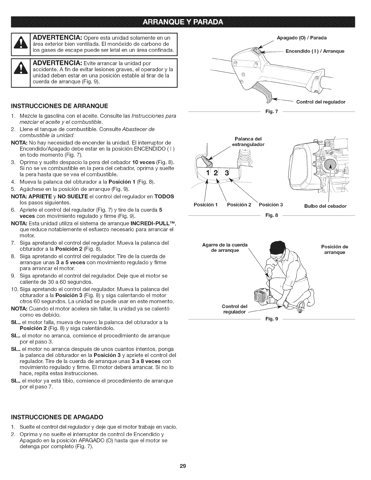
Apagado(O)/Parada
INSTRUCCIONES DE ARRANQUE
1. Mezcle la gasolina con el aceite. Consulte las Instrucciones para
mezclar el aceite y el combustible.
2. Llene el tanque de combustible. Consulte Abastecer de
combustible la unidad.
NOTA: No hay necesidad de encender la unidad. El interruptor de
Encendido/Apagado debe estar en la posici6n ENCENDIDO (I)
en todo momento (Fig. 7).
3. ©prima y suelte despacio la pera del cebador 10 veces (Fig. 8).
Si no se ve combustible en la pera del cebador, oprima y suelte
la pera hasta que se vea el combustible.
4. Mueva la palanca del obturador a la Posici6n 1 (Fig. 8).
5. Agachese en la posici6n de arranque (Fig. 9).
NOTA: APRIETE y NO SUELTE el control del regulador en TODOS
los pasos siguientes.
6. Apriete el control del regulador (Fig. 7) y tire de la cuerda 5
veces con movimiento regulado y firme (Fig. 9).
NOTA: Esta unidad utiliza el sistema de arranque INCREDI-PULL TM,
que reduce notablemente el esfuerzo necesario para arrancar el
motor.
7. Siga apretando el control del regulador. Mueva la palanca del
obturador a la Posici6n 2 (Fig. 8).
8. Siga apretando el control del regulador. Tire de la cuerda de
arranque unas 3 a 5 veces con movimiento regulado y firme
para arrancar el motor.
9. Siga apretando el control del regulador. Deje que el motor se
caliente de 30 a 60 segundos.
10. Siga apretando el control del regulador. Mueva la palanca del
obturador a la Posici6n 3 (Fig. 8) y siga calentando el motor
otros 60 segundos. La unidad se puede usar en este momento.
NOTA: Cuando el motor acelera sin fallar, la unidad ya se calent6
como es debido.
Sl... el motor falla, mueva de nuevo la palanca del obturador a la
Posici6n 2 (Fig. 8) y siga calentandolo.
SL. el motor no arranca, comience el procedimiento de arranque
por el paso 3.
SL. el motor no arranca despues de unos cuantos intentos, ponga
la palanca del obturador en la Posici6n 3 y apriete el control del
regulador. Tire de la cuerda de arranque unas 3 a 8 veces con
movimiento regulado y firme. El motor debera arrancar. Si no Io
hace, repita estas instrucciones.
SL. el motor ya esta tibio, comience el procedimiento de arranque
por el paso 7.
Palanca del
il estrangulador
....... 3j
Posicibn 1Posicibn 2
Agarre de la cuerda
de arranque _
Control del
regulador
Fig. 7
Posicibn 3
Fig. 8
Fig. 9
Bulbo del cebador
INSTRUCCIONES DE APAGADO
1.
2.
Suelte el control del regulador y deje que el motor trabaje en vacio.
Oprima y no suelte el interruptor de control de Encendido y
Apagado en la posici6n APAGADO (O) hasta que el motor se
detenga por completo (Fig. 7).
29
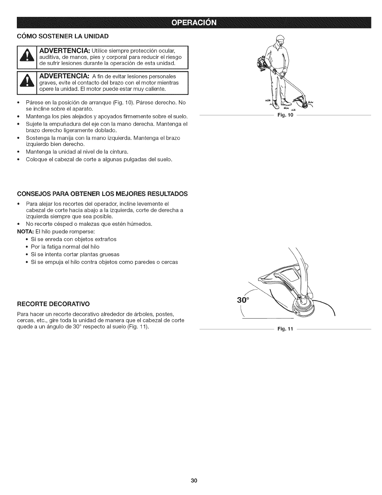
C()MO SOSTENER LA UNIDAD
ADVERTENClA: Utilice siempre protecci6n ocular, j
auditiva, de manos, pies y corporal para reducir el riesgo I
de sufrir lesiones durante la operaci6n de esta unidad.
ADVERTENCIA: A fin de evitar lesiones personales i
graves, evite el contacto del brazo con el motor mientras I
opere la unidad. El motor puede estar muy caliente.
• Parese en la posici6n de arranque (Fig. 10). Parese derecho. No
se incline sobre el aparato.
Mantenga los pies alejados y apoyados firmemente sobre el suelo.
Sujete la empur_adura del eje con la mano derecha. Mantenga el
brazo derecho ligeramente doblado.
Sostenga la manija con la mano izquierda. Mantenga el brazo
izquierdo bien derecho.
Mantenga la unidad al nivel de la cintura.
Coloque el cabezal de corte a algunas pulgadas del suelo.
Fig. 1o
CONSEJOS PARA OBTENER LOS MEJORES RESULTADOS
Para alejar los recortes del operador, incline levemente el
cabezal de corte hacia abajo a la izquierda, corte de derecha a
izquierda siempre que sea posible.
No recorte cesped o malezas que esten hQmedos.
NOTA: El hilo puede romperse:
Si se enreda con objetos extrados
Pot la fatiga normal del hilo
Si se intenta cortar plantas gruesas
Si se empuja el hilo contra objetos como paredes o cercas
\
RECORTE DECORATIVO
Para hacer un recorte decorativo alrededor de b.rboles, postes,
cercas, etc., gire toda la unidad de manera que el cabezal de corte
quede a un a.ngulo de 30 ° respecto al suelo (Fig. 11).
30 °
k
Fig. 11
30
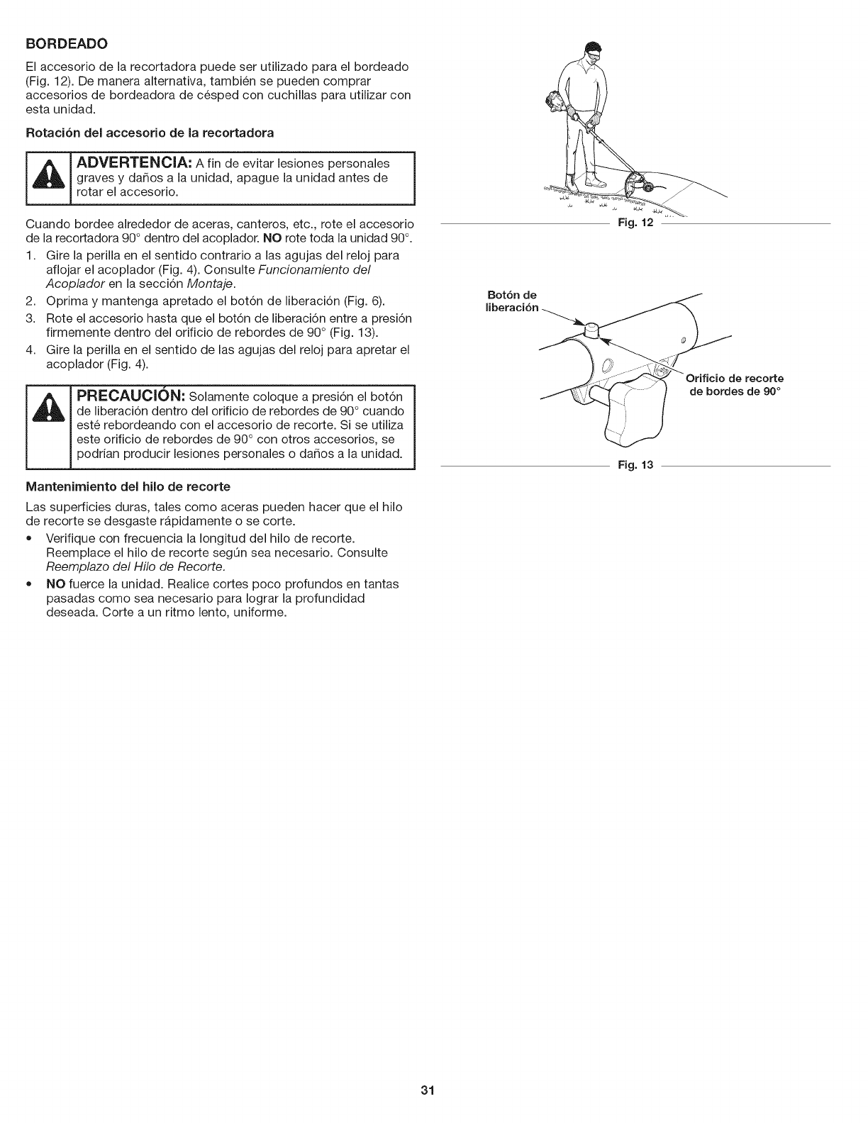
BORDEADO
El accesorio de la recortadora puede ser utilizado para el bordeado
(Fig. 12). De manera alternativa, tambien se pueden comprar
accesorios de bordeadora de cesped con cuchillas para utilizar con
esta unidad.
Rotaci6n del accesorio de la recortadora
_ADVERTENClA: A fin de evitar lesiones personales |
I
graves y dados a la unidad, apague la unidad antes de J
rotar el accesorio.
Cuando bordee alrededor de aceras, canteros, etc., rote el accesorio
de la recortadora 90° dentro del acoplador. NO rote toda la unidad 90°.
1. Gire la perilla en el sentido contrario a las agujas del reloj para
aflojar el acoplador (Fig. 4). Consulte Funcionamiento del
Acoplador en la secci6n Montaje.
2. Oprima y mantenga apretado el bot6n de liberaci6n (Fig. 6).
3. Rote el accesorio hasta que el bot6n de liberaci6n entre a presi6n
firmemente dentro del orificio de rebordes de 90 ° (Fig. 13).
4. Gire la perilla en el sentido de las agujas del reloj para apretar el
acoplador (Fig. 4).
PRECAUCION: Solamente coloque a presi6n el bot6n
de liberaci6n dentro del orificio de rebordes de 90° cuando
este rebordeando con el accesorio de recorte. Si se utiliza
este orificio de rebordes de 90 ° con otros accesorios, se
podrian producir lesiones personales o dados a la unidad.
Mantenimiento del hilo de recorte
Las superficies duras, tales como aceras pueden hacer que el hilo
de recorte se desgaste rapidamente o se corte.
• Verifique con frecuencia la Iongitud del hilo de recorte.
Reemplace el hilo de recorte segQn sea necesario. Consulte
Reemplazo del Hilo de Recorte.
NO fuerce la unidad. Realice cortes poco profundos en tantas
pasadas como sea necesario para Iograr la profundidad
deseada. Corte a un ritmo lento, uniforme.
Bot6n de
Fig. 12
de recorte
de hordes de 90 °
Fig. 13
31
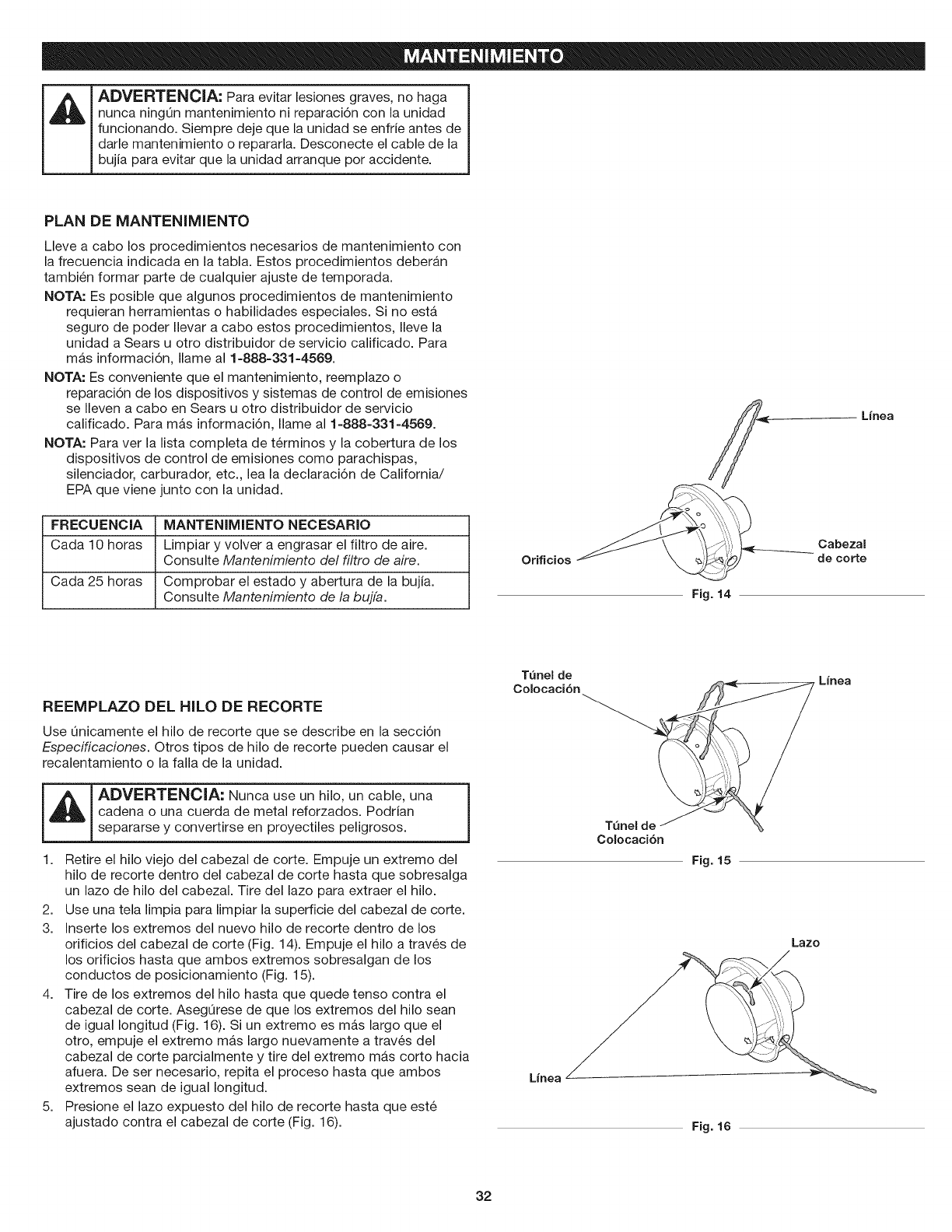
ADVERTENClA: Para evitar lesiones graves, no haga
nunca ningQn mantenimiento ni reparaci6n con la unidad
funcionando. Siempre deje que la unidad se enfrie antes de
darle mantenimiento o repararla. Desconecte el cable de la
bujia para evitar que la unidad arranque per accidente.
PLAN DE MANTENIMIENTO
Lleve a cabo los procedimientos necesarios de mantenimiento con
la frecuencia indicada en la tabla. Estos procedimientos deberan
tambien formar parte de cualquier ajuste de temporada.
NOTA: Es posible que algunos procedimientos de mantenimiento
requieran herramientas o habilidades especiales. Si no esta
seguro de poder Ilevar a cabo estos procedimientos, Ileve la
unidad a Sears u otro distribuidor de servicio calificado. Para
mas informaci6n, Ilame al 1=888=331=4569.
NOTA: Es conveniente que el mantenimiento, reemplazo o
reparaci6n de los dispositivos y sistemas de control de emisiones
se Ileven a cabo en Sears u otto distribuidor de servicio
calificado. Para mas informaci6n, Ilame al 1=888=331=4589.
NOTA: Para ver la lista completa de terminos y la cobertura de los
dispositivos de control de emisiones como parachispas,
silenciador, carburador, etc., lea la declaraci6n de California/
EPA que viene junto con la unidad.
FRECUENCIA MANTENIMIENTO NECESARIO
Cada 10 horas Limpiar y volver a engrasar el filtro de aire.
Consulte Mantenimiento del filtro de aire.
Cada 25 horas Comprobar el estado y abertura de la bujia.
Consulte Mantenimiento de la bujfa.
Orificios
Fig. 14
Linea
Cabezal
de corte
REEMPLAZO DEL HILO DE RECORTE
Use Qnicamente el hilo de recorte que se describe en la secci6n
Especificaciones. Otros tipos de hilo de recorte pueden causar el
recalentamiento o la falla de la unidad.
I _ I ADVERTENClA: Nunca use un hilo, un cable, una
cadena o una cuerda de metal reforzados. Podrian
separarse y convertirse en proyectiles peligrosos. 1
1. Retire el hilo viejo del cabezal de corte. Empuje un extremo del
hilo de recorte dentro del cabezal de corte hasta que sobresalga
un lazo de hilo del cabezal. Tire del lazo para extraer el hilo.
2. Use una tela limpia para limpiar la superficie del cabezal de corte.
3. Inserte los extremes del nuevo hilo de recorte dentro de los
orificios del cabezal de corte (Fig. 14). Empuje el hilo a traves de
los orificios hasta que ambos extremos sobresalgan de los
conductos de posicionamiento (Fig. 15).
4. Tire de los extremos del hilo hasta que quede tenso contra el
cabezal de corte. AsegQrese de que los extremos del hilo sean
de igual Iongitud (Fig. 16). Si un extremo es mas largo que el
otto, empuje el extremo mas largo nuevamente a traves del
cabezal de corte parcialmente y tire del extremo mas corto hacia
afuera. De ser necesario, repita el proceso hasta que ambos
extremos sean de igual Iongitud.
5. Presione el lazo expuesto del hilo de recorte hasta que este
ajustado contra el cabezal de corte (Fig. 16).
TQnelde Linea
_ o
Colocaci6n
Fig. 15
Lazo
Lfnea
Fig. 16
32
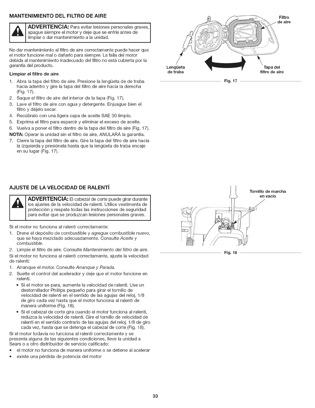
MANTENIMIENTO DEL FILTRO DE AIRE
ADVERTENCIA: Para evitar lesiones personales graves,
apague siempre el motor y deje que se enfrie antes de
mp ar o dar manten m ento a a un dad. j
No dar mantenimiento al filtro de aire correctamente puede hacer que
el motor funcione mal o dafiarlo para siempre. La falla del motor
debida al mantenimiento inadecuado del filtro no esta cubierta pot la
garantia del producto.
Limpiar el filtro de aire
1. Abra la tapa del filtro de aire. Presione la lengQeta de de traba
hacia adentro y gire la tapa del filtro de aire hacia la derecha
(Fig. 17).
2. Saque el filtro de aire del interior de la tapa (Fig. 17).
3. Lave el filtro de aire con agua y detergente. Enjuague bien el
filtro y dejelo secar.
4. RecObralo con una ligera capa de aceite SAE 30 limpio.
5. Exprima el filtro para esparcir y eliminar el exceso de aceite.
6. Vuelva a porter el filtro dentro de la tapa del filtro de aire (Fig. 17).
NOTA: Operar la unidad sin el filtro de aire, ANULARA la garantia.
7. Cierre la tapa del filtro de aire. Gire la tapa del filtro de aire hacia
la izquierda y presi6nela hasta que la lengQeta de traba encaje
en su lugar (Fig. 17).
LengQeta
de traba
Fig. 17
Filtro
\Tapa del
filtro de aire
AJUSTE DE LA VELOCIDAD DE RALENTi
ADVERTENCIA: El cabezal de corte puede girar durante
los ajustes de la velocidad de ralenti. Utilice vestimenta de
protecci6n y respete todas las instrucciones de seguridad
para evitar que se produzcan lesiones personales graves.
Si el motor no funciona al ralenti correctamente:
1. Drene el dep6sito de combustible y agregue combustible nuevo,
que se haya mezclado adecuadamente. Consulte Aceite y
combustible.
2. Limpie el filtro de aire. Consulte Mantenimiento del filtro de aire.
Si el motor no funciona al ralenti correctamente, ajuste la velocidad
de ralenti:
1. Arranque el motor. Consulte Arranque y Parada.
2. Suelte el control del acelerador y deje que el motor funcione en
ralenti.
• Si el motor se para, aumente la velocidad de ralenti. Use un
destornillador Phillips pequefio para girar el tornillo de
velocidad de ralenti en el sentido de las agujas del reloj, 1/8
de giro cada vez hasta que el motor funciona al ralenti de
manera uniforme (Fig. 18).
Si el cabezal de corte gira cuando el motor funciona al ralenti,
reduzca la velocidad de ralenti. Gire el tornillo de velocidad de
ralenti en el sentido contrario de las agujas del reloj, 1/8 de giro
cada vez, hasta que se detenga el cabezal de corte (Fig. 18).
Si el motor todavia no funciona al ralenti correctamente y se
presenta alguna de las siguientes condiciones, Ileve la unidad a
Sears o a otto distribuidor de servicio calificado:
el motor no funciona de manera uniforme o se detiene al acelerar
existe una perdida de potencia del motor
Fig. 18
Tornillo de rnarcha
en vacio
33
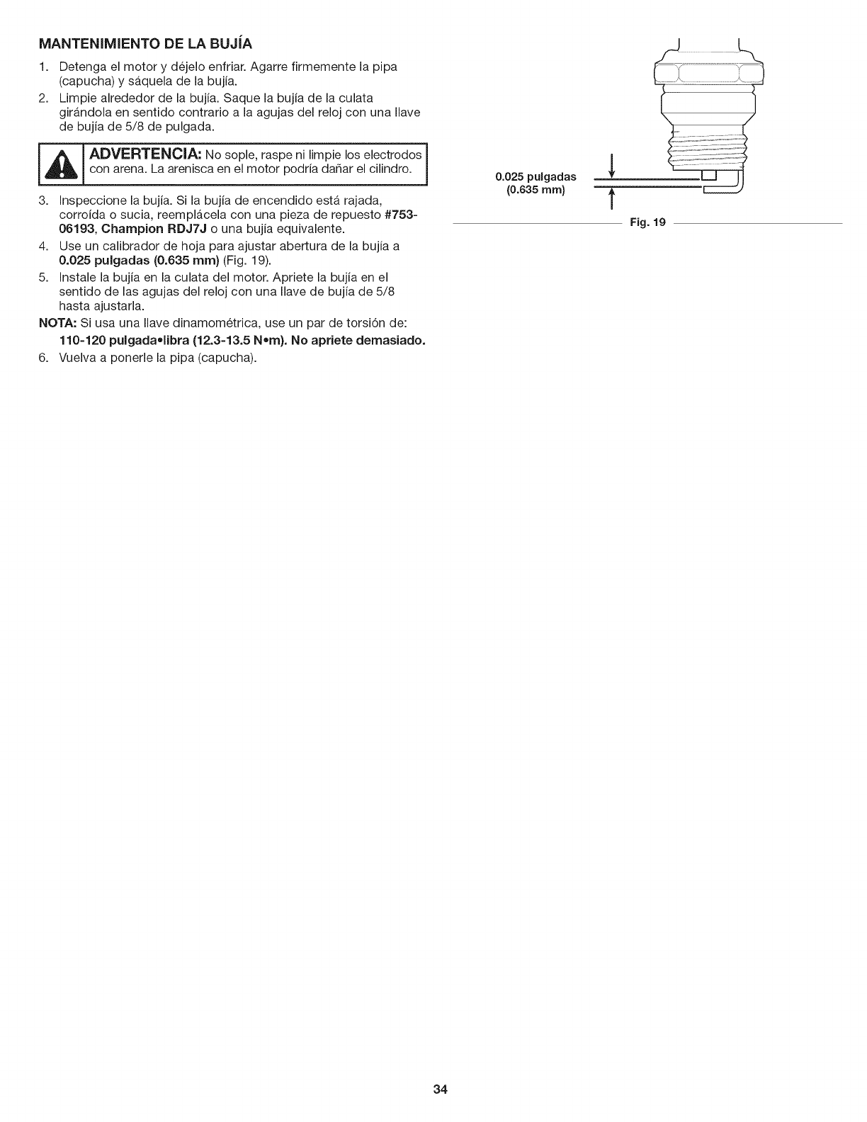
MANTENIMIENTO DE LA BUJiA
1. Detenga el motor y dejelo enfriar. Agarre firmemente la pipa
(capucha) y saquela de la bujia.
2. Limpie alrededor de la bujia. Saque la bujia de la culata
girandola en sentido contrario a la agujas del reloj con una Ilave
de bujia de 5/8 de pulgada.
l_l_ lADVERTENCIA: No sople,raspenilimpieloselectrodos
I
con arena.La areniscaen elmotor podriada_arelcilindro.
3. Inspeccionelabujia.Si labujiade encendido estarajada,
corroidao sucia,reemplb.celacon una piezade repuesto#753-
06193, Champion RDJ7J o una bujia equivalente.
4. Use un calibrador de hoja para ajustar abertura de la bujia a
0.025 pulgadas (0.635 ram) (Fig. 19).
5. Instale la bujia en la culata del motor. Apriete la bujia en el
sentido de las agujas del reloj con una Ilave de bujia de 5/8
hasta ajustarla.
NOTA: Si usa una Ilave dinamometrica, use un par de torsi6n de:
110-120 pulgada,libra (12.3=13.5 N=m}. No apriete demasiado.
6. Vuelva a ponerle la pipa (capucha).
I0.025 pulgadas
(0.635 mm)
Fig. 19
34
LIMPIEZA
ADVERTENClA: A fin de evitar lesiones personales |
graves, siempre pare el motor y deje que se enfrie antes de J
limpiar o mantener la unidad.
Use un cepillo pequer_o para limpiar el exterior de la unidad. No
utilice detergentes fuertes. Los productos de limpieza para el hogar
que contienen aceites aromaticos como pino y lim6n, y los
disolventes como el queroseno, pueden dar_ar el pla,stico. Limpie
todo rastro de humedad con una tela suave.
ALMACENAMIENTO
= Nunca almacene la unidad con combustible en lugares donde
las emanaciones pueden alcanzar llamas abiertas o chispas.
• Deje que se enfrie el motor antes de almacenar la unidad.
Trabe la unidad para evitar que se la utilice sin permiso o que se
provoquen da_os.
Almacene la unidad en una zona seca y bien ventilada.
Almacene la unidad lejos del alcance de los ni_os.
Almacenamiento a corto plazo (1-2 semanas}
1. Almacene la unidad en posici6n horizontal. Si esto no es posible,
almacene la unidad de manera vertical con el motor arriba.
AIrnacenarniento a largo plazo
1. Retire la tapa de combustible, incline la unidad y drene el
combustible en un recipiente aprobado. Vuelva a colocar la tapa
del combustible.
2. Arranque el motor y dejelo correr hasta que se detenga. Esto
asegura que todo el combustible se haya drenado del carburador.
3. Espere a que el motor se enfrie. Quitele la bujia y eche 5 gotas
de cualquier aceite de motor de 2 tiempos de alta calidad en el
cilindro. Tire despacio de la cuerda de arranque para distribuir el
aceite. Vuelva a porter la bujia.
4. Limpie minuciosamente la unidad e inspeccione si hay alguna
pieza suelta o dar_ada. Repare o reemplace las piezas dar_adas
y ajuste los tornillos, tuercas o pernos que esten flojos.
Preparaci6n de la unidad para su uso luego del
almacenamiento a largo plazo
1. Retire la bujia y drene todo el aceite del cilindro.
NOTA: No use combustible que haya estado guardado durante m_,s
de 30 dias. Deseche el combustible usado de acuerdo con las
normativas federales, estatales y locales.
35

PROBLEMA
El tanque de combustible esta vacio
El motor esta rebosado
La bujia esta corroida
SOLUCION
Llene el tanque de combustible con la mezcla adecuada
Mueva la palanca del obturador a la Posici6n 3, apriete el control de
la valvula de velocidad y tire de la cuerda de arranque
Reemplace la bujia
El filtro de aire esta sucio
La marcha en vacio no es la correcta
Limpie o cambie el filtro de aire
Ajuste la velocidad de marcha en vacio
El combustible esta viejo (tiene mas de 30 dias) y/o mal mezclado
El filtro de aire esta sucio
El combustible esta viejo (tiene mas de 30 dias) y/o mal mezclado
La bujia esta corroida
Vacie el tanque de combustible y eche combustible nuevo bien
mezclado
Limpie o cambie el filtro de aire
Vacie el tanque de combustible y eche combustible nuevo bien
mezciado
Reemplace la bujia
36

Felicitaciones pot haber hecho una compra inteligente. Su nuevo producto Craftsman® fue disedado y fabricado con vistas a una operaci6n
confiable pot a_os. Pero como todos los productos, es posible que sea necesario repararlo alguna vez. Ahi es cuando tener un Convenio de
Protecci6n de Reparaci6n puede ahorrarle dinero y problemas.
Esto es Io que incluye el Convenio de Protecci6n de Reparaci6n*:
[] Servicio de experto pot nuestros 10,000 profesionales, especialistas en reparaciones
[] Servicio ilimitado y sin costo alguno en piezas y mano de obra para todas las reparaciones cubiertas
[] Reemplazo del producto pot otto que cueste hasta $1500 si el producto cubierto no tiene reparaci6n
[] Descuento del 25% del precio normal pot el servicio y las piezas instaladas que no cubra el convenio; asi como tambien el 25% de
descuento pot el mantenimiento preventivo
[] Ayuda rApida pot tel6fono - la Ilamamos Soluci6n Rapida - asistencia tecnica por telefono de un representante de Sears.
Considerenos un "manual de usuario que habla".
Una vez que adquiera el Convenio de Protecci6n de Reparaci6n, todo Io que necesita es hacer una simple Ilamada para programar el
servicio. Puede Ilamar a cualquier hora del dia o de la noche o programar el servicio pot Internet.
El Convenio de Protecci6n de Reparaci6n es una compra libre de riesgo. Si usted Io cancela pot cualquier motivo mientras dure la garantia
del producto, le haremos un reembolso completo. Si Io hace en cualquier momento despues de vencida la garantia, le haremos un
reembolso prorrateado, iAdquiera hoy mismo su Convenio de Protecci6n de Reparaci6n!
Se aplican algunas limitaciones yexclusiones. Para precios einformaci6n adicional en Estados Unidos, Ilame al 1=800=827=6655.
*La cobertura en Canada varia en algunos articulos. Para todos los detalles, Ilame a Sears de Canada al 1-800-361-6665.
Servicio de Instalaci6n Sears
Para la instalaci6n de electrodomesticos, abrepuertas de garajes, calentadores de agua, y otros productos para el hogar por profesionales
de Sears, en Estados Unidos o CanadA, Ilame al 1-800-4-MY-HOME.
37

38

39

Product questions or problems?
Customer Care ot Line
Get answers to questions, troubleshoot problems,
order parts, or schedule repair service.
Para respuestas a preguntas o problemas, y ordenar
piezas o pedir servicio para la reparaci6n de su equipo.
To help us help you, register your product at www.craftsman.com/registration
Para poderte ayudar mejor, registra tu producto en www.craftsman.com/registration
Join the Craftsman Club todayZ
CRRFT :MRN
www.craftsman.com/signup
Receive exclusive member benefits including special pricing and offers,
project sharing, expert advice, and SHOP YOUR WAY REWARDS!
Como miembro exclusivo, recibe diversos beneficios como ofertas, precios especiales, proyectos
nuevos, consejos de expertos y nuestro programa de puntos SHOP YOUR WAY REWARDS!
® Registered Trademark /TM Trademark of KCD IP, LLC in the United States, or Sears Brands, LLC in other countries
® Marca Registrada/TM Marca de FAbrica de KCD IP, LLC en Estados Unidos, o Sears Brands, LLC in otros paises
