Craftsman 32010870 User Manual CIRCULAR SAW Manuals And Guides L0804006
CRAFTSMAN Saw Circular Manual L0804006 CRAFTSMAN Saw Circular Owner's Manual, CRAFTSMAN Saw Circular installation guides
User Manual: Craftsman 32010870 32010870 CRAFTSMAN CIRCULAR SAW - Manuals and Guides View the owners manual for your CRAFTSMAN CIRCULAR SAW #32010870. Home:Tool Parts:Craftsman Parts:Craftsman CIRCULAR SAW Manual
Open the PDF directly: View PDF ![]() .
.
Page Count: 72
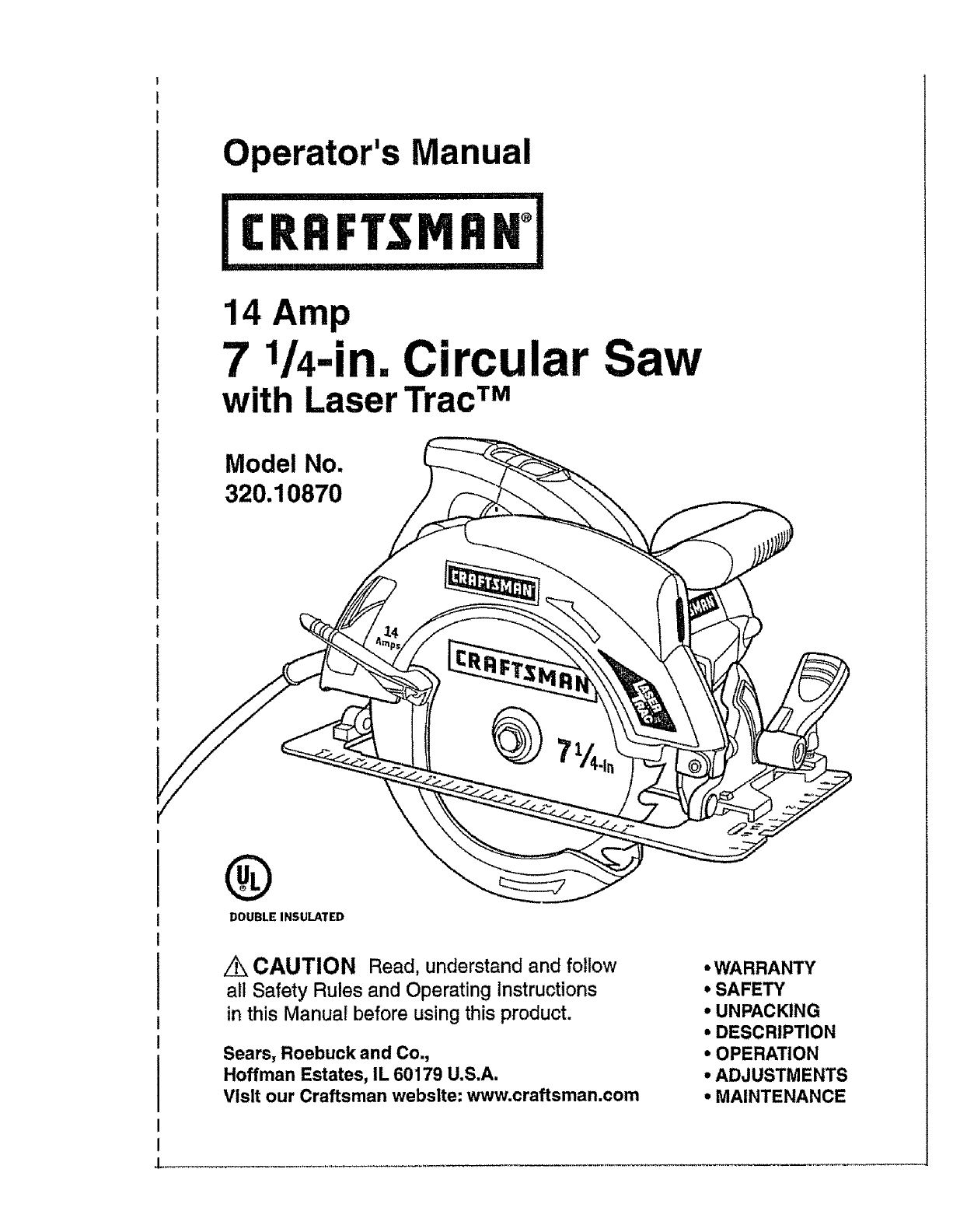
Operator's Manual
14 Amp
7_/4-in. Circular Saw
with Laser TracTM
Model No.
320.10870
®
DOUBLE INSULATED
/_ CAUTION Read, understand and follow
all Safety Rules and Operating Instructions
in this Manual before using this product.
Sears, Roebuck and Co.,
Hoffman Estates, IL 60179 U.S.A.
Visit our Craftsman webslte: www.craftsman.com
• WARRANTY
*SAFETY
•UNPACKING
* DESCRIPTION
•OPERATION
•ADJUSTMENTS
•MAINTENANCE
Warranty .................................................................................. Page 2
Safety Symbols ..................................................................................Page 3
Safety Instructions ........................................................ Pages 4- 11
Glossary of Terms ......................................................... Pages 11 - 12
Unpacking ................................................................... Pages 12- 13
Description .......................................................................... Pages t3 - 15
Operation ....................................................................... Pages 15 - 25
Adjustments ......................................................................... Page 26- 27
Maintenance ......................................................................... Pages 27 - 29
Troubleshooting .................................................................... Page 30
Accessories ............................................................................... Page 30
Repair Parts .......................................................................... Pages 31 - 34
Sears Repair Parts Phone Numbers ..................................... Back Cover
ONE YEAR FULL WARRANTY ON CRAFTSMAN ®PRODUCT
tf this Craftsman product fails due to a defect in material or workmanship
within one year from the date of purchase, RETURN ITTO THE
NEAREST SEARS STORE OR PARTS AND REPAIR CENTER OR
OTHER CRAFTSMAN OUTLET INTHE UNITED STATES FOR FREE
REPAIR (OR REPLACEMENT IF REPAIR PROVES IMPOSSIBLE).
This warranty does not include expendable parts such as lamps,
batteries, bits or blades.
If this Craftsman product is used for commercial or rental purposes,
this warranty applies for only 90 days from the date of purchase.
This warranty gives you specific legal rights, and you may also
have other rights, which vary from state to state.
Sears, Roebuck and Co., Hoffman Estates, IL 60179
SAVE THESE INSTRUCTIONS!
READ ALL INSTRUCTIONS!
2
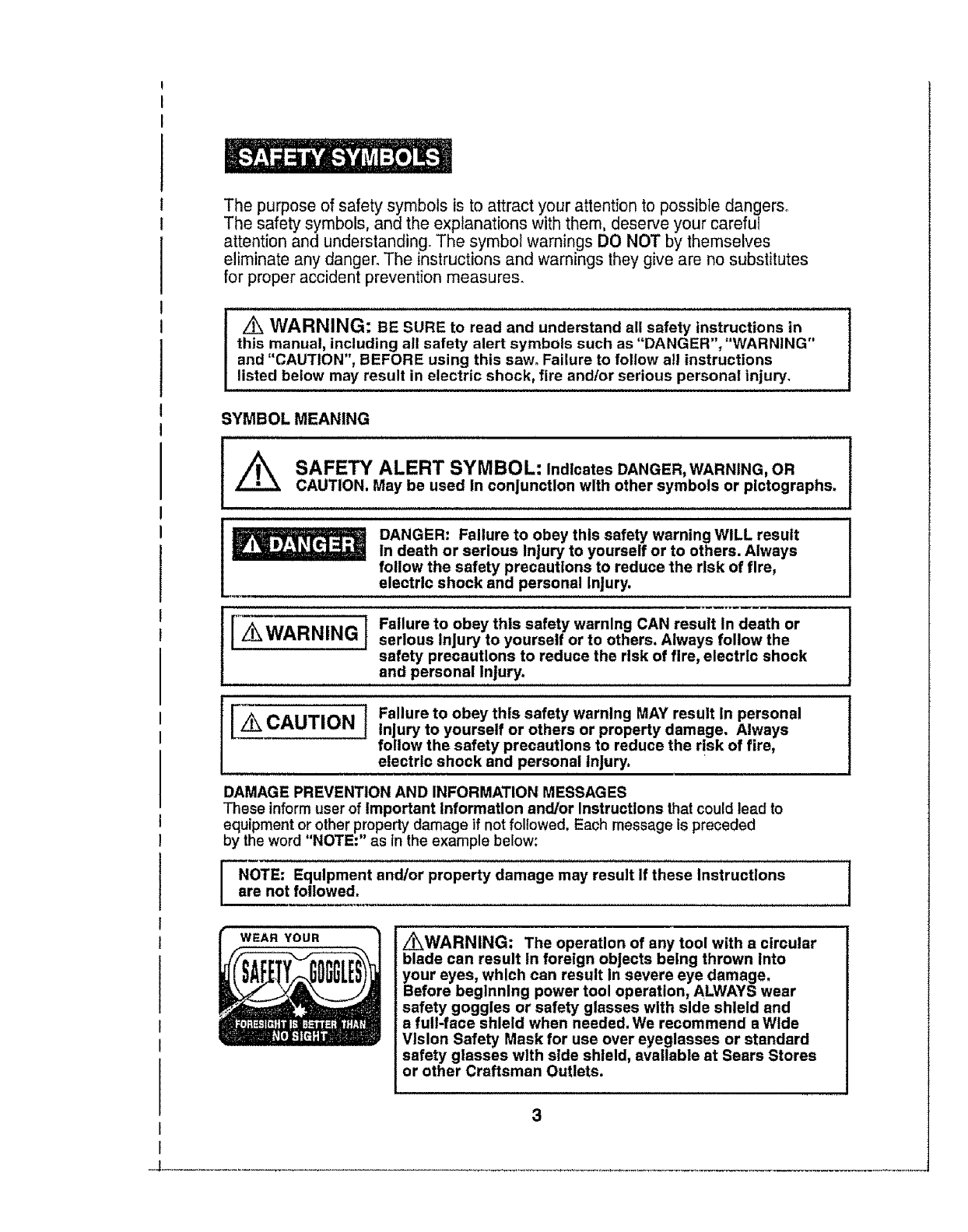
The purpose of safety symbols is to attract your attention to possible dangers.
The safety symbols, and the explanations with them, deserve your careful
attention and understanding. The symbol warnings DO NOT by themselves
eliminate any danger° The instructions and warnings they give are no substitutes
for proper accident prevention measures.
Z_ WARNING: BE SURE to read and understand all safety instructions in
this manual, including all safety alert symbols such as "DANGER", "WARNING"
and "CAUTION", BEFORE using this saw, Failure to follow all instructions
listed below may result in electric shock, fire andlor serious personal injury.
SYMBOL MEANING
SAFETY ALERT SYMBOL: Indicates DANGER, WARNING, OR
CAUTION. May be used In conjunction with other symbols or pictographs.
DANGER: Failure to obey this safety warning WILL result
In death or serious Injury to yourself or to others. Always
follow the safety precautions to reduce the risk of fire,
electric shock and personal Injury.
'z_ WARNING t Failure to obey this safety warning CAN result In death or
serlous Injury to yourself or to others. Always follow the
safety precautions to reduce the risk of fire, electric shock
and personal Injury.
I_ IFailure to obey this safety warning MAY result In personal
CAUTION Injury to yourself or others or property damage. Always
follow the safety precautions to reduce the risk of fire,
electric shock and personal Injury.
DAMAGE PREVENTION AND INFORMATION MESSAGES
These inform user of Important Information and/or Instructlons that could lead to
equipment or other property damage if not followed. Each message is preceded
by the word "NOTE:" as in the example below:
NOTE: Equipment and/or property damage may result If these Instructions
are not followed.
WEAR YOUR i_WARNING: The operation of any tool with a circular
blade can result in foreign objects being thrown Into
your eyes, which can result In severe eye damage.
Before beginning power tool operation, ALWAYS wear
safety goggles or safety glasses with side shield and
a full-face shield when needed. We recommend aWide
Vision Safety Mask for use over eyeglasses or standard
safety glasses with side shield, available at Sears Stores
or other Craftsman Outlets.
.J
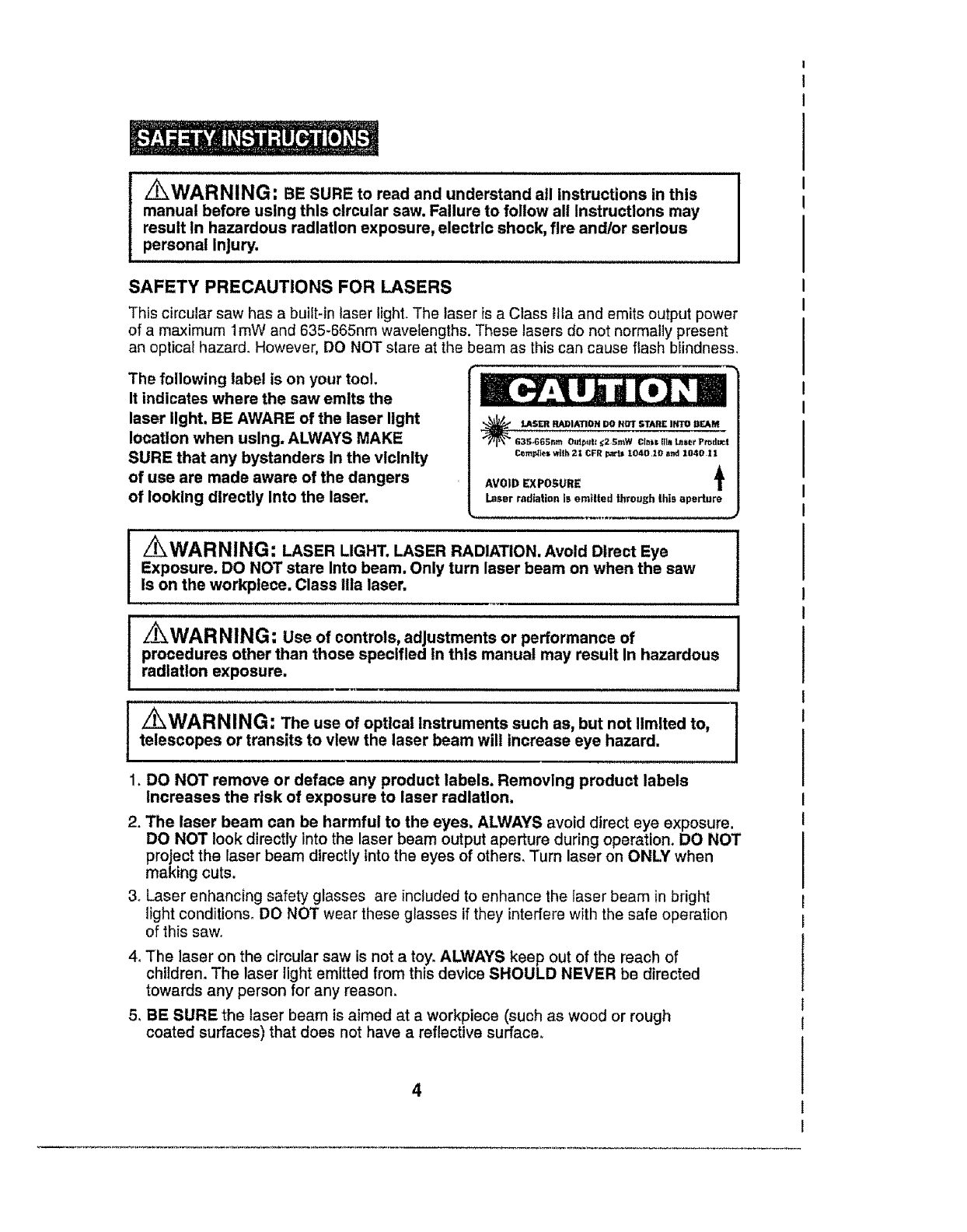
_WARNING: BE SURE to read and understand all Instructions in this
manual before using this circular saw. Failure to follow all instructions may
result In hazardous radiation exposure, electric shock, fire and/or serious
personal Injury.
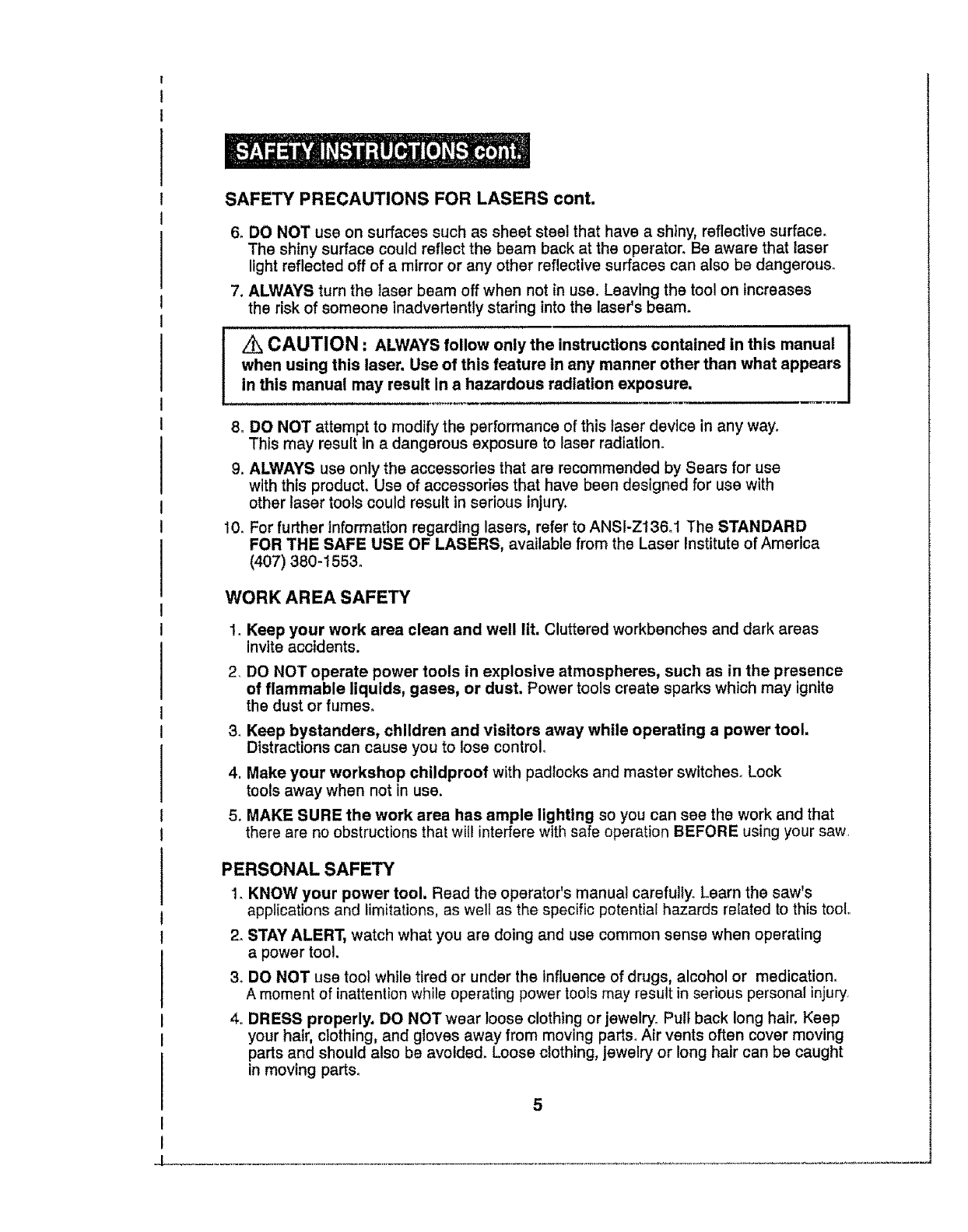
SAFETY PRECAUTIONS FOR LASERS
This circular saw has a buift-in laser light. The laser is a Class tile and emits output power
of a maximum 1roW and 635-665nm wavelengths. These lasers do not normally present
an optical hazard. However, DO NOT stare at the beam as this can cause flash blindness.
The following label is on your tool,
It indicates where the saw emits the
laser light, BE AWARE of the laser light
location when using. ALWAYS MAKE
SURE that any bystanders In the vlclnlty
of use are made aware of the dangers
of looking directly Into the laser.
G3_;,665nm O_dp_t: _;2 _;_W Cl.sl; ilia L_ser Pr_dgct
temples w_th21 CFR par_ I040,10 end 1040 11
AVOID EXPOSURE
Laser radiation is emitted through this aperture
/_WARNING: LASER LIGHT, LASER RADIATION. Avoid Direct Eye
Exposure. DO NOT stare Into beam. Only turn laser beam on when the saw
Is on the workplece. Class ilia laser,
i.......................
z_WARNING: Use of controls, adjustments or performance of
procedures other than those specified in this manual may result In hazardous
radiation exposure.
_WARNING: The use of optical Instruments such as, but not limited to,
telescopes or transits to view the laser beam will Increase eye hazard,
1. DO NOT remove or deface any product labels. Removing product labels
Increases the risk of exposure to laser radiation,
2. The laser beam can be harmful to the eyes. ALWAYS avoid direct eye exposure.
DO NOT look directly into the laser beam output aperture during operation. DO NOT
project the laser beam directly into the eyes of others, Turn laser on ONLY when
making cuts.
3. Laser enhancing safety glasses are included to enhance the laser beam in bright
light conditions° DO NOT wear these glasses if they interfere with the safe operation
of this saw,,
4. The laser on the circular saw is not a toy. ALWAYS keep out of the reach of
children. The laser light emltted from this device SHOULD NEVER be directed
towards any person for any reason.
5. BE SURE the laser beam is aimed at a workpiece (such as wood or rough
coated surfaces) that does not have a reflective surface°
SAFETY PRECAUTIONS FOR LASERS cont.
6. DO NOT use on surfaces such as sheet steel that have a shiny, reflective surface.
The shiny surface could reflect the beam back at the operator. Be aware that laser
light reflected off of a mirror or any other reflective surfaces can also be dangerous.
7. ALWAYS turn the laser beam off when not in use. Leaving the tool on increases
the risk of someone inadvertently staring into the laser's beam.
!i', CAUTION: ALWAYS follow only the instructions contained in this manual
when using this laser. Use of this feature in any manner other than what appears
in this manual may result in a hazardous radiation exposure.
8o DO NOT attempt to modify the performance of this laser device in any way.
This may result in adangerous exposure to laser radiation.
9. ALWAYS use only the accessories that are recommended by Sears for use
with this product. Use of accessories that have been designed for use with
other laser tools could result in serious injury.
10. For further information regarding lasers, refer to ANSI-Z136.l The STANDARD
FOR THE SAFE USE OF LASERS, available from the Laser Institute of America
(407) 380-1553.
WORK AREA SAFETY
1. Keep your work area clean and well lit. Cluttered workbenches and dark areas
invite accidents.
2. DO NOT operate power tools in explosive atmospheres, such as in the presence
of flammable liquids, gases, or dust. Power tools create sparks which may ignite
the dust or fumes.
3. Keep bystanders, children and visitors away while operating a power tool,
Distractions can cause you to lose control.
4, Make your workshop childproof with padlocks and master switches. Lock
tools away when not in use.
5. MAKE SURE the work area has ample lighting so you can see the work and that
there are no obstructions that wil! interfere with safe operation BEFORE using your saw
PERSONAL SAFETY
1, KNOW your power tool. Read the operator's manual carefully. Learn the saw's
applications and limitations, as well as the specific potential hazards related to this tool,,
2, STAY ALERT, watch what you are doing and use common sense when operating
a power tool.
3, DO NOT use tool while tired or under the influence of drugs, alcohol or medication,
A moment of inattention while operating power tools may result in serious personal injury,
4. DRESS properly. DO NOT wear loose clothing or jewelry. Pull back long hair, Keep
your hair, clothing, and gloves away from moving parts° Air vents often cover moving
parts and should also be avoided. Loose clothing, jewelry or long hair can be caught
in moving parts.
5
PERSONALSAFETYcont.
5, AVOID accidental starting. Be sure switch is in "OFF" position before
plugging in. DO NOT carry tools with your finger on the switch. Carrying tools
with your finger on the switch or plugging in tools that have the switch In the
"ON" position invites accidents.
6. REMOVE adjusting keys or wrenches before turning the tool "ON". A wrench
that is left attached to a rotating part of the tool may result in personal injury.
7. Do not overreach. Keep proper footing and balance at all times, Proper
footing and balance enables better control of the too! in unexpected situations.
8. ALWAYS SECURE YOUR WORK, Use clamps or a vise to hold work when
practical. It is safer than using your hand and frees both hands to operate toolo
9. USE SAFETY EQUIPMENT. Always wear eye protection. Dust mask, non-skid
safety shoes, hard hat, or hearing protection must be used for appropriate
conditions_
10. DO NOT USE ON A LADDER or unstable support. Stable footing on a solid
surface enables better control of the too! in unexpected situations.
TOOL USE AND CARE SAFETY
/'lk WARNING: BE SURE to read and understand all instructions before I
operating this saw. Failure to follow all instructions listed below may result in I
electric shock, fire and/or serious personal injury.
1_ALWAYS use clamps or other practical ways to secure and support the
workpiece to a stable platform, Holding the work by hand or against your body
is unstable and may lead to loss of control
2, DO NOT force the tool. Use the correct tool and blade for your application.
The correct tool and blade will do the job better and safer at the rate for which it is
designed,
3. DO NOT use the tool if switch does not turn it "On" or "Off", Any tool that
cannot be controlled with the switch is dangerous and must be repaired.
4DISCONNECT the plug from the power source before making any adjustments,
changing accessories or storing the tool. Such preventive safety measures
reduce the risk of starting the tool accidentally.
5. NEVER leave the tool running. ALWAYS turn it off, DO NOT leave the toot until
it comes to acomplete stop.
64STORE idle tools out of the reach of children and other untrained persons.
Tools are dangerous in the hands of untrained users.
7. MAINTAIN tools with care. Keep cutting tools sharp and clean. Properly
maintained tools with sharp cutting edges are less likely to bind and are easier to
control.
8. CHECK for misatignment or binding of moving parts, breakage of parts, and
any other condition that may affect the tool's operation° If damaged, have the tool
serviced before using. Many accidents are caused by poorly maintained tools.
9. USE ONLY accessories that are recommended for this tool. Accessories that
may be suitable for one tool may become hazardous when used on another tool.
6
_L_,
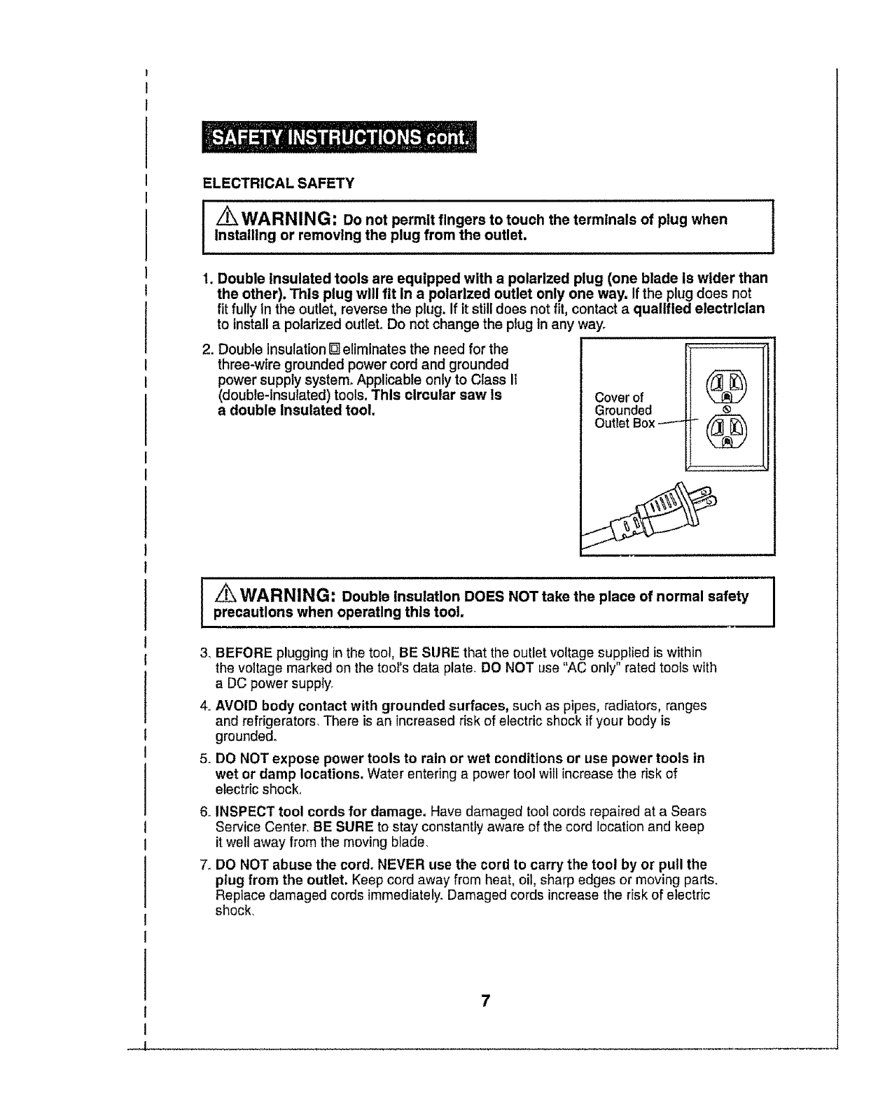
ELECTRICALSAFETY
I/_ WARNIN G: Do not permit fingers to touch the terminals of plug when
installing or removing the plug from the outlet.
1. Double insulated tools are equipped with a polarized plug (one blade is wider than
the other). This plug will fit in a polarized outlet only one way, If the plug does not
fit fully In the outlet, reverse the plug. If it still does not fit, contact aqualified electrician
to install a polarized outlet. Do not change the plug in any way.
2. Double Insulation [] eliminates the need for the
three-wire grounded power cord and grounded
power supply system. Applicable only to Class It
(double-insulated) tools. This circular saw is
a double Insulated tool.
Cover of
Grounded ®
Outlet Box ----" (_
/_ WARNING: Double insulation DOES NOT take the place of normal safety
precautions when operating this tool,
3. BEFORE plugging in the tool, BE SURE that the outlet voltage supplied is within
the voltage marked on the tool's data plate. DO NOT use "AC only" rated tools with
a DC power supply,
4,, AVOID body contact with grounded surfaces, such as pipes, radiators, ranges
and refrigerators, There is an increased risk of electric shock if your body is
grounded.
5. DO NOT expose power tools to rain or wet conditions or use power tools in
wet or damp locations. Water entering a power tool will increase the risk of
electric shock.
6. INSPECT tool cords for damage. Have damaged toot cords repaired at a Sears
Service Center. BE SURE to stay constantly aware of the cord location and keep
it well away from the moving blade.
7. DO NOT abuse the cord. NEVER use the cord to carry the toot by or pull the
plug from the outlet. Keep cord away from heat, oil, sharp edges or moving parts,
Replace damaged cords immediately. Damaged cords increase the risk of electric
shock.
EXTENSION CORDS
Use a proper extension cord. ONLY use cords listed by Underwriters Laboratories
(UL). Other extension cords can cause a drop in line voltage, resulting in a loss of
power and overheating of 1ool. For this tool an AWG (American Wire Gauge) size of
at least 14-gauge is recommended for an extension cord of 25-ff. or tess in length_
Use 12-gauge for an extension cord of 50-ft. Extension cords 100-ft. or longer are not
recommended. Remember, a smaller wire gauge size has greater capacity than
a larger number (14-gauge wire has more capacity than 16-gauge wire; 12-gauge
wire has more capacity than 14-gauge), When in doubt use the smaller number.
When operating a power tool outdoors, use an outdoor extension cord marked
"W-A" or "W"o These cords are rated for outdoor use and reduce the risk of electric
shock.
_CAUTION: Keep the extension cord clear of the working area. Position
the cord so that it will not get caught on lumber, tools or other obstructions
while you are working with a power tool.
I Z_WARNING: Check extension cords before each use. If damaged
replace immediately. Never use tool with a damaged cord since touching the
damaged area could cause electrical shock, resulting in serious injury.
SAFETY SYMBOLS FOR YOUR TOOL
The label on your tool may Include the following symbols.
V........................................................................Volts
A........................................................................................Amps
Hz......................................................................................Hertz
W..........................................................................VVatts
mln........................................................................Minutes
,._ .....................................................................................Alternating current
..................................................................................Direct current
no ........................................................................No-load speed
[] ....................................................................Class li construction, Double Insulated
_Jmin .............................................................. Revolutions or Strokes per minute
Z_"......................................................................Indicatesdanger,warningorcaution
It means attention! Your safety is involved.
SERVICE SAFETY
1. If any part of this saw is missing or should break, bend, or fail in any way;
or should any electrical component fail to perform properly: SHUT OFF
the power switch and remove the saw plug from the power source and have
the missing, damaged or failed parts replaced BEFORE resuming operation.
2. Tool service must be performed only at aSears Parts and Repair Center.
Service or maintenance performed by unqualified personnel could result in
a risk of injury.
3. When servicing a tool, use only identical replacement parts. Follow
instructions in the maintenance section of this manual. Use of unauthorized
parts or failure to follow maintenance instructions may create a risk of electric
shock or injury.
SAFETY RULES FOR CIRCULAR SAWS
Keep hands away from cutting area and blade. Keep your
second hand on the auxiliary handle or motor housing. If both hands are holding
the saw, the blade cannot cut them.
I_ CAUTION: Blades coast after saw Is switched off.
1KEEP your body positioned to either side of the saw blade and not in direct
line with the saw blade° Kickback could cause the saw to jump backwards_ (See
"Kickback .,What Causes It and Ways to Prevent It" on pages 16 and !7).
2, DO NOT reach underneath the work. The guard cannot protect you from the blade
beneath the workpiece,
_When sawing through a workpiece, the lower blade guard
DOES NOT cover the blade on the underside of the workpiece (Pg. 15 Fig, 2),
ALWAYS keep your hands and fingers away from the cutting area.
3 CHECK lower guard for proper closing BEFORE each use° DO NOT operate the saw
if the lower guard does not move freely and close instantly. Never clamp or tie the
lower guard In the open position. If the saw is accidentally dropped, the lower guard may
be bent. Raise the lower guard with the retracting lever The guard is operating properly
when it moves freely, does not touch the blade or any other part in all angles and depths
of cut, and readily returns to the closed position.
4. CHECK the operation and condition of the lower guard spring. If the guard and the
spring are not operating properly, they MUST BE serviced before use. The lower
guard may operate sluggishly, due to damaged parts, gummy deposits, or a buildup of
debris, DO NOT operate your saw until the damage has been repaired or replaced
5. The lower guard should be retracted manually ONLY for making special cuts, such
as pocket or compound cuts, ALWAYS raise the lower guard by retracting Its lever,
As soon as the blade enters the material, the lower guard MUST be released. For all
other sawing, the fower guard should operate automatically.
6. ALWAYS make sure that the lower guard is covering the blade BEFORE placing the
saw down on a work bench or floor, An unprotected moving blade will cause the saw to
walk backwards, cutting whatever is in its path. Make note of the time it takes for the blade
to stop spinning after the switch is released.
7oNEVER hold the piece being cut in your hands or across your legs. It is importantto
support the workpiece properly in order to minimize body exposure, blade binding, or loss
of control.
8, HOLD TOOL by insulated gripping surfaces (handles) when performing an operation
where the cutting tool may contact hidden wiring or its own cord. Contact with a "live"
wire will make the exposed metal parts of the tool "live" and shock the operator
9. ALWAYS clamp the workpiece securely so it wiil not move when making the cut.
10oWhen ripping, ALWAYS USE a rip fence or straight edge guide, This improves the
accuracy of the cut and reduces the chance of the blade binding°
11 ALWAYS USE blades that have the correct size and shape (diamond vs. round) arbor
holes. Blades that do not match the mounting hardware of the saw will run erratically and
cause loss of control 9
SAFETY RULES FOR CIRCULAR SAWS cont,
12oNEVER use damaged or incorrect blade washers or bolts. The blade washers and
bolts were specially designed for your saw, for optimum performance and safety of operation.
13. NEVER cut more than one piece at a time. DO NOT STACK more than one
workpiece on the worktable at a time.
14_AVOID awkward operations and hand positions where a sudden slip could
cause your hand to move into the blade,
15, NEVER reach into the cutting path of the blade.
WARNING: Use of this product can generate dust containing chemicals
known to cause cancer, birth defects or other reproductive harm. Some examples of
these chemicals are:
•Lead from lead-based paints..
• Crystalline silica from bricks and cement and other masonry products_
• Arsenic and chromium, from chemically treated lumber,
Your risk from these exposures varies, depending upon how often you do this
type of work.To reduce your exposure to these chemicals'.
• Work in a well-ventilated area,
.Work with approved safety equipment, such as those dust masks that are specially
designed to filter out microscopic particles.
Avoid prolonged contact with dust from power sanding, sawing, grinding, drilling
and other construction activities. Wear protective clothing and wash exposed areas
with soap and water.
Allowing dust to get into your mouth, eyes, or lay on the skin may promote absorption
of harmful chemicals.
z_ WARNING: Use of this tool can generate and/or disburse dust, which
may cause serious and permanent respiratory or other injury, Always use
NIOSH/OSHA approved respiratory protection appropriate for the dust exposure.
Direct particles away from face and body.
ADDITIONAL RULES FOR SAFE OPERATION
..................................I,/_ WARNING: BE SURE to read and understand all instructions. Failure
to follow all instructions listed below may result in electric shock, fire and/or
serious personal injury, ......................................
1, Know your power tool, Read operator's manual carefully. Learn the applications
and limitations, as well as the specific potential hazards related to this tool.. Following
this rule will reduce the risk of electric shock, fire or serious injury.
2_ALWAYS wear safety glasses or eye shields when using this saw. Everyday
eyeglasses have only impact-resistant lenses; they are NOT safety glasses_
3_PROTECT your lungs. Wear a face mask or dust mask if the operation is dusty.
4oPROTECT your hearing. Wear appropriate personal hearing protection during use. Under
some conditions and duration of use, noise from this product may contribute to hearing loss,
5. ALL VISTORS AND BYSTANDERS MUST wear the same safety equipment that the
operator of the saw wears_
10
ADDITIONAL RULES FOR SAFE OPERATION cont.
6. INSPECT the tool cords periodically and if damaged have them repaired at your
nearest Sears Service Center or other Authorized Service Facility. BE AWARE
of the cord location.
7ALWAYS check the tool for damaged parts, Before further use of the tool, a guard or
other part that is damaged should be carefully checked to determine if it will operate properly
and perform its intended function. Check for misalignment or binding of moving parts,
breakage of parts, and any other condition that may affect the tool's operation, A guard or
other part that is damaged should be properly repaired or replacedat a Sears Service center.
8 INSPECT and remove all nails from lumber before sawing,
9SAVE THESE INSTRUCTIONS. Refer to them frequently and use them to instruct others
who may use this tool. If someone borrows this tool, make sure they have these
instructions also.
Spindle
The shaft on which a blade or cutting tool is mounted. Also called the Arbor.
Revolutions Per Minute (RPM)
The number of turns completed by a spinning object in one minute.
Saw Blade Path
The area over, under, behind or in front of the blade, as it applies to the workpiece.
That area which will be or has been cut by the blade.
Set
The distance that the saw blade tooth is bent (or set) outward from the face of the blade
Miter Cut
A cutting operation made with the blade at any angle other than 900to the fence.
Compound Miter Cut
A compound miter cut is a cut made using a miter angle and a bevel angle at the same time
Cross cut
A cutting or shaping operation made against the grain of the workpiece
Bevel Cut
A cutting operation made with the blade at any angle other than 900to the miter table.
Dado Cut
A non-through cut which produces a square-sided notch or trough in the workpiece
(requires special blade).
Chamfer Cut
A cut removing a wedge from a block of wood so the end (or part of the end) is
angled at other than 900.
Ripping or Rip Cut
A cutting operation along the length of the workpiece.
Freehand Cut
Performing a cut without using a fence, miter gauge, fixture, work clamp, or other
proper device to keep the workpiece from twisting or moving during the cut.
Through Sawing
Any cutting operation where the blade extends completely throughthe thickness of the workpiece.
11
-t
Non-Through Cuts
Any cutting operation where the blade does not extend completely through the
thickness of the workpiece, like a dado cut.
Leading End
The end of the workpiece pushed into tool firsL
Kerr
The material removed by the blade in a through cut or the slot produced by the blade
in a non-through or partial cut
Kickback
A hazard that can occur when the blade binds or stalls, throwing the workpiece back
toward operator.
Workpiece or Material
The item on which the cutting operation is being done_ The surfaces of a workpiece
are commonly referred to as faces, ends and edges.
Gum
A sticky, sap-based residue from wood products.
Resin
A sticky, sap-based substance that has hardened.
/_ WARNING: Your saw should NEVER be connected to the power source
when you are assembling parts, making adjustments, installing or removing
blades, cleaning or when It is not In use. Disconnecting the saw will prevent
accidental starting, which could cause serious personal Injury.
1. The saw's cutting blade is installed at the factory.
2. The edge guide is force-fitted into the top of the lid of the storage/carrying case.
3. The blade wrench is also force-fitted into the top of the lid of the case. The wrench
is used when changing or installing a new blade.
4. Also included and attached to the top of the lid of the case with a hook and loop strap
is a pair of Laser enhancing safety glasses which are used to enhance the laser
beam in bright light conditions.
5o There Is a blade storage area in the bottom of the case where an extra blade can
be stored.
6. Inspect the saw carefully to make sure that no breakage or damage has occurred
during shipping, tf any of the items mentioned are missing (refer to PARTS LIST
on page 13), return the saw to your nearest Sears store or Craftsman outlet
to have the saw replaced.
_WARNING: If any parts are broken or mlsslng, DO NOT attempt to plug
in the power cord or operate saw until the broken or missing parts are replaced.
Failure to do so could result In posslble serious Injury.
12

PARTS LIST
FIg. 1
1. Saw
2. Blade
(Installed at factory)
3. Edge Guide I_1
(stored in case) -_ j
4. Blade Wrench
(stored in case)
5, Laser enhancing_
safety glasses C/\_
(for enhancing laser)
6. Operator's Manual
KNOW YOUR CIRCULAR SAW (Fig. 2)
INOTE: Before attempting to use your saw, familiarize yourself with all of the
operating features and safety requirements. I
Your circular saw has a precision-built electric motor and it should only be connected to a
120-volt, 60-Hz AC ONLY power supply (normal household current). DO NOT operate on
direct current (DC). This large voltage drop will cause a loss of power and the motor wtll
overheat° If the saw does not operate when plugged into correct 120-volt, 60-Hz AC ONLY
outlet, check the power supply The saw has an 8-ft, 2-wire power cord (no adapter needed).
This Circular Saw has the following features:
1.14 Amp, 5000 RPM (no-load speed) motor provides the power and torque for fast,
sure cuts in wood, plywood, hardboard and wood-base materials.
2, Laser TracTMThe unique, Innovative feature for accurate, efficient cuttlngl
3_LED WORKLIGHT illuminates cutting area for easy visibility.
This light stays "On" when saw is plugged into power source.
4 Quick depth-of-cut adjustments with a maximum depth of cut:
23/s-In. thick at 90°; 1 13h6-1n. thick at 45°
5. Easy to read bevel cut scale adjusts from 0° to 54,5 ° bevel capacity.
6. Die-cast aluminum blade guards for extra strength and durability.
7_Extended length trigger switch\ for maximum control and comfort.
Squeeze for power "ON", release for power "OFF".
8. Oversized machined aluminum base has integrated rip and crosscut ruler.
9. Soft-grip ergonomtcally designed contoured rear handle and front assist handle
for positive gripping, control, balance and comfort.
10_includes Craftsman ®24 tooth carbide-tipped steel general purpose blade.
I
I
_J
13
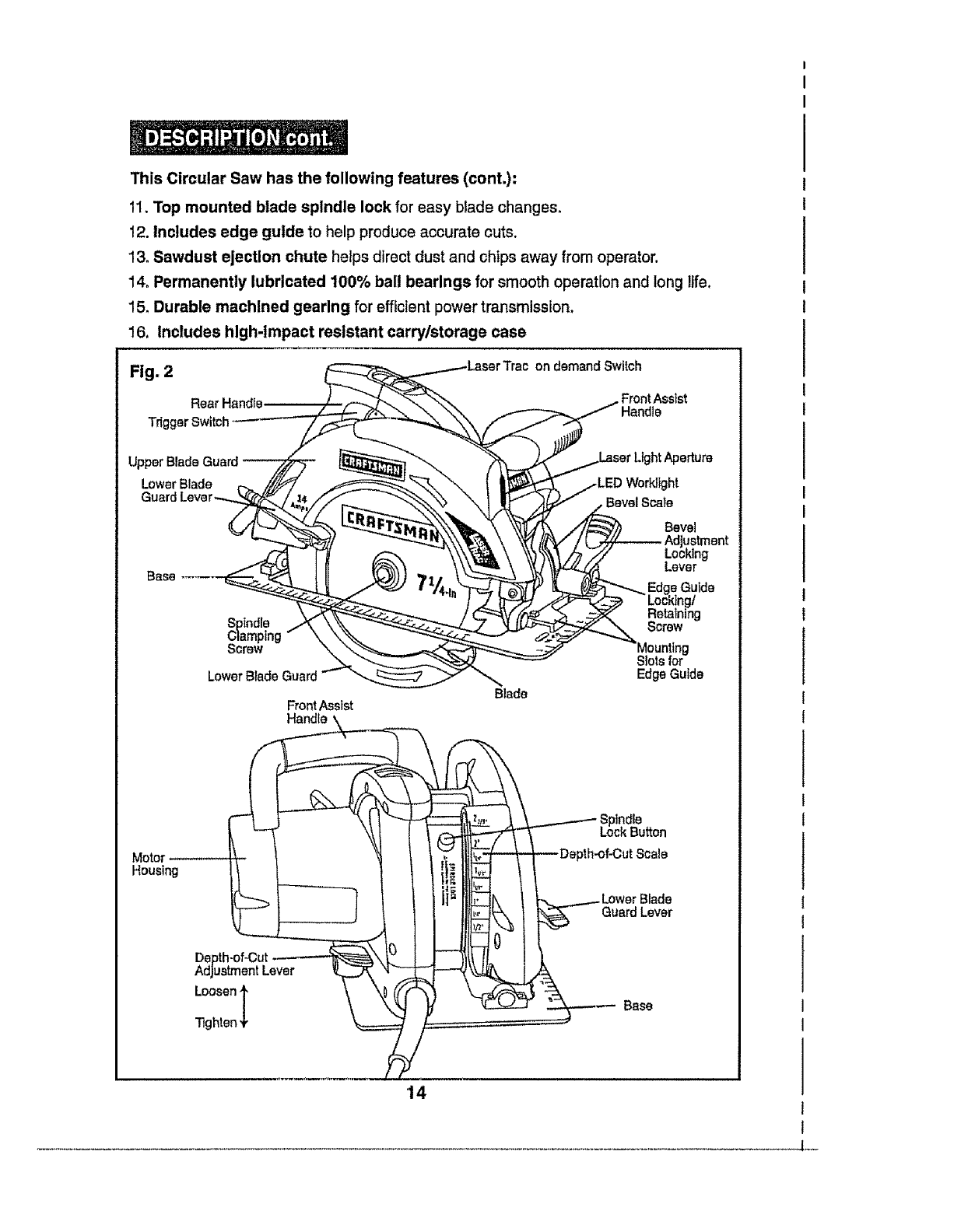
This Circular Saw has the following features (cont.):
11, Top mounted blade spindle lock for easy blade changes,
12. Includes edge guide to help produce accurate cuts.
13oSawdust ejection chute helps direct dust and chips away from operator.
14. Permanently lubricated 100% ball bearings for smooth operation and long life.
15_Durable machined gearing for efficient power transmission.
16. includes high-impact resistant carry/storage case
Fig. 2 on demandSwitch
Rear Handfe ,Front Assist
TriggerSwitch Handle
LowerBlade
BevelScale
Bevel
Adjustment
Locking
Lever
sGuide
Screw
Front Assist
Handle '
Blade
Slots for
EdgeGuide
Motor
Housing
Spindle
Lock Button
_th-of-CutScale
Guard Lever
Depth-of-Cut
Adjustment Lever
Loosenl
Tighten+
Base
14
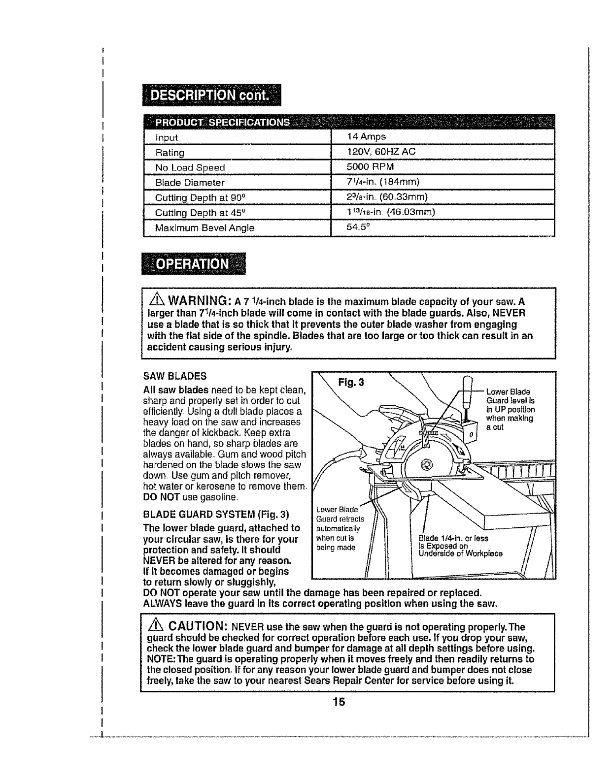
HII d.'{e] tjlj_ iH..'] d _[o] I_ [__'11 [el __ __
input 14 Amps
Rating 120V, 60HZ AC
No Load Speed 5000 RPM
Blade Diameter 7_A-in. (184mm)
Cutting Depth at 90°23/a-in (60,33mm)
Cutting Depth at 45 °1Wle-in (46 03ram)
Maximum Bevel Angle 54,5 o
Z_ WARNING: A7 1/4.inch blade is the maximum blade capacity of your saw. A
larger than 71/4-inch blade will come in contact with the blade guards. Also, NEVER
use a blade that is so thick that it prevents the outer blade washer from engaging
with the flat side of the spindle. Blades that are too large or too thick can result in an
accident causing serious injury_
SAW BLADES
All saw blades need to be kept clean,
sharp and properly set in order to cut
efficiently Using a dull blade places a
heavy load on the saw and increases
the danger of kickback. Keep extra
blades on hand, so sharp blades are
always available. Gum and wood pitch
hardened on the blade slows lhe saw
down. Use gum and pitch remover,
hot water or kerosene to remove them.
DO NOT use gasoline.
BLADE GUARD SYSTEM (Fig, 3)
The lower blade guard, attached to
your circular saw, is there for your whencutis
protection and safety. It should beingmade
NEVER be altered for any reason,
If it becomes damaged or begins
to return slowly or sluggishly,
DO NOT operate your saw until the damage has been repaired or replaced.
ALWAYS leave the guard in its correct operating position when using the saw.
Lower Blade
Guard level Is
in UP poetUon
when making
a cut
Z_ CAUTION: NEVER use the saw when the guard is not operating properly.The
guard should be checked for correct operation before each use, tf you drop your saw,
check the lower blade guard and bumper for damage at all depth settings before using.
NOTE: The guard is operating properly when it moves freely and then readily returns to
the closed position, if for any reason your lower blade guard and bumper does not close
freely, take the saw to your nearest Sears Repair Center for service before using it.
15
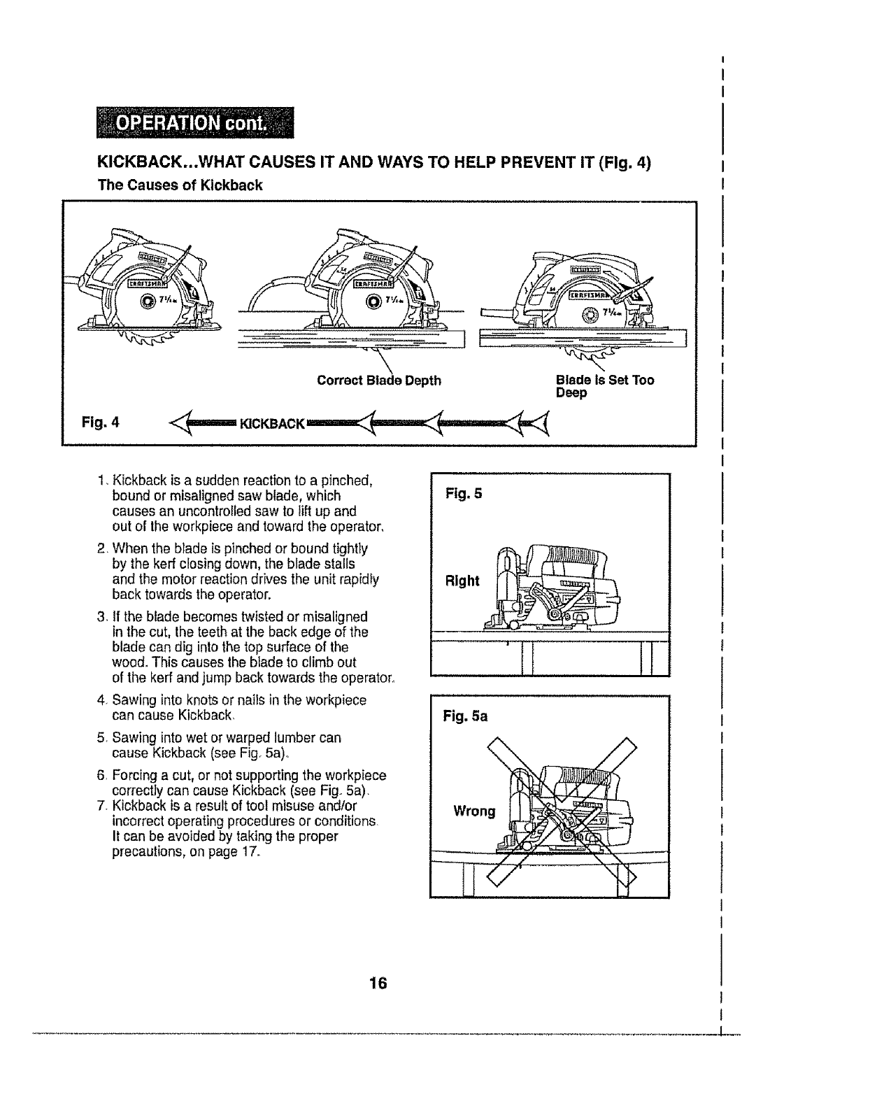
KICKBACK...WHAT CAUSES IT AND WAYS TO HELP PREVENT IT (Fig. 4)
The Causes of Kickback
\
Correct Blade Depth Blade Is Set Too
Deep
Fig. 4
1, Kickback is a sudden reaction to a pinched,
bound or misaligned saw blade, which
causes an uncontrolledsaw to lift up and
out of the workpiece and toward the operator,
2. When the blade is pinched or bound tightly
by the kerr closing down, the blade stalls
and the motor reaction drives the unit rapidly
back towards the operator.
3. If the blade becomes twisted or misaligned
in the cut, the teeth at the back edge of the
blade can dig into the top surface of the
wood. This causes the blade to climb out
of the kerr and jump back towards the operator,
4. Sawing into knots or nails in the workpiece
can cause Kickback.
5. Sawing into wet or warped lumber can
cause Kickback (see Fig. 5a)o
6, Forcing a cut, or not supporting the workpiece
correctly can cause Kickback (see Fig. 5a).
7. Kickback is a result of toot misuse and/or
incorrectoperating procedures or conditions
It can be avoided by taking the proper
precautions, on page !7.
Fig. 5
Right
UlUUll,i, i i
Fig, 5a
16
-L--
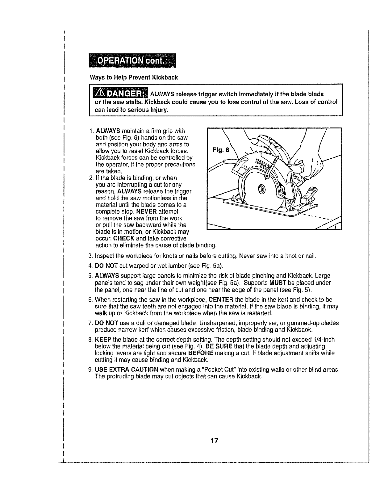
Ways to Help Prevent Kickback
ALWAYS release trigger switch immediately if the blade binds
or the saw stalls. Kickback could cause you to lose control of the saw. Loss of control
can lead to serious injury.
,,
ALWAYS maintain a firm grip with
both (see Fig 6) hands on the saw
and position your body and arms to
allow you to resist Kickback forces_
Kickback forces can be controlled by
the operator, if the proper precautions
are taken.
If the blade is binding, or when
you are interruptinga cut for any
reason, ALWAYS release the trigger
and hold the saw motionless in the
material until the blade comes to a
complete stop° NEVER attempt
to remove the saw from the work
or pull the saw backward while the
blade is in motion, or Kickback may
occur CHECK and take corrective
action to eliminate the cause of blade binding.
3, Inspect the workpiece for knots or nails before cutting. Never saw into a knot or nail,
4. DO NOT cut warped or wet lumber (see Fig 5a),
5, ALWAYS support large panels to minimize the risk of blade pinching and Kickback. Large
panels tend to sag under their own weight(see Fig, 5a) Supports MUST be placed under
the panel, one near the line of cut and one near the edge of the panel (see Fig. 5).
6, When restarting the saw in the workpiece, CENTER the blade in the kerr and check to be
sure that the saw teeth are not engaged into the material, If the saw blade is binding, it may
walk up or Kickback from the workpiece when the saw is restarted.
7, DO NOT use a dull or damaged blade Unsharpened, improperly set, or gummed-up blades
produce narrow kerr which causes excessive friction, blade binding and Kickback_
8, KEEP the blade at the correct depth setting. The depth setting should not exceed 1/4*inch
below the material being cut (see Fig, 4). BE SURE that the blade depth and adjusting
locking levers are tight and secure BEFORE making a cut, If blade adjustment shifts while
cutting it may cause binding and Kickback,
9, USE EXTRA CAUTION when making a "Pocket Cut" into existing walls or other blind areas.
The protruding blade may cut objecls that can cause Kickback
17
-J
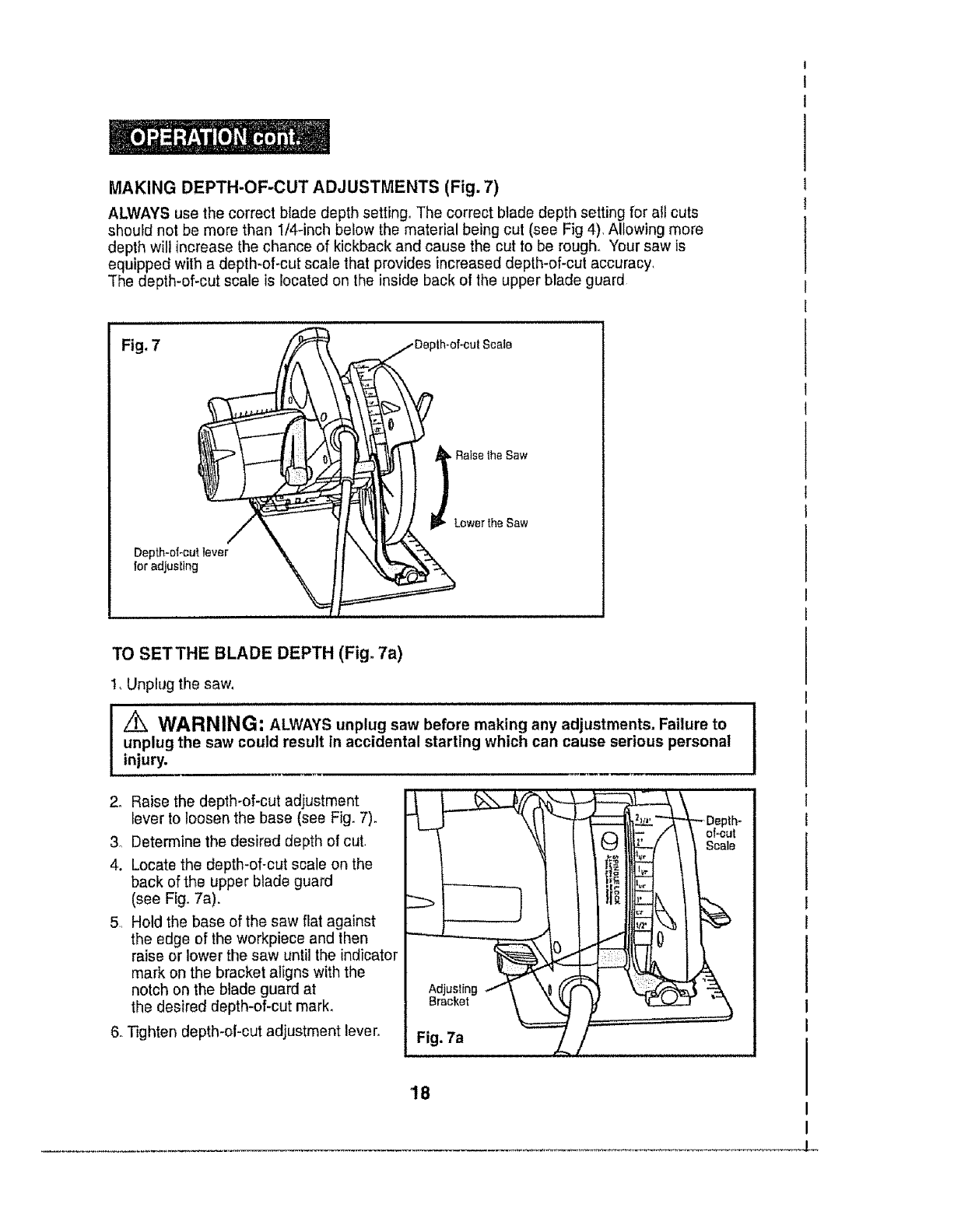
MAKINGDEPTH-OF-CUTADJUSTMENTS(Fig. 7)
ALWAYS use the correct blade depth setting° The correct blade depth setting for all cuts
should not be more than 1/4-inch below the material being cut (see Fig 4). Allowing more
depth will increase the chance of kickback and cause the cut to be rough. Your saw is
equipped with a depth-of-cut scale that provides increased depth-of-cut accuracy,
"Thedepth-of-cut scale is located on the inside back of the upper blade guard
Fig, 7
Depth.of.(::u_ 0
for adjusting
J
pth-of-cu! Scale
_j Raise the Saw
Lower the Saw
TO SETTHE BLADE DEPTH (Fig° 7a)
I, Unplug the saw,
i, , i,i i i i ,,, , , ,,, I,,,IH,,,.,,,.I.,.lll_u,J_l.JJ
l,_ WARN ING _ ALWAYS unplug saw before rnaking any adjustn_ents. Failure to I
unplug the saw could result in accidental starting which can cause serious personal
injury.
2. Raise the depth-of-cut adjustment
lever to loosen the base (see Fig. 7).
3o Determine the desired depth of cut
4. Locate the depth-of-cut scale on the
back of the upper blade guard
(see Fig. 7a).
51 Hold the base of the saw flat against
the edge of the workpiece and then
raise or lower the saw until the indicator
mark on the bracket aligns with the
notch on the blade guard at
the desired depth-of-cut mark.
6. Tighten depth-of-cut adjustment lever, Bracket
Fig. 7a A_ /
_Dep
c_ Iltl: /\ \ oFc_
i!117 t I
'lg
18
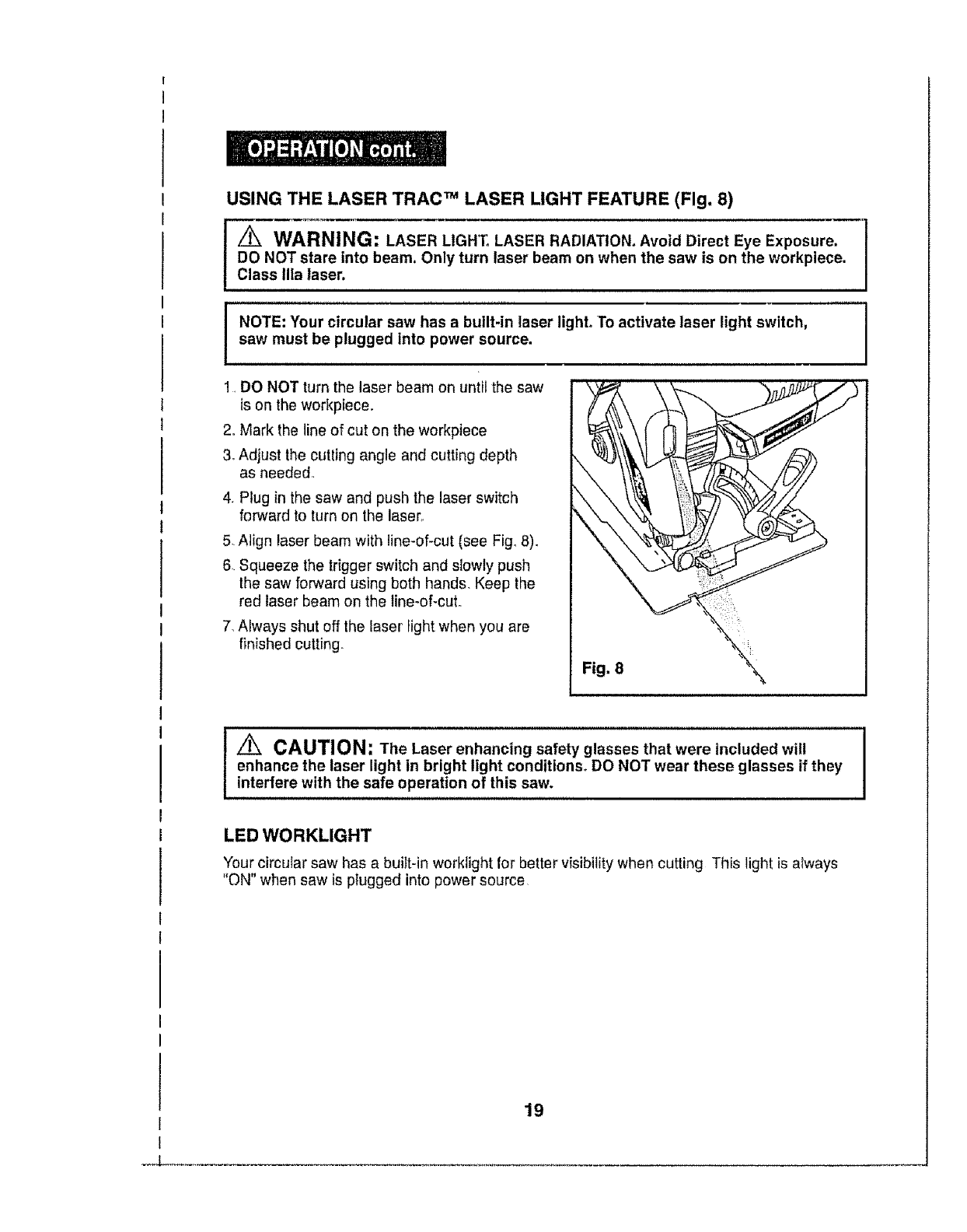
USING THE LASER TRAC TM LASER LIGHT FEATURE (Fig. 8)
WARNING: LASER LIGHT° LASER RADIATION. Avoid Direct Eye Exposure.
DO NOT stare into beam, Only turn laser beam on when the saw is on the workpiece.
Class Ilia laser.
IOTE: Your circular saw has a built-in laser light° To activate laser light switch,
saw must be plugged into power source.
1, DO NOT turn the laser beam on until the saw
is on the workpiece.
2_Mark the line of cut on the workpiece
3, Adjust the cutting angle and cutting depth
as needed
4, Plug in the saw and push the laser switch
forward to turn on the lasen
5, Align laser beam with line-of-cut (see Fig_8).
6. Squeeze the trigger switch and slowly push
the saw forward using both hands. Keep the
red laser beam on the line-of-cut.
7, Always shut off the laser light when you are
finished cutting.
Fig. 8
CAUTION: The Laser enhancing safety glasses that were included will I
I
enhance the laser light in bright light conditions. DO NOT wear these glasses if they I
interfere with the safe operation of this saw.
LED WORKLIGHT
Your circular saw has a built-in worktight for better visibility when cutting This light is always
"ON" when saw is plugged into power source
19
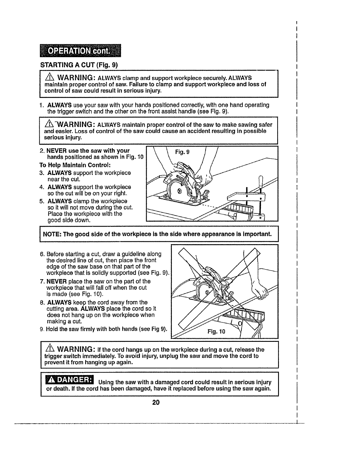
STARTING A CUT (Fig. 9)
I_WARNING: ALWAYS clamp and support workpiece securely. ALWAYS
maintain proper control of saw° Failure to clamp and support workpiece and loss of
control of saw could result in serious injury,
1. ALWAYS use your saw with your hands positioned correctly, with one hand operating
the trigger switch and the other on the front assist handle (see Fig. 9).
z_"WARNING: ALWAYS maintain proper control of the saw to make sawing safer
and easier. Loss of control of the saw could cause an accident resulting in possible
serious injury°
2° NEVER use the saw with your Fig. 9
hands positioned as shown in Fig. 10
To Help Maintain Control"
3. ALWAYS support the workpiece
near the cut,
4. ALWAYS support the workpiece
so the cut will be on your right°
5, ALWAYS clamp the workpiece
so it will not move during the cut,
Place the workpiece with the
good side down.
i NOTE: Thegood sldeof workpieoe appearance important.
the is the side where is
6. Before starting a cut, draw a guideline along
the desired line of cut, then place the front
edge of the saw base on that part of the
workptece that is solidly supported (see Fig. 9)°
7. NEVER place the saw on the part of the
workpiece that will fall off when the cut
is made (see Fig. I0).
8. ALWAYS keep the cord away from the
cutting area. ALWAYS place the cord so it
does not hang up on the workpiece when
making a cut.
Hold the saw firmly with both hands (see Fig 9).
g_
I
I
Fig, 10
i i
Z_ WARNING: If the cord hangs up on the workpieee during a cut, release the
trigger switch immediately, To avoid injury, unplug the saw and move the cord to
prevent it from hanging up again.
Using the saw with a damaged cord could result in serious injury
or death. If the cord has been damaged, have it replaced before using the saw again.
20
TO HELP MAINTAIN CONTROL cont.:
10. Squeeze the trigger switch to start the saw° ALWAYS let the blade reach full speed
before you begin the cut into the workpiece.
11. When making a cut, ALWAYS use steady, even pressure° Forcing the saw causes
rough cuts and could shorten the life of the saw or cause Kickback.
12, After completing your cut, release the trigger switch and allow the blade to come to
a complete stop. DO NOT remove the saw from the workplece while the blade
is moving.
_[__ When sawing through a workpiece, the lower biade guard DOES
NOT cover the blade on the underside of the workpiece (see Fig. 3, page 15).
ALWAYS keep your hands and fingers away from the cutting area. Any part of your
body coming in contact with the moving blade will result in serious injury.
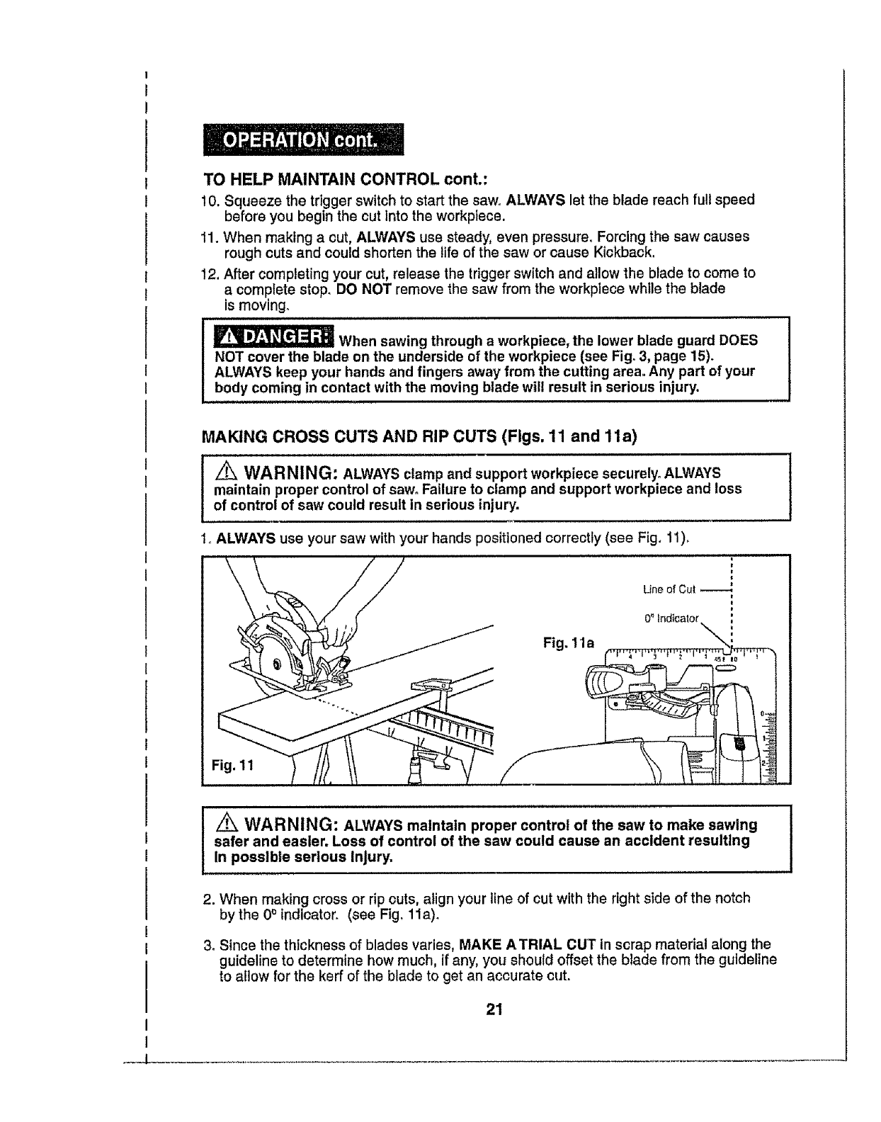
MAKING CROSS CUTS AND RIP CUTS (Figs. 11 and 1la)
_WARNING: ALWAYS clamp and support workpiece securely° ALWAYS
maintain proper control of saw. Failure to clamp and support workpiece and loss
of control of saw could result in serious injury.
1_ALWAYS use your saw with your hands positioned correctly (see Fig. 11).
=
!
0_ indicator
Fig. 11a
Fig. 11
I
I
__J
_ WARNING: ALWAYS maintain proper control of the saw to make sawing
safer and easier, Loss of control of the saw could cause an accident resulting
In possible serious Injury.
i
2. When making cross or rip outs, align your ltne of cut with the fight side of the notch
by the 0° Indicator_ (see Fig, 11a).
3. Since the thickness of blades varies, MAKE ATRIAL CUT In scrap material along the
guideline to determine how much, if any, you should offset the blade from the guideline
to allow for the kerf of the blade to get an accurate cut.
21
INTEGRATED RIP AND CROSSCUT RULERS
Marked on the base across the front (see Fig, 11a, page 21) is a handy ruler for measuring
repetitive cuts. It is marked t V4-inches to the right of 0° and 5-inches to the left of 0°,
in V1B-inch increments
Also marked on the base down the right side edge, is a ruler for measuring length of cuts,
marked 0 to 8 inches in 1/16-inchincrements,
MAKING RIP CUTS
ALWAYS use a guide when making long or wide rip cuts with your saw. You can use
either a straight edge or use the edge guide that was included with your saw.
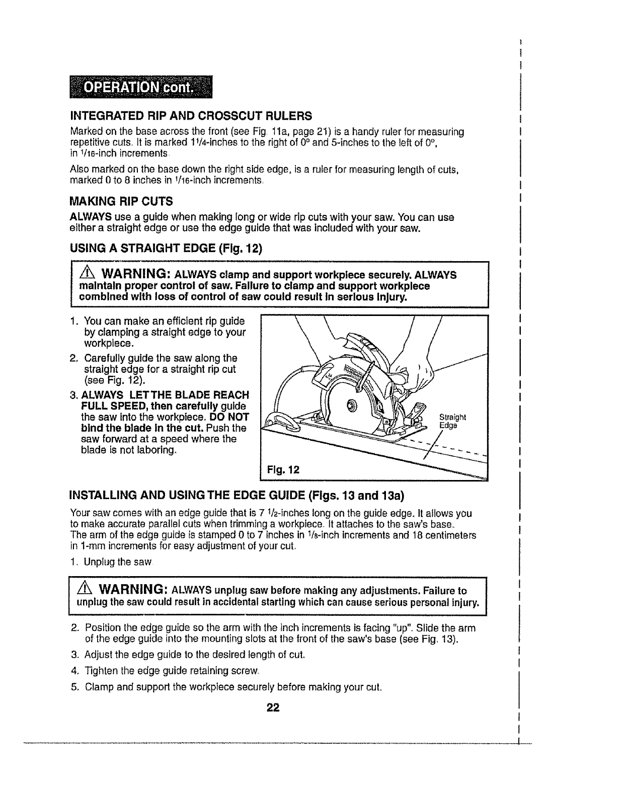
USING A STRAIGHT EDGE (Flg. 12)
WARNING: ALWAYS clamp and support workptece securely. ALWAYS
maintain proper control of saw. Failure to clamp and support workplece
combined with loss of control of saw could result tn serious injury.
1. You can make an efficient rip guide
by clamping a straight edge to your
workplece_
2. Carefully guide the saw along the
straight edge for a straight rip cut
(see Fig. 12).
3. ALWAYS LETTHE BLADE REACH
FULL SPEED, then carefully guide
the saw into the workptece. DO NOT
bind the blade In the cut, Push the
saw forward at a speed where the
blade is not laboring.
Fig. 12
INSTALLING AND USING THE EDGE GUIDE (Figs. 13 and 13a)
Your saw comes with an edge guide that is 7 1/2qnches long on the guide edge_ It allows you
to make accurate parallel cuts when trimming a workpiece. It attaches to the saw's base°
The arm of the edge guide is stamped 0 to 7 inches in 1!8-inch increments and t8 centimeters
in l-ram increments for easy adjustment of your cuL
1. Unplug the saw
Z_ WARNING: ALWAYS unplug saw before making any adjustments. Failure to
unplug the saw could result in accidental starting which can cause serious personal injury.
2. Position the edge guide so the arm with the inch increments is facing "up". Slide the arm
of the edge guide into the mounting slots at the front of the saw's base (see Fig_ 13).
3o Adjust the edge guide to the desired length of cut°
4_ Tighten the edge guide retaining screw.
5. Clamp and support the workpiece securely before making your cut.
22
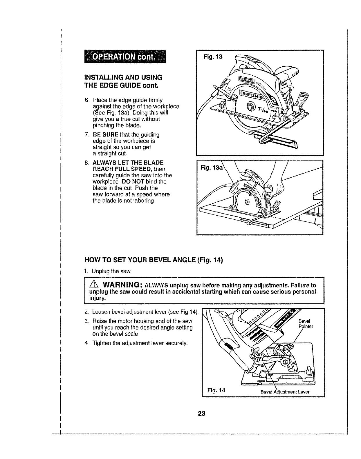
INSTALLINGAND USING
THE EDGEGUIDEcont.
6, Place the edge guide firmly
against the edge of the workpiece
(See Fig,, 13a), Doing this wilt
give you a true cut without
pinching the blade,
7, BE SURE that the guiding
edge of the workpiece is
straight so you can get
a straight cut,
8, ALWAYS LET THE BLADE
REACH FULL SPEED, then
carefully guide the saw into the
workpiece. DO NOT bind the
blade in the cut Push the
saw forward at a speed where
the blade is not laboring,
Fig.
HOW TO SET YOUR BEVEL ANGLE (Fig. 14)
1, Unplug the saw
z_ WARNING; ALWAYS unplug saw before making any adjustments° Failure to
unplug the saw could result in accidental starling which can cause serious personal
injury°
2. Loosen bevel adjustment lever (see Fig.14).
3Raise the motor housing end of the saw Bevel
until you reach the desired angle setting
on the bevel scale
4, Tighten the adjustment lever securely,
Fig° 14
I
i
__J.
23
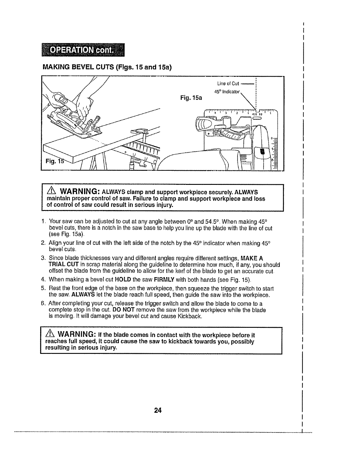
MAKINGBEVEL CUTS(Figs. 15 and 15a)
Fig. 15a
Line of Cut _ :
t
45° Indicator
.,.i,,,,. i, ,Hi ,
_WARNING: ALWAYS clamp and support workpiece securely. ALWAYS
maintain proper control of saw. Failure to clamp and support workpiece and toss
of control of saw could result in serious injury. .......
1. Your saw can be adjusted to cut at any angle between 0°and 54.5 °, When making 45°
bevel cuts, there is a notch in the saw base to help you line up the blade with the line of cut
(see Fig° 15a).
2r Align your line of cut with the left side of the notch by the 45° indicatorwhen making 450
bevel cuts.
3. Since blade thicknesses vary and different angles require different settings, MAKE A
TRIAL CUT in scrap materiai along the guideline to determine how much, if any, you should
offset the blade from the guideline to allow for the kerr of the blade to get an accurate cut.
4. When making a bevel cut HOLD the saw FIRMLY with both hands (see Fig. 15).
5_ Rest the front edge of the base on the workpiece, then squeeze the trigger switch to start
the saw. ALWAYS tet the blade reach full speed, then guide the saw into the workpiece.
6. After completing your cut, release the trigger switch and allow the blade to come to a
complete stop in the cut. DO NOT remove the saw from the workpiece while the blade
is moving It will damage your bevel cut and cause Kickback°
iZ_ WARNING: If the blade comes in contact with the workpiece before it
reaches full speed, it could cause the saw to kickback towards you, possibly
resulting in serious injury. ....................
!
24
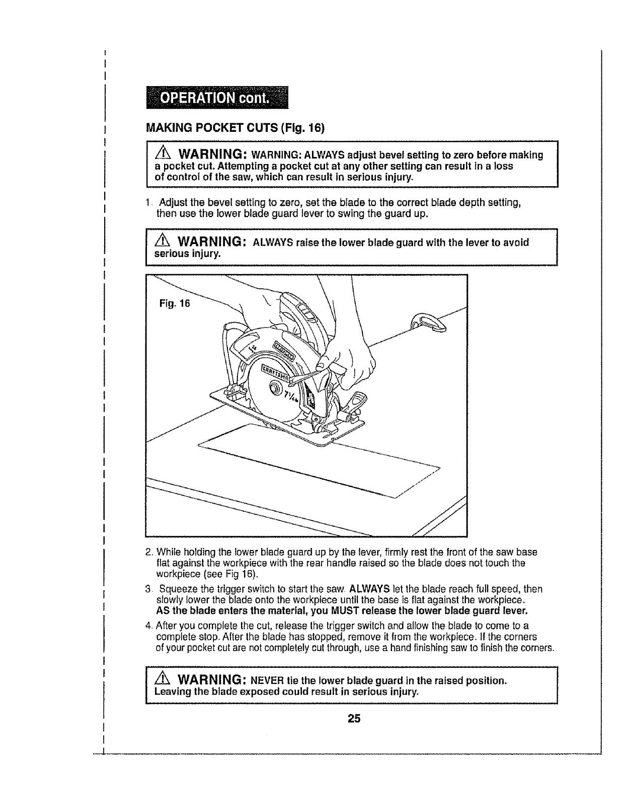
MAKING POCKET CUTS (Fig. 16)
WARNING: WARNING: ALWAYS adjust bevel setting to zero before making I
a pocket cut. Attempting a pocket cut at any other setting can result in a loss I
of control of the saw, which can result in serious injury.
1o Adjust the bevel setting to zero, set the blade to the correct blade depth setting,
then use the lower blade guard lever to swing the guard up,
_WARNING: ALWAYS raise the lower blade guard with the lever to avoid 1
serious injury.
2. While holding the lower blade guard up by the lever, firmly rest the front of the saw base
flat against the workpiece with the rear handle raised so the blade does not touch the
workpiece (see Fig 16).
3. Squeeze the trigger switch to start the saw. ALWAYS let the blade reach full speed, then
slowly lower the blade onto the workpiece until the base is flat against the workpiece.
AS the blade enters the material, you MUST release the lower blade guard lever,
4_After you complete the cut, release lhe trigger switch and allow the blade to come to a
complete stop. After the blade has stopped, remove it from the workpiece. II the corners
of your pocketcut are not completely cut through, use a hand finishing saw to finish the corners°
i
25
..... J
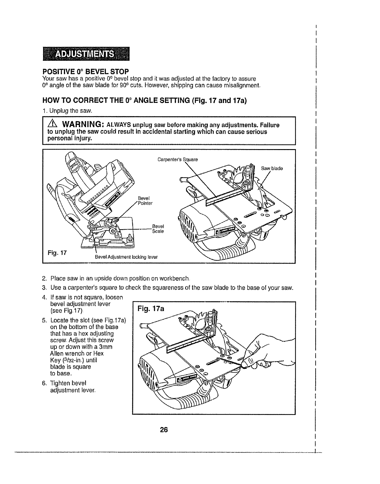
POSITIVE 0° BEVEL STOP
Your saw has a positive 0° bevel stop and it was adjusted at the factory to assure
0° angle of the saw blade for 90o cuts,. However, shipping can cause misafignment.
HOW TO CORRECT THE 0° ANGLE SE'rrlNG (Flgo 17 and 17a)
1. Unplug the saw°
/_ WARNING: At.WAYS unplug saw before making any adjustments. Failure
to unplug the saw could result in accidental starting which can cause serious
personal injury.
Fig, 17
Carpenter's Euare
Pointer
Bevel Adjustment locking tever
Saw blade
2. Place saw in an upside down position on workbench_
3, Use a carpenter's square to check the squareness of the saw blade to the base of your saw.
4. If saw is not square, loosen
bevel adjustment lever
(see Fig17) Fig. 17a
5, Locate the slot (see Fig.17a)
on the bottom of the base
that has a hex adjusting
screw, Adjust this screw
up or down with a 3ram
Allen wrench or Hex
Key (3/32-in.) until
blade is square
to base.
6. Tighten bevel
adjustment lever.
26
L....
t,_ WARNING: Attempting to make cuts without the bevel adjustment locking I
I
lever securely tightened can result in serious injury. I
/_ WARNING: To ensure safety and reliability, all repairs - with the exception
of the externally accessible brushes - should be performed by a qualified service
technician at a Sears Service Center.
WARNING: For your safety, ALWAYS turn off switch and unplug circularsaw from the power source before performing any maintenance or cleaning.
It has been found that electric tools are subject to accelerated wear and possible
premature failure when they are used to work on fiber glass boats and sports cars,
wallboard, spackling compounds or plaster. The chlps and grindings from these
materials are hlghly abrasive to electrical tool parts, such as bearings, brushes,
commutators, etc. Consequently, it is not recommended that this tool be used for
extended work on any fiberglass material, wallboard, spackling compound or
plaster_ During any use on these materials, it is extremely important that the
tool is cleaned frequently by blowing with an air jet.
i
jZ_ WARNING: Always wear safety goggles or safety glasses with side shields |
i
during power tool operations, or when blowing dust. If operation is dusty, also wear
a dust mask.
ROUTINE MAINTENANCE
WARNING: DO NOT at any time let brake fluids, gasoline, petroleum-based
products, penetrating oils, etc. come in contact with plastic parts. Chemicals can
damage, weaken or destroy plastic, which may result in serious personal injury.
Periodic maintenance allows for long life and trouble-free operation. Acleaning,
lubrication and maintenance schedule should be maintained. As a common
preventive maintenance practice, follow these recommended steps:
1_When work has been completed, clean the toot to allow smooth functioning
of the tool over timer
2. Use clean damp cloths to wipe the tool.
3. Check the state of all electrical cables.
4o Keep the motor air openings free from oil, grease and sawdust or woodchips,
and store tool in a dry place°
5. Be certain that all moving parts that are exposed are well lubricated, particularly
after lengthy exposure to damp and/or dirty conditions.
27
CHANGINGTHE BLADE (Figs. 18and 18a)
WARNING: BE SURE to wear protective work gloves while handling a saw I
blade, The blade can injure unprotected hands. I
1. Unplug the saw.
Z_ WARNING: To prevent personal injury, ALWAYS disconnect the plug from
power source BEFORE assembling parts, making adjustments or changing blades. J
2. Place saw on its side on a fiat surface.
3. To loosen the depth-of-cut adjustment lever, raise the saw up all the way and tighten
lever. This gives you easier access to blade mounting area (see Fig. 18a)o
4. Place saw upright, on its base and on a flat surface (see Fig. 18a).
5. To loosen the spindle clamping screw "A", depress the spindle lock button
(see Fig. 18). Place the blade wrench on the spindle clamping screw "A". Move the
wrench back and forth until you feel the spindle lock button depress further and it
locks the blade in position so the spindle clamping screw can be removed. Keeping
the spindle lock button firmly depressed, turn the spindle screw counterclockwise
to remove.
Spindle Lock __
Button
Fig° 18a
Depth of Cut
Adjustment Lever
28
Outer"D"Washer
"A" Spindle
Clamplng
Screw
Blade Rotation
teeth point upat front
J_
CHANGING THE BLADE cont. (Figs. 18 and 18a)
6. Raise lower blade guard using the blade guard lever and hold it in the raised
position for the next steps.
7oCompletely remove the spindle clamping screw 'W' and the outer "D" washer
and the blade (see Fig. 18a)o
8. The remaining washer is the inner bushing washer that fits around the spindle
shaft and it does not need to be removed.
9. Put a drop of oll onto the inner bushing washer and outer "D" washer where
they will touch the blade.
10. Place the new saw blade inside the lower blade guard, onto the spindle shaft
and against the inner bushing.
NOTE:The teeth of the blade should point upward at the front of the saw as
shown in (Fig. 18a).
1t. Replace the "D" washer.
12. Firmly hold down spindle lock button as you replace the spindle screw and hand
tighten it in a clockwise direction. Then use blade wrench to tighten the spindle
clamping screw thoroughly.
13. Place blade wrench back in case.
lOTE: NEVER use a blade that is too thick to allow the"D" washer to engage
with the fiat side of the spindle.
I
I
LUBRICATION
All of the bearings in this tool are lubricated with a sufficient amount of high-grade
lubricant for the life of the tool under normal operating conditions. Therefore,
no further lubrication is required.
29
.-1
If the blade does not follow a straight line:
•Teeth are dull This is caused by hitting a hard object such as a nail, dulling
teeth on one slde_ The blade tends to cut to the side with the sharpest teeth,
•Base is out of line or bent.
° Blade is bent.
• Edge guide or straight edge Is not being used.
If the blade binds or smokes from friction:
•Blade is dull.
•Blade is on backwards.
• Blade ls bent.
° Workpiece is not properly supported.
oIncorrect blade is being used.
_WARNING: The use of attachments or accessories that are not
recommended for this too! might be dangerous and could result in serious injury.
Sears and other Craftsman outlets have a large selection of 71/4-inch Craftsman
steel carbide-tipped blades designed for specific cutting applications.
Contractor bulk packs are also available°
Sears and other Craftsman outlets also offer sawhorses, combination and
framing squares, straight edges, edge guides, and a large assortment of
clamps to help you with all your sawing needs,
Visit your local Sears store or other Craftsman outlets or shop sears.corn/craftsman.
3O
L,,,
31

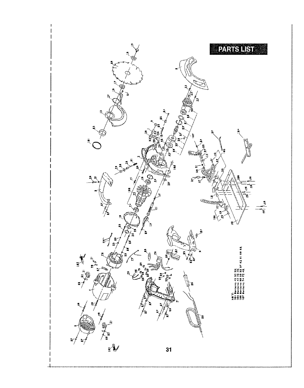
71/4-in.CIRCULARSAW- MODEL NUMBER320.10870
The Model Number will be found on the Nameplate,
Always mention the Model Number inall correspondence regarding your tool.
Item No.
1
2
3
4
5
6
Pads No.
2780040000
3420333000
3420335000
3121339000
3121340000
3320220000
Part Description
Laser Set
Gear Case
Upper Guard
Motor Housing
Rear Cover
Right Handle
7 3320219000
'8" 3320221000
9 3121384000
10 3121341000
11 3400174000
12 5650017000
13 5640044000
Qty.
!
1
1
1
1
1
1Left Handle
Front Handle 1
Lens 1
Fan Baffle 1
1Lock Rod
Pfain Washer GB96-85 6 A140
Bolt
1
1
1
1
1
1
1
1
1
14 3121378000 DePth Adjusting Leve r
15 I 3420334000 Moving Guard
16 3121379000 Moving Guard Lever
17 3550225000 Inner Flange
18 3550222000 Clamp
t9 5620151000 Flange Screw
20 3420184000 Adjusting Block
21 2800006000 Brush Holder 2
22 5610094000 Tapping Screw G86560-86 4X16 3 _
23 3121051000 Stopper 1
24 3121057000 Rubber Ring 1
25 3121054000 Spring 1
26 3700255000 Washer 1
27 5660030000 Circlips For Shaft 1
28 3550238000 Lock Shaft 1
29 3120560000 Button 1
30 3550240000 Lock Ring 1
31 3660072000 Spring I
32 3700539000 Epoxy Board 2
............33...............5610048000 Tapping Screw G8845-85 4_2X55-F 2
5620039000
3700262000
5610061000
5610042000
5610053000
5670008000
5610062000
Screw GB818-85 M4xl0
Wire Holder
ThreadFormingScrewG86560-865_30
TappingScrewG8845-85£T4.2x19-F-H
TappingScrewG8845-854.2xg.5-F
SpringPin GB879-86,,,,6X40..............
ThreadFormingScrew G86560-86M5_40
3
1
1
12
3
1
3
34
35
36
37
38
39
40
32

71/4-in.CIRCULARSAW- MODEL NUMBER 320.10870
The Model Number will be found on the Nameplate.
Always mention the Model Number in all correspondence regarding your too!o
Item No. Parts No. Part Description Qty.
41 5610057000 Thread Forming Screw 2
42 5700041000 Oil lmpreging Bearing 1
43 5700015000 Bali Bearing GB/T276-94 6201-2RD 1
44 3700780000 Depth Bracket 1
45 5680012000 Rivet GB873-86 6x16 2
46 5610083000 .Thread FormingScrewGB6561-86M4x12L 6
47 3660071000 Spring 1
48 3700269000 Base Plate 1
49 3420176000 Depth Support 1
50 3700306000 Angle indicator 1
51 5620037000 Screw GB818-85 M4_6 1
52 3420205000 Angle Support 1
53 5650053000 Washer !
54 34000tl 000 Wing Bolt 1
55 3700307000 Support Plate 1
56 5660010000 E Ring GB896-86 9 1
57 3550239000 Gear Shaft 1
58 5680004000 Plain Key GB1096-79 5x14 1
59 3550235000 Gear 1
60 5700019000 Ball Bearing GB_T276-94 6003-2RS 1
61 3700281000 Wave Washer 1
62 5660023000 circlips For Hole GB89311-86 35 1
63 3121475000 Power indictor cover (Left) 1
64 3121424000 Power indictor cover (Right) 1
65 3700586000 Lining 1
66 3810073000 Blade 1
67 3121381000 LED Cover 1
68 3420311000 Gear Case cover 1
69 3121380000 Angle Lever 1
70 3121382000 LED Support1 1
71 3121383000 LED Support2 1
72 2750160000 Rotor 1
73 2821947000 Transform Assy 1
74 57000t3000 Ball Bearing GB T276-94 6000-2Z t
75
76 4360221000 LED 1
77 2821992000 Inner wire1 , 1
78 2740066000 Stator 1
79 2821992000 inner wire2 1
80 5650007000 Spring Washer GB93-87 4 2
33

71h-in.CIRCULARSAW- MODEL NUMBER320.10870
The Model Number will be found on the Nameplate_
Always mention the Model Number in all correspondence regarding your tool,
Item No,
8t
82
83
84
65
86
87
88
Parts No.
4870036O00
4810002000
3700367000
5610093000
3121050000
3700865000
3121385000
89 4930012000
90 5610059000
9t 5650013000
92 5650001000
93 5650003000
Part Description
Switch
Power Cord &Plug
Cord Anchorage
Qty.
!
1
1
Tapping Screw JlS M412 2
Cord- Guard 1
Wrench
Laser Button ..........................................................!
Terminal 3
Thread FormingScrewGB6560-86M5_20 1
Plain Washer GB97.1-85 5 1
Plain Washer GB97.t-85 3 2
Spring Washer GB93-87 3 2
94
95
96
97
98
99
100
101
102
103
104
5620006000
5650005000
5610058000
3550375000
4930013000
5620035000
5620017000
'3660138000
HexagonSocket ScrewGB70-85 M,3_!2' 2
Plain Washer GB97,1-85 4 2
Tapping Screw GB6560-86 M5X16 1
Nut M6X2P 1
Receptacle 3
Screw GB818-85 M3.58 4
Hexagon Socket Screw 1
GB79÷85 M5x10_45H
Torsion Spring 1
4960021000
5640152000
3700663000
105
106
107
108
Carbon
Belt
Rip Fence
Support Set
Depth Bracket Set
Gear Set
Rotor Set
2
1
1
1
1
1
SEE BACK PAGE FOR PARTS ORDERING INSTRUCTIONS
34
L.....
Manual del Operador
i
14 Amp
SierraCircularde 7 _/4p
con LaserTracTM igadas
Modelo No.
320. 10870
®
Doble Aislamiento
PRECAUCION: Lea, entienda ysiga
todas las Normas de Seguridad eInstrucciones
de Funcionam_ento en este Manual antes de
usar este producto,
Sears, Roebuck and Co.,
Hoffman Estates, IL 60179 U.S.A.
Vlslte nuestra pdgina Web Craftsman®: www.craftsman.com
•GARANT[A
°SEGURIDAD
° DESEMPACADO
°DESCRIPCl6N
°FUNClONAMIENTO
•AJUSTES
•MANTENIMIENTO
Garantfa ...................................................................... P_g_na
Simbolos de Seguridad ............................................... P_.gtna
Instrucciones de Seguridad ............................................. P_glnas
Glosario de T_rminos ..................................................... P_glnas
Desempacado ............................................................. P_glnas
Descripci6n .................................................................. P_gtnas
Funcionamiento ................................................................. P_.gtnas
Ajustes ........................................................................... P_.ginas
Mantenimiento .................................................................... P_ginas
Detecci6n y Resoluci6n de Problemas ................................ P&gina
Accesorios ...................................................................................... P__gina
Piezas de Repuesto ............................................................. P_ginas
N_meros de Tel_fono del Servicio de
36
37
38 - 45
45 - 46
46 - 47
47 - 49
50 - 59
60 - 61
61 _ 63
64
64
65 _ 68
Piezas de Repuesto de Sears .......................................... Contratapa
GARANTiA DE UN A1;,IOCOMPLETO SOBRE PRODUCTOS CRAFTSMAN e
Si este producto Craftsman falla debido a defectos en el material o
mano de obra entro un arc desde la fecha de compra,REGRI_SELO
A LA TIENDA SEARS O CENTRO DE PARTES Y PIEZAS DE
REPUESTOS U OTRO PUNTO DE VENTA CRAFTSMAN MAS
CERCANO EN LOS ESTADOS UNIDOS PARA SU REPARACION
GRATUITA (O REEMPLAZO SI LA REPARACION RESULTASE
IMPOSIBLE).
Esta garantfa no incluye piezas desechables, tales como I_.mparas,
pilas, brocas o cuchillas,
Siesta herramienta Craftsman se utiliza para fines comerciales
o de alquiler, esta garant[a aplica s61o para 90 dlas desde la fecha
de compr&
Esta garantfa le otorga derechos legales especificos, y es posible que
tambi_n cuente con otros derechos, los cuales varfan de un estado
a otro.
Sears, Roebuck and Co., Hoffman Estates, IL 60179
iGUARDE ESTAS INSTRUCCIONES!
iLEATODAS LAS INSTRUCCIONES!
36
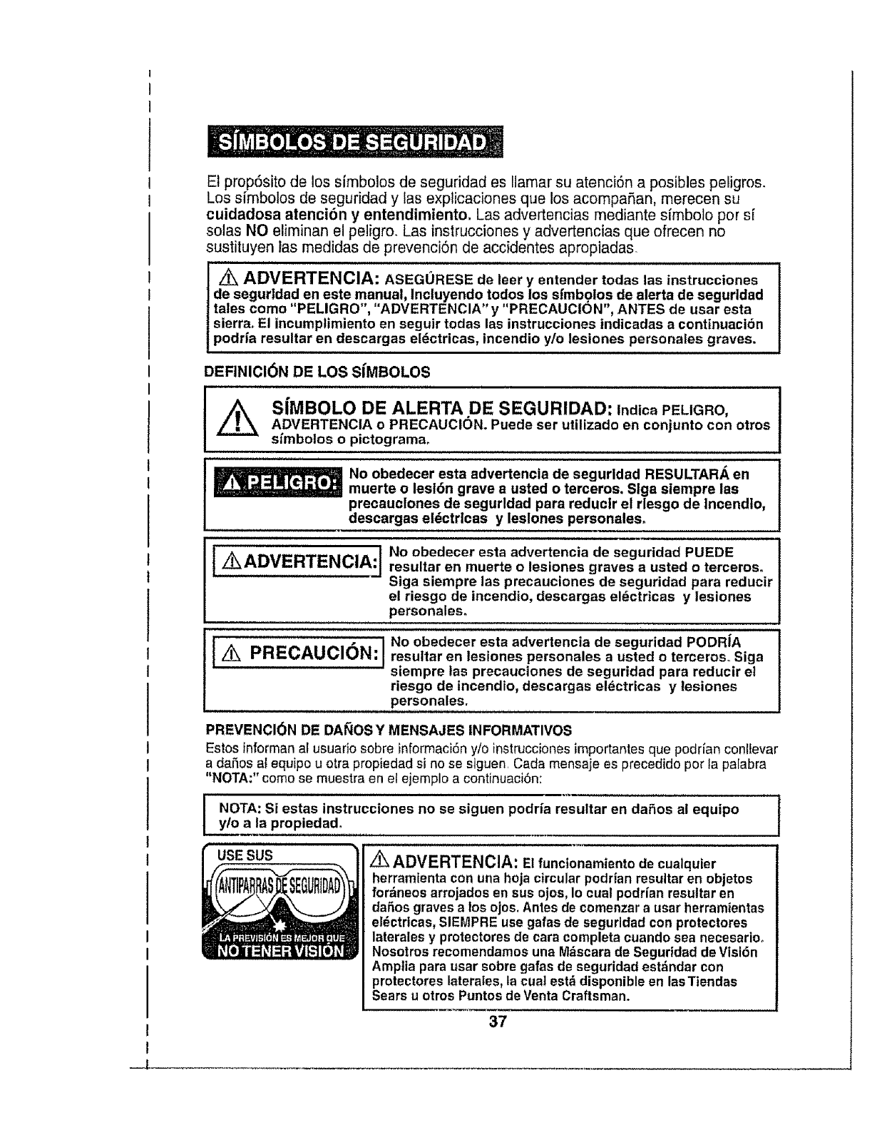
El prop6sito de los simbolos de seguridad es Elamarsu atenci6n a posibles peligros_
Los sfmbolos de seguridad y las explicaciones que los acompaSan, merecen su
cuidadosa atenci6n y entendimiento. Las advertencias mediante sfmbolo pors[
solas NO eliminan el peligro, Las instrucciones y advertencias que ofrecen no
sustituyen las medidas de prevencbn de accidentes apropiadas.
ADVERTENCIA: ASEGURESE de leer yentender todas las instrucciones
de segurldad en este manual, Incluyendo todos los sfmbgios de alerta de segurldad
tales como "PELIGRO', "ADVERTENCIA" y "PRECAUCION', ANTES de usar esta
sierra_ El incumplimiento en seguir todas las instrucciones tndicadas a continuaci6n
podrla resultar en descargas el_ctricas, incendio y/o lesiones personales graves.
DEFINICION DE LOS SIMBOLOS
,,,,,,,,, ,,, , t,,,,,,,,,,,,,,,,,,,,,,,,,,,,,,,,,,,, ,,,,,,, ,
_SIMBOLO DE ALERTA DE SEGURIDAD: lndica PELIGRO,
ADVERTENCIA o PRECAUCION. Puede ser utilizado en conjunto con otros
sfmbotos o pictograma,
No obedecer esta advertencia de segurldad RESULTAR,_ en
muerte o lesl6n grave a usted o terceros. Slga siempre las
precauclones de segurldad para reduclr el rlesgo de Incendlo,
descargas el_ctrlcas y leslones personaleso
]iK ADVERTENCIA:] No obedecer esta advertencia de seguridad PUEDE
resultar en muerte o lesiones graves a usted oterceros.
Siga siempre las precauciones de seguridad para reducir
el riesgo de incendio, descargas eldctricas y lesiones
personales_
PRECAUC"6"'I
No obedecer esta advertencia de seguridad PODRiA
resultar en lesiones personales a usted o terceroso Siga
siempre las precauciones de seguridad para reducir el
riesgo de incendio, descargas eldctrtcas y lesiones
personales.
PREVENCI_)N DE DAI_OS Y MENSAJES INFORMATIVOS
Estos informan a[ usuariosobre informaci6ny/o instrucciones importantes que poddan conflevar
a daSos at equipo u otra propiedad si no se siguen, Carla mensaje es precedido por la palabra
"NOTA:" como se muestra en el ejemplo a continuaci6n:
NOTA: Si estas instrucciones no se siguen podr[a resultar en daSos al equipo
y/o a la propiedad.
USE SUS z_ ADVERTENCIA: Elfuncionamientode cualquier
herramlenta con una hoja circular podrfan resultar en objetos
fordneos arrojados en sus ojos, Io cual podrian resultar en
daSos graves alos ojos, Antes de comenzar a usar herramientas
eldctricas, SIEMPRE use galas de seguridad con protectores
laterales y protectores de cara completa cuando sea necesarioo
Nosotros recomendamos una Mdscara de Seguridad de Visi6n
Amplia para usar sabre gafas de seguridad estdndar con
protectores laterales, la cual estd disponible en lasTiendas
Sears u otros Puntos de Venta Craftsman.
37
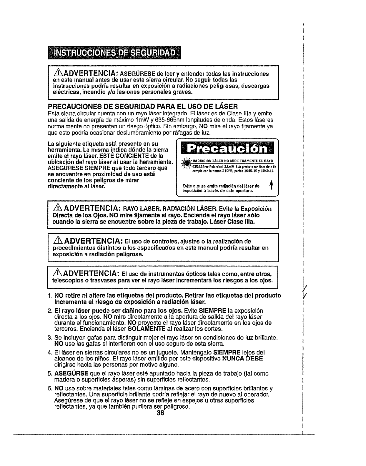
i_ADVERTENCIA: ASEGURESE de leer y entender todas las instrucciones
en este manual antes de usar esta sierra circular. No seguir todas las
instrucciones podr_a resultar en exposici6n a radiaciones peligrosas, descargas
electricas, tncendio y/o lesiones personales graves.
PRECAUCIONES DE SEGURIDAD PARA EL USO DE L_.SER
Esta sierra circular cuenta con un rayo t_.ser integradooEl I_ser es de Clase Ilia y emite
una salida de energia de m,_ximo 1mW y 635-665nrn longitudes de onda. Estos ]&seres
normalmente no presentan un riesgo 6ptico. Sin embargo, NO mire el rayo fijamente ya
que esto podrfa ocasionar deslumbramiento por r&fagas de luz°
La siguiente etiqueta estd presente en su
herramienta. La misma indica d6nde ta sierra
emite el rayo I_ser. ESTI_ CONCIENTE de la
ublcacj6n del rayo i_ser al usar la herramienta.
ASEGURESE SIEMPRE que todo tercero que
se encuentre en proximidad de uso est,1
conciente de los peligros de mirar
directamente a! t_ser.
RADtAC;_N Lt_SER NO MIRE FllAMENTE EL RA¥O
EZS*665nm Pet_nrJa:_2.Stow E_te_'_d==de_onf_er d.v lfJ
c_pb _ _ _0rrr_ 21CFR, partvs 1040o10 y 1040.1 !
A
Evite que se emita radtaci6ndelI_ser de T
exposlci6n a _OVbS de esle aperlura.
J
I Z_ ADVERTENCIA: RAYO LASER. RADIACK)N LASER. Evite la Exposici6n
Dlrecta de los Ojos. NO mire fijamente al rayo. Enclenda el rayo Idser s61o
cuando la sierra so encuentre sobre la pleza de trabaJo. Ldser Clase Ilia.
z_'ADVERTENCIA: El uso do controles, ajustes o la realizaci6n de
procedimientos distintos a los especificados en este manual podria resultar en
exposicibn a radiacibn peligrosa.
Z_ADVERTENCIA: El uso de instrumentos 6pticos tales como, entre otros, I
telescopios o trasvases para ver el rayo tdser incrementar_ los riesgos a los ojoso I
1. NO retire ni altere tas ettquetas del producto. Retlrar las etiquetas del producto
lncrementa el rlesgo de exposlcl6n a radtacl6n Idser.
2o El rayo Idser puede ser dafilno para los oJos. Evite SIEMPRE la exposicl6n
directa a los ojos. NO mire dtrectamente a ta ape rtura de salida de! rayo Idser
durante el funcionamlentoo NO proyecte el rayo laser directamente en los ojos de
terceros_ Eneienda el l&ser SOLAMENTE al realizar los cortes.
3. Se Incluyen gafas para distinguir meier e! rayo !_ser en condiciones de luz brillante.
NO use las gafas sl interfieren con el uso seguro de esta sierra,
4. El Idser en sierras clrculares no es un juguete. MantSnga!o SIEMPRE lejos del
alcance de los niSos, El rayo I_,ser emit!do por este disposftivo NUNCA DEBE
dirigtrse hacla las personas por motivo alguno,
5_ ASEGORSE que e! rayo l&ser est_ apuntado hacia la pieza de trabajo (tal como
madera o superficies _.speras) sin superficies reflectantes,
6_ NO use sobre matertales tales como l&minas de acero con superficies brillantes y
reflectantes. Una superficle brlllante podrfa reflejar el rayo de nuevo al operador,
Aseg_rese de que elrayo I&ser no se refleje en espejos u otras superficies
reflectantes, ya que tambt_n pudlera ser peligroso.
38
I
I
7. Apague SIEMPRE el rayo l&ser cuando no est_ en usoo Dejar la herramienta sin
supervisl6n tambl_n puede incrementar el riesgo de que otra persona
inadvertidamente mire directamente al rayo I&ser.
/K PRECAUCI6N: Siga SIEMPRE s61o las instrucciones conten|das en este
manual cuando use el l&ser. El uso de esta caracteristica de cualquier manera
distinta a Io que se indica en este manual podria resultar en exposici6n a radiacibn
peligrosa, osure.
8. NO intente modificar el desempeSo de este disposlttvo l&ser de cualquier forma°
Esto podrfa resuttar en una expostci6n peligrosa a la radiact6n I_ser,
9. Use SIEMPRE s61o accesorios recomendados por Sears para usar con este
producto. E! uso de accesorios que han sldo dtseSados para su uso con otras
herramientas I&ser podria resultar en lesiones graves.
10. Para.m&s Informaci6n acerca de los I&ser_ refi_rase a ANSI-Z136,1 para el
ESTANDAR PARA USO SEGURO DE LASER, disponible del Instituto L_.ser de
America (407) 380-1553.
SEGURIDAD EN EL AREA DE TRABAJO
1o Mantenga su drea de trabajo iimpia y bien iluminada. Los bancos de trabajo
atestados y las _reas oscuras atraen accidentes.
2. NO use herramientas el_ctricas en ambientes explosivos, tales como en
presencia de i|quidos, gases o polvos inflamables. Las herramientas el_ctricas
producen chlspas que podrfan encender el polvo o gases.
3. Mantenga a observadores, nifios _/visitantes lejos mientras use una
herramienta eldctrica. Las distracclones podrfan ocasionar que pierda el control,
4_ Mantenga su talle de trabajo a prueba de ni_os usando candados e interruptores
maestros. Guarde bajo Ilave las herramlentas cuando no las est_ usando.
5, ASEGORESE que el _rea de trabajo cuente con luz suficiente para que pueda
ver el trabaJo y que no existen obstrticciones que interferir&n con el uso seguro
ANTES de usar su sierra.
I
i
SEGURIDAD PERSONAL
1. CONOZCA su herramienta. Lea el manual del operador cuidadosamente. Aprenda
las aplicaciones y limitaciones de la sierra, asf como los peligros potenciales
espscfficos relacionados con esta herramlenta.
2. MANTI_NGASE ALERTA, mire Io que est& hacienda y use sentido com_n al usar
una herramlenta el_ctrica.
3. NO use la herramienta si est& cansado o bajo la Influencta de drogas, alcohol
o medicamentos. Un momento de falta de atenct6n mientras usa herramientas
el_ctricas podria resultar en lesiones personales graves.
4. VISTA apropiadamente, No use ropa suelta o joyas. Amarre el cabello largo hacia
atr&s. Mantenga su cabe!to, ropa y guantes lejos de plezas m6viles. La ropa suelta
o et cabello largo podrian quedar atrapados en las ptezas m6vileso Las aperturas de
ventilact6n cubren la mayorfa de piezas m6viles y deben evitarse_
5. EVITE la encendida de de manera acoldentaL Aseg_rese de que el Interruptor est_
en la postci6n "OFF" ("APAGADO") antes de enchufar la herramienta. NO sostenga
herramientas con su dedo en el interruptor. Llevar herramientas con su dedo en el
interruptor o enchufar las herramientas con el lnterruptor en la poslci6n "ON"
("ENCENDIDO") atrae accidentes. 39
SEGURIDADPERSONALcont.
6. RETIRE las ilaves de ajuste o !lave de la hoja antes de encender la herramtenta.
Una Ilavs dsJada sn la parts rotativa de la herramlenta podrfa resultar sn lesionas
personales,
7. No se extienda para alcanzar. Mantenga una posici6n firme y balanceada en
todo momento. Una posici6n firms y balanceada permits un msjor control de la
herramisnta en situacionos inesperadas,
8, ASEGURE SIEMPRE SU TRABAJO, Use abrazaderas o un tornillo de banco para
sostener el trabajo cuando sea prbctfco, Es m&s seguro qus usar sus manos y Ilbera
ambas manos para manejar la herramienta,
9, USE EQUIPO DE SEGURIDAD. Siempre use protecci6n para los oJos, Las mbscaras
antipolvo, zapatos de seguridad antiresbalantes, cascos o proteccl6n para los o[dos
dsbe usarse sn condtciones apropiadas,
10, NO USE LA HERRAMIENTA SOBRE UNA ESCALERA o soporte inestable. Una
posici6n flrme y estable sobre una superficis s6tida permite un major control ds la
herramlsnta sn situacionss inesperadas.
SEGURIDAD EN EL USO Y CUIDADO DE LA HERRAMIENTA
ADVERTENCIA: ASEGORESE de leer y entender todas las
instrucciones antes de usar esta sierra. No seguir todas las instrucciones
indicadas a continuaci6n podrfa resultar en descargas eldctricas, incendio y/o
lesiones personales graves.
1. SIEMPRE use abrazaderas u otras maneras practicas de asegurar y soportar la
pieza de trabajo sobre una plataforma estable. Sostsnsr el trabajo con las manos
o contra su cuerpo es inestablo y podda resultar on p_rdida de control.
2. NO fuerce la herramienta. Use la herramtenta y hoja correcta para su aplicacibn.
La herramisnta y hoja corrscta Iograr&n el trabajo major y de manera m&s segura a
la vslocidad para Io cual fueron dtssSadas,
3, NO use la herramienta st el interruptor no la enciende o apaga. Cualquier
herramienta qua no pusde ser controlada mediants el interruptor es peligrosa
y dabs ser reparadao
4_ DESCONECTE el enchufe de la fuente de alimentaci6n antes de hacer
cualquier ajuste, cambiar accesorios o guardar la herramienta. Tales medidas
preventivas de ssguridad reducen el riesgo do qua la herramienta se oncionda
accfdentalmsnts,
5_ NUNCA deje la herramienta en functonamiento. Apdguela SIEMPRE. NO dejs
la herramIenta sin supervisl6n hasta qus se haya detenido por complsto.
6. ALMACENE las herramientas sin use fuera del alcance de los ntfios y otras
personas no capacitadas para ello, Las herramientas son petigrosas en manos
de usuarios no capacttados,
7o Presente MANTENIMIENTO a las herramlentas con cuidado. Mantenga las
herramientas de corte afiladas y Ilmpias, Las herramlentas que reciben el
mantenlmiento aproptado con lateralss ds corte afilados evitar_.n atascarse
y serdn m_s f&ciles de controlaro
8. VERIFIQUE si existe una mala alineaci6n o atascamiento de piezas m6viles,
rotura de piezas y cualquier otra condici6n qus podrla afectar el funcionamiento
de la herramientao Si existen daSos, haga qua la herramisnta sea rsparada antes
de usarla, Muchos accidentes son ocasionados por herramientas real mantenldas
4O
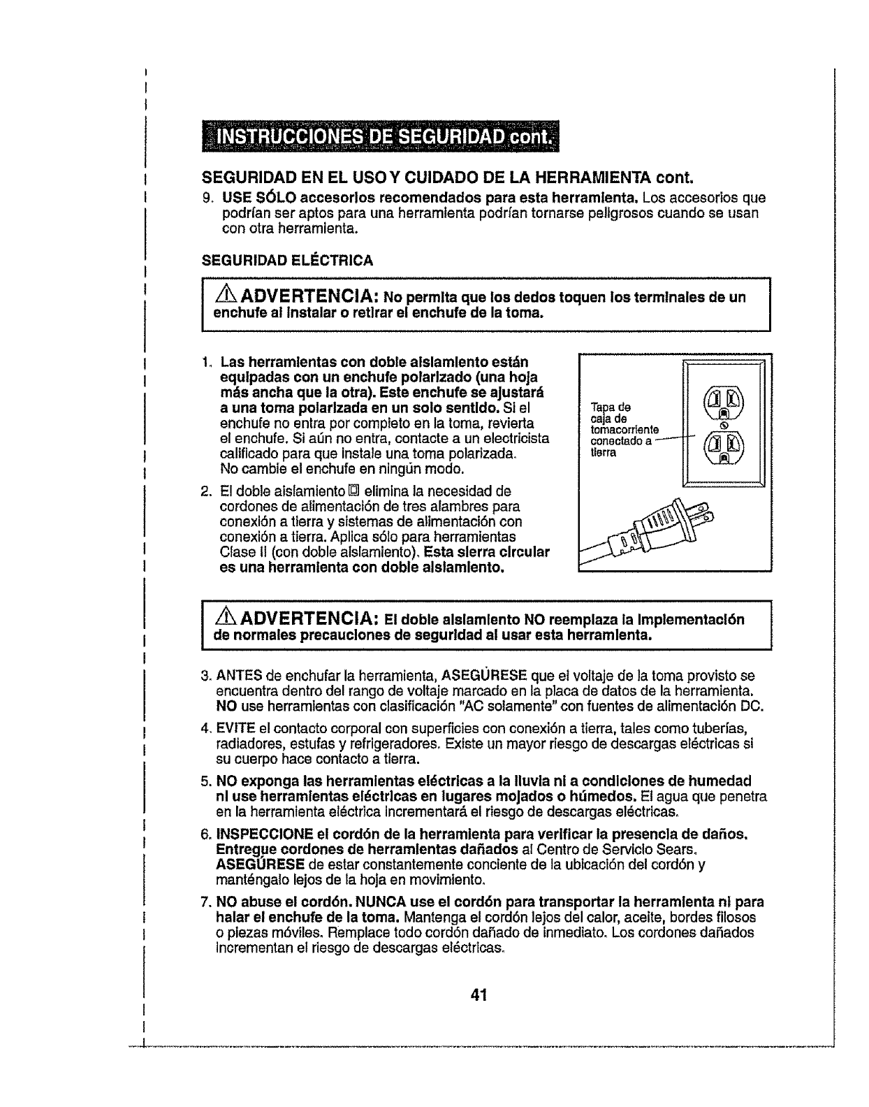
SEGURIDAD EN EL USO Y CUIDADO DE LA HERRAMIENTA cont.
9_ USE S6LO accesorios recomendados para esta herramlenta, Los accesorlos que
podrfan ser aptos para una herramtenta podrfan tornarse peltgrosos cuando se usan
con otra herramlenta,
SEGURIDAD ELi_CTRICA
I I
ADVERTENCIA: No permlta que los dedos toquen los termtnales de un
enchufe al lnstalar o retlrar el enchufe de la toma.
1, Las herramlentas con doble alslamlento estdn
equlpadas con un enchufe polarlzado (una hoJa
mds ancha que la otra). Este enchufe se aJustard
a una toma polarlzada en un solo sentldo. SI el
enohufe no entra pot completo en la toma, revierta
el enchufe. Si a_n no entra, contacte a un electricista
calificado para que instale una toma polarizada,
No cambie el enchufe en ning_n modo.
2. E! doble aistamiento [] elimlna la necesidad de
cordones de alimentact6n de tres alarnbres para
conexi6n a tierra y sistemas de alimentaci6n con
conexi6n a tierra. Aplica s61opara herramientas
Clase II (con doble alslamiento), Esta sierra circular
es una herramlenta con doble alslamlento.
Tapa de
caja de
tomacorr_ente
conectadoa --'--
tlerra
@
®
@
]/_ ADVERTENCIA: E! doble alslamlento NO reemplaza ia implementacldn
de normales precauclones de segurldad ai usar esta herramlenta.
.ANTES de enchufar la herramienta, ASEGURESE queet voltaje de la toma provisto se
encuentra dentro del rango de voltaje marcado en la placa de datos de la herramtenta.
NO use herramlentas con clasificacl6n "AC solamente" con fuentes de alimentact6n DC.
4, EVITE el contacto corporal con superficies con conexi6n a tierra, tales come tuberfas,
radiadores, estufas y refrigeradores, Existe un mayor rtesgo de descargas el_ctricas st
su cuerpo hace contacto a tierra.
5. NO exponga las herramlentas el_ctrtcas a la Iluvla ni a condiclones de humedad
nl use herramlentas eldctdcas en lugares moJados o hdmedos, El agua que penetra
en la herramtenta el_ctrica incrementar& el riesgo de descargas el_ctricas.
6. INSPECCIONE el cord6n de la herramlenta para verificar la presencla de daSos,
Entregue cordones de herramlentas daSados al Centro de Serviclo Sears,
ASEGORESE de estar constantemente conciente de la ubicaci6n del cord6n y
mant_ngalo lejos de la hoja en movimfentoo
7. NO abuse el cord6n. NUNCA use el cord6n para transportar la herramlenta nl para
halar el enchufe de la toma. Mantenga el cord6n lejos del calor, aceite, bordes filosos
o plezas m6viles. Remplace todo cord6n daSado de inmediato, Los cordones daSados
Incrementan el riesgo de descargas eldctflcas,
41
CORDONES DE EXTENSION
Use un cordbn de extensibn aproptado. SOLO use cordones listados bajo Underwriters
Laboratories (UL) Otres cordones de extensi6n podrian ocasionar una caida en el vottaje
de ta linea, resultando en la p6rdida de energia y sobrecalentamiento de ta herramienta,
Para esta herramienta, se recomienda un cord6n de extensi6n de tamaSo AWG (American
Wire Gauge) per Io menos de calibre 14 de longitud de 25 pies e menos Use un cord6n
de extensi6n calibre 12 para 50 pies de Iongitud Los cordones de extensi6n de 100 pies
om_s no se recomtendan. Recuerde, un cable de menor calibre tiene mayor
capacidad que uno de mayor nr3mero (cables calibre 14 tienen m_s capacidad que
cables calibre 16; cables de calibre 12 tienen m_s capacidad que los de calibre 14) En
case de dudas, use un n0mero mAs pequeBo AI usar herramientas et6ctricas en exteriores,
use un cord6n de extensi6n marcado "W-A" o "W" Estos cordones cuentan con clasificaci6n
iara use en exteriores y reducen et riesgo de descargas el6ctricas
z PRECAUCI6N: Mantenga el cord6n de extenst6n fuera del _rea de trabajo.
Posiclone el cordbn de manera tal que no quedarb atrapado en la madera, las
herramientas u otras obstrucciones mientras trabaje con una herramienta el_ctrica.
LL
/_,ADVERTENCIA:_- - Verifique el cordbn de extensi6n antes de carla use. Si
el mismo presenta daSos, reempl_celo de inmediato. Nunca use una herramienta
con un cordbn daSado, ya que tocar el &rea daSada del cord6n podrfa ocasionar
descargas el_ctricas, resultando en lesiones graves.
S|MBOLOS DE SEGURIDAD EN SU HERRAMIENTA
La etiqueta de su herramlenta podrla inclutr los sfmbolos siguientes:
V..........................................................................Voltios
A............. .................................................................. Amperios
Hz ................................................................... Hertz
W.......................................................................Varies
min ....... ................................................................ Minutes
....................................................................... ..... Corriente Alterna
.............................................................Corriente Directa
no ............................................................................... Vetocidad sin carga
[].......................................................................Construcci6n Clase II, Doble Aislamiento
..../min............................................................................. Revolucioneso ciclosperminute
Z_"..........................................................................Indica peligro, advedencia o precauciOn
iiiSignifica atenci6n!!l Se encuentra involucrada
su seguridad.
SEGURIDAD EN EL SERVlClO
1 Si cualquier pieza de esta sierra falta o se rompe, dobla o fatla de cualquier mode; o
si cualquier componente el_ctrico Ilegara a fallar: APAGUE et interrupter de
alimentaci6n y retire el enchufe de la fuente de alimentaci6n y que las piezas fattantes,
dafiadas c defectuosas sean reemplazadas ANTES de resumir el use.
2 Todo serviclo a la herramienla debe ser realizado solo per el Centre de Repuestos y
Reparaci6n Sears, El servicio o mantenimiento per personal no calificado podrfa resuttar
en riesgos de lesiones
3 AI prestar servicto ala herramienta, use s6to piezas de repuesto id_nticas. Siga las
instrucciones en la secci6n sobre mantenimiento de este manual, El use de piezas
no autorizadas o no seguir las instrucciones de mantenimiento podria crear un riesgo
de descarga el6ctrica o lesi6n 42
"_ e | • IDL| e
NORMAS DE SEGURIDAD PARA SIERRAS CIRCULARES
__ Mantenga las manos leJos de los bordes cortantes y la hoJa.
Mantenga su segunda mano en el mango auxlliar o cubierta del motor. SI ambas
manos estdn sostenlendo la sierra, la hoJa no podrd cortarlas.
I/_ PRECAUCION; La hoJa deceleran una vez apagada la slerra._"--]--
m
1. MANTENGA su cuerpo posicionado a cualquiera de los lados de ia hoja de la sierra
y no en Ifnea directa con la hoja. El rebote podria ocasionar que la sierra salte hacia
arras (Vet "Rebote ..Qu_ Io Ocasiona y Maneras para Prevenirlo" en las pAginas 16 y 17).
2. NO se extienda para alcanzar debajo del trabajo. El protector no le proteger_ de la hoja
debajo de la pieza de trabajo.
_AI aserrar la pieza de trabajo, el protector inferior de ta hoja NO
cubre la hoja del lado inferior de la pieza de trabajo (P_g. 15 Fig. 2). Mantenga
SIEMPRE sus manos y dedos lejos de! area de corte.
3_VERIFtQUE que el protector inferior se cierra adecuadamente ANTES de cada uso. NO
use la sierra si el protector inferior no se mueve libremente y no cierra tnstant_neamente.
Nunca sujete ni amarre et protector inferior en posicibn abierta. Si la sierra es dejada
caer accidentarmente, el protector inferior podria doblarse Levante el protector inferior
usando la palanca retr_ctil El protector funciona apropiadamente si se mueve libremente,
no toca la hoja ni ninguna otra parte en cualquier _ngulo y profundidad de corte y si
prontamente regresa a la posici6n de cierre
4_VERIFIQUE el funcionamiento y condici6n del resorte de protector inferior. Si el
protector y resorte no funcionan apropiadamente, DEBEN ser reparados antes del
uso. El protector inferior de ra hoja podrfa funcionar lentamente, debido a piezas daRadas,
dep6sitos gomosos o acumutaci6n de detritos+ NO opera su sierra hasta que se haya
reparado o reemplazado e! daRo.
5El protector inferior debe retraerse manualmente SOLO para hacer cortes especiates,
tales como cortes de bolsillo ocompuestos. Levante SIEMPRE el protector inferior
utilizando la palanca retr_ctil correspondiente. En cuanto la hoja penetre el material,
el protector inferior DEBE ser liberado. Para toda otro corte, el protector inferior debe
funcionar autom&ticamente
6 Aseg_rese SIEMPRE que el protector inferior estd cubriendo la hoja ANTES de colocar
la sierra sobre un banco de trabajo o en el suelo. Una hoja mSvil sin protecciSn
ocasionard que la sierra se desplace hacia atr_s, cortando 1oque encuentre en su camino.
Preste atenciSn a cu&nto tiempo le toma a la hoja dejar de girar despu_s de que se libere
el interruptor
7 NUNCA sostenga en sus manos la pieza que se est_ cortando ni en sus piernas.
Es importante soportar la pieza de trabajo apropiadamente para minimizar la exposiciSn
del cuerpo, el atascamiento de la hoja o ta p6rdida de control
8SOSTENGA LA HERRAMtENTA por los mangos aislados al realizar operaciones d6nde
la herramienta de corte pueda entrar en contacto con cables escondidos ocon su
propio cord6n. E! contacto con un cable "vivo" har_ que las piezas met_ticas expuestas
etectrocuten al operador
9Sujete SlEMPRE la pieza de trabajo de manera segura para que no se mueva al realizar el corte
43
NORMAS DE SEGURIDAD PARA SIERRAS ClRCULARES conL
10,, AI aserrar al hilo, USE SIEMPRE una guia de corte o guia de corte rector Esto
mejora la precisi6n del corte y reduce Eaposibilidad de atascamiento de la hoja.
1I. USE SlEMPRE hojas del tamafio correcte y forma correcta del orificio para el eje
(diamante vs. redondo). Las hojas que no concuerdan con la pieza de montaje de la
sierra girar_n de manera erratica y ocasionar_n la p_rdida de control
12. NUNCA use arandelas o pernos de la hoja, dafiados o incorrectos. Las arandelas
y pernos de la hoja [ueron diseSados especialmente para su sierra, para un 5ptimo
rendimiento y funcionamiento seguro.
13. NUNOA eorte m&s de una pieza a la vez. NO APILE m_s de una pieza de trabajo
sobre la mesa de trabajo ala vez.
14. EVITE un funcionamiento o posicionamiento de las manes lnc6mode d6nde un
resbal6n repenttno podria ocasionar que su mane se mueva en el camino de la hoja.
15, NUNCA alcanee debajo del eamino de corte de la hoja,
z_ADVERTENCIA: Algunas partfculas de potvo creadas per lijado, aserrado,
triturado, taladrado y otros trabajos de construcci6n realizados con herramientas
el_ctricas contienen quimieos conocidos per ocasionar e_ncer, defectos del
nacimiento u otros dafios reproductivos. Algunos ejemplos de estos qufmicoe son:
• Pfomo proveniente de pinturas a base de plomo.
. Sflice cristatina proveniente de ladrillos y cementos y otros productos de mamposter[a.
• Ars_nico y creme proveniente de madera tratada qufmicamenteo
Su riesgo de exposici6n varia dependiendo de cudn a menudo realiza este tipo
de trabajo, Para reducir su exposici6n a estos qufmicos:
. Trabaje en un area bien ventilada°
• Trabaje usando el equipo de seguridad aprobado, tal come mascarillas antipolvo
especialmente diseRadas para filtrar particulas microsc6picas.
Evite el contacto prolongado con polvo proveniente del tijado, aserrado, triturado,
taladrado y otras actividades de la construcci6n. Use ropa protectora y lave las
_ireas expuestas con agua y jabbno
Permitir que el polvo penetre en su boca, ojos o descanse sobre la piet puede promover
la absorciSn de quimicos daRinos.
z_ADVERTENCIA: El use de esta herramienta puede generar y/o emitir
polvo, el cual podr[a ocasionar dafios respiratorios graves y permanentes u otras
tesiones. Use siempre proteccibn respiratoria NIOSH!OSHA aprobada contra la
exposici6n al polvo. Dirija tas particulas lejos de su cara y cuerpo.
NORMAS ADICIONALES PARA UN FUNCIONAMIENTO SEGURO
i............................!
ADVERTENCIA: ASEGURESE de leer y entender todas las instrucciones.
No seguir todas las instrucciones listadas acontinuaci6n podria resuttar en
descargas eldctricas, incendto y/o lesiones personales graves.
1, Conozca su herramienta eldctrlca. Lea el manual del operador cuidadosamente,
Aprenda las aplicaciones y limitaciones, asi come los riesgos potenciales de esta
herramienta. Seguir esta norma reducir_ el riesgo de descargas el_ctricas, incendio y
lesiones graves.
2 Use SIEMPRE gafas de seguridad o protectores para los ojos al usar esta sierra.
Las galas para redes los dias solo cuentan con tentes resistentes al impacto; NO son
galas de seguridad_ 44
" O I " I_I o-
NORMAS ADICIONALES PARA UN FUNCIONAMIENTO SEGURO cont.
3. PROTEJA sus pulmones+ Use una mascara para la cara omascarilla antipolvo si Ia
operaci6n generar_ polvo°
4, PROTEJA sus ofdos+ Use protecci6n personal para los oidos apropiada durante el uso+
Bajo ciertas condiciones, el ruido producido pot esta herramienta podrfa contribuir a ta
p6rdida de audici6n.
5. TO.DOS LOS VIStTANTES Y OBSEVADORES DEBEN usar el misme equipo de
seguridad usado por et operador de la sierra.
6_ INSPECCtONE los cordones de herramienta peri6dicamente y si est_n dahados,
haga que los reparen en su Centro de Servicio Sears o Instalacibn de Servicio
Autorizada. ESTI_ CONCIENTE de la ubicaci6n del cordbno
7 Revise SIEMPRE la herramienta para verificar si existen piezas daSadas. Antes de
continuar usando esta herramienta, si un protector u otra pieza est&n dahados, debe ser
inspeccionada cuidadesamente para determinar si funcionar& apropiadamente y si
realizar& la funci0n para la cual fue disehada. Verifique si existe mala alineaci6n o
atascado de piezas m6vites, rotura de piezas y cualquier otra condici6n que podrla
afectar el funcionamiento de la herramienta. Un protector u etra pieza dahada debe
ser reparado apropiadamente o reemplazado en el Centro de Servicio Sears..
8. INSPECCIONE yretire todo clavo de ta madera antes de proceder a aserrar+
9. GUARDE ESTAS INSTRUCCIONES+ Refi_rase a elias frecuentemente y _lselas
para instruir atos dem&s sobre el use de esta herramienta. Si alguien toma
prestada la herramienta, aseg_rese que tambi6n tenga acceso a estas instrucciones+
Husillo
El eje sobre el cuai la hoja o herramienta de corte es montada+Tambi_n se le conoce como Eje
Revoluciones Por Minuto (RPM)
El nSmero de giros completos de un objeto rotativo en un minuto
Camino de ta hoja de la sierra
El _rea sobre, debajo, detr&s y frente a la hoja, a medida que se aplica a la pieza de trabajo.
Esa &rea que se codar& o se ha cortado con la hoja
Triscado
La distancia a la cual el diente de la hoja de la sierra es doblado hacia fuera desde la cara
de la hoja.
Corte a tnglete
Una operaci6nde corte hecha con la hoja a un _ngulo diferente de 90ocon respecto al tope+gula.
Corte atnglete combinado
Un corte a ingtetecombinado es un code usando un _.ngulode inglete y un &ngulode bisel al
mismo Iiempo
Corte cruzado
Una operaci6n de corte o de formado en sentido contrario a la veta de la pieza de trabajo
Corte biselado
Una operaci6nde corie hecha con una hoja a cualquier &ngulodistinto a 90ode ia mesa de inglete
Corte de ranura
Un code sin traspaso que produce una muesca oun canal de Iado a lado en la pieza de trabajo
(se requiere una hoja especial)
Chafl_,n
Code efectuado para eliminar una cuba de un bloque de madera de modo que el extremo
(o parte de este) quede a un &ngulo diferente de 90°.
Corte at filo Una operaci6n de corte a lo largo de fa tongitud de la pieza de trabajo
45
Corte manos libres
Realizer un corte sin usar una guia, un calibre de ingiete,sujeci6n, abrazadera de trabajo,ni otro
dispositivo apropiado para prevenir queta pieza de trabajo gire o se mueva durante el corte
Aserrado en profundldad
Cualquier operaciSn de code donde la hoja se extiende por completo a trav_s del espesor
de la pieza de trabajo,
Cortes no en profundidad
Cualquier operaci6n de corte d6nde ta hoja no se extiende por comptete a trav_s del
espesor de la pieza de trabajo, como pot ejemplo un corte rasurado,
Borde delantero
El extremo de la pieza de trabajo que entre en contacto con la herramienta primero,
Linea de fracture
El material retirado por la hoja en un code en profundidad o la ranura producida por
la hoja en un corte no en profundidad o parciaL
Rebote
Un peligro que puede ocurrir cuando ta hoja se atasca, lanzando la pieza de trabajo
hacia atr_s hacia el operador,
Pieza de trabajo o material
El objeto sobre el cue1 se estd realizando la operaciSn de corte,,Las superficies de la
pieza de trabajo se denominan comt_nmente cares, extremos o hordes
Goma Un residue pegajoso a base de savia proveniente de productos de madera,
Resina Sustancia pegajosa a base de savia que se ha endurecido
ADVERTENCIA: su sierra NUNCA debe ser conectada a la fuente de
alimentacl6n cuando usted estd ensamblando plezas, hacienda ajustes,
Instalando o retirando hoJas, Ilmpldndola o cuando no estd en uso. Desconecte
la sierra para prevenlr que se enclenda accldentalmente, 1ocual ocaslonarfa
leslones personales graves.
1. La hoja de corte de la sierra se instala en la f_.brica.
2, La gufa lateral es colocada a la fuerza en la parte superior de la tape del estuche de
almacenamtento/transporte,
3. La Ilave de la hoja tambl(_n es colocada a la fuerza en la parte superior de la tapa de!
estuche. La Ilave se utilize pare cambtar o instalar una hoja nueva,
4. Tambi_n se incluyen un par de gafas de segurtdad pare mejoramlento del LAser,
adheridas a la parte superior de la tape del estuche mediante un gancho y correa tipo
lazo, los cuales se uttltzan pare meJorar la visualizaci6n del rayo Idser en condioiones
de luz briUante.
5. Existe un drea pare almacenamiento de la hoja en la parte inferior del estuche donde
es posible almacenar una hoja adiciona!.
6. Inspecctone la sierra culdadosamente pare verificar que no hen ocurrido roturas nt
dafios durante el transporte. Si faltase cualcjulera delos ftems mencionados
(refi_rase a la LISTA DE PARTES de la p_glna 13), regrese la sierra a su tienda
Sears o punto de yen:re Craftsman mds cercano pare que la sierra sea reempiazada.
/_ ADVERTENCIA: SI cualquler de las plezas estdn rotas o faltantes, NO
lntente enchufar el cord6n de altmentaci6n nl usar la sierra hasta que las plezas
rotas o faltantes hayan sldo reemplazadas. No cumpllr con esta instruccl6n
podrfa resultar en poslbles leslones graves.
46
LISTA
DE PARTES
(Fig. I)
Im
)2. HoJa
(Sin ensambtar,
tnstalada en ta sierra)
3. Gufa Lateral
(almacenado ill
en estuche) __EL___
III
4, Llavedeta Hoja ill
(paracambiarla hoja)
5. Galas de _r-J-_ /
segurldad pare
meJorsmlento del
(para mejorar la visualizaci6n del I&ser)
6. Manual del Operador
CONOZCA SU SIERRA CIRCULAR (Fig. 2)
INOTA: Antes de Intentar usar su sierra, familiarfcese con todos las caracterfsticas
operacionales y requerimientos de segurldad.
Su sierra circular cuenta con un motor el_ctrico construido a precisi6n y s61o debe ser
conectado a una fuente de alimentaciSn de 120 voltios, 60-Hz AC SOLAMENTE
(corriente normal del hogar), NO opere con corriente directa (DC). Esta gran cafda en
voltaje ocasionar& p_rdida de potencia y el motor se sobrecalentar&. Sl la sierra no
funclona cuando se enchufa correctamente en una toma de 120 voltios, 60-Hz AC
SOLAMENTE, verifIque la fuente de alimentacl6n. Esta sierra cuenta con un cordbn
de alimentacl6n de 8 pies, 2 alambres (no requlere adaptador).
La Sierra Circular ofrece las sigulentes caracter|stlcas:
1oMotor de 14 Amp, 5000 RPM (velocldad sin carga), Ofrece fuerza y torque para
cortes r_pidos y seguros en readers, readers contrachapada, madera prensada
ymaterlales a base de madera.
2. Laser Trac TM ILa exclusiva e tnnovadora caracterfstica para cortes precisos
yeflclentest
3. LUZ DETRABAJO LED que ilumina el _.rea de corte para mejor visibilidad.
Esta tuz permanece encendida cuando la sierra estd enchufada aia fuente de
alimentaci6n
4. A|ustes rdpldos para profundidad de corte con una profundldad mdxlma
de corte de: 2 3/8 pulgadas a 90°; 1 13116pulgadas de espesor a 45 °
5oEscala para corte en blsel de fdcll tectura se ajusta para una capacldad de biselado
desde 0°hasta 54o5°_
6. Protectores de ia hoja de alumtnio moldeado para mayor fuerza y durabtlidad=
7. Interruptor gattllo de mayor Iongitud para m#.ximo control y confort. Aprldtelo para
encender la sierra y lib_relo para apagarlao
8. Base de alumlnlo mecanlzado de tama_o extra grande que cuenta con una regis
integrada para corte al hilo en bisel y para corte cruzado,
1
47
!
La Sierra Circular ofrece las siguientes caracterfsticas cont.:
9, Mango posterior y mango de asistencia delantero, contorneados y diseSados
ergon6micamente, de agarre suave para un agarre seguro, control, balance y confort.
10, Incluye hoja de acero Craftsman ®24 dientes con punta de carburo de tungsteno
para use general.
11, Bloqueo superior del husillo de la hoja ensamblada para cambios f,_ciles de la hoja,
12_Incluye borde gufa para ayudar a producJr cortes precisos
13_Conducto de eyecci6n de aserrfn ayuda a dirigir el poivo y astitlas lejos del operador.
I4. Rodamientos esf_ricos permanentemente lubricados al 100% para un
funcionamiento ininterrumpido y de larga duraci6n.
15, Engranajes maquinados duraderos para una transmisi6n de energfa eficiente.
16. Incluye un estuche para trasladolalmacenamiento con resistencia a alto impacto
Fig. 2
Mango posterior
Interruptorgatl]!o
Protectorsuperior
delahoJa
Palanca
la hoja
Protector Inferior
de la hoja
ptor del LaserTrac
Mango
delantero
de aststencia
rtura del rayo!_ser
z de trabajo LED
scaladel blsel
.'k _ Palanca
_, __._Z_L__.m de bloqueo
_\ ;,// para ajuste
_i:lelblse,
bt. (U.7_ TomI[Iode
_._ retenciOn!
--.._Y_" suJeclSndel
_._ borde gu[a
_Ranuras de
montaJepara
el borde gu[a
Mango
deiantero _ /,I]
de as_enc_
Cubterta_ t
PNancade
aJustepara.......
°:::::;"--
Apretar ÷\
48
BotSnde
bloqueo
delhusillo
code
__- Palanca
del protector
inferiorde
la hoja
Basa
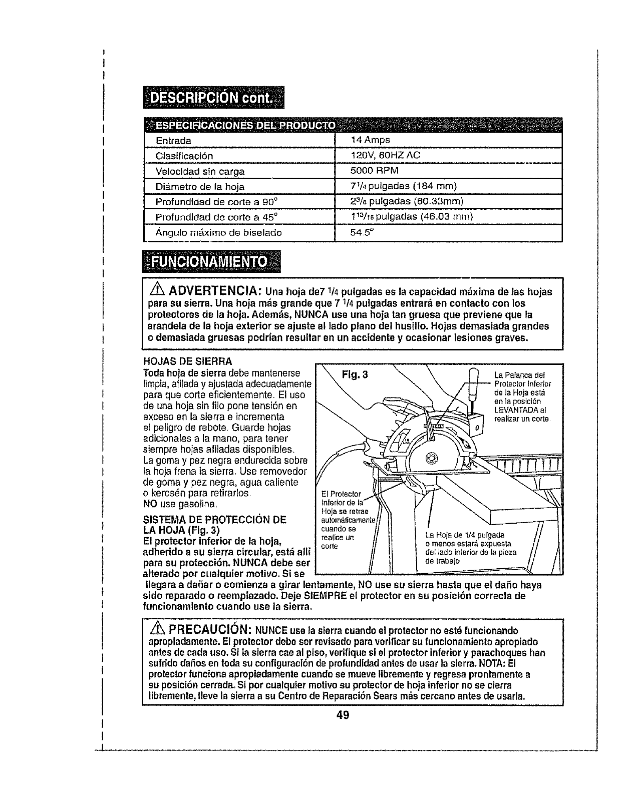
_t:__ --
Entrada 14 Amps
ClasificaciSn 120V, 60HZ AC
Velocidad sin carga 5000 RPM
Di&metro de la hoja 7t/4 pulgadas (184 mm)
Profundidad de corte a 90 ° 23/8 pulgadas (60,33mm)
Profundidad de corte a 45 o113/_6puigadas (46.03 mm)
i i i i i i
,_ngu]o m&ximo de biselado 54 5 °
Z_ ADVERTENCIA: Una hoja de7 1/4pulgadas es la capacidad m_xima de las hojas
para su sierra. Una hoja m_s grande que 71/4 pulgadas entrar_ en contacto con los
protectores de la hoja. Adem_s, NUNCA use una hoja tan gruesa que previene que la
arandela de la hoja exterior se ajuste al lado piano det husitio. Hojas demasiada grandes
odemasiada gruesas podrfan resultar en un accidente y ocasionar lesiones graves.
HOJAS DE SIERRA
Toda hoja de sierra debe mantenerse
timpia, afilada y ajustada adecuadamente
para que corte eficientemente. El uso
de una hoja sin filo pone tensi6n en
exceso en la sierra e incrementa
el peligro de rebote. Guarde hojas
adicionales a la mano, para tener
siempre hojas afiladas disponibles,.
La goma y pez negra endurecida sobre
la hoja frena la sierra. Use removedor
de goma y pez negra, agua caliente
o keros_n para retirarlos
NO use gasotina,
SISTEMA DE PROTECCI()N DE
LA HOJA (Fig, 3)
El protector inferior de la hoja,
adherido asu sierra circular, estd allf
para su protecci6n, NUNCA debe ser
alterado por cualquier motivo° Si se
Fig. 3
reallce un
corte
La Palanca del
Protector Inferior
de la Hoja est_
en la posicl6n
LEVANTADA at
realizar un cotte
de trabajo
Ilegara a daSar o comienza agirar lentamente, NO use su sierra hasta que el daSo haya
sido reparado o reemplazado. Deje StEMPRE el protector en su posici6n correcta de
funcionamiento cuando use la sierra°
/_, PRECAUCION: NUNCE use la sierra cuandoel protector no est6 funcionando
apropiadamente. El protector debe ser revisado paraverificar su funcionamiento apropiado
antes de cada uso. Si la sierra cae al piso, verifique si el protector inferior y parachoques han
sufrido daSosen toda su configuracl6n de profundtdadantes de usar la sierra. NOTA:El
protectorfunciona apropiadamente cuando se mueve libremente y regresa prontamente a
su posici6n cerradaoSi por cualquier motivesu protector de hoja inferior no se cierra
libremente,Ileve la sierra a su Centre de Reparaci6n Sears mrs cercano antes de usarla.
49
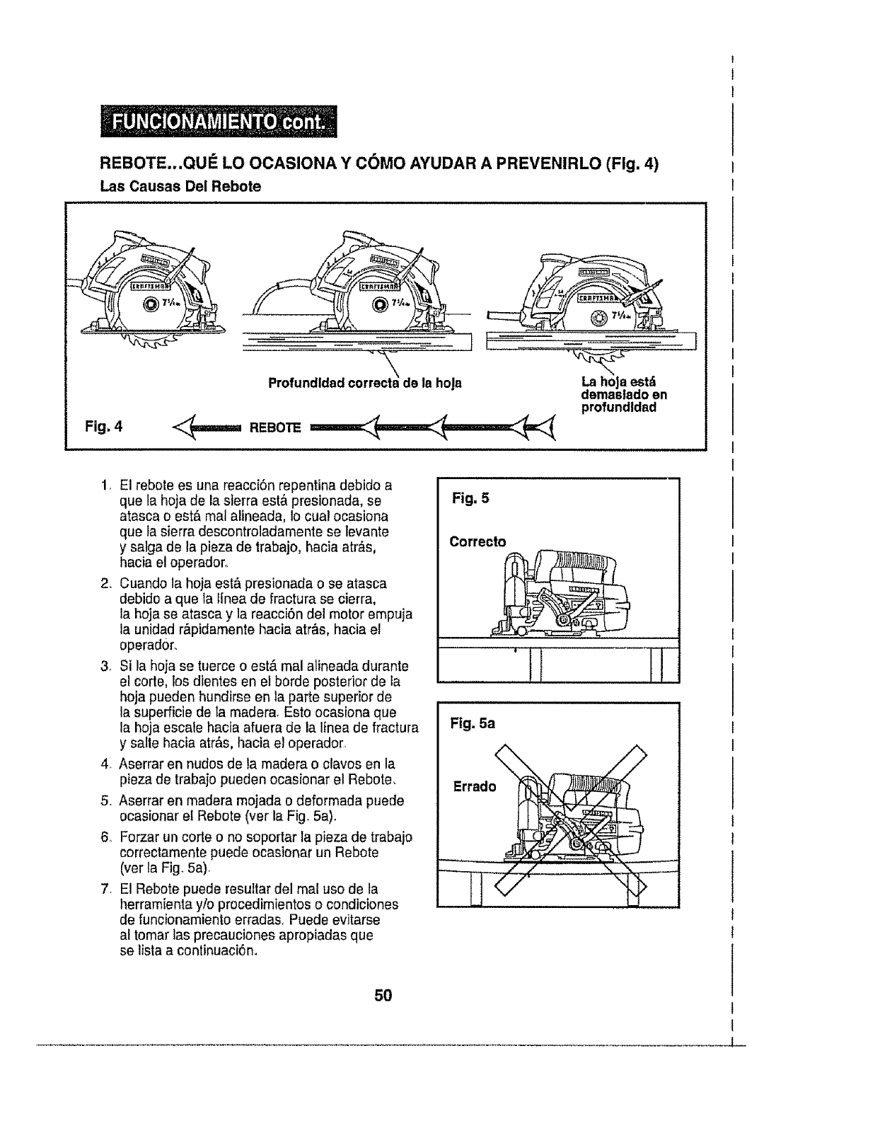
REBOTE,,.QUle LO OCASIONA Y C(_MO AYUDAR A PREVENIRLO (Fig. 4)
Las Causas Del Rebote
Fig. 4
La hoJaest_
demaslado en
profundldad
1, El rebote es una reacci6n repentina debide a
que la hoja de la sierra est& presionada, se
atasca o est& mal alineada, 1ocua! ocasiona
que la sierra descontroladamente se levante
y satga de la pieza de trabajo, hacia atrAs,
hacia el operadoro
2, Cuando la hoja est& presionada o se atasca
debido a que Ia flnea de fractura se cierra,
la hoja se atasca y la reacci6n del motor empuja
la unidad r_tpidamente hacia atr&s, hacia et
eperador.
3. Si la hoja se tuerce o est& mal alineada durante
el corte, los dientes en el borde posterior de ta
hoja pueden hundirse en la parte superior de
la superficie de la madera, Esto ocasiona que
la hoja escale hacia afuera de la Ifnea de fractura
y salte hacia atr&s, hacia el operado_,
4, Aserrar en nudos de la rnadera o claves en la
pieza de trabajo pueden ocasionar el Rebote,
5. Aserrar en madera mojada o deformada puede
ecasionar el Rebote (vet la Fig. 5a).
6. Forzar un corte o no soportar ta pieza de trabajo
correctamente puede ocasionar un Rebote
(ver la Fig. 5a).
7. El Rebote puede resuitar del real uso de la
herramienla y/o procedimientos o condiciones
de funcionamiento erradas, Puede evitarse
al tomar las precauciones apropiadas que
se lista a continuaci6n.
Fig. 5
Correcto
'i
Fig. 5a
Errado
5O
L-
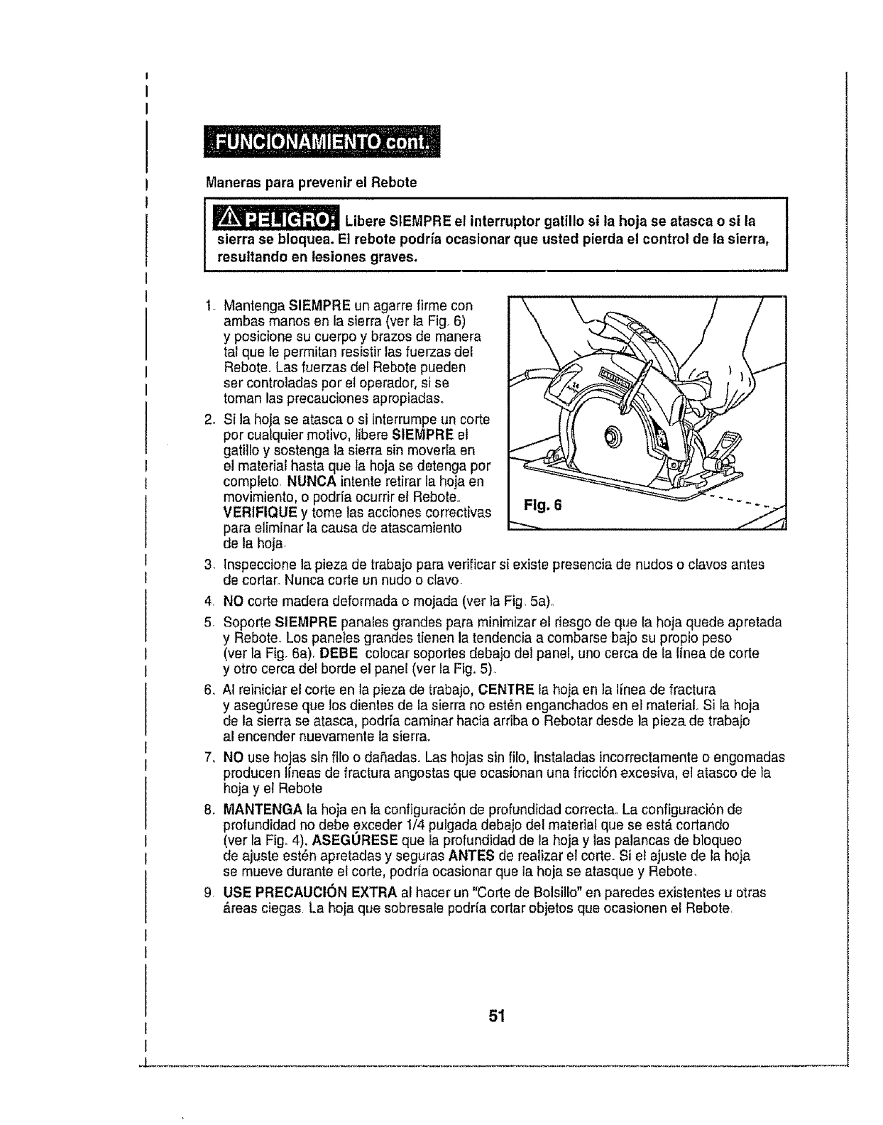
ManerasparaprevenirelRebote
LibereSIEMPREelinterruptorgatillosi la hoja se atasca o si la
sierra se bloquea. El rebote podda ocasionar que usted pierda el control de la sierra,
resultando en lesiones graves.
.
3_
4,
5_
6_
Mantenga SIEMPRE un agarre firme con
ambas manos en la sierra (ver la Fig. 6)
y posicione su cuerpo y brazos de manera
tal que te permitan resistir tas fuerzas del
Rebote. Las fuerzas del Rebote pueden
ser controladas por et operador, si se
toman las precauciones apropiadas.
Si la hoja se atasca osi interrumpeun corte
per cualquier motivo, libere SIEMPRE el
gatillo ysostenga la sierra sin moverla en
el material hasta que Ia hoja so detenga por
completo. NUNCA intente retirar la hoja on
movimiento, o podr[a ocurrir ei Rebole..
VERIFIQUE y tome las acciones correctivas Fig. 6
para elimJnar la causa de atascamiento _"'--,
de la hoja
tnspeccione la pieza de trabajo para verificar si existe presencia de nudos o clavos antes
de corlar. Nunca corle un nudo o clavo.
NO corte madera deformada e mojada (vet la Fig. 5a)o
Soporte SIEMPRE panales grandes para minimizar el riesgo de que Ia hoja quede apretada
y Rebote_ Los paneles grandes tienen la tendencia a combarse bajo su propio peso
(ver la Fig. 6a) DEBE colocar soportes debajo del panel, uno cerca de la Iinea de corte
yotro cerca del horde el panel (ver la Fig. 5).
Al reiniciar el corte en ta pieza de trabajo, CENTRE la hoja en la linea de fractura
y aseg_rese que los dientes de la sierra no est_n enganchados en el material. Si la hoja
de ta sierra se atasca, podria caminar hacia arriba o Rebotar desde la pieza de trabajo
a! encender nuevamente la sierra..
7. NO use hojas sin file o daRadas. Las hojas sin filo, instaladas incorrectamente o engemadas
producen Ifneas de fractura angostas que ocasionan una fricci6n excesiva, el atasco de la
hoja y el Rebote
8. MANTENGA la hoja en ia configuraciSn de profundidad correctao La configuraciSn de
profundidad no debe exceder 1/4 pulgada debajo del material que se est& cortando
(ver la Fig. 4). ASEGURESE que la profundidad de la hoja y las palancas de bloqueo
de ajuste est6n apretadas y seguras ANTES de realizar el corte. Si et ajuste de la hoja
se mueve durante el corte, podria ocasionar que ia hoja se atasque y Rebote.
9. USE PREOAUCION EXTRA al hacer un "Corte de Bolsillo" en paredes existentes u otras
Areas ciegas La hoja que sobresale podria cortar objetos que ocasionen el Rebote.
51
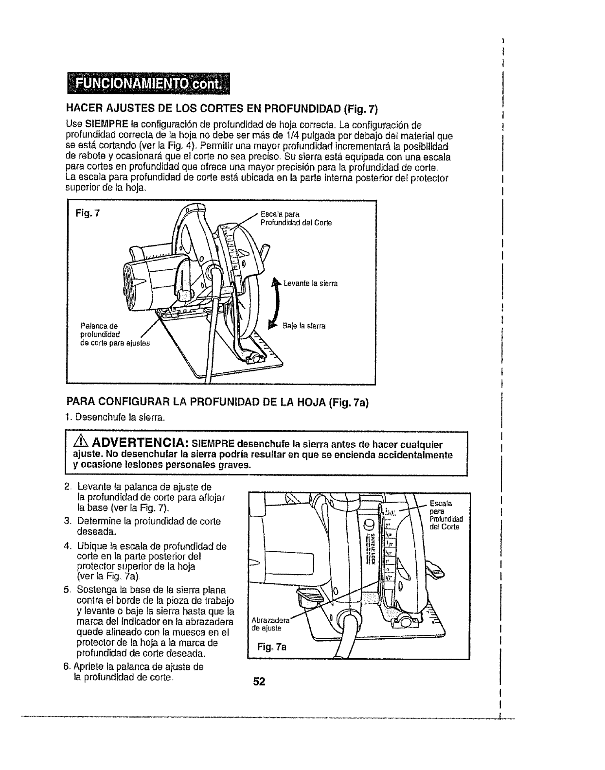
HACER AJUSTES DE LOS CORTES EN PROFUNDIDAD (Fig. 7)
Use SIEMPRE la configuraci6n de profundidad de hoja correcta_ La configuraci6n de
profundidad correcta de la hoja no debe ser m&s de 1/4 pulgada por debajo del material que
se est,. cortando (ver la Fig. 4). Permitir una mayor profundidad incrementar& la posibiiidad
de rebote y ocasionar& que el code no sea precisoo Su sierra °st& equipada con una °scala
para cortes en profundtdad que ofrece una mayor precisi6n para la profundidad de code.
La °scala para profundidad de code est_ ubicada en la parte interna posterior del protector
superior de la hoja_
Fig. 7
Palanca de
do,oo.o
__ Levant_ ta sierra
Sajelas{erra
PARA CONFIGURAR LA PROFUNIDAD DE LA HOJA (Fig. 7a)
1_Desenchufe la sierra°
I _ ADVEN/_NCIA: SlEMPREdesenchufela sierraantesde hacer cualquier
ajuste. No desenchufar la sierra podria resultar en que se encienda accidentalmente
y ocastone lesiones personates graves.
2 Levant° _apaianca de ajuste de
ia profundidad de corte para aflojar
la base (ver la Fig. 7).
3. Determine fa profundidad de code
deseada
4. Ubique ta escala de profundidad de
code en ta parte posterior del
protector superior de la hoja
(ver la Fig. 7a)
5r Sostenga fa base de la sierra ptana
contra el borde de la pieza de trabajo
y levant° o baje la sierra hasta que ta
marca del indicador en la abrazadera
quede alineado con la muesca en el
protector de la hoja a ta marca de
profundidad de corte deseada.
6_Apriete la palanca de ajuste de
la profundldad de core.
de ajuste
Fig. 7a
52
! ....
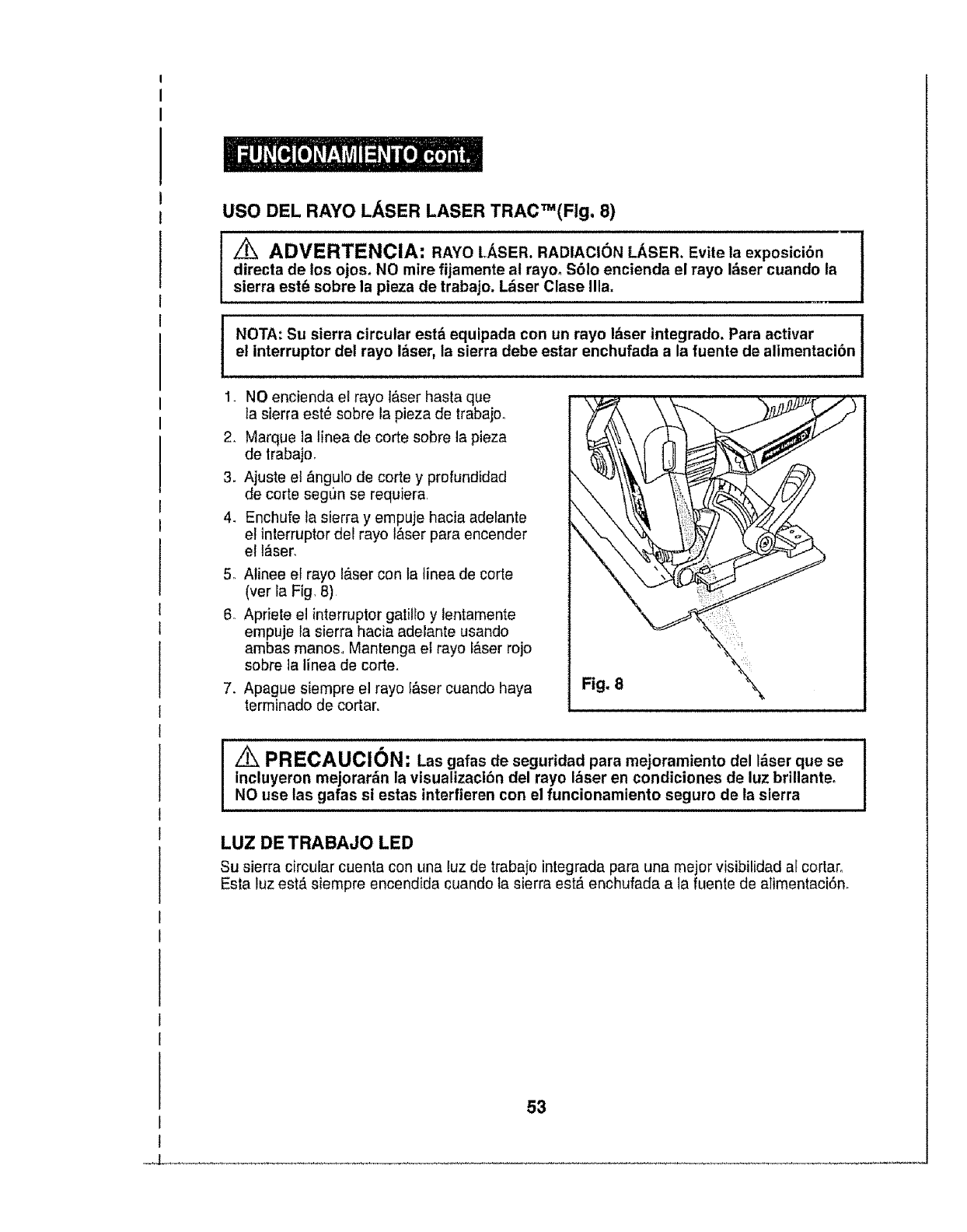
USO DEL RAYO LASER LASER TRAC_(Fig. 8)
z_ ADVERTENCIA: RAYO LASER, RADIACION LASER. Evite ia exposicibn
directa de los ojos, NO mire fijamente al rayo_ $61o encienda el rayo I_ser cuando ta
sierra est(_sobre la pieza de trabajo. L_ser Clase Ilia.
NOTA: Su sierra circular estd equipada con un rayo I_ser integrado. Para activar
el interruptor del rayo I_ser, la sierra debe estar enchufada a la fuente de alimentaci6n
1. NO encienda el rayo t&serhasta que
la sierra est_ sobre la pieza de trabajo,
2, Marque la tinea de corte sobre la pieza
de lrabajo,
3. Ajuste el _ngulo de corte y profundidad
de corte seg(m se requiera
4. Enchufe ta sierra y empuje hacia adelante
el interrupter del rayo t&ser para encender
el l_ser,
5o Alinee el rayo I&ser con la tinea de corte
(ver la Fig, 8)
6 Apriete el interruptor gatillo y lentamente
empuje la sierra hacia adelante usando
ambas manos, Mantenga el rayo f&ser rojo
sobre ta linea de corte,
7. Apague siempre el rayo I&ser cuando haya
terminado de cortar.
Fig, 8\
' _ PRECAUCION: Las gafas de seguridad para mejoramiento del I&ser que se
incluyeron mejorar_n la visualizaci_n del rayo I_ser en condiciones de luz brillanteo
NO use las gafas si estas interfieren con el funcionamiento seguro de la sierra
LUZ DE TRABAJO LED
Su sierra circular cuenta con una luz de trabajo integrada para una mejor visibilidad al cortaro
Esta luz est,. siempre encendida cuando la sierra est_ enchufada a la fuente de alimentaci6n.
I
I
53
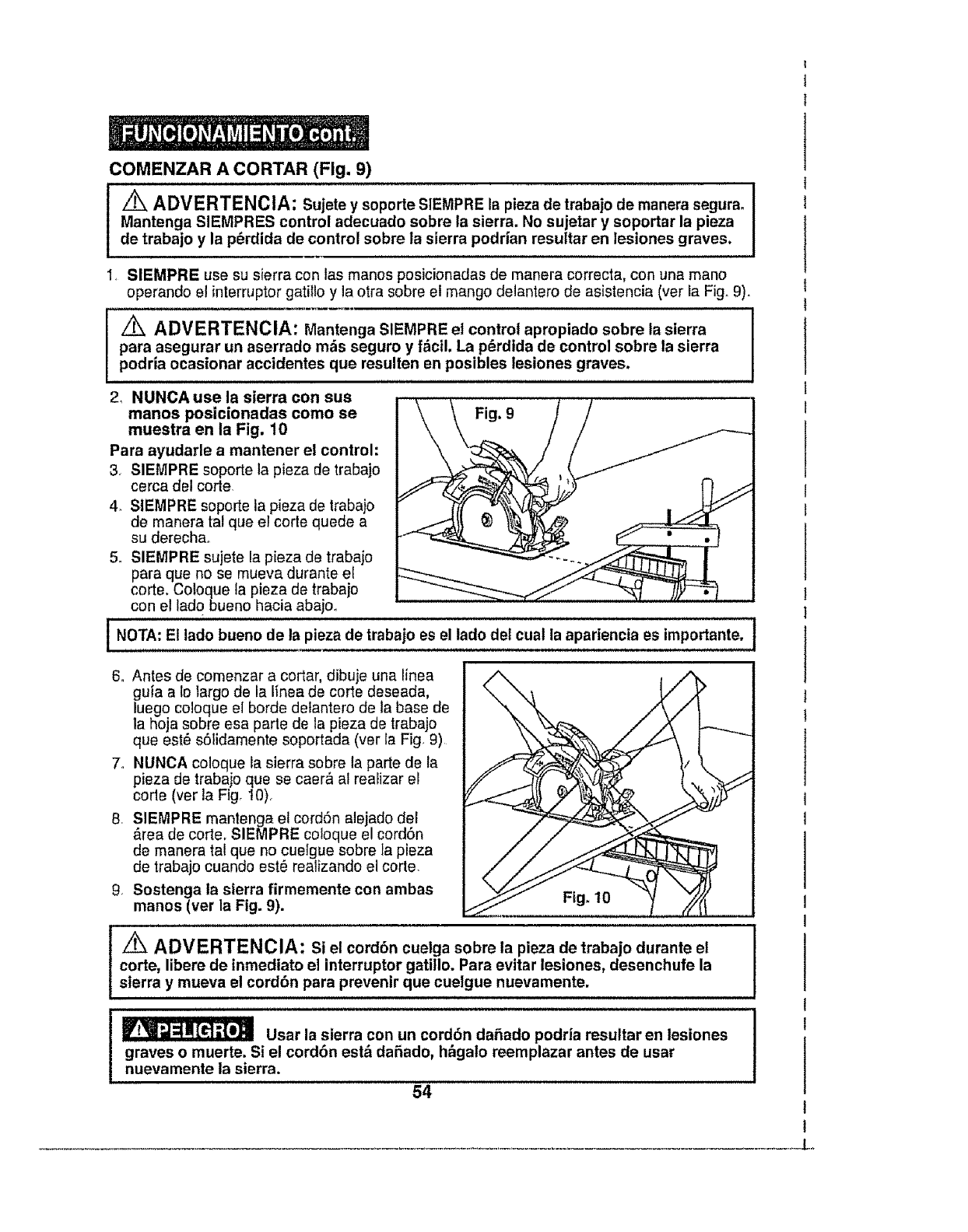
COMENZAR A CORTAR (Fig. 9)
[ _ADMERTENcIA: Sujete y sopode SIEMPRE ,a pieza de traba,o de manera segura. I
Mantenga SIEMPRES control adecuado sobre la sierra. No sujetar y soportar la pieza
de trabajo y la p6rdida de control sobre la sierra podrian resultar en lesiones graves.
I. SIEMPRE use su sierra con las manos posicionadas de manera correcta, con una mane
operando el interruptor gatillo y la otra sobre el mango delantero de asistencia (ver la Fig. 9).
ADVERTENCIA: Mantenga SIEMPRE et control apropiado sobre la sierra
para asegurar un aserrado m_s seguro y fActl. La p6rdida de control sobre la sierra
podria ocasionar accidentes que resulten en posibles lesiones graves.
2, NUNCA use la sierra con sus
manos posieionadas como se Fig. 9
muestra en la Fig. 10
Para ayudarle a mantener el control:
3. SIEMPRE soporte la pieza de trabajo
cerca del code
4. SIEMPRE soporte la pieza de trabajo
de manera tal que el corte quede a
su derechao
5o SIEMPRE sujete la pieza de trabajo
para que no se mueva durante ei
code. Coloque la pieza de trabajo
con el ladobueno hacia aba]m
NOTA: Et lado bueno de la pieza de trabajo es el iado det cual la apariencia es importante, t
6o Antes de comenzar a cedar, dibuje una linea
guia a 1olargo de la linea de come deseada,
luego coloque el borde detantero de la base de
la hoja sobre esa parle de la pieza de trabajo
que est6 sSlidamente sopodada (ver Ia Fig. 9)
7. NUNCA coloque la sierra sobre la parte de la
pieza de trabajo que se caer& at rearizar el
code (ver la Fig 10),
8. SIEMPRE mantenga el cordSn alejado del
,_rea de code. SIEMPRE coloque el cordSn
de manera tal que no cuelgue sobre ia pieza
de trabaje cuando est6 reatizande el corte.
9. Sostenga la sierra firmemente con ambas
manos (ver la Fig. 9). Fig_ 10
_ADVERTENCIA: Si el cord6n cuelga sobre la pieza de trabajo durante el
corte, libere de inmediato el interruptor gatillo. Para evitar iesiones, desenchufe la
sierra y mueva el cord6n para prevenir que cuelgue nuevamente.
_Usar la sierra con un cord6n daSado podria resuttar en lesiones
graves o muerte. Si el cord6n est& daSado, h_galo reemplazar antes de usar
nuevamente ta sierra,
54
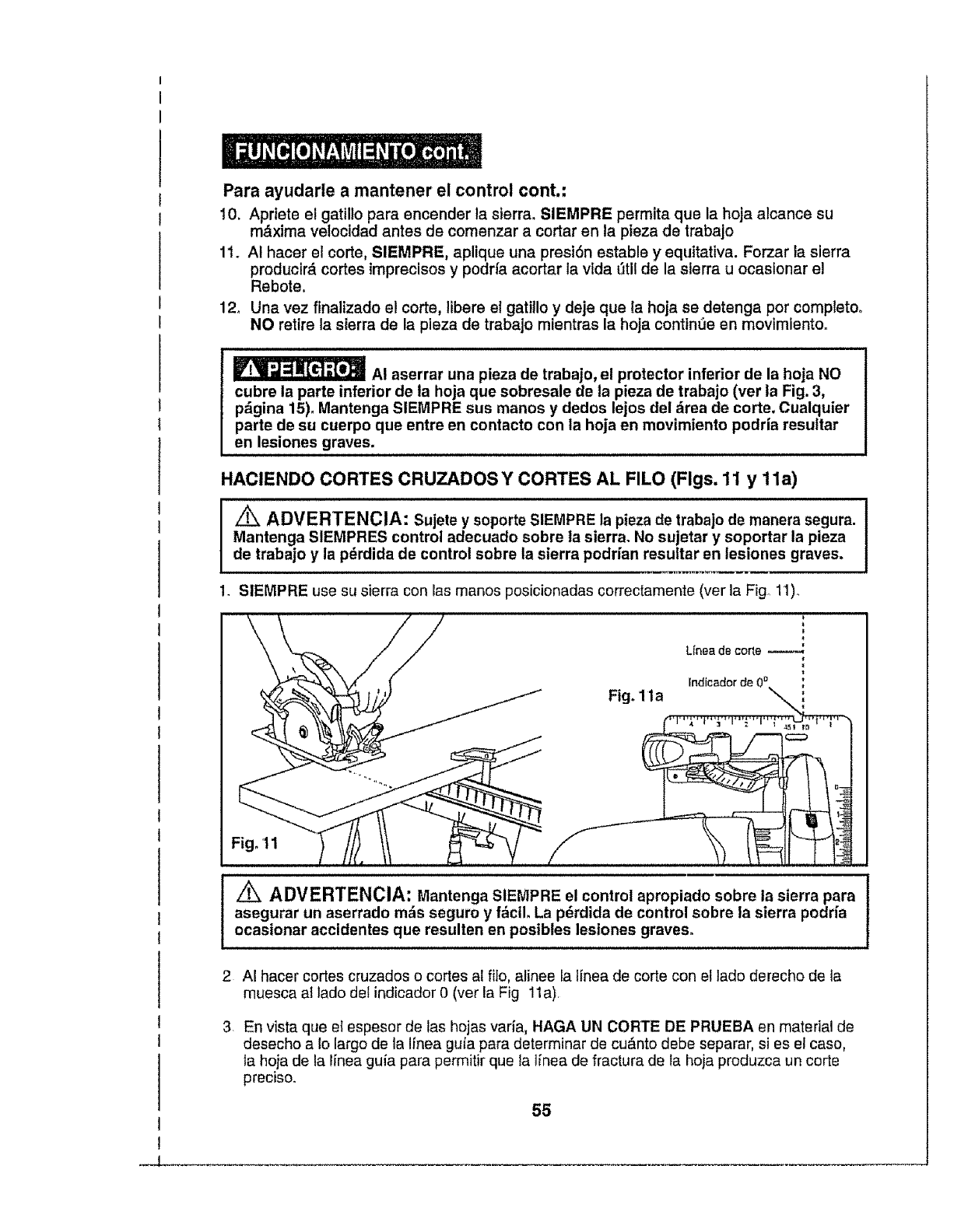
I
I
Para ayudarle a mantener el control cont.:
10. Aprtete el gatillo para encender la sierra. SIEMPRE permita que la hoja alcance su
maxima velocidad antes de comenzar a cortar en la pieza de trabajo
11. AI hacer el corte, SIEMPRE, aplique una presi6n estable y equitativa. Forzar la sierra
producir_, cortes imprecisos y podfia acortar la vida fitlt de la sierra u ocasionar el
Rebote.
12o Una vez flnalizado e! corte, libere el gatiilo y deje que ia hoja se detenga por completo.
NO retire la sierra de la pleza de trabajo mientras la hoja continue en movimlentoo
_AI aserrar una pieza de trabajo, el protector inferior de la hoja NO
cubre la parte inferior de ta hoja que sobresale de la pieza de trabajo (ver ia Fig. 3,
pfigina 15). Mantenga SIEMPRE sus manos y dodos lejos del drea de corte. Cualquier
parte de su cuerpo que entre en contacto con la hoja en movimiento podria resultar
en lesiones graves.
HACIENDO CORTES CRUZADOS Y CORTES AL FILO (Figs. 11 y 11a)
/_ ADVERTENCIA: Sujete y soporte SIEMPRE la pieza de trabajo de manera segura.
Mantenga SIEMPRES control adecuado sobre ta sierra. No sujetar y soportar la pieza
de trabajo y la p_rdida de control sobre ta sierra podrfan resultar en lesiones graves,
1. SIEMPRE use su sierra con las manos posicionadas correctamente (ver la Fig° 11)o
Fig. 1la
Unea de corle
Indicador de 0 °
Fig. 11
/_ ADVERTENCIA: Mantenga SIEMPRE el control apropiado sobre la sierra para
asegurar un aserrado mils seguro y fficll. La p6rdida de control sobre la sierra podrfa
ocasionar accidentes que resulten en posibles lesiones graves.
2 AI hacer cortes cruzados o cortes al filo, atinee la linea de corte con el lado derecho de la
muesca al lado deI indicador 0 (vet la Fig 11a).
3 En vista queet espesor de las hojas varia, HAGA UN CORTE DE PRUEBA en material de
desecho a Io largo de la linea guia para determinar de cu_nto debe separar, si es el caso,
la hoja de la Iinea guia para permitir que la linea de fractura de la hoja produzca un code
preciso.
55
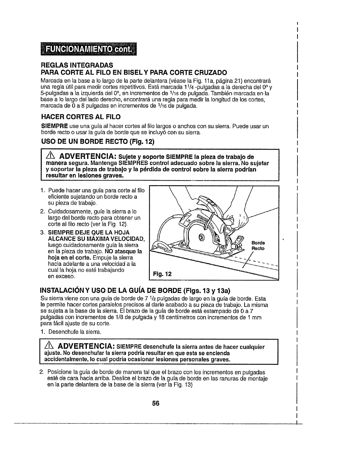
REGLAS INTEGRADAS
PARACORTEAL FILO EN BISELY PARACORTECRUZADO
Marcada en ta base a 1olargo de la parte delantera (v6ase la Fig. 1la, p_,gina 21) encontrar,'_
una regla util para medir cortes repetitivos. Est,_marcada 11/4 -pulgadas a ]a derecha del 0° y
5-pulgadas a la izquierda del 0°, en incrementos de 1/16de pulgada, Tambi6n marcada en la
base a t0 largo del lado derecho, encontrar_ una regta para medir la Iongitud de los codes,
marcada de 0 a 8 pulgadas en incrementos de 1/16de pulgada.
HACER CORTES AL FILO
SIEMPRE use una guia al hacer cortes a! filo largos o anchos con su sierra. Puede usar un
borde recto o usar la gufa de borde que se incluy6 con su sierra,
USO DE UN BORDE RECTO (Fig. 12)
/_, ADVERTENCIA: SuJete y soporte SIEMPRE la pleza de trabaJo de J
manera segura. Mantenga SIEMPRES control adecuado sobre la sierra. No sujetar
y soportar la pleza de trabaJo y la p_rdida de control sobre la sierra podrfan
resultar en lesiones graves.
1o Puede hacer una gula para corte al fi!o
eficiente sujetando un borde recto a
su pieza de trabajo.
2o Cuidadosamente, guie la sierra a Io
largo del borde recto para obtener un
code al filo recto (ver la Fig, 12),
3_ SIEMPRE DEJE QUE LA HOJA
ALCANCE SU M_XIMA VELOCIDAD,
luego cuidadosamente guia la sierra
en la pieza de trabajoo NO atasque la
hoja en el code. Empuje la sierra
hacia adelante a una velocidad a la
cual la hoja no est_ trabajando
en exoeso., Fig. 12
INSTALACI6N Y USO DE LA GUfA DE BORDE (Figs. 13 y 13a)
Su sierra viene con una gufa de borde de 7 1/_pulgadas de largo en la gufa de borde. Esta
le permite hacer codes paralelos precisos al darle acabado a su pieza de trabajo, La misma
se sujeta a la base de la sierra. El brazo de la gufa de borde est_ estampado de 0 a 7
pulgadas con incrementos de 1/8 de pulgada y 18 centimetros con incrementos de I mm
para f_cil ajuste de su code°
1. Desenchufe la sierra,,
_ADVERTENCIA: SIEMPRE desenchufe la sierra antes de hacer cualquier
ajuste. No desenchufar la sierra podrfa resultar en que esta se encienda
accidentalmente, Io cual podria ocasionar lesiones personales graves.
2. Posicione la guFade borde de manera ta! que el brazo con los incrementos en pulgadas
est8 de cara hacia arriba. Deslice el brazo de la guia de borde en las ranuras de montaje
en la parte delantera de la base de la sierra (ver la Fig,. 13)
!
56
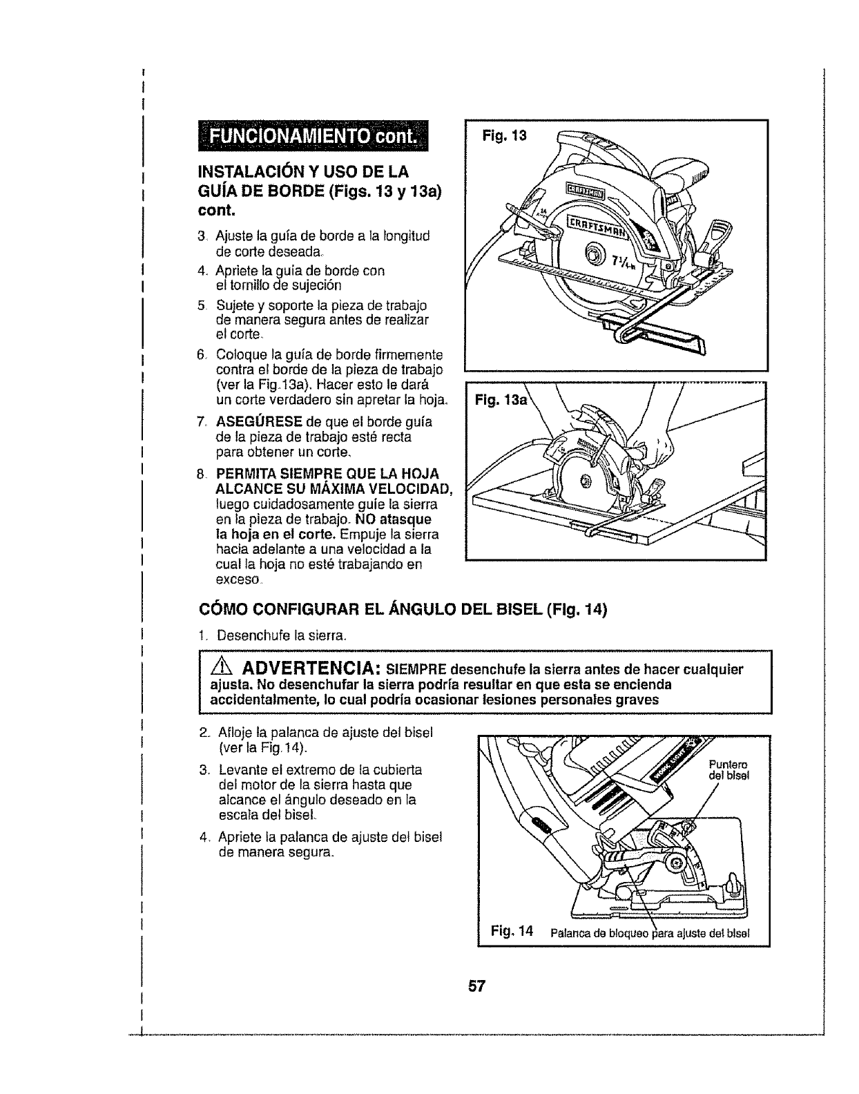
INSTALACi6N Y USO DE LA
GU|A DE BORDE (Figs. 13y 13a)
cont.
3, Ajuste la guia de borde a la longitud
de corte deseada_
4_ Apriete fa guia de borde con
el tornillo de sujeci6n
5 Sujete y soporte la pieza de trabajo
de manera segura antes de reatizar
el corte,,
6, Coloque ta guia de borde firmemente
contra el borde de la pieza de trabajo
(vet la Fig I3a), Hacer esto te dar&
un corte verdadero sin apretar la hojao
7_ ASEGORESE de que el borde gu[a
de la pieza de trabajo est# recta
para obtener un corte,
8PERMITA SIEMPRE QUE LA HOJA
ALCANCE SU MAXIMA VELOCIDAD,
luego cuidadosamente guie la sierra
en la pieza de trabajo. NO atasque
la hoja en el corte. Empuje la sierra
hacia adelante a una velocidad a la
cual ta hoja no est_ trabajando en
exceso,
Fig. 13
Fig,
C_)MO CONFIGURAR EL ANGULO DEL BISEL (Fig. 14)
1. Desenchufe la sierra_
Z_ ADVERTENCIA: SIEMPRE desenchufe la sierra antes de hacer cualquier
ajusta. No desenchufar la sierra podrfa resultar en que esta se encienda
accidentalmente, Io cual podria ocasionar lesiones personales graves
2. Afloje ta palanca de ajuste del bisel
(ver ta Fig, 14).
3. Levante et extremo de la cubierta
del motor de la sierra hasta que
alcance el &ngulo deseado en la
esca}a del bisel.
,Apriete la palanca de ajuste det bisel
de manera segura.
Fig. 14
57
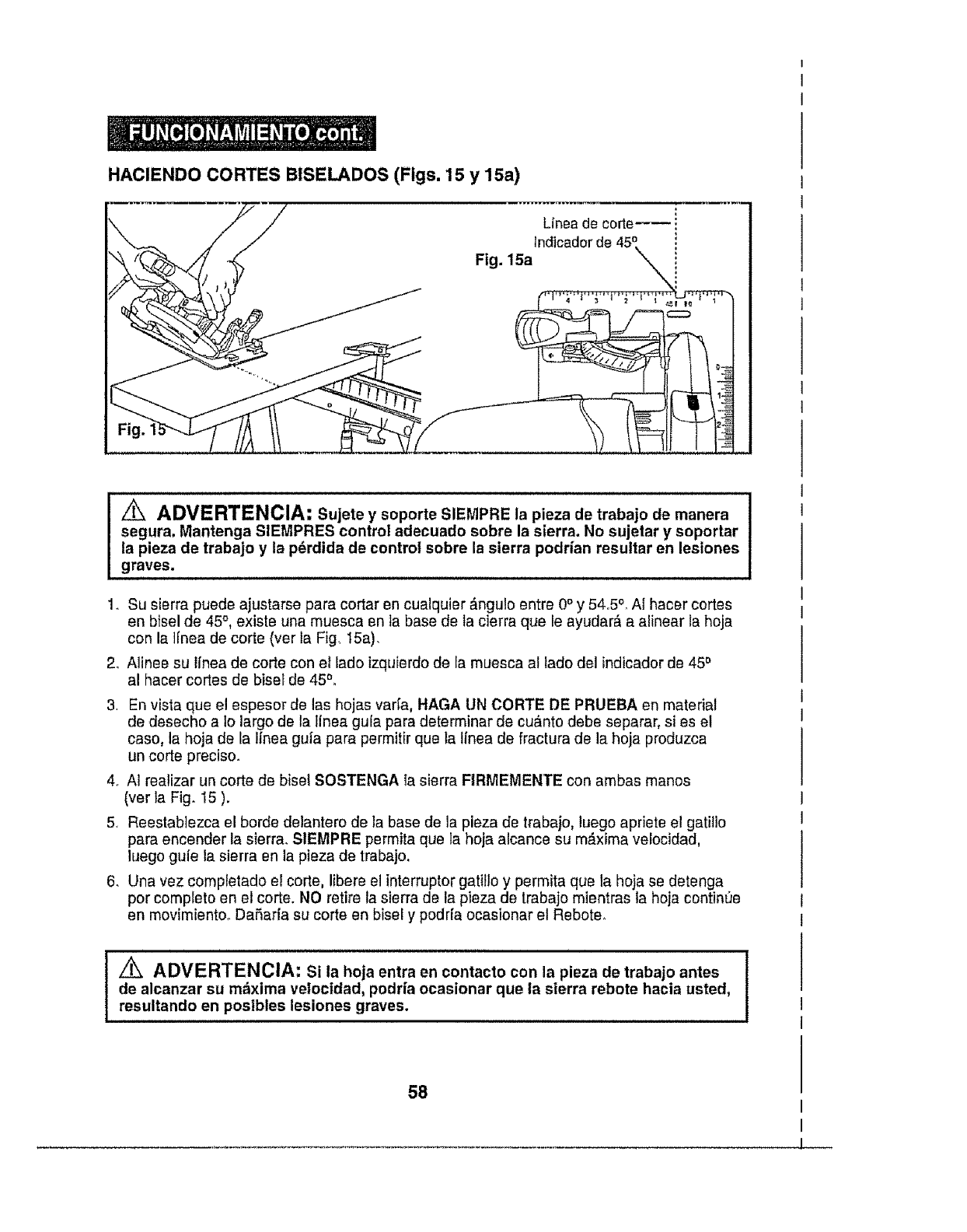
HACIENDOCORTESBISELADOS(Figs. 15y 15a)
Unea de corte_,
z_ ADVERTENCIA: Sujete y soporte SIEMPRE la pieza de trabajo de manera
segura. Mantenga SIEMPRES control adecuado eobre la sierra. No sujetar y soportar
la pieza de trabajo y la p_rdida de control sobre la sierra podrfan resuttar en lesiones
graves=
1, Su sierra puede ajustarse para cortar en cualquier &ngulo entre 0°y 54,,5°_Af hacer cortes
en btsel de 45°, existe una muesca en la base de la cierra qua le ayudar& a alinear la hoja
con la l[nea de corte (ver la Fig, 15a),
2_ A]inee su Itnea de corte con el lade izquierdo de la muesca al lade del indicador de 45°
al hacer cortes de bisel de 45°,
3, En vista qua el espesor de las hojas var[a, HAGA UN CORTE DE PRUEBA en material
de deseche a Io largo de la tinea gula para determinar de cuanto debe separar, si es el
case, la hoja de la Ifnea gufa para permitir qua la Ifnea de fractura de la hoja produzca
un corte precise.
4, AI realizar un corte de bisel SOSTENGA ]a sierra FIRMEMENTE con ambas manes
(ver la Fig, 15 ).
5, Reestabiezca el borde delantero de la base de ]a pieza de trabajo, luego apriete el gatil]o
para encender la sierra, SIEMPRE permita qua la hoja alcance su m_xima velocidad.
luego guie la sierra en ]a pieza de trabajo.
6. Una vez comptetado el code, libare el interrupter gatillo y permita qua la hoja se detenga
per complete en el corte. NO retire la sierra de la plaza de trabajo mientras la hoja continue
en movimiento_ DaSarfa su corte an bisel y podr[a ocasionar el Rebote,
Z_ ADVERTENCIA: Si la hoja entra en contacto con la plaza de trabajo antes
de alcanzar su m_xima velocidad, podrfa ocasionar que ta sierra rebote hacla usted,
resultando en posibles lesiones graves.
58
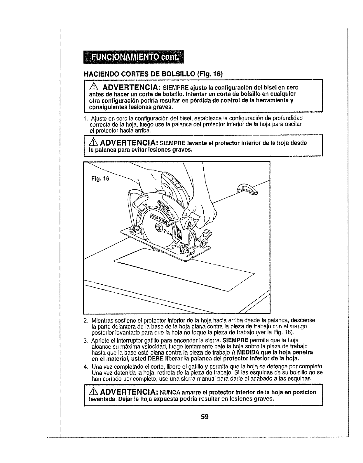
HACIENDOCORTESDE BOLSILLO (Fig. 16)
ADVERTENCIA: SIEMPRE ajuste la configuraci6n del bisel en cero
antes de hacer un corte de bolsillo. Intentar un corte de bolsUlo en cualquier
otra conftguraci_n podria resultar en p_rdida de control de la herramienta y
consigulentes lesiones graves.
1. Ajuste en cero la configuraciSn de! bisel, establezca la configuraciSn de profund]dad
correcta de ra hoja, luego use la palanca del protector inferior de la hoja para oscilar
et protector hacia arriba.
ADVERTENCIA: SIEMPRE levante el protector inferior de la hoja desde
la palanca para evitar tesiones graves.
I
I
2. Mientras sostiene el protector inferiorde la hoja hacia arriba desde la palanca, descanse
la parte delantera de la base de la hoja plana contra la pieza de trabajo con el mango
posterior levantado para que la hoja no toque ia pieza de trabajo (ver la Fig 16).
3, Apriete e[ interruptor gatitlo para encender la s{errao SIEMPRE permita que la hoja
alcance su m&xima veiocidad, luego lentamente baje la hoja sobre la pieza de trabajo
hasta que la base est6 plana contra la pieza de trabajo A MEDIDA que la hoja penetra
en el material, usted DEBE ltberar la palanca del protector inferior de ta hoja.
4. Una vez completado el corte, libere el gatillo y permita que Ia hoja se detenga por completo.
Una vez detenida la hoja, retirela de la pieza de trabajoo Si las esquinas de su bolsillo no se
han cortado por compFeto, use una sierra manual para darle el acabado a ]as esquinas.
ADVERTENCIA: NUNCA amarre el protector inferior de la hoja en posicibn I
g
levantadal Dejar la hoja expuesta podria resultar en lesiones graves, I
59
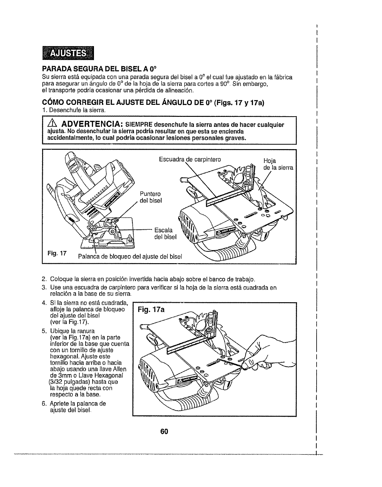
PARADASEGURADEL BISEL A 0 °
Su sierra est,, equipada con una parada segura del bisel a 0°el cual rue ajustado en la f_brica
para asegurar un _ngulo de 0° de la hoja de la sierra para cortes a 90o_Sin embargo,
el transporte podda ocasionar una p6rdida de alineaciSn.
C_MO CORREGIR EL AJUSTE DEL ANGULO DE 0 ° (Figs. 17 y 17a)
Io Desenchufe la sierra_
/ik ADVERTENCIA: SIEMPRE desenchufe la sierra antes de haeer cualquier
ajustao No desenchufar la sierra podria resultar en que esta se encienda
accidentalmente, Io cual podria ocasionar tesiones personales graves.
Fig. 17
Escuadra de carpintero
_/ Puntero
det bisel
_ Escala
del bisel
Palanea de btoqueo del ajuste del biset
Hoja
de la sierra
2, Coloque la sierra en posici6n invertida hacia abajo sobre el banco de trabajoo
3, Use una escuadra de carpintere para verificar si la hoja de la sierra est& cuadrada en
relaci6n a la base de su sierra
4. Si la sierra no est& cuadrada,
afloje la palanca de bloqueo
def ajuste del bise!
(ver la Fig.17)o
5. Ubique la ranura
(ver la Fig.17a) en la parte
inferior de la base que cuenta
con un tornitlo de ajuste
hexagonal. Ajuste este
torniltohacia ardba o hacia
abajo usando una tlava Allen
de 3ram o Llave Hexagonal
(3132 pulgadas) hasta que
la hoja quede recta con
respecto a ta base.
6. Apriete la palanca de
ajuste del bisel.
Fig. 17a
60
L-
/_ ADVERTENCIA: Intentar hacer cortes sin que la pa|anca de ajuste del
bisel est_ apretada de manera segura podria resultar en lesiones graves. I
,iiiiiii1,1111,111,1i1,1111,11,1111111ii iii ,i
Jz_ ADVERTENCIA: Para asegurar seguridad y confiabilidad, toda reparaci6ndebe ser realizada por tdcnicos calificados en un Centro de Servicio Sears.
!tk, ADVERTENClA: Para su seguridad, apague SIEMPRE el interruptor y
desenchufe la sierra circular de la fuente de alimentaci6n antes de realizar cualquier
mantenimiento o limpieza.
Se ha encontrado que las herramlentas el_otrlcas est&n sujetas a desgaste y fallas
prematuras cuando se utilizan sobre botes de fibra de vidrIo y autos deportivos, tablaroca,
compuesto de relleno o yeso. Las astillas y residuos de estos mater|ales son altamente
abrasivos para la plezas de herramientas el_ctricas, tales como rodamlentos, ceplUos,
conmutadores, etc. Consecuentemente, no se recomienda que esta herramienta sea
utilizada para trabajos extensos sobre cualquier material de fibra de vidrio, tablaroca,
compuesto de relleno o yeso. Durante cuaiquier uso sobre estos matedales,
es extremadamente importante que la herramlenta sea limpiada con frecuencia
usando un propulsor de airs.
I Z_ ADVERTENClA: Use siempre gabs de seguridad con protectores laterales J
I
al operar herramientas eldctricas, o al soplar polvo. Si ta operaci6n es polvorienta, Iuse tambi_n una mascarilla antipolvo.
MATENIMIENTO DE RUTINA
/_ ADVERTENCIA: NUNCA deje que flu|do de frenos, gasolina, productos a
base de petr61eo, aceites penetrantes, etc. entren en contacto con las piezas
pl_sticas° Los quimicos pueden daSar, debilitar odestruir el pl_stico, Io cual podr_a
resultar en lesiones personales graves.
El mantenimtento pert6dico permits una vida _3tillarga y un funcionamiento libre de
problemas. Mantenga un cronograma de limpieza, lubrfcaci6n y mantenimiento_ Como
pr&ctica de mantentmlento preventlvo comt_n, siga los siguientes pasos recomendados:
t. AI finaiizar et trabajo, limpie la herramienta para permitlr un funcionamiento
intnterrumptdo de la herramienta a Io largo del tlempo.
2, Use paSos limplos y h_medos para limpiar la herramlenta.
3. Verifique el estado de todos los cables el_ctrlcos.
4. Mantenga las aberturas del motor Ilbres de acelte, grasa y aserrfn o astlllas y guards
la herramienta en un lugar seco.
5. Aseg,Jrese que todas las piezas mSviles est_n bten lubricadas, particularmente
despu_s de una larga exposici6n a condtciones h_medas y/o sucias.
61
=1
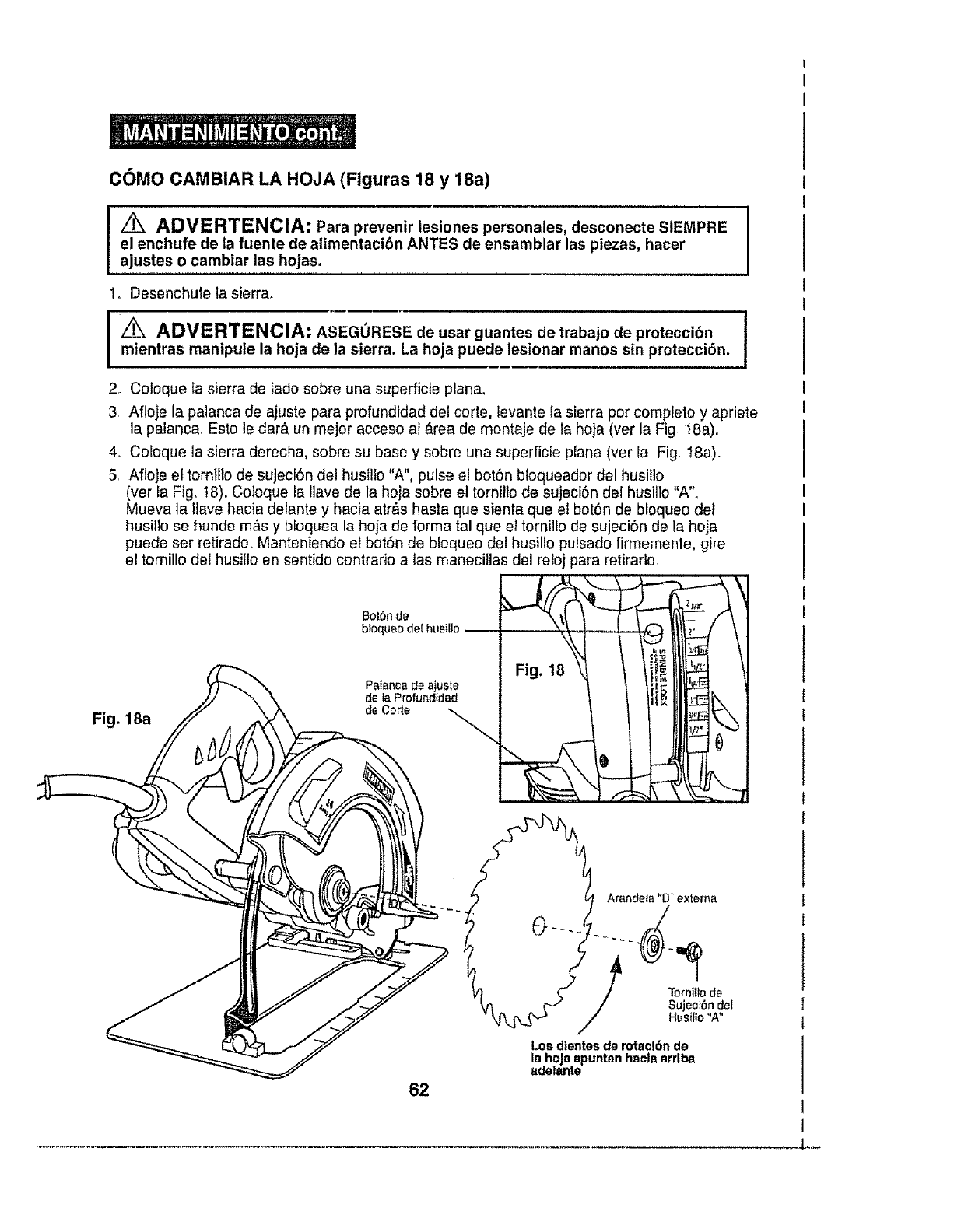
C6MO CAMBIAR LA HOJA (Flguras 18 y 18a)
_ADVERTENCIA: Para prevenir tesiones personales, desconecte S1EMPRE
el enchufe de la fuente de alimentacibn ANTES de ensamblar las piezas, hacer
ajustes o cambiar las hojas.
1o Desenchufe la sierra.
I m_rrenAa[_svmEnRipTuEINach'°jAa:dAe_EGi0erR'EaSEad_ct_asa;0c_a_teesdn_trrambaj°sde'prp_c_cb_n" I
Fig. 18a
2. Coloque ta sierra de Eadosobre una superficie plana,
3 Afloje la palanca de ajuste para profundidad del corte, levante la sierra per complete y apriete
la palanca, Esto le dar_, un rnejor acceso al &rea de mentaje de la heja (ver la Fig 18a)o
4. Coloque la sierra derecha, sobre su base y sobre una superficie plana (ver la Fig. 18a).
5. Afloje el tomillo de sujeciSn del husillo "A", pulse el botSn bloqueador del husillo
(ver la Fig. t8). Coloque la Ilave de la hoja sobre e! tornitlo de sujeciSn del husillo "A".
Mueva ta !lave hacia delante y hacia atr&s basra que sienta que el botSn de bloqueo det
husilio se hunde m&s y bloquea la hoja de forma tal que et tornillo de sujeciSn de la hoja
puede ser retirado. Manteniendo el bot6n de bloqueo del husillo pulsado firmemenle, gire
el tornilIo del husillo en sentido contrarie a tas manecillas del reloj para retirarlo
Bot6n de
de la Profundidad
de Corte
bloqueo de/husillo
Palanca de ajuste
62
Arandeta "D" extema
Torniltode
Su ecibn del
Hus Io "A"
Los d|entes de rotac|6n de
la hoJaapuntan hacls arrlba
adelante
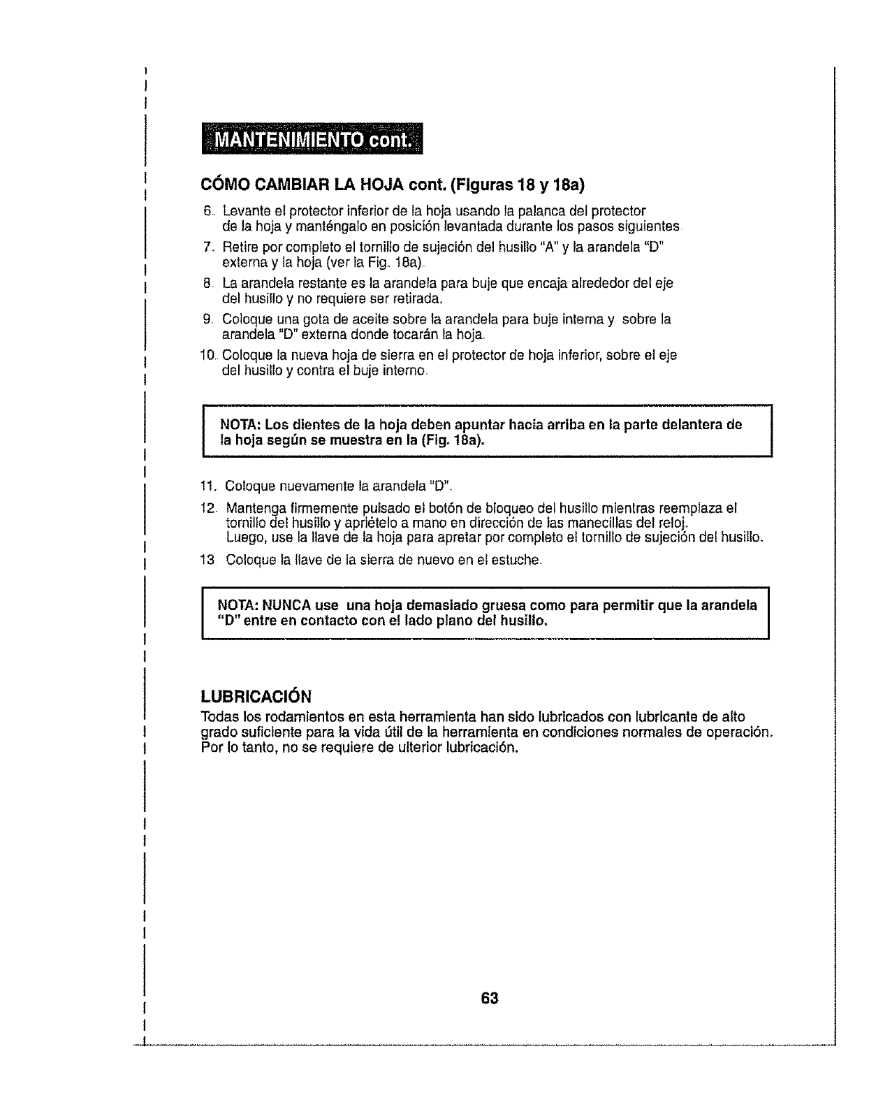
C6MO CAMBIAR LA HOJA cont. (Figuras 18 y 18a)
6_ Levante et protector inferior de la hoja usando la palanca del protector
de la hoja y mant_ngalo en posici6n levantada durante los pasos sigt_ientes
7. Retire per complete el tornil]o de sujeci6n del husillo "A" y la arandela "D"
externa y la hoja (vet la Fig. t8a),
8. La arandela restante es la arandela para buje que encaja arrededor del eje
del husillo y no requiere ser retirada,
9, Coloque una gota de aceite sobre la arandela para buje interna y sobre la
arandela "D" externa donde tocar_,n la hoja
10,,Co!oque la nueva hoja de sierra en el protector de hoja inferior,sobre el eje
del husillo y contra el buje interne,
NOTA: Los dientes de la hoja deben apuntar hacia arriba en la parte delantera dela hoja segt_n se muestra en la (Fig° 18a).
11. Cotoque nuevamente la arandela"D",
12 Mantenga firmemente putsado el bot6n de bloqueo clef husillo mientras reemplaza el
ternillo del husillo y apri_te!o a mane en direcci6n de las manecillas del reloj.
Luego, use la Ilave de la hoja para apretar per complete et tornillode sujeci6n del husilloo
13 Coloque la Ilave de la sierra de nuevo en el estuche
I O'I'A: NUNCA use una hoja demasiado gruesa come para permitir que la arandela
"D" entre en contacto con e! lade plane del husillo.
LUBRICACI6N
Todas los rodamientos en esta herramienta han side lubricados con lubricante de alto
grade euficlente para la vida _tit de la herramienta en condiciones normales de operaci6n,
Per Io tanto, no se requiere de ulterior lubricaci6n.
63
d
SI la hoja no sigue una Ifnea recta:
•Los dlentes estdn sin _o. Esto es producto de golpear objetos duros tales como
clavos, Io cual hace que los dlentes plerdan et filo de un lado. La hoja ttende a
cortar det lado con los dtentes mds aftlados.
•La base estd. fuera de Ifnea o dobladao
°La hoja estd doblada.
• La gufa de borde o gufa recta no se estd usandoo
SI la hoJa se atasca o emits humo producto de la fricci6n:
, La hoja no ttene filo.
• La hoja esteral rev_s
•La hoja est_ doblada
• La pleza de trabajo no estd soportada adecuadamente.
•Se estd usando una hoja inadecuada.
ADVERTENCIA: El uso de conexiones o accesorios no recomendados ]
I
para esta herramienta podrian ser peligrosos y podrfan resultar en leslonss graves. !
Sears y otros puntos de venta Craftsman cuenta con una amplia selecciSn de hojas
de 7 1/4pulgadas Craftsman de acero con dlentes con punta de carburo de tungsteno,
dlseSadas para apticactones especfficas de corte. Tambi_n existen disponlblee empaques
a granel para contrattstas.
Sears y otros puntos de venta Craftsman tambidn ofrecen cabrillas, escuadras de
encofrado y combinadas, bordes rectos, gufas de borde y una gran vartedad
de abrazaderas para ayudarle con todas sue necesidades de aeerrado,
Visite su ttenda local Sears uotro punto de venta Craftsman o eompre
pot Internet en searsocom/craftsman.
64

I
I
!
/
65
w

Sierra Circularde 7 1/4 pulgadas- MODELO NO. 320.10870
El N_mero del Modelo se encuentra en la Placa de identificaciSn, Mencione siempre
el NSmero del Mode!o en toda correspondencia acerca de su herramienta.
No. item No. Parte
1 2780040000
2 3420333000
3
4
5
6
7
8
3420335000
3121339000
3121340000
3320220000
3320219000
3320221000
Descripci6n,,de '!a,,P,a,rte
Set del I_,ser
Estuche de engranajes
Protector superior
Cubierta del motor
Cubierta posterior
Mango derecho
Mango izquierdo
Mango delantero
Cant'
1
1
1
1
I
1
1
1
9 3121384000
10 3121341000
11 3400174000
12 5650017000
13 5640044000
14 3121378000
15 3420334000
16 3121379000
17
18
19
20
21
22
3550225000
3550222000
5620151000
3420184000
2800006000
5610094000
23 3121051000
24 3121057000
Lente
..............Dei'iect0r cl'elventiiador
Varilla de bloq,ueo
Arandela, plana GB96-85 6 A140
Tuerca
Palanc,_,,de,,ajuste,de, pr0fundidad
Protector m6vil
Palanca del protector mSvil
Brida interior
Abrazadera
Tornillo bridado
Bloque de ajuste
Portacepillo
Tornillo roscador GB6560-86 4X":!'6'
Tope
Aro de goma
1
1
!
1
1
1
1
1
1
1
1
1
2
3
1
1
25 3121O54000
26 3700255000
27 5660030000
28 3550238000
29 3120560000
30 3550240000
31 3660072000
32
33
34
35
36
37
3700539000
5610048000
5620039000
3700262000
5610061000
5610042000
38 5610053000
39 5670008000
40 5610062000
Resorte
Arandela
Arandelas"de'"reienci6npara el eje
Eje de bloqueo
BotSn
Anillo de bloqueo
Resorte
Tabla Epoxy "
TornilFo roscador GB845-85 4.2X55-F
Tornillo G B818-85 M4x 10
Porta cables
Tornillo ros,,ca,do,GB6560-86 5_3,0.............
TornifloroscaderGB845-85 ST4.2xlg-F-H
Tornillo roscador GB845-85 4.2x9.5-F
1
1
1
1
1
1
1
2
2
3
1
1
12
3
Perno a resorte GB879-86 6x40 !
Tornillo roscado GB6560-86"M5"-40 3
66

SierraCircularde7 1/4pulgadas- MODELONO.320.10870
El N0mero del Modelo se encuentra en la Placa de ldentificaci6n, Mencione siempre
et NSmero del Modelo en toda correspondencia acerca de su herramienta.
No. item No. Pa_e
41 5610057000
42
43
44
45
46
47
5700041000
5700015000
3700780000
5680012000
5610083000
3660071000
Descripci6n de la Parte Cant,
Torni!lo roscado 2
48
49
50
51
, 52
53
3700269000
3420176000
3700306000
5620037000
3420205000
5650053000
Rodamiento a aceite
Rodamienloesf_rico GB/T276-946201-2RD
Abrazadera para profundida d..................
Remache GB873-86 6x16
Tomillo roscado GB6561-86 M4x12
Resorte
Ptaca base
Soporte de profundidad
Indicador de #,ngulo
Tomil!o GB818:85 M4_6
Soporte del &nguio
Arandela
1
1
1
2
6
1
1
1
1
1
I
1
54 3400011000 Tuerca de mariposa 1
55 3700307000 Ptaca de soporle 1
56 5660010000 Anillo E GB896-86 9 1
57 3550239000 EJe de! engranaj e 1
58 5680004000 Llave plana GB1096-79 5x14 1
59 3550235000 Engranaje 1
......60 ..... 5'7'00'0'i'9000 .... R0damientoesf_rico GB'_T276"94"6003-'2RS 1
61 3700281000 Arandela de presi6n i
62 5660023000 Arandelade retenci6nparaorificioGB89&1'86 35 1
63 3121475000 Cubiertadel IndicadordeAlimenlaci6n(Izquie_da) I
64 3121424000 Cubiertadel IndicadordeAlimenlaci6n(Derecha) 1
65 3700586000 Revestimiento 1
66 3810073000 Hoja t
67 3121381000 Cubierta del LED 1
68 3420311000 Cubierta del estuche de engranaje 1
69 3121380000 Palanca de anguio 1
70 3121382000 Soportel del LED 1
..... 71 ,312!,38,3(30, 0...... S,0Porte2 del LED ........ 1
72 2750160000 Rotor 1
73 2821947000 Ensamblaje del transformador 1
74 5700013000 RodamientoesfSricoGB_T276-94 6000-2Z 1
75
76 4360221000 LED 1
77 2821992000 Aiambrel interno 1
78 2740066000 Estator 1
79 2821992000 Alambre2 interno 1
80 5650007000 Arandela de resorte GB93-87 4 2
67

SierraCircularde 7 1/4pulgadas- MODELONO.320.10870
El N_mero det Modelo se encuentra en la Placa de Identificaci6n°Mencione siempre
et Nt_mero del Modelo en toda correspondencia acerca de su herramienta,
Item No.
81
82
83
84
85
86
87
BB
89
90
91
92
93
94
95
96
97
98
99
100
Parts No. Part Description IQty.
4870036000 Interruptor 1
4810002000 CordTn y enchufe de alimentaciSn I
3700367000 Anclaje del cord6n t
5610093000 Tornillo roscador JIS M412 2
3121050000 Protector del cordSn 1
3700865000 Uave
3121385000 B0t6n eel laser t
4930012000 Terminal 3
5610059000 %rniiio roscado G66560"86 M5_20 1
5650013000 Arandela plana G697.1-85 5 1
5650001000 Arandela plana GB97.1-85 3 2
5650003000 Arandela de resorte G693-87 3 2
5620006000 TornilloAllen hexagonalGB70-85 M3_12 2
5650005000 Arandeia piana GB9711185 4 2
5610058000 Tornitlo roscador G66560-86 M5X16 1
3550375000
4930013000
5620035000
5620017000
Tuerca M6X2P
Recept&culo
Tornitlo G6818-85 M3.5_8
Tomillo Allen hexagonal
GB79-85 M5xl 0-45H
Resorte de torsi6n
1
3
4
1
101 3660138000 1
102 4960021000 CarbTn 2
t 03 5640152000 Perno 1
104 3700663000 Gufa de corte 1
I05 Set de soporte 1
106 ............. Set d'e' la abrazadera de profundidad 1
107 Set de engranaje 1
I08 Set del rotor
VER EL ANVERSO PARA INSTRUCCIONES SOBRE C6MO ORDENAR PARTES
68
!
69
70
71

;i¸_i:!'i!i!:¸_:I¸_`
<:i :'i;i,
i?_ii_i,i!i
i:_:!i:}i:_i_i_
!ii!!iii!i ;IIili
Your Home
For repair - in your home - of all major brand appliances,
lawn and garden equipment, or heating and cooling systems,
no matter who made it, no matter wtlo sold it!
For the replacement parts, accessories and
owner's manuals that you need to do-it-yourself
For Sears professional installation of home appliances
and items like garage door openers and water heaters
1-800-4-1VIY-HOME ®Anytime. day or night
(I-800-469-4683) (USA and Canada)
w'ww.searsocom www.sears.ca
Our Home
For repair of carryqn products like vacuums, lawn equipment;
and electronics, call or go on-line for the nearest
Sears Parts and Repair Center.
1-800.488.1222 Anytime, day or night (U S A only)
wwwosears.com ?:i_,!;_;i
To purchase a protection agreement (U S A )
or maintenance agreernent (Canada) on a product serviced by Sears:
1-800-827-6655 (USA) 1-800-361-6665 (Canada)
Au Canada pour service en frangais.
1-800..LE.FOYER _c
(1-800-533-6937)
W'WW, seBr_ Ca
Para pedir servicio de reparaci6n
a domicilio, y para ordenar piezas
1.888-$U-HOGAR®
(1-888-784-6427)
© Seat_ _n_, LLC
®Registered Trademark 1TM Trademark /s_ Service Mark of' Sears Brands, LLC
®Marsa Registrada /TM Marsa de F_brlc_t /s_ Marc=, de Servicle de Sears Brands, LLC
MCMarque de commerce !_'_Marque d_pos_e de Sear= Brands, LLC
=:_:_i
1
1
!
t
I
t
t
1
!
I
1
1
1
I
I
1
1
I
(
