Craftsman 32021228 User Manual MITER SAW Manuals And Guides L0901589
CRAFTSMAN Miter Saw Manual L0901589 CRAFTSMAN Miter Saw Owner's Manual, CRAFTSMAN Miter Saw installation guides
User Manual: Craftsman 32021228 32021228 CRAFTSMAN MITER SAW - Manuals and Guides View the owners manual for your CRAFTSMAN MITER SAW #32021228. Home:Tool Parts:Craftsman Parts:Craftsman MITER SAW Manual
Open the PDF directly: View PDF ![]() .
.
Page Count: 48
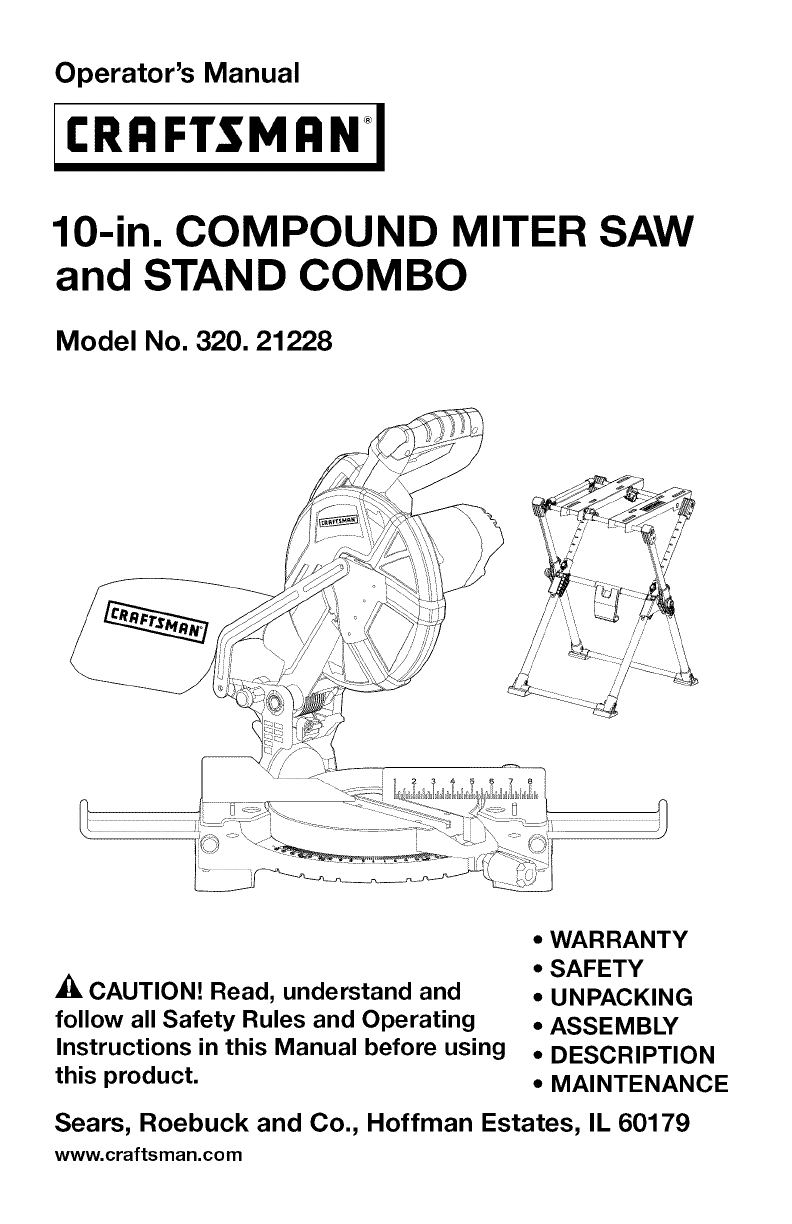
Operator's Manual
I:RR FTSM
10-in. COMPOUND MITER SAW
and STAND COMBO
Model No. 320.21228
CAUTION! Read, understand and
follow all Safety Rules and Operating
Instructions in this Manual before using
this product.
•WARRANTY
•SAFETY
•UNPACKING
•ASSEMBLY
•DESCRIPTION
•MAINTENANCE
Sears, Roebuck and Co., Hoffman Estates, IL 60179
www.craftsman.com

i q_1:] ml_ [o_ [_o_ij_i_
Warranty Page 2
Safety Symbols Page 3
Safety Instructions Pages 4-13
Unpacking Pages 13-14
Description Pages 15-18
Assembly Pages 18-23
Adjustment Pages 23-27
Operation Pages 27-38
Maintenance Pages 38-40
Troubleshooting Pages 40-41
Parts List Pages 42-47
Sears Repair Parts Phone Numbers Back Cover
ONE YEAR FULL WARRANTY ON CRAFTSMAN TOOL
If this Craftsman tool fails to give complete satisfaction within
one year from the date of purchase, return it to any Sears store
or Parts & Repair Center or other Craftsman outlet in the United
States for free repair (or replacement, if repair proves impossible).
This warranty does not include expendable parts such as lamps,
batteries, bits, or blades.
This warranty applies for only 90 days from the date of purchase if
this product is ever used for commercial or rental purposes
This warranty gives you specific legal rights, and you may also
have other rights, which vary from state to state.
Sears, Roebuck and Co., Hoffman Estates IL 601 79
AWARNING: Some dust created by using power tools contains chemicals
known to the state of California to cause cancer and birth defects or other
reproductive harm.
SAVE THESE INSTRUCTIONS!
READ ALL INSTRUCTIONS!
21228 Manual Revised 08-0307 Page 2
The purpose of safety symbols is to attract your attention to possible dangers.
The safety symbols and the explanations with them deserve your careful
attention and understanding. The symbol warnings de not, by themselves,
eliminate any danger. The instructions and warnings they give are no substitutes
for proper accident prevention measures.
_, WARNING: Be sure to read and understand all safety instructions in this
manual, including all safety alert symbols, such as "DANGER," "WARNING,"
and "CAUTION," before using this miter saw and tool stand. Failure to following
all instructions listed below may result in electric shock, fire, and/or serious
personal injury.
SYMBOL MEANNING
_, SAFETY ALERT SYMBOL: Indicates DANGER, WARNING, OR CAUTION.
May be used in conjunction with other symbols or pictographs.
_, DANGER: Failure to obey this safety warning WILL result in death or serious
injury to yourself or to others. Always follow the safety precautions to reduce the
risk of fire, electric shock and personal injury.
_, WARNING: Failure to obey this safety warning CAN result in death or serious
injury to yourself or to others. Always follow the safety precautions to reduce the
risk of fire, electric shock and personal injury.
_, CAUTION: Failure to obey this safety warning MAY result in death or serious
injury to yourself or to others. Always follow the safety precautions to reduce the
risk of fire, electric shock and personal injury.
DAMAGE PREVENTION AND INFORMATION MESSAGES
These inform user of important information and/or instructions that could lead to
equipment or other property damage if not followed. Each message is preceded
by the word "NOTE:" as in the example below:
NOTE: Equipment and/or property damage may result if these instructions are
not followed.
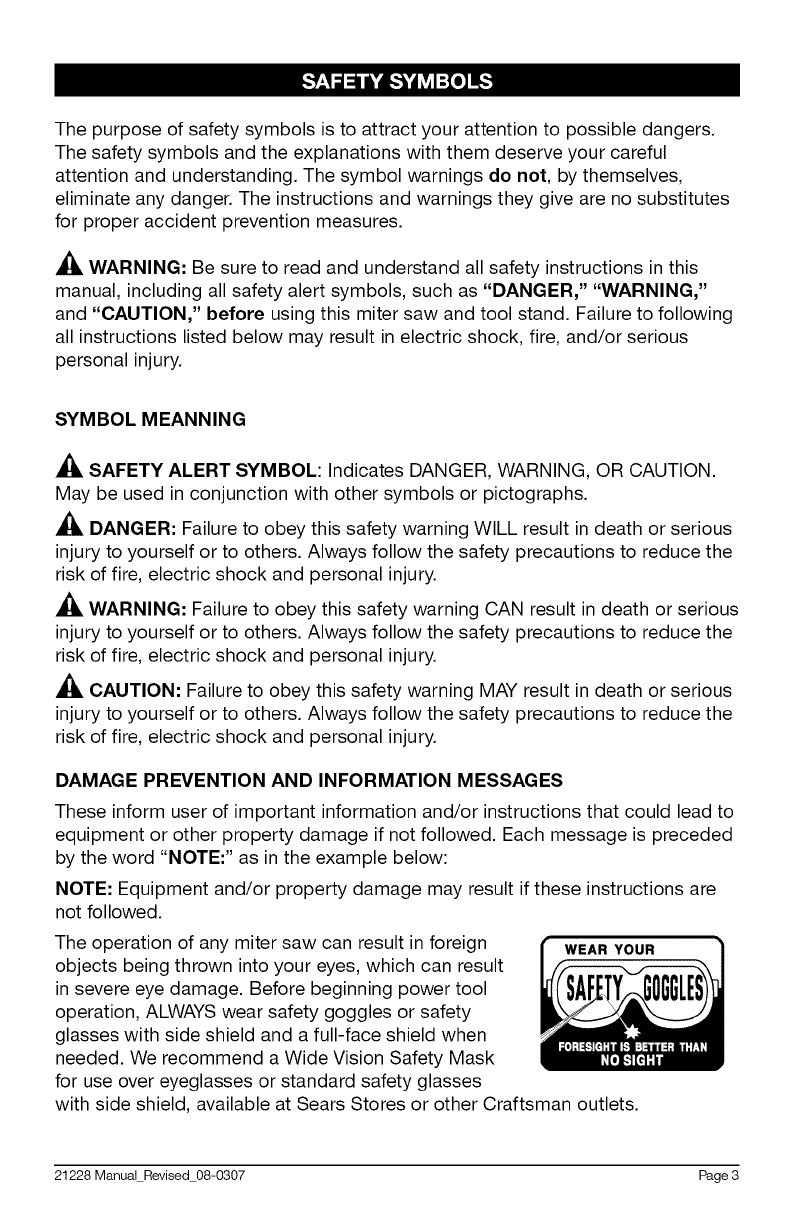
The operation of any miter saw can result in foreign
objects being thrown into your eyes, which can result
in severe eye damage. Before beginning power tool
operation, ALWAYS wear safety goggles or safety
glasses with side shield and a full-face shield when
needed. We recommend a Wide Vision Safety Mask
for use over eyeglasses or standard safety glasses
with side shield, available at Sears Stores or other Craftsman outlets.
WEAR YOUR
21228 Manual Revised 08-0307 Page 3
_lk WARNING: Be sure to read, understand and follow all Safety rules and
operating instructions in this Manual before using this tool. Failure to do so may
result in electric shock, fire and/or serious personal injury.
SAFETY PRECAUTIONS FOR LASERS
This Miter Saw has a built-in laser light. The
laser is ClasslllA and emits output power
of a maximum 2.5mW and 635-655nm
wavelengths. These lasers do not normally
present an optical hazard. However, DO
NOT stare at the beam, as this can cause
flash blindness.
Class Ilia Laser Product
Complies with 21 CFR parts 1040.10 and 1040.11
AVOID EXPOSURE t
Laser radiation is emitted through
this aperture
,_ CAUTION: The following label is on the tool. It indicates the location from
which the saw emits the laser light. BE AWARE of the laser-light location when
using. Always make sure that any bystanders in the vicinity of use are made
aware of the dangers of looking directly into the laser.
•Do not remove or deface any product labels. Removing product labels
increases the risk of exposure to laser radiation.
• The laser beam can be harmful to the eyes. Always avoid direct eye
exposure. Do not look directly into the laser-beam-output aperture during
operation. Do not project the laser beam directly into the eyes of others.
• Turn the laser on only when making cuts.
• The laser on the Miter Saw is not a toy. Always keep it out of the reach
of children.
• The laser light emitted from this device should never be directed toward any
person for any reason.
• Be sure that the laser beam is aimed at a workpiece (such as wood or a
rough-coated surface) that does not have a reflective surface.
•Do not use on materials, such as sheet steel, that have shiny, reflective
surfaces. The reflective surface could reflect the beam back at the operator.
Be aware that laser light reflected off of a mirror or any other reflective
surfaces can also be dangerous.
• Always turn the laser generator off when it is not in use. Leaving the tool on
increases the risk of someone inadvertently staring into the laser's beam.
• Always wear laser-protective eyewear when working on or near
reflective surfaces
_, CAUTION: always follow the instructions contained in this manual when using
this laser. Use of this feature in any manner other than which is directed in this
manual may result in a hazardous radiation exposure.
21228 Manual Revised 08-0307 Page 4
WORK AREA SAFETY
Keep your work area clean and well lit. Do not leave tools or wood scraps
on the saw while it is in operation. Cluttered workbenches and dark areas
invite accidents
•Do not operate power tools in explosive environments, such as in the
presence of flammable liquids, gases, or dust. Power tools create sparks that
may ignite the dust or fumes.
• Keep children and bystanders and visitors away while operating a power
tool. Distractions can cause you to lose control.
•Make your workshop childproof with padlocks and master switches. Lock
tools away when they are not in use.
•Make sure the work area has ample lighting so you can see the work, and
that there are no obstructions that will interfere with safe operation.
PERSONAL SAFETY
• Know your power tool. Read this operator's manual carefully. Learn the
compound miter saw's applications and limitations, as well as the specific,
potential hazards related to this tool.
• Stay alert, watch what you are doing, and use common sense when
operating a power tool.
•Do not use a power tool while tired or under the influence of drugs, alcohol,
or medication. A moment of inattention while operating power tools may
result in serious personal injury.
•Dress properly. Do not wear loose clothing or jewelry. Pull back long hair.
Keep your hair, clothing and gloves away from moving parts. Loose clothing
or long hair can be caught in moving parts. Air vents often cover moving
parts and should also be avoided.
• Avoid accidental starting of tools. Be sure switch is in "OFF "position
before plugging the tool into a power source.
• Remove adjusting keys or blade wrenches before turning the tool "ON."
A wrench that is left attached to a rotating part of the tool may result in
personal injury.
•De not overreach. Keep proper footing and balance at all times. Proper
footing and balance enables better control of the tool in unexpected situations.
• Always secure your work. Use clamps or a vise to hold work whenever
practical. It is safer than using your hand and frees both hands to operate
the tool.
• Use safety equipment. Always wear eye protection. Dust mask, non-
skid safety shoes, hard hat, or hearing protection must be used for
appropriate conditions.
• Never stand on tool. Serious injury could occur if the tool is tipped or if the
blade is accidentally contacted.
21228 Manual Revised 08-0307 Page 5
TOOL USE AND CARE SAFETY
_, WARNING: Be sure to read, understand, and follow all safety rules and
operating instructions in this manual before using this tool. Failure to do so may
result in electric shock, fire, and/or serious personal injury.
• Always use clamps or other practical ways to secure and support the
workpiece to a stable platform. Holding the work by hand or against your
body is unstable and may lead to loss of control.
•De not force the power tool. Use the correct tool for your application. The correct
tool will do the job better and more safely at the rate for which it is designed.
•De not use the tool if switch does not turn it "ON" or "OFF." Any tool that
cannot be controlled with the switch is dangerous and must be repaired.
•Disconnect the plug from the power source before making any adjustments,
changing accessories, or storing the tool. Such preventive safety measures
reduce the risk of starting the tool accidentally.
• Never leave the tool running. Always turn it off. Do not leave the tool until it
comes to a complete stop.
• Store idle tools out of the reach of children and other untrained persons.
Tools are dangerous in the hands of untrained users.
•Maintain tools with care. Keep cutting tools sharp and clean. Properly maintained
tools with sharp cutting edges are less likely to bind and are easier to control.
•Check for misalignment or binding of moving parts, breakage of parts, and any
other condition that may affect the tool's operation. If damaged, have the tool
serviced before using. Many accidents are caused by poorly maintained tools.
• Use only accessories that are recommended for the tool being used.
Accessories that may be suitable for one tool may become hazardous when
used on another tool.
• Never cut metals or masonry products with this tool. This miter saw is
designed for use only on wood and wood-like products.
• Keep blade guards in place and in good working order.
ELECTRICAL SAFETY
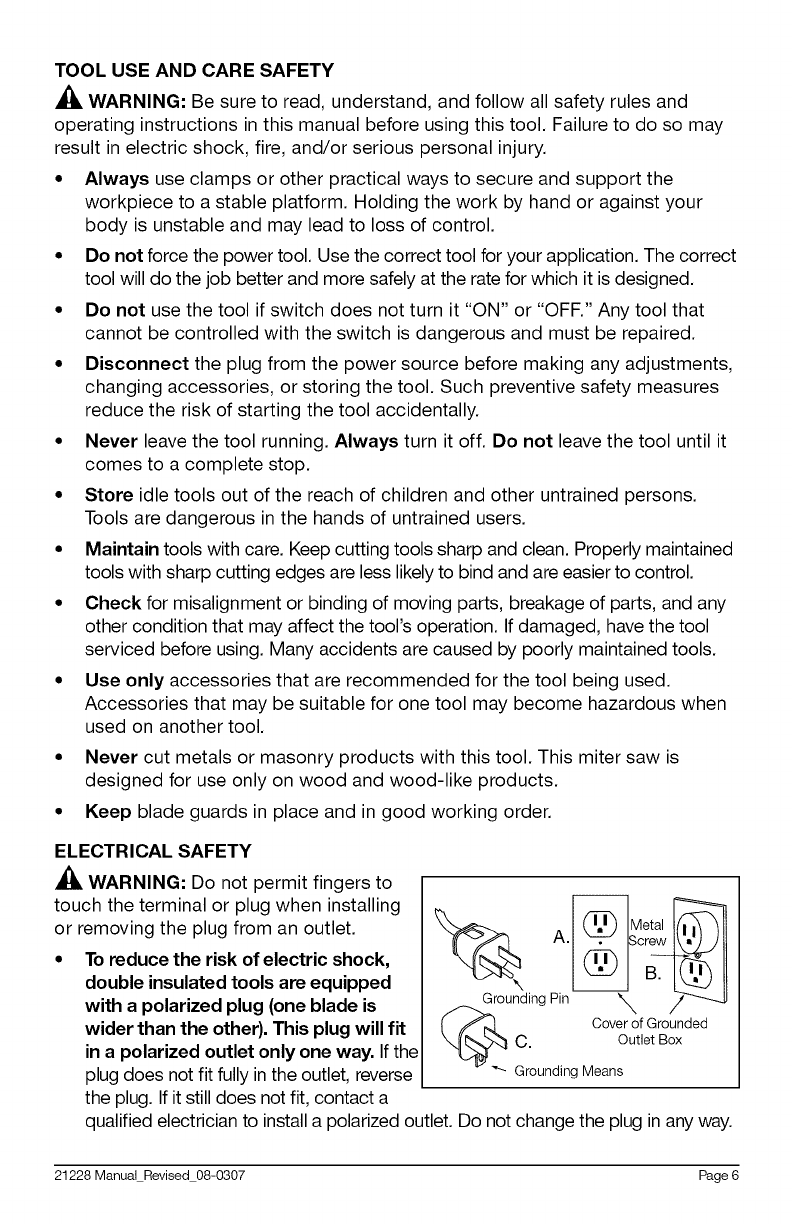
_, WARNING: Do not permit fingers to
touch the terminal or plug when installing
or removing the plug from an outlet.
•To reduce the risk of electric shock,
double insulated tools are equipped
with apolarized plug (one blade is
wider than the other). This plug will fit
in a polarized outlet only one way. If the
plug does not fit fully in the outlet, reverse
the plug. If it still does not fit, contact a
_Groun_ding pil _c_
t_ Cover of Grounded
C. Outlet Box
Grounding Means
qualified electrician to install a polarized outlet. Do not change the plug in any way.
21228 Manual Revised 08-0307 Page 6
•Double insulation eliminates the need for the three-wire grounded power
cord and grounded power-supply system. Applicable only to Class II (double-
insulated) tools. This compound miter saw is a double insulated tool.
_, WARNING: Double insulation does not take the place of normal safety
precautions when operating this tool.
• Before plugging in the tool, be sure that the outlet voltage supplied is within
the voltage marked on the tool's data plate. Do not use "AC only" rated tools
with a DC power supply.
• Avoid body contact with grounded surfaces, such as pipes, radiators,
ranges, and refrigerators. There is an increased risk of electric shock if your
body is grounded while using the tool.
• Do not expose power tools to rain or wet conditions or use power tools in
wet or damp locations. Water entering a power tool will increase the risk of
electric shock. This tool is intended for indoor use only.
• If operating a power tool in damp locations is unavoidable, always use a
ground-fault circuit interrupter to supply power to your tool. Always wear
electrician's rubber gloves and footwear in damp conditions.
• Inspect tool cords for damage. Have damaged tool cords repaired at a Sears
Service Center. Be sure to stay constantly aware of the cord's location and
keep the cord well away from the moving blade.
• Do not abuse the cord. Never use the cord to carry the tool by or to pull
the plug from the outlet. Keep the cord away from heat, oil, sharp edges,
and moving parts. Replace damaged cords immediately. Damaged cords
increase the risk of electric shock.
EXTENSION CORDS
Use a proper extension cord. Make sure that extension cords are in good
condition. When using an extension cord, be sure to use a cord heavy
enough to carry the drawn current needed by the compound miter saw. An
undersized cord will cause a drop in line voltage, resulting in loss of power
and overheating. The table on the following page shows the correct size
to use, depending on the cord length and nameplate ampere rating. If in
doubt, use the next heavier gauge: the smaller the gauge number, the heavier
the cord.
•Be sure extension cords are properly wired and in good condition. Always
replace a damaged extension cord or have it repaired by a qualified person
before using it. Protect extension cords from sharp objects, excessive heat,
and damp or wet areas.
• Use a separate electrical circuit for power tools. This circuit must not
be less than #6 wire and should be protected with a time-delay fuse. Before
connecting the tool to the power line, make sure the switch is in the "OFF"
position and the electric current is rated the same as the current stamped on
the motor nameplate; running at a lower voltage will damage the motor.
21228 Manual Revised 08-0307 Page 7

Recommended size of extension cords
Amperage rating
More than Not more than
0 6
6 10
10 12
12 16
Volts Total length of the extension cord
120v 25ft. 50ft. 100ft. 150ft.
240v 50ft. 100ft. 200ft. 300ft.
Minimum Gauge for the extension cord (AWG)
18 16 16 14
18 16 14 12
16 16 14 12
14 12 Not recommended
,& WARNING: Ensure that the power-supply outlet in question is properly
grounded. If not certain, have a licensed electrician check the outlet.
,_ WARNING: To avoid electrical hazard, fire hazards, or damage to the tool,
use proper circuit protection.
SAFETY SYMBOLS FOR YOUR TOOL
The label on your tool may include the following symbols:
V ........................................... Volts
A .......................................... Amps
Hz ......................................... Hertz
W .......................................... Watts
Min ....................................... Minutes
'_ ....................................... Alternating current
........................................ Direct current
no ........................................ No-load speed
[] ......................................... Class II construction, Double Insulated
.../min .................................... Revolutions or Strokes per minute
_, ........................................ Indicates DANGER, WARNING or CAUTION:
ATTENTION! Your safety is involved!
SERVICE SAFETY
• If any part of this saw is missing or should break, bend, or fall in any
way; or should any electrical component fall to perform properly: shut
off the power switch, remove the plug from the power source, and have the
missing, damaged or failed parts replaced before resuming operation.
• Tool service must be performed only at a Sears Parts and Repair Center.
Service or maintenance performed by unqualified personnel could result in a
risk of injury.
21228 Manual Revised 08-0307 Page 8
When servicing a tool, use only identical replacement parts. Follow
instructions in the maintenance section of this manual. Use of
unauthorized parts or failure to follow maintenance instructions may create a
risk of electric shock or injury.
SAFETY RULES FOR MITER SAWS
•Know your power tool. Read the operator's manual carefully. Learn the
applications and limitations, as well as the specific potential hazards related
to this tool. Following this rule will reduce the risk of electric shock, fire, or
serious injury.
• Always firmly clamp or bolt your miter saw to a secure, stable workbench or
table at approximately hip height.
• Be sure that all adjustments are secure before making a cut.
• Always make sure that the miter table and saw arm are locked in position
before operating your saw. Lock the miter table by securely tightening the
miter-lock knob. Lock the saw arm by securely tightening the bevel-lock knob.
• Use the hold-down clamp (included) to secure the workpiece
whenever possible.
• Be sure that the blade path is free of nails. Always carefully inspect lumber
and remove all nails before cutting.
• Always be sure that the blade clears the workpiece.
• Never start the saw with the blade touching the workpiece.
• Always allow the motor to come up to full speed before starting a cut.
• Support long workpieces when cutting to minimize the risk of the blade pinching
or kickback. The saw may slip, walk, or slide while cutting long or heavy boards.
• Never use a length-stop on the free end of a clamped workpiece.
• Never hold onto or bind the free end of the workpiece in any operation.
• If a work clamp and a length stop are used together, they must both be
installed on the same side of the saw table to prevent the saw from catching
the loose end and kicking up.
• Never cut more than one piece at a time. Do not stack more than one
workpiece on the worktable at a time.
• Avoid awkward operations and hand positions where a sudden slip could
cause your hand to move into the blade. Always make sure that you have
good balance. Never position your saw on the floor or operate it while in a
crouched position.
• Never stand or have any part of your body in line with the path of the blade.
• Only use the correct blades. Use the right blade size, style, and cutting
speed for the material being cut and the type of cut. De not use blades
with incorrect size holes. Never use blade washers or blade bolts that are
defective or incorrect. The maximum blade capacity for this saw is 10 inches.
21228 Manual Revised 08-0307 Page 9
• Always keep blades clean, sharp, and with the sufficient set. Sharp blades
minimize stalling and kickback.
• Do not use dull or damaged blades. Bent blades can break easily or
cause kickback.
• Do not remove the saw's blade guards.
• Never operate the saw with any guard or cover removed. Make sure that all
guards are operating properly before each use.
• Never hold with your hands a workpiece that is too small to be clamped.
Always keep your hands clear of the "no hands" zone.
• Never perform any operation freehand. Always place the workpiece to
be cut on the miter saw table and position it firmly against the fence as a
backstop. Always use the fence.
• Never apply lubricants to the blade when it is running. Never use solvents
to clean plastic parts. Solvents could possibly dissolve or otherwise damage
the material.
• Keep your hands away from the cutting area. Do not reach under the
material being cut or in the blade's cutting path with your fingers or hand for
any reason. Always turn the power off before reaching into the cutting area.
WARNING: The blade continues to turn after the power to the saw is turned
off. To avoid possible serious injury, after releasing the trigger switch to cut power,
allow the saw blade to stop rotating before raising the blade out of the workpiece.
• Never reach behind, under, or within three inches of the blade and its cutting
path with your hands or fingers for any reason.
• Never, for any reason, touch the blade or other moving parts during use.
• Do not turn the motor switch on and off rapidly. This could cause the blade
to loosen, which could create a hazard. Should this ever occur, stand clear
and allow the saw blade to come to a complete stop. Disconnect the saw
from the power source and securely tighten the blade bolt.
• Always turn off the saw before disconnecting it to avoid accidental starting
when reconnecting the saw to a power supply. Never leave the saw
unattended while connected to a power supply.
• Keep the motor air slots clean and free of chips or dust. To avoid motor
damage, the motor should be blown out or vacuumed frequently to keep
sawdust from interfering with the motor ventilation.
• Never lift this tool by gripping the cutting handle or the miter fence. This may
cause misalignment. Always carry saw by holding the base or carry by the
carrying handle after you have locked the saw arm in the DOWN position.
_, WARNING: use of this product can generate dust containing chemicals
known to cause cancer, birth defects or other reproductive harm. Some
examples of these chemicals are:
• Lead from lead-based paints.
21228 Manual Revised 08-0307 Page 10
•Crystalline silica from bricks and cement and other masonry products.
• Arsenic and chromium from chemically-treated lumber.
Your risk from these exposures varies, depending upon how often you do this
type of work. To reduce your exposure to these chemicals:
• Work in a well-ventilated area.
• Work with approved safety equipment, such as those dust masks that are
specially designed to filter out microscopic particles.
SAFETY RULES FOR THE USE AND OPERATION OF THE MITER SAW STAND
•Always set up the miter saw stand on a hard, dry, flat, stable surface.
• Be sure that the miter saw stand is fully opened and locked into the proper
set-up position before mounting the miter saw to the tabletop assembly.
•Follow all set-up instructions in this operator's manual.
• Always properly attach the miter saw to the stand. Do not attempt to use
the miter saw stand with the miter saw until the tool is bolted securely to the
tabletop assembly according to the instructions this operator's manual.
• When using this miter saw stand with a miter saw that has mounting holes
that do not line up with the pre-slotted holes in the miter saw stand's tabletop
assembly, mount the power tool to a plywood mounting board (sold separately),
then mount the plywood board and the miter saw to the tabletop assembly.
• Always follow all safety rules and instructions in the operator's manual of
the miter saw when operating a miter saw that is mounted to this stand.
• Always be sure that there is sufficient space around the stand to safely
operate the miter saw when setting up the miter saw stand and the miter saw.
• Always check the miter saw stand and miter saw for damaged parts.
Before further use of the stand or the tool, if any part is damaged, it should
be carefully checked to determine if it will operate properly and perform its
intended function.
•Keep hands away from the cutting area.
• Always use clamps or a vise to hold the workpiece, when practical. Using
clamps or a vise to hold the workpiece is safer than using a hand. It also
frees up both hands to operate the miter saw.
• Avoid awkward operations and hand positions where a sudden slip could
cause a hand to move into the cutting area of the tool.
• Never reach into the cutting area of a tool.
• Never sit, stand, or climb on this stand. It is not designed or constructed
to accommodate this type of use. It could tip over, causing serious injury.
• Do not store any items above or near the miter saw stand, especially when
it is set-up with a power tool attached, or allow anyone to sit, climb or stand
on the stand.
•Never use this miter saw stand as a ladder or scaffold.
21228 Manual Revised 08-0307 Page 11

ADDITIONAL RULES FOR SAFE OPERATION
A_, WARNING: Use of this tool can generate and/or disburse dust, which may
cause serious and permanent respiratory or other injury. Always use NIOSH/
OSHA approved respiratory protection appropriate for the dust exposure. Direct
particles away from face and body.
• Know your power tool. Read operator's manual carefully. Learn the applications
and limitations, as well as the specific potential hazards related to this tool.
Following this rule will reduce the risk of electric shock, fire, or serious injury.
• Always wear safety glasses or eye shields when using this saw. Everyday
eyeglasses have only impact-resistant lenses; they are not safety glasses. All
users and bystanders must wear eye protection that conforms to ANSI z87.1
•Protect your lungs. Wear a face mask or dust mask if the operation is dusty.
•Protect your hearing. Wear appropriate personal hearing protection during
use. Under some conditions and duration of use, noise from this product
may contribute to hearing loss.
• All visitors and bystanders must wear the same safety equipment that the
operator of the saw should wear.
• Inspect the tool cords periodically and, if damaged, have them repaired at
your nearest Sears Service Center or other authorized service facility. Be
aware of the cord's location when operating the saw.
• Always check the tool for damaged parts. Before further use of the tool, a
guard or other part that is damaged should be carefully checked to determine
if it will operate properly and perform its intended function. Check for
misalignment or binding of moving parts, breakage of parts, and any other
condition that may affect the tool's operation. A guard or other part that is
damaged should be properly repaired or replaced at a Sears Service Center.
• Inspect and remove all nails from lumber before sawing.
• Save these instructions. Refer to them frequently and use them to instruct
others who may use this tool. If someone borrows this tool, make sure they
have these instructions also.
GLOSSARY OF TERMS FOR WOODWORKING
• Arbor: The revolving shaft on which a blade or cutting tool is mounted.
• Arbor Lock: Allows the user to stop the blade from rotating while tightening
or loosening the arbor screw during blade replacement or removal.
• Bevel Cut: A cutting operation made with the blade at any angle other than
90 ° to the miter table.
•Chamfer Cut: A cut removing a wedge from a block of wood so that the end
(or part of the end) is angled at other than 90 °.
•Compound-Miter Cut: A cut made using both a miter angle and a bevel
angle at the same time.
•Cross Cut: A cutting operation made across the grain of the workpiece.
21228 Manual Revised 08-0307 Page 12
• Flange: A ring or collar on the end of a spindle or arbor that permits other
objects, such as a blade, to be attached to it.
• Freehand Cut: Performing a cut without using a fence, miter gauge, fixture,
work clamp, or other proper device to keep the workpiece from twisting or
moving during the cut. Do not perform any operation free-hand. Use a clamp
or vise wherever possible.
• Gum: A sticky, sap-based residue from wood products.
• Kerr: The material removed by the blade in a through cut or the slot
produced by the blade in a non-through or partial cut.
• Kickback: A hazard that can occur when the blade binds or stalls and
throws the workpiece back toward operator.
• Miter Cut: A cutting operation made with the blade at any angle other than
90 ° to the fence.
• No Hands Zone: The area between the marked lines on the left and right
side of the miter-table base. This zone is identified by No Hands Zone
symbols inside the marked lines on the miter table base.
• Non-Through Cuts: Any cutting operation where the blade does not extend
completely through the thickness of the workpiece.
• Resin: A sticky, sap-based substance that has hardened.
• Revolutions Per Minute (RPM): The number of turns completed by a
spinning object in one minute.
• Saw Blade Path: The area over, under, behind, or in front of the blade, as it
applies to the workpiece; that area which will be or has been cut by the blade.
• Set: The distance that the saw blade tooth is bent (or set) outward from the
face of the blade.
Throat Plate: A plate inserted in the Miter Saw's table that allows for
blade clearance.
• Through Sawing: Any cutting operation where the blade cuts completely
through the thickness of the workpiece.
• Workpiece or Material: The item on which the cutting operation is performed.
The surfaces of a workpiece are commonly referred to as faces, ends, and edges.
_, WARNING: Your saw should never be connected to the power source when
you are assembling parts, making adjustments, installing or removing blades,
cleaning, or when it is not in use. Disconnecting the saw will prevent accidental
starting, which could cause serious personal injury.
1. Open the carton and remove the saw by lifting it with its carrying handle.
_, IMPORTANT: Do not lift the miter saw by the cutting handle, as this will
cause misalignment of the saw arm to the saw base.
21228 Manual Revised 08-0307 Page 13
2. After lifting the saw out of the carton, place it on a flat, stable work surface
with sufficient space to permit inspection of the saw.
3. The miter saw has been shipped with the saw arm locked in the DOWN
position. To release the saw arm, press down slightly on the top of the saw
arm and pull out the locking pin.
4. The saw arm is spring operated: hold the arm and allow it to rise slowly. The
saw arm will automatically lift up and stay in the UP position to permit easy
placement of material in the cutting area.
5. When the saw is not in use, the saw arm should be locked in the DOWN
position. To lock the saw arm for transporting and for storage, press and
hold down the saw arm to the lowest position, then push the locking pin in.
6. Inspect the saw carefully to make sure that no breakage or damage has
occurred during shipping.
7. Check to make certain that all parts are accounted for. If any of the items
listed are missing, or any breakage or damage has occurred, return the saw
to your nearest Sears store or Craftsman outlet to have the saw replaced.
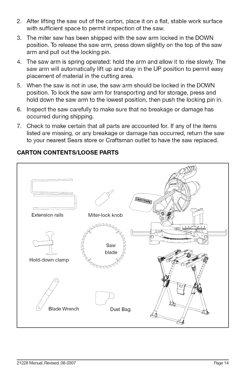
CARTON CONTENTS/LOOSE PARTS
ii
Extension rails Miter-lock knob
_f''h
Hold-down clamp
Saw
L
Blade Wrench Dust Bag
21228 Manual Revised 08-0307 Page 14
ID]_'_];;_i_e_]
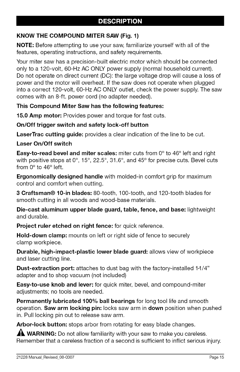
KNOW THE COMPOUND MITER SAW (Fig. 1)
NOTE: Before attempting to use your saw, familiarize yourself with all of the
features, operating instructions, and safety requirements.
Your miter saw has a precision-built electric motor which should be connected
only to a 120-volt, 60-Hz AC ONLY power supply (normal household current).
Do not operate on direct current (DC): the large voltage drop will cause a loss of
power and the motor will overheat. If the saw does not operate when plugged
into a correct 120-volt, 60-Hz AC ONLY outlet, check the power supply. The saw
comes with an 8-ft. power cord (no adapter needed).
This Compound Miter Saw has the following features:
15.0 Amp motor: Provides power and torque for fast cuts.
On/Off trigger switch and safety lock-off button
LaserTrac cutting guide: provides a clear indication of the line to be cut.
Laser On/Off switch
Easy-to-read bevel and miter scales: miter cuts from 0 ° to 46° left and right
with positive stops at 0 °, 15°, 22.5 °, 31.6 °, and 45° for precise cuts. Bevel cuts
from 0° to 46 ° left.
Ergonomically designed handle with molded-in comfort grip for maximum
control and comfort when cutting.
3 Craftsman® 10-in blades: 80-tooth, 100-tooth, and 120-tooth blades for
smooth cutting in all woods and wood-base materials.
Die-cast aluminum upper blade guard, table, fence, and base: lightweight
and durable.
Project ruler etched on right fence: for quick reference.
Hold-down clamp: mounts on left or right side of fence to securely
clamp workpiece.
Durable, high-impact-plastic lower blade guard: allows view of workpiece
and laser cutting line.
Dust-extraction port: attaches to dust bag with the factory-installed 1-1/4"
adapter and to shop vacuum (not included)
Easy-to-use knob and lever: for quick miter, bevel, and compound-miter
adjustments; no tools are needed.
Permanently lubricated 100% ball bearings for long tool life and smooth
operation. Saw arm locking pin: locks saw arm in down position when pushed
in. Pull locking pin out to release saw arm.
Arbor-lock button: stops arbor from rotating for easy blade changes.
_, WARNING: Do not allow familiarity with your saw to make you careless.
Remember that a careless fraction of a second is sufficient to inflict serious injury.
21228 Manual Revised 08-0307 Page 15
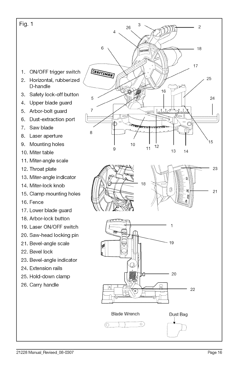
Fig. 1 26 3 _ 2
18
1. ON/OFF trigger switch
2. Horizontal, rubberized
D-handle
3. Safety lock-off button 5
4. Upper blade guard
5. Arbor-bolt guard 7
6. Dust-extraction port
7. Saw blade 8
8. Laser aperture
9. Mounting holes
10. Miter table
11. Miter-angle scale
12. Throat plate
13. Miter-angle indicator
14. Miter-lock knob
15. Clamp mounting holes
16. Fence
17. Lower blade guard
18. Arbor-lock button
19. Laser ON/OFF switch
20. Saw-head locking pin
21. Bevel-angle scale
22. Bevel lock
23. Bevel-angle indicator
24. Extension rails
25. Hold-down clamp
26. Carry handle
10
16
11 12 13
18
19
_]" 20
17
25
S
/24
14
23
21
22
Dust Bag
L
21228 Manual Revised 08-0307 Page 16
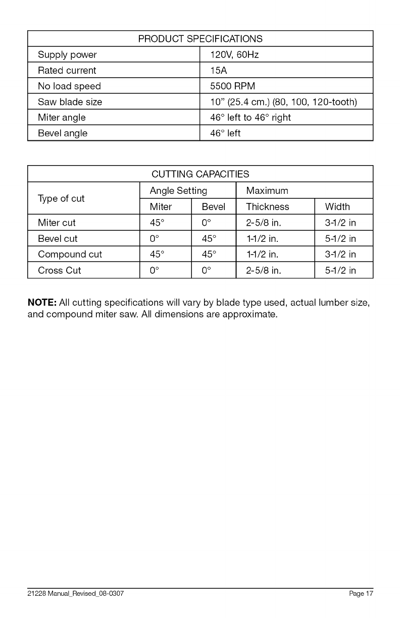
PRODUCT SPECIFICATIONS
Supply power 120V, 60Hz
Rated current 15A
No load speed 5500 RPM
Saw blade size 10" (25.4 cm.) (80, 100, 120-tooth)
Miter angle 46° left to 46° right
Bevel angle 46° left
CUTTING CAPACITIES
Type of cut
Miter cut
Bevel cut
Compound cut
Cross Cut
Angle Setting
Miter Bevel
45 ° 0 o
0o 45 °
45 ° 45 °
0o 0 o
Maximum
Thickness
2-5/8 in.
1-1/2 in.
1-1/2 in.
2-5/8 in.
Width
3-1/2 in
5-1/2 in
3-1/2 in
5-1/2 in
NOTE: All cutting specifications will vary by blade type used, actual lumber size,
and compound miter saw. All dimensions are approximate.
21228 Manual Revised 08-0307 Page 17
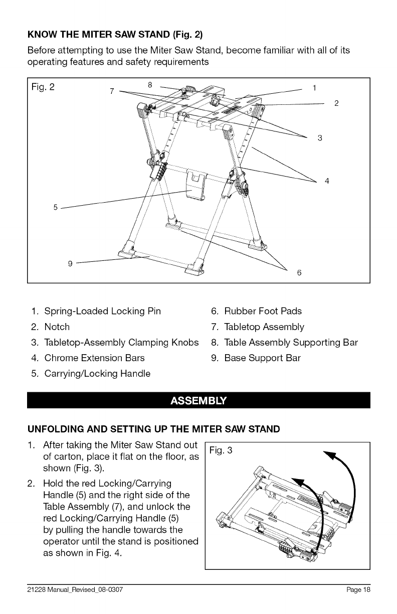
KNOW THE MITER SAW STAND (Fig. 2)
Before attempting to use the Miter Saw Stand, become familiar with all of its
operating features and safety requirements
Fig. 2
4
1. Spring-Loaded Locking Pin
2. Notch
3. Tabletop-Assembly Clamping Knobs
4. Chrome Extension Bars
5. Carrying/Locking Handle
6. Rubber Foot Pads
7. Tabletop Assembly
8. Table Assembly Supporting Bar
9. Base Support Bar
UNFOLDING AND SETTING UP THE MITER SAW STAND
1,
2,
After taking the Miter Saw Stand out
of carton, place it flat on the floor, as
shown (Fig. 3).
Hold the red Locking/Carrying
Handle (5)and the right side of the
Table Assembly (7), and unlock the
red Locking/Carrying Handle (5)
by pulling the handle towards the
operator until the stand is positioned
as shown in Fig. 4.
Fig. 3
21228 Manual Revised 08-0307 Page 18
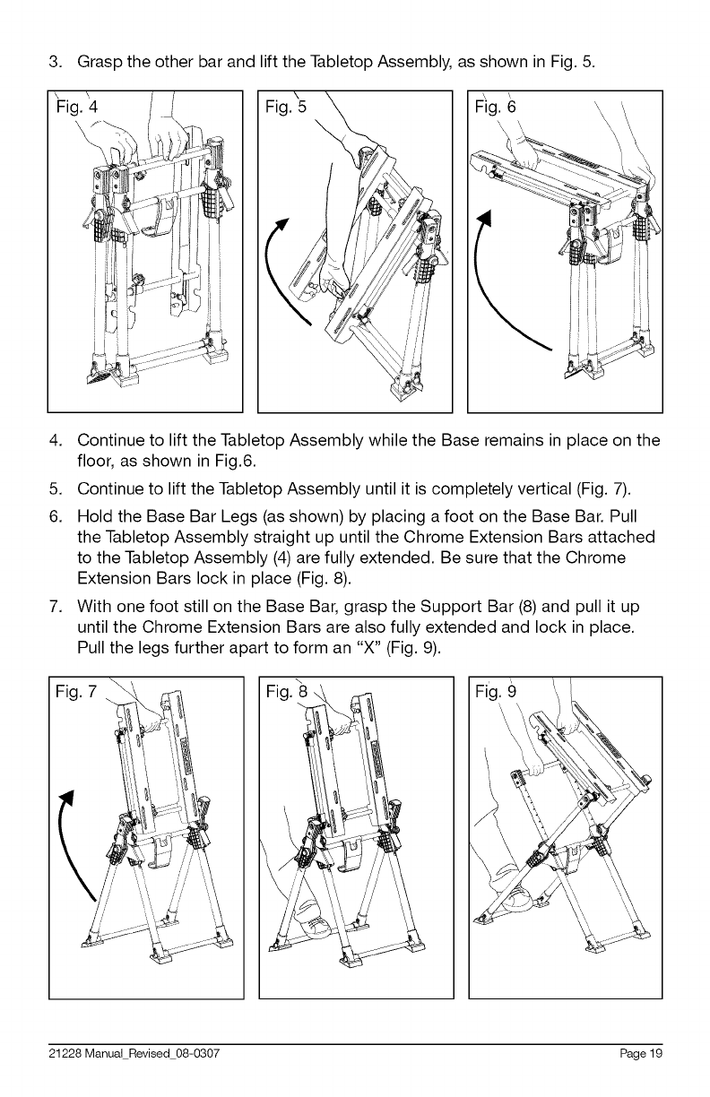
3. Grasp the other bar and lift the Tabletop Assembly, as shown in Fig. 5.
'Fig. _4 F_ig.
I
4. Continue to lift the Tabletop Assembly while the Base remains in place on the
floor, as shown in Fig.6.
5. Continue to lift the Tabletop Assembly until it is completely vertical (Fig. 7).
6. Hold the Base Bar Legs (as shown) by placing a foot on the Base Bar. Pull
the Tabletop Assembly straight up until the Chrome Extension Bars attached
to the Tabletop Assembly (4) are fully extended. Be sure that the Chrome
Extension Bars lock in place (Fig. 8).
7. With one foot still on the Base Bar, grasp the Support Bar (8) and pull it up
until the Chrome Extension Bars are also fully extended and lock in place.
Pull the legs further apart to form an "X" (Fig. 9).
21228 Manual Revised 08-0307 Page 19
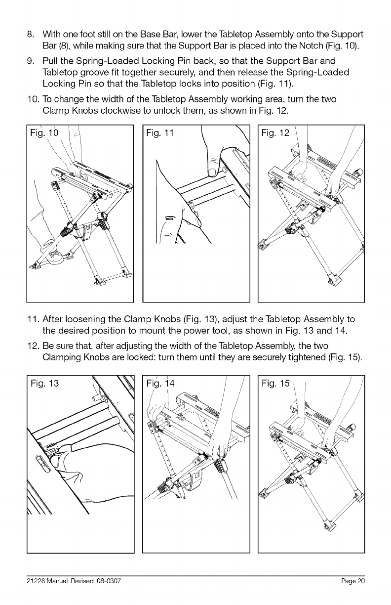
8. With one foot still on the Base Bar, lower the Tabletop Assembly onto the Support
Bar (8),while making sure that the Support Bar is placed into the Notch (Fig. 10).
9. Pull the Spring-Loaded Locking Pin back, so that the Support Bar and
Tabletop groove fit together securely, and then release the Spring-Loaded
Locking Pin so that the Tabletop locks into position (Fig. 11).
10. To change the width of the Tabletop Assembly working area, turn the two
Clamp Knobs clockwise to unlock them, as shown in Fig. 12.
Fig. 11
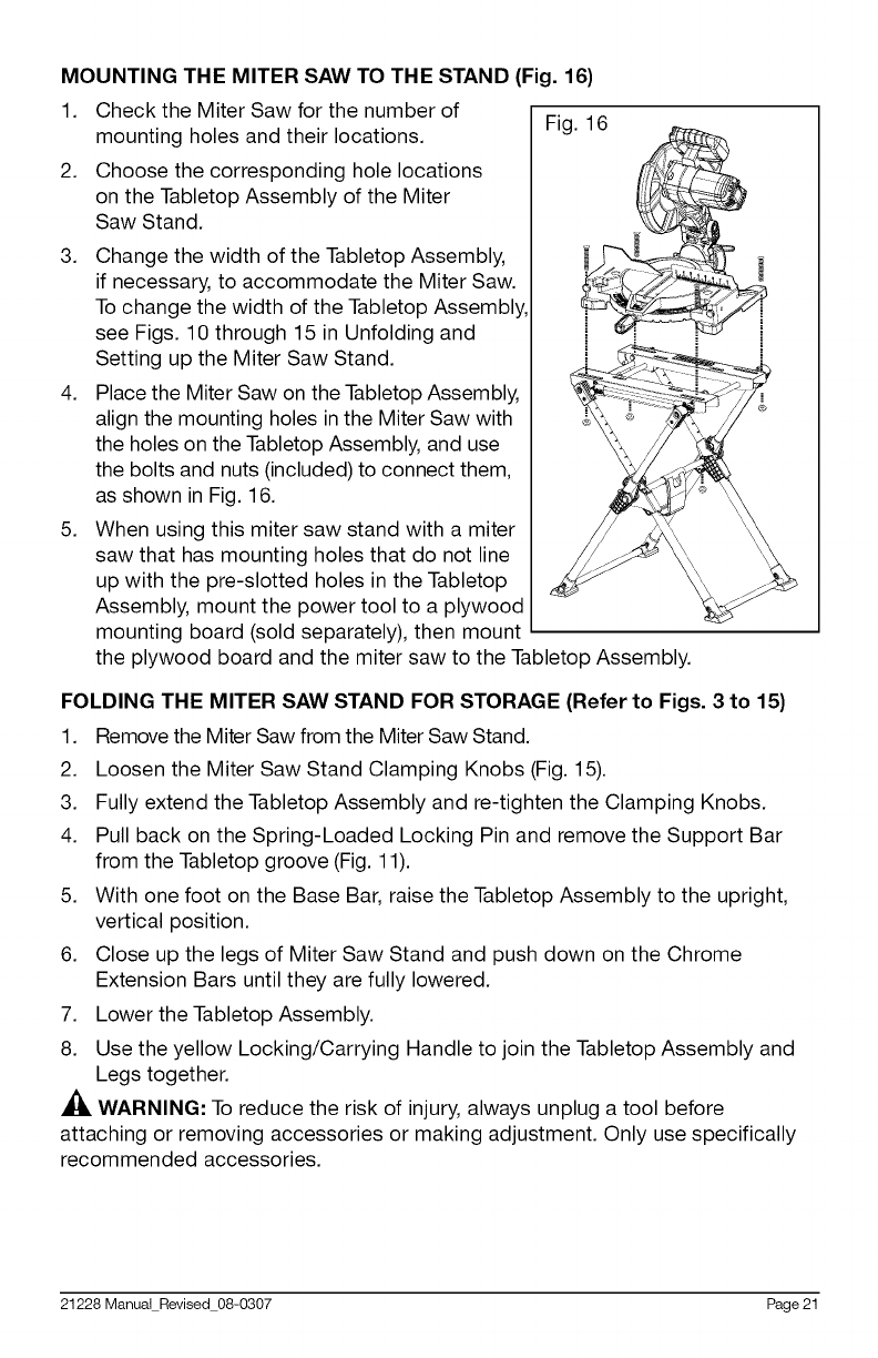
11. After loosening the Clamp Knobs (Fig. 13), adjust the Tabletop Assembly to
the desired position to mount the power tool, as shown in Fig. 13 and 14.
12. Be sure that, after adjusting the width of the Tabletop Assembly, the two
Clamping Knobs are locked: turn them until they are securely tightened (Fig. 15).
Fig. 13 Fig.
J,
//
Fig. 15, _ /
21228 Manual Revised 08-0307 Page 20
MOUNTING THE MITER SAW TO THE STAND (Fig. 16)
1. Check the Miter Saw for the number of
mounting holes and their locations.
2. Choose the corresponding hole locations
on the Tabletop Assembly of the Miter
Saw Stand.
3.
4.
5.
Change the width of the Tabletop Assembly,
if necessary, to accommodate the Miter Saw.
To change the width of the Tabletop Assembly,
see Figs. 10 through 15 in Unfolding and
Setting up the Miter Saw Stand.
Place the Miter Saw on the Tabletop Assembly,
align the mounting holes in the Miter Saw with
the holes on the Tabletop Assembly, and use
the bolts and nuts (included) to connect them,
as shown in Fig. 16.
When using this miter saw stand with a miter
saw that has mounting holes that do not line
up with the pre-slotted holes in the Tabletop
Assembly, mount the power tool to a plywood
mounting board (sold separately), then mount
the plywood board and the miter saw to the Tabletop Assembly.
Fig. 16
FOLDING THE MITER SAW STAND FOR STORAGE (Refer to Figs. 3 to 15)
1. Remove the Miter Saw from the Miter Saw Stand.
2. Loosen the Miter Saw Stand Clamping Knobs (Fig. 15).
3. Fully extend the Tabletop Assembly and re-tighten the Clamping Knobs.
4. Pull back on the Spring-Loaded Locking Pin and remove the Support Bar
from the Tabletop groove (Fig. 11).
5. With one foot on the Base Bar, raise the Tabletop Assembly to the upright,
vertical position.
6. Close up the legs of Miter Saw Stand and push down on the Chrome
Extension Bars until they are fully lowered.
7. Lower the Tabletop Assembly.
8. Use the yellow Locking/Carrying Handle to join the Tabletop Assembly and
Legs together.
_, WARNING: To reduce the risk of injury, always unplug a tool before
attaching or removing accessories or making adjustment. Only use specifically
recommended accessories.
21228 Manual Revised 08-0307 Page 21
SETTING UP THE MITER SAW
Installing the dust bag (see Fig. 17)
Place the bag's neck opening around the
dust-extraction port.
Emptying the dust bag The dust bag is
equipped with a zipper to make it easy
to empty the bag. Remove the dust bag
from the dust extraction port, hold it over
a suitable receptacle, and unzip the bag
to empty its contents.
Use with a shop vacuum An adapter
(adapter sold separately) permits a shop
vacuum to be attached to the dust-
extraction port.
Releasing and locking the saw head
1. Gently press and hold down the saw
head. Pull out the Saw-head locking
pin to release the saw head. The saw
head should freely move up and down
(see Fig. 18).
2. Place the saw head at the lowest
position. Insert the Saw-head
locking pin to lock the saw head for
transporting and storage.
Removing the blade (see Fig. 19)
_, WARNING: To reduce the risk of
injury, always unplug the tool before
removing and installing a blade.
1. Unplug the saw.
2. Release and raise the saw head.
3.
4.
5.
6.
7.
Remove the upper screw on the
arbor-bolt guard (Fig. 1, item 5) by
turning it counter-clockwise with
a screwdriver.
Fig. 17 Dust bag
ust extraction
Fig. 18
Fig. 19
Outer flange
Arbor
Arbor bolt
Inner flange Blade
Lift and hold up the lower blade guard (Fig, 1, item 17) and rotate the arbor-
bolt guard to expose the threaded arbor bolt.
Press and hold the arbor-lock button (Fig. 1, item 18) then rotate the blade
with the blade wrench (included) while depressing the arbor-lock button until
the blade is locked in position.
Use the wrench to turn the arbor bolt clockwise and remove the arbor bolt.
21228 Manual Revised 08-0307
Remove the outer flange and the blade. Wipe the flanges and the arbor to
remove any dust and debris.
Page 22

Installing the blade
1. Unplug the saw.
2. Ensure that the inner flange is properly installed.
3. Match the arrow on the blade with the arrow on the upper blade guard. Make
sure that the blade teeth are pointing downward. Install the selected blade by
sliding the blade into the upper blade guard and then placing the blade into
position on the arbor.
4. Install the outer flange.
_, WARNING: Make sure the flat side of the flange is placed against the blade.
5. Press and hold the arbor-lock button and use the wrench supplied to turn
the arbor bolt counter-clockwise until the lock engages. Securely tighten the
arbor bolt.
6. Rotate the arbor-bolt guard into position, and use the wrench to securely tighten
the bolt by turning it clockwise. Remove and store the wrench in a safe place.
7. Make sure that the arbor-lock button is released, so that the blade will
rotate freely.
8. Lower the saw head, and check the clearance between the blade and the
miter table. The blade should rotate freely.
Installing extension rails
The extension rails support long
workpieces during cutting operations.
(Fig. 20)
1. Insert both ends of an extension rail
through the holes on the outside of
the Miter Saw base.
2. Tighten the knob that locks the
extension rail in place. Make sure
that the extension rails do not move.
Fig. 20
_, WARNING: To avoid possible injury, disconnect the tool's plug from the
power source before performing any assembly, adjustment, or repair.
_, WARNING: Do not use thin-kerr blades. Thin-kerf blades can deflect and
contact the guard, which can cause injury to the operator.
ADJUSTING THE BLADE
Squaring the blade to the fence (Fig. 21 and Fig. 22)
WARNING: Failure to unplug your saw could result in accidental starting,
causing serious injury.
1. Unplug the saw.
2. Set the bevel and miter angles to 0°
21228 Manual Revised 08-0307 Page 23
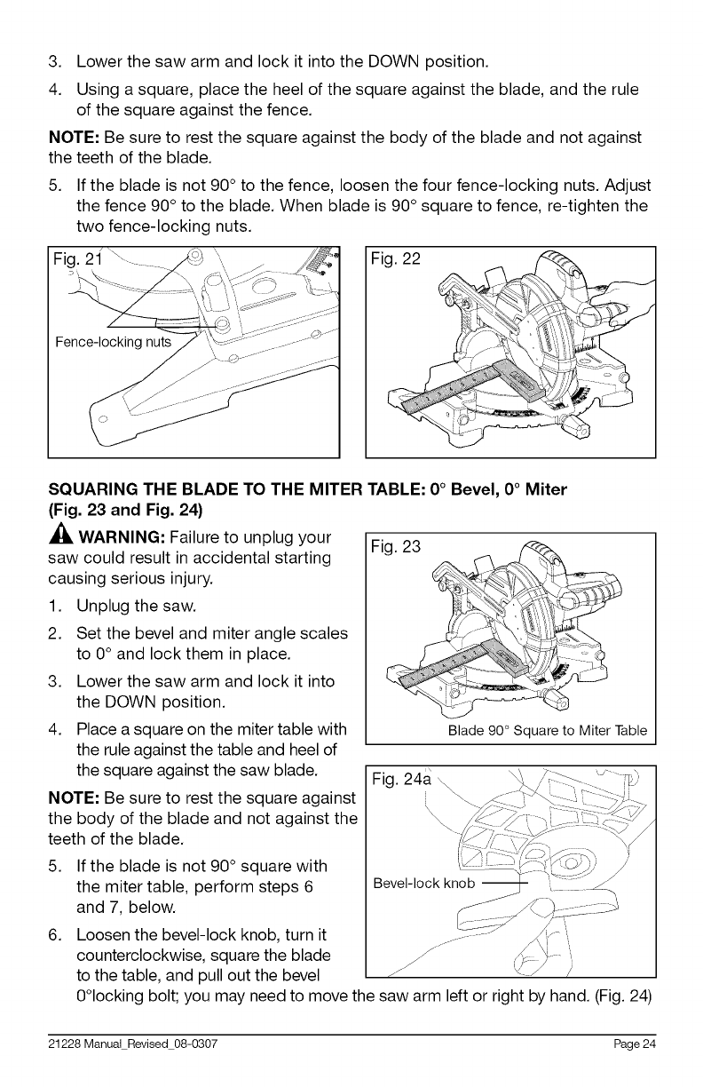
3. Lower the saw arm and lock it into the DOWN position.
4. Using a square, place the heel of the square against the blade, and the rule
of the square against the fence.
NOTE: Be sure to rest the square against the body of the blade and not against
the teeth of the blade.
5. If the blade is not 90 ° to the fence, loosen the four fence-locking nuts. Adjust
the fence 90° to the blade. When blade is 90 ° square to fence, re-tighten the
two fence-locking nuts.
\\Fig. 22
SQUARING THE BLADE TO THE MITER TABLE: 0°Bevel, 0°Miter
(Fig. 23 and Fig. 24)
,_ WARNING: Failure to unplug your
saw could result in accidental starting
causing serious injury.
1. Unplug the saw.
2. Set the bevel and miter angle scales
to 0° and lock them in place.
3. Lower the saw arm and lock it into
the DOWN position.
4. Place a square on the miter table with
the rule against the table and heel of
the square against the saw blade.
NOTE: Be sure to rest the square against
the body of the blade and not against the
teeth of the blade.
5.
6.
Fig. 23 _
,/
........'!
de 90° Square to Miter Table
Fig. 24a \
If the blade is not 90 ° square with
the miter table, perform steps 6
and 7, below.
Loosen the bevel-lock knob, turn it
counterclockwise, square the blade
to the table, and pull out the bevel
0°locking bolt; you may need to move the saw arm left or right by hand. (Fig. 24)
21228 Manual Revised 08-0307 Page 24
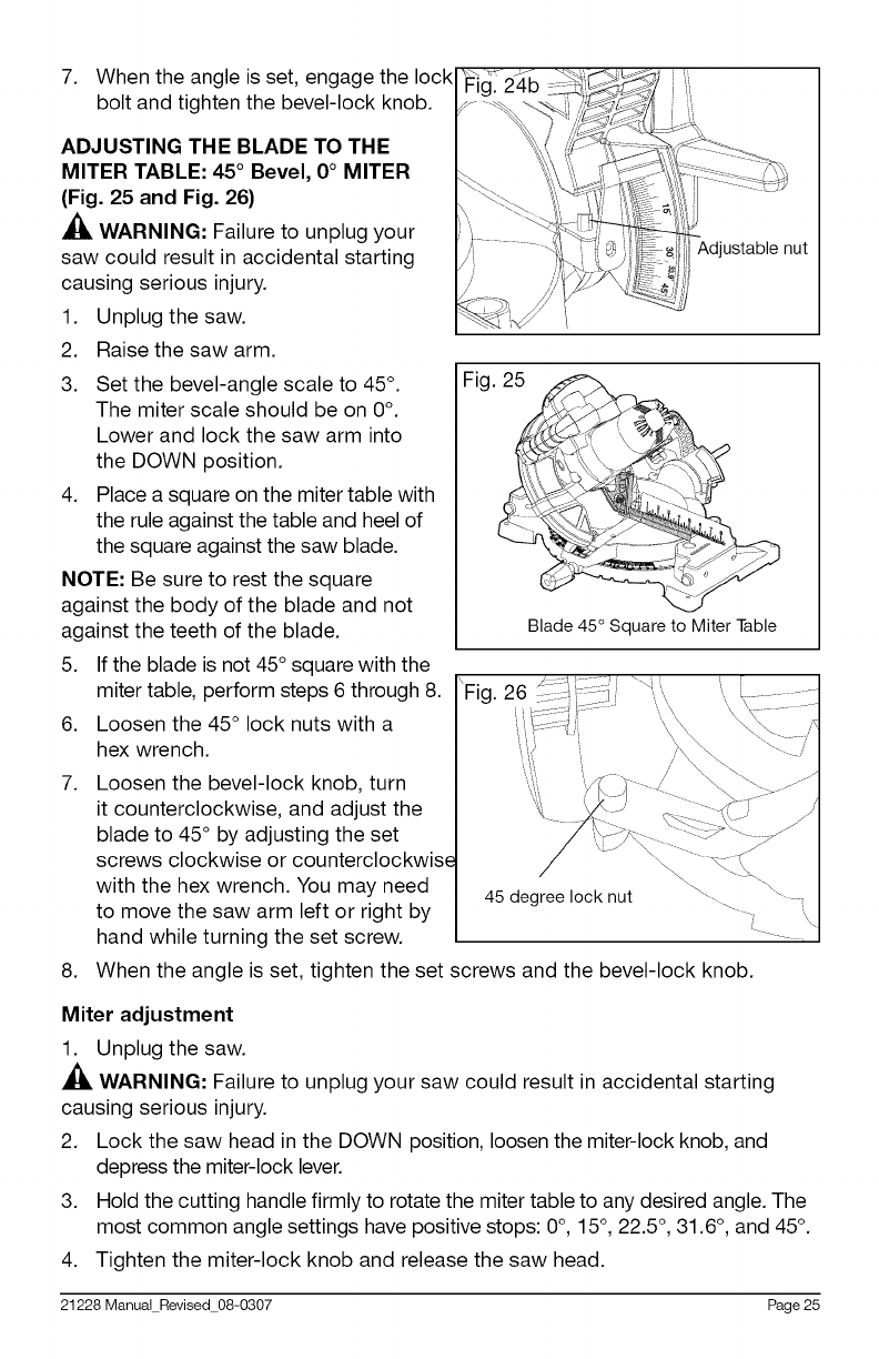
7. When the angle is set, engage the lock
bolt and tighten the bevel-lock knob.
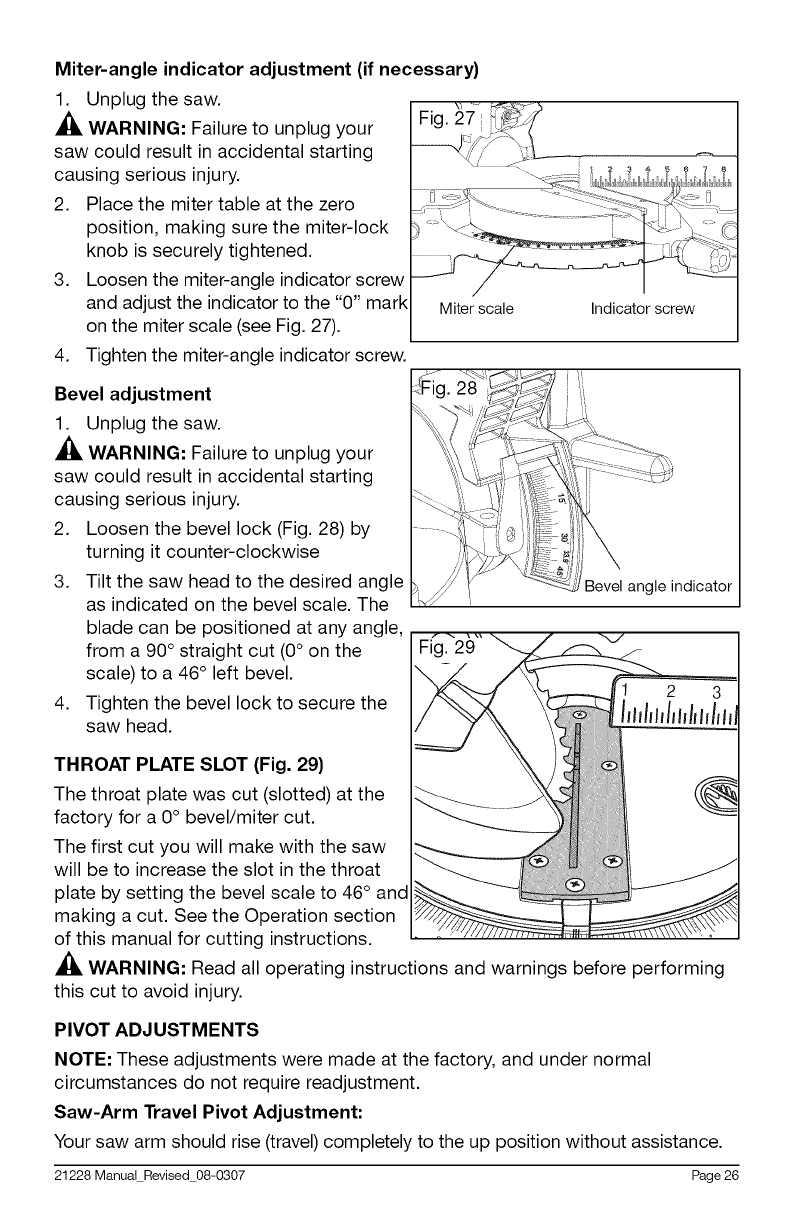
1.
2.
3.
ADJUSTING THE BLADE TO THE
MITER TABLE: 45 °Bevel, 0 °MITER
(Fig. 25 and Fig. 26)
WARNING: Failure to unplug your
saw could result in accidental starting
causing serious injury.
Unplug the saw.
Raise the saw arm.
Set the bevel-angle scale to 45 °.
The miter scale should be on 0°.
Lower and lock the saw arm into
the DOWN position.
4. Place a square on the miter table with
the rule against the table and heel of
the square against the saw blade.
NOTE: Be sure to rest the square
against the body of the blade and not
against the teeth of the blade.
5. If the blade is not 45 ° square with the
miter table, perform steps 6 through 8.
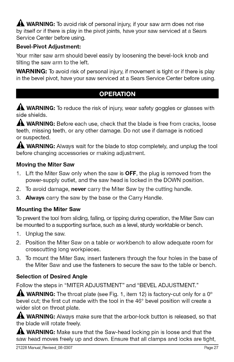
6. Loosen the 45 ° lock nuts with a
hex wrench.
7.
8.
Fig. 24b
Adjustable nut
Fig.
Blade 45° Squareto Miter Table
'Fig. 26
Loosen the bevel-lock knob, turn
it counterclockwise, and adjust the
blade to 45 ° by adjusting the set
screws clockwise or counterclockwise
with the hex wrench. You may need
to move the saw arm left or right by
hand while turning the set screw.
When the angle is set, tighten the set screws and the bevel-lock knob.
Miter adjustment
1. Unplug the saw.
,_ WARNING: Failure to unplug your saw could result in accidental starting
causing serious injury.
2. Lock the saw head in the DOWN position, loosen the miter-lock knob, and
depress the miter-lock lever.
3. Hold the cutting handle firmly to rotate the miter table to any desired angle. The
most common angle settings have positive stops: 0°, 15 °, 22.5 °, 31.6 °, and 45 °.
4. Tighten the miter-lock knob and release the saw head.
21228 Manual Revised 08-0307 Page 25
Miter-angle indicator adjustment (if necessary)
1. Unplug the saw.
,_, WARNING: Failure to unplug your
saw could result in accidental starting
causing serious injury.
2. Place the miter table at the zero
position, making sure the miter-lock
knob is securely tightened.
3. Loosen the miter-angle indicator screw
and adjust the indicator to the "0" mark
on the miter scale (see Fig. 27).
4. Tighten the miter-angle indicator screw.
Bevel adjustment
1. Unplug the saw.
_lk WARNING: Failure to unplug your
saw could result in accidental starting
causing serious injury.
2. Loosen the bevel lock (Fig. 28) by
turning it counter-clockwise
3. Tilt the saw head to the desired angle
as indicated on the bevel scale. The
blade can be positioned at any angle,
from a 90° straight cut (0° on the
scale) to a 46° left bevel.
4. Tighten the bevel lock to secure the
saw head.
Miter scale Indicator screw
Bevel igle indicator
THROAT PLATE SLOT (Fig. 29)
The throat plate was cut (slotted) at the
factory for a 0 ° bevel/miter cut.
The first cut you will make with the saw
will be to increase the slot in the throat
plate by setting the bevel scale to 46° and
making a cut. See the Operation section
of this manual for cutting instructions,
_, WARNING: Read all operating instructions and warnings before performing
this cut to avoid injury.
PIVOT ADJUSTMENTS
NOTE: These adjustments were made at the factory, and under normal
circumstances do not require readjustment.
Saw-Arm Travel Pivot Adjustment:
Your saw arm should rise (travel) completely to the up position without assistance.
21228 Manual Revised 08-0307 Page 26
_, WARNING: To avoid risk of personal injury, if your saw arm does not rise
by itself or if there is play in the pivot joints, have your saw serviced at a Sears
Service Center before using.
Bevel-Pivot Adjustment:
Your miter saw arm should bevel easily by loosening the bevel-lock knob and
tilting the saw arm to the left.
WARNING: To avoid risk of personal injury, if movement is tight or if there is play
in the bevel pivot, have your saw serviced at a Sears Service Center before using.
[e]",,1=1-'?,_'1| [e]_
_1_ WARNING: To reduce the risk of injury, wear safety goggles or glasses with
side shields.
_1_ WARNING: Before each use, check that the blade is free from cracks, loose
teeth, missing teeth, or any other damage. Do not use if damage is noticed
or suspected.
_[_ WARNING: Always wait for the blade to stop completely, and unplug the tool
before changing accessories or making adjustment.
Moving the Miter Saw
1. Lift the Miter Saw only when the saw is OFF, the plug is removed from the
power-supply outlet, and the saw head is locked in the DOWN position.
2. To avoid damage, never carry the Miter Saw by the cutting handle.
3. Always carry the saw by the base or the Carry Handle.
Mounting the Miter Saw
To prevent the tool from sliding, falling, or tipping during operation, the Miter Saw can
be mounted to a supporting surface, such as a level, sturdy worktable or bench.
1. Unplug the saw.
2. Position the Miter Saw on a table or workbench to allow adequate room for
crosscutting long workpieces.
3. To mount the Miter Saw, insert fasteners through the four holes in the base of
the Miter Saw and use the fasteners to secure the saw to the table or bench.
Selection of Desired Angle
Follow the steps in "MITER ADJUSTMENT" and "BEVEL ADJUSTMENT."
A[_ WARNING: The throat plate (see Fig. 1, item 12) is factory-cut only for a 0°
bevel cut; the first cut made with the tool in the 46 ° bevel position will create a
wider slot on throat plate.
_1, WARNING: Always make sure that the arbor-lock button is released, so that
the blade will rotate freely.
_l_ WARNING: Make sure that the Saw-head locking pin is loose and that the
saw head moves freely up and down. Ensure that all clamps and locks are tight,
21228 Manual Revised 08-0307 Page 27

in place, and that there is no excessive movement of Miter Saw parts.
Selection of workpiece
1. Be cautious with pitchy, knotty, wet, or warped workpieces. These materials
are likely to create pinching conditions.
2. Workpieces that bow and pinch may result in the saw blade kicking back.
3. Before cutting, inspect for and remove any nails from the workpiece.
4. This tool is recommended only for cutting wood and wood-like materials.
Support the workpiece
_, WARNING: Never use the help of another person as a substitute for a
table extension or as support for a workpiece that is longer or wider than the
basic miter table. Never have another person help to feed, support, or pull the
workpiece instead of using table extensions.
• Use the fence.
Align the workpiece flush against the fence. This will help to eliminate the
tendency of the blade teeth to bind. The fence can be used to support miter,
bevel, and compound cuts.
• Use the workpiece clamp
The work piece clamp fits into the clamp mounting holes on the back of the
fence. Securely clamp the workpiece to the miter table. (See Fig. 30.)
Clamping wide workpieces
When cutting wide workpieces (such as
2-in. x 8-in. boards), the boards must
be clamped with the hold-down clamp
provided or a C-clamp (sold separately).
A_, CAUTION: Pay attention to the
position of your body and hands.
Proper positioning of your body and
hands when operating the miter saw will
make cutting easier and safer. Never
place hands near the cutting area.
Fig. 30 z<_x workpiece
' ded)
Aligning the blade for the cut
_, WARNING: Do not look into the laser line.
• Do not aim the laser line at people or animals.
• Do not use the laser line on highly reflective materials because of the hazard
from reflected light.
• Only have the laser repaired by qualified service technicians.
• Do not insert hard objects into the laser lens.
• Clean the laser with a soft, dry brush.
1. Before starting a cut, draw the desired cut line on the workpiece.
21228 Manual Revised 08-0307 Page 28
2.
3.
the line marked on wood piece.
NOTE: The laser adjustment has
already been made at the factory. The
left side of the laser line aligns with
the right side of the blade. Align the
marked cutting line with the left side of
the laser line (Fig.31).
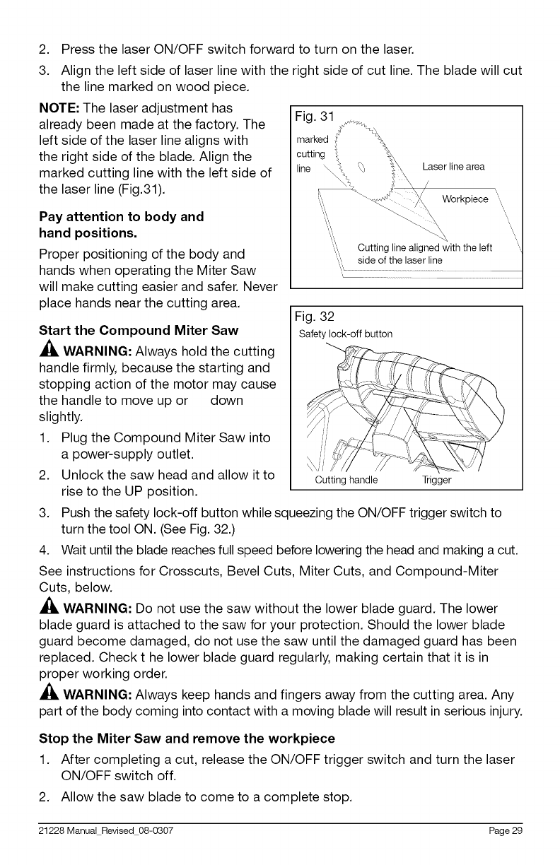
Press the laser ON/OFF switch forward to turn on the laser.
Align the left side of laser line with the right side of cut line. The blade will cut
Pay attention to body and
hand positions.
Proper positioning of the body and
hands when operating the Miter Saw
will make cutting easier and safer. Never
place hands near the cutting area.
Start the Compound Miter Saw
_, WARNING: Always hold the cutting
handle firmly, because the starting and
stopping action of the motor may cause
the handle to move up or down
slightly.
1. Plug the Compound Miter Saw into
a power-supply outlet.
2. Unlock the saw head and allow it to
rise to the UP position.
Fig. 32
Safety lock-off button
Cutting handle Trigger
3. Push the safety lock-off button while squeezing the ON/OFF trigger switch to
turn the tool ON. (See Fig. 32.)
4. Wait until the blade reaches full speed before lowering the head and making a cut.
See instructions for Crosscuts, Bevel Cuts, Miter Cuts, and Compound-Miter
Cuts, below.
_, WARNING: Do not use the saw without the lower blade guard. The lower
blade guard is attached to the saw for your protection. Should the lower blade
guard become damaged, do not use the saw until the damaged guard has been
replaced. Check t he lower blade guard regularly, making certain that it is in
proper working order.
WARNING: Always keep hands and fingers away from the cutting area. Any
part of the body coming into contact with a moving blade will result in serious injury.
Stop the Miter Saw and remove the workpiece
1. After completing a cut, release the ON/OFF trigger switch and turn the laser
ON/OFF switch off.
2. Allow the saw blade to come to a complete stop.
21228 Manual Revised 08-0307 Page 29

3. Gently raise the saw head and remove the workpiece. Do not remove the
workpiece from the sawing plate until the blade has stopped rotating. Ensure
that the lower blade guard can easily close.
4. Unplug the tool.
5. Remove loose or scrap pieces.
CROSSCUTS (Fig 33 and Fig 34)
A crosscut is a cut made across the
grain of the workpiece. A straight
crosscut is a cut made with the miter
table set in the 0° position.
Miter crosscuts are made with the miter
table set at an angle, left or right that
is not 0°.
To Crosscut With the Miter Saw
1. Unplug the saw.
_, WARNING: Failure to unplug the
saw could result in accidental starting,
causing serious injury.
2. Push in the locking pin to lock the
saw arm in the DOWN position.
3. Loosen the knob and depress the
miter-lock lever.
4.
5.
6.
7.
8.
9.
Fig. 33
Fig. 34
Firmly hold the base of the saw
arm and use it to rotate the miter
table, while also holding the saw
base steady.
Quickly locate 0°, 15°, 22.5 °, 31.6 °
and 45 °, left or right, by the stops
or clicks at these angle settings.
When the miter angle is set, tighten the miter-lock knob.
Pull out the locking pin to release the saw arm.
Place the workpiece flat on the miter table with one edge securely against
the fence. If the board is warped, place the convex side against the fence. If
the concave edge of the board is against the fence, the board could collapse
on the blade at the end of the cut and jam the blade.
Plug the saw into a power supply.
10. Turn on the Laser with the Laser ON/OFF switch.
11. Align the "red laser line" to touch the right edge of the cut line marked on
the workpiece.
12. Use the hold-down clamp to secure the workpiece against the saw table
and fence.
21228 Manual Revised 08-0307 Page 30
13. When cutting long workpieces, support the opposite end of the workpiece
with a roller stand or with another work surface that is level with the saw table.
,_ WARNING: To avoid serious personal injury, always securely tighten the
miter-lock knob before making a cut. Failure to do so could result in movement
of the control arm or miter table while making a cut.
_, CAUTION: Never use another person as an additional support for a
workpiece that is longer or wider than the basic saw table, or to help feed,
support, or pull the workpiece.
,_ WARNING: To avoid serious personal injury, always keep
hands outside the "No Hands Zone" marked on the saw
table: at least 3 inches (7.6 cm) from the blade. Also, never
perform any cutting operation "freehand" (i.e., without holding
the workpiece against the fence); the blade could grab the
workpiece, causing it to slip and twist.
14. Before turning on the saw, perform a test of the cutting operation by lowering
the saw arm to make sure that no problems will occur when the cut is made.
15. To turn on the saw, push the safety-lock button in with the thumb while
squeezing the On/Off trigger switch located under the handle. Allow several
seconds for the blade to reach maximum speed.
16. Slowly lower the blade into and through the workpiece.
17. Release the safety lock and the trigger switch, and turn off the laser
switch. Allow the saw blade to stop rotating before raising the blade out of
the workpiece.
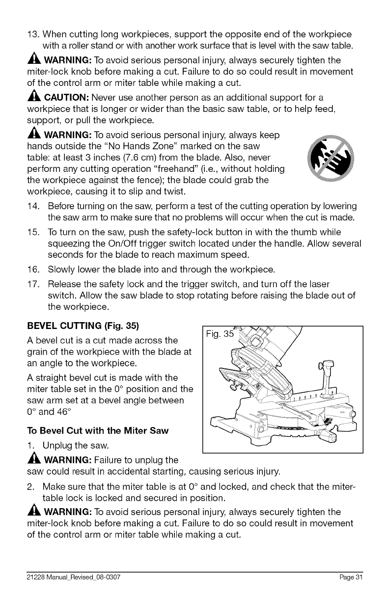
BEVEL CUTTING (Fig. 35)
A bevel cut is a cut made across the
grain of the workpiece with the blade at
an angle to the workpiece.
A straight bevel cut is made with the
miter table set in the 0° position and the
saw arm set at a bevel angle between
0 ° and 46°
To Bevel Cut with the Miter Saw
1. Unplug the saw.
_, WARNING: Failure to unplug the
saw could result in accidental starting, causing serious injury.
2. Make sure that the miter table is at 0° and locked, and check that the miter-
table lock is locked and secured in position.
,_ WARNING: To avoid serious personal injury, always securely tighten the
miter-lock knob before making a cut. Failure to do so could result in movement
of the control arm or miter table while making a cut.
21228Manual Revised 08-0307 Page31
3. Pull out the locking pin to release the saw arm.
4. To make a bevel cut, loosen the bevel-lock knob by turning the knob
counter clockwise.
5. Tilt the saw arm to the desired bevel angle as indicated on the bevel scale.
The blade can be positioned at any angle, from a 90 ° straight cut (0 on the
scale) to a 46° left bevel.
6. Tighten the bevel-lock knob.
_, WARNING: Always tighten the bevel-lock knob to secure the saw arm in
its position.
7. Place the workpiece flat on the miter table with one edge securely against
the fence. If the board is warped, place the convex side against the fence. If
the concave edge of the board is against the fence, the board could collapse
on the blade at the end of the cut and jam the blade.
8. Plug the saw into a power supply.
9. Hold the saw handle and use your index finger to turn on the laser switch by
pushing it forward.
10. Align the red laser line to touch the right edge of the cut line marked on the
workpiece. Turn off the laser.
11. Use the hold-down clamp to secure the workpiece against the Miter Saw
table and fence.
12. When cutting long workpieces, support the opposite end of the workpiece
with a roller stand or with another work surface that is level with the saw table.
,_ CAUTION: Never use another person as an additional support for a
workpiece that is longer or wider than the basic saw table or to help feed,
support, or pull the workpiece.
,_ WARNING: To avoid serious personal injury, always keep hands outside the
"No Hands Zone," as marked on the saw table: at least 3 inches (7.6 cm) from
the blade. Also, never perform any cutting operation "freehand" (i.e., without
holding the workpiece against the fence); the blade could grab the workpiece,
causing it to slip and twist.
13. Before turning on the saw, perform a trial of the cutting operation by lowering
the saw arm to make sure that no problems will occur when the cut is made.
14. Turn on the laser switch.To turn on the saw, push the safety-lock button in
with your thumb while squeezing the On/Off trigger switch located under the
handle. Allow several seconds for the blade to reach maximum speed.
15. Slowly lower the blade into and through the workpiece.
16. Release the safety lock and the trigger switch, and turn off the laser switch. Allow
the saw blade to stop rotating before raising the blade out of the workpiece.
,_, CAUTION: Always perform a "dry run" cut to determine if the operation
being attempted is possible before power is applied to Miter Saw.
21228 Manual Revised 08-0307 Page 32

CUTTING BASE MOLDING (Fig. 36)
Base moldings and many other moldings
can be cut on a miter saw. The proper
setup of the saw depends on base molding
characteristics and applications, as
described below. Perform practice cuts on
scrap materials to achieve best results.
1. Always make sure moldings rest firmly
against the fence and table. Use hold-
down clamp provided, a crown molding
vise, or C-clamps and place tape on the
area being clamped to avoid marks on
the workpiece.
2. Reduce splintering by taping the cut
area prior to making the cut. Mark the cut
line directly on the tape.
Fig. 36 Molding lying flat on miter table
(before clamping)
¢_ Fence
Meiteeri
Molding standing up against fence
(before clamping) ._
Fence
Miter at 45 °, _
Bevel
Miter Table
3. Splintering is typically due to incorrect blade style, dull blade, thinness of
workpiece, or improperly dried wood.
4. Place the workpiece flat on the miter table with one edge securely against
the fence. If the board is warped, place the convex side against the fence. If
the concave edge of the board is against the fence, the board could collapse
on the blade at the end of the cut and jam the blade.
5. Align the "red laser line" to touch the right edge of the cut line marked on
the workpiece.
6. Use the hold down clamp to secure workpiece against saw table and fence.
7. When cutting long workpieces, pull out the extension rail for extra support
for the long workpieces.
NOTE: Always perform a dry run cut so you can determine if the operation being
attempted is possible before power is applied to miter saw.
COMPOUND MITER CUTTING (Fig. 37)
A compound miter cut is a cut made using a miter angle and a bevel angle at the
same time. This type of cut is used for decorative moldings, picture frames, and
other fine joinery.
To make this type of cut, the miter table must be rotated to the correct miter
angle and the saw arm must be tilted to the correct bevel angle.
Always take special care when making compound miter cuts, due to the
interaction of the two angle settings.
Adjustments of miter and bevel settings are dependent on one another. Each time the
miter setting is adjusted, the effect of the bevel setting also changes. Each time the
bevel setting is adjusted, the effect of the miter setting is changed.
It may take several settings to obtain the desired cut. The first angle setting
should be checked after setting the second angle, since adjusting the second
angle affects the first.
21228 Manual Revised 08-0307 Page 33
Once the two correct settings for a particular cut have been obtained, always make a
test cut in scrap material before making a finish cut in good material.
To Make a Compound Miter Cut with the Miter Saw (Fig. 37)
1. Unplug the saw.
,_ WARNING: Failure to unplug the saw could result in accidental starting,
causing serious injury.
2. Pull out the locking pin to release Fig. 37
the saw arm.
3. Loosen the miter-lock knob and
depress the miter-lock lever to
loosen the miter table.
4. Hold the base of the saw arm firmly
and use it to rotate the miter table
while holding the saw base steady.
5. The0 °,15 °, 22.5 °, 31.6 °, and 45 °,
left and right settings are quickly
identifiable with the stops at the angle settings.
6. When the desired miter-table setting is achieved, tighten the miter-lock knob.
,_ WARNING: To avoid serious personal injury, always securely tighten the
miter-lock knob before making a cut. Failure to do so could result in movement
of the control arm or miter table while making a cut.
7. To set the bevel angle, loosen the bevel-lock knob by turning the knob
counter clockwise.
8. Tilt the saw arm to the desired bevel angle, as shown on the bevel scale.
Bevel angles can be set from 0°to 46°left bevel.
9. When the saw arm has been set at the desired angle, securely tighten the
bevel-lock knob.
10. Place the workpiece flat on the miter table with one edge securely against
the fence. If the board is warped, place the convex side against the fence. If
the concave edge of the board is against the fence, the board could collapse
on the blade at the end of the cut and jam the blade.
11. Plug the saw into a power supply.
12. Hold the saw handle and use your index finger to turn on the laser switch by
pushing it forward. Align the red laser line to touch the right edge of the cut line
marked on the workpiece. Turn off the laser.
13. Use the hold-down clamp to secure the workpiece against the saw table
and fence.
14. When cutting long workpieces, support the opposite end of the workpiece with a
roller stand or with another work surface that is level with the saw table.
_, CAUTION: Never use another person as an additional support for a
workpiece that is longer or wider than the basic saw table, or to help feed,
support, or pull the workpiece.
21228 Manual Revised 08-0307 Page 34
_, WARNING: To avoid serious personal injury, always keep hands outside
the "No Hands Zone", as marked on the saw table, which is at least 3 inches
(7.6 cm) from the blade. Also, never perform any cutting operation "freehand"
(i.e. without holding the workpiece against the fence); the blade could grab the
workpiece, causing it to slip and twist.
15. Make sure that there will be no obstructions to interfere with making the cut.
16. Turn on the laser switch.
17. To turn on the saw, push the safety-lock button in with your thumb while
squeezing the On/Off trigger switch located under the handle. Allow several
seconds for the blade to reach maximum speed.
18. Slowly lower the blade into and through the workpiece.
19. Release the safety lock and trigger switch, and turn off the laser switch.
Allow the saw blade to stop rotating before raising the blade out of the workpiece.
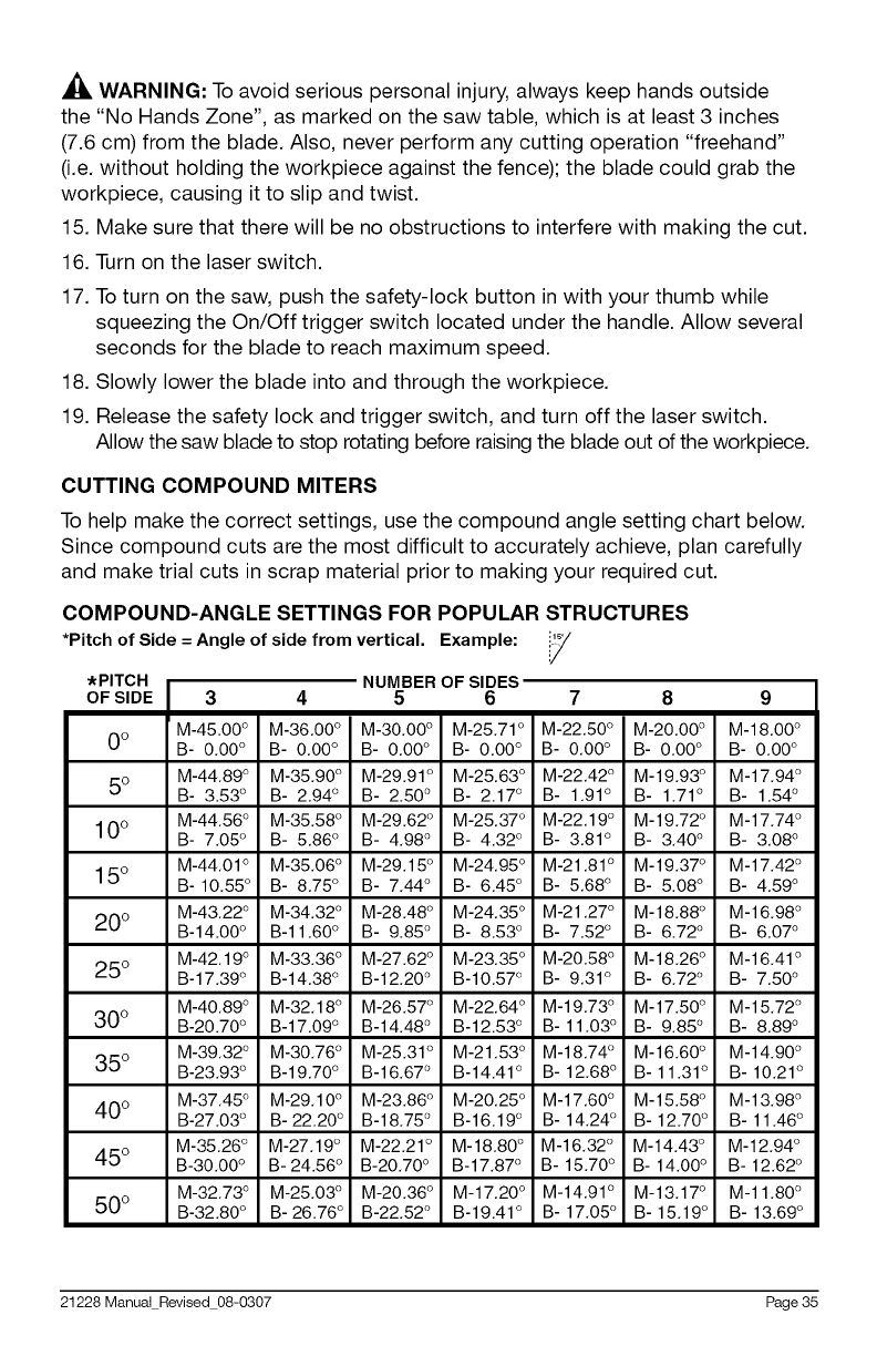
CUTTING COMPOUND MITERS
To help make the correct settings, use the compound angle setting chart below.
Since compound cuts are the most difficult to accurately achieve, plan carefully
and make trial cuts in scrap material prior to making your required cut.
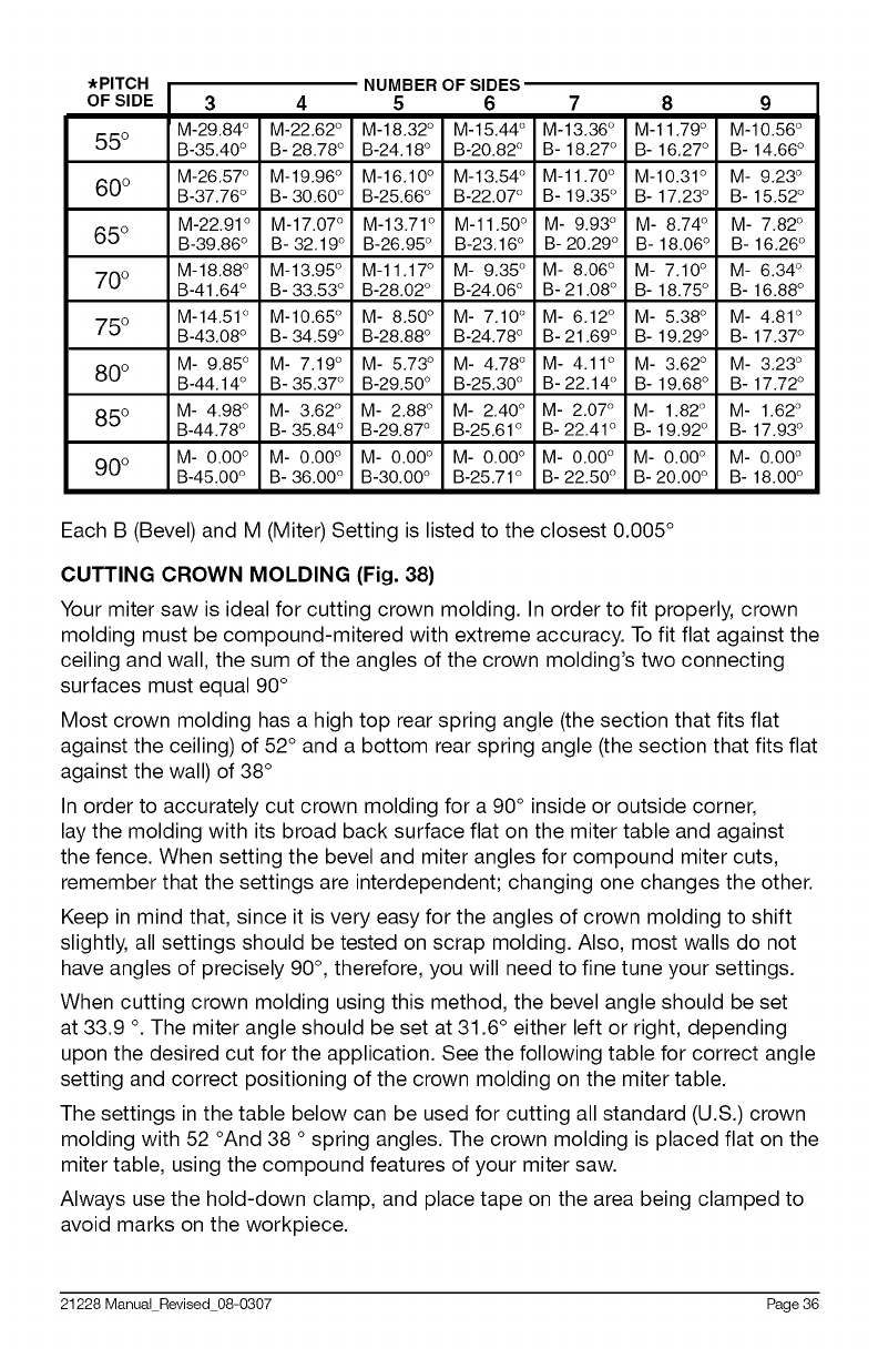
COMPOUND-ANGLE SETTINGS FOR POPULAR STRUCTURES
*Pitch of Side = Angle of side from vertical, Example: i.!_/
,'//:
*PITCH i_ulvlo=, ur _Juco
OF SIDE 3 4 5 6 7 8
M-45.00 ° M-36.00 ° M-30.00 ° M-25.71° M-22.50 ° M-20.00 ° M-18.00 °
O° B- 0.00 ° B- 0.00 ° B- 0.00 ° B- 0.00 ° B- 0.00 ° B- 0.00 ° B- 0.00 °
5 ° M-44.89 ° M-35.90 ° M-29.91 ° M-25.63 ° M-22.42 ° M-19.93 ° M-17.94 °
B- 3.53 ° B- 2.94 ° B- 2.50 ° B- 2.17 ° B- 1.91 ° B- 1.71 ° B- 1.54 °
10° M-44"56° M-35"58° M-29"62° M-25"37° M-22"19° M-19"72° M-17"74°
B- 7.05 ° B- 5.86 ° B- 4.98 ° B- 4.32 ° B- 3.81 ° B- 3.40 ° B- 3.08 °
15° M-44.01 ° M-35.06 ° M-29.15 ° M-24.95 ° M-21.81 ° M-19.37 ° M-17.42 °
B-10.55 ° B- 8.75 ° B- 7.44 ° B- 6.45 ° B- 5.68 ° B- 5.08 ° B- 4.59 °
M-43.22 ° M-34.32 ° M-28.48 ° M-24.35 ° M-21.27 ° M-18.88 ° M-16.98 °
200 B-14.00 ° B-11.60 ° B- 9.85 ° B- 8.53 ° B- 7.52 ° B- 6.72 ° B- 6.07 °
M-42.19 ° M-33.36 ° M-27.62 ° M-23.35 ° M-20.58 ° M-18.26 ° M-16.41 °
250 B-17.39 ° B-14.38 ° B-12.20 ° B-10.57 ° B- 9.31 ° B- 6.72 ° B- 7.50 °
M-40.89 ° M-32.18 ° M-26.57 ° M-22.64 ° M-19.73 ° M-17.50 ° M-15.72 °
300 B-20.70 ° B-17.09 ° B-14.48 ° B-12.53 ° B-11.03 ° B- 9.85 ° B- 8.89 °
M-39.32 ° M-30.76 ° M-25.31 ° M-21.53 ° M-18.74 ° M-16.60 ° M-14.90 °
350 B-23.93 ° B-19.70 ° B-16.67 ° B-14.41 ° B- 12.68 ° B- 11.31 ° B- 10.21 °
40 ° M-37.45° M-29.10 ° M-23.86 ° M-20.25 ° M-17.60 ° M-15.58 ° M-13.98 °
B-27.03 ° B- 22.20 ° B-18.75 ° B-16.19 ° B- 14.24 ° B- 12.70 ° B- 11.46 °
M-35.26 ° M-27.19 ° M-22.21 ° M-18.80 ° M-16.32 ° M-14.43 ° M-12.94 °
450 B-30.O0 ° B-24.56 ° B-20.70 ° B-17.87 ° B- 15.70 ° B- 14.00 ° B- 12.62 °
M-32.73 ° M-25.03 ° M-20.36 ° M-17.20 ° M-14.91 ° M-13.17 ° M-11.80 °
500 B-32.80 ° B- 26.76 ° B-22.52 ° B-19.41 ° B- 17.05 ° B- 15.19 ° B- 13.69 °
21228 Manual Revised 08-0307 Page 35
*PITCH i_ulviDcr_ ur _Juc_
OF SIDE 3 4 5 6 7 8 9
M-29.84 ° M-22.62 ° M-18.32 ° M-15.44 ° M-13.36 ° M-11.79 ° M-10.56 °
550 B-35.40 ° B-28.78 ° B-24.18 ° B-20.82 ° B- 18.27 ° B- 16.27 ° B- 14.66 °
M-26.57 ° M-19.96 ° M-16.10 ° M-13.54 ° M-11.70 ° M-10.31 ° M- 9.23 °
600 B-37.76 ° B-30.60 ° B-25.66 ° B-22.07 ° B- 19.35 ° B- 17.23 ° B- 15.52 °
M-22.91 ° M-17.07 ° M-13.71 ° M-11.50 ° M- 9.93 ° M- 8.74 ° M- 7.82 °
650 B-39.86 ° B- 32.19 ° B-26.95 ° B-23.16 ° B- 20.29 ° B- 18.06 ° B- 16.26 °
M-18.88 ° M-13.95 ° M-11.17 ° M- 9.35 ° M- 8.06 ° M- 7.10 ° M- 6.34 °
700 B-41.64 ° B-33.53 ° B-28.02 ° B-24.06 ° B-21.08 ° B- 18.75 ° B- 16.88 °
M-14.51 ° M-10.65 ° M- 8.50 ° M- 7.10 ° M- 6.12 ° M- 5.38 ° M- 4.81 °
750 B-43.08 ° B-34.59 ° B-28.88 ° B-24.78 ° B-21.69 ° B- 19.29 ° B- 17.37 °
80 ° M- 9.85 ° M- 7.19 ° M- 5.73 ° M- 4.78 ° M- 4.11 ° M- 3.62 ° M- 3.23 °
B-44.14 ° B-35.37 ° B-29.50 ° B-25.30 ° B-22.14 ° B- 19.68 ° B- 17.72 °
85 ° M- 4.98 ° M- 3.62 ° M- 2.88 ° M- 2.40 ° M- 2.07 ° M- 1.82° M- 1.62 °
B-44.78 ° B- 35.84 ° B-29.87 ° B-25.61 ° B- 22.41 ° B- 19.92 ° B- 17.93 °
M- 0.00 ° M- 0.00 ° M- 0.00 ° M- 0.00 ° M- 0.00 ° M- 0.00 ° M- 0.00 °
900 B-45.00 ° B- 36.00 ° B-30.O0 ° B-25.71 ° B- 22.50 ° B-20.00 ° B- 18.00 °
Each B (Bevel) and M (Miter) Setting is listed to the closest 0.005 °
CUTTING CROWN MOLDING (Fig. 38)
Your miter saw is ideal for cutting crown molding. In order to fit properly, crown
molding must be compound-mitered with extreme accuracy. To fit flat against the
ceiling and wall, the sum of the angles of the crown molding's two connecting
surfaces must equal 90 °
Most crown molding has a high top rear spring angle (the section that fits flat
against the ceiling) of 52 ° and a bottom rear spring angle (the section that fits flat
against the wall) of 38 °
In order to accurately cut crown molding for a 90° inside or outside corner,
lay the molding with its broad back surface flat on the miter table and against
the fence. When setting the bevel and miter angles for compound miter cuts,
remember that the settings are interdependent; changing one changes the other.
Keep in mind that, since it is very easy for the angles of crown molding to shift
slightly, all settings should be tested on scrap molding. Also, most walls do not
have angles of precisely 90°, therefore, you will need to fine tune your settings.
When cutting crown molding using this method, the bevel angle should be set
at 33.9 o. The miter angle should be set at 31.6 ° either left or right, depending
upon the desired cut for the application. See the following table for correct angle
setting and correct positioning of the crown molding on the miter table.
The settings in the table below can be used for cutting all standard (U.S.) crown
molding with 52 °And 38 o spring angles. The crown molding is placed flat on the
miter table, using the compound features of your miter saw.
Always use the hold-down clamp, and place tape on the area being clamped to
avoid marks on the workpiece.
21228 Manual Revised 08-0307 Page 36
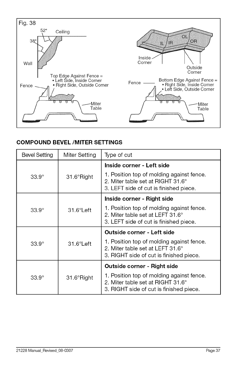
Fig. 38
52° Ceiling
Left Side, Inside Corner
Corner
Outside
Corner
Bottom Edge Against Fence =
Fence -- • Right Side, Inside Corner
/..... \ utsid/_MiternereCor
ble
COMPOUND BEVEL/MITER SETTINGS
Bevel Setting Miter Setting
33.9 °
33.9 °
33.9 °
33.9 °
31.6°Right
31.6°Left
31.6°Left
31.6°Right
Type of cut
Inside corner -Left side
1. Position top of molding against fence.
2. Miter table set at RIGHT 31.6 °
3. LEFT side of cut is finished piece.
Inside corner -Right side
1. Position top of molding against fence.
2. Miter table set at LEFT 31.6 °
3. LEFT side of cut is finished piece.
Outside corner -Left side
1. Position top of molding against fence.
2. Miter table set at LEFT 31.6 °
3. RIGHT side of cut is finished piece.
Outside corner -Right side
1. Position top of molding against fence.
2. Miter table set at RIGHT 31.6 °
3. RIGHT side of cut is finished piece.
21228 Manual Revised 08-0307 Page 37
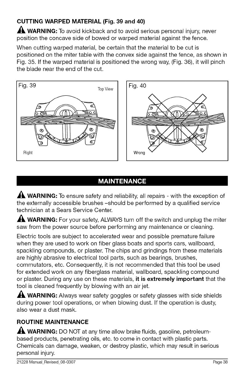
CUTTING WARPED MATERIAL (Fig. 39 and 40)
_, WARNING: To avoid kickback and to avoid serious personal injury, never
position the concave side of bowed or warped material against the fence.
When cutting warped material, be certain that the material to be cut is
positioned on the miter table with the convex side against the fence, as shown in
Fig. 35. If the warped material is positioned the wrong way, (Fig. 36), it will pinch
the blade near the end of the cut.
Fig. 39
Right
TopView Fig. 40
I_vlV,_IIl i / _4l V,_Il [ll,_!
,_, WARNING: To ensure safety and reliability, all repairs - with the exception of
the externally accessible brushes -should be performed by a qualified service
technician at a Sears Service Center.
,_ WARNING: For your safety, ALWAYS turn off the switch and unplug the miter
saw from the power source before performing any maintenance or cleaning.
Electric tools are subject to accelerated wear and possible premature failure
when they are used to work on fiber glass boats and sports cars, wallboard,
spackling compounds, or plaster. The chips and grindings from these materials
are highly abrasive to electrical tool parts, such as bearings, brushes,
commutators, etc. Consequently, it is not recommended that this tool be used
for extended work on any fiberglass material, wallboard, spackling compound
or plaster. During any use on these materials, it is extremely important that the
tool is cleaned frequently by blowing with an air jet.
,_, WARNING: Always wear safety goggles or safety glasses with side shields
during power tool operations, or when blowing dust. If the operation is dusty,
also wear a dust mask.
ROUTINE MAINTENANCE
_. WARNING: DO NOT at any time allow brake fluids, gasoline, petroleum-
based products, penetrating oils, etc. to come in contact with plastic parts.
Chemicals can damage, weaken, or destroy plastic, which may result in serious
personal injury.
21228 Manual Revised 08-0307 Page 38
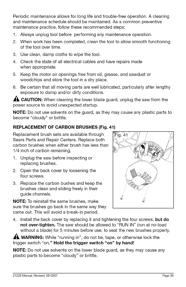
Periodic maintenance allows for long life and trouble-free operation. A cleaning
and maintenance schedule should be maintained. As a common preventive
maintenance practice, follow these recommended steps:
Always unplug tool before performing any maintenance operation.
When work has been completed, clean the tool to allow smooth functioning
of the tool over time.
1.
2.
3.
4.
5.
6.
Use clean, damp cloths to wipe the tool.
Check the state of all electrical cables and have repairs made
when appropriate.
Keep the motor air openings free from oil, grease, and sawdust or
woodchips and store the tool in a dry place.
Be certain that all moving parts are well lubricated, particularly after lengthy
exposure to damp and/or dirty conditions.
,_ CAUTION: When cleaning the lower blade guard, unplug the saw from the
power source to avoid unexpected startup.
NOTE: Do not use solvents on the guard, as they may cause any plastic parts to
become "cloudy" or brittle.
REPLACEMENT OF CARBON BRUSHES (Fig. 41)
Replacement brush sets are available through
Sears Parts and Repair Centers. Replace both
carbon brushes when either brush has less than
1/4 inch of carbon remaining.
1. Unplug the saw before inspecting or
replacing brushes.
2. Open the back cover by loosening the
four screws.
3. Replace the carbon bushes and keep the
brushes clean and sliding freely in their
guide channels. .
NOTE: To reinstall the same brushes, make
sure the brushes go back in the same way they
came out. This will avoid a break-in period.
4. Install the back cover by replacing it and tightening the four screws, but do
not over-tighten. The saw should be allowed to "RUN IN" (run at no-load
without a blade) for 5 minutes before use, to seat the new brushes properly.
,_ WARNING: While "running in", do not tie, tape, or otherwise lock the
trigger switch "on." Hold the trigger switch "on" by handZ
NOTE: Do not use solvents on the lower blade guard, as they may cause any
plastic parts to become "cloudy" or brittle.
21228 Manual Revised 08-0307 Page 39
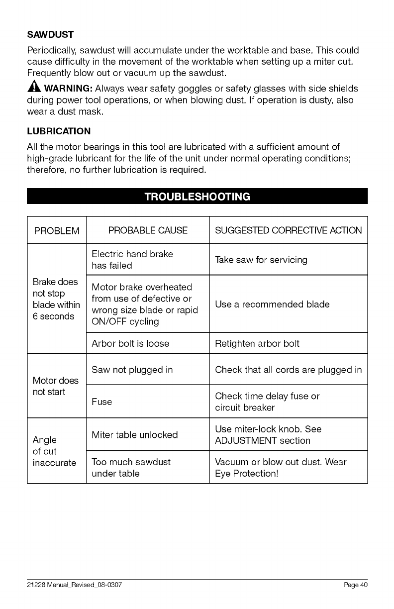
SAWDUST
Periodically, sawdust will accumulate under the worktable and base. This could
cause difficulty in the movement of the worktable when setting up a miter cut.
Frequently blow out or vacuum up the sawdust.
A_, WARNING: Always wear safety goggles or safety glasses with side shields
during power tool operations, or when blowing dust. If operation is dusty, also
wear a dust mask.
LUBRICATION
All the motor bearings in this tool are lubricated with a sufficient amount of
high-grade lubricant for the life of the unit under normal operating conditions;
therefore, no further lubrication is required.
PROBLEM PROBABLE CAUSE SUGGESTED CORRECTIVE ACTION
Electric hand brake Take saw for servicing
has failed
Brake does
not stop
blade within
6 seconds
Motor brake overheated
from use of defective or
wrong size blade or rapid
ON/OFF cycling
Use a recommended blade
Arbor bolt is loose Retighten arbor bolt
Saw not plugged in Check that all cords are plugged in
Motor does
not start Check time delay fuse or
Fuse circuit breaker
Use miter-lock knob. See
Miter table unlocked
Angle ADJUSTMENT section
of cut
inaccurate Too much sawdust Vacuum or blow out dust. Wear
under table Eye Protection!
21228 Manual Revised 08-0307 Page 40
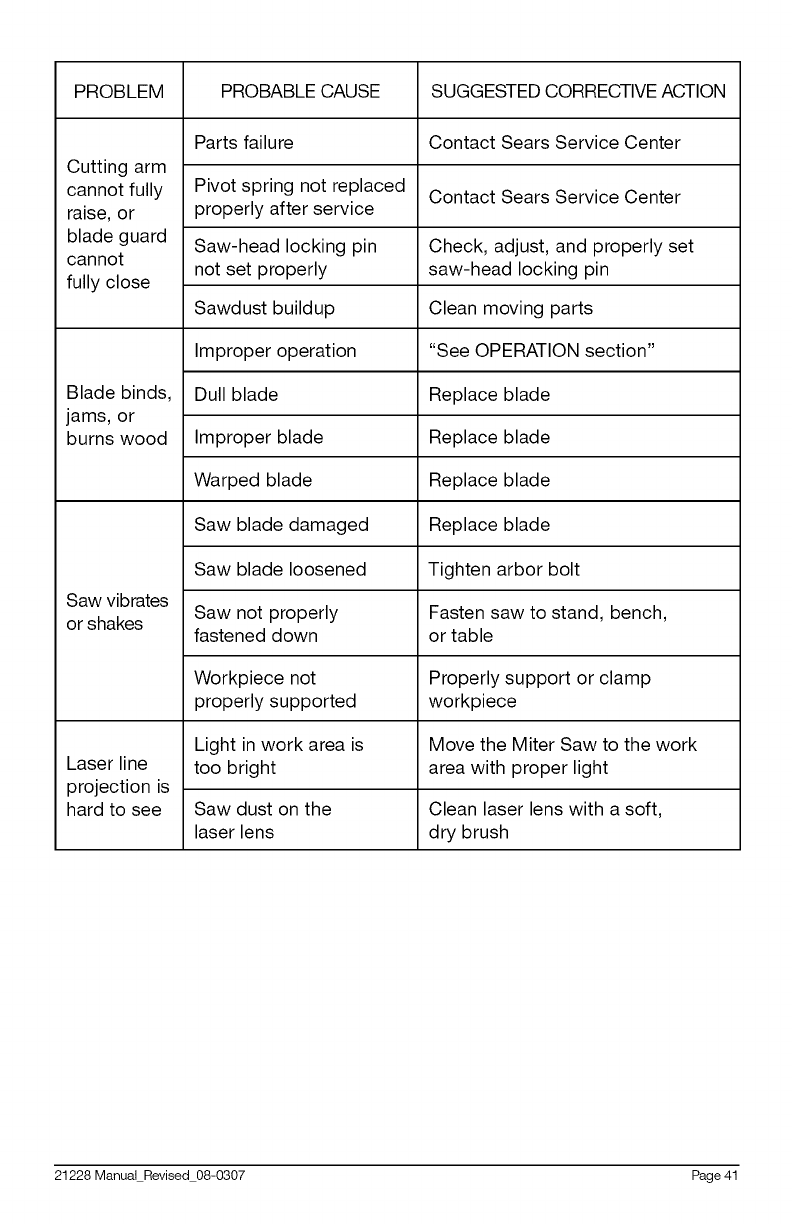
PROBLEM PROBABLE CAUSE SUGGESTED CORRECTIVE ACTION
Parts failure Contact Sears Service Center
Cutting arm
cannot fully Pivot spring not replaced Contact Sears Service Center
raise, or properly after service
blade guard Saw-head locking pin Check, adjust, and properly set
cannot not set properly saw-head locking pin
fully close
Sawdust buildup Clean moving parts
Improper operation "See OPERATION section"
Blade binds, Dull blade Replace blade
jams, or
burns wood Improper blade Replace blade
Warped blade Replace blade
Saw blade damaged Replace blade
Saw blade loosened Tighten arbor bolt
Saw vibrates Saw not properly Fasten saw to stand, bench,
or shakes fastened down or table
Workpiece not Properly support or clamp
properly supported workpiece
Light in work area is Move the Miter Saw to the work
Laser line too bright area with proper light
projection is
hard to see Saw dust on the Clean laser lens with a soft,
laser lens dry brush
21228Manual Revised 08-0307 Page41
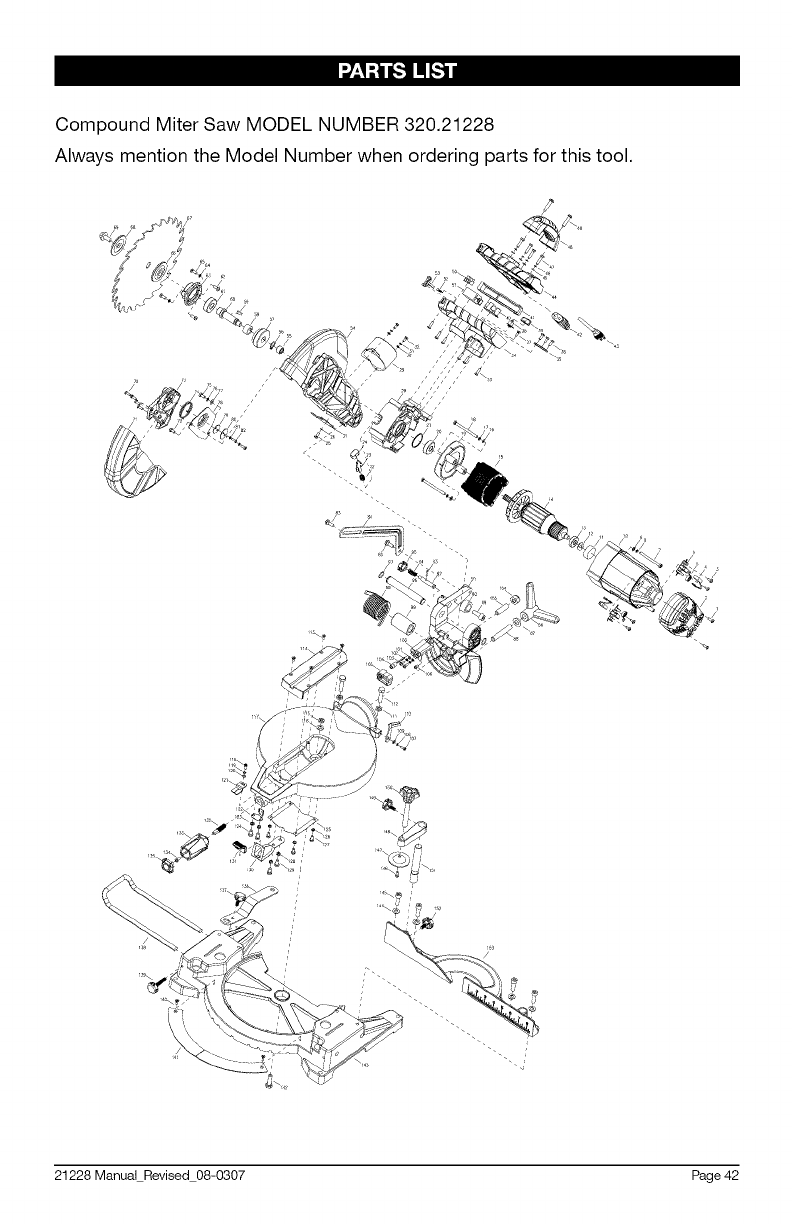
Compound Miter Saw MODEL NUMBER 320.21228
Always mention the Model Number when ordering parts for this tool.
21228 Manual Revised 08-0307 Page 42

",2'-_a [,.1I1E_1iii
No Name Quantity No Name Quantity
1 Screw 2 31 Spring washer 2
2 Motor cover 1 32 Screw 2
3 Screw 4 33 Screw 6
4 Brush 2 34 Lower handle 1
5 Brush spring 2 35 Cold clamp 1
6 Brush hold 2 36 Screw 3
7 Screw 4 37 Screw 1
8 Spring washer 4 38 Laser switch 1
9 Washer 4 39 Laser switch cap 1
10 Motor housing 1 40 Transformer 1
11 Rubber boot 1 41 Trigger 1
12 Wave wsher 1 42 Cord protector 1
13 Bearing 1 43 Cable plug 1
14 Armature 1 44 Upper handle 1
15 Stator 1 45 Washer 4
16 Washer 2 46 Spring washer 4
17 Spring washer 2 47 Screw 4
18 Screw 2 48 Carry handle 1
19 Fan baffle 1 49 Screw 2
20 Bearing 1 50 Binding post 1
21 O-ring 1 51 Switch 1
22 Gear lock pin spring 1 52 Spring 1
23 Gear lock pin 1 53 Switch lock button 1
24 Gear lock pin cap 1 54 Fixed guard 1
25 Screw 1 55 Needle bearing 1
26 Spring washer 1 56 C clip 1
27 Anti-fingertouch plate 1 57 Gear 1
28 Gear case 1 58 Gear washer 1
29 Exhaust port 1 59 Key 1
30 Washer 2 60 Arbor 1
21228 Manual Revised 08-0307 Page 43

No Name Quantity No Name Quantity
61 Bearing 1 91 Trunnion 1
62 Screw 2 92 Lock pin 1
63 Gear case cover 1 93 Rolled pin 1
64 Spring washer 2 94 Lock pin spring 1
65 Screw 2 95 Lock pin cap 1
66 Blade flange inner 1 96 Pivot shaft 1
67 Blade 1 97 Steel cable baffle ring 2
68 Blade flange outer 1 98 Torsion spring 1
69 Blade bolt 1 99 Spring bushing 1
70 Rivet 4 100 Laser carrier 1
71 Moving guard 1 101 Washer 2
72 Special screw 1 102 Spring washer 2
73 Cast center 1 103 Screw 2
74 Spring 1 104 Laser 1
75 Screw 1 105 Laser cover 1
76 Spring washer 1 106 Screw 1
77 Big washer 1 107 Screw 1
78 Moving guard plate 1 108 Spring washer 1
79 Plate guarding(small) 1 109 Washer 1
80 Plate guarding(big) 1 110 Lever pointer 1
81 Spring washer 2 111 Nut 2
82 Screw 2 112 Bolt 2
83 Shoulder Screw 1 113 Screw 4
84 Linkage 1 114 Cutting insert 1
85 Shoulder Screw 1 115 Locknut 1
86 Bevel lock handle 1 116 Big washer 1
87 Big washer 1 117 Turntable 1
88 Double stud 1 118 Screw 1
89 Socket head screw 1 119 Spring washer 1
90 Bushing 1 120 Washer 1
21228 Manual Revised 08-0307 Page 44

No Name Quantity No Name Quantity
121 Miter pointer 1 138 Support bar 1
122 Clamp plate 1 139 Knob 1
123 Spring washer 2 140 Sunk screw 2
124 Screw 2 141 Miter scale board 1
125 Safety plate 1 142 Bolt 1
126 Spring washer 4 143 Base 1
127 Screw 4 144 Washer 4
128 Spring washer 2 145 Allen key head screw 4
129 Screw 2 146 Screw 1
130 Detent 1 147 Clamp 1
131 Detent button 1 148 Support arm 1
132 Lock bolt 1 149 Knob 1
133 Lock handle 1 150 Workpiece knob 1
134 Screw 1 151 Support pole 1
135 Lock handle cap 1 152 Knob 1
136 Blade spanner 1 153 Fence 1
137 Knob 1
21228 Manual Revised 08-0307 Page 45
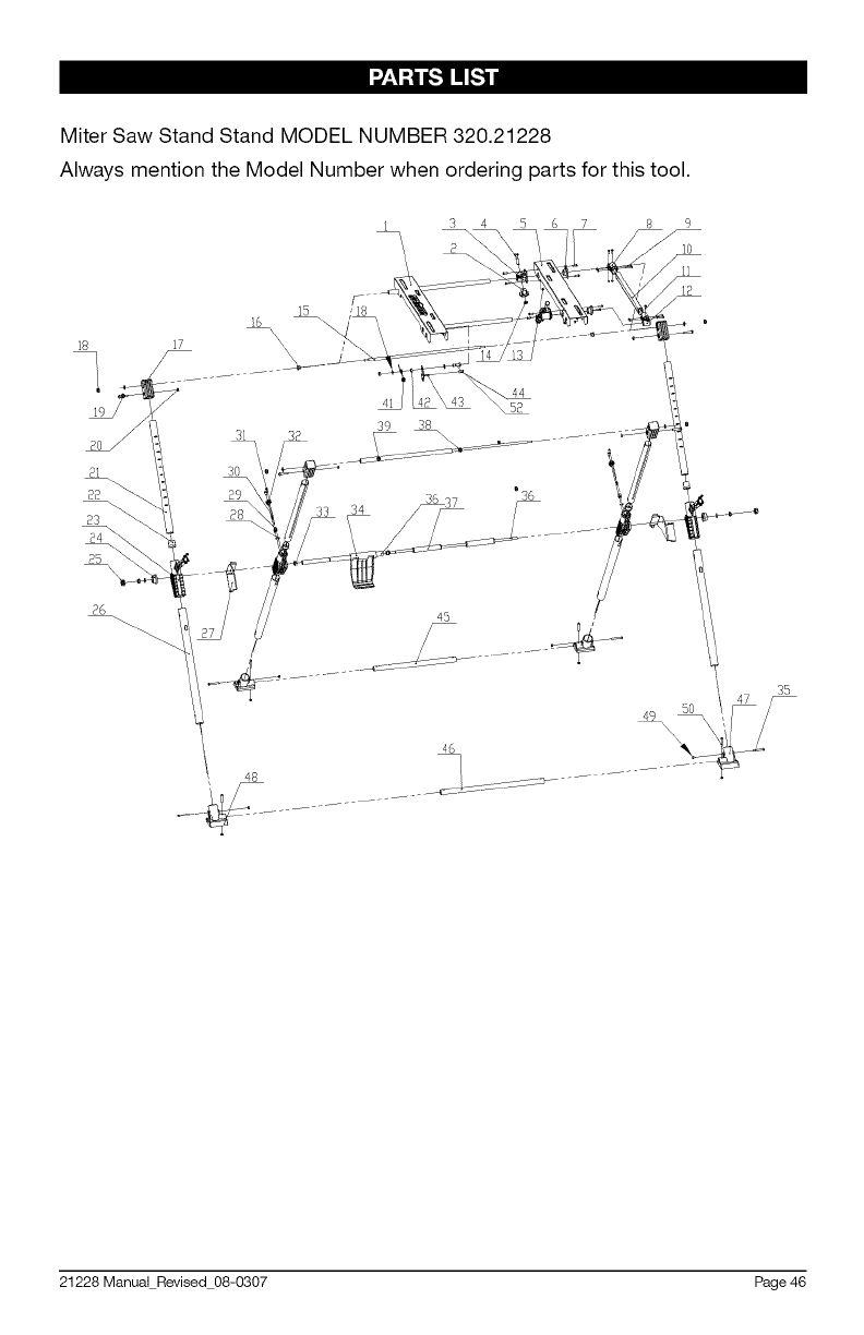
Miter Saw Stand Stand MODEL NUMBER 320.21228
Always mention the Model Number when ordering parts for this tool.
15
1 3 4 S 6 7 8 9
11
18
41
39 38
44
S?
45
35
46
21228 Manual Revised 08-0307 Page 46

",2'-_a [,.1I1E_1iii
No Quantity
1
2 2
3 2
4 2
5 1
6 2
7 10
8 1
9 4
10 1
11 1
12 1
13 14
14 9
Name
fixed worktable
assembly
knob
clamp ring
hexagon screw
moving table
slide ring
bolt M4x12
gemel 11
bolt M4x24
table pole
screw M4x12
gemel 1
nut M4
nut M8
upper outer pole
cover
upper gemel
hex bolt M8x20
screw M6x35
nut M6
inner pole
ring
gemel Bracket
nut ring
nut cover
Quantity
4
2
4
4
2
8
4
2
1
4
1
2
1
1
1
No
26
27
28
29
3O
31
32
33
34
35
36
37
38
39
4O
41
42
43
44
45
46
47
48
49
50
Name
outter pole
limit position board
plate
plate board
Washer
screw M4x12
spring cover
pole cover
lock device
screw M5x38
pole
limit position pole
upper inner pole
upper inner pipe
washing
spring A
suport ring
hook
handle cover
lower inner pole
lower outter pole
right foot
left foot
nut M5
screw M5x29
15 1 1
16 2 1
17 4 1
18 1 1
19 4 1
20 4 1
21 4 2
22 4 2
23 4 8
24 2 4
25 2
21228 Manual Revised 08-0307 Page 47

Your Home
For expert troubleshooting and home solutions advice:
°°wnww :
• ge y oe.co
For repair -in your home- of all major brand appliances,
lawn and garden equipment, or heating and cooling systems,
no matter who made it, no matter who sold it!
For the replacement parts accessories and
owner's manuals that you need to do-it-yourself.
For Sears professional installation of home appliances
and items like garage door openers and water heaters.
1-800-4-MY-HOME ® (1-8oo-469-4663)
Call anytime, day or night (U.S.A. and Canada)
www.sears.com www.sears.ca
'Sears
TM SM
® Registered Trademark /Trademark /Service Mark of Sears Brands, LLC
sM
® Marca Registrada /_ Marca de FAbrica /Marca de Servicio de Sears Brands, LLC
Mc Marque de commerce /_D Marque d_pos6e de Sears Brands, LLC ® Sears Brands, LLC
