Craftsman 32037610 User Manual ROUTER TABLE Manuals And Guides 1310223L
User Manual: Craftsman 32037610 32037610 CRAFTSMAN ROUTER TABLE - Manuals and Guides View the owners manual for your CRAFTSMAN ROUTER TABLE #32037610. Home:Tool Parts:Craftsman Parts:Craftsman ROUTER TABLE Manual
Open the PDF directly: View PDF ![]() .
.
Page Count: 35

Operator's Manual
®
PREMIUM DiE CAST ALUMINUM
ROUTER TABLE
Model No. 320.37610
_WARNING: To reduce the risk of injury,
the user must read and understand the
Operator's Manual before using this product.
COUS
LISTED
* WARRANTY
* SAFETY
* DESCRiPTiON
* UNPACKING
. ASSEMBLY
. OPERATION
. MAINTENANCE
Sears Brands Management Corporation, Hoffman Estates,
IL 60179 U.S.A.
www,ctaftsman,com

Warranty Page 2
Safety Symbols Pages 4-5
Safety Instructions Pages 6-9
Description Pages 10-11
Unpacking Pages 12-14
Assembly Pages 15-24
Operation Pages 25-29
Maintenance Page 30
Troubleshooting Page 30
Parts List Pages 31-33
CRAFTSMAN ONE YEAR LiMiTED WARRANTY
FOR ONE YEAR from the date of purchase, this product is warranted
against any defects in material or workmanship. With proof of purchase,
defective product will be replaced free of charge.
For warranty coverage details to obtain free replacement, visit the web
site: www.craftsrnan.com
This warranty is void if this product is ever used while providing commercial
services or if rented to another person.
This warranty gives you specific legal rights, and you may also have other
rights which vary from state to state.
Sears Brands Management Corporation, Hoffman Estates, IL 60179
This router table has many features for making its use more pleasant and
enjoyable. Safety, performance, and dependability have been given top priority
in the design of this product making it easy to maintain and operate.
SAVE THESE iNSTRUCTiONS!
READ ALL iNSTRUCTiONS!
Page 2 37610 Manual_Revised_12 1221

,_, DANGER: People with electronic devices, such as pacemakers, should
consult their physician(s) before using this product. Operation of electrical
equipment in close proximity to a heart pacemaker could cause interference or
failure of the pacemaker.
_,WARNING: Some dust created by power sanding, sawing, grinding, drilling
and other construction activities contains chemicals known to the State of
California to cause cancer, birth defects or other reproductive harm. Some
examples of these chemicals are:
• Lead from lead-based paints,
Crystalline silica from bricks and cement and other masonry products, and
Arsenic and chromium from chemically-treated lumber.
Your risk from these exposures varies, depending on how often you do this type
of work. To reduce your exposure to these chemical: work in a well ventilated
area, and work with approved safety equipment, such as dust masks that are
specially designed to filter out microscopic particles.
37610 Manual_Revised_12 1221 Page 3

The purpose of safety symbols is to attract your attention to possible dangers.
The safety symbols and the explanations with them deserve your careful
attention and understanding. The symbol warnings do not, by themselves,
eliminate any danger. The instructions and warnings they give are no substitutes
for proper accident prevention measures.
,_ WARNING: Be sure to read and understand all safety instructions in this
Operator's Manual, including all safety alert symbols such as "DANGER,"
"WARNING," and "CAUTION" before using this tool. Failure to following
all instructions listed below may result in electric shock, fire, and/or serious
personal injury.
SYMBOL MEANING
SAFETY ALERT SYMBOL: Indicates DANGER, WARNING, or CAUTION. May
be used in conjunction with other symbols or pictographs.
,_ DANGER: Indicates an imminently hazardous situation, which, if not
avoided, will result in death or serious injury.
,_ WARNING: Indicates a potentially hazardous situation, which, if not avoided,
could result in death or serious injury.
,_ CAUTION: Indicates a potentially hazardous situation, which, if not avoided,
could result in minor or moderate injury.
Damage Prevention and Information Messages
These inform the user of important information and/or instructions that could
lead to equipment or other property damage if they are not followed. Each
message is preceded by the word "NOTICE," as in the example below:
NOTICE: Equipment and/or property damage may result if these instructions are
not followed.
,_, WARNING: To ensure safety and reliability, all repairs should be performed
by a qualified service technician.
WARNING: The operation of any power tools can result in
foreign objects being thrown into your eyes, which can result
in severe eye damage. Before beginning power tool operation,
always wear safety goggles or safety glasses with side shields
and a full face shield when needed. We recommend a Wide
Vision Safety Mask for use over eyeglasses or standard safety
glasses with side shields. Always use eye protection which is
marked to comply with ANSI Z87.1.
Page 4 376t0 Manual_Revised_12 1221
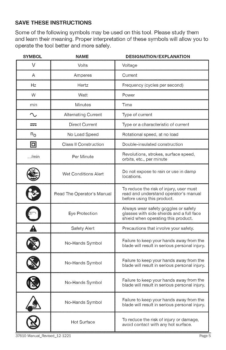
SAVE THESE iNSTRUCTiONS
Some of the following symbols may be used on this tool. Please study them
and learn their meaning. Proper interpretation of these symbols will allow you to
operate the tool better and more safely.
SYMBOL NAME DESIGNATION/EXPLANATION
V Volts Voltage
A Amperes Current
Hz Hertz Frequency (cycles per second)
W Watt Power
min Minutes Time
Alternating Current Type of current
Direct Current Type or a characteristic of current
n o No Load Speed Rotational speed, at no load
] Class II Construction Double=insulated construction
.../min Per Minute Revolutions, strokes, surface speed,
orbits, etc., per minute
Do not expose to rain or use in damp
Wet Conditions Alert locations.
To reduce the risk of injury, user must
Read The Operator's Manual read and understand operator's manual
before using this product.
O Always wear safety goggles or safety
Eye Protection glasses with side shields and a futl face
shield when operating this product.
Alert Precautions that involveSafety your safety.
No-Hands Symbol Failure to keep your hands away from theblade will result in serious personal injury.
No-Hands Failure to keep your hands away from the
Symbol blade will result in serious personal injury.
No-Hands Failure to keep your hands away from the
Symbol blade will result in serious personal injury.
No-Hands Symbol Failure to keep your hands away from the
blade will result in serious personal injury.
Hot Surface To reduce the risk of injury or damage,avoid contact with any hot surface.
37610 Manual_Revised_12 1221 Page 5
GROUNDING INSTRUCTIONS
In the event of a malfunction or breakdown, grounding provides apath
of least resistance for electric current to reduce the risk of electric
shock. This tool is equipped with an electric cord having an equipment-
grounding conductor and a grounding plug. The plug must be plugged into
a matching outlet that is properly installed and grounded in accordance with
all local codes and ordinances.
• Do not modify the plug provided =if it will not fit the outlet, have the
proper outlet installed by a qualified electrician.
• Improper connection of the equipment-grounding conductor can result
in a risk of electric shock. The conductor with insulation having an outer
surface that is green with or without yellow stripes is the equipment-grounding
conductor. If repair or replacement of the electric cord or plug is necessary, do
not connect the equipment-grounding conductor to a live terminal.
• Check with a qualified electrician or service personnel if the grounding
instructions are not completely understood, or if in doubt as to whether
the tool is properly grounded.
• Use only 3=wire extension cords that have 3-prong grounding plugs
and 3=pole receptacles that accept the tool's plug.
• Repair or replace damaged or worn cord immediately.
Page 6 37610 Manual_Revised_12 1221
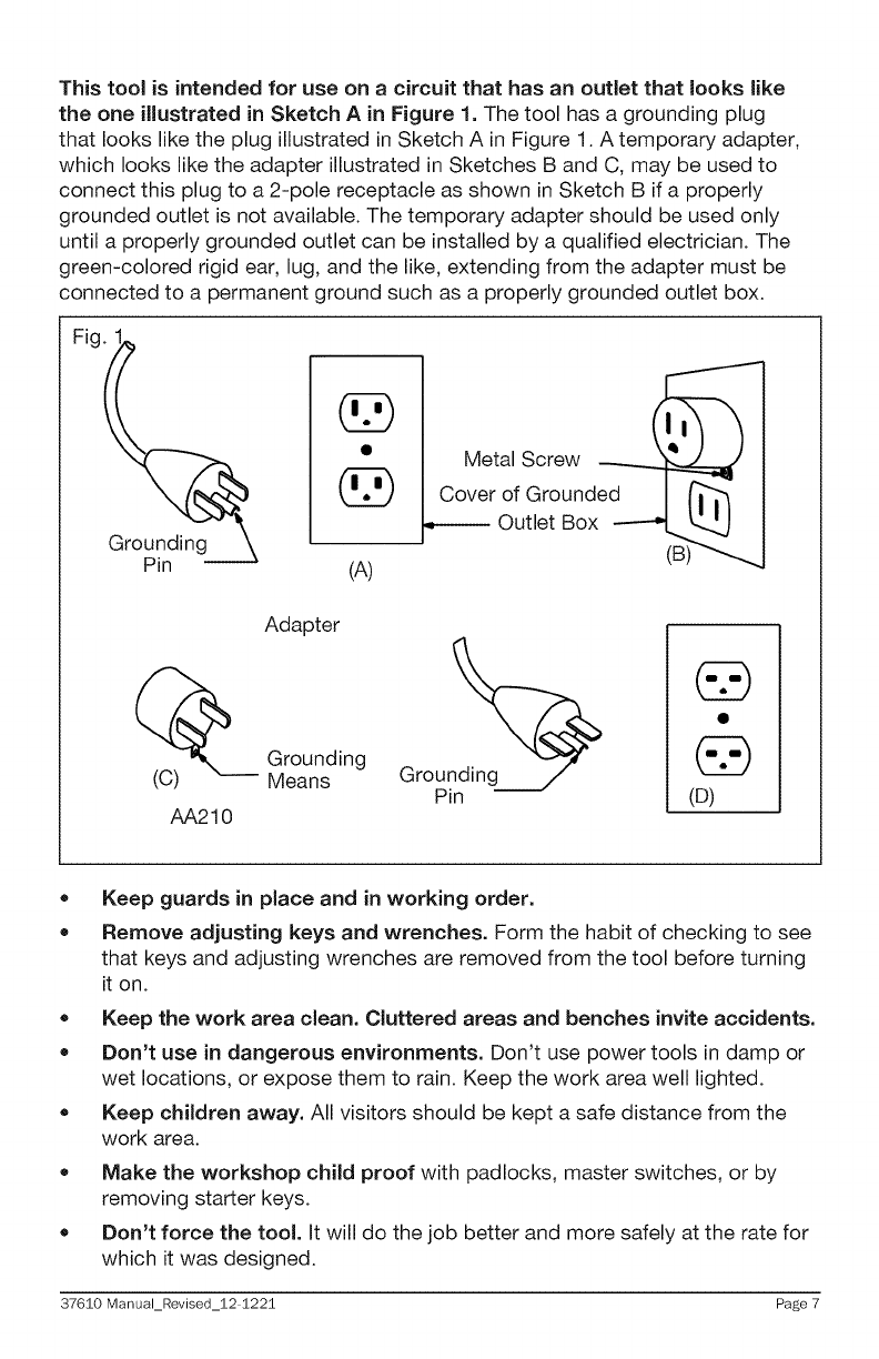
This tool is intended for use on a circuit that has an outlet that looks like
the one illustrated in Sketch A in Figure 1. The tool has a grounding plug
that looks like the plug illustrated in Sketch A in Figure 1. A temporary adapter,
which looks like the adapter illustrated in Sketches B and C, may be used to
connect this plug to a 2-pole receptacle as shown in Sketch B if a properly
grounded outlet is not available. The temporary adapter should be used only
until a properly grounded outlet can be installed by a qualified electrician. The
green-colored rigid ear, lug, and the like, extending from the adapter must be
connected to a permanent ground such as a properly grounded outlet box.
Groundin
Pin
O
(A)
Metal
Screw
Cover of Ground
•------ Outlet Box
(B)
(c)
AA210
Adapter
Grounding
Means (D)
®
®
Keep guards in place and in working order.
Remove adjusting keys and wrenches. Form the habit of checking to see
that keys and adjusting wrenches are removed from the tool before turning
it on.
• Keep the work area clean. Cluttered areas and benches invite accidents.
Don't use in dangerous environments. Don't use power tools in damp or
wet locations, or expose them to rain. Keep the work area well lighted.
= Keep children away. All visitors should be kept a safe distance from the
work area.
= Make the workshop child proof with padlocks, master switches, or by
removing starter keys.
= Don't force the tool. It will do the job better and more safely at the rate for
which it was designed.
37610 Manual_Revised_12 1221 Page 7
• Use the right tool. Don't force a tool or attachment to do a job for which it
was not designed.
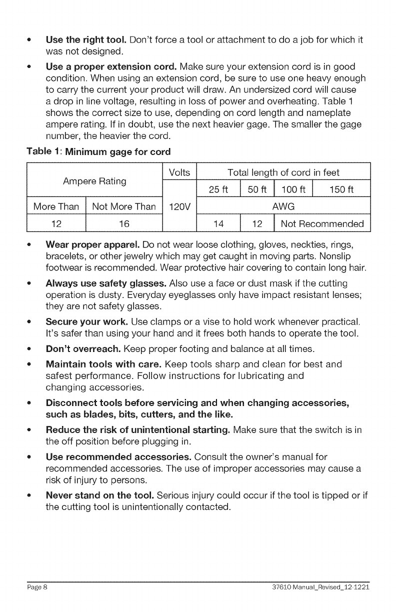
Use a proper extension cord. Make sure your extension cord is in good
condition. When using an extension cord, be sure to use one heavy enough
to carry the current your product will draw. An undersized cord will cause
a drop in line voltage, resulting in loss of power and overheating. Table 1
shows the correct size to use, depending on cord length and nameplate
ampere rating. If in doubt, use the next heavier gage. The smaller the gage
number, the heavier the cord.
Table 1: Minimum gage for cord
Ampere Rating
More Than Not More Than
12 16
Volts
120V
Total length of cord in feet
25ft 50ft ! 100ft 150ft
H
AWG
14 12 I Not Recommended
m
I
= Wear proper apparel. Do not wear loose clothing, gloves, neckties, rings,
bracelets, or other jewelry which may get caught in moving parts. Nonslip
footwear is recommended. Wear protective hair covering to contain long hair.
•Always use safety glasses. Also use a face or dust mask if the cutting
operation is dusty. Everyday eyeglasses only have impact resistant lenses;
they are not safety glasses.
= Secure your work. Use clamps or a vise to hold work whenever practical.
It's safer than using your hand and it frees both hands to operate the tool.
=Don't overreach. Keep proper footing and balance at all times.
• Maintain tools with care. Keep tools sharp and clean for best and
safest performance. Follow instructions for lubricating and
changing accessories.
=Disconnect tools before servicing and when changing accessories,
such as blades, bits, cutters, and the like.
= Reduce the risk of unintentional starting. Make sure that the switch is in
the off position before plugging in.
= Use recommended accessories. Consult the owner's manual for
recommended accessories. The use of improper accessories may cause a
risk of injury to persons.
= Never stand on the tool. Serious injury could occur if the tool is tipped or if
the cutting tool is unintentionally contacted.
Page 8 37610 Manual_Revised_12 1221
,, Check damaged parts. Before further use of the tool, a guard or other
part that is damaged should be carefully checked to determine that it will
operate properly and perform its intended function - check for alignment
of moving parts, binding of moving parts, breakage of parts, mounting, and
any other conditions that may affect its operation. A guard or other part that
is damaged should be properly repaired or replaced.
• Direction of feed: feed work into a blade or cutter only against the direction
of rotation of the blade or cutter.
Never leave a tool running unattended. Turn the power off. Don't leave
the tool until it comes to a complete stop.
SPECIFIC SAFETY RULES FOR ROUTER TABLES
For Your Own Safety Read Instruction Manual Before Operating Router Table
• Wear eye protection.
Feed the workpiece against the rotation of cutter.
Do not use awkward hand positions.
= Keep fingers away from the revolving cutter = use fixtures when necessary.
= Use overhead guard when the adjustable fence is not in place.
Do not expose the table to rain or use in damp location.
37610 Manual_Revised_12 1221 Page 9
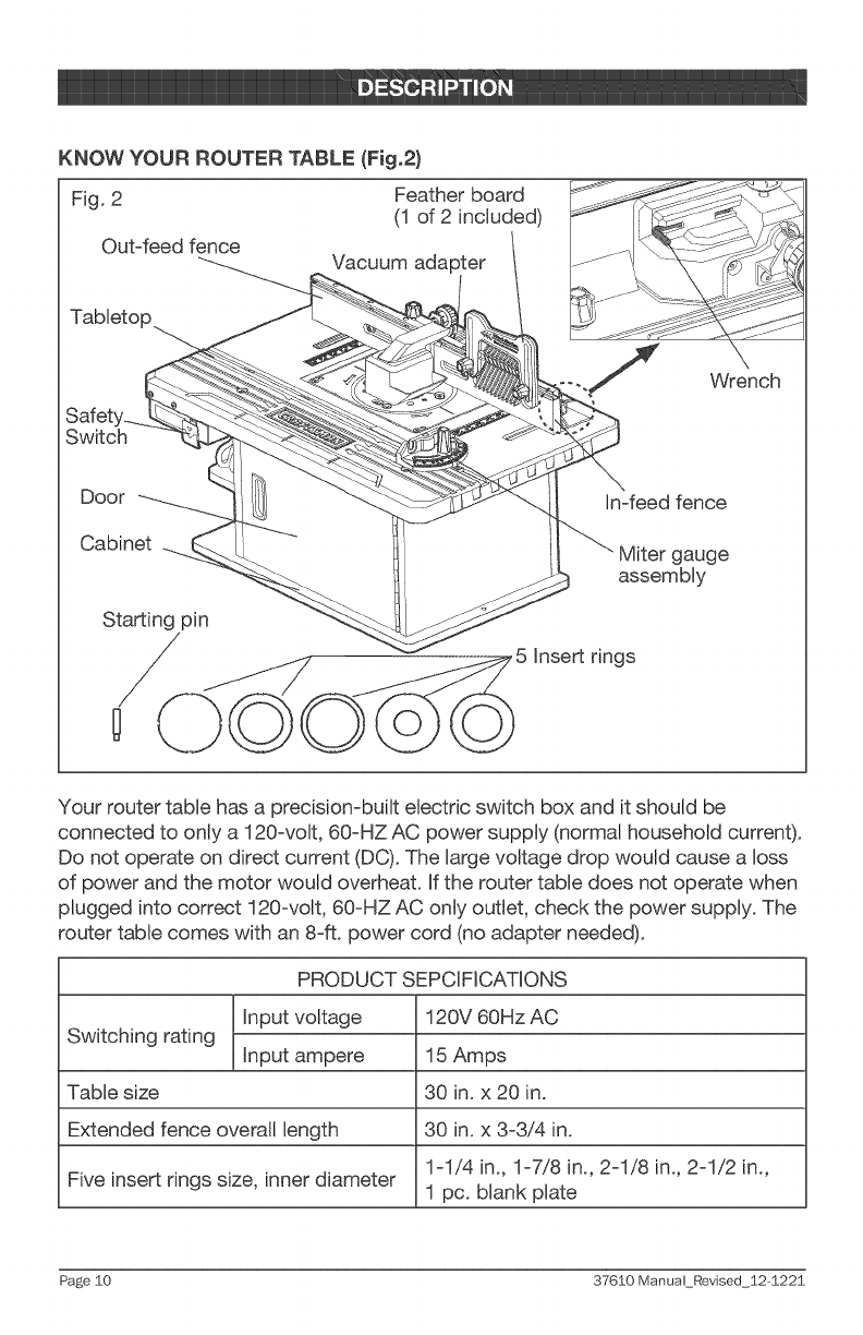
KNOW YOUR ROUTER "TABLE (Fig.2}
Fig. 2 Feather board
(1 d2 included)
Out-feed fence Vacuum adapter
Switch
Door In-feed fence
Cabinet gauge
assembly
Starting pin
/,5 Insert rings
Your router table has a precision-built electric switch box and it should be
connected to only a 120-volt, 60-HZ AC power supply (normal household current).
Do not operate on direct current (DC). The large voltage drop would cause a loss
of power and the motor would overheat. If the router table does not operate when
plugged into correct 120-volt, 60-HZ AC only outlet, check the power supply. The
router table comes with an 8-ft. power cord (no adapter needed).
PRODUCT SEPCIFICATIONS
Input voltage 120V 60Hz AC
Switching rating Input ampere 15 Amps
Table size 30 in. x 20 in.
Extended fence overall length 30 in. x 3-3/4 in.
1-1/4 in., 1-7/8 in., 2-1/8 in., 2-1/2 in.,
Five insert rings size, inner diameter 1 pc. blank plate
Page $0 37610 Manual Revised $2-1225
This Router Table has the following features:
1. Durable cast aluminum tabletop (30 in. x 20 in.) for a large, smooth and
durable work surface. The tabletop has a 3-1/8 in. router hole with 5 insert
rings (1-1/4 in., 1-7/8 in., 2-1/8 in., and 2-1/2 in.openings; 1 blank opening).
2. 2 feather board push blocks with mounting hardware that can be mounted
in slots on the fence and table.
3. Integrated safety switch with two outlets. To ensure safety and reliability,
the total current drawn on the two units must be less than 15 Amps.
4. Fence provides maximum workpiece support; the fence can be moved 2 in.
forward and 2-3/4 in. backward.
5. In-feed and out-feed fences can each be extended 2 inches.
6. Out-feed fence can be adjusted as much as 1/2 in. forward of the in-feed
fence for joining operations.
7. Vacuum adapter fits a 2-1/4 in. shop vacuum hose (available separately).
8. Miter gauge adjusts from 0 ° to 60 ° in both directions for increased stability
in many difficult feed situations.
9. Dust collection/Guard reduces dust dispersal.
10. Above-the-table height adjustment: This bit height on the installed
router can be adjusted by turning the adjustment knob clockwise or
counterclockwise with a hex wrench (not included). This feature functions
only when using the Craftsman Router Table with the following Craftsman
router models: 17541,2767, 27666, 2768, 27683, 27669, 27680, 17542,
28190, and 28084.
11. This router table is suitable for mounting the following Craftsman router
models: 17541,2767, 27666, 2768, 27683, 27669, 27680, 17542, 28190,
28084, 17540, and 17543.
37610 Manual_Revised_12 1221 Page 11
,_ WARNING: If any parts are broken or missing, do not attempt to attach the
router table to a power source or operate the router table until the broken or
missing parts are replaced. Failure to do so could result in serious injury.
,_, WARNING: Do not attempt to modify this tool or create accessories not
recommended for use with this router table. Any such alteration or modification
is misuse and could result in a hazardous condition leading to serious injury.
,_, WARNING: To prevent accidental starting that could cause serious personal
injury, always unplug the tool from the power source when assembling parts.
UNPACKING
* Carefully remove the router table and any accessories from the carton.
Make sure that all items listed in the packing list are included.
* Inspect the router table carefully to make sure that no breakage or damage
occurred during shipping.
* Do not discard the packing material until you have carefully inspected and
satisfactorily operated the router table.
* If any parts are damaged or missing, please return the product to the place
of purchase.
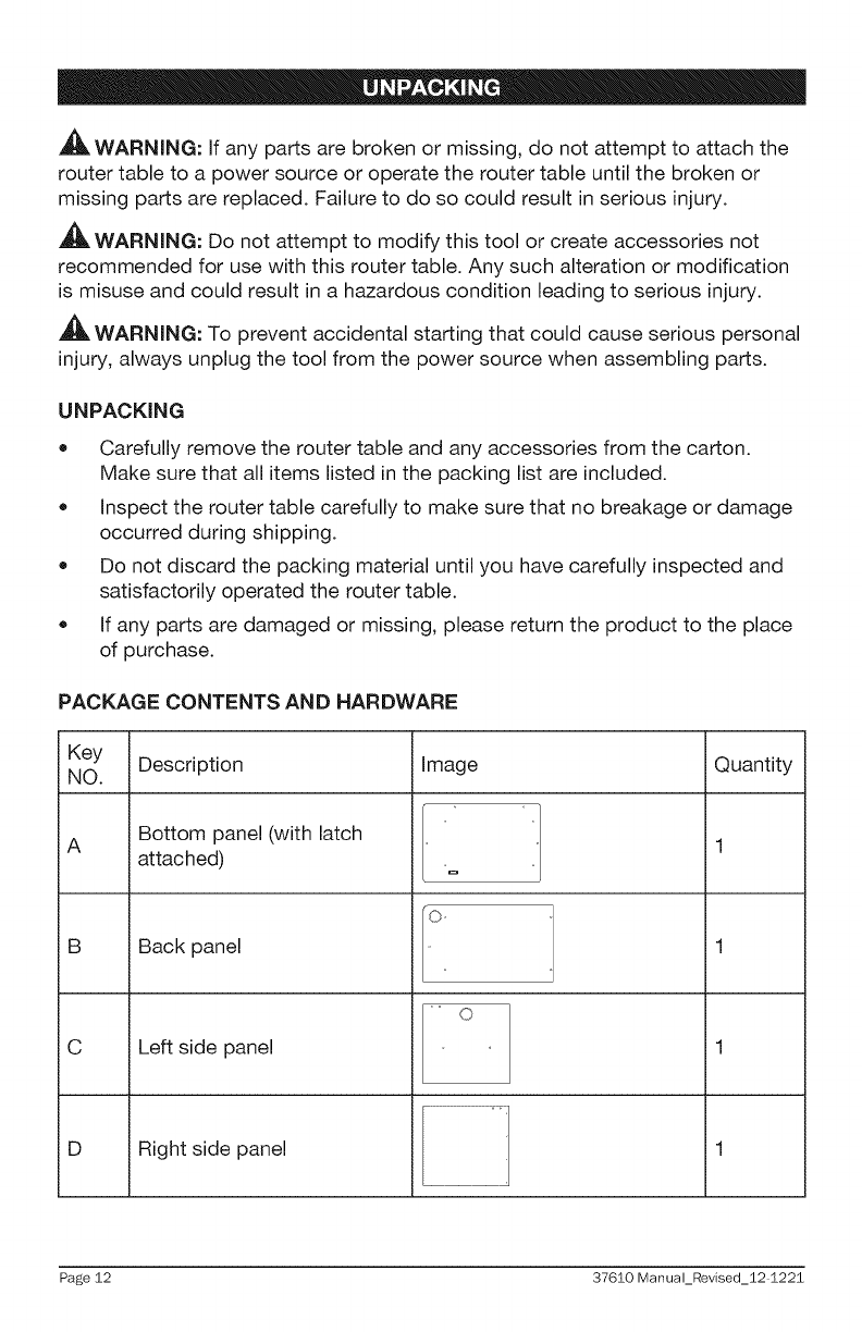
PACKAGE CONTENTS AND HARDWARE
Key Description Image Quantity
NO.
Bottom panel (with latch
Aattached)
B Back panel
C Left side panel
D Right side panel
O _
o
Page 12 37610 Manual_Revised_12 1221
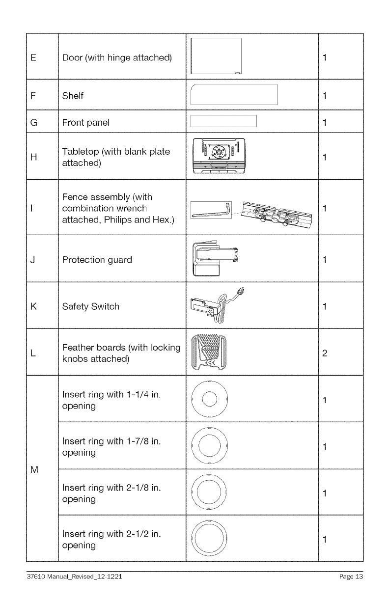
F
G
H
Door (with hinge attached)
Shelf
Front panel
Tabletop (with blank plate
attached)
Fence assembly (with
combination wrench
attached, Philips and Hex.)
Protection guard
K Safety Switch
Feather boards (with locking
knobs attached)
Insert ring with 1-1/4 in.
opening
Insert ring with 1-7/8 in.
opening
1
1
2
M
Insert ring with 2-1/8 in. 1
opening
Insert ring with 2-1/2 in. 1
opening
37610 Manual_Revised_12 1221 Page 13
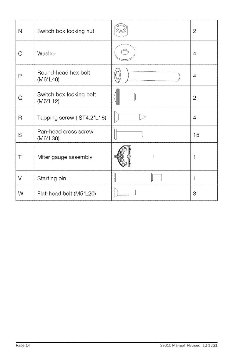
NSwitch box locking nut
0 Washer
Round-head hex bolt
(M6*L40)
Tapping screw (ST4.2*L16)
Pan-head cross screw
(M6*L30)
2
4
P :) 4
Switch box locking bolt
Q (M6*L12) 2
R 4
S 15
i
Miter gauge assembly
V Starting pin
W Flat-head bolt (M5*L20)
1
3
Page 14 37610 Manual_Revised_12 1221
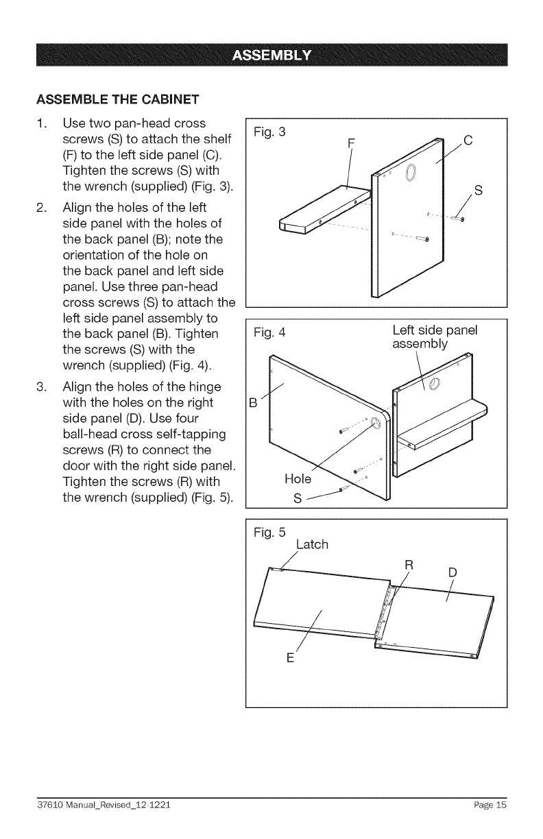
ASSEMBLE THE CABINET
1. Use two pan-head cross
screws (S) to attach the shelf
(F) to the left side panel (C).
Tighten the screws (S) with
the wrench (supplied) (Fig. 3).
2. Align the holes of the left
side panel with the holes of
the back panel (B); note the
orientation of the hole on
the back panel and left side
panel. Use three pan-head
cross screws (S) to attach the
left side panel assembly to
the back panel (B). Tighten
the screws (S) with the
wrench (supplied) (Fig. 4).
3. Align the holes of the hinge
with the holes on the right
side panel (D). Use four
ball-head cross self-tapping
screws (R) to connect the
door with the right side panel.
Tighten the screws (R) with
the wrench (supplied) (Fig. 5).
Fig. 3 F
Fig. 4 Left side panel
assembly
B
Hole
S
Fig. 5 Latch
/
37610 Manual_Revised_12 1221 Page 15
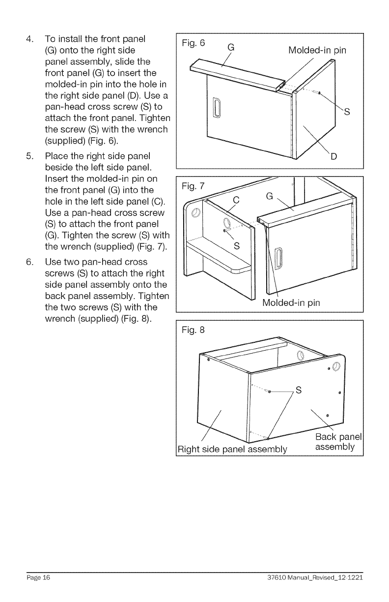
4. To install the front panel
(G) onto the right side
panel assembly, slide the
front panel (G) to insert the
molded-in pin into the hole in
the right side panel (D). Use a
pan-head cross screw (S) to
attach the front panel. Tighten
the screw (S) with the wrench
(supplied) (Fig. 6).
5. Place the right side panel
beside the left side panel.
Insert the molded-in pin on
the front panel (G) into the
hole in the left side panel (C).
Use a pan-head cross screw
(S) to attach the front panel
(G). Tighten the screw (S) with
the wrench (supplied) (Fig. 7).
6. Use two pan-head cross
screws (S) to attach the right
side panel assembly onto the
back panel assembly. Tighten
the two screws (S) with the
wrench (supplied) (Fig. 8).
Fig. 6 G Molded-in pin
Fig. 7
Fig. 8
Molded-in pin
Right side panel assembly
Back panel
assembly
Page 16 37610 Manual_Revised_12 1221
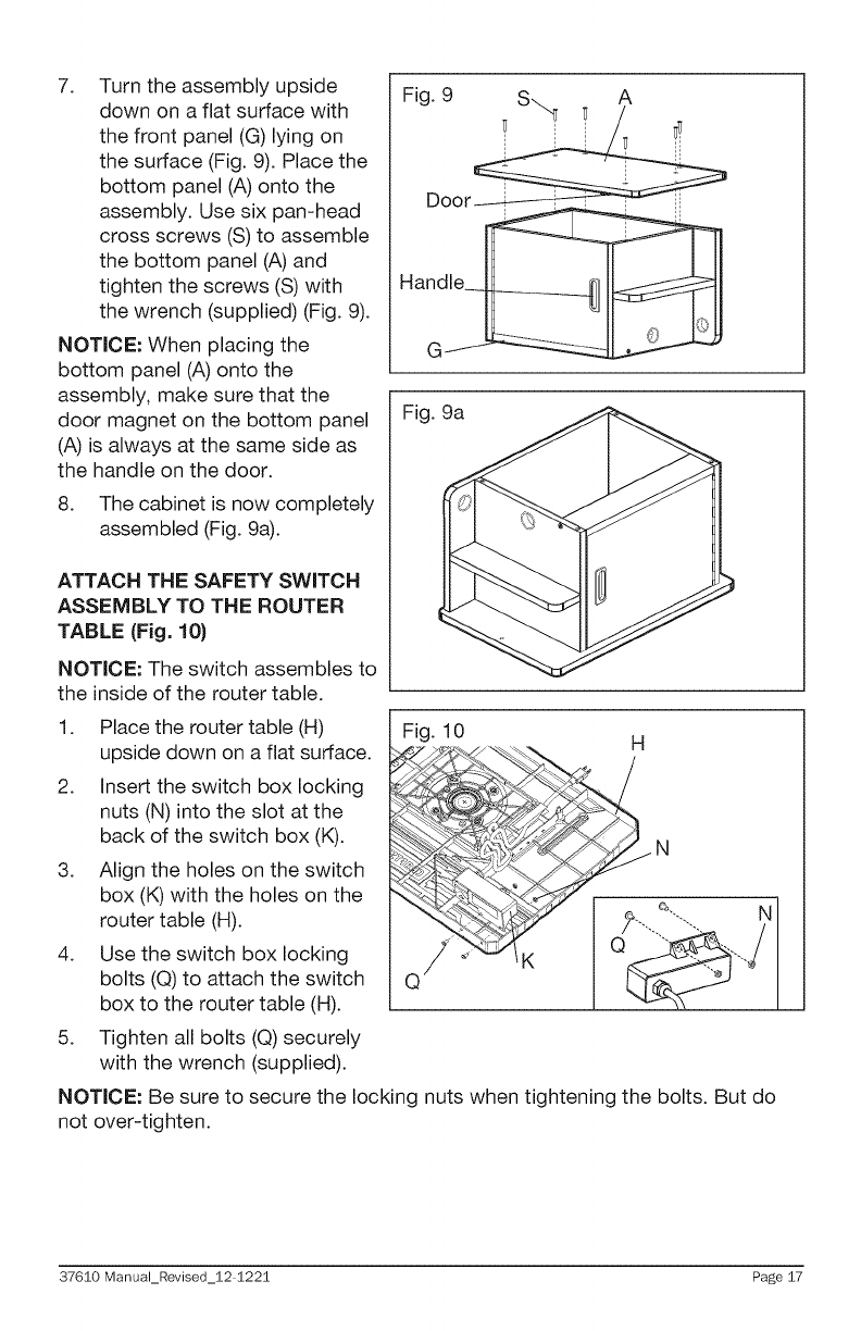
7. Turn the assembly upside
down on a flat surface with
the front panel (G) lying on
the surface (Fig. 9). Place the
bottom panel (A) onto the
assembly. Use six pan-head
cross screws (S) to assemble
the bottom panel (A) and
tighten the screws (S) with
the wrench (supplied) (Fig. 9).
NOTICE: When placing the
bottom panel (A) onto the
assembly, make sure that the
door magnet on the bottom panel
(A) is always at the same side as
the handle on the door.
8. The cabinet is now completely
assembled (Fig. 9a).
ATTACH THE SAFETY SWITCH
ASSEMBLY TO THE ROUTER
TABLE (Fig. 10)
NOTICE: The switch assembles to
the inside of the router table.
Fig. 9a
1. Place the router table (H) Fig. 10
upside down on a flat surface. H
2. Insert the switch box locking
nuts (N) into the slot at the
back of the switch box (K).
3. Align the holes on the switch
box (K) with the holes on the
router table (H).
4. Use the switch box locking
bolts (Q) to attach the switch
box to the router table (H).
5. Tighten all bolts (Q) securely
with the wrench (supplied).
NOTICE: Be sure to secure the locking nuts when tightening the bolts. But do
not over-tighten.
37610 Manual_Revised_12 1221 Page 17
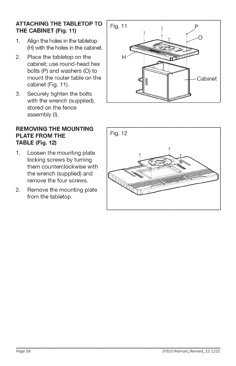
ATTACHING THE TABLETOP TO
THE CABINET (Fig. 11)
1. Align the holes in the tabletop
(H) with the holes in the cabinet.
2. Place the tabletop on the
cabinet; use round-head hex
bolts (P) and washers (O) to
mount the router table on the
cabinet (Fig. 11).
3. Securely tighten the bolts
with the wrench (supplied),
stored on the fence
assembly (I).
REMOVING THE MOUNTING
PLATE FROM THE
TABLE (Fig. 12}
1. Loosen the mounting plate
locking screws by turning
them counterclockwise with
the wrench (supplied) and
remove the four screws.
2. Remove the mounting plate
from the tabletop.
Fig. 11
Cabinet
Fig. 12
Page 18 37610 Manual_Revised_12 1221
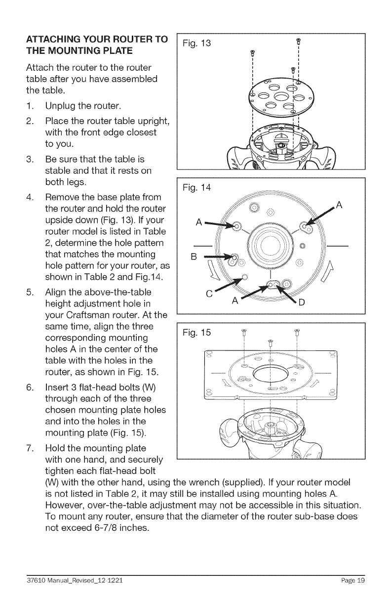
ATTACHING YOUR ROUTER TO
THE MOUNTING PLATE
Attach the router to the router
table after you have assembled
the table.
1. Unplug the router.
2. Place the router table upright,
with the front edge closest
to you.
3. Be sure that the table is
stable and that it rests on
both legs.
4. Remove the base plate from
the router and hold the router
upside down (Fig. 13). If your
router model is listed in Table
2, determine the hole pattern
that matches the mounting
hole pattern for your router, as
shown in Table 2 and Fig.14.
5. Align the above-the-table
height adjustment hole in
your Craftsman router. At the
same time, align the three
corresponding mounting
holes A in the center of the
table with the holes in the
router, as shown in Fig. 15.
6. Insert 3 flat-head bolts (W)
through each of the three
chosen mounting plate holes
and into the holes in the
mounting plate (Fig. 15).
7. Hold the mounting plate
with one hand, and securely
tighten each flat-head bolt
Fig. 13 I'
Fig. 14
CD
Fig. 15
(W) with the other hand, using the wrench (supplied). If your router model
is not listed in Table 2, it may still be installed using mounting holes A.
However, over-the-table adjustment may not be accessible in this situation.
To mount any router, ensure that the diameter of the router sub-base does
not exceed 6-7/8 inches.
37610 Manual_Revised_12 1221 Page 19
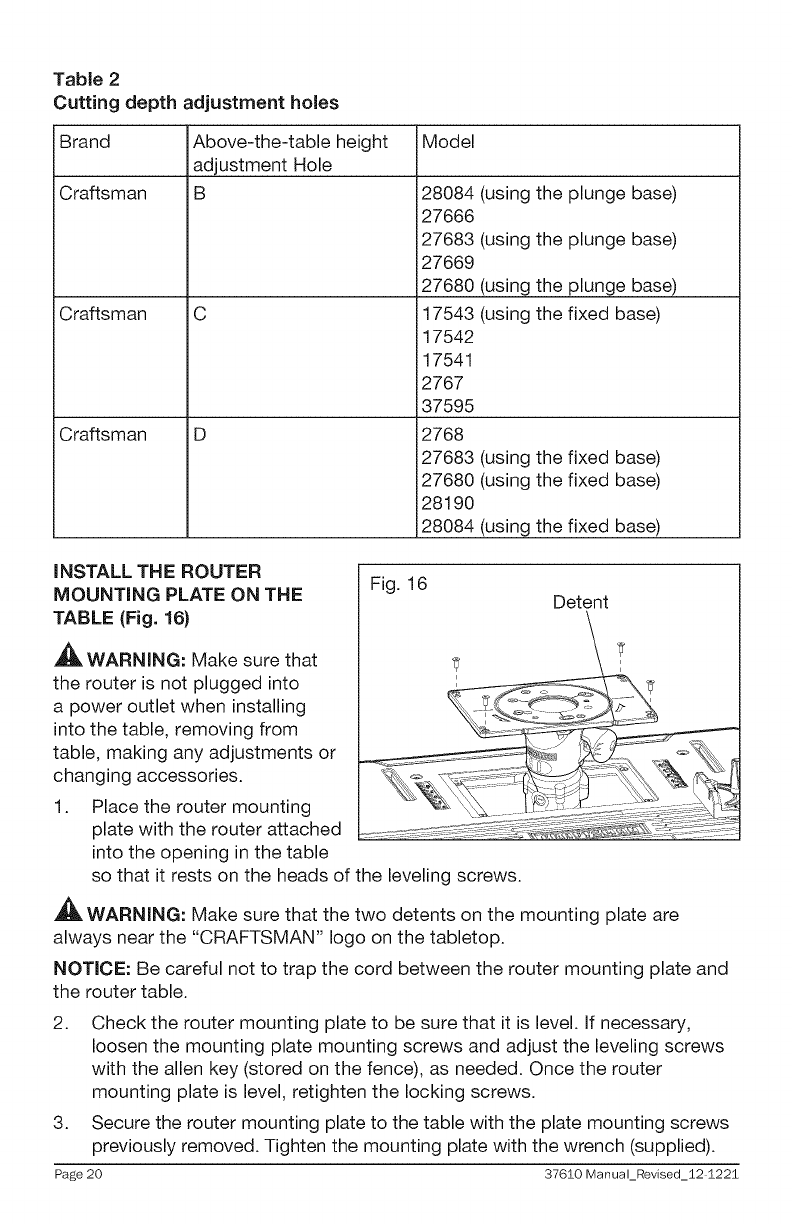
Table 2
Cutting depth adjustment holes
Brand
iCraftsman
Craftsman
Craftsman
Above-the-table height Model
adjustment Hole
B 28084
27666
27683
27669
27680
C 17543
17542
17541
2767
37595
D 2768
27683
27680
28190
28084
(using the plunge base)
(using the plunge base)
(using the plunge base)
(using the fixed base)
(using the fixed base)
(using the fixed base)
(using the fixed base)
iNSTALL THE ROUTER
MOUNTING PLATE ON THE Fig. 16 Detent
TABLE (Fig. 16)
,_ WARNING: Make sure that _
the router is not plugged into _
a power outlet when installing
into the table, removing from
table, making any adjustments or
changing accessories.
1. Place the router mounting
plate with the router attached
into the opening in the table
so that it rests on the heads of the leveling screws.
,_ WARNING: Make sure that the two detents on the mounting plate are
always near the "CRAFTSMAN" logo on the tabletop.
NOTICE: Be careful not to trap the cord between the router mounting plate and
the router table.
2.
3.
Page 20
Check the router mounting plate to be sure that it is level, if necessary,
loosen the mounting plate mounting screws and adjust the leveling screws
with the allen key (stored on the fence), as needed. Once the router
mounting plate is level, retighten the locking screws.
Secure the router mounting plate to the table with the plate mounting screws
previously removed. Tighten the mounting plate with the wrench (supplied).
37610 Manual_Revised_12 1221
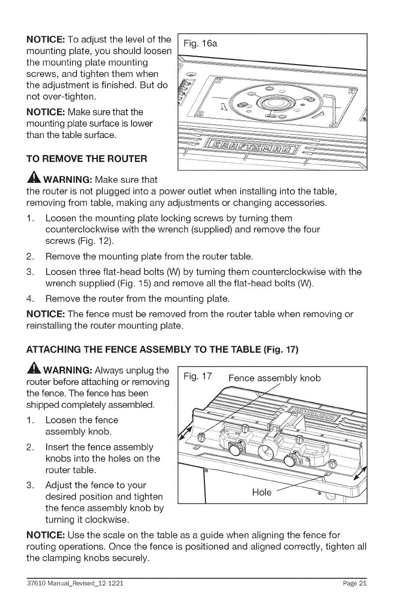
NOTICE: To adjust the level of the Fig. 16a
mounting plate, you should loosen
the mounting plate mounting
screws, and tighten them when
the adjustment is finished. But do
not over-tighten.
NOTICE: Make sure that the
mounting plate surface is lower
than the table surface.
TO REMOVE THE ROUTER
,_ WARNING: Make sure that
the router is not plugged into a power outlet when installing into the table,
removing from table, making any adjustments or changing accessories.
1. Loosen the mounting plate locking screws by turning them
counterclockwise with the wrench (supplied) and remove the four
screws (Fig. 12).
2. Remove the mounting plate from the router table.
3. Loosen three flat-head bolts (W) by turning them counterclockwise with the
wrench supplied (Fig. 15) and remove all the flat-head bolts (W).
4. Remove the router from the mounting plate.
NOTICE: The fence must be removed from the router table when removing or
reinstalling the router mounting plate.
ATTACHING THE FENCE ASSEMBLY TO THE TABLE (Fig. 17}
,_ WARNING: Always unplug the
router before attaching or removing
the fence. The fence has been
shipped completely assembled.
1. Loosen the fence
assembly knob.
2. insert the fence assembly
knobs into the holes on the
router table.
Fig. 17 Fence assembly knob
3. Adjust the fence to your
desired position and tighten Hole
the fence assembly knob by
turning it clockwise.
NOTICE: Use the scale on the table as a guide when aligning the fence for
routing operations. Once the fence is positioned and aligned correctly, tighten all
the clamping knobs securely.
37610 Manual_Revised_12 1221 Page 21
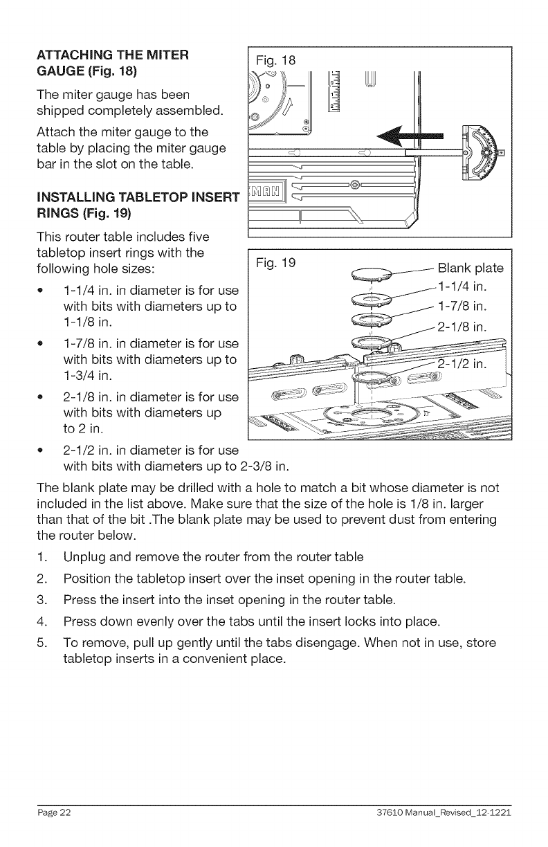
ATTACHING THE MITER
GAUGE (Fig. 18) Fig. 18
The miter gauge has been
shipped completely assembled.
Attach the miter gauge to the
table by placing the miter gauge
bar in the slot on the table.
iNSTALLiNG TABLETOP iNSERT
RINGS (Fig. 19}
®
_D
This router table includes five
tabletop insert rings with the
following hole sizes:
• 1-1/4 in. in diameter is for use
with bits with diameters up to
1-1/8 in.
1-7/8 in. in diameter is for use
with bits with diameters up to
1-3/4 in.
2-1/8 in. in diameter is for use
with bits with diameters up
to 2 in.
Fig. 19 Blank plate
2-1/2 in. in diameter is for use
with bits with diameters up to 2-3/8 in.
The blank plate may be drilled with a hole to match a bit whose diameter is not
included in the list above. Make sure that the size of the hole is 1/8 in. larger
than that of the bit .The blank plate may be used to prevent dust from entering
the router below.
1. Unplug and remove the router from the router table
2. Position the tabletop insert over the inset opening in the router table.
3. Press the insert into the inset opening in the router table.
4. Press down evenly over the tabs until the insert locks into place.
5. To remove, pull up gently until the tabs disengage. When not in use, store
tabletop inserts in a convenient place.
Page 22 37610 Manual_Revised_12 1221
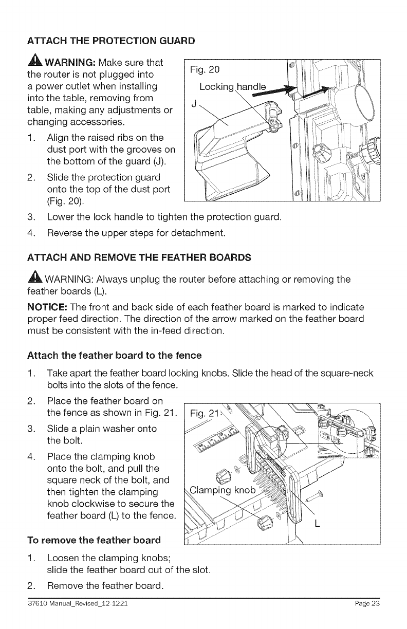
ATTACH THE PROTECTION GUARD
,_ WARNING: Make sure that
the router is not plugged into
a power outlet when installing
into the table, removing from
table, making any adjustments or
changing accessories.
1. Align the raised ribs on the
dust port with the grooves on
the bottom of the guard (J).
2. Slide the protection guard
onto the top of the dust port
(Fig. 20).
Fig. 20
Locking
3. Lower the lock handle to tighten the protection guard.
4. Reverse the upper steps for detachment.
ATTACH AND REMOVE THE FEATHER BOARDS
A
,J_ WARNING: Always unplug the router before attaching or removing the
feather boards (L).
NOTICE: The front and back side of each feather board is marked to indicate
proper feed direction. The direction of the arrow marked on the feather board
must be consistent with the in-feed direction.
Attach the feather beard to the fence
1.
2.
3.
4.
Take apart the feather board locking knobs. Slide the head of the square-neck
bolts into the slots of the fence.
Place the feather board on
the fence as shown in Fig. 21.
Slide a plain washer onto
the bolt.
Place the clamping knob
onto the bolt, and pull the
square neck of the bolt, and
then tighten the clamping
knob clockwise to secure the
feather board (L) to the fence.
To remove the feather board
1. Loosen the clamping knobs;
slide the feather board out of the slot.
2. Remove the feather board.
37610 Manual_Revised_12 1221 Page 23
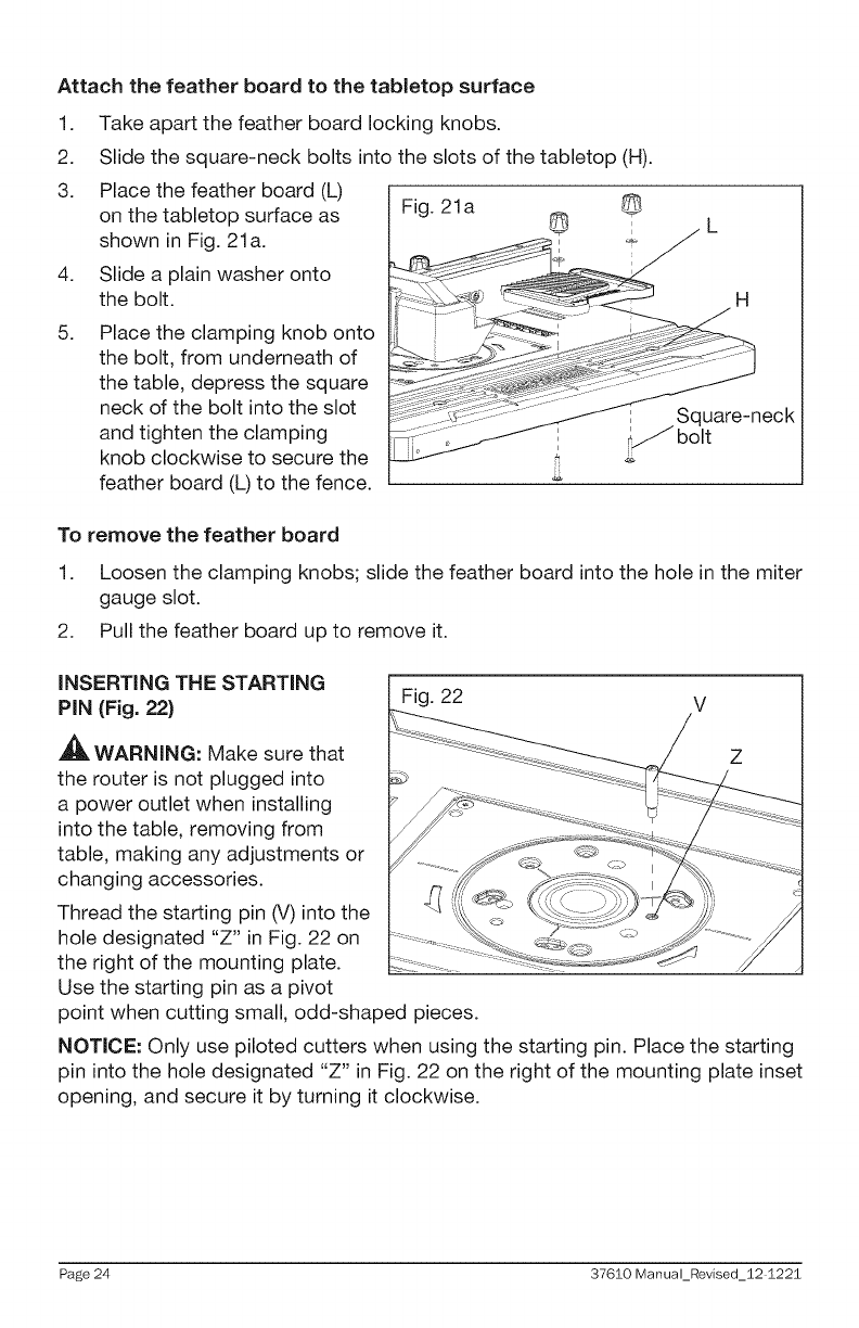
Attach the feather board to the tabletop surface
1.
2.
3.
4.
5.
Take apart the feather board locking knobs.
Slide the square-neck bolts into the slots of the tabletop (H).
Place the feather board (L)
on the tabletop surface as Fig. 21a i
shown in Fig. 21a.
Slide a plain washer onto
the bolt.
Place the clamping knob onto
the bolt, from underneath of
the table, depress the square
neck of the bolt into the slot
and tighten the clamping
knob clockwise to secure the
feather board (L) to the fence.
H
I Square-neck
_/bolt
To remove the feather board
1. Loosen the clamping knobs; slide the feather board into the hole in the miter
gauge slot.
2. Pull the feather board up to remove it.
iNSERTiNG THE STARTING i Fig. 22 i
PiN (Fig. 22) V
,_ WARNING: Make sure that Z
the router is not plugged into
a power outlet when installing
into the table, removing from
table, making any adjustments or
changing accessories.
Thread the starting pin (V) into the
hole designated "Z" in Fig. 22 on
the right of the mounting plate.
Use the starting pin as a pivot
point when cutting small, odd-shaped pieces.
NOTICE: Only use piloted cutters when using the starting pin. Place the starting
pin into the hole designated "Z" in Fig. 22 on the right of the mounting plate inset
opening, and secure it by turning it clockwise.
Page 24 37610 Manual_Revised_12 1221
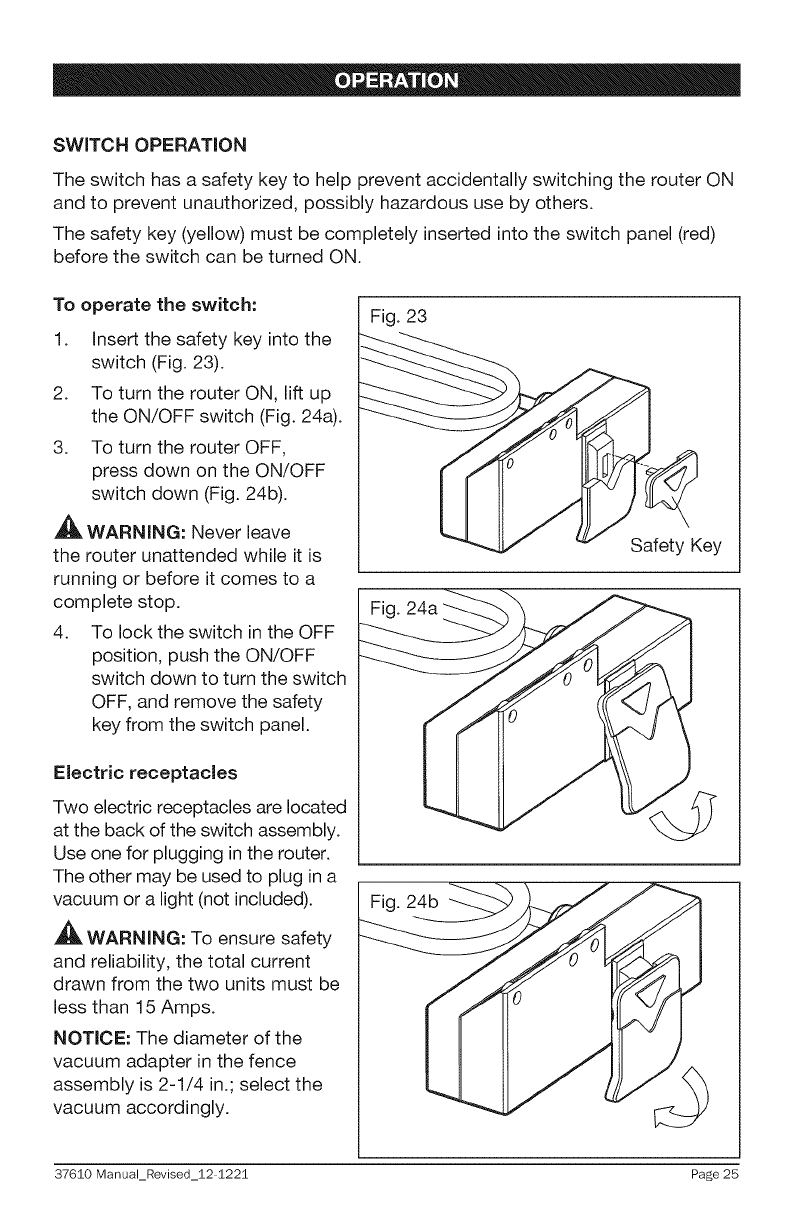
SWITCH OPERATION
The switch has a safety key to help prevent accidentally switching the router ON
and to prevent unauthorized, possibly hazardous use by others.
The safety key (yellow) must be completely inserted into the switch panel (red)
before the switch can be turned ON.
To operate the switch:
1. Insert the safety key into the
switch (Fig. 23).
2. To turn the router ON, lift up
the ON/OFF switch (Fig. 24a).
3. To turn the router OFF,
press down on the ON/OFF
switch down (Fig. 24b).
,_ WARNING: Never leave
the router unattended while it is
running or before it comes to a
complete stop.
4. To lock the switch in the OFF
position, push the ON/OFF
switch down to turn the switch
OFF, and remove the safety
key from the switch panel.
Fig. 23
Fig. 24a
Safety Key
Electric receptacles
Two electric receptacles are located
at the back of the switch assembly.
Use one for plugging in the router.
The other may be used to plug in a
vacuum or a light (not included).
_, WARNING: To ensure safety
and reliability, the total current
drawn from the two units must be
less than 15 Amps.
NOTICE: The diameter of the
vacuum adapter in the fence
assembly is 2-1/4 in.; select the
vacuum accordingly.
Fig. 24b
37610 Manual_Revised_12 1221 Page 25
FiNE ADJUSTING THE FENCE
AWARNING: Failure to unplug your router before performing adjustments to
the router or table could result in accidental starting causing serious injury.
,_ WARNING: Before checking the settings or making any adjustments, ensure
that the power to the router table and router is disconnected and that there is no
router bit in the router.
The fence enables you to support and guide the workpiece.
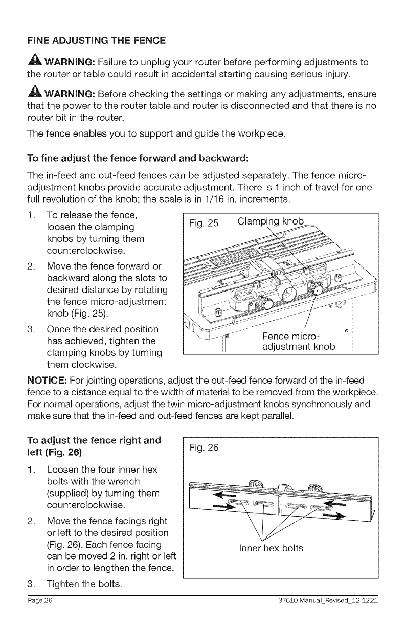
To fine adjust the fence forward and backward:
The in-feed and out-feed fences can be adjusted separately. The fence micro-
adjustment knobs provide accurate adjustment. There is 1 inch of travel for one
full revolution of the knob; the scale is in 1/16 in. increments.
1. To release the fence,
loosen the clamping
knobs by turning them
counterclockwise.
2. Move the fence forward or
backward along the slots to
desired distance by rotating
the fence micro-adjustment
knob (Fig. 25).
3. Once the desired position
has achieved, tighten the
clamping knobs by turning
them clockwise.
Fig. 25
i__- ....
Clamp knob
e
Fence micro-
adjustment knob
NOTICE: For jointing operations, adjust the out-feed fence forward of the in-feed
fence to a distance equal to the width of material to be removed from the workpiece.
For normal operations, adjust the twin micro-adjustment knobs synchronously and
make sure that the in-feed and out-feed fences are kept parallel.
To adjust the fence right and
left (Fig. 26)
1. Loosen the four inner hex
bolts with the wrench
(supplied) by turning them
counterclockwise.
2. Move the fence facings right
or left to the desired position
(Fig. 26). Each fence facing
can be moved 2 in. right or left
in order to lengthen the fence.
3. Tighten the bolts.
Fig. 26
Inner hex bolts
Page 26 37610 Manual_Revised_12 1221
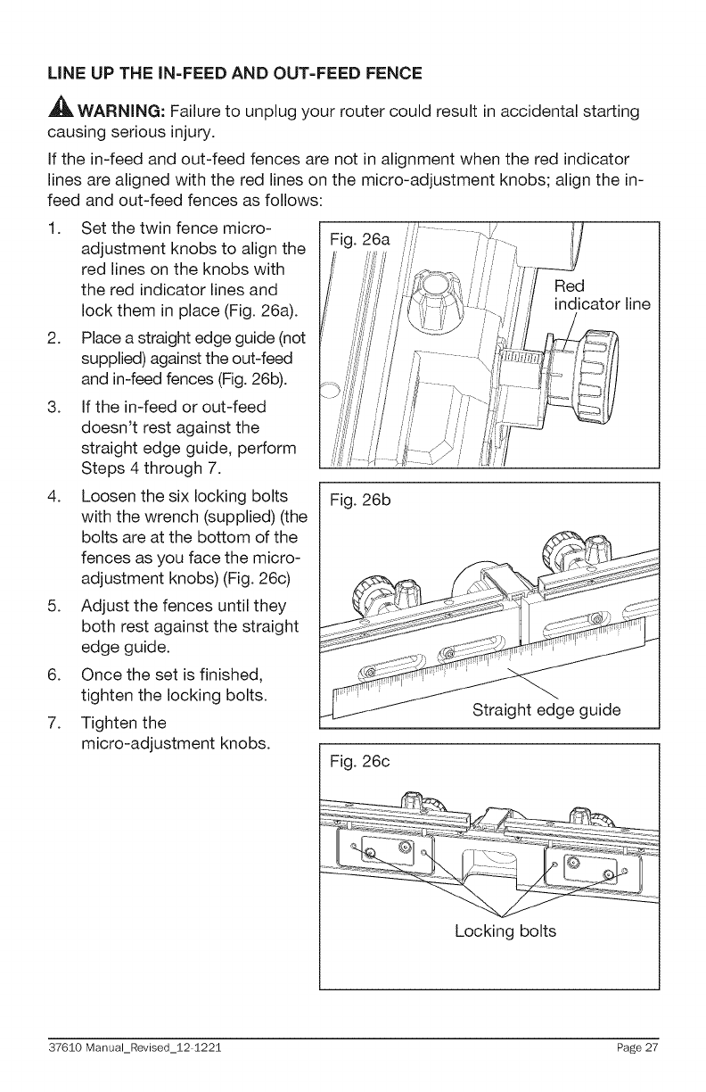
LiNE UP THE IN-FEED AND OUT=FEED FENCE
AWARNING: Failure to unplug your router could result in accidental starting
causing serious injury.
If the in-feed and out-feed fences are not in alignment when the red indicator
lines are aligned with the red lines on the micro-adjustment knobs; align the in-
feed and out-feed fences as follows:
1. Set the twin fence micro-
adjustment knobs to align the
red lines on the knobs with
the red indicator lines and
lock them in place (Fig. 26a).
2. Place a straight edge guide (not
supplied) against the out-feed
and in-feed fences (Fig. 26b).
3. If the in-feed or out-feed
doesn't rest against the
straight edge guide, perform
Steps 4 through 7.
4. Loosen the six locking bolts
with the wrench (supplied) (the
bolts are at the bottom of the
fences as you face the micro-
adjustment knobs) (Fig. 26c)
5. Adjust the fences until they
both rest against the straight
edge guide.
6. Once the set is finished,
tighten the locking bolts.
7. Tighten the
micro-adjustment knobs.
Red
indicator line
Fig. 26b
Straight edge guide
Fig. 26c
Locking bolts
37610 Manual_Revised_12 1221 Page 27
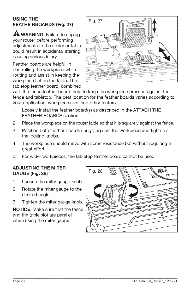
USING THE Fig. 27
FEATHE RBOARDS (Fig. 27)
WARNING: Failure to unplug
your router before performing
adjustments to the router or table
could result in accidental starting
causing serious injury.
Feather boards are helpful in
controlling the workpiece while
routing and assist in keeping the
workpiece flat on the table. The
tabletop feather board, combined
with the fence feather board, help to keep the workpiece pressed against the
fence and tabletop. The best location for the feather boards varies according to
your application, workpiece size, and other factors.
1. Loosely install the feather board(s) as described in the ATTACH THE
FEATHER BOARDS section.
2. Place the workpiece on the router table so that it is squarely against the fence.
3. Position both feather boards snugly against the workpiece and tighten all
the locking knobs.
4. The workpiece should move with some resistance but without requiring a
great effort.
5. For wider workpieces, the tabletop feather board cannot be used.
ADJUSTING THE MITER
GAUGE (Fig. 28)
1. Loosen the miter gauge knob.
2. Rotate the miter gauge to the
desired angle.
3. Tighten the miter gauge knob.
NOTICE: Make sure that the fence
and the table slot are parallel
when using the miter gauge.
Fig. 28
Page 28 37610 Manual_Revised_12 1221
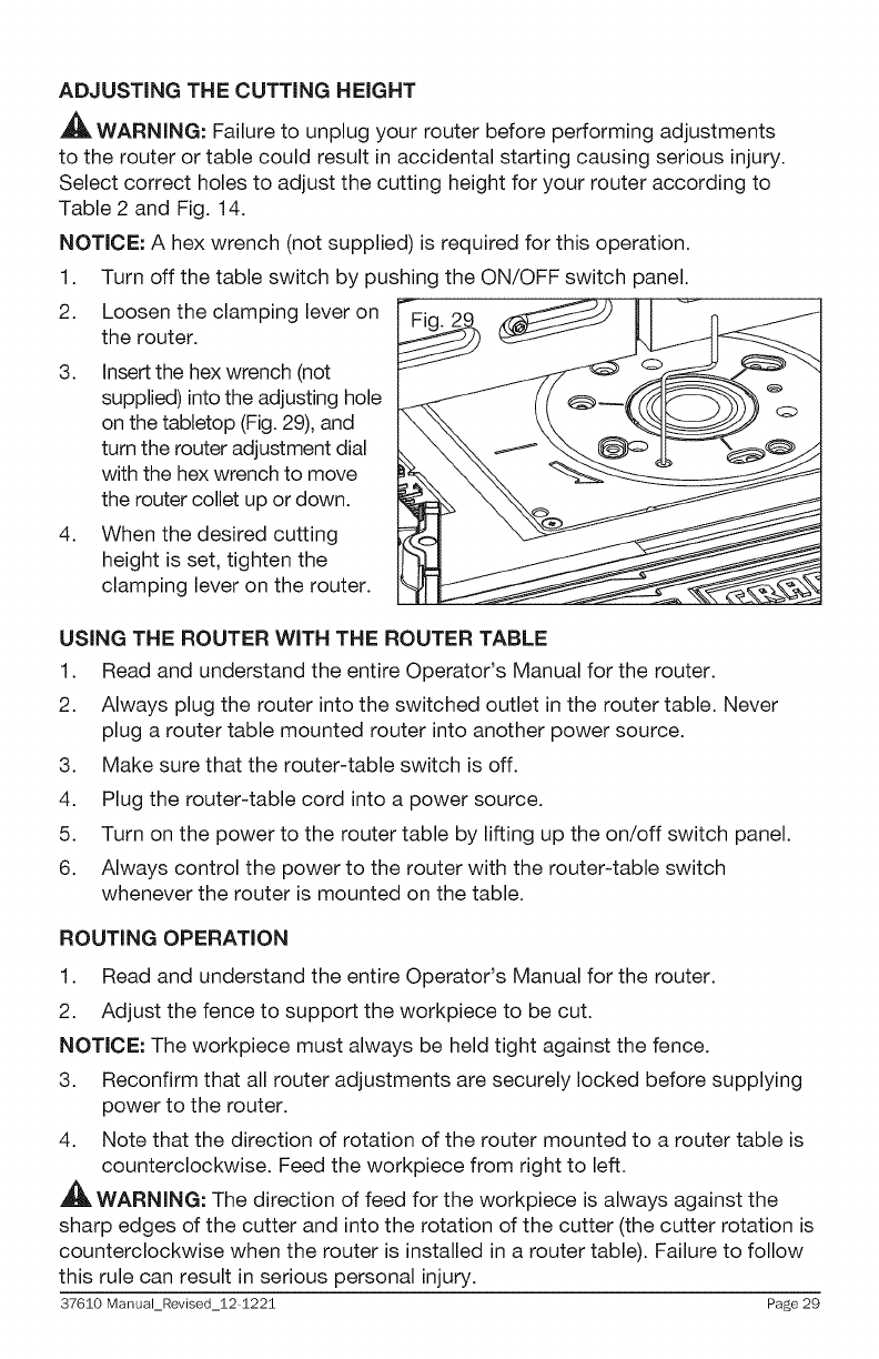
ADJUSTING THE CUTTING HEIGHT
_, WARNING: Failure to unplug your router before performing adjustments
to the router or table could result in accidental starting causing serious injury.
Select correct holes to adjust the cutting height for your router according to
Table 2 and Fig. 14.
NOTICE: A hex wrench (not supplied) is required for this operation.
1. Turn off the table switch by pushing the ON/OFF switch panel.
2. Loosen the clamping lever on
the router.
3. Insert the hex wrench (not
supplied) into the adjusting hole
on the tabletop (Fig. 29), and
turn the router adjustment dial
with the hex wrench to move
the router collet up or down.
4. When the desired cutting
height is set, tighten the
clamping lever on the router.
USING THE ROUTER WITH THE ROUTER TABLE
1. Read and understand the entire Operator's Manual for the router.
2. Always plug the router into the switched outlet in the router table. Never
plug a router table mounted router into another power source.
3. Make sure that the router-table switch is off.
4. Plug the router-table cord into a power source.
5. Turn on the power to the router table by lifting up the on/off switch panel.
6. Always control the power to the router with the router-table switch
whenever the router is mounted on the table.
ROUTING OPERATION
1. Read and understand the entire Operator's Manual for the router.
2. Adjust the fence to support the workpiece to be cut.
NOTICE: The workpiece must always be held tight against the fence.
3. Reconfirm that all router adjustments are securely locked before supplying
power to the router.
4. Note that the direction of rotation of the router mounted to a router table is
counterclockwise. Feed the workpiece from right to left.
WARNING: The direction of feed for the workpiece is always against the
sharp edges of the cutter and into the rotation of the cutter (the cutter rotation is
counterclockwise when the router is installed in a router table). Failure to follow
this rule can result in serious personal injury.
37610 Manual_Revised_12 1221 Page 29
GENERAL MAINTENANCE
_i1_ WARNING: Avoid using solvents when cleaning plastic parts. Most plastics
are susceptible to damage from various types of commercial solvents and may
be damaged by their use. Use clean clothes to remove dirt, dust, oil, grease, etc.
,_ WARNING: Do not at any time allow brake fluids, gasoline, petroleum-based
products, penetrating oils, etc. to come in contact with plastic parts. Chemicals can
damage, weaken or destroy plastic which may result in serious personal injury.
WARNING: When servicing, use only identical replacement parts. Use of any
other parts may create a hazard or cause product damage. To ensure safety and
reliability, all repairs should be performed by a qualified service technician.
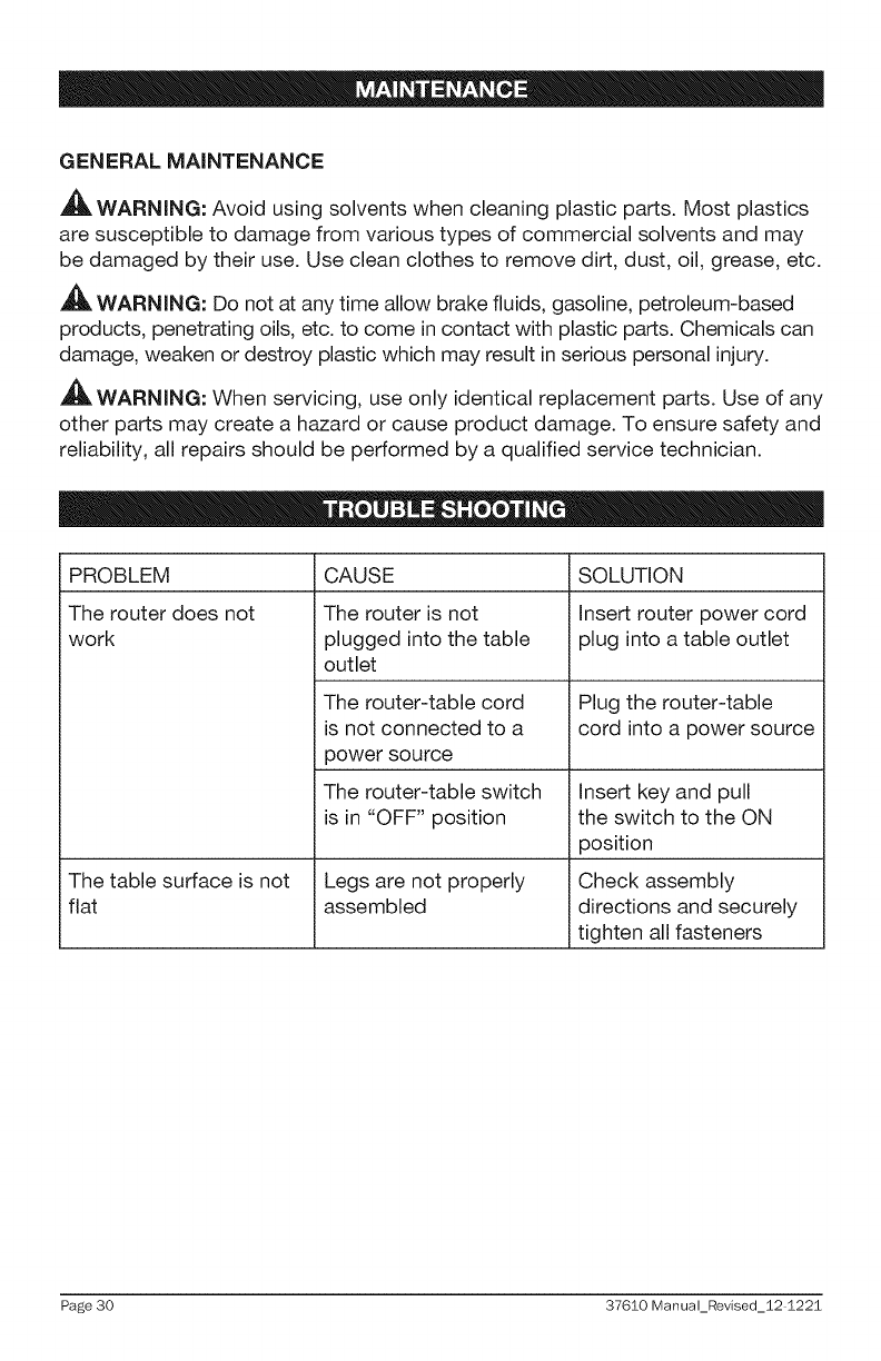
PROBLEM
The router does not
work
The table surface is not
flat
CAUSE
The router is not
plugged into the table
outlet
The router-table cord
is not connected to a
power source
The router-table switch
is in "OFF" position
Legs are not properly
assembled
SOLUTION
Insert router power cord
plug into a table outlet
Plug the router-table
cord into a power source
Insert key and pull
the switch to the ON
position
Check assembly
directions and securely
tighten all fasteners
Page 30 37610 Manual_Revised_12 I225
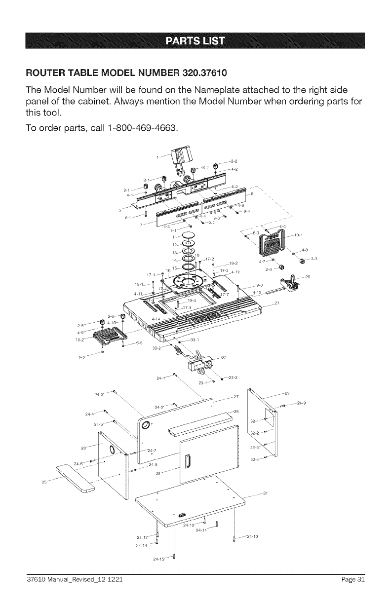
ROUTER TABLE MODEL NUMBER 320.37610
The Model Number will be found on the Nameplate attached to the right side
panel of the cabinet. Always mention the Model Number when ordering parts for
this tool.
To order parts, call 1-800-469-4663.
37610 Manual_Revised_12 1221 Page 3i

ROUTER TABLE MODEL NUMBER 320.37610
The Model Number will be found on the Nameplate attached to the right side
panel of the cabinet. Always mention the Model Number when ordering parts for
this tool.
To order parts, call 1-800-469-4663.
MPP010201041A Protection Guard
2 MPP010001001 Fence Assembling Knob 6
3 MPP010201091 Fence Micro-adjustment Locking Knob 2
4 MPP010005033 Washer 14
5 MPP010202014A Fence Assembly 1
6 MPP010005023 Locking Bolt 6
7 MPP010208014A Left Extended Fence Board Assembly 1
8 MPP010208024A Right Extended Fence Board Assembly 1
9 MPP010205023 Inner Hex Bolt 4
10 MPP010401011 Feather board 2
11 MPP010101011 Insert ring (blank) 1
12 MPP010504013 Insert ring (1-1/4 in.) 1
13 MPP010504023 Insert ring (1-7/8 in.) 1
14 MPP010504033 Insert ring (2-1/8 in.) 1
15 MPP010504043 Insert ring (2-1/4 in.) 1
16 MPP010103024 Mounting Plate 1
17 MPP010105023 Screw 4
18 MPP010506013 Starting Pin 1
19 MPP010105013 Round-head Hex Bolt 4
20 MPP010301011A Miter Gauge Assembly 1
21 MPP010103014 Tabletop 1
22 MPP010107010 Safety Switch 1
23 MPP010105043 Switch Box Locking Bolt 2
24 MPP010605183 Pan-head Cross Screw 15
Page 32 37610 Manual_Revised_12 1221
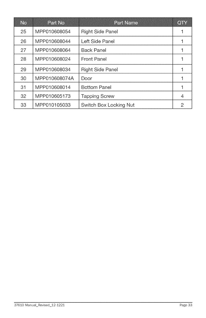
MPP010608054 Right Side Panel
26 MPP010608044 Left Side Panel
27 MPP010608064 Back Panel
28 MPP010608024 Front Panel
29 MPP010608034 Right Side Panel
30 MPP010608074A Door
31 MPP010608014 Bottom Panel
32 MPP010605173 Tapping Screw
33 MPP010105033 Switch Box Locking Nut
1
1
1
1
1
1
4
2
37610 Manual_Revised_12 1221 Page 33