Craftsman 32052751 User Manual DRILL DRIVER Manuals And Guides 1412340L
User Manual: Craftsman 32052751 32052751 CRAFTSMAN DRILL DRIVER - Manuals and Guides View the owners manual for your CRAFTSMAN DRILL DRIVER #32052751. Home:Tool Parts:Craftsman Parts:Craftsman DRILL DRIVER Manual
Open the PDF directly: View PDF ![]() .
.
Page Count: 48
Operator's Manual
CRFIFTSMFIN°
C3 1/2" DRILL/DRIVER
Model No. 5275.1
®
LISTED
_WARNING: To reduce the risk of injury,
the user must read and understand the
Operator's Manual before using this product.
•WARRANTY
•SAFETY
•DESCRIPTION
•ASSEMBLY
•OPERATION
•MAINTENANCE
•ESPANOL
Sears Brands Management Corporation, Hoffman Estates,
IL 60179 U.S.A.
www.craftsman.com
i _-_ :] ! _[O_ [O']_O]_ i/_ _i_'_
Warranty Page 2
Safety Symbols Pages 4-5
Safety Instructions Pages 6-8
Description Pages 9-10
Assembly Page 11
Operation Pages 12-18
Maintenance Pages 19-20
Troubleshooting Page 21
Parts List Pages 22-24
CRAFTSMAN LIMITED WARRANTY
FOR ONE YEAR from the date of sale, this product is warranted against any
defects in material or workmanship.
WITH PROOF OF SALE, a defective product will be replaced free of charge.
For warranty coverage details to obtain free replacement, visit the web
page: www.craftsman.com/warranty
This ONE YEAR warranty is void if this product is ever used while providing
commercial services or if rented to another person. For 90 DAY commercial
and rental use terms, see the Craftsman warranty web page.
This warranty gives you specific legal rights, and you may also have other
rights which vary from state to state.
Sears Brands Management Corporation, Hoffman Estates, IL 60179.
SAVE THESE INSTRUCTIONS!
READ ALL INSTRUCTIONS!
This drill/driver has many features for making its use more pleasant and
enjoyable. Safety, performance, and dependability have been given top priority
in the design of this product making it easy to maintain and operate.
2 © Sears Brands, LLC

DANGER: People with electronic devices, such as pacemakers, should
consult their physician(s) before using this product. Operation of electrical
equipment in close proximity to a heart pacemaker could cause interference or
failure of the pacemaker.
_WARNING: Some dust created by power sanding, sawing, grinding, drilling
and other construction activities contains chemicals known to the state of
California to cause cancer, birth defects or other reproductive harm. Some
examples of these chemicals are:
•Lead from lead-based paints
• Crystalline silica from bricks and cement and other masonry products, and
• Arsenic and chromium from chemically-treated lumber.
Your risk from these exposures varies, depending on how often you do this type
of work. To reduce your exposure to these chemical: work in a well ventilated
area, and work with approved safety equipment, such as those dust masks that
are specially designed to filter out microscopic particles.
_,'%1= quk'i[,,,,_o_
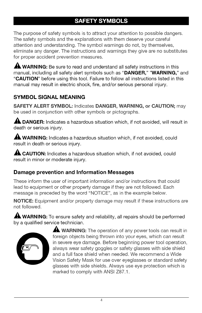
The purpose of safety symbols is to attract your attention to possible dangers.
The safety symbols and the explanations with them deserve your careful
attention and understanding. The symbol warnings do not, by themselves,
eliminate any danger. The instructions and warnings they give are no substitutes
for proper accident prevention measures.
WARNING: Be sure to read and understand all safety instructions in this
manual, including all safety alert symbols such as "DANGER," "WARNING," and
"CAUTION" before using this tool. Failure to follow all instructions listed in this
manual may result in electric shock, fire, and/or serious personal injury.
SYMBOL SIGNAL MEANING
SAFETY ALERT SYMBOL: indicates DANGER, WARNING, or CAUTION; may
be used in conjunction with other symbols or pictographs.
DANGER: Indicates a hazardous situation which, if not avoided, will result in
death or serious injury.
WARNING: Indicates a hazardous situation which, if not avoided, could
result in death or serious injury.
CAUTION: Indicates a hazardous situation which, if not avoided, could
result in minor or moderate injury.
Damage prevention and Information Messages
These inform the user of important information and/or instructions that could
Bead to equipment or other property damage if they are not followed. Each
message is preceded by the word "NOTICE", as in the example below.
NOTICE: Equipment and/or property damage may result if these instructions are
not followed.
WARNING: To ensure safety and reliability, all repairs should be performed
by a qualified service technician.
_, WARNmNG: The operation of any power tools can result in
foreign objects being thrown into your eyes, which can result
in severe eye damage. Before beginning power tool operation,
always wear safety goggles or safety glasses with side shield
and a full face shield when needed. We recommend a Wide
Vision Safety Mask for use over eyeglasses or standard safety
glasses with side shields. Always use eye protection which is
marked to comply with ANSI Z87.1.
SAVE THESE INSTRUCTIONS
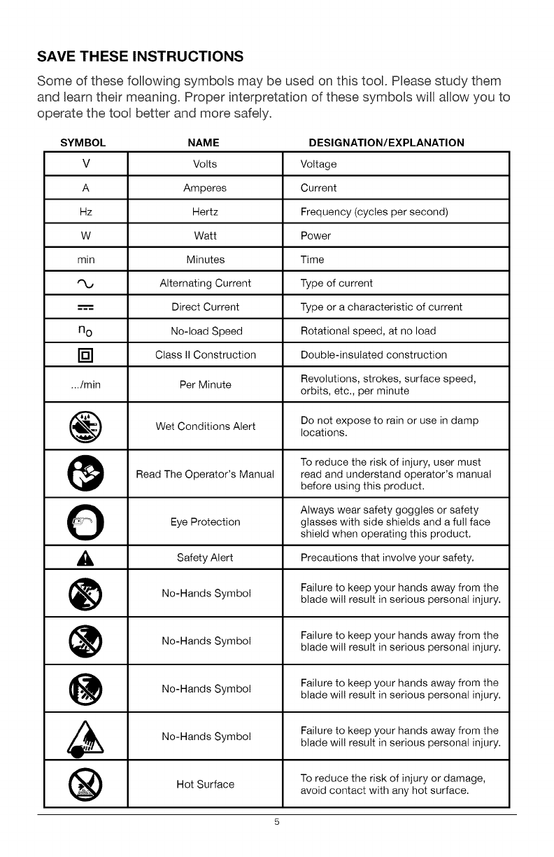
Some of these following symbols may be used on this tool. Please study them
and Beam their meaning. Proper interpretation of these symbols will allow you to
operate the tool better and more safely.
SYMBOL NAME DESIGNATION/EXPLANATION
V Volts Voltage
A Amperes Current
Hz Hertz Frequency (cycles per second)
W Watt Power
min Minutes Time
Alternating Current Type of current
---'== Direct Current Type or a characteristic of current
n o No-load Speed Rotational speed, at no load
[] Class II Construction Double-insulated construction
.../min Per Minute Revolutions, strokes, surface speed,
orbits, etc., per minute
Wet Conditions Alert Do not expose to rain or use in damp
locations.
To reduce the risk of injury, user must
Read The Operator's Manual read and understand operator's manual
before using this product.
OAlways wear safety goggles or safety
Eye Protection glasses with side shields and a full face
shield when operating this product.
_, Alert Precautions that involve
Safety your safety.
No-Hands Symbol Failure to keep your hands away from theblade wil! result in serious personal injury.
No-Hands Failure to keep your hands away from the
Symbol blade wil! result in serious personal injury.
No-Hands Failure to keep your hands away from the
Symbol blade wil! result in serious personal injury.
No-Hands Symbol Failure to keep your hands away from the
blade wil! result in serious personal injury.
Hot Surface To reduce the risk of injury or damage,
avoid contact with any hot surface.
5
GENERAL POWER TOOL SAFETY WARNINGS
WARNING: Read all safety warnings and instructions. Failureto follow the
warnings and instructions may result in electric shock, fire and/or serious injury.
Save all warnings and instructions for future reference.
The term "power tool" in the warnings refers to your mains=operated (corded)
power tool or battery=operated (cordless) power tool.
WORK AREA SAFETY
• Keep work area clean and well lit. Cluttered or dark areas invite accidents.
•Do not operate power tools in explosive atmospheres, such as in the
presence of flammable liquids, gases or dust. Power tools create sparks
which may ignite the dust or fumes.
•Keep children and bystanders away while operating a power tool.
Distractions can cause you to lose control.
ELECTRICAL SAFETY
•Power tool plugs must match the outlet. Never modify the plug in any
way. Do not use any adaptor plugs with earthed (grounded) power tools.
Unmodified plugs and matching outlets will reduce risk of electric shock
•Avoid body contact with earthed or grounded surfaces such as pipes,
radiators, ranges and refrigerators. There is an increasedrisk of electric
shock if your body is earthed or grounded.
•Do not expose power tools to rain or wet conditions. Water entering a
power tool will increase the risk of electric shock.
•Do not abuse the cord. Never use the cord for carrying, pulling or
unpluggingthe power tool. Keep cord away from heat, oil,sharp edges or
moving parts. Damaged or entangled cords increase the risk of electric shock.
•When operating a power tool outdoors, use an extension cord suitable
for outdoor use. Use of a cord suitable for outdoor use reduces the risk of
electric shock.
If operating a power tool in a damp location is unavoidable, use a
ground fault circuit interrupter (GFCI) protected power supply. Use of a
GFCI reduces the risk of electric shock.
PERSONAL SAFETY
• Stay alert, watch what you are doing and use common sense when
operating a power tool. Do not use tool while tired or under the
influence of drugs, alcohol, or medication. A moment of inattention while
operating power tools may result in serious personal injury.
• Use personal protective equipment. Always wear eye protection. Protective
equipment such as dust mask, non-skid safety shoes, hard hat, or hearing
protection used for appropriate conditions will reduce personal injuries.
•Prevent unintentional starting. Ensure the switch is in the off-position
before connecting to power source and/or battery pack, picking up or
carrying the tool. Carrying power tools with your finger on the switch or
energizing in power tools that have the switch on invites accidents.
• Remove any adjusting key or wrench before turning the power tool
on. A wrench or a key left attached to a rotating part of the power tool may
result in personal injury.
•Do not overreach. Keep proper footing and balance at all times. This
enables better control of the power tool in unexpected situations.
•Dress properly. Do not wear loose clothing or jewelry. Keep your hair,
clothing and gloves away from moving parts. Loose clothes, jewelry or
long hair can be caught in moving parts.
• If devices are provided for the connection of dust extraction and
collection facilities, ensure these are connected and properly used. Use
of these devices can reduce dust-related hazards.
POWER TOOL USE AND CARE
•Do not force the power tool. Use the correct power tool for your
application. The correct power tool will do the job better and more safely at
the rate for which it was designed.
•Do not use the power tool if the switch does not turn it on and off. Any
power tool that cannot be controlled with the switch is dangerous and must
be repaired.
•Disconnect the plug from the power source and/or the battery pack
from the power tool before making any adjustments, changing
accessories, or storing power tools. Such preventive safety measures
reduce the risk of starting the power tool accidentally.
• Store idle power tools out of the reach of children and do not allow
persons unfamiliar with the power tool or these instructions to operate
the power tool. Power tools are dangerous in the hands of untrained users.
• Maintain power tools. Check for misalignment or binding of moving
parts, breakage of parts and any other condition that may affect the
power tool's operation. If damaged, have the power tool repaired
before use. Many accidents are caused by poorly maintained power tools.
Keep cutting tools sharp and clean. Properly maintained cutting tools with
sharp cutting edges are less likely to bind and are easier to control.
Use the power tool, accessories, tool bits, etc. in accordance with
these instructions, taking into account the working conditions and the
work to be performed. Use of the power tool for operations different from
those intended could result in a hazardous situation.
BATTERY TOOL USE AND CARE
• Recharge only with the charger specified by the manufacturer. A
charger that is suitable for one type of battery pack may create a risk of fire
when used with another battery pack.
• Use power tools only with specifically designated battery packs. Use of
any other battery packs may create a risk of injury and fire.
• When battery pack is not in use, keep it away from other metal objects,
like paper clips, coins, keys, nails, screws or other small metal objects
that can make a connection from one terminal to another. Shorting the
battery terminals together may cause burns or a fire.
• Under abusive conditions, liquid may be ejected from the battery;
avoid contact. If contact accidentally occurs, flush with water. If liquid
contacts eyes, additionally seek medical help. Liquid ejected from the
battery may cause irritation or burns.
SERVICE
Have your power tool serviced by a qualified repair person using only
identical replacement parts. This will ensure that the safety of the power
tool is maintained.
Follow instructions in the Maintenance section of this manual. Use of
unauthorized parts or failure to follow Maintenance instructions may create
a risk of shock or injury.
SPECIFIC SAFETY RULES FOR DRILL DRIVER
•Know your drill/driver. Read operator's manual carefully. Learn the
applications and limitations, as well as the specific potential hazards related
to this tool. Following this rule will reduce the risk of electric shock, fire or
serious injury.
• Hold power tools by their insulated gripping surfaces when performing
an operation where the cutting tool may contact hidden wiring. If a
cutting accessory contacts a "live" wire, it may make exposed metal parts
of the power tool "live" and could give the operator an electric shock.
•Use auxiliary handle(s), if supplied with the tool. Loss of control can
cause personal injury.
ID]_o]_]]_ij[o) _I
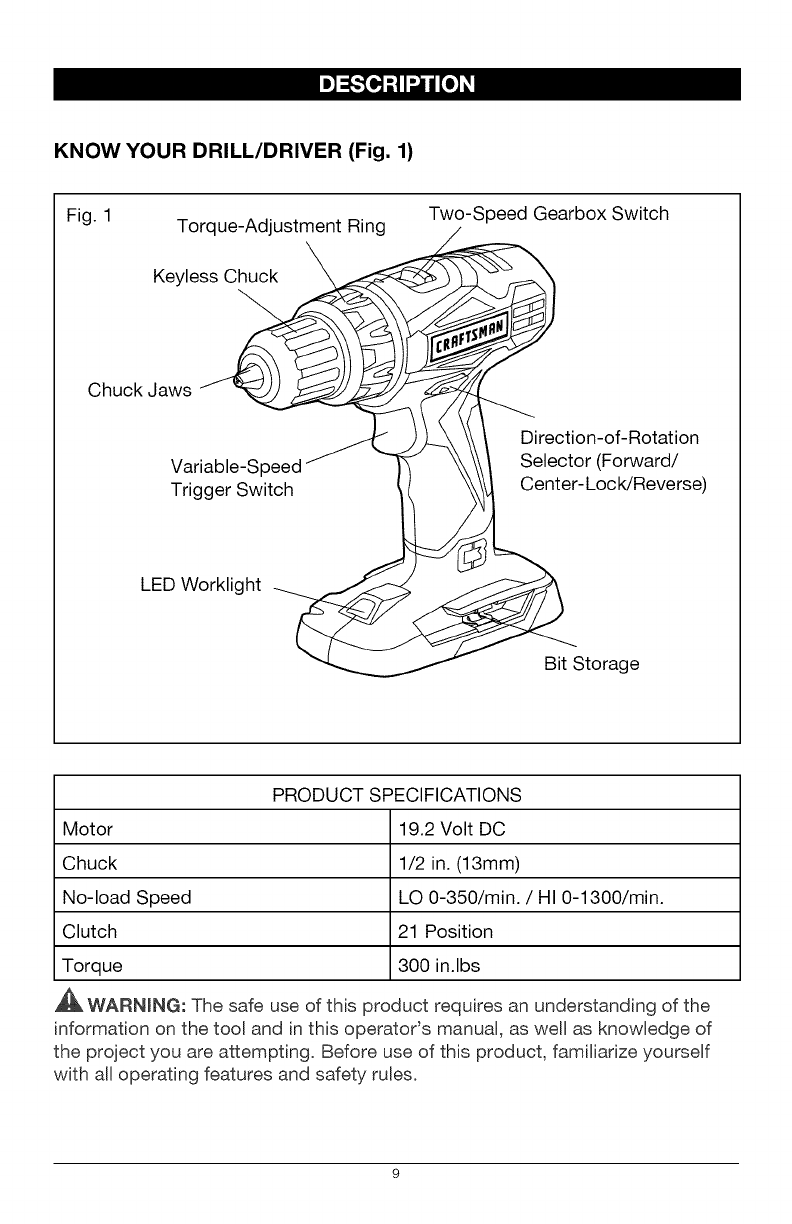
KNOW YOUR DRILL/DRIVER (Fig. 1)
Fig. 1 Torque-Adjustment Ring Two-Speed Gearbox Switch
Keyless_
Chuck Jaws J 1--
............ _ b _ Direction-of-Rotation
Variable-Speed \ Selector (Forward/
Trigger Switch 1 Center-L°cWReverse)
LED Worklight
Bit Storage
PRODUCT SPECIFICATIONS
Motor 19.2 Volt DC
Chuck 1/2 in. (13mm)
No-load Speed LO 0-350/min. /HI 0-1300/min.
Clutch 21 Position
Torque 300 in.lbs
,_ WARNmNG: The safe use of this product requires an understanding of the
information on the tool and in this operatods manual, as well as knowledge of
the project you are attempting. Before use of this product, familiarize yourself
with all operating features and safety rules.
ADJUSTABLE TORQUE
The drill/driver has a 21=position clutch: 1 drill position and 20 torque positions.
TWO-SPEED GEARBOX
The two=speed gearbox is designed for ddlling or driving at LO or HJ speeds.
A slide switch is located on top of your drill/driver for selecting the
appropriate speed.
VARIABLE SPEED
The variable=speed trigger switch delivers higher speed with increased trigger
pressure and Bower speed with decreased trigger pressure.
KEYLESS CHUCK
The keyless chuck allows you to hand=tighten or release the drill bit in the
chuck jaws.
FORWARD/CENTER-LOCK/REVERSE SELECTOR
The drill/driver has a direction=of=rotation selector located above the trigger
switch for changing the direction of bit rotation. Setting the trigger switch in the
OFF (center=lock) position helps reduce the possibility of accidental starting
when not in use.
LED WORKLIGHT
The LED worklight, located on the base of the drill/driver, illuminates when
the trigger switch is depressed. This feature provides extra light for
increased visibility.
10
_WARNING: If any parts are broken or missing, do not attempt to attach
the battery pack or operate the drill/driver until the broken or missing parts are
replaced. Failure to do so could result in possible serious injury.
WARNING: Do not attempt to modify this drill/driver or create accessories
not recommended for use with this drill/driver. Any such alteration or
modification is misuse and could result in a hazardous condition leading to
possible serious injury.
WARNING: To prevent accidental starting that could cause serious personal
injury, always remove the battery pack from the drill/driver when changing bits.
UNPACKING
This product has been shipped completely assembled.
•Carefully remove the tool and any accessories from the carton. Make sure
that all items listed in the packing list are included.
• Inspect the tool carefully to make sure no breakage or damage occurred
during shipping.
• Do not discard the packing material until you have carefully inspected and
satisfactorily operated the tool.
• If any parts are damaged or missing, please return the tool to the place
of purchase.
PACKING LIST
Drill/driver and operator's manual.
11
[e]"J:I,_:_i[e]_I
This product will accept Craftsman C3 19.2V lithium-ion battery packs. For
complete charging instructions, refer to the Operator's Manual for the battery
packs and chargers.
WARNING: To prevent accidental starting that could cause serious personal
injury, always remove the battery pack from the tool when assembling parts,
making adjustments, installing or removing bits, cleaning, or when it is not
in use.
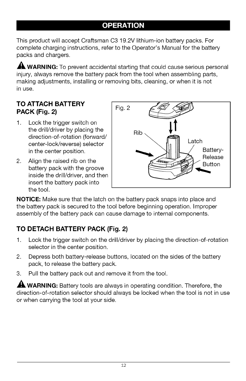
TO ATTACH BATTERY
PACK (Fig. 2)
1. Lock the trigger switch on
the drill/driver by placing the
direction-of-rotation (forward/
center-lock/reverse) selector
in the center position.
2. Align the raised rib on the
battery pack with the groove
inside the drill/driver, and then
insert the battery pack into
the tool.
Fig. 2
NOTICE: Make sure that the latch on the battery pack snaps into place and
the battery pack is secured to the tool before beginning operation. Improper
assembly of the battery pack can cause damage to internal components.
TO DETACH BATTERY PACK (Fig. 2)
1. Lock the trigger switch on the drill/driver by placing the direction-of-rotation
selector in the center position.
2. Depress both battery-release buttons, located on the sides of the battery
pack, to release the battery pack.
3. Pull the battery pack out and remove it from the tool.
WARNING: Battery tools are always in operating condition. Therefore, the
direction-of-rotation selector should always be locked when the tool is not in use
or when carrying the tool at your side.
12
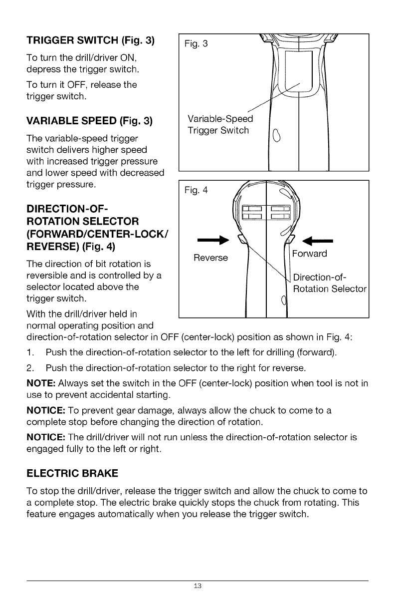
TRIGGER SWITCH (Fig. 3)
To turn the drill/driver ON,
depress the trigger switch.
To turn it OFF, release the
trigger switch.
VARIABLE SPEED (Fig. 3)
The variable-speed trigger
switch delivers higher speed
with increased trigger pressure
and lower speed with decreased
trigger pressure.
DIRECTION-OF-
ROTATION SELECTOR
(FORWARD/CENTER-LOCK/
REVERSE) (Fig. 4)
The direction of bit rotation is
reversible and is controlled by a
selector located above the
trigger switch.
With the drill/driver held in
normal operating position and
Figvir3iable_Spee d I 1
Trigger Switch .(_ I .I
Fig. 4
Reverse
I I "1,Direction-of-
l _ R°tati°n Select°r
direction-of-rotation selector in OFF (center-lock) position as shown in Fig. 4:
1. Push the direction-of-rotation selector to the left for drilling (forward).
2. Push the direction-of-rotation selector to the right for reverse.
NOTE: Always set the switch in the OFF (center-lock) position when tool is not in
use to prevent accidental starting.
NOTICE: To prevent gear damage, always allow the chuck to come to a
complete stop before changing the direction of rotation.
NOTICE: The drill/driver will not run unless the direction-of-rotation selector is
engaged fully to the left or right.
ELECTRIC BRAKE
To stop the drill/driver, release the trigger switch and allow the chuck to come to
a complete stop. The electric brake quickly stops the chuck from rotating. This
feature engages automatically when you release the trigger switch.
13
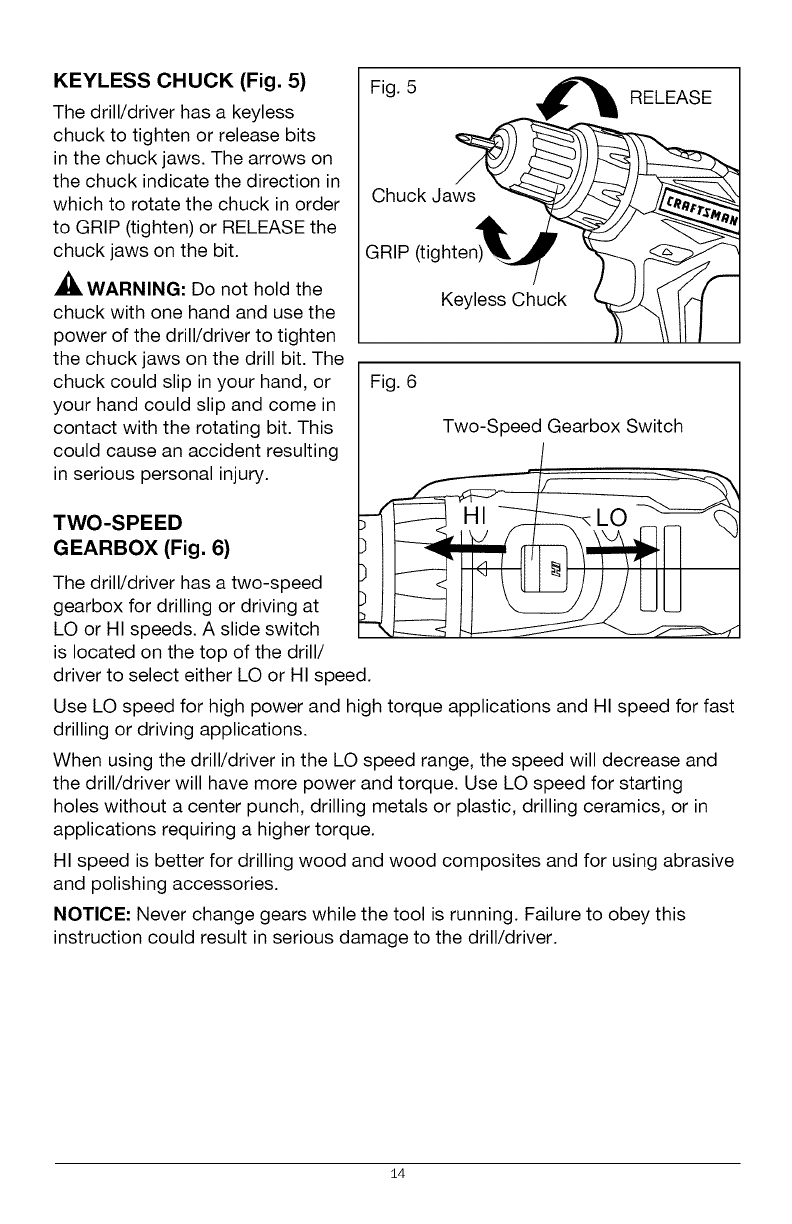
KEYLESS CHUCK (Fig. 5)
The drill/driver has a keyless
chuck to tighten or release bits
in the chuck jaws. The arrows on
the chuck indicate the direction in
which to rotate the chuck in order
to GRIP (tighten) or RELEASE the
chuck jaws on the bit.
WARNING: Do not hold the
chuck with one hand and use the
power of the drill/driver to tighten
the chuck jaws on the drill bit. The
chuck could slip in your hand, or
your hand could slip and come in
contact with the rotating bit. This
could cause an accident resulting
in serious personal injury.
TWO-SPEED
GEARBOX (Fig. 6)
The drill/driver has a two-speed
gearbox for drilling or driving at
LO or HI speeds. A slide switch
is located on the top of the drill/
Fig. 5 RELEASE
Chuck Jaws
GRIP (tighten)
Keyless Chuck
Fig. 6
Two-Speed Gearbox Switch
driver to select either LO or HI speed.
Use LO speed for high power and high torque applications and HI speed for fast
drilling or driving applications.
When using the drill/driver in the LO speed range, the speed will decrease and
the drill/driver will have more power and torque. Use LO speed for starting
holes without a center punch, drilling metals or plastic, drilling ceramics, or in
applications requiring a higher torque.
HI speed is better for drilling wood and wood composites and for using abrasive
and polishing accessories.
NOTICE- Never change gears while the tool is running. Failure to obey this
instruction could result in serious damage to the drill/driver.
14
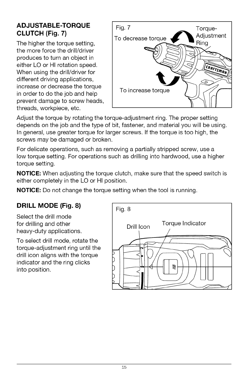
ADJUSTABLE-TORQUE
CLUTCH (Fig. 7)
The higher the torque setting,
the more force the drill/driver
produces to turn an object in
either LO or HI rotation speed.
When using the drill/driver for
different driving applications,
increase or decrease the torque
in order to do the job and help
prevent damage to screw heads,
threads, workpiece, etc.
TFogde7creasetorque _ Tdlqst_ent
To increase torq_ue_J_
Adjust the torque by rotating the torque-adjustment ring. The proper setting
depends on the job and the type of bit, fastener, and material you will be using.
In general, use greater torque for larger screws. If the torque is too high, the
screws may be damaged or broken.
For delicate operations, such as removing a partially stripped screw, use a
low torque setting. For operations such as drilling into hardwood, use a higher
torque setting.
NOTICE: When adjusting the torque clutch, make sure that the speed switch is
either completely in the LO or HI position.
NOTICE: Do not change the torque setting when the tool is running.
DRILL MODE (Fig. 8)
Select the drill mode
for drilling and other
heavy-duty applications.
To select drill mode, rotate the
torque-adjustment ring until the
drill icon aligns with the torque
indicator and the ring clicks
into position.
Fig. 8
Drill Icon Torque Indicator
15
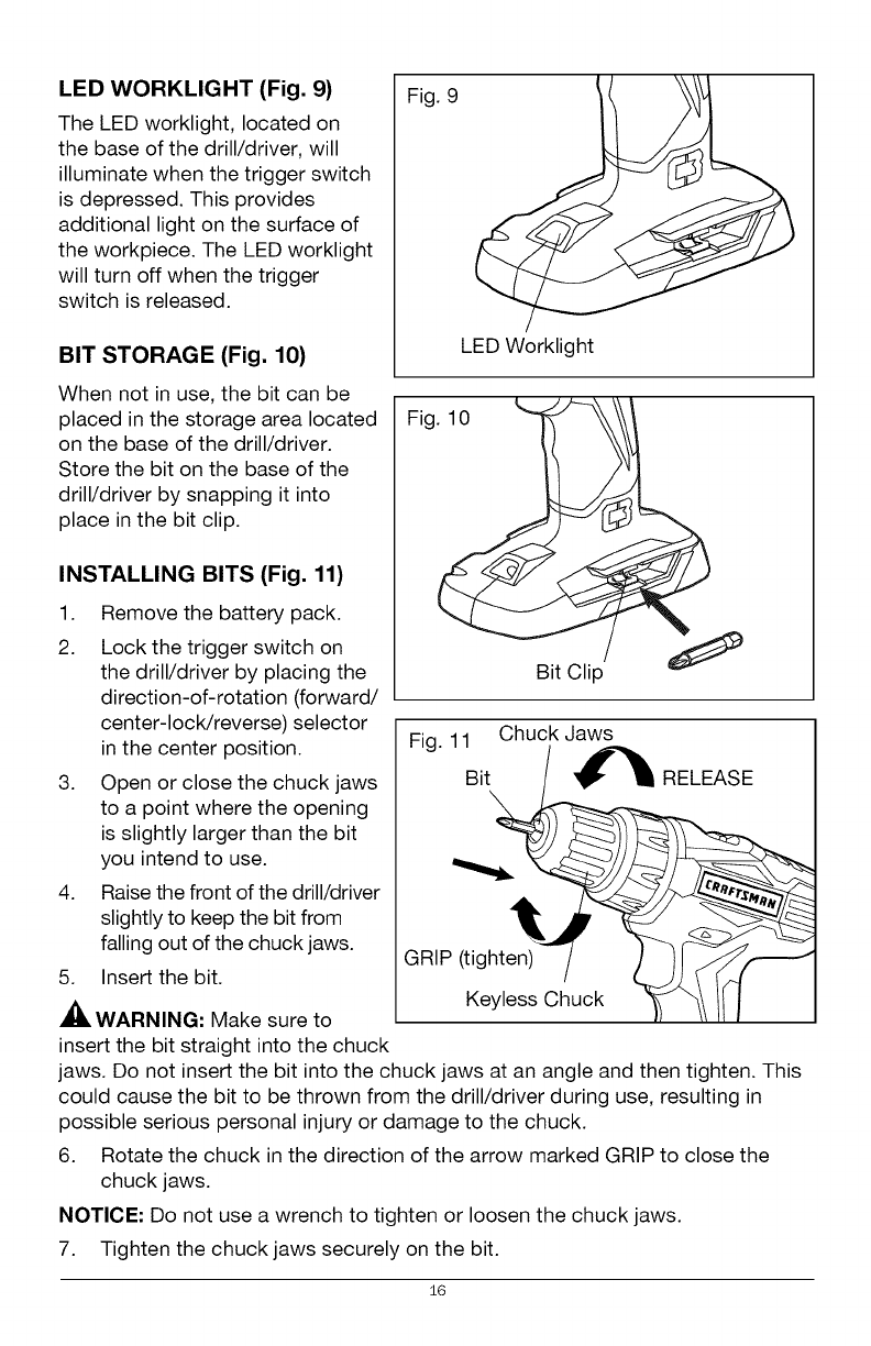
LED WORKLIGHT (Fig. 9)
The LED worklight, located on
the base of the drill/driver, will
illuminate when the trigger switch
is depressed. This provides
additional light on the surface of
the workpiece. The LED worklight
will turn off when the trigger
switch is released.
BIT STORAGE (Fig. 10)
Fig. 9
LED Worklight
When not in use, the bit can be
placed in the storage area located
on the base of the drill/driver.
Store the bit on the base of the
drill/driver by snapping it into
place in the bit clip.
INSTALLING BITS (Fig. 11)
1. Remove the battery pack.
2. Lock the trigger switch on
the drill/driver by placing the
direction-of-rotation (forward/
center-lock/reverse) selector
in the center position.
3. Open or close the chuck jaws
to a point where the opening
is slightly larger than the bit
you intend to use.
4. Raise the front of the drill/driver
slightly to keep the bit from
falling out of the chuck jaws.
5. Insert the bit.
WARNING: Make sure to
insert the bit straight into the chuck
Fig
v/
Bit Clip
Fig. 11 Chuck Jaws
Bit_
Keyless Chuck _J "_1 /I/
jaws. Do not insert the bit into the chuck jaws at an angle and then tighten. This
could cause the bit to be thrown from the drill/driver during use, resulting in
possible serious personal injury or damage to the chuck.
6. Rotate the chuck in the direction of the arrow marked GRIP to close the
chuck jaws.
NOTICE: Do not use a wrench to tighten or loosen the chuck jaws.
7. Tighten the chuck jaws securely on the bit.
16
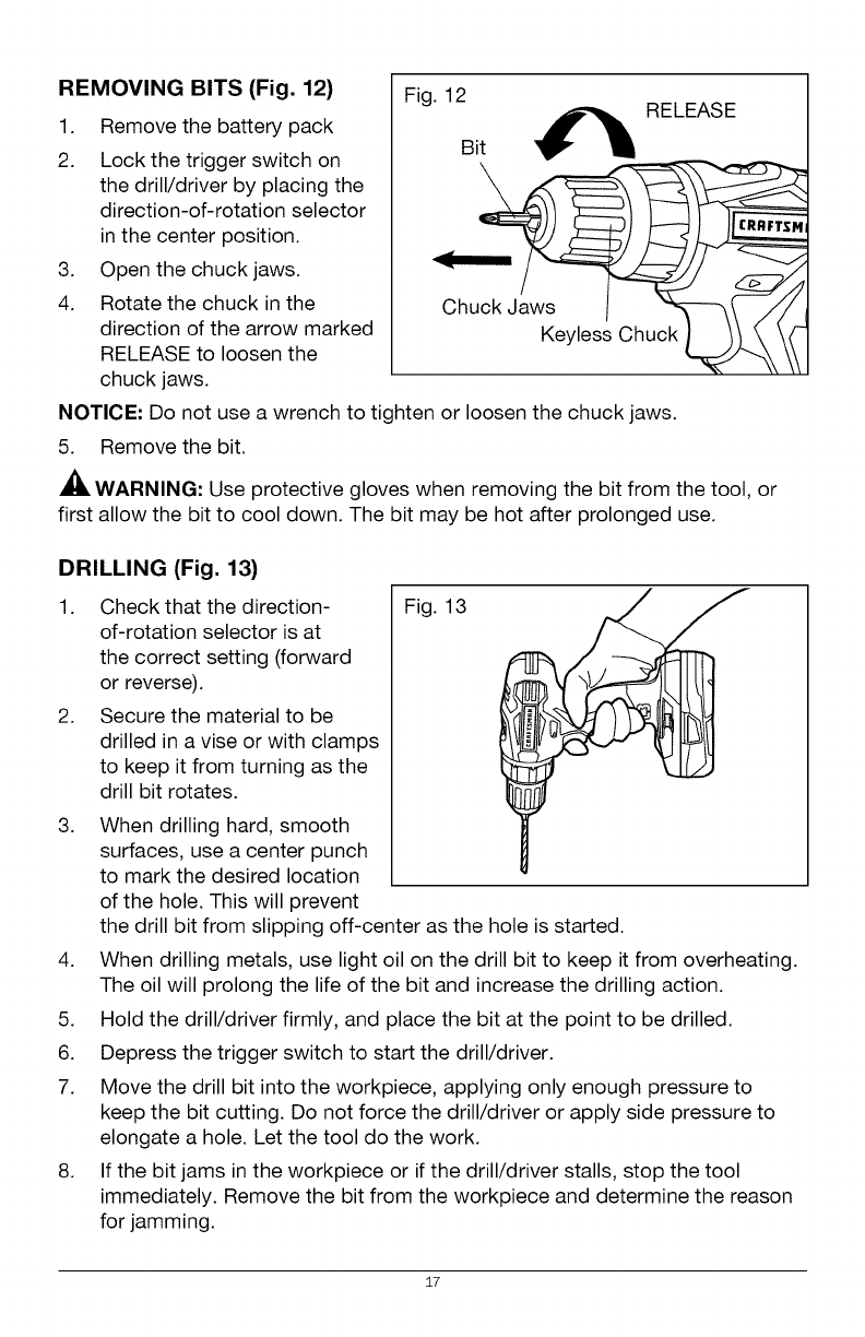
REMOVING BITS (Fig. 12)
1. Remove the battery pack
2. Lock the trigger switch on
the drill/driver by placing the
direction-of-rotation selector
in the center position.
3. Open the chuck jaws.
4. Rotate the chuck in the
direction of the arrow marked
RELEASE to loosen the
chuck jaws.
Fig. 12
Bit _ RELEASE
NOTICE: Do not use a wrench to tighten or loosen the chuck jaws.
5. Remove the bit.
WARNING: Use protective gloves when removing the bit from the tool, or
first allow the bit to cool down. The bit may be hot after prolonged use.
DRILLING (Fig. 13)
1.
2.
3.
Check that the direction-
of-rotation selector is at
the correct setting (forward
or reverse).
Secure the material to be
drilled in a vise or with clamps
to keep it from turning as the
drill bit rotates.
When drilling hard, smooth
surfaces, use a center punch
to mark the desired location
of the hole. This will prevent
Fig. 13
the drill bit from slipping off-center as the hole is started.
4. When drilling metals, use light oil on the drill bit to keep it from overheating.
The oil will prolong the life of the bit and increase the drilling action.
5. Hold the drill/driver firmly, and place the bit at the point to be drilled.
6. Depress the trigger switch to start the drill/driver.
7. Move the drill bit into the workpiece, applying only enough pressure to
keep the bit cutting. Do not force the drill/driver or apply side pressure to
elongate a hole. Let the tool do the work.
8. If the bit jams in the workpiece or if the drill/driver stalls, stop the tool
immediately. Remove the bit from the workpiece and determine the reason
for jamming.
17
NOTICE: This drill/driver is equipped with an electric brake. When the brake is
functioning properly, sparks may be visible through the vent slots in the housing.
This is normal and results from the action of the brake.
WOOD DRILLING
For maximum performance, use wood-boring brad- point drill bits (available
separately) or brad-point bits (available separately) for wood drilling.
1. When drilling "through" holes, place a block of wood behind the workpiece
to prevent ragged or splintered edges on the back side of the hole.
2. Begin drilling at a very low speed to prevent the bit from slipping off the
starting point.
3. Increase speed as the drill bit bites into the material.
METAL DRILLING
For maximum performance, use high speed steel bits (available separately) for
metal or steel drilling.
1. When drilling metals, use light oil on the drill bit to keep it from overheating.
The oil will prolong the life of the bit and increase the drilling action.
2. Begin drilling at a very low speed to prevent the bit from slipping off the
starting point.
3. Set drill speed to LO and maintain a speed and pressure which allow cutting
without overheating the bit. Applying too much pressure will:
• Overheat the drill/driver
• Wear the bearings
• Bend or burn bits
• Produce off-center or irregularly shaped holes
18
AWARNING: To avoid serious personal injury, always remove the battery
pack from the tool when cleaning or performing any maintenance.
WARNING: Always wear safety goggles or safety glasses with side shields
when using compressed air to clean the tool. If the operation is dusty, also wear
a dust mask.
GENERAL MAINTENANCE
Avoid using solvents when cleaning plastic parts. Most plastics are susceptible to
damage from various types of commercial solvents and may be damaged by their
use. Use clean cloths to remove dirt, dust, oil, grease, etc.
WARNING: Do not at any time let brake fluids, gasoline, petroleum-based
products, penetrating oils, etc. come in contact with plastic parts. Chemicals can
damage, weaken or destroy plastic which may result in serious personal injury.
WARNING: When servicing, use only identical Craftsman replacement parts.
Use of any other parts may create a hazard or cause product damage. To
ensure safety and reliability, all repairs should be performed by a qualified
service technician.
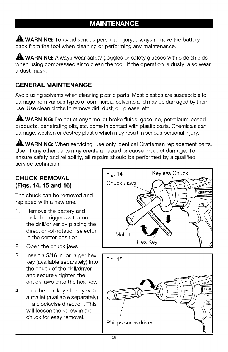
CHUCK REMOVAL
(Figs. 14. 15 and 16)
The chuck can be removed and
replaced with a new one.
1. Remove the battery and
lock the trigger switch on
the drill/driver by placing the
direction-of-rotation selector
in the center position.
2. Open the chuck jaws.
3. Insert a 5/16 in. or larger hex
key (available separately) into
the chuck of the drill/driver
and securely tighten the
chuck jaws onto the hex key.
4. Tap the hex key sharply with
a mallet (available separately)
in a clockwise direction. This
will loosen the screw in the
chuck for easy removal.
Fig. 14 Keyless Chuck
Chuck
Mallet _ "_
Hex Key
Fig. 15
Philips screwdriver
19
CRRFTSF
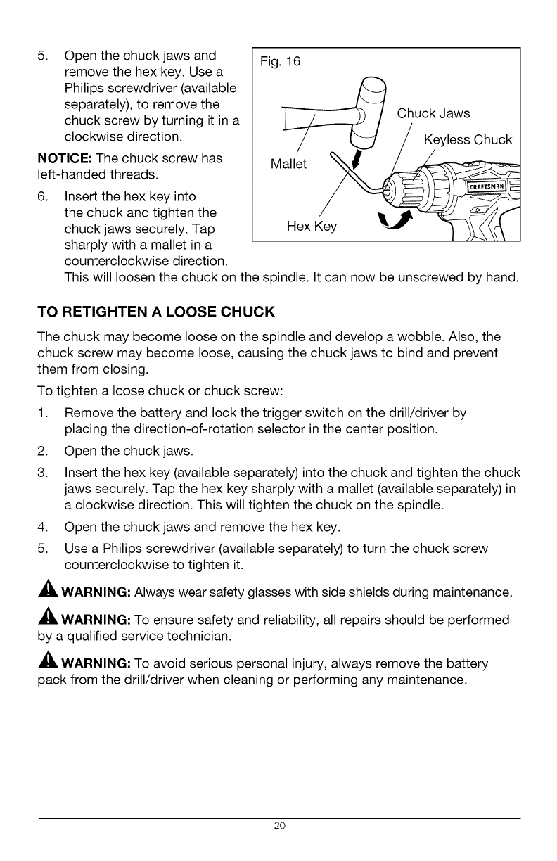
5. Open the chuck jaws and
remove the hex key. Use a
Philips screwdriver (available
separately), to remove the
chuck screw by turning it in a
clockwise direction.
NOTICE: The chuck screw has
left-handed threads.
6.
Fig. 16
Insert the hex key into
the chuck and tighten the
chuck jaws securely. Tap
sharply with a mallet in a
counterclockwise direction.
]__ Chuck Jaws
/_/KeylessChuck
Mall'et _
Hex Key _ _ 1_ t''1
This will loosen the chuck on the spindle. It can now be unscrewed by hand.
TO RETIGHTEN A LOOSE CHUCK
The chuck may become loose on the spindle and develop a wobble. Also, the
chuck screw may become loose, causing the chuck jaws to bind and prevent
them from closing.
To tighten a loose chuck or chuck screw:
1. Remove the battery and lock the trigger switch on the drill/driver by
placing the direction-of-rotation selector in the center position.
2. Open the chuck jaws.
3. Insert the hex key (available separately) into the chuck and tighten the chuck
jaws securely. Tap the hex key sharply with a mallet (available separately) in
a clockwise direction. This will tighten the chuck on the spindle.
4. Open the chuck jaws and remove the hex key.
5. Use a Philips screwdriver (available separately) to turn the chuck screw
counterclockwise to tighten it.
WARNING: Always wear safety glasses with side shields during maintenance.
WARNING: To ensure safety and reliability, all repairs should be performed
by a qualified service technician.
WARNING: To avoid serious personal injury, always remove the battery
pack from the drill/driver when cleaning or performing any maintenance.
20
b/ :_olU__oIo_
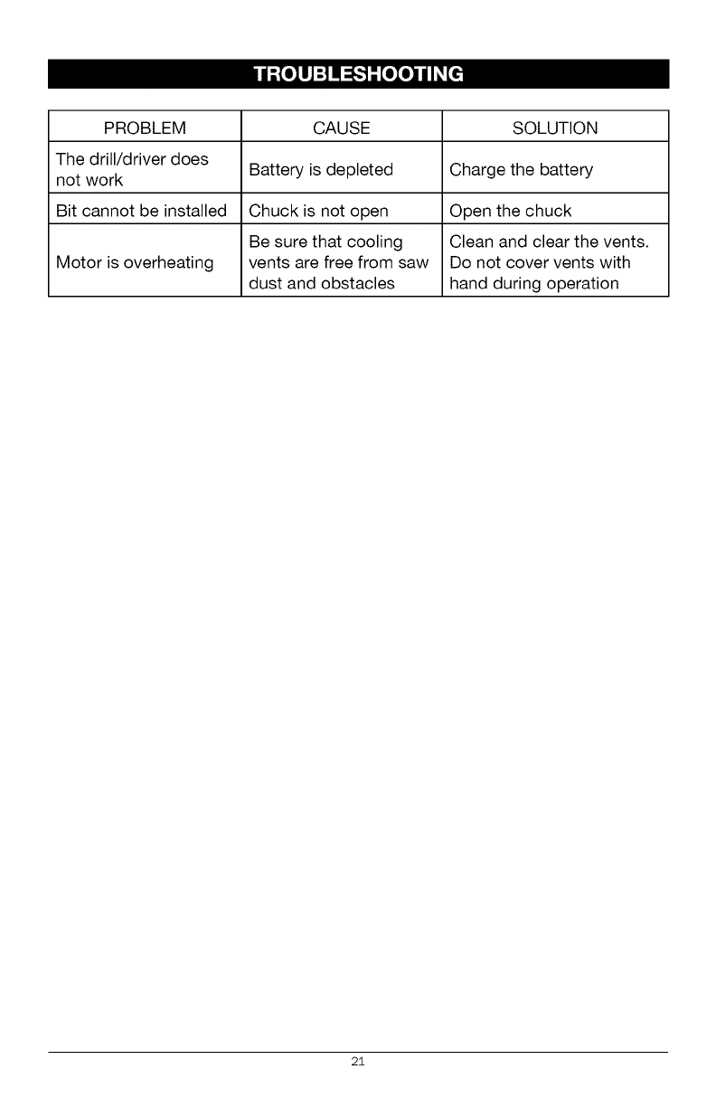
PROBLEM CAUSE SOLUTION
The drill/driver does
not work Battery is depleted Charge the battery
Bit cannot be installed Chuck is not open Open the chuck
Be sure that cooling Clean and clear the vents.
Motor is overheating vents are free from saw Do not cover vents with
dust and obstacles hand during operation
2i
2O2
18 17
1o
17
/
/
20 i I
/
/
/
/
0
o
_z
o o
CO
co 3
?g
(3")
co o
5
03
o
s"
o_
(D =
g _
_N
® _.
3
g
m
g
g
©
>
,<

I#'-'_a 6,1BE,.Iiil
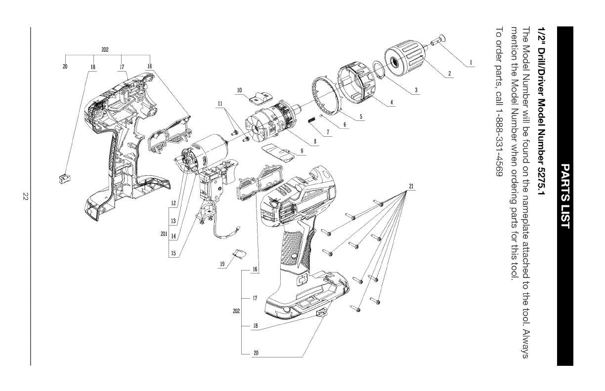
1/2" Drill/Driver Model Number 5275.1
The Model Number will be found on the nameplate attached to the tool. Always
mention the Model Number when ordering parts for this tool.
To order parts, call 1=888=331 =4569.
1 5620488000 Screw (L.H.)
2 3860112000 Chuck
3 5660176000 Circlip For Shaft
4 3123817000 Clutch Cap
5 3124166000 Decorate Ring
6 5700178000 Steel Ball
7 3660466000 Compression Spring
8 2790379000 Gear Case Assembly
9 3126501000 F/R Button
10 3321319000 Speed Change Button
11 5620505000 Screw with Washer
201 2823981000 Control Assembly
12 2790380000 Motor And Gear Assembly
13 4180257000 Lead Capacitor
14 3680140000 Magnet Ring
15 2823966000 Contact Receptacle Assembly
202 2823978000 L R Housing Set
16 3127553000 Support
17 3321809000 Left Housing
18 3703673000 Bits Holder
19 3126500000 LED Cover
20 3321808000 Right Housing
21 5610241000 Screw
1
1
1
1
1
1
1
1
1
1
2
1
1
2
1
1
1
2
1
2
1
1
10
23

24
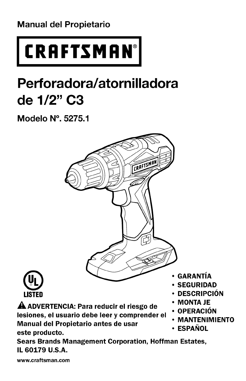
Manual del Propietario
CRFIFTSMFIN°
Perforadora/atornilladora
de 1/2" C3
Modelo N°. 5275.1
®
LISTED
_ADVERTENCIA: Para reducir el riesgo de
lesiones, el usuario debe leer y comprender el
Manual del Propietario antes de usar
este producto.
• GARANTiA
•SEGURIDAD
•DESCRIPClON
•MONTA JE
•OPERAClON
•MANTENIMIENTO
•ESPANOL
Sears Brands Management Corporation, Hoffman Estates,
IL 60179 U.S.A.
www.craftsman.com
i _-_ :] ! _[O_ EO']_O]_ i/_ _i_'_
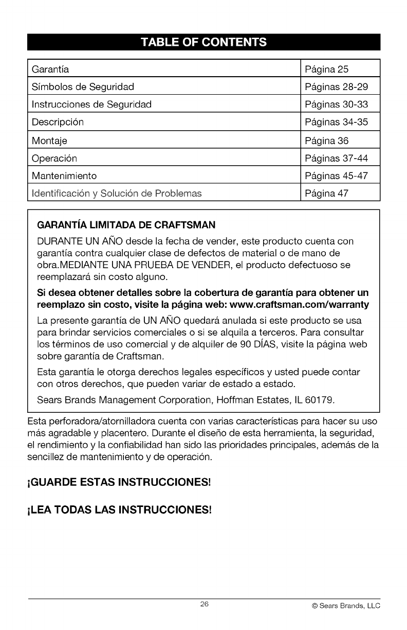
Garantia Pa.gina 25
Simbolos de Seguridad Pa.ginas 28-29
Instrucciones de Seguridad Pa.ginas 30-33
Descripcion Pa.ginas 34-35
Montaje Pa.gina 36
Operacion Pa.ginas 37-44
Mantenimiento Pa.ginas 45-47
Identificaci6n y Soluci6n de Problemas Pa.gina 47
GARANTiA LIMITADA DE CRAFTSMAN
DURANTE UN ANO desde la fecha de vender, este producto cuenta con
garantia contra cualquier clase de defectos de material o de mano de
obra.MEDIANTE UNA PRUEBA DE VENDER, el producto defectuoso se
reemplazara, sin costo alguno.
Si desea obtener detalles sobre la cobertura de garantia para obtener un
reemplazo sin costo, visite la p&gina web: www.craftsman.com/warranty
La presente garantia de UN ANO quedara, anulada si este producto se usa
para brindar servicios comerciales o si se alquila a terceros. Para consultar
los terminos de uso comercial y de alquiler de 90 DiAS, visite la pa.gina web
sobre garantia de Craftsman.
Esta garantia le otorga derechos legales especificos y usted puede contar
con otros derechos, que pueden variar de estado a estado.
Sears Brands Management Corporation, Hoffman Estates, IL 60179.
Esta perforadora/atornilladora cuenta con varias caracteristicas para hacer su uso
ma.s agradable y placentero. Durante el dise_o de esta herramienta, la seguridad,
el rendimiento y la confiabilidad han sido las prioridades principales, adema.s de la
sencillez de mantenimiento y de operacion.
iGUARDE ESTAS INSTRUCCIONES!
iLEA TODAS LAS INSTRUCCIONES!
26 © Sears Brands, LLC
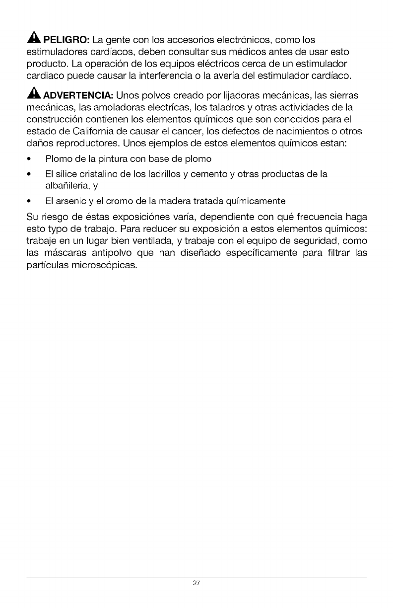
PEMGRO: La gente con los accesorios electr6nicos, como los
estimuladores cardiacos, deben consultar sus m_dicos antes de usar esto
producto. La operaci6n de los equipos electricos cerca de un estimulador
cardiaco puede causar la interferencia o la averia del estimulador cardiaco.
ADVERTENOIA: Unos polvos creado por lijadoras mec&nicas, las sierras
mec&nicas, las amoladoras electricas, los taladros y otras actividades de la
construcci6n contienen los elementos qu[micos que son conocidos para el
estado de California de causar el cancer, los defectos de nacimientos o otros
daSos reproductores. Unos ejemplos de estos elementos qu[micos estan:
• Plomo de la pintura con base de plomo
• El silice cristalino de los ladrillos y cemento y otras productas de la
alba_ileria, y
• El arsenic y el cromo de la madera tratada quimicamente
Su riesgo de estas exposiciones var[a, dependiente con qu_ frecuencia haga
esto typo de trabajo. Para reducer su exposicion a estos elementos qu[micos:
trabaje en un lugar bien ventilada, y trabaje con el equipo de seguridad, como
las mascaras antipolvo que han diseSado especfficamente para filtrar las
part[culas microscopicas.
27
El objeto de los simbolos de seguridad es atraer su atenci6n sobre posibles peligros.
Los simbolos de seguridad y las explicaciones junto a elias ameritan su
cuidadosa atenci6n y comprensi6n. Los simbolos de advertencia no eliminan
los peligros por si solos. Las instrucciones y advertencias que ofrecen no
reemplazan las medidas adecuadas de prevencion de accidentes.
ADVERTENCIA: AsegQrese de leer y comprender todas las instrucciones de
seguridad de este manual, incluyendo todos los simbolos de alerta de seguridad,
tales como "PELIGRO", "ADVERTENOIA" y "PREOAUOION" antes de utilizar esta
perforadora/atomilladora. No seguir todas las instrucciones listadas a continuacion
puede generar una descarga electrica, un incendio y/o graves lesiones corporales.
SIGNIFICADO DE LOS SiMBOLOS
PELIGRO: Indica una situacion peligrosa que, si no se evita, puede provocar
la muerte o una lesion grave. Esta palabra debe limitarse alas stiuaciones
ma.s extremas.
ADVERTENOIA: Indica una situacion peligrosa que, si no se evita, puede
provocar la muerte o una lesion grave.
PREOAUOION: Indica una situacion peligrosa que, si no se evita, puede
provocar una lesion menor o moderada.
Mensajes de informacion y de prevencion de dafios
Estos informan al usuario sobre informaciones y/o instrucciones importantes que
podrian provocar daSos al equipamiento o a la propiedad si no se siguen. Cada
mensaje est& precedido por la palabra "AVISO", como en el ejemplo siguiente:
AVISO: Pueden provocarse daSos al equipamiento y/o a la propiedad si no se
cumplen estas instrucciones.
ADVERTENOIA: Para garantizar la seguridad y la confiabilidad, todas las
reparaciones deben ser efectuadas por un tecnico calificado.
_, ADVERTENCIA: El funcionamiento de cualquier
herramienta electrica puede provocar el lanzamiento de objetos
en direccion de su rostro, y los consecuentes graves daSos
oculares. Antes de comenzar a utilizar la herramienta electrica,
siempre use gafas o lentes de seguridad con proteccion lateral
y una proteccion completa de rostro cuando sea necesario.
Recomendamos el uso de una m&scara de seguridad de vision
amplia sobre los anteojos o gafas de seguridad est&ndar con
proteccion lateral. Siempre utilice proteccion ocular con
certificacion de cumplimiento con ANSI Z87.1.
28
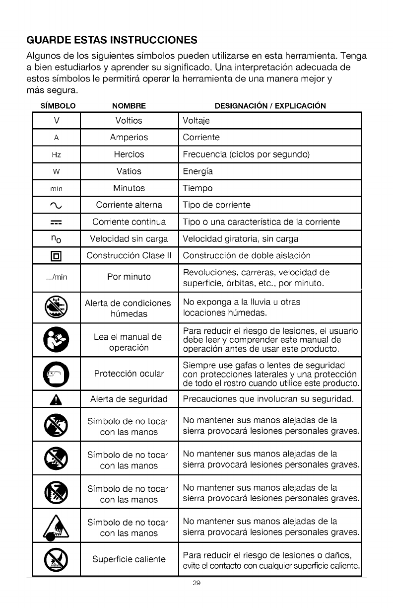
GUARDE ESTAS INSTRUCCIONES
Algunos de los siguientes simbolos pueden utilizarse en esta herramienta. Tenga
a bien estudiarlos y aprender su significado. Una interpretacion adecuada de
estos simbolos le permitira, operar la herramienta de una manera mejor y
NOMBRE DESIGNACION /EXPLICACION
V Vottios Vottaje
A Amperios Corriente
Hz Hercios Frecuencia (ciclos por segundo)
w Vatios Energfa
min Minutos Tiempo
Corriente alterna Tipo de corriente
-----= Corriente continua Tipo o una caracterfstica de la corriente
no Velocidad sin carga Velocidad giratoria, sin carga
[] Construccion Ctase II Construccion de doble aislacion
.../min Por minuto Revotuciones, carreras, velocidad de
superficie, orbitas, etc., por minuto.
Aterta de condiciones No exponga a la Iluvia u otras
h0medas Iocaciones h0medas.
Para reducir el riesgo de lesiones, el usuario
Lea el manual de debe leer y comprender este manual de
operacion operacion antes de usar este producto.
O Siempre use gafas o lentes de seguridad
Proteccion ocular con protecciones laterates y una proteccion
de todo el rostro cuando utilice este producto.
_, Aterta de seguridad Precauciones que invotucran su seguridad.
Sfmboto de no tocar No mantener sus manos atejadas de ta
con las manos sierra provocara lesiones personales graves.
Sfmboto de no tocar No mantener sus manos atejadas de ta
con las manos sierra provocara lesiones personales graves.
Sfmboto de no tocar No mantener sus manos atejadas de ta
con las manos sierra provocara lesiones personales graves.
Sfmboto de no tocar No mantener sus manos atejadas de tacon las manos sierra provocara lesiones personales graves.
Superficie caliente Para reducir et riesgo de tesiones o da_os,
evite el contacto con cualquier superficie caliente.
29
ma.s segura.
SIMBOLO
I_S-'_l_lIo_o_o_]_-_]IB]=1_.'_€tlJ -'tIB1;IB]
ADVERTENCIAS GENERALES DE SEGURIDAD DE LAS
HERRAMIENTAS ELI_CTRICAS
ADVERTENCIA: Lea y comprenda todas las instrucciones. No seguir todas
las instrucciones listadas a continuaci6n puede generar una descarga electrica, un
incendio y/o graves lesiones corporales. El termino "herramienta electrica" de todas
las advertencias listadas a continuaci6n hacen referencia a herramientas electricas
con cable o herramientas electricas operadas a baterfa (inala.mbricas).
CONSERVE TODAS LAS ADVERTENCIAS E INSTRUCCIONES PARA
REFERENCIA FUTURA
SEGURIDAD EN EL AREA DE TRABAJO
• Mantenga el &rea de trabajo limpia y bien iluminada. Las a.reas
desordenadas u oscuras son propicias para los accidentes.
•No utilice herramientas el_ctricas en atm6sferas explosivas, como en
la presencia de liquidos inflamables, gases o polvillo. Las herramientas
electricas crean chispas, que pueden encender el polvillo o el humo.
• Mantenga a los niSos ya los transet3ntes alejados mientras maneja esta
herramienta el_ctrica. Las distracciones pueden provocar la perdida de control.
SEGURIDAD ELECTRICA
•Evite el contacto corporal con superficies con conexi6n a tierra, tales
como ca_erias, radiadores, cocinas y refrigeradores. Existe un riesgo
mayor de descarga electrica si su cuerpo tiene conexi6n a tierra.
• Los enchufes de las herramientas el_ctricas deben poder insertarse en
los tomacorrientes. Nunca modifique el enchufe de ninguna manera.
No utilice enchufes adaptadores con herramientas el_ctricas con
conexi6n a tierra. No modificar los enchufes y contar con el tomacorriente
adecuado reducira.n el riesgo de una descarga electrica.
• No exponga las herramientas el_ctricas a la Iluvia oacondiciones de
humedad. El agua que ingresa a la herramienta electrica incrementara, el
riesgo de una descarga electrica.
• No maltrate el cable. Nunca utilice el cable para trasladar o
desenchufar la herramienta el_ctrica ni tire del mismo. Mantenga
el cable alejado del calor, aceite, extremos afilados o piezas en
movimiento. Los cables daSados o enredados incrementan el riesgo de
una descarga electrica.
30
•Cuando utilice una herramienta el_ctrica al aire libre, use un cable de
extensi6n especial para uso al exterior. El uso de un cable adecuado
para el aire libre reduce el riesgo de una descarga electrica.
• Si no puede evitar el uso de una herramienta el_ctrica en un lugar
hOmedo, utilice un suministro de energia protegido per un interruptor
de circuito con descarga a tierra (GFCl, per sus siglas en ingles). El uso
de un GFCI reduce el riesgo de una descarga electrica.
SEGURIDAD PERSONAL
•Mant_ngase alerta, preste atenci6n a Io que hace y tenga sentido
comdn cuando utilice una herramienta el_ctrica. No utilice una
herramienta el_ctrica si est& cansado o bajo la influencia de drogas,
alcohol o alguna medicaci6n. Un momento de distraccion mientras utiliza
herramientas electricas puede provocar lesiones personales graves.
• Utilice equipamiento de protecci6n personal. Siempre use protecci6n
ocular. El equipamiento de seguridad como las m&scaras antipolvillo,
zapatos antideslizantes, cascos o proteccion auditiva utilizados para
condiciones apropiadas reducir&n las lesiones personales.
• Evite el encendido involuntario. Verifique que el interruptor se
encuentre en la posici6n OFF (apagado) antes de conectar a la fuente
de energia y/o a la bateria, levantar la herramienta o trasladarla.
Llevar herramientas electricas con el dedo sobre el interruptor o enchufar
herramientas que tienen el interruptor en la posicion "ON" (encendido) es
una invitacion a sufrir un accidente.
•Quite las Ilaves ajustables antes de encender la herramienta el_ctrica.
Una Ilave de tuercas que se deja conectada a una pieza giratoria de la
herramienta puede provocar lesiones personales.
•No se estire de m_s. Mantenga una postura equilibrada y segura en
todo memento. Esto permite un mejor control de la herramienta electrica
en situaciones inesperadas.
• Vistase adecuadamente. No use vestimenta suelta o joyas. Mantenga su
cabello, ropa y guantes alejados de las piezas en movimiento. La ropa
suelta, joyas o cabello largo pueden engancharse en las piezas en movimiento.
• Si los dispositivos pueden conectarse a instalaciones de extracci6n
y recolecci6n de polvillo, asegQrese de que se encuentren bien
conectados y se usen adecuadamente. El uso de estos dispositivos
puede reducir los riesgos relacionados con el polvillo.
31
USO Y CUIDADO DE LA HERRAMIENTA ELI_CTRICA
• No fuerce la herramienta el_ctrica. Use la herramienta el_ctrica correcta
para su aplicaci6n. La herramienta electrica correcta har& mejor el trabajo y de
manera m&s segura cuando se usa en la clasificacion para la cual fue disefiada.
• No use la herramienta el_ctrica si el interruptor no puede encenderla
(ON) o apagarla (OFF). Cualquier herramienta que no puede controlarse
mediante el interruptor es peligrosa y debe repararse.
• Desconecte el enchufe de la fuente de energia y/o el paquete de
baterias desde la herramienta el_ctrica antes de realizar ajustes,
cambiar accesorios o almacenar herramientas el_ctricas. Dichas
medidas de seguridad preventivas reducen el riesgo de encender la
herramienta electrica de manera accidental.
Guarde las herramientas el_ctricas fuera del alcance de los niSos yno
permita que personas que no saben usar la herramienta el_ctrica o que
no conocen las instrucciones la operen. Las herramientas electricas son
peligrosas en manos de usuarios faltos de capacitacion.
Realice mantenimiento de las herramientas el_ctricas. Controle que las
piezas en movimiento no est_n mal alineadas y que no se traben, la rotura
de piezas y cualquier otra condici6n que pueda afectar el funcionamiento
de la herramienta el_ctrica. Si est& daSada, haga reparar la herramienta
antes de usarla. Muchos accidentes son provocados por herramientas que no
han recibido el mantenimiento adecuado.
Mantenga las herramientas de corte afiladas y limpias. Las herramientas
de corte bien mantenidas con extremos de corte afilados tienen menos
probabilidades de trabarse y son m&s f&ciles de controlar.
Utilice la herramienta el_ctrica, accesorios, hojas de corte, etc. de
acuerdo con estas instrucciones y del modo concebido para este tipo
particular de herramienta el_ctrica, teniendo en cuenta las condiciones
de trabajo y el trabajo a realizar. El uso de la herramienta electrica para
operaciones diferentes de las previstas puede generar una situacion peligrosa.
USO Y CUIDADO DE LA HERRAMIENTA A BATERIA
•Recargue la herramienta s61o con el cargador especificado per el
fabricante. Un cargador adecuado para un tipo de paquete de baterias
puede crear un riesgo de incendio cuando se utiliza un paquete diferente.
• Utilice herramientas el_ctricas s61o con los paquetes de baterias
designados especificamente. El uso de otra clase de paquetes de baterias
puede generar un riesgo de lesiones o incendio.
• Cuando el paquete de baterias no se encuentra en uso, mant_ngalo
alejado de otros objetos met&licos, come ganchitos para papel,
monedas, Ilaves, clavos, tornillos u otros objetos pequeSos de metal que
pueden hacer una conexi6n de una terminal a otra. Si las terminales de la
baterfa hacen un corto, pueden provocarse quemaduras o un incendio.
32
Si se la somete amalas condiciones, puede salir liquido de la bateria;
evite el contacto. Si ocurre un contacto accidental, enjuague con agua.
Si el liquido ingresa a sus ojos, busque ayuda m_dica. El liquido que sale
de la bateria puede provocar irritacion o quemaduras.
SERVICIO
Solicite a personal de reparaci6n calificado que realice el
mantenimiento y arreglos utilizando s61o las piezas de repuesto
id_nticas. Esto asegurara, el mantenimiento de la seguridad de la
herramienta electrica.
Siga las instrucciones de la Secci6n de Mantenimiento de este
manual. El uso de piezas no autorizadas o no seguir las instrucciones de
Mantenimiento pueden crear un riesgo de descarga electrica o lesiones.
NORMAS ESPECiFICAS DE SEGURIDAD PARA LA PERFORADORA/
ATORNILLADORA
•Conozca su perforadora. Lea el manual del propietario con detenimiento.
Informese sobre las aplicaciones y limitaciones, al igual que los peligros
potenciales especificos relacionados con esta herramienta. Seguir esta norma
reducira, el riesgo de una descarga electrica, un incendio o una lesion grave.
•Sostenga las herramientas el_ctricas de sus superficies de agarre
aisladas cuando realice una operaci6n en la que la herramienta de corte
pueda hacer contacto con cableado oculto o con su propio cable. El
contacto con un cable "cargado" provocara, que las piezas expuestas de
piezas de metal tambien se "carguen" y ejerzan una descarga electrica en
el operador.
•Use las manijas auxiliares, si vienen incluidas con la herramienta. La
perdida de control puede provocar una lesion personal.
33
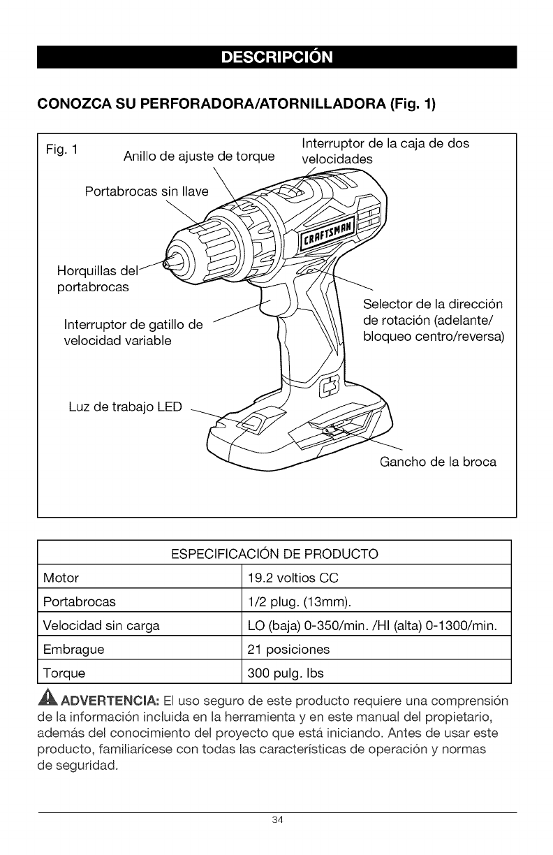
CONOZCA SU PERFORADORA/ATORNILLADORA (Fig. 1)
Interruptor de la caja de dos
Fig. 1 Anillo de ajuste de torque velocidades
\
Portabrocas sin Ilave X
Horq
portabrocas
Interruptor de gatillo de
velocidad variable
Selector de la direccion
de rotacion (adelante/
bloqueo centro/reversa)
Luz de trabajo LED
Gancho de la broca
ESPECIFICACION DE PRODUCTO
Motor 19.2 voltios CC
Portabrocas 1/2 plug. (13mm).
Velocidad sin carga LO (baja) 0-350/min./HI (alta) 0-1300/min.
Embrague 21 posiciones
Torque 300 pulg. Ibs
ADVERTENC[A: E[ uso seguro de este producto requiere una comprensi6n
de [a informaci6n inc[uida en [a herramienta yen este manual del propietario,
adem&s del conocimiento del proyecto que est& iniciando. Antes de usar este
producto, fami[iaricese con todas [as caracter[sticas de operaci6n y normas
de seguddad.
34
TORQUE AJUSTABLE
La perforadora/atomilladora cuenta con un embrague de 21 posiciones. Tiene 1
posici6n para perforadora y 20 para torque.
CAJA DE DOS VELOCIDADES
La caja de dos velocidades est,, dise_ada para perforar o atornillar en
velocidades LO (baja) o HI (alta). En la parte superior de su perforadora/
atornilladora hay un interruptor deslizable que se utiliza para seleccionar Ba
velocidad apropiada.
VELOCIDAD VARIABLE
El gatillo de velocidad variable ofrece una velocidad mayor con una presi6n de
gatillo mayor y una velocidad menor cuando se presiona el gatillo con menos
fuerza.
PORTABROCAS SIN LLAVE
El portabrocas sin llave le permite ajustar a mano o Biberar la broca de la
perforadora de las horquillas del portabrocas.
ADELANTE/REVERSA/CENTRO BLOQUEO
La perforadora!atomilladora cuenta con un selector de direcci6n de rotaci6n
ubicado sobre el interruptor de gatillo que se utiliza para cambiar la direcci6n de
rotaci6n de la brocao Colocar el interruptor de gatillo en la posici6n OFF (centro
bloqueo) ayuda a reducir la posibilidad de un arranque accidental cuando no se
encuentra en uso.
LUZ DETRABAJO LED
La luz de trabajo LED, ubicada en el base de la perforadora/atomilladora, se
ilumina cuando se presiona el interruptor de gatillo. Esta caracteristica ofrece luz
extra para Iograr una visibilidad mayor.
35
I_v_[o_
ADVERTENClA: Si falta alguna pieza o si alguna pieza est& rota, no trate de
enchufar el cable de energia u operar la perforadora/atornilladora hasta que se
reemplacen las piezas faltantes o rotas. No hacerlo puede provocar una lesion
personal grave.
ADVERTENOIA: No trate de modificar esta perforadora/atornilladora o
crear accesorios no recomendados para usar con esta herramienta. Cualquier
alteracion o modificacion constituye un uso indebido y podria provocar una
condicion peligrosa y posibles lesiones graves.
ADVERTENClA: Para prevenir un arranque accidental que podria provocar
lesiones personales graves, siempre desconecte el paquete de baterias de la
perforadora/atornilladora cuando cambie las brocas.
DESEMPAQUE
Este producto se ha enviado completamente montado.
•Con cuidado, quite la herramienta y los accesorios de la caja. AsegOrese de
que todos los elementos listados en el paquete esten incluidos.
• Inspeccione la herramienta con detenimiento para constatar que no hayan
ocurrido roturas o daSos durante el envio.
• No descarte el material de empaque hasta que haya inspeccionado la
herramienta con cuidado y la haya utilizado satisfactoriamente.
• Si falta alguna pieza o alguna pieza se encuentra rota, devuelva la
herramienta al lugar de compra.
LISTA DE EMPAQUE
Perforador&/atornilladora y manual del propietario.
36
[i]"J_ iI:IiIllII
Este producto acepta paquetes de baterias de ion de litio Craftsman C3 de
19.2V. Para las instrucciones de carga completas, consulte los Manuales del
Operador correspondientes a los paquetes de baterias y cargadores.
ADVERTENCIA: Para evitar un arranque accidental que podria provocar
lesiones personales graves, siempre desconecte el paquete de baterias de
la herramienta cuando coloque piezas, realice ajustes, instale o quite brocas,
efectOe la limpieza o cuando no Io este utilizando.
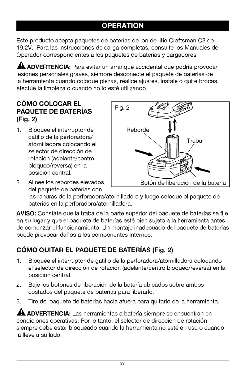
COMO COLOCAR EL
PAQUETE DE BATERJAS
(Fig. 2)
1. Bloquee el interruptor de
gatillo de la perforadora/
atornilladora colocando el
selector de direccion de
rotacion (adelante/centro
bloqueo/reversa) en la
posicion central.
2. Alinee los rebordes elevados
del paquete de baterias con
Fig. 2
Reborde i t
Boton de liberacion de la bateria
las ranuras de la perforadora/atornilladora y luego coloque el paquete de
baterias en la perforadora/atornilladora.
AVISO: Constate que la traba de la parte superior del paquete de baterias se fije
en su lugar y que el paquete de baterias este bien sujeto a la herramienta antes
de comenzar el funcionamiento. Un montaje inadecuado del paquete de baterias
puede provocar da_os a los componentes internos.
COMO QUITAR EL PAQUETE DE BATERJAS (Fig. 2)
1. Bloquee el interruptor de gatillo de la perforadora/atornilladora colocando
el selector de direcci6n de rotaci6n (adelante/centro bloqueo/reversa) en la
posicion central.
2. Baje los botones de liberaci6n de la bateria ubicados sobre ambos
costados del paquete de baterias para liberarlo.
3. Tire del paquete de baterias hacia afuera para quitarlo de la herramienta.
ADVERTENCIA: Las herramientas a bateria siempre se encuentran en
condiciones operativas. Por Io tanto, el selector de direcci6n de rotaci6n
siempre debe estar bloqueado cuando la herramienta no este en uso o cuando
la Ileve a su lado.
37
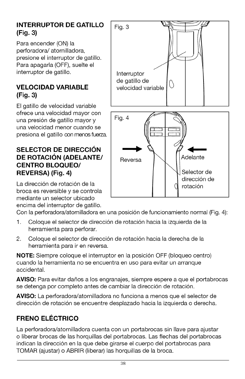
INTERRUPTOR DE GATILLO
(Fig. 3)
Para encender (ON) la
perforadora/atornilladora,
presione el interruptor de gatillo.
Para apagarla (OFF), suelte el
interruptor de gatillo.
VELOCIDAD VARIABLE
(Fig, 3)
El gatillo de velocidad variable
ofrece una velocidad mayor con
una presion de gatillo mayor y
una velocidad menor cuando se
presiona el gatillo con menos fuerz&
SELECTOR DE DIRECCION
DE ROTACION (ADELANTE/
CENTRO BLOQUEO/
REVERSA) (Fig. 4)
La direccion de rotacion de la
broca es reversible y se controla
mediante un selector ubicado
encima del interruptor de gatillo.
Fig. 3 j_
Interruptor I1
de gatillo de _ II
velocidad variable ..v ..
Fi0
Reversa Adelante
Selector de
direccion de
rotacion
Con la perforadora/atornilladora en una posicion de funcionamiento normal (Fig. 4):
1. Coloque el selector de direccion de rotacion hacia la izquierda de la
herramienta para perforar.
2. Coloque el selector de direccion de rotacion hacia la derecha de la
herramienta para ir en reversa.
NOTE: Siempre coloque el interruptor en la posicion OFF (bloqueo centro)
cuando la herramienta no se encuentra en uso para evitar un arranque
accidental.
AVISO: Para evitar da_os a los engranajes, siempre espere a que el portabrocas
se detenga por completo antes de cambiar la direccion de rotacion.
AVISO: La perforadora/atornilladora no funciona a menos que el selector de
direccion de rotacion se encuentre desplazado hacia la izquierda o derecha.
FRENO ELI_CTRICO
La perforadora/atornilladora cuenta con un portabrocas sin Ilave para ajustar
o liberar brocas de las horquillas del portabrocas. Las flechas del portabrocas
indican la direccion en la que debe girarse el cuerpo del portabrocas para
TOMAR (ajustar) o ABRIR (liberar) las horquillas de la broca.
38
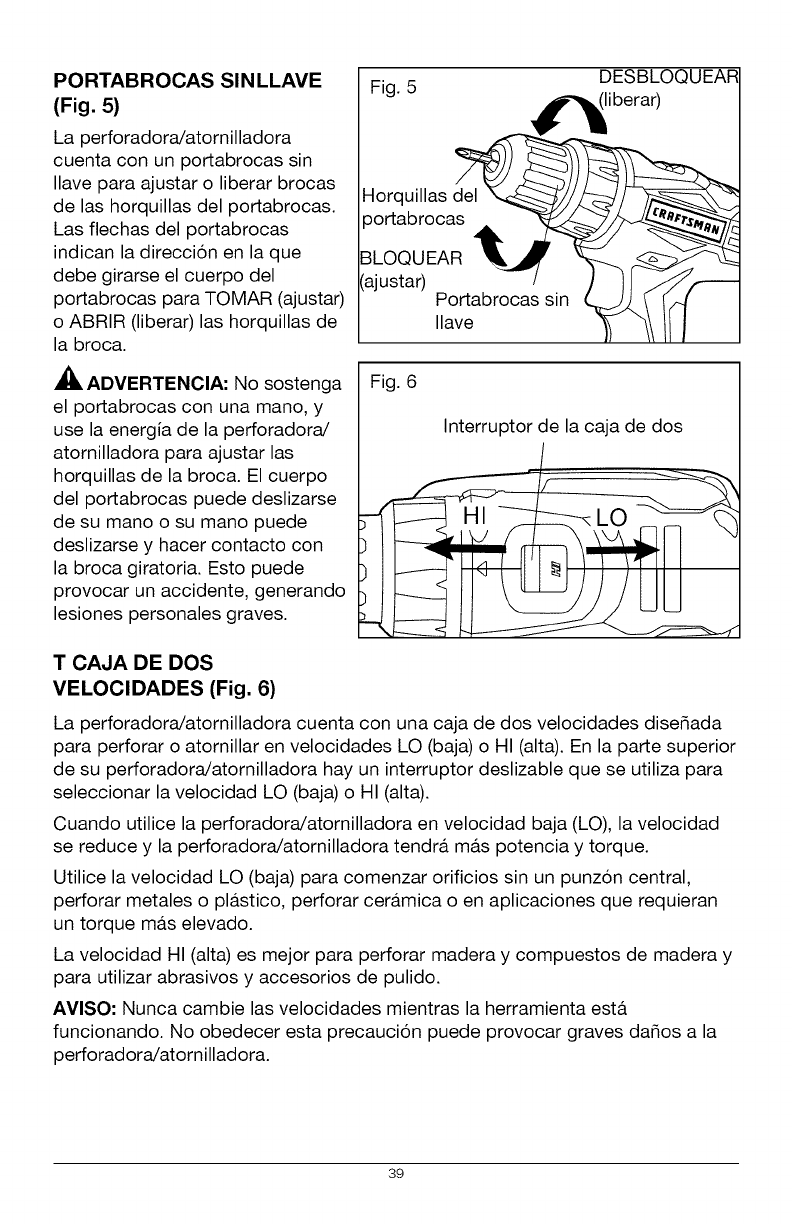
PORTABROCAS SINLLAVE
(Fig. 5)
La perforadora/atornilladora
cuenta con un portabrocas sin
Ilave para ajustar o liberar brocas
de las horquillas del portabrocas.
Las flechas del portabrocas
indican la direccion en la que
debe girarse el cuerpo del
portabrocas para TOMAR (ajustar)
o ABRIR (liberar) las horquillas de
la broca.
ADVERTENCIA: No sostenga
el portabrocas con una mano, y
use la energia de la perforadora/
atornilladora para ajustar las
horquillas de la broca. El cuerpo
del portabrocas puede deslizarse
de su mano o su mano puede
deslizarse y hacer contacto con
la broca giratoria. Esto puede
provocar un accidente, generando
lesiones personales graves.
Fig. 5 DESBLOC
Horquillas del
3ortabrocas
3LOQUEAR
_ajustar) Portabrocas sin
Ilave
Fig. 6
Interruptor de la caja de dos
T CAJA DE DOS
VELOCIDADES (Fig. 6)
La perforadora/atornilladora cuenta con una caja de dos velocidades dise_ada
para perforar o atornillar en velocidades LO (baja) o HI (alta). En la parte superior
de su perforadora/atornilladora hay un interruptor deslizable que se utiliza para
seleccionar la velocidad LO (baja) o HI (alta).
Cuando utilice la perforadora/atornilladora en velocidad baja (LO), la velocidad
se reduce y la perforadora/atornilladora tendra, ma.s potencia y torque.
Utilice la velocidad LO (baja) para comenzar orificios sin un punzon central,
perforar metales o pla.stico, perforar cera.mica o en aplicaciones que requieran
un torque ma.s elevado.
La velocidad HI (alta) es mejor para perforar madera y compuestos de madera y
para utilizar abrasivos y accesorios de pulido.
AVISO- Nunca cambie las velocidades mientras la herramienta esta.
funcionando. No obedecer esta precaucion puede provocar graves da_os a la
perforadora/atornilladora.
39
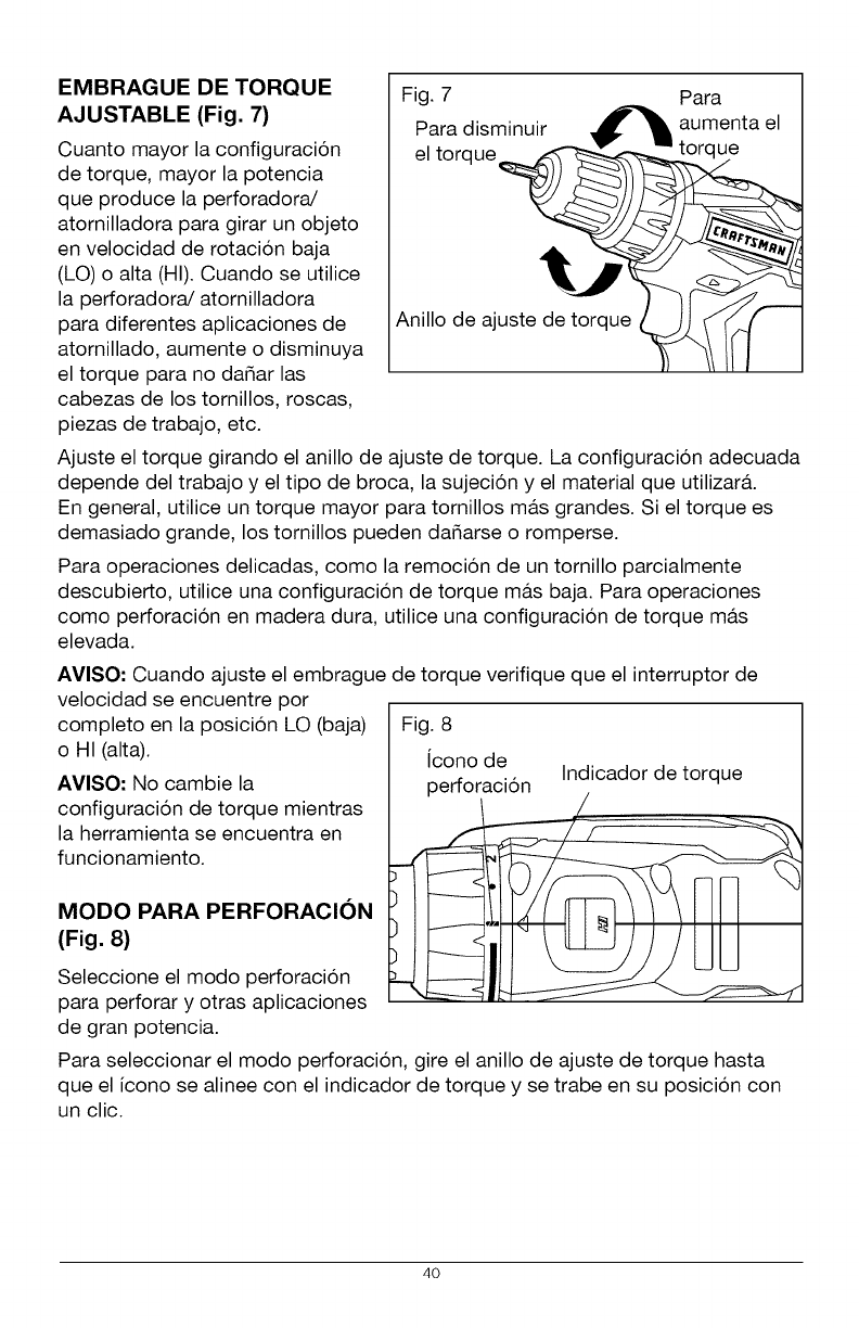
EMBRAGUE DE TORQUE
AJUSTABLE (Fig. 7)
Cuanto mayor la configuracion
de torque, mayor la potencia
que produce la perforadora/
atornilladora para girar un objeto
en velocidad de rotacion baja
(LO) o alta (HI). Cuando se utilice
la perforadora/atomilladora
para diferentes aplicaciones de
atomillado, aumente o disminuya
el torque para no dafiar las
cabezas de los tomillos, roscas,
piezas de trabajo, etc.
Fig. 7 Para
Para disminuir d_l, aumenta el
el torque_
Anillo de ajuste de t_rque __[_
Ajuste el torque girando el anillo de ajuste de torque. La configuracion adecuada
depende del trabajo y el tipo de broca, la sujecion y el material que utilizar&
En general, utilice un torque mayor para tornillos m&s grandes. Si el torque es
demasiado grande, los tornillos pueden dafiarse o romperse.
Para operaciones delicadas, como la remocion de un tornillo parcialmente
descubierto, utilice una configuracion de torque ma.s baja. Para operaciones
como perforacion en madera dura, utilice una configuracion de torque ma.s
elevada.
AVISO: Cuando ajuste el embrague de torque verifique que el interruptor de
velocidad se encuentre por
completo en la posicion LO (baja)
o HI (alta).
AVISO: No cambie la
configuracion de torque mientras
la herramienta se encuentra en
funcionamiento.
MODO PARA PERFORACION
(Fig. 8)
Seleccione el modo perforacion
para perforar y otras aplicaciones
de gran potencia.
Fig. 8
icono de
perforacion Indicador de torque
Para seleccionar el modo perforacion, gire el anillo de ajuste de torque hasta
que el icono se alinee con el indicador de torque y se trabe en su posicion con
un clic.
4O
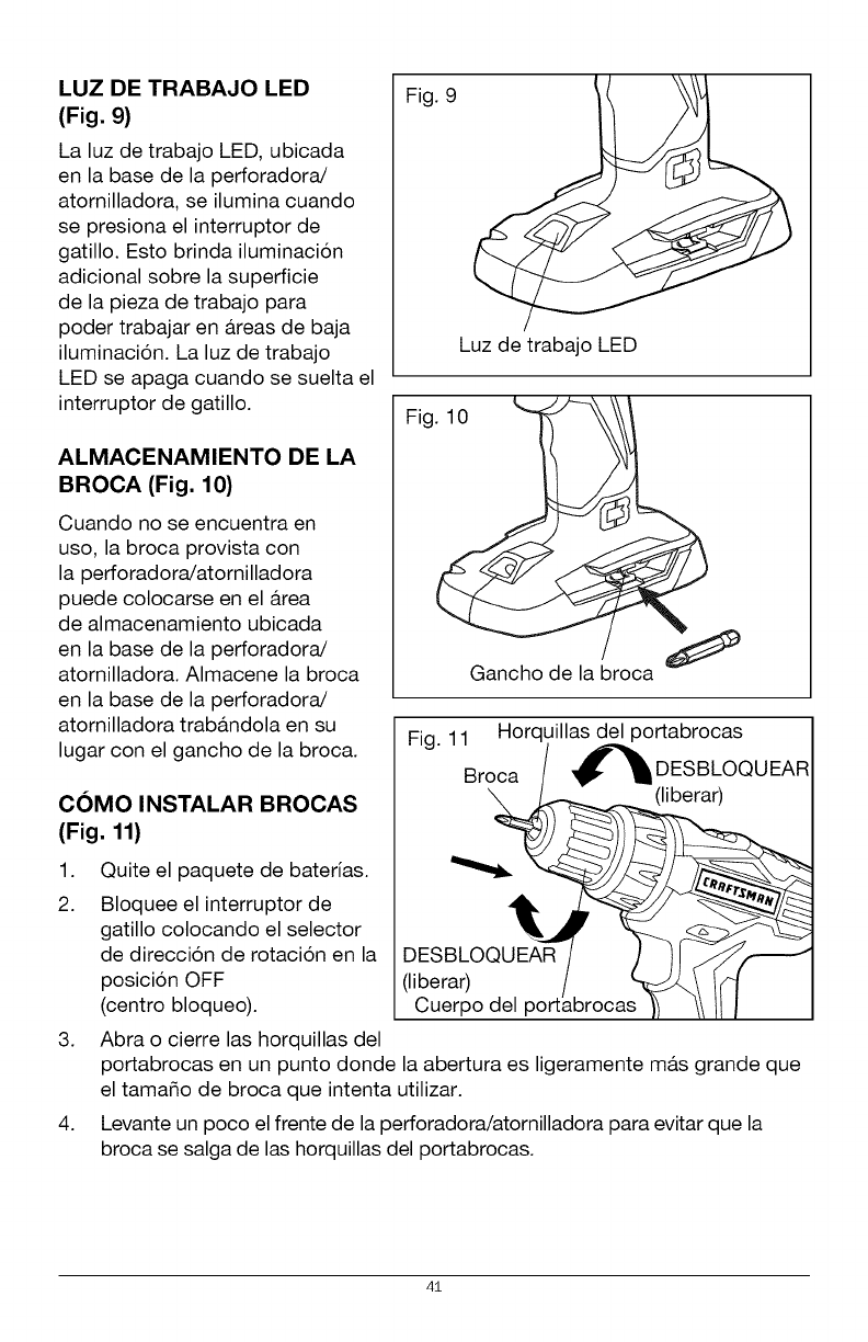
LUZ DE TRABAJO LED
(Fig. 9)
La luz de trabajo LED, ubicada
en la base de la perforadora/
atornilladora, se ilumina cuando
se presiona el interruptor de
gatillo. Esto brinda iluminacion
adicional sobre la superficie
de la pieza de trabajo para
poder trabajar en a.reas de baja
iluminacion. La luz de trabajo
LED se apaga cuando se suelta el
interruptor de gatillo.
ALMACENAMIENTO DE LA
BROCA (Fig. 10)
Cuando no se encuentra en
uso, la broca provista con
la perforadora/atornilladora
puede colocarse en el a.rea
de almacenamiento ubicada
en la base de la perforadora/
atornilladora. Almacene la broca
en la base de la perforadora/
atornilladora trab&ndola en su
lugar con el gancho de la broca.
COMO INSTALAR BROCAS
(Fig. 11)
Fig. 9
Luz de trabajo LED
Fig
Fig. 11 Horquillas del portabrocas
Broca _DESBLOQUEAR
(liberar)
1. Quite el paquete de baterias.
2. Bloquee el interruptor de
gatillo colocando el selector
de direccion de rotacion en la
posicion OFF
(centro bloqueo).
(liberar)
Cuerpo del
3. Abra o cierre las horquillas del
portabrocas en un punto donde la abertura es ligeramente ma.s grande que
el tama_o de broca que intenta utilizar.
4. Levante un poco el frente de la perforadora/atornilladora para evitar que la
broca se salga de las horquillas del portabrocas.
41
5. Introduzca una broca.
ADVERTENCIA: AsegOrese de colocar la broca directamente dentro de
las horquillas del portabrocas. No coloque la broca dentro de las horquillas
del portabrocas en a.ngulo y ajuste. Esto podria generar que la broca salga
disparada del taladro/atornillador durante el uso, provocando lesiones
personales graves durante el uso o dafios al portabrocas.
6. Gire el cuerpo del portabrocas en direccion de la flecha marcada "GRIP"
(tomar) para ajustar las horquillas del portabrocas.
AVISO- No use una Ilave para ajustar o desajustar las horquillas del portabrocas.
7. Ajuste las horquillas del portabrocas en la broca.
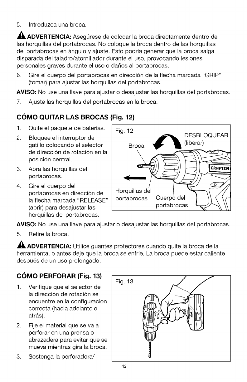
COMO QUITAR LAS BROCAS (Fig. 12)
1. Quite el paquete de baterias.
2. Bloquee el interruptor de
gatillo colocando el selector
de direccion de rotacion en la
posicion central.
3. Abra las horquillas del
portabrocas.
4. Gire el cuerpo del
portabrocas en direccion de
la flecha marcada "RELEASE"
(abrir) para desajustar las
horquillas del portabrocas.
Fig. 12 DESBLOQUEAR
Broca _ (liberar)
morquil_sasdl e/l__
portabrocas Cuerpo del _ /1 (', \{"
po abrocas \\
AVISO" No use una Ilave para ajustar o desajustar las horquillas del portabrocas.
5. Retire la broca.
ADVERTENCIA: Utilice guantes protectores cuando quite la broca de la
herramienta, o antes deje que la broca se enfrie. La broca puede estar caliente
despues de un uso prolongado.
COMO PERFORAR (Fig. 13)
1. Verifique que el selector de
la direccion de rotacion se
encuentre en la configuracion
correcta (hacia adelante o
atra.s).
2. Fije el material que se va a
perforar en una prensa o
abrazadera para evitar que se
mueva mientras gira la broca.
3. Sostenga la perforadora/
Fig. 13
42
atornilladora firmemente y coloque la broca en el punto donde va a efectuar
la perforacion.
4. Presione el interruptor de gatillo para encender la perforadora/atornilladora.
5. Introduzca la broca de la perforadora en la pieza de trabajo, aplicando
solo la fuerza suficiente para que la broca siga cortando. No fuerce la
perforadora/atornilladora ni aplique presion lateral para alargar un orificio.
Deje que la herramienta haga el trabajo.
6. Cuando realice perforaciones en superficie duras y lisas, utilice un punzon
central para marcar la ubicacion deseada del orificio. Esto evitara, que la
broca se deslice del centro cuando se inicia un orificio.
7. Cuando perfore metales, utilice aceite liviano en la broca para evitar el
sobrecalentamiento. El aceite prolonga la vida Otil de la broca y aumenta la
accion de perforacion.
8. Si la broca se traba en la pieza de trabajo o si la perforadora/atornilladora
se atasca, detenga la herramienta de inmediato. Quite la broca de la pieza
de trabajo y establezca la razon por la que se atasco.
AVISO: Esta perforadora/atornilladora se encuentra equipada con un freno
electrico. Cuando el freno funciona correctamente, pueden verse chispas a
traves de las ranuras de ventilacion de la carcasa. Esto es normal y se debe a la
accion del freno.
PERFORACION EN MADERA
Para un desempe_o ma.ximo, utilice brocas de acero de alta velocidad o brocas
para madera de punta fina.
1. Cuando perfore orificios "pasantes", coloque un bloque de madera detra.s
de la pieza de trabajo para evitar bordes irregulares o astillados en la parte
trasera del orificio.
2. Comience a perforar a una velocidad muy baja para evitar que la broca se
deslice del punto de inicio.
3. Incremente la velocidad a medida que la broca ingresa al material.
43
PERFORACION EN METAL
Para un desempe_o ma.ximo, utilice brocas de acero de alta velocidad o brocas
para madera de punta fina.
1. Cuando perfore metales, utilice aceite liviano en la broca para evitar el
sobrecalentamiento. El aceite prolonga la vida Otil de la broca y aumenta la
accion de perforacion.
2. Comience a perforar a una velocidad muy baja para evitar que la broca se
deslice del punto de inicio.
3. Mantenga una velocidad y una presion que permitan efectuar el corte sin
sobrecalentar la broca. Si aplica demasiada presion:
• Se sobrecalienta la perforadora/atornilladora.
• Se desgastan los cojinetes.
• Se doblan o queman las brocas.
• Se producen orificios descentrados o con formas irregulares.
44
ADVERTENClA: Para evitar una lesion personal grave, siempre quite el
paquete de baterias de la herramienta cuando la limpie o realice alguna clase
de mantenimiento.
ADVERTENOIA: Siempre utilice gafas de seguridad con protecciones
laterales cuando utilice aire comprimido para limpiar la herramienta. Si durante
la operacion se genera mucho polvillo, tambien use una ma.scara antipolvillo.
MANTENIMIENTO GENERAL
Evite usar solventes cuando limpie piezas pl&sticas. La mayoria de los pl&sticos
son susceptibles a dafios por parte de varios tipos de solventes comerciales y
pueden dafiarse por su uso. Utilice patios para quitar suciedad, polvillo, aceite,
grasa, etc.
ADVERTENOIA: No permita bajo ninguna circunstancia que liquido de
frenos, gasolina, productos a base de petroleo, aceites penetrantes, etc. entren
en contacto con las piezas pl&sticas. Los quimicos pueden dafiar, debilitar o
destruir el pla.stico, Io que puede provocar una lesion personal grave.
ADVERTENCIA: Cuando
realice un mantenimiento,
solo utilice piezas de repuesto
identicas. El uso de otras
piezas puede generar un
riesgo o provocar dafios al
producto. Para garantizar la
seguridad y la confiabilidad,
todas las reparaciones deben
ser efectuadas por un tecnico
calificado.
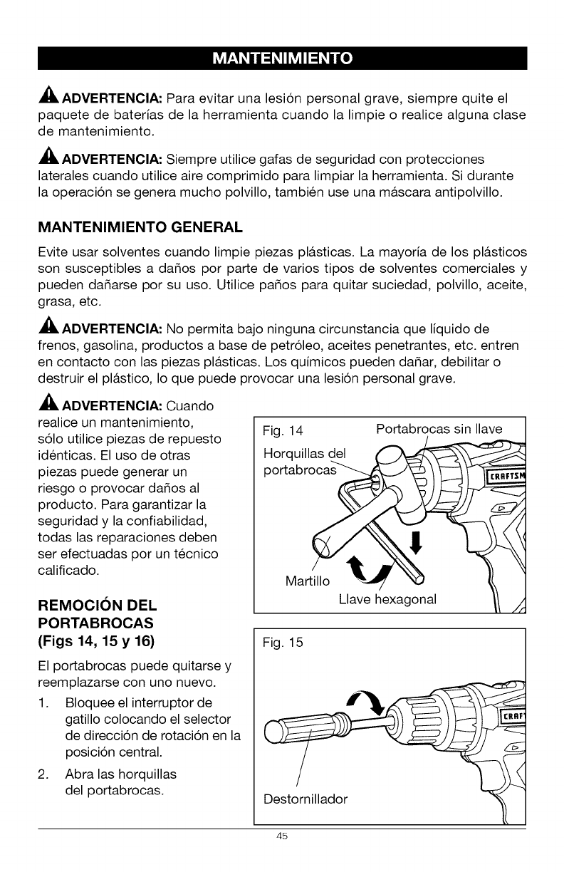
REMOCION DEL
PORTABROCAS
(Figs 14, 15 y 16)
El portabrocas puede quitarse y
reemplazarse con uno nuevo.
1. Bloquee el interruptor de
gatillo colocando el selector
de direccion de rotacion en la
posicion central.
2. Abra las horquillas
del portabrocas.
Fig. 14
Horquillas del
portabro_
Martillo _-_
Llave hexagonal
Portabrocas sin Ilave
CRRFTS_
Fig. 15
Destornillador
45
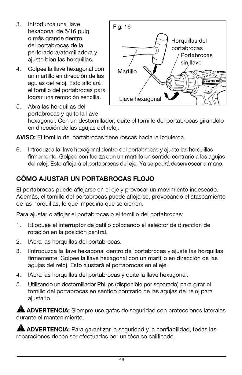
3. Introduzca una Ilave
hexagonal de 5/16 pulg.
o ma.s grande dentro
del portabrocas de la
perforadora/atornilladora y
ajuste bien las horquillas.
4. Golpee la Ilave hexagonal con
un martillo en direccion de las
agujas del reloj. Esto aflojara.
el tornillo del portabrocas para
Iograr una remocion sencilla.
5. Abra las horquillas del
portabrocas y quite la Ilave
Fig. 16
/_ Horquillas del
/portabrocas
/Portabrocas
/_/sin Ilave
Ma 'i,o
Clave hexagonal _ _ IL_
hexagonal. Con un destornillador, quite el tornillo del portabrocas gira.ndolo
en direccion de las agujas del reloj.
AVISO- El tornillo del portabrocas tiene roscas hacia la izquierda.
6. Introduzca la Ilave hexagonal dentro del portabrocas y ajuste las horquillas
firmemente. Golpee con fuerza con un martillo en sentido contrario alas agujas
del reloj. Esto aflojara, el portabrocas del eje. Ya se podra, desenroscar a mano.
COMO AJUSTAR UN PORTABROCAS FLOJO
El portabrocas puede aflojarse en el eje y provocar un movimiento indeseado.
Adema.s, el tornillo del portabrocas puede aflojarse, provocando el atascamiento
de las horquillas, Io que impediria que se cierren.
Para ajustar o aflojar el portabrocas o el tornillo del portabrocas:
1. IBIoquee el interruptor de gatillo colocando el selector de direccion de
rotacion en la posicion central.
2. IAbra las horquillas del portabrocas.
3. Ilntroduzca la Ilave hexagonal dentro del portabrocas y ajuste las horquillas
firmemente. Golpee la Ilave hexagonal con un martillo en direccion de las
agujas del reloj. Esto ajustara, el portabrocas en el eje.
4. IAbra las horquillas del portabrocas y quite la Ilave hexagonal.
5. Utilizando un destornillador Philips (disponible por separado) para girar el
tornillo del portabrocas en sentido contrario de las agujas del reloj para
ajustarlo.
ADVERTENCIA: Siempre use gafas de seguridad con protecciones laterales
durante el mantenimiento.
ADVERTENCIA: Para garantizar la seguridad y la confiabilidad, todas las
reparaciones deben ser efectuadas por un tecnico calificado.
46
ADVERTENClA: Para evitar una lesi6n personal grave, siempre quite el
paquete de baterias de la herramienta y desenchufe el cargador cuando realiza
una limpieza o alguna clase de mantenimiento.
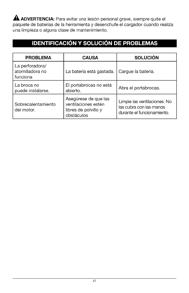
PROBLEMA CAUSA SOLUCION
La perforadora/
atornilladora no La bateria esta. gastada. Cargue la bateria.
funciona
La broca no El portabrocas no esta. Abra el portabrocas.
puede instalarse, abierto.
AsegQrese de que las Limpie las ventilaciones. No
Sobrecalentamiento ventilaciones est@n las cubra con las manos
del motor, libres de polvillo y durante el funcionamiento.
obst&culos
47

CRRFTSMRN
-888-33 -4569
T
® Registered Trademark /M Trademark of KCD IP, LLC in the United States, or Sears Brands, LLC in other countries
® Marca Registrada /T_ Marca de Fabrica de KCD IP, LLC en Estados Unldos, o Sears Brands, LLC in otros parses
