Craftsman 351215680 User Manual DRUM SANDER Manuals And Guides L0405300
CRAFTSMAN Sander Manual L0405300 CRAFTSMAN Sander Owner's Manual, CRAFTSMAN Sander installation guides
User Manual: Craftsman 351215680 351215680 CRAFTSMAN DRUM SANDER - Manuals and Guides View the owners manual for your CRAFTSMAN DRUM SANDER #351215680. Home:Tool Parts:Craftsman Parts:Craftsman DRUM SANDER Manual
Open the PDF directly: View PDF ![]() .
.
Page Count: 20

Operator's Manual
CRRFTSMRN°I
8 x 36"
DRUM SANDER WITH DUST COLLECTION
Model No.
351.21 5680
CAUTION: Read and follow
all Safety Rules and Operating
Instructions before First Use
of this Product.
Sears, Roebuck and Co., Hoffman Estates, IL 60179 U.S.A.
www.seam.com/craftsman
22118.02 Draft (05/17/04)
Warranty......................................... 2
Safety Rules ...................................... 2
Unpacking ....................................... 3
Assembly ...................................... 3-4
Installation ...................................... 4-5
Operation ...................................... 5-9
Maintenance .................................. 10-11
Troubleshooting .................................. 12
Parts Illustration and List ........................ 14-19
FULL ONE YEAR WARRANTY ON CRAFTSMAN
DRUM SANDER
If this product failsdue to a defect in material or workmanship
within one year from the date of purchase, Sears will at its
option repair or replace it free of charge. Contact your nearest
Sears Service Center (1-80O-4-MY-HOME) to arrange for
product repair, or return this product to place of purchase for
replacement.
If this product is used for commercial or rental purposes, this
warranty will apply for 90 days from the date of purchase.
This warranty applies only while this product is used in the
United States.
This warranty gives you specific legal rights, and you may
also have other dghts which vary from state to state.
Sears, Roebuck and Co,, Dept. 817WA, Hoffman Estates,
IL 60179
WARNING: For your own safety, read all of the instructions
and precautions before operating tool,
CAUTION: Always followproper operating procedures as
defined in this manual even if you are familiar with use of this
or similartools. Remember that being caraleesfor even a
fraction of a second can result in severe personal injury.
BE PREPARED FOR JOB
•Wear proper apparel. Do not wear loose clothing, gloves,
neckties, rings,bracelets or other jewelry which may get
caught in moving parts of machine.
•Wear protective hair covering to contain long hair.
•Wear safety shoes with non-slipsoles.
•Wear safety glasses complyingwith United States ANSI
Z87.1. Everyday glasses have only impactresistant lenses.
They are NOT safety glasses.
• Wear face mask or dust mask if operation is dusty.
•Be alert and thinkcieady. Never operate power toolswhen
tired, intoxicatedor when taking medications that cause
drowsiness.
PREPARE WORK AREA FOR JOB
• Keep work area clean. Cluttered work areas inviteaccidents.
• Do not use power tools in dangerous environments, Do not
use power tools in damp or wet locations.Do not expose
power tools to rain.
• Work area should be properly lighted.
• Proper electrical receptacle should be available for tool.
Three prong plug should be plugged directly into properly
grounded, three-prong receptacle.
• Extension cords should have a grounding prong and the three
wires of theextensioncord shouldbe of the correctgauge.
•Keep visitorsat a safe distance from work area.
•Keep childrenout of workplace. Make workshop childproof.
Use padlocks, master switches or remove switch keys to
prevent any unintentionaluse of power tools.
TOOL SHOULD BE MAINTAINED
• Always unplug tool prior to inspection.
• Consult manual for specific maintaining and adjusting
procedures.
• Keep tool lubricated and clean for safest operation.
• Remove adjusting tools. Form habit of checking to see that
adjustingtools are removed before switching machine on.
• Keep all parts in working order. Check to determine that the
guard or other parts will operate properly and perform their
intended function.
• Check for damaged parts. Check for alignment of moving
parts, binding, breakage, mounting and any other condition
that may affect a tool's operation.
• A guard or other part that is damaged should be properly
repaired or replaced. Do not perform makeshift repairs.
(Use parts list provided to order replacement parts.)
KNOW HOWTO USETOOL
• Use right tool for job. Do not force tool or attachment to do
ajob for which itwas not designed.
• Disconnecttool when changing belt.
• Avoid accidental start-up.Make sure that the tool is in the
"OFF" positionbefore pluggingin.
• Do notforce tool.It will work mostefficiently at the rate for
which it was designed.
•Keep hands away from moving parts and sanding surfaces.
•Never leave tool running unattended.Turn the power off
and do not leave tool until it comes to a complete stop.
•Do not overreach. Keep properfooting and balance.
•Never stand on tool. Serious injurycould occurif tool is
tipped or if belt is unintentionallycontacted.
•Knowyour tool. Learn the tool'soperation, applicationand
specificlimitations.
•Use of improper accessories may cause risk of injuryto
persons.
•Handle the work,piece correctly.Protect hands from possi-
ble injury.
CAUTION: Think safety! Safety is a combination of operator
common sense and alertness at all times when tool is being
used.
WARNING: Do not attempt to operate tool untilit is com-
pletely assembled according to the instructions.
@ Sears, Roebuck and Co. 2
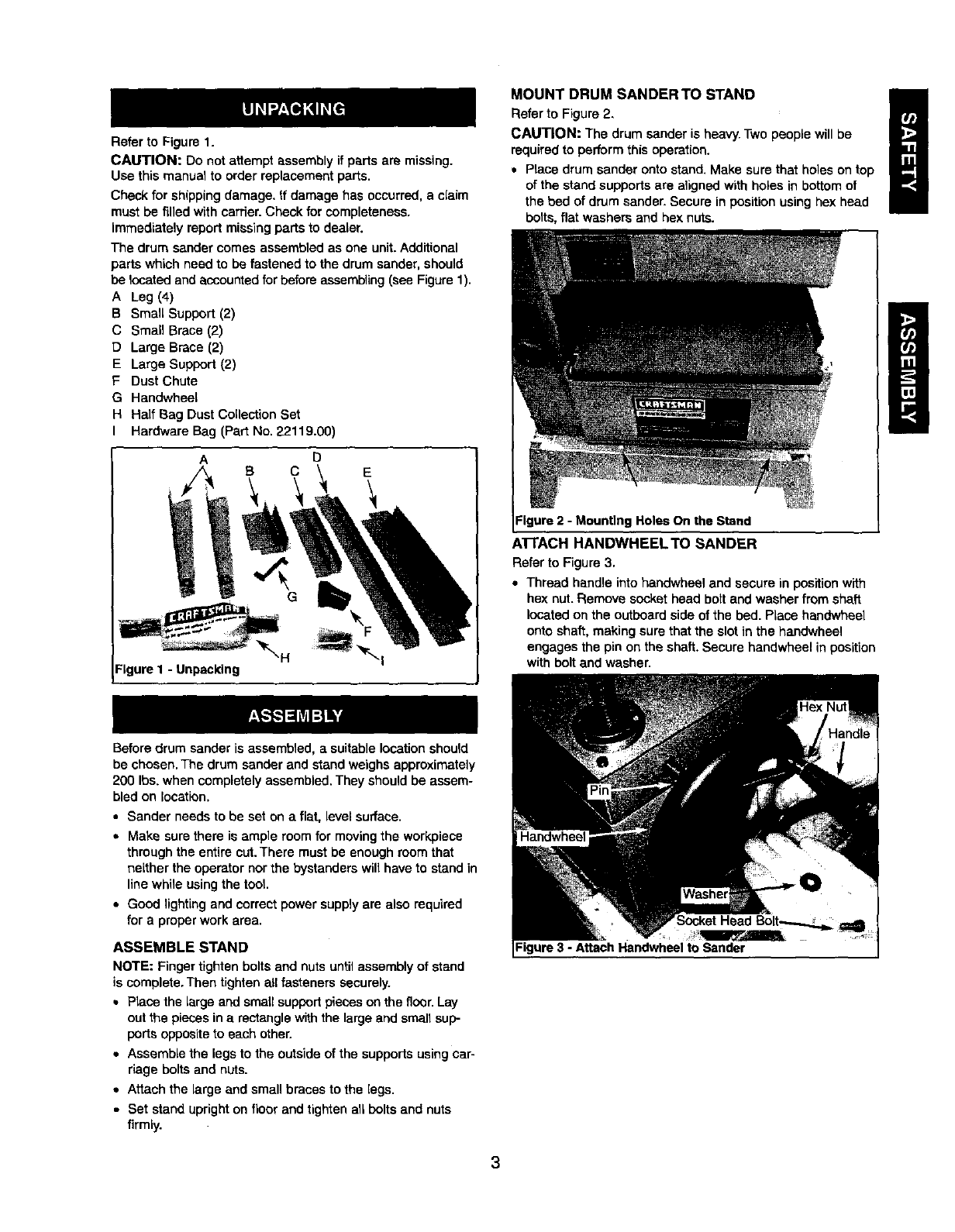
Refer to Figure 1.
CAUTION: Do not attempt assembly if parts are missing.
Use this manual to order replacement parts.
Check for shipping damage. If damage has occurred, a claim
mustbe filled with cartier. Check for completeness.
immediately report missingparts to dealer.
The drum sander comes assembled as one unit.Additional
parts which need to be fastened to the drum sander, should
be Iccated and accountedfor before assembling(see Figure 1).
A Leg (4)
B Small Support (2)
C Small Brace (2)
D Large Brace (2)
E Large Support (2)
F Dust Chute
GHandwheel
HHalf Bag Dust Collection Bet
I Hardware Bag (Part No. 22119.00)
A
Figure 1 -Unpacking
D
c\
G
E
MOUNT DRUM SANDERTO STAND B
Refer to Figure 2.
CAUTION: The drum sander is heavy.Two people will be
requiredto perform this operation.
•Place drum sander onto stand. Make sure that holes on top
of the stand supports are alignedwith holes in bottom of
the bed of drum sander. Secure in position using hex head
bolts, flat washers and hex nuts.
=Igure2 -Mounting Holes On the Stand
AI-rACH HANDWHEELTO SANDER
Refer to Figure 3.
•Thread handle into handwheel and secure in positionwith
hex nut. Remove socket head bolt and washer from shaft
locatedon the outboard side of the bed. Place handwheel
onto shaft, making sure that the slot in the handwheel
engages the pin on the shaft. Secure handwheel in position
with bolt and washer.
Before drum sander is assembled, a suitable location should
be chosen. The drum sander and stand weighs approximately
200 Ibs, when completely assembled. They should be assem-
bled on location.
•Bander needs to be set on a flat, level surface.
• Make surethere is ample room for moving the workpiece
through the entire cut, There must be enough room that
neLther the operator nor the bystanders will have to stand in
line while using the tool
• Good lightingand correct power supply are also required
for a proper work area.
ASSEMBLE STAND
NOTE: Finger tighten bolts end nuts untilassembly of stand
is complete. Then tighten all fasteners securely.
•PLacethe Largeand small supportpieces on the floor.Lay
out the pieces in a rectangle withthe large and small sup-
portsoppositeto each other.
• Assemble the legsto the outside of the supports usingcar-
riage boltsand nUts.
• Attach the large and small braces to the [egs.
•Set stand uprighton floor and tighten all bolts and nuts
firmly.
=igure3 -Attach Handwheel to Sander
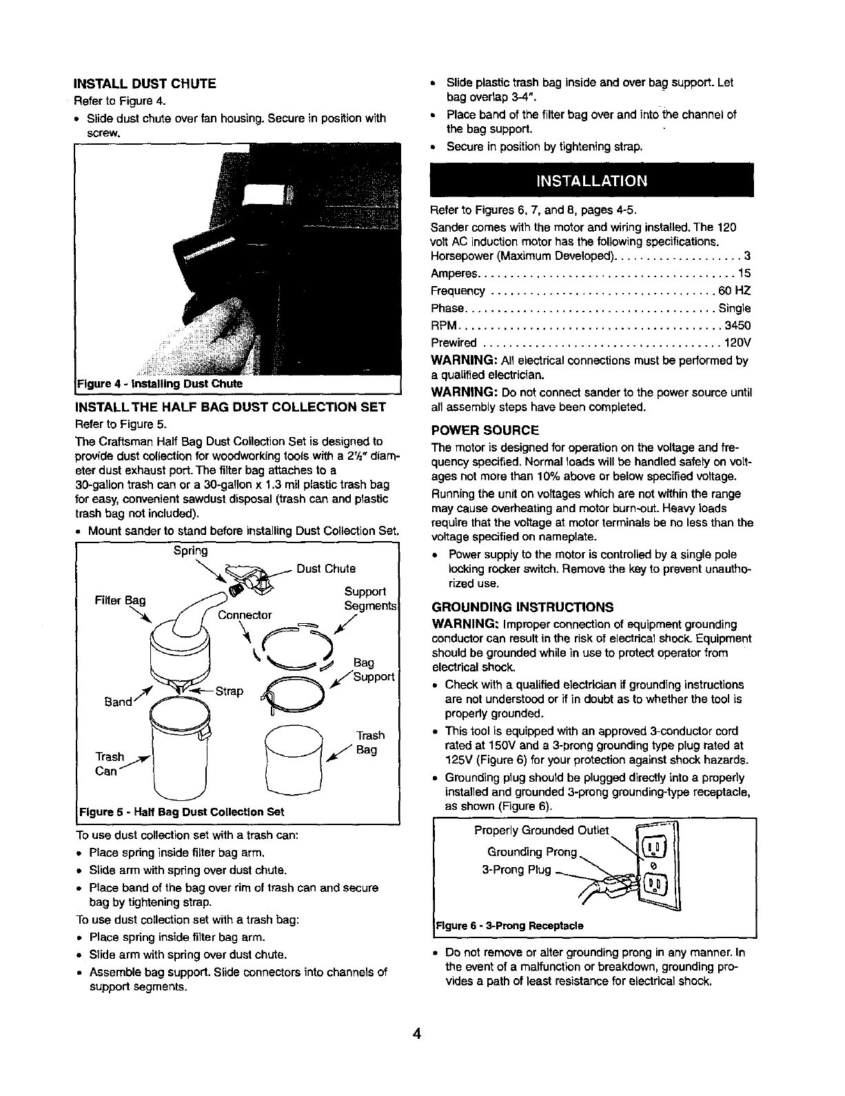
INSTALLDUSTCHUTE
RefertoFigure4.
• Slidedustchuteoverfanhousing.Securein positionwith
screw.
• Slide plastic trash bag inside end over bag support.Let
bag ovedap 3-4",
•Place band of the filter bag overand into the channel of
the bag support.
• Secure in positionby tighteningstrap.
igure 4 - Installing Duet Chute
INSTALL THE HALF BAG DUST COLLECTION SET
Refer to Figure 5.
The Craftsman Half Bag Dust Collection Set is designed to
providedust collectionfor woodworkingtools with a 2'/="diam-
eter dust exhaust port. The filter bag attaches to a
30-gatlon trash can or a 30-gallon x 1,3 rail plastictrash bag
for easy, convenient sawdust disposal (trash can and plastic
trash bag not included).
Mount sander to stand before installingDust Collection Set.
Spring DustChute
• _-,_ _ Support
Filter Bag /_..> Segments
j/Connector i
_' Sag
O*/Support
Can _._
Figure 5 - Half Bag Dust Collection Set
To use dust collectionset with a trash can:
• Place spring inside filter bag arm,
• Slide arm with spring over dust chute.
• Place band of the bag over rim of trash can and secure
bag by tightening strap.
To use dust collection set with a trash bag:
• Place spring inside filter bag arm.
• Slide arm with spdng over dust chute.
• Assemble bag support. Slide connectors into channels of
supportsegments.
Refer to Figures 6, 7, and 8, pages 4-5.
Sander comes withthe motor and wiring installed.The 120
volt AC induction motor has the following specifications.
Horsepower (Maximum Developed) .................... 3
Amperes ........................................ 15
Frequency ................................... 60 HZ
Phase ....................................... Single
RPM ......................................... 3450
Prewired ..................................... 120V
WARNING: All electrical connections mustbe performed by
a qualifiedelectrician.
WARNING: Do not connect sander to the power source until
an assembly steps have been completed.
POWER SOURCE
The motor is designed for operation on the voltageand fre-
quency specified.Normal loads willbe handled safely on volt-
ages not more than 10% above or below specified voltage.
Running the unit onvoltages which are not withinthe range
may cause overheating and motor burn-out.Heavy loads
require that the voltage at motor terminals be no less than the
voltage specified on nameplate.
•Power supply to the motor is controlled by a single pole
looking rocker switch.Remove the key to prevent unautho-
rized use,
GROUNDING INSTRUCTIONS
WARNING: Improper connection of equipment grounding
conductorcan result inthe risk of electrical shock. Equipment
should be groundedwhile in use to protect operator from
electrical shock.
• Check with a qualified electrician if groundinginstructions
are not understood or if in doubt as to whether the tool is
propedy grounded.
• This tool is equipped with an approved3-conductor cord
rated at 150V and a 3-prong groundingtype plug rated at
125V (Figure 6) for your protectionagainst shock hazards.
• Grounding plug should be plugged directly into aproperly
installed and grounded 3-prong greunding-type receptacle,
as shown (Figure 6).
Preperly Grounded Outlet F/_
Grounding Prong_ II
3-Prong Plug _
Figure 6 - 3-prong Receptacle
•De not remove or alter groundingprong in any manner. In
the eventof a malfunction or breakdown, groundingpro-
vides a path of least resistance for electrical shock.
4
WARNING: Do not permit fingers to touchthe terminals of
plug when installing or removing from outlet.
•Plug must be plugged into matching outlet that is properly
installed and grounded in accordance with all local codes
and ordinances. Do not modify plugprovided. If itwill not fit
in outlet, have proper outlet installed by a qualified
electrician.
•Inspect tool cords periodically, and if damaged, have
repaired by an authorized service facility.
• Green (or green and yellow) conductor in cord is the
groundingwire. If repair or replacement of the electric cord
or plug is necessary, do not connect the green (or green
and yellow) wire to a live terminal.
• Where a 2-prong wall receptacle is encountered, it must be
replaced with a properly grounded 3-prong receptacle
installed in accordance with National Electric Cede and
local codes and ordinances.
WARNING: This work shouldbe performed by a qualified
electrician.
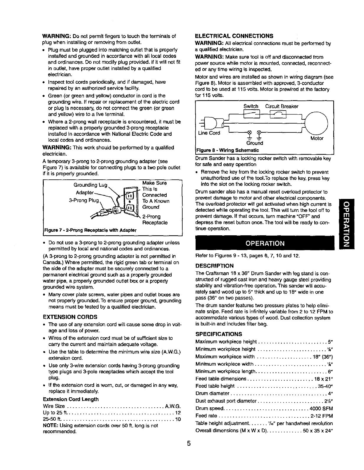
Atemporary 3-prong to 2-prong groundingadapter (see
Figure 7) is available for connecting plugs to a two pole outlet
if it is properly grounded.
Grounding Make Sure
This Is
Connected
3-Prong Plug To A Known
Ground
,2-Prong
Receptacle
Figure7 - 2-Preng ReceptaclewithAdapter
• Do not use a 3-prong to 2-prong grounding adapter unless
permitted by local and national codes and ordinances.
(A 3-prong to 2-preng grounding adapter is not permitted in
Canada.) Where permitted, the rigid green tab or terminal on
the side of the adapter must be securely connected to a
permanent electrical ground such as a properly grounded
water pipe, a properly grounded outlet box or a properly
grounded wire system.
• Many cover plate screws, water pipes and outlet boxes are
not properly grounded. To ensure proper ground, grounding
means must be tested by a qualified electrician.
EXTENSION CORDS
•The use of any extension cord will cause some dropin volt-
age and lossof power.
•Wires of the extension cord mustbe of sufficientsize to
carry the current end maintain adequate voltage.
•Use the ta_e to determine the minimum wire size (A,W.G.)
extension cord.
Use only 3-wire extension cords having 3-prong grounding
type plugs and 3-pole receptacles which accept the tool
plug,
If the extensioncord is worn, cut, or damaged in any way,
replace it immediately.
Extension Cord Length
Wire Size ................................... A.W,G.
Up to 25 tt....................................... 12
25-50 ft......................................... 10
NOTE: Using extension cords over 50 ft. long is not
recommended.
ELECTRICAL CONNECTIONS
WARNING: All electrical connectionsmust be performed by
a qualifiedelectrician.
WARNING: Make sure tool is off and disconnected from
power soume while motor is mounted, connected, reconnect-
ed or any time wiring is inspected.
Motor and wires are installed as shown in wiringdiagram (see
Figure 6). Motor is assembled with approved, 3-oonductor
cordto be used at 115 volts. Motor is prewired at the factory
for 115 volts.
Switch Circuit Breaker
Ground
:igure 8 -Wiring Schematic
Drum Sander has a locking rocker switchwith removable ke
for safe and easy operation
• Remove the key from the Iook_]ngrocker switch to prevent
unauthorized use of the tool.To replace the key, press key
into the slot on the locking rocker switch.
Drum sander also has a manual reset overload protectorto
prevent damage to motor and other electrical components.
The overload protector will get activated when high current is
detected while operating the tool. This will turn the tool off to
prevent damage. If that occurs, turn machine "OFF" and
depress the reset button once. The tool will be ready to con-
tinue operation.
Refer to Figures 9 - 13, pages 6, 7, 10 and 12.
DESCRIPTION
The Craftsman 18 x 36" Drum Sander with leg stand is con-
strocted of rugged cast iron and heavy gauge steel providing
stability and vibration-free operation. This sander will accu-
rately sand wood up to 5" thick and up to 18" wide in one
pass (36" on two passes).
The drum sander features two pressure plates to help elimi-
nate snipe. Feed rate is infinitely variable from 2 to 12 FPM to
accommodate various types of wood. Dust collection system
is built-in and includes filter bag.
SPECIFICATIONS
Maximum workplace height ......................... 5"
Minimumworkplace height ......................... %"
Maximum workplace width .................... 18" (36")
Minimumworkpiece width .......................... %"
Minimumworkpiece length .......................... 6"
Feed table dimensions ........................ 18 x 21"
Feed table height ............................. 35-40"
Drum diameter ................................... 4"
Dust exhaust port diameter ........................ 2'/z"
Drum speed............................... 4000 SFM
Feed rate ................................. 2-12 FPM
Table height adjustment....... _/,6"per handwheel revolution
Overall dimensions (M x W x D) ............. 50 x 35 x 24"
Switch.................... 120 Volts, SP,Locking rocker
Motor ................. 3HP (max, developed) 3450 RPM,
.................................... 115V, 17 AMPS
.Weight ..................................... 198 Ibs
WARNING: Operation of any power tool can result in foreign
objectsbeing thrown into eyes which can result in severe eye
damage. Always wear safety goggles complyingwith United
States ANSI Z87.1 (shown on package) before commencing
power tool operation. Safety goggles are availableat Sears
retail stores or catalog,
CAUTION: Always observe the following safety precautions.
SAFETY PRECAUTIONS
•Whenever adjustingor replacing any parts on the tool, turn
switchOFF and remove the plug from power source.
•Make sure all guards are properlyattached. All guards
should be securely fastened.
•Make sure all moving parts are free and clear of any
interference.
•Make sure all fasteners are tight and have not vibrated
loose.
•Always use the dust collection system provided with this
tool.
• Always wear eye protection or face shield.
• Make sure feed belt tracks properly. Correct tracking gives
optimumperformance.
• After turning switchon, always allow drum to come up to
full speed before sanding.
•Clear the feed table of aUobjects (tools,scrap, etc.) before
starting tool.
•Keep yourhands clear of abrasive belt and allmovingparts.
•For optimumperformance, do not stall motor or reduce
speed. Do not force the work into the abrasive.
•Support long or wide workpieces with a roller stand at table
height.
• Never push a sharp corner of the workpiece rapidly against
belt. Abrasive backing may tear.
•Replace abrasive when they become loaded (glazed) or
frayed. Check belts for tightness.
•This tool is designed to sand wood or wood productsonly.
Do not attempt to sand metal on thistool.
•Do not sand pieces of material that are shorter than 6" in
length or thinnerthat Ys".
•Prevent the workpiece from contacting the sanding belt
before starting the tool.
• Sand with the grain of the wood.
•Never perform layout, assembly, or set-up work on the table
when the tool is operating.
•Turn the tool "OFF", disconnectthe tool from the power
source, and clean the table/work area before leaving the
tool,
• Never leave the work area when the power is =ON", or
before the tool has come to a complete stop.
WARNING: Some dust created by power sanding, sawing,
grinding,drilling and other constructionactivitiescontains
chemicals known to cause cancer, birthdefects or other
reproductiveharm.
Some examples of these chemicals are:
•Lead from lead-based paints.
• Crystalline silicafrom bricksand cement and other
masonry products.
•Arsenic and chromium from chemically-traatedlumber.
Yourrisk from these exposures vary, depending on how often
you do this type of work.To reduce your exposure to these
chemicals:work in a web ventilated area and work with
approved safety equipment. Always wear MSHA/NIOSH
approved, properlyfitting face mask or respiratorwhen using
such tools.
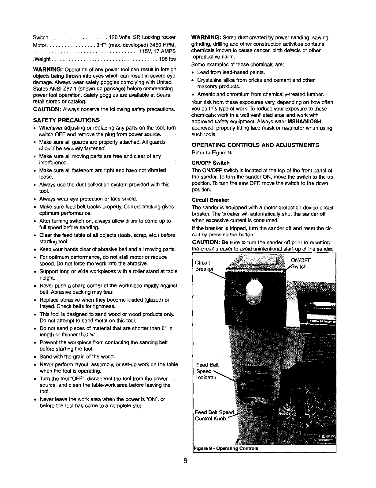
OPERATING CONTROLS AND ADJUSTMENTS
Refarto Figure9,
ON/OFF Switch
The ON/OFF switch is located at the top of the front panel of
the sander.To turn the sander ON, move the switchto the up
position. To turn the saw OFF, move the switchto the down
position.
Circuit Breaker
The sander is equipped with a motor protectiondevice-cireuit
breaker.The breaker will automatically shutthe sander off
when excessive current is consumed.
if the breaker is tripped, turn the sander off and reset the cir-
cuit by pressing the button.
CAUTION: Be sure to turn the sander off prior to resetting
the circuitbreakerto avoidunintentionalstart-upof the sander.
Cimuit
Breaker
ON/OFF
Feed Belt
Indicator
Feed Belt
Control
Figure 9 - Operating Controls
Feed Belt Speed Control Knob
CAUTION: Change speeds only while machine is running,
The feed belt speed controlknob is located in the center of
the front panel of the sander. To increase belt speed, rotate
the knobcounterclockwise.To decrease belt speed, rotate the
knob clockwise.
• Stockcan be removed more quickly by using a fast speed,
but the machine works much harder, and the wood is left
with a rougher finish. Slowing the speed will lightenthe
load of the sander, and make the finish better, but it will
increase the sanding time.
•Reduce speed for wider boards and hardwoods.
Feed Belt Speed Indicator
Indicates the belt speed in feet per minute.
Switch Lock
Refer to Figure 10.
The sander can be locked from unauthorized use by locking
the switch.To lockthe switch:
• Turnthe switchto OFF positionand disconnect saw from
power source.
• Pull the key out. The switch cannot be turned on withthe
key removed.
NOTE: Shouldthe key be removed from the switch at the ON
position,the switch can be turned off but cannot be turned on.
•To replaca key, slide key intothe slot on switchuntil it
snaps.
the Locking Key
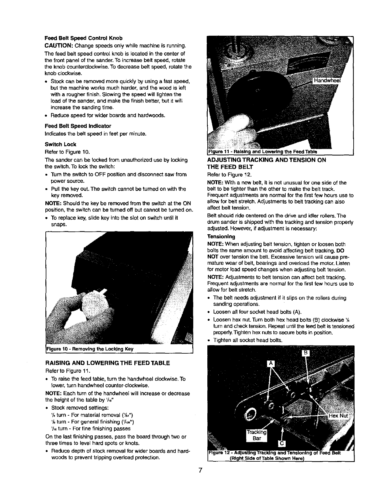
Figure 11 - Raisin9 the Feed Table
ADJUSTING TRACKING AND TENSION ON
THE FEED BELT
Refer to Figure 12.
NOTE: With a new belt, it is not unusual for one side of the
belt tobe tighterthan the other to make the belt track.
Frequent adjustmentsare normal for the first few hoursuse to
allow for belt stretch.Adjustmentsto belt trackingcan also
affect belt tension.
Belt shouldride cantered on the drive and idler rollers.The
drum sander is shipped withthe tracking and tension properly
adjusted. However, ifadjustment is necessary:
Tensioning
NOTE: When adjustingbelt tension, tighten or loosen both
bolts the same amount to avoid affecting belt tracking.DO
NOT over tensionthe belt. Excessive tension will cause pre-
mature wear of belt, bearings and overload the motor.Listen
for motor lead speed changes when adjusting belt tension.
NOTE: Adjustments to belt tension can affect belttracking.
Frequent adjustments are normal for the firstfew hoursuse to
allow for belt stretch.
• The belt needs adjustment if it slips on the rollers during
sanding operations.
• Loosen all four socket head bolts (A).
• Loosen hex nut.Turn both hex head bolts (B) clockwise '/,
turn and check tension. Repeat until the feed belt is tensioned
properly.Tighten hex nutsto secure bolts in position.
• Tighten all socket head bolts.
RAISING AND LOWERING THE FEED TABLE
Refer to Figure 11.
•To raise the feed table, turn the handwheel clockwise.To
lower,turn bendwheel counter-clockwise.
NOTE: Each turn of the handwheel will increase or decrease
the heightof the table by '/_6"
•Stock removed settings:
1/,turn - For material removal (V=")
%turn - Forgeneral finishing (V,_")
'/,_turn -Forfine finishing passes
On the lastfinishing passes, pass the board throughtwo or
three times to level hard spots or knots.
•Reduce depth of stock removal for wider boards and hard-
woods to preventtrippingoverload protection.
7
Tracking
• Connect tool to power source.
•Turnbelt feed speed controlknob to the maximum speed,
and run the feed table several minutes to check for proper
trackingof the feed belt.
•Let the belt run and observe trackingdirection.If belt does
not move to either side withinfive minutes of running, no
adjustment is needed.
•To correct improper trackingof the feed beltto the left,
loosen the hex nut of the tracking bar assembly and turn
the socket head bolt (on the leftside of the taple) counter-
clockwise 1/4turn. (Counterclockwisedirection as viewed
from the head of the bolt.) Continue this adjustment until
the feed belt is trackingproperly on the feed rollers.Let the
feed belt run several minutes before adjusting again.
Tighten the hex nutto secure tracking bar in position.
•To correct improper tracking of the feed belt to the right,
loosenthe hex head nut of the trackingbar assembly and
turn the socket head bolt (on the rightside of the table)
counterclockwisa'/, turn. (Counterclockwisedirection as
viewed from the head of the bolt.) Continue this adjustment
untilthe feed belt is tracking properlyon the feed rollers.
Let the feed belt run several minutes before adjusting
again. Tighten the hex nut to secure trackingbar position.
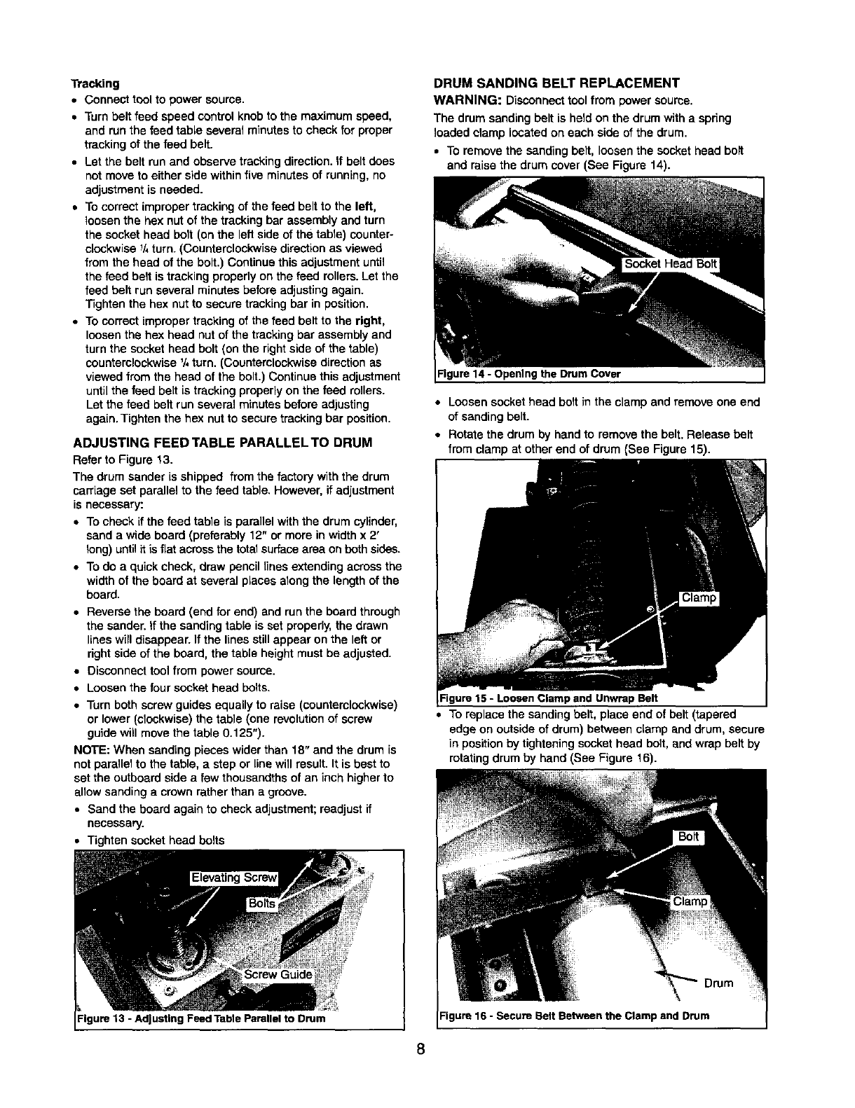
ADJUSTING FEED TABLE PARALLEL TO DRUM
Refer to Figure 13.
The drum sander is shipped from the factory with the drum
carriage set parallel to the feed table.However, if adjustment
is necessary:
•To check ifthe feed table is parallel withthe drum cylinder,
sand a wide board (preferably 12" or more in width x 2'
long) until itis fiat acrossthe totalsurfacearea on both sides.
•To do a quick check, draw pencil lines extendingacross the
width of the board at several places aloog the length of the
board.
• Reverse the board (end for end) and run the board through
the sander, if the sanding table is set properly, the drawn
lines will disappear. If the lines still appear on the left or
right side of the board, the table height must be adjusted.
• Disconnect tool from power source.
• Loosen the four socket head bolts.
•Turn both screw guides equally to raise (counterclockwise)
or lower (clockwise) the table (one revolutionof screw
guide will move the table 0.125").
NOTE: When sandLngpieces wider than 18" and the drum is
not parallelto the table, a step or line will result.It is best to
set the outboard side a few thousandths of an inch higherto
allowsanding a crown ratherthan a groove.
•Sand the board again to check adjustment;readjust if
necessary.
• Tighten socket head bolts
Figure 13 - Adjusting Feed Table Parallel to Drum
DRUM SANDING BELT REPLACEMENT
WARNING: Disconnecttool from power source.
The drum sanding belt is held on the drum with a spring
loaded clamp located on each side of the drum.
•To remove the sanding belt, loosenthe socket head boll
and raise the drum cover (See Figure 14).
Socket Head Bolt
Figure 14 - Opening the Drum Cover
• Loosen socket head bolt in the clamp and remove one end
of sanding belt.
• Rotate the drum by hand to remove the belt. Releasa belt
from clamp at other end of drum (See Figure 15).
and UnwrapBelt
• To replace the sanding belt, place end of belt (tapered
edge on outside of drum) between clamp and drum, secure
]n position by tightening socket head bolt, and wrap belt by
rotatingdrum by hand (See Figure 16).
Drum
Figure 16 - Secure BeltBetween the Clampand Drum
8
• Tightly wrap sanding belt around the drum keeping each
wrap close to the previous edge (See Figure 17).
iMPORTANT: Do not overlap the edges of the sanding belt.
Figure 17 - Wrap Belt Tightly
• Place the end of the belt between the clamp and drum and
tighten the socket head bolt in the clamp.
• Close drum cover and secure by tightening socket head belt.
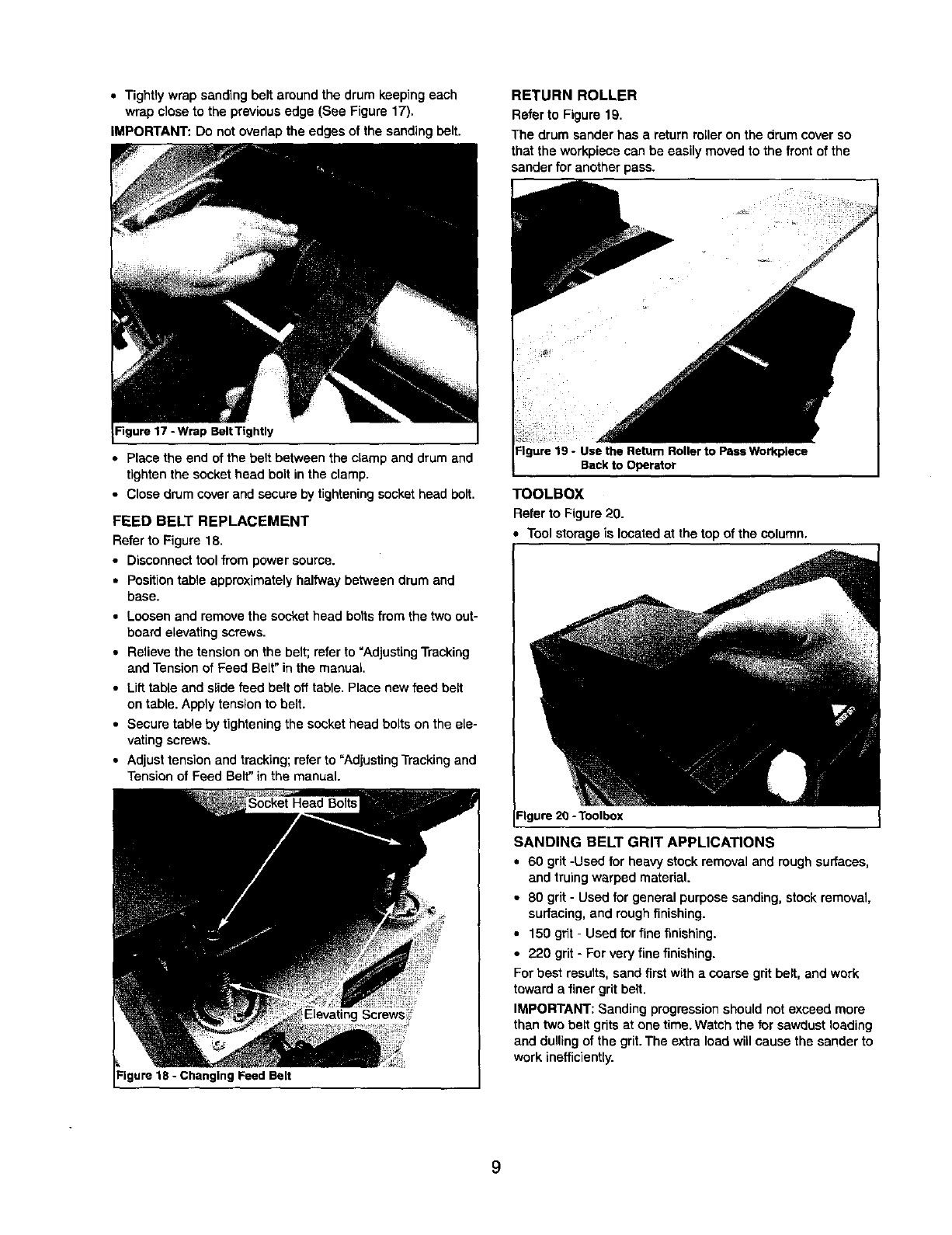
FEED BELT REPLACEMENT
Refer to Figure 18.
•Disconnecttool from power source.
• Position table approximately halfway between drum and
base.
•Loosen and remove the socket head bolts from the two out-
board elevating screws.
• Relieve the tension on the belt; refer to "Adjusting Tracking
and Tension of Feed Belt" in the manual,
• Lift table and slide feed belt off table. Place new feed belt
on table. Apply tension to belt.
• Secure table by tightening the socket head bolts on the ele-
vating screws.
• Adjust tension and tracking; refer to "Adjusting Tracking and
Tension of Feed Belt" in the manual.
Elevating Screws?
Figure 18 -Changing Feed Belt
RETURN ROLLER
Refer to Figure 19.
The drum sander has a return roller on the drum cover so
that the workplace can be easily moved to the frontof the
sander for another pass.
PassWorkplece
Backto Operator
TOOLBOX
Refer to Figure 20.
Tool storage is locatedat the top of the column.
-"lgure20 -Toolbox
SANDING BELT GRIT APPLICATIONS
•60 grit -Used for heavy stock removal and rough surfaces,
and truing warped material.
•80 grit -Used for general purpose sanding, stockremoval,
surfacing, and rough finishing.
•150 grit-Used for fine finishing.
•220 grit-For very fine finishing.
Forbest results,sand first witha coarse grit belt, and work
toward afiner grit belt.
IMPORTANT: Sanding progressionshould not exceed more
than two belt grits at one time. Watch the for sawdust loading
and dullingof the grit.The extra load willcause the sander to
work inefficiently.
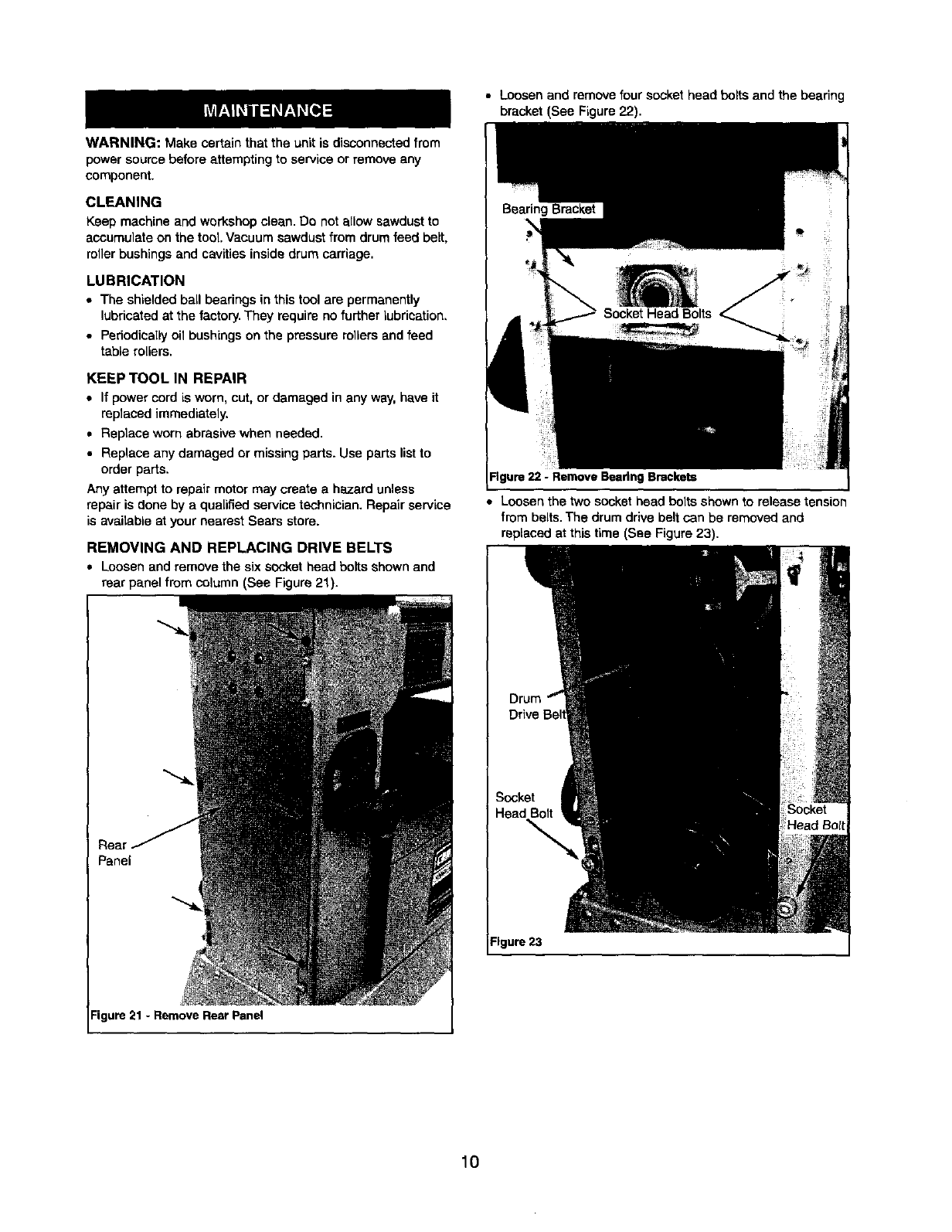
WARNING: Make certain that the unit is disconnectedfrom
power soume before attempting to service or remove any
component.
CLEANING
Keep machine and workshop clean. Do not allow sawdustto
accumulate on the tool. Vacuum sawdust from drum feed belt,
rollerbushingsand cavities insidedrum carriage.
LUBRICATION
• The shielded ball bearings in this tool are permanently
lubricated at the factory. They require no further lubrication,
•Periodicallyoil bushings on the pressure rollers and feed
table rollers.
KEEP TOOL IN REPAIR
•If power cord is worn, cut, or damaged in any way, have it
replaced immediately.
•Replace worn abrasive when needed.
• Replace any damaged or missing parts. Use parts list to
order parts.
Any attempt to repair motor may create a hazard unless
repair is done by a qualified service technician. Repair service
is available at your nearest Sears store.
REMOVING AND REPLACING DRIVE BELTS
•Loosen and remove the six socket head bolts shown and
rear panel from column (See Figure 21).
Real
Panel
• Loosen and remove four socket head bolts and the bearing
bracket (See Figure 22).
Rgure 22 - RemoveBeadngBrackets
•Loosen the twosocket head bolts shown to release tension
from belts.The drum drive belt can be removed and
replaced at thistime (See Figure 23).
Figure 23
Figure 21 -Remove Rear Panel
10
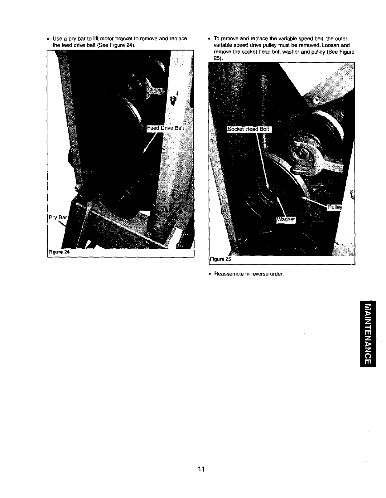
•Use a pry bar to lift motor bracket to remove and replace
the feed ddve belt (See Figure 24).
Figure 24
• To remove and replace the variable speed belt, the outer
variable speed drive pulley must be removed. Loosen and
remove the socket head bolt washer and pulley (See Figure
25).
Figure 25
•Reassembte in reverse order.
11

SYMPTOM POSSIBLE CAUSE(S) CORRECTIVE ACTION
Motor will not start 1. Low voltage 1. Check power line for proper voltage
2. Open circuit inmotor or loose 2. Inspect all lead connections on motor for loose or
connections open connection
3. Thermal overload protector activated 3. Push thermal overload button to reset
1. Short circuit in line cord or plugMotor will not start;
fuses blown or circuit
breakers are tripped
Motor fails to devalop full
power (power output of
motor decreases rapidly
with decrease in voltage
at motor terminals)
Motor stalls
(resulting in blown
fuses or tripped circuit
breakers)
2. Short circuitin motor or loose
connections
3, incorrect fuses or circuitbreakers in
power line
4. Thermal overload protector activated
1. Power line overloaded with lights,
appliances and other motors
2. Undersize wires or circuits too long
3. General overloading of power
company's facilities
1.Motor overload; too much stock removed
per pass
2. Short circuit in motor or loose
connections
3. Low voltage
:4. Incorrect fuses or circuit breakers in
power line
1. inspect line cord or plug for damaged insulationand
shorted wires
2. Inspect all lead connections on motor for loose or
shorted terminals or worn insulation on wires
3. Install correct fuses or circuitbreakers
4. Push thermal overload button to reset
1. Reduce the Loadon the power line
2. Increase wire sizes, or reduce lengthof wiring
3. Request a voltage check from the power company
1.Set drum height to remove less material per pass
2. Inspectconnections in motor for loose or shorted
terminals or worn insulationon lead wires.
3. Correct the low line voltage conditions
4. Install correct fuses or circuit breakers
Feed belt runs Not tracking properly See operation, =Adjusting Tracking andTension of the
off roners Feed Belt"
Workpieces stalls 1. Too much stock removal per pass 1. Reduce depth of stockremoval per pass
while feeding 2. Not enough tension 2. See operation, "Adjusting Tracking and Tension of the
on feed belt Feed Belt"
Workpiece thickness is Drum carriage is not paraUel to the feed See operation, =Adjusting Feed Table Parallel to Drum"
not uniform table
12

Service Record
Craftsman 18 x 36" Drum Sander with Dust Collection
DATE MAINTENANCE PERFORMED REPLACEMENT PARTS REQUIRED I
13
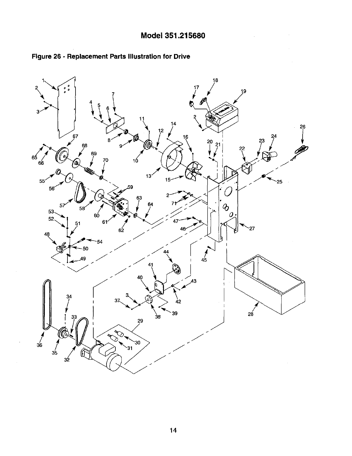
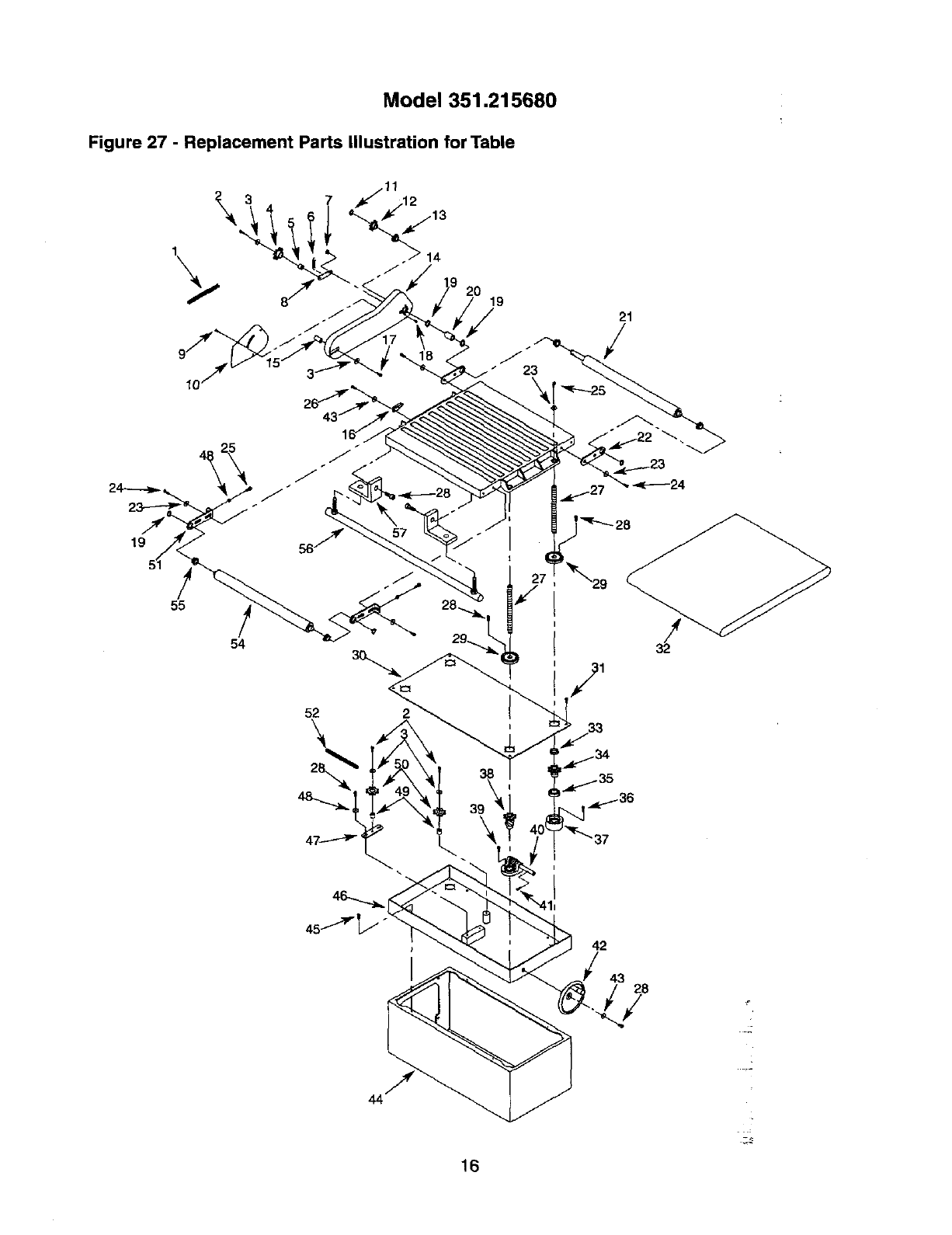
Model 351.215680
Figure 26 - Replacement Parts Illustration for Drive
2\
11 14
\ I =
18
i7/
/
38
29
/
36 /
35 J
J
J
32
2O
J
9
22
23
28
14
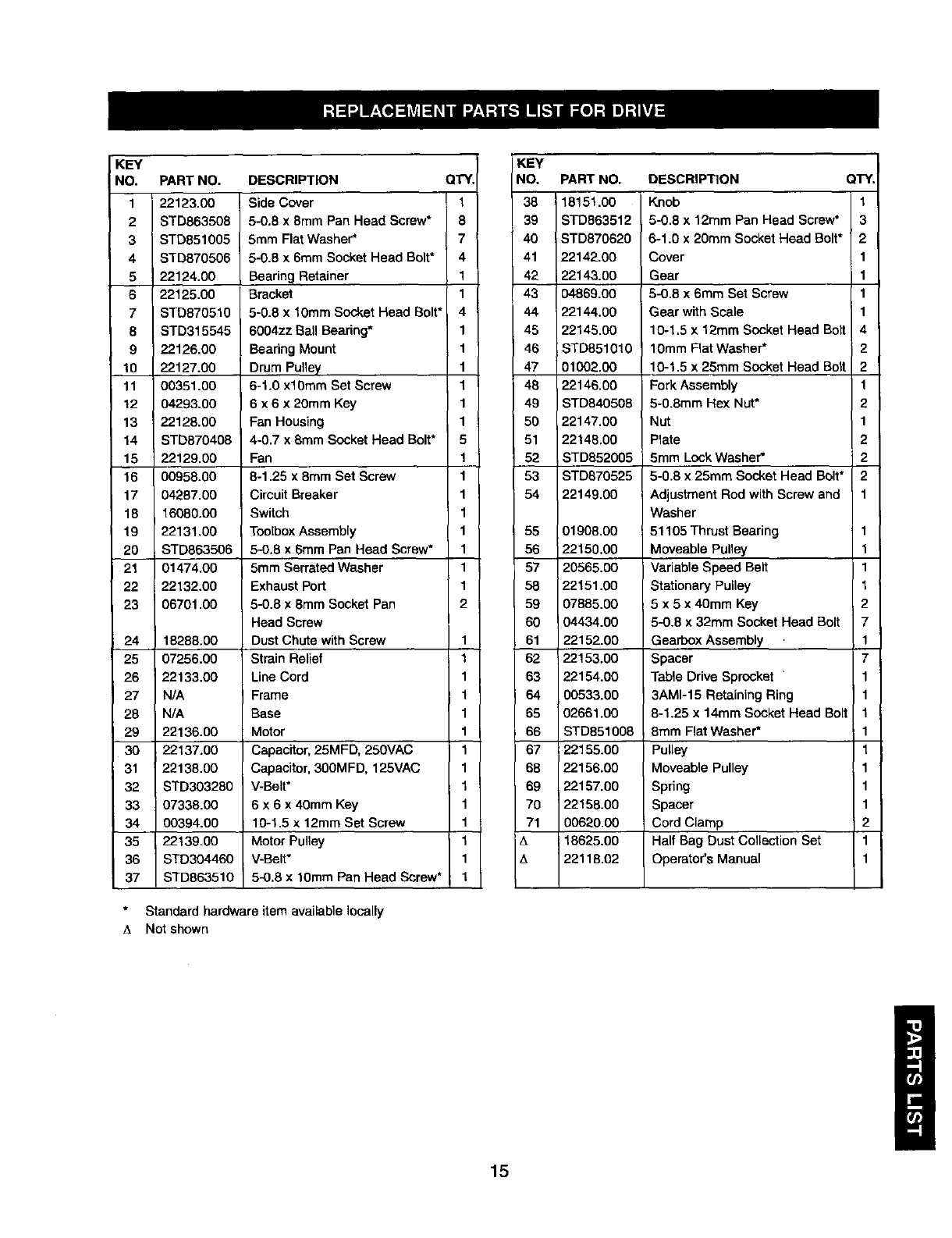
KEY
NO. PART NO. DESCRIPTION QTY.
1 22123.00 Side Cover 1
2STD863508 5-0.8 x 8mm Pan Head Screw* 8
3 STD851005 5ram FlatWasher* 7
4 STD870506 5-0.8 x 6mm Socket Head Bolt* 4
522124.00 Bearing Retainer 1
6 22125.00 Bracket 1
7 STD870510 5-0.8 x 10ram Socket Head Bolt* 4
8 STD315545 6004zz Ball Bearing* 1
9 22126.00 BearingMount 1
10 22127.00 Drum Pulley 1
11 00351.00 6-1.0 xl0mm Set Screw 1
12 04293.00 6 x 6 x 20mm Key 1
13 22128.00 Fan Housing 1
14 STD870408 4-0.7 x 8mm Socket Head Bolt* 5
15 22129.00 Fan 1
16 00958.00 8-1.25 x 8ram Set Screw 1
17 04287.00 Circuit Breaker 1
18 16080.00 Switch 1
19 22131.00 ToolboxAssembly 1
20 STD863506 5-0.8 x 6mm Pan Head Screw* 1
21 01474.00 5mm Serrated Washer 1
22 22132.00 Exhaust Port 1
23 06701.00 5-0.8 x8ram Socket Pan 2
Head Screw
24 18288.00 Dust Chute with Screw 1
25 07256.00 Strain Relief 1
26 22133.00 Line Cord 1
27 N/A Frame 1
28 N/A Base 1
29 22136.00 Motor 1
30 22137.00 Capacitor, 25MFD, 250VAC 1
31 22138.00 Capacitor, 300MFD, 125VAC 1
32 STD303280 V-Belt* 1
33 07338.00 6 x 6 x 40mm Key 1
34 00394.00 10-1.5 x 12ram Set Screw 1
35 22139.00 Motor Pulley 1
36 STD304460 V-Belt* 1
37 STD863510 5-0,8 x 10mm Pan Head Screw* 1
Standard hardware item available locally
A Not shown
KEY
NO, PART NO. DESCRIPTION QTY.
38 18151.00 Knob 1
39 STD863512 5-0.8 x 12mm Pan Head Screw* 3
40 STD870620 6-1.0 x 20mm Socket Head Bolt* 2
41 22142.00 Cover 1
42 22143.00 Gear 1
43 04869.00 5-0.8 x 6mm Set Screw 1
44 22144.00 Gear with Scale 1
45 22145.00 10-1,5 x 12mm Socket Head Bolt 4
46 STD851010 10mm Flat Washer* 2
47 01002.00 10-1.5 x 25ram Socket Head Bolt 2
48 22146.00 Fork Assembly 1
49 STD840508 5-0.8mm Hex Nut* 2
50 22147.00 Nut 1
51 22148.00 Plate 2
52 STD852005 5mm Lock Washer* 2
53 STD870525 5-0.8 x 25ram Socket Head Bolt* 2
54 22149.00 Adjustment Red with Screw and 1
Washer
55 01908.00 ; 51105 Thrust Bearing 1
56 22150,00 Moveable Pulley 1
57 20565.00 Variable Speed Belt 1
58 22151.00 Stationary Pulley 1
59 07885.00 5 x 5 x 40mm Key 2
60 04434.00 5-0.8 x 32mm Socket Head Bolt 7
61 22152.00 Gearbox Assembly 1
62 22153.00 Spacer 7
63 22154.00 Table Drive Sprocket "1
64 00533.00 3AM1-15 Retaining Ring 1
65 02661.00 8-1.25 x 14mm Socket Head Bolt 1
86 STD851008 8ram Flat Washer* 1
67 22155.00 Pulley 1
68 22156.00 Moveable Pulley 1
69 22157.00 Spring 1
70 22158.00 Spacer 1
71 00620.00 Cord Clamp 2
A 18625.00 Half Bag Dust Collection Set 1
t_ 22118.02 Operator's Manual 1
15
Model 351.215680
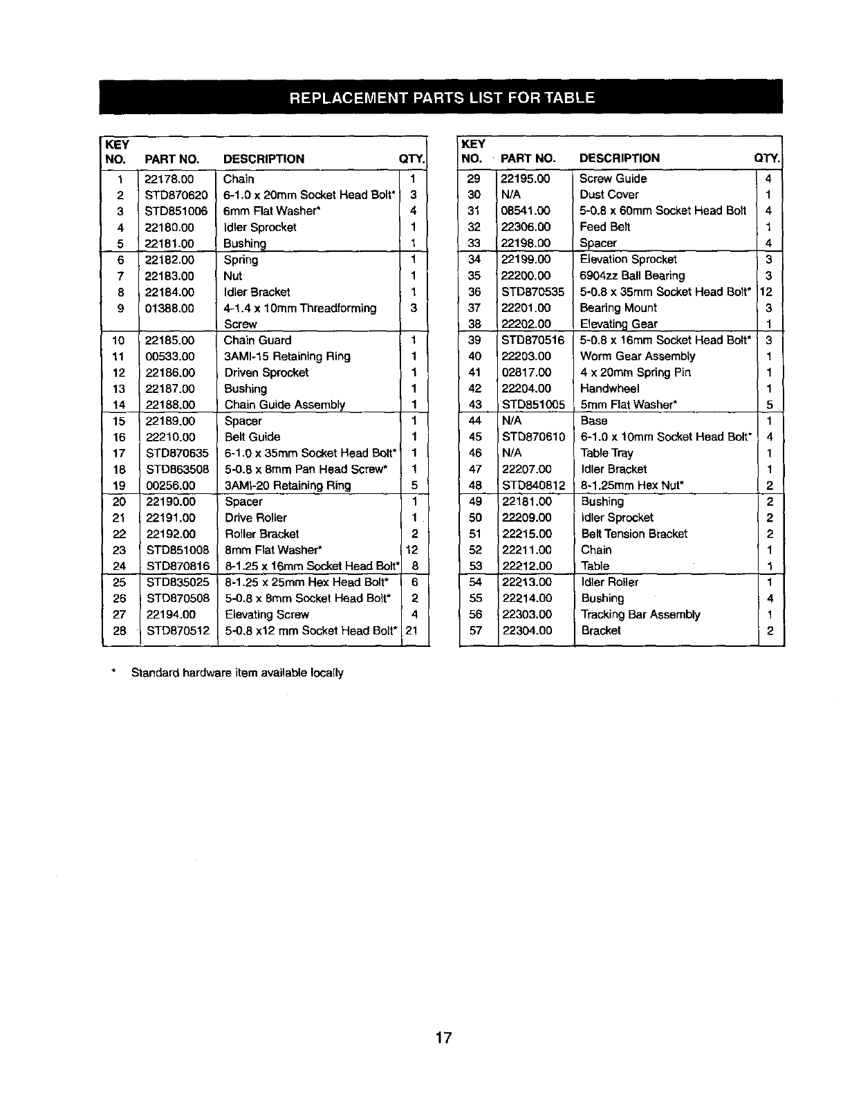
Figure 27 -Replacement Parts Illustration for Table
19
55
54
7
20 19 21
52
\
42
43;8
16
KEY
NO. PART NO. DESCRIPTION QTY.
122178.00 Chain 1
2 STD870620 6-1,0 x 20ram Socket Head Bolt* 3
3 STD851006 6ram Flat Washer* 4
4 22180,00 idler Sprocket 1
522181.00 Bushing 1
622182.00 Spring 1
7 22183.00 Nut 1
8 22184.00 Idler Bracket 1
9 01388,00 4-1.4 x 10ram Threadforming 3
Screw
10 22185,00 Chain Guard 1
11 00533.00 3AM1-15 Retaining Ring 1
12 22186.00 Driven Sprocket 1
13 22187.00 Bushing 1
14 22188.00 Chain Guide Assembly 1
15 i 22189.00 Spacer 1
16 22210.00 BeLt Guide 1
17 STD870635 6-1.0 x 35ram Socket Head Bolt* 1
18 STD863508 5-0.8 x 8mm Pan Head Screw* 1
19 00256.00 3AMI-20 Retaining Ring 5
20 22190.00 Spacer 1
21 22191.00 Drive Roller 1
22 22192.C0 Roller Bracket 2
23 STD851008 8mm Flat Washer* 12
24 STD870816 8-1.25 x 16ram Socket Head Bolt' 8
25 STD835025 8-1.25 x 25ram Hex Head Bolt* 6
26 STDB70508 5-0,8 x 8ram Socket Head Bolt* 2
27 22194.00 Elevating Screw 4
28 STD870512 5-0,8 x12 mm Socket Head Bolt* 21
Standard hardware item available locally
KEY
NO. PART NO. DESCRIPTION QTY.
29 22195.00 Screw Guide 4
30 N/A Dust Cover 1
31 08541,00 5-0.8 x 60mm Socket Head Bolt 4
32 22306.00 Feed Belt 1
33 22198.00 Spacer 4
34 22199.00 Elevation Sprocket 3
35 22200.00 6904zz Ball Bearing 3
36 STD870535 5-0.8 x 35mm Socket Head So t* 12
37 22201.00 Bearing Mount 3
38 22202.00 Elevating Gear 1
39 STD870516 5-0.8 x 16mm Socket Head Bolt* ' 3
40 22203.00 Worm Gear AssembLy 1
41 02817.00 4 x 20mm Spring Pin 1
42 22204.00 i Handwheel 1
43 STD851005 5ram Flat Washer* 5
44 N/A Base 1
45 STD870610 6-1.0 x 10ram Socket Head Bolt* 4
46 N/A Table Tray 1
47 22207.00 Idler Bracket 1
48 ISTD840812 8-1.25mm Hex Nut* 2
49 22181.00 Bushing 2
50 22209.00 idler Sprocket 2
51 22215.00 Belt Tension Bracket 2
52 22211.00 Chain 1
53 22212.00 Table 1
54 22213.00 Idler Roller 1
55 22214.00 Bushing 4
56 22303.00 Tracking Bar Assembly 1
57 22304.00 Bracket 2
17
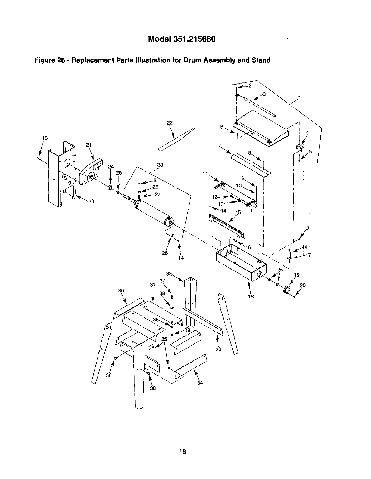
Model 351.215680
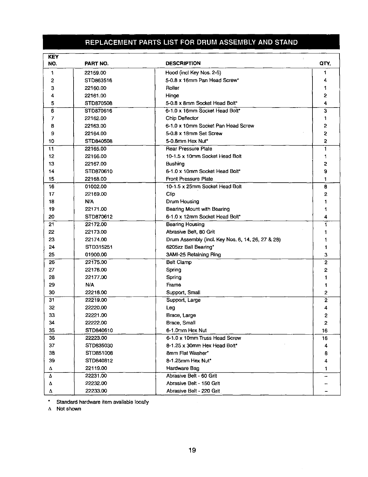
Figure 28 -Replacement Parts Illustration for Drum Assembly and Stand
28
I
l \"
14
32
_7
18
!
36
34
18
KEY
NO.
1
2
3
4
5
6
7
8
9
10
11
12
13
14
15
16
17
18
19
2O
21
22
23
24
25
26
27
28
29
3O
31
32
33
34
35
36
37
38
39
A
A
zk
PART NO.
22159.00
STD863516
22160.00
22161.00
STD870508
STD870616
22162.00
22163.00
22164.00
STD840506
22165.00
22166.00
22167.00
STD870610
22168.00
01002.00
22169.00
N/A
22171.00
STD870612
22172.00
22173.00
22174.00
STD315251
01900.00
22175.3O
22176.00
22177.00
N/A
22216.00
22219.00
22220.00
22221.00
22222.00
STD840610
22223.00
STD835030
STD851008
STD840812
22119.00
22231.00
22232.00
22233.00
DESCRIPTION
Hood (incl Key Nos. 2-6)
6-0.8 x 16mm Pan Head Screw*
Roller
Hinge
5-0.8 x 8ram Socket Head Bolt"
6-1.0 x 16ram Socket Head Bolt*
Chip Deflector
6-1.0 x 1OmmSocket Pan Head Screw
5-0.6 x 18ram Set Screw
5-0.8ram Hex Nut*
Rear Pressure Plate
10-1.5 x 10rnmSocket Head Bolt
Bushing
6-1 .Ox 10ram Socket Head Bolt*
Front Pressure Plate
10-1.5 x 25ram Socket Head Bolt
Clip
Drum Housing
Bearing Mount with Bearing
6-1.0 x 12mm Socket Head Bolt*
Bearing Housing
Abrasive Belt, 80 Grit
Drum Assembly (Incl. Key Nos. 6, 14, 26, 27 & 28)
6205zz Ball Beadn9*
3AMI-25 Retaining Ring
Belt Clamp
Spring
Spring
Frame
Support, Small
Support, Large
Leg
Brace, Large
Brace, Small
6-1.0ram Hex Nut
6-1.0 x 10ramTruss Head Screw
8-1.25 x 30mm Hex Head Bolt*
8ram Flat Washer*
8-1.25mm Hex Nut*
Hardware Bag
Abrasive Belt - 60 Grit
Abrasive Belt - 150 Grit
QTY.
1
4
1
2
4
3
1
2
2
2
1
1
2
9
1
8
2
1
1
4
1
1
1
1
3
2
2
1
1
2
2
4
2
2
16
16
4
8
4
1
Abrasive Belt -220 Grit
Standard hardware item available locally
ANot shown
19

Your Home
For repair-in your home-of all major brand appliances,
lawn and garden equipment, or heating and cooling systems,
no matter who made it, no matter who sold it!
For the replacement parts, accessories and
owner's manuals that you need to do-it-yourself.
For Sears professional installation of home appliances
and items like garage door openers and water heaters.
1-800-4-MY-HOME ® (1-800-469-4663)
Call anytime, day or night (U.S.A. and Canada)
www.sears.com www.sears.ca
Our Home
For repair of carry-in items like vacuums, lawn equipment,
and electronics, call or go on-line for the location of your nearest
Sears Parts & Repair Center,
1-800-488-1222
Call anytime, day or night (U.S.A. only)
www.sears.com
To purchase a protection agreement (U.S.A.)
or maintenance agreement (Canada) on a product serviced by Sears:
1-800-827-6655 (U.S.A.) 1-800-361-6665 (Canada)
Para pedir servicio de reparaci6n
a domicilio, y para ordenar piezas:
1-888-SU-HOGAR _
(1-888-784-6427)
Au Canada pour service en fran_ais:
1-800-LE-FOYER _
(1-800-533-6937)
www.sears.ca
®Registered Trademark /TM Trademark /SMService Mark of Sears, Roebuck and CO.
®Marca Registrade /Tu Mama de Fdbrica /sMMarca de Servicio de Sears, ROebuck and Co.
MCMarque de commerce /MoMarque deposde de Sears, Roebuck and Co. © Sears, ROebuck and Co.
