Craftsman 351233831 User Manual 12 1/2 PLANER / MOLDER Manuals And Guides L0402142
CRAFTSMAN Planer Manual L0402142 CRAFTSMAN Planer Owner's Manual, CRAFTSMAN Planer installation guides
User Manual: Craftsman 351233831 351233831 CRAFTSMAN 12-1/2 PLANER / MOLDER - Manuals and Guides View the owners manual for your CRAFTSMAN 12-1/2 PLANER / MOLDER #351233831. Home:Tool Parts:Craftsman Parts:Craftsman 12-1/2 PLANER / MOLDER Manual
Open the PDF directly: View PDF ![]() .
.
Page Count: 32

Operator's Manual
CRRFTSMRN°
121_"
PLANER/MOLDER
Model No.
351.233831
CAUTION: Read and follow
all Safety Rules and Operating
Instructions before First Use
of this Product.
Sears, Roebuck and Co., Hoffman Estates, IL 60179 U.S.A.
8507.02 Draft (08/10/97)
Warranty.................................. 2
Safety Rules .............................. 2-3
Assembly ................................. 3
Installation ............................... 3-5
Operation ............................... 5-12
Maintenance .............................. 12
Troubleshooting ............................ 13
Parts Illustration and List .................. 14-19
EspaSol ............................... 20-31
FULL ONE YEAR WARRANTY ON
CRAFTSMAN 121/="PLANER/MOLDER
If this Craftsman Planer/Molder fails due to a defect in
material or workmanship within one year from the date
of purchase, contact the nearest Sears in-home major
brand repair service in the United States, and Sears will
repair it, free of charge.
If this planer/molder is used for commercial or rental
purposes, this warranty will apply for 90 days from the
date of purchase.
This warranty applies only while the product is in the
United States. This warranty gives you specific legal
rightsand you may also have other rightswhich vary
from state to state.
Seam, Roebuck and Co., Dept. 817WA, Hoffman
Estates, IL 60179
WARNING: For your own safety, read all of the
instructionsand precautionsbefore operatingtool.
CAUTION: Always followproper operatingprocedures
as defined in this manual even if you are familiar with
use of this or similartools. Remember that being care-
less for even a fraction of asecond can result in severe
personal injury.
BE PREPARED FOR JOB
•Wear proper apparel. Do not wear loose clothing,
gloves, neckties, rings,bracelets or other jewelry
which may get caught in movingparts of machine.
• Wear protectivehair covering to contain long hair.
• Wear safety shoes with non-slipsoles.
•Wear safetyglasses complyingwith United States
ANSI Z87.1. Everyday glasses have only impact
resistantlenses.They are NOT safetyglasses.
•Wear face mask or dust mask if operation is dusty.
•Be alert and think clearly.Never operate power tools
when tired, intoxicatedor when taking medications
that cause drowsiness.
PREPARE WORK AREA FOR JOB
Keep work area clean. Cluttered work areas invite
accidents.
Do not use power tools in dangerousenvironments.
Do not use power tools in damp or wet locations.Do
not expose power tools to rein.
•Work area should be properlylighted.
•Proper electrical receptacle should be available for
tool.Three prong plug should be pluggeddirectly
into properlygrounded,three-prong receptacle.
•Extensioncords should have a groundingprong and
the three wires of the extensioncord should be of
the correct gauge.
•Keep visitorsat a safe distance from work area.
•Keep childrenout of workplace.Make Workshopchild-
proof.Use padlocks,masterswitchesor removeswitch
keysto preventany unintentionaluse of power tools.
TOOL SHOULD BE MAINTAINED
•Always unplugtool prior to inspection.
• Consult manual for specific maintainingand adjust-
ing procedures.
•Keep tool lubricated and clean for safest operation.
• Remove adjusting tools. Form habit of checking to
see that adjusting tools are removed before switch-
ing machine on.
• Keep all parts in working order. Check to determine
that the guard or other parts will operate properly
and perform their intended function.
• Check for damaged parts. Check for alignment of
moving parts, binding, breakage, mounting and any
other condition that may affecta tool's operation.
• A guard or other part that is damaged should be
properly repaired or replaced. Do not perform
makeshift repairs. (Use parts list providedto order
replacement parts.)
KNOW HOW TO USE TOOL
•Use righttool forjob. Do notforce tool or attachment
to do a job for which it was not designed.i
•Disconnecttool when changingblades.
•Avoidaccidental start-up. Make sure that_theswitch
is inthe "off"positionbefore pluggingin. =
•Do notforce tool. It willwork most efficientlyat the
rate for which it was designed.
•Keep hands away from movingparts'_nd Cutting
surfaces.
Never leave tool running unattended.Turn the power
off and do not leave tool untilit comes to a complete
stop.
Do not overreach. Keep proper footingand balance.
Never standon tool.Seriousinjurycouk:loccurif tool is
tippedor if blade is unintentionallycon__cted.
Knowyour tool.Learn the tool's operation, applica-
tion and specificlimitations.
2
•Use recommended accessories (refer to page 17).
Use of improperaccessories may cause riskof
injury to persons.
•Handle workpiece correctly.Protect hands from pos-
sible injury.
•Turn machine off if it jams. Knife or bitjams when it
digs too deeply into workpiece. (Motor force keeps it
stuck in the work.)
•Always keep drive, cutterheed and knife guards in
place and in proper operating condition.
•Feed work into knifeor cutter against directionof
rotation.
CAUTION: Think safety! Safety is a combinationof
operator common sense and alertness at all times
when tool is being used.
WARNING: Do not attempt to operate tool until it is
completely assembled accordingto the instructions.
Refer to Figures 15 and 16, pages 16 and 18.
The planer/molder is shipped assembled except for the
handwheel and handle (Figure 16, Key Nos. 22 and 24).
INSTALL HANDWHEEL AND HANDLE
Refer to Figure 16, page 18.
•Handwheel (Key No. 22) must be installed to the left
side of the planer/molder.
•Align handle (Key No. 24) with the hole on the rim of
the handwheel.
•Insert handle screw (Key No. 23) into handle and
tighten to secure.
•Slide handwheel onto crank elevation screw (Key
No. 19) so that the spring pin (Key No. 21) on the
crank elevation screw is positionedbetween the
groovein the handwheel.
REMOVE CAPS
Refer to Figure 15, page 16.
The planer/molder is shipped with caps (Key No. 13) on
the threaded shafts (Key No. 11) to avoid damage to
shafts during shipping and handling.
•Unscrew and remove caps beforeturning the tool on.
•Save caps for future use.
MOUNT PLANER TO WORK SURFACE
Refer to Figure 1.
•Planer is designed to be portable so it can be moved
to job site, butshould be mounted to stable, level
bench or table. See Recommended Accessories,
page 17.
MOUNTING INSTRUCTIONS FOR
OPTIONAL STAND MODEL 22250
Refer to Figure 1.
Material List
• ½ x 15 x 22" particleboard (not supplied)
•Four 1A-20x 1¼" Bolts withwashers and nuts (not
supplied) for mountingboard to Multi-PurposeStand.
•Four8-1.25 x 30mm boltswith washers (supplied
with planer/molder) for mountingplaner/molder to
board.
A mounting board is needed when mou_ting
planer/molder to Sears Multi-Purpose Stand Model
22250. The mounting board is made from ½" thick ply-
wood or particle board.
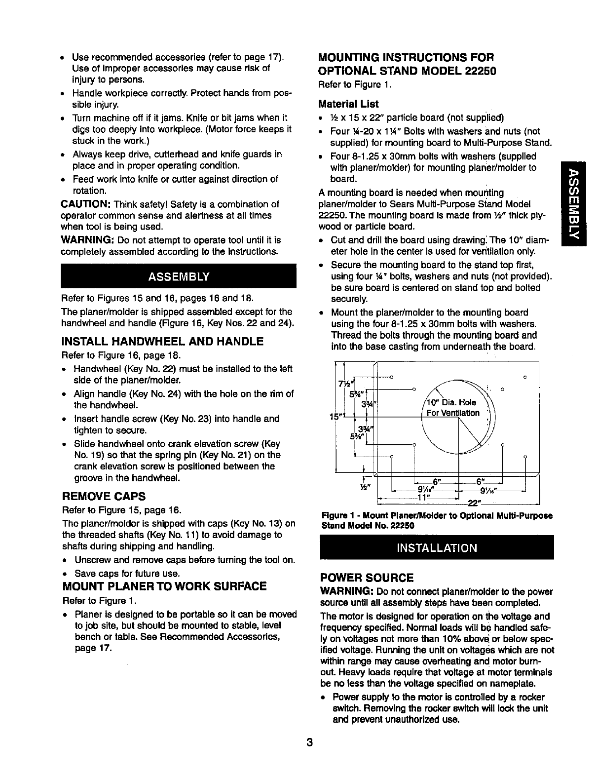
• Cut and drill the board using drawing: The 10" diam-
eter hole in the center is used for ventilationonly.
• Secure the mounting board to the stand top first,
using four ¼" bolts, washers and nuts (not provided).
be sure board is centered on stand top and bolted
securely.
•Mount the planer/molderto the mountingboard
using the four 8-1.25 x 30mm bolts withwashers.
Thread the bolts throughthe mountingboard and
into the base casting from underneath the board.
1
Figure I - Mount Planer/Molder to Optional Multi-Purpose
Stand Model No, 22250
POWER SOURCE
WARNING: Do notconnect planer/molderto the power
source untilall assembly steps have been completed.
The motor Is designed for operation on the voltage and
frequency specified.Normal loads will be handled safe-
ly on voltages not more than 10% abeve or below spec-
ified voltage. Running the unit on voltages which are not
within range may cause overheatingand motor burn-
out. Heavy loads require that voltage at motor terminals
be no less than the voltage specifiedon nameplate.
•Power supplyto the motor is controlledby arocker
switch. Removing the rocker switchwill lockthe unit
and prevent unauthorized use.
3
GROUNDINGINSTRUCTIONS
WARNING: Improper connectionof equipment
grounding conductorcan result in the risk of electrical
shock. Equipment should be grounded while in use to
protect operator from electricalshock.
• Check with a qualified electrician if grounding
instructions are not understood or if in doubt as to
whether the tool is properly grounded.
• This tool is equipped with an approved cord rated at
150V and e 3-prong grounding type plug (see Figure
2) for your protection against shock hazards.
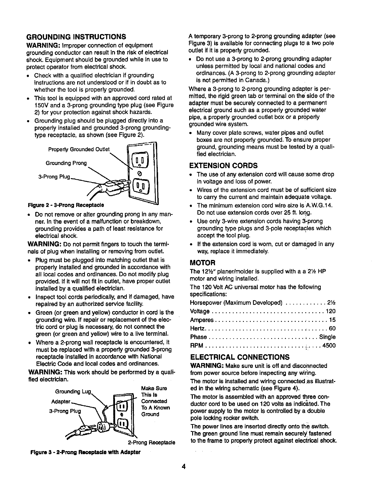
• Grounding plug should be plugged directly into a
properly installed and grounded 3-prong grounding-
type receptacle, as shown (see Figure 2).
Properly Grounded Outlet
Grounding Prong
3-Prong Plug__
Figure 2 -3-Prong Receptacle
• Do not remove or alter grounding prong in any man-
ner. In the event of a malfunction or breakdown,
grounding provides a path of least resistance for
electrical shock.
WARNING: Do not permit fingersto touch the termi-
nals of plug when installingor removingfrom outlet.
•Plug must be plugged into matchingoutlet that is
properly installed and grounded in accordance with
all local codes and ordinances•Do not modify plug
provided. If it will not fit in outlet, have proper outlet
installed by a qualified electrician.
•Inspect tool cords periodically,and if damaged, have
repaired by an authorized service facility.
•Green (or green and yellow) conductorin cord is the
grounding wire. If repair or replacement of the elec-
tric cord or plug is necessary, do not connect the
green (or green and yellow) wire to alive terminal.
•Where a 2-prong wall receptacle is encountered, it
must be replaced with apropedy grounded 3-prong
receptacle installed in accordance with National
Electric Code and local codes and ordinances.
WARNING: This work should be performed by a quali-
fied electrician.
Make Sure
GroundingLug i=======_ThisIs
c n.oo°
To A Fm_
2-ProngReceptacle
Figure 3 - 2-Prong Remeptade with Adapter
A temporary 3-prong to 2-prong groundingadapter (see
Figure 3) is available for connectingplugs to a two pole
outlet if it is properlygrounded.
•Do not use a 3-prong to 2-prong groundingadapter
unless permittedby local and national codes and
ordinances. (A 3-prong to 2-prong groundingadapter
is not permitted in Canada•)
Where a 3-prong to 2-prong groundingadapter is per-
mitted, the rigidgreen tab or terminal on the side of the
adapter must be securely connected to a permanent
electrical groundsuch as a properly grounded water
pipe, a properlygrounded outlet box or a properly
grounded wire system.
•Many coverplate screws,water pipes and outlet
boxesare not properly grounded.To ensure proper
ground, groundingmeans must be tested by aquali-
fied electrician.
EXTENSION CORDS
•The use of any extensioncord will cause'some drop
in voltage and lossof power.
•Wires of the extension cord must be of sufficientsize
to carry the currentand maintain adequate voltage.
•The minimum extensioncord wire size is A.W.G.14.
Do not use extensioncords over 25 ft. Ioqg.
•Use only 3-wire extensioncords having 3-prong
groundingtype plugsand 3-pole receptacles which
accept the tool plug.
•If the extensioncord is worn, cut or damaged in any
way, replace it immediately.
MOTOR
The 12½" planer/molder is suppliedwith a a2½ HP
motor and wiring installed.
The 120 Volt AC universal motor has the following
specifications:
Horsepower (Maximum Developed) ............ 2½
Voltage ................................. 120
Amperes ................................. 15
Hertz..................................... 60
Phase ................................ Single
RPM ............................. ; ..... 4500
ELECTRICAL CONNECTIONS
WARNING; Make sure unit is off and disconnected
from power source before inspectingany wil:ing.
The motor is installedand wiring connected:asillustrat-
ed in the wiring schematic (see Figure 4).
The motor Is assembled with an approved three con-
ductorcord to be used on 120 vo ts as indicated. The
power supplyto the motor is controlled by adouble
pole lockingrocker switch.
The power lines are inserted directlyonto the switch.
The green ground line must remain securely fastened
to the frame to properly protect against electrical shock.
4
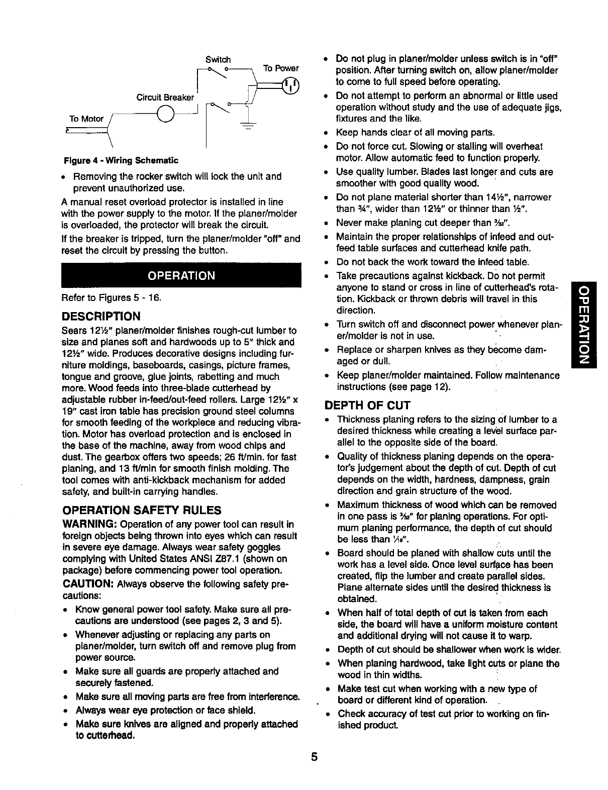
Switch
CircuitBreaker
Figure 4 - Wiring Schematic
•Removing the rocker switchwill lock the unit and
prevent unauthorized use.
A manual reset overload protector is installed in line
with the power supplyto the motor. If the planer/molder
is overloaded, the protector will break the circuit.
If the breaker is tripped, turn the planer/molder "off" and
reset the circuitby pressing the button.
Refer to Figures 5- 16.
DESCRIPTION
Sears 12½" planer/molder finishes rough-cutlumberto
size and planes soft and hardwoods up to 5" thick and
121/="wide. Produces decorative designs includingfur-
niture moldings, baseboards, casings, picture frames,
tongue and groove, glue joints, rabettingand much
more. Wood feeds into three-blade cutterhead by
adjustable rubber in-feed/out-feed rollers.Large 12½" x
19" cast irontable has precisionground steel columns
for smooth feeding of the workpiece and reducingvibra-
tion. Motor has overload protectionand is enclosed in
the base of the machine, away from wood chips and
dust. The gearbox offers two speeds; 26 ft/min, for fast
planing, and 13 f!Jminfor smooth finish molding. The
tool comes with anti-kickback mechanism for added
safety, and built-incarrying handles.
OPERATION SAFETY RULES
WARNING: Operation of any power tool can result in
foreign objects being thrown into eyes which can result
in severe eye damage. Always wear safety goggles
complyingwith United States ANSi Z87.1 (shown on
package) before commencing power tool operation.
CAUTION: Always observe the following safety pre-
cautions:
•Know general power tool safety. Make sure all pre-
cautions are understood (see pages 2, 3 and 5).
•Whenever adjusting or replacing any parts on
planer/molder,turn switch off and remove plug from
power source.
• Make sure all guards are properlyattached and
securely fastened.
• Make sure all movingpartsare free from interference.
•Always wear eye protectionor face shield.
• Make sure Imlves are aligned and propedy attached
to ¢utterhead.
•Do not plug in planer/molder unless switch is in"off"
position.After turningswitchon, allow planer/molder
to come to full speed before operating.
•Do not attempt to performan abnormal or little used
operationwithout studyand the use of adequate jigs,
fixtures and the like.
•Keep hands clear of all movingparts.
•Do not force cut. Slowing or stalling willoverheat
motor.Allow automaticfeed to function properly.
•Use quality lumber. Blades last longer and cuts are
smoother with good qualitywood.
•Do not plane material shorterthan 14½", narrower
than 3A",wider than 12Y="or thinner than ½".
•Never make planing cut deeper than _,_".
•Maintain the proper relationshipsof infeed and out-
feed table surfaces and cutterhead knife path.
•Do not back the work toward the infeed table.
•Take precautions against kickback.DO not permit
anyone to stand or cross in line of cuttarhead's rota-
tion. Kickback or throwndebris will travel in this
direction.
•Turn switchoff and disconnectpower whenever plan-
er/molder is not in use.
•Replace or sharpen knivesas they become dam-
aged or dull.
•Keep planer/molder maintained. Followmaintenance
instructions(see page 12).
DEPTH OF CUT
•Thickness planing refersto the sizing Oflumber to a
desired thickness while creating a level surface par-
allel to the opposite side of the board.
•Quality of thicknessplaning dependson the opere-
tor'sjudgement about the depth of cut. Depth of cut
depends on the width,hardness, dampness, grain
directionand grain structureof the wood.
•Maximum thickness of wood which can be removed
in one pass is _" forplaning operations.For opti-
mum planingperformance,the depth of cut should
be less than _,4,-.
•Board should be planed with shallowcuts untilthe
work has a level side. Once level surlace has been
created, flip the lumber and create parallel sides.
Plane alternate sides untilthe desired thickness is
obtained.
•When half of total depth of cut is taken from each
side, the board will have auniform moisturecontent
and additional drying will not cause it to warp.
•Depth of cut should be shallowerwhen work is wider.
•When planing hardwood, take lightct_tsor plane the
wood in thin widths.
•Make test cut when working with a new type of
board or different kind of operation.
•Check accuracy of test cut prior to workingon fin-
ished product.
5
ADJUSTINGTHE DEPTHOF CUT
Refer to Figure 16, page 18.
Board thickness which the planer/molderwill produce is
indicated by either scale (Key No. 4) on the side.
Thickness is adjusted by rotating the handwheel (Key
No. 22) clockwise to raise the knife height.
To reduce the knife height, rotata the handwheel coun-
terclockwise.
•Do notset knife below %2". Do not plane aboard
which is less than a 1,_,thick.
•Knife heightwill be moved 1Ae"with every complete
revolutionof the handwheel.
Make atest cut on a piece of wood and measure the
thickness produced.
The planer/molder will produce uneven depth of cut
(tapered cut) ifthe cutterhead is not parallel with the table.
To restore parallelism of the cutterhead with the table:
• Clamp a vise plier on the left side of the shaft (Key
No. 6) next to the bevel gear (Key. No. 10).
• Loosen set screws (Key No. 51) and disengage right
bevel gear (Key No. 10) on the elevation screw (Key
No. 18).
• Slowly rotate handwheel to raise or lower the table.
Rotate clockwise to raise table, counterclockwise to
lower table. Table will be moved by .004" with every
turn of the beveled gear by one tooth.
• After moving table the required distance, make sure
beveled gears (Key Nos. 10 and 12) are engaged
and secured with set screws.
•Release and remove the vise plier
•Make a test cut to make sure the adjustment was
appropriate.
•Add grease to bevel gears if necessary.
When the depth of cut adjustment is operating correctly,
loosen the pan head screw (Key. No. 28) and set the
indicator(Key No. 29) to show the thickness produced.
Make sure that the indicatoris positionedcorrectly.
TABLE HEIGHT ADJUSTMENT
Refer to Figure 16, page 18.
•The depth of cut of the planer/molder is adjusted by
raising or loweringthe table.
•Rotate the handwheel (Key No. 22) to raise or lower
the table to the desired position.
•The scale and indicator(Key Nos. 4 and 29) can be
used when adjusting the table height.
FEED RATE ADJUSTMENT
Refer to Figures 5 and 15, pages 6 and 16.
The planer/molder has a 2-speed gearboxthat feeds
the workplace at 13 feet per minute (FPM) for improved
surfacefinish when moldingor planingand 26 FPM for
fester planing.
• Be sureto unplugthe planer/mctderfrom powersource
and turnplaner/molderOFF beforeadjustingthe feed
rate.
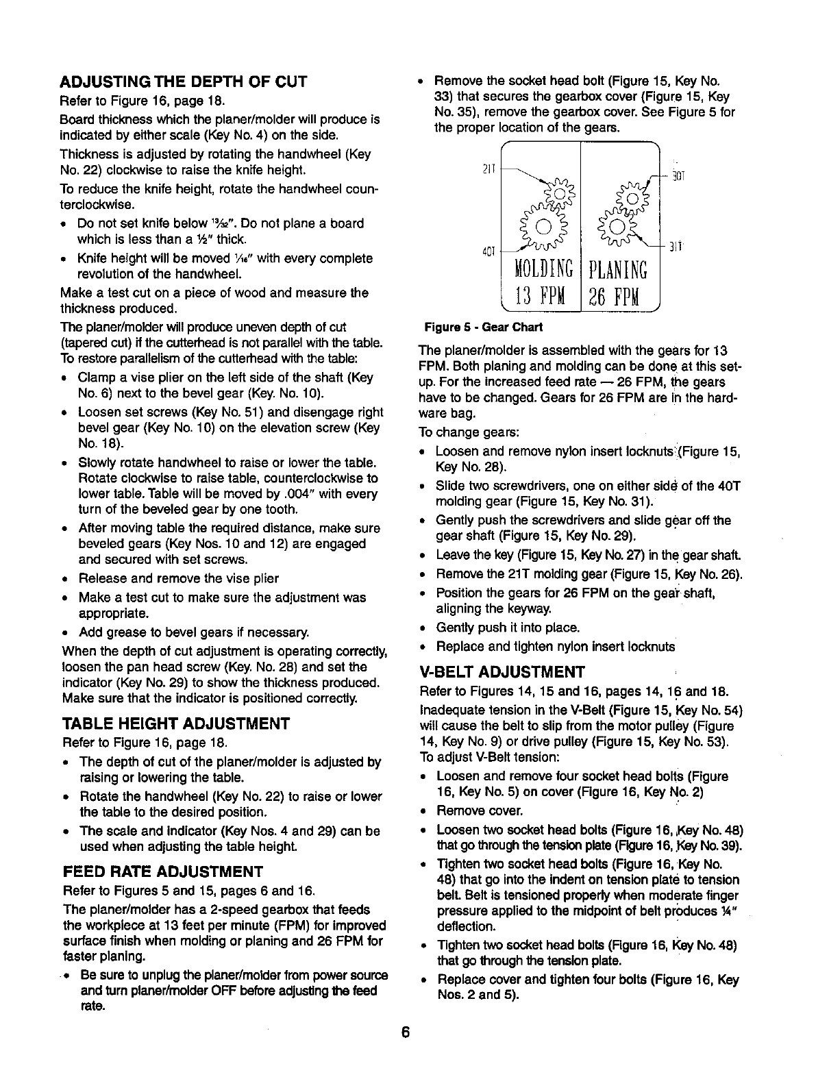
Remove the socket head bolt (Figure 15, Key No.
33) that secures the gearboxcover (Figure 15, Key
No. 35), remove the gearbox cover. See Figure 5 for
the proper location of the gears.
Figure 5 -Gear Chart
26 FPM
-30T
-_i]
The planer/molder is assembled with the gears for 13
FPM. Both planingand moldingcan be done at this set-
up. For the increased feed rate -- 26 FPM, the gears
have to be changed. Gears for 26 FPM are in the hard-
ware bag.
To change gears:
•Loosen and remove nyloninsert Iocknutsi(Figure15,
Key No. 28).
•Slide two screwdrivers,one on either side of the 40T
moldinggear (Figure 15, Key No. 31).
•Gently push the screwdriversand slide g_ar off the
gear shaft (Figure 15, Key No. 29).
•Leave the key (Figure15, KeyNo. 27) inthe gear shaft.
•Removethe 21T moldinggear (Figure 15, Key No. 26).
•Positionthe gears for 26 FPM on the gea'rshaft,
aligningthe keyway.
•Gently push it into place.
•Replace and tighten nylon insert Iocknuts
V-BELT ADJUSTMENT
Refer to Figures 14, 15 and 16, pages 14, 16 and 18.
Inadequate tension in the V-Belt (Figure 15, Key No. 54)
will cause the belt to slip from the motor pulley(Figure
14, Key No. 9) or ddve pulley (Figure 15, Key No. 53).
Toadjust V-Belttension:
•Loosen and remove four socket head bolts (Figure
16, Key No. 5) on cover (Figure 16, Key No. 2)
•Remove cover.
•Loosen two sockethead bolts (Figure 16, ,KeyNo. 48)
thatgo through the tensionplate(Figure16,gay No.39).
•Tighten two sockethead bolts (Figure 16, Key No.
48) that go intothe indenton tensionplate to tension
belt. Belt is tensioned properlywhen moderate finger
pressure applied to the midpointof belt produces _"
deflection.
• Tighten two sockethead bolts (Figure 16, Key No. 48)
that gothroughthe tensionplate.
•Replace coverand tightenfour bolts (Figure 16, Key
Nos. 2and 5).
6
WOODGRAIN
For an improved surface finish with minimal tearout,
always plane or mold the workpiece with the grain. The
workpiece should be fed into the planer/molder so that
the knives or bits are traveling with the grain as the cut-
ters finish the cut. The grain should be angled up
toward the rear of the workpiece as it is fed into the
pLaner/molder.
PLANING
WARNING: Alwaysturn the planer/molder off and dis-
connect it from the power source whenever knife cover
is removed. Never operate planer/molder without the
knife cover properly secured.
The planer/molder is supplied with planing blades mount-
ed in the cutterheedand the infeed and outfeed rollers
adjusted to the correct height. The planer/molder is capa-
ble of working at two different feed rates. Feed rate refers
to rate at which lumber travels through planer/molder.
Planing can be done at 13 FPM for an improved surface
finish or 26 FPM for faster planing (see Feed Rate
Adjustment).
• Adjust the table height to produce the depth of cut
desired.
•Stand to side which the handwheel was attached.
•Lift edge to infeed side of the table by grasping
edges of board at approximately middleof length.
• Boards longer than 24" should have additional sup-
port from free standing material stands.
• Position the workpiece with the face to be planed on
top.
• Gently slide the workpiece into the infeed side of the
planer/molder until the infeed roller begins to
advance the workpiece.
• Let go of the workpiece and allow automatic feed to
advance the workpiece.
• Do not push/pull on workpiece.
• Move to the rear and receive planed lumber by
grasping it in same manner as it was fed.
CAUTION: Do not stand directly in line withfront or
rear of planer/molder.
• Do not grasp any portion of board which has not
gone past out-feed roller.
• Repeat this operation on all boards which need to be
same thickness.
AVOIDING SNIPE
Surface that the planer/molder will produce will be
smootherif shallower depth of cut is used. Snipe refers
to adepressionat either end of board caused by an
uneven force on cutterhead when work is entering or
leaving planer. Snipe will occur when boards are not
supported properlyor when only one feed roller is in
contactwith work at beginningor end of cuLTo avoid
snipe:
•Gently push the board up while feeding the work
untilthe outfeed roller starts advancing It.
• Move to the rear and receive planed board by gently
pushing it up when the infeed rollerlooses contact
with the board.
• When planing more than one board of the same
thickness, butt boards togetherto avoid snipe.
KNIFE HEIGHT ADJUSTMENT
Refer to Figures 6 and 15, pages 7 and 16.
WARNING: Disconnect planer/molderfrom the power
source and turn the planer/molderOFF before attempt-
ing to adjust or replacethe cuttingbitsor knives,or per-
forming any adjustment or maintenanceto the
planer/molder.
Aknife height gauge is providedfor use when replacing
or adjusting the planingknives (Key No. 40).
•Unplugthe planer/molderand turn it OFF.
•Remove the knifecover (Key No. 4)
•Loosen all the set screws (Key No. 42) on all of the
gibs (Key Nos.41 and 43) in all 3 cutterhead slots.
•Using the brass punch, tap all the gibs down into the
cutterhead slot.
• Make sure the gibs are loose and can be moved.
•Remove the old knives, all gibs and spacers (Key
No. 44).
• Make sure the cutterhead slots and gibs are clean.
• Install the new planer knives and replace gibs and
spacers.
•Tighten the gib set screws only enough to holdthe
gibs and knivesin position.
•Make sure there is no gap between the gibs,and the
spacers are in place.
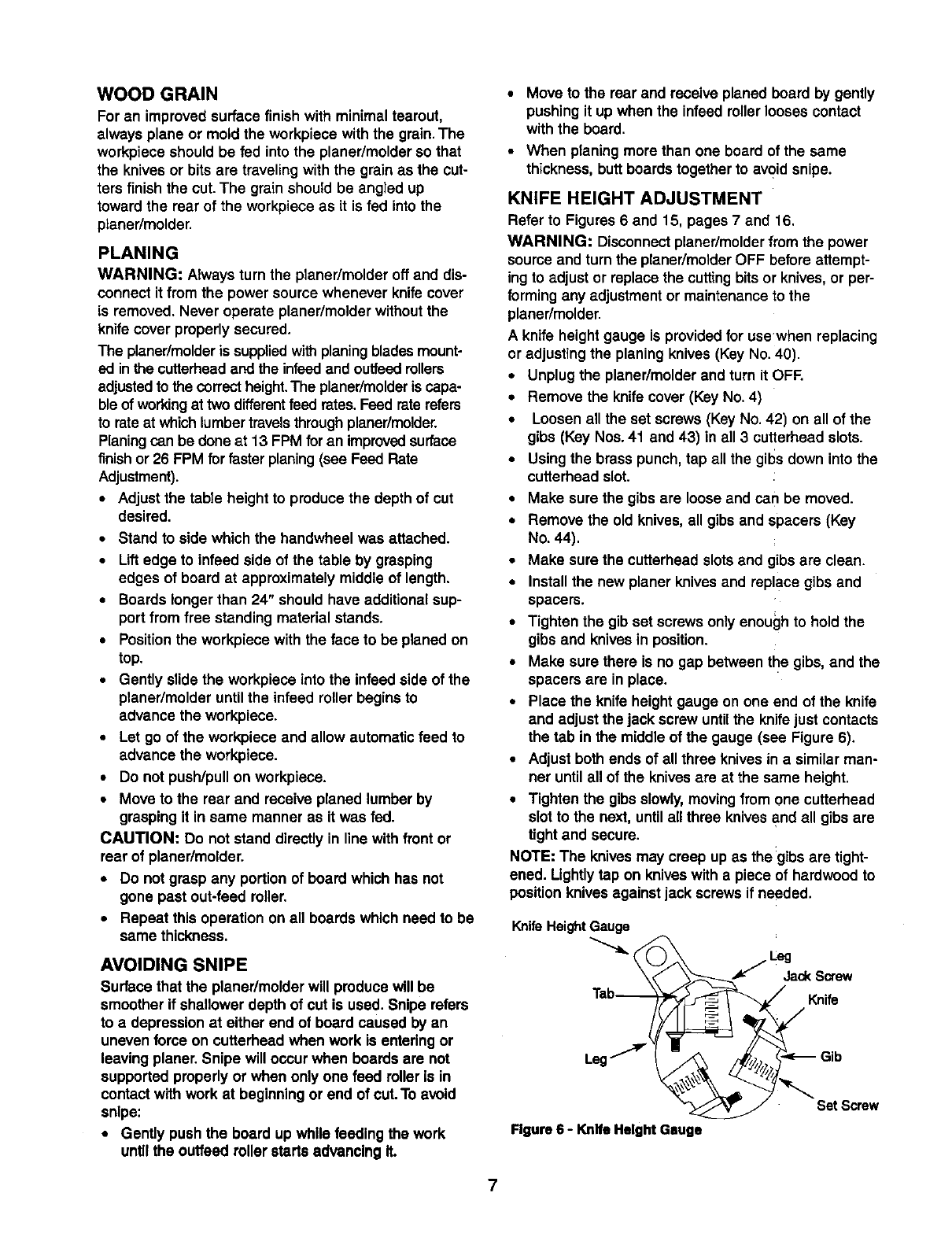
•Place the knife heightgauge on one end of the knife
and adjust the jack screw untilthe knife just contacts
the tab in the middle of the gauge (see Figure 6).
•Adjust both ends of all three knives in a similar man-
ner untilall of the knivesare at the same height.
•Tighten the gibs slowly,movingfrom one cutterhead
slot to the next, until allthree knivesand all gibs are
tight and secure.
NOTE: The knivesmay creep up as the:gibsare tight-
ened. Lightlytap on kniveswith a piece of hardwoodto
positionknivesagainst jack screws if needed.
Knife Height Gauge
Tab_ Knife
Figure 6 - Knife HeightGsuge
7
POSITIONTHE CHIPBREAKER
Refer to Figure 15, page 16.
The chipbreaker (Key No. 2) is used to help remove
wood chips from the cutter bitsand kniveswhile planing
or molding. Adjustthe chipbreaker every time the cut-
ting tools are changed or adjusted.
The chipbreakershould be positionedas closeto the
cutterheadas possiblewithoutcontactingthe cutter bits
or knives. Loosen the three hex head bolts (Key No. 3)
that hold the chip breaker and position it as close to the
cutterhead as possible, rotate the cutterhead by hand to
ensure that there is no interference with the chipbreaker.
Secure the chip breaker by tightening the three hex head
bolts. Replace and secure knife cover.
MOLDING
Molding, also known as miliworkor trim, can be defined
as astrip of wood milled with a plain or decorative sur-
face which is continuousthroughoutits length.
•To get superior moldingfinish, workpiece must be
planed and presized prior to molding.Always presize
the workpiece to '/_,"of the final thicknessprior to
molding.
Certain moldingprofiles require outer edge clean-up.
When usingsuch profilesthe workpiece must be pre-
sized to ¼" larger than the final width.This will allow ',_,"
for clean-up on either side.
Certain molding profilescut only the edge of the work-
piece. When using such profilesworkpiece must be pre-
sized to the same width as the final width.
INSTALLING CUTTER BITS
Refer to Figures 7, 8 and 15, pages 8, 9 and 16.
NOTE: The cutter bits arc mounted in the center of the
cutter head (Figure 15, Key No. 39) usingthe 2" bit gibs
(Figure 15, Key No. 43) provided.The cutter bits and
the planing blades (Figure 15, Key No. 40) are mounted
in the cutterhead at the same time so that planing and
moldingoperations can be done with the same set-up.
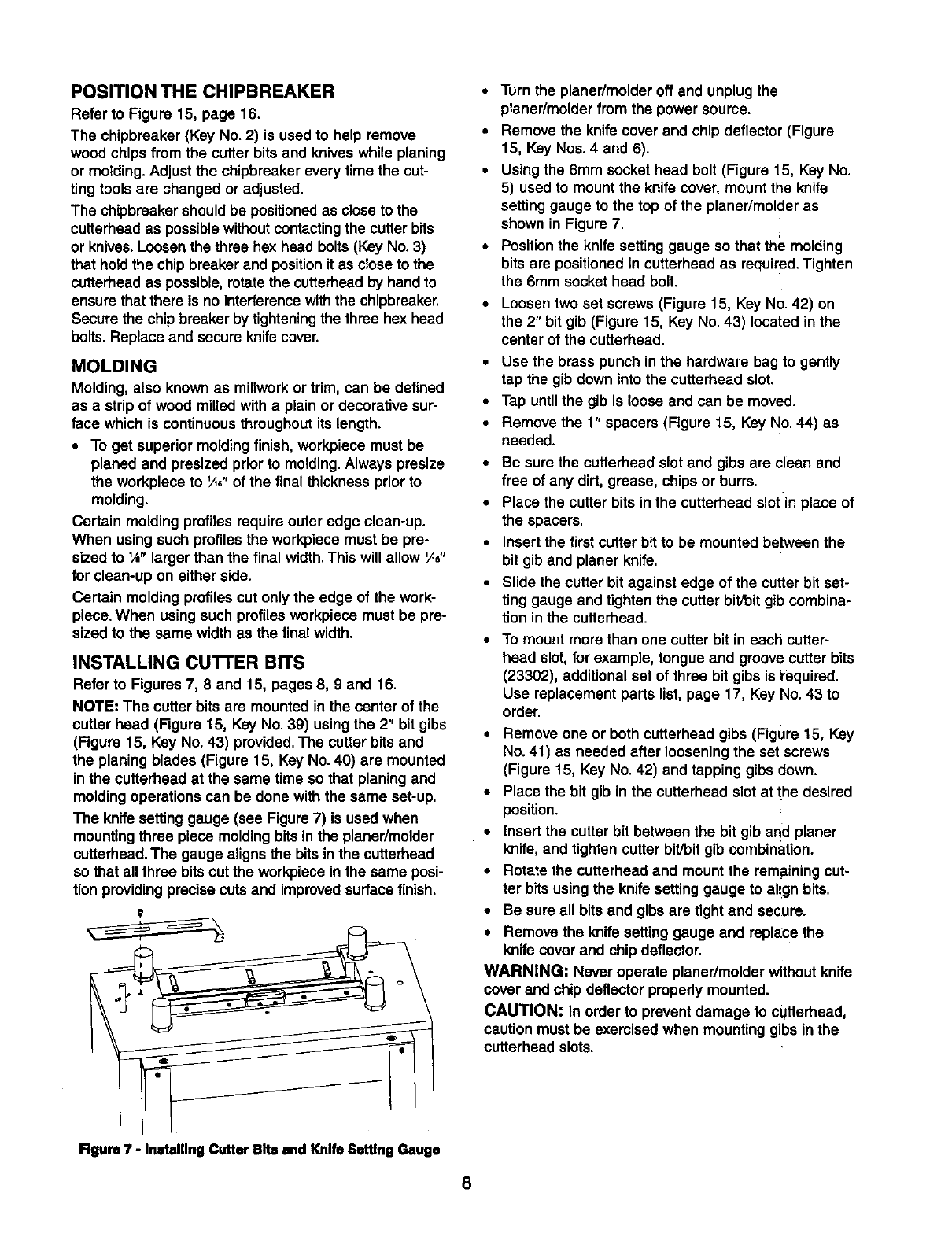
The knife setting gauge (see Figure 7) is used when
mountingthree piece moldingbitsin the planer/molder
cutterhead.The gauge alignsthe bits inthe cutterhead
so that all three bitscut the workpiece in the same posi-
tion providingprecise cuts and improvedsurfacefinish.
• Turn the planer/molder off and unplugthe
planer/molder from the power source.
• Remove the knife cover and chip deflector (Figure
15, Key Nos. 4 and 6).
•Using the 6mm socket head bolt (Figure 15, Key No.
5) used to mount the knife cover, mount the knife
setting gauge to the top of the planer/molder as
shown in Figure 7.
• Position the knife setting gauge so that the molding
bits are positioned in cutterhead as required. Tighten
the 6mm socket head bolt.
•Loosen two set screws (Figure 15, Key No. 42) on
the 2" bit gib (Figure 15, Key No. 43) located in the
center of the cutterhead.
•Use the brass punch in the hardware bag to gently
tap the gib down into the cutterhead slot.
•Tap untilthe gib is loose and can be moved.
•Remove the 1" spacers (Figure 15, Key No.44) as
needed.
•Be sure the cutterhead slot and gibs arc clean and
free of any dirt, grease, chips or burrs.
•Place the cutter bits in the cutterhead slo! in place of
the spacers.
•Insert the first cutter bitto be mounted between the
bit gib and planer knife.
•Slide the cutter bit against edge of the cutter bit set-
ting gauge and tightenthe cutter bit/bitgib combina-
tion in the cutterhead.
To mount more than one cutter bit in each cutter-
head slot, for example, tongue and groovecutter bits
(23302), additional set of three bit gibs is i'equired.
Use replacement parts list,page 17, Key No. 43 to
order.
• Remove one or both cutterhead gibs (Figure 15, Key
No. 41) as needed after looseningthe set screws
(Figure 15, Key No. 42) and tapping gibs down.
•Place the bit gib in the cutterheed slot at the desired
position.
• insert the cutter bit between the bit gib and planer
knife, and tightencutter bit]bitgib combination.
•Rotate the outterhead and mount the remainingcut-
ter bits usingthe knifesetting gauge to align bits.
•Be sure all bits and gibs are tight and secure.
• Remove the knife setting gauge and replace the
knifecoverand chip deflector.
WARNING: Never operate planer/molder withoutknife
cover and chip deflectorproperly mounted.
CAUTION: In order to prevent damage to cUtterhead,
caution must be exercisedwhen mountinggibs in the
cutterhead slots.
Figure 7 - Installing Cutter Bits and Knife Setttng Gauge
8
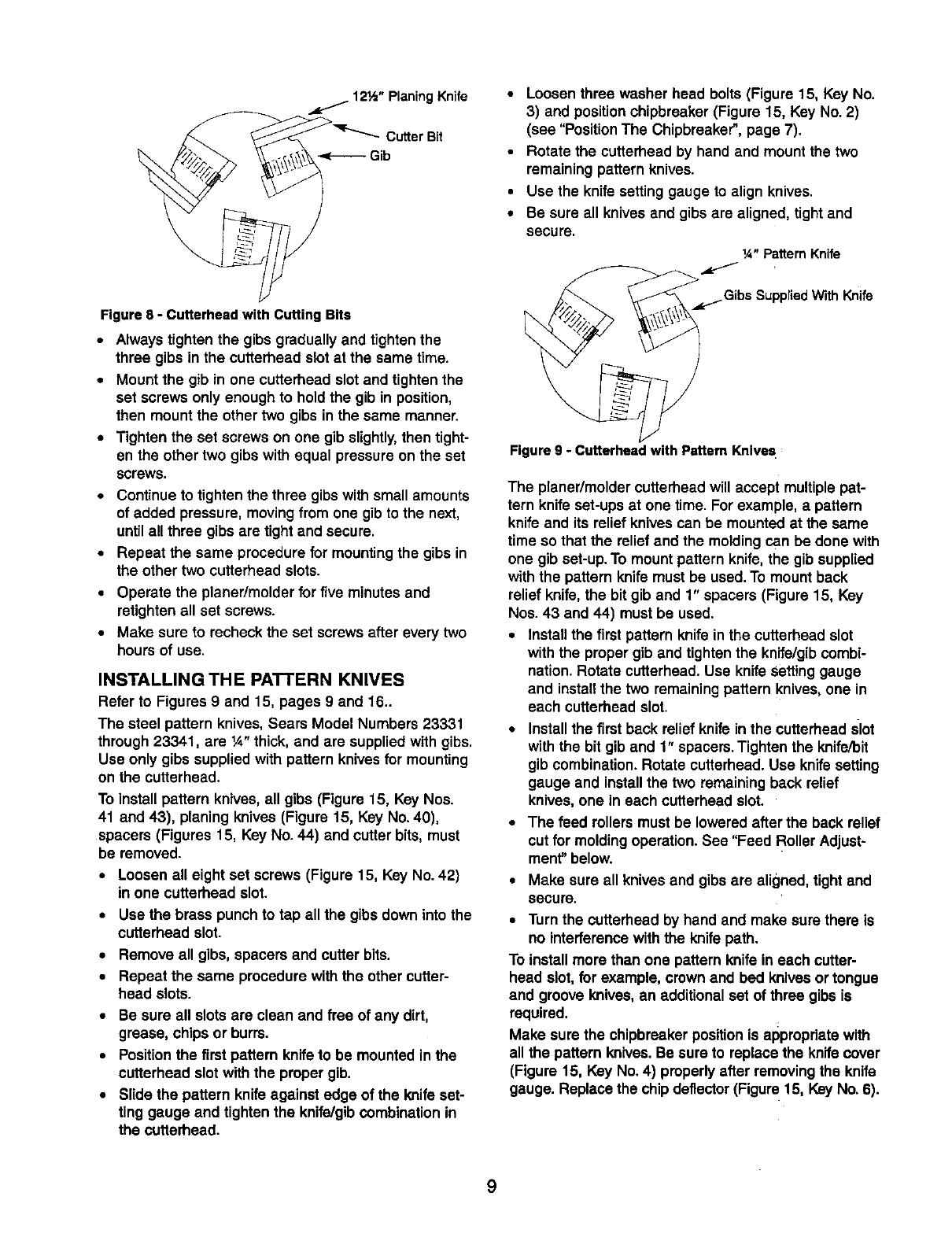
12½" Planing Knife
Cutter Bit
Gib
Figure 8 - Cutterhead with Cutting Bits
• Always tighten the gibs gradually and tightenthe
three gibs in the cutterhead slotat the same time.
•Mount the gib in one cutterhead slotand tightenthe
set screws only enough to hold the gib in position,
then mount the other two gibs in the same manner.
•Tighten the set screws on one gib slightly, then tight-
en the other two gibs with equal pressure on the set
screws.
•Continueto tightenthe three gibs with small amounts
of added pressure, movingfrom one gib to the next,
untilall three gibs are tight and secure.
•Repeat the same procedure for mountingthe gibs in
the other two cutterhead slots.
•Operate the planer/molder for five minutes and
retighten all set screws.
•Make sure to recheck the set screws after every two
hours of use.
INSTALLING THE PATTERN KNIVES
Refer to Figures 9 and 15, pages 9 and 16_
The steel pattern knives, Sears Model Numbers 23331
through 23341, are ¼" thick, and are suppliedwith gibs.
Use only gibs supplied with pattern knives for mounting
on the cutterhead.
To installpattern knives, all gibs (Figure 15, Key Nos.
41 and 43), planing knives (Figure 15, Key No. 40),
spacers (Figures 15, Key No. 44) and cutter bits, must
be removed.
•Loosen all eight set screws (Figure 15, Key No. 42)
in one cutterhead slot.
•Use the brass punch to tap all the gibs down into the
cutterhead slot.
•Remove all gibs, spacers and cutter bits.
• Repeat the same procedure with the other cutter-
head slots.
•Be sure all slotsare clean and free of any dirt,
grease, chips or burrs.
•Positionthe first pattern knifeto be mounted in the
cutterhead slot with the proper gib.
•Slide the pattern knifeagainst edge of the knife set-
ting gauge and tightenthe knife/gibCOmbinationin
the cutterhead.
• Loosen three washer head bolts (Figure 15, Key No.
3) and positionchipbreaker (Figure 15, Key No. 2)
(see "Position The Chipbreaker",page 7).
•Rotate the cutterhead by hand and mount the two
remaining pattern knives.
•Use the knife setting gauge to align knives.
•Be sure all knivesand gibs are aligned, tight and
secure.
ix="PatternKnife
,_,.j.Gibs SuppnedWith Knife
Figure 9 - Cutterhead with Pattern Knive s
The planer/molder cutterheadwill accept multiplepat-
tern knife set-ups at one time. For example, a pattern
knife and its relief knives can be mounted at the same
time so that the relief and the molding can be done with
one gib set-up.To mount pattern knife, the gib supplied
with the pattern knife must be used. To mount back
relief knife, the bit gib and 1" spacers (Figure 15, Key
Nos. 43 and 44) must be used.
•Installthe firstpattern knife inthe cutterhead slot
withthe proper gib and tighten the knife/gibcombi-
nation. Rotate cutterhead. Use knifeSettinggauge
and installthe two remainingpattern knives, one in
each cutterhead slot.
•Installthe first back relief knifein the cutterhead slot
withthe bit gib and 1" spacers. Tighten the knife/bit
gib combination.Rotate cutterhead. Use knifesetting
gauge and installthe two remaining back relief
knives, one in each cutterhead slot.
•The feed rollers must be lowered after the back relief
cut for moldingoperation. See "Feed Roller Adjust-
ment"below.
•Make sure all knives and gibs are aligned, tight and
secure.
•Turn the cutterhead by hand and make sure there is
no interference withthe knifepath.
To installmore than one pattern knife in each cutter-
head slot, for example, crown and bed knivesor tongue
and groove knives, an additional set of three gibs is
required.
Make sure the chipbreakerpositionis appropriate with
all the pattern knives. Be sure to replace the knife cover
(Figure 15, Key No. 4) properly after removingthe knife
gauge. Replace the chip deflector(Figure 15, Key No. 6).
9
FEED ROLLER ADJUSTMENT
Refer to Figures 10, 15, and 16, pages 10, 16 and 18.
The planer/molder feed rollers can be raised or lowered
as needed. The infeed and ouffeed rollersare set _6"
below the cutterheed (not the knives)at the factory for
planingoperation.The infeed and ouffeed rollers have
to be set _e" below the cutterheed for moldingopera-
tion usingthe pattern knives. Feed rollers must be
adjusted properlyfor smooth feeding of the work.piece.
NOTE: Never lower infeed and oufteed rollersbeyond
_o" lower than the cutterheed. This will cause severe
stress on the gearbox and rollersystem.
To adjust feed roller heightfor molding:
•Make two 3 x 1½x 3½" blocks and mark them as
cutterhead blocks.
• Make two 2"A, x 11/2x 3½" blocks and mark them as
molding blocks.
•Make sure the blocks are made to the mentioned
size.
• Turn handwheel (Figure 16, Key No. 22) and lower
the table (Figure 16, Key No. 20) to allow cutterhead
blocks to slide freely between the table and the cut-
terhead. Cutterhead may have to be turned by hand
to rotate knife out of the way.
• Place the 3" portion of cutterhead blocks beneath
the cutterhead, one on each side. Adjust table height
so the cutterhead block just makes contact with the
cutterhead.
•Do not raise or lower the table from nowon untilall
other adjustmentsare made.
•Place the 2"/_6"portionof moldingblocks beneath
the infeed roller,one on each side.
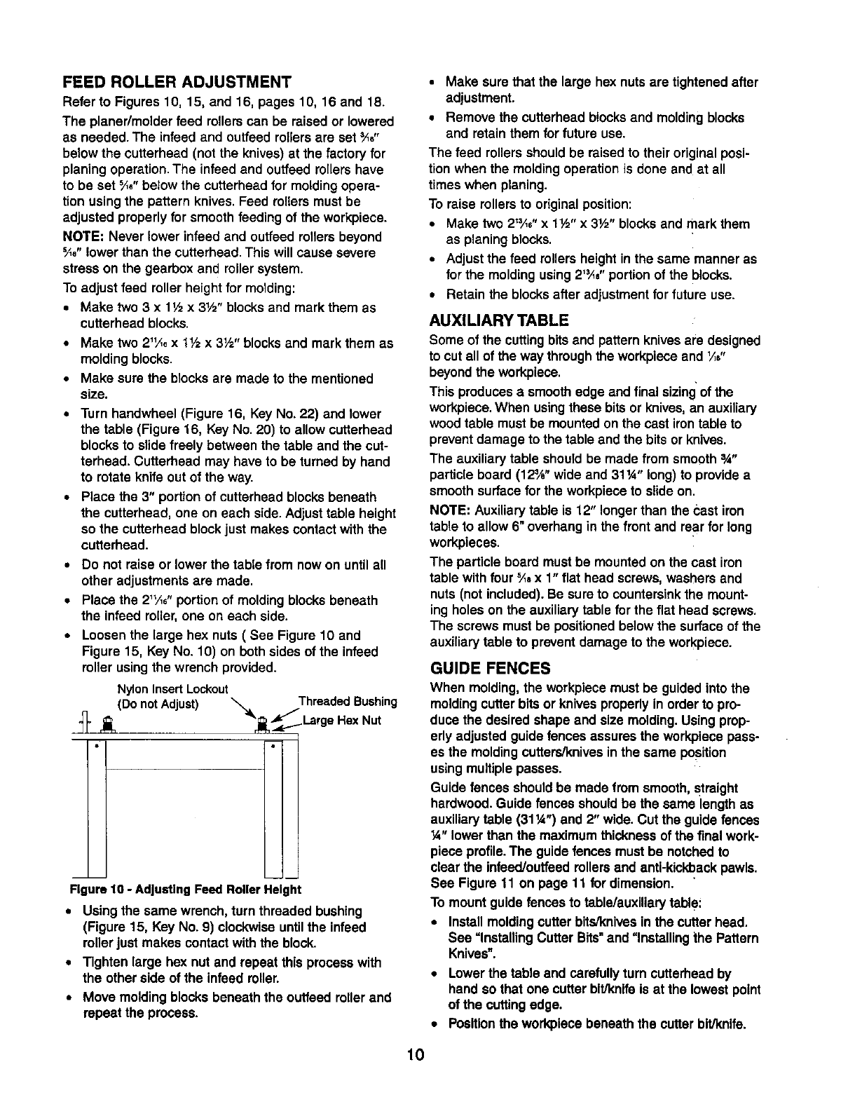
•Loosen the large hex nuts (See Figure 10 and
Figure 15, Key No. 10) on both sides of the infeed
roller using the wrench provided.
Nylon Insert Lockout Threaded Bushing
(Do not Adjust) "_'r_Large Hex Nut
Figure 10 - AdjustingFeed Roller Height
•Using the same wrench, turn threaded bushing
(Figure 15, Key No. 9) clockwise untilthe infeed
rollerjust makes contactwith the block.
•Tighten large hex nut and repeat this process with
the other side of the infeed roller.
•Move moldingblocks beneath the outfeed roller and
repeat the process.
•Make sure that the large hex nutsare tightened after
adjustment.
•Remove the cutterhead blocksand moldingblocks
and retain them for future use.
The feed rollers should be raised to their original posi-
tion when the moldingoperationis done and at all
times when planing.
To raise rollersto original position:
•Make two 21'Ae"x 1½" x 3½" blocksand mark them
as planing blocks.
• Adjust the feed rollers heightin the same manner as
for the moldingusing 2'_" portionof the blocks.
•Retain the blocksafter adjustmentfor future use.
AUXILIARY TABLE
Some of the cuttingbits and pattern knives are designed
to cut all of the way throughthe workpiece and _/;,"
beyondthe workpiece.
This produces asmooth edge and final sizing of the
workpiece.When usingthese bitsor knives,an auxiliary
wood table must be mountedon the cast irontable to
preventdamage to the table and the bits or knives.
The auxiliary table shouldbe made from smooth 3A"
particle board (12¾" wide and 31W' long) to providea
smooth surface for the workpiece to slide on.
NOTE: Auxiliarytable is 12" longerthan the bast iron
table to allow 6" overhang in the front and rear for long
workpieces.
The particle board must be mountedon the cast iron
table with four _a x 1" flat head screws, washers and
nuts(not included).Be sureto countersinkthe mount-
ing holes on the auxiliary table for the flat head screws.
The screws must be positionedbelow the surface of the
auxiliary table to prevent damage to the workpiece.
GUIDE FENCES
When molding, the workpiece must be guided into the
moldingcutterbits or knives properlyin order to pro-
duce the desired shape and size molding. Using prop-
erly adjusted guidefences assures the workplece pass-
es the moldingcutters/knivesinthe same position
usingmultiple passes.
Guide fences shouldbe made from smooth, straight
hardwood.Guide fences should be the same length as
auxiliarytable (311/4")and 2" wide. Cut the guide fences
14"lower than the maximum thicknessof the final work-
piece profile.The guidefences must be notchedto
clear the infeed/ouffeedrollersand anti-kickbackpawls.
See Figure 11 on page 11 for dimension.
To mount guide fences to table/auxiliary table:
•Installmoldingcutter bits/knivesin the cutterhead.
See =Installing Cutter Bits=and =Installing the Pattern
Knives".
•Lower the table and carefullyturn cutterheadby
hand so that one cutterbitJknlfeis at the lowest point
of the cuttingedge.
• Positionthe workplece beneath the cutter bit/knife.
10
•Slide in first guide fence and positioninside edge of
guide rail to outside edge of workpiece.
•Clamp the guide fence to table/auxiliarytable using
"C"clamps on both ends,
•Positionsecond guide fence on the other side of the
workpiece and clamp it to table/auxiliarytable,
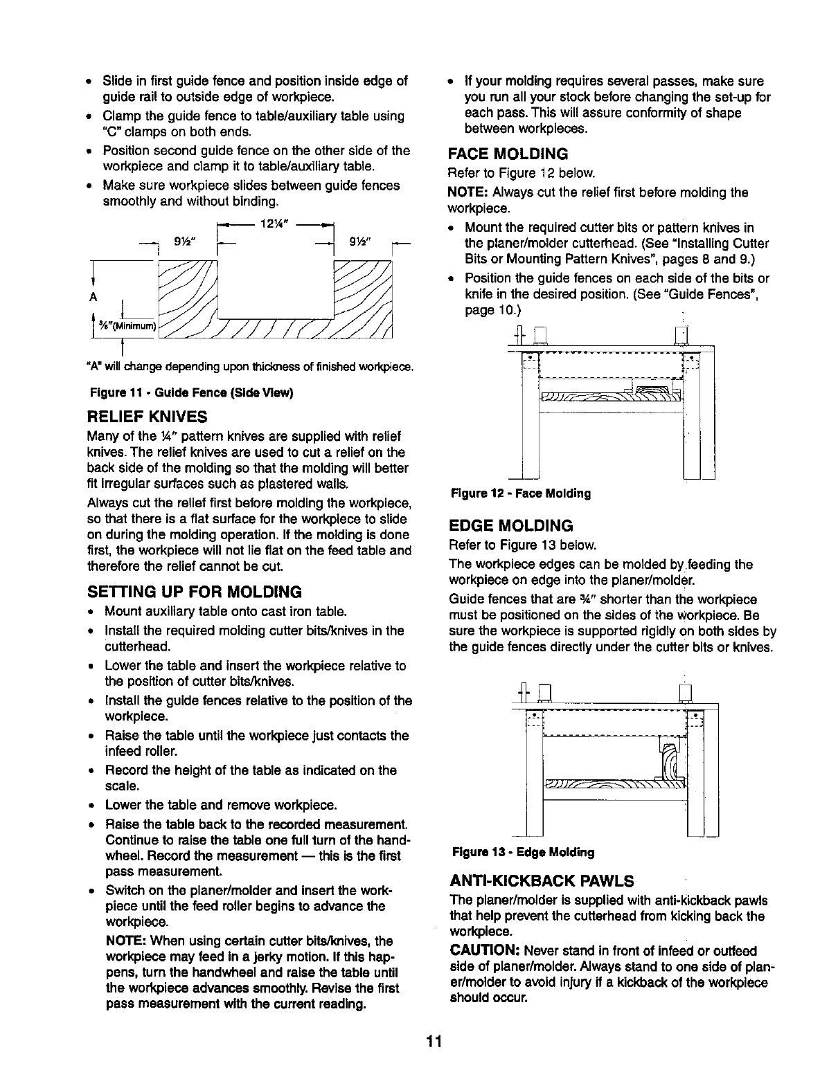
•Make sure workpiece slides between guide fences
smoothlyand without binding.
121/'" _'_
9½" 9½"
"A"willchangedependinguponthicknessof finishedworkpiece.
Figure 11 -Guide Fence (Side View)
RELIEF KNIVES
Many of the ¼" pattern knivesare suppliedwith relief
knives. The relief knives are used to cut a relief on the
back side of the molding so that the molding will better
fit irregular surfaces such as plastered walls.
Always cut the relief first before molding the workpiece,
so that there is a flat surface for the workpiece to slide
on during the molding operation. If the molding is done
first, the workpieca will not lie flat on the feed table and
therefore the relief cannot be cut.
SE'n'ING UP FOR MOLDING
• Mount auxiliary table onto cast iron table.
• Install the required molding cutter bits/knives in the
cutterhead.
•Lower the table and insert the workpiece relativeto
the positionof cutter bits/knives.
• Install the guide fences relativeto the positionof the
workpiece.
•Raise the table untilthe workpiece just contactsthe
infeed roller.
•Record the height of the table as indicated on the
scale.
•Lower the table and remove workpiece.
• Raise the table back to the recorded measurement.
Continue to raise the table one full turn of the hand-
wheel. Record the measurement -- this is the first
pass measurement.
•Switch on the planer/molder and insert the work-
piece untilthe feed roller begins to advance the
workpiece.
NOTE: When using certain cutter bite/knives,the
workpiece may feed in ajerky motion.If this hap-
pens, turn the handwheel and raise the table until
the workplece advances smoothly.Revise the first
pass measurement with the current reading.
•If your moldingrequires several passes, make sure
you run all your stock before changingthe set-up for
each pass. This will assure conformityof shape
between workpieces.
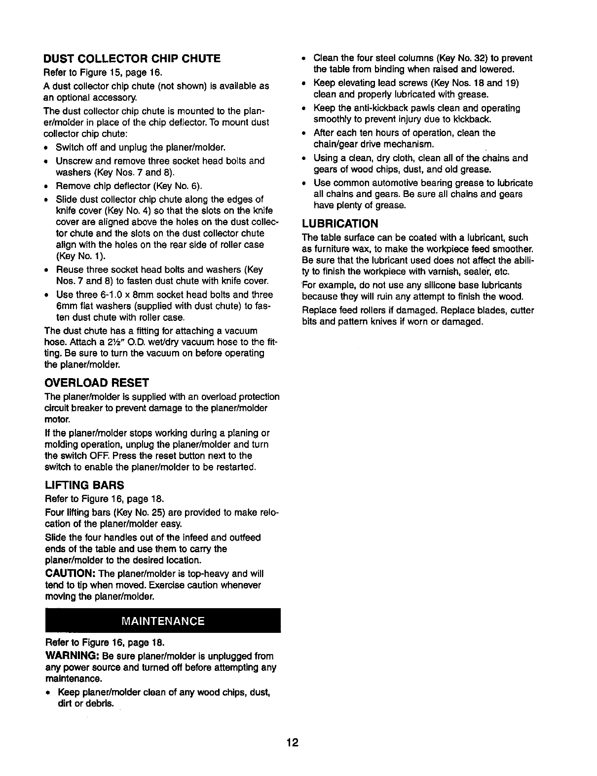
FACE MOLDING
Refer to Figure 12 below.
NOTE: Alwayscut the relief first before moldingthe
workpiece.
•Mount the requiredcutter bits or pattern knives in
the planer/molder cutterhead. (See =Installing Cutter
Bits or Mounting Pattern Knives",pages 8 and 9.)
•Positionthe guide fences on each sideof the bitsor
knife in the desired position.(See "Guide Fences",
page 10.)
mini
Figure 12 -Face Molding
EDGE MOLDING
Refer to Figure 13 below.
The workpiece edges can be molded by feeding the
workpieceon edge into the planer/molder.
Guide fences that are 3A"shorterthan the workpiece
must be positionedon the sides of the workpiece. Be
sure the workpiece is supportedrigidlyon both sides by
the guide fences directlyunder the cutter bitsor knives.
JJ JJ
Rgure 13 -Edge Molding
ANTI-KICKBACK PAWLS
The planer/molder is suppliedwith anti-kickbackpawls
that help prevent the cutterheadfrom kickingback the
workplece.
CAUTION." Never stand in front of infeed or outfeed
side of planer/molder,Always stand to one side of plan-
er/molderto avoid injuryif a kickbackof the workpleco
should occur.
11
DUST COLLECTOR CHIP CHUTE
Refer to Figure 15, page 16.
A dust collector chip chute (not shown) is available as
an optionalaccessory.
The dust collector chip chute is mountedto the plan-
er/molder in place of the chip deflector. To mount dust
collector chip chute:
•Switch off and unplugthe planer/molder.
•Unscrew and remove three socket head bolts and
washers (Key Nos. 7 and 8).
•Remove chip deflector (Key No. 6).
•Slide dust collectorchip chute along the edges of
knife cover (Key No. 4) so that the slotson the knife
cover are aligned above the holes on the dust collec-
tor chute and the slots on the dust collector chute
align with the holes on the rear side of roller case
(Key No. 1).
•Reuse three socket head bolts and washers (Key
Nos. 7 and 8) to fasten dust chute with knife cover.
•Use three 6-1.0 x 8mm socket head boltsand three
6mm flat washers (suppliedwith dust chute) to fas-
ten dust chute with roller case.
The dust chute has a fitting for attaching a vacuum
hose. Attach a 2!._"O.D. weVdry vacuum hose to the fit-
ting. Be sure to turn the vacuum on before operating
the planer/molder.
OVERLOAD RESET
The planer/molderis suppliedwithan overloadprotection
circuitbreaker to prevent damage to the planer/molder
motor.
If the planer/molder stopsworking during a planing or
moldingoperation, unplugthe planar/molder and turn
the switch OFF. Press the reset buttonnext to the
switch to enable the planer/molder to be restarted.
LIFTING BARS
Refer to Figure 16, page 18.
Four liftingbars (Key No. 25) are providedto make relo-
cation of the planer/molder easy,
Slide the four handles out of the infeed and outfeed
ends of the table and use them to carry the
planer/molder to the desired location.
CAUTION: The planer/molder is top-heavy and will
tend to tip when moved. Exemise caution whenever
movingthe planer/molder.
•Clean the four steel columns (Key No. 32) to prevent
the table from bindingwhen raised and lowered.
•Keep elevating lead screws (Key Nos. 18 and 19)
clean and properlylubricatedwith grease.
•Keep the anti-kickbackpawls clean and operating
smoothlyto prevent injury due to kickback.
•After each ten hours of operation, clean the
chain/gear drive mechanism.
•Using a clean, dry cloth, clean all of the chains and
gears of wood chips, dust, and old grease.
•Use common automotive bearing grease to lubricate
all chains and gears. Be sure all chains and gears
have plenty of grease.
LUBRICATION
The table surface can be coated with a lubricant, such
as furniturewax, to make the workpiecefeed smoother.
Be sure that the lubricantused does not affect the abili-
ty to finish the work.piecewithvarnish, sealer, etc.
'Forexample, do not usa any silicone base kJbricants
because they will ruin any attempt to finishthe wood.
Replace feed rollersif damaged. Replace blades, cutter
bitsand pattern knives if worn or damaged.
Refer to Figure 16, page 18,
WARNING: Be sure planer/molder is unpluggedfrom
any power source and turned off before attempting any
maintenance.
•Keep planer/molder clean of any wood chips, dust,
dirt or debris.
12
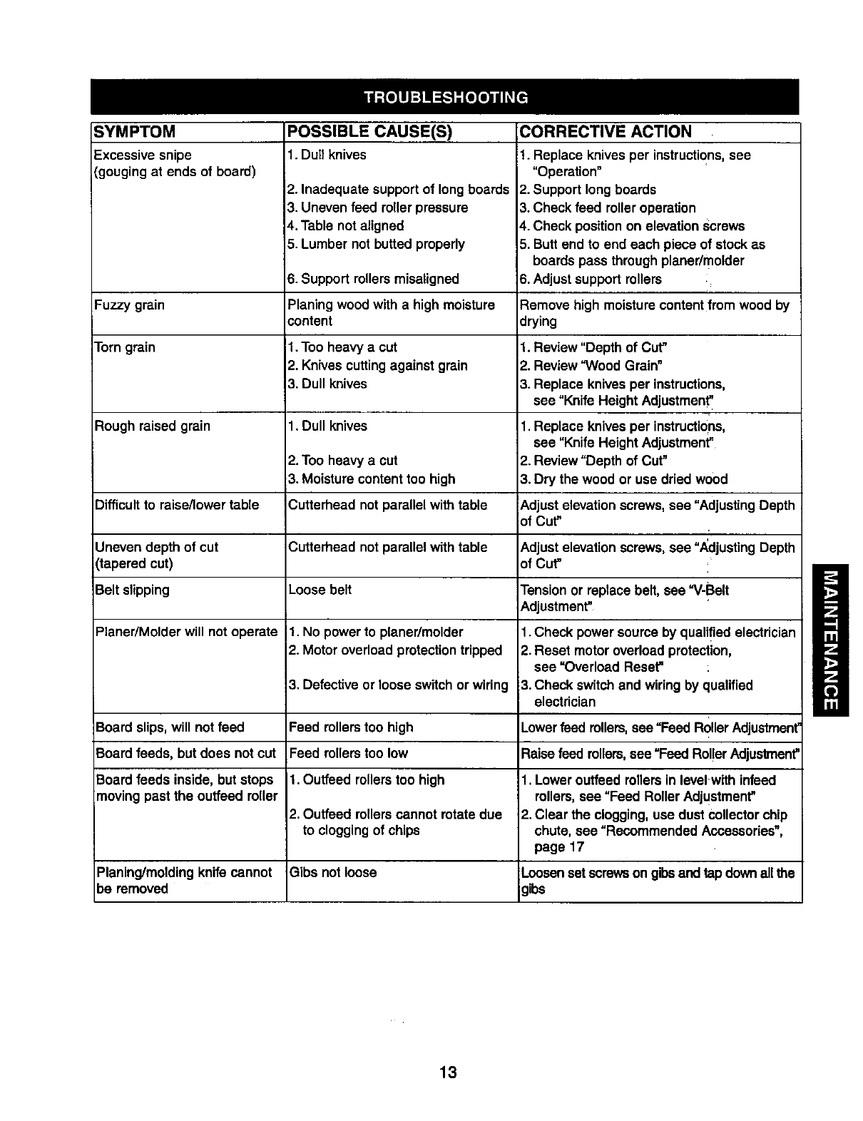
SYMPTOM
Excessive snipe
(gougingat ends of board)
Fuzzy grain
Torngrain
Rough raised grain
POSSIBLE CAUSE(S)
Difficultto raise/lowertable
Uneven depth of cut
(tapered cut)
Belt slipping
Planer/Molder will not operate
Board slips,will not feed
Board feeds, but does not cut
Board feeds inside, but stops
moving past the ouffeed miler
Planing/moldingknife cannot
be removed
1. Dull knives
2. Inadequate support of longboards
3. Uneven feed roller pressure
4. Table not aligned
5. Lumber not butted properly
6. Support rollersmisaligned
Planing wood with a high moisture
content
1. Too heavy a cut
2. Knives cuttingagainst grain
3. Dull knives
1. Dull knives
2. Too heavy a cut
3. Moisture content too high
Cutterhead not parallel with table
Cutterhead not parallel with table
Loose belt
1. No power to planer/molder
2. Motor overload protectiontripped
3. Defective or loose switch or wiring
Feed rollerstoo high
Feed rollerstoo low
1. Outfeed rollerstoo high
2. Outfeed rollerscannot rotatedue
to cloggingof chips
Gibs not loose
CORRECTIVE ACTION
1. Replace knives per instructions,see
"Operation"
2. Support longboards
3. Check feed roller operation
4. Check positionon elevationscrews
5. Butt end to end each piece of stock as
boards pass throughplaner/molder
6. Adjustsupport rollers i
Remove high moisturecontentfrom wood by
drying
1. Review "Depth of Cut"
2. Review "Wood Grain"
3. Replace knives per instructions,
see =Knife Height Adjustment'
1. Replace knives per instructions,
see =KnifeHeight Adjustment"
2. Review "Depth of Cut"
3. Dry the wood or use dried wood
_.djust elevationscrews,see =Adjusting Depth
of Cut" ,
tkdjust elevationscrews,see "Adjusting Depth
of Cut"
Tensionor replace belt, see "V-Belt
Adjustment"
1. Check power source by qualified electrician
2. Reset motor overload protection,
see "Overload Reset=
3. Check switchand wiring by qualified
electrician
Lower feed rollers,see "Feed Roller Adjustment"
Raisefeed rollers,see "Feed Rol!erAdjustment"
1. Lower outfeed rollersin level.with infeed
rollers,see "Feed Roller Adjustment"
2. Clear the clogging,use dust collectorchip
chute, see "Recommended Accessories",
page 17
Loosenset screwson gibsand tap downallthe
gibs
13
Model 351.233831
12 5
11
21 19
16
26
26
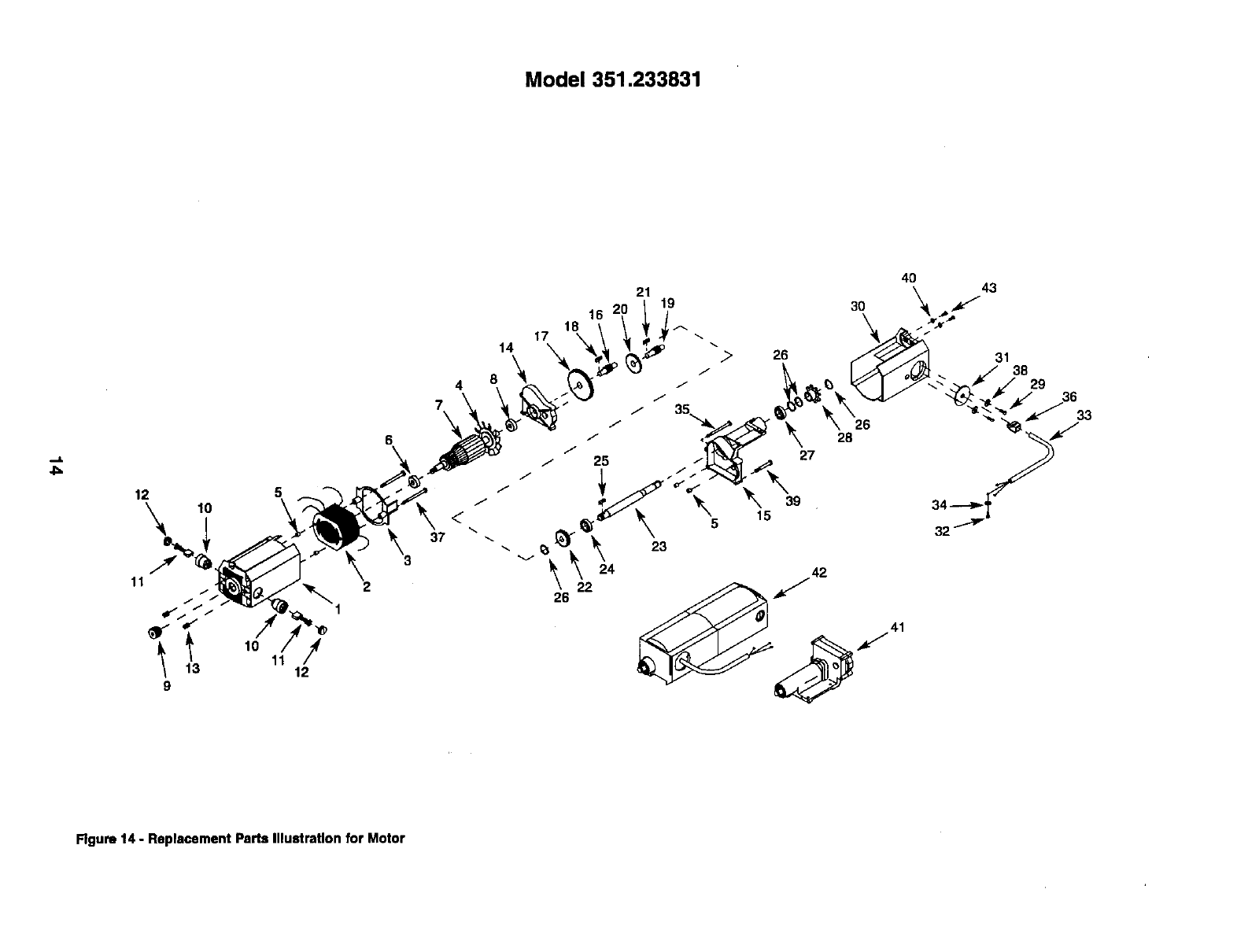
Figure 14 - Replacement Paris Illustration for Motor
KEY
NO,
1
2
3
4
5
6
7
8
9
10
11
12
13
14
15
16
17
18
19
20
21
22
PART NO.
3857.00
4283.00
4284.00
3860.00
3861.00
STD315215
4285.00
STD815205
3865.00
3866.00
3867.00
3868.00
1838.00
3869.00
3870.00
3874.00
3875.00
3873.00
3871.00
3872.00
3846.00
3876,00
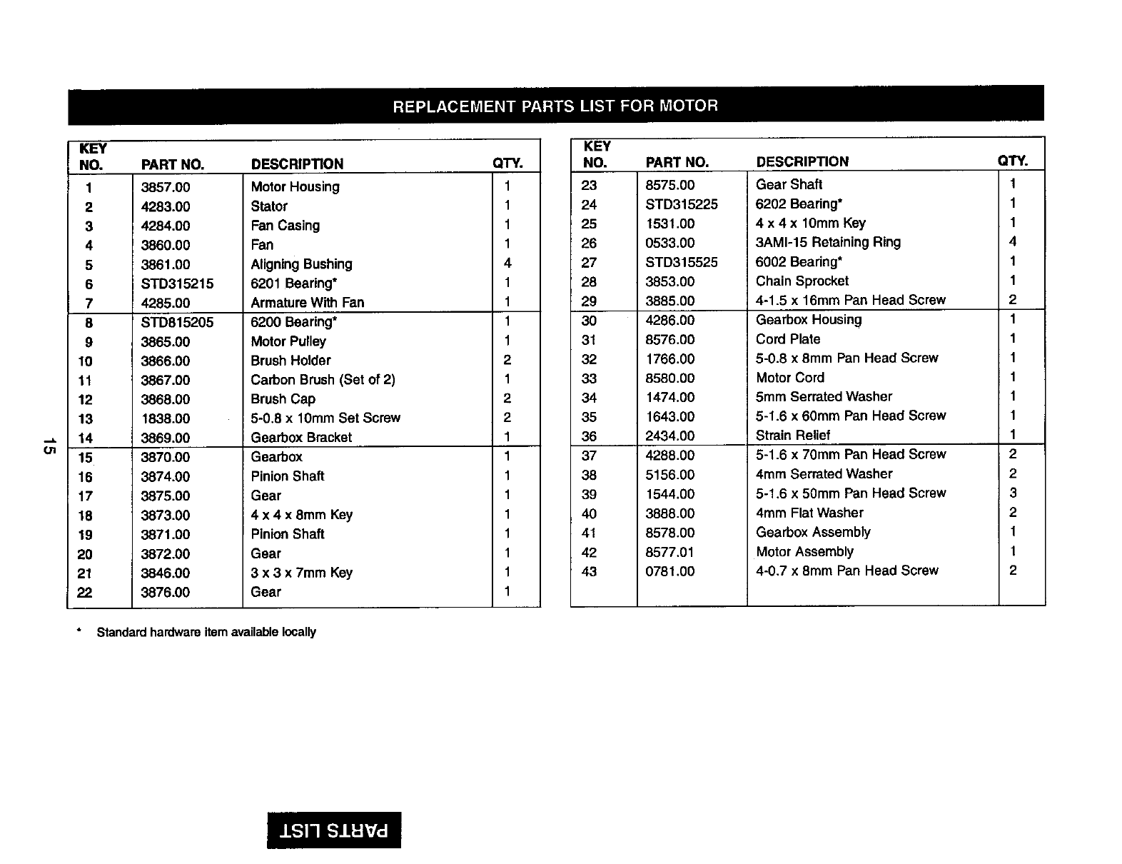
DESCRIPTION
Motor Housing
Stator
Fan Casing
Fan
AligningBushing
6201 Bearing*
Armature With Fan
6200 Bearing*
Motor Pulley
BrushHolder
Carbon Brush(Set of 2)
BrushCap
5-0.8 x 10mm Set Screw
Gearbox Bracket
Gearbox
Pinion Shaft
Gear
4 x 4 x 8mm Key
Pinion Shaft
Gear
3 x 3 x 7mm Key
Gear
Standard hardware item available locally
QTY.
1
1
1
1
4
1
1
1
1
2
1
2
2
1
1
1
1
1
1
1
1
1
KEY
NO.
23
24
25
26
27
28
29
30
31
32
33
34
35
36
37
38
39
4O
41
42
43
PART NO.
8575.00
STD315225
1531.00
0533.00
STD315525
3853.00
3885.00
4286.00
8576.00
1766.00
8580.00
1474.00
1643.00
2434.00
4288.00
5156.00
1544.00
3888.00
8578.00
8577.01
0781.00
DESCRIPTION
Gear Shaft
6202 Bearing*
4 x 4 x 10mm Key
3AM1-15 Retaining Ring
6002 Bearing*
Chain Sprocket
4-1.5 x 16ram Pan Head Screw
Gearbox Housing
Cord Plate
6-0.8 x 8mm Pan Head Screw
Motor Cord
5mm Serrated Washer
5-1.6 x 60mm Pan Head Screw
Strain Relief
5-1.6 x 70mm Pan Head Screw
4mm Serrated Washer
5-1.6 x 50ram Pan Head Screw
4mm Flat Washer
Gearbox Assembly
MotorAssembly
4-0.7 x 8mm Pan Head Screw
QTY.
1
1
1
4
1
1
2
1
1
1
1
1
1
1
2
2
3
2
1
1
2
Model351.233831
57
53
50
51
55 46
52
/T
57
54
47
5O
4
2
63
39 16
63
f
25
29
723 \59
37
67
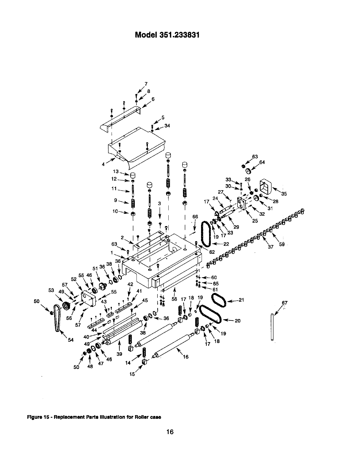
Rgure 15 - Replacement Parts Illustration for Roller case
16
KEY
NO.
1
2
3
4
5
6
7
8
9
10
11
12
13
14
15
16
17
18
19
2O
21
22
23
24
25
26
27
28
i29
30
31
32
33
34
PART NO. DESCRIPTION
8508.00
8509,00
7317.00
8510.00
8662.00
8512.00
6086.00
STD851004
8613.00
8514.00
8516.00
8516.00
8517.00
3844.00
8519.00
$520.00
3853.00
3856.00
0533.00
8522.00
8523.00
8524.00
8525.00
8526.00
8527.00
8528.00
3873.00
8529,00
8530.00
STD851005
8532.00
1775.00
6270.00
STD851006
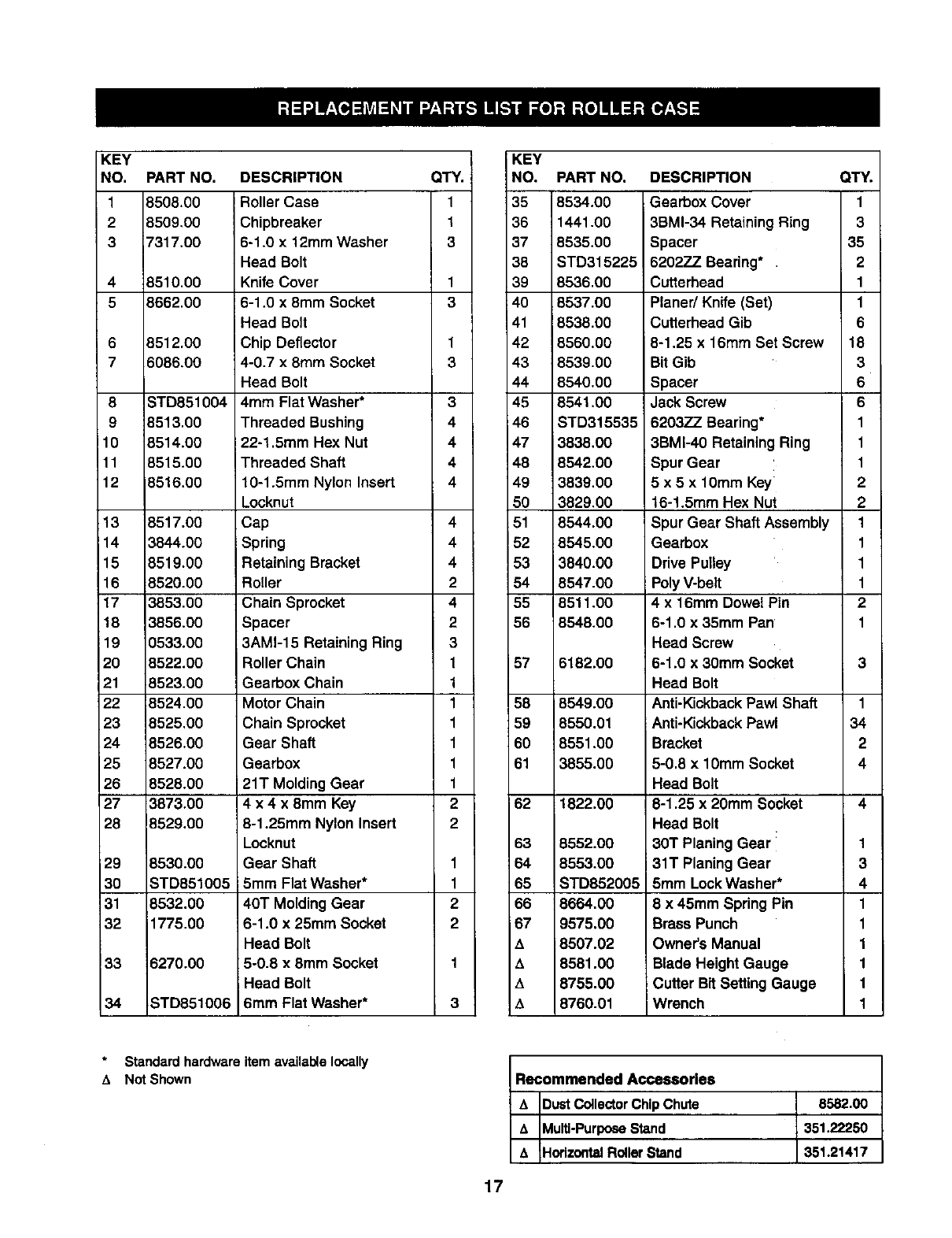
Roller Case
Chipbreaker
6-1.0 x 12mm Washer
Head Bolt
Knife Cover
6-1.0 x 8mm Socket
Head Bolt
Chip Deflector
4-0.7 x 8turn Socket
Head Bolt
4mm Flat Washer*
Threaded Bushing
22-1.5mm Hex Nut
Threaded Shaft
10-1.5mm Nylon Insert
Locknut
Cap
Spring
Retaining Bracket
Roller
Chain Sprocket
Spacer
3AM1-15 Retaining Ring
Roller Chain
Gearbox Chain
Motor Chain
Chain Sprocket
Gear Shaft
Gearbox
21T Molding Gear
4 x 4 x 8mm Key
8-1.25mm Nylon Insert
Locknut
Gear Shaft
5mm Flat Washer*
40T Molding Gear
6-1.0 x 25mm Socket
Head Bolt
5-0.8 x 8ram Socket
Head Bolt
6mm Flat Washer*
QTY.
1
1
3
1
3
1
3
3
4
4
4
4
4
4
4
2
4
2
3
1
1
1
1
1
1
1
2
2
1
1
2
2
3
KEY
NO. PART NO, DESCRIPTION QTY.
35 8534.00 Gearbox Cover 1
36 1441.00 3BMI-34 Retaining Ring 3
37 8535,00 Spacer 35
38 STD315225 6202ZZ Bearing* 2
39 8536.00 Cutterhead 1
40 8537.00 Planer/Knife (Set) 1
41 8538.00 Cutterhead Gib 6
42 8560.00 l 8-1,25 x 16mm Set Screw 18
43 8539.00 BitGib 3
44 8540,00 Spacer 6
45 8541.00 Jack Screw 6
46 STD315535 6203ZZ Bearing* 1
47 3838.00 3BMI-40 Retaining Ring 1
48 8542.00 Spur Gear 1
49 3839.00 5 x5 x 10ram Key 2
50 3829,00 16-1.5mm Hex Nut 2
51 8544.00 Spur Gear Shaft Assembly 1
!52 8545.00 Gearbox 1
53 3840.00 Drive Pulley 1
54 8547.00 PolyV-belt 1
55 6511.00 4x16mm Dowel Pin 2
56 8548,00 6-1.0 x 35ram Pan' 1
Head Screw
57 6182.00 6-1.0 x 30ram Socket 3
Head Bolt
58 8549.00 Anti-KickbackPawl Shaft 1
59 8550.01 Anti-KickbackPawl 34
60 8551 .O0 Bracket 2
61 3855.00 5-0.8 x 10mm Socket 4
Head Bolt
62 1822.00 6-1.25 x 20mm Socket 4
Head Bolt
63 8552.00 30T Planing Gear _ 1
64 8553.00 31T Planing Gear 3
65 STD852005 5mm LockWasher* 4
66 8664,00 8 x 45mm Spring Pin 1
67 9575.00 Brass Punch 1
A8507.02 Owner's Manual 1
A8581.00 Blade HeightGauge 1
A8755.00 Cutter Bit Setting Gauge 1
t_ 8760.01 Wrench 1
Recommended Accessories
A E)ustCollectorChipChute 8582.00
&_ulti-Purpose Stand 351.22250
A HorizontalRollerStand 351.21417
Standard hardware
,% Not Shown item available locally
17
Model 351.233831
28
29 '_ I
30..._
32
27
25
i
2O
,.<-_32
18
41
3
41
46
45
4
3\
38
50
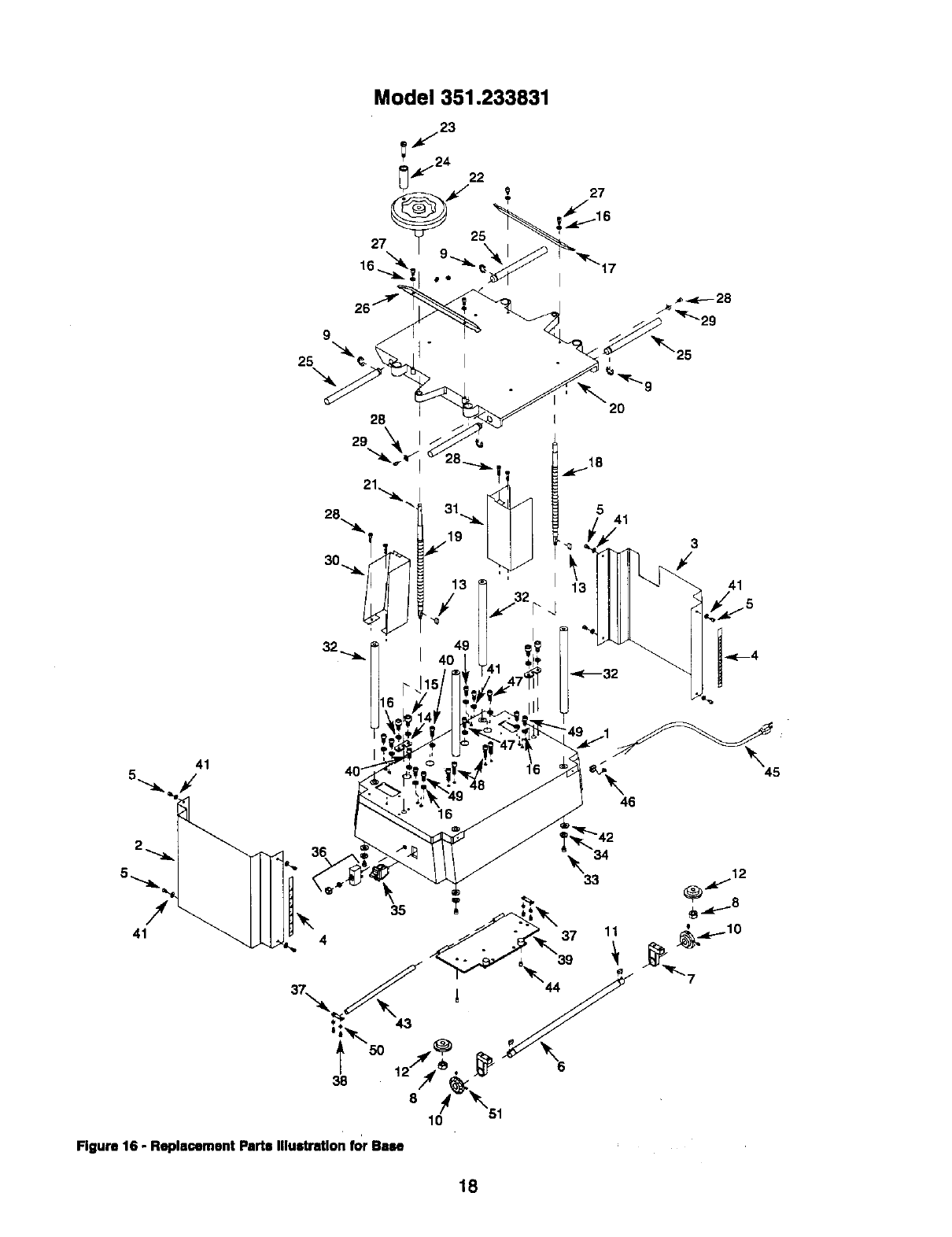
Figure 16 - Replacement Parts illustration for Base
18
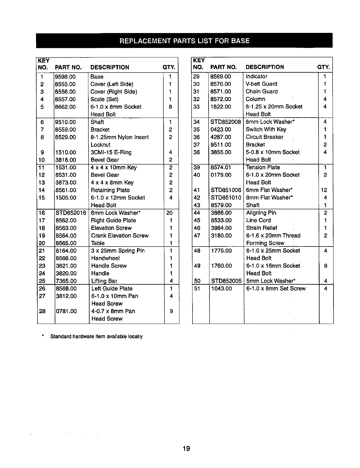
KEY
NO.
19598.00
2 8555.00
3 8556.00
4 8557.00
5}662.00
6
7
8
PART NO. DESCRIPTION
9510.00
8559.00
8529.00
9 1510.00
10 3818.00
11 1531.00
12 8531.00
13 3873.00
14 8561.00
15 1505.00
16 STD852016
17 8562.00
18 8563.00
19 8564.00
20 8565.00
21 6164.00
22 8566.00
23 3821.00
24 3820,00
25 7365.00
26 B568.00
27 _812.00
28 0781.00
Base
Cover (Left Side)
Cover (Right Side)
Scale (Set)
6-1.0 x 8mm Socket
Head Bolt
Shaft
Bracket
8-1.25mm Nylon Insert
Locknut
3CM1-15 E-Ring
Bevel Gear
4 x 4 x 10mm Key
Bevel Gear
4 x4 x8mm Key
Retaining Plate
6-1.0 x 12ram Socket
Head Bolt
6mm Lock Washer*
Right Guide Plate
Elevation Screw
Crank Elevation Screw
Table
3 x 25mm Spring Pin
Handwheel
Handle Screw
Handle
Lifting Bar
Left Guide Plate
6-1.0 x 10ram Pan
Head Screw
4-0.7 x 8ram Pan
Head Screw
QTY.
1
1
1
1
8
1
2
2
4
2
2
2
2
2
4
2O
1
1
1
1
1
1
1
1
4
1
4
KEY
NO.
29
30
31
32
33
34
35
36
37
38
39
4O
41
42
43
144
45
46
47
48
49
50
51
PART NO. DESCRIPTION
8569.00
8570.00
8571.00
8572.00
1822.00
STD852008
0423.00
4287.00
9511.00
3855.00
8574.01
0179.00
STD851006
STD851010
8579.00
3886.00
8533.00
3984.00
13180.0O
1775.00
1760.00
STD852005
1043.00
Indicator
V-belt Guard
Chain Guard
Column
8-1.25 x 20mm Socket
Head Bolt
8mm Lock Washer*
Switch With Key
Circuit Breaker
Bracket
5-0.8 x 10mm Socket
Head Bolt
ITension Plate
6-1.0 x 20ram Socket
Head Bolt
6mm Flat Washer*
8mm Flat Washer*
Shaft
Aligning Pin
Line Cord
Strain Relief
6-1.6 x 20mm Thread
FormingScrew
6-1.0 x 25mm Socket
Head Bolt
6-1.0 x 16mm Socket
Head Bolt
5mm LockWasher*
6-1.0 x 8mm Set Screw
QTY.
1
1
1
4
4
4
1
1
2
4
1
2
12
4
1
2
1
1
2
Standard hardware item available locally
19
CEPILLADORA/MOLDEADORA
DE 121/="
Modelo No.
351.233831
PRECAUClON: Lea este manual y siga las
Reglas de Seguridad ylas Instrucciones de
Operaci6n, antes de user este producto por la
primera vez.
Ingl6s ............................................ 2-19
Ilustraci6n y lista de partes ........................... 14-19
Garant_a............................................ 20
Reglas de seguridad ................................ 20-21
Montaje ............................................ 21
Instalaci6n ........................................ 21-23
Oparaci6n ........................................ 23-30
Mantenimiento ....................................... 30
Idantif'w.ati6nde problemas .............................. 31
UN A_IO ENTERO DE GARANTIA PARA LA CEPILLA-
DORA/MOLDEADORA DE 31,8 CM CRAFTSMAN
Si la cepilladora/moldeadora Craftsman falla debido aun defecto
en el material o en la mano de obrs, dentro de un aRo a partir
de la fecha de compra, p6ngase en contacto con el servicio de
reparaciones de rsareas principeles, interno, Sears en Estados
Unidos, y Sears la reparard sin costo.
SI esta cepitladora/moldeadora se usa pars fines cornerciales o
pars arriendo, esta garsntfa se aplica por 90 dfas a partir de la
fecha de comprs.
Esta garantfa se apllce solamente cuando el producto estd an
Estados Unidos. Esta garsntfa le otorga derschos legales especf-
ficos y tambidn puede tener otros derschos qua varfan de estado
a estado.
Sears, Roebuck and Co., Dept, 817WA, Hoffman Estates, IL
60179
ADVERTENClA: Pars su prop[a seguridad, lea todas las
Instruodones y las prscauciones antes de operar la herrsmienta.
PRECAUClON: Siempre siga los procedimientos de operack_'l
correctos, tel como se definen en esta manuel, aun cuando estd
familla.dzado con el uso de dsta o de otras herramientas similares.
Recuerde quesi no se t;ene cuida.do por aunque sea. una frscci6n
de un segundo se pueden producir lesicoes personeles graves.
ESTE PREPARADO PARA EL TRABAJO
Use rope. aproplada. No use ropa suelta, guantes, corbatas,
anlllos pulsera.s u otres |oyas que pueda.n quedar cogidas en
la.s partes rs6viles de la rsdquina.
Use una cubierta protectora, pare el cabelto, pa.rs suJetar el
cabello largo.
•Use zapatos de seguddad con suelas sntldesnzantes.
•Use gafa.s de segurided, que cumplan con ANSI Z87.1 de
Estados Unidos, Los enteojos cordentaa tienen solarsente
tentes resistentes al impacto. NO son anteoJos de seguridad.
•Use una mdscara pare la cara o una mdscara pars el poivo,
si ia operaci6n produce polvo.
•Estd alerta y piense claramente. Nunca opers herramientas
rsecdnicas cuando est_ cansado, intoxicado o cuando estd
tomando medicamentos que causan mareos.
PREPARACION DEL AREA PARA EJECUTAR EL
TRABAJO
•Mantenga el drsa limpia.Las drsas de trabajodesordenadas
atraenaccidentes.
•No use herramientas mecdnicas en amblentes peligrssos. No
use herramientas mecdnicas en lugares ht_medos o mojados.
No exponga las herramientas mecdnicas ala Iluvia.
•El drsa de trabajo debe estar iluminada adecuadamente.
•Tiene qua heber disponlble un rsceptdcoto el_ctdco adecuado
para la herramienta. El enchufe de tres puntas se tiene qua
enchufar dirsctamente en un recept_leulo de trss puntas
conectado atierra corrsctamente.
Los cordones de extensi6n deben tenet una punta de co-
nexi6n a tierra y los tree alambres del cord6n de exlensi6n
deben ser del calibre correcto.
Ma.ntenga. a los visitantes a una distancia prudente del drea
de traba.jo.
Mantenga a los niRos fuera del lugar de trabejo. Haga que
su teller sea a prueba, de ni5os. Use ca.ndados, interruptores
principales o remueve las I[aves del interruptor para evitar el
uso no intencional de las herramientas mecdnicas.
ES IMPORTANTE MANTENER I.AS HERR AMIENTAS
Desenchufe siersprs ta herramienta antes de inspeccionarla.
Consulte el manual pa.ra,informarse sobre los procedimientos
de mantenlmiento y ajuste espec_'ficos.
Ma.ntenga la herrarsienta lubdcada y limpia, pare o_ener una
opersci6n rods segura.
Remueva la.s herra.mlentas de ajuste. F6rmese el hdbito de
reviser para verificar el la.s herra.rsientas de ajuste se ha.n
removido antes de encender la mdquina..
Mantenga todas las partes Iistas pare funcionar. Revise pare
determiner que el protector u otras pa.rtes opersrdn correcta-
mente y hardn el trsbajo que deben hacer.
Revise pars verificar sl hay partes de_adas. Revise pars
vedficar el elineamiento de lea partes moviblea, sl hay atas-
camiento, rcturas y rsontaje o cuelquler otra condici6n qua
pudiers afectar laopersci6n de laherramienta,
•Si hay una protecciSn o cuelquier otra parte dafiadaa, tienen
que rsparsrse corrsctamente osemblarse. No haga rspars-
clones provisodas. (Use la lista de partes qua viene incluida
pare ordenar las partes de rspuesto.)
EL OPERADOR DEBE SABER COMO USAR LA
HERRAMIENTA
•Use la herramientacorrecta pars el trabajo,No fuerce la
herramlenta,oel accesodo,nl los use pars untrabaJopare
el cualnohartsidediseRados.
•Desconectela herrsrslentacoando camble lash_Jas.
•Evlte el arranquapor accldentes,Asegdmseque el Interruptor
de le herramlentaestden la poelcl6n"apaga.do"(off) antesdo
enchufada.
•No fuercela herramlenta.TrabaJarden la formamSsafidente
ala veloddad pera la cuel sa diseftS.
20
Mantenga las manos alejadas de las partes m6viles y de las
superficies cortadoras.
Nunca deje que una herramienta funcione cola. Descon6ctela
y no se vaya hasta que se defenga completamente.
No trate de alcanzar demasiado lejos. Mant6ngase firme
yequilibredo.
Nunca se pare en la herramienta. Se pueden producir
lesiones graves si la herramienta se incline, o sise tcoa
el disco o la correa pot accidente.
•Conozca su herramienta. Aprenda la operaci6n de la herra-
mienta, aplicacibn y lim_taeiones especfficas.
•Use los acoesorios que se recomienda. (Refri6rase ala pdgi-
na 17.) Si se usan accesodos iecorrectos, se puede producir
riesgo de lesiones personales.
• Deje las manos libres para operar la mdquina. Prot_jalas de
posibles lesionea.
• Desconecte la mdquina si ae atassa. La cuchillo o la hoja se
atassa cuando penetra demasiedo profundamente en la pleza
de trabajo. (La fuerza del motor la mantiene pegada ala pieza
de trabajo.)
• Siempre mantenga el impulsor, el portacochilla y tas protec-
ciones de las cuchUlas en su lugar y en condiciones de
operaci6n adecuadas.
• Alimente el trabajo en la euchilla oen la cortedora en contra
de la direcci6n de rotaci6n.
PRECAUClON: IPiense en la seguridadt La seguddad es una
combinacibn de sentido com0n del operador y de ester alerta
en todo mornento cuando se estd usando la herramienta.
ADVERTENCIA: No trate de operarla herramlentahasteque
est_ completamentemontadasegt_nlas Instrucciones.
Refidrase alas Figuras 15 y 16, pdginas 16 y 18.
La ospilladora/moideadora se envfa montada, exospto por el
velante y el mango (Figura 16, Clave Nos. 22 y 24).
INSTALACION DEL VOLANTE Y EL MANGO
Refidrasea la Figure 16, pdglna 15.
El volante(Clave No.22) se tieneque Instalar af 1adoizquier-
do de [a ospilladora/moldeadora.
Annee el mango(Clave No.24) conel aguJeroen el aro del
volante.
Inserteel tomUlodel mango (Clave No.23) en el mango y
apri6tetoen forma segura.
Desliceel velante en el tornillode eteved6nde la mantvela
(Clave No.19) de modo que el pasadorde resorte(ClaveNo.
21) en eltornillode eleveci6nde la manivela quede colocado
entre la ranuray el volante.
REMOClON DE LAS TAPAS
Refldrasea la Figure 15, p=_gina16.
La ospllladora/moldeadora se envfacon lastapas (Clave No.13)
en los ejes roscados(Clave No. 11) para evitarel dafioen los
ejes duranteel envfoy el manejo.
Desatomilley remuevalas tapes antesde enosnderla herra-
mienta.
Guarde las tapespara usoen el futuro.
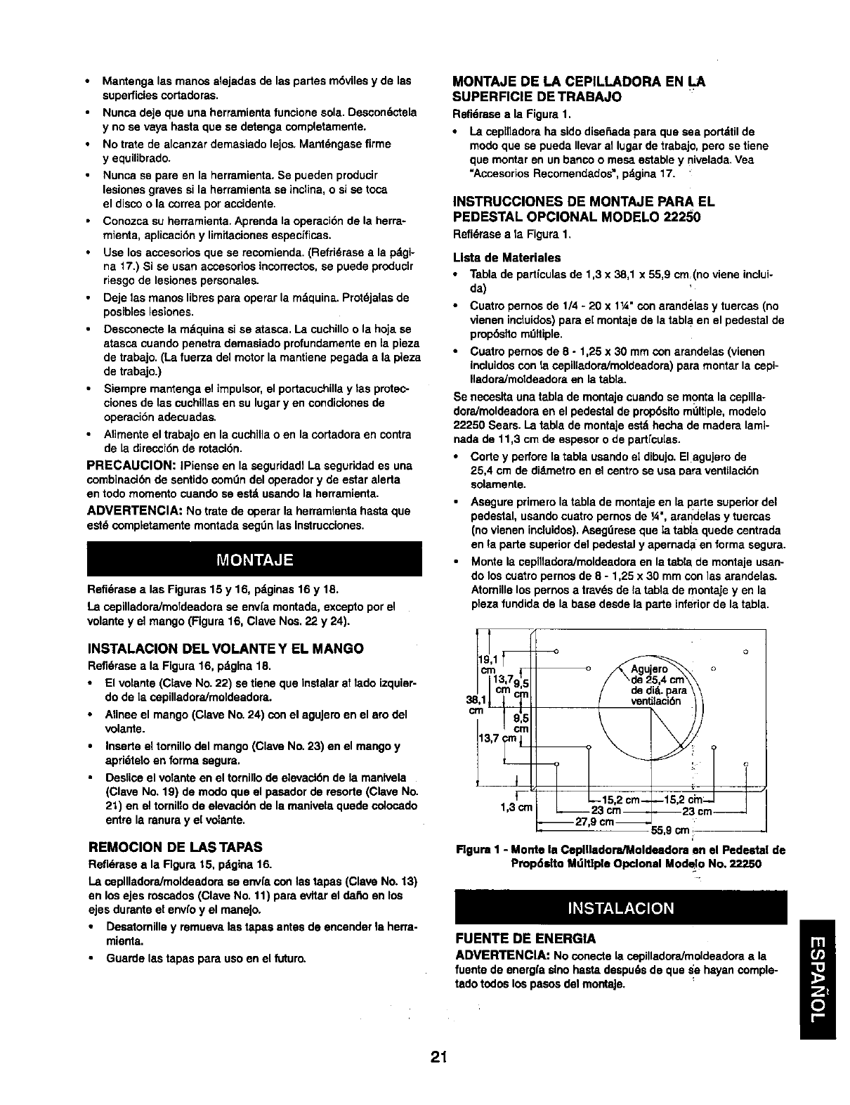
MONTAJE DE LA CEPILLADORA EN LA
SUPERFICIE DE TRABAJO
Refi6mseala Figure 1.
La cepl[ladoraha sidodise_edapara que sea portdtilde
modoque se pueda Ilevar allugar de trabajo,pero setiene
que montaren unbanco o mesaestable y nivelada.Vea
"AccesoriosRecomendados",pdgina17.
INSTRUCCIONES DE MONTAJE PARA EL
PEDESTAL OPCIONAL MODELO 22250
Refidrasea Ia Figura1,
Llste de Materiales
Tabla de partfculas de 1,3 x 38,1 x 55,9 cm(no viene inclui-
da)
Cuatro pernos de 1/4 -20 x 11A"con arandelas y tuercas (no
vienen incluidos) pare e[ montaje de la tabla en el pedestal de
prop6sffo mdltiple.
Cuatro pernos de 8 -1,25 x 30 mm con arandelas (vienen
incluidos con la ospilladora/moldeadora) para montar la cepi-
IladoraJmoldeedora en la tabta.
Se necesita una tabla de montaje cuando se monte la ospilla-
doraJmoldeadom en el pedestal de prop6sito mdltiple, modelo
22250 Sears. La table de montaje estd hecha de madem lamb-
neda de 11,3 cm de espesor o de partfcu[as.
Corte y perfore la tabla usando el dibujo. Elagujero de
25,4 cm de didmetro en el centro se usa Data ventilaci6n
solamente.
Asngure primero la tabla de montaje en la I_arte superior del
pedestal, usando cuatro pernos de ¼", arandelas y tuercas
(no vienen inctuidos). Asegdrese que la tabla quede osntrada
en la parte superior del pedestal y apernad aen forma segura.
Monte la cepilladora/moldeedora en la tabla de montaje usan-
do los cuatro pernos de 8 - 1,25 x 30 mm con las arandelas.
Atomille los pernos a travds de ta tabla de montaje yen la
pleza fundida de la base desde la parte inferior de la tabla.
cm13,7915
.I Cmcm
cm
13,7 crnI
1,3 crn 2im!_ _
9 cm 55 9 cm _-
Figure 1 -Monte la Ceplgedora/Moldndom en el Pedestal de
Propdelto Mdltlple Opclonal Modelo No. 22250
FUENTE DE ENERGIA
ADVERTENCIA: No conectela cepilladoraJmoldeadoraala
fuentede energfaslno hastedespu6sde que _e hayan comple-
tadotodos los pesosdel montaje.
21
Elmotorha sidodisefiedoparaoperarconelvoftafey lafre-
cuenc_aespecificedos,Lasca_gasnorrnalesse pueden rnanejar
conseguridadconvoltajesde no rndsde 10°/oporsobreobajo
del voltajeespecificado.SI se hace funcionar la unidadconvol-
tajes que no estdn dentrode la garna,se puedepraducir un
calentamientoexcasivoy quernarseel rnctor.LOScargaspesa-
des exigenque el voltaje en los terminalesdel motorno scan
menosque el voltajeespedficado.
El abasteeirnlento de energfaque va admotorestd controlado
por el interruptoroscilante. Si se remueveel ir_erruptorosci-
lantese asegura la unidady se impideel uso no autorizado.
INSTRUCCIONES PARA LA CONEXION A TIERRA
ADVERTENCIA: Si se conectaincorractamenteelconductor
de conexidnatierra de1equlpo,se puede producirun desgo de
choqueeldctdco.El equipodabe estar conectadoa tierra mien-
tras se estd usando,para protegeral operadorcontra un choque
eldctdco.
•SI las Instrucoiones para la conexidn atierra no se ent[enden
o si se tienen dudes de que la herrarnienta estd conectada a
tierm correctamente, consulte a un electdcista calificado.
• Esta herramienta vlene equlpada con un corddn de 3 conduc-
totes, aprobado, con capacldad de 150V y con un enchufe
de 3 puntas del tipo de conexibn a tierra (yea la Figure 2) para
su prateccidn en contra de los peligros de choque el_ctrico.
•El enchufe de eonexl_,n a tierra se dabe enchufar directa-
mente en un receptdculo de conexidn a tierra de 3 puntas,
conectado a tierra e Instalado correctamente, como se
rnuestra (Figure 2).
Tornacorrlente conectado
a tierra correctamente
Punta de conexidn a tierra
3En;uhntufaesde __
Figure 2 - Recapt_culo de 3 Puntas
No remuevanialtere la puntade conexidna t{errade ninguna
manera. En el caso de una fallao de una descargadisruptive,
la conexi_ a tlerra proporcionael caminode menorrasisten-
cla al choqueeldctdco.
ADVERTENClA: No perm;taque los dedostoquen lostermi-
hales o el enchufe cuandose estdninstalandoo rernoviendodel
tomaeordente.
El enchufe se debe enchufar en el tomacorriente correspon-
dlente, que dabe estar instadadocorrectarnente y conectedo
a tierra segOn todos los cddigos y reglarnentos locales. No
modiflque el enehufe que se propornlona. SI no calza en
el tomacordente, haga que un electrlcista oslificado instale
uno osrrecto.
Inspecclonelos cordones de la herramlentaped_llcamente y,
sl est_.nda_ados, hdgalosreparar por unservido autodzado.
El conductor verde (o verdey amarillo)del corddn es el cable
de conexldn a tlerra.Si es necasadoreparar o carnbiarel cor-
ddn eldctdcoo el enehufe,no conecte el cableverde (o verde
yamadUo)a un terminalosrgado.
Cuandoca eneuentraunrecaptdcolode paredde 2 puntas,
se debe reemplazarpor un reosptdoslode 3 puntasconecta-
do a tlerracorrectament_ee Instaladode acuerdocon loscddt-
gosy raglarnentos del NationalElectdcCodey con los c_:ll-
gos locales.
ADVERTENCIA: Este trabajo debe serejecutadopor un elec-
tdcistacalificado.
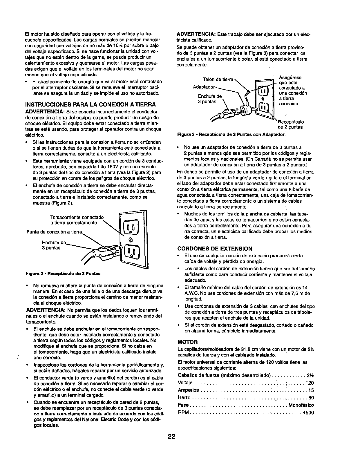
Se puede obtenerun adaptadorde conexibn a tierraproviso-
riode 3 puntasa 2 puntas(veala Figura3) pare conectarlos
enchufesa untomacorrientebipolar,si estd conectadoa tierra
correctamente.
Tal6nde tierra_,======_ Asegdrese
A_IF _ que este
dap dor , J TII co°ectedoa
.... _ _ I_ II unaconexidn
P_ncnulrede \! II atierra
3 pun__ concoido
'*_ _'/ _Recapt_culo
de 2 puntas
Figure3 -Receptdculode 2 Puntascon Adaptador
No use un adaptador de conexi_,n atierra de 3 puntas a
2 puntas amenos que sea permitido por los cddigos y regia-
rnentos locales y nacionales, (En Canadd no se perrnite usar
un adaptador de conexidn • tierra de 3 puntas a 2 puntas.)
En donde se permite el uso de un adaptador de conexidn a tierra
de 3 puntas a 2 puntas, la lengOeta verde rlgida o el terminal en
el lado del adaptador debe ester conectado firmernente a una
conexidn atierra eldctrica perrnanente, tadcorno una tuberla de
ague conectada a tierra correctamente, una caja de tomacorden-
te conectada a tierra correctarnente o un sistema de cables
conectado a tierra correctarnente.
Muchos de lostornillosde la planchade cubierta, lastube-
rfas de ague y lascajas de tornacorrienteno estdnconecta-
dos a tierra correctamente,Pareasegurar una conexidnatie-
rra correcta, un e[ectricistacalificadodabe probai"los medios
de conexidnatlerra.
CORDONES DE EXTENSION
El uso de cualquiercorddnde extensidnproducir_,cierta
carda de voltajey pdrdidade energ[a.
Loscablesdel corddn de exlensi(_ntienen que aer del tama_o
suficientecomo para conducircorrientey rnantener el voltaje
adecuado.
El tamaRomfnimodel cable del cordbnde extensidnes 14
A.W.C.No usecordonesde extensidncon mdsde 7,6 rn de
Iongitud.
•Use cordones de extensidnde 3 cables,con enchufesdel Upo
de conexi_n a tierra de tres puntasy receptdculosde tripola-
resque acepten el enchufe de la unidad.
•Si el corddnde extensi6nestd desgastado,cortedoo daSado
en algunaforma, cdrnbieloinrnediatamente,
MOTOR
La capilladora/rnoldeadora de 31,8 cm viene con un motorde 21,_
caballos de fuerza y con el osbleado instalado.
El motor universalde corriente alternade 120 voltiostiene las
especificacionessiguientes:
Caballos de fuerza (mdximo desarrollado) ............ 2½
Voltaje ............................ ;.. : ...... 120
Ampedos ........................ ; ..... '....... 15
Hertz ........................................ 60
Fase ................................. i Monofdslco
RPM ............................ _........... 4500
22
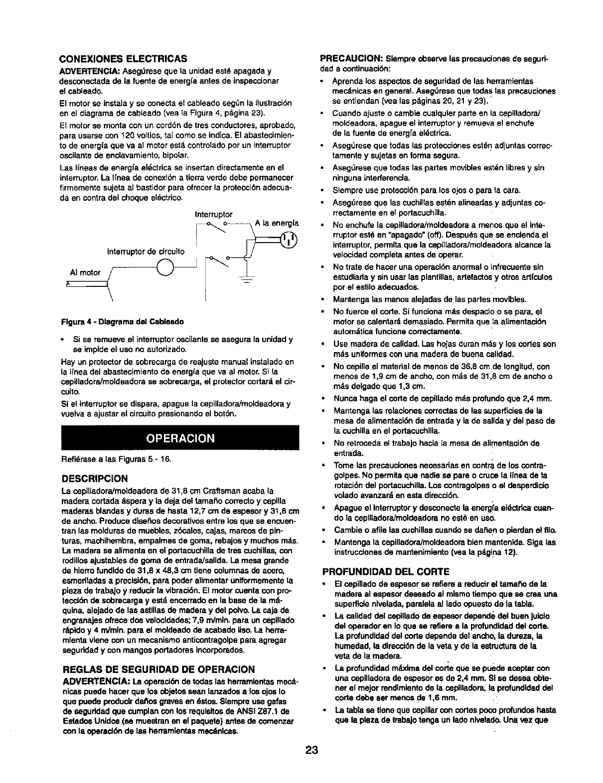
CONEXIONES ELECTRICAS
ADVERTENCIA: Asegt_raseque la unidadastd apagada y
dasconectadade la fuantede energfaantes de inspeccionar
el cableado.
El motor se instala y se conecta el cableado segt_n la ilustreci6n
en el diagrama de cablaado (vea la Flgura 4, pagina 23).
El motor se monta con un cord6n de tres conductores, aprobado,
para usarse con 120 voltice, tal como se indica. El abastecimien-
to de energfa qua va al motor eat& controlado pot un interruptor
cecilante de enelavamiento, bipolar.
Las gneas de enargfa el_ctrica se insertan directamente en el
interruptor. La Ifnaa de conexi6n a tierre verde debe permanecer
firmemente sujeta al bastidor para ofrecer la protecci6n adecua-
da en contra del choque el_ctrico.
Interruptor
Interruptor de circuito _"__/_ [_a
Figure 4 - Dlagrema del Cableado
• Si se mmueve el interruptorcecHantese asegure la unidady
sa impideel uso no autorizado.
Hay unprotectorde sobmcargade majuste manualinstaladoen
la lrnea del abastecimientode energfa qua va al motor.Si la
cepilladore/moldeadorase sobrecarga,el protectorcortar_,el cir-
cuito.
Si el interruptorse dispara,apague la cepiHadora/moldeadoray
vuelvaaajustarel circuitopresionandoel bot6n.
Refi6rese alas Figures 5 - 16.
DESCRIPClON
La cepiiladora/moldeadora de 31,8 cm Craftsman acaba la
madera cortada 8spera y la deja del tamaSo correcto y cepilla
maderas blandas y duras de hasta 12,7 crn de aspasor y 31,8 cm
de ancho. Produce dlsaftos decorativce entre ice qua se encuen-
tmn las moldums de muebles, zbsalos, cajas, mamos de pin-
tures, manhihembra, empalmas de goma, rebajce y muchos mds.
La madera sa alimenta en el portacuchilla de ires cuchillas, con
rodillce ajustablas de goma de entrada/salida. La mesa grende
de hierro fundido de 31,6 x 48,3 cm tlene columnas de acero,
esmadtadas apreclsi6n, para. poder elimentar uniformemente la
pieza de trabaJo y reducir la vibreci6n. El motor cuenta con pro-
tecci6n de sobmcerga y estd encerrado en la base de la md-
qulna, eleJado de laa astillas de madera y del polvo. La caja de
engranajas ofrece dos velocidades; 7,9 m/min, para un cepillado
rdpido y 4 m/min, para el moldeado de acabado Iiso. La herra-
mlenta vlene con un mecanismo anticontragolpe para agregar
seguddad y con mangos portadores incorporados.
REGLAS DE SEGURIDAD DE OPERACION
ADVERTENCIA: La opereci6nde todaslas herremJentasmecd-
nicaspuede hacerque los objetceesan lanzadcea los ojosIo
quapuodeproduclrdafiosgravesan 6stce. Slempreusagafas
de ceguddad qua cumplanconlos requisitcede ANSI Z87.1 de
Estado_Unldes (sa muestmnen el paquete) antesde comenzar
conla operad6nde lea herramlentasmecdnlsas,
PRECAUClON: Siempreobservelas precaucionasde segud-
dada continuaci6n:
Aprenda los aspectos de asguridad de las herramientas
mecdnicas en general. AsegOmse qua todas las preceucionas
se entiendan (vea las pdginas 20, 21 y 23).
Cuando ajuste o cambie cualquier parte en la cepilladora]
moldeadore, apague el interruptor y remueva el enchufe
de la fuente de energfa eldctrica.
Aseg_rese que todas las prctecciones est6n adjuntas correc-
tamenta y sujetas en forma segure.
Asegt_mse que todas las partes moviblas estdn iibms y sin
ninguna interferencia.
Siempre use protecci6n para los ojos o para la care.
Asegdmsa que las cuehillas estdn elineadas y adjuntes co-
rrectamente en el portacuchilla.
No enchufe la cepiliadoraJmoldeadore a mence que el inte-
rruptor estd en "apagado" (off). Despuds qua se encienda el
interruptor, permita qua la cepilladora/moldeadora elcance la
velocided completa antes de operer.
No trete de hacer una opereci6n anormal oinfrecuente sin
estudiada y sin usar las plantillas, artefactos y otros artfculos
por el estilo adecuadce.
Mantenga las manos alejadas de las partes movibles.
No fuerce el code. Si funciona mds despacio o se para, el
motor se calentard demasiado. Permita que fla.alimentaci6n
automdtica funcione correctamente.
Use madera de salidod. I.as hojasduranmds y loscortes son
mds uniformesconuna madera de buena calidad.
No cepiUe el material de menos de 36,8 cm de Iongitud, con
mence de 1,9 em de ancho, con mds de 31,8 cm de ancho o
rods delgado qua 1,3 cm.
Nunca haga el corte de cepillado rods profundo que 2,4 mm.
Mantenga las relacionas cormctas de las superficies de la
mesa de elimentaci6n de entrade y la de salida y del paso de
la cuchilla en el portacuchilla.
No retroceda el trabajo hacia la mesa de elimentaci6n de
entrada.
Tome las preceucionas necasarias en contra de los contra-
golpes. No parmita que nadia sa pare o cruce la Ifnas de la
rotaci_n del portacuchilla. Los contragolpas o el desperdicio
volado avanzard an esta dimcd6n.
Apague el intarruptor y desconecte la energia aldctdca cuan-
do la cepilladora/moldeadore no estd en uso.
Cambie o afile las cuchillas cuando se da_en o pierdan el filo.
Mantenga la cepilladoraJmoldeadora bien mantenida. Siga las
instrucdones de mantenimianto (vea la p4gina 12).
PROFUNDIDAD DEL CORTE
•El cepillado de espesor se refiere a reducir el tamaho de !a
madere al espasor deasado el mlsmo tiempo que sa crea una
superficte nlvelada, parelela el lado opuesto de la tabla.
•I.a calidad del cepUlado de espesor depande del buan Juiclo
del operador en Io que sa refiere a la profundidad del corte.
La profundidad del corte depende del ancho, la dureza, la
humedad, la direcci6n de la veta y de la estructure de la
veta de la madera.
•La profundidad m_odma del corie que se puede aceptar con
una copilladore de espesor es de 2,4 mm. SI se desea obta-
ner el major rendimiento de kt cepilladore, la profundidad del
corte debe sar mence de 1,6 mm.
• La tabla sa tiene qua cepinar con codes poco profundce hasta
qua la plesa de tmbaJo tenga un lade nlvelado. Una vez qua
23
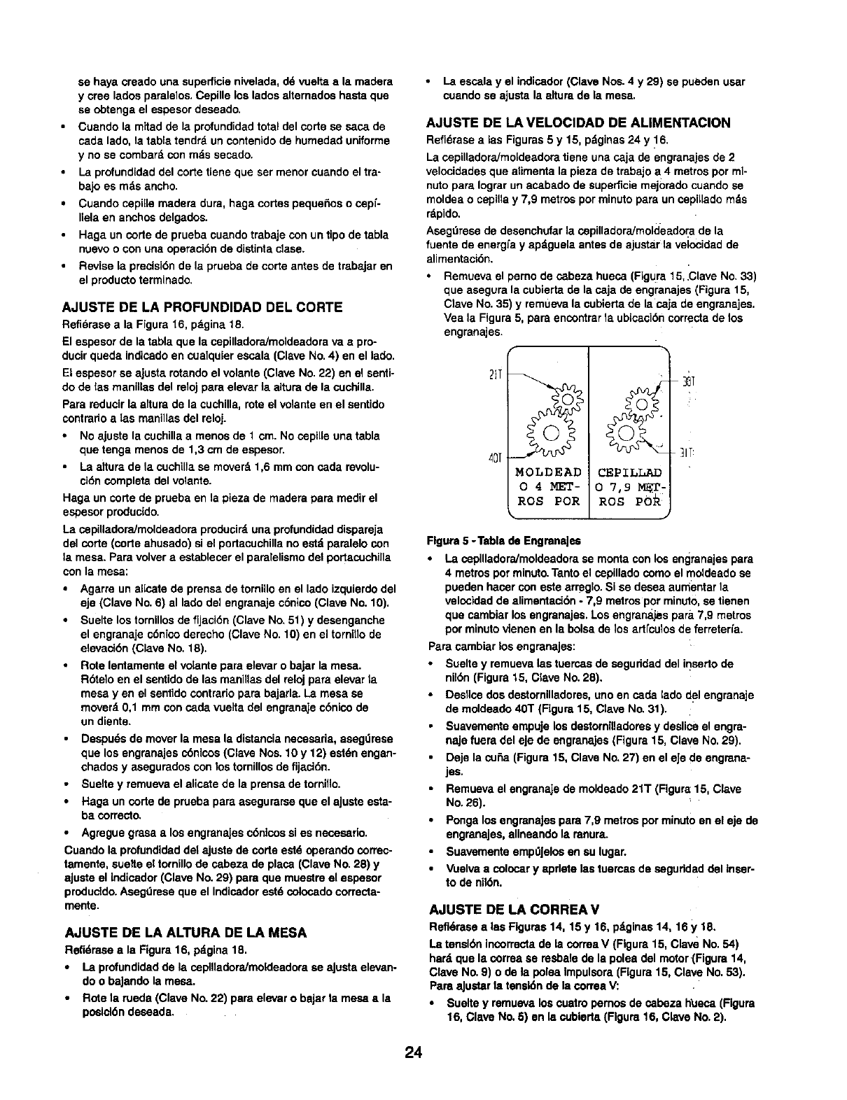
sa haya creado una superflcie nivelada, d6 vuelta a la madera
y croe lados paralelos. Cepille los lados altemados hasta que
sa obtenga el espesor deseado.
Cuando la mitad de la profundidad total del corte se sasa de
cada lado, la tabla tendrd un contenido de humedad uniforme
y no se combard con mds sasado.
La profundidad del corte tiene que ser menor cuando el tra-
bajo es mds ancho.
•Cuando cepil[e madera dura, haga codes peque6os o cepf-
Ilela en anchos delgados.
• Haga un code de prueba cuando trabaje con un tipo de tabla
nuavo o con una operaci6n de distinta dase.
•Revise la precisi6n de la prueba de corte antes de trabajar en
el producto terminado.
AJUSTE DE LA PROFUNDIDAD DEL CORTE
Refidrasa ala Figure 16, pdgina 18.
El espesor de la tabla que la cepilladora/moldsadora vaa pro-
ducir queda indicado en cualquier escala (Clave No. 4) en el lado.
Et espesor sa aJusta rotando el volante (Clave No. 22) en el senti-
do de tas manillas del reloj pare elevar ta altura de la cuchilla.
Para reducir la aitura de la cuchilla, rote el velante en el sentido
contrario alas manillas del reloj.
•No ajuste la cochilla amenos de 1 cm. No copille una table
que tenga menos de 1,3 cm de espesor,
•La altura de la cuchUla sa moverd 1,6 mm con cada revolu-
cidn complete del volante.
Haga un corte de prueba en la pieza de madera para medir el
espesor producido.
La cepiUadora/moldeadora producir_, una profundidad dispareja
del corte (code ahusado) si el portacuchilla no estd paralelo con
la mesa. Para volver a establecer el paralelismo de1 podacuchilla
con la mesa:
•Agarre un alicate de prensa de tornillo en el lado izquierdo del
eje (Clave No. 6) al lado del engranaje c6nico (Clave No. 10),
Suelte los tornillos de fijaci6n (Clave No. 51) y desenganche
el engranaje c6nico derecho (Clave No. 10) en el tornitlo de
elevaci6n (Clave No. 18).
Rote lentamente el vdante para elevar o bajar la mesa.
Rbtelo en el santido de las manillas del reloj pare elevar ta
mesa yen el sentido contrario para bajarla. La mesa sa
moverd 0,1 mm con cada vuelta del engranaje c6nico de
un diente.
Despu6sde moverla mesa la distancianecesaria,asagdresa
que los engranajescdnlcos(Clave Nos.10 y 12) estdnengan-
chadosy aseguradosconlos tornillosde fijaci6n.
Sueltey remuevael alicatede la prensade torni,o.
Haga uncode de pruebapare asegurarseque el aJuste esta-
ba correcto.
Agregue grasa alos engranajes c6ntcos si es necesado.
Cuando la profundidad det ajuste de code est6 operando correc-
tamente, suelte el tornillo de sabeza de place (Clave No. 28) y
aJuste el Indicador (Clave No. 29) pare que muestro el espesor
produddo. Aseg0mse que el Indicador eat6 colosado correcta-
mente.
AJUSTE DE LA ALTURA DE LA MESA
Refidrasaala Figura16, pdgina18.
• La profundidadde la cepilladoraJmoideadorase ajusta elevan-
do o baJandola mesa.
• Rote la rueda (Clave No.22) pare elevaro baJarla mesa ala
posicl6ndesaada.
La essala y el indicador (Clave Nos. 4 y 29) se pueden usar
cuando se ajusta la altura de la mesa.
AJUSTE DE LA VELOCIDAD DE ALIMENTACION
Refi6rase a las Figuras 5 y 15, p_ginas 24 y 16,
La cepilladora/mo[deadora tiene una caja de engranajes de 2
velocidades que alimenta la pieza de trabajo a4 metros pot ml-
nuto pare Iograr un asabado de superficie mejorado cuando se
moldea o cepilla y 7,9 metros por minuto para un cepi[lado rods
rdpido,
Asegt_rese de desenchufar la cepilladora/rnoldeador a de la
fuente de energ[a y apdguela antes de ajustar la velocidad de
alimentaci6n.
Remueva el perno de c_beza hueca (FLgura 15, ,Clave No. 33)
que asegura la cubierta de la caja de engranajes (Figura 15,
Clave No. 35) y remueva la cubierta de la caja de engranajes.
Vea la Figure 5, pare encontrar la ubisaci6n correcta de los
engranajes.
2IT
,4D[
MOLDEAD
O4MET-
ROS POR
CEPILLAD
0 7,9 MET-
ROS
30T
lIT
Figure 5 -Table de EngranaJsa
La cepllladoraJmoldeadorasa monteconlos engranajespare
4 metrospot minuto.Tantoel copillado comoel moldeadose
pueden hacer con este arreglo. Si se desea aumentarla
velocidadde alimentaci6n -7,9 metrosporminuto,se tienen
que cambiarlos engranajes.Los engranajespara7,9 metros
por minutovienen en la bolsade los ad[culos de ferreterfa.
Parecambiar losengranaJes:
•Sueltey remuevalas tuercasde saguridad del insedo de
nikSn(Figure15, Clave No.28).
Desllcedosdestomilladores,uno en cada lado del engranaje
de moldeado40T (Flgura15, Clave No.31).
Suavementeempujelos destorniUadoresy desliceel engra-
najefuera del eje de engranaJes(Figure15, Clave No. 29).
Deje la cuSa(Figura15, Clave No.27) en el eJede engrana-
jes.
Remuevael engranajede moldeado21T (Figure15, Clave
No.26).
Ponga losengranaJespare 7,9 metrosporminutoen el eje de
engranajes,alineandola ranura.
SuavementeempdJelosen au lugar.
•Vuelvaa colocar yapdote lastuercasde saguddad del inser-
to de nil6n.
AJUSTE DE LA CORREA V
Refidrasealas Figures14, 15 y 16, pdginas14, 16 y 18.
La tensionincorrectade la correaV (Figure15, Clave No.54)
hard que la correa se resbalede la poleadel motor(Figura 14,
Clave No.9) o de la poleaImpulsora(Figure15, Clave No. 53).
Pare,aJustarla tensk_nde la correa%/."
•Sueltey remuavalos cuatropemos de cabeza h_Jeca(Figure
16, Clave No.5) en la cubleda(Rgura 16, Clave No. 2).
24
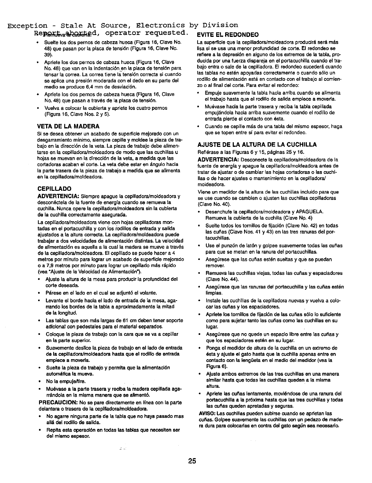
Exception - Stale At Source,
Re_9_]_a_%_d, operator requested.
Sueltelos dos pernosde osbeza hueca (Figura 16, Clave No.
48) que pasan porla placa de tensi6n(Figura16, Clave No.
39).
Apdetelos dospernos de cabezahueca (Figura16, Clave
No.48) que van en la indentaci6n.en la p[aca de tensi6n para
tensarla correa. La correatieos la tensi6ncorrectasi ccando
se aplica una presi6nmoderadaconel dedoen su parle del
mediose produce6,4 mm de desvLaci6n.
Aprietelos dos pernosde cabeza hueca(Figura16, Clave
No.48) que pasana traves de la placa de tensi6n.
Vuelvaa colocarla cubiertay apneteloscuatm pernos
(Figura 16, Clave Nos.2 y 5).
VETA DE LA MADERA
Si se desea obtener un acabado de supelficiemejoradocon un
desgarramientomfnimo,siempmcepille y moldeela pieza de tra-
bajo en la direcci6nde la veta. La pleza dotrabaJodebe alimen-
tarse en la cepilladora/moldeadorade modo que lascuchglasu
hojasse muevanen la direcci6nde la veta, a modidaque las
cortadorasaosban el corte.La veta debe estaren _.ngulohacia
la parle traserade la pieza de trabajoamedidaque se alimenta
en la cepilladora/moldeadora.
CEPILLADO
ADVERTENClA: Siempre apague la cepilladora/moideadomy
descondctelade lafuentede energfa cuandosa remuevala
cuchilla.Nunca operela capilladora/moldeadore sin la cubierta
de la cuchillacorrectamenteasegurada.
La cepllladora/moldeadoraviene con hojascepilladorasmon-
tadas en el portacuchillay con los i:odillos do entraday salida
ajustadosa la altura correcta. LacepiHadora/mo_deadorapuede
trabajara dosvelcoidadesde alimentaci6n distintas.La velocidad
de aflmentaci6nes aquellaa la cual la maderase mueve a trav_s
de la cepilladoraJmoldeadora.El cepilIadose puede hacer a4
metros por minutopara Iograrun acabado de superticlemejorado
o a 7,9 metrospot minutopara Iograrun cepilladorods rdpido
(vea "Ajustede laVelcoidadde Alimentaci6n").
•Ajuste la alturade la mesa para producirla profundidaddel
code deseada.
• Pdmse en el lado en el cualse adjunt6el volante.
• Levanteel bordehacia el lade de entrada de la mesa, aga-
rrandolos bordesde la tabla a aproximadamentela mitad
de la Iongitud.
Lastablas que sonmds largas de 61 cm debentenor seporte
adicional conpedestalsepara el matedal separados.
•Coloquela pieza de trabajo conla cam que se va aceplllar
en la parte superior.
Suavementede.slicela pteza de trabajoen el ladode entrada
de la ospifladora,'moldeadom hastaqueel rodillode ontrada
empiece a moverla.
Sueltela pleza de trabajoy permitaque la alimentaci6n
automdticala mueva.
No la empujeitire.
Mu6vase a la parle traseray recibala madera ospillada aga-
rrdndoiaen la mlsmamanera que se aliment6.
PRECABCION: No so pare dimctamenteen Ifnea conla parte
dolantorao trasera de la ospllladora/moldeadora.
No agarm nlngunaparle de la tabla que nohaya pasadomas
alld del rodillode salida.
Replta esta operacl6n en todas las tab_asque neossiten ser
del mlsmo sepesor.
Electronics by Division
EVITE EL REDONDEO
La superficieque la ospillador_moldeadora producirdsard mds
lisasi sa usa unamenor profundidadde corse.El redondeose
refiereala depmsi6nen algunode losextremosde la tabla, pro-
ducidapot unafuerza disparejaen el portacuchiliacuandoel tra-
bajo entrao sale de la cepilladora.EI redondeosucederdcuando
las tablasno est6napoyadas correctamenteo cuandos61oun
rodillode alimentaci6nestd en contacto conel trabajoal comien-
zoo al final del corte. Para evitarel redondeo:
•Empuje suavemente la tabta hacia arriba cuando se alimenta
el trabajo hasta qua el rodillo de salida empiece a moveda.
•Mudvase hacia la parle trasera y reciba la tabla cepillada
empujdndola hacia ardba suavernente cuando el rodillo de
entrada pierde el contacto con esta.
•Cuando se cepille mds de una tabla del mismo espesor, haga
que se topen entre sf para evitar el redondeo.
AJUSTE DE LA ALTURA DE LA CUCHILLA
Refidrase a las Figuras 6 y 15, pdginas 25 y 16.
ADVERTENClA: Desconecte la cepilladora/moldeadora de la
fuente de energfa y apague la cepilladora/moldeadora antes de
tratar de ajustar o de cambiar las hojas cortadoras o las cuchi-
Ilas o de haoer ajustes o mantenimiento en La capilladora/
moldeadora.
Viene un medidor de la altura de las cuchillas incluido para que
se use cuando se cambien oajusten las cuchillas cepilladoras
(Clave No. 40).
Desenchufe la cepilladora/moldeadora y APAGUELA.
Remueva la cubierta de la cuchilla (Clave NO. 4)
Suelte todos los tornillos de fijaci6n (Clave No. 42) en todas
las cu_as (Clave Nos. 41 y 43) en las tres ranuras del por-
tacuchillas.
Use el punz6nde lat6n y golpee suavementetodas lascuSas
paraque se metan en la ranuradel portacuchillas.
Aseg,',mseque las cutlasestdnsueltasy que se puedan
remover.
Remueva las cuchillasviejas,todas iascu_as y espaciadores
(Clave No.44).
AsegOreseque las renuras del portacuchillay las cu6as est6n
limpias.
Instalelas cuchlllasde la cepilladoranuevasy vuelva a colo-
car las cutlasy losespaciadores.
Apdete lostomillosde fljaci6nde lascu6as s61oIo suficiente
cornoparasujetartanto lascufiascomo las cuchillasen su
lugar.
Aseg_lreseque no quede un espaclolibreentre las cu6as y
que los espaciadomsestdnen su lugar.
Pongael medidorde altura dola cuchillaen unoxtremode
6stay ajusteel gatohasta que la cuchillaapenas entre en
contactocon la lengOetaen el medio del medidor(vea la
Flgura 6).
Ajusteambos extremosde lastres ouchillasen una manera
similarhasta quo todaslas cuchiltasquedenala misma
altura.
•Apriete las sagas lentamente, movidndose de una ranura dei
portacuchilla ala pr6xima hasta que las tres cuchillas y todas
las cu6as queden apretadas y seguras.
AVISO: I.as cuchillas pueden subirse cuando se apdetan Ise
cu6as. Golpee suavemente las cuchillas con un pedazo de made-
ra dura para colocadas en contra del gato sagdn sea neossado.
25
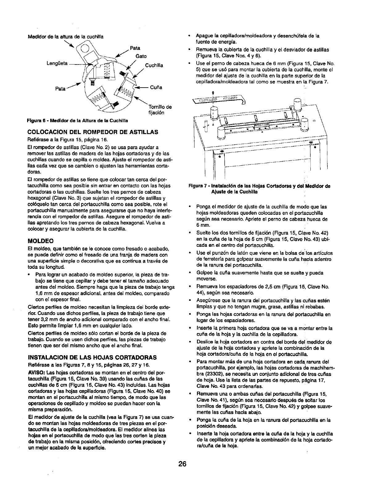
Medidor de la afiura de la cuchiHa
JPa;ao
Leng0eta _CuchiUa
fijT°rcr_° de
Figure 6 -Medldor de la Altura de la Cuchllla
COLOCACION DEL ROMPEDOR DE ASTILLAS
Refi6raseala Figure 15, pdgina 16
El rompedorde astillas (Clave No 2) se usa para ayudara
removerlas astillas de madera de las hojasoortadorasy de las
cuchillascuandose sepilla o moidea.Ajuste el rompedorde asti-
lies cadavez que se cambieno ajusten las herramientascorta-
doras
El rompedor de astillas se tiene que colocar tan serca del por-
tacuchilla como sea posible sin entrar en contacto con las hojas
cortadoras o las cuchillas Suelte los tres pernos de cabeza
hexagonal (Clave No. 3) que sujetan el rompeder de astillas y
col6quelo tan cerca del portacuchilla como sea posible, rote el
portacuchilla manualmente para asegurarse que no haya interfe-
rencla con el rompedor de astillas Asegure el rompedor de astk
lies apretando los tres pernos de cabeza hexagonal Vuelva a
colocor y asegurar la cubierta de la cuchilla
MOLDEO
El moldeo, que tambi(_n se le conoca como fresado o acabado,
se puede definir como el fresade de una franja de madera con
una supefficie simple o decorativa que es continua atravds de
toda su Iongitud.
Para Iograr un acabado de moldeo superior, ta pieza de tra-
bajo se tiene que cepillar y debe tener el tamario adecuado
antes del moldeo. Siempre haga que ta pieza de trabajo tenga
1,6 mm de espesor adicional, antes del moldea, comparade
con el espesor final.
Ciertos perfiles de moldeo necesitan la limpieza del borde exte-
rior. Cuando use dichos perfiles, la pieza de trabajo tiene gue
tener 3,2 mrn de ancho adicional comparade con el ancho fnal.
Esto permite limpiar 1,6 mm en cualquier lade.
Ciertos perfiles de motdeo s61o cortan el borde de la pieza de
trabajo. Cuande se usen dichos perfiles, las piezas de trabajo
denen que ser del mismo ancho que el ancho final.
INSTALACION DE LAS HOJAS CORTADORAS
Refl_rasealeeFigures7, 8 y 15 p_ginas26, 27 y 16
AVISO: Las hojascortadorasse montanen el cantro del pot
taouchllla(Figure15, Clave No. 39) usandolas curiaede las
cuchlllasde 5 crn (Figure15, Clave No 43) induidas I.as hojas
cortadoras y las hoJascopilladeras (Figure15, Clave No 40) se
montan en el portacuchillaal mismo tiempo, de mode que las
operacionesde caplllado y moldeose puedanhacer con la
mismapreparaci6n
El medidor de ajustede la cuchilla(yea la Figure7) se usa cuan-
do se montan lee hojas moldeadorasde tree plezas en el por-
tacuchlllade la copllladora/moldeadora El medldoralinea les
hojasen el portacuchlllade modo que lastres corten la pleza
de trebeJoen la mlsmaposici6n,ofreclendocortespreclsosy
unmeJoracabade de Is eupefficie.
Apague la copilladora/moldeadora y desenchtJfela de la
fuente de energfa
Remueva la cubierta de la cuchilla y el desviader de astillas
(Figura 15, Clave Nos 4 y6).
Use el perno de cabeza hueca de 6 mm (Figure 15, Clave No
5) que se us5 para montar la cubierta de la cuchilla, monte el
medider del ajuste de la cuohilla on la parte superior de la
cepilladora/moldeadora tal como se muestra en !a Figura 7
Figure 7 - Instalacl6n de las Holse Cortadoms y del Medldor de
A[uste de la Cuchllla
• Ponga el medidor de ajuste de la cuchilla de mode que las
hojas moldeadoras queden colocadas en el portacuchilla
segt]n sea necesario Apriete el pemo de cabeza hueca de
6 mm
• Suelte los dos tornillos de fljacibn (Figura 15, Clave No 42)
en la curia de la hoja de 5 cm (Figure 15, Clave No 43) ubi
cada en el centro del portacuchilla
•Use el punz6n de lat6n que viene en la boise de:los artfculos
de ferreterfa para golpear suavemente la curia hacia adentro
de la mnura del portacuchilla
Golpee la cuSa suavemente haste que se suelte y pueda
moverse
•Remueva los espaciadores de 2,5 cm (Figure 15, Clave No
44), segt]n sea nesesario
•Asegt]rese que la ranura del portacuchiHa y las cuSas esten
limpias y que no tengan mugre, grasa, astillas ni rebabas
•Ponga las hojas cortadoras en la ranura del portacuchilla en
lugar de los espaciadores
•Inserte la primera hoja cortadora que se va a montar entre la
cuba de la hoja yla cuchilla de la copilladora.
•Deslice la hoje cortadora en contra del borde del medidor de
ajuste de la hoja cortadera y apriete la combinaci6n de la
hoja cortadora/cu£_a de la hoja en el portacuchilla.
•Para montar m_s de una hoja cortadora en cad& ranura del
portacuchilla, por ejemplo, lea hojas oortadoras de machihem-
bra (23302), se necesita un conjunto adicionel de tree cuSas
de hoja Use la lista de las partes de repuesto, pSgina 17,
Clave No. 43 para ordenadas
•Remueva una oambas curiae del portacuchilla (Figure 15,
Clave No. 41), segt]n sea nesesario despu6s de so_tar los
tornillos de fijaci6n (Figure 15, Clave No 42) y golpee suave-
mente las cu_as hacla abajo
•Ponga la cufia de la hoja en la mnura del portacuchilla en la
posici6n deseada
Inserte la hoja cortadora entre la curia de Is hoJa y la cochlna
de la copilladora y apnete la combinaci6n de la hoja cortado-
raJcufia de la hoja
26
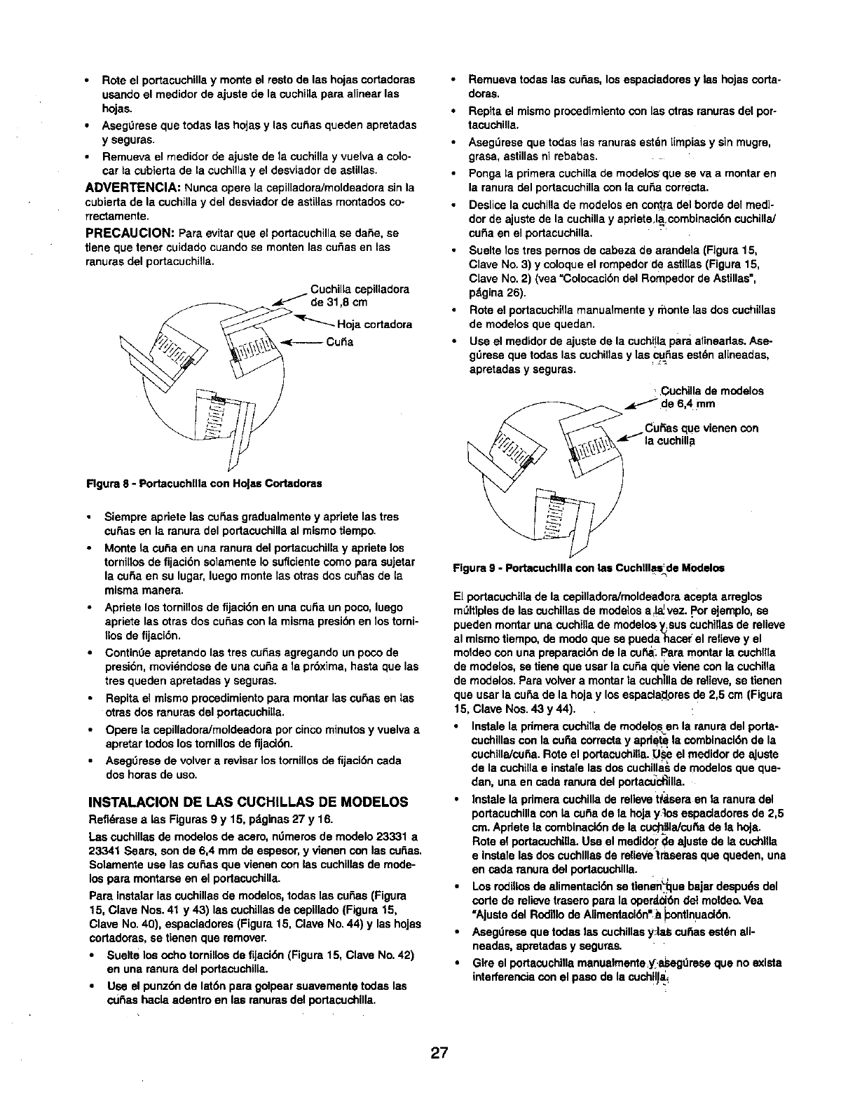
Rote el portacuchilla y monte el resto de las hojas cortadoras
usando el medidor de ajuste de la cuchilla para alinear las
hojas.
Aseg0rese que todas las hoJasy las cuf_as queden apretadas
y seguras.
Rernueva el medidor de ajuste de la cuchilla y vuelva a co]o-
car la cubierta de la cuchilla y el desviador de astillas.
ADVERTENClA: Nunca opere la cepilladoraJmoldeadora sin la
cubierta de la cuehilla y del desviador de astillas rnontados co-
rrectamente.
PRECAUClON: Para evitar que el portacuchilla se daSe, se
tiene que tenet cuidado cuando se monten las cu_as en las
ranuras del portacuchilla.
Cuehilla ospilladora
de 31,8 cm
_"qr-.._ Hoja cortadora
Rgura 8 -Portacuehllla con Holas Cortadoras
• Siempre apriete las cu_as gmdualmente y apriete las tres
cu_as en la ranura del portacuchilla al mismo tiempo.
•Monte la cuba en una ranura del podacuchilla y apriete los
tornilios de fijaci6n solamente Io suflclente como para sujetar
la cuba en su lugar, luego monte tas otras dos cu_as de la
misma manera.
•Apriete los tornillos de fijaci6n en una cuSa un poco, luego
apriete las otras dos cuSas con la misma presi6n en los torni-
llos de fijaci6n.
Contin0e apmtando las tros cu_as agregando un poco de
presi6n, moviendose de una cuSa ala pr6xima, hasta que las
tres queden apretadas y seguras.
Repita el mismo proosdimiento pare montar las euSas en las
otras dos mnuras del portacuchiila.
Opere la ospilladora/moldeadora por cinco minutos y vuelva a
apretar todos los tomfllos de fijaci6n.
Asegt_rese de volver a reviser los tornillos de fijacl6n cada
dos horas de uso.
INSTALACION DE I.AS CUCHILLAS DE MODELOS
Refldrase a las Figuras 9 y 15, pdglnas 27 y 16.
Las cuchillas de modelos de aosro, ndmeros de modelo 23331 a
23341 Sears, son de 6,4 mm de espesor, y vienen con las cubes,
Solamente use las osSas que vienen con les cuchillas de mode-
los pare montarse en el portacuchilla.
Pare instalar las cuchnlas de modelos, todes las cuSas (Figura
15, Clave Nos. 41 y 43) las cuchillas de cepillado (Figure 15,
Clave No. 40), espaciadoms (Figure 15, Clave No. 44) y las hojas
cortadoras, se tienen que remover.
•Suelte los ocho tornillos de fijaci6n (Figura 15, Clave No. 42)
en una ranura del portacuchille.
•Use el punz6n de lat6n para golpear suavemente todas las
cuf_as haela adentro en las ranums del portacuchllla.
Remuevatodaslas cu_as, losespaciadoresy las hoJascorta-
doras.
Repita el mismo proosdimiento con las otras ranums del por-
tacuchilla.
Aseg_rese que todas ]as ranuras estdn [{mpias y sin mugre,
grass, astillas ni rebabas.
Ponga la primers cuchilla de modelos _que se va a montar en
la ranura del portacuchilla con la cuss corrects.
Deslios la euchilla de modelos en contra del horde del medi-
dor de ajuste de la cuchilla y apriete.la.combinaci6n cuchillaJ
curia en el portacuchilla.
Suelte los tros pernos de cabeza de arandela (Figure 15,
Clave No. 3) y coloque el rompedor de astil[as (Figure 15,
Clave No. 2) (yea "Colocacibn del Rompedor de Astillas =,
pdgina 26).
Rote el portacuchilla manualmente y monte las dos cuchUlas
de modelos que queden.
Use el medidor de ajuste de la cuchHla pare alirteadas. Ase-
gt_mse que todas las cuchillas y las curlas est_n alineadas,
apretadas y seguras.
•Cuchilla de modelos
de 6,4 mm
CuRas que vienen con
la ¢uchilla
Figure 9 -Portacochllla con los Cuehllles: de Modelos
El portacuchillade la ospilladoraJmoldeadoraacepta arreglos
mt_ltiplesde las cuchillasde modelos a_!_vez..Porejemplo,se
pueden montaruna cuchillade modelos_sus cuchiflasde relieve
al mismotiempo,de modoque se pueda hacerel relieve y el
moldeocon una prepamei6nde la cu_: Paremontarla cuchIIla
de modelos,setiene que userla curiaqueviene con lacuchilla
de modelos.Paravolvera montarla cuch]llade relieve, setienen
que user la cuss de la hojay losespacla_omsde 2,5 cm (Figure
15, Clave Nos.43 y 44).
•Instalela pdmera cuchtttade modelo_sen la mnuradel porta-
cuchillascon la curia correctsy apd_ la combinaci6n de la
cuchilla/cu_a.Rote el portaoschilla._l_seel medidorde ajuste
de la cuchillae instalelasdos cuchillasde modelosque que-
dan, una en osda ranuradel portactJc_illa.
•Iostalela pdmera cuchillade relievet_sem en la ranuradel
portacuchillacon la cuss de la hoja y]os espaclademsde 2,5
cm.Apdetela combinaci6nde la cuch_JaJcu_ade la hoJa.
Rote el portacuchl,a.Use el medidorde aJustede la oschilla
e instelelos doscuchlllasde relievetrasems que queden, una
en cede mnuradel portaeuchllla.
Los rodillosde alimentaci6n se tlenen_luebajardespudsdel
code de relieve troseropare la operd.01_ndel moldeo.Vea
"Ajustedel Rodillode Alimentaei6n'__osntlnuad6n,
•Asegdmse quetodas lascuchillasyJaS cu_iasest_n all-
neades, apmtadasy segur_s.
Gtre el portacuehinamanualmente;y_.asegdreseque no exists
interferenciacon elpaso de la cuch!l_ai
27
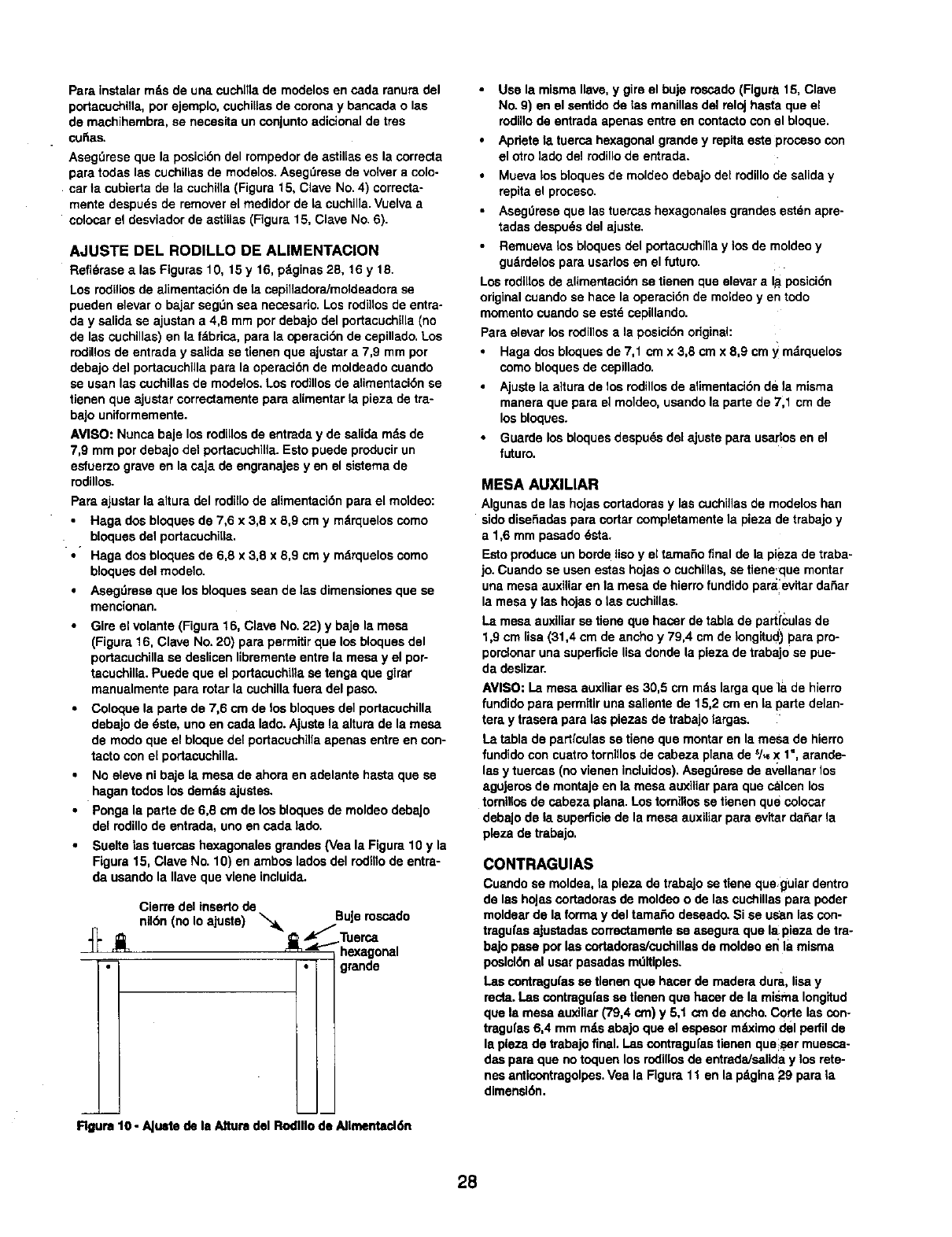
Pare instelar mds de una cuchllla de modelos en cede ranura del
portacuchilla, por ejemplo, cuehiUas de corona y bancada o las
de machihembra, se necesita un conjunto adicional de tres
cuSas.
Aseg_rese qua la posicibn del rempedor de astillas es la correcta
para todas los cuchillos de modelos. AsegDrese de volver a colo-
car la cubierta de la cuchiila (Figure 15, Clave No. 4) correcta-
mente despu_s de remover el medidor de la cuchilla. Vuelva a
colosar el desviador de astiilas (Figure 15, Clave No. 6).
AJUSTE DEL RODILLO DE ALIMENTACION
Refidrase alas Figuras 10, 15 y 16, pdginas 28, 16 y 18.
Los rodillos de alimentecidn de ta cepilladora/moldeadore se
pueden elevar o bajar segOn sea neossarlo. Los rodi]los de entra-
day salida se ajustan a 4,8 mm por debajo del portacuchilla (no
de las cuchillas) en la fdbrica, para la operacidn de cepillade, Los
rodillos de entrada y salida se tienen que ajustar a 7,9 mm por
debajo del portacuchilla pare la operaeidn de moldeado cuando
se usan las cuehillas de modelos, Los rodillos de alimentacidn se
tienen que ajustar correctamente para alimentar la pieza de tre-
bajo uniformemente.
AVISO: Nunca baje los rodillos de entrade y de salida mds de
7,9 mm por debajo del portacuchilla. Esto puede producir un
esfuerzo grave en la ca.ja de engranajes yen el sistema de
rodillos.
Pare ajustar la attura del rodillo de alimentacidn para el moldeo:
Haga dos bloques de 7,6 x 3,8 x 8,9 cm y mdrquelos como
bloques del portecuchilla.
•Haga dos bloques de 6,8 x 3,8 x 8,9 cm y mdrquelos eomo
bloques del modelo.
Asegdrese que los bloques seen de las dimensiones que se
mencionan.
Gire el volante(Figure16, Clave No.22) y baje la mesa
(Figure16. Clave No.20) parepermitirque losbloquesdel
portacuchillase deslicenlibrementeentre la mesa y el por-
tacuchilla.Puede que el portaeuchilTase tenga que girar
manuelmentepararotarla cuchillafuera del paso.
Coloque la parte de 7,6 cm de los bloquosdel portacuchilla
debejode 6ste, unoen cada lade.Ajustela alturade la mesa
de modoque el bloquedel portaouchillaapenas entreen con-
tacto coneLportacuchnla.
No eleveni baje ta mesa de ahoraen adelante haste que se
hagen todos los demdsajustes.
Ponga la parte de 6,8 cm de los bloquesde moldeodebaJo
del redillo de entrada,uno en cada lade.
Suelte Isatuercas hexagonalosgrandos(Vea la Figure10 y la
Figure15, Clave No. 10) en ambos ladesdel rodnlode entra-
da usandela Ilave quevlene incluida.
Cierre del inserto de
nildn (no Io ajuste) _, BuJerescado
_._ Tuersa
"_" _i_ _ _"_'_hexagonal
;- • grande
Rgure 10 -AJu=te de le Alture del Rodlllo de AIImentad_t
Use la misma Ilave, y gire el buje roscado (Figure. 15, Clave
No. 9) en el santido de las manillas del reloj basra que el
rodUlode entrada apenas entre en contacto con el bloque.
Apnete la tuerca hexagonal grande y repita este proceso con
el otro lade del rodillo de entrada.
Mueva los bloques de moldeo debajo del redillo de salida y
repita el prosaso.
Asag0rese que las tuercas hexagonales grandes est_n apre-
tadas despuds del ajuste.
Remueva los bloques del portacuchilla y los de moldeo y
gudrdelos para usarlos en el future.
Los rodillos de aUmentacidn se tienen que elevara lit posicidn
original cuando se hace la operacidn de moldeo yen todo
momento cuando se estd cepiUande.
Pare elevar los rodillos ala posicidn original:
Haga dos bloques de 7,1 cmx 3,8 cmx 8,9 cm y mdrquelos
como bloques de cepillado.
Ajuste la altura de los rodillos de alimentacidn de la misma
manera que pare el moldeo, usando la parte de 7,1 em de
los bloques.
Guarde los bloques despu_s del ajuste pare usarlos en el
future.
MESA AUXlLIAR
Algunas de las hojas eortadoras y las cuchillas de modelos hen
side diseSadas para cortar completamente la pieza de trabajo y
a 1,6 mm pasado 6sta.
Esto produce un borde Uso yel tamafio final de la pieza de traba-
jo. Cuando se usen estas hojas o cuchillas, se tiene,que montar
una mesa auxiliar en le mesa de hierro fundido paralevitar daSar
la mesa y las hojas o las cuchillas.
La mesa auxiliar se tiene que hacer de tabla de parti_:ulas de
1,9 cm lisa (31,4 cm de ancho y 79,4 cm de Iongitucl) para pro-
porclonar una superfide lisa donde la pieza de trebajo se pue-
da desnzar.
AVISO: La mesa auxiliares 30,5 cm rodslargaque ]a de hierre
fundide pareperm_tiruna salientede 15,2 cmen la parte delan-
terny traserapara laspiesas de trabajo largas.
La tabla de partrculasse tiene que montar en la mesa de hierro
fundidecon cuatrotornlllosde cabeza planede 5/_X 1",arande-
lasy tuercas(no vienen incluidos).Aseg_resede avellanarlos
aguJeroade montajeen la mesa auxiliarpare que calcenlos
tornillosde sabeza plana. Lostornillosse tienen que colocar
debaJode la superficiede la mesa auxlliarpara evttardaSarla
p[eza de trabajo.
CONTRAGUIAS
Cuendo se moldea, la piesa de trabajo se tiene queguiar dentro
de las hojas cortadems de moldeo o de las cuchillas pare poder
moldear de la forma y del tamaSo deseado. Si se us_n las con-
tragufas ajustadas correctamente se asegura que la pieza de tra-
bajo pase por las cortaderas/cuchlllas de moldeo er_la misma
poslcl_n al usar pasadas mdlUples.
Las contragu(as se tlenen que haeer de madera dura, lisa y
recta. Las contragufas se tienen que haosr de la misma Iong_tud
que la mesa euxiliar (79,4 cm) y 5,1 cm de ancho, Corte los con-
tragu|as 6,4 mrn rods abajo que el espesor mdximo del perfil de
la pleza de trabajo final. Las contragufas tienen que_ser muesca-
dsa pare que no toquen los rodillos de entrada/sanda y los rete-
nes anticontragolpes. Vea la Figure 11 en la pdgina 29 para {a
dimensldn,
28
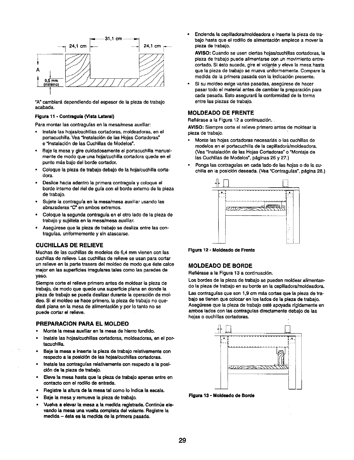
_31,1 crn_
_-_ 24,1 cm 24,1 cm
A
=A" cambiard dependiendo del espesor de la pieza de trabajo
asabada.
Figure 11 -Contragufa (Vista Lateral)
Pare montar las contragufas en la mesa/mesa auxiliar:
Instale las hojas/cuchillas cortadoras, moldeadoras, en el
pertacuchilla. Vea =lnstalaci6n de las Hojas Cortadoras"
e "lnstalaciSn de las Cuchillas de Modelos".
Baje la mesa y gire cuidadosamente el per_aeuchilla manual-
mente de modo que una hoja/cuchilla cortadora quede en el
punto mds bajo del borde cortador.
Cotoque la pieza de trabajo debajo de la hojaicuchilla coda-
dora.
Deslice hacia adentro la primera contraguia y coloque el
borde intereo del riel de gufa con el borde externo de la pieza
de trebajo.
Sujete ta contragufa en la msaaimesa auxiliar usando las
abrazaderas "C" en ambos extremos.
Coloque la segunda contraguia en el otto lade de la pieza de
trabajo y suJ_tela en la mesa/mesa auxillar.
Aseg0rese que la pieza de trabajo se desliza entre las con-
tragufas, uniformemente y sin atassarsa.
CUCHILLAS DE RELIEVE
Muchas de las cuchillas de modelos de 6,4 mm vienen con las
cuchillas de relieve. Las cuchillas de relieve se usan pare coriar
un relieve en la parte trasera del moldeo de modo qua dste calce
major en las superficies irregulares tales como las parades de
yeso.
Siempre corte el relieve pdmem antes de moldear la pieza de
trabajo, de modo que quede una superficie plana an donde la
plaza de trabaJo sa pueda deslizar durante la opereci6n de mol-
deo. SI el moldeo se hace primero, la pleza de trabajo no que-
dard plana en la mesa de elimentact6n y por Io tanto no se
puede cortar el relieve.
PREPARACION PARA EL MOLDEO
• Monte la mesa auxfltar en la mesa de hierro fundido.
• Instalelas hojas/cuchillascortadores,moldeadoras,en el per-
tacuchllla.
•Baje la mesa e insartela pleza de trabajorelativamentecon
respectos la posici6nde las hojas/cuchillascortadoras.
•Instalelas contragufsarelativamentecon respectoa la posi-
cl6nde la pieza de trabaJo.
• Elevela mesa haste que la plezade trabajoapenas entre en
contectocon el rodillode entrada.
Registrela alturade la mesa tel come Io Indisa la essala.
BaJela mesa y remuevala pleza de trabajo.
• Vuelvaaelevar la mesa • la medldaregistrada.Contindeale-
vando la mesa una vueltacompletedel volarfie. Reglstrela
medida- dsta es la medidade la pdmerapasada.
•Enciend8 la cepilladora/moldaadora e insarte la pieza de tra-
bajo hasta qua el rodillo de alimentaci6n empiece a mover la
pieza de trabajo.
AVISO: Cuando se usen elertas hojas/euchillas cortadoras, la
pieza de trabajo puede alimentarse _un mevimiento entre°
cortado, Si _sto sucede, gire el volante y eleve la mesa hasta
qua la pieza de trabajo sa mueva uniforrnemente. Compare la
medida de la primate pasada con la indisaci6n presente.
•Si su moldeo exige varias pasadas, asegt_rese de hacer
pasar rode el mateda[ antes de carnbiar la preparaci6n para
cada pasada. Esto asegurard la conformidad de la forma
entre las plazas de trabajo.
MOLDEADO DE FRENTE
Refi_rase ala Figure 12 acontinuaci6n,
AVISO: Siempre corte el relieve primero antes de moldear la
pieza de trabajo.
•Monte las hojas cortadoras necesarias o las cuchillas de
modelos en el portacuchilla de la cepilladora/moldeadora.
(Vea "lnstalaci6n de las Hojas Cortadoras" o "Montaje de
las Cuehillas de Modelos", pdginas 26 y 27.)
•Ponga las eontragufas en cada lado de las hojas o de la cu-
chilla an la pesici6n deseada. (Vea =Contragu[as ", pdgina 28.)
Figure 12 -Moldsado de Frente
MOLDEADO DE BORDE
Refi6rasea la Figure13 a continuaci6n.
Losbordesde la piezade trabajo sa pueden moldearalimentan-
do la pieza de trabajoen su borde en la cepilladoraimoldeadora.
Lascontragufasque son 1,9 cm rods codas que la pieza de tra-
bajosa tienen que colosaren los ladosde la piezade trebajo.
Asagdresaque la pieza de trebajoest6 apeyadarfgidamenteen
ambos ladoscon las contragufasdirectamentedebajo de las
hojaso cuchlllascorladoras.
L..; _ J
Figure 13 -Moldeado de Borde
29
RETENES ANTICONTRAGOLPES
La copilladora/moldeadora viene con retenesanticontragolpes
pars ayudara evitarque el podacuchillacontragolpeela pieza de
trabajo.
PRECAUClON: Nuncase pareat frente del lado de entradao
de saUdade la cepilladora/moldeadora.Siempre pdreseaun lado
de la cepilladora]moldeadorapars evitarlesionessi se produce
un contragolpede la pieza de trabajo.
CANAL DE ASTILLAS DEL COLECTOR DE POLVO
Refi_rase ata Figura 15, pdgina 16.
Hay disponible un canal de astillas del colector de polvo (no se
muestra) corno un accesorio opeionaL
El canal de astillas del colector de polvo se monte en la cepi-
Uadora/moldeadora en el lugar del desviador de astillas. Para
montar el canat de astillas del colector de polvo:
•Apague y desenchufe la cepilladora]moldeadora.
Desatornille y remueva los tres pernos de cabeza hueca y las
arandelas (Clave Nos. 7 y 8).
Remueva el desviador de astlllas (Clave No. 6).
Deslice el cans( de astillas del colector de polvo aIo largo de
los hordes de la cubierta de la cuchilla (Clave No. 4) de modo
que las ranuras de la cubierta de la cuchilla queden a]ineadas
sobre los agujeros en el canat del colector de polvo y las
ranuras en el canal del colector de polvo queden alineadas
con los agujeros en el lado trasero de la caja del rodillo
(Clave No. 1).
Vuelva a user los tres pernos de cabezs hueca y las arande-
las (Clave Nos. 7 y 8) para sujetar el canal de polvo con la
cubierta de la cuchitla.
Use los tres pernos de cabeza hueca de 6-1,0 x 8 mm y tres
arandelas planes de 6 mm (qua vienen incluidos con el canal
de polvo) para sujetar el canal de polvo en la caja del rodillo.
El canal de polvo cuenta con un accesorio pars adjuntar una
manguera de vac[o. Adjunte la manguem de vacro mojado/seco
de 6,4 cm de didmetro extemo en el aecesorio. AsegOrese de
encender el vacfo antes de operar la cepilladora/moldeadora.
REAJUSTE DE SOBRECARGA
La sepiliedora]moldeadora viene con un interruptorde circuito
pars la protecoi6nde la sobrecargapara evitar da5ar el motor
de la cepilladora/motdeadora.
Si la cepilladora/moldeadorapara de trabaja'rdurante una
operaci6nde copillado o moldeado,deseneh_felay apague el
interruptor.Presioneel bot6nde reajusteque estd a] lado del
Interruptorpars volverhacer arrancarla capilladora/moldeadora.
BARRAS DE LEVANTAMIENTO
Refi6mse ala Figura16, p_gina18.
Se proporcionancuatrobarrasde levantarnlento (Clave No.25)
parafacilitarel cambio de lugar de la cepilladoraJmoldeadora.
Deslicelos cuatromangos fuerade los extremosde entraday
salida de la mesa y _selos para nevarIs cepilladora/moideadora
al lugar deseado.
PRECAUC|ON: La sepilladora/moldeadora es pesadaen Is
parte superiory tender_,a inclinarseeuandose mueva. Tenga
muchosuidadocuandomuevala sepilladora/moldeadora.
Refidraseala Figure16, pdgina18.
ADVERTENCIA: Aseg_rese quela cepiUadora/moldeadora
estd desenchufadade todafuente de energfa y apagada antes
de tratarde hacerel mantenimiento.
Mantenga la cepiUadora/moldeadora limpia, sin astillas de
madera, polvo, mugre o desperdleio.
Umpie tas cuatm columnas de acero (Clave No. 32) para evi-
tar qua la mesa se atasque cuaodo se eleve y se baje.
Mantenga los tomiltos de entrada de elevaei6n (Craves Nos.
18 y 19) limpios y lubricados correctamente con grasa.
Mantenga los retenes anticontragolpes limpios y operando
uniformemente pars evitar lesiones debido a los contragolpes.
Despu_s de cads diez horas de operaci6n, limpie el mecanis-
mo de ta cadena/engranaje impulsor.
Limpie las astiltas de madem, el polvo y la grasa!vieja de
todas las cadenas y los engranajes con un patio limpio y
seco.
Use grass de rodamientos automotrices corriente pars lubri°
car todas las cadenas y engranajes. Asegdrese que las cade-
nas y los engranajes tengan sufieiente grase.
LUBRICACION
La superficiede la mesa se puede cubrircon lubricante,tel como
cera de muebles,para hacorque la pieza de trabajose alimente
mdsuniformemente.Asegdreseque el lubrtcanteque se va a
ucarno afectela capacidadde acabar la pieza de trabajocon
barniz,setlo,etc.
Porejemplo,nouse ning0nlubricantede base de silic6ndebido
aque arruinar_tla posibilidadde acabar la madera, i
Cambie los rodillosde anmentaci6nsi estdn da_ados.Cambie las
hojas,las hojascortadoras y lascochillas de modelossl estdn
desgastadaso dai_adas.
30
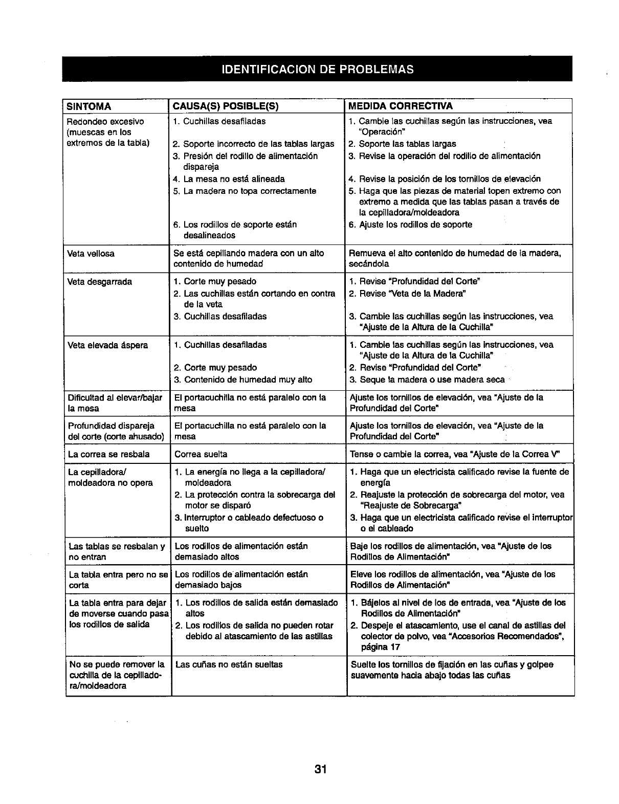
SlNTOMA
Redondeo exossivo
(muessas en los
extremes de la tabla)
Veta vellosa
Vete desgarrada
Veta elevada dspem
Dificultad al elevar/bajar
la mesa
Profundidad dispareja
del corte (corte ahusado)
La correa sa resbala
La cepilladora/
moldeadora no opera
Las tablas se resbalan y
no entran
La tabla entra pete no se
corta
La tabla entra pars dejar
de moversa cuando pasa
los rodillosde salida
No se puede remover la
cuchillade la cepillado-
ra/moldeadora
CAUSA(S) POSIBLE(S)
1. Cuchillas desafiladas
2. Soporte incorrectode las tablas largas
3. Presi6n del rodillode alimentacide
dispareja
4. La mesa no est'. alineada
5. La madera no topa correctamente
6. Los rodillos de soporte estdn
desalinesdos
Se estd cepillando madera con un alto
contenido de humedad
1. Corte muy pesado
2. Las cuchillasest_.ncortando en contra
de la veta
3. Cuchillas desafiladas
1. Cuchi]las desafiladas
2. Corte muy pesado
LContenido de humedad muy alto
El portacuchillano estd paralelo con la
mesa
E1portacuchilla no estd paralelo con la
mesa
Correa suelta
1. La energfa no Ilega a la cepilladora/
moldeadora
2. La proteccide contra la sobrecarga del
motor se disparb
3. Interruptoro cableado defectuoso o
suelto
Los rodillos de alimentaci6n est_n
demasiado altos
Los rodil[osde alimentacide estdn
demasiado bajos
1. Los rodillosde salida estdn demasiado
altos
2. Los rodillosde salida no pueden rotar
debido al atassamiento de las astillas
Las cutlas no estdn sueltas
MEDIDA CORRECTIVA
1. Cambie las cuchinassagLin las instrucciones,vea
"Operaci6n"
2. Soporte las tablas largas
3. Revise la operaci6n del rodil[ode alimentaci6n
4. Revise la posici6n de los tornillos de elevaci6n
15. Haga que las piezas de material topen extremo con
extremo a medide que las tablas pasan atravds de
la sapilladora/moldeedora
6. Ajuste los rodillosde soporte
Remueva el alto contenidode humedad de ta madera,
sec_mdola
1. Revise "Profundidad del Corte"
2. Revise "Veta de la Madera"
3. Cambie las cuchillasseg0n las instrucciones,yea
"Ajuste de la Altura de la Cuchilla"
1. Cambie las cuchillasseg_n las instrucciones,vea
"Ajuste de la Altura de la Cuchilla"
2. Revise=Profundidad del Code"
3. Sequela readers o use madera seca
Ajuste los tornillos de elevaci6n, yea "Ajuste de la
Profundidaddel Code"
Ajuste los tornillos de elevacidn, vea "Ajustede la
ProflJndidad del Corte"
Tense o cambie la correa, vea "Ajuste de la Correa V"
1. Haga que un electricistacalificado revise la fuente de
energfa
2. Reajuste la protecci6nde sobrecarga del motor,vea
"Reajuste de Sobrecarga"
3. Hags que un electricista cafificado reviseel interrupto
oel cableado
Baje los rodillosde alimentaci6n, vea "Ajustede los
RodiIIos de Alimentaci6n"
Eleve los rodillos de alimentaci6n, yea "Ajuste de los
Rodillos de Alimentaci6n"
1. Bdjelos al nival de los de entrade, vea "Ajustede los
Rodillosde Alimentaci6n"
2. Despeje el atascamlento, usa el canal de astillas dal
colector de polvo, vea "Acsasedos Recomendades",
pdgina 17
Suelte los tomillos de fijaci6n en las cuilas y golpee
suavemente hacia abaJotodas las cutlas
31

For the repair or replacement parts you need
delivered directly to your home
Call 7 am -7 pm, 7 days a week
1-800-366-PART
(1-800-366-7278)
Pars ordenar piezas con entrega a
domicillo - 1-800-659-7084
For in-home major brand repair service
Call 24 hours a day, 7 days a week
1-800-4-REPAIR
(1-800-473-7247)
Para pedir servicio de reparaci6n a
domicillo - 1-800-669-7084 ....
For the location of a Sears Parts and
Repair Center in your area _
Call 24 hours a day, 7 days a week
1-800-488-1222
When requesting service or ordering
parts, always provide the following
*information:
• Product Type
• Model Number
•Part Number
•Part Description
SE/AUR8
America's Repair Specialists
