Craftsman 351275931 User Manual COMPOUND MILLING TABLE Manuals And Guides L0521267
CRAFTSMAN Workbench / Project Manual L0521267 CRAFTSMAN Workbench / Project Owner's Manual, CRAFTSMAN Workbench / Project installation guides
User Manual: Craftsman 351275931 351275931 CRAFTSMAN COMPOUND MILLING TABLE - Manuals and Guides View the owners manual for your CRAFTSMAN COMPOUND MILLING TABLE #351275931. Home:Tool Parts:Craftsman Parts:Craftsman COMPOUND MILLING TABLE Manual
Open the PDF directly: View PDF ![]() .
.
Page Count: 6
Operator's Manual
CRR.FTSMRN°
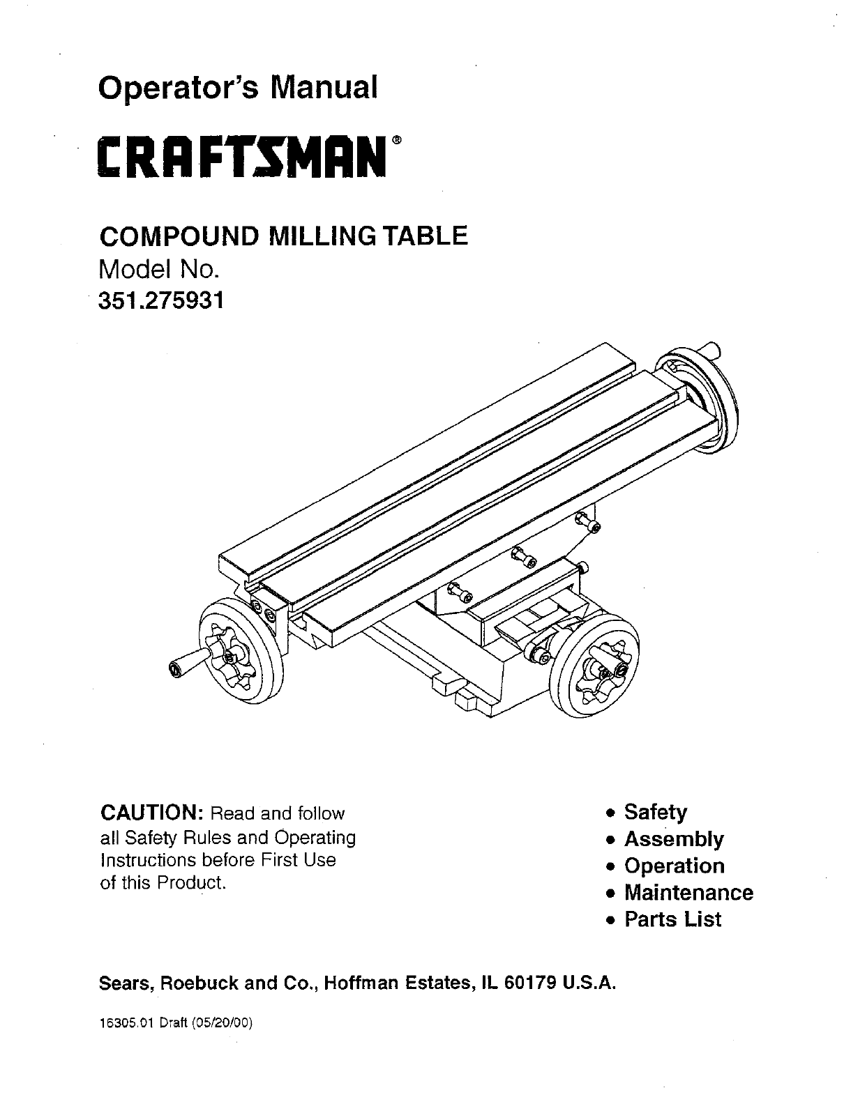
COMPOUND MILLING TABLE
Model No.
351.275931
CAUTION: Read and follow
all Safety Rules and Operating
Instructions before First Use
of this Product.
•Safety
•Assembly
• Operation
•Maintenance
• Parts List
Sears, Roebuck and Co., Hoffman Estates, IL 60179 U.S.A.
16305.01 Draft (05/20/00)
Warranty ....................................... 2
Safety Rules .................................... 2
Unpacking ..................................... 2
Assembly ....................................... 2
Operation .................................... 2-3
Maintenance .................................... 3
Parts Illustration and List ......................... 4-5
FULL ONE YEAR WARRANTY
if this product fails due to adefect in material or workmanship
withinone year from the date of pumhase, Sears will at its
option repair or repiaae it free of charge.
Contact your nearest Sears Service Center to arrange for
product repair, or return this product to place of purchase for
replacemnt.
ti this product is used for commercial or rental purposes, this
warranty will apply for 90 days from the date of purchase.
This warranty gives you specific legal rights, and you may
also'have other rightswhich vary from state to state.
Sears, Roebuck and Co., Dept 817WA, Hoffman Estates, IL
6O179
• Understand and follow all safety instructions supplied with drill
pre._s,or other machines on which milling table is used,
• Mount table to work surface by polting or clamping base
securely in four mounting locations.
•Be alert and think clearly. Always check your set up; for
example, rotate accessory by hand before applying power.
• Make sure workpiaces, guides, fences, or power heads are
securely clamped, as applicable, Do not force accessory.
Be positive you are feeding in right direction.
• Never feed "_ree-hancF without table guide and/or guides.
Use vises or appropriate clamps to secure each workplace,
securely clamping them to work surface.
• Use only accessories designed for mill. Keep power tool
guard in place. Dress properly. Do not wear jewelry, gloves,
or loose clothing.
•Wear a face shield or safety glasses. Never place hands in
jeopardy.
Check for shipping damage. If damage has occurred, a claim
must be filed with carrier immediately. Check for complete-
ness. immediately report missing parts to dealer.
NOTE: The tool has been coated with a protective coating.
in order to ensure proper fit and operation, the coating must
be removed. Removed coating with mild solvents, such as
mineral spirits, and asoft cloth. Nonflammable solvents are
recommended. After cleaning, cover all exposed surfaces with
a light coating of oil. Be sure to lubricate table as described in
"Maintenance".
WARNING:Never use highly volatile solvents. Avoid getting
cleaning solution on paint as it may tend to deteriorate these
finishes. Use soap and water onpainted components.
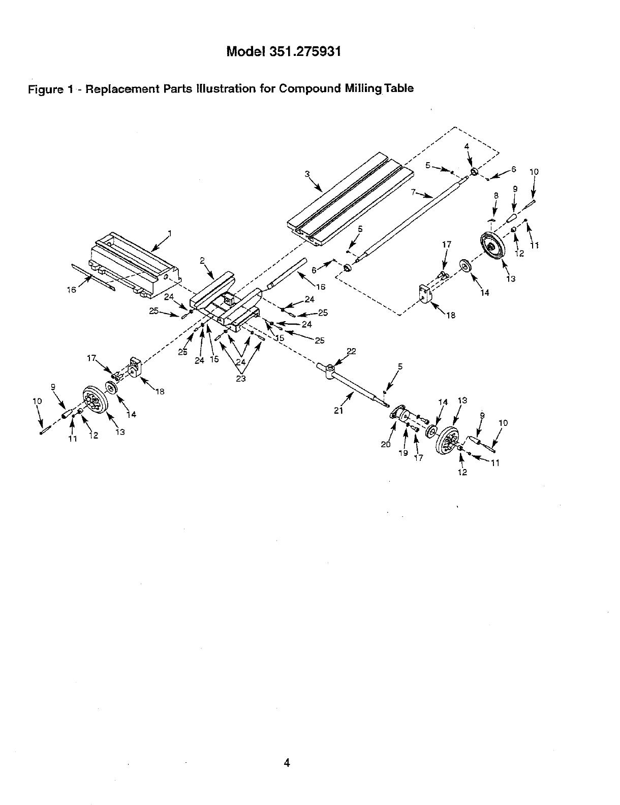
Refer to Figure 1,
•Attach each handle (Key No. g) to handwheai (Key No. 13)
with handle screw (Key No. 10).
• Tighten each screw securely.
• Attach one hendwhee[ (Key No. 13) to cross feed screw
(Kay No. 21) with key (Key No. 5) and locking nut (Key No.
12).
• Attach two handwhesls to longitudinal feed screw (Key No.
7) with keys and locking nuts.
• Tighten each locking nut securely.
DESCRIPTION
Craftaman Compound Milling Table is manufactured from cast
iron and steel The table fits most drill presses. Milling opera-
tions can be done by moving work right and left (longitudinal),
or front and back (cross) directions. The table can also be
used to accurately position or index a workpiece under a drill
but when not doing milling operations. A U-clamp hold down
set is included with the table.
• The Milling Table is heavy. Do not lift it by the crank handles.
• Make sure that drill press table is fastened securely, does
not shift in any direction, and is clean and free of nicks and
burrs.
,, Center table on drill press. There are two 5/,. slots on each
side of base for secudng to dn'll press.
• If drill press table has T-slots, use four T-nut clamp assam-
bliss, two on each side, to secure milling table. Clamp
assemblies are not supplied.
• If drill press table has slots to fit T-nuts, use four bolts with
heavy washem (not supplied) and attach T-nuts to bottom of
table. Secure milling table w_thlocking nuts (not supplied).
• If drill press table does not have T-slots or threaded holes,
drill and tap four holes, matching location of %" slots in
base. Fasten milling table with four bolts and heavy wash-
sis (not supplied).
SPECIFICATIONS
Table .................................... 18'/, x 6"
T-Slots ....................................... %="
T-Slots (center to center) ........................ 2%_"
Longitudinal Travel .............................. 12"
Cross Travel ................................... 8"
Value of One Division ........................ 0,0008"
Cross Travel
per One Revolution .......................... 0.0787"
Longitudinal Travel
per One Revolution .......................... 0.0787"
2
U-CLAMP
•U-clamp can be used to clamp thicknesses up to 2".
• Position workpiece; it should rest flat on table prior to
clamping.
• For clamping, use edge of U-stamp which is closest to ball
joint because a greater force is created at this edge.
• Make sure U-clamp can rest on workpisce and table with
hole in ball joint over a slot in table.
• Slide stud with T-nut into slot.
• Slide U-clamp over stud and into position to clamp on as
much of the workpiece as possible.
• Screw the flange nut onto stud.
• Make sure T-nut is properly shouldered in slot and the stud
is perpendicular to table.
• Tighten flange nut to securely clamp workpisce.
T-NUT
• For a proper clamping configuration, T-nut should be
shouldered within T-nut slot or open slot of work table.
•T-nut must be connected to threaded stud. T-nut has thread
stops: screw stud into T-nut until thread stops.
• With a T-slotted table, studs should be connected before
inserting stud with T-nut into table.
• With an open slotted table, studs san not be connected
until after stud with T-nut is inserted through slot.
ADJUST POSITION
• Motion toward or away from operation is adjusted with
cross feed screw by turning handwheel on the front.
•Motion from side te side is adjusted with longitudinal feed
screw by turning handwheal on either side.
• Use handwheels to move table to desired position. Make
sure that table motion is smooth, Adjust wear plates if nec-
essaFy.
ADJUST WEAR PLATES
Refer to Figure 1.
• Wear plates (Key No. 16) are used to minimize play within
guide grooves.
• Wear plates should be s_usted to produce a uniform drag
for entire length of travel.
• Both wear plates should be adiusted in the same manner.
• Loosen he)( nuts (Key No. 24),
• Adjust drag of wear plate by applying an equal amount of
torque to each set screw (Key Nos. 23 and 25) st each end
of the wear plates. Adjust the screws until a slight drag is
felt when rotating the handwheeL
• Lock set screws into position by holding position with an
L- wrench and tightening hex nuts.
INDEXING TABLE MOTION
• Index collar rotates with handwheel but can be repositioned
to calibrate table feed, Position table at a convenient refer-
ence point.
•Turn handwheel to move table opposite to the direction
which it will travel. Slowly turn handwheal to bdng table
back to reference point. This wili take out play in feed
screw.
• Hold handwheal steady and rotate index collar to align it
with scale.
• Index collar can be calibrated to inc_cate relative distance
traveled in same direction. Collar must be indexed again to
accurately indicate distances in opposite direction.
OPERATING GUIDELINES
Refer to Figure 1.
• Do not attempt to take heavy cuts. It may "grab" and ruin
your workpisce, break cutter, or damage equipment.'The
choice of cut must be proportional to dgidity of set up,
capability of equipment, choice of milling cutter, and hard-
ness of workplace.
• Direction of feed should always be against direction of cut-
ter rotation.
• Avoid vibration during milling operation. Correct this by
using a cutter with a different number of teeth, by changing
speed of cutter rotation, or by adjusting feed of cuL
•Covering the opening over cross feed screw (Key No. 21),
in front and back, is recommended to prevent any chips
from dropping on threads of screw and on table base.
•Tighten center set screw (Key No. 25) to secure position if
required.
• After completing each milling operation, clean all chips off
table and out of T-slots with a hard bristle brush.
• Keep threads of cross and longitudinal feed screws oiled
and free of foreign matter.
• KeeP table top, all machined sur[aces and moving parts
lubricated,
• Periodically turn handwheels to move table right and left,
back and forth, and full length o1travel. This will keep the
Milling Table in good working condition.
3
Model351.275931
Figure 1 - Replacement Parts Illustration for Compound Milling Table
_" 1_1 12 13
10
2O 19
12
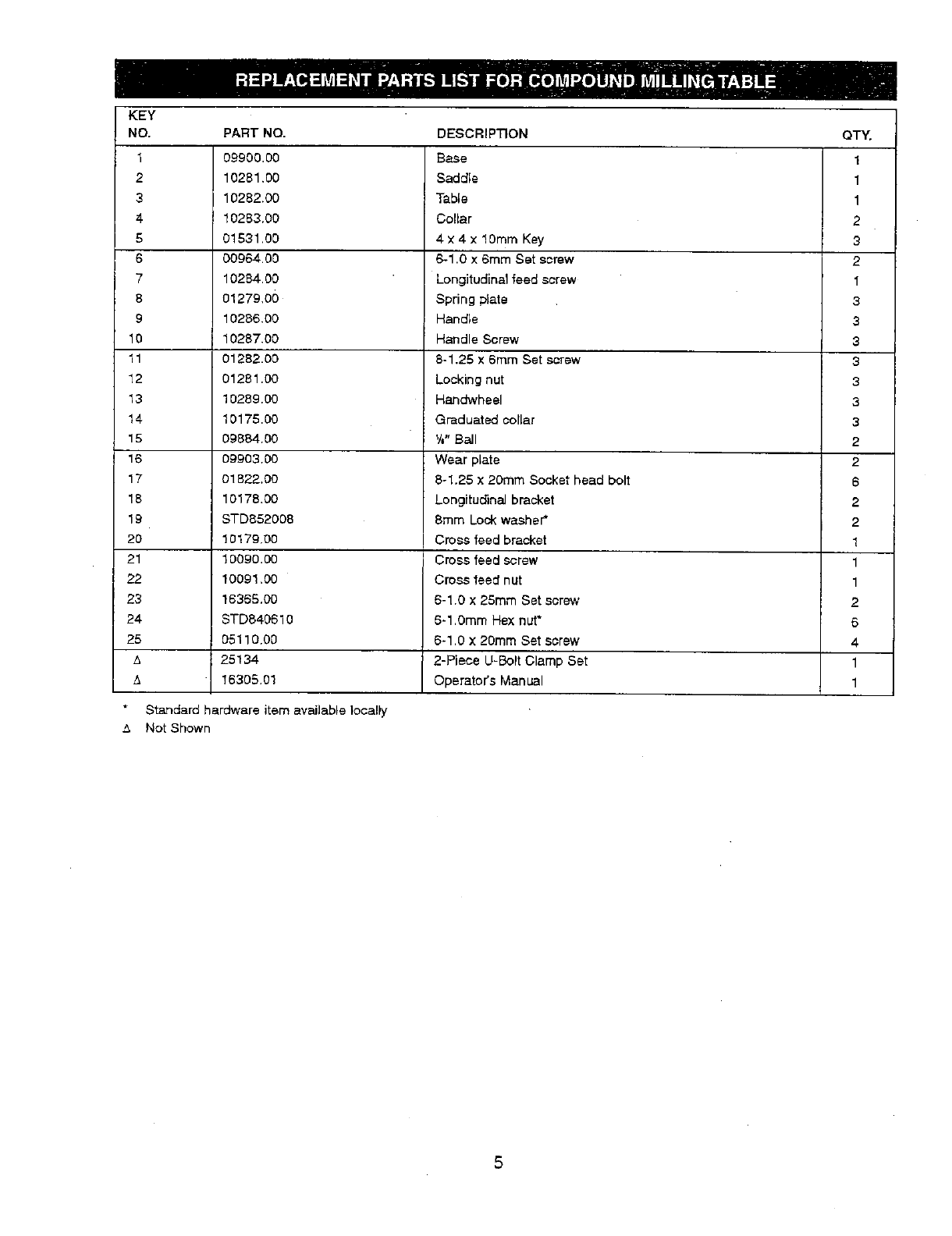
KEY
NO. PART NO. DESCRIPTION QTY,
1 09900.00 Base 1
2 10281.00 Saddle 1
310282.00 Table 1
4 10283.00 Collar 2
5 01531.00 4 x 4 x 10ram Key 3
800964.00 6-1.0 x 6ram Set screw 2
710284.00 Longitudinal feed screw 1
8 01279,0() Spring plate 3
9 10286.00 Handle 3
10 10287.00 Handle Screw 3
11 01282.00 8-1.25 x 6ram Set screw 3
12 01281.00 Locking nut 3
13 10289.00 Handwheel 3
14 10175.00 Graduated collar 3
15 09884.00 YJ"Bail 2
16 09903.00 Wear plate 2
17 01822.00 8-1.25 x 20ram Socket head bolt 6
18 10178.00 Longitudinal bracket 2
19 STD852008 8ram Lock washer* 2
20 ! 0179.00 Cross feed bracket 1
21 10090.00 Cross feed screw 1
22 10091,00 Cross feed nut 1
23 18385.00 6-1.0 x 25rnm Set screw 2
24 STD840610 6-1.0ram Hex nut* 6
25 05110.00 6-1.0 x 20ram Set screw 4
z_ 25134 2-Piece U-Bolt Clamp Set 1
/_ 16305.01 Operator's Manual 1
Standard hardware item available locally
"_ Not Shown

In U.S.A. or Canada
for in-home major brand repair service:
Call 24 hours a day, 7 days a week
1-800-4-MY-HOME °" (1-800-469-4663)
Para pedir servicio de reparaci6n a domicilio -1-800-676-5811
Au Canada pour tout le service - 1-877-LE-FOYER" (1-877-533-6937)
For the repair or replacement parts you need:
Call 6 a.m. - 11 p.m. CST, 7 days a week
PartsDirect
1-800-366-PART (1-800-366-7278)
www.sears.com/partsdirect
Para ordenar piezas con entrega a domicilio - 1-800-659-7084
For the location of a Sears Service Center in your area:
Call 24 hours a day, 7 days a week
1-800-488-1222
To purchase or inquire about a Sears Maintenance Agreement:
Call 7 a.m. - 5 p.m. CST, Monday - Saturday
1-800-827-6655
r•
HomeCentral
