Craftsman 35834020 User Manual ELECTRIC CHAIN SAWS Manuals And Guides L0902472
CRAFTSMAN Chainsaw, Electric Manual L0902472 CRAFTSMAN Chainsaw, Electric Owner's Manual, CRAFTSMAN Chainsaw, Electric installation guides
User Manual: Craftsman 35834020 35834020 CRAFTSMAN CRAFTSMAN ELECTRIC CHAIN SAWS - Manuals and Guides View the owners manual for your CRAFTSMAN CRAFTSMAN ELECTRIC CHAIN SAWS #35834020. Home:Lawn & Garden Parts:Craftsman Parts:Craftsman CRAFTSMAN ELECTRIC CHAIN SAWS Manual
Open the PDF directly: View PDF ![]() .
.
Page Count: 28
[Sears I
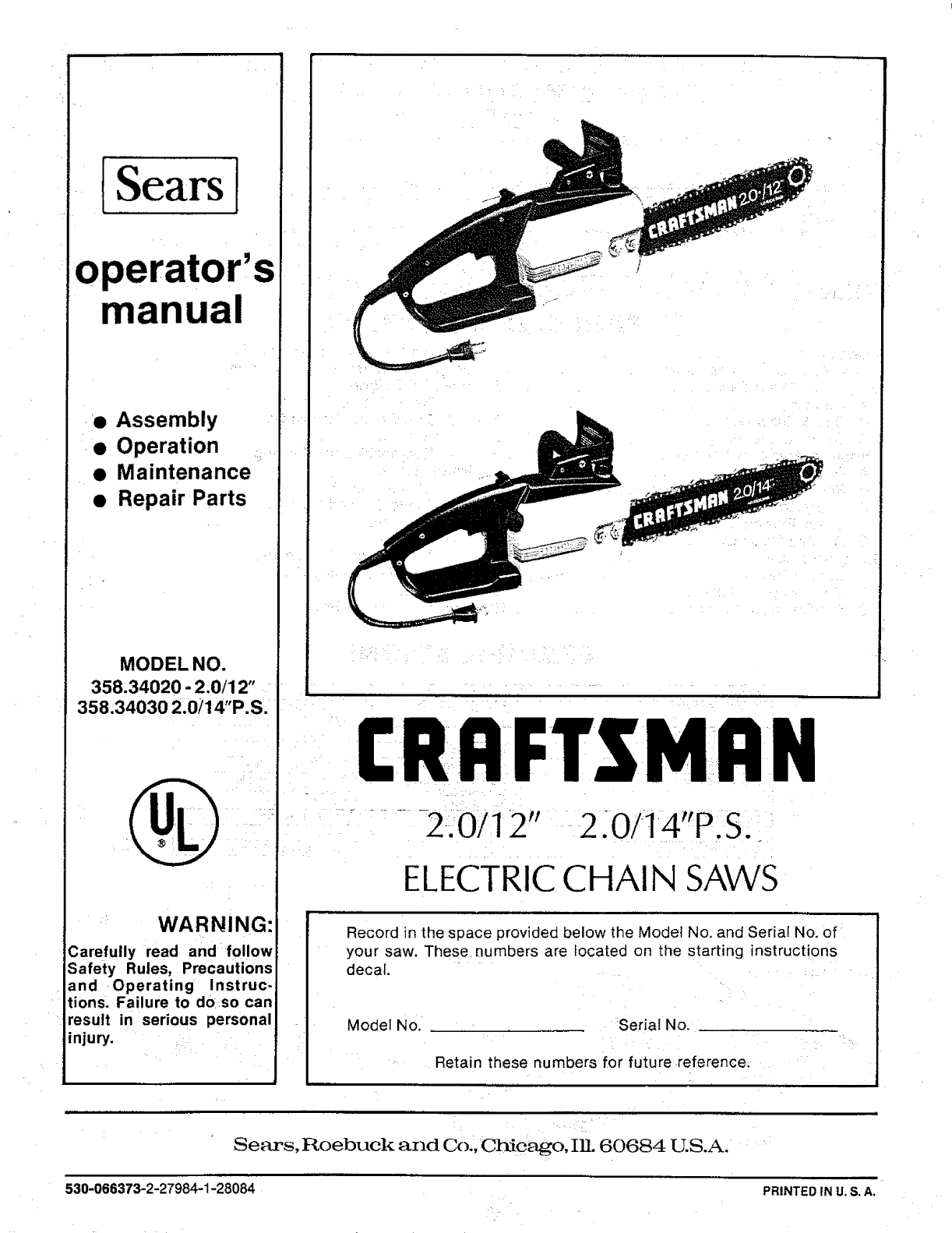
operator's
manual
• Assembly
• Operation
• Maintenance
• Repair Parts
MODEL NO.
358.34020 - 2.0/12"
358.34030 2.0/14"P.S.
WARNING:
3arefuily read and follow
Safety Rules, Precautions
and Operating Instruc-
tions. Failure to do so can
result in serious personal
injury.
I:RRFTgMRN
..........2ili'0112" -2.0/14"P. S.
ELECTRIC CHAIN SAWS
Record in the space provided below the Model No. and Serial No. of
your saw. These numbers are located on the starting instructions
decal.
Model No. Serial No.
Retain these numbers for future reference;
i
Sears, Roebuck and Co., Chicago, IIL 60684 U.S.A.
530-066373-2-27984-1-28084 PRINTED IN U. S. A.
FULL 1 YEAR WARRANTY ON ELECTRIC CHAIN SAW
(Excluding Bar & Chain)
For one year from date of purchase, Sears will repair defects in material or workmanship in this electric chain saw at no
charge. '
This warranty excludes bar & chain, which are expendable parts and become worn during normal use.
If this chain .saw is used for commercial or rental purposes, this warranty applies for only 30 days from date of purchase. WARRANTY
SERVICE IS AVAILABLE BY RETURNING THE CHAIN SAW TO THE NEAREST SEARS SERVICE CENTER IN THE UNITED
STATES.
': This warranty gives you specific legal rights, and you may atso have other rights which vary from state to state.
Sears,RoebuckandCo., SearsTower, Dept. 698/731A, Chicago, I L60684
TABLE OF CONTENTS
Specifications ............................... 2
Safety Rules and Precautions ................. 3
Know Your,Chain Saw ........................ 5
_.A. Introduction ................... .... ....... 5
B_-Double Insulation . ....... 5
:CI CartonContents "5
Preparing Your Saw For Use ........ ....,. _.... 5
A. Getting:Ready ................ ............ 5
B. Power Source and Extension Cord ........... 5
C. Attaching the Bar and Chain 6
D:.Chain Tension 7
E: Bar and Chain Oil '8
Using Your Saw ...................... : ...... 8
A. Control Devices ......................... :8
B. Controlling Kickback ...................... 9
C. Pre-Operation Checks .................... 10
D. Starting and Stopping the Saw ............. 10
Using the Power Sharp ®System .............. 11
Types of Cutting ............................ 13
A. Basic Cutting Technique ................... 13
B. Tree .Felling Techniques ...... i .. ............ _.... 13
C. Bucking _ 15
D. Debranching and Pruning .... ... :....... :. 16
Maintenance .............. ............ _....... 17
A. Cleaning the Saw ........ ................ 17
B. Guide Bar and Chain 17
IC. Sprocket ............................... 19
D_Storage ............................... 20
E. Maintenance Accessories ................. 20
F. Trouble Shooting Chart ................... 21
Parts List .................................. 22
Quick Reference Page ....................... 27
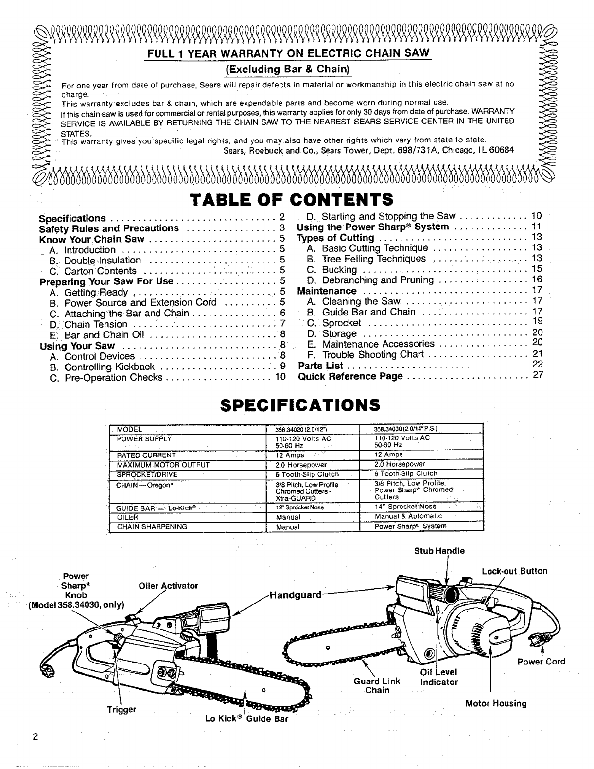
SPECIFICATIONS
MODEL .
POWER SUPPLY
....RATED CURRENT
MAXIMUM MOTOR OUTPUT
' SPROCKETIDRIVE
CHAIN _Oregon"
358.34020 (2.0/12")
110-120 Volts AC
50-60 Hz
12 Amps : "
2.0 Horsepowe; t
6Tooth'-'Sli'p Cluict_
3/8 F'itch, Low Profile
Chromed Cutters -
GUIDE BAR--" Lo-Kick ® ' " '
OILER
CHAIN SHARPENING
"'358.34030 (2.0;!4" P,S,)
110-t20 Volts AC
50-60 Hz
12 AmpS
2.0 Horsepower'
6 Tooth-Slip Ciutch
318 Pitc'h, Low Profite.
Power Sharp ®Chromed
i'"'i:......
Xtra-GUARD
12" Spm_:ket Nose
Manual
Manual
Cutte{s _, :: .
14-Sp'roc'ket' Nose ,,_
M_,nual & Automatic
Power Shatp_ System
Power
Sharp ®
Knob
(Model 358.34030, only)
Oiler Activator
Stub Handle
Lock-out Button
2
Trigger Lo Kick ®•Guide Bar
Guard Link
Chain Indicator
Power Cord
Motor Housing
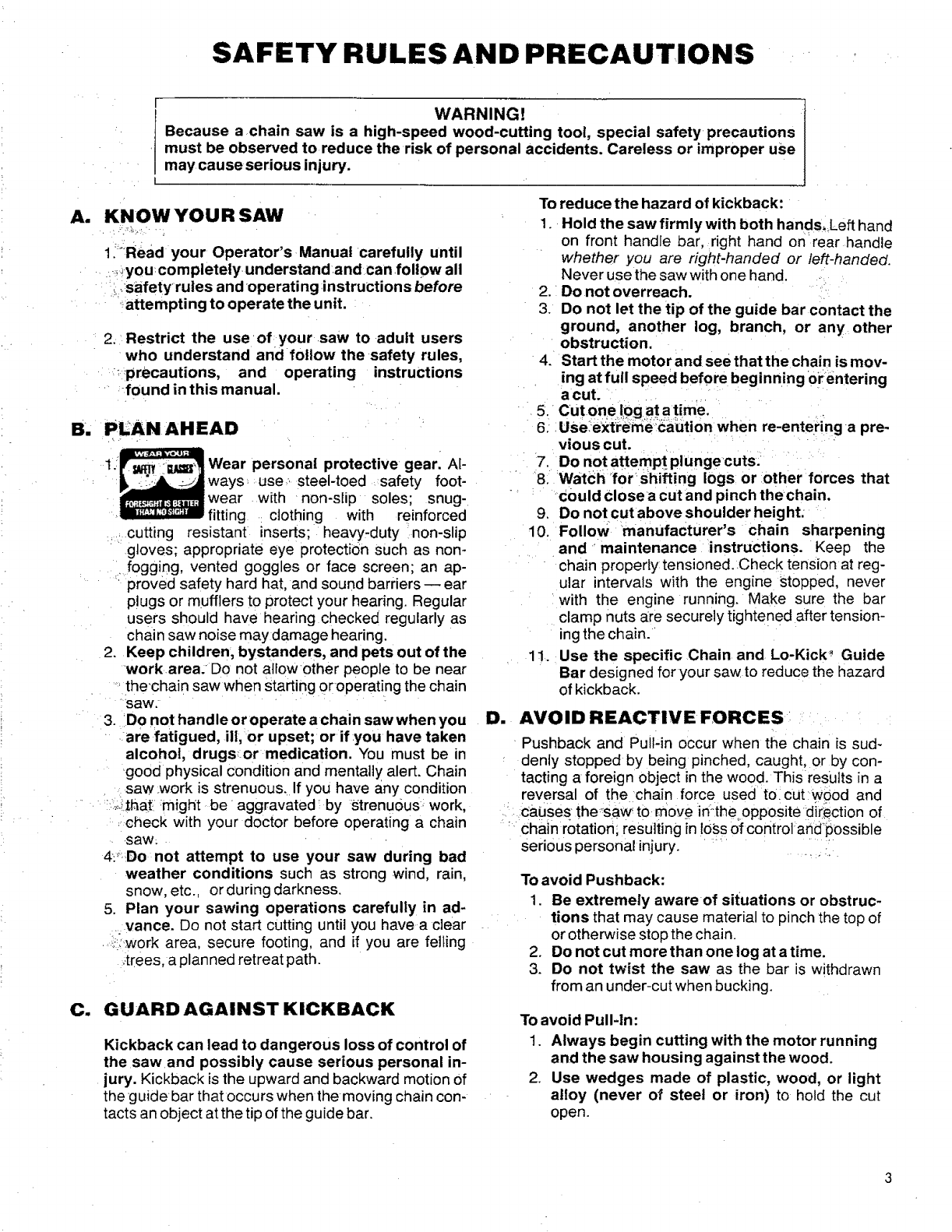
SAFETY RULES AND PRECAUTIONS
rWARNING!
Because a chain saw is a high-speed wood-cutting tool, special safety precautions
must be observed to reduce the risk of personal accidents. Careless or improper use
may cause serious injury.
A. KNOWYOUR SAW
l_:Read your Operator's Manual carefully until
_you completely understand andcan follow all
iisafetyrules and operating :instructions before
_;attempting to operate the unit.
2. Restrict the use of your saw to adult users
who understand and follow the safety rules,
:_precautions, and operating instructions
found in this manual.
B. P_AN AHEAD _
Wear personal protective gear. Al-
ways, :use,. steel-toed ,:safety foot-
11 wear with non-slip soles; snug-
fitting : clothing with reinforced
cutting resistant inserts; heavy-duty non-slip
gloves; appropriate eye protection such as non-
i fogging, vented goggles or face screen; an ap-
proved safety hard hat, and sound barriers -- ear
Plugs or mufflers to protect your hearing. Regular
users should have hearing checked regularly as
chain saw noise may damage hearing.
2. Keep children, bystanders, and pets out of the
workarea: Do not allowother people to be near
....the'chain saw when starting 0r operating the chain
saw.
3. Do not handle oroperate achain saw when you
are fatigued, ill, or upset; or if :you have taken
alcohol, drugsor medication. You must be in
good physical condition and mentally alert. Chain
saw _work is strenuous. If you have any condition
.:_:ithat might be aggravated by r;trenu0us, work,
,check with your doctor before operating a chain
.saw;
4:'_Do not attempt to use your saw during bad
weather conditions such as strong wind, rain,
snow, etc., or during darkness.
5. Plan your sawing operations carefully in ad-
. vance. Do not start cutting until you have aclear
.:;'?work area, secure footing, and if you are felling
:;:trees,a planned retreat path.
C. GUARD AGAINST KICKBACK
Kickback can lead to dangerous loss of control of
the saw and possibly cause serious personal in-
jury. Kickback is the upward and backward motion of
the guidebar that occurs when the moving chain con-
tacts an object at the tip of the guide bar.
To reduce the hazard of kickback:
1. Hold the sawfirmlywith both hands, Left hand
on front handle bar, right hand on rear handle
whether you are right-handed or left-handed.
Never use the saw with one hand.
2. Do not overreach.
3. Do not let the tip of the guide bar contact the
ground, another log, branch, or any other
obstruction.
4. Start the motor and see that the chain is mov-
ing at full speed before beginning orentering
a cut.
5. Cut one i:0g at atime.
6: Use_eYt:reme_ca:ution when re-entering a pre-
vious cut.
7. Do not attempt plunge cuts.
8. WatCh _for shifting logs or other forces that
Could close a cut and pinch thechain.
9. Do not cut above shoulder height:
10. Follow manufacturer's chain sharpening
and maintenance instructions. Keep the
chain properly tensioned. Check tension at reg-
ular intervals with the engine Stopped, never
with the engine running. Make sure the bar
clamp nuts a_resecurely tightened after tension-
ing the chain.
11. Use the specific Chain and Lo-Kick _ Guide
Bar designed for your saw to reduce the hazard
of kickback.
D. AVOID REACTIVE FORCES
Pushback and Pull-in occur when the chain is sud-
denly stopped by being pinched, caught, or by con-
tacting aforeign object in the wood. This results in a
reversal of the chain force used to. cut wood and
caiJses the_saw'to move iri_the opposite direction of
chain rotation; resulting in 10Ssof control andpossible
serious personal injury.
To avoid Pushback:
1. Be extremely aware of situations or obstruc-
tions that may cause material to pinch the top of
or otherwise stop the chain.
2. Do not cut more than one log at a time.
3. Do not twist the saw as the bar is w!thdrawn
from an under-cut when bucking.
To avoid Pull-ln:
1. Always begin cutting with the motor running
and the saw housing against the wood.
2. Use wedges made of plastic, wood, or light
alloy (never of steel or iron) to hold the cut
open.
Ell
Fll
g_
10.
11.
1. Do not operate a chain saw that is damaged,
improperly adjusted, or not completely and
securely assembled.
2. Do not use thesaw if the trigger switch does
not turn the unit on and off properly. Repairs
to the trigger switch must be made by your Sears
Service Center.
3. Do not operate the saw from aladder or in a
tree.
4. Position all parts of your body to the left of
cut when the motor is running.
5. Cut wood only. Do not use a chain saw for any
purpose other than those described in this man-
ual.
6. Make sure the chain will not make contact
before starting the motor. Never try to start the
saw when the guide bar is in acut or kerf.
7: Use extreme caution when cutting small size
brush and saplings. Slender material may
catch .the saw chain and be whipped toward you
or pul!:you off balance.
8. Be alert for springback when cutting a limbthat
isunder tension to avoid being struck by the limb
or saw when the tension inthe wood fibers is re-
leased.
Do not force the saw through a cut. Exert light
pressure only. Pressure on the saw at the end
of acut could cause loss of Control when the cut
is completed.
Avoid body contact with the chain anytime
the saw is plugged into a power source. The
chain willcontinue to move for a short time after
the trigger is released.
Unplug the power connection when the saw
is not in use.
MAINTAIN YOUR SAW IN
GOOD WORKING ORDER
1. Unplug the saw before servicing or changing
accessories.
2. Hat;e _lll chainsaw service performed bY YOur
sears service Center, other than the service
described in the maintenance section of this
manual.
3. Keep chain and guide bar clean and properly
lubricated.
4. Keep oil cap, screws and fasteners tight.
5. Keep the handles dry, clean_ and free of oil.
6. Stop the saw if the chain strikes a foreign ob-
ject. Check for alignment, binding, breakage,
and mounting of moving parts and any other con-
dition that may affect the operation of the unit.
Check guards and all other parts to see if each
will operate properly and perform its intended
function. Any part that is damaged should be
properly repaired or replaced by using the in-
structions inthismanual or by seeing your Sears
Service Center.
7. Be certain the saw chain stops moving when
the trigger switch is released.
8. Make certain that all hand tools are removed
from the saw before connecting the saw to the
power source.
9. Make sure all replacement partsare genuine
recommended parts.
10. Never modify your saw in any way. Use only
attachments supplied or specifically recom-
mended by Sears:
G. CARRY AND STORE
YOUR SAW SAFELY
1. Never carry your saw while climbing. Both
hands are needed for safe climbing.
2. Carry the unit unplugged,by the front handle,
finger off "the trigger switch, and with the
guide bar and chain to the rear.
3. Carry the saw with guide bar and chain
covered by the scabbard.
4. Before transporting in any vehicle or storing
in any enclosure, allow your saw to coot com-
pletely, cover the bar and chain and properly se-
cure to avoid turnover or damage.
5. Drain oil tank before storing your saw for 30 or
more.days.
6. S.tore in a dry area Out of the reach of children.
SAVE THESE INSTR UCTIONS
KNOW YOUR CHAIN SAW
A. INTRODUCTION
The information found in this manual will help
you properly prepare your chain saw for use,
• understand how to operate your saw safely, and
perform maintenance required to keep your unit
in good working condition.
::Your saw has been designed with safety in mind
and includes the following safety features as
.standard equipment:
...... Handguard
-.... Lo.Kick ®Guide Bar
Guard Link Chain
The chain saw should never be operated unless
these devices are properly installed on the unit,
...3-he Lo-Kick'-" Guide Bar and Guard Link Chain.have
".been designed to help reduce 'the hazard: of
KICKBACK. You should thoroughly read and under-
,,,stand the section, "CONTROLLING KICKBACK" on
'page 9 and I0.
B, DOUBLE INSULATION
Your Chain Saw is double insulated to help pro-
tect against electric shock. A double insulated
tool isconstructed throughout with two separate
"layers" of electrical insulation or one double
thickness of insulation between the operator
and the electrical system of the tool.
Tools built with this insulation system are not in-
tended to be grounded. As a result, the exten.
sion cord used with your saw can be plugged in-
to any conventional 120 volt electrical outlet
without concern for maintaining a ground con-
nection.
Safety precautions must be observed when
operating any electrical tool. The double insula-
tion system only supplies added protection
against injury resulting from a possible elec-
trical insulation failure within the saw.
WARNING=.
All electrical repairs to this saw, including
housing, switch, motor, etc., must be diagnos.
ed and repaired by your Sears Service Center or
nearest Sears store. Failure to do so could
cause the double insulation construction to
become ineffective and result in serious per.
sona! injury.
Cu CARTON CONTENTS : ....:
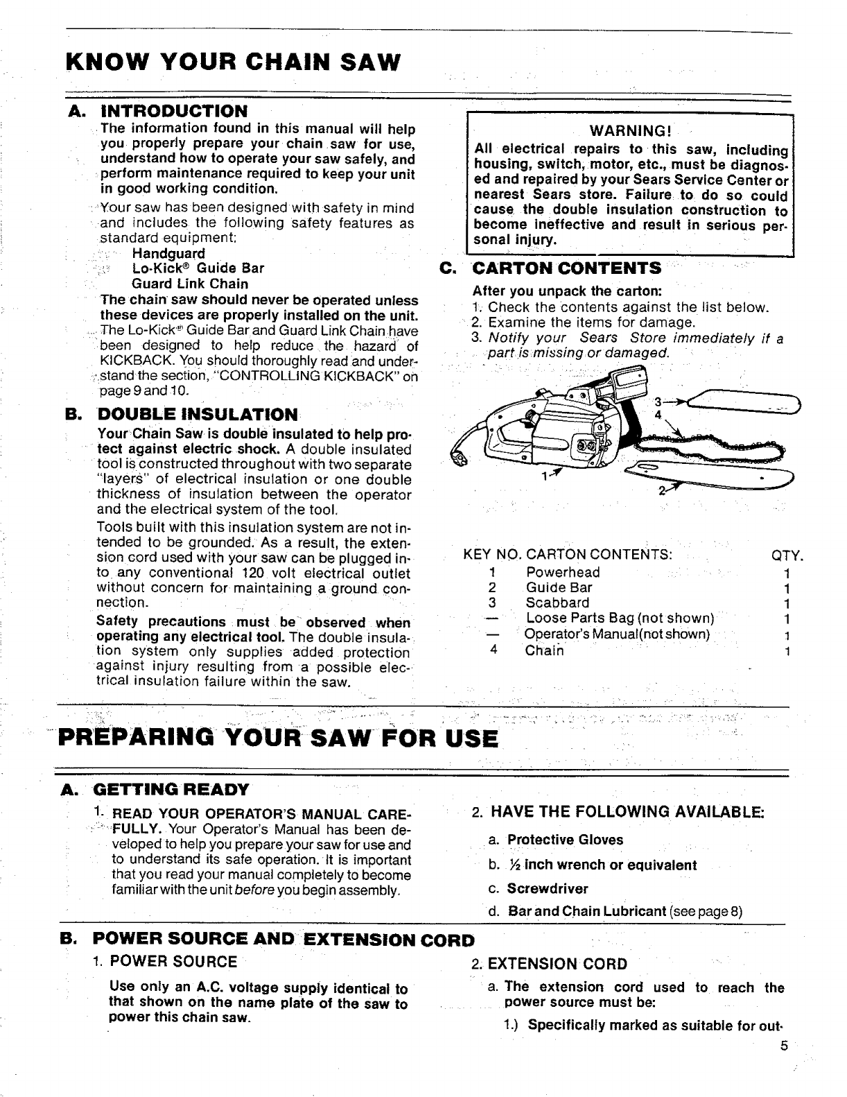
After you unpack the carton:
t. Check the Contents against the list below.
2. Examine the items for damage.
3. Notify your Sears Store immediately if a
....... part;is.missingor damaged.
KEY NO. CARTON CONTENTS:
1 Powerhead
2 Guide Bar
3 Scabbard
-- Loose Parts Bag (not shown)
-- Operator's Manual(not shown)
4 Chain
QTY.
1
1
1
1
1
1
PREPARING YOURSAW FOR USE "i
A. GETTING READY
El
1. READ YOUR OPERATOR'S MANUAL CARE-
..... FULLY. Your Operator's Manual has been de-
veloped to help you prepare your saw for use and
to understand its safe operation. It is important
that you read your manual completely to become
familiar with the unit before you begin assembly.
2. HAVE THE FOLLOWING AVAILABLE:
a. Protective Gloves
b. ½ inch wrench or equivalent
c. Screwdriver
d. Bar and Chain Lubricant (see page 8)
POWER SOURCE AND EXTENSION CORD
1, POWER SOURCE 2. EXTENSION CORD
Use only an A.C. voltage supply identical to
that shown on the name plate of the saw to
power this chain saw.
a. The extension cord used to reach the
Dower source must be:
1.) Specifically marked as suitable for out-
door use.The suffix, W-A, must be in-
cluded on the cord label.
2.) Heavy enough to carry the current from
the power source to the distance at
which the saw is to be used. 0therwise,
loss of power and overheating can oc-
cur causing damage to the unit. Refer
.to Figure 1 for minimum wire gauge
recommendations.
3.) In good condition. Cord insulation
must be intact with no cracks or
deterioration. Plug connectors must be
undamaged.
b. Suitable extension cords are available at
your Sears Retail or Catalog Store.
3. IMPORTANT POINTS
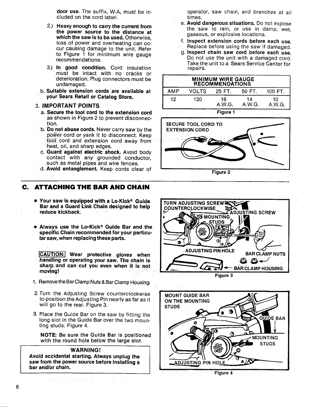
a, Secure the tool cord to the extension cord
as shown in Figure 2 to prevent disconnec-
tion.
b. Donot abuse cords. Never carry saw by the
pO_er cord or yank it to disconnect. Keep
_t'oiSll_cord and extension cord away from
heat, oil, and sharp edges.
c. Guard against electric shock. Avoid body
contact with any grounded conductor,
such as metal pipes and wire fences.
d. Avoid entanglement. Keep cords clear of
operator, saw chain, and branches at all
times.
e. Avoid dangerous situations. DO not expose
the saw to rain, or use in damp, wet,
gaseous, or explosive locations.
f. Inspect extension cords before each use.
Replace before using4he saw if damaged.
g. Inspect chain saw cord before each use.
Do not use the unit with adamaged cord.
Take the unit to a Sears Service Center for
repairs.
MINIMUM WIRE GAUGE 1
RECOMMENDATIONS I
AMP VOLTS 25 FT. 50 FT. 100 FT. 1
]
12 120 16 14 10
A.W.G. A.W.G. A.W.G.
Figure 1
SECURE TOOL CORD TO
EXTENSION CORD
Figure 2
C. ATTACHING THE BAR AND CHAIN
6
• Your saw is equipped with a Lo.Kick ®Guide
Bar and a Guard Link Chain designed to help
reduce kickback.
• Always use the Lo-Kick ®Guide Bar and the
specific Chain recommendedfor yourparticu-
lar saw, when replacing these parts.
[CAUTION:I Wear protective gloves when
handling or operating yoursaw. The chain is
sharp:and can cut you even when it is not
mov!ng!' "_........:,_-:_=_' _
1. Remove the Bar Clamp Nuts & Bar Clamp Housing.
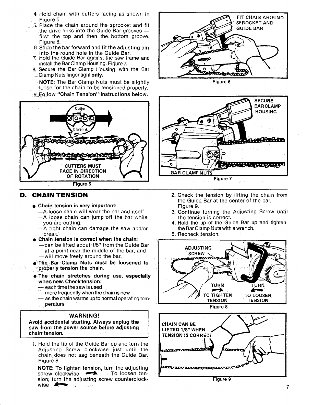
2. Turn the Adjusting Screw counterclockwise
to position the Adjusting Pin nearly as far as it
.... Will go to the rear. Figure 3.
&Place the Guide Bar on the saw by fitting the
long slot:in the Guide Bar over the two moun-
ting studs. Figure 4.
NOTE: Be sure the Guide Bar is positioned
with the round hole below the large slot.
WARNING!
Avoid accidental starting. Always unplug the
sawfromthe power source before installing a
bar and/or chain.
TURN ADJUSTING
COUNTERCLOCKWISE _DJUSTING SCREW
ADJUSTING PIN HOLE BARCLAMPNUTS
ll_ '-_,Jki'll ,.i ' CLAMP HOUSING i
Figure 3
_,:Figure 4
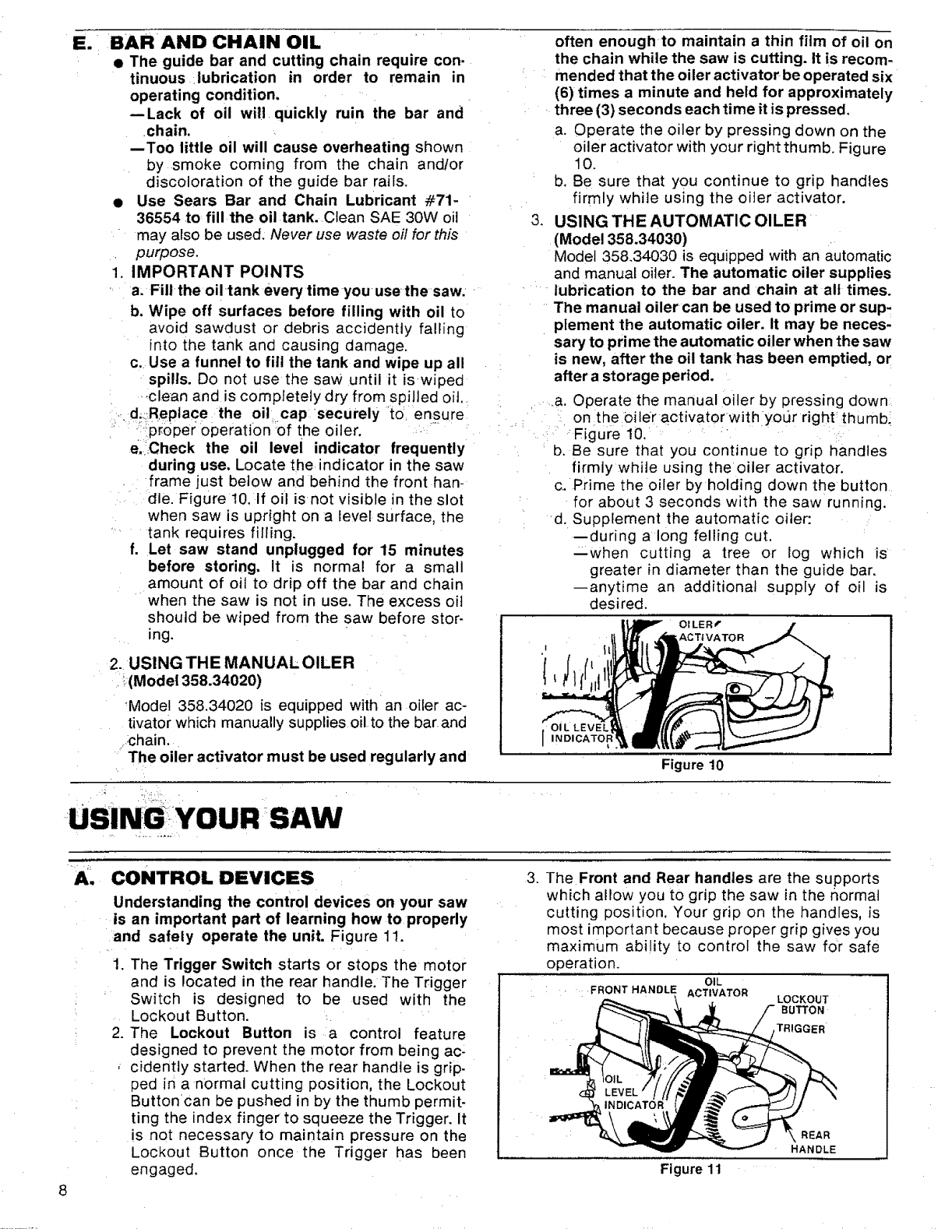
; 4. Hold chain with cutters facing as shown in
Figure 5.
: 5. Place the chain around the sprocket and fit
the drive links into the Guide Bar grooves --
first the top and then the bottom groove,
Figure 6.
....6, Slide the bar forward and fit the adjusting pin
into the round hole in the Guide Bar.
7. Hold the Guide Bar against the saw frame and
install the Bar Clamp Housing. Figure 7.
8, Secure the Bar Clamp Housing with the Bar
,._Clamp Nuts finger tight only.
.NOTE: The Bar Clamp Nuts must be slightly
loose for the chain to be tensioned properly.
;9,iEo_llow "Chain Tension" instructions below.
CUTTERS MUST
FACE IN DIRECTION
OF ROTATION
Figure 5
Figure 6
•Figure 7
SECURE
HOUSING
D. CHAIN TENSION
•Chain tension is very important:
--A loose chain will wear the bar and itself.
--A loose chain can jump off the bar while
you' are'cutting.
--A'tight chain can damage the saw andtor
break.
• Chain tension is correct :when the chain:
--can be liftedabout 1!8" from the Guide Bar
at a point near the middle of the bar, and
--will move freely around the bar.
,e_The'Bar Clamp Nuts must be;loosened to
;_prOperly tension the chain.
•The chain stretches during use, especially
:when new. Check tension"
-- each time the saw is used
'_ more frequently when the chain isnew
•-- as the chain warms up to normal operating tern-
: perature
WARNING!
Avoid accidental starting. Always unplug the
saw from the power source before adjusting
chain tension.
1. Hold the tip of the Guide Bar up and turn the
Adjusting Screw clockwise just until the
chain does not =sag beneath the Guide Bar,
Figure 8.
NOTE: To tighten tension, turn the adjusting
screw clockwise _ . To loosen ten,
sion, turn the adjusting screw counterclock-
wise
2, Check the tension by tifting the chain from
the Guide Bar at the center of the bar.
Figure 9.
3. Continue turning the Adjusting Screw until
the tension is correct.
4. Hold the tip.of the Guide Bar,up and tighten
the Bar Clamp Nuts with a wrench.
5. 'Recheck tension.
ADJUSTING
SCREW
Figure 8
i, , ,
Figure 9
El BAR AND CHAIN OIL often enough to maintain a thin film of oil on
• The guide bar and cutting chain require con. the chain while the saw is cutting. It is recom.
tinuous lubrication in order to remain in mended that the oiler activatorbe operated six
operating condition,
--Lack of oil will quickly ruin the bar and
chain.
--Too little oil will cause overheating shown
by smoke coming from the chain andlor
discoloration of the guide bar rails.
•Use Sears Bar and Chain Lubricant #71-
36554 to fill the oil tank. Clean SAE 30W oil
may also be used. Never use waste oil for this
purpose.
IMPORTANT POINTS
a. Fill the oi! tank every time you use the saw.
b. Wipe off surfaces before filling with oil to
avoid sawdust or debris accidently falling
into the tank and causing damage.
c. Use a funnel to fill the tank and wipe up all
spills. Do not use the saw until it iswiped
,_clean and is completely dry from spilled oit.
d.Replace the oil cap securely to ensure
_ proper operat On of the oiler.
e, Check the oil level indicator frequently
during use. Locate the indicator in the saw
frame just below and behind the front han-
dle. Figure 10. If oil isnot visible in the slot
when saw is upright on a level surface, the
•tank requires filling.
f. Let saw stand unplugged for 15 minutes
before storing. It is normal for a small
amount of oil to drip off the bar and chain
when the saw is not in use. The excess oil
should be wiped from the saw before stor-
ing.
2. USING THE MANUALOILER
!(Model 358.34020)
Model 358.34020 is equipped with an oiler ac-
tivator which manually supplies oil to the bar and
.:chain,
The oiler activator must be used regularly and
.
(6) times a minute and held for approximately
three (3) seconds each time it is pressed.
a. Operate the oiler by pressing down on the
oiler activator with your right thumb. Figure
10.
b. Be sure that you continue to grip handles
firmly while using the oiler activator.
USING THE AUTOMATIC OILER
(Model 358.34030)
Model 358.34030 is equipped with an automatic
and manual oiler. The automatic oiler supplies
lubrication to the bar and chain at all times.
The manual oiler can be used to prime or sup-
plement the automatic oiler. It may be neces-
sary to pri me the automatic oiler when the saw
is new, after the oil tank has been emptied, or
after a storage period.
a. Operate the manual oiler by pressing down
on the Oiler activator with your right thumb_
Figure 10.
b. Be sure that you continue to grip handles
firmly while using the oiler activator.
c. Prime the oiler by holding down the button
for about 3 seconds with the saw running.
d. Supplement the automatic oiler:
--during a long felling cut.
--when cutting a tree or log which is
greater in diameter than the guide bar.
anytime an additional supply of oil is
desired.
OILER€
AC Tt VA TO R
Figure 10
BSINGYOUR SAW
8
A, CONTROL DEVICES
Understanding the control devices on your saw
is an important part of learning how to properly
and safely operate the unit. Figure 11.
1. The Trigger Switch starts or stops the motor
and is located in the rear handle. The Trigger
Switch is designed to be used with the
Lockout Button.
2. The Lockout Button is a control feature
designed to prevent the motor from being ac-
cidently started. When the rear handle is grip-
ped in a normal cutting position, the Lockout
Buttoncan be pushed in by the thumb permit-
ting the index finger to squeeze the Trigger. It
is not necessary to maintain pressure on the
Lockout Button once the Trigger has been
engaged.
3. The Front and Rear handles are the supports
which allow you to grip the saw in the normal
cutting position, Your grip on the handles, is
most important because proper grip gives you
maximum ability to control the saw for safe
operation.
OIL
FRONT HANDLE ACTIVATOR LOCKOUT
BUTTON
TRIGGER
Figure 11
REAR
HANDLE
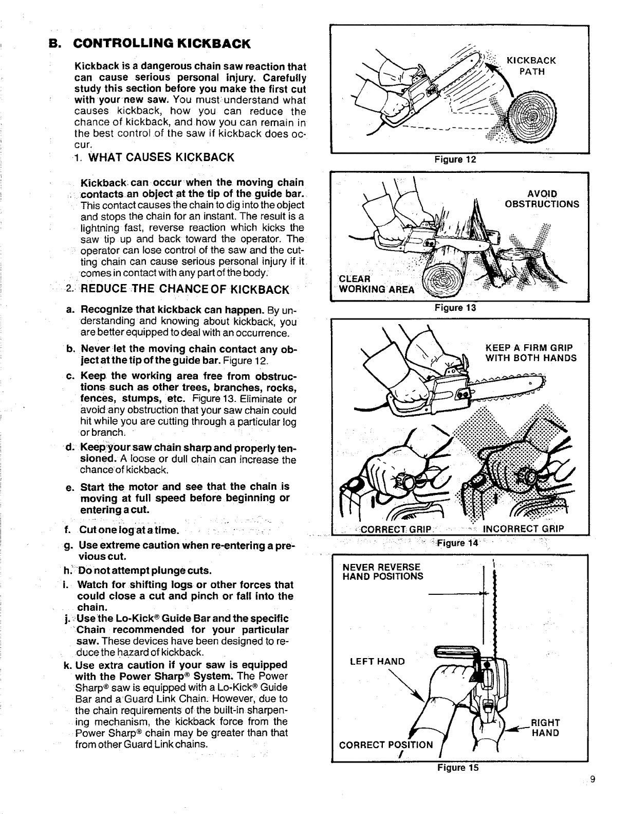
B. CONTROLLING KICKBACK
Kickback is a dangerous chain saw reaction that
can cause serious personal injury. Carefully
study this section before you make the first cut
with your new saw. You must., understand what
causes kickback, how you can reduce the
chance of kickback, and how you can remain in
the best control of the saw if kickback does oc-
cur.
.1. WHAT CAUSES KICKBACK
Kickback can occur when the moving chain
: :contacts an objectat the tip of the guide bar.
This contact causesthe chain to dig into the object
and stops the chain for an instant. The result is a
lightning fast, reverse reaction which kicks the
saw tip up and back toward the operator. The
operator can lose control of the saw and the cut-
ting chain can cause serious personal injury if it
comes incontact withany partof the body:
2.: REDUCE THE CHANCE OF KICKBACK
a. Recognize that kickback can happen. By un-
derstanding:and knowing about kickback, you
are better equipped to deal with an occurrence.
b. Never let the moving chain contact any ob-
ject at the tip of the guide bar. Figure 12.
c. Keep the working area free from obstruc-
tions such as other trees, branches, rocks,
fences, stumps, etc. Figure13. Eliminate or
avoid any obstruction that your saw chain could
hit while you are cutting through aparticular log
or branch, '
d; Keepiyour saw chain sharp and properly ten-
sioned. A loose or dull chain can increase the
chanceof kickback.
e. Start the motor and see that the chain .is
moving at full speed before beginning or
entering a cut.
f. Cut oneiogat atime. _ : :- ......:_.
g. Use extreme caution when re-entering a pre-
vious cut.
h,' Do not attempt plunge cuts.
i. Watch for shifting logs or other forces that
could close a cut and pinch or fall into the
• • chain.
j, _Usethe Lo-Kick® Guide Bar and the specific
_Chain recommended for your particular
saw. These devices have been designed to re-
duce the hazard of kickback.
k. Use extra caution if your saw is equipped
with the Power Sharp ®System; The Power
Sharp ®saw is equipped with a Lo,Kick® Guide
Bar and aGuard Link Chain: However, due to
the chain requirements of the built;in sharpen-
ing mechanism, the kickback force from the
Power Sharp® chain may be greater than that
from other Guard Link chains.
KICKBACK
PATH
Figure 12 '
AVOID
OBSTRUCTIONS
:WORKINGARE_
Figure 13
KEEPA FIRM GRIP
WITH BOTH HANDS
"':"INCORREC'T GRIP
, _:CORRECT_GRIP: ,........
i
NEVER REVERSE
HAND POSITIONS
LEFT HAND
\,
CORRECT POSITION
J
RIGHT
HAND
Figure 15 9
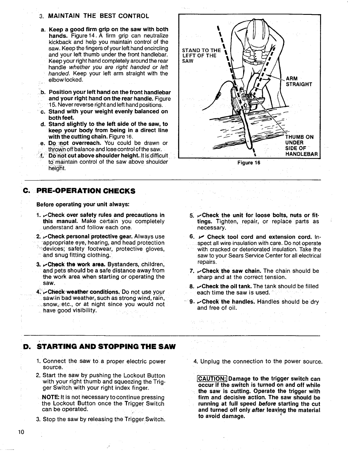
3. MAINTAIN THE BEST CONTROL
a. Keep a good firm grip on the saw with both
hands. Figure14. A firm grip can neutralize
kickback and help you maintain control of the
saw. Keep the fingers of your left hand encircling
and your left thumb under the front handlebar,
Keep your right hand completely around the rear
handle whether you are right handed or/eft
handed. Keep your left arm straight with the
elb0W_locked.
b. Position your left hand on the front handlebar
'and your right hand on the rear handle. Figure
15. Never reverse rightand left hand positions.
c. Stand with your weight evenly balanced on
both feet.
d. Stand slightly to the left side of the saw, to
keep your body from being in a direct line
with the cutting chain. Figure 16.
e. Do_.-not overreach. You could be drawn or
: : th_n off balance and lose control ofthe saw.
__if.'_D6_._i_tcut above shoulder height. Itis;difficult
td_maintain control of the saw above shoulder
STAND TO THE_
LEFT OF THE
SAW
ARM
STRAIGHT
Figure 16
JMBON
UNDER
SIDE OF
HANDLEBAR
C. .PRE-OPERATION CHECKS
Before operating your unit always:
1. ,,,Check over safety rules and precautions in
this manual. Make certain you completely
understand and follow each one.
•2. ,,,Check personal protective gear. Always use
!appr0priate eye,_hearing, and 'head protection
:_i!.devices; Safety footwear, protective gloves,
and snug fitting clothing.
3. ,,,Check the work area. Bystanders; childrenl
and pets should be a safe distance away from
the work area when starting or operating the
saw.
....... 4.1_,,,Check-weather conditions. Do n0t _use.your
.... saw_inbad weather, such as strong wind, rain,
....... snow,:_etc., or at night since you would not
have good visibility. _
.
6.
.
9.
,,-Check the unit for loose bolts, nuts or fit-
tings. Tighten, repair, or replace parts as
necessary.
tJ' Check tool cord and extension cord. in-
spect all wire insulation withcare. Do notoperate
with cracked or deteriorated insulation. Take the
sawto your Sears Service Center for all electrical
repairs.
,,,Check the saw chain. The chain should be
sharp and at the correct tension.
,,-Check the oil tank. The tank should be filled
eachtime the saw is used.
,,-Check the handles. Handles should be dry
and free of oil.
10
D. STARTING AND STOPPING THE SAW
1. Connect the saw to a proper electric power
source.
2. Start the saw by pushing the Lockout Button
with your right thumb and squeezing the Trig-
ger Switch with your right index finger.
NOTE: ltis not necessary tocontinue pressing
the Lockout Button once the Trigge[ Switch
can be operated. _
3. Stop the saw by releasing the Trigger Switch.
4. Unplug the connection to the power source.
[CAUTION:J Damage to the trigger switch can
occur if the switch is turned on and off while
the saw is cutting. Operate the trigger with
firm and decisive action. The saw should be
running at full speed before starting the cut
and turned off only after leav,ing the material
to avoid damage.
USING THE POWER SHARP ®SYSTEM
(MODEL 358.34030)
Model 358.34030 is equipped with a Power Sharp® Sys-
tem that will perform approximately 80% of the sharpening
necessaryfor the saw. chain:.The PowerSharp® System
uses.a builtqn grinding stone to sharpen the cutter top
platesand set.depth gauges. As the built-in sharpener is
,used;,the cutter.side plates gradually will.be altered.About
every, 3rd to 5th time the Power Sharp ®System :is used,
har_d_filiSgis required to correct the cutter side plates.
.....ICAUTION:IAiways wear gloves when handling
the chain. The chain is sharp and can cut
you easily, even when it is not moving.
:.v_e_:Sharpenthesaw chain when:
--wood chips become small and powdery.
Wood chips made by the chain should be
about thesizeof the teeth ofthe chain,
--saw cuts to one side.
--saw has to be forcedthrough •the cut.
•Replace the sharpening Stone when a new
Power Sharp® chain is installed. The sharpen-
ing stone will wear to the shape.of the worn chain
and will cause excessive wear to a new chain if not
replaced. Replacement Power Sharp® Chain,
Stock No. 71-3618, comes supplied with a Shar-
pening Stone Replacement. Refer to re#lacement
instructions in this section.
• Removethesharpening stone ifa standard or
removing the sharpening Stone below. Use as re-
placement chain Stock No. 71-3617. Follow stan-
dard chain sharpening instructions, page. 18.
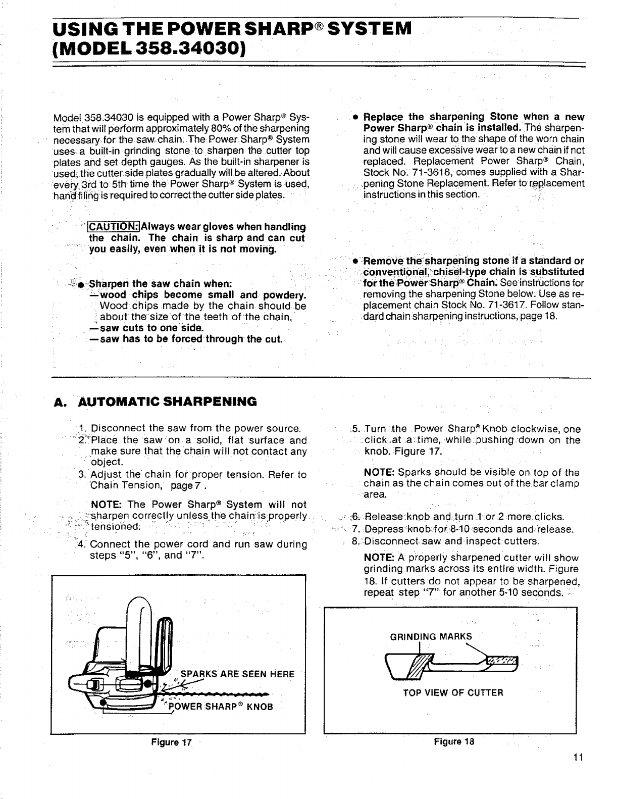
A. AUTOMATIC SHARPENING
t. Disconnect the saw from the power source.
"_2_"Place the saw on a solid, flat surface and
make sure that the chain will not contact any
-object.
3. Adjust the chain for proper tension. Refer to
Chain Tension, page7.
NOTE: The Power Sharp ® System will not
:_:sharpencorrectly unless the chainis_properly
: '_-:"_"tehsioned. ".........
4.:Connect the power cord and run saw during
steps "5", "6", and "7".
SPARKS ARE SEEN HERE
_POWER SHARP®KNOB
/
5..Turn the Power SharpP Knob clockwise, one
.click,at a:time,..while..pushingdown on the
knob. Figure 17.
NOTE: Sparks should be visible on .top of the
chain as the chain comes out of the bar clamp
area.
_.:.._6.Release:knob andt:urn.1 or2 moreclicks.
_.'-. 7. Depres.sNnob:.,for 8-10 seconds and.release.
&'Disconnect.saw and inspect cutters,
NOTE: A properly sharpened cutter will show
grinding marks across its entire width. Figure
18. If cutters do not appear to be sharpened,
repeat step "7" for another 5-10 seconds,
GRINDING MARKS
TOP VIEW OF CUTTER
Figure 17 Figure 18
11
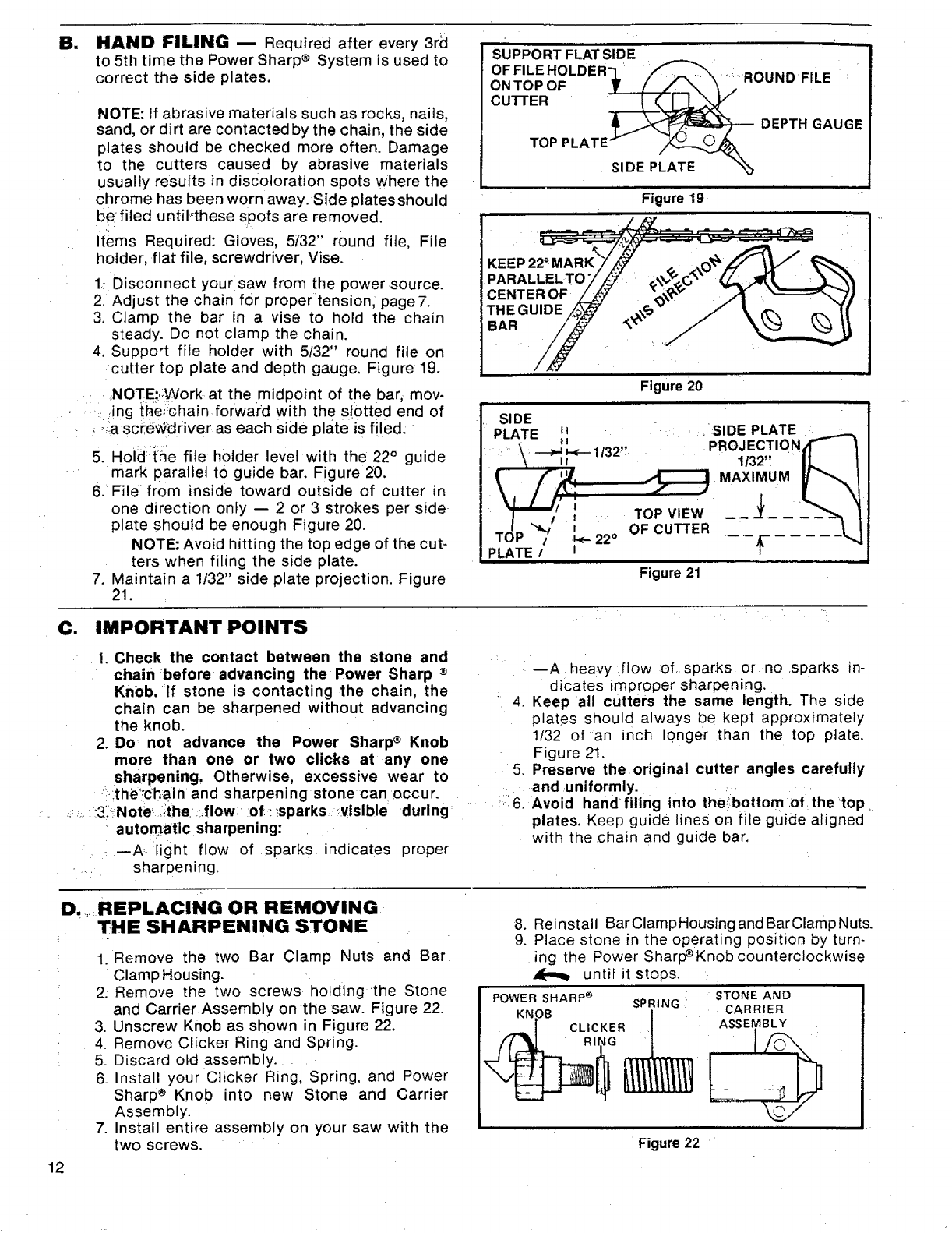
ml HAND FILING -- Required after every 3rd
to 5th time the Power Sharp ® System is used to
correct the side plates,
NOTE: If abrasive materials such as rocks, nails,
sand, or dirt are contacted by the chain, the side
plates should be checked more often. Damage
to the cutters caused by abrasive materials
usually results in discoloration spots where the
chrome has been worn away. Side plates should
befiled untiPthese spots are removed.
Items Required: Gloves, 5t32" round file, File
hotder, flat file, screwdriver, Vise.
1.;-Disconnect your saw from the power source.
2, Adjust the chain for proper tension, page7.
3. Clamp the bar in a vise to hold the chain
steady. Do not clamp the chain.
4, Support file holder with 5f32" round file on
cutter top plate and depth gauge, Figure 19.
......NOTE;:Work at the midpoint of the bar, mov-
.-:: ,!ng !he:Tchain forward with the s!otted end of
,_ascrewdriver as each side plate is filed.
5. Hoid;{h:e file holder level-with the 22° guide
mark parallel to guide bar. Figure 20.
6. File from inside toward outside of cutter in
one direction only -- 2 or 3 strokes per side
plate should be enough Figure 20.
NOTE: Avoid hitting the top edge of the cut-
ters when filing the side plate.
7. Maintain a tt32" side plate projection. Figure
21.
C. IMPORTANT POINTS
SUPPORT FLATSIDE
KEEP22°MARK
PARALLELTO"
CENTER OF
THEGUIDE
BAR
Figure 20
SIDE " J
"PLATE t_ - SIDE PLATE _J
__._ ,, PROJECTION
It " C"41
'!".,"i .... ToPVlEW_...t!'_ '', 11
_A- "_" I OF CUTTER
,Ui-' /_-22 o/_ -_!
PLATE /I T !
Figure 21
1. Check the contact between the stone and
chain before advancing the Power Sharp ®
Knob."lf stone is contacting the chain, the
chain can be sharpened without advancing
the knob.
2. Do not advance the Power Sharp ®Knob
more than one or two clicks at any one
sharpening, Otherwise, excessive wear to
'i.lthe'_chain and sharpening stone can occur.
: .... ::._.:3?iNot:ei::,{he:,flow of.::!sparks ;visible "during:
•automatic sharpening:
:--A:-light flow of spark s indicates proper
., sharpening.
D.,,_ REPLACING OR REMOVING
THE SHARPENING STONE
1. Remove the two Bar Clamp Nuts and Bar
Clamp Housing.
2. Remove the two screws: holding the Stone
and Carrier Assembly on the saw. Figure 22.
3. Unscrew Knob as shown in Figure 22.
4. Remove Clicker Ring and Spring.
5. Discard old assembly.
6. Install your Clicker Ring, Spring, and Power
Sharp ® Knob into new Stone and Carrier
Assembly.
7. Install entire assembly on your saw with the
two screws.
--A. heavy .flow .:of..sparks or no .sparks in-
dicates improper sharpening.
4. Keep all cutters the same length. The side
plates should always be kept approximately
1/32 of an inch longer than the top plate.
Figure 21.
5. Preserve the original cutter angles carefully
and uniformly. :
::ii6. Avoid hand filing into the;bottom of the top
plates. Keep guide lines on file guide aligned
with the chain and guide bar.
8. Reinstall BarClampHousing and BarClamp Nuts.
9. Place stone in the operating position by turn-
ing the Power Sharp®Knob counterclockwise
until it stops.
S"TON E AND
POWER SHARP _ SPRING CARRIER
RA_SEMBL>I -_ '
Figure 22
12

TYPES OF CUTTING
A. :BASIC CUTTING TECHNIQUE
1. IMPORTANT POINTS.
.
a. Cut wood .only. :Do not cut metal, plastics,
•masonry, non-wood, building materials;etc.
b. Stop the saw if the chain strikes a foreign
._ object. Inspect the Unit and repair or replace
parts as necessary.
c.: Keep the chain out of dirt and sand. Even a
._ smallamountofdirtwillquicklydullachainand
...... thus, increase the possibility of kickback:
UNDERSTAND REACTIVE FORCES
Pushback andPull-in occur when the chain is
suddenly stopped by being pinched, caught,
Or by contacting a foreign object in the wood.
i,This results in a reversal of the chain force used
.to.cut wood and causes thesaw to move in the op-
p0site direction of chain rotation, resulting in loss
of controt and possible serious personal injury.
•Pushback:
_occurs when the chain, on top of the bar, is
" suddentystopped when the top of the bar is
.... used for cutting.
--drives the saw straight -back toward the
operator, possibly causing loss of saw con-
trol.
To avoid Pushback:
a. Be extremely aware of situations or
obstructions that may cause material to pinch
the top of or otherwise stop the chain.
b. Do not cut more than one log at a time.
BEGINCUTTING WITH THE SAW ....
• Pull-in:
--occurs when the chain on the bottom of the
bar is suddenly stopped.
-- occurs when the saw housing is not held sec-
urely against the tree or limb and/or when the
cut is not begun with the motor running.
--pulls the saw forward, and could cause the
operator to lose control.
To avoid Pull-in:
.... a. Always begin cutting with the motor run-
ning and the saw housing against the
wood.
b; Use wedges made of plastic, wood, or light
alloy (never of steel or iron) to hold the cut
open.
.... i. CAU.TION:Do!.not ._staiL the chain in the cut.
,, _This will overheat the:motor and cause damage.
3. PROCEDURE
Practice Cutting a few small logs using the follow-
ing.technique to get the "feel" of using your saw
before you begin a major sawing operation.
a. Assume the proper cutting stance de-
scribed in.the section ,Controlling Kickback"--
firm grip on front and rear handles, weight
evenly balanced on both feet, and body slightly
to the left side of the saw.
b. Make sure the extension cord is com-
pletely away from the saw and your body
sothe cord cannot be cut or become wrap-
'c. Do not:twist the sawas the bar is withdrawn pedaround your,feet or.legs.
from an under-cut, c. Press the trigger to start:the chain moving
befor e beginning the cut.
d. Begin cutting with the saw. frame up
.against the log. Figure 23. ,
e. Allow the chain.to cut for. you. Exert only
light downward pressure. If you force the cut,
...... damage,to the bar, chain or motor can result,
f._ Do not put:pressure on the saw at th'e end
._.::.of thecuttoav0id losing controlwhen the cut
iscomptete. ".......
g. _Release the,Trigger Switch as soon as the
:cut is completed. .
h. Unplug the unit after each cutting opera-
tion.
B. TREE-FELLING TECHNIQUES
1. PLAN YOUR SAWING OPERATIONCARE-
_,':_;_FULLY IN ADVANCE
a.. Clear the work area. You need a clear area alld.
around the tree where you can have secure
footing.
b. Study the natural conditions that can cause
the tree to fall in aparticular direction.
1:) TheWIND direction and speed
2.) The LEAN of the tree
3.) WEIGHTED with BRANCHES on one side
4.) Surrounding TREES and OBSTACLES
c. Look for decay and rot. If the trunk is rotted,
it could snap and fail toward the operator.
d. Check for broken or dead branches which
could fall on you while cutting. •
e. Make surethere is enough room forthetree
to fail. Maintaining a distance of 2V2 tree
lengths from the nearest person or other ob-
jects. Motor noise may drown out warning call.
f. Remove dirt, stones, loose bark, nails,
staples, and wire from the tree where cuts
areto be made,
g. Plan to stand on the up-hill side when cut-
ting on a slope.
h. Plan aclear retreat path to the rear and
diagonal to the line of fall. Figure 24. 13
=
b.
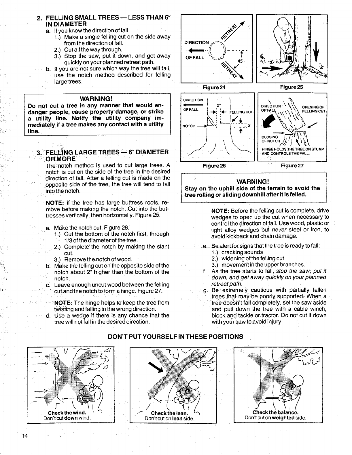
FELLING SMALL TREES pLESS THAN 6"
IN DIAMETER
a. If you knowthe direction offalt:
1.) Make a single felling cut on the side away
from the direction of fall,
2.) Cut all the way through.
3.) Stop the saw, put it down, and get away
quickly on your planned retreat path.
If you are not sure which way the tree will fail,
use the notch method described for felling
largetrees:
WARNING!
Do not cut a tree in any manner that would en-
danger people, cause property damage, orstrike
a utility line. Notify the utility company im-
mediately if a tree makes any contact with a utility
line.
3: FELIL_NG LARGE TREES'- 6" DIAMETER
'ORMORE
The_n0tch method is used to cut large trees. A
notch is cut on the side of the tree in the desired
direction of fall. After a felling cut is made on the
opposite side of the tree, the tree will tend to fail
into the notch.
NOTE: If the tree has large buttress roots, re-
move before making the notch. Cut into the but-
tresses vertically, then horizontally. Figure 25.
b_
C.
•/
a. Make the notch cut. Figure 26.
1.) Cut the bottom of the notch first, through
1/3 of the diameterof the tree.
2.) Complete the notch by making the slant
cut.
3.) Remove the notch of wood.
Make the felling cut on the opposite side of the
notch about 2" higher than the bottom of the
notch.
Leave enough uncut wood between the felling
cut and thenotch to form a hinge; Figure 27.
>NOTE.: The hinge helps to keep the tree from
twisting and falling inthe wrong direction.
d. Use awedge if there is any chance that the
tree will not fail in the desired direction.
DIRECTION
OF FALL
• i4 '_
',S I
Figure 24 Figure 25
DIRECTION
OF FALL,
NOTCH
,2";
--I_: :41-- FELLINGCUT
Z
Figure 26
\
DIRECTION OPENING OF
FELLING CUT
CLOSING
"OF NOTCH
HINGE HOLD STHE TREE ON STUMP
AND CONTROLS THE FALL.
!>.
Figure 27
t WARNING!
Stay on the uphill side of the terrain to avoid the
tree rolling or sliding downhillafter it is felled.
NOTE: Before the fetIing cut is complete, drive
wedges to open upthe cut when necessary to
control the direction of fall, Use wood; plastic or
light alloy wedges but never steel or iron, to
avoid kickback and chain damage.
..... e...Be alert f0r signs,that the tree is readyto fall:
1.) cracking sounds
2.) widening of the felling cut
3.) movement inthe upper branches.
f. As the tree starts to fall, stop the saw; put it
down, and get away quickly on your planned
retreat path.
. g. Be extremely ,cautious with partially fallen
'trees that maybe poorly supported. Wh#n a
• _ tree doesn't fall completely, set the saw aside
and pull down the tree with a cable winch,
block andtackle or tractor. Do not cut it down
with your saw to :avoid injury.
DON'T PUT YOURSELF IN THESE POSITIONS
._i_."._,:._;_,'-.,"__" /
Checkthe wind.
Don'tcutdown wind. _'_ Checkthe lean.
Don'tcutonleanside. Check the balance.
Don't cut on weighted side.
14 •
C. BUCKING
Bucking is the term used for cutting a fallen
tree to the desired log size.
1. IMPORTANT POINTS
a. Cut only one log at a time.
b. Cut =shattered wood very carefully_ Sharp
pieces of wood could be flung toward the
operator.
c.. Use a sawhorse to cut small logs. Never
allow another person to hold the log while cut-
ting and never hold the logwith your legor fool
do Do not cut in an area wheretogs, limbs and
roots are tangled such as in a blown down
area. Drag the logs into aclear area befo_'ecut-
ting by pulling out exposed and cleared logs
first.
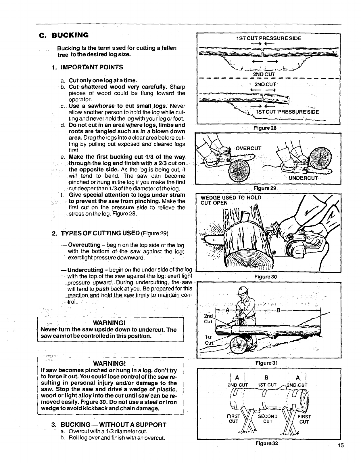
e. Make the first bucking cutt/3 of theway
:=,_ •throughthelogand finish with a 2/3 cuton •
,,,,_-, the opposite side, As the logis being cut, it
will tend to bend, The saw can become
pinched or hung inthe log ifyou make the first
:.cut deeper than 1/3of the diameter of the fog.
• f. Give special attention to logs under strain
,:to prevent the saw from pinching. Make the
first cut on the pressure side to relieve the
:. stress on the log. Figure 28.
2. TYPES OF CUTTING USED (Figure 29)
Overcutting -begin on the top side of the log
with the bottorn of the saw against the log;
exert light pressure downward.
;..:, . WARNING!
Never turn the saw ;upside down to undercut. The
saw cannot be controlled in this position.
-- Undercutting - begin on the under side of the log
with the top,of the saw against the log; exert light
.: pressure upward. During undercutting, the, saw
will tend to push back at you. Be prepared for this
._r.eaction.andhold ,the saw firmly to maintain con-
trol .... -
- :td? WARNING]
If saw becomes pinched or hung in a log, don't try
to force it out. You could lose control of the saw re-
suiting in personal injury and!or damage to the
saw. Stop the saw and drive a wedge of plastic,
wood or light alloy into the cut until saw can be re-
moved easily. Figure 30. Do not use a steel or iron
wedge to avoid kickback andchain damage.
.BUCKING--WITHOUT A SUPPORT
al Overcutwith a !/3 diametercut.
b, Roll log overand finish with an overcut,
1ST CUT PRESSURE SIDE
2ND CUT
.. 2NDCUT _ !,,:
_,_,_:_:=1STCUT •PRESSURESIDE
.... Figure28
OVERCUT
: ::UNDERCUT •
, _Figure 29
CUT OPEN _,
Figure30
Figure 31
2ND CUT 1ST 2ND CUT
FIRST
CUT CUT CUT
Figure 32 t 5
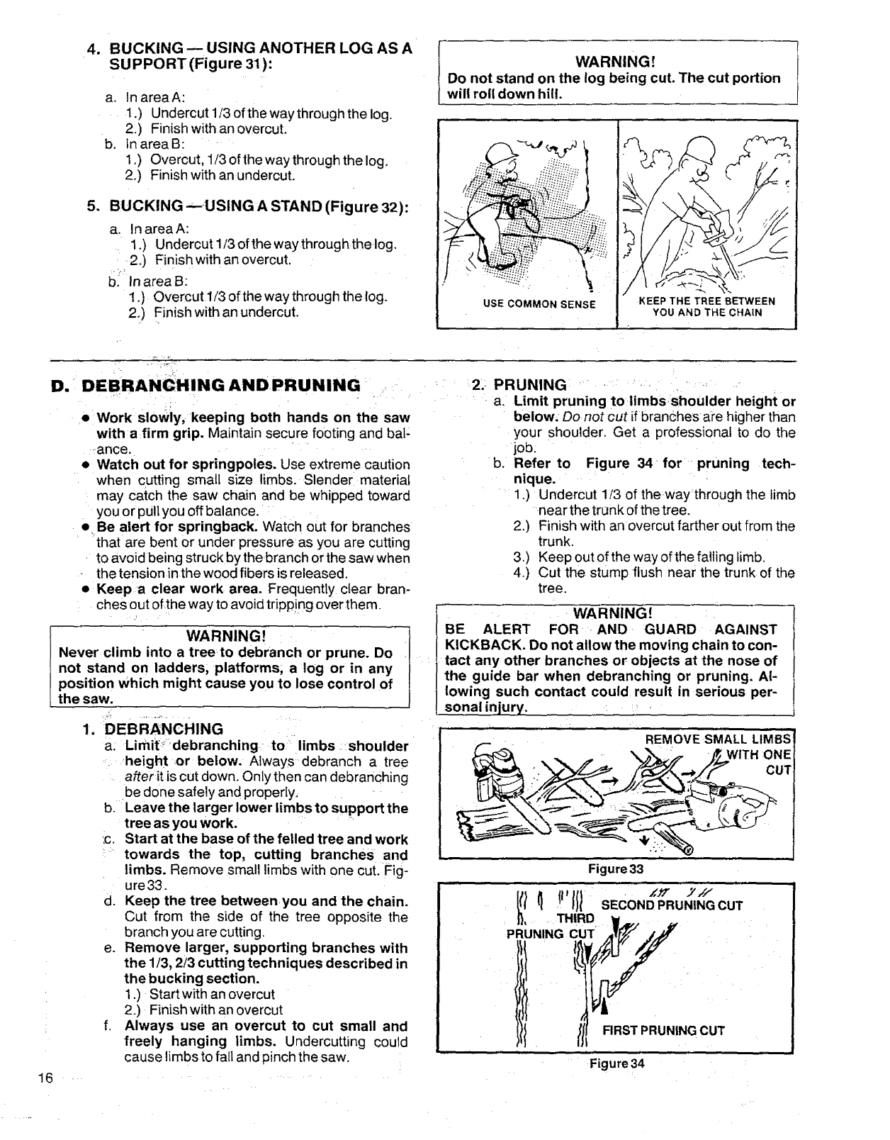
4. BUCKING -- USING ANOTHER LOG AS A
SUPPORT (Figure 31):
a. In areaA:
1.) Undercut 113of the way through the log.
2.) Finish with an overcut.
b. fn area B:
1.) Overcut, 1/3 of the way through the log.
2.) Finish with an undercut.
5_ BUCKING --USING A STAND (Figure 32):
a. In areaA:
1.) Undercut 1t3 of the way throughthelog.
: 2.) Finishwith anovercut.
. :f._
b. Inarea B:
1.) Qvercut 1/3 of the way through the log.
2.) Finish with an undercut.
WARNING!
Do not stand on the log being cut. The cut portion
will roll down hill.
USE COMMON SENSE KEEP THE TREE BETWEEN
YOU AND THE CHAIN
D. DEBRANCHING ANDPRUNING ....
• Work sloWiy, keeping both hands on the saw
with a firm grip. Maintain secure footing and bal:
_:ance,
• Watch out for springpoles, Use extreme caution
when cutting small size limbs. Slenderl material
may catch the saw chain and be whipped toward
you or pull you off balance,
eBe alert for springback. Watch out for branches
that are bent or under pressure as you are cutting
to avoid being struck by thebranch orthe saw when
the tension in the wood fibers is released.
•Keepa clear work area. Frequently clear bran-
ches out of the way to avoid tripp!ng over them.
WARNING!
Never climb into a treeto debranch or prune. Do
not stand on ladders, platforms, a log or in any
position which might cause you to lose control of
the saw.
1. DEBRANCHING
a: Limit::' debranching to:' limbs shoulder
i _height or below. Always: debranch a tree
after:it is cut down. Only then can debranching
be done safely and properly,
b. Leave the larger lower limbs to support the
tree as you work. \
ic, Start at the base of the felled tree and work
:: towards the top, cutting branches and
limbs. Remove small limbs with one cut. Fig-
ure 33.
d. Keep the tree betweenyou and the chain.
Cut from the side of the tree opposite the
branch you are cutting,
e, Remove larger, supporting branches with
the 1/3, 2/3 cutting techniques described in
the bucking section.
1.) Startwith an overcut
2.) Finish with an overcut
f. Always use an overcut to cut small and
freely hanging limbs. Undercutting could
cause limbs to fall and pinch the saw.
16 •
:' :2:, PRUNING .... : :" ' : "
, a, Limit pruning to/imbsshoulder height or
below: Do not cut if branches apehigher than
your shoulder, Get a professional to do the
job:
b. Refer to Figure 34 _for pruning tech-
nique.
1,) Undercut 1/3 of thewaythrough the limb
near the trunk of the tree,
2.) Finish with an overcut farther out from the
trunk.
3.) Keep out of the way of the falling limb,
4.) Cut the stump flush near the trunk of the
tree,
WARNING!
BE ALERT FOR AND GUARD AGAINST
KICKBACK. Do not allow the moving chain to con-
tact any other branches or objects at the nose of
the guide bar when debranching or pruning. Al-
lowing such contact could result in serious per-
sonal injury.
REMOVE SMALL LIMBS
WITH :ONE
CUT
,-.,
Figure33
Figure34
MAINTENANCE
• A good maintenanceprogram of regular inspec.
tion and care wilt increase the service life and
help to maintain the safety and performance of
your, saw.
WARNING!
Allelectrical repairs to this saw, including hous-
'ing, rswitch, motor, etc.,must be diagnosed and
repaired_by yourSears ServiceCenteror nearest
Sears store. Failure to do so could cause the
double insulation construction to become inef-
_fective and result in serious personal injur_,.
•inspect all wire insulation carefully before each
,period of use. Do not operateortry to repai[.rthe...
' _saw ,if wire insulation is cracked or deteriorat-
:ed. Take the unit to your Sears Service Center
' for repair,
•....Check the saw for loose bolts, screws, nuts, and
fittings daily when the saw ris in use. Loose
,:. fasteners can cause an unsafe condition as wel!
....." as:damage to your saw. Tighten, repair, or
,,replace as necessary.
WARNING! '
Avoid accidental starting. _Always unplug the saw
from the power source before cteaningor perform-
ing any maintenance to the saw.
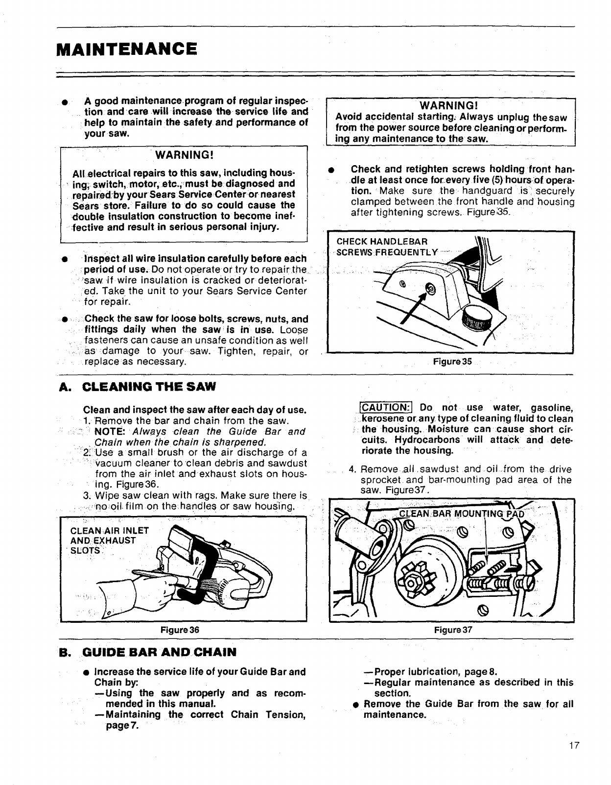
Check and retighten screws holding front han-
dle at least once for:every five (5) hoursofopera.
tion, Make sure the handguard is securely
clamped between the front handle and housing
after tightening screws.. Figure;35.
CHECK HANDLEBAR
SCREWS FREQUENTLY ......
Figure35
A. CLEANING THE SAW
Clean and inspect the saw after each day of use.
1. Remove the bar and chain from the saw,
" ,::,::- NOTE: Always ,clean the Guide Bar and
. _Chain when the chain is sharpened,
" 2;iUse a small brush or the air discharge of a
:: _'acuum cleaner to clean debris and sawdust
from the air inlet andexhaust slots on hous-
' _ing. Figure36.
3; Wipe saw clean with rags. Make sure there is.
,, :,,:,_nooit_film on the:hand!es or saw housing.
CLEANAIR INLET
ANDEXHAUST
• SLOTS" i.
Figure 36
[CAUTION:I Do not use water, gasoline,
kerosene or any type of cleaning fluid to clean
the housing. Moisture can cause short cir-
cuits. Hydrocarbons will attack and dete-
riorate the housing.
4. Remove,all ,sawdust and oil ,from the drive
sprocket and bar-mounting pad area of the
saw. Figure37,
Figure 37
B, ,GUIDE :BAR AND:CHAIN
•Increase the service life of your Guide Bar and
Chain by:
--Using the saw properly and as recom-
mended in this manual.
--Maintaining the correct Chain Tension,
page 7.
--Proper lubrication, page8.
--Regular maintenance as described in this
section.
•Remove the Guide Bar from the saw for all
maintenance.
17
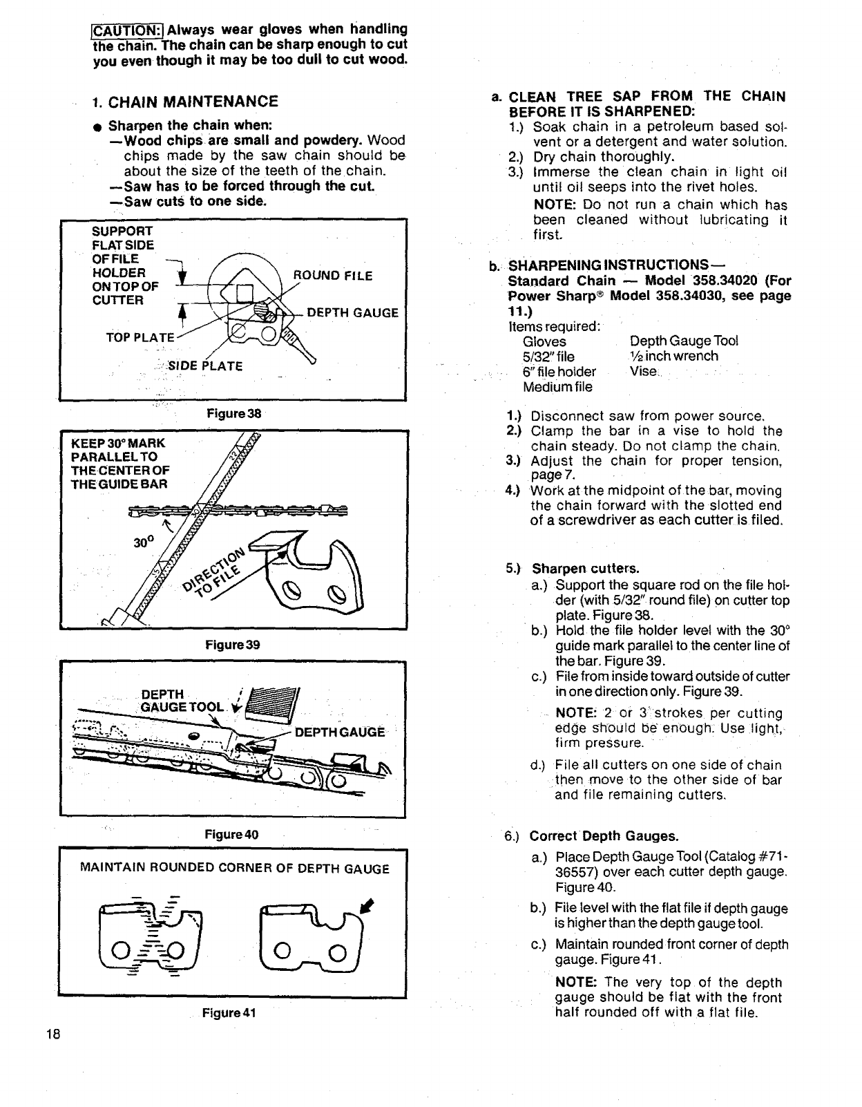
Always wear gloves when handling
the Chain. The chain can be sharp enough to cut
you even though it may be too dull to cut wood,
1. CHAIN MAINTENANCE
• Sharpen the chain when:
--Wood chipsare small and powdery. Wood
chips made by the saw chain should be
about the size of the teeth of the chain.
--Saw has to be forced through the cut.
--Saw cuts to one side.
SUPPORT
FLATSIDE
OF FILE _
HOLDER '_' /A \\ ROUNDFILE
ONTOPOF -'L-_'_F" _ _ V
CUTTER ___...L_<_
__ DEPTH GAUGE
TOP PLATE :,.. ,..,_.__.._-___._,_
::,_:SIDEPLATE
Figure 38
ao CLEAN TREE SAP FROM THE CHAIN
BEFORE IT IS SHARPENED:
1.) Soak chain in a petroleum based sot-
vent or a detergent and water solution.
2.) Dry chain thoroughly.
3.) Immerse the ctean chain in light oil
until oil seeps into the rivet holes.
NOTE: Do not run a chain which has
been cleaned without lubricating it
first.
b.:SHARPENING INSTRUCTIONS
Standard Chain -- Model 358.34020 (For
Power Sharp ®Model 358.34030, see page
11.)
Items required:
Gloves Depth Gauge Tool
5/32" file 1/2inchwrench
...... 6'_fileholder Vise_......
Medium file
1.) Disconnect saw from power source,
2.) Clamp the bar in a vise to hold the
chain steady. Do not clamp the chain.
3.) Adjust the chain for proper tension,
page 7.
.... 4.) Work at the midpoint of the,bar, moving
the chain forward with the slotted end
of a screwdriver as each cutter is filed,
18
Figure 39
r
...... DEPTH
":GAUGETOOL.*_/ ' ' .
_j..-"_.,,_..._ DEPTH GAUGE
Figure40
rl
MAINTAIN ROUNDED CORNER OF DEPTH GAUGE
Figure 41
5.) Sharpen cutters.
a.) Support the square rod on the file hol-
der (with 5/32" round file) on cutter top
plate. Figure 38.
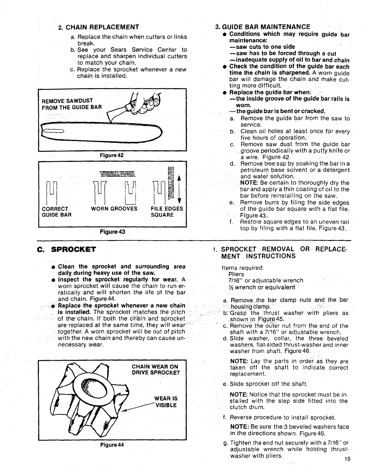
b,) Hold the file holder level with the 30°
guide mark parallel to the center line of
the bar. Figure 39.
c.) File from inside toward outsideof cutter
inone direction only. Figure 39.
NOTE! 2 or 3_strokes per cutting
edge should b_ enough: Use :light,-
firm pressure. "
d.) File all cutters on one side of chain
:then :move to the other side of bar
and file remaining cutters.
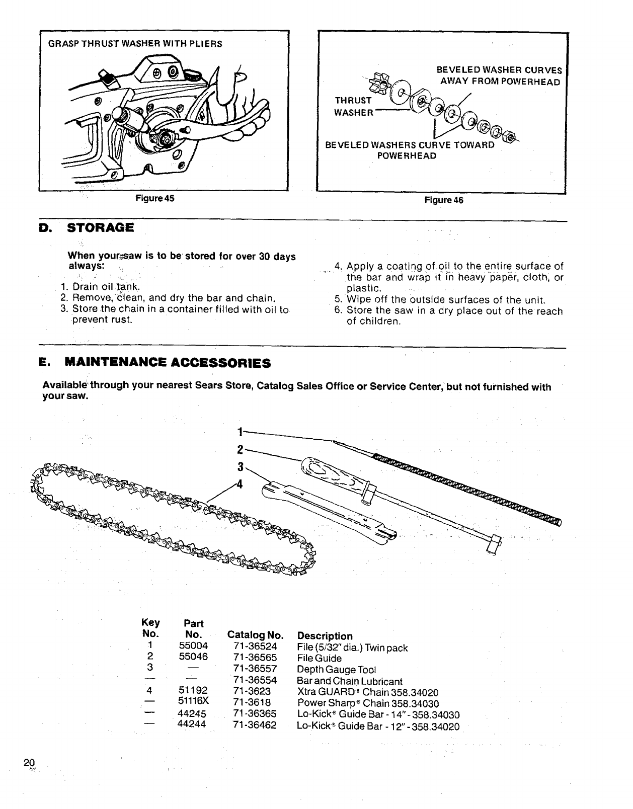
6.) CorrectDepth Gauges.
a.) Place Depth Gauge Tool(Catalog #71-
36557) over each cutter depth gauge.
Figure 40.
b.) File level with the flat file if depth gauge
is higher than the depth gauge tool.
c.) Maintain rounded front corner of depth
gauge, Figure 41.
NOTE: The very top of the depth
gauge should be flat with the front
half rounded off with a flat file.
2. CHAIN REPLACEMENT
a. Replace the chain when cutters or links
break.
b. See your Sears Service Center to
replace and sharpen individual cutters
to match, your chain.
c. Replace the sprocket whenever a new
chain is installed.
E=
/..... Figure 42
CORRECT WORN GROOVES
GUIDE BAR FILE EDGES
SQUARE
Figure 43
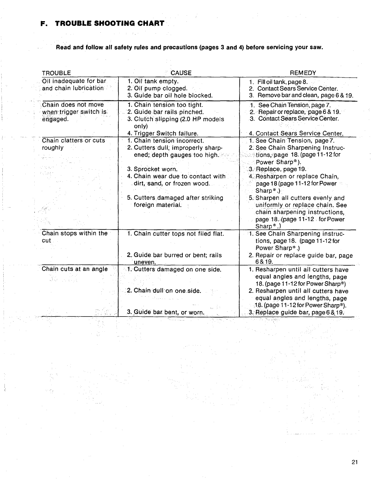
3. GUIDE BAR MAINTENANCE
• Conditions which may require guide bar
maintenance:
--saw cuts to one side
--saw has to be.forced through a cut
--inadequate supply ofoil to bar and chain
• Check the condition of the guide bar each
_time the. chain_is sharpened. A worn guide
bar will damage the chain and make cut-
ting more difficult .....
•Replace the guide bar when: ' :_:.
--the inside groove of the guide bar rails is
worn..
........ -- the guide bar isbent or cracked, '
a. Remove the guide bar from the saw to
service.
b. Clean oil holes at least once for every
five hours of operation! .....
c, Remove saw dust from the guide bar
groove periodically with aputty knife or
awire. Fi.gure 42, _ ,
d. •Remove tree:sapby soaking the bar in a
'petroleum base solvent ora,,detergent
.... : 'and Wate'r:solution,
,NOTE: Becertainto thoroughly dry the
bar and apptya thin coating of oil to the
bar before reinstalling on the saw.
e, Remove burrs by filing the side edges
of the guide bar. square with a flat file.
", Figure43, " '
f. Restore square edges to an uneven rait
top by filing with aflat file, Figure43,
C. SPROCKET
•Clean the sprocket and surrounding area
_dai!y during heavy use of the saw.
•Inspect the sprocket _regularly for wear. A.
worn sprocketwill cause the chain to run er-
ratica!ly,and will shorten the life of the bar
and chain. Figure44.
CHAIN WEAR ON
DRIVE SPROCKET
Figure 44
1. SPROCKET REMOVAL OR REPLACE-
MENT. INSTRUCTIONS
Items required:
Pliers
7/16" or adjustable wrench
.wrench or equivalent: ....
a. Remove.:the bar clamp nuts and the bar
,:_:-,,_:ieReplace the sprocket whenever a :new, chain . : " '. :.,!ih0usin'g'clamp,.... ,, ,/_,_:_
, _is,:installed. The sprocket matches the-pitch :':_ ," _:,':"b:Gra'sp " the thrust :washer with pliers as
'K of the_chain, If both the ch_in'and sprocket ,shown,in Figure45. _
are replaced at the same time, they wil! weai-_'i .......... C.Remc)ye the_o_"t'ernut from the end of the
_;,together. A worn sprocket wilt be out of pitch shaft, with a7/16" or adjustable wrench.
" withthe new chain and thereby can causeun- :: d, Slide washer, collar, the three beveled
necessary wear. washers, flat-sided thrust-washer and inner
washer from shaft. Figure46.
NOTE: Lay the parts in order as they are
taken off the shaft to indicate correct
,replacement.
e. Slide sprocket off the shaft,
NOTE: Notice that the sprocket must be in-
stalled with the step side fitted into the
clutch drum.
Reverse procedure to install sprocket.
NOTE: Be sure the 3 beveled washers face
in the directions shown. Figure46.
g. Tighten the end nut securely with a 7116" or
adjustable wrench while holding thrust-
washer with pliers. 19
GRASPTHRUST WASHERWITH PLIERS
0. STORAGE
When your_saw is to be=stored for over 30 days
always: ,:
7, •
. 1. Drain oil,.tank.
2. Remove,-_lean, and dry the bar and chain.
3. Store .the chain in a container filled with oil to
:prevent rust.
BEVE LED WASHER CURVES
____ _ AWAY FROM POWERHEAD
WASHER _'_" %_'_
BEVELED WASHERSCURVE TOWARD_
POWERHEAD
Figure 46
4. Apply a coating of 0!! to the en!ire surface of
the bar and wrap it in heavy paper, cloth, or
plastic ....
5. Wipe off the outside surfaces of the unit.
6. Store the saw in a dry place out of the reach
of children.
E. MAINTENANCE ACCESSORIES
Available_through your nearest Sears Store, Catalog Sales Office or Service Center, but not furnished with
your saw.
Key
No.
1
2
3
4
Pa_
No.
55004
55046
51192
51116X
44245
44244
Catalog No.
71-36524
71-36565
71-36557
71-36554
71-3623
71-3618
71-36365
71-36462
Description
File (5/32" dia.) Twin pack
File Guide
Depth Gauge Tool
Bar and Chain Lubricant
Xtra GUARD-" Chain 358.34020
Power Sharp'-" Chain 358.34030
Lo-Kick-" Guide Bar- 14"- 358.34030
Lo-Kick_" Guide Bar - 12" -358.34020
20
Fm TROUBLE SHOOTING CHART
Read and follow all safety rules and precautions (pages 3 and 4) before servicing your saw.
TROUBLE
,Oil inadequate for bar
and chain lubrication
Chain does not move
wi_en'trigger switch' is
_efigaged.
Chain clatters or cuts
roughly
Chain stops within the
cut
Chain cuts at an angle
CAUSE
1. Oil tank empty.
2: Oil pump clogged.
3. Guide bar oil hole blocked.
1. Chain tension too tight.
2, Guidebar rails pinched.
3, Clutch slipping (2:0 HP models
only)
4. Trigger Switch failure.
1. Chain tension incorrect.
2. Cutters dull, _improperly sharp-
ened; depth gauges too high. ,-:
3. Sprocket worn.
4. Chain wear due to contact with
dirt, sand, or frozen wood.
5, Cutters damaged after striking
foreign material.
1. Chain cutter tops not filed flat.
2. Guide bar burred or bent; rails
uneven.
1. Cutters damaged on on e side.
2. Chain dutlon oneside.
I 3..,Guide bar bent, or worn,
REMEDY
1. Fill oil tank, page 8.
2. Contact Sears Service Center.
3. Remove bar and clean, page 6 & 19.
1. See Chain Tension, page 7.
2. Repair or replace, page 6 & 19.
3. Contact Sears Service Center.
4. Contact Sears Service Center.
1. See Chain Tension, page7.
2. See Chain Sharpening Instruc-
•,,: _tions;_:page 18, (page 11-12 for
Power Sharp ®).
.&Replace page 19_
4_Resharpen or replace Chain,
page 18 (page 11-12 forPower
Sharp _ ,)
5. Sharpen all cutters evenly and
uniformly or rep!ace Cha!n. See
chain sharpening instructions,
page 18._(page 11,12 for Power
Sharp _.)
1. See Chain Sharpening instruc-
tions, page18. (page 11-12for
Power Sharp s .)
2. Repair or reptace guide bar, page
6&19.
1. Resharpen until all cutters have
equal angles and lengths, page
18. (page 11-12 for Power Sharp ®)
2. Resharpen until all cutters have
equal angles and lengths, page
:18.(page 11-t 2 for Power Sharp®).
3::Replace guide bar, page 6 &19.
-- ,_
21
1
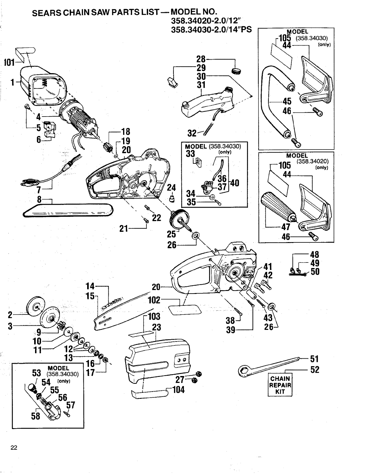
SEARS CHAIN SAW PARTS LIST-- MODEL NO.
358.34020-2.0/12"
358.34030-2.0/14"PS
88-_=__ .._,. \
----"; %22
-- lilli i
35
25
26
42
MODEL
(358.340301
(on|y)
2
323
11 13
MODEL
53 (358.34030)
54 Cor,,y)
58
3
_51
_.A;N i 52
]REPAIR I
[. KIT
22
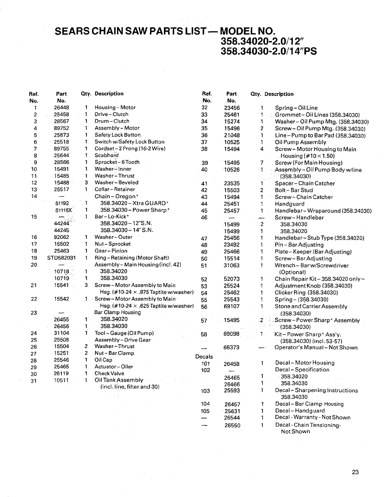
SEARS CHAIN SAW PARTS LIST-- MODEL NO.
358.34020-2.0/12"
358.34030-2.0/14"PS
Ref.
No.
1
2
3
4
5
6
7
8
9
10
11
12
13
14
15
16
17
18
19
20
21
22
23
24
25
26
27
28
29
30
31
Pa_
No.
26448
25458
28567
89752
25873
25518
89755
25644
28566
15491
15485
15488-
25517
51192
51116X !i
44244;"
44245
92062
15502
25463
STD582091
lO718 i:
10719
15541,
15542
26455
26456
31104
25508
15504
15251
25546
25465
26119
!0511
Qty. Description Qty, Description
Ref.
No.
1 Housing - Motor 32
I Drive-,Clutch 33
1 Drum-Clutch 34
1 Assembly- Motor 35
1 Safety Lock Button 36
1 Switch wiSafety Lock Sutton 37
1 Cordset- 2 Prong (16-2 Wire) 38
1 Scabbard
1 Sprocket-6Tooth 39
I Washer_lnner -40
1 Washer _LThrust
3 Washer-Beveled 41
1 Collar- Retainer 42
Chain Oregon" 43
1 358.34020- Xtra GUARD" 44
1 358.34030- Power Sha rp" 45
I Ba r- Lo-Kick * 46
358.34020- I2"S. N.
358.34030- 14" S.N.
1 Washer- Outer 47
1 Nut- Sprocket 48
1Gear-Pinion 49
1 Ring- Retaining (Motor Shaft) 50
Assembly- Main Housing (incl. 42) 51
1 358.34O20
1 358.34030
3 Screw- MotorAssemblyto Main
Hsg. (#10-24 x .875 Taptite w/washer)
Screw- Motor Assembly to Main_
Hsg. (#10-24 x .625 Taptitewiwasher)
Bar Clamp Housing
1 358.34020, 57
1 • 358.34030
1 Tool-Gauge(OilPump) 58
Assembly- Drive Gear
Washer=,Thrust
Nut- BarClamp
Oi! Cap
Actuator- Oiler
Check Valve
Oil Tank ;Assembly
(incl. line, filter and 30)
1
2
2
1
1
1
t
52
53
54
55
56
Decals
101
102
103
104
105
Pa_
No.
23456 1
25461 t
15274 1
15496 2
21048 1
10525 1
15494 4
15495 7
:10526 1
23535 1
15503 2
15494 1
25451 1
25457 1
,15499 2
15499 1
25456 1
23492 1
25466 1
15514 1
31063 1
52O73
25524
25462
25543
69107
15495
69098
66373
26458
26465
26466
25593
26457
25631
26544
26550
1
1
1
1
1
,2
Spring- Oil Line
-Grommet-Oil Lines (358,34030)
Washer- Oil Pump Mtg. (358,34030)
Screw- Oil Pump Mtg. (358.34030)
Line- Pumpto BarPad (358,34030)
Oil Pum p Assembly
Screw- Motor Housing to Main
Housing (#10 x 1:50)
Screw(For Main Housing)
i,Assem bly-'O il'Pump Body witine
"(358,34030)
Spacer- Chain Catcher
Bolt- Bar Stud
Screw- Chain Catcher
Handguard
Handlebar- Wraparound (358.34030)
Screw- Handlebar
358,34030
358.34020
Handlebar- Stub Type (358.34020)
Pin - Bar Adjusting
Plate- Keeper (Bar Adjusting)
Screw- Bar Adjusting
Wrench- Bar w/Screwdriver
(Optional)
Chain Repair Kit- 358.34020 only-
Adjustment Knob (358.34030)
Clicker Ring (358:34030)
Spring-(358,34030)
Stone and Carrier Assembly
(358.34030)
:Screw-Power Sharp" Assembly
: _(358,34030)
_Kit-_ Powe r S harp" Ass'y.
(358.34030) (incl, 53-57)
Operator's Manual- Not Shown
1
1
1
I
1
I
I
Decal- Motor Housing
Decal- Specification
358.34020
358.34030
Decal _-Sharpening Instructions
358.34030
Decal- Bar Clamp Housing
Decal- Handguard
Decal - Warranty- Not Shown
Decal - Chain Tensioning-
Not Shown
23

NOTES
24

NOTES
25

NOTES
26
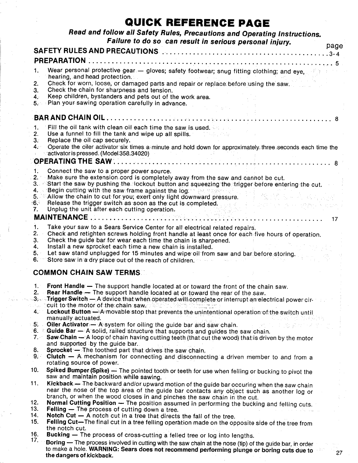
QUICK REFERENCE PAGE
Read and follow all Safety Rules, Precautions and Operating Instructions.
Failure to do so can result in serious personal injury, page
SAFETY RULES AND PRECAUTIONS ........................................... 3-4
PREPARATION : .......................... ..................................... 5
1. Wear personal protective gear gloves; safety footwear; snug fitting clothing; and eye,
hearing, .and head protection.
2. Check for worn, loose, or damaged parts and repair or replace, before;using the ,saw.
3. Check the chain for sharpness and tension,
4., Keep children, bystanders and pets out of the work area,
5. rPlan your sawing operation carefully in advance.
BAR AND CHAIN OIL ..................... ..................................... 8
1. Fill the oil tank with clean oil each time the saw is used,
2. Use a funnelto fill thetank and wipe up all spills,
3, Replace the oil cap securely.
4, Operate the oiler activator_six; times aminute and hold down for approximately_.three:,seconds each time the
_activator is pressed. (ModeL358,34020)
OPERATING THE SAW. _..... .. ..................................................... 8
1. Connect the saw to a proper power source.
2. .Make sure the extensioncord is completely away from the saw and cannot be cut.
3., Startthe saw by pushing.the:lockout button and squeezing_the :tfigger:beforeenteringthecut.
4, Begin cutting with the saw _frame against the log:
5. ' Allow thechain to cut:for:you; exertonly light downward pressure.
_6:: Release the triggerswitchassoon as the:cut is completed,
7. Unplug the unit after each cutting operation.
MAINTENANCE. ................. ............................................ 17
i. Take your saw to a Sears Service Center for all electrical related repairs.
2. Check and retighten screws holding front handle at.least once for each five hours of operation.
3. Check the guide bar for wear each time the chain is sharpened.
4. Install a new sprocket each time a new chain is installed.
5, Let saw stand unplugged for 15 minutes andwipe_oi/from saw and barbefore_storing,
6, "Storesawina'dry place out of the reach of children,
COMMON CHAINSAW TERMS i
1. Front Handle:-- The support handle located.at .or toward the front of the chain saw.
2. Rear Handle..-- The support handle located at ortoward the rear of the ,saw.
, , -3; ..... TriggerSwitch--Adeyice.thatwhenoperated:will;comp:lete:orinterrupt:an'etectrical powercir-
,: cult to'the motor of.the:chain saw ............................
4. Lockout Button --_,A'movable stop that prevents the unintentional operationof:theswitch until
manually actuated,
5:. Oiler Activator;--A:system for oilingthe guide bar and saw chain.
6, : Guide: Bar -- Asolid,, railed structure that supports and guides the saw chain.
7. SawChain --A loop:of chain having.cutting teeth (that cutthewood) that_is driven by the motor
and supported by the guide bar.
8, Sprocket,- ?Fhe toothed part that drives the saw chain.
9,, Clutch-- A mechanism for connecting, and disconnecting a driven member to and from a
rotating source of power.
10. Spiked Bumper(Spike)- The pointed tooth or teeth for use when felling or bucking to pivot the
saw and maintain position while sawing.
11. Kickback,-, Thebackward andlor upward motion of the guide bar occuring when the saw chain
near the nose of'the top area of the guide bar contacts any object such as another log or
branch, or when the wood closes in and pinches the saw chain in the cut.
12. Normal Cutting Position -- The position assumed in performing the bucking and felling cuts.
13. Felling -- The process of cutting down a tree.
14. Notch Cut -- A notch cut in a tree that directs the fall of the tree.
15, Felling Cut--The final cut in a tree felling operation made on the opposite side of the tree from
the notch cut.
t6. Bucking -- The process of cross-cutting a felled tree or log into lengths.
17. Boring -- The process involved in cutting with the saw chainat the nose (tip) of the guide bar, in order
to make a hole. WARNING: Sears does not recommend performing plunge or boring cuts due to
the dangers of kickback. 27
{Sears]
MODEL NO.
358.34020 -2.0/12"
358.34030 2.0/14"PS
How to Order
Repair Parts
SEARS SERVICE
IS AT YOUR SERVICE
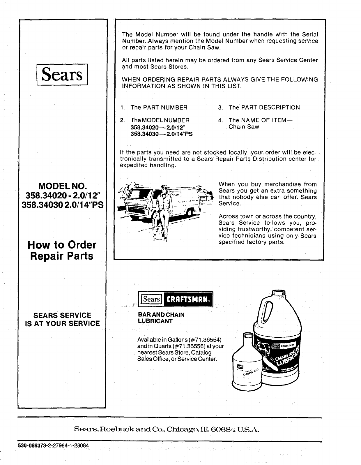
The Model Number will be found under the handle with the Serial
Number. Always mention the Model Number when requesting service
or repair parts for your Chain Saw.
All parts listed herein may be ordered from any Sears Service Center
and most Sears Stores.
WHEN ORDERING REPAIR PARTS ALWAYS GIVE THE FOLLOWING
INFORMATION AS SHOWN tN THIS LIST.
1. The PART NUMBER
2. The MODEL NUMBER
358.34020-- 2.0/12"
358.34030-- 2.0/14"PS
3. The PART DESCRIPTION
4. The NAME OF ITEM--
Chain Saw
If the parts you need are not stocked locally, your order will be elec-
tronically transmitted to a Sears Repair Parts Distribution center for
expedited handling.
When you buy merchandise from
Sears you get an extra something
that nobody else can offer. Sears
Service.
Across town or across the country,
Sears Service follows you, pro.
viding trustworthy, competent ser-
vice technicians using oniy Sears
specified factory parts.
BAR AN D CHAIN
LUBRICANT
Available in Gallons (#71.36554)
and in Quarts (#71.36556) at your
nearest Sears Store, Catalog
Sales Office, or Service Center.
Sears, Roebuck and Co., Chicago, Ill. 60684 U.S.A.
11 i
530-066373-2-27984-1',,28084 ..... ,:....
