Craftsman 358356242 User Manual Gas, Chainsaw Manuals And Guides L0801193
CRAFTSMAN Chainsaw, Gas Manual L0801193 CRAFTSMAN Chainsaw, Gas Owner's Manual, CRAFTSMAN Chainsaw, Gas installation guides
User Manual: Craftsman 358356242 358356242 CRAFTSMAN Gas, Chainsaw - Manuals and Guides View the owners manual for your CRAFTSMAN Gas, Chainsaw #358356242. Home:Lawn & Garden Parts:Craftsman Parts:Craftsman Gas, Chainsaw Manual
Open the PDF directly: View PDF ![]() .
.
Page Count: 36
IMPORTANT MANUAL Do Not Throw Away
Operator's
Manual
@
Model No.
358.356242
Always Wear Eye Protection
WARNING
READ THE OPERATOR'S
MANUAL AND FOLLOW
ALL WARNINGS AND
SAFETY INSTRUCTIONS.
FAILURE TO DO SO CAN
RESULT IN SERIOUS
INJURY.
CRAFTSMAN+
2.5 cu. in./40 cc 2-CYCLE
18 in. Guide Bar
GASOLINE CHAIN SAW
• Assembly
• Operation
•Customer Responsibilities
•Service and Adjustments
•Repair Parts
• Table of Contents-
Inside Back Cover
Sears, Roebuck and Co., Hoffman Estates, IL 60179 USA
530--083047-438/03/94
&SAFETY RULES
WARNING: ....
ALWAYSDISCONNECT SPARK PLUG WIRE AND PLACE WIRE WHERE IT CANNOT CONTACT SPARK
PLUG TO PREVENT ACCIDENTAL STARTING WHEN SETTING UP,TRANSPORTING, ADJUSTING OR
MAKING REPAIRS EXCEPT CARBURETOR ADJUSTMENTS.
BECAUSE A CHAIN SAW 1S A HIGH-SPEED WOOD-CUTTING TOOL, SPECIAL SAFETY
PRECAUTIONS MUST BE OBSERVED TO REDUCE THE RISK OF ACCIDENTS. CARELESS OR
IMPROPER USE OF THIS TOOL CAN CAUSE SERIOUS INJURY. i
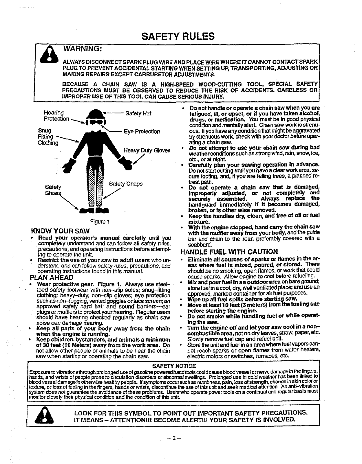
Hearing _ Safety Hat
Protection
Snug Eye Protection
Fitting
Clothing
Gloves
Safety Safety'Chaps
Shoes
Figure t
KNOW YOUR SAW
•Read your operator's manual carefully until you
completely understandand can follow all safety rules,
precautions, and operating instructions before attempt-
ing to operate the unit.
• Restrict the use of your saw to adult users who un-
derstand and can follow safety rules, precautions,and
operating instructionsfound inthis manual
PLAN AHEAD
° Wear protective gear. Figure 1. Always use stee/-
toed safety footwear with non-slip soles; snug-f_ting
clothing; heavy-duty, non-slip gloves; eye protection
suchas non-fogging, ventedgoggles orface screen;an
approved safety hard hat; and sound barriers---_r
plugsor mufflers to protectyour hearing. Regular users
should have hearing checked regu/ady as chain saw
noise can damage hearing.
Keep all parts of your body away from the chain
when the engine is running.
Keep children, bystanders, and animals aminimum
of 30 feet (10 Meters) away from the workarea. Do
not aliow other people or animals to be near the chain
saw when startingor operating the chain saw.
• Do not handle or operate a chain sawwhen you are
fatigued, ill, or upset, or if you have taken alcohol,
drugs, or medication. You must be in good physical
conditionand mentallyalert Chainsaw workis strenu-
ous If youhaveany condition that mightbe aggravated
by strenuouswork, check with yourdoctorbefore oper-
ating a chainsaw
• Do not attempt to use your chain saw during bad
weather conditions suchas strongwind.rain,snow,ice,
etc, or at night.
•Carefully plan your sawing operation in advance.
Do notstart cuttinguntilyou have ac/earwo_ area,se-
cure footing,and, if you are fellingtrees, aplanneo re-
"_'eat path.
• Do not operate a chain saw that is damaged,
improperly adjusted, or not completely and
securely assembled. Always replace the
handguard immediately if it becomes damaged,
broken, or is other wise removed.
• Keep the handles dry, clean, and free of oil or fuel
mixture.
• W'dhthe engine stopped, hand carry the chain saw
with the muffler away from your body, and the guide
bar and chain to the rear, preferably coverea with a
scabbard,
HANDLE FUEL WITH CAUTION
•Eliminate all sources of sparks or flames in the ar-
eas where fuel is mixed, poured, or stored. There •
should be no smoking, open flames, or workthat could
cause sparks Allow engine to coo! before refueling.
•Mixand pour fuel in an outdoorarea on bare ground;
storefuelina coot,dry, wellventilatedplace;anduse an
approved, marked container for all fuel purposes
Wipe up all fuel spills before starting saw.
:, Move at least 10 feet (3 meters) from the tueling site
before starting the engine.
• Do not smoke while handling fuel or white operat-
ing the saw.
- Turn the engine off and let your saw cool in a non-
combustible area, noton dry leaves, straw, paper,etc.
Slowly remove fuel cap and refuel unit.
• Storethe unit and fuel in an areawhere fuelvapors can-
not reach sparks or open flames from water heaters,
electric motors or switches, furnaces, etc.
I ...... SAFETY NOTICE
F-xposureto vibra_onsthroughprolongeduseofgasolinepoweredhandtoolscouldcausebloodvesselornervedamageinthefinge_,
hands,and wdstsofpeopleproneto circula_ondisordersorabnormalswellings.Prolongeduse incoldweatherhasbeen,nKeam
bloodvessefdamageinotherwbehealthypeople.Ifsymptomsoccursuchasnumbness=pain,lossofstrength, changeinskinco|_or
texture,or lossoffeelingin thefingers,handsorwrists,discontinuetheuseof_unitandseekmedicalattention_ ante-wt_rauon
system.......doesnotguaranteetheavoidanceofthese problems Userswhooperatepowertoolsonacontinualand regularbasismust
lmontlor closelytheirphys=catconditionand theconditionofth=sunit
j
I_ LOOK FOR THIS SYMBOL TO POINT OUT 'MPORT_NT SAFETY PRECAUTIONS" t
IT MEANS - AT£ENTION!!! BECOME ALERT!!! YOUR SAFETY IS INVOLVED.
-2-
SAFETY RULES
OPERATE YOUR SAW SAFELY
•Do not operate a chain saw with one hand. Serious
injuryto the operator, helpers, bystanders or any com-
binationof these persons may resultfrom one-handed
operation. A chain saw is intendedfor two-handed use.
• Operate the chain saw only in well-ventilated out-
door areas.
Do not operate saw from aladder or in a tree, unless
specificallytrained to do so.
Position all parts of your body to the left of cut and
away from the chain when the engine is running.
• Cut wood only. Do not use your saw to pry or shove
away limbs, roots,or other objects.
•Make sure the chain will not make contact with any
object while starting the engine. Nevertry tostad the
saw when the guide bar is in acut or kerr.
• Use extreme caution when cuffing small size brush
and saplings. Slender matedal can catch the chain
•and be whipped toward you or pullyou off baJance.
- Be alert for springback when cuttinga limbthat is un-
der tensionso you will not be struck by IP_ limb or saw
when the tension in the wood fibers is released.
• Do not put pressure on the saw at the end of a cut.
Applying pressurecan cause you to lose controlwhen
the cut is completed.
•Stop the engine before setting the saw down.
-Keep fuel and oil caps, screws, and fasteners se-
curely tightened.
MAINTAIN YOUR SAW IN GOOD WORKING
ORDER
* Have all chain saw service performed by your Sears
Service Center with the exceptionofthe itemslisted in
the mainter_ncesection of thismanual. Forexample, if
impropertools are used to removeor holdthe flywheel
when servicing the dutch, structural damage to the fly-
wheel can occur and cause the flywheel to burst.
. Make certain the chain stops moving when the
throttle trigger is released. For correction, refer to
"Carburetor Adjustments."
• Stop the saw if the chain strikes a foreign objec'L
Inspect unitand repairor replace partsas necessary.
- Disconnect the spark plug I_lore performing any
maintenance except forcarburetoradjustments.
•Never modify yoursaw in any way. Use only attach-
ments supplied or'specificaJlyrecommended by the
manufacturer,
TRANSPORTING AND STORAGE
:Stop the unit before transporting.
Allow engineto cool,covertheguidebar and chain,and
secure the unit before stodng or transportingin ave-
hicle.
*Empty fuel tank before storing ortransportingthe unit.
Use up any fuel left inthe carburetorby startingthe en-
gine and lettingthe engine run until _ st.ops.
°Store un_ and fuet in an area where lueI vapors cannot
reach sparks or open flames from water heaters, elec-
tric motors or switches, furnaces, etc.
• Store unitsothe chaincannot accidentallycause injury.
. Store the unit out of the reachof children.
,, , , IH,I ,,,, iii i i i I,,II,H,,II,I ii i
'serious injury.
adangerous reaction that can lead to
.ll ......H.i
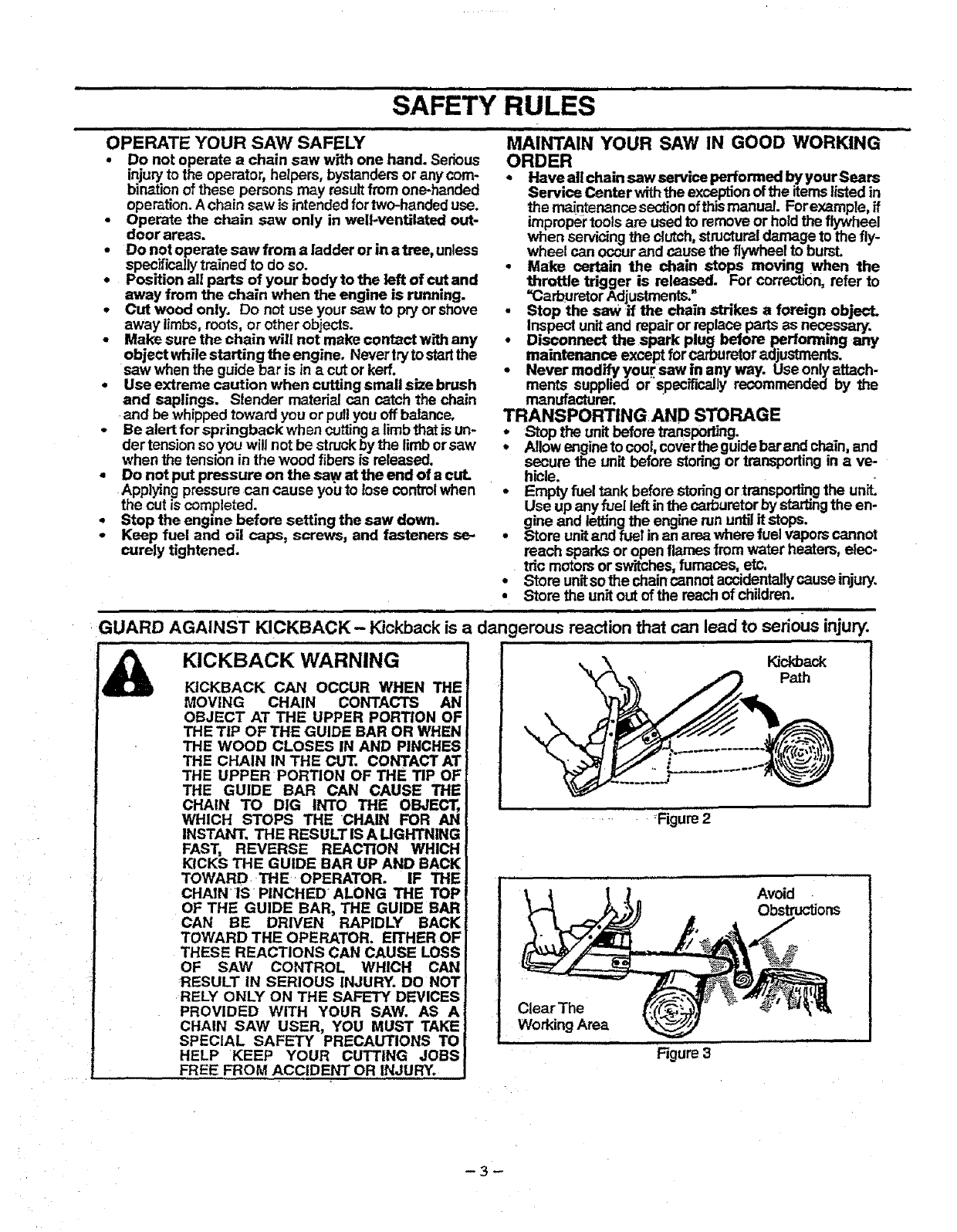
GUARD AGAINST KICKBACK- Kickback is
IA .....
KICKBACK WARNING
KICKBACK CAN OCCUR WHEN THE
MOVING CHAIN CONTACTS AN
OBJECT AT THE UPPER PORTION OF
THE TIP OF THE GUIDE BAR OR WHEN
THE WOOD CLOSES IN AND PINCHES
THE CHAIN IN THE CUT. CONTACT AT
THE UPPER PORTION OF THE TIP OF
THE GUIDE BAR CAN CAUSE THE
CHAIN TO DIG INTO THE OBJECT,
WHICH STOPS THE CHAIN FOR AN
INSTANT. THE RESULT IS A LIGHTNING
FAST, REVERSE REACTION WHICH
KICKS THE GUIDE BAR UP AND BACK
TOWARD• THE OPERATOR. IF THE
CHAIN IS PINCHED ALONG THE TOP
OF THE GUIDE BAR, THE GUIDE BAR
CAN BE DRIVEN RAPIDLY BACK
TOWARD THE OPERATOR. EITHER OF
THESE REACTIONS CAN CAUSE LOSS
OF SAW CONTROL WHICH CAN
RESULT IN SERIOUS INJURY. DO NOT
RELY ONLY ON THE SAFETY DEVICES
PROVIDED WITH YOUR SAW. AS A
CHAIN SAW USER, YOU MUST TAKE
SPECIAL SAFETY PRECAUTIONS TO
HELP KEEP YOUR CUTTING JOBS
FREE FROM ACCIDENT OR INJURY.
Kickback
Path
........ Rgure 2
Avoid
Obstructions
Clear The
Working Area
,,,,,, Figure 3
-3-

i,i ii iii iii i HI I IIII Imlllr
SAFETY RULES
i,ll
iNevRvee 1 sno
Hand Positions The Left
Of The Saw
Elbow
•Locked
UnderSide Of
\Handlebar
Figure 4
REDUCE THE CHANCE OF KICKBACK
•Recognize that kickback can happen. With abasic
understandingof kickback, youcen reducethe element
of surprise which contributes to accidents.
•Never let the moving chain contact any object at the
tip of the guide bar. Figure 2.
• Keep the working area free from obstructions such
as other trees, branches, rocks, fences, stumps, etc.
Figure 3. Eliminate or avoid any obstructionthat your
chain couldhitwhile youare cuttingthroughaparticular
log or branch.
•Keep your chain sharp and properly tensioned. A
loose or dullchain can increase the chance of kickback
to occur. Follow manufacturer'schain sharpening and
maintenance instructions. Check tensionat regufarin-
terva{s with the engine stopped, never with the engine
running. Make sure the bar clamp nuts are securely
tightened after tensioning the chain.
•Begin and continue cutting at full throttle. If the
chain is moving at a slower speed, there is greater
chance for kickback to occur.
MAINTAIN CONTROL
4Keep agood, firm grip on the saw with both hands
when the engine is running and don't let go. Figure
4. A firmgrip can neutralizekickbackand helpyou main-
taincontrolofthe saw. Keep thefingersofyourleft hand
encirclingand your leftthumb underthe fronthandlebar.
Keep your right handcompletelyaround the rearhandle
whetheryou are righthanded or lefthanded. Keep your
left arm straightwiththe elbow locked.
•Position your left hand on the front handlebar so it
is in a straight line with your right hand on the rear
handle when making bucking cuts. Figure4. Never
reverseright and left hand positionsfor any typeof cut-
• _d with your weight evenly balanced on both
feet.
•Stand slighUyto the left side of the sawto keepyour
body from being in a direct line with the cutting
chain. Figure 4.
•Do not overreach. You could be drawn orthrown off
balance and lose controlof the saw.
•Do not cut above shoulder height, it is difficultto
maintaincontrol ofsaw above shoulder heighL
UNDERSTANDING REACTIVE FORCES
Pinch-Kickback and Pull-In occur when the chain is
suddenly stopped by being pinched, ¢aught_ or by
contacting a tore_n object in the wood. Troisszopp_ng
ofthe chainresults in a reverea]of the chain forceusedto
cutwood and causes thesawto move inthe oppositedirec-
tion of the chain rotation. E[therreactioncan resultinloss
of control and possibleserious injury.
_, Cut one log at a time.
• Use extreme caution when re-entering aprevious
cut.
•Do not attempt plunge cuts.
•Watchforshiftinglogsorotherforoesthatcouldclose
acut and pinch or fall into chain.
•Use the Reduced-Kickback Guide Bar and Low-
• Pinch.Kickback
- occurswhen chain on top of guide bar is suddenty
stopped.
-rapidlydfivessawstraightbacktowardoperator.
•Puli-ln
- OCcurswhen thechain onthe bottom ofthe guide bar
is suddenly stopped.
-pulls the saw rapidlyforward.
,,,,,,,, i i,, ,i H,,,
sampleofchainsawsbelow3.8 cubicinchdisplacementspe-
cifiedinANSI B175.1-1991,
•Handguard,designedtoreducethechanceofyourlefthand
contacting"{hechainifyour handsli.pcOffthe_ro_hand!elo_r.
•Positionof front and rear handlebars, oestgneOw_na=s-
tahoebetweenhandlesand =in-line with each other, i ne
spreadand=in4ine"positionof the handsprovided bythis de-
signworktogethertogivebalanceand resistar_cein.p?.ntro.I,-
lingthe pivotofthe sawbacktowardthe operazor_ lac_acK
OCCURS.
•sawsas set bythe American Naliot_ Standaras _, .,
B TS+l-199 ..,........ "
_educe_ _c_ I_us T_P
Syra met_i_f Guide Bar
KICKBACK SAFETY FEATURES
I&No
THE FOLLOWING FEATURES ARE IN-
CLUDED ON YOUR SAW TO HELP REDUCE
THE HAZARD OF KICKBACK; HOWEVER,
SUCH FEATURES WILL NOT TOTALLY
ELIMINATE THIS DANGEROUS REACTION.
AS A CHAIN SAW USER, DO NOT RELY
ONLY ON SAFETY DEVICES. YOU MUST
FOLLOW ALL SAFETY PRECAUTIONS,
INSTRUCTIONS, AND MAINTENANCE IN
THIS MANUAL TO HELP AVOID KICKBACK
AND OTHER FORCES WHICH CAN RESULT
IN SERIOUS INJURY.
Reduced-Kickback Guide Bar,designedwithasmallradius
tip whichreducesthe size of the Idckback dangerzone onthe
guidebartip. Figure5. AReduced-KickbackGuideBarisone
whichhasbeen demonstratedtosignificantly reducethe num-
berand seriousness of kickbackswhentested in accordance
Kickback Chain specified for your saw.
, Hi i Jw, i H,,,I,H
with ANSI B175.1 ;*-1991
Low-Kickback Chain, designed with acontoured depth
gauge and guard link which deflect kickback force and allow
wood to gradually ride into the cutter. Figure 5. Low-K-Jckback
Chain is chain which has met £Jcl4_backperformance require*
ments of ANSI B175.1-1991 when tested on arepresentative
Cor_er_
• A,-_ _Wood
|_tO Cg_et
Syr_f_t _ 1_€_ p_ettt_J
Gui_e_ar P_d_usT=#
Figure 5
-4-
CONGRATULATIONSon your purchase of a Sears
Craftsman GasolineChainSaw. It has been designed, en-
gineered and manufactured to giveyou the best possible
dependabilityand performance.
Should you experience any prob2ems you cannot easily
remedy, please contactyour nearest Sears Service Cen-
tedDepartment Sears has competent, wel! trained techni-
cians and the proper tools to service or repair this unit.
Please read and retain this manual. The instructions w_l
enable you to assemble and maintain your unit pmpedy.
Always observethe =SAFETY RULES."
MODEL NUMBER: 358.356242
_ERIAL NUMBER:
)ATE OF PURCHASE:
"HE MODEL AND SERI_ NUMBER WILL BE FOUND
ON THE PRODUCT.
YOU SHOULD RECORD BOTH SERIAL NUMBER
AND DATE OF PURCHASE AND KEEP IN ASAFE
PLACE FOR FUTURE REFERENCE.
MAINTENANCE AGREEMENT
ASears MaintenanceAgreement is available onthisprod-
uct, Contact your nearest Sears Store for details.
CUSTOMER RESPONSIBILITIES
•Read and observe the safety rules.
•Follow a regular schedule in maintaining, caring for,
and using your uniL
• Follow the instructions under =Customer Responsibili-
ties"and"Storage" sections of this Operator's Manual.
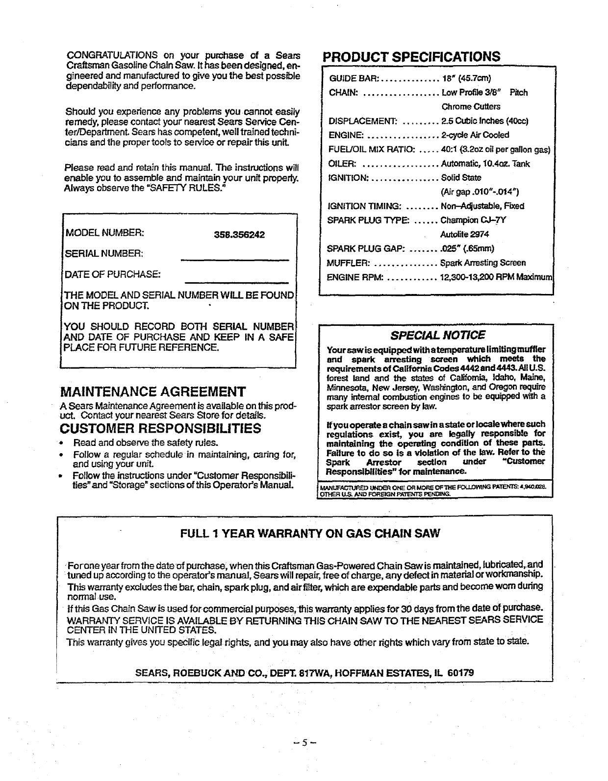
PRODUCT SPECIFICATIONS
GUIDE BAR: .............. 18_(45.7cm}
CHAIN: .................. Low Profile3/8" Pitch
Chrome Cutters
DISPLACEMENT: ......... 2.5 Cubic Inches (40cc)
ENGINE: ................. 2-cycle/dr Cooled
FUEL/OIL MIX RATIO: ..... 40:1 (3.2oz oil per gallon gas)
OILER: .................. Automatic, 10.4oz. Tank
IGNITION: ................ Solid State
(Airgap .010"-.014")
IGNITION TIMING: ........ Non-Adjustable, Fixed
SPARK PLUG TYPE: ...... Champion CJ-TY
Autoi_te2974
SPARK PLUG GAP: ........ 025" (.65ram)
MUFFLER: ............... Spark Atre_ng Screen
ENGINE RPM: ............ 12,300-13,200 RPM Maximum
SPECIAL NOTICE
Yoursawis equippedwithatemperaturelimltingmuffler
end spark arresting screen which meets the
requirementsof CaliforniaCodes4442and4443.AIIU.S.
forest land and the statesof Califom_ Idaho, Maine,
Minnesota,New Jersey,Washington,andOregonrequire
many internal combustionenginesto be equippedwitha
sparkarre.._orscreenbylaw.
ifyouoperateachain sawinastateorlocalewhere such
regulations exist, you are legally responsible for
maintaining the operating condition of these parts.
Failure to do so is s violationof the law. Referto the
Spark Arrestor section under ,Customer
Responsibilities"for maintenance,
MANL_FA_"tlJRB)UND_q ONE OR _ORS OFTHE FOt/.OW;NG PA_: 4,940X_.
OTHER US. AND FOrtH PATENTSPEP,_NG.
FULL 1 YEAR WARRANTY ON GAS CHAIN SAW
Fo rune year from the date of purchase, when thisCraftsman Gas-Powered Chain Saw is maintained,lubricated, and
tuned upaccording te the operator's manual, Sears will repair,free of charge, any defect in material orworkmanship.
This warranty excludesthe bar, chain,spark plug, and air fitter,which are expendable parts and become worn during
nomla] use,
If thisGas ChainSaw is used for commercial purposes/this warranty applies for 30 days from the date of purchese.
WARRANTY SERVICE IS AVAILABLE BY RETURNING THIS CHAIN SAW TO THE NEAREST SEARS SERVICE
CENTER IN THE UNITED STATES.
This warranty gives you specific legal rights, and you may also have other rightswhich vary from state to state.
SEARS, ROEBUCK AND CO,, DEPT. 817WA, HOFFMAN ESTATES, IL 60179
-5-
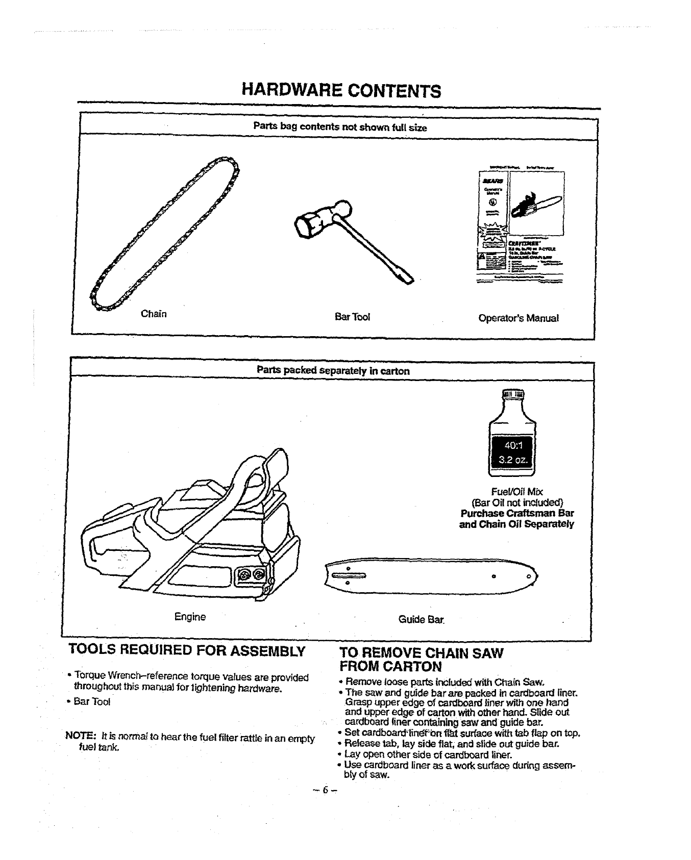
HARDWARE CONTENTS
Parts bag contents not shown full size
m
I
Chain i_r Tool Operator's Manual
Fuel/Oii Mix
(BarOil not included)
Purchase Craftsman Bar
and Chain Oil Separately
Engine Gukie Bar.
TOOLS REQUIRED FOR ASSEMBLY
•Torque Wrench-referenc_ torque values are provided
throughout this manu_ for tighten)rig hardware,
•Bar Tool
NOTE: tt is norma_to hear the fuel filter rattle in _mempty
fuel tank.
TO REMOVE CHAIN SAW
FROM CARTON
Remove loose p_rts included with Chain Saw,
The saw and guide bar are packed incardboa_ finer.
Grasp upper edge of cardboard 5ner with one nano.
and upper edge of carton withother nand. _lide out
cardboard liner containing s_w and guide bar.
• Set cardboard_En_f_bnfl_t surface with tab flap on top.
•Release t,_b, lay siOefiat, and sSde outguide bar.
•Lay open other side of cardboard liner.
• Use cardboard finer as awork surface dudng assem-
bly of saw.
,m, = , ,,,i,ii = , i,,,,,= = =r ,,,,=
WARNING: .............!
IF THIS UNIT IS RECEWED ASSEMBLED, I
REPEAT ALL STEPS IN THIS SECTION |
TO BE SURE ASSEMBLY IS CORRECT |
AND PROPERLY ADJUSTED FOR THE i
OPERATOR. !
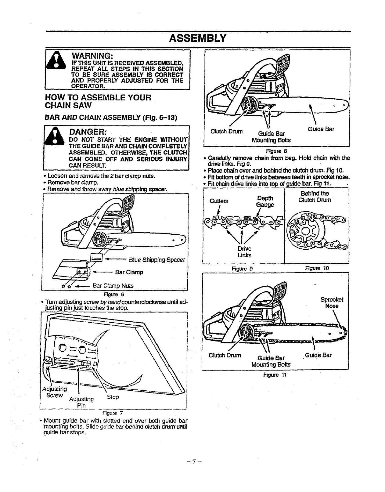
HOW TO ASSEMBLE YOUR
CHAIN SAW
BAR AND CHAIN ASSEMBLY (Fig. 6-13)
DANGER:
DO NOT START THE ENGINE WITHOUT
THE GUIDE BARAND CHAIN COMPLETELY
ASSEMBLED. OTHERWISE,, THE CLUTCH
CAN COME OFF AND SERIOUS INJURY,
CAN RESULT. ,i
• Loosen and remove the 2 bar clamp nuts.
•Remove bar damp.
-Remove and throw away blue shippingspacer.
-=------- Bar Clamp
=--.- Bar Clamp Nuts
Figure 6
•Turn adjusting screw byhandcountemlockwise untilad-
justing pin justtouches the stop.
Adjusting
Screw Adjusting Stop
Pin
Figure7
*Mount guidebar withslottedend overbothguidebar
mounting bolts. Slide guide bar t_ehindctut_hdrum' until
guide bar stops.
=iJ,,== ,,,,,
\
Guide Bar
ClutchDrum Guide Bar
Mounting Bolts
f
Figure 8
• Carefully remove chain from bag. Hold chain withthe
iddve links.Fig 9.
•Place chain over and behind the clutch drum. Fig 10.
*Frtbottomof drive links between teeth in sprocketnose.
•Rt chain drive linksinto top of guide bar. Rg 11.
Behind the
Cutters Depth Clutch Drum
tGauge
\1/
Drive
Links
Rgure 9Rgure 10
Guideear
Mounting Belts
Figure 11
Nose
Guide Bar
-7-
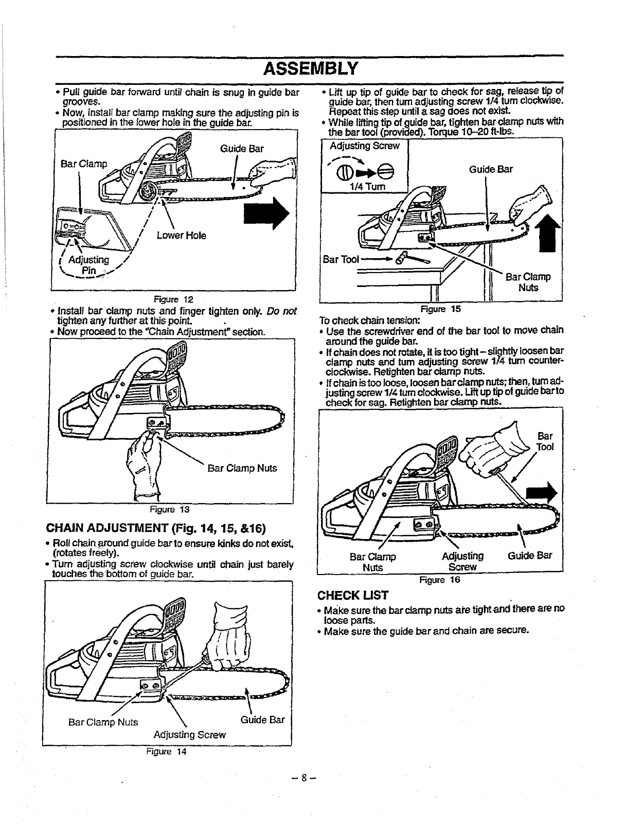
.... guide bar 'fo .............. snug '
• Pull rward untit chain is in guidebar
grooves.
• Now, installbar clamp making sure the adjusting pin is
positioned in the lower hole in the guide bar.
Guide Bar
/
/
Lower Hole
Adjusting /
Pin ,,I /
Figure 12
*Install bar clamp nuts and finger tighten only. Do not
tighten any further at this point.
Now proceedto the "Chain Adjustment" section.
Bar Clamp Nuts
•Lift uP""tipof g.ide bar 'iocheck for Sa'gi"release tip of
guide bar, then turn adjusting screw 1/4 turncJoc_ise.
Repeat thisstep untilasag does notexis_
• While liftingtip of guide bar, tighten barclamp nutswith
the bar tool (provided).Torque 10-20 ft4bs.
Adjusting Screw
"_(_)_b._ Guide Bar
1/4 "rum
Bar Clamp
Nuts
Figure 15
Tocheck chain tension:
*Use the screwdriverend of the bar too! to move chain
around the guidebar.
°Ifchain does notrotate,it istoo tight- slightlyloosen bar
clamp nuts and tum adjusting screw 1/4 turn counter-
clockwise. Retightenbar clamp nuts.
,Ifchain istoo loose,loosenbar clamp nuts;then, turnad-
justing screw 1/4 turnc!ockwise. Liftuptipof guidebutte
check for sag. Retightenbar clamp nuts°
l
Figure 13
CHAIN ADJUSTMENT (Fig. 14, 15, &16)
•Rollchain around guidebarto ensure kinksde notexist,
(rotates freely).
•"rum adjusting screw clockwise until chain just barely
touches the bottom of guide bar. l
Bar Clamp Nuts Guide Bar
Adjusting Screw
Figure 14
Bar Clamp Adjusting Guide Bar
Nuts Screw
Figure 16
CHECK UST
•Make sure the bar clamp nuts ale tight andthere are no
loose parts.
•Make sure the guidebar and chain are secure.
-8-
i = _1 ,,,,ill i i, ,, ,_ i i,,,i,i = ii IILIIII IIII ill ILl Ill, I, .
OPERATION
,, , ,=,,, == ill _N
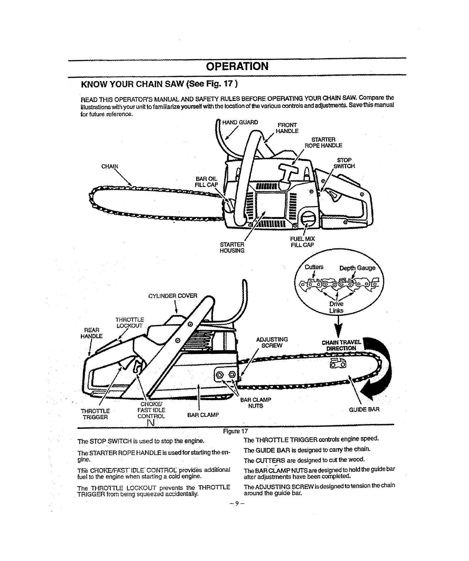
KNOW YOUR CHAIN SAW (See Fig. 17 )
READ THiS OPERATOR'S MANUAL AND SAFETY RULES BEFORE OPERATING YOUR CHAIN SAW, Compare the
i_lustrationswith yourunit to familiarize yourseffwiththe location ofthe various controlsand adjustments, Save this manu_I
for future reference.
HANDGUARD FRONT
HANDLE
STARTER
ROPEHANDLE
STOP
SWITCH
REAR
HANDLE
THROTTLE
STARTER
HOUSING
CYLINDER COVER
ADJUSTING
SCREW
FUELMiX
FILLCAP
CHAINTI_VEL
DIRECTION
•CHOKE/
THROTTLE FASTIDLE
TRIGGER CO_q3:{OL
t\1 BARCLAMP
_RCLAMP
NUTS GUIDE BAR
The STOP SWITCH is used to stop the engine,
The STARTER ROPE HANDLE is used for starting the en-
gine,
TheeC_IO_'E!F,_ST'IDLE CONTROL_ p_ovidi_sadder{oral
fuel to the engine when sta_t}ng a cold engine.
...................Figur_1_........................
The THROTTLE TRIGGER controlsengine speed.
The GUIDE BAR is designedto carry the chain.
The CUTTERS are designed to cut the wood,
The THROTTLE LOCKOUT prevents the THROTTLE
TRIGGER from being squeezed accidentally,
The BAF_CI_vl P NUTS are designedto hold the guidebar
after adjustments have been completed.
The ADJUSTING SCREW is designedto tension the chain
around the guide bar,
-9-
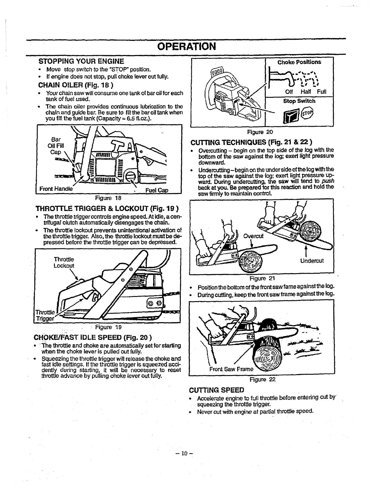
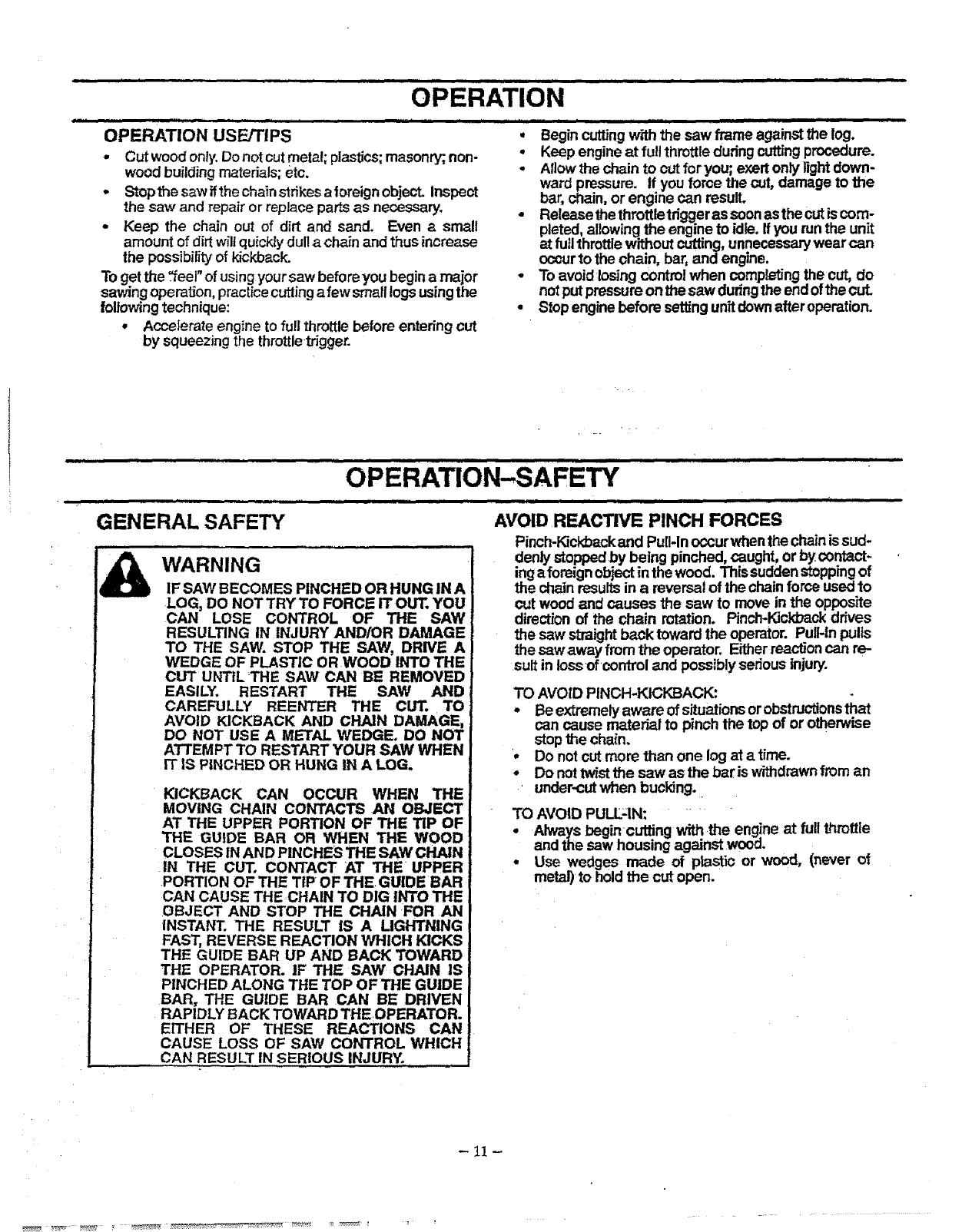
STOPPING YOUR ENGINE
•Move stop switch to the "STOP" position.
o If engine does not stop, pullchoke lever outfully.
CHAIN OILER (Fig. 18 )
•Yourchain saw will consume onetank of baroil for each
tank of fuel used.
•The chain oiler provides continuouslubricationto the
chain and guidebar. Be sure to fg]the baroiltank when
you fill the fuel tank (Capacity =6.5 fl.oz.).
Bar \
Oil Fill
\i
!
Front Handle
..................... Figure 18
Fuel CaD
THROI-rLE TRIGGER & LOCKOUT (Fig. 19 )
• Thethmttletdggercontrols enginespeed.Atidle, acen-
trifugat ctutch automatically disengages the chain.
•The throttte lockout prevents unintentional actuation of
the throttle tdgger. Also, the throttle lockout must be de-
pressed before the throttle trigger can be depressed.
Throttle
Lo_out
a
Figure 20
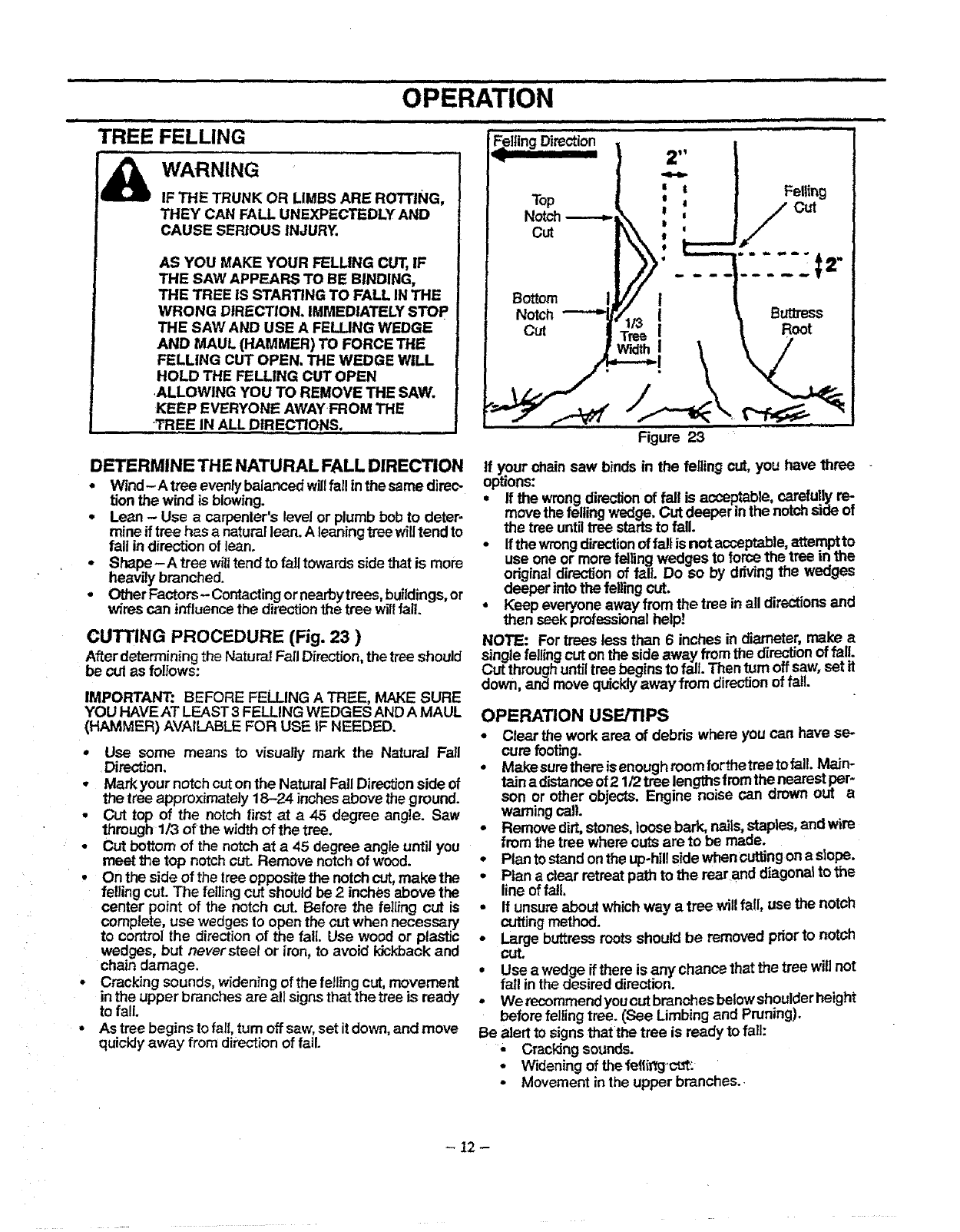
CuI"rlNG TECHNIQUES (Fig. 21 & 22 )
• Overcutting- begin on the top side of the log with the
bottomof the saw against the log; exert light pressure
downward.
•Undercutting-begin on theundersideofthe log withthe
top of the s_w against the Io9; exert light pressure up:.
ward. During undercutting,the saw will tend to pusn
backat you. Be prepared 1orthis reactionand holdthe
saw firmly to maintatn control.
Figure 21
• Pos_on the bottomofthe front sawfame against the log-
•Duringcutting,keep the frontsaw frame against the log.
:_ Figure 19
CHOKE/FAST IDLE SPEED (Fig. 20 )
•The throttle and choke are a,utomaticallysetfor starling
when the choke lever is pulled out fully.
•Squeezing the throttletrigger wiltretease the choke and
fast idle settings. If the throttle trigger is squeezed acc'_-
dently during starting, it will be necessary to reset
throttleadvance by pulling choke lever out fulb'. FrontSaw Frame
Figure 22
CUTTING SPEED
• Accelerate engine to full throttlebefore entering cut by
squeezing the throttletrigger.
•Never cut with engine at partialthrottle speed.
-10 -
IIIIIIH I I . IIIIIIIIIII I .-- I IIII I I II I I IIIHI
OPERATION
iiiiiiiii i i,,111 i ,i i ii IHI
OPERATION USE/TIPS
•Cut woodonly.Do not cut metat; plastics; masonry;, non-
wood building materials; etc.
, Stopthe saw ifthe chain strikes aforeign object. Inspect
the saw and repair or replace parts as necessary.
•Keep the chain cut of dirt and sand. Even asmall
amount of dirt wilt quickty dull a chain and thus increase
the possibility of kickback.
To get the _eel" of usingyour saw before you begin a major
sawing opera, on, practice cutting a few small togs usingthe
followingtechnique:
• Accelerate engine to full throttle before entedng cut
by squeezing the throttle trigger.
III IIII IIIIIIIIIIIIII I I I
Q
t
,, ,,,,,,,,,,,,,,, i iiii i iii ii i
Begin cuttingw_ththe saw frame against the log.
Keep engine at fullthrottleduring cuttingprocedure.
Allowthe chain to cut foryou; exert only lightdown-
ward pressure. If you force the cut, damage to the
bar, chain, or engine can result.
Release thethrottletriggeras soonas the cutis com-
pleted,allowing the engine to idle. Ifyou run the unit
at futlthrottlewithout cutting,unnecessarywear can
occurto the chain, bar, and engine.
To avoid losing control when completingthe cut, do
notputpressureon the saw dunngthe endof the cut.
Stopengine before settingunitdownafter operation.
OPERATION-SAFETY
iii,, H
GENERAL SAFETY
,,,,,,,L,,ii
WARNING
IF SAW BECOMES PINCHED OR HUNG IN A
LOG, DO NOT TRY TO FORCE IT OUT. YOU
CAN LOSE CONTROL OF THE SAW
RESULTING IN INJURY AND/OR DAMAGE
TO THE SAW. STOP THE SAW, DRIVE A
WEDGE OF PLASTIC OR WOOD INTO THE
CUT UNTIL THE SAW CAN BE REMOVED
EASILY. RESTART THE SAW AND
CAREFULLY REENTER THE CUT. TO
AVOID KICKBACK AND CHAIN DAMAGE,
DO NOT USE A METAL WEDGE, DO NOT
ATTEMPT TO RESTART YOUR SAW WHEN
IT IS PINCHED OR HUNG IN A LOG.
KICKBACK CAN OCCUR WHEN Tile
MOVING CHAIN CONTACTS AN OBJECT
AT THE UPPER PORTION OF THE TiP OF
THE GUIDE BAR OR WHEN THE WOOD
CLOSES IN AND PINCHES THE SAW CHAIN
IN THE CUT. CONTACT AT THE UPPER
PORTION OF THE TiP OF THE GUIDE BAR
CAN CAUSE THECHAIN TO DIG INTO THE
OBJECT AND STOP 3"HE CHAIN FOR AN
INSTANT. THE RESULT IS A LIGHTNING
FAST, REVERSE REACTION WHICH KICKS
THE GUIDE BAR UP AND BACK TOWARD
THE OPERATOR. IF THE SAW CHAIN IS
PINCHED ALONG THE TOP OF THE GUIDE
BAR, THE GUIDE BAR CAN BE DRIVEN
RAPIDLY BACK TOWARD THE!OPERATOR.
EITHER OF THESE REACTIONS CAN
CAUSE LOSS OF SAW CONTROL WHICH
CAN RESULT IN SERIOUS INJURY.
iii i i i ,,,,,, ,,,,,,,,,,,,,,,,,,,,i i ii iiiiiiii
AVOID REACTIVE PINCH FORCES
Pinch-Kickbackand PulHn occur whenthe chain issud-
denly stoppedby being pinched,caught, or by contact-
ing aforeign object in the wood. This suddenstopping of
the chain results ina reversal of the chain force usedto
cut wood and causes the saw to move in the opposite
direction of the chain rotation. Pinch-Kickbackdrives
the saw straightback toward the operator. PuU-tnpulls
the sawaway fromthe operator. Eitherreactioncan re-
sult in lossof control and possibly seriousinjury.
TO AVOID PINCH-KICKBACK:
* Be extremelyaware of situationsorobstructionsthat
can cause rnatedal to pinch the top of or otherwise
stop the chain.
oDo notcut more than one log at a time.
.Donottwistthesawasthebariswithdrawnfrom an
under-cutwhen bucking.
TO AVOID PULL-IN:
oAlways begincuffing with the engine at full throttle
and the saw housing against wooo.
-Use wedges made of ptastic or wood, (never of
metal) to hold the cut open.
- 11 -
ii ilull i ii i i riiii iii Iiii i i ii i,iiiinll iiil,,inll i
OPERATION
,,,,,,,,,,,
TREE .....
i i i ii iiiiii
FELLING
WARNING
IF THE TRUNK OR LIMBS ARE ROTTING,
THEY CAN FALL UNEXPECTEDLY AND
CAUSE SERIOUS INJURY.
AS YOU MAKE YOUR FELLING CUT,IF
THE SAW APPEARS TO BE BINDING,
THE TREE IS STARTING TO FALL IN THE
WRONG DIRECTION. IMMEDIATELY STOP
THE SAW AND USE A FELLING WEDGE
AND MAUL (HAMMER) TO FORCE TIlE
FELLING CUT OPEN. THE WEDGE WILL
HOLD THE FELLING CUT OPEN
.ALLOWING YOU TO REMOVE THE SAW.
KEEP EVERYONE AWAYFROM THE
"TREE IN ALL DIRECTIONS.
,,,111111111111_ii n iiiii,nll i
'Felling Direction .........
Top
Notch
Cut
13ottom
Notch
Cut
Figure 23
Felling
//°=
-".U_I="
BUttress
Root
DETERMINE THE NATURAL FALL DIRECTION
•Wind-A tree evenlybalanced willfallinthe same direc-
tion the wind is blowing.
• Lean -Use acarpenter's level or plumbbob to deter-
mine if tree has a naturallean. A leaning tree willtend to
fall in direction of lean.
•Shape - A tree willtend to fail towards sidethatis more
heavily branched.
•Other Factors- Contacting or nearbytrees, buildings, or
wires can influence the direction the tree willfall.
CUTTING PROCEDURE (Fig. 23 )
After determining the Natura! Fall Direction,the tree should
be cul as foliows:
IMPORTANT: BEFORE FELLING A TREE, MAKE SURE
YOU HAVE AT LEAST 3 FELLING WEDGES AND A MAUL
(HAMMER) AVAILABLE FOR USE IF NEEDED.
, Use some means to visually mark the Natural Fall
Direction.
• Mark your notch cut on the Natural Fall Direction side of
the tree approximately 18-24 inches above the ground.
•Cut top of the notch first at a 45 degree angle. Saw
through 1/3 of the width of the tree.
•Cut bottom of the notch at a 45 degree angle until you
meet the top notchcut Remove notch of wood.
•On the side of the tree oppositethe notch cut,make the
felling cut. The felling cut should be 2 inches above the
center point of the notch cut. Before the felling cut is
complete, use wedges to open the cut when necessary
to control the directionof the fall. Use wood or plastic
wedges, but neversteel or iron, to avoid idckback and
chain damage.
-Cracking sounds, widening of the felling cut, movement
in the upper branches are all signs that the tree is ready
to fall.
-As tree begins to fall, turn off saw, set it down, and move
quickly away from direction of fall.
if your chain saw binds in the felling cut, you have three -
options:
•If the wrongdirectionof fall is acceptS,le, c_ietully re:.
move the felling wedge, Cut deeper inme notchsioe ot
the tree untiltree startsto fall.
•If the wrongdirectionof falt is not ac.c.eptable,.a_empt.to
use one or more felling wedges to mrce the tree in.me
original directionof fall Do so by ddving the weoges
deeper into the fellingcut,
•Keep everyone away from the tree inall directionsand
then seek professionalhelp!
NOTE: For trees less than 6 inches in diameter, make a
single felling cut onthe side away from the direr."on of _1!.
Cut throughuntiltree begins to fall. Then turn o_s_.w,smn
down, and move quicklyaway from direction oTra_.
OPERATION USE/TIPS
°Clear the work area of debris where you can have se-
cure footing.
*Make sure there is enough room forthetree to fall. Maim
taJnadistance of 21/2 tree lengths fromthe nearest per-
son or other objects. Engine noise can crown out a
warning call.
• Remove dirt,stones, loose bark, nails,staples, and wire
from the tree where cuts are to be made.
°Plan to stand on the up-hil! side whenGuttingon a slope.
-Plan a clear retreat path to the rear and diagonal tothe
line of fall.
,If unsure about which way a tree will fall, use the notch
cuttingmethod.
•Large buttress roots should be removed prior to notch
cut.
,Use a wedge if there is any chance that the tree will not
fall in the desired direction.
,We recommendycu cut branches below shoulder height
before felling tree. (See Limbing and Pruning).
Be alert to signs that the tree is ready to fall:
•Crackingsounds.
•Widening of theie|lirtg'c'_:
• Movement inthe upper branches..
-22 -
ill, iiiii,1111 i iiii i i i,,111iiiiii
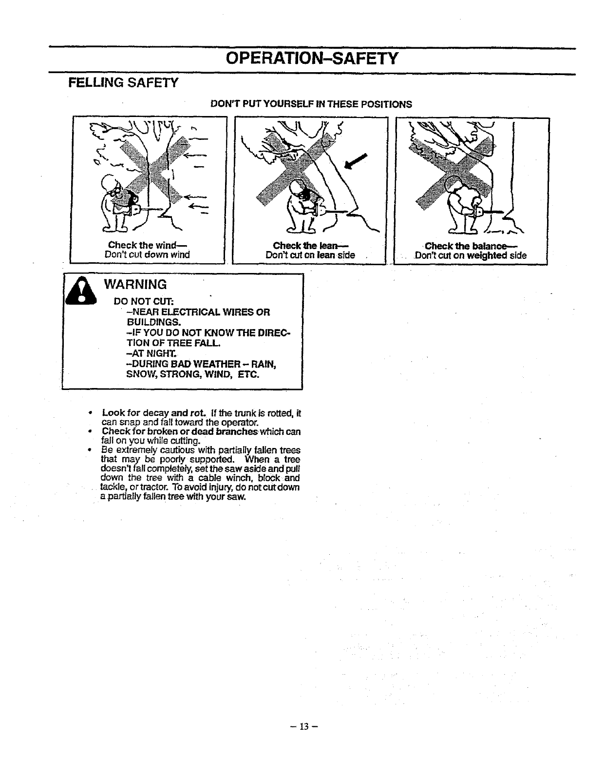
FELLING SAFETY .....................
DON'T PUT YOURSELF IN THESE POSITIONS
Check the wind--
Don't cut down wind
WARNING
DO NOT CUT:
'-NEAR ELECTRICAL WIRES OR
BUILDINGS.
-IF YOU DO NOT KNOW THE DIREC-
TION OF _EE FALL
-AT NIGHT.
-DURING BAD WEATHER- RAIN,
SNOW, STRONG, WIND, EI'C.
_ i
Check the lean--
Don_tcut on lean side
i,i
ill
*Look for decay and rot. If the trunk is rotted, it
can snap and fatltowan_the operator.
.Check for broken or dead branches which can
fall on you while cutting.
oBe extremely cautious with partially fallen trees
that may be poody supported. When a tree
doesn't fall completely, set the saw aside and pull
down the tree with a cable winch, block and
.tackle, ortractor. To avoid injury',do notcutdown
apartially fallen tree with your saw.
-13-
ii i ii, iii ii ii i iiiiiiiiiiiiiii i i i
OPERATION
Ill Ill
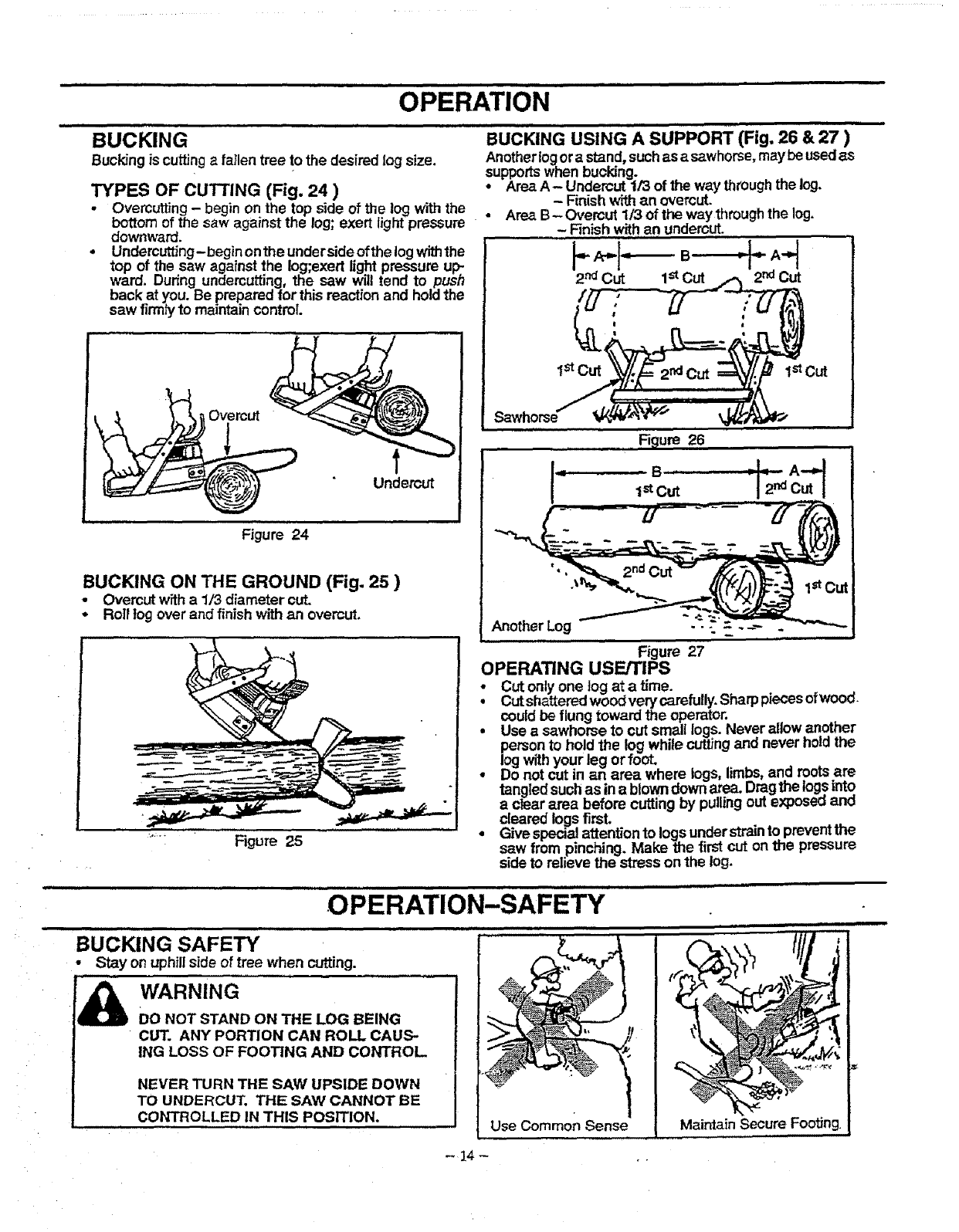
BUCKING BUCKING USING A SUPPORT (Fig. 26 & 27 )
Anotherlogora stand, suchas a sawhorse, maybe usedas
Bucking is cutting a fallen tree t° the desired log size. supports when bucking. . , .
TYPES OF cuTrlNG (Fig. 24 ) Area A- Undercut 1/3 of the way througn me log.
- Finishwithan overcut.
.Overcutt_ng - begin on the top side of the log with the •Area B- Overcut 1/3 of the waythrough the log.
bottom of the saw against the log; exert lightpressure -Finish withan undercut.
downward.
Undercutting-begin on the undersideof the log withthe
top of the saw against the log;exert light pressure up:.
ward. Dudng undercutting, the saw will tend to push
back at you. Be prepared for this reaction and holdthe
saw firmtyto maintain control.
i ,
Figure 24
BUCKING ON THE GROUND (Fig. 25 )
•Overcut with a 1/3 diameter cut.
• Roll tog over and finish with an overcut.
I
Figure 25
1_Cut
...........F ure26
,=o= c.,t
Another Log --:....
,=l. = i, .HHI L = I= = .I =J= I = = H
OPERATION-SAFETY
Figure 27
OPERATING USE/TIPS
Cut only one log at atime. ._
: Cut shattered wood very earefully. Sharp piecesorwooo-
couldbe flung toward the operator.
ise asawhorse to cut small logs. Never allow another
personto ho!d the log while outing and never held the
logwithyour leg or fool .....
Do not cut in an area where logs, limps,ano rootsare
tangledsuchas inablowndown area. Dragthe togsinto
a clear area before cutting by pullingout exposed and
cleared logs first. " nto reventthe
• Give specia!attention to logs unaerstrai . p
saw from pinching. Make the first cut onthe pressure
side to relieve the stress on the log.
BUCKING SAFETY
•Stay on uphillside of tree when cutting.
Ig DO NOT STAND ON THE LOG BEING
CUT. ANY PORTION CAN ROLL CAUS-
ING LOSS OF FOOTING AND CONTROL
NEVER TURN THE SAW UPSIDE DOWN
TO UNDERCUT, THE SAW CANNOT BE
CONTROLLED IN THIS POSITION. Mair_ain Secure Footing.
-14 -
= =l ,, i , ,,,,i =,,,, === _ = = ,,,,,= == =
OPERATION
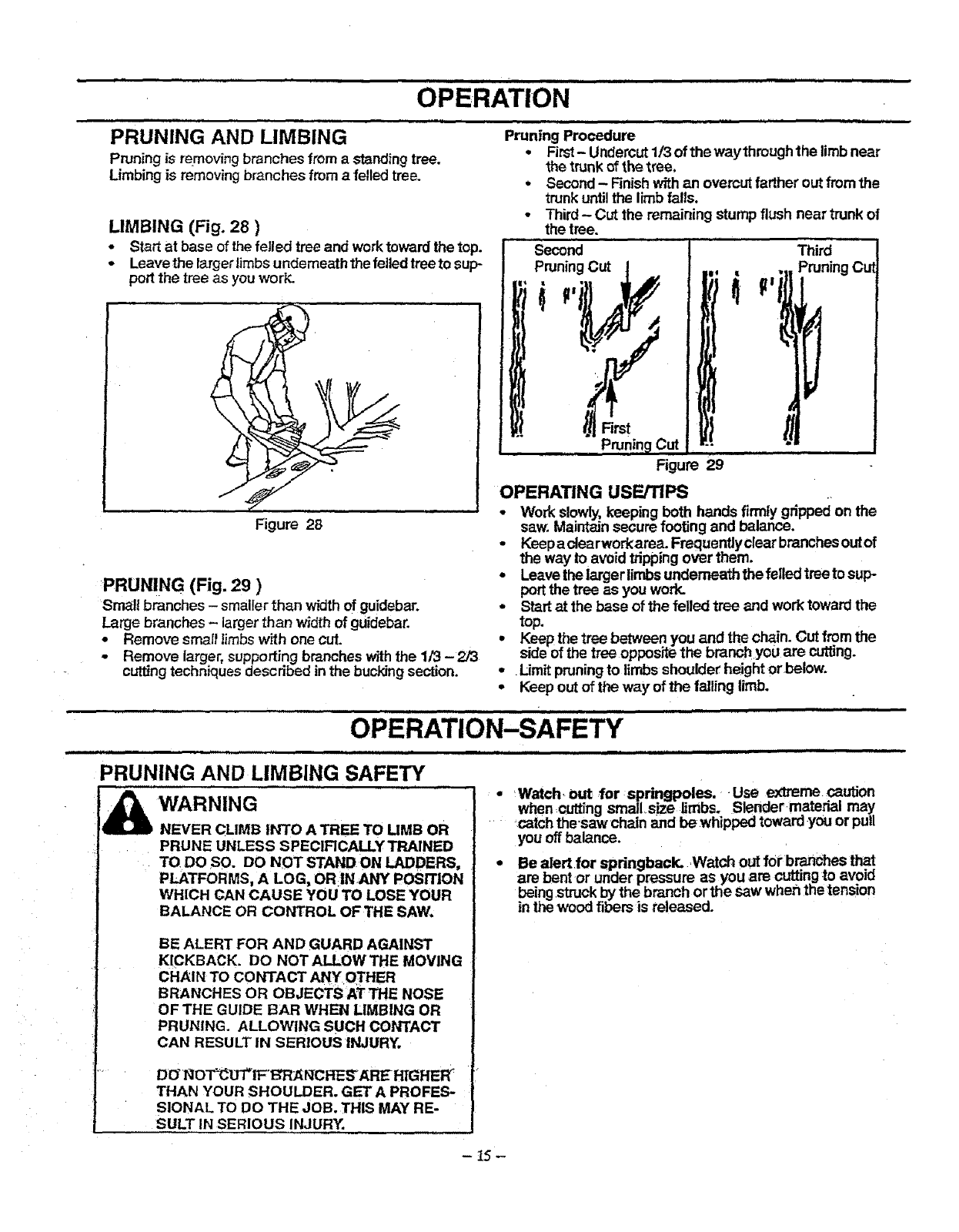
'PRUNING AND LIMBING Pruning Procedure
•First- Undercut1/3 of the waythrough the limbnear
Pruning is removingbranches from a standingtree. the trunk of the tree.
Limbing is removing branches from afelled tree. • Second - Finish withan overcut farther out from the
trunk unti! the limb falls.
• Third - Cut the remaining stump flush near trunk of
LIMBING (Fig. 28 )
oStart at base of the felled tree and worktoward the top.
-Leave the largerlimbsunderneaththe felledtree to sup-
port the tree as youwork.
Figure 28
:PRUNING (Fig. 29 )
Small branches -smaller than width of guide.bar.
Large branches - larger than width of guidebar.
•Remove smal! limbs with one cut.
- Remove larger, supporting brancheswiththe 1/3 -2/3
cuttingtechniques described in the bucking section.
the tree.
Second Third
Pruning Cut
Figure 29
OPERATING USErrlPS
•Work slowly,keeping both hands firmly gripped on the
saw. Maintain secure footing and balance.
•Keepaclearworkarea.Frequentlyclearbranchesoutof
the way to avoid 1Tippingover them.
•Leave the larger limbsunderneaththefelledtreetosup-
port the tree as you work.
oStart at the base of the felled tree and work toward the
top.
•Keep the tree between you and the chain. Cut from the
sideof the tree oppositethe branchyou are cutting.
•Limit pruningto limbs shoulder heightor below.
•Keep out of the way of the falling limb.
i ± ...... ,,,i =
i , ,
PRUNING AND LIMBING SAFETY
WARNING
NEVER CLIMB INTO A TREE TO UMB OR
PRUNE UNLESS SPECIFICALLY TRAINED
TO DO SO. DO NOT STAND ON LADDERS,
PLATFORMS, A LOG, ORIN ANY POSITION
WHICH CAN CAUSE YOU TO LOBE YOUR
BALANCE OR CONTROL OFTHE SAW.
BE ALERT FOR AND GUARD AGAINST
KICKBACK. DO NOT ALLOW THE MOVING
CHAIN TO CONTACT ANY OTHER
BRANCHES OR OBJECTS AT THE NOSE
OF THE GUIDE BAR WHEN LIMBING OR
PRUNING. ALLOWING SUCH CONTACT
CAN RESULT IN SERIOUS INJURY.
DO"NO_iF'tS"RAI_CRES'AR_ PEGFIER
THAN YOUR SHOULDER. GET A PROFES-
SIONAL TO DO THE JOB. THIS MAY RE-
SULT IN SERIOUS INJURY.
I
..................... ,, == ,i ,,,,,,, J,,,i,
Watch, out for springpoles. •Use extreme caution
whencutting small size limbs. Slender matedal ma_,
catch thesaw chain and bewhipped towaro you or pull
yOUOffbalance.
Be alert for springback. Watch out for branches that
are bent or ur_derpressure as you are .cutti'ng_ avoid
being struckby the branch orthe saw wnan me tenston
in the wood fibers is released.
-15-
i i i i ,, i ii illll,i ............................ ""
OPERATION
ii iiiiiiiii i lllllllllllllllllll ii i ii i iiiii
BEFORE STARTING ENGINE:
WARNING:
BE SURE TO READ THE FUEL SAFETY IN-
FORMATION IN THE SAFETY RULES SEC-
TION ON PAGE 2 OF THIS MANUAL BE-
FORE YOU BEGIN.
IF YOU DO NOT UNDERSTAND THE FUEL
SAFETY SECTION DO NOT ATTEMPT TO
FUEL YOUR UNIT; SEEK HELP FROM
SOMEONE THAT DOES UNDERSTAND THE
FUEL SAFETY SECTION OR CALL THE
CUSTOMER ASSISTANCE HOTUNE AT
1_800-235-5878.
GUIDE BAR AND CHAIN OIL
For maximum guide bar and chain life, we recommend you
use Craftsman chain saw bar oil. If Craftsman bar oil is not
avaJlable, you may use a goodgrade SAE30 oiluntil you are
able to obtain Craftsman brand. The oil output is automati-
callymetered during operation. Your saw willuse one tank of
baroil for every tank of fuel mix. Always fill the bar oil tank
when you fill the fuel tank.
GASOLINE
The two-cycle engine onthisproductrequiresa fuel mixture
of regular unleaded gasolineand ahigh quality40:1 2.-cycle
engineoil (AIR-COOLED) for lubricationof the bearings and
other moving parts. The correctfueVo_ mixture is40:1 (see
Fuel Mixture Chart). Too t_le oil orthe incorrect oiltype will
cause poorperformance and may causethe engine to over-
heat and seize.
Gasolineand,oil must be premixed inaclean approved fuel
container. Always use fresh regular unleaded gasoline.
Thisengine hasbeen certified to operateon unleaded gaso-
line and Craftsman 40:1 2-cycle engine oil(AIR-COOLED).
IMPORTANT: Experience indicates that alcohol
blended fuels caIled gasohol (or using ethanol or metha-
nol) can attract moisture, which leads to oiVgas separa-
tion and formation of acids during storage. Acidic gas
can damage the fuel system of an engine while in stor-
age. To avoid engine problems, the fuel system should
be emptied before storage for 30 days or longer. Drain
the gas tank, then run the fuel outof the carburetor and
fuel lines by starting the engine and letting it run until it
stops. Use fresh fuel next season_. See STORAGE
instructions for additional information. Never use engine
orcarburetor cleaner products in the fuel tank or perma-
nent damage may occur.
FUEL STABILiTPR
Fuel stabilizerisan acceptable alternative inminimizing the
formationof fuelgumdepositsdudngstorage.AddstabilLzer
to gasoline infuel tank or storage container.Alwaysfollow
the fuel mix ratio found on the stabilizer container. Run
engineat least 5 minutesafteradding stabilizerto allow the
stabilizer to reach the carburetor.You do not have to drain
the fuel tank for storage if you are usingfuel stabilizer.
CRAFTSMAN 40:1 2-cycle engine oil (AIR-COOLED) is
speciallyblended withfuel stabilizers.Ifyou do notuse this
Sears oil, youcan add afuel stabilizer (suchas Craftsman
No. 33500) to your fue! tank,
2-CYCLE OIL:
CRAFTSMAN 40:1 2-cycle engine oil (AIR-COOLED)
stronglyrecommended.This oilisspe_a|ly blendedwithfue|
stabilizersforincreasedfuelstabilk'y(extendsfuel rffeupto 5
times longer) and reducedsmoke.
If CRAFTSMAN 40:1 2.cycle engine oil (AIR-COOLED) is
not available, use a good quality 40:1 2-cycle engine oil
(AIR-COOLED) engineoil thathas arecommendedfuel mix .
ratio40:1.
IMPORTAN'13 Do not use:
•AUTOMOTIVE OIL
•BOAT OILS (NMMA, BIA. etc.)
These oils do not have proper additives for 40:1 2-cycle
engine oil (AIR-COOLED) engines and can cause
engine damage.
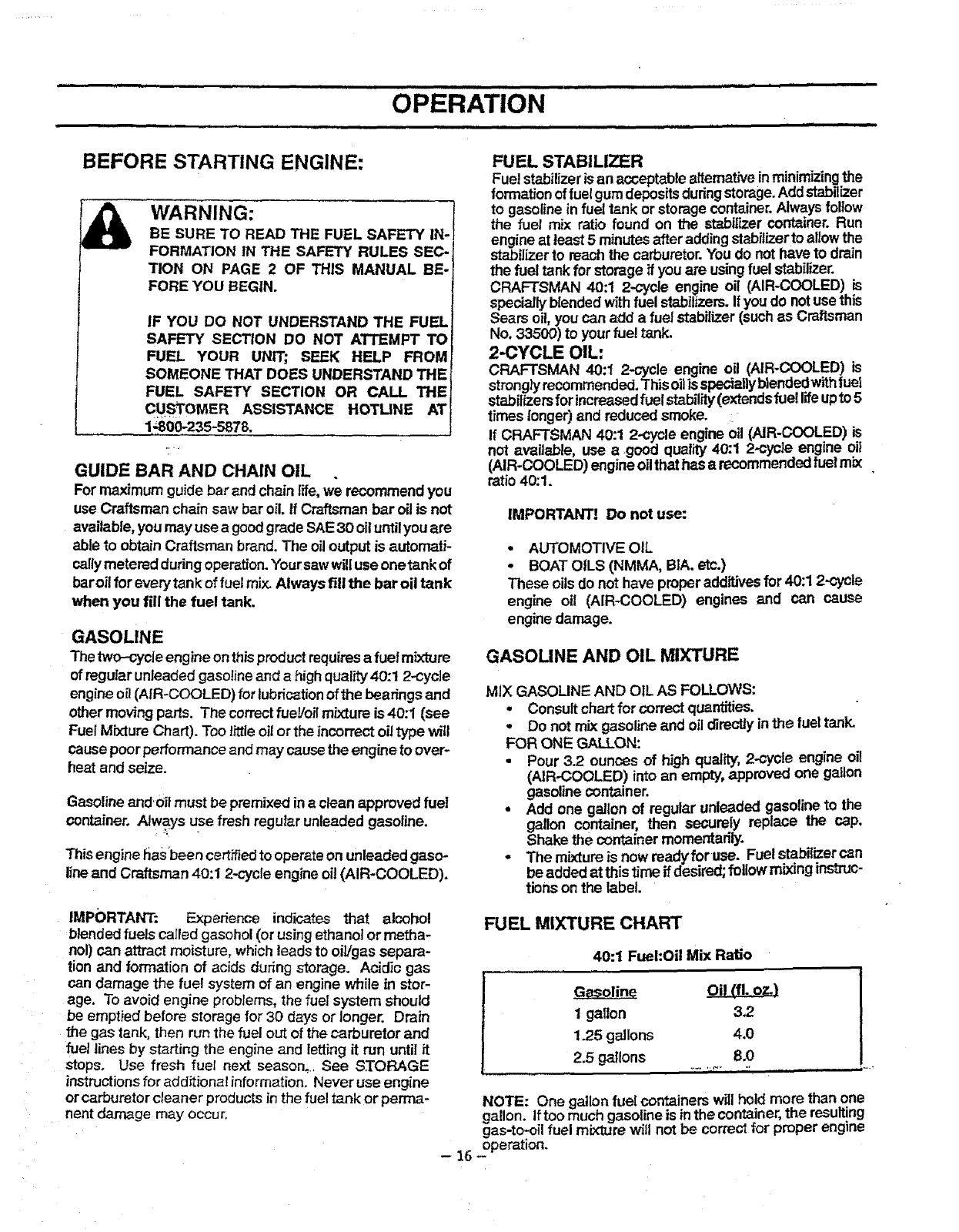
GASOLINE AND OIL MIXTURE
MIX GASOLINE AND OIL AS FOLLOWS:
•Consult cha.,tfor correctquarr_ies.
•Do not mix gasoline and oil directlyinthe fuel tank.
FOR ONE GALLON:
•Pour 3.2 ounces of high quality, 2-cycle engine oil
(AIR-COOLED) into an empty,approved one gallon
gasoline container.
• Add one gallon of regular unleaded gasoline to the
gallon container, then securely replace the cap,
Shake the container momentarily.
o The mixture is now readyfor use. Fuel stabi{izercan
be added at thistime if desired;followmixingins'mJC-
tions on the label.
FUEL MIXTURE CHART
40:1 Fuel:Oil Mix Ratio
Oil (1'1.o_}
1gallon 3.2
1.25 gallons 4,0
2.5 gallons 8.0
NOTE: One gallon fuel containers will hold more than one
gallon. Iftoo much gasoline is inthe container,the resulting
gas-to-oil fuel mixture wilt not be correct for proper engine
-16 operation.
OPERATION
,,ill III I IIIIII I II IIm,,,ll I .........................
STOPPING YOUR ENGINE STARTING A COLD ENGINE OR WARM
ENGINE AFTER RUNNING OUT OF FUEL
•Move the stopswitchto,the =STOP" position.
• If engine does not stop, pull choke lever out fully.
WARNING:
ALWAYS WEAR GLOVES; SAFETY
FOOTWEAR; SNUG-FITTING
CLOTHING; AND EYE, HEARING, AND
HEAD PROTECTION DEVICES WHEN
OPERATING A CHAIN SAW.
THE CHAIN MUST NOT MOVE WHEN
THE ENGINE RUNS AT IDLE SPEED.
REFER TO THE =CARBURETOR
ADJUSTMENTS " SECTION FOR
CORRECTION.
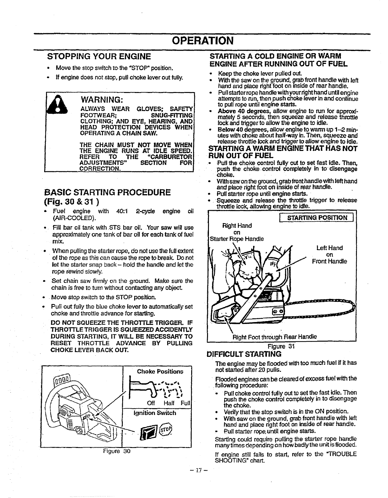
BASIC STARTING PROCEDURE
(Fig. 30 & 31 )
o Fuel engine with 40:1 2-cycle engine oil
(AIR-COOLED).
• RU bar oil tank with STS bar oil Your saw will use
approximatety one tank of bar oil for each tank of fuel
mix.
•When pulling the starter rope, do not use the full extent
of the rope as thiscan cause the rope to break. Do not
let the starter snap back - hold the handle and let the
rope rewind slowly.
• Set chain saw firmly on the ground. Make sure the
chain is free to turn without contacting any object.
-Move stop switch to the STOP position.
• Pull out fuily the blue choke lever to automaticallyset
choke and throttle advance for starting.
DO NOT SQUEEZE THE THROTTLE TRIGGER. IF
THROTTLE TRIGGER IS SQUEEZED ACClDENTLY
DURING STARTING, IT WILL BE NECESSARY TO
RESET THROTTLE ADVANCE BY PULLING
CHOKE LEVER BACK OUT.
Choke Positions i
Figure 30
Keepthe choke lever pulled out.
•W'rththe saw on the ground, grabfront handle with left
hand and place rightfoot on mnsiaeor rear handle.
• Pullstarterrope handlewithyourrighthand untilengine
attempts to run,then push chokelever in and continue
to pullrope untilengine starts.
•Above 40 degrees, allow engine to run for approxi-
mately 5 seconds, then squeeze and release throttle
lock and trigger to allow the engineto idle.
•Below 40 degrees, allow engineto warm up 1-2 min-
uteswith choke about half-way in.Then, squeeze and
releasethrottle lockand triggerto allow engine to idle.
STARTING A WARM ENGINE THAT HAS NOT
RUN OUT OF FUEL
•Pull the choke control fully out to set fast idle. Then,
push the choke;control completely in to- disengage
choke.
•Withsaw on the ground,grab fronthandlewithleft hand
and place nght foot on inside of rear handle.
•Pullstarter rope untilengine starts.
-Squeeze and release the throttle trigger to release
throttlelock, allowing engine to !die. ,
i STARTING POSmON I
Right Hand
on
Starter Rope H_ndte
l ,., Front Handle
Right Foot throughRear Handle
Figure 31
DIFRCULT STARTING
The engine may be flooded withtoo much fuel if it has
not started after 20 pulls.
Flooded enginescan be cleared of excess fuel withthe
followingprocedure:
•Pull choke contro!fully outto set the fast idle.Then
push the choke control completelyin to disengage
the choke.
•Verifythat the stop switch is in the ON position.
•W'rthsaw on the ground, grab front handle with left
hand and place right foot on inside of rear handle.
,PuJ!sta_er rope,until engine starts.
Starting could require pulling the starter rope handle
many times depending o n howbadlythe unit isflooded.
If engine still fails to start, refer to the "TROUBLE
SHOOTING" chart.
-t7 -
i,,ml ,i, ,,,,,,, ,,,,,,,,,,,,,,,, i,i i
CUSTOMER RESPONSIBILITIES
................... ii
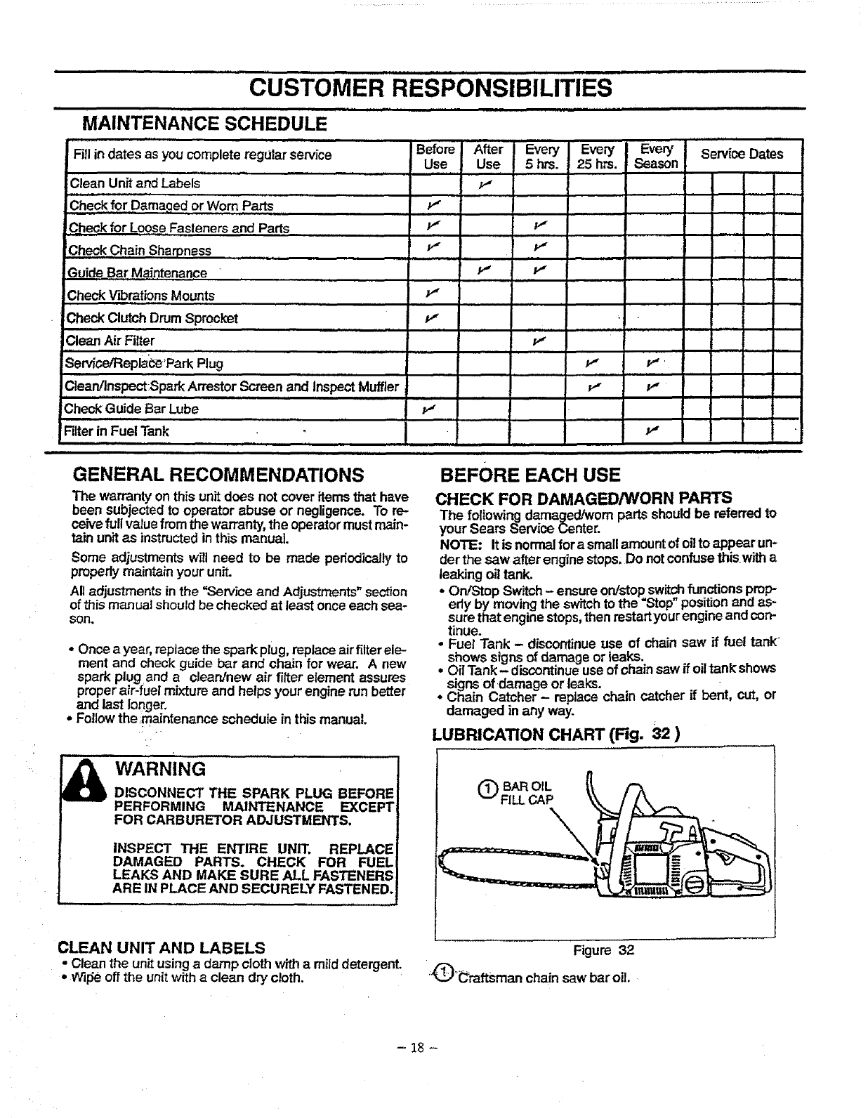
MAINTENANCE SCHEDULE
iii HI,, ,,,,,lllllllilllllll
Fill indates asyou complete regular service Before After
Use
Clean Unit and Labels ............................
CheckforD maqedorWo , ...................,.."
Check for Loose Fasteners and Parts f
Check Chain Sharpness P"
!Guide_Bar Maintenance • i
p,,
Check Clutch Drum Sprocket P"
,
Clean Air Filter
iHi .... i i , ,l iN
SePAce,_eplac'_ _ParkPlug
Clean/Inspect:SparkArrestor Screen and InspectMuffler
Ill II
:CheckGuide Bar Lube v_
ii ,
Filterin Fuel Tank
Every Every Every Service Dates
Use 5 hrs 25 hrs Season
p,,
....... J
ps
,H p,, p,.
H,i Hi
i,ii
p,,
liH Hi
ps p,,
p,,
GENERAL RECOMMENDATIONS
The warranty on this unit does not cover items that have
been subjected to operator abuse or negligence, To re-
ceive full valuefrom the warranty,the operator mustmain-
tain unit as instructedin this manual.
Some adjustments will need to be made periodicallyto
properly maintain your unit.
All adjustments in the "Service and Adjustments" section
of this manual should be checked at least once each sea-
son.
• Once a year, replace the spark plug, replace airfilter ele-
ment and check guide bar and chain for wear. A new
spark plug and aclean/new air fitter element assures
proper air-fuel mixture and helps your engine run better
and last longer.
oFollow the;maintenance schedule in this manual.
WARNING
DISCONNECT THE SPARK PLUG BEFORE
PERFORMING MAINTENANCE EXCEPT
FOR CARBURETOR ADJUSTMENTS,
INSPECT THE ENTIRE UNIT. REPLACE
DAMAGED PARTS. CHECK FOR FUEL
LEAKS AND MAKE SURE ALL FASTENERS
ARE IN PLACE AND SECURELY FASTENED.
,,,i,,, ,
BEFORE EACH USE
CHECK FOR DAMAGED/WORN PARTS
The following damaged/worn parts should be referred to
your Sears Service Center
NOTE: It is normal for a smallamount of oilto appear un*
der the saw after engine stops, Do notconfuse thisw_ a
leaking oil tank.
•On/Stop Switch- ensure on/stop switchfunctionsprop
edy by moving the switchto the =Stop"positionand as-
sure that engine stops,then restartyourengine and con-
tinue.
• Fuel Tank - discontinue use of chain saw if fuel tank
shows signs of damage or leaks. . .
° Oil Tank- discontinue use of chain saw if oHtank snows
signs of damage or leaks.
•Chain Catcher - replace chain catcher if bent, cut, or
damaged in any way.
LUBRICATION CHART (Fig. 32 )
OBAR OIL
FILL CAP
CLEAN UNIT AND LABELS
• Clean the unit usingadamp cloth with amild detergent.
•Wllseoff the unit witha clean dry cloth.
Figure 32
;_°_raftsman chain saw bar oil.
-18 -
cusTOMER RESIPONSIBiLITIES .............
,,,,,,,, i ,,,,i, ii
CHECK FOR LOOSE FASTENERS/PARTS
•Bar Clamp Nuts
• Chain
• Muffler
•Cylinder Shield
•Air Filter
.Clutch Drum/Sprocket
Throttle Trigger/Lockout
• Handle Screws
-AV Springs
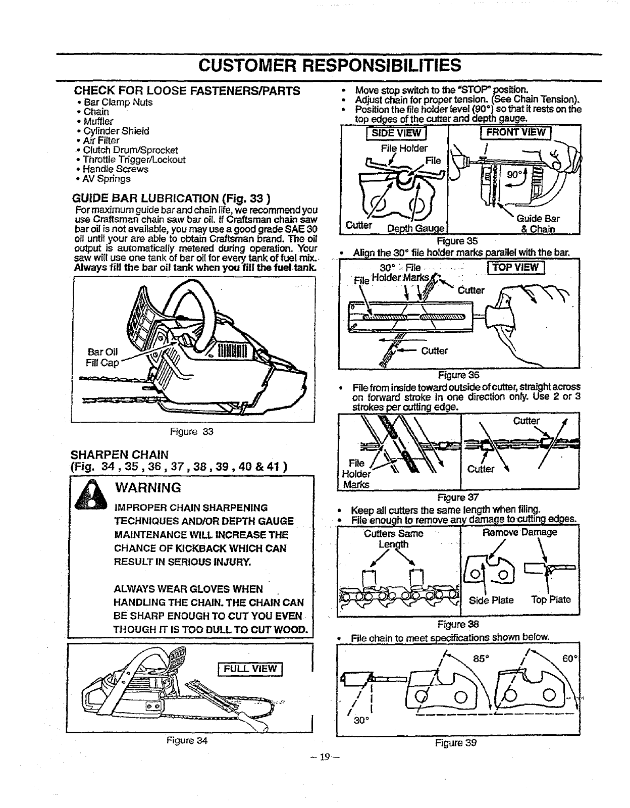
GUIDE BAR LUBRICATION (Fig. 33 )
For maximum guide bar and chainlife,we recommendyou
use Craffsrr_n chain saw bar oil. if Craftsman chain saw
bar oil is not available, you may use agood grade SAE 30
oil untilyour are able to obtain Craftsman brand. The oil
output is automatically metered during operation. Your
saw will use one tank of bar oilfor every tank of fuel mix..
Always fill the bar oil tank when you fill the fuel tank.
Bar Oil
i i i
•Move stopswitchto the _STOF_ position.
•Adjustchain for proper tension. (See Chain Tension).
•Positionthe fileholder level (90=) sothat it rests onthe
......top edges of the cutterand depth gauge.
lsIoEWEWJpRO view]
File HoTder
File
Culler,, DepthGau_ &Chain
Figure 35
., All,inthe 30 ° file holder marks parallel withthe bar.
30'_ : File .......... I TOP VIEW J
"File Holdei:Ma_s[_ :
Figure 36
• File from insidetoward outsideof cutter, straightacross
on forward stroke in one direction only. Use 2or :3
strokes per cutting edge.
Figure 33
SHARPEN CHAIN
(Fig. 34,35,36,37,38,39,40 & 41 )
_WARNING
IMPROPER CHAIN SHARPENING
TECHNIQUES AND/OR DEPTH GAUGE
MAINTENANCE WILL INCREASE THE
CHANCE OF KICKBACK WHICH CAN
RESULT IN SERIOUS INJURY.
ALWAYS WEAR GLOVES WHEN
HANDLING THE CHAIN. THE CHAIN CAN
BE SHARP ENOUGH TO CUT YOU EVEN
THOUGH IT IS TOO DULL TO CUT WOOD.
IlUlIIII I IIIII III ,
.i,....I
Figure 34
-19--
Figure 37
outtersthe same
Figure 38
,File cha!n to meet specifications shown below.
85 °
Figure 39
,,f , , ii ,, i iii , i ,,,,,,,,,,,,,,,,,,iii ,,,,i
CUSTOMER RESPONSIBILITIES
,i ii .......................................................... iiiiii
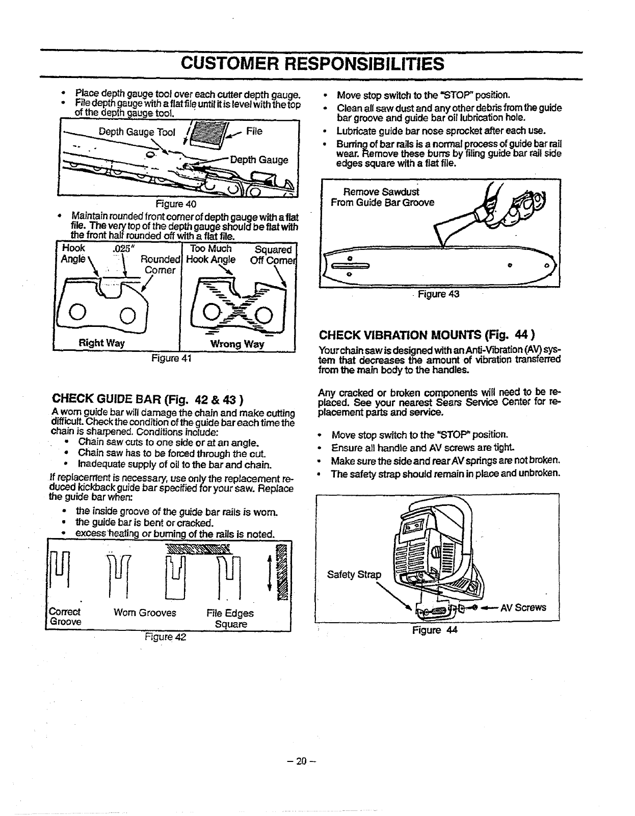
•Place depth gauge tool over each cutterdepth gauge. •Move stop switchto the "STOP" position.
•F_edepthgaugewithaflatfileuntilitislevelwiththetop * Cleanallsawdustandanyotherdebrisfro,mtheguide
of the depthgauge tool "
.................... bar grooveand guide bar oil lubricationhole.
Lubricateguide bar nose sprocketafter each use,
Burdngof bar railsis a normalprocess ofguldebar rail
wear, Remove these burrs by filingguidebar railside
edges square withaflat file.
Rgure 40
Maintainroundedfront comerof depth gauge withafiat
file. The very topof the depthgauge shouldbe fiat with
the front halfroundedoff withafiat file.
Hook
HookAn<e OffCornel
0
Right Way Wrong Way--
Figure 41
Remove Sawdust
From Guide Bar Groove
o
Figure 43
CHECK VIBRATION MOUNTS (Fig. 44 )
Yourchainsaw is designedwithan Anti-'Vqbration(A_ sys:
tern that decreases the amount of vibrationtransferreo
from the main body to the handles.
.3orrect
Groove
CHECK GUIDE BAR (Fig. 42 & 43 )
A wom guide bar willdamage the chain and make cutting
o.micult.Checkthe conditionofthe guidebar each time the
Cllain is sharpened. Conditionsinclude:
•Chain saw cuts to one side or at an angle.
•Chain saw has to be forced through the cut.
•Inadequate supply of oil to the bar and chain.
if replacement is necessary, use only the replacement re-
duced kickback guide bar specified for your saw. Replace
the guide bar when:
•the inside groove of the guide bar rails is worn.
•the guidebar is bent orcracked.
excess'hea!!ngor burning of the mils is noted.
Worn Grooves File Edges
Square
F_gure42
Any cracked or broken components will need to be re-
placed. See your nearest Sears Service (,;enter mr re-
placement parts and service.
•Move stop switchto the =STOP" position.
•Ensure all handle and AV screwsare tight.
•Make surethe side and rearAV springsare notbroken.
• The safety strapshould remain inplace and unbroken.
Safety Strap
\
_,VScrews
Figure 44
-20-
,, ,,, ,i ,= =, = m=,=,
CUSTOMER RESPONSIBILITIES
= = •i,1 11 = = = m= .retail,i= =miim= ,, 11
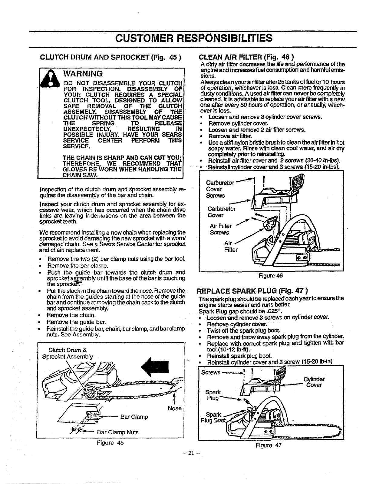
CLUTCH DRUM AND SPROCKET (Fig. 45 )
WARNING
DO NOT DISASSEMBLE YOUR CLUTCH
FOR INSPECTION. DISASSEMBLY OF
YOUR CLUTCH REQUIRES A SPECIAL
CLUTCH TOOL, DESIGNED TO ALLOW
SAFE REMOVAL OF THE CLUTCH
ASSEMBLY. DISASSEMBLY OF THE
CLUTCH WITHOUT THIS TOOL MAY CAUSE
THE SPRING TO RELEASE
UNEXPECTEDLY, RESULTING I_
POSSIBLE INJURY. HAVE YOUR SEAR,<
SERVICE CENTER PERFORM THI_
SERVICE.
THE CHAIN IS SHARP AND CAN CUT YOU;
THEREFORE, WE RECOMMEND THAT
GLOVES BE WORN WHEN HANDLING THE
CHAIN SAW.
Inspectionof the clutch drum and _procket assembly re-
quires the disassembly of the bar and chain.
Inspect your clutch drum and sprocket assembly for ex-
cessive wear, which has occurred when the chain ddve
links are leaving indentations on the area between the
sprocket teeth.
We recommend installing a new chainwhen replacingthe
sprocket to avoid damaging the new sprocketwitha worn/
damaged chain. See aSears Service Center for sprocket
and chain replacement.
*Remove the two (2) bar clamp nuts using the bartooL
,, Remove the bar clamp.
.Push the guide bar towards the clutch drum and
sprocket as.__emblyuntil the base of the bar is touching
the sprocl_Tt_.
. Pulltheslackinthechaintowardthenose.Rernovethe
chain from the guides starting at the nose of the guide
bar and continue removing the chain backto the clutch
and sprocket assembly.
•Remove the chain.
•Remove the guide bar.
• Reinstall the guide bar, chain;,barclamp, and barclamp
nuts. See Assembly.
Clutch Drum &
Sprocket Assembty II
Nose
CLEAN AIR FILTER (Fig. 46 )
Adirty air filter decreasesthe life and perfon'nanceof the
engine and increasesfuel consumptionand harmfulemis-
sions.
Always cleanyour airfilter after25 tanks of fuelorl O hours
of operation, whicheveris less. Clean more frequently in
dusty conditions. A usedairfi.ltercan never be completely
cleaned. It is advisable to repJaceyour air filterwithanew
one after every 50 hoursof operation, or annually,which-
ever is less.
•Loosen and remove3 cylindercover screws•
•Remove cylindercover.
•Loosen and remove2air filterscrews.
•Remove airfilter.
•Use astiffnylonbdstlebrushto cle._ the airfiiterin hot
soapy water. Rinse with clean cool water, ano air dry
completely priorto reinstalling.
•Reinstall air filter coverand 2 screws (30-40 in-lbs).
Ill..iReinstall'cylindercoverand 3 screws t_15-20in-lbs_.
Carburetor ""_ _ !_
Screws .......__
Carburetor __ I
Cover
Air Filter
Screws
Air
Filter
Figure 46
REPLACE SPARK PLUG (Fig. 47 )
The sparkplugshouldbe replacedeach yearto ensurethe
engine starts easier and runs better.
.Spark Plug gap should be .025".
*,Loosenand remove3 screws on cylinder cover.
•Remove cylinder co_ter.....
•Twistoff the spark plug boot.
,Remove and throwaway spark plugfrom the cylinder.
•Replace with correct spark plug and tighten with bar
tool (10_12 Ib-ft).
•Reinstall spark plugbcoL
Reinstall cylinder cover and 3 screw (15-20 llPin).
! " !N c nder
_.,_----" Cover
Figure 47
-21 "
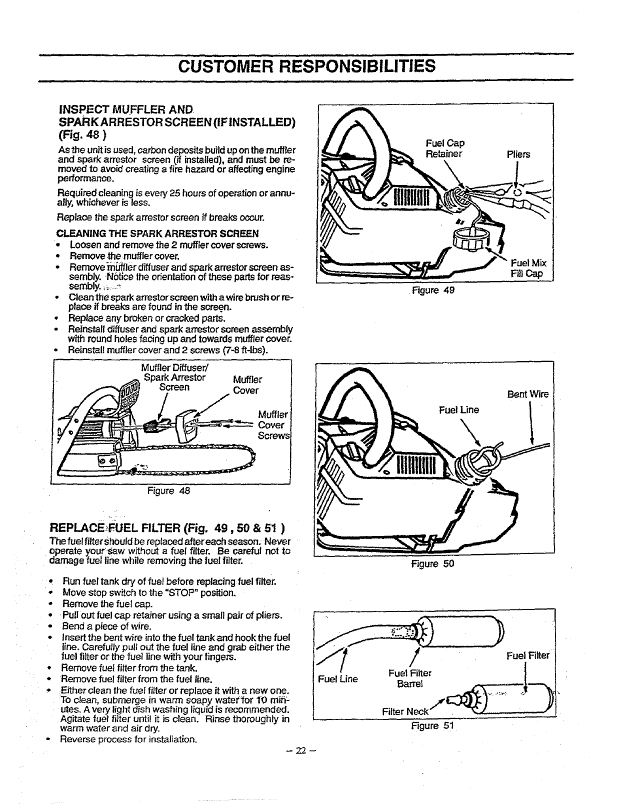
INSPECTMUFFLERAND
SPARKARRESTORSCREEN(IFINSTALLED)
(Fig.4S)
ASthe unit is used,carbondepositsbuilduponthe muffler
and spark arrestor screen (if installed),and must be re-
moved to avoid creatinga fire hazard or affecting engine
performance.
Required cleaningis every 25 hoursof operationorannu-
ally, whicheveris less.
Replace the sparkarrestor screen if breaks occur.
CLEANING THE SPARK ARRESTOR SCREEN
• Loosenand removethe 2mufflercover screws.
=Remove the muffler cover.
=Remove_ler diffuserand spark arrestor screen as-
sembly. Notion the orientationof these partsfor reas-
sembly,_=..._
•Clean the sparkarrestor screenwitha wirebrushor re-
place if breaks are foundin the screen.
•Replace any broken or cracked parts.
• Reinstall diffuser and spark arrestor screen assembly
w_thround holes facing up and towards muffler cover.
° Reinstall muffter cover and 2screws (7-8 ft-lbs).
Muffler Diffuser/
Spark Arrestor Muffler
)o,-° Cove,
..,!_ €_,,_ _ _ Muffler
Cover
Figure 48
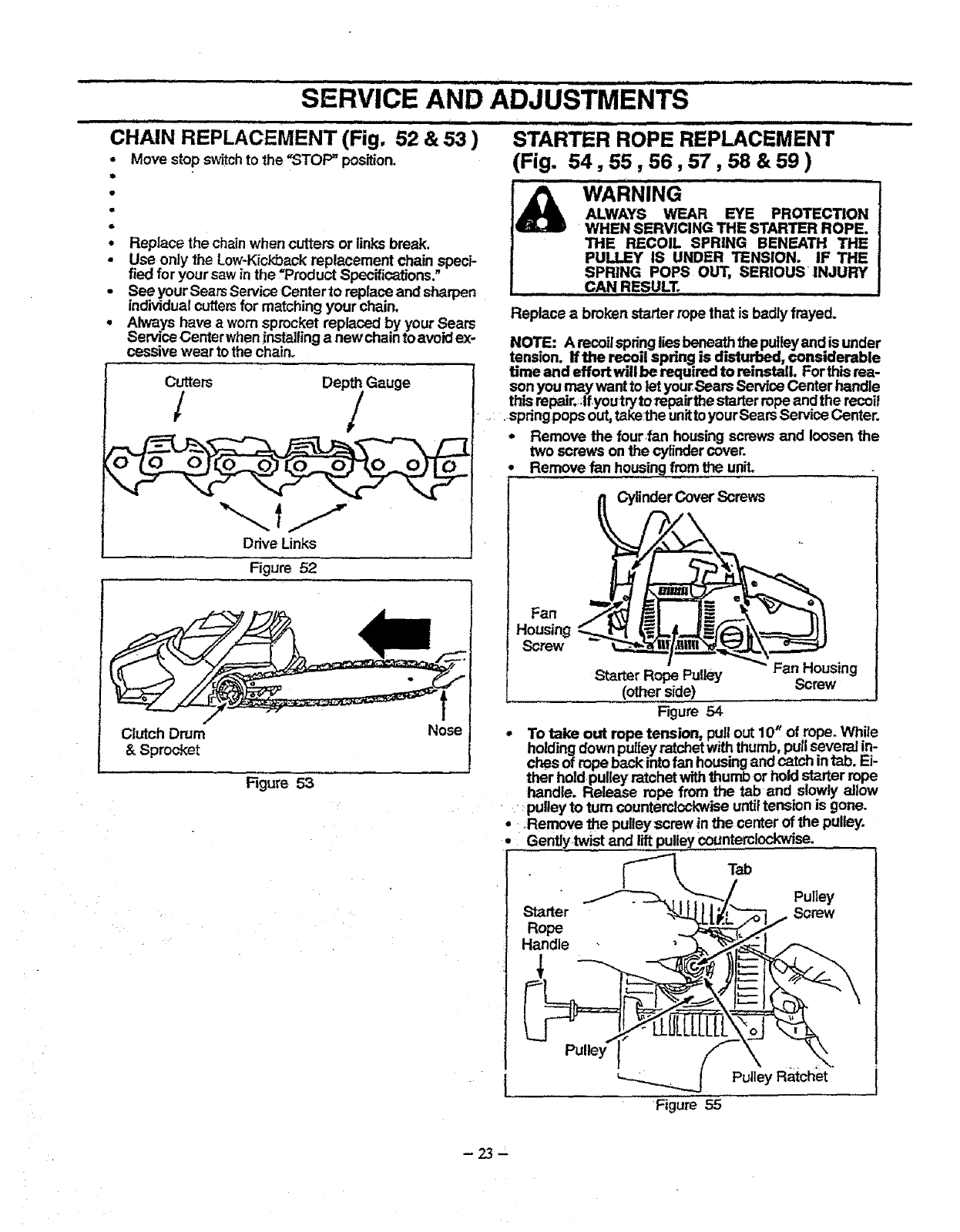
REPLACE_,FUEL RLTER (Fig. 49,50 & 51 )
The fue! filter sh0uldbe replaced after each season: Never
operate yourlsaw without afuel filter. Be careful not to
damage fuel line while removingthe fuel filter.
•Run fuel tank dry of fuel before replacingfuel filter.
-Move stop switch to the =STOP" position.
°Remove the fuel cap.
°Pull out fue! cap retainer usinga small pair of pliers.
•Bend a piece of wire.
• Insert the bent wire into the fuel tank and hookthe fuel
line. Carefully pullout the fuel line and grab either the
fuel filter or the fuel line withyour fingers.
Remove fuel fitterfrom the tank.
Remove fuel filter from the fuel line.
Either clean the fuel filter or replace it with a new one.
To clean, submerge in warm soapy watettor 1O min-
utes. Avery lightdish washing liquidis recommended.
Agitate fuel filter until it is clean. Rinse thoroughly in
warm water and air dry.
oReverse process for installation.
Fuel Line
Fuel Cap
Retainer
Figure 49
Fuel Mix
Filt
Bent Wire
Fuel Line
Rgure 50
Fuel Filter
Fuel Fi_ter
Barrel
Filter Neck,_ _J- ,,r_j .; ._
Figure 51
.=== IH,,, ,,,,,,= = ==,m I=,,H, = ,= i=,= =
SERVICE AND ADJUSTMENTS
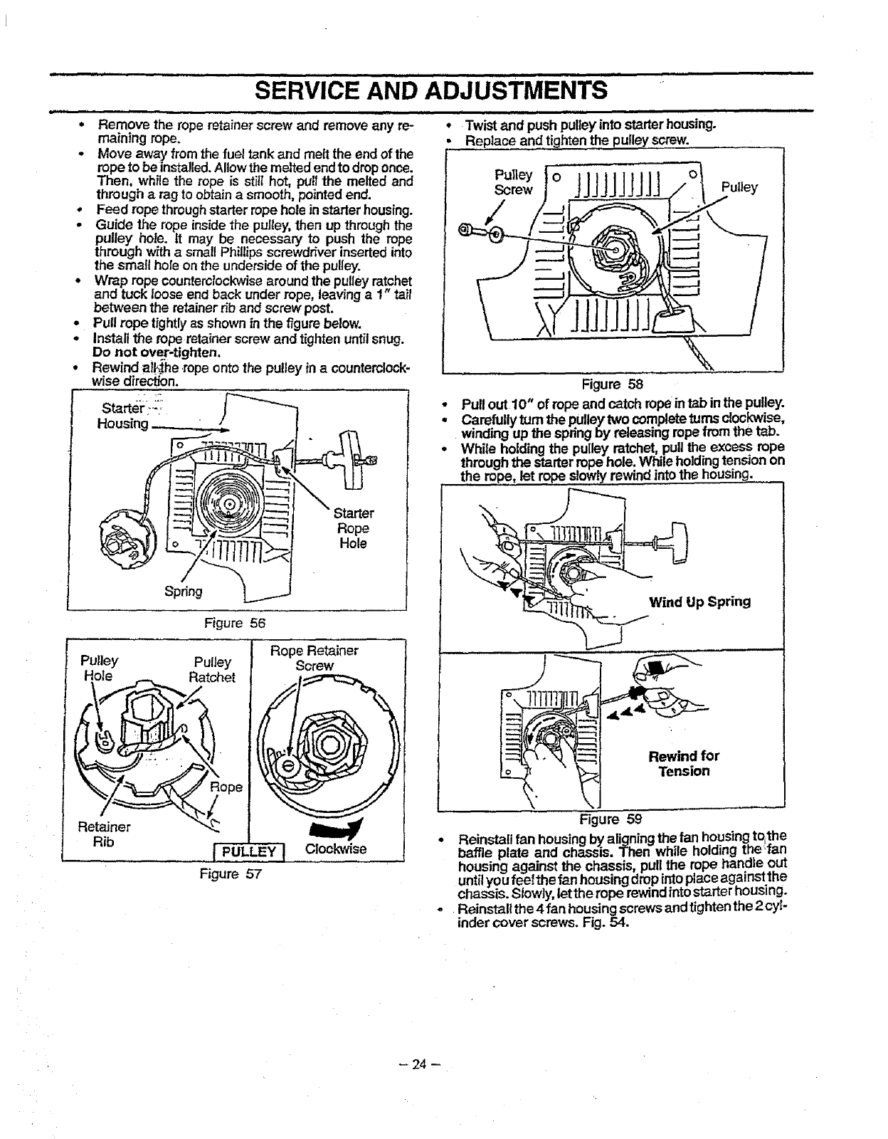
..................REPLY.CEMENT (F,g 52 & 53 ) ........
CHAIN " .
•Move stop switch to the "STOP" position.
Replace the chainwhen cutters or links break.
Use only the Low-Kickback replacement chain speci-
fied for your saw in the "Product Specifications."
See your Sears Service Center to repiace and sharpen
individual cb_tersfor matching your chain,
Always have a wornsprocket replaced by your Sears
Service Centerwhen installing a newohain to avoid ex-
cessive wear to the chain.
Cutters/De? Gauge
Drive Links
Figure 52 ]
Clutch Drum
&Sprocket
Figure 53
i.,H = =
STARTER ROPE REPLACEMENT
(Fig. 54,55,56,57,58 &59 )
Replace abroken starter ropethat is badlyfrayed.
NOTE: A recoilspdnglies beneath the pulleyand is under
tension. If the re_. il spring is d'mt_, €onsiderable
time and effort wdl be required to reinstall, Forthis rea-
son youmay want to let yourSears ServiceCenter handle
thismpair._;If.youtryto repairthe starterrope and the recoil
.... spdngpops out,take:theunittoyourSears Service Center.
- Remove the four:fan housing screws and loosen the
two screws on the cylindercover.
Remove fan housingfromthe uniL
_Cylinder Cover Screws
Fan _=
Housing _
Screw " -
Starter Rope Pulley Screw ing
(other side)
Figure 54
• To take out rope tension, pullout 10" of rope. While
holdingdown pulleyratchetwiththumb, pullseveral in-
ches of rope hack intofan housingand catch intab. Ei-
ther holdpulley ratchetwiththumb or hold starter .rope
handle. Release rope from the tab ano slowly aJiow
•_pulley to turn counterclockwiseuntiltension is gone.
••.Remove the pulley screw in the center of the pulley.
•Gentlytwist and lift pulleycounterclockwise.
Tab
Starter
Rope
Handle
Pulley
Screw
__'-Pulley Ratchet
Figure 55
-23-
Inll II I .,,"l,,lll,',llllI I II I I _ I Ill I I I Ill lU II IlllIlll
SERVICE AND ADJUSTMENTS
J, i= = = =,,,m,n i1 In = nil,
•Twist and push pulley into _-_rter housing.
Replace and tightenthe pulley screw.
III f I U Ill UlllUllll
Remove the rope retainer screw and removeany re-
maining rope.
Move away from the fuel tank and melt the end of the
rope to be insta!led.Allow the meltedendto droponce.
Then, while the rope is still hot, pullthe melted and
through arag to obtainasmooth,pointedend.
•Feed rope throughstarter rope hole instarterhousing.
•Guide the rope inside the pulley, then up through the
pulley hole. it may be necessary to push the rope
through with a small Phillips screwdriver inserted into
the small hole on the underside of the pulley.
•Wrap rope counterclockwisearound the pulleyratchet
and tuck loose end back under rope, leaving a1" tail
between the retainer rib and screw post.
• Pull rope tightly as shown in the figurebelow.
•Install the roperetainer screw and tighten untilsnug.
Do not over-tighten.
°Rewindat!,_he rope onto the pulley in a counterclock-
wise direction.
Starter :--:
Housing _.
Figure 56
o
Spring
Rope
Hole
"] Rope Retainer
Rib I 'PULLEY IClockwise
Figure 57
Pulley o
Screw JJjjJJjJJj Pu,,ey
Figure 58
• Pull out 10" of rope and catch rope intab in the pulley.
• Carefully turn the pulleytwo completeturns clockwise,
winding up the springby releasing rope from the taD.
•While holding the pulley ratchet, pug the excess rope
through the starter rope hole, While .hpld!ngtension on
the rope, let ropeslowlYrewind intome housing.
pSpnng
,,.,,,,
11111
"_Tension
Figure 59
Re nstai fan housingby aligningthe fan housing tqthe
baffle plate and chassis. Then while ho cling the fan
housing against the chassis, pull the rope handle out
until you feelthe fan housing drop into placeagainstthe
chassis. Slowly,let the rope rewind intostarter housing.
Reinstall the 4 fan housing screws and tighten the 2 cyl-
inder cover screws. Fig. 54.
-24-
........................... SERVICE AND..................................................ADJUSTMENTS
i i i .,...H i.,,.,.... i i .m..i i i .it i
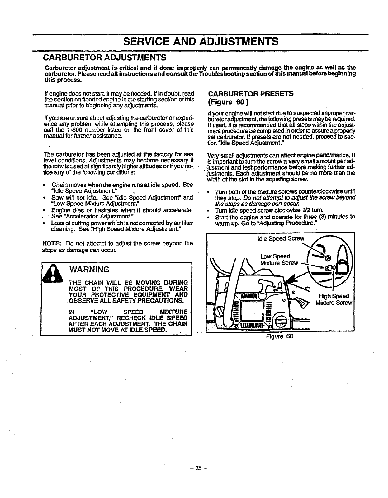
CARBURETOR ADJUSTMENTS
Carburetor adjustment is critical and if done improperly can permanently damage the engine as well as the
carburetor. Please read all instructions and consult the Troubleshooting section of this manual before beginning
this process.
If engine does not start, it may be flooded.If indoubt, read
the section on flooded engine in the startingsection of this
manual prior to beginning any adjustments.
ff you are unsureabout adjusting the carburetor or experi-
ence any problem while attempting this process, please
call the 1-800 number listed on the front cover of this
manual for further assistance.
CARBURETOR PRESETS
(Figure 60 )
If your enginewill notstartdue to suspectedimpropercar-
buretoradjustrnent,the followingpresetsmay be required.
If used, it is recommended that all steps withinthe adjust-
ment procedure be completed in order to assure a propedy
set carburetor. If presets are not needed, proceedto sec-
tion =idle Speed Adjustment."
The carburetor has been adjusted at the factory for sea Very smalladjustments can affect engine performance,!t
level conditions.Adjustments may become necessary if _is importantto turn the screw avery small.amountper aa-
the saw isused at significantlyhigt'ier altitudesor if youno-.,-justment and test,performa(Lce'beforemaking turt.heraa-
tJceany of the following conditions: .justments.Each adjustment should be no more man me
widthof the slot inthe adjusting screw.
-Chain moves when the engine runsat idle speed. See
=Idle Speed Adjustment."
• Saw will not idle. See =Idle Speed Adjustment" and
=Low Speed MixtureAdjustment. =
• Engine dies or hesitates when it should accelerate.
See =Acceleration Adjustment."
• Loss of cuttingpowerwhich is not corrected by air filter
cleaning. See ,High Speed MixtureAdjustment."
•Turn both of the mixture screws countemlockwiseuntil
they stop. Do not attempt to adjust the screw beyond
the stopsas damage can occur.
•Turn idle speed screw clockwise 1/2 tum.
* Start the engine and operate for three (3) minutesto
• warm up. Go to =Adjusting Proceoure:
NOTE: Do not attempt to adjust the screw beyond the
stops as damage can occur.
WARNING
THE CHAIN WILL BE MOVING DURING
MOST OF THIS PROCEDURE, WEAR
YOUR PROTECTIVE EQUIPMENT AND
OBSERVE ALL SAFETY PRECAUTIONS.
IN "LOW SPEED MIXTURE
ADJUSTMENT," RECHECK IDLE SPEED
AFTER EACH ADJUSTME_. THE CHAIN
MUST NOT MOVE AT IDLE SPEED .... Figure 60
SERVICE AND ADJUSTMEN'FS
.......... PROC,:'DuR,:.............................................
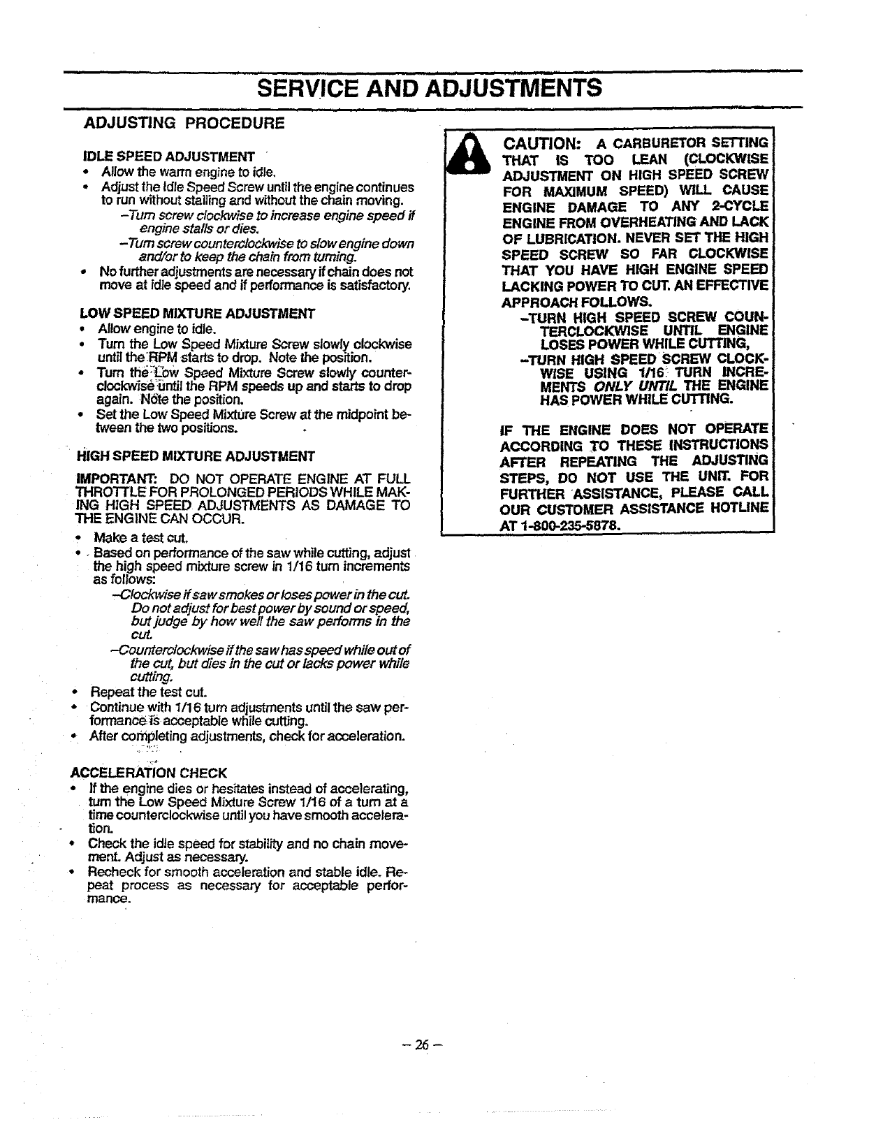
ADJUSTING .....
_cAuTION: A CARBURETORSETTING
THATIS Too LEAN(CLOCKWISE
IDLE SPEED ADJUSTMENT '
•Allowthe warm engine to idle,
•AdjusttheldteSpeedScrewuntiltheenginecontinues
to run withoutstallingand withoutthe chain moving.
-Turn screw clockwise to increase engine speed if
engine stalls or dies
-Turn screwcounterclockwise to slowengine down
and/or to keep the chain from turning
•No further adjustmentsare necessary if chaindoes not
move at idle speed and if performance is satisfactory
LOW SPEED MIXTURE ADJUSTMENT
•Allow engine to idle.
•Turn the Low Speed Mixture Screw slowlyclockwise
untilthe:RPM starts to drop. Note the position.
•Turn the:iLbWSpeed Mixture Screw slowly counter-
clockwise_ntil the RPM speeds up and starts to drop
again. NSte the position,
•Set the Low Speed MixtUreScrew at the midpointbe*
tween the two positions.
ADJUSTMENT ON HIGH SPEED SCREW
FOR MAXIMUM SPEED) WILL CAUSE
ENGINE DAMAGE TO ANY 2-CYCLE
ENGINE FROM OVERHEATING AND LACK
OF LUBRICATION. NEVER SET THE HIGH:
SPEED SCREW SO FAR CLOCKWISE
THAT YOU HAVE HIGH ENGINE SPEED
LACKING POWER TO CUT. AN EFFECTIVE
APPROACH FOLLOWS.
-TURN HIGH SPEED SCREW COUN-
TERCLOCKWISE UNTIL ENGINE
LOSES POWER WHILE CUTTING,
-TURN HIGH SPEED SCREW CLOCK-
WISE USING 1/16! TURN INCRE-
MENTS ONLY UNTIL THE ENGINE
HAS POWER WHILE CLrI"TING;
HiGH SPEED MIXTURE ADJUSTMENT
IMPORTANT: DO NOT OPERATE ENGINE AT FULL
THRO'I-FLE FOR PROLONGED PERIODS WHILE MAK-
ING HIGH SPEED ADJUSTMENTS AS DAMAGE TO
THE ENGINE CAN OCCUR.
•Make a test cut.
•. Based on performance of the saw while cutting,adjust
the high speed mixture screw in 1/16 turn increments
as follows:
-Clockwise ffsaw smokes or losespower in the cut
Do not adjust for best power by sound or speed,
but judge by how weft the saw performs in the
cut
-Oounterclockwise ff the sa whas speed whileout of
the cut, but dies in the cut or lacks power while
cutting
• Repeat the test cut
•Continue with 1/16 turn adjustments until the saw per-
formanc_s acceptable while cutting.
• Aftercotnpletingadjustments, checkforacceleration
ACCELERATION CHECK
• If the engine dies or hesitatesinstead of accelerating,
turn the Low Speed MixtureScrew 1/16 of a turn at a
timecounterclockwise untilyou have smoothaccelera-
tion.
•Check the idtespeed for stabilityand no chain move-
ment.Adjust as necessary.
•Recheck for smoeth acceleration and stable idle. Re-
peat process as necessary for acceptable perfor-
mance
IF THE ENGINE DOES NOT OPERATE
ACCORDING .TO THESE INSTRUCTIONS
AFTER REPEATING THE ADJUSTING
STEPS, DO NOT USE THE UNIT. FOR
FURTHER ASSISTANCE, PLEASE CALL;
OUR CUSTOMER ASSISTANCE HOTLINE
AT 1-800-235"5878. i
-26-
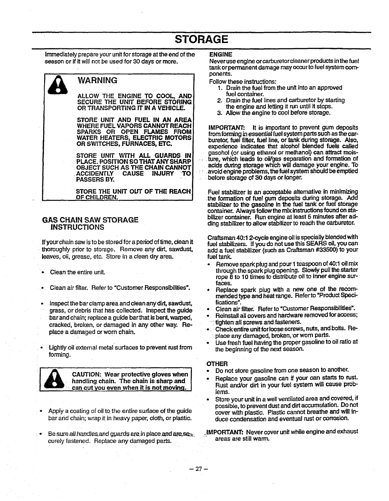
STORAGE
immediately prepare your unfffor storage atthe end of the
season or if it will not be used for 30 days or mere,
WARNING
ALLOW THE ENGINE TO COOL, AND
SECURE THE UNIT BEFORE STORING
OR TRANSPORTING IT IN A VEHICLE.
STORE UNIT AND FUEL IN AN AREA
WHERE FUEL VAPORS CANNOT REACH
SPARKS OR OPEN FLAMES FROM
WATER HEATERS, ELECTRIC MOTORS
OR SWITCHES, FURNACES, ETC.
STORE UNIT WITH ALL GUARDS IN
PLACE. POSITION SO THAT ANY SHARP
OBJECT SUCH AS THE CHAIN CANNOT
•ACCIDENTLY CAUSE INJURY TO
PASSERS BY.
STORE THE UNIT OUT OF THE REACH
OF CHILDREN.
GAS CHAIN SAW STORAGE
INSTRUCTIONS
If yourchain saw is to be stored for a period of time, clean it
thoroughly prior to storage. Remove any dirt, sawdust,
leaves, oil, grease, etc. Store in a clean dry area.
• Clean the entire unit.
•Clean air filter. Refer to "Customer ResponstbiFdies".
inspect the barclamp area and clean any dirt, sawdust,
grass, or debris that has collected. Inspect the guide
bar and chain; replace a guide bar that is bent, warped,
cracked, broken, or damaged in any other way. Re-
place a damaged or worn chain.
Ughtly oil external metal surfaces to prevent rustfrom
forming.
j& I
CAUTION: Wear protective gloves when
handling chain. The chain is sharp and
can cut you even when it is not moving.
• Apply a coating of oil to the entire surface of the guide
bar and chain; wrap it in heavy paper, cloth, or plastic.
....................... ,,, ,, , =,=
ENGINE
Never useengine orcerburetorcleanerproductsinthefuel
tank or permanent damagemay occurto fuel systemcom-
ponents.
Follow these instructions:
1. Drain the fuel from the unitinto an approved
fuel container.
2. Drain the fuel lines and carburetorby starting
the engine and lettJngit run until it stops.
3. Allow the engine to cool before storage.
IMPORTANT: It is importantto prevent gum deposits
from formingin essentialfuel systempartssuchas the car-
buretor, fuel filter, fuel line, or tank during storage. Also,
experience indicates that alcohol blended fuels called
gasohcl (or using ethanolor methanol)can attract tools-
.... ture" whichteade to:oil/gas-separation and formation of
acids during storage which wil! damage your engine. To
:__ avoid engineproblems,thefuel systemshouldbe emptied
before storage of 30 days Or|0nger.
Fuel stabilizer is an acceptable alternative in rrdntmizing
the formation of fuel gum depositsdudng storage. Add
stabilizer to the gasoline in the fuel tank or fuel storage
container. Alwaysfollowthe mix instructionstouna onsta-
bilizer container. Run engine at least 5 minutes after ad-
ding stabilizer to allow stabilizerto reach the carburetor.
Craftsman 40:1 2-cycle engineoilis speciallyblended with
fuel stabilizers. If you do notuse this SEARS oil,you can
add a fuel stabilizer (such as Craftsman #33500) to your
fuel tank.
•Remove spark plugand pour 1teaspoon of 40:1oil mix
throughthe spark plugopening. Slowly puUthe.starter
rope 8 to 10 times to distributeoi!to inner engine sur-
faces.
•Replace spark plug with a new one of the rectum-
mended type and heat range. Referto =ProductSpeci-
fications".
•Clean air filter. Refer to =Customer Responsibilities'.
•Reinstall all covers and hardware removed for access;
:tightenall screws andfasteners.
•Checkentire unitforlcosescrews, nuts, andbolts. Re-
place any damaged, broken, or wornparts.
• Use fresh fuel havingthe proper gasoline to oil ratio at
the beginning of the next season.
OTHER
•Do not store gasolinefrom one season to another.
•Replace your gasoline can if your can startsto rusL
Rust and/or dirt in your fuel system will cause prob-
lems.
• Store your unitin awell ventilated area and covered, if
possible, to prevent dust and dirt accumulation. Do not
cover with plastic. Plastic cannot breathe and will in-
duce condensation and eventual rust or corrosion.
•Besure _l ha_dJesoandggaZds are,in place.and are.s_: IMPORTANT: Never coveruoitwhile engine and exhaust
curetyfastened. Replace any damaged parts, areas are stillwarm.
-- 27 -

,, iiiiiiiiiii =l
iii iiiii i • ,c i i,, ,,111111i
TROUBLE SHOOTING CHART
sY i=TO ......... cAusE
Engine will not start
or will run onlyfor
afew seconds af-
ter starting.
Engine will not idle
properly.
Engine will not
accelerate,lacks
power, or dies
under a load.
Engine
smokes
excessively.
Engine runs hot.
,.,,,,,, ..
Oil inadequate for 1.
bar and chain 2.
lubrication. 3.
Chain moves at Idle 1.
Speed. 2.
,...,,.,,.........
Chain does not move t,
when engine is 2.
accelerated. 3.
4.
i
Chain clatters 1.
orcuts roughly. 2.
3.
4.
5.
6.
,,,,,,,,,, ,
Chain stops within 1.
in,ii iiii iiii ii ii ml i i i
TROUBLE SHOOTING POINTS
,,11111111 i iii IIIH II
1. Fuel
2• Engine flooded.
3. Spark plugnot fidng-
4. Fuel not reaching carburetor.
5. Carburetor requires adjustment.
6. Stop Switch off.
7. None of the above.
1. Idte speed set toofast ortoo slow.
2. Low speed mixture requiresadjustment.
3. Crankshaft seals worn.
4. Compression low.
5, None of the above.
..........i,
1. Air filter dirty.
2. Spark plugfouled.
3. Carburetor requires adjustment.
4, Exhaust ports or muffler outletsplugged.
5. Compressionlow.
6. None of the above.
4.Air..er
2. Fuel mixture incorrect.
3. High speed mixture requires adjustment.
• Choke partially on.
5. Crankcase leak. ,., Hi
1. Fuel mixture incorrect.
2. High speed mixture set too low (Lean).
3. Spark plug incorrect.
4. Exhaust ports or muffler outlets plugged.
5, Carbon build-up on muffler outlet screen.
6. Fan housing]cylinder fins dirty.
7, None of the above.
.... i i , i H..ll
Oil tank empty.
Oil pump or oil filter c_ogged.
Guide bar oil hole blocked•
Idte speed requires adjustrnenL
Clutch requires repa=r.
i , i i ,,,i, ,,. H i
Chain tension too tight•
Carburetor requires adjustment.
Guide bar rails pinched.
Glut.ch slipping. ..................
Chain tension incorrect,
Cutters damaged.
Chain worn.
Cutters dull, impropedysharpened, or
depth gauges too high.
Sprocket worn.
Chain installed backwards.
Chain cutter tops notfiled flat•
REMEDY
....11 Fill tank with correctfuel mixture
,See "Starting Instructions."
Clean fuel filter; inspect fuel line.
1 Install new plug/check ignition system.
6_ See "Carburetor Adjustments."
Move switchto the ,START" position.
_ Contact your Sears Service Ce,,nter/Dept.
1. See "Carburetor Ad ustrnents."
2. See "Carburetor Ad ustments."
3. Contact your Sears Service CentedDepL
4. Contact your Sears Service Center/Dept.
5, Contact your Sears Service Center/Dept:......
1. Clean or replace air filter.
2. Clean or replace spark plug arid re--gap,
3. See =carburetor A_ustments. _
4. Contact your Sears Service Center/Dept.
5_ Contact your Sears Service Center/Dept,
,Contact your Sears Service,Center/Dept`
1. Clean or replace air filter.
2. Refuel withcorrect fuel mixture.
3. See =CarburetorAdjustments,"
4. Push Choke knob in.
5, Contact YourSears Service Center/Dept.
1. See "Fueling Your Unit." .
2. See "CarburetorAdjustments.
3. Replace with correct plug. __.
4. Contact yourSears Servicecenter/uep_.
5. Clean spark arrestor screen.
6. Clean area.
7. Contact your Sears Service Center/Dept.
1. RII oil tank.
2. Contact your Sears Service Center/Dept.
3, Remove bar and clean.
,,,,H
1. See =carburetor Adjustments," _
2. Contact your Sears Sewice Center/Dept.
1. See "Chain Tension."
:2. See =Carburetor Adjustments."
3. Repair or replace.
4. Contact your,Sears Service Center/DepL
1, See =Chain Tension•"
2. Contact your Sears Service CentedDept`
3. Resharpen or replacechain.
4. See the chain sharpening instructions.
5. Contact your Sears Service Center/Dept`
6. Install chain !n right direction. ...........
t. See the chain sharpening instructions.
2. Repair or replace guide bar.
3. Contact your Sears Service Center/Dept.
1. Resharpen until all cutters have equal
angles and lengths.
2. Resharpen until all cutters have equal
angles and leng_.s....
3. Replace guide bar. ....
the cut.
Chain cuts at an
angle.
2. Guide bar burred or bent; rails uneven.
3. Clutch slipping,
1, Cutters damaged on one side,
2. Chain dull on one side.
3. Guide bar bent or worn.
ff situations occur which are not covered in this manual, use care and good judgement.
ff you need assistance, contact your SEARS Service Center/Department or the
CUSTOMER ASSISTANCE HOTLINE at 1-800-235-5878.
-28,

29

...... ............... ,, , , ,,,i ,.,, i, H i ,,liH H j JH i]l JJ,ll
REPAIR PARTS
ii i ,i ,,,,, ,,, , ,,, , J i Ni,,i i mini ]l , •,l,,,,l,ll,,,, ........
3O

3t

............. NOTES ..................
i i iiiii , iii iii iii i i iiii i iiiiiiiiii i IIII i iiiiiii
32

33

NOTES
34
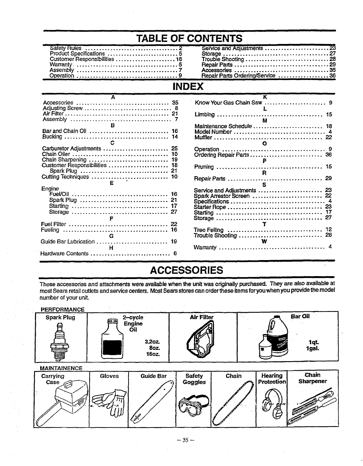
iiiiiiiiiiiii1[1111i / I II I I IIIIIIIIIIIHII IIIIII I
TABLE OF CONTENTS
....................." ' ana _oj'ustments ' "'SateIy Rules .................................. 2",Service ............... 23
ProductSpecifications .......................... 5 Storage ...................................... 27
Customer Responsibilities...................... 18 Trouble Shooting ............................. 28
Warranty............. _........................ 5Repair Parts .................................
Assembly ...................................... 7 Accessories ............................... _..
Operation ..................................... 9 Repair Parts Orderinq_ervice .................. 36
/ IIIIIII1_1/11/ I IIIIIIIIIIIIIIII I IIIIII IIIII / III]1111gll / II II
INDEX
i i iiiii i iiiii i
A
Accessories..................................35
Adjusting Screw ................................ 8
,ajr Filter ...................................... 21
Assembly ..................................... 7
B
Bar and Chain Oif ............................. 16
Bucking ...................................... 14
C
Carburetor Adjustments ........................ 25
Chain Oiler ................................... 10
Chain Sharpening .............................. 19
Customer Responsibilities ...................... 18
Spark Plug ................................ 21
CuttingTechniques ............................ 10
E
Engine
FueIIOil...................................16
Spark Plug ................................ 21
Starting ................................... 17
Storage ................................... 27
F
Fuel Filter .................................... 22
Fueling ...................................... 16
G
Guide Bar Lubrication.......................... 19
H
Hardware Contents ............................. 6
III[ ....
IIIIIIIIIIIIIII II I III I! iiiiiiiiiiiiiiiiiIIII "
K
Know Your Gas Chain Saw ...................... 9
L
Limbing ...................................... 15
M
Maintenance Schedule ......................... 18
Model Number ................................. 4
Muffler .......................................22
O
Operation .....................................g
OrderingRepairParts...........................36
P
Pruning ......................................... 15
R
Repair Parts .................................. 29
S
Service and Adjustments .................... ... 23
Spark Arrestor Screen ......................... 22
Specifications .................................. 4
Starter Rope .................................. 23
Starting ...................................... 17
Storage ...................................... 27
T
Tree Felling .................................. 12
Trouble Shooting ..................... , ........ 28
W
Warranty .......................... ............ 4
.............................. i im......i, i
ACCESSORIES
These accessories and attachments were availablewhen the unit was originallypurchased. They are also available at
most Sears retait outlets and service centers. MostSears storescan order these items foryou when you provide the model
number of your unit.
PERFORMANCE
Spark Plug
MAINTA1NENCE
Carrying Gloves
2-cycle
Engine
Oil
3.20:"
80777
16o:'-
Guide Bar
Air Filter
Safety Chain
Goggles
......." .... BarOil .......
Hearing
Protection
lqL
lgat.
ii ,,,,,,,,,
¸Chain
Sharpener
-35 -
., i, i i i i
Operator's
Manual
Model No.
358.356242
IF YOU NEED REPAIR
SERVICE OR PARTS:
REPAIR SERVICE
1-800-4-REPAIR
(1-800-473-7247)
ORDERING PARTS
1-800-FON-PART
(1-800-366-7278)
CRRFTSHRN°
2,5 cu. inJ36 cc 2 CYCLE
18 in. Guide Bar
GASOLINE CHAIN SAW
Each Gasoline Chain Saw has itsown model number. The model
numberfor your unit will be foundon adecal attached to the unit.
All partslistedherein may be orderedthrough Sears, Roebuckand
Co, Service Centers and most Retail Stores.
WHEN ORDERING REPAIR PARTS, ALWAYS GIVE THE FOL-
LOWING INFORMATION
. PRODUCT- =GASOLINE CHAIN SAW"
• MODEL NUMBER-358.356242
. PART NUMBER
• PART DESCRIPTION
YourSears merchandise has added value when you considerthat
Sears has service units nationwidestaffed withSears trainedtech-
nicians..: professional technicians specifically trained on Sears
products, havingthe parts, tools and the equipment to insure that
we meet our pledge to you, we service what we sel!.
•/
Sears, Roebuck and Co., Hoffman Estates, IL 60179 USA
,,, ,,,,i,
