Craftsman 536772341 User Manual EDGER Manuals And Guides L0212165
CRAFTSMAN Edger Manual L0212165 CRAFTSMAN Edger Owner's Manual, CRAFTSMAN Edger installation guides
User Manual: Craftsman 536772341 536772341 CRAFTSMAN EDGER - Manuals and Guides View the owners manual for your CRAFTSMAN EDGER #536772341. Home:Lawn & Garden Parts:Craftsman Parts:Craftsman EDGER Manual
Open the PDF directly: View PDF ![]() .
.
Page Count: 64
I(RRFTSMRN1
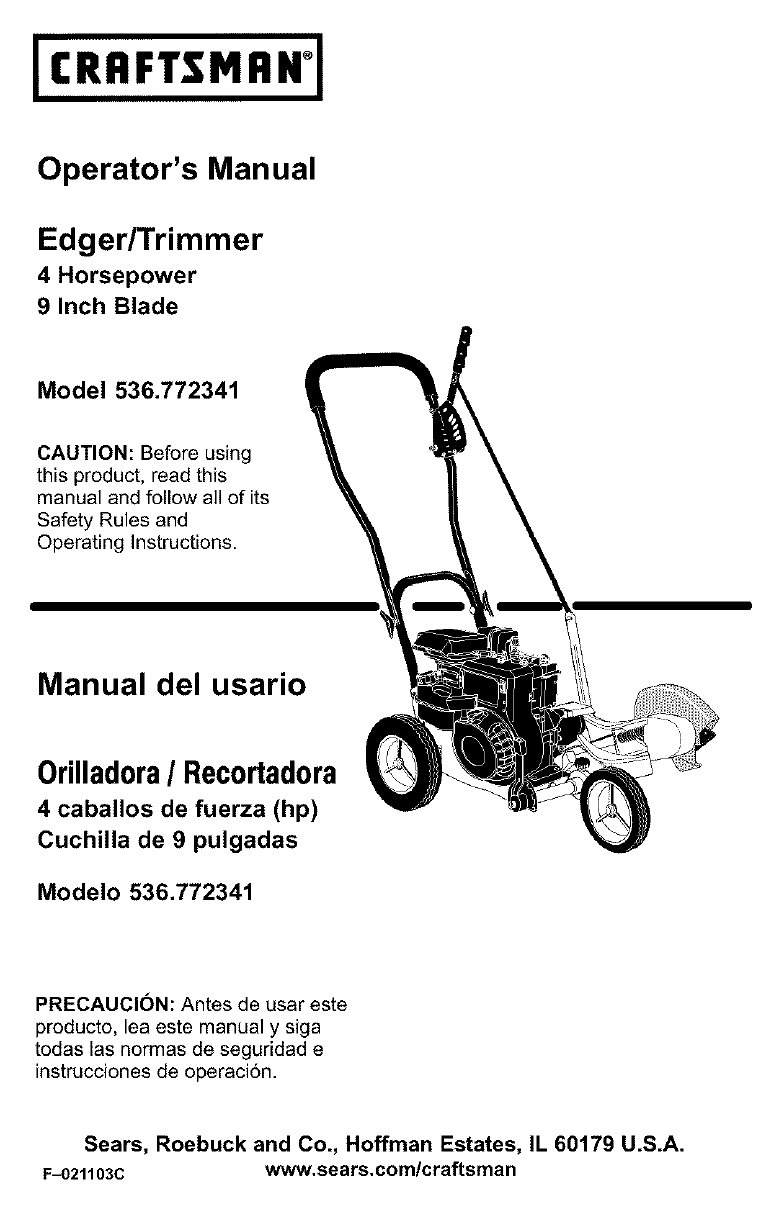
Operator's Manual
Edger/Trimmer
4 Horsepower
9 Inch Blade
Model 536.772341
CAUTION: Before using
this product, read this
manual and follow all of its
Safety Rules and
Operating Instructions.
Manual del usario
0rilladora/Recortadora
4 caballos de fuerza (hp)
Cuchilla de 9 pulgadas
Modelo 536.772341
PRECAUCION: Antes de usar este
producto, lea este manual y siga
todas las normas de seguridad e
instrucciones de operaci6n.
Sears, Roebuck and Co., Hoffman Estates, IL 60179 U.S.A.
F_)21103C www.sears.com/craftsman
TABLE OF CONTENTS
WARRANTY STATEMENT
SAFETY RULES
INTERNATIONAL SYMBOLS
ASSEMBLY
OPERATION
MAINTENANCE
2 SERVICE AND ADJUSTMENT 19
3 TROUBLESHOOTING TABLE 22
5 EDGER REPAIR PARTS 26
6 ENGINE REPAIR PARTS 34
10 SPANISH (ESPAI_IOL) 40
16 PARTS AND SERVICE BACK COVER
WARRANTY STATEMENT
LIMITED TWO-YEAR WARRANTY ON CRAFTSMAN EDGER
For two years from the date of purchase, when this Craftsman Edger is maintained, lubri-
cated, and tuned up according to the operating and maintenance instructions in the owner's
manual, Sears will repair, free of charge, any defect in material or workmanship.
If this Craftsman Edger is used for commercial or rental purposes, this warranty applies for
only 90 days from the date of purchase.
This warranty does not cover the following:
• Expendable items which become worn during normal use, such as spark plugs, etc.
• Repairs necessary because of operator abuse or negiigence, including bent crank shafts
and the failure to maintain the equipment according to the instructions contained in the
owner's manual.
WARRANTY SERVICE IS AVAILABLE BY RETURNING THE CRAFTSMAN EDGER TO
THE NEAREST SEARS SERVICE CENTER IN THE UNITED STATES. THIS WARRANTY
APPLIES ONLY WHILE THIS PRODUCT IS IN USE IN THE UNITED STATES.
This warranty gives you specific Iegal rights, and you may also have other rights which vary
from state to state.
Sears, Roebuck and Co., D817WA, Hoffman Estates, IL 60179
Engine Exhaust, some of its
constituents, and certain vehicle
components contain or emit che-
micals known to the State of Cali-
fornia to cause cancer and birth
defects or other reproductive
harm.
Battery posts, terminals and rela-
ted accessories contain lead and
lead compounds, chemicals
known to the State of California to
cause cancer and birth defects or
other reproductive harm. WASH
HANDS AFTER HANDLING.
F_021103C
IMPORTANT: This unit is equipped
with an internal combustion engine
and must not be used on or near
any unimproved forest-covered,
brush-covered or grass-covered
land unless the engine's exhaust
system is equipped with a spark at-
rester meeting applicable local or
state laws (if any). If a spark arrest-
er is used, it must be maintained in
effective working order by the op-
erator.
In the State of California the above is
required by law (Section 4442 of the
California Public Resources Code),
Other states may have similar laws,
Federal laws apply on federal lands,
A spark attester/muffler is available
through your nearest Sears Service
Center (see the REPAIR PARTS sec-
tion in this manual),

SAFETY RULES
Safe Operation Practices for Edger.
WARNING: Look for this symbol to point out important safety precautions.
It means: "Attention! Become Alert! Your Safety Is Involved."
_IL ARNING: To prevent acciden-
tal starting when setting-up,
transporting, adjusting or mak-
ing repairs, always disconnect spark
plug wire and put wire where it cannot
contact the spark plug.
Before Use
• Read the owner's manual carefutty. Be
thoroughly familiar with the controls and
the proper use of the Edger. Know how to
stop the Edger and disengage the controls
quickly.
• Do not operate the Edger without weadng
adequate outer garments. Wear footwear
that will improve footing on slippery sur-
faces.
• Keep the area of operation clear of all per-
sons, particularly small children and pets.
• Thoroughly inspect the area where the
Edger is to be used and remove all foreign
objects.
Fuel Safety
• Handle fuel with care; it is highly flam-
mable.
• Use an approved container.
• Check fuel supply before each use, allow-
ing space for expansion as the heat of the
engine and/or sun can cause fuel to ex-
pand.
• Fill fueI tank outdoors with extreme care.
Never fill fuel tank indoors. Replace fuel
tank cap securely and wipe up spilled fuel.
• Never remove the fuel tank cap or add fuel
to a running or hot engine.
• Never store fuel or Edger with fuel in the
tank inside a building where fumes may
reach an open flame.
F_)211030
Operating Safety
• Never allow children or young teenagers to
operate the Edger. Keep them away while
it is operating. Never allow adults to oper-
ate the Edger without proper instruction.
• Do not operate this machine if you are tak-
ing drugs or other medication which can
cause drowsiness or affect your ability to
operate this machine.
• Do not use this machine if you are mentaliy
or physically unable to operate this ma-
chine safely.
• Always wear safety glasses or eye shields
during operation or whiIe performing an
adjustment or repair to protect your eyes
from foreign objects that may be thrown
from the Edger.
• Do not put hands or feet near or under ro-
tating parts.
• Exercise extreme caution when operating
on or crossing gravel drives, walks, or
roads. Stay alert for hidden hazards or
traffic.
• Exeroise caution to avoid slipping or falling.
• Never operate the Edger without proper
guards, plates, or other safety protective
devices in place.
• Never operate the Edger at high transport
speeds on slippery surfaces. Look behind
and use care when backing.
• Never allow bystanders near the Edger.
• Keep children and pets away while
operating.
• Never operate the Edger without good visi-
bility or light.
• Do not run the engine indoors. The ex-
haust fumes are dangerous, containing
CARBON MONOXIDE, an ODGRLESS
and DEADLY GAS.
• Take all possible precautions when leaving
the Edger unattended. Stop the engine.
• DO not ovedoad the Edger capacity by at-
tempting to till too deep at too fast a rate.
3
SAFETY RULES
Safe Storage
• Always refer to the owner's manual instruc-
tions for important details if the Edger is to
be stored for an extended period.
• Never store the Edger with fuel in the fuel
tank inside a building where ignition
sources are present such as water and
space heaters, clothes dryers, and the like.
Allow the engine to cool before storing in
any enclosure.
• Keep the Edger in safe working condition.
Check all fasteners at frequent intervals for
proper tightness.
Repair /Adjustments Safety
• After striking a foreign object, stop the en-
gine. Remove the wire from the spark plug,
and keep the wire away from the plug to
prevent accidental starting. Thoroughly in-
spect the Edger for any damage, and re-
pair the damage before restarting and
operating it.
If Edger should start to vibrate abnormally,
stop engine and check immediately for the
cause. Vibration is generally a warning of
trouble.
Stop the engine whenever you leave the
operating position. Also, disconnect the
spark plug wire before unclogging the
blade and when making any repairs, ad-
justments, or inspections.
When cleaning, repairing, or inspecting,
shut off the engine and make certain all
moving parts have stopped.
Never attempt to make any adjustments
while the engine is running.
F=021103C 4

SAFETY RULES
INTERNATIONAL SYMBOLS
IMPORTANT: Many of the following symbols are located on your unit or on literature sup-
plied with the product. Before you operate the unit, learn and understand the purpose for
each symbol.
Control And Operating Symbols
Slow Fast Fuel Oil
Primer Button
Safety Warning Symbols
A
WARNING WARNING
Thrown Objects. Rotating Parts. Stop Engine. WARNING
Keep Bystanders Away. Disconnect Spark Wire Before
Making Adjustments.
IMPORTANT WARNING STOP
Read Owner's Manual Wear Eye Protection
Before Operating
This Machine.
F_021103C 5
ASSEMBLY
ASSEMBLY
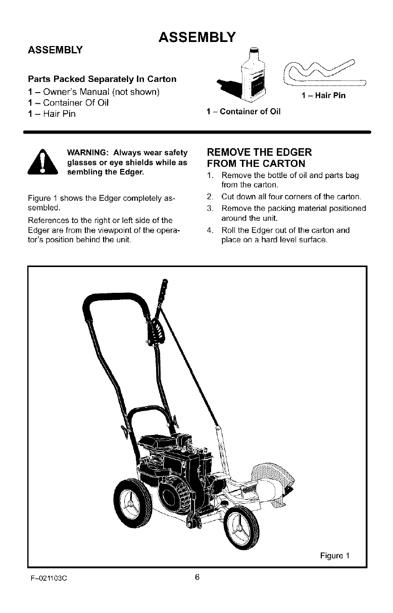
Parts Packed Separately In Carton
1 - Owner's Manual (not shown)
1 - Container Of Oil
1 - Hair Pin
1 -HairPin
1-Container of Oil
WARNING: Always wear safety
glasses or eye shields while as,
sembling the Edger.
Figure 1 shows the Edger completely as-
sembled.
References to the right or left side of the
Edger are from the viewpoint of the opera-
tot's position behind the unit.
REMOVE THE EDGER
FROM THE CARTON
1. Remove the bottle of oil and parts bag
from the carton.
2. Cut down all four corners of the carton.
3. Remove the packing material positioned
around the unit.
4. Roll the Edger out of the carton and
place on a hard level surface.
Figure 1
F_021103C 6
ASSEMBLY
HOW TO RAISE THE HANDLE
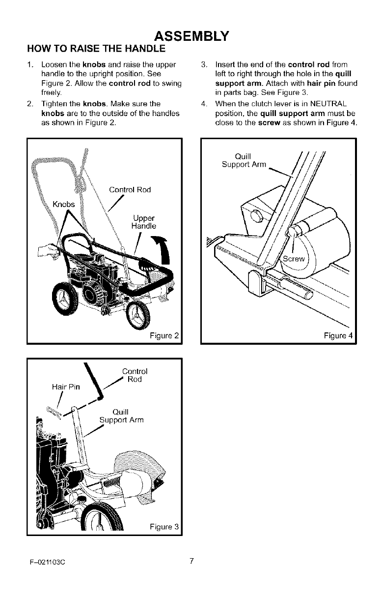
1. Loosen the knobs and raise the upper
handle to the upright position. See
Figure 2. Allow the control rod to swing
freely.
2. Tighten the knobs. Make sure the
knobs are to the outside of the handles
as shown in Figure 2.
3. Insert the end of the control rod from
left to right through the hole in the quill
support arm. Attach with hair pin found
in parts bag. See Figure 3.
4. When the clutch lever is in NEUTRAL
position, the quill support arm must be
close to the screw as shown in Figure 4.
Control Rod
Upper
Handle
Figure 2
Quill
Support Arm
Figure 4
Rod
Hair Pin
Quill
upport Arm
Figure 3
F_021103C 7
ASSEMBLY
HOW TO PREPARE THE ENGINE
Fill With Oil
This Edger was shipped with a container of
SAE30 motor oil. Add this oil to the engine
before operating. To fill the crankcase, see
"How To Add The Engine Oil".
NOTE: The engine may contain a small
amount of oil. When adding oil, frequently
insert the oil fill cap/dipstick and check
the amount of oil in the engine. DO NOT
OVERFILl.
Oil Recommendations
Only use high quality detergent oil rated with
API service classification SG. Select the oil's
SAE viscosity grade according to your ex-
pected operating temperature. Above 32 de-
grees, use SAE30 oil. Although
multi-viscosity oils (5W30, lOW30, etc.) im-
prove starting in cold weather, these multi-
viscosity oils will result in increased oil
consumption when used above 40 degrees.
Check the engine oil level more frequently to
avoid possible engine damage from running
the engine low on oil.
4
32 °
Colder _ --Warmer
5W30 SAE30
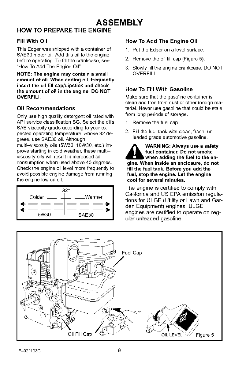
How To Add The Engine Oil
1. Put the Edger on a level surface.
2. Remove the oil fill cap (Figure 5).
3. Slowly fill the engine crankcase. DO NOT
OVERFILL.
How To Fill With Gasoline
Make sure that the gasoline container is
clean and free from dust or other foreign ma-
terial. Never use gasoline that could be stale
from long periods of storage.
1. Remove the fuel cap.
2. Fill the fuel tank with clean, fresh, un-
leaded grade automotive gasoline.
_hlL ARNING: Always use a safety
fuel container. Do not smoke
when adding the fuel to the en=
gine. When inside an enclosure, do not
fill the fuel tank. Before you add the
fuel, stop the engine. Let the engine
cool for several minutes.
_1 The engine is certified to comply with
California and US EPA emission regula-
tions for ULGE (Utility or Lawn and Gar-
den Equipment) engines. ULGE
engines are certified to operate on reg-
ular unleaded gasoline.
Fuel Cap
Oil Fill Cap
F_021103C 8
ASSEMBLY
_" CHECKLIST
For the best performance and satisfaction
from this quality product, please review the
following checklist before you operate the
Edger:
#-" All assembly instructions have been
completed.
Check carton. Make sure no loose
parts remain in the carton.
All fasteners have been propedy tight-
ened.
As you learn how to use the Edger, pay extra
attention to the following important items:
#-'_" Engine oil is at proper level.
#-'_" Fuel tank is filled with a fresh, clean,
regular Unleaded gasoline.
#-'_" Become familiar and understand the
function of all controls. Before you
start the engine, operate all controls.
F_021103C 9
OPERATION
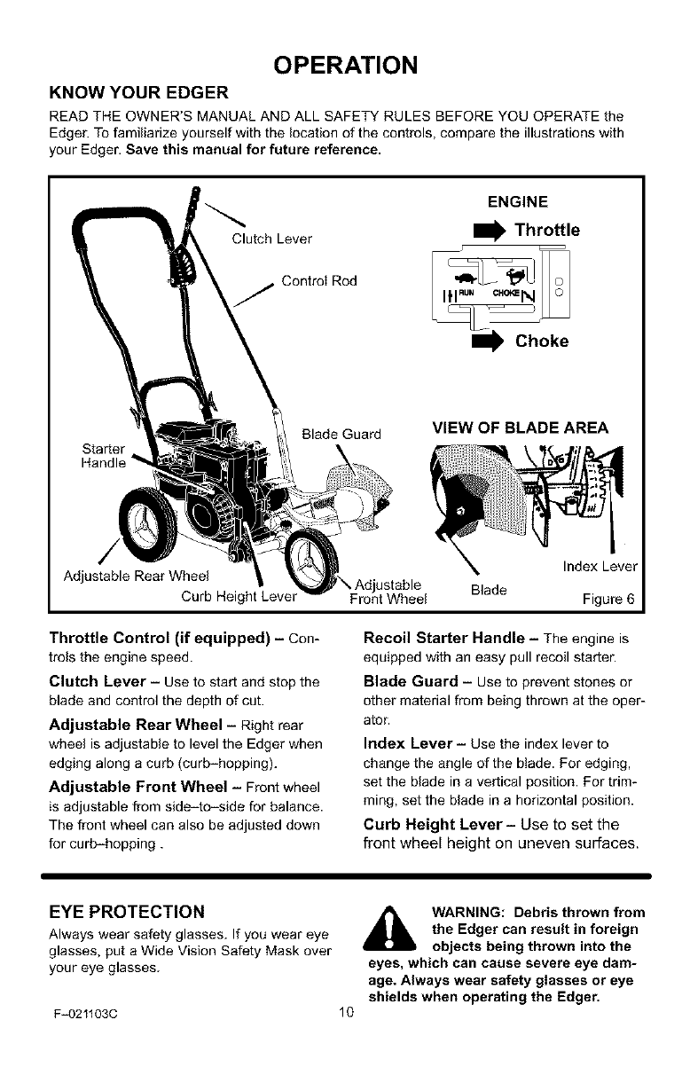
KNOW YOUR EDGER
READ THE OWNER'S MANUAL AND ALL SAFETY RULES BEFORE YOU OPERATE the
Edger. To familiarize yourself with the location of the controls, compare the illustrations with
your Edger. Save this manual for future reference.
Clutch Lever
ENGINE
I_ Throttle
Control Rod
Starter
Handle "
Blade Guard VIEW OF BLADE AREA
Adjustable Rear Wheel
Curb Height Lever Front Wheel Blade
Index Lever
Figure 6
Throttle Control (if equipped)- Con-
trols the engine speed.
Clutch Lever - Use to start and stop the
blade and control the depth of cut.
Adjustable Rear Wheel -Right rear
wheel is adjustable to level the Edger when
edging along a curb (curb-hopping).
Adjustable Front Wheel - Front wheel
is adjustable from side-to-side for balance.
The front wheel can also be adjusted down
for curb-hopping.
Recoil Starter Handle - The engine is
equipped with an easy pull recoil starter'.
Blade Guard -Use to prevent stones or
other material from being thrown at the oper-
ator.
Index Lever- Use the index lever to
change the angle of the blade. For edging,
set the blade in a vertical position. For trim-
ming, set the blade in a horizontal position.
Curb Height Lever- Use to set the
front wheel height on uneven surfaces.
EYE PROTECTION
Always wear safety glasses. If you wear eye
glasses, put a Wide Vision Safety Mask over
your eye glasses.
F_021103C
WARNING: Debris thrown from
the Edger can result in foreign
objects being thrown into the
eyes, which can cause severe eye dam-
age. Always wear safety glasses or eye
shields when operating the Edger.
10
OPERATION
HOW TO STOP THE EDGER
Emergency Stopping
To immediately stop the engine and the
blade, move the throttle control to the STOP
position.
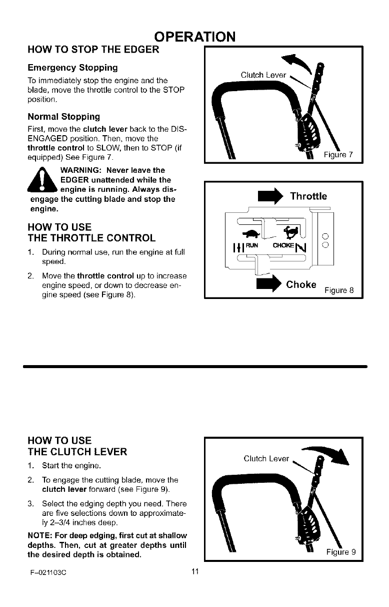
Normal Stopping
First, move the clutch lever back to the DIS-
ENGAGED position. Then, move the
throttle control to SLOW, then to STOP (if
equipped) See Figure 7.
_ARNING: Never leave the
EDGER unattended while the
engine is running. Always dis-
engage the cutting blade and stop the
engine.
HOW TO USE
THE THROTTLE CONTROL
1. During normal use, run the engine at full
speed.
2. Move the throttle control up to increase
engine speed, or down to decrease en-
gine speed (see Figure 8).
Figure 7
I Throttle
Figure 8
HOW TO USE
THE CLUTCH LEVER
1. Star the engine.
2. To engage the cutting blade, move the
clutch lever forward (see Figure 9).
3. Select the edging depth you need. There
are five selections down to approximate-
ly 2-3/4 inches deep.
NOTE: For deep edging, first cut at shallow
depths. Then, cut at greater depths until
the desired depth is obtained.
Clutch Lever
Figure 9
F_021103C 11
OPERATION
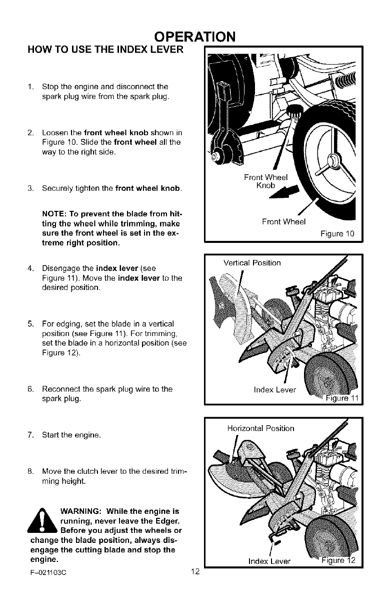
HOW TO USE THE INDEX LEVER
1. Stop the engine and disconnect the
spark plug wire from the spark plug.
2. Loosen the front wheel knob shown in
Figure 10. Slide the front wheel all the
way to the right side.
3. Securely tighten the front wheel knob.
Front Wheel
Knob
NOTE: To prevent the blade from hit-
ting the wheel while trimming, make
sure the front wheel is set in the ex-
treme right position.
4. Disengage the index lever (see
Figure 11). Move the index lever to the
desired position.
5. For edging, set the blade in a vertical
position (see Figure 11). For trimming,
set the blade in a horizontal position (see
Figure 12).
6. Reconnect the spark plug wire to the
spark plug.
Front Wheel
Figure 10
Vertical Position
Index Lever
7. Start the engine.
8. Move the clutch lever to the desired trim-
ming height.
_k WARNING: While the engine is
running, never leave the Edger.
Before you adjust the wheels or
change the blade position, always dis-
engage the cutting blade and stop the
engine.
F_021103C 12
Horizontal Position
Index Lever Figure 12

OPERATION
HOW TO USE THE CURB-HOPPING FEATURE
Because the front wheel and the right rear
wheel are adjustable, the Edger can be used
on uneven surfaces, such as the curb shown
in Figure 13. Set the wheel positions as fol-
iows.
1. Stop the engine.
2. Disconnect the spark plug wire from the
spark plug.
3. Loosen the front wheel knob.
4. Slide the front wheel to the best posi-
tion to clear the curb and balance the
unit.
wheel until the front wheel is level with
the left rear wheel and the unit is setting
on the curb as shown in Figure 13.
7. Loosen the rear wheel knob.
8. Lower the right rear wheel until the
Edger is level and the left rear wheel is
on the curb.
9. Securely tighten the rear wheel knob.
10. Connect the spark plug wire to the spark
plug.
5. Securely tighten the front wheel knob.
6. Use the curb height adjust lever to
lower the front wheel. Lower the front
_k ARNING: Keep away from the
rotating blade. The blade can
cause injury.
Rear Wheel Knob
Blade Guard
Front
Wheel Knob
Front Wheel
ht Rear Wheel
Figure 13
F_021103C 13
OPERATION
HOW TO STOP THE ENGINE
Emergency Stopping
To immediately stop the engine and the
blade, move the throttle control to the STOP
position.
Normal Stopping
1. To stop the engine, move the clutch lever
all the way back to the DISENGAGED
position.
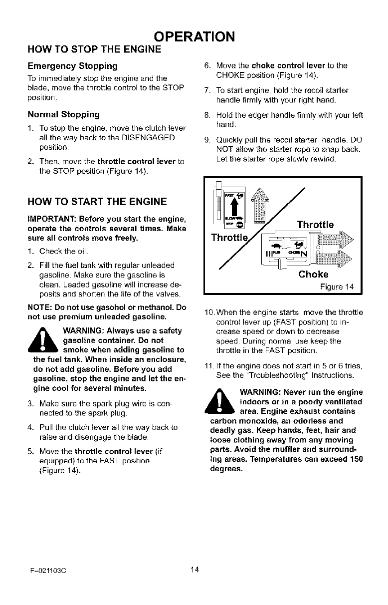
2. Then, move the throttle control lever to
the STOP position (Figure 14).
6. Move the choke control lever to the
CHOKE position (Figure 14).
7. To start engine, hold the recoil starter
handle firmly with your right hand.
8. Hold the edger handle firmly with your left
hand.
9. Quickly pull the recoil starter handle. DO
NOT allow the starter rope to snap back.
Let the starter rope slowly rewind.
HOW TO START THE ENGINE
IMPORTANT: Before you start the engine,
operate the controls several times. Make
sure all controls move freely.
1. Check the oil.
2. Fill the fuel tank with regular unleaded
gasoline. Make sure the gasoline is
clean. Leaded gasoIine will increase de-
posits and shorten the life of the valves.
NOTE: Do not use gasohol or methanol. Do
not use premium unleaded gasoline.
_lb ARNING: Always use a safety
gasoline container. Do not
smoke when adding gasoline to
the fuel tank. When inside an enclosure,
do not add gasoline. Before you add
gasoline, stop the engine and let the en-
gine cool for several minutes.
3. Make sure the spark plug wire is con-
nected to the spark plug.
4. Pull the clutch lever all the way back to
raise and disengage the btade.
5. Move the throttle control lever (if
equipped) to the FAST position
(Figure 14).
_Throttle
Choke
Figure14
10.When the engine starts, move the throttle
controI lever up (FAST position) to in-
crease speed or down to decrease
speed. During normal use keep the
throttle in the FAST position.
11. If the engine does not start in 5 or 6 tries,
See the "Troubleshooting" Instructions.
_ARNING: Never run the engine
indoors or in a poorly ventilated
area. Engine exhaust contains
carbon monoxide, an odorless and
deadly gas. Keep hands, feet, hair and
loose clothing away from any moving
parts. Avoid the muffler and surround-
ing areas. Temperatures can exceed 150
degrees.
F=021103C 14
OPERATION
EDGING TIPS
• Edging is best performed when conditions
are dry. If the soil is to wet, dirt becomes
packed around the blade causing prema-
ture belt wear and decreased perfor-
mance.
• If dirt does become packed around the
blade, stop the engine and remove the
wire from the spark plug. Remove the
packed dirt and debris from the blade.
• For deep edging, first cut at shallow
depths. Then, cut at greater depths until
the desired depth is obtained.
• For uniform edging, make sure the blade
guide rides on the surface.
• Edging can be customized by varying the
number of passes and by the distance the
blade is from the surface.
WARNING: Read the Owner's
manual. Know location and
functions of all controls. Keep
all safety devices and shields in place.
Never allow children or uninstructed
adults to operate Edger. Shut off engine
before unclogging blade or making re-
pairs. Keep bystanders away from ma=
chine. Keep away from the blade and all
rotating parts, which cause injury.
F_021103C 15
MAINTENANCE
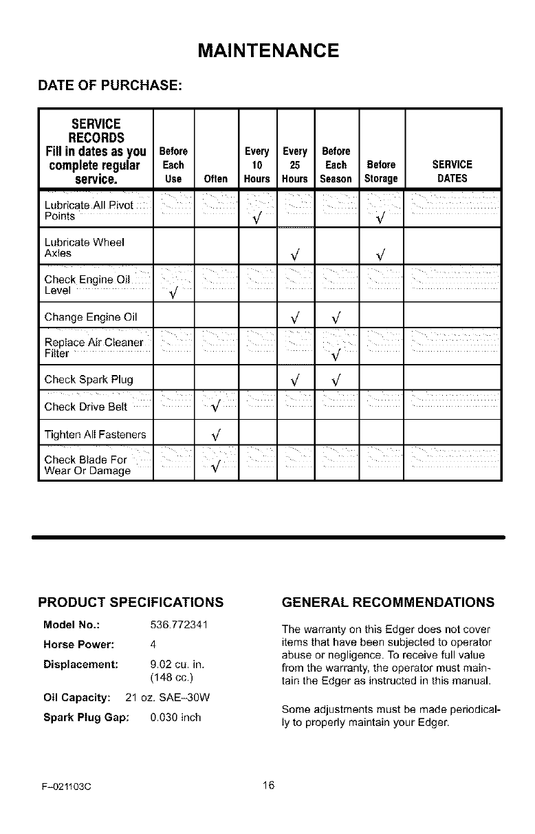
DATE OF PURCHASE:
SERVICE
RECORDS
Fill in dates as you Before Every Every Before
complete regular Each 10 25 Each Before SERVICE
service. Use Often Hours Hours Season Storage DATES
i
Lubricate All Pivot
Points
I I I I
I I I
Lubricate Wheel
Axles
I
Check Engine Oil
Level _/
, , , , ,
Change Engine Oil
Replace Air Cleaner
Filter
ill i i
i i i
Check Spark Plug _/ _/
Tighten AII Fasteners
Check Blade For I I _ I
Wear Or Damage *7 ....
PRODUCT SPECIFICATIONS
Model No.: 530.772341
Horse Power: 4
Displacement: 9.02 cu. in.
(148 cc.)
Oil Capacity: 21 oz. SAE-3OW
Spark Plug Gap: 0.030 inch
GENERAL RECOMMENDATIONS
The warranty on this Edger does not cover
items that have been subjected to operator
abuse or negligence. To receive full value
from the warranty, the operator must main-
tain the Edger as instructed in this manual.
Some adjustments must be made periodical-
ly to properly maintain your Edger.
F_021103C 16
LUBRICATION
After each 25 hours, apply a small amount of
engine oil to all moving parts, particularly the
wheels.
How To Change The Engine Oil
Change the oil in the engine crankcase after
each 25 hours of use.
MAINTENANCE
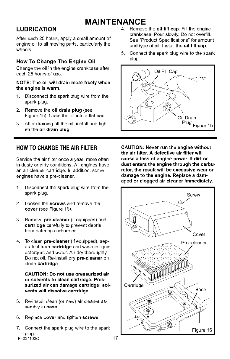
4. Remove the oil fill cap. Fill the engine
crankcase. Pour slowly. Do not overfill.
See "Product Specifications" for amount
and type of oil. Install the oil fill cap.
5. Connect the spark plug wire to the spark
plug.
NOTE: The oil will drain more freely when
the engine is warm.
1. Disconnect the spark plug wire from the
spark plug.
2. Remove the oil drain plug (see
Figure 15). Drain the oil into a flat pan.
3. After draining all the oil, install and tight-
en the oil drain plug.
Oil Fill Cap
Plug Figure 15
HOWTO CHANGETHEAIR FILTER
Service the air filter once a year; more often
in dusty or dirty conditions. All engines have
an air cleaner cartridge. In addition, some
engines have a pre-cleaner.
1. Disconnect the spark plug wire from the
spark plug.
2. Loosen the screws and remove the
cover (see Figure 16).
3. Remove pre-cleaner (if equipped) and
cartridge carefully to prevent debris
from entering carburetor.
4. To clean pre-cleaner (if equipped), sep-
arate it from cartridge and wash in liquid
detergent and water. Air dry thoroughly.
Do not oil. Re-install dry pre-cleaner on
dean cartridge.
CAUTION: Do not use pressurized air
or solvents to clean cartridge. Pres-
surized air can damage cartridge; sol-
vents will dissolve cartridge.
5. Re-install clean (or new) air cleaner as-
sembly in base.
6. Replace cover and tighten screws.
CAUTION: Never run the engine without
the air filter. A defective air filter will
cause a loss of engine power. If dirt or
dust enters the engine through the carbu-
retor, the result will be excessive wear or
damage to the engine. Replace a dam-
aged or clogged air cleaner immediately.
Screw
Cover
Pre-cleaner
Cartridge
7. Connect the spark plug wire to the spark Figure 16
plug.
F_021103C 17
MAINTENANCE
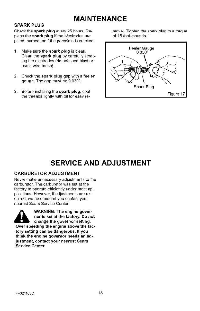
SPARK PLUG
Check the spark plug every 25 hours. Re-
place the spark plug if the electrodes are
pitted, burned, or if the porcelain is cracked.
moval. Tighten the spark plug to a torque
of 15 foot-pounds.
1. Make sure the spark plug is clean.
Clean the spark plug by carefully scrap-
ing the electrodes (do not sand blast or
use a wire brush).
2. Check the spark plug gap with a feeler
gauge. The gap must be 0.030".
3. Before installing the spark plug, coat
the threads lightly with oil for easy re-
Feeler Gauge
0.030"
Spark Plug
Figure I
SERVICE AND ADJUSTMENT
CARBURETOR ADJUSTMENT
Never make unnecessary adjustments to the
carburetor. The carburetor was set at the
factory to operate efficiently under most ap-
plications. However, if adjustments are re-
quired, we recommend you contact your
nearest Sears Service Center.
_lb WARNING: The engine gover-
nor is set at the factory. Do not
change the governor setting.
Over speeding the engine above the fac-
tory setting can be dangerous. If you
think the engine governor needs an ad-
justment, contact your nearest Sears
Service Center.
F-021103C 18
SERVICE AND ADJUSTMENT
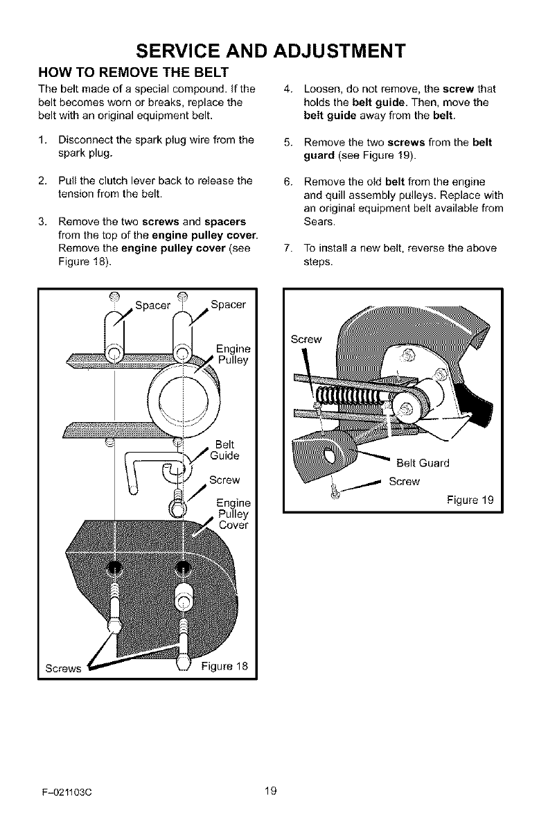
HOW TO REMOVE THE BELT
The belt made of a special compound, if the 4. Loosen, do not remove, the screw that
belt becomes worn or breaks, replace the holds the belt guide. Then, move the
belt with an original equipment belt. belt guide away from the belt.
1. Disconnect the spark plug wire from the
spark plug.
5. Remove the two screws from the belt
guard (see Figure 19).
2. Pull the clutch lever back to release the
tension from the belt.
3. Remove the two screws and spacers
from the top of the engine pulley cover.
Remove the engine pulley cover (see
Figure 18).
6. Remove the old belt from the engine
and quill assembly pulleys. Replace with
an original equipment belt available from
Sears.
7. To install a new belt, reverse the above
steps.
@
Belt Guard
_ Screw Figure 19
Screws Figure 18
F-021103C 19
SERVICE AND ADJUSTMENT
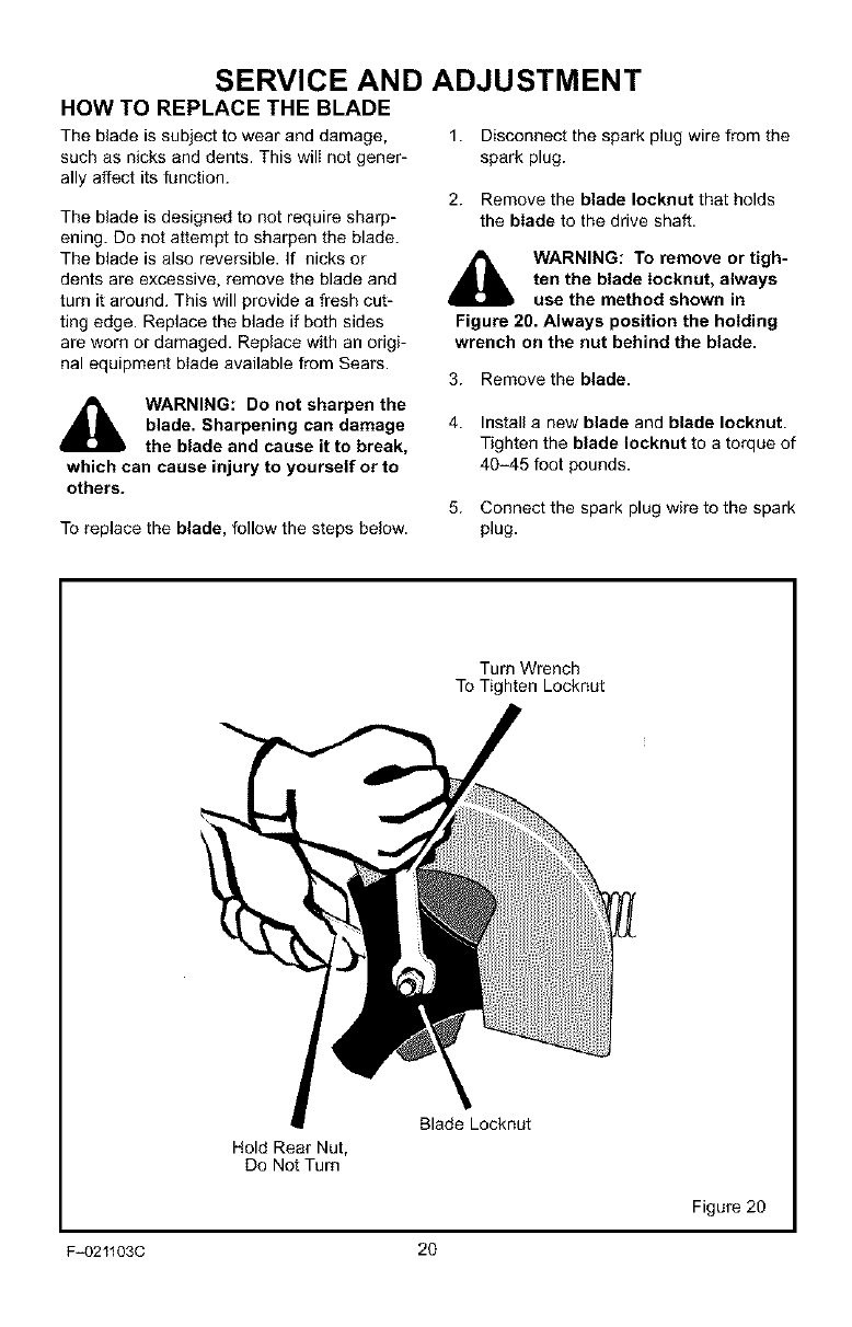
HOW TO REPLACE THE BLADE
The blade is subject to wear and damage,
such as nicks and dents. This will not gener-
ally affect its function.
The blade is designed to not require sharp-
ening. Do not attempt to sharpen the blade.
The blade is also reversible. If nicks or
dents are excessive, remove the blade and
turn it around. This will provide a fresh cut-
ting edge. Replace the blade if both sides
are worn or damaged. Replace with an origi-
nal equipment btade available from Sears.
WARNING: Do not sharpen the
blade. Sharpening can damage
the blade and cause it to break,
which can cause injury to yourself or to
others.
To replace the blade, follow the steps below.
1. Disconnect the spark plug wire from the
spark plug.
2. Remove the blade Iocknut that holds
the blade to the drive shaft.
,_ WARNING: To remove or tigh-
ten the blade Iocknut, always
use the method shown in
Figure 20. Always position the holding
wrench on the nut behind the blade.
3. Remove the blade.
4. Install a new blade and blade Iocknut.
Tighten the blade Iocknut to a torque of
40-45 foot pounds.
5. Connect the spark plug wire to the spark
plug.
Turn Wrench
To Tighten Locknut
Blade Locknut
Hold Rear Nut,
Do Not Turn
Figure 20
F-021103C 20
SERVICE AND ADJUSTMENT
STORAGE
_1_ WARNING: Never store the
Edger indoors with fuel in the
fuel tank. Never store in an en-
closed, poorly ventilated area where
fumes could reach an open flame, a
spark or a pilot light as on a furnace, wa-
ter heater or clothes dryer.
_lb ARNING: Do not remove gas-
oline while inside a building,
near a fire, or while you smoke.
Gasoline fumes can cause an explosion
or a fire.
When the Edger is put in storage for thirty
days or more, follow the steps below to
make sure the Edger is in good condition the
following season.
Edger
Completely clean the Edger.
Check the Edger for worn or damaged
pads. Tighten all loose hardware.
Apply a smatI amount of engine oil to all
moving parts, particulady the wheels.
Put the Edger in a building that has good
ventilation.
Cover the Edger with a suitable protec-
tive cover that does not retain moisture.
Do not use plastic.
IMPORTANT: Never cover the Edger while
the engine and exhaust areas are still
warm.
NOTE: A yearly checkup or tune-up by a
Sears Service Center is a good way to
make sure that your Edger will provide
maximum performance for the next sea-
son.
Engine
IMPORTANT: It is important to prevent
gum deposits from forming in fuel system
parts such as the carburetor, fuel filter,
fuel hose, and tank during storage. Also,
using alcohol-blended fuels (called gaso-
hol, ethanol or methanol) can attract
moisture which leads to separation and
formation of acids during storage. Acidic
gas can damage the fuel system of an en-
gine while in storage.
To prevent engine damage when the Edger
is in storage for 30 days or more, follow the
steps below:
Let the engine run until it is out of gaso-
line.
If you do not want to remove the gaso-
Iine, add a fuel stabilizer to any gasoline
Ieft in the fuel tank. A fuel stabilizer will
minimize gum deposits and acids. If the
fuel tank is almost empty, mix the fuel
stabilizer with fresh gasoline in a sepa-
rate container and add the mixture to the
fuel tank. Always follow the instructions
on the stabilizer container. Start the en-
gine. Let the engine run for 10 minutes
to allow the mixture to reach the carbu-
retor.
Change the engine oil. See "How To
Change The Engine Oil" in the Mainte-
nance section.
Lubricate the piston/cylinder area. This
can be done by first removing the spark
plug and squirting a small amount of
clean engine oil into the spark plug hole.
Then, cover the spark plug hole with a
rag to absorb oil spray. Next, rotate the
engine by pulling the starter two or three
times. Finally, install the spark plug and
attach the spark plug wire.
Store the Edger in the operating position
with the wheels down. If the Edger is
stored in any other position, oil from the
crankcase will enter the cylinder and
cause a service problem.
F=021103C 21
TROUBLE SHOOTING CHART
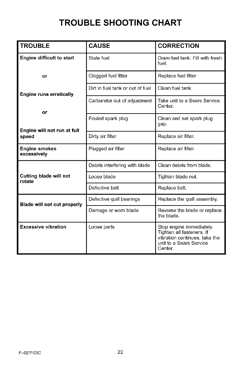
TROUBLE
Engine difficult to start
or
Engine runs erratically
or
Engine will not run at full
speed
Engine smokes
excessively
Cutting blade will not
rotate
Blade will not cut properly
Excessive vibration
CAUSE
Stale fuel
Clogged fuel filter
Dirt in fuel tank or out of fuel
Carburetor out of adjustment
Fouled spark plug
Dirty air filter
Plugged air filter
Clean debds from btade.
Debris interfering with blade
Loose blade
Defective belt
Defective quill bearings
Damage or worn blade
Loose parts
CORRECTION
Drain fuel tank. Fill with fresh
fuel.
Replace fuel filter
Clean fuel tank.
Take unit to a Sears Service
Center.
Clean and set spark plug
gap.
Replace air filter.
Replace air filter.
Tighten blade nut.
Replace belt.
Replace the quill assembly.
Reverse the blade or replace
the blade.
Stop engine immediateiy.
Tighten all fasteners. If
vibration continues, take the
unit to a Sears Service
Center.
F-021103C 22
SEARS, ROEBUCK AND CO.
Federal and California Emission Control Systems Limited Warranty
Small Off-Road Engines
CALIFORNIA & US EPA EMISSION
CONTROL WARRANTY STATEMENT
The U. S. Environmental Protection Agency
("EPA"), the California Air Resources Board
("CARB") and Sears, Roebuck and Co. are
pleased to explain the Federal and California
Emission Control Systems Warranty on your
new small off-road engine. In California, new
1995 and later small off-road engines must be
designed, built and equipped to meet the
State's stringent anti-smog standards. In oth-
er states, new 1997 and later model year en-
gines must be designed, built and equipped, at
the time of sale, to meet the U.S. EPA regula-
tions for small non-road engines. Sears, Roe-
buck and Co. will warrant the emission control
system on your small off-road engine for the
periods of time listed below, provided there
has been no abuse, neglect, unapproved mod-
ification, or improper maintenance of your
small off-road engine.
Your emission control system may include
parts such as the carburetor, ignition system
and exhaust system. Also included may be the
compression release system and other emis-
sion-related assemblies.
Where a warrantable condition exists, Sears,
Roebuck and Co. will repair your small off-
road engine at no cost to you for diagnosis,
parts and labor.
MANUFACTURER'S EMISSION
CONTROL SYSTEM WARRANTY
COVERAGE
Emission control systems on 1995 and later
model year California small off-road engines
are warranted for two years as hereinafter
noted. In other states, 1997 and later model
year engines are also warranted for two years.
If, during such warranty period, any emission-
related part on your engine is defective in ma-
terials or workmanship, the part will be
repaired or replaced by Sears, Roebuck and
Co.
OWNER'S WARRANTY
RESPONSIBILITIES
As the small off-road engine owner, you are
responsible for the performance of the re-
F-021103C
quired maintenance listed in your Owner's
Manual, but Sears, Roebuck and Co. will not
deny warranty solely due to the lack of receipts
or for your failure to provide wdtten evidence
of the performance of all scheduled mainte-
nance.
As the small off-road engine owner, you
should, however, be aware that Sears, Roe-
buck and Co. may deny you warranty cover-
age if your small off-road engine or a part
thereof has failed due to abuse, neglect, im-
proper maintenance or unapproved modifica-
tions.
You are responsible for presenting your small
off-road engine to a Sears, Roebuck and Co.
Authorized Service Outlet as soon as a prob-
lem exists. The warranty repairs should be
completed in a reasonable amount of time, not
to exceed 30 days.
Warranty service can be arranged by contact-
ing either a Sears, Roebuck and Co. Autho-
rized Service Outlet, or by contacting Sears,
Roebuck and Co. at 1-800473-7247.
23
IMPORTANT NOTE
Esta This warranty statement explains your
rights and obligations under the Emission
Control System Warranty ("ECS Warranty")
which is provided to you by Sears, Roebuck
and Co. pursuant to California law. See also
the Sears, Roebuck and Co. Limited Warran-
ties for Sears, Roebuck and Co. which is en-
closed therewith on a separate sheet and also
is provided to you by Sears, Roebuck and Co.
The ECS Warranty applies only to the emis-
sion control system of your new engine. To the
extent that there is any conflict in terms be-
tween the ECS Warranty and the Sears, Roe-
buck and Co. Warranty, the ECS Warranty
shall apply except in any circumstances in
which the Sears, Roebuck and Co. Warranty
may provide a longer warranty period. Both the
ECS Warranty and the Sears, Roebuck and
Co. Warranty describe important rights and
obligations with respect to your new engine.
Warranty service can only be performed by a
Sears, Roebuck and Co. Authorized Service
Outlet. At the time of requesting warranty ser-
vice, evidence must be presented of the date
of sale to the original purchaser. The purchas-

ershallpayanychargesformakingservice
callsand/orfortransportingtheproductsto
andfromtheplacewheretheinspectionand/
orwarrantyworkisperformed.Thepurchaser
shallberesponsibleforanydamageorlossin-
curredinconnectionwiththetransportationof
anyengineoranypart(s)thereofsubmittedfor
inspectionand/orwarrantywork.
Ifyouhaveanyquestionsregardingyourwar-
rantyrightsandresponsibilities,youshould
contactSears,Roebuckand Co. at
1-800_.73-7247.
EMISSION CONTROL SYSTEM
WARRANTY
Emission Control System Warranty ("ECS
Warranty") for 1995 and later model year Cali-
fornia small off-road engines (for other states,
1997 and later model year engines):
A. APPLICABILITY: This warranty shall apply
to 1995 and later model year California small
off-road engines (for other states, 1997 and
later model year engines). The ECS Warranty
Period shall begin on the date the new engine
or equipment is delivered to its original, end-
use purchaser, and shall continue for 24 con-
secutive months thereafter.
B. GENERAL EMISSIONS WARRANTY
COVERAGE: Sears, Roebuck and Co. war-
rants to the original, end-use purchaser of the
new engine or equipment and to each subse-
quent purchaser that each of its small off-road
engines is:
1. Designed, built and equipped so as to con-
form with all applicable regulations adopted by
the Air Resources Board pursuant to its au-
thority in Chapters I and 2, Part 5, Division 26
of the Health and Safety Code, and
2. Free from defects in materials and work-
manship which, at any time during the ECS
Warranty Period, will cause a warranted emis-
sions-related part to fail to be identical in elI
materiaI respects to the part as described in
the engine manufacturer's application for certi-
fication.
C. The ECS Warranty only pertains to emis-
sions-related parts on your engine, as follows:
1. Any warranted, emissions-related parts
which are not scheduled for replacement as
required maintenance in the Owner's ManuaI
shall be warranted for the ECS Warranty Peri-
od. If any such part fails during the ECS War-
ranty Period, it shall be repaired or replaced by
F-021103C 24
Sears, Roebuck and Co. according to Subsec-
tion 4 below. Any such part repaired or re-
placed under the ECS Warranty shall be
warranted for any remainder of the ECS War-
ranty Period.
2. Any warranted, emissions-related part
which is scheduled only for regular inspection
as specified in the Owner's Manual shall be
warranted for the ECS Warranty Period. A
statement in such written instructions to the ef-
fect of "repair or replace as necessary", shall
not reduce the ECS Warranty Period. Any
such part repaired or replaced under the ECS
Warranty shall be warranted for the remainder
of the ECS Warranty Period.
3. Any warranted, emissions-related part
which is scheduled for replacement as re-
quired maintenance in the Owner's Manual,
shall be warranted for the period of time prior
to the first scheduled replacement point for
that part. If the part fails prior to the first sched-
uled replacement, the part shall be repaired or
replaced by Sears, Roebuck and Co. accord-
ing to Subsection 4 below. Any such emis-
sions-related part repaired or replaced under
the ECS Warranty, shall be warranted for the
remainder of the ECS Warranty Period prior to
the first scheduled replacement point for such
emissions-related part.
4. Repair or replacement of any warranted,
emissions-related part under this ECS War-
ranty shall be performed at no charge to the
owner at a Sears, Roebuck and Co. Autho-
rized Service Oufiet.
5. The owner shall not be charged for diagnos-
tic labor which Ieads to the determination that
a part covered by the ECS Warranty is in fact
defective, provided that such diagnostic work
is performed at a Sears, Roebuck and Co. Au-
thorized Service Oufiet.
6. Sears, Roebuck and Co. shall be liable for
damages to other original engine components
or approved modifications proximately caused
by a failure under warranty of an emission-re-
Iated part covered by the ECS Warranty.
7. Throughout the ECS Warranty Period,
Sears, Roebuck and Co. shah maintain a sup-
ply of warranted emission-related parts suffi-
cient to meet the expected demand for such
emission-related pads.
8. Any Sears, Roebuck and Co. authorized
and approved emission-related replacement
part may be used in the performance of any
ECS Warranty maintenance or repair and will
be provided without charge to the owner'. Such
useshallnotreduceSears,RoebuckandCo.
ECSWarrantyobligations.
9.Unapprovedadd-onormodifiedpartsmay
notbeusedtomodifyorrepairaSears,Roe-
buckandCo.engine.SuchusevoidsthisECS
Warrantyandshallbesufficientgroundsfor
disallowinganECSWarrantyclaim.Sears,
RoebuckandCo.shallnotbeliable hereunder
for failures of any warranted parts of a Sears,
Roebuck and Co. engine caused by the use of
such an unapproved add-on or modified part.
EMISSION-RELATED PARTS
INCLUDE THE FOLLOWING:
1. Carburetor Assembly and its Internal Com-
ponents
a) Fuel filter
b) Carburetor gaskets
c) Intake pipe
2. Air Cleaner Assembly
a) Air filter element
3. Ignition System, including:
a) Spark plug
b) Ignition module
c) Flywheel assembly
4. Catalytic Muffler (if so equipped)
a) Muffler gasket (if so equipped)
b) Exhaust manifold (if so equipped)
5. Crankcase Breather Assembly and its
Components
a) Breather connection tube
10/22/99 EPA/CARB
Sears, Roebuck and Co., Hoffman Estates, IL 60179 U.S.A.
F=021103C 25
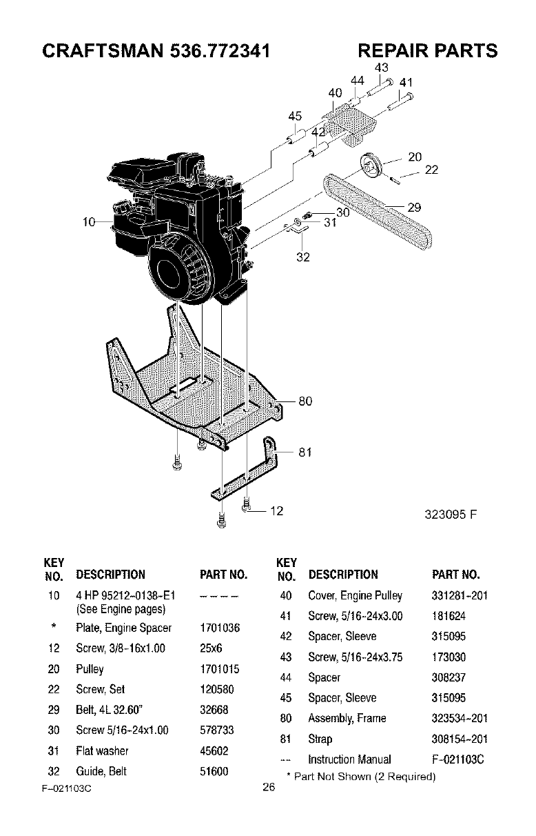
CRAFTSMAN 536.772341
12
40
45
32
81
REPAIR PARTS
43
44 41
20
_j22
29
323095 F
KEY KEY
NO. DESCRIPTION PARTNO. NO. DESCRIPTION PARTNO.
10 4 HP95212-0138-E1 40 Cover,EnginePulley 331281-201
(SeeEnginepages) 41 Screw,5/16-24x3.00 181624
*Plate,EngineSpacer 1701036 42 Spacer,Sleeve 315095
12 Screw,3/8-16xl .O0 25x6 43 Screw,5/16-24x3.75 173030
20 Pulley 1701015 44 Spacer 308237
22 Screw,Set 120580 45 Spacer,Sleeve 315095
29 Belt,4L32.60" 32668 80 Assembly,Frame 323534-201
30 Screw5/16-24x1.00 578733 81 Strap 308154-201
31 Flatwasher 45602 -- InstructionManual F-021103C
32 Guide,Belt 51600 * Part Not Shown (2 Required)
F=021103C 26
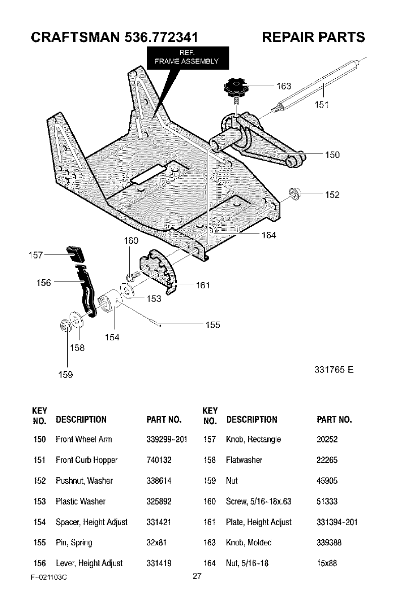
CRAFTSMAN 536.772341 REPAIR PARTS
_163 151
/
150
157_
160 164
158
159
154
155
331765 E
KEY KEY
NO. DESCRIPTION PARTNO. NO. DESCRIPTION PARTNO.
150 FrontWheelArm 339299-201 157 Knob,Rectangle 20252
151 FrontCurbHopper 740132 158 Flatwasher 22265
152 Pushnut,Washer 338614 159 Nut 45905
153 PlasticWasher 325892 160 Screw,5/16-18x.63 51333
154 Spacer,HeightAdjust 331421 161 Plate,HeightAdjust 331394-281
155 Pin,Spring 32x81 163 Knob,Molded 339388
156 Lever,HeightAdjust 331419 164 Nut, 5/16-18 15x88
F=021103C 27
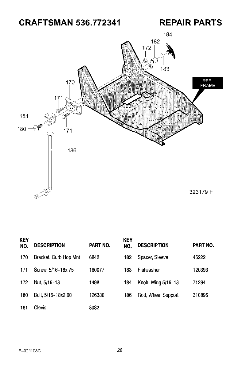
CRAFTSMAN 536.772341 REPAIR PARTS
184
182
170
171
171
186
183
323179 F
KEY
NO. DESCRIPTION PARTNO.
170 Bracket,CurbHop Mnt 6842
171 Screw,5/16-18x.75 180077
172 Nut,5/16-18 1498
180 Bolt,5/16-18x2.00 126380
181 Clevis 8082
KEY
NO. DESCRIPTION
182 Spacer,Sleeve
183 Flatwasher
184 Knob,Wing5/16-18
186 Rod,WheelSupport
PARTNO.
45222
120393
71294
310896
F_021103C 28
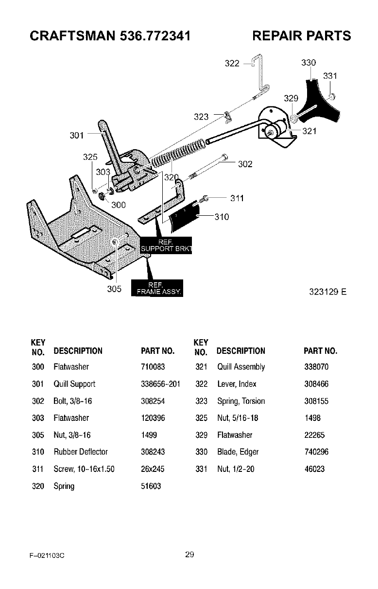
CRAFTSMAN 536.772341 REPAIR PARTS
301
325
323
311
330
331
329
321
305 323129 E
KEY
NO. DESCRIPTION
300 Flatwasher
301 QuillSupport
302 Bolt,3/8-16
303 Flatwasher
305 Nut,3/8-16
310 RubberDeflector
311 Screw,10-16x1.56
320 Spring
PARTNO.
710083
338656-201
308254
120396
1499
308243
26x245
51603
KEY
NO. DESCRIPTION
321 QuillAssembly
322 Lever,Index
323 Spring,Torsion
325 Nut, 5/16-18
329 Flatwasher
330 Blade,Edger
331 Nut, 1/2-28
PARTNO.
338070
308466
308155
1498
22265
740296
46023
F_021103C 29
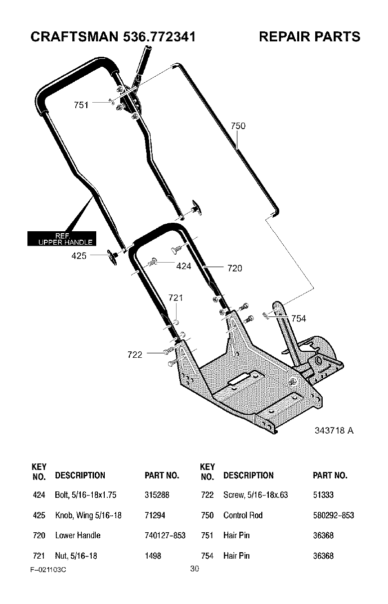
CRAFTSMAN 536.772341 REPAIR PARTS
751
425
\\X
\
720
721
\\\\\\\\\\\\
754
722
343718 A
KEY
NO. DESCRIPTION
424 Bolt,5/16-18xl.75
425 Knob,Wing5/16-18
720 LowerHandle
721 Nut,5/16-18
F=021103C
PARTNO.
315288
71294
740127-853
1498
KEY
NO. DESCRIPTION
722 Screw,5/16-18x.63
750 ControlRod
751 HairPin
754 HairPin
30
PARTNO.
51333
580292-853
36368
36368
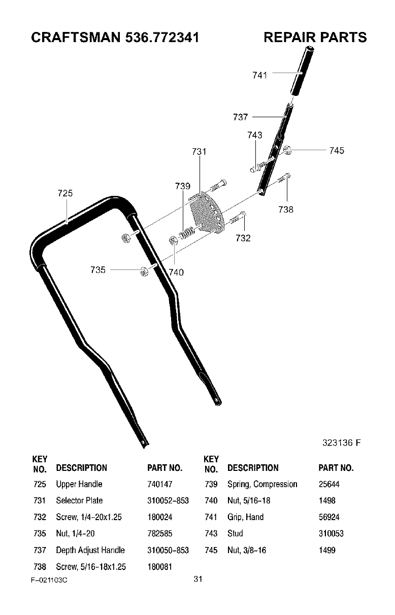
CRAFTSMAN 536.772341
731
REPAIR PARTS
737
743
745
725
735
739
J
732
738
323136 F
KEY KEY
NO. DESCRIPTION PARTNO. NO. DESCRIPTION PARTNO.
725 UpperHandle 740147 739 Spring,Compression 25644
731 SelectorPlate 310052-853 740 Nut,5/16-18 1498
732 Screw,1/4-20xl.25 180024 741 Grip, Hand 56924
735 Nut, 1/4-20 782585 743 Stud 310053
737 DepthAdjustHandle 310050-853 745 Nut,3/8-16 1499
738 Screw,5/16-18x1.25 180081
F=O21103C 31
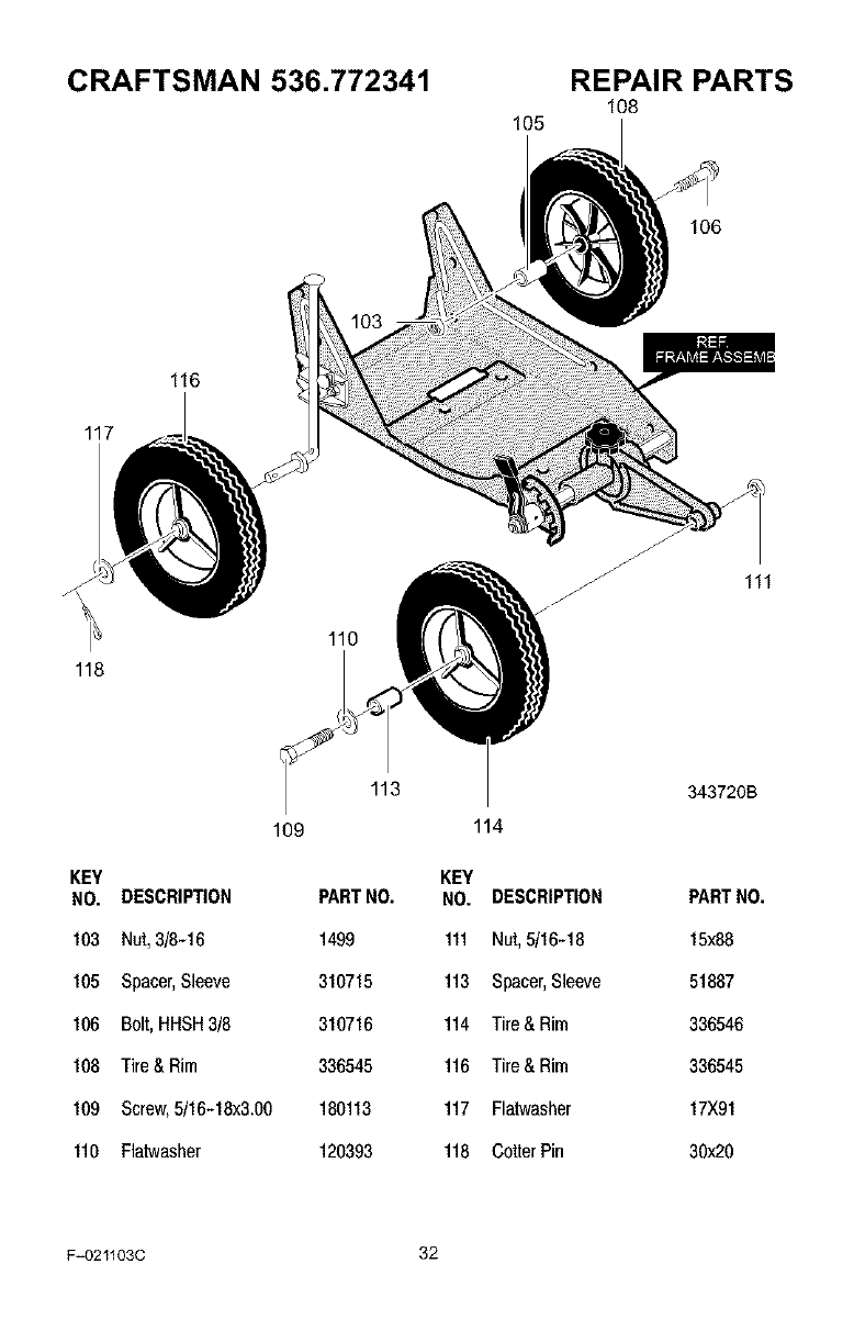
CRAFTSMAN 536.772341 REPAIR PARTS
108
105
116
117
118
109
110
113
106
343720B
114
KEY KEY
NO. DESCRIPTION PARTNO. NO. DESCRIPTION PARTNO.
103 Nut,3/8-16 1499 111 Nut,5/16-18 15x88
105 Spacer,Sleeve 310715 113 Spacer,Sleeve 51887
106 Bolt,HHSH3/8 310716 114 Tire& Rim 336546
188 Tire&Rim 336545 116 Tire& Rim 336545
189 Screw,5/16-18x3.08 180113 117 Flatwasher 17X91
110 Flatwasher 120393 118 CotterPin 38x28
F_021103C 32
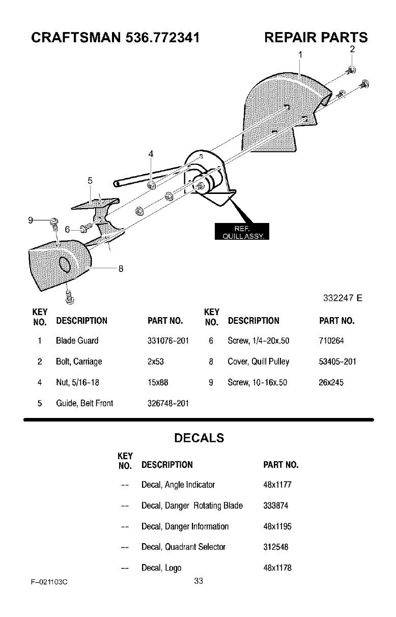
CRAFTSMAN 536.772341 REPAIR PARTS
2
1
4
5
332247 EE
KEY KEY
NO. DESCRIPTION PARTNO. NO. DESCRIPTION PARTNO,
1BladeGuard 331076-201 6 Screw,1/4-20x,50 710264
2 Bolt,Carriage 2x53 8 Cover,QuillPulley 53405-201
4 Nut,5/16-18 15x88 9 Screw,10-16x,50 26x245
5 Guide,BeltFront 326748-201
F=O21103C
DECALS
KEY
NO. DESCRIPTION PARTNO.
-- Decal,AngleIndicator 48x1177
-- Decal,Danger RotatingBlade 333874
-- Decal,DangerInformation 48x1195
-- Decal,QuadrantSelector 312548
-- Decal,Logo 48x1178
33
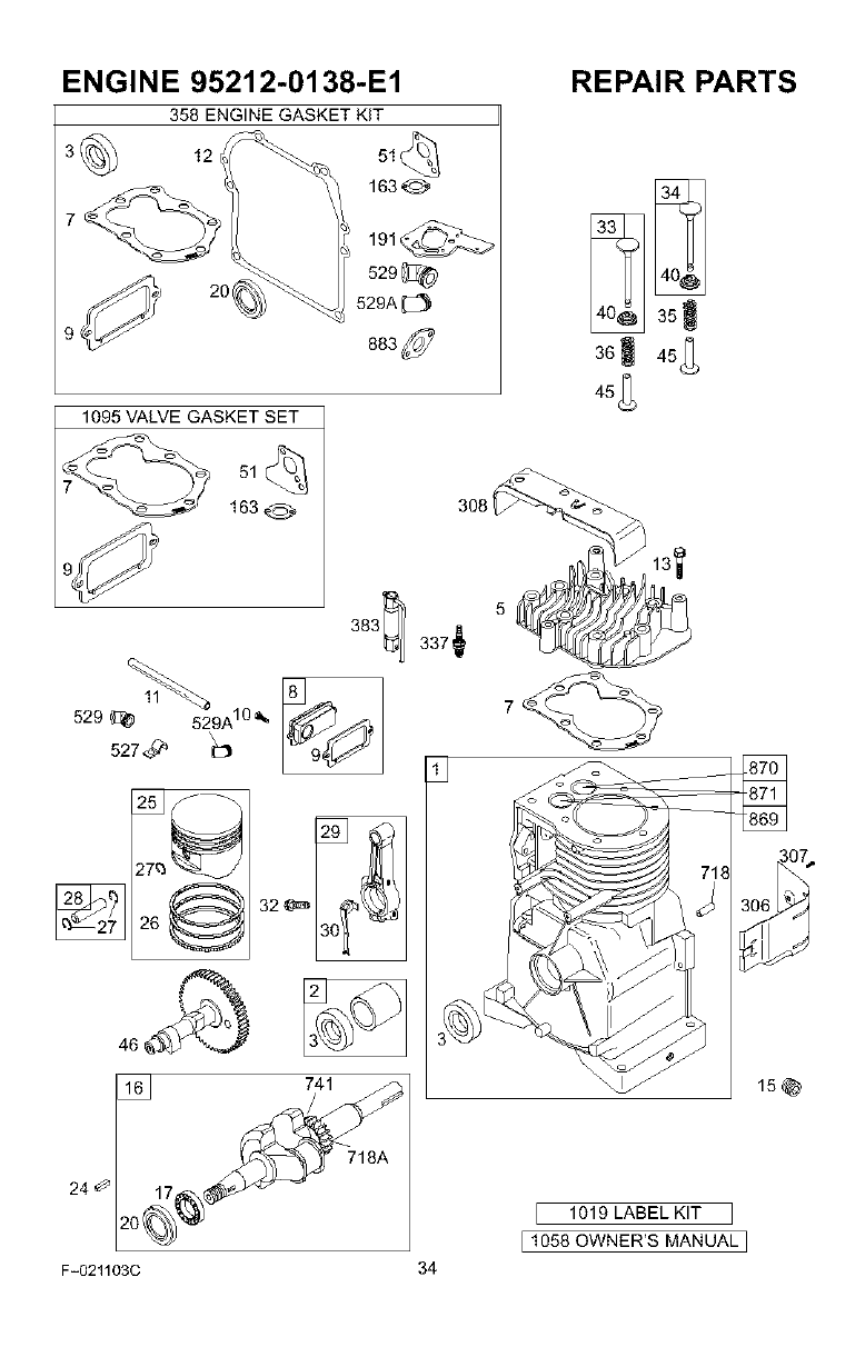
ENGINE 95212-0138-E1
358 ENGINE GASKET KIT
12 51 _
163_
191@
529J_
529A
1095 VALVE GASKET SET
51_
163 @
529 _ 529A10 _,
527_
REPAIR PARTS
35!
36_ 45_
45_
24
16J 741
718A
20
F-021103C 34
1019 LABEL KIT
[1058 OWNER'S MANUAL]
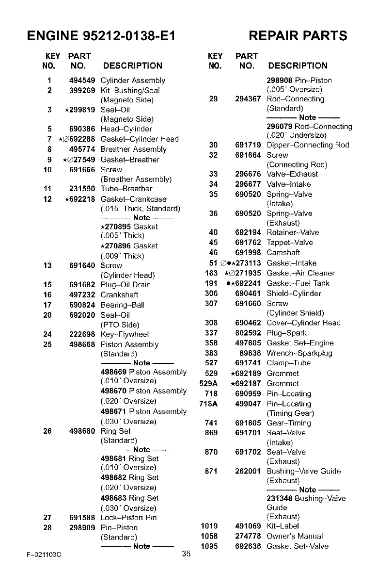
ENGINE 95212-0138-E1 REPAIR PARTS
KEY PART
N0. NO. DESCRIPTION
1 494549
2 399269
3 *299819
5 690386
7*0692288
8495774
9*Q27549
10 691666
11 231550
12 *692218
13 691640
15 691682
16 497232
17 690824
20 692020
24 222698
25 498668
26 498680
27 691588
28 298909
F-021103C
KEY PART
NO. NO.
Cylinder Assembly
Kit-Bushing/Seal
(Magneto Side) 29 294367
Seal-Oil
(Magneto Side)
Head-Cylinder
Gasket-Cylinder Head 30 691719
Breather Assembly 32 691664
Gasket-Breather
Screw 33 296676
(Breather Assembly) 34 296677
Tube-Breather 35 690520
Gasket-Crankcase
(.015" Thick, Standard) 36 690520
Note
*270895 Gasket
(.005" Thick) 40 692194
*270896 Gasket 45 691762
(.009" Thick) 46 691998
Screw 51 _o.273113
(Cylinder Head) 163 *Q271935
Plug-Oil Drain 191 e.692241
Crankshaft 306 690461
Bearing-Ball 307 691660
Seal-Oil
(PTO Side) 308 690462
Key-Flywheel 337 802592
Piston Assembly 358 497605
(Standard) 383 89838
Note 527 691741
498669 Piston Assembly 529 *692189
(.010" Oversize) 529A *692187
498670 Piston Assembly 718 690959
(.020" Oversize) 718A 499047
498671 Piston Assembly
(.030" Oversize) 741 691805
Ring Set 869 691701
(Standard)
Note 870 691702
498681 Ring Set
(.010" Oversize) 871 262001
498682 Ring Set
(.020" Oversize)
498683 Ring Set
(.030" Oversize)
Lock-Piston Pin
Pin-Piston 1019 491069
(Standard) 1058 274778
-- Note -- 1095 692638
35
DESCRIPTION
298908 Pin-Piston
(.005" Oversize)
Rod-Connecting
(Standard)Note
296079 Rod-Connecting
(.020" Undersize)
Dipper-Connecting Rod
Screw
(Connecting Rod)
Valve-Exhaust
Valve-Intake
Spring-Valve
(Intake)
Spring-Valve
(Exhaust)
Retainer-Valve
Tappet-VaNe
Camshaft
Gasket-Intake
Gasket-Air Cleaner
Gasket-Fuel Tank
Shield-Cylinder
Screw
(Cylinder Shield)
Cover-Cylinder Head
Plug-Spark
Gasket Set-Engine
Wrench_Sparkptug
Clamp-Tube
Grommet
Grommet
Pin-Locating
Pin-Locating
(Timing Gear)
Gear-Timing
Seat-Valve
(Intake)
Seat-Valve
(Exhaust)
Bushing-Valve Guide
(Exhaust) Note
231348 Bushing-Valve
Guide
(Exhaust)
Kit-Label
Owner's Manual
Gasket Set-Valve
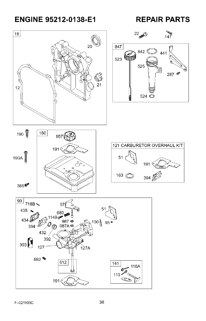
ENGINE 95212-0138-E1 REPAIR PARTS
22_ 147
842 _ 441
523 _
525
287 _'
524 O
365_
957 0
191_
121 CARBURETOR OVERHAUL KIT
51
191
163 (_) 394f_
718B_. 97_,_.,__ _._
435 _ 689 51
_ 1149_ '_'_} _
434 _ 212_0j 987 @ f_b, 130 _ 95"
394 _,_) 987Ae _ _3
432 /_ _
393 _ 1273_ _27A
692 %
191_
F-021103C 36
ENGINE 95212-0138-E1 REPAIR PARTS
KEY PART KEY PART
N0. NO. DESCRIPTION NO. NO. DESCRIPTION
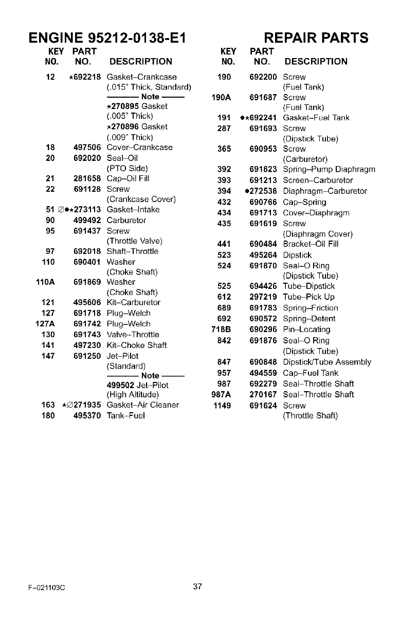
12 *692218 Gasket-Crankcase 190 692200 Screw
(.015" Thick, Standard) (Fuel Tank)
Note 190A 691687 Screw
*270895 Gasket (Fuel Tank)
(.005" Thick) 191 e.692241 Gasket-Fuel Tank
*270896 Gasket 287 691693 Screw
(.009" Thick) (Dipstick Tube)
18 497506 Cover_rankcase 365 690953 Screw
26 692020 Seal-Oil (Carburetor)
(PTO Side) 392 691823 Spring-Pump Diaphragm
21 281658 Cap-OiIFill 393 691213 Screen-Carburetor
22 691128 Screw 394 e272538 Diaphragm-Carburetor
(Crankcase Cover) 432 690766 Cap-Spring
51 _e.273113 Gasket-Intake 434 691713 Cover-Diaphragm
90 499492 Carburetor 435 691619 Screw
95 691437 Screw (Diaphragm Cover)
(Throttle Valve) 441 690484 Bracket-Oil Fill
97 692018 Shaft-Throttle 523 495264 Dipstick
110 690401 Washer 524 691870 SeaI-O Ring
(Choke Shaft) (Dipstick Tube)
110A 691869 Washer 525 694426 Tube-Dipstick
(Choke Shaft) 612 297219 Tube-Pick Up
121 495606 Kit-Carburetor
127 691718 Plug-Welch 689 691783 Spring-Friction
692 690572 Spring-Detent
127A 691742 Plug-Welch
130 691743 Valve-Throttle 718B 690296 Pin-Locating
842 691876 SeaI-O Ring
141 497230 Kit-Choke Shaft
147 691250 Jet-Pilot (Dipstick Tube)
(Standard) 847 690848 Dipstick/Tube Assembly
-- Note-- 957 494559 Cap-Fuel Tank
499502 Jet-Pilot 987 692279 Seal-Throttle Shaft
(High Altitude) 987A 270167 Seal-Throttle Shaft
163 ,_@271935 Gasket-AirCleaner 1149 691624 Screw
180 495370 Tank-Fuel (Throttle Shaft)
F-021103C 37
ENGINE 95212-0138-E1 REPAIR PARTS
356,,,,_'_h_ 188"_
621
216
831
780_
201_
305
-_78_
1
445
163 _' ]
1036 EMISSION LABEL
883
823@¢
332
597
456_. b
689 _'_
459_
F-021103C 38
ENGINE 95212-0138-E1 REPAIR PARTS
KEY PART KEY PART
N0. NO. DESCRIPTION NO. NO. DESCRIPTION
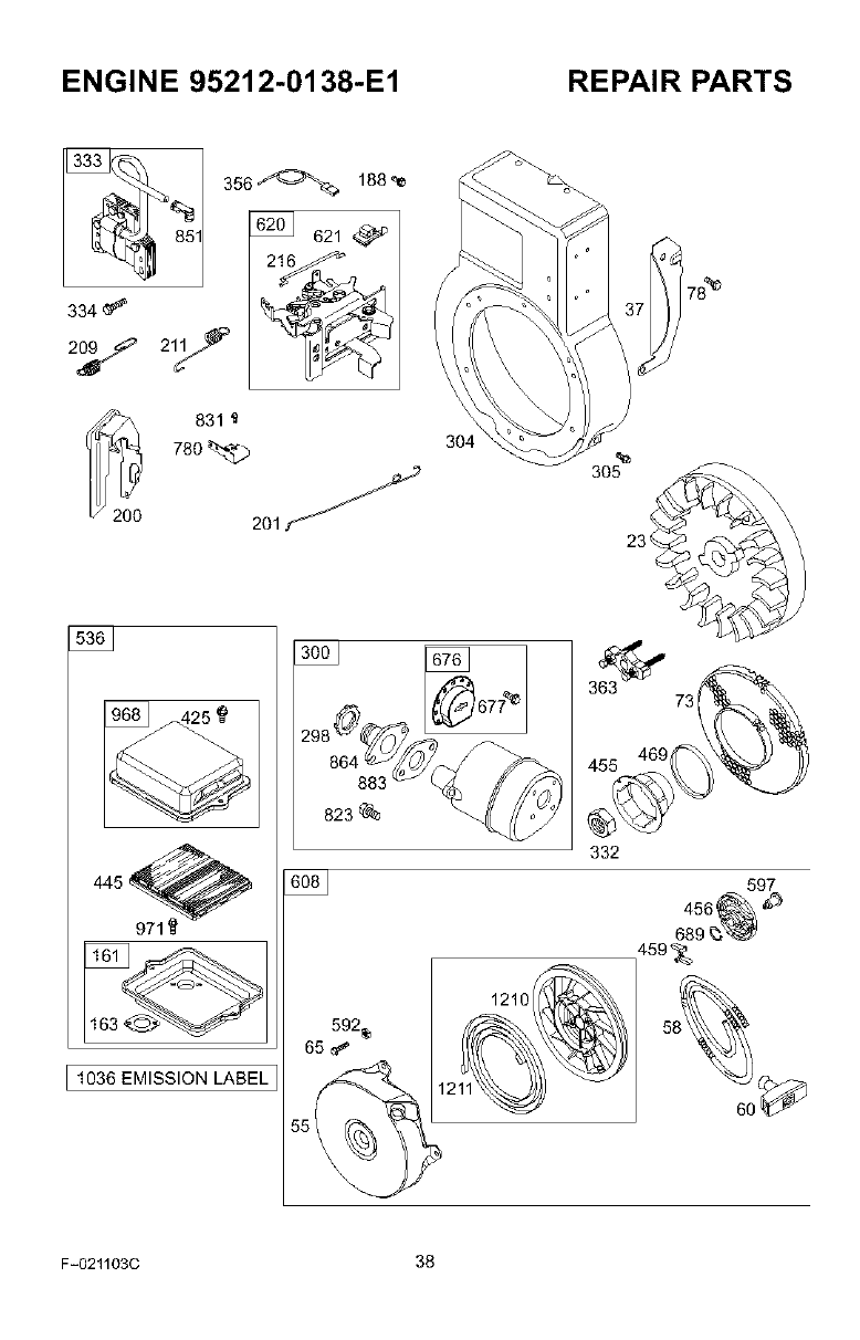
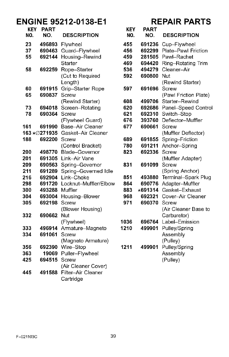
23 496893 Flywheel 455 691236 Cup-Flywheel
37 690463 Guard-Flywheel 456 692299 Plate-Pawl Friction
55 692144 Housing-Rewind 459 281505 PawI-Rachet
Starter 469 694420 Ring-Rotating Trim
58 692259 Rope-Starter 536 494279 Cleaner-Air
(Cut to Required 592 690800 Nut
Length) (Rewind Starter)
60 691915 Grip-Starter Rope 597 691696 Screw
65 690837 Screw (Pawl Friction Plate)
(Rewind Starter) 608 499706 Starter-Rewind
73 694018 Screen-Rotating 620 692686 Panel-Speed Control
78 690364 Screw 621 692310 Switch-Stop
(Flywheel Guard) 676 393760 Deflector-Muffler
161 691990 Base-Air Cleaner 677 690661 Screw
163.Q271935 Gasket-Air Cleaner (Muffler Deflector)
188 692200 Screw 689 691855 Spring-Friction
(Control Bracket) 780 691211 Anchor-Spring
200 498770 Blade-Governor 823 692336 Screw
201 691305 Link-Air Vane (Muffler Adapter)
209 690563 Spring-Governor 831 691099 Screw
211 691289 Spring-Governed Idle (Spring Anchor)
216 692904 Link-Choke 851 493880 Terminal-Spark Plug
298 691720 Lecknut-Muffler/Elbow 864 690776 Adapter-Muffler
300 493288 Muffler 883 *691314 Gasket-Exhaust
304 693004 Housing-Blower 968 692321 Cover-Air Cleaner
305 692198 Screw 971 690370 Screw
(Blower Housing) (Air Cleaner Base to
332 690662 Nut Carburetor)
(Flywheel) 1036 696764 Label-Emission
333 496914 Armature-Magneto 1210 499901 Pulley/Spring
334 691061 Screw Assembly
(Magneto Armature) (Pulley)
356 692390 Wire-Stop 1211 499901 Pulley/Spring
363 19069 Puller-Flywheel Assembly
425 694515 Screw (Pulley)
(Air Cleaner Cover)
445 491588 Filter-Air Cleaner
Cartridge
F-021103C 39
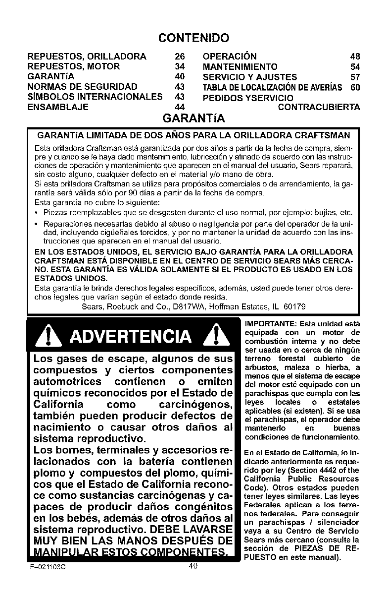
CONTENIDO
REPUESTOS, ORILLADORA 26 OPERACIC)N 48
REPUESTOS, MOTOR 34 MANTENIMIENTO 54
GARANTiA 40 SERVICIO Y AJUSTES 57
NORMAS DE SEGURIDAD 43 TABLA DE LOCALIZACI6N DE AVERiAS 60
SiMBOLOS INTERNACIONALES 43 PEDIDOS YSERVICIO
ENSAMBLAJE 44 CONTRACUBIERTA
GARANTiA
GARANTiA LIMITADA DE DOS AI_IOS PARA LA ORILLADORA CRAFTSMAN
Esta oriIladora Craftsman esta garantizada pot dos afios a partir de la fecha de compra, siem-
prey cuando se le haya dado mantenimiento, lubricaci6n y aflnado de acuerdo con las instruc-
clones de operaci6n y mantenimiento que aparecen en el manual del usuado, Sears reparar&,
sin costo alguno, cualquier defecto en el material y/o mano de obra.
Siesta ofilladora Craftsman se utiliza para prop6sitos comerciales o de arrendamiento, Ia ga-
rantia sera v_lida s61opor 90 dias a partir de la fecha de compra.
Esta garantia no cubre Io siguiente:
• Piezas reemplazables que se desgasten durante el uso normal, pot ejemplo: bujias, etc.
• Reparaciones necesarias debido al abuso o negligencia pot parte del operador de la uni-
dad, incluyendo cigLieSales torcidos, y por no mantener la unidad de acuerdo con las ins-
trucciones que aparecen en el manual del usuario.
EN LOS ESTADOS UNIDOS, EL SERVICIO BAJO GARANTiA PAPA LA ORILLADORA
CRAFTSMAN ESTA DISPONIBLE EN EL CENTRO DE SERVICIO SEARS MAS CERCA-
NO. ESTA GARANTiA ES VALIDA SOLAMENTE SI EL PRODUCTO ES USADO EN LOS
ESTADOS UNIDOS.
Esta garantia le bdnda derechos legales especiflcos, adem&s, usted puede tener otros dere-
chos Iegales que varian segQn el estado donde resida.
Sears, Roebuck and Co., D817WA, Hoffman Estates, IL 60179
Los gases de escape, algunos de sus
compuestos y ciertos componentes
automotrices contienen o emiten
quimicos reconocidos por el Estado de
California como carcinbgenos,
tambi_n pueden producir defectos de
nacimiento o causar otros da6os al
sistema reproductivo.
Los bornes, terminales y accesorios re-
lacionados con la bateria contienen
plomo y compuestos del plomo, quimi-
cos que el Estado de California recono-
ce como sustancias carcinbgenas y ca-
paces de producir da6os cong_nitos
en los beb_s, ademas de otros da6os al
sistema reproductivo. DEBE LAVARSE
MUY BIEN LAS MANOS DESPUES DE
MANIPULAR ESTOS COMPONENTES.
F_021103C 40
IMPORTANTE: Esta unidad esta
equipada con un motor de
combustibn interna y no debe
set usada en o cerca de ningt'ln
terreno forestal cubierto de
arbustos, maleza o hierba, a
menos que el sistema de escape
deI motor est_ equipado con un
parachispas que cumpla con las
leyes locales o est_tales
aplicables (si existen). Si se usa
el parachispas, el operador debe
mantenerlo erl buenas
condiciones de funcionamiento.
En el Estado de California, Io in-
dicado anteriormente es reque-
rido por ley (Section 4442 of the
California Public Resources
Code). Otros estados pueden
tenet leyes similares. Las leyes
Federales aplican a los terre-
nos federales. Para conseguir
un parachispas /silenciador
vaya a su Centro de Servicio
Sears mas cercano (consulte la
seccibn de PIEZAS DE RE-
PUESTO en este manual).
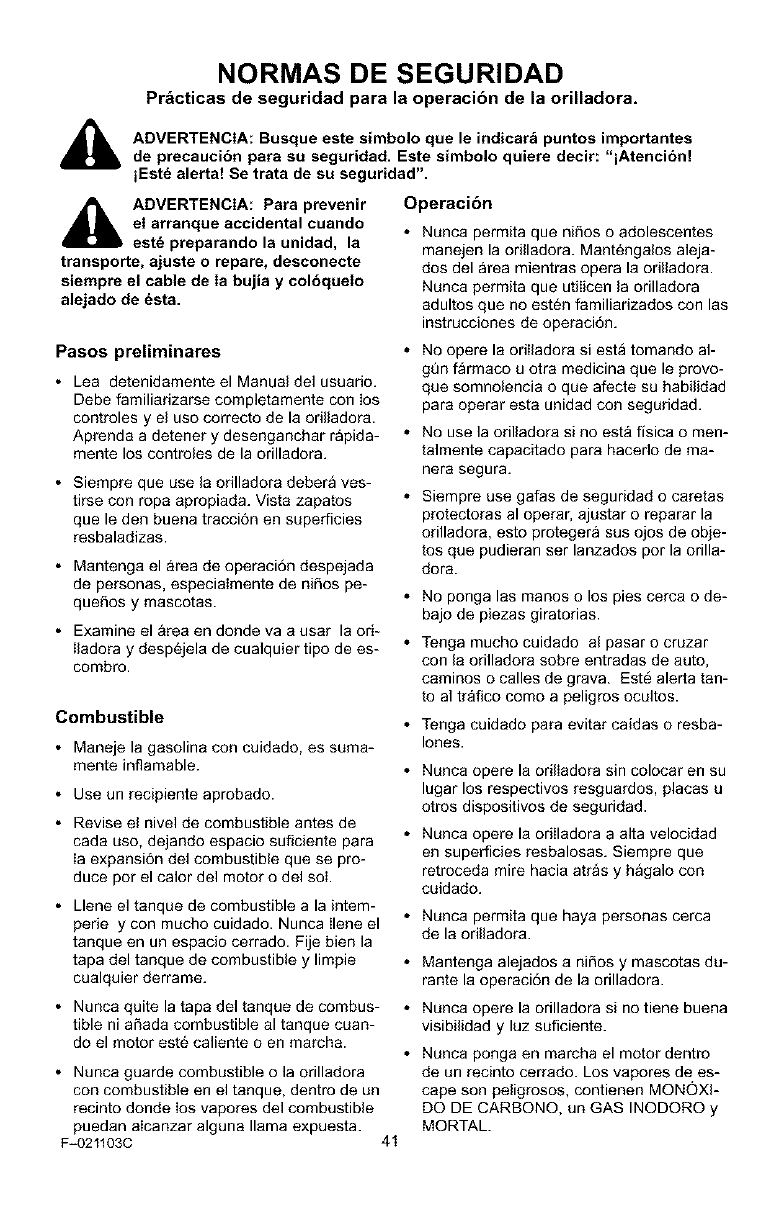
NORMAS DE SEGURIDAD
Pr&cticas de seguridad pars la operacibn de la orilladora.
_1_ DVERTENCIA: Busque este simbolo clue le indicarb puntos importantes
de precaucibn para su seguridad. Este simbolo quiere decir: "lAtencibn!
iEst_ alerta! Se trata de su seguridad".
_[b ADVERTENCIA: Para prevenir
el arranque accidental cuando
est_ preparando la unidad, la
transporte, ajuste o repare, desconecte
siempre el cable de Ia bujia y colbquelo
alejado de _sta.
Operacibn
• Nunca permita que nifios o adolescentes
manejen la orilladora. Mant6ngalos aleja-
dos del area mientras opera la odlladora.
Nunca permita que utiIicen la orilladora
adultos que no est6n familiarizados con las
instrucciones de operaci6n.
Pasos preliminares
• Lea detenidamente el Manual del usuano.
Debe familiadzarse completamente con Ios
controles y el uso correcto de la odlladora.
Aprenda a detener y desenganchar rapida-
mente los controles de la orilladora.
• Siempre que use la odlladora debera ves-
tirse con ropa apropiada. Vista zapatos
que le den buena tracci6n en superficies
resbaladizas.
• Mantenga el &rea de operaci6n despejada
de personas, especiaimente de niSos pe-
queSos y mascotas.
• Examine el &tea en donde va a usar la od-
Iladora y desp6jela de cualquier tipo de es-
combro.
Combustible
• Maneje la gasolina con cuidado, es suma-
mente inflamable.
• Use un recipiente aprobado.
• Revise el nivel de combustible antes de
cada uso, dejando espacio suficiente para
Ia expansi6n del combustible que se pro-
duce pot el calor del motor o del sol.
• Llene el tanque de combustible a la intem-
perie y con mucho cuidado. Nunca Ilene el
tanque en un espacio cerrado. Fije bien la
tapa del tanque de combustible y limpie
cualquier derrame.
• Nunca quite la tapa del tanque de combus-
tible ni aSada combustible al tanque cuan-
do el motor est6 caliente o en march&
• Nunca guarde combustible o la orilladora
con combustible en el tanque, dentro de un
recinto donde los vapores del combustible
puedan alcanzar alguna llama expuesta.
F-021103C 41
• NO opere la odlladora siesta tomando al-
gun farmaco u otra medicina que le provo-
que somnolencia o que afecte su habilidad
para operar esta unidad con seguridad.
• No use la orilladora si no esta fisica o men-
talmente capacitado parr hacedo de ma-
nera segura.
• Siempre use galas de seguridad o caretas
protectoras al operaL ajustar o reparar la
orilladora, esto protegera sus ojos de obie-
tos que pudieran ser lanzados por la orilla-
dora.
• No ponga las manos o los pies cerca o de-
bajo de piezas giratorias.
• Tenga mucho cuidado al pasar o cruzar
con la orilladora sobre entradas de auto,
caminos o calles de grava. Est6 alerta tan-
to al trafico como a peligros ocultos.
• Tenga cuidado para evitar caidas o resba-
lores.
• Nunca opere la odlladora sin colocar en su
lugar los respectivos resguardos, placas u
otros dispositivos de seguridad.
• Nunca opere la orilladora a alta velocidad
en superficies resbalosas. Siempre que
retroceda mire hacia atras y hagalo con
cuidado.
• Nunca permita que haya personas cerca
de la odlladora.
• Mantenga alejados a niSos y mascotas du-
rante la operaci6n de la orilladora.
• Nunca opere la orilladora si no tiene buena
visibilidad y luz suflciente.
• Nunca ponga en marcha el motor dentro
de un recinto cerrado. Los vapores de es-
cape son peligrosos, contienen MONOXI-
DO DE CARBONO, un GAS INODORO y
MORTAL.
NORMAS DE SEGURIDAD
• Tome todas las precauciones posibles
cuando deje la orilladora desatendida.
Apague el motor.
• No sobrecargue la capacidad de la orilla-
dora al tratar de rebordear a mucha profun-
didad y a mucha velocidad.
Almacenamiento
• Siva a guardar la orilladora por un periodo
largo de tiempo, siempre consulte las ins-
trucciones del manual deI usuario donde
encontrara informaci6n importante al res-
pecto.
• Nunca almacene la odlladora, con com-
bustible en el tanque, dentro de un recinto
donde hayan fuentes de ignici6n tales co-
mo catentadores de agua y estufas, seca-
doras de ropa y otras fuentes similares.
Permita que el motor se enfrie antes de
guardar la unidad en un recinto cerrado.
• Mantenga la orilladora en condiciones se-
guras de funcionamiento. Revise con regu-
Iaridad todos los sujetadores para
comprobar que est6n debidamente apreta-
dos.
Reparacion /Ajustes
Si golpea un objeto extraSo, con la unidad,
apague el motor. Desconecte el cable de la
bujia y mant_ngalo alejado de 6sta para
evitar un arranque accidental del motor.
Revise bien la orilIadora para ver si sufri6
algQn daSo, de ser asi, debera reparada
antes de haceda funcionar nuevamente.
Si la orilladora comienza a vibrar excesiva
o anormalmente, apague el motor. Revise
la unidad de inmediato para determinar la
causa. Generalmente la vibraci6n indica
que existe alguna averia.
Apague el motor siempre que tenga que
dejar la posici6n de operaci6n. Desconecte
tambi_n el cable de la bujia antes de des-
atascar la cuchilla y antes de realizar cuai-
quier reparaci6n, ajuste o inspecci6n a la
unidad.
Antes de limpiar, reparar o inspeccionar la
unidad, apague el motor y asegt3rese de
que todas las partes en movimiento se ha-
yah detenido.
Nunca haga ajustes o reparaciones mien-
tras el motor est_ en marcha.
F_021103C 42
NORMAS DE SEGURIDAD
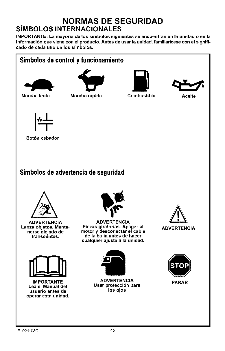
SiMBOLOS INTERNACIONALES
IMPORTANTE: La mayoria de los simbolos siguientes se encuentran en Ia unidad o en la
informacibn que viene con el producto. Antes de usar la unidad, familiaricese con el signifi-
cado de cada uno de los simbolos.
Simbolos de control y funcionamiento
Marcha lenta Marcha rapida Combustible Aceite
Botbn cebador
Simb010sde advertenciade seguridad
ADVERTENCIA ADVERTENCIA
Lanza objetos. Mante- Piezas giratorias. Apagar el ADVERTENCIA
nerse ale jado de motor y desconectar el cable
transeuntes, de la bujia antes de hacer
cualquier ajuste a la unidad.
IMPORTANTE
Lea el Manual del
usuario antes de
operar esta unidad.
ADVERTENCIA
Usar proteccibn para
los ojos
PARAR
F_021103C 43
ENSAMBLAJE
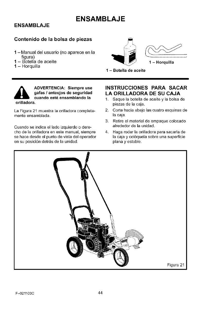
ENSAMBLAJE
Contenido de la bolsa de piezas
1-Manual del usuario (no aparece en la
figura)
1 - Botella de aceite
1 - Horquilla 1 - Horquilla
1 - Botella de aceite
ADVERTENCIA: Siempre use
gafas /anteojos de seguridad
cuando est_ ensamblando la
orilladora.
La Figura 21 muestra la orilladora completa-
mente ensamblada.
Cuando se indica el lado izquierdo o dere-
cho de la orilladora en este manual, siempre
se hace desde el punto de vista del operador
en su posici6n detr_s de la unidad.
INSTRUCCIONES PARA SACAR
LA ORILLADORA DE SU CAJA
1. Saque la botella de aceite y Ia bolsa de
piezas de la caja.
2. Corte hacia abajo Ias cuatro esquinas de
Ia caja.
3. Retire el material de empaque colocado
alrededor de la unidad.
4. Haga rodar la orilladora para sacarla de
Ia caja y col6quela sobre una superficie
plana y estable.
Figura 21
F-021103C 44
ENSAMBLAJE
COMO LEVANTAR EL MANGO
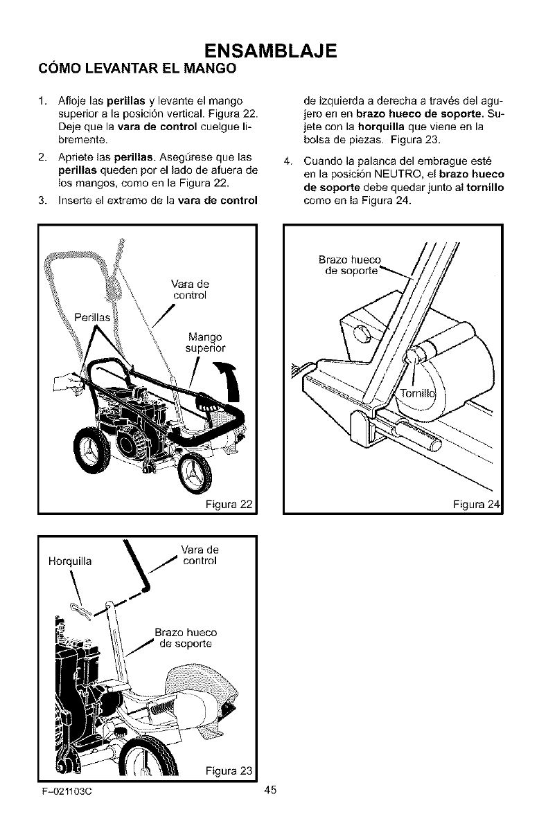
1. Afloje las perillas y levante el mango
superior a la posici6n vertical. Figura 22.
Deje que la vara de control cuelgue li-
bremente.
2. Apriete las perillas. Aseg[irese que las
perillas queden por el lado de afuera de
los mangos, como en la Figura 22.
3. Inserte el extremo de la vara de control
de izquierda a derecha a trav6s del agu-
jero en en brazo hueco de soporte. Su-
jete con la horquilla que viene en la
bolsa de piezas. Figura 23.
4. Cuando la palanca del embrague est_
en la posici6n NEUTRO, el brazo hueco
de soporte debe quedar junto aI tornillo
como en Ia Figura 24.
Vara de
control
/
Mango
supenor
Figura 22
Brazo hueco
Figura 24
Vara de
Horquilla
Brazo hueco
de soporte
Figura 23
F_0211030 45
ENSAMBLAJE
COMO PREPARAR EL MOTOR Cbmo ahadir el aceite de motor
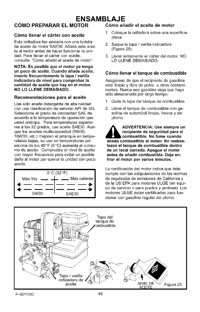
Cbmo Ilenar el cbrter con aceite
Esta orilladora fue enviada con una botella
de aceite de motor SAE30. A_ada este acei-
teal motor antes de hacer funcionar la uni-
dad. Para Ilenar el carter con aceite,
consulte "C6mo afiadir el aceite de motor".
1. Coloque la orilladora sobre una superficie
plana.
2. Saque la tapa /varilla indicadora
(Figura 25).
3. Llene lentamente el c&rter del motor. NO
LO LLENE DEMASIADQ.
NOTA: Es posible que el motor ya tenga
un poco de aceite. Cuando a_ada aceite,
inserte frecuentemente la tapa /varilla
indicadora de nivel para comprobar la
cantidad de aceite que hay en el motor.
NO LO LLENE DEMASIADO.
Recomendaciones para el aceite
Use s61o aceite detergente de alta caiidad
con una clasificaci6n de servicio API de SG.
Seleccione el grado de viscosidad SAE de
acuerdo a la temperatura de operaci6n que
usted anticipa. Para temperaturas superio-
res a los 32 grados, use aceite SAE30. Aun-
que los aceites multiviscosidad (5W30,
10W30, etc.) mejoran el arranque en tempe-
raturas bajas, su uso en temperaturas por
encima de los 40°F (0C) aumenta el consu-
mo de aceite. Compruebe eI nivel de aceite
con mayor frecuencia para evitar un posibie
daSo al motor por operar la unidad con poco
aceite.
,4
0C (32°F) J
M_Is fri° __ -- 2scalien;e I
5w30 - s 30 I
Cbmo Ilenar el tanque de combustible
AsegL_rese de que el recipiente de gasolina
est6 limpio y libre de polvo u otros contami-
nantes. Nunca use gasolina vieja que haya
sido almacenada por largo tiempo.
1. Quite la tapa del tanque de combustible.
2. Llene el tanque de combustible con ga-
solina de autom6vil limpia, fresca y sin
plomo.
_IL DVERTENCIA: Use siempre un
recipiente de seguridad para el
combustible. No fume cuando
a_ada combustible al motor. No reabas-
tezca el tanque de combustible dentro
de un local cerrado. Apague el motor
antes de a_adir combustible. Deje en-
friar el motor pot ratios minutos.
La certificaci6n del motor indica que _ste
cumple con las estipulaciones de las normas
de regulaci6n de emisiones de California y
de la US EPA para motores ULGE (en equi-
po de servicio o para prados y jardines). Los
motores ULGE estan certificados para fun-
cionar con gasolina regular sin plomo.
aceite NIVEL DE Figura 25
ACEITE
F=021103C 46
ENSAMBLAJE
_" LISTA DE COMPROBACION
Para obtener un rendimiento 6ptimo y la ma-
yor satisfacci6n de este producto de alta ca-
Iidad, favor de revisar la siguiente lista de
comprobaci6n antes de hacer funcionar su
orilladora:
Se hart completado todas las instruc-
ciones de ensamblaje.
Se ha revisado la caja de envfo para
asegurar que no haya quedado en
ella ninguna pieza suelta.
Se han apretado bien todos los suje-
tadores (pernos, tornillos, etc.).
A medida que vaya aprendiendo sobre el
uso de la onlladora, preste especial atenci6n
a los siguientes puntos importantes:
#-'_" El nivel de aceite del motor es el co-
rrecto.
_'_" El tanque de combustible ha sido IIe-
nado con gasolina regular limpia, fres-
ca y sin plomo.
_'_" Se ha familiarizado y entiende 18fun-
ci6n de todos los controles. Antes de
hacer arrancar el motor ha verificado
el funcionamiento de todos los contro-
les.
F-021103C 47
OPERACION
CONOZCA SU ORILLADORA
ANTES DE HACER FUNCIONAR LA ORILLADORA, LEA EL MANUAL DEL USUARIO Y TO-
DA LA INFORMACI6N SOBRE SEGURIDAD. Para famiiiarizarse con la ubicaci6n de los con-
troles, compare las siguientes ilustraciones con su orilladora. Guarde este manual para
referencias futuras.
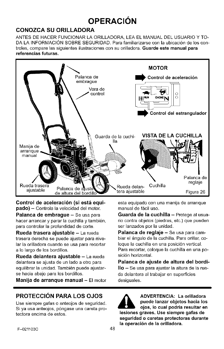
Palanca de
embrague
Vara de
_ control
MOTOR
IControl de aceleracibn
I_. Control del estrangulador
Manija de
manual
Guarda de la cuchi-
Ila VISTA DE LA CUCHILLA
i
/,
Rueda trasera
ajustabte Palanca de
de altura del bordill_
Palanca de
Rueda delan- Cuchilla reglaje
ajustable Figura 26
Control de aceleracibn (si est& equi=
pado) - Controla la veIocidad del motor.
Palanca de embrague - Se usa para
hacer arrancar y parar la cuchilla y tambi_n,
para controlar la profundidad de corte.
Rueda trasera ajustable i La rueda
trasera derecha se puede ajustar para nive-
Iar Ia orilladora cuando se usa para recortar
a Io largo de los bordillos.
Rueda delantera ajustable - La rueda
delantera se ajusta de un lado a otro para
equilibrar la unidad. Tambi_n puede ajustar-
se hacia abajo para los bordillos.
Manija de arranque manual - El motor
esta equipado con una manija de arranque
manual de facil uso.
Guarda de la cuchUla - Protege al usua-
rio contra objetos (piedras, etc.) que pueden
ser lanzados por la unidad.
Palanca de reglaje iSe usa para cam-
biar el angulo de la cuchilla. Para orilIar, co-
Ioque Ia cuchilla en una posici6n vertical.
Para recortar, coloque la cuchilla en una po-
sici6n horizontal.
Palanca de ajuste de altura del bordi-
Iio iSe usa para ajustar la altura de la rue-
da delantera al trabajar en superficies
desiguales.
PROTECCION PARA LOS OJOS
Use siempre galas o anteojos de seguridad.
Si ya usa anteojos, p6ngase una careta pro-
tectora encima de estos.
F_021103C
_lb ADVERTENCIA: La orilladora
puede lanzar objetos hacia los
ojos, Io cual podria resultar en
Iesiones graves. Use siempre gafas de
seguridad o caretas protectoras durante
Ia operacibn de Ia orilladora.
48
COMO DETENER LA
ORILLADORA
OPERACI()N
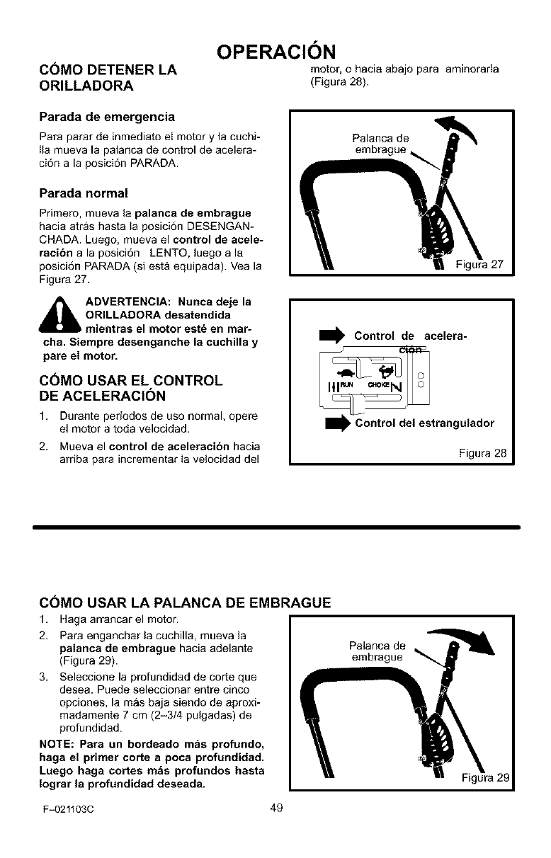
motor, o hacia abajo para aminorada
(Figura 28).
Parada de emergencia
Para parar de inmediato eI motor y la cuchi-
Ila mueva la palanca de control de acelera-
ci6n a la posici6n PARADA.
Parada normal
Primero, mueva la palanca de embrague
hacia atr&s hasta la posici6n DESENGAN-
CHADA. Luego, mueva el control de acele-
raci6n a la posici6n LENTO, luego a la
posici6n PARADA (si est& equipada). Vea la
Figura 27.
_DVERTENCIA: Nunca deje la
ORILLADORA desatendida
mientras el motor est_ en mar-
cha. Siempre desenganche la cuchilla y
pare el motor.
COMO USAR EL CONTROL
DE ACELERACIC)N
1. Durante periodos de uso normal, opere
el motor a toda velocidad.
2. Mueva el control de aceleracibn hacia
arriba para incrementar Ia velocidad del
Palanca de
Figura 27
I_, Control de acelera-
__trangulador
Figura 28
COMO USAR LA PALANCA DE EMBRAGUE
1. Haga arrancar el motor.
2. Para enganchar la cuchilla, mueva la
palanca de embrague hacia adelante
(Figura 29).
3. Seleccione la profundidad de corte que
desea. Puede seleccionar entre cinco
opciones, lamas baja siendo de aproxi-
madamente 7 cm (2-3/4 pulgadas) de
profundidad.
NOTE: Para un bordeado mas profundo,
haga el primer corte apoca profundidad.
Luego haga cortes m_s profundos hasta
Iograr la profundidad deseada,
F=021103C 49
Palanca de
embrague
Figura 29
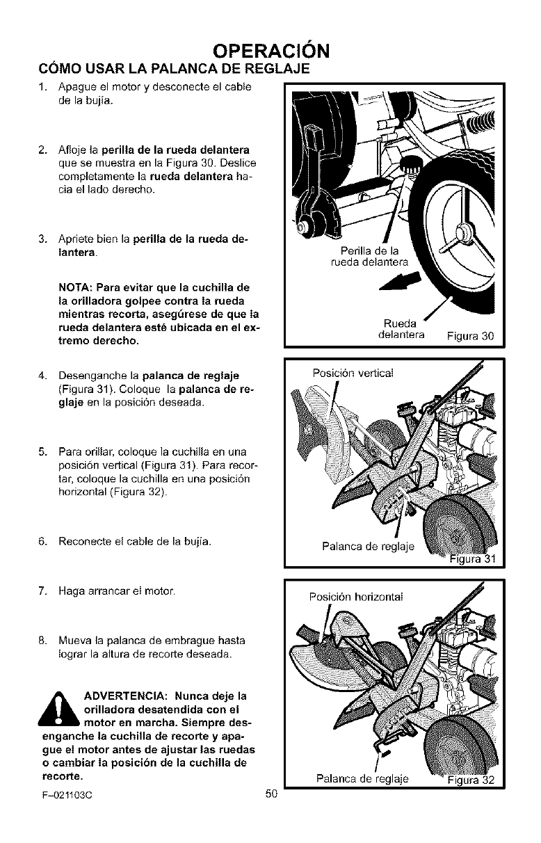
OPERACI()N
COMO USAR LA PALANCA DE REGLAJE
1. Apague el motor y desconecte el cable
de la bujia.
2. Afloje la perilla de la rueda delantera
que se muestra en la Figura 30. Deslice
completamente la rueda delantera ha-
cia el lado derecho.
3. Apriete bien la perilla de la rueda de-
Iantera.
NOT,&.:Para evitar que la cuchilla de
la orilladora golpee contra Ia rueda
mientras recorta, asegt_rese de que Ia
rueda delantera est_ ubicada en el ex-
tremo derecho.
Perilla de la
rueda delantera
Rueda
delantera Figura 30
4. Desenganche la palanca de reglaje
(Figura 31). Coloque la palanca de re-
glaje en la posici6n deseada.
5. Para odllar, coloque la cuchilla en una
posici6n vertical (Figura 31). Para recor-
tar, coloque la cuchilla en una posici6n
horizontal (Figura 32).
6. Reconecte el cable de la bujia.
Posici6n vertical
Palanca de reglaje
7. Haga arrancareI motor.
8. Mueva la palanca de embrague hasta
Iograr la altura de recorte deseada.
_IL DVERTENCIA: Nunca deje la
orilladora desatendida con el
motor en marcha. Siempre des-
enganche la cuchilla de recorte y apa-
gue el motor antes de ajustar las ruedas
o cambiar Ia posicibn de la cuchilla de
recorte.
F-021103C
Posici6n horizontal
Palanca de reglaie
50
Figura 32
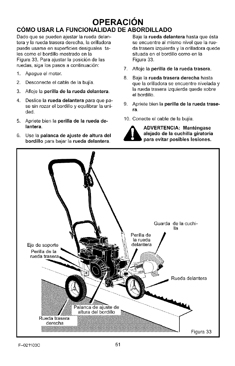
OPERACI()N
COMO USAR LA FUNCIONALIDAD DE ABORDILLADO
Dado que se pueden ajustar la rueda delan-
tera y la rueda trasera derecha, la orilladora
puede usarse en superficies desiguales ta-
les como el bordillo mostrado en Ia
Figura 33. Para ajustar la posici6n de las
ruedas, siga los pasos a continuaci6n:
1. Apague el motor.
2. Desconecte el cable de la bujia.
3. Afloje la perilla de la rueda delantera.
4. Deslice la rueda delantera para que pa-
se sin rozar el bordillo y equilibrar Ia uni-
dad.
7.
8.
9.
Baje la rueda delantera hasta que _sta
se encuentre al mismo nivel que la rue-
da trasera izquierda y la orilladora quede
situada en el bordillo como en Ia
Figura 33.
Afloje la perilla de la rueda trasera.
Baje ia rueda trasera derecha hasta
que la oriIladora se encuentre nivelada y
Ia rueda trasera izquierda quede sobre
el bordillo.
Apriete bien Ia perilla de la rueda trase-
ra.
5. Apriete bien la perilla de la rueda de-
Iantera.
6. Use Ia palanca de ajuste de altura del
bordillo para bajar Ia rueda delantera.
10. Conecte el cabte de la bujia.
_IL ADVERTENCIA: Mant_ngase
alejado de Ia cuchilla giratoria
para evitar posibles lesiones.
Eje de soporte
Perilla de la
rueda trasera
Perilla de
la rueda
delantera
Guarda de la cuchi-
Ila
Rueda delantera
Palanca de ajuste de
altura del bordilIo
Rueda trasera
derecha
Figura 33
F_021103C 51
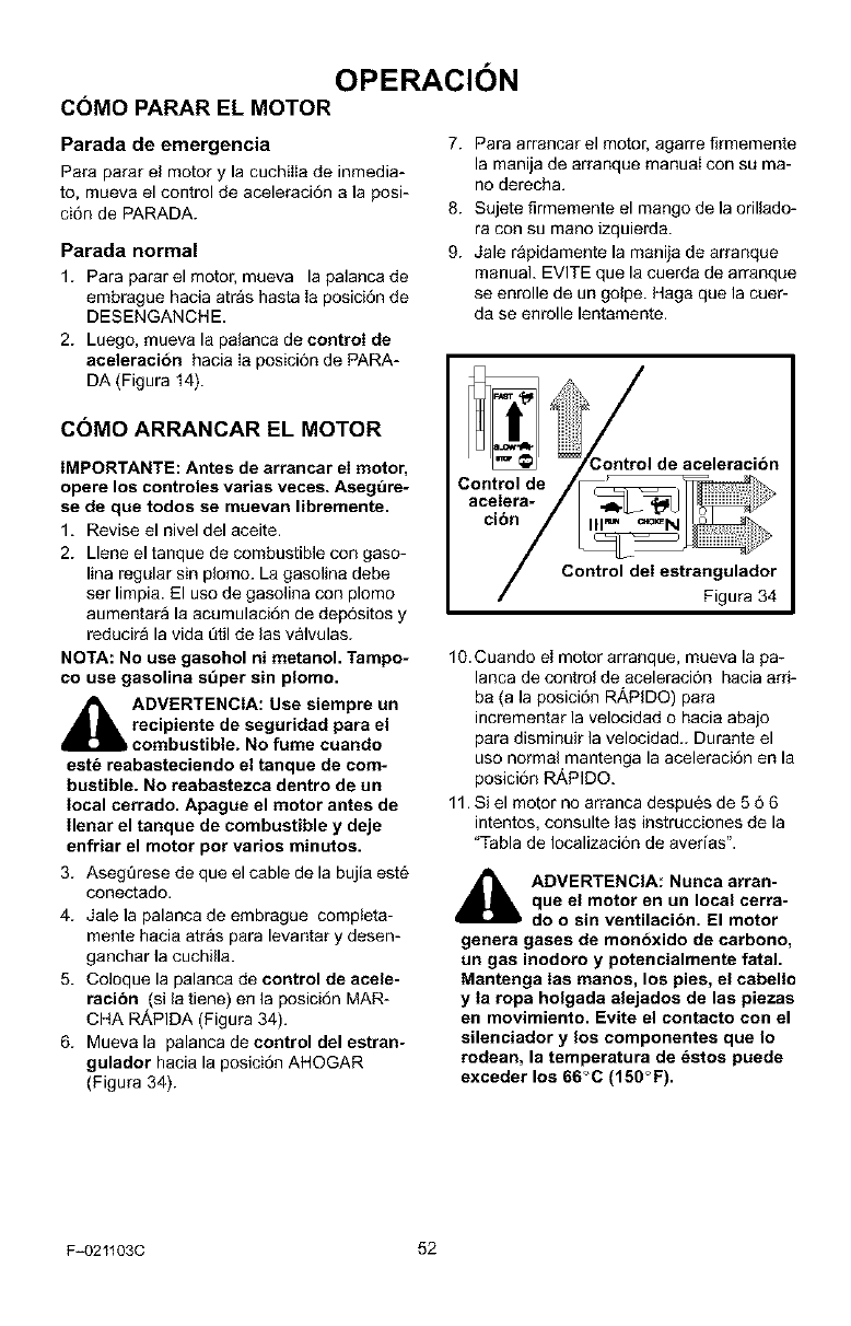
OPERACION
COMO PARAR EL MOTOR
Parada de emergencia
Para parar el motor y la cuchiIIa de inmedia-
to, mueva el control de aceleraci6n a la posi-
ci6n de PARADA.
Parada normal
1. Para parar el motor, mueva la palanca de
embrague hacia atras hasta Ia posici6n de
DESENGANCHE.
2. Luego, mueva la palanca de control de
aceleracibn hacia Ia posici6n de PARA-
DA (Figura 14).
COMO ARRANCARELMOTOR
IMPORTANTE: Antes de arrancar el motor,
opere los controles varias veces. Asegt3re-
se de que todos se muevan libremente.
1. Revise el nivel del aceite.
2. Llene el tanque de combustible con gaso-
lina regular sin plomo. La gasolina debe
ser limpia. El uso de gasolina con plomo
aumentara la acumulaci6n de dep6sitos y
reducira la vida [itil de las valvulas.
NOTA: No use gasohol ni metanol. Tampo-
co use gasolina s6per sin plomo.
,_, ADVERTENGIA: Use siempre un
recipiente de seguridad para el
,combustible. No fume cuando
est_ reabasteciendo el tanque de com-
bustible. No reabastezca dentro de un
local cerrado. Apague el motor antes de
Ilenar el tanque de combustible y deje
enfriar el motor pot ratios minutos.
3. Asegt_rese de que el cable de la bujia est6
conectado.
4. Jale la palanca de embrague compteta-
mente hacia atras para levantar y desen-
ganchar la cuchilla.
5. Coloque la palanca de control de acele-
racibn (si la tiene) en la posici6n MAR-
CHA RAPIDA (Figura 34).
6. Mueva la palanca de control del estran-
gulador hacia la posici6n AHOGAR
(Figura 34).
7. Para arrancar el motor, agarre firmemente
la manija de arranque manual con su ma-
no derecha.
8. Sujete flrmemente el mango de la orillado-
ra con su mano izquierda.
9. Jale r&pidamente la manija de arranque
manual. EVITE que la cuerda de arranque
se enrolle de un golpe. Haga que la cuer-
da se enrolle lentamente.
/
3ontrol de aceleracibn
Figura 34
10. Cuando el motor arranque, mueva la pa-
lanca de control de aceleraci6n hacia ard-
ba (a la posicidn Ri_PIDO) para
incrementar la velocidad o hacia abajo
para disminuir la velocidad.. Durante el
uso normal mantenga la aceleraci6n en la
posici6n RAPIDO.
11. Si el motor no arranca despues de 5 66
intentos, consulte las instrucciones de la
"Tabla de Iocalizaci6n de averias".
,_ ADVERTENCIA: Nunca arran-
que el motor en un local cerra-
do o sin ventilacibn. El motor
genera gases de monbxido de carbono,
un gas inodoro y potencialmente fatal.
Mantenga Ias manos, los pies, el cabell_
yIa ropa holgada alejados de las piezas
en movimiento. Evite el contacto con el
silenciador y los componentes que Io
rodean, la temperatura de _stos puede
exceder los 66C (150°F).
F-021103C 52
OPERACION
RECOMENDACIONES PARA EL
USO DE SU ORILLADORA
• La orilladora trabaja mejor cuando el tiem-
po esta seco. Si la tierra esta muy moja-
da, el barro se pega y acumula alrededor
de la cuchilla haciendo que 6sta se des-
gaste prematuramente y que la unidad no
funcione como debe.
• Si se pega el barro a la cuchilla, apague el
motor y desconecte el cable de la bujia.
Quite eI barro y basura pegados a la cu-
chilla.
• Para un bordeado mas profundo, corte
primero a poca profundidad. Luego, haga
cortes m&s profundos hasta Iograr Ia pro-
fundidad deseada.
• Para obtener un borde parejo, aseg[irese
de que la guia de la cuchilla se deslice
sobre la superficie del suelo.
• El bordeado puede modificarse variando
el numero de pasadas y tambi_n por la
distancia en que se encuentre la cuchilla
en relaci6n a la superficie.
_lb DVERTENCIA: Lea el Manual
del usuario. Familiaricese con
la ubicacibn y la funcibn de
todos los controles. Mantenga todos los
dispositivos de seguridad y protectores
en su lugar. Nunca permita que usen la
unidad los nifios o adultos no familiari-
zados con Ia orilladora. Apague el mo-
tor antes de limpiar la cuchilla o de ha-
cer reparaciones a la unidad. Mantenga
a los espectadores o transe_ntes a dis-
tancia mientras usa la orilladora. Man-
tdnga alejada de su cuerpo la cuchilla y
todas las partes giratorias que puedan
causar lesiones.
F_021103C 53
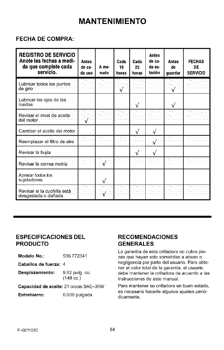
MANTENIMIENTO
FECHA DE COMPRA:
REGISTR0 DE SERVICl0 Antes
Anote las fechas a medi- Antes Csda Cada deca- Antes FECHAS
da que comp!ete cads deca- Ame- 10 25 dses- de DE
servlclo, dsuso nudo horas horss tacibn guardsr SERViCI0
IIII I
Lubricar todos los puntos I I I I i '
degi_ _/ V_
Lubricar Ios ejes de las
ruedas V V
del motor _/ .....
Cambiar el aceite del motor _
I " " " I I "
Reemplazar el filtro de sire .... _/
Revisar la bujia _
i , , , ,
Revisar la cortes motriz I ,/ . . . .
Apretar todos los
sujetadores _/
Revisar si la cuchilIa est_
desgastada o da6ada
ESPECIFICACIONES DEL
PRODUCTO
Modelo No.: 536.772341
Caballos de fuerza: 4
Desplazamiento: 9,02 pulg. cu.
(148 cc.)
Capacidad de aceite: 21 onzas SAE-30W
Entrehierro: 0,030 pulgada
RECOMENDACIONES
GENERALES
La garantia de esta ofilladora no cubre pie-
zas que hayan sido sometidas a abuso o
negligencia pot parle del usuado. Para obte-
net el valor total de la garantia, el usuafio
debe mantener Ia ofilladora de acuerdo a las
instrucciones de este manual.
Para mantener su orilladora en buen estado,
es necesado hacerle algunos ajustes peri6-
dicamente.
F_021103C 54
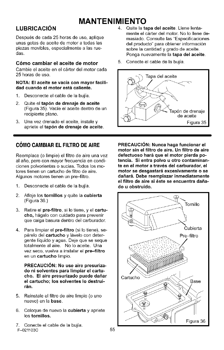
LUBRICACIC)N
Despu_s de cada 25 horas de use, aplique
unas gotas de aceite de motor a todas Ias
piezas movibles, especialmente alas rue-
das.
Cbmo cambiar el aceite de motor
Cambie el aceite en el c_rter del motor cada
25 horas de uso.
NOTA: El aceite se vacia con mayor facili-
dad cuando el motor esta caliente.
MANTENIMIENTO
4. Quite la tapa del aceite. Llene lenta-
mente el carter del motor. No Io Ilene de-
masiado. Consulte las "Especificaciones
del producto" para obtener informaci6n
sobre la cantidad y grado de aceite.
Ponga nuevamente la tapa del aceite.
5. Conecte el cable de la bujia.
Tapa del aceite
1. Desconecte el cable de la bujia.
2. Quite el tapbn de drenaje de aceite
(Figura 35). Vade el aceite dentro de un
recipiente piano.
3. Una vez drenado el aceite, instale y
apriete el tapbn de drenaje de aceite.
je
de aceite
Figura 35
C()MOCAMBIAREL FILTRODEAIRE
Reemplace (o limpie) el filtro de aire una vez
al aSo, pero con mayor frecuencia en condi-
clones polvorientas o sucias. Todos los mo-
totes tienen un cartucho de filtro de aire.
Algunos motores tienen un pre-filtro.
1. Desconecte el cable de la bujia.
2. Afloje los tornillos y quite la cubierta
(Figura 36.)
3. Retire el pre-filtro, si Io tiene, y eI cartu-
cho, hagalo con cuidado para prevenir
que caiga basura dentro del carburador.
4. Para limpiar el pre-filtro (si Io tiene), se-
parelo del cartucho y Iavelo con deter-
gente liquido y agua. Deje que se seque
totalmente al aire. No Io aceite. Una
vez seco, vuelva a instalar el pre-filtro
en un cartucbo limpio.
PRECAUCI(3N: No use aire presuriza-
do ni solventes para limpiar el cartu-
cho. El aire presurizado puede da£_ar
el cartucho; los solventes Io destrui-
r_ln.
5. Reinstale el filtro de aire limpio (0 uno
nuevo) en la base.
6. Coloque de nuevo la cubierta y apriete
ios tornillos.
PRECAUCION: Nunca haga funcionar el
motor sin el filtro de aire. an filtro de aire
defectuoso har_ que el motor pierda po-
tencia. Si entra polvo uotto contaminan-
teen el motor atraves del carburador, el
motor se desgastara excesivamente o se
da_ar& Debe reemplazar inmediatamente
el filtro de aire si _ste se encuentra daha-
do u obstruido.
Tornillo
Cubierta
Pre-filtro
Cartucho Base
7. Conecte el cable de la bujia. Figura 36
F-021103C 55
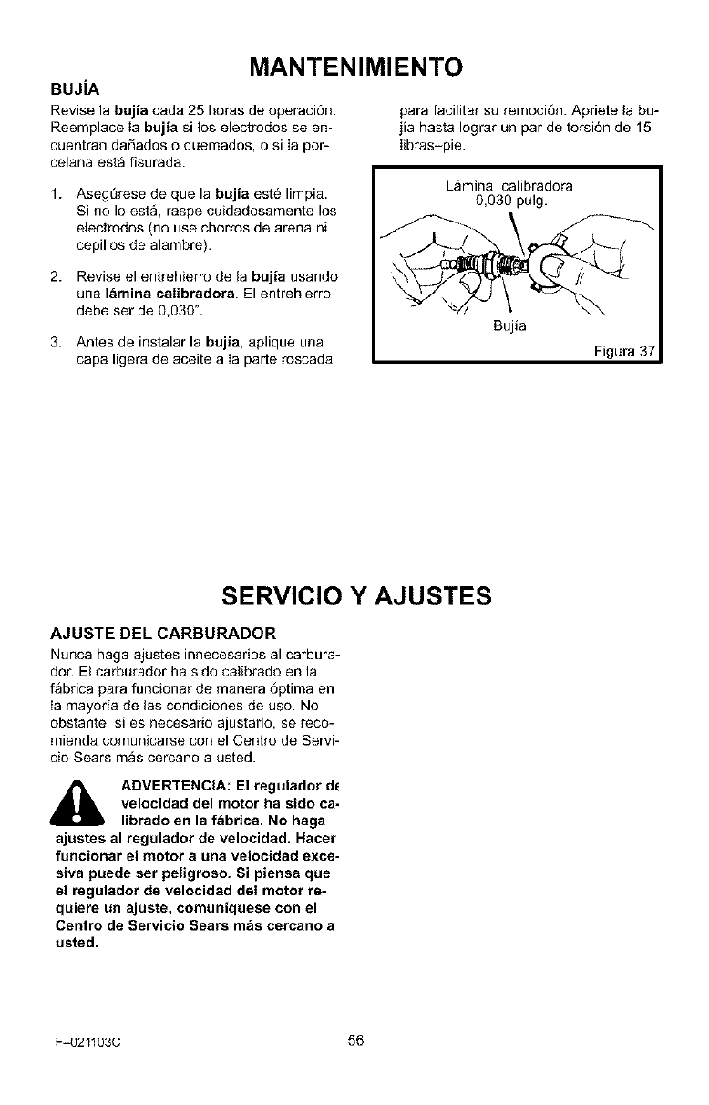
MANTENIMIENTO
BUJiA
Revise la bujia cada 25 horas de operaci6n, para facilitar su remoci6n. Apriete la bu-
Reemplace Ia bujia si los electrodos seen- jia hasta Iograr un par de torsi6n de 15
cuentran daSados e quemados, o si Ia por- Iibras-pie.
celana esta fisurada.
1. Aseg[irese de que la bujia est6 limpia.
Si no Io est& raspe cuidadosamente los
electrodos (no use chorros de arena ni
cepilles de alambre).
2. Revise el entrehierro de la bujia usando
una lamina calibradora. El entrehierro
debe ser de 0,030%
3. Antes de instalar la bujia, aplique una
capa ligera de aceite a ia parte roscada
Lamina calibradora
0,030 pulg.
Sujia
Figura 3
SERVICIO
AJUSTE DEL CARBURADOR
Nunca haga ajustes innecesarios al carbura-
dot. El carburador ha sido calibrado en la
fabrica para funcionar de manera 6ptima en
ia mayoria de las condiciones de use. No
obstante, si es necesario ajustarlo, se reco-
mienda comunicarse con el Centre de Servi-
cio Sears mas cercano a usted.
,_ ADVERTENCIA: El regulador dc
velocidad del motor ha sido ca-
librado en la fabrica. No haga
ajustes al regulador de velocidad. Hacer
fu_ciortar eJ motor a LUlaveJocidad exce-
siva puede ser peligroso. Si piensa clue
el regulador de velocidad deI motor re-
quiere un ajuste, comuniquese con el
Centro de Servicio Sears m&s cercano a
usted.
Y AJUSTES
F_021103C 56
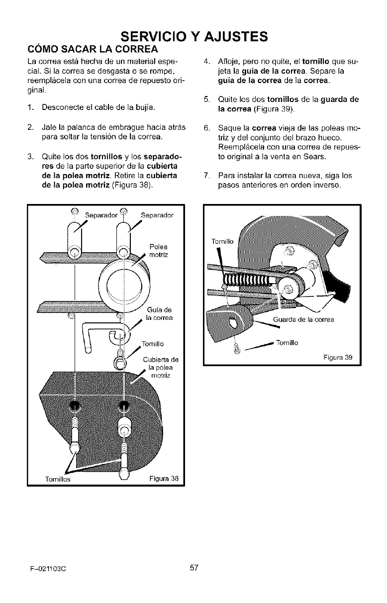
SERVICIO Y AJUSTES
COMO SACAR LA CORREA
La correa esta hecha de un matedal espe-
cial. Si la correa se desgasta o se rompe,
reemplacela con una correa de repuesto ori-
ginal
1. Desconecte el cable de la bujia.
4. Afloje, pero no quite, el tornillo que su-
jeta la guia de la correa. Separe la
guia de la correa de Ia correa.
5. Quite los dos tornillos de la guarda de
Ia correa (Figura 39).
2. Jale la palanca de embrague hacia atr_s
para soltar la tensi6n de la correa.
3. Quite los dos tornillos y los separado-
res de la parte superior de la cubierta
de la polea motriz. Retire la cubierta
de la polea motriz (Figura 38).
6.
7.
Saque la correa vieja de las poleas mo-
triz y del conjunto del brazo hueco.
Reempl_cela con una correa de repues-
to original a la venta en Sears.
Para instalar la correa nueva, siga los
pasos anteriores en orden inverso.
Separador q Separador
TomiHos
Polea
motriz
Tomillo
Cubierta de
F{gura 38
GLlard8 de la corTea
_/Tomillo
Figura 39
F-021103C 57
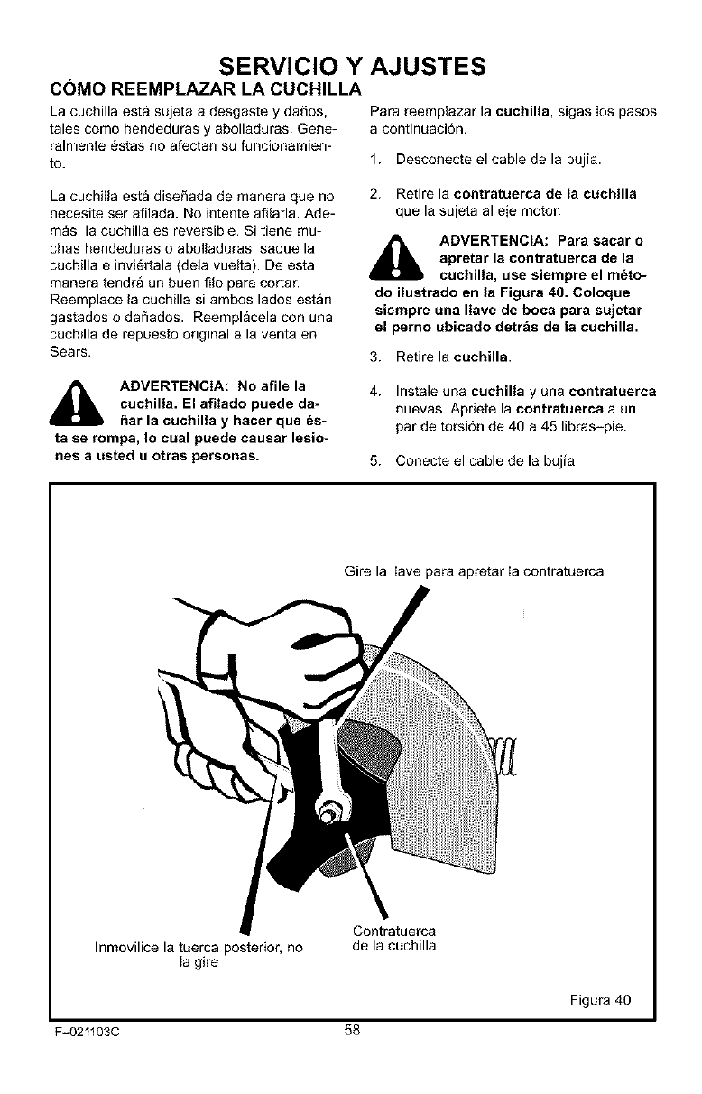
SERVICIO Y AJUSTES
COMO REEMPLAZAR LA CUCHILLA
La cuchilla esta sujeta a desgaste y daSos,
tales como hendeduras y abolladuras. Gene-
ralmente _stas no afectan su funcionamien-
to.
Para reemplazar la cuchilla, sigas los pasos
a continuaci6n.
1. Desconecte el cable de la bujia.
La cuchilla esta dise_ada de manera que no
necesite ser afilada. No intente afilarla. Ade-
m_s, la cuchilla es reversible. Si tiene mu-
chas hendeduras o abolladuras, saque la
cuchilla e invi_rtala (dela vuelta). De esta
manera tendra un buen filo para cortar.
Reemplace la cuchilla si ambos lados estan
gastados o dafiados. Reemplacela con una
cuchilla de repuesto original a la venta en
Sears.
ADVERTENCIA: No afile la
cuchilla. El afilado puede da-
bar la cuchilla y hacer que _s-
ta se rompa, Io cual puede causar lesio-
nes a Listed u otras personas.
2. Retire la contratuerca de Ia cuchilla
que la sujeta al eje motor.
_lb DVERTENCIA: Para sacar o
apretar la contratuerca de la
cuchilla, use siempre el m_to-
do ilustrado en la Figura 40. Coloque
siempre una Ilave de boca para sujetar
el perno ubicado detr&s de la cuchilla.
3. Retire la cuchilla.
4. Instale una cuchilla y una contratuerca
nuevas. Apriete la contratuerca a un
par de torsi6n de 40 a 45 libras-pie.
5. Conecte el cable de la bujia.
Gire la liave para apretar ia contratuerca
Inmovilice la tuerca posterior, no
Ia gire
Contratuerca
de la cuchilla
Figura 40
F=021103C 58
SERVICIO Y
ALMACENAMIENTO
_lb DVERTENCIA: Nunca guarde
la orilladora con combustible
en el tanque en un recinto ca-
rrado. Nunca la guarde en un Area cerra-
da y con poca ventilacibn, donde los va-
pores del combustible pudieran alcanzar
una llama expuesta, chispas o el piloto
en un sistema de calefaccibn, calentador
de agua o secadora de ropa.
_lb ADVERTENCIA: No saque la
gasolina del tanque mientras
se encuentra dentro de un re-
cinto cerrado, cerca de fuego o mientra_
est_ fumando. Los vapores de Ia gasoli-
na pueden causar una explosibn o un in-
cendio.
Cuando deba guardar la orilladora pot treinta
dias o m_s, siga los pasos indicados a conti-
nuaci6n para asegurarse que la orilladora
est6 en buenas condiciones de uso para la
proxima temperada.
Orilladora
Limpie bien la orilladora.
Revise la orilladora pot si tuviera piezas
gastadas o dabadas. Apriete todas Ias
piezas que est6n sueltas.
Coloque una pequeba cantidad de acei-
te de motor en todas las partes movi-
bles, especialmente en las ruedas.
Guarde la orilladora en un recinto que
tenga buena ventilaci6n.
Cubra la orilladora con una cubierta
apropiada que no retenga humedad. No
use pl&stico.
IMPORTANTE: Nunca cubra la orilladora
mientras el motor y las Areas de escape
est_n todavia calientes.
NOTA: Una revisibn o un aflnamiento
anual hecho en un Centro de Servicio
Sears es una buena manera de asegurar
que su orilladora le brindar_ un bptimo
rendimiento la prbxima temporada.
Motor
IMPORTANTE: Es importante evitar que
se formen residuos de resina en los com-
F-021103C 59
AJUSTES
ponentes del sistema de combustible, ta-
Ies como el carburador, filtro de
combustible, linea de combustible y tan-
que, durante el almacenamiento de la uni-
dad. Ademas, el uso de combustibles
mezclados con alcohol (Ilamados gaso-
hoI, etanol ometanol) puede atraer hume-
dad Io cual Ileva a la separacibn del
combustible y a la formacibn de acidos
durante el almacenamiento de Ia unidad.
Los gases acidos pueden da_ar el siste-
ma de combustible de un motor mientras
se encuentra guardado.
Para prevenir el dafio al motor cuando la ori-
Iladora esta guardada por 30 dias o mas,
siga los pasos siguientes:
Deje el motor andando hasta que se ie
termine la gasolina.
Si usted no desea sacar la gasolina del
tanque, aSada un estabilizador de com-
bustible a la gasolina que queda en el
tanque. El estabilizador de combustible
minimizara los dep6sitos de resina y los
acidos. Si el tanque de combustible esta
casi vacio, mezcle el estabilizador con
gasolina fresca en otto recipiente y aria-
da la mezcla al tanque de combustible.
Siga siempre las instrucciones que apa-
recen en el envase deI estabilizador.
Arranque el motor. Deje que ei motor co-
rra por 10 minutos para permitir que la
mezda alcance el carburador.
Cambie el aceite del motor. Consulte
"C6mo cambiar el aceite del motor" en la
secci6n de Mantenimiento.
Lubrique el Area del pist6n /cilindro. Es-
to se puede hacer quitando primero la
bujia y colocando una pequeSa cantidad
de aceite de motor limpio en el orificio de
ia bujia. Luego, cubra el orificio de la bu-
jia con un paso para absorber el aceite
rociado. A continuaci6n, haga girar el
motor jalando la manija de arranque ma-
nual dos o tres veces. Pot QItimo, instale
ia bujia y vuelva a conectar el cable.
Guarde la orilladora en Ia posici6n de
operaci6n con las ruedas sobre el suelo.
Si guarda la orilIadora en cualquier otra
posici6n, el aceite del carter del motor
entrara en el cilindro Io cual causaria un
problema de servicio.
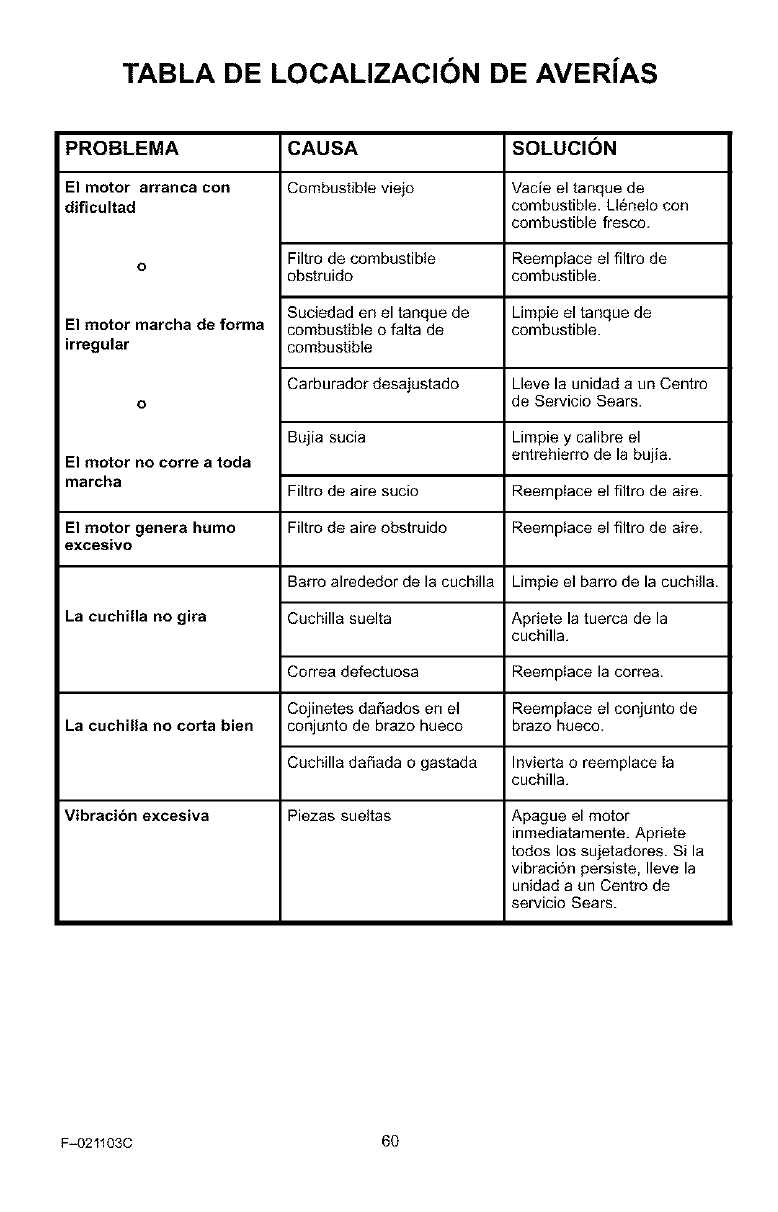
TABLA DE LOCALIZACION DE AVERiAS
PROBLEMA
El motor arranca con
dificultad
o
El motor marcha de forma
irregular
o
El motor no corre a toda
marcha
El motor genera humo
excesivo
La cuchilla no gira
La cuchiUa no corta bien
Vibracibn excesiva
CAUSA
Combustible vi_o
Filtro de combustible
obstruido
Suciedad en el tanque de
combustible o falta de
combustible
Carburador desaiustado
Bujia sucia
Filtro de aire sucio
Filtro de aire obstruido
SOLUCI(SN
Vacfe el tanque de
combustible. Ll_nelo con
combustible fresco.
Reemplace el filtro de
combustible.
Limpie el tanque de
combustible.
Lleve la unidad a un Centro
de Servicio Sears.
Limpie y calibre el
entrehierro de la bujia.
Reempiace el filtro de aire.
Reempiace el filtro de aire.
Barro alrededor de la cuchilla Limpie el barro de la cuchilla.
Cuchilla suelta Apriete la tuerca de la
cuchilla.
Correa defectuosa
Cojinetes da_ados en el
conjunto de brazo hueco
Cuchilla dafiada o gastada
Piezas sueltas
Reempiace la correa.
Reemplace el conjunto de
brazo hueco.
Invierta o reemplace Ia
cuchilla.
Apague el motor
inmediatamente. Apriete
todos los sujetadores. Si la
vibraci6n persiste, Ileve la
unidad a un Centro de
servicio Sears.
F_021103C 60
SEARS, ROEBUCK AND CO.
Garantia limitada de cumplimiento con el Sistema Federal
de control de emisiones y con el sistema de control de
emisiones del Estado de California
Motores peque_os para vehiculos todo terreno
CONTROL DE EMISIONES DE
CALIFORNIA Y DE LA AGENCIA DE
PROTECCION AMBIENTAL (EPA) DE
E.U,A. - DECLARACION DE LA
GARANTiA
La Agencia de Protecci6n Ambiental de los
Estados Unidos (en Io sucesivo "EPA"), ei
Consejo de California para los Recursos del
Aire (en Io sucesivo "CARB") y Sears, Roe-
buck and Co. tienen el placer de explicar Io que
es la Garantia Federal y de California para Sis-
temas de Control de Emisiones de su nuevo
motor pequeSo para vehiculos todo terreno.
En California, los motores pequeSos para ve-
hiculos todo terreno modelo 1995 y modelos
de aSos postedores deben ser disefiados,
construidos y equipados para cumplir con las
estrictas normas anti contaminaci6n del Esta-
do. En otros estados, los motores modelo
1997 y modelos de aSos postedores deben
estar disefiados, construidos y equipados, al
momento de su venta, para que cumplan con
ias disposiciones de la EPA acerca de motores
pequeSos para vehiculos todo terreno. Sears,
Roebuck and Co. 9arantizara el sistema para
el control de emisiones de su motor peque_o
para vehiculos todo terreno por los periodos
de tiempo que se mencionan mas adelante,
siempre y cuando su motor pequeSo para ve-
hiculos todo terreno no haya sufrido aig_n
abuso, negligencia, modificaci6n no aprobada
o mantenimiento indebido.
Su sistema para el control de emisiones puede
incluir partes como el carburador, el sistema
de encendido y el sistema de escape. Tambi_n
puede incluir ei sistema de descompresi6n y
otras unidades relacionadass con las emisio-
nes.
Cuando surja una condici6n protegida por la
garantia, Sears, Roebuck and Co. reparara su
motor pequeSo para vehiculos todo terreno
sin costo alguno para usted pot concepto de
diagn6stico, partes y mano de obra.
SISTEMA PARA EL CONTROL DE
EMISIONES DEL FABRICANTE -
COBERTURA DE LA GARANT|A
Los sistemas para el control de emisiones del
modelo 1995 y modelos de afios posteriores
de motores pequeSos para vehiculos todo te-
rreno en California estan garantizados por dos
afios, tal y como se menciona en la presente
garantia. En otros estados, los motores mode-
Io 1997 y modelos de aSos posteriores tam-
bi_n estan garantizados pot dos aSos. En
caso de que, durante dicho periodo de la ga-
rantia, cualquier pieza del motor, relacionada
con emisiones, est6 defectuosa en su material
o mano de obra, Sears, Roebuck and Co. re-
parara o cambiara dicha pieza.
RESPONSABILIDADES DEL
PROPIETARIO DE LA GARANTiA
Como propietario del motor peque_o para ve-
hiculos todo terreno usted es responsable de
que se Ileve a cabo el mantenimiento requeri-
do que se menciona en el Manual del Propieta-
rio, pero Sears, Roebuck and Co. no negar_ la
garantia unicamente debido a la falta de un re-
cibo o a que usted no proporcione una prueba
escrita de que se ha Ilevado a cabo el manteni-
miento programado.
No obstante, usted, como propietario deI mo-
tor pequeSo para vehiculos todo terreno, de-
beta estar consciente de que Sears, Roebuck
and Co. ]e puede negar la cobertura de la ga-
rantia si su motor o alguna parte del mismo ha
fallado debido a abuso, negligencia, manteni-
miento inadecuado o modificaciones no apro-
badas.
Usted es responsable de presentar su motor
pequeSo para vehiculos todo terreno en el Ta-
ller de Servicio Autorizado de Sears, Roebuck
and Co. en cuanto surja el problem& Las repa-
raciones bajo la garantia deben Ilevarse a ca-
bo dentro de un periodo de tiempo razonable
que no exceda de 30 dias.
Se puede programar el servicio de garantia
Ilamando al Taller de Servicio Autodzado de
F_021103C 61
Sears, Roebuck and Co. o a Sears, Roebuck
and Co. al 1-800-473-7247 (llamada gratuita
en E.U.A.).
NOTA IMPORTANTE
Esta declaraci6n de garantia explica los dere-
chos y las obligaciones que usted tiene de
conformidad con Ia Garantia del Sistema para
el Control de Emisiones (en Io sucesivo la "Ga-
rantia SCE"), la cual Sears, Roebuck and Co.
Ie proporciona de conformidad con las leyes
de California. V_ase tambi6n las Garantias Li-
mitadas de Sears, Roebuck and Co. que se
adjuntan a la Garantia SCE en una hoja por
separado y que tambi6n le proporciona Sears,
Roebuck and Co. La Garantia SCE Qnicamen-
te se aplica en el sistema para el control de
emisiones de su motor nuevo. Hasta el punto
en donde no haya ning[in conflicto en t6rminos
entre la Garantia SCE y la Garantia de Sears,
Roebuck and Co., la Garantia SCE aplicar&
para cualquier circunstancia a excepci6n de a-
quella en que la Garantia de Sears, Roebuck
and Co. pueda proporcionar un periodo de ga-
rantia m_s largo. La Garantia SCE y la Garan-
tia de Sears, Roebuck and Co. describen
importantes derecbos y obligaciones que us-
ted tiene con respecto a su motor nuevo.
S61o se puede Ilevar a cabo eI servicio de ga-
rantia en un Taller de Servicio Autorizado de
Sears, Roebuck and Co. AI momento de solici-
tar un servicio de garantia, se debe presentar
una prueba de la fecha de compra por parte
del comprador original. El comprador pagar_
cualquier cargo por concepto de Ilamadas de
servicio y/o transportaci6n de productos des-
de y para el lugar en donde se Ileve a cabo el
trabajo de inspecci6n y/o garantia. El compra-
dor sera responsable de cualquier da_o o p_r-
dida en el que se incurra con relaci6n a la
transportaci6n de cualquier motor o cualquier
parte del mismo que se presente para inspec-
ci6n y/o trabajo de garantia.
Si tiene alguna pregunta con relaci6n a sus de-
rechos y responsabilidades, debera Ilamar a
Sears, Roebuck and Co. al 1-800-473-7247.
GARANT|A DEL SISTEMA PAPA EL
CONTROL DE EMISIONES
Garantia del Sistema para el Control de Emi-
siones ("Garantia SCE") de motores peque-
5os para vehiculos todo terreno modelo 1995
y modelos de aSos posteriores en California
(para otros estados, motores modelo 1997 y
afios posteriores):
F_021103C 62
A. CAMPO DE APLICACION: Esta garantia
deber& aplicarse a los motores pequeSos para
vebiculos todo terreno modelo 1995 y mode-
los de aSos posteriores en California (para
otros estados, motores modelo 1997 y mode-
Ios de aSos posteriores). El Periodo de la Ga-
rantia SCE iniciara en la fecha de entrega del
nuevo motor o equipo al comprador original y
continuara durante ios siguientes 24 meses
consecutivos.
B. COBERTURA GENERAL DE LA GA-
RANTIA DEL SISTEMA PARA EL CON-
TROL DE EMISIONES: Sears, Roebuck and
Co. garantiza al comprador original del nuevo
motor o equipo y a cada comprador subse-
cuente que cada uno de sus motores peque-
5os para vehiculos todo terreno esta:
1. DiseSado, construido y equipado para que
cumpla con todas las disposiciones aplicables
adoptadas pot el Consejo para los Recursos
del Aire de conformidad con su autoridad es-
pecificada en los Capitulos 1 y 2, Parte 5, Divi-
si6n 26 del C6digo de Salud y Seguridad, y
2. Libre de defectos en sus materiales y mano
de obra, Io cual cause en cualquier momento
durante el Periodo de la Garantia SCE, la falla
de una parte relacionada con emisiones y que
est6 bajo la garantia en cuanto a que no sea
id_ntica en sus materiales a la parte descrita
en la solicitud de motor del fabricante para su
certificaci6n.
C. La Garantia SCE s61oatafie alas partes de
su motor relacionadas con emisiones de la si-
guiente manera:
1. Cualquier parte relacionada con emisiones
que no se especifique como de cambio, tal y
como se requiere en el mantenimiento especi-
ficado en el Manual del Propietario, debera ga-
rantizarse pot el Periodo de la Garantia SCE.
Si dicha parte falla durante el Periodo de la Ga-
rantia SCE, Sears, Roebuck and Co. la repa-
rata o cambiara de acuerdo con la Subsecci6n
4 que se menciona m_s adelante. Cualquier
parte reparada o cambiada de conformidad
con la Garantia SCE debera estar garantizada
por el resto del Periodo de la misma.
2. Cualquier parte garantizada y relacionada
con emisiones que est_ especificada s61o pa-
ra inspecciones regulates conforme al Manual
de! Propietario debera estar garantizada pot el
Periodo de la Garantia SCE. Una declaraci6n
en dichas instrucciones pot escrito a efecto de
"reparar o cambiar tal y como sea necesario"
no reducira el Periodo de la Garantia SCE. Di-
cha parte reparada o cambiada conforme a Ia
GarantiaSCEdeberagarantizarsepotelresto
delPeriododelamisma.
3.Cualquierpartegarantizadayrelacionada
conemisionesqueseespecifiqueparacam-
bio,deconformidadconelManuaIdelPropie-
tario,deberagarantizarsepotelperiodode
tiempoprevioalprimerpuntodecambiode
esaparte.Silapartefallaantesdelprimer
cambioprogramado,Sears,RoebuckandCo.
repararaocambiaraesapartedeacuerdocon
IaSubsecci6n4quesemencionam_sadelan-
te.Cualquierparterelacionadaconemisiones
queserepareocambiedeconformidadconla
GarantiaSCEdeberaestargarantizadapotel
restodelPeriododelamismaprevioalprimer
puntodecambioprogramadodeesapartere-
Iacionadaconemisiones.
4.Lar'eparaci6no el cambio de cualquier parte
garantizada y relacionada con emisiones de
conformidad con esta Garantia SCE se debe-
ra Ilevar a cabo, sin cargo alguno para el pro-
pietario, en un Taller Autorizado de Servicio de
Sears, Roebuck and Co.
5. No se cargara al propietario el costo por tra-
bajo de diagn6stico, el cual Ileva a la determi-
naci6n de que una parte protegida por la
Garantia SCE si esta defectuosa, provisto que
dicho trabajo de diagn6stico se Ileve a cabo en
un Taller Autorizado de Servicio de Sears,
Roebuck and Co.
6. Sears, Roebuck and Co. sera responsable
de daSos a otros componentes originales del
motor o modificaciones aprobadas que proba-
blemente sean causados por una falla com-
prendida en la garantia de una parte
relacionada con emisiones cubierta pot la Ga-
rantia SCE.
7. Durante el Periodo de la Garantia SCE,
Sears, Roebuck and Co. debera conservar un
suministro de partes garantizadas y relaciona-
das con emisiones que sea suficiente para
cumplir la demanda esperada de esas partes
relacionadas con emisiones.
8. Se puede utilizar cualquier parte de repues-
to relacionada con emisiones autorizada y
aprobada pot Sears, Roebuck and Co. para
utilizarse en el desempeSo de cualquier man-
tenimiento o cambio de la Garantia SCE, la
cual se proporcionara sin cargo alguno para el
propietario. Dicho uso no reducira las obliga-
clones de Sears, Roebuck and Co. conforme
a Ia Garantia SCE.
9. Las partes que se agreguen o modiflquen
sin aprobaci6n no se podran utilizar para mo-
dificar o reparar un motor de Sears, Roebuck
and Co. Dicho uso anula esta Garantia SCE y
conformara las bases suficientes para recha-
zar la demanda de una Garantia SCE. Sears,
Roebuck and Co. no ser_ responsable, con-
forme a esta garantia, por las fallas de cual*
quiet parte garantizada de un motor de Sears,
Roebuck and Co. causadas por el uso de di-
cha parte agregada o modificada sin aproba-
ci6n.
LAS PIEZAS RELACIONADAS CON
EMISIONES INCLUYEN LO
SIGUIENTE:
1. Ensamblaje del carburador y sus compo-
nentes internos
a) Filtro de combustible
b) Empaques (juntas) del carburador
c) Tubo de entrada
2. Unidad de filtro de aire
a) Elemento del filtro de aire
3. Sistema de encendido, que inctuye:
a) Bujia de encendido
b) M6dulo de encendido
c) Ensamblaje del volante
4. Silenciador catalitico (siesta equipado)
a) Empaque del silenciador (siesta equipado)
b) Colector de escape (siesta equipado)
5. Ensamblaje del respiradero del carter del ci-
g0eSal y sus componentes
a) Tubo de conexi6n del respiradero
10/22/99 EPA/CARB
Sears, Roebuck and Co., Hoffman Estates, IL 60179 U.S.A.
F_021103C 63

Para pedirservicio de reparaci n
a domicilio, yparaordenar piezas:
I_U-HOG/_d:P M
(1-88_784-6427)
Your Home
For repair in your home of all major brand appliances,
lawn and garden equipment, or heating and cooling systems,
no matter who made it, no matter who sold it!
For the replacement parts, accessories and
owner s manuals that you need to do-it-yourself.
For Sears professional installation of home appliances
and items like garage door openers and water heaters.
1-800-4-MY-HOME fi Anytime, day or night
(1-800-469-4663) (U.S.A. and Canada)
www.sears.com www.sears.ca
Our Home
For repair of carry-in products like vacuums, lawn equipment,
and electronics, call or go on-tine for the nearest
Sears Parts and Repair Center.
1-800-488-1222 Anytime, day or night (U.S.A. only)
www.sears.com
To purchase a protection agreement on a product serviced by Sears:
1-800-827-6655 (U.S.A.) 1-800-361-6665 (Canada)
_ii_ii;,i,iiiiiiiiiiiiiiiiiiiiiiiiiiiiiiiiiiiiiiiiiiiiiiiiiiiiiiiiii;!_!_
_iiiiiiiiiiiii?
iiiiiiiiiiiiii
iiiiiiiiiiiiii
iiiiiiiiiiiiii
iiiiiiiiiiiiii
iiiiiiiiiiiiii
iiiiiiiiiiiiii
iiiiiiiiiiiiii
iiiiiiiiiiiiii
iiiiiiiiiiiiii
iiiiiiiiiiiiii
iiiiiiiiiiiiii
iiiiiiiiiiiiii
iiiiiiiiiiiiii
iiiiiiiiiiiiii
iiiiiiiiiiiiii
iiiiiiiiiiiiii
iiiiiiiiiiiiii
iiiiiiiiiiiiii
iiiiiiiiiiiiii
iiiiiiiiiiiiii
iiiiiiiiiiiiii
iiiiiiiiiiiiii
iiiiiiiiiiiiii
iiiiiiiiiiiiii
iiiiiiiiiiiiii
iiiiiiiiiiiiii
iiiiiiiiiiiiii
AU Canada pour service en fran ais:
1-800-LE-FOYER Me
(1-800-533-6937)
www.seers.oa
' Sear& Rc_buck al_dCo,
TM $M
fi Registered Trademark /Trademark /Service Mark of Sears, Roebuck and Co.
T_ Sk4
fi Marca Registrada /'! Marca de F,Z_rica /Marca de Servicio de Sears, Roebuck and Co.
hD
r_c Ma que de comme ce /Ma que dQ_sGe de Sea s, Roebuck and Co,
