Craftsman 536797502 User Manual CULTIVATOR TILLER Manuals And Guides L0910313
CRAFTSMAN Cultivator Manual L0910313 CRAFTSMAN Cultivator Owner's Manual, CRAFTSMAN Cultivator installation guides
User Manual: Craftsman 536797502 536797502 CRAFTSMAN CULTIVATOR TILLER - Manuals and Guides View the owners manual for your CRAFTSMAN CULTIVATOR TILLER #536797502. Home:Farm Equipment Parts:Craftsman Parts:Craftsman CULTIVATOR TILLER Manual
Open the PDF directly: View PDF ![]() .
.
Page Count: 40
i:rR FTSMRN +
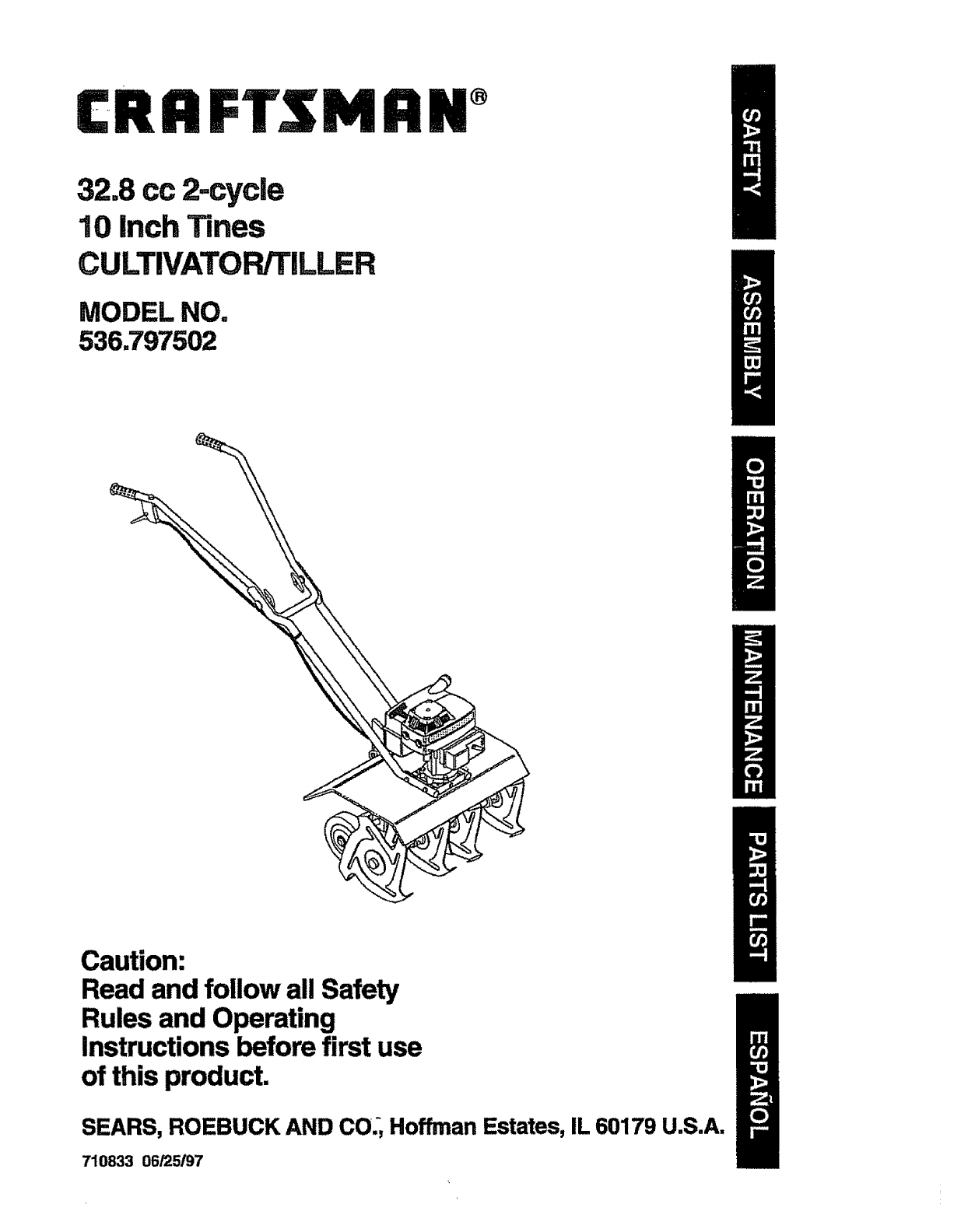
32,8 cc 2=cycle
10 Inch Tines
CULTIVATOPJTILLER
MODEL NO.
536.797502
Caution:
Read and follow all Safety
Rules and Operating
Instructions before first use
of this product
SEARS, ROEBUCK AND CO,, Hoffman Estates, IL 60179 USA.
710833 06/25/97
Table of Contents 2 Service and Adjustments 13-14
Warranty 2 Storage 14-15
Safety Rules 2-3 Troubleshooting 15
Contents of Shipping Carton 4 Edger Repair Parts 16-19
Assembly 4-6 Engine Repair Parts 20-23
Operation 7-10 Spanish (EspaSol) 24-39
Maintenance 11-12 Parts OrderingtService Back Cover
LIMITED ONE-YEAR WARRANTY ON CRAFTSMAN CULTIVATOR/TILLER
For one year from the date of purchase, when this Craftsman cultivator/tiller is main-
tained, lubricated, and tuned up according to the operating and maintenance instruc-
tions in the owner's manual, Craftsman will repair, free of charge, any defect in mate-
rial or workmanship.
This warranty excludes tine(s), spark plug, and air cleaner which are expendable parts
and become worn during normal use°
If this Craftsman cultivator/tiller is used for commercial or rental purposes, this war-
rarity applies for only 30 days from the date of purchase. This warranty applies only
while this product is in use ti_e United States. WARRANTY SERVICE IS AVAILABLE
BY RETURNING THE CULTIVATOR TO THE NEAREST CRAFTSMAN SERVICE
CENTER IN THE UNITED STATES.
This warranty gives you specific legal rights, and you may also have other rights which
vary from state to state.
SEARS, ROEBUCK AND CO., D817WA, Hoffman Estates, iL 60179
•_Look for this symbol to point out important safety precautions. It means --
ATTENTION!!! Become alert!!! Your safety is involved.
_ CAUTION: Always disconnect spark
plug wire and place wire where it cannot
contact spark plug to prevent accidental
starting when setting-up, transporting,
adjusting or making repairs.
IMPORTANT: Safety standards require
operator presence controls to minimize the
risk of injury. "Yourcultivator/tiller is
equipped with such controls. Do not attempt
to defeat the function of the operator
presence control under any circumstances.
BEFORE USE
° Read the owner's manual carefully. Be
thoroughly familiar with the controls and
the proper use of the cultivator/tiller.
Know how to stop the cultivator and
disengage the controls quickly.
•Do not operate the cultivator/tiller without
wearing adequate outer garments. Wear
footwear that will improve footing on
slippery surfaces.
.Keep the area of operation clear of all
persons, particularly small children and
pets.
•Thoroughly inspect the area where the
cultivator/tUler is to be used and remove
all foreign objects.
FUEL SAFETY
°Handle fuel with care; it is highly flam-
mable.
-Use an approved container.
•Check fuel supply before each use,
allowing space for expansion as the heat
of the engine and/or sun can cause fuel to
expand.
°Fil! fuel tank outdoors with extreme care,
Never fill fuel tank indoors. Replace fuel
tank cap securely and wipe up spilled
fuel,
•Never remove the fuel tank cap or add
fuel to a running or hot engine.
Never store fuel or cultivator with fuel in
2°
the tank inside a building where fumes
,may reach an open flame.
OPERATING SAFETY
• Never allow children or young teenagers
to operate the cultivator/tiller. Keep them
away while it is operating. Never allow
adults to operate the cultivator/tiller
without proper instruction.
° Do not operate this machine if you are
taking drugs or other medication which
can cause drowsiness or affect your
ability to operate this machine.
° Do not use this machine if you are
mentally or physically unable to operate
this machine safely.
° Always wear safety glasses or eye
shields during operation or while perform-
ing an adjustment or repair to protect
your eyes from foreign objects that may
be thrown from the cultivator/tiller.
o Do not put hands or feet near or under
rotating parts.
° Exercise extreme caution when operating
on or crossing gravel drives, walks, or
roads. Stay alert for hidden hazards or
traffic.
• Exercise caution to avoid slipping or
falling.
° Never operate the cultivator/tilter without
proper guards, plates, or other safety
protective devices in place.
• Never operate the cultivator/tiller at high
transport speeds on slippery surfaces°
Look behind and use care when backing.
• Never a!low bystanders near the cultiva-
tor.
° Keep children and pets away while
operating.
°Never operate the cultivator/tiller without
good visibility or light,
- Do not run the engine indoors. The
exhaust fumes are dangerous, containing
CARBON MONOXIDE, an ODORLESS
and DEADLY GAS.
•Take all possible precautions when
leaving the cultivator/tiller unattended.
Stop the engine.
•Do not overload the cultivator/tiller
capacity by attempting to till too deep at
too fast a rate.
SAFE STORAGE
• Always refer to the owner's manual
instructions for important details if the
cultivator/tiller is to be stored for an
extended period.
• Never store the cultivator/tiller with fuel in
the fuel tank inside a building where
ignition sources are present such as
water and space heaters, clothes dryers,
and the like. Allow the engine to cool
before storing in any enclosure.
°Keep the cultivator in safe working
condition. Check all fasteners at frequent
intervals for proper tightness.
REPAIR/ADJUSTMENTS SAFETY
- After striking a foreign object, stop the
engine. Remove the wire from the spark
plug, and keep the wire away from the
plug to prevent accidental starting.,
Thoroughly inspect the cultivator/tiller for
any damage, and repair the damage
before restarting and operating it.
•If cultivator/tiller should start to vibrate
abnormally, stop engine and check
immediately for the cause. Vibration is
generally a warding of trouble.
°Stop the engine whenever you leave the
operating position. Also, disconnect the
spark plug wire before unclogging the
tines and when making any repairs,
adjustments, or inspections.
•When cleaning, repairing, or inspecting,
shut off the engine and make certain all
moving parts have stopped.
- Never attempt to make any adjustments
while the engine is running except when
specifically recommended by the manu-
facturer.
/_ WARNING: The engine exhaust
from this product contains chemicals
known to the State of California to cause
cancer, birth defects or other reproductive
harm.
WARNING: This unit is equipped
with an internal combustion engine and
should not be used on or near any unim-
proved forest-covered, brush--covered or
grass-covered land unless the engine's ex-
haust system is equipped with a spark ar-
rester meeting applicable local or state laws
(if any). If aspark arrester is used, it should
be maintained in effective working order by
the operator.
3
in the state of California the spark arrester is
required by law (Section 4442 of the Califor-
nia Public Resources Code). Other states
may have similar laws. Federal laws apply
on federal lands, A spark arrester/muffler is
available through your nearest Craftsman
Authorized Service Center (See REPAIR
PARTS section in this manual).
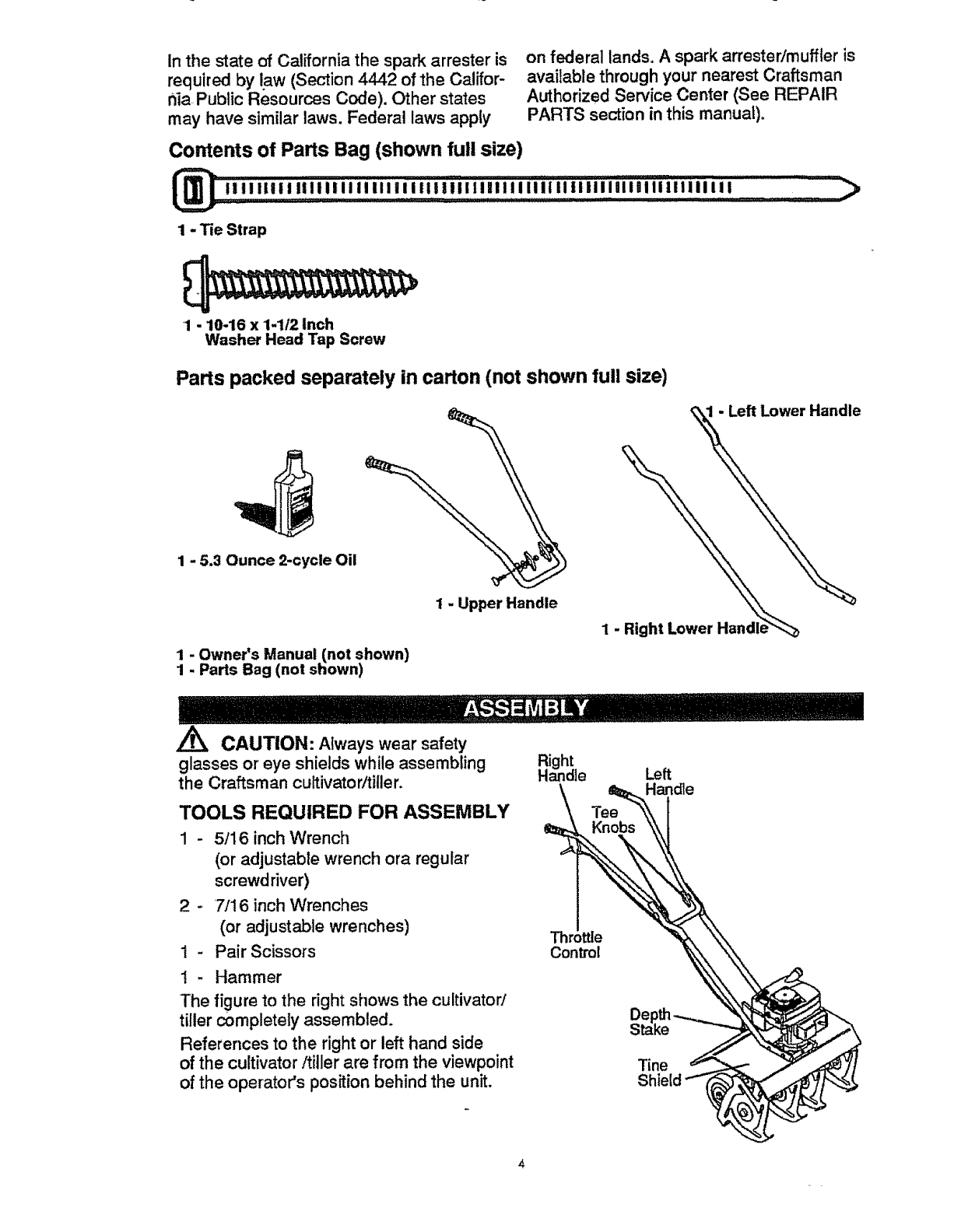
Contents of Parts Bag (shown full size)
lllllillllltllllllllllllllll:iilllllllllll:iilillliilHi+iiiJ_iHIIIIIII ...................................
1-Tie Strap
1-10-16 x 1-1/2 Inch
Washer Head Tap Screw
Parts packed separately in carton (not shown full size)
1-5.3 Ounce 2-cycle Oil
I-Upper Handle
1-Left Lower Handle
1-
1-Owner's Manual (not shown)
1 Parts Bag (not shown)
glasses or eye shields while assembling
the Craftsman cultivator/tiller.
TOOLS REQUIRED FOR ASSEMBLY
1 - 5/16 inch Wrench
(or adjustable wrench ora regular
screwdriver)
2 - 7/16 inch Wrenches
(or adjustable wrenches)
1 - Pair Scissors
1- Hammer
The figure to the right shows the cultivator/
tiller completely assembled.
References to the right or left hand side
of the cultivator/tiller are from the viewpoint
of the operator's position behind the unit.
CAUTION: Always wear safety Right
Handle
Tee
Knobs
Control
Left
Handle
Tine
Shield
TO REMOVE CULTIVATOR/TILLER
FROM CARTON
•"Remove the plastic parts bag from the
carton.
• Remove the handles from the carton.
• Remove packing insert from carton°
•Liltthe cultivator/tiller out of the carton
and place on a hard level surface.
- Remove packing material from around
tines.
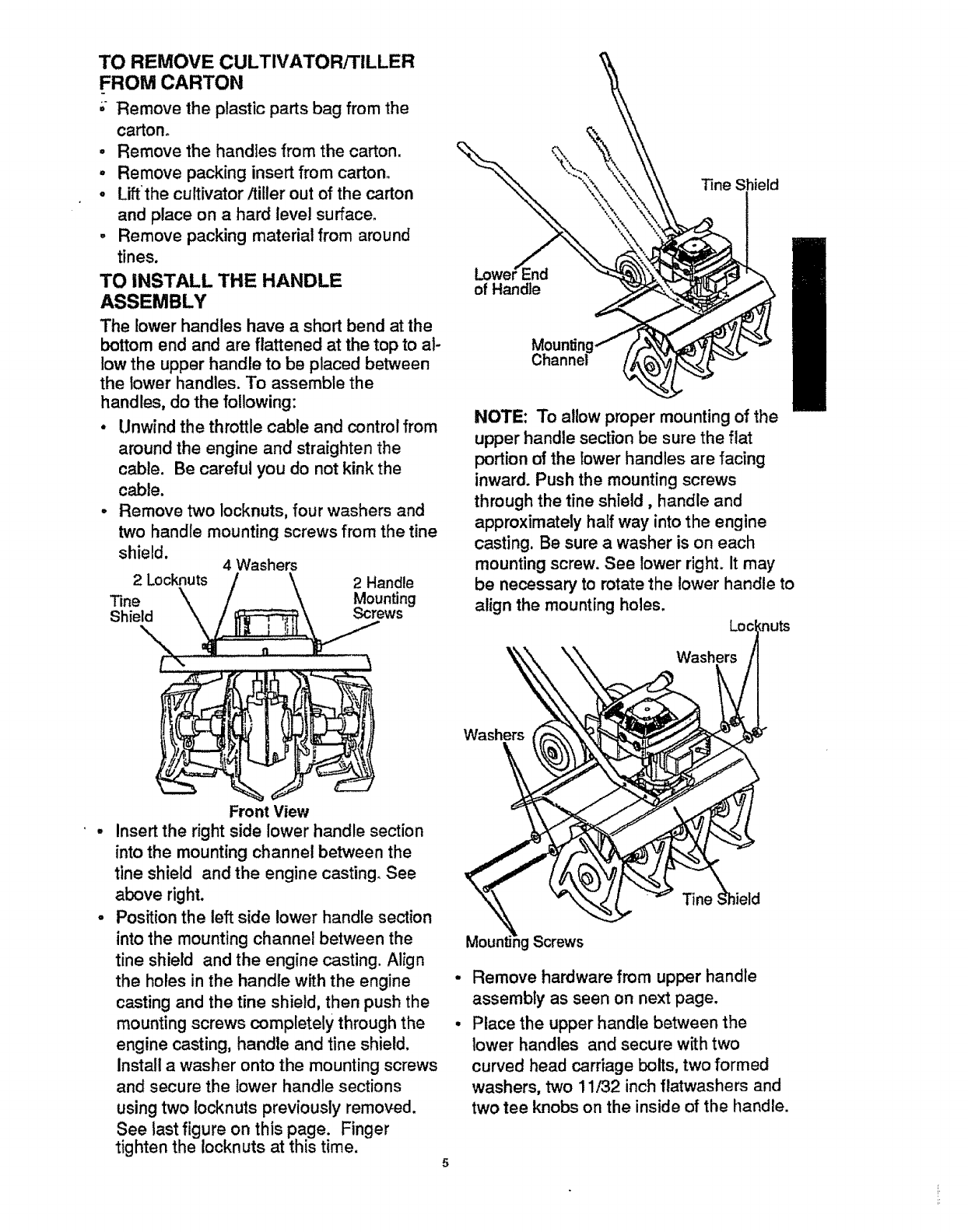
TO INSTALL THE HANDLE
ASSEMBLY
The lower handles have a short bend at the
bottom end and are flattened at the top to al-
low the upper handle to be placed between
the lower handles. To assemble the
handles, do the following:
• Unwind the throttle cable and control from
around the engine and straighten the
cable. Be careful you do not kink the
cable.
° Remove two locknuts, four washers and
two handle mounting screws from the tine
shield, 4 Washers
2 Locknuts 2 Handle
"Fine Mounting
Shield Screws
Tine Shield
Lower_nd
of Handle
NOTE: To allow proper mounting of the
upper handle section be sure the flat
portion ofthe lower handles are facing
inward. Push the mounting screws
through the tine shield, handle and
approximately half way into the engine
casting. Be sure a washer is on each
mounting screw. See lower right. It may
be necessary to rotate the lower handle to
align the mounting hotes.
Front View
Insert the right side lower handle section
into the mounting channel between the
tine shield and the engine casting. See
above right.
Position the left side lower handle section
into the mounting channel between the
tine shield and the engine casting. Align
the holes in the handle with the engine
casting and the tine shield, then push the
mounting screws completely through the
engine casting, handle and tine shield.
Install awasher onto the mounting screws
and secure the lower handle sections
usingtwo Iocknuts previously removed.
See last figure on this page. Finger
tighten the Iocknuts at this time. 5
Washers
Remove hardware from upper handle
assembly as seen on next page.
Place the upper handle between the
lower handles and secure with two
curved head carriage bolts, two formed
washers, two 11/32 inch flatwashers and
two tee knobs on the inside of the handle.
Finger tighten only.
°. Using two 7/16 inch wrenches, tighten
the locknuts on the screws in the lower
ends of the lower handles just enough to
hold the lower handles firmly in place.
IMPORTANT: Overtightening the screws
enough to change the shape of the
handles can result in damage to the en-
gine casting.
Tighten the handle hardware by holding
the curved head carriage bolt against the
outside of the lower handle while
tightening the tee knobs securely.
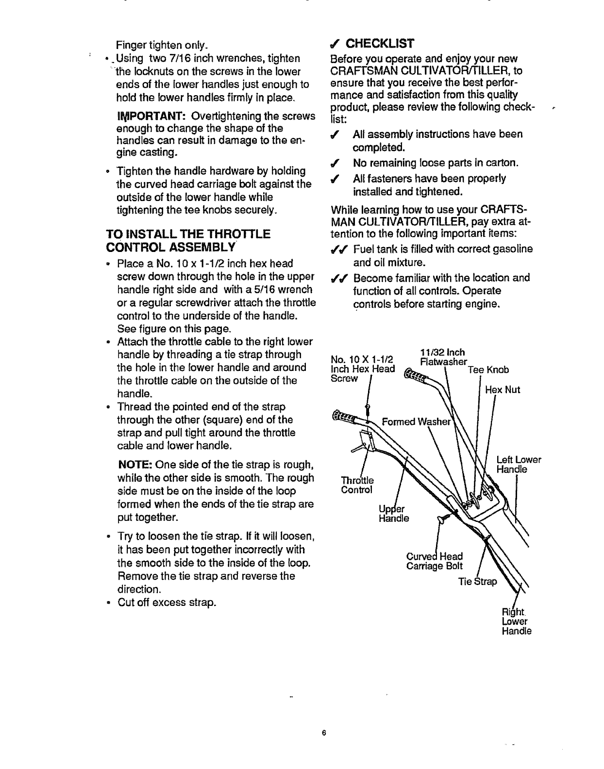
TO INSTALL THE THROTTLE
CONTROL ASSEMBLY
-Place a No. 10 x 1-1/2 inch hex head
screw down through the hole in the upper
handle right side and with a5/16 wrench
or a regular screwdriver attach the throttle
control to the underside of the handle.
See figure on this page.
•Attach the throttle cable to the right lower
handle by threading atie strap through
the hole in the lower handle and around
the throttle cable on tile outside of the
handle.
•Thread tile pointed end of the strap
through the other (square) end of the
strap and pull tight around the throttle
cable and lower handle.
NOTE: One side of the tie strap is rough,
while the other side is smooth. The rough
side must be on the inside of the loop
formed when the ends of the tie strap are
put together.
•Try to loosen the tie strap. If it wildloosen,
it has been put together incorrectly with
the smooth side to the inside of the loop.
Remove the tie strap and reverse the
direction.
•Cut off excess strap.
,f CHECKLIST
Before you operate and enjoy your new
CRAFTSMAN CULTIVATOR/TILLER, to
ensure that you receive the best perfor-
mance and satisfaction from this quality
product, please review the following check-
list:
_f All assembly instructions have been
completed.
_" No remaining loose parts in carton.
1/ AU fasteners have been properly
installed and tightened.
While learning how to use your CRAFTS-
MAN CULTIVATOF!_ILLER, pay extra at-
tention to the following important items:
#V Fuel tank is filled with correct gasoline
and oil mixture.
4',f Become familiar with the location and
function of all controls. Operate
controls before starting engine.
11/32 Inch
No. 10 X 1-1/2 Ratwasher
Inch Hex Head Tee Knob
Screw
Hex Nut
TI
Control
Left Lower
Handle
Head
Carriage Bolt
Tie Strap
Ri it
Lower'
Handle
6
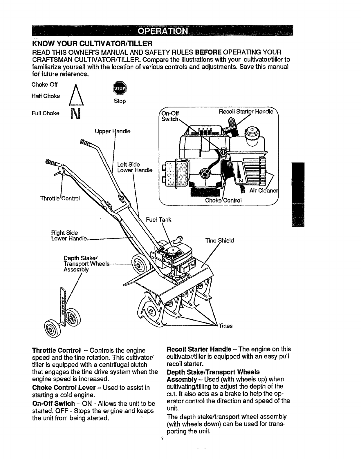
KNOW YOUR CULTIVATOR/TILLER
READ THIS OWNER'S MANUAL AND SAFETY RULES BEFORE OPERATING YOUR
CRAFTSMAN CULTIVATOR/TILLER. Compare the illustrationswith your cultivator/tillerto
familiarize yourself with the location of various controls and adjustments. Save this manual
for future reference.
Choke Off A
Half Choke
Full Choke
Stop
Upper Fandle
Recoil
Throttle Control - Controls the engine
speed and the tine rotation. This cultivator/
tiller is equipped with a centrifugal clutch
that engages the tine drive system when the
engine speed is increased.
Choke Control Lever -. Used to assist in
starting a cold engine.
On-Off Switch - ON -Allows the unit to be
started. OFF- Stops the engine and keeps
the unit from being started.
Recoil Starter Handle- The engine on this
cultivator/titler is equipped with an easy pull
recoil starter.
Depth Stake/Transport Wheels
Assembly- Used (with wheels up) when
cultivating/tillingto adjust the depth of the
cut. It also acts as a brake to help the op-
erator control the direction and speed of the
unit.
The depth stake/transport wheel assembly
(with wheels down) can be used for trans-
porting the unit.
i
HOW TO USE YOUR CULTIVATOR/
TILLER
WARNING: "['he operation of this cul-
tivator/tiller can result in foreign objects be-
ing thrown into the eyes, which can cause
severe eye damage. Always wear safety
glasses or eye shields while operating the
unit.
We recommend standard safety glasses or
Wide Vision Safety Mask for over your
glasses.
TO STOP CULTIVATOR/TILLER
o Release the throttle control to stop the
tines.
,, Move the on-off switch on the engine to
the OFF position.
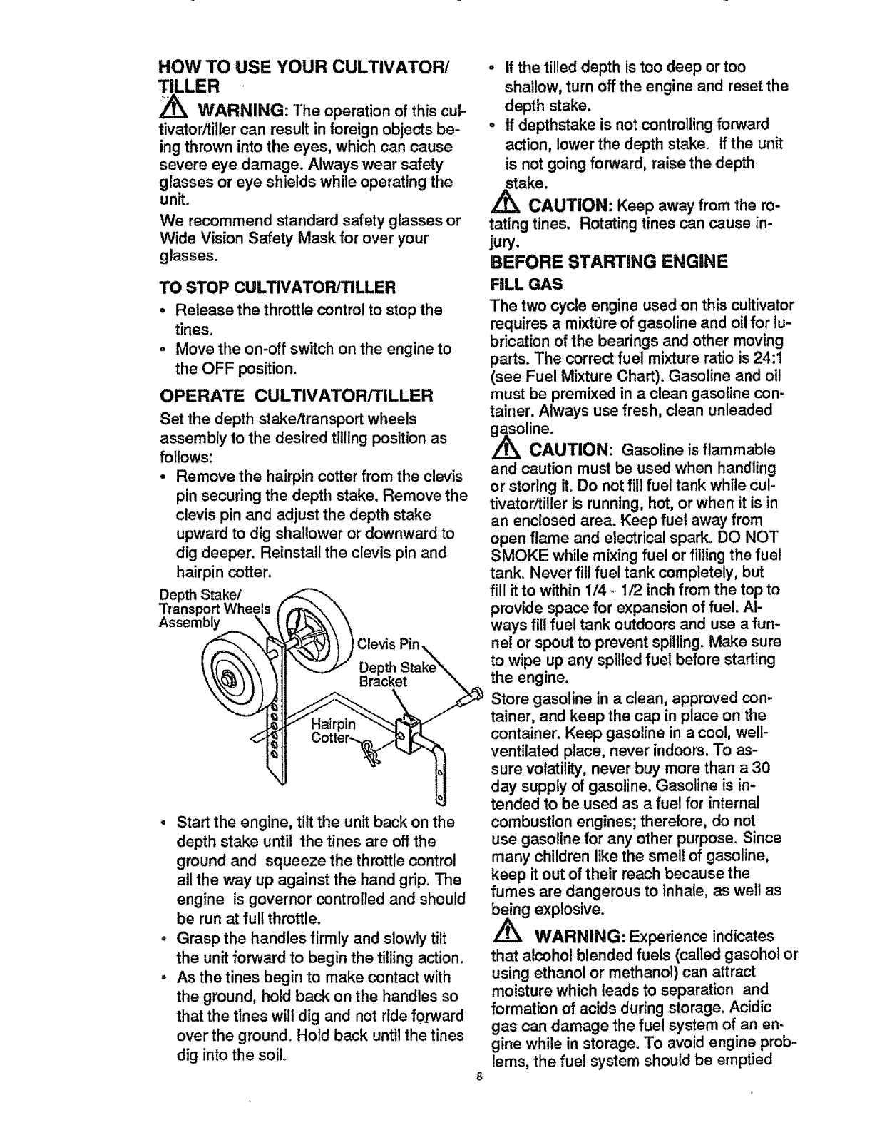
OPERATE CULTIVATOR/TILLER
Set the depth stake/transport wheels
assembly to the desired tillingposition as
follows:
• Remove the hairpin cotter from the clevis
pin securing the depth stake. Remove the
clevis pin and adjust the depth stake
upward to dig shallower or downward to
dig deeper. Reinstall the clevis pin and
hairpin cotter.
Depth Stake/
Transport Wheels
Assembly
Clevis Pin,
• Start the engine, tilt the unit back on the
depth stake until the tines are off the
ground and squeeze the throttle control
all the way up against the hand grip. The
engine is governor controlled and should
be run at full throttle.
°Grasp the handles firmly and slowly tilt
the unit forward to begin the tilling action.
-As the tines begin to make contact with
the ground, hold back on the handles so
that the tines will dig and not ride f0_vard
over the ground. Hold back until the tines
dig into the soilo
8
• If the tilled depth is too deep or too
shallow, turn off the engine and reset the
depth stake.
-If depthstake is not controlling forward
action, lower the depth stake. If the unit
is not going forward, raise the depth
stake.
CAUTION: Keep away from the ro-
tating tines. Rotating tines can cause in-
jury.
BEFORE STARTING ENGINE
FILL GAS
The two cycle engine used on this cultivator
requires a mixture of gasoline and oil for lu-
brication of the bearings and other moving
parts. The correct fuel mixture ratio is 24:1
(see Fuel Mixture Chart). Gasoline and oil
must be premixed in a clean gasoline con-
tainer. Always use fresh, clean unleaded
soline.
CAUTION: Gasoline is flammable
and caution must be used when handling
or storing it. Do not fill fuel tank while cul-
tivator/tiller is running, hot, or when it is in
an enclosed area. Keep fuel away from
open flame and electrical spark. DO NOT
SMOKE while mixing fuel or filling the fuel
tank. Never fill fuel tank completely, but
fill itto within 1/4.1/2 inch from the top to
provide space for expansion of fuel. Al-
ways fill fuel tank OLrtdoors and use a fun-
nel or spout to prevent spilling. Make sure
to wipe up any spilled fuel before starting
the engine.
Store gasoline in a clean, approved con-
tainer, and keep the cap in place on the
container. Keep gasoline in a cool, well-
ventilated place, never indoors. To as-
sure volatility, never buy more than a 30
day supply of gasoline. Gasoline is in-
tended to be used as a fuel for internal
combustion engines; therefore, do not
use gasoline for any other purpose° Since
many children like the smell of gasoline,
keep it out of their reach because the
fumes are dangerous to inhale, as well as
ng explosive.
WARNING: Experience indicates
that alcohol blended fuels (called gasohol or
using ethanol or methanol) can attract
moisture which leads to separation and
formation of acids during storage. Acidic
gas can damage the fuel system of an en-
gine while in storage. To avoid engine prob-
lems, the fuel system shou{d be emptied
before storage for 30 days or longer. Drain
the gas tank, start the engine and let it run
until the fueltines and carburetor are empty.
Use fresh fuel next season. See Storage In-
structions for additional information. Never
use engine or carburetor cleaner products
in the fuel tank or permanent damage may
occur.
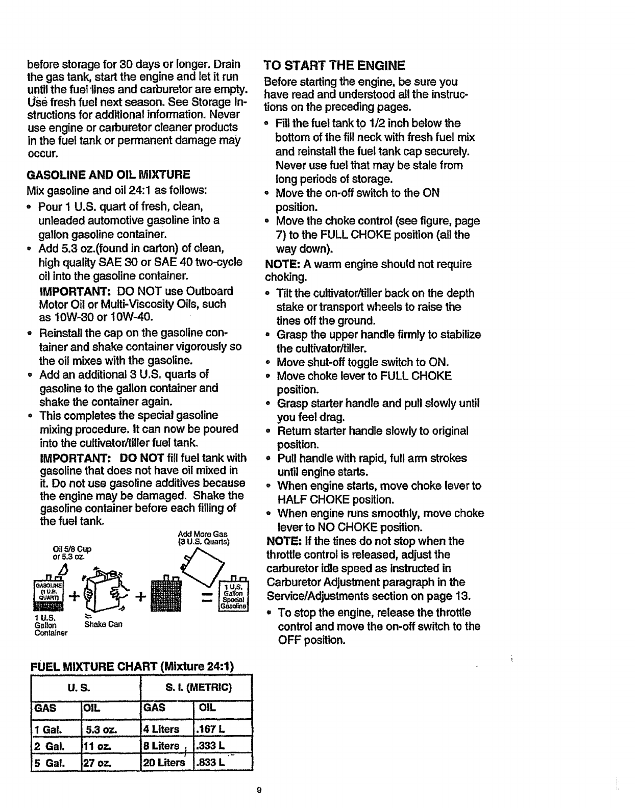
GASOLINE AND OIL MIXTURE
Mix gasoline and oil 24:1 as follows:
oPour 1 U.S. quart of fresh, clean,
unleaded automotive gasoline into a
gallon gasoline container.
•Add 5.3 oz.(found in carton) of clean,
high quality SAE 30 or SAE 40 two-cycle
oilinto the gasoline container.
IMPORTANT: DO NOT use Outboard
Motor Oil or Multi-Viscosity Oils, such
as 10W-30 or 10W-40.
oReinstall the cap on the gasoline con-
tainer and shake container vigorously so
the oil mixes with the gasoline.
o Add an additional 3 U.S. quarts of
gasoline to the gallon container and
shake the container again.
°This completes the special gasoline
mixing procedure, It can now be poured
into the cultivatorltitler fuel tank.
IMPORTANT: DO NOT fi!l fuel tank with
gasoline that does not have oil mixed in
it. Do not use gasoline additives because
the engine may be damaged. Shake the
gasoline container before each filling of
the fuel tank.
Add More Gas
(3 U,S. Quarts)
Oft5/8 Cup
or 5.3 oz-
+
1U.S. "_-
Gabon Shake Can
Container
FUEL MIXTURE CHART (Mixture 24:1)
U, S. S.I. (METRIC)
GAS OIL GAS OIL
1 Gal. 5,3 oz. i4 Liters ,167 L
2 Gal. ill oz. 8 Liters _.333 L
5 Gal, 27 oz, 20 Liters .833 L
Jl
TO START THE ENGINE
Before starting the engine, be sure you
have read and understood all the instruc-
tions on the preceding pages.
°Fillthe fuel tank to 1/2 inchbelow the
bottom of the fill neck with fresh fuel mix
and reinstall the fuel tank cap securely.
Never use fuel that may be stale from
long pedods of storage.
°Move the on-off switch to the ON
position.
• Move the choke control (see figure, page
7) to the FULL CHOKE position (all the
way down).
NOTE: A warm engine should not require
choking.
, Tilt the cultivator/tillerback on the depth
stake or transport wheels to raise the
tines off the ground.
° Grasp the upper handle firmly to stabilize
the cultivator/tiller.
o Move shut-off toggle switch to ON.
°Move choke lever to FULL CHOKE
position.
°Grasp starter handle and pull s!owly until
you feel drag.
° Return starter handle slowly to original
position.
,, Pull handle with rapid, full arm strokes
until engine starts.
° When engine starts, move choke lever to
HALF CHOKE position.
°When engine runssmoothly, move choke
lever to NO CHOKE position.
NOTE: If the tines do not stop when the
throttle control is released, adjust the
carburetor idle speed as instructed in
Carburetor Adjustment paragraph in the
ServicelAdjustments section on page t3.
• To stop the engine, release the throttte
control and move the on-off switch to the
OFF position.
°if the engine becomes flooded, see the
-Spark Plu_lMaintenance paragraph in the
Maintenance section of this manual.
Then pull the starter rope v_iththe choke
lever in the NO CHOKE position.
CAUTION: The muffler and sur-
rounding areas become hot after running
the engine. Avoid these areas.
TILLING HINTS
°Tilling is digging in, turning over and
breaking up packed soil before planting.
Loose unpacked soil helps root growth.
Best tilling depth is 4 to 6 inches. A tiller
will also clear the soil of unwanted
vegetation. The decomposition of this
vegetation matter enriches the soil.
Depending on the climate (rainfall and
wind), it may be advisable to till the soil at
the end of the growing season to further
conditionthe soil.
°Avoid tilling soil that is too dry as it will
pulverize and produce a dust that will not
hold water. Also, tillingsoil that is too wet
will be hard on the machine and produce
unsatisfactory clods.
•Better growth will be obtained in tilled
ground if a relatively small area is tilled
properly and the tilled ground is used
soon after tilling to preserve the moisture
content.
°The depth stake (on the back of the
cultivator/tiller) serves adual purpose
(see figure, page 8). tt helps regulate the
depth of the cut to a uniform level and
also acts as a brake to help the operator
control the speed of the cultivator/tiller.
°Lowering the depth stake will slow the
cultivator itillerand make it tilt deeper.
Raising the depth bar will allow it to move
faster and tilt more shallow.
° If the cultivator/tiller stops forward motion
and tries to dig deeper than necessary,
move the handles from side to side to
start forward motion.
CULTIVATING HINTS
°Cultivating is loosening or digging around
growing plants which allows the plants to
flourish.
° When usingthe cultivator/tiller to remove
weeds, it is best to cultivate no deeper
than 1-1/2 inches. Cultivating deeper will
only pull to the surface ungerminated
weed seeds. You may want to raise the
depth bar to lessen the braking action.
°When cultivating around plants or close
areas, you may want to remove the
outside tines (see Tine Replacement
paragraph in the Service/Adjustments
section of this manual).
/_ CAUTION:
,, Read the Owner's manual.
,, Know location and functions of all
controls.
oKeep all safety devices and shields in
place.
°Never allow children or uninstructed
adults to operate cultivator/tiller.
°Shut off engine before unclogging tines or
making repairs.
°Keep bystanders away from machine.
° Keep away from rotating parts and tines.
They can cause injury.
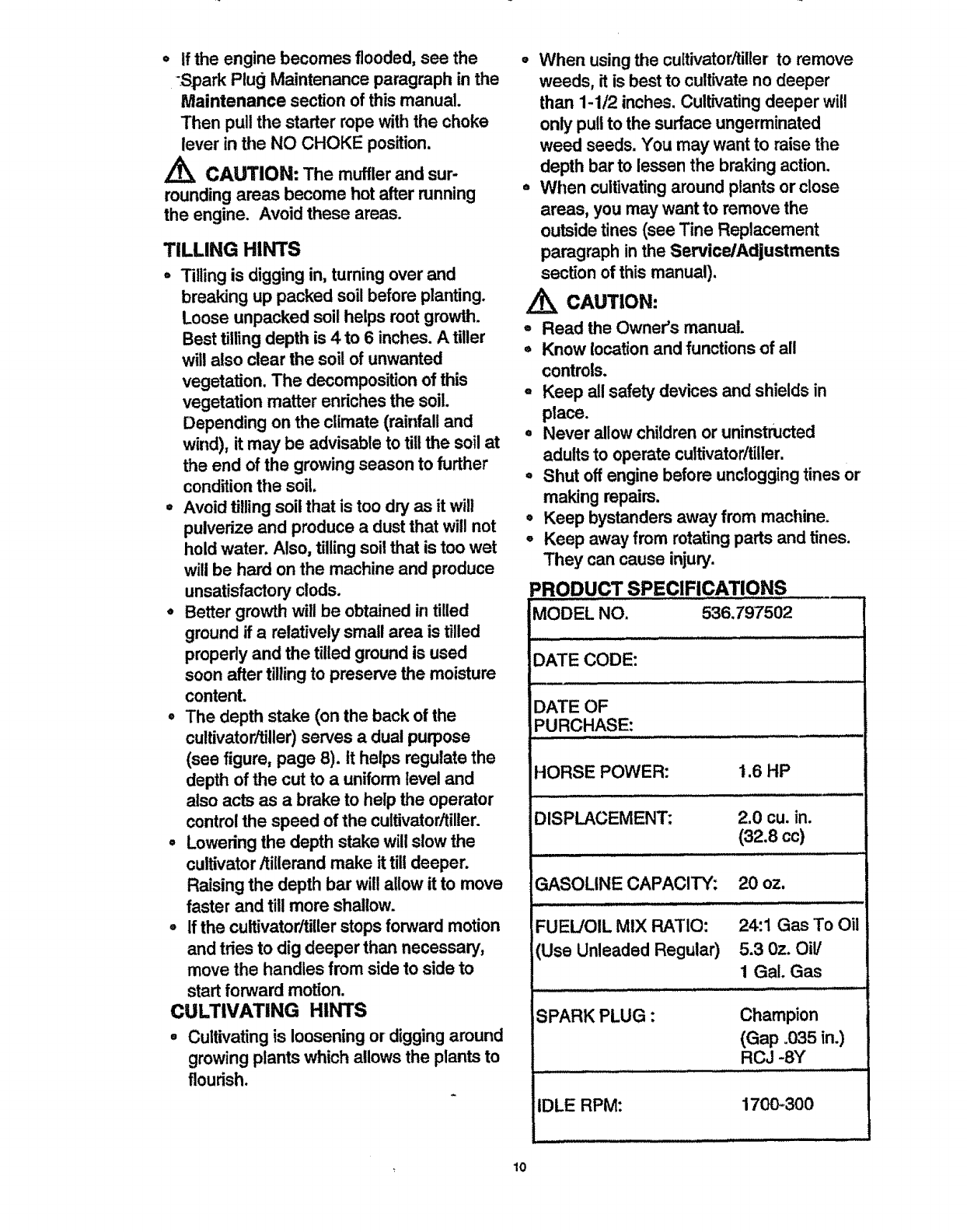
=RODUCT SPECIFICATIONS ....
MODEL NO. 536.797502
:)ATE CODE:
DATE OF
PURCHASE:
_IORSE POWER: 1.6 HP
L
DISPLACEMENT: 2.0 cu. in.
(32.8 cc)
GASOLINE CAPACITY:
.:..m
FUEL/OIL MIX RATIO:
(Use Unleaded Regular)
20 OZ,
24:1 Gas To Oil
5.3 Oz. OiV
1Gal. Gas
SPARK PLUG :
IDLE RPM:
Champion
(Gap .035 in.)
RCJ -8Y
1700-300
lO
CUSTOMER RESPONSIBILITIES
SERVICE
RECORDS
Fill in dates as
you complete
regular service
Tighten"AIIScrewsand Nuts V'_ p_'
==
LubricateTine Shaft
LubricateTransmission
Check Spark Plug
Clean andRe-OilAirCleanerFiI[er
Drain Fuel
SCHEDULE
v" v,'
v"
Ii
SERVICE
DATES
GENERAL RECOMMENDATIONS
The warranty on this cultivator/tiller not
cover items that have been subjected to op-
erator abuse or negligence. To receive full
value from the warranty, the operator must
maintain the cultivator/tiller as instructed in
this manual. The above chart is provided to
assist the operator in properly maintaining
the cultivator/tiller.
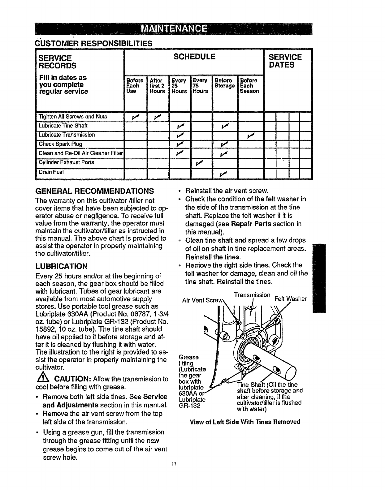
LUBRICATION
Every' 25 hours and/or at the beginning of
each season, the gear box should be filled
with lubricant. Tubes of gear lubricant are
available from most automotive supply
stores. Use portable tool grease such as
Lubriplate 630AA (Product No. 06787, 1_3/4
oz. tube) or Lubriplate GR-132 (Product No.
15892, 10 oz. tube). The tine shaft should
have oil applied to it before storage and af-
ter it is cleaned by flushing it with water.
The illustration to the right is provided to as-
sist the operator in properly maintaining the
cultivator.
\CAUTION: Allow the transmission to
cool before filling with grease.
•Remove both left side tines. See Service
and Adjustments section in this manual
• Remove the air vent screw from the top
left side of the transmission.
Using agrease gun, fill the transmission
through the grease fitting until the neJN
grease begins to come out of the air vent
screw hole.
•Reinstall the air vent screw.
•Check the condition of the felt washer in
the side of the transmission at the tine
shaft. Replace the felt washer if it is
damaged (see Repair Parts section in
this manual).
, Clean tine shaft and spread a few drops
of oil on shaft in fine replacement areas.
Reinstall the tines.
-Remove the right side tines. Check the
felt washer for damage, clean and oil the
tine shaft. Reinstall the tines.
Transm{ssion
Air Vent Felt Washer
Grease
fitting
(Lubricate
the gear
box with
lubri
Lubriplate
GR-132
(Oil the tine
shaft before storage and
after cleaning, if the
cultivatorltiller is flushed
with water)
View of Left Side With Tines Removed
tl
ENGINE
_ARK PLUG MAINTENANCE
If the engine is flooded, clean the area
around the spark plug base to prevent for-
eign material from entering the cylinders
when the plug is removed, Remove and dry
the spark plug. Regap the electrodes to
.035" if necessary, if anew spark plug is
needed, refer to the Product Specifications
chart inthis manual for the proper replace-
ment. Tighten the spark plug firmly. If a
torque wrench is available, torque the spark
plug to 15 foot- pounds.
AIR CLEANER MAINTENANCE
The air cleaner filter should be cleaned and
re-oiled after every 25 hoursof use. Clean
more often under dusty conditions.
IMPORTANT: The engine can be worn out
in a very short period oftime if dirt or grit is
allowed to enter the engine,
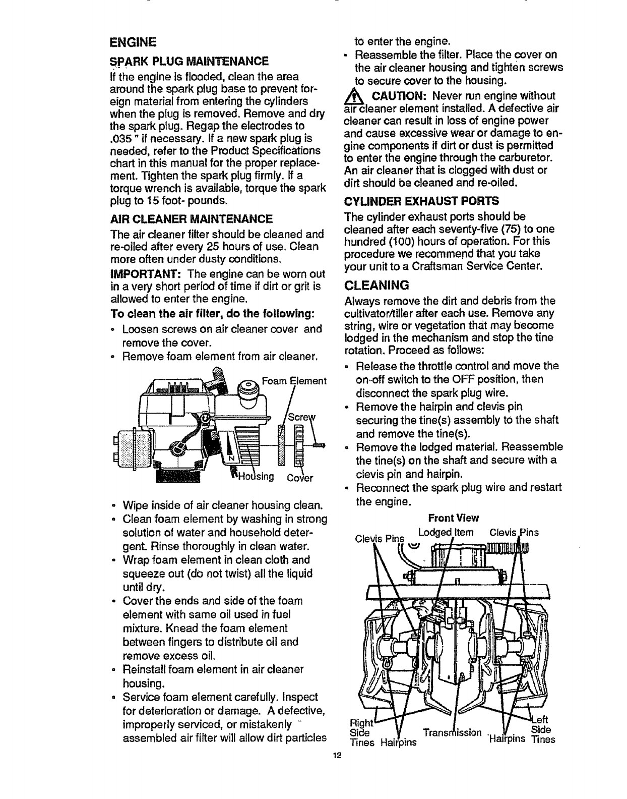
To clean the air filter, do the following:
oLoosen screws on air cleaner cover and
remove the cover.
-Remove foam element from air cleaner.
Foam Element
ousing Cmier
°Wipe inside of air cleaner housing clean.
-Clean foam element by washing in strong
solution of water and household deter-
gent. Rinse thoroughly in clean water.
•Wrap foam element in clean cloth and
squeeze out (do not twist) all the liquid
until dry.
, Cover the ends and side of the foam
element with same oil used in fuel
mixture_ Knead the foam element
between fingers to distribute oil and
remove excess oilo
-Reinstall foam element in air cleaner
housing.
• Service foam element carefully. Inspect
for deterioration or damage. A defective,
improperly serviced, or mistakenly
assembled air filter will allow dirt particles
to enter the engine.
- Reassemble the filter. Place the cover on
the air cleaner housing and tighten screws
to secure cover to the housing.
_CAUTION: run engine
Never without
air cleaner element installed. A defective air
cleaner can result in loss of engine power
and cause excessive wear or damage to en-
gine components if dirtor dust is permitted
to enter the engine through the carburetor.
An air cleaner that is clogged with dust or
dirt should be cleaned and re-oiled.
CYLINDER EXHAUST PORTS
The cylinder exhaust ports should be
cleaned after each seventy-five (75) to one
hundred (100) hours of operation. For this
procedure we recommend that you take
your unit to a Craftsman Service Center.
CLEANING
Always remove the dirt and debris from the
cultivator/tiller after each use. Remove any
string, wire or vegetation that may become
lodged in the mechanism and stop the tine
rotation. Proceed as foilows:
•Release the throttle Control and move the
on.off switch to the OFF position, then
disconnect the spark plug wire.
•Remove the hairpin and clevis pin
securing the tine(s) assembly to the shaft
and remove the tine(s)o
°Remove the lodged material. Reassemble
the tine(s) on the shaft and secure with a
clevis pin and hairpin.
° Reconnect the spark plug wire and restart
the engine.
Front View
Pins Lodged Item Clevis
Trans bission Side
Tines Hairpins "Ha _ins Tines
12
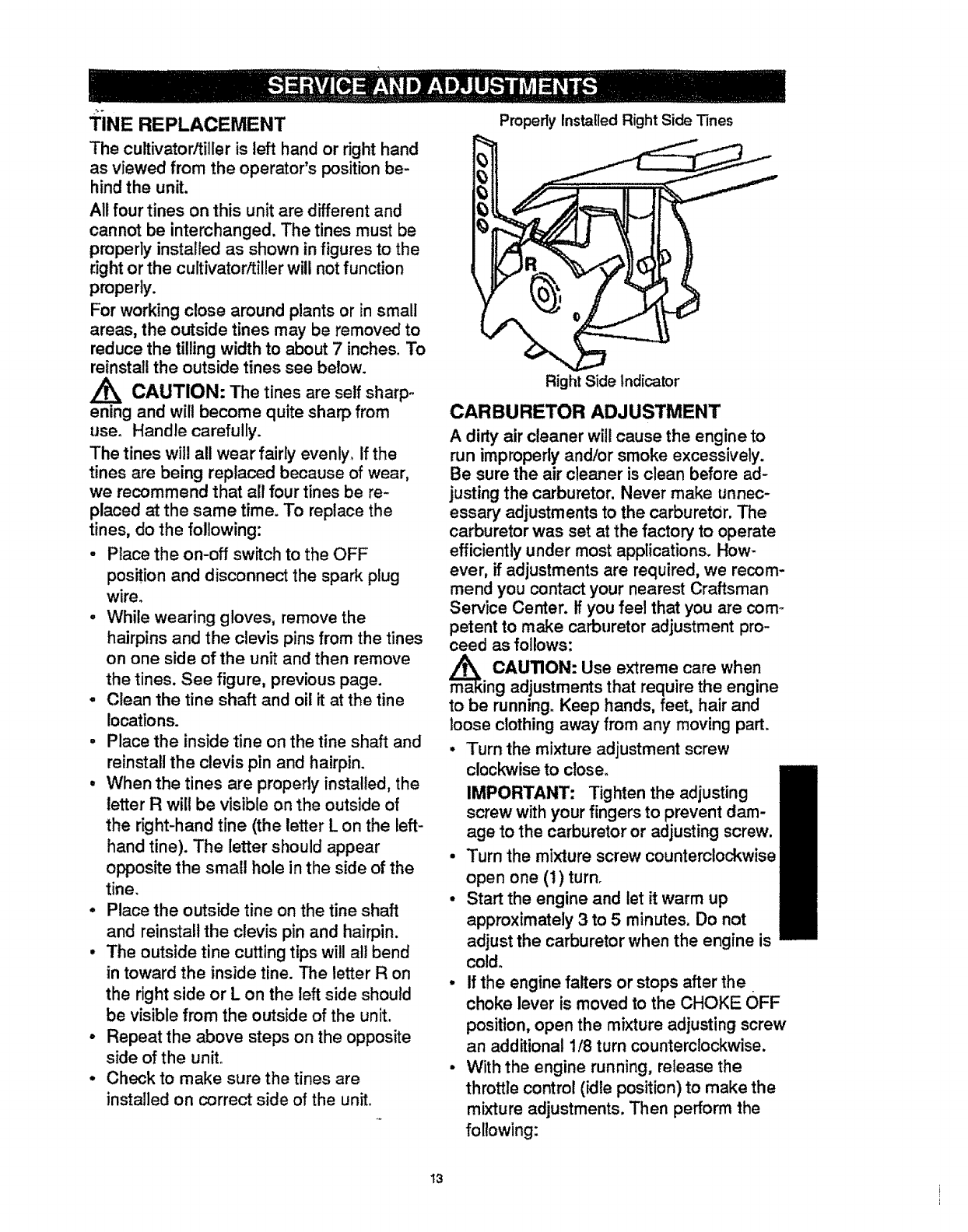
TINE REPLACEMENT
The cultivator/tiller is left hand or right hand
as viewed from the operator's position be-
hind the unit.
All four tines on this unit are different and
cannot be interchanged. The tines must be
properly installed as shown in figures to the
right or the cultivator/tiller will not function
properly.
For working close around plants or in small
areas, the outside tines may be removed to
reduce the tilling width to about 7 inches. To
reinstall the outside tines see below.
CAUTION: The tines are self sharp-
ening and wilt become quite sharp from
use° Handle carefully.
The tines will all wear fairly evenly_ If the
tines are being replaced because of wear,
we recommend that all four tines be re-
placed at the same time. To replace the
tines, do the following:
- Place the on-off switch to the OFF
position and disconnect the spark plug
wire.
,While wearing gloves, remove the
hairpins and the clevis pins from the tines
on one side of the unit and then remove
the tines. See figure, previous page.
-Clean the tine shaft and oil it at the tine
locations.
° Place the inside tine on the fine shaft and
reinstall the clevis pin and hairpin.
• When the tines are properly installed, the
letter R will be visible on the outside of
the right-hand fine (the letter L on the left-
hand tine). The letter should appear
opposite the small hole in the side of the
tine.
°Place the outside tine on the tine shaft
and reinstall the clevis pin and hairpin.
• The outside tine cutting tips will all bend
in toward the inside tine. The letter R on
the right side or L on the left side should
be visible from the outside of the unit.
°Repeat the above steps on the opposite
side of the unit.
•Check to make sure the tines are
installed on correct side of the unit.
Properly Installed Right Side Tines
Right Side Indicator
CARBURETOR ADJUSTMENT
A dirty air cleaner will cause the engine to
run improperly and/or smoke excessively.
Be sure the air cleaner is clean before ad-
justing the carburetor. Never make unnec-
essary adjustments to the carburetor. The
carburetor was set at the factor,/to operate
efficiently under most applications. How-
ever, if adjustments are required, we recom-
mend you contact your nearest Craftsman
Service Center. If you feel that you are como
petent to make carburetor adjustment pro-
ceed as follows:
m_a CAUTION: Use extreme care when
ing adjustments that require the engine
to be running. Keep hands, feet, hair and
loose clothing away from any moving part.
•Turn the mixture adjustment screw
clockwise to close.
IMPORTANT: Tighten the adjusting
screw with your fingers to prevent dam-
age to the carburetor or adjusting screw.
Turn the mixture screw counterclockwise
open one (1) turn.
Start the engine and let it warm up
approximately 3 to 5minutes, Do not
adjust the carburetor when the engine is
cold.
If the engine falters or stops after the
choke lever is moved to the CHOKE OFF
position, open the mixture adjusting screw
an additional 1/8 turn counterclockwise.
With the engine running, release the
throttle control (idle position) to make the
mixture adjustments. Then perform the
following:
t3
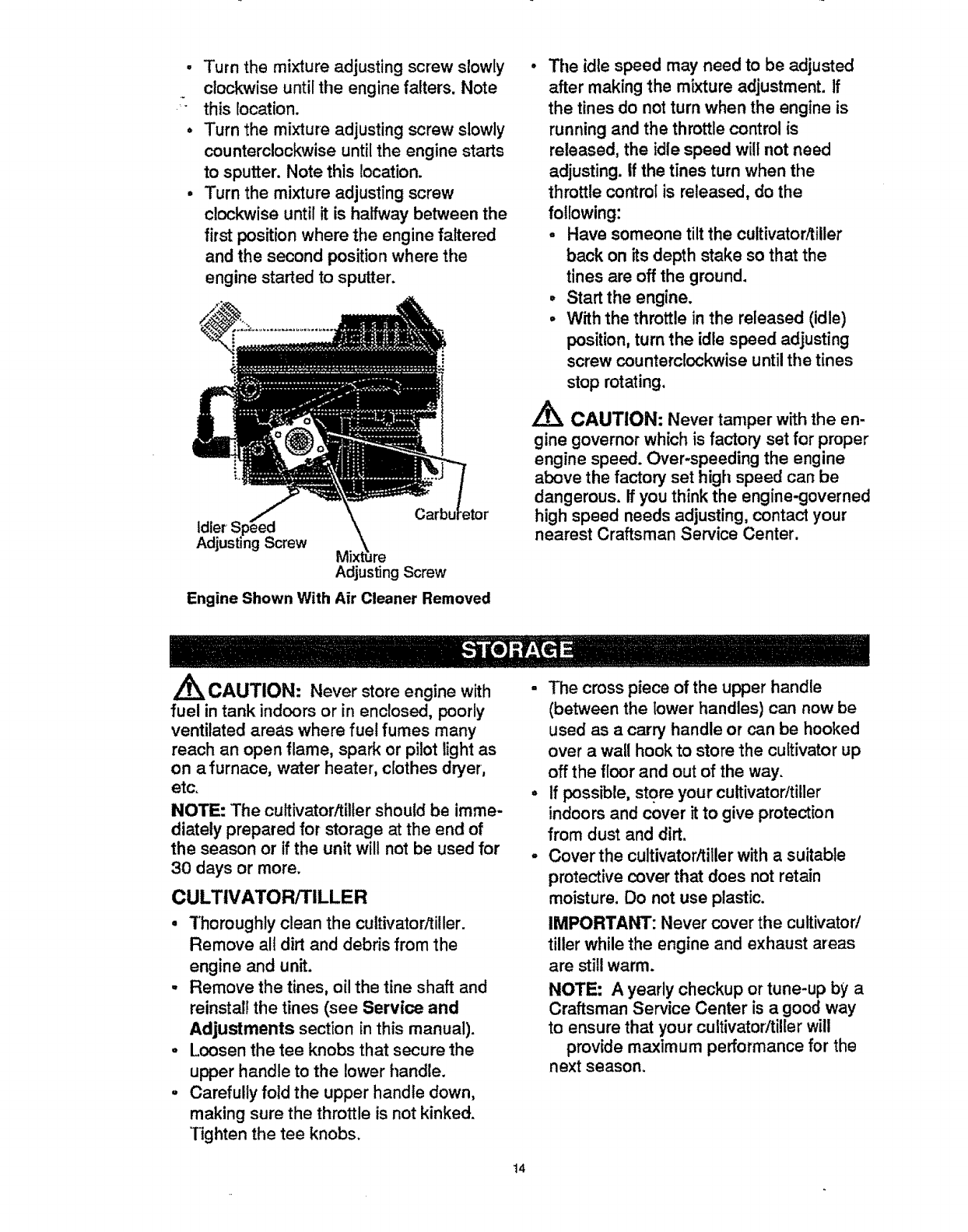
• Turn the mixture adjusting screw slowly
clockwise until the engine falters. Note
' this location.
• Turn the mixture adjusting screw slowly
counterclockwise until the engine starts
to sputter. Note this location.
- Turn the mixture adjusting screw
clockwise until it is halfway between the
first position where the engine faltered
and the second position where the
engine started to sputter.
idler
Screw M re
Adjusting Screw
Engine Shown With Air Cleaner Removed
• Tile idle speed may need to be adjusted
after making the mixture adjustment. If
the tines do not turn when the engine is
running and the throttle control is
released, the idle speed will not need
adjusting, tf the tines turn when the
throttle control is released, do the
following:
•Have someone tilt the cultivator/tiller
back on its depth stake so that the
tines are off the ground.
•Start the engine.
.With the throttle in the released (idle)
position, turn the idle speed adjusting
screw counterclockwise until the tines
stop rotating.
CAUTION: Never tamper with the en-
gine governor which is factory set for proper
engine speed. Over-speeding the engine
above the factory set high speed can be
dangerous. If you think the engine-governed
high speed needs adjusting, contact your
nearest Craftsman Service Center.
CAUTION: Never store engine with
fuel in tank indoors or in enclosed, poorly
ventilated areas where fuel fumes many
reach an open flame, spark or pilot light as
on a furnace, water heater, clothes dryer,
etc.
NOTE: The cultivator/tiller should be imme-
diately prepared for storage at the end of
the season or if the unit will not be used for
30 days or more.
CULTIVATOR/TILLER
• Thoroughly clean the cultivator/tiller.
Remove all dirt and debris from the
engine and unit.
• Remove the tines, oil the tine shaft and
reinstall the tines (see Service and
Adjustments section in this manual).
oLoosen the tee knobs that secure the
upper handle to the lower handle.
,Carefully fold the upper handle down,
making sure the throttle is not kinked.
Tighten the tee knobs.
- The cross piece of the upper handle
(between the lower handles) can now be
used as a carry handle or can be hooked
over a wall hook to store the cultivator up
off the floor and out of the way.
if possible, store your cultivator/tiller
indoors and cover it to give protection
from dust and dirt.
Cover the cultivator/tiller with a suitable
protective cover that does not retain
moisture. Do not use plastic.
IMPORTANI": Never cover the cultivator/
tiller while the engine and exhaust areas
are still warm.
NOTE: A yearly checkup or tune-up by a
Craftsman Service Center is a good way
to ensure that your cultivator/tiller will
provide maximum performance for the
next season.
14
ENGINE
IMPORTANT: It is important to prevent
gum deposits from forming in essential fuel
system parts such as the carburetor, fuel fil-
ter, fuel hose or tank during storage. Also,
experience indicates that alcohol blended
fuels (called gasohol or using ethanol or
methanol) can attract moisture which leads
to separation and formation of acids during
storage_ Acidic gas can damage the fuel
system of an engine while in storage_
,Drain the fuel from the fuel tank into an
approved container outdoors, away from
open flame.
Start and run the engine until it stops due
to lack of fuel.
Pull the starter handle slowly until you
feel resistance due to compression
pressure, then stop.
Release the starter tension slowly to
prevent the engine from reversing due to
compression pressure. This position will
close both the intake and exhaust ports to
prevent corrosion of the piston and
cylinder bore.
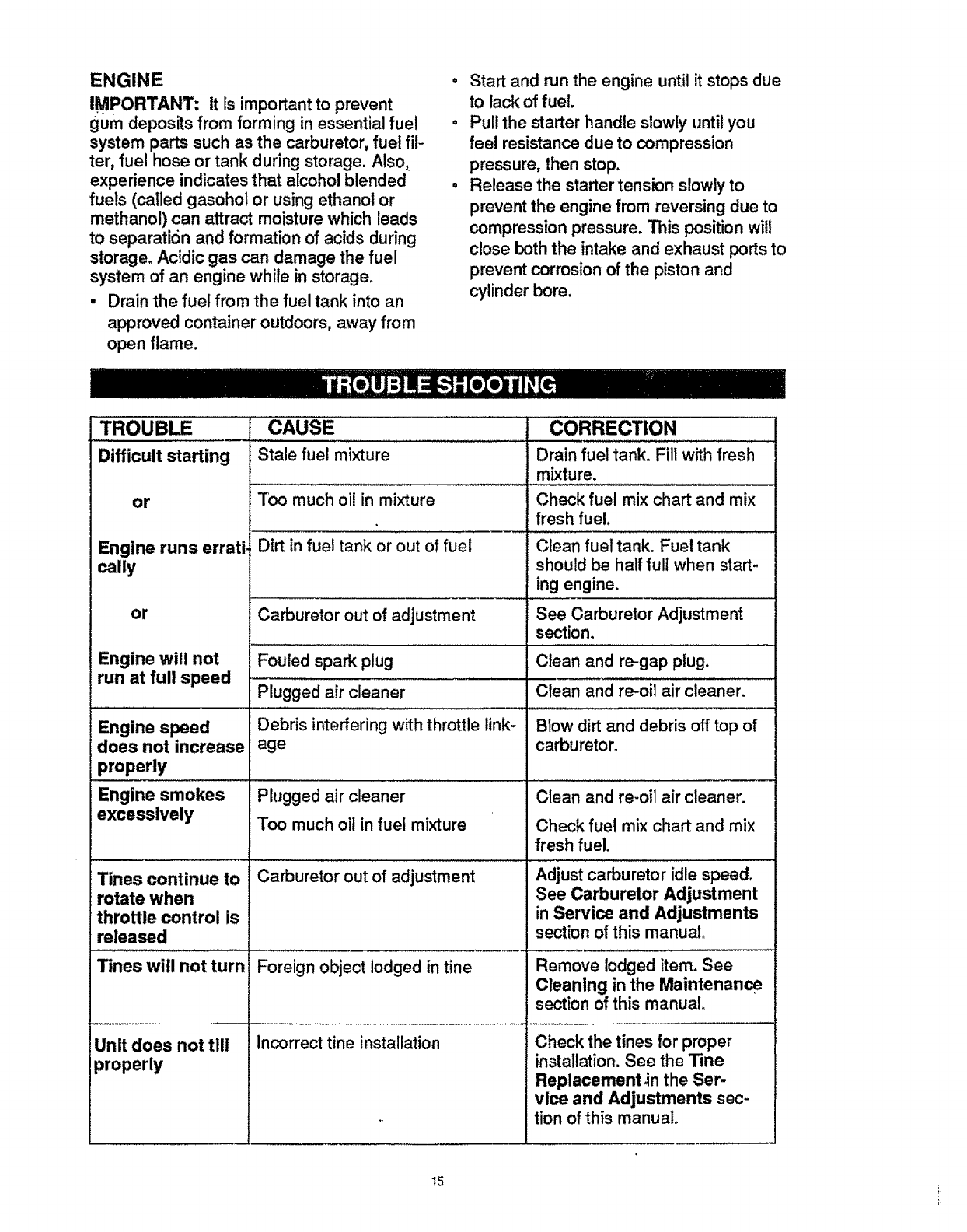
TROUBLE
Difficult starting
or
Engine runs errati.
cally
or
Engine will not
run at full speed
Engine speed
does not increase
properly
Engine smokes
excessively
CAUSE CORRECTION
Tines continue to
rotate when
throttle control is
released
Tines will not turn
Unit does not till
properly
Stale fuel mixture
Too much oil in mixture
Drain fuel tank. Fill with fresh
mixture.
Check fuel mix chart and mix
fresh fuel.
Dirt in fuel tank or out of fuel Clean fuel tank. Fuel tank
should be half full when start-
ing engine.
Carburetor out of adjustment See Carburetor Adjustment
section.
Fouled spark plug Clean and re-gap plug.
Plugged air cleaner Clean and re-oit air cleaner.
Debris interfering with throttle link- Blow dirt and debris off top of
age carburetor.
Plugged air cleaner Clean and re-oil air cleaner.
Too much oil in fuel mixture Check fuel mix chart and mix
fresh fuel,
Carburetor out of adjustment Adjust carburetor idle speed,
See Carburetor Adjustment
in Service and Adjustments
section ofthis manual.
Foreign object iodged in tine Remove lodged item. See
Cleaning in the Maintenance
section ofthis manual
.................... , ,,,, ,,,,,,,, , ................................................
Incorrect tine installation Check the tines for proper
installation.See the Tine
Replacement.in the $er-
vlce and Adjustments sec-
. tion of this manual.
!5
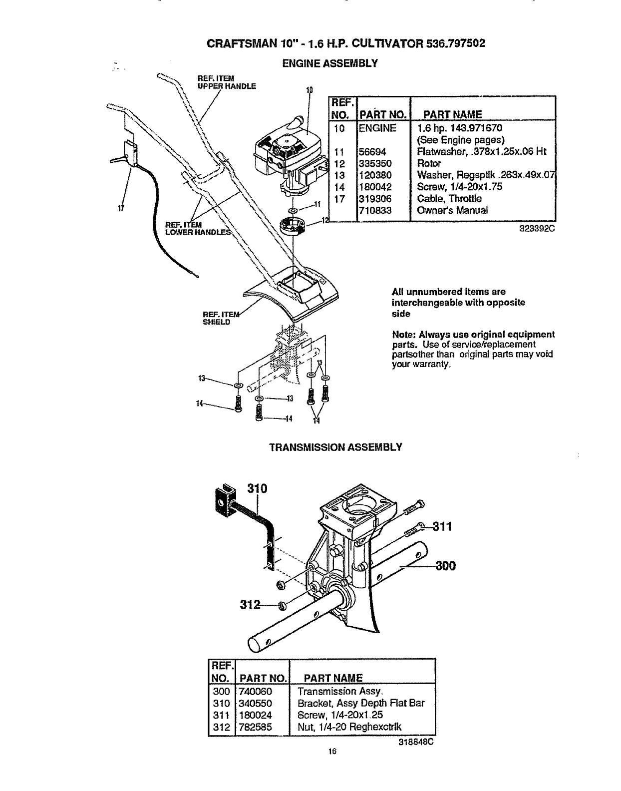
CRAFTSMAN 10" - 1.6 H.P. CULTIVATOR 536.797502
ENGINE ASSEMBLY
710833
PART NAME
1.6 hp. 143.971670
(See Engine pages)
Flatwasher, .378x1.25x.06 Ht
Rotor
Washer, Regsptlk .263xA9x 07
Screw, 1/4-20x1.75
Cable, Throttle
Owner's Manual
323392(3
SI_ELD
All unnumbered items are
interchangeable with opposite
side
Note: Always use original equipment
parts. Use of ser¢ice/replacement
parlsotherthan originalparts mayvoid
your warranty,
TRANSMISSION ASSEM BLY
310
REF.
NO.
300
310
311
312
PART NO.
;740060
340550
180024
782585
PART NAME
Transmission Assy
Bracket, Assy Deplh Flat Bar
Screw, 1/4-20xl,25
Nut, 114-20 Reghexotdk
318848C
16
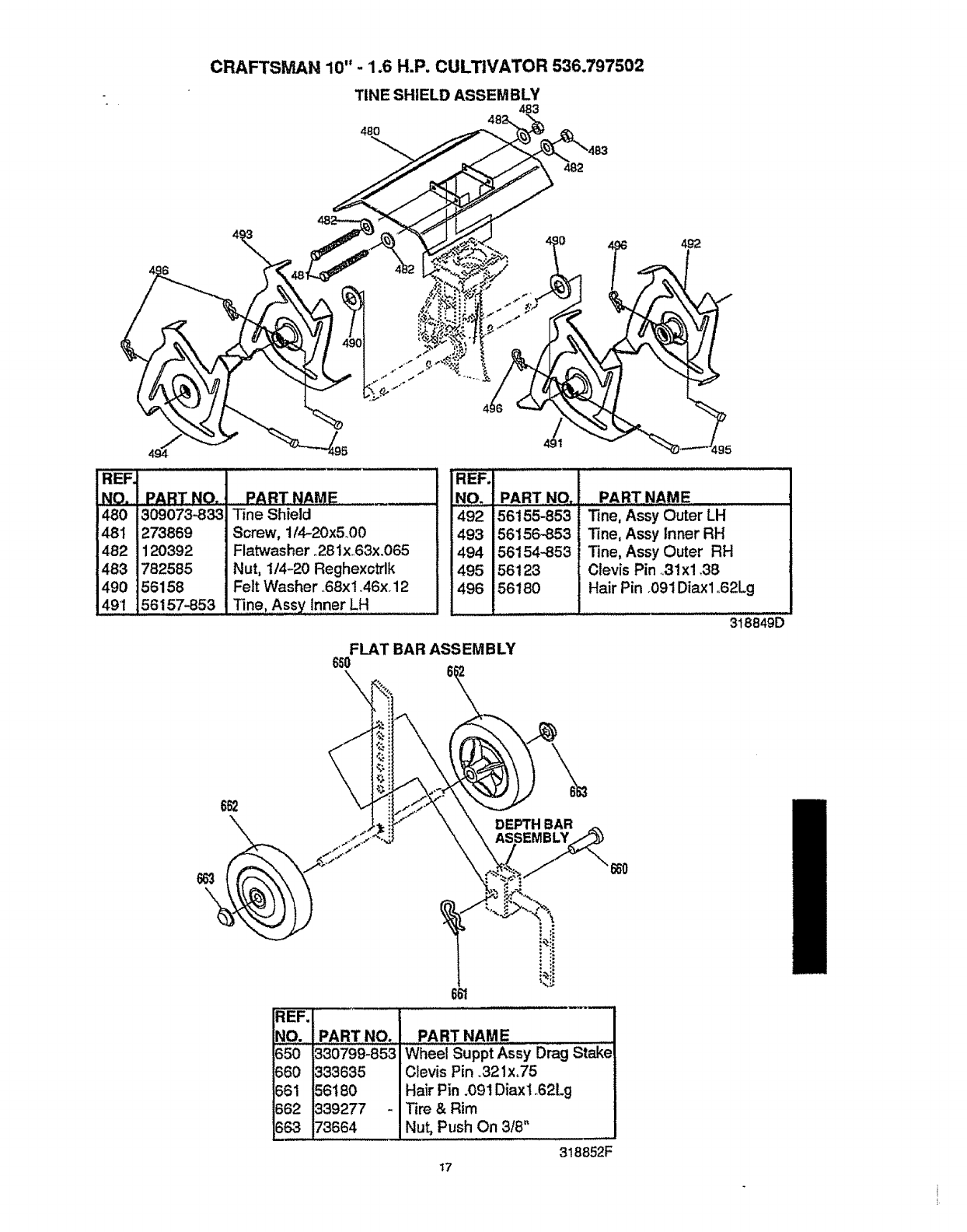
CRAFTSMAN 10" - 1.6 H.P, CULTIVATOR 536.797502
TINE SHIELD ASSEMBLY
483,
48O
\492
REF,
.....NO. PART NO,
480 309073-833
48I 273869
482 120392
483 782585
490 56158
491 56157-853
PART NAME _ !
Tine Shield
Screw, 114-20x5_00
Flat'washer ,281x..63x.065
Nut, 1/4-20 Reghex_trlk
Felt Washer .68x 1.46x. 12
Tine, Assy Inner LH
REF.
NO. PART NO,
492 56155-853
493 56156-853
494 56154-853
495 56123
496 56180
PART NAME
line, Assy Outer LH
Tine, Assy Inner RH
"Fine,Assy Outer RH
Clevis Pin .,31x1.38
Hair Pin .091 Diaxl ,,62Lg
3t8849D
FLAT BAR ASSEMBLY
65O
REF. .........
NO. PART NO. PART NAME
650 _330799-853 Wheel Suppt Assy Drag Stake
660 333635 Clevis Pin ,.321x,75
661 56180 Hair Pin .091 Diaxt _62Lg
662 339277 - Tire&Rim
363 73664 Nut, Push On 318"
318852F
17
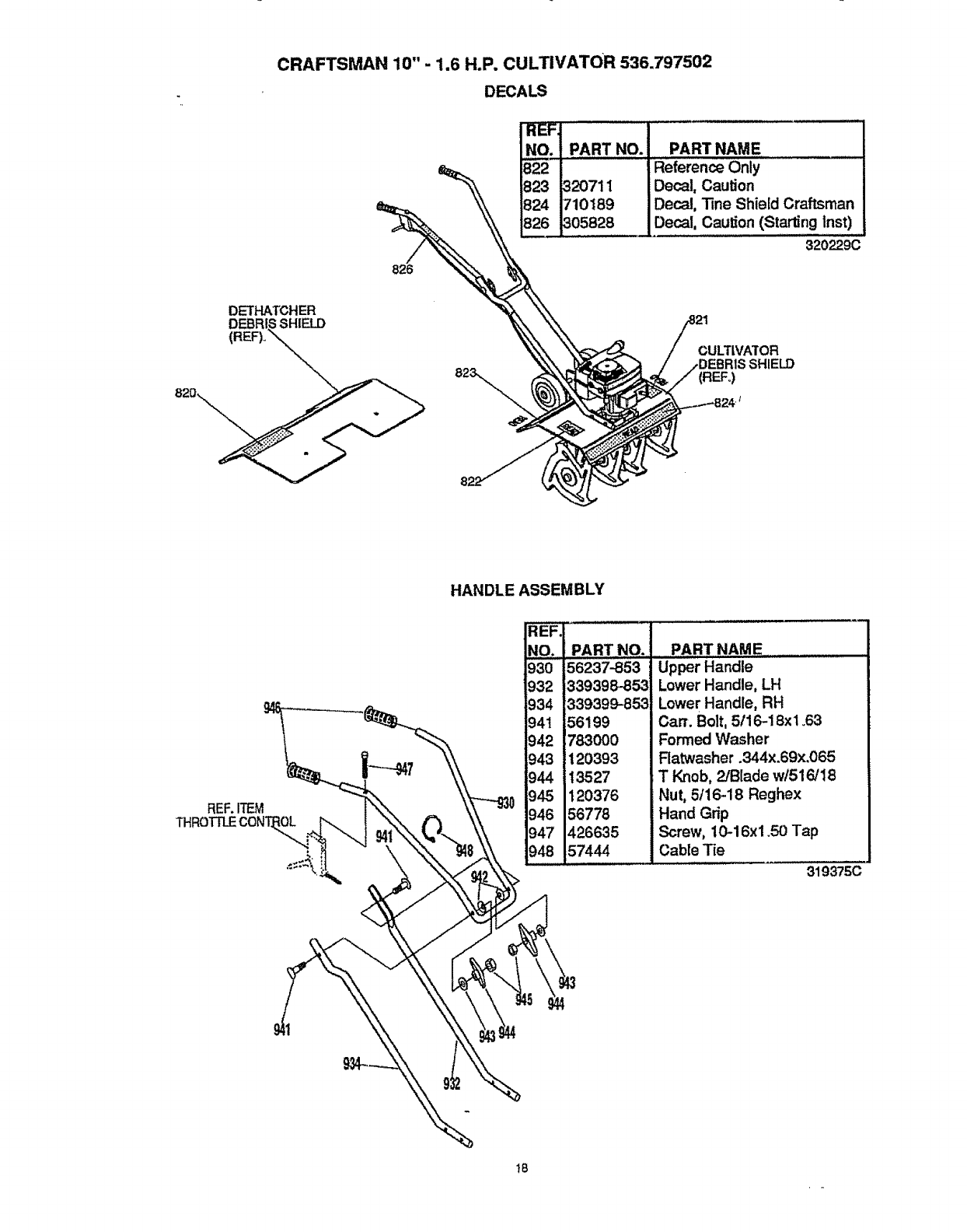
CRAFTSMAN 10"- 1.6 H.P. CULTIVATOR 536.797502
DECALS
826
!_EF, '.....................
N_,O.... P,A,,RT,,,NO.,......PART NAME ........
822 Reference Only
823 _20711 Decal, Caution
824 710189 Decal, "line Shield Craftsman
826 305828 Decal, Caution (Starting lnst)
320_9c
DETHATCHER
CULTIVATOR
ELD
(REFo)
REF.ITEM
HANDLE ASSEMBLY
_PART,,NO.
930 156237-853
932 ]339398-,853
934 1339399-853
941 156199
942 1783000
943 i120393
945 1120376
046156776
947 1426635
9_..1574,_
PART NAME ....
Upper Handle
Lower Handle, LH
Lower Handle, RH
Cart. Bolt, 5116-18xl _63
Formed Washer
Flat:washer .344x.69x.065
T Knob, P/Blade w/516/18
Nut, 5f16-18 Reghex
Hand Grip
Screw, 10-16xl .50 Tap
Cable T_e
319375(3
t8

CRAFTSMAN 2-CYCLE ENGINE MODEL NUMBER: 143.971670
Carburetor No. 632979
REF: PART ...........
NO. NO.
632979
1
2
3
3A
3B
4
5
6
7
't7
20
21
27
28
30
31
34
632947
632928
632926
6-32950
632949
632939A
632929A
632930
632931
PAF NAME
Carburetor
(IncL 18 of EngineParts List)
Throttle &Lever Ass'y_.
Throttle ReturnSpring
DustSe Retainer
Dust Se RetainerScrew
Spacer
Dust Se JWasher
Dust Se
ThrottleShu'tter
Throttle ShutterScrew
632946 Idle Spe
632989 Idle Mixl
632912 Idle Ten
632916 Hinge P
632915 * Meterinc
632918 "Inlet Ne_
632920 Meterin.c
632917 Meterinc
Screw
re Screw
FonSpring
Lever
Spring
LeverPin Screw
REF.
NO.
H,IJH
45
48
5O
51
52
53
60
62
63
64
65
70
I9
PART i
NO.
632919
632902
632904
632903
632905
632906
632933
632908
632907
632988
632945
632934
PART NAME
*Fuel inletScreen
*Welch Plug
*Diaphragm
(Included in 60 & 70)
*Cover Gasket
(Includedin 60 & 70)
Cover
Cover Screw
*Repair Kit
(IncL items marked *innotes)
*PumpDiaphragm
{Included in 60 & 70)
" PumpGasket
(Included in 60 & 70)
PumpCover
PumpCover Screw
Diaghragrn/GasketSet
(lnclo50, 51, 62 & 63)
._..... i ¸
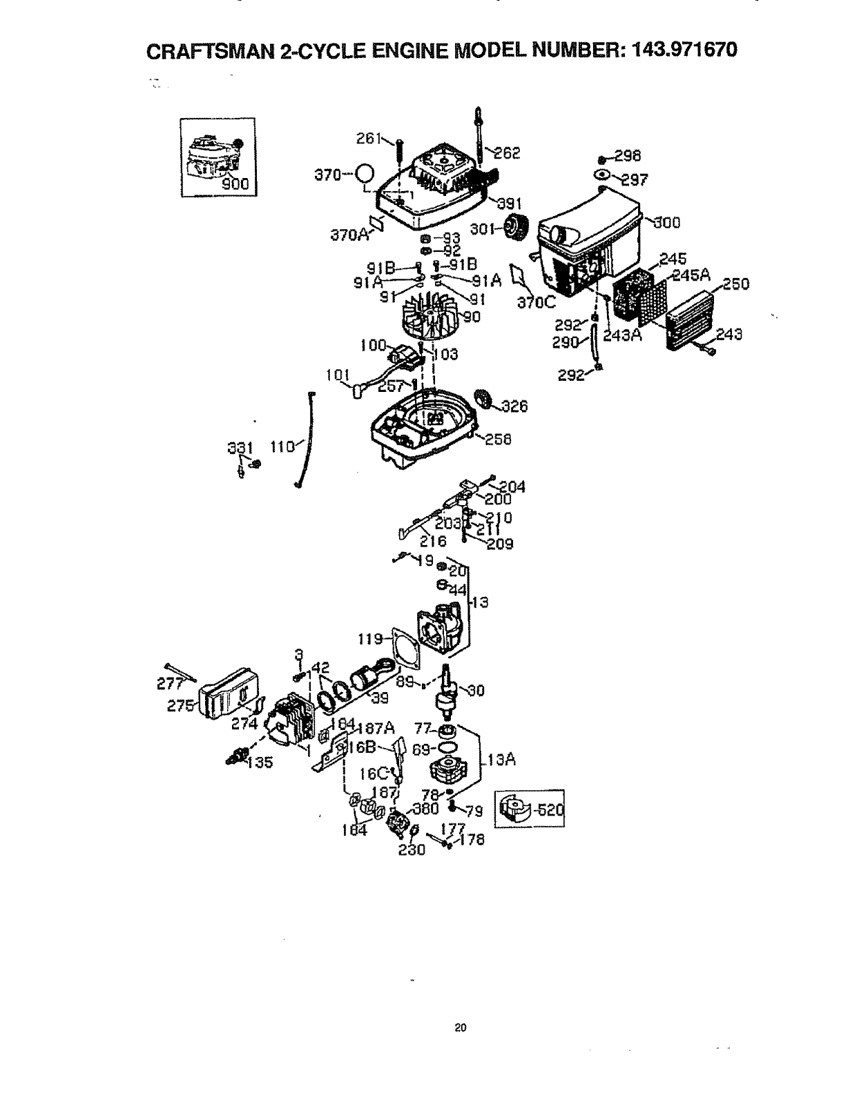
CRAFTSMAN 2..CYCLE ENGINE MODEL NUMBER: 143.971670
6;31
lq
91
•--262 _.ga
58
0
20
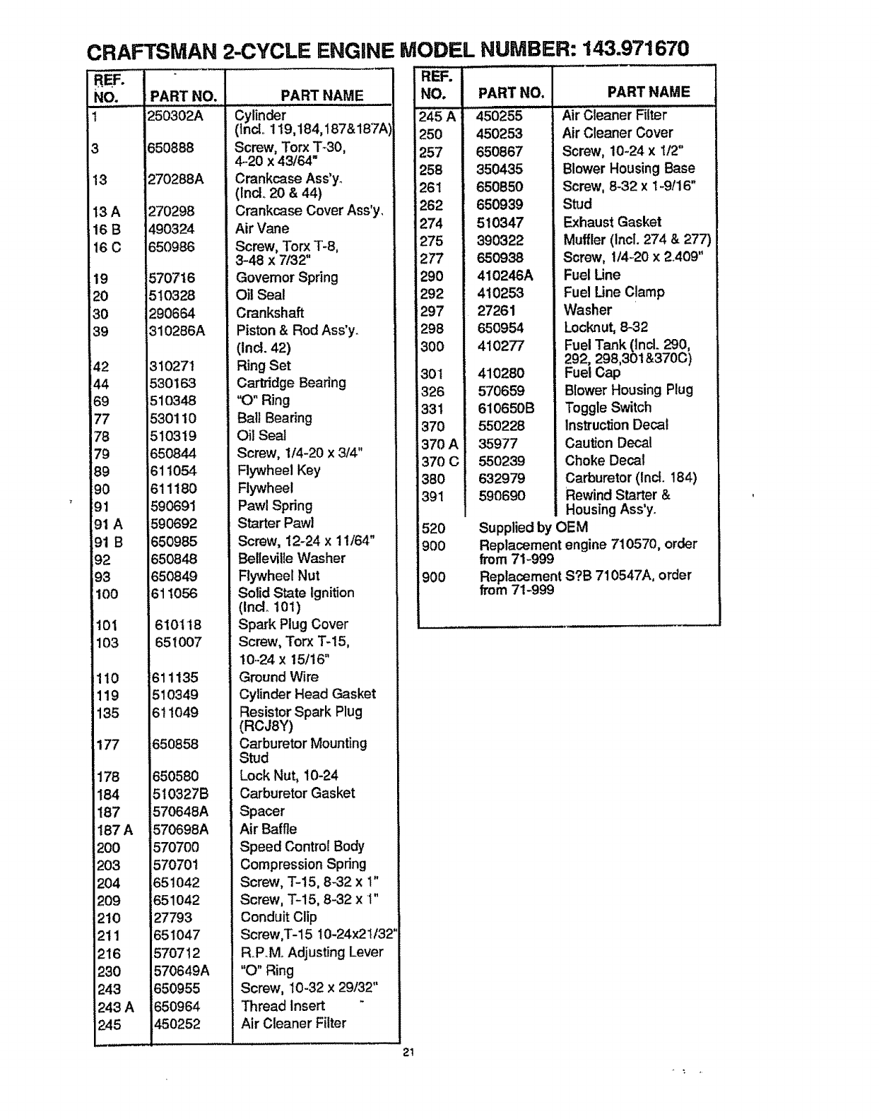
CRAFTSMAN 2-CYCLE ENGINE MODEL NUMBER: 143o971670
REF.
No.
t
3
13
13A
16B
16C
:19
_20
30
39
42
44
69
77
78
79
89
90
: 91
91 A
91 B
92
93
;100
101
103
1t0
119
135
177
178
I84
187
!87A
20O
203
204
209
210
211
216
230
243
243 A
245
PART NO.
650888
270288A
270298
490324
650986
i570716
510328
290664
310286A
310271
530163
510348
530110
510319
650844
611054
611180
590691
590692
650985
650848
650849
611056
610118
651007
611135
510349
611049
650858
65058O
510327B
570648A
570698A
570700
570701
651042
651042
27793
651047
57O712
570649A
650955
650964
450252
PART NAME
Cylinder
(Incl.. 119,184,187&187A
Screw, Torx T_30,
4-20 x 43164"
Crankcase Ass'y_
(IncL 20 & 44)
Crankcase Cover Ass'y,
Air Vane
Screw, Torx "['-8,
3-48 x 7/32"
Governor Spring
Oil Seal
Crankshaft
Piston & Rod Ass'y.
(Incl. 42)
Ring Set
Cartridge Bearing
"O" Ring
Ball Bearing
Oil Seal
Screw, 1/4-20 x 3/4"
Flywheel Key
Flywheel
Pawl Spring
Starter Pawl
Screw, 12-24 x 11/64"
Belleville Washer
Flywheel Nut
Solid State Ignition
(lnclot01)
Spark Plug Cover
Screw, Torx T-15,
10.-24 x t5/16"
Ground Wire
Cylinder Head Gasket
Resistor Spark Plug
(RCJ8Y)
Carburetor Mounting
Stud
Lock Nut, 10-24
Carburetor Gasket
Spacer
Air Baffle
Speed Control Body
Compression Spring
Screw, 3"-t5, 8-32 x 1"
Screw, "['-15, 8-32 x 1"
Conduit Clip
Screw,T-15 10-24x21132
R.P.M Adjusting Lever
"O" Ring
Screw, 10-32 x29132"
Thread Insert
Air Cleaner Filter
REF. I
NO.
__50
_-57
258
26! :
262
274
275
277
29O
292
297
298
3OO
301
326
331
370
370 A
370 C
380
391
520
900
900
PART NO.
'45o255
450253
650867
350435
650850
650939
510347
390322
650938
410248A
410253
27261
650954
410277
410280
570659
610650B
550228
35977
550239
632979
590690
PART NAME
Air cleaner Filter ' "
Air Cleaner Cover
Screw, 10-24 x 112"
Blower Housing Base
Screw, 8-32 x 1-9/16"
Stud
Exhaust Gasket
Muffler (Incl. 274 & 277)
Screw, 1/4-20 x2409"
Fuel Une
Fuel Une Clamp
Washer
Locknut, 8-32
Fuel Tank (Incl. 290,
292, 298,301&370C)
Fuel Cap
Blower Housing Plug
Toggle Switch
Instruction Decal
Caution Decal
Choke Decal
Carburetor (IncL t84)
Rewind Starter &
Housing Ass'y.
Supplied by OEM
Replacement engine 710570, order
from 71-999
Replacement S?B 710547A, order
from 71-999
21
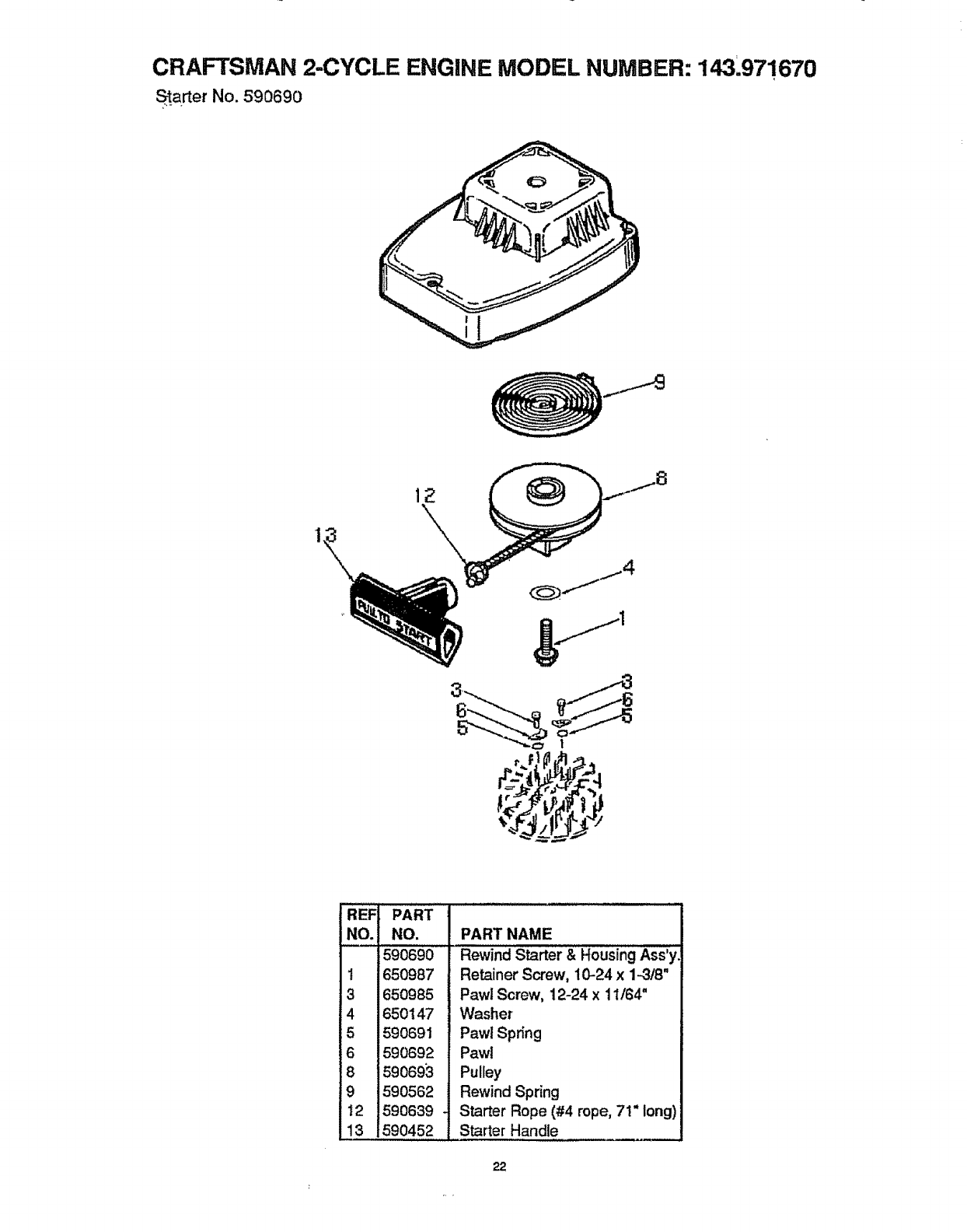
CRAFTSMAN 2-CYCLE ENGINE MODEL NUMBER: 143.971670
Starter No. 590690
REF
NO.
1
3
4
5
6
8
9
12
13
PART
NO.
;590690
650987
650985
650147
590691
590692
590695
590562
590639
590452
PART NAME
Rewind Starter & Housing Ass'y
Retainer Screw, 10-24 x 1-3/8"
Pawt Screw, 12-24 x 11/64"
Washer
Pawl Spring
Pawl
Pulley
Rewind Spring
Starter Rope (#4 rope, 71" long)
Starter Handle
22
o. ,
CULT WADO RA/ZU RCADO RA
Contenido 23
Garantia 23
Reglas de Seguridad 23-25
Contenido labolsa con las partes 25
Montaje 26-28
Operacion 28-32
Maintiemento 32-34
Servicio Y Ajustes 35-36
Almacenamiento 36+37
Identificacion de Pr0blemas 38
Partes de Repuesto 16-18
Partes de Motor 19-2
Orden de Partes Servicio Contratapa
GARANTIA LIMITADA DE UN ANO
DE LA CULTIVADORA/ZURCADORA CRAFTSMAN
Durante un afio a partir de la fecha de compra, siempre y cuando esta cultivadora/
zurcadora Craftsman sea mantenida, lubricada, y afinada en conformidad con las
instruccjones de operacion y mantenimiento en e! manual del duefio. CRAFTSMAN
reparara, gratuitamente, cualquier defecto debido a materiales o mano de obra.
Esta garantia no incluye el(los) brazo(s), ta bujfa, o el filtro que son piezas fungibtes que
se desgastan con et uso normal.
En el caso de que est cultivadora/zurcadora sea utilizada con fines comerciales o de
alquiler, esta garantfa ser& v_lida Linicamente durante 30 dlas apartir de la fecha de
compra. Esta garantla es vatida s61o cuando este producto se utilice en los Estados
Unidos. EL SERVIClO DE GARANT1A SE ENCUENTRA DtSPONIBLE AL DEVOLVER
LA CULTIVADORNZURCADORA AL CENTRO DE SERVICIO CRAFTSMAN MAS
CERCANO EN LOS ESTADOS UNIDOS+
Esta garantfa le otorga derechos especfficos legales, y es posibte que tenga otros
derechos, los cuales varlan de estado a estado.
Sears, Roebuck and Co+, Departamento D/817WA, Hoffman Estates, IL 60179
BUSQUE ESTE SIMBOLO QUE SEi_ALA LAS PRECAUCIONES DE SEGURIDAD
IMPORTANCIA+ QUIERE DECIR -
DE
SEGURIDAD ESTA COMPROMETIDA,
_PRECAUCION: Siempre
desconecte el alambre de la bujia y
pongalo en donde no pueda entrar en
contacto con esta para ev_tar et arranque
por accidente durante la preparacion, el
transporte, el ajuste o cuano se hagan
reparaciones.
IMPORTANTE: Los estandares de seguridad
demandan los controles que exigen la
presencia del operador para reducir aun
minimo et riesgo de tesiones. Su
cultivadora/zurcadora viene equipada con
dichos controtes. Por ningun motivo trate
de anular ta funcion de control que exige la
presencia del operador+
ANTES DE CADA USO
•Lea et manual de! dueSo
cuidadosarhente. Familiadcese
completamente con los controles y con el
uso adecuado de la cultivadora!
zurcadora. Sepa cSmo pararla y
deseganchar los controles r&pidamente. 23
IIiATENClON!!! IilESTE ALERTA!!! SU
o No opere la cultivadora/zurcadora sin
usar ropa exterior adecuada. Use
zapatos que mejoren el equilibrio en las
superficies resbalosas.
•Mantenga el &rea de operaci6n
despejada de toda la genre,
especialmente los nifios pequefios y los
animales dom_sticos.
• Inspeccione cuidadosamente el &rea en
dondese va a usar la cultivadora/
zurcadora y remueva todos los objetos
extraSos.
SEGURIDAD DEL COMBUSTIBLE
•Maneje el combustible con cuidado; es
altamente inflamable.
,Use un envase adecuado+
• Revise el suministro de combustible
antes de cada uso, permitiendo que
exista espacio para la expansi6n pues el
calor del motor y/o sol pueden hacer que
se expanda el combustible+
-Llene el estanque de combustible afuera
con mucho cuidado. Nunca llene el
,:-estanque de combustible en tecintos
cerrados. Vuelva a colocar ia tapa del
estanque de combustible en forma
segura y timpie el combustible
derramadoo
Nunca remueva ta tapa del estanque de
combustible o agregue combustible a un
motor que est,. funcionando o que est&
caliente.
-Nunca almacene combustible o ia
cultivadora!zurcadora con combustible en
el estanque dentro de un edificio en
donde los gases puedan alcanzar una
llama expuesta.
SEGURIDAD DE OPERACION
oNunca permita que los niBos o
adolescentes j6venes operen la
cultivadora/zu rcado ra. Mant6ngalos
atejados cuando est6 en operaci6n.
Nunca perrnita que los adultos operen la
cultivadora/zurcadora sin los
conocimientos adecuados.
• Siempre use anteojos de seguridad o
protecciones para los ojos durante la
operaci6n, o cuando haga ajustes o
reparaciones, para proteger sus ojos
contra objetos extrafios que la
cuttivadora/zurcadora pueda {anzar_
•No ponga las manos ni los pies cerca o
debajo de partes rotatorias.
o Tonga sumo cuidado cuando opere o
atraviese entradas de autom6viles de
ripio, senderos o carninos. Mant_ngase
alerta de peligros escondidos o tr&fico.
°Tenga cuidado para evitar resbalarse o
caerse.
- Nunca opere la cultivadora/zurcadora sin
las protecciones y las planchas
adecuadas, o sin otros dispositos de
protecci6n de seguridad en su lugar.
•Nunca opere la cultivadora/zurcadora a
aitas ve!ocidades de transporte en
superficies resbalosas. Mire hacia atr_s
y tonga cuidado cuando retroceda.
-Nunca permita ta presencia de
espectadores cerca de la cultivadora/
zurcadora.
• Mantenga a los niSos y a los animales
dom_sticos alejados mientras se est_ en
operaci6n.
.Nunca opere la cuttivadora/zurcadoFa sin
buena visibilidad o luz.
= No haga funcionar el motor en recintos 24
cerrados. Los gases de escape son
peligrosos (¢ontienen MONOXIDO DE
CARBONO, UN GAS SIN OLOR QUE
CAUSA LA MUERTE).
• Tome todas las precauciones posibles
cuando deje la cultivadoraJzurcadora
labradora desatendida. Pare el motor.
° No sobrecargue la capacidad de la
cultivadora/zurcadora tratando de
cultivadora muy profundamente a mucha
velocidad.
ALMACENAMIENTO CON
SEGURIDAD
• Siempre refi_rase a las instrucciones del
manual del dueSo para verificar los
detalles de importancia si la cultivadorai
zurcadora se va aalmacenar por un largo
perl'odo de tiempo.
° Nunca almacene la cuitivadora/zurcadora
con combustible en et estanque de
combustible dentro de un edificio en
donde se encuentren presentes fuentes
de ignici6n, tales como, los calentadores
de agua o del ambiente, secadoras de
ropa y otros artefactos parecidos.
Permita que se enfrfe el motor antes de
guardarlo en alg5n lugar cerrado.
•Mantenga la mini zurcadora/cultivadora
en condiciones de trabajo seguras.
Revise todos los sujetadores a intervalos
frecuentes para verificar si est&n
apretados en forma segura.
SEGURIDAD DE REPARACIONES/
AJUSTES
Despu_s de pegarle a objetos extraSos,
pare el motor. Remueva el atambre de la
bujia, y mant_ngato alejado de _sta para
evitar el arranque por accidente. Revise
ta mini zurcadora/cultivadora
cuidadosamente para verificar si est&
daSada y repare los daSos antes de
volver a hacer arrancar y operar la
cultivadora/zurcadora.
•Si la cultivadoraJzurcadora empieza a
vibrar anormaimente, pare el motor y
revise inmediatamente la causa_ La
vibracibn, normalmente es un aviso de
problemas.
• Pare el motor cuando abandone la
posici6n de operaci6n. Tambi_n
desconecte el alambre de la bujia antes
de destaponar los brazos de cultivo y
cuando haga reparaciones, ajustes o
inspecciones.
,Cuando haga timpiezas, reparaciones o
inspecciones, apague el motor y
. aseg_rese que todas las parses en
movimiento se hayan detenido.
•Nunca irate de hacer ajustes mientras el
motor est& funcionando (excepto
cuando especificamente Io
recomiende el fabricante).
4,
ADVERTENCIA: Et escape del motor
de este producto contiene productos
qufmicos que se sabe en el estado de
California que producen c&ncer, defectos
de nacimiento y otros dafios reproductivos.
_ADMERTENOIA: Esta unidad viene
equipada con un motor de combusti6n
interna y no se debe usar sobre, o cerca,
de un terreno no desarrollado cubierto de
bosques, de arbustos o de c_sped, a
menos que el sistema de escape del motor
venga equipado con un amortiguador de
chispas que cumpla con las leyes locales o
estatales (si existen). Si se usa un
amortiguador de chispas, el operador debe
mantenerlo en condiciones de trabajo
eficientes.
En el estado de California, la ley exige un
amortiguador de chispas (Seccl6n 4442 del
"California Public Resources Code"
(Decreto de Recursos Pdblicos de
California). Otros estados pueden contar
con otras ieyes parecidas. Las leyes
federales se aplican en las tierras federales.
Su Centro de Servicio Autorizado Crafts-
man m&s cercano tiene disponible un
amortiguador de chispas/silenciador (vea la
secci6n PARTES DE REPUESTO en este
manual).
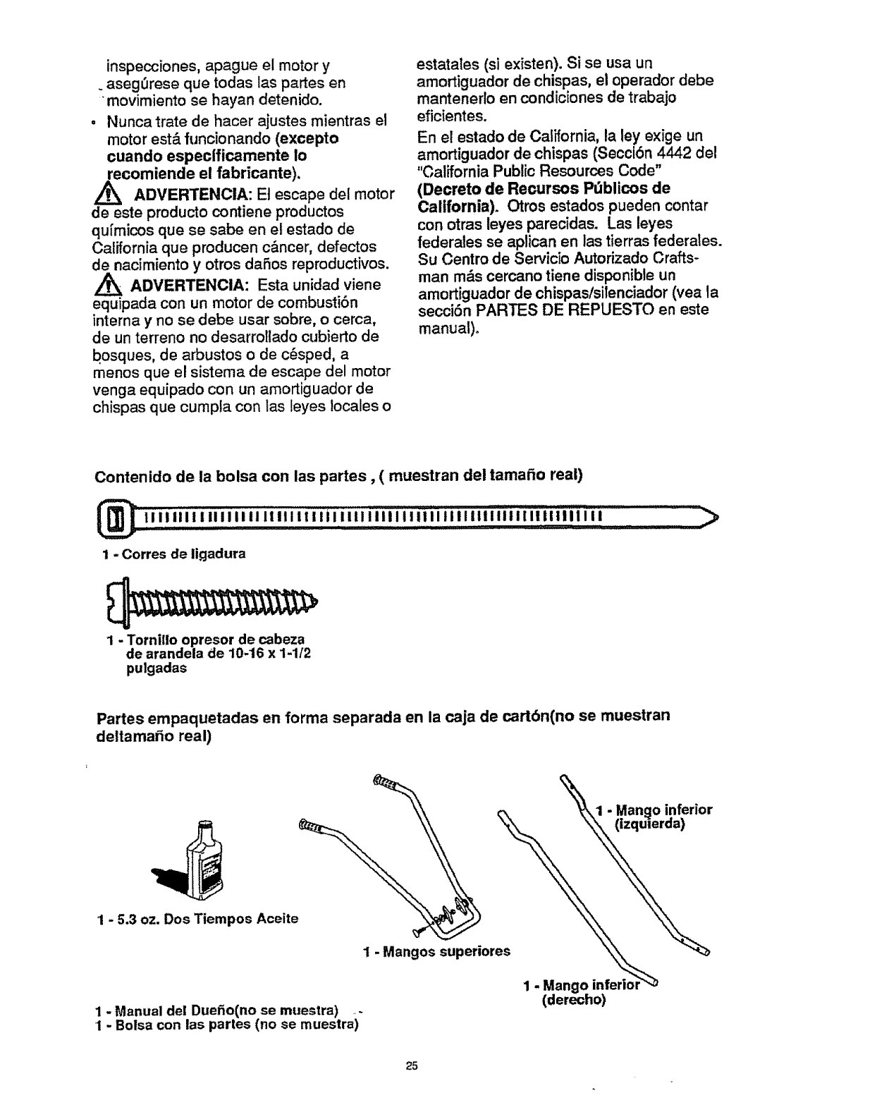
Contenido de la bolsa con las partes, ( muestran del tamaffo real)
_! ,I I'ill ! II1'i il li h tilt "
,_,!,,,,!.......... lllililllillillll!llllllilllillllli,!,,! tl:i::iiii.:;- _)
1-Corres de ligadura
1 - Tornilio opresor de cabeza
de arandela de 10-16 x 1-1/2
pulgadas
Partes empaquetadas en forma separada en la caja de cart6n(no se muestran
deltamafio real)
c, _1 -Mango inferior
1-Mangoinferior"_
(derecho)
1-Manual de! Duefio(no se muestra) .-
!-Bolsa con las parles (no se muestra)
25
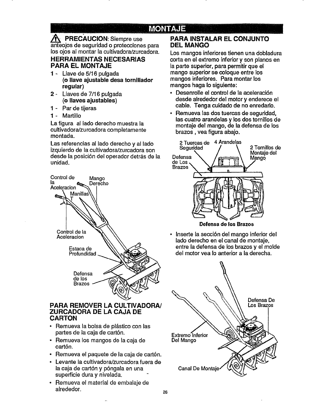
A/t_ PREC_,UCION: Siempre use
anteojos de seguridad o protecciones para
los ojos al montar ta cultivadora/zurcadora,
HERRAMIENTAS NECESARIAS
PARA EL MONTAJE
1 - Llave de 5/16 pulgada
(o Ilave ajustable desa tornillador
regular)
2 - Llaves de 7/16 pulgada
(o Ilaves ajustables)
1 - Par de tijeras
1- Martillo
La figura al lado derecho muestra la
cultivadoraJzu rcadora completamente
montadao
Las referencias al lado derecho y al lado
izquierdo de la cultivadora/zurcadora son
desde la posici6n det operador detr&s de la
unidad.
PARA INSTALAR EL CONJUNTO
DEL MANGO
Los mangos inferiores tienen una dobladura
corta en el extremo inferior y son ptanos en
la parte superior, para permitir que el
mango superior se coloque entre los
mangos inferiores, Para montar los
mangos haga Io siguiente:
,Desenrolle el control de la aceleraci6n
desde alrededor del motor y enderece el
cable. Tenga cuidado de no enredarlo.
•Remueva tas dos tuercas de seguridad,
las cuatro arandelas y los dos tornillos de
montaje det mango, de la defensa de los
brazos, vea figura abajo.
2 Tuercas de 4 Arandelas
Seguridad
Defensa
de Los
2 Tornillosde
Montaje det
Control de Mango
ta Derecho
Control de la
Aceleracion
Estaca de
Profundidad
Defensa de los Brazos
lnserte la secci6n del mango inferior del
lado derecho en el canal de montaje,
entre la defensa de los brazos y et molde
del motor vea Io anterior a la derecha.
Defensa
de los
Brazos
PARA REMOVER LA CULTIVADORA/
ZURCADORA DE LA CAJA DE
CARTON
• Remueva la botsa de pl_stico con las
partes de la caja de cartSno
•Remueva los mangos de la caja de
cartbn.
- Remueva el paquete de ia caja de cart6n.
• Levante la cultivadora/zurcadora fuera de
la caja de cart6n y p6ngala en una
supefficie dura y nivelada.
•Remueva el material de embalaje de
alrededor.
Extremo inferior
Det Mango
Canal De
26
Defensa De
Los Brazos
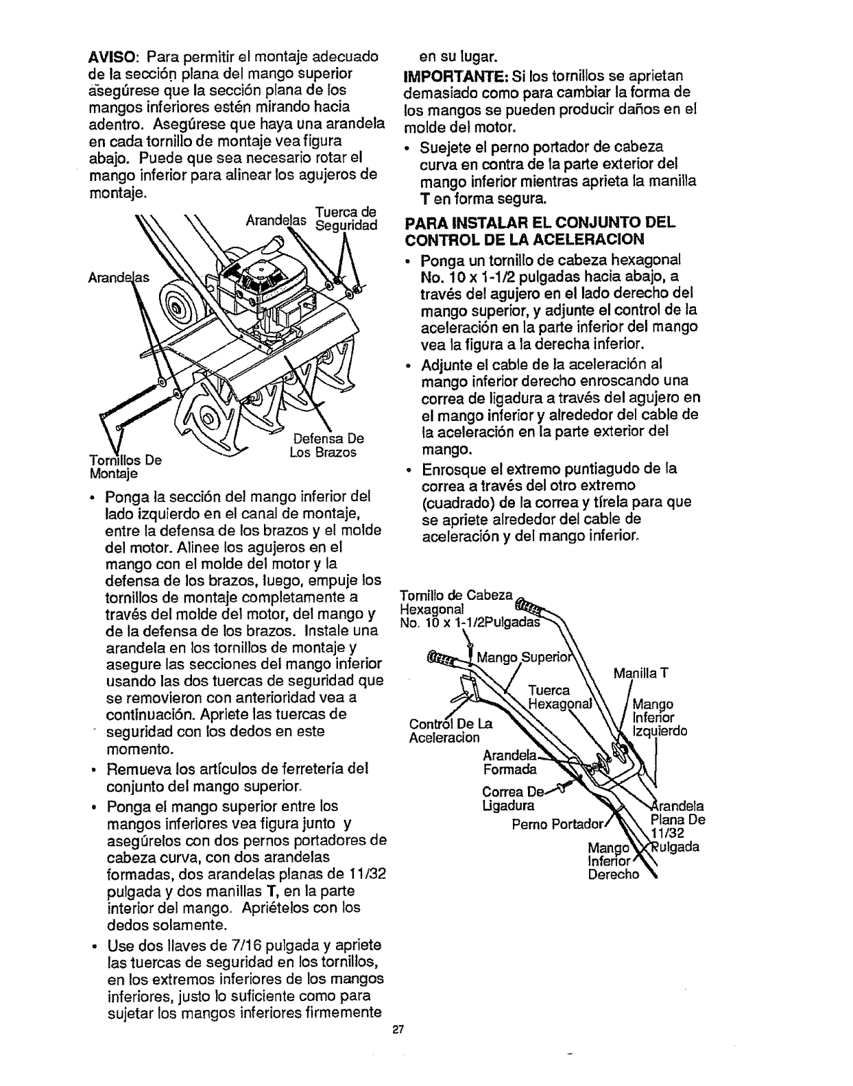
AVISO: Para permitir el montaje adecuado
de la secci6n plana del mango superior
a'segt3rese que la secci6n plana de los
mangos inferiores est6n mirando hacia
adentro° Asegfirese que haya una arandela
en cada tornillo de montaje vea figura
abajo. Puede que sea necesario rotar el
mango inferior para alinear los agujeros de
montaje.
Arandelas Tuerca de
. Sog,.,ri, a,
Arand_
<
Tornwllos e
Montaje
Ponga la secci6n del mango inferior det
lado izquierdo en el canal de montaje,
entre la defensa de los brazos y el molde
del motor. Alinee los agujeros en el
mango con et molde del motor y la
defensa de los brazos, luego, empuje los
tornitlos de montaje completamente a
trav6s del molde del motor, dot mango y
de la defensa de los brazos. Instale una
arandela en los tornillos de montaje y
asegure las secciones del mango inferior
usando las dos tuercas de seguridad que
se removieron con anterioridad vea a
conttnuaci6n. Apriete las tuercas de
seguridad con los dodos en este
momento.
Remueva los art[culos de ferreter[a del
conjunto del mango superior°
Ponga el mango superior entre los
mangos inferiores vea figura junto y
asegt3relos con dos pernos portadores de
cabeza curva, con dos arandelas
formadas, dos arandelas planas de 1t/32
pulgada y dos manillas T, en la parte
interior del mango° Apri_tetos con los
dedos solamente.
Use dos llaves de 7/16 pulgada y apriete
las tuercas de seguridad en los tornillos,
en los extremos inferiores de los mangos
inferiores, justo !o suficiente como para
sujetar los mangos inferiores firmemente
en su lugar.
IMPORT.ANTE: Si los tornillos se aprietan
demasiado como para cambiar la forma de
los mangos se pueden producir daSos en el
molde del motor.
•Suejete el perno portador de cabeza
curva en contra de la parte exterior del
mango inferior mientras aprieta Ia manilla
Ten forma segura.
PARA INSTALAR EL CONJUNTO DEL
CONTROL DE LA ACELERACION
• Ponga un tornil[ode cabeza hexagonal
No. 10 x 1-1/2 pulgadas hacia abajo, a
trav_s del agujero en el lado derecho del
mango superior, y adjunte el control de la
aceleraci6n en la parte inferior del mango
yea la figura a la derecha inferior.
. Adjunte et cable de la aceleraci6n al
mango inferior derecho enroscando una
correa de ligadura a tray,s del agujero en
el mango inferior y atrededor del cable de
ta aceleraci6n en la parte exterior del
mango.
°Enrosque el extremo puntiagudo de la
correa a trav6s del otto extremo
(cuadrado) de la correa y tfrela para que
se apriete alrededor del cable de
aceleraci6n y del mango inferior,
Tomillo de Cabeza
Hexagonal
No. 10x
De La
Aceleracion
Arandela.
Formada
Correa
Ugadura
Pemo
Manilla T
o
uierdo
Plana De
1/32
Mango
lnfenor
Derecho
27
AVISO; Un lado de la correa de ligadura es
&spero, y et otro es liso+ El tado &spero
tiene que quedar en la parte interior de la
+curvatura que se forma cuando se juntan los
extremos de la correa de ligadura+
o Trate de sottar la correa de tigadura, si se
suelta, quiere decir que se ha amarrado
con la parte lisa en la parte interior de la
cuwatura. Remueva [a correa de ligadura
e invierta ta direccibn.
- Corte la correa en exceso+
",/LISTA DE REVISION
Antes de operar y de disfrutar de su
cultivadora/zurcadora nuevo, le deseamos
que receiba el mejor rendimiento y la mayor
satisfaccion de este de calidad.
HAGA EL FAVOR DE REVtSAR LA LISTA
A CONTINUAClON:
_/Se han completado todas las
instrucciones de montaje.
-,/ No quedan partes suettas en la caja de
cart6n.
_/ Revise si hay sujetadores sueltos.
A! mismo tiempo que como usar su
CULTIVADORAiZURCADORA, preste
atencion extra a los puntos de importancia
que se presentana continuacion:
V_/ El tanque de combustible est& lleno
con la mezcla correcta de gasolina y
aceite.
",N Famitiar[cese con la ubicaci6n y la
funci6n de todos los controles+
Op_relos antes de hacer arTancar el
motor.
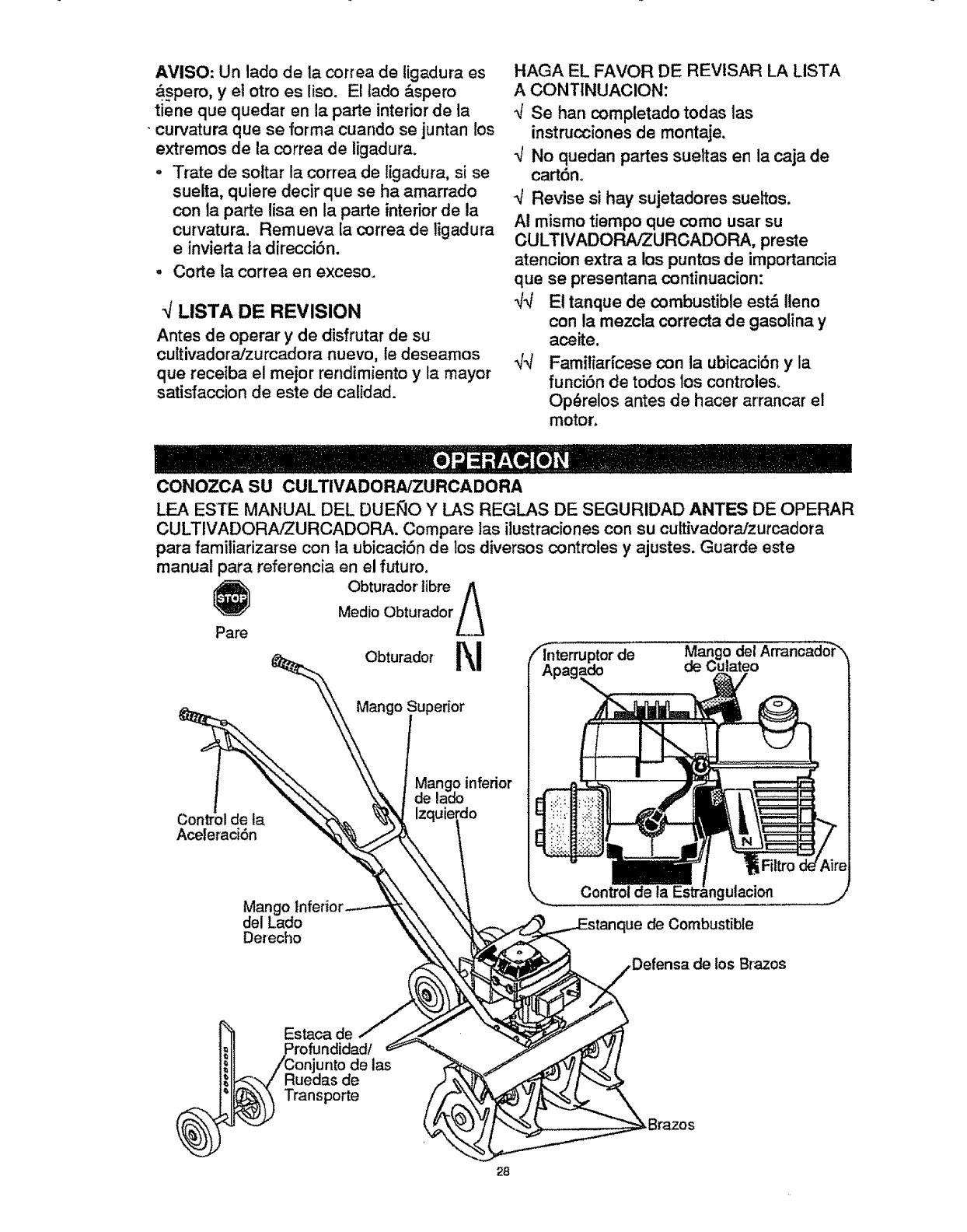
CONOZCA SU CULTIVADORA/ZURCADORA
LEA ESTE MANUAL DEL DUEllO Y LAS REGLAS DE SEGURIDAD ANTES DE OPERAR
CULTIVADORA/ZURCADORA. Compare las itustraciones con su cultivadora/zurcadora
para familiarizarse con la ubicaci6n de los diversos controles y ajustes. Guarde este
manual para referencia en el futuro.
Obturador tibre A
Medio Obturador L_
Pare
Obturado, rt_! ode,
Mango _upedor
de la
Aceleraci6n
Mango inferior
de lado
erdo
Mango
delLado
Derecho
Control de la gulacion
]ue de Combustible
de los Brazos
Estaca de
unto de las
de
Transporte
28
Control de la Aceleracibn _Controla la
velocidad del motor y la rotaci6n de los
brazos. La cultivadora/zurcadora est&
equipada con un embrague centrffugo que
engancha al sistema de impulsi6n de los
brazos cuando aumenta ia velocidad del
motor.
Palanca de control de la Estrangulacibn
- Se usa para ayudar ahacer arrancar un
motor ffio.
Interruptor de Apagado - Se usa para
parar el motor,
Mango del Arrancador - El motor de esta
cultivadora/zurcadora cuenta con
arrancador de culateo f_,cilde tiraro
Estaca de ProfundidadlConjunto de las
ruedas de transports - Se usa (con las
ruedas tevantadas) cuando se est&
labrando o cuttivando para ajustar la
profundidad del corte, Tamb[6n actQa como
un freno para ayudar al operador a
controlar la direcci6n y la velocidad de la
unidad.
La estaca de profundidad/conjunto de las
ruedas de transporte (con las ruedas
bajadas) se puede usar para transportar la
unidad.
COMO USAR SU /
ZURCADORACULTIVADORA
j_ ADVERTENCIA: La operaci6n de esta
cuttivadoraizurcadora puede hacer que
salten objetos extrafios dentro de sus ojos,
to que pue de producir dafios graves en
dstos. Siempre use ant_jos de seguridad o
protecciones para los ojos al operar la
cultivadora/zu rcadora.
- Suelte el control de ta aceleraci6n para
parar los brazos.
- Mueva el interruptor de apagado en el
motor a la posici6n de "APAGADO"
(OFF).
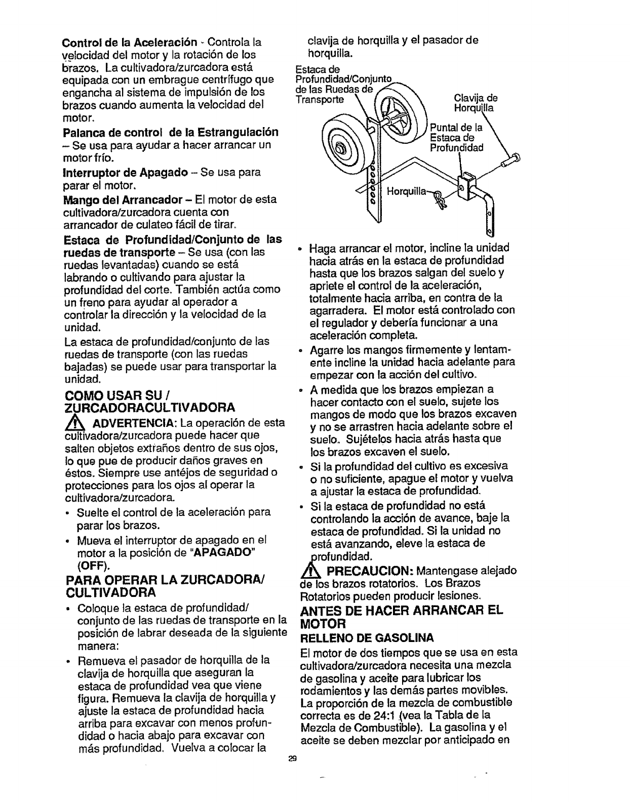
PARA OPERAR LA ZURCADORA/
CULTIVADORA
• Coloque ta estaca de profundidad/
conjunto de las ruedas de transporte en la
posici6n de labrar deseada de la siguiente
manera:
. Remueva et pasador de horquilla de la
clavija de horquilla que aseguran la
estaca de profundidad vea que viene
figura. Remueva ta clavija de horquiIla y
ajuste la estaca de profundidad hacia
arriba para excavar con menos prof_n-
didad o hacia abajo para excavar con
m&s profundidad. Vuelva a colocar la 29
ctavija de horquilla y el pasador de
horquilla.
Estaca de
Profu
de las
Transporte \ Ctavi a de
Horc lla
o Haga arrancar el motor, incline la unidad
hacia atr&s en la estaca de profundidad
hasta que los brazos salgan del suelo y
apriete el control de la aceleracibn,
totalmente hacia arriba, en contra de la
agarradera. El motor est& controlado con
el regulador y deberfa funcionar auna
aceleraci6n completa°
°Agarre los mangos firmemente y lentam-
ente incline la unidad hacia adelante para
empezar con la acci6n del cultivo°
• A medida que los brazos empiezan a
hacer contacto con el suelo, sujete los
mangos de modo que los brazos excaven
y no se arrastren hacia adelante sobre el
suelo. Suj_tel0s hacia atr&s hasta que
los brazos excaven el suelo,
• Si la profundidad det cultivo es excesiva
o no suficiente, apague el motor y vuelva
aajustar la estaca de profundidad.
• Si la estaca de profundidad no est&
controlando ia acci6n de avance, baje la
estaca de profundidad. Si la unidad no
est& avanzando, eleve la estaca de
,_ofundidad.
PRECAUCION: Mantengase alejado
de los brazos rotatorios. Los Brazos
Rotatorios pueden producir lesiones.
ANTES DE HACER ARRANCAR EL
MOTOR
RELLENO DE GASOLINA
El motor de dos tiempos que se usa en esta
cultivadora/zurcadora necesita una mezcla
de gasolina y aceite para lubricar los
rodamientos y las dem&s partes movibles.
La proporciSn de la mezcta de combustible
correcta es de 24:1 (yea la Tabta de la
Mezcla de Combustible). La gasolina yet
aceite se deben mezclar por anticipado en
g_solina nueva, limpia y sin plomo.
-L_ PREOAUCION: La gasolina es
inflamable y se tiene que tener cuidado
cuando se maneje o almacene. No Ilene el
estanque de combustible mientras que la
cultivadora/zurcadora esta funcionando,
cuando esta caliente o cuando esta en un
recinto cerrado. Mantengala alejada de
una llama expuesta, de las chispas
electricas y no fume cuando mezcle el
combustible o cuando llene el estanque de
combustible. Nunca Ilene et estanque de
combustible completamente: sino que Ilene
el estanque hasta dentro de 1/4-1/2
Pulgada desde la parte superior para
permitir la expansion det combustible.
Siempre Ilene el estanque de combustible
afuera y use un embudo o un pico para
evitar el derrame. Asegurese de limpiar
todo el combustible derramado antes de
hacer arrancar el motor.
Almacene la gasolina envase apmbado y
limpio ymantenga la tapa de este en su
lugar. Guarde la gasolina en un lugar
fresco y bien ventilado: nunca en la casa.
Nunca compre mas gasolina que la que
necesita para 30 dias para asegurar la
volatUidad= La gasolina tiene como fin
servir de combustible en motores de
combustion intema; por Io tanto, no use la
gasolina par ningun otro fin. Dado que a
muchos nifios les gusta el olor de la
gasolina, mantengala alejada de su alcance
pues los vapores son peligrosos de aspirar,
asi como explosivo.
ADVERTENClA: La experiencia ha
indicado que Ioscombustibles mezclados
con alcohol (conocidos como gasohol, o el
uso de etanol o metanol) pueden atraer la
humedad, la que conduce a ta separaci0n y
formaci6n de dcidos durante el
almacenamiento. La gasolina acfdica
puede dafiar el sistema del combustible de
un motor durante el almacenamiento. Para
evitar los problemas con el motor, se debe
vaciar el sistema de combustible antes de
guardarlo por un perfodo de 30 dfas o m_,s.
Vacie el estanque de combustible, haga
arrancar el motor y hdgalo funcionar hasta
que las tfneas del combustible y el
carburador queden vac[os. La pr6xima
temporada use combustible nuevo. Vea las
instrucciones de Almacenamiento para
m_ informaci6n. Nunca use productos de
limpieza para el motor o para el carbu'rador
en el estanque del combustible, pues se
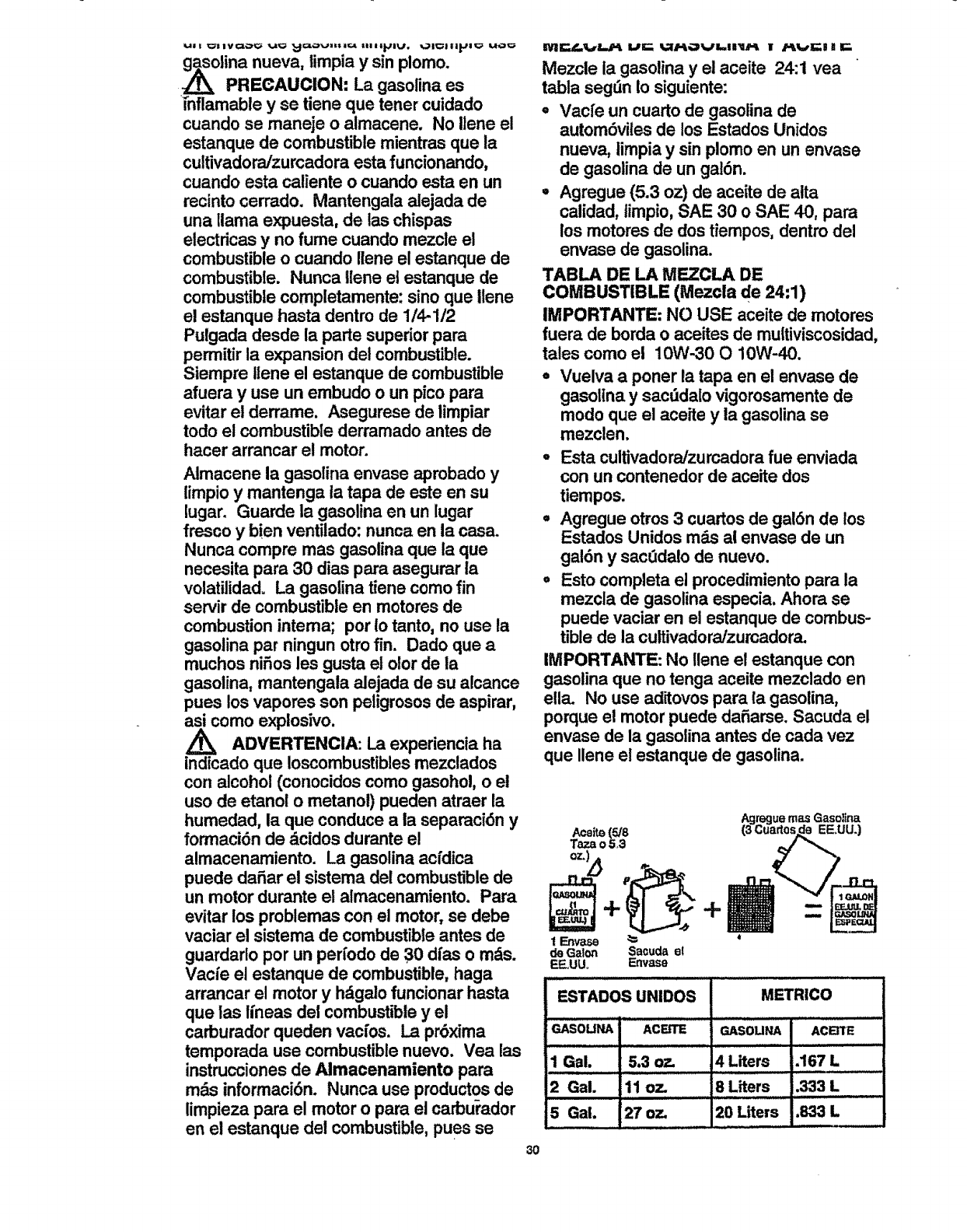
Mezcle ia gasolina y el aceite 24:1 yea
tabla segfin to siguiente:
=Vacfe un cuarto de gasolina de
autom6viles de los Estados Unidos
nueva, limpia y sin plomo en un envase
de gasolina de un gal6n.
°Agregue (5.3 oz) de aceite de aita
calidad, timpio, SAE 30 o SAE 40, para
los motores de dos tiempos, dentro del
envase de gasolina.
TABLA DE LA MEZCLA DE
COMBUSTIBLE (Mezcla de 24:1)
IMPORTANTE; NO USE aceite de motores
fuera de borda o aceites de multiviscosidad,
tales como el 10W-30 O 10W-40.
Vuelva a poner la tapa en el envase de
gasolina y sacfidalo vigorosamente de
modo que el aceite y la gasolina se
mezclen.
°Esta cultivadora/zurcadora fue enviada
con un contenedor de aceite dos
tiempos.
°Agregue otros 3 cuartos de gal6n de los
Estados Unidos m_s ai envase de un
gal6n y sacfidalo de nuevo.
°Esto completa el procedimiento para la
mezcla de gasolina especia. Ahora se
puede vaciar en el estanque de combus-
tible de la cultivadora/zumadora.
IMPORTANTE: No Ilene el estanque con
gasolina que no tenga aceite mezclado en
ella. No use aditovos para la gasolina,
porque el motor puede dafiarse. Sacuda el
envase de la gasolina antes de cada vez
que Ilene el estanque de gasolina.
3O
=emas Gasolina
METRICO
_sou_ ACmTE
.167 L
lEn_ _*
de Galon Sacuda el
EF-UU+ Envase
ESTADOS UNIDO8
;_SOU_ ACal'_
1 Gal. 5.3 oz. 4 Liters
2 Gal. 11 oz. 8 Liters ,333 L
5 Gal. 127oz. 20 Liters .833 L
PARA HACER ARRANCAR EL
MOTOR
Antes de hater arrancar el motor,
asegq_resede que haya lefdo y
comprendido todas las instrucciones en las
p&ginas antedores.
,Uene el estanque de combustible (1/2
pulgada por debajo de la parte inferior del
cueilo para relteno) con una mezcla de
combustible nueva y vuetva ainstalar la
tapa del estanque de combustible en
forma segur& Nunca use combustible
que pueda estar rancio debido a un largo
periodo de alamacenamiento.
° Mueva el interruptor de apagado ala
posici6n de "ENCENDIDO" (ON).
•Mueva el control de la estrangulaci6n vea
figura pagfna 29 a la posici6n de
estrangulaci6n "COMPLETA" (FULL)
(hasta abajo del todo).
AVISO: Un motor caliente no debe
necesitar estrangulaci6n.
o Incline la mini zurcadoraJcultivadora de
vuelta sobre la estaca de profundidad
para levantar los brazos fuera del suelo.
° Agarre el mango superior firmemente
para estabilizar la mini zurcadora/
cultivadora y tire el mango del arrancador
con tiros cortos y r&pidos. No permita
que el mango del arrancador se devuelva
abruptamente, d_jelo que se vuelva a
enrollar lentamente ai mismo tiempo que
se sujeta el cord6n del arrancador. Se
necesitar&n unos cuantos tiros en el
mango del arrancador para alimentar la
gasolina desde el estanque de combus-
tible al carburador.
°Cuando el motor arranque, mueva el
control de estrangulaci6n a la posici6n de
MEDIA ESTRANGULACION (HALF
CHOKE) hasta que el motor empiece a
funcionar uniformemente. Luego mueva
el control de estrangulaci6n a la posici6n
de SIN ESTRANGULACION (NO
CHOKE) (completamente hasta arriba).
°Si el motor falla, mueva el control de
estrangulaciSn a la posici6n de MEDIA
ESTRANGULACION (HALF CHOKE)
hasta que el motor empiece a funcionar
uniformemente. Luego mueva el control
de estrangulaci6n a la posici6n de SIN
ESTRANGtJLACION (NO CHOKE).
•Si el motor arraanca, pero no contint_a
funcionando, mueva el control de -
estrangutaci6n a la posici6n de SIN
ESTRANGULAClON (NO CHOKE) y
repita las instrucciones de arranque.
AVISO: 8i los brazos no paran cuando se
suelta el control de la aceleracf6n, vuelva a
ajustar la vetocidad en vacfo del
carburador, seg_n se sefiala en el Paso 5
del p&rrafo del Ajuste del Carburador en ia
secci6n de Servicio/Ajustes de este
manual.
° Para parar el motor, suelte el control de
la aceleraci6n ymueva el interruptor de
apagado a ia posici6n de "APAGADO"
(OFF).
oSi se ahoga el motor yea el p_rrafo de
Mantenimiento de la Bujfa en la secci6n
de Mantenimiento de este manual
Luego tire el cord6n arrancador con la
palanca de la estrangulaci6n a la
p0sici6n de SIN EeTRANGULACION
NO CHOKE)°
PRECAUClON: El silenciador y las
areas de alrededor se calientan despues de
hacer funcionar el motor. Evite estas
areas.
CONSEJOS PARA MINI
ZURCADORA/CU LTIVADORA
E! cultivo quiere decir el excavar, dar
vuelta y romper el suelo duro antes de
plantar. El suelo suelto y blando perrnite
el desarrollo de ias raices. La mejor
profundidad de cuttivoes 4a6 putgadas.
La cultivadora/zumadora tambi_n puede
despejar el suelo de las malezas
indeseables. La descomposici6n de
estas malezas enriquece el sue]o.
Dependiendo del clima (lluvia o viento),
puede ser recomendable cultivar el suelo
a fines de la temporada de cultivo para
acondicionado at_n m&s°
Evite cultivar el suelo que est& demasiado
seco, pues dste se pulveriza y produce un
polvo que no puede retener et agua.
Tambi_n, serd diffcit para ia m_.quina
cultivar el suelo qu estd. demasiado
mojado y producir& terrones no
satisfactodos.
• Se obtendrd un mejor crecimiento en el
suelo cultivado si se cultiva un &tea
pequeSa en forrna adecuada y se usa el
terreno cuitivado muy pronto despuds de
cultivar para retener la humedad.
°La estaca de profundidad (en la parte
posterior de la cultivadora/zurcadora)
sirve un fin doble vea figura pagina 30).
31
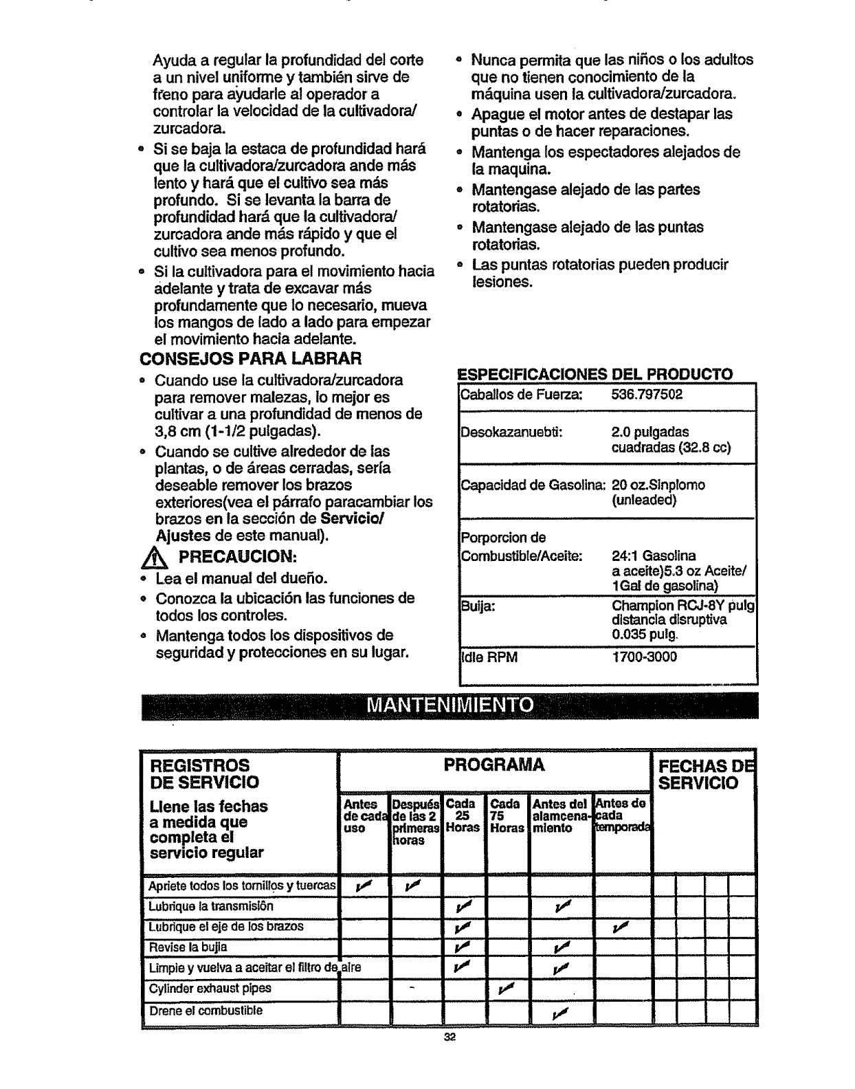
Ayuda a regular la profundidad del corte
aun nivel uniforme y tambidn sirve de
h'eno para a'yudarle al operador a
controlar la velocidad de la cultivadora/
zurcadora.
.Si se baja la estaca de profundidad hard
que la cultivadora!zurcadora ande rods
lento y hard que el cultivo sea m_
profundo. Si se levanta la barra de
profundidad hard que la cultivadora/
zurcadora ande rods rdpido y que el
cultivo sea menos profundo.
,, Si la cultivadora para el movimiento hacia
adelante y trata de excavar mds
profundamente que 1onecesario, mueva
los mangos de iado a lado para empezar
el movimiento hacia adelante.
CONSEJOS PAPA LABRAR
= Cuando use la cuitivadora/zurcadora
para remover malezas, Io mejor es
cultivar auna profundidad de menos de
3,8 cm (1-1/2 pulgadas).
°Cuando se cultive airededor de ias
plantas, o de dreas cerradas, seri'a
deseable remover los brazos
exteriores(vea el pdrrafo paracambiar los
brazos en la secci6n de Servicio/
Ajustes de este manual).
PRECAUCION:
=Lea el manual del dueSo.
=Conozca la ubicaci6n las funciones de
todos loscontroles.
°Mantenga todos los dispositivos de
seguridad y protecciones en su lugar.
° Nunca permita que las ni5os o los adultos
que no tienen conocimiento de la
mdquina usen la cultivadora/zumadora.
• Apague el motor antes de destapar las
puntas o de hacer reparaciones.
° Mantenga los espectadores alejados de
la maquina.
°Mantengase alejado de las partes
rotatorias.
oMantengase alejado de las puntas
rotatorias.
°Las puntas rotatorias pueden producir
lesione-s.
ESPECIFICACIONES DEL PRODUCTO
_aba!los de Fuerza: 536,797502
Desokazanuebti: 2.0 pulgadas
cuadradas(32.8 cc)
Capacidad de Gasolina: 20 oz.Stnplomo
(unleaded)
Porporcionde
CombustiblelAceite:
Buija:
Idle RPM
24:1 Gasolina
aaceite)5.3 oz Aceite/
1Galde gasolina)
c.= pionRCJ.eYpuli
distancladlsruptiva
0.035 pulg
1700-3000
REGlSTROS
DE SERVIClO
Uene ias fechas
a medida que
completa el
servt¢io regular
Apdete todos los tomillos y tuercas _
Lubdqueia LransmislOn
LubdqUe eleje de los brazos ......... iv#
Revise la bujla ................................................................
PROGRAMA
Antes BeSl_S Cada Cada
de cad; de las 2 25 75
uso pdmems Horas Horas
horas
Limpie y vuelvaa aceitar el filtrod_ _tre P_
Dreneel combustible
Antes del
alamcena,
mlento
_mtes de
:ada
_porada
_.._..__..::_..:
FECHAS DE
SERVIC|O
32
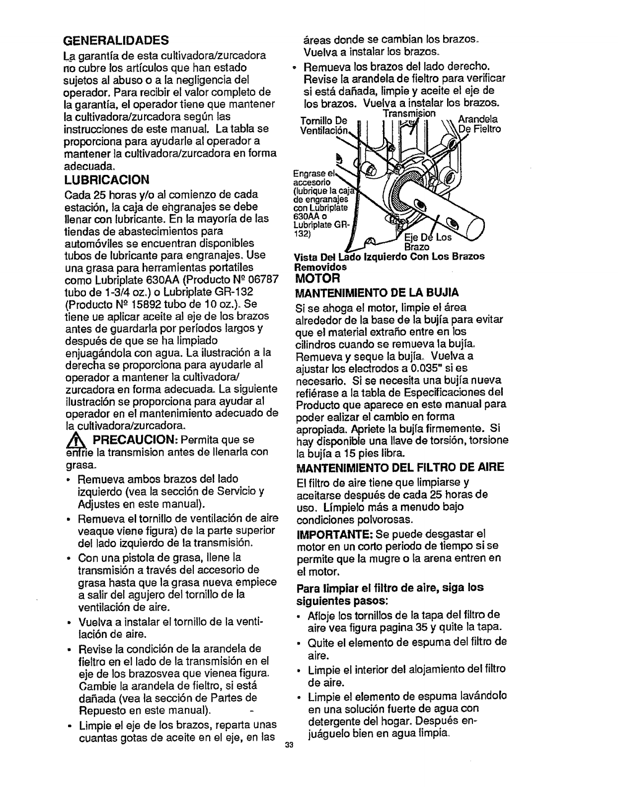
GENERALIDADES
LP garantfa de esta cultivadoraJzurcadora
no cubre los articulos que hart estado
sujetos al abuso o a la negligencia del
operador. Para recibir el valor completo de
la garantia, el operador tiene que mantener
la cuttivadora/zurcadora seg_n tas
instrucciones de este manual, La tabla se
proporciona para ayudarle at operador a
mantener la cultivadora!zurcadora en forma
adecuada°
LUBRICACION
Carla 25 horas y/o at comienzo de cada
estaci6n, la caja de ehgranajes se debe
Ilenar con tubricante. En ia mayorfa de las
tiendas de abastecimientos para
autom6viles se encuentran disponibles
tubos de lubricante para engranajes, Use
una grasa para herramientas portatiles
como Lubriplate 630AA (Producto N-°06787
tubo de 1-3/4 oz,) o Lubriplate GR-132
(Producto N°15892 tubo de 10 oz.). Se
tiene ue aplicar aceite al eje de los brazos
antes de guardarla por periodos largos y
despu_s de que se ha limpiado
enjuag&ndola con agua. La itustraci6n a la
derecha se proporciona para ayudarle al
operador a mantener la cultivadora/
zurcadora en forma adecuada, La siguiente
ilustraci6n se proporciona para ayudar al
operador en el mantenimiento adecuado de
ta cultivadoraJzurcadora,
e._r PRECAUCION: Permita que se
ela transmision antes de Ilenarla con
grasa.
,Remueva ambos brazos del lado
izquierdo (vea la secci6n de Servicio y
Adjustes en este manual).
• Remueva el tornillo de ventilaci6n de aire
veaque viene figura) de la parte superior
del lado izquierdo de la transmisi6no
° Con una pistola de grasa, ilene la
transmisi6n a trav_s del accesorio de
grasa hasta que la grasa nueva empiece
asalir del agujero del tornilto de la
ventilaci6n de aire.
• Vuelva a instalar el tornillo de la venti-
laci6n de aire.
• Revise la condici6n de la arandela de
fieltro en el lado de la transmisi6n en el
eje de los brazosvea que vienea figura.
Cambie la arandela de fieltro, si est,_
daSada (yea ta secci6n de Partes de
Repuesto en este manual).
- Limpie el eje de los brazos, reparta unas
cuantas gotas de aceite en el eje, en las
&reas donde se cambian los brazos.,
Vuelva a instatar los brazos.
Remueva los brazos del lado derecho.
Revise la arandela de fieltro para verfficar
si est& daSada, limpie y aceite el eje de
los brazos. Vuetva ainstalar los brazos.
Transmision
Tomillo De Arandela
De Fieltro
COn
630AA o
LubdplateGR-
132)
Vista Del izquierdo Con Los Brazos
Removidos
MOTOR
MANTENIMIENTO DE LA BUJIA
Si se ahoga el motor, limpie et drea
alrededor de la base de la bujia para evita.r
que el material extraSo entre en los
cilindros cuando se remueva la bujta°
Remueva ysequela bujia, Vuelva a
ajustar loselectrodos a0.035" si es
necesario. Si se necesita una bujfa nueva
refi_rase a la tabla de Especificaciones del
Producto que aparece en este manual para
poder ealizar el cambio en forma
apropiada. Apriete la buj[a firmemente. Si
hay disponible una ilave de torsi6n, torsione
la bujia a 15 pies libra.
MANTENIMIENTO DEL FILTRO DE AIRE
El fiitro de aire tiene que limpiarse y
aceitarse despu_s de cada 25 horas de
uso. Umpielo m_s a menudo bajo
condiciones polvorosas.
IMPORTAt_I'E: Se puede desgastar el
motor en un corto periodo de tiempo si se
permite que la mugre o la arena entrenen
el motor,
Para limpiar el filtro de aire, siga los
siguientes pasos:
• Afloje los tornitlosde la tapa del filtro de
aim vea figura pagina 35 y quite la tapa.
•Quite el elemento de espuma del filtro de
aire.
• Limpie el interior del alojamiento del filtro
de aire.
•Limpie el elemento de espuma lav&ndolo
en una soluci6nfuerte de agua con
detergente del hogaro Despu_s en-
ju&guelo bien en agua timpia
33
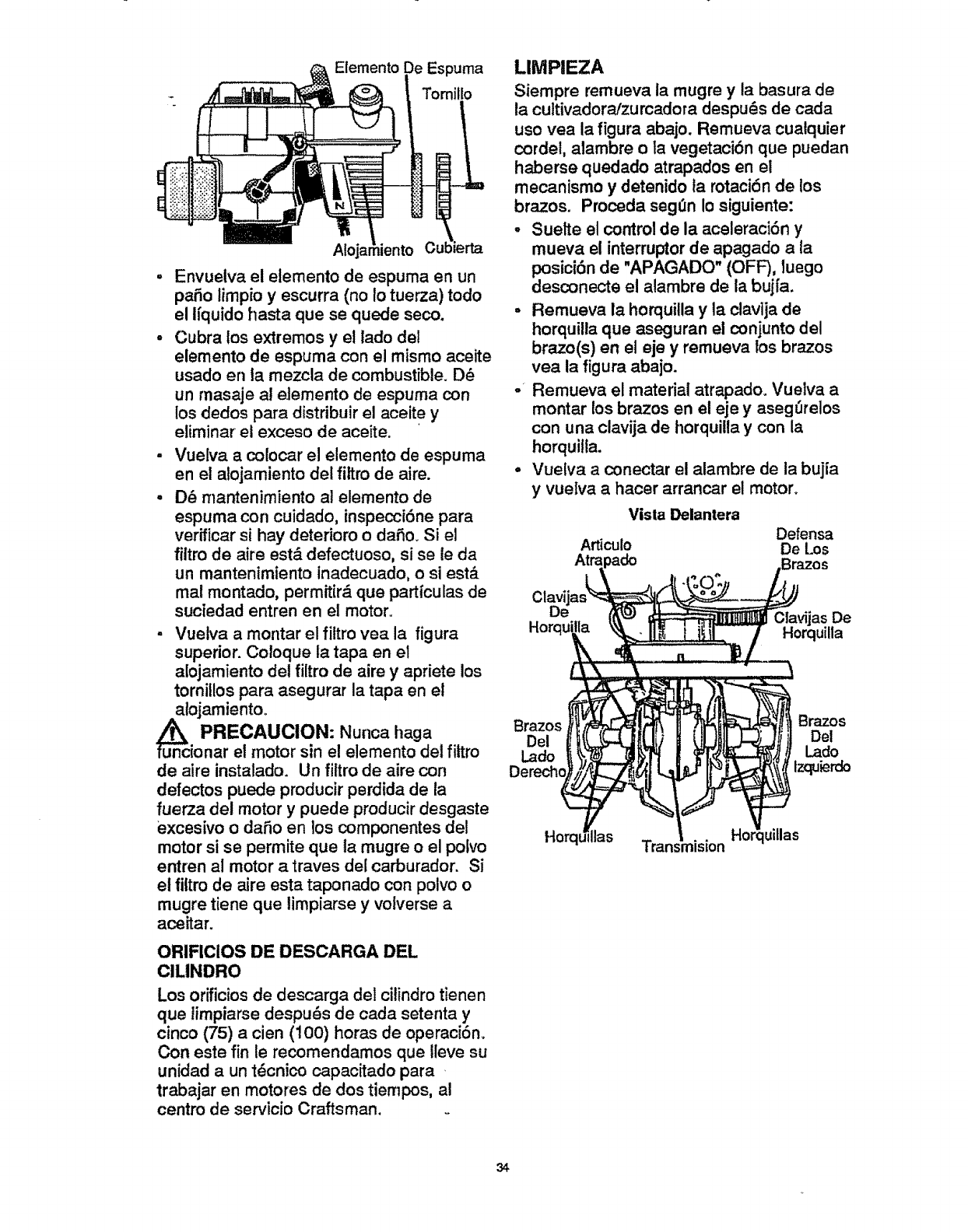
Elemento Espuma
Tomillo
Envuelva el elemento de espuma en un
patio limpio y escurra (no Io tuerza) todo
el ifquido hasta que se quede seco.
Cubra los extremos y el lado del
elemento de espuma con el mismo aceite
usado en ta mezcla de combustible. D_
un masaje al e|emento de espuma con
los dedos para distribuir el aceite y
eliminar el exceso de aceite.
Vuelva a colocar el elemento de espuma
en el alojamiento del filtro de aire.
D_ mantenimiento al elemento de
espuma con cuidado, inspecci6ne para
verificar si hay deterioro o daSo. Si el
filtro de aire est,, defectuoso, si se le da
un mantenimiento inadecuado, o si est&
mal montado, permitir,_ que particulas de
suciedad entrenen el motor.
- Vuelva a montar el filtro vea la figura
superior. Coloque la tapa en el
alojamiento del filtro de aire y apriete los
tornillos para asegurar la tapa en el
u_ncal°jamient°°
PRECAUCION: Nunca haga
ionar el motor sin el elemento det fittro
de aire instalado. Un filtro de aire con
defectos puede producir perdida de la
fuerza del motor y puede producir desgaste
excesivo oda_o en los componentes del
motor si se permite que la mugre o el polvo
entren al motor a traves del carburador. Si
et fiitro de aire esta taponado con polvo o
mugre tiene que limpiarse y volverse a
aceitar.
ORIFICiOS DE DESCARGA DEL
ClLINDRO
Los orificios de descarga del citindro tienen
que timpiarse despu_s de cada setenta y
cinco (75) a cien (! 00) horas de operaciSn.
Con este fin le recomendamos que ileve su
unidad a un t_cnico capacitado para
trabajar en motores de dos tiempos, al
centro de servicio Craftsman.
LIMPIEZA
Siempre remueva la mugre y la basura de
la cultivadora/zurcadora despu_.s de cada
uso yea la figura abajo. Remueva cuatquier
cordel, alambre o ta vegetacidn que puedan
haberse quedado atrapados en el
mecanismo y detenido la rotaci6n de los
brazos. Proceda seg(m Io siguiente:
, Suelte el control de la aceleraci6n y
mueva el interruptor de apagado a la
posici6n de "APAGADO" (OFF), tuego
desconecte el alambre de la bujfa.
-Remueva la horquilla y la clavija de
horquilla que aseguran el conjunto del
brazo(s) en el eje y remueva los brazos
yea la figura abajo.
-Remueva el material atrapado. Vuetva a
montar losbrazos en el eje y asegOrelos
con una clavija de horquilla y con la
horquilta.
•Vuetva a conectar el alambre de la bujia
y vuelva a hacer arrancar el motor.
Vista Delantera
Defensa
Articulo De Los
Clavijas De
Horquilla
Brazos Brazos
Del Del
Lado
l.ado izquierdo
Horq_ Ilas Trans'mision Ho luillas
34
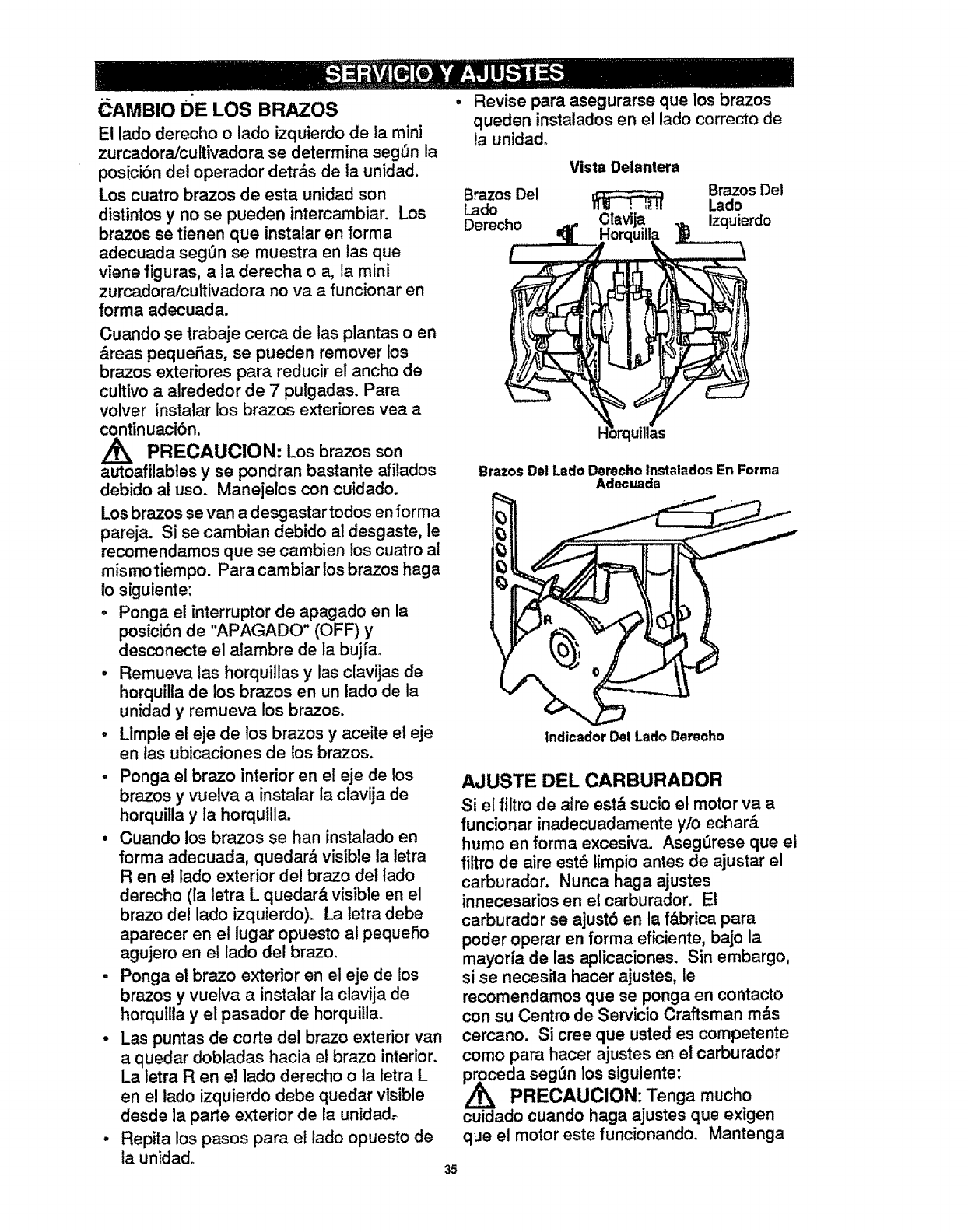
,CAMBIO dE LOS BRAZOS
El lado derecho o lado izquierdo de ta mini
zurcadora!cultivadora se deterrnina seg_n la
posicibn del operador detr_s de la unidad.
Los cuatro brazos de esta unidad son
distintos y no se pueden intercarnbiar. Los
brazos se tienen que instalar en forma
adecuada segOn se muestra en las que
viene figuras, a la derecha o a, la mini
zurcadora/cultivadora no va a funcionar en
forma adecuada.
Cuando se trabaje cerca de las plantas o en
&reas peque_as, se pueden remover los
brazos exteriores para reducir el ancho de
cultivo a alrededor de 7 pulgadas. Para
volver instalar los brazos extefiores yea a
continuaci6n,
PRECAUOION: Los brazos son
autoafilabtes y se pondran bastante afilados
debido al uso. Manejelos con cuidado.
Los brazos se van a desgastar todos en forma
pareja. Si se cambian debido al desgaste, le
recomendamos que se cambien los cuatro al
mismotiempo. Para cambiar los brazos haga
!o siguiente:
oPonga el interruptor de apagado en la
posici6n de "APAGADO" (OFF) y
desconecte el alambre de la buj[a°
• Remueva las horquillas y las clavijas de
horquilla de los brazos en un lado de la
unidad y remueva los brazos.
-Limpie el eje de los brazos y aceite el eje
en tas ubicaciones de los brazos.
-Ponga el brazo interior en el eje de los
brazos y vuelva a instalar la clavija de
horquilla y la horquilla.
•Cuando los brazos se han instalado en
forma adecuada, quedar& visible la tetra
R en el lado exterior de! brazo del tado
derecho (la letra L quedar& visible en el
brazo del lado izquierdo), La letra debe
aparecer en el lugar opuesto al pequeSo
agujero en el lado del brazo.
• Ponga el brazo exterior en el eje de los
brazos y vuelva a instalar la clavija de
horquitla y el pasador de horquilla.
o Las puntas de corte del brazo exterior van
a quedar dobtadas hacia el brazo interior.
La letra R en el lado derecho o la letra L
en el lado izquierdo debe quedar visible
desde la parts exterior de la unidad.-
o Repita los pasos para el lado opuesto de
la unidad. 35
• Revise para asegurarse que los brazos
queden instalados en el lado correcto de
la unidad_
Vista Delantera
BrazosDel
Brazos Del Lado
Lado lira ' +_.!1
Derecho
Brazos Dsl Lado Derecho lnstalados En Forma
Adecuada
Indicador De! Lado Derecho
AJUSTE DEL CARBURADOR
Si el filtro de airs est& sucio el motor va a
funcionar inadecuadamente y!o echar&
humo en forma excesiva. AsegDrese que et
filtro de aire est_ limpio antes de ajustar el
carburador. Nunca haga ajustes
innecesarios en el carburador. El
carburador se ajust6 en la f&brica para
poder operar en forma eficiente, bajo la
mayoda de las aplicaciones. Sin embargo,
si se necesita hacer ajustes, le
recomnendamosque se ponga en contacto
con su Centro de Servicio Craftsman m&s
cercano. Si cree que usted es competente
como para hacer ajustes en el carburador
ceda segL1nlos siguiente:
PRECAUClON: Tenga mucho
cuidado cuando haga ajustes que exigen
que el motor este funcionando. Mantenga
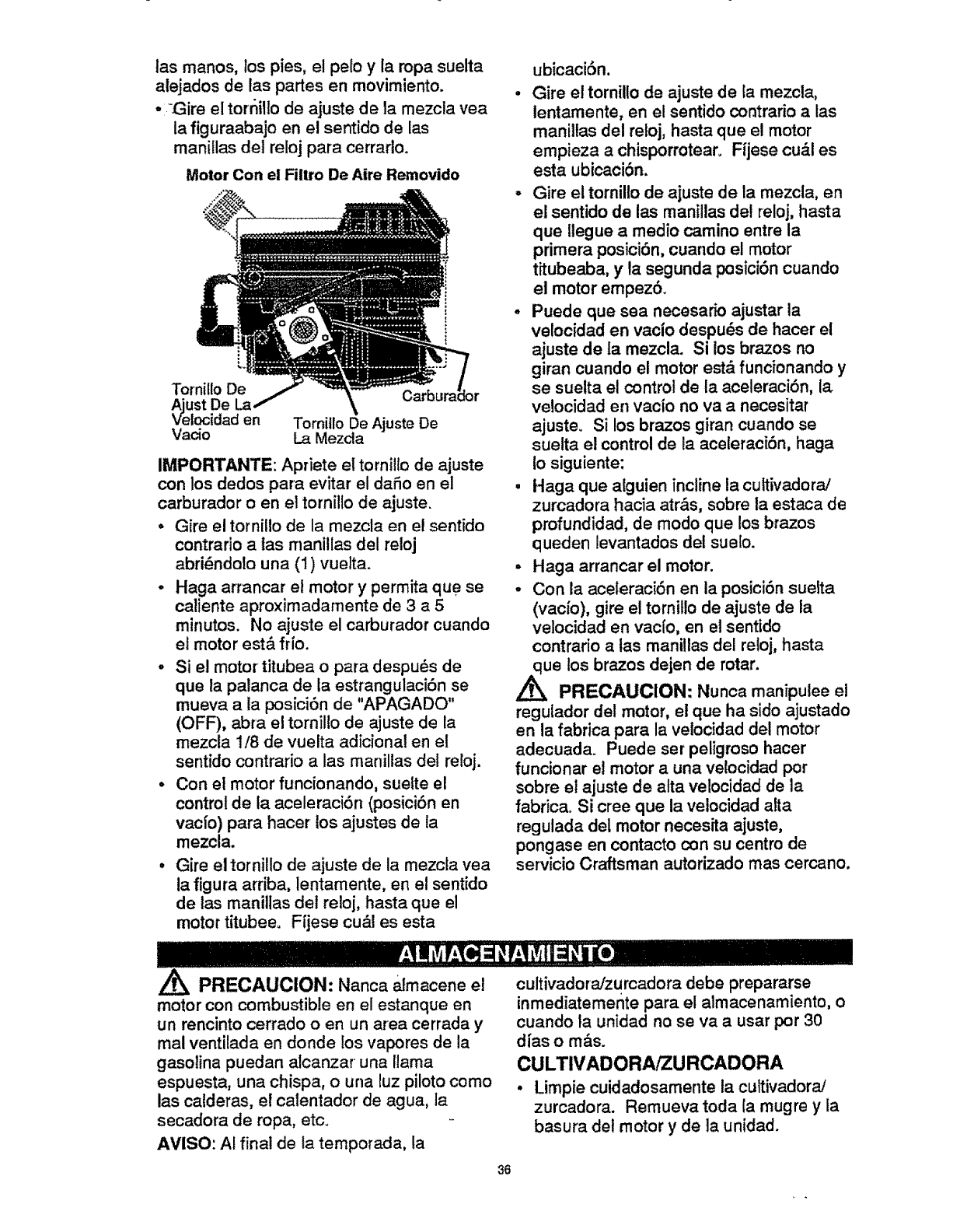
las manos, los pies, et polo y la ropa suelta
alejados de las partes en movimiento.
• iGire el torrlilto de ajuste de la mezcla yea
la figuraabajo en el sentido de las
manillas del reloj para cerrarlo.
Motor Con el Fiitro De Aire Removido
Tornillo De
UStDe
locjdad en
Va_o Tomitlo De Ajuste De
La Mezcla
IMPORTANTE: Apriete el tornillo de ajuste
con los dodos para evitar el daSo en el
carburador o en el tornillo de ajuste.
=Gire el tornillo de la mezcla en el sentfdo
contrario a tas manillas del reloj
abri_ndolo una (1) vuelta.
o Haga artancar et motor y permita que se
caliente aproximadamente de 3 a 5
minutos. No ajuste el carburador cuando
el motor est& frio.
o Si el motortitubea o para despu_s de
que la palanca de la estrangulacibn se
mueva ala posici6n de "APAGADO"
(OFF), abra el tornil!o de ajuste de la
mezcla t/8 de vuelta adicional en el
sentido contrario a las manillas del reloj.
•Con el motor funcionando, suelte el
control de la aceleraci6n (posici6n en
vacfo) para hacer los ajustes de la
mezcla.
• GJre el tornillo de ajuste de la mezcla vea
la figura arriba, lentamente, en el sentido
de las manillas del reloj, hasta que el
motor t[tubeeo F_jese cu&l es esta
ubicaci6n.
°Gire el tornillo de ajuste de la mezcla,
lentamente, en el sentido contrario alas
maniltas del reloj, hasta que el motor
empieza a chisporrotear. Fijese cu_.l es
esta ubicaci6n.
°Gire el tornillo de ajuste de la mezcla, en
el sentido de las manillas de! reloj, hasta
que llegue a medio camino entre la
primera posici6n, cuando el motor
titubeaba, y la segunda posici6n cuando
el motor empez6.
oPuede que sea necesario ajustar la
velocfdad en vacfo despu(_s de hacer el
ajuste de fa mezcla. Si los brazos no
giran cuando el motor est& funcionando y
se suelta el control de la aceleracibn, la.
velocidad en vacto no va a necesitar
ajuste. Si los brazos giran cuando se
suelta el control de la aceleraci6n, haga
1o siguiente:
. Haga que alguien incline la cultivadora/
zurcadora hacia atr&s, sobre la estaca de
profundidad, de modo que los brazos
queden levantados del sue[o.
• Haga arrancar el motor.
.Con la aceleraci6n en ia posicibn suelta
(vacio), gire el tornitlo de ajuste de la
velocidad en vac[o, en el sentido
contrario alas manillas del reloj, hasta
2_ue los brazos dejen de rotar.
PRECAUClON: Nunca manipulee el
regulador del motor, el que ha sido ajustado
en la fabrica para la velocidad del motor
adecuada. Puede ser peligroso hacer
funcionar el motor a una vetocidad por
sobre el ajuste de alta velocidad de ta
fabrica. Si cree que la velocidad alta
regulada del motor necesita ajuste,
pongase en contacto con su centro de
servicio Craftsman autorizado mas cercano,
PRECAUCION: Nanca almacene el
motor con combustible en el estanque en
un rencinto cerrado o en un area cerrada y
mal ventilada en donde los vapores de la
gasolina puedan alcanzar una llama
espuesta, una chispa, o una luz piloto como
las calderas, e! calentador de agua, ia
secadora de ropa, etc.
AVISO: AI final de ta temporada, la
cultivadora/zurcadora debe prepararse
inmediatemente para el almacenamiento, o
cuando la unidad no se va a usar por 30
dias om&s.
CULTIVADORAiZU RCADORA
• Limpie cuidadosamente la cuttivadora/
zurcadora. Remueva toda la mugre y la
basura dot motor y de la unidad.
36
-Remueva los brazos y aceite el eje de los
brazos y yuelva a instalarlos (vea la
Lsecci6n de Servicio y Ajustes en este
manual).
, Suelte las maniltas T que aseguran el
mango superior al mango inferior.
, Con cuidado, dobte el mango superior
hacia abajo asegur_.ndose que la
aceteraci6n no est& enrededa. Apriete las
manillas 1".
- La pieza transversal del mango superior
(entre los mangos inferiores) ahora se
puede usar como un mango portador o se
puede colgar en un gancho de la pared
para almacenar la cultivadora/zurcadora
colgada fuera del piso y fuera del paso,.
,Si es posible, guarde su cultivadora!
zurcadora en un recinto cerrado y cSbrala
para protegerla contra el polvo y la mugre°
• Cubra la cultivadora/zurcadora con una
cubierta protectora adecuada que no
retenga la humedado No use pl&stico.
IMPORTANTE: Nunca cubra la cultivadora/
zurcadora cuando el motor el area de
excape aun estan calientes.
AVISO: Una buena forma de asegurarse
que la mini zurcadora/cultivadora le
entregar& un rendimiento m_imo la pr6xima
temporada es Ilevarla una vez al aSo al
Centro de Servicio Craftsman para revisarla
o afinarla.
MOTOR
IMPORTANTE: Es importante evitar que se
formen depositos de goma en partes
fundamentales del sistema de combustible,
tales como, el carburador, el fiftro del
combustible, la manguera del combustible o
en el estanque durante el atmacenamiento.
La experiencia tambien indica que los
combustibles mezclados con alcohol
(conocido como gasohol o que tienen
etanol o metanol) pueden atraer humedad,
Io que conduce a la separacion ya la
formacion de acidos durante el
almacenamiento. La gasotina acidica
puede daSar el sistema de combustible de
un motor durante el periodo de
almacenamiento.
. Drene el combustible dei estanque det
combustible en un envase aprobado
afuera, alejado de una llama expuesta,
•Haga arrancar el motor hasta que pare
debido ala falta de combustible.
- Tire el mango del arrancador,
lentamente, hasta que sienta resistencia
debido ala presi6n de la compresi6n,
luego pare.
,Suelte ia tensi6n del arrancador
lentamente para evitar que el motor ande
marcha atr&s debido a la presi6n de la
compresi6n. Esta posici6n cerrar& tanto
el agujero de admisi6n como el de
descarga, para evitar la corrosi6n del
pist6n y del di&metro interior det cilindro.
37 !
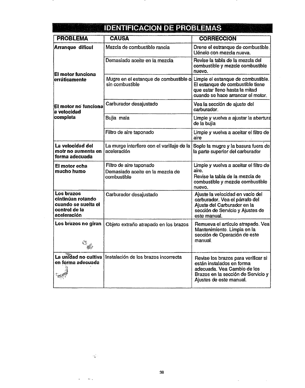
PROBLEMA CAUSA CORRECClON
Arranque dificul Mezcla de combustible rancia Drene el estranque de combustible,
Udneto con mezcla nueva.
Demasiado aceite en ta mezcla Revise la tabla de la mezcla del
combustible y mezcle combustible
El motor funciona nuevo.
err_ticamente Mugre en el estanque de combustible o Limpie el estanque de combustible.
sin combustible El estanque de combustible tiene
que estar lleno hasta la mitad
cuando se hace arrancar el motor,
El motor no funciona Vea la secci6n de ajuste del
;_elocidad carburador,
¢ompleta Umpie y vuetva a ajustar la abertur_
La velocidad del
motr no aumenta en
[orma ade_ada
!El motor echa
mucho humo
de la bujia
Umpie yvuelva a aceitar el filtro de
aire
Sople la mugre y la basura fuera'de
la parte supedor del carburador
Los brazos
cintindan rotando
cuando se suelta el
control de la
aceleraci6n
Los br'azos no giran
La unldad no cultiva
en f0rma adecuada
Carburador desajustado
Bujia mala
Filtro de aire taponado
La murge interfiere con el vafillaje de la
aceleraci6n
Fit_o de aire taponado
Demasiado aceite en la mezcla de
combustible
Carburador desajustado
Objeto extrafio atrapado en los brazos
lnstalaci6n de los brazos incorrecta
Umpie y vuelva a aceitat el filtro de
aire.
Revise la tabla de fa mezcla de
combustible y mezcte combustible
nuevo.
Ajuste la velocidad en vacio del
carburador. Vea el p_rrafo del
Ajuste del Carburador en la
secciSn de Serv_cioy Ajustes de
este manual.
Remueva el art{culo atrapado, Vea
Mantenimiento,. Limpia en ]a
secci6n de Operaci6n de este
manual.,
Revise los brazos para verificar si
estdn ins_dos en forma
adecuada. Vea Cambio de los
Brazos en la secciSn de Servicio y
Ajustes de este manual.
.,;j
38

3g

For the repair or replacement parts you
_r_d delivered directly to your home
Call 7 am-7 pm, 7 days a week
1-800-366-PART
(1-800-366-7278)
Para ordenar piezas con entrega
a domicilio -1-800-659-7084
For in-house major brand repair service
Call 24 hours a day, 7 days a week
1-800-4-REPAIR
(1-800-473-7247)
Para pedir servicio de reparacion a
domicilio -1-800-676-5811
For the location of a Sears Parts and
Repair Center in your area
Call 24 hours a day, 7 days a week
1=800-488-1222
For information on purchasing a Sears
Maintenance Agreement or to inquire
about an existing Agreement
Call 9 am .5pm, Monday-Saturday
1-800=827=6655
When requesting service or ordering
parts, always provide the following
information:
, Product Type oPart Number
•Model Number • Part Description
Amen'ca'sRepairSpecialists Ptintsd in U.S,A.
