Craftsman 536797571 User Manual EDGER Manuals And Guides L0204040
CRAFTSMAN Edger Manual L0204040 CRAFTSMAN Edger Owner's Manual, CRAFTSMAN Edger installation guides
User Manual: Craftsman 536797571 536797571 CRAFTSMAN EDGER - Manuals and Guides View the owners manual for your CRAFTSMAN EDGER #536797571. Home:Lawn & Garden Parts:Craftsman Parts:Craftsman EDGER Manual
Open the PDF directly: View PDF ![]() .
.
Page Count: 19
OWNER'S
MANUAL
MODEL NO.
536.797571
Caution:
Read and Follow
All Safety Rules
and Instructions
Before Operating
This Equipment
CRAFTSMRN
3.5 HORSEPOWER
9 INCH
EDGER/TRIMMER
Assembly
Operation
Customer Responsibilities
Service and Adjustments
•Repair Parts
SEARS, ROEBUCK AND CO., Hoffman Estates, IL 60179 U.S.A.
Part No. 336765

SAFETY RULES
-- CAUTION: ALWAYS DISCONNECT SPARK PLUG WIRE AND PLACE WIRE WHERE IT/_.
C NOTCO.TACTSPARKP'UGTOPREVENTAOC.DENTALSTA.T,NGWHENSET
A
T,NGuP,TRANSPORT,NG.ADJUST,NGORMAK,.GREPA,RS
BEFORE USE
Read the owner'smanual carefully. Be thoroughly
familiarwiththe controlsand the proper use of the
edger/trimmer.Know howto stopthe edger/trimmer
anddisengagethecontrols quickly.
•Do not operate the edger/trimmer without wearing
adequate outer garments. Wear footwear that will
improvefootingon slipperysurfaces.
•Keep the area of operation clear of all persons,
particularlysmallchildrenand pets.
• Thoroughly inspectthe area wherethe edger/trimmer
is to be used and remove allforeignobjects.
FUEL SAFETY
• Handle fuel withcare; it is highlyflammable.
•Use an approved container.
•Chackfuelsupplybeforeeach use,allowingspacefor
expansionasthe heat of the engineand/or suncan
cause fuelto expand.
•Fillfueltank outdoorswithextreme care.Neverfill fuel
tankindoors.Replacefuel tankcap securelyandwipe
up spilledfuel.
• Never remove the fuel tank cap or add fuel to a
runningor hot engine.
•Neverstorefuel oredger/trimmerwithfuelinthetank
insidea buildingwhere fumes may reach an open
flame.
•Never operate the edger/trimmer at high transport
speeds on slipperysurfaces. Look behind and use
care when backing.
•Never allow bystandersnear the edger/trimmer.
•Keep childrenand pets awaywhile operating.
•Never operatethe edger/trimmerwithoutgoodvisibil-
ity or light.
•Donot runtheengineindoors. The exhaustfumesare
dangerous (containingCARBON MONOXIDE, an
ODORLESS and DEADLY GAS).
• Take allpossibleprecautionswhen ioaving tbe edger/
trimmer unattended,Stop the engine.
•Do not overload the edger/trimmer capacity by at-
temptingto edge too deep at too fast a rate.
SAFE STORAGE
•Always referto the owner'smanual storagesection
for imporfantdetails if the edger/trimmer is to be
stored for an extended period.
•Neverleavethe edger/trimmerwithfuelinthefueltank
insidea building where ignitionsourcesare present
suchas waterandapace heaters,clothesdryers,and
the like.Allowthe engineto cool before placinginany
enclosure.
• Keep the edger/tdmmer in safe working condition.
Check all fasteners at frequent inte_,als for proper
tightness.
OPERATING SAFETY REPAIR/ADJUSTMENTS SAFETY
•Never allowchildrenor young teenagers to operate
the edger/trimmer.Keep them away while it isoper-
ating.Neveraliowadultstooperatethe edger/trimmer
withoutproperinslruction.
•Always wear safety glasses or eye shields during
operationorwhileperforming an adjustmentorrepair
to protectyoureyesfromforeignobjectsthat maybe
thrownfrom the edger/trimmer.
•DOnotputhandsorfeet nearor underrotatingparts.
•Exemiseextremecautionwhenoperatingonorcross-
inggraveldrives,walks,orroads.Stayalertforhidden
hazardsortraffic.
Exercise cautionto avoid slippingor falling.
Never operate the edger/trimmer wilhout proper
guards, plates,or other safety protectivedevices in
place.
After striking aforeignobject,stopthe engine(motor).
Removethe wire from the spark plug, and keep the
wire away from the plug to prevent accidental starting.
Thoroughly inspectthe edger/trimmer for any dam-
age, and repair the damage before restarting and
operating the edger/trimmer.
If the edger/trimmer should start to vibrate abnor-
mally,stop the engine (motor)and checkimmediately
for the cause. Vibration is generally a warning of
trouble.
LOOK FOR THIS SYMBOL TO POINT OUT IMPORTANT SAFETY PRECAUTIONS. IT MEANS-,
ATTENTION!!! BECOME ALERT!!! YOUR SAFETY IS INVOLVED.
•Stop the blade whenever you leave the operating
position.Also, stopthe engine and disconnect the
spark plugwirebefore uncloggingthe bladeandwhen
making any repairs,adjustments,or inspections.
•When cleaning, repairing,or inspecting,shutoffthe
engineandmakecertainallmovingpartshavestopped.
•Never attempt to make any adjustmentswhile the
engine is running (except when specificallyrecom-
mended bythe manufacturer). I
2
CONGRATULATIONS on your purchase of a Sears
Craftsman Edger/trimmer. It has been designed, engi-
neered and manufacturedto give youthe best possible
dependabilityandperformance.
Shouldyou experienceany problem you cannot easily
remedy, please contact your nearest Sears Service
Center/Department. We have competent, well-trained
techniciansandthe proper toolsto serviceor repairthis
unit.
Please readandretainthismanual. The instructionswill
enable you to assemble and maintainyour edger/trim-
mer properly. Alwaysobserve the "SAFETY RULES."
MODEL
NUMBER 536.797571
SERIAL
NUMBER
DATE OF
PURCHASE
THE MODEL AND SERIAL NUMBERS WILL BE
FOUND ON A DECAL ON THE FRAME OF THE
EDGER/TRIMMER BEHIND THE ENGINE.
YOU SHOULD RECORD BOTH SERIAL NUMBER
AND DATE OF PURCHASE AND KEEP IN ASAFE
PLACE FOR FUTURE REFERENCE.
MAINTENANCE AGREEMENT
A Sears Maintenance Agreement is available on this
product, Contact your nearest Sears Store for details.
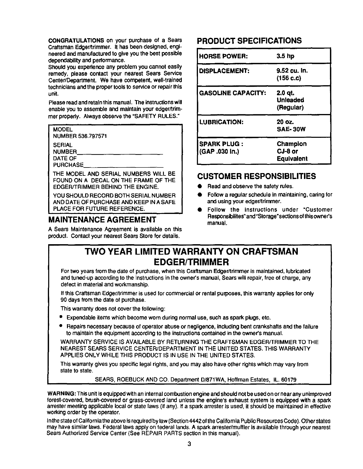
PRODUCT SPECIFICATIONS
HORSE POWER: 3.5 hp
DISPLACEMENT: 9.52 cu. In.
(156 c.c)
GASOLINE CAPACITY: 2.0 qt.
Unleaded
(Regular)
LUBRICATION: 20 oz.
SAE- 30W
SPARK PLUG :
GAP .030 In.)
Champion
CJ-8 or
Equivalent
CUSTOMER RESPONSIBILITIES
•Read and observe the safety rotes.
•Followa regular schedulein maintaining, caringfor
and using your edger/trimmer.
•Follow the Instructions under uCustomer
Responsibilites"and"Storage"sectionsofthisowner's
manual.
TWO YEAR LIMITED WARRANTY ON CRAFTSMAN
EDGER/TRIMMER
Fortwo years fromthe date of purchase, whenthis Craftsman Edger/trimmer is maintained, lubricated
and tuned-up accordingto the instructionsinthe owner's manual, Sears will repair, free of charge, any
defect in material and workmanship.
Ifthis Craftsman Edger/trimmeris used for commercialor rental purposes, thiswarranty appliesfor only
90 days fromthe date of purchase.
This warranty does not coverthe following:
•Expendable items which become worn duringnormal use, such as spark plugs, etc.
•Repairs necessarybecause of operator abuseor negligence, includingbent crankshafts andthe failure
to maintain the equipmentaccordingto the instructionscontained in the owner's manual.
WARRANTY SERVICE IS AVAILABLE BY RETURNING THE CRAFTSMAN EDGER/TRIMMER TO THE
NEAREST SEARS SERVICE CENTER/DEPARTMENT iN THE UNITED STATES. THIS WARRANTY
APPLIES ONLY WHILE THIS PRODUCT IS IN USE IN THE UNITED STATES.
This warranty givesyou specificlegal rights,and you may also have other rightswhich may vary from
state to state.
SEARS, ROEBUCK AND CO. Department D/871W,A,Hoffman Estates, IL. 60179
WARNING: This unitisequippedwithan internalcombustion engineandshouldnotbe usedonor nearany unimproved
forest-covered,brush-coveredor grass-covered land unless the engine's exhaust system is equipped with a spark
arrestermeeting applicablelocalor state laws (if any). If a sparkarrester is used, it should be maintained in effective
workingorder bythe operator.
Inthe stateof Calitorniatheaboveisrequiredby law(Section4442 oflhe Callfomia PublicResourcesCede). Otherslates
may have similarlaws. Federal laws applyon federal lands.A sparkarrester/muffleris availablethroughyour nearest
Sears AuthorizedService Center (See REPAIR PARTS sectionin this manual).
3
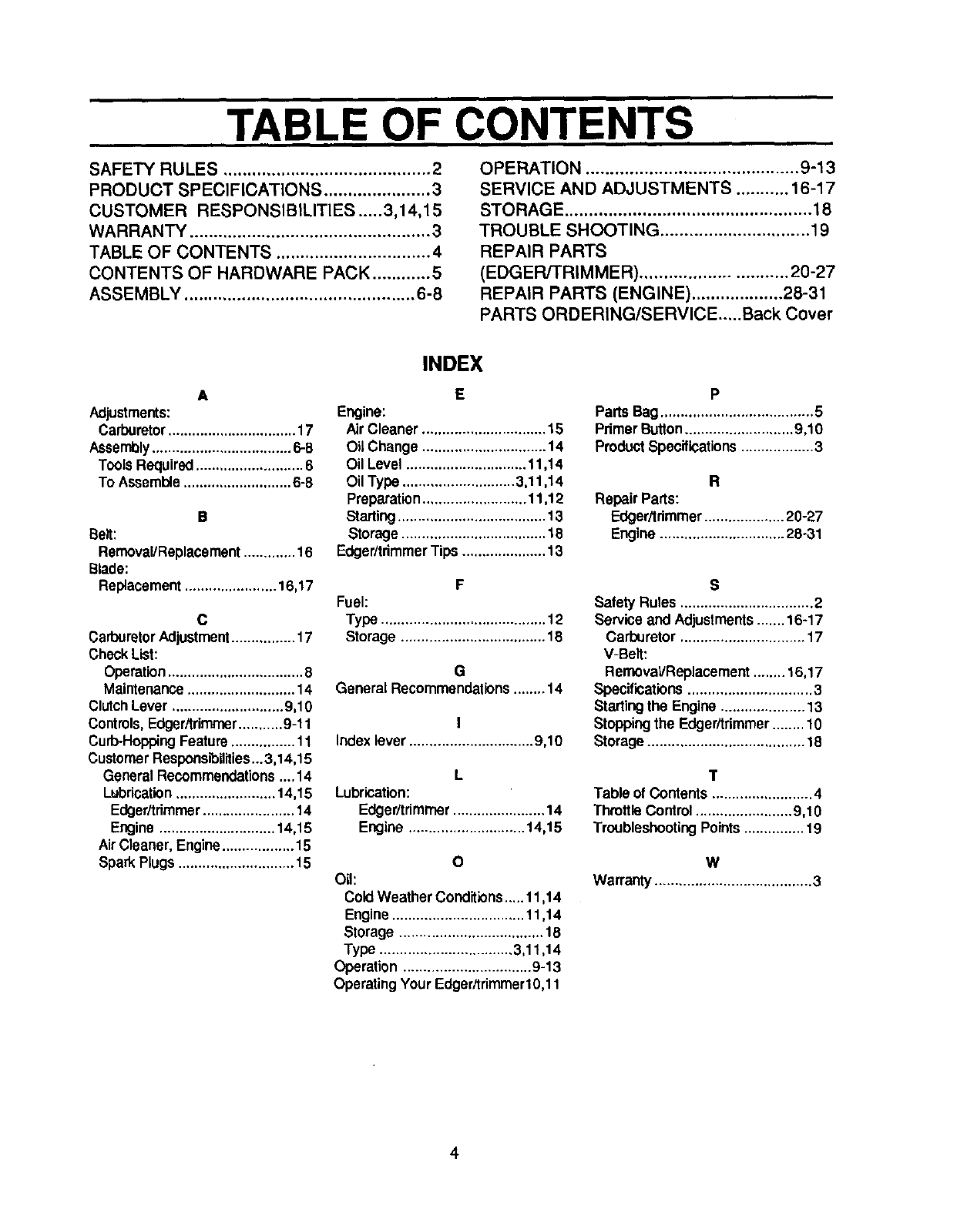
TABLE OF CONTENTS
SAFETY RULES ........................................... 2
PRODUCT SPECIFICATIONS ...................... 3
CUSTOMER RESPONSIBILITIES ..... 3,14,15
WARRANTY .................................................. 3
TABLE OF CONTENTS ................................ 4
CONTENTS OF HARDWARE PACK ............ 5
ASSEMBLY ................................................ 6-8
OPERATION ............................................ 9-13
SERVICE AND ADJUSTMENTS ........... 16-17
STORAGE ................................................... 18
TROUBLE SHOOTING ............................... 19
REPAIR PARTS
(EDGER/TRIMMER) .............................. 20-27
REPAIR PARTS (ENGINE) ................... 28-31
PARTS ORDERING/SERVICE.....Back Cover
A
Adjustments:
Carburetor ................................ 17
Assembly ................................... 6-8
Tools Required ........................... 6
To Assemble ........................... 6-8
B
Belt:
Removal/Replacement............. 16
Blade:
Replacement....................... 16,17
C
Carburetor Adjustment ................ 17
CheckList:
Operation .................................. 8
Maintenance ........................... 14
Clutch Lever ............................ 9,10
Controls, Edger/trimmer........... 9-11
Curb.Hopping Feature ................ 11
Customer Respensibilities ...3,14,15
General Recommendations....14
Lubrication......................... 14,15
Edger/trimmer....................... 14
Engine............................. 14,15
AirCleaner, Engine.................. 15
Spark Plugs............................. 15
INDEX
E
Engine:
Air Cleaner ............................... 15
Oil Change ............................... 14
Oil Level .............................. 11,14
Oil Type ............................ 3,11,14
Preparation .......................... 11,12
Starting..................................... 13
Storage .................................... 18
Edger/tdrnmerTips ..................... 13
F
Fuel:
Type ......................................... 12
Storage .................................... 18
G
General Recommendations ........14
I
Index lever ............................... 9,10
L
Lubrication:
Edger/trimmer ....................... 14
Engine ............................. 14,15
O
Oil:
Cold Weather Conditions..... 11,14
Engine ................................. 11,14
Storage .................................... 1B
Type ................................. 3,11,14
Operation ................................ 9-13
Operating Your Edger/trimmer10,11
P
Parts Bag ...................................... 5
Palmer Button........................... 9,10
Product Specifications.................. 3
R
Repair Parts:
Edger/trimmer.................... 20-27
Engine ............................... 28o31
S
Safety Rules ................................. 2
Service and Adjustments....... 16-17
Carburetor ............................... 17
V-Belt:
Removal/Replacement........ 16,17
Specifications............................... 3
Startingthe Engine ..................... 13
Stoppingthe Edger/trimmer........ 10
Storage....................................... 18
T
Table of Contents......................... 4
ThrottleControl ........................ 9,10
TroubleshootingPoints............... 19
W
Warranty....................................... 3
4
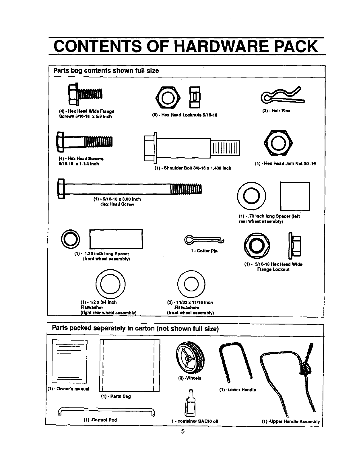
CONTENTS OF HARDWARE PACK
Parts bag contents shown full size
(4) -He= Head Wide Flange
_rews 5/16-18 x 5/8 Inch (8) -Flex Head Loclmule 5/16-18 (2) -Hair Pins
(4) -Hax Head Screws
5/16-18 x 1-1/4 inch (1) • Shoulder Bolt 3/8-16 x 1.400 Inch
©
(1) -Hex Head Jam Nut 3/8-16
(1) "3H/1_18_ 3'?lewrich
(1) • .70 Inch long Spacer (left
rear wheel assembly)
(1) - 1.39 Inch long Spacer
(front wheel 8ssembly)
©
(1) - 112x 3/4 inch
Ratwltsher
(right rear wheel assembly)
1 - Cotter Pin
©
(2) -11/32 x 11/16 inch
Flatweshers
(front wheel aeaembly)
(1) - 5/16-18 Hex Head Wide
Flange Locknut
Parts packed separately In carton (not shown full size)
€1)- Owner's manual
J
i
I
i
I
I
!
(1) - Parts Bag
(1) -Control Rod
(1) -Lower Handle
1 - conlelner SAE30 oil
5
(1) -Upper Handle Assembl)
ASSEMBLY
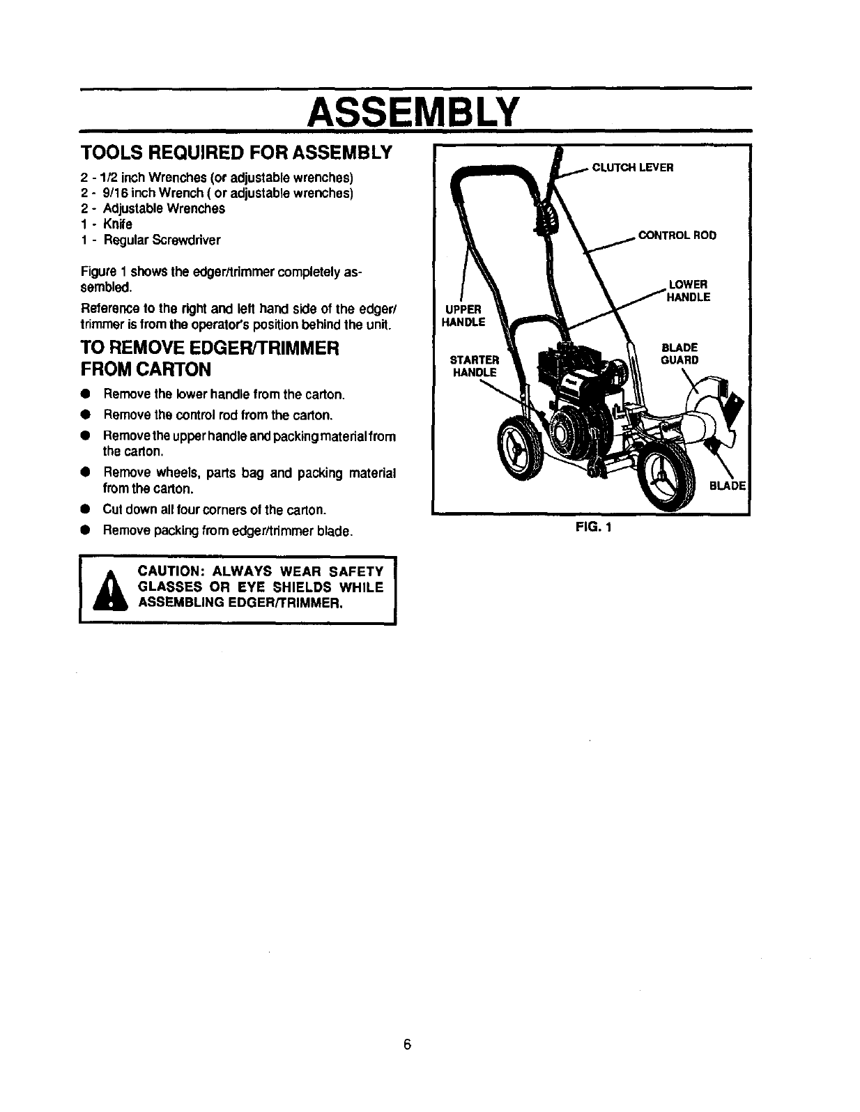
TOOLS REQUIRED FOR ASSEMBLY
2 - 1/2 inchWrenches (Oradjustablewrenches)
2 - 9/16 inchWrench ( or adjustablewrenches)
2 - AdjustableWrenches
1 - Knife
1-Regular Screwdriver
Figure 1showsthe edger/trimmercompletelyas-
sembled.
Referenceto the rightand lelt hand side of the edger/
trimmeris fromthe operator'spositionbehindthe unit.
TO REMOVE EDGER/TRIMMER
FROM CARTON
•Removethe lower handlefrom the carton.
•Removethe controlrod fromthe carton,
•Removethe upperhandleandpacking materialfrom
the carton.
•Remove wheels, parts bag and packing material
fromthe carton.
•Cul down alltour corners of the carton.
•Removepackingfrom edger/trimmerblade. FIG. 1
ICAUTION: ALWAYS WEAR SAFETY
GLASSES OR EYE SHIELDS WHILE
ASSEMBLING EDGER/TRIMMER.
6
ASSEMBLY
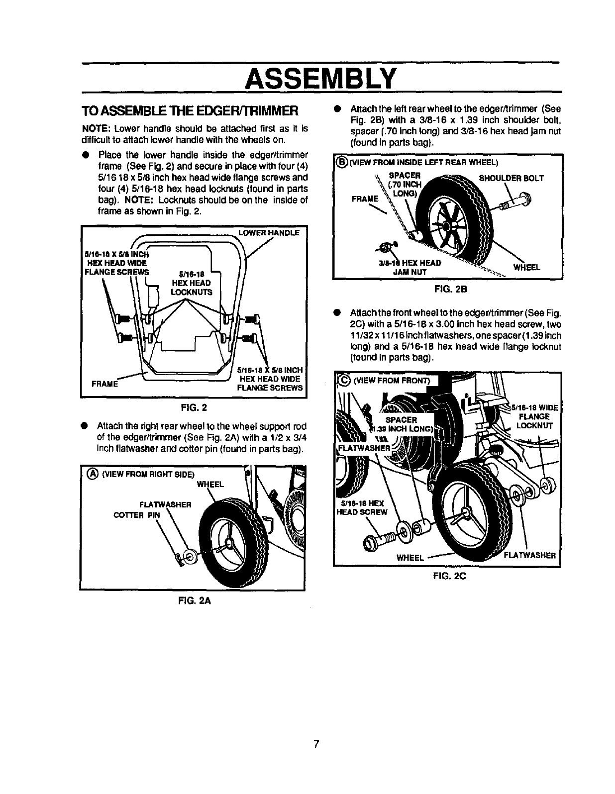
TOASSEMBLE "IHE EDGER/TRIMMER
NOTE: Lower handle should be attached first as it is
difficultto attach lower handlewiththe wheels on.
Place the lower handle inside the edger/trimmer
frame (See Fig. 2) and secure inplace withfour (4)
5/1618 x 5/8 inchhex headwide flange screws and
four (4) 5/16-18 hex head Iocknuts(found in parts
bag). NOTE: Locknutsshould be onthe insideof
frame as shown in Fig. 2.
I LOWER HANDLE
,
_le-la x_aINCX 1 %V
HEXHEADWIDE /II
FLANGE SCREWS .5/16-18 _ J I
HEX HEAD
I.'% _" I5118-18XS/81NCH
I/_, _/ HEX HEAD WIDE
I FRAME FLANGE SCREWS
FIG. 2
•Attachthe dght rearwheel to the wheel suppod rod
of the edger/trimmer (See Fig. 2A) with a 1/2 x3/4
inchllatwasherand cotterpin (foundin parts bag).
•Attachthe left rearwheel to the edger/trimmer (See
Fig. 2B) with a 3/8-16 x 1.39 inch shoulder bolt,
spacer (.70 inchlong) and 3/8-16 hex head jam nut
(foundin parts bag).
_) (VIEW FROM INSIDE LEFT REAR WHEEL)
SPACER SHOULDER BOLT
FRAME
_'_IjAI_IE_u_.HEAD WHEEL
FIG. 2B
•Attachthefrontwheel tothe edger/trimmer(See Fig.
2C) witha5/1 6-18 x 3.00 inch hex head screw,two
11/32 x 11/16inch flatwashers,onespacer(1.39 inch
long) and a5/16-18 hex head wide flange locknut
(foundin partsbag).
I (VIEW FROM FRONT}
FIG. 2C
FIG. 2A
7

ASSEMBLY
• Placetheupperhandleonthe lowerhandle(See Fig.
3), alignupperhandleholesinthe lowerhandle, and
secureinplacewithfour (4) 5/16-1B x 1-1/4 inchhex
headscrewsandfour(4) 5/16-18 hex head Iocknuts
(foundinpadsbag). Locknutsshouldbeto the inside
of the two handlesas shown in Fig. 3.
NOTE: Clutchleverislocated onthe lefthand sideofthe
upper handlewhen properlyinstalled.
• Insert one end of the control rod from left to right
throughthe hole In the clutchlever (See Fig.3) and
attach witha hair pin (foundinthe parts bag).
•Placethe clutchlever inthe first depth selection
(Fig. 3) and insertthe other end of the controlrod
throughthe holeinthe quillsupportarm (See Fig.3).
Attachwithhairpin(found in partsbag).
•Movethe clutchleverto rearmost (NEUTRAL) posi-
tion and latchin. See note below.
NOTE: If it is difficultto get the clutch lever into NEU-
TRAL. It maybenecessaryto loosenthefour screwsand
nutsholdingthe lowerhandlesto the frame (See Fig.4).
Pry up(forward)onthe handlesonly enoughto allowthe
clutchleverto lreely enter the NEUTRAL position. Re-
tighten nuts and screws, When the clutch lever is in
NEUTRAL the quill supportarm should be against the
spacerand screwbehindit (See Fig.3 inset).
/ CHECKLIST
BEFORE YOU OPERATE AND ENJOY YOUR NEW
EDGER/TRiMMER,WE WISH TOASSURETHATYOURE-
CEIVE THE BESTPERFORMANCEAND SATISFACTION
FROMTHIS QUAL/TYPRODUCT.
PLEASEREVIEWTHEFOLLOWINGCHECKLIST:
/A_Iassemblyinstructionshavebeencompleted.
,f Noremainingloosepartsincarton.
,,I Allfastenershavebeenproperlyinstalledandtightened.
WHILELEARNINGHOW TO USE YOUR EDGER/TRIM-
MER, PAY EXTRA ATTENTION TO THE FOLLOWING
IMPORTANTiTEMS:
4'.s" Engine oil is at properlevel.
// Fuel tank is filled with fresh, clean, regular Unleaded
gasoline.
/#" Become familiar with all controls-their location and
function.Operate controlsbefore startingengine.
FIG. 3
FIG. 4
8
OPERATION
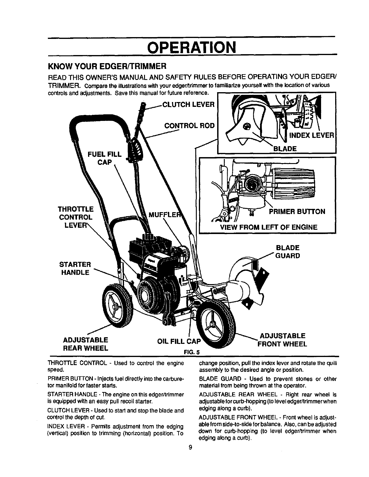
KNOW YOUR EDGER/TRIMMER
READ THIS OWNER'S MANUAL AND SAFETY RULES BEFORE OPERATING YOUR EDGER/
TRIMMER. Comparethe illustrationswith your edger/trimmerto familiarize yoursolfwith the locationof various
controlsand adjustments. Save this manual forfuture reference.
:H LEVER
FUEL FILL
CAP
CONTROLROD
THROTTLE
CONTROL
LEVER_
MUFFLE
STARTER
HANDLE
INDEX LEVER
BLADE
PRIMER BUTTON
VIEW FROM LEFT OF ENGINE
BLADE
ADJUSTABLE
REAR WHEEL OIL FILL CAP
FIG. 5
ADJUSTABLE
FRONT WHEEL
THROTTLE CONTROL - Used to control the engine
speed.
PRIMER BU'I-I'ON- Injectsfueldirectlyintothe carbure-
tor manifoldfor faster starts.
STARTER HANDLE - The engineon thisedger/trimmer
is equippedwithan easy pull recoilstarter.
CLUTCH LEVER -Used to start and stopthe blade and
controlthe depth of cut.
INDEX LEVER -Permits adjustmentfrom the edging
(vertical) positionto trimming (horizontal) position. To
change position, pullthe index lever and rotatethe quill
assemblyto the desired angle or position.
BLADE GUARD -Used to prevent stones or other
materialfrom beingthrown at the operator.
ADJUSTABLE REAR WHEEL . Right rear wheel is
adjustableIorcurb-hopping(to level edgedtrimmerwhen
edging alonga curb).
ADJUSTABLE FRONT WHEEL- Front wheel is adjust-
ablefromside-to-sidefor balance. Also, can be adjusted
down for curb-hopplng (to level edger/trimmer when
edging along a curb).
9
OPERATION
IThe operationofthisedger/trimrnercan resultinforeignobjectsbeingthrowninto the
eyes, which can result in severe eye damage. Alwayswear safety glassesor eye
shieldswhile operatingthe edger/tdmmer.
We recommendstandardsafetyglassesor Wide VisionSafety Mask forover your
glasses.
HOW TO USE YOUR EDGER/TRIMMER
TO STOP EDGER/TRIMMER
• To stopthe engine, make surethe clutchlever is all
the way beck (or up) and move the throttlecontrol
leverto the STOP position.
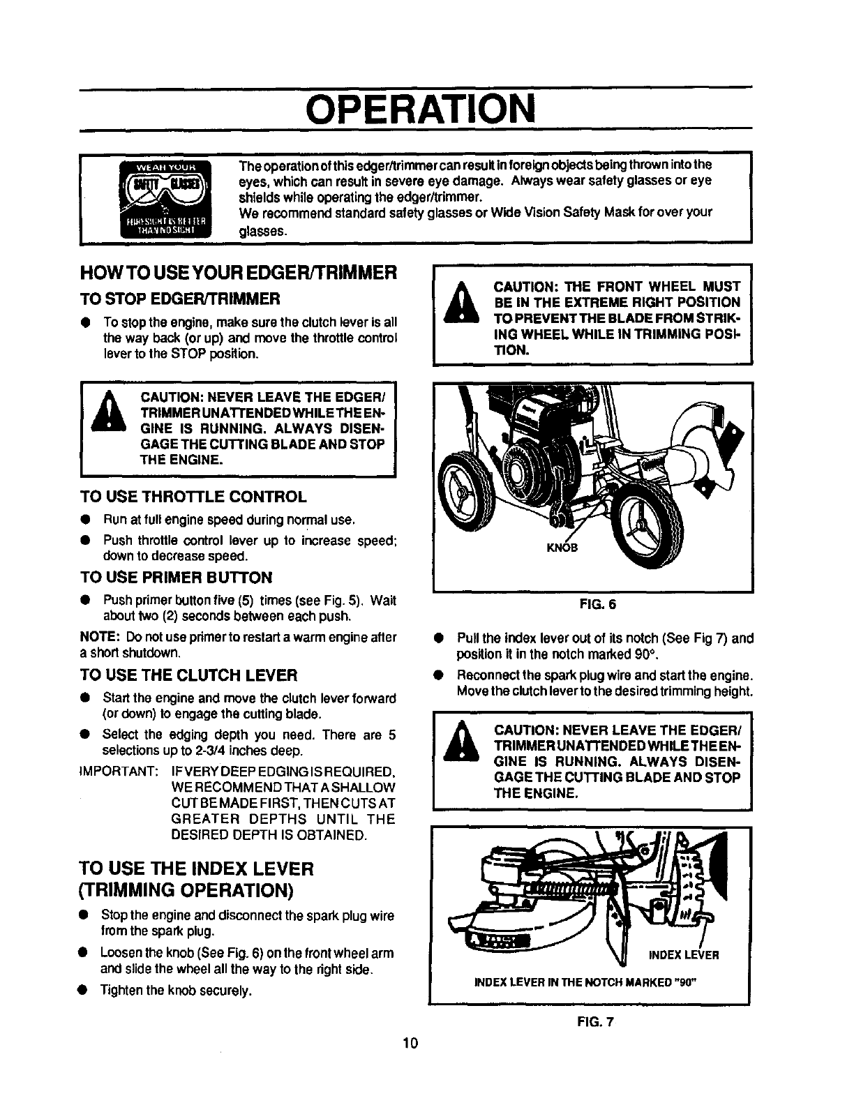
CAUTION: THE FRONT WHEEL MUST
BE IN THE EXTREME RIGHT POSITION
TO PREVENT THE BLADE FROM STRIK-
ING WHEEL WHILE IN TRIMMING POSI-
TION.
AI
CAUTION: NEVER LEAVE THE EDGER/ |
TRIMMER UNATFENDED WHILE THE EN-
GINE IS RUNNING. ALWAYS DISEN-
GAGE THE CUTTING BLADE AND STOP
THE ENGINE.
TO USE THROTTLE CONTROL
• Run at full enginespeed duringnormal use,
•Push throttle control lever up to increase speed;
downto decrease speed.
TO USE PRIMER BU'I'I'ON
•Pushprimerbuttonfive (5) times (see Fig.5). Wait
abouttwo (2) secondsbetween each push.
NOTE: Do not use pdmerto restartawarm engineafter
a shortshutdown.
TO USE THE CLUTCH LEVER
•Start the engine and move the clutch leverforward
(or down) to engage the cuttingblade.
•Select the edging depth you need. There are 5
selectionsupto 2-3/4 inches deep.
iMPORTANT: IFVERY DEEP EDGINGIS REQUIRED,
WE RECOMM END THAT A SHALLOW
CUT BE MADE FIRST, THEN C UTSAT
GREATER DEPTHS UNTIL THE
DESIRED DEPTH IS OBTAINED.
TO USE THE INDEX LEVER
(TRIMMING OPERATION)
•Stopthe engineanddisconnectthe spark plugwire
fromthe spark plug.
•Loosenthe knob(See Fig.6) onthe frontwheel arm
and slidethe wheel all the way to the rightside.
•Tightenthe knob securely.
FIG. 6
•Pull the index lever outof its notch (See Fig 7) and
position it inthe notch marked 90°.
•Reconnectthe sparkplugwiro and startthe engine.
Movethe clutchleverto the desiredtrimmingheight.
_ll AUTION: NEVER LEAVE THE EDGER/
TRIMMER UNATTENDED WHILE THE EN-
GINE IS RUNNING. ALWAYS DISEN-
GAGE THE CUTTING BLADE AND STOP
THE ENGINE.
INDEX LEVER
INDEX LEVER IN THE NOTCH MARKED "90"
10
FIG. 7
OPERATION
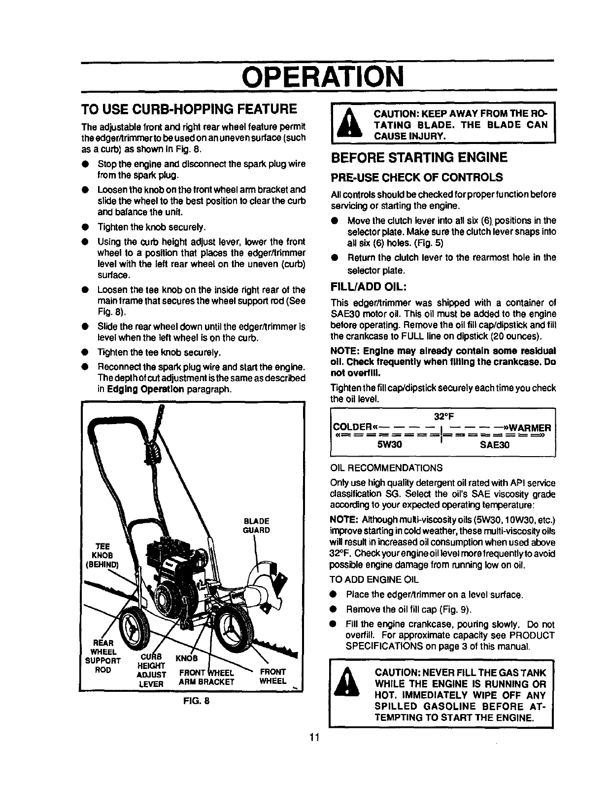
TO USE CURB-HOPPING FEATURE
The adjustablefront and right rear wheelfeature permit
theedger/trimmer to be usedonanunevensurfaco(such
as a curb] as shown In Fig. 8.
•Stopthe engineand disconnectthe sparkplugwire
fromthe sparkplug.
•Loosenthe knobonthe frontwheel arm bracketand
slidethe wheel to the best positionto clearthe curb
and balancethe unit.
•Tightenthe knob securely.
Usingthe curb height adjust lever, lower the front
wheel to a positionthat places the edger/trimmer
levelwith the left rear wheel on the uneven (curb)
sudace.
•Loosenthe tee knob on the inside rightrear of the
mainframe that securesthe wheel supportrod (See
Fig. 8).
•Slidethe rearwheel down untilthe edgeritrimmer is
levelwhen the leftwheel ison the curb.
•"13ghtenthe tee knob securely.
•Reconnectthe spark plugwire and startthe engine.
Thedepthofcutedjustment isthe sameasdescribed
inEdging Operation paragraph.
I& CAUTION: KEEP AWAY FROM THE RO- |
I
TATING BLADE. THE BLADE CAN I
CAUSE INJURY.
BEFORE STARTING ENGINE
PRE-USE CHECK OF CONTROLS
Allcontrolsshouldbe checkedforproperfunctionbefore
servicingor startingthe engine.
•Move the clutch lever into all six (6) positions inthe
selectorplate. Make surethe clutchleversnaps into
all six (6) holes. (Fig. 5)
•Returnthe clutch lever to the rearmost hole in the
selector plate.
FILL/ADD OIL:
This edger/trimmer was shipped with a container of
SAE30 motoroil. This oil must be added to the engine
before operating. Remove the oil fUicap/dipstickand flit
the crankcaseto FULL line on dipstick(20 ounces).
NOTE: Engine may already contain some residual
oil Check frequently when filling the crankcase. Do
not overfill.
Tightenthefillcap/dipsticksecurelyeach time youcheck
the oil level.
I32OF
COLDER(€
_== -- -- == -- ----------- I
--5W _'_'_u-- -- --I
OIL RECOMMENDATIONS
- --)>WARMER
SAE30
Onlyuse highqualitydetergentoil ratedwithAPI service
classificationSG. Select the oirs SAE viscositygrade
accordingto your expectedoperatingtemperature:
NOTE: Althoughmulti-viscosityoils(5W30, 10W30,etc.)
improvestartingincoldweather, these multi-viscosityoils
willresultinincreasedoil consumptionwhenused above
32°F. Checkyour engineoil levelmorefrequentlytoavoid
possible enginedamage from runninglowon oil,
TO ADD ENGINE OIL
•Place the edger/trimmer on a level surface.
•Remove the oilfill cap (Fig. 9),
•Fill the engine crankcase, pouring slowly. Do not
overfill. For approximate capacity see PRODUCT
SPECIFICATIONS on page 3 of this manual.
FIG. 8
11
OPERATION
CAUTION: GASOLINE IS FLAMMABLE
AND CAUTION MUST BE USED WHEN
HANDLING OR STORING IT. DO NOT
FILL FUEL TANK WHILE EDGER/TRIMMER IS
RUNNING, HOT, OR WHEN EDGER/TRIMMER IS
IN AN ENCLOSED AREA. KEEP AWAY FROM
OPEN FLAME, ELECTRICAL SPARK, AND DO
NOT SMOKE WHILE FILLING THE FUEL TANK.
NEVER FILL FUEL TANK COMPLETELY; BUT
FILL THE TANK TO WITHIN 1/4 - 1/2 INCH FROM
THE TOP TO PROVIDE SPACE FOR EXPANSION
OF FUEL.ALWAYSFILL FUEL TANK OUTDOORS
AND USE A FUNNEL OR SPOUT TO PREVENT
SPILLING. MAKE SURE TO WIPE UP ANY
SPILLED FUEL BEFORE STARTING THE EN-
GINE.
STORE GASOLINE IN A CLEAN, APPROVED
CONTAINER, AND KEEP THE CAP IN PLACE ON
THE CONTAINER. KEEP GASOLINE IN A COOL,
WELL VENTILATED PLACE; NEVER IN THE
HOUSE. NEVER BUY MORE THAN A 30 DAY
SUPPLY OF GASOLINE TO ASSURE VOLATIL-
ITY. GASOLINE IS INTENDED TO BE USED AS A
FUEL FOR INTERNAL COMBUSTION ENGINES;
THEREFORE, OONOT USE GASOLINE FOR ANY
OTHER PURPOSE. SINCE MANY CHILDREN LIKE
THE SMELL OF GASOLINE, KEEP IT OUT OF
THEIR REACH BECAUSE THE FUMES ARE
DANGEROUS TO INHALE, AS WELL AS BEING
EXPLOSIVE.
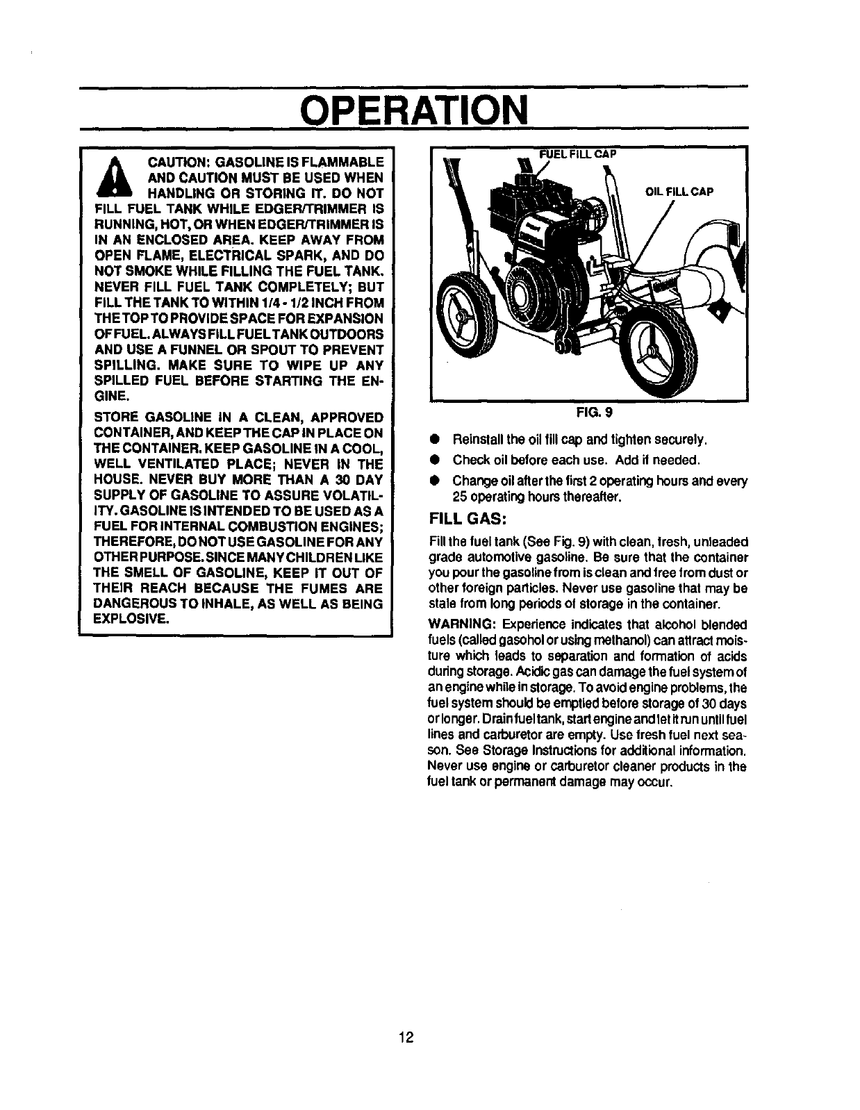
FIG. 9
• Reinstallthe oil fillcap andtighten securely.
•Check oil before each use. Add if needed.
•Change oilafter the first 2 operatinghoursand every
25 operatinghoursthereafter.
FILL GAS:
Fillthe fuel tank (See Fig. 9) with clean, trosh,unleaded
grads automotivegasoSne. Be sure that the container
youpourthe gasoitnefromis clean andfree fromdustor
other foreign particles. Never use gasoline that may be
stale from longperiods of storage in the container.
WARNING: Experience indicatesthat alcohol blended
fuels(calledgasoholorusingmethanol)can attractmois-
ture which leads to separation and formation of acids
duringstorage.Acidicgas can damagethe fuelsystemof
an enginewhileinstorage.Toavoidengineproblems,the
fuel systemshouldbe emptiedbefore storageof 30 days
orlonger,Drainfueltank,start engineand letitrununtilfuel
linesand carburetorare empty. Use fresh fuel next sea-
son. See Storage Instructionsfor additionalinformation.
Never use engineor carburetor cleaner productsin the
fuel tank or permanentdamage may occur.
12
OPERATION
TO START THE ENGINE
Before startingthe engine, be sure you have read and
understoodallthe instructionson the precedingpages.
The edger/trimmer is equippedwith a recoilstarter.The
operationofthe engineiscontrolledbythethrottlecontrol
lever,
•Pull the clutchlever all the way back (or up) to the
rearmosthole to raise and disengage the blade.
•Movethe throtttecontrol lever(See Fig.5)tothe RUN
position.
•Pushpdmerbuttonfive (5) times (see Fig.5). Wait
about two (2) seconds between each push.
NOTE: Do notuse pdmerlo restarta warm engine alter
a shortshutdown.
To start engine, grasp the engine starter handle
firmlyyour righthand.
Hold the edger/trimmer handle firmly withyour left
hand.
Pullup sharplyonthe recoilstarterhandle. DO NOT
allowthestartsr ropetosnapback,letit rewindslowly
while holdingthe stader handle.
NOTE: If enginefailsto start after three (3) pulls,push
primerbuttontwo (2) times and pull starterrope again.
•Whenthe enginestarts.Pushthrottlecontrolleverup
to increasespeed;down to decrease speed. Run at
full engine speed duringnormaluse.
NOTE: The cutting blade speed is controlled by the
enginespeed. TO reduce the cuttingblade speed, push
downonthe throttlecontrol lever. To increase the blade
speed, push the throttlecontrol lever up.
•To stopthe engine, make surethe clutchlever is all
the way back (or up) and move the throttlecontrol
leverto the STOP position.
iiiiiACAUTION: NEVER RUN THE ENGINE IN-
DOORS OR IN APOORLY VENTILATED
AREA. ENGINE EXHAUST CONTAINS
CARBON MONOXIDE, AN ODORLESS
GAS AND DEAOLY GAS.
KEEP HANDS, FEET, HAIR AND LOOSE
CLOTHING AWAY FROM ANY MOVING
PARTS ON THE ENGINE OR EDGER/
TRIMMER.
WARNING - AVOID THE MUFFLER AND
SURROUNDING AREAS (SEE FIG. 6).
TEMPERATURES MAY EXCEED 150°F.
EDGING TIPS
Edgingis best performedwhen conditions are dry. If
the soilistoowet, dirtbecomespackedinandaround
the blade causing premature belt wear and de-
creased perlormanoe.
•If dirt does become packed around the blade, stop
the engine, removethe sparkplugwire, and remove
the packeddebrisbefore continuing to edge.
•If very deep edgingis required,we recommendthat
ashallowcutbe madefirst,thencutsatgreaterdepth
untilthe desired depth is obtained.
•Unilorm edging can be performed when the blade
guideridesonandagainstthe surfacewhichyouare
edging.
•Edging can be customizedbyvaryingthe numberof
passes and by the distance your blade is from lhe
surfaceyou are edging.
13
CUSTOMER RESPONSIBILITIES
MAINTENANCE
CHECK LIST SERVICE RECORD
FILLIN DATES
ASYOU COMPLETE
REGULARSERVICE
BEFORE STORAGE
BEGINNING EACH SEASON
EVERY 25 HOURS OF USE
EVERY 10 HOURS OF USE
EVERY 5 HOURS OF USE
FREQUENTLY
BEFORE EACH USE
AFTER FIRST 2 HOURS OF USE
LubriCateall Pivot Points
LubricateWheal Axles
Check Engine Oil Level
Change Engine Oil
Replace AirCleaner Filter
Check Spark Plug
Check Drive Belt
TbghtanAll So'ews and Nuts
Check BladeWear/Damage
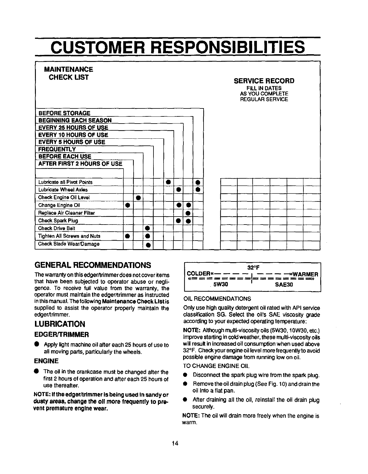
GENERAL RECOMMENDATIONS
Thewarrantyonthisedger/trimmerdoesnotcoveritems
that have been subjectedto operator abuse or negli-
gence. To receive full value from the warranty, the
operator mustmaintain the edger/trimmeras instructed
inthismanual. The followingMaintenance Check LIStis
supplied to assist the operator properly maintain the
edger/trimmer.
LUBRICATION
EDGER/TRIMMER
•Applylightmachineoil after each 25 hoursof use to
all movingparts, particularlythe wheels.
ENGINE
•The oil inthe crankcasemust be changed alter the
first2 hoursof operationanclafter each 25 hoursof
use therealter.
NOTE: If the edger/trimmer Is being used In sandy or
dusty areas, change the oll more frequently to pre-
vent premature engine wear.
32OF
COLDER_= I: -_>WARMER___.===_
5W30 SAE30
OIL RECOMMENDATIONS
Onlyuse highquality detergentoil ratedwith API service
classificationSG. Select the oil's SAE viscositygrade
accordingto your expectedoperatingtemperature:
NOTE: Althoughmulti-viscosityoils(5W30, 10W30, etc.)
improvestartingincoldweather, these multi-viscosityoils
will resultin increasedoil consumption when used above
32°F. Checkyourengineoillevelmorofrequentlyto avoid
pessPoleenginedamage fromrunninglow on oil.
TO CHANGE ENGINE OIL
• Disconnectthe spark plug wire from the spark plug.
•Removethe oildrain plug(See Fig. 10) anddrainthe
oil into a flat pan.
• After draining all the oil, reinstall the oil drain plug
securely.
NOTE: The oil will drain more freely when the engine is
warm.
14
CUSTOMER RESPONSIBILITIES
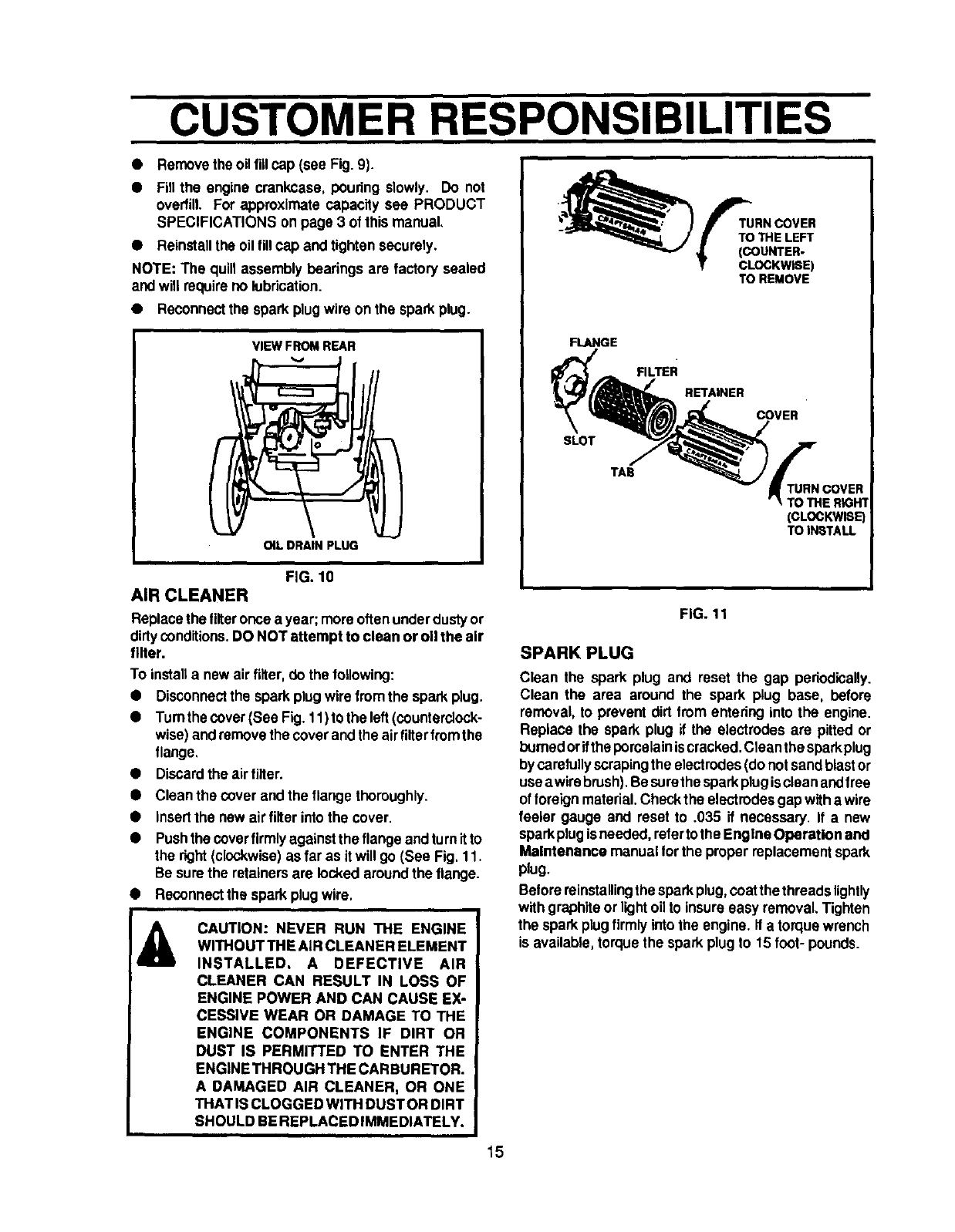
• Removethe oilfill cap (see Fig.9).
•Fill the engine crankcase, pouring slowly. Do not
overfill. For approximate capacity see PRODUCT
SPECIFICATIONS on page 3 of this manual,
•Reinstallthe oil tillcap and tightensecurely.
NOTE: The quill assembly bearings are factory sealed
andwill requireno lubrication.
• Reconnectthe spark plugwire on the sparkplug.
VIEW FROM REAR
OIL DRAIN PLUG
FIG. 10
AIR CLEANER
Replacethe tilteroncea year; moreoftenunderdustyor
dirtyconditions.DO NOT attempt to clean or oil the air
filter.
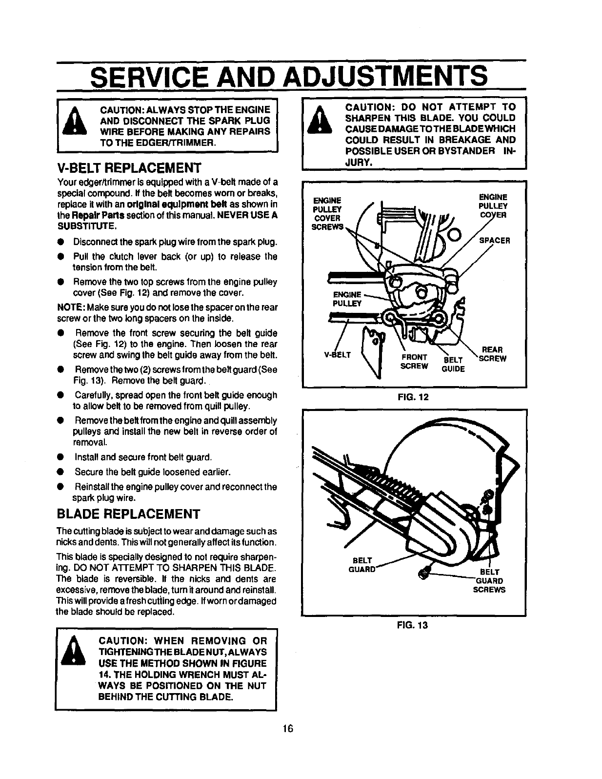
To installa new air filter,do the to,owing:
•Disconnectthe sparkplugwire fromthe sparkplug.
•Turnthe cover (See Fig. 11)to the left (counterclock-
wise) andremovethe coverand the airfilterfromthe
flange,
Discardthe airfilter.
Clean the cover and the flange thoroughly.
Insertthe new air filter intothe cover.
Pushthe coverfirmlyagainstthe flange andturn itto
the right(clockwise)asfar as it will go (See Fig, 11.
Be surethe retainersare lucked around the flange.
Reconnectthe spark plugwire.
CAUTION: NEVER RUN THE ENGINE
WITHOUT THE AIR CLEANER ELEMENT
INSTALLED. A DEFECTIVE AIR
CLEANER CAN RESULT IN LOSS OF
ENGINE POWER AND CAN CAUSE EX-
CESSIVE WEAR OR DAMAGE TO THE
ENGINE COMPONENTS IF DIRT OR
DUST IS PERMITTED TO ENTER THE
ENGINE THROUGH THE CARBURETOR.
A DAMAGED AIR CLEANER, OR ONE
THAT IS CLOGGED WITH DUSTOR DIRT
SHOULD BE REPLACED IMMEDIATELY.
15
TO REMOVE
FLANGE
SLOT
FILTER
RETAINER
COVER
TURNCOVER
TOTHE RIGH1
(CLOCKWISE
TO INSTALL
FiG. 11
SPARK PLUG
Clean the spark plug and reset the gap periodically.
Clean the area around the spark plug base, before
removal, to prevent dirt from entering into the engine.
Replace the spark plug if the electrodes are pitted or
burnedorifthe pomelainiscracked.Cleanthe sparkplug
by carefully scrapingthe electrodes(donot sandblast or
use awire brush),Be surethesparkplugiscleanandfree
of foreign material.Checkthe electrodesgapwitha wire
feeler gauge and reset to .035 it necessary. If a new
sparkplugisneeded, refertothe Engine Operation and
Maintenance manualforthe proper replacement spark
plug.
Beforereinstallingthe sparkplug,coatthethreads lightly
with graphiteor lightoil to insureeasy removal,Tighten
the spark plugfirmly intothe engine. If a torquewrench
is available, torquethe spark plugto 15 foot- pounds.
SERVICE AND ADJUSTMENTS
CAUTION: ALWAYS STOP THE ENGINE I
AND DISCONNECT THE SPARK PLUG
WIRE BEFORE MAKING ANY REPAIRS
TO THE EDGER/TRIMMER.
V-BELT REPLACEMENT
Your edger/trimmerisequippedwithaV-belt made of a
specialcompound.If the belt becomes worn or breaks,
replaceit withan original equipment belt as shownin
the Repair Parts sectionof thismanual.NEVER USE A
SUBSTITUTE,
• Disconnectthe sparkplugwirefrom the sparkplug.
•Pull the clutch lever back (or up) to release the
tensionfrom the belt.
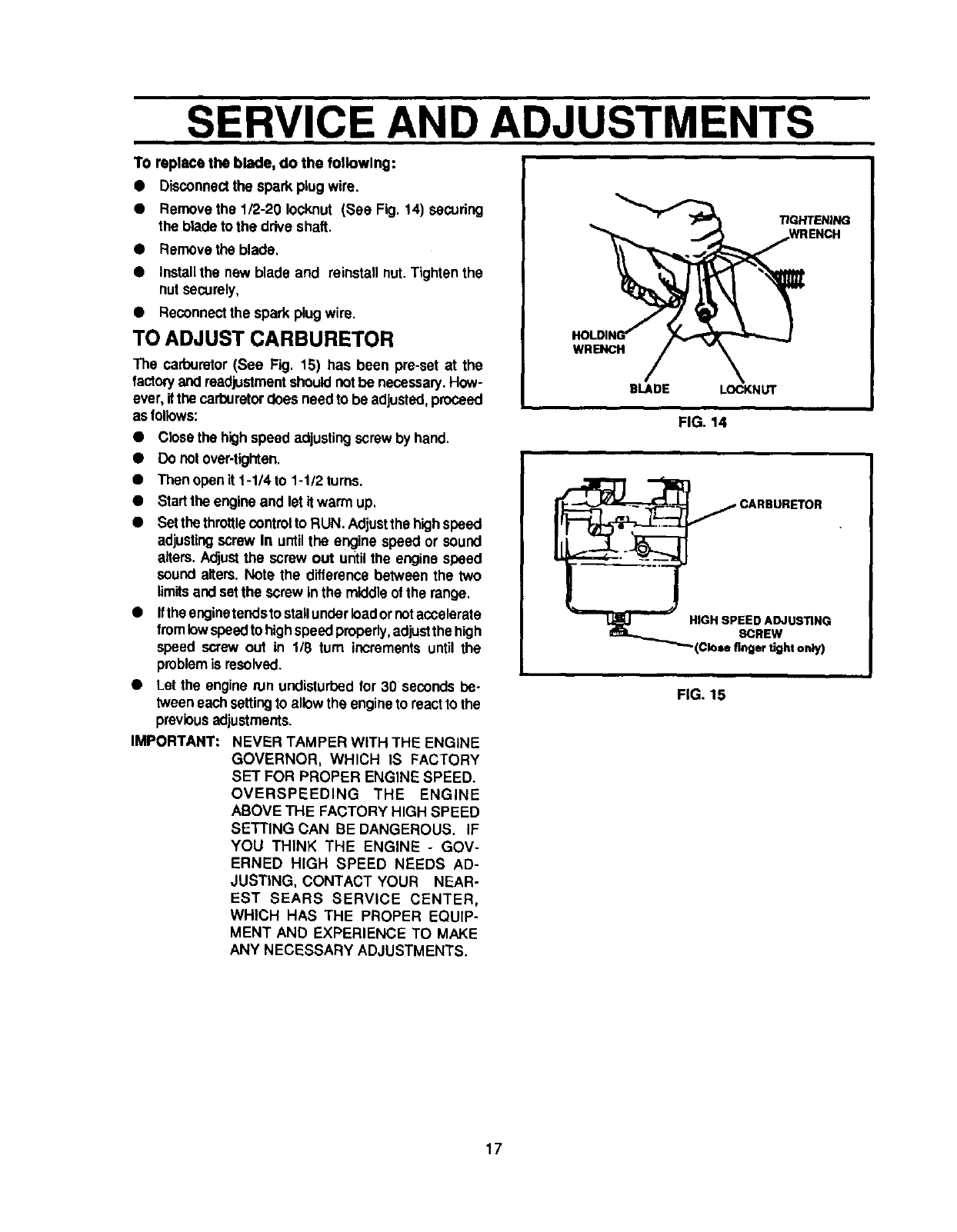
Removethe two topscrews fromthe enginepulley
cover (See Fig. 12) and remove the cover.
NOTE: Make sureyoudo notlosethe spaceronthe roar
screwor the two longspacerson the inside.
•Remove the front screw secudng the belt guide
(See Fig. 12) to the engine. Then loosen the rear
screw and swingthe belt guideaway fromthe belt.
•Removethetwo (2) screwsfromthe beifguard(See
Fig. 13). Remove the belt guard.
•Carefully,spread open the front belt guide enough
to allow beltto be removed fromquill pulley.
•Removethe beltfromthe engineand quillassembly
pulleysand installthe new bell in reverse order of
removal.
•Installand securefront beltguard.
• Secure the beltguide loosenedearlier.
•Reinstallthe enginepulleycoverandreconnectthe
sparkplugwire.
BLADE REPLACEMENT
The cuttingblade is subjectto wear anddamage suchas
nicksanddents.Thiswill notgenerallyaffectitsfunction.
This blade is speciallydesigned to not requiresharpen-
ing. DO NOT A'I-I'EMPT TO SHARPEN THIS BLADE.
The blade is reversible. It the nicks and dents are
excessive,removethe blade,turn itaroundandreinstall.
This willprovideafreshcutiingedge. Ifwornordamaged
the blade shouldbe replaced.
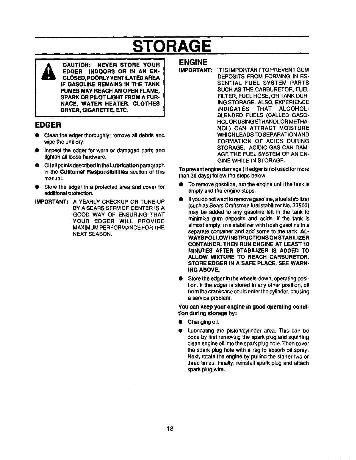
&CAUTION: WHEN REMOVING OR
TIGHTENING THE BLADE NUT,ALWAYS
USE THE METHOD SHOWN IN FIGURE
14. THE HOLDING WRENCH MUST AL-
WAYS BE POSITIONED ON THE NUT
BEHIND THE CUTTING BLADE.
ACAUTION: DO NOT ATTEMPT TO
SHARPEN THIS BLADE, YOU COULD
CAUSE DAMAGE TOTHE BLADEWHICH
COULD RESULT IN BREAKAGE AND
POSSIBLE USER OR BYSTANDER IN-
JURY.
ENGINE
PULLEY
COVER
SCREWS
ENGINE
PULLEY
PULLEY
REAR
FRONT BELT
SCREW GUIDE
FIG. 12
BELT
BELT
SCREWS
FIG. 13
16
SERVICE AND ADJUSTMENTS
TO replace the blade, do the following:
•Disconnect the sparkplug wire.
•Removethe 1/2-20 Iocknut (See Fig. 14) secudng
the blade to the drive shaft,
•Removethe blade,
•installthe new blade and reinstall nut.Tighten the
nutsecurely,
•Reconnectthe spark plugwire.
TO ADJUST CARBURETOR
The carburetor(See Fig. 15) has been pre-set at the
factoryand readjustmentshouldnotbe necessary.How-
ever,itthe carburetordoes needto be adjusted,proceed
asfollows:
•Close the highspeed adjustingscrew by hand.
•Do notover-tighten.
•Then openit 1-1/4 to 1-1/2 turns.
•Startthe engineand let it warm up,
•Setthe throttlecontrolto RUN. Adjustthe highspeed
adjustingscrew In untilthe engine speed or sound
alters. Adjustthe screw out until the erKJinespeed
sound alters. Note the differencebetween the two
limitsandsetthe Screwinthe middleofthe range,
•Iftheenginetendsto stallunderloadornot accelerste
fromlowspeedto highspeedproperly,adjustthe high
speed screw out in 1/8 turn increments until the
problemis resolved.
•Let the engine run undisturbedfor 30 seconds be-
tween eachsettingto allow the engineto reactto the
previousadjustments.
IMPORTANT: NEVER TAMPER WITH THE ENGINE
GOVERNOR, WHICH IS FACTORY
SET FOR PROPER ENGINE SPEED.
OVERSPEEDING THE ENGINE
ABOVE THE FACTORY HIGH SPEED
SETTING CAN BE DANGEROUS. IF
YOU THINK THE ENGINE -GOV-
ERNED HIGH SPEED NEEDS AD-
JUSTING, CONTACT YOUR NEAR-
EST SEARS SERVICE CENTER,
WHICH HAS THE PROPER EQUIP-
MENT AND EXPERIENCE TO MAKE
ANY NECESSARY ADJUSTMENTS.
TIGHTENING
WRENCH
BLADE LOCKNUT
FIG. 14
_CARBURETOR
I._ HIGH SPEED ADJUSTING
8CREW
"_(Cloee finger tight only)
FIG. 15
17
STORAGE
&CAUTION: NEVER STORE YOUR
EDGER INDOORS OR IN AN EN-
CLOSED, POORLY VENTILATED AREA
IF GASOLINE REMAINS IN THE TANK
FUMES MAY REACH AN OPEN FLAME,
SPARK OR PILOT LIGHT FROM A FUR-
NACE, WATER HEATER, CLOTHES
DRYER, ClGARETI'E, ETC.
EDGER
•Clean the edger thoroughly;remove all debris and
wipethe unitdry.
•Inspect the edger for worn or damaged parts and
tightenall loose hardware.
•Oilallpointsdescitbedinthe LubrlcaUon paragraph
in the Customer Responsibilities section of this
manual.
•Store the edger in a protected area and cover for
additionalprotection.
IMPORTANT: A YEARLY CHECKUP OR TUNE-UP
BY A SEARS SERVICE CENTER IS A
GOOD WAY OF ENSURING THAT
YOUR EDGER WILL PROVIDE
MAXIMUM PERFORMANCE FORTHE
NEXT SEASON.
ENGINE
IMPORTANT: IT IS IMPORTANTTO PREVENT GUM
DEPOSITS FROM FORMING IN ES-
SENTIAL FUEL SYSTEM PARTS
SUCH AS THE CARBURETOR, FUEL
FILTER, FUEL HOSE, OR TANK DUR-
ING STORAGE. ALSO, EXPERIENCE
INDICATES THAT ALCOHOL-
BLENDED FUELS (CALLED GASO-
HOLOR USING ETHANOLOR METHA-
NOL) CAN ATTRACT MOISTURE
WHICH LEADS TO SEPARATION AND
FORMATION OF ACIDS DURING
STORAGE. ACIDIC GAS CAN DAM-
AGE THE FUEL SYSTEM OF AN EN-
GINE WHILE IN STORAGE.
To preventenginedamage ( ifedger isnotusedformore
than 30 days) follow the steps below.
To remove gasoline,run the engineuntilthe tank is
empty and the engine stops.
Ifyoudonotwantto removegasoline,a fuelstabilizer
(suchas Sears Craftsman fuel stabilizerNo. 33500)
may be added to any gasoline left in the tank to
minimize gum deposits and acids. If the tank is
almostempty, mixstabilizerwithfreshgasoline in a
separate container and add some to the tank. AL-
WAYS FOLLOWlNSTRUCTIONS ON STABlUZER
CONTAINER. THEN RUN ENGINE AT LEAST 10
MINUTES AFTER STABILIZER IS ADDED TO
ALLOW MIXTURE TO REACH CARBURETOR.
STORE EDGER IN ASAFE PLACE. SEE WARN-
ING ABOVE.
Store the edger inthe wheels-down,operatingposi-
tion. If the edger is stored in any other position, oil
fromthe crankcasecould enterthe cylinder,causing
a serviceproblem.
You can keep your engine In good operating condi-
tion during storage by:
• Changing oil.
Lubricating the piston/cylinderarea. This can be
done by first removingthe spark plug and squirting
clean engineoil intothe sparkplughole.Then cover
the spark plug hole with a rag to absorb oil spray.
Next, rotatethe engine by pullingthe startertwo or
three times. Finally, reinstallspark plug and attach
spark plugwire.
18

TROUBLE
Difficult starting
Engine runs erratic
Cuffing blade fails to
turn
Blade falls to cut
properly
Excessive vibration
TROUBLE SHOOTING
CAUSE
Stale fuel
Defectivespark plug
Cloggedfuelfilter
Blockedfuel line or empty fuel tank
Carburetoroutof adjustment
Fouled sparkplug
Clogged aircleaner
Jammed due to foreign object
Looseblade
DefectiveV-belt
Defectivequill bearings
Damaged or worn blade
Loose parts
CORRECTION
Drainfuel tank. Fillwithfreshfuel.
Clean and re-gap sparkplug.
ill
Replace fuel filter.
Clean fuel line; check gas tank.
m
Have carburetoradjusted.
Clean and adjust gap.
Tap clean or replace aircleaner.
Clear obstruction,
Tighten blade retainingnut.
Replace the V-belt.
Replace the bearings.
Reverse blade or replace blade.
Stop engine immediately;tightenall bolts.If
vibrationcontinues,take the unit intothe
nearest SEARS Service Center.
19
