Craftsman 536881114 User Manual 30 11 HP SNOWTHROWER Manuals And Guides L0312019
CRAFTSMAN Snowthrower, Gas Manual L0312019 CRAFTSMAN Snowthrower, Gas Owner's Manual, CRAFTSMAN Snowthrower, Gas installation guides
User Manual: Craftsman 536881114 536881114 CRAFTSMAN 30 11 HP SNOWTHROWER - Manuals and Guides View the owners manual for your CRAFTSMAN 30 11 HP SNOWTHROWER #536881114. Home:Lawn & Garden Parts:Craftsman Parts:Craftsman 30 11 HP SNOWTHROWER Manual
Open the PDF directly: View PDF ![]() .
.
Page Count: 104 [warning: Documents this large are best viewed by clicking the View PDF Link!]

]CRRFTSMRN 1
Operator's Manual
Snow Thrower
11 Horsepower
Electric Start
30-inch Dual Stage
Model 536.881114
CAUTION: Before using this product,
read this manual and follow all of its
Safety Rules and Operating Instruction
Manual del usario
Quitanieves
de 30 pulgadas
11 caballos de fuerza (hp)
Biet&pico
Arranque el_ctrico
Modelo 536.881114
PRECAUCI6N: Antes de usar este producto,
lea este manual y siga todas las reglas de
seguridad e instrucciones de operaci6n.
Sears, Roebuck and Co., Hoffman Estates, IL 60179 U.S.A.
F-031001L www.sears.com/craftsman
WARRANTY STATEMENT ...... 2
SAFETY RULES ............... 2
INTERNATIONAL SYMBOLS .... 4
ASSEMBLY ................... 6
OPERATION .................. 12
MAINTENANCE ............... 18
SERVICE AND ADJUSTMENT .. 21
STORAGE .................... 31
TROUBLESHOOTING TABLE . .. 32
REPAIR PARTS ............... 36
ENGINE REPAIR PARTS ....... 57
SPANISH (ESPA_IOL) .......... 65
PARTS ORDERING/SERVICE ..
BACK COVER
LIMITED TWO-YEAR WARRANTY ON CRAFTSMAN SNOW THROWER
For two years from the date of purchase, when this Craftsman Snow thrower is maintained,
lubricated, and tuned up according to the operating and maintenance instructions in the
owner's manual, Sears will repair, free of charge, any defect in material or workmanship.
If this Craftsman Snow thrower is used for commercial or rental purposes, this warranty ap-
plies for only 90 days from the date of purchase.
This warranty does not cover the following:
Items which become wom during normal use, such as spark plugs, drive belts and shear
pins.
Repair necessary because of operator abuse or negligence, including bent crankshafts
and the failure to maintain the equipment according to the instructions contained in the
owner's manual.
WARRANTY SERVICE IS AVAILABLE BY RETURNING THE CRAFTSMAN SNOW
THROWER TO THE NEAREST SEARS SERVICE CENTER IN THE UNITED STATES.
THIS WARRANTY APPLIES ONLY WHILE THIS PRODUCT IS IN USE IN THE UNITED
STATES.
This warranty gives you specific legal rights, and you may also have other rights which may
vary from state to state.
Sears, Roebuck and Co., D817WA, Hoffmen Estates. IL 60179
_lb OOK FOR THIS SYMBOL TO POINT OUT IMPORTANT SAFETY PRECAUTIONS.
IT MEANS-- ATTENTION!!! BECOME ALERT!!! YOUR SAFETY IS INVOLVED.
Engine Exhaust, some of its constituents, and
certain vehicle components contain or emit
chemicals known to the State of California to
cause cancer and birth defects or other repro-
ductive harm.
Battery posts, terminals and related accessories
contain lead and lead compounds, chemicals
known to the State of California to cause cancer
and birth defects or other reproductive harm.
WASH HANDS AFTER HANDLING.
WARNING: Always discon-
nect the spark plug wire
and place it where it cannot
make contact with spark plug to
prevent accidental starting during:
Preparation, Maintenance, or Stor-
age of your snow thrower.
IMPORTANT: Safety standards re-
quire operator presence controls to
minimize the risk of injury. Your snow
thrower is equipped with such controls.
Do not attempt to defeat the function of
the operator presence control under any
circumstances.
F-031001L 2
TRAINING
1. Read this operating and service instruction
manual carefully. Be thoroughly familiar
with the controls and the proper use of the
snow thrower. Know how to stop the snow
thrower and disengage the controls quick-
ly.
2. Never allow children to operate the snow
thrower. Never allow adults to operate the
snow thrower without proper instruction.
3. Keep the area of operation clear of all per-
sons, particularly small children end pets.
4. Exercise caution to avoid slipping or falling
especially when operating in reverse.
PREPARATION
1. Thoroughly inspect the area where the
snow thrower is to be used and remove all
doormats, sleds, boards, wires, and other
foreign objects.
2. Disengage all clutches before starting the
engine (motor).
3. Do not operate the snow thrower without
wearing adequate winter outer garments.
Wear footwear that will improve footing on
slippery surfaces.
4. Handle fuel with care; it is highly flam-
mable.
a. Use an approved fuel container.
b. Never remove fuel tank cap or add fuel
to a running engine (motor) or hot en-
gine (motor).
c. Fill fuel tank outdoors with extreme
care. Never fill fuel tank indoors.
d. Replace fuel cap securely and wipe up
spilled fuel.
e. Never store fuel or snow thrower with
fuel in the tank inside of a building
where fumes may reach an open flame
or spark.
f. Check fuel supply before each use, al-
lowing space for expansion as the heat
of the engine (motor) and/or sun can
cause fuel to expand.
5. For all snow throwers with electric starting
motors use electric starting extension
cords certified CSA/UL. Use only with a re-
ceptecle that has been installed in accord-
ance with local inspection authorities.
6. Never attempt to make any adjustments
while the engine (motor) is running (except
when specifically recommended by manu-
facturer).
7. Let engine (motor) and snow thrower ad-
just to outdoor temperatures before starting
to clear snow.
F-031001L
8_ Always wear safety glasses or eye shields
during operation or while performing an ad-
justment or repair to protect eyes from
foreign objects that may be thrown from the
snow thrower.
OPERATION
1. Do not operate this snow thrower ifyou are
taking drugs or other medication which can
cause drowsiness or affect your ability to
operate this snow thrower.
2. Do not use the snow thrower # you are
mentally or physically unable to operate the
snow thrower safely.
3. Do not put hands or feet near or under ro-
tating parts. Keep clear of the discharge
opening at all times.
4. Exercise extreme caution when operating
on or crossing gravel drives, walks or
roads. Stay alert for hidden hazards or
traffic.
5. After striking a foreign object, stop the en-
gine (motor), remove the wire from the
spark plug, thoroughly inspect snow
thrower for any damage, and repair the
damage before restarting and operating
the snow thrower.
6. If the snow thrower should start to vibrate
abnormally, stop the engine (motor) and
check immediately for the cause. Vibration
is generally a warning of trouble.
7. Stop the engine (motor) whenever you
leave the operating position, before un-
clogging the auger/impaller housing or dis-
charge chute and when making any
repairs, adjustments, or inspections.
8. When cleaning, repairing, or inspecting,
make certain the auger/impeller and all
moving parts have stopped and all controls
are disengaged. Disconnect the spark plug
wire and keep the wire away from the spark
plug to prevent accidental starting.
9. Take all possible precautions when leaving
the snow thrower unattended. Disengage
the auger/ impeller, stop engine (motor),
and remove key.
10. Do not run the engine (motor) indoors, ex-
cept when starting the engine (motor) and
for transporting the snow thrower in or out
of the building. Open the outside doors; ex-
haust fumes are dangerous (containing
CARBON MONOXIDE, an ODORLESS
and DEADLY GAS).
11. Do not clear snow across the face of
slopes. Exercise extreme caution when
changing direction on slopes. Do not at-
tempt to clear steep slopes.
12. Never operate the snow thrower without
proper guards, plates or other safety pro-
tective devices in place.
13.Neveroperatethesnowthrowernearen-
closures,automobiles,windowwells,drop-
offs,andthelike without proper adjustment
of Me snow discharge angle. Keep children
and pets away.
14. Do not overload the snow thrower capacity
by attempting to clear snow at too fast a
rate.
15. Never operate the snow thrower at high
transport speeds on slippery surfaces.
Look behind and use care when backing
up.
16. Never direct discharge at bystanders or
allow anyone in front of the snow thrower.
17. Disengage powar to the collector/impeller
when snow thrower is transported or not in
use.
18. Use anly attachments and ascassorias ap-
proved by the manufacturer of the snow
thrower (such as tire chains, electric start
kits, ect.).
19. Never operate the snow thrower without
good visibility or light. Always be sure of
your footing and keep a firm hold on the
handles. Walk;never run.
20. Do not over-reach. Keep proper footing
and balance at all times.
21. Do not attempt to use snow thrower on a
roof.
MAINTENANCE AND STORAGE
1. Check shear bolts and other bolts at fre-
quent intervals for proper tightness to be
sure the snow thrower is in safe working
condition.
2. Never store the snow thrower with fuel in
the tank inside a building where ignition
sources are present such as hot water end
space heaters, clothas dryers, and the like.
Allow the engine (motor) to cool before
storing in any enclosure.
3. Always refer to operator's guide instruc-
tions for important details if the snow
thrower is to be stored for an extended
period.
4. Maintain or replace safety and instruction
labels, as necessary.
5. Run the snow thrower a few minutes after
throwing snow to prevent freeze-up of the
augedimpeller.
_IL WARNING: This snow thrower isfor use on sidewalks, driveways
and other ground level surfaces.
Caution should be exercised while using on
steep sloping surfaces. DO NOT USE
SNOW THROWER ON SURFACES ABOVE
GROUND LEVEL such as roofs of resi-
dences, garages, porches or other such
structures or buildings.
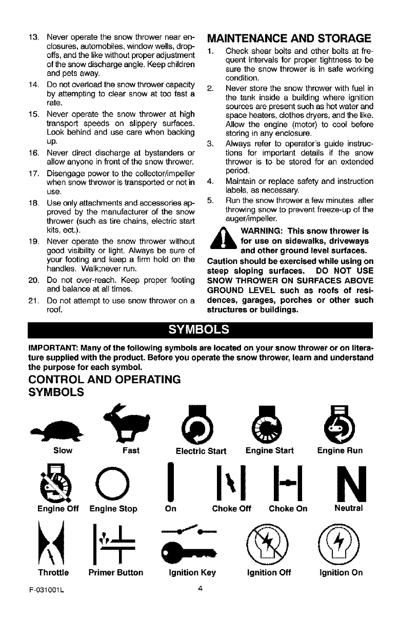
IMPORTANT: Many of the following symbols are located on your snow thrower or on litera-
ture supplied with the product. Before you operate the snow thrower, learn and understand
the purpose for each symbol.
CONTROL AND OPERATING
SYMBOLS
Slow Fast Electric Start Engine Start Engine Run
H N
Engine Off Engine Stop On Choke Off Choke On Neutral
Throttle Primer Button Ignition Key ®G
Ignition Off Ignition On
F-031001L
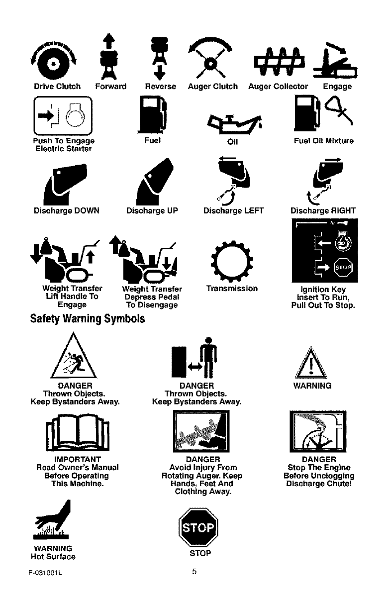
Drive Clutch Forward
Push To Engage
Electric Starter
Reverse Auger Clutch Auger Collector Engage
Fuel Oil Fuel Oil Mixture
Discharge DOWN Discharge UP Discharge LEFT Discharge RIGHT
Weight Transfer Weight Transfer Transmission Ignition Key
Lift Handle To Depress Pedal Insert To Run,
Engage To Disengage Pull Out To Stop.
Safety Warning Symbols
DANGER
Thrown Objects.
Keep Bystanders Away.
IMPORTANT
Read Owner's Manual
Before Operating
This Machine.
O
DANGER
Thrown Objects.
Keep Bystanders Away.
DANGER
Avoid Injury From
Rotating Auger. Keep
Hands, Feet And
Clothing Away.
A
WARNING
DANGER
Stop The Engine
Before Unclogging
Discharge Chute!
WARNING
Hot Surface STOP
F-O31001L 5
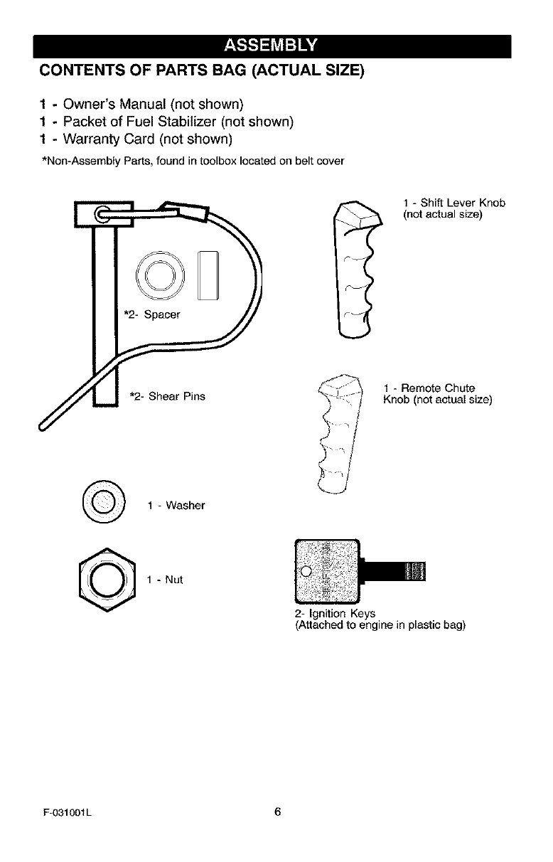
CONTENTS OF PARTS BAG (ACTUAL SIZE)
1-Owner's Manual (not shown)
1-Packet of Fuel Stabilizer (not shown)
1 - Warranty Card (not shown)
*Non-Assembly Parts,foundintoolboxlocatedonbeltcover
1 - Shift Lever Knob
(not actual size)
¢- I
1 - Washer
©1 - Nut
2- Ignition Keys
(Attached to engine in plastic bag)
F-O31001L 6
_b ARNING: Always wear
safety glasses or eye shields
while assembling snow
thrower.
TOOLS REQUIRED FOR
ASSEMBLY
1 - Knife to cut carton
2- 1/2 inch wrenches
(or adjustable wrenches)
2-9/16 inch wrenches
(or adjustable wrenches)
2-3/4 inch wrenches
(or adjustable wrenches)
1 - Pliers (to spread cotter pin)
1- Screwdriver
1 - Measuring tape or ruler
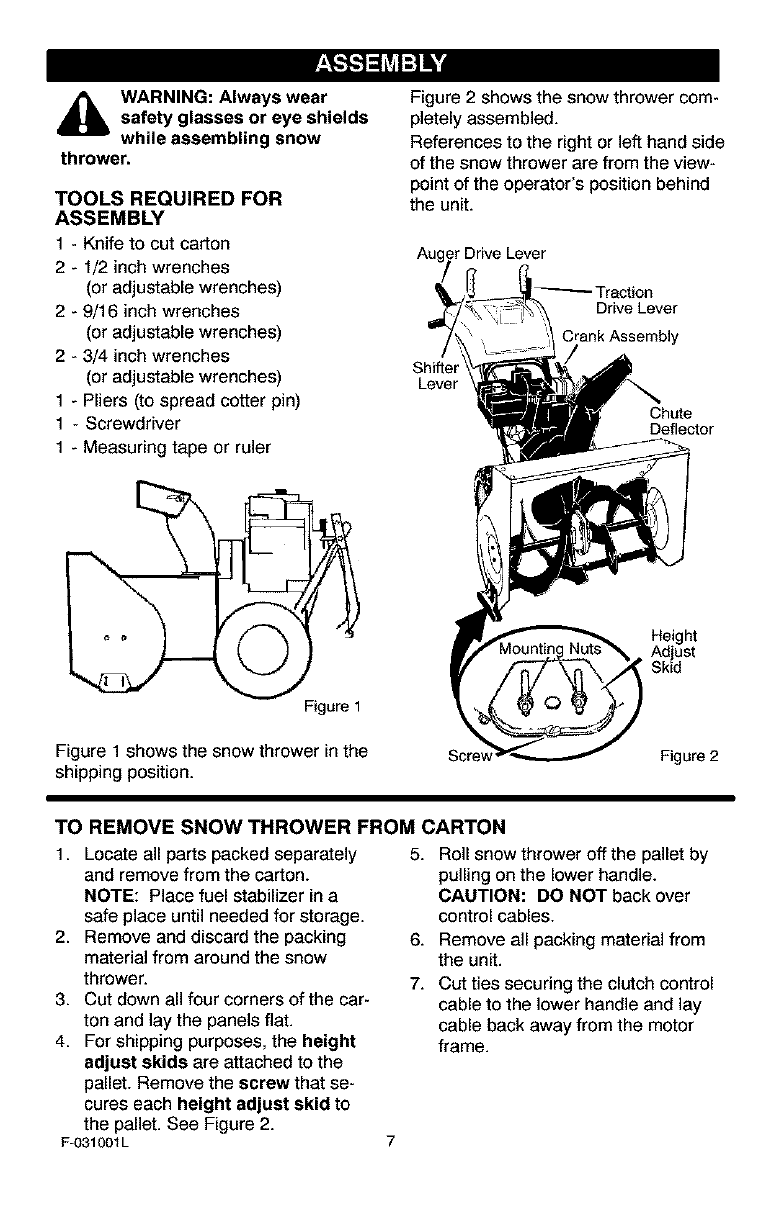
Figure 1
Figure 1 shows the snow thrower in the
shipping position.
Figure 2 shows the snow thrower com-
pletely assembled.
References to the right or left hand side
of the snow thrower are from the view-
point of the operator's position behind
the unit.
Auger Drive Lever
!_ Traction
Drive Lever
Crank Assembly
Shifter
Lever
Chute
Deflector
Height
Adjust
'Skid
Scre\ Figure 2
TO REMOVE SNOW THROWER FROM CARTON
1. Locate all parts packed separately
and remove from the carton.
NOTE: Place fuel stabilizer in a
safe place until needed for storage.
2. Remove and discard the packing
material from around the snow
thrower.
3. Cut down all four corners of the car-
ton and lay the panels flat.
4. For shipping purposes, the height
adjust skids are attached to the
pallet. Remove the screw that se-
cures each height adjust skid to
the pallet. See Figure 2.
F-031001L
5. Roll snow thrower off the pallet by
pulling on the lower handle.
CAUTION: DO NOT back over
control cables.
6. Remove all packing material from
the unit.
7. Cut ties securing the clutch control
cable to the lower handle and lay
cable back away from the motor
frame.
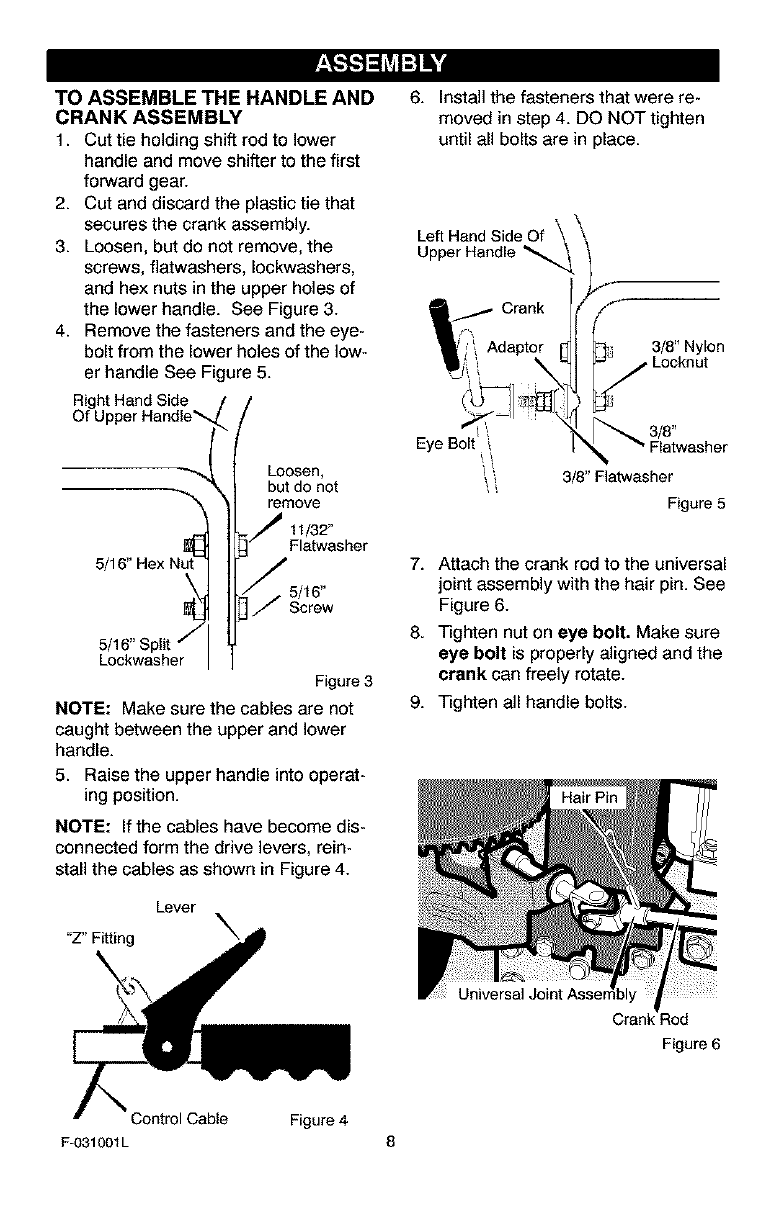
TO ASSEMBLE THE HANDLE AND
CRANK ASSEMBLY
1. Cut tie holding shift rod to lower
handle and move shifter to the first
forward gear.
2. Cut and discard the plastic tie that
secures the crank assembly.
3. Loosen, but do not remove, the
screws, flatwashers, Iockwashers,
and hex nuts in the upper holes of
the lower handle. See Figure 3.
4. Remove the fasteners and the eye-
bolt from the lower holes of the low-
er handle See Figure 5.
Right Hand Side
Of U
5/
5/16" Split j
Lockwasher
Loosen,
but do not
remove
11/32"
Flatwasher
5/16"
Screw
Figure 3
NOTE: Make sure the cables are not
caught between the upper and lower
handle.
5. Raise the upper handle into operat-
ing position.
NOTE: If the cables have become dis-
connected form the drive levers, rein-
stall the cables as shown in Figure 4.
Lever
"Z" Fitting
6. Install the fasteners that were re-
moved in step 4. DO NOT tighten
until all bolts are in place.
Left Hand Side Of
Upper Handle
Eye Bolt
3/8" Nylon
_ Locknut
_"Flatwasher
3/8" Flatwasher
Figure 5
7. Attach the crank rod to the universal
joint assembly with the hair pin. See
Figure 6.
8. Tighten nut on eye bolt. Make sure
eye bolt is properly aligned and the
crank can freely rotate.
9. Tighten all handle bolts.
Figure 6
Control Cable Figure 4
F-031001L 8
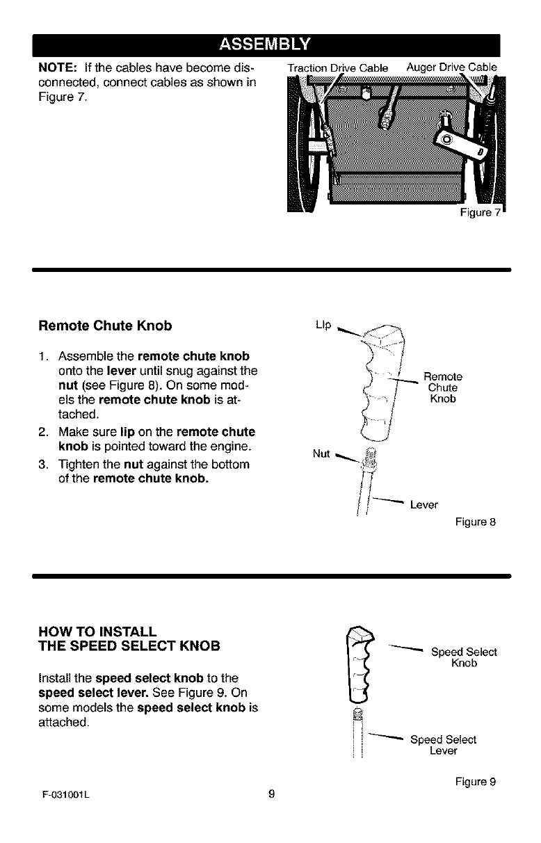
NOTE: If the cables have become dis-
connected, connect cables as shown in
Figure 7.
Traction Drive Cable Auger Drive Cable
Remote Chute Knob
1. Assemble the remote chute knob
onto the lever until snug against the
nut (see Figure 8). On some mod-
els the remote chute knob is at-
tached.
2. Make sure lip on the remote chute
knob is pointed toward the engine.
3. Tighten the nut against the bottom
of the remote chute knob.
Figure 7
Rem_e
Chute
Knob
Lever
Figure 8
HOW TO INSTALL
THE SPEED SELECT KNOB
Install the speed select knob to the
speed select lever. See Figure 9. On
some models the speed select knob is
attached.
_ Speed Select
Knob
_ _-""_ Speed Select
I Lever
Figure 9
F-031001L 9
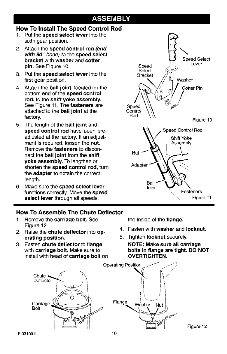
How To Install The Speed Control Rod
1. Put the speed select lever intothe
sixth gear position.
2. Attach the speed control rod (end
with 90 °bend) to the speed select
bracket with washer and cotter
pin. See Figure t0.
3. Put the speed select lever into the Bracket
first gear position.
4. Attach the ball joint, located on the
bottom end of the speed control
rod, to the shift yoke assembly.
See Figure 11. The fasteners are Speed
attached to the ball joint at the Control
factory. Rod
5. The length ot the ball joint and
speed control rod have been pre-
adjusted at the factory, if an adjust-
ment is required, loosen the nut.
Remove the fasteners to discon-
nect the ball joint from the shift Nut _'_'
yoke assembly. To lengthen or
shorten the speed control rod, turn Adapter
the adapter to obtain the correct
length.
6. Make sure the speed select lever
functions correctly. Move the speed
select lever through all speeds.
Joint
Speed Select
Lever
Cotter Pin
Figure 10
Shift Yoke
Assembly
\\ Fasteners
\\. Figure 11
How To Assemble The Chute Deflector
1. Remove the carriage bolt. See
Figure 12.
2. Raise the chute deflector into op-
erating position.
3. Fasten chute deflector to flange
with carriage bolt. Make sure to
install with head of carriage bolt on
the inside of the flange.
4. Fasten with washer and Iocknut.
5. Tighten Iocknut securely.
NOTE: Make sure all carriage
bolts in flange are tight. DO NOT
OVERT|GHTEN.
Chute
Deflector
Carriage,_
Bolt
F-031001L 10
Washer Nut
Figure 12
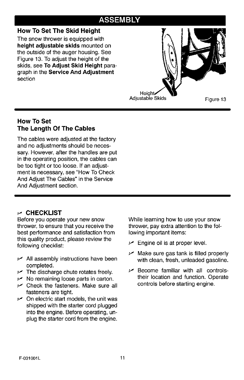
How To Set The Skid Height
The snow thrower is equipped with
height adjustable skids mounted on
the outside of the auger housing. See
Figure 13. To adjust the height of the
skids, see To Adjust Skid Height para-
graph in the Service And Adjustment
section
Adjustable Skids Figure 13
How To Set
The Length Of The Cables
The cables were adjusted at the factory
and no adjustments should be neces-
sary. However, after the handles are put
in the operating position, the cables can
be too tight or too loose. If an adjust-
ment is necessary, see "How To Check
And Adjust The Cables" in the Service
And Adjustment section.
_" CHECKLIST
Before you operate your new snow
thrower, to ensure that you receive the
best performance and satisfaction from
this quality product, please review the
following checklist:
_" All assembly instructions have been
completed.
_" The discharge chute rotates freely.
_" No remaining loose parts in carton.
_" Check the fasteners. Make sure all
fasteners are tight.
_" On electric start models, the unit was
shipped with the starter cord plugged
into the engine. Before operating, un-
plug the starter cord from the engine.
While learning how to use your snow
thrower, pay extra attention to the fol-
lowing important items:
_" Engine oil is at proper level.
_" Make sure gas tank is filled properly
with clean, fresh, unleaded gasoline.
_" Become familiar with all controls-
their location and function. Operate
controls before starting engine.
F-O31001L 11
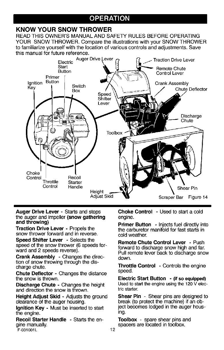
KNOW YOUR SNOW THROWER
READ THIS OWNER'S MANUAL AND SAFETY RULES BEFORE OPERATING
YOUR SNOW THROWER. Compare the illustrations with your SNOW THROWER
to familiarize yourself with the location of various controls and adjustments. Save
this manual for future reference.
Electric Auger Drive
Start
Button
Primer
Ignition Button Crank Assembly
Key Switch
Box Chute Deflector
Traction Ddve Lever
Remote Chute
Control Lever
Discharge
Chute
Choke
Control Recoil
Throttle Starter
Control Handle Shear Pin
Height
Adjust Skid Scraper Bar Figure 14
Auger Drive Lever - Starts and stops
the auger and impeller (snow gathering
and throwing)
Traction Drive Lever - Propels the
snow thrower forward and in reverse.
Speed Shifter Lever - Selects t_e
speed of t_e snow thrower (6 speeds for-
ward and 2speeds reverse).
Crank Assembly - Changes the direc-
tion of snow throwingthrough the dis-
charge chute.
Chute Deflector - Changes the distance
the snow is thrown.
Discharge Chute - Changes the height
and direction t_e snow is thrown.
Height Adjust Skid - Adjusts the ground
clearance of the auger housing.
Ignition Key - Must be inserted to start
the engine.
Recoil Starter Handle - Starts the en-
gine manually.
F-031001L 12
Choke Control -Used to _ a cold
engine.
Primer Button - Injects fuel directly into
the carburetor manifold for fast starts in
cold weather.
Remote Chute Control Lever - Push
forward to discharge snow high and far.
Pull remote lever back to discharge snow
down.
Throttle Control -Controls the engine
speed.
Electric Start Button -(if so equipped)
Usedto startthe engineusingthe120 Velec-
tricstarter.
Shear Pin - Shear pins are designed to
break (to protectthe machine) if an ob-
iect becomes lodged in the auger hous-
ing.
Toolbox - spare shear pins and
spacers are located in toolbox.
Theoperationofanysnowthrowercan
resultinforeignobjectsbeingthrown
intotheeyes,whichcanresultinse-
vereeyedamage.Alwayswearsafety
glassesoreyeshieldswhileoperating
thesnowthrower.
Werecommendstandardsafety
glassesorawidevisionsafetymaskfor
overyourglasses.
_lb ARNING: Read Owner's
Manual before operating
machine. Never direct dis-
charge toward bystanders. Stop the
engine before unclogging discharge
chute or auger housing and before
leaving the machine,
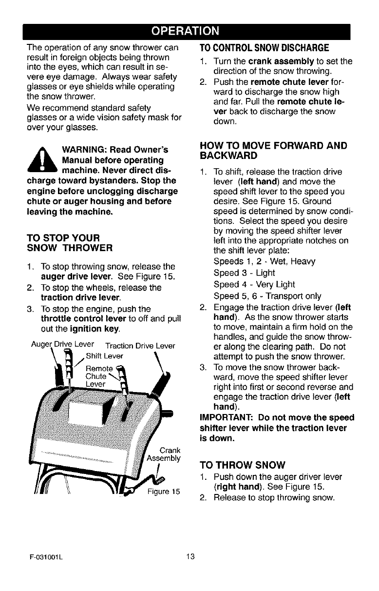
TO STOP YOUR
SNOW THROWER
1. To stop throwing snow, release the
auger drive lever. See Figure 15.
2. To stop the wheels, release the
traction drive lever.
3. To stop the engine, push the
throttle control lever to off and pull
out the ignition key.
Auger Drive Lever Traction Drive Lever
Shift Lever
Crank
Assembly
Figure 15
TO CONTROLSNOWDISCHARGE
1. Turn the crank assembly to set the
direction of the snow throwing.
2. Push the remote chute lever for-
ward to discharge the snow high
and far. Pull the remote chute le-
ver back to discharge the snow
down.
HOW TO MOVE FORWARD AND
BACKWARD
1. TO shift, release the traction drive
lever (left hand) and move the
speed shift lever to the speed you
desire. See Figure 15. Ground
speed is determined by snow condi-
tions. Select the speed you desire
by moving the speed shifter lever
left into the appropriate notches on
the shift lever plate:
Speeds 1, 2 - Wet, Heavy
Speed 3 - Light
Speed 4 - Very Light
Speed 5, 6 - Transport only
2. Engage the traction drive lever (left
hand). As the snow thrower starts
to move, maintain a firm hold on the
handles, and guide the snow throw-
er along the clearing path. Do not
attempt to push the snow thrower.
3. To move the snow thrower back-
ward, move the speed shifter lever
right into first or second reverse and
engage the traction drive lever (left
hand).
IMPORTANT: Do not move the speed
shifter lever while the traction lever
is down.
TO THROW SNOW
1. Push down the auger driver lever
(right hand). See Figure 15.
2. Release to stop throwing snow.
F-O31001L 13
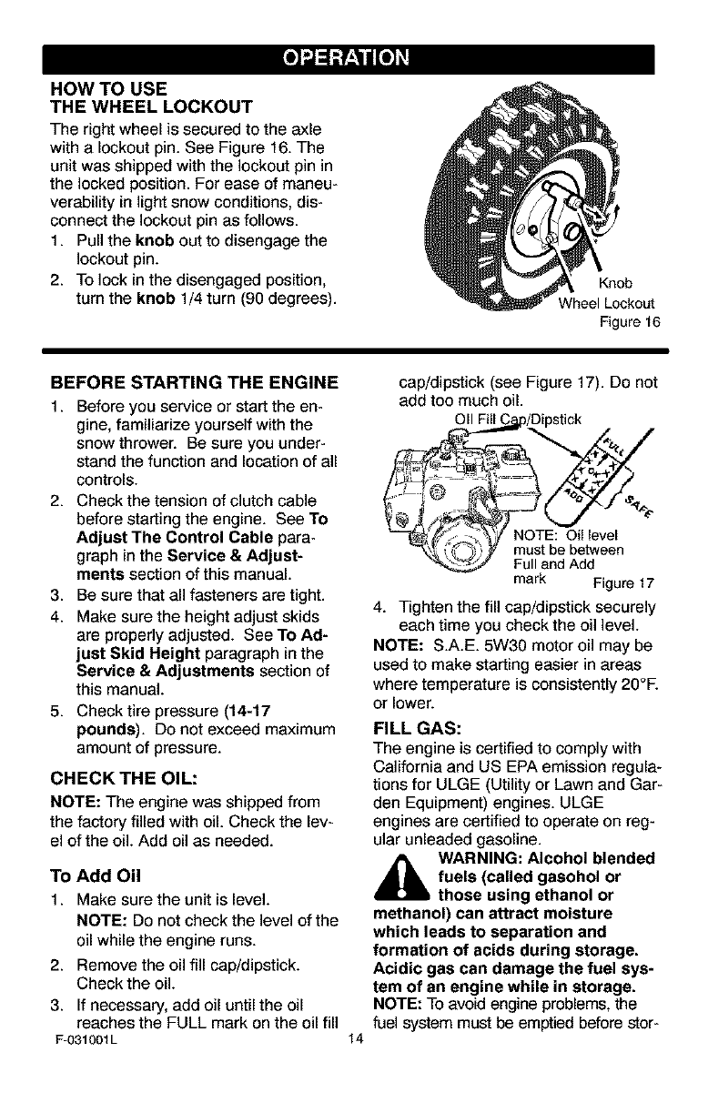
HOW TO USE
THE WHEEL LOCKOUT
The right wheel is secured to the axle
with a lockout pin. See Figure 16. The
unit was shipped with the lockout pin in
the locked position. For ease of maneu-
verability in light snow conditions, dis-
connect the lockout pin as follows.
1. Pull the knob out to disengage the
lockout pin.
2. To lock in the disengaged position,
turn the knob 1/4 turn (90 degrees).
Knob
Wheel Lockout
Figure 16
BEFORE STARTING THE ENGINE
1. Before you service or start the en-
gine, familiarize yourself with the
snow thrower. Be sure you under-
stand the function and location of all
controls.
2. Check the tension of clutch cable
before starting the engine. See To
Adjust The Control Cable para-
graph in the Service & Adjust-
ments section of this manual.
3. Be sure that all fasteners are tight.
4. Make sure the height adjust skids
are properly adjusted. See To Ad-
just Skid Height paragraph in the
Service & Adjustments section of
this manual.
5. Check tire pressure (14-17
pounds). Do not exceed maximum
amount of pressure.
CHECK THE OIL:
NOTE: The engine was shipped from
the factory filled with oil. Check the lev-
el of the oil. Add oil as needed.
TO Add Oil
1. Make sure the unit is level.
NOTE: Do not check the level of the
oil while the engine runs.
2. Remove the oil fill cap/dipstick.
Check the oil.
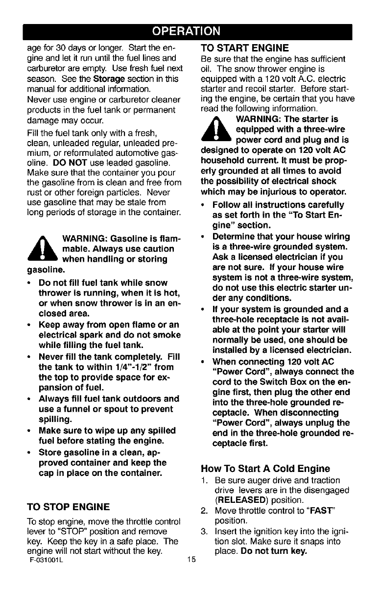
3. If necessary, add oil until the oil
reaches the FULL mark on the oil fill
F-031001L 14
cap/dipstick (see Figure 17). Do not
add too much oil.
011Fill C_p/Dipstick
-_%'_,,'NOTE: Oil level
_y must.be between
Fulland Add
mark Figure 17
4. Tighten the fill cap/dipstick securely
each time you check the oil level.
NOTE: S.A.E. 5W30 motor oil may be
used to make starting easier in areas
where temperature is consistently 20°E
or lower.
FILL GAS:
The engine is certified to comply with
California and US EPA emission regula-
tions for ULGE (Utility or Lawn and Gar-
den Equipment) engines. ULGE
engines are certified to operate on reg-
ular unleaded gasoline.
,_ WARNING: Alcohol blended
fuels (called gasohol or
those using ethanol or
methanol) can attract moisture
which leads to separation and
formation of acids during storage.
Acidic gas can damage the fuel sys-
tem of an engine while in storage.
NOTE: To avoid engine problems, the
fuel system must be emptied before stor-
agefor30daysorlonger.Starttheen-
gineandlet it run until the fuel lines and
carburetor are empty. Use fresh fuel next
season. See _e Storage section in this
manual for additional information.
Never use engine or carburetor cleaner
products in the fuel tank or permanent
damage may occur.
Fill the fuel tank only with a fresh,
clean, unleaded regular, unleaded pre-
mium, or reformulated automotive gas-
oline. DO NOT use leaded gasoline.
Make sure that the container you pour
the gasoline from is clean and free from
rust or other foreign particles. Never
use gasoline that may be stale from
long periods of storage in the container.
4_b WARNING: Gasoline is flam-
mable. Always use caution
when handling or storing
gasoline.
•Do not fill fuel tank while snow
thrower is running, when it is hot,
or when snow thrower is in an en-
closed area.
•Keep away from open flame or an
electrical spark and do not smoke
while filling the fuel tank.
•Never fill the tank completely. Fill
the tank to within 1/4"-1/2" from
the top to provide space for ex-
pansion of fuel.
•Always fill fuel tank outdoors and
use a funnel or spout to prevent
spilling.
•Make sure to wipe up any spilled
fuel before stating the engine.
•Store gasoline in a clean, ap-
proved container and keep the
cap in place on the container.
TO STOP ENGINE
To stop engine, move the throttle control
lever to "STOP" position and remove
key. Keep the key in a safe place. The
engine will not start without the key.
F-031001L
TO START ENGINE
Be sure that the engine has sufficient
oil. The snow thrower engine is
equipped with a 120 volt A.C. electric
starter and recoil starter. Before start-
ing the engine, be certain that you have
read the following information.
4_lb WARNING: The starter is
equipped with a three-wire
power cord and plug and is
designed to operate on 120 volt AC
household current. It must be prop-
erly grounded at all times to avoid
the possibility of electrical shock
which may be injurious to operator.
• Follow all instructions carefully
as set forth in the "To Start En-
gine" section.
•Determine that your house wiring
is a three-wire grounded system.
Ask a licensed electrician if you
are not sure. If your house wire
system is not a three-wire system,
do not use this electric starter un-
der any conditions.
•If your system is grounded and a
three-hole receptacle is not avail-
able at the point your starter will
normally be used, one should be
installed by a licensed electrician.
•When connecting 120 volt AC
"Power Cord", always connect the
cord to the Switch Box on the en-
gine first, then plug the other end
into the three-hole grounded re-
ceptacle. When disconnecting
"Power Cord", always unplug the
end in the three-hole grounded re-
ceptacle first.
15
How To Start A Cold Engine
1. Be sure auger drive and traction
drive levers are in the disengaged
(RELEASED) position.
2. Move throttle control to "FAST'
position.
3. Insert the ignition key into the igni-
tion slot. Make sure it snaps into
place. Do not turn key.
4. Rotatechokeknobclockwisetothe
chokeONposition.
5. (Electric Start) Plug the power cord
into the switch box on the engine.
Plug the other end of power cord
into a three-hole, grounded 120
VOLT, AC receptacle.
6. Push the primer button as speci-
fied below. Remove finger from
primer button between pushes.
Do not push if temperature
above 50 ° F (10 ° C).
Push two times if temperature is
50° F (10 ° C) to 15°F (-10° C).
Push four times if temperature is
below 15° F (-10 ° C).
Push five times if temperature is
below 0° F (-18 ° C).
7. (Electric Start) Push down on the
starter button until the engine
starts. Do not crank for more than
10 seconds at a time. This electric
starter is thermally protected. If
overheated it will stop automatically
and can be restarted only when it
has cooled to a safe temperature (a
wait of about 5 to 10 minutes is re-
quired).
8. (Recoil Start) Rapidly pull the re-
coil starter handle. Do not allow
the recoil starter handle to snap
back. Slowly return the recoil start-
er handle.
9. Ifthe engine does not start in 5 or 6
tries, See Difficult Starting in the
"Troubleshooting Table".
10. When the engine starts, move the
choke control to "1/2 choke" posi-
tion. When engine runs smoothly,
move choke control to the off
Position.
11. (Electric Start) First disconnect
power cord from receptacle. Then,
disconnect the power cord from the
switch box.
12. Run engine at full throttle "FAST"
when throwing snow.
Allow the engine to warm up for several
minutes before blowing snow in temper-
F-031001L
atures below 0°F.
16
How To Start A Warm Engine
If restarting a warm engine after a short
shutdown, leave the choke lever in the
off position and do not push the primer
button. If the engine fails to start, follow
the Cold Start instructions.
FROZEN STARTER
If the starter is frozen and will not turn
engine:
1. Pull as much rope out of the starter
as possible.
2. Release the starter handle and let it
snap back against the starter. Re-
peat until the engine starts.
To help prevent possible freeze-up of
recoil starter and engine controls, pro-
ceed as follows after each snow remov-
al job.
1. With the engine running, pull the
starter rope hard with a continuous
full arm stroke three or four times.
Pulling of starter rope will produce a
loud clattering sound. This is not
harmful to the engine or starter.
2. With the engine not running, wipe all
snow and moisture from the carbu-
retor cover in area of control levers.
Also move throttle control, choke
control, and starter handle several
times.
,_ WARNING: Never run en-
gine indoors or in enclosed,
poorly ventilated areas. En-
gine exhaust contains CARBON
MONOXIDE, AN ODORLESS AND
DEADLY GAS. Keep hands, feet,
hair and loose clothing away from
any moving parts on engine and
snow thrower.
• The temperature of muffler and
nearby areas may exceed 150°R
Avoid these areas.
•DO NOT allow children or young
teenagers to operate or be near
snow thrower while it is operat-
ing.
HOWTOREMOVESNOWFROM
AUGER
_[b WARNING: Do not attempt
to remove snow or debris
that may become lodged in
auger without taking the following
precautions:
A cleaning stick is attached to the top of
the auger housing. Use the cleaning
stick to remove snow from the auger
housing.
Release auger drive lever.
Move throttle lever to stop position.
Remove (do not turn) ignition key.
Disconnect spark plug wire.
Do not place your hands in the au-
ger or discharge chute. Use the
cleaning stick to remove snow.
SNOW THROWING TIPS
1. For maximum snow thrower efficien-
cy in removing snow, adjust ground
speed, NEVER the throttle. Go
slower in deep, freezing or wet
snow. Ifthe wheels slips, reduce
forward speed. The engine is de-
signed to deliver maximum perfor-
mance at full throttle and should be
run at this power setting at all times.
2. Most efficient snow throwing is ac-
complished when the snow is re-
moved immediately after if fails.
3. For complete snow removal, slightly
overlap each path previously taken.
4. The snow should be discharged
down wind whenever possible.
5. For normal usage, set the skids so
that the scraper bar is 1/8" above
the skids. For extremely hard-
packed snow surfaces, adjust the
skids upward so that the scraper
bar touches the ground.
6. On gravel or crushed rock surfaces,
set the skids at 1-1/4" below the
scraper bar. See To Adjust Skid
Height paragraph in the Service &
Adjustments section of this manu-
al. Rocks and gravel must not be
picked up and thrown by the ma-
chine.
7. After the snow throwing job has
been completed, allow the engine to
idle for a few minutes, which will
melt snow and accumulated ice off
the engine.
8. Clean the snow thrower thoroughly
after each use.
9. Remove ice and snow accumulation
and all debris from the entire snow
thrower, and flush with water (if pos-
sible) to remove all salt or other
chemicals. Wipe snow thrower dry.
F-031001L 17
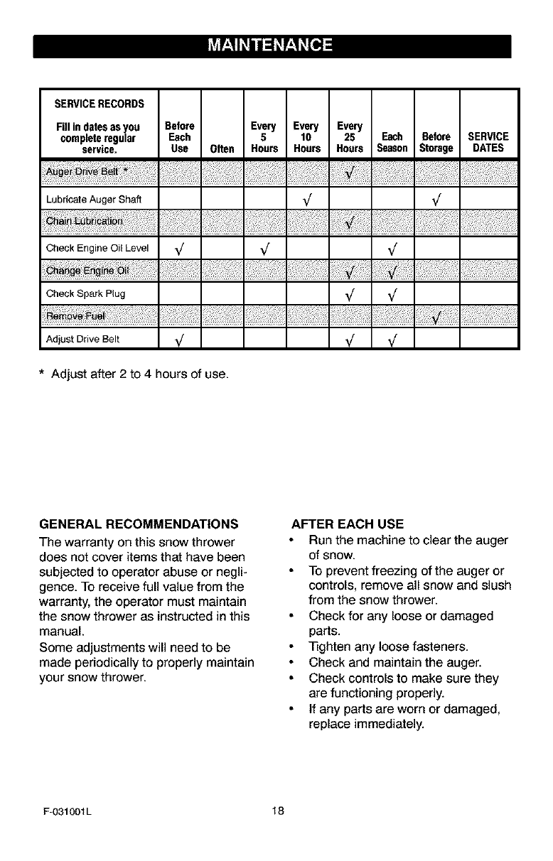
SERVICERECORDS
Fillindatesasyou Before Every Every Every
completeregular Each 5 10 25 Each Before SERVICE
service. Use Often Hours Hours Hours Season Stcrage DATES
Lubricate Auger Shaft _
Check Engine 0il Level _/ V V
Check Spark Plug _
vo
AdjustDrive Belt V V V
*Adjust after 2 to 4 hours of use.
GENERAL RECOMMENDATIONS
The warranty on this snow thrower
does not cover items that have been
subjected to operator abuse or negli-
gence. To receive full value from the
warranty, the operator must maintain
the snow thrower as instructed in this
manual.
Some adjustments will need to be
made periodically to properly maintain
your snow thrower.
AFTER EACH USE
Run the machine to clear the auger
of snow.
To prevent freezing of the auger or
controls, remove all snow and slush
from the snow thrower.
Check for any loose or damaged
parts.
_ghten any loose fasteners.
Check and maintain the auger.
Check controls to make sure they
are functioning properly.
If any parts are worn or damaged,
replace immediately.
F-O31OOIL 18
PRODUCT SPECIFICATIONS
HORSEPOWER 11 HP
DISPLACEMENT 21.82 cu, in.
GASOLINE 4 quads
CAPACITY (unleaded)
OIL CAPACITY 5W30
(20 oz capacity)
SPARK PLUG: Champion RJt9LM
(Gap .030 in,) er
equivalent
VALVE CLEARANCE: Inteke: ,010 In,
Exhaust: .010 In,
SNOW THROWER
AUGER DRIVE BELT
Adjust the auger drive belt after the first
2 to 4 hours of use, again about mid-
season and twice each season thereaf-
ter (See "Belt Adjustment" in the
Service and Adjustment section).
AUGER SHAFT LUBRICATION
EVERY 10 HOURS
1. Lubricetethe Zerk fittings (A) every ten
hourswith agrease gun.
2. Each time a shear bolt is replaced,
the auger shaft MUST be greased.
See Figure 18. See To Replace Au-
ger Shear Bolt in the Service and
Adjustment section.
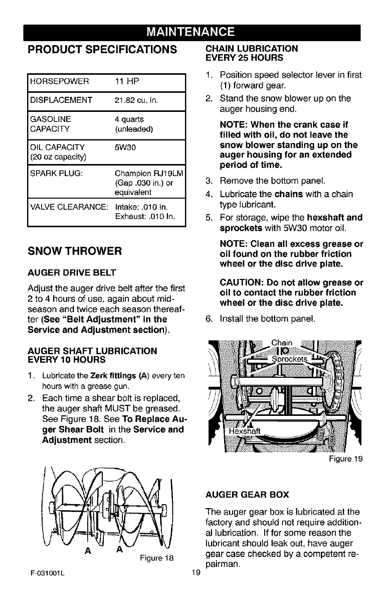
CHAIN LUBRICATION
EVERY 25 HOURS
1. Position speed selector lever in first
(1) forward gear.
2. Stand the snow blower up on the
auger housing end.
NOTE: When the crank case if
filled with oil, do not leave the
snow blower standing up on the
auger housing for an extended
period of time.
3. Remove the bottom panel.
4. Lubricate the chains with a chain
type lubricant.
5. For storage, wipe the hexsheft and
sprockets with 5W30 motor oil.
NOTE: Clean all excess grease or
oil found on the rubber friction
wheel or the disc drive plate.
CAUTION: Do not allow grease or
oil to contact the rubber friction
wheel or the disc drive plate.
6. Install the bottom panel.
Figure 19
A
F-031001L
Figure 18
19
AUGER GEAR BOX
The auger gear box is lubricated at the
factory and should not require addition-
al lubrication. If for some reason the
lubricant should leak out, have auger
gear case checked by a competent re-
pairman.
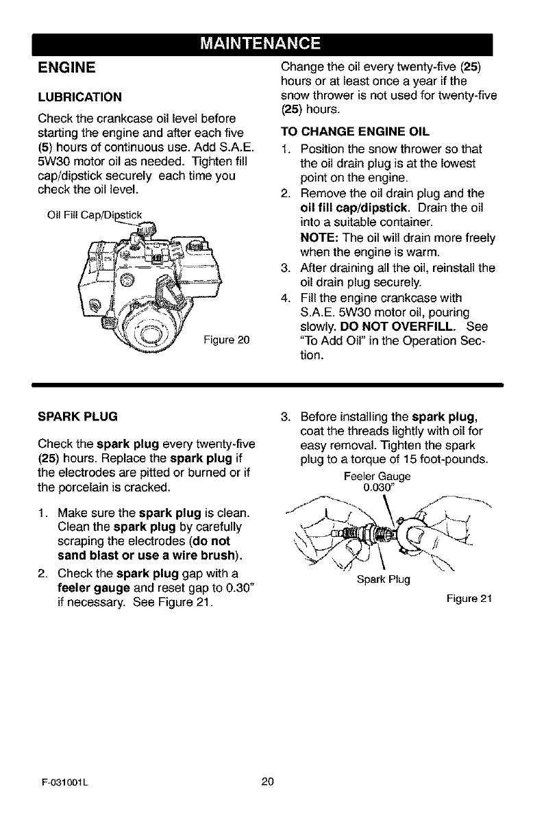
ENGINE
LUBRICATION
Check the crankcase oil level before
starting the engine and after each five
(5) hours of continuous use. Add S.A.E.
5W30 motor oil as needed. Tighten fill
cap/dipstick securely each time you
check the oil level.
Oil Fill Cap/Di_
Figure 20
Change the oil every twenty-five (25)
hours or at least once a year if the
snow thrower is not used for twenty-five
(25) hours.
TO CHANGE ENGINE OIL
1. Position the snow thrower so that
the oil drain plug is at the lowest
point on the engine.
2. Remove the oil drain plug and the
oil fill cap/dipstick. Drain the oil
into a suitable container.
NOTE: The oil will drain more freely
when the engine is warm.
3. After draining all the oil, reinstall the
oil drain plug securely.
4. Fill the engine crankcase with
S.A.E. 5W30 motor oil, pouring
slowly. DO NOT OVERFILL. See
"To Add Oil" in the Operation Sec-
tion.
SPARK PLUG
Check the spark plug every twenty-five
(25) hours. Replace the spark plug if
the electrodes are pitted or burned or if
the porcelain is cracked.
1. Make sure the spark plug is clean.
Clean the spark plug by carefully
scraping the electrodes (do not
sand blast or use awire brush).
2. Check the spark plug gap with a
feeler gauge and reset gap to 0.30"
if necessary. See Figure 21.
3. Before installing the spark plug,
coat the threads lightly with oil for
easy removal. Tighten the spark
plug to a torque of 15 foot-pounds.
Feeler Gauge
O.03O"
Spark Plug
Figure 21
F-031001L 20
_lb ARNING: Always discon-
nect the spark plug wire and
place it where it cannot
make contact with spark plug to pre-
vent accidental starting when mak-
ing any adjustments or repairs.
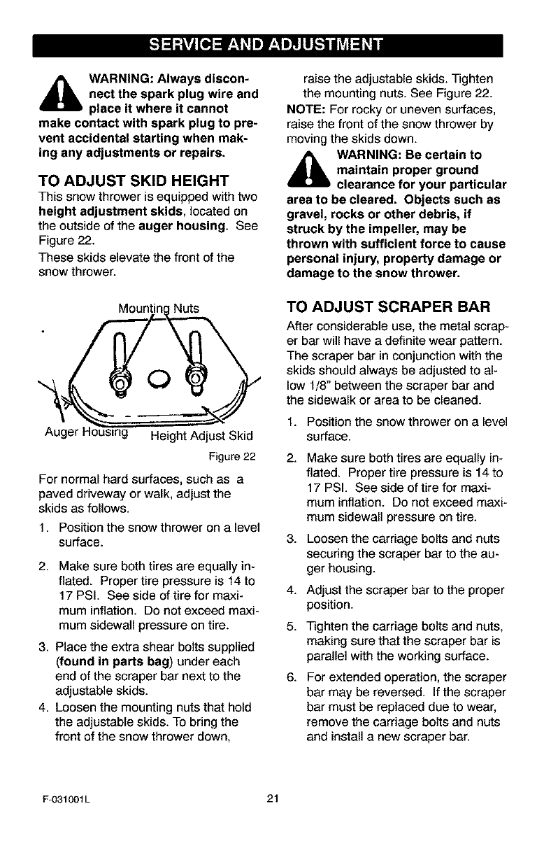
TO ADJUST SKID HEIGHT
This snow thrower is equipped with two
height adjustment skids, located on
the outside of the auger housing. See
Figure 22.
These skids elevate the front of the
snow thrower.
Nuts
0
Auger t- Height Adjust Skid
Figure 22
For normal hard surfaces, such as a
paved driveway or walk, adjust the
skids as follows.
1. Position the snow thrower on a level
surface.
2. Make sure both tires are equally in-
flated. Proper tire pressure is 14 to
17 PSI. See side of tire for maxi-
mum inflation. Do not exceed maxi-
mum sidewall pressure on tire.
3. Place the extra shear bolts supplied
(found in parts bag) under each
end of the scraper bar next to the
adjustable skids.
4. Loosen the mounting nuts that hold
the adjustable skids. To bring the
front of the snow thrower down,
raise the adjustable skids. Tighten
the mounting nuts. See Figure 22.
NOTE: For rocky or uneven surfaces,
raise the front of the snow thrower by
moving the skids down.
_lb ARNING: Be certain to
maintain proper ground
clearance for your particular
area to be cleared. Objects such as
gravel, rocks or other debris, if
struck by the impeller, may be
thrown with sufficient force to cause
personal injury, property damage or
damage to the snow thrower.
TO ADJUST SCRAPER BAR
After considerable use, the metal scrap-
er bar will have a definite wear pattern.
The scraper bar in conjunction with the
skids should always be adjusted to al-
low 1/8" between the scraper bar and
the sidewalk or area to be cleaned.
1. Position the snow thrower on a level
surface.
2.
3.
4.
5.
6.
Make sure both tires are equally in-
flated. Proper tire pressure is 14to
17 PSI. See side of tire for maxi-
mum inflation. Do not exceed maxi-
mum sidewall pressure on tire.
Loosen the carriage bolts and nuts
securing the scraper bar to the au-
ger housing.
Adjust the scraper bar to the proper
position.
Tighten the carriage bolts and nuts,
making sure that the scraper bar is
parallel with the working surface.
For extended operation, the scraper
bar may be reversed. If the scraper
bar must be replaced due to wear,
remove the carriage bolts and nuts
and install a new scraper bar.
F-O31001L 21
BELT ADJUSTMENT
Traction Drive Belt
The traction drive belt has constant
spring pressure and does not require
an adjustment. If the traction drive belt
is slipping, replace the belt. See "How
To Replace The Belts" in the Service
And Adjustment section.
Auger Drive Belt
If your snow blower will not discharge
snow, check the control cable adjust-
ment. If it is correct, then check the
condition of the auger drive belt. If it is
damaged or loose, replace it (see "How
To Replace The Belts" in this section of
the manual).
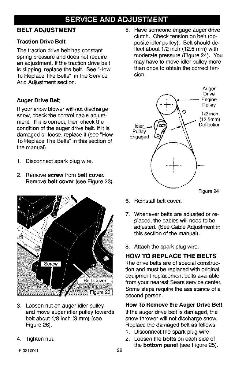
1. Disconnect spark plug wire.
2. Remove screw from belt cover.
Remove belt cover (see Figure 23).
Belt Cover
3. Loosen nut on auger idler pulley
and move auger idler pulley towards
belt about 1/8 inch (3 mm) (see
Figure 26).
4. Tighten nut.
F-031001L
5. Have someone engage auger drive
clutch. Check tension on belt (op-
posite idler pulley). Belt should de-
flect about 1/2 inch (12.5 mm) with
moderate pressure (Figure 24). You
may have to move idler pulley more
than once to obtain the correct ten-
sion.
Auger
( e
--_ ,_ Pulley
j ;,_O 1/2 inch
._- '.,_ (12.5ram)
Idler_s- (_ ._'_\/ Deflection
Pu,,ey " :,\
Engaged L_ ,,
Figure 24
6. Reinstall belt cover.
7. Whenever belts are adjusted or re-
placed, the cables will need to be
adjusted. (See Cable Adjustment in
this section of the manual).
22
8. Attach the spark plug wire.
HOW TO REPLACE THE BELTS
The drive belts are of special construc-
tion and must be replaced with original
equipment replacement belts available
from your nearest Sears service center.
Some steps require the assistance of a
second person.
How To Remove the Auger Drive Belt
If the auger drive belt is damaged, the
snow thrower will not discharge snow.
Replace the damaged belt as follows.
1. Disconnect the spark plug wire.
2. Loosen the bolts on each side of
the bottom panel (see Figure 25).

3. Remove the bottom panel,
Bolt Bottom
Panel
Auger
Housing
4. Remove screw from belt cover.
Remove the belt cover (see
Figure 23).
5. Loosen the belt guide. Pull the belt
guide away from the auger drive
pulley (see Figure 26).
6. Pull the idler pulley away from the
auger drive belt.
7. Remove the old auger drive belt
from the auger drive pulley and
_ Traction Drive Be,t
Engine Pulley
from the engine pulley. Replace
the auger drive belt with an original
equipment replacement belt avail-
able from a Sears service center.
8. Install the new auger drive belt
onto the auger drive pulley and
onto pulley.
9. Adjust the auger drive belt. See
"How To Adjust The Auger Drive
Belt" in the Service And Adjustment
section.
10. Adjust the belt guide. See "How To
Adjust The Belt Guide" in the Ser-
vice And Adjustment section.
11. Install the belt cover. Tighten
screw (See Figure 23).
12. Check the adjustment of the cables.
See "How To Check And Adjust The
Cables" in the Service And Adjust-
ment section.
13. Install the bottom panel (see
Figure 25).
14. Tighten the bolts on each side of
the bottom panel.
15. Connect the spark plug wire.
Belt Guide
'\ WII _
Auger Idler Pulley
Auger Drive Pulley
Auger Drive Belt
E-Ring
Swing Plate
Axle Rod
Traction Drive
Spring
Traction
Drive Belt
Traction
Drive Pulley
Engine
Pulley
Figure 26
F-031001L 23
How To Remove
The Traction Drive Belt
If the snow thrower will not move for-
ward, check the traction drive belt for
wear or damage. If the traction drive
belt is worn or damaged, replace the
belt as follows.
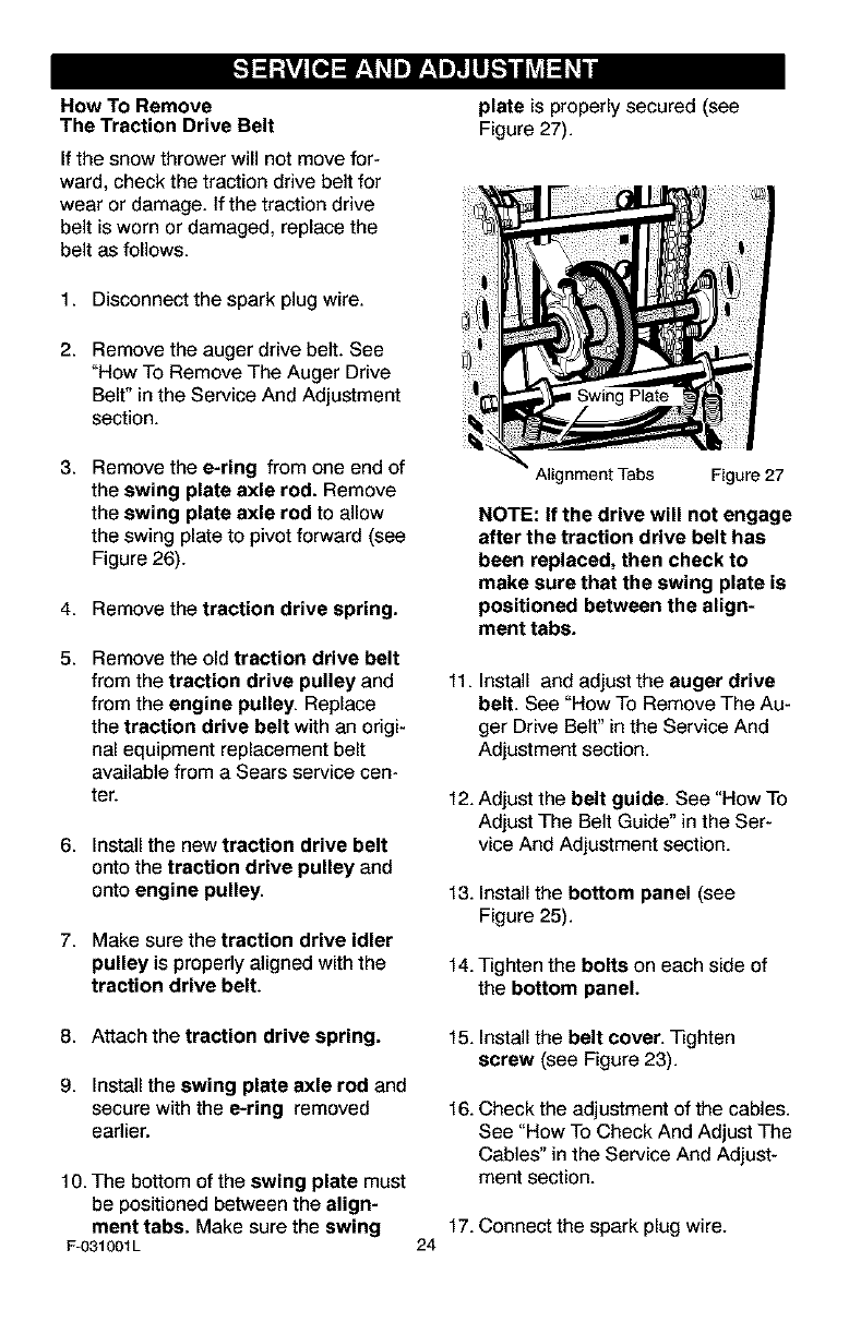
plate is properly secured (see
Figure 27).
1. Disconnect the spark plug wire.
2. Remove the auger drive belt. See
"How To Remove The Auger Drive
Belt" in the Service And Adjustment
section.
3. Remove the e-ring from one end of
the swing plate axle rod. Remove
the swing plate axle rod to allow
the swing plate to pivot forward (see
Figure 26).
4. Remove the traction drive spring.
5. Remove the old traction drive belt
from the traction drive pulley and
from the engine pulley. Replace
the traction drive belt with an origi-
nal equipment replacement belt
available from a Sears service cen-
ter.
6. Install the new traction drive belt
onto the traction drive pulley and
onto engine pulley.
7. Make sure the traction drive idler
pulley is properly aligned with the
traction drive belt.
Alignment Tubs Figure 27
NOTE: If the drive will not engage
after the traction drive belt has
been replaced, then check to
make sure that the swing plate is
positioned between the align-
ment tabs.
11. Install and adjust the auger drive
belt. See "How To Remove The Au-
ger Drive Belt" in the Service And
Adjustment section.
12. Adjust the belt guide. See "How To
Adjust The Belt Guide" in the Ser-
vice And Adjustment section.
13. Installthe bottom panel (see
Figure 25).
14. Tighten the bolts on each side of
the bottom panel.
8. Attach the traction drive spring.
9. Install the swing plate axle rod and
secure with the e-ring removed
earlier.
10. The bottom of the swing plate must
be positioned between the align-
ment tabs. Make sure the swing
Fu031001L
15. Installthe belt cover. Tighten
screw (see Figure 23).
16. Check the adjustment of the cables.
See "How To Check And Adjust The
Cables" in the Service And Adjust-
ment section.
17. Connect the spark plug wire.
24
BELT GUIDE ADJUSTMENT
1. Remove spark plug wire.
2. Have someone engage auger drive.
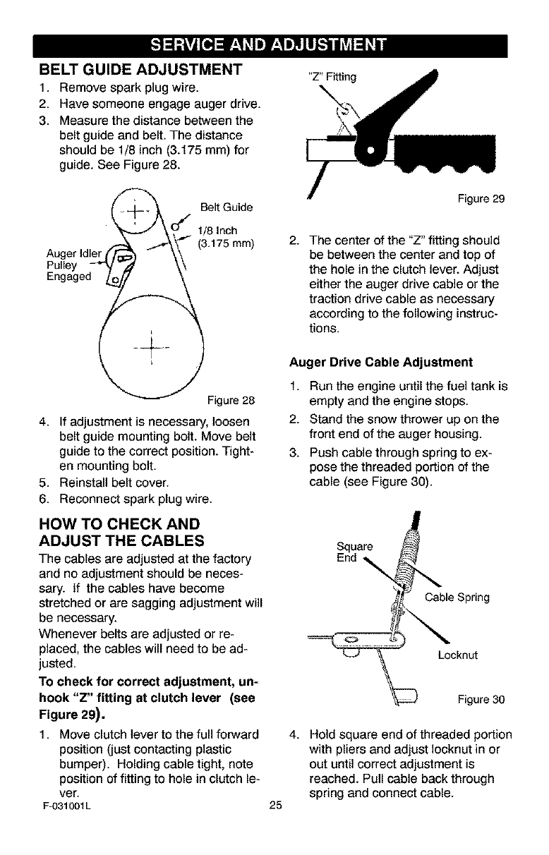
3. Measure the distance between the
belt guide and belt. The distance
should be 1/8 inch (3.175 mm) for
guide. See Figure 28.
"Z" Fitting
__. Belt Guide
_'_" O_ 1/8 Inch
Auger Idler (_[ __'_" (3,175 ram)
EPnu_eYed_i___
Figure 28
4. If adjustment is necessary, loosen
belt guide mounting bolt. Move belt
guide to the correct position. Tight-
en mounting bolt.
5. Reinstall belt cover.
6. Reconnect spark plug wire.
HOW TO CHECK AND
ADJUST THE CABLES
The cables are adjusted at the factory
and no adjustment should be neces-
sary. If the cables have become
stretched or are sagging adjustment will
be necessary.
Whenever belts are adjusted or re-
placed, the cables will need to be ad-
justed.
To check for correct adjustment, un-
hook "Z" fitting at clutch lever (see
Figure 29).
1. Move clutch lever to the full forward
position (just contacting plastic
bumper). Holding cable tight, note
position of fitting to hole in clutch le-
ver.
Fu031001L
Figure 29
2. The center of the "Z" fitting should
be between the center and top of
the hole in the clutch lever. Adjust
either the auger drive cable or the
traction drive cable as necessary
according to the following instruc-
tions.
Auger Drive Cable Adjustment
1. Run the engine until the fuel tank is
empty and the engine stops.
2. Stand the snow thrower up on the
front end of the auger housing.
3. Push cable through spring to ex-
pose the threaded portion of the
cable (see Figure 30).
Square
End
Cable Spring
Locknut
Figure 30
25
4. Hold square end of threaded portion
with pliers and adjust Iocknut in or
out until correct adjustment is
reached. Pull cable back through
spring and connect cable.
TRACTION DRIVE CABLE ADJUSTMENT
1. Runthe engineuntilthe fueltank is 6. Puehthe bottomof the traction
empty and the engine stops.
2. Stand the snow thrower up on the
front end of the auger housing.
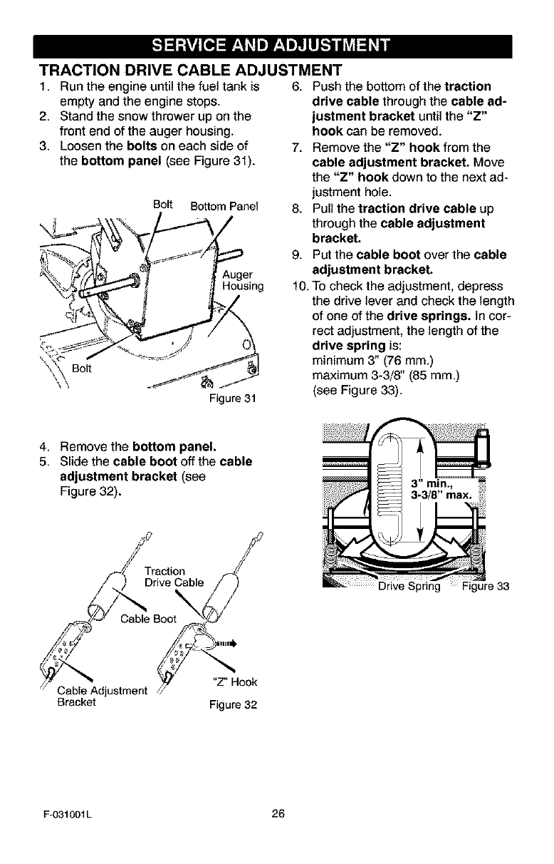
3. Loosen the bolts on each side of
the bottom panel (see Figure 31).
Bolt Bottom Panel
Auger
Housing
Figure 31
drive cable through the cable ad-
justment bracket until the "Z"
hook can be removed.
7. Remove the "Z" hook from the
cable adjustment bracket. Move
the "Z" hook down to the next ad-
justment hole.
8. Pull the traction drive cable up
through the cable adjustment
bracket.
9. Put the cable boot over the cable
adjustment bracket.
10. To check the adjustment, depress
the drive lever and check the length
of one of the drive springs. In cor-
rect adjustment, the length of the
drive spring is:
minimum 3" (76 mm.)
maximum 3-3/8" (85 mm.)
(see Figure 33).
4. Remove the bottom panel.
5. Slide the cable boot off the cable
adjustment bracket (see
Figure 32). 3-3/8" max. .....
/ /
' Trection
Cable Boo
j Cable_Adjustment /v_t 'Z" Hook
Bracket Figure 32
F-O31001L 26
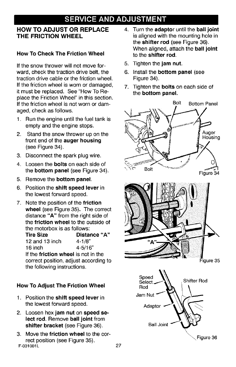
HOW TO ADJUST OR REPLACE
THE FRICTION WHEEL
How To Check The Friction Wheel
If the snow thrower will not move for-
ward, check the traction drive belt, the
traction drive cable or the friction wheel.
If the friction wheel is worn or damaged,
it must be replaced. See "How To Re-
place the Friction Wheel" in this section.
If the friction wheel is not worn or dam-
aged, check as follows.
1. Run the engine until the fuel tank is
empty and the engine stops.
2. Stand the snow thrower up on the
front end of the auger housing
(see Figure 34).
3. Disconnect the spark plug wire.
4. Loosen the bolts on each side of
the bottom panel (see Figure 34).
5. Remove the bottom panel.
6. Position the shift speed lever in
the lowest forward speed.
7. Note the position of the friction
wheel (see Figure 35). The correct
distance "A" from the right side of
the friction wheel to the outside of
the motorbox is as fallows:
Tire Size Distance "A"
12 and 13 inch 4-1/8"
16 inch 4-5/16"
If the friction wheel is not in the
correct position, adjust according to
the following instructions.
4.
5.
6.
7.
Turn the adaptor until the ball joint
is aligned with the mounting hole in
the shifter rod (see Figure 36).
When aligned, attach the ball joint
to the shifter rod.
Tighten the jam nut.
Install the bottom panel (see
Figure 34).
Tighten the bolts on each side of
the bottom panel.
Bolt Bottom Panel
Auger
Housing
Bolt Figure 34
Figure 35
How To Adjust The Friction Wheel
1. Position the shift speed lever in
the lowest forward speed.
2. Loosen hexjam nut on speed se-
lect rod. Remove ball joint from
shifter bracket (see Figure 36).
3. Move the friction wheel to the cor-
rect position (see Figure 35).
F-031001L
Rod
Jam
Adaptor
Ball Joint
27
Shifter Rod
\_ Figure 36
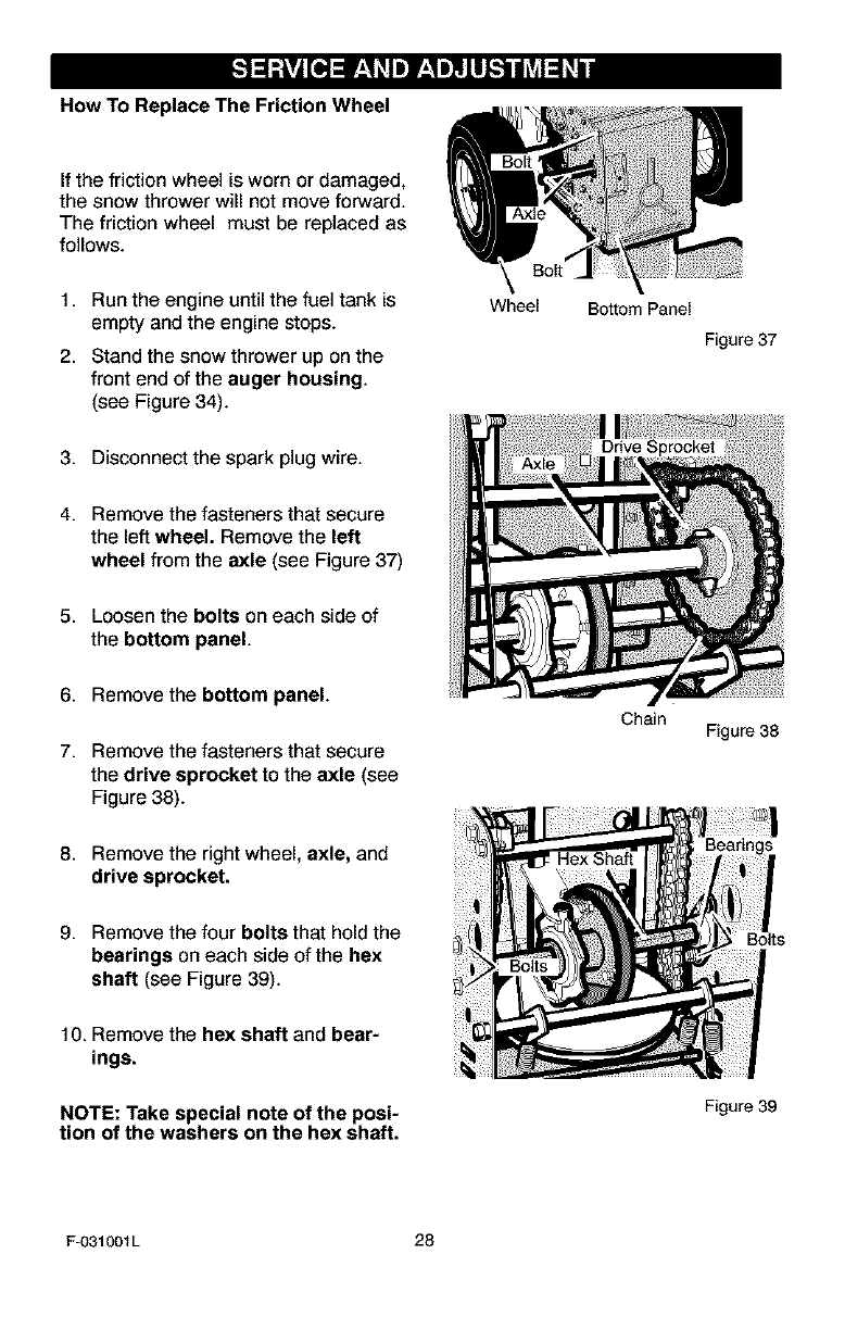
How To Replace The Friction Wheel
If the friction wheel is worn or damaged,
the snow thrower will not move forward.
The friction wheel must be replaced as
follows.
1. Run the engine until the fuel tank is
empty and the engine stops.
2. Stand the snow thrower up on the
front end of the auger housing.
(see Figure 34).
Wheel Bottom Panel
Figure 37
3. Disconnect the spark plug wire.
4. Remove the fasteners that secure
the left wheel. Remove the left
wheel from the axle (see Figure 37)
5. Loosen the bolts on each side of
the bottom panel.
6. Remove the bottom panel.
7. Remove the fasteners that secure
the drive sprocket to the axle (see
Figure 38).
Chain Figure 38
8. Remove the right wheel, axle, and
drive sprocket.
9. Remove the four bolts that hold the
bearings on each side of the hex
shaft (see Figure 39).
10. Remove the hax shaft and bear-
ings.
NOTE: Take special note of the posi-
tion of the washers on the hex shaft.
Bolts
Figure 39
F-O31001L 28
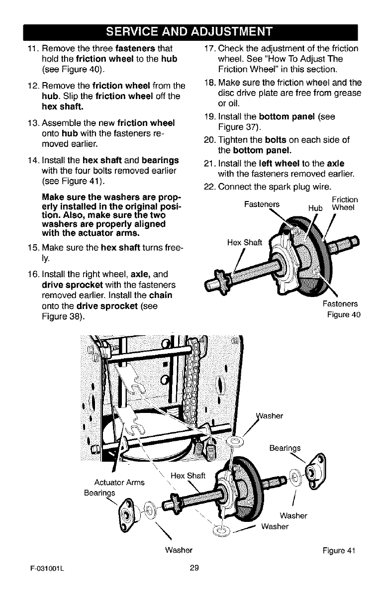
11. Remove the three fasteners that
hold the friction wheel to the hub
(see Figure 40).
12. Remove the friction wheel from the
hub. Slip the friction wheel off the
hex shaft.
13. Assemble the new friction wheel
onto hub with the fasteners re-
moved earlier.
14. Install the hex shaft and bearings
with the four bolts removed earlier
(see Figure 41).
Make sure the washers are prop-
erly installed in the original posi-
tion. Also, make sure the two
washers are properly aligned
with the actuator arms.
15. Make sure the hex shaft turns free-
16. Install the right wheel, axle, and
drive sprocket with the fasteners
removed earlier. Install the chain
onto the drive sprocket (see
Figure 38).
17. Check the adjustment of the friction
wheel. See "How To Adjust The
Friction Wheel" in this section.
18. Make sure the friction wheel and the
disc drive plate are free from grease
or oil.
19. Install the bottom panel (see
Figure 37).
20. Tighten the bolts on each side of
the bottom panel.
21. Install the left wheel to the axle
with the fasteners removed earlier.
22. Connect the spark plug wire.
Friction
Fasteners Hub Wheel
Hex Shaft
Fasteners
Figure 40
Actuator Arms
Bearings
\
Washer
Bearings
/
Washer
Washer
Figure 41
F-O31001L 29
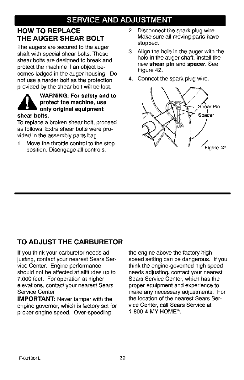
HOW TO REPLACE
THE AUGER SHEAR BOLT
The augers are secured to the auger
shaff with special shear bolts. These
shear bolts are designed to break and
protect the machine if an object be-
comes lodged in the auger housing. Do
not use a harder bolt as the protection
provided by the shear bolt will be lost.
,_ WARNING: For safety and to
protect the machine, use
only original equipment
shear bolts.
To replace a broken shear bolt, proceed
as follows. Extra shear bolts were pro-
vided in the assembly parts bag.
1. Move the throttle control to the stop
position. Disengage all controls.
2. Disconnect the spark plug wire.
Make sure all moving parts have
stopped.
3. Align the hole in the auger with the
hole in the auger shaft. Install the
new shear pin and spacer. See
Figure 42.
4. Connect the spark plug wire.
_ Sh_etar Piner
4°°,8,2
TO ADJUST THE CARBURETOR
If you think your carburetor needs ad-
justing, contact your nearest Sears Ser-
vice Center. Engine performance
should not be affected at altitudes up to
7,000 feet. For operation at higher
elevations, contact your nearest Sears
Service Center
IMPORTANT: Never tamper with the
engine governor, which is factory set for
proper engine speed. Over-speeding
the engine above the factory high
speed setting can be dangerous. If you
think the engine-governed high speed
needs adjusting, contact your nearest
Sears Service Center, which has the
proper equipment and experience to
make any necessary adjustments. For
the location of the nearest Sears Ser-
vice Center, call Sears Service at
1-800-4-MY-HOME®.
F-031001L 30
_lb ARNING: Never store your
snow thrower indoors or in
an enclosed, poorly venti-
lated area. If gasoline remains in the
tank, fumes may reach an open
flame, spark or pilot light from a fur-
nace, water heater, clothes dryer,
cigarette, etc.
To prevent damage (if snow thrower is
not used for more than 30 days) follow
the steps below.
SNOW THROWER
1. Thoroughly clean the snow thrower.
2. Lubricate all lubrication points. See
the Maintenance section.
3. Be sure that all nuts, bolts and
screws are securely fastened, in-
spect all visible moving parts for
damage, breakage and wear. Re-
place if necessary.
4. Touch up all rusted or chipped paint
surfaces; sand lightly before paint-
ing.
5. Cover the bare metal parts of the
blower housing auger and the im-
peller with rust preventative, such
as a spray lubricant.
NOTE: A yearly checkup or tune-up by
a Sears service center is a good way of
ensuring that your snow thrower will
provide maximum performance for the
next season.
ENGINE
Gasoline must be removed or treated to
prevent gum deposits from forming in
the fuel tank, filter, hose, and carburetor
during storage. Also, during storage al-
cohol blended gasoline that uses etha-
nol or methanol (sometimes called
gasohol) attracts water, it acts on the
gasoline to form acids which damage
the engine.
f,
2.
3,
4,
5.
Run the engine until the fuel tank is
empty and the engine stops.
If you do not remove the gasoline,
use fuel stabilizer supplied with unit
or purchase Craftsman Fuel Stabi-
lizer No. 3550. Add fuel stabilizer to
any gasoline left in the tank to mini-
mize gum deposits and acids. If the
fuel tank is almost empty, mix stabi-
lizer with fresh gasoline in a sepa-
rate container and add some to the
fuel tank.
Always follow the instructions on the
stabilizer container. After the stabi-
lizer is added to the fuel tank, run
the engine at least ten minutes to
allow the mixture to reach the car-
buretor.
Change the engine oil.
Lubricate the piston/cylinder area.
First, remove the spark plug and
squirt a few drops of clean engine
oil into the spark plug hole. Next,
cover the spark plug hole with a rag
to absorb oil spray. Then, pull two or
three times on the recoil starter rope
to rotate the engine. Finally, install
the spark plug and attach the spark
plug wire.
OTHER
1. If possible, store your snow thrower
indoors and cover it to give protec-
tion from dust and dirt.
2. If the snow thrower must be stored
outdoors, put the snow thrower on
blocks to raise it off of the ground.
3. Cover the snow thrower with a suit-
able protective cover that does not
retain moisture. Do not use plastic.
IMPORTANT: Never cover snow
thrower while engine and exhaust areas
are still warm.
F-O31001L 31
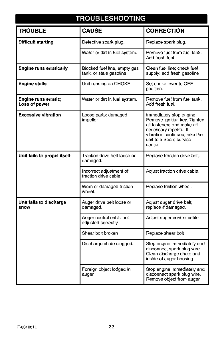
TROUBLE CORRECTION
Difficult starting
CAUSE
Defective spark plug,
Water or dirt in fuel system.
Replace spark plug.
Remove fuel from fuel tank.
Add fresh fuel.
Engine runs erratically Blocked fuel line, empty gas Clean fuel line; check fuel
tank, or stale gasoline supply; add fresh gasoline
Engine stalls Unit running on CHOKE. Set choke lever to OFF
position.
Engine runs erratic; Water or dirt in fuel system. Remove fuel from fuel tank.
Loss of power Add fresh fuel,
Excessive vibration Loose parts: damaged immediately stop engine,
impeller Remove ignition key, Tighten
all fasteners and make all
necessary repairs, if
vibration continues, take the
unit to a Sears service
center.
Unit fails to propel itself Traction drive belt loose or Replace traction drive belt.
damaged.
Incorrect adjustment of Adjust traction drive cable,
traction drive cable
Worn or damaged friction Replace friction wheel,
wheel,
Auger drive belt loose or
damaged. Adjust auger drive belt;
replace if damaged.
Auger control cable not Adjust auger control cable.
adjusted correctly.
Shear bolt broken Replace shear bolt
Discharge chute clogged. Stop engine immediately and
disconnect spark plug wire.
Clean discharge chute and
inside of auger housing.
Unit fails to discharge
SnOW
Foraigno_ectlodgedin
auger
Stop engine immediately and
disconnect spark plug wire.
Remove object from auger.
F-O31001L 32
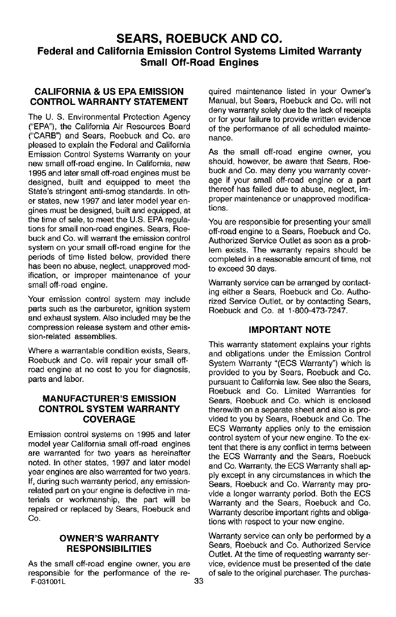
SEARS, ROEBUCK AND CO.
Federal and California Emission Control Systems Limited Warranty
Small Off-Road Engines
CALIFORNIA & US EPA EMISSION
CONTROL WARRANTY STATEMENT
The U. S. Environmental Protection Agency
("EPA"), the California Air Resources Board
("CARB'_ and Sears, Roebuck and Co. are
pleased to explain the Federal and California
Emission Control Systems Warranty on your
new small off-road engine. In California, new
1995 and later small off-road engines must be
designed, built and equipped to meet the
State's stringent anti-smog standards. In oth-
er states, new 1997 and later model year en-
gines must be designed, built and equipped, at
the time of sale, to meet the U.S. EPA regula-
tions for small non-rand engines. Sears, Roe-
buck and Co. will warrant the emission control
system on your small off-road engine for the
periods of time listed below, provided there
has been no abuse, neglect, unapproved mod-
ification, or improper maintenance of your
small off-road engine.
Your emission control system may include
parts such as the carburetor, ignition system
and exhaust system. Also included may be the
compression release system and other emis-
sion-related assemblies.
Where a warrantable condition exists, Sears,
Roebuck and Co. will repair your small off-
road engine at no cost to you for diagnosis,
parts end labor.
MANUFACTURER'S EMISSION
CONTROL SYSTEM WARRANTY
COVERAGE
Emission control systems on 1995 and later
model year California small off-road engines
are warranted for two years as hereinafter
noted. In other states, 1997 and later model
year engines are also warranted for two years.
If, dudng such warranty period, any emission-
related part on your engine is defective in ma-
terials or workmanship, the part will be
repaired or replaced by Sears, Roebuck and
Co.
OWNER'S WARRANTY
RESPONSIBILITIES
As the small off-road engine owner, you are
responsible for the performance of the ra-
F-031001L
quired maintenance listed in your Owner's
Manual, but Sears, Roebuck and Co. will not
deny warranty solely due to the lack of receipts
or for your failure to provide written evidence
of the performance of all scheduled mainte-
nance.
As the small off-road engine owner, you
should, however, be aware that Sears, Roe-
buck and Co. may deny you warranty cover-
age if your small off-road engine or a pert
thereof has failed due to abuse, neglect, im-
proper maintenance or unappraved modifica-
tions.
You are responsible for presenting your small
off-road engine to a Sears, Roebuck and Co.
Authorized Service Outlet as soon as a prob-
lem exists. The warranty repairs should be
completed in a reasonable amount of time, not
to exceed 30 days.
Warranty service can be arranged by contact-
ing either a Sears, Roebuck end Co. Autho-
rized Service Outlet, or by contacting Sears,
Roebuck and Co. at 1-900-473-7247.
33
IMPORTANT NOTE
This warranty statement explains your rights
and obligations under the Emission Control
System Warranty "(ECS Warranty") which is
provided to you by Sears, Roebuck and Co.
pursuant to California law. See also the Sears,
Roebuck and Co. Limited Warranties for
Sears, Roebuck and Co. which is enclosed
therewith on a separate sheet and also is pro-
vided to you by Sears, Roebuck and Co. The
ECS Warranty applies only to the emission
control system of your new engine. To the ex-
tent that there is any conflict in terms between
the ECS Warranty end the Sears, Roebuck
and Co. Warranty, the ECS Warranty shall ap-
ply except in any circumstances in which the
Sears, Roebuck and Co. Warranty may pro-
vide a longer warranty period. Both the ECS
Warranty and the Sears, Roebuck end Co.
Warranty describe important rights and obliga-
tions with respect to your new engine.
Warranty service can only be performed by a
Sears, Roebuck and Co. Authorized Service
Outlet. At the time of requesting warranty ser-
vice, evidence must be presented of the date
of sale to the original purchaser. The purchas-

ershallpayanychargesformakingservice
callsand/orfortransportingtheproductsto
andfromtheplacewheretheinspectionand/
orwarrantyworkisperformed.Thepurchaser
shallberasponsibleforanydamageorlossin-
curredinconnectionwiththetransportationof
anyengineoranypart(s)thereofsubmittedfor
inspectionand/orwarrantywork.
Ifyouhaveanyquestionsregardingyourwar-
rantyrightsandresponsibilities,youshould
contactSears,Roebuckand Co. at
1-800-473-7247.
EMISSION CONTROL SYSTEM
WARRANTY
Emisalon Control System Warranty ("ECS
Warranty") for 1995 and later model year Cali-
fornia small off-road engines (for other states,
1997 and later model year engines):
A, APPLICABILITY: This warranty shall apply
to 1995 and later model year California small
off-road engines (for other states, 1997 and
later model year engines). The ECS Warranty
Period shall begin on the date the new engine
or equipment is delivered to its original, end-
use purchaser, and shall continue for 24 con-
secutive months thereafter.
B. GENERAL EMISSIONS WARRANTY
COVERAGE: Sears, Roebuck and Co. war-
rants to the original, end-use purchaser of the
new engine or equipment and to each subse-
quent purchaser that each of its small off-road
engines is:
1. Designed, built and eqalppod so as to con-
form with all applicable regulations adopted by
the Air Resources Board pursuant to its au-
thority in Chapters 1 and 2, Part 5, Division 26
of the Health and Safety Code, and
2. Free from defects in materials and work-
manship which, at any time during the ECS
Warranty Period, will cause a warranted emis-
sions-related part to fail to be identical in all
material respects to the part as described in
the engine manufacturer's application for certi-
fication.
C. The ECS Warranty only pertains to emis-
sions-related parts on your engine, as follows:
1. Any warranted, emissions-related parts
which are net scheduled for replacement as
required maintenance in the Owner's Manual
shall be warranted for the ECS Warranty Peri-
od. If any such part fails during the ECS War-
ranty Period, it shall be rebeired or replaced by
F-031001L 34
Sears, Roebuck and Co. according to Subsec-
tion 4 below. Any such part repaired or re-
placed under the ECS Warranty shall be
warranted for any remainder of the ECS War-
ranty Period.
2. Any warranted, emissions-relatod part
which is scheduled only for regular inspection
as spacified in the Owner's Manual shall be
warranted for the ECS Warranty Period. A
statement in such wdtten instructions to the ef-
fect of "repair or replace as necessary", shall
not reduce the ECS Warranty Period. Any
such part repaired or replaced under the ECS
Warranty shall be warranted for the remainder
of the ECS Warranty Period.
3. Any warranted, emissions-relatod part
which is scheduled for replacement as re-
quired maintenance in the Owner's Manual,
shall be warranted for the period of time prior
to the first scheduled replacement point for
that part. If the part fails prior to the first sched-
uled replacement, the part shall be repaired or
replaced by Sears, Roebuck and Co. accord-
ing to Subsection 4 below. Any such emis-
sions-related part repaired or replaced under
the ECS Warranty, shall be warranted for the
remainder of the ECS Warranty Pedod prior to
the first scheduled replacement point for such
emissions-related part.
4. Repair or replacement of any warranted,
emissions-related part under this ECS War-
ranty shall be performed at no charge to the
owner at a Sears, Roebuck and Co. Autho-
rized Service Outlet.
5. The owner shall not be charged for diagnos-
tic labor which leads to the determinatiee that
a part covered by the ECS Warranty is in fact
defective, provided that such diagnostic work
is performed at a Sears, Roebuck and Co. Au-
thorized Service Outlet.
6. Sears, Roebuck and Co. shall be liable for
damages to other original engine components
or approved modifications proximately caused
by a failure under warranty of an emission-re-
lated part covered by the ECS Warranty.
7. Throughout the ECS Warranty Period,
Sears, Roebuck and Co. shall maintain a sup-
ply of warranted emission-related parts suffi-
cient to meet the expected demand for such
emission-relatod parts.
8. Any Sears, Roebuck and Co. anthorized
and approved emissiee-relatod replacement
part may be used in the performance of any
ECS Warranty maintenance or repair and will
be provided without charge to the owner. Such
useshallnotreduceSears.RoebuckendCo.
ECSWarrantyobligations.
9,Unapprovedadd-onormodifiedpartsmay
notbeusedtomodifyorrepairaSears,Roe-
buckandCo.engine,SuchusevoidsthisECS
Warrantyandshallbesufficientgroundsfor
disallowinganECSWarrantyclaim.Sears,
RoebuckendCo.shallnotbeliablehereunder
forfailuresofanywarrantedpartsofaSears,
RoebuckandCo.engine caused by the use of
such an unappraved add-on or modified part.
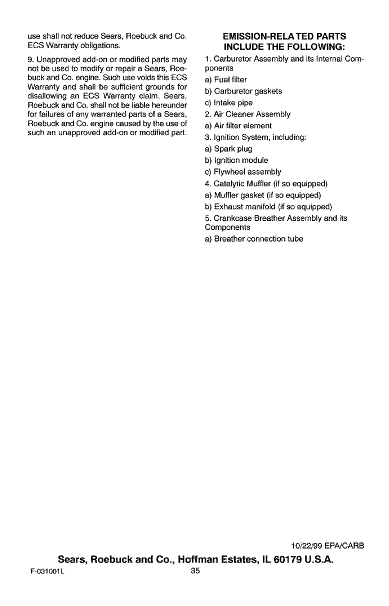
EMISSION-RELATED PARTS
INCLUDE THE FOLLOWING:
1. Carburetor Assembly and its Internal Com-
ponents
a) Fuel filter
b) Carburetor gaskets
c) Intake pipe
2, Air Cleaner Assembly
a) Air filter element
3, Ignition System, including:
a) Spark plug
b) Ignition module
c) Flywheel assembly
4, Catalytic Muffler (if so equipped)
a) Muffler gasket (if so equipped)
b) Exhaust manifold (if so equipped)
5, Crankcase Breather Assembly end its
Components
a) Breather connection tube
10/22/99 EPA!CARB
Sears, Roebuck and Co., Hoffman Estates, IL 60179 U.S.A.
F-031001L 35
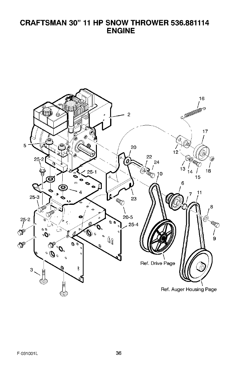
CRAFTSMAN 30" 11 HP SNOW THROWER 536.881114
ENGINE
16
25-3
\
2
\
20
22
24
10
/15
6
11
17
/
/
18
/8
/
9
3
Ref. Drive Page
Ref. Auger Housing Page
F-031001L 36
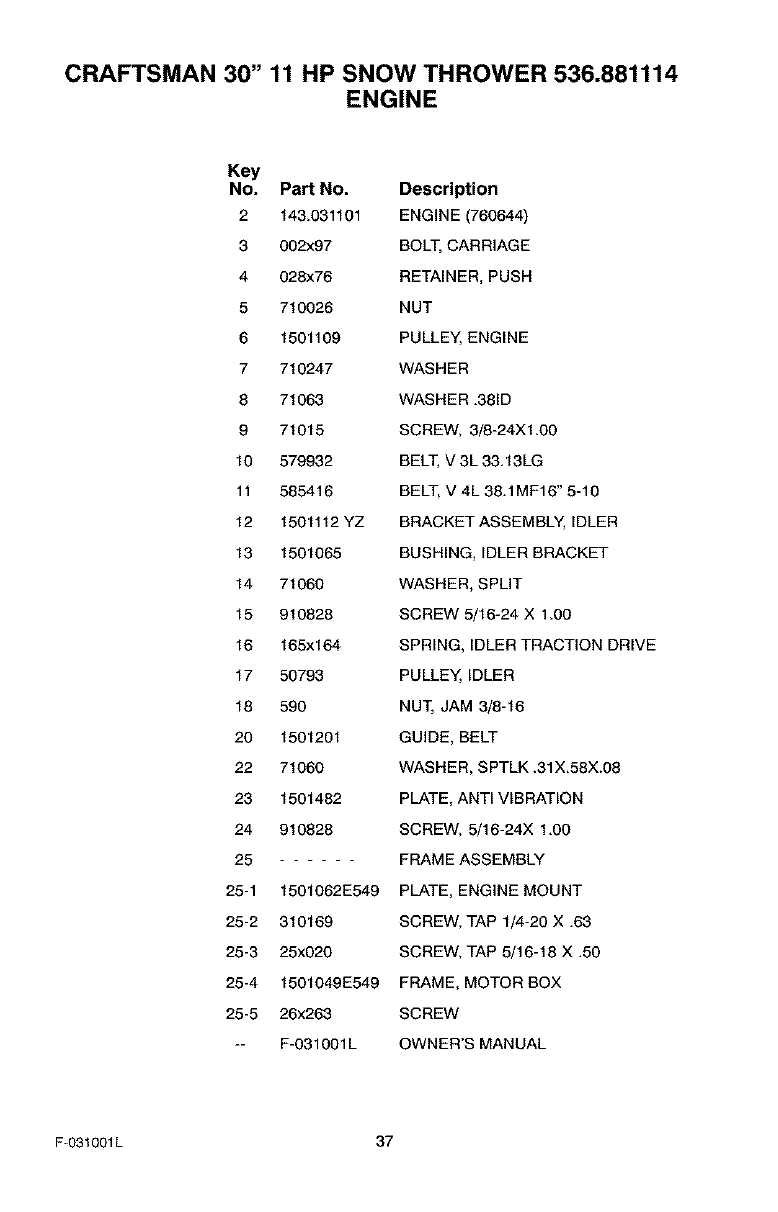
CRAFTSMAN 30" 11 HP SNOW THROWER 536.881114
ENGINE
Key
No. Part No. Description
2 143.031101 ENGINE (760644)
3 002x97 BOLT, CARRIAGE
4 028x76 RETAINER, PUSH
5 710026 NUT
6 1501109 PULLEY, ENGINE
7 710247 WASHER
8 71063 WASHER .381D
9 71015 SCREW, 3/8-24Xl.00
10 579932 BELT, V 3L 33.13LG
11 585416 BELT, V 4L 38.1MF16" 5-10
12 1501112 YZ BRACKET ASSEMBLY, IDLER
13 1501065 BUSHING, IDLER BRACKET
14 71060 WASHER, SPLIT
15 910828 SCREW 5/16-24 X 1.00
16 165x164 SPRING, IDLER TRACTION DRIVE
17 50793 PULLEY, IDLER
18 590 NUT, JAM 3/8-16
20 1501201 GUIDE, BELT
22 71060 WASHER, SPTLK .31X.58X.08
23 1501482 PLATE, ANTI VIBRATION
24 910828 SCREW, 5/16-24X 1.00
25 FRAME ASSEMBLY
25-1 1501062E549 PLATE, ENGINE MOUNT
25-2 310169 SCREW, TAP 1/4-20 X .63
25-3 25x020 SCREW, TAP 5/16-18 X .50
25-4 1501049E549 FRAME, MOTOR BOX
25-5 26x263 SCREW
-- F-O31O01L OWNER'S MANUAL
F-031001L 37
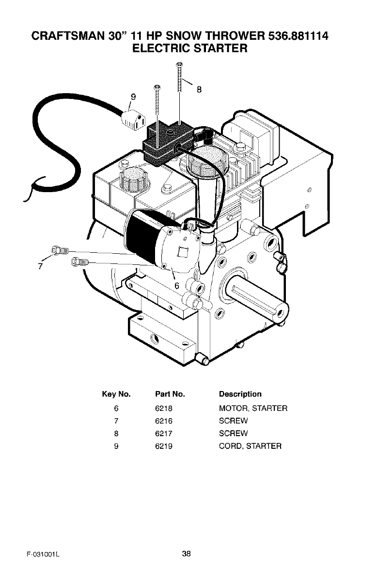
CRAFTSMAN 30" 11 HP SNOW THROWER 536.881114
ELECTRIC STARTER
8
9
7\
Key No.
6
7
8
9
Part No. Description
6218 MOTOR, STARTER
6216 SCREW
6217 SCREW
6219 CORD, STARTER
F-O31001L 38
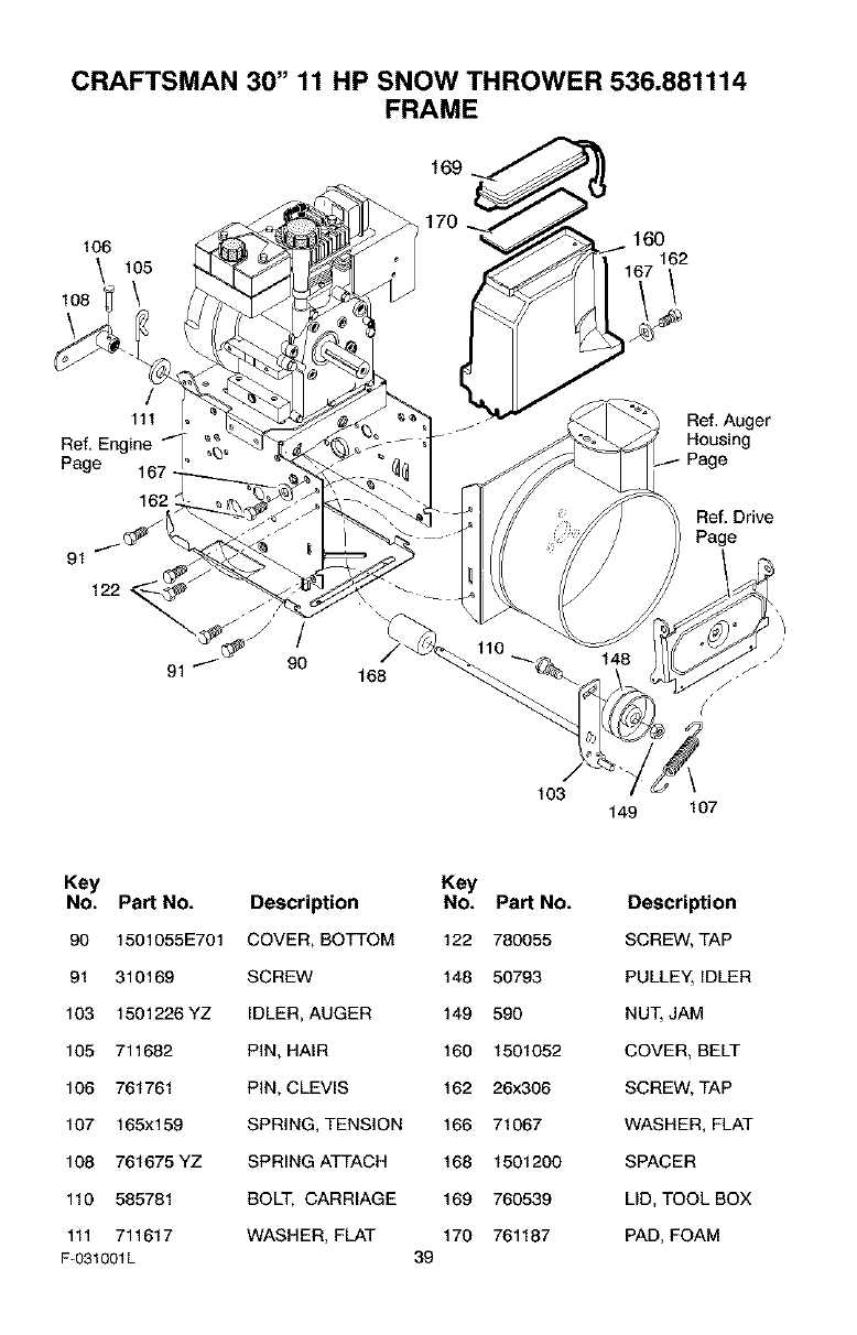
CRAFTSMAN 30" 11 HP SNOW THROWER 536.881114
FRAME
170 -_7_ 160
106 v_J f_ 162
108 \ _/_1_
/
111 -Ref. Auger
Ref. Engine _ _ Housing
Page '£ Page
162 : Ref, Drive
Page
91
122
103 149 107
Key Key
No. Part No. Description No. Part No. Description
90 1501055E701 COVER, BOTTOM 122 780055 SCREW, TAP
91 310169 SCREW 148 50793 PULLEY, IDLER
103 1501226YZ IDLER, AUGER 149 590 NUT, JAM
105 711682 PIN, HAIR 160 1501052 COVER, BELT
106 761761 PIN, CLEVIS 162 26x306 SCREW, TAP
107 165x159 SPRING, TENSION 166 71067 WASHER, FLAT
108 761675YZ SPRING ATTACH 168 1501200 SPACER
110 585781 BOLT, CARRIAGE 169 760539 LID, TOOL BOX
111 711617 WASHER, FLAT 170 761187 PAD, FOAM
F-031001L 39
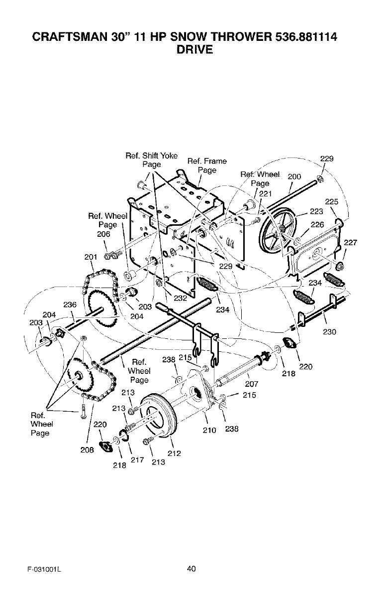
CRAFTSMAN 30" 11 HP SNOW THROWER 536.881114
DRIVE
Ref, Shift Yoke
Page Ref, Frame _ _ _.229
200
Ref. Whee
Page
206
\
201
\
225 _/
\
227
/
236
230
Ref,
Wheel
Page \
208 212
217 213
218
207
215
\
210 238
220
218
F-O31001L 40
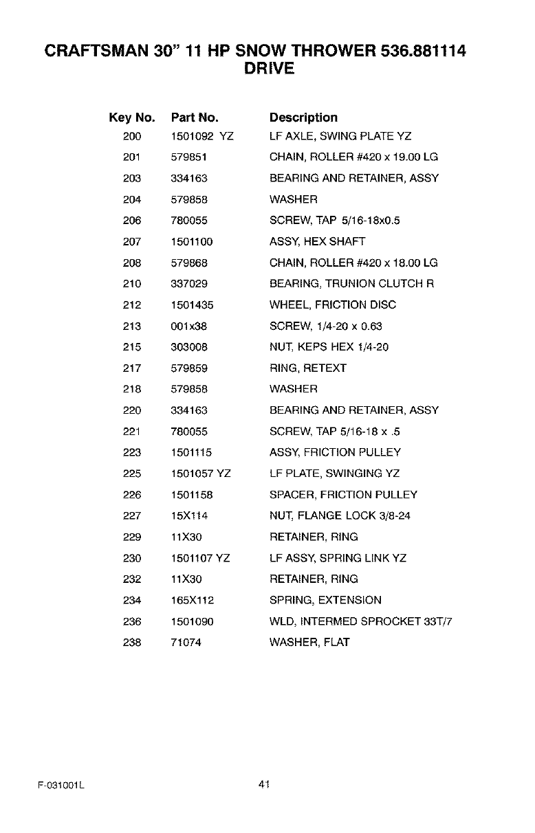
CRAFTSMAN 30" 11 HP SNOW THROWER 536.881114
DRIVE
Key No. Part No.
200 1501092 YZ
201 579851
203 334163
204 579858
206 780055
207 1501100
208 579868
210 337029
212 1501435
213 001x38
215 303008
217 579859
218 579858
220 334163
221 780055
223 1501115
225 1501057 YZ
226 1501158
227 15Xl14
229 11X30
230 1501107 YZ
232 11X30
234 165X112
236 1501090
238 71074
Description
LF AXLE, SWING PLATE YZ
CHAIN, ROLLER #420 x 19.00 LG
BEARING AND RETAINER, ASSY
WASHER
SCREW, TAP 5/16-18x0.5
ASS'(, HEX SHAFT
CHAIN, ROLLER #420 x 18.00 LG
BEARING, TRUNION CLUTCH R
WHEEL, FRICTION DISC
SCREW, 1/4-20 x 0.63
NUT, KEPS HEX 1/4-20
RING, RETEXT
WASHER
BEARING AND RETAINER, ASSY
SCREW, TAP 5/16-18 x .5
ASS'(, FRICTION PULLEY
LF PLATE, SWINGING YZ
SPACER, FRICTION PULLEY
NUT, FLANGE LOCK 3/8-24
RETAINER, RING
LF ASSY, SPRING LINK YZ
RETAINER, RING
SPRING, EXTENSION
WLD, INTERMED SPROCKET 33T/7
WASHER, FLAT
F-031001L 41
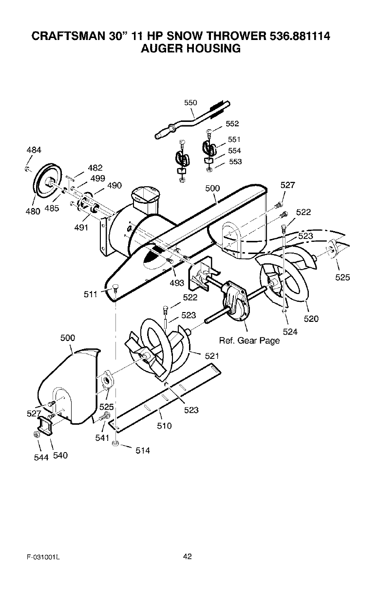
CRAFTSMAN 30" 11 HP SNOW THROWER 536.881114
AUGER HOUSING
484
480
482
499 490
491
527
522
5OO
522
\ 520
524
Ref. Gear Page
521
525
\\
544 540
541
510
514
523
F-O31001L 42
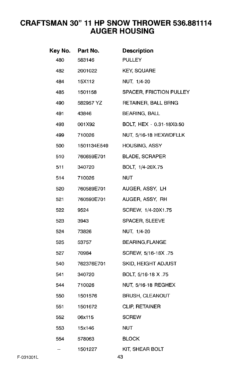
CRAFTSMAN 30" 11 HP SNOW THROWER 536.881114
AUGER HOUSING
F-031001L
Key No. Part No. Description
480 583146 PULLEY
482 2001022 KEY, SQUARE
484 15Xl12 NUT, 1/4-20
485 1501158 SPACER, FRICTION PULLEY
490 582957 YZ RETAINER, BALL BRNG
491 43846 BEARING, BALL
493 001X92 BOLT, HEX - 0.31-18X0.50
499 710026 NUT, 5/16-18 HEXWDFLLK
500 1501134E549 HOUSING, ASSY
510 760659E701 BLADE, SCRAPER
511 340720 BOLT, 1/4-20X.75
514 710026 NUT
520 760589E701 AUGER, ASSY, LH
521 760590E701 AUGER, ASSY, RH
522 9524 SCREW, 1/4-20XI.75
523 3943 SPACER, SLEEVE
524 73826 NUT, 1/4-20
525 53757 BEARING,FLANGE
527 70984 SCREW, 5/16-18X .75
540 762376E701 SKID, HEIGHT ADJUST
541 340720 BOLT, 5/16-18 X .75
544 710026 NUT, 5/16-18 REGHEX
550 1501576 BRUSH, CLEANOUT
551 1501672 CLIP, RETAINER
552 06xl 15 SCREW
553 15xl 46 NUT
554 578063 BLOCK
-- 1501227 KIT, SHEAR BOLT
43
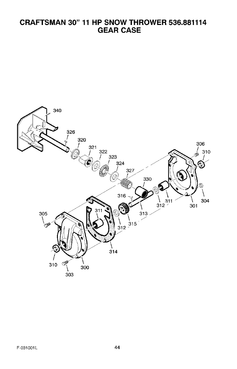
CRAFTSMAN 30" 11 HP SNOW THROWER 536.881114
GEAR CASE
340
326
320
305
/
310 _ 300
303
301
306
310
304
F-O31001L 44
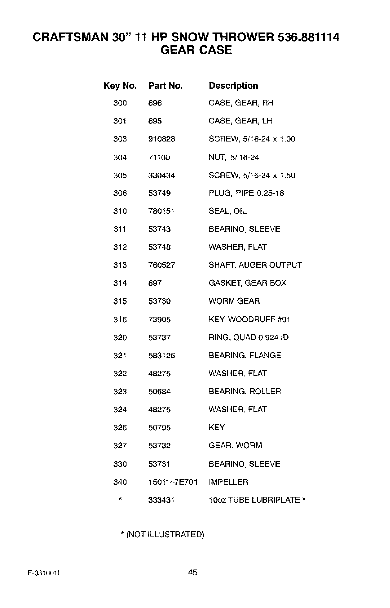
CRAFTSMAN 30" 11 HP SNOW THROWER 536.881114
GEAR CASE
Key No. Part No. Description
300 896 CASE, GEAR, RH
301 895 CASE, GEAR, LH
303 910828 SCREW, 5/16-24 x 1.00
304 71100 NUT, 5/'16-24
305 330434 SCREW, 5/16-24 x 1.50
306 53749 PLUG, PiPE 0.25-18
310 780151 SEAL, OiL
311 53743 BEARING, SLEEVE
312 53748 WASHER, FLAT
313 760527 SHAFT, AUGER OUTPUT
314 897 GASKET, GEAR BOX
315 53730 WORM GEAR
316 73905 KEY, WOODRUFF #91
320 53737 RING, QUAD 0.924 ID
321 583126 BEARING, FLANGE
322 48275 WASHER, FLAT
323 50684 BEARING, ROLLER
324 48275 WASHER, FLAT
326 50795 KEY
327 53732 GEAR, WORM
330 53731 BEARING, SLEEVE
340 1501147E701 IMPELLER
333431 10oz TUBE LUBRIPLATE *
*(NOT iLLUSTRATED)
F-031001L 45
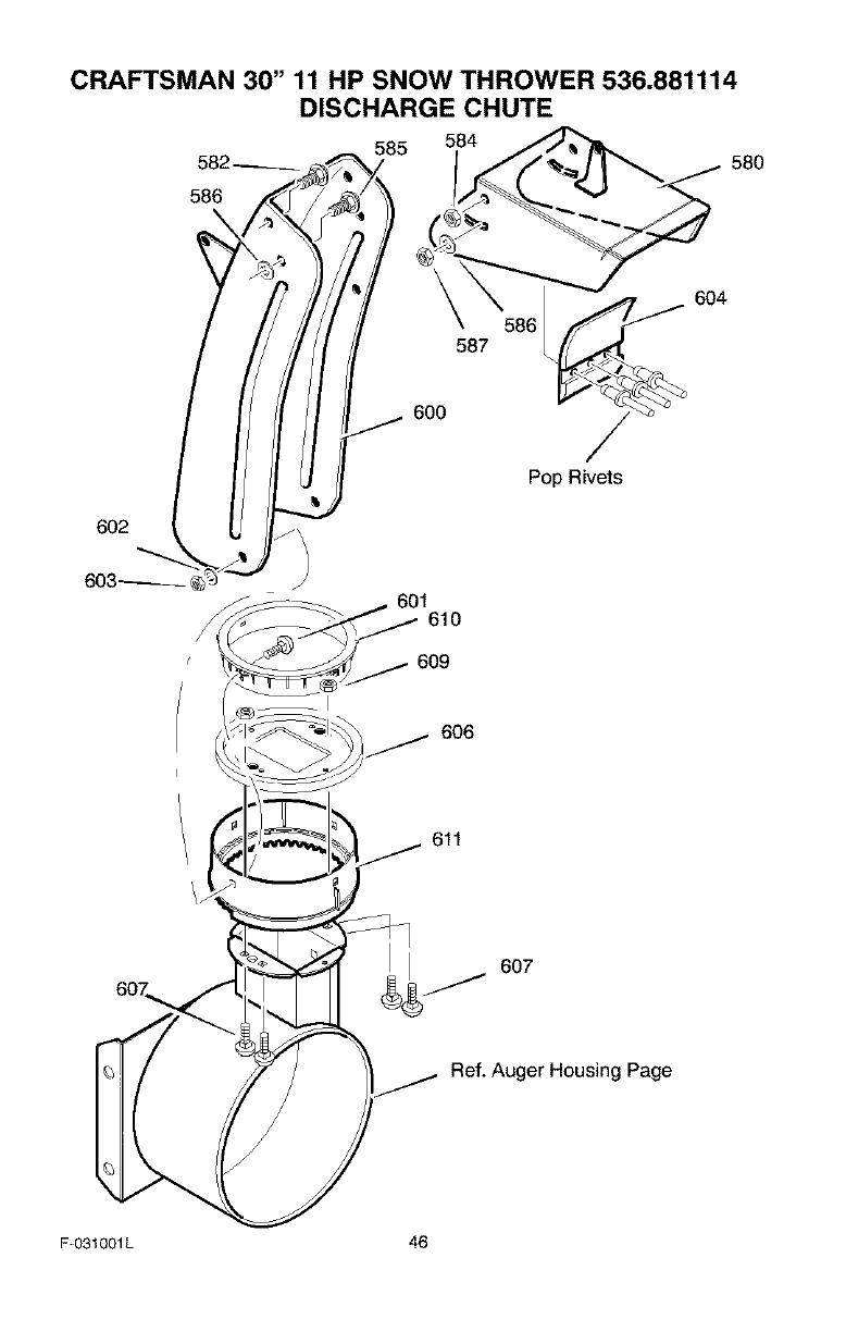
CRAFTSMAN 30" 11 HP SNOW THROWER 536.881114
DISCHARGE CHUTE
585 584
582 __ 580
586
\
602 _ !
603_
600
604
587
Pop Rivets
601610
609
I
/_ 606
611
6o7 607
Ref. Auger Housing Page
F-031001L 46
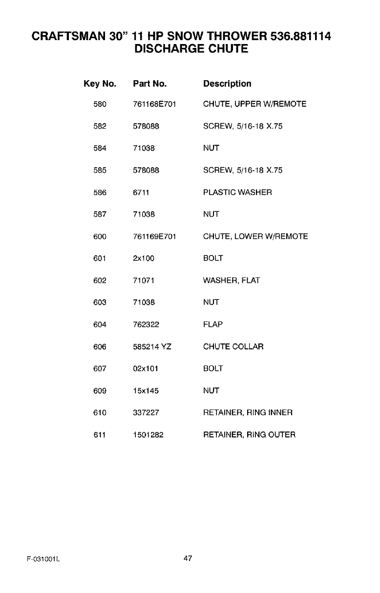
CRAFTSMAN 30" 11 HP SNOW THROWER 536.881114
DISCHARGE CHUTE
Key No. Part No. Description
580 761168E701 CHUTE, UPPER W/REMOTE
582 578088 SCREW, 5/16-18 X,75
584 71038 NUT
585 578088 SCREW, 5/16-18 X,75
586 6711 PLASTIC WASHER
587 71038 NUT
600 761169E701 CHUTE, LOWER W/REMOTE
601 2x100 BOLT
602 71071 WASHER, FLAT
603 71038 NUT
604 762322 FLAP
606 585214 YZ CHUTE COLLAR
607 02x101 BOLT
609 15x 145 NUT
610 337227 RETAINER, RING INNER
611 1501282 RETAINER, RING OUTER
F-031001L 47
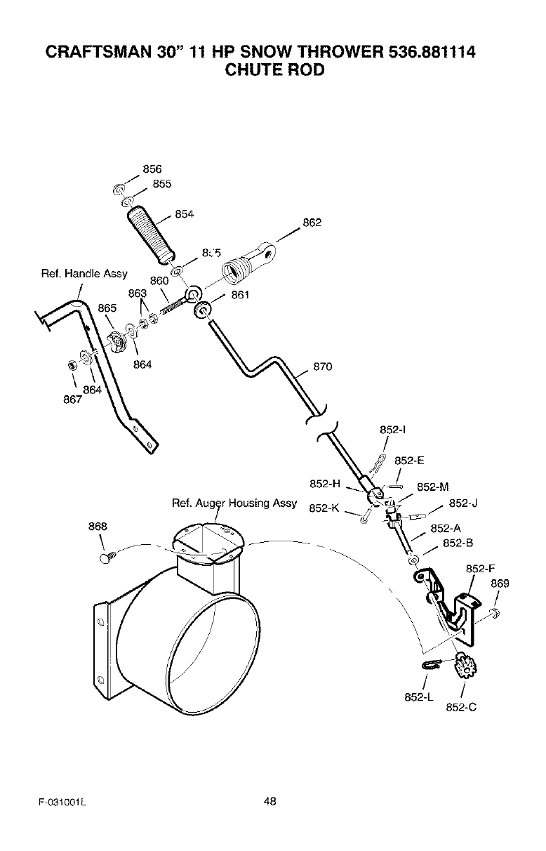
CRAFTSMAN 30" 11 HP SNOW THROWER 536.881114
CHUTE ROD
856
_" 855
• 854 862
J
Ref, Handle Assy
861
\
867
868
\
864 870
852-H
r Housing Assy 852-K
852-E
852-M
852-J
852-A
j 852-B
852-F
869
\ \\ //
\\\
852-L /
852-C
F-O31001L 48
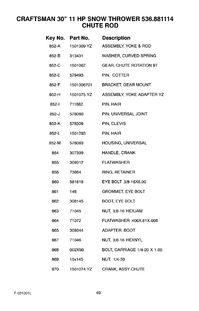
CRAFTSMAN 30" 11 HP SNOW THROWER 536.881114
CHUTE ROD
Key No. Part No. Description
852-A 1501309 YZ ASSEMBLY, YOKE & ROD
852-B 313431 WASHER, CURVED SPRING
852-C 1501067 GEAR, CHUTE ROTATION 9T
852-E 579493 PIN, COTTER
852-F 1501306701 BRACKET, GEAR MOUNT
852-H 1501075 YZ ASSEMBLY, YOKE ADAPTER YZ
852-1 711682 PIN, HAIR
852-J 578060 PIN, UNIVERSAL JOINT
852-K 578309 PIN, CLEVIS
852-L 1501293 PIN, HAIR
852-M 578063 HOUSING, UNIVERSAL
854 307399 HANDLE, CRANK
855 309312 FLATWASHER
856 73664 RING, RETAINER
860 581618 EYE BOLT 3/8-16X6.00
861 148 GROMMET. EYE BOLT
862 308145 BOOT. EYE BOLT
863 71045 NUT, 3/8-16 HEXJAM
864 71072 FLA_/VASH ER .406X.81X.066
865 309344 ADAPTER, BOOT
867 71046 NUT, 3/8-16 HEXNYL
868 002X98 BOLT, CARRIAGE 1/4-20 X 1.00
869 15x145 NUT, 1/4-20
870 1501074 YZ CRANK, ASSY CHUTE
F-031001L 49
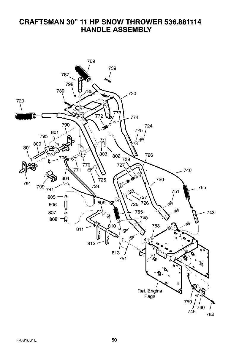
CRAFTSMAN 30" 11 HP SNOW THROWER 536.881114
HANDLE ASSEMBLY
729
\
795
8OO
801
\
787
798
739
\
801
729
790 I
739
720
774
724
726
791 799 741
805
8O6
807
740
765
743
811
Ref, Engine
Page 759
745 762
F-O31001L 50
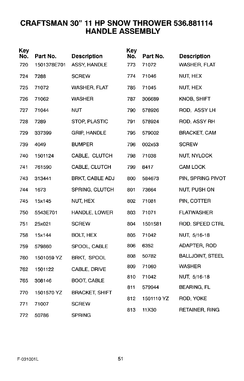
CRAFTSMAN 30" 11 HP SNOW THROWER 536.881114
HANDLE ASSEMBLY
Key Key
NO. Part NO. Description NO. Part NO. Description
720 1501378E701 ASSY, HANDLE 773 71072 WASHER, FLAT
724 7288 SCREW 774 71046 NUT, HEX
725 71072 WASHER, FLAT 785 71045 NUT, HEX
726 71062 WASHER 787 306689 KNOB, SHIFT
727 71044 NUT 790 578926 ROD, ASSY LH
728 7289 STOP, PLASTIC 791 578924 ROD, ASSY RH
729 337399 GRIP, HANDLE 795 579002 BRACKET, CAM
739 4049 BUMPER 796 002x53 SCREW
740 1501124 CABLE, CLUTCH 798 71038 NUT, NYLOCK
741 761590 CABLE, CLUTCH 799 8417 CAM LOCK
743 313441 BRKT, CABLE ADJ 800 584673 PIN, SPRING PIVOT
744 1673 SPRING, CLUTCH 801 73664 NUT, PUSH ON
745 15x145 NUT, HEX 802 71081 PIN, COTTER
750 5543E701 HANDLE, LOWER 803 71071 FLATWASH ER
751 25x021 SCREW 804 1501581 ROD, SPEED CTRL
758 15x144 BOLT, HEX 805 71042 NUT, 5/16-18
759 579860 SPOOL, CABLE 806 6352 ADAPTER, ROD
760 1501059 YZ BRKT, SPOOL 808 50782 BALLJOINT, STEEL
762 1501122 CABLE, DRIVE 809 71060 WASHER
810 71042 NUT, 5/16-18
765 308146 BOOT, CABLE
811 579944 BEARING, FL
770 1501570 YZ BRACKET, SHIFT
812 1501110 YZ ROD, YOKE
771 71007 SCREW
813 11X30 RETAINER, RING
772 50786 SPRING
F-031001L 51
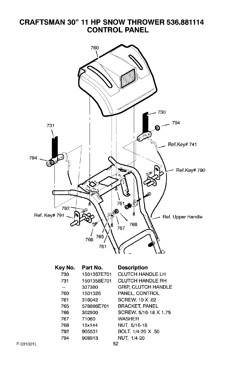
CRAFTSMAN 30" 11 HP SNOW THROWER 536.881114
CONTROL PANEL
731 794
794
Ref, Key# 741
Ref.Key# 790
Ref, Key# 791 Ref, Upper Handle
766
761
F-031001L
Key No.
730
731
760
761
765
766
767
768
792
794
PaN No.
1501357E701
1501358E701
337380
1501326
316042
578866E701
302900
71060
15x144
905531
908913
Description
CLUTCH HANDLE LH
CLUTCH HANDLE RH
GRIP, CLUTCH HANDLE
PANEL, CONTROL
SCREW, 10 X .62
BRACKET, PANEL
SCREW, 5/16-18 X 1.75
WASHER
NUT, 5/16-18
BOLT, 1/4-20 X .50
NUT, 1/4-20
52
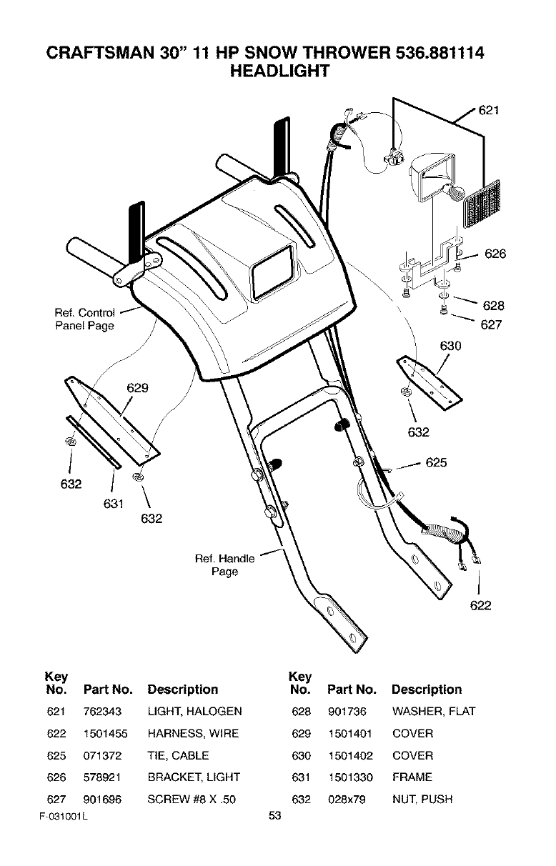
CRAFTSMAN 30" 11 HP SNOW THROWER 536.881114
HEADLIGHT
626
Ref. Control
Panel Page
Ref. Handle
Page
632
625
630
A
622
628
627
Key
No. Part No. Description
621 762343 LIGHT, HALOGEN
622 1501455 HARNESS, WIRE
625 071372 TIE, CABLE
626 578921 BRACKET, LIGHT
627 901696 SCREW #8 X .50
F-031001L 53
Key
No. Part No. Description
628 901736 WASHER, FLAT
629 1501401 COVER
630 1501402 COVER
631 1501330 FRAME
632 028x79 NUT, PUSH
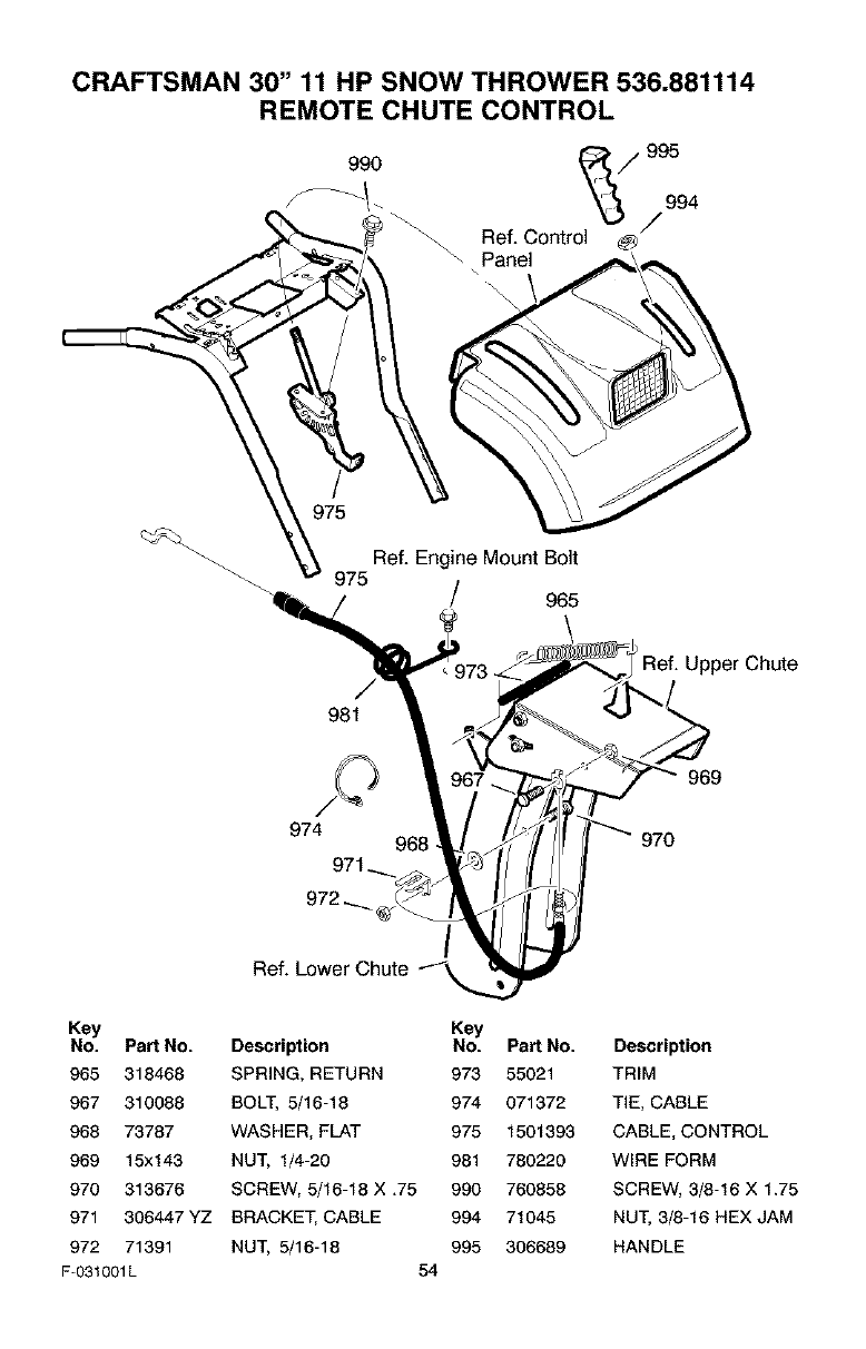
CRAFTSMAN 30" 11 HP SNOW THROWER 536.881114
REMOTE CHUTE CONTROL
990 ,995
/994
Ref. Control
Panel
\
975
Ref. Engine Mount Bolt
975 /965
\
_73
981
Ref. Upper Chute
974 968
969
970
/
Ref. Lower Chute
Key
No. Part No.
965 318468
967 310088
968 73787
969 15x143
970 313676
971 308447 YZ
972 71391
F-031001L
Key
Description No. Part No.
SPRING. RETURN 973 55021
BOLT, 5/18-18 974 071372
WASHER, FLAT 975 1501393
NUT. 1/4-20 981 780220
SCREW, 5/16-18 X .75 990 760858
BRACKET, CABLE 994 71045
NUT, 5/16-18 995 306689
54
Description
TRIM
TIE, CABLE
CABLE, CONTROL
WIRE FORM
SCREW, 3/8-18 X 1.75
NUT, 3/8-16 HEX JAM
HANDLE
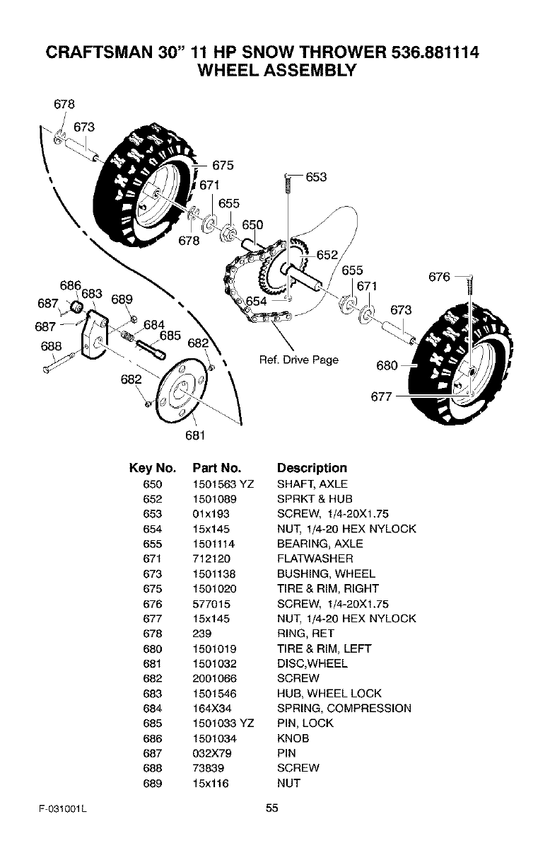
CRAFTSMAN 30" 11 HP SNOW THROWER 536.881114
WHEEL ASSEMBLY
678
673
675
I\\
686
688
682
\\
Ref, Drive Page
671
673
677
681
Key No. PaN No.
650 1501563 YZ
652 1501089
653 01x193
654 15x145
655 1501114
671 712120
673 1501138
675 1501020
676 577015
677 15x145
678 239
680 1501019
681 1501032
682 2001066
683 1501546
684 164X34
685 1501033 YZ
686 1501034
687 032X79
688 73839
689 15x116
Description
SHAFT, AXLE
SPRKT & HUB
SCREW, 1/4-20XI.75
NUT, 1/4-20 HEX NYLOCK
BEARING, AXLE
FLATWASHER
BUSHING, WHEEL
TIRE & RIM, RIGHT
SCREW, 1/4-20XI.75
NUT, 1/4-20 HEX NYLOCK
RING, RET
TIRE & RIM, LEFT
DISC,WHEEL
SCREW
HUB, WHEEL LOCK
SPRING, COMPRESSION
PiN, LOCK
KNOB
PIN
SCREW
NUT
F-031001L 55
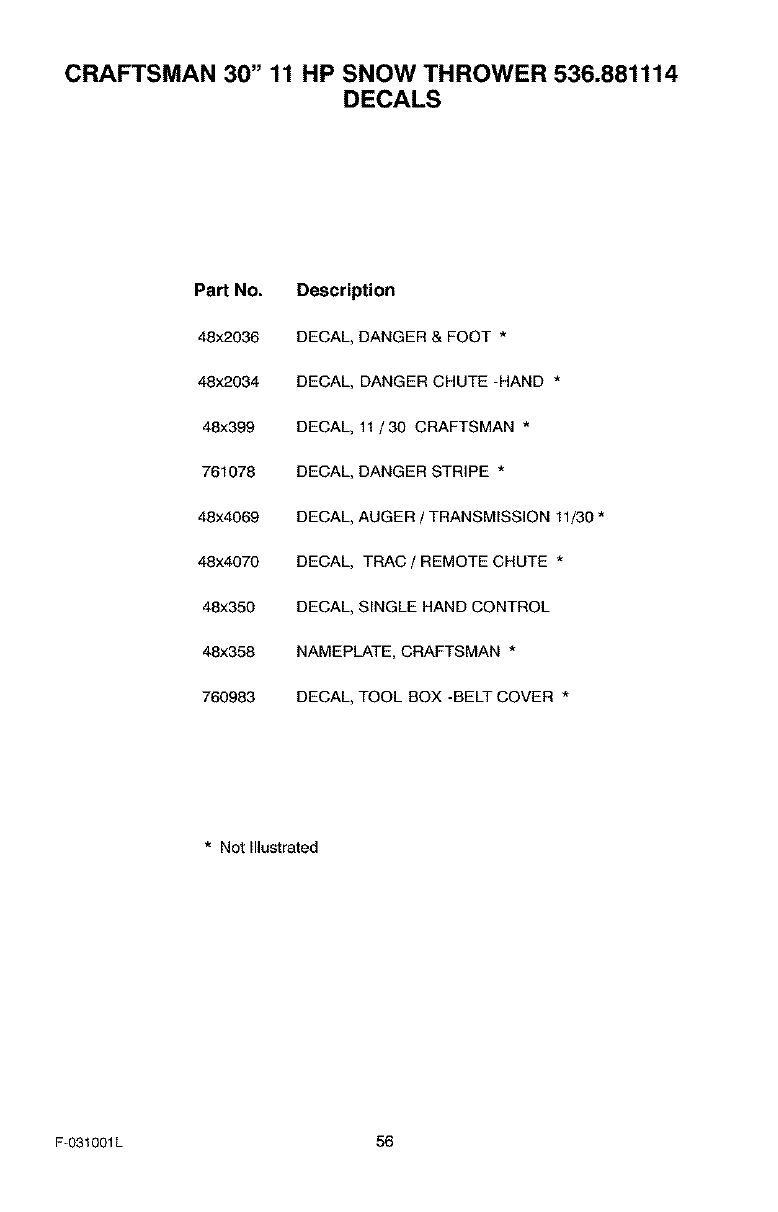
CRAFTSMAN 30" 11 HP SNOW THROWER 536.881114
DECALS
Pa_ No.
48x2036
48x2084
48x399
761078
48x4069
48x4070
48x350
48x358
760983
Description
DECAL, DANGER & FOOT *
DECAL, DANGER CHUTE -HAND *
DECAL, 11 /30 CRAFTSMAN *
DECAL, DANGER STRIPE *
DECAL, AUGER /TRANSMISSION 11/30 *
DECAL, TRAC /REMOTE CHUTE *
DECAL, SINGLE HAND CONTROL
NAMEPLATE, CRAFTSMAN *
DECAL, TOOL BOX -BELT COVER *
*Not Illustrated
F-031001L 56
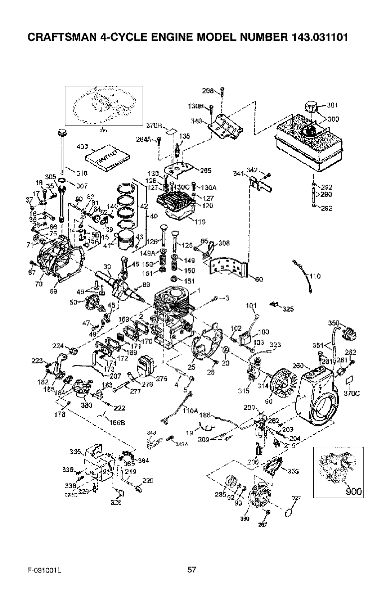
CRAFTSMAN 4-CYCLE ENGINE MODEL NUMBER 143.031101
370C
F-O31001L 57
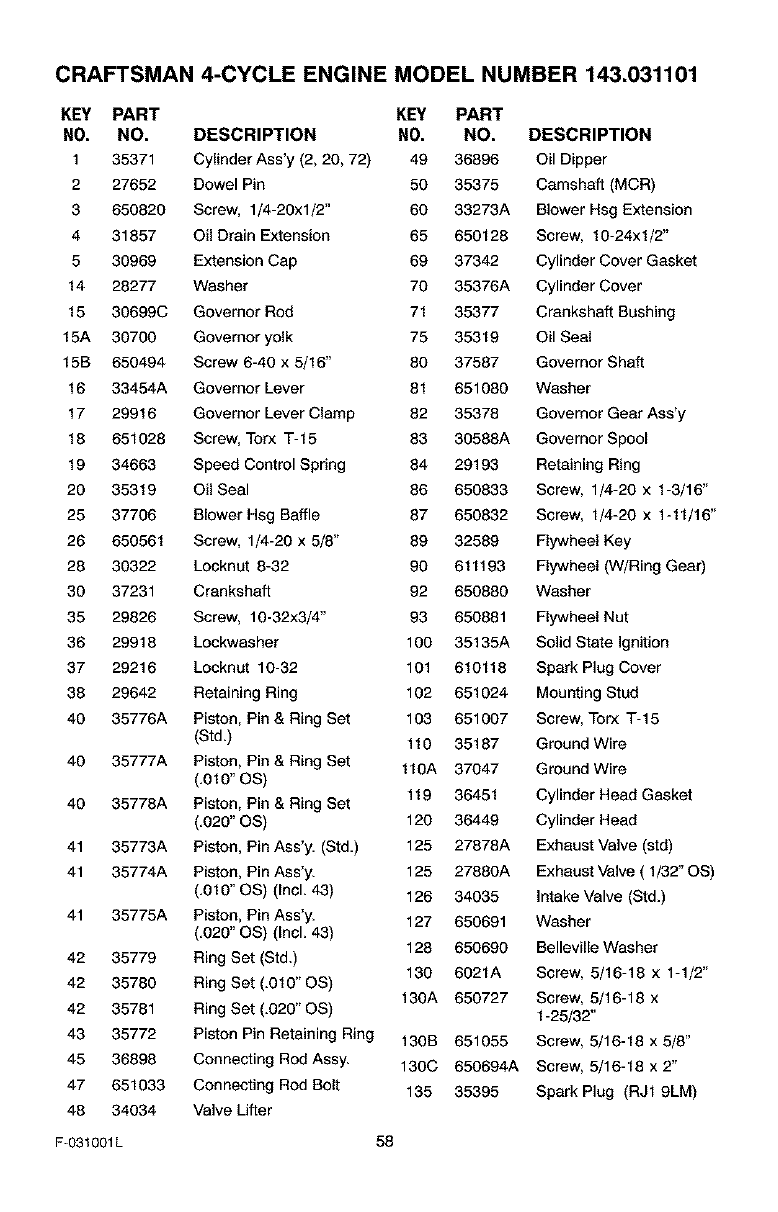
CRAFTSMAN 4-CYCLE ENGINE MODEL NUMBER 143.031101
KEY PART KEY PART
NO. NO. DESCRIPTION NO. NO. DESCRIPTION
1 35371 Cylinder Ass'y (2, 20, 72) 49 36896 Oil Dipper
2 27652 Dowel Pin 50 35375 Camshaft (MCR)
3 650820 Screw, 1/4-20xl/2" 60 33273A Blower Hsg Extension
4 31857 O{I Drain Extension 65 650128 Screw, 10-24xl/2"
5 30969 Extension Cap 69 37342 Cylinder Cover Gasket
14 28277 Washer 70 35376A Cylinder Cover
15 30699C Governor Rod 71 35377 Crankshaft Bushing
15A 30700 Govemoryolk 75 35319 Oil Seal
15B 650494 Screw 6-40 x 5/16" 80 37587 Governor Shaft
16 33454A Governor Lever 81 651080 Washer
17 29916 Governor Lever Clamp 82 35378 Governor Gear Ass'y
18 651028 Screw, Torx T-15 83 30588A Governor Spool
19 34663 Speed Control Spring 84 29193 Retaining Ring
20 35319 Oil Seal 86 650833 Screw, 1/4-20 x 1-3/16"
25 37706 Blower Hsg Baffle 87 650832 Screw, I/4-20 x 1-11/16"
26 650561 Screw, 1/4-20 x 5/8" 89 32589 Flywheel Key
28 30322 Locknut 8-32 90 611193 Flywheel (W/Ring Gear)
30 37231 Crankshaft 92 650880 Washer
35 29826 Screw, 10-32x3/4" 93 650881 Flywheel Nut
36 29918 Lockwasher 100 35135A Solid State Ignition
37 29216 Locknut 10-32 101 610118 Spark Plug Cover
38 29642 Retaining Ring 102 651024 Mounting Stud
40 35776A Piston, Pin & Ring Set 103 651007 Screw, Torx T-15
(Std.) 110 35187 Ground Wire
40 35777A Piston, Pin & Ring Set 110A 37047 Ground Wire
(.010" OS)
40 35778A Piston, Pin & Ring Set 119 36451 Cylinder Head Gasket
(.020" OS) 120 36449 Cylinder Head
41 35773A Piston, Pin Ass'y. (Std.) 125 27878A Exhaust Valve (std)
41 35774A Piston, Pin Ass'y. 125 27880A Exhaust Valve ( 1/32" OS)
(.010" OS) (IncL 43) 126 34035 Intake Valve (Std.)
41 35775A Piston, Pin Ass'y. 127 650691 Washer
(.020" OS) (IncL 43) 128 650690 Belleville Washer
42 35779 Ring Set (Std.) 130 6021A Screw, 5/16-18 x 1-1/2"
42 35780 Ring Set (.010" OS) 130A 650727 Screw, 5/16-18 x
42 35781 Ring Set (.020" OS) 1-25/32"
43 35772 Piston Pin Retaining Ring 130B 651055 Screw, 5/16-18 x 5/8"
45 36898 Connecting Rod Assy. 130C 650694A Screw, 5/16-18 x 2"
47 651033 Connecting Rod Bolt 135 35395 Spark Plug (RJl 9LM)
48 34034 Valve Lifter
F-031001L 58
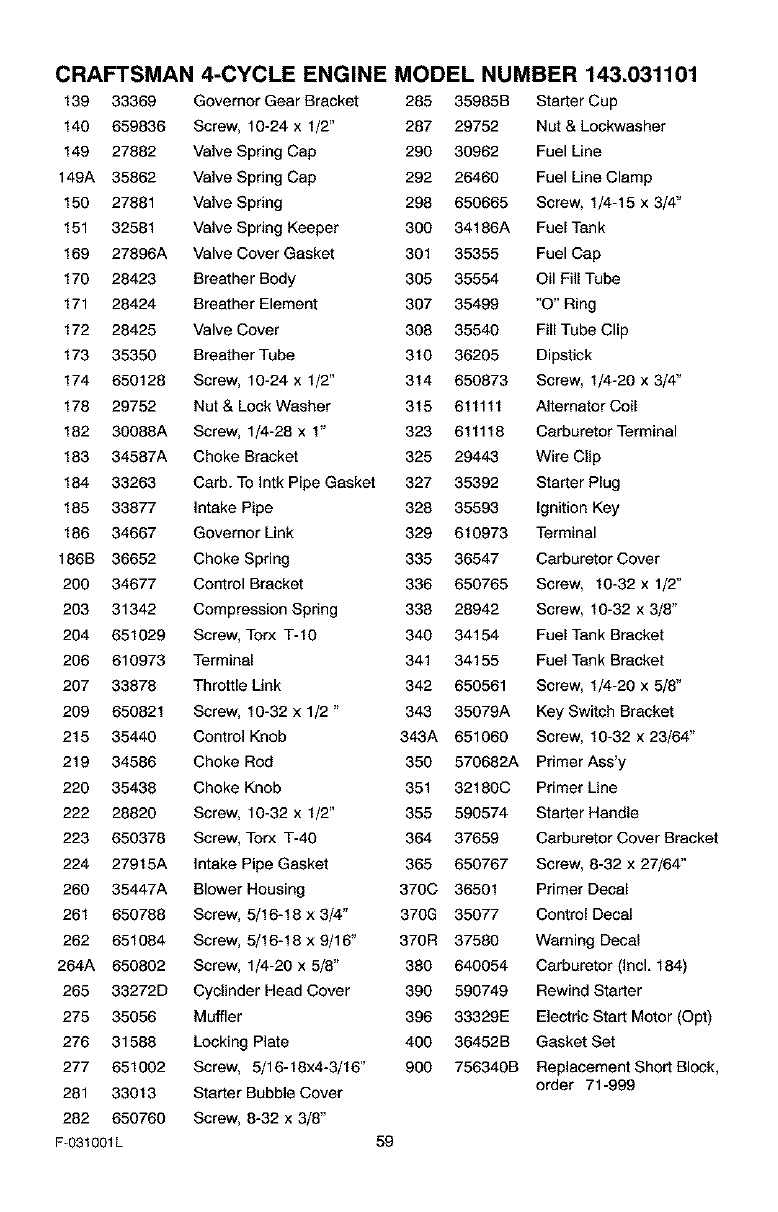
CRAFTSMAN 4-CYCLE ENGINE MODEL NUMBER 143.031101
139 33369 Governor Gear Bracket 285 35985B Starter Cup
140 659836 Screw, 10-24 x I/2" 287 29752 Nut & Lockwasher
149 27882 Valve Spring Cap 290 30962 Fuel Line
149A 35862 Valve Spring Cap 292 26460 Fuel Line Clamp
150 27881 Valve Spring 298 650665 Screw, 1/4-15 x 3/4"
151 32581 Valve Spring Keeper 300 34186A Fuel Tank
169 27896A Valve Cover Gasket 301 35355 Fuel Cap
170 28423 Breather Body 305 35554 Oil FillTube
171 28424 Breather Element 307 35499 "O" Ring
172 28425 Valve Cover 308 35540 Fill Tube Clip
173 35350 Breather Tube 310 36205 Dipstick
174 650128 Screw, 10-24 x 1/2" 314 650873 Screw, 1/4-20 x 3/4"
178 29752 Nut & Lock Washer 315 611111 Alternator Coil
182 30088A Screw, 1/4-28 x 1" 323 611118 Carburetor Terminal
183 34587A Choke Bracket 325 29443 Wire Clip
184 33263 Carb. To Intk Pipe Gasket 327 35392 Starter Plug
185 33877 Intake Pipe 328 35593 Ignition Key
186 34667 Governor Link 329 610973 Terminal
186B 36652 Choke Spring 335 36547 Carburetor Cover
200 34677 Control Bracket 336 650765 Screw, 10-32 x 1/2"
203 31342 Compression Spring 338 28942 Screw, 10-32 x 3/8"
204 651029 Screw, Torx T-1O 340 34154 Fuel Tank Bracket
208 610973 Terminal 341 34155 Fuel Tank Bracket
207 33878 Throttle Link 342 650561 Screw, 1/4-20 x 5/8"
209 650821 Screw, 10-32 x 1/2 " 343 35079A Key Switch Bracket
215 35440 Control Knob 343A 651060 Screw, 10-32 x 23/64"
219 34586 Choke Rod 350 570682A Primer Ass'y
220 35438 Choke Knob 351 32180C Primer Line
222 28820 Screw, 10-32 x 1/2" 355 590574 Starter Handle
223 650378 Screw, Torx T-40 364 37659 Carburetor Cover Bracket
224 27915A Intake Pipe Gasket 365 650767 Screw, 8-32 x 27/64"
260 35447A Blower Housing 370C 36501 Primer Decal
261 650788 Screw, 5/16-18 x 3/4" 370G 35077 Control Decal
262 651084 Screw, 5/16-18 x 9/16" 370R 37580 Warning Decal
264A 650802 Screw, 1/4-20 x 5/8" 380 640054 Carburetor (Incl. 184)
265 33272D Cyclinder Head Cover 390 590749 Rewind Starter
275 35056 Muffler 396 33329E Electric Start Motor (Opt)
276 31588 Locking Plate 400 36452B Gasket Set
277 651002 Screw, 5/16-18x4-3/16" 900 756340B Replacement Short BIock,
281 33013 Starter Bubble Cover order 71-999
282 650760 Screw, 8-32 x 3/8"
F-031001L 59
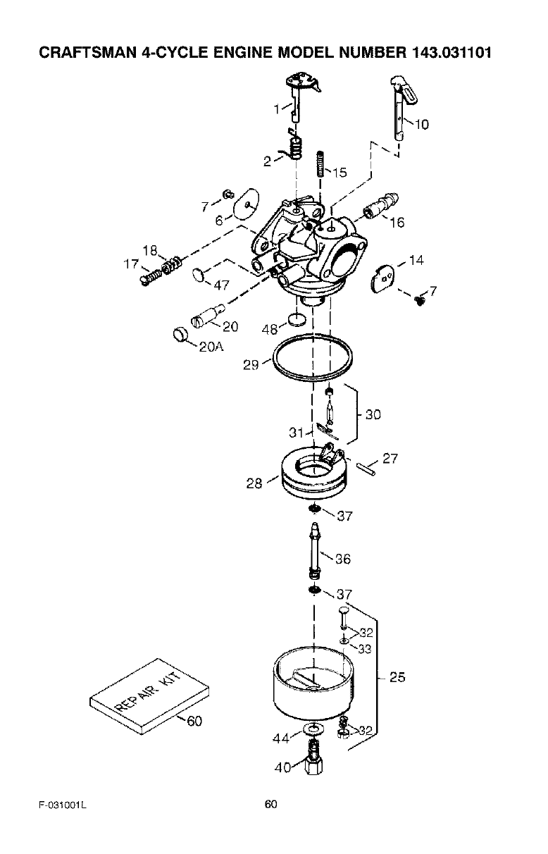
CRAFTSMAN 4-CYCLE ENGINE MODEL NUMBER 143.031101
0
U.15
J
47 /I v,_ :E_ V",,, ..'7
60 25
F-O31001L 60
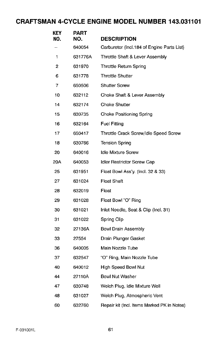
CRAFTSMAN 4-CYCLE ENGINE MODEL NUMBER 143.031101
KEY PART
NO. NO. DESCRIPTION
-- 640054 Carburetor (Inc1.184 of Engine Parts List)
1 631776A Throttle Shaft & Lever Assembly
2 631970 Throttle Return Spring
6 631778 Throttle Shutter
7 650506 Shutter Screw
10 632112 Choke Shaft & Lever Assembly
14 632174 Choke Shutter
15 630735 Choke Positioning Spring
16 632164 Fuel Fitting
17 650417 Throttle Crack Screw/Idle Speed Screw
18 630766 Tension Spring
20 640016 Idle Mixture Screw
20A 640053 Idler Restrictor Screw Cap
25 631951 Float Bowl Ass'y. (Incl. 32 & 33)
27 631024 Float Shaft
28 632019 Float
29 631028 Float Bowl "O" Ring
30 631021 Inlet Needle, Seat & Clip (Incl. 31)
31 631022 Spring Clip
32 27136A Bowl Drain Assembly
33 27554 Drain Plunger Gasket
36 640005 Main Nozzle Tube
37 632547 "O" Ring, Main Nozzle Tube
40 640012 High Speed Bowl Nut
44 27110A Bowl Nut Washer
47 630748 Welch Plug, Idle Mixture Well
48 631027 Welch Plug, Atmospheric Vent
60 632760 Repair kit (IncL Items Marked PK in Notes)
F-031001L 61
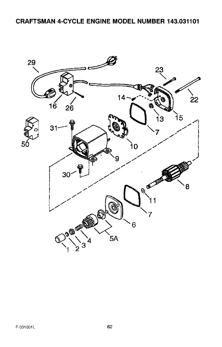
CRAFTSMAN 4-CYCLE ENGINE MODEL NUMBER 143.031101
29
16 26
23
\
\22
_, 13 1_/q
31"I" /I
, 7 ...- r
50 "iO "I I
5A
F-031001L 62
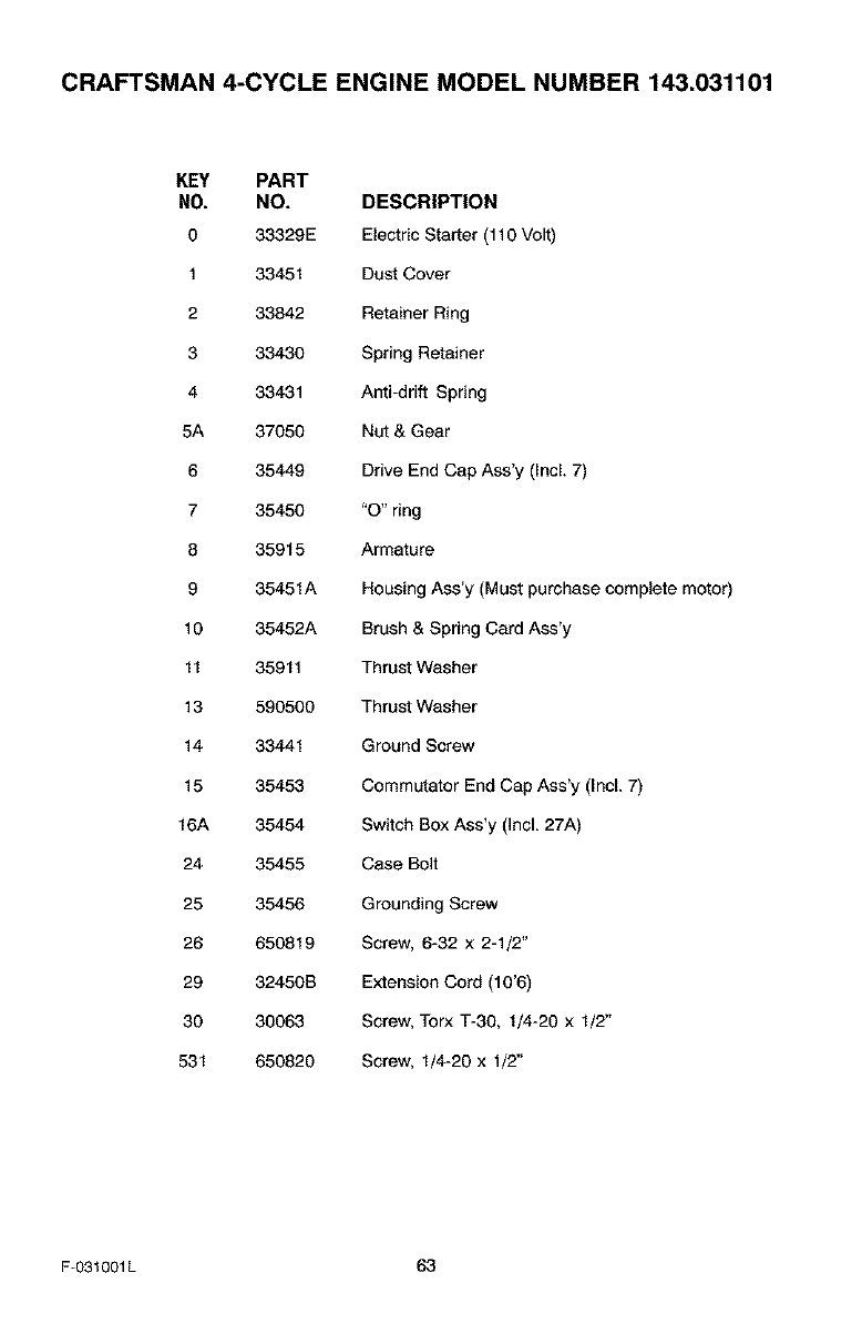
CRAFTSMAN 4-CYCLE ENGINE MODEL NUMBER 143.031101
KEY PART
NO. NO. DESCRIPTION
0 33329E Electric Starter (110 Volt)
1 33451 Dust Cover
2 33842 Retainer Ring
3 33430 Spring Retainer
4 33431 Anti-drift Spring
5A 37050 Nut & Gear
6 35449 Drive End Cap Ass'y (Incl. 7)
7 35450 "O" ring
8 35915 Armature
9 35451A Housing Ass'y (Must purchase complete motor)
10 35452A Brush & Spring Card Ass'y
11 35911 Thrust Washer
13 590500 Thrust Washer
14 33441 Ground Screw
15 35453 Commutator End Cap Ass'y (Incl. 7)
16A 35454 Switch Box Ass'y (Incl. 27A)
24 35455 Case Bolt
25 35456 Grounding Screw
26 650819 Screw, 6-32 x 2-1/2"
29 32450B Extension Cord (10'6)
30 30063 Screw, Torx T-30. 1/4-20 x 1/2"
531 650820 Screw, 1/4-20 x 1/2"
F-031001L 63
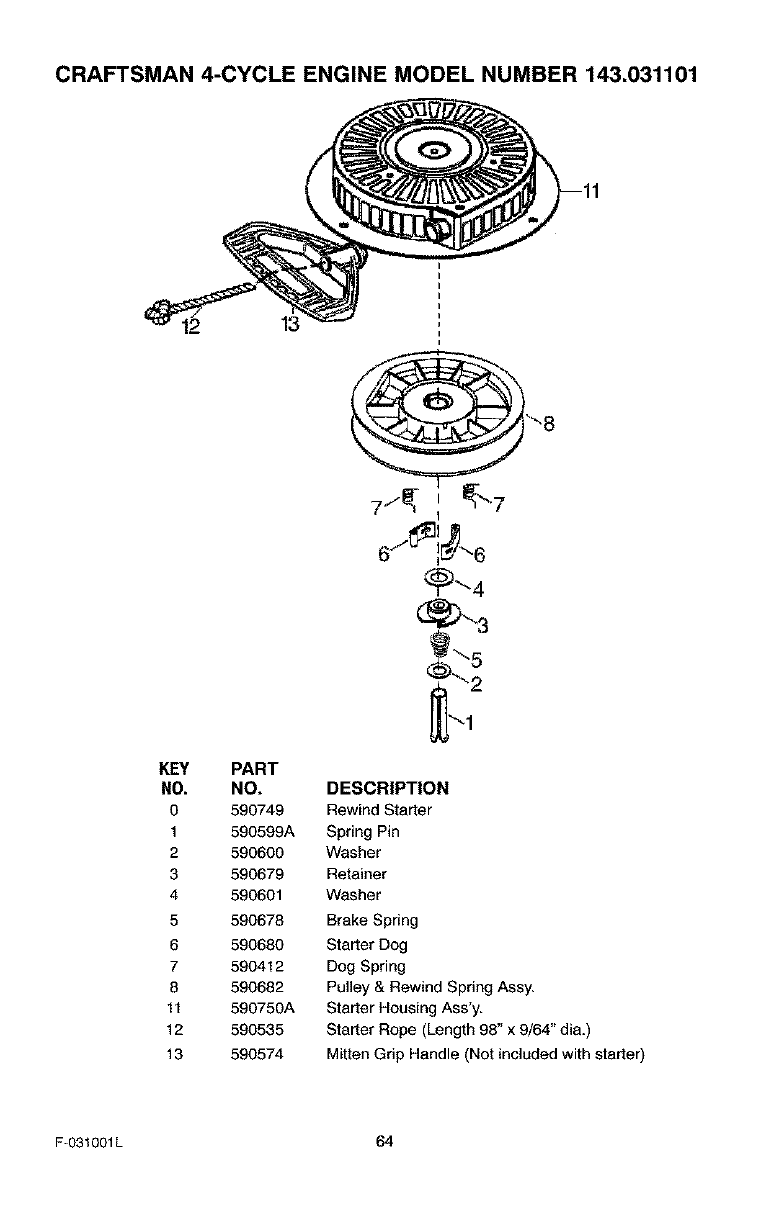
CRAFTSMAN 4-CYCLE ENGINE MODEL NUMBER 143.031101
12 13
KEY PART
NO. NO.
0 590749
1 590599A
2 590600
3 590679
4 590601
5 590678
6 590680
7 590412
8 590682
11 590750A
12 590535
13 590574
DESCRIPTION
Rewind Starter
Spring Pin
Washer
Retainer
Washer
Brake Spring
Starter Dog
Dog Spring
Pulley & Rewind Spring Assy.
Starter Housing Ass'y.
Starter Rope (Length 98" x 9/64" dia.)
Mitten Grip Handle (Not included with starter)
F-031001L 64
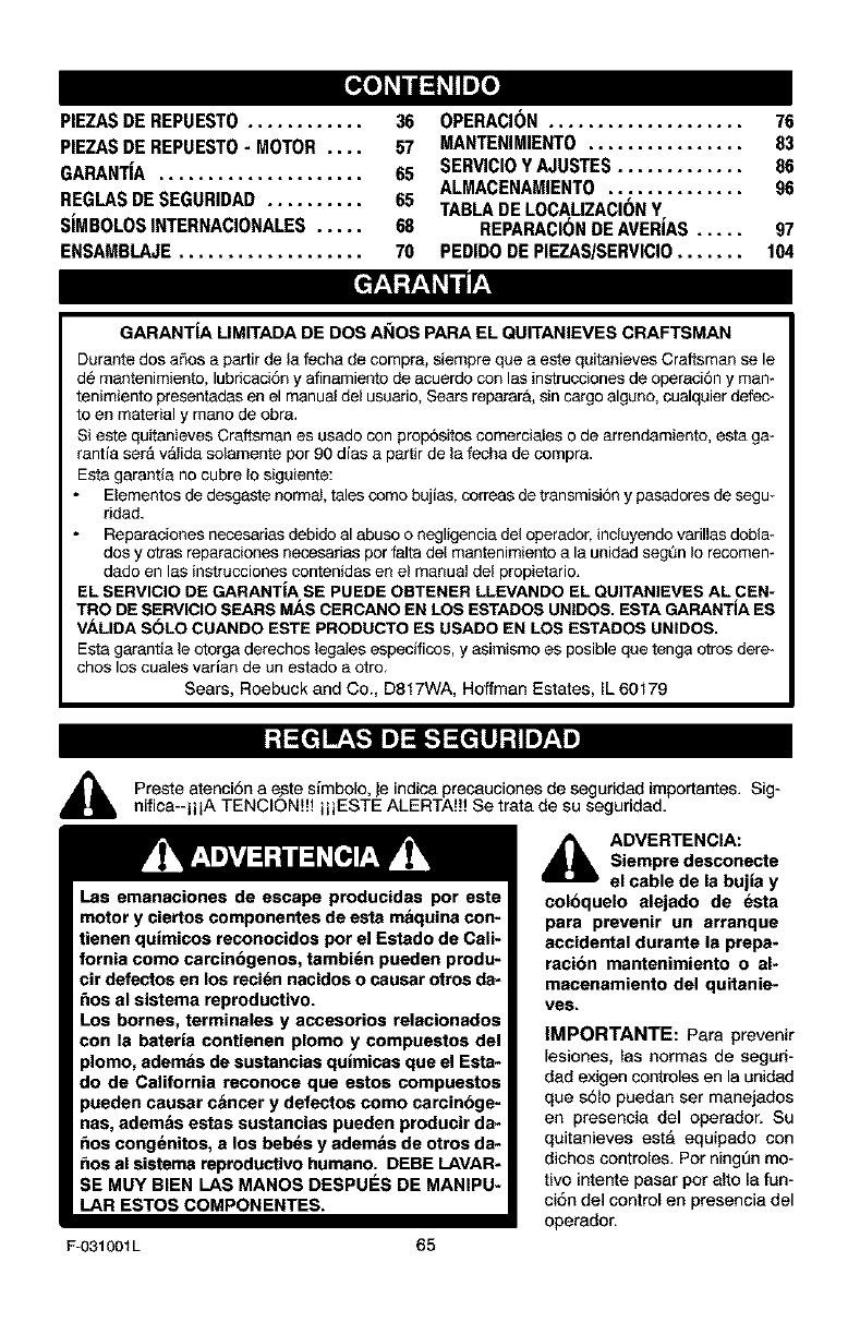
[_o) _I 1:1_IIm]_o]
PIEZASDE REPUESTO............ 36
PIEZASDE REPUESTO-MOTOR .... 57
GARANTIA ..................... 65
REGLASDESEGURIDAD .......... 65
SIMBOLOSINTERNACIONALES..... 68
ENSAMBLAJE................... 70
OPERACI(_N.................... 76
MANTENIMIENTO ................ 83
SERVICIOYAJUSTES............. 86
ALMACENAMIENTO.............. 96
TABLADELOCAUZACI(_NY
REPARACI(_NDEAVERJAS..... 97
PEDIDODEPIEZAS/SERVICIO....... 104
GARANTiA LIMITADA DE DOS AI_IOS PARA EL QUITANIEVES CRAFTSMAN
Durante dos aSos a partir de la fecha de compr& siempre que a este quitanieves Craftsman sele
d6 mantenimiento, lubricaci6n y afinamiento de acuerdo con las instrucciones de operaci6n y man-
tenimiento presentadas en el manual del usuario, Sears reparar& sin cargo algano, cualquier defec-
to an material y mano de obra,
Sieste quitanieves Craftsman es usado con prop6sitos comerciales o de arrsndamiento, esta ga-
rantia set& v_lida solamente pot 90 dias a partir de la fecha de compra.
Esta garantia no cubre Io siguiente:
Elementos de desgaste normal, tales como bujias, correas de transmisi6n y pasadorss de segu-
ridad.
Reparaciones necesarias debido al abuso o negligencia del opersdor, incluyendo varillas dobla-
dos y otras reparaciones necesarias par falta deI mantenimiento a la unidad segQn Io recomem
dado en las instrucciones contenidas en el manual del propietario.
EL SERVICIO DE GARANTiA SE PUEDE OBTENER LLEVANDO EL QUITANIEVES AL CEN-
TRO DE SERVIClO SEARS MAS CERCANO EN LOS ESTADOS UNIDOS. ESTA GARANTiA ES
VALIDA SOLO CUANDO ESTE PRODUCTO ES USADO EN LOS ESTADOS UNIDOS.
Esta garantia le otorga derechos legales especificos, y asimismo es posible que tenga otros dere*
chos los cuales varian de un estado a otro.
Sears, Roebuck and Co., D817WA, Hoffman Estates, IL 60179
Preste atenci6n a e.ste simbolo, je indica preeauciones de seguddad importantes. Sig-
nifica--iii A TENCION!!! i ii ESTE ALERTA!!! Se trata de su seguridad.
Las emanaciones de escape producidas por este
motor y ciertos componentes de esta maquina con-
tienen quimicos reconocidos pot el Estado de Cali-
fornia como carcinbgenos, tambi_n pueden produ-
cir detactos en los reci_n nacidos o causar otros da-
_os al sistema reproductivo.
Los homes, terminales y accesorios relacionados
con la bateria contienen plomo y compuestos del
plomo, ademas de sustancias qulmicas que el Esta-
do de California reconoce que estos compuestos
pueden causar c&ncer y defectos como carcinbge-
nas, adem&s estas sustancias pueden producir da-
_os cong_nitos, a los beb_s y adem&s de otros da-
_os al sistama reproductivo humano. DEBE LAVAR-
SE MUY BIEN LAS MANOS DESPUES DE MANIPU-
LAR ESTOS COMPONENTES.
F-O31001L 65
_1_ DVERTENCIA:
Siempre desconecte
el cable de la bujia y
coloquelo alejado de esta
para prevenir un arranque
accidental durante la prepa*
racibn mantenimiento o al-
macenamiento del quitanie*
ves.
IMPORTANTE: Para prevenir
lesiones, las normas de seguri-
dad exigen controles en la unidad
que s61o puedan ser manejados
en presencia del operador. Su
quitanieves esta equipado con
diehos eontroles. Pot ning6n mo-
tivo intente pasar por alto la fun-
ci6n del control en presencia del
operador.
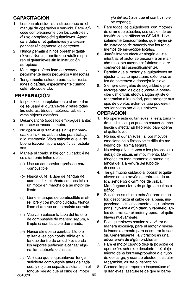
CAPAClTACIbN
1. Lea con atenciAn [as instrucciones en el
manual de operaciAn y servicio. Familiari-
cese completamente con los controles y
el uso apropiado de] quitanieves. Apren-
da a detener el quitanieves y a desen-
ganchar rapidamente los controles.
2. Nunca permita ani_os operar el quita-
nieves. Nunca permita que adultos ape-
ten el quitanieves sin la instrucciAn
apropiada.
3. Mantenga el Area libre de personas, es-
pecielmente niAos pequeAos y mascotas.
4. Tenga mucho cuidado pare evitar resba-
lanes o caidas, especialmente cuando
est_ retrocediendo.
PREPARAClbN
1. Inspecciene compietamente e[ Area don-
de se usara el quitanieves y retire todas
las esteras, trineos, tableros, cables, y
otros objetos extraAos.
2. Desenganche todos los embragues antes
de hacer arrancar el motor.
3. No opere el quitanieves sin vestir pren-
das de inviemo adecuadas pare. trabajar
ala intemperie. Vista calzedo que le d_
buena tracciAn sobre superficies resbale-
sas,
4. Maneje el combustible cen cuidade; Aste
es altamente inflamable.
(a) Use un contenedor aprobado pare.
combustible.
(b) Nunca quite la tape del tanque de
combustible ni armadacombustible a
un motor en marcha o a un motor ca-
liente.
(c) Llene el tanque de combustible al el-
re libre y con mucho cuidado. Nunca
Ilene el tanque en un reeinto cerrado.
y/o del sol hace que el combustible
se expanda.
5. Para todos los quitanieves con motores
de arranque el_ctrico, use cables de ex-
tensiAn con certificaciAn CSA!UL Use
solamente tomacorrientes que hayan si-
do instalados de acuerdo con los regla-
mentos de inspecciAn locales.
6. JamAs intente efectuar ning_n ajuste
mientras el motor se encuentra en mar-
cha (excepto cuando el fabricante Io re-
comiende asi especificamente).
7. Permita que el motor y el quitanieves se
ajusten alas temperatures exteriores an-
tes de comenzar a despejar la nieve.
8. Siempre use gafas de seguridad o pro-
tectores pare los ojos durante la opera-
clan o mientras efectQa alg5n ajuste o
reparaciAn ala unidad, pare proteger sus
ojos de objetos extraAos que pudiesen
set lanzados par el quitanieves.
OPERACION
t, No epere este quitanieves si estA toman-
do medicinas que puedan causar somno-
lencia o afectar su habilidad para operar
el quitanieves.
2. No use el quitanieves si por motives
emocionales o fisicos se le dificulta ma-
nejarlo de forma segura.
3. No coloque las manos o los pies cerca o
debajo de piezas en movimiento. Men-
tAngase en todo momento a buena dis-
tancia de le abertura del tubo de
descarga.
4. Tenga mucho cuidado al operar el quite-
nieves en o a tray,s de entradas de au-
tos, senderos o caminos de grava.
MantAngase alerfa de peligros ocultos o
trafico.
5- Si golpea un objeto extra5o, pare el mo-
tor, desconecte el cable de la bujia, ins-
peccione meticulosamente el quitanieves
por si hubiera algQn daAo, y repArelo an-
tes de arrancar el motor y operar el quite-
nieves nuevamente.
Si el quitenieves comienza a vibrar de
manere excesiva, pare el motor y revise-
Io inmediatamente pare encontrar la cau-
se. Generalmente, la vibraciAn as una
advertencia de elgin problem&
7. Pare el motor cuando deje la posiciAn de
operaciAn, antes de desobstruir el aloja-
miento de la barrena/propulsor o el tubo
de descarga, y cuando efect5e cualquier
reparaciAn, ajuste o inspecciAn.
Cuando limpie, repare o inspeccione el
quitanieves, asegArese de que ]a barre-
(d) Vuelva a colocar la tape del tanque
de combustible de manera segura, y
limpie el combustible derramado. 6.
(e) Nunca almacene combustible o el
quitanieves con combustible en el
tanque dentro de un ediflcio donde
los vapores pudiesen alcanzar algu-
na llama abierta o chispas.
(f) Verifique que el quitanieves tenga
suficiente combustible antes de cede
uso, y deje un espacio adicional en el 8.
tanque puesto que el calor del motor
F-031001L 66
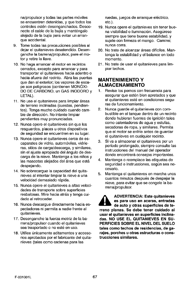
na/propulsorytodasInspartesm6viles
seencuentrendetenidas,yquetodoslos
controlesest_ndesenganchados.Desoo-
necteelcabledelabujiaymant_ngalo
alejadodelabujiapareevitarunarran-
queaccidental.
9. TometodasInsprecaucionesposiblesal
dejerelquitanievesdesatendido.Desen-
ganchelabarrena!propulsor,pareelmo-
toryretire18Ilave.
10.Nohagaarrancerelmotorenrecintos
cerrados,exceptoperaarrancerypare
trensportarelquitanieveshaciaedentroo
haciaafueradelrecinto.Abralaspuertas
quedenalexterior;losvaporesdeesca-
pesonpeligresos(contienenMONOXl-
DODECARBONO,unGASINODOROy
LETAL).
11.Nouseelquitanievesparelimpier&reas
deterrenoinclinadas(cuestas,pendien-
tes).Tengamuchocuidadocuandocam-
hiededirecci6n.Nointentelimpier
pendientesmuypronunciadas.
12.Nuncaopereelquitanievessinquelos
resguardos,placesuotrosdispositivos
deseguridadseencuentrenensuIugar.
13.Nuncaopereelquitanievescercadees-
caparetesdevidrio,eutom6viles,vidrie-
ras,sitiosdecerga/descarga,ysimilares,
sinelajusteapropiadodelangulodedes-
cargadelanieve.Mantengaalosnifiosy
lasmascotasalejadosdel&reequeest&
despejando.
14.Nosobrecarguelecapecidaddelquita-
nievesalintenterlimpiarlanieveauna
velocidaddemesiador&pida.
15.Nuncaopereelquitanievesaaltasveloci-
dadesdetransportesobresuperficies
resbalosas.Mirehaciaarrasytengacui-
dadoalretroceder.
16.Nuncadescarguedirectamentehaciaes-
pectadoresnipermitaanediefrenteal
quitanieves.
17.Desenganchelefuerzamotrizdelabe-
rrena/propulsorcuandoelquitanieves
seetrasportadoonoest6enuso.
18.Utilice8nicamenteadffamentosyacceso-
dosaprobadospotelfabricantedelquite-
nieves(talescomocadenasparelas
ruedas,juegosdearranqueel6ctrico,
etc.).
19.Nunceopereel quitanieves sin tener bue-
na visibilidad o iluminaci6n. Asegt_rese
siempre que tiene buena estabilidad, y
sujete con firmeza el mange. Camine;
nunca corl'e.
20. No trate de alcanzer &reas dificiles. Man-
tenga ]a estabilided yel balance en todo
momento.
21. No trete de user el quitenieves pare lim-
piar techos.
MANTENIMIENTO Y
ALMACENAMIENTO
1. Revise los pemos con frecuencia pera
asegurer que est6n bien epretados y que
el quitanieves est6 en condiciones segu-
ras de funcionamiento.
2. Nunce guerde el quitanieves con com-
bustible en el tanque dentro de un recinto
donde hubieran fuentes de ignici6n tales
como calentadores de ague y estufes,
secadoras de ropa, y similares. Permite
que el motor se enfrie antes de guarder
el quitanieves en cualquier recinto.
3. Siva a almacenar el quitanieves pot un
pedodo prolongado, siempre consulte las
instrucciones del manual del operador
donde encontrara consejos importantes.
4. Mantenga o reemplace las etiquetas de
seguridad e instrucciones, segOn sea ne-
cesario.
5. Mantenga el quitanieves en marcha unos
cuantos minutos despu_s de despeiar le
nieve, para ev_ar que se congele la be-
rrena/propulsor.
_IL ADVERTENCIA: Este quitanieves
es para use en aceras, entradas
de auto y otras superficies de te-
rreno planas. Se debe tener cuidado al
usar el quitanieves en superficies inclina-
das. NO USE EL QUITANIEVES EN SU-
PERFICIES SOBRE EL NWEL DEL SUELO
tales como techos de residencias, de ga-
rajes, porches u otras estrgcturas o cons-
trucciones similares.
F-031001L 67
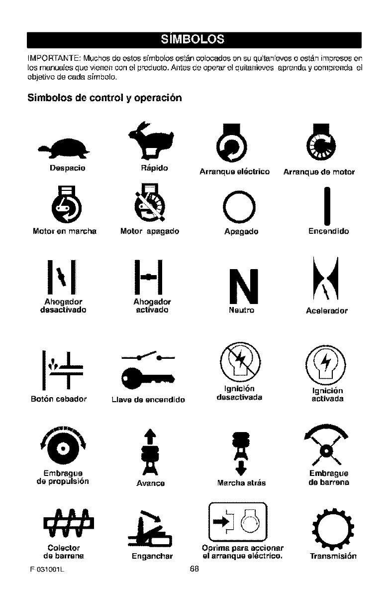
_o_o_S
IM F'ORTANTE: Muchos de estos simbolos est&q solosados en su qu tan eves o est_n impresos en
los manuales que vienen con el producto, A_eS de opemr el quitanieves aprenda y oompl'enda el
objetivo de cada simbolo.
Simbolos de control y operacibn
Despacio R_pido Arranque el_rico
@ o Arranque de motor
I
Motor en marcha Motor apagado Apagado Encendtdo
I:[, NU
dasactivado activado Neutro Acelerador
BorOn cebador Llave de encendido
® G
Ignict_n Igni¢i_n
dasactivada activada
Embrague
de propulst6n
Colector
de barrena
F 031001L
Avance Marcha arras de barrena
Enganchar el arranque 8_ctrico. Transmisi6n
_8
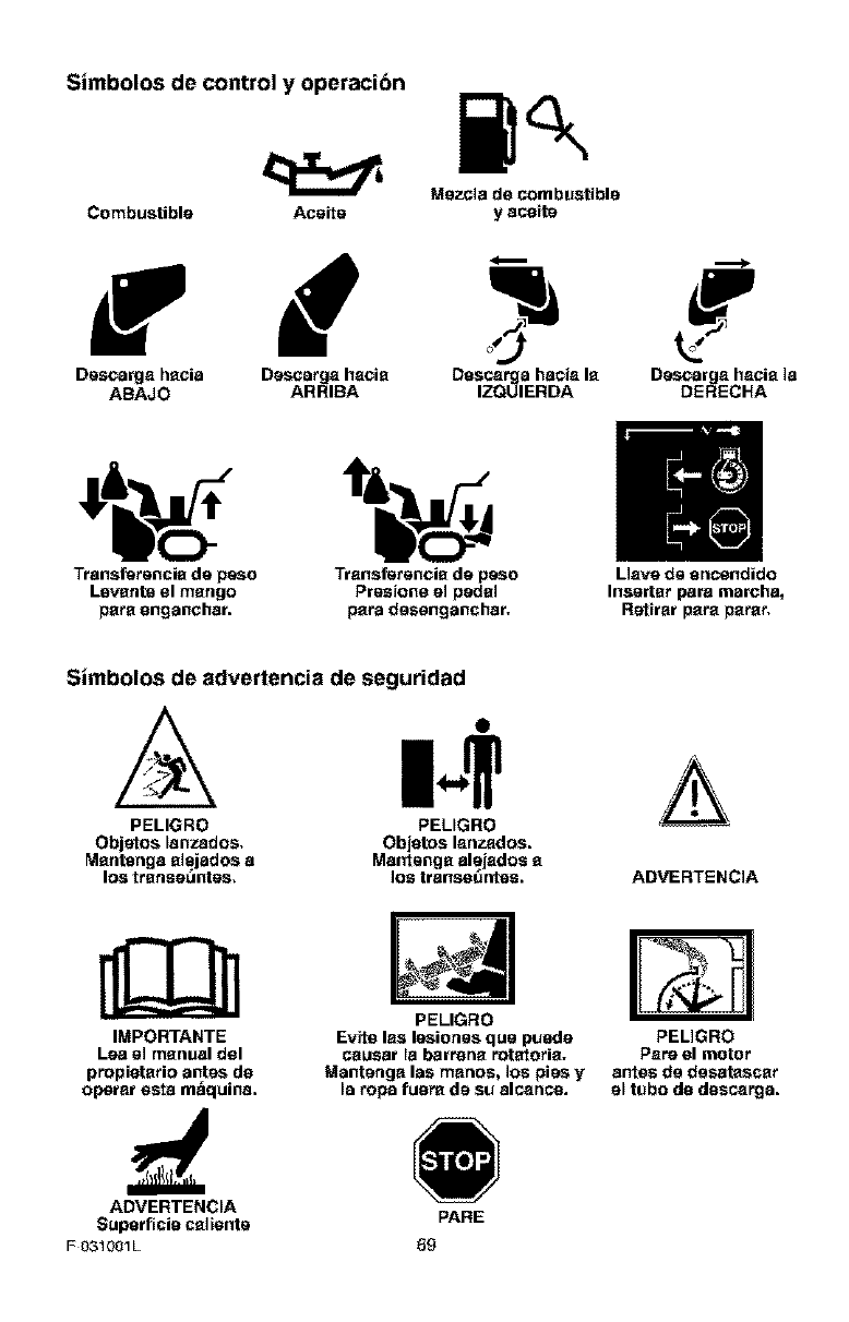
Simbolos de control y operacibn
Mezcia de combustible
Combustible Aceite y aco}te
Descarga hscia D_rscarga hscis Dascarga hacis Is D_rscarga hscis la
ABAJO ARRIBA IZQUIERDA DERECHA
i' .H
Transferencis de peso Transferencis de peso Llsvs de sncendido
Lsvstlt8 el mstlgo Presions el pedsl Illsertsr pars marchs_
psre onganchsr, psra dessnganchsr, Retlrar psre psrer,
Simbolos de advertencia de seguridad
PELIGRO
Objetos lanzados.
Msntenga slsjados a
los trsnea_ntes.
PELIGRO
Objotos lanzados.
Ma_rtengs alsjados s
los tranea_ntes.
A
ADVERTENCIA
IMPORTANTE
Lea el manual dsl
propietsrio antes ds
operar osta m_quina.
PELIGRO
Evits las leaiones que pueds
cauear _abarrens rotatoris.
Mantsnga las manos, los pies y
la repa fuore de su alcanco.
PELIGRO
Pare el motor
antes de deeatascsr
s_ tubs do doscarga.
ADVERTENCIA
Superf}cio csl}snte PARE
F031001L 59
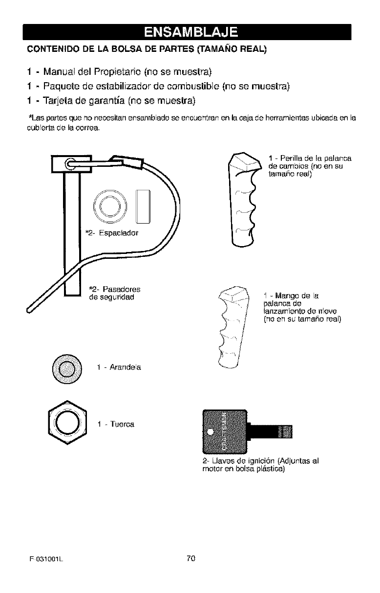
CONTENIDO DE LA BOLSA DE PARTES _AMANO REAL)
1 - Manual del Propietado (no se muestra)
1 - Paquete de estabilizador de combustible (no se muestra)
1 - Tarjeta de garantia (no se muestra)
*log parteg que no neeegitan ensamblede se enouentran en la oaja de herramienta_ ubic_de en la
oub erta de la correa.
I-Arendela
I1=Perilla de la palanca
de oambies (ne en su
tamaffo real)
F_
I - Mango de le
palanea de
laneam ente de neve
{he en su tama6e real)
©1 - Tuerea
2- Llavee de igniei6n (Adiuntas al
mater en balsa pl6stica}
F031001L 70
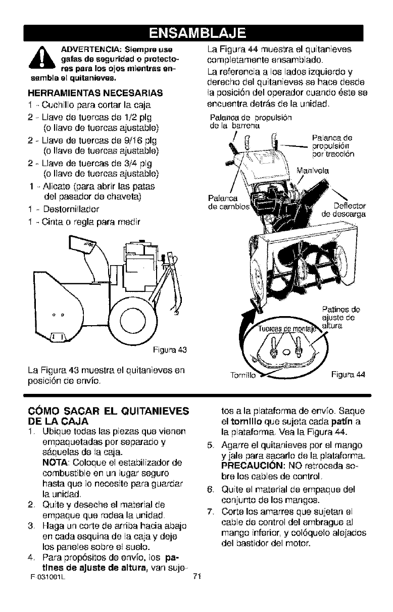
I:] Ir,_lJ
_li DVERTENCIA: $iempre use
galas de seguridad o protecto-
res para los ojos mientras en_
sambla el quitanieves,
HERRAMIENTAS NECESARIAS
I _ Ouchillo pare osrtar la caja
2 _ Uave de tuercas de 1/2 pig
(o Ilave de tuercae ajuetable)
2 _ Uave de tuercas de 9/I6 pig
(o Ilave de tuercae ajuetable)
2 _ Uave de tuercas de 3/4 pig
(o Ilave de tuercae ajuetable)
1 _ Alicate (pare abrir las pates
del paeador de chaveta)
I _ Destomillador
I - Cinta o regla pare medir
oFigure43
La Figure 43 muestra el quitanieves en
posici6n de envio,
La Figure 44 mueetra el quitanieves
completamente ensamblado.
La referencia a los lades izquierdo y
derecho del quitanieves ee hace deede
la posici6n del operador cuando 6ere ee
encuentra detr_e de la unidad.
Palancade propulsiSn
de la barrena
/
Patines de
ajuste de
altura
Tomillo Figure44
C(_MO SACAR EL QUITANIEVES
DE LA CAJA
I, Ubique todas las piezas que vienen
empaquetadas per eeparado y 5,
e#.quelas de la caja.
NOTA: Coloque el eetabilizador de
combustible en un lugar eeguro
haste que Io neoseite pare guarder 6,
la unidad
2, Quite y deseche el material de
empaque que rodea la unidad. 7,
3, Haga un code de arriba hacia abajo
en cada esquina de la caja y deje
los panelee eobre el euelo.
4. Pare prop6sitos de envfo, Ioe pc-
tines de aJuste de altura, van suje_
F 031001L 71
tos ala plataforma de envfo. Saque
el tornlllo que sujeta cada patfn a
la plataforma, Vea la Figure 44.
Agarre el quitanievee per el mango
y jale pare eacarlo de la plataforma.
PRECAUCI(_N: NO retrocede eo_
bre los cables de control.
Quite el material de empaque del
conjurto de los mangos.
Corte los amarree que eujelan el
cable de control del embrague al
mango inferior, y os16quelo alejados
del bastidor del reeler.
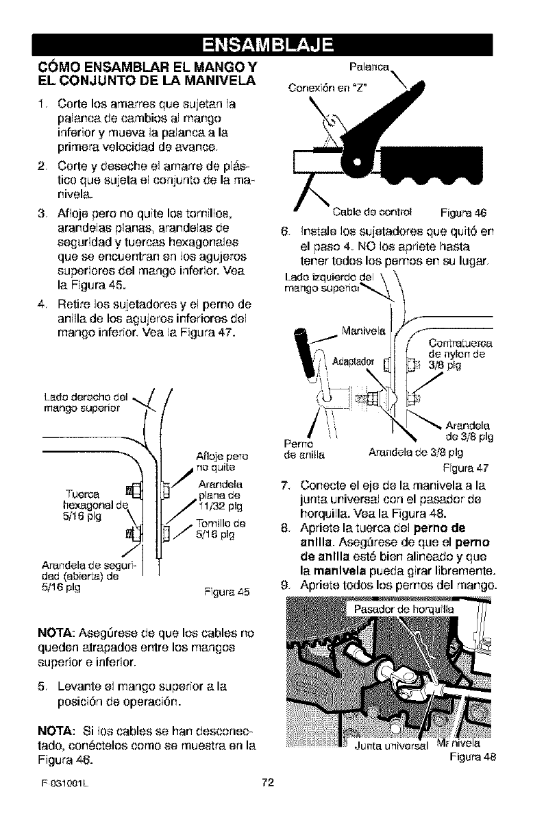
C(_MO ENSAMBLAR EL MANGO Y
EL CONJUNTO DE LA MANIVELA
I. Carte los amarres que sujetan la
palanca de eatables al mango
inferior y mueva la palanea ala
primera velocidad de avarice,
2, Carte y deseche el amarre de pl#,s_
tico que sujeta el conjunto de la ma_
nivela.
3. Afloje pero no quite los tornillos,
arandelas planes, arandelas de
seguridad y tuercas hexagonales
que se encuentran en Io8 agujeros
superiores del mango inferior. Yea
la Figura 45.
4. Retire los sujetadores y el pemo de
anilla de los agujeros inferiores del
mango inferior. Yea la Figura 47.
mango superior
Arandela de segur_'-
dad (ab er_) de
5/16 pig
Afloje pete
no quite
Arandela
•Tomille de
5/16 pig
Fgura 45
Cenex 6n en "Z"
Cable de contrel Figure46
6. Inetale los sujeladores que quit6 en
el paso 4. NO los apriete haste
tenet todos los pernos en su lugar.
Ladeizquierde del
mango superie_
plg
de anilla Arandela de 3/8 pig
Fgura 47
7. Conecle el eje de la manivela ala
junta universal con el pasador de
horquilla. Vea la Figura 48.
8. Apriete la tuerca del perno de
anllla. Aseg_rese de que el pemo
de anllla eut6 bien alineado y que
la manlvela pueda girar libremente.
9, Apriete todos los pemos del mango.
NOTA: Aseg_rese de que los cables no
queden atrapados entre los mangos
superior e inferior.
5. Levante el mango superior ala
posiei6n de operaei6n.
NOTA: Si los cables se hen desconee_
tado, con6ctelos come se mueetra en la
Figure 46.
F 031001L 72
Junta universal
Figure 48
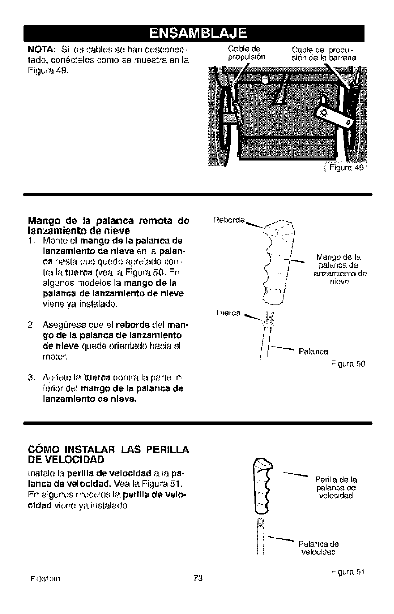
NOTA: Si los cables se hart desconec_
tado, con6ctolos como so muo_tra on la
Figura 49.
Cable de
propulsion Cable de propul-
sion de la barrena
Mango de la palanca remora de
lanzamiento de nieve
I, Monte el mango de la palanca de
lanzamlento de nleve en la palan-
ca hasta qua quede aprotado con-
tra la tuerca (yea la Figura 50. En
algunos modelos la mango de la
palanca de lanzamlento de nlave
viene ya instalado,
2 AsegOrese qua el reborde del man-
go de la palanca de lanzamlento
de nleve quode oriontado hacia el
motor.
3, Apriote la tuerca contra la parto irl-
ferior do1 mango de la palanca de
lanzamlento de nleve.
Reborde
Palanea
Figura 50
C(_MO INSTALAR LAS PERILLA
DE VELOCIDAD
Instale la perllla de velocldad a la pa-
lanca de velocldad. Vea la Figura 51.
En algurlos modolos la perllla de velo-
cldad viorle ya instalado, _ Perilla de la
palanoa de
velocidad
#
'_ _ Palancade
H veloc dad
Figura 51
F031001L 73
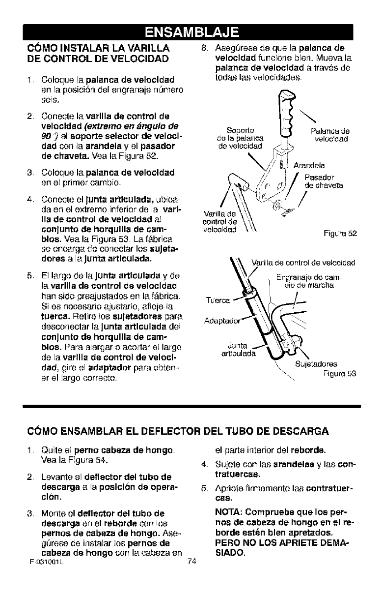
C(_MO INSTALAR LA VARILLA
DE CONTROL DE VELOCIDAD
I. Coleque la palanca de velocldad
en la posiciCn del engranaje n_mero
_eiS.
2. Conecle la varllla de control de
velocldad (extramo en _Jngu!o de
90 _)al soporl:e selector de velocl-
dad con la arandela y el pasador
de chaveta. Vea la Figura 52.
3. Coleque la palanca de velocldad
on el primer carnbio.
4. Conecte el Junta artlculada, ubica-
da en el extrerno inferier de la varl-
Ila de control de velocldad al
conJunto de horqullla de cam-
blos. Vea la Figura 53. La f_d3rica
se encarga de conectar lee suJeta-
dotes a la Junta artlculada.
5. El large de la Junta artlculada y de
la varllla de control de velocldad
hart side preajustados on la f_brica.
Si es necesarie ajustarlo, afloje la
tuerca. Retire los suJctadores para
desconectar la Junta artlculada del
conJunto de horqullla de cam-
blos. Para alargar o acortar el largo
de la varllla de control de valocl-
dad, gire el adaptador para ebtem
er el largo correcte.
6. Aseg_rese de qua la palanca de
velocldad funcione bien. Mueva la
palanca de velocldad a tray(as de
todas las velocidades.
Soporte Palanca de
de la palanca , velocfd_d
de velocid_d
Figure52
_,\_ V_rilla de control de velocidad
Junta_ _
ar_iculada _ N
Sujet_dores
Figura 53
C(_MO ENSAMBLAR EL DEFLECTOR DEL TUBO DE DESCARGA
I. Quite el perno cabeza de hongo.
Vea la Figura 54.
2. Levante el deflector del tubo de
descarga a la poslclbn de opera-
clCn.
3. Monte el deflector del tubo de
descarga en el reborde con los
pernos de cabeza de hongo. Ase_
g_rese de inslalar los pernos de
cabeza de hongo con la cabeza en
F 031001L
4,
5.
74
el parte interior del reborda.
Sujete con las arandelas y las con-
tratuercae.
Apriete firmemente las contratuer-
(;as.
NOTA: Compruebe que los per-
nos de cabeza de hongo en el re-
borde eat(an blen apretados.
PERO NO LOS APRIETE DEMA-
SIADO.
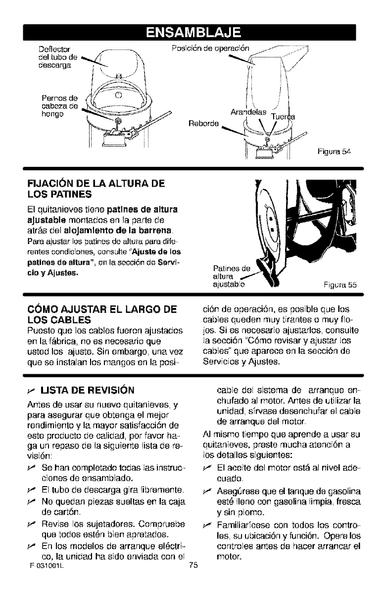
I:] Ir±lJ
Arandelas
Reborde
Figura 54
FIJACI(_N DE LA ALTURA DE
LOS PATIN ES
El quitanieves tiene patlnes de altura
aJustable montados en la parts de
arras del aloJamlento de la barrena.
Paraa[ustar los patines de altura p_ra dile-
rentes condc ones, consulte "Ajuste de los
patines de altura" an le.s_,oi6n de Servi*
cio y Ajustes, P_tines de
altura
ajustable Figura 55
C(_MO AJUSTAR EL LARGO DE
LOS CABLES
Puesto que los cables fueron ajustados
en la f_brica, no es necesario que
ueted los ajuete. Sin embargo, unavez
que se inslalan los mangos en la posi_
ci6n de operaci6n, es posible que los
cables queden muy tirantes o muy flo_
jos. Si es necesario ajuetarlos, consulte
la secci6n "C6mo revisar y ajuetar los
cables' que a4oarece en la secci6n de
Servicios y Ajusles.
USTA DE REVISION
Artes de usar su nuevo quitanieves, y
para asegurar que obtenga el mejor
rendimienlo y la mayor salisfacci6n de
eete products de calidad, pot favor ham
ga un repaso de la siguierte lisla de rex
visi6n:
Se ban completado todas las inetruc-
ciones de ensamblado.
El tubo de descarga gira libremente<
No quedan piezas sueltas en la caja
de cart6n.
Revise los sujetadores. Compruebe
que todos esl_n bien apretados.
En los modelos de arranque el6clri_
co, la unidad ha sido enviada con el
F 031001L 75
cable del sietema de arranque em
chufado al motor. Antes de uti]izar la
unidad, sfrvase desenchufar el cable
de arranque del motor.
AI mismo tiempo que aprende a usar su
quitanieves, presle mucha atenci6n a
los deta]les siguientes:
_,* El aceite del motor esl_ al nivel ade_
cuado<
_,* Aseg_rese que el tanque de gaso]ina
eet_ Ileno con gasolina limpia, fresca
y sin plomo.
Familiadcese con todos los contro_
les, su ubicaci6n y funci6n. Opere los
controles artes de hacer arrancar el
motor.
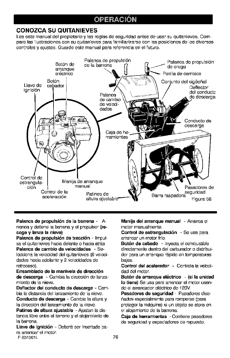
CONOZCA SU QUITANIEVES
Leoeste manual del propietorio y los reglos de seguridod antes de user su quitonieves, Com-
pare los lustrooionescon su quiton evsa pare fomiliorizorse con los poe e ones de los diverses
cor_rolsayajustes, Guarde este manuel paparefereneo en el future,
Pa]onoa de prepuls 6n Palonea do propulsi6n
Bot_n de de la borreno /do erugo
orronque
el6otrfco
Bet6n _ehol
Llove de Defleotor
ignfof6n del conduot¢
Polar,ca _ desaarga
de cambk
de veloc_
dadsa
Condsate do
descorgo
rremientos
estrongulo- Monijo de orronque
o6n mocool Posodores de
Control de Io Potines de Borpa rsap_dora segurid°d
ocoleroci6n altura ojustable ='-'_ Ffguro 56
Palanca de propulsion do ]a barter=a * A-
ydetene la b_r_r_ y el propulsar (re
cogs y lanza la nieve)
Palanca de propulsion do tracci6n - Impul-
se el quitanievsa hacie delante o Pec_ootr&s
Palanca de cambio do velocidedes - Se-
I_ieno Io salooidad del quit_nieves (6 salooi_
dodos hocfa edel_nte y 2 velcoidadsa de
retrosase).
Ensamblado de la rsanivelo do di_w.ci6n
de descarga _ Cambie Io direc_6n de lenze-
monte de le nieve.
Deflector de] conducto do dsscargo _ Cam-
bi_ le dist_ns adel lanzomier_e do la nieve.
Conducto de descarga - Cambio Io oltura y
Io direc_6n del I_nzomiento de la nieve.
Patinas de altura ojuatable * Ajustan Io dis:
tancio libr_ entre el terrene yel alejom onto de
Io barrer_.
Llave de ignici6n _ Deber& sat fnsartade pa-
r_ arranoar el motor,
F031001L
Manijo del arranqua manual - Arr'_nc_ el
motor manualmente
Control de estranguloci6rl _ Se USapare
arranoar un m_r fr[e
Bot6n do cebado - ]nyeot_el Sarnbu_ble
drectamente dentro del c_rburedor o d str bui_
dor pare un arranqsa _pdo en temperatures
b_jsa.
Control del acelorador - Controlo I_ velod-
dod dee motor.
Bot6n do arranque el_trico - (st Io unidod
Io lJone) Se USapare arrancar el motor us_ _
do el orr_nc_der electrisa do _20V.
Posaderes de seguridad - Pasador_s dise-
_dsa espedalrnente papa rornper_e _r_
proteger Io m_qufna) si un ebjeto sa atoro en
el olojemiento de I_ b_rreno.
Cajo de herramteldas - Centene pasadores
do saguridad ysapac adersa de repues_.
76
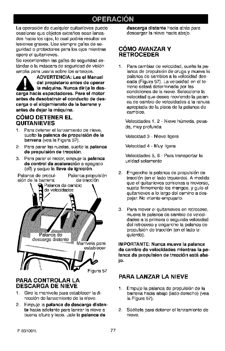
La operaci6n de oualqu er quitan evse puede
e_as onar qua ebjetos extr'a_es sear lanza-
des hacia los ejse, le seal podria rseultar en
Iseienes graves. Use s empre gafes de se-
guddad o protecterse papa los ejse mientras
opera el quitanievse.
Se re_',omfendan Ins gafes de seguridad se-
t_.ndar o la m_.so_pa de segurfdad de visiSn 1,
amplia papa userle sabre los arteejse.
_b ADVERTENCIA: Lee el Manual
del propietario antes de operar
la m&quina. Nunea dirija la des-
cerga hacia espsctadorss. Pars el motor
antes de desobstruir el conducto de des*
cerga o el elojamieneto de Is barrens y
antes de dejar Is mfiquine.
COMO DETENER EL
QUITANIEVES
1, Papa detener el [enzamiente de nieve
sueite la palanea de propulsi6n de ]a
barrens (yea la Figure 57).
2, Papa par'at ]as ruedas, seelte le palanca
de prepulsibn de traeci6n.
3, Papa parer el metoq empuje la palenca
de control de aceisraei6n a afmgade
(Off)y saque ]e Ileve de igniei_n 2,
Palasea de propul- Palesea propuls 5n
si6n de la barrena de tpase 6n
Palar_a de ¢ambio
de velocidades
Figupa 57
PARA CONTROLAR LA
DESCARGA DE NIEVE
1, Gire la menivela pare estableser la di-
resoi6nde lanzamiente de la nave,
2, Empuje la palance de descarga distan-
ts haole adelante p_r'alanzar la nieve e
buena altura ylejse. Jale la palanca de
dascerga distente haoia atr_.s pars
dsecztrger la nieve haole abajo
COMO AVANZAR Y
RETROCEDER
Papa ¢4tmbiar de velseidad, suelte la pa-
lano_ de propulsi6n de oruga y mueva la
palanoa de oambise a la velocidad des
eada (Figure 57), La velseidad en el te-
rrene setar& determinada per ]as
oondio onse de la nieve Seleseone ]a
velseidad qua desea mevfendo la palan-
ca de cambio de velseidadse ala rasera
apropiada de le plec_ de le pelanoa de
oambise.
Veleoidades 1 2 -Nieve hOmeda peso-
de, rosy protunde
Velseidad 3- Nave ligere
Veleoidad 4 - Muy Igera
Velseidadse 5 6 - Pare transporter la
untied selemente
Enganohe le palenoa de prepuls 6n de
[pase6n (an el lade zquierde) A medide
que el quitanievse semienza a meverse,
sejete firmemente los mangos y guie el
quit_nievse ale largo del ¢4tmino a des-
pejar. No irtente empujarlo
9, Papa mover el quit_nieves en retreoeso
mueva la palanoa de cambie de velooi-
dudes ala prfmera e segunda velecidad
del retrseese y enganohe la palanoa de
propulsi6n de tpasef6n (an el lade fz-
quierdo).
IMPORTANTE: Nunca mueve ]a palance
de cembie de vslocidades mientras Is pa*
lense de propulsion de tracci6n est_ aba-
jo,
PARA LANZAR LA NIEVE
1, Empuje le palano_ de propulsi6n de la
barrena haole abaje {lade derecho) (yea
la Ffgur'e 57}
2, S861tela pare detener el lanzam ante de
nieve
F031001L 77
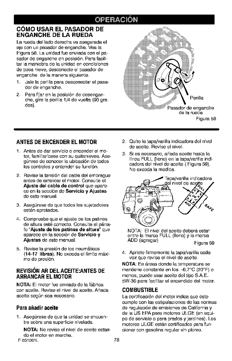
C(_MO USAR EL PASADOR DE
ENGANCHE DE LA RUEDA
La ruede del lade dereO_a ve a_gureda el
eje _n on pas_der de enganohe Vee ]a
Figupa 58. La undad rue enviada con el pa-
sedar de engenehe en posioi6n. PaPa f_oili-
tar la maniebre de le unidad en oond c Ones
de peca nieve, desconeete el pesader de
enganehe de la manere siguierte
1. Jale ]a perflla pare desconeoter el pasa-
der de enganohe.
2. PaPaf jar en la posioi6n de desengen-
ehe, gire la perilla 1/4 de vueite (90 gra-
des).
.iiiiiiii :_ iiiiiiii_ii;_!iiiii_.iiii2i_
Jiiiiiiiii!%iiiii!_ii3iiii!iiiiiii!iii;;?iiii%
, Ui;iiiiiiiiiiiiiiiiiiDiii!i%Z iii,,
de laruede
Figure58
ANTESDE ENCENDEREL MOTOR
1. Antes de dar se_ca e enoender el mo-
tor, famflfar_cese con su quitenieves. Ase-
gQrese de concoer la ubic_oi6n de todes
lee controles y entender su fund6n.
2, Revise la tensi6n del cable del embrague
antes de arPaneer el mater. Consulte el
Ajuste dal cable de control qua apare-
ceen la secci6n de Servicio y Ajustes
de este manual.
3. Aseg0rese de qua tedos lee sujetaderes
est6n apretados.
4. Cempruebe qua el ajuste de lee p_tines
de elture est_ correcte. Consulte el f_rr_-
fe "Aj uste de los patinas de altura" qua
af_rece en la secci6n de Ser_ioia y
Ajustes de este manual.
5. Revise la presi6n de los neum&ticos
(14_17 libras). No exceda el limte m&.xi-
mo de pros 6n.
REVISI6N AFt DEL ACEITE:ANTES DE
ARRANCAR EL MOTOR
NOTA: El motor fue enviado de la f_.brice
con aceite. Revise el nivel de aceite. A5ada
eceite segOnsea necesarie.
Parea_adir aceile
1. Aseg0rese de qua la unded se encuen-
tre sabre una supeffioie nfvelada
NOTA: Ne revise el nivel de aeeite esten-
do el motor en marehe.
F 031001L
2. Oute la tapaivarilla indicedopa del nk,el
de ace re. Revse el nivel.
3. Si es neces_rie, aSade aceite hest_ la
I[nee FULL (llano) en la tepeJvarilla ind-
cadera del nivel de acute { Figure 5g}.
Ne exoeda le medfda.
Tape_arilla ind e4_dere
78
NOTA: El nivel del aeeite debera ester
e_tre ]a merge FULL (llano) y la mama
ADD (agreger) Figure 59
4. Aprotefirmemente letapa!varille cada
vez que terse el nivel de ecete
NOTA: En _.rees donde la tempepatupa se
mantiene constente en lee -67_C (2O_F) o
menus, puede user aoeite del tif_o SAE.
5W-30 paPa fadlitar el enoendide del motor.
COMBUSTIBLE
La curt f caci6n del motor indian qua _ste
cumple con Ins estipulacienes de Ins cormas
de regulaci6n de emisienes de California y
de la US EPA pare mutates ULGE (en equi-
pe de servicie o paPa prades yjard nee). Lee
matures ULGE estan oer_ifioedos paPa fun-
cienar con gacolina regular sn plume.
_ll DVERTENCIA: Los combusti-
bias mezclados con alcohol
(llamadoa gasohol o aqusllos
qce usen stsnol o metanol) pcedan
street humedsd la CUe[ conduce a[a s_P
paracibn y formaci_n de &cidos dursnts
sl almacansmianto. Los gases acldtcos
pceden da_ar el sistema de combustible
de un motor rnientras se enccentra an
slmacecemisnto.
NOTA; Para evitar problemas en el motor, el
sistema de combust hie debe vaciarse antes
del guardar la undad por 30 dfas omas,
Arranque el motor y d_ielo en mamha h_._ta
qua las #neas de combustible yel sarbura-
dot est6n ratios. Use gasoline fressa la si-
guiente temporada, Pare mayor informaoi6n
consults la secoi6n de Almscenemisnto de
este manual.
Nun_ use produotos de I mpieza de motor o
oarburador en el tanque de combustible, de
Io sontrario podr[a causer da_o permanente
ala unidad
Llano el tanque solamente con gasoline fres-
oa Iimpia regular sin plomo s_per sin plo-
ms o gasoline aubmotor reform ulada, NO
use gasoline son plomo, AsegOrese de qua
el recipierte qua sontiene la gasoline a utili-
za£ este Iimpio y sin bxido u otras partioulas
extra6as. Nunc_ use gasoline qua pueda
ester voncida debido a su prolongado alma-
senamiento.
ADVERTENCIA; La gasoline as
inflamsble y dabs racer rnucho
cuidado al msnipularla o
slamcensrla.
No liens el tanqua de combustible
misntras el quitanievas se encuantre
an msrcha, cesndo ast_ salients, o
cesndo el quitaniavas se ancesntra
an un _rse cerrsda.
Mantsnga la unidad alajada de llamas
abia_as o chtspas al_stricss y no fu*
ms miantras liens el tanqua de com-
bustible.
Nunca Bane el tenqua cornplstarnants,
Llsce el tanqce haste dsjar entre
t/4-1/2 pulgada de la parts superior
pare proporcionar aspacie pars la ax*
pansi6n del combustible.
Siampre Ilsce el tanqua al airs Iibre y
use un embudo o boquilla pare preva_
nit el derrerna.
Asag_rasa de Iimpiar cualquier corn*
bustible derrernado antes de arrancar
el motor.
Almscena la gasoline an un conten_
dot, limpio y aprebado, y mantenga la
tape pcests y segurs an el
contansdor,
PARADA DEL MOTOR
Pare parer la marsha del motor, muova la
palansa de control de aselerasiOn ala posi-
si0n PARAR y retire la Ilave, Mantenga la
liars en un lugar seguro El motor no puede
arrancar sfn la Ilave de fgnici6n.
ARRANQUEDEL MOTOR
Aseg0rese de qua el motor tonga suflofente
asete El motor del quitanieves est,. equipa-
F031001L 79
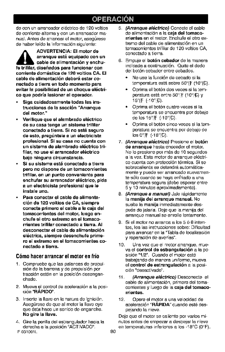
de con un arrancador el6ctrico de _20 velties
de corr ante altema y con un errencador ma-
nual. Antes de err_ncar el motor, etseg0rese
de haber leide la nformaci6n sigu ente:
_lj DVERTENCIA: El meter de
arranque est_ equipado con un
cable de alimentaci6n yenchu_
fe trifilar, dise_ados pare funeionar con
corriente demt_stica de 120 veltioe CA. El
cable de alimentaoi6n dabar_ ester co_
nectado a tierre entodo memento pare
evitar la posibilidad de un cheque el6ctri-
co qua podr[a lesienar al operader,
• Sign cuidadesementa todas lee ins_
trucciones de la secci6n "Arranque
del motor,"
•Verifique qua el alambrado el_ctrico
de su case tonga un sistema trifilar
coneotedo atterra, Si no estt_ seguro
de esto, pregtlntele aun elactricista
profestonal. Si su case no ouenta con
un ststame de alambrade el6ctrico tri_
filer, no use el arrancader el6etrtce
bajo ningune circunstancia,
•Si su sistema est_ conaotedo a tterre
pore no dispose de un tomecorrtente/s
triftlar, en un punto conveniante pare
enchufar su arrancader el6etrtco, pida
aun electrtcista profasienel qse le
instals use.
•Pare conacter el cable de alimenta-
oi6n de 120 veltios de CA, stempre
connote primate el cable a la caja del
tomacorrieotes del motor, luege an_
ohufe el otto extreme an el tomaco_
rrientes trifilar conectade a tiarra. AI
desconeoter el cable de alimentaci6n
el6otrica, siempre desenohufe prime_
re el extreme en el tomecerrtente/s co_
nectado atierra.
C6raohacerarrancarel rao_oren frio
1, Cempruebe que Ins palancas de propul-
si6n de la barrena yde prepuls 6n per
tracci6n est0n en la posiei6n desengan-
chede.
2, Mueva el control de ecoleraciOn ala posi-
ci6n "RAPIDO'L
3, Inserte la Ilave en le ranura de gnici6m
AsegSrese de qua al meter la Ilave eye
qua 6sta hate un senfdo de enganche,
NO gire la Ilave.
4, Gire la perilla del estrangulador haole la
derecha ala posiei6n 'ACTIVADO"
F 031001L 8O
5, (Arranque aide,trice) Cenecte el cable
de alimentaeibn ale caja del tomaco-
rrientes en el motor, Enehufe el etro ex-
treme del cable de aliment_ef6n en un
tomacorrientes trifilar de _20 velties CA,
conectade a tierra.
6, Empu}e el bot6n cabador de la manera
ind cada a continuee 6n, Quite e[ dede
del bot6n sebador entre cebades.
• No use la funei6n de cebe.do si la
temperature est& sabre 50"1_ (10"1@).
• Optima el bot6n des votes sila tem-
perature est& er_re 50"(_ (10"(_) y
15'IF (40°(6),
• Oprima el bot6n cuatro votes sila
temperature se encuentra per debaje
de los 15_(_ (-_0" C),
• Optima el bot6n cinca votes sila tem=
peroture se encuentre per debaje de
los 0°[_ (-18_C),
7, {Arranque al_ctrico) Presiene el bot6n
de arranque haste encender el motor.
Ne Io presiene per m&s de _0 segundes
a le vez. Este meter de arranque el6ctr -
co euenta con protecci6n t6rmica, Si se
sobreoalienta se dotendr_ aurora&rice-
monte y puede set arrancade nuevamen-
te s61o ouando se haya erfriado a usa
temperature segura (dope esperar entre
5 y 10 minutes aproxfmadamente}.
8, {Arranque amanual) Jale r_pidamente
la manija del arrenque manual. No
suelte la menije inmediat_mente des-
ps6s de }alarla Deje qua la meni}a del
arranque manual se estella lentamente.
9, Si el motor no arran_ a los 5 6 6 intern
toe, lea Ins instruooianes cobre: Difieultad
pare an'ancer en la "Table de lec_lizaci6n
y reparaei6n de averfas'*
10. Use vez qua el motor arrenqse mue-
va el cootrol de estrangulaot_n ala pe-
sici6n "1/2 _. Cuande el motor est0
trabajanda de manera uniferme, mueva
el control de estrangulaei6n e la paei=
ci6n "desaot_ade'*
1_ (Arranque ali_ctrico) Desconecte el
cable de alimentaei6n primate del toma-
corrientes yluega de la caja del tomaco*
rrientes,
12. Opera el meter a usa velcoidad de
acelereei6n ' RAPIDA" euande est6 des-
pejando la nave,
Deje qua el motor se celiente per varies mi-
nutes antes de empezar e despejar la nave
en temperatures in[eriores alos -18_O {0"F L
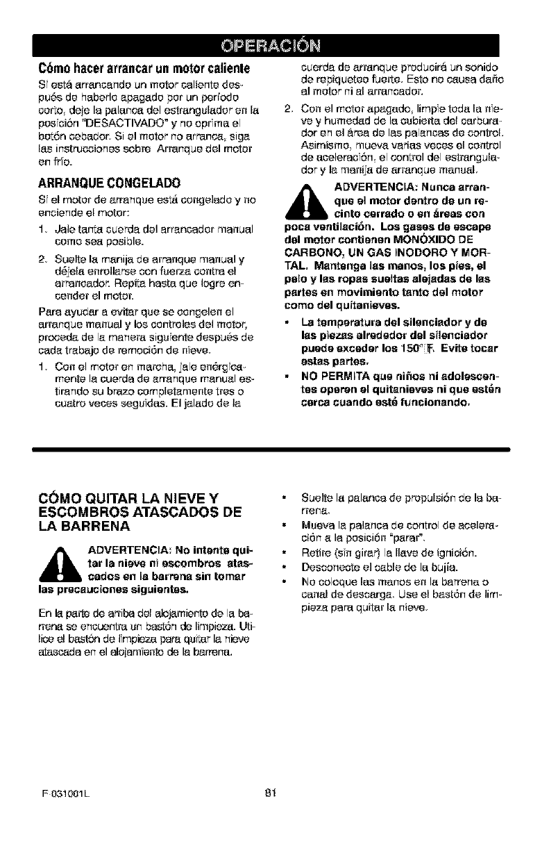
C6m0 hgcergrrancgrunmotorcglienle
S esta arrancendo un motor celiente des-
pu_s de hebede apegade pot un periodo
corto deie la palence del estrangslader en la
posfoiSn "DESACTIVADO" y no oprfme el
botSn cebedor, Si el motor no errance siga
las instrucoiones cobra Arrenque del motor
en fr'o.
ARRANQUE CONGELADO
S el motor de arranqce est_ congeladoyno
enoiendeel motor:
1, Ja]e ter%a cuerda de] errencador manuel
como sea posible.
2, Sueite la manije de arranque manuel y
d_jela enrollerse con fcerza contra el
arranoedor. Repita haste qua Iogre on-
condor el motor.
Pare ayudar e evitar qua se congelen el
errenque manuel y los controles del motor,
prcoeda de le menera sigu ante despu_s de
cede trebejo de remcoi6n de nave,
1, Con el motor en merche, jale en6rgfce-
merits le ouerda de erranqce manual es-
tirendo su brazo completamente tres o
cuatro votes segufdes. El jalado de la
cuerda de arranque preduoira un sonido
de repiquetco fuerte, Esto no ceuce de_o
al motor ni el arrancedor,
2, Con el motor apagedo limpe toda le ne-
ve y humedad de le oubie_e del oerbura-
dot en el &tea de las palences de control
Asimismo mueva varies veoes el control
de eceleradSn el control del estrangule-
dory ]a manija de arranque manual
_IL ADVERTENCIA; Nunea arran-
qua el motor dentro de un re-
cinto csrrado o en _raas con
poce vsntilecibn. Los gases de escape
dal motor contiensn MON(_XIDO DE
CARBONO_ UN GAS INODORO Y MOR-
TAL. Mantenga lea rnanos, los pies, el
pale y las ropes sueltas alejadas de las
partes en rnovimiento tanto dsl motor
corno del quitanieves.
La ternperatura del silsnciador y de
lea piezas alrsdsdor dal sileneiador
puede exceder los 150_ _. Evite tocer
estas partes.
NO PERMITA qus ni_os ni adolescsn-
tes oparen el quitanievss ni qua sst_n
cerce euando sst_ funcionendo.
C(_MO QUITAR LA NIEVE Y
ESCOMBROS ATASCADOS DE
LA BARRENA
_lb ADVERTENCIA: No intents qui*
tar la nieve ni sscembros atas_
eados en la barrena sin tornar
las prscaueiones siguientes.
En la parle de arriba del _J_miento de le b_-
trace se enocontre un bast6n de limpieza. Uti-
lice el b_st_q de ]fmpiez_ papa quitar la nieve
_da en el alojam onto de la barrece.
Sue]to la pelance de propulsiSn de la be-
rrerle
Mceva le palance de control de ecelera-
oi6n a la posioi6n "parer',
Retire (sin girer) la Ilave de ignioi6n.
Desconeote el cable de le bujia.
No coloque los menos en la barrens o
canal de descerge Use el bast6n de ]im-
pieza pare quiter la nieve
F031001L 81
CONSF-JOSSOBREEL
LANZAMIENTODENIEVE
1, Pare un rondimiento m@.ximode su quta-
nieves al dospeiar la nieve ajuste la ve-
Iocidad sobre el terreno NUNCA haga
este ajuste on el control do aoeloraci6n
Avance ]entamerqe on nieve profunda
congelada o mojada. Si las ruedas pati-
nan, r'oduz¢__la velocidad de avenue. El
motor esta diseSado pare br ndar un ton-
dim ento m_c_mo baio aceleraui6n total y
debe set operado en este valor de potato
cia en todo momento.
2, El lanzamiento de nieve es mas efioierle
si el trebaio so roaliza inmediatamente
despu6s de la nevada.
3, Pare una reraooi6n complete de la niove
traslape Ifgeramente cada camino adop-
tado proviamente En nfeve profunda su-
perponga los barridos entre si pare evitar
sobrecargar la ra_.quina.
4, La nieve deberia set des_rgada en la
direooi6n del viento sfempro qua sea f_o_
sible.
5, Pare uso normal, ajuste los patinas de
aitura de manera qua la barra raspadora
quede a 1/8 de pulgada sobre los pati-
nas. Pare superfioies de nievo sumamem
te compacta, ajuste los f_tines de altura
haca arriba de manera qua la barra ras-
pedora haga contaoto con el suelo,
6, En superlicies de grave o piedra tritura-
de, ajuste los patinas de altura a 1-1/4
pulgada$ pot debajo de la barra raspado-
re. Consulte el parrafo "Ajusl, e de los
patinas de altura" en la seoci6n de Ser_
vioio y Ajuatgs de este manual. Este
ajuste es fmportante pare qua la maquina
no recoia y lanoe piedras n grave
7, Despu6s de completer el trabajo de des-
pejar la nievo, deje el motor en maroha
pot ucos ouartos minutos, esto derret r_.
la nieve yhielo acumulados alrededor del
motor.
8, Limpie completamente el quitanieves
despu6s de c_da uso.
9, Qute toda aoumulaoi6n de hielo y nieve
y todo material extrarlo del qutanioves y
enjuague con ague (sf fuera posible) pare
remover toda la sal u otros quimicos So-
qua el quitan eves con un paiio,
F031001L 82
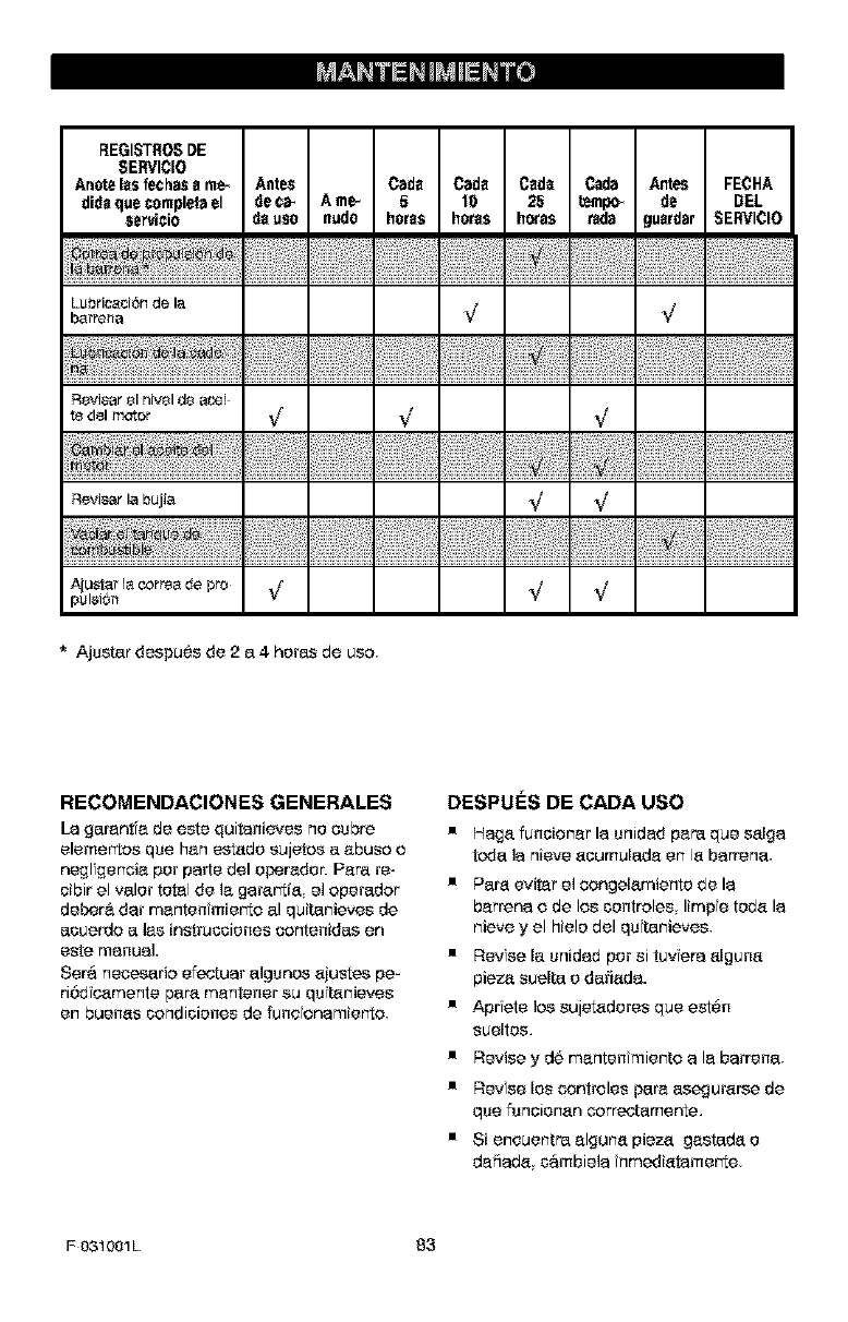
BEGISTROSDE
SE_/ICIO
Anoteles fechass me_ Antes Cads Cads Csd_ C_Ia Antes FECHA
did_que complelael de ¢_ A me_ 5 10 25 tempo_ de DEL
esrvicio d_ uso nudo hor_s hor_s horas fads gu_dar SERVICIO
Lubri_ci6n de la
b_rrena !/ !/
R_,iaar _1niv_l de aceE
te d,I motor ,,/ I/ I/
Reviaar la bujia _I _I
Ajustar la correa de pro _/ ,/ ,/
pulsi6r_
* Ajustar despu6s de 2 a 4 horas de usa.
RECOMENDACIONES GENERALES
La garant'a de este quitanieves no cubre
elemertos qua han estado sujetos a abuso o
negligenoia pot parte del operadoc Para re-
oibir el valor total de la garar_tfa el operador
debar& dar mantenfmierto al quitanieves de
acuerdo a las instrucciones contenidas en
este manual.
Sara necesario efectuar algunos ajustes pe-
riSd c_mente par'a mantener su qs tanieves
en buenas condiciones de rune onamierto
DESPU_:S DE CADA USO
• Haga funoionar la snidad para qua salga
toda la nieve aoumulada en la barrena,
• Par'a evitar el oongelamiento de la
barrena o de los oontroles limpfe toda la
nieve y el hielo del qsftanieves,
• Revise la unidad pot si tuviera alguna
piez_ suelta o darlada.
• AprTete los sujetadores qua est6n
sueltos,
• Revise y d6 manten miento a la barrena,
• Revse los controles par'a asegurarse de
qua fsnoionan correctamente,
• Si encuentra alguna pieza gastada o
daiiada c6mbiela fnmediatamerte
F031001L 83
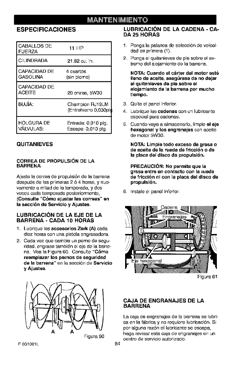
ESPECIFICACION ES
CABALLOS DE 11 HP
FUERZA
;ILINDRADA 21.82 cu. n
CAPACIDAD DE 4 csar_os
GASOLINA [sin plomo)
CAPACIDAD DE
ACEITE 20 anzas, 5W30
BUJiA: Champion RJ_9LM
(Entrehierro 0 030pl_
HOLGURA DE Entrada: OOlO pig,
V._.LVULAS: Escape 0,010 pig.
QUITANIEVES
CORREA DE PROPULSI6N DE LA
BARRENA
Ajsste le eerrea de prepulsi6n de la barrena
despu6s de les pr meres 2 64her'as y nue-
vamente a rafted de la temporada, y des
races cads temporada posteriarmente,
(Consults "C_mo aju_tsr lee cerises" en
Is session de Servieio y Ajuetes,
LUBRICACI(_N DE LA EJE DE LA
BARRENA -CADA 10 HORAS
1. Lsbrique los acc;esortos Zsrk (A) oada
diez horns can una pistola engr'asadora.
2. Cada vez qua c_mbie un perne de segu-
tided engrase tambf6n el eie de la ben's-
he. Yea la Figure 60. Consults "C6mo
rasmplazar los parries de saguridad
de la barrens" en la s_r;i6n de Servicio
y Ajustss
LUBRICACI(_N DE LA CADENA -CA-
DA 25 HORAS
1. Penga la t_lan¢_4_de seleeo 6n de veloci-
dad en pr mere (1).
2. Penga el quitanieves de pfe sabre el ex-
treme de] eloiamiente de la barrens.
NOTA: Cuando el e_rtsr dal motor eat6
llano de aceite, aseg_rese de no dejar
el quitanievss de pie sabre el
alojamiaoto de ]e barrens par touche
ttempo.
3. Qste elt_nel nferor,
4. Lsbrique Ins cadsnas con un lubricates
especial pare cadenas.
5, Cuenda vaya a almacerEarla, limpie el sis
hexagonal y los engranajes con a_ite
de mater 5W30.
NOTA: Limpis redo exceso de grass o
de aceite de la rueda de fdcot6n o de
la place del disco de propulst6n.
PRECAUCION: No parmita qua la
grass entre en contecto con la rueda
de fricci6n nt con la place dal disco do
propulst6n.
6. Instals el panel inferior',
A A
Figure 80
F 031001L
Figure 61
CAJA DE ENGRANAJES DE LA
BARRENA
84
La c_ja de engrenajes de le barrena se Isbri-
ca en la f_br ¢__y no requiere lubricae 6n. Si
per alguna razSn el lubricants se escape,
haga reviser esta caja de engranajes en un
centre de servicie autarizado
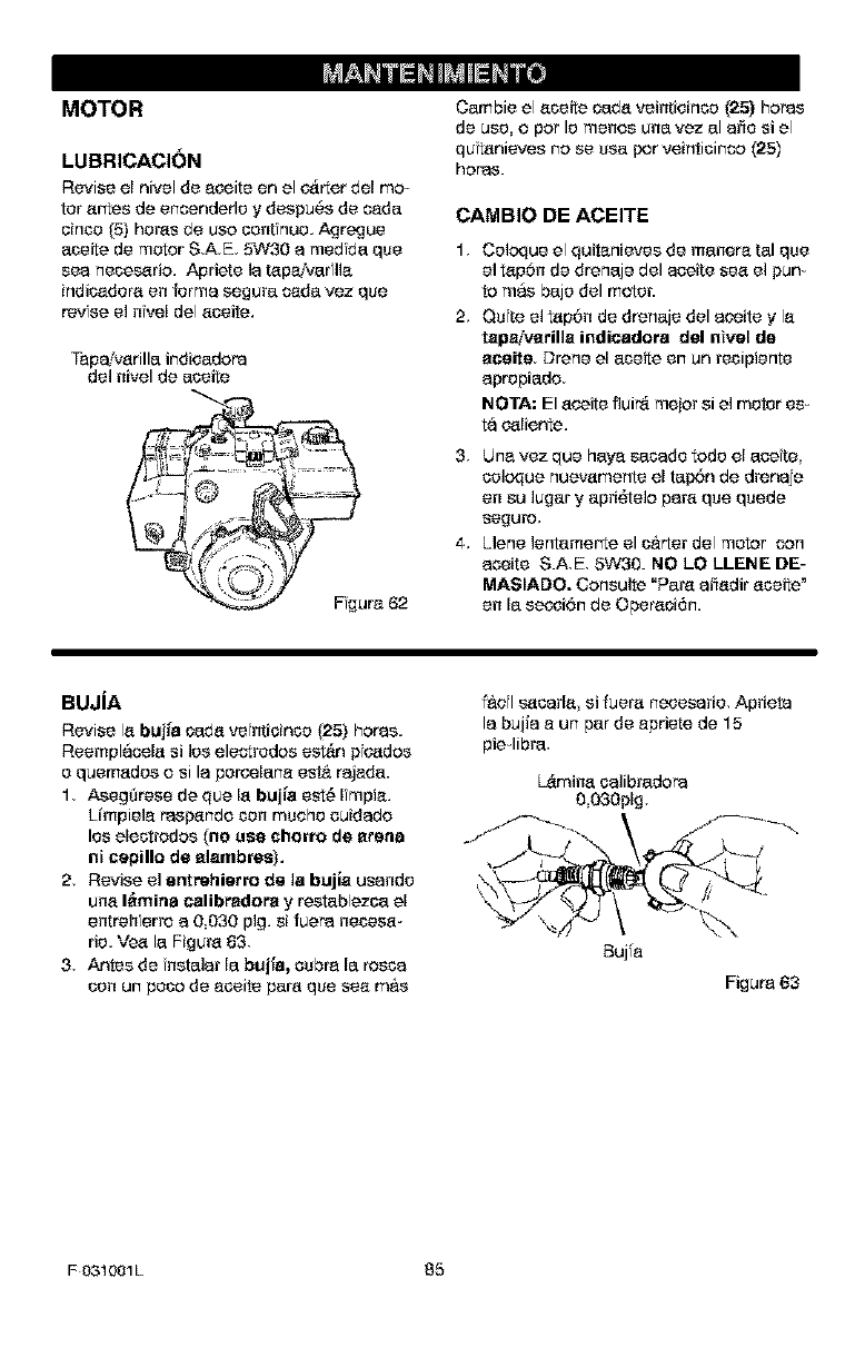
MOTOR
LUBRICACI(_N
Revise e[ nivel de eceite en el c_rter dot me
tor ertes de encenderle ydespu6s de c_de
oinco (5) heros de uco cent hue. Agregue
eceite de motor S,AE 5W30 e medfde qua
see necesario. Apriete le tepaiverflle
indicedere en ferme segure cede vez qua
revise el nfvel del eceite.
Tapa!verille indioedora
del nivel de eceite
Fgura 62
Cembie el eceite cede veintioinco (25} horns
de use. o per le maces una vez el erie si el
qutenieves no se see f_orveinticinco (25)
horns.
CAMBIO DE ACEITE
1,
2,
Celoque el quitenieves de manere tel qua
el tep6n de dreneje del ecoite see el pun-
to mas beje del motor.
Qufte el tep6n de dreneje del eceite yle
tepa!verille indicedore del nivel de
eeeite Drene el eceite en un recipiente
epropiedo
NOTA; El eceite fluir_ meier si el motor es-
ta c_liente,
3, Une vez qua heye secede rode el ecete
celoque nuevemente el te_n de dreneje
en su luger y epridtelo pare qua quede
se£1uro,
4, Llene lentemerte el c&rter del motor con
eoeite S.A,E, 5W30. NO LO LLENE DE-
MAS[ADO. Consuite =Pare efiedir eceite"
en la secoi6n de Opereci6n.
BUJiA
Revise le buj_a cede ve nticinco (25) horns.
Reemplaco[e si lee electrodes est&n pfc_doe
e quemedee o sile perce[ane eat& rejede.
1, Asegerese de que[e buj_a est6 [mpie.
Limpiele ras_ndo con touche ouidedo
los electrodes (he use chorro de arena
ni cepillo de elembree).
2, Revise el entrehierro de la bujle usendo
une I_mina calibredore y resteblezce el
entreh erro e 0030 pig. si fuera necese-
rio. Vee le Figure 83
3, Antes de netaler [a bujie, cube ia testa
con un pace de eceite pare qua see m&e
f&ol s_cerle si fuere neceserie, Aprieta
le bujie e un per de epriete de 15
pie-libra,
L_mine celibredora
0 030pig,
Buj'a
Figura 63
F031001L 85
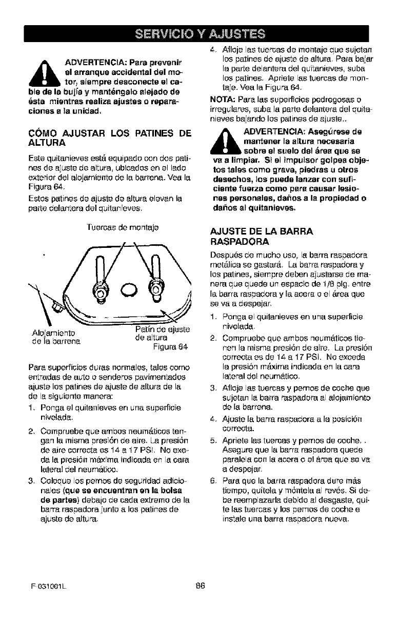
_k DVERTENCIA: Para prevenir
el arranque accide_rtal del mo_
b tot, siempre desconecte elca-
ble de la buj_a y mant_ngalo alejado de
_sta mientras realiza ajustes o repara*
ciones a la unidad,
COMe AJUSTAR LOS PATINES DE
ALTURA
Estequitanievesest,.equipado con des pati-
nes de aju_tede al_ur_,ubio_dosen ell_do
exteriordelaloj_mientode lab_rrena.Ve_ la
Figura 64.
Estos p_tines de _iuste de altum elevan la
parle dela_era del quitan eves.
Tuercas de montaje
©
Para superficies duras normales, tales oomo
ertradas de auto o senderos pavimen_dos
ajuste los patinas de aiuste de altur'a de la
de la siguiente manera:
1, Ponga el quitan eves en una superlioe
nivelada.
2, Compruebe qua ambos neum_ticos tern
gan la misma presf6n de aire La pr'esi6n
de aire oorreota es 14 a 17 PSL No exe-
da la presi6n maxima indioada en la oara
lateral del neumatf_
3, Coloque los pernos de seguridad adioio-
hales (que so eneuerttran on la bolsa
do partes) debajo de cada extreme de la
barra raspadora junto a los patinas de
ajuste de altura,
4, Atloje las tuersas de momaje qua suietan
los patinas de ajuste de altura. Para bajar
la parte delantera del qutanieves suba
los patinas Apriete las tuercas de men-
taje. Vea la Figura 64
NOTA: Para las superlioies pedr'egos_s o
irregulares, suba la parte delanter'a del quita-
nieves bajande los patinas de aiuste..
_lb DVERTENCIA: Asegtltese do
ma_rtener la altura necesaria
sobre el suelo del =_reaque so
va a limpiar. St elimpulaor golpea obje-
tos tales come grava, piedras u otros
desechos, los puede lanzar con sufi-
ciente fuerza come para eausar lesio_
has peraonales, da_os a la propiedad o
da_os al quitanieves,
AJUSTE DE LABARRA
RASPADORA
Despu_s de muoho use, la barr'a raspadora
met_.lioa se gastar_. La barr'a raspadora y
los patinas, siempre deben ajustarse de ma-
nora qua quede un espado de 178pig, entre
la barr'a raspadora y la acer'a o el &tea qua
se va a despeiar,
1, Ponga el quitanieves en una superfioie
nivelada
2, Compruebe qua ambos neum_.tioos tie-
hen la misma presi6n de aire, La prosi6n
correcta es de 14 a 17 PSL No exoeda
la presi6n m&xima indicada en la tara
lateral del nauru&rico,
3, Afloje las tuercas y pemos de ooohe qua
sujetan la barra rasp_dora al alojam onto
de la barren&
4, Aiuste labarr'a raspadora a la position
oorreota.
5, Apr eta las tuercas y pernos de coche.,
Asegure qua la barr'a raspadora quede
paralela oon la aeera o el &tea qua se va
a despeiar',
6, Para qua la barra r'aspador'adure m_.s
tiempo, quitela ym6mela al rev_s Si de-
be reemplazada debfdo al desgaste, qui-
te las tuercas y los pemos de coohe e
instale una barr'a raspadora nueva,
F 031001L 86
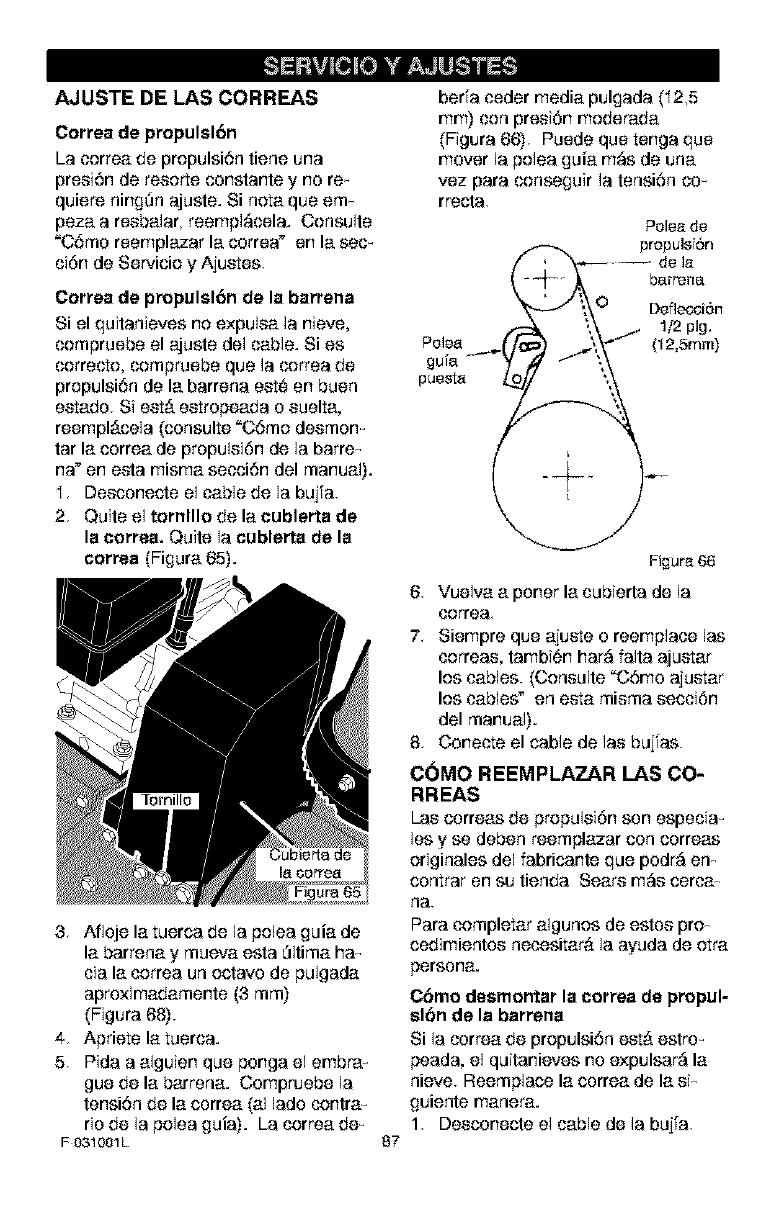
AJUSTE DE LAS CORREAS
Correa de propulsl6n
La correa de propulsi6n tiono una
prosi6nde resorteconstantey no re_
quioro ningSn ajuste. Si nma que em_
peza a rosbalar, reempl_cela. Consulte
"C6mo reemplazar la corroa" on la sec_
ci6nde Servicio y Ajuotes.
Correa de propulsl6n de la barrena
Si el quitanievos no oxpu]sa ]a nievo,
compruobe el ajuste do1cable. Si es
correcto, compruobe que la oorrea do
propulsi6n de la barrona eot_ en buon
eotado. Sieot#. eotropeada o suelta,
roempl#.cela (consulte "C6mo desmon-
tar la correa de propulsi6n do la barre_
na" en esta misma secci6n del manual).
I. Desconecte el cable de la bujfa.
2. Quite ol tornlllo de la cublerta de
la correa. Quite la cublerta de la
correo (Figura 65).
3. Aflojo la tuorca de la polea guia de
la barrona y muova osta _ltima ha_
cia la correa un octave de pulgada
aproximadamente (3 ram)
(Figura 68).
4. Apriote latuerca.
5. Pida a alguien quo ponga el embra_
gue de la barrena. Compruebe la
tensi6n de la correa (al lade contra_
rio de la polea guia). La correa de_
F 031001L 87
ber[a coder media pulgada (I2,5
ram) con prosi6n modorada
(Figura 66). Puode quo tonga quo
mover ]a polea guia m_s de una
voz para conseguir la tensi6n co_
rrecta.
Polea de
.. propulsf6n
// "_--- de ]a
_ --_,._ barrena
_/;_O Defl_ci6n
/- ;,\ 1/2 pig.
gu[a y "f ;,_
puest_ /'_0'
Figura 66
6. Vuelva a porter la cubierta do la
correa.
7. Siompre quo ajuote o reemplaco las
correas, tambi6n har_ falta ajuotar
los cables. (Consulte "C6mo ajuotar
los cables" on eota misma socci6n
del manual).
8. Conecte el cable de las bujfas.
COMO REEMPLAZAR LAS CO-
RREAS
Las corroas do propulsi6n son especia_
los y so debon roomplazar con corroas
originalos del fabricanto quo podr_ en_
contrar en su tionda Soars m_s cerca-
fla.
Para complotar algunos de ostos pro_
cedimiontos nocositar_ la ayuda do otra
persona.
CSmo dosmontar la correa de propul-
sl6n de la barrena
Si la corroa do propulsi6n oot#. ostro_
peada, el quitaniovos no oxpulsar_ la
niove. Reomplace la corroa de la si_
guionte manora.
1. Desconocte el cable do la bujfa.
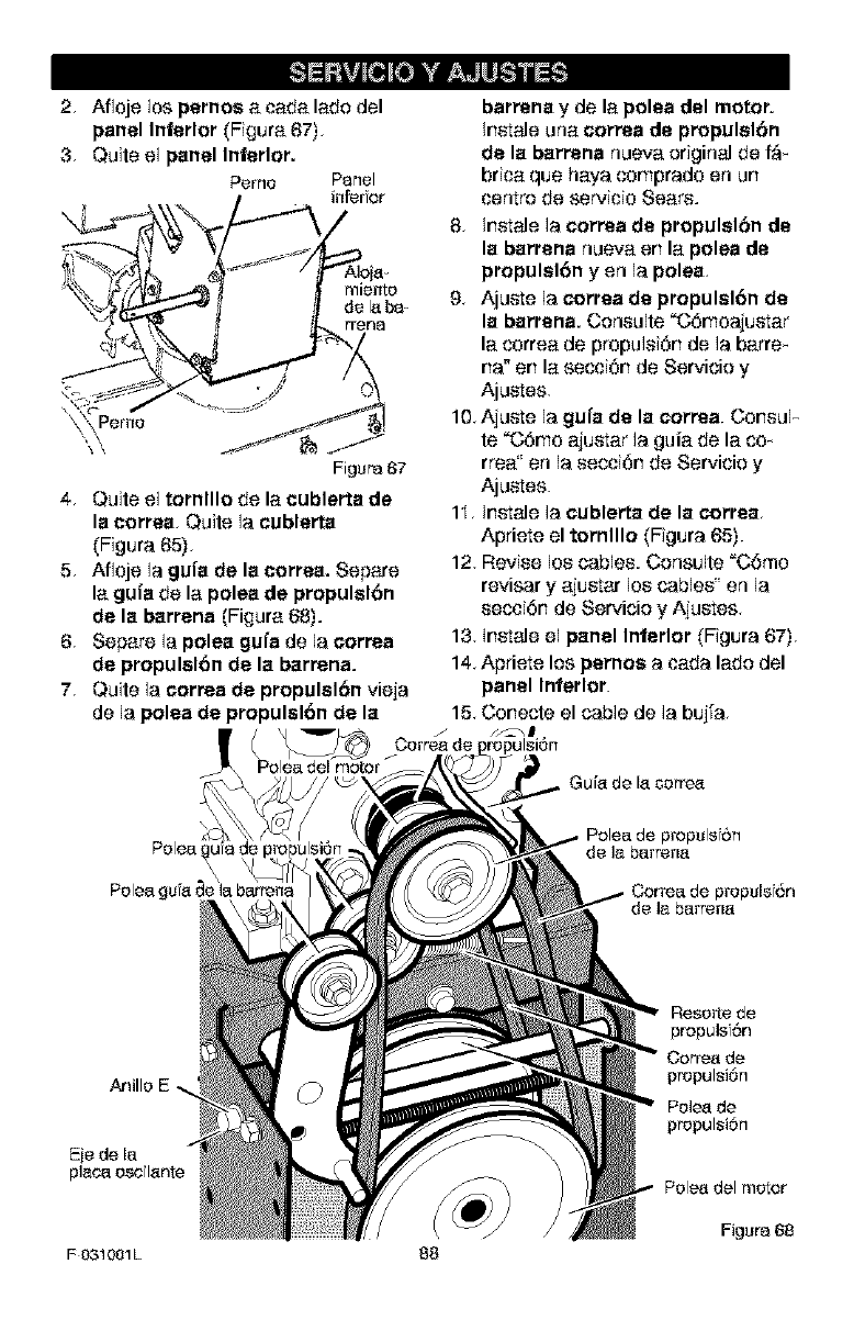
2, Aflojelos pernos a cada lade del
panel Inferior (Figura 67),
3, Quite el panel Inferior.
Perne Panel
inferior
Figura 67
4, Quite el tornlllo de la cublerta de
la correa< Quite la cublerta
(Figura 65),
5, Afloje la gula de la correa. Separe
la gula de la polea de propulslbn
de la barrena (Figura 68).
6, Separe la polea gufa de la correa
de propulslbn de la barrena.
7, Quite la ¢orrea de propulel6n vieja
de la polea de propulsl6n de la
Palea del motor
barrena y de la polea del motor.
Instals una correa de pmpulelbn
de la barrena nueva original de f'&_
brica qua haya comprado en un
centre de servicio Sears.
8, instals ]a correa de propulsl6n de
la barrena nueva en la polea de
propulsldn y en la polea,
9, Ajuste ]a correa de propulsl6n de
la barrena. Conoulte "C6rnoajustar
la correa de propuloi6n de la barre_
ha" on la secci6n de Servicio y
Ajustes.
10, Ajuste la gufa de la ¢orrea. Conoul-
te "C6rno ajustar la guia de la cox
rrea" on la oecci6n de Servicio y
Ajustes.
1I, Instals ]a cublerta de la correa<
Apriete el tornlllo (Figura 65).
12, Revise los cableo. Consulte "C6mo
revisar yajustar los cableo' on la
oecci6n de Servicio y Ajustes<
13 instals el panel Inferior (Figura 67)<
14<Apriete los parnos a cada lade del
panel Inierlor.
15, Conecte el cable de la bujfa<
Anille
Eie de la
F 031001L 88
Reserfede
propuls 6n
Correa de
propulsi6n
Pelea de
propulsi6n
Pele_ del motor
Figura 68
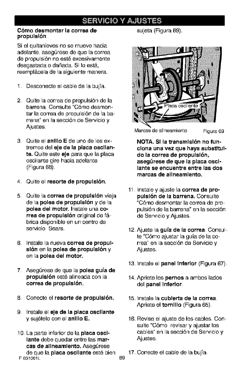
C&mo deemontar le correa de
propulsion
Si el quitanieves no se mueve hacia
adelante, aseg_rese de que la cerrea
de propulsi6n no est_ excesivamente
desgastada o decade. Si Io est,..
reempl_cela de la siguiente manera.
I. Desconecte el cable de la bujfa.
2. Quite la correa de propulsi6n de la
barrena. Consulte _'C6mo desmom
tar la cerrea de prepulsi6n de la ba-
rrena" en la secci6n de Servicio y
Ajuetes.
3. Quite el anlllo E de uno de los ex_
tremos del eJe de la place oscllan-
re. Quite este eJe pare que la place
escilarte gire hacia adelante
(Figure 68).
4. Quite el resorte de propulsl6n.
5, Quite la correa de propulslbn vieja
de la polea de propulslbn y de la
polea del motor. Inetale una co-
rrea de propulslbn original de f;_
brica disponible en un centre de
servicio Sears.
6, Inetale la nueva correa de propul-
elan en la polea de propulel6n y
en la polea del motor.
7. Aseg_rese de que la polea gufa de
propulsl6n eet_ alineada con la
correa de propulsl6n.
sujeta (Figura 69).
Marca$ de r_lneamierlo Fgura 69
NOTA. SI la transmlsl6n no fun-
clone una vez que haya eubstltul-
do la correa de propulslbn,
aeeg_rese de que la place oscl-
lante se encuentre entre lee dos
marcas de allneamlento.
1I, Inetale y ajuste la correa de pro-
pulsl6n de la barrena. Consulte
"C6mo desmontar la correa de pro_
pulsi6n de la barrena" en la secci6n
de Servicio y Ajustes.
12. Ajuete la gufa de la correa. Consul_
te "C6mo ajuetar la guia de la coN
rrea" en la secci6n de Servicio y
Ajuetes.
13, Inetale el panel Interior (Figure 67),
14. Apriete los pernos a ambos lades
del panel Inferior
8, Conecte el resorte de propulslbn.
9< Inetale el eJe de la plata oscllante
y suj6telo con el anlllo E.
I 0. La parte inferior de la placa oscl-
lante debe quedar entre las mar-
¢as de allneamlento. Aseg_rese
de que la place oscllante eet¢ bien
F031001L
15. Inetale la cublerta de la correa<
Apriete el tornlllo (Figure 65),
16. Revise el ajuete de los cables. Corn
suite "C6mo reviser y ajustar los
cables' en la secci6n de Servicio y
Ajuetes<
17. Conecte el cable de la bujfa.
89
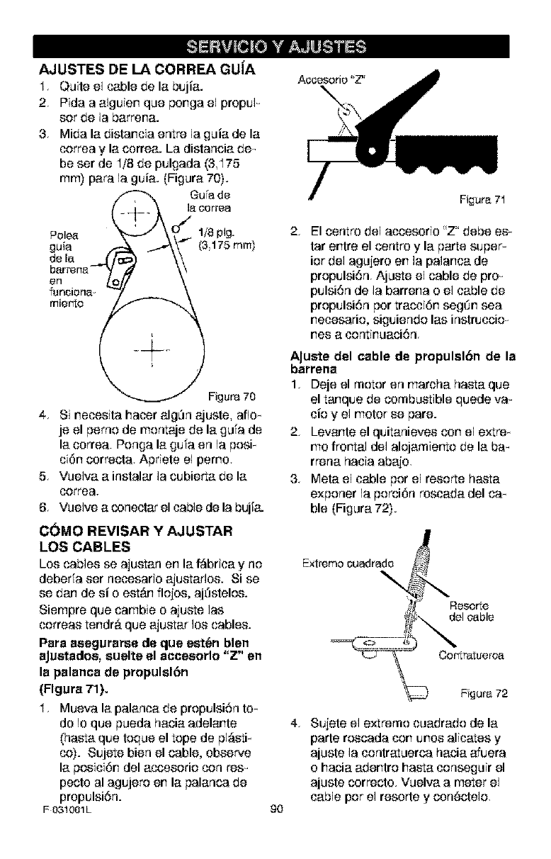
AJUSTES DE LA CORREA GUJA
I, Quite el cable de la bujia.
2, Pida a alguien que ponga el propuF
set de la barrana.
3, Mida la distancia entre la guia de la
cerrea y la cerrea. La distancia de_
be ser de I/8 de pulgada (8,I75
ram) para la guia. (Figura 70).
gu'a de
18oorrea
Palea 1/8 pig.
guia (3,175 mm)
de la
Figure 70
4, Si neceeita hacer _g_n ajuste, afle_
je el perno de montaje de la gufa de
la correa. Penga la gufa en la posF
ci6n correcta. Apdete el perno.
5, Vuelva a instalar la cubierta de la
cerrea.
6, Vuelve a conectar el cable de la bujfa.
2. El centre del accesorio "Z' debe ee_
tar entre el centre y la parte super_
ior del agujero en la palanca de
prepulsi6n. Ajume el cable de pro_
pulsi6n de la barrana o el cable de
propulsi6n per tracci6n seg_n sea
necesario, siguiendo las instruccio_
nee a continuaci6n,
AJuete del cable de propulel6n de la
barrena
1. Deje el motor en marcha hasta que
el tanque de combustible quede va_
tie y el motor ee pare.
2, Levante el quitanievee con el e×tre_
me frontal del alojamiento de la ba_
rrena hacia abajo,
3, Meta el cable par el reeorte hama
exponer la porci6n rescada del ca_
ble (Figura 72).
C(_MO REVISAR Y AJUSTAR
LOS CABLES
Los cab]ee se ajuetan an la f&brJca y no Extremo ouadrado
deberfa eer necesario ajuetadoe. Si se
ee dan de ei o eet_m flojoe, aj_stelos.
Siempre que cambie o ajuete 1as
correae tandr#, que ajuetar Ioe cables.
Para aeegurarse de que est_n blen
aJuetadoe, euelte el acceeorlo "Z" en
la palanca de propulel6n
(Flgura 71).
I, Mueva la palanca de propulsi6n to_
do Io que pueda hacia adelante
(basra que toque el tope de pJ_sti_
co). Sujete bien el cable, observe
la paeici6n del acceeorio con res_
peclo al agujero an la palanca de
propulsi6n.
F 031001L go
\_ Fgura 72
4, Sujete el extreme cuadrado de la
parle roscada con unoe alicates y
ajuste la contratuerca hacia afuera
o hacia adantro hasta conseguir el
ajuste correcto. Vuelva a meter el
cable per el resorte y con#ctele,
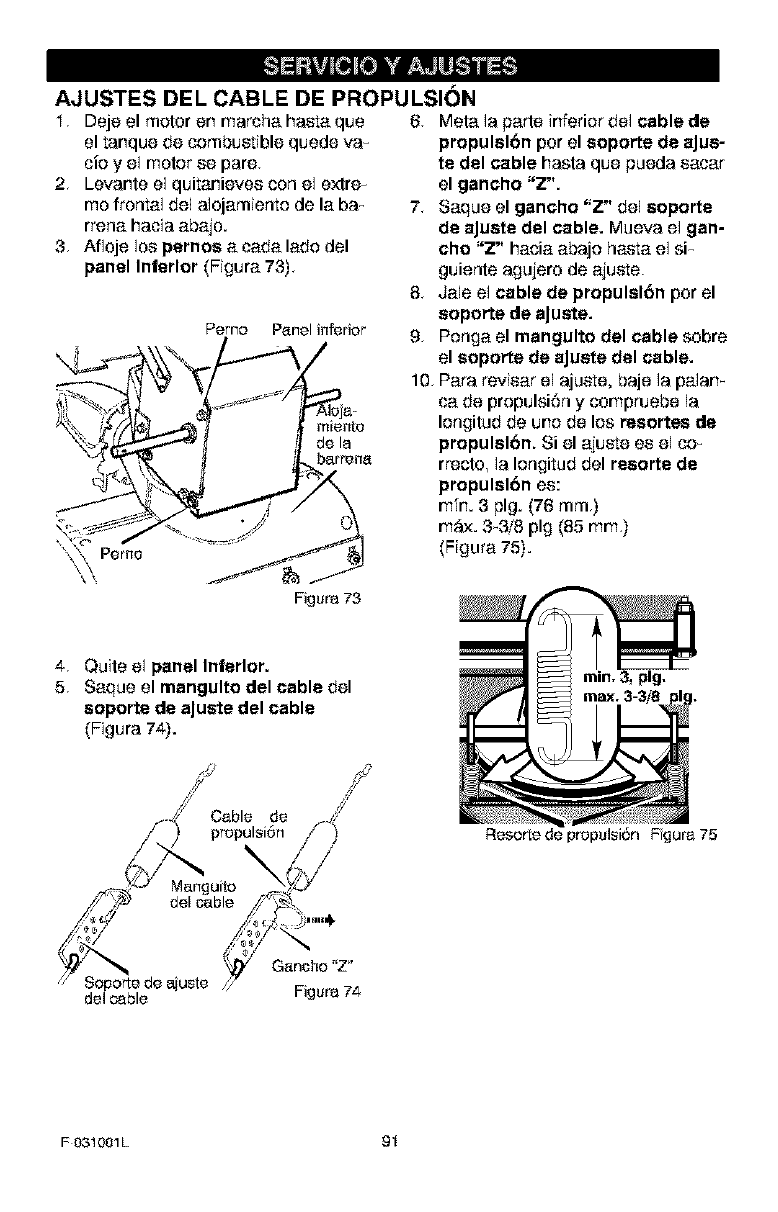
AJUSTES DEL CABLE DE PROPULSli3N
I< Deje el motor en marcha hasta que 6< Meta la parts inferior del cable de
el tanque de combustible quede va_
cio y el motor ee pare.
2< Levante el quitanievee con el extre_
mo frontal de1 alojamiento de la-ba_
rrena- hacia a-ba-jo.
3, Afloje los pernos a-ca-da-la-do del
panel Inferior (Figura- 73)<
Pemo P_nel inferior
Pemo
Figura 73
4< Quits el panel Inferior.
5< Sa-que el mangulto del cable del
soporte de aJuste del cable
(Figura 74).
propulslbn por el soporte de aJue-
te del cable hasta que pueda ea-ca-r
el gancho "Z".
7< Sa-que el gancho "Z" del eoporte
de aJuete del cable. Mueva e] gan-
cho "Z" ha-cia-a-bajo ha-eta-el si_
guiente agujero de a-juste.
8< Ja-le el cable de propulshSn por el
soporle de aJuste.
9< Ponga- el mangulto del cable sobre
el soporte de aJuete del cable.
1Q Pa-ra reviea-r el ajuste, baje la pa-lam
ca. de propulsi6n y compruebe la
Iongitud de uno de los resortes de
propulel6n. Si el a-justs ee el co-
rrecto, la Iongitud del resorts de
propulsl6n ee:
mfn. 3 pig. (76 ram<)
m_,x. 3_3/8 pig (85 ram)
(Figura- 75).
rain, 3, pig,
S.S
-/oo.,o Z
/_ ") propol_i6n y')
uito
// y_ del oable _ ',_.2%
__ _ _ Ganoho"Z"
// Soporte de aiuste //" w7_
del cable .igura ._
Resor_e de propulsir_n Fgura 75
F031001L 91
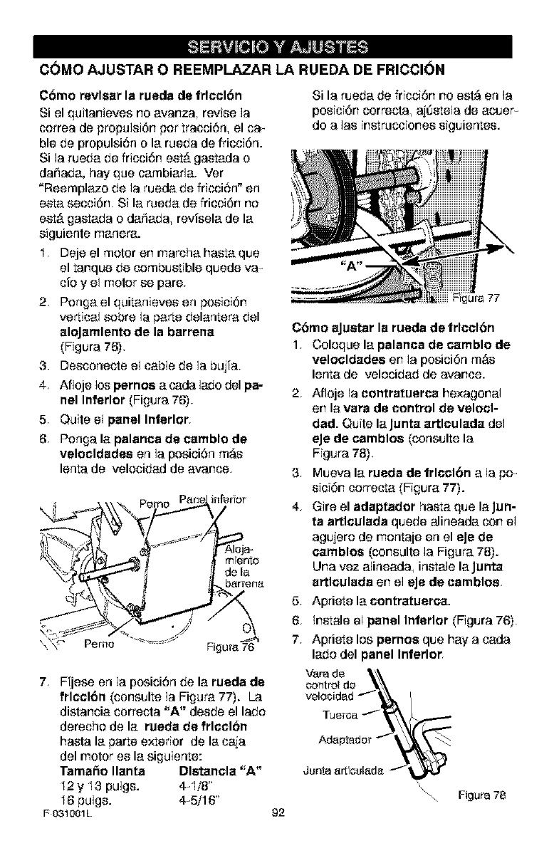
C(_MO AJUSTAR O REEMPLAZAR LA RUEDA DE FRICCION
Cbmo revlsar la rueda de trlcclbn
Si el quitanieves no avanza, revise la
correa de propulei6n por tracci6n, el ca_
ble de propulsi6n o la rueda de fricci6n.
Si ]a rueda de friosi6n est,. gastada o
da_ada, hay que cambiada. Ver
"Reemplazo de la rueda de friosi6n + en
eeta secci6n. Si la rueda de fricci6n no
eet_ gastada o dafiada, revisela de la
eiguiente manera.
I. Deje el motor en marcha hasta que
el tanque de combustible quede va_
cioy el motor ee pare.
2. Ponga el quitanievos en posici6n
vertical eobre la parte delantera del
aloJamlento de la barrena
(Figura 76).
3. Deeconecte el cable de la bujfa.
4. Afloje los pernos a cada lade del pa-
nel Inferior (Figura 76).
5. Quite el panel Interior.
6. Ponga la palanca de camblo de
velocldades en la posici6n m_e
lenta de velocidad de avarice.
infer or
mento
de la
barrer_a
7. Ffjese en la posici6n de la rueda de
frlcclbn (consulte la Figura 77). La
distancia correcta "A" deede el lade
derecho de la rueda de frlccl6n
hasta la parte exterior de la caja
del motor ee la siguiente:
Tamai_o Ilanta Dlstancla "A"
I2 y I3 pulge. 4_I/8'
16 pulge. 4_5/16'
F031001L
Si la rueda de fricci6n no est_ en la
posici6n correcta, ajl]etela de acuer_
do a lae inetruccionee eiguientos.
92
C6mo aJuetar la rueda de trlccl6n
1. Coloque la palanca de camblo de
velocldades en la posici6n m_.e
lenta de velocidad de avarice.
2, Afloje la contratuerca hexagonal
en la vara de control de velocl-
dad. Quite la Junta a_lculada del
eJe de camblos (consulte la
Figura 78).
3. Mueva la rueda de trlccl6n a la pox
eici6n correcta (Figura 77).
4< Gire el adaptador hasta que la Jun-
ta artlculada quede alineada con el
agujero de montaje en el eJe de
eatables (coneulte la Figura 78).
Una vez alineada, inetale la Junta
artlculada en el eJede camblos
5. Apriete la contratuerca.
6. ;netale el panel Interior (Figura 76).
7. Apriete los pernos que hay a cada
lade del panel Interior
Varade _\\
control de _\\
velo_idad -'f_, /
A6aptado
Junta art cul_da _--_,_r \ Figura 78
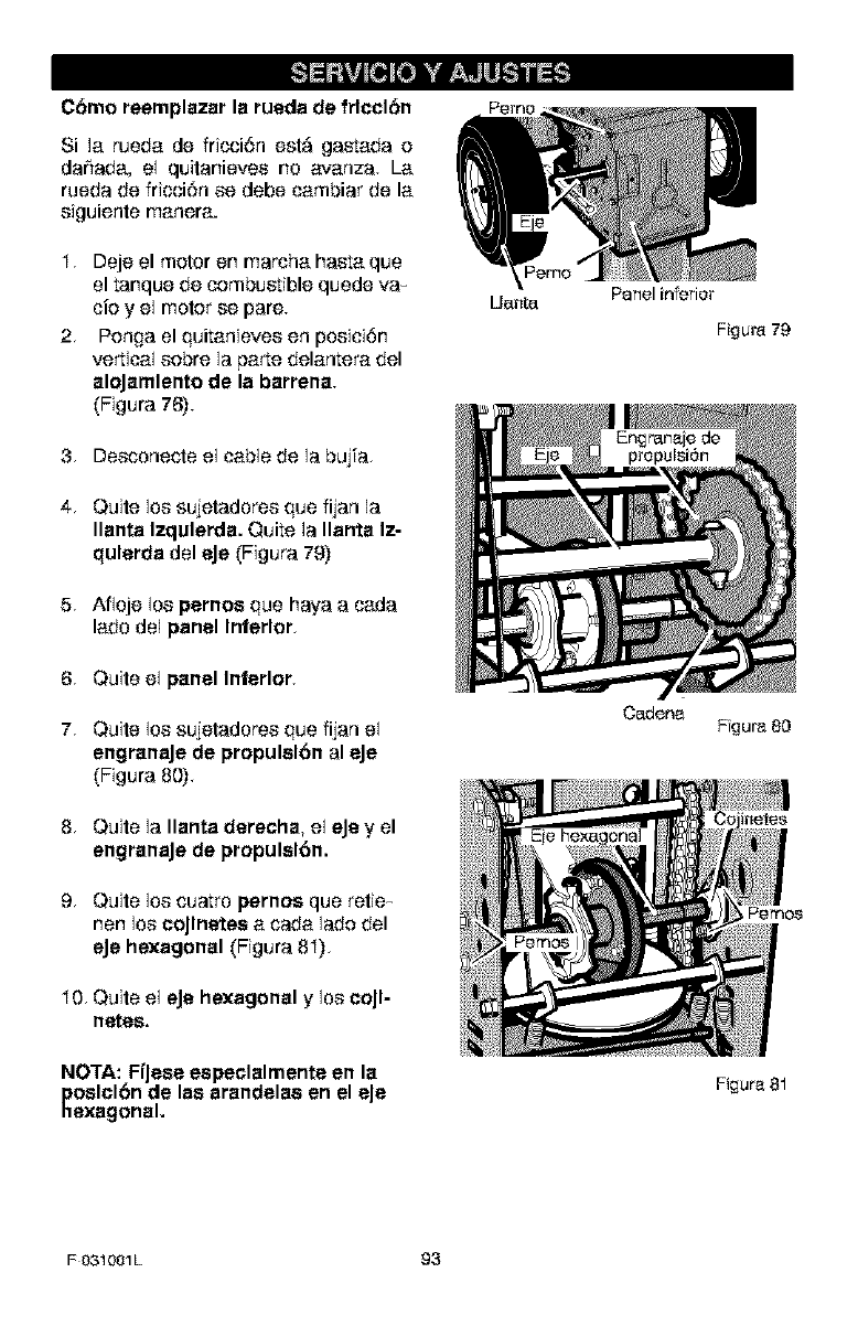
C_mo reemplazar la rueda de frlccl_n
Si ]a rueda de fricoi6n e_l,_ ga_ada e
da_ada, el quitanievee no avanza. La
rueda de fricci6n ee debe cambiar de la
eiguiente manera.
I, Deje elmeier en marcha ha_a que
el tanque de combustible quede va_
cie y el motor ee pare.
2, Penga el quitanievee en poeici6n
vertical eebre la parte delantera del
aloJamlento de la barrena.
(Figura 76).
3. Deeconecle el cable de la bujfa.
4, Quite los sujetadoree que fijan la
Ilanta Izqulerda. Quite ]a Ilanta Iz-
qulerda del eJe (Figura 79)
5 Afloje los pernos que haya a cada
lade de1panel Inferior,
6, Quite el panel Inferior,
7, Quite los sujetadoree que fijan el
engranaJe de propulslbn al eJe
(Figura 80),
8, Quite ]a Ilanta derecha, el eJey el
engranaJede propulslbn.
9, Quite los cuatro pernos que retie-
hen los coJlnetes a cada lade del
eJe hexagonal (Figura 8I),
I0, Quite el eJe hexagonal y los col I-
netee,
NOTA: FfJese especlalmente en la
poslcl6n de las arandelaa en el eJe
hexagonal.
Uo.tl[O. Panel inferior
Fi£1ura79
Cadena Ffgura 80
Figura 81
FO31001L 93
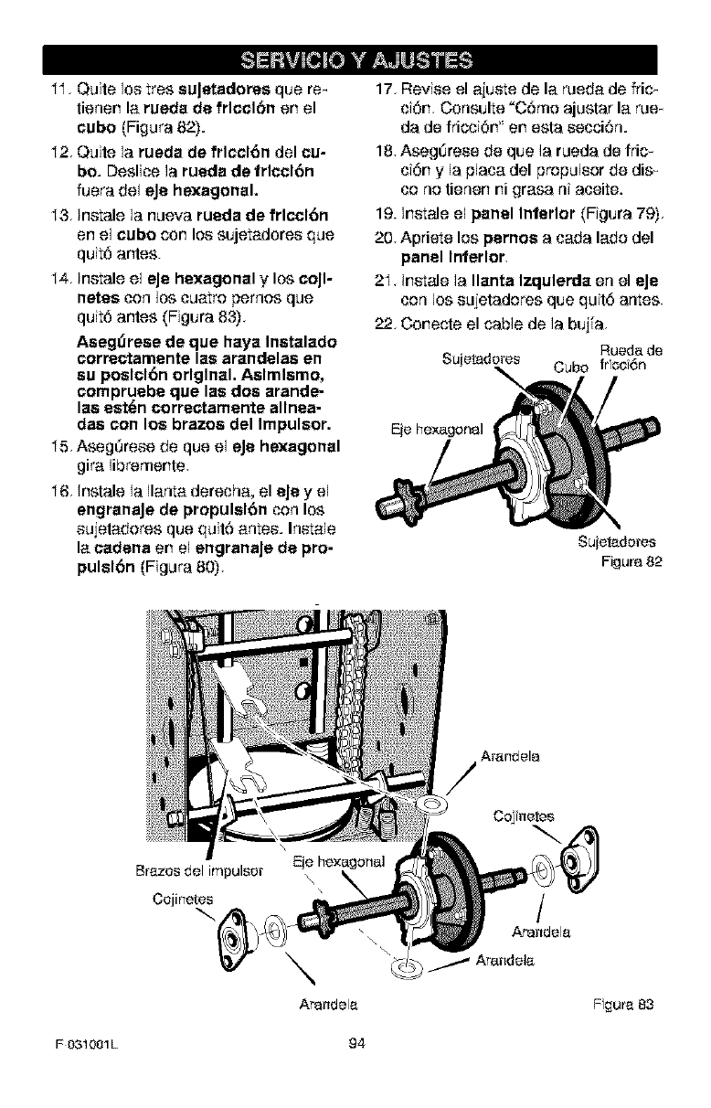
II, Quite los tres suJetadores que re_
tienen la rueda de frlccl6n on el
cubo (Figura 82).
I2, Quite la rueda de frlccl6n del cu-
bo. Deslice la rueda de frlccl6n
fuera de1 eJe hexagonal.
I3, Inmale la nueva rueda de frlccl6n
en el cube con los sujetadores que
quit6 antes.
I4, Instale el eJe hexagonal ylos coJl-
netes con bs cuatro pemos que
quit6 antes (Figura 83),
Aseg_rese de que haya Inatalado
correctamente las arandelaa en
su poslcl6n original. Aslmlamo,
compruebe que las dos arande-
laa eat(an correctamente allnea-
des con los brazes del Impulsor.
I5, Aseg_rese de que el eJe hexagonal
gira libremente.
I6, Instale la Ilanta derecha, el eJey el
engranaJe de propulsl6n con los
sujetadores que quit6 antes. Inmale
la cadena en el engranaJe de pro-
pulslbn (Figura 80),
17, Revise el ajume de la rueda de fric_
ci6n, Consulte "C6mo ajustar la rue_
da de fricci6n " en esta secci6n.
18, Aseg_rese de que la rueda de fric_
ci6n y la plata del propulsor de dis_
co no tienen ni grasa ni aceite.
19. Inmale el panel Interior (Figura 79),
20, Apriete los pernos a cada lado del
panel Interior,
2I, Inmale la Ilanta Izqulerda en el eJe
con los sujetadores que quit6 antes,
22, Conecte el cable de la bujfa,
Eje hexagonal
Sujetadores
Figura 82
C_fnetes
\
Arandela
/
Arandela
Fgura 83
F031001L 94
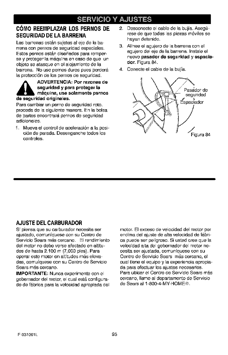
C6MO REEMPLAZAR LOS PERNOS DE
SEGURIDAD DE LA BARRENA
Las barrenas est_n sujotas aEeje de ]a ba-
rrena con pernos de seguridad espee ales,
Estos parses est_n disehados par'a romper-
sey preteger lam_.qu na on case do qua un
objeto se atasque on el alojamfento de la
barrena, No use pernos dures pues perdera
la protecofr_n de los pernos de seguridad.
_k DVERTENCIA: Per razones de
aeguridad y para proteger la
m_qutna, use solamente pernos
de seguridad odgtnales.
Para cambiar un perno de seguridad rote
prcoeda de la siguiente manera, En la bolsa
de partes encor_trar& peruse de seguridad
adiofonales
1 Muava el con[rel de acoleraoi6n a la posi-
si6n de parsda. Desenganehe redes los
sontreles,
2Desconeote el cable de la bujia. AsegS-
rese de qua todas las plazas m6viles se
hayan detenido.
3 Alfnee elaguiere de la barrena son el
agujere del eie de la barren& Instale el
nsevo pasador de seguridad y espacia_
dot. Figura 84.
4 Coneste el cable do la bujl'a,
!_dor do
,_ i! 5- - seguridad
AJUSTE DEL CARBURADOR
S piensa qua su carburador necosita sat
ajustado, comun'quese con su Centre de
Servisio Soars mas corcano, El rendimento
de] motor no debe verse afest_do on altitu-
des de hasta 2,100 m (7,000 pies), Para
operar este motor en air tudes mas eleva=
das, comuiquese con su Centre de Servioio
Sears m&s cereano
IMPORTANTE: Nunca experimente con el
gobercador del motor, el oual est,. sonfigura-
do de fabrica para la velcoidad aprepiada del
motor', El excess de velcoidad del motor por
enema del ajusta do alta velosidad de fabri-
ca puede set pelfgreco Si u_ed sree qua ]a
velcofdad alta del gobercador del motor ne-
oesita set ajustada, oomuniquese son su
Centre de Servioio Sears m_.s ceroarlo, el
oualI:eneelequipoylaexperienoiaaprepia_
da para efeotuar los ajustes necesarios,
Par'a ubicar el Centre de Ser_fefo Sears m&s
oercano, llama al dapartamerto do Servisio
de Soars al 1-8004-MY-HOME=/;'
F031001L 95
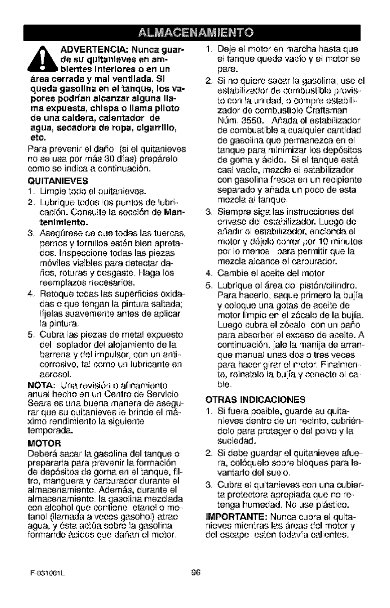
_i DVERTENCIA: Nunca guar-
de su qultanleves en am-
blentes Interlores o en un
drea cerrada y real ventllada. SI
queda gaeollna en el tanque, los va-
pores podffan alcanzar alguna lla-
ma expuesta, chlspa o llama plloto
de una caldera, calentador de
ague, secadora de tops, clgarrlllo,
etc.
Para prevenir eldaho (si elquitanievos
no se usa per m_s 30 dfas) prep_relo
come se indica a continuaci6n.
QUITANIEVES
I, lJmpie todo el quitanievos.
2, Lubrique todos los puntos de lubri-
caci6n. Oonsulte la secci6n de Man-
tenlmlento.
3, Aseg_rese de que todas las tuercas,
pernos y tomillos est6n bien apreta_
dos. Inspeccione todas las piezas
m6viles visibles para detectar da-
fios, roturas y desgaste. Haga los
reemplazos necosarios.
4, Retoque tedas las superficies o×ida-
das e que tengan la pirtura saltada;
Ifjelas suavemente antes de aplicar
la pintura.
5, Cubra las piezas de metal e×puesto
del soplador del aleiamiento de la
barrena y del impulsor, con un antF
corresivo, tal cemo un lubricante en
aerosol.
NOTA: Una revisi6n o afinamiento
anual hecho en un Centre de Servicio
Sears os una buena manera de asegu_
rat que su quitanievos le brinde el m_
×imo rendimiento la siguiente
temporada.
MOTOR
Deber;_ sacar la gasolina del tanque o
prepararla para prevenir la formaci6n
de dep6sitos de goma en el tanque, fiF
tro, manguera y carburador durante el
almacenamiento. Adem;_s, durante el
almacenamiento, la gasolina mezclada
con alcohol que contiene etanol o me_
tanol 01amada a veces gasohol) atrae
agua, y _sta actha sobre la gasolina
formande &cidos que daffan el motor,
1, Deje el motor en marcha hasta que
el tanque quede vacio y el motor se
pare.
2, Si no quiere sacar la gasolin& use el
eslabilizador de combustible provis_
to con la unidad, o compre estabili-
zador de combustible Craftsman
NOm. 3550. Ar'_ada el estabilizador
de combustible a cualquier cantidad
de gasolina que permanezca en el
tanque para minimizar los dep6sitos
de gomay ;_cido. Si el tanque est_
casi vacfo, mezcle el estabilizador
con gasolina frosca en un recipiente
separade y a_ada un poos de esta
mezcla al tanque.
3, Siempre siga las instruosienes del
envase del estabilizador. Luego de
aSadir el estabilizador, encienda el
motor y d6jele cerrer per 10 minutes
per Io menos para permitir que la
mezcla alcanos el carburader.
4, Cambie el aosite del motor
5, Lubrique el ;_rea del pist6nlcilindre.
Para haosrlo, saque primere la bujfa
y celoque una getas de aosite de
motor limpie en el z6cale de la bujia.
Luego cubra el z6calo con un paJ_O
para absorber el excose de aosite. A
cortinuaci6n, jale la manija de arran_
que manual unas dos o tres veoss
para hacer girar el motor. Finalmen_
re, reinstate la bujfa y conecte el ca-
ble,
OTRAS INDICACIONES
1, Si fuera posible, guarde su quita-
nievos dentre de un recinte, cubri#n_
dole para protegerlo del polvo y la
suciedad.
2, Si debe guardar el quitanievos afue-
ra, col6quele sobre bloques para le_
vartarle del suelo.
3, Cubra el quitanieves con una cubier-
ta protectera apropiada que no re_
tenga humedad No use pl;_stice.
IMPORTANTE: Nunca cubra el quita_
nievos mientras las ;_reas del motor y
del escape est_n todavfa calientos.
FO31001L 96
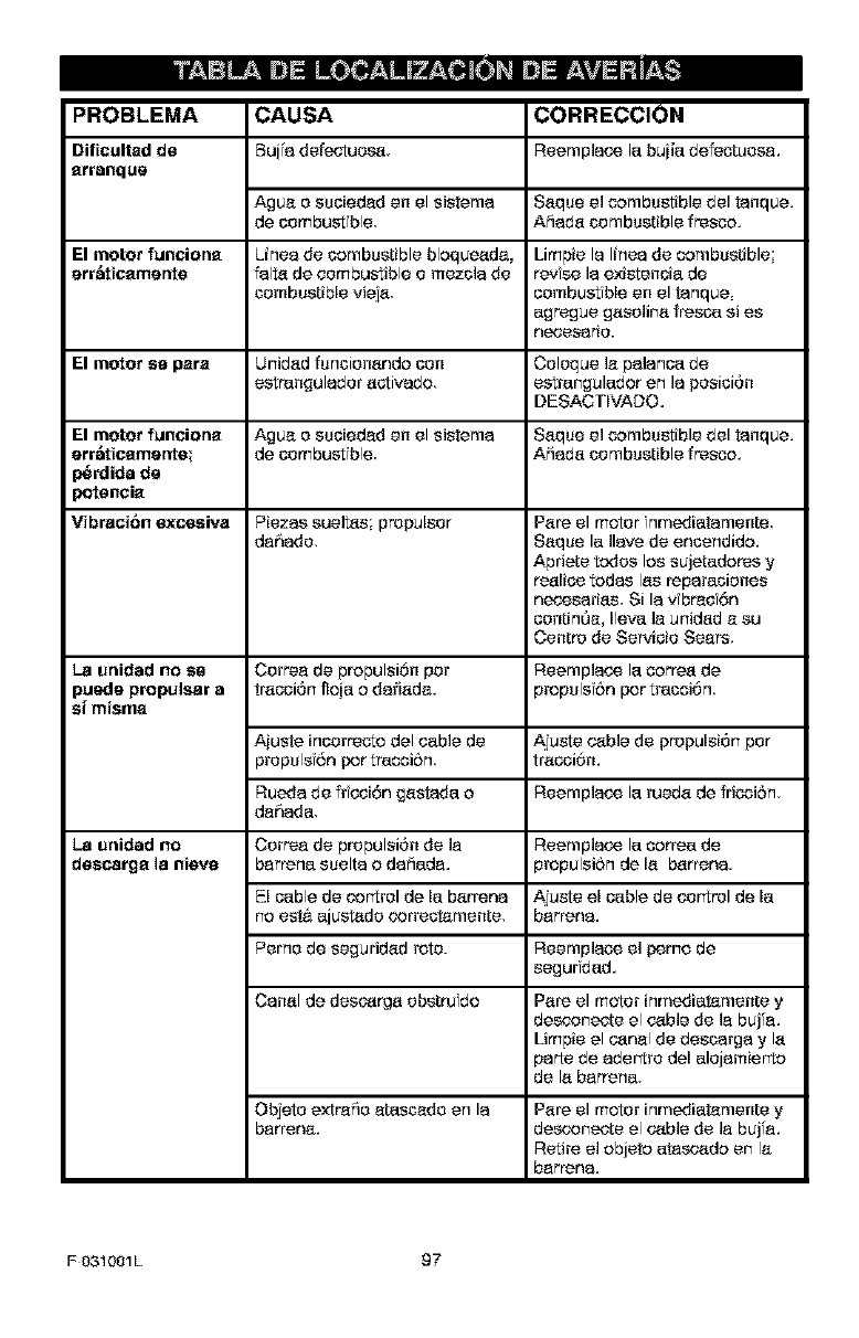
PROBLEMA
Dificultad do
arranqus
CAUSA CORRECCION
Buj'a defectcoca Reemplace la buiia defectuosa.
Agua o scoiedad en el sistema Saque el combustible del tanque.
de combustfble Aiiada combustible fresco.
El meter funciona Linen de combustible blaqueada, Limpie la linen de combustible;
err_ieamente falta de combustible omezcia de revise la existecoia de
combustible vieja combustible en el tanque
agrsgue gasolina fresca si es
nc_f_esario.
El motor sa pars Unibad funciocanda con Coloque ]a palanca de
estrangulador activado estrangulador An la posici6n
DESACTEVADO.
El motor funeiona Agua o scoiedad en el sistema Saque el combustible del tanque.
err_icamente_ de combustfble Aiiada combustible fresco.
_rdida de
_tencia
Vibraei6n excesiva Piezas sueltas propulsor Pare el motor nmediatamente
dahado, Saque la liars de encendida.
Apriete redes los sujetadores y
reaEce tadas Ins reparaciones
neo,esafias, Si lav brac 6n
continOa, Ileva ]a unidad a so
Centre de Servicio Sears,
La unidad no se Correa de propulsi6n par Reemplace la correa de
puede propulsar a tracci6n floja o darlada, propulsf6n par tracoiOn
s[ misma
Aiuste incorresto del cable de A]uste cable de prepulsi6n par
propulsfr_n For tracoi6n tracci6m
Rueda de frfccir_n gastada a Reemplace la rueda de friooiSn
dahada,
La unidad no Correa de prepulsi6n de la Reemplace la correa de
descarga la nieva barrena suelta o dafiada, propulsiSn de la barren&
El cable de cor'trel de la barrena Ajuste el cable de oor'trel de la
no est.&ajustado correctamente, barrena.
Perno de seguridad rote. Reemplaco el f>erno de
segurfdad.
Canal de descarga obstrufdo Pare el motor inmediatamente y
desconecte el cable de ]a buj'a.
Limpie el canal de descarga y la
parts de abet'ire del alojamierto
de la barrena,
Objeto extrafio atascado An la
barrena. Pare el motor inrnediatamente y
desconecte el cable de la buj'a.
Retire el objeta at.ascada en la
barrena.
F 031001L 97
SEARS, ROEBUCK AND CO.
Garantia limitada de cumplimiento con el Sislema Federal
de control de emisiones y con el sistema de control de
emisiones del Estado de California
Motores peque_os para vehiculos todo terreno
CONTROL DE EMISIONES DE
CALIFORNIA Y DE LA AGENCIA DE
PROTECCION AMBIENTAL (EPA) DE
EU.A. - DECLARACION DE LA
GARANTJA
La Agenea de Pr_teco6n Ambiental de los
Estadce Unidos ("EPA'), elConsejo de Cal-
fomia papa los Recursos del Aim ('CARB") y
Sears Roebuck and Co, tiecen el placer de
explYc_r {a qce es la Garantia Federal y de Ca-
IYfornia para Sistemas de Control de Emisio-
nes de su nuevo motor pequeSo para
vehioulos redo terrena, En California, los too-
tares pequeSos para veh'oaloe rode terreno
de medelo 1995 ymodelos de aSos poeterio-
res deben set dise5ados constroidos y equY-
pados para cumpl r con los estr eras normas
ar'ti contaminaeY6n del Estado En otros esta-
dos, los motores modelo 1997 y modeloe de
aSos posteriores deben estar diseSadoe,
construYdos y equipadoe, al momenta de su
venta para que cemplan con los disposicio-
nes de ]a EPA aceroa de motores peqce5as
para vehicalos todo terreno, Sears, Roebuck
and Ca,, garantizara el sYstemapara el central
de emYsiones de su motor pequer'ia pare veh#
culos redo terreno par los periodos de tiempo
que se mencionan mas adelante sempre y
cuanda su motor pedce5a para veh'culos redo
terreno no haya sulfide algOn abuse, negligen-
cia modificeci6n no aprsbeda o mantonimien-
to indebido
Su sistema para el control de emisicoes puede
incluir pages cerno el oarburador, el sistema
de encendida y el sistema de escape. Tambi6n
puede ineluir el alstema de descompresi6n y
otras unidades relaoanadas con los emisio-
ties,
Cuando suda una cond e6n protegida par la
garantia, Sears, Roebuck and Co., reparar_
su motor pequer'ia para veh'culas todo terreno
sin costa algana para usted par concepto de
diagn6stYco paries y mane de obra.
SISTEMA PARA EL CONTROL DE
EMISIONES DEL FABRICANTE -
COBERTURA DE LA GARANTiA
Los s stereos para el control de emisiones del
rnodelo 1995 y modelos de aSos posteriores
de motores peque_oe para veh'sulos redo te-
rrena en California est&q gar_ntYzedos #or dos
arias taly coma se menc oea en la presente
garantia. En arras estados los motares mode-
Io 1997 y medelos de a6os posteriores tam-
bi6n est_.n garantizados par dos arioe, En
cesa de que, durante dieho periodo de la go-
rant'a, oualquier pieza del motor, relaalanada
con emisioces est6 defeotuoea ensus mate-
dales o mane de obra, Sears Roebuck and
Co,, reparar_, a cambiar_ dicha pieza
RESPONSABILIDADES DEL
PROPIETARIO DE LA GARANTiA
Coma propiotar o del motor peque6o para ve-
h'oulos todo terreno usted es responsable de
qce se Ileve a cabo el mantenimiento reqceri-
do qce se meneiona en el Manual dal usuado
pete Sears, Roebuck and Co,, no cegara {a
garantia 0nic_mento debida a la falt_ de un re-
ciba a a que ustod no proporcione ana proeba
esedta de que se ha Ilevado a cabo el manteni-
miento programado,
No obstante usted, coma prapietario del mo-
tor peqceSo para vehioalos tedo terreno de-
ber_. estar censcierte be que Se_rs Roebuck
and Co le puede negar la cobertura de la ga-
rant'a si su motor a algana porto del misma ha
fallado debYdo a abuse, cegligenala, marteni-
miento inadecuado o rnod ficealones no apro-
badas.
Ustod es responsable de precertar su motor
pequeiio para vehiculos todo terrece en el Ta-
ller be Se_,4cio Autorizado de Sears Roebuck
and Co, en cuanto suria el problem& Los re-
paraaloees baio la garar't[a deben Ilevarse a
cabo dentro de un periedo de tYempo razona-
ble que no exceda de 30 bias,
Se puede programar el servicio de garar't[a
Ilamando al Taller de Servicio Autorizado de
F031001L 98
Seers, Roebuck and Co., o a Se_rs, Roebusk
and Co al 1-800-473-7247 (llamada grstui-
ta on E.U.A.).
NOTA IMPORTANTE
Esta deolerac 6n de garantia expli¢_._los dere-
chos y las obligaoonos que coted tone do
conf'ormidad son la Gamnt fa del Sistoma para
el Control de Emisiocos ("Garentia SCE"), la
cual Seers, Roebuck and Co., le propomiona
de conform dad con las leyes do California.
Consulte t_mbi_n las Gerantias Umitadas do
Soars Roebuck and Co., que se adjuntan a la
Garent[a SCE en coa hoja aperte y qco tam-
bi6n le proporsiona Sears Roebuck and Co.
La Garantia SCE 5nicomente so aplisa en el
sistema par'a el control de emisiones de su
motor nueco Hast_ el punto en donde no h_ya
ning0n sorflicto en t_rminos entre la Gerant[a
SCE y la Gamntia de Se_rs Roebusk and Co.,
la Garant'a SCE aplicora para oua]quier sir-
cunstanc a a exoepsi0n de aqcolla en qco la
Garent[a de Soars Rcobusk and Co., pueda
proporcionar un periodo de 9erantia m_.s laF
go. La Garentia SCE y la Garentia de Sears
Rcobuck and Co desoriben importantes de-
reohos y obligacionco que usted "#oneson res-
pecto a su motor cooco.
SSIo co puede Ilever a sabo el corvisio de 9a-
rent'a en un Taller de Servicio Autoricodo do
Soars Roebuck and Co. AI momento do solici-
tar co corv sic de gerantia co debe precor_r
una prueba de ]a _echa de compra pot f_rte
del comprador original. El comprador pagar_
cualquier cer9o pot oencopto de ]lamadas do
corvicio y/o transportasi0n de productos des-
de y pera el luger en donde co Iloco a cobo el
trabajo do inspecci6n yio geraotia. El sompra-
dot cora responcoble de ocolquier dafio o f_r-
dida en ol que co incerre con relaciSn a la
transportaofSn de oualqufor motor o oualqufor
porte del mismo que se presento pare icop_c _
ciSn y/o trebajo de gerantia
S _ene alguco pregunta son r'elasi0na sus de-
reohos y resl;,onsabilidades, dober_. Ilamar a
Sears Roebuckand Co al _-800-4737247
GARANTIA DEL SISTEMA PARA EL
CONTROL DE EMISIONES
Garer_[a dol Sistoma pare ol Control de Em-
sionos ('Garant'a SCE") do motores peque-
6os pera coh'sulos todo torreno modelo 1995
y modelos de a6os posterieres en Californfa
(pera circe cotadoe motorco modelo 1997 y
ahos posteriores):
F 031001L 99
A. CAMPO DE APLICACI6N: Esta gerar%[a
dober_ aplicerco a los moterco pequefios pare
veh[culco todo terrsno modelo _995 y mode-
los de afios posteriores en California (pera
circe estados motores modelo 1997 y mode-
los de anoe posterforss). El Porfodo do la Oa-
rant'a SCE co infcfar_ en la focha de or_roga
del cooco motor o equipo al oemprador origi-
nal y continuar_ derante los siguientes 24 me-
cos concocutk, oe
B. COBERTURA GENERAL DE LA GA-
RANT[A DEL SIS'TEMA PARA EL CON-
TROL DE EMISIONES Sears, Roebuck and
Co. 9arer_iza al oempredor original dol nuovo
motor o equfpo y a coda oemprader subco-
coente qco su motor pequefio para veh[culos
todo terreno cot_.:
1. D co5ado, cocotm do y equipado para qco
cumpla son todas las dispos oiones apl cables
adoptadas por el Concojo para los Reoursoe
dol Aire de sonformidad con su autoridad os-
pecilicada on los Capftulco _ y 2, Parte 5 Divi-
sign 26 del C0dfgo do Salud y Seguridad, y
2. Libre de defestos en sus materiales y me.no
de obm Io oua] cause en oualquier momento
durante el Per*odo de la Gerantia SCE la falla
de una parte rolasionada con emisionco y qoe
est6 ba[o la 9erantia on ouanto a quo no coa
id0ntisa en sco matoria]co a la parto dessrfta
en la colicitud de motor del f_brisante para su
cortificoof6n.
C La Gamntfa SCE sslo atafie alas l_ertes do
su motor rolacionadas con emisionos do la si-
gu onto manera:
1. Cualquier parte rolacionaba son emisionos
qco no co es#esifique como de combfo tal y
como co requ ors en el mantonimiento copeoi-
fisado on el Maoe_l del Propfeterio, deber& ga-
rantizerco pot el Periodo de la Oarer_ia SCE.
Sf dich_ parte fall_ dumnte el Periodo de ]a Ga-
rentia SCE Sears Roebuck and Co la repa-
rat& o cambiar_, do accordo con la Subsecci0n
4 quo co mensiona mas abelante. Cualquier
parte roperada o cambiada de confermidad
con la Garent [a SCE deber_ ester geranticoda
pot el resto del Perfodo de ]a misma
2. Cualquier patio garantizada y relasionada
con emisiones qco este copecificoda s01o pa-
ra nspecoionos reguleres confermo al Manual
dol Propfeterio dober& ester gamntizada _r ol
Periodo de la Gerantia SCE Una declareciSn
en dishas nstrussiocos per oserito aefeoto do
"reperar o c_mbiar tal y coma soa necocorio"
no red stirS, el Per*odo de la Garaotia SCE. Di-
cha perte reperada o camb ada conferme a la
GarantfaSCEdeber_garantzarseparelredo
delPerododelaraisin&
3, Cualquier parte garantizada y relacionada
cor'_ emisiones qua so espeoifique pars e_m=
bio, de conform dad con el Manual del Propie=
tara deber_ garantizarse par el periodo do
tiempo preys al prmer punts do combo do
eca parts. Sila parts falls antes del prfmer
cambio programatic Sears, Roebuck and Co,
reparara o cambiarA eca parle de acuerdo son
la Subsecsf6n 4 que se mentions m&s adelan-
to. Cualquier porte reladonada con emisiones
que se repare o comus de conformidad con la
Garant[a SCE deber_, estar gamntfzada par el
rests del Periods de la misma previs al pCmer
punts de cambfo programatic de es_ patio re-
lacionada con emisiones,
4, La repamci6n o el cambio de cualquier parts
garantizada y relas onada con emisiones do
conformidad con est_ Garartia SCE se debe-
ra Ilevar a cabs sin cargo alguno pars el pro-
pietario, en un Taller Autorizado de Servicis de
Sears, Roebuck and Co
5, No se cargarA al prspietario el cos'to par tm-
bajo do diagn6st co, el coal Ileva a la determ -
nad6n de que una pa_e protegida par la
Garant[a SCE si es_ defectuoca provisto que
dicho trabaio de dfagn6stico se Ileve a cabs en
un Taller Autsrfzado de Servicis de Sears
Roebuck and Co.
6, Sears, Roebuck and Co. se¢_ responcable
de da_os astros componentes Or ginales del
motor o modificaciones aprobadas que proba-
blemente scan cascades par una falls com-
prendfda en la garantia be una par_e
relacisnada con emisisnes ouberta par la Ga-
rant'a SCE,
7, Durante el Periods de la Garant[a SCE
Soars, Roebuck and Co. deber_, conservar un
sumfnistro de partes garan_zadas y relacioca-
dos con emisiones qca sea sufioiente para
cumplir la demands esperada de ecas partes
relac onadas con emisiones
8, Se puede ut lizar ocalquier parts de repues-
to relacionada con emsones autorizada y
aprebada f_or Sears, Roebuck and Co. pare
utilizarse en el desempefio de caalquier man-
tenimiento o cambio de la Gamr_t[a SCE la
coal se proporsiocar& sin cargo alguno p_m el
propietarfo, Dicho use no reducir_ ]as obliga-
ciones de Sears Roebuck and Co, conforms
a la Gamntia SCE.
9. Los partes qca se agreguen o mad flquen
sin aprobaci6n no se podr_n utilizar pars mo-
dificar o reparar un motor de Sears, Roebuck
and Co. Dioho use anula est_ Garant[a SCE y
csnformar& los bases suficientes pars recha-
zar la demands be una Garar_tia SCE Sears
Roebuck and Co no set& responcable con-
forms aesta garar_t[a par las fallas de cuaF
quer parts garantiz_da do un motor de Sears
Roebuck and Co, causadas par el use de d-
cha parts agregada s rood ffcada sin aproba-
ci6n.
I.AS PARTES RELACIONADAS CON
EMISIONES INCLUYEN A LAS
SIGUIEN'I'ES:
1. Unidad del carburador y sus oemponertes
intemos
a} Filtro de combustible
b} Empaques (juntas} del carburador
_) Tubs de entrada
2, Unidad de filtrs do airs
a} Elements del filtro de afro
3, Sistema de encendido, que fncluye:
a} Bui[a de encandfdo
b} M6duls de encandfdo
_) Encamblaje del volante
4, Silenciador cat_litico (si est_ equipado}
a} Em_que de] silenciador {sf esta equfp_ds)
b} Coleotor de escape [si est_ equipado}
5. Encamblaie del respimdero del carter del ci-
g0efial y sos componentes
a} Tubs de oenexi6n del respfradero
10/22/99 EPAiCARB
Sears, Roebuck and Co., Hoffman Eslates, IL 60179 U.S.A.
F 031001L 100

F 031001L 101

FO31001L 102

F031001L 103

Your Home
For repair -in your home - of all major brand appliances,
lawn and garden equipment, or heating and cooling systems,
no matter who made it, ne matter who sold it!
For the replacement parts, accessories and
owner's manuals that you need to do-it-yourself.
For Sears professional installation of home appliances
and items like garage door openers and water heaters.
1-800-4-MY-HOME ® Anytime, day or night
(1_gQ0-46g_4663) (U.S,A. and Canada)
www.sears.com www sears.ca
OurHome
For repair of carry-in products like vacuums, lawn equipment;
and electronics, call or go on-line for the nearest
Sears Parts and Repair Center.
1-800-488-1222 Anytime,dayor night(U_SA only)
To purchase a protection agreement (U.S.A.)
or maintenance agreement (Canada) on a product serviced by Sears;
1-800-827-6655 (ur&_.) 1"800--361--6665 (Canada)
Para_dir servido de repamd6n
a domidlio, y parao_enar piezas:
1-888_SU4-1OGARsM
(1-888-784-6427)
Au Canada pourservice en frangais:
1-8804_E-FOYERMc
(1-800-_937}
www_sears.ca
© _rs, Roebuck and Co
® Registered Trademark /TM Trademark !SMService Mark of Sears Roebuck and Go.
® i_Aama Registrada /_r_Marca de F_b_ica /_ Mama de Servicio de Sears, Roebgck and Co.
_c Marque de commerce J_ Marque d6posee de Sears, Roebuck and Co,
