Craftsman 536881410 User Manual SNOW THROWER Manuals And Guides L0812517
CRAFTSMAN Snowthrower, Gas Manual L0812517 CRAFTSMAN Snowthrower, Gas Owner's Manual, CRAFTSMAN Snowthrower, Gas installation guides
User Manual: Craftsman 536881410 536881410 CRAFTSMAN SNOW THROWER - Manuals and Guides View the owners manual for your CRAFTSMAN SNOW THROWER #536881410. Home:Lawn & Garden Parts:Craftsman Parts:Craftsman SNOW THROWER Manual
Open the PDF directly: View PDF ![]() .
.
Page Count: 72
ICRI:IFTSM I:1N°I
Operator's Manual
Snow Thrower
650 Series, 4-Cycle Engine
21-inch Single Stage
Auger Propelled
Model 536.881410
CAUTION: Before using this product,
read this manual and follow all of its
Safety Rules and Operating Instructions.
Manual del usario
Quitanieves
650 Serie, 4-Ciclo Motor
de 21 pulgadas
Monoetapico
Propulsado por barrena
Modelo 536.881410
PRECAUCION: Antes de usar este producto,
lea este manual y siga todas las reglas de
seguridad e instrucciones de operaci6n.
Sears, Roebuck and Co., Hoffman Estates, IL 60179 U.S.A.
1741476 www.sears.com/craftsm an
Rev, 01 07-01-2007
/q_'1:) I= [.]d [o[._']
WARRANTY STATEMENT ......
SAFETY RULES ...............
INTERNATIONAL SYMBOLS ...
ASSEMBLY ...................
OPERATION ..................
MAINTENANCE ...............
SERVICE AND ADJUSTMENT ..
2STORAGE .................... 24
2TROUBLESHOOTING CHART .. 25
4 REPAIR PARTS ............... 29
7 ENGINE REPAIR PARTS ....... 36
9SPANISH (ESPAI_IOL) .......... 43
16 PARTS ORDERING/SERVICE ..
19 BACK COVER
kViVl_'1;t ;__'I_ih'4[,.'[_=l?JF-.l_l
LIMITED ONE-YEAR WARRANTY ON CRAFTSMAN SNOW THROWER
For one year from the date of purchase, when this Craftsman Snow thrower is maintained,
lubricated, and tuned up according to the operating and maintenance instructions in the
owner's manual, Sears will repair, free of charge, any defect in material or workmanship.
If this Craftsman Snow thrower is used for commercial or rental purposes, this warranty ap-
plies for only 90 days from the date of purchase.
This warranty does not cover the following:
• Items which become worn during normal use, such as spark plugs, drive belts and shear pins.
• Repair necessary because of operator abuse or negligence, including bent crankshafts
and the failure to maintain the equipment according to the instructions contained in the
owner's manual.
WARRANTY SERVICE IS AVAILABLE BY RETURNING THE CRAFTSMAN SNOW
THROWER TO THE NEAREST SEARS SERVICE CENTER IN THE UNITED STATES.
THIS WARRANTY APPLIES ONLY WHILE THIS PRODUCT IS IN USE IN THE UNITED
STATES.
This warranty gives you specific legal rights, and you may also have other rights which may
vary from state to state.
Sears, Roebuck and Co., D817WA, Hoffman Estates. IL 60179
LOOK FOR THIS SYMBOL TO POINT OUT IMPORTANT SAFETY PRECAUTIONS,
IT MEANS-- ATTENTIONH! BECOME ALERT!!! YOUR SAFETY IS INVOLVED,
Engine Exhaust, some of its constituents, and
certain vehicle components contain or emit
chemicals known to the State of California to
cause cancer and birth defects or other repro-
ductive harm.
Battery posts, terminals and related accessories
contain lead and lead compounds, chemicals
known to the State of California to cause cancer
and birth defects or other reproductive harm.
WASH HANDS AFTER HANDLING.
,_ WARNING: Always discon-
nect the spark plug wire
and place it where it cannot
make contact with spark plug to
prevent accidental starting during:
Preparation, Maintenance, or Stor-
age of your snow thrower.
IMPORTANT: Safety standards re-
quire operator presence controls to
minimize the risk of injury. Your snow
thrower is equipped with such controls.
Do not attempt to defeat the function of
the operator presence control under any
circumstances.
1741476 2
,_ WARNING: This snow thrower is
capable of amputating hands
and feet and throwing objects.
Failure to observe the following safety in-
structions could result in serious injury.
TRAINING
1. Read this operating and service instruction
manual carefully. Be thoroughly familiar
with the controls and the proper use of the 5.
snow thrower. Know how to stop the snow
thrower and disengage the controls quickly.
2. Never allow children to operate the snow
thrower. Never allow adults to operate the
snow thrower without proper instruction. 6.
3. Keep the area of operation clear of all per-
sons, particularly small children and pets.
4. Exercise caution to avoid slipping or falling 7.
especially when operating in reverse.
PREPARATION
2,
3.
4,
Thoroughly inspect the area where the
snow thrower is to be used and remove all
doormats, sleds, boards, wires, and other
foreign objects.
Disengage all clutches before starting the
engine (motor).
Do not operate the snow thrower without
wearing adequate winter outer garments.
Wear footwear that will improve footing on
slippery surfaces. Avoid loose fitting cloth-
ing that can get caught in moving parts.
Handle fuel with care; it is highly flam-
mable.
a. Use an approved fuel container.
b. Never remove fuel tank cap or add fuel
to a running engine (motor) or hot en-
gine (motor).
c. Fill fuel tank outdoors with extreme
care. Never fill fuel tank indoors.
d. Replace fuel cap securely and wipe up
spilled fuel.
e. Never store fuel or snow thrower with
fuel in the tank inside of a building
where fumes may reach an open flame
or spark.
f. Check fuel supply before each use, al-
lowing space for expansion as the heat
of the engine (motor) and/or sun can
cause fuel to expand.
g. Neverfill containers inside avehicle or
on a truck or trailer bed with a plastic
liner. Always place containers on the
ground, away from vehicle, before fill-
ing.
h. When practical, remove gas-powered
equipment from the truck or trailer and
refuel iron the ground. If this is not pos-
1741476
sible, then refuel such equipment on a
trailer with a portable container, rather
than from a gasoline dispenser nozzle.
i. Keep the nozzle in contact with the rim
of the fuel tank container opening at all
times, until refueling is complete. Do
not use a nozzle lock-open device.
j. If fuel is spilled on clothing, change
clothing immediately.
For all snow throwers with electric starting
motors use electric starting extension
cords certified CSA!UL. Use only with a re-
ceptacle that has been installed in accord-
ance with local inspection authorities.
Let engine (motor) and snow thrower ad-
just to outdoor temperatures before starting
to clear snow.
Always wear safety glasses or eye shields
during operation or while performing an ad-
justment or repair to protect eyes from
foreign objects that may be thrown from the
snow thrower.
OPERATION
1. Do not operate this snow thrower if you are
taking drugs or other medication which can
cause drowsiness or affect your ability to
operate this snow thrower.
2. Do not use the snow thrower if you are
mentally or physically unable to operate the
snow thrower safely.
3. Do not put hands or feet near or under ro-
tating parts. Keep clear of the discharge
opening at all times.
4. Exercise extreme caution when operating
on or crossing gravel drives, walks or
roads. Stay alert for hidden hazards or
traffic.
5. After striking a foreign object, stop the en-
gine (motor), remove the wire from the
spark plug, thoroughly inspect snow
thrower for any damage, and repair the
damage before restarting and operating
the snow thrower.
6. If the snow thrower should start to vibrate
abnormally, stop the engine (motor) and
check immediately for the cause. Vibration
is generally a warning of trouble.
7. Stop the engine (motor) whenever you
leave the operating position, before un-
clogging the auger/impeller housing or dis-
charge chute and when making any
repairs, adjustments, or inspections.
8. When cleaning, repairing, or inspecting,
make certain the auger/impeller and all
moving parts have stopped and all controls
are disengaged. Disconnect the spark plug
wire and keep the wire away from the spark
plug to prevent accidental starting.
9. Takeallpossibleprecautionswhenleaving
thesnowthrowerunattended.Disengage
theauger/impeller,stopengine(motor),
andremovekey.
10.Donotstartorrunengineinenclosedarea,
evenifdoorsorwindowsareopen.Ex-
haustfumesaredangerous(containing
CARBONMONOXIDE,anODORLESS
andDEADLYGAS).
11.Exerciseextremecautionifoperatingon
steepsloppingsurfaces.
12.Donotclearsnowacrossthefaceof
slopes.Exerciseextremecautionwhen
changingdirectiononslopes.Donotat-
tempttoclearsteepslopes.
13.Neveroperatethesnowthrowerwithout
properguards,platesorothersafetypro-
tectivedevicesinplace.
14.Neveroperatethesnowthrowernearen-
closures,automobiles,windowwells,drop-
offs,andthelikewithoutproperadjustment
ofthesnowdischargeangle.Keepchildren
andpetsaway.
15.Donotoverloadthesnowthrowercapacity
byattemptingtoclearsnowattoofasta
rate.
16.Neveroperatethesnowthrowerathigh
transportspeedsonslipperysurfaces.
Lookbehindandusecarewhenbacking
up.
17.Neverdirectdischargeatbystandersor
allowanyoneinfrontofthesnowthrower.
18.Disengagepowertothecollector/impeller
whensnowthroweristransportedornotin
use,
19. Use only attachments and accessories ap-
proved by the manufacturer of the snow
thrower (such as tire chains, electric start
kits, ect.).
20. Never operate the snow thrower without
good visibility or light. Always be sure of
your footing and keep a firm hold on the
handles. Walk;never run.
21. Do not over-reach. Keep proper footing
and balance at all times.
22. Do not use the snow thrower on surfaces
above ground level such as roofs of resi-
dences, garages, porches or other such
structures or buildings.
23. This snow thrower is for use on sidewalks,
driveways and other ground level sur-
faces.
24. Never touch a hot engine or muffler.
,_ WARNING: This snow thrower isfor use on sidewalks, driveways
and other ground level surfaces.
Caution should be exercised while using on
steep sloping surfaces. DO NOT USE
SNOW THROWER ON SURFACES ABOVE
GROUND LEVEL such as roofs of resi-
dences, garages, porches or other such
structures or buildings.
MAINTENANCE AND STORAGE
Clearing A Clogged Discharge Chute
,_ WARNING: Hand contact with
the rotating impeller inside the
discharge chute is the most
common cause of injury associated with
snow throwers. Never use your hand to
clean out the discharge chute.
To Clear The Chute:
•SHUTOFFTHE ENGINE!
• Wait 10 seconds to be sure that the im-
peller blades have stopped rotating.
•Always use a clean-out tool, not your
hands.
1. Check shear bolts and other bolts at fre-
quent intervals for proper tightness to be
sure the snow thrower is in safe working
condition.
2. Store the snowthrower away from ignition
sources or appliances that have a pilot
light, such as hot water and space heaters,
clothes dryers, etc.... Allow the engine
(motor) to cool before storing in any enclos-
ure.
3. Always refer to operator's guide instruc-
tions for important details if the snow
thrower is to be stored for an extended
period.
4. Maintain or replace safety and instruction
labels, as necessary.
5. Run the snow thrower a few minutes after
throwing snow to prevent freeze-up of the
auger/impeller.
1741476 4
[.._o]l!.._
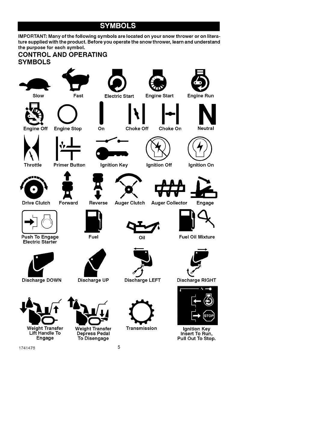
IMPORTANT: Many of the following symbols are located on your snow thrower or on litera-
ture supplied with the product. Before you operate the snow thrower, learn and understand
the purpose for each symbol.
CONTROL AND OPERATING
SYMBOLS
Slow Fast
Engine Off Engine Stop
Electric Start Engine Start
I I-I
On Choke Off Choke On
Throttle Primer Button Ignition Key
Engine Run
N
Neutral
G G
Ignition Off Ignition On
Drive Clutch Forward Reverse Auger Clutch Auger Collector Engage
Push To Engage Fuel Oil Fuel Oil Mixture
Electric Starter
r d
Discharge DOWN Discharge UP Discharge LEFT Discharge RIGHT
0
Weight Transfer Weight Transfer Transmission Ignition Key
Lift Handle To Depress Pedal Insert To Run,
Engage To Disengage Pull Out To Stop.
1741476 5
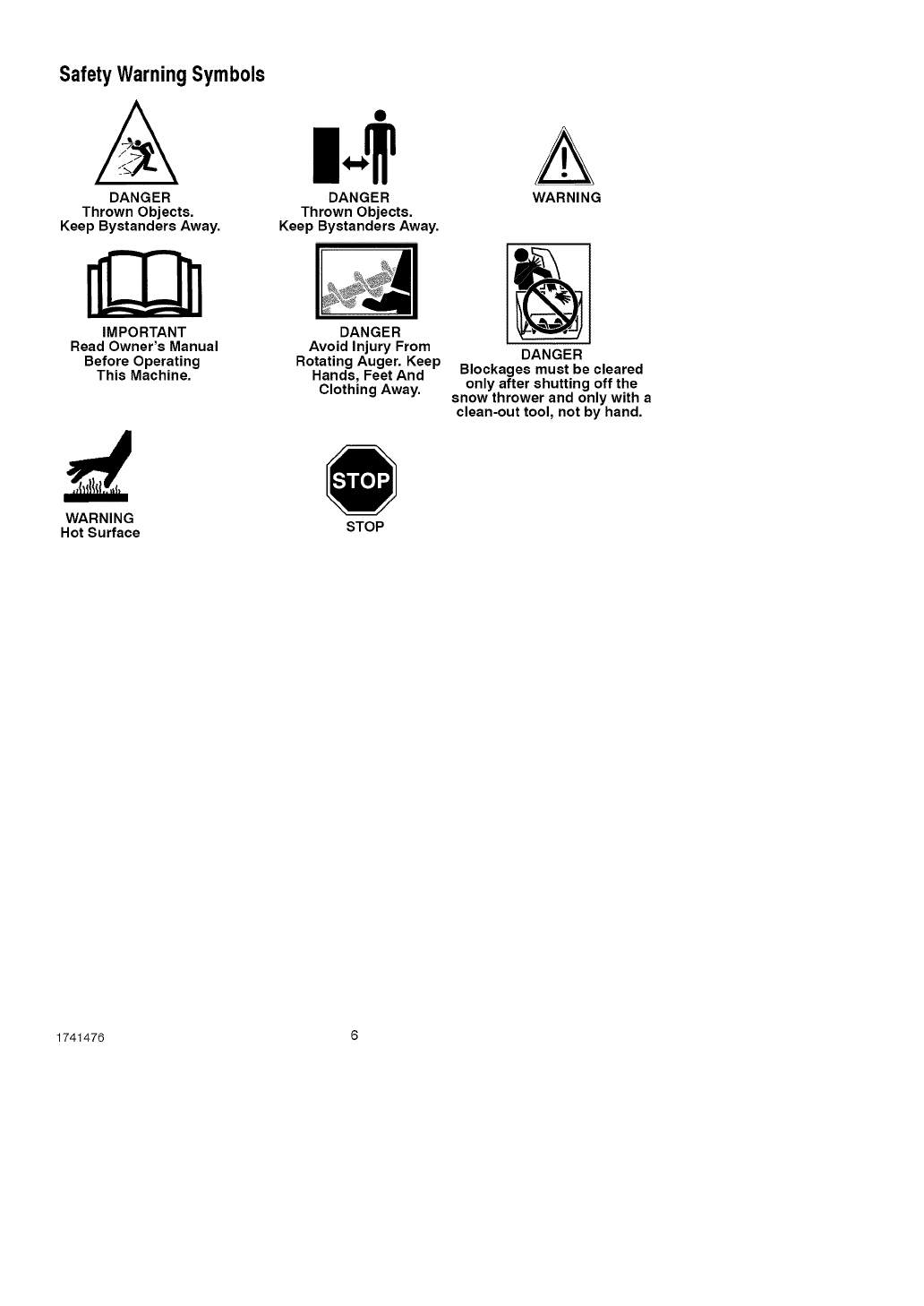
Safety Warning Symbols
A
DANGER
Thrown Objects.
Keep Bystanders Away.
IMPORTANT
Read Owner's Manual
Before Operating
This Machine.
DANGER
Thrown Objects.
Keep Bystanders Away.
DANGER
Avoid Injury From
Rotating Auger. Keep
Hands, Feet And
Clothing Away.
WARNING
DANGER
Blockages must be cleared
only after shutting off the
snow thrower and only with a
clean-out tool, not by hand.
WARNING
Hot Surface STOP
1741476 6

Contents of Parts Bag (actual size)
1 - Owner's Manual (not shown)
1 - Packet of Fuel Stabilizer (not shown)
1- Container 5W30 Oil
,_ WARNING: Always wearsafety glasses or eye shields
while assembling snow
thrower.
TOOLS REQUIRED
1 - Knife to cut carton
Figure 1 shows the snow thrower in the
operating position.
References to the right or left hand side
of the snow thrower are from the view-
point of the operator's position behind
the unit.
HOW TO
REMOVE FROM THE CARTON
1. Locate and remove container of
Craftsman 5W30 oil.
2. Locate all parts packed separately
and remove from the carton.
NOTE: Place fuel stabilizer in a
safe place until needed for storage.
3. Remove and discard the packing
material from around the snow
thrower.
4. Cut down all four corners of the car-
ton and lay the panels flat.
5. Roll snow thrower off the carton by
pulling on the lower handle.
CAUTION: DO NOT back over
cables.
6. Remove the packing material from
handle assembly. Remove the lower
insert from the axle.
Auger Drive Lever
Auger
Drive Cable
Crank
Chute Assembh
Deflector
Figure 1
1741476 7
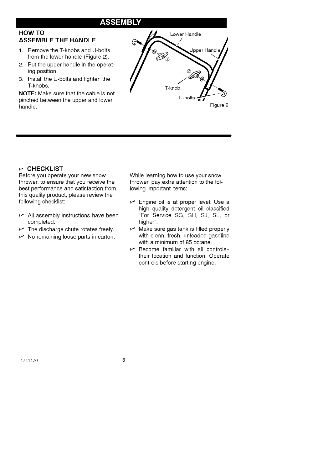
HOW TO
ASSEMBLE THE HANDLE
1. Remove the T-knobs and U-bolts
from the lower handle (Figure 2).
2. Put the upper handle in the operat-
ing position.
3. Install the U-bolts and tighten the
T-knobs.
NOTE: Make sure that the cable is not
pinched between the upper and lower
handle.
Lower Handle
T-knob
U-bolts
Handle
I
Figure 2
_" CHECKLIST
Before you operate your new snow
thrower, to ensure that you receive the
best performance and satisfaction from
this quality product, please review the
following checklist:
_" All assembly instructions have been
completed.
_" The discharge chute rotates freely.
_" No remaining loose parts in carton.
While learning how to use your snow
thrower, pay extra attention to the fol-
lowing important items:
_" Engine oil is at proper level. Use a
high quality detergent oil classified
"For Service SG, SH, SJ, SL, or
higher".
_" Make sure gas tank is filled properly
with clean, fresh, unleaded gasoline
with a minimum of 85 octane.
_" Become familiar with all controls-
their location and function. Operate
controls before starting engine.
1741476 8
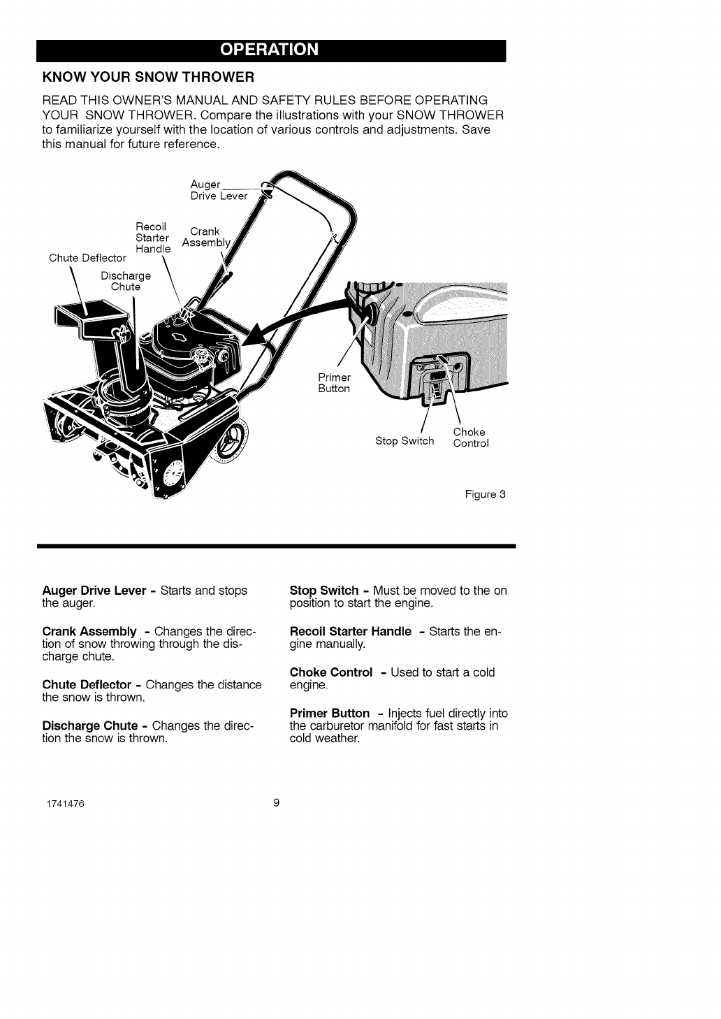
KNOW YOUR SNOW THROWER
READ THIS OWNER'S MANUAL AND SAFETY RULES BEFORE OPERATING
YOUR SNOW THROWER. Compare the illustrations with your SNOW THROWER
to familiarize yourself with the location of various controls and adjustments. Save
this manual for future reference.
Recoil
Starter
Handle
Chute Deflector
Discharge
Chute
Auger
Drive Lever
Crank
Assembl
Primer
Button
Choke
Stop Switch Control
Figure 3
Auger Drive Lever - Starts and stops
the auger.
Crank Assembly - Changes the direc-
tion of snow throwing through the dis-
charge chute.
Chute Deflector - Changes the distance
the snow is thrown.
Discharge Chute - Changes the direc-
tion the snow is thrown.
Stop Switch IMust be moved to the on
position to start the engine.
Recoil Starter Handle - Starts the en-
gine manually.
Choke Control - Used to start a cold
engine.
Primer Button - Injects fuel directly into
the carburetor manifold for fast starts in
cold weather.
1741476 9
[o_o_l
,_ WARNING: Read Owner's
Manual before operating
machine. Never direct dis-
charge toward bystanders. Stop the
engine before unclogging discharge
chute or auger housing and before
leaving the machine.
TO STOP YOUR
SNOW THROWER
1. To stop throwing snow, release the
auger drive lever. See Figure 3.
NOTE: If the snow thrower contin-
ues to slowly move forward, see
"How To Adjust The Auger Control
Cable" in the Service And Adjust-
ment Section.
2. To stop the engine, move the igni-
tion lever to the off position.
CAUTION: To stop the engine, do not
move the choke control to CHOKE
position. Backfire or engine damage
can occur.
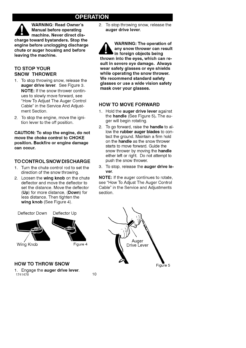
TO CONTROL SNOW DISCHARGE
1. Turn the chute control rod to set the
direction of the snow throwing.
2. Loosen the wing knob on the chute
deflector and move the deflector to
set the distance. Move the deflector
(Up) for more distance, (Down) for
less distance. Then tighten the
wing knob (See Figure 4).
Deflector Down Deflector Up
/
Wing Knob Figure 4
2. To stop throwing snow, release the
auger drive lever.
_WARNING: The operation of
any snow thrower can result
in foreign objects being
thrown into the eyes, which can re-
sult in severe eye damage. Always
wear safety glasses or eye shields
while operating the snow thrower.
We recommend standard safety
glasses or use a wide vision safety
mask over your glasses.
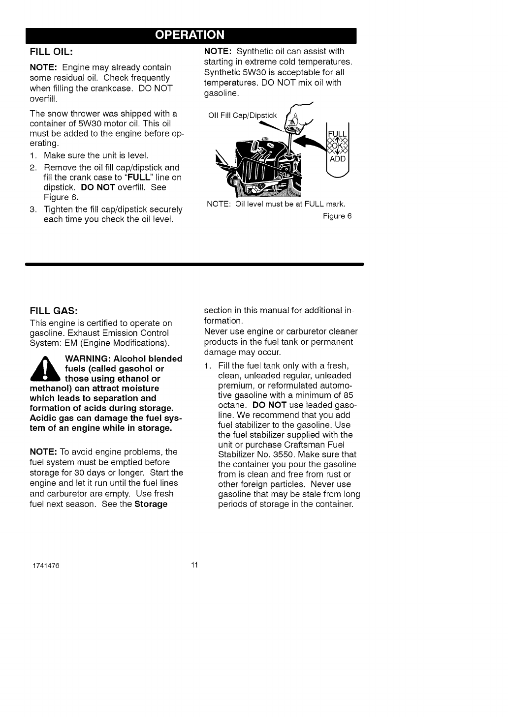
HOW TO MOVE FORWARD
1. Hold the auger drive lever against
the handle (See Figure 5). The au-
ger will begin rotating.
2. To go forward, raise the handle to al-
low the rubber auger blades to con-
tact the ground. Maintain a firm hold
on the handle as the snow thrower
starts to move forward. Guide the
snow thrower by moving the handle
either left or right. Do not attempt to
push the snow thrower.
3. To stop, release the auger drive le-
ver.
NOTE: If the auger continues to rotate,
see "How To Adjust The Auger Control
Cable" in the Service and Adjustments
section.
Auger
HOW TO THROW SNOW
1. Engage the auger drive lever.
1741476 lO
Figure 5
[o_o_l
FILL OIL:
NOTE: Engine may already contain
some residual oil. Check frequently
when filling the crankcase. DO NOT
overfill.
The snow thrower was shipped with a
container of 5W30 motor oil. This oil
must be added to the engine before op-
erating.
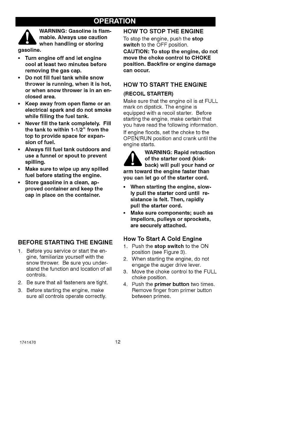
1. Make sure the unit is level.
2. Remove the oil fill cap/dipstick and
fill the crank case to "FULL" line on
dipstick. DO NOT overfill. See
Figure 6,
3. Tighten the fill cap/dipstick securely
each time you check the oil level.
NOTE: Synthetic oil can assist with
starting in extreme cold temperatures.
Synthetic 5W30 is acceptable for all
temperatures. DO NOT mix oil with
gasoline.
011 Fill Cap/Dipstick
NOTE: Oil level must be at FULL mark.
Figure 6
FILL GAS:
This engine is certified to operate on
gasoline. Exhaust Emission Control
System: EM (Engine Modifications).
,_ WARNING: Alcohol blended
fuels (called gasohol or
those using ethanol or
methanol) can attract moisture
which leads to separation and
formation of acids during storage.
Acidic gas can damage the fuel sys-
tem of an engine while in storage.
NOTE: To avoid engine problems, the
fuel system must be emptied before
storage for 30 days or longer. Start the
engine and let it run until the fuel lines
and carburetor are empty. Use fresh
fuel next season. See the Storage
section in this manual for additional in-
formation.
Never use engine or carburetor cleaner
products in the fuel tank or permanent
damage may occur.
1. Fill the fuel tank only with a fresh,
clean, unleaded regular, unleaded
premium, or reformulated automo-
tive gasoline with a minimum of 85
octane. DO NOT use leaded gaso-
line. We recommend that you add
fuel stabilizer to the gasoline. Use
the fuel stabilizer supplied with the
unit or purchase Craftsman Fuel
Stabilizer No. 3550. Make sure that
the container you pour the gasoline
from is clean and free from rust or
other foreign particles. Never use
gasoline that may be stale from long
periods of storage in the container.
1741476 11
[o_o_l
_ARNING: Gasoline is flam-
mable. Always use caution
when handling or storing
gasoline.
•Turn engine off and let engine
cool at least two minutes before
removing the gas cap.
•Do not fill fuel tank while snow
thrower is running, when it is hot,
or when snow thrower is in an en-
closed area.
•Keep away from open flame or an
electrical spark and do not smoke
while filling the fuel tank.
•Never fill the tank completely. Fill
the tank to within 1-1/2" from the
top to provide space for expan-
sion of fuel.
•Always fill fuel tank outdoors and
use a funnel or spout to prevent
spilling.
•Make sure to wipe up any spilled
fuel before stating the engine.
•Store gasoline in a clean, ap-
proved container and keep the
cap in place on the container.
BEFORE STARTING THE ENGINE
1. Before you service or start the en-
gine, familiarize yourself with the
snow thrower. Be sure you under-
stand the function and location of all
controls.
2. Be sure that all fasteners are tight.
3. Before starting the engine, make
sure all controls operate correctly.
HOW TO STOP THE ENGINE
To stop the engine, push the stop
switch to the OFF position.
CAUTION: To stop the engine, do not
move the choke control to CHOKE
position. Backfire or engine damage
can occur.
HOW TO START THE ENGINE
(RECOIL STARTER)
Make sure that the engine oil is at FULL
mark on dipstick. The engine is
equipped with a recoil starter. Before
starting the engine, make certain that
you have read the following information.
If engine floods, set the choke to the
OPEN/RUN position and crank until the
engine starts.
_b ARNING: Rapid retraction
of the starter cord (kick-
back) will pull your hand or
arm toward the engine faster than
you can let go of the starter cord.
•When starting the engine, slow-
ly pull the starter cord until re-
sistance is felt. Then, rapidly
pull the starter cord.
•Make sure components; such as
impellors, pulleys or sprockets,
are securely attached.
How To Start A Cold Engine
1. Push the stop switch to the ON
position (see Figure 3).
2. When starting the engine, do not
engage the auger drive lever.
3. Move the choke control to the FULL
choke position.
4. Push the primer button two times.
Remove finger from primer button
between primes.
1741476 12
[o_o_l
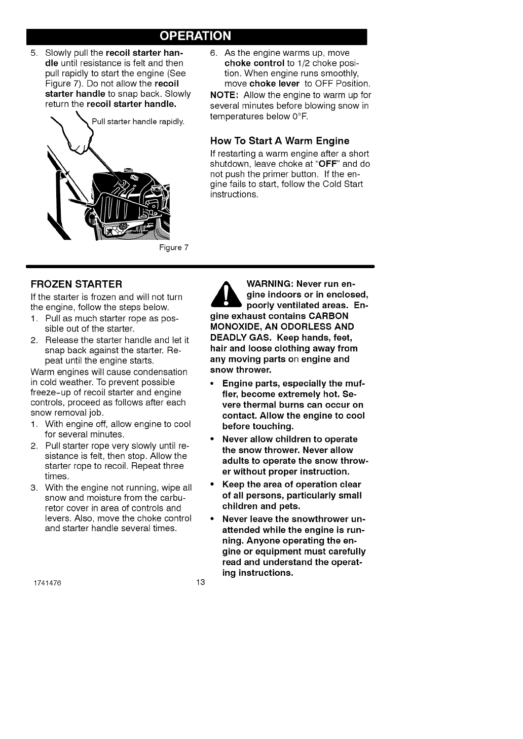
5. Slowly pull the recoil starter han-
dle until resistance is felt and then
pull rapidly to start the engine (See
Figure 7). Do not allow the recoil
starter handle to snap back. Slowly
return the recoil starter handle.
Pull starter handle rapidly.
6. As the engine warms up, move
choke control to 1/2 choke posi-
tion. When engine runs smoothly,
move choke lever to OFF Position.
NOTE: Allow the engine to warm up for
several minutes before blowing snow in
temperatures below 0°F.
How To Start A Warm Engine
If restarting a warm engine after a short
shutdown, leave choke at "OFF" and do
not push the primer button. If the en-
gine fails to start, follow the Cold Start
instructions.
Figure 7
FROZEN STARTER
If the starter is frozen and will not turn
the engine, follow the steps below.
1. Pull as much starter rope as pos-
sible out of the starter.
2. Release the starter handle and let it
snap back against the starter. Re-
peat until the engine starts.
Warm engines will cause condensation
in cold weather. To prevent possible
freeze-up of recoil starter and engine
controls, proceed as follows after each
snow removal job.
1. With engine off, allow engine to cool
for several minutes.
2. Pull starter rope very slowly until re-
sistance is felt, then stop. Allow the
starter rope to recoil. Repeat three
times.
3. With the engine not running, wipe all
snow and moisture from the carbu-
retor cover in area of controls and
levers. Also, move the choke control
and starter handle several times.
1741476 13
_ARNING: Never run en-
gine indoors or in enclosed,
poorly ventilated areas. En-
gine exhaust contains CARBON
MONOXIDE, AN ODORLESS AND
DEADLY GAS. Keep hands, feet,
hair and loose clothing away from
any moving parts on engine and
snow thrower.
• Engine parts, especially the muf-
tier, become extremely hot. Se-
vere thermal burns can occur on
contact. Allow the engine to cool
before touching.
•Never allow children to operate
the snow thrower. Never allow
adults to operate the snow throw-
er without proper instruction.
•Keep the area of operation clear
of all persons, particularly small
children and pets.
•Never leave the snowthrower un-
attended while the engine is run-
ning. Anyone operating the en-
gine or equipment must carefully
read and understand the operat-
ing instructions.
HOW TO CLEAR
ACLOGGED DISCHARGE CHUTE
,_ WARNING: Hand contact
with the rotating impeller in-
side the discharge chute is
the most common cause of injury as-
sociated with snow throwers. Never
use your hand to clean out the dis-
charge chute.
To Clear The Chute:
•SHUT OFF THE ENGINE!
•Wait 10 seconds to be sure that the
impeller blades have stopped ro-
tating.
•Always use a clean-out tool, not
your hands.
Use a clean-out tool to remove snow
from the auger housing.
• Release the auger drive lever.
• Pull out the key.
• Disconnect spark plug wire.
• Do not place your hands in the au-
ger or discharge chute. Use a
clean-out tool to remove snow or
debris.
,_ WARNING: Blockage must
be cleared only after shut-
ting off the snow thrower
and only with a clean-out tool, not
by hand.
SNOW THROWING TIPS
1. When the handle is raised, the au-
ger blades will engage the ground
and the snow thrower will move for-
ward. When the auger drive lever is
released, the auger blades will stop.
If the blades do not stop, see "How
To Adjust The Auger Drive Cable" in
the Service And Adjustment section.
2. Most efficient snow throwing is ac-
complished when the snow is re-
moved immediately after if falls.
3. For complete snow removal, slightly
overlap each previous path.
4. Whenever possible, discharge the
snow down wind.
5.
6.
The distance the snow will be dis-
charged can be adjusted by moving
the discharge chute deflector. Raise
the deflector for more distance or
lower the deflector for less distance.
In windy conditions, lower the chute
deflector to direct the discharged
snow close to the ground where it is
less likely to blow into unwanted
areas.
7. For safety and to prevent damage
to the snow thrower, keep the area
to be cleared free of stones, toys 2.
and other foreign objects.
1741476 14
8. When clearing snow from crushed
rock or gravel driveways, do not al-
low the auger blades to contact the
driveway. Move the handle down to
slightly raise the auger blades.
9. The forward speed of the snow
thrower is dependent on the depth
and weight of the snow. Experience
will establish the most effective
method of using the snow thrower
under different conditions.
10. After each snow throwing job, allow
the engine to run for a few minutes.
The snow and accumulated ice will
melt off the engine.
11. Clean the snow thrower after each
use.
12. Remove ice, snow and debris from
the entire snow thrower. Flush with
water to remove all salt or other
chemicals. Wipe snow thrower dry.
DRY AND AVERAGE SNOW
1. Snow up to eight inches deep can
be removed rapidly and easily by
walking at a moderate rate. For
snow or drifts of a greater depth,
slow your pace to allow the dis-
charge chute to dispose of the snow
as rapidly as the auger receives the
snow.
Plan to have the snow discharged in
the direction the wind is blowing.
[o_o_l
WET PACKED SNOW
Move slowly into wet, packed snow. If
the wet, packed snow causes the auger
to slow down or the discharge chute be-
gins to clog, back off and begin a series
of short back and forth jabs into the
snow. These short back and forth jabs,
four to six inches, will "belch" the snow
from the chute.
SNOW BANKS AND DRIFTS
In snow of greater depth than the unit,
use the same "jabbing" technique de-
scribed above. Turn the discharge
chute away from the snow bank. More
time will be required to remove snow of
this type than level snow.
1741476 15
CUSTOMER RESPONSIBILITIES
SERVICERECORDS
Fillindatesas you Before Every Every Every Every
completeregular Each 8 25 50 100 Each Before
service. Use Often Hours Hours Hours Hours Season Storage
Check Engine Oil Level
Change Engine Oil Vr
I I I
Tighten All Screws and II I I I I
Nuts
Check and Clean Spark Vr
Plug
Clean and Inspect Vr
Spark Arrestor
I I I I I
Lubr cate Chute Contro !/
Flange I I I I I I I I
Check Fuel V r
Auger Drive Belt * Vr
*Adjust after 2 to 4 hours of use.
GENERAL RECOMMENDATIONS
The warranty on this snow thrower does
not cover items that have been sub-
jected to operator abuse or negligence.
To receive full value from the warranty,
the operator must maintain the snow
thrower as instructed in this manual.
Some adjustments will need to be
made periodically to properly maintain
your snow thrower.
EMISSIONS CONTROL
Maintenance, replacement, or repair of the
emission control devices and systems can
be performed by any non-road engine re-
pair establishment or individual. Regular
maintenance will improve the performance
and extend the life of the engine.
•To prevent freezing of the auger or
controls, remove all snow and slush
from the snow thrower.
• Check for loose or damaged parts.
• Tighten any loose fasteners.
• Check and maintain the auger.
• Check controls to make sure they
are functioning properly.
• If any parts are worn or damaged,
replace immediately.
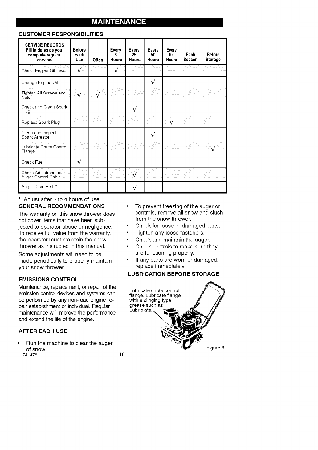
LUBRICATION BEFORE STORAGE
Lubricate chute control
flange. Lubricate flange
with a clinging type
grease such as
Lubriplate. _
AFTER EACH USE
• Run the machine to clear the auger
of snow.
1741476 16
Figure 8
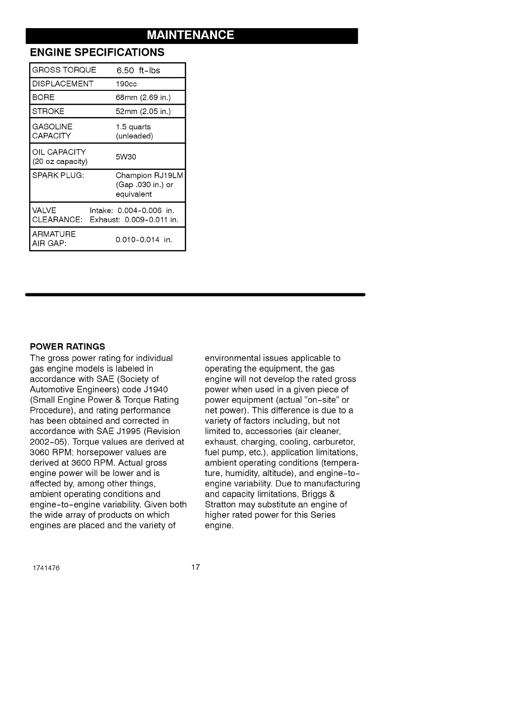
ENGINE SPECIFICATIONS
GROSS TORQUE 6.50 ft-lbs
DISPLACEMENT 190cc
BORE 68mm (2.69 in.)
STROKE 52mm (2.05 in.)
GASOLINE 1.5 quarts
CAPACITY (unleaded)
OIL CAPACITY 5W30
(20 oz capacity)
SPARK PLUG: Champion RJ19LM
(Gap .030 in.) or
equivalent
VALVE Intake: 0.004-0.006 in.
CLEARANCE: Exhaust: 0.009-0.011 in.
ARMATURE
AIR GAP: 0.010-0.014 in.
POWER RATINGS
The gross power rating for individual
gas engine models is labeled in
accordance with SAE (Society of
Automotive Engineers) code J1940
(Small Engine Power & Torque Rating
Procedure), and rating performance
has been obtained and corrected in
accordance with SAE J1995 (Revision
2002-05). Torque values are derived at
3060 RPM; horsepower values are
derived at 3600 RPM. Actual gross
engine power will be lower and is
affected by, among other things,
ambient operating conditions and
engine-to-engine variability. Given both
the wide array of products on which
engines are placed and the variety of
environmental issues applicable to
operating the equipment, the gas
engine will not develop the rated gross
power when used in a given piece of
power equipment (actual "on-site" or
net power). This difference is due to a
variety of factors including, but not
limited to, accessories (air cleaner,
exhaust, charging, cooling, carburetor,
fuel pump, etc.), application limitations,
ambient operating conditions (tempera-
ture, humidity, altitude), and engine-to-
engine variability. Due to manufacturing
and capacity limitations, Briggs &
Stratton may substitute an engine of
higher rated power for this Series
engine.
1741476 17
ENGINE
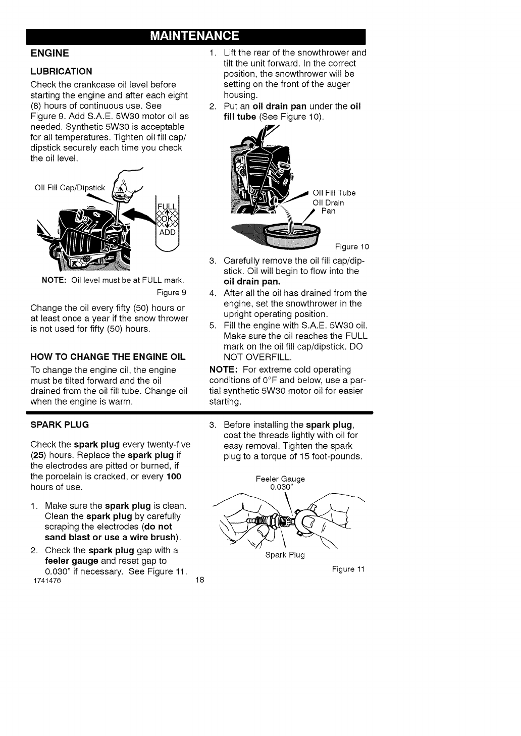
LUBRICATION
Check the crankcase oil level before
starting the engine and after each eight
(8) hours of continuous use. See
Figure 9. Add S.A.E. 5W30 motor oil as
needed. Synthetic 5W30 is acceptable
for all temperatures. Tighten oil fill cap/
dipstick securely each time you check
the oil level.
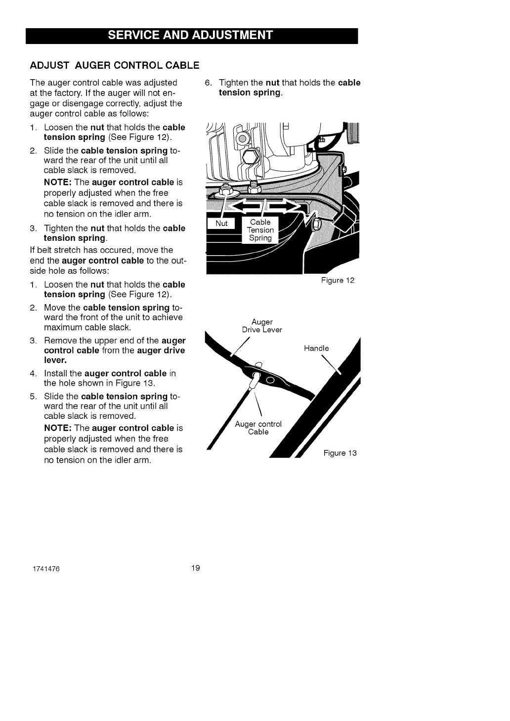
1. Lift the rear of the snowthrower and
tilt the unit forward. In the correct
position, the snowthrower will be
setting on the front of the auger
housing.
2. Put an oil drain pan under the oil
fill tube (See Figure 10).
OII Fill Cap/Dipstick
NOTE: Oil level must be at FULL mark.
Figure 9
Change the oil every fifty (50) hours or
at least once a year if the snow thrower
is not used for fifty (50) hours.
HOW TO CHANGE THE ENGINE OIL
To change the engine oil, the engine
must be tilted forward and the oil
drained from the oil fill tube. Change oil
when the engine is warm.
OII Fill Tube
OII Drain
Pan
Figure 10
3. Carefully remove the oil fill cap/dip-
stick. Oil will begin to flow into the
oil drain pan,
4. After all the oil has drained from the
engine, set the snowthrower in the
upright operating position.
5. Fill the engine with S.A.E. 5W30 oil.
Make sure the oil reaches the FULL
mark on the oil fill cap/dipstick. DO
NOT OVERFILL.
NOTE: For extreme cold operating
conditions of 0°F and below, use a par-
tial synthetic 5W30 motor oil for easier
starting.
SPARK PLUG
Check the spark plug every twenty-five
(25) hours. Replace the spark plug if
the electrodes are pitted or burned, if
the porcelain is cracked, or every 100
hours of use.
1. Make sure the spark plug is clean.
Clean the spark plug by carefully
scraping the electrodes (do not
sand blast or use a wire brush).
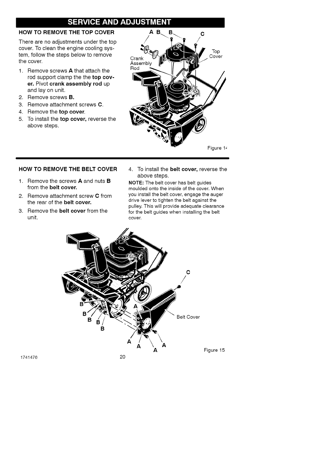
2. Check the spark plug gap with a
feeler gauge and reset gap to
0.030" if necessary. See Figure 11.
1741476
3.
18
Before installing the spark plug,
coat the threads lightly with oil for
easy removal. Tighten the spark
plug to a torque of 15 foot-pounds.
Feeler Gauge
0.030"
Spark Plug
Figure 11
ADJUST AUGER CONTROL CABLE
The auger control cable was adjusted
at the factory. If the auger will not en-
gage or disengage correctly, adjust the
auger control cable as follows:
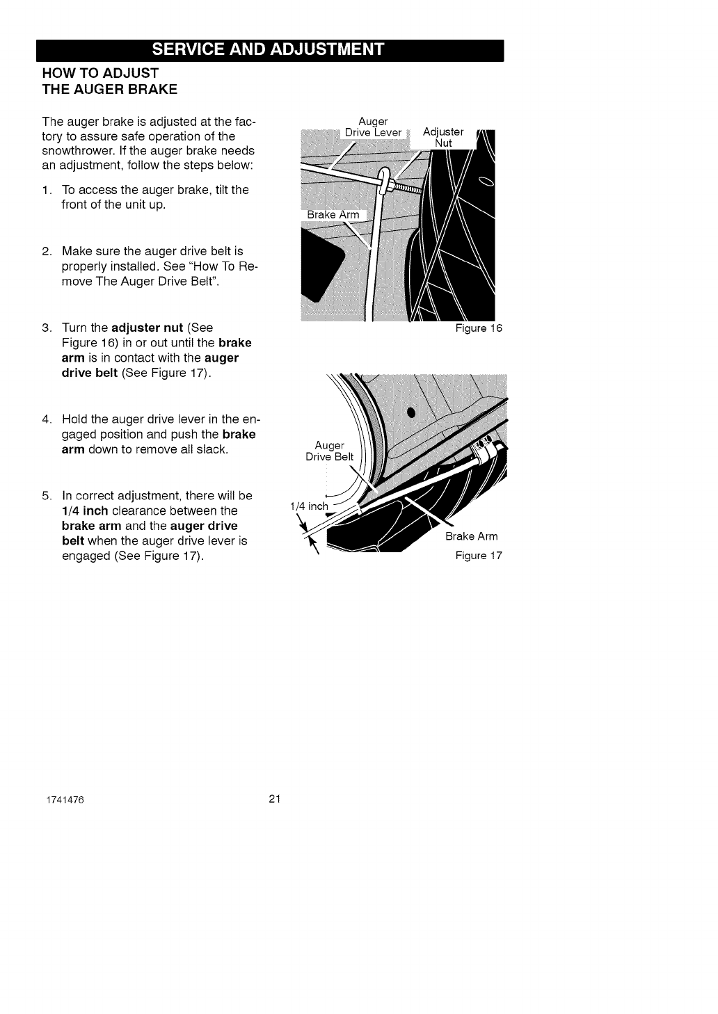
1. Loosen the nut that holds the cable
tension spring (See Figure 12).
2. Slide the cable tension spring to-
ward the rear of the unit until all
cable slack is removed.
NOTE: The auger control cable is
properly adjusted when the free
cable slack is removed and there is
no tension on the idler arm.
3. Tighten the nut that holds the cable
tension spring.
If belt stretch has occured, move the
end the auger control cable to the out-
side hole as follows:
1. Loosen the nut that holds the cable
tension spring (See Figure 12).
2. Move the cable tension spring to-
ward the front of the unit to achieve
maximum cable slack.
3. Remove the upper end of the auger
control cable from the auger drive
lever.
4. Install the auger control cable in
the hole shown in Figure 13.
5. Slide the cable tension spring to-
ward the rear of the unit until all
cable slack is removed.
NOTE: The auger control cable is
properly adjusted when the free
cable slack is removed and there is
no tension on the idler arm.
6. Tighten the nut that holds the cable
tension spring.
Spring
Auger
Drive Lever
Figure 12
Handle
Auger control
Cable
Figure 13
1741476 19
HOW TO REMOVE THE TOP COVER
There are no adjustments under the top
cover. To clean the engine cooling sys-
tem, follow the steps below to remove
the cover.
1. Remove screws Athat attach the
rod support clamp the the top cov-
er. Pivot crank assembly rod up
and lay on unit.
2. Remove screws B.
3. Remove attachment screws C.
4. Remove the top cover.
5. To install the top cover, reverse the
above steps.
AC
/ /
Crank
Assembly
Rod
Top
Cover
Figure 1L
HOW TO REMOVE THE BELT COVER
1. Remove the screws Aand nuts B
from the belt cover,
2. Remove attachment screw C from
the rear of the belt cover,
3. Remove the belt cover from the
unit.
4. To install the belt cover, reverse the
above steps.
NOTE: The belt cover has belt guides
moulded onto the inside of the cover. When
you install the belt cover, engage the auger
drive lever to tighten the belt against the
pulley. This will provide adequate clearance
for the belt guides when installing the belt
cover.
C
/
1741476
B
B
A
20
Belt Cover
A A
AFigure 15
HOW TO ADJUST
THE AUGER BRAKE
The auger brake is adjusted at the fac-
tory to assure safe operation of the
snowthrower. If the auger brake needs
an adjustment, follow the steps below:
1. To access the auger brake, tilt the
front of the unit up.
2. Make sure the auger drive belt is
properly installed. See "How To Re-
move The Auger Drive Belt".
Auger
Drive Lever
Brake Arm
Adjuster
Nut
3. Turn the adjuster nut (See
Figure 16) in or out until the brake
arm is in contact with the auger
drive belt (See Figure 17).
Figure 16
4. Hold the auger drive lever in the en-
gaged position and push the brake
arm down to remove all slack. Auger
Drive Belt
5. In correct adjustment, there will be
1/4 inch clearance between the
brake arm and the auger drive
belt when the auger drive lever is
engaged (See Figure 17).
1/4 inch
Brake Arm
Figure 17
1741476 21
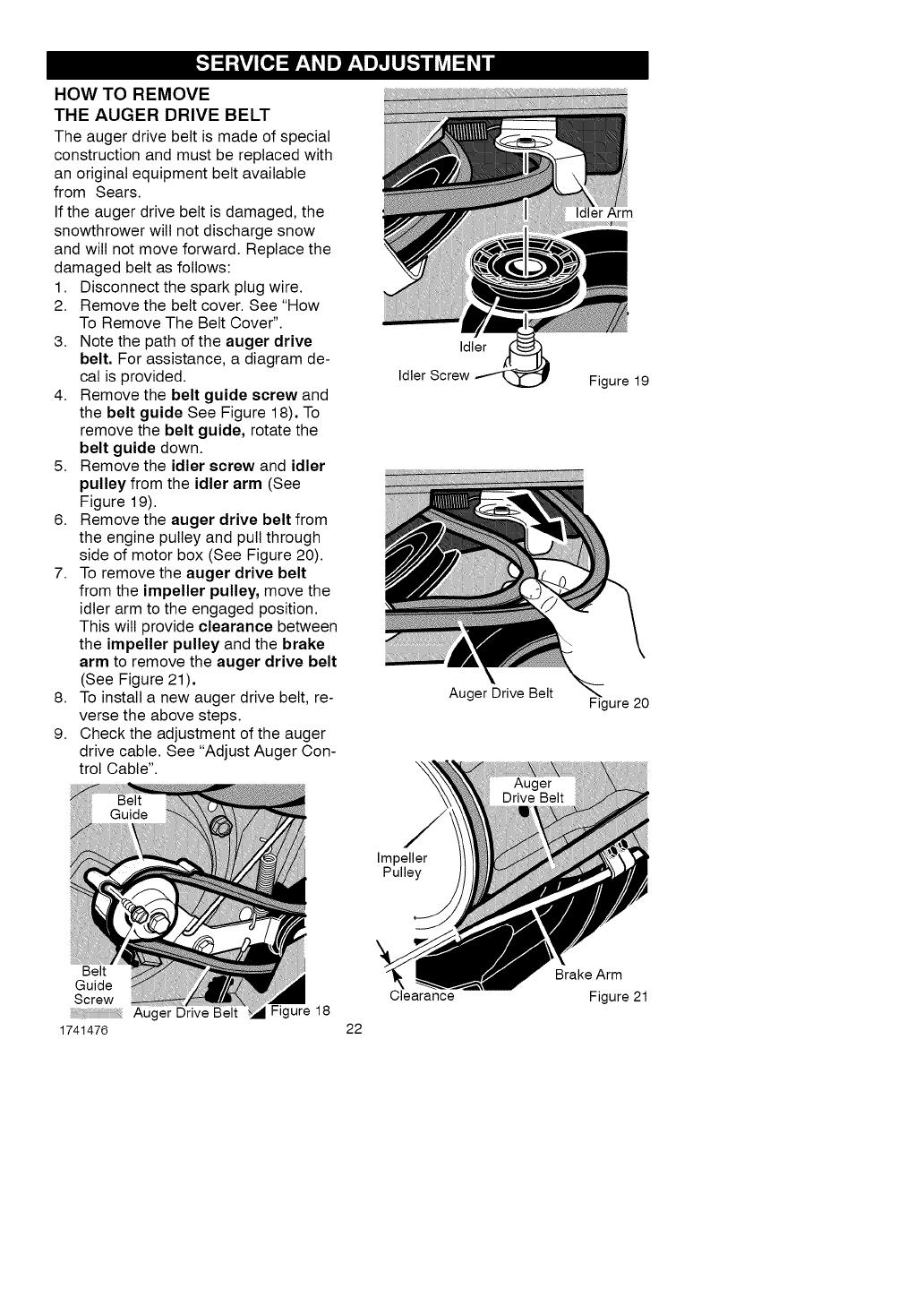
HOW TO REMOVE
THE AUGER DRIVE BELT
The auger drive belt is made of special
construction and must be replaced with
an original equipment belt available
from Sears.
If the auger drive belt is damaged, the
snowthrower will not discharge snow
and will not move forward. Replace the
damaged belt as follows:
1. Disconnect the spark plug wire.
2. Remove the belt cover. See "How
To Remove The Belt Cover".
3. Note the path of the auger drive
belt. For assistance, a diagram de-
cal is provided.
4. Remove the belt guide screw and
the belt guide See Figure 18). To
remove the belt guide, rotate the
belt guide down.
5. Remove the idler screw and idler
pulley from the idler arm (See
Figure 19).
6. Remove the auger drive belt from
the engine pulley and pull through
side of motor box (See Figure 20).
7. To remove the auger drive belt
from the impeller pulley, move the
idler arm to the engaged position.
This will provide clearance between
the impeller pulley and the brake
arm to remove the auger drive belt
(See Figure 21).
8. To install a new auger drive belt, re-
verse the above steps.
9. Check the adjustment of the auger
drive cable. See "Adjust Auger Con-
trol Cable".
Idler
Idler Screw
Auger Drive Belt
Idler Arm
Figure 19
Figure 20
Impeller
Pulley
Belt
Guide
Screw
Auger Drive Belt
1741476
Figure 18
Clearance
22
Brake Arm
Figure 21
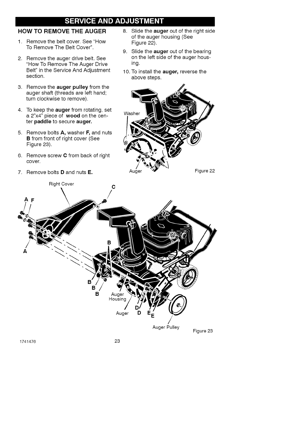
HOW TO REMOVE THE AUGER
1. Remove the belt cover. See "How
To Remove The Belt Cover".
2. Remove the auger drive belt. See
"How To Remove The Auger Drive
Belt" in the Service And Adjustment
section.
3.
4.
5.
Remove the auger pulley from the
auger shaft (threads are left hand;
turn clockwise to remove).
To keep the auger from rotating, set
a 2"x4" piece of wood on the cen-
ter paddle to secure auger.
Remove bolts A, washer F, and nuts
Bfrom front of right cover (See
Figure 23).
6. Remove screw C from back of right
cover.
8.
9.
Slide the auger out of the right side
of the auger housing (See
Figure 22).
Slide the auger out of the bearing
on the left side of the auger hous-
ing.
10. To install the auger, reverse the
above steps.
Washer
7. Remove bolts D and nuts E, Auger Figure 22
AF
/
Right Cover C
A
BBBAuger
Housing
Auger D EE
Auger Pulley Figure 23
1741476 23
,_ WARNING: Never store your
snow thrower with gasoline
in the fuel tank indoors or in
an enclosed, poorly ventilated area.
If gasoline remains in the tank,
fumes may reach an open flame,
spark or pilot light from a furnace,
water heater, clothes dryer, ciga-
rette, etc.
To prevent damage (if snow thrower is
not used for more than 30 days) follow
the steps below.
SNOW THROWER
1. Thoroughly clean the snow thrower.
2. Lubricate all lubrication points. See
the Maintenance section.
3. Be sure that all nuts, bolts and
screws are securely fastened. In-
spect all visible moving parts for
damage, breakage and wear. Re-
place if necessary.
4. Touch up all rusted or chipped paint
surfaces; sand lightly before paint-
ing.
5. Cover the bare metal parts of the
blower housing auger and the im-
peller with rust preventative, such
as a spray lubricant.
NOTE: A yearly checkup or tune-up by
a Sears service center is a good way of
ensuring that your snow thrower will
provide maximum performance for the
next season.
ENGINE
Gasoline must be removed or treated to
prevent gum deposits from forming in
the fuel tank, filter, hose, and carburetor
during storage. Also, during storage al-
cohol blended gasoline that uses etha-
nol or methanol (sometimes called
gasohol) attracts water. It acts on the
gasoline to form acids which damage
the engine.
1741476 24
1. Run the engine until the fuel tank is
empty and the engine stops.
2. If you do not remove the gasoline,
use fuel stabilizer supplied with unit
or purchase Craftsman Fuel Stabi-
lizer No. 3550. Add fuel stabilizer to
any gasoline left in the tank to mini-
mize gum deposits and acids. If the
fuel tank is almost empty, mix stabi-
lizer with fresh gasoline in a sepa-
rate container and add some to the
fuel tank.
3. Always follow the instructions on the
stabilizer container. After the stabi-
lizer is added to the fuel tank, run
the engine at least ten minutes to
allow the mixture to reach the car-
buretor.
4. While the engine oil is warm,
change the engine oil.
5. Remove the spark plug and pour
about 15 ml (1/2 oz) of engine oil
into the cylinder. Replace the spark
plug and crank slowly to distribute
the oil.
,_ WARNING: Do not crank en-
gine with spark plug re-
moved.
6. Store in a clean and dry area, but
NOT near a stove, furnace or water
heater which uses a pilot light or
any device that can create a spark.
OTHER
1. If possible, store your snow thrower
indoors and cover it to give protec-
tion from dust and dirt.
2. If the snow thrower must be stored
outdoors, put the snow thrower on
blocks to raise it off of the ground.
3. Cover the snow thrower with a suit-
able protective cover that does not
retain moisture. Do not use plastic.
IMPORTANT: Never cover snow
thrower while engine and exhaust areas
are still warm.
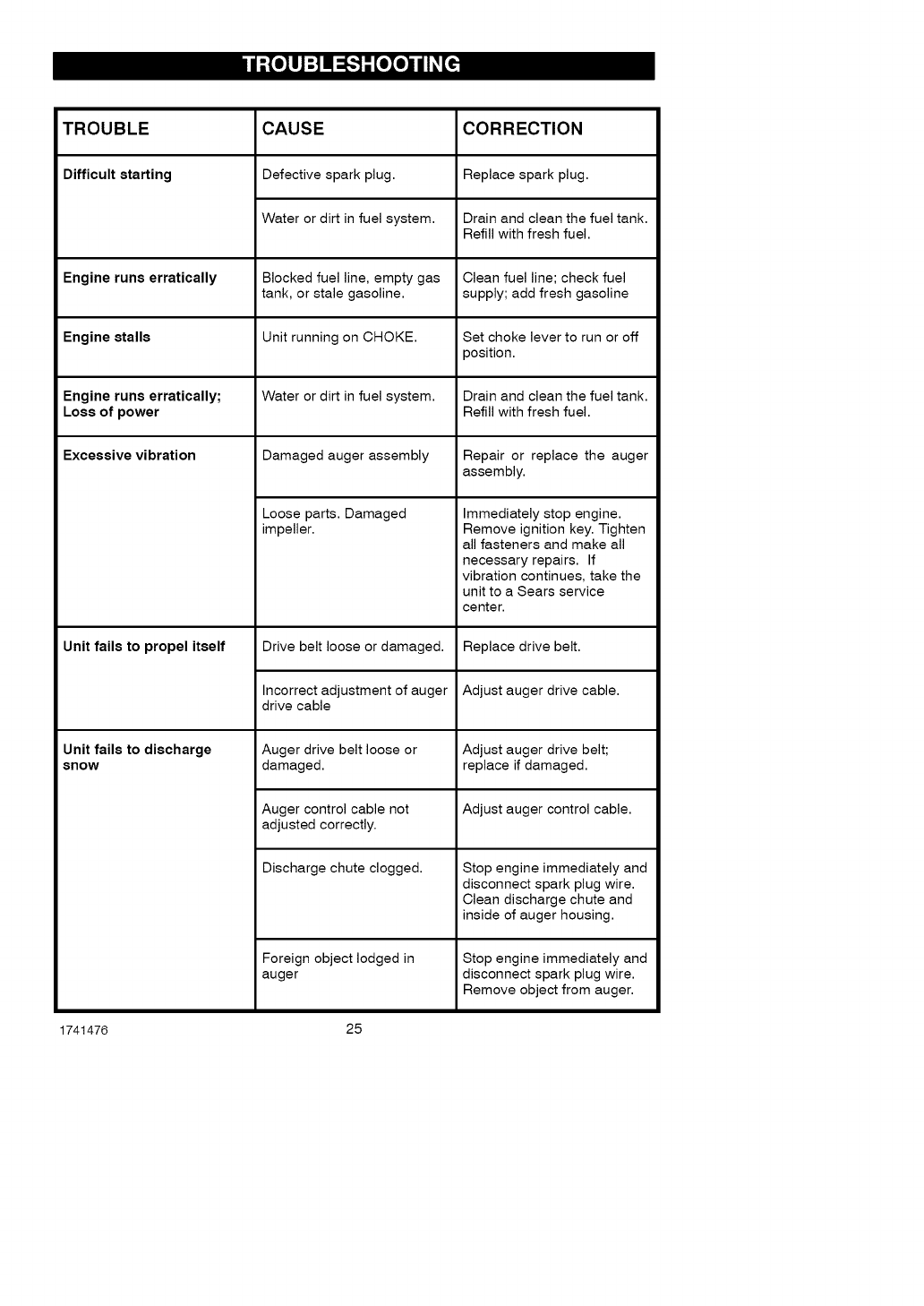
TROUBLE CORRECTION
Difficult starting Replace spark plug.
CAUSE
Defective spark plug.
Water or dirt in fuel system. Drain and clean the fuel tank.
Refill with fresh fuel.
Engine runs erratically Blocked fuel line, empty gas Clean fuel line; check fuel
tank, or stale gasoline, supply; add fresh gasoline
Engine stalls Unit running on CHOKE. Set choke lever to run or off
position.
Engine runs erratically; Water or dirt in fuel system. Drain and clean the fuel tank.
Loss of power Refill with fresh fuel.
Excessive vibration Damaged auger assembly
Unit fails to propel itself
Loose parts. Damaged
impeller.
Drive belt loose or damaged.
Incorrect adjustment of auger
drive cable
Auger drive belt loose or
damaged.
Auger control cable not
adjusted correctly.
Discharge chute clogged.
Foreign object lodged in
auger
Unit fails to discharge
snow
Repair or replace the auger
assembly.
Immediately stop engine.
Remove ignition key. Tighten
all fasteners and make all
necessary repairs. If
vibration continues, take the
unit to a Sears service
center.
Replace drive belt.
Adjust auger drive cable.
Adjust auger drive belt;
replace if damaged.
Adjust auger control cable.
Stop engine immediately and
disconnect spark plug wire.
Clean discharge chute and
inside of auger housing.
Stop engine immediately and
disconnect spark plug wire.
Remove object from auger.
1741476 25
(This page applicable in the U.S.A. and Canada only.)
Sears, Roebuck and Co., U.S.A. (Sears), the California Air Resources Board
(CARB) and the United States Environmental Protection Agency (U.S. EPA)
Emission Control System Warranty Statement
(Owner's Defect Warranty Rights and Obligations)
The California Air Resources Board
(CARB), U.S. EPA and Sears are pleased
to explain the Emission Control System
Warranty on your small off-road engine
(SORE). In California, new small off-road
engines model year 2006 and later must
be designed, built and equipped to meet
the State's stringent anti-smog standards.
Elsewhere in the United States, new
non-road, spark-ignition engines certified
for model year 1997 and later must meet
similar standards set forth by the U.S. EPA.
Sears must warrant the emission control
system on your engine for the periods of
time listed below, provided there has been
no abuse, neglect or improper
maintenance of your small off-road engine.
Your emission control system includes
parts such as the carburetor, air cleaner,
ignition system, fuel line, muffler and
catalytic converter. Also included may be
connectors and other emission related
assemblies.
Where a warrantable condition exists,
Sears will repair your small off-road
engine at no cost to you including
diagnosis, parts and labor.
Sears, Roebuck and Co. Emission Control Defects Warranty Coverage
Small off-road engines are warranted
relative to emission control parts defects
for a period of two years, subject to
provisions set forth below. If any covered
part on your engine is defective, the part
wilt be repaired or replaced by Sears.
Owner's Warranty
As the small off-road engine owner, you
are responsible for the performance of
the required maintenance listed in your
Operating and Maintenance Instructions.
Sears recommends that you retain all
your receipts covering maintenance on
your small off-road engine, but Sears
cannot deny warranty solely for the lack
of receipts or for your failure to ensure the
performance of all scheduled
maintenance.
As the small off-road engine owner, you
should however be aware that Sears may
deny you warranty coverage if your small
off-road engine or a part has failed due to
abuse, neglect, improper maintenance or
Responsibilities
unapproved modifications.
You are responsible for presenting your
small off-road engine to an Authorized
Sears Service Dealer as soon as a
problem exists.
The undisputed warranty repairs should
be completed in a reasonable amount of
time, not to exceed 30 days.
If you have any questions regarding your
warranty rights and responsibilities, you
should contact a Sears Service
Representative at 1-800-469-4663.
The emission warranty is a defects
warranty. Defects are judged on normal
engine performance. The warranty is not
related to an in-use emission test.
1741476 26
Sears, Roebuck and Co. Emission Control Defects Warranty Provisions
The following are specific provisions relative to your Emission Control Defects Warranty
Coverage. It is inaddition to the Sears engine warranty for non-regulated engines found
in the Operating and Maintenance Instructions.
1. Warranted Parts
Coverage under this warranty ex-
tends only to the parts listed below
(the emission control systems parts)
to the extent these parts were pres-
ent on the engine purchased.
a. Fuel Metering System
•Cold start enrichment system
• Carburetor and internal parts
• Fuel Pump
• Fuel line, fuel line fittings, 4.
clamps
• Fuel tank, cap and tether
• Carbon canister
b. Air Induction System
• Air cleaner
• Intake manifold
• Purge and vent line
c. Ignition System
• Spark plug(s)
• Magneto ignition system
d. Catalyst System 5.
• Catalytic converter
• Exhaust manifold
• Air injection system, Pulse
valve
e. Miscellaneous Items
• Vacuum, temperature, posi-
tion, time sensitive valves and
switches
• Connectors and assemblies
2. Length of Coverage
Sears warrants to the initial owner
and each subsequent purchaser that
the Warranted Parts shall be free from
defects inmaterials and workmanship
which caused the failure of the War-
ranted Parts for a period of two years
from the date the engine is delivered
to a retail purchaser.
mination that a Warranted Part is
defective, if the diagnostic work is
performed at an Authorized Sears
Service Dealer. For emissions war-
ranty service contact your nearest
Authorized Sears Service Dealer as
listed in the "Yellow Pages" under
"Engines, Gasoline," "Gasoline En-
gines," "Lawn Mowers," or similar
category.
Claims and Coverage Exclusions
Warranty claims shall be filed in ac-
cordance with the provisions of the
Sears Engine Warranty Policy. War-
ranty coverage shall be excluded for
failures of Warranted Parts which are
not original Sears parts or because of
abuse, neglect or improper mainte-
nance as set forth in the Sears En-
gine Warranty Policy. Sears is not
liable to cover failures of Warranted
Parts caused by the use of add-on,
non-original, or modified parts.
Maintenance
Any Warranted Part which is not
scheduled for replacement as re-
quired maintenance or which is
scheduled only for regular inspection
to the effect of "repair or replace as
necessary" shall be warranted as to
defects for the warranty period. Any
Warranted Part which is scheduled for
replacement as required mainte-
nance shall be warranted as to de-
fects only for the period of time up to
the first scheduled replacement for
that part. Any replacement part that is
equivalent in performance and dura-
bility may be used in the performance
of any maintenance or repairs. The
owner is responsible for the perfor-
mance of all required maintenance,
as defined inthe Sears Operating and
Maintenance Instructions.
3. No Charge 6.
Repair or replacement of any War-
ranted Part will be performed at no
charge to the owner, including diag-
nostic labor which leads to the deter-
1741476 27
Consequential Coverage
Coverage hereunder shall extend to
the failure of any engine components
caused by the failure of any War-
ranted Part still under warranty.
Look For Relevant Emissions Durability Period and Air
Index Information On Your Engine Emission Label
Engines that are certified to meet the California Air Resources Board (CARB) Tier 2
Emission Standards must display information regarding the Emissions Durability Pe-
riod and the Air Index. Sears, Roebuck and Co., U.S.A. makes this information avail-
able to the consumer on our emission labels. The engine emission label will indicate
certification information.
The Emissions Durability Period describes the number of hours of actual running
time for which the engine is certified to be emissions compliant, assuming proper
maintenance in accordance with the Operating & Maintenance Instructions. The fol-
lowing categories are used:
Moderate: Engine is certified to be emission compliant for 125 hours of actual engine
running time.
Intermediate: Engine is certified to be emission compliant for 250 hours of actual en-
gine running time.
Extended: Engine is certified to be emission compliant for 500 hours of actual engine
running time.
For example, a typical walk-behind lawn mower is used 20 to 25 hours per year.
Therefore, the Emissions Durability Period of an engine with an intermediate
rating would equate to 10 to 12 years.
Certain Sears, Roebuck and Co., U.S.A. engines will be certified to meet the United
States Environmental Protection Agency (USEPA) Phase 2 emission standards. For
Phase 2 certified engines, the Emissions Compliance Period referred to on the Emissions
Compliance label indicates the number of operating hours for which the engine has been
shown to meet Federal emission requirements.
Engines that are certified to meet the California Air Resources Board (CARB) Tier 2
Emissions Standard must display information regarding the Emissions Durability
Period and the Air Index. Sears, Roebuck and Co., U.S.A. makes this information
available to the consumer on our emissions labels. The engine emissions label will
indicate certification information.
For engines less than 225 cc displacement.
Category C = 125 hours
Category B = 250 hours
Category A = 500 hours
For engines of 225 cc or more displacement.
Category C = 250 hours
Category B = 500 hours
Category A = 1000 hours
1741476 28
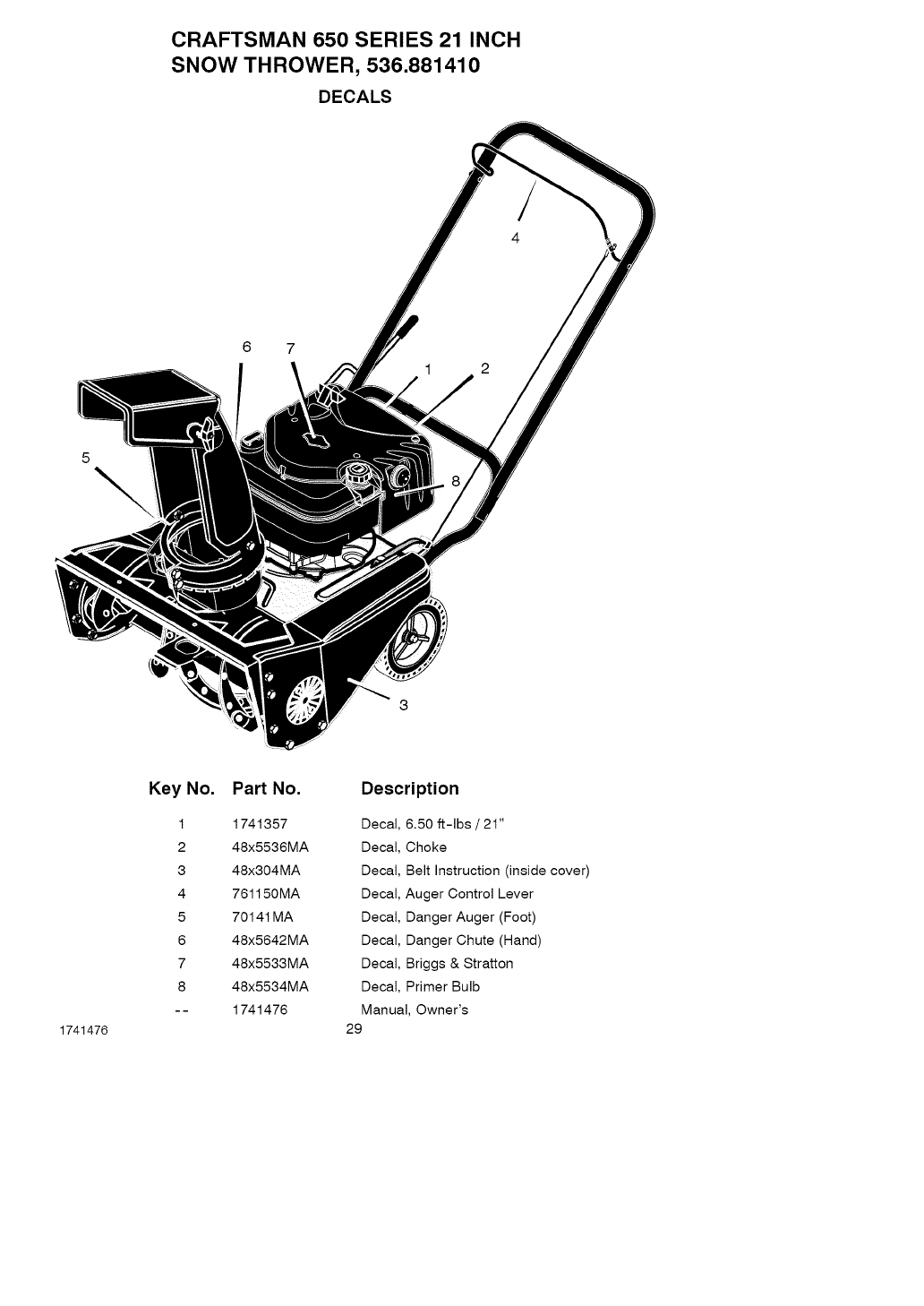
CRAFTSMAN 650 SERIES 21 INCH
SNOW THROWER, 536.881410
DECALS
5\
1741476
Key No. Part No. Description
1 1741357 Decal, 6.50 ft-lbs /21"
2 48x5536MA Decal, Choke
3 48x304MA Decal, Belt Instruction (inside cover)
4 761150MA Decal, Auger Control Lever
5 7014t MA Decal, Danger Auger (Foot)
6 48x5642MA Decal, Danger Chute (Hand)
7 48x5533MA Decal, Briggs & Stratton
8 48x5534MA Decal, Primer Bulb
-- 1741476 Manual, Owner's
29
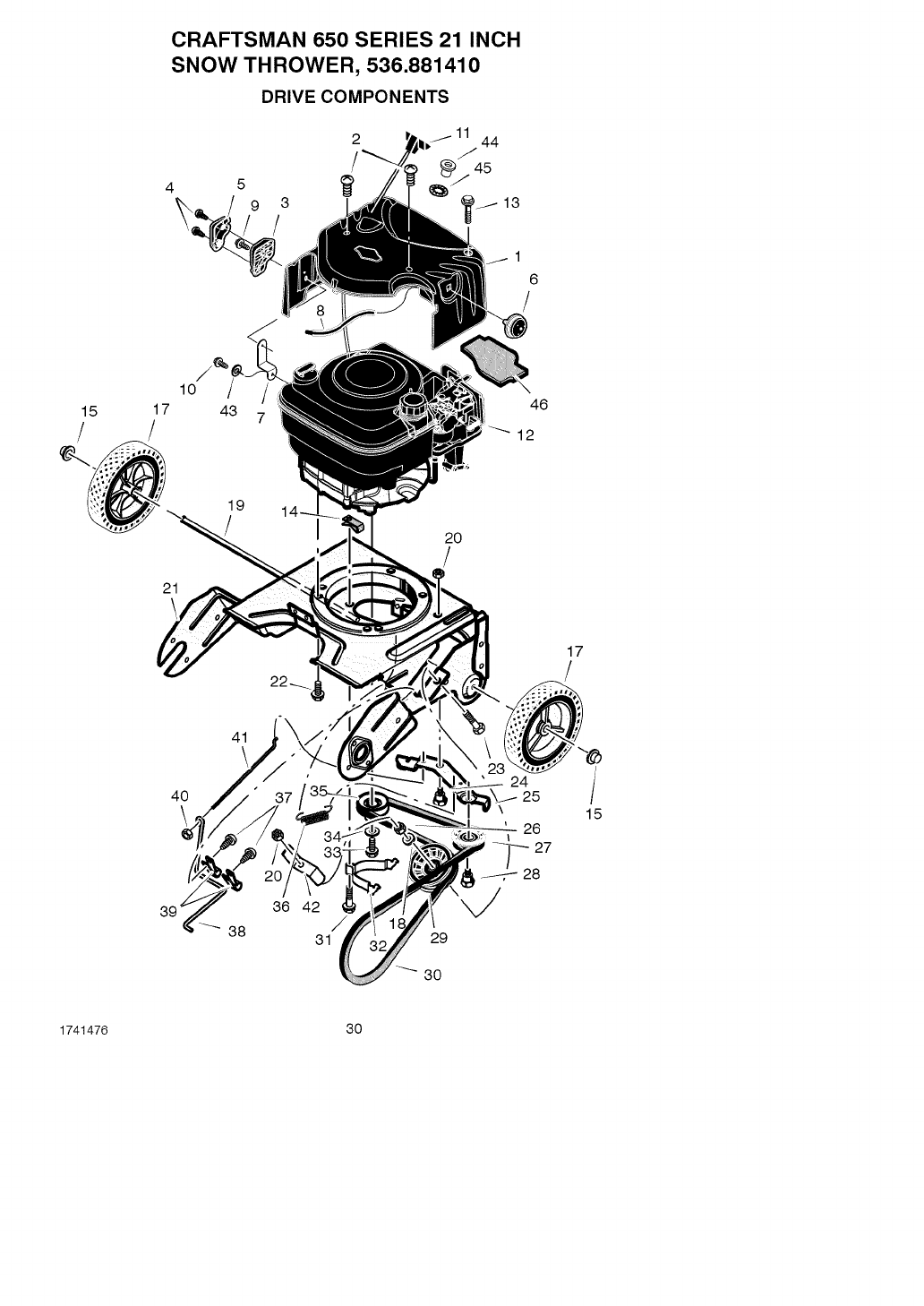
CRAFTSMAN 650 SERIES 21 INCH
SNOW THROWER, 536.881410
DRIVE COMPONENTS
15
!17
/
10
43 7
1
6
!
46
_12
21
19
!20
!
17
!
40
\
41
36 42
38 31 29
30
24
\
26
27
28
/
15
1741476 30
CRAFTSMAN 650 SERIES 21 INCH
SNOW THROWER, 536.881410
DRIVE COMPONENTS
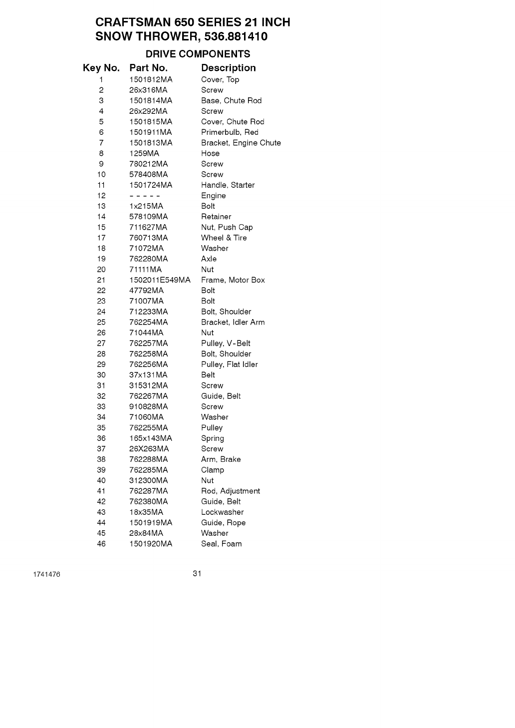
Key No. Part No. Description
1 1501812MA Cover, Top
2 26x316MA Screw
3 1501814MA Base, Chute Rod
4 26x292MA Screw
5 1501815MA Cover, Chute Rod
6 1501911MA Primerbulb, Red
7 1501813MA Bracket, Engine Chute
8 1259MA Hose
9 780212MA Screw
10 578408MA Screw
11 1501724MA Handle, Starter
12 Engine
13 1x215MA Bolt
14 578109MA Retainer
15 711627MA Nut, Push Cap
17 760713MA Wheel & Tire
18 71072MA Washer
19 762280MA Axle
20 71111MA Nut
21 1502011E549MA Frame, Motor Box
22 47792MA Bolt
23 71007MA Bolt
24 712233MA Bolt, Shoulder
25 762254MA Bracket, Idler Arm
26 71044MA Nut
27 762257MA Pulley, V- Belt
28 762258MA Bolt, Shoulder
29 762256MA Pulley, Flat Idler
30 37x13t MA Belt
31 315312MA Screw
32 762267MA Guide, Belt
33 910828MA Screw
34 71060MA Washer
35 762255MA Pulley
36 165xl 43MA Spring
37 26X263MA Screw
38 762288MA Arm, Brake
39 762285MA Clamp
40 312300MA Nut
4t 762287MA Rod, Adjustment
42 762380MA Guide, Belt
43 18x35MA Lockwasher
44 1501919MA Guide, Rope
45 28x84MA Washer
46 1501920MA Seal, Foam
1741476 31
CRAFTSMAN 650 SERIES 21 INCH
SNOW THROWER, 536.881410
AUGER COMPONENTS
6
/
17
1
2
12
\
18
16
14 10
1741476 32
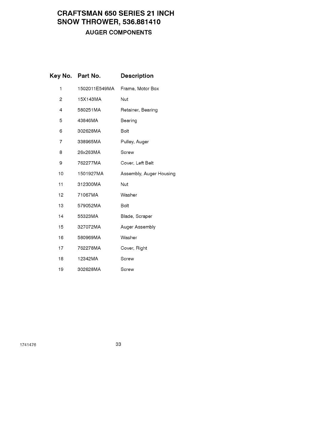
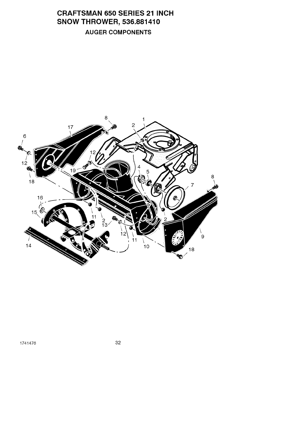
CRAFTSMAN 650 SERIES 21 INCH
SNOW THROWER, 536.881410
AUGER COMPONENTS
Key No. Part No. Description
1 1502011E549MA Frame, Motor Box
2 15X143MA Nut
4 580251MA Retainer, Bearing
5 43846MA Bearing
6 302628MA Bolt
7 338965MA Pulley, Auger
8 26x263MA Screw
9 762277MA Cover, Left Belt
10 1501927MA Assembly, Auger Housing
11 312300MA Nut
12 71067MA Washer
13 579052MA Bolt
14 55323MA Blade, Scraper
15 327072MA Auger Assembly
16 580969MA Washer
17 762278MA Cover, Right
18 12342MA Screw
19 302628MA Screw
1741476 33
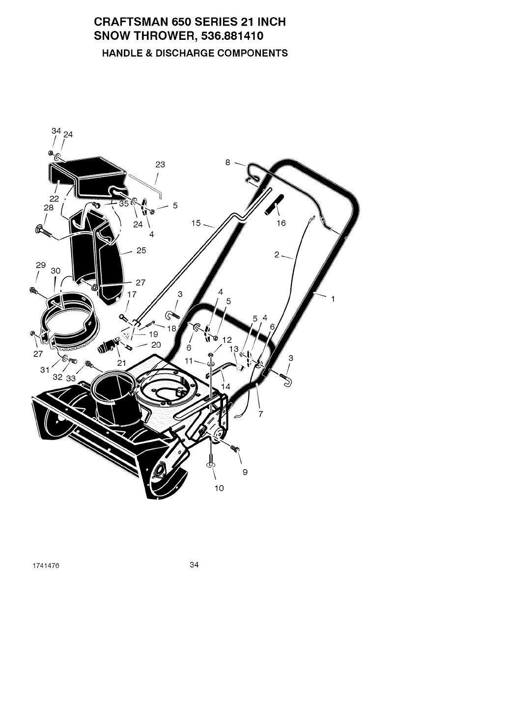
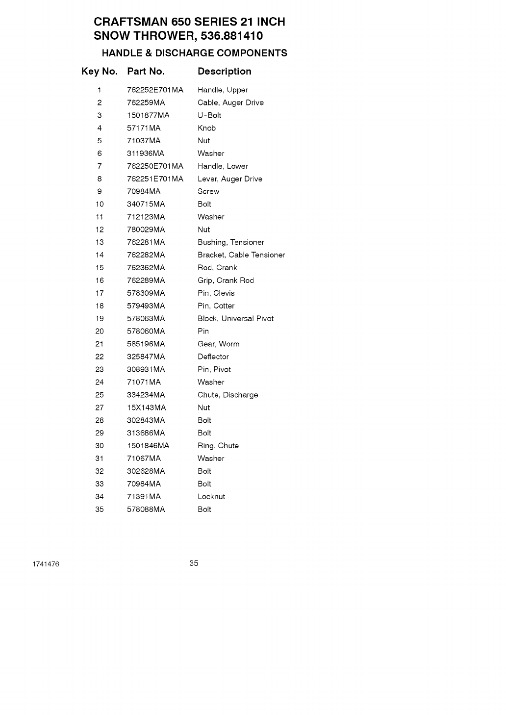
CRAFTSMAN 650 SERIES 21 INCH
SNOW THROWER, 536.881410
HANDLE & DISCHARGE COMPONENTS
29
/
22
28
23
4
25
27
_7 4 5
27
31 32 33
20
3
9
10
1741476 34
CRAFTSMAN 650 SERIES 21 INCH
SNOW THROWER, 536.881410
HANDLE & DISCHARGE COMPONENTS
Key No. Part No. Description
1 762252E701MA Handle, Upper
2 762259MA Cable, Auger Drive
3 1501877MA U- Bolt
4 57171MA Knob
5 71037MA Nut
6 311936MA Washer
7 762250E701MA Handle, Lower
8 762251 E701MA Lever, Auger Drive
9 70984MA Screw
10 340715MA Bolt
11 712123MA Washer
12 780029MA Nut
13 762281MA Bushing, Tensioner
14 762282MA Bracket, Cable Tensioner
15 762362MA Rod, Crank
16 762289MA Grip, Crank Rod
17 578309MA Pin, Clevis
18 579493MA Pin, Cotter
19 578063MA Block, Universal Pivot
20 578060MA Pin
21 585196MA Gear, Worm
22 325847MA Deflector
23 308931MA Pin, Pivot
24 71071 MA Washer
25 334234MA Chute, Discharge
27 15Xl 43MA Nut
28 302843MA Bolt
29 313686MA Bolt
30 1501846MA Ring, Chute
31 71067MA Washer
32 302628MA Bolt
33 70984MA Bolt
34 71391 MA Locknut
35 578088MA Bolt
1741476 35
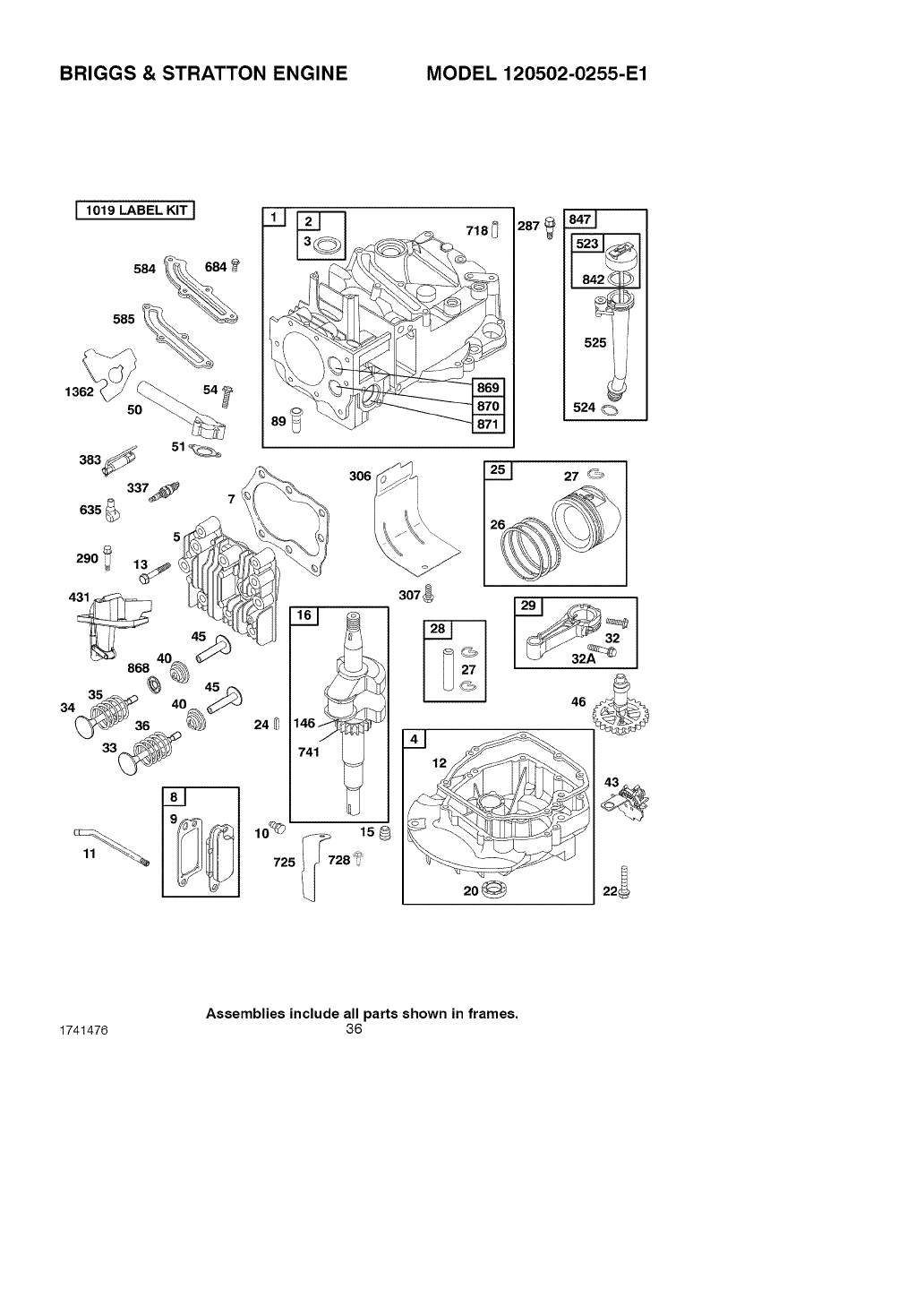
BRIGGS & STRATTON ENGINE MODEL 120502-0255-E1
I1019 LABEL KIT I
584 684_
585
306
287_ ©©
525 i
524 C_
741
lO_
725
i
158
728_ _
307_
Assemblies include all parts shown in frames,
1741476 36
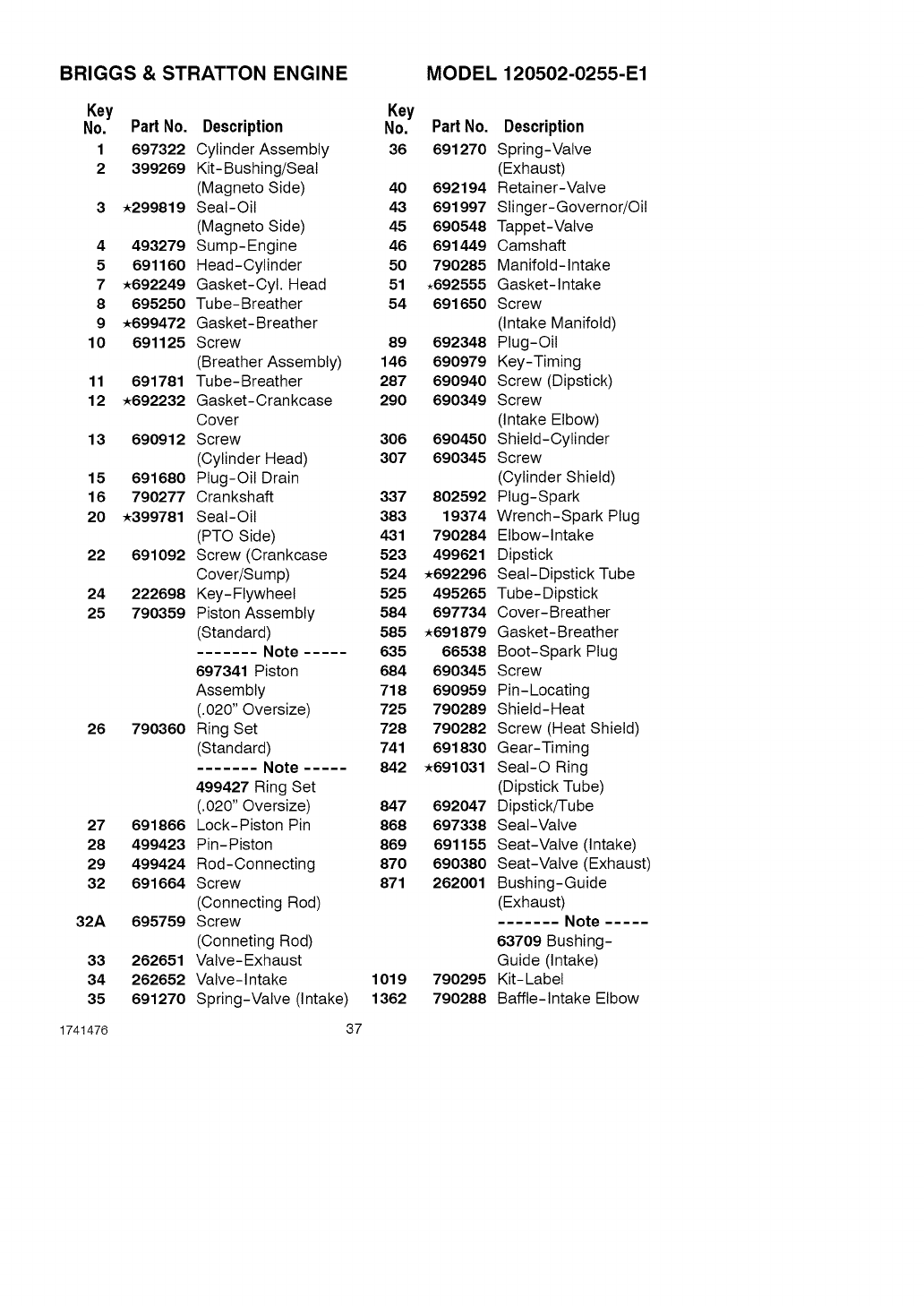
BRIGGS & STRATTON ENGINE MODEL 120502-0255-E1
Key Key
No. Part No. Description No.
1697322 Cylinder Assembly 36
2 399269 Kit-Bushing/Seat
(Magneto Side) 40
3 ,299819 Seal-Oil 43
(Magneto Side) 45
4 493279 Sump-Engine 46
5 691160 Head-Cylinder 50
7 ,692249 Gasket-Cyl. Head 51
8 695250 Tube-Breather 54
9 ,699472 Gasket-Breather
10 691125 Screw 89
(Breather Assembly) 146
11 691781 Tube-Breather 287
12 ,692232 Gasket-Crankcase 290
Cover
13 690912 Screw 306
(Cylinder Head) 307
15 691680 Plug-Oil Drain
16 790277 Crankshaft 337
20 .399781 Seal-Oil 383
(PTO Side) 431
22 691092 Screw (Crankcase 523
Cover/Sump) 524
24 222698 Key-Flywheel 525
25 790359 Piston Assembly 584
(Standard) 585
....... Note ..... 635
697341 Piston 684
Assembly 718
(.020" Oversize) 725
26 790360 Ring Set 728
(Standard) 741
....... Note ..... 842
499427 Ring Set
(.020" Oversize) 847
27 691866 Lock-Piston Pin 868
28 499423 Pin-Piston 869
29 499424 Rod-Connecting 870
32 691664 Screw 871
(Connecting Rod)
32A 695759 Screw
(Conneting Rod)
33 262651 Valve-Exhaust
34 262652 Valve-Intake 1019
35 691270 Spring-Valve (Intake) 1362
1741476 37
Part No. Description
691270 Spring-Valve
(Exhaust)
692194 Retainer-Valve
691997 Slinger-Governor/Oil
690548 Tappet-Valve
691449 Camshaft
790285 Manifold-Intake
.692555 Gasket-Intake
691650 Screw
(Intake Manifold)
692348 Plug-Oil
690979 Key-Timing
690940 Screw (Dipstick)
690349 Screw
(Intake Elbow)
690450 Shield-Cylinder
690345 Screw
(Cylinder Shield)
802592 Plug-Spark
19374 Wrench-Spark Plug
790284 Elbow-Intake
499621 Dipstick
,692296 Seal-Dipstick Tube
495265 Tube-Dipstick
697734 Cover-Breather
,691879 Gasket-Breather
66538 Boot-Spark Plug
690345 Screw
690959 Pin-Locating
790289 Shield-Heat
790282 Screw (Heat Shield)
691830 Gear-Timing
,691031 Seal-O Ring
(Dipstick Tube)
692047 Dipstick/Tube
697338 Seal-Valve
691155 Seat-Valve (Intake)
690380 Seat-Valve (Exhaust)
262001 Bushing-Guide
(Exhaust)
....... Note .....
63709 Bushing-
Guide (Intake)
790295 Kit-Label
790288 Baffle-Intake Elbow
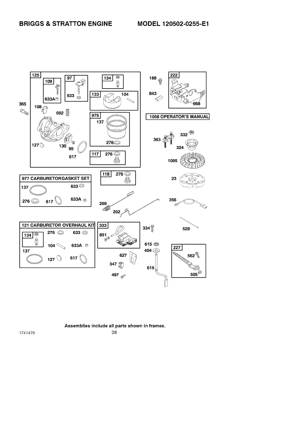
BRIGGS & STRATTON ENGINE MODEL 120502-0255-E1
365
%
617
137
276_
1188
843
1058 OPERATOR'S MANUAL]
_332_
363 -=_
324
1005
977 CARBURETORGASKET SET
137@ 633@
276_ 617% 633A @
121 CARBURETOR OVERHAUL KIT
_276 _633 @
104<'_ 633A ®
137
334_
615
404 C_
23
356_: _
505 °
Assemblies include all parts shown in frames,
1741476 38
BRIGGS & STRATTON ENGINE MODEL 120502-0255-E1
Key
No. PartNo. Description
23 790536 Flywheel
95 691636 Screw
(Throttle Valve)
97 493267 Shaft-Throttle
104 e691242 Pin-Float Hinge
108 691182 Valve-Choke
109 498593 Shaft-Choke
117 498975 Jet-Main
(Standard)
118 497348 Jet-Main
(High Altitude)
121 498260 Kit-Carburetor
Overhaul
125 790276 Carburetor
127 e694468 Plug-Welch
130 691203 Valve-Throttle
133 398187 Float-Carburetor
134 e398188 Kit-Needle/Seat
137ee693981 Gasket-Float Bowl
188 693399 Screw
(Control Bracket)
202 691829 Link-Mechanical
Governor
209 691851 Spring-Governor
(Yellow)
222 692982 Bracket-Control
227 690783 Lever-Governor
Control
276 ee271716 Washer-Sealing
324 695161 Screen/Cup Assem-
bly
332 690662 Nut
(Flywheel)
333 802574 Magneto-Armature
334 691061 Screw
(Armature Magneto)
Key
No. PartNo. Description
347 790283 Switch-Rocker
356 693010 Wire-Stop
363 19069 Puller-Flywheel
365 692524 Screw
(Carburetor)
404 690272 Washer
(Governor Crank)
497 690664 Screw
(Stopswitch Bracket)
505 691251 Nut
(Governor Control
Lever)
528 696751 Hose-Primer
562 691119 Bolt
(Governor Control
Lever)
615 690340 Retainer-Governor
Shaft
616 698801 Crank-Governor
617.ee270344 SeaI-O Ring
(Intake Manifold)
627 692872 Bracket-Stopswitch
633 eO691321 Seal-Choke/Throttle
Shaft
633A ee693867 Seal-Choke/Throttle
Shaft
668 .493823 Spacer
(Includes 2)
692 690572 Spring-Detent
843 691895 Sleeve-Lever
851 493880 Terminal-Spark Plug
975 493640 Bowl-Float
977 498261 Gasket Set-Carbure-
tor
1005 790035 Fan-Flywheel
1058 275963 Operator's Manual
1741476 39
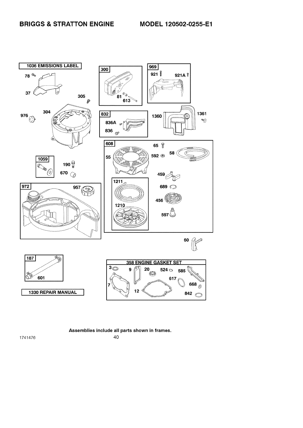
BRIGGS & STRATTON ENGINE MODEL 120502-0255-E1
I1036 EMISSIONS LABEL I
976@
305
304 @
190
670
972_ _957
I
|6161_
°
1361
65
592_ 58__
469_
689 _
456
597
60
601
I1330REPAIRMANUALI
358 ENGINE GASKET SE_TT ]
3_ 9 _'_ 2% 524_ 585_. I
Assemblies include all parts shown in frames,
1741476 40
BRIGGS & STRATTON ENGINE MODEL 120502-0255-E1
Key
No. PartNo. Description
3*299819 Seal-Oil
(Magneto Side)
7 .692249 Gasket-Cylinder
Head
9 .699472 Gasket-Breather
12 .692232 Gasket-Crankcase
Cover
20 .399781 Seal-Oil
(PTO Side)
37 694086 Guard-Flywheel
55 691421 Starter-Rewind
Housing
58 693389 Rope-Starter
(Cut to
Required Length)
60 691915 Grip-Starter Rope
65 690837 Screw
(Reqind Starter)
78 691108 Screw
(Flywheel Guard)
81 691740 Lock-Muffler Screw
187 691050 Line-Fuel
(Cut to
Required Length)
190 690940 Screw
(Fuel Tank)
300 692038 Muffler
304 790286 Housing-Blower
305 691108 Screw
(Blower Housing)
358 497316 Gasket Set-Engine
456 692299 Plate-Pawl Friction
459 281505 PawI-Ratchet
524 .692296 Seal-Dipstick Tube
585 .691879 Gasket-Breather
Passage
592 690800 Nut
(Rewind Starter)
597 691696 Screw
(Pawl Friction Plate)
Key
No. Part No. Description
601 95162 Clamp-Hose
608 697743 Starter-Rewind
613 691340 Screw
(Muffler)
617.ee270344 SeaI-O Ring
(Intake Manifold)
668 .493823 Spacer
(Includes 2)
689 691855 Spring-Friction
670 692294 Spacer-Fuel Tank
832 790280 Guard-Muffler
836 690664 Screw
(Muffler Guard)
836A 690661 Screw
(Muffler Guard)
842 .691031 Seal-O Ring
(Dipstick Tube)
921 690700 Screw
(Blower Housing
Cover)
921A 691135 Screw
(Blower Housing
Cover)
957 397974 Cap-Fuel Tank
969 790294 Cover-Blower
Housing
972 699374 Tank-Fuel
976 790221 Primer-Carburetor
1036 790411 Label-Emissions
1059 692311 Kit-Screw/Washer
1210 498144 Pulley/Spring
Assembly
(Pulley)
1211 498144 Pulley/Spring
Assembly
(Spring)
1330 276171 Repair Manual
1360 790281 Cover-Switch
1361 790282 Screw
(Cover Switch)
1741476 41

1741476 42
[_o_o]
PIEZAS DE REPUESTO
PIEZASDEREPUEST0DELMOTOR
GARANTiA
REGLAS DE SEGURIDAD
SiMBOLOS INTERNACIONALES
ENSAMBLAJE
OPERACION
29 MANTENIMIENTO 58
36 SERVICIO Y AJUSTES 61
43 ALMACENAMIENTO 67
43 TABLA DE LOC,ALIZACION y
47 REPARACION DE AVERIAS 68
49 PEDIDO DE PIEZAS/SER, VICIO
51 CUBIERTA DE ATRAS 72
GARANT{A LIMITADA DE UN AI_IOPARA LA MAQUINA
QUITANIEVES DE CRAFTSMAN
Per un a_o a partir de la fecha de compra, siempre que a este quitanieves Craftsman se le de
mantenimiento, lubricaci6n y afinamiento de acuerdo con las instrucciones de operaci6n y mante-
nimiento presentadas en el manual del propietario, Sears reparara sin cargo alguno, cualquier
defecto en el material y mane de obra.
Si este quitanieves de Craftsman es usado para prop6sitos comerciales o de arrendamiento, esta
garantia sera valida solamente por 90 dias a partir de la fecha de compra.
Esta garantia no cubre Io siguiente:
• Elementos fungibles los cuales se gastan durante el uso normal, tales come bujias, correas
de transmisi6n y pasadores de seguridad.
• Reparaciones necesarias debido al abuso o negligencia del operador, incluyendo eje de ci-
gQer_al doblado, y por no darle el mantenimiento necesario a la unidad, segQn Io recomendado
en las instrucciones contenidas en el manual del propietario.
EL SERVICIO DE GARANTIA SE PUEDE OBTENER LLEVANDO EL QUITANIEVES DE
CRAFTSMAN AL CENTRO DE SERVICIO SEARS MAS CERCANO EN LOS ESTADOS UNI-
DOS. ESTA GARANTIA ES VALIDA SOLO CUANDO ESTE PRODUCTO ES USADO EN LOS
ESTADOS UNIDOS.
Esta garantia le otorga derechos legales especificos, yes posible que tenga otros derechos los
cuales varian de estado a estado.
Sears, Roebuck and Co., D817WA, Hoffman Estates, IL 60179
I_f_ .e]ll_:'] IB]=1[,.']__
Preste atenci6n a e#te simbolo, [e indica precauciones de seguridad importantes. Sig-
nifica--ii iATENCION!!! iiiESTE ALERTA!!! Se trata de su seguridad.
Las emanaciones de escape producidas por este
motor y ciertos componentes de esta maquina con-
tienen quimicos reconocidos por el Estado de Cali-
fornia como carcinogenos, tambien pueden produ-
cir defectos en los recien nacidos o causar otros da-
r_os al sistema reproductivo.
Los bornes, terminales y accesorios relacionados
con la bateria contienen plomo y compuestos del
plomo, ademas de sustancias quimicas que el Esta-
do de California reconoce que estos compuestos
pueden causar cancer y defectos como carcinoge-
nas, ademas estas sustancias pueden producir da-
r_os congenitos, a los bebes y ademas de otros da-
r_osal sistema reproductivo humano. DEBE LAVAR-
SE MUY BIEN LAS MANOS DESPUleS DE MANIPU-
LAR ESTOS COMPONENTES.
1741476 43
_DVERTENCIA:
Siempre desconecte
el cable de la bujia y
coloquelo alejado de esta
para prevenir un arranque
accidental durante la prepa-
racion mantenimiento o al-
macenamiento del quitanie-
ves,
IMPORTANTE: Para prevenir
lesiones, las normas de seguri-
dad exigen controles en la unidad
que s61o puedan ser manejados
en presencia del operador. Su
quitanieves est& equipado con
dichos controles. Por ningt_n mo-
tivo intente pasar por alto la fun-
ci6n del control en presencia del
operador.

,_ ADVERTENCIA: Este quitanie-
yes tiene la capacidad de ampu-
tar las extremidades y de lanzar
objetos con velocidad. No respetar las si-
guientes instrucciones de seguridad pue-
de resultar en lesiones graves,
CAPACITACION
1. Lea con atenci6n las instrucciones en el
manual de operaci6n y servicio. Familiarf-
cese completamente con los controles y el
uso apropiado del quitanieves. Aprenda a
detener el quitanieves y a desenganchar
r&pidamente los controles.
2. Nunca permita a niSos operar el quita-
nieves. Nunca permita que adultos operen
el quitanieves sin la instrucci6n apropiada.
3. Mantenga el &rea libre de personas, espe-
cialmente niSos pequeSos y mascotas.
4. Tenga mucho cuidado para evitar resbalo-
nes o caidas, especialmente cuando este
retrocediendo.
PREPARACION
1. Inspeccione completamente el areadonde
se usar& el quitanieves y retire todas las
esteras, trineos, tableros, cables, y otros
objetos extraSos.
2. Desenganche todos los embragues antes
de hacer arrancar el motor.
3. No opere el quitanieves sin vestir prendas
de invierno adecuadas para trabajar a lain-
temperie. Vista calzado que le de buena
tracci6n sobre superficies resbalosas. No
use ropa holgada que pueda quedarse
enredada en los componentes m6viles.
4. Maneje el combustible con cuidado; este
es altamente inflamable.
a. Use un contenedor aprobado para
combustible.
b. Nunca quite latapa del tanque de com-
bustible ni aSada combustible a un mo-
tor en marcha o a un motor caliente.
c. Llene el tanque de combustible al aire
libre y con mucho cuidado. Nunca Ilene
el tanque en un recinto cerrado.
d. Vuelva a colocar la tapa del tanque de
combustible de manera segura, y lim-
pie el combustible derramado.
e. Nunca almacene combustible o el qui-
tanieves con combustible en el tanque
dentro de un edificio donde los vapores
1741476 44
pudiesen alcanzar alguna llama abier-
ta o chispas.
f. Verifiquequeelquitanieves tengasufi-
ciente combustible antes de cada uso,
y deje un espacio adicional en el tan-
que puesto que el calor del motor y/o
del sol hace que el combustible se ex-
panda.
g. Nunca Ilene los contenedores dentro
de un vehiculo o sobre las plataformas
pl&sticas de un cami6n o trailer. Man-
tengalos siempre alejados del vehiculo
y sobre el suelo antes de Ilenarlos.
h. Siempre que sea posible, para reabas-
tecer equipos con motores de gasoli-
ha, b&jelos primero del cami6n o trailer
y p6ngalos sobre el suelo. De no ser
posible, use un contenedor port&til pa-
ra reabastecer dichos equipos sobre el
trailer; no use la manguera del surtidor
de gasolina.
i. Mantenga siempre la boquilla en con-
tacto con la orilla del tanque o recipien-
te de combustible durante todo el
proceso de reabastecimiento. No em-
plee el dispositivo de apertura autom&-
tica ubicado en la boquilla.
j. C&mbiese inmediatamente toda ropa
contaminada con combustible.
5. Paratodos los quitanieves con motores de
arranque electrico, use cables de exten-
si6n con certificaci6n CSA/UL. Use sola-
mente tomacorrientes que hayan sido
instalados de acuerdo con los reglamentos
de inspecci6n locales.
6. Permita que el motor y el quitanieves se
ajusten alas temperaturas exteriores an-
tes de comenzar a despejar la nieve.
7. Siempre use gafas de seguridad o protec-
tores para los ojos durante la operaci6n o
mientras efectQa algt_n ajuste o reparaci6n
a la unidad, para proteger sus ojos de obje-
tos extraSos que pudiesen ser lanzados
por el quitanieves.
OPERACION
1. No opere este quitanieves si estatomando
medicinas que puedan causar somnolen-
cia o afectar su habilidad para operar el qui-
tanieves.
2. No use el quitanieves si por motivos emo-
cionales o fisicos se le dificulta manejarlo
de forma segura.
3. No coloque las manos o los pies cerca o
debajo de piezas en movimiento. Manten-
gaseentodomomentoabuenadistancia
delaaberturadeltubodedescarga.
4. Tengamuchocuidadoaloperarelquitanie-
vesenoatravesdeentradasdeautos,
senderosocaminosdegrava.Mantenga-
sealertadepeligrosocultosotr&fico.
5..Sigolpeaunobjetoextrafio,pareelmotor,
desconecteelcabledelabujia,inspeccio-
nemeticulosamenteelquitanievesporsi
hubieraalgt_ndafio,yrep&reloantesde
arrancarel motor y operar el quitanieves
nuevamente.
6. Si el quitanieves comienza a vibrar de ma-
hera excesiva, pare el motor y reviselo in-
mediatamente para encontrar la causa.
Generalmente, la vibraci6n es una adver-
tencia de algt_n problema.
7. Pare el motor cuando deje la posici6n de
operaci6n, antes de desobstruir el aloja-
miento de la barrena/propulsor o el tubo de
descarga, y cuando efectQe cualquier re-
paraci6n, ajuste o inspecci6n.
8. Cuando limpie, repare o inspeccione el qui-
tanieves, asegt_rese de que la barrena/pro-
pulsor y todas las partes m6viles se
encuentren detenidas, y que todos los con-
troles esten desenganchados. Desconec-
te el cable de la bujia y mantengalo alejado
de la bujia para evitar un arranque acciden-
tal.
9. Tome todas las precauciones posibles al
dejar el quitanieves desatendido. Desen-
ganche la barrena/propulsor, pare el motor
y retire la Ilave.
10. No haga arrancar el motor en recintos ce-
rrados, aQn con las puertas y ventanas
abiertas. Los vapores de,escape son peli-
grosos (contienen MONOXIDO DE CAR-
BONO, un GAS INODORO y LETAL).
11. Conduzca cuidadosamente sobre terreno
inclinado.
12. No use el quitanieves para limpiar &reas de
terreno inclinadas (cuestas, pendientes).
Tenga mucho cuidado cuando cambie de
direcci6n. No intente limpiar pendientes
muy pronunciadas.
13. Nunca opere el quitanieves sin que los res-
guardos, placas u otros dispositivos de se-
guridad se encuentren en su lugar.
14. Nunca opere el quitanieves cerca de esca-
parates de vidrio, autom6viles, vidrieras,
sitios de carga/descarga, y similares, sin el
ajuste apropiado del &ngulo de descarga
de la nieve. Mantenga a los nifios y las
mascotas alejados del &rea que est& des-
pejando.
15. No sobrecargue la capacidad del quitanie-
ves al intentar limpiar la nieve a una veloci-
dad demasiado r&pida.
16. Nunca opere el quitanieves a altas veloci-
dades de transporte sobre superficies res-
balosas. Mire hacia atr&s y tenga cuidado
al retroceder.
17. Nunca descargue directamente hacia es-
pectadores ni permita a nadie frente al qui-
tanieves.
18. Desenganche la fuerza motriz de la barre-
na/propulsor cuando el quitanieves sea
trasportado o no este en uso.
19. Utilice Qnicamente aditamentos y acceso-
dos aprobados por el fabricante del quita-
nieves (tales como cadenas para las
ruedas, juegos de arranque electrico, etc.).
20. Nunca opere el quitanieves sin tener bue-
na visibilidad o iluminaci6n. Asegt_rese
siempre que tiene buena estabilidad, y su-
jete con firmeza el mango. Camine; nunca
corra.
21. No trate de alcanzar &reas dificiles. Man-
tenga la estabilidad y el balance en todo
momento.
22. No opere el quitanieves encima de estruc-
turas ubicadas sobre el nivel del suelo, por
ejemplo encima de techos de residencias,
garajes, terrazas u otras estructuras o edi-
ficios similares.
23. Este quitanieves ha sido disefiado para
usarse sobre aceras, entradas de vehicu-
los y otras superficies a nivel del suelo.
24. No toque nunca un motor o silenciador ca-
liente.
_DVERTENCIA: Este quitanie-
ves ha sido diser_ado para usarse
sobre aceras, entradas de vehicu-
los y otras superficies a nivel del suelo,
Conduzca cuidadosamente sobre superfi-
cies inclinadas, NO OPERE EL QUITANIE-
VES ENCIMA DE ESTRUCTURAS QUE SE
ENCUENTRAN SOBRE EL NIVEL DEL SUE-
LO, como los techos de residencias, gara-
jes, terrazas u otras estructuras oedificios
similares,
1741476 45
MANTENIMIENTO Y
ALMACENAMIENTO
Cbmo despejar tubos de descarga
atascados
ADVERTENCIA: Las lesiones
mas comunes asociadas con el
uso del quitanieves son las que
se producen cuando las manos entren en
contacto con el dispositivo impulsor den-
tro del tubo de descarga. No use nunca las
manos para despejar el tubo de descarga.
Para despejar el tubo:
• APAGUE EL MOTOR.
•Espere unos 10 segundos para que las
aletas del impulsor dejen de girar.
•Use siempre la herramienta de limpie-
za, no las manos.
1. Revise los pernos con frecuencia para ase-
gurar que esten bien apretados y que el
quitanieves este en condiciones seguras
de funcionamiento.
2. Guarde el quitanieves a una distancia de
fuentes de ignici6n o de aparatos domesti-
cos que tengan llamas de encendido, tales
como calentadores de agua y estufas, se-
cadoras de ropa, etc. Permita que el motor
se enfrie antes de guardar el quitanieves
en cualquier recinto.
3. Siva a almacenar el quitanieves por un pe-
riodo prolongado, siempre consulte las ins-
trucciones del manual del operador donde
encontrar& consejos importantes.
4. Mantenga o reemplace las etiquetas de
seguridad e instrucciones, segt_n sea ne-
cesario.
5. Mantenga el quitanieves en marcha unos
cuantos minutos despues de despejar la
nieve, para evitar que se congele la barre-
na/propulsor.
1741476 46
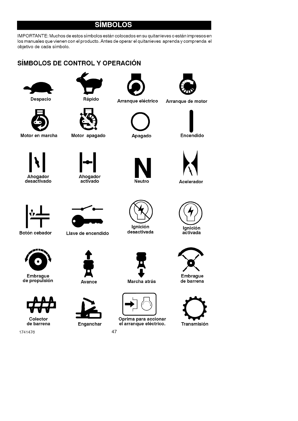
[.,,_o]mEo::[..l
IM PORTANTE: Muchos de estos simbolos est&n colocados en su quitanieves o est&n impresos en
los manuales que vienen con el producto. Antes de operar el quitanieves aprenda y comprenda el
objetivo de cada simbolo.
SlMBOLOS DE CONTROL YOPERACION
Despacio Rapido Arranque electrico Arranque de motor
oI
Motor en marcha Motor apagado Apagado Encendido
i',I I-I N
Ahogador Ahogador
desactivado activado Neutro Acelerador
Q G
Ignicion Ignicion
Boton cebador Llave de encendido desactivada activada
Embrague Embrague
de propulsion Avarice Marcha atras de barrena
Colector
de barrena 0
Oprima para accionar
Enganchar el arranque electrico, Transmision
1741476 47
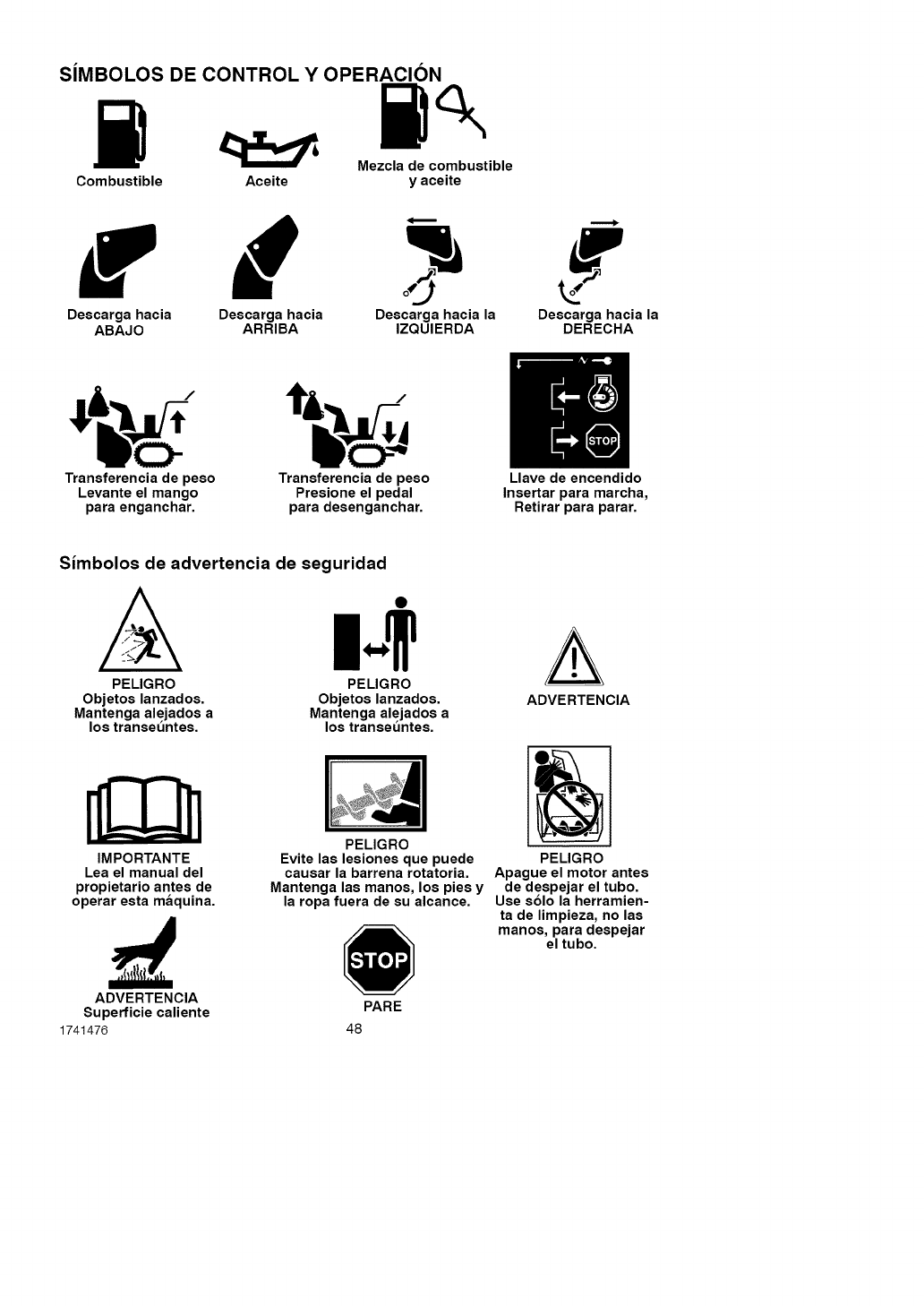
SlMBOLOS DE CONTROL YOPERACION
Mezcla de combustible
Combustible Aceite y aceite
r 6
Descarga hacia Descarga hacia Descarga hacia la Descarga hacia la
ABAJO ARRIBA IZQUIERDA DERECHA
Transferencia de peso
Levante el mango
para enganchar.
Transferencia de peso
Presione el pedal
para desenganchar.
Llave de encendido
Insertar para marcba,
Retirar para parar.
Simbolos de advertencia de seguridad
A
PELIGRO
Objetos lanzados.
Mantenga alejados a
los transeuntes.
PELIGRO
Objetos lanzados.
Mantenga alejados a
los transeuntes.
A
ADVERTENCIA
IMPORTANTE
Lea el manual del
propietario antes de
operar esta maquina.
PELIGRO
Evite las lesiones que puede PELIGRO
causar la barrena rotatoria. Apague el motor antes
Mantenga las manos, los pies y de despejar el tubo.
la ropa fuera de su alcance. Use solo la herramien-
ta de limpieza, no las
manos, para despejar
el tubo.
ADVERTENCIA
Superficie caliente
1741476 48
PARE
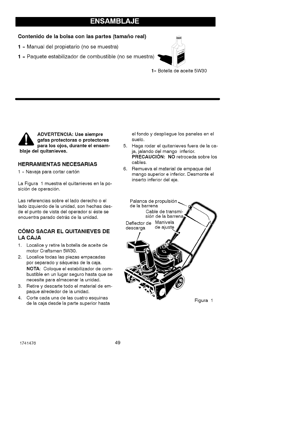
Contenido de la bolsa con las partes (tamafm real) iJ
1 - Manual del propietario (no se muestra)
1 Paquete estabilizador de combustible (no se muestra) _ _.
1- Botella de aceite 5W30
,_ ADVERTENCIA: Use siempre
gafas protectoras o protectores
pare los ojos, durante el ensam-
blaje del quitanieves,
HERRAMIENTAS NECESARIAS
1 - Navaja pare cotter carten
La Figure 1 muestra el quitanieves en la po-
sicien de operacien.
Las referencias sobre el lado derecho o el
lado izquierdo de la unidad, son hechas des-
de el punto de vista del operador si este se
encuentra parado detr&s de la unidad.
COMO SACAR EL QUITANIEVES DE
LA CAJA
1. Localice y retire la botella de aceite de
motor Craftsman 5W30.
2. Localice todas las piezas empacadas
por separado y s&quelas de la caja.
NOTA: Coloque el estabilizador de com-
bustible en un lugar seguro haste que se
necesite pare almacenar la unidad.
3. Retire y descarte todo el material de em-
paque alrededor de la unidad.
4. Corte cada una de las cuatro esquinas
de la caja desde la parte superior haste
el fondo y despliegue los paneles en el
suelo.
5. Haga rodar el quitanieves fuera de la ca-
ja, jalando del mango inferior.
PRECAUCION: NO retroceda sobre los
cables.
6. Remueva el material de empaque del
mango superior einferior. Desmonte el
inserto inferior del eje.
Palanca de
de la barrena
Cable de transmi-
si6n de la
Deflector de Manivela
descarga de
Figure 1
1741476 49
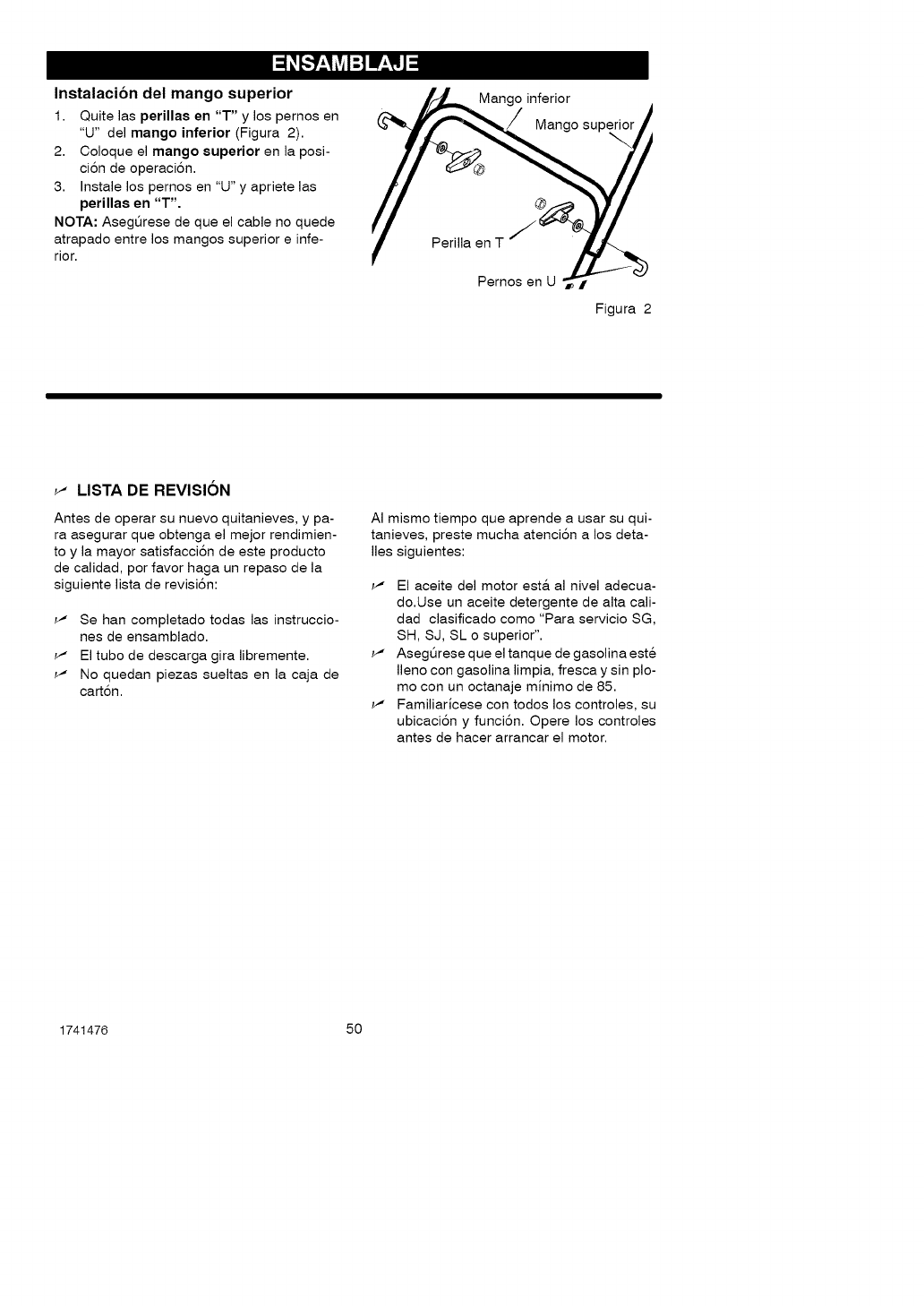
Instalacibn del mango superior
1. Quite las perillas en "T" y los pernos en
"U" del mango inferior (Figura 2).
2. Coloque el mango superior en la posi-
ci6n de operaci6n.
3. Instale los pernos en "U" y apriete las
perillas en "T".
NOTA: Asegt_rese de que el cable no quede
atrapado entre los mangos superior einfe-
rior.
Mango inferior
Mango sup_
Perilla en T
Pernos en UI
Figura 2
_" LISTA DE REVISION
Antes de operar su nuevo quitanieves, y pa-
ra asegurar que obtenga el mejor rendimien-
to y la mayor satisfacci6n de este producto
de calidad, por favor haga un repaso de la
siguiente lista de revisi6n:
_" Se han completado todas las instruccio-
nes de ensamblado.
_" El tubo de descarga gira libremente.
_" No quedan piezas sueltas en la caja de
cart6n.
AI mismo tiempo que aprende a usar su qui-
tanieves, preste mucha atenci6n a los deta-
lies siguientes:
_" El aceite del motor est& al nivel adecua-
do.Use un aceite detergente de alta cali-
dad clasificado como "Para servicio SG,
SH, SJ, SL o superior".
_" Asegt_rese que el tanque de gasolina este
Ileno con gasolina limpia, fresca y sin plo-
mo con un octanaje minimo de 85.
_" Familiaricese con todos los controles, su
ubicaci6n y funci6n. Opere los controles
antes de hacer arrancar el motor.
1741476 50
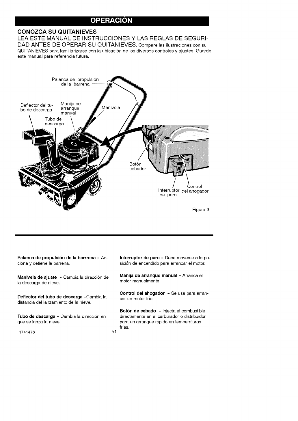
CONOZCA SU QUITANIEVES
LEA ESTE MANUAL DE INSTRUCCIONES Y LAS REGLAS DE SEGURI-
DAD ANTES DE OPERAR SU QUITANIEVES. Comparelas ilustraciones consu
QUITANIEVES para familiarizarse con la ubicaci6n de los diversos controles y ajustes. Guarde
este manual para referencia futura.
Palanca de propulsi6n
de la barrena --
Deflector del tu- Manija de
bo de descarga arranque
manual
Tubo de
descarga
Manivela
Bot6n
cebador
Control
Interruptor del ahogador
de paro
Figura 3
Palanca de propulsion de la barrrena - Ac-
ciona y detiene la barrena.
Manivela de ajuate - Cambia la direcci6n de
la descarga de nieve.
Deflector del tubo de descarga -Cambia la
distancia del lanzamiento de la nieve.
Tubo de deacarga - Cambia la direcci6n en
que se lanza la nieve.
1741476
Interruptor de paro - Debe moverse a la po-
sici6n de encendido para arrancar el motor.
Manija de arranque manual - Arranca el
motor manualmente.
Control del ahogador - Se usa para arran-
car un motor frio.
51
Boton de cebado - Injecta el combustible
directamente en el carburador o distribuidor
para un arranque r&pido en temperaturas
frias.
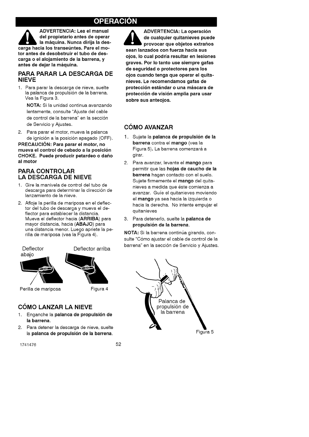
_ADVERTENCIA: Lea el manual
del propietario antes de operar
la maquina. Nunca dirija la des-
carga hacia los transet_ntes. Pare el mo-
tor antes de desobstruir el tubo de des-
carga o el alojamiento de la barrena, y
antes de dejar la maquina.
PARA PARAR LA DESCARGA DE
NIEVE
Para parar la descarga de nieve, suelte
la palanca de propulsi6n de la barrena.
Vea la Figura 3.
NOTA: Si la unidad continua avanzando
lentamente, consulte "Ajuste del cable
de control de la barrena" en la secci6n
de Servicio y Ajustes.
2. Para parar el motor, mueva la palanca
de ignici6n a la posiciSn apagado (OFF).
PRECAUCION: Para parar el motor, no
mueva el control de cebado ala posicion
CHOKE. Puede producir petardeo o dar_o
al motor
PARA CONTROLAR
LA DESCARGA DE NIEVE
1. Gire la manivela de control del tubo de
descarga para determinar la direcci6n de
lanzamiento de la nieve.
2. Afloje la perilla de mariposa en el deflec-
tor del tubo de descarga y mueva el de-
flector para establecer la distancia.
Mueva el deflector hacia (ARRIBA) para
mayor distancia, hacia (ABAJO) para
una distancia menor. Luego apriete la pe-
rilla de mariposa (vea la Figura 4).
Deflector Deflector arriba
abajo
_ DVERTENCIA: La operacion
de cualquier quitanieves puede
provocar que objetos extrar_os
sean lanzados con fuerza hacia sus
ojos, Io cual podria resultar en lesiones
graves. Por Io tanto use siempre gafas
de seguridad o protectores para los
ojos cuando tenga que operar el quita-
nieves. Le recomendamos gafas de
proteccion estandar o una mascara de
proteccion de vision amplia para usar
sobre sus anteojos.
COMO AVANZAR
1. Sujete la palanca de propulsion de la
barrena contra el mango (vea la
Figura 5). La barrena comenzar& a
girar.
2. Para avanzar, levante el mango para
permitir que las hojas de caucho de la
barrena hagan contacto con el suelo.
Sujete firmemente el mango del quita-
nieves a medida que este comienza a
avanzar. Guie el quitanieves moviendo
el mango ya sea hacia la izquierda o
hacia la derecha. No intente empujar el
quitanieves
3. Para detenerlo, suelte la palanca de
propulsion de la barrena.
NOTA: Si la barrena continQa girando, con-
suite "C6mo ajustar el cable de control de la
barrena" en la secci6n de Servicio y Ajustes.
/
Perilla de mariposa Figura 4
COMO LANZAR LA NIEVE
1. Enganche la palanca de propulsion de
la barrena.
2. Para detener la descarga de nieve, suelte
la palanca de propulsion de la barrena. Figura 5
1741476 52
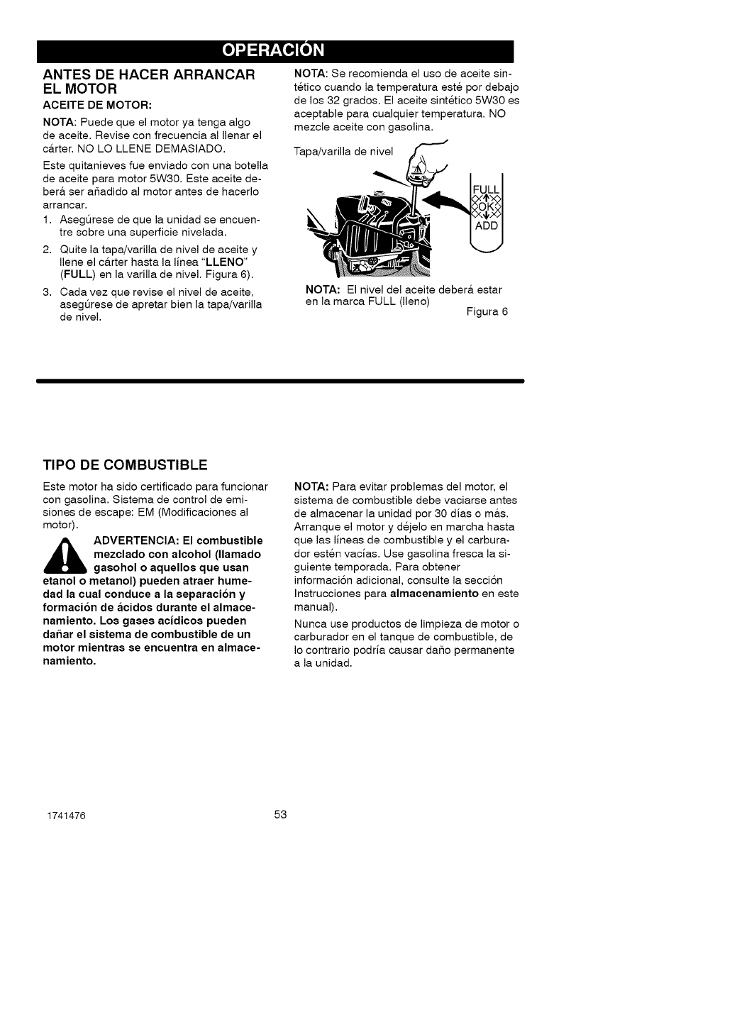
ANTES DE HACER ARRANCAR
EL MOTOR
ACEITE DE MOTOR:
NOTA: Puede que el motor ya tenga algo
de aceite. Revise con frecuencia al Ilenar el
c&rter. NO LO LLENE DEMASIADO.
Este quitanieves rue enviado con una botella
de aceite para motor 5W30. Este aceite de-
ber& ser a_adido al motor antes de hacerlo
arrancar.
1. Asegt_rese de que la unidad se encuen-
tre sobre una superficie nivelada.
2. Quite la tapa/varilla de nivel de aceite y
Ilene el c&rter hasta la linea "LLENO"
(FULL) en la varilla de nivel. Figura 6).
3. Cada vez que revise el nivel de aceite,
asegt_rese de apretar bien la tapa/varilla
de nivel.
NOTA: Se recomienda el uso de aceite sin-
tetico cuando la temperatura este por debajo
de los 32 grados. El aceite sintetico 5W30 es
aceptable para cualquier temperatura. NO
mezcle aceite con gasolina.
Tapa/varilla de nivel
NOTA: El nivel del aceite deber& estar
en la marca FULL (lleno) Figura 6
TIPO DE COMBUSTIBLE
Este motor ha sido certificado para funcionar
con gasolina. Sistema de control de emi-
siones de escape: EM (Modificaciones al
motor).
_ ADVERTENCIA: El combustible
mezclado con alcohol (llamado
gasohol o aquellos que usan
etanol o metanol) pueden atraer hume-
dad la cual conduce a la separacion y
formacion de acidos durante el almace-
namiento, Los gases acidicos pueden
dar_ar el sistema de combustible de un
motor mientras se encuentra en almace-
namiento,
NOTA: Para evitar problemas del motor, el
sistema de combustible debe vaciarse antes
de almacenar la unidad por 30 dias o m&s.
Arranque el motor y dejelo en marcha hasta
que las lineas de combustible y el carbura-
dor esten vacias. Use gasolina fresca la si-
guiente temporada. Para obtener
informaci6n adicional, consulte la secci6n
Instrucciones para almacenamiento en este
manual).
Nunca use productos de limpieza de motor o
carburador en el tanque de combustible, de
Io contrario podria causar daSo permanente
a la unidad.
1741476 53
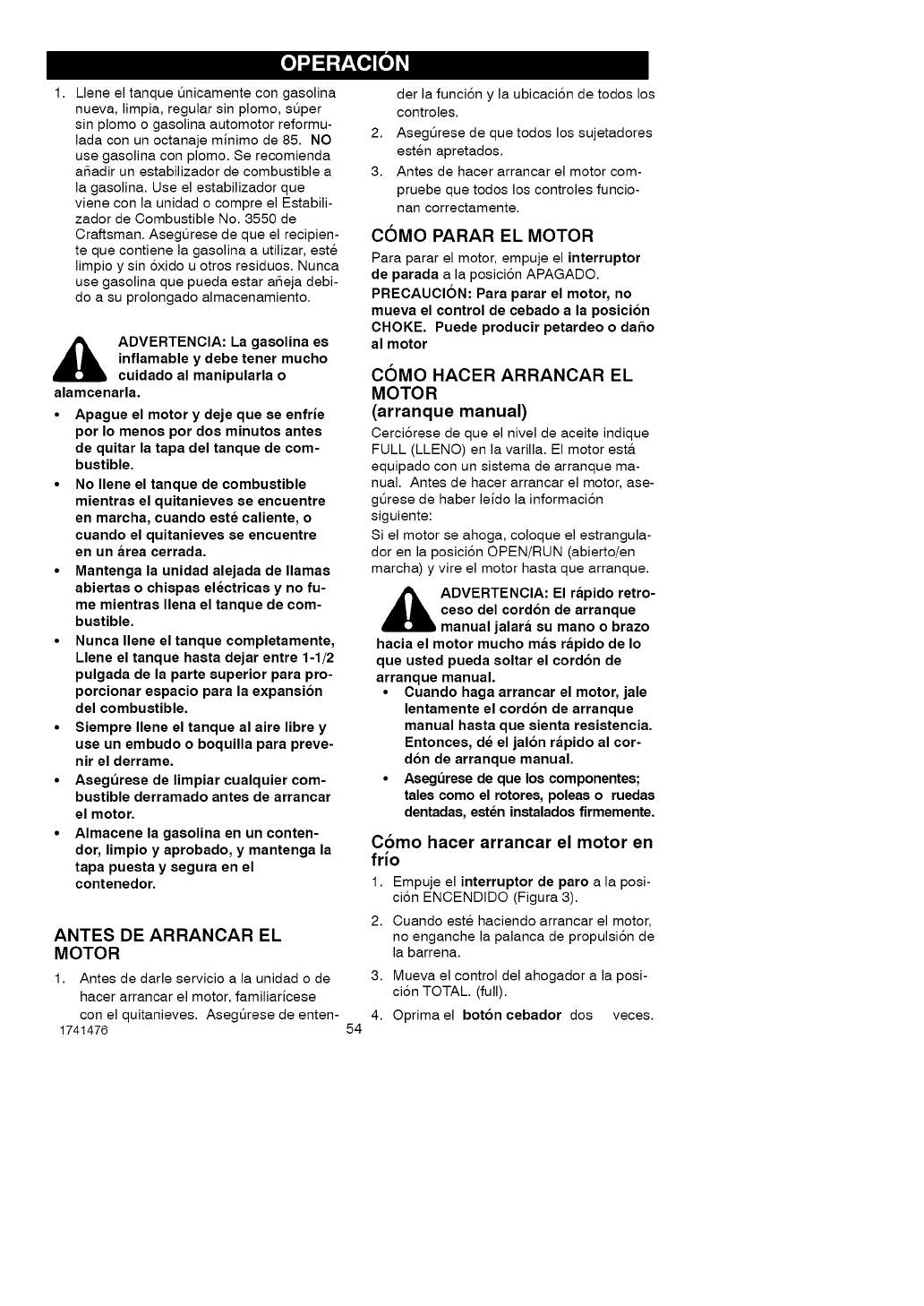
Llene el tanque Qnicamente con gasolina
nueva, limpia, regular sin plomo, sQper
sin plomo o gasolina automotor reformu-
lada con un octanaje minimo de 85. NO
use gasolina con plomo. Se recomienda
aSadir un estabilizador de combustible a
la gasolina. Use el estabilizador que
viene con la unidad o compre el Estabili-
zador de Combustible No. 3550 de
Craftsman. Asegt_rese de que el recipien-
te que contiene la gasolina a utilizar, este
limpio y sin 6xido u otros residuos. Nunca
use gasolina que pueda estar aSeja debi-
do a su prolongado almacenamiento.
ADVERTENCIA: La gasolina es
inflamable y debe tener mucho
cuidado al manipularla o
alamcenarla.
•Apague el motor y deje que se enfrie
por Io menos por dos minutos antes
de quitar la tapa del tanque de com-
bustible.
•No Ilene el tanque de combustible
mientras el quitanieves se encuentre
en marcha, cuando este caliente, o
cuando el quitanieves se encuentre
en un area cerrada.
•Mantenga la unidad alejada de llamas
abiertas o chispas electricas y no fu-
me mientras Ilena el tanque de com-
bustible.
•Nunca Ilene el tanque completamente,
Llene el tanque hasta dejar entre 1-1/2
pulgada de la parte superior para pro-
porcionar espacio para la expansion
del combustible.
•Siempre Ilene el tanque al aire libre y
use un embudo o boquilla para preve-
nir el derrame.
•Asegt_rese de limpiar cualquier com-
bustible derramado antes de arrancar
el motor.
•Almacene la gasolina en un conten-
dor, limpio y aprobado, y mantenga la
tapa puesta y segura en el
contenedor.
ANTES DE ARRANCAR EL
MOTOR
1. Antes de darle servicio a la unidad o de
hacer arrancar el motor, familiaricese
con el quitanieves. Asegt_rese de enten-
1741476 54
der la funci6n y la ubicaci6n de todos los
controles.
2. Asegt_rese de que todos los sujetadores
esten apretados.
3. Antes de hacer arrancar el motor com-
pruebe que todos los controles funcio-
nan correctamente.
COMO PARAR EL MOTOR
Para parar el motor, empuje el interruptor
de parada a la posiciSn APAGADO.
PRECAUCION: Para parar el motor, no
mueva el control de cebado a la posicion
CHOKE, Puede producir petardeo o dar3o
al motor
COMO HACER ARRANCAR EL
MOTOR
(arranque manual)
Cerci6rese de que el nivel de aceite indique
FULL (LLENO) en la varilla. El motor est&
equipado con un sistema de arranque ma-
nual. Antes de hacer arrancar el motor, ase-
gt_rese de haber leido la informaci6n
siguiente:
Si el motor se ahoga, coloque el estrangula-
dor en la posici6n OPEN/RUN (abierto/en
marcha) y vire el motor hasta que arranque.
_ DVERTENCIA: El rapido retro-
ceso del cordon de arranque
manual jalara su mano o brazo
hacia el motor mucho mas rapido de Io
que usted pueda soltar el cordon de
arranque manual,
• Cuando haga arrancar el motor, jale
lentamente el cordon de arranque
manual hasta que sienta resistencia,
Entonces, de el jalon rapido al cor-
don de arranque manual,
• Asegt_rese de que los componentes;
tales como el rotores, poleas oruedas
dentadas, esten instalados firmemente,
Como hacer arrancar el motor en
frio
1. Empuje el interruptor de paro a la posi-
ci6n ENCENDIDO (Figura 3).
2. Cuando este haciendo arrancar el motor,
no enganche la palanca de propulsi6n de
la barrena.
3. Mueva el control del ahogador a la posi-
ci6n TOTAL. (full).
4. Oprima el boton cebador dos veces.
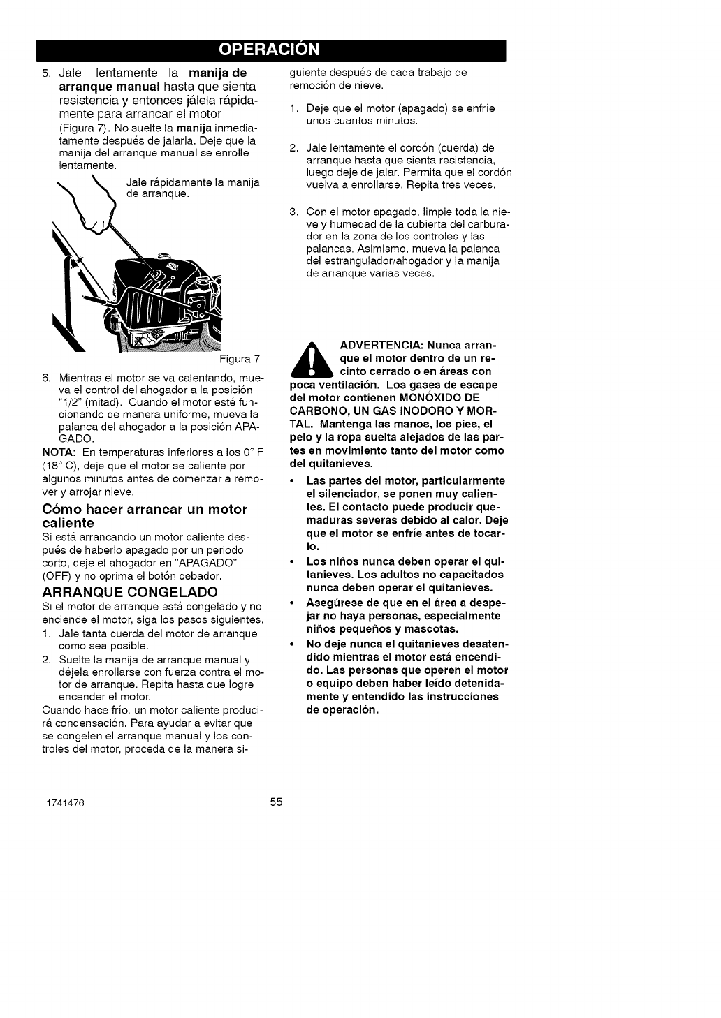
5, Jale lentamente la manijade
arranque manual hasta que sienta
resistencia y entonces j&lela r&pida-
mente para arrancar el motor
(Figura 7). No suelte la manija inmedia-
tamente despues de jalarla. Deje que la
manija del arranque manual se enrolle
lentamente.
Jale r&pidamente la manija
de arranque.
guiente despues de cada trabajo de
remoci6n de nieve.
1. Deje que el motor (apagado) se enfrie
unos cuantos minutos.
2, Jale lentamente el cord6n (cuerda) de
arranque hasta que sienta resistencia,
luego deje de jalar. Permita que el cord6n
vuelva a enrollarse. Repita tres veces.
3, Con el motor apagado, limpie toda la nie-
ve y humedad de la cubierta del carbura-
dor en la zona de los controles y las
palancas. Asimismo, mueva la palanca
del estrangulador/ahogador y la manija
de arranque varias veces.
Figura 7
6. Mientras el motor se va calentando, mue-
va el control del ahogador a la posici6n
"1/2" (mitad). Cuando el motor este fun-
cionando de manera uniforme, mueva la
palanca del ahogador a la posici6n APA-
GADO.
NOTA: En temperaturas inferiores a los 0 ° F
(18 ° C), deje que el motor se caliente por
algunos minutos antes de comenzar a remo-
ver y arrojar nieve.
C6mo hacer arrancar un motor
caliente
si est& arrancando un motor caliente des-
pues de haberlo apagado por un periodo
corto, deje el ahogador en "APAGADO"
(OFF) y no oprima el bot6n cebador.
ARRANQUE CONGELADO
Si el motor de arranque est& congelado y no
enciende el motor, siga los pasos siguientes.
1. Jale tanta cuerda del motor de arranque
como sea posible.
2. Suelte la manija de arranque manual y
dejela enrollarse con fuerza contra el mo-
tor de arranque. Repita hasta que Iogre
encender el motor.
Cuando hace frio, un motor caliente produci-
r& condensaci6n. Para ayudar a evitar que
se congelen el arranque manual y los con-
troles del motor, proceda de la manera si-
_ DVERTENCIA: Nunca arran-
que el motor dentro de un re-
cinto cerrado o en areas con
poca ventilacion. Los gases de escape
del motor contienen MONOXIDO DE
CARBONO, UN GAS INODORO Y MOR-
TAL. Mantenga las manos, los pies, el
pelo y la ropa suelta alejados de las par-
tes en movimiento tanto del motor como
del quitanieves.
•Las partes del motor, particularmente
el silenciador, se ponen muy calien-
tes. El contacto puede producir que-
maduras severas debido al calor. Deje
que el motor se enfrie antes de tocar-
Io.
•Los nir3os nunca deben operar el qui-
tanieves. Los adultos no capacitados
nunca deben operar el quitanieves.
•Asegt_rese de que en el area a despe-
jar no haya personas, especialmente
nifms pequer3os y mascotas.
•No deje nunca el quitanieves desaten-
dido mientras el motor esta encendi-
do. Las personas que operen el motor
oequipo deben haber leido detenida-
mente y entendido las instrucciones
de operacion.
1741476 55
COMO DESPEJAR TUBOS DE
DESCARGA ATASCADOS
ADVERTENCIA: Las lesiones
mas comunes asociadas con el
uso del quitanieves son las que
se producen cuando las manos entren en
contacto con el dispositivo impulsor den-
tro del tubo de descarga. No use nunca las
manos para despejar el tubo de descarga.
Para despejar el tubo:
•APAGUE EL MOTOR.
•Espere unos 10 segundos para que las
aletas del impulsor dejen de girar.
•Use siempre la herramienta de limpie-
za, no las manos.
Utilicelo para quitar la nieve atascada en el
alojamiento de la barrena.
• Suelte la palanca de propulsi6n de la ba-
rrena.
• Retire (sin girar) la Ilave.
• Desconecte el cable de la bujia.
• No coloque las manos en la barrena o
canal de descarga. Use el bast6n de lim-
pieza para quitar la nieve.
,_ ADVERTENCIA: Es necesario
apagar el motor antes de des-
pejar los atascos. Use solo la
herramienta de limpieza, no las manos.
SUGERENCIAS PARA EL
LANZAMIENTO DE NIEVE
1. Cuando se levanta el mango, las hojas
de caucho de la barrena entran en con-
tacto con el suelo y el quitanieves avan-
za. Cuando se suelta la palanca de
propulsi6n de la barrena, las hojas de
caucho de la barrena se paran. Si las
hojas de caucho no paran, consulte "C6-
mo ajustar el cable de propulsi6n de la
barrena" en la secci6n de Servicio y
Ajustes.
2. El lanzamiento de nieve m&s efectivo se
Iogra cuando la nieve se quita inmedia-
tamente despues de la nevada.
3. Para quitar completamente la nieve, so-
breponga ligeramente las pasadas del
quitanieves.
4. Cuando sea posible, descargue la nieve
a favor del viento.
5. Se puede ajustar la distancia a la que la
nieve ser& lanzada, moviendo el deflec-
tor del tubo de descarga. Para m&s dis-
tancia levante el deflector, para menos
distancia baje el deflector.
6. En condiciones de mucho viento, baje el
deflector del tubo de descarga para diri-
gir la nieve lanzada m&s cerca del suelo
para evitar que el viento la sople hacia
&reas no deseadas.
7. Para su seguridad y para prevenir el da-
5o al quitanieves, mantenga el &rea que
va a limpiar, libre de rocas, juguetes y
otros objetos extraSos.
8. Cuando este quitando la nieve sobre en-
tradas de auto cubiertas con grava o ro-
ca triturada, no deje que las cuchillas de
la barrena toquen el suelo. Mueva el
mango hacia abajo para levantar ligera-
mente las cuchillas de la barrena.
9. La velocidad de avarice del quitanieves
depende de la profundidad y del peso de
la nieve. La manera m&s eficiente de
usar el quitanieves ser& determinada por
su experiencia bajo diversas condicio-
nes.
10. Despues de cada trabajo deje que el
motor funcione por unos minutos. Asi
se derretira la nieve y el hielo acumula-
dos en el motor.
11. Limpie el quitanieves despues de cada
uso.
12. Quite el hielo, la nieve y los residuos de
todo el quitanieves. Enjuaguelo con agua
para quitarle toda la sal y otros productos
quimicos. Seque el quitanieves.
1741476 56
NIEVE SECA YDE
POCA PROFUNDIDAD
1. La nieve que se acumule hasta profundi-
dades de ocho pulgadas puede quitarse
r&pida y f&cilmente, caminando a una
velocidad moderada con el quitanieves.
Para acumulaciones de nieve de mayor
profundidad, camine m&s lento para per-
mitir la descarga uniforme de nieve tan
pronto sea recogida por la barrena.
2. Intente descargar la nieve a favor del
viento.
NIEVE MOJADA Y COMPACTA
Avance lentamente para despejar la nieve
mojada y compacta. Si este tipo de nieve
hace que la barrena gire m&s lento o empie-
za a atascar el tubo de descarga, retirese un
poco y empiece una serie de movimientos
cortos con el quitanieves, hacia adelante y
hacia atr&s. Estos movimientos cortos en la
nieve (de cuatro a seis pulgadas), ayudar&n
a arrojar la nieve del tubo de descarga.
BANCOS Y ACUMULACIONES
GRANDES DE NIEVE
Para despejar la nieve que se acumula a
una altura mayor que el quitanieves, use el
metodo descrito anteriormente (movimientos
cortos hacia adelante y hacia air&s). Oriente
el tubo de descarga en direcci6n opuesta a
la del banco o acumulaci6n grande de nieve.
La remoci6n de este tipo de nieve tomar&
m&s tiempo.
1741476 57
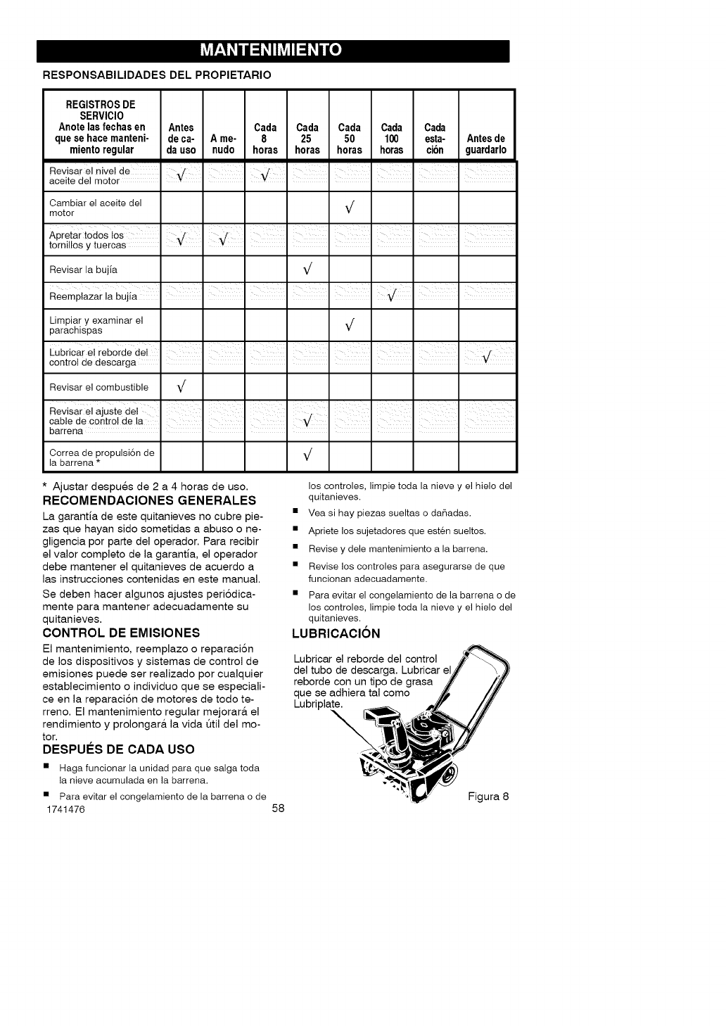
k_-' k k k_ k O]
RESPONSABILIDADES DEL PROPIETARIO
REGISTROS DE
SERVICIO
Anote las fechas en Antes Cada Cada Cada Cada Cada
que se hace manteni- de ca- A me- 8 25 50 100 esta- Antes de
miento regular da uso nudo horas horas horas horas cibn guardarlo
Revisar el nivel de .f .f
aoeite del motor - ¥ - ¥
Cambiar el aceite del j
motor v
nI I I
Apretar todos los II I I I I
tornUlos y tuercas
Revisar la bujia Vr
Limpiar y examinar el ,[
parachispas v
Revisar el combustible V r
I I I ' I I I I
Revisarelajustedet I I I I I I I I
cablede contro de a I I I V I I I I
barrena
Correa de propulsi6n de Vr
la barrena *
*Ajustar despues de 2 a 4 horas de uso.
RECOMENDACIONES GENERALES
La garantia de este quitanieves no cubre pie-
zas que hayan sido sometidas a abuso o ne-
gligencia por parte del operador. Para recibir
el valor completo de la garantia, el operador
debe mantener el quitanieves de acuerdo a
las instrucciones contenidas en este manual.
Se deben hacer algunos ajustes peri6dica-
mente para mantener adecuadamente su
quitanieves.
CONTROL DE EMISIONES
El mantenimiento, reemplazo o reparaci6n
de los dispositivos y sistemas de control de
emisiones puede ser realizado por cualquier
establecimiento o individuo que se especiali-
ce en la reparaci6n de motores de todo te-
rreno. El mantenimiento regular mejorar& el
rendimiento y prolongar& la vida Qtil del mo-
tor.
DESPUI_S DE CADA USO
• Haga funcionar la unidad para que salga toda
la nieve acumulada en la barrena.
los controles, limpie toda la nieve y el hielo del
quitanieves.
• Vea si hay piezas sueltas o da_adas.
• Apriete los sujetadores que est6n sueltos.
• Revise y dele mantenimiento a la barrena.
• Revise los controles para asegurarse de que
funcionan adecuadamente.
• Para evitar el congelamiento de la barrena o de
los controles, limpie toda la nieve y el hielo del
quitanieves.
LUBRICACION
Lubricar el reborde del control
del tubo de descarga. Lubricar el
reborde con un tipo de grasa
que se adhiera tal como
Lubriplate.
\
• Para evitar el congelamiento de la barrena o de Figura 8
1741476 58
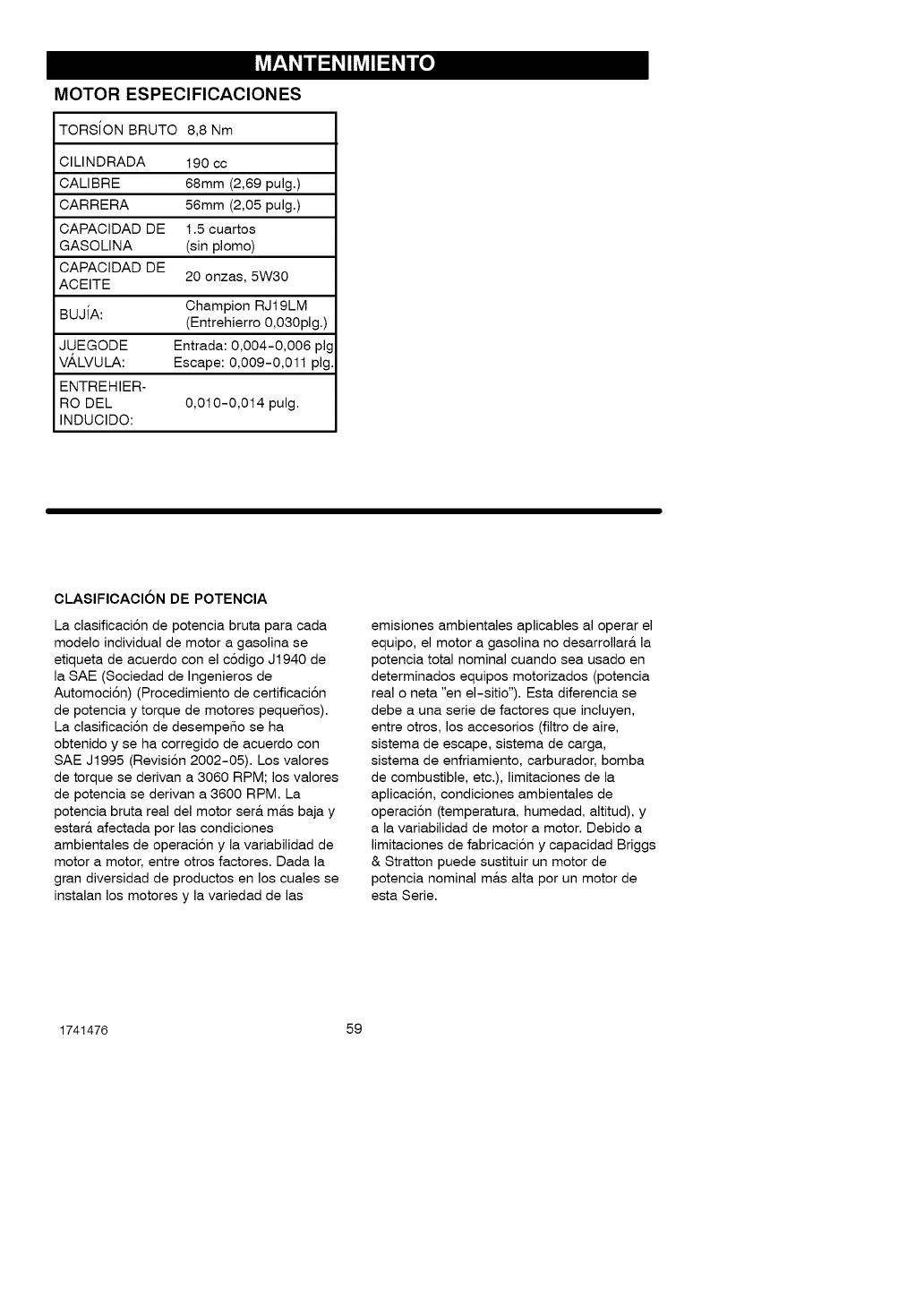
___ _, _, _ _, o]
MOTOR ESPECIFICACIONES
TORSION BRUTO 8,8 Nm
CILINDRADA 190 cc
CALIBRE 68mm (2,69 pulg.)
CARRERA 56mm (2,05 pulg.)
CAPACIDAD DE 1.5 cuartos
GASOLINA (sin plomo)
CAPACIDAD DE
ACEITE 20 onzas, 5W30
BUJiA: Champion RJt 9LM
(Entrehierro 0,030pig.)
JUEGODE Entrada: 0,004-0,006 pig
VALVULA: Escape: 0,009-0,011 pig.
ENTREHIER-
RO DEL 0,010-0,014 pulg.
INDUCIDO:
CLASIFICACION DE POTENCIA
La clasificaci6n de potencia bruta para cada
modelo individual de motor a gasolina se
etiqueta de acuerdo con el c6digo J1940 de
la SAE (Sociedad de Ingenieros de
Automoci6n) (Procedimiento de certificaci6n
de potencia y torque de motores pequeSos).
La clasificaci6n de desempeSo se ha
obtenido y se ha corregido de acuerdo con
SAE J1995 (Revisi6n 2002-05). Los valores
de torque se derivan a 3060 RPM; los valores
de potencia se derivan a 3600 RPM. La
potencia bruta real del motor ser& m&s baja y
estar& afectada por las condiciones
ambientales de operaci6n y la variabilidad de
motor a motor, entre otros factores. Dada la
gran diversidad de productos en los cuales se
instalan los motores y la variedad de las
emisiones ambientales aplicables al operar el
equipo, el motor a gasolina no desarrollara la
potencia total nominal cuando sea usado en
determinados equipos motorizados (potencia
real o neta "en el-sitio"). Esta diferencia se
debe a una serie de factores que incluyen,
entre otros, los accesorios (filtro de aire,
sistema de escape, sistema de carga,
sistema de enfriamiento, carburador, bomba
de combustible, etc.), limitaciones de la
aplicaci6n, condiciones ambientales de
operaci6n (temperatura, humedad, altitud), y
a la variabilidad de motor a motor. Debido a
limitaciones de fabricaci6n y capacidad Briggs
& Stratton puede sustituir un motor de
potencia nominal mas alta por un motor de
esta Serie.
1741476 59
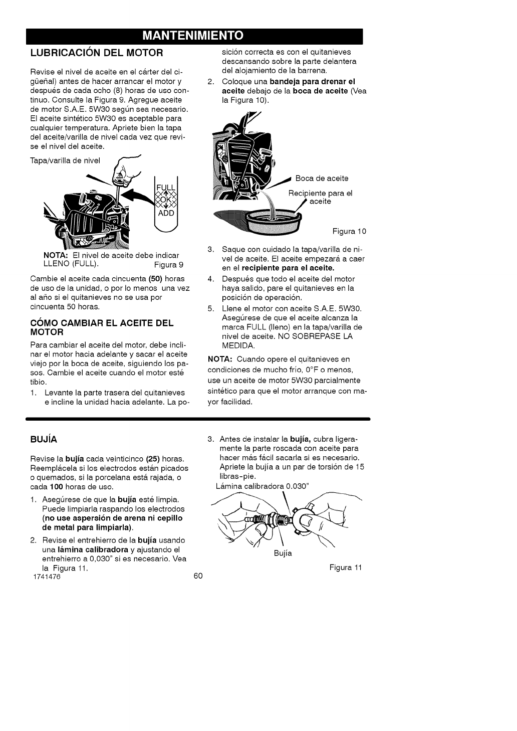
___ _, _, _ _, o]
LUBRICACION DEL MOTOR
Revise el nivel de aceite en el c&rter del ci-
gL)eSal) antes de hacer arrancar el motor y
despues de cada ocho (8) horas de uso con-
tinuo. Consulte la Figura 9. Agregue aceite
de motor S.A.E. 5W30 segt_n sea necesario.
El aceite sintetico 5W30 es aceptable para
cualquier temperatura. Apriete bien la tapa
del aceite/varilla de nivel cada vez que revi-
se el nivel del aceite.
Tapa/varilla de nivel
2,
sici6n correcta es con el quitanieves
descansando sobre la parte delantera
del alojamiento de la barrena.
Coloque una bandeja para drenar el
aeeite debajo de la boca de aeeite (Vea
la Figura 10).
Boca de aceite
Recipiente para el
NOTA: El nivel de aceite debe indicar
LLENO (FULL). Figura 9
Cambie el aceite cada cincuenta (50) horas
de uso de la unidad, o por Io menos una vez
al aSo si el quitanieves no se usa por
cincuenta 50 horas.
COMO CAMBIAR EL ACEITE DEL
MOTOR
Para cambiar el aceite del motor, debe incli-
nar el motor hacia adelante y sacar el aceite
viejo por la boca de aceite, siguiendo los pa-
sos. Cambie el aceite cuando el motor este
tibio.
1. Levante la parte trasera del quitanieves
eincline la unidad hacia adelante. La po-
Figura 10
3. Saque con cuidado la tapa/varilla de ni-
vel de aceite. El aceite empezar& a caer
en el recipiente para el aeeite.
4. Despues que todo el aceite del motor
haya salido, pare el quitanieves en la
posici6n de operaciSn.
5. Llene el motor con aceite S.A.E. 5W30.
Asegt_rese de que el aceite alcanza la
marca FULL (lleno) en la tapa/varilla de
nivel de aceite. NO SOBREPASE LA
MEDIDA.
NOTA: Cuando opere el quitanieves en
condiciones de mucho frio, 0°F o menos,
use un aceite de motor 5W30 parcialmente
sintetico para que el motor arranque con ma-
yor facilidad.
BUJiA
Revise la bujia cada veinticinco (25) horas.
Reempl&cela si los electrodos est&n picados
o quemados, si la porcelana est& rajada, o
cada 100 horas de uso.
1. Asegt_rese de que la bujia este limpia.
Puede limpiarla raspando los electrodos
(no use aspersion de arena ni eepillo
de metal para limpiarla).
2. Revise el entrehierro de la bujia usando
una lamina ealibradora y ajustando el
entrehierro a 0,030" si es necesario. Vea
la Figura 11.
1741476 6O
3. Antes de instalar la bujia, cubra ligera-
mente la parte roscada con aceite para
hacer m&s f&cil sacarla si es necesario.
Apriete la bujia a un par de torsi6n de 15
libras-pie.
L&mina calibradora 0.030"
Bujia
Figura 11
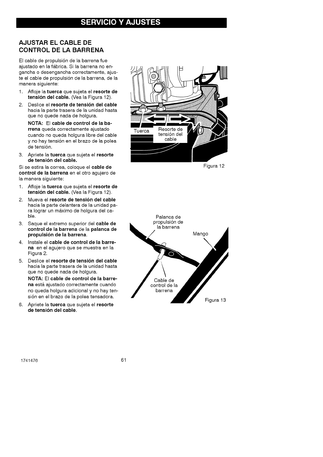
AJUSTAR EL CABLE DE
CONTROL DE LA BARRENA
El cable de propulsi6n de la barrena fue
ajustado en la f&brica. Si la barrena no en-
gancha o desengancha correctamente, ajus-
te el cable de propulsi6n de la barrena, de la
manera siguiente:
1. Afloje la tuerca que sujeta el resorte de
tension del cable. (Vea la Figura 12).
2. Deslice el resorte de tension del cable
hacia la parte trasera de la unidad hasta
que no quede nada de holgura.
NOTA: El cable de control de la ba-
rrena queda correctamente ajustado
cuando no queda holgura libre del cable
y no hay tensi6n en el brazo de la polea
de tensi6n.
3. Apriete la tuerca que sujeta el resorte
de tension del cable.
Si se estira la correa, coloque el cable de
control de la barrena en el otro agujero de
la manera siguiente:
1. Afloje la tuerca que sujeta el resorte de
tension del cable. (Vea la Figura 12).
2. Mueva el resorte de tension del cable
hacia la parte delantera de la unidad pa-
ra Iograr un m&ximo de holgura del ca-
ble.
3. Saque el extremo superior del cable de
control de la barrena de la palanca de
propulsion de la barrena.
4. Instale el cable de control de la barre-
na en el agujero que se muestra en la
Figura 2.
5. Deslice el resorte de tension del cable
hacia la parte trasera de la unidad hasta
que no quede nada de holgura.
NOTA: El cable de control de la barre-
na est& ajustado correctamente cuando
no queda holgura adicional y no hay ten-
si6n en el brazo de la polea tensadora.
6. Apriete la tuerca que sujeta el resorte
de tension del cable.
Tuerca tensi6n del
I cable
Palanca de
propulsi6n de
la barrena
Cable de
control de la
barrena
Figura 12
Mango
Figura 13
1741476 61

COMOQUITARLACUBIERTASUPERIOR
No hay controles de ajuste debajo de la
cubierta superior. Para limpiar el sistema
de enfriamiento del motor, siga los pasos
a continuaci6n para quitar la cubierta.
1. Quite los tornillos Aque sujetan la
abrazadera de soporte de la varilla
a la cubierta superior. Haga girar
la varilla de la manivela hacia arri-
bay dejela sobre la unidad.
2. Retire el tornittos B,
3. Retire los tornillos de sujeci6n C.
4. Retire la cubierta superior.
5. Para instalar la cubierta superior,
siga los pasos anteriores en orden
inverso.
AC
/ /
manivela
de ajuste
_erior
Figura 14
COMOQUITARLA CUBIERTADE CORREA
1. Quite los tornillos A y las tuercas B
de la cubierta de correa.
2. Retire el tornillo de sujeci6n C de la
parte trasera de la cubierta de co-
rrea,
3. Retire la cubierta de correa de la
unidad.
4. Para instatar la cubierta de correa,
siga los pasos anteriores en orden
inverso.
NOTA: La cubierta de correa tiene guias
moldeadas en la parte interior de la cu-
bierta. Cuando instale la cubierta de co-
rrea, encaje la palanca de propulsi6n de
la barrena para apretar la correa contra la
polea. Esto darA un espacio adecuado
para las guias de la correa cuando insta-
le la cubierta de la misma.
C
/
1741476
B
B
A
62
AA
A
Cubierta
de correa
Figura 15
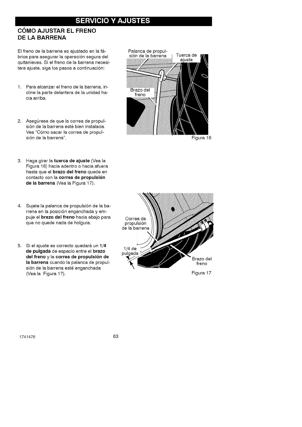
COMO AJUSTAR EL FRENO
DE LA BARRENA
El freno de la barrena es ajustado en la f&-
brica para asegurar la operaci6n segura del
quitanieves. Si el freno de la barrena necesi-
tara ajuste, siga los pasos a continuaci6n:
1. Para alcanzar el freno de la barrena, in-
cline la parte delantera de la unidad ha-
cia arriba.
2, Asegt_rese de que la correa de propul-
si6n de la barrena este bien instalada.
Vea "C6mo sacar la correa de propul-
si6n de la barrena'.
Palanca de propul-
si6n de la barrena
Brazo del
freno
Tuerca de
ajuste
Figura 16
3, Haga girar la tuerca de ajuste (Vea la
Figura 16) hacia adentro o hacia afuera
hasta que el brazo del freno quede en
contacto con la correa de propulsion
de la barrena (Vea la Figura 17).
4, Sujete la palanca de propulsi6n de la ba-
rrena en la posici6n enganchada y em-
puje el brazo del freno hacia abajo para
que no quede nada de holgura. Correa de
propulsi6n
de la barrena
5, Si el ajuste es correcto quedar& un 1/4
de pulgada de espacio entre el brazo
del freno y la correa de propulsion de
la barrena cuando la palanca de propul-
si6n de la barrena este enganchada
(Vea la Figura 17).
1/4 de
pulgada Brazo del
freno
Figura 17
1741476 63
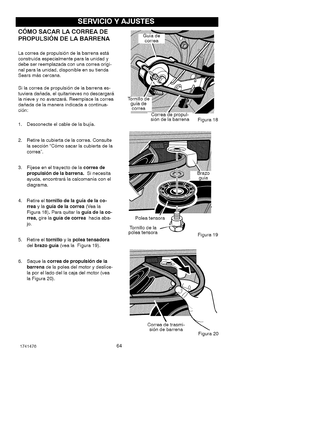
COMO SACAR LA CORREA DE
PROPULSION DE LA BARRENA
La correa de propulsi6n de la barrena est&
construida especialmente para la unidad y
debe ser reemplazada con una correa origi-
nal para la unidad, disponible en su tienda
Sears m&s cercana.
Si la correa de propulsi6n de la barrena es-
tuviera daSada, el quitanieves no descargar&
la nieve y no avanzar&. Reemplace la correa
daSada de la manera indicada a continua-
ci6n:
1. Desconecte el cable de la bujia.
correa
Tornillo de
guia de
correa
Correa de propul-
si6n de la barrena Figura 18
2. Retire la cubierta de la correa. Consulte
la secci6n "C6mo sacar la cubierta de la
correa'.
3, Fijese en el trayecto de la correa de
propulsion de la barrena. Si necesita
ayuda, encontrar& la calcomania con el
diagrama.
4, Retire el tornillo de la guia de la co-
rrea y la guia de la correa (Vea la
Figura 18). Para quitar la guia de la co-
rrea, gire la guia de correa hacia aba-
jo.
5. Retire el tornillo y la polea tensadora
del brazo guia (vea la Figura 19).
8, Saque la correa de propulsion de la
barrena de la polea del motor y deslice-
la por el lado della caja del motor (vea
la Figura 20).
Polea tensora
Tornillo de la
polea tensora
Correa de trasmi-
si6n de barrena
Brazo
guia
Figura 19
Figura 20
1741476 64
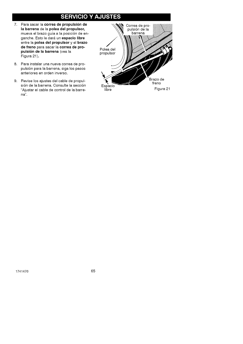
7,
8,
9,
Para sacar la correa de propulsion de
la barrena de la polea del propulsor,
mueva, el bra.zo guia. a. la.posici6n de en-
ga.nche. Esto le da.r& un espacio libre
entre la.polea del propulsor y el brazo
de freno pa.ra,sa.ca.rla.correa de pro-
pulsion de la barrena (vea. la.
Figura. 21 ),
Pa.ra. insta.la.r una. nueva, correa, de pro-
pulsi6n pa.ra, la. ba.rrena., siga. los pa.sos
a.nteriores en orden inverso.
Revise los ajustes del cable de propul-
si6n de la. ba.rrena.. Consulte la. secci6n
"Ajusta.r el cable de control de la. ba.rre-
ha.'.
Polea. del
propulsor
Espa.cio
libre
Correa. de pro-
pulsi6n de la.
ba.rrena.
Brazo de
freno
Figura 21
1741476 65
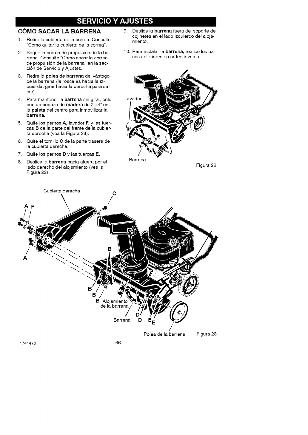
COMO SACAR LA BARRENA
1. Retire la cubierta de la correa. Consulte
"C6mo quitar la cubierta de la correa".
2. Saque la correa de propulsi6n de la ba-
rrena. Consulte "C6mo sacar la correa
de propulsi6n de la barrena" en la sec-
ci6n de Servicio y Ajustes.
3. Retire la polea de barrena del v&stago
de la barrena (la rosca es hacia la iz-
quierda; girar hacia la derecha para sa-
car).
4, Para mantener la barrena sin girar, cole-
que un pedazo de madera de 2"x4" en
la paleta del centre para inmovilizar la
barrena.
5. Quite los pernos A, lavador F, y las tuer-
cas B de la parte del frente de la cubier-
ta derecha (vea la Figura 23).
6. Quite el tornillo C de la parte trasera de
la cubierta derecha.
7. Quite los pernos D y las tuercas E.
8. Deslice la barrena hacia afuera por el
lado derecho del alojamiento (vea la
Figura 22).
9. Deslice la barrena fuera del soporte de
cojinetes en el lado izquierdo del aloja-
miento.
10. Para instalar la barrena, realice los pa-
sos anteriores en orden inverse.
Lavador
Barrena
Figura 22
AF
!
Cubierta derecha
\C
/
A
B
B
B Alojamiento
de la barrena
Barrena D E
Polea de la barrena Figura 23
1741476 66
l_ml?i!__e]=l'#_17J]]=l_o]
_ADVERTENCIA: Nunca guar-
de su quitanieves con gasoli-
na en el tangue de combus-
tible en ambientes interiores o en un
area cerrada y mal ventilada. Si que-
da gasolina en el tanque, los vapo-
res podrian alcanzar alguna llama
expuesta, chispa o llama piloto de
una caldera, calentador de agua,
secadora de ropa, cigarrillo, etc.
Para prevenir el daflo (si el quitanieves
no se usa por m&s 30 dias) prep&relo
como se indica a continuaci6n.
QUITANIEVES
1. Limpie todo el quitanieves.
2. Lubrique todos los puntos de lubri-
caci6n. Consulte la secci6n de Man-
tenim lento,
3. AsegOrese de que todas las tuercas,
pernos y tornillos esten bien apreta-
dos. Inspeccione todas las piezas
m6viles visibles para detectar da-
flos, roturas y desgaste. Haga los
reemplazos necesarios.
4. Retoque todas las superficies oxida-
das o que tengan la pintura sattada;
lijelas suavemente antes de aplicar
la pintura.
5. Cubra las piezas de metal expuesto
del soplador del alojamiento de la
barrena y del impulsor, con un anti-
corrosivo, tal como un lubricante en
aerosol.
NOTA: Una revisi6n o afinamiento
anual hecho en un Centro de Servicio
Sears es una buena manera de asegu-
rar que su quitanieves le brinde el m&-
ximo rendimiento la siguiente
temporada.
MOTOR
Deber& sacar la gasolina del tanque o
prepararla para prevenir la formaci6n
de dep6sitos de goma en el tanque, fil-
tro, manguera y carburador durante el
almacenamiento. Adem&s, durante el
almacenamiento, la gasolina mezclada
con alcohol que contiene etanol o me-
tanol (llamada a veces gasohol) atrae
agua, y esta actQa sobre la gasolina
formando &cidos que daflan el motor.
1741476 67
1. Deje el motor en marcha hasta que
el tanque quede vacio y el motor se
pare.
2. Si no quiere sacar la gasolina, use el
estabilizador de combustible provisto
con la unidad, o compre estabilizador
de combustible Craftsman NQm. 3550.
Aflada el estabilizador de combustible
a cualquier cantidad de gasolina que
permanezca en el tanque para minimi-
zar los dep6sitos de goma y &cido. Si
et tanque est& casi vacio, mezcle el
estabilizador con gasolina fresca en un
recipiente separado y aflada un poco
de esta mezcla al tanque.
3. Siempre siga las instrucciones del
envase del estabilizador. Luego de
afladir el estabilizador, encienda el
motor y dejelo correr por 10 minutos
por Io menos para permitir que la
mezcta alcance el carburador.
4. Cambie el aceite del motor cuando
a_n est& tibio.
5. Saque la bujia y vierta aproximada-
mente 15 mt (1/2 onza) de aceite
para motor en el cilindro. Vuelva a
colocar la bujia y vire el motor lenta-
mente para distribuir el aceite.
,_ ADVERTENCIA: No vire el
motor cuando no tiene colo-
cada la bujia.
6. Atmacene en un &rea timpia y seca,
pero NO cerca de una estufa, calde-
ra o calentador de agua que tenga
una llama piloto ni algQn otro dispo-
sitivo que pueda generar chispas.
OTRAS INDICACIONES
1. Si fuera posible, guarde su quita-
nieves dentro de un recinto, cubrien-
dolo para protegerlo del polvo y la
suciedad.
2. Si debe guardar el quitanieves afue-
ra, col6quelo sobre bloques para le-
vantarlo del suelo.
3. Cubra el quitanieves con una cubier-
ta protectora apropiada que no re-
tenga humedad. No use pl&stico.
IMPORTANTE: Nunca cubra el quita-
nieves mientras las &reas del motor y
del escape esten todavia catientes.
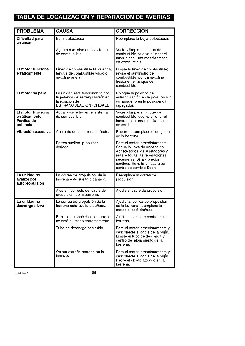
PROBLEMA CAUSA CORRECClON
Dificultad para Bujia defectuosa. Reemplace la bujia defectuosa.
arrancar
Agua o suciedad en el sistema Vacie y limpie el tanque de
de combustible, combustible; vuelva a Ilenar el
tanque con una mezcla fresca
de combustible.
El motor funciona Linea de combustible bloqueada, Limpie la linea de combustible;
erraticamente tanque de combustible vacio o revise el suministro de
gasolina afieja, combustible; ponga gasolina
fresca en el tanque de
combustible.
El motor se para La unidad est& funcionando con Coloque la palanca de
la palanca de estrangulaci6n en estrangulaci6n en la posici6n run
la posici6n de (arranque) o en la posici6n off
ESTRANGULACION (CHOKE). (apagado).
El motor funciona Agua o suciedad en el sistema Vacie y limpie el tanque de
erraticamente; de combustible, combustible; vuelva a Ilenar el
Perdida de tanque con una mezcla fresca
potencia de combustible
Vibraci6n excesiva Conjunto de la barrena dafiado. Repare o reemplace el conjunto
de la barrena.
Partes sueltas, propulsor
dafiado.
La unidad no
avanza por
autopropulsion
La unidad no
descarga nieve
La correa de propulsi6n de la
barrena est& suelta o dafiada.
Ajuste incorrecto del cable de
propulsi6n de la barrena.
La correa de propulsi6n de la
barrena est& suelta o dafiada.
El cable de control de la barrena
no est& ajustado correctamente.
Tubo de descarga obstruido.
Objeto extrafio atorado en la
barrena
Pare el motor inmediatamente.
Saque la Ilave de encendido.
Apriete todos los sujetadores y
realice todas las reparaciones
necesarias. Si la vibraci6n
continQa, Ileva la unidad a su
centro de servicio Sears.
Reemplace la correa de
propulsi6n.
Ajuste el cable de propulsi6n.
Ajuste la correa de propulsi6n
de la barrena; reemplace la
correa si est& dafiada,
Ajuste el cable de control de la
barrena.
Pare el motor inmediatamente y
desconecte el cable de la bujia.
Limpie el tubo de descarga y
dentro del alojamiento de la
barrena.
Pare el motor inmediatamente y
desconecte el cable de la bujia.
Retire el objeto atorado en la
barrena.
1741476 68
(Estap&ginaesaplicableOnicamenteenEstadosUnidosdeAmericayCanad&.)
Sears, Roebuck and Co., U.S.A. (Sears), Junta de Recursos Ambientales de California
(CARB) y Agencia de Proteccion Ambiental de los Estados Unidos (U.S. EPA)
Declaracion de la Garantia del Sistema de Control de Emisiones (Derechos y
Obligaciones del Propietario de la Garantia de Defectos)
La Junta de Recursos Ambientales (CARB), la
Agencia de Protecci6n Ambiental de los Esta-
dos Unidos (U.S. EPA) y Sears se complacen
en explicarles la Garantia del Sistema de Con-
trol de Emisiones de su motor pequeSo para to-
do terreno (SORE). En California, los nuevos
motores pequeSos para todo terreno, modelo
2006 en adelante, deben ser diseSados, fabri-
cados y equipados para cumplir los rigurosos
est&ndares anti-contaminaci6n del Estado.
En cualquier otra parte de los Estados Unidos,
los nuevos motores de encendido por chispa pa-
ra no uso en carreteras modelos 1997 y posterio-
res, deben cumplir est&ndares similares a los
establecidos por la Agencia de Protecci6n Am-
biental de los Estados Unidos (U.S. EPA). Sears
debe garantizar el sistema de control de emisio-
nes en su motor por los periodos de tiempo lista-
dos abajo, teniendo en cuenta que no haya
habido abuso, negligencia o mantenimiento no
apropiado en su motor pequeSo para uso en te-
rrenos sin pavimento.
Su sistema de control de emisiones incluye
partes tales como el carburador, el filtro de aire,
el sistema de encendido, el mofley el converti-
dor catalitico. Tambien puede incluir conecto-
res y otros conjuntos relacionados con el
sistema de emisiones.
Siempre que exista una condici6n de garantia,
Sears reparar& su motor peque59 para uso en
terrenos sin pavimento sin ningun costo para
usted incluyendo el diagn6stico, las partes y la
mano de obra.
Cobertura de la Garantia de Defectos del Sistema de Control de Emisiones Sears
Los motores pequeSos para uso en terrenos
sin pavimento se garantizan relativo a los de-
fectos de las partes del sistema de control de
emisiones durante un periodo de dos aSos, su-
jeto alas provisiones establecidas abajo. Si al-
guna de las partes bajo cobertura en su motor
se encuentra defectuosa, la parte ser& repara-
da o reemplazada por Sears.
Responsabilidades del
Como propietario de un motor pequeSo para
uso en terrenos sin pavimento, usted es res-
ponsable de que se Ileve a cabo el manteni-
miento requerido el cual se indica en sus
Instrucciones de Mantenimiento y Operaci6n.
Sears le recomienda guardar todos sus recibos
que cubran el mantenimiento en su motor
pequeSo para uso en terrenos sin pavimento,
pero Sears no solo puede negar la garantia por
la falta de recibos sino por su omisi6n al asegu-
rar la realizaci6n de todo el mantenimiento pro-
gramado.
No obstante, como propietario de un motor pe-
queSo para uso en terrenos sin pavimento, us-
ted tiene que darse cuenta que Sears puede
negarle la cobertura de la garantia si su motor
pequeSo para uso en terrenos sin pavimento o
una de sus partes ha fallado debido a abuso,
Propietario de la Garantia
negligencia, mantenimiento incorrecto o modi-
ficaciones no aprobadas
Usted es responsable de presentar su motor
pequeSo para uso en terrenos sin pavimento a
un Distribuidor de Servicio Autorizado Sears
tan pronto se presente el problema. Las repara-
ciones bajo garantia indisputables deben com-
pletarse en un periodo de tiempo razonable
que no se exceda de 30 dias.
Si usted tiene algunas preguntas relacionadas
con los derechos y responsabilidades de la ga-
rantia, debe contactar a un Representante de
Servicio Sears marcando el telefono:
1-800-469-4663.
La garantia de emisiones es una garantia de
defectos. Los defectos son juzgados en el des-
empeSo normal de un motor. La garantia no es-
t& relacionada con una prueba de emisiones en
USO.
1741476 69
Provisiones de la Garantia de Defectos del Sistema de Control de Emisiones Sears
Las siguientes son provisiones especificas re-
lativas a la Cobertura de Garantia de Defectos
del Sistema de Control de Emisiones. Es una
adici6n de la garantia del motor Sears para los
motores no-regulados encontrados en las
Instrucciones de Mantenimiento y Operaci6n.
1. Partes Garantizadas
La cobertura bajo esta garantia se extiende
Qnicamente alas partes listadas abajo (par-
tes de los sistemas de control de emisiones)
hasta la extensi6n que estas partes fueron
presentadas en el motor comprado.
a. Sistema de Medici6n de Combustible
• Sistema de Enriquecimiento
de Arranque en Frio
(estrangulaci6n suave)
• Carburador y Partes Intemas
• Bomba de Combustible
• Tubo de combustible, aditamentos
tubo de combustible, abrazaderas
• Tanque de combustible, cubierta y
correa de sujeci6n
• Filtro de carb6n
b. Sistema de Inducci6n de Aire
• Filtro de Aire
• MQItiple de Admisi6n
• Manguera de purga y ventilaci6n
c. Sistema de Encendido
• Bujia(s)
• Sistema de Encendido con Magneto
d. Sistema Catalizador
• Convertidor Catalitico
• MQItiple de Escape
• Sistema de Inyecci6n de Aire o
Valvula de Pulsaci6n
e. Items Varios Usados en los Sistemas
Anteriores
• Vacio, Temperatura, Posici6n,
Valvulas Sensitivas de Tiempo
y Suiches
• Conectores y Conjuntos
2. Duraci6n de la Cobertura
Sears garantiza al propietario inicial y a ca-
da comprador subsecuente que las Partes
Garantizadas estara_n libres de defectos en
materiales y mano de obra la cual haya oca-
sionado fallas de las Partes Garantizadas
por un periodo de dos afios a partir de lafe-
cha en que es entregado el motor a un
comprador detallista.
3. Sin Costo
La reparaci6n o cambio de cualquier Parte
Garantizada se Ilevar& a cabo sin costo al-
guno para el propietario, incluyendo la labor
de diagn6stico la cual conduce a la determi-
naci6n de que esa Parte Garantizada es de-
fectuosa, si el trabajo de diagn6stico es
realizado en un Centro de Servicio Autoriza-
do Sears. Para servicio de garantia de emi-
siones contacte su Centro de Servicio
Autorizado Sears m&s cercano listado en
las "P&ginas Amarillas" bajo "Motores,
Gasolina", "Motores a Gasolina", "M&quinas
Cortacesped" o en una categoria similar.
4. Reclamos y Exclusiones de la Cobertura
Los reclamos de la garantia se completar&n
de acuerdo con las provisiones de la P61iza
de Garantia del Motor Sears. La cobertura
de la garantia estar& excluida para fallas de
las Partes Garantizadas las cuales no sean
partes originales Sears o por abuso, negli-
gencia o mantenimiento incorrecto segt_n
se establece en la P61iza de Garantia del
Motor Sears. Sears no se hace responsable
de cubrir fallas de Partes Garantizadas oca-
sionadas por el uso de adici6n de partes,
partes no-originales o partes modificadas.
5. Mantenimiento
Cualquier parte garantizada la cual no este
programada para cambio al realizar el
mantenimiento requerido o la cual este pro-
gramada Qnicamente para una inspecci6n
regular por el efecto de "repare o cambie si
es necesario" se garantizar& por defectos
durante el periodo de la garantia. Cualquier
Parte Garantizada la cual este programada
para cambio por el mantenimiento requerido
se garantizar& Qnicamente por defectos du-
rante el periodo de tiempo hasta el primer
cambio programado para esa parte. Cual-
quier repuesto que sea equivalente en des-
empefio y durabilidad puede ser usado al
Ilevar a cabo toda tarea de mantenimiento o
reparaci6n. El propietario es responsable
de la realizaci6n de todo el mantenimiento
requerido, segt_n se define en las Instruccio-
nes de Mantenimiento y Operaci6n Sears.
6. Cobertura Consecuente
La cobertura aqui establecida se extender&
hasta la falla de cualquiera de los compo-
nentes del motor ocasionada por la falla de
cualquier Parte Garantizada que aQn se en-
cuentre bajo garantia.
1741476 70
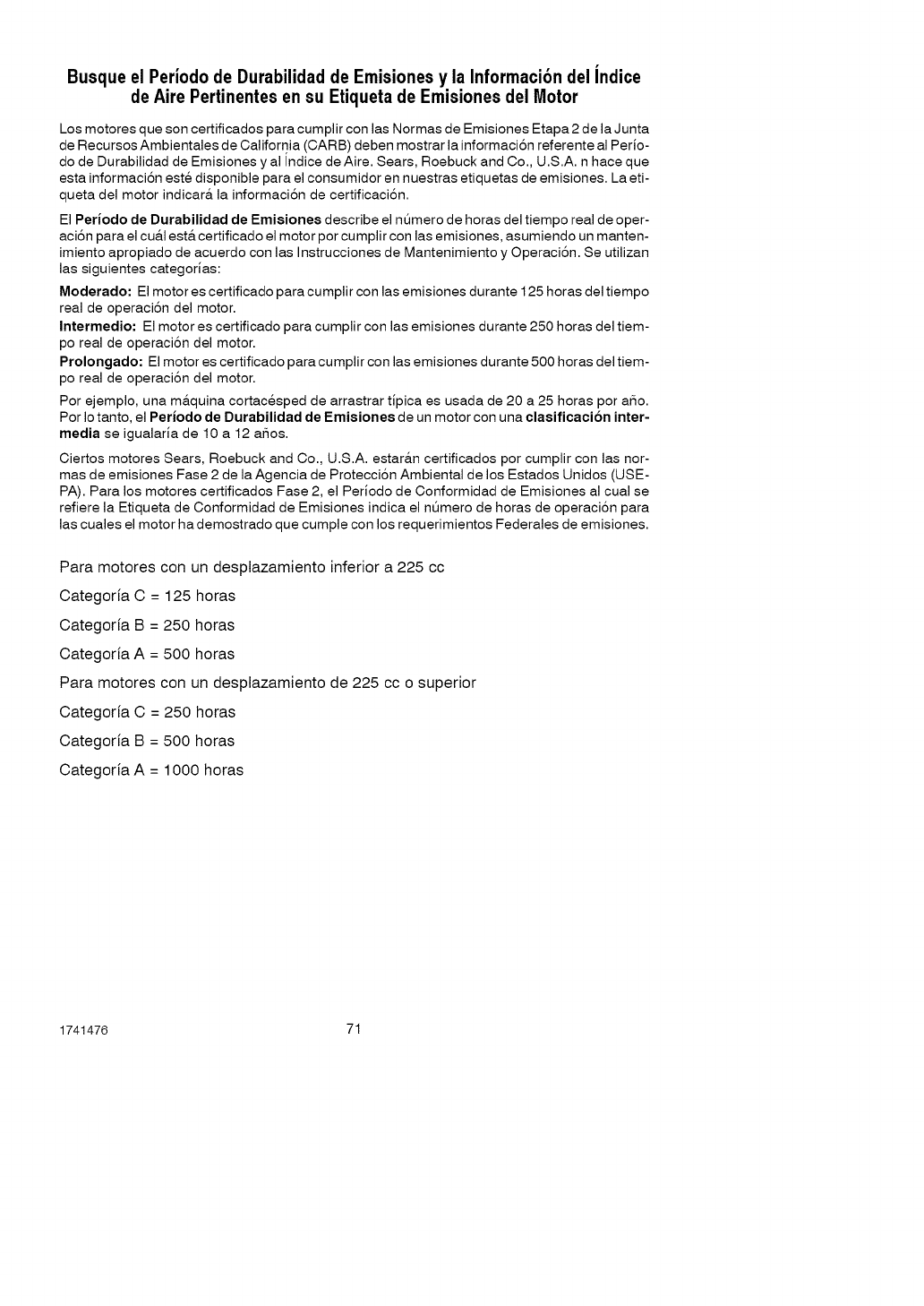
Busque el Periodo de Durabilidad de Emisiones y la Informaci6n del indice
de Aire Pertinentes en su Etiqueta de Emisiones del Motor
Los motores que son certificados para cumplir con las Normas de Emisiones Etapa 2 de la Junta
de Recursos Ambientales de California (CARB) deben mostrar la informaci6n referente al Perio-
do de Durabilidad de Emisiones y al Indice de Aire. Sears, Roebuck and Co., U.S.A. n hace que
esta informaci6n este disponible para el consumidor en nuestras etiquetas de emisiones. La eti-
queta del motor indicar& la informaci6n de certificaci6n.
El Periodo de Durabilidad de Emisiones describe el nQmero de horas del tiempo real de oper-
aci6n para el cu&l est& certificado el motor por cumplir con las emisiones, asumiendo un manten-
imiento apropiado de acuerdo con las Instrucciones de Mantenimiento y Operaci6n. Se utilizan
las siguientes categorias:
Moderado: El motor es certificado para cumplir con las emisiones durante 125 horas del tiempo
real de operaci6n del motor.
Intermedio: El motor es certificado para cumplir con las emisiones durante 250 horas del tiem-
po real de operaci6n del motor.
Prolongado: El motor es certificado para cumplir con las emisiones durante 500 horas del tiem-
po real de operaci6n del motor.
Por ejemplo, una m&quina cortacesped de arrastrar tipica es usada de 20 a 25 horas por aSo.
Por Io tanto, el Periodo de Durabilidad de Emisiones de un motor con una clasificacion inter-
media se igualaria de 10 a 12 a_os.
Ciertos motores Sears, Roebuck and Co., U.S.A. estaran certificados por cumplir con las nor-
mas de emisiones Fase 2 de la Agencia de Protecci6n Ambiental de los Estados Unidos (USE-
PA). Para los motores certificados Fase 2, el Periodo de Conformidad de Emisiones al cual se
refiere la Etiqueta de Conformidad de Emisiones indica el nt_mero de horas de operaci6n para
las cuales el motor ha demostrado que cumple con los requerimientos Federales de emisiones.
Para motores con un desplazamiento inferior a 225 cc
Categorfa C = 125 horas
Categorfa B = 250 horas
Categoria A = 500 horas
Para motores con un desplazamiento de 225 cc o superior
Categorfa C = 250 horas
Categorfa B = 500 horas
Categorfa A = 1000 horas
1741476 71
Your Home
For repair-in your home-of all major brand appliances,
lawn and garden equipment, or heating and coolingsystems,
no matter who made it, no matter who sold it!
For the replacement parts, accessories and
owner's manuals that you need to do-it-yourself.
For Sears professional installation of home appliances
and items like garage door openers and water heaters.
iiiiiiiiiiiiiii
1-800-4-MY-HOME ®(1-800-469-4663)
Ca,.ao_t,_e,da_o,ni0ht(_.S.A,andCanada)
www.seors.comwww.sear_.co
OurHome
iiiiiiiiiiiiii_ For repair of carry-in items like vacuums, lawn equipment,
and electronics, call or go on-line for the location of your nearest
Sears Parts & Repair Center.
iiiiiiiiiiiiii_
1-800-488-1222
Ca,,ao_ti_e,da_o,ni0ht(0SAon,_)
www._,_.com
TO purchase a protection agreement (USA.)
or maintenance agreement (Canada)on a product serviced by Sears:
iiiiiiiiiiiiii_ 1-800-827-6655 (USA) 1-800-361-6665 (Canada)
iiiiiiiiiiiiii_
iiiiiiiiiiiiii_
iiiiiiiiiiiiii_
Para pedir servicio de reparaci6n Au Canada pour service en frangais:
a domicilio,y pareordenarpiezas: 1-800-LE-FOYER Mc
1-8as-su-HOGAR® (_-8oo-s33-6937)
(_-888-784-_7) _,_._ea,s._ ...._iiili_!......
TM SM
® Registered Trademark /Trademark /Service Mark of Sears Brands, LLC
® Marca Registrada /TMMarca de F_bdca /SM Marca de Servicio de Sears Brands, LLC
Mc Marque de commerce /MDMarque d6pos6e de Sears Brands, LLC © Sears Brands, LLC
