Craftsman 536881510 User Manual SNOW THROWER Manuals And Guides L0803378
CRAFTSMAN Snowthrower, Gas Manual L0803378 CRAFTSMAN Snowthrower, Gas Owner's Manual, CRAFTSMAN Snowthrower, Gas installation guides
User Manual: Craftsman 536881510 536881510 CRAFTSMAN SNOW THROWER - Manuals and Guides View the owners manual for your CRAFTSMAN SNOW THROWER #536881510. Home:Lawn & Garden Parts:Craftsman Parts:Craftsman SNOW THROWER Manual
Open the PDF directly: View PDF ![]() .
.
Page Count: 80
I CRRFTSMRN1
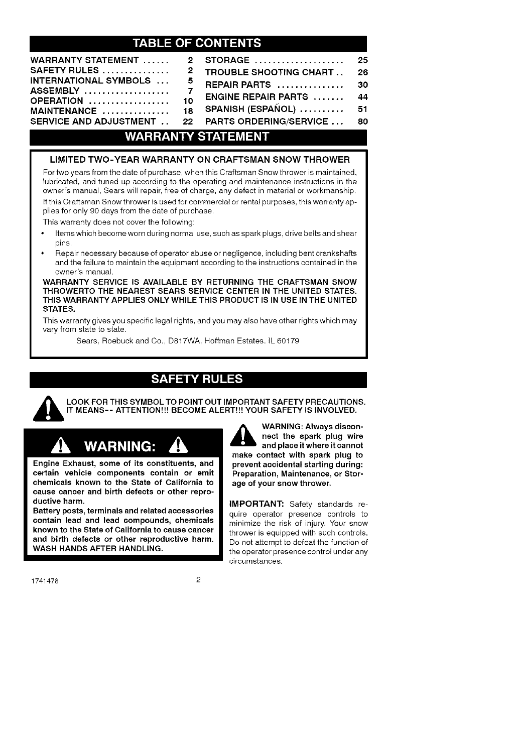
Operator's Manual
Snow Thrower
525 Series
Electric Start
22-inch Single Stage
Auger Propelled
Model 536.881510
CAUTION: Before using this product,
read this manual and follow all of its
Safety Rules and Operating Instructions,
Manual del usario
Quitanieves
de 22 pulgadas
525 Serie
Monoetapico
Arranque electrico
Propulsado por barrena
Modelo 536.881510
PRECAUCION: Antes de usar este producto,
lea este manual y siga todas las reglas de
seguridad e instrucciones de operaci6n,
Sears, Roebuck and Co., Hoffman Estates, IL 60179 U.S.A.
www.sears.com/craftsman
1741478
Rev. 01 07-01-2007
if'.._:] n=[o]_ [_o__
WARRANTY STATEMENT ...... 2
SAFETY RULES ............... 2
INTERNATIONAL SYMBOLS ,.. 5
ASSEMBLY ................... 7
OPERATION .................. 10
MAINTENANCE ............... 18
SERVICE AND ADJUSTMENT .. 22
STORAGE .................... 25
TROUBLE SHOOTING CHART,. 26
REPAIR PARTS ............... 30
ENGINE REPAIR PARTS ....... 44
SPANISH (ESPAI_IOL) .......... 51
PARTS ORDERING/SERVICE ... 80
|flv/,_1;| ;r,_1_i ik'd[-_
LIMITED TWO-YEAR WARRANTY ON CRAFTSMAN SNOW THROWER
For two years from the date of purchase, when this Craftsman Snow thrower is maintained,
lubricated, and tuned up according to the operating and maintenance instructions in the
owner's manual, Sears will repair, free of charge, any defect in material or workmanship.
If this Craftsman Snow thrower is used for commercial or renta! purposes, this warranty ap-
plies for only 90 days from the date of purchase.
This warranty does not cover the following:
Items which become worn during normal use, such as spark plugs, drive belts and shear
pins.
Repair necessary because of operator abuse or negligence, including bent crankshafts
and the failure to maintain the equipment according to the instructions contained in the
owner's manual.
WARRANTY SERVICE IS AVAILABLE BY RETURNING THE CRAFTSMAN SNOW
THROWERTO THE NEAREST SEARS SERVICE CENTER IN THE UNITED STATES.
THIS WARRANTY APPLIES ONLY WHILE THIS PRODUCT IS IN USE IN THE UNITED
STATES.
This warranty gives you specific legal rights, and you may also have other rights which may
vary from state to state.
Sears, Roebuck and Co., D817WA, Roffman Estates. IL 60179
_IL OOK FOR THIS SYMBOL TO POINT OUT IMPORTANT SAFETY PRECAUTIONS.
IT MEANS-- ATTENTION!!! BECOME ALERT!!! YOUR SAFETY IS INVOLVED.
_lb WARNING: Always discon-
nect the spark plug wire
and place it where it cannot
make contact with spark plug to
prevent accidental starting during:
Preparation, Maintenance, or Stor-
age of your snow thrower.
Engine Exhaust, some of its constituents, and
certain vehicle components contain or emit
chemicals known to the State of California to
cause cancer and birth defects or other repro-
ductive harm.
Battery posts, terminals and related accessories
contain lead and lead compounds, chemicals
known to the State of California to cause cancer
and birth defects or other reproductive harm.
WASH HANDS AFTER HANDLING.
IMPORTANT: Safety standards re-
quire operator presence controls to
minimize the risk of injury. Your snow
thrower is equipped with such controls.
Do not attempt to defeat the function of
the operator presence control under any
circumstances.
1741478 2
,_ WARNING: This snow thrower is
capable of amputating hands
and feet and throwing objects.
Failure to observe the following safety in-
structions could result in serious injury.
TRAINING
1. Read this operating and service instruction
manual carefully. Be thoroughly familiar
with the controls and the proper use of the
snow thrower. Know how to stop the snow
thrower and disengage the controls quick-
ly.
2. Never allow children to operate the snow
thrower. Never allow adults to operate the
snow thrower without proper instruction.
3. Keep the area of operation clear of alt per-
sons, particularly smalt children and pets.
4. Exercise caution to avoid slipping or falling
especially when operating in reverse.
PREPARATION
2,
3.
1741478
Thoroughly inspect the area where the
snow thrower is to be used and remove all
doormats, sleds, boards, wires, and other
foreign objects.
Disengage all clutches before starting the
engine (motor).
Do not operate the snow thrower without
wearing adequate winter outer garments.
Wear footwear that will improve footing on
slippery surfaces. Avoid loose fitting cloth-
ing that can get caught in moving parts.
Handle fueI with care; it is highly flam-
mable.
a. Use an approved fuel container.
b. Never remove fuel tank cap or add fuel
to a running engine (motor) or hot en-
gine (motor).
c. Fill fuet tank outdoors with extreme
care. Never fitl fuel tank indoors.
d. Replace fuel cap securely and wipe up
spilled fuel.
e. Never store fuet or snow thrower with
fuel in the tank inside of a building
where fumes may reach an open flame
or spark.
f. Check fuel supply before each use, a!-
lowing space for expansion as the heat
of the engine (motor) and/or sun can
cause fuel to expand.
g. Never fill containers inside a vehicle or
on a truck or trailer bed with a plastic
liner. Always place containers on the
3
5.
6.
7.
ground, away from vehicle, before fill-
ing.
h. When practical, remove gas-powered
equipment from the truck or trailer and
refuel it on the ground. If this is not pos-
sible, then refuel such equipment on a
trailer with a portable container, rather
than from a gasoline dispenser nozzle.
i. Keep the nozzle in contact with the rim
of the fuel tank container opening at all
times, until refueling is complete. Do
not use a nozzle lock-open device.
j. If fuet is spilled on clothing, change
clothing immediately.
For all snow throwers with electric starting
motors use electric starting extension
cords certified CSA/UL Use onty with a re-
ceptacle that has been installed in accord-
ance with local inspection authorities.
Let engine (motor) and snow thrower ad-
just to outdoor temperatures before starting
to clear snow.
Always wear safety glasses or eye shields
during operation or while performing an ad-
justment or repair to protect eyes from
foreign objects that may be thrown from the
snow thrower.
OPERATION
1. Do not operate this snow thrower if you are
taking drugs or other medication which can
cause drowsiness or affect your ability to
operate this snow thrower.
2. Do not use the snow thrower if you are
mentally or physically unable to operate the
snow thrower safely.
3. Do not put hands or feet near or under ro-
tating parts. Keep clear of the discharge
opening at all times.
4. Exercise extreme caution when operating
on or crossing gravel drives, walks or
roads. Stay alert for hidden hazards or
traffic.
5. After striking a foreign object, stop the en-
gine (motor), remove the wire from the
spark plug, thoroughly inspect snow
thrower for any damage, and repair the
damage before restarting and operating
the snow thrower.
6. If the snow thrower should start to vibrate
abnormally, stop the engine (motor) and
check immediately for the cause. Vibration
is generally a warning of trouble.
7. Stop the engine (motor) whenever you
leave the operating position, before un-
clogging the auger/impeller housing or dis-
charge chute and when making any
repairs, adjustments, or inspections.
8. Whencleaning,repairing,orinspecting,
makecertaintheauger/impellerandall
movingpartshavestoppedandallcontrols
aredisengaged.Disconnectthesparkptug
wireandkeepthewireawayfromthespark
plugtopreventaccidentalstarting.
9. Takealipossibleprecautionswhenleaving
thesnowthrowerunattended.Disengage
theauger/impeller,stopengine(motor),
andremovekey.
10.Donotstartorrunengineinenclosedarea,
evenif doorsorwindowsareopen.Ex-
haustfumesaredangerous(containing
CARBONMONOXIDE,anODORLESS
andDEADLYGAS).
11.Exerciseextremecautionifoperatingon
steepsloppingsurfaces.
12.Donotclearsnowacrossthefaceof
slopes.Exerciseextremecautionwhen
changingdirectiononslopes.Donotat-
tempttoclearsteepslopes.
13.Neveroperatethesnowthrowerwithout
properguards,platesorothersafetypro-
tectivedevicesinplace.
14.Neveroperatethesnowthrowernearen-
closures,automobiles,windowwetts,drop-
offs,andthetikewithoutproperadjustment
ofthesnowdischargeangle.Keepchildren
andpetsaway.
15.Donotoverloadthesnowthrowercapacity
byattemptingtoclearsnowattoofasta
rate.
16.Neveroperatethesnowthrowerathigh
transportspeedsonslipperysurfaces.
Lookbehindandusecarewhenbacking
up.
17.Neverdirectdischargeatbystandersor
allowanyoneinfrontofthesnowthrower.
18.Disengagepowertothecollector/impeller
whensnowthroweristransportedornotin
use.
19.Useonlyattachmentsandaccessoriesap-
provedbythemanufacturerofthesnow
thrower(suchastirechains,electricstart
kits,ect.).
20.Neveroperatethesnowthrowerwithout
goodvisibilityorlight.Alwaysbesureof
yourfootingandkeepafirmholdonthe
handles.Walk;neverrun.
21.Donotover-reach.Keepproperfooting
andbalanceatalltimes.
22.Donotusethesnowthroweronsurfaces
abovegroundlevelsuchasroofsofresi-
dences,garages,porchesorothersuch
structuresorbuildings.
23.Thissnowthrowerisforuseonsidewalks,
drivewaysandothergroundlevelsur-
faces.
24.Nevertouchahotengineormuffler.
,_ WARNING: This snow thrower is
for use on sidewalks, driveways
and other ground level surfaces.
Caution should be exercised while using on
steep sloping surfaces. DO NOT USE
SNOW THROWER ON SURFACES ABOVE
GROUND LEVEL such as roofs of resi-
dences, garages, porches or other such
structures or buildings.
MAINTENANCE AND STORAGE
Clearing AClogged Discharge Chute
,_ WARNING: Hand contact with
the rotating impeller inside the
discharge chute is the most
common cause of injury associated with
snow throwers. Never use your hand to
clean out the discharge chute.
To Clear The Chute:
•SHUT OFFTHE ENGINEt
•Wait 10 seconds to be sure that the im-
peller blades have stopped rotating.
•Always use a clean-out tool, not your
hands.
1. Check shear bolts and other bolts at fre-
quent intervals for proper tightness to be
sure the snow thrower is in safe working
condition.
2. Store the snowthrower away from ignition
sources or appliances that have a pilot
light, such as hot water and space heaters,
clothes dryers, etc.... Allow the engine
(motor) to cool before storing in any enclos-
ure.
3. Always refer to operator's guide instruc-
tions for important details if the snow
thrower is to be stored for an extended
period.
4. Maintain or replace safety and instruction
labels, as necessary.
5. Run the snow thrower a few minutes after
throwing snow to prevent freeze-up of the
auger/impeller.
1741478 4
_"_"_'_o_l_..-_
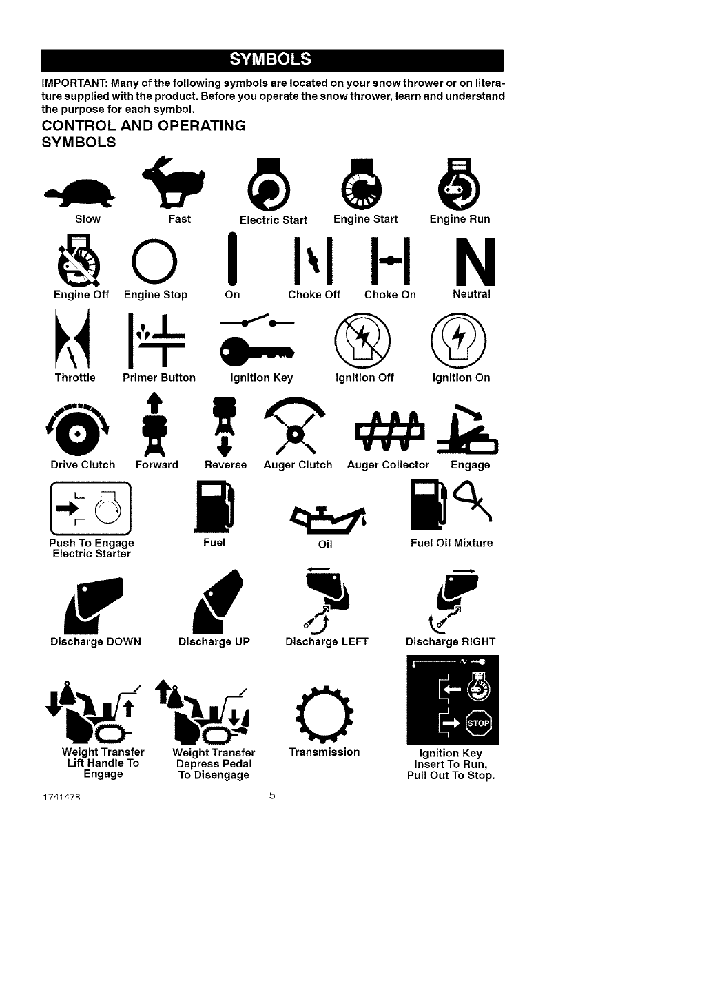
IMPORTANT: Many of the following symbols are located on your snow thrower or on litera-
ture supplied with the product. Before you operate the snow thrower, learn and understand
the purpose for each symbol.
CONTROL AND OPERATING
SYMBOLS
Slow Fast Electric Start Engine Start Engine Run
@0 II-I N
Engine Off Engine Stop On Choke Off Choke On Neutral
Throttle Primer Button Ignition Key ®®
Ignition Off Ignition On
VVV
Drive Clutch Forward Reverse Auger Clutch Auger Collector Engage
Push To Engage Fuel Oil Fuel Oil Mixture
Electric Starter
w d -#
Discharge DOWN Discharge UP Discharge LEFT Discharge RIGHT
Weight Transfer Weight Transfer Transmission Ignition Key
Lift Handle To Depress Pedal Insert To Run,
Engage To Disengage Pull Out To Stop.
1741478
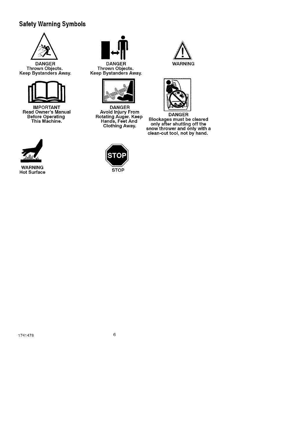
Safety Warning Symbols
A
DANGER
Thrown Objects.
Keep Bystanders Away.
IMPORTANT
Read Owner's Manual
Before Operating
This Machine.
DANGER
Thrown Objects.
Keep Bystanders Away.
DANGER
Avoid Injury From
Rotating Auger. Keep
Hands, Feet And
Clothing Away.
A
WARNING
DANGER
Blockages must be cleared
only after shutting off the
snow thrower and only with a
clean-out tool, not by hand.
WARNING
Hot Surface STOP
1741478 6
Contents of Parts Bag
1 - Owner's Manual (not shown)
1 - Electric Starter Cord (not shown)
J_
1- Container 5W30 oi!
1 - Fuel Stabilizer (not shown)
_lb ARNING: Always wearsafety glasses or eye shields
while assembling snow
thrower.
TOOLS REQUIRED
1 - Knife to cut carton
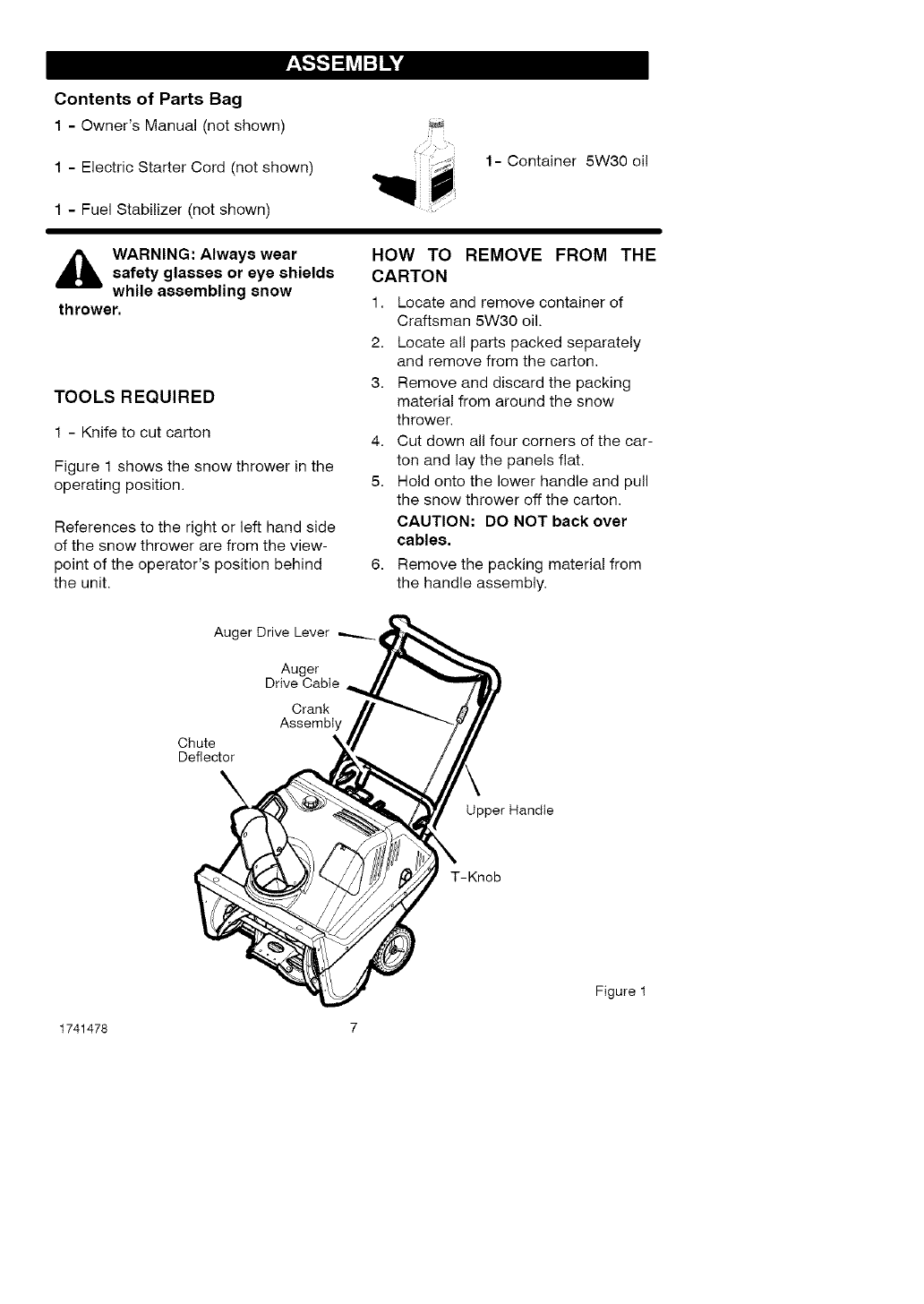
Figure 1 shows the snow thrower in the
operating position.
References to the right or left hand side
of the snow thrower are from the view-
point of the operator's position behind
the unit.
HOW TO REMOVE FROM THE
CARTON
1. Locate and remove container of
Craftsman 5W30 oil.
2. Locate all parts packed separately
and remove from the carton,
3. Remove and discard the packing
material from around the snow
thrower.
4. Cut down all four corners of the car-
ton and lay the panels flat.
5. Hold onto the lower handle and pull
the snow thrower off the carton.
CAUTION: DO NOT back over
cables,
6. Remove the packing material from
the handle assembly.
Auger Drive Lever
Auger
Drive Cable
Crank
Assembly
Chute
Deflector
Upper Handle
T-Knob
Figure 1
1741478 7
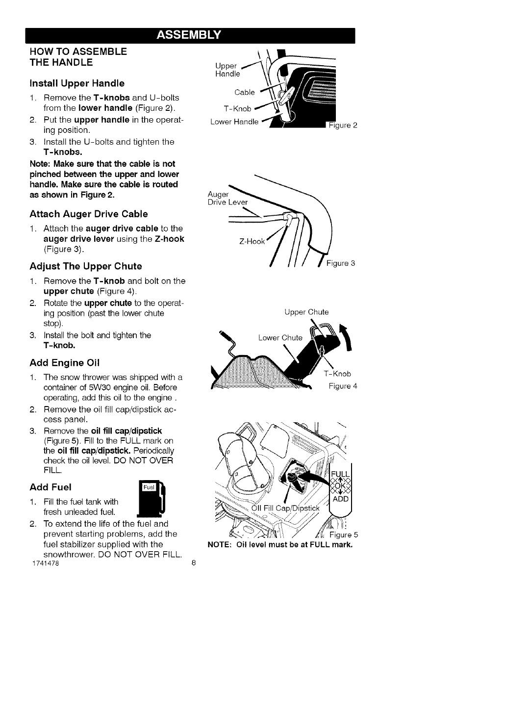
HOW TO ASSEMBLE
THE HANDLE
Install Upper Handle
1. Remove the T-knobs and U-bolts
from the lower handle (Figure 2).
2. Put the upper handle in the operat-
ing position.
3. Install the U-bolts and tighten the
T-knobs.
Note: Make sure that the cable is not
pinched between the upper and lower
handle, Make sure the cable is routed
as shown in Figure 2.
Attach Auger Drive Cable
1. Attach the auger drive cable to the
auger drive lever using the Z-hook
(Figure 3).
Adjust The Upper Chute
1. Remove the T-knob and bolt on the
upper chute (Figure 4).
2. Rotate the upper chute to the operat-
ing position (past the lower chute
stop).
3. Install the bolt and tighten the
T-knob.
Add Engine Oil
1. The snow thrower was shipped with a
container of 5W30 engine oil. Before
operating, add this oil to the engine.
2. Remove the oil fill cap/dipstick ac-
cess panel.
3. Remove the oil fill cap/dipstick
(Figure 5). Fill to the FULL mark on
the oil fill cap/dipstick. Periodically
check the oil level. DO NOT OVER
FILL.
Add Fuel
1. Fil! the fuel tank with
fresh unleaded fue!.
2. To extend the life of the fuel and
prevent starting problems, add the
fuel stabilizer supplied with the
snowthrower. DO NOT OVER FILL.
1741478
Au(
Upper
Handle
Cable
T-Knob
gure 2
Drive Lever
Figure 3
Upper Chute
Lower Chute
X
T-Knob
Figure 4
Oil Fill
Figure 5
NOTE: Oil level must be at FULL mark.
_" CHECKLIST
Before you operate your new snow
thrower, to ensure that you receive the
best performance and satisfaction from
this quality product, please review the
following checklist:
_" All assembly instructions have been
completed.
_" The discharge chute rotates freely.
_" No remaining loose parts in carton.
While learning how to use your snow
thrower, pay extra attention to the fol-
lowing important items:
_" Make sure engine oil is at proper lev-
el. Use a high quality detergent oil
classified "For Service SG, SH, S J,
SL, or higher".
_" Make sure the fuel tank is filled prop-
erly with clean, fresh, unleaded gaso-
line with a minimum of 85 octane.
_" Become familiar with the location of
all controls and understand their
function.
_" Before starting the engine, make sure
all controls operate correctly.
1741478 9
[o)_J_P_o)_l
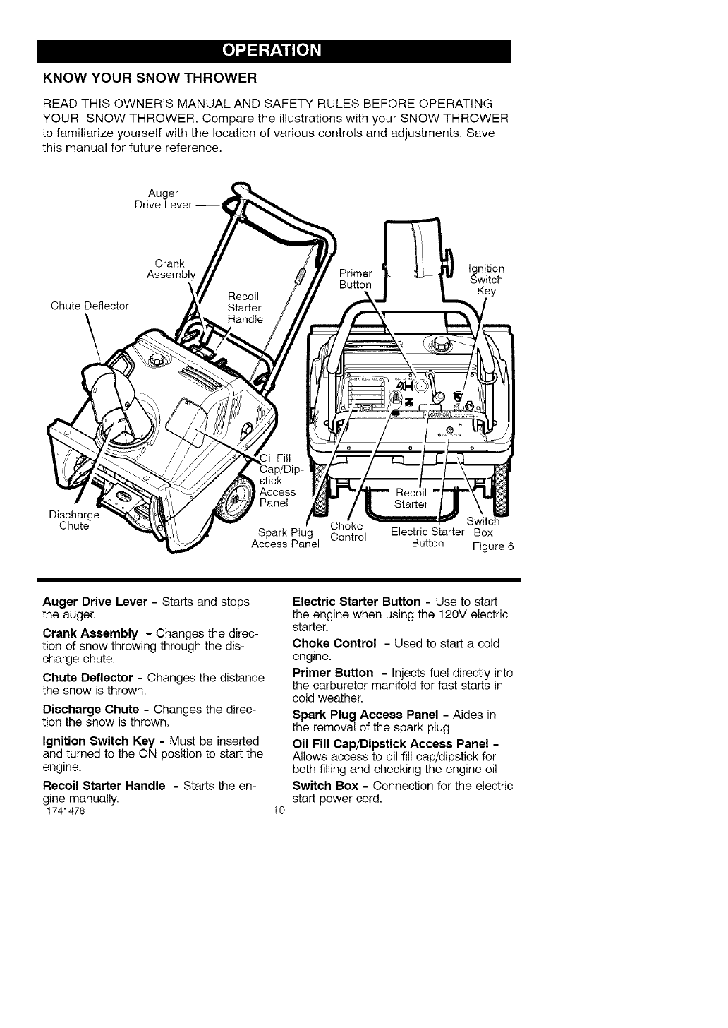
KNOW YOUR SNOW THROWER
READ THIS OWNER'S MANUAL AND SAFETY RULES BEFORE OPERATING
YOUR SNOW THROWER. Compare the illustrations with your SNOW THROWER
to familiarize yourself with the location of various controls and adjustments. Save
this manual for future reference.
Auger
Drive Lever-
Chute Deflector
\
Crank Ignition
Assembly Primer Switch
Key
Discharge
Chute
stick
Access
Panel
Choke
Spark Ptug Control Electric Starter Box
Access Panel Button Figure 6
Auger Drive Lever -Starts and stops
the auger.
Crank Assembly - Changes the direc-
tion of snow throwing through the dis-
charge chute,
Chute Deflector - Changes the distance
the snow is thrown.
Discharge Chute - Changes the direc-
tion the snow is thrown,
Ignition Switch Key - Must be inserted
and turned to the ON position to start the
engine.
Recoil Starter Handle - Starts the en-
gine manually.
1741478 10
Electric Starter Button - Use to start
the engine when using the 120V electric
starter,
Choke Control - Used to start a cold
engine.
Primer Button - Injects fuel directly into
the carburetor manifold for fast starts in
cold weather.
Spark Plug Access Panel - Aides in
the removal of the spark plug.
Oil Fill Cap/Dipstick Access Panel -
Allows access to oil fill cap/dipstick for
both filling and checking the engine oil
Switch Box - Connection for the electric
start power cord.
[o)_J_P_o)_l
_i ARNING: Read Owner's
Manual before operating
machine. Never direct dis-
charge toward bystanders. Stop the
engine before unclogging discharge
chute or auger housing and before
leaving the machine.
TO STOP YOUR
SNOW THROWER
1. To stop throwing snow, release the
auger drive lever. See Figure 6.
NOTE: If the snow thrower contin-
ues to slowly move forward, see
"How To Adjust The Auger Control
Cable" in the Service And Adjust-
ment Section.
2. To stop the engine, move the igni-
tion switch key to the off position.
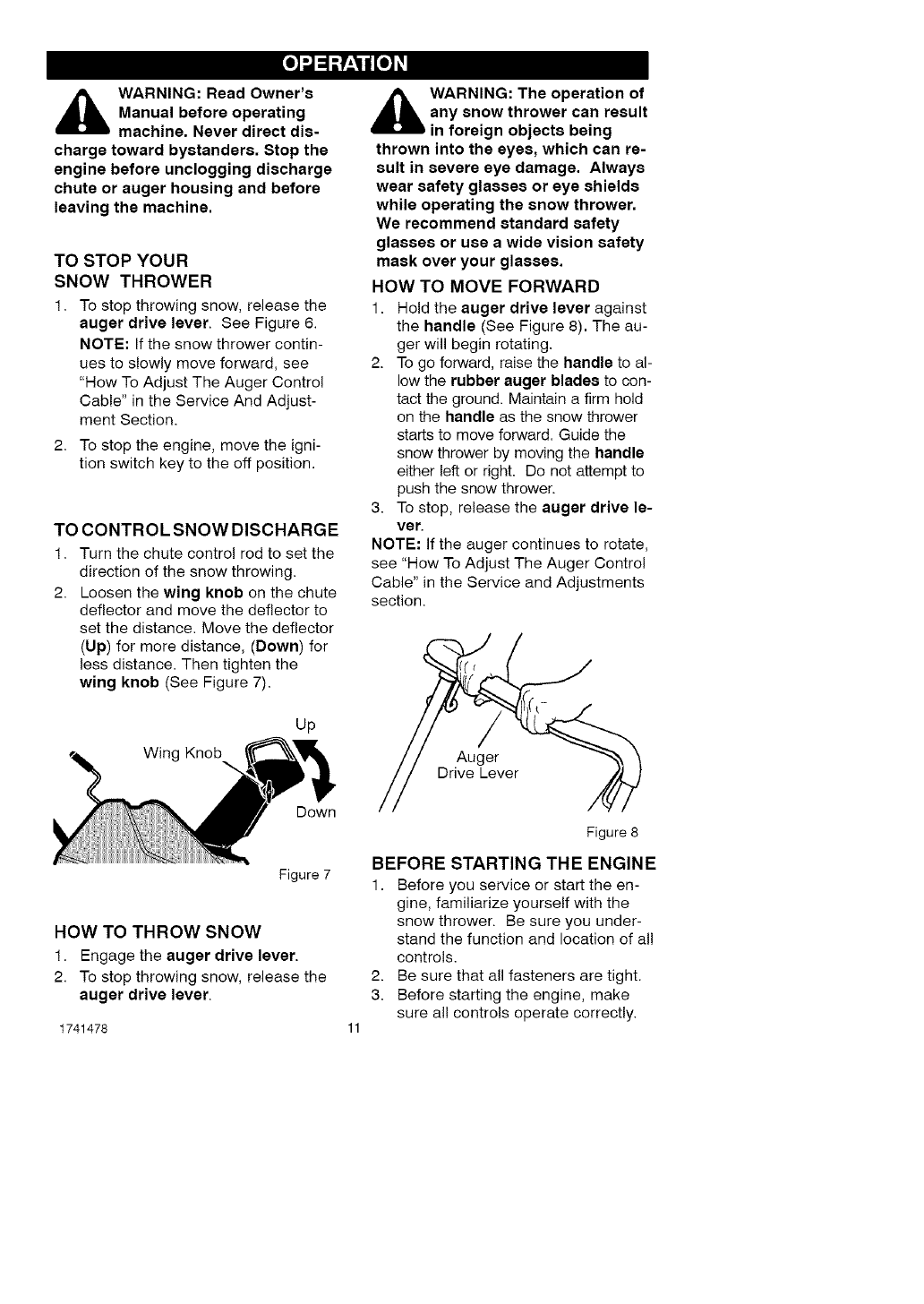
TO CONTROL SNOW DISCHARGE
1. Turn the chute control rod to set the
direction of the snow throwing.
2. Loosen the wing knob on the chute
deflector and move the deflector to
set the distance. Move the deflector
(Up) for more distance, (Down) for
less distance. Then tighten the
wing knob (See Figure 7).
Up
Winc
Down
Figure 7
HOW TO THROW SNOW
1. Engage the auger drive lever.
2. To stop throwing snow, release the
auger drive lever.
1741478
_i ARNING: The operation of
any snow thrower can result
in foreign objects being
thrown into the eyes, which can re-
sult in severe eye damage. Always
wear safety glasses or eye shields
while operating the snow thrower.
We recommend standard safety
glasses or use a wide vision safety
mask over your glasses.
HOW TO MOVE FORWARD
1. Hold the auger drive lever against
the handle (See Figure 8). The au-
ger will begin rotating.
2. To go forward, raise the handle to al-
low the rubber auger blades to con-
tact the ground. Maintain a firm hold
on the handle as the snow thrower
starts to move forward. Guide the
snow thrower by moving the handle
either left or right. Do not attempt to
push the snow thrower.
3. To stop, release the auger drive le-
ver.
NOTE: If the auger continues to rotate,
see "How To Adjust The Auger Control
Cable" in the Service and Adjustments
section.
Auger
Drive Lever
Figure 8
BEFORE STARTING THE ENGINE
1. Before you service or start the en-
gine, familiarize yourself with the
snow thrower. Be sure you under-
stand the function and location of all
controls.
2. Be sure that all fasteners are tight.
3. Before starting the engine, make
sure all controls operate correctly.
[o)_J_P_o)_l
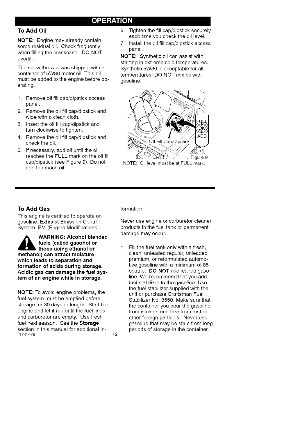
To Add Oil
NOTE: Engine may already contain
some residual oil. Check frequently
when filling the crankcase. DO NOT
overfil!.
The snow thrower was shipped with a
container of 5W30 motor oil. This oil
must be added to the engine before op-
erating.
1. Remove oi! fi!! cap/dipstick access
panel.
2. Remove the oil fill cap/dipstick and
wipe with a clean cloth.
3. Insert the oil fill cap/dipstick and
turn clockwise to tighten.
4. Remove the oil fill cap/dipstick and
check the oil.
5. If necessary, add oil until the oil
reaches the FULL mark on the oil fill
cap/dipstick (see Figure 9). Do not
add too much oil.
6. Tighten the fill cap/dipstick securely
each time you check the oil level.
7. Install the oil fill cap/dipstick access
panel.
NOTE: Synthetic oil can assist with
starting in extreme cold temperatures.
Synthetic 5W30 is acceptable for all
temperatures. DO NOT mix oil with
gasoline.
Oil Fill
!i.'
,Figure 9
NOTE: Oil level must be at FULL mark.
To Add Gas
This engine is certified to operate on
gasoline. Exhaust Emission Control
System: EM (Engine Modifications).
AARNING: Alcohol blended
fuels (called gaeohol or
those using ethanol or
methanol) can attract moisture
which leads to separation and
formation of acids during storage.
Acidic gas can damage the fuel sys-
tem of an engine while in storage.
NOTE: To avoid engine problems, the
fuel system must be emptied before
storage for 30 days or longer. Start the
engine and let it run until the fuel lines
and carburetor are empty. Use fresh
fuel next season. See the Storage
section in this manual for additional in-
1741478
formation.
Never use engine or carburetor cleaner
products in the fuel tank or permanent
damage may occur.
12
Fill the fuel tank only with a fresh,
clean, unleaded regular, unleaded
premium, or reformulated automo-
tive gasoline with a minimum of 85
octane. DO NOT use leaded gaso-
line. We recommend that you add
fuel stabilizer to the gasoline. Use
the fuel stabilizer supplied with the
unit or purchase Craftsman Fuel
Stabilizer No. 3550. Make sure that
the container you pour the gasoline
from is clean and free from rust or
other foreign particles. Never use
gasoline that may be stale from long
periods of storage in the container.
[o)_J_P_o)_l
,_ WARNING: Gasoline is flam-
mable. Always use caution
when handling or storing
gasoline.
•Turn engine off and let engine
cool at least two minutes before
removing the gas cap.
•Do not fill fuel tank while snow
thrower is running, when it is hot,
or when snow thrower is in an en-
closed area.
•Keep away from open flame or an
electrical spark and do not smoke
while filling the fuel tank.
•Never fill the tank completely. Fill
the tank to approximately 1-1/2"
below the top of the tank opening
to provide space for expansion of
fuel.
•Always fill fuel tank outdoors and
use a funnel or spout to prevent
spilling.
•Make sure to wipe up any spilled
fuel before stating the engine.
•Store gasoline in a clean, ap-
proved container and keep the
cap in place on the container.
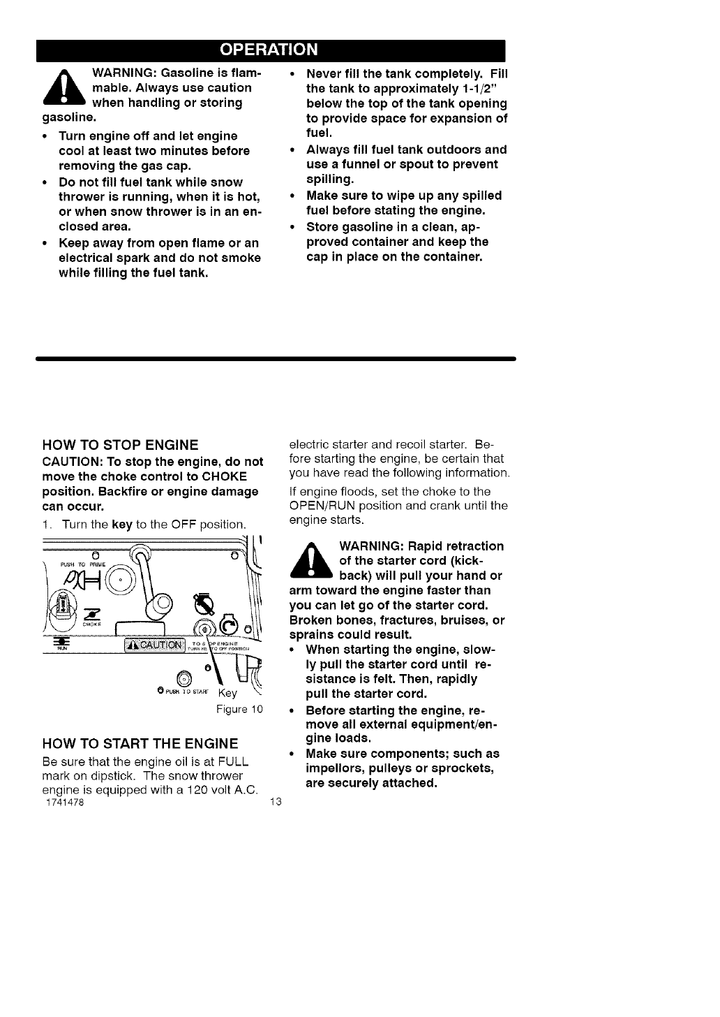
HOW TO STOP ENGINE
CAUTION: To stop the engine, do not
move the choke control to CHOKE
position. Backfire or engine damage
can occur.
1. Turn the key to the OFF position.
' f
_.T Key
Figure 10
HOW TO START THE ENGINE
Be sure that the engine oil is at FULL
mark on dipstick. The snow thrower
engine is equipped with a 120 volt A.C.
1741478 13
electric starter and recoil starter. Be-
fore starting the engine, be certain that
you have read the following information.
If engine floods, set the choke to the
OPEN/RUN position and crank until the
engine starts.
,_ WARNING: Rapid retraction
of the starter cord (kick-
back) will pull your hand or
arm toward the engine faster than
you can let go of the starter cord.
Broken bones, fractures, bruises, or
sprains could result.
•When starting the engine, slow-
ly pull the starter cord until re-
sistance is felt. Then, rapidly
pull the starter cord.
•Before starting the engine, re-
move all external equipment/en-
gine loads.
•Make sure components; such as
impellors, pulleys or sprockets,
are securely attached.
[o)_J_P_o)_l
_lb ARNING: The starter i8
equipped with a three-wire
power cord and plug and i8
designed to operate on 120 volt AC
household current. It must be prop-
erly grounded at all times to avoid
the possibility of electrical shock
which may be injurious to operator.
•Follow all instructions carefully
as set forth in the "To Start En-
gine" section.
•Determine that your house wiring
i8 a three-wire grounded system.
Ask a licensed electrician if you
are not sure. If your house wire
system is not a three-wire system,
do not use this electric starter un-
der any conditions.
If your system is grounded and a
three-hole receptacle is not avail-
able at the point your starter will
normally be used, one should be
installed by a licensed electrician.
When connecting 120 volt AC
"Power Cord", always connect the
cord to the Switch Box on the en-
gine first, then plug the other end
into the three-hole grounded re-
ceptacle. When disconnecting
"Power Cord", always unplug the
end in the three-hole grounded re-
ceptacle first.
How To Start A Cold Engine
1. Make sure auger drive lever is in
the disengaged (RELEASED) posi-
tion.
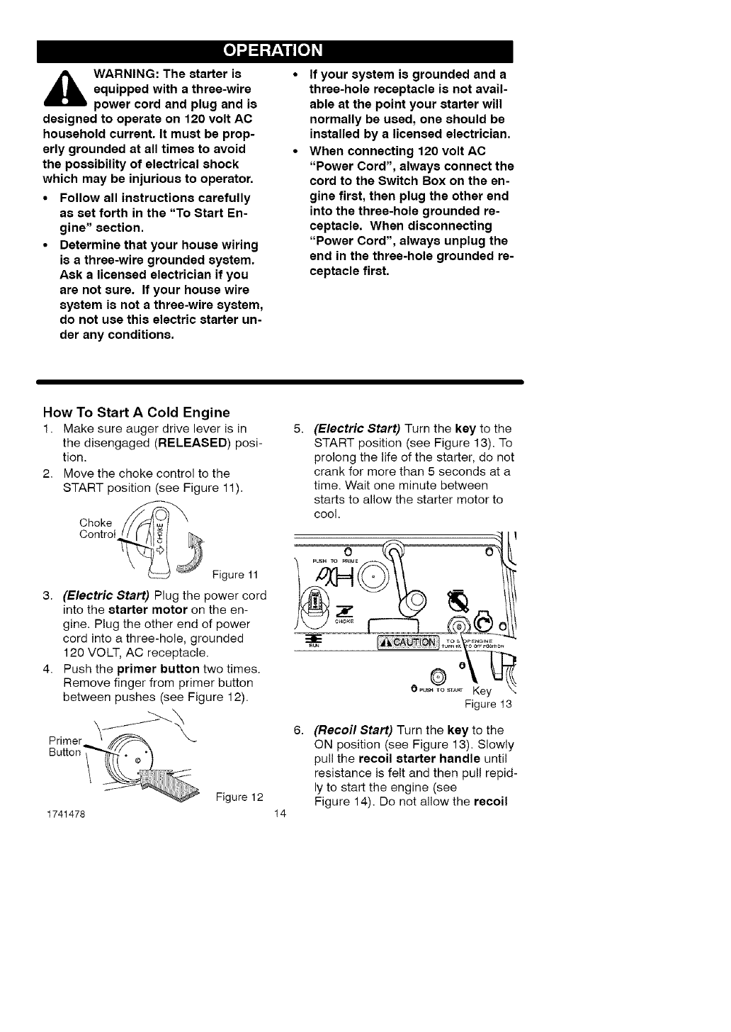
2. Move the choke control to the
START position (see Figure 11).
Choke
Control
Figure 11
3. (Electric Start) Plug the power cord
into the starter motor on the en-
gine. Plug the other end of power
cord into a three-hole, grounded
120 VOLT, AC receptacle.
4. Push the primer button two times.
Remove finger from primer button
between pushes (see Figure 12).
Primer
Button"
1741478
Figure 12
14
(Electric Start) Turn the key to the
START position (see Figure 13). To
prolong the life of the starter, do not
crank for more than 5 seconds at a
time. Wait one minute between
starts to allow the starter motor to
cool.
OPu_o_,._ Key !
Figure t3
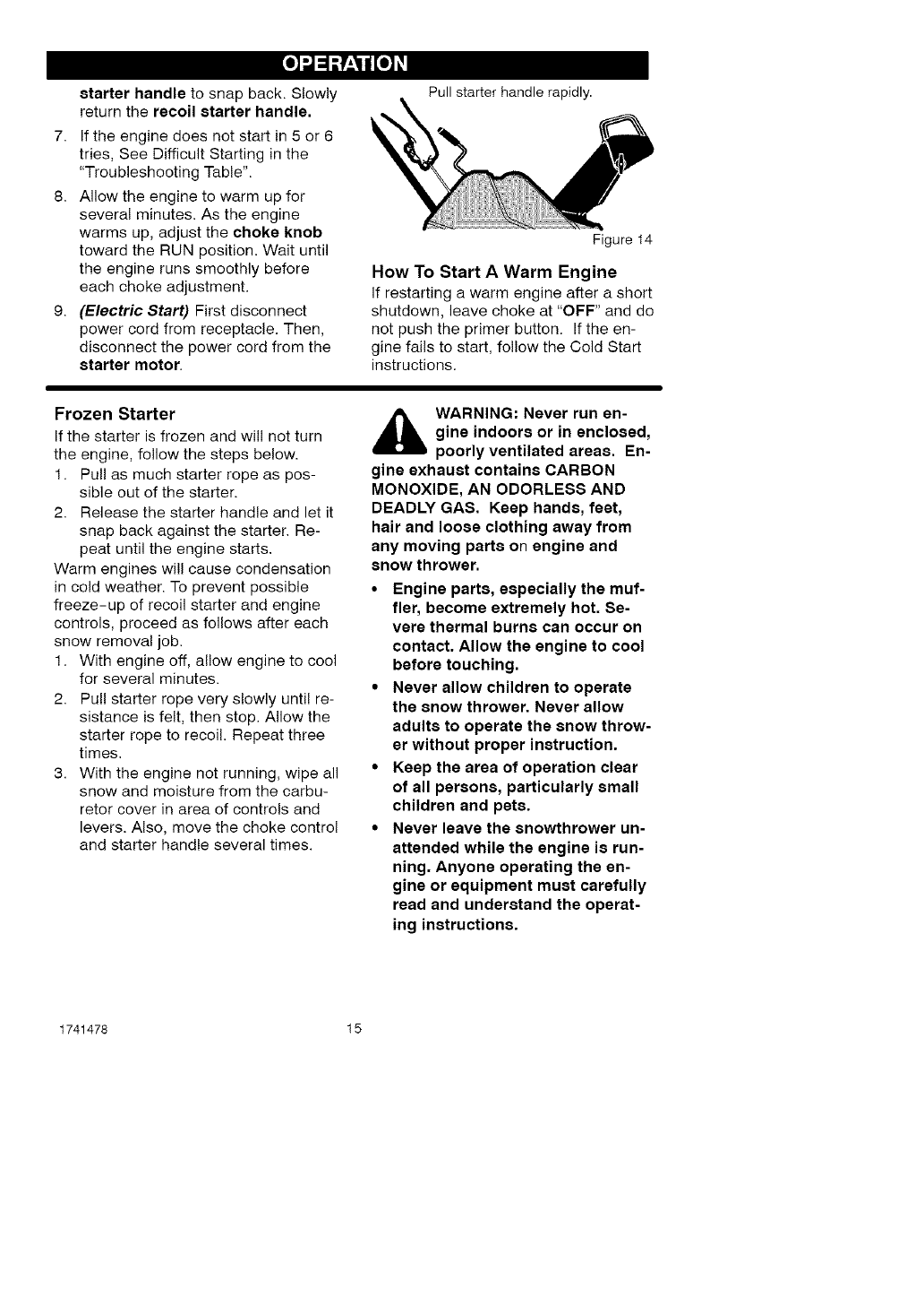
(Recoil Start) Turn the key to the
ON position (see Figure 13). Slowly
pull the recoil starter handle until
resistance is felt and then pull tepid-
ly to start the engine (see
Figure 14). Do not allow the recoil
[o)_J_P_o)_l
starter handle to snap back. Slowly
return the recoil starter handle.
7. If the engine does not start in 5 or 6
tries, See Difficult Starting in the
"Troubleshooting Table".
8. Allow the engine to warm up for
several minutes. As the engine
warms up, adjust the choke knob
toward the RUN position. Wait until
the engine runs smoothly before
each choke adjustment.
9. (Electric Start) First disconnect
power cord from receptacle. Then,
disconnect the power cord from the
starter motor.
Pull starter handle rapidly.
Figure 14
How To Start AWarm Engine
if restarting a warm engine after a short
shutdown, leave choke at "OFF" and do
not push the primer button. If the en-
gine fails to start, fol!ow the Cold Start
instructions.
Frozen Starter
If the starter is frozen and will not turn
the engine, follow the steps below.
1. Pull as much starter rope as pos-
sible out of the starter.
2. Release the starter handle and let it
snap back against the starter. Re-
peat until the engine starts.
Warm engines will cause condensation
in cold weather. To prevent possible
freeze-up of recoil starter and engine
controls, proceed as follows after each
snow removal job.
1. With engine off, allow engine to cool
for several minutes.
2. Pull starter rope very slowly until re-
sistance is felt, then stop. Allow the
starter rope to recoil. Repeat three
times.
3. With the engine not running, wipe all
snow and moisture from the carbu-
retor cover in area of controls and
levers. Also, move the choke control
and starter handle several times.
,_ WARNING: Never run en-
gine indoors or in enclosed,
poorly ventilated areas. En-
gine exhaust contains CARBON
MONOXIDE, AN ODORLESS AND
DEADLY GAS. Keep hands, feet,
hair and loose clothing away from
any moving parts on engine and
snow thrower.
•Engine parts, especially the muf-
fler, become extremely hot. Se-
vere thermal burns can occur on
contact. Allow the engine to cool
before touching.
•Never allow children to operate
the snow thrower. Never allow
adults to operate the snow throw-
er without proper instruction.
•Keep the area of operation clear
of all persons, particularly small
children and pets.
•Never leave the snowthrower un-
attended while the engine is run-
ning. Anyone operating the en-
gine or equipment must carefully
read and understand the operat-
ing instructions.
1741478 15
[o)_J_P_o)_l
HOW TO CLEAR
A CLOGGED DISCHARGE CHUTE
WARNING: Hand contact
with the rotating impeller in-
side the discharge chute is
the most common cause of injury as-
sociated with snow throwers. Never
use your hand to clean out the dis-
charge chute.
To Clear The Chute:
• SHUT OFF THE ENGINE!
• Wait 10 seconds to be sure that the
impeller blades have stopped ro-
tating.
•Always use a clean-out tool, not
your hands.
Use a clean-out tool to remove snow
from the auger housing.
• Release the auger drive lever.
• Pull out the key.
• Disconnect spark plug wire.
• Do not place your hands in the au-
ger or discharge chute. Use a
clean-out tool to remove snow or
debris.
_lb ARNING: Blockage must
be cleared only after shut-
ting off the snow thrower
and only with a clean-out tool, not
by hand.
SNOW THROWING TIPS
1. When the handle is raised, the au-
ger blades will engage the ground
and the snow thrower will move for-
ward. When the auger drive lever is
released, the auger blades will stop.
if the blades do not stop, see "How
To Adjust The Auger Drive Cable" in
the Service And Adjustment section.
2. Most efficient snow throwing is ac-
complished when the snow is re-
moved immediately after if fails.
3. Let the engine (motor) and the snow
thrower adjust to outdoor tempera-
ture before starting to clear snow.
4. For complete snow removal, slightly
overlap each previous path.
5. Whenever possible, discharge the
snow down wind.
6. The distance the snow will be dis-
charged can be adjusted by moving
the discharge chute deflector. Raise
the deflector for more distance or
lower the deflector for less distance.
7. In windy conditions, lower the chute
deflector to direct the discharged
snow close to the ground where it is
1741478 16
less likely to blow into unwanted
areas.
8. For safety and to prevent damage
to the snow thrower, keep the area
to be cleared free of stones, toys
and other foreign objects.
9. When clearing snow from crushed
rock or gravel driveways, do not al-
low the auger blades to contact the
driveway. Move the handle down to
slightly raise the auger blades.
10. The forward speed of the snow
thrower is dependent on the depth
and weight of the snow. Experience
will establish the most effective
method of using the snow thrower
under different conditions.
11. After each snow throwing job, allow
the engine to run for afew minutes.
The snow and accumulated ice wil!
melt off the engine.
12. Clean the snow thrower after each
use.
13. Remove ice, snow and debris from
the entire snow thrower. Flush with
water to remove all salt or other
chemicals. Wipe snow thrower dry.
[o)_J_P_o)_l
DRY AND AVERAGE SNOW
1. Snow up to eight inches deep can
be removed rapidly and easily by
walking at a moderate rate. For
snow or drifts of a greater depth,
slow your pace to allow the dis-
charge chute to dispose of the snow
as rapidly as the auger receives the
snow.
2. Plan to have the snow discharged in
the direction the wind is blowing.
WET PACKED SNOW
Move slowly into wet, packed snow. If
the wet, packed snow causes the auger
to slow down or the discharge chute be-
gins to clog, back off and begin a series
of short back and forth jabs into the
snow. These short back and forth jabs,
four to six inches, will "belch" the snow
from the chute.
SNOW BANKS AND DRIFTS
In snow of greater depth than the unit,
use the same "jabbing" technique de-
scribed above. Turn the discharge
chute away from the snow bank. More
time will be required to remove snow of
this type than level snow.
1741478 17
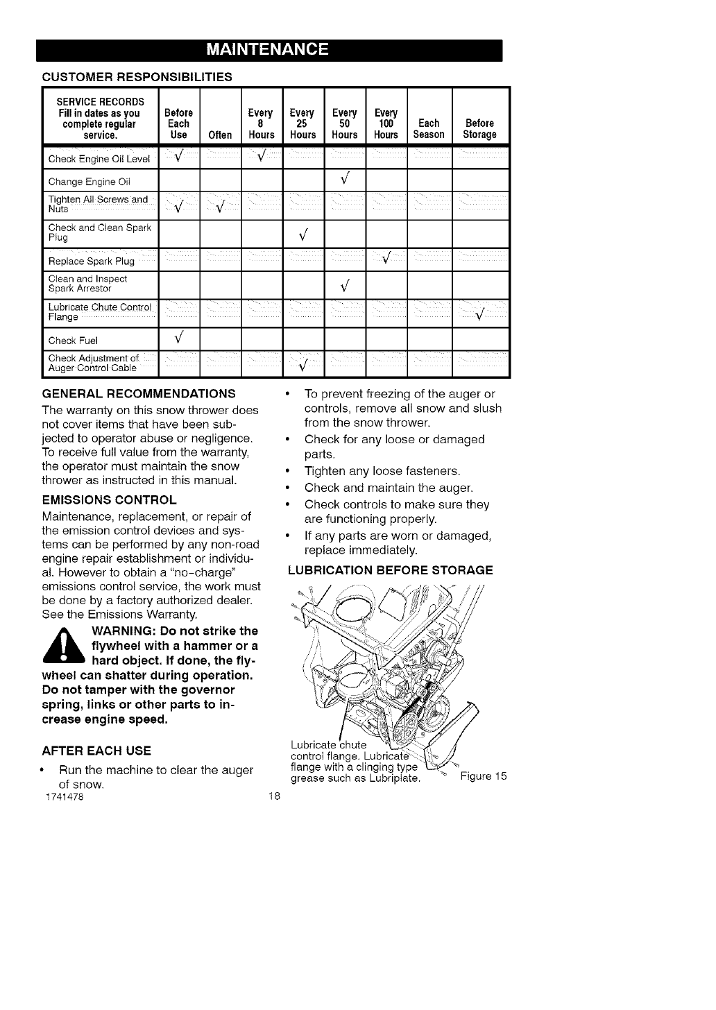
CUSTOMER RESPONSIBILITIES
SERVICERECORDS
Fill in dates asyou Before Every Every Every Every
completeregular Each 8 25 50 100 Each Before
service, Use Often Hours Hours Hours Hours Season Storage
Check Engine Oil Leve_ • ' " I I I I
Change Engine OiI _/
Tighten All Screws and
Nuts
Check and Clean Spark
Plug _/
Clean and Inspect
Spark Arrestor _/
Check Fuel _/
CheckAdjustmentof III } I I I I
Auger Centre Cab e Y
GENERAL RECOMMENDATIONS
The warranty on this snow thrower does
not cover items that have been sub-
jected to operator abuse or negligence.
To receive full value from the warranty,
the operator must maintain the snow
thrower as instructed in this manual.
EMISSIONS CONTROL
Maintenance, replacement, or repair of
the emission control devices and sys-
tems can be performed by any non-road
engine repair establishment or individu-
al. However to obtain a "no-charge"
emissions control service, the work must
be done by a factory authorized dealer.
See the Emissions Warranty.
_ WARNING: Do not strike the
flywheel with ahammer or a
hard object. If done, the fly-
wheel can shatter during operation.
Do not tamper with the governor
spring, links or other parts to in-
crease engine speed.
AFTER EACH USE
•Run the machine to clear the auger
of snow.
1741478
• To prevent freezing of the auger or
controls, remove all snow and slush
from the snow thrower.
• Check for any loose or damaged
parts.
• Tighten any loose fasteners.
• Check and maintain the auger.
• Check controls to make sure they
are functioning properly.
• If any parts are worn or damaged,
replace immediately.
LUBRICATION BEFORE STORAGE
18
control flang,
flange with a clinging type "_
grease such as Lubriptate. _ Figure 15
ENGINE SPECIFICATIONS
GROSS TORQUE 5.25 ft-lbs
DISPLACEMENT 148 cc
BORE 65mm (2.562 in.)
STROKE 45mm (1.750 in.)
GASOLINE 2 quarts (85 octane
CAPACITY leaded)
OIL CAPACITY 5W30
(16 oz capacity)
SPARK PLUG: Champion RJ19LM
(Gap .030 in.) or
equivalent
VALVE Intake: 0.005-0.007 in.
CLEARANCE: Exhaust: 0.007-0.009 in.
ARMATURE
AIR GAP: 0.006-0.010 in.
POWER RATINGS
The gross power rating for individual
gas engine models is labeled in
accordance with SAE (Society of
Automotive Engineers) code J1940
(Small Engine Power & Torque Rating
Procedure), and rating performance
has been obtained and corrected in
accordance with SAE J1995 (Revision
2002-05). Torque values are derived at
3060 RPM; horsepower values are
derived at 3600 RPM. Actual gross
engine power will be lower and is
affected by, among other things,
ambient operating conditions and
engine-to-engine variability. Given both
the wide array of products on which
engines are placed and the variety of
environmental issues applicable to
operating the equipment, the gas
engine will not develop the rated gross
power when used in a given piece of
power equipment (actual "on-site" or
net power). This difference is due to a
variety of factors including, but not
limited to, accessories (air cleaner,
exhaust, charging, cooling, carburetor,
fuel pump, etc.), application limitations,
ambient operating conditions (tempera-
ture, humidity, altitude), and engine-to-
engine variability. Due to manufacturing
and capacity limitations, Briggs &
Stratton may substitute an engine of
higher rated power for this Series
engine.
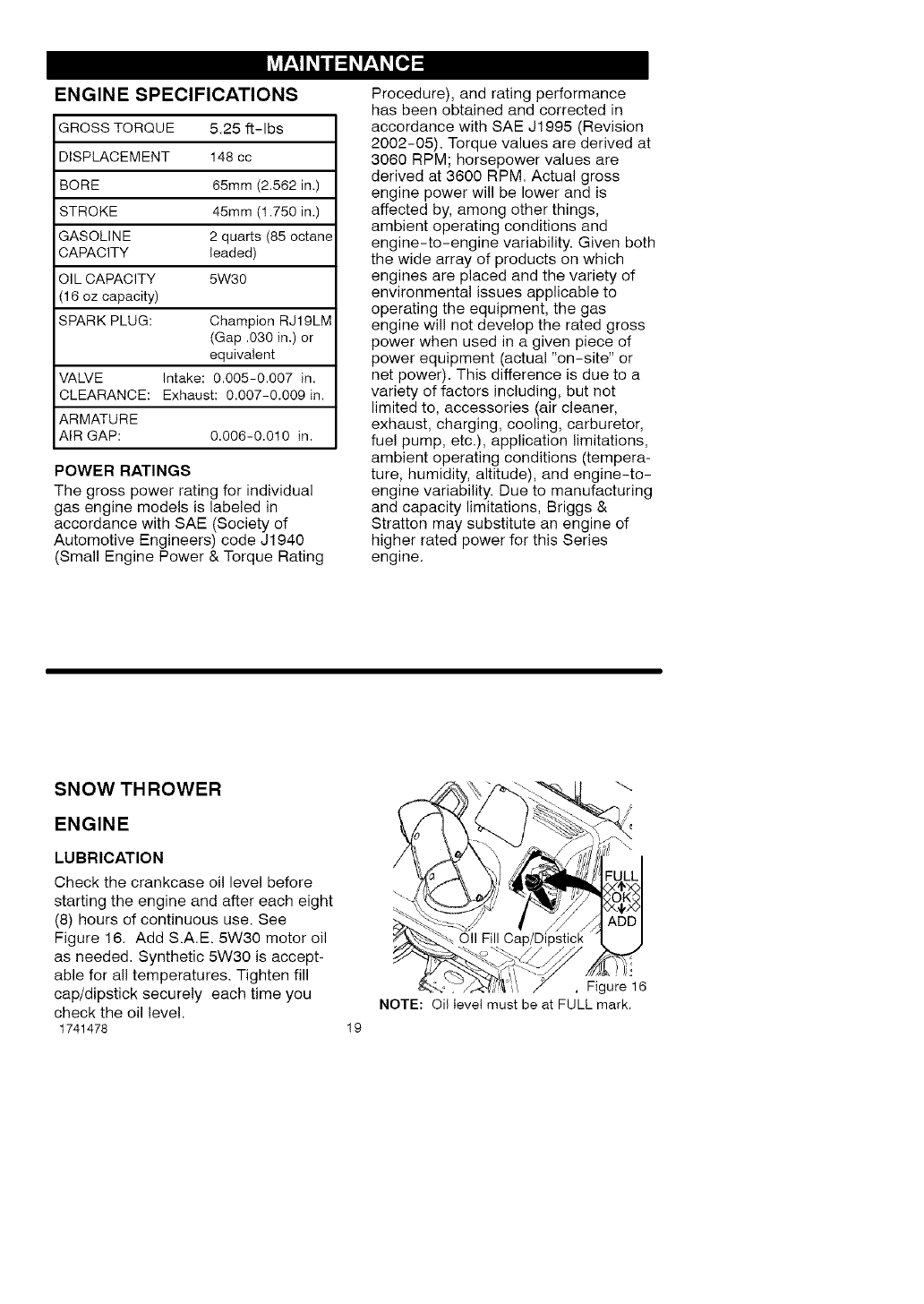
SNOW THROWER
ENGINE
LUBRICATION
Check the crankcase oil level before
starting the engine and after each eight
(8) hours of continuous use. See
Figure 16. Add S.A.E. 5W30 motor oil
as needed. Synthetic 5W30 is accept-
able for all temperatures. Tighten fill
cap/dipstick securely each time you
check the oil level.
1741478 19
Oil Fill
!i.'
,Figure 16
NOTE: Oi! level must be at FULL mark.
Change the oi! every fifty (50) hours or
at least once a year if the snow thrower
is not used for fifty (50) hours.
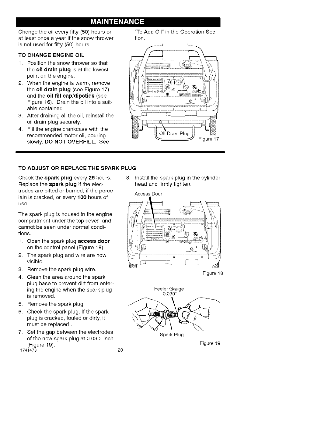
TO CHANGE ENGINE OIL
1. Position the snow thrower so that
the oil drain plug is at the lowest
point on the engine.
2. When the engine is warm, remove
the oil drain plug (see Figure 17)
and the oil fill cap/dipstick (see
Figure 16). Drain the oil into a suit-
able container.
3. After draining all the oil, reinstall the
oil drain plug securely.
4. Fill the engine crankcase with the
recommended motor oil, pouring
slowly. DO NOT OVERFILL. See
"To Add Oil" in the Operation Sec-
tion.
TO ADJUST OR REPLACE THE SPARK PLUG
Check the spark plug every 25 hours.
Replace the 8park plug ifthe elec-
trodes are pitted or burned, if the porce-
lain is cracked, or every 100 hours of
use.
8. install the spark plug in the cylinder
head and firmly tighten.
Access Door
The spark plug is housed in the engine
compartment under the top cover and
cannot be seen under normal condi-
tions.
1. Open the spark plug acce88 door
on the control panel (Figure 18).
2. The spark plug and wire are now
visible.
3. Remove the spark plug wire.
4. Clean the area around the spark
plug base to prevent dirt from enter-
ing the engine when the spark plug
is removed.
5. Remove the spark plug.
6. Check the spark plug. If the spark
plug is cracked, fouled or dirty, it
must be replaced.
7. Set the gap between the electrodes
of the new spark plug at 0.030 inch
(Figure 19).
1741478
Figure 18
2O
Feeler Gauge
0.030"
Spark Plug
Figure 19
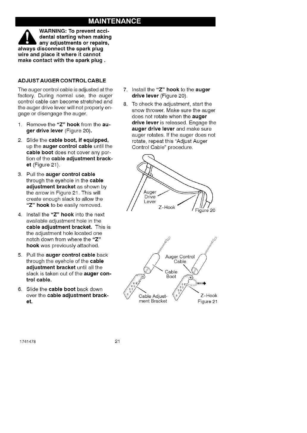
_ARNING: To prevent acci-
dental starting when making
any adjustments or repairs,
always disconnect the spark plug
wire and place it where it cannot
make contact with the spark plug.
ADJUST AUGER CONTROL CABLE
The auger control cable is adjusted at the 7.
factory. During normal use, the auger
control cable can become stretched and 8.
the auger drive lever wil! not properly en-
gage or disengage the auger.
1. Remove the "Z" hook from the au-
ger drive lever (Figure 20).
2. Slide the cable boot, if equipped,
up the auger control cable until the
cable boot does not cover any por-
tion of the cable adjustment brack-
et (Figure 21).
3. Pull the auger control cable
through the eyehole in the cable
adjustment bracket as shown by
the arrow in Figure 21. This will
create enough slack to allow the
"Z" hook to be easily removed.
4. install the "Z" hook into the next
available adjustment hole in the
cable adjustment bracket. This is
the adjustment hole located one
notch down from where the "Z"
hook was previously attached.
5. Pull the auger control cable back
through the eyehole of the cable
adjustment bracket until all the
slack is taken out of the auger con-
trol cable.
6. Slide the cable boot back down
over the cable adjustment brack-
et,
install the "Z" hook to the auger
drive lever (Figure 20).
To check the adjustment, start the
snow thrower. Make sure the auger
does not rotate when the auger
drive lever is released. Engage the
auger drive lever and make sure
auger rotates, if the auger does not
rotate, repeat this "Adjust Auger
Control Cable" procedure.
Auger
Drive
Lever
Z-Hook Figure 20
Auger Control
Cable
Cable
Boot
Cable Adjust-
ment Bracket
Z-Hook
Figure 21
1741478 21
[.,,."_o,,_ V_IZIB]P'_"_
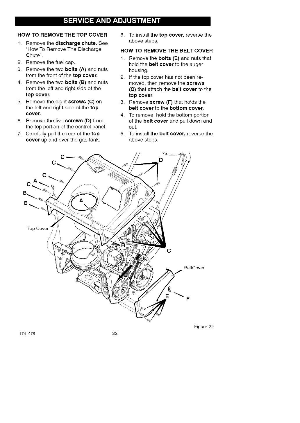
HOW TO REMOVE THE TOP COVER
1. Remove the discharge chute. See
"How To Remove The Discharge
Chute".
2. Remove the fuel cap.
3. Remove the two bolts (A) and nuts
from the front of the top cover.
4. Remove the two bolts (B) and nuts
from the left and right side of the
top cover.
5. Remove the eight screws (C) on
the left and right side of the top
cover,
6. Remove the five screws (D) from
the top portion of the control panel.
7. Carefully pull the rear of the top
cover up and over the gas tank.
8. To install the top cover, reverse the
above steps.
HOW TO REMOVE THE BELT COVER
1. Remove the bolts (E) and nuts that
hold the belt cover to the auger
housing.
2. If the top cover has not been re-
moved, then remove the screws
(C) that attach the belt cover to the
top cover.
3. Remove screw (F) that holds the
belt cover to the bottom cover.
4. To remove, hold the bottom portion
of the belt cover and pull down and
out.
5. To install the belt cover, reverse the
above steps.
Top
/
/
\\\C
BeltCover
F
Figure 22
1741478 22
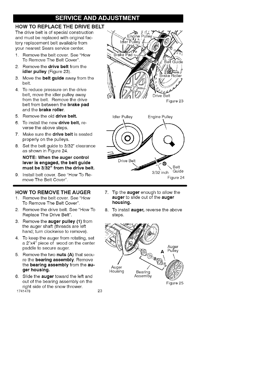
HOWTO REPLACE THE DRIVE BELT
The drive belt is of special construction
and must be replaced with original fac-
tory replacement belt available from
your nearest Sears service center.
1. Remove the belt cover. See "How
To Remove The Belt Cover".
2. Remove the drive belt from the
idler pulley (Figure 23).
3. Move the belt guide away from the
belt.
4. To reduce pressure on the drive
belt, move the idler pulley away
from the belt. Remove the drive
belt from between the brake pad
and the brake roller.
5. Remove the old drive belt.
6. To install the new drive belt, re-
verse the above steps.
7. Make sure the drive belt is seated
properly on the pulleys.
8. Set the belt guide to 3/32" clearance
as shown in Figure 24.
NOTE: When the auger control
lever is engaged, the belt guide
must be 3/32" from the drive belt.
9. Install belt cover. See "How To Re-
move The Belt Cover".
Belt Guide
Brake Roller
Drive Belt
Figure 23
Idler Pulley Engine Pulley
3/32 inch Guide
Figure 24
HOW TO REMOVE THE AUGER
1. Remove the belt cover. See "How
To Remove The Belt Cover".
2. Remove the drive belt. See "How To
Replace The Drive Belt".
3. Remove the auger pulley (1) from
the auger shaft (threads are left
hand; turn clockwise to remove).
4. To keep the auger from rotating, set
a 2"x4" piece of wood on the center
paddle to secure auger.
5. Remove the two nuts (A) that secu-
re the bearing assembly. Remove
the bearing assembly from the au-
ger housing,
6. Slide the auger toward the left and
out of the bearing assembly on the
right side of the snow thrower.
1741478
7. Tip the auger enough to allow the
auger to slide out of the auger
housing.
8. To install auger, reverse the above
steps.
-_..,__,_,_]{( t.,_<_. Auger
APulley
mousing Bearing _,_)_y
Assemlby _,_
Figure 25
23
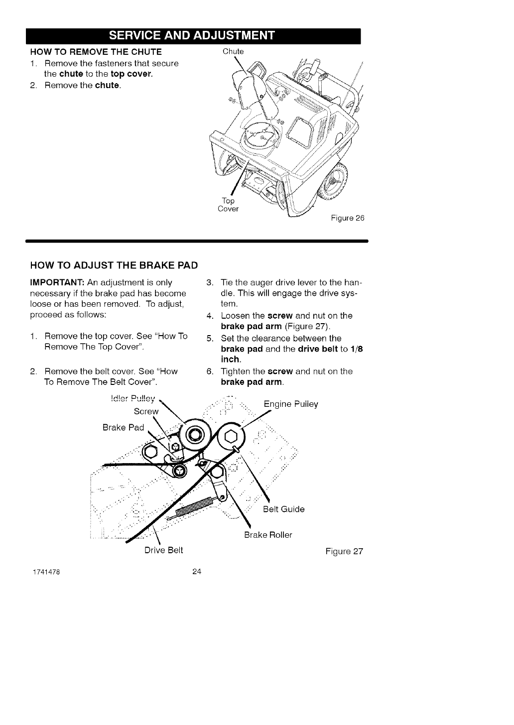
HOW TO REMOVE THE CHUTE
1. Remove the fasteners that secure
the chute to the top cover•
2. Remove the chute.
Chute
\
Top
Cover
Figure 26
HOW TO ADJUST THE BRAKE PAD
IMPORTANT: An adjustment is only
necessary if the brake pad has become
loose or has been removed• To adjust,
proceed as follows:
1. Remove the top cover• See "How To
Remove The Top Cover".
2. Remove the belt cover• See "How
To Remove The Belt Cover".
Brake Pad
Drive Belt
3. Tie the auger drive lever to the han-
dle• This will engage the drive sys-
tem.
4. Loosen the screw and nut on the
brake pad arm (Figure 27).
5. Set the clearance between the
brake pad and the drive belt to 1/8
inch.
6. Tighten the screw and nut on the
brake pad arm.
•:::" Belt Guide
Brake Roller
Figure 27
1741478 24
[,.'_:j]#_ .eT=l
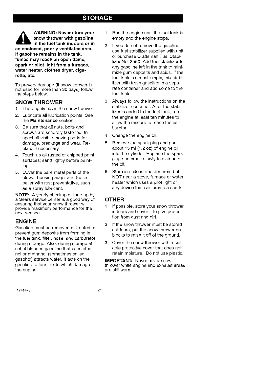
,_ WARNING: Never store your
snow thrower with gasoline
in the fuel tank indoors or in
an enclosed, poorly ventilated area.
If gasoline remains in the tank,
fumes may reach an open flame,
spark or pilot light from a furnace,
water heater, clothes dryer, ciga-
rette, etc.
To prevent damage (if snow thrower is
not used for more than 30 days) follow
the steps below.
SNOW THROWER
1. Thoroughly clean the snow thrower.
2. Lubricate all lubrication points. See
the Maintenance section.
3. Be sure that all nuts, bolts and
screws are securely fastened. In-
spect all visible moving parts for
damage, breakage and wear. Re-
place if necessary.
4. Touch up all rusted or chipped paint
surfaces; sand lightly before paint-
ing.
5. Cover the bare metal parts of the
blower housing auger and the im-
peller with rust preventative, such
as a spray lubricant.
NOTE: A yearly checkup or tune-up by
a Sears service center is a good way of
ensuring that your snow thrower will
provide maximum performance for the
next season.
ENGINE
Gasoline must be removed or treated to
prevent gum deposits from forming in
the fuel tank, filter, hose, and carburetor
during storage. Also, during storage al-
cohol blended gasoline that uses etha-
nol or methanol (sometimes called
gasohol) attracts water. It acts on the
gasoline to form acids which damage
the engine.
1. Run the engine until the fuel tank is
empty and the engine stops.
2. If you do not remove the gasoline,
use fuel stabilizer supplied with unit
or purchase Craftsman Fuel Stabi-
lizer No. 3550. Add fue! stabilizer to
any gasoline left in the tank to mini-
mize gum deposits and acids. If the
fuel tank is almost empty, mix stabi-
lizer with fresh gasoline in a sepa-
rate container and add some to the
fuel tank.
3. Always follow the instructions on the
stabilizer container. After the stabi-
lizer is added to the fuel tank, run
the engine at least ten minutes to
allow the mixture to reach the car-
buretor.
4. Change the engine oil.
5. Remove the spark plug and pour
about 15 ml (1/2 oz) of engine oil
into the cylinder. Replace the spark
plug and crank slowly to distribute
the oil.
6. Store in a clean and dry area, but
NOT near a stove, furnace or water
heater which uses a pilot light or
any device that can create a spark.
OTHER
1. If possible, store your snow thrower
indoors and cover it to give protec-
tion from dust and dirt.
2. If the snow thrower must be stored
outdoors, put the snow thrower on
blocks to raise it off of the ground.
3. Cover the snow thrower with a suit-
able protective cover that does not
retain moisture. Do not use plastic.
IMPORTANT: Never cover snow
thrower while engine and exhaust areas
are still warm.
1741478 25
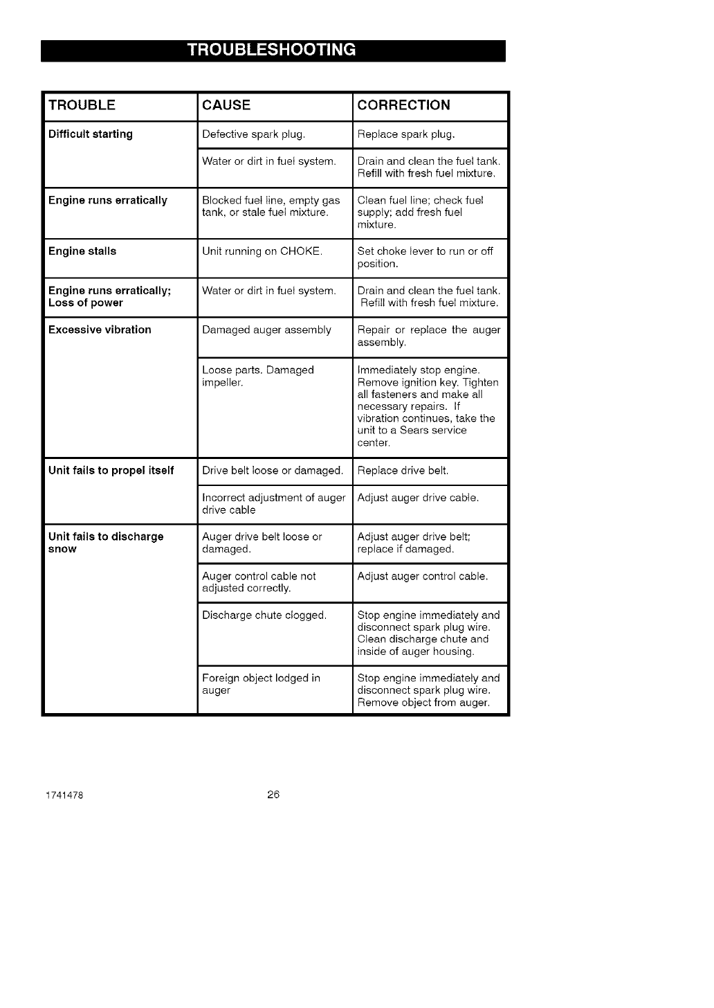
h_o__oIo_
TROUBLE CORRECTION
Difficult starting Replace spark plug.
Drain and clean the fuet tank.
Refill with fresh fuel mixture.
Engine runs erratically Clean fuel line; check fueI
supply; add fresh fuel
mixture.
Engine stalls Set choke lever to run or off
position.
Engine runs erratically; Drain and clean the fuet tank.
Loss of power Refill with fresh fueI mixture.
Excessive vibration
Unit fails to propel itself
CAUSE
Defective spark plug.
Water or dirt in fuet system.
Blocked fuet line, empty gas
tank, or stale fuet mixture.
Unit running on CHOKE.
Water or dirt in fuet system.
Damaged auger assembly
Loose parts. Damaged
impeller.
Drive belt loose or damaged.
Incorrect adjustment of auger
drive cable
Repair or replace the auger
assembly.
Unit fails to discharge
snow
Immediately stop engine.
Remove ignition key. Tighten
all fasteners and make all
necessary repairs. If
vibration continues, take the
unit to a Sears service
center.
Replace drive belt.
Adjust auger drive cable.
Auger drive belt loose or Adjust auger drive belt;
damaged, replace if damaged.
Auger control cable not Adjust auger control cable.
adjusted correctly.
Discharge chute clogged. Stop engine immediately and
disconnect spark plug wire.
Clean discharge chute and
inside of auger housing.
Foreign object lodged in
auger
Stop engine immediately and
disconnect spark plug wire.
Remove object from auger.
1741478 26
(This page applicable in the U.S.A. and Canada only.)
Sears, Roebuck and Co., U.S.A. (Sears), the California Air Resources Board
(CARB) and the United States Environmental Protection Agency (U.S. EPA)
Emission Control System Warranty Statement
(Owner's Defect Warranty Rights and Obligations)
The California Air Resources Board
(CARB), U.S. EPA and Sears are pleased
to explain the Emission Control System
Warranty on your small off-road engine
(SORE). In California, new small off-road
engines model year 2006 and later must
be designed, built and equipped to meet
the State's stringent anti-smog standards.
Elsewhere in the United States, new
non-road, spark-ignition engines certified
for model year 1997 and later must meet
similar standards set forth by the U.S. EPA.
Sears must warrant the emission control
system on your engine for the periods of
time listed below, provided there has been
no abuse, neglect or improper
maintenance of your small off-road engine.
Your emission control system includes
parts such as the carburetor, air cleaner,
ignition system, fuel line, muffler and
catalytic converter. Also included may be
connectors and other emission related
assemblies.
Where a warrantable condition exists,
Sears will repair your small off-road
engine at no cost to you including
diagnosis, parts and labor.
Sears, Roebuck and Co. Emission Control Defects Warranty Coverage
Small off-road engines are warranted provisions set forth below. If any covered
relative to emission control parts defects part on your engine is defective, the part
for a period of two years, subject to wil! be repaired or replaced by Sears.
Owner's Warranty
As the small off-road engine owner, you
are responsible for the performance of
the required maintenance listed in your
Operating and Maintenance Instructions.
Sears recommends that you retain all
your receipts covering maintenance on
your small off-road engine, but Sears
cannot deny warranty solely for the lack
of receipts or for your failure to ensure the
performance of all scheduled
maintenance.
As the small off-road engine owner, you
should however be aware that Sears may
deny you warranty coverage if your small
off-road engine or a part has failed due to
abuse, neglect, improper maintenance or
Responsibilities
unapproved modifications.
You are responsible for presenting your
small off-road engine to an Authorized
Sears Service Dealer as soon as a
problem exists.
The undisputed warranty repairs should
be completed in a reasonable amount of
time, not to exceed 30 days.
If you have any questions regarding your
warranty rights and responsibilities, you
should contact a Sears Service
Representative at 1-800-469-4663.
The emission warranty is a defects
warranty. Defects are judged on normal
engine performance. The warranty is not
related to an in-use emission test.
1741478 27
Sears, Roebuck and Co. Emission Control Defects Warranty Provisions
The following are specific provisions relative to your Emission Control Defects Warranty
Coverage. It is in addition to the Sears engine warranty for non-regulated engines found
in the Operating and Maintenance Instructions.
1. Warranted Parts
Coverage under this warranty ex-
tends only to the parts listed below
(the emission control systems parts)
to the extent these parts were pres-
ent on the engine purchased.
a. Fuel Metering System
• Cold start enrichment system
• Carburetor and internal parts
• Fuel Pump
• Fuel line, fuel line fittings, 4.
clamps
• Fuel tank, cap and tether
• Carbon canister
b. Air Induction System
• Air cleaner
• Intake manifold
• Purge and vent line
c. Ignition System
• Spark plug(s)
• Magneto ignition system
d. Catalyst System 5.
• Catalytic converter
• Exhaust manifold
• Air injection system, Pulse
valve
e. Miscellaneous Items
• Vacuum, temperature, posi-
tion, time sensitive valves and
switches
• Connectors and assemblies
Length of Coverage
Sears warrants to the initial owner
and each subsequent purchaser that
the Warranted Parts shall be free from
defects in materials and workmanship
which caused the failure of the War-
ranted Parts for a period of two years
from the date the engine is delivered
to a retail purchaser.
mination that a Warranted Part is
defective, if the diagnostic work is
performed at an Authorized Sears
Service Dealer. For emissions war-
ranty service contact your nearest
Authorized Sears Service Dealer as
listed in the "Yellow Pages" under
"Engines, Gasoline," "Gasoline En-
gines," "Lawn Mowers," or similar
category.
Claims and Coverage Exclusions
Warranty claims shall be filed in ac-
cordance with the provisions of the
Sears Engine Warranty Policy. War-
ranty coverage shall be excluded for
failures of Warranted Parts which are
not original Sears parts or because of
abuse, neglect or improper mainte-
nance as set forth in the Sears En-
gine Warranty Policy. Sears is not
liable to cover failures of Warranted
Parts caused by the use of add-on,
non-original, or modified parts.
Maintenance
Any Warranted Part which is not
scheduled for replacement as re-
quired maintenance or which is
scheduled only for regular inspection
to the effect of "repair or replace as
necessary" shall be warranted as to
defects for the warranty period. Any
Warranted Part which is scheduled for
replacement as required mainte-
nance shall be warranted as to de-
fects only for the period of time up to
the first scheduled replacement for
that part. Any replacement part that is
equivalent in performance and dura-
bility may be used in the performance
of any maintenance or repairs. The
owner is responsible for the perfor-
mance of all required maintenance,
as defined in the Sears Operating and
Maintenance Instructions.
3. No Charge 6.
Repair or replacement of any War-
ranted Part will be performed at no
charge to the owner, including diag-
nostic labor which leads to the deter-
1741478 28
Consequential Coverage
Coverage hereunder shall extend to
the failure of any engine components
caused by the failure of any War-
ranted Part still under warranty.
Look For Relevant Emissions Durability Period and Air
Index Information On Your Engine Emission Label
Engines that are certified to meet the California Air Resources Board (CARB) Tier 2
Emission Standards must display information regarding the Emissions Durability Pe-
riod and the Air Index. Sears, Roebuck and Co., U.S.A. makes this information avail-
able to the consumer on our emission labels. The engine emission label will indicate
certification information.
The Emissions Durability Period describes the number of hours of actual running
time for which the engine is certified to be emissions compliant, assuming proper
maintenance in accordance with the Operating & Maintenance Instructions. The fo!-
lowing categories are used:
Moderate: Engine is certified to be emission compliant for 125 hours of actual engine
running time.
Intermediate: Engine is certified to be emission compliant for 250 hours of actual en-
gine running time.
Extended: Engine is certified to be emission compliant for 500 hours of actual engine
running time.
For example, a typical walk-behind lawn mower is used 20 to 25 hours per year.
Therefore, the Emissions Durability Period of an engine with an intermediate
rating would equate to 10 to 12 years.
Certain Sears, Roebuck and Co., U.S.A. engines will be certified to meet the United
States Environmental Protection Agency (USEPA) Phase 2 emission standards. For
Phase 2 certified engines, the Emissions Compliance Period referred to on the Emissions
Compliance label indicates the number of operating hours for which the engine has been
shown to meet Federal emission requirements.
Engines that are certified to meet the California Air Resources Board (CARB) Tier 2
Emissions Standard must display information regarding the Emissions Durability
Period and the Air Index. Sears, Roebuck and Co., U.S.A. makes this information
available to the consumer on our emissions labels. The engine emissions labe! will
indicate certification information.
For engines less than 225 cc displacement.
Category C = 125 hours
Category B = 250 hours
Category A = 500 hours
For engines of 225 cc or more displacement.
Category C = 250 hours
Category B = 500 hours
Category A = 1000 hours
1741478 29
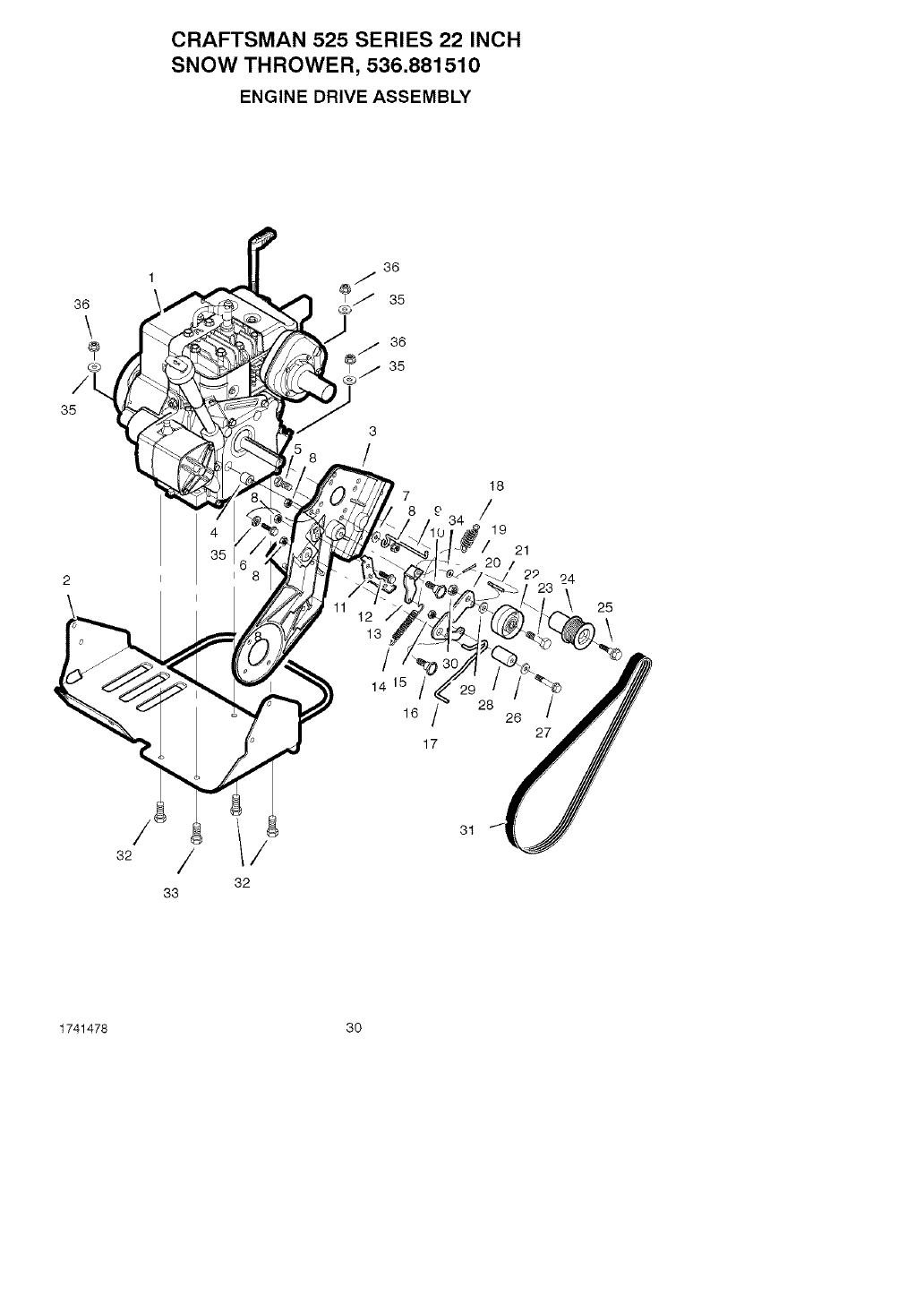
CRAFTSMAN 525 SERIES 22 INCH
SNOW THROWER, 536.881510
ENGINE DRIVE ASSEMBLY
1741478 30
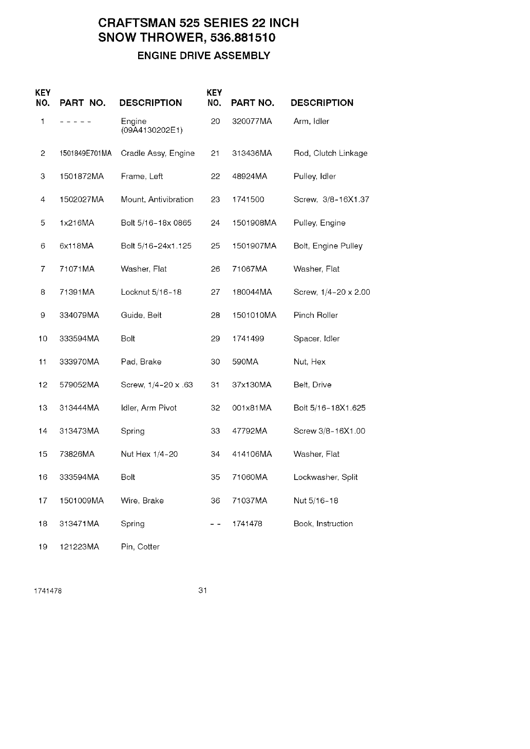
CRAFTSMAN 525 SERIES 22 INCH
SNOW THROWER, 536.881510
ENGINE DRIVE ASSEMBLY
KEY
NO. PART NO. DESCRIPTION
1 Engine 20 320077MA
(09A4130202E1)
2 1501849E701MA Cradle Assy, Engine 21 313436MA
3 1501872MA Frame, Left 22 48924MA
4 1502027MA Mount, Antivibration 23 1741500
5 1x216MA
6 6xl 18MA
7 71071MA
8 71391MA
9 334079MA
10 333594MA
11 333970MA
12 579052MA
13 313444MA
14 313473MA
15 73826MA
16 333594MA
17 1501009MA Wire, Brake
18 313471MA Spring
19 121223MA Pin, Cotter
KEY
NO. PART NO. DESCRIPTION
Arm, Idler
Rod, Clutch Linkage
Pulley, Idler
Screw, 3/8-16Xl.37
Bolt 5/16-18x 0865 24 1501908MA Pulley, Engine
Bolt 5/16-24xl .125 25 1501907MA Bolt, Engine Pulley
26 71067MA Washer, Flat
27 180044MA Screw, 1/4-20 x 2.00
28 1501010MA Pinch Roller
Washer, Fiat
Locknut 5/16-18
Guide, Belt
Bolt 29 1741499
Pad, Brake 30 590MA
Screw, 1/4-20 x .63 31 37xl 30MA
Idler, Arm Pivot 32 001x81MA
Spring 33 47792MA
Nut Hex 1/4-20 34 414106MA
Bolt 35 71060MA
36 71037MA
- - 1741478
Spacer, Idler
Nut, Hex
Belt, Drive
Bolt 5/16-18Xl .625
Screw 3/8-16Xl .00
Washer, Flat
Lockwasher, Split
Nut 5/16-18
Book, Instruction
1741478 31
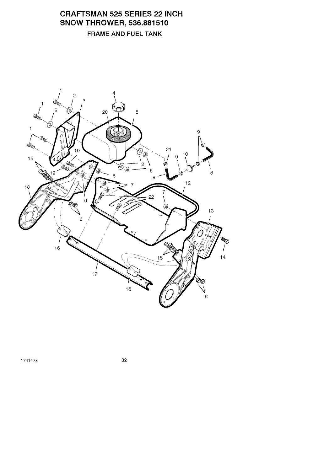
CRAFTSMAN 525 SERIES 22 INCH
SNOW THROWER, 536.881510
FRAME AND FUEL TANK
1
1
15
18
1
3
2/20
2
6
9
21
12
\
\
8
13
16 /
14
17
16
1741478 32
CRAFTSMAN 525 SERIES 22 INCH
SNOW THROWER, 536.881510
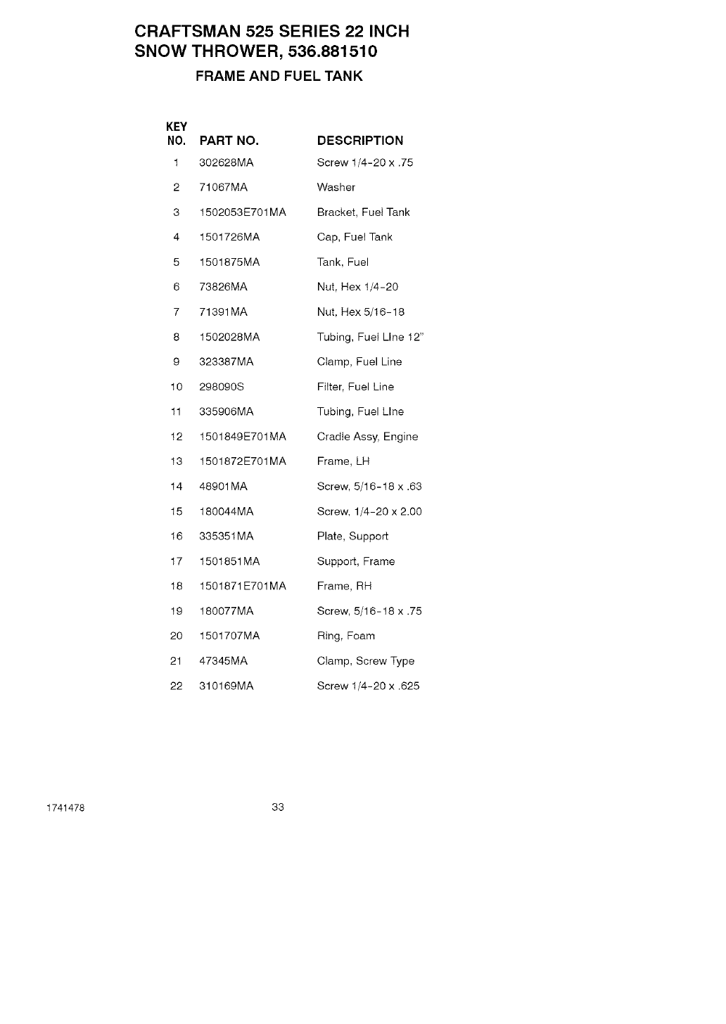
FRAME AND FUEL TANK
KEY
NO, PART NO. DESCRIPTION
1 302628MA Screw t/4-20 x .75
2 71067MA Washer
3 1502053E701MA Bracket, FueI Tank
4 1501726MA Cap, Fuel Tank
5 1501875MA Tank, Fuel
6 73826MA Nut, Hex 1/4-20
7 71391MA Nut, Hex 5/16-18
8 1502028MA Tubing, Fuel Line 12"
9 323387MA Clamp, Fuel Line
10 298090S Filter, Fuel Line
11 335906MA Tubing, Fuel Line
12 1501849E701MA Cradle Assy, Engine
13 1501872E701MA Frame, LH
14 48901MA Screw, 5/16-18 x .63
15 180044MA Screw, 1/4-20 x 2.00
16 335351MA Plate, Support
17 1501851MA Support, Frame
18 1501871E701MA Frame, RH
19 180077MA Screw, 5/16-18 x .75
20 1501707MA Ring, Foam
21 47345MA Clamp, Screw Type
22 310169MA Screw 1/4-20 x .625
1741478 33
CRAFTSMAN 525 SERIES 22 INCH
SNOW THROWER, 536.881510
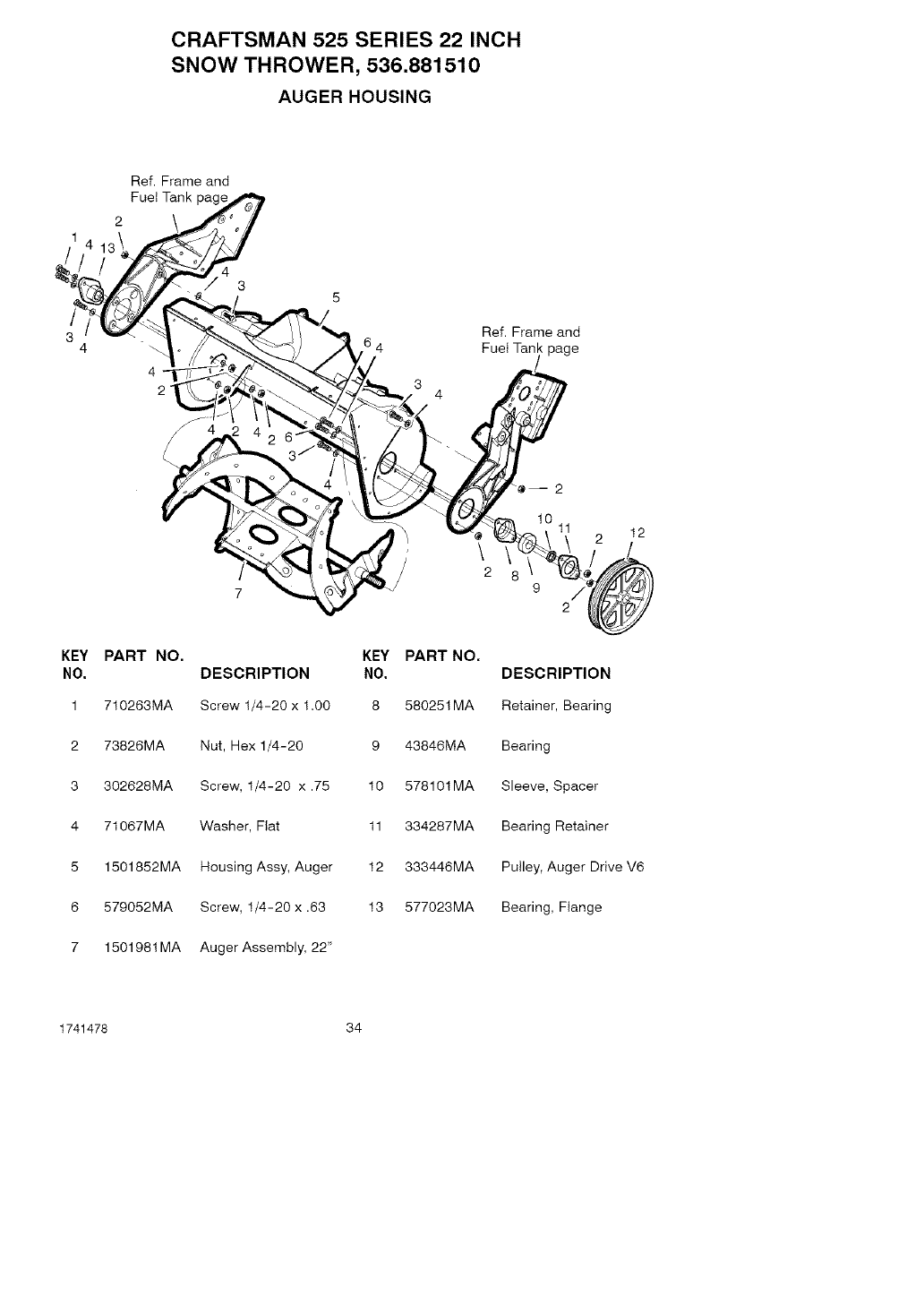
AUGER HOUSING
Ref. Frame and
Fuel Tank page
4
2
4
3
Ref. Frame and
Fuel Tank page
KEY PART NO,
NO. DESCRIPTION
1 710263MA Screw 1/4-20 x 1.00
2 73826MA Nut, Hex 1/4-20
3 302628MA Screw, 1/4-20 x .75
4 71067MA Washer, Fiat
5 1501852MA Housing Assy, Auger
6 579052MA Screw, 1/4-20 x .63
7 1501981MA Auger Assembly, 22"
tl 12
\
2 8 9
KEY PART NO.
NO. DESCRIPTION
8 580251MA Retainer, Bearing
9 43846MA Bearing
10 578101MA Sleeve, Spacer
11 334287MA Bearing Retainer
12 333446MA Pulley, Auger Drive V6
13 577023MA Bearing, Flange
1741478 34
CRAFTSMAN 525 SERIES 22 INCH
SNOW THROWER, 536.881510
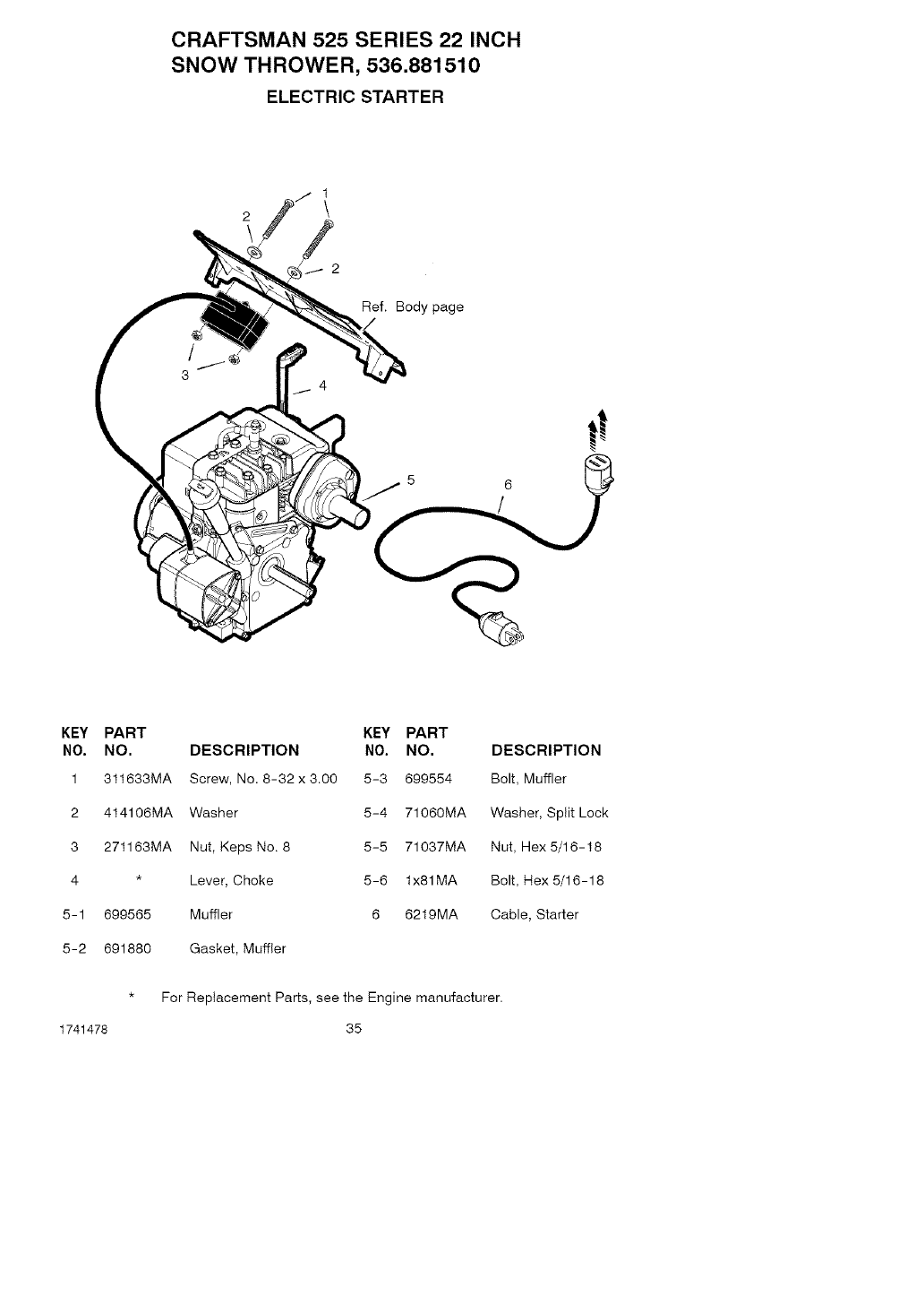
ELECTRIC STARTER
Ref. Body page
KEY PART KEY PART
NO. NO. DESCRIPTION NO. NO.
1 311633MA Screw, No. 8-32x3.OO 5-3 699554
2 414106MA Washer 5-4 71060MA
3 271163MA Nut, Keps No. 8 5-5 71037MA
4 * Lever, Choke 5-6 lx81MA
5-1 699565 Muffler 6 6219MA
5-2 691880 Gasket, Muffler
DESCRIPTION
Bolt, Muffler
Washer, Split Lock
Nut, Hex 5/16-18
Bolt, Rex 5/16-18
Cable, Starter
* For Replacement Parts, see the Engine manufacturer.
1741478 35
CRAFTSMAN 525 SERIES 22 INCH
SNOW THROWER, 536.881510
HANDLE ASSEMBLY
2
\ 1
8
\
13
12
12
Ref. Frame and
Fuel Tank page
15
10
/
/
8
13
\
6
\7
1741478 36
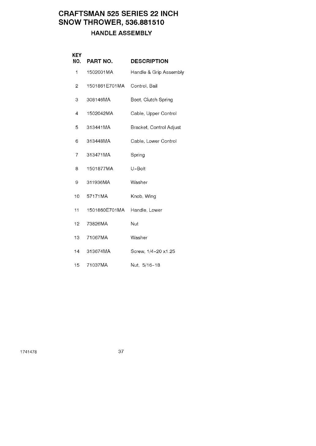
CRAFTSMAN 525 SERIES 22 INCH
SNOW THROWER, 536.881510
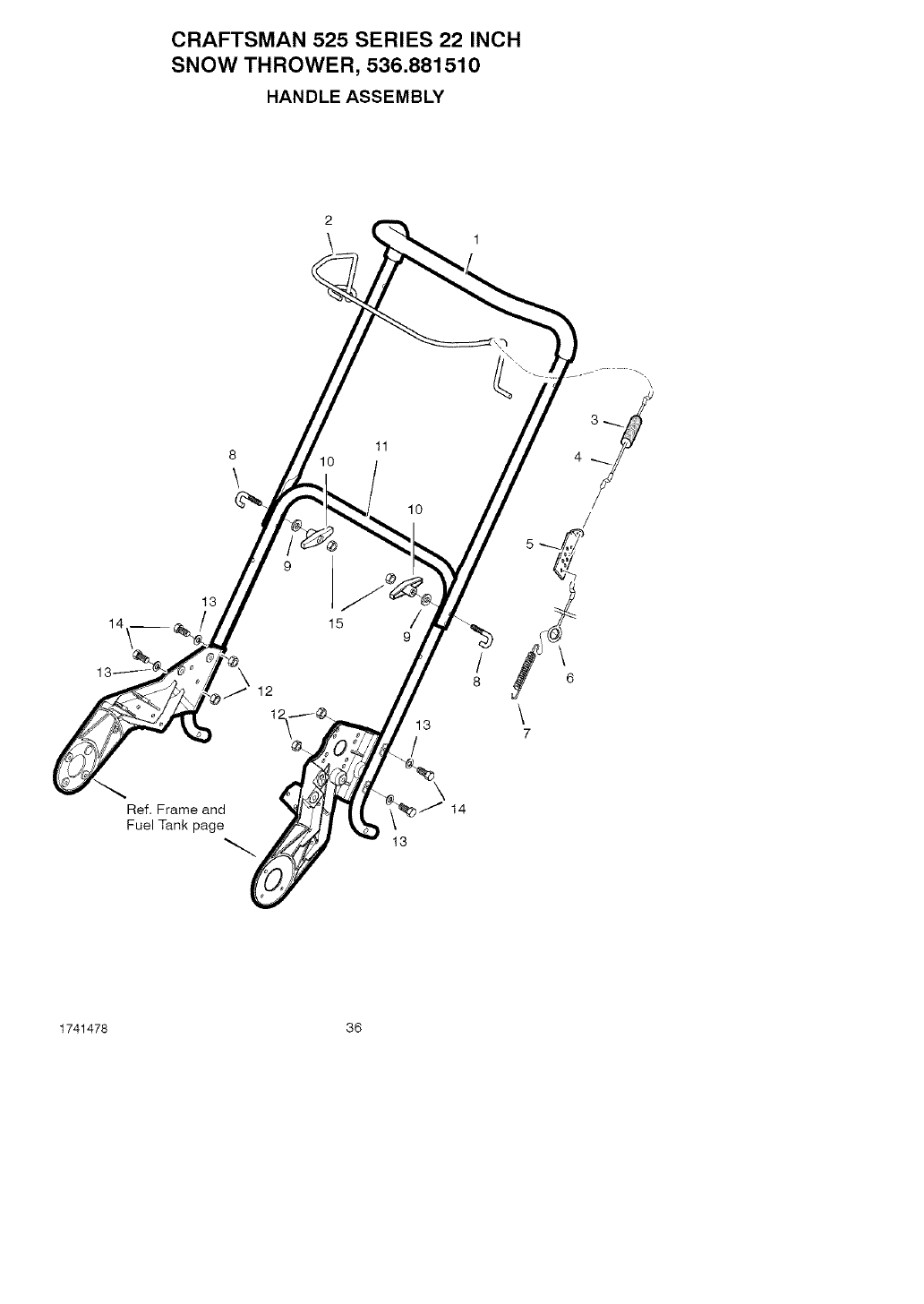
HANDLE ASSEMBLY
KEY
NO, PART NO. DESCRIPTION
1 1502001MA Handle & Grip Assembly
2 1501861E701MA Control, Bail
3 308146MA Boot, Clutch Spring
4 1502042MA Cable, Upper Control
5 313441MA Bracket, Control Adjust
6 313448MA Cable, Lower Control
7 313471MA Spring
8 1501877MA U-Bolt
9 311936MA Washer
10 57171MA Knob, Wing
11 1501860E701MA Handle, Lower
12 73826MA Nut
13 71067MA Washer
14 313674MA Screw, 1/4-20 xl.25
15 71037MA Nut, 5/16-18
1741478 37
CRAFTSMAN 525 SERIES 22 INCH
SNOW THROWER, 536.881510
CHUTE ASSEMBLY
_11
/
2O
23
Ref. Auger page
32
33 /
34 /
34 /
34
34
1741478 38
CRAFTSMAN 525 SERIES 22 INCH
SNOW THROWER, 536.881510
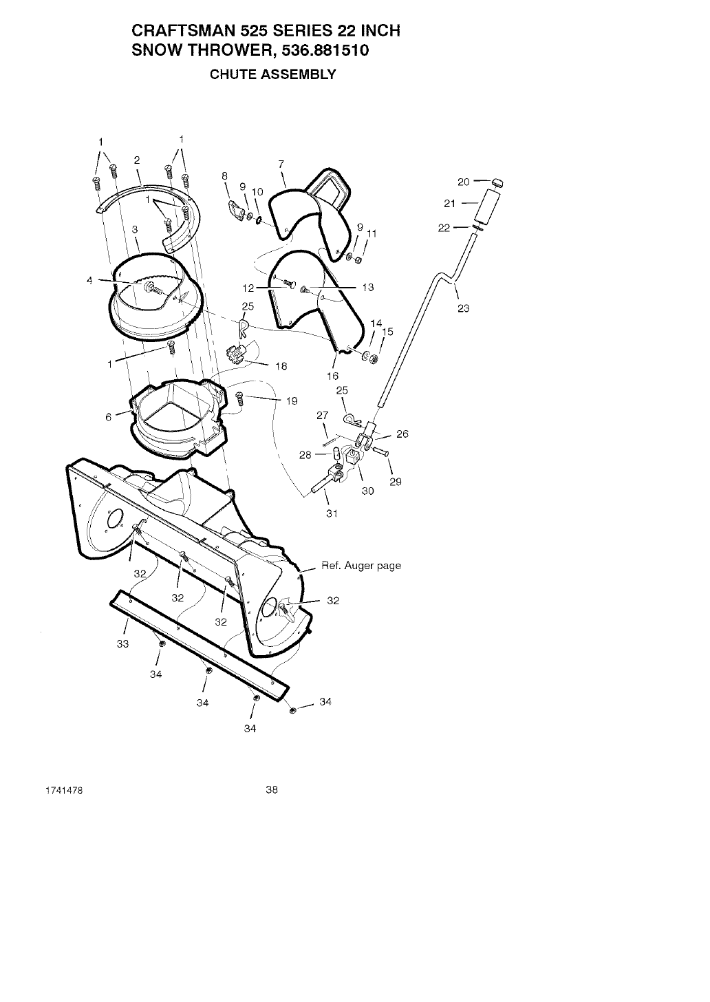
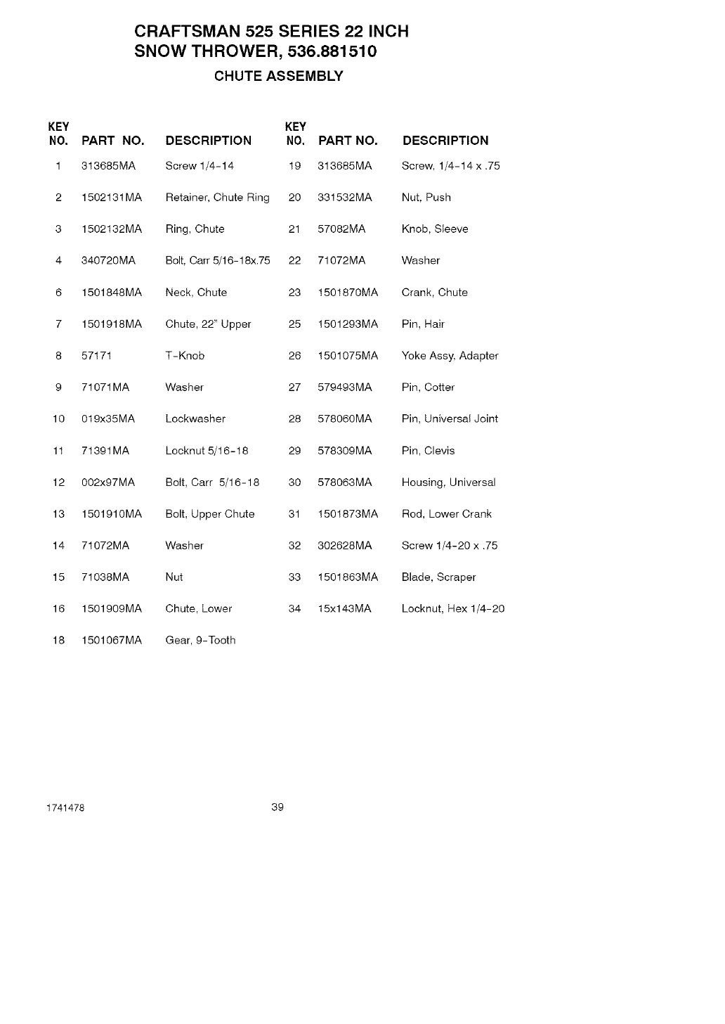
CHUTE ASSEMBLY
KEY
NO. PART NO. DESCRIPTION
1 313685MA Screw 1/4-14 19 313685MA
2 1502131MA Retainer, Chute Ring 20 331532MA
3 1502132MA Ring, Chute 21 57082MA
4 340720MA Bolt, Cart 5/16-18x.75 22 71072MA
6 1501848MA Neck, Chute
7 1501918MA Chute, 22" Upper
KEY
NO. PART NO. DESCRIPTION
Screw, 1/4-14 x .75
Nut, Push
Knob, Sleeve
Washer
23 1501870MA Crank, Chute
25 1501293MA Pin, Hair
8 57171 T-Knob 26 1501075MA Yoke Assy, Adapter
9 71071MA Washer 27 579493MA Pin, Cotter
10 019x35MA Lockwasher 28 578060MA Pin, Universal Joint
11 71391MA Locknut 5/16-18 29 578309MA Pin, Clevis
12 0O2x97MA Bolt, Cart 5/16-18 30 578063MA Housing, Universal
13 1501910MA Bolt, Upper Chute
14 71072MA Washer
15 71038MA Nut
16 1501909MA Chute, Lower
18 1501067MA Gear, 9-Tooth
31 1501873MA Rod, Lower Crank
32 302628MA Screw 1/4-20 x .75
33 1501863MA Blade, Scraper
34 15xl 43MA Locknut, Hex 1/4-20
1741478 39
CRAFTSMAN 525 SERIES 22 INCH
SNOW THROWER, 536.881510
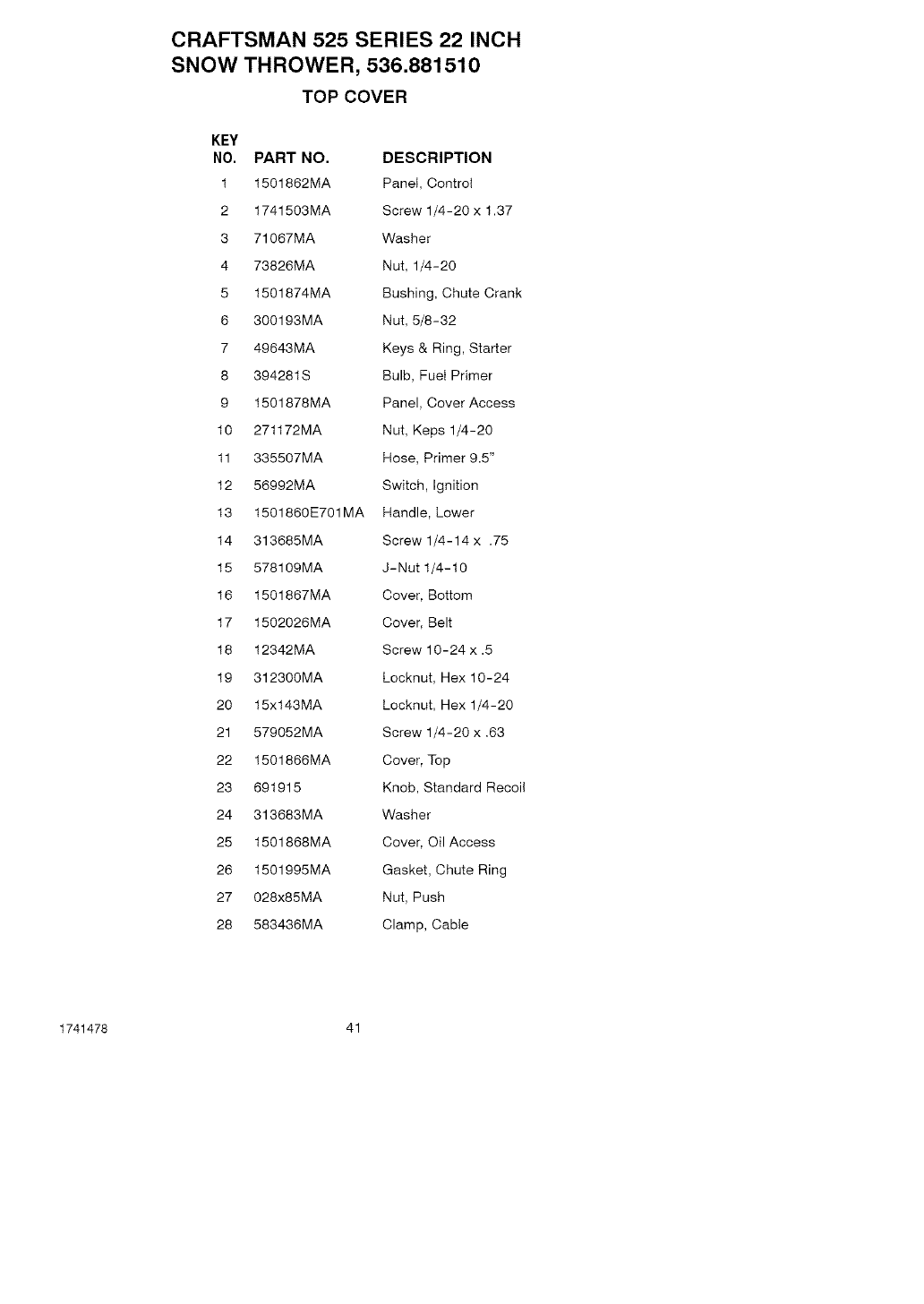
TOP COVER
22
14 24
1
6 7 8
23
18 \
4
26
19
20
19
Ref. Auger Housing page
/
14
16
1741478 40
CRAFTSMAN 525 SERIES 22 INCH
SNOW THROWER, 536.881510
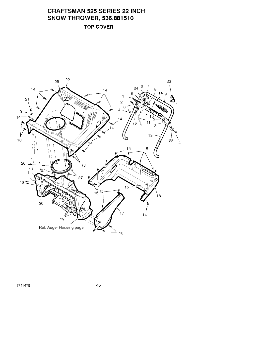
TOP COVER
KEY
NO, PART NO, DESCRIPTION
1 1501862MA PaneI, Control
2 1741503MA Screw 1/4-20 x 1.37
3 71067MA Washer
4 73826MA Nut, 1/4-20
5 1501874MA Bushing, Chute Crank
6 300193MA Nut, 5/8-32
7 49643MA Keys & Ring, Starter
8 394281B Bulb, Fuet Primer
9 1501878MA Panel, Cover Access
10 271172MA Nut, Keps 1/4-20
11 335507MA Hose, Primer 9.5"
12 56992MA Switch, Ignition
13 1501860E701MA Handle, Lower
14 313685MA Screw 1/4-14 x .75
15 578109MA J-Nut 1/4-t0
16 1501867MA Cover, Bottom
17 1502026MA Cover, Belt
18 12342MA Screw 10-24 x .5
19 312300MA Locknut, Hex 10-24
20 15x143MA Locknut, Hex 1/4-20
21 579052MA Screw 1/4-20 x .63
22 1501866MA Cover, Top
23 691915 Knob, Standard Recoi!
24 313683MA Washer
25 1501868MA Cover, Oil Access
26 1501995MA Gasket, Chute Ring
27 028x85MA Nut, Push
28 583436MA Clamp, Cable
1741478 41
CRAFTSMAN 525 SERIES 22 INCH
SNOW THROWER, 536.881510
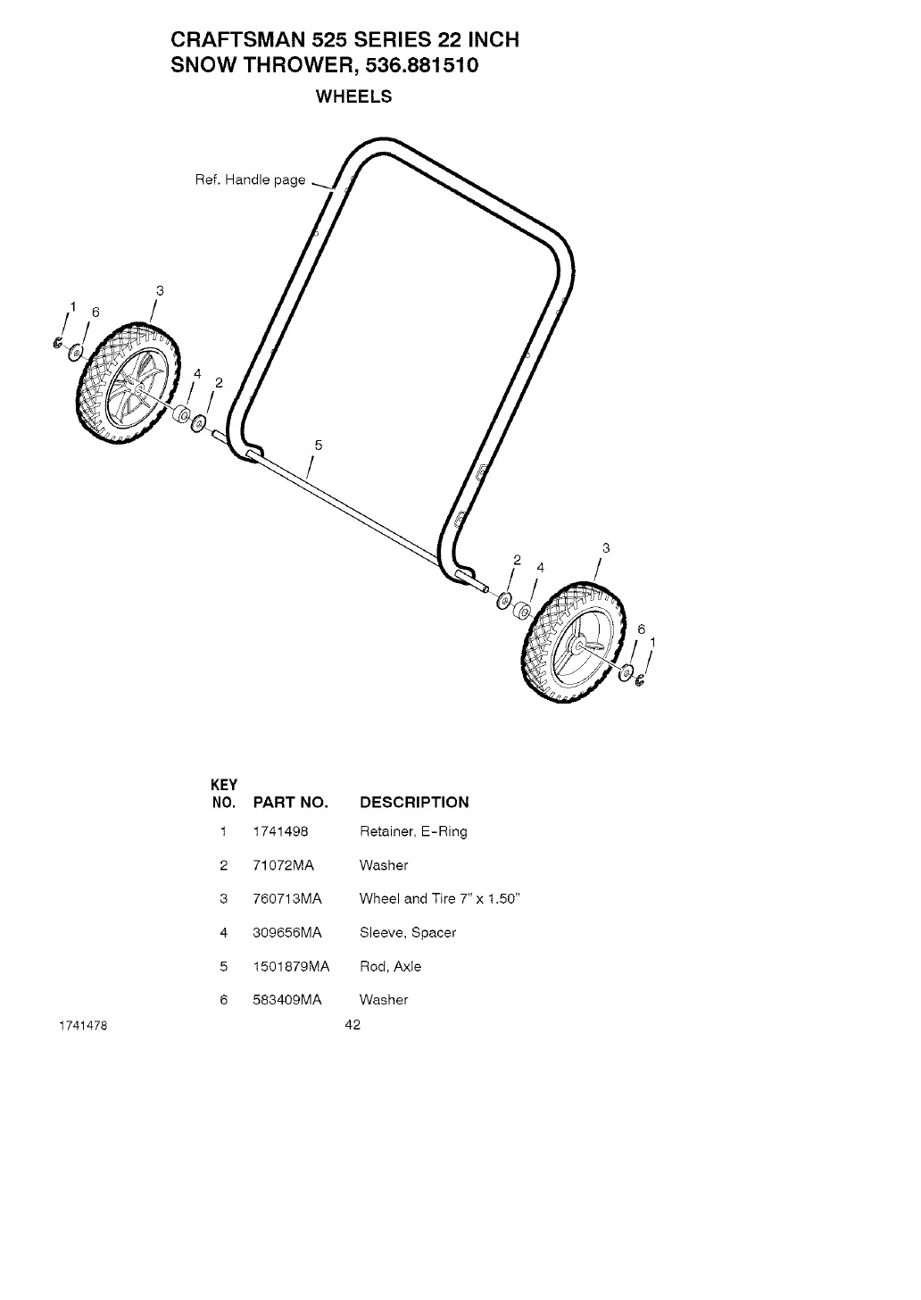
WHEELS
13 Ref. Handle p_
3
/
61
!
1741478
KEY
NO. PART NO. DESCRIPTION
1 1741498 Retainer, E-Ring
2 71072MA Washer
3 760713MA Wheel and Tire 7" x 1.50"
4 309656MA Sleeve, Spacer
5 1501879MA Rod, Axle
6 583409MA Washer
42
CRAFTSMAN 525 SERIES 22 INCH
SNOW THROWER, 536.881510
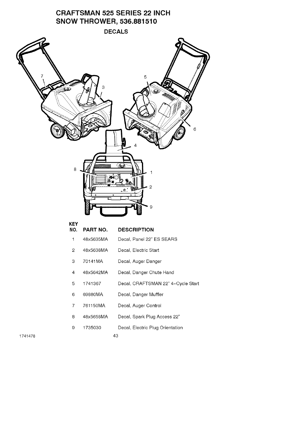
DECALS
1741478
KEY
NO, PART NO,
1 48x5635MA
2 48x5638MA
3 70141MA Decal
4 48x5642MA Decal
5 1741367 Decal
6 69880MA Decal
7 761150MA Decal
8 48x5658MA Decal
9 1735030 Decal
43
1
2
DESCRIPTION
Decal, PaneI 22" ES SEARS
Decal Electric Start
Auger Danger
Danger Chute Hand
CRAFTSMAN 22" 4-Cycle Start
Danger Muffler
Auger Control
Spark Plug Access 22"
Electric Plug Orientation
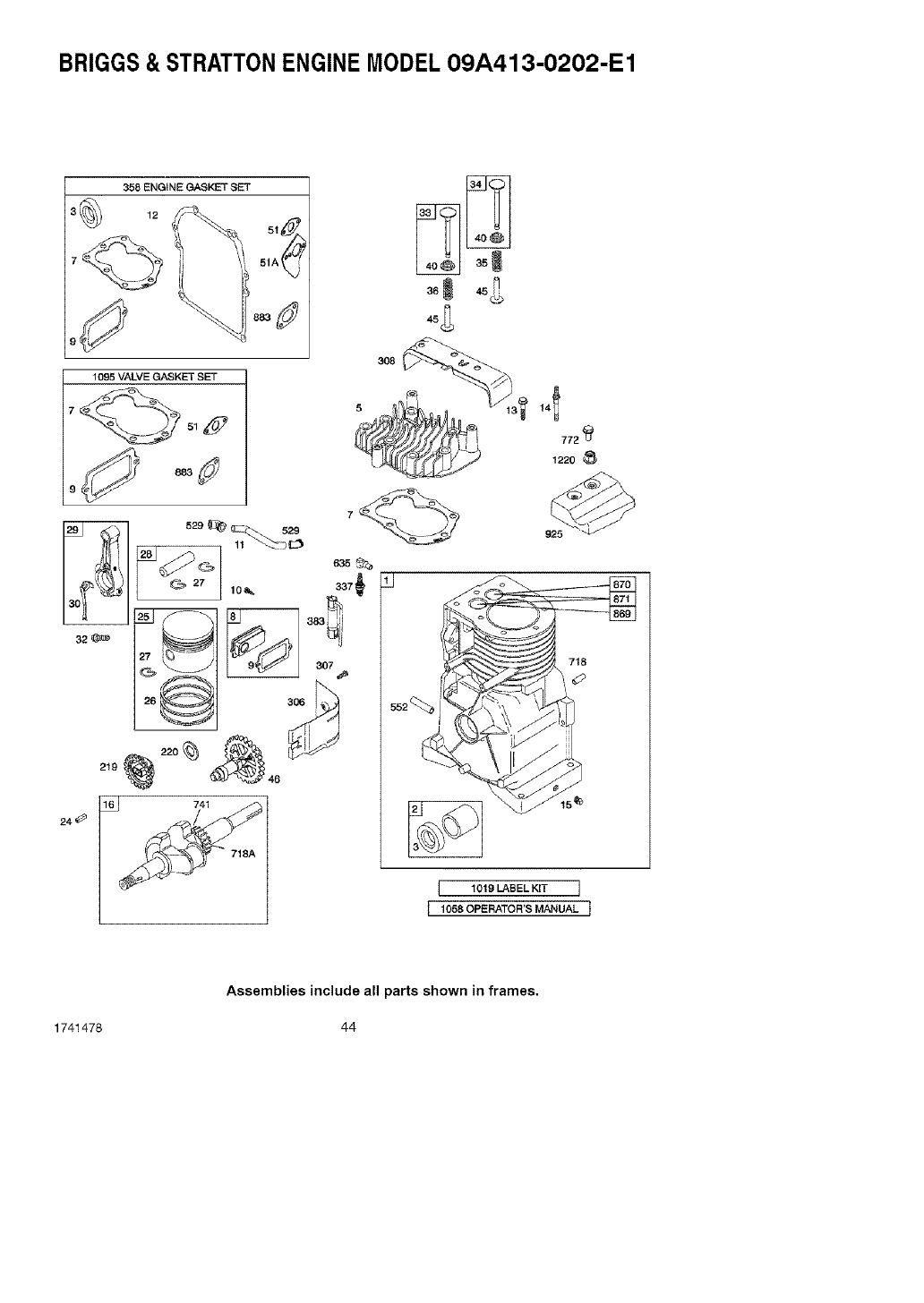
BRIGGS& STRATTONENGINE MODEL09A413-O202-E1
358 ENGINE GASKET SET
1095 VALVE GASKET SET
7
308
7
q
772 4_
1220 _,_
925
718
552_
15,_
[ 1019 LABEL K,T ]
I1058 0PERATOR'S MANUAL j
1741478
Assemblies include all parts shown in frames.
44
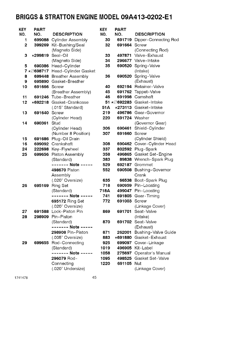
BRIGGS& STRATTONENGINE MODEL09A413-O202-E1
KEY PART KEY PART
NO. NO. DESCRIPTION NO. NO. DESCRIPTION
1 699088 Cylinder Assembly 30 691719 Dipper-Connecting Rod
2 399269 Kit-Bushing/Seal 32 691664 Screw
(Magneto Side) (Connecting Rod)
3 _299819 Seal-Oil 33 497871 Valve-Exhaust
(Magneto Side) 34 296677 Valve-intake
5 690386 Head-Cylinder 35 690520 Spring-Valve
7 _G698717 Head-Cylinder Gasket (Intake)
8 699448 Breather Assembly 36 690520 Spring-Valve
9 695890 Gasket-Breather (Exhaust)
10 691666 Screw 40 692194 Retainer-Valve
(Breather Assembly) 45 691762 Tappet-Valve
11 691246 Tube-Breather 46 691998 Camshaft
12 _692218 Gasket-Crankcase 51 _G692283 Gasket-intake
(.015" Standard) 51A _273113 Gasket-intake
13 691640 Screw 219 496786 Gear-Governor
(Cylinder Head) 220 691724 Washer
14 690361 Stud (Governor Gear)
(Cylinder Head) 306 690461 Shield-Cylinder
(Number 8 Position) 307 691660 Screw
15 691686 Plug-Oil Drain (Cylinder Shield)
16 699092 Crankshaft 306 690462 Cover-Cylinder Head
24 222698 Key-Flywheel 337 802592 Plug-Spark
25 699656 Piston Assembly 358 496865 Gasket Set-Engine
(Standard) 383 89836 Wrench-Spark Plug
....... Note ..... 529 692187 Grommet
498670 Piston 552 690506 Bushing-Governor
Assembly Crank
(.020" Oversize) 635 66536 Boot-Spark Plug
26 695169 Ring Set 718 690959 Pin-Locating
(Standard) 718A 499047 Pin-Locating
....... Note ..... 741 691805 Gear-Timing
695172 Ring Set 772 691003 Screw
(.020" Oversize) (Linkage Cover)
27 691586 Lock-Piston Pin 869 691701 Seat-Valve
28 298909 Pin-Piston (Intake)
(Standard) 870 691702 Seat-Valve
....... Note ..... (Exhaust)
298908 Pin-Piston 871 262001 Bushing-Valve Guide
(.005" Oversize) 883 _691880 Gasket-Exhaust
29 699655 Rod-Connecting 925 699097 Cover-Linkage
(Standard) 1019 496905 Kit-Label
....... Note ..... 1056 275697 Operator's Manual
296079 Rod- 1095 498525 Gasket Set-Valve
Connecting 1220 691105 Nut
(.020" Undersize) (Linkage Cover)
1741478 45
BRIGGS& STRATTONENGINE MODEL09A413-O202-E1
_2j
122
356 _,_ _ "" "_,_z, _
209 ,_ 1238
883
864
276@ i
1741478
Assemblies include all parts shown in frames.
46
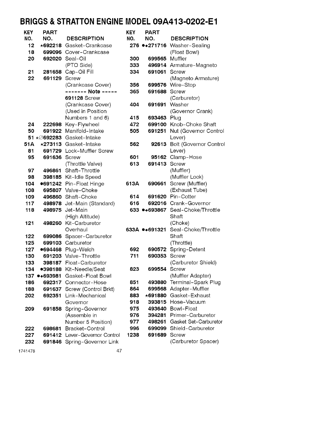
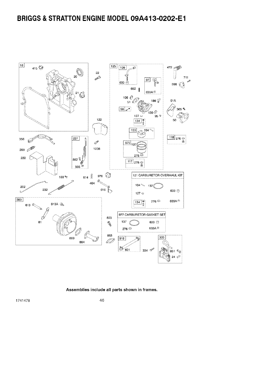
BRIGGS& STRATTONENGINE MODEL09A413-O202-E1
KEY PART KEY PART
NO, NO. DESCRIPTION NO. NO, DESCRIPTION
12 *692218 Gasket-Crankcase 276 e_,271716 Washer-Sealing
18 699096 Cover-Crankcase (Float Bowl)
20 692020 Seal-Oil 300 699565 Muffler
(PTO Side) 333 496914 Armature-Magneto
21 281658 Cap-Oil Fill 334 691061 Screw
22 691129 Screw (Magneto Armature)
(Crankcase Cover) 356 699576 Wire-Stop
....... Note ..... 365 691688 Screw
691128 Screw (Carburetor)
(Crankcase Cover) 404 691691 Washer
(Used in Position (Governor Crank)
Numbers 1 and 6) 415 693463 Plug
24 222698 Key-Flywheel 472 699100 Knob-Choke Shaft
50 691922 Manifold-intake 505 691251 Nut (Governor Control
51 _G692283 Gasket-intake Lever)
51A *273113 Gasket-intake 562 92613 Bolt (Governor Control
81 691729 Lock-Muffler Screw Lever)
95 691636 Screw 601 95162 Clamp-Hose
(Throttle Valve) 613 691413 Screw
97 496861 Shaff-Throttle (Muffler)
98 398185 Kit-Idle Speed (Muffler Lock)
104 e691242 Pin-Float Hinge 613A 690661 Screw (Muffler)
108 695807 Valve-Choke (Exhaust Tube)
109 496860 Shaft-Choke 614 691620 Pin-Cotter
117 498978 Jet-Main (Standard) 616 692016 Crank-Governor
118 498975 Jet-Main 633 e_693867 SeaI-ChokeThrottle
(High Altitude) Shaft
121 498260 Kit-Carburetor (Choke)
Overhaul 633A e.691321 SeaI-ChokefThrottle
122 699086 Spacer-Carburetor Shaft
125 699103 Carburetor (Throttle)
127 e694468 Plug-Welch 692 690572 Spring-Detent
130 691203 Valve-Throttle 711 690353 Screw
133 398187 Float-Carburetor (Carburetor Shield)
134 e398188 Kit-Needle/Seat 823 699554 Screw
137 e.693981 Gasket-Float Bowl (Muffler Adapter)
186 692317 Connector-Hose 851 493880 Terminal-Spark Plug
188 691637 Screw (Control Brkt) 864 699568 Adapter-Muffler
202 692351 Link-Mechanical 883 *691880 Gasket-Exhaust
Governor 918 393815 Hose-Vacuum
209 691858 Spring-Governor 975 493640 Bowl-Float
(Assemble in 976 394281 Primer-Carburetor
Number 5 Position) 977 498261 Gasket Set-Carburetor
222 698681 Bracket-Control 996 699099 Shield-Carburetor
227 691412 Lever-Governor Control 1238 691689 Screw
232 691846 Spring-Governor Link (Carburetor Spacer)
1741478 47
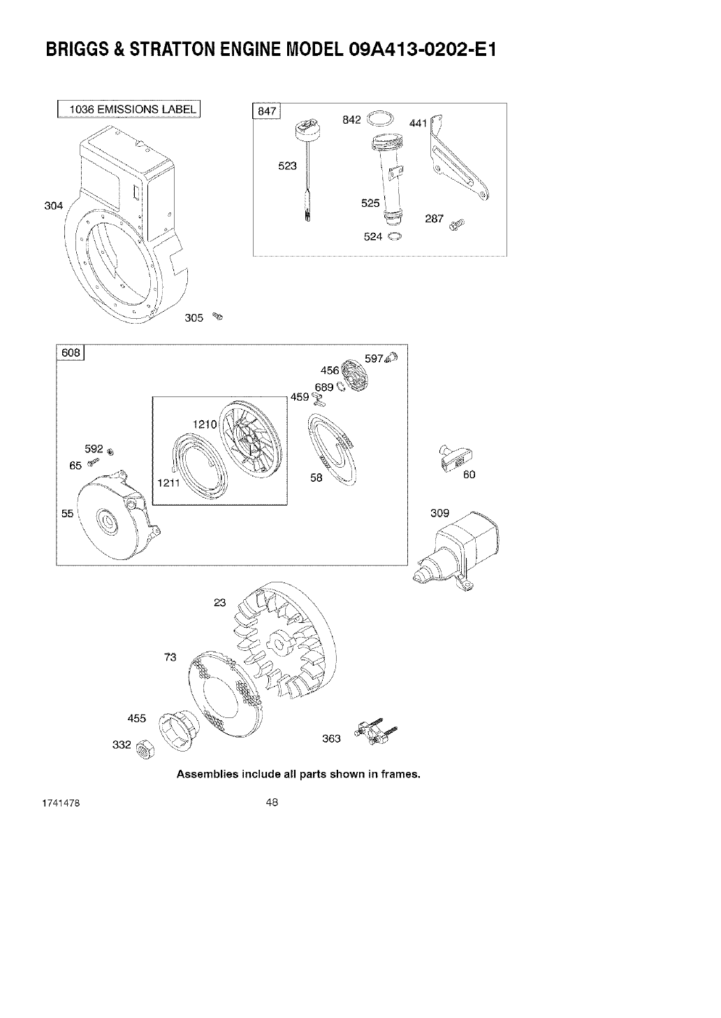
BRIGGS& STRATTONENGINE MODEL09A413-O202-E1
304
i
I 1036 EMISSIONS LABEL I
523 ,]
842 ,.._ 4_
' i
524 <-# 287 _,;
3O5 %
592 <e
65 _
459 _>
309
23
73
1741478
363 _
Assemblies include all parts shown in frames.
48
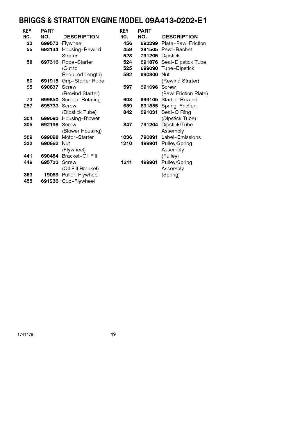
BRIGGS& STRATTONENGINE MODEL09A413-O202-E1
KEY PART KEY PART
NO, NO. DESCRIPTION NO. NO, DESCRIPTION
23 699573 Flywheel 456 692299 Plate-Pawl Friction
55 692144 Housing-Rewind 459 281505 PawI-Rachet
Starter 523 791205 Dipstick
58 697316 Rope-Starter 524 691876 SeaI-DipstickTube
(Cut to 525 699090 Tube-Dipstick
Required Length) 592 690800 Nut
60 691915 Grip-Starter Rope (Rewind Starter)
65 690837 Screw 597 691696 Screw
(Rewind Starter) (Pawl Friction Plate)
73 699850 Screen-Rotating 608 699105 Starter-Rewind
287 695733 Screw 689 691855 Spring-Friction
(Dipstick Tube) 842 691031 SeaI-O Ring
304 699093 Housing-Blower (Dipstick Tube)
305 692198 Screw 847 791204 Dipstick/Tube
(Blower Housing) Assembly
309 699098 Motor-Starter 1036 790891 Label-Emissions
332 690662 Nut 1210 499901 Pulley/Spring
(Flywheel) Assembly
441 690484 Bracket-Oil Fill (Pulley)
449 695733 Screw 1211 499901 Pulley/Spring
(Oil Fill Bracket) Assembly
363 19069 Puller-Flywheel (Spring)
455 691236 Cup-Flywheel
1741478 49

1741478 50
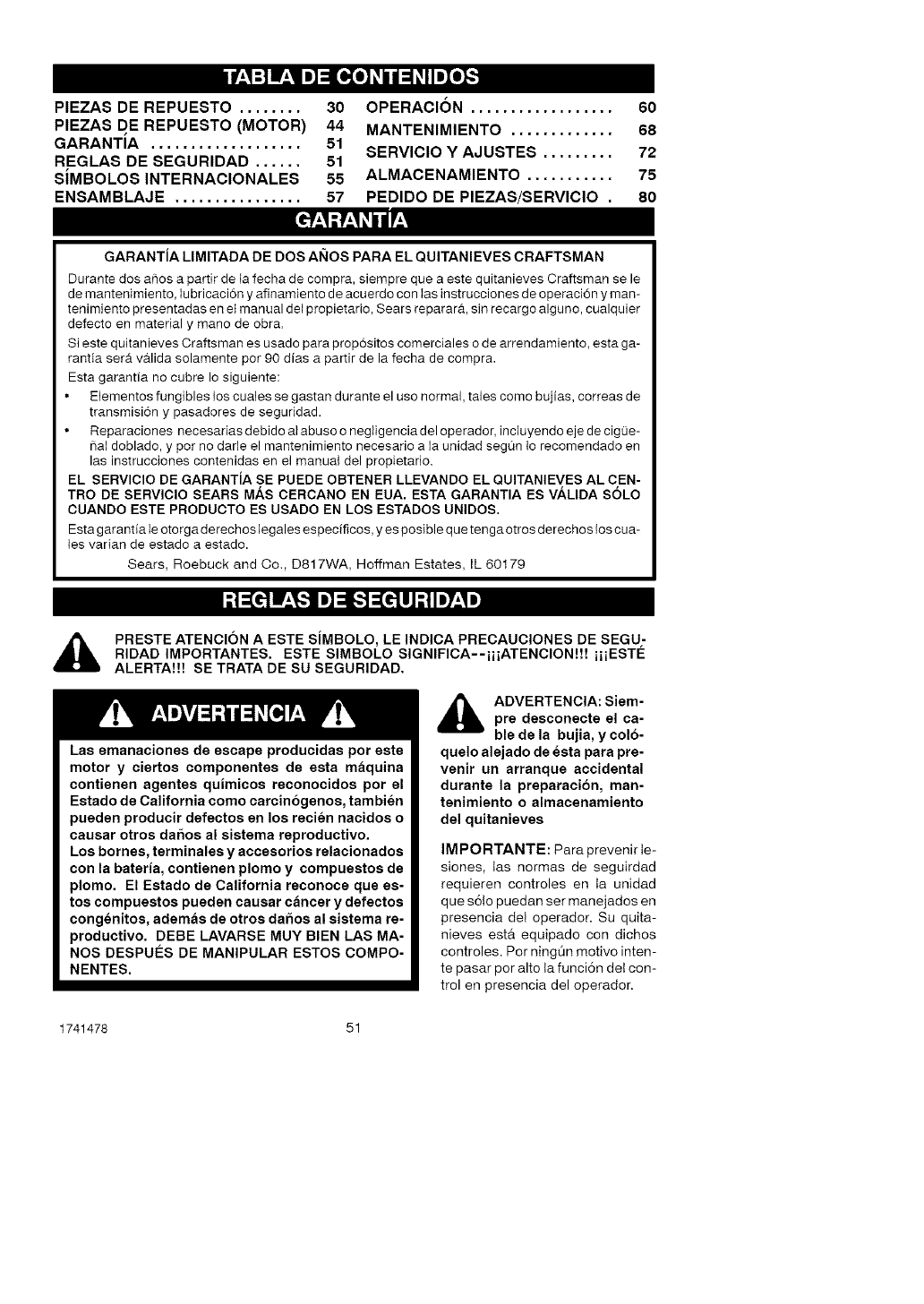
uuP':_:]I':11m]= [_o_o_'_
PIEZAS DE REPUESTO ........ 30
PIEZAS DE REPUESTO (MOTOR) 44
GARANTiA ................... 51
REGLAS DE SEGURIDAD ...... 51
SIMBOLOS INTERNACIONALES 55
ENSAMBLAJE ................ 57
OPERACION .................. 60
MANTENIMIENTO ............. 68
SERVICIO Y AJUSTES ......... 72
ALMACENAMIENTO ........... 75
PEDIDO DE PIEZAS/SERVICIO .80
GARANTiA LIMITADA DE DOS AI(tOS PARA EL QUITANIEVES CRAFTSMAN
Durante dos ahos a partir de la fecha de cornpra, siempre que a este quitanieves Craftsman se le
de mantenimiento, lubricaci6n y afinamiento de acuerdo con las instrucciones de operaci6n y man-
tenimiento presentadas en et manual de{ propietario, Sears reparara, sin recargo alguno, cualquier
defecto en material y mano de obra.
Si este quitanieves Craftsman es usado para prop6sitos comerciales o de arrendamiento, esta ga-
rantia ser_t va.lida solamente pot 90 alias a partir de la fecha de compra.
Esta garantia no cubre Io siguiente:
Elementos fungibles los cuales se gastan durante el uso normal, tales como bujias, correas de
transmision y pasadores de seguridad.
Reparaciones necesarias debido al abuse o negligencia del operador, incluyendo eje de cigQe-
hal doblado, y pot no darle el mantenimiento necesario a la unidad segun 1o recomendado en
las instrucciones contenidas en el manual del propietario.
EL SERVlClO DE GARANTiA SE PUEDE OBTENER LLEVANDO EL QUITANIEVES AL CEN-
TRO DE SERVlClO SEARS MAS OERCANO EN EUA. ESTA GARANTIA ES VALIDA SOLO
CUANDO ESTE PRODUCTO ES USADO EN LOS ESTADOS UNIDOS.
Esta garantia le otorga derechos legales especificos, yes posible que tenga otros derechos los cua-
{es varian de estado a estado.
Sears, Roebuck and Co., D817WA, Hoffman Estates, IL 60179
_ll RESTE ATENCION A ESTE SiMBOLO, LE INDICA PRECAUCIONES DE SEGU-
RIDAD IMPORTANTES, ESTE SlMBOLO SlGNIFICA--iiiATENClON!!! iiiESTE
ALERTA!!! SE TRATA DE SU SEGURIDAD.
Las emanaciones de escape producidas por este
motor y ciertos componentes de esta maquina
contienen agentes quimicos reconocidos por el
Estado de California como carcinogenos, tambien
pueden producir defectos en los recien nacidos o
causar otros daSos al sistema reproductivo.
Los bornes, terminales y accesorios relacionados
con la bateria, contienen plomo y compuestos de
plomo. El Estado de California reconoce que es-
tos compuestos pueden causar cancer y defectos
congenitos, ademas de otros daSos al sistema re-
productivo. DEBE LAVARSE MUY BIEN LAS MA-
NOS DESPUI_S DE MANIPULAR ESTOS COMPO-
NENTES.
l_li ADVERTENCIA: Siem-pre desconecte el ca-
ble de la bujia, y colo-
quelo alejado de esta para pre-
venir un arranque accidental
durante la preparacion, man-
tenimiento o almacenamiento
del quitanieves
IMPORTANTE: Para prevenir te-
siones, tas normas de seguirdad
requieren controles en ta unidad
que s6!o puedan ser manejados en
presencia del operador. Su quita-
nieves est& equipado con dichos
controles. Per ningOn motive inten-
te pasar por alto ta funci6n det con-
trol en presencia del operador.
1741478 51
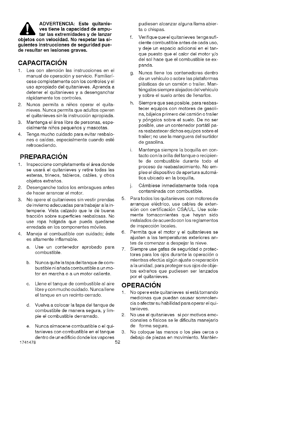
,_ ADVERTENCIA: Este quitanie-
yes tiene la capacidad de ampu-
tar las extremidades y de lanzar
objetos con valocidad. No respetar las si-
guientes instruccionas de seguridad pue-
de resultar an lesiones graves.
CAPACITACION
1. Lea con atenci6n las instrucciones en et
manual de operaci6n y servicio. Famitiari-
cese comptetamente con los controtes y et
uso apropiado det quitanieves. Aprenda a
detener et quitanieves y a desenganchar
r&pidamente tos controles.
2. Nunca permita a niBos operar et quita-
nieves. Nunca permita que adultos operen
el quitanieves sin la instrucci6n apropiada.
3. Mantenga el &rea tibre de personas, espe-
cialmente niBos pequeiqos y mascotas.
4. Tenga mucho cuidado para evitar resbalo-
nes o cafdas, especialmente cuando est6
retrocediendo.
PREPARACION
1. Inspeccione completamente el &rea donde
se usar& et quitanieves y retire todas tas
esteras, trineos, tableros, cables, y otros
objetos extra5os.
2. Desenganche todos tos embragues antes
de hacer arrancar et motor.
3. No opere et quitanieves sin vestir prendas
de invierno adecuadas para trabajar a la in-
temperie. Vista caIzado que Ie d6 buena
tracci6n sobre superficies resbalosas. No
use ropa holgada que pueda quedarse
enredada en los componentes m6viles.
4. Maneje el combustible con cuidado; 6ste
es altamente inflamabte.
a. Use un contenedor aprobado para
combustible.
b. Nunca quite ta tapa dettanque de com-
bustible ni aBada combustible a un mo-
tor en marcha o a un motor caliente.
c. Llene el tanque de combustible aI aire
Iibre y con mucho cuidado. Nunca Ilene
el tanque en un recinto cerrado.
d. Vuelva a cotocar la tapa del tanque de
combustible de manera segura, y lim-
pie eI combustible derramado. 2.
e. Nunca aImacene combustible o el qui-
tan!eves con combustible en el tanque 3.
dentro de un edificio donde los vapores
1741478 52
pudiesen aIcanzar alguna llama abier-
ta o chispas.
f. Verifiqueque elquitanieves tengasufi-
ciente combustible antes de cada uso,
y deje un espacio adicional en et tan-
que puesto que el caIor det motor y/o
del sol hace que el combustible se ex-
panda.
g. Nunca tlene tos contenedores dentro
de un vehiculo o sobre las ptataformas
ptasticas de un cami6n o trailer. Man-
t6ngalos siempre alejados det vehiculo
y sobre el suelo antes de tlenarIos.
h. Siempre que sea posible, para reabas-
tecer equipos con motores de gasoli-
na, b_tjelos primero del cami6n o trailer
y p6ngalos sobre el suelo. De no ser
posible, use un contenedor port_ttil pa-
ra reabastecer dichos equipos sobre el
trailer; no use la manguera del surtidor
de gasotina.
i. Mantenga siempre ta boquilla en con-
tacto con Ia orilla del tanque o recipien-
te de combustible durante todo el
proceso de reabastecimiento. No em-
ptee et dispositivo de apertura automa-
t!ca ubicado en ta boquilla.
j. C_tmbiese inmediatamente toda ropa
contaminada con combustible.
5. Paratodos los quitanieves con motores de
arranque el6ctrico, use cables de exten-
si6n con certificaci6n CSA/UL. Use sota-
mente tomacorrientes que hayan sido
instatados de acuerdo con los reglamentos
de inspecci6n locales.
6. Permita queet motor y el quitanieves se
ajusten a las temperaturas exteriores an-
tes de comenzar a despejar ta nieve.
7. Siempre use gafas de seguridad o protec-
tores para los ojos durante ta operaci6n o
mientras efect0a alg0n ajuste o reparaci6n
a ta unidad, para proteger sus ojos de obje-
tos extraBos que pudiesen ser lanzados
por et quitanieves.
OPERACION
1. No opere este quitanieves si estertomando
medicinas que puedan causar somnolen-
cia o afectar su habilidad para operar et qui-
tan!eves.
No use el quitanieves si pot motivos emo-
cionales o flsicos se le dificutta manejado
de forma segura.
No cotoque las manos o los pies cerca o
debajo de piezas en movimiento. Mant6n-
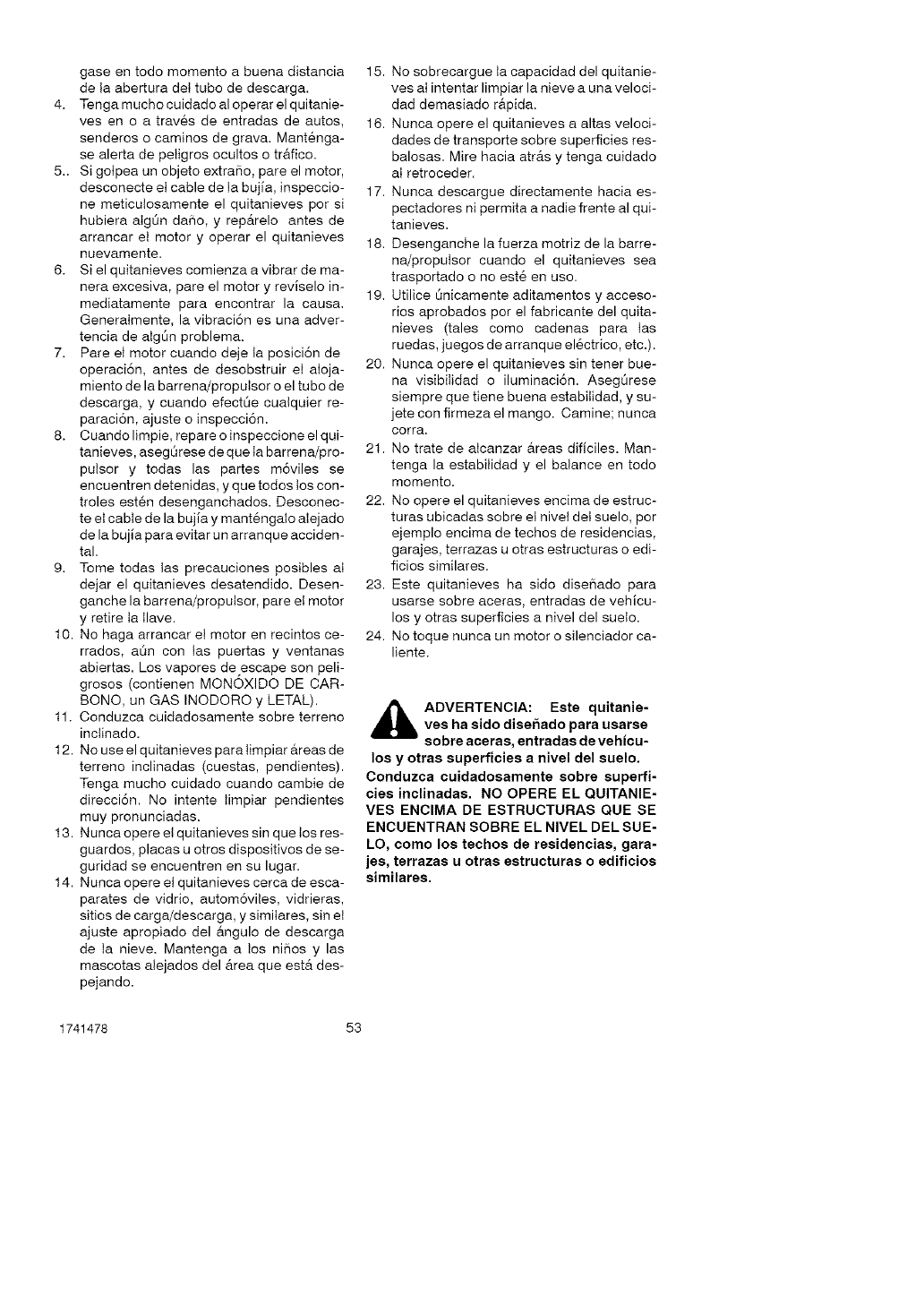
gaseentodomementoabuenadistancia
detaaberturadettubededescarga.
4. Tengamuchocuidadoaloperarelquitanie-
vesenoatrav6sdeentradasdeautos,
senderosocaminosdegrava.Mant6nga-
sealertadepeligrosocultosotrafico.
5..Sigotpeaunobjetoextra,o,pareelmotor,
desconecteetcabledetabujfa,inspeccio-
nemeticutosamenteelquitanievespersi
hubieraaIg0nda_o,yrep_treloantesde
arrancarelmotoryoperarelquitanieves
nuevamente.
6. Sielquitanievescomienzaavibrardema-
neraexcesiva,pareelmotoryrevlseloin-
mediatamenteparaencontrarlacausa.
GeneraImente,lavibraci6nesunaadver-
tenciadeaIg0nproblema.
7. PareeImotorcuandodejetaposici6nde
operaci6n,antesdedesobstruirelaIoja-
mientodelabarrena/proputsoroeltubode
descarga,ycuandoefectOecualquierre-
paraci6n,ajusteoinspecci6n.
8. Cuandolimpie,repareoinspeccioneelqui-
tanieves,asegOresedequeIabarrena/pro-
putsory todaslaspartesm6vilesse
encuentrendetenidas,yquetodostoscon-
trolesest6ndesenganchados.Desconec-
teetcabledelabujiaymant6ngaloalejado
delabujlaparaevitarunarranqueacciden-
tal.
9. TometodastasprecaucionesposiblesaI
dejarelquitanievesdesatendido.Desen-
ganchelabarrena/proputsor,pareelmotor
yretiretatlave.
10.Nohagaarrancarelmotorenrecintosce-
rrados,aOnconIaspuertasyventanas
abiertas.Losvaporesdeescapesonpeli-
grosos(contienenMONOXIDODECAR-
BONO,unGASINODOROyLETAL).
11.Conduzcacuidadosamentesobreterreno
inctinado.
12.Nouseelquitanievesparatimpiarareasde
terrenoinclinadas(cuestas,pendientes).
Tengamuchocuidadocuandocambiede
direcci6n.NointenteIimpiarpendientes
muypronunciadas.
13.Nuncaopereelquitanievessinquetosres-
guardos,placasuotrosdispositivosdese-
guridadseencuentrenensulugar.
14.Nuncaopereelquitanievescercadeesca-
paratesdevidrio,autom6viles,vidrieras,
sitiosdecarga/descarga,ysimiIares,sinet
ajusteapropiadodelangulodedescarga
detanieve.Mantengaatosni_osy las
mascotasalejadosdel_treaqueesterdes-
pejando.
15.Nosobrecarguetacapacidaddelquitanie-
vesaIintentarlimpiarlanieveaunaveloci-
daddemasiadorapida.
16.Nuncaopereelquitanievesaaltasveloci-
dadesdetransportesobresuperficiesres-
balosas.Mirehaciaatr_tsytengacuidado
aIretroceder.
17.Nuncadescarguedirectamentehaciaes-
pectadoresnipermitaanadiefrentealqui-
tanieves.
18.Desenganchelafuerzamotrizdelabarre-
na/proputsorcuandoelquitanievessea
trasportadoonoest6enuse.
19.UtiliceOnicamente aditamentos y acceso-
rios aprobados pot el fabricante del quita-
nieves (tales como cadenas para tas
ruedas, juegos de arranque el6ctrico, etc.).
20. Nunca opere el quitanieves sin tener bue-
na visibilidad o iluminaci6n. Aseg6rese
siempre que tiene buena estabitidad, y su-
jete con firmeza el mango. Camine; nunca
corra.
21. No trate de aIcanzar areas dificiles. Man-
tenga la estabilidad y el balance en todo
momento.
22. No opere el quitanieves encima de estruc-
turas ubicadas sobre et nivet det suelo, por
ejemplo encima de techos de residencias,
garajes, terrazas u otras estructuras o edi-
ficios similares.
23. Este quitanieves ha sido dise_ado para
usarse sobre aceras, entradas de vehicu-
los y otras superficies a nivel del sueto.
24. No toque nunca un motor o silenciador ca-
liente.
ADVERTENCIA: Este quitanie-ves ha sido disefiado para usarse
sobre acsras, entradas de vshicu-
los y otras superficies a nivel del suelo.
Conduzca cuidadosaments sobre superfi-
cies inclinadas. NO OPERE EL QUITANIE-
VES ENCIMA DE ESTRUCTURAS QUE SE
ENCUENTRAN SOBRE EL NIVEL DEL SUE-
LO, como los tschos de rssidencias, gara-
jes, tsrrazas u otras estructuras o edificios
similarss.
1741478 53
MANTENIMIENTO Y
ALMACENAMIENTO
como despejar tubos de descarga
atascados
,_ ADVERTENCIA: Las lesiones
mas comunes asociadas con el
uso del quitanieves son las que
se produceR cuando las manos entren en
contacto con el dispositivo impulsor den-
tro del tubo de descarga. No use nunca las
manos para despejar el tubo de descarga.
Para despejar el tubo:
•APAGUE EL MOTOR.
•Espere unos 10 segundos para que las
aletas del impulsor dejen de girar.
•Use siempre la herramienta de limpie-
za, no las manos.
1. Revise los pernos con frecuencia para ase-
gurar que est6n bien apretados y que et
quitanieves est6 en condiciones seguras
de funcionamiento.
2. Guarde et quitanieves a una distancia de
fuentes de ignici6n o de aparatos dom6sti-
cos que tengan llamas de encendido, tales
como caIentadores de agua y estufas, se-
cadoras de ropa, etc. Permita que el motor
se enfde antes de guardar el quitanieves
en cuaIquier recinto.
3. Siva a aImacenar el quitanieves por un pe-
riodo protongado, siempre consulte tas ins-
trucciones del manual det operador donde
encontrara consejos importantes.
4. Mantenga o reemptace tas etiquetas de
seguridad e instrucciones, segQn sea ne-
cesario.
5. Mantenga el quitanieves en marcha unos
cuantos minutes despu6s de despejar ta
nieve, para evitar que se congete la barre-
na/propulsor.
1741478 54
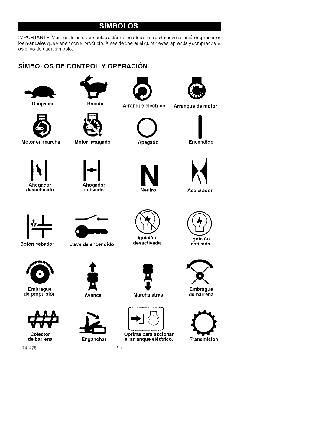
IM PORTANTE: Muchos de estos simbolos est&n colocados en su quitanieves o est&n impresos en
los manuales que vienen con el producto. Antes de operar el quitanieves aprenda y comprenda et
objetivo de cada simboto.
SiMBOLOS DE CONTROL Y OPERACION
Despacio Rapido Arranque electrico
OArranque de motor
I
Motor en marcha Motor apagado Apagado Encendido
HN
Ahogador Ahogador
desactivado activado Neutro Acelerador
Boton cebador Llave de encendido
® ®
Ignicion Ignicibn
desactivada activada
Embrague
de propulsion
VVV
Colector
de barrena
1741478
Avarice Marcha atras
1.:o}
Oprima para accionar
Enganchar el arranque electrico.
55
Embrague
de barrena
O
Transmisibn
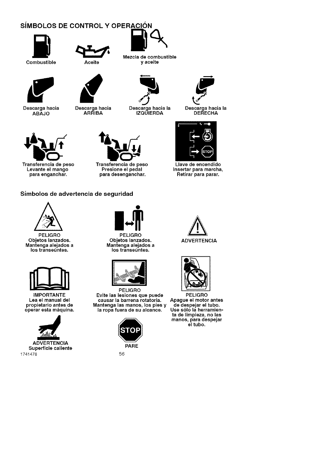
SiMBOl-OS DE CONTROl- Y OPERACION
Mezcla de combustible
Combustible Aceite y aceite
f / ?
Descarga hacia Descarga hacia Descarga hacia la Descarga hacia la
ABAJO ARRIBA IZQUIERDA DERECHA
rer--dl
|.m
Transferencia de peso Transferencia de peso Llave de encendido
Levante el mango Presione el pedal Insertar para marcha,
para enganchar, para desenganchar. Retirar para parar.
Simbolos de advertencia de seguridad
A
PELIGRO
Objetos lanzados.
Mantenga alejados a
los transeentes.
PELIGRO
Objetos lanzados.
Mantenga alejados a
los transeuntes.
IMPORTANTE
Lea el manual del
propietario antes de
operar esta maquina.
PELIGRO
Evite las lesiones que puede
causar la barrena rotatoria.
Mantenga las manos, los pies y
la ropa fuera de su alcance.
A
ADVERTENCIA
PELIGRO
Apague el motor antes
de despejar el tubo.
Use solo la herramien-
ta de limpieza, no las
manos, para despejar
el tubo.
ADVERTENCIA
Superficie caliente
1741478 56
PARE
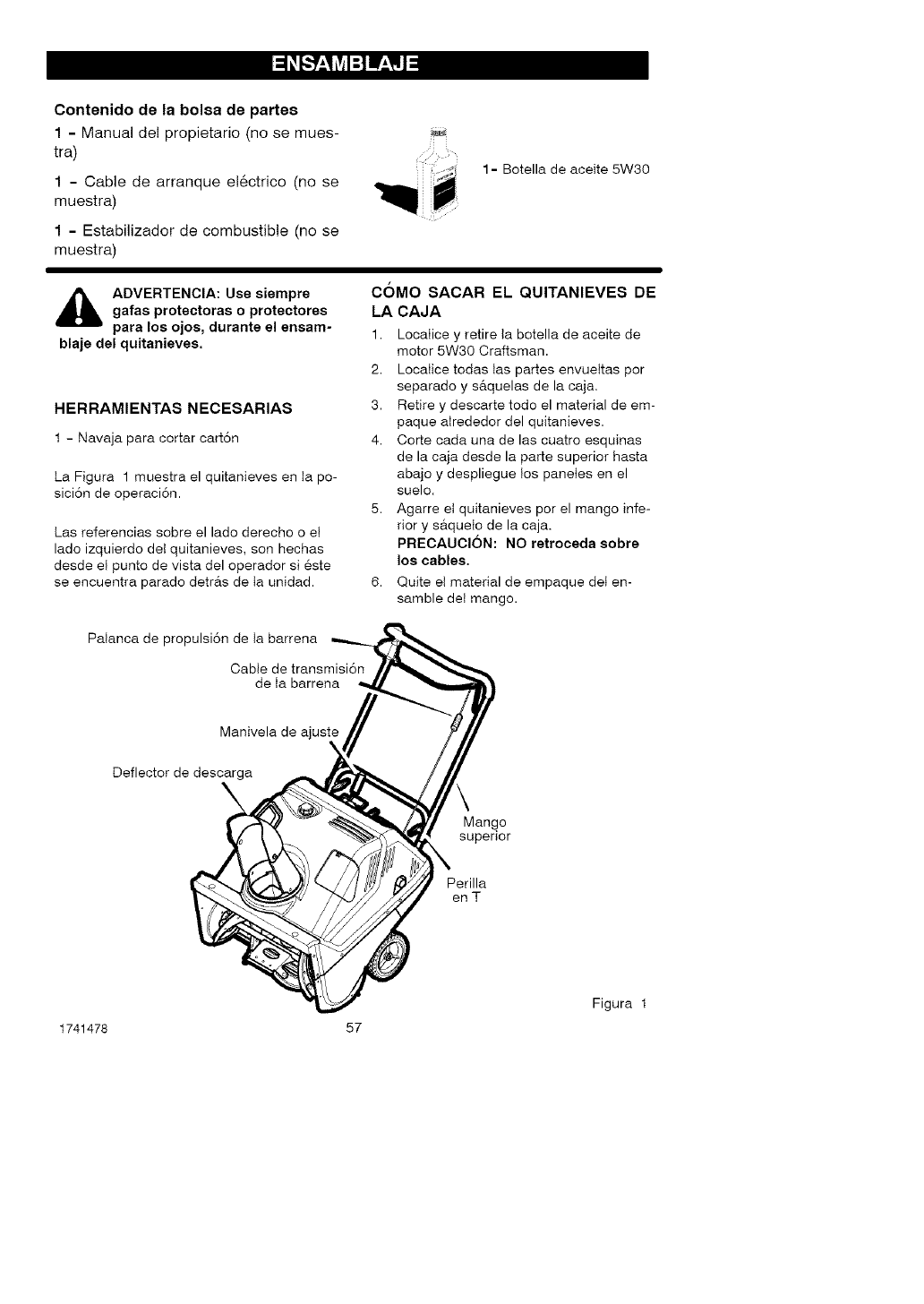
Contenidode la bolsa de partes
1- Manual del propietario (no se mues-
tra)
1 - Cable de arranque e!6ctrico (no se
muestra)
1 - Estabilizador de combustible (no se
muestra)
1 - Botella de aceite 5W30
ADVERTENClA: Use siempre
galas protectoras o protectores
para los ojos, durante el ensam-
blaje del quitanieves.
HERRAMIENTAS NECESARIAS
1 - Navaja para cortar cart6n
La Figura 1 muestra el quitanieves en Ia po-
sici6n de operaci6n.
Las referencias sobre el lade derecho o el
lade izquierdo del quitanieves, son hechas
desde el punto de vista del operador si 6ste
se encuentra parado detr_ts de Ia unidad.
COMO SACAR EL QUITANIEVES DE
LA CAJA
1. LocaIice y retire Ia botella de aceite de
motor 5W30 Craftsman.
2. LocaIice todas tas partes envueltas por
separado y s&quelas de la caja.
3. Retire y descarte todo el material de em-
paque aIrededor del quitanieves.
4. Corte cada una de las cuatro esquinas
de la caja desde la parte superior hasta
abajo y despliegue Ios panetes en el
suelo.
5. Agarre et quitanieves pot el mango infe-
rior y saqueto de la caja.
PRECAUCION: NO retroceda sobre
los cables.
6. Quite et material de empaque deI en-
samble det mango.
Palanca de propulsi6n de Ia barrena
Cable de transmisi6n
de Ia barrena
Manivela de ajuste
Deflector de descarga
Mango
superior
Perilla
enT
Figura 1
1741478 57
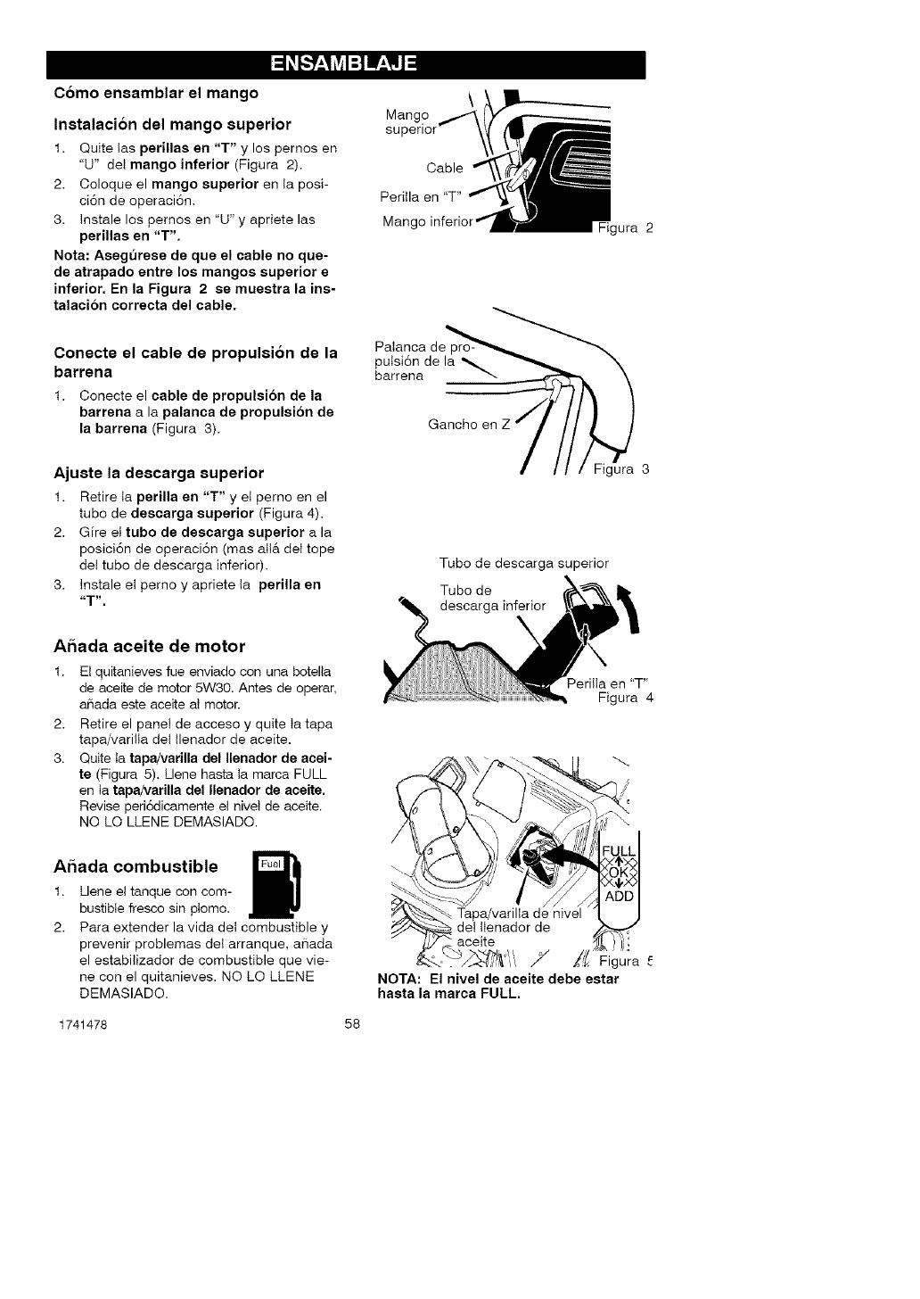
Como ensamblar el mango
Instalacion del mango superior
1. Quite tas perillas en "T" y los pernos en
"U" del mango inferior (Figura 2).
2. Coloque el mango superior en Ia posi-
ci6n de operaci6n.
3. Instale los pernos en "U" y apriete las
perillas en "T",
Nota: Assgursse de que el cable no que-
de atrapado entre los mangos superior s
inferior. En la Figura 2 se musstra la ins-
talaci6n corrscta dsl cable.
Conecte el cable de propulsi6n de la
barrena
1. Conecte el cable de propulsion de la
barrena a la palanca de propulsi6n de
la barrsna (Figura 3).
Ajuste la descarga superior
1. Retire ta psrilla en "T" yet perno en el
tube de descarga superior (Figura 4).
2. Gire el tubo de descarga superior ala
posici6n de operaci6n (mas alta deI tope
del tube de descarga inferior).
3. Instale et pemo y apriete Ia perilla en
_=t _"
Ahada aceite de motor
1. Et quitanieves fue enviado con una botella
de aceite de motor 5W30. Antes de operar,
aBada este aceite aI motor.
2. Retire el panel de acceso y quite ta tapa
tapa/vari!Ia del tlenador de aceite.
3. Quite ta tapa/varilla del Ilenador de acei-
ts (Figura 5). Llene hasta ta marca FULL
en Ia tapaNarilla del Ilsnador de acsite,
Revise peri6dicamente et nivet de aceite.
NO LO LLENE DEMASIADO.
Mango
superior
Cable
Peritla en "T"
Mang_ gura 2
Palanca de
putsi6n de la
barrena
Gancho en Z
Figura 3
Tube de descarga superior
Tubo de
descarga inferior
PerilIa en "T"
Figura 4
Ahada combustible
1.
2.
Llene et tanque con com-
bustible fresco sin ptomo.
Para extender la vida det combustible y
prevenir problemas del arranque, a_ada
el estabilizador de combustible que vie-
ne con el quitanieves. NO LO LLENE
DEMASIADO.
7" /_ Figura
NOTA: El nivel de aceite debe estar
hasta la marca FULL.
1741478 58
_" LISTA DE REVISION
Antes de operar su nuevo quitanieves, y pa-
ra asegurar que obtenga et mejor rendimien-
to y ta mayor satisfacci6n de este producto
de calidad, por favor haga un repaso de la
siguiente lista de revisi6n:
_' Se han completado todas tas instruccio-
nes de ensamblado.
_' El tubo de descarga gira libremente.
_' No quedan piezas suettas en la caja de
cart6n.
AI mismo tiempo que aprende a usar su qui-
tanieves, preste mucha atenci6n a Ios deta-
lies siguientes:
Aseg0rese de que haya suficiente aceite
de motor. Use un aceite detergente de alta
calidad ctasificado como "Para servicio
SG, SH, SJ, SL o superior".
_' Aseg@ese de que el tanque de combusti-
ble contenga gasolina Iimpia y nueva sin
plomo, con un octanaje m[nimo de 85.
Familiadcese con ta ubicaci6n de todos
los controles y aseg0rese de entender la
funci6n de cada uno.
_' Antes de encender et motor, asegOrese de
que todos tos controles est6n funcionando
correctamente.
1741478 59
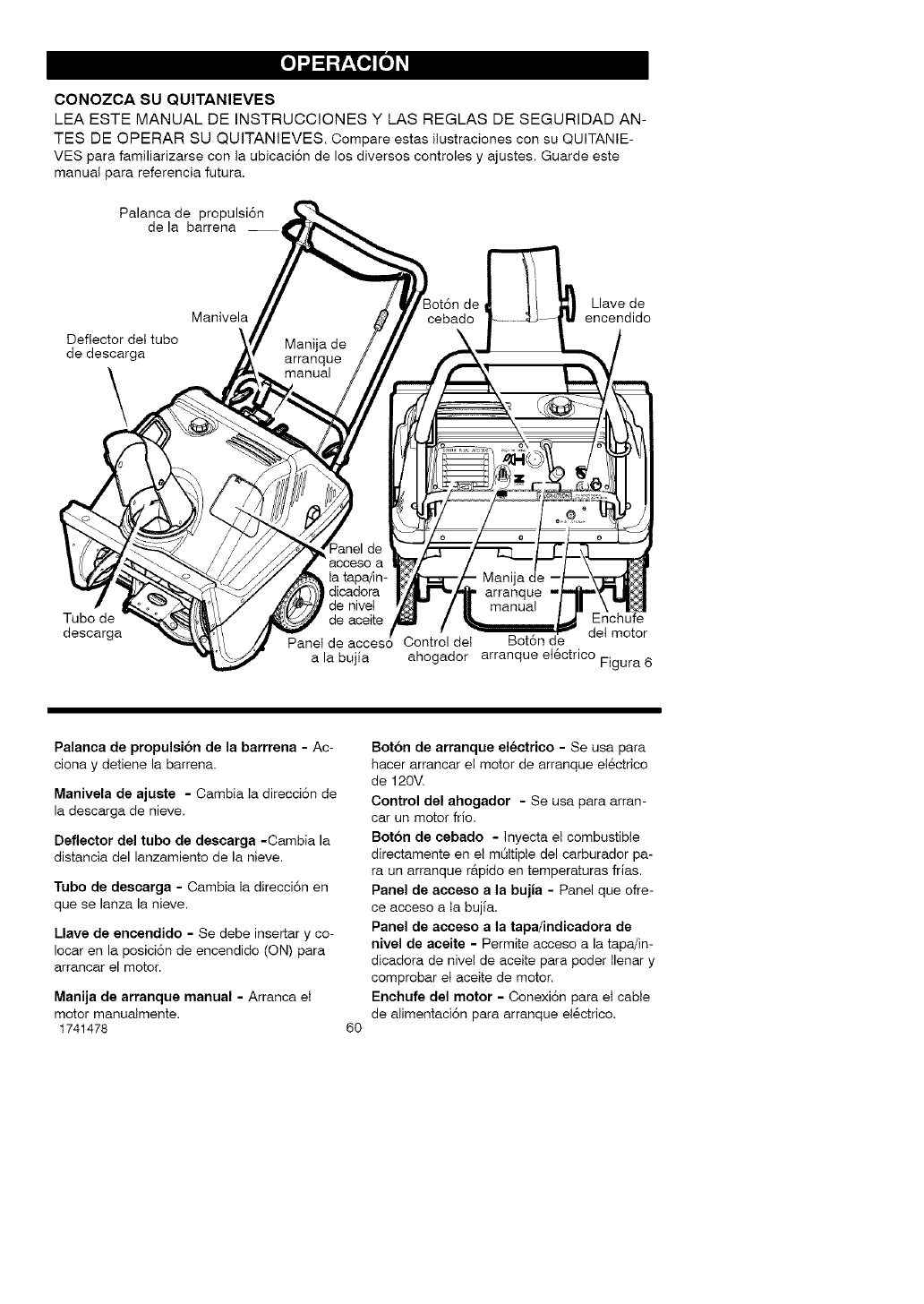
CONOZCA SU QUlTANIEVES
LEA ESTE MANUAL DE INSTRUCCIONES Y LAS REGLAS DE SEGURIDAD AN-
TES DE OPERAR SU QUITANIEVES. Compare estas itustraciones con su QUITANIE-
VES para familiarizarse con ta ubicaci6n de los diversos controles y ajustes. Guarde este
manuat para referencia futura.
Palanca de propulsi6n
de la barrena
Deflector det tube
de descarga
\
de Llave de
Manivela encendido
Tubo de
descarga
dicadora
de nivet
de aceite Enchufe
Panel de acceso Control det Bot6n e det motor
a la bujia ahogador arranque et6ctrico Figura 6
Palanca de propulsibn de la barrrena - Ac-
ciona y detiene la barren&
Manivela de ajuste - Cambia Ia direcci6n de
la descarga de nieve.
Deflector del tubo de descarga -Cambia la
distancia del lanzamiento de la nieve.
Tubo de descarga - Cambia la direcci6n en
que se lanza la nieve.
Llave de encendido - Se debe insertar y co-
Iocar en la posici6n de encendido (ON) para
arrancar el motor.
Manija de arranque manual - Arranca el
motor manualmente.
1741478 6O
Boton de arranque electrico - Se usa para
hacer arrancar eI motor de arranque eI6ctrico
de 120',/
Control del ahogador - Se usa para arran-
car un motor frio.
Boton de cebado - Inyecta et combustible
directamente en et mOttipte del carburador pa-
ra un arranque r&pido en temperaturas frias.
Panel de acceso ala bujia - Panel que ofre-
ce acceso a ta bujla.
Panel de acceso ala tapa/indicadora de
nivel de aceite - Permite acceso a la tapa/in-
dicadora de nivel de aceite para poder Ilenar y
comprobar et aceite de motor.
Enchufe del motor - Conexi6n para eI cable
de atimentaci6n para arranque et6ctrico.
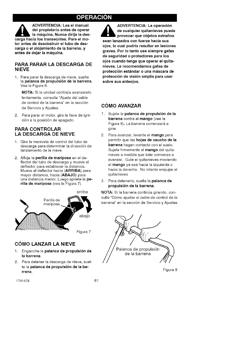
_ADVERTENCIA: Lea el manual
del propietario antes de operar
la maquina. Nunca dirija la des-
carga hacia los transeuntes. Pare el mo-
tor antes de desobstruir el tubo de des-
carga o el alojamiento de la barrena, y
antes de dejar la maquina.
PARA PARAR LA DESCARGA DE
NIEVE
1. Para parar la descarga de nieve, suette
Ia palanca de propulsion de la barrena.
Yea la Figure 6.
NOTA: Si ta unidad continOa avanzando
lentamente, consutte "Ajuste det cable
de control de la barrena" en ta secciSn
de Servicio y Ajustes.
2. Para parar el motor, gire ta Ilave de igni-
ciSn a Ia posiciSn de apagado.
PARA CONTROLAR
LA DESCARGA DE NIEVE
1. Gire ta maniveta de control del tubo de
descarga para determinar la direcci6n de
Ianzamiento de ta nieve.
2. Afloje la perilla de mariposa en el de-
flector det tubo de descarga y mueva et
deflector para establecer la distancia.
Mueva el deflector hacia (ARRIBA) para
mayor distancia, hacia (ABAJO) para
una distancia menor. Luego apriete la pe-
rilla de mariposa (vea la Figura 7).
arriba
Perilla de
mar
_DVERTENCIA: La operacion
de cualquier quitanieves puede
provocar que objetos extra5os
sean lanzados con fuerza hacia sus
ojos, Io cual podria resultar en lesiones
graves. Pot Io tanto use siempre gafas
de seguridad o protectores para los
ojos cuando tenga que operar el quita-
nieves. Le recomendamos gafas de
proteccion estandar o una mascara de
proteccion de vision amplia para usar
sobre sus anteojos.
COMO AVANZAR
1. Sujete la palanca de propulsion de la
barrena contra el mango (vea la
Figura 8). La barrena comenzar_t a
girar.
2. Para avanzar, levante el mango para
permitir que tas hojas de caucho de la
barrena hagan contacto con el suelo.
Sujete firmemente et mango del quita-
nieves a medida que 6ste comienza a
avanzar. Gu[e el quitanieves moviendo
el mango ya sea hacia ta izquierda o
hacia ta derecha. No intente empujar et
quitanieves
3. Para detenedo, suette ta palanca de
propulsion de la barrena.
NOTA: Si la barrena contint_a girando, con-
suite "CSmo ajustar el cable de control de ta
barrena" en Ia secci6n de Servicio y Ajustes.
abajo
Figura 7
COMO LANZAR LA NIEVE
1. Enganche ta palanca de propulsion de
la barrena.
2. Para detener la descarga de nieve, suel-
te ta palanea de propulsion de la ba-
rrena.
de la barrena
Figura 8
1741478 61
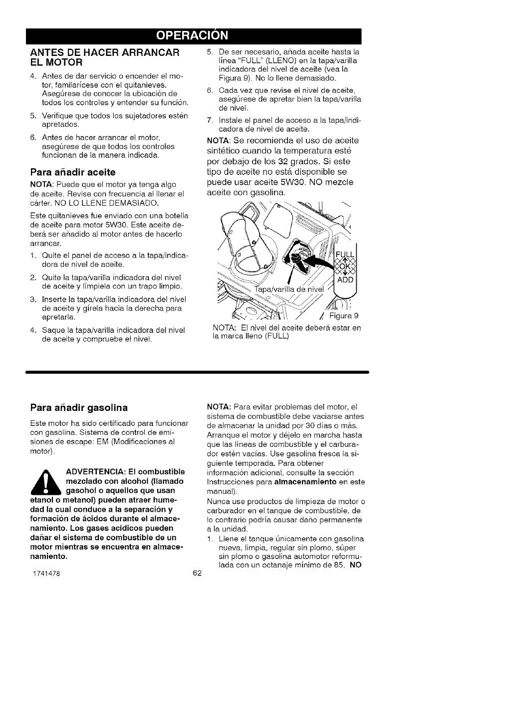
ANTES DE HACER ARRANCAR
EL MOTOR
4. Antes de dar servicio o encender el mo-
tor, familarlcese con el quitanieves.
Aseg0rese de conocer la ubicaci6n de
todos los controles y entender su funci6n.
5. Verifique que todos los sujetadores est6n
apretados.
6. Antes de hacer arrancar el motor,
aseg0rese de que todos los controles
funcionan de la manera indicada.
Para a6adir aceite
NOTA: Puede que el motor ya tenga algo
de aceite. Revise con frecuencia aI tlenar et
carter. NO LO LLENE DEMASIADO.
Este quitanieves fue enviado con una botetta
de aceite para motor 5W30. Este aceite de-
berA ser affadido al motor antes de hacerlo
arrancar.
1. Quite el panel de acceso a la tapa/indica-
dora de nivel de aceite.
2. Quite Ia tapa/varilta indicadora del nivet
de aceite y Iimpiela con un trapo limpio.
3. Inserte la tapa/varilla indicadora del nivel
de aceite y glrela hacia Ia derecha para
apretarla.
4. Saque Ia tapa/varilta indicadora det nivet
de aceite y compruebe et nivet.
5. De set necesario, affada aceite hasta ta
llnea "FULL" (LLENO) en Ia tapa/varilla
indicadora det nivel de aceite (vea Ia
Figura 9). No Io Ilene demasiado.
6. Cada vez que revise et nivel de aceite,
asegt_rese de apretar bien Ia tapa/variIIa
de nivel.
7. Instale el panel de acceso a la tapa/indi-
cadora de nivel de aceite.
NOTA: Se recomienda el uso de aceite
sint6tico cuando la temperatura est6
por debajo de los 32 grados. Si este
tipo de aceite no esta disponible se
puede usar aceite 5W30. NO mezcle
aceite con gasolina.
/4
:_...._ # // /.
_ Tapa/varilla de nivel
.o. /..-<l,/_ii 7/F ura9
NOTA: Et nivel del aceite debera estar en
la marca Ileno (FULL)
Para a6adir gasolina
Este motor ha side certificado para funcionar
con gasolina. Sistema de control de emi-
siones de escape: EM (Modificaciones al
motor).
_ DVERTENCIA: El combustible
mezclado con alcohol (llamado
gasohol o aquellos que usan
etanol o metanol) pusden atraer hume-
dad la cual conduce a la separacion y
formacibn de acidos durante el almace-
namiento. Los gases acidicos pueden
daffar el sistema de combustible de un
motor mientras se encuentra en almace-
namiento.
1741478 62
NOTA: Para evitar problemas det motor, et
sistema de combustible debe vaciarse antes
de almacenar Ia unidad por 30 dlas o mAs.
Arranque el motor y d6jeto en marcha hasta
que tas lineas de combustible y el carbura-
dor est6n vacias. Use gasolina fresca Ia si-
guiente temporada. Para obtener
informaci6n adicionaI, consutte ta secci6n
Instrucciones para almacenamiento en este
manual).
Nunca use productos de limpieza de motor o
carburador en et tanque de combustible, de
Io contrario podria causar da_o permanente
a Ia unidad.
1. Llene el tanque Onicamente con gasotina
nueva, limp!a, regular sin ptomo, s0per
sin ptomo o gasotina automotor reformu-
lada con un octanaje minimo de 85. NO
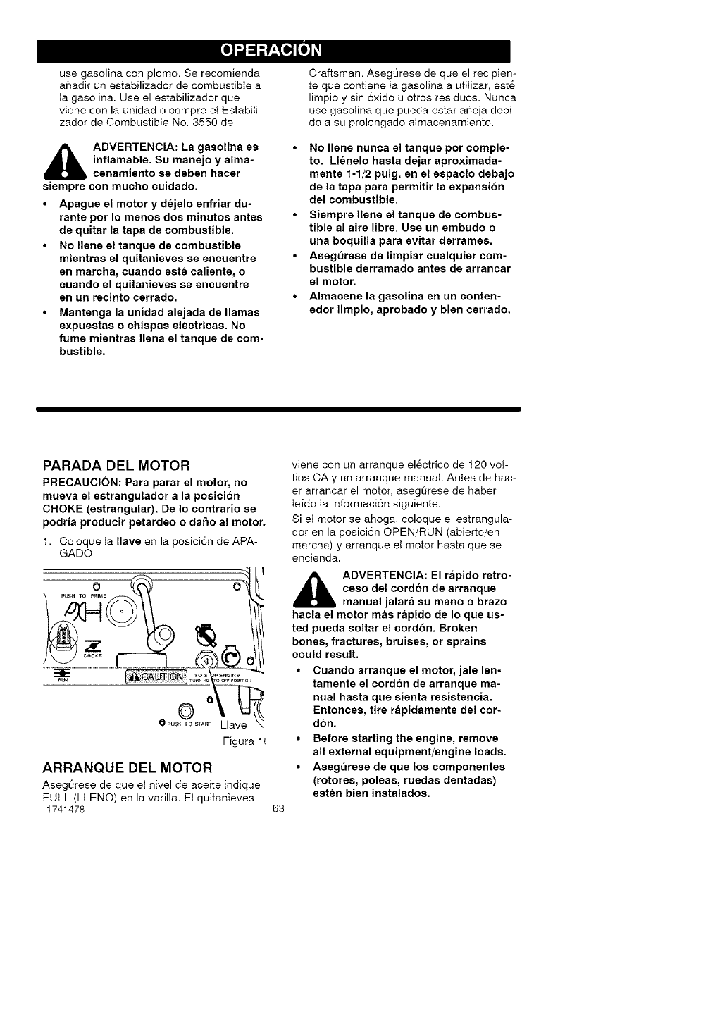
usegasolinaconplomo.Serecomienda
aSadirunestabilizadordecombustiblea
Iagasolina.Useelestabilizadorque
vieneconlaunidadocompreet Estabili-
zador de Combustible No. 3550 de
_b DVERTENCIA: La gasolina es
inflamable. Su manejo y alma-
cenamiento se deben hacer
siempre con mucho cuidado.
• Apague el motor y dejelo enfriar du-
rante pot Io menos dos minutos antes
de quitar la tapa de combustible.
• No Ilene el tanque de combustible
mientras el quitanieves se encuentre
en marcha, cuando este caliente, o
cuando el quitanieves se encuentre
en un recinto cerrado.
•Mantenga la unidad alejada de llamas
expuestas o chispas electricas. No
fume mientras Ilena el tanque de com-
bustible.
Craftsman. AsegOrese de que el recipien-
te que contiene ta gasolina a utitizar, est6
limpio y sin 6xido u otros residuos. Nunca
use gasotina que pueda estar aSeja debi-
do a su prolongado atmacenamiento.
•No Ilene nunca el tanque por comple-
to. Llenelo hasta dejar aproximada-
mente 1-1/2 pulg. en el espacio debajo
de la tapa para permitir la expansion
del combustible.
•Siempre Ilene el tanque de combus-
tible al aire libre. Use un embudo o
una boquilla para evitar derrames.
•Asegt_rese de limpiar cualquier com-
bustible derramado antes de arrancar
el motor.
•Almacene la gasolina en un conten-
edor limpio, aprobado y bien cerrado.
PARADA DEL MOTOR
PRECAUCION: Para parar el motor, no
mueva el estrangulador a la posici6n
CHOKE (estrangular). De Io contrario se
podria producir petardeo o da5o al motor.
1. Coloque Ia Ilave en la posici6n de APA-
GADO.
Figura 1(
ARRANQUE DEL MOTOR
Aseg_rese de que el nivel de aceite indique
FULL (LLENO) en la varilla. Ei quitanieves
1741478 63
viene con un arranque el_ctrico de t20 vot-
tios CA y un arranque manual. Antes de hac-
er arrancar el motor, asegOrese de haber
Ieldo Ia informaci6n siguiente.
Si el motor se ahoga, coloque el estrangula-
dor en la posici6n OPEN/RUN (abierto/en
marcha) y arranque eI motor hasta que se
encienda.
_ DVERTENCIA: El ri=pido retro-
ceso del cordon de arranque
manual jalari= su mano o brazo
hacia el motor mas ri=pido de Io que us-
ted pueda soltar el cordon. Broken
bones, fractures, bruises, or sprains
could result.
• Cuando arranque el motor, jale len-
tamente el cordon de arranque ma-
nual hasta que sienta resistencia.
Entonces, tire rapidamente del cor-
don.
• Before starting the engine, remove
all external equipment/engine loads.
• Asegt_rese de que los componentes
(rotores, poleas, ruedas dentadas)
esten bien instalados.
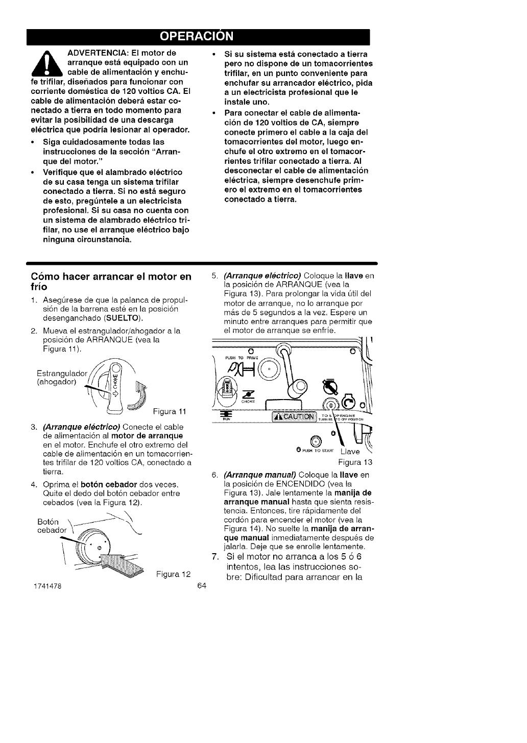
_lb DVERTENCIA: El motor de
arranque esta equipado con un
cable de alimentacion y enchu-
fe trifilar, disehados para funcionar con
corriente domestica de 120 voltios CA. El
cable de alimentacion debera estar co-
nectado a tierra en todo momento para
evitar la posibilidad de una descarga
electrica que podria lesionar al operador.
• Siga cuidadosamente todas las
instrucciones de la seccion "Arran-
que del motor."
•Verifique que el alambrado electrico
de su casa tenga un sistema trifilar
conectado a tierra. Si no esta seguro
de esto, pregt_ntele a un electricista
profesionaL Si su casa no cuenta con
un sistema de alambrado electrico tri-
filar, no use el arranque electrico bajo
ninguna circunstancia.
Si su sistema esta conectado a tierra
pero no dispone de un tomacorrientes
trifilar, an un punto conveniente para
enchufar su arrancador electrico, pida
a un electricista profesional que le
instale uno.
Para conectar el cable de alimenta-
cion de 120 voltios de CA, siempre
conecte primero el cable a la caja del
tomacorrientes del motor, luego en-
chufe el otro extremo en el tomacor-
rientes trifilar conectado a tierra. AI
desconectar el cable de alimentacion
electrica, siempre desenchufe prim-
ero el extremo en el tomacorrientes
coneotado a tierra.
Como hacer arrancar el motor en
frio
1. AsegQrese de que ta paIanca de propul-
si6n de Ia barrena est@en la posici6n
desenganchado (SUELTO).
2. Mueva el estrangutador/ahogador a la
posici6n de ARRANQUE (vea la
Figura 11).
Estrangulador/_ "\
(ahogador)
J Figura 11
3. (Arranque electrico) Oonecte et cable
de alimentaci6n al motor de arranque
en et motor. Enchufe el otro extremo del
cable de aIimentaci6n en un tomacorrien-
tes trifilar de 120 vottios CA, conectado a
tierra.
4. Oprima et boton cebador dos veces.
Quite el dedo del bot6n cebador entre
cebados (vea Ia Figura 12).
1741478
Figura 12
64
5. (Arranque electrico) Cotoque ta Ilave en
la posici6n de ARRANQUE (vea la
Figura 13). Para protongar la vida Otil del
motor de arranque, no Io arranque por
m_ts de 5 segundos a la vez. Espere un
minuto entre arranques para permitir que
et motor de arranque se enfrie.
Figura t3
6. (Arranquo manual) Coloque la Ilave en
la posioidn de ENCENDIDO (yea Ia
Figura 13). Jale tentamente ta manija de
arranque manual hasta que sienta resis-
tencia. Entonces, tire rfipidamente det
corddn para encender et motor (yea ta
Figura 14). No suelte la manija de arran-
qua manual inmediatamente despu6s de
jaIarta. Deje que se enrolle tentamente.
7. Si el motor no arranca a los 5 6 6
intentos, lea las instrucciones so-
bre: Dificultad para arrancar en la
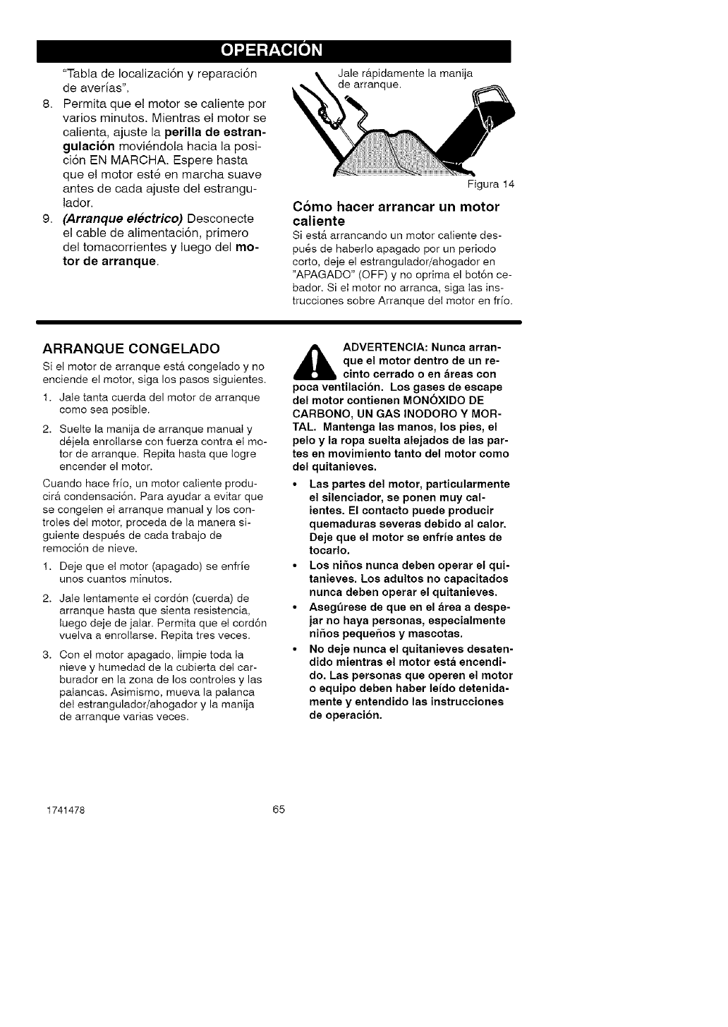
"TabladeIocalizaci6ny reparaci6n
deaverias".
8. Permitaqueelmotorsecalientepor
variosminutos.Mientraselmotorse
calienta,ajustelaperilladeestran-
gulaci6nmoviendolahacialaposi-
ci6nENMARCHA.Esperehasta
queelmotoresteenmarchasuave
antesdecadaajustede!estrangu-
lador.
9. (Arranque electrico) Desconecte
el cable de alimentaci6n, primero
del tomacorrientes y luego del mo-
tor de arranque.
Jale r&pidamente la manija
de arranque.
Figura 14
Como hacer arrancar un motor
caliente
Si ester arrancando un motor caliente des-
pu6s de haberlo apagado pot un periodo
corto, deje el estrangulador/ahogador en
"APAGADO" (OFF) y no oprima el bot6n ce-
bador. Si et motor no arranca, siga Ias ins-
trucciones sobre Arranque det motor en frio.
ARRANQUE CONGELADO
Si el motor de arranque esta congetado y no
enciende el motor, siga los pasos siguientes.
1. Jale tanta cuerda del motor de arranque
como sea posible.
2. Suelte la manija de arranque manual y
d6jela enrollarse con fuerza contra el mo-
tor de arranque. Repita hasta que Iogre
encender el motor.
Cuando hace frio, un motor caliente produ-
cir& condensaci6n. Para ayudar a evitar que
se congeten et arranque manual y los con-
troles del motor, proceda de ta manera si-
guiente despu6s de cada trabajo de
remoci6n de nieve.
1. Deje queet motor (apagado) se enfrie
unos cuantos minutos.
2. Jale lentamente et cord6n (cuerda) de
arranque hasta que sienta resistencia,
Iuego deje de jalar. Permita que et cord6n
vuelva a enrollarse. Repita tres veces.
3. Con et motor apagado, timpie toda Ia
nieve y humedad de la cubierta det car-
burador en la zona de los controtes y las
palancas. Asimismo, mueva la palanca
del estrangulador/ahogador y la manija
de arranque varias veoes.
_lb ADVERTENCIA: Nunca arran-
que el motor dentro de un re-
cinto cerrado o en areas con
poca vantilacion. Los gases de escape
dal motor contienen MONOXIDO DE
CARBONO, UN GAS INODORO Y MOR-
TAL. Mantenga las manos, los pies, el
pelo y la ropa suelta alejados de las par-
tes en movimiento tanto del motor como
dal quitanieves.
• Las partes del motor, particularmente
el silenciador, se ponen muy cal-
iantes. El contacto puede producir
quemaduras sevaras debido al calor.
Deje que el motor se anfria antes de
tocarlo.
•Los nihos nunca daben operar el qui-
tanieves. Los adultos no capacitados
nunca deben operar el quitanievas.
•Asegt_rese de que en el area a despe-
jar no haya personas, aspecialmente
nihos pequehos y mascotas.
•No daje nunca el quitanievas desaten-
dido mientras el motor esta encendi-
do. Las personas que operen el motor
oaquipo deben haber leido datenida-
mente y entendido las instruccionas
de operacion.
1741478 65
C6MO DESPEJAR TUBOS DE
DESCARGA ATASCADOS
,_ ADVERTENClA: Las lesiones
mas comunes asociadas COB el
uso del quitanieves son las que
se produceR cuaado las maaos entren en
contacto con el dispositivo impulsor den-
tro del tubo de descarga. No use nunca las
manos para despejar el tubo de descarga.
Para despejar el tubo:
• APAGUE EL MOTOR.
• Espere unos 10 segundos para que las
aletas del impulsor dejen de girar.
• Use siempre la herramienta de limpie-
za, no las manos.
UtiIiceto para quitar ta nieve atascada en eI
atojamiento de Ia barrena.
Suelte Ia palanca de propulsi6n de Ia ba-
rrena.
Retire (sin girar) ta Ilave.
Desconecte el cable de ta bujia.
No coloque las manos en la barrena o
canal de descarga. Use el bast6n de Iim-
pieza para quitar Ia nieve.
,_ ADVERTENCIA: Es necesario
apagar el motor antes de des-
pejar los atascos. Use solo la
herramienta de limpieza, no las manos.
SUGERENClAS PARA EL
LANZAMIENTO DE NIEVE
1. Cuando se levanta el mango, las hojas
de caucho de la barrena entran en con-
tacto con et suelo yet quitanieves avan-
za. Cuando se sueIta la palanca de
proputsi6n de la barrena, las hojas de
caucho de la barrena se paran. Si tas ho-
jas de caucho no paran, consulte "C6mo
ajustar el cable de proputsi6n de ta barre-
na" en la secci6n de Servicio y Ajustes.
2. El tanzamiento de nieve m&s efectivo se
Iogra cuando la nieve se quita inmedia-
tamente despu6s de la nevada.
3. Deje que el motor yet quitanieves se
ajusten a la temperatura externa antes
de despejar Ia nieve.
4. Para quitar completamente ta nieve, so-
breponga Iigeramente las pasadas del
quitanieves.
5. Cuando sea posibte, descargue la nieve
a favor del viento.
6. Se puede ajustar Ia distancia a la que ta
nieve ser& Ianzada, moviendo et deflec-
tor det tubo de descarga. Para m&s dis-
tancia tevante el deflector, para menos
distancia baje el deflector.
7. En condiciones de mucho viento, baje et
deflector det tubo de descarga para did-
1741478 66
gir la nieve tanzada m&s cerca del suelo
para evitar que et viento Ia sople hacia
&reas no deseadas.
8. Para su seguridad y para prevenir et da-
5o aI quitanieves, mantenga et &rea que
va a timpiar, libre de rocas, juguetes y
otros objetos extraSos.
9. Cuando est6 quitando Ia nieve sobre en-
tradas de auto cubiertas con grava o to-
ca triturada, no deje que Ias cuchitlas de
Ia barrena toquen el sueto. Mueva et
mango hacia abajo para tevantar ligera-
mente las cuchi!Ias de la barrena.
10. La velocidad de avance det quitanieves
depende de ta profundidad y del peso de
Ia nieve. La manera m&s eficiente de
usar et quitanieves ser& determinada por
su experiencia bajo diversas condiciones.
11. Despu6s de cada trabajo deje que el
motor funcione pot unos minutos. Asi
se derretir& ta nieve y el hielo acumula-
dos en el motor.
12. Limpie et quitanieves despu6s de cada
USO.
13.Quite et hieto, ta nieve y tos residuos de
todo el quitanieves. Enju&guelo con agua
para quitade toda ta sal y otros productos
qulmicos. Seque eI quitanieves.
NIEVE SECA YDE
POCA PROFUNDIDAD
1. La nieve que se acumute hasta profundi-
dades de ocho putgadas puede quitarse
r&pida y f_tcitmente, caminando a una
velocidad moderada con et quitanieves.
Para acumulaciones de nieve de mayor
profundidad, camine m&s lento para per-
mitir la descarga uniforme de nieve tan
pronto sea recogida por ta barrena.
2. Intente descargar Ia nieve a favor del
viento.
NIEVE MOJADA Y COMPACTA
Avance lentamente para despejar Ia nieve
mojada y compacta. Si este tipo de nieve
hace que la barrena gire m&s lento o empie-
za a atascar et tubo de descarga, retlrese un
poco y empiece una sede de movimientos
cortos con el quitanieves, hacia adelante y
hacia atr&s. Estos movimientos cortos en ta
nieve (de cuatro a seis putgadas), ayudar&n
a arrojar ta nieve deI tubo de descarga.
BANCOS Y ACUMULAClONES
GRANDES DE NIEVE
Para despejar la nieve que se acumula a
una altura mayor que el quitanieves, use et
m6todo descdto anteriormente (movimientos
cortos hacia adetante y hacia atr&s). Oriente
el tubo de descarga en direcci6n opuesta a
Ia det banco o acumutaci6n grande de nieve.
La remoci6n de este tipo de nieve tomar&
m&s tiempo.
1741478 67
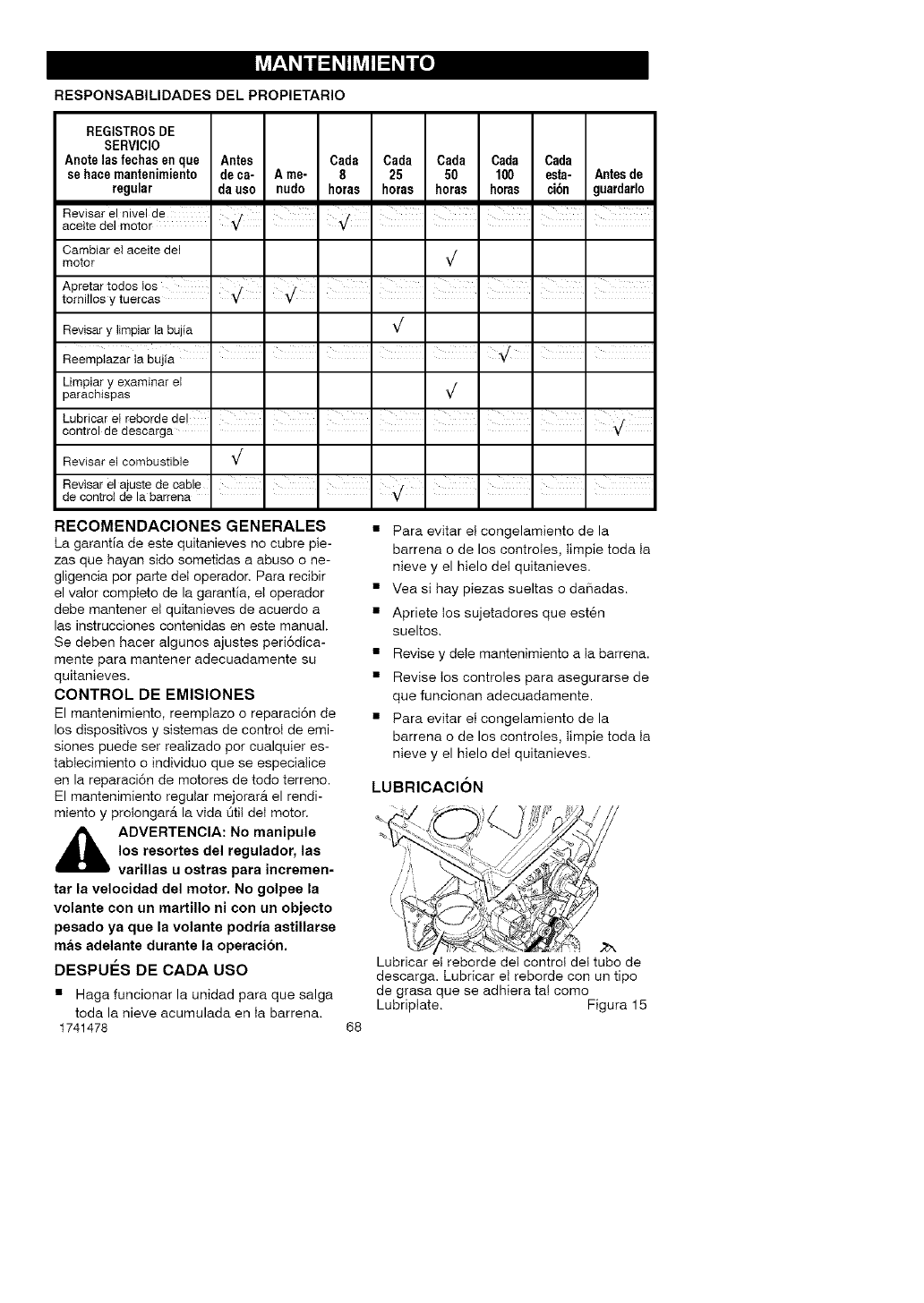
u'-h, h, u h, o]
RESPONSABILIDADES DEL PROPIETARIO
REGISTROSDE
SERVICIO
Anotelas fechasenque Antes Cada Cada Cada Cada Cada
se hace mantenimiento de ca- A me- 8 25 50 100 esta- Antesde
regular da uso nudo horas horas horas horas ci6n guardarlo
Revisar el nivel de _ I I
aceite del motor ¥ ¥
Cambiar el aceite del
motor _/
Apretar todos Ios I f'
tomitlos y tueroas _/
Revisary limpiarla bujia _/
Limpiary examinar el
parachispas _/
Lubricar el reborde del , /
contro de descarga ¥
Revisar el combustible _/
Revisarelajustedeoable II ' i i i
de contro de a barrena " ¥
RECOMENDACIONES GENERALES
La garantla de este quitanieves no cubre pie-
zas que hayan sido sometidas a abuso o ne-
gligencia por parte det operador. Para recibir
el valor compteto de la garantia, eI operador
debe mantener et quitanieves de acuerdo a
las instrucciones contenidas en este manual.
Se deben hacer algunos ajustes peri6dica-
mente para mantener adecuadamente su
quitanieves.
CONTROL DE EMISIONES
El mantenimiento, reemptazo o reparaci6n de
los dispositivos y sistemas de control de emi-
siones puede set reatizado por cualquier es-
tabIecimiento o individuo que se especialice
en la reparaci6n de motores de todo terreno.
El mantenimiento regular mejorarA el rendi-
miento y prolongarA la vida Qtit deI motor.
_IL ADVERTENCIA: No manipule
los resortes del regulador, las
varillas u ostras para incremen-
tar la velocidad del motor. No golpee la
volante con un martillo ni con un objecto
pesado ya que la volante podria astillarse
mas adelante durante la operacion.
DESPUES DE CADA USO
• Haga funcionar la unidad para que salga
toda la nieve acumulada en Ia barrena.
1741478
• Para evitar et congelamiento de la
barrena o de los controtes, Iimpie toda Ia
nieve y el hielo del quitanieves.
• Vea si hay piezas sueltas o da_adas.
• Apriete tos sujetadores que est6n
sueltos.
• Revise y dete mantenimiento a Ia barrena.
• Revise Ios controles para asegurarse de
que funcionan adecuadamente.
• Para evitar et congelamiento de la
barrena o de los controles, timpie toda Ia
nieve y el hielo det quitanieves.
LUBRICACION
68
Lubricar et reborde det control del tube de
descarga. Lubricar et reborde con un tipo
de grasa que se adhiera ta! como
Lubriptate. Figura 15
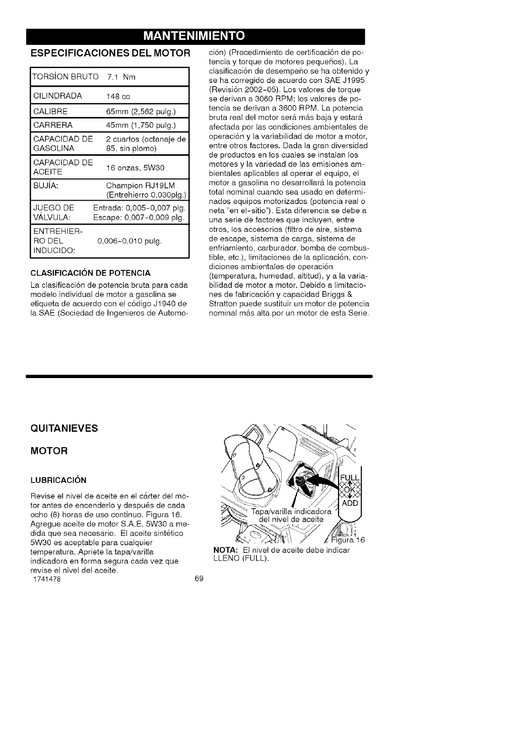
l_ A i i u i o]
ESPEClFICAClON ES DEL MOTOR
TORSION BRUTO 7.1 Nm
CILINDRADA 148 cc
CALIBRE 65mm (2,562 pulg.)
CARRERA 45mm (1,750 pulg.)
CAPACIDAD DE 2 cuartos (octanaje de
GASOLINA 85, sin plomo)
CAPACIDAD DE
ACEITE 16 onzas, 5W30
BUJiA: Champion RJ19LM
(Entrehierro 0,030pig.)
JUEGO DE Entrada: 0,005-0,007 ptg.
VA,LVULA: Escape: 0,007-0,009 pig.
ENTREHIER-
RO DEL 0,006-0,010 puIg.
INDUCIDO:
CLASlFICAClON DE POTENClA
La ctasificaci6n de potencia bruta para cada
modelo individual de motor a gasolina se
etiqueta de acuerdo con et c6digo Jt940 de
la SAE (Sociedad de Ingenieros de Automo-
ci6n) (Procedimiento de certificaci6n de po-
tencia y torque de motores pequeSos). La
ctasificaci6n de desempeSo se ha obtenido y
se ha corregido de acuerdo con SAE J1995
(Revisi6n 2002-05). Los vaIores de torque
se derivan a 3060 RPM; los valores de po-
tencia se derivan a 3600 RPM. La potencia
bruta real del motor ser_t m&s baja y estarA
afectada por tas condiciones ambientaIes de
operaci6n y la variabilidad de motor a motor,
entre otros factores. Dada la gran divers!dad
de productes en los cuaIes se instaIan los
motores y la variedad de tas emisiones am-
bientales aplicabtes al operar el equipo, el
motor a gasotina no desarrollarA la potencia
total nominal cuando sea usado en determi-
nados equipos motorizades (potencia real e
neta "en el-sitio"). Esta diferencia se debe a
una serie de factores que incluyen, entre
etros, los accesories (filtro de aire, sistema
de escape, sistema de carga, sistema de
enfriamiento, carburador, bomba de combus-
tible, etc.), timitacienes de la aplicaci6n, con-
diciones ambientaIes de operaci6n
(temperatura, humedad, altitud), y a la varia-
bilidad de motor a motor. Debido a timitacio-
nes de fabricaci6n y capacidad Briggs &
Stratton puede sustituir un motor de potencia
nominal m&s atta per un motor de esta Serie.
QUITANIEVES
MOTOR
LUBRICACION
Revise el nivel de aceite en el c&rter det mo-
tor antes de encenderlo y despu6s de cada
ocho (8) horas de uso continue. Figura t6.
Agregue aceite de motor S.A.E. 5W30 a me-
dida que sea necesario. El aceite sint6tico
5W30 es aceptable para cuaIquier
temperatura. Apriete ta tapa/varilta
indicadora en forma segura cada vez que
revise el nivel del aceite.
1741478 69
gura 16
NOTA: Et nivet de aceite debe indicar
LLENO (FULL).
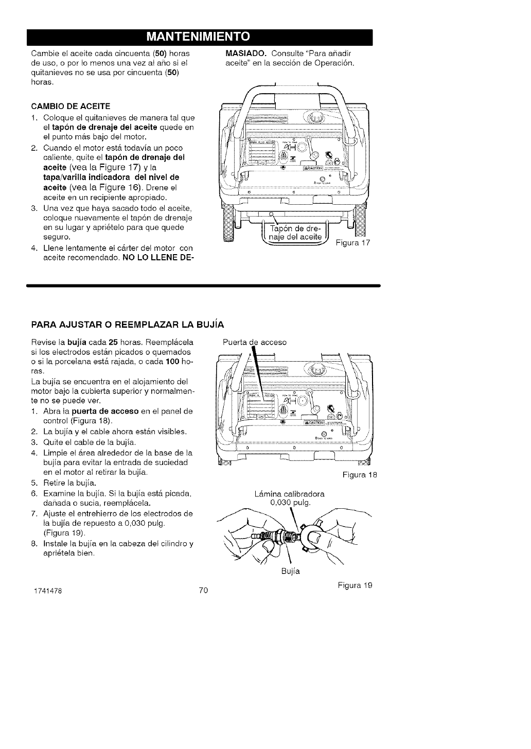
u'-h, h, u h, o]
Cambie et aceite cada cincuenta (50) horas
de uso, o por to menos una vez aI a_o si et
quitanieves no se usa por cincuenta (50)
horas.
MASIADO. Consulte "Para aSadir
aceite" en Ia secci6n de Operaci6n.
CAMBIO DE ACEITE
1. Coloque el quitanieves de manera tal que
el tap6n de drenaje del aeeite quede en
el punto mAs bajo del motor.
2. Cuando et motor estA todavla un poco
caliente, quite el tap6n de drenaje del
aceite (vea la Figure 17) y Ia
tapa/varilla indicadora del nivel de
aceite (yea la Figure 16). Drene el
aceite en un recipiente apropiado.
3. Una vez que haya sacado todo el aceite,
coloque nuevamente el tap6n de drenaje
en su lugar y apri_telo para que quede
seguro.
4. Llene lentamente el cArter det motor con
aceite recomendado. NO LO LLENE DE-
PARA AJUSTAR O REEMPLAZAR LA BUJiA
Revise ta bujia cada 25 horas. ReemplAcela
si los electrodes estAn picados o quemados
o si la porcelana estA rajada, o cada 100 ho-
ras.
La buj_a se encuentra en el alojamiento del
motor bajo ta cubierta superior y normalmen-
te no se puede ver.
1. Abra ta puerta de acceso en el panet de
control (Figura t8).
2. La bujla y el cable ahora estAn visibles.
3. Quite el cable de ta bujla.
4. Limpie el Area alrededor de la base de ta
bujla para evitar la entrada de suciedad
en et motor aI retirar Ia buj_a.
5. Retire la buj_a.
6. Examine la bujla. Si ta bujla estA picada,
da5ada o sucia, reemptAcela.
7. Ajuste el entrehierro de los etectrodos de
Ia buj[a de repuesto a 0,030 pulg.
(Figura 19).
8. Instale la buj[a en la cabeza det cilindro y
apri6teta bien.
1741478 7O
Puerta de acceso
Figura 18
LAmina calibradora
0,030 pulg.
Bujla
Figura 19
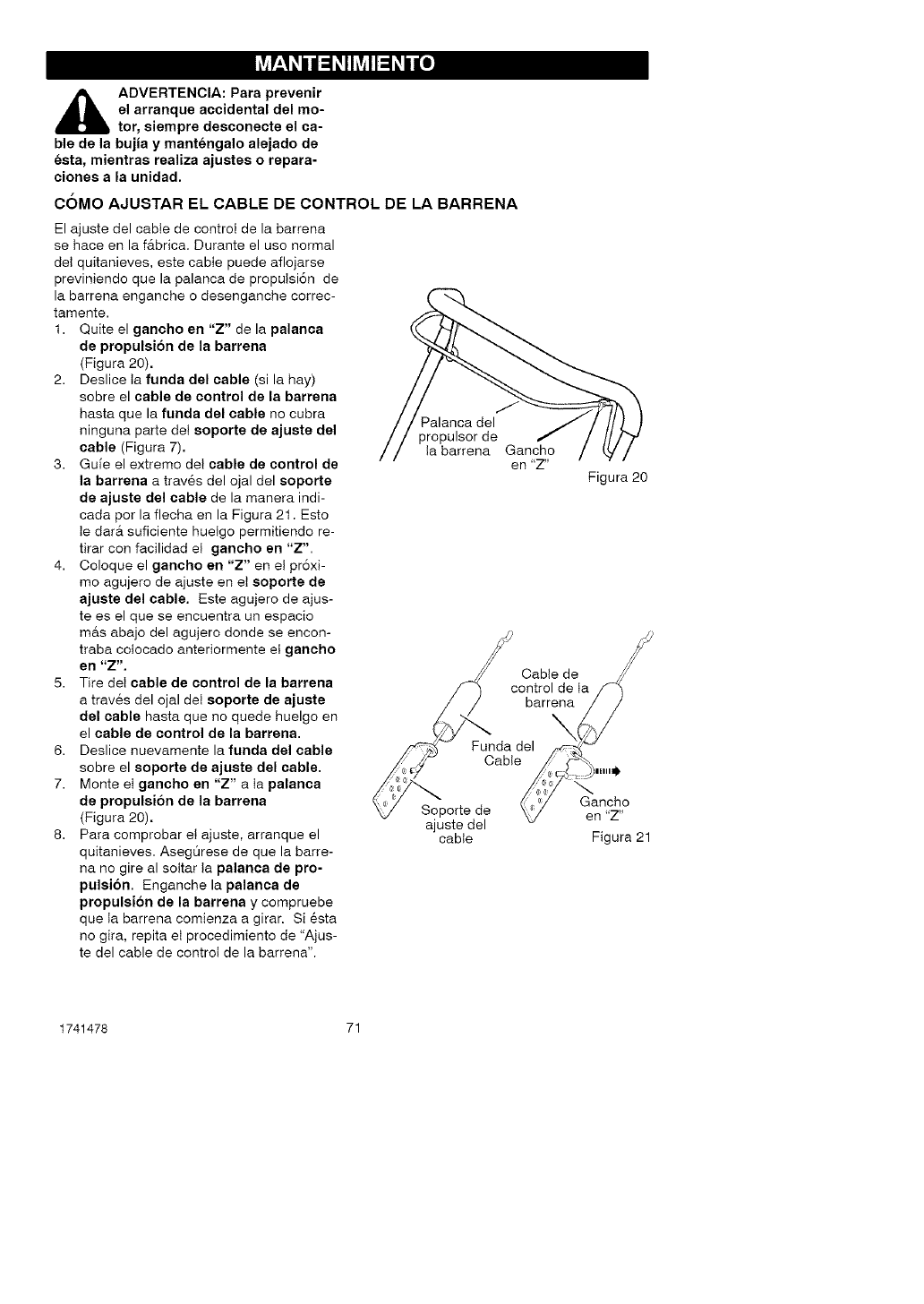
u'-h, h, u h, o]
_1= ADVERTENCIA: Para prevenir
el arranque accidental dal mo-
tor, siempre desconecte el ca=
ble de la bujia y mantengalo alajado de
esta, mientras raaliza ajustas o rapara-
clones a la unidad.
COMO AJUSTAR EL CABLE DE CONTROL DE LA BARRENA
El ajuste del cable de control de la barrena
se hace en la f&brica. Durante el use normal
del quitanieves, este cable puede aflojarse
previniendo que la palanca de proputsi6n de
la barrena enganche o desenganche correc-
tamente.
1. Quite el gancho an "Z" de la palanca
de propulsion de la barrena
(Figura 20).
2. Deslice ta funda dal cable (si la hay)
sobre el cable de control de la barrena
hasta que la funda del cable no cubra
ninguna parte del soporte de ajuste del
cable (Figura 7).
3. Gule el extremo det cable de control de
la barrana a trav6s del ojal del soporte
de ajusta dal cable de la manera indi-
cada pot la flecha en la Figura 21. Esto
Ie darer suficiente huelgo permitiendo re-
tirar con facilidad el gancho an "Z".
4. Coloque el gancho en "Z" en et pr6xi-
mo agujero de ajuste en et soporta de
ajusta dal cable. Este agujero de ajus-
te es el que se encuentra un espacio
mas abajo del agujero donde se encon-
traba colocado anteriormente el gancho
en "Z".
5. Tire det cable de control de la barrena
a trav6s del ojal det soporte de ajuste
del cable hasta que no quede huelgo en
el cable de control de la barrana,
6. Deslice nuevamente la funda dal cable
sobre el soporte de ajusta del cable.
7. Monte et gancho en "Z" a ta palanca
de propulsion de la barrana
(Figura 20).
8. Para comprobar et ajuste, arranque el
quitanieves. AsegOrese de que la barre-
na no gire al soltar ta palanca de pro-
pulsi6n. Enganche la palanca de
propulsi6n de la barrana y compruebe
que Ia barrena comienza a girar. Si 6sta
no gira, repita et procedimiento de "Ajus-
te del cable de control de la barrena".
Palanca del
propulsor de
Ia barrena Gancho
en "Z"
Figura 20
Cable de
cO_tarOledneta /_
ajuste del
cable Figura 21
1741478 71
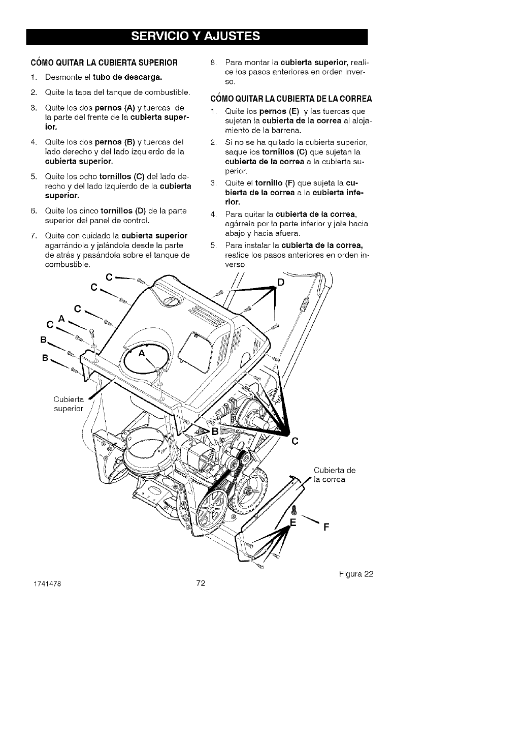
_._o_[o] WP_LII_'_d_'_
COMO QUITAR LA CUBIERTA SUPERIOR
1. Desmonte el tubo de descarga,
2. Quite ta tapa det tanque de combustible.
3. Quite tos dos pernos (A) y tuercas de
ta parte det frente de Ia eubierta super-
ior,
6,
7.
Quite tos dos pernos (B) y tuercas del
Iado derecho y del lado izquierdo de la
eubisrta superior.
Quite tos echo tornillos (C) det Iade de-
recho y del lado izquierdo de la cubierta
superior,
Quite los cinco tornillos (D) de la parte
superior det panel de control.
Quite con cuidado la cubierta superior
agarr&ndola y jaI&ndota desde la parte
de atr&s y pas_tndota sobre et tanque de
combustible.
C
8. Para montar ta cubierta superior, reali-
ce los pasos anteriores en orden inver-
SO.
COMO QUITAR LA CUBIERTA DE LA CORREA
1. Quite tos pernos (E) y tas tuercas que
sujetan ta cubierta de la correa al a!oja-
miento de la barrena.
2. Si no se ha quitado ta cubierta superior,
saque tos tornillos (C) que sujetan la
cubierta de la correa a la cubierta su-
perior.
3. Quite et tornillo (F) que sujeta la cu-
bierta de la correa a la cubierta infe-
rior.
4. Para quitar ta ¢ubierta de la correa,
ag_trreta por Ia parte inferior y jate hacia
abajo y hacia afuera.
5. Para instaIar la cubierta de la corrsa,
reaIice los pasos anteriores en orden in-
verso.
//
Cubierta
superior /
/
/
\
\C
Cubierta de
Ia correa
F
-%
Figura 22
1741478 72
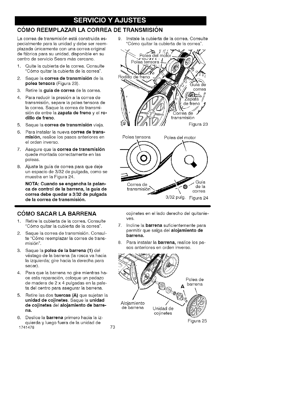
_._o_[o] WP_LII_"_/_'_
COMO REEMPLAZAR LA CORREA DE TRANSMISION
La correa de transmisi6n estA construida es-
peciaImente para ta unidad y debe ser reem-
ptazada Onicamente con una correa original
de fAbrica para su unidad, disponible en su
centre de servicio Sears m&s cercano.
9. InstaIe la cubierta de ta correa. Consulte
"C6mo quitar la cubierta de ta correa".
Polea
1. Quite la cubierta de la correa. ConsuIte
"C6mo quitar ta cubierta de la correa'.
2. Saque ta correa de transmision de Ia
polea tensora (Figura 23).
3. Retire ta guia de correa de ta correa.
4. Para reducir ta presi6n a ta correa de
transmisi6n, separe ta polea tensora de
la correa. Saque la correa de transmi-
si6n de entre la zapata de freno y el ro-
dillo de freno.
5. Saque ta eorrea de transmisibn vieja.
6. Para instalar ta nueva eorrea de trans-
misibn, reaIice tos pasos anteriores en
el orden inverse.
Asegure que la correa de transmision
quede montada correctamente en Ias
poleas.
Ajuste ta gufa de correa para que deje
un espacio de 3/32 de pulgada, come se
muestra en la Figura 24.
NOTA: Cuando se enganeha la palan-
ca de control de la barrena, la guia de
eorrea debe quedar a 3/32 de pulgada
de la eorrea de transmision.
Rodilto de freno
de
correa
Correa de
transmisi6n
Figura 23
Potea tensora Polea det motor
Correa de • Gufa
de la
correa
3/32 pulg. Figura 24
COMe SACAR LA BARRENA
1. Retire ta cubierta de la correa. ConsuIte
"C6mo quitar ta cubierta de la correa'.
2. Saque ta correa de transmisi6n. ConsuI-
te "C6mo reemplazar la correa de trans-
misi6n'.
3. Saque ta polea de la barrena (1) dei
v&stago de Ia barrena (ta rosca va hacia
la izquierda; gire hacia la derecha para
sacar).
4. Para que la barrena no gire mientras ha-
ce esta reparaci6n, eoloque un pedazo
de madera de 2 x 4 puigadas en ta paie-
ta det centre para asegurar ta barrena.
5. Retire tas dos tueroas (A) que sujetan ta
unidad de eojinetes. Saque ta unidad
de cojinetes det alojamiento de barre-
ha,
6. Deslice ta barrena primero hacia la iz-
quierda y Iuego fuera de Ia unidad de
1741478 73
cojinetes en el Iado derecho del quitanie-
ves.
7. Incline ta barrena suficientemente para
permitir que salga det alojamiento de
barrena,
8. Para instaIar la barrena, realice los pa-
sos anteriores en orden inverse.
b'"in°
Ao,..ento
de barrena Unijidnaelede
Figura 25
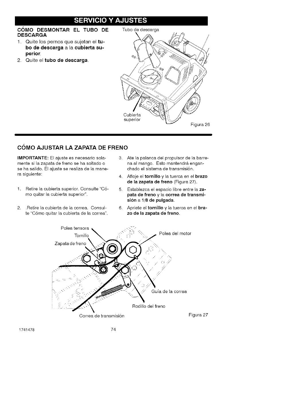
_._o_[o] WP_LII_'_/_'_
COMO DESMONTAR EL TUBO DE
DESCARGA
1. Quite los pemos que sujetan el tu-
bo de descarga a la cubierta su-
perior.
2. Quite el tubo de descarga.
Tube de descarga
\
Cubierta
superior
Figura 26
COMO AJUSTAR LA ZAPATA DE FRENO
IMPORTANTE: Et ajuste es necesario sola-
mente si ta zapata de freno se ha sottado o
se ha salido. El a uste se realiza de la mane-
ra siguiente:
1. Retire ta cubierta superior. Consulte "C6-
mo quitar la cubierta superior".
2. .Retire la cubierta de ta correa. Consul-
te "C6mo quitar Ia cubierta de la correa".
3, Ate ta palanca det proputsor de ta barre-
na a! mango. Esto mantendr& engan-
chado el sistema de transmisi6n.
4. Afloje el tornillo y la tuerca en et brazo
de la zapata de freno (Figura 27).
5. Establezca el espacio tibre entre la za-
pata de freno y ta correa de transmi-
si6n a 1/8 de pulgada.
6. Apriete et tornillo y ta tuerca en et bra-
zo de la zapata de freno,
Polea tensora
Torni!Io
Zapata de freno
Polea det motor
::" Guia de Ia correa
Rodillo del freno
Correa de transmisi6n Figura 27
1741478 74
_1= ADVERTENCIA: Nunca guar-
de su quitanieves con gaso-
lina en el tangue de combus-
tible en ambientes interiores o en
un area cerrada y mal ventilada. Si
queda gasolina en el tanque, los va-
pores podrian alcanzar alguna lla-
ma expuesta, chispa o llama piloto
de una caldera, calentador de
agua, secadora de ropa, cigarrillo,
etc.
Para prevenir el dafio (si el quitanieves
no se usa per mas 30 alias) prepAre!o
come se indica a continuaci6n.
QUlTANIEVES
1. Limpie todo el quitanieves.
2. Lubrique todos los puntos de lubri-
caci6n. Consulte la secci6n de Man-
tenimiento.
3. AsegQrese de que todas las tuercas,
pernos y tornillos esten bien apreta-
dos. Inspeccione todas las piezas
m6viles visibles para detectar da-
fios, roturas y desgaste. Haga los
reemplazos necesarios.
4. Retoque todas las superficies oxida-
das o que tengan la pintura saltada;
lijelas suavemente antes de aplicar
la pintura.
5. Cubra las piezas de metal expuesto
del soplador del alojamiento de la
barrena y del impulsor, con un anti-
corrosivo, tal come un lubricante en
aerosol.
NOTA: Una revisi6n o afinamiento
anual hecho en un Centre de Servicio
Sears es una buena manera de asegu-
tar que su quitanieves le brinde el ma-
ximo rendimiento la siguiente
temporada.
MOTOR
Debera sacar la gasolina del tanque o
prepararla para prevenir la formaci6n
de dep6sitos de goma en el tanque, ill-
tro, manguera y carburador durante el
almacenamiento. AdemAs, durante el
almacenamiento, la gasolina mezclada
con alcohol que contiene etanol o me-
tanol (llamada a veces gasohol) atrae
agua, y 6sta actQa sobre la gasolina
formando Acidos que dafian el motor.
1. Deje el motor en marcha hasta que
el tanque quede vacio y e! motor se
pare.
2. Si no quiere sacar la gasolina, use el
estabilizador de combustible provis-
to con la unidad, o compre estabili-
zador de combustible Craftsman
NL_m.3550. Afiada el estabilizador
de combustible a cualquier cantidad
de gasolina que permanezca en el
tanque para minimizar los dep6sitos
de goma y acido. Si e! tanque estA
casi vacio, mezcle el estabilizador
con gasolina fresca en un recipiente
separado y afiada un poco de esta
mezcla al tanque.
3. Siempre siga las instrucciones del
envase del estabilizador. Luego de
afiadir el estabilizador, encienda el
motor y d6jelo correr per 10 minutos
por Io menos para permitir que la
mezcla alcance el carburador.
4. Cambie el aceite del motor
5. Saque la bujia y vierta aproximada-
mente 15 ml (1/2 onza) de aceite
para motor en el cilindro. Vuelva a
colocar la bujia y vire el motor lenta-
mente para distribuir el aceite.
6. AImacene en un Area limpia y seca,
pete NO cerca de una estufa, cal-
dera o calentador de agua que ten-
ga una llama piloto ni algQn otro
dispositivo que pueda generar chis-
pas.
OTRAS INDICACIONES
1. Si fuera posible, guarde su quita-
nieves dentro de un recinto, cubri6n-
dolo para protegerlo del polvo y la
suciedad.
2. Si debe guardar el quitanieves afue-
ra, col6quelo sobre bloques para le-
vantarlo del suelo.
3. Cubra el quitanieves con una cubier-
ta protectora apropiada que no re-
tenga humedad. No use plastico.
IMPORTANTE" Nunca cubra el quita-
nieves mientras las Areas del motor y
del escape est6n todavia calientes.
1741478 75
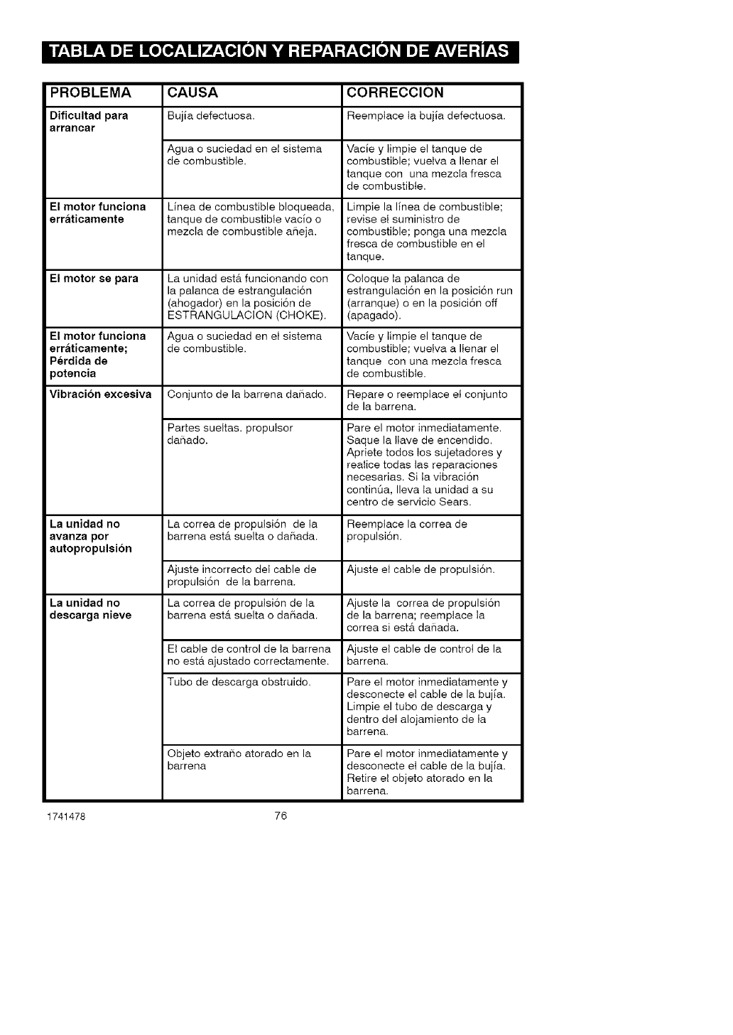
PROBLEMA CAUSA CORRECClON
Dificultad para Bujla defectuosa. Reemplace Ia bujla defectuosa.
arrancar
Agua o suciedad en et sistema Vacle y timpie el tanque de
de combustible, combustible; vuetva a IIenar el
tanque con una mezcta fresca
de combustible.
El motor funciona Linea de combustible bloqueada, Limpie la I[nea de combustible;
erraticamente tanque de combustible vacio o revise el suministro de
mezcla de combustible aSeja, combustible; ponga una mezcla
fresca de combustible en el
tanque.
El motor se para La unidad est& funcionando con Coloque ta palanca de
la palanca de estrangulaci6n estrangutaci6n en la posici6n run
(ahogador) en la posici6n de (arranque) oen la posici6n off
ESTRANGULACION (CHOKE). (apagado).
El motor funoiona Agua o suciedad en et sistema Vacle y timpie el tanque de
erraticamente; de combustible, combustible; vuetva a IIenar el
Perdida de tanque con una mezcta fresca
potencia de combustible.
Vibration excesiva Conjunto de la barrena daSado. Repare o reemplace et conjunto
de la barrena.
Partes sueItas, propulsor
da5ado.
La unidad no
avanza pot
autopropulsion
La unidad no
descarga nieve
La correa de proputsi6n de ta
barrena ester suelta o daSada.
Ajuste incorrecto det cable de
propulsi6n de la barrena.
La correa de proputsi6n de Ia
barrena ester suelta o daSada.
Pare el motor inmediatamente.
Saque la ttave de encendido.
Apriete todos tos sujetadores y
realice todas tas reparaciones
necesarias. Si ta vibraci6n
continua, Ileva ta unidad a su
centro de servicio Sears.
Reemptace la correa de
propulsi6n.
Ajuste et cable de propulsi6n.
Ajuste la correa de propulsi6n
de la barrena; reemptace Ia
correa si est& daSada.
Et cable de control de ta barrena Ajuste et cable de control de la
no esta ajustado correctamente, barrena.
Tubo de descarga obstruido. Pare el motor inmediatamente y
desconecte et cable de la bujla.
Limpie el tubo de descarga y
dentro det alojamiento de Ia
barrena.
Objeto extraSo atorado en la
barrena Pare el motor inmediatamente y
desconecte et cable de la bujla.
Retire el objeto atorado en la
barrena.
1741478 76
(Estap&ginaesapticableOnicamenteenEstadosUnidosdeAmericayCanad&.)
Sears, Roebuck and Co., U.S.A. (Sears), Junta de Recursos Ambientales de California
(CARB) y Agsncia de Protsccion Ambiental de los Estados Unidos (U.S. EPA)
Dsclaracion de la Garantia del Sistsma de Control de Emisiones (Derechos y
Obligacionss del Propistario de la Garantia de Defectos)
La Junta de Recursos Ambientales (CARB), la
Agencia de Protecci6n AmbientaI de los Esta-
dos Unidos (U.S. EPA) y Sears se comptacen
en explicades ta Garantla del Sistema de Con-
trol de Emisiones de su motor pequeiqo para to-
do terreno (SORE). En California, tos nuevos
motores pequeSos para todo terreno, modelo
2006 en adelante, deben ser diseSados, fabri-
cados y equipados para cumplir tos rigurosos
estAndares anti-contaminaci6n del Estado.
En cualquier otra parte de tos Estados Unidos,
los nuevos motores de encendido pot chispa pa-
ra no uso en carreteras modetos t 997 y posterio-
res, deben cumptir est&ndares similares a tos
establecidos por la Agencia de Protecci6n Am-
biental de Ios Estados Unidos (U.S. EPA). Sears
debe garantizar el sistema de control de emisio-
nes en su motor por los periodos de tiempo lista-
dos abajo, teniendo en cuenta que no haya
habido abuso, negligencia o mantenimiento no
apropiado en su motor pequeSo para uso en te-
rrenos sin pavimento.
Su sistema de control de emisiones incluye
partes tales como et carburador, el filtro de aire,
el sistema de encendido, el mofle yet converti-
dor catalltico. Tambi6n puede incluir conecto-
res y otros conjuntos relacionados con el
sistema de emisiones.
Siempre que exista una condici6n de garantia,
Sears repararA su motor pequeiqo para uso en
terrenos sin pavimento sin ningQn costo para
usted incluyendo el diagn6stico, las partes y Ia
mano de obra.
Cobertura de la Garantia de Defectos del
Los motores pequefios para uso en terrenos
sin pavimento se garantizan relativo a Ios de-
fectos de tas partes del sistema de control de
emisiones durante un per[odo de dos a_os, su-
Sistema de Control de Emisiones Sears
jeto alas provisiones establecidas abajo. Si aI-
guna de las partes bajo cobertura en su motor
se encuentra defectuosa, ta parte ser_t repara-
da o reemptazada por Sears.
Responsabilidades del Propietario de la Garantia
Como propietario de un motor pequefio para
uso en terrenos sin pavimento, usted es res-
ponsable de que se Ileve a cabo et manteni-
miento requerido el cual se indica en sus
Instrucciones de Mantenimiento y Operaci6n.
Sears le recomienda guardar todos sus recibos
que cubran el mantenimiento en su motor
peque_o para uso en terrenos sin pavimento,
pero Sears no solo puede negar la garantfa por
la falta de recibos sino por su omisi6n al asegu-
rat la realizaci6n de todo et mantenimiento pro-
gramado.
No obstante, como propietario de un motor pe-
que_o para uso en terrenos sin pavimento, us-
ted tiene que darse cuenta que Sears puede
negarle ta cobertura de ta garantia si su motor
peque_o para uso en terrenos sin pavimento o
una de sus partes ha fa!lado debido a abuso,
negtigencia, mantenimiento incorrecto o modi-
ficaciones no aprobadas
Usted es responsable de presentar su motor
pequefio para uso en terrenos sin pavimento a
un Distribuidor de Servicio Autorizado Sears
tan pronto se presente el problema. Las repara-
clones bajo garanfia indisputables deben com-
pletarse en un perlodo de tiempo razonabte
que no se exceda de 30 dfas.
Si usted tiene algunas preguntas relacionadas
con Ios derechos y responsabilidades de la ga-
rantia, debe contactar a un Representante de
Servicio Sears marcando et tel6fono:
1-800-469-4663.
La garantia de emisiones es una garantla de
defectos. Los defectos son juzgados en el des-
empefio normal de un motor. La garantla no es-
terretacionada con una prueba de emisiones en
USO.
1741478 77
Provisiones de la Garantia de Defectos del Sistema de Control de Emisiones Sears
Las siguientes son provisiones especificas re-
lativas a la Cobertura de Garanfia de Defectos
del Sistema de Control de Emisiones. Es una
adici6n de la garant[a del motor Sears para los
motores no-regulados encontrados en tas
Instrucciones de Mantenimiento y Operaci6n.
1. Partes Garantizadas
La cobertura bajo esta garant[a se extiende
Unicamente a tas partes listadas abajo (par-
tes de los sistemas de control de emisiones)
hasta Ia extensi6n que estas partes fueron
presentadas en el motor comprado.
a. Sistema de Medici6n de Combustible
• Sistema de Enriquecimiento
de Arranque en Fr[o
(estrangutaci6n suave)
• Carburador y Partes Internas
• Bomba de Combustible
• Tubo de combustible, aditamentos
tubo de combustible, abrazaderas
• Tanque de combustible, cubierta y
correa de sujeci6n
• Filtro de carb6n
b. Sistema de Inducci6n de Aire
• Fittro de Aire
• MUltiple de Admisi6n
• Manguera de purga y ventilaci6n
c. Sistema de Encendido
• Bujla(s)
• Sistema de Encendido con Magneto
d. Sistema CataIizador
• Convertidor Catalltico
• MUltiple de Escape
• Sistema de Inyecci6n de Aire o
V_ttvula de Pulsaci6n
e. Items Varios Usados en Ios Sistemas
Anteriores
• Vaclo, Temperatura, Posici6n,
V_tlvulas Sensitivas de Tiempo
y Suiches
• Conectores y Conjuntos
2. Duraci6n de ta Cobertura
Sears garantiza aI propietario inicial y a ca-
da comprador subsecuente que tas Partes
Garantizadas estar_tn libres de defectos en
materiales y mano de obra la cua! haya oca-
sionado fallas de las Partes Garantizadas
per un periodo de dos a_os a partir de lafe-
cha en que es entregado el motor a un
comprador detallista.
3. Sin Costo
La reparaci6n o cambio de cualquier Parte
Garantizada se Ilevara a cabo sin costo aI-
guno para el propietario, incluyendo ta labor
de diagn6stico la cual conduce a Ia determi-
naci6n de que esa Parte Garantizada es de-
fectuosa, si et trabajo de diagn6stico es
realizado en un Centro de Servicio Autoriza-
do Sears. Para servicio de garantia de emi-
siones contacte su Centro de Servicio
Autorizado Sears mas cercano Iistado en
las "P_tginas Amarillas" bajo "Motores,
Gasolina", "Motores a Gasolina", "M_tquinas
Cortac6sped" o en una categorla similar.
4. Reclamos y Exclusiones de la Cobertura
Los rectamos de la garant[a se comptetaran
de acuerdo con las provisiones de ta P61iza
de Garantla det Motor Sears. La cobertura
de ta garantia estara excluida para fallas de
las Partes Garantizadas tas cuales no sean
partes originaIes Sears o por abuso, negti-
gencia o mantenimiento incorrecto segUn
se estabtece en la P61iza de Garantia del
Motor Sears. Sears no se hace responsabte
de cubrir falIas de Partes Garantizadas oca-
sionadas por el uso de adici6n de partes,
partes no-originales o partes modificadas.
5. Mantenimiento
Cualquier parte garantizada la cuaI no est_
programada para cambio al reaIizar el
mantenimiento requerido o ta cual est6 pro-
gramada Unicamente para una inspecci6n
regular por et efecto de "repare o cambie si
es necesario" se garantizara pot defectos
durante el perlodo de ta garantla. CuaIquier
Parte Garantizada ta cua! est6 programada
para cambio pot el mantenimiento requerido
se garantizara Unicamente pot defectos du-
rante et perlodo de tiempo hasta el primer
cambio programado para esa parte. Cual-
quiet repuesto que sea equivalente en des-
empe_o y durabilidad puede ser usado al
Ilevar a cabo toda tarea de mantenimiento o
reparaci6n. Et propietario es responsable
de la reaIizaci6n de todo el mantenimiento
requerido, segUn se define en tas I nstruccio-
nes de Mantenimiento y Operaci6n Sears.
6. Cobertura Consecuente
La cobertura aqul establecida se extendera
hasta Ia fatla de cualquiera de tos compo-
nentes del motor ocasionada por la fa!la de
cualquier Parte Garantizada que aUn se en-
cuentre bajo garant_a.
1741478 78
Busque el Per!ode de Durabilidad de Emisiones y la Informaci6n del Indice
de Aire Pertinentes en su Etiqueta de Emisiones del Motor
Los motores que son certificados para cumplir con tas Normas de Emisiones Etapa 2 de ta Junta
de Recursos AmbientaIes de California (CARB) deben mostrar la informaci6n referente al Perle-
do de Durabitidad de Emisiones y al indice de Aire. Sears, Roebuck and Co., U.S.A. n hace que
esta informaci6n est6 disponible para et consumidor en nuestras etiquetas de emisiones. La eti-
queta del motor indicara ta informaci6n de certificaci6n.
El Per!ode de Durabilidad de Emisiones describe et n0mero de horas det tiempo real de oper-
aci6n para el cu_t!estercertificado el motor per cumptir con tas emisiones, asumiendo un manten-
imiento apropiado de acuerdo con las Instrucciones de Mantenimiento y Operaci6n. Se utilizan
las siguientes categorlas:
Moderade: El motor es certificado para cumptir con las emisiones durante 125 horas del tiempo
real de operaci6n del motor.
Intermedio: El motor es certificado para cumptir con las emisiones durante 250 horas del tiem-
pc rea! de operaci6n del motor.
Prolongado: El motor es certificado para cumplir con las emisiones durante 500 horas det tiem-
pc rea! de operaci6n det motor.
Per ejempto, una m&quina cortac6sped de arrastrar tlpica es usada de 20 a 25 horas per a_o.
Per to tanto, et Per!ode de Durabilidad de Emisiones de un motor con una elasificaei6n inter-
media se igualaria de 10 a t2 aBos.
Ciertos motores Sears, Roebuck and Co., U.S.A. estaran certificados per cumplir con las nor-
mas de emisiones Fase 2 de ta Agencia de Protecci6n Ambiental de los Estados Unidos (USE-
PA). Para los motores certificados Fase 2, el Perlodo de Conform!dad de Emisiones al cual se
refiere ta Etiqueta de Conform!dad de Emisiones indica eI n0mero de horas de operaci6n para
las cuales el motor ha demostrado que cumple con los requerimientos Federales de emisiones.
Para motores con un desplazamiento inferior a 225 cc
Categoria C = 125 horas
Categoria B = 250 horas
Categoria A = 500 horas
Para motores con un desplazamiento de 225 cc o superior
Categoria C = 250 horas
Categoria B = 500 horas
Categoria A = 1000 horas
1741478 79
Your Home
For repair-in your home-of all major brand appliances,
lawn and garden equipment, or heating and cooling systems,
no matter who made it, no matter who sold it! iiiiiiiiiii_
For the replacement parts, accessories and
owner's manuals that you need to do-it.yourself. iiiiiiiiiii_
For Sears professional installation of home appliances
and items like garage door openers and water heaters.
1-800-4-MY-HOME ®(1-8oo-469-4663)
Call anytime, day or night (U.SA. and Canada)
HHHHH_
www,sears.com www.sears.ca
OurHome
For repair of carry-in items likevacuums, lawn equipment,
and electronics, call or go on-line for the location of your nearest
Sears Parts & Repair Center.
1-800-488-1222
Call anytime, day or night (U.S.A. only)
www.,e, .cor,
To purchase a protection agreement (U.S.A.)
or maintenance agreement (Canada) on a product serviced by Sears:
1-800-827-6655 (USA.) 1-800-361-6665 (Canada)
Para pedir servicio de reparaci6n Au Canada pour service en frangais:
a domicilio, y para ordenar piezas: 1.800.LE.FOYERMC
I"888"SU-HOGAR® (1-800-533-6937)
(1-888-784-6427) www.sears.ca
@ Registered Tradern_ rk tT_4Trademark /s_ Service Mark of Sears Brands, LLC
® Marca Re;iistrada /TMMarc_ de F_bdca /s_l Marca de Servicie de Sears Brands, LLC
_c Ma_que de commerce !M_ Marque d_pos_e de Sears Brands, LLC © Sears 8_ands, LLC
