Craftsman 536885214 User Manual SNOW THROWER Manuals And Guides L0401005
CRAFTSMAN Snowthrower, Gas Manual L0401005 CRAFTSMAN Snowthrower, Gas Owner's Manual, CRAFTSMAN Snowthrower, Gas installation guides
User Manual: Craftsman 536885214 536885214 CRAFTSMAN SNOW THROWER - Manuals and Guides View the owners manual for your CRAFTSMAN SNOW THROWER #536885214. Home:Lawn & Garden Parts:Craftsman Parts:Craftsman SNOW THROWER Manual
Open the PDF directly: View PDF ![]() .
.
Page Count: 64
]CRRFTSMRN°]
Operator's Manual
Snow Thrower
5.0 Horsepower
Electric Start
21-inch Single Stage
Auger Propelled
Model 536.885214
CAUTION: Before using this product,
read this manual and follow all of its
Safety Rules and Operating Instructions.
Manual del usario
Quitanieves
de 21 pulgadas
5.0 caballos de fuerza (hp)
Monoet&pico
Arranque el_ctrico
Propulsado por barrena
Modelo 536.885214
PRECAUCION: Antes de usar este producto,
lea este manual y siga todas las reglas de
seguridad e instrucciones de operaci6n.
Sears, Roebuck and Co., Hoffman Estates, IL 60179 U.S.A.
F-031021C www.sears.com/craftsman
WARRANTY STATEMENT ...... 2
SAFETY RULES ............... 2
INTERNATIONAL SYMBOLS .... 4
ASSEMBLY ................... 6
OPERATION .................. 8
MAINTENANCE ............... 14
SERVICE AND ADJUSTMENT . .. 16
STORAGE .................... 20
TROUBLE SHOOTING CHART .. 21
REPAIR PARTS ................ 25
ENGINE REPAIR PARTS ........ 34
SPANISH (ESPAI_OL) .......... 40
PARTS ORDERING/SERVICE . .. 64
LIMITED TWO-YEAR WARRANTY" ON CRAFTSMAN SNOW THROWER
Fer two years from the dote of purchase, when this Craftsman Snow thrower is malnta ned,
lubricated, and toned up according to the operating and maintenance instructions in the
owner's manual, Sears will repair', free of charge, any defect in material Or workmaeship+
If this Craftsman Snow thrower is used for commercial or rental purposes thfs warranty ap+
plies for only 90 days from the date of purchase
This warranty does not cover the following:
Items whfch basome worn during normal use, such as spark plugs, drive belts and shear
pins.
Repair necessary because of operator abuse or caglfgesee, including bern crankshafts
and the fctlurs to maintain the equipment asasrdfng to the instru_fons contained in the
owner's ITlenuel
WARRANTY SERVICE IS AVAILABLE BY RETURNING THE CRAFTSMAN SNOW
THROWERTO THE NEAREST SEARS SERVICE CENTER IN THE UNITED STATES.
THIS WARRANTY APPLIES ONLY WHILE THIS PRODUCT IS IN USE IN THE UNITED
STATES.
This warranty gives you specific legal rights, and you may also have o_qer rights which may
vary from state 1o state
Sears Roebuck and Co., DSt 7WA, Hoffman Estates IL 80179
_k OOK FOR THIS SYMBOL TO POINT OUT IMPORTANT SAFETY PRECAUTIONS.
IT MEANS-* ATTENTIONIll BECOME ALERTIH YOUR SAFETY IS INVOLVED.
Engine Exhaust, some of its constituents, and
certain vehicle components sontsin or emit
chemicals known to the Ststs of Cslifornia to
csuea cancer and birth defects or other repro*
dustive hsrm.
Battery posts, terminals and related accessories
contain lead and lead compounds, chemicals
known to the State of California to cause cancer
and birth defects or other reproductive harm.
WASH HANDS AFTER HANDLING,
_k WARNING: Always diecon -
nect the spark plug wire
and place it where it cannot
make contact with spark plug to
prevent accidental starting during:
Preparation, Maintenance, or Stor-
age of your snow thrower.
IMPORTANT: Safety standards rs-
quire operator presesee contr'ols to
minimize the risk of injury. Your snow
thrower is equipped with such sentrels.
Do not attempt to defeat the function of
the operator presenes contrel under any
cmumstancas.
F0310210 2
TRAINING
t, Read this opemt ng and service instruction
manual c_refally, Be thoroughly familiar
with the controls and the proper use of the
snow thrower, Know how to stop the snow
thrower and disengage the controls quick-
e.
2, Never allow children to operate the snow
thrower', Never allow adults to Operate the
snow thrower wtheet proper instruction
3. Keep the area of operation clear of all per-
sons, particularly small children and pets.
4. Exercise caution to avoid slipping or falling
especially when operlaifng in reverse
PREPARATION
t. Thoroughly nspeat the area where the
snow thrower is to be used and remove all
doormats, sleds boards wires and other
foreign objects.
2. Disengage all clutches before starting the
engine (motor)
3. De not operate the snow thrower without
wearing adequate winter outer garments.
Wear footwear that will fmpreve footing an
slippery surfaces,
4, Handle fuel wth care; it is highly flam-
mable.
a Use an approved fuel container
b Never remove fuel tank cap or add fuel
to a running engine (mato0 or hot en-
gine (motor).
o, Fill fuel tank outdoors wfth extreme
sere, Never fill fuel tank indoors
d Replace fuel cab securely and wipe up
spilledfuel,
e Never store fuel or snow thrower with
fuel fn the tank inside of a building
where fumes may reach an open flame
orspark,
f Check fuel supply before each use al-
Iowfng speee for expansion as the heat
of the engine (motor) and/or sun can
cause fuel to expend
5, For all snow throwers with aleatbe starting
motors use electric startng extension
cords cortified CSAiUL Use only with a re-
septacle that h_s been installed in accord-
anse wth tocal inspeet on authbet es,
6, Never attempt to make any adjustments
while ifTe engine (motor) is running (except
when specifically recommended by maco-
faatureO.
Let engine (motor) and snow thrower ad-
just to outdoor temperatures before starting
to clearsnow,
3
Always wear safety glasses or eye shields
during oper_t on or while performing an e,d-
iustmont or repair to protect eyes from
foreign objects that may be thrown from ifTe
snow thrower,
OPERATION
". Do r_t operate ths snow thrower if you are
taking drugs or other medication whch cart
cause draws nses Or affect your ability to
operate ths snow thrower,
2. Do not use the snow thrower if you are
mentally cr physfcally unable to operate the
snow thrower ,safely,
3. Do not put hands Or feet near or under re-
taifng parts, Keep clear of the discharge
opening at all _mes
4. Eserciee extreme caution when operating
on or crossing gravel drives walks Or
reads, Stay alert far hidden hazards Or
traffc.
5. Alter stYking a foreign object, stop the on-
gine (motor), remove the wire from the
spark plug thoroughly inspect snow
thrower far any damage and repair the
damage before restarting and opemtfng
the snow thrower.
6. If the snow thrower should start to vibrate
abnormally, stop the engfne (motor) and
check fmmediately for the cause Vibmtfon
is generally a warnfng of trouble.
7. Stop the engine (motor) whenever you
leave the operating position, before an-
clogging the auger/impeller housing or dis-
charge chute and when making arty
repairs, adjustments or inspections
8. When sleaning repeiring or inspeating
make certain the augedimpeller and all
moving parts have stopped and all controls
are disengaged, Disoonneat the s]cark plug
wfrs and keep ifTewire away from the spark
plug to prevent accfdental startfng,
9. Take all possible precautfons when leavfng
the snow thrower unattended. Disengage
the auger! impelle£ stop engine (mote0
and remove key.
10. Do nat run the engine (motor) indoors ex-
copt when stsrting the engine (mote0 and
far transporting the snow thrower in or out
of the ballding. Open the outside doors; ex-
haust fumes are dangerous (containfng
CARBON MONOXIDE, an ODORLESS
and DEADLY GAS).
it, Do not clear snow across the face of
slopes, Esercse extreme caution when
changing direction on slopes, Do not at-
tempt to clear steep slopes.
12. Never operate the snow thrower wthact
proper guards, plates or other cafo_ pro-
tective devices in place.
t3, Neveroperatethesnowthrowern_ren-
closuresautomobiles,wedow_sellsdrop-
otisandthelikew_beutproberadjustment
ofthesnowdiecharge_gleKeepchildron
andpetsaway.
t4. Denotovedeadthessewthrowercapacity
byattemptingtoclearsnowatteef_sta
rate.
t5. Neverobemtethesnowthrowerathigh
transportspeedsonslipperysu_ses.
Lookbehindandusec_rswhenb_cking
up.
t6. Neverdirectdischargeatbystandersor
allowanyoneinfrontofthesnowthrower.
t7. Disengagepowertothesellector_Zimpoller
whensqowthroweristr_nsbertedornetin
use.
re. Useorflya_chmentsandaooesecdes@-
provedbythemanuf_eturorofthesnow
thrower{suchastirechains,eleetr'sstart
kitsect.),
t9, Neverobemtethesnowthrowerwithout
goodvisbilityorlight,Alwaysbesureof
yourfootingandkeepafirmholdonthe
handlesWalk;neverrun.
20. De nat over-roach. Keep proper footing
and balance at all gmes
2t. De nat attempt to use snow thrower on a
_of.
MAINTENANCE AND STORAGE
1. Check shear belts and other bolts at fre-
quent intervals for propor tightness to be
sure the snow thrower is n sere work ng
ceeditien.
2. Never store the snow thrower with fuel fn
the tank insfde a building where ignition
sources are present such as hot w_ter and
space heaters, clothes dryers, and the like.
Allow the engine (mato0 to cool before
storing in any enclosure
3. Always refer to operator's guide instruc-
tions for important details ff the snow
thrower is to be stored for an extended
period.
4. Maintain or rsplase safety and instructiee
labels as necessary.
5. Ran the ssew thrower a few m natse after
throwing snow to prevent freeze-up of the
auger/impeller.
4_lb WARNING: This snow thrower is
for use on sidewalks, driveways
and other ground level surfaces.
Caution should be exercised while using on
steep sloping surfaces. DO NOT USE
SNOW THROWER ON SURFACES ABOVE
GROUND LEVEL such as roofs of resi*
donees, garages, porches or other such
structures or buildings.
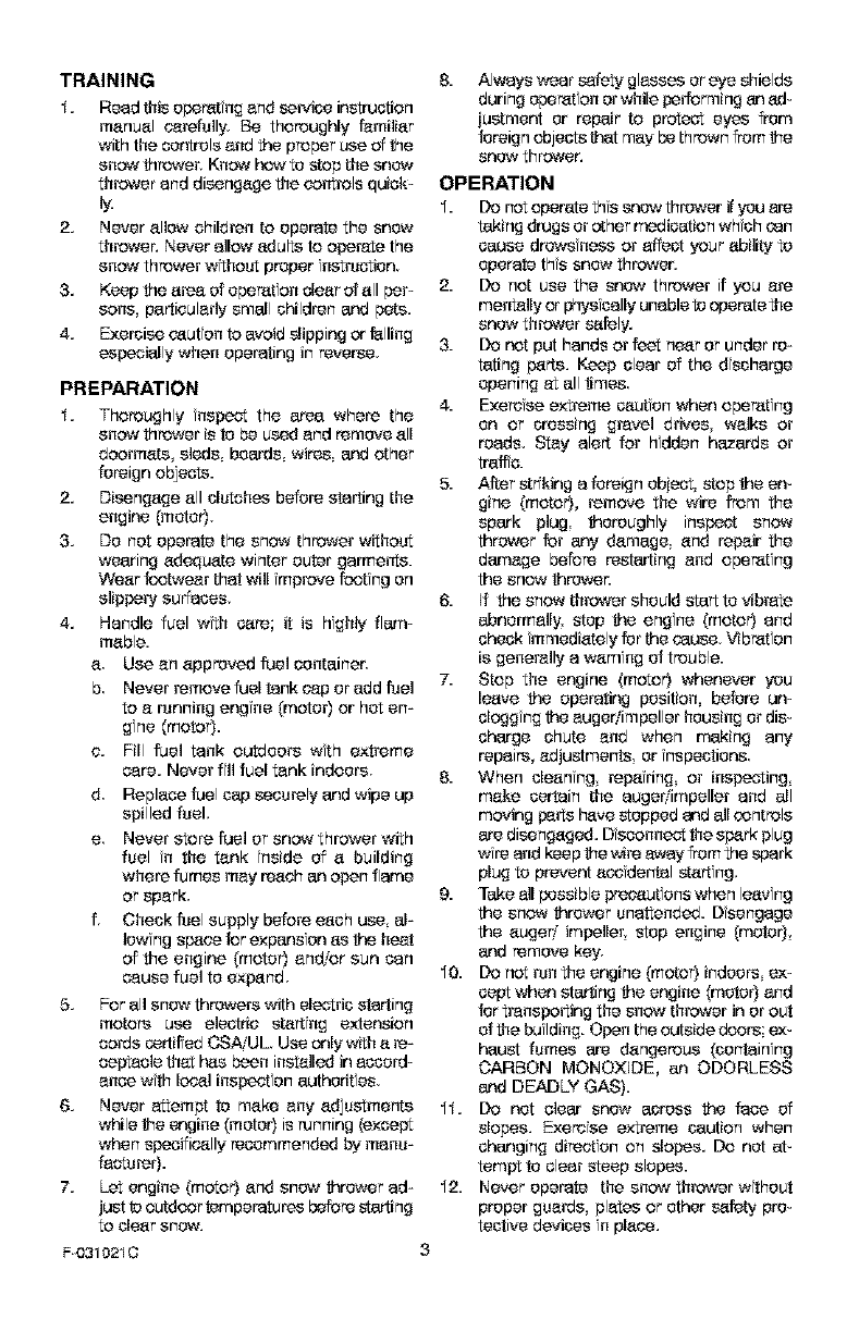
IMPORTANT; Many of the following symbols are located on your snow thrower or on litara*
ture supplied with the product. Before you operate the snow thrower, learn end understand
the purpose for each symbol.
Control And Operating Symbols
Slow Fast Electric Start Engine Start Engine Run
I-I N
Engine Off Engine SLop On Choke Off Choke On Neutral
Throttle Primer Button Ignition Key Ignition Off Ignition On
F0310210 4
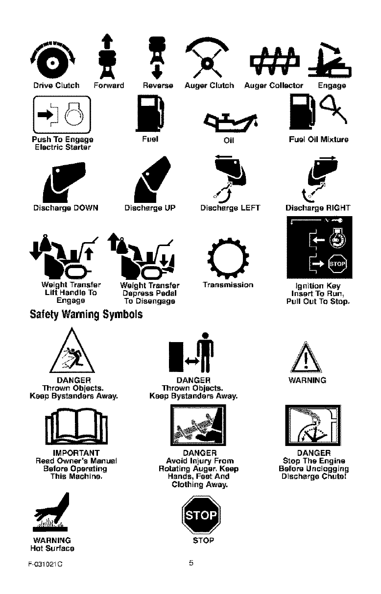
Drive Clutch FoPwerd
Push TO Engage
Electric Starter
Reverse Auger Clutch Auger Colll_'_[or Engage
Fuel Oil Fuel Oil Mixture
f
Discharge DOWN Discharge UP Discharge LEFT Discharge RIGHT
Weight Transfer Weight Transfer Transmission Ignition Key
Lift Handle To Depress Pedal Inse_ To Run,
Engage To Disengage Pull Out To Stop.
Safety Warning Symbols
DANGER
Thrown Objects.
Keep Bystanders Away.
IMPORTANT
Read Owner's Manual
Before Operating
This Machine.
m.$
DANGER WARNING
]]lrown O bjl_*ts.
Keep Bystanders Away.
DANGER
Avoid Injury From
Rotating Auger. Keep
Hands, Feat And
Clothing Away.
DANGER
Stop The Engine
Before Unclogging
Discharge Chute(
WARNING
Hot Surface STOP
F0310210 5
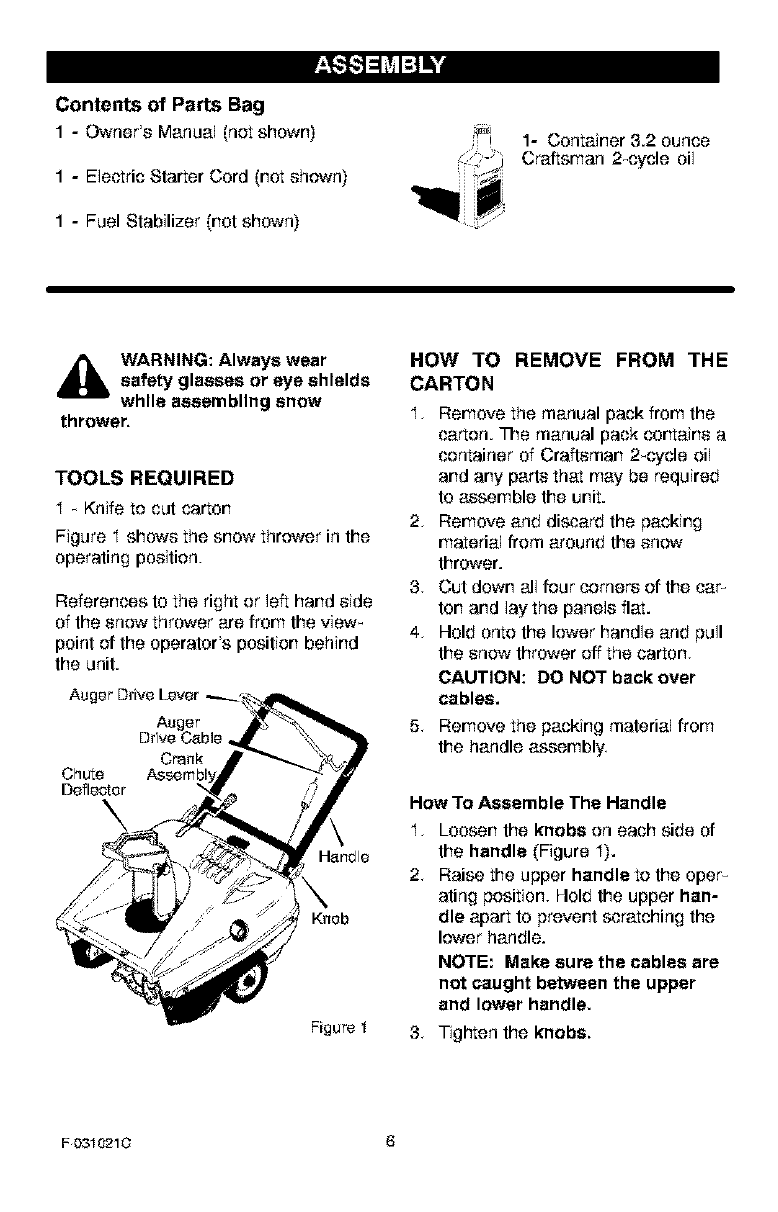
Contents of Parts Bag
1-Owner's Manual (not shown)
1-Electric Starter Cord (not shown)
1 - Fuel Stabilizer (not shown)
1- Container 3.2 ounce
Craftsman 2_cycle oil
,i_ WARNING: Always wearsafety glasses or eye shields
while easembllng snow
thrower.
TOOLS REQUIRED
I _ Knife to cut carton
Figure I shows the snow thrower in the
operating position.
References to the right or left hand side
of the snow thrower are from the view_
point of the operator's position behind
the unit.
Auger Drive Lever _.
Auger
Drfve Cable,
Crank
Chute
Deflector
Knob
Figure I
HOW TO REMOVE FROM THE
CARTON
I, Remove the manual pack from the
carton. The manual pack cortains a
container of Craftsman 2_cycle oil
and any parts that may be required
to assemble the unit.
2, Remove and discard the packing
material from around the snow
thrower.
3. Cut down all four corners of the car-
ton and lay the panels flat.
4. Hold onto the lower handle and pull
the snow thrower off the carton.
CAUTION: DO NOT back over
cables.
5. Remove the packing material from
the handle assembly
How To Assemble The Handle
I. Loosen the knobs on each side of
the handle (Figure I).
2. Raise the upper handle to the oper_
ating position. Hold the upper han-
dle apart to prevent scratching the
lower handle.
NOTE: Make sure the cables are
not caught between the upper
and lower handle.
3. Tigl"ten the knobs.
F 0310210 6
_" CHECKLIST
Before you operate your new snow
thrower, to ensure that you receive the
best performance and satisfaction from
this quality product, please review the
following checklist:
,I All assembly instructions have been
completed.
,I The discharge chute rotates freely.
,I No remaining loose parts in carton.
While learning how to use your snow
thrower, pay extra attention to the foF
lowing importar't items:
,I Make sure the fuel tank is filled with
the correct mixture (40:1 ratio) of gas_
aline and oil.
,I Become familiar with the location of
all controls and understand their
function.
,I Before starting the engine, make sure
all controls operate correctly.
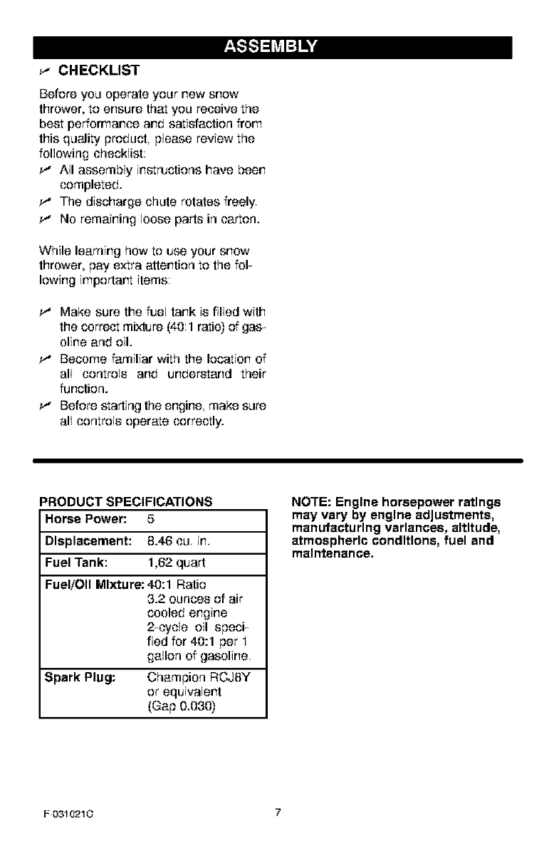
PRODUCT SPECIFICATIONS
Horse Power: 5
Displacement: 8.46 cu, in,
Fuel Tank: 1,62 quart
Fuel/Oil Mlxturs: 40:1 Ratio
3.2 ounces of air
cooled engine
2_cycle oil speci_
fled for 40:1 per I
gallon of gasoline,
Spark Plug: Champion RCJ8Y
or equivalent
(Gap 0.030)
NOTE: Engine horsepower ratings
may vary by engine adjustments,
manufacturing variances, altitude,
atmospheric conditions, fuel and
maintenance.
F 0310210 7
[o]-,j =1;__aud[o_
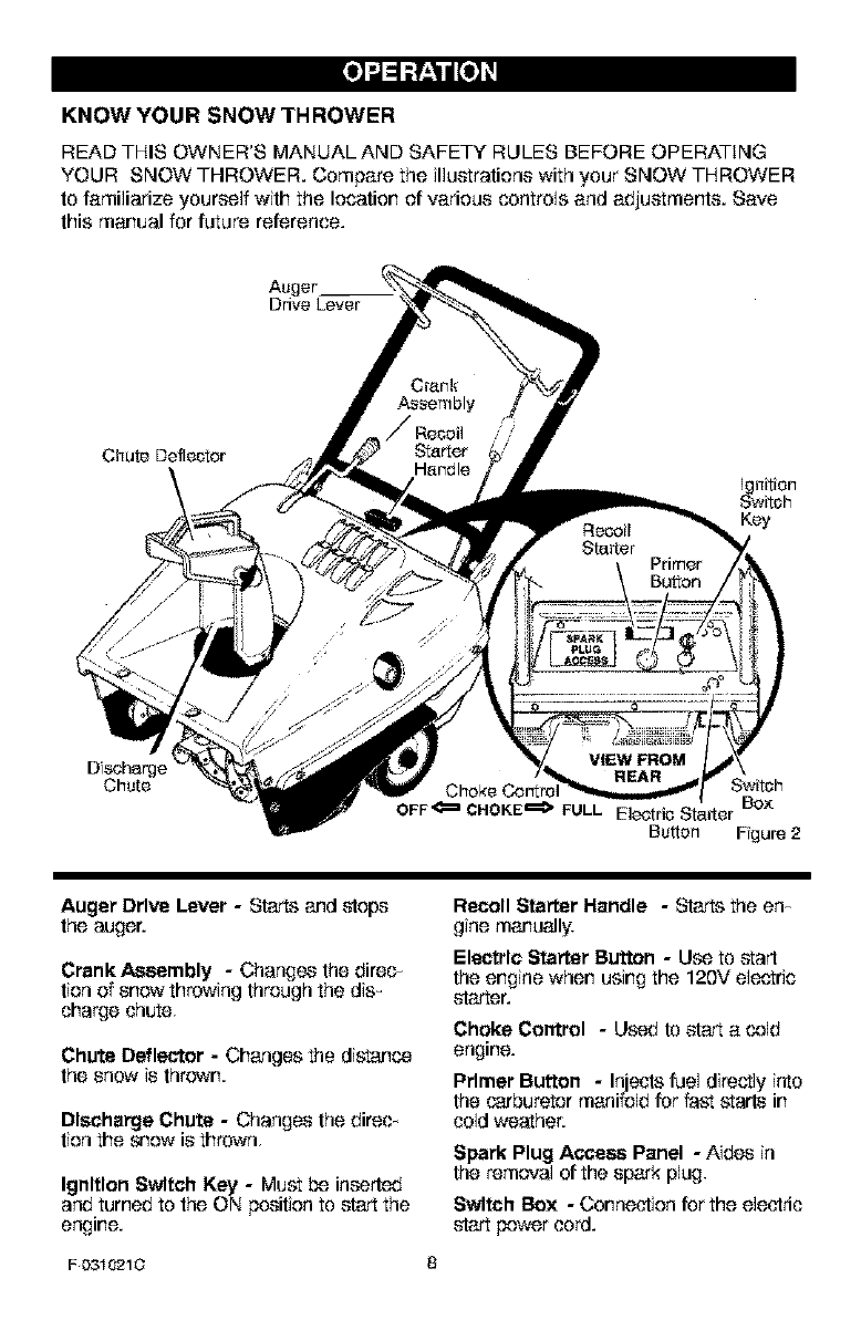
KNOW YOU R SNOW TH ROWER
READ THIS OWNER'S MANUAL AND SAFETY RULES BEFORE OPERATING
YOUR SNOW THROWER. Compare the illustrations with your SNOW THROWER
to familiarize yourself with the location of various controls and adjustments. Save
this manual for future reference.
Drive Lever
Chute Deflector
D soharge REAR
Chute Switch
Box
OFF_ CHOKE_ FULL Electric Sta_er
Button Fgure 2
Auger DHve Lever -Starts and stops
the auger.
Crank Assembly - Changes the direc_
tion of snow throwing through the dis_
charge chute.
Chute Deflector - Changes the distance
the snow is thrown.
Dlecha_e Chute - Changes the direc_
tion the snow is thrown.
Ignition Switch Key -Must be inserted
and turned to the ON position to start the
engine.
Recoil Starter Handle -St_ the en_
gine manually.
Electric Starter Button -Use to start
the engine when using the 120V electric
starter.
Choke Control -Used to st_ a cold
engine.
Primer Button -Injects fuel directly into
the carburetor manifold for fast starts in
cold weather.
Spark Plug A_ Panel -Aides in
the removal of the spark plug.
Switch Box -Connection for the electric
start power cord.
F 0310210 8
[o]-,j =1;__aud[o_
,_ WARNING: Read Owner's
Manual before operating
machine. Never direct dis-
charge toward bystanders. Stop the
engine before unclogging discharge
chute or auger housing and before
leaving the machine.
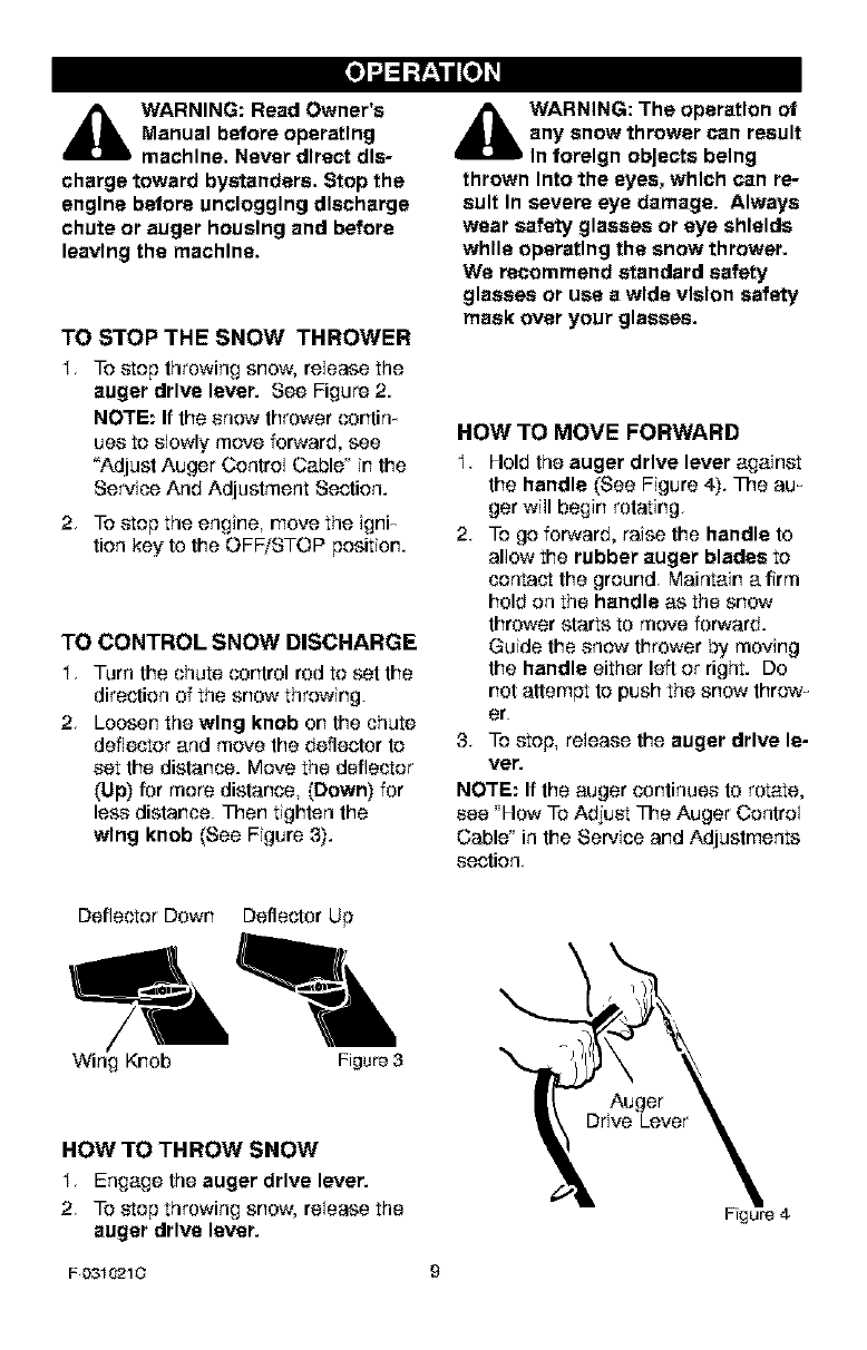
TO STOP THE SNOW THROWER
I. To stop throwing snow, release the
auger drive lever. See Figure 2.
NOTE: If the snow thrower contim
uss to slowly move forward, see
"Adjust Auger Control Cable" in the
Service And Adjustment Section.
2. To step the engine, move the igni_
tion key to the OFF/STOP position.
TO CONTROL SNOW DISCHARGE
I. Turn the chute control rod to set the
direction of the snow throwing.
2. Loosen the wing knob on the chute
deflector and move the deflector to
set the distance. Move the deflector
(Up) for more distance, (Down) for
less distance. Then tighten the
wing knob (See Figure 3).
d_lb WARNING: The operation of
any snow thrower can result
In torelgn objects being
thrown Into the eyes, which can re-
sult In severe eye damage. Always
wear safety glasses or eye shields
while operating the snow thrower.
We recommend standard safety
glasses or use a wide vision safety
mask over your glasses.
HOW TO MOVE FORWARD
I,
2.
Hold the auger drive lever against
the handle (See Figure 4). The au-
ger will begin rotating.
To go forward, raise the handle to
allow the rubber auger blades to
contact the ground. Maintain a firm
hold on the handle as the snow
thrower starts to move forward.
Guide the snow thrower by moving
the handle either left or right. Do
not attempt to push the snow throw_
er.
3. To stop, release the auger drive le-
ver.
NOTE: If the auger continues to rotate,
see _How To Adjust The Auger Control
Cable" in the Service and Adjustments
section.
Deflector Down Deflector Up
Wing Knob Figure 3
HOW TO THROW SNOW
I, Engage the auger drive lever.
2. To stop throwing snow, release the
auger drive lever.
F 0310210
Auger
Fgure 4
[o]d =1;__aud[o_
FILL GAS:
The engine is certified to comply with
California and US EPA emission regula-
liens for ULGE (Utility or Lawn and Gar-
den Equipment) engines. ULGE
engines are certified to operate on reg_
ular unleaded gasoline.
_ARNING: Alcohol blended
fuels (called gasohol or
those using ethanol or
methanol) can attract moisture
which leads to separetlon and
formation of acids during storage.
Acidic gas can damage the fuel sys-
tem of an engine while In storage.
NOTE: To avoid engine problems, the
fuel system must be emptied before
storage for 30 days or longer. Start the
engine and let it run until the fuel lines
and carburetor are empty. Use the car_
buretor bowl drain to empty residual
gasoline from the float chamber. Use
fresh fuel next season. See the Stor-
age section in this manual for additional
information.
Never use engine or carburetor cleaner
products in the fuel tank or permanent
damage may occur.
HOW TO MIX THE FUEL MIXTURE
The two cycle engine, used on this
snow thrower, requires a mixture of
gasoline and oil for lubrication of the
bearings and other moving parts. The
correct fuel mixture ratio is 40:I (3.2 oz.
oil per one gallon of gas _ see the Fuel
Mixture Chart). Gasoline and oil must
be pre_mixed in a clean gasoline con_
talnar. Always use fresh, clean, um
leaded gasoline.
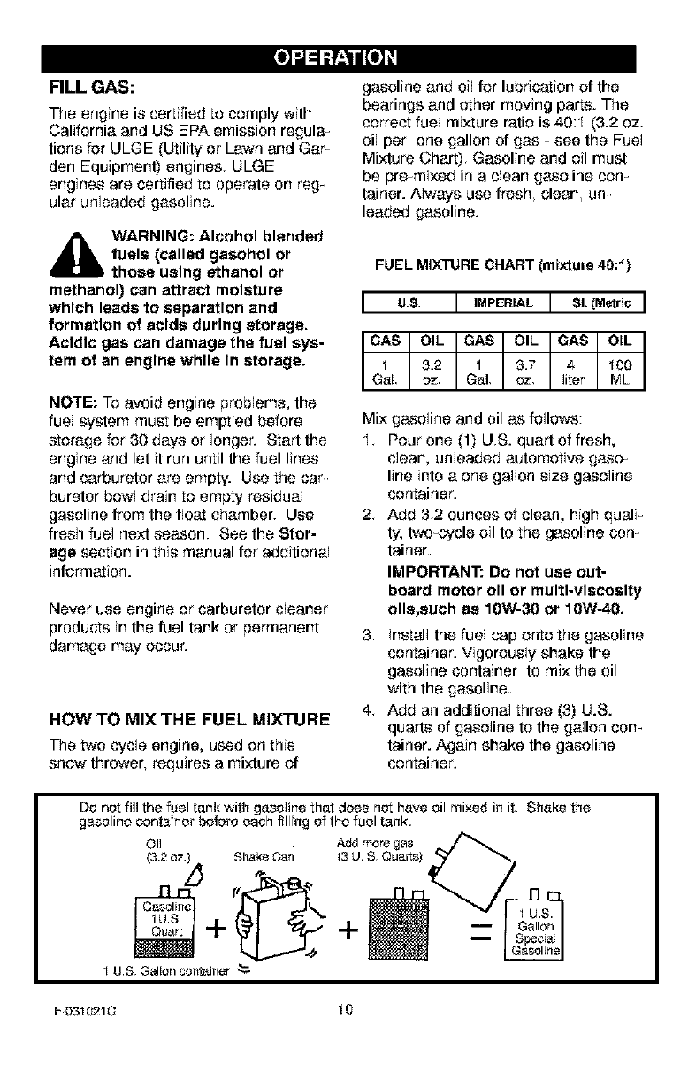
FUEL MIX1]JRECHART (mixturs 40:1)
I us I '"PE''LI s,.€-o,,oI
Mix gasoline and oil as follows:
I. Pour one (1) US. quart of fresh,
clean, unleaded automotive gaso_
line into a one gallon size gasoline
container.
2. Add 3.2 ounces of clean, high quali_
ty, two-cycle oil to the gasoline con_
tainer.
IMPORTANT: Do not use out-
board motor oll or multi-viscosity
oils,such as 10W-30 or 10W-40.
3. install the fuel cap onto the gasoline
container. Vigorously shake the
gasoline container to mix the oil
with the gasoline.
4. Add an additional three (3) U.S.
quarts of gasoline to the gallon corn
tainer. Again shake the gasoline
container.
Do not fill the fuel tank with gasoline that does not have oil mixed in it. Shake the
gasoline oenta nor before each fill ng of the fuel tank,
Oil _-
Add more gas
(3.2 0_) Shake O_t/ (3 U. $ Ou_rts)
4- +
1 U.$ Galloncontainer"_
F0310210 10
[o]-,j=1;__aud[o_
_ll ARNING: Gasoline Is flam-
mable. Always use caution
when handling or storing
gesollne.
• Do not fill fuel tankwhllesnow
thrower Is running, when It Is hot,
or when snow thrower Is In an en-
closed area.
• Keep away from open flame or an
electrical spark and do not smoke
while filling the fuel tank.
• Never fill the tank completely. Fill
the tank to within 1/4"-1/2" from
the top to provide space for ex-
pansion of fuel.
• Always fill fuel tank outdoors and
use a funnel or spout to prevent
spilling.
• Make sure to wipe up any spilled
fuel before stating the engine.
• Store gesollne In a clean, ap-
proved container and keep the
cap In place on the container.
BEFORE STARTING THE ENGINE
I, Before you service er start the en-
gine, familiarize yourself with the
snow thrower. Be sure you under-
stand the function and location of all
controls.
2, Be sure that all fasteners are tight.
3+ Before starting the engine, make
sure all controls eperate correctly.
HOW TO STOP THE ENGINE
To stop the engine, move the ignition
key to the OFF/STOP position,
F (_310210
HOW TO START THE ENGINE
The engine is equipped with a I20 volt
AC electric starter and also a recoil
starter,
i_ll WARNING: The starter Is
designed to operate on 120
volt A.C. household current.
Carefully follow all Instructions In
the "How To Start The Engine" esc-
rich. To connect a 120 volt A.C.
power cord, always plug the power
cord to the switch box on the en-
gine first. Then, plug the other end
Into the receptacle. When dlecon-
nectlng the power cord, always un-
plug the end from the receptacle
first.
11
How To Start A Cold Engine
I. Fill the fuel tank with a fresh, clean
fuel mixture. See "How To Mix The
Fuel Mixture".
2. Make sure the auger drive lever is
in the disengaged (released) posF
tion.
3, insert the Ignition key and turn to
the ON position.
4, Slide the choke control to the
FULL choke position.
5, (Electric Start) Plug the power cord
into the switch box located on the
engine.
6. (Electric Start) Plug the other end
of the power cord irto a I20 VOLT,
A.O. receptacle. (See the WARN_
ING in this section).
7, Push the primer button as speci_
fled below. Remove finger from
primer button between pushes.
Do not push if temperature is
above 50 _ F (10 _ C),
Push two times if temperature is
50_ F (I0_ 0) to I5°_ (_I0° C).
Push four times if temperature is
below I5 _ F (_10_ C).
Push five times if temperature is
below 0_ F (_18_ C).
[o]-.1=1;__,_ud[o_
8. (Electric Start) Push on the elec-
tric start button until the engine
starts. DO not crank the starter for
more than I 0seconds at a time.
The electric starter is thermally pro_
tected. If the electric starter over_
heats, it will automatically stop and
can only be restarted when it has
cooled to a safe temperature. A wait
of about 5 to 10 minutes is required
to allow the electric starter to cool.
9. (RecollStart) Rapidly pull the re-
coil starter handle. Do not allow
the recoil starter handle to snap
back. Slowly return the recoil start-
er handle.
I 0. if the engine does not start in 5 or 6
tries, See Difficult Starting in the
"Troubleshooting Table".
II. (Electric Start) When the engine
starts, release the electric start
button.
I2. (Electric Start) First disconnect the
power cord from the receptacle.
Then, disconnect the power cord
from the switch box.
I3. As the engine warms up, move the
choke control to 1/2 choke posi_
tion. When the engine runs smooth_
ly, move the choke control to the
off position.
NOTE: Allow the engine to warm up for
several minutes before blowing snow in
temperatures below 0_F.
How To Start A Warm Engine
If restarting a warm engine after a short
shutdown, leave choke at "OFF' and do
net push the primer button. If the en_
gine fails to start, follow the Cold Start
instructions.
_lb ARNING: Never run en-
gine Indoors or In enclosed,
poorly ventilated areas. En-
gine exhaust contains CARBON
MONOXIDE, AN ODORLESS AND
DEADLY GAS. Keep hands, feet,
hair and loose clothing away from
any moving parts on engine and
snow thrower.
• The temperature of muffler and
nearby areas may exceed 150°F.
Avoid these areas.
• DO NOT allow children or young
teenagers to operate or be near
snow thrower while It Is operet-
Ing.
HOW TO REMOVE OBJECTS
FROM AUGER
_lb ARNING: Do not attempt
to remove any Item that may
become lodged In auger
without taking the following precau-
tions:
Release auger drive lever.
Move the ignition lever to the stop
position to stop the engine.
Disconnect spark plug wire.
Do not place your hands in the au_
ger or discharge chute. Use a pry
bar.
F0310210 12
[o] d =1;__aud[o_
SNOW THROWING TIPS
I. When the handle is raised, the au_
ger blades will engage the greund
and the snow thrower will move fer_
ward. When the auger drive lever is
released, the auger blades will stop.
If the blades do net stop, see _'How
To Adjust The Auger Drive Cable" in
the Service And Adjustment section.
2 Most efficient snow throwing is ac_
cemplished when the snow is rex
moved immediately after if falls.
3 Fer complete snow removal, slightly
overlap each previous path.
4. Whenever possible, discharge the
snew down wind.
5. The dietance the snow will be dis_
charged can be adjusted by moving
the discharge chute deflecter. Raise
the deflector for more dietance or
lower the deflecter for less distance.
6. In windy osnditions, lower the chute
deflector te direct the discharged
snow close te the ground where it is
less likely to blow into unwanted
areas.
7. Fer safety and to prevent damage
to the snow thrower, keep the area
to be cleared free of stones, toys
and other foreign objects.
8. When clearing snow from crushed
rock er gravel driveways, de net aF
low the auger blades te contact the
driveway. Move the handle down te
slightly raise the auger blades.
9. The ferward speed of the snow
thrower is dependent on the depth
and weight of the snow. Experience
will establish the most effective
method of using the snow thrower
under different conditions.
I0. After each snow throwing job, _lew
the engine te run for afew minutes.
The snow and accumulated ice will
melt off the engine.
II. Clean the snow thrower after each
use. Remove ice, snow and debris
from the entire snow thrower. Flush
with water te remove all salt or other
chemicals. Wipe snow thrower dry.
DRY AND AVERAGE SNOW
I. Snow up to eigl"t inches deep can
be removed rapidly and easily by
walking at a moderate rate. For
snow er drifts of a greater depth,
slow your pace to allow the dis_
charge chute te dispose of the snow
as rapidly as the auger receives the
snow.
2. Plan to have the snow discharged in
the direction the wind is blowing.
WET PACKED SNOW
Move slowly into wet, packed snow. If
the wet, packed snow causes the auger
to slow down er the discharge chute be_
gins te clog, back off and begin a series
of short back and forth jobs into the
snow. These short back and forth jobs,
four te six inches, will "belch" the snow
from the chute.
SNOW BANKS AND DRIFTS
in snow of greater depth than the unit,
use the same "jabbing' technique de_
scribed above. Turn the discharge
chute away from the snow bank. More
time will be required te remove snow of
this type than level snow.
F0310210 13
CUSTOMER RESPONSIBILITIES
SERVICERECORDS
Fillindotesasyou Before Every Every Every
completeregular Each 5 10 25 Each Before SERVICE
service. Use Often Hours Hours Hours Season Storege DATES
'??' .......................
Check Spark Plug _/ _/
Drain FueE _/
¢
GENERAL RECOMMENDATIONS
The warranty on this snow thrower
does not cover items that have been
subjected to operator abuse or negli-
gence. To receive full value from the
warranty, the operator must maintain
the snow thrower as instructed in this
manual.
Some adjustments will need to be
made periodically to properly maintain
your snow thrower.
AFTER EACH USE
Run the machine to clear the auger
of snow.
To prevent freezing of the auger or
controls, remove all snow and slush
from the snow thrower.
Check for any loose or damaged
paris.
TigHen any loose fasteners.
Check and mairtain the auger.
Check controls to make sure they
are functioning properly.
+fany parts are worn or damaged,
replace immediately.
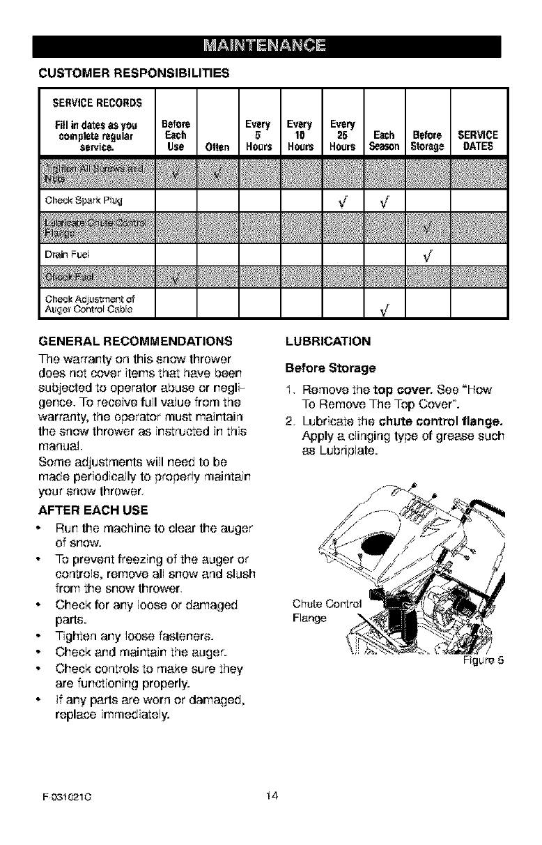
LUBRICATION
Before Storage
I. Remove the top cover, See "How
To Remove The Top Cover'.
2. Lubricate the chute control flange.
Apply a clinging type of grease such
as Lubriplate.
Chute Co.tel
Flange
/
Figure 5
F 0310210 14
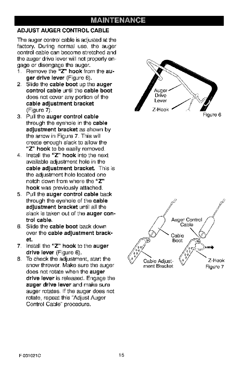
ADJUST AUGER CONTROL CABLE
The auger control cable is adjusted at the
factory. During normal use, the auger
control cable can become stretched and
the auger drive lever will not properly en_
gags or disengage the auger.
I. Remove the "Z" hook from the au-
ger drive laver (Figure 6).
2. Slide the cable boot up the auger
control cable until the cable boot
does not cover any portion of the
cable adjustment bracket
(Figure 7).
3. Pull the auger control cable
through the eyehele in the cable
adjustment bracket as shown by
the arrow in Figure 7. This will
create enough slack te allow the
"Z" hook te be easily removed.
4. Install the "Z" hook into the next
available adjustment hole in the
cable adjustment bracket. This is
the adjustmert hole located one
notch down from where the "Z"
hook was previously attached.
5. Pull the auger control cable back
through the eyehole of the cable
adjustment bracket until all the
slack is taken out of the auger con-
trol cable.
6. Slide the cable boot back down
over the cable adjustment brack-
et.
7. Install the "Z" hook te the auger
drive lever (Figure 6).
8. To check the adjustment, start the
snow thrower. Make sure the auger
does net rotate when the auger
drive lever is released. Engage the
auger drive lever and make sure
auger rotates. If the auger does not
rotate, repeat this _'Adjust Auger
Control Cable' procedure.
Drive
Lever
Z-Hook
Auger Control
Cable
Figure 6
Cable Adjust- Z-Hook
merit Bracket Figure 7
F0310210 15
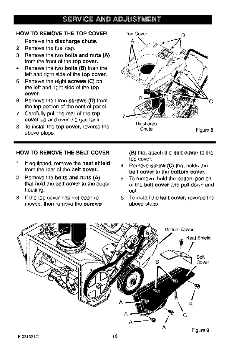
HOW TO REMOVE THE TOP COVER
I. Remove the discharge chute.
2. Remove the fuel cap.
3. Remove the two bolts and nuts (A)
from the front of the top cover.
4. Remove the two bolts (B) from the
left and right side of the top cover.
5. Remove the eigl"t screws ((3) on
the loft and right side of the top
covet',
6. Remove the three screws (D) from
the top portion of the control panel.
7. Carefully pull the rear of the top
cover up and over the gas tank.
8. To install the top cover, reverse the
above stops.
TopCover
A
Dischsrge
Chute Figure 8
HOW TO REMOVE THE BELT COVER
I. if equipped, remove the heat shield
from the rear of the belt cover.
2. Remove the bolts and nuts (A)
that hold the belt cover to the auger
housing.
3. if the top cover has not been rex
moved, then remove the screws
(B) that attach the belt cover to the
top cover.
4. Remove screw (C) that holds the
belt cover to the bottom cover.
5. To remove, hold the bottom portion
of the belt cover and pull down and
out
6. To install the belt cover, reverse the
above stops.
Bottom Cover
Heat Shield
Belt
Cover
A
\C
A
B
Figure 9
F 0310210 16
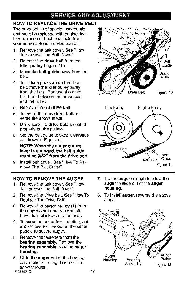
HOW TO REPLACE THE DRIVE BELT
The drive belt is of special construction !-÷._ b.:_ _:_.._z _>_4_ r_ j_\
and must be replaced with original (ac_ _
tory replacement bell available from
your nearest Sears service center.
I. Remove the belt cover. See "How
To Remove The Belt Cove€.
2. Remove the drive belt from the
Idler pulley (Figure 10).
3 Move the belt guide awayfrom the
belt.
4. To reduce pressure on the drive
belt, move the idler pulley away
from the belt. Remove the drive Drive Belt
belt from between the brake pad
and the roller.
Belt
Guido
Brake
Roller
Figure 10
5. Remove the old drive belt. IdlerPulley
6. TO install the new drive belt, rex
verse the above steps.
7. Make sure the drive belt is seated
properly on the pulleys.
8. Set the belt guide to 3/32' clearance
as shown in Figure 11.
NOTE: When the auger control
lever Is engaged, the belt guide Drive Bel_
must be 3/32" from the drive belt.
9. Install belt cover. See "How To Rex
move The Belt Cover'.
Engine Pulley
Belt
3/'32 inch Guide
Fgure 11
HOW TO REMOVE THE AUGER
I. Remove the belt cover. See _How
To Remove The Belt Cove€.
2. Remove the drive belt. See "HowTo
Replace The Drive Belt".
3. Remove the auger pulley (1) from
the auger shaft (threads are left
hand; turn clockwise to remove).
4. To keep the auger from rotating, set
a 2"x4" piece of wood on the center
paddle to secure auger.
5. Remove the fasteners from the
bearing assembly. Remove the
bearing assembly from the auger
housing.
6. Slide the auger out of the bearing
assembly on the right side of the
snow thrower.
F 0310210
7. Tip the auger enough to allow the
auger to slide out of the auger
housing.
8. To install auger, reverse the above
steps.
17
Housing Beefing
Assemlby
•Auger
Pulley
Fgure 12
,_ WARNING: To prevent acci-
dental starting when making
any adjustments or repalre,
always disconnect the spark plug
wire and place It where It cannot
make contact with the spark plug.
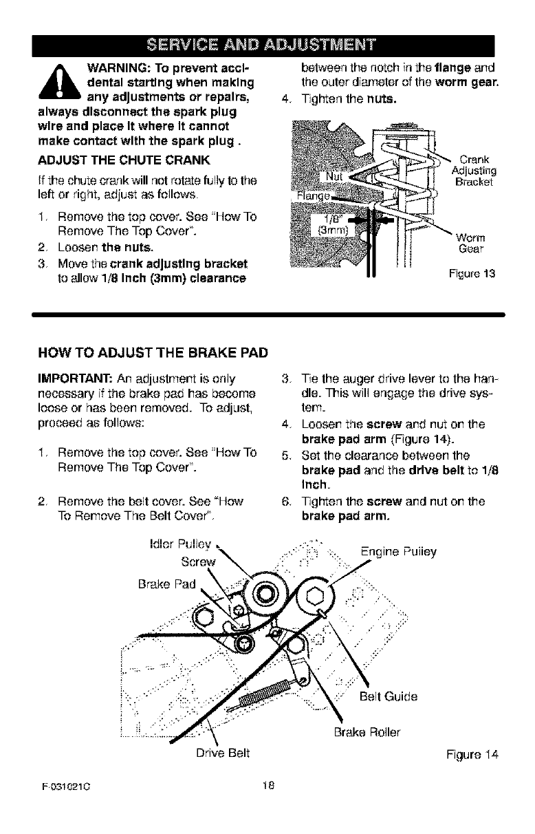
ADJUST THE CHUTE CRANK
If the chute crank will not rotate fully lo the
left or right, adjuet as follows.
I. Remove the top cover. See "How To
Remove The Top Cover'.
2. Loosen the nuts.
3. Move the crank adjusting bracket
to allow 1/8 Inch (3mm) clearance
between the notch inthe flange and
the outer diameter of the worm gear.
4. Tiglqten the nuts.
Crank
Bracket
Worm
Gear
Fgure 13
HOW TO ADJUST THE BRAKE PAD
IMPORTANT: An adjustrnert is only
necessary if the brake pad has become
loose or has been removed. To adjust,
proceed as follows:
I. Remove the top cover. See "How To
Remove The Top Cover'.
2. Remove the belt cover. See "How
To Remove The Belt CoveCL
Brake Pad
Drive Belt
3,
4.
5.
6.
Tie the auger drive lever to the ham
die. This will engage the drive sys_
tern.
Loosen the screw and nut on the
brake pad arm (Figure 14).
Set the clearance between the
brake pad and the drive belt to 1/8
Inch.
Tigl"ten the screw and nut on the
brake pad arm.
:::" Belt Guide
Brake Roller
Figure I4
F 0310210 18
TO ADJUST THE CARBURETOR
The ca,'buretor is net adjusl_ble. Em
gine performance should net be af_
fected at altitudes up te 7,000 feet. For
operation at higher elevations, contact
your nearest Sears Service Center.
IMPORTANT: Never tamperwiththe
engine governor, whichisfactory sot for
proper engine speed. Over-speeding
the engine above the factory high
speed selling can be dangerous. If the
engine_governed high speed needs an
adjustment, contact your nearest Sears
Service Center. They have the proper
equipment and experience to make any
necessary adjustments.
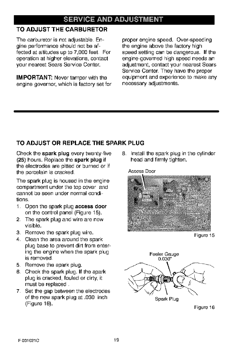
TO ADJUST OR REPLACE THE SPARK PLUG
Check the spark plug every twenty_five
(25) hours. Replace the spark plug if
the electrodes are pitted or burned or if
the porcelain is cracked.
The spark plug is housed in the engine
compartment under the top cover and
cannot be seen under normal cendF
tiens.
I, Open the spark plug access door
on the control panel (Figure I5).
2, The spark plug and wire are now
visible.
3. Remove the spark plug wire.
4, Clean the area around the spark
plug base to prevent dirt from enter_
ing the engine when the spark pJug
is removed.
5. Remove the spark pJug.
6, Check the spark plug. If the spark
plug is cracked, fouled or dirty, it
must be replaced
7, Set the gap between the electrodes
of the now spark pJug at .030 inch
(Figure 16).
8, Install the spark pJug in the cylinder
head and firmly tighten.
AOOeSB Doer
Figure 15
Spark Plug
Figure 16
F0310210 19
_ARNING: Never store your
snow thrower Indoors or In
an enclosed, poorly venti-
lated area. If gesollne remains In the
tank, fumes may reach an open
flame, spark or pilot light from a fur-
nace, water heater, clothes dryer,
clgarette_ etc.
NOTE: To prevent engine damage (if
snow thrower is not used for more than
30 days) fellow the steps below.
SNOW TH ROWER
I. Thoroughly clean the snow thrower.
2. Lubricate all lubrication points. See
the Maintenance section.
3. Be sure that all nuts, bolts and
screws are securely fastened. Im
spect all visible moving pads for
damage, breakage and wear. Rex
place if necessary.
4. Touch up all rusted or chipped paint
surfaces; sand lightly before palrtx
ing.
5. Cover the bare metal parts of the
blower housing auger and the im_
peller with rust preventative, such
as a spray lubricart.
NOTE: A yearly checkup or tune_up by
a Sears service center is a good way of
ensuring that your snow thrower will
provide maximum performance for the
next season.
ENGINE
_ARNING: Drain the geso-
line outdoors, away from
tire or flame.
Gasoline must be removed or treated to
prevent gum deposits from forming in
the fuel tank, filter, hose, and carburetor
during storage. Also, during storage alx
cohol blended gasoline that uses etha-
nol or methanol (sometimes called
gasohol) attracts water. It acts on the
gasoline to form acids which damage
the engine.
F 0310210
2.
3,
4,,
5.
To remove gasoline, run the engine
until the fuel tank is empty and the
engine stops.
If you do not remove the gasoline,
use fuel stabilizer supplied with unit
or purchase Craftsman Fuel Stabi_
lizer No. 3550. Add fuel stabilizer to
any gasoline left in the tank to minix
mize gum deposits and acids. If the
fuel tank is almost empty, mix stabix
lizer with fresh gasoline in a sepa-
rate container and add some to the
fuel tank.
Always follow the instruction on the
stabilizer container. After the stabix
lizer is added to the fuel tank, run
the engine at least ten minutes to
allow the mixture to reach the car-
buretor.
Change the engine oil.
Lubricate the piston/cylinder area as
follows: First, remove the spark plug
and squid a few drops of clean em
gine oil into the spark plug hole.
Next, cover the spark plug hole with
a rag to absorb oil spray. Then, pull
two or three times on the recoil
starter rope to rotate the engine. Fix
nally, install the spark plug and at_
tach the spark plug wire.
20
OTHER
I. if possible, store your snow thrower
indoors and cover it to give protec x
tion from dust and dirt.
2. If the snow thrower must be stored
outdoors, put the snow thrower on
blocks to raise it off of the ground.
3. Cover the snow thrower with a suit x
able protective cover that does not
retain moisture. Do not use plastic.
IMPORTANT: Never cover snow
thrower while engine and exhaust areas
are still warm.
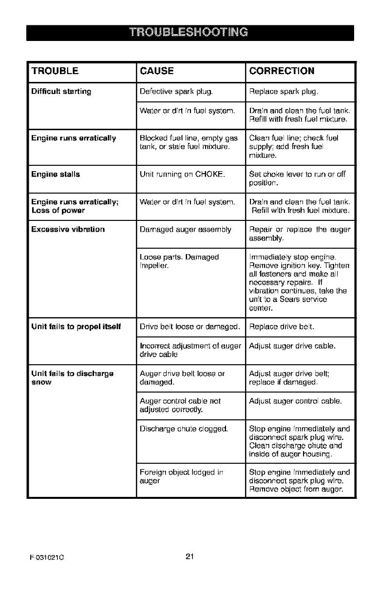
TROUBLE CORRECTION
Difficult starting Replase spark plug,
Dran and clean the fuel tank
Refll with fresh fuel mixture
Engine runs erratically Clean fuel line; chock fuel
supply; add fresh fuel
mixture.
Engine stalls Set shake lever to run er off
position.
Engine runs erratically; Dr_n and clean the fuel tank.
Loss of power Refill wth fresh fuel mixture.
Excessive vibration
Unit fails to propel itself
CAUSE
Defective s_rk plug.
Water er dr[ n fuel system.
Blockedfuelline,empty gas
tank, or s_le fuelmixture.
Unit running on CHOKE.
Water er dr[ n fuel system.
Damaged auger assembly
Loose parts, Damaged
repeller.
Drive belt loose er damaged.
Inserrect adiustmer_t et auger
drive cable
Auger drive belt loose er
damaged.
Auger control cable net
adjusted serreegy.
Discharge chute clogged.
Repair er replase the auger
assembly
Unit fails to disehsrgs
S_IOW
Immediately stop engine.
Remove ignition key. Tighten
all fasteners and make all
necessary repairs If
vibration ocntisees take the
unft tea Sears service
senter.
Replace drive belt.
Adjust auger drse cable.
Adjust auger drive belt;
replace if damaged.
Adjust auger sentral cable.
Stop engine fmmediately and
dissennest spark plug wre.
Clean dissharge chute and
inside ot auger housing,
Foreign abject lodged in Stop engine fmmediately and
auger dissennest spark plug wre.
Remove object from auger,
F0310210 21
SEARS, ROEBUCK AND CO.
Federal and California Emission Control Systems Limited Warranty
Small Off-Road Engines
CALIFORNIA & US EPA EMISSION
CONTROL WARRANTY STATEMENT
The U. S. Environmental Preteotion Agency
('EPA") the Calitorna Air Resources Board
('CARB") and Sears Roebuck and Co are
pleased to explain the Federal and California
Emission Control Systems Warranty on your
new small off-road engine. In California, new
t 995 and inter small off-road eng nes must be
designed built and equipped to meet the
State's str ngent anti-smog standards. In oth-
er states new 1997 and later model year en-
gines must be desigsed built and equipped, at
the time of sale, to meet the LLS EPA regale-
tens for small nomread engines. Sears, Ree_
buck and Co. will warrant the emiseion control
system on your small olf-r'oad engine for the
perfods of tfme listed below, provided there
has been no abuse, neglect, unapproved mod-
ficotion or improper mairteeence of your
small elf-read engine.
Your emissee control system may include
pa_s such as the carburetor', ignition system
and exhaust system. Aise included may be the
compression release system and other emis-
sfon-relatod assemblies.
Where awarrantable condition exists Sears,
Roebuck and Co. will repair your small off_
read engine at no cost to you for diagnosis,
pa_s and labor.
MANUFACTURER'SEMISSION
CONTROLSYSTEM WARRANTY
COVERAGE
Emission control systems on 1995 and later
model year California small off-read engines
are warranted for two years as hereinafter
noted. In ether states, 1997 and later model
year engines are also warranted for two year's
If, during such warrar_ty period any emission-
related part an your eegtse is dofentive in ma-
terfals or workmanship, the pad will be
ref_ired or replaced by Sears Roebuck and
Co.
OWNER'S WARRANTY
RESPONSIBILITIES
As the small elf-read engine owner, you are
respensble for the pedormance of the re-
F 0310210
quired maintenance listed n your Owner's
Manual, but Sears Roebuck and Co. will not
deny warranty solely due to the lack of receipts
or for your failure to provide written evidence
of the performance of all scheduled matste-
nance.
As the small off-read engne owner, you
should however, be aware that Sears, Roe-
buck and Co. may deny you warrar_ty cover-
age if your small off-reed engfne or a part
thereof has failed due to abuse, neglect im-
proper maintenance or unappreved modifica-
tions.
You are responsible for present eg your small
off-reed engine to aSears Roebuck and Co.
Authorized Service Outlet as soon as aprob-
lem exists. The warrar_ty repairs should be
completed in a reasonable amount of gme, nat
to exceed 30 days.
Warranty service can be arranged by ccntant-
ng ether a Sears Roebuck and Co. Autho-
rized Servse Outlet, or by ser%anting Sears,
Roebuck and Co. at 1-800473-7247.
22
IMPORTANT NOTE
Ths warranty statemert explains your rghts
and obligations under the Emission Control
System Warrar_ty ("ECS Warranty"} which s
provided to you by Sears, Roebuck and Co.
pursuant to California law. See also the Sears
Roebuck and Co. Limited Warrar_ties for
Sears, Roebuck and Co. whfch is enclosed
therewith on a separate sheet and also is pro-
vfded to you by Sears, Roebuck and Co. ]-he
ECS Warranty applies only to the emission
sertrsl system of your new engine. To the ex-
tent that there is any ccnflfnt in terms between
the ECS Warranty and the Sears, Roebuck
and CO. Warrar%t, the ECS Warranty shall ap-
ply exsept in any cireumntanses in which the
Sears, Roebuck and Co. Warranty may pro-
vfde a longer warranty period. Both the ECS
Warranty and the Sears, Roebuck and Co.
Warranty dose€be important rights and oblfga-
tions with respect to your new engine.
Warranty service can only be performed by a
Sears, Roebuck and Co. Authorized Service
Outlet At the tfme of requesting warranty ser-
vfse evfdense must be presented of the date
of sale to the original purchaser, The purches-
ershallpayanychargesfarmakingservice
cellsand/orfartransportingtheproductsto
andfromtheplacewherethesepectonand/
orwarrantyworkispe_rmed.Thepurchaser
shallberesponsibleforanydamageOrlossn-
cuffedinconnectionwiththetranspertctionof
anyengineorar_y_rt{s)thereofsubmittedfor
inspectionand/orwarrantywork.
Ifyouhaveanyquestionsregardingyourwar-
Pantyrightsandrespansiblitesyoushould
car%antSears,Roebuckand Co. at
t-800-4737247.
EMISSION CONTROL SYSTEM
WARRANTY
Emission Control System Warranty ("ECS
WarPanty _')for t 995 and later model year Cal-
fornia small off-rood eng cos (for other states,
t 997 and later model year engines):
A. APPLICABILITY: This warranty shall apply
to t 995 and later model year California small
off-reed engines (for other states, 1997 and
later model year engines) The ECS Warranty
Period shall begin on the dote the new engine
or equipment is delivered to its original end-
use purchaser, and shall continue for 24 cen-
secct ve months thereafter,
B, GENERAL EMISSIONS WARRANTY
COVERAGE: Sears Raebsek and Co, war-
rants to the original, end-use purchaser of the
new engine or edalpmer_ and to each subse-
quent purchaser that each of its small off-road
ang ass is:
t. Dss gned, built and equ pped so as to con-
form with all applicable regular one adopted by
the Air Resources Board pursuant to its au-
thority fn Chapters 1 and 2 Part 5, Division 26
of the Health and Safety Code and
2 Free from defects in materials and work-
manship which, at any tfme during the ECS
Warranty Period, will c_use a warranted emis-
sions-relcted part to fail to be idenbeal in all
material respects to the part as dascrfbed in
the engine manufacturer's application for certi-
fication,
C. The ECS Warrar_ty only pertains to emis-
sons-related parts on your engine, as fallows:
t. Any warranted emissons-rolcted parts
which are nat scheduled for replacement as
required maintenance in the Owner's Manual
shall be warranted for the ECS Wan'acty Peri-
od. If any such part fails during the ECS War-
Panty Period, it shall be repaired or replaced by
F 0310210 23
Sears, Roebuck and Co. according to Subsec-
tion 4 below. Any such parL repaired or re-
placed under the ECS Warranty shall be
warranted far any remainder of the ECS War-
Panty Period.
2. Any warranted emissions-rolcted part
which is scheduled only for regular inspection
as specified in the Owner's Manual shall be
warranted for the ECS Warranty Period. A
statement in such written iss_-uctions to the el-
fact of 'Yepa r or replace as necessary' shall
not reduce the ECS Warrar_y Period. Any
such part ropnfred or replaced under the ECS
Warranty shall be warranted for the remafnder
of the ECS Warrar_y Period
3. Any warranted emissions-rolcted f_rt
which is scheduled for replacement as re-
quired maintenance in the Owner's Manual,
shall be warranted for the period Of time prior
to the first scheduled replacement pofnt for
that p_rt. If the part fails prior to the first sched-
uled replacement the _rt shall be repaired or
replaced by Sears Roebuck and Co. accord-
fag to Subsection 4 below. Any such emis-
sfons-rolcted part repaired or replaced under
the ECS Warranty_ shall be warranted for the
remainder of the ECS Warranty Per*ed pr*or to
the first scheduled replacement pefct for such
emisefons-rolcted part.
4. Repair or replacement of any warranted,
emiseons-rolcted part under ths ECS War-
Pantyshall be performed at no charge to the
owner at a Sears, Roebuck and Co. Autho-
rized Service Outlet.
5. The owner shall net be charged for diagses-
to labor which leads to the determination that
a part covered by the ECS Warranty fs fn fact
defective, provided that such diagnostic work
fs performed at a Se_rs Roebuck and Co. Au-
thorized Service Outlet.
6. Sears, Roebuck and Co. shall be labia for
damages to other or gina] engce components
or approved modifications proximately caused
by a failure under warranty of an emission-re-
lated part cevered by the ECS Warranty.
7. Throughout the ECS Warranty Period,
Sears, Roebuck and Co. shall mainta n n sup-
ply Ofwarranted emfsefon-rolcted parts suffi-
ofer_ to meet the expected demand for such
emisefon-rolcted parts.
8. Any Sears Roebuck and Co. authorized
and approved emissiomrolcted replanemer_
part may be used in the performance of any
ECS Wan'anty maintenance or repair and will
be provided w thoct charge to the owner, Such
useshallnotreduceSearsRoebuckandCo.
ECSWarrantyobligations.
9 Unapprovedadd-onormodifiedpartsmay
notbeusedtomodifyorrepairaSears,Roe-
buckandCo.engine.SuchusevoidsthisECS
Warrantyandshallbesufficientgroundsfor
disallowfnganECSWarrantyclaim.Sears,
RoebuckandCo.shallnotbeliablehereunder
forfailuresofanywarrantedpar_sofaSears,
RoebuckandCoenginecausedbytheuseof
suchanunapprevedadd-onormodifiedf_rL
EMISSION-RELATED PARTS
INCLUDE THE FOLLOWING:
t Carburetor Assembly and Is Internal Com-
poner%s
a} Fuel filter
b} Carburetor gaskets
c} Intake pipe
2 Ar Cleaner Assembly
a} Air filter element
3 Ignition System including:
a} Spark plug
b} ignition module
c} Flywheel assembly
4. Catalytic Muffler (f so equipped}
a} Morner gasket (if so equipped}
b} Exhaust manifold (ff so equipped}
5 Crankcase Breather Assembly and its
Components
a) Breather oonnectfon tube
t 0/22/99 EPAiCARB
Sears, Roebuck and Co., Hoffman Estates, IL 60179 U.S.A.
F 0310210 24
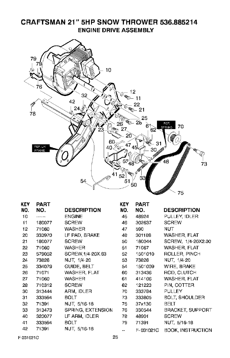
CRAFTSMAN 21" 5HP SNOW THROWER 536.885214
ENGINE DRIVE ASSEMBLY
79
10
I2
78 21
25
7O
73
75
KEY PART KEY PART
NO. NO. DESCRIPTION NO. NO. DESCRIPTION
10 ...... ENGINE 45 48924 PULLEY, IDLER
II 180077 SCREW 46 302637 SCREW
12 71060 WASHER 47 590 NUT
20 333970 LF PAD BRAKE 48 301188 WASHER FLAT
21 180077 SCREW 50 180044 SCREW 1/4-20X2.,00
22 71060 WASHER 51 71067 WASHER FLAT
23 579052 SCREW 1i4-20X 83 52 1501010 ROLLER PINCH
24 73826 NUT, 1/4-20 53 73826 NUT, 1/4-20
25 334079 GUIDE, BELT 54 1501009 WIRE, BRAKE
26 71071 WASHER FLAT 60 313438 ROD, CLUTCH
27 71060 WASHER 61 414108 WASHER FLAT
28 710312 SCREW 62 121223 PIN, COTTER
30 313444 ARM, IDLER 70 333784 PULLEY
31 333594 BOLT 73 333805 BOLT, SHOULDER
32 71391 NUT, 5/18-18 75 37×130 BELT
33 313473 SPRING, EXTENSION 76 330544 BRACKET, SUPPORT
40 320077 LF ARM, IDLER 78 48801 SCREW
41 333594 BOLT 79 71391 NUT, 5/18-18
42 71391 NUT, 5/16-18 -- F-031021C BOOK, INSTRUCTION
F 0310210 25
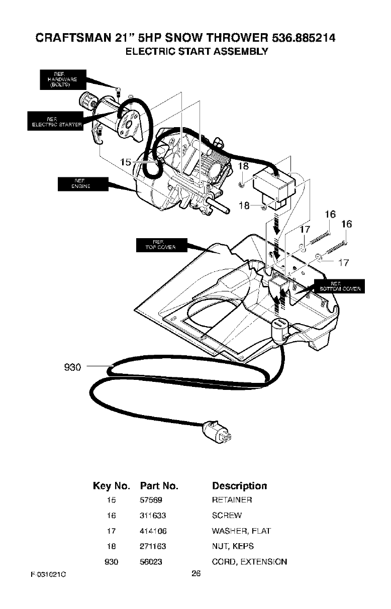
CRAFTSMAN 21" 5HP SNOW THROWER 536.885214
ELECTRIC START ASSEMBLY
16 16
930
F 0310210
Key No.
15
16
17
18
930
Part No.
57569
311633
414106
271163
56023
Description
RETAINER
SCREW
WASHER FLAT
NUT, KEPS
CORD, EXTENSION
26
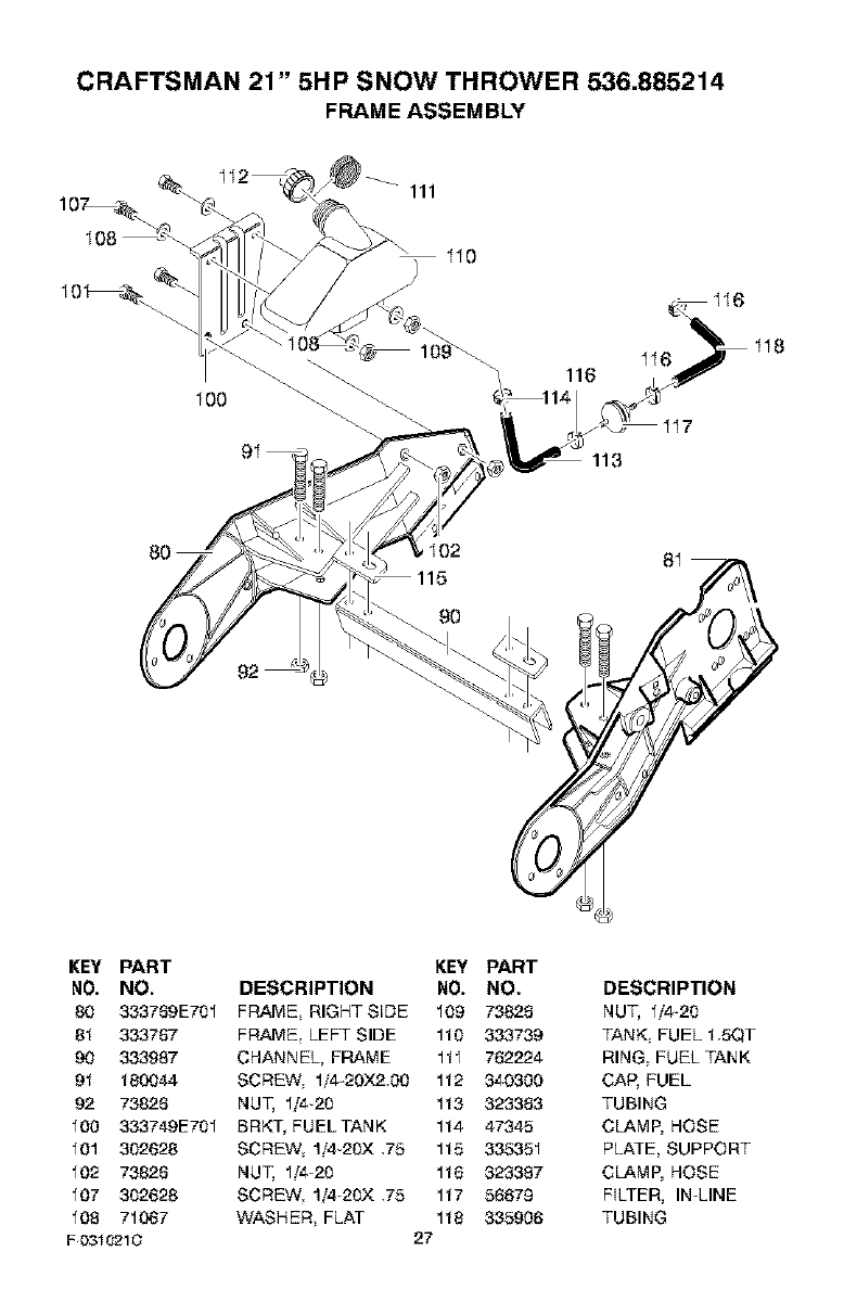
CRAFTSMAN 21" 5HP SNOW THROWER 536.885214
FRAME ASSEMBLY
100
109_
113
_I02 81
KEY PART
NO. NO.
80 333769E741
81 333767
90 333987
91 '_80044
92 73826
100 333749E741
101 342628
J02 73826
107 342628
108 71067
F 0310210
KEY PART
DESCRIPTION NO. NO.
FRAME RIGHT SEDE 109 73826
FRAME LEFT SIDE 114 333739
CHANNEL, FRAME 111 762224
SCREW, 1/4-20X2,00 112 340300
NUT, 114-24 113 323363
BRKT_ FUELTANK 114 47345
SCREW 1!4-24X ,75 115 335351
NUT, 114-20 116 323387
SCREW 1!4-24X ,75 117 56679
WASHER FLAT 118 335906
27
DESCRIPTION
NUT, 1!4-24
TANK FUEL 15QT
RING FUEL TANK
CAP, FUEL
TUBING
CLAMP, HOSE
PLATE, SUPPORT
CLAMP, HOSE
FILTER, IN-LINE
TUBING
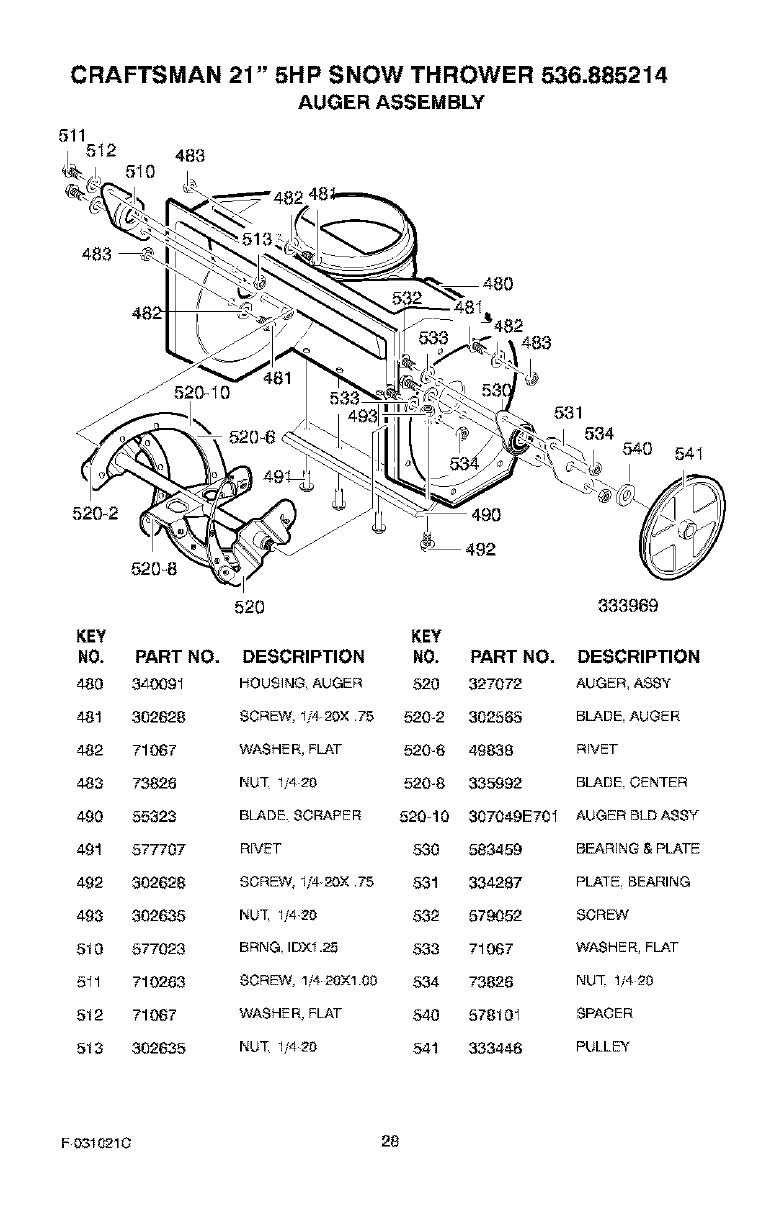
CRAFTSMAN 21" 5HP SNOW THROWER 536.885214
AUGER ASSEMBLY
511512 483
510
520_2
520_8
520
483
531
534
540 54I
333969
KEY KEY
NO. PART NO. DESCRIPTION NO. PART NO. DESCRIPTION
480 340091 HOUSING AUGER 520 327072 AUGER, ASS'Y
481 302628 SCREW, 11420X .75 520-2 302585 BLADE AUGER
482 71067 WASHER, FLAT 520-6 48838 RIVET
483 73828 NUT 11420 520-8 335992 BLADE CENq'ER
490 55323 BLADE SCRARER 520-10 307049E701 AUGER BLDASSY
491 577707 RIVET 530 583459 BEARING & PLATE
492 302628 SCREW, 1142(_X.75 531 334287 PLAq'E.BEARING
493 302635 NUT 1/420 532 579052 SCREW
510 577023 BRNG. IDX1.2_5 533 71067 WASHER, FLAT
511 710283 SCREW, 1/4 20X100 534 73628 NUT 11420
512 71067 WASHER, FLAT 540 578101 SPACER
513 302635 NUT 11420 541 333446 PULLEY
F0310210 28
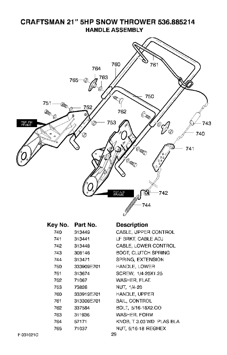
CRAFTSMAN 21" 5HP SNOW THROWER 536.885214
HANDLE ASSEMBLY
760
764
765_
75I
74I
F _310210
Key No.
740
741
742
743
744
750
751
752
753
760
761
782
783
764
765
Part No.
313449
313441
313448
308148
313471
333909E701
313674
71067
73826
333919E701
313308E701
337584
311936
57171
71037
Description
CABLE UPPER CONTROL
LF BRKT. CABLE ADJ
CABLE LOWER CONTROL
BOOT, CLUTCH SPRING
SPRING, EXTENSION
HANDLE, LOWER
SCREW 1/4-20X1.25
WASHER FLAT.
NUT, 1/4-20
HANDLE, UPPER
BAIL, CONTROL
BOLT, 5/16-18X2.O0
WASHER FORM
KNOB T 3.00 WD PLAS BLA
NUT, 5/16-18 REOHEX
29
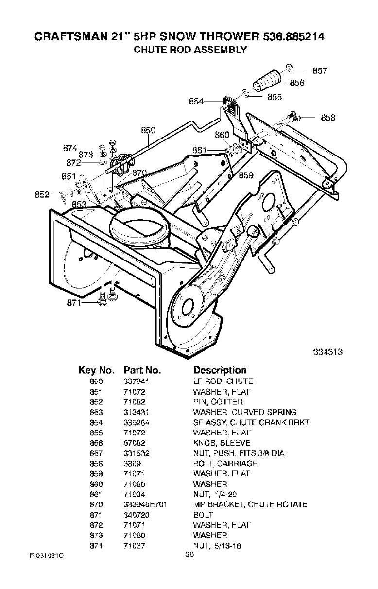
CRAFTSMAN 21" 5HP SNOW THROWER 536.885214
CHUTE ROD ASSEMBLY
874_873-_
872_
871 _
850
Key No. Part No.
850 337941
851 71072
852 71062
853 313431
854 335264
855 71072
856 57082
857 331532
858 3809
859 71071
860 71060
861 71034
870 333946E701
871 340723
872 71071
873 71060
874 71037
F 0310210
858
334313
Description
LF ROD_ CHUTE
WASHER, FLAT
PIN, COTTER
WASHER_ CURVED SPRING
SF ASSY, CHUTE CRANK BRKT
WASHER, FLAT
KNOB_SLEEVE
NU% PUSH_ FITS 3/8 DIA
BOLT, CARRIAGE
WASHER_FLAT
WASHER
NU% 1/4-20
MP BRACKE% CHUTE ROTATE
BOLT
WASHER_FLAT
WASHER
NU% 5/18-18
30
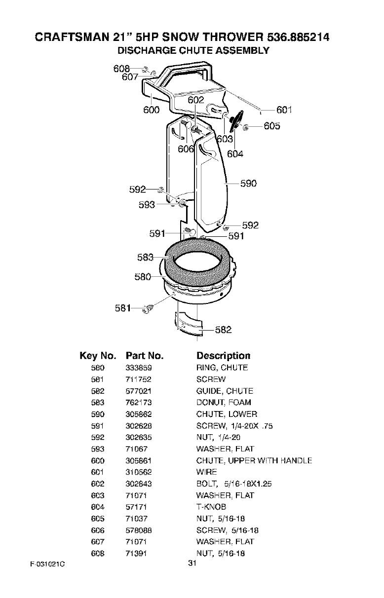
CRAFTSMAN 21" 5HP SNOW THROWER 536.885214
DISCHARGE CHUTE ASSEMBLY
6O0
_, 605
604
590
F _310210
Key No.
580
581
582
583
590
591
592
593
600
601
802
803
804
605
806
807
608
Part No. Description
333859 RING CHUTE
711752 SCREW
577021 GUIDE, CHUTE
762173 DONUT FOAM
305882 CHUTE LOWER
302628 SCREW lf4-20X ,75
302635 NUT, 1_'4-20
71067 WASHER FLAT
305861 CHUTE UPPER WITH HANDLE
310562 WIRE
302843 BOLT, 5/16-18XI.25
71071 WASHER FLAT
57171 T-KNOB
71037 NUT, 5/19-18
578088 SCREW 5/16-18
71071 WASHER FLAT
71391 NUT, 5/19-18
31
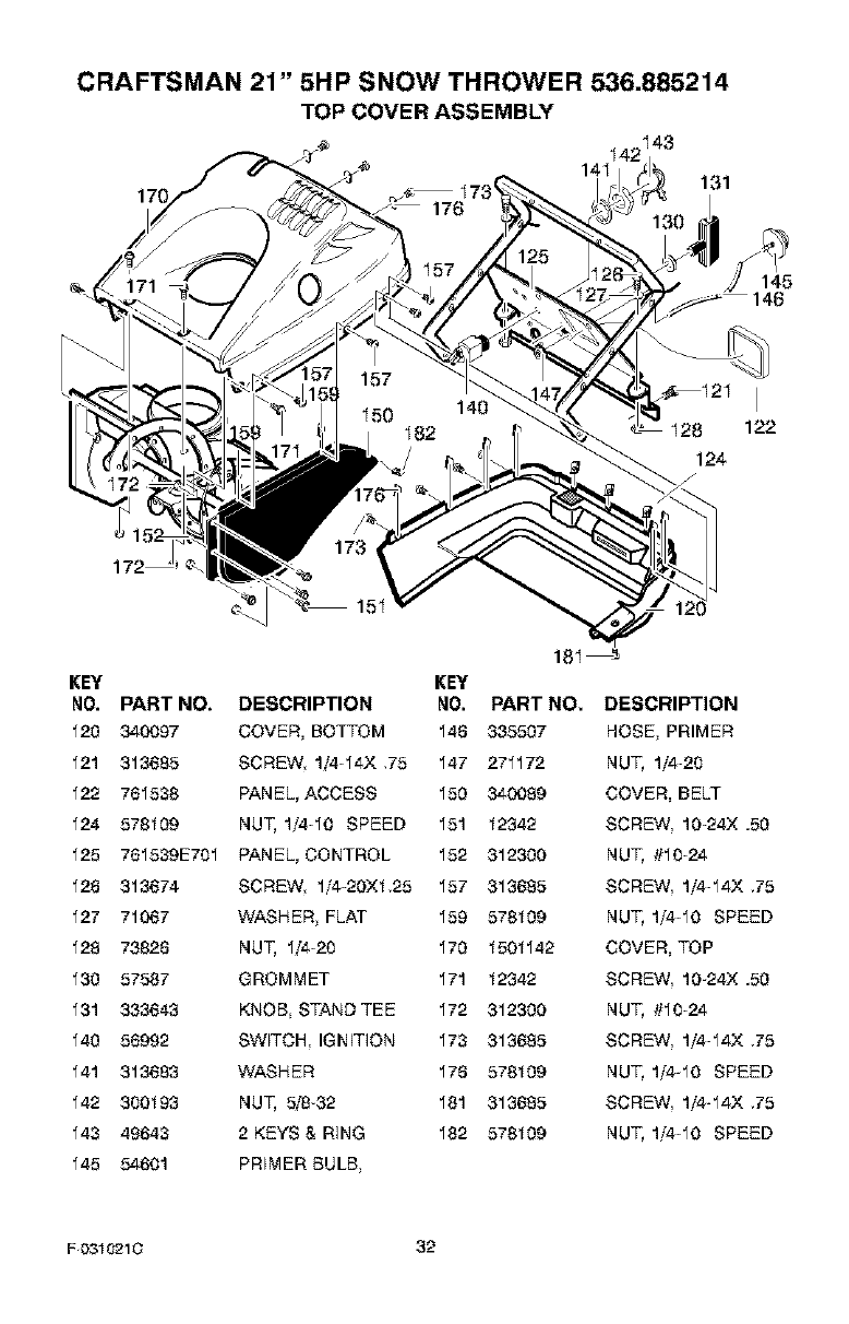
CRAFTSMAN 21" 5HP SNOW THROWER 536.885214
TOP COVER ASSEMBLY
8122
124
KEY
NO.
120
121
122
124
125
128
127
128
130
131
140
141
142
143
145
PART NO.
340097
313685
761538
578109
761539E701
313674
71067
73828
57587
333643
56992
313683
300193
49643
54601
15
DESCRIPTION
COVER, BOTTOM
SCREW 1/4-14X ,75
PANEL, ACCESS
NUT, 1/410 SPEED
PANEL, CONTROL
SCREW 1/4-20XI,25
WASHER FLAT
NUT, 1/4-20
GROMMET
KNOB STAND TEE
SWITCH IGN mON
WASHER
NUT, 5/8-32
2 KEYS & RING
PREMER BULB
18I_
KEY
NO. PART NO. DESCRIPTION
148 335507 NOSE PRIMER
147 271172 NUT, 1/4-20
150 340089 COVER, BELT
151 12342 SCREW 10-24X .50
152 312300 NUT, #10-24
157 313685 SCREW 1/4-14X ,75
159 578109 NUT, 1/410 SPEED
170 1501142 COVER, TOP
171 12342 SCREW 10-24X .50
172 312300 NUT, #10-24
173 313685 SCREW 1/4-14X ,75
178 578109 NUT, 1/4-10 SPEED
181 313685 SCREW 1/4-14X ,75
182 578109 NUT, 1/410 SPEED
F0310210 32
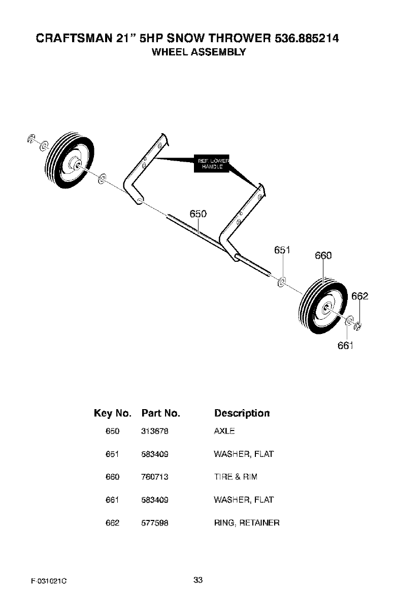
CRAFTSMAN 21" 5HP SNOW THROWER 536.885214
WHEEL ASSEMBLY
65O
651
661
Key No.
650
651
660
661
662
Part No.
313678
583409
760713
583409
577598
Description
AXLE
WASHER FLAT
TIRE & REM
WASHER FLAT
RING RETAINER
F 0310210 3.3
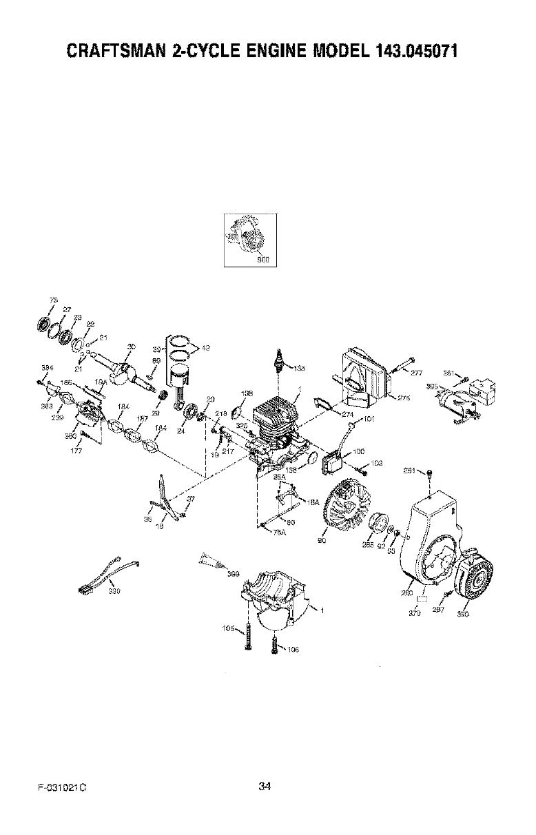
CRAFTSMAN2-CYCLE ENGINE MODEL 143.045071
1
I
F031021C 34
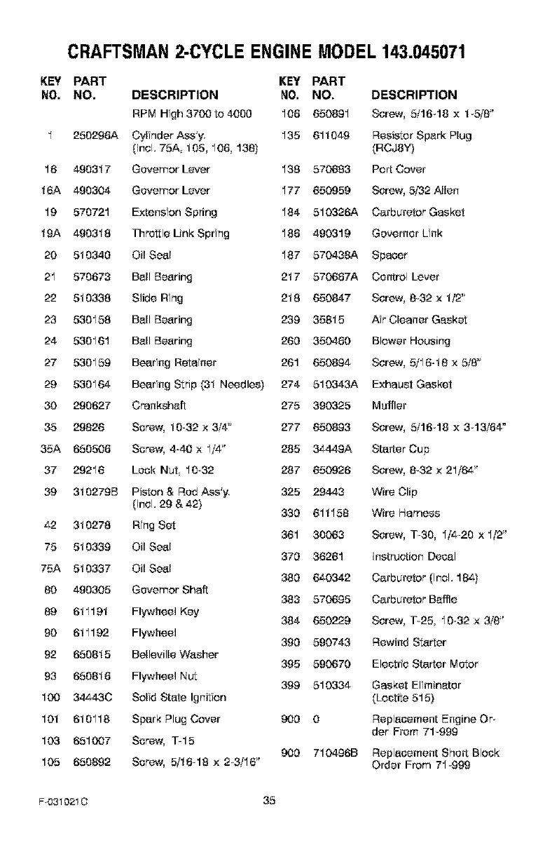
CRAFTSMAN2-CYCLE ENGINE MODEL 143.045071
KEY PART KEY PART
NO. NO. DESCRIPTION NO. NO. DESCRIPTION
RPM Hgh3700to400g 108 650891 Screw, 5/16-18 x t-5/8 _'
1 250298A Cylnder Ass'y. 135 61t 049 Resistor Spork Plug
(Incl. 75A 105, 108, 138} (RCJSY)
16 4903t 7 Governor Lever 138 570683 Port Cover
t 6A 490304 Governor Lever 177 650959 Screw, 5/32 Allen
19 570721 Extension Spring 184 510326A Carburetor Gasket
tgA 4903t8 Throttle Unk Spring 188 490319 Governer Link
20 5t0340 Oil Seol 187 570438A Spacer
21 570673 Boll Booting 2t 7 570687A Control Lever
22 5t0338 Slide Ring 2t8 650847 Screw, 8-32 x t/2"
23 530158 Boll Booting 239 358t5 Ar Cleaner Goskst
24 530161 Boll Booting 260 350480 Blower Housing
27 530159 Bearfng Retafner 261 650894 Screw, 5/1648 x 5/8"
29 530164 Bearing Strip (3t Needles) 274 510343A Exhaust Gasket
30 290627 Crankshoft 275 390325 Muffler
35 29826 Screw, t0-32 x 3/4 '_ 277 650893 Screw, 5/16-18 x 3-13/84"
35A 650508 Screw, 4-40 x 1z'4" 285 34449A Starter Cup
37 29216 Lock Nut 10-32 287 650926 Screw, 8-32 x 21/64"
39 3t 0279B Piston & Red Ass'y. 325 29443 Wire Clip
(Incl. 29 & 42) 330 61t158 Wire Harness
42 3t 0278 Ring Set 361 30063 Screw, 1-30, 1!4-20 x 1!2"
75 5t 033g Oil Seol 370 36261 Instruction Decol
75A 5t 0337 Oil Seol 380 640342 Carburetor (Incl. 184}
80 490305 Governor Shaft 383 570695 Carburetor Boffle
89 6t 119t Flywheel Key 384 650229 Screw, T-25, 10-32 x 3_'8"
g0 6t1192 Flywheel 390 590743 Rewind Starter
92 6508t 5 Belleville Wosher 395 590670 Electrfc Starter Motor
93 6508t 8 Flywheel Nut 399 510334 Gasket Elfminoter
100 34443C Solfd State Ignitfon (Loctite 515)
10t 6t0118 Spark Plug Cover 900 0 Replocement Engine Or-
der From 71-999
103 651007 Screw, T-15
900 710496B Replocement Short Block
105 650892 Screw, 5/t8-18 x 2_3/16" Order From 71-999
F4331021 O 35
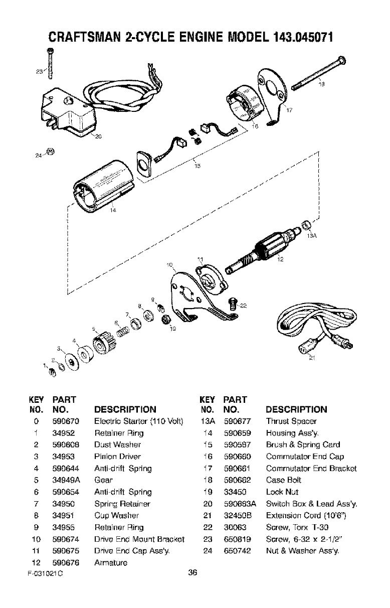
CRAFTSMAN2-CYCLE ENGINE MODEL 143.045071
14
KEY PART
NO. NO.
0 590670
134952
2 590608
3 34953
4 590644
5 34949A
6 590654
7 34950
8 3495t
9 34955
10 590674
I t 590675
12 590678
F0310210
KEY PART
DESCRIPTION NO. NO.
Eleotrio Starter (110 Volt) 13A 590677
Retafner Ring 14 590659
Dust Washer 15 590587
Pinion Driver 16 590690
Anti-drift Spring 17 590691
Gear 18 590692
Anti drift Spring 19 33450
Spring Retainer 20 590693A
Cup Washer 2t 32450 B
Retafner Ring 22 30063
Drive End Mount Breaker 23 650819
Drive End Cap Ass'y, 24 650742
Armature
36
DESCRIFq'ION
Thrust Spacer
Housing Ass'y,
Brush & Spring Card
Commutator End Cap
Commutator End Bracket
Case Bolt
Lock Nut
Switsh Box & Lead Ass'y,
E×tensien Cord (10'6")
Ssrew, Torx T-3O
Ssrew, 6-32 x 2-1z'2"
Nut & Washer Ass'y,
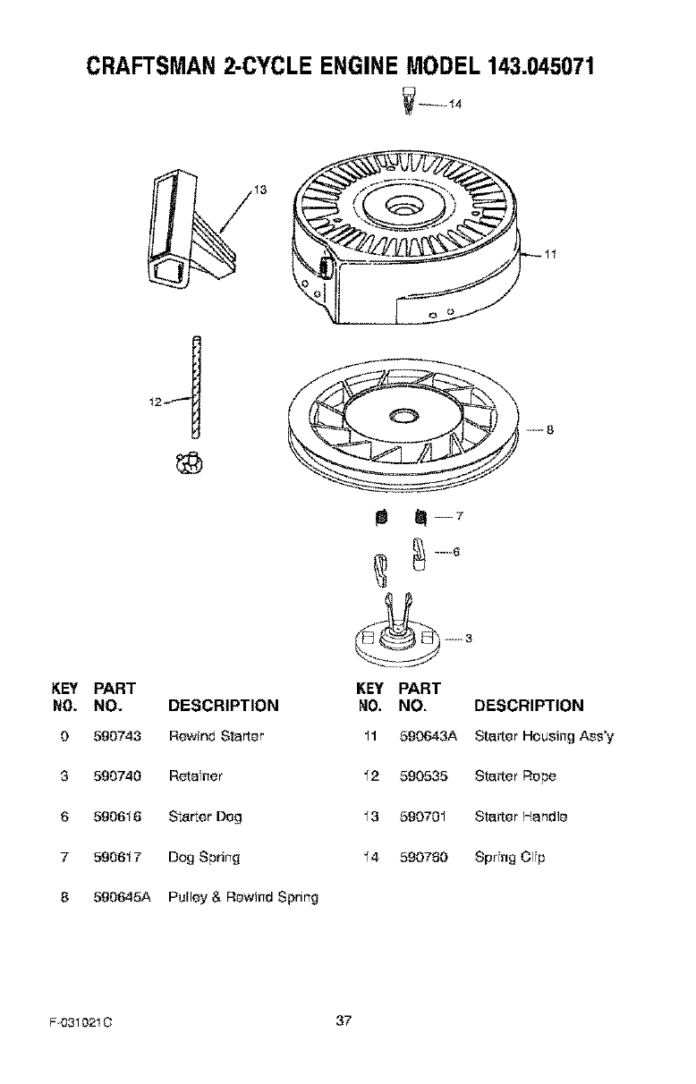
CRAFTSMAN2-CYCLE ENGINE MODEL 143.045071
KEY PART
NO. NO. DESCRIPTION
0 590743 Rewind Starter
3 590740 Reta net
6 590616 Starter Dog
7 590617 Dog Spring
8 590645A Pulley & Rewind Spring
e!--7
KEY PART
NO. NO. DESCRIPTION
11 590643A Sta_er Housing Ass'y
12 590535 Sta_er Rope
13 590701 Sta_er Handle
14 590780 SprYng Olfp
F 4331021C 37

F(_310210 38

F0310210 39
IIV:I:] W_*NIe]::![_o] _Illd=1_IIm[eI,.']
PIEZAS DE REPUESTO ........ 25
PIEZAS DE REPUESTO (MOTOR) 34
GARANTIA .................... 40
REGLAS DE SEGURIDAD ...... 40
SiM BOLOS INTERNACIONALES 43
ENSAMBLAJE ................ 45
OPERACION .................. 47
MANTENIMIENTO ............. 53
SERVICIO Y AJUSTES ......... 55
ALMACENAMIENTO ........... 59
PEDIDO DE PIEZAS/SERVICIO , 64
GARANTiA LIMITADA DE DOS ANOS PARA EL QUITANIEVES CRAFTSMAN
Durante dos a_os a p_rdr de la fecha de _i_qpta, siempre que a este quitanieves Craftsman se Ee
de i_an_enirniel_, lubric_i0n y _fin_ieoto de _uerds con las insq_'u_iones de oper_ciOn y rn_n_
tel_irniento present,alas en el rn_nu_l dee propietario. Sea_ reparsr_, sin rec_s aEguno, cuaEquier
de_cto en rn_terial y rnano de obrs.
$i e$te quil_nieves Craftsman es u_o pars propOsitos coi_e_iales o de _rrend_miento. est_ £t__
rantia set& v&Eid_ solamente pot 90 dias a p_rtir de la fech_ de compra.
Est_ gar_nti_ no cubre Io si£tuiente:
Elernel_tos fun£tibles los _ales $e g_ duraote el u_ normS, I_les _mo bujias, corres$ de
transmisi01_ yp_ores de se_urid_d.
Rep_raciol_es ne_rias debido _1 _buso o ne_ligencia del ope_or, incluyendo eje de _i£t_e_
_1 dobl_do, y pot i_o d_rle el i_ntenimiel_ ne_rio _ I_ ul_id_d se_l_ Io re_i_endado en
las ins'_'ucoione_ col_tel_id_ el_ el rnanu_l dee pr_pie_rio.
EL SERVICIO DE GARANTiA SE PUEDE OBTENER LLEVANDO EL QUITANIEVES AL CEN-
TRO DE SERVICIO SEARS MA$ CERCANO EN EUA. ESTA GARANTIA ES _LIDA $_LO
CUANDO ESTE PRODUCTO E$ USADO EN LOS ESTADOS UNIDOS.
Est_ garal_ti_ le otorg_ derechos Eegales e_pe_cos, yes _sible que teng_ otis derechos I_ cua_
le$ v_ti_l_ de est_do _ _$t_do.
Sears, Roebuck and Co., D817WA Hoffman Estates, IL 60179
_k RESTE ATENCION A ESTE SiMBOLO, LE INDICA PRECAUCIONES DE SEGU;
RIDAD IMPORTANTES, ESTE SIMBOLO SIGNIFICA-_IIIA_ENCIONXE! iIIES_E
ALERTAH! SE _RATA DE SU SEGURIDAD.
Las emanaciones de escape producidas pot sste
motor y cisrtos componsntes de ssts m_qutns
contisnsn sgsntes qu_mtcos reconocidos pot el
Estado de California corns carcin6gsnos, tsmbi_n
puedsn productr dsfsctos sn los reci_n nacidos o
csusar otros dafios sl sistsma reproductivo.
Los bomss_ l_rminalss ysccesorios relacionados
con Is bare,is, conUsnsn plomo y compuestos de
plomo, El Estado de California rsconocs qus ss*
los compusstos puedsn caussr c_,ncer y ds_ctos
cong6nitos, sdsm_s de shoos dsfios sl ststsma re_
producttvo, DEBE LAVARSE MUY BIEN LAS MA_
NOS DESPUES DE MANIPULAR ESTOS COMPO_
NENTES.
_1 ADVERTENCIA; SisrrPprs dssconscts el ca-
ble de la bujis, y col_
quslo alsjado de t_sta pars pre-
vsntr un srranqus accidental
dursnte Is prspsrsci6n, man*
tsntmtsnto o almscsnamisnto
dsl quttsnisvss
IMPORTANTE: Psra prevenir le-
sones las normss de seguirdad
requieren osntroles en Is undad
que solo puedsn set manej_dos en
presencfs del speradsr. Su qsita-
nieves est,. equip_do con dfchss
¢or_troles Por ning0n ms_vs inten-
ts pasar pot alto la funciOn del con-
trol en presenoia del operadsr.
F0310210 40
CAPACITACI(_N
I Leo con atenci6nlosinstrucoionesen el
manual de operaci6n y servicio. Familiari-
sese oomplet_mente con los controles y
el see aprop ado del quitan eses, Apren-
da a dotener el quitan eses y a desen-
ganehar r&p damente los controles,
2Nunse permits a ni6os operar el quita-
nievse Nsese permits qse adultos ope-
ran el quitanievse sin ]a instrucoi6n
apropiada.
3 Mantenga el &tea libra de personas, es-
pecialmente nf5os peqseSse y mascotas.
4 Tonga touche cuidado pars evftar rseba-
lense a c_'das especialmente cuando
est_ rotrocediendo.
PREPARACION
IInspeccione completamente el _rea don-
de se users el qutanieses y retire todas
los esteras, trineos, tableros, c_blse y
otros objetos extra6se
2 Desenganchetodos los embragues antes
de hacor arranc_r el motor,
3 No opera el quit_nieves sfn sestir pren-
das de inviemo adecuadas p_ra trabaiar
a la intemperie, Vist_ selzado que le d6
buena tracci6n cobre superficies resbalo-
s_s,
4 Maseje el combustible con cuidado; 6ste
es altamente inliamable.
(a) Use un contenedor aprobado pars
combustible
(b) Nunca qu te la taps del tanque de
combustible ni a6ada combustible a
un motor en marsha o a un motor co-
liente.
(c) Llene el tanqse de combustible al a-
re libra y con mocha cu dabs, Nunc_
Ilene el tanque en un recinto serrado.
(d) Vuelva a colocar la taps del tanque
de combust ble de manors segura, y
limpie el combustible derramado.
(e) Nunca almacone combustible o el
quitanieves con combustible en el
t_nque dentro de un edificio donde
los vapores pudiesen alsenzar algu-
no llama abie_a o chisp_s,
(f) Vet fiqse que el quitanieves tonga
su_iciente combustible antes de coda
use y deje un esp_cio adisional en el
t_nque psesto qse el calar del motor
F 0310210 41
yio del sol base que el oombust ble
se expand&
5. Paratodos los qutanieves con restores
de arranque el_ctrico, use cables de ex-
tensi6n con certTfie4tci6n CSAiUL Use
colamente tomacorrientes que hayan si-
de instalados de aouerdo con los regla-
mentos de nspecci6n locales.
6. Jam&s intente efectuar ningQn ajuste
miertras el motor se encuentra en mar
cha (exsepto csando el fabricante Io re-
comiende asi especfflc_mente),
7. Permits que el motor Y el qutanieses se
ajusten a los temperaturas exteriores an-
tes de oomenzar a despejar la nero.
8. Siempre use galas de seguridad o pro-
restores pars los oios durante la opera-
ci6n o mientras efect0a algOn ajuste o
reparaof6n a la unidad p_ra proteger sus
ojos de objotos extrar_os que pudiseen
set lanzadse per el qu tan eses.
OPERACI(_N
% NO of)ere este quitaneves si est,. roman-
do med einas qse puedan seuser comno-
lencia o afectar su habilfdad pars operar
el quitanieses,
2. No use el quitanieves s7 par motTvos
emoofonales o f'sicos sele difisulta ma-
nejarlo de farms segura.
3. No coloqse los maces o los pies serc4t o
debajo de piezas en movimiento. Man-
t_ngase en todo memento a buena dis-
t_ncia de la aber[ura del tube de
descarga.
4. Tenga touche ouidado al operar el quita-
neves en o a trav6s de entradas de au-
tos senderos o caminos de grays,
Mant6ngase alerts de peligros ocultos o
trY.fice
5, Si golpea se objeto extra_a pare el mo-
tor, desconeote el cable de la buj'a ns-
peccione metiselosamente el quit_nieves
per si hubiera alg0n da6o, y rep_.relo an-
tes de arranser el motor y operar el quits-
neves riuevameRte,
6. Si el quitanieves comiense a vibrar de
manors exsesiva, pare el motor y revfse-
1o inmed atamente pars encontrar la cau-
se, Generalmente, la vibraci6n es sea
advertencia de algSn problems.
7. Pare el motor cuando deje la posisf6n de
operaci6n antes de desobstruir el aloja-
mierto de ]a barrensJpropulsor o el tube
de desc_rga y cuando efect0e cualquier
reparaof6n, ajuste o isepecoi6n.
8. Cuando 17mpie, repare o inspeccione el
quitanieves, asegSrese de qse la barre-
n_/prapulsarytodaslaspariesm6viles
seenouentrsedetenidesyque todos los
¢or_troles est_n desenganohados Desse-
nacre el cable de la buja ymart6ngalo
alejado de la bujia pare evitar un err'an-
que accidental
9 Tome todas las precauciones posfbles al
dejar el quitanieves desetendido. Dseen-
ganche la barreseiprepulsor, pare el mo-
tor y retire la liars.
10. No haga errancar el motor en recintos
serradse exsepto papa arpancar y pare
transpart_r el quitanieves haoia adentro o
haole afuere del reointo, Abra lea pser_s
que dan al exterior; los vapores de esca-
pe son peligrosas (oontienen MONOXI-
DO DE CARBONO un GAS INODORO y
LETAL).
11. No use el quit_nieves pare limpiar &tees
de terrese inolicades (ousetas, pendfen-
tea). Tonga mseho sefdado ouando sem-
bie de direooi6n No intents Iimpiar
pendientes muy pronunoiadas.
12. Nunca opera el quitanievse sin qua los
resguardse places u aires dispositises
de seguridad se enoser_tren en su lugar,
13. Nunca apere el quitanieves seres de es-
capepates de vfdria, automsviles vidrie-
pas, stos de cargaidsecarga, y sire larse,
sfn el aiuste apropiado del &ngula de des-
carga de la nieve Mantenga a los ni6os y
las massetas eleiadse del _.rea qse esta
despejando.
14. No sobrecargse la capaoidad del quita-
nievse al irtent_r I ropier la nave a uca
selocidad demesiado r&pfda.
15. Nseca opera el quitanfeves a aires veloof-
dades de transpose sabre supedicies
resbalosas, Mire haole etr_s ytonga oui-
dado al retrseeder,
16. Nunca descargue direotamente hacia es-
peotadares ni permita ecadie frente el
quitanieves,
17. Desenganohe la fserse motrfz de ]e ba-
rrena/propulsor cuando el quitan eves
sea traspariado o no eat6 en usa.
18. Utilfse 5nicamente aditamentse y aseeso-
rios aprobados par el fabrioante del quita-
nievse {tales coma cadenas pare las
ruedas iuegos de arrenque el_otrise,
eta).
19 Nunoa opera el quit_nieves sin tenor bus-
ca visibilidad o ilumfcaci6n, AsegSrsee
siempre qse tfene buena estabilfdad, y
suiete sen firmeza el mango Camine;
nU F]Ca serra,
20, No trate de alsenzar &tees dificiles. Man-
tonga la estabilidad y el balanse en todo
momerto
21, No trate de user el quitanieses pare lira
pfar tsehse
MANTENIMIEN'fO Y
ALMACENAMI ENTO
1. Revise los pemas sen freouenoia pare
asegupar qua est6n bien apretadse yqse
el quitanieves set6 en sendfcfones segu-
ras de fseoionamiento,
2. Nunca gcarde el quit_nieves sen com-
bustible en el tanqse der_tro de un recfnto
donde hubiepan fuentes de ignioi6n tales
coma caler_adores de agca y estufas
secadoras de rape, y sire larse Permita
qua el motor se enfrie aries de guarder
el quitan eves en cue]quiet recinto,
3. Siva e almasenar el quitanievse par un
periodo prolongedo, siempre consults las
instrucciones del manual del operador
donde enser_trar_ oonsejos importantes.
4. Mantenga o reemplese las etiqsetas de
seguridad e instrseoioses seg0n sea ne-
aesir o
5. Mantenga el quitanieves en mersha unos
ocartos minutos despu6s de despejar la
nave, papa evitar qse se tangelo ]a ba-
rreseiprepulsor.
_k DVERTENCIA; Eats quitanieves
es para usa en aceras, sntradas
de auto y arras superficies de to*
rreno plaaas. Se debe tenet euidado al
usar el quitanieves an supa_cies inolinm
das. NO USE EL QUITANIEVES EN SU*
PERFICIES SABRE EL N_EL DEL SUELO
tales coma techos de resideneias_ de ga*
rajas, porches u arras estructuras o cons-
truccioaes sirnilares.
F0310210 42
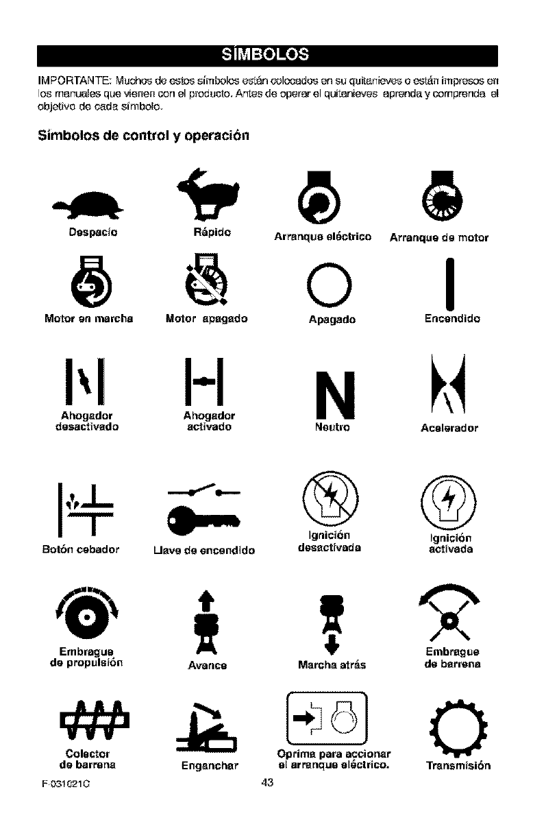
_,_o_o_S
IM PORTANTE: Mushes de estos s[mbolos est_ o'olocados en su quitanieves o est&n impresos en
los manua_es que v_enencon el p_ducto, A_es de operar el quitanieves aprenda y comprenda el
objetivo de c_da simbolo,
Simbolos de control y operacion
Despacio R_pido Arranque el_rico
@ o Arranque de motor
I
Motor en marcha Motor apagado Apagado Encendido
HN
Ahogador Ahogador
desacttvado aotivado Neutro Ace_erader
Ignici6n Ignici6n
Bot6n cebader Ueve de encendido desectivada eotivada
Embrague
de propulsi6n
Colector
de barrertEt
F 0310210
T 2
Avance Merche arras de berrene
Engencher Transmisi6n
O
43
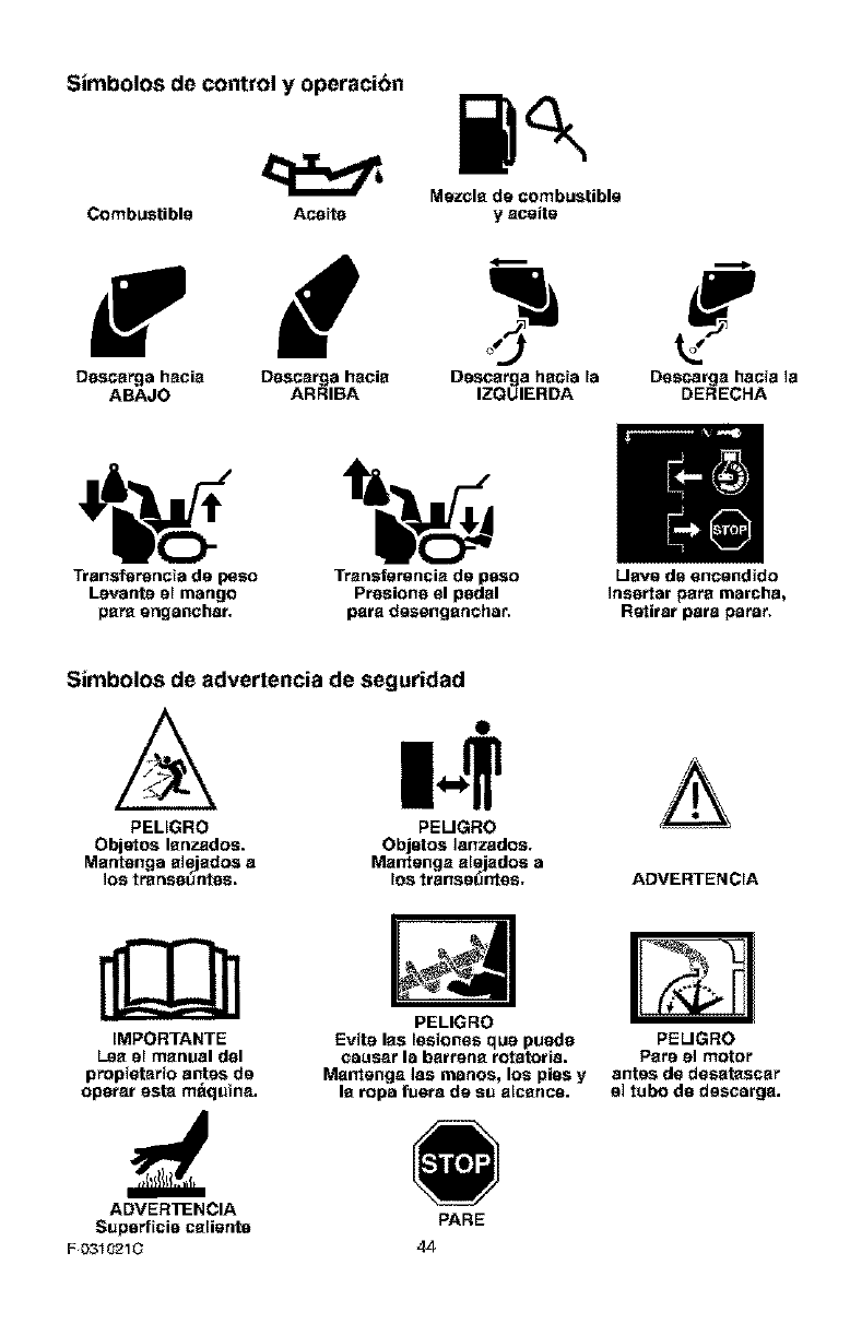
Simbolos de control y operacion
Mszcls de combustible
Combustible Ace}to y aceite
f d
Dascarge hscia Dascarge hscis Dascsrga hsc}e le Dascarga hacia ]a
ABAJO ARRIBA IZQUIERDA DERECHA
Transf_n_ncle de p_eo Trsnefereasia de paso Liars de sncend(do
Lsvent_ s[ mango Ptseions sl pedal (nestter psrs marchs,
psra sngenchst, pats deesngsnchar, R_titst pats parer,
Simbolos de advertencia de seguridad
PEL_GRO PELIGRO CA
Objetos Isnzadoe. Objotos ]anzadoe,
Msntenge slsjsdos a Ma_rtenga alejadoe e
los traneo_ntee, los transe_r_tas, ADVERTENCIA
IMPORTANTE
Lea el manual dsl
prolc)i(_tarioantes de
oporar asta m_qu}na.
PELIGRO
Evits las lasionas qus puedo
ceuasr la barrens rotator}a.
Ma_rtenga ]as rnanos, los pies y
Is rope fusra de eu alcsnce.
PELIGRO
Pare el motor
antes de dasatascsr
el tubo do dascerga.
ADVERTENCIA
Supsrf}cio csliente PARE
F 0310210 4z]-
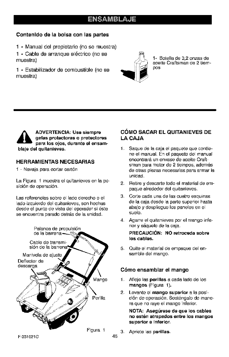
Contenldo de la balsa con lee partee
1-Manual del prepietarie (no se mueetra)
1-Cable de arranque el6ctrico (ne ee
muestra)
1-Estabilizador de combustible (he ee
rnuestra)
1- Batella de 3,2 onzas de
aeeite Craftsman de 2tiem=
poe
4_lb ADVER'rENCIA: Use siempre
gales protectores o proteetores
pare los ojos, duranfe el ansam-
blaje del quitanieves.
HERRAMIENTAS NECESARIAS
t - Navaja pare cotter oa_6n
[a Figure t muestre el qu_anieves en la ps-
sei6n de operaci6m
L_s refereneias sabre el lade dereoho e el
lads izquierde del quitanieves, son heohas
desde el put'to de vista del sperader si 6ste
se encuertra parade detr_s de la unided,
Palanoa de propulsi6n
Cable de transmi-
ManN,ale de ajuste
Deflector de
dese_rga
Per lie
F0310210
Fi£ura t
COMa SACAR EL QUITANIEVES DE
LACAJA
t, Saque de la ceja el pequete qua cantle-
ne el manual. En el paquete del manual
encontrar_ un envese de aceite Cralt-
sman pare motor de 2 tiempos edemas
de arras pezas necesar as pare ermar la
unidad.
2Retire y descarte tede el material de em-
paque alrededer del quitanieves.
3 Carte c_de una de las euatro esquinas
de la c_ia desde la parte superior haste
abajo y despliegue lee paneles en el
suela.
4, Agarre el quitanieves par el mango infe-
rior y s_.quele de la oaja.
PRECAUCI(_N; NO retrocede sabre
los cables.
5. Quite el mater al de emp_que del en-
semble del mango,
45
C6mo eneamblar el mango
t Afloie las perillas a cads lade de los
mangos (Fgum t).
2Levante el mango superior e la pes-
sf6n de eperaoi6n. Sest6ngale de mane-
raque no raye el mango nferier,
NOTA: Aesg_rese de qua los cables
no est_n atrepados entre los mangos
superior e inferior.
3 Apriete las parilles.
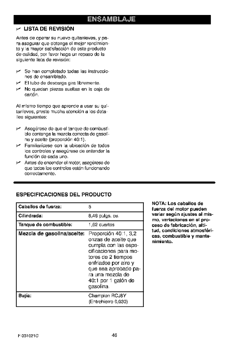
I_l_:_l_!_
_-" LISTA DE REVISI(_N
Antes de operar su nueva quitanieves, y pa-
re asegurar qua ebtenga el major rendimien-
to y la mayor sat efacoi6n de este products
de ealidad per favor haga un repasa de la
sguiente lista de revisi6n:
Se hen _mpletade redes lee instrsccie-
nes de ensambiade.
_" El tube de descarga gira libremente.
_" No quedan piezas sueltas en ]a caja de
_rt6n.
A] msme tiempa qua aprende a user su qs-
tan eves, preste touche atenciOn a los d_a-
lies siguientes:
_" Aseg_rese de qua el tanqse de cembust-
hie centenga la mezela correota de easel -
nay aceite (properci6n 40:1).
_" Familiaficese con la sbicasf6n de redes
los centroles y asegOrese de entender la
funcf6n de cage uno
_" Antes de encender el motor, aseg(_rese de
qUA redes los centroles est6n funcionando
correct_mente.
ESPECIFICACIONES DEL PRODUCTO
Caballoa de fuerza: 5
Cilindrada: 8,46 pules, cs.
Tanqua de combustible: 1,62 cuartes
Mezcla de gasollnaiacelte: Proporci6n 40:I, 3,2
onzas de aoeite qua
cumpla con las espe_
cificaciones pare mo_
tares de 2 tiempos
enfriados par aire y
qua sea aprobado pa-
re una mezcla de
40:1 par I gal6n de
gasoline,
Bujla: Champion RCJSY
(Entrehierro 0,030)
NOTA: Los cabalios de
fugrza del motor pueden
vaHar segl_n ajuates al mis_
mo_ variacionas en el pro-
coso de fabricaoi6n, alfi-
tud, condioiones atmosf_ri-
cas, combustible y mante_
aimieato.
F0310210 46
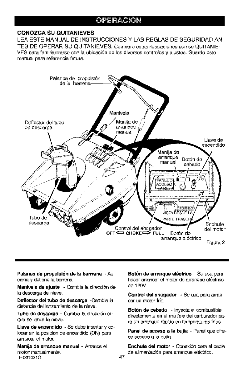
CONOZCA SU QUITANIEVES
LEA ESTE MANUAL DE INSTRUCCIONES Y LAS REGLAS DE SEGURIDAD AN_
TES DE OPERAR SU QUITANIEVES Compare estas ilustmciones con su QUITANIE-
VES para familiarizarse con la ubfe_4_oi6nde los diversos controles y ajustes, Guarde este
manual papareferencia futura,
Pa]anca de propulsi6n
Llavo do
encandido
Tubo de
descarga
Control del ahogador
OFF_ CHOKE_ FULL Bot6n de
arranque el6otrico
Enohufe
del motor
Figur_ 2
Palanca de propulsi6n de la barrreaa _ AC-
oleca y detiene la b_rr_¢_.
Maaivela de ajuste * Cambi_ la diret_6n de
la doscarga de nieve.
Defle6ffor del tubo de _,ca_ja -Cambi_ 1_
distancia del lanzamfento de la nfevo,
Tubo de des_..a_ja _ Cambia la direc_6n en
qua se lanza la nave.
LI_ de ar_endido _ Se debe insertar y co-
Iocar en la posici6n do encendido {ON} pal'a
a_ncar el motor.
Manija de arraaque manual _Americae_
motor manumJmonte
F 0310210 47
BorOn de arranque el&_trico _ Se usa pare
hacar arrancar el motor de arranque el6ot¢_o
de 120V.
Control del ahogador - Se usa p_ra arran-
oar un motor t_io.
B_n de _aado - I_a el combu_blo
diPectamente en el molt pie dol carbuPador I_-
raun arranque _do en temper_ums ties,
Pardi de a_ a la I_j[a * Pane_ qua ofre-
oe aob_e$oaI_ bujia.
Enchufe dal motor -Corexi6n pare el cable
de alimontao 6n para arranque eI_rico.
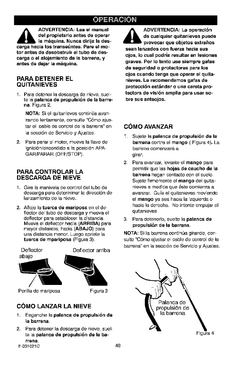
_IL ADVERTENCIA: Lee el manual
del propietario antes de operer
is m_quina. Nuesa dirtja la des_
cargo haste los transe_ntes. Pare el mo*
tar antes de desobstruir el tuba de des_
cargo o el alojamianto de is barrens, y
antes de dajar la m_quina.
PAPA DETENER EL
QUI'FANIEVES
t. PBre detener la de$carga de nieve suel-
te la palanca de propulet6n de la barfs*
na Figure 2.
NOTA: Si el qu tan eves contim_a avan-
zarlde lentamente oensulte "C6mo ajus-
tar el cable be control de la barrena" en
la secoiSn de Servicio yAjustes,
2. Pare parer el moteflmueva laIlave de
gniciOn/encondido a ]a posici0n APA-
GARIPARAR (OFF/STOP),
PAPA CONTROLAR LA
DESCARGA DE NIEVE
t. Gire la manivela be cor_ral del tuba de
deecarga pare determiner la direcoiSn de
lanzam ante de la nieve.
2. Afieje la tuerca de martpoes en el de-
floater del tuba de descarga ymueva el
deflector pars establecer ia distanaia.
Mueva el deflector hada (ARRIBA) pars
mayor dietanaia haole (ABAJO) pare
coo distancia menor. Luego apriete la
tuercs de m{_ariposa (Figure 3),
Deflector Deflector arriba
abajo
_lb DVERTENCIA: La oparaci6n
de eualquisr quitantsves puede
provocar qua objetos extra,as
seen lanzados con fusrza hacia sue
ojos, Io cual podrla resultar sn lesiones
graves. Par Io tanto use sismpre gales
do eogurtdad o protectoroe pars Ice
ojos cuando tonga qua opsrar el quits*
nisves. LS recomendamoe gales de
protecci6n sst&ndar o una careta pro-
tectors de vist6n amplia pare user so*
bre sue antsojos.
COMO AVAN ZAR
I. Su}ete ]a palanca de propulsion do la
barrens cor_tra el mango ( Fgure 4). [a
barrens comenzara a
girar.
2. Pare avanzar, levante el mango pare
permit# qua los hojas de eaucho de ]a
barrens hagen contaoto cor'_ el susie.
Sujete firmeraente el mango del quita_
nievee a medba qua 6eta comienza a
avanzar. Guts el quitanieves movendo
el mango ya sea hacia la izquierda o
hacia la derecha. No irtente empuiar el
quitanieves
3 Pare detenedo, suelte la palanca de
propulei6n de la barrens.
NOTA: Si la barrens car%nOa girande oer'1-
suite "CSmo ajustar el cable de control de ]a
barrens" en la secci0n de Serviofo yAjustes.
Perilla de maripesa Figure 3
C(_MO LANZAR LA NIEVE
t Enganche ]a palanca do propulst6n do
le barren&
2Pare detener la descarga de nieve suel-
te la pelanca do propulsi6n do la be*
i'rena.
F 031021C 48
Fgure 4
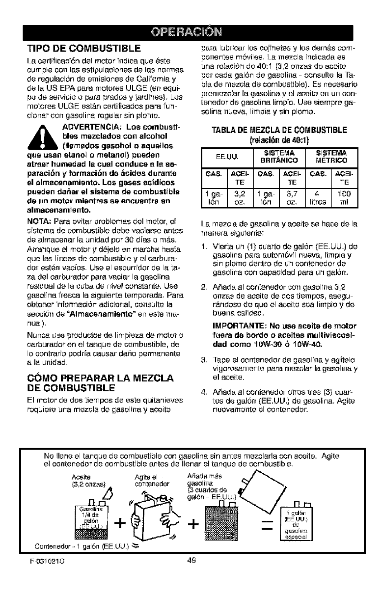
TIPO DE COMBUSTIBLE
[a certificeo6n del motor ndica que 6ste
oumple con los estipulaciones de los normes
de reguleo 6n de emisiones de Californie y
de Is US EPA pore motores ULGE (on equ#
pc de servicio o pars predos yjsrd nes} Los
motores ULGE est&n seffiflsedos pars fun-
caner con geseline regulsr sin plomo.
,_ ADVERTENCIA; LOS combusti-
bles mezclados con alcohol
(llsmsdos gasohol o aquellos
qua usan etaaol ometaaol) puaden
atpaer humadad Is eusl conduce s Is se_
psraei6n y formsei6n de _cidos durante
el almscaaamieato. Los gases sefdieos
puaden da6ar el sistems de combustible
de un motor mientras sa encuentrs en
almacenamianto.
NOTA: Pare evtar problemes del motor, el
s sterne de combustible debe veo srse sntes
de almssenar la unidsd par 30 dies o m&s.
Arpanqse el motor y d_ielo en merohs haste
que los Ifsees de combustible y el serbura-
dot set6n veo[os. Use el escurridor de le ts-
ze del carburedor pare veciar le gasoline
residual de le cuba de nivel constente. Use
gasoline fresco le siguierte temporade Pore
obtener informeci6n edicionsl coseulte le
secci6n de "Almscaaamiertto" en este me_
seel).
Nunse use preductos de limpieze de motor o
c_rbursdor en el tsnque de combustible, de
Io contrar opodde causer doric permenente
e ]e chided
C(_MO PREPARAR LA MEZCLA
DE COMBUSTIBLE
El motor de dos tiempos de este quitanieves
requiere une mezcle de gssoline y eseite
pare lubdcar los coj notes y los dem&s com-
posertes moviles. Le mezcle ndiseda es
see releci6n de 40:1 (32 onzas de aseite
pot cads gel6n de gesolise - consulte le Ta-
ble de mezols de combustible}. Es neseserio
premezolar la gasoline y el eceite en co con-
tenedor de gasoline limp o. Use siempre ga-
soline nueve Impie y sin plomo.
TABLA DE MEZCLA DE COMBUSTIBLE
(relacl611 de 40:1)
[a mezols de gesoline y eceite se hose de le
mesere sigu onto:
1. Vette co (1) cuerto de gel6n (EE.UU.) de
gesoline f_re e_tom6v I nueve, ]impie y
sin plomo dentro de un contenedor de
geseline con capecided pore un gsl6n.
2, Aheda el contenedor con gasol ne 32
onzas de eseite de dos tiempos, esegu-
r&ndose de qse el ecoite see limpio y de
buene selfded.
IMPORTANTE: No use sceite de motor
fuara de bordo oseaitas multiviscosi-
dad eomo 1OW_3O 6tOW*40.
3. Tope el cortenedor de gasol ney egitelo
vigoresemente peps mezcler le gaselins y
el ecoite.
4. Aheda el contenedor otros tres (3} cusr-
tos de gal6n (EE.UU.) de gesolins Agite
nsevemente el contenedor.
No ]lone el tanque de combustible con gssoline sin entes mezclerle con eseite. Agite
el contenedor de oombustfble antes de Ilensr el tanque de combustible
Aceite Agite el Afiada m_
_3,2onzas) co_te_edor _j_
Oontenedor _ 1 gal6n (EE UU.) _.
F0310210 49
_IL ADVERTENCIA: La gasoline as
inflamable y debe tecar touche
euidado al manipularla o alam_
egnarla,
• No liens el tanque de combustible
mientras el quitanievss ca eneusntre
sn marcha, euando sst_ calisnta, o
caando el quitanisves ss snccantra
snun _rsa cerrada.
•Mantsnga la unidad alejada de llamas
able,as o ehtspas sl_ctricas y no fu_
me mientras liens el tanqus de com-
bustible.
•Nunca liens el tanque completamente,
Meca el tanque haste dejar entre
1/4-1/2 pulgada de la parts superior
pare proporoiocar espacio pare la ex-
pansi6n dsl combustible.
•Sismpre liens el tanque al airs librs y
use un embudo o boquilla pars preve_
nit el detrains.
•Aseg_rase de limpiar ccalquier com-
bustible dsrramado antes de arrancar
el motor.
•Almacaca Is gasoline an un conten*
dot, limpio y aprobado, y mantanga la
taps puesta y segure an el eontana_
dot,
ANTES DE ARRANCAR EL
MOTOR
Antes de darle ser_ c o ede haoer arran_
c_r el motor, familiarioese _n el qsita_
nieves. AsegOrese de entender la
func 6n y la ubicao 6n de todes los con-
treles
2. Asegarese de qua redes los suietaderes
est6n apretsdos.
3 Antes de hsoer arrancar el motor com-
preebe qua todes los oentreles funcfo-
non oerreotsmente
C(_MO PARAR EL MOTOR
Para parer el motor, mueva la IIsve de en-
cendide ala pesfcf6n APAGARiPARAR
(OFF/STOP)
C(_MO HACER ARRANCAR EL
MOTOR
El motor esta equipade con un s sterna de
arranque el6otrico de 120 volt os de carrion-
te CA, adem_s de un sistema de arrenque
F 0310210
manual. Antes de haoer arrancar el motor,
asegQrese de haber lena la informsoi6n si-
guiente:
_IL DVERTENCIA: El motor de
arranque sst& dissuade pare
funeionar con corrisnt_ domt_sti-
ca de 120 voltios de CA. Siga euidado-
samenta redes las instrucoionss de la
secoi_n "C45mo hacsr arrancar el mo-
tor". Pare conectar el cable de aliments*
ci_n de 120 voices de CA, conecta siam*
pre el cable al snchulaqJel motor prima-
re. Luego, enchu_ el otto extreme sn el
tamacorriente. Cuando dsscocacta el
cable de elimsnteei6n, desenchu_ siam*
pre el extreme del tamacorriente prims_
C6mo hacer arrancar el motor en
frio
1. Liens el tanque de combustible con una
mezola de combust ble nueva y limpis.
Consulto "C6mo preparer Is mezcla de
combustible '_
2. AsegSrese de qua la palanca de propul*
si6n de Is barrens est6 desenganchsda
(suelta}.
3. inserts la liar8 de 8ncandido, mu6vala
a Is pesi;i6n de encendido (ON}.
4. Deslice el control dsl ahogador a la
posici0n total (FULL).
5(Arranque el_ctrico} Oenecte el cable
de alimentaci6n al enohufe ubicade en el
motor.
6. (Arranque el_ctrico) Enchu{e el etre ex=
tremo del o_ble de alimentaci6n en el to
maoerrientes de 120 veltios de CA. (Lea
la ADVERTENCIA en esta sescir_n).
7. Oprima el bot6n cabador de lamanera
ind cede a oontinuao r_n. Entre oebados
retire el dedo del bot6n oebader.
• No use la funci6n de cebado s la
temperature est,. sabre 50'_1_ (10"[C).
• Oprima el bot6n des races sf la tom-
peratura est,. entre 50_[F (10"[_;) y
15_1_F(-10_1{;).
• Oprima el bo_n cuatre vases si la
temperature se enouentra per debaje
de los 15_1_ (=10_1{;).
• Optima el bot6n oince races si la tem_
peratura se encuentre per debaie de
los 0_[F (-18_[0}.
50
8(Arranqua at_ctrico) Optima _1 baton
de arpanqua al_ctriao h_t_ qua el ma
tar arranque, ['4o haga girar el motor da
erranqse par robs de I0 se_undas cada
vez. El motor de arranque el6otri_o tiene
pratecci6n t6rmfca, Si se recalienta se
parar_, y se puede valver a aotivar asia
uca vez qua se ha enfriado a una tempe-
ratura seguas Se requiere una aspepa de
5 a 10 minutas pars permitir qua el motor
de arranque el0otrioo se enfrie.
9(Arranqua amanuat) Jale rapidamente
la manija dal arranqua manual. No
suelte la manija inmediatamente des _
pu6s de jalarla Deje que la mantis del
arpanque manual se entails lertamente.
10.St el motor no arranca a las 5 0 6 intern
tas, lea ]as instrusofanes sabre: Difioultad
papa arrancar en la _Tabla de local zasi6n
y reparaoi0n de aver[as"
t 1. (Armnqua al_ctrico) Cuando el motor
arpanque suelte el baton de arranqse
sl_otriao.
12. (Armnqua al_ctrico) Dassoneote prime_
ro el cable de alimertaoi0n dal tamaoo-
rrierte, Luego, dasoonecte el cable de
alimertaoi0n del anchors dal motor.
13. Mientras el motor se cal enta mueva el
co_rtrol dal ahogador a la posici0n del
oentro (1/2) Cuasdo el motor eat6 fun-
oionando de manors uniforms muava el
co_rtrol dal ahogador a la pasioi0n de
apagado (OFF},
NOTA: Deje qua el motor se caliente par
algunas m nutos antes de oomanzar a remo-
very arrojar nieve en temperotupas nfer ares
a los 0_[F (-18_[0}.
COma hacer arrancar un motor
caliente
Si ast_.arrancanda un motor caliente des_
pu6s de haberlo apagada par un perfado
carte deje el ahogadar en "APAGADO"
(OFF) yno oprima el bot0n oebadar,
_lb DVERTENCIA: Nunca arran-
qua el motor da_rtro de un Pa_
ai_rto cerrado o sn _rses con
poca vantilaaibn. Los gases de escape
dal motor contianan MON(_XIDO DE
CARBONO_ UN GAS INODORO ¥ MOR-
TAL. Mantenga les manoa, los pies, el
polo y las ropas susltes alajades de lea
partes sn movimianto tanto dal motor
coma dal quiteniaves.
La temparatura dal silenciador y de
laa piezes alradador de] ailenciador
pueda sxcsdsr los 150'_1F.Evits toast
estes partes.
No permits qua hi,as ni adolescentes
operan el quitaniaves ni qua est6n
carca cuando est_ funaionando.
C(_MO RETIRAR OBJETOS
ATASCADOS DE LA BARRENA
_ADVERTENCIA: No intents Pax
mover ning_n objeto atescado
an la barrens sin tomar primaro
los pracauaiones atguiantas:
Suelle la palanca de propulsion de la ba-
rrer_a.
Mueva la palanca de ensend do a lapa _
sfci6n de parada pars parar el motor,
Dasconeota el cable de ]a buiia.
Na soloque las manse en la barrens o en
el tuba de dascarga. Use uca barfs de
apalancamiento.
F0310210 51
SUGERENCIAS PAPA EL
LANZAMIENTO DE NIEVE
Cuande se levanta el mango les hsjas
de eeuche de la berrena entranen cam
testa con el susie y el quiten eves avan-
za. Cuande se suelte la pelanoa de
propulsi6n de la barrens les ouohillas
de le barrens se paten. Si las ccohillas
no paten, consulte 'COme ejustar el as-
hie de prapulsi6n de le barrena" on la
secci0n do Servicie y Ajustes.
2 El lanzemento de nieve m&s efectvo se
Iogra cuende le nieve so quite inmedia_
temerte despu6s de le nevada.
3 Pare quitar completamente le nieve ss-
brepenga ligeremente les pesedes del
quit_nieves.
4 Cuande sea posible, descergue la nieve
a favor del viento.
5 So puede ajustar la distanoia, ala qua la
nieve sere lanzeda maviende el defleo-
tsr del tube de descarga. Pare mas dfs-
tense levante el deflector, pare maces
distanoie beje el defleoter.
6 En condfdones de touche viente beje el
defleoter del tuba de descarga pare dirf-
girle nieve lanzada mas ¢eroa del suels
pare evitar qua el vierto la sepia hasa
Areas no deseades.
7 Pare su seguridad y pare prevenir el de-
fie el quitanieves mantenga el Area qua
vaa limpiar, libra de piedres juguetes y
otros ebjetes extra6os
8 Cuande est6 quitande la nieve sabre an-
trades de auto cub er_s con grave o rs-
c_ triturade no deie que las cuchilles de
la barrena toquen el susie.
Mueve el mango hacia abaio pare levan-
tar ligeremente le barrens.
9. [e velcoidad de avanco del quiteneves
depends de la profundfded y del peso de
la nieve. La manera mAs efisiente de
user el quitanieves sara determinada per
su experfencia bais diversas condfdo-
nes.
10.
11,
Despu_s de oeda trabajs deje qua el
motor fcooiene per unes minutes. Asf
se derretfrA la nieve y el hiele ecumula-
dos en el motor.
Utopia el quit_nieves despu6s do cada
use. Quite el hielo, la nave y los resi-
dues de rode el quitanieves. EnjuAguele
con ague pare quiterle toda la sel y arras
sustancias qufmices. Seque el quitenfe-
ves,
NIEVE SECA Y DE POCA
PROFUNDIDAD
1. [e nieve qua so asumule h_ta prsfund#
dedes de echo pulgadas puede quiterse
r&pfda y fAoilmente oeminendo e cos ve-
Icoided mederade con el quit_nieves.
Pare asumulecienes do nave de mayer
profandided c_mfne mas lento pare per-
mitir la descerge un forms de nieve tan
pronto sea recogfda per la barren&
2 Intents desoargar la nave e favor del
vferto.
NIEVE MOJADA Y COMPACTA
Avarice ]entamente pare despejar ]a nieve
mejeda y compacts. Sieste tfpe de nfeve
hate qua la barrena gfre mas lento o empfe-
za a atascer el tubs de descarga retirese co
psco yempiece une saris de may mientes
cortes con el quitanieves, hecia adelante y
haole arras Estos movimientes cortes en le
nieve (de ouetro a seis pulgedas}, ayuderan
a arroier la nieve del tube de desoerga.
BANCOS Y ACU MULACION ES
GRANDES DE NIEVE
Pare despejar la nieve qua se aoumula e
una alture mayor clue el qu tanieves, use el
metoda deserito anteriormente (mavimientos
cortes haole edelente y heoia ebbs). Orients
el tuba do descarge en dfrecof6n opuesta a
la del benco e ecumuleoiOn grands de nave.
[e remedSn de este tfps de nieve tomara
mas tiempe.
F 0310210 52
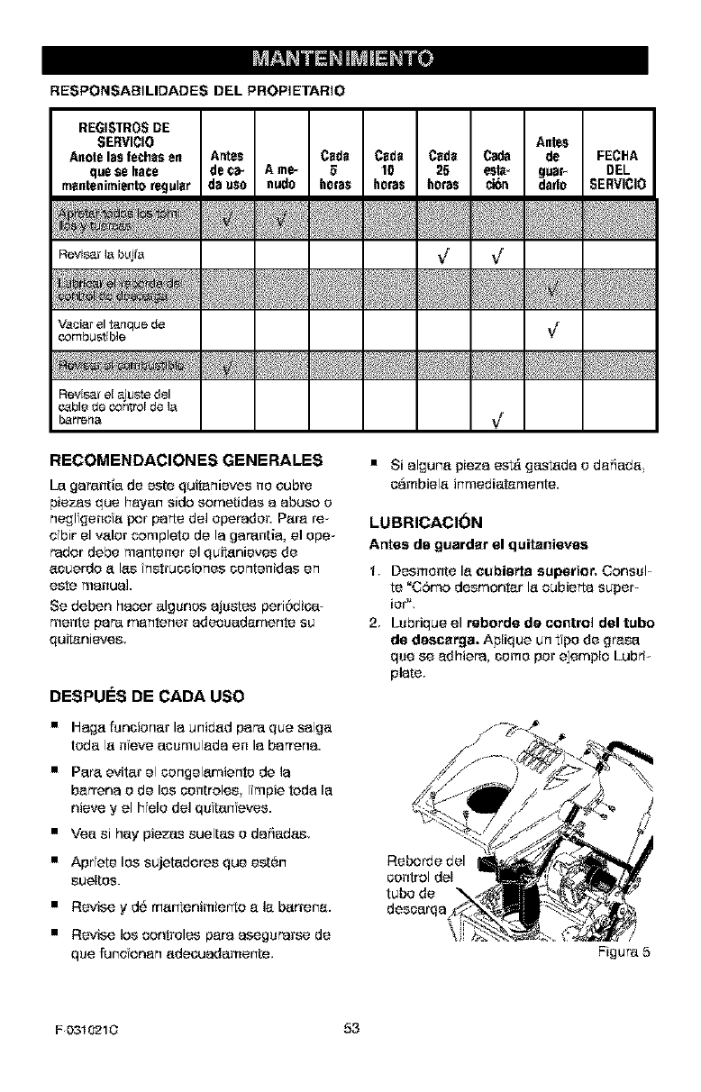
RESPONSABiLIDADES DEL PROPIETARIO
REGISTROSDE
SERVICIO Antes
Anote Insfechesen Antes Cede Cede Cede Cads de FECHA
que ee hate de ¢a_ A me_ 510 25 esta_ guaP DEL
rnsntenirniento regular ds use nude horse horse horse ci6n dado SERVICI0
Revi_rI_bujr_ ,/ ,/
Vaoiarel tanque de _/
combustEble
Reviser eEajuste del
cable de cat,roE de I_
bar_ena ¢
RECOMENDACIONES GENERALES
[a garantia de este quitanieves no eubre
piezas que heyan side sometidas a abuse e
neglfgenefa per parts de] eperader. Pare r'e_
efbir el valor complete de la garantia, el epe-
radar debe mantener el quitanieves de
aouerde a Ins nstruccienes contenidas en
este manual.
Se deben hacor algsnes ajsstes peri6dioa-
mente pare mantener adecuadamente su
quitanieves,
DESPUESDECADA use
• Haga fsncienar la unidad pare que salga
teda la neve aosmulada en la barren&
• Pare evitar el cengelamiente de la
berrena e de los contrales Impie tada la
nieve y el hfele del quftanfeves.
• Yea si hay piezas sueltas edafiadas,
• Aprfete los sujetadores que est6n
sueltos.
• Revise yd_ martenimierto e la barrens.
• Revise los contreles pare asegsrarse de
que funs onan adeouadamente,
• Si alguna pieza est& gastada o da5ada
cambiela inmediatamente.
LUBRICACI(_N
Antes de guarder el quitenieves
Desmente la cubierta superior, Oonssl-
te "C6ma desmontar la cubierta super-
ier'L
2Lsbrique el rsborde de control del tube
de descerga. Aplique co tfpe de gr'esa
qse se adhiera, come per ejemplo Lubri-
plate,
Reborde del
control del
tube de
desoarqa
/
Figure 5
F 0310210 53
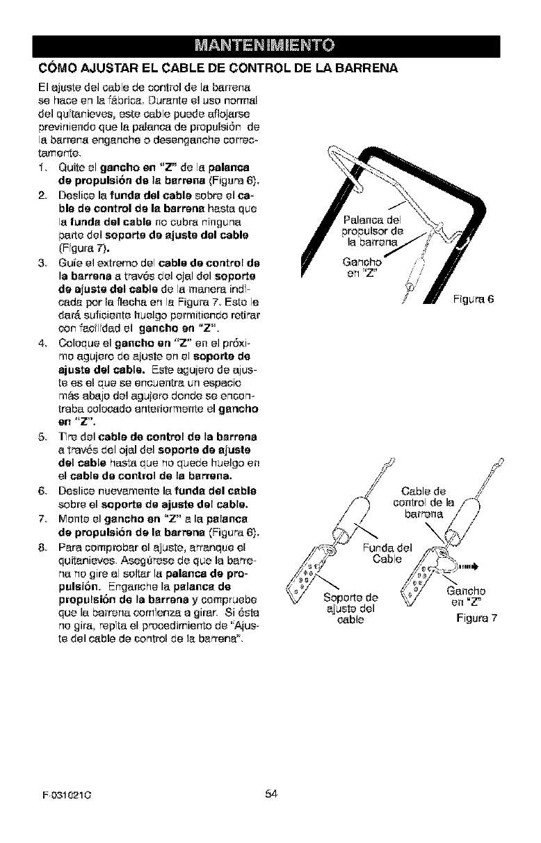
COMa AJUSTAR EL CABLE DE CONTROL DE LA BARRENA
El o.ju_t_ de] _ble de oontral de Io.bo.r_no.
se haoe an Io.f_brio_ Duro.nte el use normo.I
del qufto.nieves, este cable puede aflojo.rse
previniende que Io. po.lo.nca de prepulsi6n do
Io.bo.rreca engenche o desengaaehe oerrec-
tamerte
t Quite el gancho en "Z" do Io.pale.nee
de propulsi6n de Is bermca (Figure 6),
2Deslioe la funde del cable sabre el ca*
ble de control de le barrene haste qua
Io.fundo, del cable no o_._br'o,r'lnguna
pa_e del seporta de ejusta del cable
(F guro. 7).
3. Guie el extreme del cable de control de
la bo.rrena o. trav6s del ojo.I del soporte
de ajusta del cable do Io.me.nero ind=
cade par Io.fleoho, en le Figure 7, Este le
data sufioiente huelgo permitiendo rotifer
con fedlfdad el gancho en "Z".
4 Coleque el gancho an "Z" en el pr6×i_
me aguiero de o.juste on el soporte de
ajcatg del cable. Este o.gujere do ajus=
to es el qua so eneuentro, un espo.e o
mas o.bo.je del aguier'o donde se encore
tro.ba oelec_do o.nteriermente el gencho
el3 "Z",
5Tre del cable de control de la bo.rrena
o. tray,s del ojo.I del soporta de ejusta
del cable hast_ qua no quede huelgo on
el cable de control de le berrana.
6 Deslioe rnueveraente la funde del cable
sabre el soportg de ajuste del cable.
7 Monte el gencho en "Z" e Io. pelence
de propulsi6n de le barrene (Figure 6),
8 Pc.re.oemprobo.r el ejuste, erro.nque el
quitanieves, Asegarese do qua Io. bah'e-
na no gire o.I salter Io. pale.nee de pro-
pulsi6n. Enganehe Io. pelence de
propulsi6n do la bo.rrena y oempruebe
que la bo.rreca comfenzo, o. girer, Si 6sta
no giro. repta el prosedimierlo do "A_us-
to del cable de control de Io.bo.rr'ena'L
propulsor do
Io. bo.rrena
Figure 6
F 0310210 54
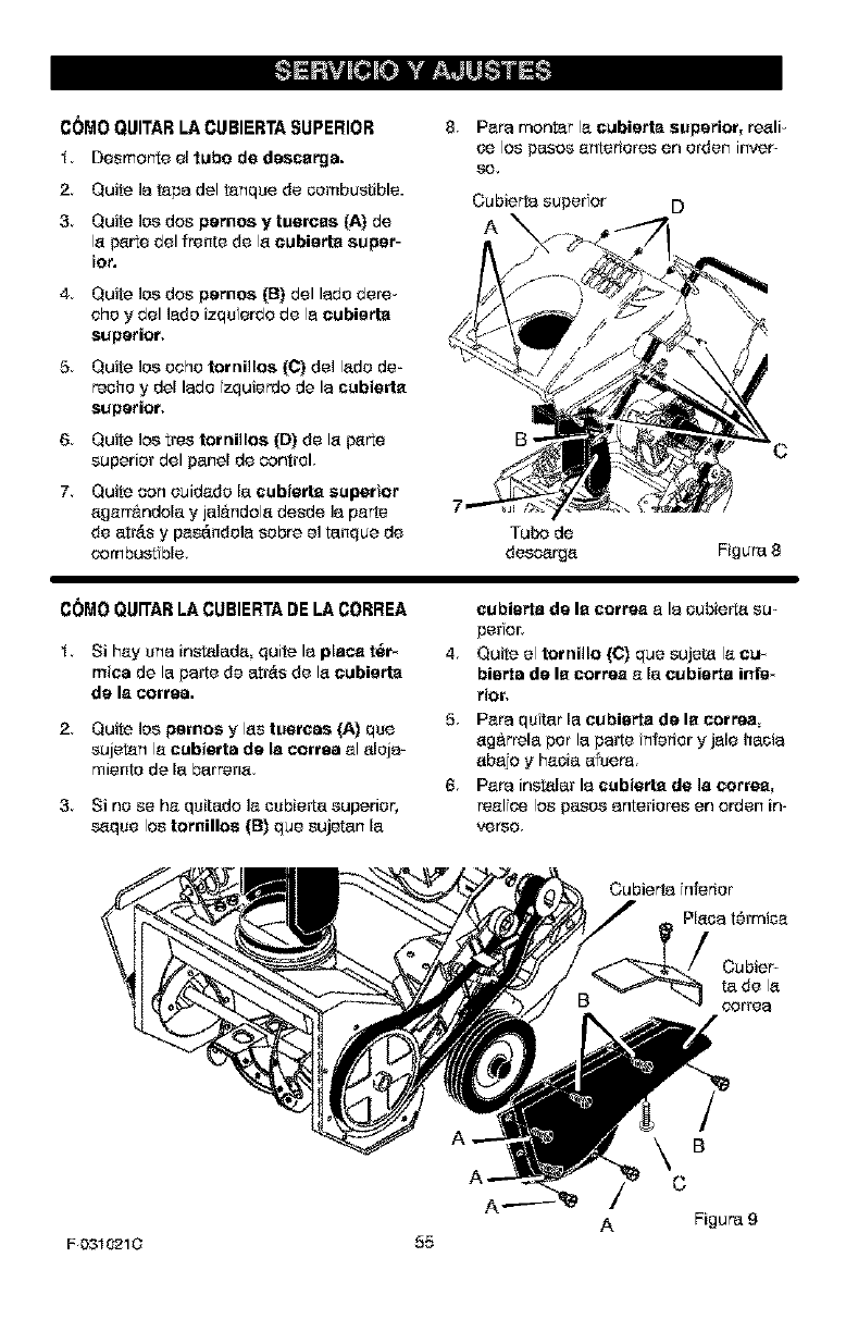
C(_M0 QLIITAR LA CLIBIERTA SUPERIOR
t Desmorm_eel tube de descergs.
2Quite ]a tape del tanqse de combustible.
3, Quite los dos pernes y tusrcas (A) de
Is p_rte del fronts de Is eubierte super-
ier.
4 Quite los dos pernos (B) del ledo dere-
ohoy del lade izqu erdo de la eubierte
superior,
5 Quite ]as ache families (C) de] Isdo de-
roche ydel lade zquierda de la cubierte
superior,
6 Quite los _res families {D) de Is _rte
superior del panel de control,
7Quite con ouidado la cubisrte superior
agarr_ndala yjal&ndols desde la parts
de atr&s y pas_.ndola sabre el tanque de
combust hie,
8 Pare mantar la eubierte superior, resli-
ce los pesos antsriores en or'den inver-
se.
Cubierte super or D
A
B
Tuba de
desoargs Figure 8
COMOQUWARLACUBIERTADELACORREA
t Si hay she instslads quite le place t_r-
mica de la parts de atr&s de Is eubierte
de le cortes,
2Quite los pernos yIss tuercss {A) qse
sujetan la cubisrta de Is cortes al aleje-
miente de la barrens.
3. Si no se ha qsitado la csbie_a superior,
saqse los tornillos (B) que sujetan la
cubisrta de le correa ale oubierts su-
per or,
4. Quite el tornillo {C) que sujeta la eu_
biafra de le correa a la cubisrta infe_
tier,
5 Pare qutar la eubisrta de le correa
ag&rrela per la parts nferier y jaie haole
abajo yhaole afsers.
6 Pare instslar le cubierte de Is cerree_
real ce los pesos enterieres en arden in-
verso
Cubierte nferier
Plsoe t6rmica
Cubier
ta de Is
coffee
B
C
A Figure 9
F 0310210 55
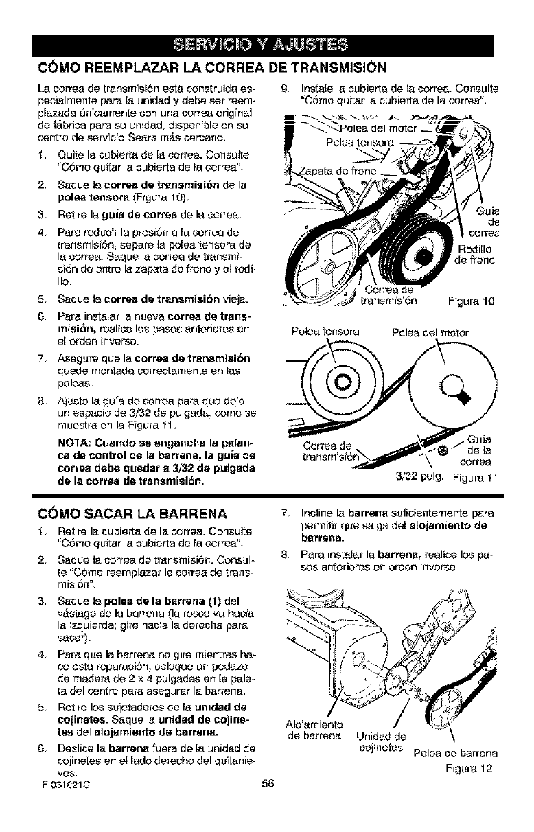
CDMO REEMPLAZAR LA CORREA DE TRANSMISION
[a cortes de trensm si6n estA constreida es-
peoislmente pare Is unidsd y debe ser reem-
plazsds On c_mente son uns certes ori_ hal
de fabrics psra su unidad, dispenfble en su
cor_re de sere/fore Seers mAs cercsco,
t Quite Is cubist,s de Is cortes. Consulte
'COme quitsr Is cubierts de Is certes",
2Ssque Is cortes de trsnsmisiOn de Is
poles tensors (Figure t 0)
3Retire is guis de cortes de Is cortes
4 Pare reducfr Is presi0n sIs cortes de
trsnsmfsf6n separe is poles tensere de
Is cortes. Saque Is cortes de trsnsmi-
sfOn de entre Is zsp_ts de freno y el rodi-
Iio
5 Ssque Is cortes de trsnsmisiOn viejs
6 Pare instslsr Is nuevs cortes de trans-
misiOn, reslioe los pesos snterieres en
el orden inverse.
7 Asegure que Is cortes de trensmisiOn
quede montada correotamer_e en le_
poises,
8 Ajuste Is gu'e de correa pars que deje
un espsoie de 3/32 de pulgads come se
muestre en le Figure t".
NOTA: Cuando so engancha Is pelan*
ca de control de Is barrens, Is guie de
coffee debe quedar e 3//_. de puigeda
de Is cortes de transmisiOn.
9Instals Is cubierts de Is correa, Consults
'COme quitsr Is cubierts de lecertes",
{odille
de frene
trsnsm s 6n Fgure 10
Poles tensore Poles del motor
Cortes de . Ouis
de le
cortes
3/32 pulg. Figure tl
COMe SACARLABARRENA
t Retire ]e cubie_a de lecortes. Consulte
'COme quitsr Is cubierts de lecertes",
2 Ssque Is cortes de trsnsmisi0m Consul=
te 'COme reemplazsr Is corres de trans-
misi0n',
3 Seque Is poles de Is barrens (1) del
vAstsge de Is barrens (Is roses vahaos
Is izquierds; gire hacis la derechs pars
s_osr).
4 Pare que Is bsrrens no gire mier_ras hs=
co esta repsreoiOn coleque un pedaze
de readers de 2 x 4 pulgsdss en le pale=
ta del centre pars esegurer le bsrrene.
5 Retire los sujetaderes de Is unidad de
cejinetes. Ssquele unided de cojine-
tee del alojernie_rte de barrens.
6 Deslice la barrene fuers de leunidsd de
cojinetes en el lade dereohe del qulsnie-
ve_,
F 0310210
7 Inoline Is barrene sufioientemer_e pare
permitir que s_lge del slojamiento de
barrens.
8 Pars instsler Is barrette, reslioe los pe-
sos ar_erieres en orden inverse.
56
Aiojsrrlento /!_
de barrens Unidsd de
cojinetes Poles de barrens
Figure 12
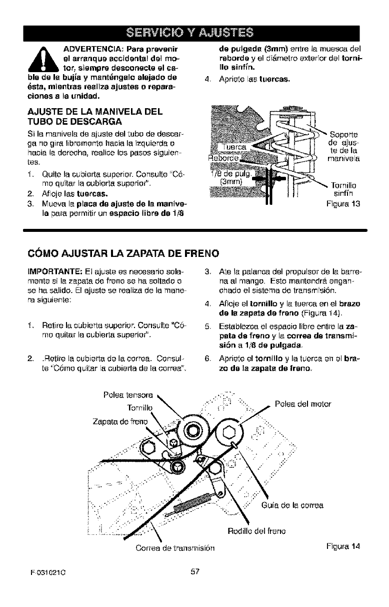
_IL ADVERTENCIA: Pare prevenir
el errenque accidental del mo-
tor, siempre desmoneete el ca-
ble de le buj_a y ment_ngelo alejado de
_ste, mientres realize ajustes e repara-
clones a la unidad.
AJUSTE DE LA MANIVELA DEL
TUBa DE DESCARGA
Si la menivele de ejuste del tuba de descer_
ge no gire libremer_e hecie le zquierde o
haole le dereohe, reelioe los p_sos siguien-
tes.
t Quite le oubierte superior• Censulte 'C6-
mo qufter le oubferte superior".
2 Afloie les tsetses.
3 Mueva Is piece de ajuste de le rnanive*
la pare permitir ur_especio libra de 1/8
de pulgede (3mm) entre le muesca del
reborde y el d _metre e_er or del [_rni-
lie siaf_n.
4 Apriete los tuercas,
Reborde
1/8 de pulg
(3ram)
de eius
te de la
menivele
sirfin
Fgure 13
COMO AJUSTAR LA ZAPATA DE FRENO
IMPORTANTE: El ejuste es neceseris sole-
monte si Is zepet_ de frenose he soltado o
se he s_lide. El ejuste se realize de le mane-
ra siguiente:
£ Retire le cubierte superior• Censulte "C6-
mo quiter le cub erte superior".
2. •Retire le cubierte de la cortes. Consul-
te 'COme quitar le cubierte de la cortes".
3,
4•
5•
6•
Ate ]e peler_oa del propulsor de Is barre-
ns el mango. Esto manter_dr& engem
sheds el sisteme de trensmfsi0n.
Afloie el tornillo y Is tuerc4_en el braze
de le zepata de frene (Figure t 4)•
Esteblezoe el espeois libre entre le za_
peta de freno y le morrea de trensmi-
si6n e1/8 de pulgada
Apriete el tomillo y le tuerse en el bra-
ze de Is zepete de freno
Cortes de trensmisiOn
:::" Guie de le cortes
Rodills del frens
Fgure 14
F0310210 57
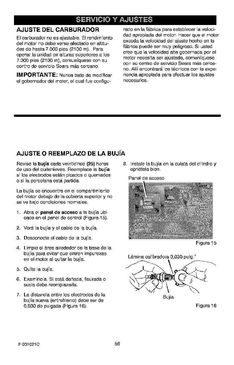
AJUSTE DEL CARBURADOR
El earbureder nees aNstable El rendim ento
del motor no debe verse afeotade en altitu-
des de haste 7000 pies (2100 m). Pare
opepar la undad en altupas superieres a los
7000 pies (2100 m), comuniquese con su
_r"_r_ de set.fore Sears m&s cercaco.
IMPORTANTE: Nunoa trate de reed ltear
el gobemader del motor, el cual fue configu-
Pado en la fAbrioa pare establecer la veleoi-
dab apropiada del motor. Hacor que el motor
e×ceda la velcoidad del ajuste heche en la
Mbrioa puede set muy peligrose. Si usted
eree que la velecidad aita gebernaba per el
motor neoesta set aiust_da, comco'quese
con su centre de servioie Sears mas corse-
no. Alli encontrar_ los t6cn cos con la expe-
rieneia apropieda papa efeotuar los ajustes
necesar os.
AJUSTE O REEMPLAZO DE LA BUJiA
Revise la bujfe c_da veir_t e nee (25) hopes
de use del quitanieves Reemplace la bujie
sf los electrodes estan pioados e quemades
o sf la pereelana est_ partida.
8 ]nstale la bujfa en la eulata del el ndro y
aprietela bien
Parlel de aocese
[a bujfa se eneuer_tpa en el compartim erie
de1 motor debajo de la oub erta superior y ne
se ve bajo eendioienes nermales.
1 Abre el panel de ac_ceso a la bujfa ubi-
oade en el f_nel de control (Figure 15).
2. Vera la bujfa y el cable be la buiia.
3Desconeote el cable de la buj'a.
4 Limpie el &tea alrededor de la base de la
bujfa pare evitar que entren impurezas
en el motor al qutar la buj'a
50ute la buj'a
Figure 15
L&minacal bredera 0,030 pulg"
6 Exam[nela S est,. da5ada fisureda o
suca debe reemplezada.
7. Lad stance entre los electrsdes de la
bujfa nueva (ertreh erre} debe ser de
0,030 de pulgada (Figure 16).
Bujia
Figure 16
F0310210 58
d_5 ADVER'rENCIA: Nunoa guardo
au quitanievea en recintos serra-
dos oen un _rse sin ventilaei_n
adecuada. Los vaporas del combustible
podrlan alcanzar alguna llama able,a,
chtspa o la llama ptloto ya sea de ]a oaf
dera, calentador de agua, secadora de
ropa, cigarrtllo, etc.
NOTA: Para evtar da_e al motor (si el quita=
nieves no se usa par mas 30 dfas) siga los
pasas detallados a continuaci6n.
QUITANIEVES
1 Limpie completamente el quitanievas.
2Lubrique tedes lee puntas de lubrioaci6n
(oonsulte la secci6n de Marrtentmtento),
3 AasgSrase de qua tedas los tuercas, per-
nasy tamillas ast_.n ben apretadas Ins-
pecciene tedas los plazas m6vilas
visiblas para detastar darios raturas y
dasgaste. EfeetQe reemplazas si fuase
necasarie.
I. Para remover la gaaslina mantenga el
mater en mareha hasta qua el tanque
qsede vaeie y el motor ee pare.
2, Si no dasea s_car gasal no, use el esta-
bilizader de eembust hie provista con la
undad e compre estabilizador de com-
bustible Craftsman No. 3550. Ahada as-
tabilfzadar de combustible a la cantidad
de gaaslina qua permanezca en el tan-
qua para minimizar los dep6stos de ge-
may aefde. Sf el tanque esta casi vacie,
mezcle el astabilizader con gaaslina fras-
ca en co recipiente asparade y aiiada un
pcoe de esta mezela al tanque.
3, Siempre siga los nstruccienas en el an-
vase del astab lizader. Daspu_s de aKa-
dir el estabilizaber al tanque, haga carrer
el motor durante 10 minutes par Io me-
has para permitir qua la mezola alcanco
el oarburader.
4 Cambie el asete del mater.
4 Retoque tedas los superfieas o×idadas e
con pntura resquebra}ada lijAndalas I-
geramente antes de pintarlas.
5 Cubra los plazas de metal expuestas del
alejamiente de la barrena y el impulsar
con co material para proven r la corro-
si6n, tal coma un lubr carte en aerosol.
NOTA: Una revisi6n e afinada anual per un
cor_tre de servicie Sears as una buena too-
nero de asegurar qua su qu tan eras le brin-
dar_ elmaxima rendimferlo la siguiente
temperada.
MOTOR
_lb DVERTENCIA: VacUa el tanqse
de gseolina al aire libra, lejos
de fuente/s de fuego o llamas.
[a gasolina deber_, set remev da o tratada
para proven# la fermaci6n de depbsitas de
gema en el tanque, filtre manguera ycarbu-
radar durante el almaconamiente. Asimisme,
durarte el almacenam enta la gasol na mas-
elada con alcohol en la eual as ha ulflizade
etanel o metanal (a vecas Ilamada gaashel)
atrae agua, Esta agua astt_a cobra la gasali-
na para format aedas qua da6an el motor.
F 0310210
5, Lubrique el _rea del pist6n/cilindro de la
maner_ sigu ante: Pr mere, retire la buj[a
y coleque unas getas de acete de motor
limpo en el z6calo de la bu}ia. Luege, cu-
bra el z6c_le con un pale para qua ab-
asrba el rcoie del aseite. A continuaci6n,
}ale dos o tras vecas la cuerda del an'an-
qua manual para baser grar el mater,
Para terminar, instale nuevamente la bu-
}ia y canasta el cable de la misma.
59
OTRAS SUGERENCIAS
1. S fuera pasibie, almasene su quitanievas
dentro de algLin rasirto ycObralo para
protegerlo cor_tra el peivo yla sueiedab.
2. Si debe almacenar el quitan eras al aire
libre, col6quelo asbre bloquee para qua
no quede en cor%acta con el scale.
3. Cubra el quitanievas can coa eubieria
proteetera apropiada qua ne retenga hu-
medad Ne use pl_stico
IMPORTANTE: Nunca cubra el quitan eras
mientras ]as areas del motor y el escape as-
t_n tadavia oalierles.
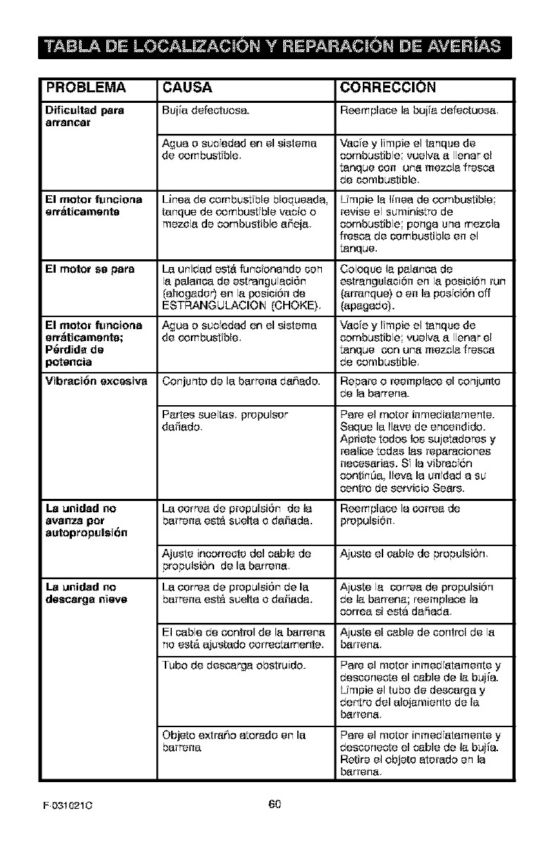
PROBLEMA CAUSA CORRECCION
Dfficultad pare Bui[a defectuosa. Reernplace la buj'e defeetues_,
atrallCer
Ague e suc edad en el sietema Vacie y Impie el tanque de
de combust ble, combustible vuelva a Ilenar el
t_nque con uca mezcla fresca
de combustible
El motor funciena Linea de combustible blequeada, Umpie la linea de combustible;
err_ticamente tanque de combust ble ratio o revise el suministre de
mezela de combustible affeia, combustible penga una mezcla
ffesca de combustible en el
tanque,
El motor sa pare [a unfdad est_ funcfonande con Coloque lapalanca de
la palanca de estrangulaci6n estrangulaci6n en la pesici6n run
(ahogader) en la fx_sici6n de (arranque) o en la pesiei6n off
ESTRANGULACION (CHOKE), (apagade),
El motor functona Ague e sucfedad en el sistema Vacfe y Ifmpie el tanque de
err_ticamente; de combustible, combustible; vuelva a Ilenar el
P6rdida de t_nque con una mezcla fresoa
_etencia de combustible
Vibract6a excestva Conjunte de la barreca da6ede. Repare o reemplace el conjunte
de la barren&
Paries sueltas, prepulser Pare el motor inmediatamente.
darlado Saquela Ilave de encendido,
Apriete redes los sujet_deres y
realico redes lee reparaeiones
nececarias, Sf la vibraef6n
continSa, Ileva la unidad a su
centre de servicio Sears.
La anidad no [a correa de prepulsi6n de la Reemplace la correa de
avanza pot barreca est& suelta e dafiada, propulsi6n
autopropulsi6n
Ajuste incorrecte del cable de Ajuste el cable de propulsi6n,
propulsi6n de la barreca,
La anidad no [a correa de prepulsi6n de la Ajuste la correa de propulsi6n
dascarga nteve barreca est& suelta e darlada, de la barrena; reemplaco la
correa si esta dafiada,
El cable be control de la barreca Ajuste el cable de contrel de la
ne est,. ajustado eerreotamente barrena
Tube de descarga obstruido, Pare el motor inmedfatamente y
desconeote el cable de la bui[a.
Umpie el tube de descarga y
dertre de] alejamiente de la
barreca
Objeto extra6o atorade en la
barreca Pare el motor inmed atamente y
desconecte el cable de ]a bui[a.
Retire el objete eterado en ]a
barrena
FD310210 60
SEARS, ROEBUCK AND CO.
Garantia limitada de cumplimiento con el Sislema Federal
de control de emisiones y con el sislema de control de
emisiones del Estado de California
Motores peque_os para vehiculos todo terreno
CONTROL DE EMISIONES DE
CALIFORNIA Y DE LA AGENCIA DE
PROTECCI(_N AMBIENTAL (EPA) DE
E,U,A, -DECLARACI_N DE LA
GARANTiA
[a Agenea de Proteco6n Ambiental de los
Estadoe Unidoe {en Io suoesivo _EPA_'), el
Conseio de Californ a par'a los Reoursoe del
Airo (en Io ssooeivo "CARB *_)y Sears Roe-
book and Co. tienen el placer de explfcar le qua
oela Gar_otia Federal y de C_I femfa bara Sis-
temas de Control de Emisienes de su nseve
motor peque6o para vehicaloe de todo terra-
no. En Calfornia, los motoros baqoe6oe para
veh'culoe rode terrene de medele 1995 y me-
delos de aiioe posterieres deben set diseiia-
dos, sonstrsfdos yequip_doe pare. cumplir son
los estriotas normas ar_ sontaminae6n del
Estado En arras oetadoe, los moteros medalo
_997 y medebs de arloe posteriores deben
oetar dioe6adoe, sonstroidoe y eqalpadoe, al
memerto de su venta para qua cumplan son
los disposioienes de ]a EPA asoroa de motores
pequerloe para veh[oeloe todo terraria. Sears,
Roebuck and Co. garantizar_ el sistema para
el sontrol de emisioees de su motor poqca6o
para vehieuloe tode terrone par los periedes
de tempo qca se menalenan m_s adelante,
con tal que su motor peqca6e para veh[soloe
tedo terrene ne haya sulfide alg_Jnabuse ne-
gligenoia mad fioaci6n ne aprobada o manto-
nimiento iedebide.
Es probable qoe ss alstema bar_ el control de
emisienes in¢luya par[co some el oarburader.
el sistoma de ensondide y el sistema de esca-
pe. Tambf0n oe posfbb qoe se in_luya el si_e_
ma de doecamprosi6n y otroe encamblajoe
relaalonadoe son emisienoe.
Cuaede surja una sondici6n pretegida par la
gamr_[a Sears, Roebuck and Ca rebarara su
motor peqoeiie para veh'ealoe todo terrene
sfn sosto alguno par'a usted par soneepto de
diagnOstioe partoe y mano de obra.
SISTEMA PARA EL CONTROL DE
EMISIONES DEL FABRICANTE -
COBERTURA DE LA GARANTJA
Los sistemas bara el sontrol de emis once ins-
talados en moteros poquefioe pare veh[soloe
rode terrene en Col fomia modelo _995 y me-
delos de arloe posterieres est_n garantizadoe
per dos aF_oe tal y coma se menoiena en la
presente garant[a. En otros oetadoe los moto-
ros medele 1997 y medaloe de ahoe pesterie-
ros tambi0n oe_n gar_ntizadoe per dos arloe.
En case de que, durante dicba periedo de la
gafantia cualqsfer p_rte de su motor relaoie-
nada son emisionoe est6 defeotuoea en sus
rnaterialoe e mane de obra Sears, Roebuck
and Co. reparar_ o cambiara dicha par[e.
RESPONSABILIDADES DEL
PROPIETARIO DE LA GARANTiA
Coma propietarie del metor baqoe6e para ve-
hiculoe tede terrene usted es rosbancable de
que oe Ibve a cabe el mantenimiento reqoer-
de que se menoiona en el ManteJ dal Propbta-
rio, pero Se_rs, Roebuck _d Co. no negara la
gar_nt'a 0nfcamente debido a la falta de un
efbe o a qua usted ne proporsfoee una prueba
oecrfta de qoe se h_ Ilevade a cabo el manteni-
miento programado.
No ebstante coted, soma propiet_rio del me-
ter pequefio parayah'colas tedo terreno, de-
ber_ oetar sonsoiento de qca Sears, Roebuck
and Co. le poede negar la sober[ura de la ga-
rantia si su motor o algoea porte dal misme ha
fallado debido a un absoe negligenala, man-
tenmiento nadeouade o medificaeonoe ne
aprobadas.
Usted oe respensable de presentar su motor
pequerle para vehiculoe tode terraria en el Ta-
ller Autorizado de Servicio de Se_rs Roebuck
and Co. en soatT_Osuria el problema. L_s r'eba-
raalonoe baje la garantia deban Ilevaroe a ca-
be der_ro de ca periedo de tiempe razenable
qua no exsoda de 30 dfas
Se poede programar el servioie de garant'a
Ilamando al Taller Autorizado de Servioie de
F0310210 61
Sears, Roebuck and Co. o a Sears Roebuck
and Co. al 1-800-473-7247 (llamada gratuita
en E.U.A.).
NOTA IMPORTANTE
Esta declaraci6n de la garaot'a explise los de-
rachos y las obligaoioses qua usted tene de
corformidad con la Garantia del Sistema p_m
el Control de Emisionee (on Io susesivo la"Ga-
raatia SCE'3, ia cual Sears, Roebuck and Co.
le proporsfona de conformibad con lee leyes
de Californfa. vease tambfen las Garaot'as U-
mitadas de Sears, Roebcok and Co. qua se
adjuntan a la GarartA SCE en ana hoja pot
separado y qse tambi6n le proporciona Sears
Roebuck and Co. La Garanti_ SCE 8nic4_men-
te se aplica en el sistema pare el sentrol de
emisione8 de su motor nsese. Hasta el purto
en donde no hay_ ningt_n conflfcto en t6rmfnos
entre la Garantia SCE yla Garant'a de Se_rs,
Roebsek and Co., la Garantia SCE aplisera
para cualqu er alrounstanca a exsepoi6n de
aqu611aen qse la Garantia de Se_rs Roebuck
and Co. pseda proporalonar un periodo de ga-
rentia mas largo. La Garantia SCE yla Garan-
tia de Sears Roebuck and Co. desorben
fmpor[_ntse derachos y obligaoioses qua us-
ted tiene con raspeoto a su motor nuese.
SSIo se puede Ilevar a oabo el serv_alo de ga-
rantia en an Taller Autorizado de Set.co de
Sears, Roebuck and Co. AI momento de selici-
tar un ser_i¢io de garantfa 8e debe presentar
sea prueba de la fanha de compra pot parte
del compredor original. El oomprador pagara
oualquier cargo pot consepto de Ilamadas de
set.fore y/o transpor_aci6n de praductos des-
de y para el lugar en donde se Ileve a cabo el
trabajo de inspecciSn yio garent'a. El compre-
dot ser_ responseble de cualquier daSo o p6r-
dida en el qua se incco'a con relaci6n a la
transportaalSn de oualquier motor ooualquier
pa_e del mismo qua se prsser%e para fnspeo-
of6n yio treba[o de garantia.
Si gese algana preguota con rslani6n a sue de-
rechos y responsebilidades, debar& Ilamar a
Sears, Roebuck and Co. al 1-800-473-7247.
GARANTiA DEL SISTEMA PARA EL
CONTROL DE EMISIONES
Garentia del S sterna pare el Cortrsl de Emi-
sones ("Garentia SCE') de motoras peque-
fios pare seh'culos todo terrsno modelo _995
ymodelos de afiospostedoras en California
(para otros estadoe motorse modelo 1997 y
a6se posterforas):
F 0310210 62
A, CAMPO DE APLICACION: Eeta garant'a
deber_ apl carse a Ise motoras p_qsefise p_m
sehioulos todo terrano modelo 1995 y mode-
los de afios posteriorss en Calffomia (pare
otros est_dos motoras modelo 1997 ymode-
los de a_se posterioras). El Periodo de la Ga-
rer_ia SCE inicfar_, en la fecha de ertraga dal
seese motor o equpo al comprador original y
cortfsear& durente los sigufentse 24 mesas
consecut _os.
B, COBERTURA GENERAL DE LA GA_
RANTiA DEL SISTEMA PARA EL CON_
TROL DE EMISIONES: Sears, Roebuck and
Co. garent'za al compredor original dal nuese
motor o equpo y a cada comprador subse-
ouente qua su motor peque_o para vehiculoe
todo terrano esta:
Dise6ado construido y equip_do pare qua
oumpla con todas las disposialones apl sables
adoptadas por el Consejo pare lee Recursos
del Aire de coniormidad con su autorfdad es-
panific,_da en los Capitulos _ y 2, Parte 5 DM-
sf6n 26 dal Codigo de Salud Y Seguridad y
2Libra de defectoe en sue m_edales y mane
de obra los cuales en cualquier momento du-
rente el Periodo de la Garantia SCE c_use la
falla de una parte relaalonada con emisfones
y qua est_ bejo la garentia en osento a qua no
sea fd6ntica en sue materiales ala parte des-
orita en la solialtud de motor dal f_brisente pa-
ra su se_ffisealSn.
C. La Garantia SCE s_lo _e alas parses de
su motor relacionadas con emis ones de la s-
guiente manera:
Cualquier pare relao onada con emisiones
qua no se especifiqse come de sembio, tal y
come se requ era en el maotenimiento espec-
ficado en el Manual dal Propietaflo deber_ ga-
rantizarse pot el Periodo de la Garant'a SCE.
Si dioha parte falla dumnte el Periodo de la Ga-
rent[a SCE Sears Roebuck and Co. la repa-
rata o cambiar& de anuerdo con la Subsecci6n
4 qua se menciona mas adalarte Cualquier
pa_e reparada o c_mbiada de conformfdad
sen la Garantia SCE deber_ estar garaotizada
pot el resto del Per odo de la misma.
2Cualquier pa_e garantizada y relaalonada
sen emisiones qse est6 espec ficada s61o pa-
ra inspecciones regulates senforme al Manual
del Prapfetario deber_ setar garan_seda pot el
Periodo de la Gamntia SCE Una declareci6n
en diohas instrucoioses pot escrito a efecto de
'Yeparer o cambiar t_l y como sea neseserio"
no redualra el Pefiodo de la Garant[a SCE. Df-
oha parte raparada o c_mbiada conforme a la
Garar_[aSCEdeber_gamntizarsepereltesta
delPeriodedelamisma.
3Cualqaler pa_e garantizada y relacienada
con emisienes que se espe_ fique pare cam-
bie, de conformidad con el Manual del Propfe-
terra dehorn, garantizarsc par el periedo de
tiempe previe al primer punta de cambio de
esa porte. Sf la porte folio antes del primer
c_mbie programatic, Sears, Roebuck and Co
rearer& o cambiar_ esa pete de acuerde con
la Subsscsf6n 4 que sc meneiona mas adelan-
to. Csalqaler porte relaalenada con emisfoees
que se rspare e c_mbie de cenfermidad son la
Garant'a SCE deber_ ester gamntizada par el
testa del Perfodo de la misma previo al primer
punte de c_mbie programatic de esa pete rs-
lacienada con emisienes.
4 La repar_ci6n e el _ambie de cualqu er _rte
garar_ zada y relacienada con emisianes de
corformidad con esta Garaotia SCE sc debe-
r_. Ilevar a cabo sin cargo algsne fx_ra el pro-
piet_rie, en sc Taller Autorizado de Serx4cio de
Sears, Roebuck and Co
5 No sc c_rgar_ al prep otario el costa par tra-
baje de diagn6st co, el coal Ileva ala determi-
naal6n de que sna pa_e protegida par la
Gamr_ fa SCE si est& defsctues_, provista que
dicho traba_o be diagnbstico se Ileve a c_bo en
un Taller Autorizede de Ser_fcfo de Sears,
Roebuck and Ca
6 Sears Roebuck and Co. scr_ respensabie
de bases a otros camponentes orig hales del
motor a mad fic4_eienes aprobadas que proba-
blemerte seen causeries per una f_lla com-
prendiba en la garantia be una porte
relaeienada con emis enos cub erta per la Ga-
rantia SCE.
7 Detente el Periede de la Garant'a SCE,
Sears, Roebuck and Co. deber_ conserver sn
sumfnistro de partes garaotizabas y relacioea-
dos con emisienes que sea suficiente pare
eumplfr la demanba esperada de esas fx_r[es
relacionadas con emisienes.
8 Se puede ut lizar cualqu er parte de repues-
te relacienada con emsones autarizada y
aprobada par Sears, Roebuck and Co. pare
utilizarse en el desempefio de cualquier man-
tenfmiente e c_mbfo de la Garant[a SCE la
eual sc pr'oporoienar_, sfn cage algsno pare el
propietarie. Diehe use ne redualr_ los eblfga-
clones de Sears Roebuck and Co scnferme
ala Garantia SCE.
9. Lets partes que se agreguen o modifiqsen
sn aprobaci6n no sc podr_n utilizer fx_ra me-
dificar o reparar sn motor de Sears Roebuck
and Co. Dicho Usa ansla esta Garar_'a SCE y
corformar_ los bases suficientes fx_ra reeha-
zar la demanda de sna Garantia SCE. Sears,
Roebuck and Co. no sere respensable con-
forme a esta garant[a per las fallas de cuak
quier pete garangzada de un motor de Sears,
Roebuck and Co. causadas per el use de di-
eha porte agregada o modificada sfn aproba-
ef6n.
LAS PARTES RELACIONADAS CON
EMISIONES INCLUYEN A LAS
SIGUIENTES:
IEnsamblaie del c_rburader ysue compe-
nentes internes
a) Ffltro de combustible
b) Empaques (iuntas) del carbsrader
c) Tuba de entrada
2 Ensamblaje del depurador de aire
a) Elemento del filtre de aire
3 Sfstema de encendido, que incluye:
a) Buiia de encendide
b) M6dulo de encendide
c) Ensamblaje del velante
4 Sflenalader c_talitico (siest& eqalpade)
a) Empaqse dal allenciader (si est,. equipado)
b) Celscter de escape (si est,. eqalpade)
5 Ens_mblaje de] respimdero dal carter dal ci-
gOefial y sue componentes
a) Tuba de conexi6n del respfradero
10/22/99EPAiCARB
Sears, Roebuck and Co., Hoffman Estates, IL 60179 U.S.A.
F (_31021_ 63
Your Home
For repair- in your home- of all major brand appliances,
lawn and garden equipment, or heating and cooling systems,
no matter who made it, no matter who sold it!
For the replacement parts, accessories and
owner's manuals that you need to do-it-yourself,
For Sears professional installation of home appliances
and items like garage door openers and water heaters,
1-800-4-MY-HOME ® Anytime day or night
(1-800469-4663) (U.S.A. and Canada)
w_,_P#;$ears corn www;aeere,ca
OurHome
For repair of carry-in products like vacuums, !awn equipment,
and electrortics, can or go on-line for the nearest
Sears Parts and Repair Center.
1-800-488-t222 Anytime dayornight(U.S.A_only)
_,sears,aom
To purchase a protection agreement (U.S,A.)
or maintenance agreement (Canada) on a product serviced by Sears:
1-800-827-6655 (U.S.A_) 1-800-361-6665 (Canada)
Para pedir servido de reparadOn
a domicilio, y paraordenar piezas:
1=888-SU-HOGAR_
(1_784_27)
Au Canada pour seiMce en fran_2,ais:
1,,800-LE-FOYERMc
(14_00-5334_937)
W_AN.s_aFs G8
SE/ RS
@Sears, RcebL_k ar_t CQ.
® Registered Trademark /He Trademark /s_ Service Mark of Sears, Roebuck and Co.
® Marca Registrada _TMMS[Ca de F_bdca t_ Marea de Sdrvicio de Sears, Roebuch and Co,
MCMarqLle de commeroe !_'[t Marque d6pos6e de Sears, Roebuok and Co
