Craftsman 536886350 User Manual SNOWTHROWER Manuals And Guides L1002516
CRAFTSMAN Snowthrower, Gas Manual L1002516 CRAFTSMAN Snowthrower, Gas Owner's Manual, CRAFTSMAN Snowthrower, Gas installation guides
User Manual: Craftsman 536886350 536886350 CRAFTSMAN SNOWTHROWER - Manuals and Guides View the owners manual for your CRAFTSMAN SNOWTHROWER #536886350. Home:Lawn & Garden Parts:Craftsman Parts:Craftsman SNOWTHROWER Manual
Open the PDF directly: View PDF ![]() .
.
Page Count: 72
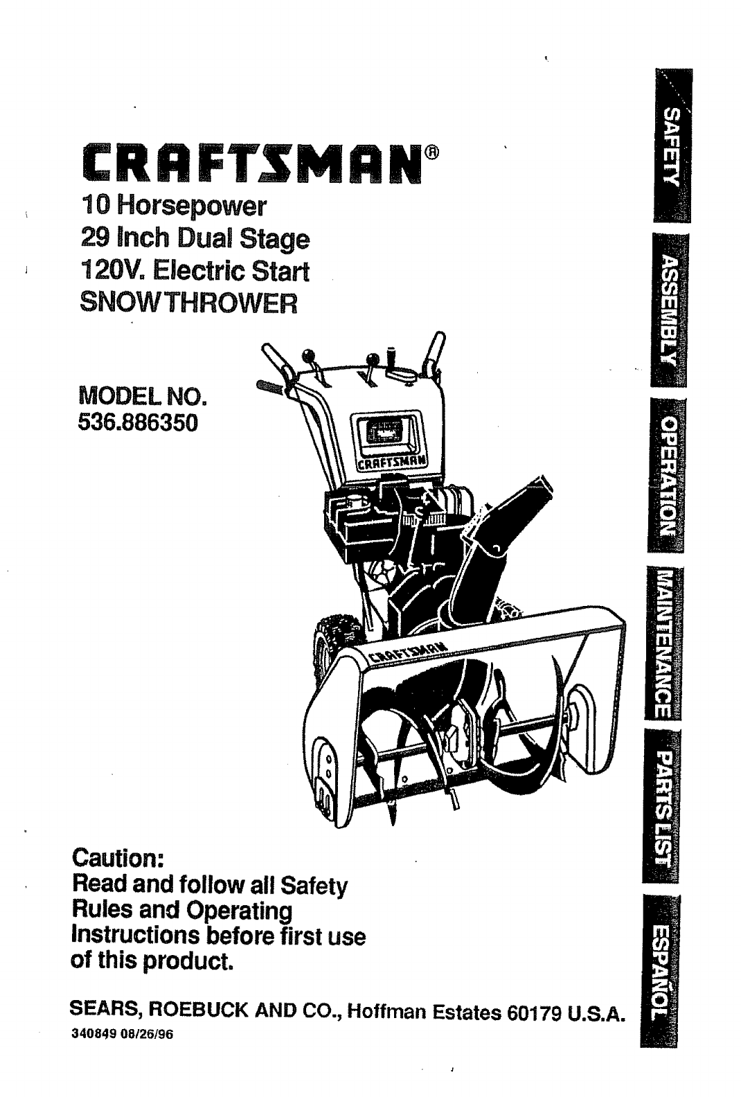
CRRFTSMRW
10 Horsepower
29 Inch Dual Stage
120V. Electric Start
SNOWTHROWER
MODEL NO,
536.886350
Caution:
Read and follow all Safety
Rules and Operating
Instructions before first use
of this product,
SEARS, ROEBUCK AND CO., Hoffman Estates 60179 U.S.A.
340849 08/26/96
Table of Contents 2
Warranty 2
Safety Rules 2-4
Contents of Shipping Carton 4-5
Assembly 5-9
Operation !0-14
Maintenance 15-17
Service and Adjustments 18-23
Storage 24
Troubleshooting 25
Snow Thrower Repair Parts 26-38
Engine Repair Parts 39-42
Spanish(EspaSol) 43-69
Parts Ordering/Service Back Cover
LIMITED TWO-YEAR WARRANTY ON CRAFTSMAN SNOW THROWER
For two years from the date of purchase, when this Craltsman Snow Thrower is main-
tained, lubricated, and tuned up according to the operating and maintenance instruc-
tions in the owner's manual, Sears will repair, free of charge, any defect in material or
workmanship.
if this Craftsman Snow Thrower is used for commercial or rental purposes, this war-
ranty applies for only 90 days from the date of purchase.
This warranty does not cover the following:
-Items which become worn during normal use, such as spark plugs, drive belts and
shear pins.
• Repairs necessary because of operator abuse or negligence, including bent crank
shafts and the failure to maintain the equipment according to the instructions con_
rained in the owner's manual.
WARRANTY SERVICE IS AVAILABLE BY RETURNING THE CRAFTSMAN SNOW
THROWER TO THE NEAREST SEARS SERVICE CENTER/DEPARTMENT IN THE
UNITED STATES, THIS WARRANTY APPLIES ONLY WHILE THIS PRODUCT IS IN
USE IN THE UNITED STATES,
This warranty gives you specific legal rights, and you may also have other rights which
may vary from state to staten
Sears, Roebuck and Co., D817WA, Hoffman Estates, IL 60179
CAUTION: Always disconnect spark
plug wire and place wire where it cannot
contact spark plug to prevent accidental
starting when setting-up, transporting,
adjusting or making repairs.
IMPORTANT: Safety standards require
operator presence controls to minimize the
risk of injury. Your snow thrower is
equipped with such controls° Do not attempt
to defeat the function of the operator
presence control under any circumstances.
TRAINING
1. Read the operator's manual carefully.
Be thoroughly familiar with the controls
and the proper use of the snow thrower.
Know how to stop the snow thrower and
disengage the controls quickly.
2. Never allow children to operate the
snow thrower and keep them away
2
Look for this symbol to point out Important safety precautions, It means---
ATTENTION!!! Become alert!!! Your safety is involved.
3_
,
while it is operating. Never allow adults
to operate the snow thrower without
proper instruction. Do not carry passen-
gers.
Keep the area of operation clear of all
persons, particularly small children and
pets.
Exercise caution to avoid slipping or
falling, especially when operating in
reverse.
PREPARATION
1. Thoroughly inspect the area where the
snow thrower is to be used and remove
all doormats, sleds, boards, wires and
other foreign objects.
Disengage all clutches before starting
the engine (motor).
3. Do not operate the snow thrower
without wearing adequate winter outer
garments. Wear footwear that will
improve footing on slippery surfaces.
4. Handle fuel with care; it is highly
flammable. 6,
(a) Use an approved fuel container.
(b) Never remove fuel tank cap or add
fuel to a running engine or hot
engine.
(c) Fill fuel tank outdoors with extreme 7.
care. Never flit fuel tank indoors.
(d) Replace fuel tank cap securely and
wipe up spilled fuel
(e) Never store fuel or snow thrower 8.
with fuel in the tank inside of a
building where fumes may reach
an open flame or spark,
(f) Check fuel supply before each use,
allowing space for expansion as 9.
the heat of the engine (motor) and/
or sun can cause fuel to expand.
S. Use extension cords and receptacles
as specified by the manufacturer for all 10.
snow throwers with electric drive
motors or electric starting motors.
6. Adjust the snow thrower height to clear
gravel or crushed rock surfaces.
7. Never attempt to make any adjustments
while the engine (motor) is running 11,
(except when specifically recom-
mended by the manufacturer).
8. Let engine (motor) and snow thrower
adjust to outdoor temperatures before 12.
starting to clear snow,
9. Always wear safety glasses or eye 13.
shields during operation or while
performing an adjustment or repair to
protect eyes from foreign objects that
may be thrown from the snow thrower.
OPERATION 14.
1. Do not operate this machine if you are
taking drugs orother medication which 15.
can cause drowsiness or affect your
ability to operate this machine.
2. Do not use this machine if you are
mentally or physically unable to operate 16.
this machine safely_
3. Do not put hands or feet near or under
rotating parts. Keep clear of the 17.
discharge opening at all times.
4. Exercise extreme caution when operat-
ing on or crossing gravel drives, walks, 18.
or roads. Stay alert for hidden hazards
or traffic.
5o After striking a foreign object, stop the
engine (motor), remove the wire from
the spark plug, disconnect the cord on
electric motors, thoroughly inspect the
snow thrower for any damage, and
repair the damage before restarting and
operating the snow thrower.
tf the snow thrower should start to
vibrate abnorrdally, stop the (motor)
check immediately for the cause_
Vibration is generally a warning of
trouble.
Stop the engine (motor) whenever you
leave the operating position, before
unclogging the auger/impeller housing or
discharge guide, and when making any
repairs, adjustments, or inspections,
When cleaning, repairing, or inspecting,
make certain the auger/impeller and all
moving parts have stopped. Disconnect
the spark plug wire and keep the wire
away from the plug to prevent accidental
starting.
Take all possible precautions when
leaving the snow thrower unattended.
Disengage the. auger/impeller, stop
engine, and remove key.
Do not run the engine indoors, except
when starting the engine and for
transporting the snow thrower in or out
of the building. Open the outside doors;
exhaust fumes are dangerous (contain-
ing CARBON MONOXIDE, an ODOR-
LESS and DEADLY GAS).
Do not clear snow across the face of
slopes. Exercise caution when changing
direction on slopes. Do not attempt to
cle.ar steep slopes_
Never operate the snow thrower without
proper guards, plates or other safety
protective devices in place.
Never operate the snow thrower near
glass enclosures, automobiles, window
wells, drop-offs, and the like without
proper adjustment of the snow discharge
angle. Keep children and pets away,
Do not overload the machine capacity by
attempting to clear snow at too fast a
rate,
Never operate the snow thrower at high
transport speeds on slippery surfaces.
Look behind and use care when
backing.
N_ver direct discharge at bystanders or
allow anyone in front of the snow
thrower.
Disengage power to the auger/impeller
when snow thrower is transportedor not
In use.
Use only attachments and accessories
approved by the manufacturer of the
snow thrower (such as tire chains,
electric start kits, etc)_
19o Neveroperatethe snowthrower
withoutgoodvisibilityor lighLAlways
besureof yourfooting,andkeepa
firm holdon the handles_Walk;never
run.
MAINTENANCE AND STORAGE
1. Check shear bolts and other bolts
frequently for proper tightness to be
sure the snow thrower is in safe ,
working condition.
2. Never store the snow thrower with fuel
in the fuel tank inside a building where
ignition sources are present such as
hot water and space heaters, clothes
dryers, and the like. Allow the engine
to cool before storing in any enclosure.
3. Always refer to operator's manual
instructions for important details if the
snow thrower is to be stored for an
extended period.
4. Maintain or replace safety and
instruction labels, as necessary.
5. Run the snow thrower a few minutes
after throwing snow to prevent freeze-
up of the augedimpeller.
,_ WARNING: The engine exhaust
from this product contains chemicals
known to the State of California to cause
cancer, birth defects or other reproductive
harm.
Z_ WARNING: This snow thrower is for
use on sidewalks, driveways and other
ground level surfaces.
Caution should be exercised while using on
steep sloping surfaces. DO NOT USE
SNOW THROWER ON SURFACES
ABOVE GROUND LEVEl. such as roofs of
residences, garages, porches or other such
structures or buildings.
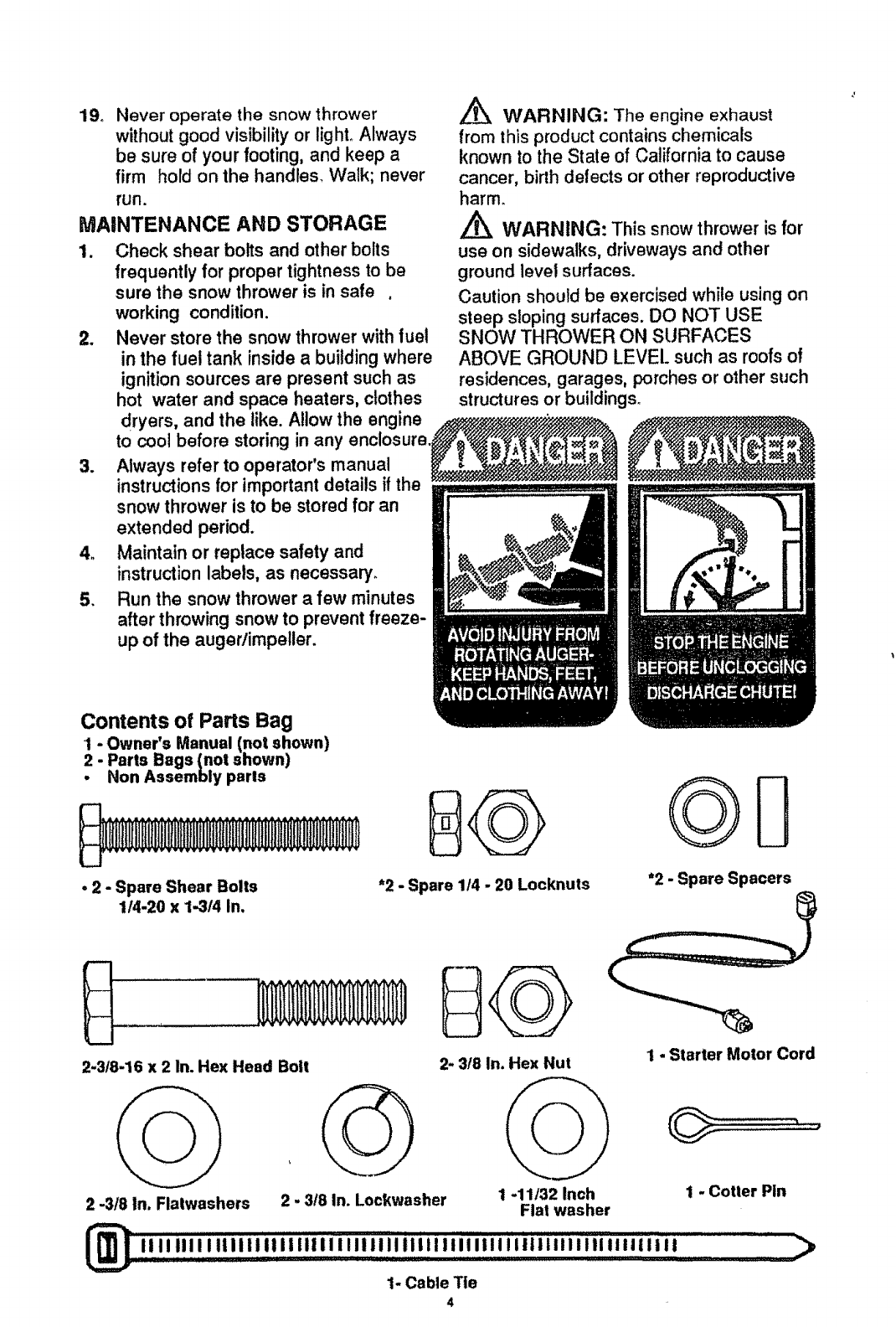
Contents of Parts Bag
- Owner's Manual (not shown)
Parts Bags (not shown)
Non Assembly paris
• 2 -Spare Shear Bolts
114-20 x 1-314 In. *2 - Spare 1/4 -20 Locknuts "2 - Spare Spacers
2.3t8-16 x 2 In. Hex Head Bolt
2.318 In, Flatwashers 2-3/8 In. Lockwasher
2- 3/8 In. Hex Nut
1-11/32 Inch
Flat washer
I - Starter Motor Cord
1-Cotter Pin
,,,,,,,ii,,,,,,,,,,,,.,,,,,,,,,,,,,,,,,,,,,,,,,,,,,,,,,,,,,,,,, >
1- Cable Tie
4
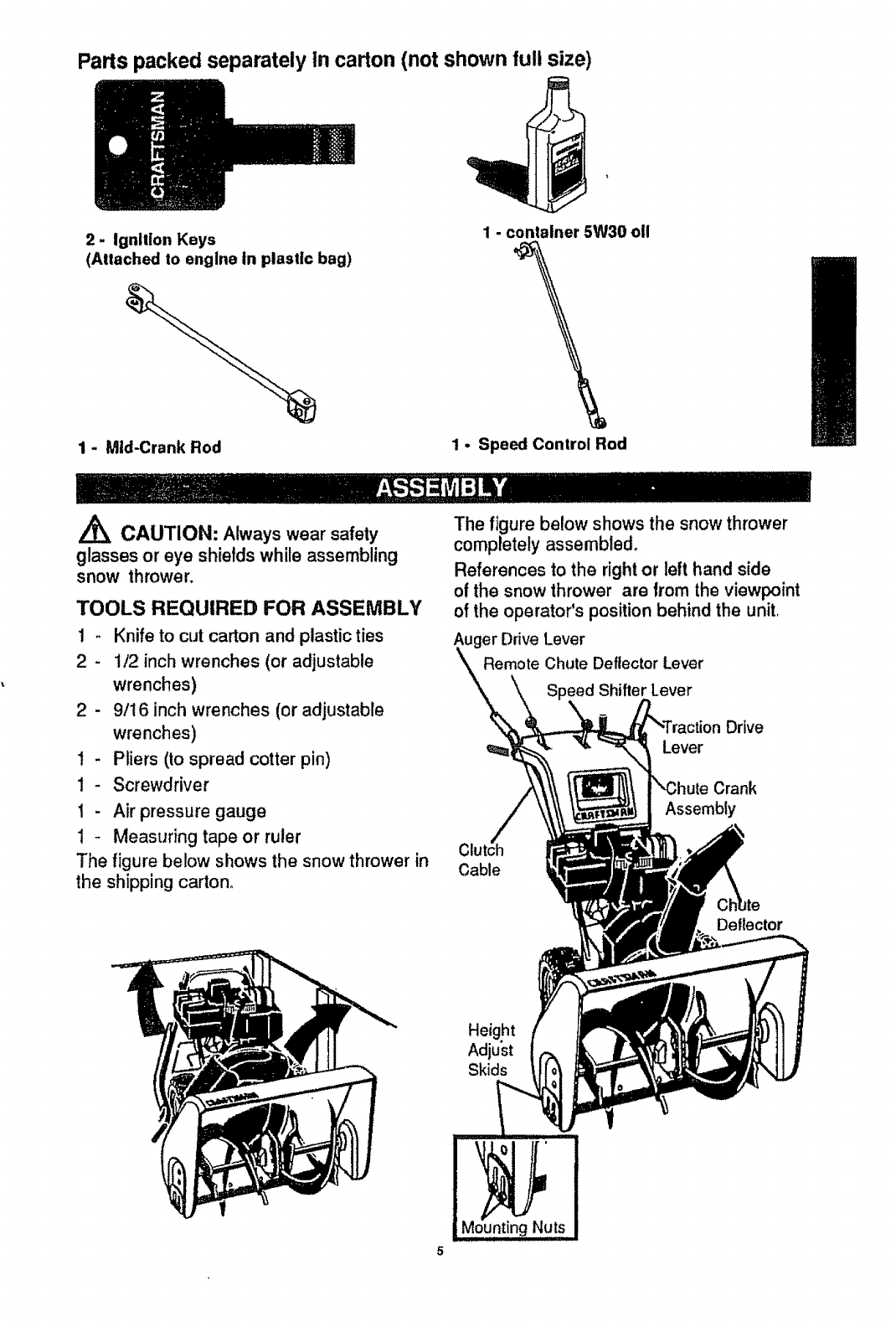
Parts packed separately In carton (not shown full size)
2- Ignlllon Keys
(Attached to engine In plastic bag)
1 - Mid-Crank Rod
1 - container 5W30 oll
1 - Speed Control Rod
/_ CAUTION: Always wear safety
glasses or eye shields while assembling
snow thrower,
TOOLS REQUIRED FOR ASSEMBLY
1 - Knife to cut carton and plasticties
2 - 1/2 inch wrenches (or adjustable
wrenches)
2 - 9/16 inch wrenches (or adjustable
wrenches)
1 - Pliers (to spread cotter pin)
I- Screwdriver
1 - Air pressure gauge
1 - Measuring tape or ruler
The figure below shows the snow thrower in
the shippingcarton,
The figure below shows the snow thrower
completely assembled,
References to the right or left hand side
of the snow thrower are from the viewpoint
of the operator's position behind the unit.
Auger Drive Lever
Remote Chute Deflector Lever
_eedShifter Lever
Drive
Lever
Crank
Assembly
C
Cable
Deflector
Height
Adjust
Skids
5
HOW TO SET UP YOUR SNOW
THROWER
• Locate and remove container of 5W30 oil
and parts bag found in parts box.
. Remove top pallet from carton.
•Cut and discardthe plasticties securing
the mid-chute rod and speed control rod
to the pallet, place them aside. Discard
pallet.
oCut all four corners of the carton from top
to bottom and lay the panels flat.
• Cut the bands holdingthe snowthrower
to the lower pallet°
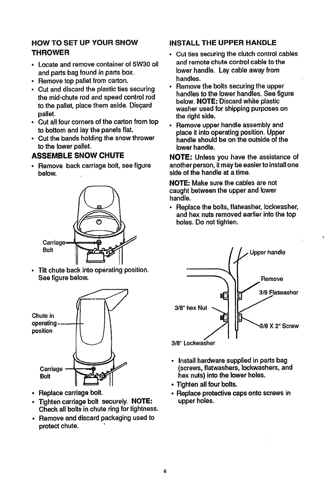
ASSEMBLE SNOW CHUTE
•Remove back carriage bolt, see figure
below.
Bolt
iNSTALL THE UPPER HANDLE
•Cut ties securingthe clutch control cables
and remote chute controlcable to the
lower handle. Lay cable away from
handles.
•Remove the bolts securing the upper
handles to the lower handles, See figure
below. NOTE: Discard white plastic
washer used for shippingpurposes on
the right side.
. Remove upper handle assembly and
place it into operating position.Upper
handle should be on the outside of the
lower handle.
NOTE: Unless you have the assistance of
another person, itmay be easier to installone
side of the handle at a time.
NOTE: Make sure lhe cables are not
caught between the upper and lower
handle.
•Replace the bolts, flatwasher, Iockwasher,
and hex nuts removed earlier into the top
holes. Do not tighten.
. Tilt chute back into operating position.
See figure below.
Chute in
operating---.--.
position
o
O
Carriagew _...,.,_ ._
Bolt
Replace carriage bolt.
lighten carriage bolt securely. NOTE:
Check all boltsin chute ring for tightness,
Remove and discard packaging used to
protect chute.
i lll ii,
3/8"hexNut .-_
L
3t8" Lockwasher
Remove
318 Flatwasher
X2" Screw
•Install hardware supplied in partsbag
(screws, flatwashers, Iockwashers, and
hex nuts) into the lower holes.
°Tighten all four bolts.
°Replace protective caps onto screws in
upper holes.
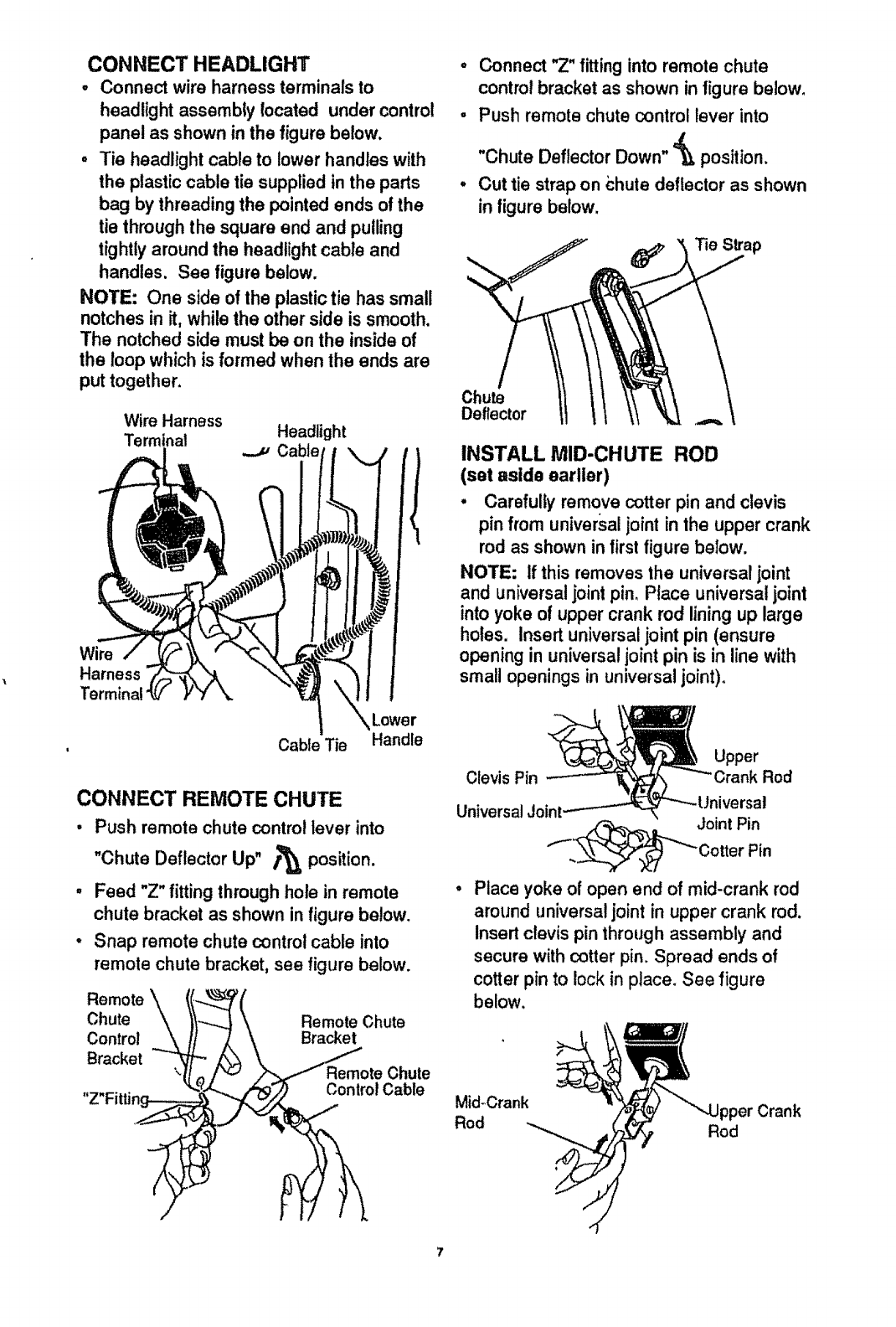
CONNECT HEADLIGHT
• Connectwireharnessterminalsto
headlightassemblylocated undercontrol
panelasshowninthefigurebelow.
• Tie headlightcableto lowerhandleswith
theplasticcabletie suppliedintheparts
bagbythreadingthe pointedends ofthe
tie through the square end and pulling
tightlyaround the headlight cable and
handles. See figure below.
NOTE: One side of the plastictie has small
notches in it, while the other side is smooth.
The notched side must be on the insideof
the loop which is formed when the ends are
put together.
Wire Harness
Terminat Headlight
JCable
Wire
Harness
Termir
Cable Tie
Lower
Handle
CONNECT REMOTE CHUTE
• Push remote chute control lever into
Up" /'_ position.
"Chute Deflector
-Feed "Z" fitting through hole in remote
chute bracket as shown in figure below.
•Snap remote chute control cable into
remote chute bracket, see figure below.
Remote
Chute Remote Chute
Control Bracket
Bracket Chute
Control Cable
o Connect "Z" fittinginto remote chute
control bracket as shown in figure below.
• Push remote chute contro! lever into
"Chute Deflector Down" '=_ position.
°Cut tie strap on chute deflector as shown
infigure below.
Chute
Deflector
INSTALL MID-CHUTE ROD
(set aside earlier)
• Carefully remove cotter pin and clevis
pin from universaljoint in the upper crank
rod as shown in firstfigure below.
NOTE; If this removes the universal joint
and universaljoint pin, Place universal joint
into yoke of upper crank rod liningup large
holes. Insert universal joint pin (ensure
opening in universal joint pin is in line with
small openings in universaljoint),
Upper
Clevis Pin Rod
Universal Joint
.,.__Joint Pin
CotterPin
°Place yoke of open end of mid-crank rod
around universal joint in upper crank rod.
Insert clevis pin through assembly and
secure with cotter pin. Spread ends of
cotter pin to lock in place. See figure
below.
Mid-Crank pper Crank
Rod Rod
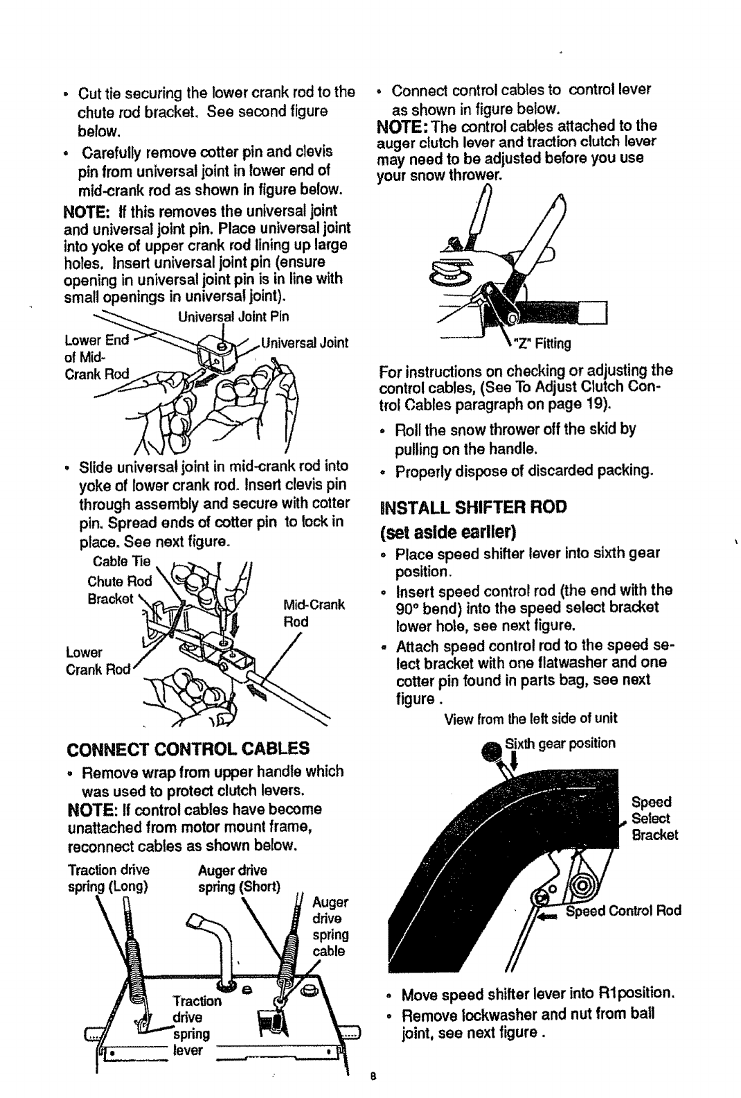
Cut tie securing the rower crank rod to the
chute rod bracket. See second figure
below.
,Carefully remove cotter pin and clevis
pin from universal joint in lower end of
mid-crank rod as shown in figure below.
NOTE: tfthis removes the universaljoint
and universal joint pin. Place universaljoint
into yoke of upper crank rod lining up large
holes, Insert universal joint pin (ensure
opening in universal joint pin is in line with
small openings in universal joint).
"_--..._ UniversalJointPin
LowerEn__"-_.._ _..ttniversal Joint
/
Slide universal, ofntin mid-crank rod into
yoke of lower crank rod. Insert clevis pin
through assembly and secure with cotter
pin. Spread ends of cotter pin to lockin
place. See next figure.
_/// Mid-Crank
Rod
CableTie _._._ ,
ChuteRod "k_-_
Lowo 7"
Crank Rod" @-_
CONNECT CONTROL CABLES
,Remove wrap from upper handle which
was used to protect clutchlevers,
NOTE: If control cables have become
unattached from motor mount frame,
reconnect cables as shown below.
Traction drive Auger drive
(Long) spring (Short)
Auger
ddve
spdng
cable
pdng
_o lever
•Connect controlcabtes to control lever
as shown in figure below.
NOTE: The control cables attached to the
auger clutch lever and traction clutch lever
may need to be adjusted before you use
your snow thrower.
Z" Fitting
For instructionson checking or adjusting the
control cables, (See To Adjust Clutch Con-
trol Cables paragraph on page 19).
o Roll the snow thrower off the skid by
pulling on the handle.
•Properly dispose of discarded packing.
INSTALL SHIFTER ROD
(set aside earlier)
°Place speed shifter lever into sixth gear
position.
•Insert speed control rod (the end with the
90° bend) into the speed select bracket
lower hole, see next figure.
-Attach speed control rod to the speed se-
lect bracket with one flatwasher and one
cotter pin found in parts bag, see next
figure°
Viewfrom theleftsideofunit
Speed
Select
Bracket
Speed Control Rod
o
°
Move speed shifter lever into Rlposition.
Remove lockwasher and nut from ball
joint, see next figure,
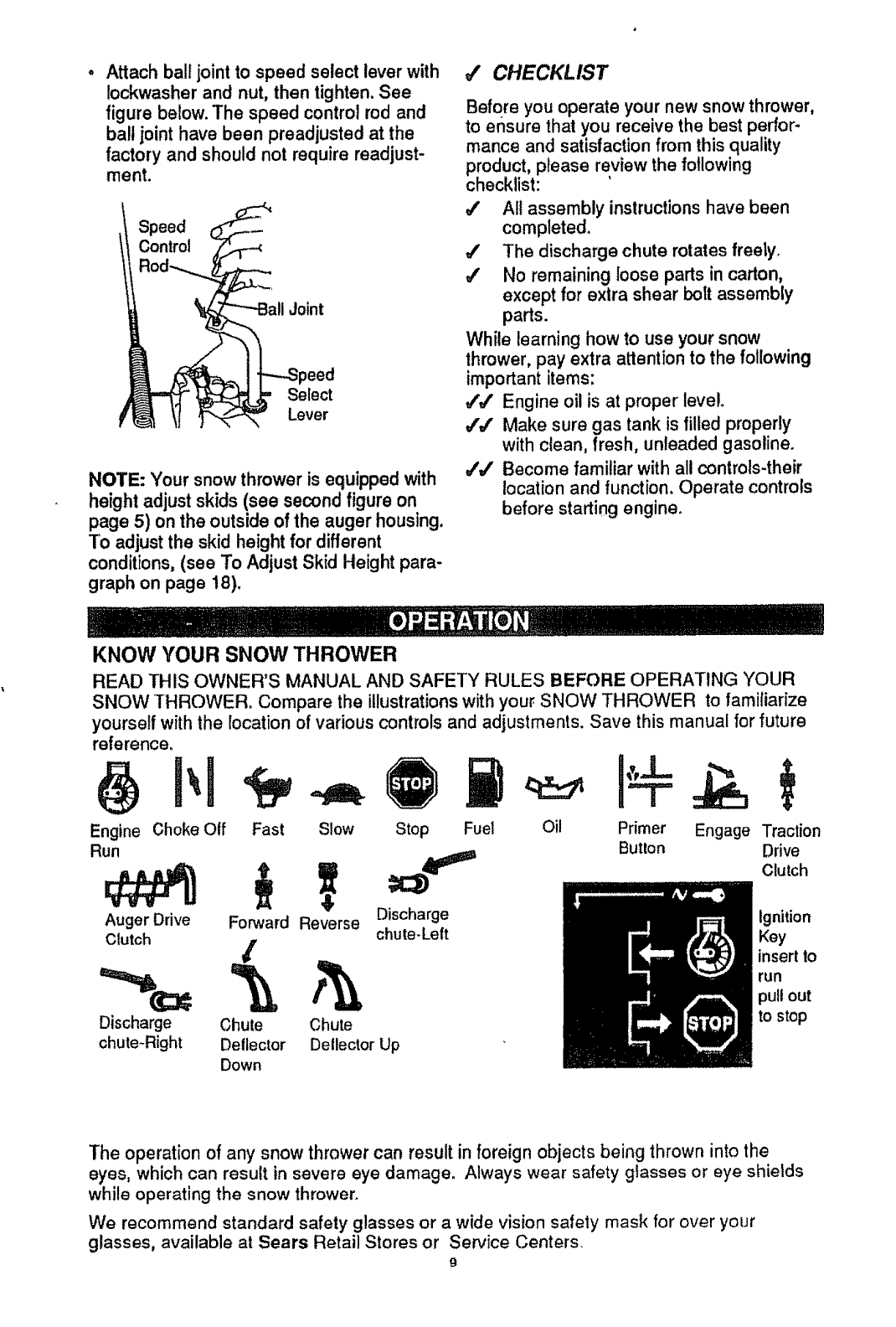
Attach ball joint to speed select lever with
Iockwasher and nut, then tighten. See
figure below. The speed control rod and
ball joint have been preadjusted at the
factory and should not require readjust-
ment.
Speed
Control
Joint
_eed
Select
Lever
NOTE: Your snow thrower is equipped with
height adjust skids (see second figure on
page 5) on the outside of the auger housing.
To adjust the skid height for different
conditions, (see To Adjust Skid Height para-
graph on page t8).
JCHECKLIST
Before you operate your new snow thrower,
to ensure that you receive the best perfor-
mance and satisfaction from this quality
product, please review the following
checklist:
All assembly instructions have been
completed.
#' The discharge chute rotates freety.
4' No remaining loose parts in carton,
except for extra shear bolt assembly
parts.
While learning how to use your snow
thrower, pay extra attention to the following
important items:
J',# Engine oil is at proper level.
#'J Make sure gas tank is filled properly
with clean, fresh, unleaded gasoline.
_'J Become familiar with all controls-their
location and function. Operate controls
before starting engine.
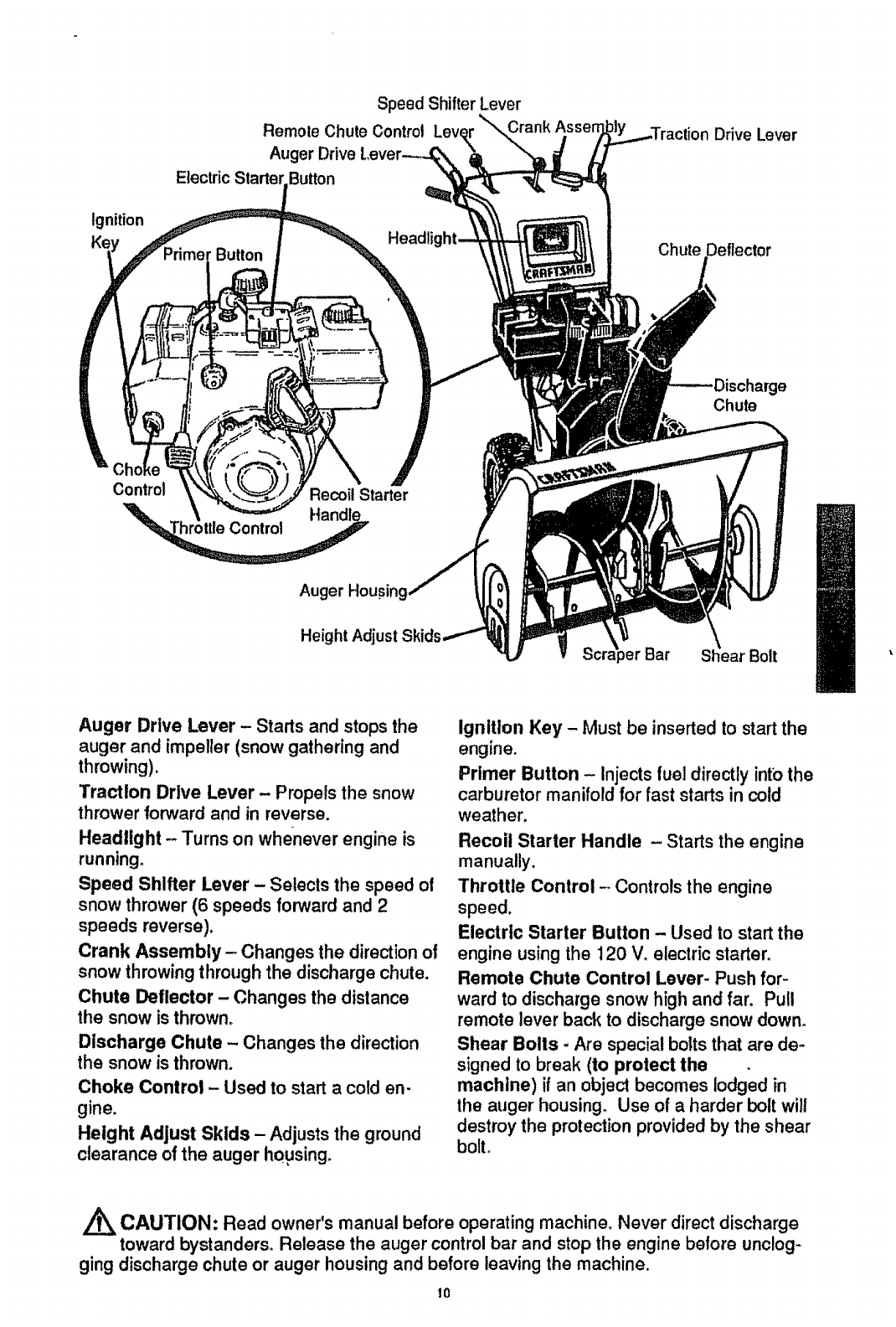
KNOW YOUR SNOW THROWER
READ THIS OWNER'S MANUAL AND SAFETY RULES BEFORE OPERATING YOUR
SNOW THROWER, Compare the illustrationswith your SNOW THROWER to familiarize
yourself with the location ofvarious controls and adjustments, Save this manual for future
reference_
Engine Choke Otf
Run
Auger Drive
Clutch
Fast Slow Stop Fuel
Forward Reverse Discharge
chute-Left
/
Discharge Chute Chute
chute-Right Detlector Detlector Up
Down
Oil Primer Engage Traction
Button Drive
Clutch
Ignition
Key
insert to
run
pullout
to stop
The operation of any snow thrower can result in foreign objects being thrown into the
eyes, which can result in severe eye damage. Always wear safety glasses or eye shietds
while operating the snow thrower_
We recommend standard safety glasses or a wide vision safety mask for over your
glasses, available at Sears Retail Stores or Sewice Centers_
9
ignition
Speed Shifter Lever
Remole Chute Control Lever
\
Auger Drive
Electric Startel Button
Headl
Drive Lever
Chute Deflector
e
Chute
Control
_ttteControl
Recoil Starter
Auger Housing
Height Adjust Bolt
Auger Drive Lever - Starts and stops the
auger and impeller (snow gathering and
throwing),
Traction Drive Lever - Propels the snow
thrower forward and in reverse,
Headlight - Turns on whe_neverengine is
running.
Speed Shifter Lever - Selects the speed of
snow thrower (6 speeds forward and 2
speeds reverse).
Crank Assembly- Changes the direction ol
snow throwing through the discharge chute.
Chute Deflector - Changes the distance
the snow is thrown,
Discharge Chute - Changes the direction
the snow is thrown.
Choke Control - Used to start a cold en-
gine.
Height Adjust Skids - Adjusts the ground
clearance of the auger housing.
Ignition Key - Must be inserted to start the
engine.
Primer Button - Injects fuel directly into the
carburetor manifold for fast starts in cold
weather.
Recoil Starter Handle - Starts the engine
manually.
Throttle Control - Controls the engine
speed.
Electric Starter Button - Used to start the
engine using the 120 V, electric starter.
Remote Chute Control Lever- Push for-
ward to discharge snow high and far. Pull
remote lever back to discharge snow down°
Shear Bolls -Are special bolts that are de-
signed to break (to protect the
machine) if an object becomes lodged in
the auger housing. Use of a harder bolt will
destroy the protection provided by the shear
bolt.
CAUTION: Read owner's manual before operating machine, Never direct discharge
toward bystanders, Release the auger control bar and stop the engine betore unclog-
ging discharge chute or auger housing and before leaving the machine.
10
HOW TO USE YOUR SNOW
THROWER
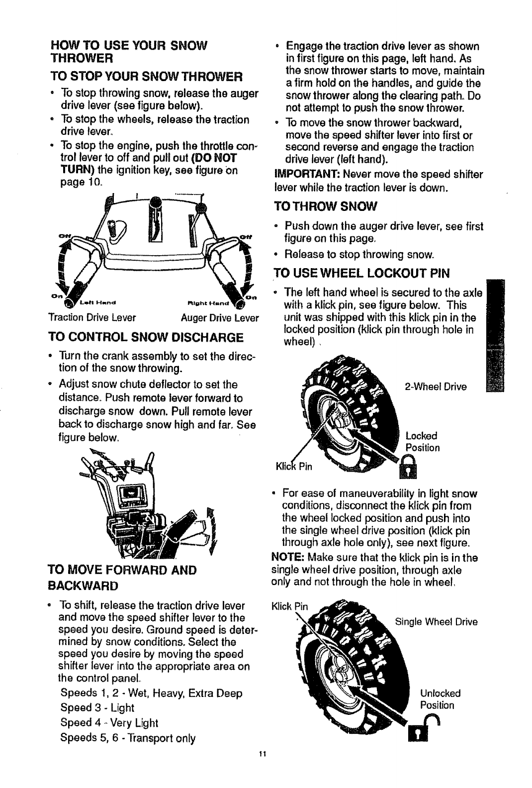
TO STOP YOUR SNOW THROWER
• To stop throwing snow, release the auger
drive lever (see figure below).
. To stop the wheels, release the traction
drive lever.
°To stop the engine, push the throttle con-
trol lever to off and pull out (DO NOT
TURN) the ignitionkey, see figure on
page 10_
Traction Drive Lever Auger Drive Lever
TO CONTROL SNOW DISCHARGE
Turn the crank assembly to set the direc-
tion of the snow throwing.
Adjust snow chute deflector to set the
distance. Push remote lever forward to
discharge snow down. Pull remote lever
back to discharge snow high and far. See
figure be!ow_
•Engage the traction drive lever as shown
in first figure on this page, left hand. As
the snow thrower starts to move, maintain
afirm hold on the handles, and guide the
snow thrower along the clearing path. Do
not attempt to push the snow thrower.
•To move the snow thrower backward,
move the speed shifter lever into first or
second reverse and engage the traction
drive lever (left hand).
IMPORTANT: Never move the speed shifter
lever while the traction lever is down.
TO THROW SNOW
•Push down the auger drive lever, see first
figure on this page.
•Release to stop throwing snow.
TO USE WHEEL LOCKOUT PIN
The left hand wheel is secured to the axle
with a klick pin, see figure below. This
unit was shipped with this klick pin in the
locked position (klick pin through hole in
wheel)
2-Wheet Drive
Locked
Position
TO MOVE FORWARD AND
BACKWARD
To shift, release the traction drive lever
and move the speed shifter lever to the
speed you desire. Ground speed is deter-
mined by snow conditions. Select the
speed you desire by moving the speed
shifter lever into the appropriate area on
the control panel
Speeds !, 2 -Wet, Heavy, Extra Deep
Speed 3 - Light
Speed 4- Very Light
Speeds 5, 6 -"ffansport only
11
• For ease of maneuverability in light snow
conditions, disconnect the klick pin from
the wheel locked position and push into
the single wheel drive position (klick pin
through axle hole only), see next figure.
NOTE: Make sure that the klick pin is in the
single wheel drive position, through axle
only and not through the hole in wheel,
Klick Pin
Single Wheel Drive
Unlocked
Position
BEFORE STARTING THE ENGINE
-if the snow thrower must be moved with-
out the aid of the engine, it is easier to pull
the snow thrower by the handles rather
than pushing°
,Before you service or start the engine, fa-
miliarize yourself with the snow thrower.
Be sure you understand the function and
location of all controls.
NOTE: Check tension of clutch cables be-
fore starting the engine (See To AdjustThe
Control Cables paragraph on page !g).
• Be sure that all fasteners are tight.
° Make sure the height adjust skidsare
properly adjusted (See To Adjust Skid
Height paragraph on page 18).
, Check tire pressure (14 to 17 pounds).
See side of tire for maximum inflation.Do
not exceed listed maximum pressure.
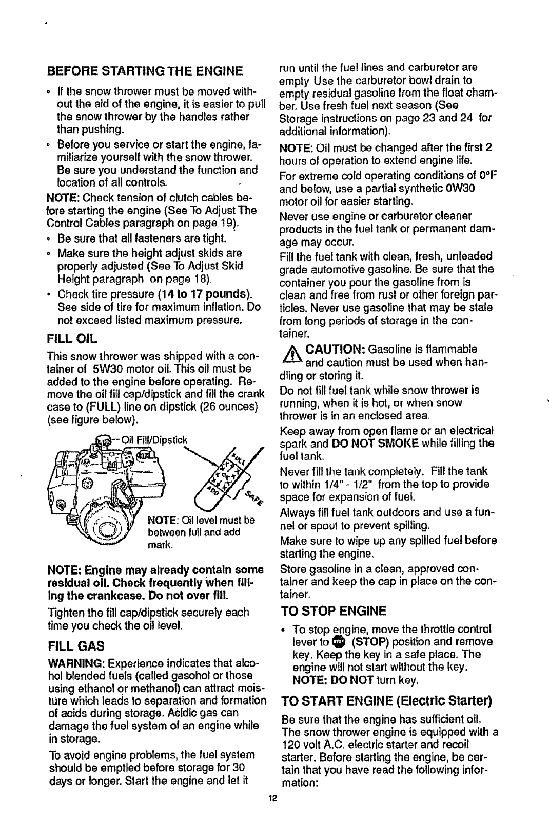
FILL OIL
This snow thrower was shipped with a con-
tainer of 5W30 motor oiloThis oil must be
added to the engine before operating. Re-
move the oil fill cap/dipstick and fill the crank
case to (FULL) line on dipstick (26 ounces)
(see figure below).
Fill/Dipstick
NOTE: Oil level must be
between full and add
mark.
NOTE: Engine may already contain some
residual oil Check frequently When fill-
Ing the crankcase. Do not over fill.
Tighten the fill cap/dipstick securely each
time you check the oil level,
FILL GAS
WARNING: Experience indicates that alco-
hol blended fuels (called gasohot or those
usingethanol or methanol) can attract mois-
ture which leads to separation and formation
of acids during storage. A_idicgas can
damage the fue! system o! an engine while
in storage.
To avoid engine problems,the fuel system
should be emptied before storage for 30
days or longer. Start the engine and let it
12
run until the fuel lines and carburetor are
empty Use the carburetor bow! drain to
empty residual gasoline from the float cham-
ber. Use fresh fuel next season (See
Storage instructions on page 23 and 24 for
additional in!ormation).
NOTE: Oil must be changed after the first 2
hours of operation to extend engine life.
For extreme cold operating conditions of 0°F
and below, use a partial synthetic 0W30
motor oil for easier starting°
Never use engine or carburetor cleaner
products in the fuel tank or permanent dam-
age may occur_
Fill the fuel tank with clean, fresh, unleaded
grade automotive gasoline. Be sure that the
container you pour the gasoline from is
clean and free from rust or other foreign par-
ticles. Never use gasoline that may be state
from long periods of storage in the con-
tainer.
/_ CAUTION: Gasoline is flammable
and caution must be used when han-
dling or storing it.
Do not fil! fuel tank while snow thrower is
running, when it is hot, or when snow
thrower is in an enclosed area.
Keep away from open flame or an electrical
spark and DO NOT SMOKE while filling the
fuel tank.
Never fill the tank completely. Fill the tank
to within 1/4" -1/2" from the top to provide
space for expansion of fuel.
Always fill fue! tank outdoors and use a fun-
nel or spout to prevent spilling.
Make sure to wipe up any spilled fuel before
starting the engine.
Store gasoline in a clean, approved con-
tainer and keep the cap in place on the con-
tainen
TO STOP ENGINE
To stop engine, move the throttle control
lever to _ (STOP) positton and remove
key. Keep the key in a safe place. The
engine will not start without the key.
NOTE: DO NOT turn key.
TO START ENGINE (Electric Starter)
Be sure that the engine has sufficient oil.
The snow thrower engine is equipped with a
120 volt A.Co electric starter and recoil
starter. Before starting the engine, be cer-
tain that you have read the following infor-
mation:
,_k CAUTION: This starter is equipped
Z.L%with a three-wire power cord and plug
and is designed to operate on 120 volt AC
household current. It must be properly
grounded at a!l times to avoid the possibility
of electrical shock which may be injuriousto
operator. Follow all instructionscarefully as
set forth in the "To Start Engine" section.
Determine that your housewiring is a three-
wire grounded system. Ask alicensed elec-
trician if you are notsure, If your house
wire system is not a three-wire system, do
not use this electric starter under any condi-
tions. If your system is grounded and a
three-hole receptacle is not available at the
point your starter will normallybe used, one
should be installed by a licensed electrician.
When connecting 120 volt AC power cord,
always connect the cordto the switchbox
on the engine first,then plug the other end
intothe three-hole grounded receptacle.
When disconnectingpower cord, always
unplug the end in the three-hole grounded
receptacle first.
COLD START
•Be sure the auger drive and traction drive
levers are in the disengaged (released)
position_
•Move the throttle control to _ (FAST)
position, See figure on page 10.
o Remove the keys from the plastic bag°
Insert one key into the ignition slot. Be
sure it snaps into place_ DO NOT TURN
KEY. Keep the second key in a safe
place.
• Rotate the choke knob to (FULL) choke
position. See figure on page 10o
• Connect the power cord to the switch box
on the engine.
•Plug the other end of the power cord into
a three-hole, grounded 120 volt A.C.
receptacle_
°Push the primer button while covering the
vent hole as follows: (Remove finger from
primer button between primes). See
figure on page 10 for location.
Do not prime if temperature is above
50°F.
Two times if temperature is 50°F to 15°F.
Four times if temperature is below 15°F.
Push down on the starter button until the
engine starts. Do not crank for more than
10 seconds at a time° This electric starter
is thermall_i protected, tf overheated it will
stop automatically and can be restarted
only when it has cooled to a safe
temperature (a wait of about 5 to 10
minutes is required).
•When the engine starts, release the
starter button an€ slowly rotate the choke
to (OFF) position, tf the engine falters,
rotate the choke to(FULL) and then
gradually to (OFF).
,Disconnect the power cord from the
receptacle first and then from the switch
box on engine.
NOTE: Allow the engine to warm up for a
few minutes because the engine will not de-
velop full power until it reaches operating
temperature.
•Run the engine at full throttle _ (FAST)
when throwing snow_
TO START ENGINE (Recolt Starter)
Be sure that the engine has sufficient oil.
The snow thrower engine is equipped with a
recoil starter. Before starting the engine, be
certain that you have read the following in-
formation:
COLD START
• Be sure the auger drive and traction drive
levers are in the disengaged (released)
position.
• Move the throttle control to '_ (FAST)
position. See figure on page 10 for loca-
tion.
•Remove the keys from the plastic bag. In-
sert one key into the ignition slot. Be sure
it snaps into place. DO NOT TURN KEY°
Keep the second key in a safe place.
, Rotate the choke control to (FULL) choke
position. See figure on page t 0"
• Push the primer button, see figure on
page 10, while covering the vent hole as
follows: (Remove finger from primer but-
ton between primes).
Do not prime if temperature is above
50oE
Two times if temperature is 50°F to 15°E
Four times if temperature is below 15°F.
° Pull the recoil starter handle rapidly. Do
not allow the handle to snap back, but al-
low it to rewind slowly while keeping a
firm hold on the starter handle.
13
•As the engine warms up and begins to op-
erate evenly, rotate the choke control
slowly to the (OFF) position. If the engine
falters, return to (FULL) choke, then
slowly move to the (OFF) position.
NOTE: Allow the engine to warm up for a
few minutes because the engine will not de-
velop full power until it reaches operating
temperature_
-Run the engine at full throttle ,tEp (FAST)
when throwing snow.
WARM START
If restarting a warm engine after a short
shutdown, leave choke at (OFF) and do not
push the primer button. If the engine fails to
start, follow the Cold Start instructions
above_
FROZEN RECOIL STARTER
if the starter Is frozen and will not turn
engine:
.Pull as much rope out of the starter as
possible.
-Release the starter handle and let it snap
back against the starter_
If the starter still fails to turn engine, repeat
the two previous steps until the starter en-
gages. Then continue with the directions for
cold start.
To help prevent possible freeze-up of recoil
starter and engine controls, proceed as fol-
lows after each snow removal job.
•With the engine running, pull the starter
rope hard with a continuous full arm
stroke three or four times. Pulling of
starter rope will produce a loud clattering
sound° This is not harmful to the engine or
starter.
•With the engine not running, wipe all
snow and moisture from the carburetor
cover in area of control levers. Also move
throttle control, choke control, and starter
handle several times_
_ CAUTION: Never run engine indoors
or in enclosed, poorly ventilated areas.
Engine exhaust contains carbon monoxide,
an odorless and deadly gas. Keep hands,
feet, hair and loose clothing away from any
moving parts on engine and snow thrower.
WARNING: Temperature of muffler and
nearby areas may exceed 150 ° F. Avoid
these areas.
DO NOT allow children or young teenagers
to operate or be near snow thrower while it
is operating.
t4
_ CAUTION: Do no attempt to remove
any item that may become lodged in
auger without taking the following precau-
tions:
°Release auger drive and traction drive
levers.
•Move throttle lever to stop position.
•Remove (DO NOT TURN) ignition key.
•Disconnect spark plug wire.
•Do not place your hands in the auger or
discharge chute. Use a pry bar.
SNOW THROWING TIPS
°For maximum snow thrower efficiency in
removing snow, adjust ground speed,
NEVER the throttle. Go slower in deep,
freezing, or wet snow. if the wheels slip,
reduce forward speed. The engine is de-
signed to deliver maximum performance
at ful! throttle and should be run at this
power setting at all times. Most efficient
snow blowing is accomplished when the
snow is removed immediately after it falls.
° For complete snow removal, slightly over-
lap each path previously taken_ Use more
overlap in deep snow to prevent overroad-
ingo
•The snow should be discharged down
wind whenever possible, in windy condi_
tions, lower the chute deflector to direct
discharged snow close to the ground,
where it is less likely to b_ow into un-
wanted areas.
•For normal usage, set the skids so that
the scraper bar is 1/8" above the skids.
For extremely hard-packed snow sur-
faces, adjust the skids upward so that the
scraper bar touches the ground.
•On gravel or crushed rock surfaces, set
the skids at 1-1/4" below the scraper bar
(See To Adjust Skids Height paragraph on
page 18). Stones and gravel must not be
picked up and thrown by the machine.
°After the snow throwing job has been
completed, allow the engine to idle for a
few minutes, which will melt snow and ac-
cumulated ice off the engine.
•Clean the snow thrower thoroughly after
each use.
Remove ice and snow accumulation and
all debris from the entire snow thrower,
and flush with water (if possible) to re-
move all salt or other chemicals. Wipe
snow thrower dry.

CUSTOMER RESPONSIBILITIES
SERVICE
RECORDS
FEll In dates as Alter
you complete tlmt 2
regular service Houm
SCHEDULE SERVICE
DATES
ii ',, ,,_r., I I' I
Before A_ '" Every Every Every Each 'Elofore*
Each eded 5 10 25 Season Storage
Use Hours Hours .!ours
!Tighten All Screws &Nuts
Lubricate Pivot Points
Lubricate AugerShaft(See
Shear Bolt Replacement
Lubricate DiscDrive Plate Zerk
CheckSparkPlug
CheckEngineOilLevel ..... tv_ ++_
ChangeEngineOil • .......... m ...... u : ::: .....
Check Fuel
Drain Fuel I,j
(_heckAugerClutchCable p_ .... = "
Adjustment ISee Cable Adj) , = ................. • ....
Chec'k'Tra.ct+on_lutch C'able " ' ....... " : ................................
Adjustment (See CableAdj) _ ,I"4
Check Drive Belts p_
PRODUCT SPECIFICATIONS
HORSE POWER: 10 HP
DISPLACEMENT: 21.82 cu. in.
GASOLINE CAPACITY: 4 quart
(unleaded)
OIL (26 oz. Capacity) : 5W-30
SPARK PLUG: Champion RJ19LM
(Gap .030) or
Equivalent
VALVE CLEARANCE: Intake: 0.10 In.
Exhaust: .010 In.
GENERAL RECOMMENDATIONS
+.
, n ..
..... =_ - :: : f
B
v"
,, _' _, .......
Some adjustments will need to be made pe-
riodicallyto properly maintain your snow
thrower+
LUBRICATION CHART
Lubricate
Disc Drive
Plate Zerk
witha Hi
Temp EP
Moly Grease.
The warranty on this snow thrower does not
cover items that have been subjected to op-
erator abuse or negligence. To receive full
value from the warranty, the operator must
maintain the snow thrower as instructed in
this manual. The above chart is provided to
assist the operator in properly maintaining
the snow thrower. Lubricate the Auger Shaft,
Coat withaclingingtype grease
such as Lubriptateor fiber
impregnated grease,
t5
SNOW THROWER
AFTER FIRST USE
•Check for any loose or damaged parts
after each use.
-Tighten any loose fasteners°
• Check and maintain the auger.
AFTER EACH USE
•Remove all snow and slush off the snow
thrower to prevent freezing of auger' or
controls.
.Check controls to make sure they are
functioning properly.
•If any parts are worn or damaged, replace
immediately.
SNOW TH ROWER
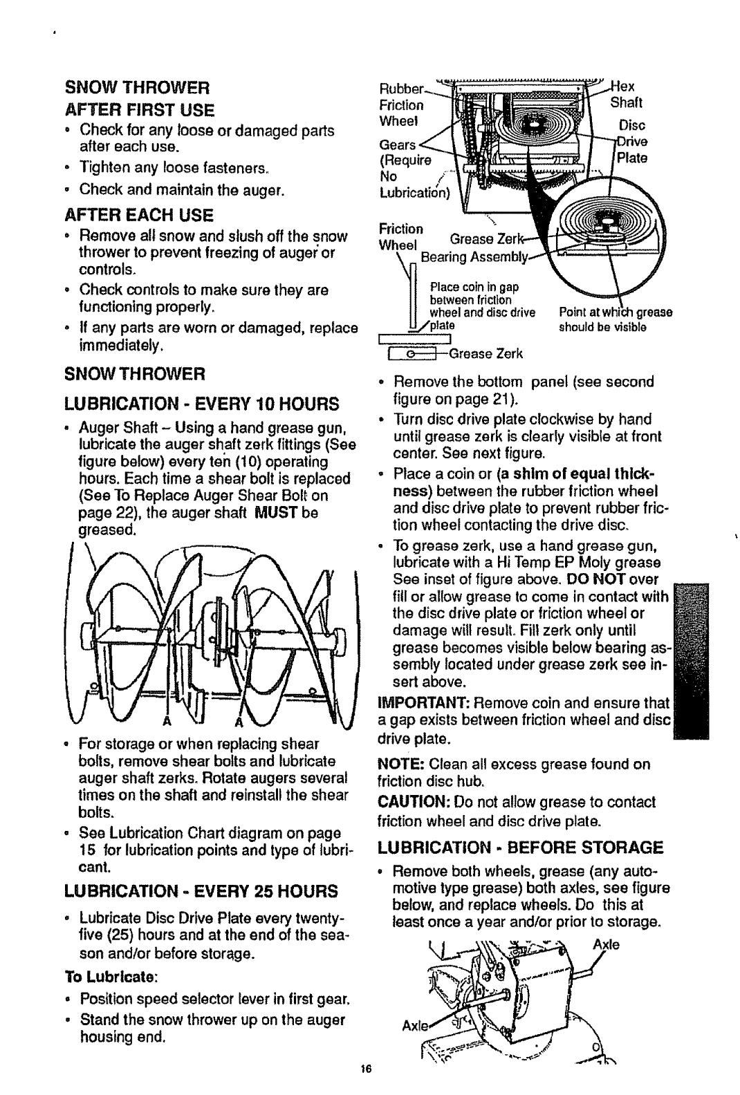
LUBRICATION -EVERY 10 HOURS
Auger Shaft - Using a hand grease gun,
lubricate the auger shaft zerk fittings (See
figure below) every ten (10) operating
hours. Each time a shear bolt is replaced
(See To Replace Auger Shear Bolt on
page 22), the auger shaft MUST be
greased,
A
For storage or when replacingshear
bolts, remove shear boltsand lubricate
auger shaft zerks. Rotate augers several
times on the shaft and reinstallthe shear
bolts.
See Lubrication Chart diagram on page
15 for lubrication points and type of lubri-
cant.
LUBRICATION -EVERY 25 HOURS
° Lubricate Disc Drive Plate every twenty-
five (25) hours and at the end of the sea-
son andlor before storage.
To Lubricate:
,Positionspeed selector lever in firstgear.
• Stand the snow thrower up on the auger
housing end.
Friction
Wheel
(Require
No /
•,#
Lubncat_on)
Shaft
Disc
we
Plate
Friction
Wheel Grease
Bearing
Placecoiningap
betweenfriction
wheeland discdrive
._,,/ptate
L!
_t--Grease Zerk
Point grease
should be visible
.Remove the bottom panel (see second
figure on page 21 ).
•Turn disc drive plate clockwise by hand
until grease zerk is clearly visible at front
center. See next figure.
° Place a coin or (a shim of equal thick-
ness) between the rubber friction wheel
and disc drive plate to prevent rubber fric-
tion wheel contacting the drive disc.
•To grease zerk, use a hand grease gun,
lubricate with a Hi Temp EP Moly grease
See inset of figure above. DO NOT over
fill or allow grease to come in contact with
the disc drive plate or friction wheel or
damage will result. Fill zerk only until
grease becomes visible below bearing as-
sembly located under grease zerk see in-
sert above.
IMPORTANT: Remove coin and ensure that
agap exists between friction wheel and disc
drive plate.
NOTE: Clean all excess grease found on
friction disc hub,
CAUTION: Do not allow grease to contact
friction wheel and disc drive plate.
LUBRICATION -BEFORE STORAGE
Remove both wheels, grease (any auto-
motive type grease) both axles, see figure
below, and replace wheels. Do this at
least once a year and/or priorto storage.
Axle
i6
LUBRICATION
,Hex Shaft and Gears- Hex shaft and
gears require no lubrication. All bearings
and bushings are lifetime lubricated and
require no maintenance.
NOTE: Any greasing or oiling of the above
components can cause contamination of
the friction wheel, if the discdrive plate or
friction wheel comes in contact withgrease
or oil, damage to the friction wheel wil!re-
suit.
Should grease or oi! come in contact with
the disc drive plate or friction wheel, be sure
to clean the plate and wheel thoroughly.
NOTE: For storage, the hex shaft and
gears should be wiped with 5W-30 motor oil
to prevent rusting. See first figure on this
page.
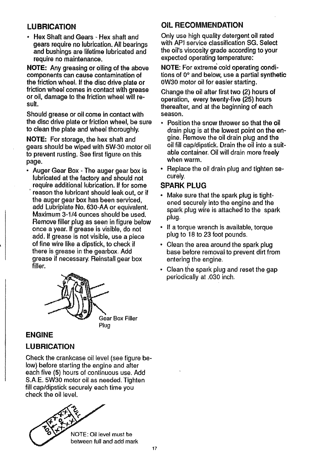
.Auger Gear Box - The auger gear box is
lubricated at the factory and should not
, require additional lubrication. If for some
reason the lubricant should leak out, or if
the auger gear box has been serviced,
add Lubriplate No. 630-AA or equivalent.
Maximum 3-1/4 ounces should be used.
Remove filler plug as seen in figure below
once a year. If grease is visible, do not
add. if grease is not visible, use a piece
of fine wire like a dipstick, to check if
there is grease in the gearbox. Add
grease if necessary. Reinstall gear box
filler.
OIL RECOMMENDATION
Only use high quality detergent oil rated
with API service classification SG. Select
the oil's viscosity grade according to your
expected operating temperature:
NOTE: For extreme' cold operating condi-
tions of 0°and below, use a partial synthetic
0W30 motor oil for easier starting.
Change the oil after first two (2) hours of
operation, every twenty-five (25) hours
thereafter, and at the beginning of each
season.
Position the snow thrower so that the oil
drain plug is at the lowest point on the en-
gineo Remove the oil drain plug and the
oil fill cap/dipstick. Drain the oil into a suit-
able container. Oil will drain more freely
when warm.
- Replace the oil drain plug and tighten se-
curely,
SPARK PLUG
Make sure that the spark plug is tight-
ened securely into the engine and the
spark plug wire is attached to the spark
plug_
•if atorque wrench is available, torque
plug to 18 to 23 foot pounds°
° Clean the area around the spark plug
base before removal to prevent dirt from
entering the engine.
•Clean the spark plug and reset the gap
periodically at .030 inch.
Gear Box Filler
Plug
ENGINE
LUBRICATION
Check the crankcase oil level (see figure be-
low) before starting the engine and after
each five (5) hours of continuous use. Add
S.A.E. 5W30 motor oil as needed° Tighten
fill cap/dipstick securely each time you
check the oil level.
el must be
nd add mark 17
Z_ CAUTION: Always disconnect the
spark plug wire and tie back away from
the plug before making any adjustments
or repairs.
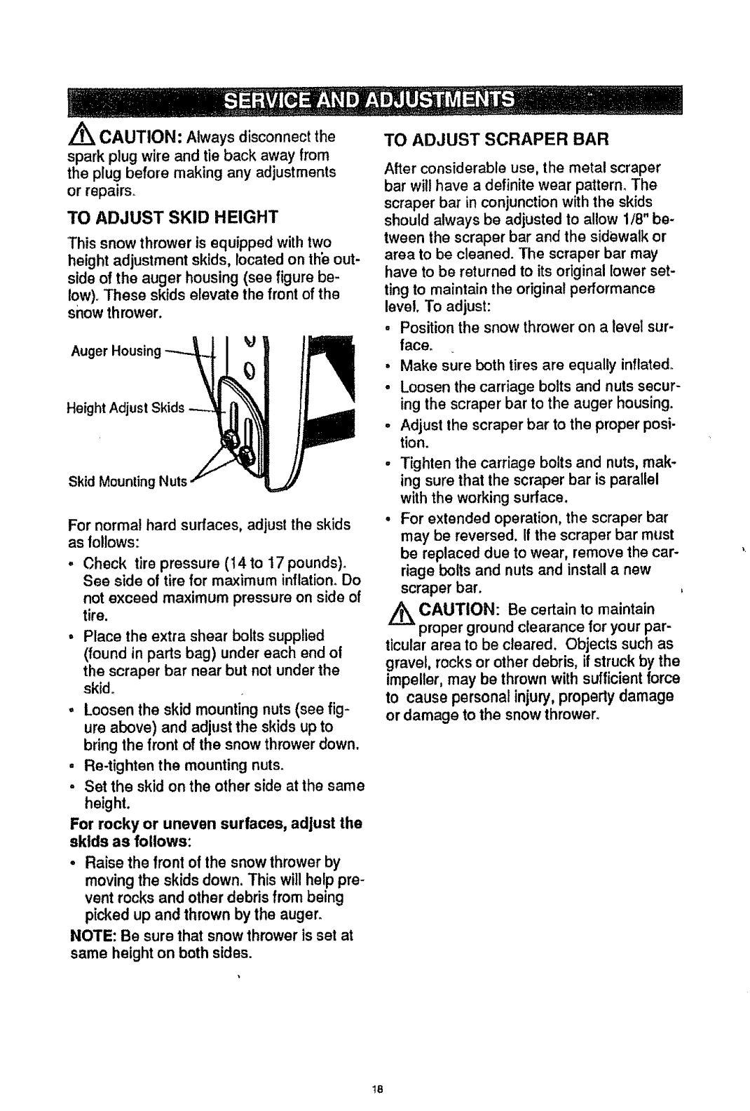
TO ADJUST SKID HEIGHT
*Thissnow thrower is equipped with two
height adjustment skids, located on th_ out-
side of the auger housing (see figure be-
low). These skids elevate the front of the
snow thrower.
Auger Housing
Height Adjust Skids
Skid Mounting Nuts
For normal hard surfaces, adjustthe skids
as tollows:
° Check tire pressure (14 to 17 pounds).
See side of tire for maximum inflation.Do
not exceed maximum pressure on side of
tire.
•Place the extra shear bolts supplied
(found in parts bag) under each end of
the scraper bar near but not under the
skid°
•Loosen the skid mounting nuts (see fig-
ure above) and adjust the skids up to
bring the front of the snow thrower down.
• Re-tighten the mounting nuts.
• Set the skid on the other side at the same
height.
For rocky or uneven surfaces, adjust the
skids as follows:
• Raise the front of the snow thrower by
movingthe skids down. This will help pre-
vent rocks and other debris from being
picked up and thrown by the auger_
NOTE: Be sure that snow thrower is set at
same height on both sides.
TO ADJUST SCRAPER BAR
After considerable use, the metal scraper
bar will have a definite wear pattern. The
scraper bar in conjunction with the skids
should always be adjusted to allow 1/8" be-
tween the scraper bar and the sidewalk or
area to be cleaned. The scraper bar may
have to be returned to its original lower set-
ting to maintain the original performance
level. To adjust:
•Position the snow thrower on a level sur-
face.
oMake sure both tires are equally inflated.
•Loosen the carriage bolts and nuts secur-
ing the scraper bar to the auger housing.
•Adjust the scraper bar to the proper posi-
tion.
•Tighten the carriage bolts and nuts, mak-
ing sure that the scraper bar is parallel
with the working surface.
•For extended operation, the scraper bar
may be reversed. If the scraper bar must
be replaced due to wear, remove the car-
riage bolts and nuts and install a new
scraper bar.
CAUTION: Be certain to maintain
proper ground clearance for your par-
ticular area to be cleared, Objects such as
gravel, rocks or other debris, if struck by the
impeller, may be thrown with sufficient force
to causepersonalinjury,property damage
or damage to the snow thrower,
18
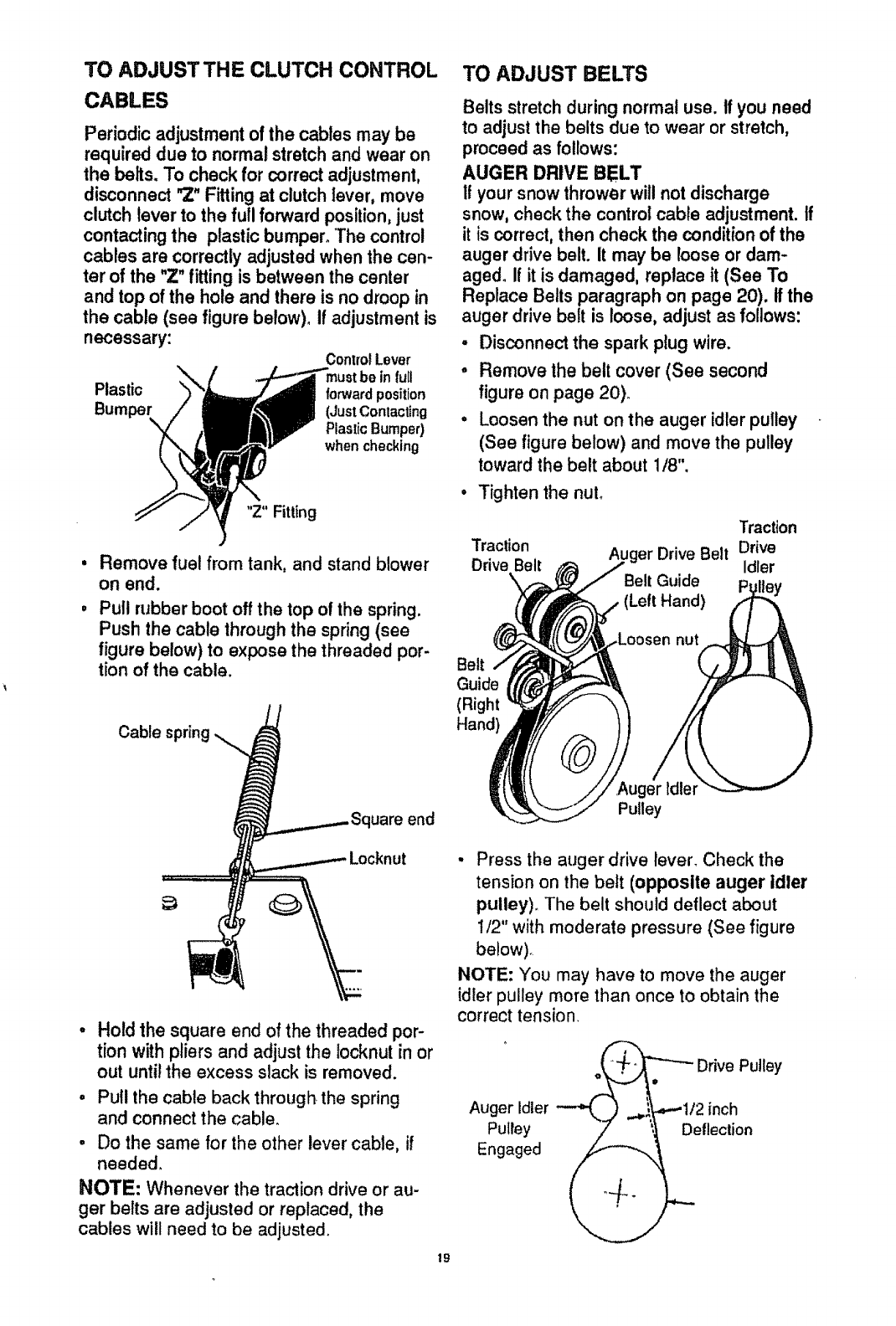
TO ADJUSTTHE CLUTCH CONTROL
CABLES
Periodic adjustment ofthe cables may be
required due to normal stretch and wear on
the belts. To check for correct adjustment,
disconnect "Z"Fitting at clutch lever, move
clutch lever to the full forward position,just
contacting the plastic bumper°"Thecontrol
cables are correctly adjusted when the cen-
ter of the "Z"fitting is between the center
and top of the hole and there is no droop in
the cable (see figure below)° If adjustment is
necessary: ControlLever
infull
Plastic forwardposition
(JustContacting
PlasticBumper)
when checking
"Z" Fitting
Remove fuel from tank, and stand blower
on end.
Pull rubber boot off the top of the spring.
Push the cable through the spring (see
figure below) to expose the threaded por-
tion of the cable.
Cablespring._,_ Squareend
======_/_._ Locknut
° Hold the square end of the threaded por-
tion with pliers and adjust the Iocknut in or
out until the excess slack is removed.
o Pull the cable back through the spring
and connect the cable.
.Do the same for the other lever cable, if
needed.
NOTE: Whenever the traction drive or au-
ger belts are adjusted or replaced, the
cables will need to be adjusted.
19
TO ADJUST BELTS
Belts stretch during normal use. If you need
to adjustthe belts due to wear or stretch,
proceed as follows:
AUGER DRIVE BELT
If your snowthrower will not discharge
snow, check the controlcable adjustment. If
it is correct,then check the conditionof the
auger drive belt. It may be loose or dam-
aged. If it is damaged, replace it (See To
Replace Belts paragraph on page 20). If the
auger drive belt is loose, adjust as follows:
• Disconnect the spark plug wire.
°Remove the belt cover (See second
figure on page 20)_
° Loosen the nut on the auger idler pulley
(See figure below) and move the pulley
toward the belt about 1/8".
Tighten the nuL
Traction
Traction Auger Drive Belt Drive
Drive Belt Idler
Belt Guide ey
(Left Hand)
Belt
Guide
(Right
Hand)
nut
,Auger idler
Pulley
•Press the auger drive lever. Check the
tension on the belt (opposite auger idler
pulley). The belt should deflect about
!/2" with moderate pressure (See figure
below).
NOTE: You may have to move the auger
idler pulley more than once to obtain the
correct tension.
" _.+_2,_ Drive Pulley
Auger idler "-""L__) ..._--'1/2 inch
Pulley __ ._Deflection
Engaged
-Replace the belt cover°
• Check the clutch control cable
adjustment.
o Reconnect the spark plug wire.
TRACTION DRIVE BELT
The traction drive belt (see figure below)
has constant spring pressure and does not
require adjustment.
• Replace the traction drive belt if it is slip-
ping (see To Replace Belts paragraph on
this page).
TO REPLACE BELTS
The drive belts on this snow thrower are of
special construction ahd should be replaced
with original equipment belts available from
your nearest SEARS Store or Service Cen-
ter.
You wilt need the assistance of a second
person while replacing the belts.
Drain the gasoline from the fuel tank by re-
moving the fuel line at the carburetor. Drain
the gas into acontainer and reinstall the
fuel line.
,/_ CAUTION: Drain the gasoline out-
doors, away from the fire or flame.
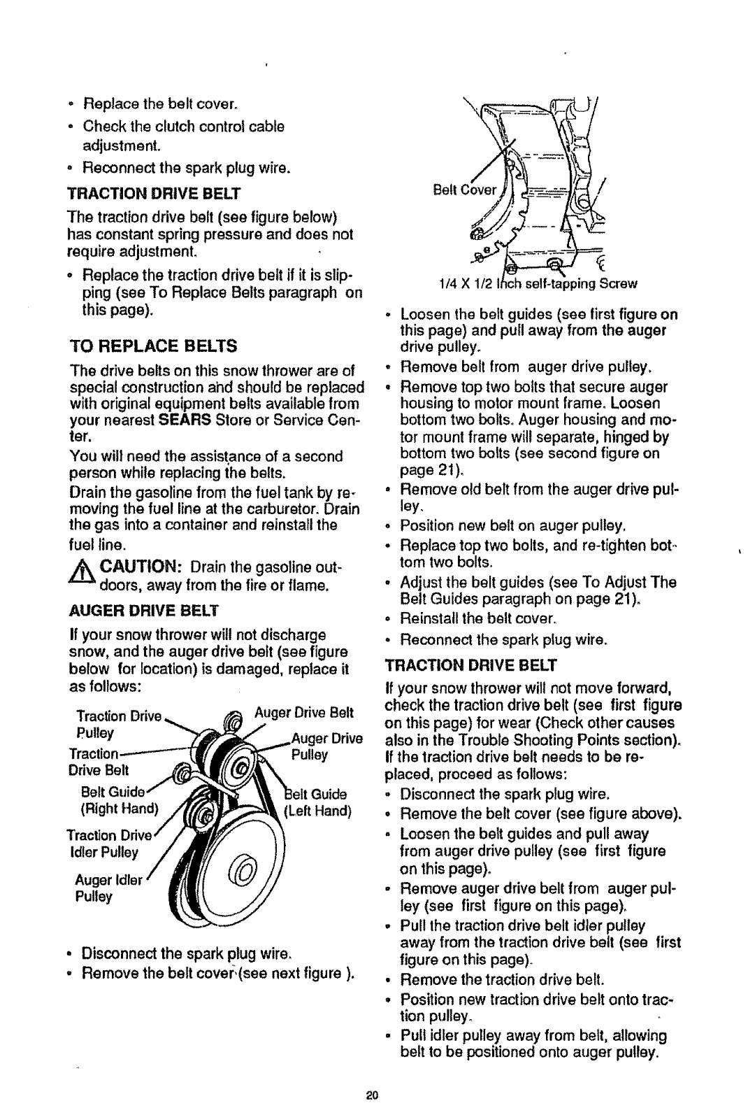
AUGER DRIVE BELT
If your snow thrower will not discharge
snow, and the auger drive belt (see figure
below for location) is damaged, replace it
as follows:
Traction Drive Auger Drive Belt
Pulley
Traction Pulley
Drive Belt
Belt Guide
(Right Hand) (Left Hand)
Traction
Idler Pulley
Auger
Pulley
°Disconnect the spark plug wire.
,Remove the belt covm:.(see next figure ).
\
/
1/4 X 1/2 =ppingScrew
•Loosen the belt guides (see tirst figure on
this page) and pull away from the auger
drive pulley.
•Remove belt from auger drive pulley,
• Remove top two bolts that secure auger
housing to motor mount frame. Loosen
bottom two bolts. Auger housing and mo-
tor mounl frame will separate, hinged by
bottom two bolts (see second figure on
page 2t).
, Remove old belt from the auger drive pul-
ley.
o Position new belt on auger pulley,
° Replace top two bolts, and re-tighten bet..
tom two bolts.
° Adjust the belt guides (see To Adjust The
Belt Guides paragraph on page 21)o
° Reinstall the belt cover.
, Reconnect the spark plug wire.
TRACTION DRIVE BELT
If your snow thrower will not move forward,
check the traction drive belt (see first figure
on this page) for wear (Check other causes
also in the Trouble Shooting Points section).
If the traction drive belt needs to be re-
placed, proceed as follows:
• Disconnect the spark plug wire.
• Remove the belt cover (see figure above).
° Loosen the belt guides and pull away
from auger drive pulley (see first figure
on this page).
-Remove auger drive belt from auger pul-
ley (see first figure on this page).
- Pul! the traction drive belt idier pulley
away from the traction drive belt (see first
figure on this page).
• Remove the traction drive belt.
•Position new traction drive belt onto trac-
tion pulley°
• Pult idler pulley away from belt, allowing
belt to be positioned onto auger pulley.
20
. Release idler pulley, Ensure idler pulley
is properly engaged with belt,
° Reinstall auger drive belt.
° Adjust the belt guides and tighten mount-
ing screws (see To Adjust The Belt
Guides paragraph on this page),
° Adjust idler on auger belt.
- Reinstall the belt cover_
° Reconnect the spark plug wire,
•Disconnect the spark plug wire.
• Drain the gaso}ine from the gas tank.
-Stand snow thrower on the auger housing
end.
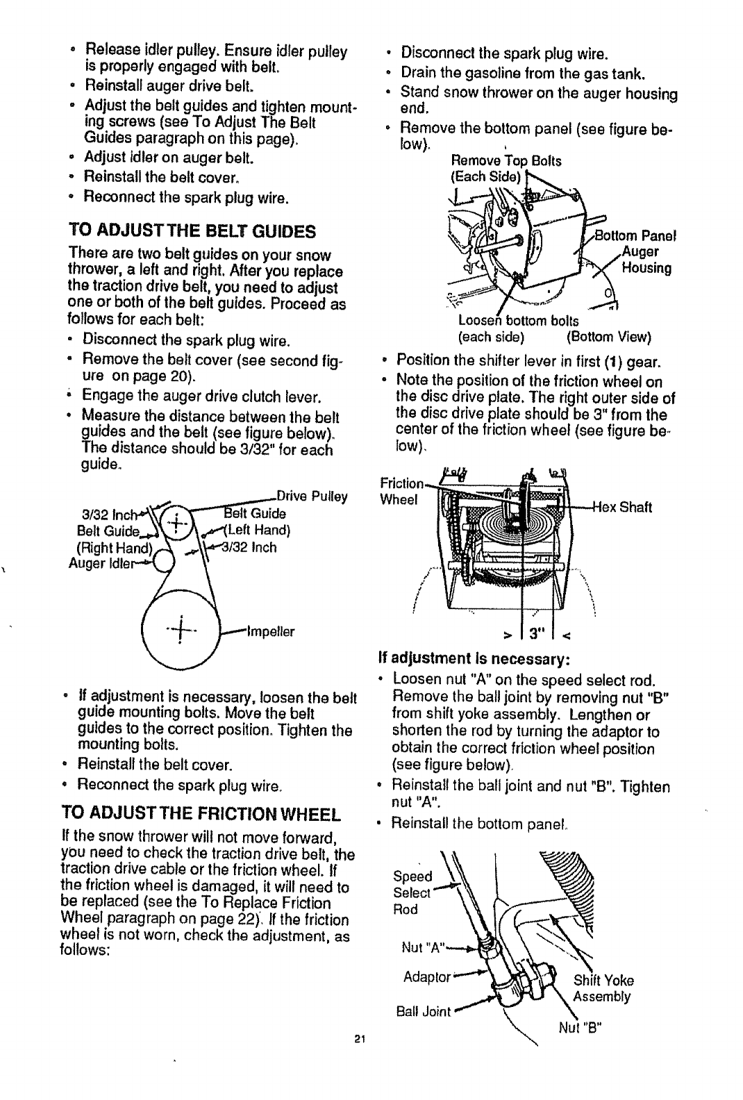
• Remove the bottom panel (see figure be-
low)_ Remove Top Bolts
(Each Side)
TO ADJUST THE BELT GUIDES
There are two belt guides on your snow
thrower, a left and right, After you replace
the traction drive belt, you need to adjust
one or both of the belt guides. Proceed as
follows for each belt:
•Disconnect the spark plug wire.
•Remove the belt cover (see second fig-
ure on page 20).
-' Engage the auger drive clutch lever.
•Measure the distance between the belt
guides and the belt (see figure below).
The distance should be 3132" for each
guide.
inch.,,_.,._.,...._DriveV ..I____'= Putley
3/32
Belt Guide.._ ",_T_\_"( Left Hand)
(Right Hand)(_-- .#:\_,_3/32Inch
•If adjustment is necessary, loosen the belt
guide mounting bolls. Move the belt
guides to the correct position. Tighten the
mounting bolts.
° Reinstall the belt cover.
°Reconnect the spark plug wire°
TO ADJUST THE FRICTION WHEEL
if the snow thrower wilt not move forward,
you need to check the traction drive belt, the
traction drive cable or the friction wheel. If
the friction wheel is damaged, it will need to
be replaced (see the To Replace Friction
Wheel paragraph on page 22). If the friction
wheel is not worn, check the adjustment, as
follows:
Panel
Housing
@
@
Looser bottom bolts
(each side) (Bottom View)
Position the shifter lever in first (1) gear.
Note the position of the friction wheel on
the disc drive plate, The right outer side of
the disc drive plate should be 3 from the
center of the friction wheel (see figure be,.
low),
Wheel Shaft
If adjustment Is necessary:
•Loosen nut "A" on the speed select rod.
Remove the ball joint by removing nut "B"
from shift yoke assembly. Lengthen or
shorten the rod by turning the adaptor to
obtain the correct friction wheel position
(see figure below).
• Reinstall the ball joint and nut "B". Tighten
nut "A".
Reinstall the bottom panel°
Speed
Rod
21
Nut
Ada Shift Yoke
Assembly
Bait Joint k_. Nut "B"
\
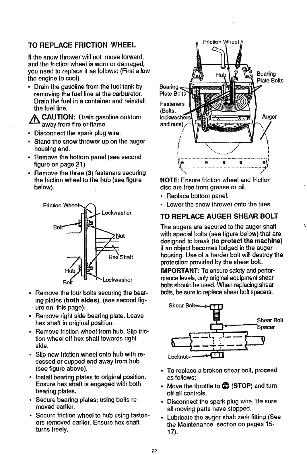
TO REPLACE FRICTION WHEEL
If the snow thrower wil! not move forward,
and the friction wheel is worn or damaged,
you need to replace it as follows: (First allow
the engine to cool).
oDrain the gasoline from the fuel tank by
removing the fuel line at the carburetor.
Drain the fuel in a container and reipstall
the fuel line.
CAUTION: Drain gasoline outdoor
away from fire or flame.
° Disconnect the spark plug wire,
° Stand the snow thrower up on the auger
housing end°
° Remove the bottom panel (see second
figure on page 21).
° Remove the three (3) fasteners securing
the friction wheel to the hub (see figure
below).
Friction Wheel',,_!'-'_I
r{[_= Lockwasher
Bol i_,=!
Shaft
Bo_ u "_ Lockwasher
•Remove the four bolts securing the bear-
ing plates (both sides), (see second fig-
ure on this page)_
• Remove right side bearing plate, Leave
hex shaft in original position.
°Remove friction wheel from hub. Slip fric-
tion wheel off hex shaft towards right
side.
°Slip new friction wheel onto hub with re-
cessed or cupped end away from hub
(see figure above).
,Install bearing plates to original position.
Ensure hex shaft is engaged with both
bearing ptates_
° Secure bearing plates; using bolts re-
moved earlier.
Secure friction wheel to hub using fasten-
ers removed earlier. Ensure hex shaft
turns freely.
Bearin
Plate
Friclion
Bearing
Plate Bolts
Fasteners
(Bolts,
and nuts),/ .....
/
/
Auger
.........................................................................iJ
._._e e e e e
NOTE: Ensure frictionwheel and friction
disc are free from grease or oil.
•Replace bottom panel
°Lower the snow thrower onto the tires.
TO REPLACE AUGER SHEAR BOLT
The augers are secured to the auger shaft
with special bolts (see figure below) that are
designed to break (to protect the machine)
if an object becomes lodged in the auger
housing. Use of a harder bolt will destroy the
protection provided by the shear bolt.
IMPORTANT: To ensure safety and perfor-
mance levels,only original equipment shear
bolts shouldbe used. When replacing shear
bolts, be sureto replace shear bolt spacers.
Shear Bolt._ Shear Bolt
°To replace a broken shear bolt, proceed
as follows:
,Move the throttle to I_1 (STOP) and turn
off all controls.
, Disconnect the spark plug wire° Be sure
all moving parts have stopped.
•Lubricate the auger shaft zerk fitting (See
the Maintenance section on pages 15-
17)+
22
o Alignthe hole in the auger with the hole
inthe auger shaft. Install the new shear
bolt and shear bolt spacer provided°
• Reconnect the spark plug wire.
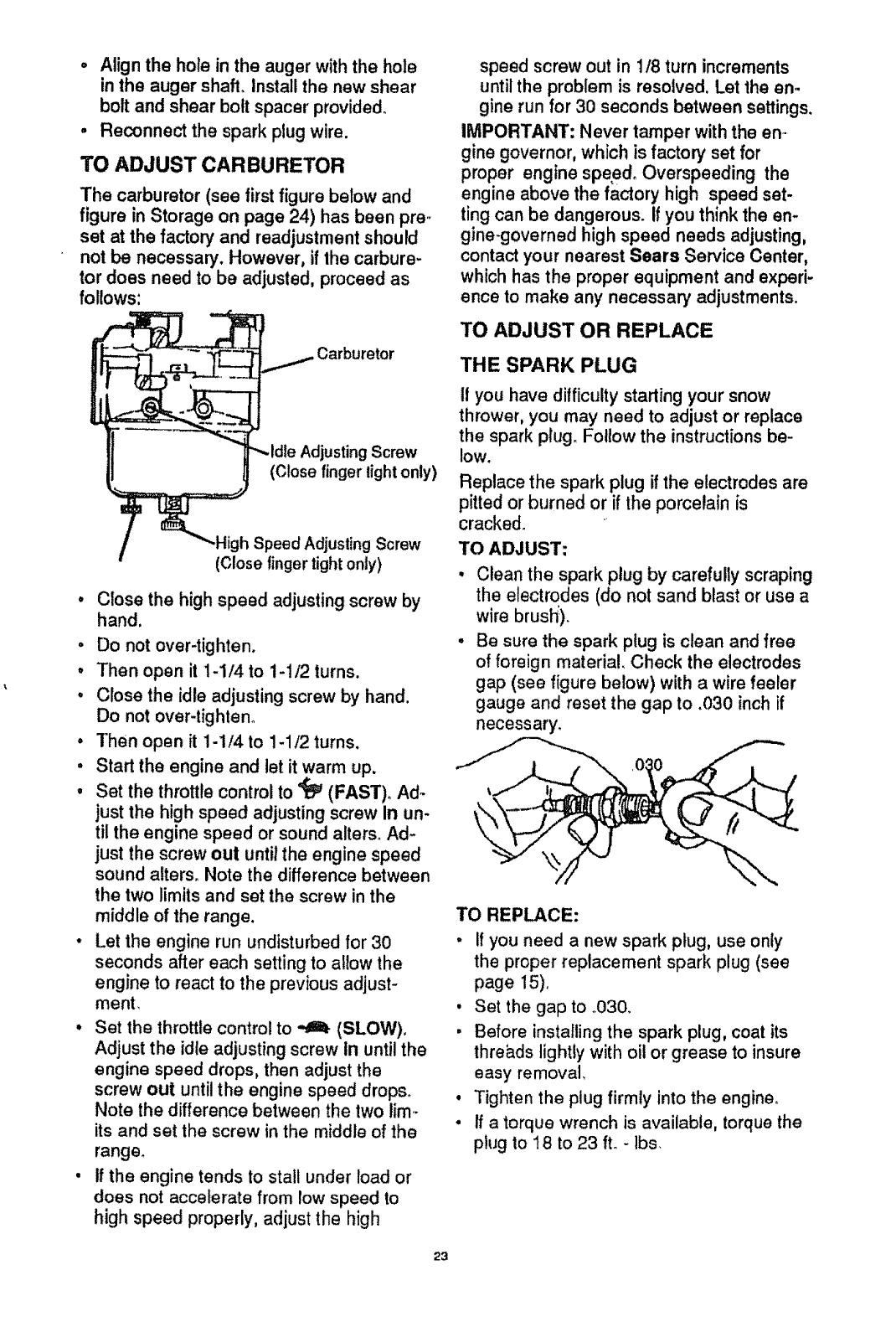
TO ADJUST CARBURETOR
The carburetor (see first figure below and
figure in Storage on page 24) has been pre,
set at the factory and readjustment should
not be necessary. However, if the carbure-
tor does need to be adjusted, proceed as
follows:
,Carburetor
Adjusting Screw
(Close finger light only)
igh Speed Adjusting Screw
(Close finger tightonly)
Close the high speed adjusting screw by
hand.
• Do not over-tighten,
° Then open it 1-1/4 to 1-1/2 turns.
• Close the idle adjusting screw by hand.
Do not over-tighteno
° Then open it 1-1/4 to 1-1/2 turns.
•Start the engine and let it warm up,
•Set the throttle control to '_ (FAST), Ad-
just the high speed adjusting screw In un-
til the engine speed or sound alters_ Ad-
just the screw out until the engine speed
sound alters, Note the difference between
the two limits and set the screw in the
middle of the range.
°Let the engine run undisturbed for 30
seconds after each setting to allow the
engine to react to the previous adjust-
ment,
• Set the throttle control to _ (SLOW),
Adjust the idle adjusting screw in until the
engine speed drops, then adjust the
screw out until the engine speed drops,
Note the difference between the two lim-
its and set the screw in the middle of the
range,
• If the engine tends to stall under load or
does not accelerate from low speed to
high speed properly, adjust the high
speed screw out in 1/8 turn increments
until the problem is resolved. Let the en.
gine run for 30 seconds between settings.
IMPORTANT: Never tamper with the en.
gine governor, which is factory set for
proper engine speed° Overspeeding the
engine above the factory high speed set-
ting can be dangerous, if you think the en-
gine-governed high speed needs adjusting,
contactyour nearest Sears Service Center,
which has the proper equipment and experi-
ence to make any necessary adjustments.
TO ADJUST OR REPLACE
THE SPARK PLUG
If you have difficulty starting your snow
thrower, you may need to adjust or replace
the spark pIug. Follow the instructions be-
low.
Replace the spark plug if the electrodes are
pitted or burned or if the porcelain is
cracked,
TO ADJUST:
Clean the spark plug by carefully scraping
the electrodes (do not sand blast or use a
wire brush:),
Be sure the spark plug is clean and free
of foreign material, Check the electrodes
gap (see figure below) with a wire feeler
gauge and reset the gap to .030 inch if
necessary,
TO REPLACE:
• If you need a new spark plug, use only
the proper replacement spark plug (see
page 15),
• Set the gap to .030,
,Before installing the spark plug, coat its
thre_.ds lightly with oil or grease to insure
easy removal,
, Tighten the plug firmly into the engine°
• If a torque wrench is available, torque the
plug to 18 to 23 fL - lbs,
23
,_ CAUTION: Never store your snow
thrower indoorsor in an enclosed, poorly
ventilated area if gasoline remains inthe
tank. fumes may reach an open flame,
spark or pilot light from a furnace, water
heater, clothes dryer, cigarette, etco
To prevent engine damage (if snow thrower
is not used for more than 30 days) follow
the steps below.
SNOW THROWER STORAGE
o Thoroughly clean the snow thrower.
•Lubricate all lubrication points (see the
Maintenance section on pages 15.t 7)°
, Be sure that al! nuts, bolts and screws are
securely fastened. Inspect all visible mov-
ing parts for damage, breakage and wear.
Replace if necessary.
• Touch up at! rusted or chipped paint sur-
faces; sand lightly before painting.
° Cover the bare metal parts of the blower
housing auger and the impeller with rust
preventative, such as a spray lubricant.
NOTE: A yearly checkup or tune_up by a
SEARS Service Center is agood way to in-
sure that your snow thrower will provide
maximum performance for the next season.
ENGINE STORAGE
Gasoline must be removed or treated to pre-
vent gum deposits from forming in the tank,
filter, hose, and carburetor during storage.
Also during storage, alcohol blended gaso-
line that uses ethanol or methanol (some-
times called gasohol) attracts water, ttacts
on the gasoline to form acidswhich damage
the engine.
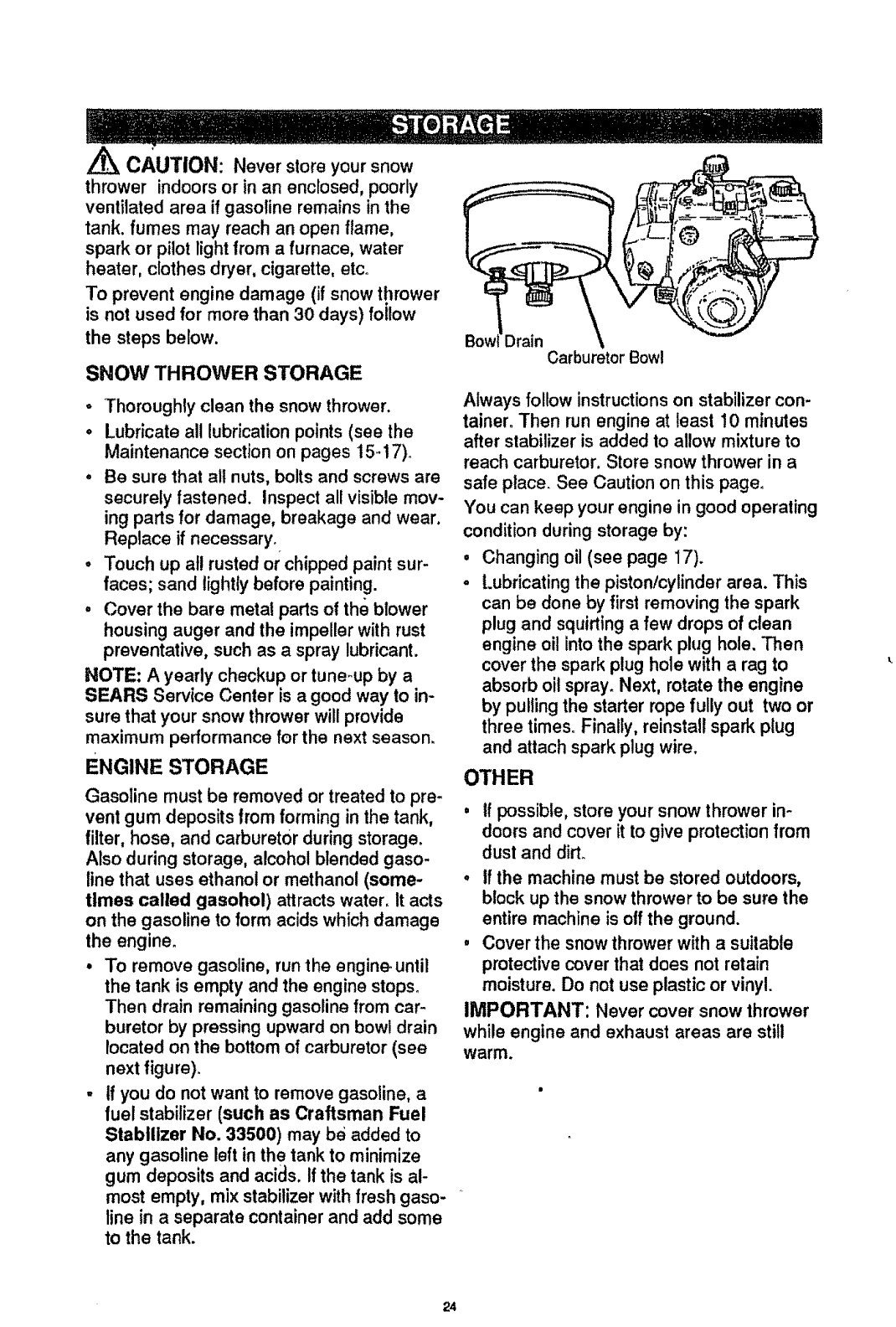
•To remove gasoline, run the engine_until
the tank is empty and the engine stops_
Then drain remaining gasoline from car-
buretor by pressing upward on bowl drain
located on the bottom of carburetor (see
nextfigure).
- if you do not want to remove gasoline, a
fuel stabilizer (such as Craftsman Fuel
Stabilizer No. 33500) may be added to
any gasoline leftin the tank to minimize
gum deposits and acids. If the tank is al-
most empty, mix stabilizer with fresh gaso-
line in aseparate container and add some
to the tank.
Carburetor Bow!
Always follow instructionson stabilizer con-
tainer. Then run engine at least 10 minutes
after stabilizer is added to allow mixtureto
reach carburetor. Store snow thrower in a
safe ptace_See Caution on this page.
You can keep your engine in good operaling
condition during storage by:
•Changing oil (see page 17).
oLubricatingthe pistonlcylinder area. This
can be done by first removing the spark
plug and squirtinga few drops of clean
engine oil into the spark plug hole. Then
cover the spark plug hole with a rag to
absorb oilspray_Next, rotate the engine
by pulling the starter rope fully out two or
three times. Finally, reinstall spark plug
and attach spark plug wire.
OTHER
oif possible, store your snow thrower in-
doors and cover it to give protection from
dust and dirL
oIf the machine must be stored outdoors,
block up the snow thrower to be sure the
entire machine is otf the ground.
,Cover the snow thrower with a suitable
protective cover that does not retain
moisture. Do not use plastic or vinyl.
IMPORTANT: Never cover snow thrower
while engine and exhaust areas are still
warm.
24
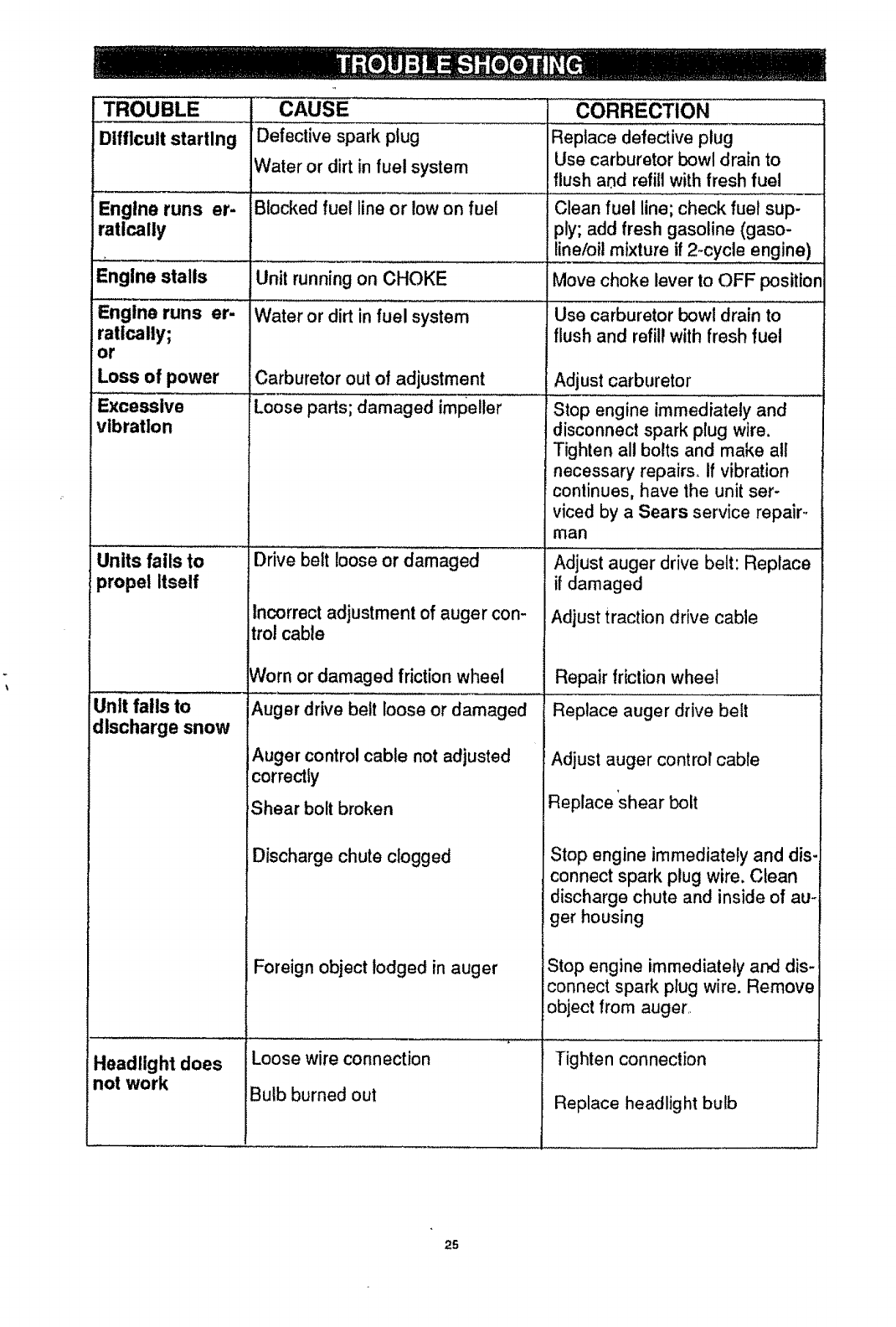
TROUBLE
Difficult starting
Engine runs er-
ratically
Engine stalls
Engine runs er-
ratically;
or
Loss of power
Excessive
vibration
CAUSE
Defective spark plug
Water or dirt in fuel system
Blocked fuel line or low on fuel
Units fails to
propel Itself
Unit falls to
discharge snow
Headlight does
not work
Unit runningon CHOKE
Water or dirt in fuel system
Carburetor out of adjustment
Loose parts; damaged impeller
Drive belt loose or damaged
Incorrect adjustment of auger con-
trol cable
Worn or damaged friction wheel
Auger drive belt loose or damaged
Auger control cable not adjusted
correctly
Shear bolt broken
Discharge chute clogged
Foreign object lodged in auger
Loose wire connection
Bulb burned out
CORRECTION
Replace defective plug
Use carburetor bowl drain to
flush arid refillwithfresh fuel
Clean fuel line; check fuel sup-
;)ly;add fresh gasoline (gaso-
line/oil mixture if 2-cycle engine)
Move choke lever to OFF position
Use carburetor bowl drain to
flush and refillwith fresh fuel
Adjust carburetor
Stop engine immediately and
disconnect spark plug wire.
Tighten all bolts and make all
necessary repairs. If vibration
continues, have the unit ser-
viced by a Sears service repair.-
man
Adjust auger drive belt: Replace
if damaged
Adjust traction drive cable
Repair frictionwheel
Replace auger drive belt
Adjust auger control cable
Replace 'shear bolt
Stop engine immediately and dis-
connect spark plug wire. Clean
discharge chute and inside of au-
ger housing
Stop engine immediately and dis-
connect spark plug wire. Remove
object from auger_
Tighten connection
Replace headlight bulb
25
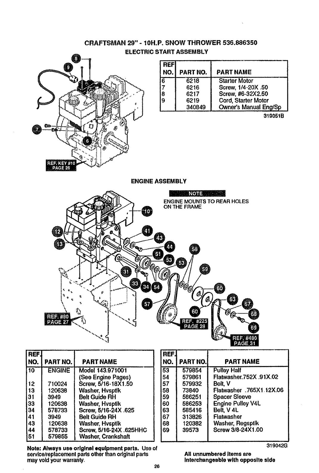
CRAFTSMAN 29" -10H.P. SNOW THROWER 536.886350
ELECTRIC START ASSEMBLY
REF
NO. PART NO. PART NAME
662t8
76216
8 6217
96219
340849
Starter Motor
Screw, 1f4_20X .50
Screw, #6-32X2.50
Cord, Starter Motor
Owner's Manual EngtSp
3t9051B
ENGINE ASSEMBLY
_l I
ENGINE MOUNTS TO REAR HOLES
ON THE FRAME
REFJ
NO, PART NO. PART NAME
lo ENGINE i43:971 i
(See Engine Pages)
12 710024
t3 120638
31 3949
33 120638
34 578733
41 3949
43 120638
Screw, 5/16-18Xl .50
Washer, Hvspttk
Belt Guide RH
Washer, Hvsptlk
Screw, 5!16-24X .625
Belt Guide RH
Washer, Hvsptlk
44 578733 Screw, 5t16-24X_625HHC
5t 579855 . Washe_ Crankshaft ........................
Note: Always use orlglnel equipment parts, Use of
servlcelreplacemenipads otherthan originalparts
may voidyour warranty. 26
REF
NO, PART NO.
53 579854
54 579861
57 579932
158 73840
59 586251
60 586253
163 585416
67 313826
68 120382
69 39573
PART NAME
Pulley Half
Flatwasher.752X .9 lX.02
Belt, V
Flatwasher .765Xl 12X.06
Spacer Sleeve
Engine Pulley V4L
Belt, V 4L
Flatwasher
Washer, Regspttk
Screw 3/8-24X1.00
319042G
Al! unnumbered Items are
Interchangeable with opposite side
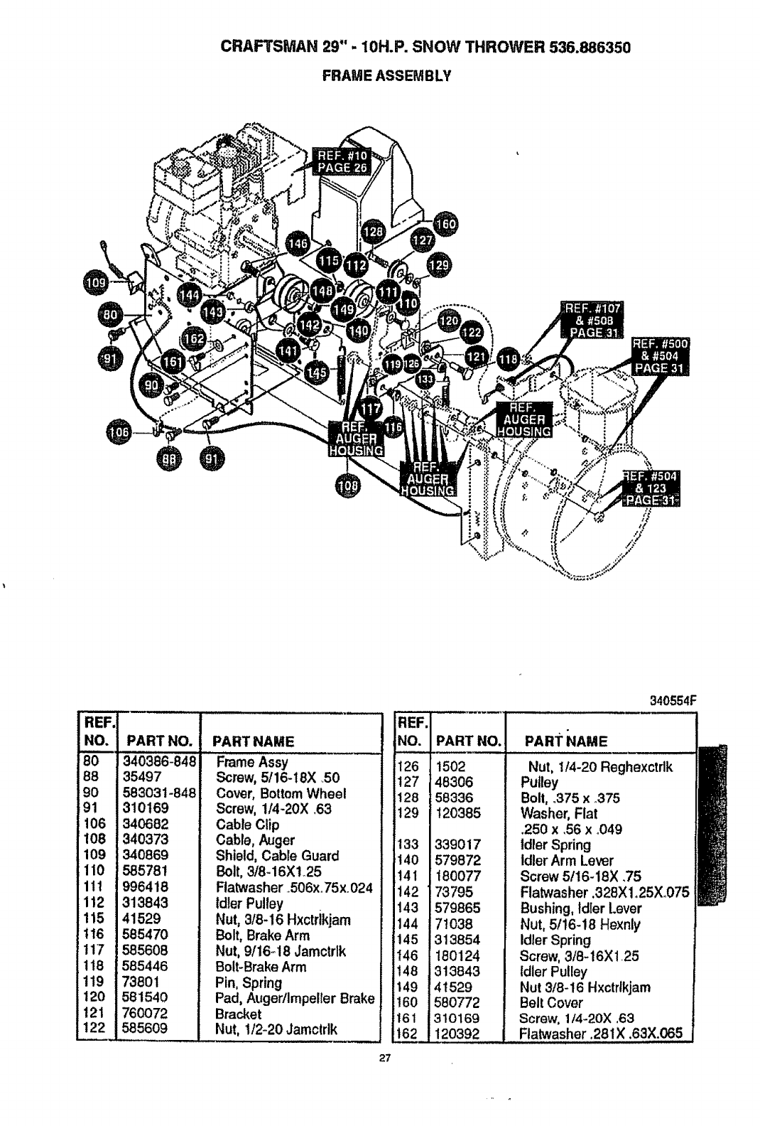
CRAFTSMAN 29" -10H.P. SNOW THROWER 536.886350
FRAM E ASSEM BLY
¢
I°°
88
90
91
106
1Io8
!109
111o
Illl
1112
1115
11+6
it17
!118
1119
1120
1121
PART NO.
340386-848
35497
583031-848
310169
340682
340373
340869
585781
996418
313843
41529
585470
585608
!585446
'73801
581540
760072
585609
PART NAME
Frame Assy
Screw, 5/16-i8X 50
Cover, Bottom Wheel
Screw, 114-20X .63
Cable Clip
Cable, Auger
Shield, Cable Guard
Bolt, 3/8-16Xt25
Flatwasher .506xo75x.024
Idler Pulley
Nut, 3/8-16 Hxctdkjam
Bolt, Brake Arm
Nut, 9/t6_ 18 Jamctrlk
Bolt-Brake Arm
Pin, Spring
Pad, Auger/Impeller Brake
Bracket
Nut, 1/2-20 Jamctrlk
27
REF.
iNC.
126
127
128
129
133
140
t41
t42 '
143
144
145
146
148 =
149
!60
161 I
1621
PART NO,
1502
48306
158336
120385
339017
579872
1180077
73795
579865
71038
313854
180124
313843
41529
580772
310169
120392
340554F
PART NAME I
Nut, 1/4-20 Reghexctrlk
Pulley
Bolt, .375 x.375
Washer, Flat
.250 x,56 x°049
Idler Spring
Idler Arm Lever
Screw 5/16-18X .75
Flatwasher,328X 1.25X.075
Bushing, Idler [.ever
Nut, 5t16-18 Hexnly
Idler Spring
Screw, 3/8-16Xt.25
Idler Pulley
Nut 3/8-16 Hxctrlkjam
Belt Cover
Screw, 1/4-20X ,63
Flatwasher .281X .63X.065
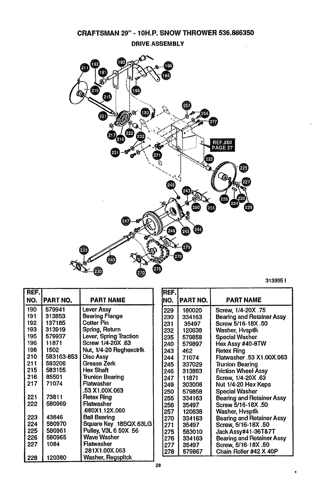
CRAFTSMAN29"- 10H.P.SNOWTHROWER536.886350
DRIVEASSEMBLY
.@
REF.
NO,
190
191
192
193
195
t96
198
210
211
215
2t6
217
221
222
223
224
225
226
227
228
®@@@
;PART NO.
i57 41
313853
137185
313919
579937
11871
1502
583163-.853
583206
583155
85501
71O74
73811
580969
43846
580970
580961
580965
1084
120380
PART NAME
Lever Assy
Bearing Flange
Cotter Pin
Spring, Return
Lever, Spring Traction
Screw 1/4-20X .63
Nut, 1/4-20 Reghexctrlk
LDisc Assy
iGrease Zerk
Hex Shaft
TrunionBearing
Ratwasher
.53 X1.00X,063
Retex Ring
Ratwasher
.680Xl+12X.060
Ball Bearing
Square Key, 18SQX°63LG
Pulley,V3L 650X ..56
Wave Washer
Ftatwasher
+281Xlo00X+063
Washer, Regspltck
REF.
NO.
row,
229
230
231
232
235
240
243
244
245
246
247
249
250
255
256
257
270
271
275
276
277
278
.@
3139951
PART NO.
180020
334163
35497
120638
579858
579897
462
71074
337029
313883
11871
303008
579858
334163
35497
120638
334163
35497
583010
334163
35497
579867
PART NAME
Screw, 1/4-20X .75
Bearing and Retainer Assy
Screw 5t16-18X +50
Washer, Hvsptik
Special Washer
Hex Assy #40-8TW
Retex Ring .
Flatwasher .53 X1,0OX+063
Trunion Bearing
Friction Wheel Assy
Screw, 1t4-20X .63
Nut !/4-20 Hex Keps
Special Washer
Bearing and Retainer Assy
Screw 5t16-18)( .50
Washer, Hvsptlk
Bearing and Retainer Assy
Screw, 5/16-18X .50
Jack Assy#41-36T&7T
Bearing and Retainer Assy
Screw, 5/16-18X .50
Chain Roller #42 X 40P
2B
1
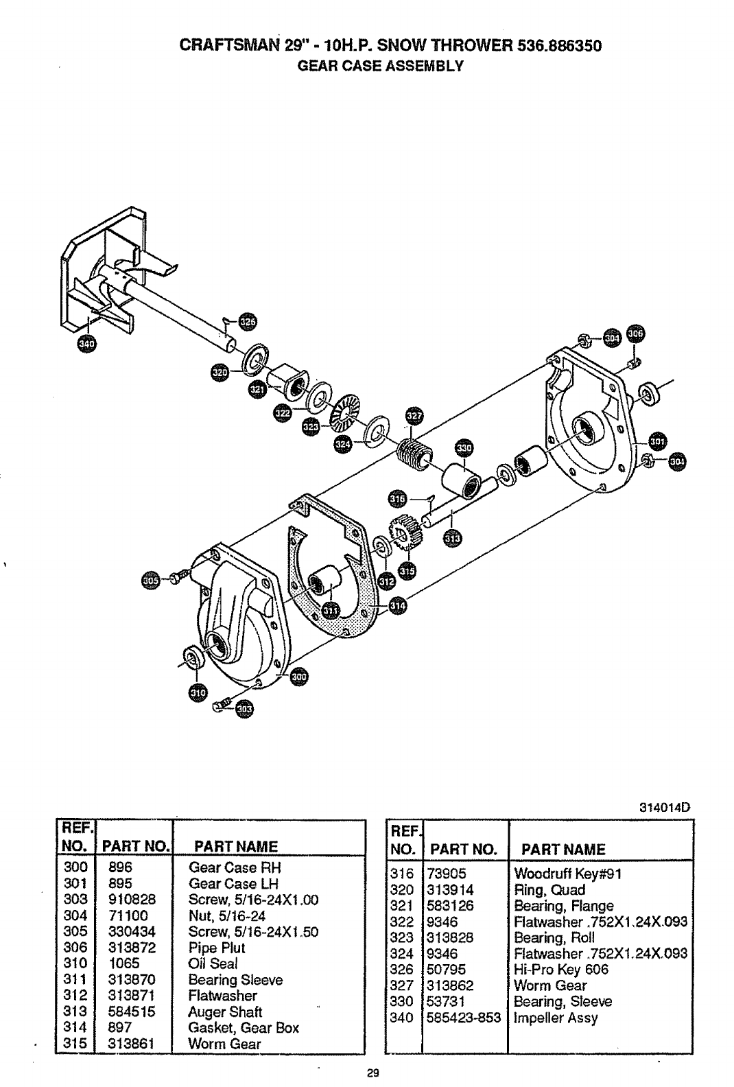
CRAFTSMAN 29" -10H.P. SNOW THROWER 536.886350
GEAR CASE ASSEMBLY
@
@
@
@
3o31
8o41
3o51
306 I
31Ol
3111
312I
313 !
314I
3151
PART NO.
896
895
910828
71100
330434
313872
1065
313870
313871
584515
897
313861
PART NAME
Gear Case RH
Gear Case LH
Screw, 5/16-24X1.00
Nut, 5/16-24
Screw, 5/t6-24X1.50
Pipe Rut
Oil Seal
Bearing Sleeve
Flatwasher
Auger Shaft
Gasket, Gear Box
Worm Gear
REF.
NO. PART NO.
3t6 73905
320 313914
'321 583126
322 9346
323 313828
324 9346
326 50795
327 3'13862
330 53731
340 585423-853
314014D
PART NAME
Woodruff Key#91
Ring, Quad
Bearing, Flange
Flatwas her. 752 X1,24X .093
Bearing, Roll
Flatwasher ,_752X1.24X.093
Hi-Pro Key 606
Worm Gear
Bearing, Sleeve
Impeller Assy
29
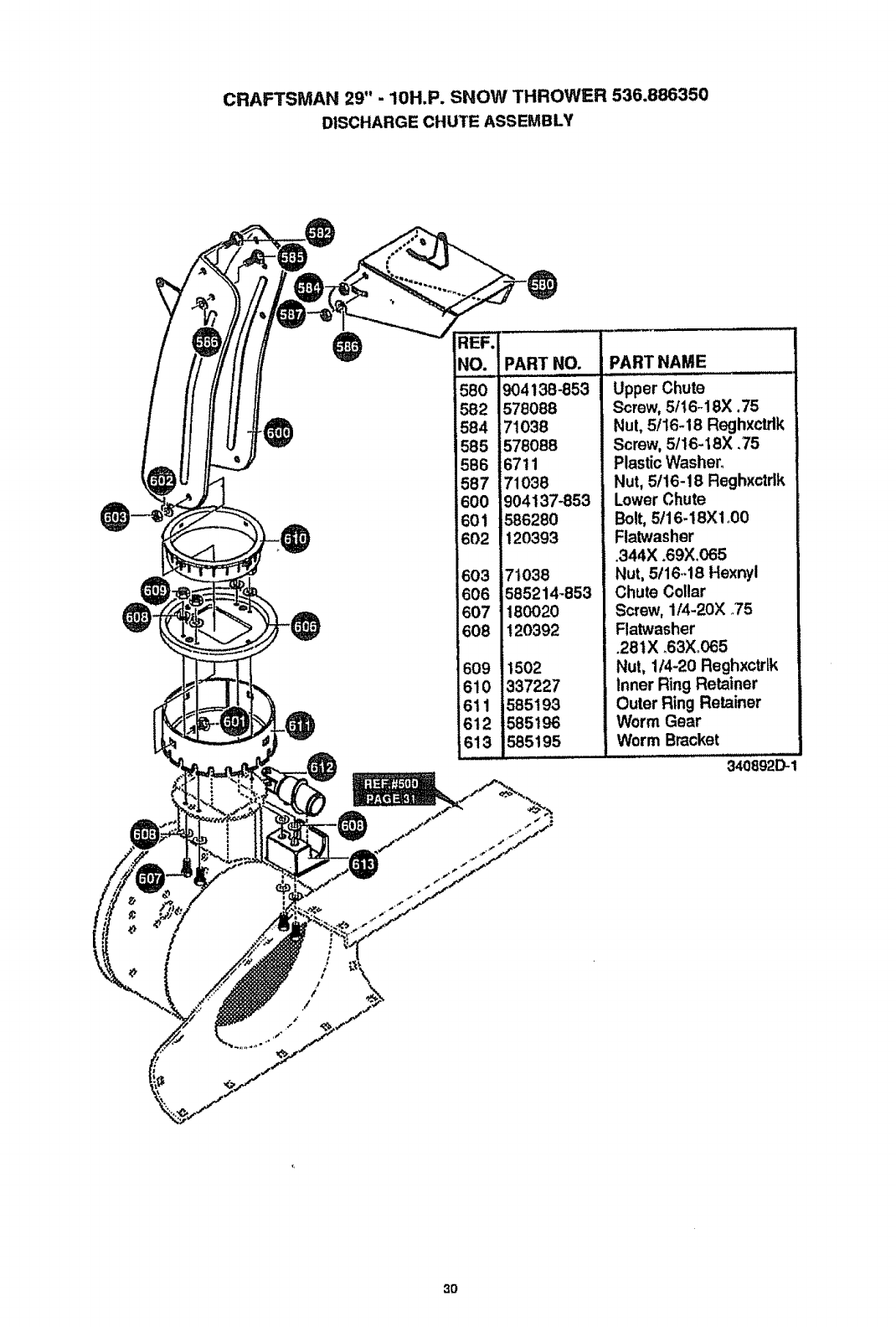
CRAFTSMAN 29" -10H.P. SNOW THROWER 536.886350
DISCHARGE CHUTE ASSEMBLY
REF.
NO. PART NO.
580 4138-e53
582 578088
584 71038
585 578088
586 6711
587 71038
600 904137-853
601 586280
602 120393
603 71038
606 585214-853
607 180020
608 120392
609 1502
610 337227
611 585193
612 585196
613 585195
PART NAME
Upper Chute
Screw, 5II 6-18X. 75
Nut, 5/16-18 Reghxctdk
Screw, 5/16-18X .75
Plastic Washer.
Nut, 5/16-18 Reghx_dk
Lower Chute
Bolt, 5/16-18X1o00
Flatwasher
.344X .69X.065
Nut, 5!16..18 Hexnyl
Chute Collar
Screw, 1/4-20X _75
Flatwasher
.28 tX .63Xo065
Nut, 114-20 Reghxctrtk
Inner Ring Retainer
Outer Ring Retainer
Worm Gear
Worm Bracket
340892D-1
3O
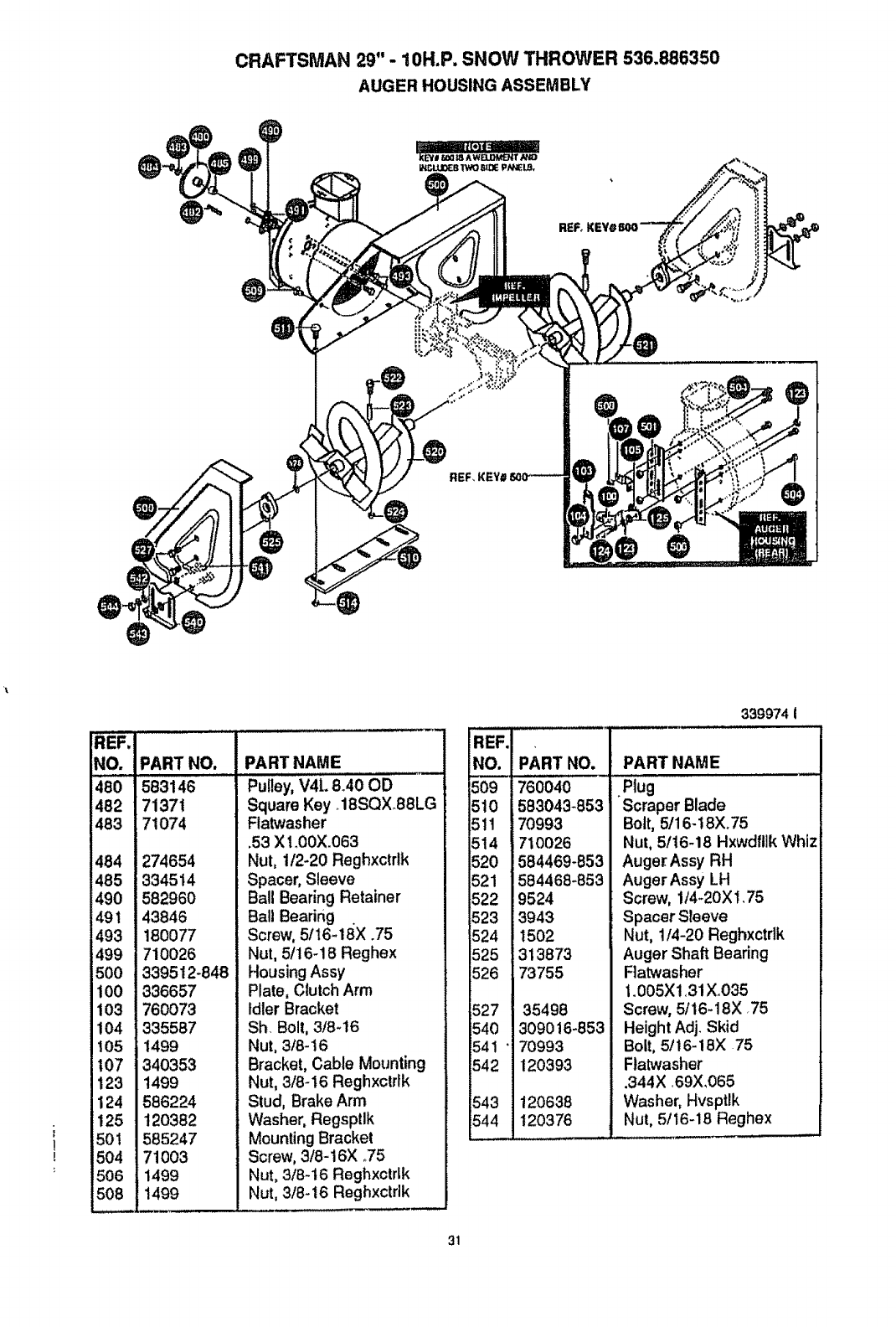
CRAFTSMAN 29" - 10H.P. SNOW THROWER 536.886350
AUGER HOUSING ASSEMBLY
!
!
REF.
NO.
._ i.,m,
48O
482
483
484
485
490
491
493
499
500
100
103
!04
105
107
123
124
125
501
504
506
508
PART NO.
583146
71371
71074
274654
334514
582960
43846
180077
710026
339512-848
336657
760O73
335587
1499
340353
1499
586224
12O382
585247
71003
1499
1499
PART NAME
Pulley, V4L 8_40OD
Square Key_18SQX88LG
Flatwasher
.53 X1_00X.063
Nut, 1/2-20 Reghxctrlk
Spacer, Sleeve
Ball Bearing Retainer
Ball Bearing
Screw, 5II6-18X .75
Nut, 5/16-18 Reghex
Housing Assy
Plate, Clutch Arm
Idler Bracket
Sh Bolt, 3/8-16
Nut, 3t8-16
Bracket, Cable Mounting
Nut, 3/8-16 Reghxctrtk
Stud, Brake Arm
Washer, Regsptlk
Mounting Bracket
Screw, 3/8-16X ,.75
Nut, 3/8-16 Reghxctrlk
Nut, 3/8-16 Reghxctdk
IREF.
JNO. PART NO.
760040
510 583043-853
151t 7o993
1514 710026
520 584469-853
521 584468-853
522 9524
523 3943
524 t502
525 313873
526 73755
527 35498
540 309016-853
541' 70993
542 120393
543 120638
544 120376
339974 I
PART NAME
oPlug
Scraper Blade
Bolt, 5/16-18X.75
Nut, 5/16-18 Hxwdflik Whiz
Auger Assy RH
Auger Assy LH
Screw, 1/4-20X1,75
Spacer Sleeve
Nut, t/4-20 Reghxctdk
Auger Shaft Bearing
Flatwasher
t.005X1,31Xo035
Screw, 5/16-18X .75
Height Adj. Skid
Bolt, 5/16-18X 75
Ftatwasher
.344X ,69X,065
Washer, Hvsptlk
Nut, 5/16-18 Reghex
31
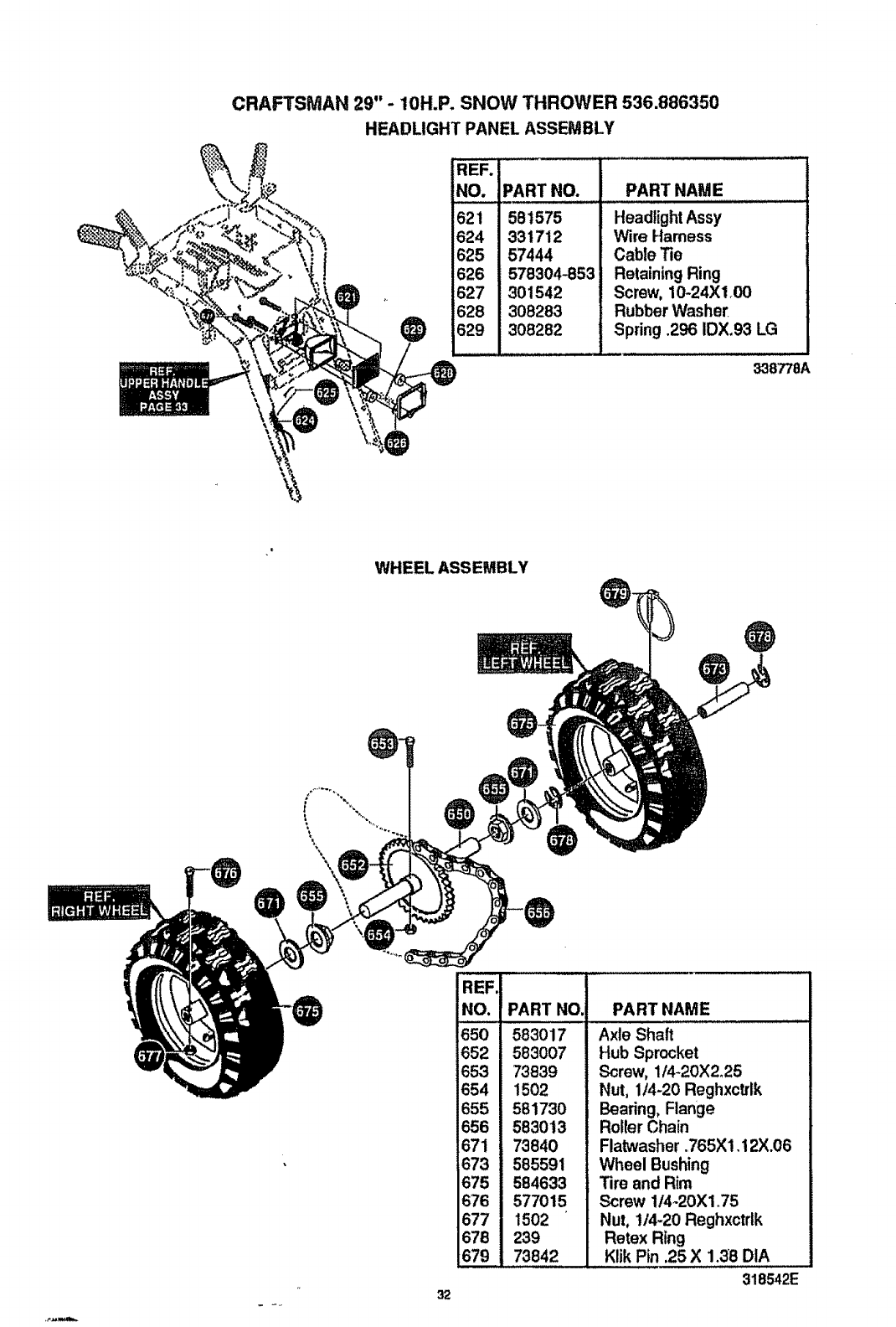
CRAFTSMAN 29"- 10H.P. SNOW THROWER 536.886350
HEADLIGHT PANEL ASSEMBLY
REF.
NO. PART NO.
581575
624 331712
625 57444
626 578304-853
627 301542
628 308283
629 308282
PART NAME
Headlight Assy
Wire Harness
Cable Tie
Retaining Ring
Screw, 10-24X!.00
Rubber Washer
Spring .296 IDX.93 LG
338'T/8A
WHEEL ASSEMBLY
\\
REF.
NO.
65O
652
653
654
655
656
671
673
675
676
677
678
679
PART NO, PART NAME
583017
583007
73839
1502
581730
583013
73840
585591
584633
577015
1502
239
73842
Axle Shaft
Hub Sprocket
Screw, 114-20X2.25
Nut, 1/4-20 Reghxctrlk
Beating, Flange
Ro!ler Chain
Flatwasher .765Xl.12X.06
Wheel Bushing
Tire and Rim
Screw 1t4_20X1.75
Nut, 1/4-20 Reghxctrtk
Retex Ring
Klik Pin .25 X 1.38 DIA
318542E
32
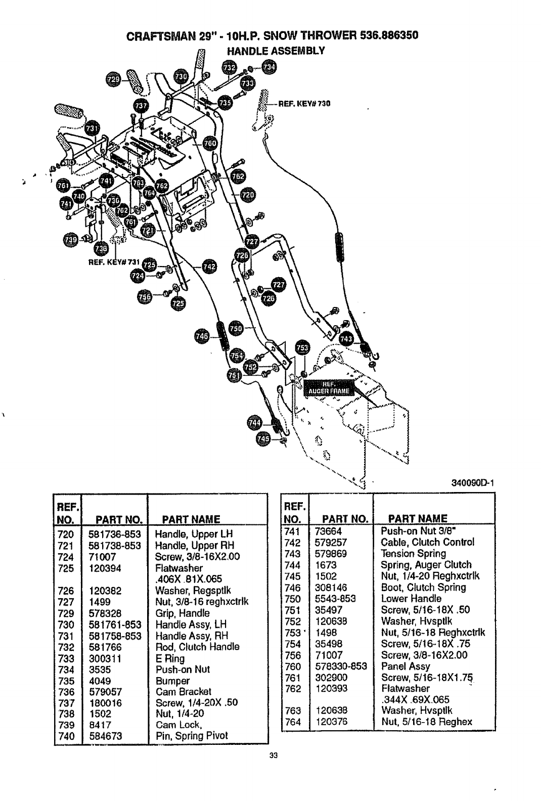
CRAFTSMAN 29" -10H.P. SNOW THROWER 536.886350
HANDLE ASSEMBLY
KEY# 730
REF,
@
REF.
NO. PART NO.
720 581736-853
721 581738-853
724 71007
725 120394
726 120382
727 1499
729 578328
730 581761-853
731 581758-853
732 581766
733 300311
734 3535
735 4049
736 579057
737 180016
738 1502
739 8417
740 584673
PART NAME
Handle, Upper LH
HandJe,Upper RH
Screw, 3/8-16X2o00
Flatwasher
.406X 81X 065
Washer, Regsptlk
Nut, 3/8-16 reghxctrlk
Grip, Handle
Handte Assy, LH
Handle Assy, RH
Rod, Clulch Handle
E Ring
Push-on Nut
Bumper
Cam Bracket
Screw, 1/4-20X .50
Nut, 1!4_20
Cam Lock,
Pin, Spring Pivot
33
340090D.1
IREF.
NO. PART NO.
741 73664
742 579257
743 579869
744 1673
745 1502
746 308146
750 5543-853
751 35497
752 120638
753" 1498
754 35498
756 71O07
760 578330-853
761 302900
762 120393
763 120638
764 120376
PART NAME
Push-on Nut 3/8"
Cable, Clutch Control
Tension Spring
Spring, Auger Clutch
Nut, 1/4-20 Reghxctdk
Boot, Clutch Spring
Lower Handle
Screw, 5116-18X ,50
Washer, Hvspttk
Nut, 5116-18 Reghxctdk
Screw, 5/16-18X ,75
Screw, 3/8-16X2.00
Panel Assy
Screw, 5116-18Xl ,75
Ftatwasher
,344X 69X 065
Washer, Hvsptlk
Nut, 5/16-t8 Reghex
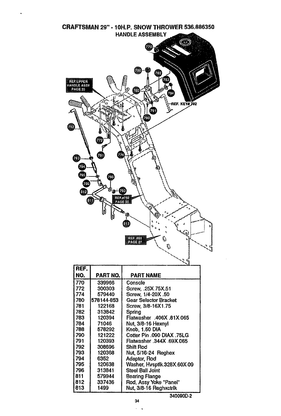
CRAFTSMAN 29"- 10H.P. SNOW THROWER 536.886350
HANDLEASSEMBLY
REF.
NO. PART NO,
770......339966
772 300303
774 579440
780 578144-853
781
782
783
784
788
790
791
792
793
794
795 _i
796
811
812 i
813 I
\
122168
313842
120394
71046
578292
121222
120393
308696
120368
6352
120638
313841
579944
337436
1499
PART NAME
Console
Screw, .25X75X.51
Screw, 1/4-20X _50
Gear Selector Bracket
Screw, 3t8._16X1.75
Spring
Flatwasher _406X ,81X,065
Nut, 3/8-16 Hexnyl
Knob, 1.50 DtA
Cotter Pin _090 DtAX .,75LG
Flatwasher .344X o69X_065
Shift Rod
Nut, 51!6o24 Reghex
Adaptor, Rod
Washer, Hvsptlk328X.60X09
Steel Ball Joint
Bearing Flange
Rod, Assy Yoke "Panel"
Nut, 318-16 Reghxctrlk
3400g0D*2
34
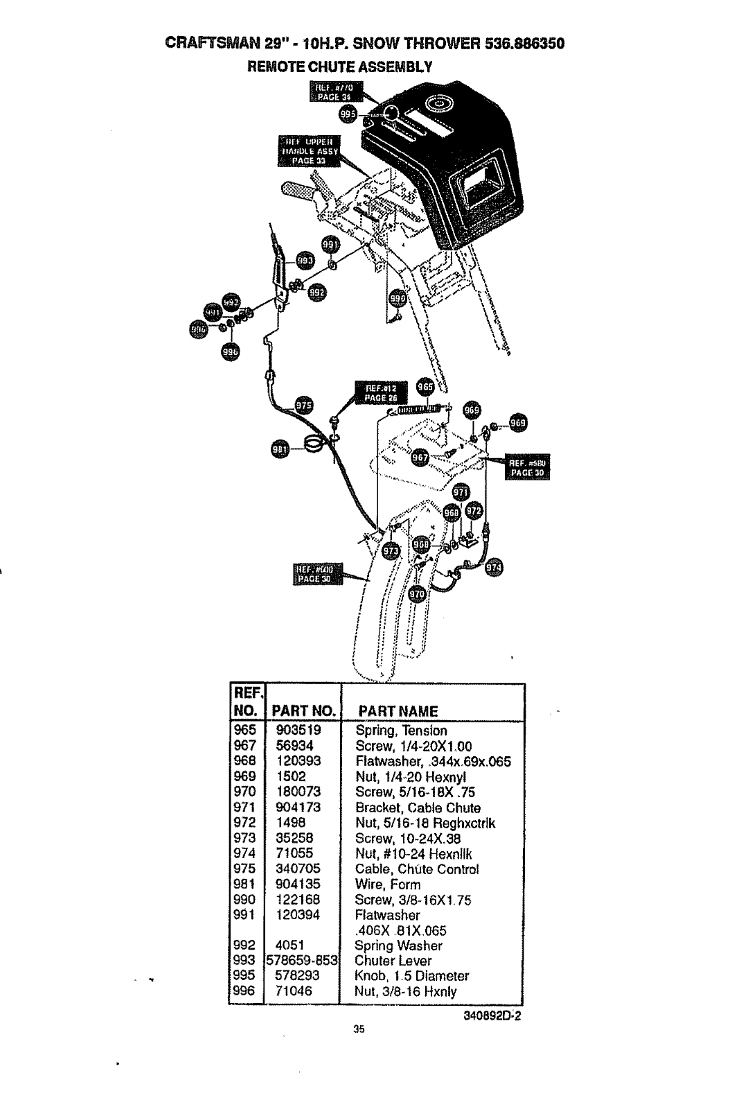
CRAFTSMAN 29" - tOH.P. SNOW THROWER 536.886350
REMOTE CHUTE ASSEMBLY
@
REF.I
NO.!
967 i
968 I
969 I
970 I
971 I
972 I
973 I
974 I
975 I
981 !
99O I
991 I
992 I
993 I
995 I
996 I
=
PART NO.,
903519
56934
120393
1502
180o73
904173
1498
35258
71055
340705
904135
122168
120394
4051
578659-853
578293
71046
PART NAME
Spring, Tension
Screw, 1/4-20XI,00
Flatwasher, o344xo69x,065
Nut, 1/4-20 Hexnyl
Screw, 5116-18X .75
Bracket, Cable Chute
Nut, 5/16-18 Reghxctdk
Screw, I0-24X.38
Nut, #10-24 Hexnllk
Cable, Ch_JteControl
Wire, Form
Screw, 3/8-16X 1.75
Flatwasher
,406X .81X065
Spring Washer
Chuter Lever
Knob, 1.5 Diameter
Nut, 3/8-16 Hxnty
340892D;2
35
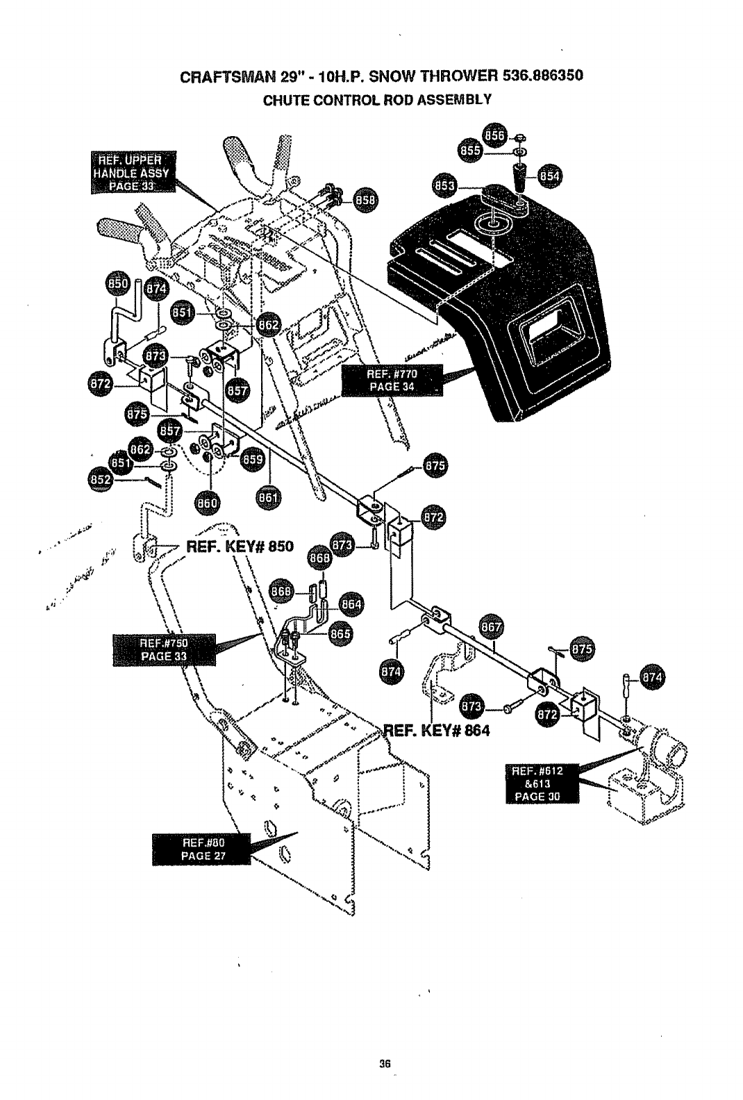
CRAFTSMAN 29"- 10H.P. SNOW THROWER 536.886350
CHUTE CONTROL ROD ASSEMBLY
\
,\
\\
REF. KEY# 850
\\\,
KEY# 864
\
36
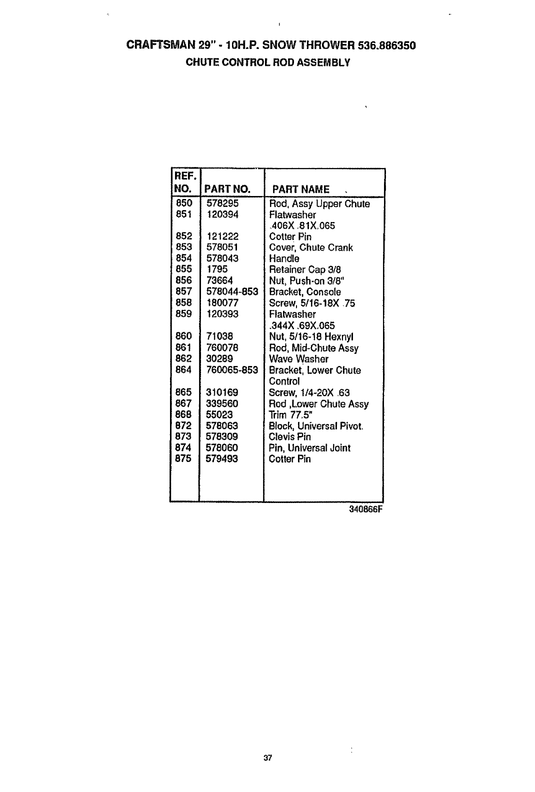
t
CRAFTSMAN 29"- 10H.P. SNOW THROWER 536.886350
CHUTE CONTROL ROD ASSEMBLY
REF. .................................
NO. PART NO.
850 578295
851 120394
852 121222
853 578051
854 578043
855 1795
856 73664
857 578044_853
858 180077
859 120393
860 71038
861 760078
862 30289
B64 760065-853
865 310169
867 339560
868 55023
872 578063
873 578309
874 578060
875 579493
PART NAME
Rod, Assy Upper Chute
Flatwasher
AO6X 81X_065
Cotter Pin
Cover, Chute Crank
Handle
Retainer Cap 3/8
Nut, Push-on 3/8"
Bracket, Console
Screw, 5/16-18X .75
Ftatwasher
.344X .69X.065
Nut, 5116-t8 Hexnyl
Rod, Mid-Chute Assy
Wave Washer
Bracket, Lower Chute
Control
Screw, 114-20X 63
Rod ,Lower Chute Assy
Trim 77_5"
Block, Universal Pivot.
Clevis Pin
Pin, Universal Joint
Cotter Pin
340866F
37
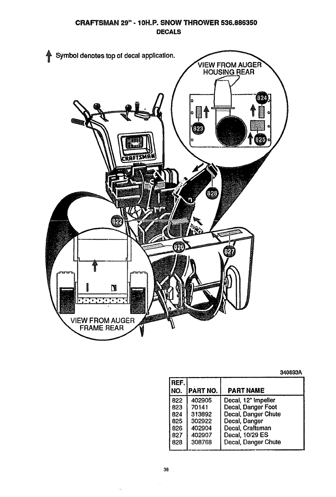
CRAFTSMAN 29"- 10H.P. SNOW THROWER 536.886350
DECALS
Symbol denotes top of decalapplication.
FROM
HOUSING REAR
VIEW FROM AUGER
FRAME REAR
,IPARTNO.
i 4o29os
170141
! 313892
I 302922
]826 I402904
J827 I 402907
_J 308768
340893A
PART NAME
Decal, 12" Impeller
Decal, Danger Foot
Decal, Danger Chute
Decal, Danger
Decal, Craftsman
Decal, !0/29 ES
Decal, Danger Chute
38
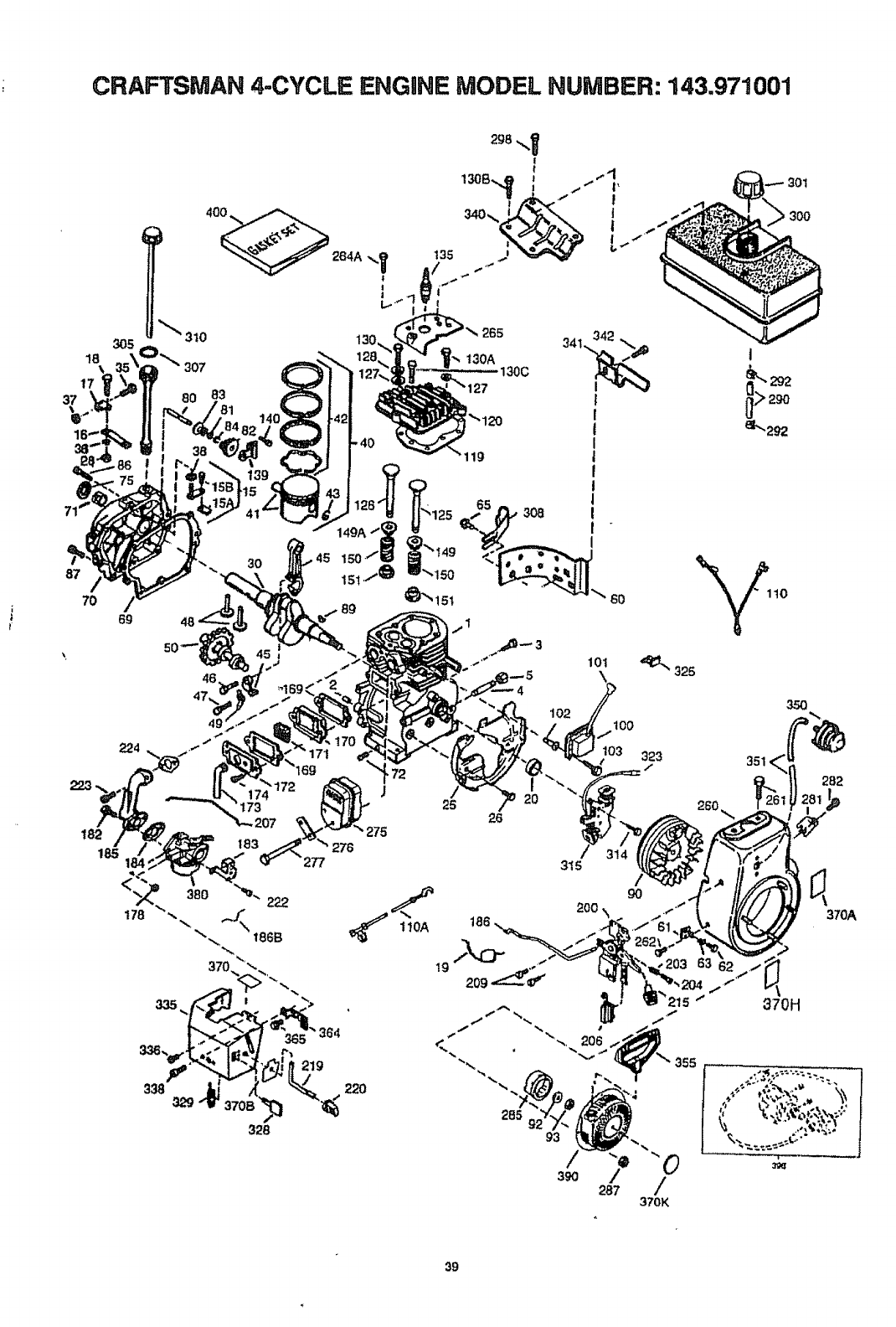
CRAFTSMAN 4-CYCLE ENGHNEMODEL NUMBER: 143.971001
t,
t
305
18
87
7O
69
224
83
3O
119
6O 110
I
J
173
207 "" 275
183 276
277
19
25 26
,I
t
285
100
103 323
/
315
gO
200 \ ._
355
g3
35O
351
282
I,
370H
39
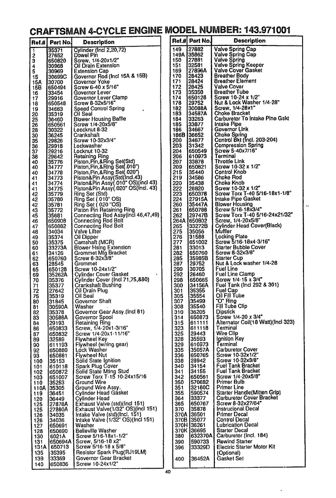
CRAFTSMAN 4-CYCLE ENGINE MODEL NUMBER: 143.971001
J
_ef.#
ill
1
2
3
4
5
15
15A
15B
t6
t8
19
20
25
26
28
30
35
36
37
38
40
40
40
41
41
41
42
42
_2
43
45
46
47
48
49
50
60
61
62
63
65
69
70
71
72
75
80
8t
82
83
84
86
87
89
90
92
93
100
101
102
103
110
110A
1!9
120
125
t25
126
!26
127
128
130
!31
131h
t35
139
140
35371
_7652
_50820
]0968
]0969
]0699C
]0700
350494
]3454
).9916
350548
]4663
]5319
]6460
350561
t0322
36245
._9826
._9918
_.g216
._9642
}5776
34777
34778
34773
34774
34775
35779
35780
35781
35772
35681
350908
350882
]4034
]5374
35375
]3273A
34126
._50760
28545
550128
35262A
35376
35377
27642
35319
31845
30590A
35378
30588A
29193
650833
650832
32589
61 t193
650880
650881
35153
610118
650872
651007
35253
35305
36451
36449
27878A
2788OA
34035
34036
650691
650690
6021A
65o6941
650713
35395
33369
1650836
Description
_Cylinder(Incl 2,20192)
Dowe! Pin
Screw, 114+20xt12"
Oil Drain Extension
ExtensionCap
Governor Rod 15A & 15B)
Governor Yoke(Inct
Screw 6-40 x 5116"
Governor Lever
Governor Lever Clamp
Screw 8-32x5116"
Speed Conlrol Spring
Oil Seal
Blower Housing Baffle
Screw 1/4-20x5/8"
Loocknut8-32
Crankshaft
Screw 10+32x3/4"
Lockwasher
Locknut 10+32
Retaining Ring
_Piston,Pin,&RingSet(Std)
Piston,Pin,&R]ng Set(+010")
Piston,Ptn,&Rtng Set(,020")
Piston&Pin Assy(Std(Inct.43)
Piston&Pin Assy(+010 OS)(mc143)
Piston&Pin Assy(,.020" OS(lncl.. 43)
Ring Set (Std)
Ring Set (010" OS)
Ring Set ( 020 OS) _
Piston Pin Retaining Hing
Connecting Rod Assy(inc146,47,49)
Connecting Rod Bolt
Connecting Rod Bolt
Valve Lifter
Oil Dipper
Camshaft (MCR)
Blower Hsing Extension
Grommet Mtg Bracket
Screw 8+32x318"
Grommet
Screw 10.24xlt2"
Cylinder Cover Gasket
Cylinder Cover (lnc171,75,&80)
Crankshaft Bushing
Oil Drain Plug
Oil Seal
Governor Shaft
Washer
Governor Gear Assy..(incl 8!)
Governor Spool
Retaining Ring
Screw, 1/4-20xl +3ti6"
iScrew 114-20x1-tllt6"
Flywheel Key
Flywheel (w/ring gear)
Lock Washer
Flywheel Nut
Solid State Ignition
Spark PlugCover
Solid State Mting Stud
Screw Torx T+15 !0-24x15116
Ground Wire
Ground Wire Assy+
Cylinder Head Gasket
Cytinder Head
Exhaust Valve (std)(Incl t51)
Exhaust Valve(t132" OS)(incl 151)
Intake Valve (std)(IncL 151)
Intake Valve (1/32" OS)(Inc1151)
Washer
Belleville Washer
Screw 5/16L_I8x 1-1t2"
Screw, 5tt6-18 x2"
Screw 5/t6-18 x 518"
Resistor Spark Plug(RJ19LM)
Governor Gear Bracket
Screw 10-24x!12"
Ref.# Part No_ Description "
149 27882 Valve SpringCap
149A 35862 Valve SpringCap
150 27881 Valve Spring
15t 32581 Valve SpringKeeper
169 27896A Valve Cover Gasket
t70 28423 Breather Body
171 28424 Breather Element
172 28425 Valve Cover
173 35350 Breather Tube
174 650128 Screw 10-24 x 1/2"
t78 29752 Nut & Lock Washer 114+28"
182 30088A Screw, 114-28xl"
183 34587A Choke Bracket
184 33263 Carburetor To intake Pine Gskt
185 33877 Intake Pipe
186 34667 i Governor Link
!86B 36652 Choke Spring
200 34677 Control Bk!([ncL 203-204)
203 3t 342 Compression Spring
204 650549 Screw 5-40x7/16"
206 610973 Terminal
207 33878 ThrottleLink
209 1650821 Screw t0-32 x 1/2'
215 35440 Control Knob
219 34586 Choke Rod
220 35438 Choke Knob
222 28820 Screw 10-32 x 1/2"
223 650378 Screw Torx T-40 5/16-18x1-1/8"
224 279t5A intake Pipe Gasket
260 !35447A Blower Housing
261 650788 Screw 5/16-18x3/4'*
262 29747B Screw Torx T-40 5tt6.24x21/32"
264A 650802 Screw. 1/4+20x5/8"
265 33272B Cylinder Head Cover(Black)
275 35056 Muffler
276 31588 Locking Plate
277 651002 ScrewS116-18x4-3116"
281 33013 Starter Bubble Cover
282 650760 Screw 8-32x3/8'*
285 35985B Starter Cup
287 29752 Nut & Lock washer 1/4-28
290 30705 Fuel Line
292 26460 Fuel Line Clamp
298 650665 Screw 1/4-15 x3/4"
300 34156A Fuel Tank (lncl 292 & 301)
301 35355 Fuel Cap
305 35554 Oil Fill Tube
307 35499 "O" Ring
308 35540 Fill Tube Clip
310 36205 Dipstick
314 650873 Screw 114.20x3/4"
315 611111 Alternator Coi1(18Watt)(lncf 323)
323 611118 Terminal
325 29443 Wire Clip
328 35593 Ignition Key
J329 6t0973 Terminal
335 35057A Carburetor Cover
336 650765 Screw 10-32x112"
338 28942 Screw !0-32x3t8"
340 34154 Fuel Tank Bracket
341 34155 Fue! Tank Bracket
342 650561 Screw tl4,.20x518"
350 570682 Primer Bulb
351 32180C Primer Line
355 590574 StarterHandle(Mitten Grip)
364 33377 Carburetor Cover Bracket
365 650767 Screw 8-32x27/64"
370 35878 InstrucionalDecal
370A 36501 Primer Decal
370B 35077 Control Decal
370H 3626! LubricationDecal
370K 36695 Starter Decal
380 632370A Carburetor (tncL 184)
390 590733 Rewind Starter
396 33329D Electric StarterMotor Kit
(Optional)
Gasket Set400 36452A
4O

CRAFTSMAN 4-CYCLE ENGINE MODEL. NUMBER: 143.971001
Starter No. 590733
/
13
_8
6_ 6
REF
NO.
0'
1
2
3
4
5
6
7
8
11
12
13
PART
NO.
590733
590599A
590600
590696
590601
590697
590698
590699
590709
590734
590535
590574
PART NAME
Rewind Starter
ring Pin (incl. 4)
sher
Retainer
Washer
Brake Spring
Starter Dog
Dog Spring
Pulley & Rewind Sprg Assy
Starter Housing Assy
Starter Rope .
(Length 98 x9/64 dia)
Mitten Grip Handle(not
included with starter)
41
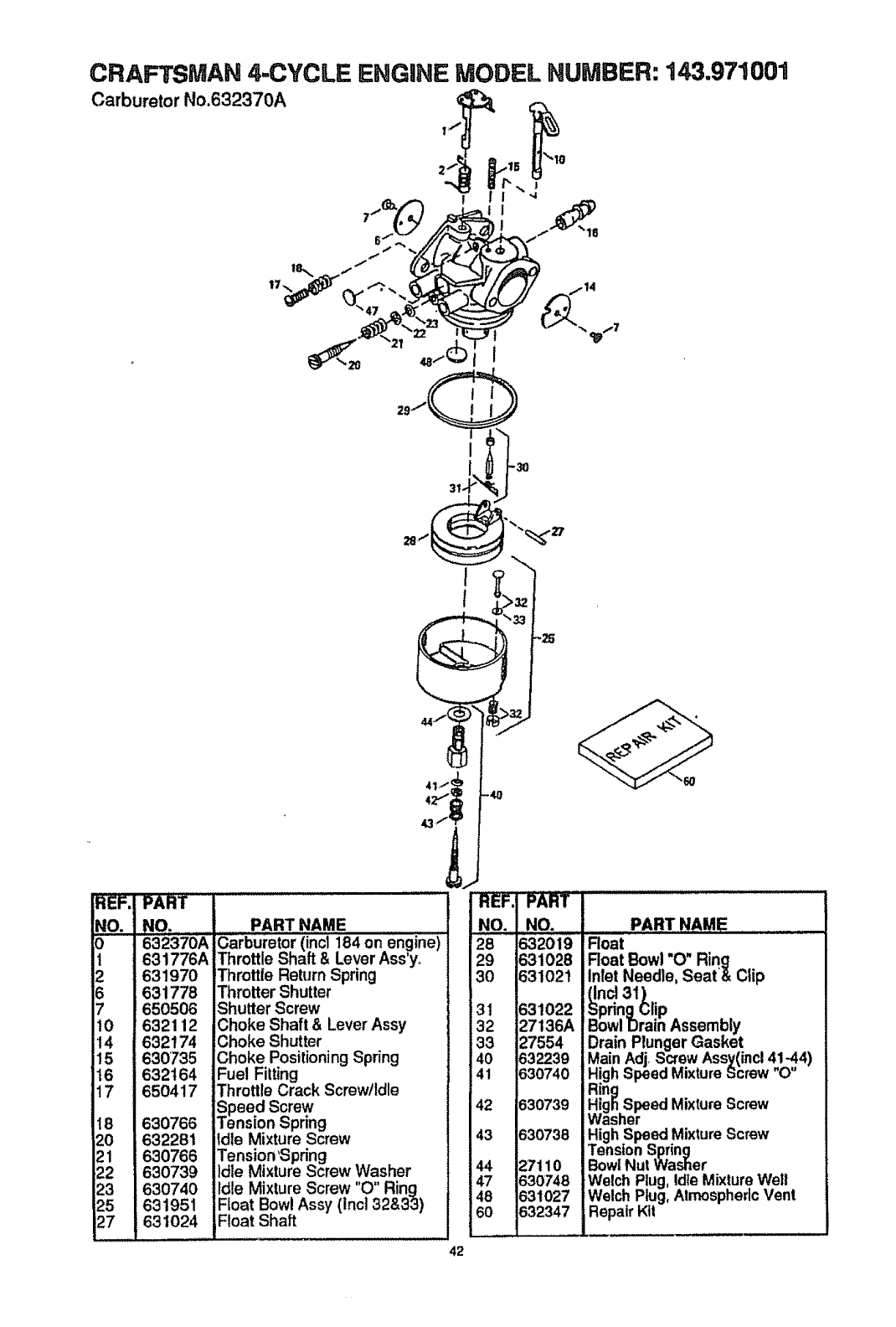
CRAFTSMAN 4-CYCLE ENGINE MODEL NUMBER: 143.971001
Carburetor No.632370A
I-30
31-
REF. PART ..................
NO. NO. PART NAME
3....63237'0A Carburetor (incl 184 on engine)
1631776A Throttle Shaft & Lever Ass'y.
2631970
631778
7 650506
10 632112
14 632174
15 630735
t6 632164
17 650417
18 630766
20 632281
21 630766
22 630739
23 630740
25 631951
27 631024
Throttle Return Spring
Throtter Shutter
Shutter Screw
Choke Shaft & Lever Assy
Choke Shutter
Choke PositioningSpring
Fuel Fitting
Throttle Crack Screw/idle
Speed Screw
Tension Spring
Idle Mixture Screw
Tension 'Spring
idle Mixture Screw Washer
Idle Mixture Screw "O" Ring
Float BowlAssy (lnc132&3_J)
Float Shaft
-4O
::Re_F:! PA_T'1.....................
NO. ! NO. i PART NAME
28 1632019IFloat
29 J631028 I Float Bowl "O" Ring
30 J631021 I Inlet Needle, Seat& Clip
! !(Inc131)
31 ]631022 I SpringClip
32 J27136A ]BowlDrain Assembly
33 127554 JDrain Plunger Gasket
40 1632239 JMain Adj_Screw Assy(inc141_..4)
41 ]630740 i HighSpeed MixtureScrew "o"
Rin
III Washer
143 _630738 | HighSpeed MixtureScrew
I i I Tension Spring
]44 127110 | BowlNut Washer
i47 1630748 ] Welch Plug,Idle MixtureWell
148 1631027 | Welch Plug,Atmospheric Vent
_ Repair Kit
42
REMOVEDORA DE NIEVE (Arranque ei_ctrico opcional)
Tabla of Contenidos 43
Garantia 43
Reglas de Seguridad 43-45
Contenido del paquete con articutos46
Montaje 47-51
Operacion 51.56
Mantenimento 5760
Servicio y Ajustes 60-67
Almacenamiento 68
Sotucion de Problemas 69
Partes de Repuesto 26-38
Partes de Motor 39-42
Spanish(EspaSot) 43-69
Orden de Partes Servicio Contratapa
GARANTIA LIMITADA DE DOS SOBRE LA REMOVEDORA DE NIEVE
CRAFTSMAN
Durante dos afros a partir de la fecha de compra, cuando esta Removedora de nieve
Craftsman sea martenida, lubricada y afinada de acuerdo con las instrucciones en el
manual det propietario, SEARS reparar&, sin recargo alguno, cualquier defecto en
mater!ales y mano de obrao
Si esta Removedora de nieve Craftsman se usa para prop6sitos comerciales o de
arrendamiento, esta garantfa es v&{ida durante 90 dfas apartir de la fecha de compra.
Esta garamtia no cubre Io siguiente:
• Elementos fungibles los cuales se gastan durante el uso normal, tales como buij|as,
correas de transmisi6n yclaavijas de seguro por esfuerzo cot!ante,.
•Reparaciones necesarias debido al abuso o negligencia de! operador, incluyendo
cig(JeSales doblados y la falta de mantenimiento del equipo de acuerdo con las
instrucciones contenidas en el manual del propietario
EL SERVICIO DE GARANTIA SE PUEDE OBTENER AL DEVOLVER LA
REMOVEDORA DE NIEVE CRAFTSMAN AL CENTROtDEPARTAMENTO DE
SERVICIO SEARS MAS CERCANO EN LOS ESTADOS UNtDOSo ESTA GARANTIA
ES VALIDA SOLO CUANDO ESTE PRODUCTO SEA USADO EN LOS ESTADOS
UNIDOS
Esta garantia le otorga derechos legates especfficos, yasimismo es posible que
tenga otros derechos los cuales varian de estado a estado
Sears, Roebuck and Coo, D817WA, Hoffman Estates, 1L 60t79
PRECAUClON: Siempre desconecte el
atambre de la bulia y coloquelo donde no
jaga contactao con bujia para evitar un
arranque accidental a| montar, transportar,
ajustar o efectuar reparaciones
IMPORTANTE: Los estandares de
seguridad requieren ia presencia del
operador en tos con!roles para minimizar el
rlesgo de heridas. Su removerdora de nieve
esta equipada con dichos con!roles, No
intente pasar por alto la funcion del control
de preseencia del operador bajo ninguna
cirounstancia
CAPAClTACtON
•Lea el manual del operador
cuidadosamente Familiar[cese
completamente con los controlesy el
uso apr0piado de la removedora de
nieve. Sepa cSmo detener la
removedora de nieve y desenganchar
los controles rapidamente
Busque este slmbolo para destacar precauciones de seguridad importantes.
Esto significa,---ATENCION!!! Este!!! U seguridad esta de por medio.
43
•Nunca permita a niSos operar la
removedora de nieve y mantengalos
fuera del alcance de la misma mientras
se encuentra en operaciSn Nunca
permita que adultos operen la
removedora de nieve sin instrucciSn
apropiada. No Ileve pasajeros_
•Mantenga et _rea libre de personas,
especialmente niSos pequeSos y
mascotas
• Ten_a precauciSn a fin de evitar
desltzamientos o cafdas, especiatmente
al operar la removedora de nieve en
retroces0o
PREPARAClON
•lnspeccione completamente el &rea
donde se usar& la removedora de nieve
y retire todas las esteras, trineos,
tableros, alambres, y otros objetos
extraSos
• Desenganchetodoslosembraguesy
cambiea neutroantesde arrancarel
motor.
•No opere ta removedora de nieve sin
vestlr las prendas de invierno
adecuadaspara ambientes exteriores.
Vista calzado que mejore su
estabilidad en superficies lisas.
• Maneje et combustible con cuidado; es
altamente inflamable.
(a) Use un contenedor para combustible
aprobado°
(b) Nunca retire la tapadera del tanque de
combtible o a5ada combustible a un
motor en rnarchao a un motor
caliente.
(c) Llene el tanque para combustible al
aire libre, con cuidadoextremoo
Nunca llene el tanque en ambientes
interiores.
(d) Coloque nuevamente la tapadera
del tanque paracombustible de
manera segura y limpie et com-
bustible derramado.
(e) Nunca almacene combustible o la
removedora de nieve con combustible
en e! tanque dentro de un edificio
donde los vapores pudiesen entraren
contacto con una llama desprotegida o
una chispa
(|) Verifique las existencias de combus-
tible antes de cada uso, permitiendo
espacio para expansiSn puesto que
el calor del motor y/o el sol pueden
causar la expansion del combustible.
• Use cables de extensi6n y
recept&culos de ta manera
especificada por el fabricante para
todas las removedoras de nieve con
motores accionados por energia
electrica o motores de arranque
el_ctrico.
• Aiuste la altura de la removedora de
reeve para pasar sobre superficies de
grava o piedra triturada.
• Jam&s intente efectuar ning0n ajuste
mientras el motor se encuentra en
marcha (excepto cuando el fabricante
1o recomiende asl especfficamenle).
• Permita que el motor y ta removedora
de nieve se ajusten a tas temperaturas
exteriores antes de comenzar a retirar
la nieve.
.Siempre use galas de seguridad o
protectores para los ojos durante la
operaciSn o mientra,_ se efectSa un
ajuste o reparaci6n para proteger sus
ojos de objetos extraSos que pudiesen
ser lanzados por la removedora de
nieve.
OPERACION
•No coloque tas manos o los I_ies cerca
o bajo piezas rotativas, Mant_ngase a
distancia de la abertura para descarga
todo el tiempo.
• N ° opere esta m&quina si est& tomando
drogas u otras medicinas que pudiera
causar somnolencia oque pudieran
afectar su habilidad para operar esta
m_.quina.
, No opere esta m__quina si su estado
emocional o fisico no ie permite
operaria con seguridad.
• Tenga precauci6n extrema al operar
sobre o al cruzar caminos, aceras, o
caltes de grava. MantL, ngase alerta en
caso de petigros ocultos o tr&fico.
°Despu_s de golpear un objeto extraSo,
pare el motor, retire el alambre de la
buiia, desconecte el cable en motores
electricos, inspeccione completamente
la removedora de nieve a fin de
encontrar cualquier da5o, y reparar
dicho daSo antes de arrancar y operar
ta removedora de nieve nuevamente.
, En el caso de que la removedora de
nieve comience a vibrar fuera de Io nor-
mal, pare e! motor y revise la m&quina
tnmediatamente para encontrar la
causa_ Generalmente, la vibraciSn es
una advertencia de problemas.
•Pare el motor dondequiera que deje la
poslci6n de operaci6n, antes de
desobstru{r el alojamiento del barreno/
propulsor o gula de descarga, y cuando
efect_e cualesquiera reparaclones,
ajustes, o inspecclones.
•Al)impiar, reparar, o inspeccionar la
maqulna asegurese de que el barreno/
propulsor ytoda parte mSvil se hayan
detenido. Desconecte el alambre de la
bujia y mant_ngalo alejado de la bujla
para evitar un arranque accidental,
°No ponga en marcha el motor en
ambientes interiores, excepto al
arrancar el motor y para transportar ta
removedora de nieve hacia adentro o
hacia afuera det edificioo Abra las
puedas exteriores; et humo del escape
es peligroso (contiene MONOXtDO DE
CARBONO, un GAS INODORO y
LETAL).
° No timpie nieve perpendicularmente a
la direcci6n de pendientes. Tenga
precauci6n al cambiar de direcci6n en
pendientes. No intente limpiar
pendientes pronunciadas.
o Nunca opere ta removedora de nieve
sin que los resguardos, placas u otros
dispositivos de seguridad se
encuentren en su lugar
44
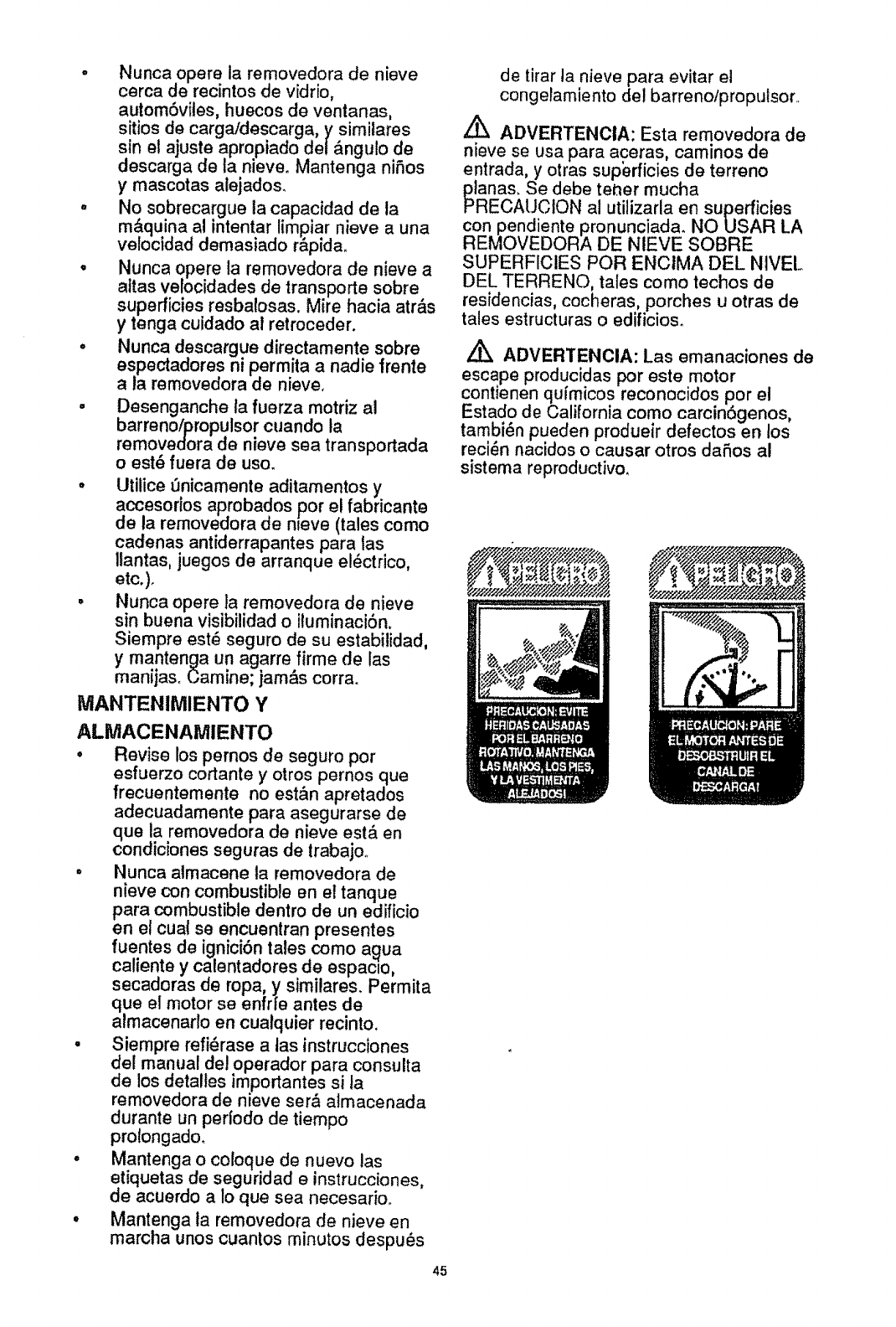
o Nunca opere la removedora de nieve
cerca de recintos de vidrio,
automSvites, huecos de ventanas,
sitios de carga/descarga, y similares
sin el ajuste apropiado del_,ngulo de
descarga de la nieve. Mantenga niSos
y mascotas alejados.
, No sobrecargue ta capacidad de la
m&quina al intentar limpiar nieve a una
velocidad demasiado r_.pida.
•Nunca opere la removedora de nieve a
attas velocidades de transporte sobre
superficies resbalosas. Mire hacia atr&s
y tenga cuidado al retroceder.
• Nunca descargue directamente sobre
espectadores ni permita a nadie frente
a la removedora de nieve,
• Desenganche la fuerza motriz al
barreno/.Dropulsor cuando ta
removedora de nieve sea transportada
o est6 fuera de uso.
° Utitice t_nicamente aditamentos y
accesorios aprobados por el fabricante
de la removedora de nteve (tales como
cadenas antiderrapantes para las
Ilantas, juegos de arranque el(_ctrico,
etc.).
° Nunca opere la removedora de nieve
sin buena visibilidad o iluminaciSn.
Siempre est_ seguro de su estabilidad,
y mantenga un agarre firme de las
mani,taso t.;am[ne; jamas corra.
MANTENIMIENTO Y
ALiVtACENAMIENTO
• Revise los pernos de seguro por
esfuerzo cortante y otros pernos que
frecuentemente no est&n apretados
adecuadamente para asegurarse de
que la removedora de nieve est,. en
condiciones seguras de trabajoo
° Nunca almacene ta removedora de
nieve con combustible en e! tanque
para combustible dentro de un edificio
en et cuat se encuentran presentes
fuentes de ignicibn tales como a_ua
caliente y calentadores de espaclo,
secadoras de ropa, y similares. Permita
que el motor se enfrte antes de
atmacenar/o en cualquier recinto.
° Siempre refi_rase alas instrucciones
del manual del operador para consulta
de los detalles importantes si ta
removedora de nieve sera atmacenada
durante un per(odo de tiempo
prolongado.
• Mantenga o coloque de nuevo las
etiquetas de seguridad e instrucciones,
de acuerdo a lo que sea necesario.
°Mantenga ta removedora de nieve en
marcha unos cuantos minutos despu(_s
45
de tirar ta nieve para evitar el
congelamiento del barreno/proputsor.
ADVERTENCIA: Esta removedora de
nieve se usa para aceras, caminos de
entrada, y otras superficies de terreno
lRanas.Se debe tether mucha
ECAUCION al utilizarla en superficies
con pendiente pronunciada. NO USAR LA
REMOVEDORA DE NIEVE SOBRE
SUPERFICIES POR ENCtMA DEL NIVEL
DEL TERRENO, tales como techos de
residencias, cocheras, porches u otras de
tales estructuras o edificioso
ADVERTENCIA: Las emanaciones de
escape producidas por este motor
contienen qulmicos reconocidos por el
Estado de California como carcinogenos,
tambien pueden produeir defectos en tos
reci_n nacidos o causar otros daSos al
sistema reproductivo.
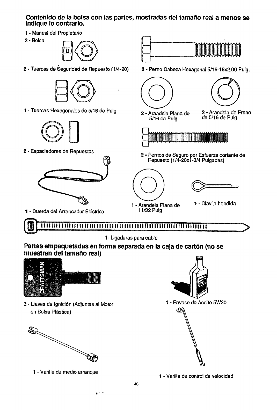
Contenldo de la boisa con las partes, mostradas del tama#toreal a menos se
Indlque Io contrarlo.
1 - Manual del Propietario
2-'Tuercas de Seguridad de Repuesto (1/4-20)
I _Tuercas Hexagonales de 5/16 de Pulg.
GB
2 - Espaciadores de Repuestos
2- Perno Cabeza Hexagonal 5/16-18x2.00 Pulg_
2-Arandela Plana de
5/16 de Pulg.
2 - Arandela de Freno
de 5/16 de Pulg.
2 - Pernos de Seguro por Esfuerza cortante de
Repuesto (1/4-20x 1-3/4 Pulgadas)
1 - Cuerda del Arrancador Eldctrico
1 - Arandela Plana de
11/32 Pulg_
1 _Clavija hendida
_, ! I illi!,!,t !lli!! I,I II III I I I IIi I,II! I!!11 lilliii'_'i'i"i"iiiilllll II ilii II! I,! ...................""""___
1- Ligaduras para cable
PaNes empaquetadas en forma separada en la caja de cart6n (no se
muestran del tamatio real)
2- Llaves de Ignici6n (Adjuntas al Motor
en Bolsa Pl&stica)
1 - Varitla de medio arranque
It
46
1 - Envase de Aceite 5W30
1- Varilla de control de velocidad
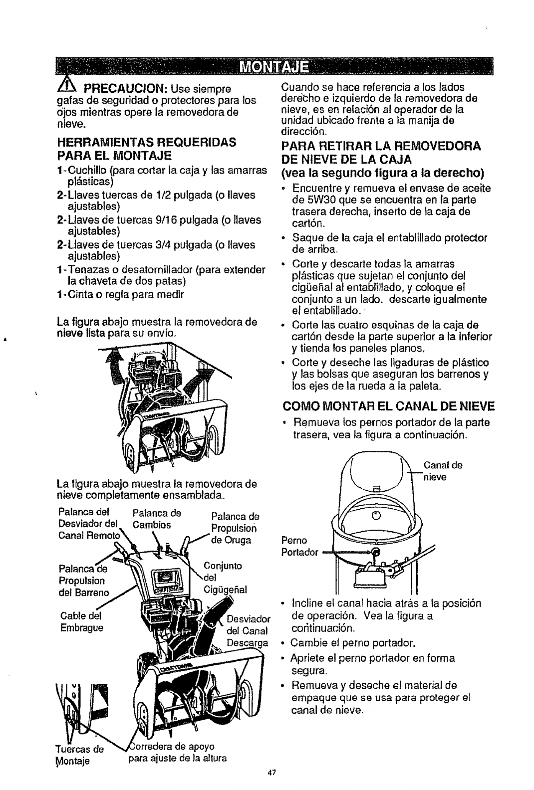
PRECAUClON: Use siempre
gafas de segurldad o protectores para los
0ios mientras opere la removedora de
nleve.
HERRAMIENTAS REQUERIDAS
PARA EL MONTAJE
1-Cuchillo (para cortar la caja y las amarras
pl&sticas)
2-Llaves tuercas de 1/2 pulgada (o ilaves
ajustables)
2-Ltaves de tuercas 9/16 pulgada (o ltaves
ajustables)
2-Ltaves de tuercas 3/4 pulgada (o llaves
ajustables)
1-Tenazas o desatornillador (para extender
la chaveta de dos patas)
1-Cinta o regta para medir
La figura abajo muestra la removedora de
nieve lista para su env{o.
La figura ab.ajo muestra la removedora de
nieve completamente ensamblada.
Palanca del Palanca de Palanca de
Desviador del Oambios Propulsion
Canal Oruga
Propulsion
del Barreno
Conjunto
Cable del
Embrague Desviador
del Canal
Cuando se hace referencia a los lados
dereoho e izquierdo de la removedora de
nieve, es en relac[6n a! operador de la
unidad ubicado frente a fa manija de
direcci6no
PARA RETIRAR LA REMOVEDORA
DE NIEVE DE LA CAJA
(vea la segundo ligura a la derecho)
, Encuentre y remueva el envase de aceite
de 5W30 que se encuentra en la parte
trasera derecha, inserto de ta caja de
cart6n.
•Saque de la caja el entablillado protector
de arriba.
Corte y descarte todas ta amarras
pr&sticas que sujetan el conjunto del
cigBeSal al entabliliado, y coloque el
conjunto a un tado. descarte igualmente
el entablillado. ;
-Corte las cuatro esquinas de la caja de
cart6n desde la parle superior a ia inferior
y lienda los paneles pianos.
• Corte y deseche tas ligaduras de pl&stico
ylas bolsas que aseguran los barrenos y
los ejes de la rueda a ta paletao
COMO MONTAR EL CANAL DE NIEVE
• Remueva los pernos portador de ta parte
trasera, yea [a figura a continuacibn.
Canal de
nieve
Pemo
Portador
• Incline el canal hacia atr_.s a Ia posici6n
de operaci6n. Vea la figura a
cor_tinuaci6n.
• Carnbie et perno portador.
•Apriete el perno portador en forma
segura_
•Remueva y deseche el material de
empaque que se usa para proteger el
canal de nieve_ •
Tuercas de
_ontaje
de apoyo
para ajuste de la altura
4?
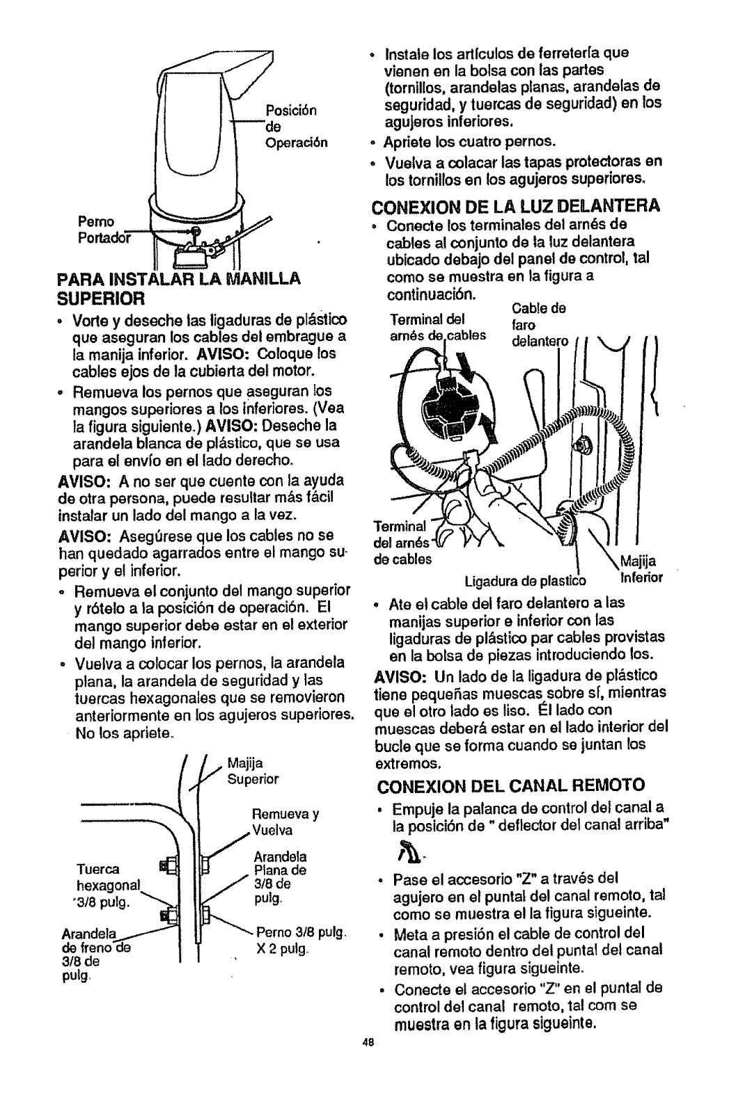
Pemo
Po_doT--
PARA INSTALAR LA tVlANILLA
SUPERIOR
•Vorte y deseche las ligaduras de pl_stico
que aseguran los cables del embrague a
la manija inferior. AVISO: Coloque los
cables ejos de la cubierta del motor.
- Remueva los pernos que aseguran los
mangos superiores a los inferiores. (Vea
la figure siguiente.) AVISO: Deseche la
arandela blanca de pl&stico,que se usa
pare el envfo en el lado derecho.
AVISO: A no ser que cuente con la ayuda
de otra persona, puede resuttar rn&s fdcil
instalar un lado del mango ala vez.
AVISO: AsegOrese que los cables no se
han quedado agarrados entre e! mango su.
perior y el inferior.
°Rernueva el conjunto de! mango superior
y r6telo a ta posicibnde operaci6n. El
mango superior debe estar en el exterior
del mango inferior.
oVuetva a colocar lospernos, la arandela
ptana, la arandela de seguridad y las
tuercas hexagonales que se removieron
anteriorrnente en losagujeros superiores,
No los apriete.
Majija
Superior
Remueva y
,Vuelva
Arandela
Tuerca Ptana de
hexagonal 318de
°3/8 ], pulg.
Arandela _. Perno 318pulg.
de freno de X 2pulg_
3/8 de
putg,
48
° Instate los arllculos de ferreter[a que
vienen en la bolsa con las partes
(tornillos,arandelas planas, arandelas de
seguridad, y tuercas de seguridad) en los
agujeros inferiores.
o Apriete los cuatro pernos.
° Vuelva acolacar tas tapes protectoras en
los tornillosen los agujeros superiores_
CONEXION DE LA LUZ DELANTERA
°Conecte losterminates del arn_s de
cables al conjunto de la luz delantera
ubicado debajo det panel de control,tel
Terminal
del am_s
de cables
como se muestra en la figure a
continuaciSn. Gable de
Terminal del faro
cables delantero
Majija
Ligadura de pla,' Inferior
° Ate el cable del faro delantero a las
manijas superior einferior con las
ligaduras de pl&stico par cables provistas
en la bolsa de piezas introduciendo los.
AVISO: Un lado de la ligadura de pl&stico
tiene pequeSas muescas sobre s[, mientras
que el otro lado es liso. I_1lado con
muescas deber& estar en el lado interior del
bucle que se forma cuando se juntan los
extremos.
CONEXION DEL CANAL REMOTO
Empuje la palanca de control del canal a
la posici6n de" deflector del canal arriba"
• Pase el acoesorio "Z" a trav_s del
agujero en el puntal del canal remoto, tal
como so rnuestra el la figure sigueinte.
• Mete a presi6n el cable de control del
canal remoto dentro del puntal del canal
remoto, yea figure sigueinte.
, Conecte el accesorio "Z" en el puntal de
control del canal remoto, tel com se
rnuestra en la figure sigueinte,
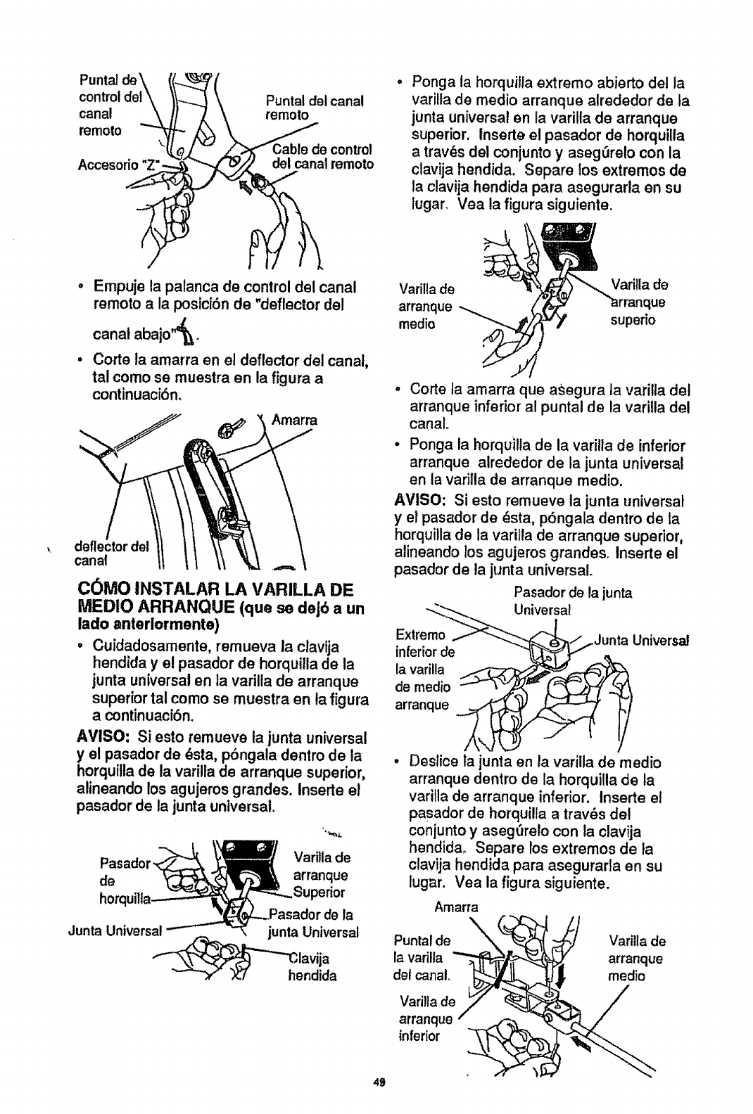
Puntal de'_
col Puntal del canal
canal remoto
mmoto
'_ de control
Accesorio" del canal remoto
Ponga la horquitla extremo abierto della
varilla de medio arranque alrededor de ta
junta universal en la varilla de arranque
superior. Inserte el pasador de horquilla
a trav_s del conjunto y aseg_relo con la
clavija hendida. Separe los extremos de
la clavija hendida para asegurarla en su
lugar. Vea la figura siguiente.
- Empuje la palanca de control del canal
remoto a la posici6n de "deflector del
canal abajo&o
• Corte la amarra en el deflector del canal,
tal como se muestra en la figura a
continuaci6n.
Amarra
deflector del
canal
C0MO INSTALAR LA VARILLA DE
MEDIO ARRANQUE (que se deJ6 a un
lado anteriormente)
•Cuidadosamente, remueva la clavija
hendida y el pasador de horquilla de la
junta universal en la varilla de arranque
superior tal como se muestra en la figura
a continuaci6n.
AVISO: Si esto remueve la junta universal
y el pasador de _sta, pOngala dentro de la
horquitlade la varilla de arranque superior,
alineando los agujeros grandes. Inserte el
pasador de la junta universal.
Pasado Varilta de
de arranque
horquilta perior
de la
Junta Universal junta Universal
""-___h,elavija
ndida
Varilla de Varilla de
arranque
medio superio
49
• Corte ta amarra que asegura la varilla del
arranque inferior al puntal de la varilla del
canal.
.Ponga la horquilla de la varilla de inferior
arranque alrededor de la junta universal
en ta varilla de arranque medio.
AVISO: Si esto remueve la junta universal
y el pasador de _sta, pbngala dentro de la
horquilla de la varilla de arranque superior,
alineando los agujeros grandesr Inserte el
pasador de la junta universal.
Pasador de tajunta
Universal
Extremo _Junta Universal
inferiorde
la varilla
de medio
arranque
•Deslice la junta en la varilla de medio
arranque dentro de la horquilla de la
varilla de arranque inferior. Inserte el
pasador de horquilla a trav_s del
con junto y asegt)relo con la clavija
hendid& Separe los extremos de la
clavija hendida para asegurarla en su
lugar. Vea la figura siguiente.
Amarra
Puntal de __
la varilla _"_,_.._
del canal, _...J
!
Varilla de _
arranque - ..___,-_ _,;
inferior .__
Varilla de
arranque
medio
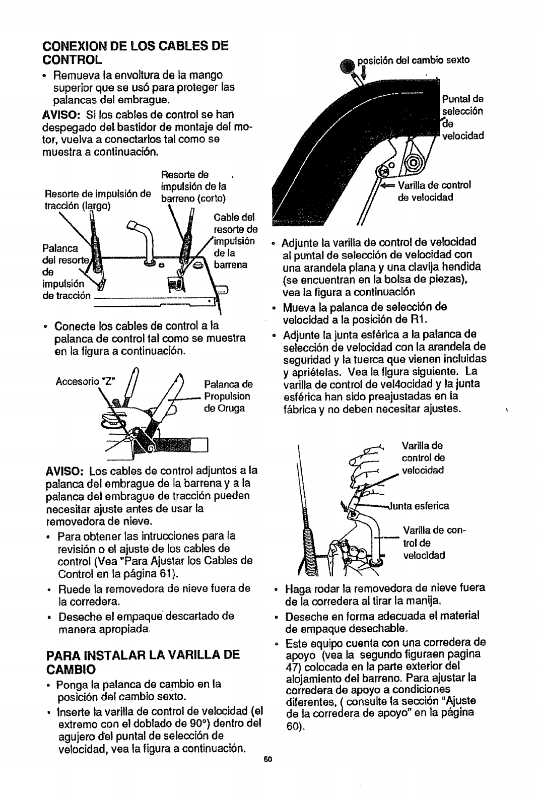
CONEXION DE LOS CABLES DE
CONTROL
oRemueva la envoltura de la mango
superior que se us6 para pmteger las
palancas del embrague.
AVISO: Si los cables de control se han
despegado det bastidor de montaje del mo-
tor, vuelva aconectarlos tal como se
muestra a continuaci6n.
Resorte de impulsi6n de
tracci6n
-\
Palanca
del
de
imlc
de tracci6n
Resorte de
impulsi6nde la
barreno (corto)
Cable del
resorte de
de la
barrena
, Conecte los cables de control ala
palanca de control tal como se muestra
en la figura a continuaci6n.
Accesorio "Z" Palanca de
Propulsion
de Oruga
, del cambio sexto
Puntal de
selecci6n
velocided
de control
de velocidad
° Adjunte la variUa de controlde velocidad
al puntal de selecci6n de velocidad con
una arandela plana y una clavija hendida
(se encuentran en la bolsa de piezas),
vea la figura a continuaci6n
•Mueva la patanca de selecci6n de
velocidad a !a posici6nde R1.
-Adjunte la junta est_rica a la palanca de
setecciSnde velocidad con la arandela de
seguridad y la tuerca que vienen inclutdas
yapri_telas. Vea la tigura siguiente. La
varilla de controlde vel4ocidad y la junta
esf_rica han sido preajustadas en la
f&brica yno deben necesitar ajustes.
AVISO: Los cables de control adjuntos a la
palanca del embrague de la barrena y a la
palanca del embrague de tracci6n pueden
necesitar ajuste antes de usar la
removedora de nieve.
• Para obtener las intrucciones para ta
revisi6n o el ajuste de los cables de
control (Vea "Para Ajustar los Cables de
Control en la p&gina 61).
- Ruede la removedora de nieve luera de
ta corredera.
•Deseche el empaque descartado de
manera apropiada,
PARA INSTALAR LA VARILLA DE
CAMBIO
,Ponga la palanca de cambio en la
posicibn del cambfo sexto.
° Inserts la vari!ia de controlde velocidad (el
extremo con el doblado de 90°) dentro del
agujero del puntal de seleccf6n de
velocidad, vea la figura a continuaciSn. 5O
Variila de
control de
velocidad
esferica
VariUade con-
trol de
velocidad
Haga rodar la removeclorade nieve fuera
de la corredera al tirar la manija.
Deseche en forma adecuada el material
de empaque desechable.
Este equipo cuenta con una corredera de
apoyo (yea la segundo tiguraen pagina
47) cotocada en la parte exterior del
alojamiento del barreno. Para ajustar la
corredera de apoyo a condiciones
diferentes, ( consulte ta secci6n "Ajuste
de la corredera de apoyo" en la p&gina
60)
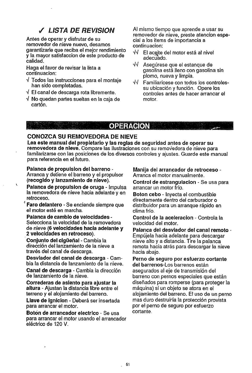
4' LISTA DE REVISION
Antes de operar y disfrutar de su
removedor de nieve nuevo, desamos
garantizarle que reciba el mejor rendimiento
y la mayor satisfaccion de este producto de
calidado
Haga el favor de revisar ta tista a
conlinuacion:
qTodos las instrucciones para el montaje
han sido completadas,
",/El canal de descarga rota libremente,
_/ No quedan partes sueltas en la caja de
cart6m
AI mismo tiempo que aprende a usar su
removedor de nieve, preste atencfon espe-
cial a los items de importancia a
continuacion:
qq El acg_te del motor est& al nivel
adecuado.
q-,l Aseg_rese que el estanque de
gasolina est_ lleno con gasotina sin
plomo, nueva y limpiao
_/_/ Familiaficese con todos los controtes-
su ubicaciSn y funci6no Opere los
controles antes de hacer arrancar el
motor°
CONOZCA SU REMOVEDORA DE NIEVE
Lea este manual del propletario y las reglas de seguridad antes de operar su
removedora de nleve. Compare las ilustracionescon su remoqedora de nieve para
familarizarse con las posiciones de los diversos controles y ajustes_Guarde este manual
para referencia en el futuro,
Palanca de propulsion del barreno -
Arranca y detiene el barreno y el propulsor
(recogldo y tanzamlento de nieve).
Palanca de propulsion de oruga - Impulsa
la removedora de nieve hacra adetante y en
retroceso.
:Faro detantero - Se enciende siempre que
el motor est_ en marcha_
Palanca de camblo de velocldades -
Selecciona la velocidad de la removedora
de nieve (6 velocldades hacta adelante y
,2 velocldades en retroceso).
Conjunto del ctg0et_al - Cambia la
direcci6n del lanzamiento de la nieve a
tray, s del canal de descarga_
Desvlador del canal de descarga - Cam-
bia la distancia de lanzamiento de la nieve,
Canal de descarga - Cambia ta direcciSn
de lanzamiento de la nieve,
Correderas de aslento para ajustar la
altura _Ajustan la distancia libre entre el
terreno yel alojamlento del barreno.
Llave de Igniclon - Deberd ser insertada
para arrancar el motor,
Boton de arrancador electrlco - Se usa
para arrancar el motor usando el arrancador
et_ctrico de 120 V_
Manija det arrancador de retroceso -
Arranca el motor manualmente,
Control de estrangulacion - Se usa para
arrancar un motor fr[Oo
Boton cebo- Inyecta el combustible
directamente dentro del carburador o
distribuidor para un arranque r&pido en
ctima frio,,
Control de ta aceleracion - Controla la
velocidad del motor.
Palanca del desvlador del canal remoto
Emp_jela hacia adelante para descargar
nieve alto y a distancia, Tire la palanca
remota hacia atr&s para descargar ta nieve
hacia abajoo
Perno de seguro por esfuerzo cortante
dei barrenos-Los barrenos est&n
asegurados al eje de transmisiOn det
barreno con pernos especiales que est&n
disefiados para romperse (para proteger ]a
m&quina) si un objeto se atora en el
alojamiento del barreno, E! uso de un perno
mas duro destruir|a la protecci6n provista
por et perno de seguro por esfuerzo
cortante,
5_
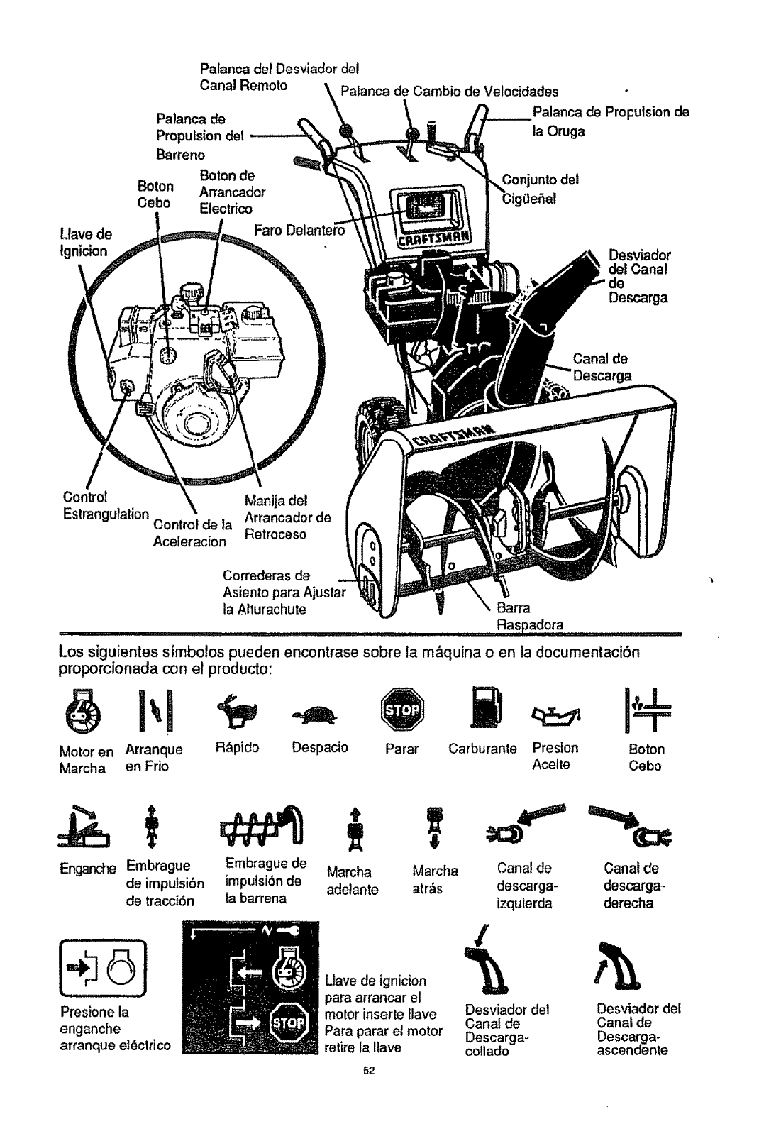
Llave de
tgnicion
Palanca de! Desviador del
Canal Remoto _\
Palanca de
Propulsion del
Barreno
Boronde
Boron Arrancador
Cebo Electrico
Faro
Palanca de Cambio de Velocidades
Palanca de Propulsion de
la Oruga
3onjunto del
Desviador
del Canal
Descarga
Canal de
Control k Manija del
Estrangulation Arrancader de
Control de la
Aceleracion Retroceso
Correderas de
Asiento para Ajustar
ta Alturachute Barra
Raspadora ....
Los siguientes simbolos pueden encontrase sobre la m_quina o en la documentaci6n
proporcionada con el producto:
Motor en Arranque
Marcha en Frio
R&pido Despacio Parar Carburante Presion Boton
Aceite Cebo
Embrague Embrague de Marcha
de imputsi6n imputsi6nde adelante
de tracci6n la barrena
Marcha
arras
ii i,
[÷61
Presione la
enganche
arranque et_ctrico
Canal de Canal de
descarga- descarga-
izquierda derecha
52
Llave de ignicion _
para arrancar el
motor inserte llave Desviador del Desviador del
Canal de Canal de
Para parar et motor Descarga- Descarga-
retire la Ilave collado ascendente
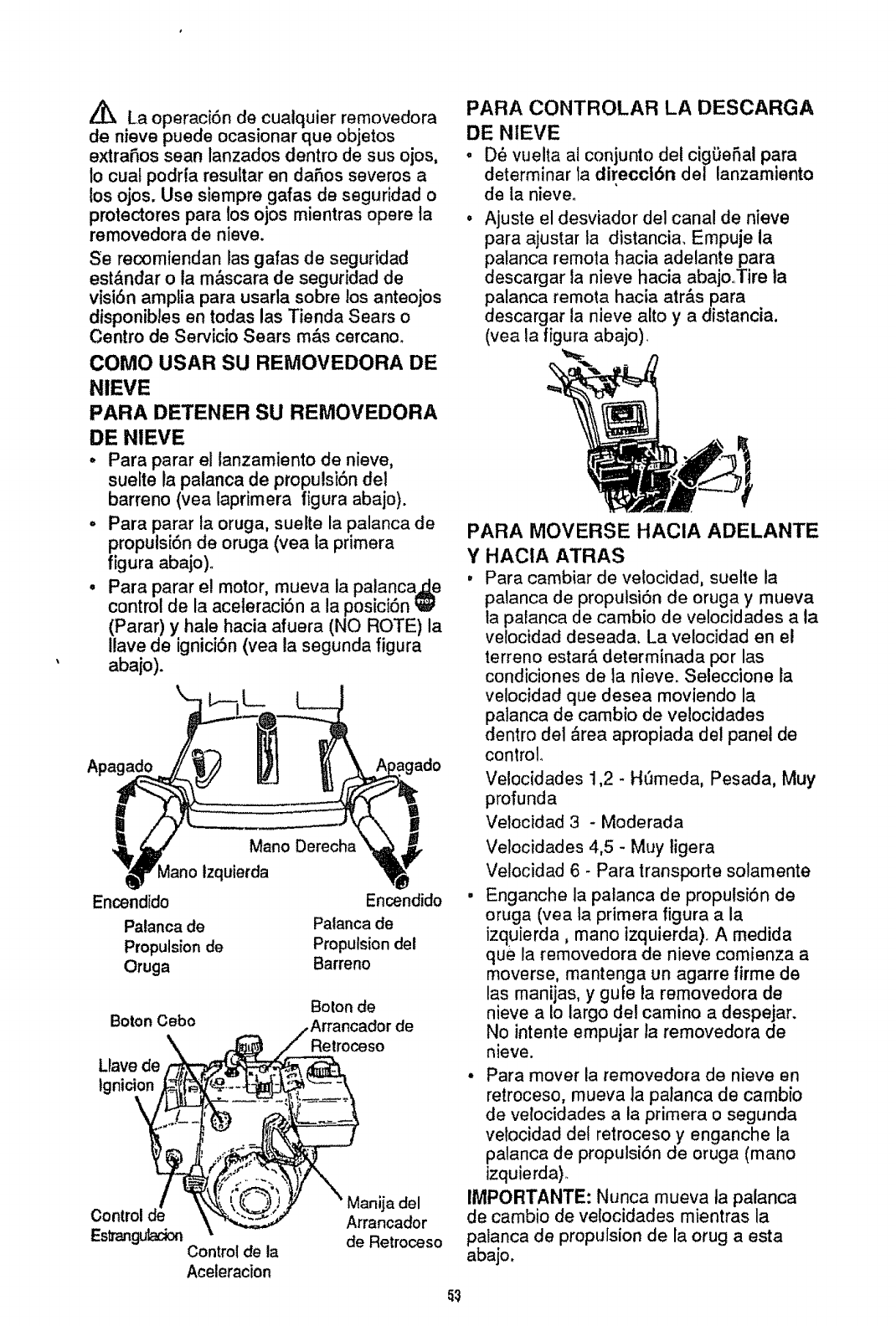
La operaci6n de cualquier removedora
de nieve puede ocasionar que objetos
extraSos sean lanzados dentro de sus ojos,
1ocuat podrfa resultar en daSos severos a
los ojos. Use siempre galas de seguridad o
protectores para los ojos mientras opere la
removedora de nieve.
Se recomiendan las gafas de seguridad
est&ndar o la m&scara de seguridad de
visi6n amptia para usarta sobre los anteojos
disponibles en todas las Tienda Sears o
Centro de Ser¢icio Sears m&s cercano_
COMO USAR SU REMOVEDORA DE
NIEVE
PARA DETENER SU REMOVEDORA
DE NIEVE
• Para parar el lanzamiento de nieve,
suelte la palanca de propu!si6ndel
barreno (yea laprimera figura abajo).
-Para parar ta oruga, suelte la palanca de
propulsi6n de oruga (vea la primera
figura abajo)o
•Para parar e! motor, mueva la palancaj;Le
control de la aceleracion ala posici6n
(Parar) y hale hacia afuera (NO ROTE) la
Ilave de ignici6n(yea la segunda figura
abajo).
=gado
Mano Derecha
Mano Izquierda
Encendido
Palanca de
Propulsion de
Oruga
Encendido
Palanca de
Propulsion del
Barreno
BoronCebo
Llave de
ignition
Boron de
Retroceso
de
EstranguladonControl de la
Aceleracion
Manija del
Arrancador
de Retroceso
PARA CONTROLAR LA DESCARGA
DE NIEVE
.D_ vuelta al conjunto det cig0eSal para
determinar ta direcclbn del lanzamiento
de la nieve.
° Ajuste el desviador del canal de nieve
para ajustar la distancia. Empuje la
palanca remora hacia adelante para
descargar la nieve hacia abajo,.Tire la
palanca remota hacia atr&s para
descargar la nieve alto y a distancia,
(vea la figura abajo).
PARA MOVERSE HACIA ADELANTE
Y HACIA ATRAS
,Para cambiar de velocidad, suelte la
palanca de proputsi6n de oruga y mueva
la patanca de cambio de velocidades a la
vetocidad deseada. La velocidad en el
terreno estar& determinada por las
condiciones de la nieve. Seleccione la
velocidad que desea moviendo la
palanca de cambio de velocidades
dentro del &rea apropiada del panel de
control
Velocidades ! ,2 - H_meda, Pesada, Muy
profunda
Velocidad 3 - Moderada
Velocidades 4,5 - Muy ligera
Velocidad 6 - Para transporte solamente
• Enganche la palanca de propulsi6n de
oruga (vea la primera figura ala
izquierda, mano tzquierda)° A medida
que la removedora de nieve comienza a
moverse, mantenga un agarre firme de
las manijas, y gufe la removedora de
nieve a Io largo del camino a despejar.
No intente empujar la removedora de
nieve.
•Para mover la removedora de nieve en
retroceso, mueva la paianca de cambio
de velocidades a la primera o segunda
velocidad del retroceso y enganche la
palanca de propulsi6n de oruga (mano
izquierda)_
IMPORTANTE: Nunca mueva ta palanca
de cambio de velocidades mientras la
palanca de propulsion de la orug a esta
abajo,
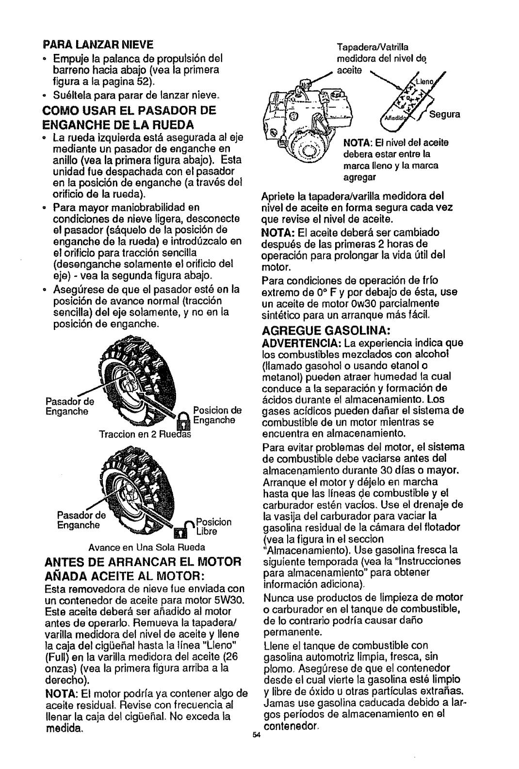
PARA LANZAR NIEVE
.Empuje la palanca de propulsi6n del
barreno hacia abajo (vea la primera
figura a la pagina 52).
-Su_ltela para parar de lanzar nieve°
COMO USAR EL PASADOR DE
ENGANCHE DE LA RUEDA
oLa rueda izquierda est_ asegurada al eje
mediante un pasador de enganche en
anillo (yea la primera figura abajo). Esta
unidad fue despachada con et pasador
en la posici6n de enganche (a trav6s del
orificio de la rueda).
•Para,mayor maniobrabilidad en
condlciones de nieve ligera, desconecte
el pasador (s_.quelo de la posici6n de
enganche de la rueda) e introd0zcalo en
el orificio para tracciSn senciUa
(desenganche solamente el orificio del
eje) -yea la segunda figura abajo.
•AsegL_rese de que el pasador est8 en la
posici6n de avance normal (tracci6n
sencitla) de! eje solamente, y no en ta
posici6n de enganche.
Pasador de
Enganche
Traccion en 2
Posicion de
Enganche
Pasador
Enganche _osicion
.ibre
Avarice en Una Sola Rueda
ANTES DE ARRANCAR EL MOTOR
AI_ADA ACEITE AL MOTOR:
Esta removedora de nieve fue enviada con
un conteneder de aceite para motor 5W30.
Este aceite deber& ser afiadido al motor
antes de operarlo, Remueva la tapadera/
varilta medidora del nivel de aceite yIlene
la caja del cigSefiat hasta la Ifnea "Llano"
(Full) en la varilla medidora del aceite (26
onzas) (vea la primera figura arriba ala
derecho).
NOTA: El motor podrfa ya contener algo de
aceite residual Revise con frecuencia al
ilenar la caja del cigSeRal. No exceda la
rnedida_
Tapadera/Vatrilla
medidora de1nivel de
aceite ,,_ / /
:'-- • "'$'_ ura
_NOTA: El nivel del aceite
_)" debera estar entre la
rnarca Ileno yla rnarca
agregar
Apriete la tapadera/varitla medidora del
nivel de aceite en forma segura cada vez
que revise el nivel de aceite.
NOTA: El aceite deber& ser cambiado
despu6s de las primeras 2 horas de
operaci6n para prolongar la vida 0til del
motor.
Para condiciones de operaci6n de fr[o
extremo de 0" F y por debajo de 6sta, use
un aceite de motor Ow30 parcialmente
sint_tico para un arranque m&s f,_ciL
AGREGUE GASOLINA:
ADVERTENCIA: La experiencia indica que
los combustibles mezctados con alcohol
(llamado gasohol o usando etanol o
metanol) pueden atraer humedad ta cual
conduce a ta separaci6n y formaci6n de
&cidos durante el almacenamiento. Los
gases acfdicos pueden dafiar el sistema de
combustible de un motor mtentras se
encuentra en almacenamiento.
Para evitar problemas del motor, el sistema
de combustible debe vaciarse antes del
almacenamiento durante 30 dlas o mayor.
Arranque el motor y d_jelo en marcha
hasta que tas lineas de combustible y el
carburador est_n vaclos. Use el drenaje de
la vasija del carburador para vaciar la
gasolina residual de la c&mara del flotador
(vea la figura in el seccion
"Almacenamiento), Use gasolina fresca la
siguiente ternporada (vea la "lnstrucciones
para almacenamiento" para obtener
informaci6n adiciona).
Nunca use productos de limpieza de motor
o carburador en et tanque de combustible,
de io contrario podria causar dafio
permanente.
Llene el tanque de combustible con
gasolina automotriz limpia, lresca, sin
plomo. Aseg_rese de que el contenedor
desde el cual vierte la gasolina est_ limpio
y libre de 6xido u otras particulas extrafias.
Jamas use gasolina caducada debido a lar-
gos periodos de almacenamiento en el
contenedor.
54
A_ PRECAUClON: Lea el manual del
propietario antes de operar la maquina.
Jamas dirija ta descarga hascia
espectadoreso Pare el motor antes de
desobstruir el canal de descarga o el
abjamienato del barreno y antes de dejar la
maquina.
Z_ PREOAUCiON: La _asolina es
inf!amable se deberaten_er mucho cuidado
at manipular,'_ o almacenarla_
No llene et tanque de combustible mientras
la removedora de nieve se encuentra en
marcha, cuando esta caliente, o cuando la
removedora de nieve se encuentra en un
area cerrada.
Mantengase alejado(a) de llamas abiertas o
chispas electricas y no fume mientras llena
el tanque de combustible.
Nunca Ilene el tanque completamente.
Llene el tanque hasta el nivel entre 1/4-1/2
pulgada desde la parle superior para
proporcionar espacio para la expansion del
combustible.
Siempre ilene el tanque en ambientes
exteriores y use un embudo o boquilla para
prevenir el derrame. Asegurese de limpiar
cuatquier combustible derramado antes de
arrancar el motor.
Almacene la gasolina en un contenedor,
limpfo y aprobado, y mantenga la tapadera
de! contenedor en su tugar.
PARA PARAR EL MOTOR
, Para parar ia marcha del motor, mueva la
palanca d_Lcontrot de la aceleraci6n a la
posici6n _ (Parar) y retire la Itave.
Mantenga la Itave en un lugar seguro. El
motor no arrancara sin la Ilave_
PARA ARRANCAR EL MOTOR
(Arrancador el_ctrico)
Aseg_rese de que el motor tenga suficiente
aceite (vea "Lubricaci6n del motor" en la
p.agina 53)° E! motor de la removedora de
reeve est& equipado con un arrancador
ei_ctrico de 120 voltios corriente alterna y
arrancador de retrocesoo Antes de arrancar
el motor, aseg0rese de haber lefdo la
informaci6n siguiente:
ARRANQUE EN FRIO (yea la flgura
en la paglna 51)
•Aseg_rese de que las palancas de
propulsi6n de! barreno yde propulsiSn de
oruga est,_n en la posici6n
desenganchada "SueRa" (Released)_
°Mueva el,pontrol de la acelerac[6n a la
posiciSn "I_ (R&pido).
•Remueva las Ilaves de la botsa pl&stica.
Inserte una llave en la ranura de [gnici6n.
AsegOrese de que encaja en su lugar° NO
ROTE LA LLAVE. Mantenga la segunda
Itave en un lugar'seguroo
,Rote la manecilla de estrangulaci6n a la
pos}ciSn estrangulaci6n" Total" (Full).
• Conecte el cable de alimentaci6n
el_ctrica a ta caja de interruptores en el
motor.
,Enchufe el otro extremo del cable de
alimentaci6n et6ctrica en un recept&culo
trifilar de 120 voltios y corriente alterna
con polo a tierra.
°Empuje el bot6n cebo mJentras cubre el
agujero de ventilaciSn de ta manera
siguiente: (Remueva el dedo del boton
cebo entre cebados).
No efectSe el cebado si la temperatura
esia sobre 50 °F_
Dos veces si latemperatura est& entre
50,°F hasta t5 ° Fo
Cuatro veces si la temperatura se
encuentra por debajo de 15 ° F.
•Empuje el botSn del arrancador hacia
abajo basra que el motor arranque. No
intentar el arranque por mas de 10
segundos a la vez. Este arrancador
el_ctrico est& protegido termatmente. Si
se'sobrecalienta se detendr&
autom&ticamente y puede ser arrancado
nuevamente sSlo cuando se ha enfdado
hasta una temperatura segura (se
requiere una espera de 5 a 10 minutos
aproximadamente).
•Cuando el motor arranca, suelte el botbn
del arrancador y lentamente rote el
estrangulador a la posici6n "Apagado"
(O!f). Si el motor falla, rote la
estrangutaci6n a" Total" (Full) y tuego
gradualmente a" Apagado" (Off).
•Desconecte el cable de alimentaci6n
el_ctrica desde el recept&culo primero y
luego desde la caja de interruptores en el
motor.
NOTA: Permita que el motor caliente por
unos cuantos minutos puesto que el motor
no desarrollar& una potencia completa sino
hasta que alcance la temperatura de
operaciSn.
• Opere el motor a toda velocidad '_
(R_pido) ai remover nieve.
ARRANQUE EN CALIENTE
Si est& arrancando un motor caliente
despu_s de un apag6n corto, deje et
estrangulador en" Apagado" (Off) y no pulse
el bot6n cebo.
55
PRECAUCION: Este arrancador esta
equipado con un cable de alimentacion
tritilar y esta disefiado para operar en
corriente alterna domiciliar de 120 voltios.
Deber&a estar conectado a tierra de
manera adecuada en todo momento para
evitar ta posibilidad de un choque electrico,
el cual podria causar heridas al operador.
Siga las instrucciones cuidadosamente de
la manera en que se detallen en la seccion
"Para Arrancar el Motor". Verifique que el
alambrado de su casa sea trifilar con polo a
tierra. Pregunte aun electricista autorizado
si no se encuentra seguro. Si el sistema de
atambrado de su casa no es un sisterna
trifilar, no use el arrancador electrico
bajoninguna condicion. Si su sistema tiene
polo a tierra y no se encuentra disponible
un receptaculo trifitar en et punto en que su
arrancador sera usado normalmente, se
debe instalar uno por un etectricista
autorizado.
AI conectar el cable de almentacion
electrica de corriente altera de 120 voltios,
siempre conecte el cable ala caja de
interruptores en el motor primero, Luego
enchufe el otro extremo en el receptaculo
trifilar con polo a tierra.
A! desconectar et cable de almentacion
electrica, siempre desenchufe el extremo
en el receptaculo con polo a tierra primero.
Z_ PREOAUClON: Nuncaponga el motor
en marcha en ambientes interiores o en ar_
eas encerradas, mal ventiladas, el escape
del motor contiene monoxido de carbono,
un gas inodoro y letal. Mantenga las
manos, pies, cabello y vestimenta floja
alejados de cualesquiera piezas moviles en
el motor yen la removedora de nieve.
Advertencia: Las temperaturas det escape
yareas cercanas podrian exceder los
150°Fo Evite estas areas. No permita a
nifios o adolescentes jovenes operar o
estar cerca de la removedora de nieve
mientras esta se encuentra en operaciOno
PARA PARAR EL MOTOR
•Para parar ta marcha del motor, mueva la
palanca de control de la aceleraci6n a la
posici6n 1_ (Parar) y retire la Ilave.
Mantenga la llave en un tugar seguro. El
motor no arrancara sin la Ilave.
NOTA: NO rote la Ilaveo
56
PARA ARRANCAR EL MOTOR
(Arrancador de retroceso)
Asegt3rese de que el motor tiene suficiente
aceiteo Antes de arrancar el motor,
aseg_3rese de haber le|do la siguiente
informaci6n:
ARRANQUE
en la paglna
e
EN FRIO (vea la tlgura
51)
Aseg0rese de que las palancas de
propulsi6n det barreno yde propulsi6n de
oruga est&n en la posici6n
desenganchada "Suelta" (Released).
Mueva el.,_ntrol de ia aceteracibn ala
posici6n -I_ (R&pido). '
Remueva las tlaves de la bolsa pl&stica,
Inserte una Ilave en la ranura de ignici6n.
Aseg0rese de que encaja en su lugar.
NO ROTE LA LLAVE. Mantenga la
segunda Itave en un lugar seguro.
Rote la manecilla de estrangulaci6n a la
posici6n estrangulaciSn "Total" (Full).
Empuje el bot6n cebo mientras cubre el
agujero de ventilaci6n de la manera
siguiente: (Remueva el dedo del bot6n
cebo entre cebados).
No efectL'Je el cebado si la temperatura
esta sobre 500
Dos vecessi la temperatura est,. entre
50 °F hasta 15° F.
Cuatro veces si la tempe_'atura se
encuentra por debajo de 15 °F.
•Hale la manija del arrancador
r&pidamente, No permita que ta manija
regrese a su posici6n original, pero
permita que se dewielva lentamente
mientras mantiene un agarre firme sobre
la manija del arrancador.
•A medida que calienta el motor y
comienza a funcionar uniformemente,
rote la manecilla de estrangulacibn a la
posici6n" Apagado" (Off)° Si e! motor
falta, regrese a estrangulaci6n "Total"
(Full), luego tentamente mu_vala a la
posici6n estrangulaci6n "Apagado" (Off).
NOTA: Permita que el motor caliente por
unos cuantos minutos puesto que e! motor
no desarrollar& una potencia compteta sino
hasta que alcance ta temperatura de
operaci6n.
• Opere el motor a toda velocidad '_
(R,_pido) al remover nieve.
ARRANQUE EN CALIENTE
Si est& arrancando un motor caliente
despu_s de un apag6n corto, deje el
estrangulador en "Apagado" (Off) y no
pulse el bot6n cebo.
ARRANCADOR DERETROCESO
CONGELADO
Sielarmncadorest_congelado yno
arra aelmotor:
,Hale tanta Iongitud de cueFda del
arrancador como sea posibleo
°Suelte ta manija del arrancador y d_jela
enrollarse de nuevo contra et arrancador.
Si el motor |aUa en arrancar, repita el
rocedimiento. Si intentos continuados no
eran el arrancador, siga el procedimiento
para arranque el6ctrico en frfoo
Para ayudar a evitar ta posibitidad de
congelamiento del arrancador de retroceso
y los controles del motor, proceda de la
manera siguiente despu_s de cada trabajo
de remoci6n de nieve_
- Con el motor en marcha, hale la cuerda
de arranque en6rgicamente con un
alargamiento de brazo continuo tres o
cuatro veces. El halado de la cuerda de
arranque producir& un sonido de
repiqueteo fuerte. Esto no causa dafio ni
at motor ni al arrancador_
o Con el motor parado, limpie toda la
nieve y humedad de la cubierta del
carburador en et &rea de las palancas de
control. Asimismo, mueva el control de
aceleraci6n, control de estrangulaci6n, y
manija del arrancador varias veces y deje
el estrangulador en la posici6n "Total"
(Full) y lapalanca de aceleraci6n en ta
posicibn _ (R&pido).
PISTAS SOBRE LANZAMIENTO DE
NIEVE
o Para mayor eficiencia de lanzamiento de
nieve durante la remoci6n de la misma,
ajuste la ve!ocidad en el terreno, NUNOA
la aceleraci6n_ Avance lentamente en
nieve profunda, congelada, o h_3meda. Si
la rueda desliza, reduzca la velocidad
hacia adelante. Et motor esta diseSado
para brindar un rendimiento m&ximo bajo
aceleraci6n total y debe ser operado en
este valor de potencia en todo momento_
-Et lanzamiento de nieve es m&s eficiente
si la remoci6n de ta misma se elect[)a
inmediatamente despu_s de su cafdao
° Para una remoci6n completa de la nieve,
traslape ligeramente cada camino
adoptado previamente.
•La nieve deber[a ser descargada en la
direcci6n del viento siempre que sea
posible.
o Para uso normal, posicione las
correderas de apoyo de manera tal que
la barra raspadora se encuentre 1/8 de
pulgada sobre las correderas de apoyo_
Para superficies de nieve dura
extremadamen[e compacta, ajuste fas
correderas de apoyo hacia arriba de
manera que la barra raspadora haga
contacto con el terrenoo
° En superficies de grava o roca triturada,
posicione las correderas de apoyo a
1-1/4 pulgadas por debajo de la barra
raspadora (vea el p&rrafo "C6mo ajustar
la altura de las correderas de apoyo" en
la p&gina 60). Las rocas y grava no
deber&n ser recogidas y lanzadas por la
m&quina.
• Si la parte delantera de la removedora de
nieve tiene la tendencia de elevarse
reduzca la velocidad sobre el terreno y
enganche el sistema de transferencia de
peso°
,Despu6s de que se haya comptetado et
lanzamiento de nieve, permita que el
motor se encuentre en reposo por unos
cuantos minutos, Io cual derretir& la nieve
y hielo acumufado del motor.
•Efect0e una limpieza completa de la
removedora de nieve luego de cada uso.
•Remueva la acumulaci6n de hielo y
nieve y todo material extraSo
heterog_neo de la removedora de nieve
en su totalidad, y lave con agua (si fuese
posibfe) para remover toda sal u otras
substancias qu[micas. Seque la
removedora de nieve.
Z_ PRECAUCION: No intente remover
cualquier elemento que resulte atorado en
barreno si tomar las precauciones
siguientes:
•Suelte las palancas de propulsion det
barreno y de propulsion de oruga.
•Mueva la palanca de control de la
aceleracion a la posicion pararo
• Remueva (No Rote) la llave de
ignicion.
° Besconecte el alambre de la buija_
•No coloque las manos en el barreno o
canal de descarga. Use una barra de
apalancamiento.
57
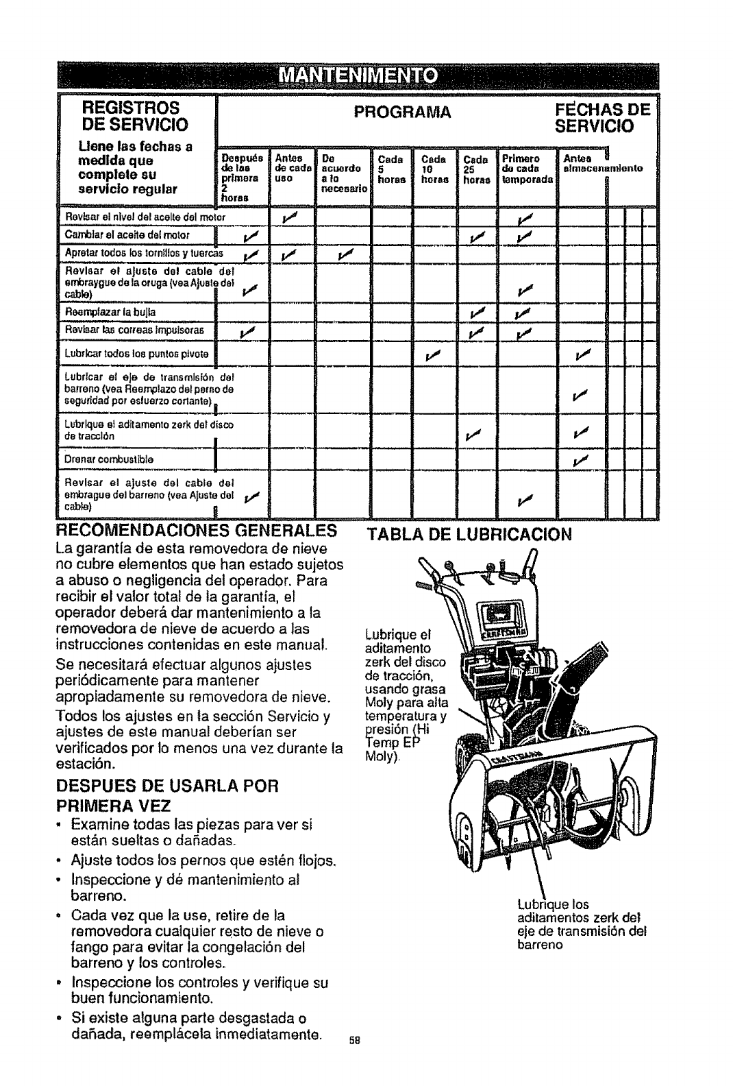
REGISTROS
DE SERVICIO
Uene las fechas a
medlda qua
complele su
servicio regular
PROGRAMA
Deepuds Antes Do Cads
de los /de cads scuerdo 5
primer,,, use slo horse
2necea_!o
horse
FECHAS DE
SERVICIO
Cede Cads Primers Antes
10 25 do cads almt=cenernIento
horas horse temporads g
I
Revlsarel nivel del acolte dal motor
Cambtarel scabs deimotet v" p,/ v"
Apretat redes los tom!itosy tuorcas pJ _p,_
Reviser el ajuste del cable del
errforaygue de la eruga (veaAJuatede! i'f _,_
__ _e) ........
Re,emplazat la buJla p,# p#t
J, L, • n , •
Reviser las cotreas Impulso_as
LubTk_arredes los puntospivots
LubrIcar el eJe de transmlsl_n dot
barrens (yea Reempiazo deIpeme de
_' 11
v"
Lubrlqueel aditamento zsrk dot disco
de traccl6n
Dronercombustible l---
Revlsar el ajuste del cable doI
ernb_'aguedel barrens (vea AJustedel p# pj
,,H ....
RECOMENDACIONES GENERALES TABLA DE LUBRICACION
La garantia de esta removedora de nieve
no cubre elementos qua han estado sujetos
a abuse o negligencia dot operador. Para
recibir el valor total de la garantia, el
operador debar& dar mantenimiento a Ia
removedora de nieve de acuerdo alas
instrucciones contenidas en este manual.
v"
v"
Se necesitar& efectuar algunos ajustes
peri6dicamente para mantener
apropiadamente su removedora de nieve.
Todos los ajustes en ta secci6n Servicio y
ajustes de este manual deberian ser
verificados per Is manes una vez durante la
estaciSn.
DESPUES DE USARLA PeR
PRIMERA VEZ
• Examine todas las piezas para ver si
est&n sueltas o daFtadas.
-Ajuste todos los pernos qua est_n f!ojos.
•Inspections y db mantenimiento al
barrens.
•Cads vez qua la use, retire de la
removedora cualquier rests de nieve o
fangs para evitar la congelaciSn del
barrens y los controles.
•lnspeccione los controles y verifique su
buen funcionamiento.
•Si exists atguna parte desgastada o
dahacla, reemp!&cela inmediatamente.
Lubriqueel
aditamento
zerk del disco
de tracci6n,
usando grass
Moly para atta
temp_eratura y
presi6n (Hi
Temp EP
Moly).
LuL ,_los
aditamentos zerk del
eje de transmisi6n del
barrens
58
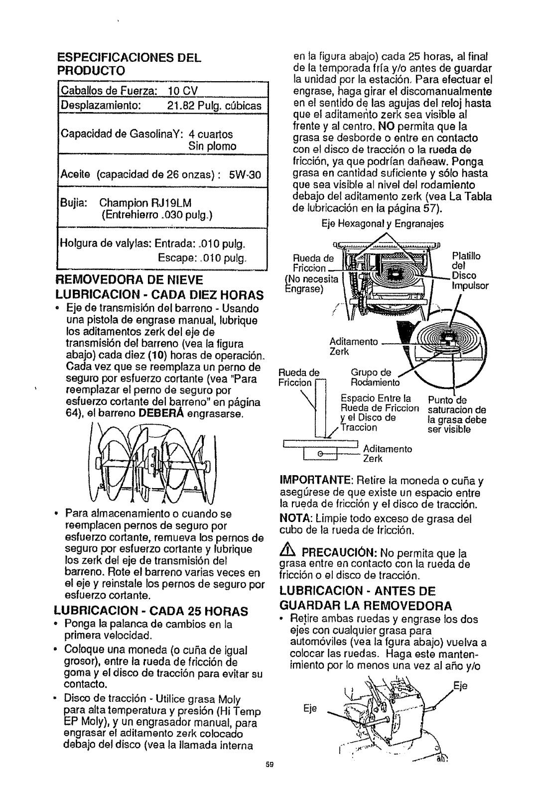
ESPECIFICACIONES DEL
PRODUCTO
CabaUos de Fuerza: 10 cv
Desplazamiento: 21.82 Pulg. c_bicas
Capacidad de GasolinaY: 4 cuartos
Sin plomo
Aceite (capacidad de 26 onzas)" 5W-30
Bujia: Champion RJ19LM
(Entrehierro .030 pulgo)
Holgura de valylas: Entrada: .010 pulgo
Escape: .010 pulgo
REMOVEDORA DE NIEVE
LUBRICACION - CADA DIEZ HORAS
•Eje de transrnisi6n det barreno -Usando
una pistola de engrase manual, lubrique
los aditamentos zerk del eje de
transrnisi6nde! barreno (yea la figura
abajo) cada diez (10) horas de operaci6n.
Cada vez que se reemplaza un perno de
seguro por esfuerzo cortante (yea "Para
reemplazar el perno de seguro por
esfuerzo cortante del barreno" en p&gina
64), el barreno DEBERA engrasarse,
en ta figura abajo) carla 25 horas, al final
de la temporada fr[a y!o antes de guardar
la unidad por la estaci6n. Para efectuar el
engrase, haga girar el discornanualmente
en el sentido de las agujas del reloj hasta
que el aditamer_to zerk sea visible al
frente y at centro. NO perrnita que la
grasa se desborde o entre en contacto
con el disco de tracci6n ola rueda de
friccJ6n, ya que podr[an daSeaw. Ponga
grasa en cantidad suficiente y s6to hasta
que sea visible al nivet del rodamiento
debajo del aditamento zerk (yea La Tabla
de lubricaci6n en la p&gina 57).
Eje Hexagonal y Engranajes
Rueda de Plalitlo
Friccion del
Disco
_No necesita
ngrase) Imputsor
Aditamento
Zerk
Rueda de Gru
Friccion
"\J I Espacio Entre la
"_ [ Rueda de Friccion
! I yet Disco de
[_Traccion
JI J _ Adilamento
Zerk
Punto
saturation de
ta grasa debe
ser visible
Para almacenarniento o cuando se
reemplacen pernos de seguro por
esfuerzo cortante, remueva los pernos de
seguro por esfuerzo cortante y lubrique
los zerk del eje de transmisi6n del
barreno. Rote el barreno varias veces en
el eje y reinstale los pernos de seguro por
esfuerzo cortante.
LUBRICAClON - CADA 25 HORAS
° Ponga la palanca de cambios en la
primera ve!ocidad.
, Cotoque una moneda (o curia de igual
grosor), entre la rueda de fricci6n de
goma y et disco de tracci6n para evjtar su
contacto.
•Disco de tracci6n - Utilice grasa Moly
para alta temperatura y presi6n (Hi Temp
EP Moly), y un engrasador manual, para
engrasar el aditamento zerk co!ocado
debajo del disco (vea la tlamada Jnterna
59
IMPORTANTE: Retire ta moneda o cuSa y
aseg_rese de que existe un espacio entre
la rueda de fricci6n y el disco de tracci6n.
NOTA: Limpie todo exceso de grasa del
cubo de la rueda de fricci6n.
Z_ PRECAUCl0N: No permita que la
grasa entre en contacto con la rueda de
fricci6n o el disco de tracci6n.
LUBRICACION - ANTES DE
GUARDAR LA REMOVEDORA
,, Re!ire ambas ruedas y engrase los dos
ejes con cualquier grasa para
autom6viles (vea la fgura abajo) vuelva a
colocar las ruedas. Haga este manten-
imiento por Io menos una vez al afro y/o
i_ _"'_" T_
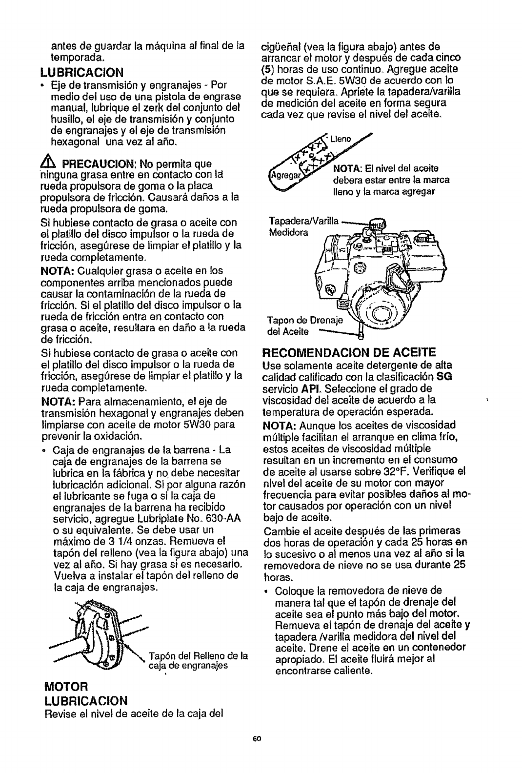
antesde guardarlam&quinaal finaldeta
temporada,
LUBR|CACION
° Eje de transmisi6n y engranajes -Por
medio del uso de una pistola de engrase
manual, tubrique el zerk de! conjunto del
husillo, el eje de transmisi6n y conjunto
de engranajes y el eje de transmisi6n
hexagonal una vez al a_,o.
,/_ PRECAUCION:No permita que
ninguna grasa entre en contacto con 1_
rueda propulsora de goma o la placa
propulsora de fricci6n. Causar& daSos a la
rueda propulsora de goma.
Si hubiese contacto de grasa o aceite con
el pLatil!odel disco impulsor o la rueda de
|ricci6n, aseg6rese de fimpiar e! platillo y la
rueda completamente_
NOTA: Cualquier grasa o aceite en los
componentes arriba mencionados puede
causar la contaminaci6n de la rueda de
fricci6n. Si el platillo det disco impulsor o la
rueda de fricciSn entra en contacto con
grasa o aceite, resultara en daSo a la rueda
de fricci6m
Si hubiese contacto de grasa o aceite con
el platillo det disco impulsor o la rueda de
fricci6n, aseg_'Jrese de timpiar el ptatillo y la
rueda completamente,
NOTA: Para atmacenamiento, el eje de
transmisiSn hexagonal y engranajes deben
limpiarse con aceite de motor 5W30 para
prevenir la oxidaciSno
oCaja de engranajes de ta barrena - La
caja de engranajes de la barrena se
lubrica en ta f&brica y no debe necesitar
lubricaci6n adicional, Si por alguna raz6n
el lubricante se fuga o si la caja de
engranajes de la barrena ha recibido
servtc_o, agregue Lubriplate Noo 630.AA
o su equivalente_ Se debe usar un
m&ximo de 3 1/4 onzas. Remueva el
tap6n det relleno (yea ta figura abajo) una
vez al aSo. Si hay grasa si es necesario.
Vuelva a instalar e! tap6n del relleno de
la caja de engranajes,
Tap6n del Relleno de la
caja de engranajes
MOTOR
LUBRICACION
Revise el nivel de aceite de la caja del
cigOeSal (vea la |igura abajo) antes de
arrancar el motor y despu_s de cada cinco
(5) horas de uso continuo. Agregue aceite
de motor S,A.E. 5W30 de acuerdo con lo
que se requiera_ Apriete la tapadera/varilla
de medici6n del aceite en forma segura
cada vez que revise el nivel del aceite..
debera es,tar entre Ia marca
Ileno y ta marca agregar
Tapadera/Varilla
Medidora
Tapon de Drenaje
del Aceite
RECOMENDACION DE ACEITE
Use solamente aceite detergente de alta
calidad calificado con la clasificaci6n SG
servicio APIo Seleccione et grado de
viscosidad del aceite de acuerdo a la
temperatura de operaci6n esperada.
NOTA: Aunque los aceites de viscosidad
m6ltiple facilitan el arranque en clima fr[o,
estos aceites de viscosidad m_Itiple
resuttan en un incremento en el consumo
de aceite al usarse sobre 32°F. Verilique el
nivel del aceite de su motor con mayor
frecuencia para evitar posibles daSos al mo-
tor causados por operaci6n con un nivel
bajo de aceite.
Cambie el aceite despu_s de las primeras
dos horas de operaci6n ycada 25 horas en
io sucesivo o al menos una vez al aSo si la
removedora de nieve no se usa durante 25
horas.
,Coloque la removedora de nieve de
manera tat que el tap6n de drenaje del
aceite sea e! punto m&s bajo del motor.
Remueva el tap6n de drenaje del aceite y
tapadera/varilla medidora del nivel del
aceite. Drene el aceite en un contenedor
apropiado. El aceite fluir_, rnejor at
encontrarse caliente.
6O
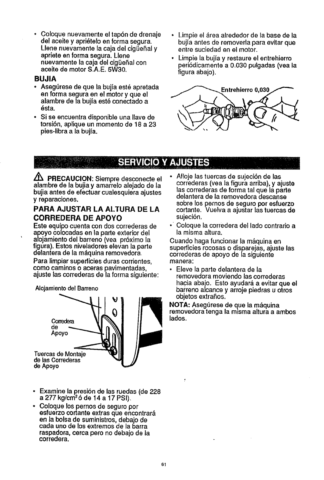
Coloque nuevamente et tap6n de drenaje
del aceite y apri_tero an forma segurao
Llene nuevamente la caja del cigi:_eSal y
apdete en forma segura. Llene
nuevamente la caja del cigiJeSal con
aceite de motor SoA_Eo5W30_
BUJIA
-Aseg_rese de que la bujra est_ apretada
en forma segura en el motor y que et
alambre de la bujla est6 conectado a
_sta.
•Si se encuentra disponibte una tlave de
torsi6n, aplique un momento de 18 a 23
pies-libra a ia bujfa.
• Limpie el ,_rea alrededor de la base de la
bujia antes de removerla para evitar que
entre suciedad en el moron
• Limpie la bujia y restaure el entrehierro
peri6dicamente a 0.030 pulgadas (vea la
figura abajo).
Enlrehierro 0
,_ PRECAUCION: Siempre desconecte el
alambre de la bujia y amarrelo alejado de la
bujia antes de efectuar cualesquiera ajustes
y reparaciones.
PARA AJUSTAR LA ALTURA DE LA
CORREDERA DE APOYO
Este equipo cuenta con dos correderas de
al:x?.yocolocadas en la parte exterior del
alojamiento del barreno (vea prSximo la
figura). Estos niveladores etevan la parle
delantera de la m,_quina removedora
Para limpiar superficies duras corrientes,
como cammos o aceras pavimentadas,
ajuste las correderas de la forma siguiente:
Alojamiento del Barreno
I
de
Apoyo
•Afloje ias tuercas de sujeci6,n de las
correderas (yea la figura arrlba), y ajuste
las correderas de forma tal qua la parle
delantera de la removedora descanse
sobre los pernos de seguro por esfuerzo
cortante. Vuelva a ajustar las tuercas de
sujeciSn_
•'Coloque la corredera del lado contrario a
la misma attura.
Cuando haga funcionar la m&quina en
superficies rocosas o disparejas, ajuste tas
correderas de apoyo de la siguiente
manera:
,Eleve la parte delantera de la
removedora moviendo tas correderas
hacia abajo. Esto ayudar_, a evitar que et
barreno alcance y arroje piedras u otros
objetos extra£=os.
NOTA: Asegt3rese de que ta m&quina
removedora tenga la misma altura a ambos
ladoso
Tuercas de Montaje
de las Correderas
de Apoyo
Examine la presibn de las ruedas (de 228
a 277 kg/cm25 de 14 a 17 PSI)_
Co loque los pernos de seguro por
estuerzo cortante extras que encontrar&
en ta bolsa de suministros, debajo de
cada uno de los extremos de la barra
raspadora, cerca pero no debajo de ia
corredera.
6t
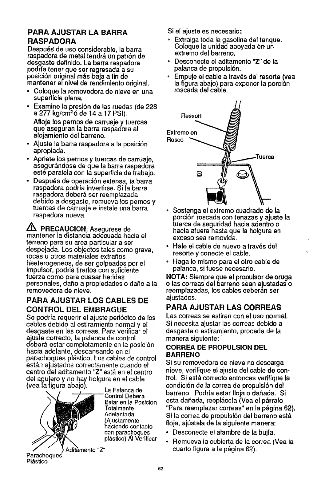
PARA AJUSTAR LA BARRA
RASPADORA
Despu_ de uso considerable, la barra
raspadora de metal tendr,_ un patr6n de
desgaste definido. La barra raspadora
podrta tener que ser regresada a su
posici6n original m_s baja a fin de
mantener e/nivel de rendimiento original.
• Coloque la removedora de nieve en una
superficie plana.
• Examine la presi6n de las ruedas (de 228
a 277 kg/cm26 de 14 a 17 PSt)_
Afloje los pernos de carruaje y tuercas
que aseguran ta barra raspadora al
alojamiento det barreno_
o Ajuste la barra raspadora a la posici6n
apropiada.
,, Apriete los pernos y tuercas de carruaje,
asegur&ndose de que la barra raspadora
est_ paraleta con la superficie de trabajo,
• Despu_s de operaci6n extensa, la barra
raspadora podrfa invertirse. Si la barra
raspadora deber& ser reemplazada
debido a desgaste, remueva los pernos y
tuercas de carruaje e instale una barra
raspadora nueva.
PRECAUCION: Asegurese de
mantener la distancia adecuada hacia el
terreno para su area particular a ser
despejada. Los objectos tales como grava,
rocas u otros materiales extrafios
heeterogeneos, de ser golpeados por el
impulsor, podria tirarlos con suficiente
fuerza como para cuasar heridas
personales, dafio apropiedades o dafio a la
removedora de nieve.
PARA AJUSTAR LOS CABLES DE
CONTROL DEL EMBRAGUE
Se podrfa requerir el ajuste peri6dico de los
cables debido al estiramiento normal y el
desgaste en las correas. Para verificar el
ajuste correcto, la palanca de control
deber& estar completamente en la posici6n
hacia adelante, descansando en el
parachoques pl_stico. Los cables de control
est&n ajustados correctamente cuando el
centro del aditamento "Z" esta en el centro
del agujero y no hay holgura en el cable
(yea la figura abajo)o La Patanca de
Debera
Estar en la Posicion
Totalmente
Adelantada
(Ajustamente
'haciendo contacto
con parachoques
pl_stico)/_1Verificar
Parachoques
Pt&stico
62
Si el ajuste es necesario:
- Extraiga toda ta gasolina del tanque.
Coloque la unidad apoyada en. un
extremo del barreno.
• Desconecte el aditamento "Z" de la
palanca de propulsi6n.
. Empuje et cable a tray,s del resorte.(vea
la figura abajo) para exponer la porct6n
roscada del cable.
Ressort
Extremo en
Rosco
• Sostenga el extremo cuadrado de la
porci6n roscada con tenazas y ajuste ta
tuerca de seguridad hacia adentro o
hacia afuerahasta que la holgura en
exceso sea removida_
° Hale et cable de nuevo a trav_s del
resorte y conecte el cable.
•Haga to mismo para el otro cable de
palanca, si tuese necesario.
NOTA: Siempre que el propulsor de oruga
o las correas del barreno sean ajustadas o
reemplazadas, los cables deberan ser
ajustados.
PARA AJUSTAR LAS CORREAS
Las correas se estiran con et uso normal.
Si necesita ajustar las correas debido a
desgaste o estiramiento, proceda de la
manera siguiente:
CORREA DE PROPULSION DEL
BARRENO
Si su removedora de nieve no descarga
nieve, verifique el ajuste de! cable de corn
troL Si est& correcto entonces verifique la
condici6n de la correa de propulsi6n del
barreno. Podria estar floja o dafiada. Si
esta dafiada, reeplbcela (Vea el p&rrafo
"Para reemplazar correas" en ta p&gina 62).
Si la correa de propulsi6n del barreno est,,
floja, ajOstela de la siguiente manera:
• Desconecte el atambre de la buj_a.
•Remueva la cubierta de la correa (Vea la
cuarto figura a ta pbgina 62).
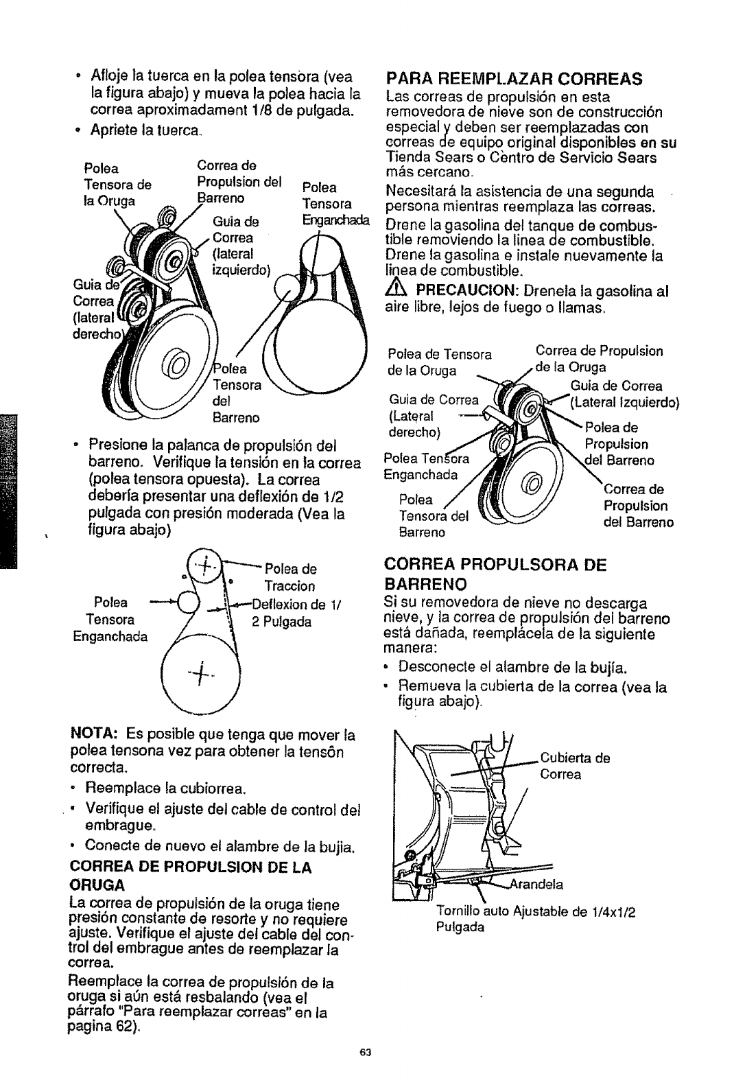
o Aflojelatuercaenlapoteatens0ra(yea
lafiguraabajo) y mueva la polea hacia la
correa aproximadament 1/8 de pulgada.
°Apriete la tuercao
Polea Correa de
Tensora de Propulsion del
la Oruga Barreno
Guia de
Correa
Polea
Tensora
Eng
Correa
PARA REEMPLAZAR CORREAS
Las correas de proputsi6n en esta
removedora de nieve son de construcci6n
especialy deben ser reemplazadas con
correas de equil:_, original disponibles en su
Tienda Sears oCentro de Servicio Sears
m&s cercano.
Necesitar& la asistencia de una segunda
persona mientras reemplaza las correas.
Drene la gasolina del tanque de combus-
tible removiendo la linea de combustible.
Drene la gasolina einstale nuevamente ta
linea de combustible.
Z_ PRECAUCION: Drenela la gasotina al
aire libre, lejos de fuego o llamas,
mensora
del
Barreno
Presione la palanca de propulsiSn del
barreno. Verifique la tensi6n en la correa
(polea tensora opuesta). La correa
deberfa presentar una deflexi6n de 1/2
pulgada con presi6n moderada (Vea la
figura abajo)
o_ Polea de
,,._-" ,_° Traccion
Potea --'_J .._._Deflexion de 1/
Tensora /' _,t 2 Pulgada
Enganchada (/_-i,, _
NOTA: Es posible que tenga que mover la
potea tensona vez para obtener la tensSn
correcta.
-Reemplace la cubiorrea.
• Verifique el ajuste del cable de control det
embrague°
• Conecte de nuevo et alambre de la bujia.
CORREA DE PROPULSION DE LA
ORUGA
La correa de proputsi6n de la oruga tiene
presi6n constante de resorte y no requiere
ajuste. Verifique el ajuste det cable del con-
trol del embrague antes de reemplazar la
correa.
Reemplace ta correa de propulsi6n de la
or uga si aun est& resbalando (yea el
parrafo "Para reemplazar correas" en la
paglna 62).
63
Polea de Tensora
de la Oruga ..,.,,.
Guia de Correa _/
(Lateral ---_
derecho} j
Polea Ten§ora
Enganchada A
Polea /_t
Tensora del %
Barreno
Correa de Propulsion
_,ela Oruga
Guia de Correa
_("__Lateral Izquierdo)
_L.L___, "" Polea de
_.__ Propulsion
F,",_ )) \._ Barreno
tkL_// Correa de
_\ _/// Propulsion
_-._J del Barreno
CORREA PROPULSORA DE
BARRENO
Si su removedora de nieve no descarga
nieve, y ta correa de propulsiSn del barreno
esta daSada, reemplacela de la siguiente
manera:
° Desconecte el atambre de la bujla.
•Remueva la cubierta de la correa (vea la
figura abajo)_
,Cubierta de
Correa
Tornillo auto Ajustable de 1/4xl/2
Pulgada
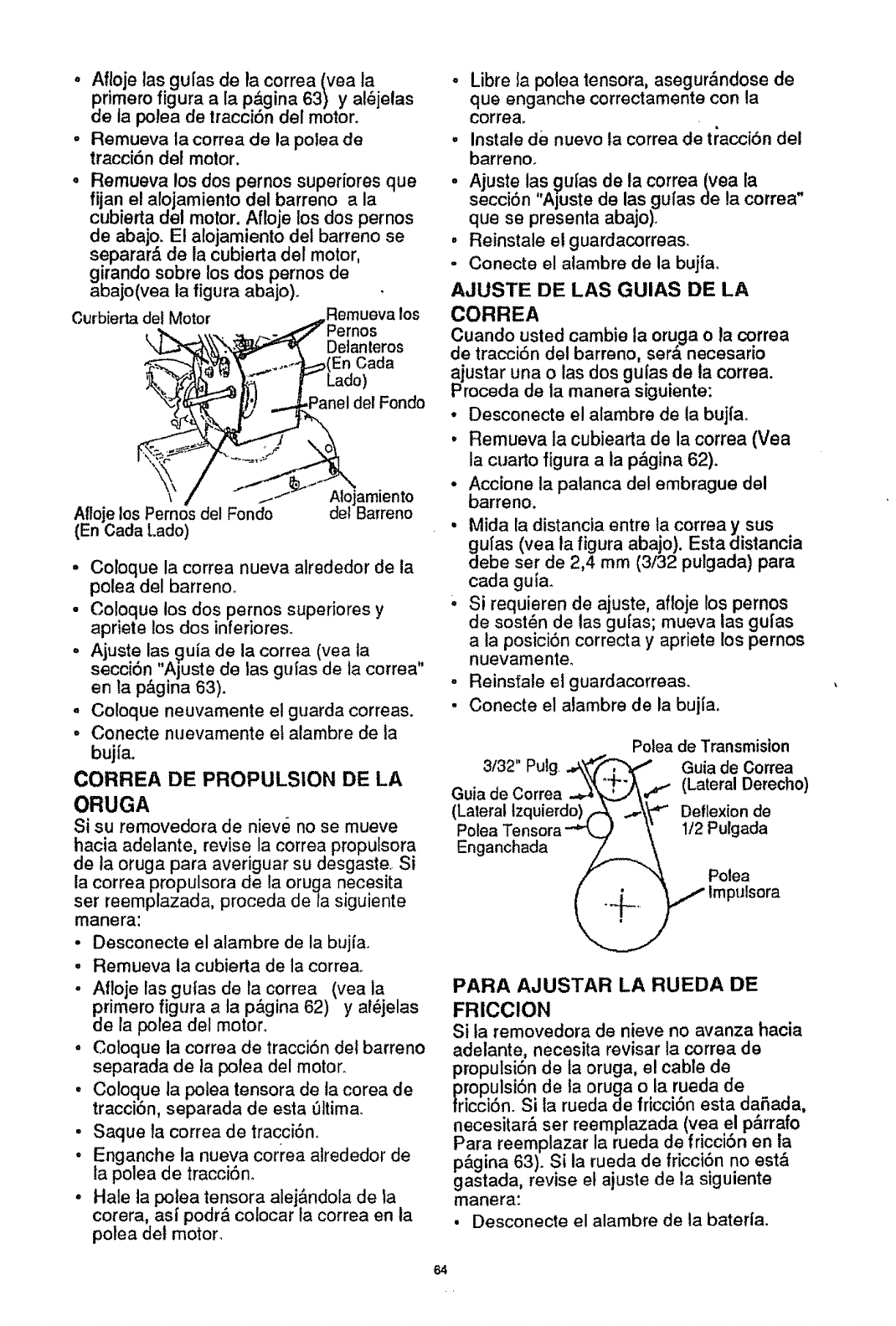
o Afloje las gufas de ta correa (vea la
primero figura a la p&gina 63) y al_jelas
de ia poJea de tracci6n del motor.
,Remueva la correa de la polea de
tracci6n del motor.
° Remueva los dos pernos superiores que
fijan el alojamiento del barreno a la
cubierta del motor, Afloje los dos pernos
de abajo. El a[ojamiento del barreno se
separar& de la cubierta del motor,
g!rando sobre los dos pernos de
abajo(vea la figura abajo).
Curbierta del Motor _.,,Rernuevalos
_.,_ . ..,..., _-_,_7 Pernos
\.L..3_ _._ Delanleros
,_7_ _ ....,.._nel del Fondo
AllojelosPerno_delFondo delBarreno
(En Oada t.ado
• Coloque la correa nueva alrededor de la
potea del barreno.
• Coloque los dos pernos superiores y
apriete los dos inferiores.
, Ajuste las guia de la correa (yea la
secci6n "Ajuste de las guias de la correa"
en la p&gina 63).
o Coloque neuvamente el guarda correas.
°Conecte nuevamente el alambre de ta
bujia.
CORREA DE PROPULSION DE LA
ORUGA
Si su removedora de nieve no se mueve
hacia adelante, revise la correa propulsora
de la oruga para averiguar su desgaste. Si
la correa propulsora de ta oruga necesita
ser reemplazada, proceda deta siguiente
manera:
-Desconecte el alambre de la bujfa.
° Remueva ta cubierta de la correao
, Aftoje las guias de la correa (vea la
primero figura a la p&gina 62) y al6jelas
de la polea del motor.
• Coloque la correa de tracci6n det barreno
separada de la polea del motor_
• Coloque la polea tensora de ta corea de
tracci6n, separada de esta 01tima.
• Saque la correa de tracciOn.
•Enganche la nueva correa alrededor de
la polea de tracci6n.
• Hale la polea tensora alej&ndola de la
corera, asf podr& colocar ta correa en la
polea det motor.
•Libre la pole a tensora, asegur&ndose de
que enganche correctamente con la
correa.
•Instale de nuevo la correa de tiacci6n del
barreno.
° Ajuste las gufas de la correa (yea la
secci6n "Ajuste de las gu[as de la correa"
que se presenta abajo).
, Reinstale e! guardacorreas.
- Conecte el atambre de la bujia°
AJUSTE DE LAS GUIAS DE LA
CORREA
Cuando usted cambie la oruga o la correa
de tracci6n del barreno, sera necesario
ajustar una o las dos guias de la correa.
Proceda de la manera siguiente:
• Desconecte el alambre de la buj{a.
° Remueva ta cubiearta de la correa (Vea
la cuarto figura a la phgina 62).
°Accione ta palanca del embrague del
barreno.
°Mida la distancia entre la correa y sus
gufas (vea la figura abajo). Esta distancia
debe ser de 2,4 mm (3/32 pulgada) para
cada guia.
' Si requieren de ajuste, aftoje los pernos
de sost6n de las gufas; mueva las gufas
a la posici6n correcta y apriete los pernos
nuevamente.
•Reinstale el guardacorreas.
• Conecte el alambre de la bujla.
Polea de Transmision
PARA AJUSTAR LA RUEDA DE
FRICCION
Si la removedora de nieve no avanza hacia
adelante, necesita revisar la correa de
propulsi6n de la oruga, el cable de
rOpulsi6n de la oruga o la rueda de
icci6n. Si la rueda de fricci6n esta da5ada,
necesitar& ser reemplazada (yea el p&rrafo
Para reemplazar la rueda de friccion en la
p&gina 63). Si ia rueda de fricci6n no est&
gastada, revise e! ajuste de la siguiente
manera:
• Desconecte e! alambre de la bater|a.
64
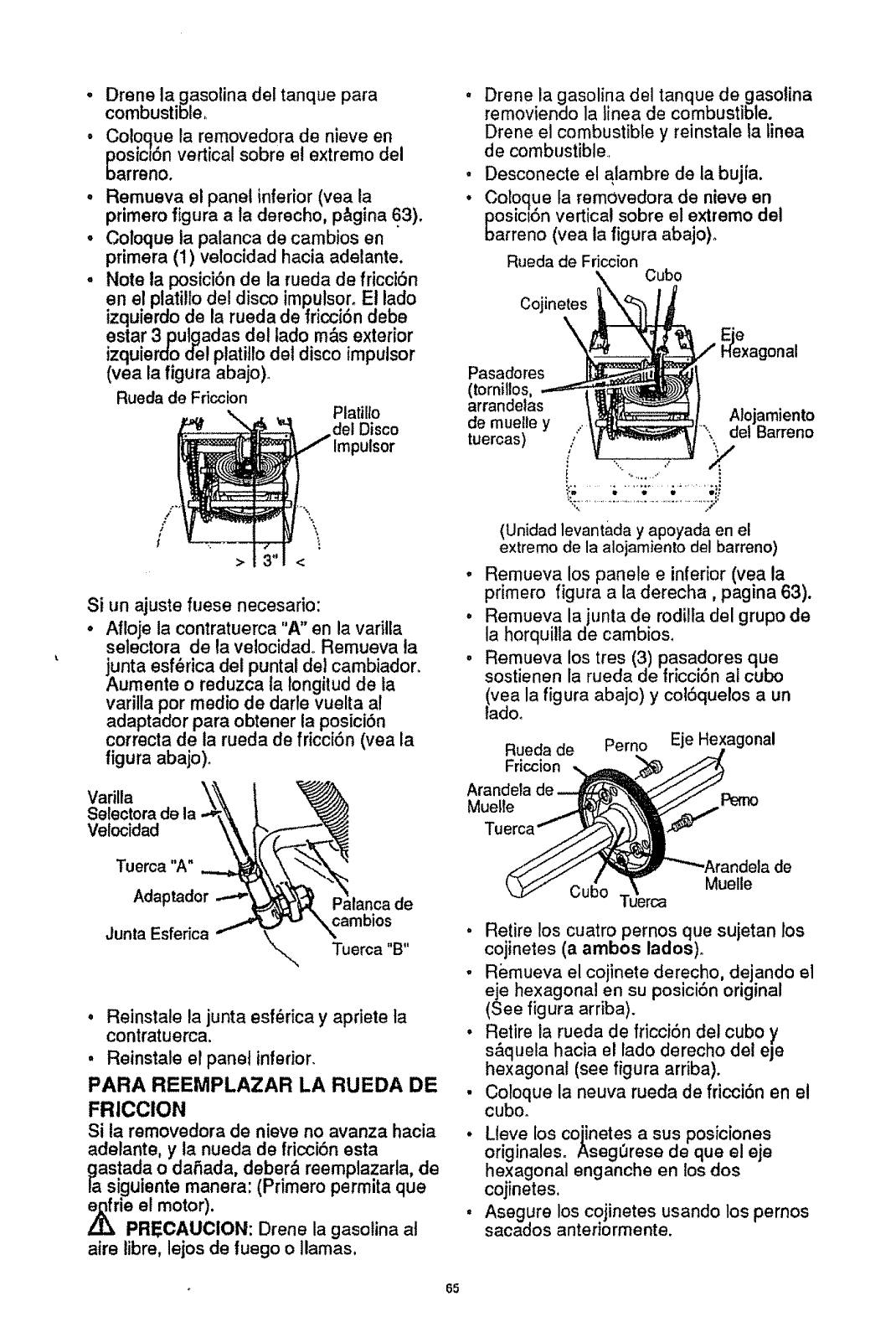
Drene la gasolina del tanque para
combustible,
Coloque la removedora de nieve en
posic_6nvertical sobre et extremo del
oarreno.
R emueva el panel inferior (yea la
pnmero figura a la derecho, p&gina 63),
Coloque ta patanca de cambios en
primera (1) velocidad hacia adelante.
Note la posiciSn de la rueda de fricciSn
en el platillo del disco impulsor. El lado
izquierdo de la rueda de friccion debe
estar 3 pulgadas det tado m&s exterior
izquierdo del ptatillo det disco impulsor
(yea la figura abajo)o
Rueda de Friccion Platillo
del Disco
><
Si un ajuste fuese necesario:
o Afloje la contratuerca "A" en la varitla
selectora de la velocidado Remueva la
junta esf_rica del puntal del cambiador.
Aumente o reduzca ta longitud de la
varilla por medio de darl.e vuelta al
adaptador para obtener la posici6n
correcta de la rueda de fricciSn (yea la
figura abajo)°
Varilla
Selectora de la
Velocidad
, Drene la gasolina del tanque de gasolina
removiendo la linea de combustible.
Drene el combustible y reinstale la iinea
de combustible.
. Desconecte el alambre de la bujfa.
• Coloque ta removedora de nieve en
posici6n vertical sobre el extremo del
barreno (vea la figura abajo)o
Rueda de Friccion
Cojinetes , o
\ e
xagonal
Pasadores
(tornillos,
arrandelas Alojamiento
de muelle y ."_ del Barreno
tuercas) .., Z
'% _t •
(Unidad levantada y apoyada en el
extremo de la alojamiento del barreno)
° Remueva los panele e inferior (yea la
primero figura a la derecha, pagina 63).
• Remueva la junta de rodilta del grupo de
la horquilla de cambios.
o Remueva los tres (3) 9asadores que
sostienen la rueda de fricci6n al cubo
(yea la figura abajo) y col6quelos a un
ladoo
Rueda de Perno Eje He:
Friccion ,_
Muelle
Tuerca "A"
Adaptador
Junta Esferica
• Reinstale la junta esf_rica y apriete ta
contratuerca.
• Reinstate el panel inferior.
PARA REEMPLAZAR LA RUEDA DE
FRICCION
Si la removedora de nieve no avanza hacia
adelante, y la nueda de fricci6n esta
gastada o daSada, deber_, reemplazarla, de
la siguiente manera: (Primero permita que
e_frie el motor).
/._ PRECAUCION: Drene la gasotina al
aire libre, lejos de fuego ollamas,
Cubo Tuerca Muelle
.Retire los cuatro pernos que sujetan los
cojinetes (a ambos lados).
,Remueva el cojinete derecho, dejando el
eje hexagonal en su posici6n original
(See figura arriba).
•Retire la rueda de fricci6n dei cubo y
s&quela hacia el lado derecho de! eje
hexagonal (see figura arriba).
•Coloque la neuva rueda de fricci6n en el
cubo_
•Lleve los cojinetes a sus posiciones
originales. AsegOrese de que el eje
hexagonal enganche en los dos
cojinetes,
°Asegure los cojinetes usando los pernos
sacados antenormente.
65
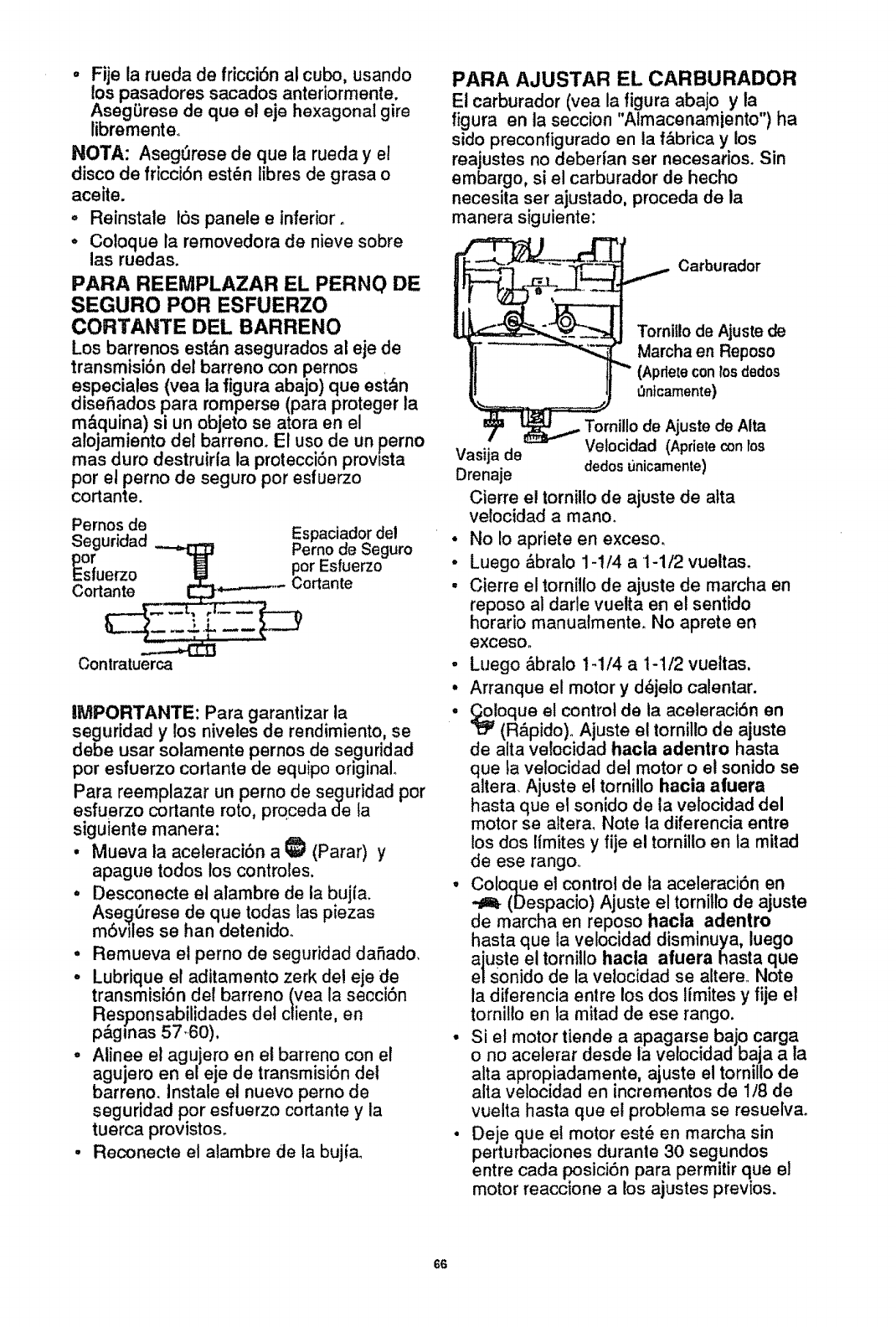
• Fije la rueda de fricci6n al cubo, usando
los pasadores sacados anteriormente.
Aseg(Jrese de que el eje hexagonal gire
libremente.
NOTA: Aseg_rese de que la rueda y el
disco de fricci6n est_n libres de grasa o
aceite.
o Reinstale los panele e inferior.
° Co!oque la removedora de nieve sobre
las ruedas.
PARA REEMPLAZAR EL PERNO DE
SEGURO POR ESFUERZO
CORTANTE DEL BARRENO
Los barrenos est,_n asegurados al eje de
transmisi6n det barreno con pernos
especiales (yea la figura abajo) que est&n
diseSados para romperse (para proteger la
m&quina) si un objeto se atora en el
a!ojamiento del barreno. El uso de un perno
mas duro destruirfa la protecciSn provista
por el perno de seguro por esfuerzo
cortante.
Pernos de
Contratuerca
IMPORTANTE: Para garantizar la
seguridad y los niveles de rendimiento, se
debe usar solamente pernos de seguridad
por esfuerzo cortante de equipo original
Para reemplazar un perno de seguridad por
esfuerzo cortante roto, pro.ceda de fa
siguiente manera:
• Mueva la aceleraciSn a !_ (Parar) y
apague todos los controles.
° Desconecte el alambre de la bujfa.
Ase_rese de que todas tas piezas
m6vlles se han detenidoo
° Remueva el perno de seguridad dafiado,
o Lubrique el aditamento zerk de! eje de
transmision del barreno (yea la seeciSn
Responsabilidades del cliente, en
pagtnas 57.60),
° Alinee el agujero en el barreno con el
agujero en el eje de transmisi6n de!
barreno, instale el nuevo perno de
seguridad por esfuerzo cortante y la
tuerca provistos.
•Reconecte el alambre de ta bujiao
PARA AJUSTAR EL CARBURADOR
El carburador (vea la figura abajo y la
figura en la seccion "Almacenamiento") ha
sido preconfigurado en la f_,brica y los
reajustes no deberfan set necesarios. Sin
embargo, si el carburador de hecho
necesita ser ajustado, proceda de la
manera siguiente:
Carburador
Tornitlo de Ajuste de
Marcha en Reposo
(Apdeteconlos dedos
0ntcamente)
, Tornillo de Ajuste de Alta
Vasija de Velocidad (Apriete conFos
Drenaje dedos tJnicamente)
Cierre el torniito de ajuste de alta
vefocidad a mano.
. No Io apriete en exceso.
.Luego &bralo 1-!/4 a 1-1/2 vueltas.
. Cierre el tornillo de ajuste de marcha en
reposo al darle vuelta en el sentido
horario manualmente. No aprete en
exceso°
.Luego &bralo t-1/4 a 1-1/2 vueltas,
.Arranque el motor y d_jelo calentar.
._oloque el control de ta aceleraci6n en
I_ (R&pido)o Ajuste el tornillo de ajuste
de alta velocidad hacla adentro hasta
que la velocidad del motor o e! sonido se
altera. Ajuste e! tornillo hacia aluera
hasta que el sonido de la velocidad del
motor se altera, Note la diferencia entre
los dos ltmites y fije el tornillo en la mitad
de ese rango._
°Coloque et control de la aceleraciSn en
(Despacio) Ajuste el tornitfo de ajuste
de rnarcha en reposo hacla adentro
hasta que la velocidad disminuya, luego
ajuste el tornillo hacla afuera hasta que
el Sonido de la vetocidad se altere., Note
la diferencia entre los dos limites y fije el
tornillo en la mitad de ese tango.
-Si el motor tiende a apagarse bajo carga
o no acelerar desde la velocidad baja a la
alta apropiadamente, ajuste el tornillo de
alia velocidad en incrementos de 1/8 de
vuelta hasta que el probtema se resuelva.
-Deje que et motor est_ en marcha sin
perturbaciones duranle 30 segundos
entre cada _posici6n para permitir que el
motor reacclone a los ajustes previos.
66
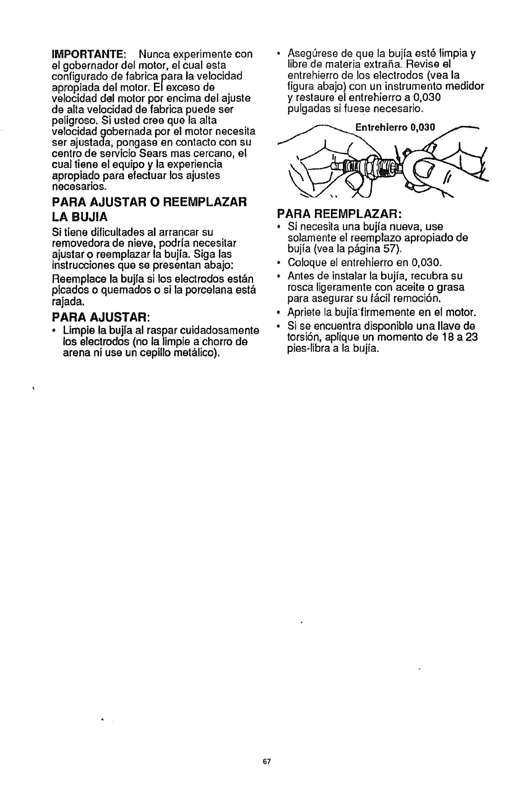
IMPORTANTE: Nunca experimente con
el gobernador del motor, el cual esta
configurado de fabrica para la velocidad
apropiada det motor E! exceso de
velocidad de! motor por encima del ajuste
de atta velocidad de fabrica puede set
peligroso. Si usted cree que la alta
vetocidad gobernada pot el motor necesita
ser ajustada, pongase en contacto con su
centro de servicio Sears mas cercano, el
cual tiene el equipo y la experiencia
apropiado para efectuar los ajustes
necesarlos.
PARA AJUSTAR O REEMPLAZAR
LA BUJIA
Si tiene dificultades al arrancar su
removedora de nieve, podrla necesitar
ajustar o reemplazar la bujia Siga las
instrucciones que se presentan abajo:
Reemplace la bujfa si los electrodos est,_n
plcados o quemados o si la porcelana est&
rajada
PARA AJUSTAR:
• Limpie la buj[a al raspar cuidadosamente
los electrodos (no la limpie a chorro de
arena ni use un cepiUo met&lico)
Aseg_rese de que la bujfa est_ limpia y
libre de materia extraSa Revise el
entrehierro de los electrodos (yea la
figura abajo) con un instrumento medidor
y restaure el entrehierro a 0,030
pulgadas si fuese necesario
Entrehierro 0,030
PARA REEMPLAZAR:
,Si necesJta una bujfa nueva, use
sotamente el reemplazo apropiado de
bujla (vea la p&gina 57)
•Coloque el entrehierro en 0,030°
•Antes de instalar la bujia, recubra su
rosca ligeramente con aceite o grasa
para asegurar su f&cil remociSn
•Apriete la bujialirmemente en el motor.
•Si se encuentra disponible una Ilave de
torsi6n, apfique un momento de 18 a 23
pies libra a la bujia
67
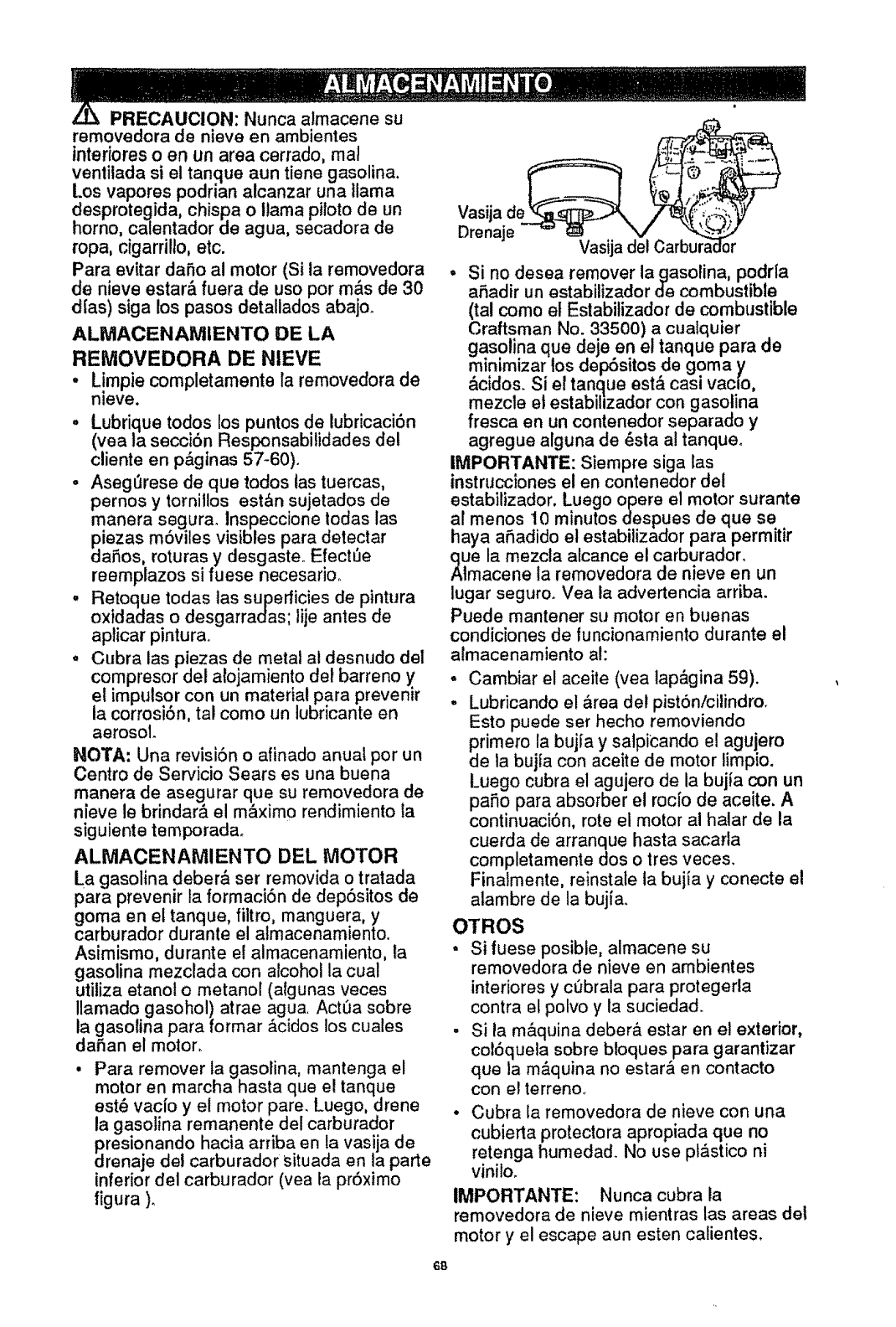
PRECAUCION: Nunca almacene su
removedora de nieve en ambientes
intedores o en un area cerrado, real
ventitada si el tanque aun tiene gasolina.
Los vapores podrian alcanzar una llama
desprotegida, chispa o llama piloto de un
homo, catentador de agua, secadora de
ropa, cigarrillo, etc.
Para evitar datio al motor (Si ta removedora
de nieve estar& fuera de uso por m&s de 30
dIas) siga los pasos detallados abajo.
ALMACENAMIENTO DE LA
REMOVEDORA DE NIEVE
•L!mpie completamente la removedora de
nleve.
oLubrique todos los puntos de lubricaci6n
(vea la seccitn Responsabifidades del
cliente en p&ginas 57-60)o
•Asegerese de que todos tas tuercas,
pernos y tornillos est&n sujetados de
manera s egura, lnspeccione todas las
piezas moviles visibles para delectar
datos, roturas y desgasteo Efect_e
reemplazos si fuese necesario..
°Retoque todas tas superficies de pintura
oxidadas o desgarradas; lije antes de
aplicar pinturao
°Cubra las piezas de metal at desnudo del
compresor del a{ojamiento de! barreno y
et impulsor con un material para prevenir
la corrosiSn, tal como un lubricante en
aerosol.
NOTA: Una revisitn o afinado anual por un
Centro de Servicio Sears es una buena
manera de asegurar que su removedora de
nieve le brindar& el m&xim0 rendimiento la
siguiente temporadao
ALMACENAMIENTO DEL MOTOR
La gasolina deber& ser removida o tratada
para prevenir ta formacitn de deptsitos de
goma en el tanque, filtro, manguera, y
carburador durante el atmacenamientoo
Asimismo, durante el almacenamiento, la
gasolina mezclada con alcohol la cual
utiliza etanot o metanol (algunas veces
Ilamado gasohol) atrae agua. Act_a sobre
ia gasolina para formar &cidos los cuales
da5an el motor,
•Para remover la gasolina, mantenga el
motor en marcha hasta que e! tanque
est_ vac{o y el motor pare. Luego, drene
la gasotina remanente del carburador
presionando hacia arriba en la vasija de
drenaje del carburador situada en la parte
inferior del carburador (vea la prtximo
figura )o
6B
Vasija de__
Drenaje '=" _Vasija del
°Si no desea remover lagasolina, podr{a
atadir un estabilizador de combustible
(tal como et Estabilizador de combustible
Craftsman No. 33500) a cualquier
gasolina que deje en e! tanque para de
minimizar los dep6sitos de goma y
&cidos. Si el tangue est,_ casi vacio,
mezcle et estabillzador con gasolina
fresca en un contenedor separado y
agregue alguna de _sta a! tanqueo
IMPORTANTE: Siempre siga las
instrucciones el en contenedor det
estabilizador, Luego opere el motor surante
al menos 10 minutos despues de que se
haya atadido el estabilizador para permitir
clue la mezcta alcance el carburador.
Almacene la removedora de nieve en un
lugar seguro. Vea la advertencia arriba.
Puede mantener su motor en buenas
condiciones de luncionamiento durante el
aimacenamiento al:
oCambiar el aceite (vea lap&gina 59).
-Lubricando el &readet pisttn/cilindro.
Esto puede ser hecho removiendo
dPrimero la buj{a y satpicando el agujero
e la bujla con aceite de motor limpio.
Luego cubra el agujero de la bujia con un
patio para absorber el roc{o de aceite. A
continuaci6n, rote el motor al halar de la
cuerda de arranque hasta sacarla
completamente dos o Ires veces.
Finalmente, reinstale la bujfa y conecte el
alambre de la bujfao
OTROS
• Si fuese posible, almacene su
removedora de nieve en ambientes
interiores y cObrala para protegerla
contra e! polvo y la suciedad.
, Si la m&quina deber& estar en el exterior,
col6quela sobre bloques para garantizar
que la m&quina no estar& en contacto
con el terreno_
•Cubra la removedora de nieve con una
cubierta protectora apropiada que no
retenga humedad. No use pt&stico ni
vinilo,
IMPORTANTE: Nunca cubra la
removedora de nieve mientras las areas del
motor y el escape aun esten calientes,
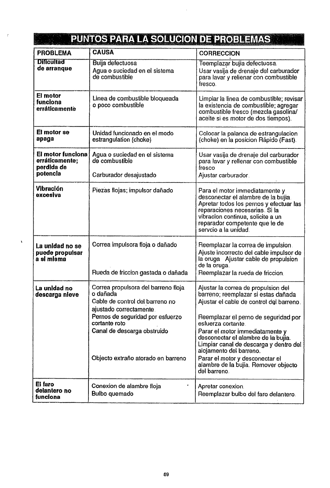
PROBLEMA CAUSA
DIIicuiIad Buija defectuosa
de arranque Agua o suciedad en el sistema
de combustible
El motor
funclona
err_ticamentb
El motor se
apaga
Linea de combustiblebloqueada
o poco combustible
Unidad func[onadoen el modo
estrangulation(choke)
Ague o suciedad en el sistema
de combuslible
Carburador desajustado
........................ ,,,i ......... ,......... ....
Vlbract6n Piezas flojas; impulsor daSado
exceelva
El motor funclona
errdlicamente;
perdida de
potencla
La unldad no ee
puede propulsar
e el mlama
L
La unldad no
descarga nleve
El faro
delantero no
funclona
w.
Correa impulsora floja o daSado
CORRECCION ..................
Teemplazar bujia defectuosa.
User vasija de drenaje del carburador
para laver y relienar con combustible
fresco.
Limpiar la linea de combustible; revisar
la existencia de combustible: agregar
combustible fresco (mezcla gasofina/
aceite si es motor de dos tiempos).
Colocar la palanca de estrangulacion
(choke) en la posicion R&pido (Fast).
User vasija de drenaje de) carburador
pare _avar y rellenar con combustible
fresco
Ajustar carburador.
Para el motor immediatamente y
desconectar el alarnbre de la bujia.
Apretar todos los pernos y efectuar fas
reparaciones necesarias. Si la
vibracion continua, solicite a un
reparador competente que le de
servcio ala unidad.
...................... , ,,, ,
Reemplazar ]a correa de impulsion
Ajuste incorrecto del cable impulsor de
la oruga Ajustar cable de propulsion
de la oruga
Correa propulsora def barreno floja
o daSada
Cabte de control del barreno no
ajustado correctamente
Pernos de segufidad por esfuerzo
cortante roto
Canal de descarga obstruido
Rueda de friccion gastada o da5ada Reemplazar la rueda de friccion.
Ajustar la correa de propulsion det
barreno; reemplazar siestas da£_ada
Ajustar el cable de control d_l barreno.
Reemplazar et perno de seguridad por
esfuerza cortante.
Parar el motor immediatamente y
desconectar el alambre de la bujia.
Limpiar canal de descarga y dentro del
alojamento del barreno.
Objecto extraSo atorado en barreno Parar el motor y desconectar et
alambre de la bujia.. Remover objecto
del barreno
Conexion de alambre floja Aprelar conexion.
Bulbo quemado Reemplazar bulbo del faro delantero.
89

70

71
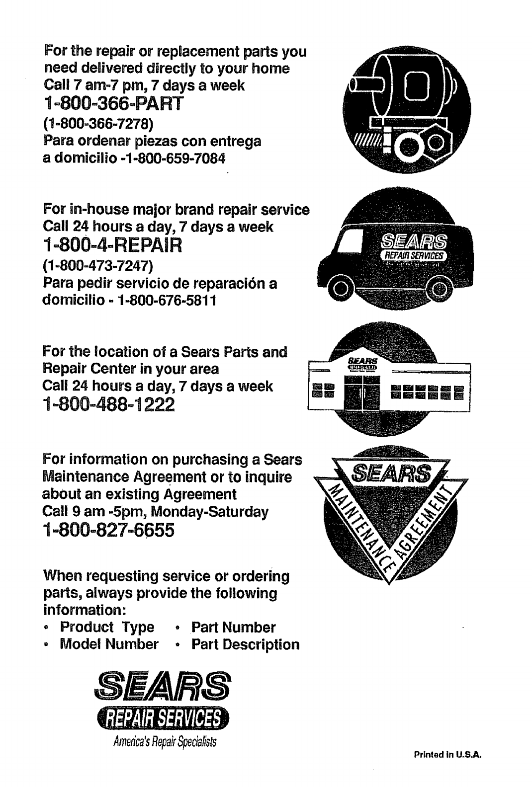
For the repair or repnacementparts you
need delivered directly to your home
Call 7 am-7 pro, 7 days a week
1=800-366-PART
(1-800-366-7278)
Para ordenar piezas con entrega
a domicilio -1-800-659-7084
For in-house major brand repair service
Call 24 hours a day, 7 days a week
1=800=4=REPAIR
(1-800-473-7247)
Para pedir servicio de reparacibn a
domicilio. 1.800.676.5811
For the location of a Sears Parts and
Repair Center in your area
Call 24 hours a day, 7 days a week
1-800-488-1222
For information on purchasing a Sears
Maintenance Agreement or to inquire
abOut an existing Agreement
Call 9 am -Spm, Monday-Saturday
1=800=827-6655
When requesting service or ordering
parts, always provide the following
information:
• Product Type • Part Number
•Model Number .Part Description
America'sRepairSpecialists Printed in U,S.A,
