Craftsman 536887751 User Manual SNOWTHROWER, GAS Manuals And Guides L0301192
CRAFTSMAN Snowthrower, Gas Manual L0301192 CRAFTSMAN Snowthrower, Gas Owner's Manual, CRAFTSMAN Snowthrower, Gas installation guides
User Manual: Craftsman 536887751 536887751 CRAFTSMAN SNOWTHROWER, GAS - Manuals and Guides View the owners manual for your CRAFTSMAN SNOWTHROWER, GAS #536887751. Home:Lawn & Garden Parts:Craftsman Parts:Craftsman SNOWTHROWER, GAS Manual
Open the PDF directly: View PDF ![]() .
.
Page Count: 100
ICRRFTSMRN1
Operator's Manual
Snow Thrower
7.75 Horsepower
Electric Start
26-inch Dual Stage
Model 536.887751
CAUTION: Before us=ngthis product,
read this manual and follow all of =ts
Safety Rules and Operat=ng Instruct=ons
Manual del usario
Qu itan ieves
de 26 pulgadas
7.75 caballos de fuerza (hp)
Bietapico
Arranque electrico
Modelo 536.887751
PRECAUCION: Antes de usar este producto,
lea este manual y slga todas las reglas de
segundad e _nstrucc_ones de operac_6n
Sears, Roebuck and Co., Hoffman Estates, IL 60179 U.S.A.
F_)21027L www.sears.com/craftsman
nf'._-] U:l[o]d[H_o]_i I _ _i 1,,2
WARRANTY STATEMENT ....... 2
SAFETY RULES ............... 2
INTERNATIONAL SYMBOLS .... 4
ASSEMBLY ................... 6
OPERATION ................... 12
MAINTENANCE ................ 19
SERVICE AND ADJUSTMENT ... 22
STORAGE .................... 33
TROUBLESHOOTINGTABLE ... 34
REPAIR PARTS ................ 38
ENGINE REPAIR PARTS ........ 56
SPANISH (ESPANOL) .......... 63
PARTS ORDERING/SERVICE .
BACK COVER
LIMITED TWO-YEAR WARRANTY ON CRAFTSMAN SNOW THROWER
For two years from the date of purchase, when this Craftsman Snow thrower is maintained,
lubricated, and tuned up according to the operating and maintenance instructions in the
owner's manual, Sears will repair, free of charge, any defect in material or workmanship.
If this Craftsman Snow thrower is used for commercial or rental purposes, this warranty ap-
plies for only 90 days from the date of purchase.
This warranty does not cover the following:
Items which become worn dudng normal use, such as spark plugs, drive belts and shear
pins.
Repair necessary because of operator abuse or negligence, including bent crankshafts
and the failure to maintain the equipment according to the instructions contained in the
owner's manual.
WARRANTY SERVICE IS AVAILABLE BY RETURNING THE CRAFTSMAN SNOW
THROWER TO THE NEAREST SEARS SERVICE CENTER IN THE UNITED STATES.
THIS WARRANTY APPLIES ONLY WHILE THIS PRODUCT IS IN USE IN THE UNITED
STATES.
This warranty gives you specific legal rights, and you may also have other rights which may
vary from state to state.
Sears, Roebuck and Co., D817WA, Hoffman Estates. IL 60179
_k OOK FOR THIS SYMBOL TO POINT OUT IMPORTANT SAFETY PRECAUTIONS.
IT MEANS-- ATTENTION!!! BECOME ALERT!H YOUR SAFETY IS INVOLVED.
Engine Exhaust, some of its constituents, end
certain vehicle components contain or emit
chemicals known to the State of California to
cause cancer and birth defects or other repro-
ductive harm.
Battery posts, terminals and related accessories
contain lead end lead compounds, chemicals
known to the State of California to cause cancer
end birth defects or other reproductive harm.
WASH HANDS AFTER HANDLING.
d_ WARNING: Always discon-
nect the spark plug wire
and place it where it cannot
make contact with spark plug to
prevent accidental starting during:
Preparation, Maintenance, or Stor-
age of your snow thrower.
IMPORTANT: Safety standards re-
quire operator presence controls to
minimize the risk of injury. Your snow
thrower is equipped with such controls.
Do not attempt to defeat the function of
the operator presence control under any
circumstances.
F-021027L 2
TRAINING
1. Read this oberaiing and service instruction
manual carefully. Be thoroughly familiar
with the controls and the proper use of the
snow thrower. Know how to stop the snow
thrower and disengage the controls quick-
]y.
2. Never allow children to operate the snow
thrower. Never allow adults to operate the
snow thrower without proper instruction.
3. Keep the area of operation clear of all per-
sons, perticulady small children and pets.
4. Exercise caution to avoid slipping or falling
especially when operating in reverse.
PREPARATION
1. Thoroughly inspect the area where the
snow thrower is to be used and remove all
doormats, sleds, boards, wires, and other
foreign objects.
2. Disengage all clutches before starting the
engine (motor).
3. Do not operate the snow thrower without
wearing adequate winter outer garments.
Wear footwear that will improve footing on
slippery surfaces.
4. Handle fuel with care; it is highly flam-
mable.
a. Use an approved fuel container.
b. Never remove fuel tank cap or add fuel
to a running engine (motor) or hot en-
gine (motor).
c. Fill fuel tank outdoors with extreme
care. Never fill fuel tank indoors.
d. Replace fuel cap securely and wipe up
spilled fuel.
e. Never store fuel or snow thrower with
fuel in the tank inside of a building
where fumes may reach an open flame
or spark.
f. Check fuel supply before each use, al-
lowing space for expansion as the heat
of the engine (motor) and/or sun can
cause fuel to expand.
5. For all snow throwers wflh electric starting
motors use electric starting extension
cords certified CSA/UL. Use only with a re-
ceptacle that has been installed in accord-
ance with local ieepection authorities.
6. Never attempt to make any adjustments
while the engine (motor) is running (except
when specifically recommended by manu-
tacturer).
7. Let engine (motor) and snow thrower ad-
just to o_door temperatures before starting
to clear snow.
F-021027L
Always wear safety glasses or eye shields
during operation or while performing an ad-
justment or repair to protect eyes from
foreign objects that may be thrown from the
snow thrower.
OPERATION
1. Do not operate this snow thrower if you are
taking drugs or other reedication which can
cause drewsiness or affect your ability to
operate this snow thrower.
2. Do not use the snow thrower if you are
mentally or physically unable to operate the
snow thrower safely.
3. Do not put hands or feet near or under ro-
tating parts. Keep clear of the discharge
opening at all times.
4. Exercise extreme caution when operating
on or crossing gravel drives, walks or
roads. Stay alert for hidden hazards or
traffic.
5. After striking a foreign object, stop the en-
gine (motor), remove the wire from the
spark plug, thoroughly inspect snow
thrower for any damage, and repair the
damage before restarting and operating
the snow thrower.
6. If the snow thrower should start to vibrate
abnormally, stop the engine (motor) and
check immediately for the cause. Vibration
is generally a warning of trouble.
7. Stop the engine (motor) whenever you
leave the operating position, before un-
clogging the augedimpeller housing or dis-
charge chute and when making any
repairs, adjustments, or inspections.
8. When cleaning, repairing, or inspecting,
make certain the auger/impeller and all
moving parts have stopped and all controls
are disengaged. Disconnect the spark plug
wire and keep the wire away from the spark
plug to prevent accidental starting.
9. Take all possible precautions when leaving
the snow thrower unattended. Disengage
the auger/ impeller, stop engine (motor),
and remove key.
10. Do not run the engine (motor) indoors, ex-
cept when starting the engine (motor) and
for transporting the snow thrower in or out
of the building. Open the outside doors; ex-
haust fumes are dangerous (containing
CARBON MONOXIDE, an ODORLESS
and DEADLY GAS).
11. Do not clear snow across the face of
slopes. Exercise extreme caution when
changing direction on slopes. Do not at-
tempt to clear steep slopes.
12. Never operate the snow thrower wflhout
proper guards, plates or other safety pro-
tective devices in place.
13.Neveroperatethe snow thrower near en-
closures, automobiles, window wells, drop-
offs, and the like without proper adjustment
of the snow discharge angle. Keep children
and pets away.
14. Do not overload the snow thrower capacity
by attempting to clear snow at too fast a
rate.
15. Never operate the snow thrower at high
transport speeds on slippery surfaces.
Look behind and use care when backing
up.
16. Never direct discharge at bystanders or
allow anyone in front of the snow thrower.
17. Disengage power to the collectodimpeller
when snow thrower is transported or not in
use.
18. Use only attachments and accaesedes ap-
proved by the manufacturer of the snow
thrower (such as tire chains, electdc start
kits, ect.).
19. Never operate the snow thrower without
good visibility or light. Always be sure of
your footing and keep a firm hold on the
handles. Walk;never run.
20. Do not over-reach. Keep proper footing
and balance at all times.
21. Do not attempt to use snow thrower on a
roof.
MAINTENANCE AND STORAGE
1. Check shear bolts and other bolts at fre-
queet intervals for proper tightness to be
sure the snow thrower is in safe working
condition.
2. Never store the snow thrower with fuel in
the tank inside a building where ignition
sources are present such as hot water and
space heaters, clothes dryers, and the like.
Allow the engine (motor) to cool before
stodng in any enclosure.
3. Always refer to operator's guide instruc-
tions for important details if the snow
thrower is to be stored for an extended
period.
4. Maintain or replace safety and instruction
labels, as necessary.
5. Run the snow thrower a few min_es after
throwing snow to prevent freeze-up of the
anger/impellec
_1= WARNING: This snow thrower isfor use on sidewalks, driveways
and other ground level surfaces.
Caution should be exercised while using on
steep sloping surfaces. DO NOT USE
SNOW THROWER ON SURFACES ABOVE
GROUND LEVEL such as roofs of resi-
dences, garages, porches or other such
structures or buildings.
]
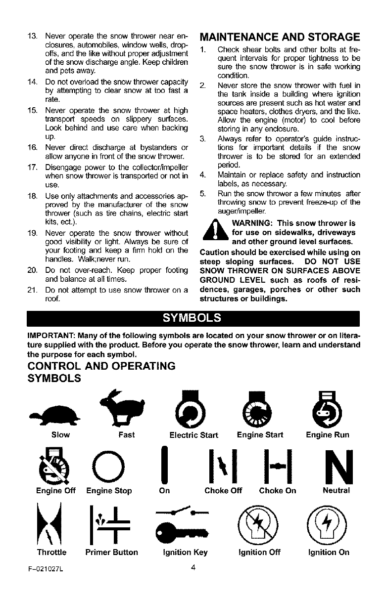
IMPORTANT: Many of the following symbols are located on your snow thrower or on litera-
ture supplied with the product. Before you operate the snow thrower, learn and understand
the purpose for each symbol.
CONTROL AND OPERATING
SYMBOLS
Engine Off Engine Stop On Choke Off Choke On Neutral
Throttle Primer Button Ignition Key
F-021027L 4
H N
®G
Ignition Off Ignition On
Slow Fast Electric Start Engine Start Engine Run
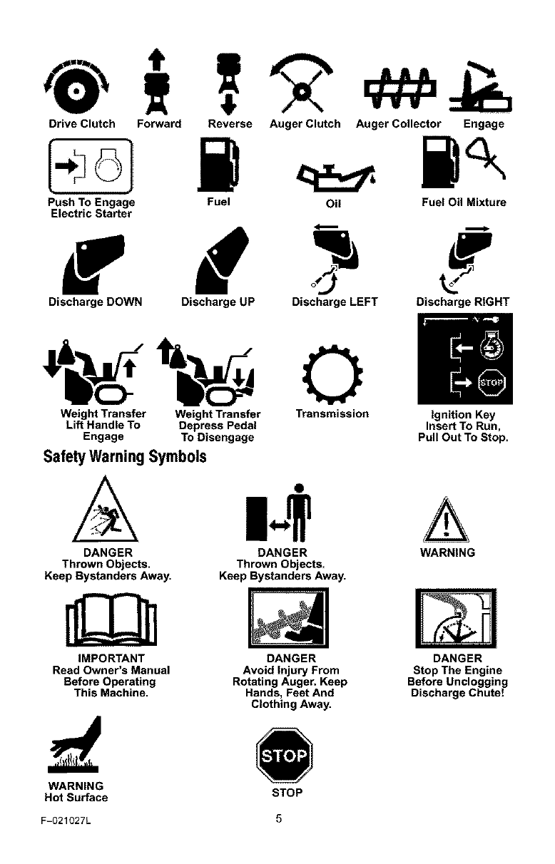
DriveClutch Forward
PushToEngage
ElectricStarter
ReverseAugerClutchAugerCollector Engage
Fuel Oil FuelOilMixture
f
Discharge DOWN Discharge UP Discharge LEFT Discharge RIGHT
Weight Transfer Weight Transfer Transmission Ignition Key
Lift Handle To Depress Pedal Insert To Run,
Engage To Disengage Pull Out To Stop.
Safety Warning Symbols
DANGER
Thrown Objects.
Keep Bystanders Away.
IMPORTANT
Read Owner's Manual
Before Operating
This Machine.
O
DANGER
Thrown Objects.
Keep Bystanders Away.
DANGER
Avoid Injury From
Rotating Auger. Keep
Hands, Feet And
Clothing Away.
A
WARNING
DANGER
Stop The Engine
Before Unclogging
Discharge Chute!
WARNING
Hot Surface STOP
F-O21027L 5
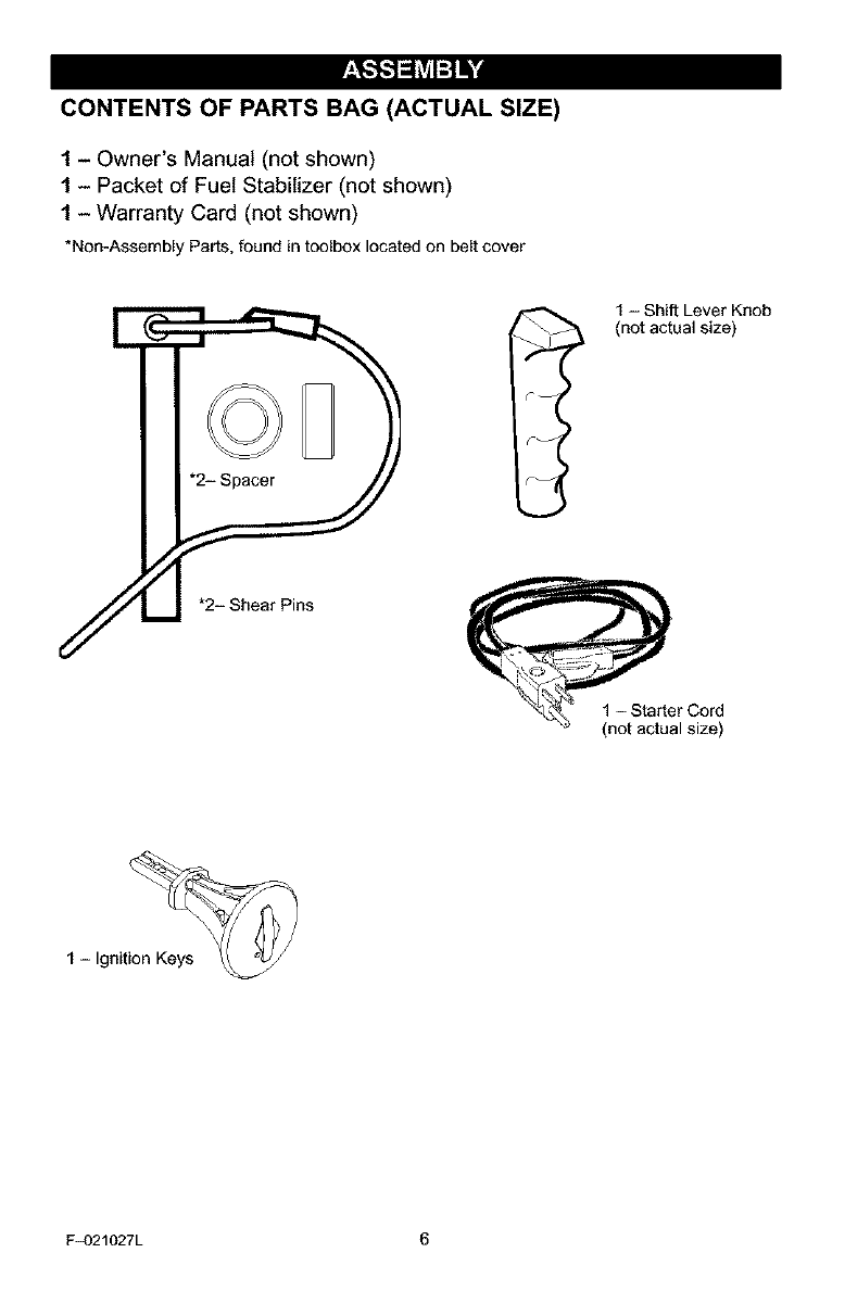
CONTENTS OF PARTS BAG (ACTUAL SIZE)
1- Owner's Manual (not shown)
1- Packet of Fuel Stabilizer (not shown)
1 - Warranty Card (not shown)
*Non-Assembly Parts,foundintoolboxlocatedon beltcover
1 - Shift Lever Knob
(not actual size)
r I
F_)21027L 6
,_ WARNING: Always wearsafety glasses or eye shields
while assembling snow
thrower.
TOOLS REQUIRED FOR
ASSEMBLY
1 - Knife to cut carton
2 - 1/2 inch wrenches
(or adjustable wrenches)
2 - 9/16 inch wrenches
(or adjustable wrenches)
2 - 3/4 inch wrenches
(or adjustable wrenches)
1 - Pliers (to spread cotter pin)
1 - Screwdriver
1 - Measuring tape or ruler
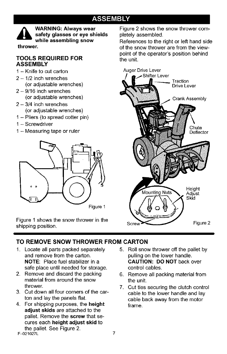
Figure 1
Figure1 shows the snow thrower in the
shipping position,
Figure 2 shows the snow thrower com-
pletely assembled.
References to the right or left hand side
of the snow thrower are from the view-
point of the operator's position behind
the unit.
Auger Drive Lever
Traction
Drive Lever
Crank Assembly
Chute
Deflector
Height
Adjust
Skid
Scre_ Figure 2
TO REMOVE SNOW THROWER FROM CARTON
1. Locate all parts packed separately
and remove from the carton.
NOTE: Place fuel stabilizer in a
safe place until needed for storage.
2. Remove and discard the packing
material from around the snow
thrower.
3. Cut down all four corners of the car-
ton and lay the panels flat.
4. For shipping purposes, the height
adjust skids are attached to the
pallet. Remove the screw that se-
cures each height adjust skid to
the pallet. See Figure 2.
F_)21027L
5. Roll snow thrower off the pallet by
pulling on the lower handle.
CAUTION: DO NOT back over
control cables.
6. Remove all packing material from
the unit.
7. Cut ties securing the clutch control
cable to the lower handle and lay
cable back away from the motor
frame.
TO ASSEMBLE THE HANDLE AND
CRANK ASSEMBLY
1. Cut tie holding shift rod to lower
handle and move shifter to the first
forward gear.
2. Cut and discard the plastic tie that
secures the crank assembly.
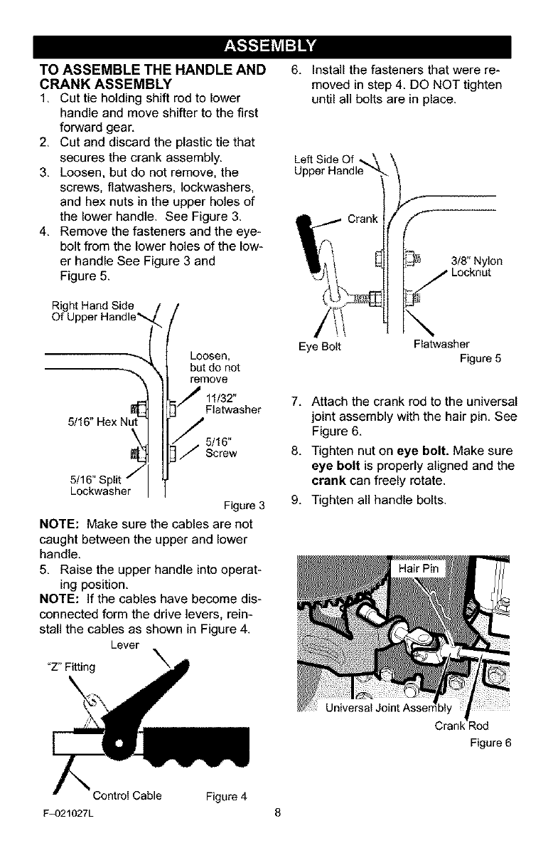
3. Loosen, but do not remove, the
screws, flatwashers, Iockwashers,
and hex nuts in the upper holes of
the lower handle. See Figure 3.
4. Remove the fasteners and the eye-
bolt from the lower holes of the low-
er handle See Figure 3 and
Figure 5.
Right Hand Side
Of U
5/16" Hex Nu
Loosen,
but do not
remove
11/32"
Flatwasher
5/16"
Screw
Figure 3
NOTE: Make sure the cables are not
caught between the upper and lower
handle.
5. Raise the upper handle into operat-
ing position.
NOTE: If the cables have become dis-
connected form the drive levers, rein-
stall the cables as shown in Figure 4.
Lever
"Z" Fitting
6. Install the fasteners that were re-
moved in step 4. DO NOT tighten
until all bolts are in place.
Left Side Of -_\
Upper Handle
Eye Bolt
3/8" Nylon
j Locknut
\Flatwasher
Figure 5
7. Attach the crank rod to the universal
joint assembly with the hair pin. See
Figure 6.
8. Tighten nut on eye bolt. Make sure
eye bolt is properly aligned and the
erank can freely rotate.
9. Tighten all handle bolts.
Cran_ _od
Figure 6
Control Cable Figure 4
F_)21027L 8
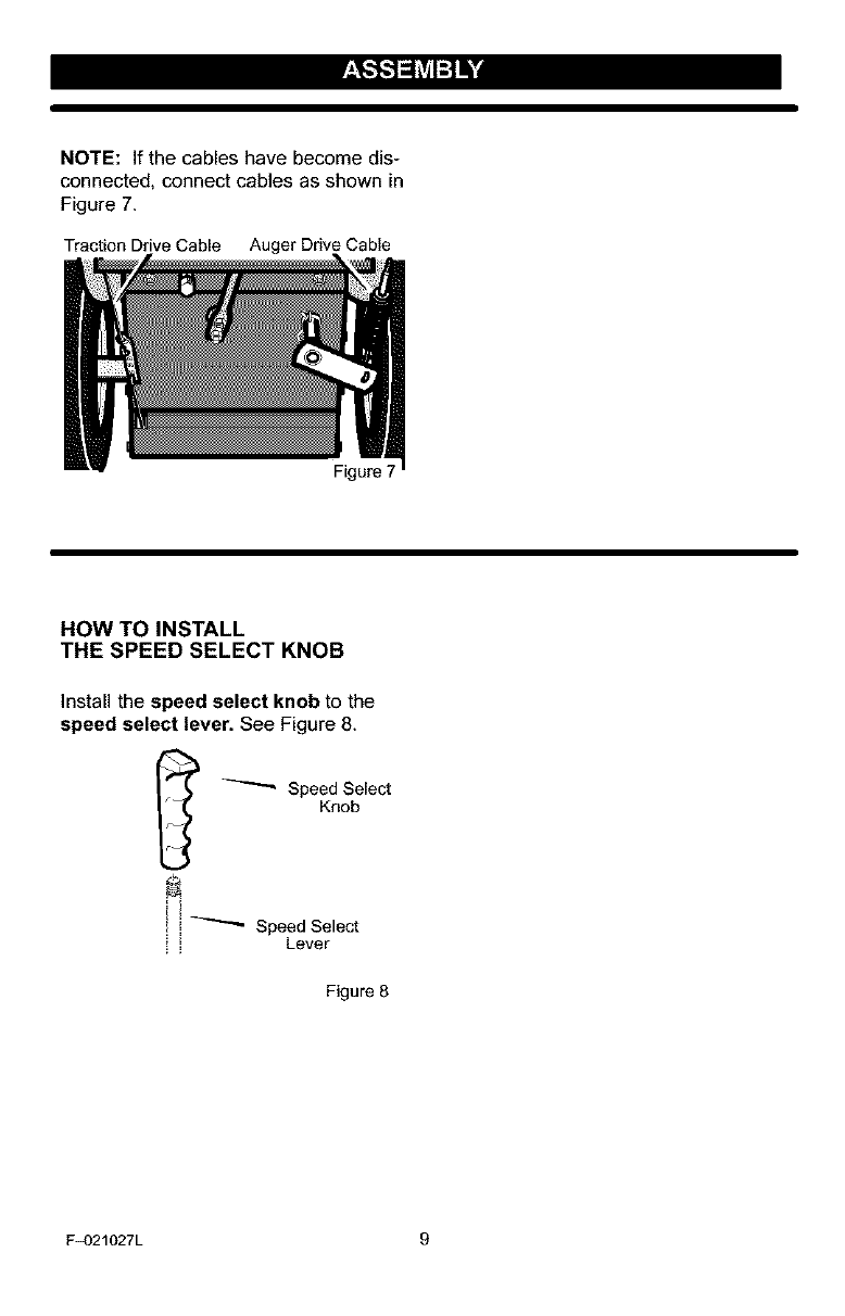
NOTE: If the cables have become dis-
connected, connect cables as shown in
Figure 7.
Traction Drive Cable Auger Drive Cable
Figure 7
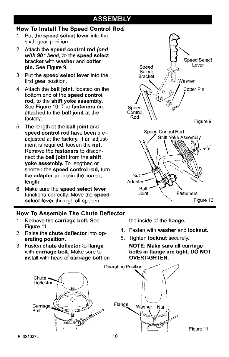
HOW TO INSTALL
THE SPEED SELECT KNOB
Install the speed select knob to the
speed select lever. See Figure 8.
_ Speed Select
Knob
,! i!_ Speed Select
Lever
Figure 8
F_)21027L g
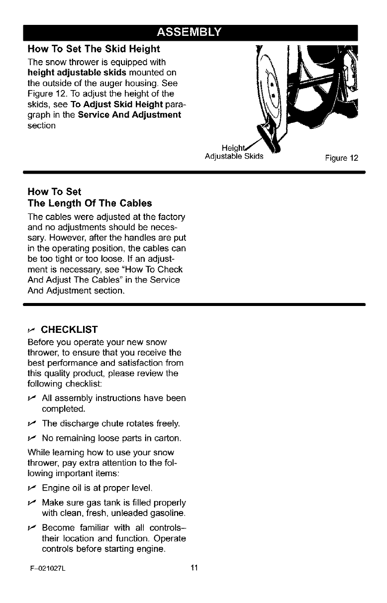
How To Install The Speed Control Rod
1. Put the speed select lever into the
sixth gear position. I
2. Attach the speed control rod (end _.
with 90 °bend) to the speed select
bracket with washer and cotter Speed Select
Lever
pin. See Figure 9. Speed
Select
3. Put the speed select lever into the Bracket
first gear position.
4. Attach the ball joint, located on the Cotter Pin
bottom end of the speed control
rod, to the shift yoke assembly.
See Figure 10. The fasteners are Speed
attached to the ball joint at the Control
factory. Rod
5. The length ot the ball joint and
speed control rod have been pre-
adjusted at the factory, if an adjust-
ment is required, loosen the nut.
Remove the fasteners to discon-
nect the ball joint from the shift
yoke assembly. To lengthen or
shorten the speed control rod, turn
the adapter to obtain the correct
length.
6. Make sure the speed select lever
functions correctly. Move the speed
select lever through al speeds.
Figure 9
Speed Control Rod
Shift Yoke Assembly
Jo _ se eF_gurel o
How To Assemble The Chute Deflector
1. Remove the carriage bolt. See
Figure 11.
2. Raise the chute deflector into oP-
erating position.
3. Fasten chute deflector to flange
with carriage bolt. Make sure to
install with head of carriage bolt on
the inside of the flange.
4. Fasten with washer and Iocknut.
5. Tighten Iocknut securely.
NOTE: Make sure all carriage
bolts in flange are tight. DO NOT
OVERTIGHTEN.
Operating Pos
Chute
Deflector
Carriage
Bolt
F_)21027L
/l
Flang_,Washer Nut
10
Figure 11
How To Set The Skid Height
The snow thrower is equipped with
height adjustable skids mounted on
the outside of the auger housing. See
Figure 12. To adjust the height of the
skids, see To Adjust Skid Height para-
graph in the Service And Adjustment
section
Adjustable Skids Figure 12
How To Set
The Length Of The Cables
The cables were adjusted at the factory
and no adjustments should be neces-
sary. However, after the handles are put
in the operating position, the cables can
be too tight or too loose. If an adjust-
ment is necessary, see "How To Check
And Adjust The Cables" in the Service
And Adjustment section.
_" CHECKLIST
Before you operate your new snow
thrower, to ensure that you receive the
best performance and satisfaction from
this quality product, please review the
following checklist:
_" All assembly instructions have been
completed,
_" The discharge chute rotates freely,
_" No remaining loose parts in carton,
While learning how to use your snow
thrower, pay extra attention to the fol-
lowing important items:
_" Engine oil is at proper level,
_" Make sure gas tank is filled properly
with clean, fresh, unleaded gasoline,
_" Become familiar with all controls-
their location and function, Operate
controls before starting engine,
F_)21027L 11
[i]-.]_l;ralil[i]_]
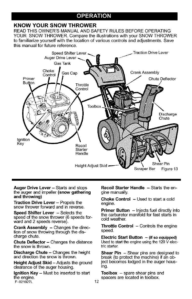
KNOW YOUR SNOW THROWER
READ THIS OWNER'S MANUAL AND SAFETY RULES BEFORE OPERATING
YOUR SNOW THROWER, Compare the illustrations with your SNOW THROWER
to familiarize yourself with the location of various controls and adjustments. Save
this manual for future reference.
Speed Shifter Lever,
Auger Drive Lever _.
Traction Drive Lever
Gas Tank
Choke
Control
Primer
Crank Assembly
Chute Deflector
Discharge
Chute
Ignition
Key Recoil
Starter
Handle
Height Adjust Skid Shear Pin
Scraper Bar Figure 13
Auger Drive Lever - Starts and stops
the anger and impeller (snow gathering
and throwing)
Traction Drive Lever - Propels the
snow thrower forward and in reverse.
Speed Shitter Lever - Selects the
speed of the snow thrower (6 speeds for-
ward and 2 speeds reverse),
Crank Assembly - Changes the direc-
tion of snow throwing through the dis-
charge chute.
Chute Deflector - Changes the distance
the snow is thrown,
Discharge Chute - Changes the height
and direction the snow is thrown.
Height Adjust Skid - Adjusts the ground
clearance of the auger housing.
Ignition Key - Must be inserted to start
the engine,
F_)21027L
Recoil Starter Handle - Starts the en-
gine manually.
Choke Control -Used to start a cold
engine.
Primer Button -Injects fuel directly into
the carburetor manifold for fast starts in
cold weather.
Throttle Control - Controls the engine
speed.
Electric Start Button - (if so equipped)
Used to start the engine using the 120 V elec-
tric starter.
Shear Pin - Shear pins are designed to
break (to protect the machine) if an ob-
ject becomes lodged in the auger hees-
ing.
Toolbox - spare shear pins and
spacers are located in toolbox.
12
[e]-.]_=;rz_lil[e]_3
The operation of any snow thrower can
result in foreign objects being thrown
into the eyes, which can result in se-
vere eye damage. Always wear safety
glasses or eye shields while operating
the snow thrower.
We recommend standard safety
glasses or a wide vision safety mask for
over your glasses.
_IL ARNING: Read Owner's
Manual before operating
machine. Never direct dis-
charge toward bystanders. Stop the
engine before unclogging discharge
chute or auger housing and before
leaving the machine.
TO STOP YOUR
SNOW THROWER
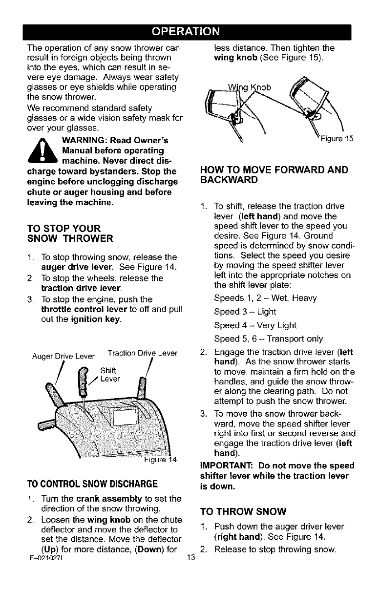
1. To stop throwing snow, release the
auger drive lever. See Figure 14.
2. To stop the wheels, release the
traction drive lever,
3. To stop the engine, push the
throttle control lever to off and pull
out the ignition key.
Auger Drive Lever Traction Drive Lever
less distance. Then tighten the
wing knob (See Figure 15).
HOW TO MOVE FORWARD AND
BACKWARD
1, To shift, release the traction drive
lever (left hand) and move the
speed shift lever to the speed you
desire. See Figure 14. Ground
speed is determined by snow condi-
tions. Select the speed you desire
by moving the speed shifter lever
left into the appropriate notches on
the shift lever plate:
Speeds 1, 2 - Wet. Heavy
Speed 3 - Light
Speed 4 - Very Light
Speed 5. 6 - Transport only
2. Engage the traction drive lever (left
hand), As the snow thrower starts
to move, maintain a firm hold on the
handles, and guide the snow throw-
er along the clearing path. Do not
attempt to push the snow thrower.
3. To move the snow thrower back-
ward, move the speed shifter lever
right into first or second reverse and
engage the traction drive lever (left
hand),
IMPORTANT: Do not move the speed
shifter lever while the traction lever
TO CONTROL SNOW DISCHARGE is down.
1. Turn the crank assembly to set the
direction of the snow throwing.
2. Loosen the wing knob on the chute
deflector and move the deflector to
set the distance. Move the deflector
(Up) for more distance, (Down) for
F_)21027L 13
TO THROW SNOW
1. Push down the auger driver lever
(right hand). See Figure 14.
2. Release to stop throwing snow.
[i]-.]_l;ralil[i]_3
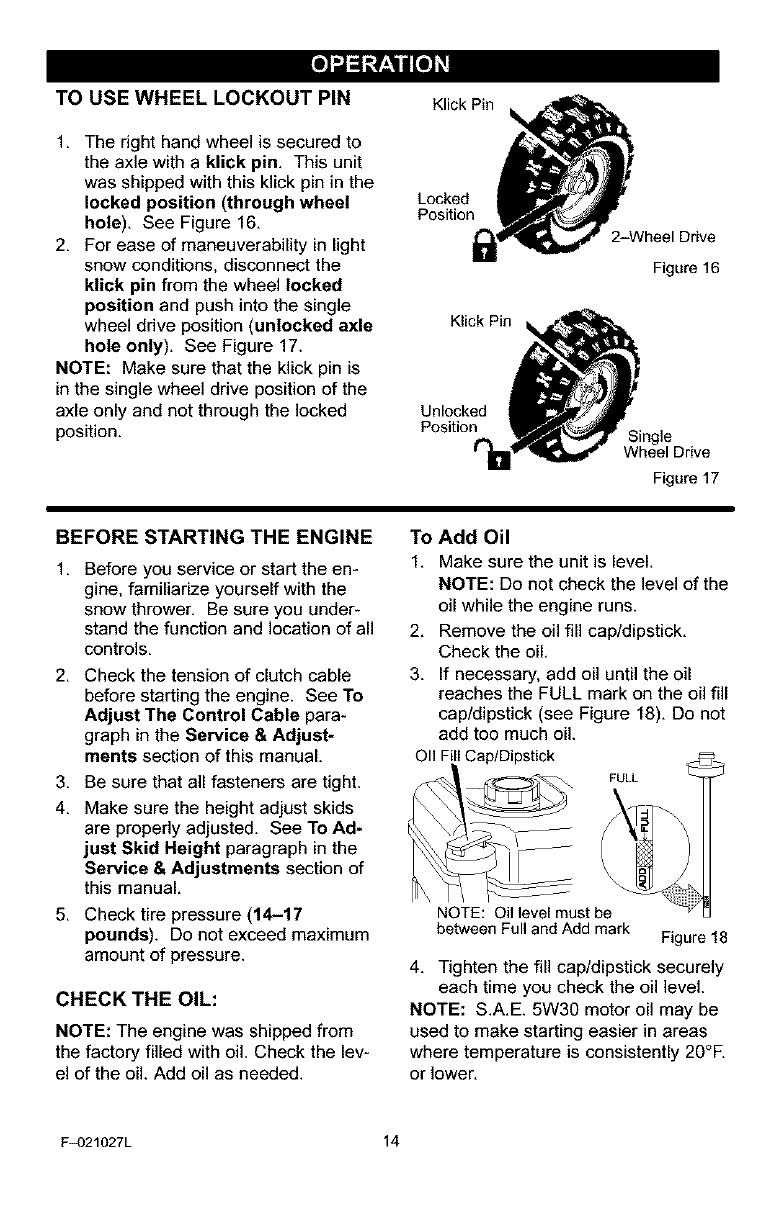
TO USE WHEEL LOCKOUT PIN
1. The right hand wheel is secured to
the axle with a klick pin. This unit
was shipped with this klick pin in the
locked position (through wheel
hole). See Figure 16.
2. For ease of maneuverability in light
snow conditions, disconnect the
klick pin from the wheel locked
position and push into the single
wheel drive position (unlocked axle
hole only). See Figure 17.
NOTE: Make sure that the klick pin is
in the single wheel drive position of the
axle only and not through the locked
position.
Klick Pin
Locked
Position
2-Wheel Drive
Figure 16
Figure 17
BEFORE STARTING THE ENGINE
1. Before you service or start the en-
gine, familiarize yourself with the
snow thrower. Be sure you under-
stand the function and location of all
controls.
2. Check the tension of clutch cable
before starting the engine. See To
Adjust The Control Cable para-
graph in the Service & Adjust*
ments section of this manual.
3. Be sure that all fasteners are tight.
4. Make sure the height adjust skids
are properly adjusted. See To Ad-
just Skid Height paragraph in the
Service & Adjustments section of
this manual.
5. Check tire pressure (14-17
pounds). Do not exceed maximum
amount of pressure.
CHECK THE OIL:
NOTE: The engine was shipped from
the factory filled with oil. Check the lev-
el of the oil. Add oil as needed.
To Add Oil
1. Make sure the unit is level.
NOTE: Do not check the level of the
oil while the engine runs.
2. Remove the oil fill cap/dipstick.
Check the oil.
3. If necessary, add oil until the oil
reaches the FULL mark on the oil fill
cap/dipstick (see Figure 18). Do not
add too much oil.
OI1 Fill Cap/Dipstick
FULL
NOTE: Oil level must be
between Full and Add mark Figure 18
4, Tighten the fill cap/dipstick securely
each time you check the oil level.
NOTE: S.A,E. 5W30 motor oil may be
used to make starting easier in areas
where temperature is consistently 20°R
or lower.
F_)21027L 14
[e]-.]_=;ralil[e]_j
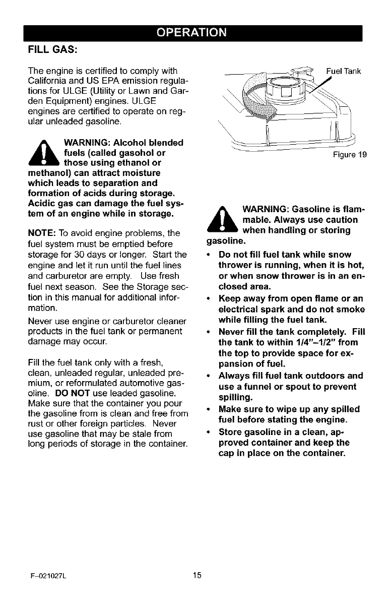
FILL GAS:
The engine is certified to comply with
California and US EPA emission regula-
tions for ULGE (Utility or Lawn and Gar-
den Equipment) engines. ULGE
engines are certified to operate on reg-
ular unleaded gasoline.
_L ARNING: Alcohol blended
fuels (called gasohol or
those using ethanol or
methanol) can attract moisture
which leads to separation and
formation of acids during storage.
Acidic gas can damage the fuel sys-
tem of an engine while in storage.
NOTE: To avoid engine problems, the
fuel system must be emptied before
storage for 30 days or longer. Start the
engine and let it run until the fuel lines
and carburetor are empty. Use fresh
fuel next season. See the Storage sec-
tion in this manual for additional infor-
mation.
Never use engine or carburetor cleaner
products in the fuel tank or permanent
damage may occur.
Fill the fuel tank only with a fresh,
clean, unleaded regular, unleaded pre-
mium, or reformulated automotive gas-
oline. DO NOT use leaded gasoline.
Make sure that the container you pour
the gasoline from is clean and free from
rust or other foreign particles. Never
use gasoline that may be stale from
long periods of storage in the container.
Fuel Tank
Figure 19
_IL ARNING: Gasoline is flam*
mable. Always use caution
when handling or storing
gasoline.
•Do not fill fuel tank while snow
thrower is running, when it is hot,
or when snow thrower is in an en*
closed area.
•Keep away from open flame or an
electrical spark and do not smoke
while filling the fuel tank.
•Never fill the tank completely. Fill
the tank to within 1/4"-1/2" from
the top to provide space for ex-
pansion of fuel.
•Always fill fuel tank outdoors and
use a funnel or spout to prevent
spilling.
•Make sure to wipe up any spilled
fuel before stating the engine.
•Store gasoline in a clean, ap-
proved container and keep the
cap in place on the container.
F_)21027L 15
[e]-.]_=;rz_lil[e]_3
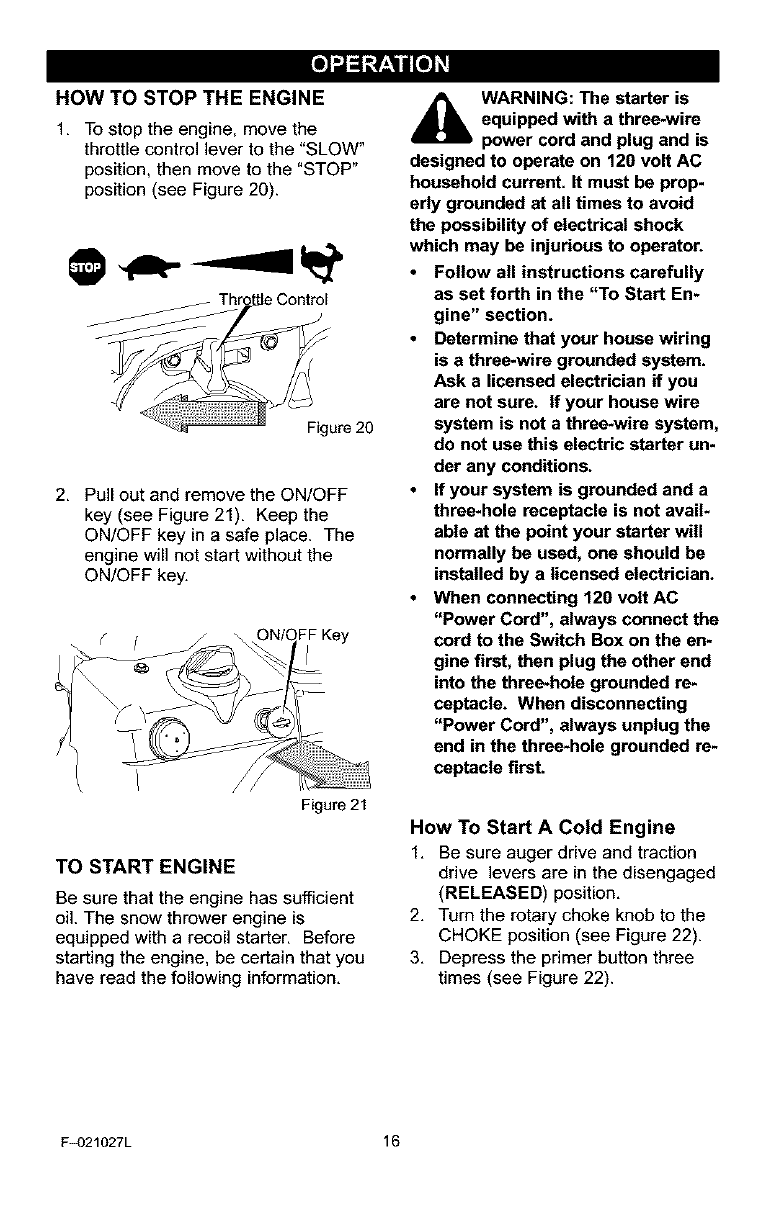
HOW TO STOP THE ENGINE
1. To stop the engine, move the
throttle control lever to the "SLOW"
position, then move to the "STOP"
position (see Figure 20).
ontml
Figure20
2. Pull out and remove the ON/OFF
key (see Figure 21). Keep the
ON/OFF key in asafe place. The
engine will not start without the
ON/OFF key.
Figure21
TO START ENGINE
Be sure that the engine has sufficient
oil. The snow thrower engine is
equipped with a recoil starter. Before
starting the engine, be certain that you
have read the following information.
_IL ARNING: The starter is
equipped with a three-wire
power cord and plug and is
designed to operate on 120 volt AC
household current. It must be prop-
edy grounded at all times to avoid
the possibility of electrical shock
which may be injurious to operator.
•Follow all instructions carefully
as set forth in the "To Start En-
gine" section.
•Determine that your house wiring
is a three-wire grounded system.
Ask a licensed electrician if you
are not sure. If your house wire
system is not a three-wire system,
do not use this electric starter un-
der any conditions.
•If your system is grounded and a
three*hole receptacle is not avail*
able at the point your starter will
normally be used, one should be
installed by a licensed electrician.
•When connecting 120 volt AC
"Power Cord", always connect the
cord to the Switch Box on the en=
gine first, then plug the other end
into the three*hole grounded re=
ceptacle. When disconnecting
"Power Cord", always unplug the
end in the three*hole grounded re=
ceptacle first.
How To Start A Cold Engine
1. Be sure auger drive and traction
drive levers are in the disengaged
(RELEASED) position.
2. Turn the rotary choke knob to the
CHOKE position (see Figure 22).
3. Depress the primer button three
times (see Figure 22).
F_]21027L 16
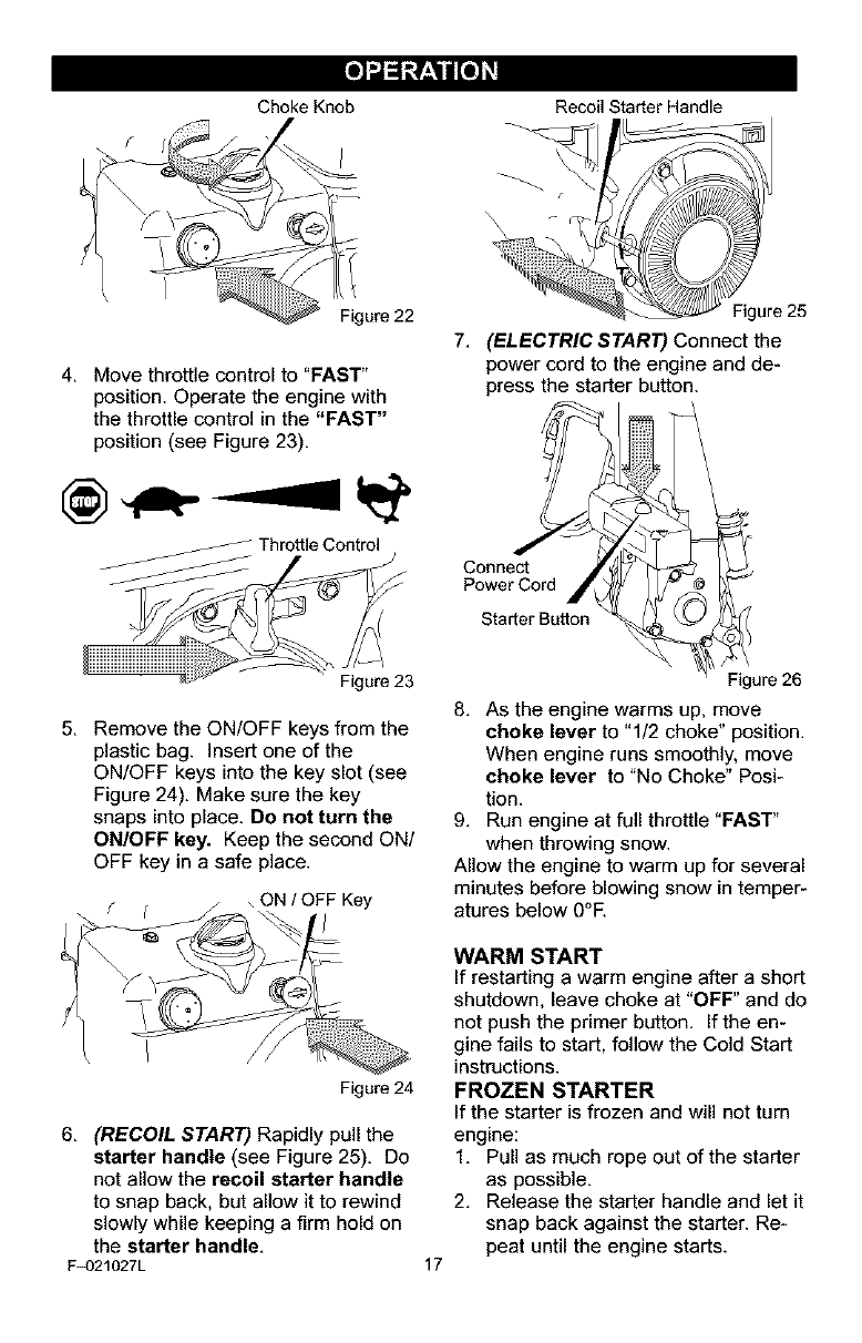
Choke Knob Recoil Starter Handle
4. Move throttle control to "FAST"
position. Operate the engine with
the throttle control in the "FAST"
position (see Figure 23).
_ Throttle Control
gure 25
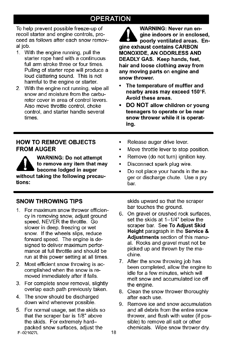
7. (ELECTRIC START) Connect the
power cord to the engine and de-
press the starter button.
Connect
Power Cord
Starter Button
Figure 23
5. Remove the ON/OFF keys from the
plastic bag. Insert one of the
ON/OFF keys into the key slot (see
Figure 24). Make sure the key
snaps into place. Do not turn the
ON/OFF key. Keep the second ON/
OFF key in a safe place.
Figure24
6. (RECOIL START) Rapidly pull the
starter handle (see Figure 25). Do
not allow the recoil starter handle
to snap back, but allow it to rewind
slowly while keeping a firm hold on
the starter handle,
F_)21027L
Figure26
8. As the engine warms up, move
choke lever to "1/2 choke" position.
When engine runs smoothly, move
choke lever to "No Choke" Posi-
tion.
9. Run engine at full throttle "FAST"
when throwing snow.
Allow the engine to warm up for several
minutes before blowing snow in temper-
atures below 0°E
17
WARM START
If restarting a warm engine after a short
shutdown, leave choke at "OFF" and do
not push the primer button. If the en-
gine fails to start, follow the Cold Start
instructions.
FROZEN STARTER
If the starter is frozen and will not turn
engine:
1. Pull as much rope out of the starter
as possible.
2. Release the starter handle and let it
snap back against the starter. Re-
peat until the engine starts.
Tohelppreventpossiblefreeze-upof
recoilstarterandenginecontrols,pro-
ceedasfollowsaftereachsnowremov-
aljob.
1. Withtheenginerunning,pullthe
starterropehardwithacontinuous
fullarmstrokethreeorfourtimes.
Pullingofstarterropewillproducea
loudclatteringsound.Thisisnot
harmfultotheengineorstarten
2. Withtheenginenotrunning,wipeall
snowandmoisturefromthecarbu-
retorcoverinareaofcontrollevers.
Alsomovethrottlecontrol,choke
control,andstarterhandleseveral
times.
_lb ARNING: Never run en*
gine indoors or in enclosed,
poorly ventilated areas. En*
gine exhaust contains CARBON
MONOXIDE, AN ODORLESS AND
DEADLY GAS. Keep hands, feet,
hair and loose clothing away from
any moving parts on engine and
snow thrower.
•The temperature of muffler and
nearby areas may exceed 150°F.
Avoid these areas.
•DO NOT allow children oryoung
teenagers to operate or be near
snow thrower while it is operat*
ing.
HOW TO REMOVE OBJECTS
FROM AUGER
_lb ARNING: Do not attempt
to remove any item that may
become lodged in auger
without taking the following precau-
tions:
Release auger drive lever.
Move throttle lever to stop position.
Remove (do not turn) ignition key.
Disconnect spark plug wire.
Do not place your hands in the au-
ger or discharge chute. Use a pry
bar.
SNOW THROWING TIPS
1. For maximum snow thrower efficien-
cy in removing snow, adjust ground
speed, NEVER the throttle. Go
slower in deep, freezing or wet
snow. If the wheels slips, reduce
forward speed. The engine is de-
signed to deliver maximum perfor-
mance at full throttle and should be
run at this power setting at all times.
2. Most efficient snow throwing is ac-
complished when the snow is re-
moved immediately after if falls.
3. For complete snow removal, slightly
overlap each path previously taken.
4. The snow should be discharged
down wind whenever possible.
5. For normal usage, set the skids so
that the scraper bar is 1/8" above
the skids. For extremely hard-
packed snow surfaces, adjust the
F_)21027L 18
skids upward so that the scraper
bar touches the ground.
6. On gravel or crushed rock surfaces,
set the skids at 1-1/4" below the
scraper bar. See To Adjust Skid
Height paragraph in the Service &
Adjustments section of this manu-
al. Rocks and gravel must not be
picked up and thrown by the ma-
chine.
7. After the snow throwing job has
been completed, allow the engine to
idle for a few minutes, which will
melt snow and accumulated ice off
the engine.
8. Clean the snow thrower thoroughly
after each use.
9. Remove ice and snow accumulation
and all debris from the entire snow
thrower, and flush with water (if pos-
sible) to remove all salt or other
chemicals. Wipe snow thrower dry.
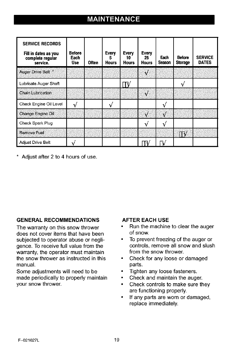
SERVICERECORDS
Fill indatesas you Before Every Every Every
completeregular Each 5 10 25 E_h Before SERVICE
service. Use Often Hours Hours Hours Seas_l Storage DATES
Lubricate Auger Shaft _ _/
Check Engine Oil Level _/ _/ _/
Check Spark Plug _/ ,,/
Adjust Drive Belt _/ ["_
* Adjust after 2 to 4 hours of use.
GENERAL RECOMMENDATIONS
The warranty on this snow thrower
does not cover items that have been
subjected to operator abuse or negli-
gence. To receive full value from the
warranty, the operator must maintain
the snow thrower as instructed in this
manual.
Some adjustments will need to be
made periodically to properly maintain
your snow thrower.
AFTER EACH USE
Run the machine to clear the auger
of snow.
To prevent freezing of the auger or
controls, remove all snow and slush
from the snow thrower.
Check for any loose or damaged
parts.
Tighten any loose fasteners.
Check and maintain the auger.
Check controls to make sure they
are functioning properly.
If any parts are worn or damaged,
replace immediately.
F_)21027L 19
PRODUCT SPECIFICATIONS
HORSEPOWER 7.75 HP
DISPLACEMENT 206 cc
GASOLINE 4 quarts
CAPACITY (unleaded)
OIL CAPACITY 5W30
(20 oz capacity)
SPARK PLUG: Longlife platium
P/N 5066
VALVE Intake: 0.004-0.006 in.
CLEARANCE: Exhaust: 0.009-0.011 in.
SNOW THROWER
AUGER DRIVE BELT
Adjust the auger drive belt after the first
2 to 4 hours of use, again about mid-
season and twice each season thereaf-
ter (See "Belt Adjustment" in the
Service and Adjustment section).
AUGER SHAFT LUBRICATION
EVERY 10 HOURS
1. Lubricatethe Zerk fittings (A) every ten
hours with a grease gun,
2. Each time a shear bolt is replaced,
the auger shaft MUST be greased.
See Figure 27. See To Replace Au-
ger Shear Bolt in the Service and
Adjustment section.
AFigure 27
CHAIN LUBRICATION
EVERY 25 HOURS
1. Position speed selector lever in first
(1) forward gear.
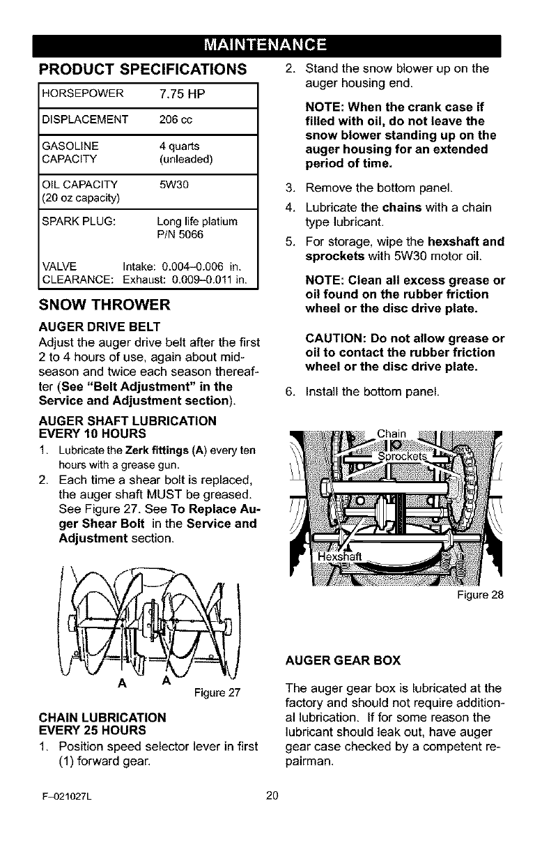
2, Stand the snow blower up on the
auger housing end.
NOTE: When the crank case if
filled with oil, do not leave the
snow blower standing up on the
auger housing for an extended
period of time.
3. Remove the bottom panel.
4. Lubricate the chains with a chain
type lubricant.
5. For storage, wipe the hexshaft and
sprockets with 5W30 motor oil.
NOTE: Clean all excess grease or
oil found on the rubber friction
wheel or the disc drive plate.
CAUTION: Do not allow grease or
oil to contact the rubber friction
wheel or the disc drive plate.
6. Install the bottom panel.
Hexshaff
Figure 28
AUGER GEAR BOX
The auger gear box is lubricated at the
factory and should not require addition-
al lubrication. If for some reason the
lubricant should leak out, have auger
gear case checked by a competent re-
pairman.
F_)21027L 20
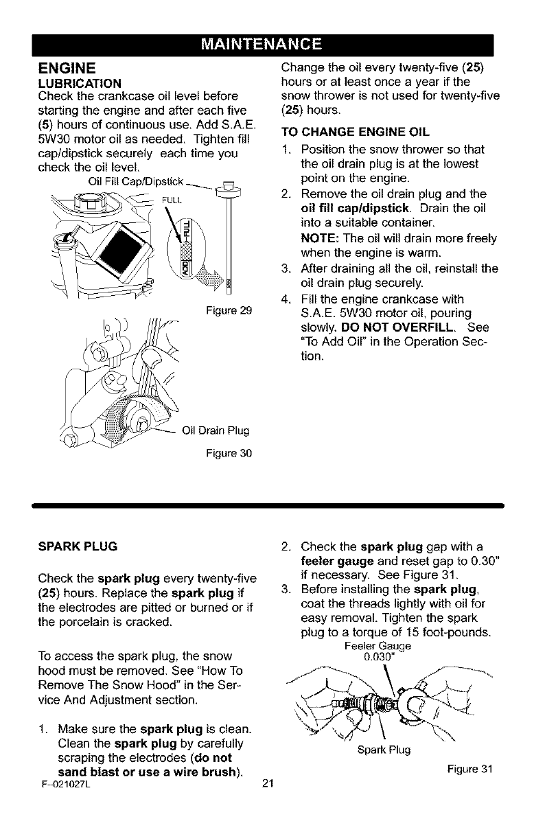
ENGINE
LUBRICATION
Check the crankcase oil level before
starting the engine and after each five
(5) hours of continuous use. Add S.A.E.
5W30 motor oil as needed. Tighten fill
cap/dipstick securely each time you
check the oil level.
Oil Fill Cap/Dipstick _ <:_
FULL
Figure 29
Change the oil every twenty-five (25)
hours or at least once a year if the
snow thrower is not used for twenty-five
(25) hours.
TO CHANGE ENGINE OIL
1, Position the snow thrower so that
the oil drain plug is at the lowest
point on the engine,
2, Remove the oil drain plug and the
oil fill cap/dipstick. Drain the oil
into a suitable container.
NOTE: The oil will drain more freely
when the engine is warm.
3. After draining all the oil, reinstall the
oil drain plug securely.
4. Fill the engine crankcase with
S.A.E. 5W30 motor oil, pouring
slowly. DO NOT OVERFILL, See
"To Add Oil" in the Operation Sec-
tion.
Figure 30
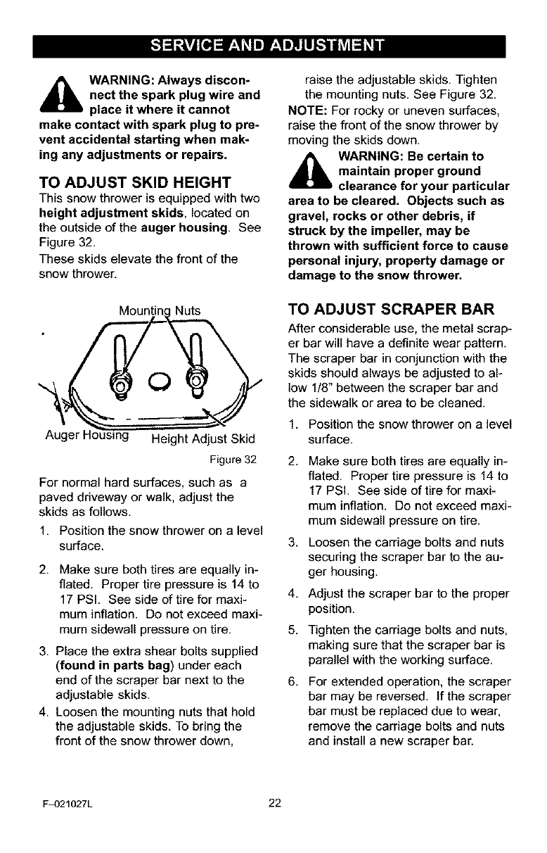
SPARK PLUG
Check the spark plug every twenty-five
(25) hours. Replace the spark plug if
the electrodes are pitted or burned or if
the porcelain is cracked.
To access the spark plug, the snow
hood must be removed. See "How To
Remove The Snow Hood" in the Ser-
vice And Adjustment section.
1. Make sure the spark plug is clean.
Clean the spark plug by carefully
scraping the electrodes (do not
sand blast or use awire brush).
F_)21027L
2. Check the spark plug gap with a
feeler gauge and reset gap to 0.30"
if necessary. See Figure 31.
3. Before installing the spark plug,
coat the threads lightly with oil for
easy removal. Tighten the spark
plug to a torque of 15 foot-pounds.
Feeler Gauge
0.030"
2_.../
21
Spark Plug
Figure 31
[."_ej= r;1_l"] f,.1,,]tLl_"]ad_VAl_bi
_ARNING: Always discon*
nect the spark plug wire and
place it where it cannot
make contact with spark plug to pre-
vent accidental starting when mak-
ing any adjustments or repairs.
TO ADJUST SKID HEIGHT
This snow thrower is equipped with two
height adjustment skids, located on
the outside of the auger housing. See
Figure 32,
These skids elevate the front of the
snow thrower,
Nuts
O
Auger t- g Height Adjust Skid
Figure 32
For normal hard surfaces, such as a
paved driveway or walk, adjust the
skids as follows,
1, Position the snow thrower on a level
surface.
2. Make sure both tires are equally in-
flated. Proper tire pressure is 14 to
17 PSI. See side of tire for maxi-
mum inflation. Do not exceed maxi-
mum sidewall pressure on tire.
3. Place the extra shear bolts supplied
(found in parts bag) under each
end of the scraper bar next to the
adjustable skids.
4. Loosen the mounting nuts that hold
the adjustable skids. To bring the
front of the snow thrower down,
raise the adjustable skids. Tighten
the mounting nuts. See Figure 32.
NOTE: For rocky or uneven surfaces,
raise the front of the snow thrower by
moving the skids down.
_1= ARNING: Be certain to
maintain proper ground
clearance for your particular
area to be cleared. Objects such as
gravel, rocks or other debris, if
struck by the impeller, may be
thrown with sufficient force to cause
personal injury, property damage or
damage to the snow thrower.
TO ADJUST SCRAPER BAR
After considerable use, the metal scrap-
er bar will have a definite wear pattern.
The scraper bar in conjunction with the
skids should always be adjusted to al-
low 1/8" between the scraper bar and
the sidewalk or area to be cleaned.
1. Position the snow thrower on a level
surface.
2,
3,
4.
5.
6.
Make sure both tires are equally in-
flated. Proper tire pressure is 14 to
17 PSI. See side of tire for maxi-
mum inflation. Do not exceed maxi-
mum sidewall pressure on tire.
Loosen the carriage bolts and nuts
securing the scraper bar to the au-
ger housing.
Adjust the scraper bar to the proper
position,
Tighten the carriage bolts and nuts,
making sure that the scraper bar is
parallel with the working surface.
For extended operation, the scraper
bar may be reversed. If the scraper
bar must be replaced due to wear,
remove the carriage bolts and nuts
and install a new scraper bar.
F_)21027L 22
[."_ej= r;1_l"] F,.1,,]tLl_"]ad_VAl_bli
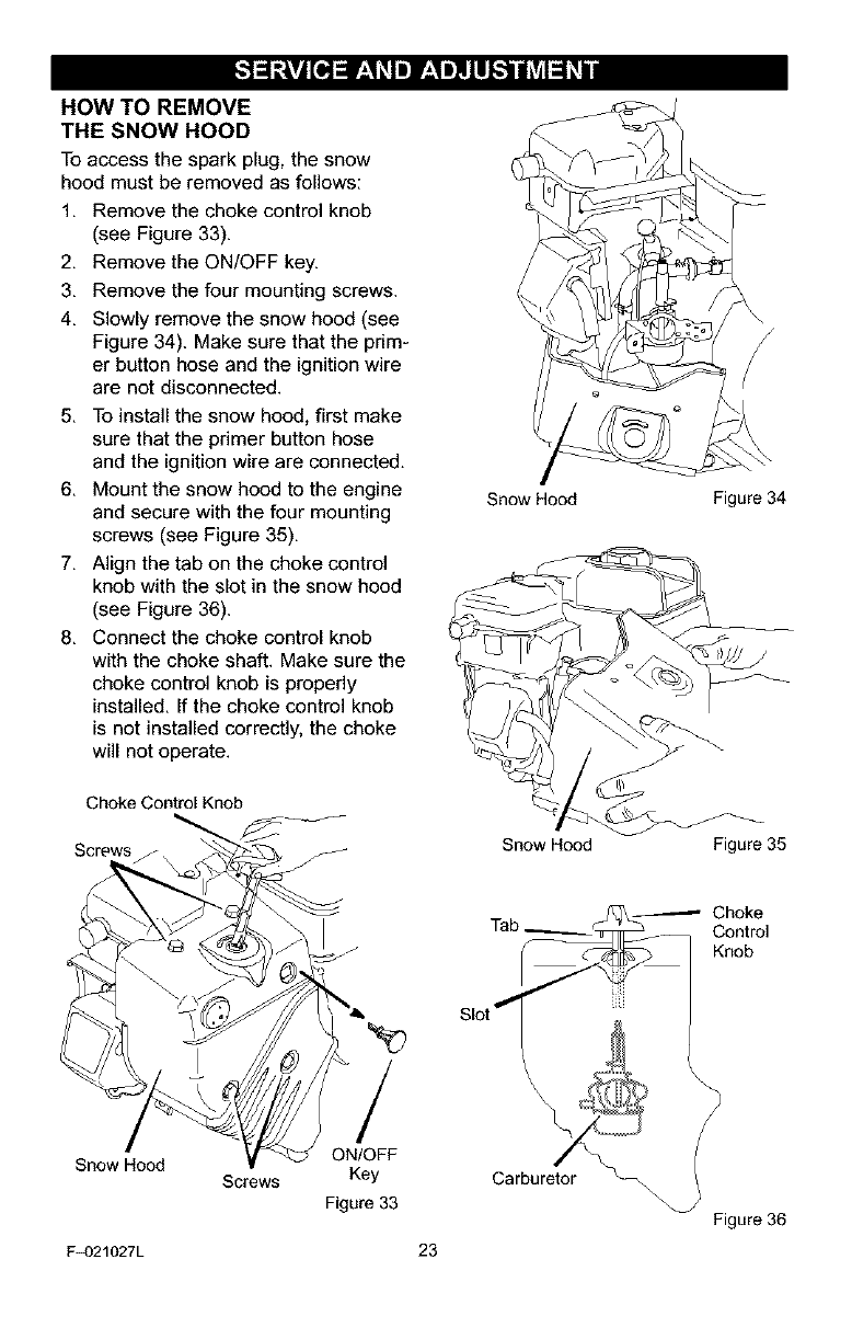
HOW TO REMOVE
THE SNOW HOOD
To access the spark plug, the snow
hood must be removed as follows:
1, Remove the choke control knob
(see Figure 33).
2, Remove the ON/OFF key.
3, Remove the four mounting screws.
4, Slowly remove the snow hood (see
Figure 34). Make sure that the prim-
er button hose and the ignition wire
are not disconnected.
5, To install the snow hood, first make
sure that the primer button hose
and the ignition wire are connected.
6, Mount the snow hood to the engine
and secure with the four mounting
screws (see Figure 35),
7, Align the tab on the choke control
knob with the slot in the snow hood
(see Figure 36).
8, Connect the choke control knob
with the choke shaft. Make sure the
choke control knob is properly
installed, If the choke control knob
is not installed correctly, the choke
will not operate.
Choke Control Knob
Screws
Snow Hood Figure 34
Snow Hood Figure 35
-Choke
Tab Control
Knob
Slot _ iJii
Snow Hood
F_)21027L
Screws
/
ON/OFF
Key
Figure 33
23
Figure 36
[."_ej= r:111"]f,.1,,]l.LIl_"]ad_VAl_bli
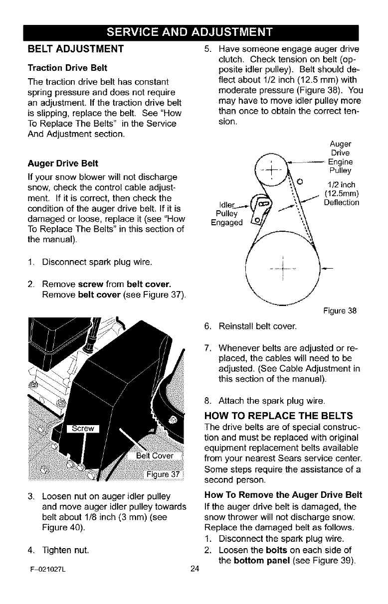
BELT ADJUSTMENT
Traction Drive Belt
The traction drive belt has constant
spring pressure and does not require
an adjustment. If the traction drive belt
is slipping, replace the belt. See "How
To Replace The Belts" in the Service
And Adjustment section.
Auger Drive Belt
If your snow blower will not discharge
snow, check the control cable adjust-
ment. If it is correct, then check the
condition of the auger drive belt. If it is
damaged or loose, replace it (see "How
To Replace The Belts" in this section of
the manual).
1. Disconnect spark plug wire.
2. Remove screw from belt cover.
Remove belt cover (see Figure 37).
5. Have someone engage auger drive
clutch. Check tension on belt (op-
posite idler pulley). Belt should de-
flect about 1/2 inch (12.5 mm) with
moderate pressure (Figure 38). You
may have to move idler pulley more
than once to obtain the correct ten-
sion.
Auger
--j_ ,_, Pulley
J;,_0 1/2 inch
._- ".._ (12.5mm)
idler_._._C/tc f'_\_'_" Deflection
Pulley )to, /- ;,\
Engaged _ ',
L "
Figure 38
6. Reinstall belt cover.
7. Whenever belts are adjusted or re-
placed, the cables will need to be
adjusted. (See Cable Adjustment in
this section of the manual).
3. Loosen nut on auger idler pulley
and move auger idler pulley towards
belt about 1/8 inch (3 mm) (see
Figure 40).
4. Tighten nut.
F_)21027L 24
8. Attach the spark plug wire.
HOW TO REPLACE THE BELTS
The drive belts are of special construc-
tion and must be replaced with original
equipment replacement belts available
from your nearest Sears service center,
Some steps require the assistance of a
second person,
How To Remove the Auger Drive Belt
If the auger drive belt is damaged, the
snow thrower will not discharge snow.
Replace the damaged belt as follows.
1. Disconnect the spark plug wire.
2. Loosen the bolts on each side of
the bottom panel (see Figure 39).
[."_ej_ r;lll"] f'.1"]llll_"]ad_VAl_#li
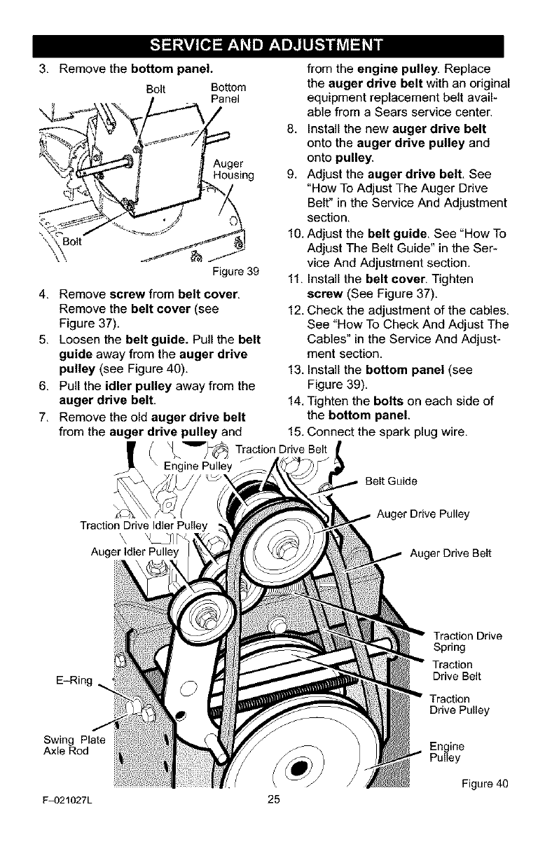
3, Remove the bottom panel.
Bolt Bottom
Pane,
Auger
Housing
\\
Figure 39
4, Remove screw from belt cover,
Remove the belt cover (see
Figure 37).
5, Loosen the belt guide. Pull the belt
guide away from the auger drive
pulley (see Figure 40),
6, Pull the idler pulley away from the
auger drive belt,
7, Remove the old auger drive belt
from the auger drive pulley and
_'_=_/_ Traction Drive Belt
Engine Pulley
from the engine pulley, Replace
the auger drive belt with an original
equipment replacement belt avail-
able from a Sears service center.
8, Install the new auger drive belt
onto the auger drive pulley and
onto pulley.
9, Adjust the auger drive belt, See
"How To Adjust The Auger Drive
Belt" in the Service And Adjustment
section,
10, Adjust the belt guide, See "How To
Adjust The Belt Guide" in the Ser-
vice And Adjustment section,
11, Install the belt cover, Tighten
screw (See Figure 37).
12, Check the adjustment of the cables,
See "How To Check And Adjust The
Cables" in the Service And Adjust-
ment section,
13, Install the bottom panel (see
Figure 39),
14, Tighten the bolts on each side of
the bottom panel.
15, Connect the spark plug wire,
Belt Guide
Traction Drive Idler Pulley
Auger Idler Pulley
Auger Drive Pulley
Auger Drive Belt
E-Ring
Swing Plate
Axle Rod
Traction Drive
Spring
Traction
Drive Belt
Traction
Drive Pulley
Engine
Pulley
Figure 40
F_)21027L 25
[."_ej= r:1_l"]f,.1,,]tLl_"]ad_VAl_bi
How To Remove
The Traction Drive Belt
If the snow thrower will not move for-
ward, check the traction drive belt for
wear or damage, If the traction drive
belt is worn or damaged, replace the
belt as follows,
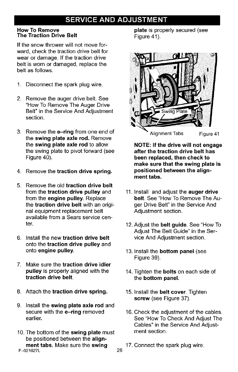
plate is properly secured (see
Figure 41),
1, Disconnect the spark plug wire.
2, Remove the auger drive belt, See
"How To Remove The Auger Drive
Belt" in the Service And Adjustment
section.
3, Remove the e-ring from one end of
the swing plate axle rod. Remove
the swing plate axle rod to allow
the swing plate to pivot forward (see
Figure 40).
4, Remove the traction drive spring.
5, Remove the old traction drive belt
from the traction drive pulley and
from the engine pulley. Replace
the traction drive belt with an origi-
nal equipment replacement belt
available from a Sears service cen-
ter.
6, Install the new traction drive belt
onto the traction drive pulley and
onto engine pulley,
7, Make sure the traction drive idler
pulley is properly aligned with the
traction drive belt,
Alignment Tabs Figure 41
NOTE: If the drive will not engage
after the traction drive belt has
been replaced, then check to
make sure that the swing plate is
positioned between the align*
ment tabs.
11, Install and adjust the auger drive
belt. See "How To Remove The Au-
ger Drive Belt" in the Service And
Adjustment section,
12, Adjust the belt guide, See "How To
Adjust The Belt Guide" in the Ser-
vice And Adjustment section,
13, Install the bottom panel (see
Figure 39),
14, Tighten the bolts on each side of
the bottom panel.
8, Attach the traction drive spring.
9, install the swing plate axle rod and
secure with the e-ring removed
earlier.
10, The bottom of the swing plate must
be positioned between the align-
ment tabs. Make sure the swing
F_)21027L
15, Install the belt cover, Tighten
screw (see Figure 37).
16, Check the adjustment of the cables,
See "How To Check And Adjust The
Cables" in the Service And Adjust-
ment section,
17, Connect the spark plug wire,
26
[,,",]_ej= r;1_l"] f*.1,,]l.LIl_"]ad_VAl_bli
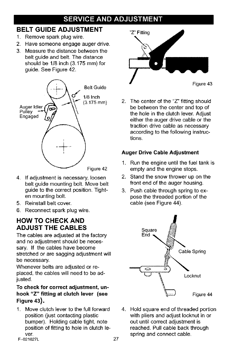
BELT GUIDE ADJUSTMENT
1, Remove spark plug wire,
2, Have someone engage auger drive,
3, Measure the distance between the
belt guide and belt, The distance
should be 1/8 inch (3,175 mm) for
guide. See Figure 42.
"Z" Fitting
_--_ O,_/ Belt Guide
Auger idler, _ _ - \\
Pulley _/'" d \\
Engaged 0_._._
Figure 42
4. If adjustment is necessary, loosen
belt guide mounting bolt. Move belt
guide to the correct position. Tight-
en mounting bolt.
5. Reinstall belt cover.
6. Reconnect spark plug wire.
HOW TO CHECK AND
ADJUST THE CABLES
The cables are adjusted at the factory
and no adjustment should be neces-
sary. If the cables have become
stretched or are sagging adjustment will
be necessary.
Whenever belts are adjusted or re-
placed, the cables will need to be ad-
justed.
To check for correct adjustment, un-
hook "Z" fitting at clutch lever (see
Figure 43),
1. Move clutch lever to the full forward
position (just contacting plastic
bumper). Holding cable tight, note
position of fitting to hole in clutch le-
ver.
F_)21027L
Figure 43
2. The center of the "Z" fitting should
be between the center and top of
the hole in the clutch lever. Adjust
either the auger drive cable or the
traction drive cable as necessary
according to the following instruc-
tions.
Auger Drive Cable Adjustment
1. Run the engine until the fuel tank is
empty and the engine stops.
2. Stand the snow thrower up on the
front end of the auger housing.
3. Push cable through spring to ex-
pose the threaded portion of the
cable (see Figure 44).
Square
End _
Cable Spring
o
Locknut
27
Figure 44
4. Hold square end of threaded portion
with pliers and adjust Iocknut in or
out until correct adjustment is
reached. Pull cable back through
spring and connect cable.
[."_ej= r;1_l"] f,.1,,]l.LIl_"]ad_VAl_bli
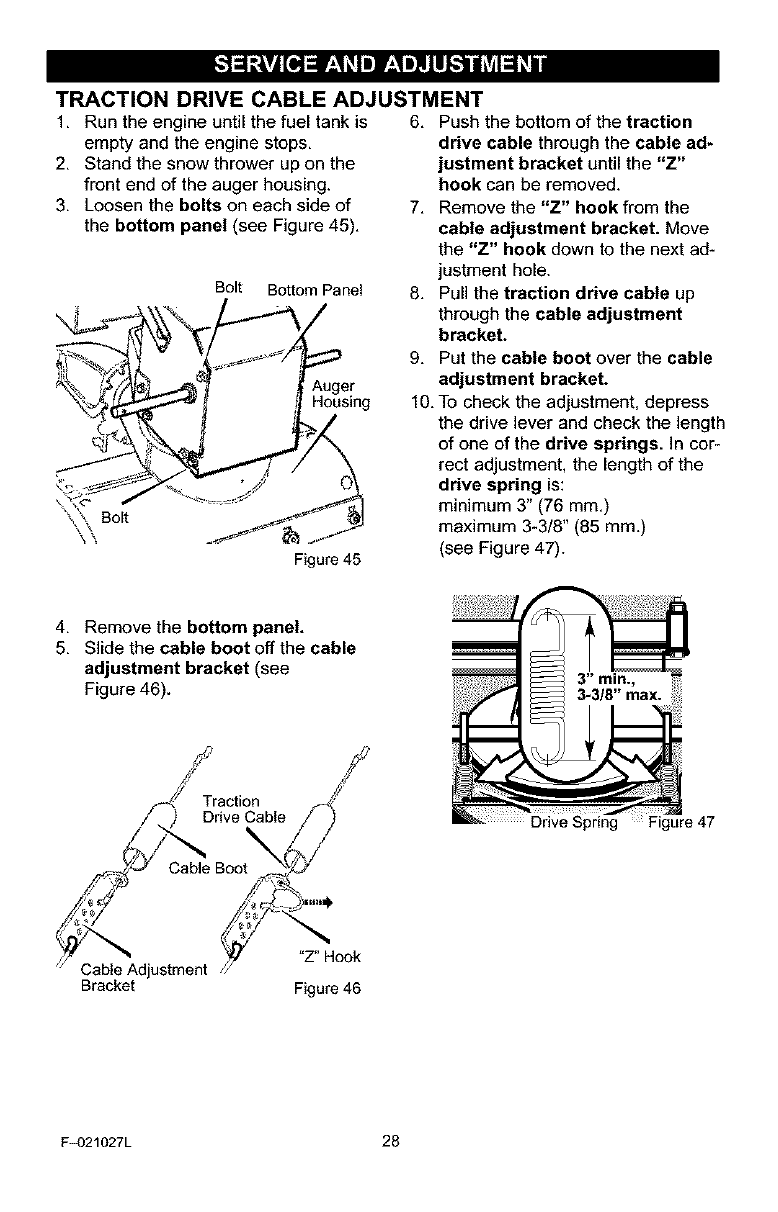
TRACTION DRIVE CABLE ADJUSTMENT
1, Run the engineuntilthe fuel tank is 6, Pushthe bottom of the traction
empty and the engine stops.
2. Stand the snow thrower up on the
front end of the auger housing.
3. Loosen the bolts on each side of
the bottom panel (see Figure 45).
Bolt Bottom Panel
Auger
Housing
Bolt
\,,
Figure 45
drive cable through the cable ad-
justment bracket until the "Z"
hook can be removed.
7. Remove the "Z" hook from the
cable adjustment bracket. Move
the "Z" hook down to the next ad-
justment hole.
8. Pull the traction drive cable up
through the cable adjustment
bracket.
9. Put the cable boot over the cable
adjustment bracket.
10. To check the adjustment, depress
the drive lever and check the length
of one of the drive springs. In cor-
rect adjustment, the length of the
drive spring is:
minimum 3" (76 mm.)
maximum 3-3/8" (85 mm.)
(see Figure 47).
4. Remove the bottom panel.
5. Slide the cable boot off the cable
adjustment bracket (see
Figure 46). 3-3/8" max.
Traction f4__;pT't
Drive Cable /
Cable Adjustment _/v 7_"Hook
Bracket Figure 46
Drive Figure 47
F_)21027L 28
[."_ej= r;111"]f,.1,,]tLIl_"]ad_VAl_bli
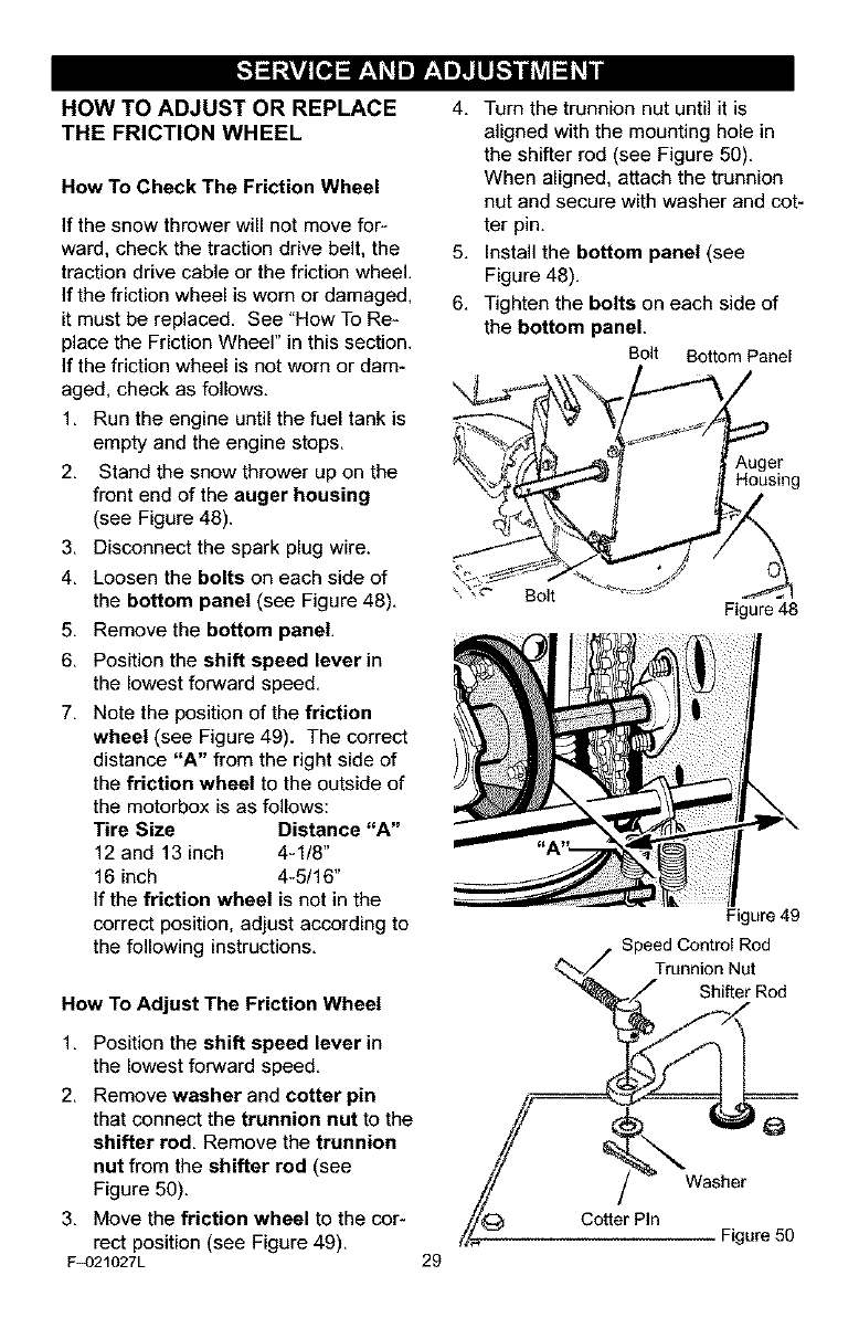
HOW TO ADJUST OR REPLACE
THE FRICTION WHEEL
How To Check The Friction Wheel
If the snow thrower will not move for-
ward, check the traction drive belt, the
traction drive cable or the friction wheel.
If the friction wheel is worn or damaged.
it must be replaced. See "How To Re-
place the Friction Wheel" in this section.
If the friction wheel is not worn or dam-
aged, check as follows.
1. Run the engine until the fuel tank is
empty and the engine stops.
2. Stand the snow thrower up on the
front end of the auger housing
(see Figure 48).
3. Disconnect the spark plug wire.
4. Loosen the bolts on each side of
the bottom panel (see Figure 48).
5. Remove the bottom panel.
6. Position the shift speed lever in
the lowest forward speed.
7. Note the position of the friction
wheel (see Figure 49). The correct
distance "A" from the right side of
the friction wheel to the outside of
the motorbox is as follows:
Tire Size Distance "A"
12 and 13 inch 4-1/8"
16 inch 4-5/16"
If the friction wheel is not in the
correct position, adjust according to
the following instructions,
How To Adjust The Friction Wheel
1. Position the shift speed lever in
the lowest forward speed.
2. Remove washer and cotter pin
that connect the trunnion nut to the
shifter rod, Remove the trunnion
nut from the shifter rod (see
Figure 50).
3. Move the friction wheel to the cor-
rect position (see Figure 49).
F_)21027L
4. Turn the trunnion nut until it is
aligned with the mounting hole in
the shifter rod (see Figure 50).
When aligned, attach the trunnion
nut and secure with washer and cot-
ter pin.
5. Install the bottom panel (see
Figure 48).
6. Tighten the bolts on each side of
the bottom panel.
Bolt Bottom Panel
Auger
Housing
\ Bolt Figure 48
29
Figure 49
Speed Control Rod
Trunnion Nut
//_ Cotter Pin - -.
/,/,_-- Figure 50
[."_ej= r;111"]f,.1,,]l.LIl_"]ad_VAl_bli
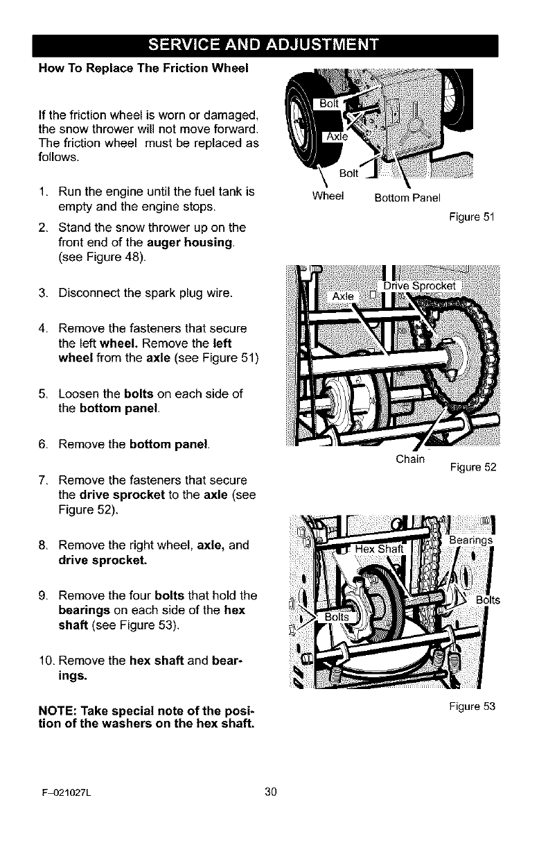
How To Replace The Friction Wheel
If the friction wheel is worn or damaged,
the snow thrower will not move forward.
The friction wheel must be replaced as
follows.
1. Run the engine until the fuel tank is
empty and the engine stops.
2. Stand the snow thrower up on the
front end of the auger housing.
(see Figure 48).
Wheel Bottom Panel
Figure 51
3. Disconnect the spark plug wire.
4. Remove the fasteners that secure
the left wheel. Remove the left
wheel from the axle (see Figure 51)
5. Loosen the bolts on each side of
the bottom panel.
6. Remove the bottom panel.
7. Remove the fasteners that secure
the drive sprocket to the axle (see
Figure 52).
Chain Figure 52
8. Remove the right wheel, axle, and
drive sprocket.
9. Remove the four bolts that hold the
bearings on each side of the hex
shaft (see Figure 53).
10. Remove the hex shaft and bear-
ings.
NOTE: Take special note of the posi-
tion of the washers on the hex shaft.
Bolts
Figure 53
F_)21027L 30
[."_ej= r:111"]f,.1,,]l.LIl_"]ad_VAl_bli
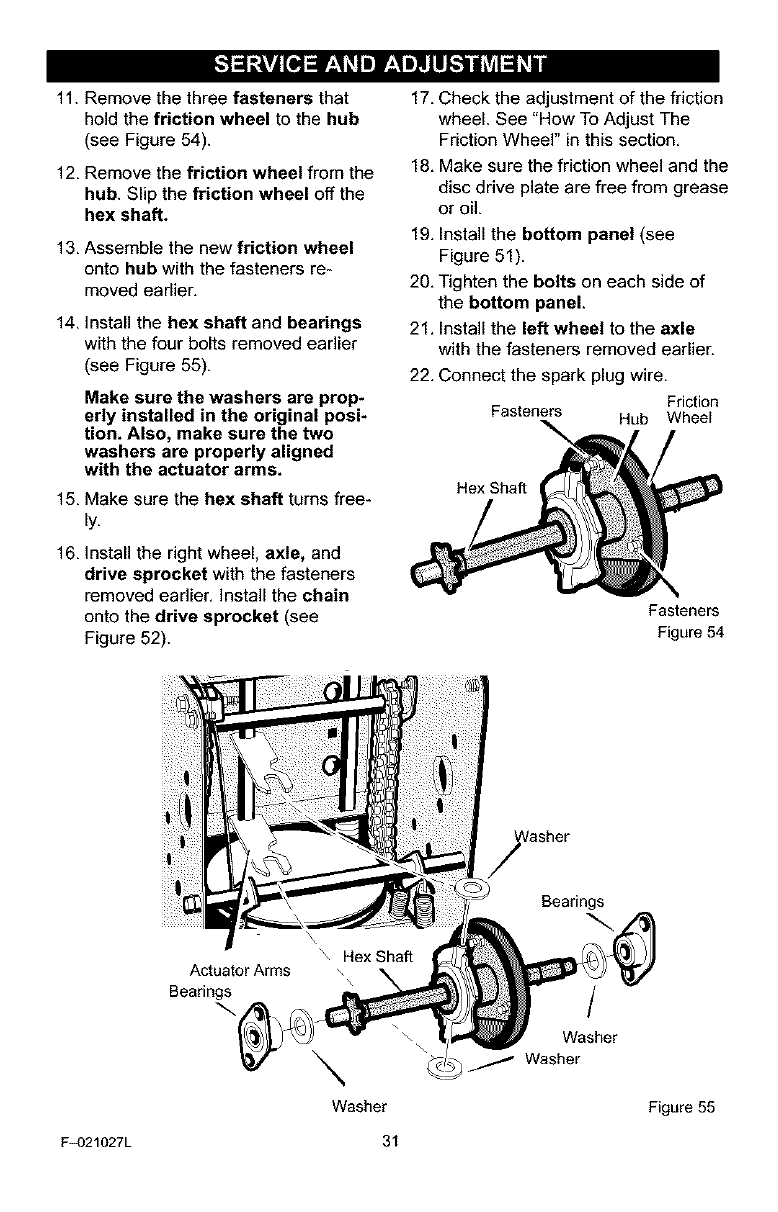
11. Remove the three fasteners that
hold the friction wheel to the hub
(see Figure 54).
12, Remove the friction wheel from the
hub. Slip the friction wheel off the
hex shaft.
13, Assemble the new friction wheel
onto hub with the fasteners re-
moved earlier,
14, Install the hex shaft and bearings
with the four bolts removed earlier
(see Figure 55).
Make sure the washers are prop*
erly installed in the original posi-
tion. Also, make sure the two
washers are properly aligned
with the actuator arms.
15, Make sure the hex shaft turns free-
ly,
16, Install the right wheel, axle, and
drive sprocket with the fasteners
removed earlier, Install the chain
onto the drive sprocket (see
Figure 52).
17, Check the adjustment of the friction
wheel. See "How To Adjust The
Friction Wheel" in this section,
18, Make sure the friction wheel and the
disc drive plate are free from grease
or oil.
19, Install the bottom panel (see
Figure 51),
20, Tighten the bolts on each side of
the bottom panel.
21, Install the left wheel to the axle
with the fasteners removed earlier.
22, Connect the spark plug wire,
Friction
Fasteners Hub Wheel
Hex Shaft
Fasteners
Figure 54
Actuator Arms
Bearings
\
Washer
Bearings
/
Washer
Washer
Figure 55
F_)21027L 31
[."_oj= r;111"] r,.1,,]tLl_"]ad_VAl_bi
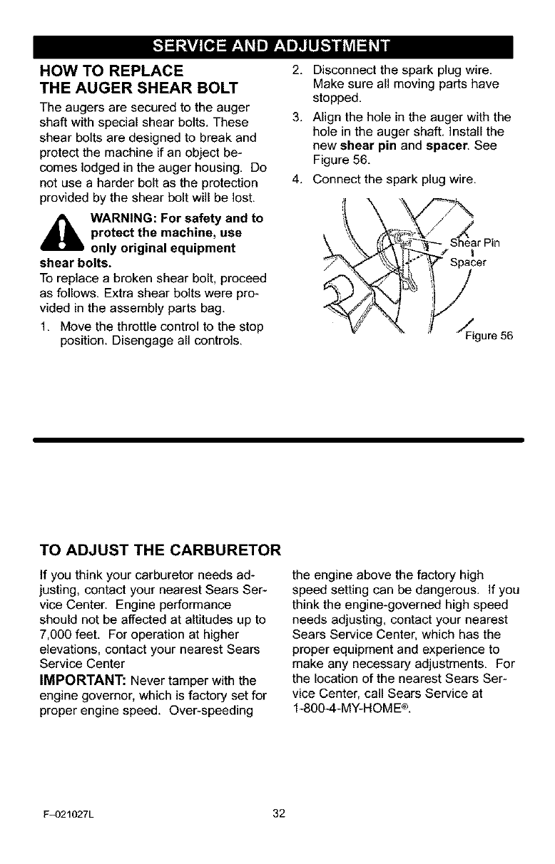
HOW TO REPLACE
THE AUGER SHEAR BOLT
The augers are secured to the auger
shaft with special shear bolts. These
shear bolts are designed to break and
protect the machine if an object be-
comes lodged in the auger housing. Do
not use a harder bolt as the protection
provided by the shear bolt will be lost.
_lb ARNING: For safety and to
protect the machine, use
only original equipment
shear bolts.
To replace a broken shear bolt, proceed
as follows. Extra shear bolts were pro-
vided in the assembly parts bag.
1. Move the throttle control to the stop
position. Disengage all controls.
2. Disconnect the spark plug wire.
Make sure all moving parts have
stopped.
3. Align the hole in the auger with the
hole in the auger shaft. Install the
new shear pin and spacer. See
Figure 56.
4. Connect the spark plug wire.
"_ SF_earPinter
0ure 0
TO ADJUST THE CARBURETOR
If you think your carburetor needs ad-
justing, contact your nearest Sears Ser-
vice Center. Engine performance
should not be affected at altitudes up to
7,000 feet. For operation at higher
elevations, contact your nearest Sears
Service Center
IMPORTANT: Never tamper with the
engine governor, which is factory set for
proper engine speed. Over-speeding
the engine above the factory high
speed setting can be dangerous. If you
think the engine-governed high speed
needs adjusting, contact your nearest
Sears Service Center, which has the
proper equipment and experience to
make any necessary adjustments. For
the location of the nearest Sears Ser-
vice Center, call Sears Service at
1-800-4-MY-HOME®.
F_)21027L 32
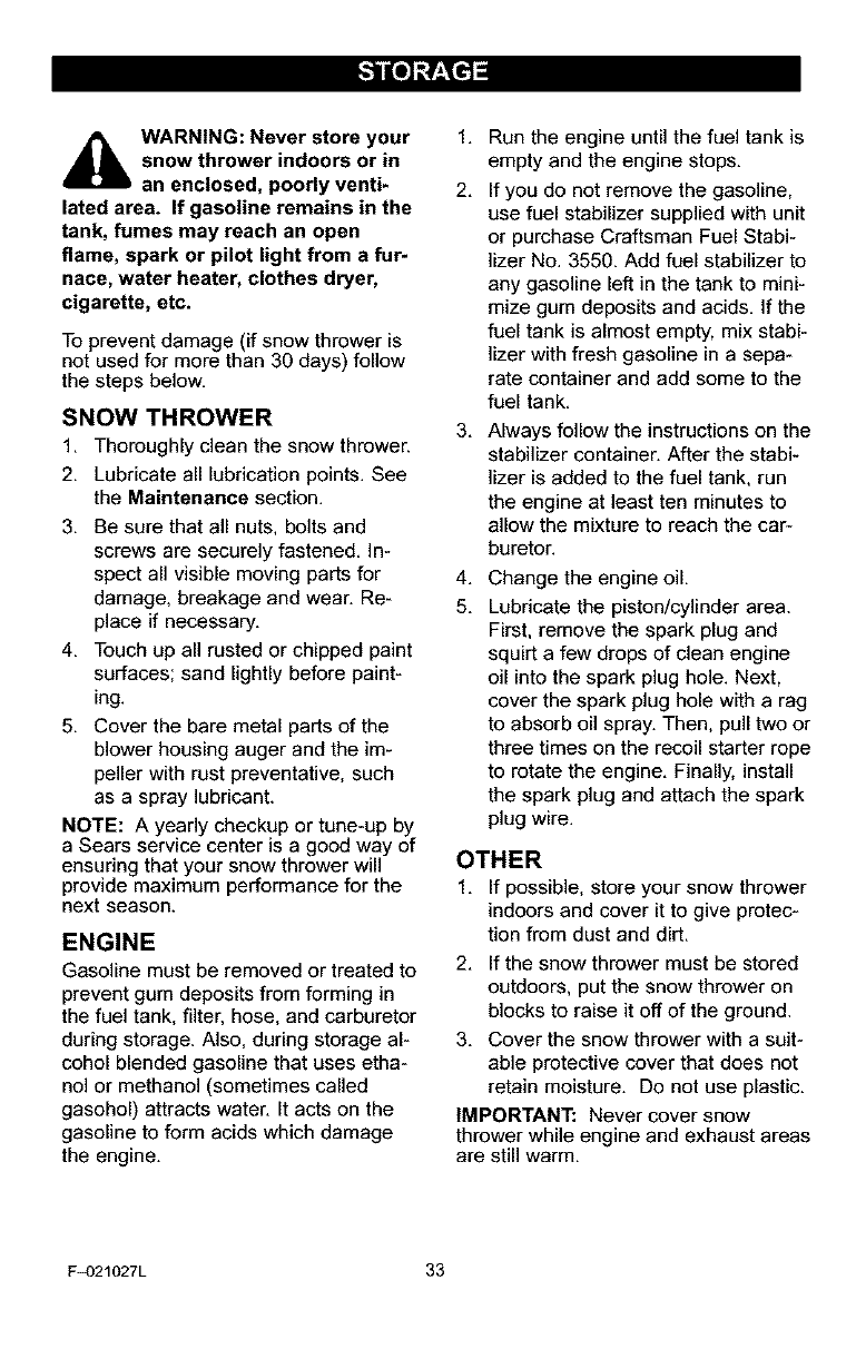
_lb ARNING: Never store your
snow thrower indoors or in
an enclosed, poorly venti*
lated area. If gasoline remains in the
tank, fumes may reach an open
flame, spark or pilot light from a fur*
nace, water heater, clothes dryer,
cigarette, etc.
To prevent damage (if snow thrower is
not used for more than 30 days) follow
the steps below.
SNOW THROWER
1, Thoroughly clean the snow thrower,
2, Lubricate all lubrication points, See
the Maintenance section,
3. Be sure that all nuts, bolts and
screws are securely fastened. In-
spect all visible moving parts for
damage, breakage and wear. Re-
place if necessary.
4. Touch up all rusted or chipped paint
surfaces; sand lightly before paint-
ing.
5. Cover the bare metal parts of the
blower housing auger and the im-
peller with rust preventative, such
as a spray lubricant.
NOTE: A yearly checkup or tune-up by
a Sears service center is a good way of
ensuring that your snow thrower will
provide maximum performance for the
next season.
ENGINE
Gasoline must be removed or treated to
prevent gum deposits from forming in
the fuel tank, filter, hose, and carburetor
during storage. Also, during storage al-
cohol blended gasoline that uses etha-
nol or methanol (sometimes called
gasohol) attracts water. It acts on the
gasoline to form acids which damage
the engine.
1,
2.
3,
4,
5.
Run the engine until the fuel tank is
empty and the engine stops.
If you do not remove the gasoline,
use fuel stabilizer supplied with unit
or purchase Craftsman Fuel Stabi-
lizer No. 3550. Add fuel stabilizer to
any gasoline left in the tank to mini-
mize gum deposits and acids. If the
fuel tank is almost empty, mix stabi-
lizer with fresh gasoline in a sepa-
rate container and add some to the
fuel tank.
Always follow the instructions on the
stabilizer container. After the stabi-
lizer is added to the fuel tank, run
the engine at least ten minutes to
allow the mixture to reach the car-
buretor.
Change the engine oil.
Lubricate the piston/cylinder area.
First, remove the spark plug and
squirt a few drops of clean engine
oil into the spark plug hole. Next,
cover the spark plug hole with a rag
to absorb oil spray. Then, pull two or
three times on the recoil starter rope
to rotate the engine. Finally, install
the spark plug and attach the spark
plug wire.
OTHER
1. If possible, store your snow thrower
indoors and cover it to give protec-
tion from dust and dirt.
2. If the snow thrower must be stored
outdoors, put the snow thrower on
blocks to raise it off of the ground.
3. Cover the snow thrower with a suit-
able protective cover that does not
retain moisture. Do not use plastic.
IMPORTANT: Never cover snow
thrower while engine and exhaust areas
are still warm.
F_)21027L 33
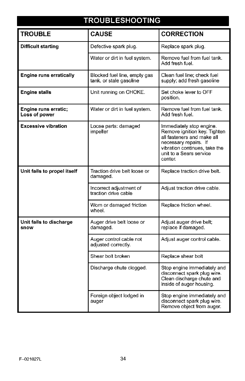
i|((ell:J_]M_."]_[eIe_ll_[e']
TROUBLE CORRECTION
Difficult starting
CAUSE
Defective spark plug.
Water or dirt in fuel system.
Replace spark plug.
Remove fuel from fuel tank.
Add fresh fuel,
Engine runs erratically Blocked fuel line, empty gas Clean fuel line; check fuel
tank, or stale gasoline supply; add fresh gasoline
Engine stalls Unit running on CHOKE. Set choke lever to OFF
position.
Engine runs erratic; Water or dirt in fuel system. Remove fuel from fuel tank.
Loss of power Add fresh fuel.
Excessive vibration Loose parts: damaged Immediately stop engine.
impeller Remove ignition key. Tighten
all fasteners and make all
necessary repairs. If
vibration continues, take the
unit to a Sears service
center.
Unit fails to propel itself Traction drive belt loose or Replace traction drive belt.
damaged.
Incorrect adjustment of Adjust traction drive cable.
traction drive cable
Replace friction wheel.Worn or damaged friction
wheel.
Auger drive belt loose or
damaged. Adjust auger drive belt;
replace if damaged.
Auger control cable not Adjust auger control cable.
adjusted correctly.
Shear bolt broken Replace shear bolt
Discharge chute clogged. Stop engine immediately and
disconnect spark plug wire.
Clean discharge chute and
inside of auger housing.
Unit falls to discharge
slrlow
Foreign object lodged in
auger
Stop engine immediately and
disconnect spark plug wire.
Remove object from auger.
F_)21027L 34
SEARS, ROEBUCK AND CO,
Federal and California Emission Control Systems Limited Warranty
Small Off-Road Engines
CALIFORNIA & US EPA EMISSION
CONTROL WARRANTY STATEMENT
The U. S. Environmental Protection Agency
("EPA"), the California Air Resources Board
("CARB") and Sears, Roebuck and Co. are
pleased to explain the Federal and California
Emission Control Systems Warranty on your
new small off-toed engine. In California, new
1995 and later small off-road engines must be
designed, built and equipped to meet the
State's stringent anti-smog standards. In oth-
er states, new 1997 and later model year en-
gines must be designed, built and equipped, at
the time of sale, to meet the U.S. EPA regula-
tions for small non-road engines. Sears, Roe-
buck and Co. will warrant the emission control
system on your small off-road engine for the
periods of time listed below, provided there
has been no abuse, neglect, unapproved mod-
ification, or improper maintenance of your
small off-road engine.
Your emission control system may include
parts such as the carburetor, ignition system
and exhaust system. Also included may be the
compression release system and other emis-
sion-related assemblies.
Where a warrantable condition exists, Sears,
Roebuck and Co. will repair your small off-
road engine at no cost to you for diagnosis,
parts and labor.
MANUFACTURER'S EMISSION
CONTROL SYSTEM WARRANTY
COVERAGE
Emission control systems on 1995 and later
model year California small off-road engines
are warranted for two years as hereinafter
noted. In other states, 1997 and later model
year engines are also warranted for two years.
If, during such warranty period, any emission-
related part on your engine is defective in ma-
terials or workmanship, the part will be
repaired or replaced by Sears, Roebuck and
Co.
OWNER'S WARRANTY
RESPONSIBILITIES
As the small off-road engine owner, you are
responsible for the performance of the re-
F_)21027L
quired maintenance listed in your Owner's
Manual, but Sears, Roebuck and Co. will not
deny warranty solely due to the lack of receipts
or for your failure to provide written evidence
of the performance of all scheduled mainte-
nance.
As the small off-road engine owner, you
should, however, be aware that Sears, Roe-
buck and Co. may deny you warranty cover-
age if your small off-road engine or a part
thereof has failed due to abuse, neglect, im-
proper maintenance or unapproved modifica-
tions.
You are responsible for presenting your small
off-road engine to a Sears, Roebuck and Co.
Authorized Service Outlet as soon as a prob-
lem exists. The warranty repairs should be
completed in a reasonable amount of time, not
to exceed 30 days.
Warranty service can be arranged by contact-
ing either a Sears, Roebuck and Co. Autho-
rized Service Outlet, or by contacting Sears,
Roebuck and Co. at 1_00-473-7247.
35
IMPORTANT NOTE
Esta This warranty statement explains your
rights and obligations under the Emission
Control System Warranty "(ECS Warranty")
which is provided to you by Sears, Roebuck
and Co. pursuant to California law. See also
the Sears, Roebuck and Co. Limited Warran-
ties for Sears, Roebuck and Co. which is en-
closed therewith on a separate sheet and also
is provided to you by Sears, Roebuck and Co.
The ECS Warranty applies only to the emis-
sion control system of your new engine. To the
extent that there is any conflict in terms be-
tween the ECS Warranty and the Sears, Roe-
buck and Co. Warranty, the ECS Warranty
shall apply except in any circumstances in
which the Sears, Roebuck and Co. Warranty
may provide a longer warranty period. Both the
ECS Warranty and the Sears, Roebuck and
Co. Warranty describe important rights and
obligations with respect to your new engine.
Warranty service can only be performed by a
Sears, Roebuck and Co. Authorized Service
Outlet. At the time of requesting warranty ser-
vice, evidence must be presented of the date
of sale to the original purchaser. The purchas-

ershallpayanychargesformakingservice
callsand/orfortransporfingtheproductsto
andfromtheplacewheretheinspectionand/
orwarrantyworkisperformed.Thepurchaser
shallberesponsibleforanydamageorlossin-
curredinconnectionwiththetransportationof
anyengineoranypart(s)thereofsubmittedfor
inspectionned/orwarrantywork.
Ifyouhaveanyquestionsregardingyourwar-
rantyrightsandresponsibilities,youshould
contactSears,Roebuckand Co. at
1-800473-7247.
EMISSION CONTROL SYSTEM
WARRANTY
Emission Control System Warranty ("ECS
Warranty") for 1995 and later model year Cali-
fornia small oft-road engines (for other states,
1997 and later model year engines):
A. APPLICABILITY: This warranty shall apply
to 1995 and later model year California small
oft-road engines (for other states, 1997 and
later model year engines). The ECS Warranty
Period shall begin on the date the new engine
or equipment is delivered to its original, end-
use purchaser, and shall continue for 24 con-
secutive months thereafter.
B. GENERAL EMISSIONS WARRANTY
COVERAGE: Sears, Roebuck and Co. war-
rants to the original, end-use purchaser of the
new engine or equipment and to each subse-
quent purchaser that each of its small oft-road
engines is:
1. Designed, built and equipped so as to con-
form with all applicable regulations adopted by
the Air Resources Board pursuant to its au-
thority in Chapters 1 and 2, Part 5, Division 26
of the Health and Safety Code, and
2. Free from defects in materials and work-
manship which, at any time during the ECS
Warranty Period, will cause a warranted emis-
sions-related part to fail to be identical in all
material respects to the part as described in
the engine manufacturer's application for certi-
fication.
C. The ECS Warranty only pertains to emis-
sions-related parts on your engine, as follows:
1. Any warranted, emissions=related parts
which are not scheduled for replacement as
required maintenance in the Owner's Manual
shall be warranted for the ECS Warranty Peri-
od. If any such part fails during the ECS War-
ranty Period, it shall be repaired or replaced by
F_)21027L 36
Sears, Roebuck and Co. according to Subsec-
tion 4 below. Any such part repaired or re-
placed under the ECS Warranty shall be
warranted for any remainder of the ECS War-
ranty Period.
2. Any warranted, emissions-related part
which is scheduled only for regular inspection
as specified in the Owner's Manual shall be
warranted for the ECS Warranty Period. A
statement in such written instructions to the ef-
fect of "repair or replace as necessary", shall
not reduce the ECS Warranty Period. Any
such part repaired or replaced under the ECS
Warranty shall be warranted for the remainder
of the ECS Warranty Period.
3. Any warranted, emissions-related part
which is scheduled for replacement as re-
quired maintenance in the Owner's Manual,
shall be warranted for the period of time prior
to the first scheduled replacement point for
that part. If the part fails prior to the first sched-
uled replacement, the part shall be repaired or
replaced by Sears, Roebuck and Co. accord-
ing to Subsection 4 below. Any such emis-
sions-related part repaired or replaced under
the ECS Warranty, shall be warranted for the
remainder of the ECS Warranty Period prior to
the first scheduled replacement point for such
emissions-related part.
4. Repair or replacement of any warranted,
emissions-related part under this ECS War-
ranty shall be performed at no charge to the
owner at a Sears, Roebuck and Co. Autho-
rized Service Outlet.
5. The owner shall not be charged for diagnos-
tic labor which leads to the determination that
a part covered by the ECS Warranty is in fact
defective, provided that such diagnostic work
is performed at a Sears, Roebuck and Co. Au-
thorized Service Outlet.
6. Sears, Roebuck and Co. shall be liable for
damages to other original engine components
or approved modifications proximately caused
by a failure under warranty of an emission-re-
lated part covered by the ECS Warranty.
7. Throughout the ECS Warranty Period,
Sears, Roebuck and Co. shall maintain a sup-
ply of warranted emission-related parts suffi-
cient to meet the expected demand for such
emission-related parts.
8. Any Sears, Roebuck and Co. authorized
and approved emission-related replacement
part may be used in the performance of any
ECS Warranty maintenance or repair and will
be provided without charge to the owner. Such
useshallnotreduceSears,RoebuckandCo.
ECSWarrantyobligations,
9.Unapprovededd-onormodifiedpartsmay
notbeusedtomodifyorrepairaSears,Roe-
buckandCo.engine.SuchusevoidsthisECS
Warrantyandshallbesufficientgroundsfor
disallowinganECSWarrantyclaim.Sears.
RoebuckandCo.shallnotbeliablehereunder
forfailuresofanywarrantedpartsofaSears,
RoebuckandCo.enginecausedbytheuseof
suchanunapprovedadd-onormodifiedpart.
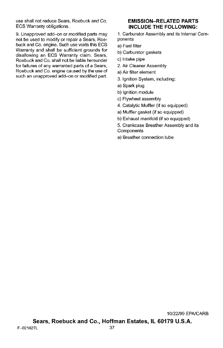
EMISSION-RELATEDPARTS
INCLUDE THE FOLLOWING:
1. Carburetor Assembly and its Internal Com-
ponents
a) Fuel filter
b) Carburetor gaskets
c) Intake pipe
2. Air Cleaner Assembly
a) Air filter element
3. Ignition System, including:
a) Spark plug
b) Ignition module
c) Flywheel assembly
4. Catalytic Muffler (if so equipped)
a) Muffler gasket (if so equipped)
b) Exhaust manifold (if so equipped)
5. Crankcase Breather Assembly and its
Components
a) Breather connection tube
10/22/99 EPA!CARB
Sears, Roebuck and Co., Hoffman Estates, IL 60179 U.S.A.
F_)21027L 37
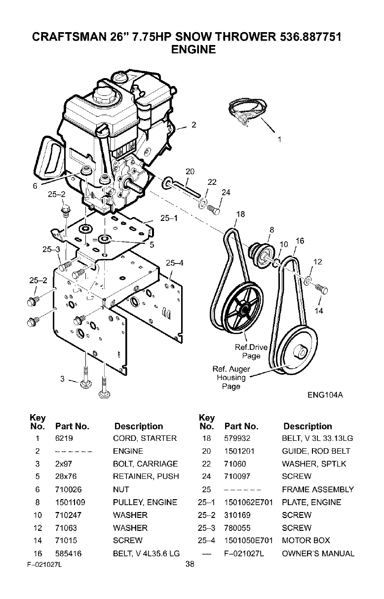
CRAFTSMAN 26" 7.75HP SNOW THROWER 536.887751
ENGINE
2
1
25-3
25-2
25-2
22
24
/
18
/8
16
12
/
/
14
Key
No. Pad No.
1 6219
2
3 2x97
5 28x76
6 710026
8 1501109
10 710247
12 71063
14 71015
16 585416
F_321027L
Description
CORD, STARTER
ENGINE
BOLT, CARRIAGE
RETAINER, PUSH
NUT
PULLEY, ENGINE
WASHER
WASHER
SCREW
BELT, V 4L35.6 LG
Ref, Drive
Page
Ref, Auger
Housing
Page ENG104A
Key
No. Pad No. Description
18 579932 BELT, V3L 33.13LG
20 1501201 GUIDE, ROD BELT
22 71060 WASHER, SPTLK
24 710097 SCREW
25 FRAME ASSEMBLY
25-1 1501062E701 PLATE, ENGINE
25-2 310169 SCREW
25-3 780055 SCREW
25-4 1501050E701 MOTOR BOX
-- Fq)21027L OWNER'S MANUAL
38
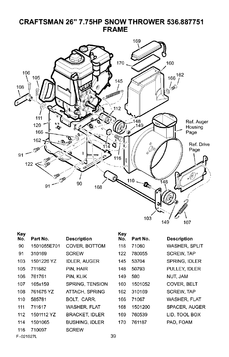
CRAFTSMAN 26" 7.75HP SNOW THROWER 536.887751
FRAME
169
106
\
106
170 160
162
111
qo Ref, Auger
120 Housing
Page
162
91
122
/
91 / 90 168
Ref, Drive
Page
Key
No. Part No.
90 1501055E701
91 310169
103 1501226YZ
105 711682
106 761761
107 165x159
108 761675YZ
110 585781
111 711617
112 1501112YZ
114 1501065
116 710097
F_321027L
/
103
Key
Description No. Part No.
COVER, BOTTOM 118 71060
SCREW 122 780055
IDLER, AUGER 145 53704
PiN, HAIR 148 50793
PiN, KLIK 149 590
SPRING, TENSION 160 1501052
ATTACH, SPRING 162 310169
BOLT, CARR. 166 71067
WASHER, FLAT 168 1501200
BRACKET, iDLER 169 760539
BUSHING, IDLER 170 761187
SCREW
39
149 107
Description
WASHER, SPLIT
SCREW, TAP
SPRING, IDLER
PULLEY, IDLER
NUT, JAM
COVER, BELT
SCREW, TAP
WASHER, FLAT
SPACER, AUGER
LID, TOOL BOX
PAD, FOAM
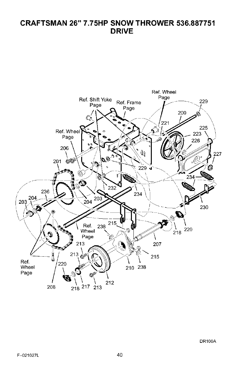
CRAFTSMAN 26" 7.75HP SNOW THROWER 536.887751
DRIVE
Ref. Wheel
Ref. Shift Yoke Page
Page Ref, Frame 229
Page
Page 225 /
\
201
227
/
/236
Ref,
Wheel
Page
208 218 217 213
212
2O7
215
210 238
23O
\
'18 220
DR100A
F_321027L 40
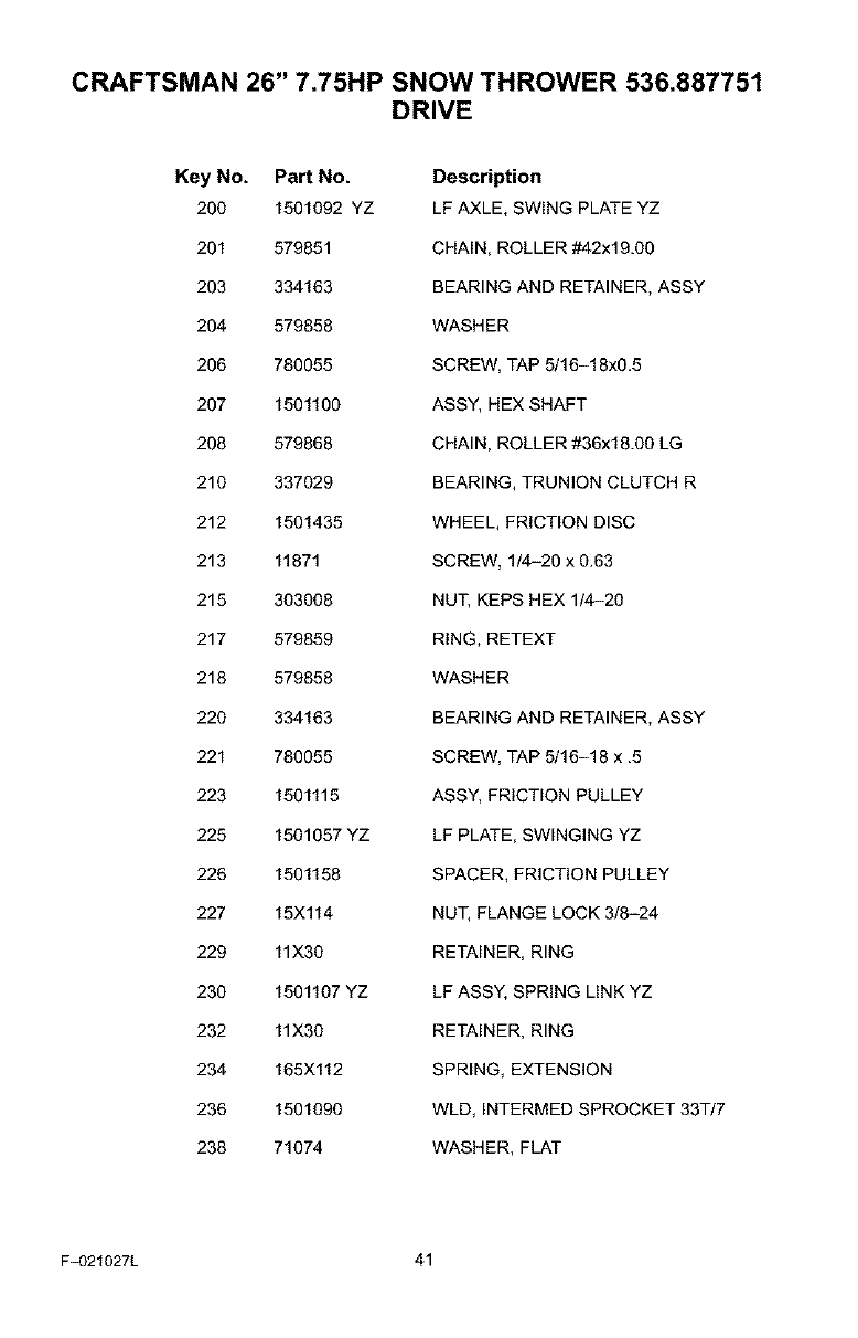
CRAFTSMAN 26" 7.75HP SNOW THROWER 536.887751
DRIVE
Key No. PaN No.
200 1501092 YZ
201 579851
203 334163
204 579858
206 780055
207 1501100
208 579868
210 337029
212 1501435
213 11871
215 303008
217 579859
218 579858
220 334163
221 780055
223 1501115
225 1501057 YZ
228 1501158
227 15X114
229 11X30
230 1501107 YZ
232 11X30
234 165X112
236 1501090
238 71074
Description
LF AXLE, SWING PLATE YZ
CHAIN, ROLLER #42x19.00
BEARING AND RETAINER, ASSY
WASHER
SCREW, TAP 5/16-18x0_5
ASS'(, HEX SHAFT
CHAIN, ROLLER #36x18.00 LG
BEARING, TRUNION CLUTCH R
WHEEL, FRICTION DISC
SCREW, 1/4-20 x 0_63
NUT, KEPS HEX 1/4-20
RING, RETEXT
WASHER
BEARING AND RETAINER, ASSY
SCREW, TAP 5/16-18 x .5
ASS'(, FRICTION PULLEY
LF PLATE, SWINGING YZ
SPACER, FRICTION PULLEY
NUT, FLANGE LOCK 3/8-24
RETAINER, RING
LF ASSY, SPRING LINK YZ
RETAINER, RING
SPRING, EXTENSION
WLD, INTERMED SPROCKET 33T/7
WASHER, FLAT
F_321027L 41
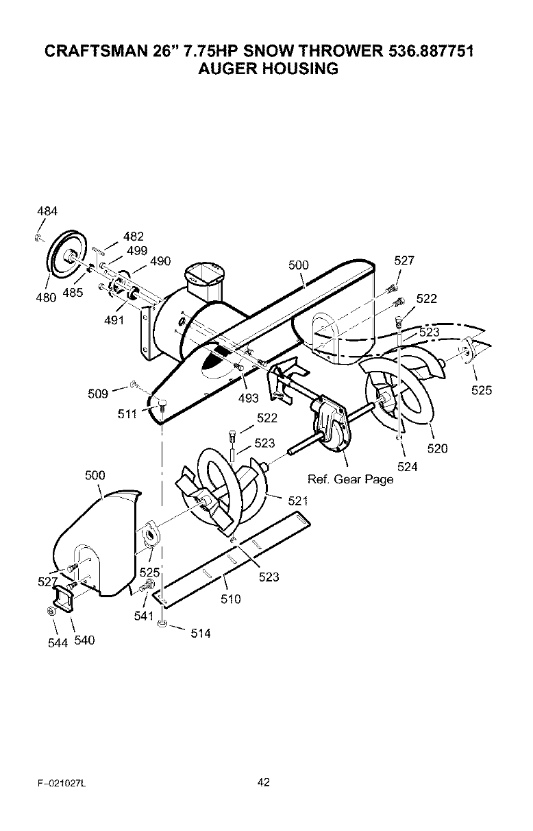
CRAFTSMAN 26" 7.75HP SNOW THROWER 536.887751
AUGER HOUSING
484
/
480
482
499 490
491
5OO 527
522
5OO
522 \
\ 520
524
Ref. Gear Page
521
\
525
\\
544 540
523
510
F_321027L 42
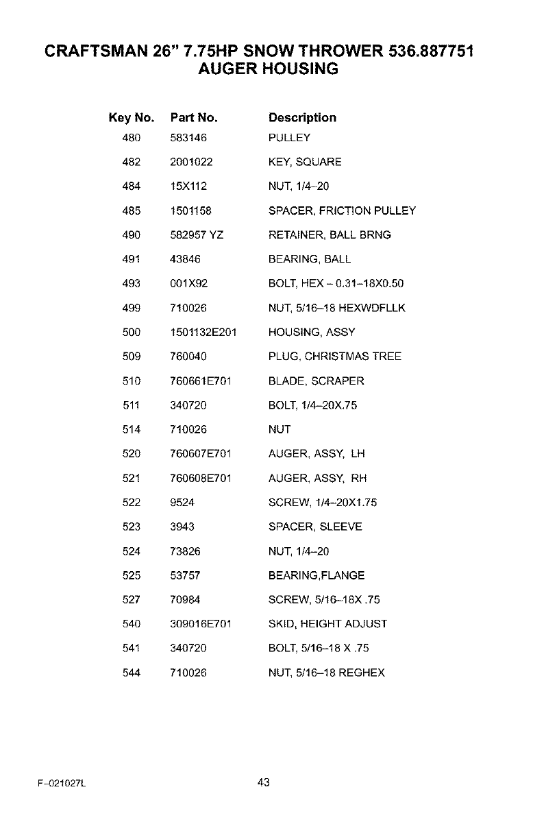
CRAFTSMAN 26" 7.75HP SNOW THROWER 536.887751
AUGER HOUSING
Key No. Part No. Description
480 583146 PULLEY
482 2001022 KEY, SQUARE
484 15Xl12 NUT, 1/4-20
485 1501158 SPACER, FRICTION PULLEY
490 582957 YZ RETAINER, BALL BRNG
491 43846 BEARING, BALL
493 001X92 BOLT, HEX - 0.31-18X0.50
499 710026 NUT, 5/16-18 HEXWDFLLK
500 1501132E201 HOUSING, ASSY
509 760040 PLUG, CHRISTMAS TREE
510 760661E701 BLADE, SCRAPER
511 340720 BOLT, 1/4-20X.75
514 710026 NUT
520 760607E701 AUGER, ASSY, LH
521 760608E701 AUGER, ASSY, RH
522 9524 SCREW, 1/4-20X1.75
523 3943 SPACER, SLEEVE
524 73826 NUT, 1/4-20
525 53757 BEARING,FLANGE
527 70984 SCREW, 5/16-18X .75
540 309016E701 SKID, HEIGHT ADJUST
541 340720 BOLT, 5/16-18 X .75
544 710026 NUT, 5/16-18 REGHEX
F_321027L 43
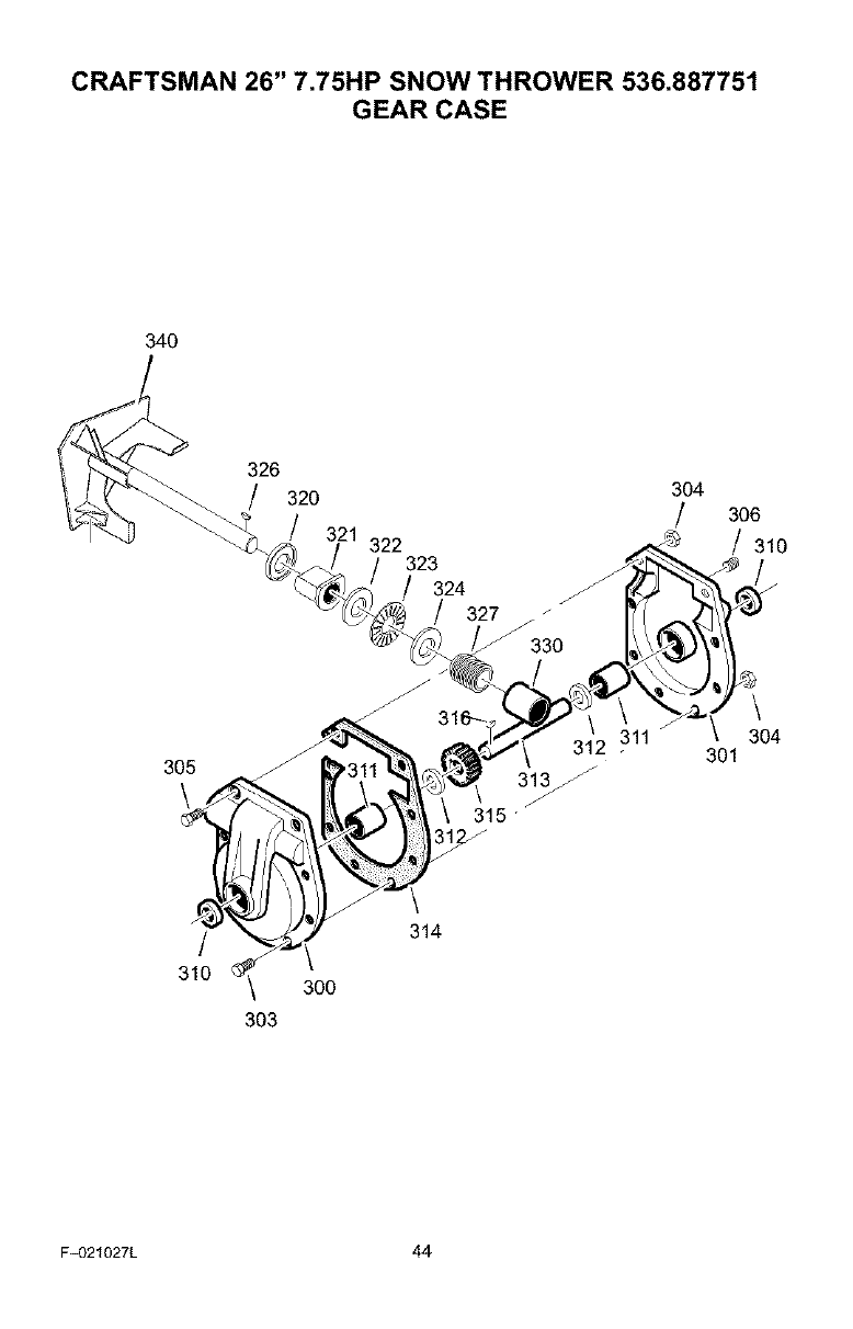
CRAFTSMAN 26" 7.75HP SNOW THROWER 536.887751
GEAR CASE
340
326
/320 304
/306
/321 322 /310
323
324
/327
305
\
312 311
15
301
\
304
314
/\
310 _ 300
303
F_321027L 44
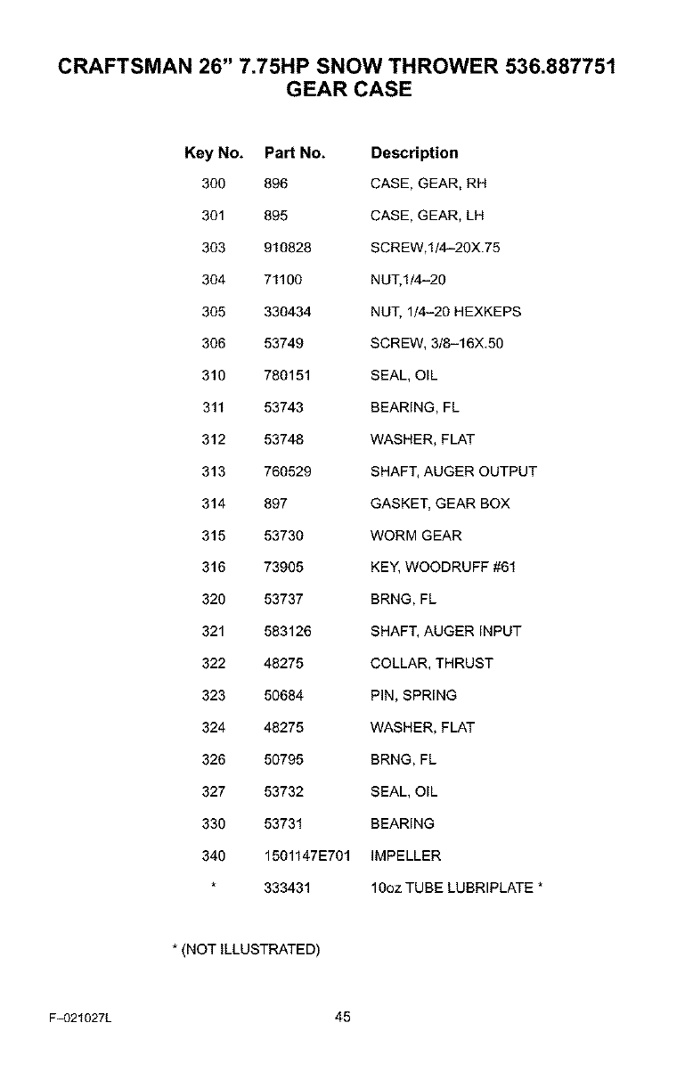
CRAFTSMAN 26" 7.75HP SNOW THROWER 536.887751
GEAR CASE
Key No. Part No. Description
300 896 CASE, GEAR, RH
301 895 CASE, GEAR, LH
303 910828 SCREW,1/4-20X.75
304 71100 NUT, I/4-20
305 330434 NUT, 1/4-20 HEXKEPS
306 53749 SCREW, 3/8-16X,50
310 780151 SEAL, OIL
311 53743 BEARING, FL
312 53748 WASHER, FLAT
313 760529 SHAFT, AUGER OUTPUT
314 897 GASKET, GEAR BOX
315 53730 WORM GEAR
316 73905 KEY, WOODRUFF #61
320 53737 BRNG, FL
321 583126 SHAFT, AUGER INPUT
322 48275 COLLAR, THRUST
323 50684 PIN, SPRING
324 48275 WASHER, FLAT
326 50795 BRNG, FL
327 53732 SEAL, OIL
330 53731 BEARING
340 1501147E701 IMPELLER
333431 10oz TUBE LUBRIPLATE *
* (NOT ILLUSTRATED)
F_321027L 45
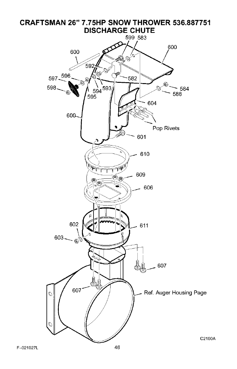
CRAFTSMAN 26" 7.75HP SNOW THROWER 536.887751
DISCHARGE CHUTE
599 583
6OO
6OO
609
606
602 611
Ref. Auger Housing Page
F_321027L 46
C2100A
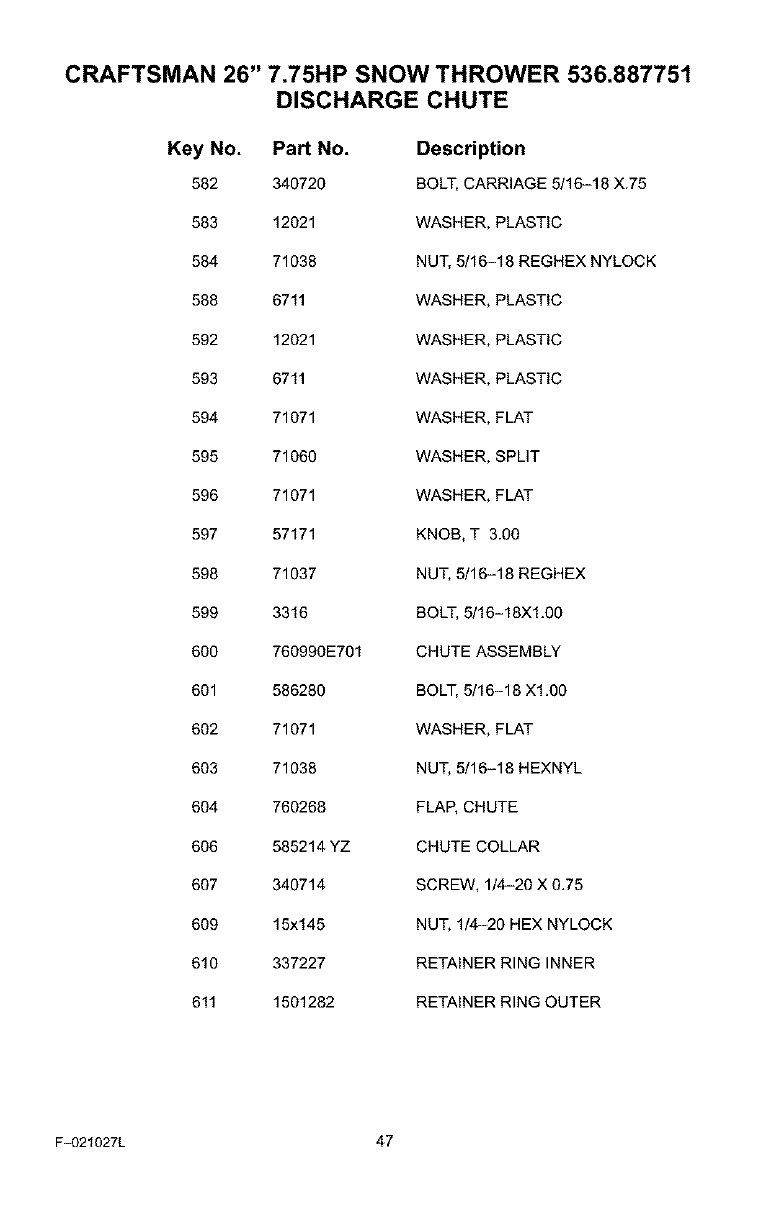
CRAFTSMAN 26" 7.75HP SNOW THROWER 536.887751
DISCHARGE CHUTE
Key No. Part No. Description
582 340720 BOLT, CARRIAGE 5/16-18 X.75
583 12021 WASHER, PLASTIC
584 71038 NUT, 5/16-18 REGHEX NYLOCK
588 6711 WASHER, PLASTIC
592 12021 WASHER, PLASTIC
593 6711 WASHER, PLASTIC
594 71071 WASHER, FLAT
595 71060 WASHER, SPLIT
596 71071 WASHER, FLAT
597 57171 KNOB, T 3.00
598 71037 NUT, 5/16-18 REGHEX
599 3316 BOLT, 5/16-18X1.00
600 760990E701 CHUTE ASSEMBLY
601 586280 BOLT, 5/16-18 X1.00
602 71071 WASHER, FLAT
603 71038 NUT, 5/16-18 HEXNYL
604 760268 FLAP, CHUTE
606 585214 YZ CHUTE COLLAR
607 340714 SCREW, 1/4-20 X 0.75
609 15x145 NUT, 1/4-20 HEX NYLOCK
610 337227 RETAINER RING INNER
611 1501282 RETAINER RING OUTER
F_321027L 47
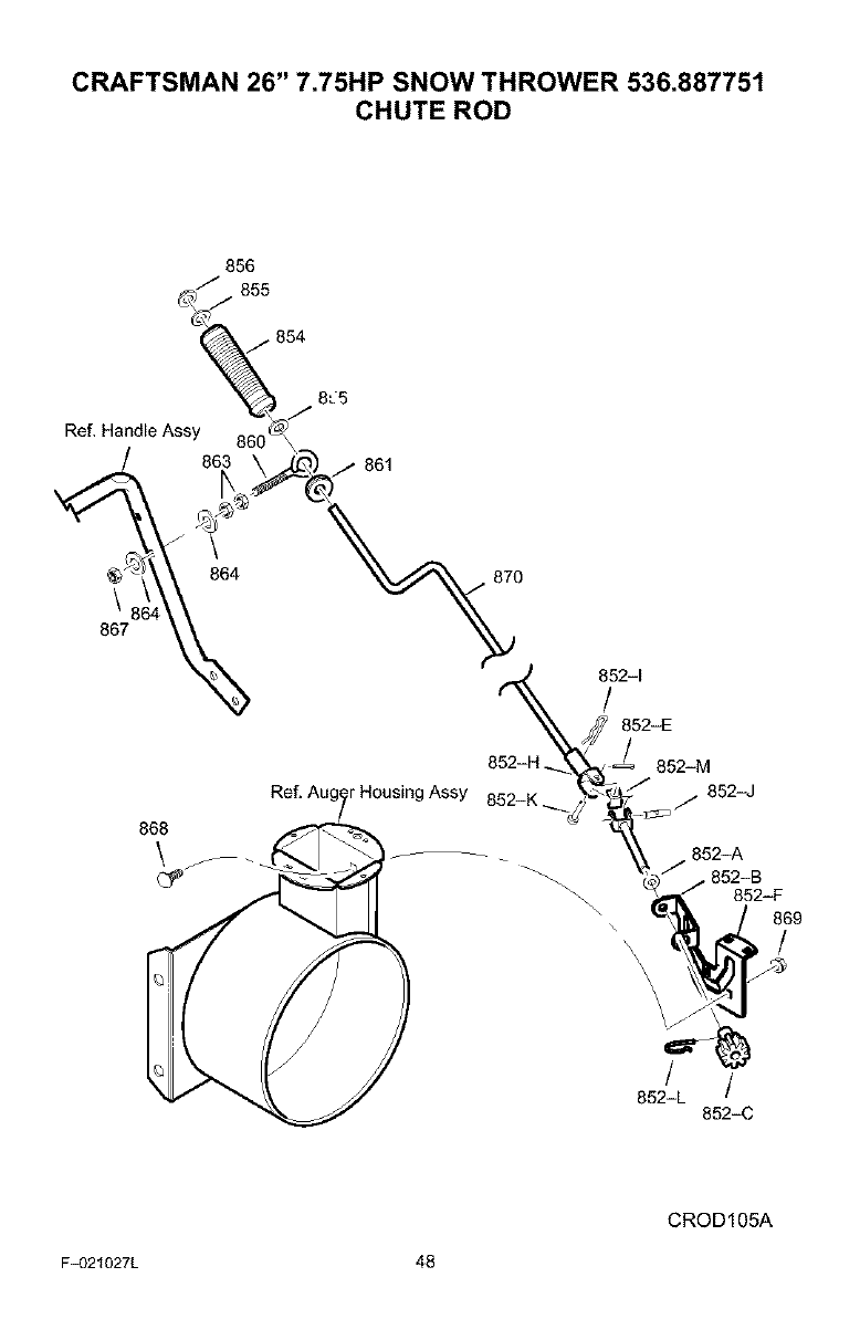
CRAFTSMAN 26" 7.75HP SNOW THROWER 536.887751
CHUTE ROD
856
855
854
Ref, Handle Assy 86_0_J
\
867
r Housing Assy 852-K
868
852-1
/852-E
2852-M
852-J
•852-B
_52-L /
852-C
852-F
869
/
CROD105A
F_321027L 48
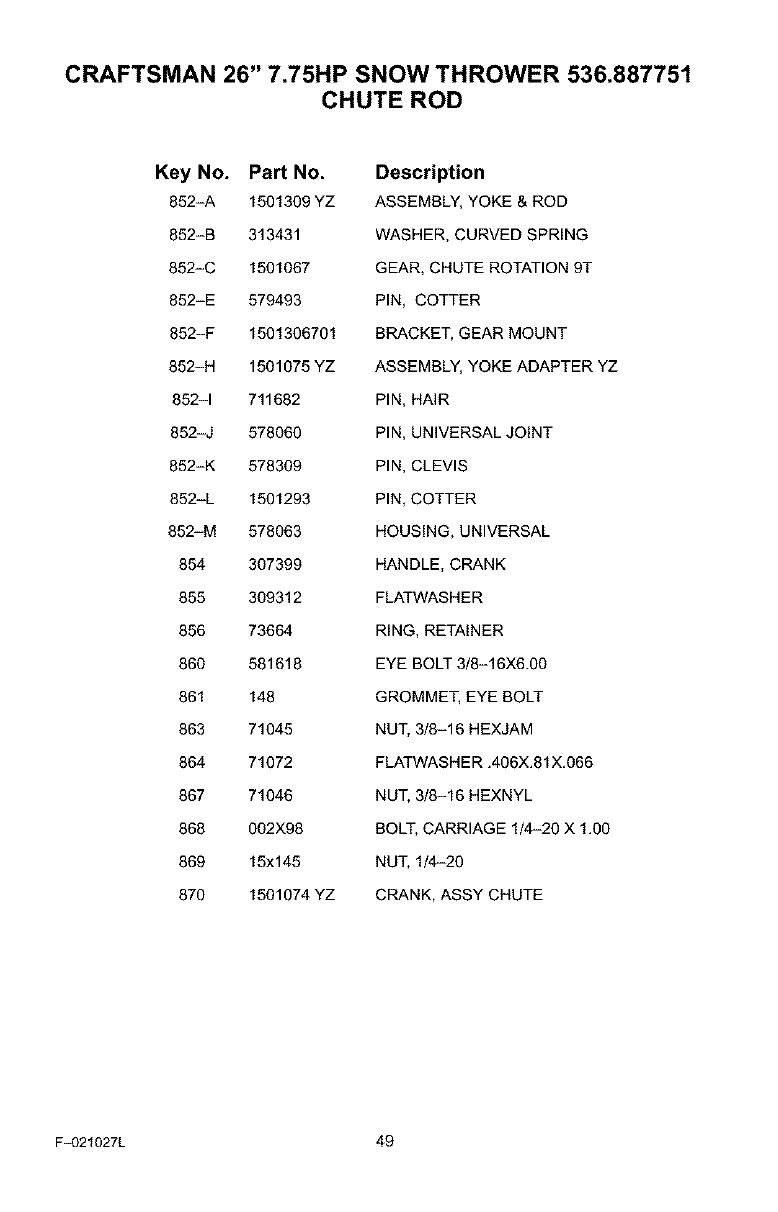
CRAFTSMAN 26" 7.75HP SNOW THROWER 536.887751
CHUTE ROD
Key No. Part No. Description
852-A 1501309 YZ ASSEMBLY, YOKE & ROD
852-B 313431 WASHER, CURVED SPRING
852-C 1501067 GEAR, CHUTE ROTATION 9T
852-E 579493 PIN, COTTER
852-F 1501306701 BRACKET, GEAR MOUNT
852-H 1501075 YZ ASSEMBLY, YOKE ADAPTER YZ
852-1 711682 PIN, HAIR
852-J 578060 PIN, UNIVERSAL JOINT
852-K 578309 PIN, CLEVIS
852-L 1501293 PIN, COTTER
852-M 578063 HOUSING, UNIVERSAL
854 307399 HANDLE, CRANK
855 309312 FLATWASHER
856 73664 RING, RETAINER
860 581618 EYE BOLT 3/8-16X6.00
861 148 GROMMET, EYE BOLT
863 71045 NUT, 3/8-16 HEXJAM
864 71072 FLATWASHER .406X.81X.066
867 71046 NUT, 3/8-16 HEXNYL
868 002X98 BOLT, CARRIAGE 1/4-20 X 1.00
869 15x145 NUT, 1/4-20
870 1501074 YZ CRANK, ASSY CHUTE
F_321027L 49
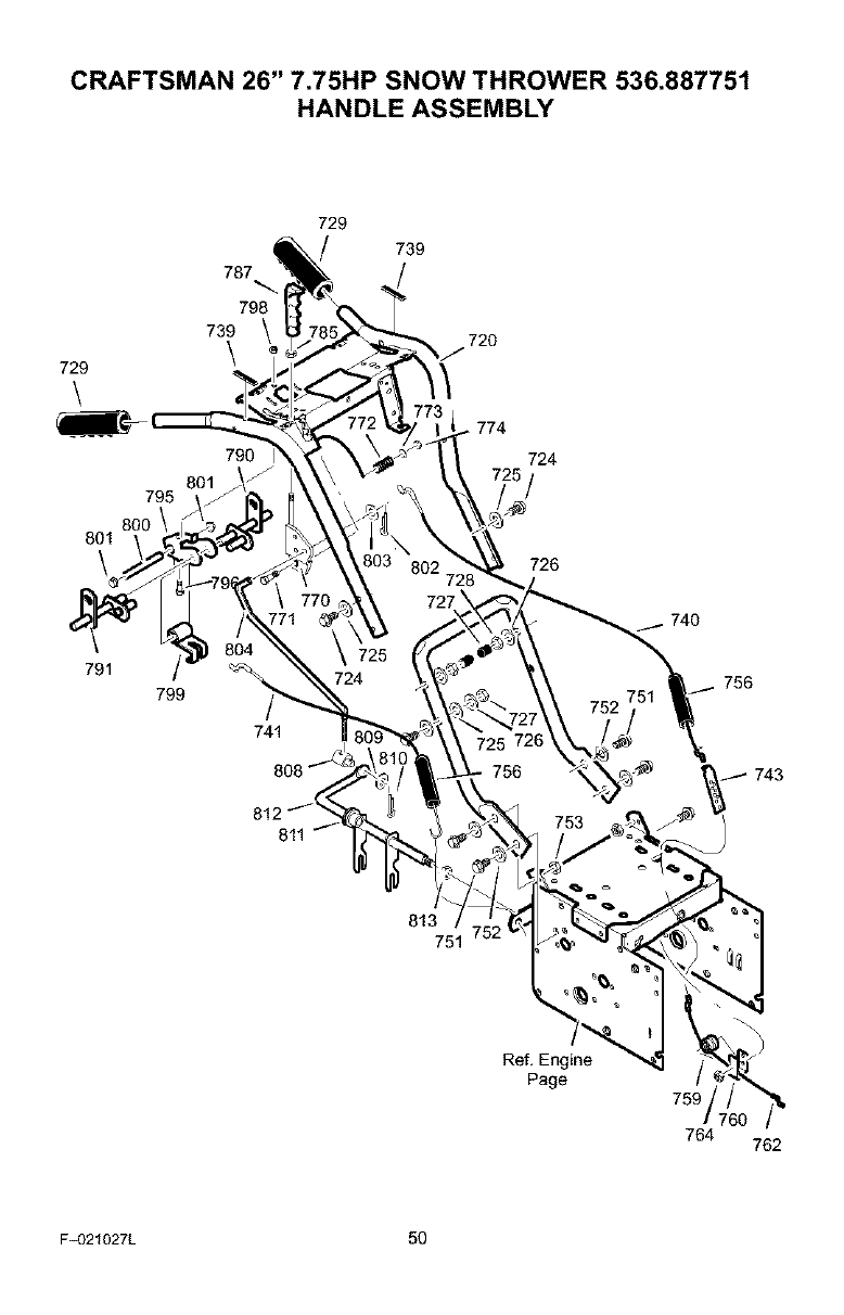
CRAFTSMAN 26" 7.75HP SNOW THROWER 536.887751
HANDLE ASSEMBLY
729
\
795
801
\
787
798
739
\
801
729
790 I
739
72O
774
724
726
791
741
740
756
743
813
751
Ref, Engine
Page 759
764 762
F_321027L 50
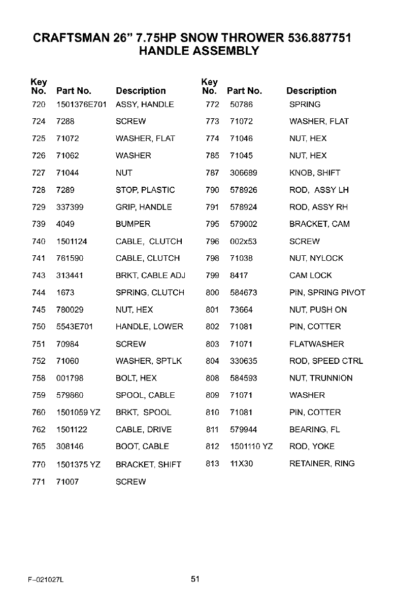
CRAFTSMAN 26" 7.75HP SNOW THROWER 536.887751
HANDLE ASSEMBLY
Key Key
No. Part No. Description No. Part No. Description
720 1501376E701 ASSY, HANDLE 772 50786 SPRING
724 7288 SCREW 773 71072 WASHER, FLAT
725 71072 WASHER, FLAT 774 71046 NUT, HEX
726 71062 WASHER 785 71045 NUT, HEX
727 71044 NUT 787 306689 KNOB, SHIFT
728 7289 STOP, PLASTIC 790 578926 ROD, ASSY LH
729 337399 GRIP, HANDLE 791 578924 ROD, ASSY RH
739 4049 BUMPER 795 579002 BRACKET, CAM
740 1501124 CABLE, CLUTCH 796 002x53 SCREW
741 761590 CABLE, CLUTCH 798 71038 NUT, NYLOCK
743 313441 BRKT, CABLE ADJ 799 8417 CAM LOCK
744 1673 SPRING, CLUTCH 800 584673 PIN, SPRING PIVOT
745 780029 NUT, HEX 801 73664 NUT, PUSH ON
750 5543E701 HANDLE, LOWER 802 71081 PIN, COTTER
751 70984 SCREW 803 71071 FLATWASHER
752 71060 WASHER, SPTLK 804 330635 ROD, SPEED CTRL
758 001798 BOLT, HEX 808 584593 NUT, TRUNNION
759 579860 SPOOL, CABLE 809 71071 WASHER
760 1501059 YZ BRKT, SPOOL 810 71081 PIN, COTTER
762 1501122 CABLE, DRIVE 811 579944 BEARING, FL
765 308146 BOOT, CABLE 812 1501110 YZ ROD, YOKE
770 1501375 YZ BRACKET, SHIFT 813 11X30 RETAINER, RING
771 71007 SCREW
F_321027L 51
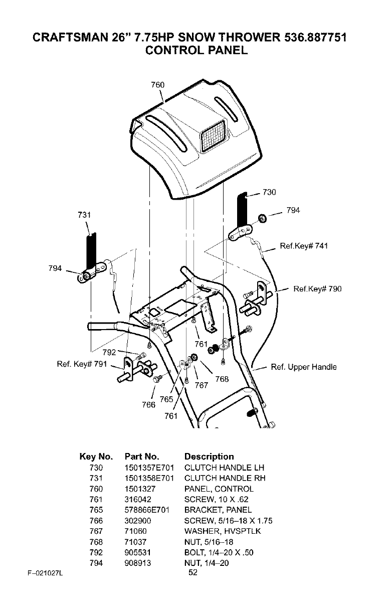
CRAFTSMAN 26" 7.75HP SNOW THROWER 536.887751
CONTROL PANEL
731
\
794
Ref.Key# 741
Ref.Key# 790
Ref. Key# 791 Jpper Handle
766
761
F_321027L
Key No. Part No. Description
730 1501357E701 CLUTCH HANDLE LH
731 1501358E701 CLUTCH HANDLE RH
760 1501327 PANEL, CONTROL
761 316042 SCREW, 10 X .62
765 578866E701 BRACKET, PANEL
766 302900 SCREW, 5/16-18 X 1.75
767 71060 WASHER, HVSPTLK
768 71037 NUT, 5/16-18
792 905531 BOLT, 1/4-20 X .50
794 908913 NUT, 1/4-20
52
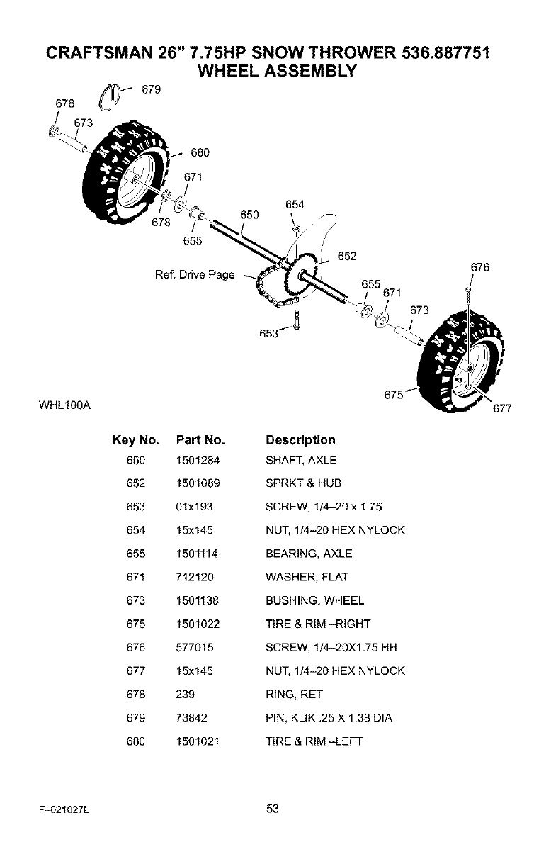
CRAFTSMAN 26" 7.75HP SNOW THROWER 536.887751
WHEEL ASSEMBLY
679
678
/
680
671
654
650
655
652 676
Ref. Drive Page /
WHL100A
Key No. Part No. Description
650 1501284 SHAFT, AXLE
652 1501089 SPRKT & HUB
653 01x193 SCREW, 1/4-20 x 1.75
654 15x145 NUT, 1/4-20 HEX NYLOCK
655 1501114 BEARING, AXLE
671 712120 WASHER, FLAT
673 1501138 BUSHING, WHEEL
675 1501022 TIRE & RIM -RIGHT
676 577015 SCREW, 1/4-20Xl.75 HH
677 15x145 NUT, 1/4-20 HEX NYLOCK
678 239 RING, RET
679 73842 PIN, KLIK .25 X 1.38 DIA
680 1501021 TIRE & RIM -LEFT
677
F_321027L 53
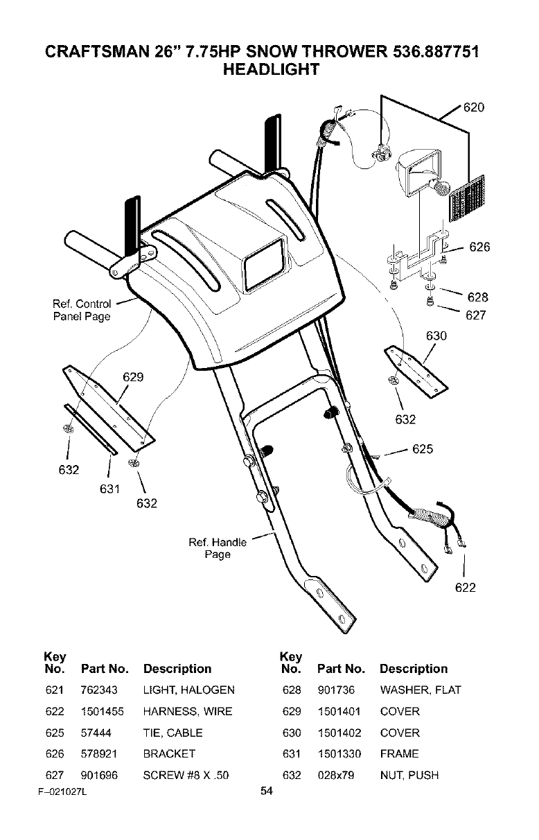
CRAFTSMAN 26" 7.75HP SNOW THROWER 536.887751
HEADLIGHT
626
Ref. Control
Panel Page
S
632
Ref. Handle
Page I
622
Key
No. Part No.
621 762343
622 1501455
625 57444
626 578921
627 901696
F_321027L
Description
LIGHT, HALOGEN
HARNESS, WIRE
TIE, CABLE
BRACKET
SCREW #8 X .50
54
Key
No. Part No. Description
628 901736 WASHER, FLAT
629 1501401 COVER
630 1501402 COVER
631 1501330 FRAME
632 028x79 NUT, PUSH
CRAFTSMAN 26" 7.75HP SNOW THROWER 536.887751
DECALS
Pa_ No.
48x2036
48x2034
48x4055
761079
48x4054
48x388
48x358
760983
48x393
Description
DECAL DANGER & FOOT *
DECAL DANGER CHUTE-HAND *
DECAL TRACTION DRIVE-ENGAGE (RED) *
DECAL DANGER STRIPE *
DECAL AUGER DRIVE-ENGAGE (RED) *
DECAL 7.75/26 CRAFTSMAN (RED) *
NAMEPLATE, CRAFTSMAN *
DECAL, TOOL BOX-BELT COVER *
DECAL, SCH. (RED) *
*Not illustrated
F_321027L 55
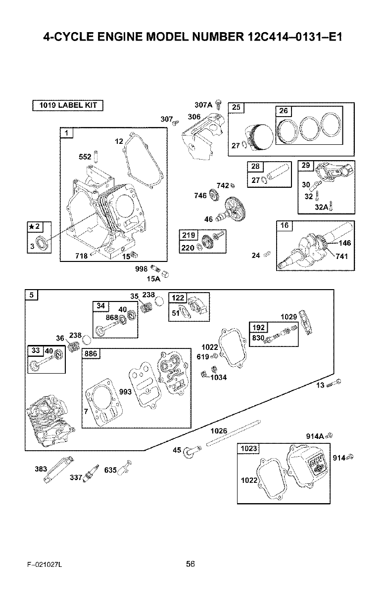
4-CYCLE ENGINE MODEL NUMBER 12C414-0131-E1
I1019 LABEL KtT I
36\
12
15A "
._" I._
"146
,_ _J-'_ _Y "741
F_321027L 56
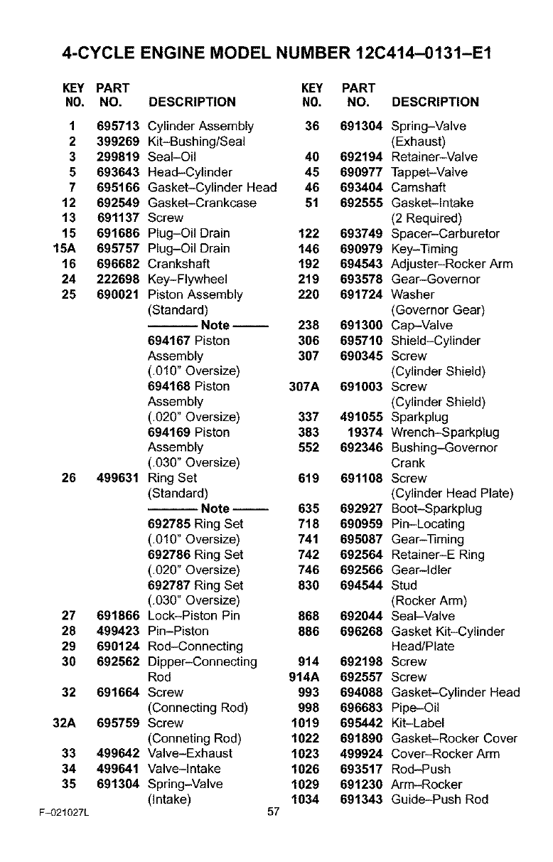
4-CYCLE ENGINE MODEL NUMBER 12C414-0131-E1
KEY PART KEY PART
NO. NO. DESCRIPTION NO. NO. DESCRIPTION
1 695713 Cylinder Assembly 36 691304 Spring-Valve
2399269 Kit-Bushing/Seal (Exhaust)
3 299819 Seal-Oil 40 692194 Retainer-Valve
5693643 Head-Cylinder 45 690977 Tappet-Valve
7 695166 Gasket-Cylinder Head 46 693404 Camshaft
12 692549 Gasket-Crankcase 51 692555 Gasket-intake
13 691137 Screw (2 Required)
15 691686 Plug-Oil Drain 122 693749 Spacer-Carburetor
15A 695757 Plug-Oil Drain 146 690979 Key-Timing
16 696682 Crankshaft 192 694543 Adjuster-Rocker Arm
24 222698 Key-Flywheel 219 693578 Gear-Governor
25 690021 Piston Assembly 220 691724 Washer
(Standard) (Governor Gear)
Note-- 238 691300 Cap-Valve
694167 Piston 306 695710 Shield-Cylinder
Assembly 307 690345 Screw
(.010" Oversize) (Cylinder Shield)
694168 Piston 307A 691003 Screw
Assembly (Cylinder Shield)
(.020" Oversize) 337 491055 Sparkplug
694169 Piston 383 19374 Wrench-Sparkplug
Assembly 552 692346 Bushing-Governor
(.030" Oversize) Crank
26 499631 Ring Set 619 691108 Screw
(Standard) (Cylinder Head Plate)
Note-- 635 692927 Boot-Sparkplug
692785 Ring Set 718 690959 Pin-Locating
(.010" Oversize) 741 695087 Gear-Timing
692786 Ring Set 742 692564 Retainer-E Ring
(.020" Oversize) 746 692566 Gear-idler
692787 Ring Set 830 694544 Stud
(.030" Oversize) (Rocker Arm)
27 691866 Lock-Piston Pin 868 692044 Seal-Valve
28 499423 Pin-Piston 886 696268 Gasket Kit-Cylinder
29 690124 Rod-Connecting Head/Plate
30 692562 Dipper-Connecting 914 692198 Screw
Rod 914A 692557 Screw
32 691664 Screw 993 694088 Gasket-Cylinder Head
(Connecting Rod) 998 696683 Pipe-Oil
32A 695759 Screw 1019 695442 Kit-Label
(Conneting Rod) 1022 691890 Gasket-Rocker Cover
33 499642 Valve-Exhaust 1023 499924 Cover-RockerArm
34 499641 Valve-intake 1026 693517 Rod-Push
35 691304 Spring-Valve 1029 691230 Arm-Rocker
(Intake) 1034 691343 Guide-Push Rod
F_321027L 57
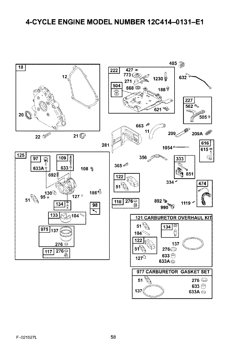
4-CYCLE ENGINE MODEL NUMBER 12C414-0131-E1
1,;
lO8
485 _
222 427 _';
365 _
1054_--
356U_'_
334 _
892_ 1119 _
99o_ _
121 CARBURETOR OVERHAUL KIT
104_
137276_0
127_633_/
633A_
977 CARBURETOR GASKET SET
51_ 276 _
633 _
633A _
F_321027L 58
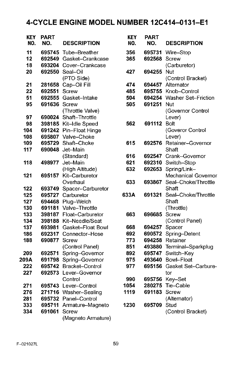
4-CYCLE ENGINE MODEL NUMBER 12C414-0131-E1
KEY PART KEY PART
NO. NO. DESCRIPTION NO. NO. DESCRIPTION
11 695745
12 692549
18 693204
20 692550
21 281658
22 692551
51 692555
95 691636
97 690024
98 398185
104 691242
108 695807
109 695729
117 690048
118 498977
121 695157
122 693749
125 695727
127 694468
130 691181
133 398187
134 398188
137 693981
186 692317
188 690877
209 692571
209A 691798
222 695742
227 692573
271 695743
276 271716
281 695732
333 695711
334 691061
Tube-Breather 356 695731 Wire-Stop
Gasket-Crankcase 365 692568 Screw
Cover-Crankcase (Carburetor)
Seal-Oil 427 694255 Nut
(PTO Side) (Control Bracket)
Cap-Oil Fill 474 694457 Alternator
Screw 485 695755 Knob-Control
Gasket-Intake 504 694254 Washer Set-Friction
Screw 505 691251 Nut
(Throttle Valve) (Governor Control
Shaft-Throttle Lever)
Kit-Idle Speed 562 691112 Bolt
Pin-Float Hinge (Goveror Control
Valve-Choke Lever)
Shaft-Choke 615 692576 Retainer-Governor
Jet-Main Shaft
(Standard) 616 692547 Crank-Governor
Jet-Main 621 692310 Switch-Stop
(High Altitude) 632 692653 Spring/Link-
Kit-Carburetor Mechanical Governor
Overhaul 633 693867 Seal-Choke/Throttle
Spacer-Carburetor Shaft
Carburetor 633A 691321 Seal-Choke/Throttle
Plug-Welch Shaft
Valve-Throttle (Throttle)
Float-Carburetor 663 696685 Screw
Kit-Needle/Seat (Control Panel)
Gasket-Float Bowl 668 694257 Spacer
Connector-Hose 692 690572 Spring-Detent
Screw 773 694258 Retainer
(Control Panel) 851 493880 TerminaI-Sparkplug
Spring-Governor 892 695747 Switch-Key
Spring-Governor 975 493640 Bowl-Float
Bracket-Control 977 695156 Gasket Set-Carbure-
Lever-Governor tor
Control 990 695756 Key-Set
Lever-Control 1054 280275 Tie-Cable
Washer-Sealing 1119 691183 Screw
Panel-Control (Alternator)
Armature-Magneto 1230 695709 Stud
Screw (Control Bracket)
(Magneto Armature)
F_321027L 59
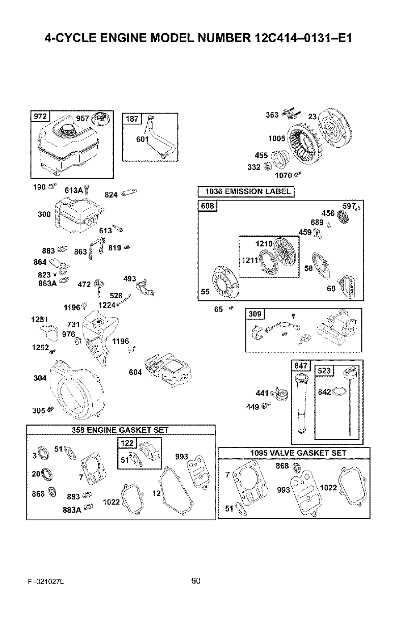
4-CYCLE ENGINE MODEL NUMBER 12C414-0131-E1
190_ 613A_ 824_
1251
305_
358 ENGINE GASKET SET
1070_
1036 EMISSION LABEL I
608J 456_97_,
689
459_
1095 VALVE GASKET SET
F_321027L 60
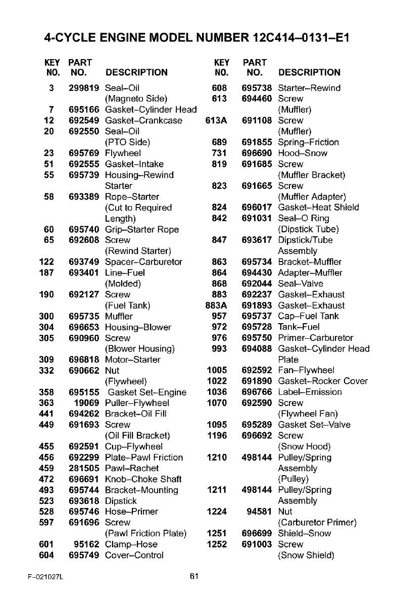
4-CYCLE ENGINE MODEL NUMBER 12C414-0131-E1
KEY PART KEY PART
NO. NO. DESCRIPTION NO. NO. DESCRIPTION
3 299819
7 695166
12 692549
20 692550
23 695769
51 692555
55 695739
58 693389
60 695740
65 692608
122 693749
187 693401
190 692127
300 695735
304 696653
305 690960
309 696818
332 690662
358 695155
363 19069
441 694262
449 691693
455 692591
456 692299
459 281505
472 696691
493 695744
523 693618
528 695746
597 691696
601 95162
604 695749
Seal-Oil 608 695738 Starter-Rewind
(Magneto Side) 613 694460 Screw
Gasket-Cylinder Head (Muffler)
Gasket-Crankcase 613A 691108 Screw
Seal-Oil (Muffler)
(PTO Side) 689 691855 Spring-Friction
Flywheel 731 696690 Hood-Snow
Gasket-Intake 819 691685 Screw
Housing-Rewind (Muffler Bracket)
Starter 823 691665 Screw
Rope-Starter (Muffler Adapter)
(Cut to Required 824 696017 Gasket-Heat Shield
Length) 842 691031 SeaI-O Ring
Grip-Starter Rope (Dipstick Tube)
Screw 847 693617 Dipstick/Tube
(Rewind Starter) Assembly
Spacer-Carburetor 863 695734 Bracket-Muffler
Line-Fuel 864 694430 Adapter-Muffler
(Molded) 868 692044 Seal-Valve
Screw 883 692237 Gasket-Exhaust
(Fuel Tank) 883A 691893 Gasket-Exhaust
Muffler 957 695737 Cap-Fuel Tank
Housing-Blower 972 695728 Tank-Fuel
Screw 976 695750 Primer-Carburetor
(Blower Housing) 993 694088 Gasket-Cylinder Head
Motor-Starter Plate
Nut 1005 692592 Fan-Flywheel
(Flywheel) 1022 691890 Gasket-Rocker Cover
Gasket Set-Engine 1036 696766 Label-Emission
Puller-Flywheel 1070 692590 Screw
Bracket-Oil Fill (Flywheel Fan)
Screw 1095 695289 Gasket Set-Valve
(Oil Fill Bracket) 1196 696692 Screw
Cup-Flywheel (Snow Hood)
Plate-Pawl Friction 1210 496144 Pulley/Spring
PawI-Rachet Assembly
Knob-Choke Shaft (Pulley)
Bracket-Mounting 1211 496144 Pulley/Spring
Dipstick Assembly
Hose-Primer 1224 94581 Nut
Screw (Carburetor Primer)
(Pawl Friction Plate) 1251 696699 Shield-Snow
Clamp-Hose 1252 691003 Screw
Cover-Control (Snow Shield)
F_321027L 61

F_)21027L 62
[_o] _I I_ _II ,,[o]
PIEZASDEREPUESTO ............ 38
PIEZASDEREPUESTO- MOTOR .... 56
GARANTIA ..................... 63
REGLASDESEGURIDAD .......... 63
SIMBOLOSINTERNACIONALES..... 66
ENSAMBLAJE................... 68
OPERACI(_N ....................
MANTENIMIENTO ................
SERVICIOY AJUSTES.............
ALMACENAMIENTO ..............
TABLADE LOCALIZACK_NY
REPARACI(_NDEAVERIAS .....
PEDIDODE PIEZAS/SERVICIO.......
74
81
84
95
96
100
[eY.,1zlr.,1_lmi_.,ll
GARANTiA LIMITADA DE DOS AI_IOS PAPA EL QUITANIEVES CRAFTSMAN
Durante dos afios a partir de la fecha de compra, siempre que a este quitanieves Craftsman se le
d6 mantenimiento, lubricaci6n y afinamiento de acuerdo con las instrucciones de operaci6n y man*
tenimiento presentadas en el manual del usuario, Sears reparar& sin cargo alguno, cualquier defec*
to en material y mano de obra.
Si este quitanieves Craftsman es usado con propbsitos comerciales o de arrendamiento, esta ga*
rantia set& v_lida solamente pot 90 dias a partir de la fecha de compra.
Esta garantia no cubre Io siguiente:
Elementos de desgaste normal, tales corno bujias, correas de transmisi6n y pasadores de segu*
ridad.
Reparaciones necesarias debido al abuso o negligencia del operador, incluyendo varillas dobla-
dos y otras reparaciones necesarias por falta del mantenimiento a la unidad seg6n Io recomen*
dado en las instrucciones contenidas en el manual del propietario.
EL SERVICIO DE GARANTiA SE PUEDE OBTENER LLEVANDO EL QUITANIEVES AL CEN-
TRO DE SERVIClO SEARS MAS CERCANO EN LOS ESTADOS UNIDOS. ESTA GARANTJA ES
VALIDA SOLO CUANDO ESTE PRODUCTO ES USADO EN LOS ESTADOS UNIDOS.
Esta garantia le otorga derechos legales especificos, y asimismo es posible que tenga otros dere-
chos los cuales vadan de un estado a otro.
Sears, Roebuck and Co., D817WA, Hoffman Estates, IL 60179
IrJ =[__lJ rJ Im7.,Im]
Preste atenci6n a e.ste slmbolo, ]e indica precauciones de seguridad importantes. Sig-
nifica--iiiATENCION!!! iiiESTE ALERTA!!! Se trata de su seguridad.
Las emanaciones de escape producidas por este
motor y ciertos componentes de esta mbquina con-
tienen quimicos reconocidos por el Estado de Cali-
fornia como cercinbgenos, tembidn pueden produ-
cir defectos en los recidn nacidos o causar otros da-
_os al sistema reproductivo.
Los homes, terminales y accesorios relacionados
con le bateria contienen plomo y compuestos del
plomo, adembs de sustancias quimicas que el Esta-
do de California reconoce que estos compuestos
pueden causar cbncer y defectos como carcinbge-
nas, edembs estas sustencias pueden producir da-
_os congdnitos, elos bebds y adembs de otros da-
_os al sistema reproductivo humano. DEBE LAVAR-
SE MUY BIEN LAS MANOS DESPUES DE MANIPU-
LAR ESTOS COMPONENTES.
F_)21027L 63
_bk DVERTENCIA:
Siempre desconecte
el cable de la bujia y
colbquelo elejado de dsta
pare prevenir un arranque
accidental durante la prepa-
recibn mantenimiento o al-
macenamiento del quitanie-
ves.
IMPORTANTE: Para prevenir
lesiones, las nomlas de seguri-
dad exigen controles en la unidad
que s61o puedan ser manejados
en presencia del operador. Su
quitanieves esta equipado con
dichos controles. Por ningtin mo-
tivo intente pasar por alto la fun-
ci6n del control en presencia del
operador.
CAPACITACION
1. Lea con atenci6n las instrucciones en el
manual de operaci6n y servicio. Familiari-
cese completamente con los controles y
el uso apropiado del quitanieves. Apren-
daa detener el quitanieves y a desen-
ganchar r_pidamente los controles.
2. Nunca permita a niFLosoperar el quita-
nieves. Nunca permita que adultos ope-
ten el quitanieves sin la instrucci6n
apropiada.
3. Mantenga el _rea libre de personas, es-
pecialmente nifios pequefios y mascotas.
4. Tenga mucho cuidado para evitar resba-
Iones o caidas, especialmente cuando
est6 retrocediendo.
PREPARACION
1. Inspeccione completamente el area don-
de se usar_ el quitanieves y retire todas
las esteras, trineos, tableros, cables, y
otros objetos extrafios.
2. Desenganche todos los embragues antes
de hacer arrancar el motor.
3. No opere el quitanieves sin vestir pren-
das de invierno adecuadas para trabajar
a la intemperie. Vista calzado que le d6
buena tracci6n sobre superficies resbalo-
sas.
4. Maneje el combustible con cuidado; _ste
es altamente inflamable.
(a) Use un contenedor aprobado para
combustible.
(b) Nunca quite la tapa del tanque de
combustible ni aSada combustible a
un motor en marcha o a un motor ca-
Iiente.
(c) Llene el tanque de combustible al ai-
re libre y con mucho cuidado. Nunca
Ilene el tanque en un recinto cerrado.
y/o de] sol hace que el combustible
se expanda.
5. Para todos los quitanieves con motores
de arranque el6ctrico, use cables de ex-
tensi6n con cerfificaci6n CSNUL Use
solamente tomacorrientes que hayan si-
do instalados de acuerdo con los regla-
mentos de inspecci6n locales.
6. Jam_s intente efectuar ningt_n ajuste
mientras el motor se encuentra en mar-
cha (excepto cuando el fabricante Io re-
comiende asl especificamente).
7. Permita que el motor y el quitanieves se
ajusten a las temperaturas exteriores an-
tes de comenzar a despejar la nieve.
8. Siempre use gafas de seguridad o pro-
tectores para los ojos durante la opera-
ci6n o mientras efectt3a algQn ajuste o
reparaci6n a la unidad, para proteger sus
ojos de objetos extraSos qua pudiesen
ser lanzados por el quitanieves.
OPERACION
1. No opere este quitanieves si est_ toman-
do medicinas que puedan causar somno-
lencia o afectar su habilidad para operar
el quitanieves.
2. No use elquitanieves si por motivos
emocionales o ffsicos se le dificulta ma-
nejarlo de forma segura.
3. No coloque las manos o los pies cerca o
debajo de piezas en movimiento. Man-
t6ngase en todo momento a buena dis-
tancia de la abertura del tubo de
descarga.
4. Tenga mucho cuidado al operar el quita-
nieves en o a trav_s de entradas de au-
tos, senderos o caminos de grava.
Mant6ngase alerta de peligros ocultos o
tr_fico.
5.. Si golpea un objeto extraFIo, pare el mo-
tor, desconecte el cable de la bujla, ins-
peccione meticulosamente el quitanieves
pot si hub]era algt_n dafio, y reparelo an-
tes de arrancar el motor y operar el quita-
nieves nuevamente.
6. Si el quitanieves comienza a vibrar de
manera excesiva, pare el motor y revise-
Io inmediatamente para encontrar la cau-
sa. Generalmente, la vibraci6n es una
advertencia de alg_n problema.
7. Pare el motor cuando deje la posici6n de
operaci6n, antes de desobstruir el aloja-
miento de la barrena/propulsor o el tubo
de descarga, y cuando efectt_e cualquier
reparaci6n, ajuste o inspecci6n.
Cuando limp]e, repare o inspeccione el
quitanieves, asegt3rese de que la barre-
(d) Vuelva a colocar la tapa del tanque
de combustible de manera segura, y
limpie el combustible derramado.
(e) Nunca almacene combustible o el
quitanieves con combustible en el
tanque dentro de un edificio donde
los vapores pudiesen alcanzar algu-
na llama abierta o chispas.
(f) Verifique que el quitanieves tenga
suficiente combustible antes de cada
uso, y deje un espacio adicional en el 8.
tanque puesto que el calor del motor
F_)21027L 64
na/propulsorytodaslaspartesm6viles
seencuentrendetenidas,yquetodoslos
controlesest_ndeaenganchados.Desco-
necteel cable de la bujia y mant_ngalo
alejado de la bujfa para evitar un arran-
que accidental.
9. Tome todas las precauciones posibles al
dejar el quitanieves desatendido. Desen-
ganche la barrena/propulsor, pare el mo-
tor y retire la Ilave.
10. No haga arrancar el motor en recintos
cerrados, excepto para arrancar y para
transportar el quitanieves hacia adentro o
hacia afuera del recinto. Abra ]as puertas
que dan al exterior; los vapores de esca-
pe son peligrosos (contienen MONOXI-
DO DE CARBONO, un GAS INODORO y
LETAL).
11. No use el quitanieves para limpiar _reas
de terreno inclinadas (cuestas, pendien-
tes). Tenga mucho cuidado cuando cam-
bie de direcci6n. No intente limpiar
pendientes muy pronunciadas.
12. Nunca opere el quitanieves sin que los
resguardos, placas u otros dispositivos
de seguridad se encuentren en su ]ugar.
13. Nunca opere el quitanieves cerca de es-
caparates de vidrio, autom6viles, vidrie-
ras, sitios de carga/descarga, y similares,
sin el ajuste apropiado del _ngulo de des-
carga de la nieve. Mantenga a los niSos y
las mascotas alejados del area que est_
despejando.
14. No sobrecargue la capacidad del quita-
nieves al intentar limpiar la nieve a una
velocidad demasiado r&pida.
15. Nunca opere el quitanieves a altas veloci-
dades de transporte sobre superficies
resbalosas. Mire hacia atras y tenga cui-
dado al retroceder.
16. Nunca descargue directamente hacia es-
pectadores ni permita a nadie frente al
quitanieves.
17. Desenganche la fuerza motdz de la ba-
rrena/propulsor cuando el quitanieves
sea trasportado o no est6 en uso.
18. Utilice t_nicamente aditamentos y acceso-
dos aprobados por el fabricante del quita-
nieves (tales como cadenas para las
ruedas, juegos de arranque el_ctrico,
etc.).
19. Nunca opere el quitanieves sin tenet bue-
na visibilidad o iluminaci6n. AsegQrese
siempre que tiene buena estabilidad, y
sujete con firmeza el mango. Camine;
nunca corra.
20. No trate de alcanzar _reas dificiles. Man-
tenga la estabilidad y el balance en todo
momento.
21. No trate de usar el quitanieves para lim-
piar techos.
MANTENIMIENTO Y
ALMACENAMIENTO
1. Revise los pemos con frecuencia para
asegurar que est6n bien apretados y que
el quitanieves est_ en condicionea segu-
ras de funcionamiento.
2. Nunca guarde el quitanieves con com-
bustible en el tanque dentro de un recinto
donde hubieran fuentes de ignici6n tales
como calentadores de agua y estufas,
secadoras de ropa, y similarea. Pemlita
que el motor se enfrie antes de guardar
el quitanieves en cualquier recinto.
3. Siva a almacenar el quitanieves por un
periodo prolongado, siempre consulte las
instrucciones del manual del operador
donde encontrara consejos importantes.
4. Mantenga o reemplace laa etiquetas de
seguridad e instrucciones, segt_n sea ne-
cesario.
5. Mantenga el quitanieves en marcha unos
cuantos minutos despu_s de despejar la
nieve, para evitar que se congele la ba-
rrena/propulso_
_IL ADVERTENCIA: Este quitanieves
es para uso en eceras, entradas
de auto y otras superficies de te-
rreno plenas. Se debe tener cuidado al
usar el quitanieves en superficies inclina-
das. NO USE EL QUITANIEVES EN SU-
PERFICIES SOBRE EL NIVEL DEL SUELO
tales como techos de residencias, de ga-
rajes, porches uotras estructuras o cons-
trucciones similares.
F_)21027L 65
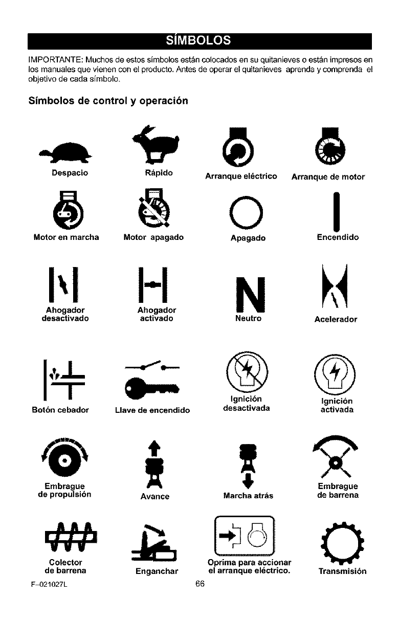
_o_o_
IMPORTANTE: Muchos de estos slmbolos est_n colocados en su quitanieves o est&n impresos en
los manuales que vienen con el producto, Antes de operar el quitanieves aprenda y comprenda el
objetivo de cada simbolo.
Simbolos de control y operacibn
Despacio R_pido Arranque el_ctrico
@ o Arranque de motor
I
Motor en marcha Motor apagado Apagado Encendido
I',I H N
Ahogador Ahogador
desactivado activado Neutro Acelerador
Botbn cebador Llave de encendido
® G
Ignicibn Ignicibn
desactivada activada
Embrague
de propulsibn
Colector
de barrena
F_)21027L
Avance Marcha atr&s de barrena
Enganchar Transmisibn
o
el arranque el_ctrico.
66
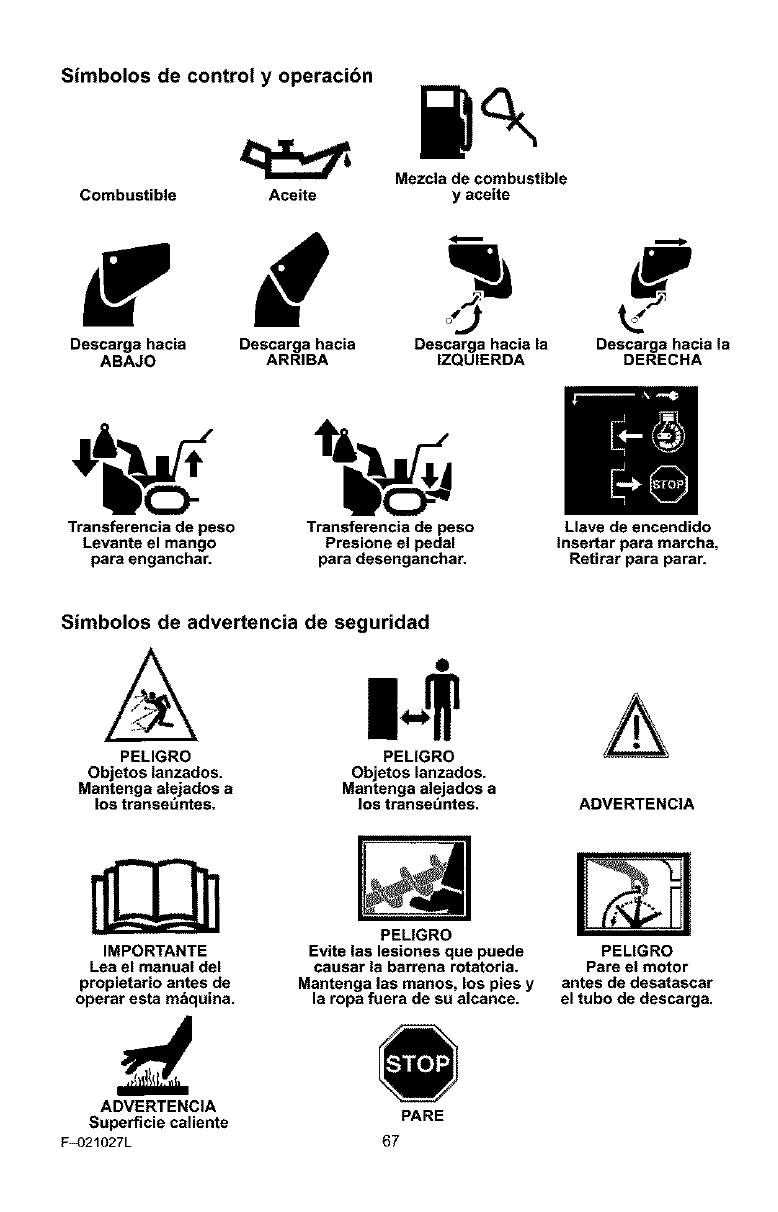
Simbolos de control y operacibn
Mezcla de combustible
Combustible Aceite y aceite
Descarga hacia Descarga hacia Descarga hacia la Descarga hacia la
ABAJO ARRIBA IZQUIERDA DERECHA
Transferencia de peso Transferencia de peso Llave de encendido
Levante el mango Presione el pedal Insertar para marcha,
para enganchar, para desenganchar. Retirar para parar.
Simbolos de advertencia de seguridad
A
PELIGRO
Objetos lanzados.
Mantenga alejados a
los transet_ntes.
O
PELIGRO
Objetos lanzados.
Mantenga alejados a
los transet_ntes. ADVERTENCIA
IMPORTANTE
Lea el manual del
propietario antes de
operar esta m_quina.
PELIGRO
Evite (as lesiones que puede
causar la barrena rotatoria.
Mantenga las manos, los pies y
la ropa fuera de su alcance.
PELIGRO
Pare el motor
antes de desatascar
el tubo de descarga.
ADVERTENCIA
Superficie caliente PARE
F_)21027L 67
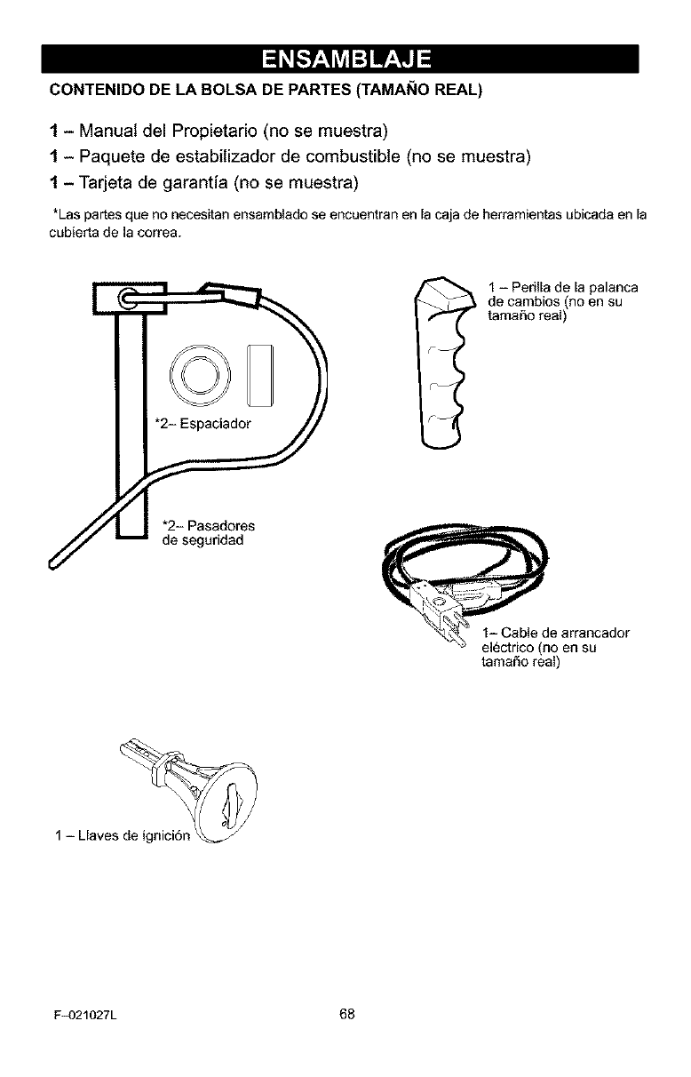
CONTENIDO DE LA BOLSA DE PARTES (TAMAI_IO REAL)
1- Manual del Propietario (no se muestra)
1- Paquete de estabitizador de combustible (no se muestra)
1 - Tarjeta de garantia (no se muestra)
*Las partes que no necesitan ensamblado se encuentran en la caja de herramientas ubicada en la
cubierta de la correa.
1 - Perilla de la palanca
no en su
de cambios
tamaSo real
tamaSo real)
1-Llaves_
F_)21027L 68
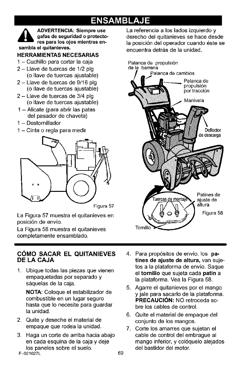
_IL ADVERTENCIA: Siempre use
gafas de seguridad o protecto-
res para los ojos mientras en-
sambla el quitanieves.
HERRAM|ENTAS NECESARIAS
1 - Cuchillo para cortar la caja
2 - Llave de tuercas de 1/2 pig
(o Ilave de tuercas ajustable)
2 - Llave de tuercas de 9/16 pig
(o Ilave de tuercas ajustable)
2 - Llave de tuercas de 3/4 pig
(o Ilave de tuercas ajustable)
1 - Alicate (para abrir las patas
del pasador de chaveta)
1 - Destornillador
1 - Cinta o regla para medir
Figura 57
La Figura 57 muestra el quitanieves en
posici6n de envio.
La Figura 58 muestra el quitanieves
completamente ensamblado.
La referencia a los lados izquierdo y
derecho del quitanieves se hace desde
]a posici6n del operador cuando 6ste se
encuentra detr_s de la unidad.
Palanca de propulsi6n
de la barrena
Palanca de cambios
Palanca de
propulsi6n
por tracci6n
Manivela
Deflector
dedescarga
Tornillo
Patines de
,ajuste de
altura
Figura 58
C6MO SACAR EL QUITANIEVES
DE LA CAJA
1, Ubique todas las piezas que vienen
empaquetadas por separado y
s_quelas de la caja,
NOTA: Coloque el estabilizador de
combustible en un lugar seguro
hasta que Io necesite para guardar
la unidad.
2. Quite y deseche el material de
empaque que rodea la unidad.
3. Haga un corte de arriba hacia abajo
en cada esquina de la caja y deje
los paneles sobre el suelo.
F_)21027L 69
4. Para prop6sitos de env[o, los pa-
tines de ajuste de altura, van suje-
tos ala plataforma de envio. Saque
el tornillo que sujeta cada patina
]a plataforma. Vea la Figura 58.
5. Agarre el quitanieves por el mango
y jale para sacado de la plataforma.
PRECAUCION: NO retroceda so-
bre los cables de control.
6,
7.
Quite el material de empaque del
conjunto de los mangos,
Corte los amarres que sujetan el
cable de control del embrague al
mango inferior, y col6quelo alejados
del bastidor del motoE
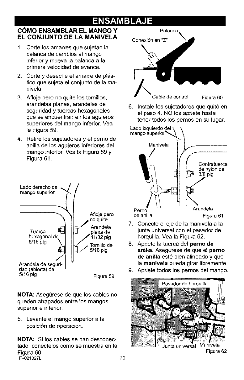
C6MO ENSAMBLAR EL MANGO Y
EL CONJUNTO DE LA MANIVELA
1. Corte los amarres que sujetan la
palanca de cambios al mango
inferior y mueva la palanca a la
primera velocidad de avance.
2. Corte y deseche el amarre de pl_s-
tico que sujeta el conjunto de la ma-
nivela.
3. Afloje pero no quite los tornillos,
arandelas planas, arandelas de
seguridad y tuercas hexagonales
que se encuentran en los agujeros
superiores del mango inferior. Vea
la Figura 59.
4, Retire los sujetadores y el perno de
anilla de los agujeros inferiores del
mango inferior, Vea la Figura 59 y
Figura 61,
mango superior
de_ Afloje pero
no quite
Arandela
Tuerca
hexagonal
5/16 pig ,_l , Tornillo de
5/16 pig
Arandela de segufi_
dad ab erta) de
5/16 pig Figura 59
Conexi6n en "Z"
Cable de control Figura 60
6, Instale los sujetadores que quit6 en
el paso 4. NO los apriete hasta
tener todos los pernos en su lugar,
Lado izquierdo i
Manivela
f
Contratuerca
.._. de nylon de
plg
\
Perno Arandela
de anilla Figura 61
7, Conecte el eje de la maniveia a la
junta universal con el pasador de
horquilla. Vea la Figura 62,
8, Apdete la tuerca del pemo de
anilla. Asegt_rese de que el pemo
de anina est6 bien alineado y que
la manivela pueda girar libremente,
9, Apdete todos los pemos del mango.
NOTA: AsegDrese de que los cables no
queden atrapados entre los mangos
superior e inferior.
5, Levante el mango superior a la
posici6n de operaci6n.
NOTA: Si los cables se han desconec-
tado, con6ctelos come se muestra en la
Figura 60,
F_)21027L 70
Junta universal
Figura 62
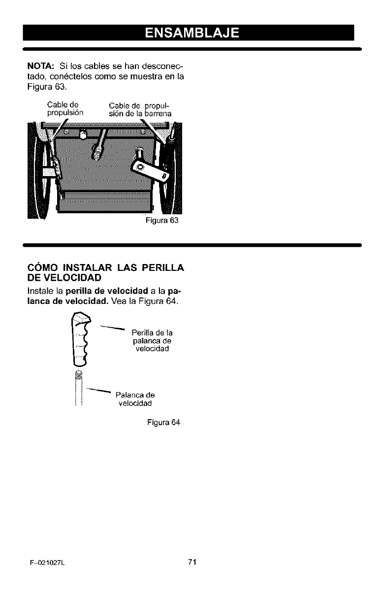
NOTA: Si los cables se han desconec-
tado, con6ctelos como se muestra en la
Figura 63.
Cable de Cable de propul-
propulsi6n si6n de la barrena
Figura 63
COMO INSTALAR LAS PERILLA
DE VELOCIDAD
Instale la perilla de velocidad a la pa-
lanca de velocidad. Yea la Figura 64.
_Perilla de la
palanca de
velocidad
,_ _ Palanca de
" velocidad
Figura 64
F_)21027L 71
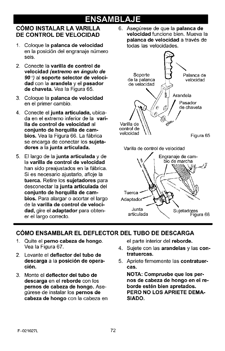
COMO INSTALAR LA VARILLA
DE CONTROL DE VELOCIDAD
1, Coloque la patanca de velocidad
en la posid6n del engranaje nL)mero
seis,
2, Conecte la varilla de control de
velocidad (extremo en #,ngulo de
90 °) al soporte selector de veloci-
dad con la arandela y el pasador
de chaveta. Vea la Figura 65.
3, Coloque la patanca de velocidad
en e] primer cambio.
4, Conecte el junta articulada, ubica-
da en el extremo inferior de la vari-
Ila de control de velocidad al
conjunto de horquilla de cam-
bios. Vea la Figura 66, La f_bdca
se encarga de conectar los sujeta-
dotes ala junta articulada.
5, El largo de la junta articulada y de
la variiia de control de velocidad
han sido preajustados en la f_brica,
Si es necesario ajustarlo, afloje la
tuerca. Retire los sujetadores para
desconectar la junta articulada del
conjunto de horquilla de cam-
bios. Para alargar o acortar el largo
de la varilla de control de veloci-
dad, gire el adaptador para obten-
er el ]argo correcto.
6, Asegt]rese de que la palanca de
velocidad funcione bien. Mueva la
patanca de velocidad a trav6s de
todas las velocidades.
Soporte Palanca de
de la palanca , velocidad
de velocidad
Vafilla de
control de
velocidad
&randela
Pasador
de chaveta
/
Figura 65
Varilla de control de velocidad
Tuerca .,_-"
Adaptador -..''_ ,
Junta
a_iculada
Engranaje de cam-
bio de marcha
sje F Sr 66
C6MO ENSAMBLAR EL DEFLECTOR DEL TUBO DE DESCARGA
1, Quite el perno cabeza de hongo,
Vea la Figura 67.
2, Levante el deflector del tubo de
descarga ala posici6n de opera-
ci6n.
el parte interior del reborde.
4. Sujete con las arandelas y las con-
tratuercas.
5. Apriete firmemente las contratuer-
cas.
3, Monte el deflector del tubo de
descarga en el reborde con los
pernos de cabeza de hongo. Ase-
g_rese de instalar los pernos de
cabeza de hongo con la cabeza en
NOTA: Compruebe que los per-
nos de cabeza de hongo en el re*
borde est6n bien apretados.
PERO NO LOS APRIETE DEMA-
SIADO.
F_)21027L 72
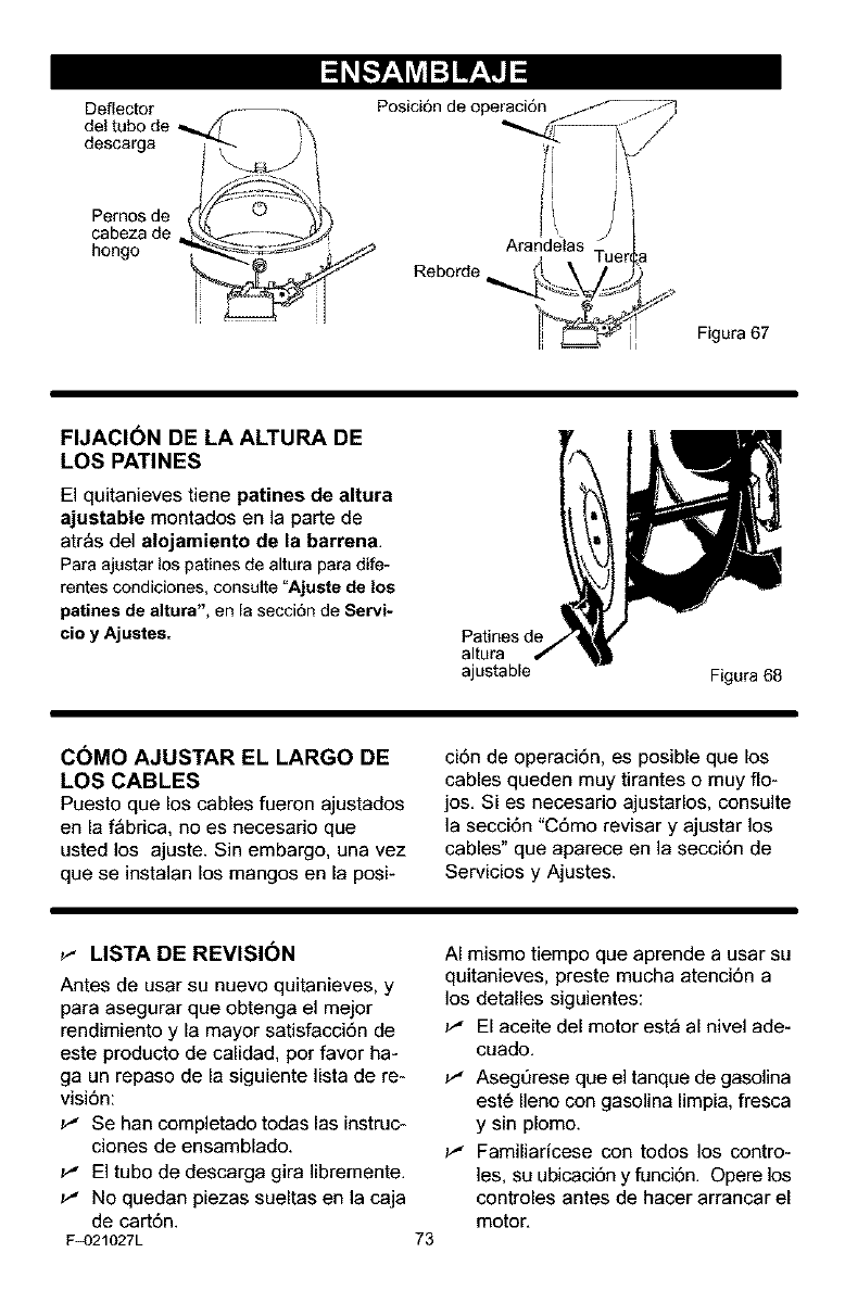
Deflector
del tubo de
descarga
Pernos de
cabeza de
hongo
Posici6n de operaci6n /,-_P7
Arandelas
Reborde_
Figura 67
FIJACI6N DE LA ALTURA DE
LOS PATINES
El quitanieves tiene patines de altura
ajustable montados en la parte de
atr_s del alojamiento de la barrena.
Para ajustar los patines de altura para dife-
rentes condiciones, consulte "Ajuete de los
petinee de altura", en la secci6n de Servi-
cio y Ajustes. Patines de
altura
ajustable Figura 68
COMO AJUSTAR EL LARGO DE
LOS CABLES
Puesto que los cables fueron ajustados
en la f_brica, no es necesario que
usted los ajuste. Sin embargo, una vez
que se instalan los mangos en la posi-
ci6n de operaci6n, es posible que los
cables queden muy tirantes o muy rio-
jos. Si es necesario ajustarlos, consulte
la secci6n "C6mo revisar y ajustar los
cables" que aparece en la secci6n de
Servicios y Ajustes.
_" LISTA DE REVISION
Antes de usar su nuevo quitanieves, y
para asegurar que obtenga el mejor
rendimiento y la mayor satisfacci6n de
este producto de calidad, por favor ha-
ga un repaso de la siguiente lista de re-
visi6n:
_" Se han completado todas las instruc-
clones de ensamblado.
_" El tubo de descarga gira libremente.
_" No quedan piezas sueltas en la caja
de cart6n.
F_)21027L 73
AI mismo tiempo que aprende a usar su
quitanieves, preste mucha atenci6n a
los detalles siguientes:
_" El aceite del motor est_ al nivel ade-
cuado.
_" Asegt]rese que el tanque de gasolina
est6 Ileno con gasolina limpia, fresca
y sin plomo.
_" Familiaricese con todos los contro-
les, su ubicaci6n y funci6n. Opere los
controles antes de hacer arrancar el
motor.
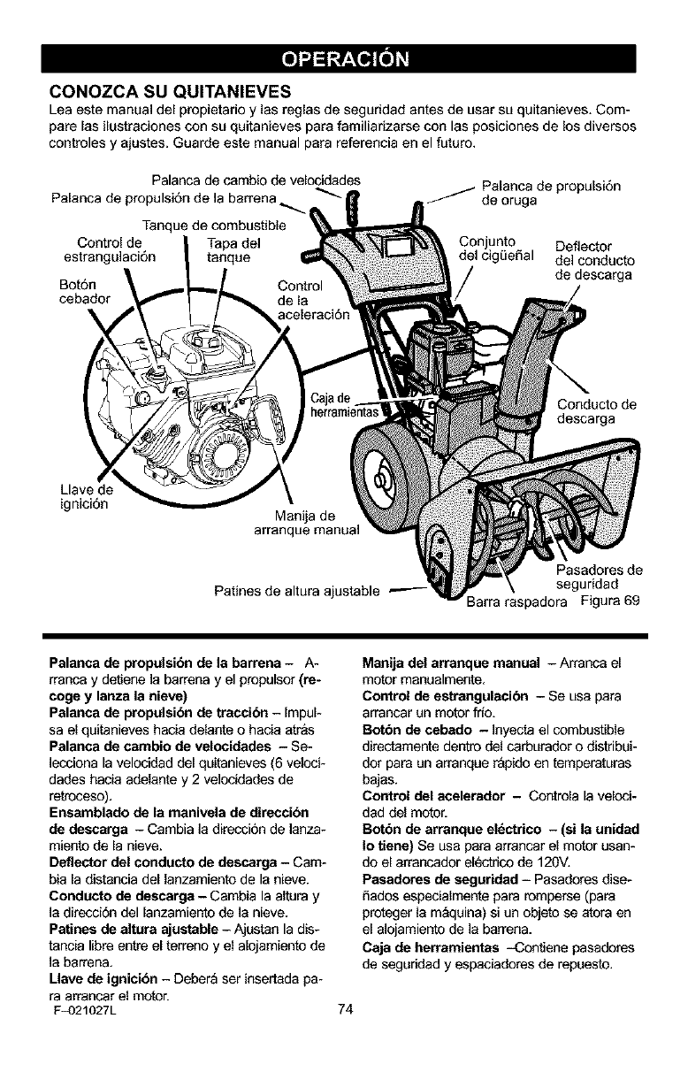
CONOZCA SU QUITANIEVES
Lea este manual del propietarioy las reglas de seguridad antes de usar su quitanieves. Com-
pare las ilustraciones con su quitanieves para familiarizarse con las posiciones de los diversos
controles y ajustes. Guarde este manual para referencia en el futuro.
Palanca de cambio de velocidades
Palanca de propulsi6n de la barrena _-_
Tanque de combustible
Control de Tapa de]
estrangulaci6n tanque
Bo_n
cebador
_ Palanca de propulsi6n
de oruga
Con junto Deflector
del cig_eflal del conducto
de descarga
Conductode
desca_a
Llave de
ignici6n Man_a de
arranque manual
Paflnes de altura ajustable
Pasadores de
seguridad
3arra raspadora Figura 69
Palanca de propulsibn de le barrena - A-
rranca y detiene la barrena y el propulsor(re-
coge y lanze le nieve)
Pelance de propulsibn de traccibn - Impul-
sa el quitanieves hacia delante o hacia atras
Pelence de carnbio de velocidedee - Se-
]ecciona la velocidad del quitanieves (6 veloci-
dades hacia adelante y 2 velocidades de
retroceso).
Ensambledo de la manivela de direccibn
de descarge - Cambia la direcci6n de lanza-
miento de la nieve.
Deflector del conducto de descarga - Cam-
bia la distancia del lanzamiento de la nieve.
Conducto de descarga - Cambia la altura y
la direcciSn del lanzamiento de la nieve.
Pa_ines de altura ajustable - Ajustan la dis-
tancia Iibre entre el terreno y el alojamiento de
]a barren&
Llave de ignicibn - Deber_ ser insertada pa-
ra arrancar el motor.
F_)21027L
Manija del arranque manual - Arranca el
motor manaalmente,
Control de estrangulacibn - Se usa para
arrancar un motor frio.
Botbn de cebado - ]nyecta el combustible
directamente dentro del carburador o distribui-
dot para un arranque r&pido en temperaturas
bajas.
Control del acelerador - Controla la veloci-
dad del motor.
Botbn de arranque el_ctrico - (si la unidad
Io tiene) Se usa para arrancar el motor usan-
do el arrancador el_ctrico de 120V.
Pasadores de segurided - Pasadores dise-
flados especialmente para romperse (para
proteger la m_quina) si un objeto se atora en
el alojamiento de la barren&
Caja de herramientas -Contiene pasadores
de seguddad y espaciadores de repuesto.
74
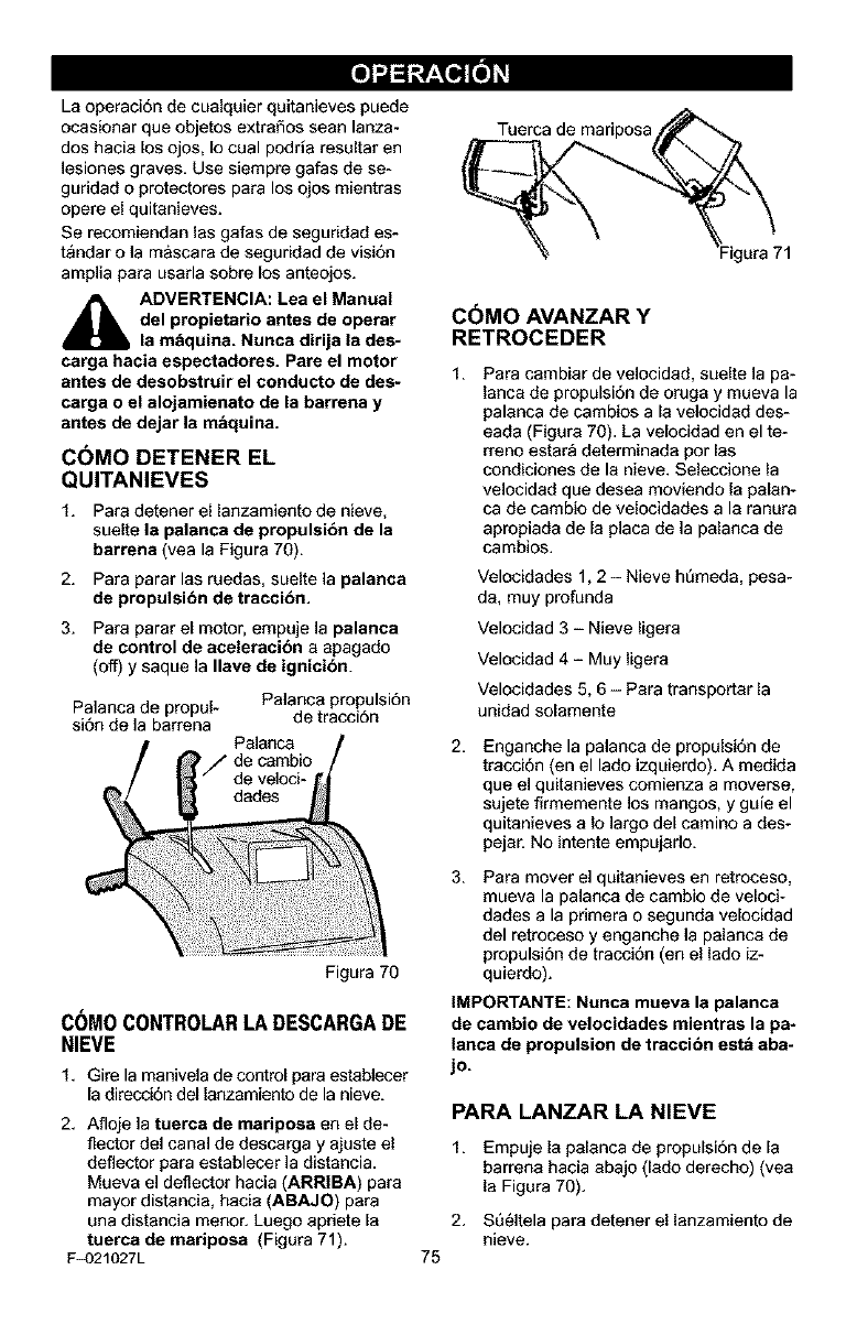
Laoperacidndecoalquierquitanievespuede
ocasionarqueobjetosextrafiosseanlanza-
doshacialosojos,Iocoalpodriaresaltaren
lesionesgraves.Usesiempregafasdese-
guddadoprotectoresparalosojosmientras
opereelquitanieves.
Serecomiendanlasgafasdeseguridades-
t_ndarolam&scaradeseguddaddevisi6n
ampliaparausadasobrelosanteojos.
_ADVERTENCIA: Lea el Manuel
del propietario antes de operar
la mbquina. Nunca dirija la des-
carga hacie espectadorea. Pare el motor
antes de desobstruir el conducto de des-
carga o el alojamienato de la barrena y
antes de dejer la mbquina.
C6MO DETENER EL
QUITANIEVES
1. Para detener el lanzamiento de nieve,
suelte la palanca de propulsibn de la
barrena (yea la Figura 70).
2. Para parar las ruedas, suelte la palanca
de propulsibn de traccibn,
3. Para parar el motor, empuje la palanca
de control de aceleracibn a apagado
(off) y saque la Ileve de ignicibn.
Palanca de propul-
si6n de la barrena
Palanca propulsi6n
de tracci6n
Figura 70
C(_MOCONTROLARI..ADESCARGADE
NIEVE
1. Gire la manivela de control pare establecer
la direcoi6n del lanzamiento de la nieve.
2. Afloje la tuerca de mariposa en el de-
flector del canal de descarga y ajuste el
deflector para establecer la distancia.
Mueva el deflector hacia (ARRIBA) para
mayor distancia, hacia (ABAJO) para
ana distancia menor. Luego apdete la
tuerca de meripose (Figara 71).
F_)21027L
Tuerca de madposa
Egara71
C6MO AVANZAR Y
RETROCEDER
t. Para cambiar de velocidad, suelte la pa-
lanca de propulsi6n de oruga y mueva la
palanca de cambios a la velocidad des-
eada (Figura 70), La velocidad en el te-
rreno estar_ determinada per las
condiciones de la nieve, Selecoione la
velocidad que desea moviendo la palan-
ca de cambio de velocidades a la ranura
apropiada de la placa de la palanca de
cambios,
Velocidades 1,2 - Nieve htimeda, pesa-
da, muy profunda
Velocidad 3 - Nieve ligera
Velocidad 4 -Muy ligera
Velocidades 5, 6 - Para transportar la
unidad solamente
2, Enganche la palanca de propulsi6n de
tracci6n (en el lado izquierdo). A medida
que el quitanieves comienza a moverse,
sujete flrmemente los mangos, y gale el
quitanieves a Io largo del camino a des-
pejar. No intente empujado.
3. Para mover el quitanieves en retroceso,
mueva la palanca de cambio de veloci-
dades a la pdmera o segunda velocidad
del retroceso y enganche la palanca de
propulsidn de tracci6n (en el lado iz-
quierdo).
IMPORTANTE: Nunca mueva la palanca
de cambio de velocidades mientras la pa-
lanca de propulsion de traccibn estb eba-
jo.
75
PARA LANZAR LA NIEVE
1. Empaje la palanca de propulsi6n de la
barrena hacia abajo (lado derecho) (vea
la Figara 70).
2. SQ_ltela para detener el lanzamiento de
nieve.
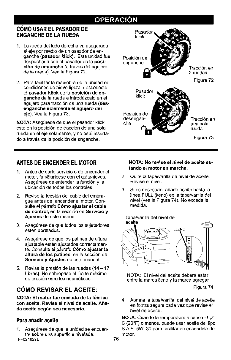
COMOUSARELPASADORDE
ENGANCHEDE LARUEDA
1. La rueda del lade derecha va asegurada
al eje per medio de un pasador de en-
ganche (pasador klick). Esta unidad fue
despachada con el pasador en la posi-
eibn de enganehe (a tray,s del agujero
de la rueda). Veala Figura 72.
2. Para facilitar la maniobra de la unidad en
condiciones de nieve ligera, desconecte
el pasador klick de la posicibn de en-
ganche de la rueda e introdt_zcalo en el
agujero pars tracci6n de una rueda (des-
enganche solamente el agujer_del
eje). Veala Figura 73,
NOTA: Asegt_rese de que el pasador klick
est6 en la posicidn de traccidn de una sola
rueda en el eje solamente, y no est6 inserta-
do a tray,s de la posici6n de enganche.
Pasador
klick
Posici6n de
enganche
kPiacSkad° r
Posici6n de
desengan-
che t'_
Traccidn en
2 ruedas
Figura 72
Figura 73
ANTESDE ENCENDEREL MOTOR
1. Antes de darle servicio o de encender el
motor, familiadcese con el quitanieves.
AsegQrese de entender la funci6n y la
ubicaci6n de todos los controles.
2. Revise la tensi6n del cable del embra-
gue antes de encender el motor. Con-
suite el p_rrafo Cbmo ajustar el cable
de control, en la secci6n de Servicio y
Ajustes de este manual
3. AsegQrese de que todos los sujetadores
est6n apretados.
4. AsegQrese de que los patines de altura
ajustable est6n ajustados correctamen-
te. Consulte el p_rrafo Cbmo ajustar Is
altars de los p_ines, en la secci6n de
Servicio yAjustes de este manual.
5. Revise la presi6n de las ruedas (14- 17
libras). No sobrepase el limite m_ximo
de presi6n para los neumaticos
C6MO REVISAR EL ACEITE:
NOTA: El motor rue enviado de la f_brica
con aceite. Revise el nivel de aceite. A_a-
da aceite seg_n sea necesario.
Paraa_adiraceite
1. Asegtirese de que la unidad se encuen-
tre sobre una superficie nivelada.
F_)21027L
NOTA: No revise el nivel de aceite es-
tando el motor en marcha.
2. Quite la tapa/varilla de nivel de aceite.
Revise el niveL
3. Si es necesario, aSada aceite hasta la
linea FULL (lleno) en la tapa/varilla del
nivel (vea la Figura 74). No exceda la
medida.
Tapa/varilla del nivel de
aceite
LLENO
76
NQTA: El nivel del aceite debera estar
entre la marca Ileno y la marca agregar
Figura 74
4. Apriete la tapa/varilla del nivel de aceite
en forms segura cada vez que revise el
nivel de aceite.
NOTA: Cuando la temperatura aicance -6,7 °
C (20°F) o menos, puede usar aceite del tipo
S.A.E. 5W-30 pars facilitar en encendido del
motor.
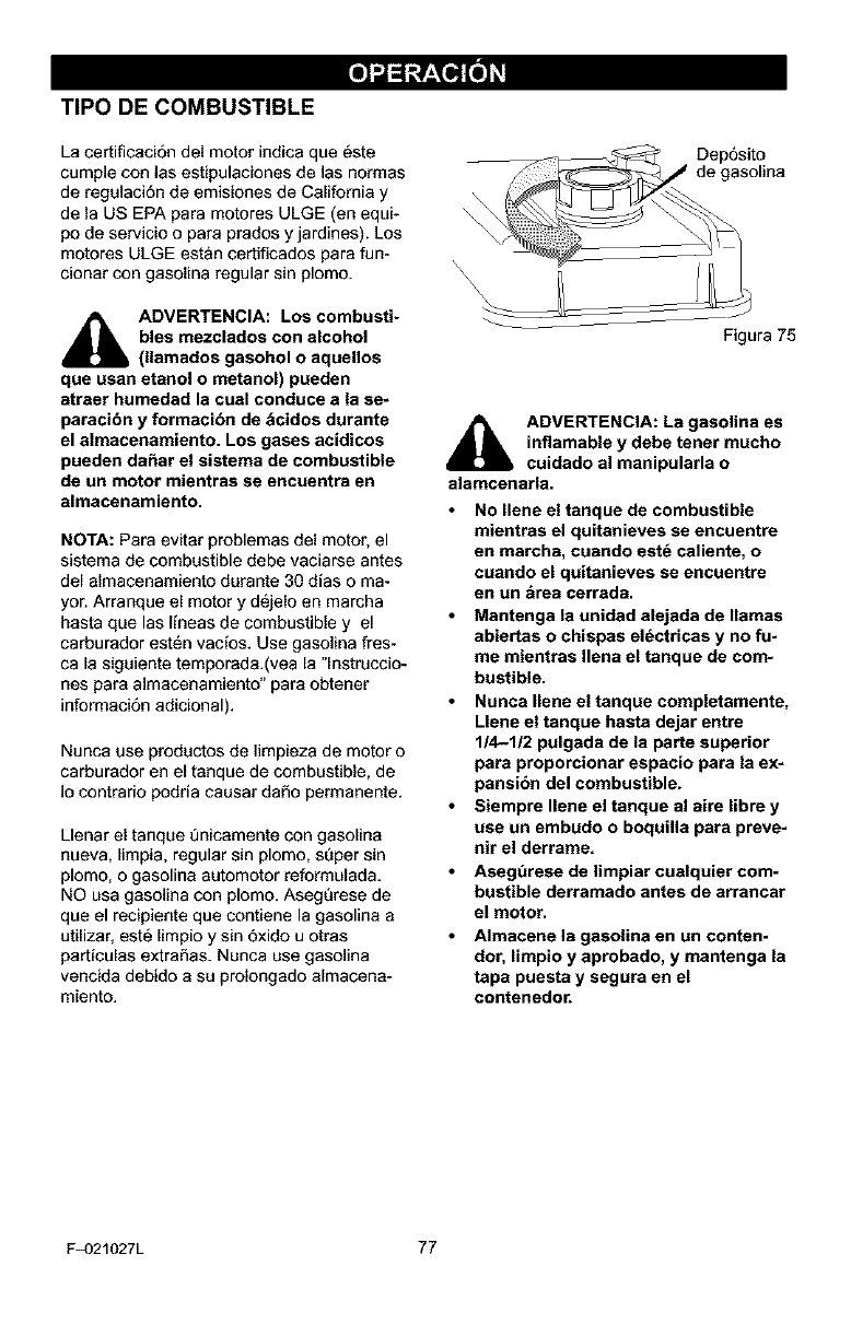
TIPO DE COMBUSTIBLE
La certificaci6n del motor indica que _ste
cumple con las estipulaciones de las normas
de regulaci6n de emisiones de California y
de la US EPA para motores ULGE (en equi-
po de servicio o para prados y jardines). Los
motores ULGE est&n certificados para fun-
cionar con gasolina regular sin plomo.
_i DVERTENCIA: Los combusti-
bles mezcladoe con alcohol
(llamados gasohol o aquellos
que usan etanol o metanol) pueden
atreer humedad le cual conduce e la se-
paracibn y formacibn de bcidos durante
el elmacenemiento. Los gases acidicos
pueden daSar el sisteme de combustible
de un motor mientras se encuentra en
almacenamiento.
NOTA: Para evitar problemas del motor, el
sistema de combustible debe vaciarse antes
del almacenamiento durante 30 dias o ma-
yor. Arranque el motor y d6jelo en marcha
hasta que las Ifneas de combustible y el
carburador est6n vacfos. Use gasolina fres-
ca la siguiente temporada.(vea la "lnstruccio-
nes para almacenamiento" para obtener
informaci6n adicional).
Nunca use productos de limpieza de motor o
carburador en el tanque de combustible, de
Io contrado podria causar daSo pem_anente.
Llenar el tanque Qnicamente con gasolina
nueva, limpia, regular sin plomo, sQper sin
plomo, o gasolina automotor reformulada.
NO usa gasolina con plomo. AsegQrese de
que el recipiente que contiene la gasolina a
utilizar, est6 limpio y sin 5xido u otras
partfculas extraSas. Nunca use gasolina
vencida debido a su prolongado almacena-
miento.
\
DepSsito
de gasolina
Figura 75
ADVERTENCIA: La gasolina es
inflamable y debe tenet mucho
cuidado al manipularla o
alamcenarla.
No Ilene el tanque de combustible
mientres el quitanieves se encuentre
en marcha, cuando eetd caliente, o
cuando el quitanieves se encuentre
en un _rea cerreda.
Mantenge la unidad alejada de llamas
abiertas o chispes eldctricas y no fu-
me mientras Ilena el tanque de com-
bustible.
Nunca Ilene el tanque completemente,
Llene el tanque hasta dejar entre
114-1/2 pulgada de la perte superior
pare proporcionar espacio para la ex-
pensibn del combustible.
Siempre Ilene el tanque al aire libre y
use un embudo o boquilla para preve-
nit el derrame.
Aeeg_rese de limpiar cuelquier com-
bustible derramado antes de arrancar
el motor.
Almacene la gasolina en un conten-
dot, limpio yaprobado, y mantenga la
tapa puesta y segura en el
contenedor.
F_)21027L 77
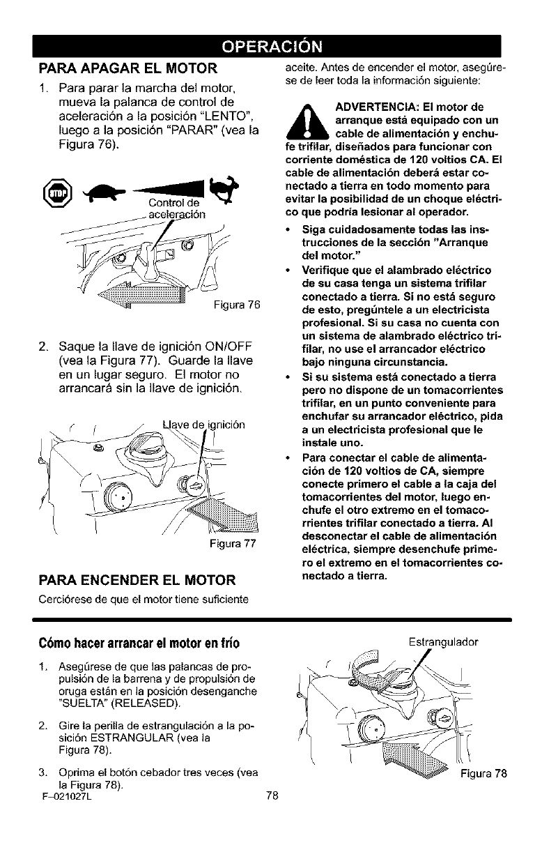
PARA APAGAR EL MOTOR
1. Para parar la marcha del motor,
mueva la palanca de control de
aceleraci6n a la posici6n "LENTO",
luego ala posici6n "PARAR" (vea la
Figura 76).
Figura 76
2. Saque la Ilave de ignici6n ON/OFF
(vea la Figura 77). Guarde la Ilave
en un lugar seguro. El motor no
arrancar_ sin la Ilave de ignici6n.
Figura 77
PARA ENCENDER EL MOTOR
Cerci6rese de que el motor tiene suficiente
aceite. Antes de encender el motor, aseg_re-
se de leer toda la informaci6n siguiente:
_IL ADVERTENCIA: El motor de
arranque est_ equipado con un
cable de alimentacibn y enchu-
fe trifilar, dise_ados para funcionar con
corriente dom6stica de 120 voltios CA. El
cable de alimentacibn deber& estar co-
nectado a tierra en todo momento para
evitar la posibilidad de un choque eldctri-
co que podria lesionar al operador.
Siga cuidadosamente todas las ins-
trucciones de la seccibn "Arranque
del motor."
Verifique que el alambrado el_ctrico
de su casa tenga un sistema trifilar
conectado a tierra. Si no est& seguro
de esto, preg_ntele a un electricista
profesional. Si su casa no cuenta con
un sistema de alambrado el_ctrico tri-
filar, no use el arrancador el_ctrico
bajo ninguna circunstancia.
Si su sistema est_ conectado a tierra
pero no dispone de un tomacorrientes
trifilar, en un punto conveniente para
enchufar su arrancador el6ctrico, pida
a un electricista profesional que le
instale uno.
Para conectar el cable de alimenta-
cibn de 120 voltios de CA, siempre
conecte primero el cable a la caja del
tomacorrientes del motor, luego en-
chufe el otto extremo en el tomaco-
rrientes trifilar conectado atierra. AI
deseonectar el cable de alimentacibn
el6ctrica, siempre desenchufe prime-
ro el extremo en el tomacorrientes co-
nectado a tierra.
Cbmohacerarrancarel motoren frio
1. Aseg_rese de que las palancas de pro-
pulsi6n de [a barrena y de propulsi6n de
oruga est_n en la posici6n desenganche
"SUE LTA" (RELEASED).
2. Gire la perilla de estrangulaci6n a la po-
sici6n ESTRANGULAR (vea la
Figura 78).
Estrangulador
#
3. Oprima el bot6n cebador tres veces (vea
]a Figura 78).
F_)21027L 78
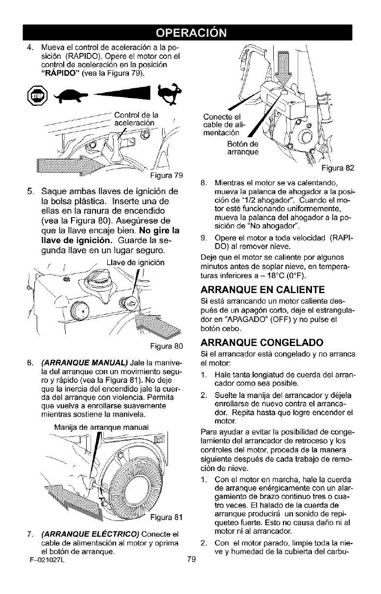
4. Muevaelcontroldeaceleraci6nalapo-
sici6n(RAPIDO).Opereel motor con el
control de aceleraci6n en la posici6n
"RAPIDO" (vea ]a Figura 79).
Controlde la
aceleraci6n /
Figura 79
5, Saque ambas Ilaves de ignici6n de
la bolsa pl_stica. ]nserte una de
elias en la ranura de encendido
(vea la Figura 80). AsegDrese de
que la Ilave encaje bien, No gire la
Ilave de ignicibn. Guarde la se-
gunda Ilave en un lugar seguro.
fLlavede ignici6n
Figura 80
6. (ARRANQU£ MANUAL) Jale la manive-
la del arranque con un movimiento segu-
roy r_pido (vea la Figura 81). No deje
que la inercia del encendido jale la cuer-
da del arranque con violencia. Permita
que vuelva a enrollarse suavemente
mientras sostiene la manivela.
Manija de ar nque manual
\
Figura 81
7. (ARRANQUE EL eLCTRICO) Conecte el
cable de alimentaci6n al motor y opnma
el bot6n de arranque.
F_)21027L 79
Conecte el
cable de ali-
mentaci6n
Bot6n de
8rranque
Figura 82
8. Mientras el motor se va calentando,
mueva ]a palanca de ahogador a la posi-
ci6n de "1/2 ahogador". Cuando el mo-
tor est6 funcionando uniformemente,
mueva ]a palanca del ahogador a la po-
sici6n de "No ahogador".
9. Opere el motor a toda velocidad (RAPI-
DO) al remover nieve.
Deje que el motor se caliente pot algunos
minutos antes de soplar nieve, en tempera-
turas inferiores a - 18°C (O°F).
ARRANQUE EN CALIENTE
Si est_ arrancando un motor caliente des-
pu6s de un apag6n corto, deje el estrangula-
dor en "APAGADO" (OFF) y no pulse el
bot6n cebo.
ARRANQUE CONGELADO
si el arrancador esta congelado y no arranca
el motor:
1. Hale tanta ]ongiatud de cuerda del arran-
cador como sea posible.
2. Suelte la manija del arrancador y d6jela
enrollarse de nuevo contra el arranca-
dor. Repita hasta que Iogre encender el
motor.
Para ayudar a evitar la posibilidad de conge-
lamiento del arrancador de retroceso y los
controles del motor, proceda de la manera
siguiente despu_s de cada trabajo de remo-
ci6n de nieve.
1. Con el motor en marcha, hale la cuerda
de arranque en_rgicamente con an alar-
gamiento de braze continue tres o cua-
tro veces. El halado de la cuerda de
arranque producir_ un sonido de repi-
queteo fuerte. Esto no causa daSo ni al
motor ni al arrancador.
2. Con el motor parado, limpie toda la hie-
ve y humedad de la cubierta del carbu-
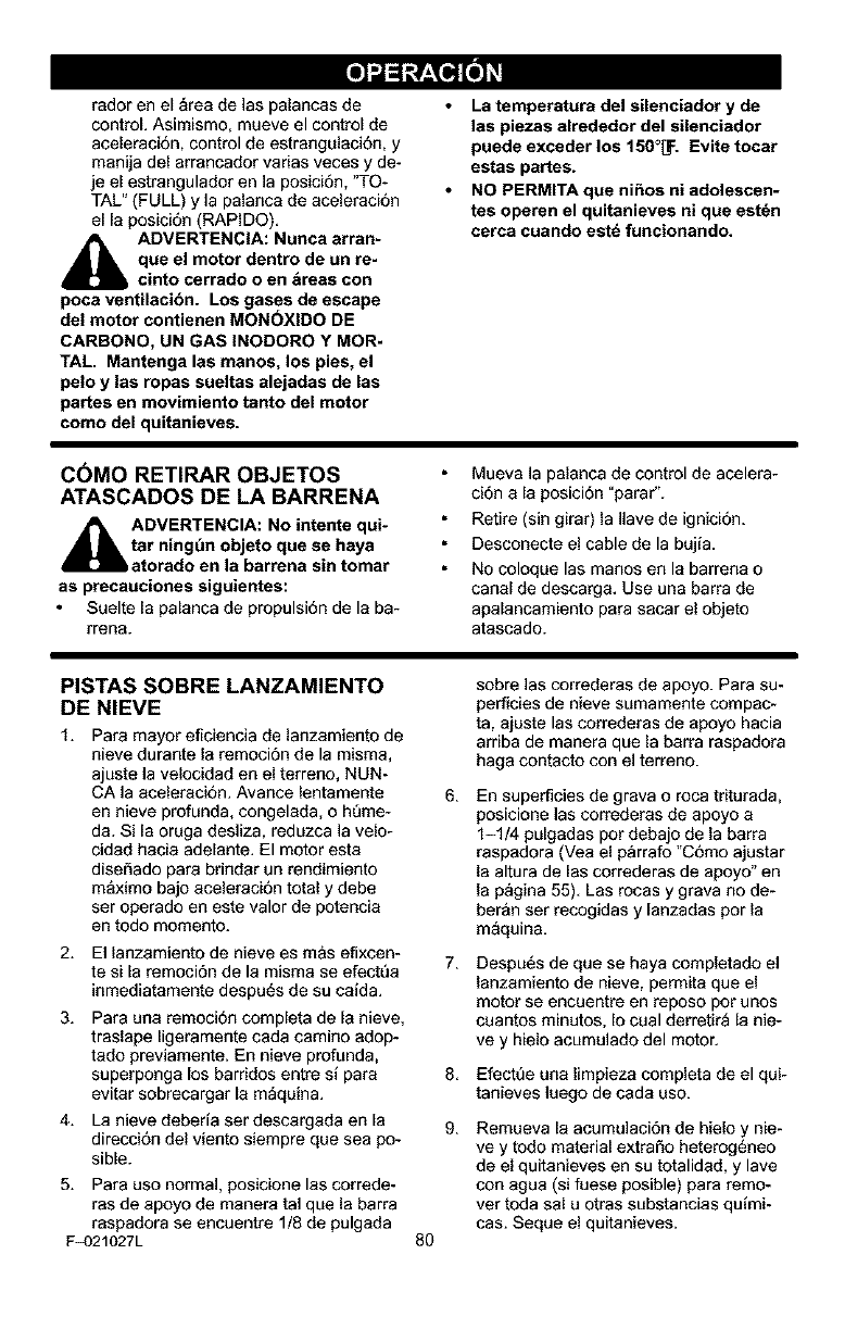
radorenel_readelaspalancasde
control.Asimismo,mueveelcontrolde
aceleraci6n,controldeestrangulaci6n, y
manija del arrancador varias veces y de-
je el estrangulador en ]a posici6n, "TO-
TAL" (FULL) y la palanca de aceleraci6n
el la posici6n (RAPIDO).
_i ADVERTENCIA: Nunca arran-
que el motor dentro de un re-
cinto cerrado o en &reas con
poca ventilacibn. Los gases de escape
del motor contienen MON(_XlDO DE
CARBONO, UN GAS INODORO Y MOR-
TAL. Mantanga las manos, los pies, el
pelo y las ropas sueltas alejadas de las
partes en movimiento tanto del motor
como del quitanieves.
La temperatura del silenciador y de
las piezas alrededor del silenciador
puede exceder los 150°_. Evita tocar
estas partes.
NO PERMITA que ni_os ni adolescen-
tes operen el quitanieves ni que est_n
cerca cuando estd funcionando.
C6MO RETIRAR OBJETOS
ATASCADOS DE LA BARRENA
ADVERTENCIA: No intente qui-
tar ning_n objeto que se haya
atorado en la barrena sin tomar
as precauciones siguientes:
Suelte [a palanca de propulsi6n de la ba-
rrena.
Mueva la palanca de control de acelera-
ci6n a la posiciSn "parar".
Retire (sin girar) la Ilave de ignici6n.
Desconecte el cable de la bujfa.
No coloque las manos en la barrena o
canal de descarga. Use una barra de
apalancamiento para sacar el objeto
atascado.
PISTAS SOBRE LANZAMIENTO
DE NIEVE
1. Para mayor eficiencia de ianzamiento de
nieve durante la remociSn de la misma,
ajuste la velocidad en el terreno, NUN-
CA la aceleraci6n. Avarice lentamente
en nieve profunda, congelada, o ht_me-
da. Si la oruga desliza, reduzca ]a velo-
cidad hacia adelante. El motor esta
diseSado para brindar un rendimiento
m&ximo bajo aceleraci6n total y debe
ser operado en este valor de potencia
en todo momento.
6.
2. El lanzamiento de nieve es m&s efixcen-
te si la remociSn de la misma se efectt_a 7.
inmediatamente despu_s de su caida.
3. Para una remoci6n completa de [a nieve,
traslape ligeramente cada cam]no adop-
tado previamente. En nieve profunda,
superponga los barridos entre si para 8.
evitar sobrecargar la m_quina.
4. La nieve deberia ser descargada en la 9.
direcci6n del viento siempre que sea po-
sible.
5. Para uso normal, posicione las correde-
ras de apoyo de manera tal que la barra
raspadora se encuentre 1/8 de pulgada
F_)21027L 8O
sobre ]as correderas de apoyo. Para su-
perficies de nieve sumamente compac-
ta, ajuste las correderas de apoyo hacia
arriba de manera que la barra raspadora
haga contacto con el terreno.
En superficies de grava o roca triturada,
posicione las correderas de apoyo a
1-1/4 pulgadas por debajo de la barra
raspadora (Vea el p&rrafo "CSmo ajustar
la altura de las correderas de apoyo" en
la p_gina 55). Las rocas y grava no de-
ber&n ser recogidas y [anzadas por la
m_quina.
Despu6s de que se haya completado el
lanzamiento de nieve, permita que el
motor se encaentre en repose per unos
caantos minutos, Io caal derretir_ la nie-
ve y hielo acumulado del motor.
Efectt_e una Iimpieza completa de el qui-
tanieves luego de cada uso.
Remueva la acumulaci6n de hielo y hie-
ve y todo material extraSo heterog6neo
de el quitanieves en su total]dad, y lave
con agua (si fuese posible) para remo-
ver toda sal u otras substancias qu{mi-
cas. Seque el quitanieves.
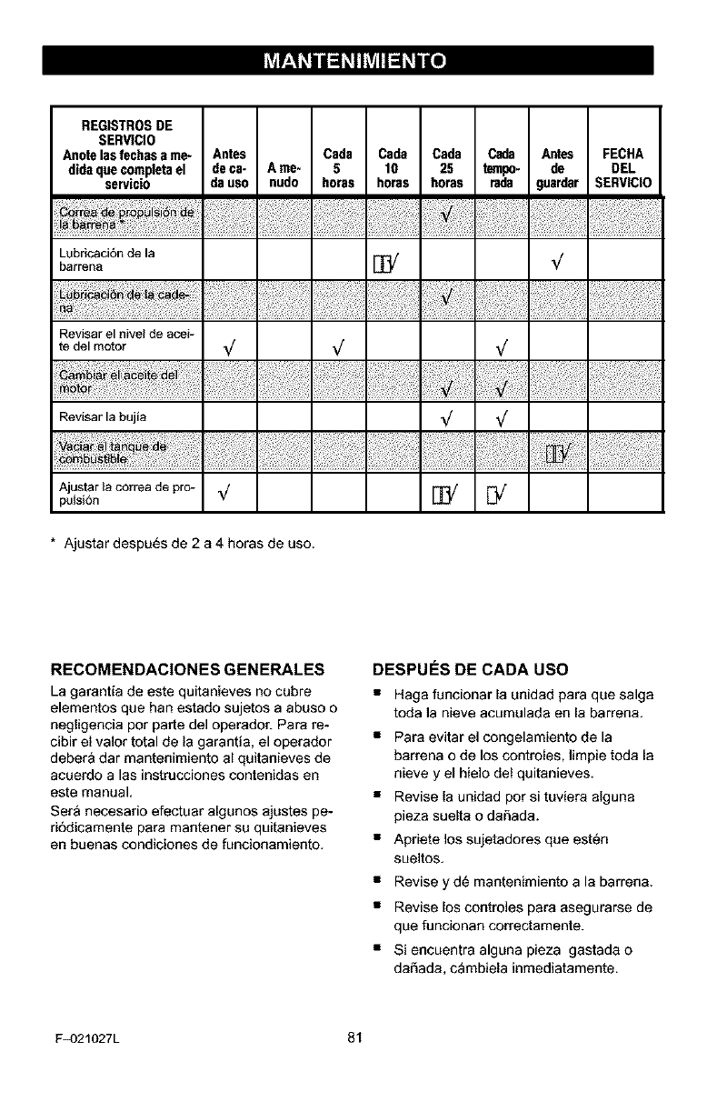
REGISTROSDE
SERVICIO
Anote lasfechasame- Antes Cada Cads Cada Cada Antes FECHA
didaque completael de ca- A me- 5 10 25 tempo, de DEL
servicio da use nuda horas horas horas rada guardar SERVICIO
Lubricacidn de la
barrens E_ _/
Revisar el nivel de acei-
te del motor _/ _/ _/
..................................................
Revisar la bujia _/
vo ;i ii#!:.,..
Ajustar la correa de pre- _/ E_ [_
putsi6n
* Ajustar despu_s de 2 a 4 horas de uso,
RECOMENDACIONES GENERALES
La garantia de este quitanieves no cabre
elementos que han estado sujetos a abuso o
negligencia pot parte del operador. Pars re-
cibir el valor total de la garantia, el operador
debera dar mantenimiento al quitanieves de
acuerdo a las instrucciones contenidas en
este manual,
Set& necesario efectuar algunos ajustes pe-
ri6dicamente para mantener su quitanieves
en buenas condiciones de funcionamiento.
DESPUES DE CADA USO
•Haga funcionar la unidad para que salga
toda la nieve acumulada en la barren&
• Para evitar el congelamiento de la
barrena o de los controles, limpie toda la
nieve y el hielo del quitanieves,
• Revise la unidad por si tuviera alguna
pieza suelta o daSada.
• Apriete los sujetadores que est_n
sueltos.
• Revise y d_ mantenimiento a la barren&
• Revise los contro]es pars asegurarse de
que funcionan correctamente.
• Si encuentra alguna pieza gastada o
da_ada, cambiela inmediatamente.
F_)21027L 81
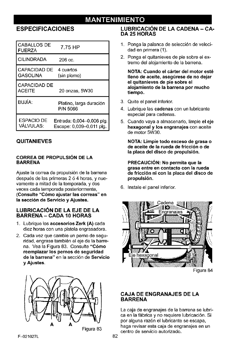
ESPECIFICACIONES LUBRICACI6N DE LA CADENA - CA-
DA 25 HORAS
CABALLOS DE 7.75 HP
FUERZA
;ILINDRADA 206 cc.
CAPACIDAD DE 4 cuartos
GASOLINA (sin plomo)
CAPACIDAD DE
ACEITE 20 onzas, 5W30
BUJiA: Platino, larga duraci6n
P/N 5066
ESPAClO DE Entrada: 0,004-0,006 pig.
V._LVULAS: Escape: 0,009-0,011 pig.
QUITANIEVES
CORREA DE PROPULSI(_N DE LA
BARRENA
Ajuste la correa de propulsi6n de la barrena
despu6s de las pnmeras 2 64 horas, y nue-
vamente a mitad de la temporada, y dos
veces cada temporada posteriormente,
(Consulte "Cbmo ajustar las correas" en
la seccibn de Servicio y Ajustes.
LUBRICACI(_N DE LA EJE DE LA
BARRENA - CADA 10 HORAS
1. Lubrique los accesorios Zerk (A) cada
diez horas con una pistola engrasadora.
2. Cada vez que cambie an pemo de segu-
ridad, engrase tambi_n el eje de la barre-
na. Yea la Figara 83. Consalte "Cbmo
reemplazar los pernos de seguridad
de la barrena" en la secci6n de Servicio
y Ajustes.
AA
Figura 83
F_)21027L
1. Ponga la palanca de selecci6n de veloci-
dad en primera (1).
2. Ponga el quitanieves de pie sobre el ex-
tremo del alojamiento de la barrena.
NOTA: Cuando el cbrter del motor est_
Ileno de aceite, aseg_rese de no dejar
el quitanieves de pie sobre el
alojamiento de la barrena pot mucho
tiempo.
3. Quite el panel inferior.
4. Lubrique las cedenas con un lubricante
especial para cadenas.
5. Cuando vaya a almacenarlo, limpie el eje
hexagonal y los engranajes con aceite
de motor 5W30.
NOTA: Limpie todo exceso de gresa o
de aceite de la rueda de friccibn o de
la placa del disco de propulsibn.
PRECAUCI(_N: No permita que la
grasa entre en contacto con la rueda
de friccibn ni con la placa del disco de
propulsibn.
6. Instale el panel inferior.
Figara 84
82
CAJA DE ENGRANAJES DE LA
BARRENA
La caja de engranajes de la barrena se labri-
ca en la f_bdca y no requiere lubdcaci6n. Si
por alguna raz6n el lubdcante se escapa,
haga revisar esta caja de engranajes en un
centro de servicio autorizado.
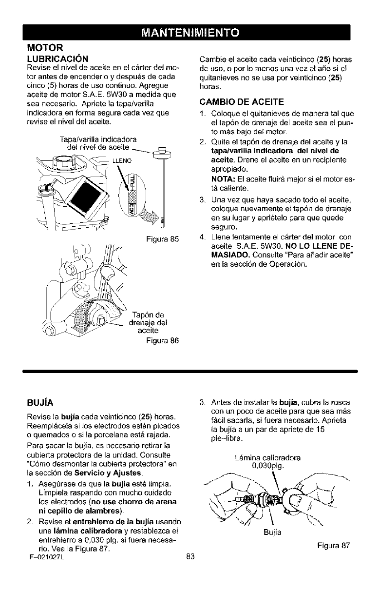
MOTOR
LUBRICACI(_N
Revise el nivel de aceite en el c_rter del mo-
tor antes de encenderlo y despu6s de cada
cinco (5) horas de uso continue. Agregue
aceite de motor S.A.E. 5W30 a medida que
sea necesario. Apriete la tapa/varilla
indicadora en forma segura cada vez que
revise el nivel del aceite.
Tapa/vadlla indicadora
del nivel de aceite
LLENO
Figura 85
.=del
aceite
Figura 86
Cambie el aceite cada veinticinco (25) horas
de uso, o por Io menos una vez al aSo si el
quitanieves no se usa por veinticinco (25)
horas.
CAMBIO DE ACEITE
1. Coloque el quitanieves de manera tal que
el tapdn de drenaje del aceite sea el pun-
to m_s bajo del motor.
2. Quite el tap6n de drenaje del aceite y la
tapa/varille indicadora del nivel de
aceite. Drene el aceite en un recipiente
apropiado.
/-IOTA: El aceite fluira mejor si el motor es-
t_ caliente.
3. Una vez que haya sacado rode el aceite,
coloque nuevamente el tap6n de drenaje
en su lugar y apri_telo para que quede
seguro.
4. Llene lentamente el c_rter del motor con
aceite S.A.E. 5W30. NO LO LLENE DE-
MASIADO. Consulte "Para aSadir aceite"
en la secci6n de Operaci6n.
BUJIA
Revise la bujia cada veinticinco (25) horas.
Reempl_cela si los electrodes estan picados
o quemados o si la porcelana est_ rajada.
Para sacar la bujia, es necesario retirar la
cubierta protectora de la unidad. Consulte
"C6mo desmontar la cubierta protectora" en
la secci6n de Servicio y Ajustes.
1. Aseg_rese de que la bujia est6 limpia.
Limpiela raspando con mucho coidado
los electrodos (no use chorro de arena
ni cepillo de alambres).
2. Revise el entrehierro de la bujia usando
una I&mina celibradora y restablezca el
entrehierro a 0,030 pig. si fuera necesa-
rio. Vea la Figura 87.
F_)21027L
3. Antes de instalar la bujia, cubra la rosca
con un poco de aceite para que sea mas
f_cil sacarla, si fuera necesario. Aprieta
la bujia a un parde apriete de 15
pie-libra.
L_mina calibradora
0,030pig.
83
Bujia
Figura 87
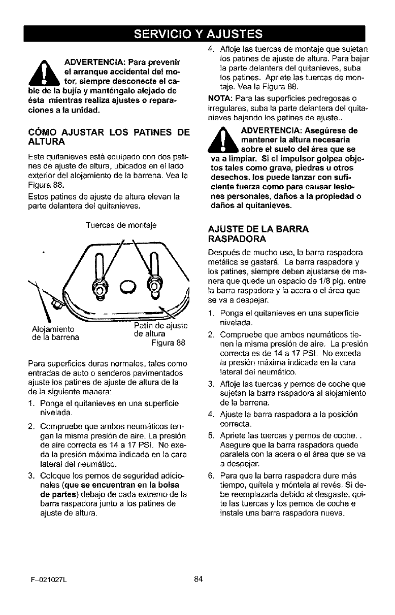
_IL ADVERTENCIA: Para prevenir
el arranque accidental del mo-
tor, siempre desconecte el ca-
ble de la bujia y mant6ngalo alejado de
6eta mientras realiza ajustes o repara=
clones a la unidad.
C_MO AJUSTAR LOS PAT|NES DE
ALTURA
Este quitanieves est& equipado con dos pati-
nes de ajuste de altura, ubicados en el lade
exterior del alojamiento de la barren& Vea la
Figura 88.
Estos patines de ajuste de altura elevan la
parte delantera del quitanieves.
Tuercas de montaje
O
Patin de ajuste
Alojamiento de altura
de la barrena Figura 88
Para superficies duras normales, tales come
entradas de auto o senderos pavimentados
ajuste los patines de ajuste de altura de la
de la siguiente manera:
1. Ponga el quitanieves en una superficie
nivelada.
2. Compruebe que ambos neum_ticos ten-
gan la misma presi6n de aire. La presi6n
de aire correcta es 14 a 17 PSi, No exe-
da ]a presidn m_xima indicada en la cara
lateral deI neum_tico.
3. Coloque los pemos de seguridad adicio-
nales (que se encuentran en la bolsa
de partes) debajo de cada extremo de la
barra raspadora junto a los patines de
ajaste de altura.
4. Afloje las tuercas de montaje que sujetan
los patines de ajuste de altura. Para bajar
la parte delantera del quitanieves, saba
los patines. Apriete las tuercas de men-
taje. Vea ]a Figura 88.
NOTA: Para las superficies pedregosas o
irregulares, saba la parte delantera del quita-
nieves bajando los patines de ajaste..
_hk DVERTENCIA: Aseg_rese de
mantener la altura necesaria
sobre el suelo del _rea que se
va a limpiar. Si el impulsor golpea obje-
tos tales como grava, piedras u otros
desechos, los puede lanzar con sufi-
ciente fuerza como para causar lesio-
nes personales, da_os ala propiedad o
da_os al quitanieves,
AJUSTE DE LA BARRA
RASPADORA
Despa6s de mucho uso, la barra raspadora
met&lica se gastar& La barra raspadora y
los patines, siempre deben ajustarse de ma-
nera que quede un espacio de 1/8 pig. entre
la barra raspadora y [a acera o el _rea que
se va a despejar.
1. Ponga el qaitanieves en una superficie
nivelada.
2, Compruebe que ambos neumaticos tie-
hen ]a misma presi6n de aire. La presi6n
correcta es de 14 a 17 PSL No exceda
la presi6n m_xima indicada en ]a cara
lateral del neumatico.
3. Afloje las tuercas y pemos de coche que
sujetan la barra raspadora al alojamiento
de la barren&
4. Ajaste la barra raspadora a la posici6n
correcta.
5. Apriete las tuercas y pemos de coche..
Asegure que la barra raspadora quede
paralela con la acera o el _rea que se va
a despejar.
6. Para que la barra raspadora dure mas
tiempo, quitela y m6ntela al rev6s. Si de-
be reemplazada debido al desgaste, qui-
te [as tuercas y los pernos de coche e
instale una barra raspadora nueva.
F_)21027L 84
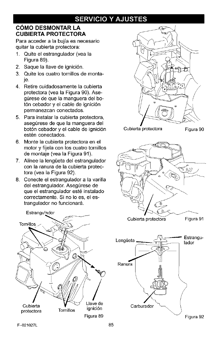
C6MO DESMONTAR LA
CUBIERTA PROTECTORA
Para acceder a la bujfa es necesario
quitar la cubierta protectora:
1. Quite el estrangulador (vea la
Figura 89).
2. Saque la Ilave de ignici6n.
3. Quite los cuatro tornillos de monta-
je.
4. Retire cuidadosamente la cubierta
protectora (vea la Figura 90). Ase-
gt_rese de que la manguera del bo-
t6n cebador y el cable de ignici6n
permanezcan conectados.
5. Para instalar la cubierta protectora,
asegDrese de que la manguera del
bot6n cebador y el cable de ignici6n
est6n conectados.
6. Monte la cubierta protectora en el
motor y fijela con los cuatro tornillos
de montaje (vea la Figura 91).
7. Alinee la leng0eta del estrangulador
con la ranura de la cubierta protec-
tora (vea la Figura 92).
8. Conecte el estrangulador a la varilla
del estrangulador. AsegDrese de
que el estrangulador est6 instalado
correctamente. Si no Io es, el es-
trangulador no funcionar_.
Estrangulador
TomiUos .J
Cubierta protectora Figura 90
Cubierta protectora Figura 91
_-Estrangu-
LengL_eta lador
Ranura_
Cubierta
pmtectora Tornillos
F_)21027L
/
Llave de
ignici6n
Figura 89
85
Figura 92
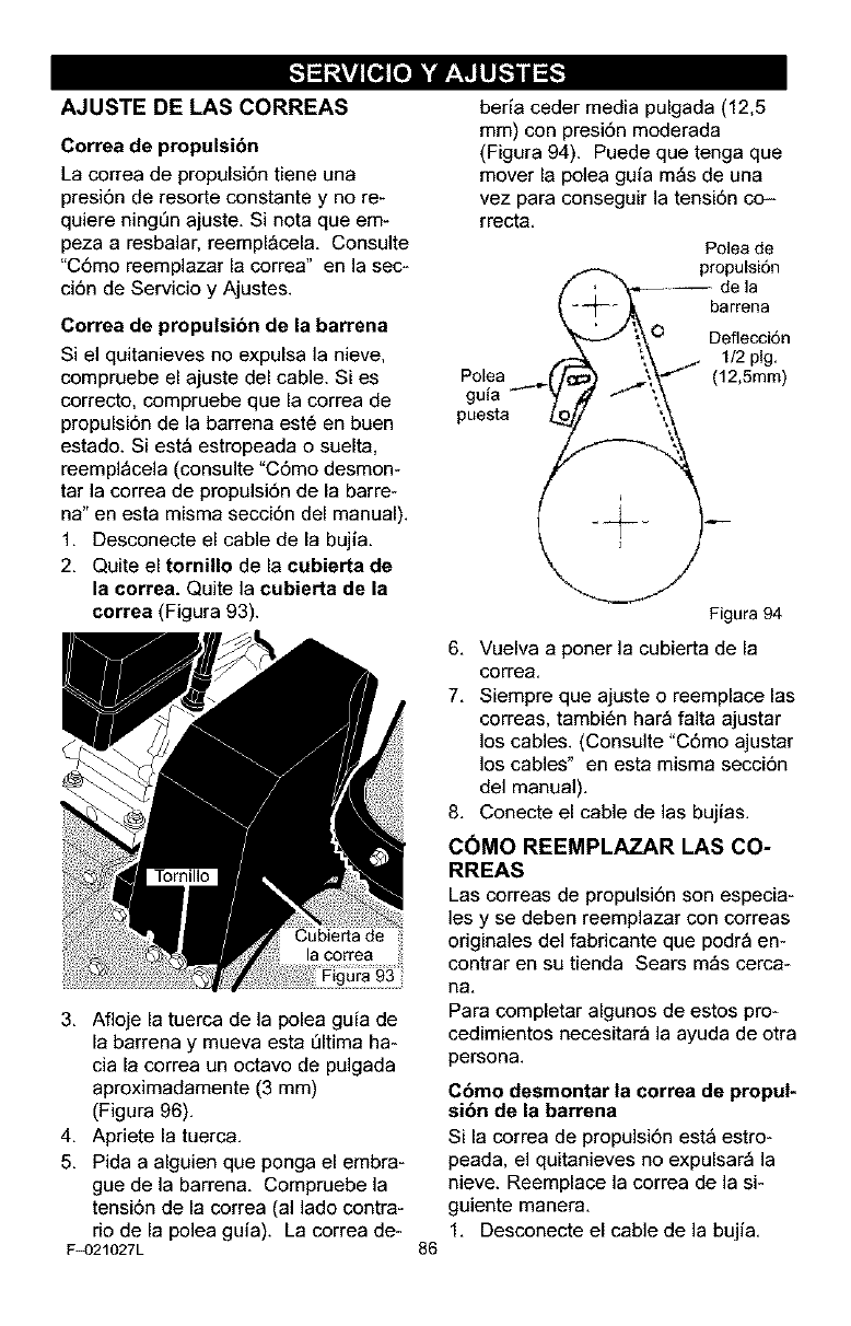
AJUSTE DE LAS CORREAS
Correa de propulsibn
La correa de propulsi6n tiene una
presi6n de resorte constante y no re-
quiere ning_n ajuste. Si nota que em-
peza aresbalar, reempl_cela. Consulte
"C6mo reemplazar la correa" en la sec-
ci6n de Servicio y Ajustes.
Correa de propulsibn de la barrena
Si el quitanieves no expulsa la nieve,
compruebe el ajuste del cable. Si es
correcto, compruebe que la correa de
propulsi6n de la barrena est6 en buen
estado. Si est_ estropeada o suelta,
reempl_cela (consulte "C6mo desmon-
tar la correa de propulsi6n de la barre-
na" en esta misma secci6n del manual).
1. Desconecte el cable de la bujia.
2. Quite el tomino de la cubierta de
la correa. Quite la cubierta de la
correa (Figura 93).
3. Afloje la tuerca de la polea guia de
la barrena y mueva esta _ltima ha-
cia la correa un octavo de pulgada
aproximadamente (3 mm)
(Figura 96).
4. Apriete la tuerca.
5. Pida a alguien que ponga el embra-
gue de la barren& Compruebe la
tensi6n de la correa (al lado contra-
rio de la polea gufa). La correa de-
F_)21027L 86
beda ceder media pulgada (12,5
mm) con presi6n moderada
(Figura 94). Puede que tenga que
mover la polea gufa m_s de una
vez para conseguir la tensi6n co--
rrecta.
Polea de
_. propulsi6n
f"k-.---- Is
\ Pg"
Po,ea
gufa y l" ;,_
puesta _ ','_
Figura 94
6. Vuelva a porter la cubierta de la
correa.
7. Siempre que ajuste o reemplace las
correas, tambi6n har_ falta ajustar
los cables. (Consulte "C6mo ajustar
los cables" en esta misma secci6n
del manual).
8. Conecte el cable de las bujias.
C(_MO REEMPLAZAR LAS CO-
RREAS
Las correas de propulsi6n son especia-
les y se deben reemplazar con correas
originales del fabricante que podr_ en-
contrar en su tienda Sears m_s cerca-
ha,
Para completar algunos de estos pro-
cedimientos necesitar_ la ayuda de otra
persona.
Cbmo desmontar la correa de propul-
sibn de la barrena
Si la correa de propulsi6n est_ estro-
peada, el quitanieves no expulsar_ la
nieve. Reemplace la correa de la si-
guiente manera.
1. Desconecte el cable de la bujfa.
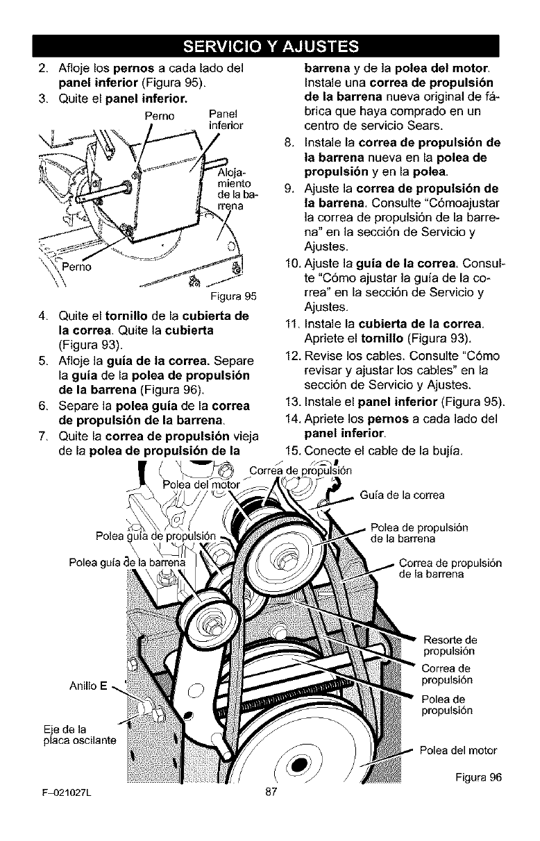
2. Aflojelospernos a cada lado del
panel inferior (Figura 95).
3. Quite el panel inferior.
Perno Panel
inferior
miento
de la ba-
.\\
Figura 95
4. Quite el tomillo de la eubierta de
la eorrea. Quite la cubierta
(Figura 93).
5. Afloje la guia de la correa. Separe
la guia de la polea de propulsidn
de la barrena (Figura 96).
6. Separe la polea guia de la correa
de propulsibn de la barren&
7. Quite la eorrea de propulsi6n vieja
de la polea de propulsibn de la
( _ jCorreade
Polea del motor
barrena y de ]a polea del motor,
Instale una correa de propulsi6n
de la barrena nueva original de f_-
brica que haya comprado en un
centro de servicio Sears,
8, Instale la correa de propulsibn de
la barrena nueva en la polea de
propulsibn y en la pole&
9, Ajuste la correa de propulsibn de
la barrena. Consulte "C6moajustar
]a correa de propulsi6n de la barre-
ha" en la secci6n de Servicio y
Ajustes.
10. Ajuste la guia de la correa. Consul-
te "C6mo ajustar la guia de la co-
rrea" en la secci6n de Servicio y
Ajustes.
11. Instale la cubierta de la correa.
Apriete el tornillo (Figura 93).
12. Revise los cables. Consulte "C6mo
revisar y ajustar los cables" en la
secci6n de Servicio y Ajustes.
13. Instale el panel inferior (Figura 95).
14. Apriete los pernos a cada lado deI
panel inferior.
15. Conecte el cable de la bujia.
f_m
Guia de la correa
Polea
\\
. \
Polea gufade la barrena
propulsi6n
de la barrena
propulsi6n
de la barrena
Anillo
Eje de la
F_)21027L 87
Resorte de
pmpulsi6n
Correa de
propuisi6n
Polea de
propulsi6n
Polea del motor
Figura 96
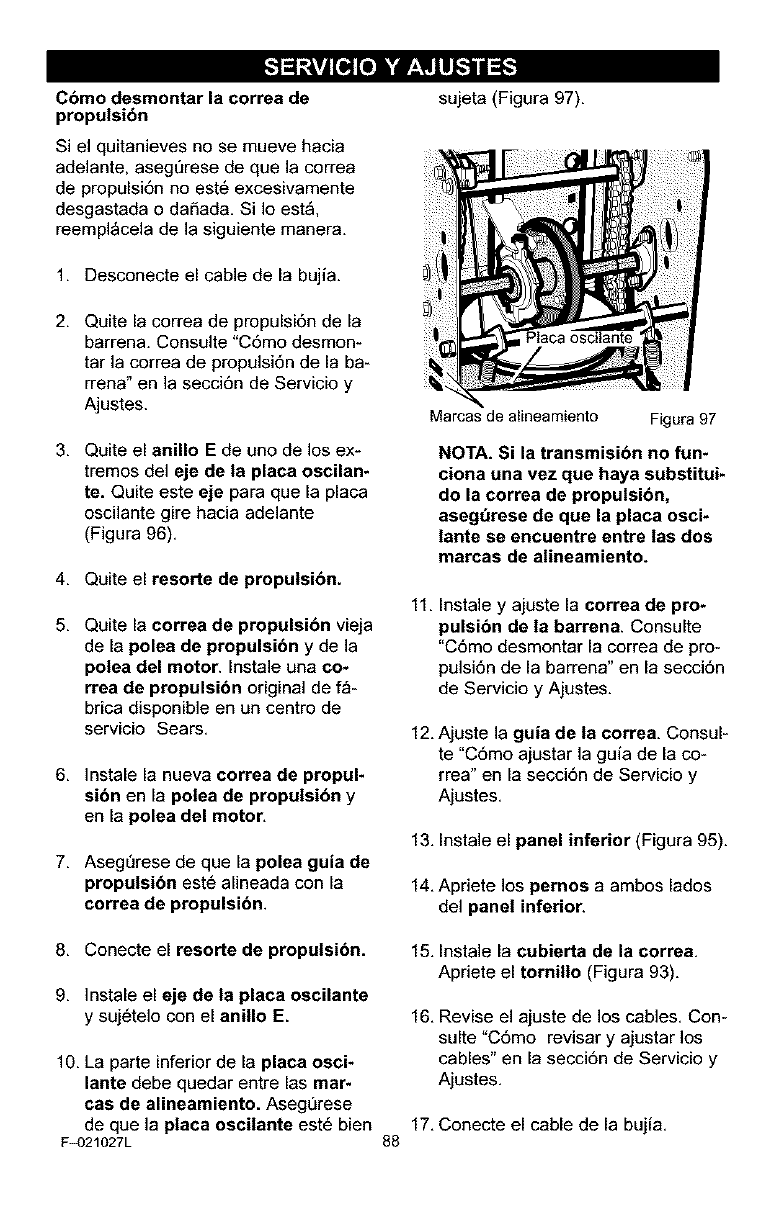
Cbmo desmontar la correa de
propulsibn
Si el quitanieves no se mueve hacia
adelante, asegt_rese de que la correa
de propulsi6n no est6 excesivamente
desgastada o daSada. Si Io est&
reempl_cela de la siguiente manera.
1. Desconecte el cable de la bujia.
2. Quite la correa de propulsi6n de la
barrena. Consulte "C6mo desmon-
tar la correa de propulsi6n de la ba-
rrena" en la secci6n de Servicio y
Ajustes.
3. Quite el anillo Ede uno de los ex-
tremes del eje de la placa oscilan-
re. Quite este eje para que la placa
oscilante gire hacia adelante
(Figura 96).
4. Quite el resorte de propulsibn.
5. Quite la correa de propulsibn vieja
de la polea de propulsibn y de la
polea del motor, Instale una co*
rrea de propulsibn original de f_-
brica disponible en un centro de
servicio Sears.
6, Instale la nueva correa de propul-
sibn en la polea de propulsibn y
en la polea del motor,
7, AsegDrese de que la polea guia de
propulsi6n est6 alineada con la
correa de propulsi6n.
sujeta (Figura 97),
Marcas de alineamiento Figura 97
NOTA. Si la transmisibn no fun-
ciona una vez que haya substitui*
do la correa de propulsibn,
asegt_rese de que la placa osci-
lante se encuentre entre las dos
marcas de atineamiento.
11. Instale y ajuste la correa de pro-
pulsibn de la barrena. Consulte
"C6mo desmontar la correa de pro-
pulsi6n de la barrena" en la secci6n
de Servicio y Ajustes,
12, Ajuste la guia de la correa, Consul-
te "C6mo ajustar la guia de la co-
rrea" en la secci6n de Servicio y
Ajustes,
13, Instale el panel inferior (Figura 95).
14, Apriete los pernos a ambos lades
del panel inferior.
8, Conecte el resorte de propulsi6n.
9. ]nstale el eje de la placa oscilante
y suj6telo con el anino E.
10, La parte inferior de la placa osci-
lante debe quedar entre las mar-
cas de alineamiento. Asegt]rese
de que la placa oscilante est6 bien
F_)21027L
15. Instale la cubierta de la correa,
Apriete el tornillo (Figura 93).
16. Revise el ajuste de los cables. Con-
suite "C6mo revisar y ajustar los
cables" en la secci6n de Servicio y
Ajustes.
17, Conecte el cable de la bujia,
88
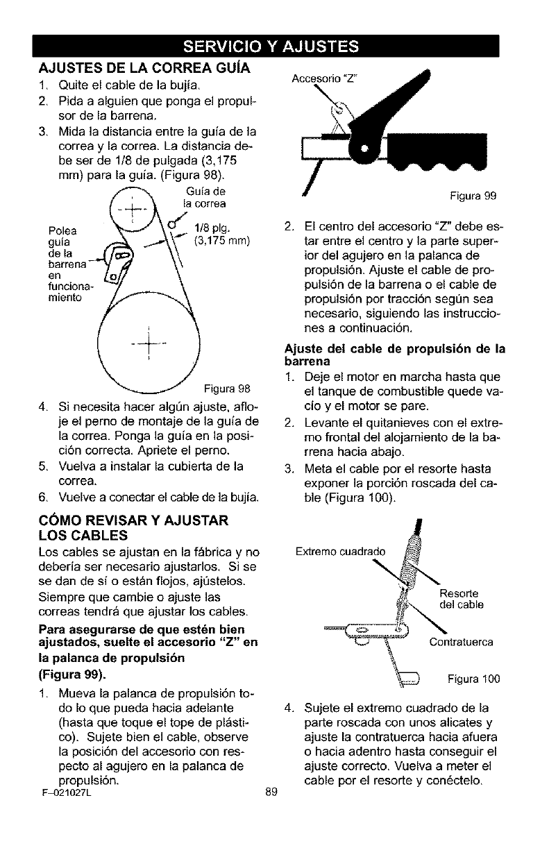
AJUSTES DE LA CORREA GUIA
1. Quite el cable de la bujia.
2. Pida a alguien que ponga el propul-
sor de la barrena.
3. Mida la distancia entre la guia de la
correa y la correa. La distancia de-
be ser de 1/8 de pulgada (3,175
ram) para la guia. (Figura 98).
/_ Guia de
Q+-_O _a correa
Polea "_ J\'..,.._ 1/8 pig.
guia _ _k -_'_\- (3,175 mm)
dela e_
barrena-_ _) _\
fenntie na" L_' \
miento I .@_.
_._ gigura 98
4. Si necesita bacer algDn ajuste, aflo-
je el perno de montaje de la guia de
la correa. Ponga la guia en la posi-
ci6n correct& Apriete el perno.
5. Vuelva a instalar la cubierta de la
correa.
6. Vuelve a conectar el cable de la bujia.
C6MO REVISAR Y AJUSTAR
LOS CABLES
Los cables se ajustan en la f_brica y no
deberia ser necesario ajustarlos. Si se
se dan de si o est_n flojos, ajt]stelos.
Siempre que cambie o ajuste las
correas tendr_ que ajustar los cables.
Para asegurarse de que est6n bien
ajustados, suelte el accesorio "Z" en
la palanca de propulsibn
(Figura 99).
1. Mueva la palanca de propulsi6n to-
do Io que pueda hacia adelante
(hasta que toque el tope de pl_sti-
co). Sujete bien el cable, observe
la posici6n del accesorio con res-
pecto al agujero en la palanca de
propulsi6n.
F_)21027L
Accesodo"_'
Figura 99
2. El centro del accesorio "Z" debe es-
tar entre el centro y la parte super-
ior del agujero en la palanca de
propulsi6n. Ajuste el cable de pro-
pulsi6n de la barrena o el cable de
propulsi6n por tracci6n segt_n sea
necesario, siguiendo las instruccio-
nes a continuaci6n.
Ajuste del cable de propulsi6n de la
barrena
1, Deje el motor en marcha basta que
el tanque de combustible quede va-
cio yel motor se pare,
2. Levante el quitanieves con el extre-
mo frontal del alojamiento de la ba-
rrena hacia abajo.
3. Meta el cable por el resorte hasta
exporter la porci6n roscada del ca-
ble (Figura 100).
Extreme cuadrado
Resorte
del cable
89
Contratuerca
_ Figura 100
4. Sujete el extremo cuadrado de la
parte roscada con unos alicates y
ajuste la contratuerca hacia afuera
o hacia adentro hasta conseguir el
ajuste correcto. Vuelva a meter el
cable por el resorte y con6ctelo.
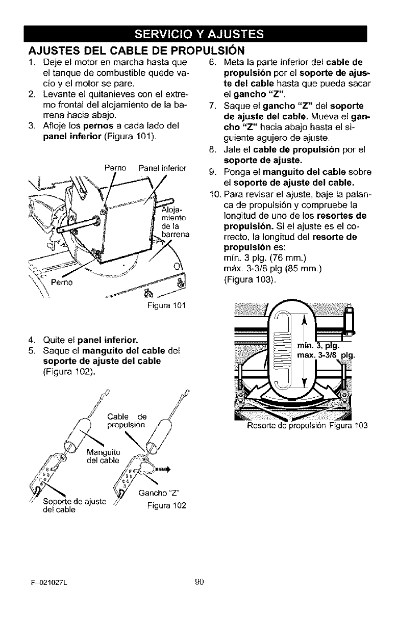
AJUSTES DEL CABLE DE PROPULSI6N
1, Deje el motor en marcha hasta que 6, Meta la parte inferior del cable de
el tanque de combustible quede va-
cio y el motor se pare,
2, Levante el quitanieves con el extre-
mo frontal del alojamiento de la ba-
rrena hacia abajo.
3, Afloje los pemos a cada lado del
panel inferior (Figura 101),
Pemo Panel inferior
miento
de la
barrena
4, Quite el panel inferior.
5, Saque el manguito del cable del
seporte de ajuste del cable
(Figura 102).
propulsibn por el soporte de ajus-
te del cable hasta que pueda sacar
el gancho "Z".
7. Saque el gancho "Z" del soporte
de ajuste del cable. Mueva el gan-
cho "Z" hacia abajo hasta el si-
guiente agujero de ajuste.
8, Jale el cable de propulsibn por el
soporte de ajuste.
9. Ponga el manguito del cable sobre
el soporte de ajuste del cable.
10. Para revisar el ajuste, baje la palan-
ca de propulsi6n ycompruebe la
]ongitud de uno de los resortes de
propulsibn. Si el ajuste es el co-
rrecto, la Iongitud del resorte de
propulsibn es:
min, 3 pig, (76 mm,)
m_x, 3-3/8 pig (85 mm.)
(Figura 103).
rain. 3, pig.
Cable de f _//'J_
propulsi6n_/
Manguito Ny/._
delcable ,zi/F_ .
Soportede ajuste /_ G_'cn:t°jZ"
del cable F*gura102
Resorte de propalai6n Figura 103
F_)21027L 90
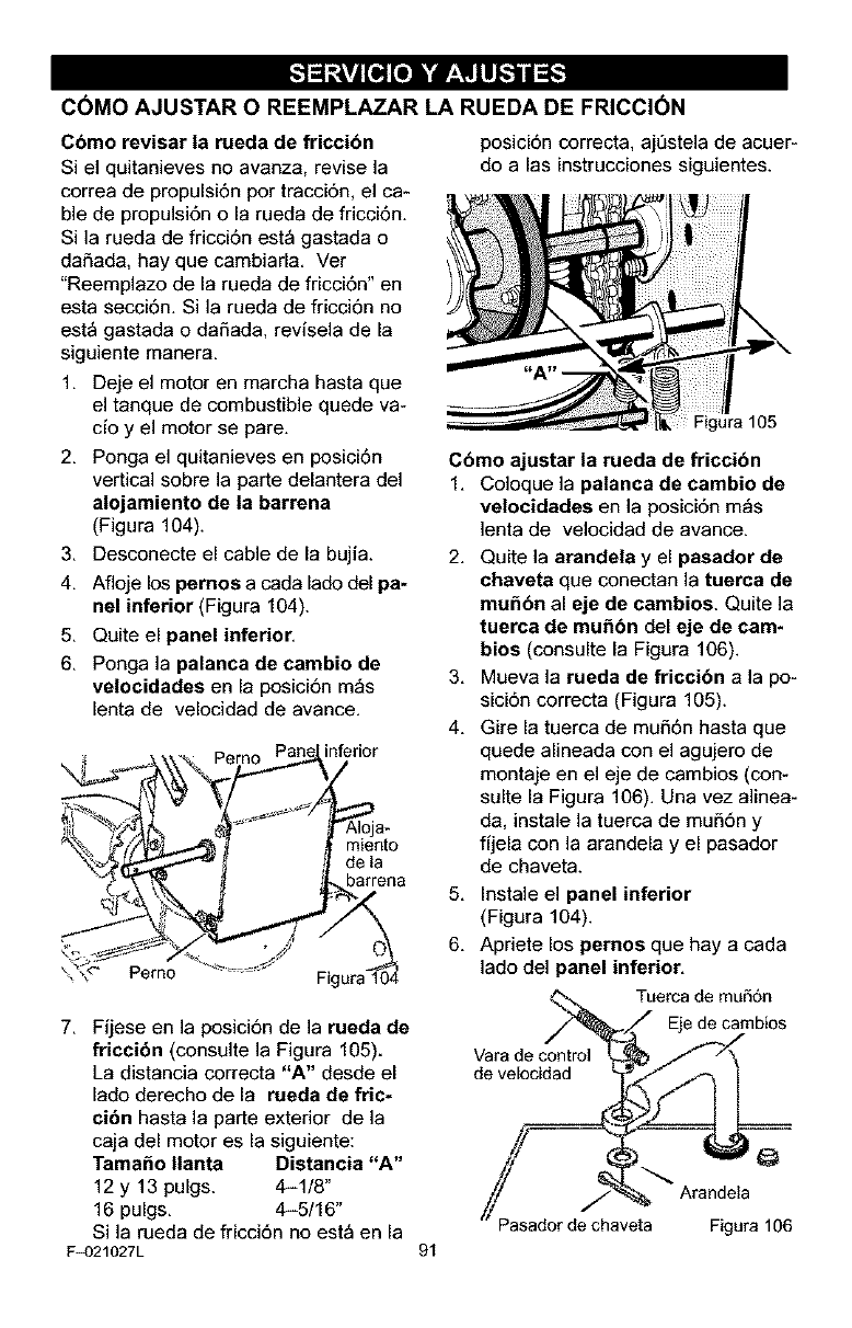
C6MO AJUSTAR O REEMPLAZAR LA RUEDA DE FRICCI6N
Cbmo revisar la rueda de friccibn
Si el quitanieves no avanza, revise la
correa de propulsi6n por tracci6n, el ca-
ble de propulsi6n o la rueda de fricci6n.
Si la rueda de fricci6n est_ gastada o
daSada, hay que cambiarla. Ver
"Reemplazo de la rueda de fricci6n" en
esta secci6n. Si la rueda de fricci6n no
est_ gastada o daSada, revisela de la
siguiente manera.
1. Deje el motor en marcha hasta que
el tanque de combustible quede va-
cioy el motor se pare.
2. Ponga el quitanieves en posici6n
vertical sobre la parte delantera del
atojamiente de la barrena
(Figura 104).
3. Descenecte el cable de la bujia.
4. Afloje los pernos a cada lado del pa*
nel inferior (Figura 104).
5. Quite el panel inferior.
6. Ponga la palanca de cambio de
velocidades en la posici6n m_s
lenta de velocidad de avance.
inferior
miento
de la
barrena
Perno Figura 104
7. Fijese en la posici6n de la rueda de
friccibn (consulte la Figura 105).
La distancia correcta "A" desde el
lade derecho de la rueda de fric-
ci6n hasta la parte exterior de la
caja del motor es la siguiente:
TamaSo Ilanta Distancia "A"
12 y13 pulgs. 4-1/8"
16 pulgs. 4-5/16"
Si la rueda de fricci6n no est_ en la
F_)21027L
posici6n correct& ajt_stela de acuer-
do alas instrucciones siguientes.
91
Figura 105
Cbmo ajustar la rueda de friccibn
1, Coloque la palanca de cambio de
velocidades en la posici6n m_s
lenta de velocidad de avance.
2. Quite la arandela y el pasador de
chaveta que conectan la tuerca de
rnuSbn al eje de cambios. Quite ]a
tuerca de mu_bn del eje de cam*
bies (consulte la Figura 106).
3. Mueva la rueda de friccibn a la po*
sici6n correcta (Figura 105).
4. Gire la tuerca de mu56n hasta que
quede alineada con el agujero de
montaje en el eje de cambios (con-
suite la Figura 106). Una vez alinea-
da, instale la tuerca de mu56n y
fijela con la arandela y el pasador
de chaveta.
5,
6.
Instale el panel inferior
(Figura 104).
Apriete los pernos que hay a cada
]ado del panel inferior,
._,_ Tuercade mu56n
J Eje de cambios
Varade cont/rol _ 7_'f "/
de velocidad
_//" /_Arandela
//Pasador de chaveta Figura 106
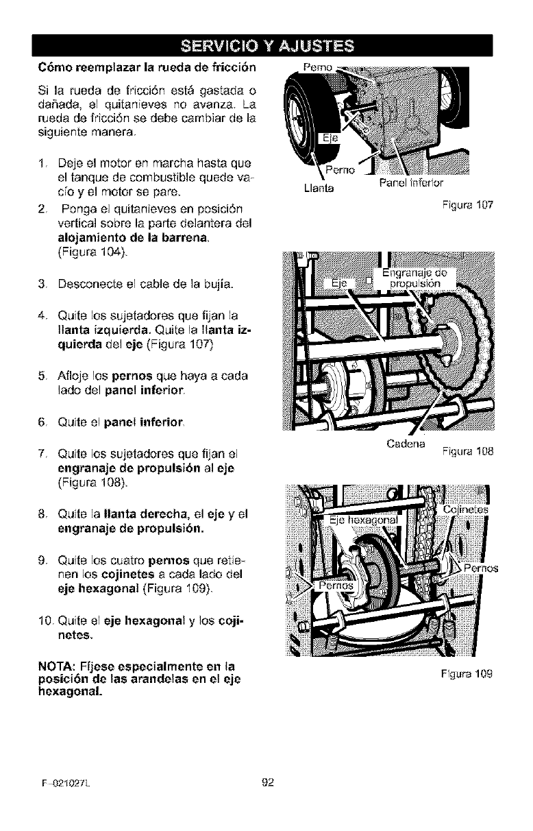
Cbmo reemptazar la rueda de fricci6n
Si la rueda de fricci6r_ est_ gastada o
da_ada, el quitanieves no avanza La
rueda de fricci6n se debe cambiar de la
siguiente manera.
1 Deje el motor en marcha hasta que
el tanque de combustible quede va T
c[oy el motor se pare.
2. Ponga el quitanieves en posici6n
vertical sobre la parte delantera del
alojamiento de la barren&
(Figura 104).
3 Desconecte el cable de la bujia.
4 Quite los sujetadores que fijan la
ttanta izquierda, Quite la Ilanta iz-
quierda del eje (Figura 107)
5 Afloje los pernos que haya a cada
lado del panel inferior,
6 Quite el panel inferior,
7 Quite los sujetadores que fijan el
engranaje de propulsi6n al eje
(Figura 108).
8 Quite la Ilanta dereeha, el eje y el
engranaje de propulsibn.
9 Quite los cuatro pemos que retie
hen los eojinetes a cada lado del
eje hexagonal (Figura 109),
10 Quite el eje hexagonal y los eoji-
netes,
NOTA: Fijese espeeialmente en la
poeiei6n de tas arandetas en et eje
hexagonal.
Llaftta
Ftgura 107
Ftgura 108
Per_os
Ft_ura 109
F 02t027L 92
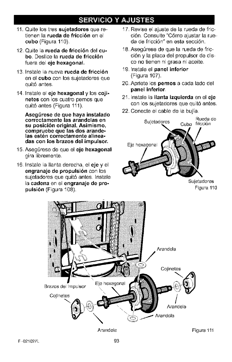
11. Quite los tres sujetadores que re
tienen la rueda de fricei6n on el
eubo (Figura 110)
12 Quite la rueda de friccibn del cu-
bo. Deslice la rueda de frieci6n
fuera del eje hexagonal.
13 Instale la nueva rueda de fricci6n
on el cubo con los sujetadores que
quit6 antes
14 Instale el eje hexagonal y los coji-
netes con los cuatro pemos que
quit6 antes (Figura 111).
AsegOrese de que haya instalado
eorrectamente las arandetas en
su posici6n original. Asimismo,
eompruebe que las dos arande-
tas est6n eorreetamente atinea-
das con los brazos del imputsor,
15 Aseg_rese de que el eje hexagonal
gira libremente
16 Instale la Ilanta derecha el eje y el
engranaje de propulsi6n con los
sujetadores que quitd antes, Instale
la cadena en el engranaje de pro-
pulsi6n (Figura 108).
17 Revise el ajuste de la rueda de fric_
ci6n, Consulte "C6me ajustar la rue
da de fricci6n" en esta secci6n.
18 Aseg5rese de que la rueda de fric_
ci6n y la placa del propulsor de dis_
co no tienen ni grasa ni aceite
19 Instale el panel inferior
(Figura 107),
20, Apriete los pernoe a cada lade del
panel inferior,
21 Instale la Ilanta izquierda en el eje
con los sujetaderes que quit5 antes
22 Conecte el cable do la buj[a
Ruc'da de
Sujetadores Cubo fricci6_t
Eje hexagonal
Sujetadoros
Figura 110
Arandeta
\\
C_inetes
F 02t027L 93
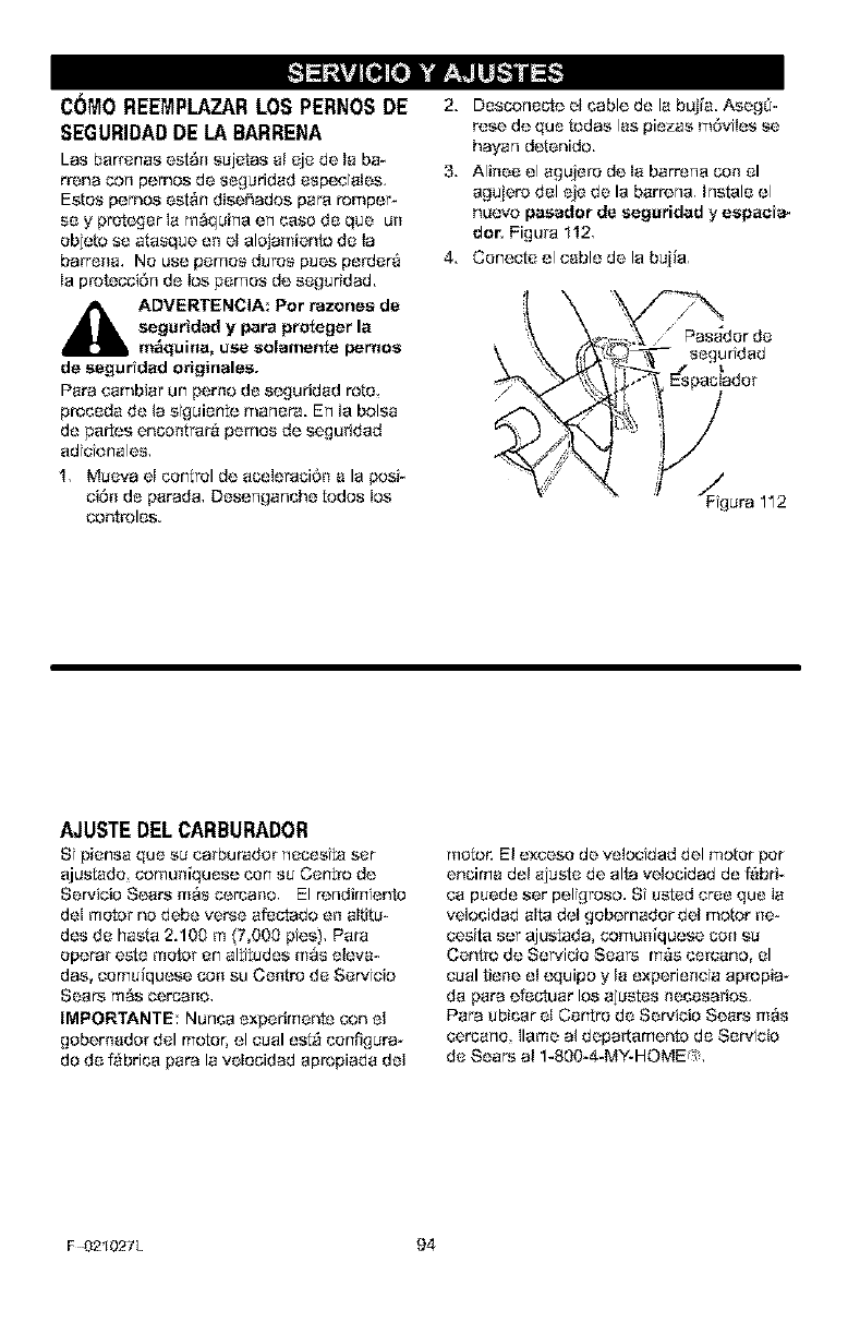
C(_MOREEMPLAZAR LOS PERNOS DE
SEGURIDAD DE LA BARRENA
LaS barrenas est_n s_jetes a! eje de ta ba-
rrona con pemes de se_uridad especiales,
Eetos pemes est_n disei_ades pare romper-
se y pret_._er la m_quina en case de qua un
objeto se atasque en el alejamiento de la
barrena, No use pemes durss pues perde_
Ia protecci6rl de los pemos de seguridad.
_IL DVERTENClA: Per razonea de
segurided y pare proteger la
m_quina, use solamente pernos
de eeguridad originalee.
Pare cambiar an perno de s{._}uridad rote
precede de la stguiente marlera. Erl ta boise
de partes encentra_4 pemos de seguridad
adtctonales,
1, Mueva el control de aceleraai6n ala ;_si-
ci6n de parade, Desenganche redes los
conb_les.
2. Descone{,le el cable de la buj[a. AeegS-
rose de qua Lodes lee plazas m6viles ee
hayer1 detenido.
3. Alinee el agujero de ta barrer]a con el
aguiero del eje de la barrerla, hstale el
nuevo paaedor de segaridad y espacia-
dor, Figul_a 112,
4. Conecte el cable de la buiia,
'/ " erda
"_ I'" Espaciadar
x
. _* _ F.!g Ura 112
AJUSTEDELCARBURADOR
Si piensa qua ea cerburador rleceeita ser
ajustado comuniquese curl su Centre de
Servicio Sears mAs cerceno, El rer_dimtento
del motor no debe verse afeclado en altitu-
des de haste 2.100 m _7,000 pies), #era
eperar este motor en altitudes m_s eleva-
dee, cemuiquese con su Centre de Servicio
Sears m_s cercano,
IMPORTANTE: Nurlca experimente con el
gebernador del motor, el caal est9 cenfigura_
de de f_brica pare la vetaaidad ap*_piada del
motor. El excese de retarded del motor per
enaima del aiuste de alta veloaidad de Pabfi-
ca puede set pelt_roso. St usted crse qua la
velocidad alta dot gebemador del motor ne-
cesita set ajustada, comuniquese con su
Centre de Servicio Sears mas ce_ano, el
coal tiene el cquipo y la experieneta apropia-
de pare efecluar los ajustes necesa_ios,
Pare ubicar el Centre de Servicio Sears mAs
cercarlo llama el depa_tamente de Servtcio
de Sears el 1-800_4*MY-HOME _>,
F 02t027L 94
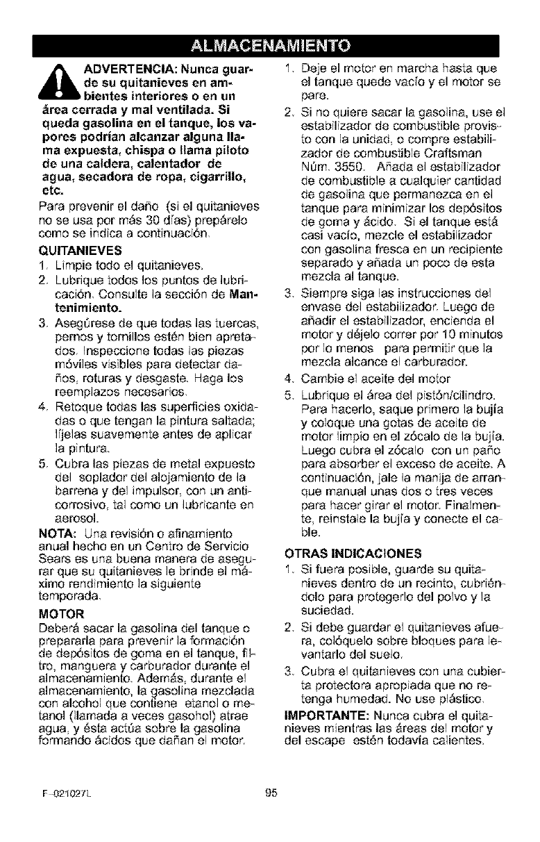
d_hb ADVERTENCIA: Nunca guar-
de su quitanieves en am-
bientes interiores o en un
_rea cerrada y mat venUlada. Si
queda gasolina en el tanque, los va-
pores podrian alcanzar alguna lla-
ma expuesta, ehispa o llama piloto
de una catdera, ealentador de
agua, seeadora de ropa, eigarrillo,
etc.
Para prevenir el dafio (si el quitanieves
no se usa per m_s 30 dTas) prep_relo
come se indica a continuaci6n
QUITANIEVES
1 Limpie rode el quitanieves,
2 Lubrique todos los puntos de lubri_
caci6n Consulte la secci6n de Man-
tenimiento.
3 Asegt_rese de que todas las tuercas,
pemes y tornillos est6n bien apreta_
dos. Inspeccione todas 1as piezas
nq6viles visibles para detectar da-
Res, roturas y desgaste. Haga los
reemplazos necesarios.
4. Retoque todas las superficies oxida_
das o que tengan la pintura saltada;
I[jelas suavemente antes de aplicar
la pintura.
5. Cubra las piezas de nqetal expuesto
de1 soplador de1 alojamiento de la
barrena y de1 impulser con un anti_
corrosive, tal come un lubricante en
aerosol.
NOTA: Una revisi6n o afinarniento
anual hecho en un Centre de Servicio
Sears es una buena nqanera de asegu_
tar que su quitanieves Is brinde el m_
×inqo rendimiento la siguiente
temporada.
MOTOR
Deber& sacar la gasolina del tanque e
prepararla para prevenir la formaci6n
de dep6sitos de goma en el tanque, ilia
tro, manguera y carburador durante el
almacenamiento. Adem,_s durante el
almacenamiento, la gasolina nqezclada
con alcohol que contiene etanol o rne_
tanol 01arnada a veces gasohol) atrae
agua, y 6sla actt_a sobre la gasolina
ferrnando _cidos que dafian el motor.
1 Deje el motor en marcha hasta que
el tanque quede vacfo y el motor se
pare.
2 Si r_oquiere sacar la gasolina, use el
estabilizador de combustible provis
to con la unidad o compre estabili_
zador de combustible Craftsman
Nt_m 3550 ARada el estabilizador
de combustible a cualquier car_tidad
de gasolina que permanezca en el
tanque para nqinirnizar les dep6sitos
de goma y ,_cido. Si el tanque est,_
casi vacio, mezcle el estabilizador
con gaselina fresca en un recipiente
separado y afiada un poco de esta
rnezcla al tanque.
3. Siernpre siga las instrucciones del
envase del estabilizador, Luego de
afiadir el estabilizador, encienda el
motor y d_jelo cotter per 10 nqinutos
pot Io menos para permitir que la
mezcla alcanco el carburador.
4 Cambie el aceite del motor
5 Lubrique el _rea del pist6ntcilindro.
Para hacerle, saque primero la bujia
y coloque una gotas de aceite de
motor limpio en el z6cale de la buj[a.
Luego cubra el z6calo con un pare
para absorber el exceso de aceite. A
continuaci6n, jale la manija de arran
que nqanual LJnasdos o tres veces
para hacer girar el motor_ Finalmen
te reinstale la buj[a y conecte el caT
ble.
OTRAS INDICACtONES
1 Si fuera posible, guarde su quita_
nieves dentro de un recinto, cubri6n
dole para pretegedo del pelvo y la
suciedad.
2 Si debe guardar el quitanieves afue
ra, col6quelo sobre bloques para le
vantarlo del suelo
3 Cubra el quitanieves con una cubieF
ta protectora apropiada que no re_
tenga humedad. No use pl_stico
IMPORTANTE: Nunca cubra el quita_
nieves mientras las 9teas del motor y
del escape est6n todavia calientes.
F 02t027L 95
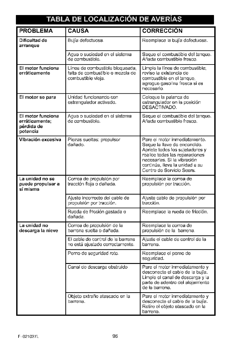
PROBLEMA
Difiaaltad de
arra_qoe
CAUSA CORRECCION
Buiia defectuosa, Reemplace la bujfa defectuosa,
Agua o suciedad en el sistema Saque el combustible del tanque.
de combustible. A_ada combustible fresco.
El motor funaiona Linea de combustible bloqueada Limpte ta Ifnea de eerrlbustible;
err_ticamente falta de combustible o mezcla de revise ta existencia de
combustible vieia, combustible en el tarlque,
agrogue gasolt_a fresco si es
rtecesario,
El motor ee para Unidad funcio_ando ton Coloque la palanca de
estrarlgulader aetivado, estrangulador en la position
DESACTIVADO.
El motor funaiona A_ua o suciedad or1el sistema Saque el combustible del tarlque,
err_ticamente; de combustible. A_ada combustible fresco.
_rdida de
_otencia
Vibraai6n excesiva Plazas suettas propulsor Pare el motor inmediatamente,
da_tado. Saque Ia Ilave de e_lcendtde.
Apriete todos los sujetadoros y
realtce todas las reparaciones
necesaeas, St la vibration
tentt_T_a, Ileva la untdad a su
Centre de Servicio Sears.
La unidad no se Corroa de propulsion per Reemplace la eorroa de
puede propulsar a trocaiOrl fleja o da_'_ada, propulsion per tracci0_.
sf misma
Ajuste incorr_te del cable de Ajcste cable de propulsion per
propulsion ;_r tracciOn, tratti6_.
Rueda de fritti0n _astada e Reemplace la rueda de fricai0_.
da_'_ada.
La o_idad no Corroa de propulsion de la Reemplace la corroa de
desaarga la aieve barrena suelta o daY,ado, propulsion de la barrorla,
El cable de control de la barre[_a Ajcate el cable de co_trol de la
r_oesta ajustado correctame_te, barrer_a.
Pemo de seguridad rote. Reemplace el pemo de
se_uridad.
Canal de descarga ebstraida Pare el motor inmediatamente y
desconecte el cable de la buj[a,
Limpte el ca[_al de descarga y la
paste de ade_tro dot alejamtenta
de la barrona.
Objeto extraRo atastado en la
barrer_a. Pare el motor inmediatamef_te y
desconecte el cable de la buj[a,
Retire el objete atastado en la
barrer_a.
F 02t027L 96
SEARS, ROEBUCK AND CO.
Garantia limitada de cumplimiento con el Sistema Federal
de control de emisiones y con el sistema de control de
emisiones del Estado de California
Motores pequehos pare vehiculos todo terreno
CONTROL DE EMIStONES DE
CALIFORNIA Y DE LA AGENCtA DE
PROTECCION AMBtENTAL (EPA) DE
E,U,A, - DECLARACI(_N DE LA
GARANTiA
La Agencia de Protecct6n Ambienfal de los
Esfados Unidoe (' EPA°), et Consejo de Cali-
fornia pare los Recursos del Airo ('CARB") y
Sears Roebuck and Co. tienen el placer de
expltcar Io qua es la Garantia Federal y de Ca-
Iifemia pare Ststemas de Control de Emtsto-
nee de su nuovo motor peque_o pare
vehiculos todo torreno. En California, los mo-
fa_s pequef_os pare vehiculos todo terreno
de medelo 1995 y modelos de afros posterio-
roe deben ear disef_ados, construtdes y equi-
pados pa_4 cumpItr con Ias estrictas normes
anti contarrlt_eci6n dot Estade. En otros osta-
dos, tes motores modelo 1997 y medelos de
altos posterieres deben ester disef}ados,
construidos y equipados, al memento de su
ve[}ta, pare qua cumplan con los dtspostcto-
nee de Ia EPA acorca de mofaros pequeftos
pare veh[cules fade terreno, Sears Roebuck
and Co., garantizar_ el ststema pare el control
de emisiones de su motor pequeRo pare vehf-
culos todo terreno ;_r los periodas de tiempa
qua se mencionen m6s adelante siempro y
cuando su motor p'_que F_Opare vehfculos fade
fa_erlo no haya eufddo algQn abuse, negligen-
cia, modtficact6n no ap_bada o mart[enimien-
to indebido,
Su ststoma pare el cof_eI de emtsiones puede
incluir partes come el carburadeq el ststema
de encendido y e! sislema de e_ape, Tambi6n
puede tncluir el sistema de descomp*_si6n y
otras unidades relacionadas con lae emtsto-
rtOS,
Cuarldo surja una condict6n protegide per ta
garantia, Sears Roebuck and Co., reparar_
su mofar pequef_o pare veh[culos todo terreno
sincosto alguno pare usted per concepfa de
diagn6stice, pa[tes y mane de obra,
StSTEMA PARA EL CONTROL DE
EMIStONES DEL FABRICANTE-
COBERTURA DE LA GARANT{A
Los sistomae pare el control de emtsio_}es del
modelo 1995 y modelos de a_ios posterioros
de motores peque_ios pare veh[culos fade to-
rreno en California estAn gararffizados per d_
a_os, tel y come se monciona en la presento
9ar.antia, En otros esfados los metoresmode_
Io 1997 y modelos de arcs posteriares farm
bi6n asian garentizados per dos a_os, Ef_
case de qua, detente diche periodo de la ga-
rantia, cualquier plaza del motoK relacionada
con emisfanes est6 defectuosa en sue mate-
dales o mane de obra Soars, Roebuck and
Co,, roparara o cambtar_ dtcha pieza,
RESPONSABtLtDADES DEL
PROPtETARIO DE LA GARANTiA
Come prepietario del motor peque[To pare v_
hiculos todo terreno usted es res;_nsable de
qua se Ileve a cabe el mar_tonimiento requeri-
de qua se menciona en el Manual dol usuafio,
pore Sears, Roebuck and Co., no nogara la
garantia Onic_amentodebido ala falta de un re-
ctbe e a qua ustod no properciono una prueba
escrita de qua se ha ll_ado a cabo el ma[_k;ni-
miento pr_ramedo,
No obstanfa, usfad come propietarfa del m_
tot pequeRo pare vehiculos todo terreno de-
bar_4osfar consciente de qua Sears, Roebuck
and C_., le puede no%jarla cobe_ture de la 9a_
rent[a si su motor o al_una porte dei mtsmo ha
Palladodebido a abuse nc_]ltgencia, martent-
miento inadecuado o modificactor_es no apr_
bodes,
Ustod es respensable de presenter su motor
pequef_o pare vehiculos fade terrono en et Ta_
ller de Servicto Autodzado de Sears, Roebuck
and Co., en cuanto suria el probleme, Los re_
pal_aciones bajo ta 9al_ant[a debar1 Ilevarse a
cebo dentro de un periodo de ttempo razona-
hie qua no exceda de 30 dies.
So puede programar el servicie de garant[a
Ilamando al Taller de Servicie Autorizade de
F 02t027L 97
Soars, Roebuck and Co., o aSears, Roebuck
and Co,, al 1_00_73-7247 (llamada gratui-
ta on E,U,A,).
NOTA IM PORTANTE
Eota declaraci6n de garant[a e×plica los dero-
chos y las obligaciones qua ustod ttene do
conformidad con Ia Garantia doI Sistema pare
o! Control do Emisiones ('Garant[a SCE'), to
cuaI Sears, Roebuck and Co. le proporciona
de conformidad con tas leyes de California,
Coneulto tambt6n lee Ga_antias Ltmitades do
Soars R_buck and Co,, qua so adjuntan ala
Garantia SCE on una hoja apa_to y qua tam-
bi6n Io pro;_rciona Sears, Roebuck and Co,,
La Garant[a SCE _ntcamente so aplica en el
sistema pare el control do emisiones de su
motor nuevo. Haste el puntoen donde no haya
ning_n conflicto on t6rminos entre la Garant[a
SCE y la Garant[a de Soars, R_buck and Co,,
Ia Ga_antia SCE apltcar_ pa_a cualquter ct__-
cunstancie a oxcepci6n de aquet!e on qua to
Garantia de Sears, Roebuck and Go, puede
proporcionar un periodo de garontia m_e la__
go. La Gararlt[e SCE y la Gararlt[a de Soars
Roebuck and Co, do_riben tmportanteo de-
r_hoe y obligacionos qua ustod tiono con r_-
pocto a su motor nuevo,
$6Io so puode Ilevar a cat_ el sorvicio de ga-
rant[a on un Taller do Sorvicio Autorizado do
Soars Roebuck and Co, At memento do soIici-
tar un servicto de gerantia, so debe presenter
una pruoba do la focha do cornpra per porto
del comp_ador original. El comprador pagora
cualquier cargo per concopto do llamadas do
sorvicio y/o transpor[aci6n de produulos des-
de y pare el lugar en donde so Itovo a cabo el
trabajo do inspocci6rl yfo garant[a, Et compra-
dor sor_ responsable de cualquier dare o p6r-
dida en el qua se tncurra con rolaci6n a to
trans;_rtaci6n de cuatquier motor o cualquter
parto del mismo qua ee prosento pare inspoc_
ci6n yio trabajo de garant[a.
Si tione alguna preguata con relaci6n a sue do-
rechoe y *_s[_nsabilidados, debora Ilamar a
Soars R_buck and Co. al 1-800-473-7247.
GARANTIA DEL SISTEMA PARA EL
CONTROL DE EMtSIONES
Garontia del Stotoma pare el Control de Emi-
siones ('Gararlt[a SCE _) de motoroe peque-
Roe pare voh[culos todo terreno modelo 1995
y modelos de afros posto¢ores on California
(pare otros estados, motor.s modeto 1997 y
afros posteriores):
F 02t027L 98
A. CAMPO DE APLICACI_N: Esta gerant[a
dober_ apli_rse a I_ moto*x..s_uof_os pare
veh[culos todo terreno modulo 1995 y mode-
los de aries postoriores on California (pare
otros eotados, motorss modelo 1997 y mode-
los do afros posterior), El Peri_xJo de la Ga-
rantie SCE se intctar_ on la roche de entroga
dol [fuovo tricker o equipo al comp_ador origi-
nal y conttnuara durante los sigutenteo 24 mo-
ses corlsocuttvos,
B. COBERTURA GENERAL DE LA GA-
RANTJA DEL SISTEMA PARA EL CON-
TROL DE EMIStONES: Soars, Roebuck and
Co, garant[za al comprodor original del nuevo
motor o equipo y a cada comprador subse-
cuonte quo su motor peque_o pare veh¢culos
redo terreno osta:
1, DiseRado construido y equipado pare qua
cumple oon rodeo 1asdispootcionos apltcablos
adoptades _r et Consejo pare los Rocursos
dol Aire de conformidad con eu autoridad es-
pocificada on Ice Cap[rules 1 y 2 Parte 5, Divi-
st6n 26 de1C6digo de Salud y Seguridad, y
2, Libro do dofoctoo en sue matedalos y mane
do obra, Io cual cause on cualquior memento
durante el Pododo de la Gar.ant[a SCE, la falla
de una parto rolactonada con emtsiones y qua
est6 bajo la garant[a on cuanto a que no sea
td6ntica en sue matodales a la parto descrita
en la solicitud de motor del fabricante pare eu
cerbficaci6rl,
C. La Garant[a SCE s6Io ata_o a1aspartes do
su motor relacionadas con emisionos do Ia si_
guionto manera:
1, Cualquior parte rolacionada con emisiones
qua no so ospocdiquo corno de aerobic, tel y
come so roquiore en el mantonimiento especi_
ficado on el Manual del Propietado, deber_ ga_
rantizarse per el Pedodo de la Gar.ant[a SCE,
Si dicha parte falla durante el Pefiododo la Ga-
rantia SCE, Sears, Roebuck and Co. le repa-
ral_ o cambtar6 de acuordo con Ia Subser_i6n
4 quo so menciona m_s adelente, Cualquier
paste reparada o cambiada de conformidad
con ta Garant[a SCE deber_ ester gararltizada
per el rosto dol Poriodo de la miema.
2, Cualquter parle garantizada y relacionada
con omietonos qua est6 osp_._tficada s61o pa-
re inspc_ionos regulates conforme al Manual
dot P*_pietedo dobora ester garartiizada per el
Periodo de la Garant[a SCE. Una declaract6n
en dichas instrucciones per escdto a efocto do
'repairer o cambiar tel y come sea necosario"
no reducir_ el Periodo do ta Garant[a SCE. Di-
cha parte roparada o cambiada corfforme a Ia
Gara[TtiaSCEdeber_gara_zarse;_r el r_ste
dol Poriodo de la misma.
3. Cualquier parto garanttzada y relacionada
co[_ omisio_es quo so especifique pare cars-
hie, do co_fformidad con el Manual del Propie-
taHo dober& gara[_tiza_e per el poriodo de
tiorspo provio al primer pu_to de eatable de
caa parle. Sita paste Palla antes dot primer
carsbio pr_ramado, Sears Roebuck and Co.
reparar_ o carsbtar_ esa parle de acuerdo con
Ia Subsc_i6f_ 4 que so mendona m&e adelan-
to. Ccalquier parle relacionada con erstsiones
qae _ *_pa*_ o cambie de corfformtdad con la
Garaftt[a SCE deber8 ester gare[_tizada per et
rosto dol Petite de ta misma provio al primer
porto de cambto pr_ramado de esa parle re-
Iacio[tada con emtstones.
4. La roparaei6n o el cambio de ccalquier parto
garaf_tizada y rolacionada con emisio_es de
co_lformidad con esta Gara[ltia SCE so debe-
r_ Ilevar a cabo, st_ cargo alguno pare el pro-
pieta¢o, on u_TTaller Autorizado de Sorvioto de
Soars, Roebuck a[td Co.
5. No _ target& al prepiotario el costo per tre-
baio de diag[T6stico, el coal Ileva a Ia dotem_i-
naoi6n do que una parto protegtda per ta
Gara[ttia SCE e[ _t_ dofectuosa, provtsto que
dicho trabajo de dia£[t6stico _ tleve a cabo en
a_ Taller Autorizado de Sorvicio de Sears,
Roebuck a[td Co.
6. Sears, Roebuck and Co, sere rosponsable
de defies a otros com[_nentos originalos del
motor o modificacionca aprobadas que probe-
blemof_te seen causados per are falla cors-
prendida on la gara_Ttia de one parte
rolacio[fada con emisto[fes cabierta per la Ga-
rant[a SCE,
7. Durarlto el Periodo de la Gal_entia SCE,
Seers Roebuck and Co. deber_ _nservar an
sarsinistro de par_ca gararffizadas y rolaciona-
des con omisiones que sea suf'oionte pa_e
carsplir la demanda esperada de esas pa[tos
relaotonadas co_f emtsiones,
8. So puede utilizer ccalquior parte de topees-
to relacie_ada con ersisiones autorizada y
ap*_bada per Sears Roebuck and Co. pare
utilizable on el desompef_o de caalquter mare
tentrsiento o eatable de ta Garant[a SCE, la
caal so proporsionar_ st_cargo al_u_o pare el
propietario. Dtoho use _o roducir_ las oblige-
crones de Sears, Roebuck and Co, corlforme
a la Gararltia SCE,
9, Las partos quo so agreguen o modiflque[_
sin aprobaoic_,nno so podr_n utilizer pare mo_
diflcar e reparar un motor de Sears, Roebuck
and Co, Dtcho use a_ula esta Gara_tt[a SCE y
oonforrsar.4 tas bases sufioientos pare recha-
zar la demanda de u_a Garantia SCE. Sears,
Roebuck and Co. no ser_ responsablo, con-
forme a esta ga_entia, per lee fallas de caal-
quiet parte garanttzada de un motor de Sears,
Roebuck and Co, causeries per et use de dP
oha parte agregada o modificada sin aproba-
ot6n.
LAS PARTES RELACIONADAS CON
EMISIONES INCLUYEN A LAS
SIGUIENTES:
1, U_fidad del oarburador y sue com;_nentes
internes
a) Ftlb_ de combustible
b) Empaqaes (juntas) del carburador
o) Tube de e[ttrada
2. Unidad de filtro de aire
a) Elemento dol filtro de afro
3, Sietema de enco_dido, quo t_otuye:
a) Bujfa de erlcendtdo
b) M6dulo de e_toendido
o) Ensarsblaje dol volanto
4, Silenciador catalltico (si estA equtpado)
a) Empaque del silenciador (si est_ equipado)
b) Celector de escape (st est_ oquipado)
5, E[_sarsblaje del respiradero dol c_rter dol ci-
g0of_al y sue corspo_entes
a) Tube de oonoxiS_t dol respiradero
10/22/99 EPA/CARB
Sears, Roebuck and Co., Hoffman Estates, IL 60179 U.S.A.
F 02t027L 99

Get it fixed, at your home or ours!
Your Home
Fo_ repa=r in your home of all malor b=and apphances,
lawn and garden equtpment, or heating and coohng systems
no matter who made it, ne matter who seld it!
Fm timereplauement paris, aooessones and
owner s manuals that you need to do-it-yourself
For Sears professtonal mstallatton of home apphances
and ttems hke garage door openers and water heatels
1-800-4-MY-HOME fl Anytime d_y nr mght
_I-800-469-46631 _U S A anc_C,_nad31
www.sears corn www.sears ca
Our Home
For repair of carry-m product_ hke vacuums lawn equipment,
and electrontcs, call ot go on-hne for timenearest
Sears Parts and Repair Center.
1-800-488-1222 Anytime da,_ or mght tU 5 A ;,nly?
WWW,Se_II-S COrn
Te purchase a protection agreement on a preduct serviced by Sears
1-800-827-6655 _US_,, 1-800-361-6565 _Ca'ado}
Papa pedlL servlclo de rep,_rac=n
a dom=olEo y para o=denar Dens
1-888-SU-HOGAR r,I
/_LICanada pour service en fran sis
=
I"SOO'LE-FOYER=''
