Craftsman 536887996 User Manual SNOWTHROWER, GAS Manuals And Guides L0408167
CRAFTSMAN Snowthrower, Gas Manual L0408167 CRAFTSMAN Snowthrower, Gas Owner's Manual, CRAFTSMAN Snowthrower, Gas installation guides
User Manual: Craftsman 536887996 536887996 CRAFTSMAN SNOWTHROWER, GAS - Manuals and Guides View the owners manual for your CRAFTSMAN SNOWTHROWER, GAS #536887996. Home:Lawn & Garden Parts:Craftsman Parts:Craftsman SNOWTHROWER, GAS Manual
Open the PDF directly: View PDF ![]() .
.
Page Count: 96
I(RRFTSMRN1
Operator's Manual
Snow Thrower
9 Horsepower
Electric Start
Dual Stage
Model 536.887996
CAUTION: Before using this product,
read this manual and follow all of its
Safety Rules and Operating Instructions.
Manual del usario
Quitanieves
9 caballos de fuerza (hp)
Bietapico
Arranque electrico
Modelo 536.887996
PRECAUCION: Antes de usar este producto,
lea este manual y siga todas las reglas de
seguridad e instrucciones de operaci6n.
Sears, Roebuck and Co., Hoffman Estates, IL 60179 U.S.A.
F-041084L www.sears.com/craftsman
i('-I:]I=IEe]_[_e_'_
WARRANTY STATEMENT ...... 2
SAFETY RULES ............... 2
INTERNATIONAL SYMBOLS .... 4
ASSEMBLY ................... 6
OPERATION .................. 10
MAINTENANCE ............... 16
SERVICE AND ADJUSTMENT .. 19
STORAGE .................... 30
TROUBLESHOOTING TABLE . ,. 31
REPAIR PARTS ............... 36
ENGINE REPAIR PARTS ....... 54
SPANISH (ESPAI_IOL) .......... 62
PARTS ORDERING/SERVICE ..
BACK COVER
|V/:I,|;r:1_iIi'd[-"_
LIMITED TWO-YEAR WARRANTY ON CRAFTSMAN SNOW THROWER
For two years from the date of purchase, when this Craftsman Snow thrower is maintained,
lubricated, and tuned up according to the operating and maintenance instructions in the
owner's manual, Sears will repair, free of charge, any defect in material or workmanship.
If this Craftsman Snow thrower is used for commercial or rental purposes, this warranty ap-
plies for only 90 days from the date of purchase.
This warranty does not cover the following:
Items which become worn during normal use, such as spark plugs, drive belts and shear
pins.
Repair necessary because of operator abuse or negligence, including bent crankshafts
and the failure to maintain the equipment according to the instructions contained in the
owner's manual.
WARRANTY SERVICE IS AVAILABLE BY RETURNING THE CRAFTSMAN SNOW
THROWER TO THE NEAREST SEARS SERVICE CENTER IN THE UNITED STATES.
THIS WARRANTY APPLIES ONLY WHILE THIS PRODUCT IS IN USE IN THE UNITED
STATES.
This warranty gives you specific legal rights, and you may also have other rights which may
vary from state to state.
Sears, Roebuck and Co., D817WA, Hoffman Estates. IL 60179
_IL OOK FOR THIS SYMBOL TO POINT OUT IMPORTANT SAFETY PRECAUTIONS.
IT MEANS-- ATTENTION!!! BECOME ALERTt!! YOUR SAFETY IS INVOLVED.
Engine Exhaust, some of its constituents, and
certain vehicle components contain or emit
chemicals known to the State of California to
cause cancer and birth defects or other repro-
ductive harm.
Battery posts, terminals and related accessories
contain lead and lead compounds, chemicals
known to the State of California to cause cancer
and birth defects or other reproductive harm.
WASH HANDS AFTER HANDLING.
,_ WARNING: Always discon-
nect the spark plug wire
and place it where it cannot
make contact with spark plug to
prevent accidental starting during:
Preparation, Maintenance, or Stor-
age of your snow thrower.
IMPORTANT: Safety standards re-
quire operator presence controls to
minimize the risk of injury. Your snow
thrower is equipped with such controls.
Do not attempt to defeat the function of
the operator presence control under any
circumstances.
F-O41084L 2
TRAINING
1. Read this operating and service instruction
manual carefully. Be thoroughly familiar
with the controls and the proper use of the
snow thrower. Know how to stop the snow
thrower and disengage the controls quick-
ly.
2. Never allow children to operate the snow
thrower. Never allow adults to operate the
snow thrower without proper instruction.
3. Keep the area of operation clear of all per-
sons, particularly small children and pets.
4. Exercise caution to avoid slipping or falling
especially when operating in reverse.
PREPARATION
1. Thoroughly inspect the area where the
snow thrower is to be used and remove all
doormats, sleds, boards, wires, and other
foreign objects.
2. Disengage all clutches before starting the
engine (motor).
3. Do not operate the snow thrower without
wearing adequate winter outer garments.
Wear footwear that will improve footing on
slippery surfaces.
4. Handle fuel with care; it is highly flam-
mable.
a. Use an approved fuel container.
b. Never remove fuel tank cap or add fuel
to a running engine (motor) or hot en-
gine (motor).
c. Fill fuel tank outdoors with extreme
care. Never fill fuel tank indoors.
d. Replace fuel cap securely and wipe up
spilled fuel.
e. Never store fuel or snow thrower with
fuel in the tank inside of a building
where fumes may reach an open flame
or spark.
f. Check fuel supply before each use, al-
lowing space for expansion as the heat
of the engine (motor) and/or sun can
cause fuel to expand.
5. For all snow throwers with electric starting
motors use electric starting extension
cords certified CSA/UL. Use only with a re-
ceptacle that has been installed in accord-
ance with local inspection authorities.
6. Never attempt to make any adjustments
while the engine (motor) is running (except
when specifically recommended by manu-
facturer).
7. Let engine (motor) and snow thrower ad-
just to outdoor temperatures before starting
to clear snow.
F-041084L
8. Always wear safety glasses or eye shields
during operation or while performing an ad-
justment or repair to protect eyes from
foreign objects that may be thrown from the
snow thrower.
OPERATION
1. Do not operate this snow thrower if you are
taking drugs or other medication which can
cause drowsiness or affect your ability to
operate this snow thrower.
2. Do not use the snow thrower if you are
mentally or physically unable to operate the
snow thrower safely.
3. Do not put hands or feet near or under ro-
tating parts. Keep clear of the discharge
opening at all times.
4. Exercise extreme caution when operating
on or crossing gravel drives, walks or
roads. Stay alert for hidden hazards or
traffic.
5. After striking a foreign object, stop the en-
gine (motor), remove the wire from the
spark plug, thoroughly inspect snow
thrower for any damage, and repair the
damage before restarting and operating
the snow thrower.
6. If the snow thrower should start to vibrate
abnormally, stop the engine (motor) and
check immediately for the cause. Vibration
is generally a warning of trouble.
7. Stop the engine (motor) whenever you
leave the operating position, before un-
clogging the auger/impeller housing or dis-
charge chute and when making any
repairs, adjustments, or inspections.
8. When cleaning, repairing, or inspecting,
make certain the auger/impeller and all
moving parts have stopped and all controls
are disengaged. Disconnect the spark plug
wire and keep the wire away from the spark
plug to prevent accidental starting.
9. Take all possible precautions when leaving
the snow thrower unattended. Disengage
the auger/ impeller, stop engine (motor),
and remove key.
10. Do not run the engine (motor) indoors, ex-
cept when starting the engine (motor) and
for transporting the snow thrower in or out
of the building. Open the outside doors; ex-
haust fumes are dangerous (containing
CARBON MONOXIDE, an ODORLESS
and DEADLY GAS).
11. Do not clear snow across the face of
slopes. Exercise extreme caution when
changing direction on slopes. Do not at-
tempt to clear steep slopes.
12. Never operate the snow thrower without
proper guards, plates or other safety pro-
tective devices in place.
13.Neveroperatethesnowthrowernearen-
closures,automobiles,windowwells,drop-
offs,andthelikewithoutproperadjustment
ofthesnowdischargeangle.Keepchildren
andpetsaway.
14.Donotover!oadthesnowthrowercapacity
byattemptingtoclearsnowattoofasta
rate.
15.Neveroperatethesnowthrowerathigh
transportspeedsonslipperysurfaces.
Lookbehindandusecarewhenbacking
up.
16.Neverdirectdischargeatbystandersor
allowanyoneinfrontofthesnowthrower.
17.Disengagepowertothecollector/impeller
whensnowthroweristransportedornotin
use.
18.Useonlyattachmentsandaccessoriesap-
provedbythemanufacturerofthesnow
thrower(suchastirechains,electricstart
kits,ect.).
19.Neveroperatethesnowthrowerwithout
goodvisibilityorlight.Alwaysbesureof
yourfootingandkeepafirmholdonthe
handles.Walk;neverrun.
20.Donotover-reach.Keepproperfooting
andbalanceatalltimes.
21.Donotattempttousesnowthrowerona
roof.
MAINTENANCE AND STORAGE
1. Check shear bolts and other bolts at fre-
quent intervals for proper tightness to be
sure the snow thrower is in safe working
condition.
2. Never store the snow thrower with fuel in
the tank inside a building where ignition
sources are present such as hot water and
space heaters, clothes dryers, and the like.
Allow the engine (motor) to cool before
storing in any enclosure.
3. Always refer to operator's guide instruc-
tions for important details if the snow
thrower is to be stored for an extended
period.
4. Maintain or replace safety and instruction
labels, as necessary.
5. Run the snow thrower a few minutes after
throwing snow to prevent freeze-up of the
auger/impeller.
_b WARNING: This snow thrower isfor use on sidewalks, driveways
and other ground level surfaces.
Caution should be exercised while using on
steep sloping surfaces. DO NOT USE
SNOW THROWER ON SURFACES ABOVE
GROUND LEVEL such as roofs of resi-
dences, garages, porches or other such
structures or buildings.
_"_"_'_'£o_1_..-_
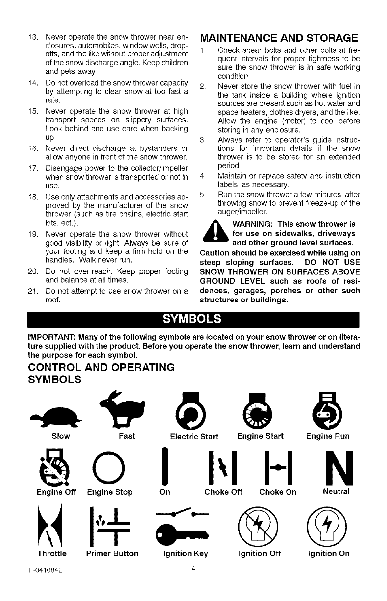
IMPORTANT: Many of the following symbols are located on your snow thrower or on litera-
ture supplied with the product. Before you operate the snow thrower, learn and understand
the purpose for each symbol.
CONTROL AND OPERATING
SYMBOLS
Slow Fast Electric Start Engine Start Engine Run
IN
Throttle Primer Button Ignition Key
F-O41084L 4
I'''L" ®@
Ignition Off Ignition On
Engine Off Engine Stop On Choke Off Choke On Neutral
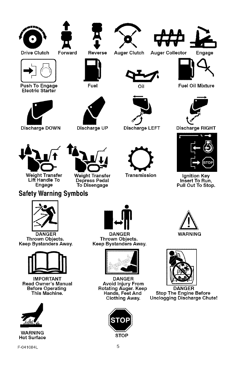
DriveClutch Forward
PushToEngage
ElectricStarter
DischargeDOWN
ReverseAugerClutchAugerCollector Engage
Fuel Oil FuelOilMixture
Discharge UP Discharge LEFT Discharge RIGHT
(.m
Weight Transfer Weight Transfer Transmission Ignition Key
Lift Handle To Depress Pedal Insert To Run,
Engage To Disengage Pull Out To Stop.
Safety Warning Symbols
DANGER
Thrown Objects.
Keep Bystanders Away.
m-IrA
DANGER WARNING
Thrown Objects.
Keep Bystanders Away.
IMPORTANT DANGER
Read Owner's Manual
Before Operating
This Machine.
Avoid Injury From
Rotating Auger. Keep
Hands, Feet And
Clothing Away.
DANGER
Stop The Engine Before
Unclogging Discharge Chute!
WARNING
Hot Surface STOP
F-O41084L 5
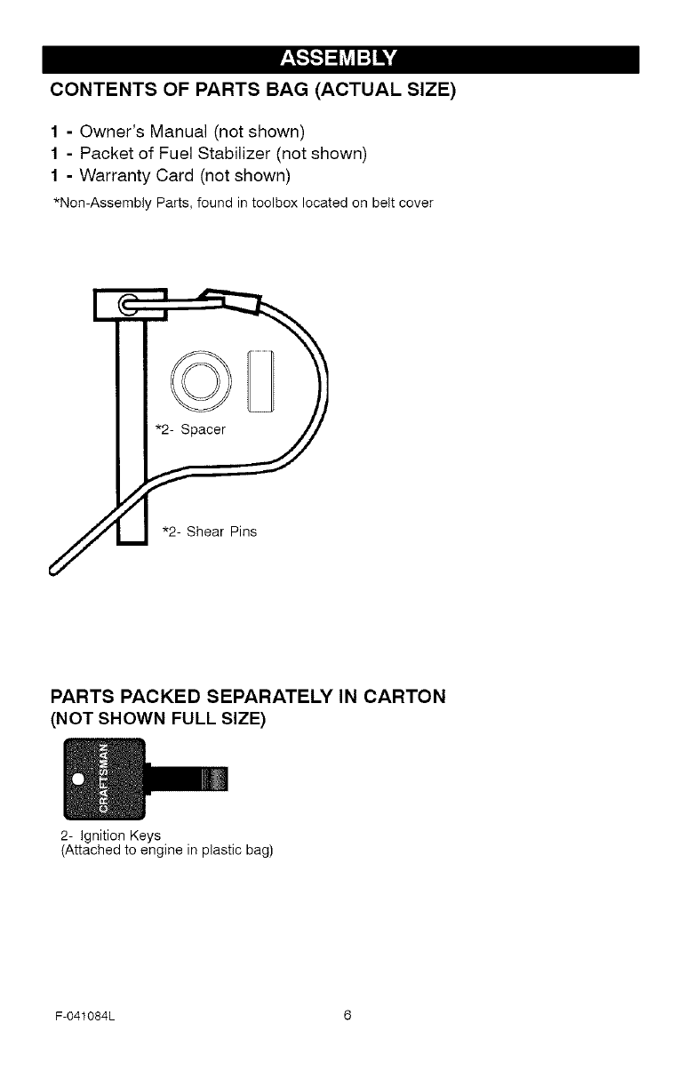
CONTENTS OF PARTS BAG (ACTUAL SIZE)
1-Owner's Manual (not shown)
1-Packet of Fuel Stabilizer (not shown)
1 - Warranty Card (not shown)
*Non-Assembly Parts, foundintoolboxlocatedonbeltcover
*2- Shear Pins
PARTS PACKED SEPARATELY IN CARTON
(NOT SHOWN FULL SIZE)
2- Ignition Keys
(Attached to engine in plastic bag)
F-041084L 6
_hb ARNING: Always wear
safety glasses or eye shields
while assembling snow
thrower.
TOOLS REQUIRED FOR
ASSEMBLY
1 - Knife to cut carton
2 - 1/2 inch wrenches
(or adjustable wrenches)
2 - 9/16 inch wrenches
(or adjustable wrenches)
2 - 3/4 inch wrenches
(or adjustable wrenches)
1 - Pliers (to spread cotter pin)
1 - Screwdriver
1 - Measuring tape or ruler
/'-"4
oFigure 1
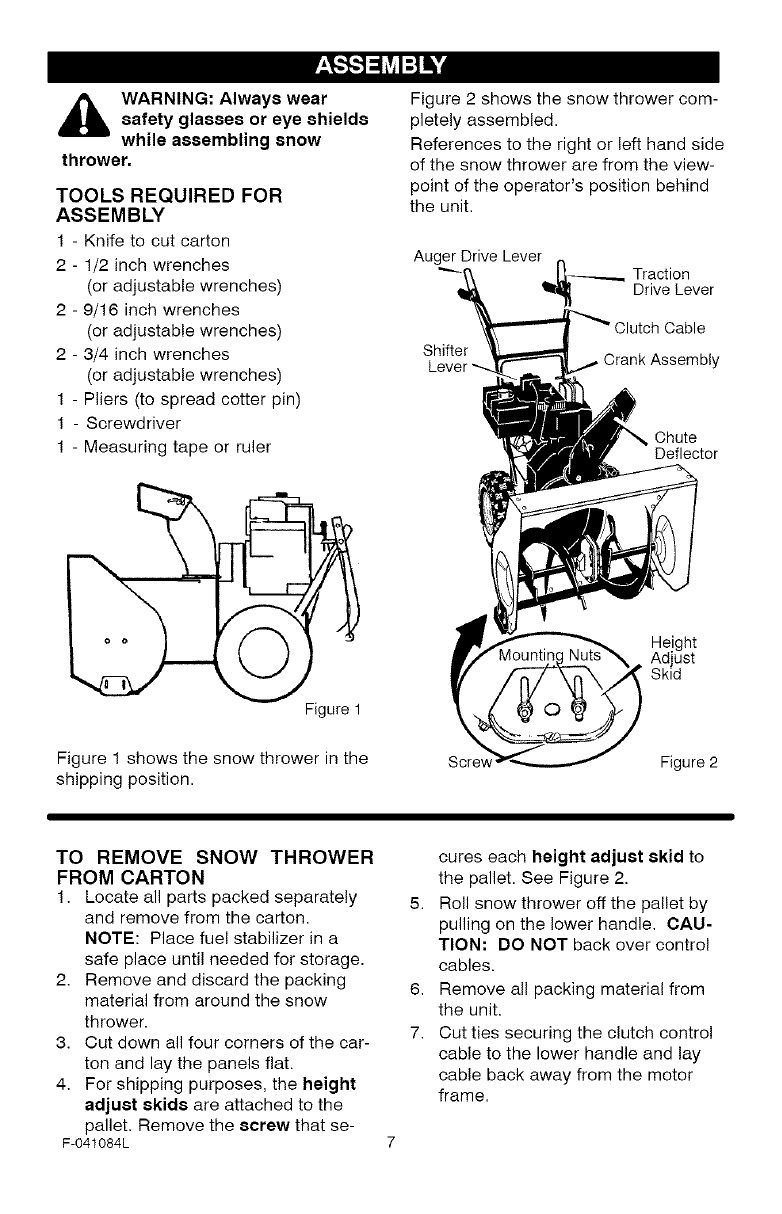
Figure 1 shows the snow thrower in the
shipping position.
Figure 2 shows the snow thrower com-
pletely assembled.
References to the right or left hand side
of the snow thrower are from the view-
point of the operator's position behind
the unit.
Auger Drive Lever
Shifter
Traction
Drive Lever
Cable
Crank Assembly
Chute
Deflector
Height
Adjust
Skid
Scre_ Figure 2
TO REMOVE SNOW THROWER
FROM CARTON
1. Locate all parts packed separately
and remove from the carton.
NOTE: Place fuel stabilizer in a
safe place until needed for storage.
2. Remove and discard the packing
material from around the snow
thrower.
3. Cut down all four corners of the car-
ton and lay the panels flat.
4. For shipping purposes, the height
adjust skids are attached to the
pallet. Remove the screw that se-
F-041084L
cures each height adjust skid to
the pallet. See Figure 2.
5. Roll snow thrower off the pallet by
pulling on the lower handle. CAU-
TION: DO NOT back over control
cables.
6. Remove all packing material from
the unit.
7. Cut ties securing the clutch contro!
cable to the lower handle and lay
cable back away from the motor
frame.
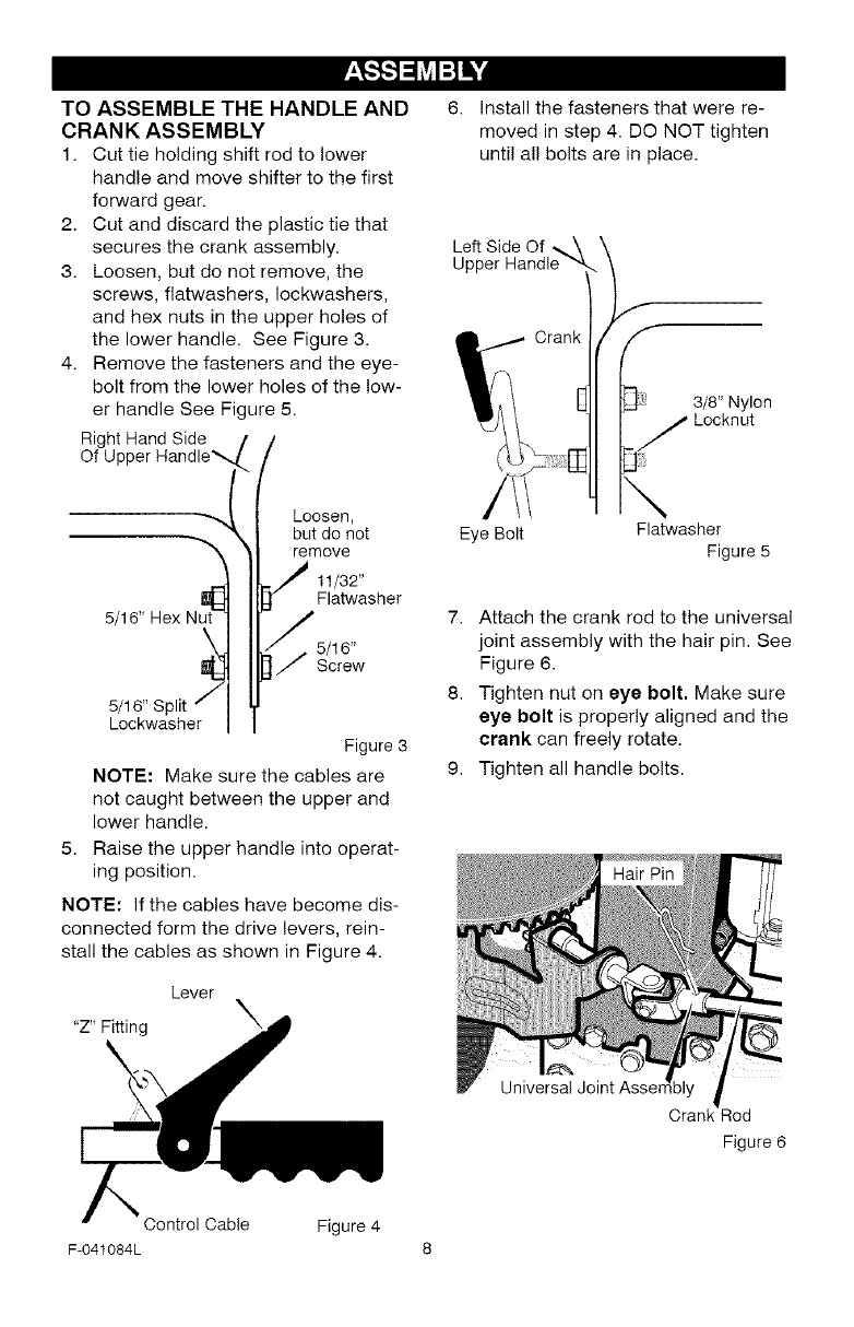
TOASSEMBLETHEHANDLEAND
CRANKASSEMBLY
1. Cuttieholdingshiftrodtolower
handleandmoveshiftertothefirst
forwardgear.
2. Cutanddiscardtheplastictiethat
securesthecrankassembly.
3. Loosen,butdonotremove,the
screws,flatwashers,Iockwashers,
andhexnutsintheupperholesof
thelowerhandle.SeeFigure3.
4. Removethefastenersandtheeye-
bolt from the lower holes of the low-
er handle See Figure 5.
Right Hand Side
Of Upper Handle_,
Loosen,
but do not
"_ remove
ut_ 11/32"
Flatwasher
5/16" Hex N
5/16"
Screw
5/16" Split f
Lockwasher
Figure 3
NOTE; Make sure the cables are
not caught between the upper and
lower handle.
5. Raise the upper handle into operat-
ing position.
NOTE: If the cables have become dis-
connected form the drive levers, rein-
stall the cables as shown in Figure 4.
Lever
"Z" Fitting X
6. Install the fasteners that were re-
moved in step 4. DO NOT tighten
until all bolts are in place.
Left Side Of _.\
Upper Handle -,4,
Crank
3/8" Nylon
Locknut
Eye Bolt
\Flatwasher
Figure 5
7. Attach the crank rod to the universal
joint assembly with the hair pin. See
Figure 6.
8. Tighten nut on eye bolt, Make sure
eye bolt is properly aligned and the
crank can freely rotate.
9. Tighten all handle bolts.
Universal Joint Asser
Crank Rod
Figure 6
Control Cable Figure 4
F-041084L 8
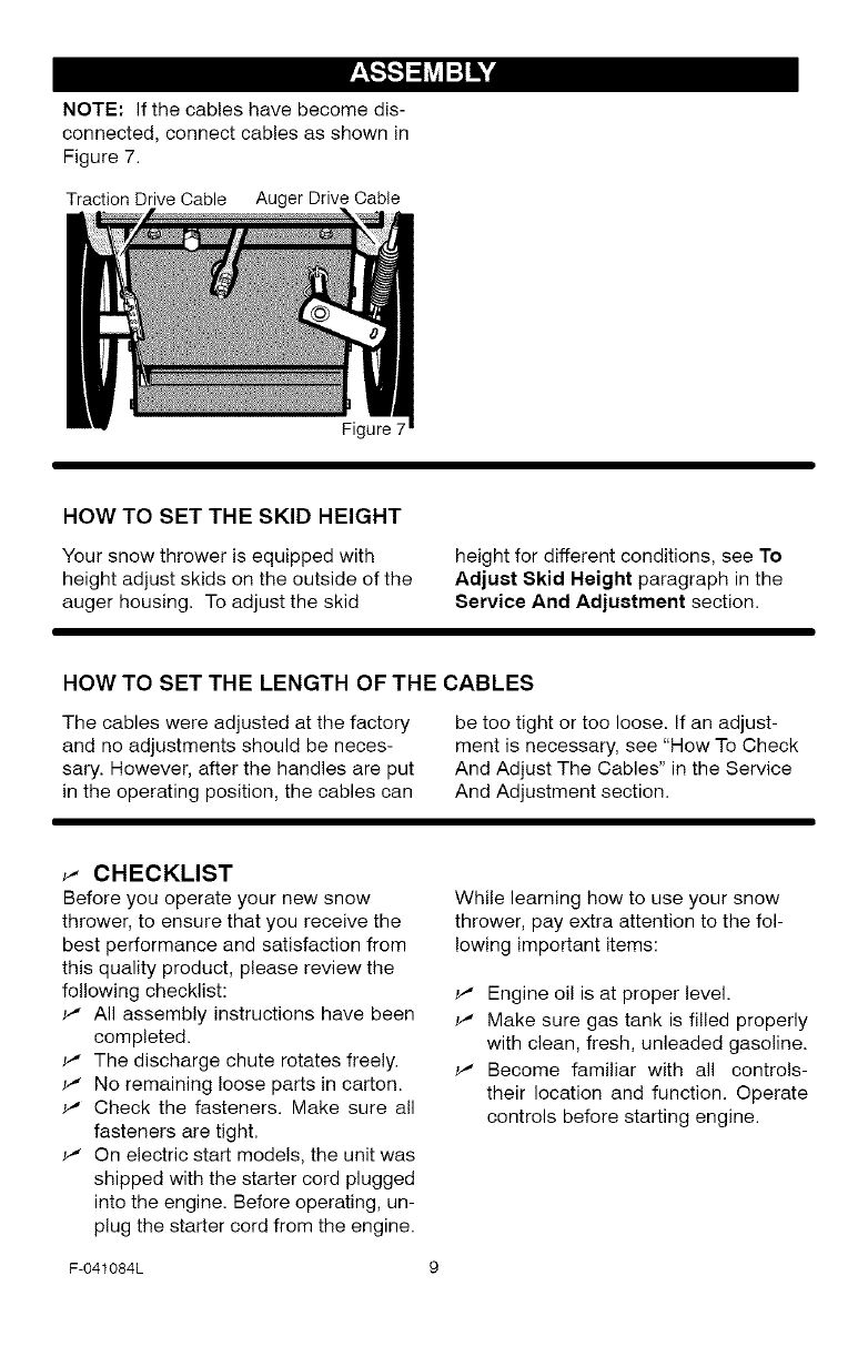
NOTE"Ifthecableshavebecomedis-
connected,connectcablesasshownin
Figure7.
TractionDriveCable AugerDriveCable
Figure7
HOW TO SET THE SKID HEIGHT
Your snow thrower is equipped with
height adjust skids on the outside of the
auger housing. To adjust the skid
height for different conditions, see To
Adjuet Skid Height paragraph in the
Service And Adjuetment section.
HOW TO SET THE LENGTH OF THE CABLES
The cables were adjusted at the factory
and no adjustments should be neces-
sary. However, after the handles are put
in the operating position, the cables can
be too tight or too loose. If an adjust-
ment is necessary, see "How To Check
And Adjust The Cables" in the Service
And Adjustment section.
_" CHECKLIST
Before you operate your new snow
thrower, to ensure that you receive the
best performance and satisfaction from
this quality product, please review the
following checklist:
All assembly instructions have been
completed.
_" The discharge chute rotates freely.
_" No remaining loose parts in carton.
_' Check the fasteners. Make sure all
fasteners are tight.
_" On electric start models, the unit was
shipped with the starter cord plugged
into the engine. Before operating, un-
plug the starter cord from the engine.
While learning how to use your snow
thrower, pay extra attention to the fol-
lowing important items:
_' Engine oil is at proper level.
_' Make sure gas tank is filled properly
with clean, fresh, unleaded gasoline.
_' Become familiar with all controls-
their location and function. Operate
controls before starting engine.
F-041084L 9
[o_o)_
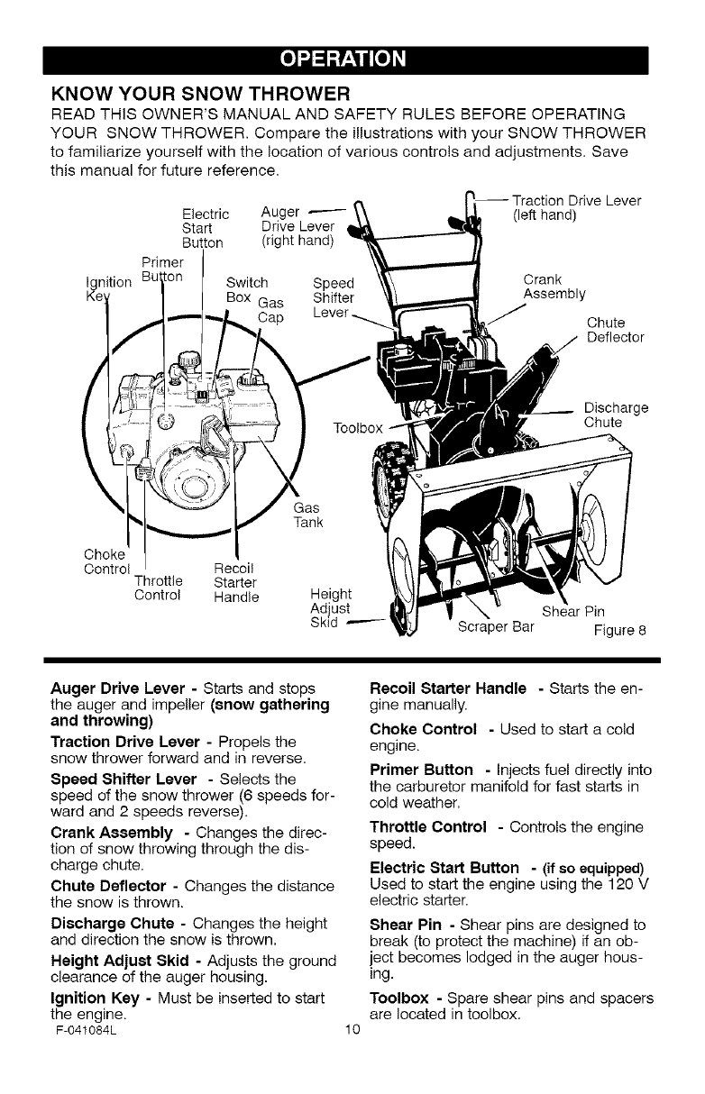
KNOW YOUR SNOW THROWER
READ THiS OWNER'S MANUAL AND SAFETY RULES BEFORE OPERATING
YOUR SNOW THROWER. Compare the illustrations with your SNOW THROWER
to familiarize yourself with the location of various controls and adjustments. Save
this manual for future reference.
Drive Lever
Electric Auger (left hand]
Start Drive Lever
Button (right hand)
Primer
Ignition Bu Switch Crank
Box Gas Assembly
Cap Chute
Deflector
Discharge
Chute
Choke
Control Recoil
Throttle Starter
Control Handle
Gas
Tank
Height
Ad ust Shear Pin
Sk d --'---- Scraper Bar Figure 8
Auger Drive Lever - Starts and stops
the auger and impeller (snow gathering
and throwing)
Traction Drive Lever - Propels the
snow thrower forward and in reverse.
Speed Shifter Lever - Selects the
speed of the snow thrower (6 speeds for-
ward and 2 speeds reverse).
Crank Assembly - Changes the direc-
tion of snow throwing through the dis-
charge chute,
Chute Deflector - Changes the distance
the snow is thrown.
Discharge Chute - Changes the height
and direction the snow is thrown,
Height Adjuet Skid - Adjusts the ground
clearance of the auger housing.
Ignition Key - Must be inserted to start
the engine.
F-041084L 10
Recoil Starter Handle -Starts the en-
gine manually,
Choke Control -Used to start a cold
engine.
Primer Button - Injects fuel directly into
the carburetor manifold for fast starts in
cold weather,
Throttle Control - Controls the engine
speed.
Electric Start Button - (if so equipped)
Used to start the engine using the 120 V
electric starter,
Shear Pin - Shear pins are designed to
break (to protect the machine) if an ob-
iect becomes lodged in the auger hous-
ing.
Toolbox - Spare shear pins and spacers
are located in toolbox.
[o_o)_
The operation of any snow thrower can
result in foreign objects being thrown
into the eyes, which can result in se-
vere eye damage. Always wear safety
glasses or eye shields while operating
the snow thrower.
We recommend standard safety
glasses or a wide vision safety mask for
over your glasses.
_b ARNING: Read Owner's
Manual before operating
machine. Never direct dis-
charge toward bystanders. Stop the
engine before unclogging discharge
chute or auger housing and before
leaving the machine.
TO STOP YOUR
SNOW THROWER
1. To stop throwing snow, release the
auger drive lever.
2. To stop the wheels, release the
traction drive lever,
3. To stop the engine, push the
throttle control lever to off and pull
out the ignition key.
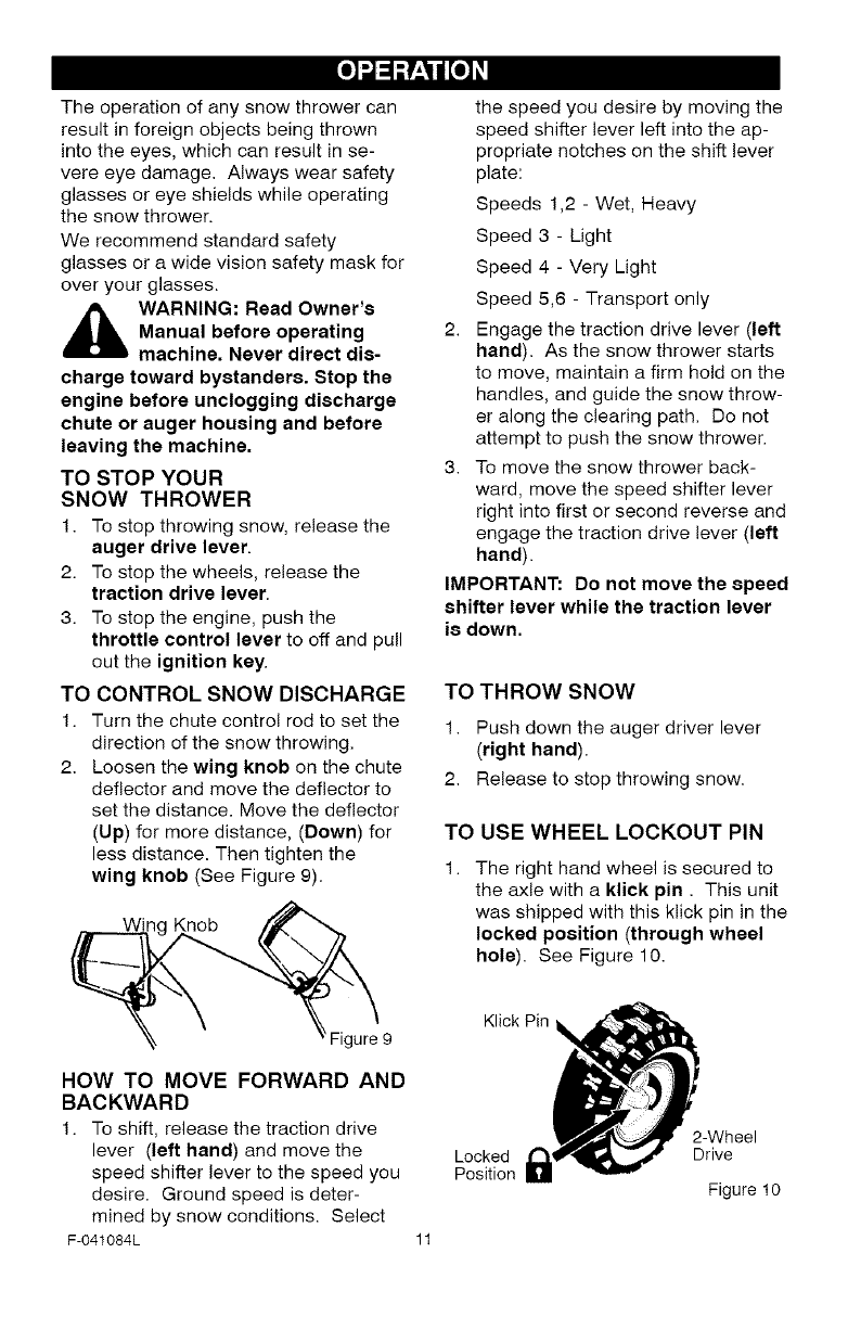
TO CONTROL SNOW DISCHARGE
1. Turn the chute control rod to set the
direction of the snow throwing.
2. Loosen the wing knob on the chute
deflector and move the deflector to
set the distance. Move the deflector
(Up) for more distance, (Down) for
less distance. Then tighten the
wing knob (See Figure 9).
Knob
the speed you desire by moving the
speed shifter lever left into the ap-
propriate notches on the shift lever
plate:
Speeds 1,2 - Wet, Heavy
Speed 3 - Light
Speed 4 - Very Light
Speed 5,6 - Transport only
2. Engage the traction drive lever (left
hand). As the snow thrower starts
to move, maintain a firm hold on the
handles, and guide the snow throw-
er along the clearing path. Do not
attempt to push the snow thrower.
3. To move the snow thrower back-
ward, move the speed shifter lever
right into first or second reverse and
engage the traction drive lever (left
hand).
IMPORTANT: Do not move the speed
shifter lever while the traction lever
is down.
TO THROW SNOW
1. Push down the auger driver lever
(right hand).
2. Release to stop throwing snow.
TO USE WHEEL LOCKOUT PIN
The right hand wheel is secured to
the axle with a klick pin. This unit
was shipped with this klick pin in the
locked position (through wheel
hole). See Figure 10.
Figure 9
Klick Pin
HOW TO MOVE FORWARD AND
BACKWARD
1. To shift, release the traction drive
lever (left hand) and move the Locked
speed shifter lever to the speed you Position
desire. Ground speed is deter-
mined by snow conditions. Select
F-041084L 11
2-Wheel
Drive
Figure 10
[o_o)_
Unlocked
Position
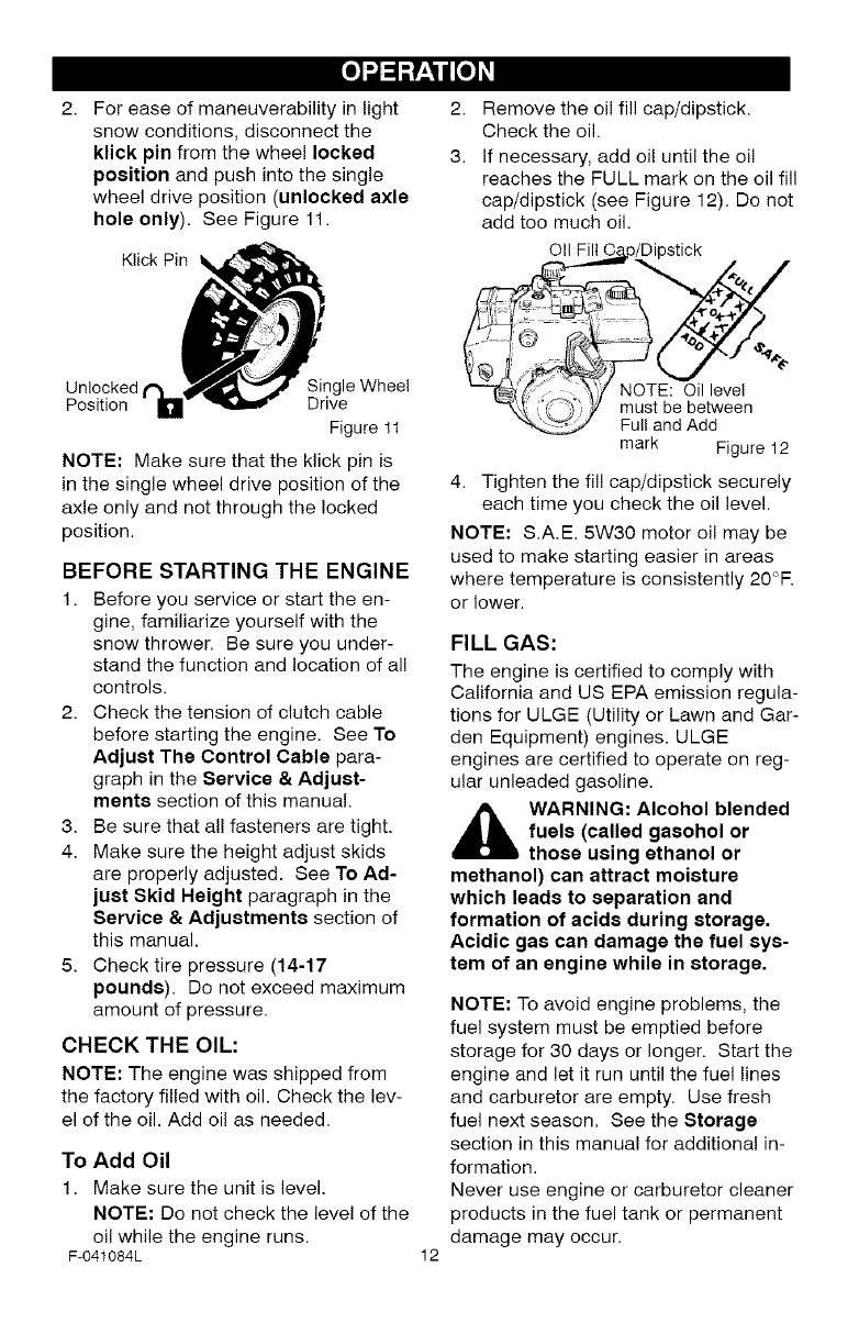
For ease of maneuverability in light 2. Remove the oil fill cap/dipstick.
snow conditions, disconnect the Check the oil.
klick pin from the wheel locked 3. If necessary, add oil until the oil
position and push into the single reaches the FULL mark on the oil fill
wheel drive position (unlocked axle cap/dipstick (see Figure 12). Do not
hole only). See Figure 11. add too much oil.
NOTE: Make sure that the klick pin is
in the single wheel drive position of the
axle only and not through the locked
position.
Klick Pin_ OII Fill b/Dipstick
_4t
Single Wheel _,_' NOTE: Oil level
| ive -"_, X_ _): _ must be between
Figure 11 "_,._ Full and Add
mark Figure t 2
BEFORE STARTING THE ENGINE
1. Before you service or start the en-
gine, familiarize yourself with the
snow thrower. Be sure you under-
stand the function and location of all
controls.
2. Check the tension of clutch cable
before starting the engine. See To
Adjust The Control Cable para-
graph in the Service & Adjust-
ments section of this manual.
3. Be sure that all fasteners are tight.
4. Make sure the height adjust skids
are properly adjusted. See To Ad-
just Skid Height paragraph in the
Service &Adjustments section of
this manual.
5. Check tire pressure (14-17
pounds). Do not exceed maximum
amount of pressure.
CHECK THE OIL:
NOTE: The engine was shipped from
the factory filled with oil. Check the lev-
el of the oil. Add oil as needed.
To Add Oil
1. Make sure the unit is level.
NOTE: Do not check the level of the
oil while the engine runs.
F-041084L
4. Tighten the fill cap/dipstick securely
each time you check the oil level.
NOTE: S.A.E. 5W30 motor oil may be
used to make starting easier in areas
where temperature is consistently 20°R
or lower.
FILL GAS:
The engine is certified to comply with
California and US EPA emission regula-
tions for ULGE (Utility or Lawn and Gar-
den Equipment) engines. ULGE
engines are certified to operate on reg-
ular unleaded gasoline.
_ ARNING: Alcohol blended
fuels (called gaeohol or
those using ethanol or
methanol) can attract moisture
which leads to separation and
formation of acids during storage.
Acidic gas can damage the fuel sys-
tem of an engine while in storage.
12
NOTE: To avoid engine problems, the
fuel system must be emptied before
storage for 30 days or longer. Start the
engine and let it run until the fuel lines
and carburetor are empty. Use fresh
fuel next season. See the Storage
section in this manual for additional in-
formation.
Never use engine or carburetor cleaner
products in the fuel tank or permanent
damage may occur.
[o_o)_
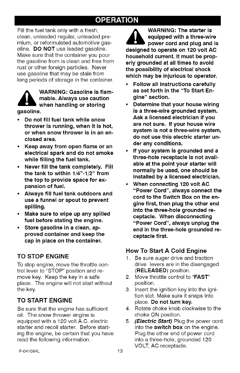
Fill the fuel tank only with a fresh,
clean, unleaded regular, unleaded pre-
mium, or reformulated automotive gas-
oline. DO NOT use leaded gasoline.
Make sure that the container you pour
the gasoline from is clean and free from
rust or other foreign particles. Never
use gasoline that may be stale from
long periods of storage in the container.
A ARNING: Gasoline is flam-
mable. Always use caution
when handling or storing
gasoline.
•Do not fill fuel tank while snow
thrower is running, when it is hot,
or when snow thrower is in an en-
closed area.
•Keep away from open flame or an
electrical spark and do not smoke
while filling the fuel tank.
•Never fill the tank completely. Fill
the tank to within 1/4"-1/2" from
the top to provide space for ex-
pansion of fuel.
•Always fill fuel tank outdoors and
use a funnel or spout to prevent
spilling.
•Make sure to wipe up any spilled
fuel before stating the engine.
•Store gasoline in a clean, ap-
proved container and keep the
cap in place on the container.
TO STOP ENGINE
To stop engine, move the throttle con-
trol lever to "STOP" position and re-
move key. Keep the key in a safe
place. The engine will not start without
the key.
TO START ENGINE
Be sure that the engine has sufficient
oil. The snow thrower engine is
equipped with a 120 volt A.C. electric
starter and recoil starter. Before start-
ing the engine, be certain that you have
read the following information.
F-041084L
A ARNING: The starter is
equipped with a three-wire
power cord and plug and is
designed to operate on 120 volt AC
household current. It must be prop-
erly grounded at all times to avoid
the possibility of electrical shock
which may be injurious to operator.
•Follow all instructions carefully
as set forth in the "To Start En-
gine" section.
•Determine that your house wiring
is a three-wire grounded system.
Ask a licensed electrician if you
are not sure. If your house wire
system is not a three-wire system,
do not use this electric starter un-
der any conditions.
•If your system is grounded and a
three-hole receptacle is not avail-
able at the point your starter will
normally be used, one should be
installed by a licensed electrician.
•When connecting 120 volt AC
"Power Cord", always connect the
cord to the Switch Box on the en-
gine first, then plug the other end
into the three-hole grounded re-
ceptacle. When disconnecting
"Power Cord", always unplug the
end in the three-hole grounded re-
ceptacle first.
13
How To Start A Cold Engine
1. Be sure auger drive and traction
drive levers are in the disengaged
(RELEASED) position.
2. Move throttle control to "FAST"
position.
3. Insert the ignition key into the igni-
tion slot. Make sure it snaps into
place. Do not turn key.
4. Rotate choke knob clockwise to the
choke ON position.
5. (Electric Start) Plug the power cord
into the switch box on the engine.
Plug the other end of power cord
into a three-hole, grounded 120
VOLT, AC receptacle.
[o_o)_
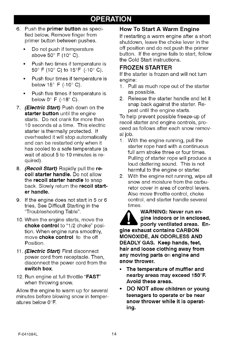
Push the primer button as speci-
fied below. Remove finger from
primer button between pushes.
• Do not push if temperature
above 50 ° F (!0 ° C).
• Push two times if temperature is
50° F (10° C) to 15°F (-10° C).
• Push four times if temperature is
below 15° F (-10° C).
• Push five times if temperature is
be!ow 0° F (-18° C).
7. (Electric Start) Push down on the
starter button until the engine
starts. Do not crank for more than
10 seconds at a time. This electric
starter is thermally protected. If
overheated it will stop automatically
and can be restarted only when it
has cooled to a safe temperature (a
wait of about 5 to 10 minutes is re-
quired).
8. (Recoil Start) Rapidly pull the re-
coil starter handle, Do not allow
the recoil starter handle to snap
back. Slowly return the recoil start-
er handle.
9. If the engine does not start in 5 or 6
tries, See Difficult Starting in the
"Troubleshooting Table".
10. When the engine starts, move the
choke control to "1/2 choke" posi-
tion. When engine runs smoothly,
move choke control to the off
Position.
11. (Electric Start) First disconnect
power cord from receptacle. Then,
disconnect the power cord from the
switch box.
12. Run engine at full throttle "FAST"
when throwing snow.
Allow the engine to warm up for several
minutes before blowing snow in temper-
atures below 0°R
How To Start A Warm Engine
If restarting a warm engine after a short
shutdown, leave the choke lever in the
off position and do not push the primer
button. If the engine fails to start, follow
the Cold Start instructions.
FROZEN STARTER
If the starter is frozen and will not turn
engine:
1. Pull as much rope out of the starter
as possible.
2. Release the starter handle and let it
snap back against the starter. Re-
peat until the engine starts.
To help prevent possible freeze-up of
recoil starter and engine controls, pro-
ceed as follows after each snow remov-
al job.
1. With the engine running, pull the
starter rope hard with a continuous
full arm stroke three or four times.
Pulling of starter rope will produce a
loud clattering sound. This is not
harmful to the engine or starter.
2. With the engine not running, wipe all
snow and moisture from the carbu-
retor cover in area of control levers.
Also move throttle control, choke
control, and starter handle several
times.
,_ WARNING: Never run en-
gine indoors or in enclosed,
poorly ventilated areas. En-
gine exhaust contains CARBON
MONOXIDE, AN ODORLESS AND
DEADLY GAS. Keep hands, feet,
hair and loose clothing away from
any moving parts on engine and
snow thrower.
•The temperature of muffler and
nearby areas may exceed 150°1=.
Avoid these areas.
•DO NOT allow children or young
teenagers to operate or be near
snow thrower while it is operat-
ing.
F-041084L 14
[o_o)_
TO REMOVE SNOW FROM AUGER
A ARNING: Do not attempt
to remove snow or debris
that may become lodged in
auger without taking the following
precautions:
A cleaning stick is attached to the top of
the auger housing. Use the cleaning
stick to remove snow from the auger
housing.
• Release auger drive lever.
• Move throttle lever to stop position.
• Remove (do not turn) ignition key.
• Disconnect spark plug wire.
• Do not place your hands in the au-
ger or discharge chute. Use the
cleaning stick to remove snow.
SNOW THROWING TIPS
1. For maximum snow thrower efficien-
cy in removing snow, adjust ground
speed, NEVER the throttle. Go
slower in deep, freezing or wet
snow. If the wheels slips, reduce
forward speed. The engine is de-
signed to deliver maximum perfor-
mance at full throttle and should be
run at this power setting at all times.
2. Most efficient snow throwing is ac-
complished when the snow is re-
moved immediately after if falls.
3. For complete snow removal, slightly
overlap each path previously taken.
4. The snow should be discharged
down wind whenever possible.
5. For normal usage, set the skids so
that the scraper bar is 1/8" above
the skids. For extremely hard-
packed snow surfaces, adjust the
skids upward so that the scraper
bar touches the ground.
6. On gravel or crushed rock surfaces,
set the skids at 1-1/4" below the
scraper bar. See To Adjust Skid
Height paragraph in the Service &
Adjustments section of this manu-
al. Rocks and gravel must not be
picked up and thrown by the ma-
chine.
7. After the snow throwing job has
been completed, allow the engine to
idle for a few minutes, which will
melt snow and accumulated ice off
the engine.
8. Clean the snow thrower thoroughly
after each use.
9. Remove ice and snow accumulation
and all debris from the entire snow
thrower, and flush with water (if pos-
sible) to remove all salt or other
chemicals. Wipe snow thrower dry.
F-041084L 15
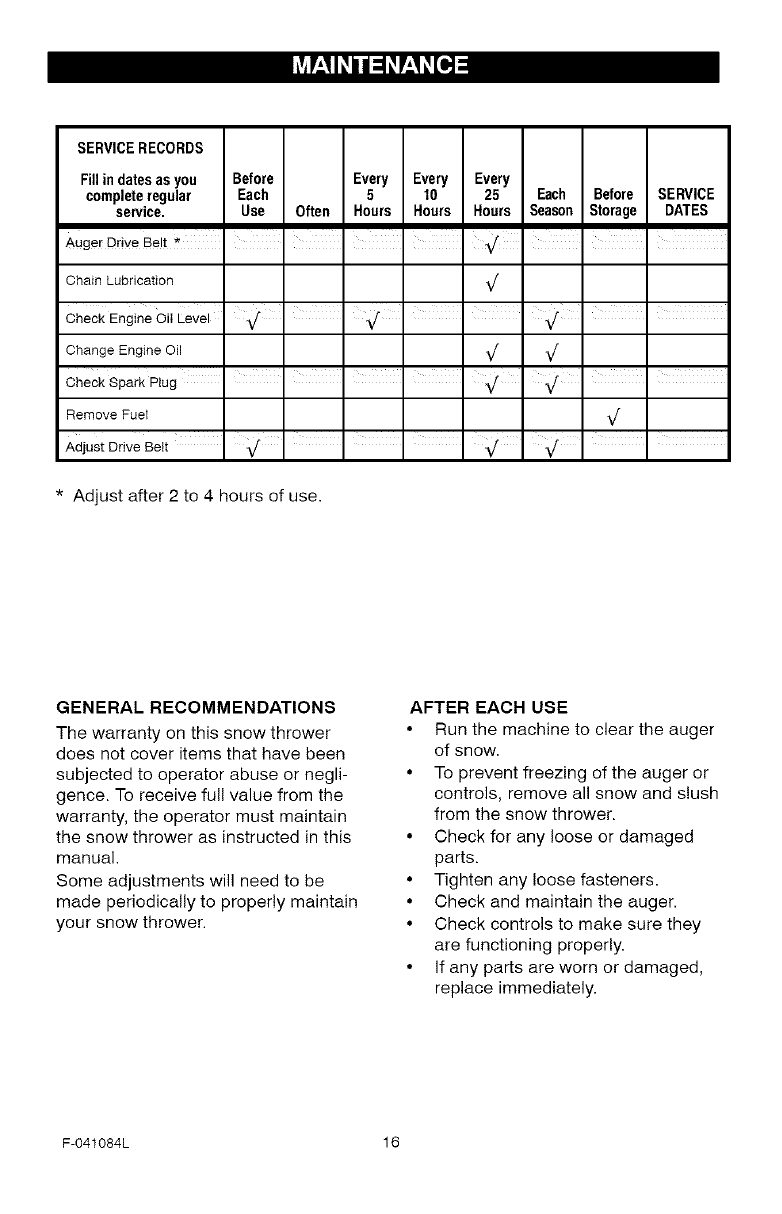
SERVICERECORDS
Fillin datesas you Before Every Every Every
completeregular Each 5 10 25 Each Before SERVICE
service. Use Often Hours Hours Hours Season Storage DATES
Chain Lubrication _/
i i = = =
Check Engine Oil Level _/ • • _/ • -_/ -
Change Engine Oil _/ _/
Check Spark Plug - I I I I
Remove Fuel _/
.iiIII
Adjust Drive Belt _/ _/
* Adjust after 2 to 4 hours of use.
GENERAL RECOMMENDATIONS
The warranty on this snow thrower
does not cover items that have been
subjected to operator abuse or negli-
gence. To receive full value from the
warranty, the operator must maintain
the snow thrower as instructed in this
manual.
Some adjustments will need to be
made periodically to properly maintain
your snow thrower.
AFTER EACH USE
•Run the machine to clear the auger
of snow.
• To prevent freezing of the auger or
controls, remove all snow and slush
from the snow thrower.
• Check for any loose or damaged
parts.
• Tighten any loose fasteners.
• Check and maintain the auger.
• Check controls to make sure they
are functioning properly.
• If any parts are worn or damaged,
replace immediately.
F-041084L 16
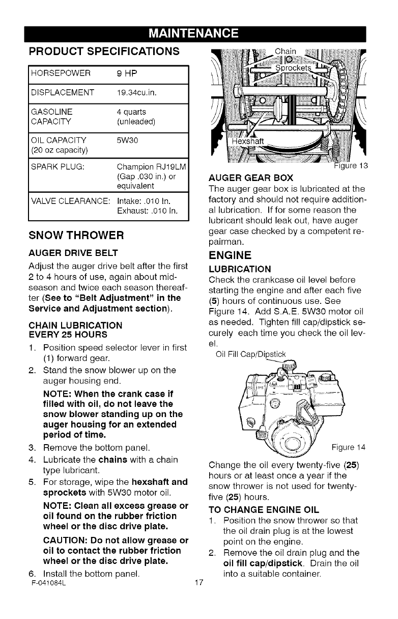
PRODUCT SPECIFICATIONS Chain
HORSEPOWER 9 HP
DISPLACEMENT 19.34cu.in.
GASOLINE 4 quarts
CAPACITY (unleaded)
OIL CAPACITY 5W30
(20 oz capacity)
SPARK PLUG: Champion RJ19LM
(Gap .030 in.) or
equivalent
VALVE CLEARANCE: Intake: .010 In.
Exhaust: .010 In.
SNOW THROWER
AUGER DRIVE BELT
Adjust the auger drive belt after the first
2 to 4 hours of use, again about mid-
season and twice each season thereaf-
ter (See to "Belt Adjustment" in the
Service and Adjustment section).
CHAIN LUBRICATION
EVERY 25 HOURS
1. Position speed selector lever in first
(1) forward gear.
2. Stand the snow blower up on the
auger housing end.
NOTE: When the crank case if
filled with oil, do not leave the
snow blower standing up on the
auger housing for an extended
period of time.
3. Remove the bottom panel.
4. Lubricate the chains with a chain
type lubricant.
5. For storage, wipe the hsxshaft and
sprockets with 5W30 motor oil.
NOTE: Clean all excess grease or
oil found on the rubber friction
wheel or the disc drive plate.
CAUTION: Do not allow grease or
oil to contact the rubber friction
wheel or the disc drive plate.
6. install the bottom panel.
F-041084L
Hexshaft
17
Figure 13
AUGER GEAR BOX
The auger gear box is lubricated at the
factory and should not require addition-
al lubrication. If for some reason the
lubricant should leak out, have auger
gear case checked by a competent re-
pairman.
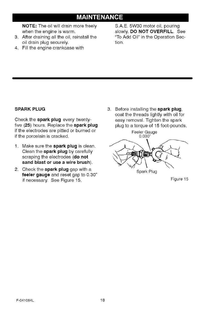
ENGINE
LUBRICATION
Check the crankcase oil level before
starting the engine and after each five
(5) hours of continuous use. See
Figure 14. Add S.A.E. 5W30 motor oil
as needed. Tighten fill cap/dipstick se-
curely each time you check the oil lev-
el.
Oil Fill Cap/Dipstick
Figure 14
Change the oil every twenty-five (25)
hours or at least once a year if the
snow thrower is not used for twenty-
five (25) hours.
TO CHANGE ENGINE OIL
1. Position the snow thrower so that
the oil drain plug is at the lowest
point on the engine.
2. Remove the oil drain plug and the
oil fill cap/dipstick, Drain the oi!
into a suitable container.
NOTE: The oil will drain more freely
when the engine is warm.
3. After draining all the oil, reinstall the
oil drain plug securely.
4. Fill the engine crankcase with
S.A.E. 5W30 motor oi!, pouring
slowly. DO NOT OVERFILL. See
"To Add Oil" in the Operation Sec-
tion.
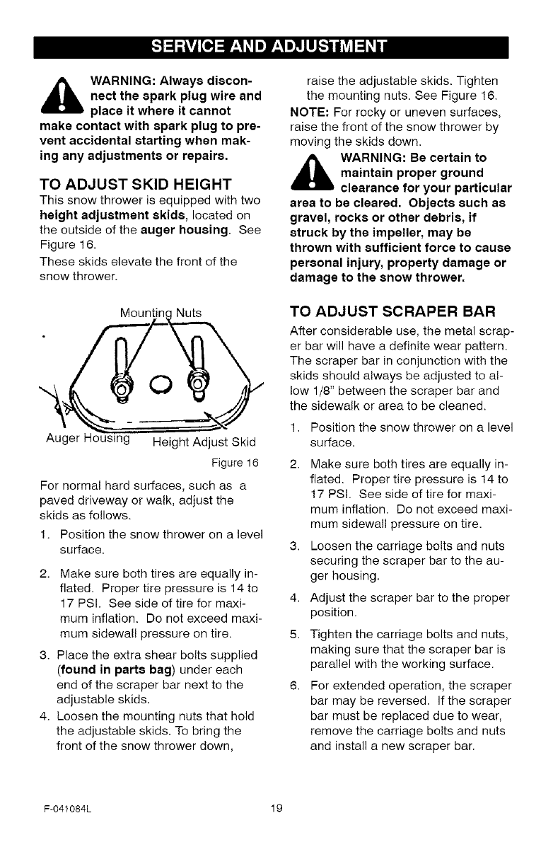
SPARK PLUG
Check the spark plug every twenty-
five (25) hours. Replace the spark plug
if the electrodes are pitted or burned or
if the porcelain is cracked.
1. Make sure the spark plug is clean.
Clean the spark plug by carefully
scraping the electrodes (do net
sand blast or use awire brush).
2. Check the spark plug gap with a
feeler gauge and reset gap to 0.30"
if necessary. See Figure 15.
3. Before installing the spark plug,
coat the threads lightly with oil for
easy removal. Tighten the spark
plug to a torque of 15 foot-pounds.
Feeler Gauge
0.030"
Spark Plug
Figure 15
F-O41084L 18
_b ARNING: Always discon-
nect the spark plug wire and
place it where it cannot
make contact with spark plug to pre-
vent accidental starting when mak-
ing any adjustments or repairs.
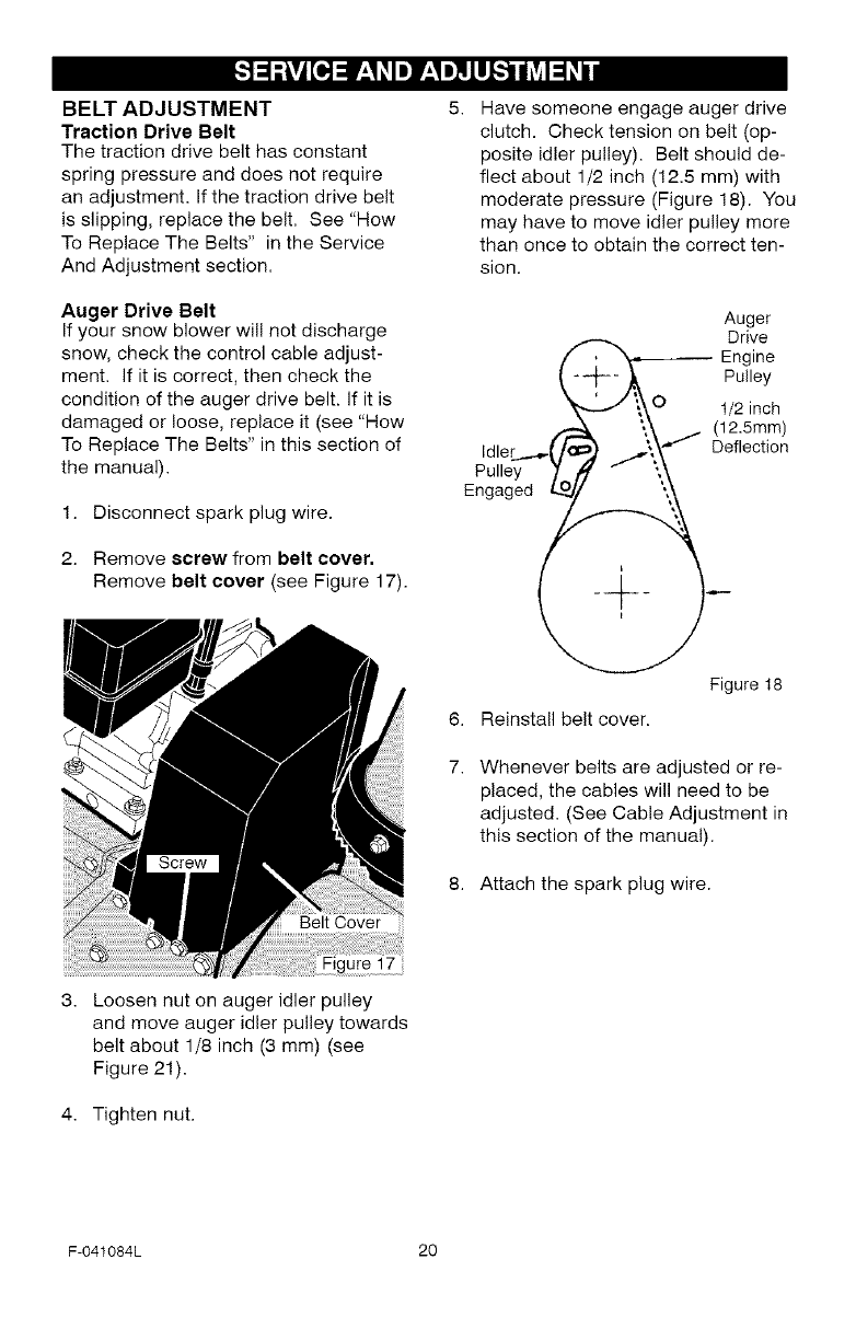
TO ADJUST SKID HEIGHT
This snow thrower is equipped with two
height adjustment skids, located on
the outside of the auger housing. See
Figure 16.
These skids elevate the front of the
snow thrower.
Mountinc Nuts
0
Au( g Height Adjust Skid
Figure 16
For normal hard surfaces, such as a
paved driveway or walk, adjust the
skids as follows.
1. Position the snow thrower on a level
surface.
2. Make sure both tires are equally in-
flated. Proper tire pressure is 14 to
17 PSI. See side of tire for maxi-
mum inflation. Do not exceed maxi-
mum sidewall pressure on tire.
3. Place the extra shear bolts supplied
(found in parts bag) under each
end of the scraper bar next to the
adjustable skids.
4. Loosen the mounting nuts that hold
the adjustable skids. To bring the
front of the snow thrower down,
raise the adjustable skids. Tighten
the mounting nuts. See Figure 16.
NOTE: For rocky or uneven surfaces,
raise the front of the snow thrower by
moving the skids down.
_k WARNING: Be certain to
maintain proper ground
clearance for your particular
area to be cleared. Objects such as
gravel, rocks or other debris, if
struck by the impeller, may be
thrown with sufficient force to cause
personal injury, property damage or
damage to the snow thrower.
TO ADJUST SCRAPER BAR
After considerable use, the metal scrap-
er bar will have a definite wear pattern.
The scraper bar in conjunction with the
skids should always be adjusted to al-
low 1/8" between the scraper bar and
the sidewalk or area to be cleaned.
1. Position the snow thrower on a level
surface.
2. Make sure both tires are equally in-
flated. Proper tire pressure is 14 to
17 PSI. See side of tire for maxi-
mum inflation. Do not exceed maxi-
mum sidewall pressure on tire.
3. Loosen the carriage bolts and nuts
securing the scraper bar to the au-
ger housing.
4. Adjust the scraper bar to the proper
position.
5. Tighten the carriage bolts and nuts,
making sure that the scraper bar is
parallel with the working surface.
6. For extended operation, the scraper
bar may be reversed. If the scraper
bar must be replaced due to wear,
remove the carriage bolts and nuts
and install a new scraper bar.
F-041084L 19
BELT ADJUSTMENT
Traction Drive Belt
The traction drive belt has constant
spring pressure and does not require
an adjustment. If the traction drive belt
is slipping, replace the belt. See "How
To Replace The Belts" in the Service
And Adjustment section.
Auger Drive Belt
If your snow blower will not discharge
snow, check the control cable adjust-
ment. If it is correct, then check the
condition of the auger drive belt. If it is
damaged or loose, replace it (see "How
To Replace The Belts" in this section of
the manual).
1. Disconnect spark plug wire.
2. Remove screw from belt cover.
Remove belt cover (see Figure 17).
6,
7.
Have someone engage auger drive
clutch. Check tension on belt (op-
posite idler pulley). Belt should de-
flect about 1/2 inch (12.5 mm) with
moderate pressure (Figure 18). You
may have to move idler pulley more
than once to obtain the correct ten-
sion.
Auger
Q ,,,_ EDr_ive
-_ r, Pulley
Y\\O 1/2 inch
t- '_,_ j (12.5mm)
Idler ....._C/_ ./\\'"/ Deflectio n
Pulley 7 - ',,\
Engaged __
Figure 18
Reinstall belt cover.
Whenever belts are adjusted or re-
placed, the cables will need to be
adjusted. (See Cable Adjustment in
this section of the manual).
8. Attach the spark plug wire.
Loosen nut on auger idler pulley
and move auger idler pulley towards
belt about 1/8 inch (3 mm) (see
Figure 21).
Tighten nut.
F-041084L 20
HOW TO REPLACE THE BELTS
The drive belts are of special construc-
tion and must be replaced with original
equipment replacement belts available
from your nearest Sears service center.
Some steps require the assistance of a
second person.
How To Remove the Auger Drive Belt
If the auger drive belt is damaged, the
snow thrower will not discharge snow.
Replace the damaged belt as follows.
1. Disconnect the spark plug wire.
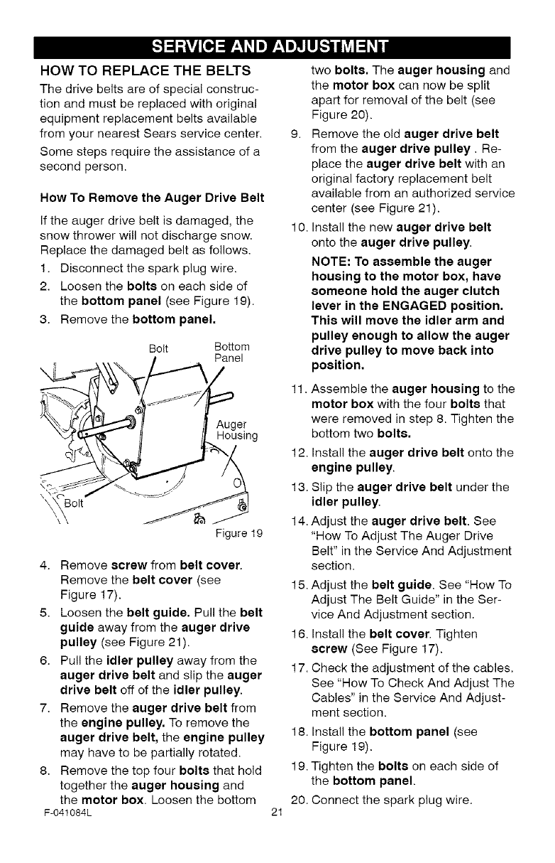
2. Loosen the bolte on each side of
the bottom panel (see Figure 19).
3. Remove the bottom panel.
Bolt Bottom
Panel
Auger
Housing
olt
Figure 19
4. Remove screw from belt cover.
Remove the belt cover (see
Figure 17).
5. Loosen the belt guide. Pull the belt
guide away from the auger drive
pulley (see Figure 21).
6. Pull the idler pulley away from the
auger drive belt and slip the auger
drive belt off of the idler pulley.
7. Remove the auger drive belt from
the engine pulley. To remove the
auger drive belt, the engine pulley
may have to be partially rotated.
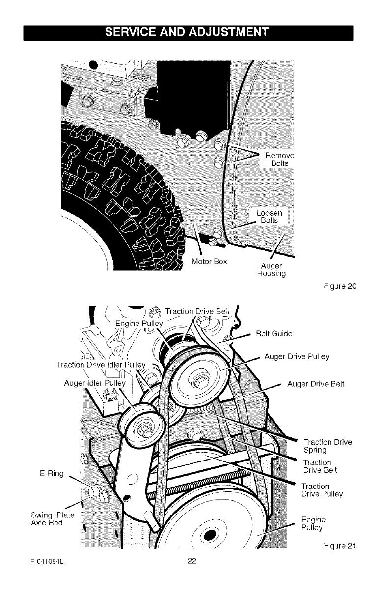
8. Remove the top four bolts that hold
together the auger housing and
the motor box. Loosen the bottom
F-041084L 21
two bolts. The auger housing and
the motor box can now be split
apart for removal of the belt (see
Figure 20).
9. Remove the old auger drive belt
from the auger drive pulley. Re-
place the auger drive belt with an
original factory replacement belt
available from an authorized service
center (see Figure 21).
10. Install the new auger drive belt
onto the auger drive pulley.
NOTE: To assemble the auger
housing to the motor box, have
someone hold the auger clutch
lever in the ENGAGED position.
This will move the idler arm and
pulley enough to allow the auger
drive pulley to move back into
position.
11. Assemble the auger housing to the
motor box with the four bolts that
were removed in step 8. Tighten the
bottom two bolts.
12. Install the auger drive belt onto the
engine pulley.
13. Slip the auger drive belt under the
idler pulley.
14. Adjust the auger drive belt. See
"How To Adjust The Auger Drive
Belt" in the Service And Adjustment
section.
15. Adjust the belt guide. See "How To
Adjust The Belt Guide" in the Ser-
vice And Adjustment section.
16. Install the belt cover. Tighten
ecrew (See Figure 17).
17. Check the adjustment of the cables.
See "How To Check And Adjust The
Cables" in the Service And Adjust-
ment section.
18. Install the bottom panel (see
Figure 19).
19. Tighten the bolts on each side of
the bottom panel.
20. Connect the spark plug wire.
E-Ring
Swing Plate
Axle Rod
Traction Drive Idler
Auger Idler Pulley
Motor Box
Remove
Bolts
LoosenBoltsiiiiiiii
Auger
Housing
Figure 20
Belt Guide
Auger Drive Pulley
Auger Drive Belt
Traction Drive
Spring
Traction
Drive Belt
Traction
Drive Pulley
Engine
Pulley
Figure 21
F-041084L 22
How To Remove
The Traction Drive Belt
If the snow thrower will not move for-
ward, check the traction drive belt for
wear or damage. If the traction drive
belt is worn or damaged, replace the
belt as follows.
1. Disconnect the spark plug wire.
Remove the auger drive belt. See
"How To Remove The Auger Drive
Belt" in the Service And Adjustment
section.
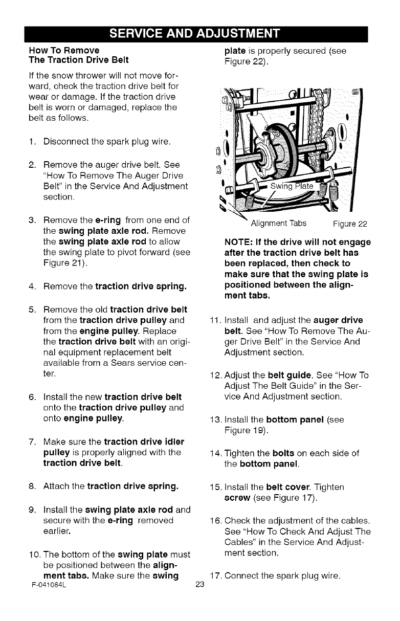
plate is properly secured (see
Figure 22).
Remove the e-ring from one end of
the swing plate axle rod. Remove
the swing plate axle rod to allow
the swing plate to pivot forward (see
Figure 21).
4. Remove the traction drive spring.
Remove the old traction drive belt
from the traction drive pulley and
from the engine pulley. Replace
the traction drive belt with an origi-
nal equipment replacement belt
available from a Sears service cen-
ter.
6. install the new traction drive belt
onto the traction drive pulley and
onto engine pulley.
7. Make sure the traction drive idler
pulley is properly aligned with the
traction drive belt.
8. Attach the traction drive spring.
9. Install the swing plate axle rod and
secure with the e-ring removed
earlier,
1 0. The bottom of the swing plate must
be positioned between the align-
ment tabs. Make sure the swing
F-041084L
Alignment Tabs Figure 22
NOTE: If the drive will not engage
after the traction drive belt has
been replaced, then check to
make sure that the swing plate is
positioned between the align-
ment tabs,
11. Install and adjust the auger drive
belt. See "How To Remove The Au-
ger Drive Belt" in the Service And
Adjustment section.
12. Adjust the belt guide. See "How To
Adjust The Belt Guide" in the Ser-
vice And Adjustment section.
13. Install the bottom panel (see
Figure 19).
14. Tighten the bolts on each side of
the bottom panel.
15. Install the belt cover, Tighten
screw (see Figure 17).
16. Check the adjustment of the cables,
See "How To Check And Adjust The
Cables" in the Service And Adjust-
ment section.
17. Connect the spark plug wire.
23
BELT GUIDE ADJUSTMENT
1. Remove spark plug wire.
2. Have someone engage auger drive.
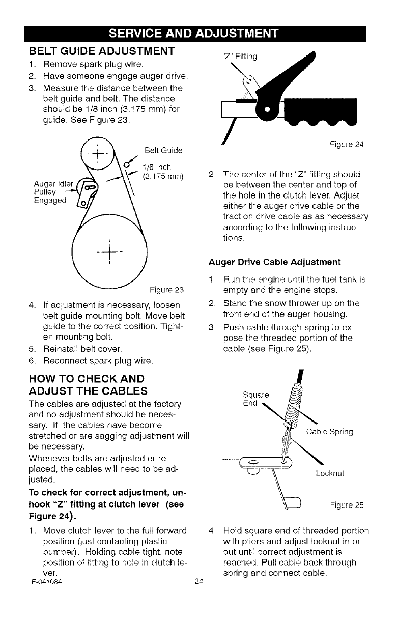
3. Measure the distance between the
belt guide and belt. The distance
should be 1/8 inch (3.175 mm) for
guide. See Figure 23.
"Z" Fitting
l _._ Belt Guide
..i"
\ u 1/8 Inch
-.i--\\ f (3.175ram)
Auger Idler t _ -\\
Pulley _" \\
Engaged _o
Figure 23
4. If adjustment is necessary, loosen
belt guide mounting bolt. Move belt
guide to the correct position. Tight-
en mounting bolt.
5. Reinstall belt cover.
6. Reconnect spark plug wire.
HOW TO CHECK AND
ADJUST THE CABLES
The cables are adjusted at the factory
and no adjustment should be neces-
sary. If the cables have become
stretched or are sagging adjustment will
be necessary.
Whenever belts are adjusted or re-
placed, the cables will need to be ad-
justed.
To check for correct adjustment, un-
hook "Z" fitting at clutch lever (see
Figure 24).
1. Move clutch lever to the full forward
position (just contacting plastic
bumper). Holding cable tight, note
position of fitting to hole in clutch le-
ver.
F-041084L
Figure 24
The center of the "Z" fitting should
be between the center and top of
the hole in the clutch lever. Adjust
either the auger drive cable or the
traction drive cable as as necessary
according to the following instruc-
tions.
Auger Drive Cable Adjustment
1. Run the engine until the fuel tank is
empty and the engine stops.
2. Stand the snow thrower up on the
front end of the auger housing.
3. Push cable through spring to ex-
pose the threaded portion of the
cable (see Figure 25).
Square
End _,
Cable Spring
o
Locknut
24
Figure 25
Hold square end of threaded portion
with pliers and adjust Iocknut in or
out until correct adjustment is
reached. Pull cable back through
spring and connect cable.
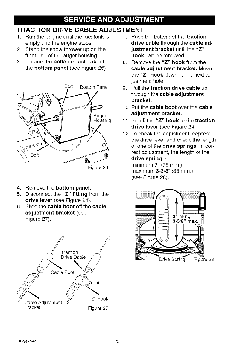
TRACTION DRIVE CABLE ADJUSTMENT
1. Run the engine until the fuel tank is
empty and the engine stops.
2. Stand the snow thrower up on the
front end of the auger housing.
3. Loosen the bolts on each side of
the bottom panel (see Figure 26).
Bolt Bottom Panel
Figure 26
7. Push the bottom of the traction
drive cable through the cable ad-
justment bracket until the "Z"
hook can be removed.
8. Remove the "Z" hook from the
cable adjustment bracket. Move
the "Z" hook down to the next ad-
justment hole.
9. Pull the traction drive cable up
through the cable adjustment
bracket.
10. Put the cable boot over the cable
adjustment bracket.
11. Install the "Z" hook to the traction
drive lever (see Figure 24).
12. To check the adjustment, depress
the drive lever and check the length
of one of the drive springs. In cor-
rect adjustment, the length of the
drive spring is:
minimum 3" (76 mm.)
maximum 3-3/8" (85 mm.)
(see Figure 28),
4. Remove the bottom panel,
5. Disconnect the "Z" fitting from the
drive lever (see Figure 24).
6. Slide the cable boot off the cable
adjustment bracket (see
Figure 27).
Traction
Drive _//
Cable Boot__J
Cable Adjustment /_ "7" Hook
Bracket Figure 27
Drive Spring Figure 28
F-041084L 25
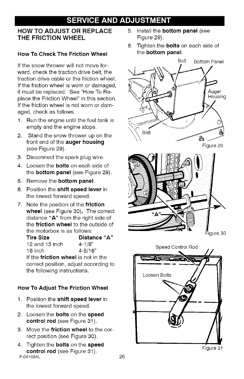
HOW TO ADJUST OR REPLACE
THE FRICTION WHEEL
How To Check The Friction Wheel
If the snow thrower will not move for-
ward, check the traction drive belt, the
traction drive cable or the friction wheel.
If the friction wheel is worn or damaged,
it must be replaced. See "How To Re-
place the Friction Wheel" in this section.
If the friction wheel is not worn or dam-
aged, check as follows.
1. Run the engine until the fuel tank is
empty and the engine stops.
2. Stand the snow thrower up on the
front end of the auger housing
(see Figure 29).
3. Disconnect the spark plug wire.
4. Loosen the bolts on each side of
the bottom panel (see Figure 29).
5. Remove the bottom panel.
6. Position the shift speed lever in
the lowest forward speed.
7. Note the position of the friction
wheel (see Figure 30). The correct
distance "A" from the right side of
the friction wheel to the outside of
the motorbox is as follows:
Tire Size Distance "A"
12 and 13 inch 4-1/8"
16 inch 4-5/16"
if the friction wheel is not in the
correct position, adjust according to
the fo!lowing instructions.
5. Install the bottom panel (see
Figure 29).
6. Tighten the bolts on each side of
the bottom panel.
Bolt Bottom Panel
er
Housing
\_ Bolt
Figure 29
Figure 30
Speed Control Rod
How To Adjust The Friction Wheel
1. Position the shift speed lever in
the lowest forward speed.
2. Loosen the bolts on the speed
control rod (see Figure 31).
3. Move the friction wheel to the cor-
rect position (see Figure 30).
4. Tighten the bolts on the speed
control rod (see Figure 31).
F-041084L 26
Figure 31
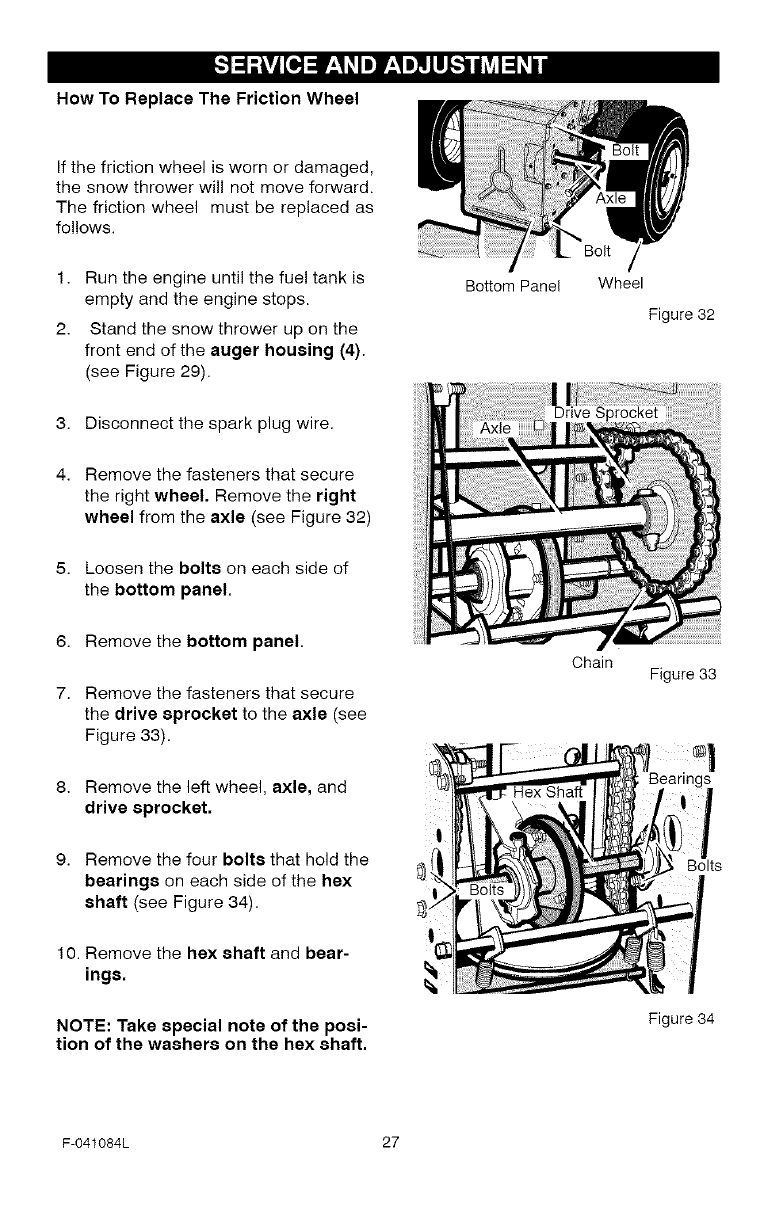
How To Replace The Friction Wheel
If the friction wheel is worn or damaged,
the snow thrower will not move forward.
The friction wheel must be replaced as
follows.
1. Run the engine until the fuel tank is
empty and the engine stops.
2. Stand the snow thrower up on the
front end of the auger housing (4).
(see Figure 29).
3. Disconnect the spark plug wire.
4. Remove the fasteners that secure
the right wheel. Remove the right
wheel from the axle (see Figure 32)
5. Loosen the bolts on each side of
the bottom panel.
6. Remove the bottom panel.
7. Remove the fasteners that secure
the drive sprocket to the axle (see
Figure 33).
8. Remove the left wheel, axle, and
drive sprocket.
9. Remove the four bolts that hold the
bearings on each side of the hex
shaft (see Figure 34).
10. Remove the hex shaft and bear-
ings.
NOTE: Take special note of the posi-
tion of the washers on the hex shaft.
Bo_om Panel
Chain
Wheel
Figure 32
Figure 33
Bolts
Figure 34
F-041084L 27
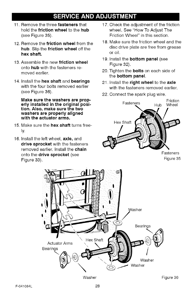
11. Remove the three fasteners that
hold the friction wheel to the hub
(see Figure 35).
12. Remove the friction wheel from the
hub. Slip the friction wheel off the
hex shaft,
13. Assemble the new friction wheel
onto hub with the fasteners re-
moved earlier.
14. Install the hex shaft and bearings
with the four bolts removed earlier
(see Figure 36).
Make sure the washers are prop-
erly installed in the original posi-
tion. Also, make sure the two
washers are properly aligned
with the actuator arms.
15. Make sure the hex shaft turns free-
ly.
16. Install the left wheel, axle, and
drive sprocket with the fasteners
removed earlier. Install the chain
onto the drive sprocket (see
Figure 33).
17. Check the adjustment of the friction
wheel. See "How To Adjust The
Friction Wheel" in this section.
18. Make sure the friction wheel and the
disc drive plate are free from grease
or oil.
19. Install the bottom panel (see
Figure 32).
20. Tighten the bolts on each side of
the bottom panel.
21. Install the right wheel to the axle
with the fasteners removed earlier.
22. Connect the spark plug wire.
Friction
Fasteners Hub Wheel
Hex Shaft
Fasteners
Figure 35
F-041084L
Actuator Arms
Bearings
\
Washer
28
Bearings
/
Washer
1/Washer
Figure 36
HOW TO REPLACE
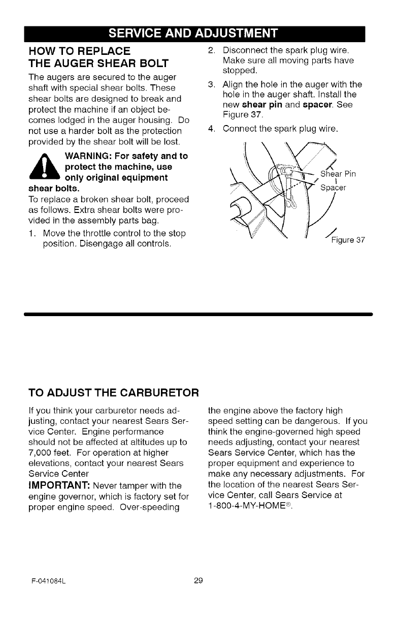
THE AUGER SHEAR BOLT
The augers are secured to the auger
shaft with special shear bolts. These
shear bolts are designed to break and
protect the machine if an object be-
comes lodged in the auger housing• Do
not use a harder bolt as the protection
provided by the shear bolt wil! be lost.
_hL ARNING: For safety and to
protect the machine, use
only original equipment
shear bolts,
To replace a broken shear bolt, proceed
as follows. Extra shear bolts were pro-
vided in the assembly parts bag.
1. Move the throttle control to the stop
position. Disengage all controls.
2. Disconnect the spark plug wire.
Make sure all moving parts have
stopped.
3. Align the hole in the auger with the
hole in the auger shaft. Install the
new shear pin and spacer. See
Figure 37.
4. Connect the spark plug wire.
//"
J_
Shear Pin
.' ! |
•Spacer
__gure 37
TO ADJUST THE CARBURETOR
If you think your carburetor needs ad-
justing, contact your nearest Sears Ser-
vice Center. Engine performance
should not be affected at altitudes up to
7,000 feet. For operation at higher
elevations, contact your nearest Sears
Service Center
IMPORTANT: Never tamper with the
engine governor, which is factory set for
proper engine speed. Over-speeding
the engine above the factory high
speed setting can be dangerous. If you
think the engine-governed high speed
needs adjusting, contact your nearest
Sears Service Center, which has the
proper equipment and experience to
make any necessary adjustments• For
the location of the nearest Sears Ser-
vice Center, call Sears Service at
1-800-4-MY-HOME ®.
F-041084L 29
,_ WARNING: Never store your
snow thrower indoors or in
an enclosed, poorly venti-
lated area. If gasoline remains in the
tank, fumes may reach an open
flame, spark or pilot light from a fur-
nace, water heater, clothes dryer,
cigarette, etc.
To prevent damage (if snow thrower is
not used for more than 30 days) follow
the steps below.
SNOW THROWER
1. Thoroughly clean the snow thrower.
2. Lubricate all lubrication points. See
the Maintenance section.
3. Be sure that all nuts, bolts and
screws are securely fastened. In-
spect all visible moving parts for
damage, breakage and wear. Re-
place if necessary.
4. Touch up all rusted or chipped paint
surfaces; sand lightly before paint-
ing.
5. Cover the bare metal parts of the
blower housing auger and the im-
peller with rust preventative, such
as a spray lubricant.
NOTE: A yearly checkup or tune-up by
a Sears service center is a good way of
ensuring that your snow thrower will
provide maximum performance for the
next season.
ENGINE
Gasoline must be removed or treated to
prevent gum deposits from forming in
the fuel tank, filter, hose, and carburetor
during storage. Also, during storage al-
cohol blended gasoline that uses etha-
nol or methanol (sometimes called
gasohol) attracts water. It acts on the
gasoline to form acids which damage
the engine.
1. Run the engine until the fuel tank is
empty and the engine stops.
2. If you do not remove the gasoline,
use fuel stabilizer supplied with unit
or purchase Craftsman Fuel Stabi-
lizer No. 3550. Add fuel stabilizer to
any gasoline left in the tank to mini-
mize gum deposits and acids. If the
fuel tank is almost empty, mix stabi-
lizer with fresh gasoline in a sepa-
rate container and add some to the
fuel tank.
3. Always follow the instructions on the
stabilizer container. After the stabi-
lizer is added to the fuel tank, run
the engine at least ten minutes to
allow the mixture to reach the car-
buretor.
4. Change the engine oil.
5. Lubricate the piston/cylinder area.
First, remove the spark plug and
squirt a few drops of clean engine
oil into the spark plug hole. Next,
cover the spark plug hole with a rag
to absorb oil spray. Then, pull two or
three times on the recoil starter rope
to rotate the engine. Finally, install
the spark plug and attach the spark
plug wire.
OTHER
1. If possible, store your snow thrower
indoors and cover it to give protec-
tion from dust and dirt.
2. If the snow thrower must be stored
outdoors, put the snow thrower on
blocks to raise it off of the ground.
3. Cover the snow thrower with a suit-
able protective cover that does not
retain moisture. Do not use plastic.
IMPORTANT: Never cover snow
thrower while engine and exhaust areas
are still warm.
F-041084L 30
h_o_U_oIo_
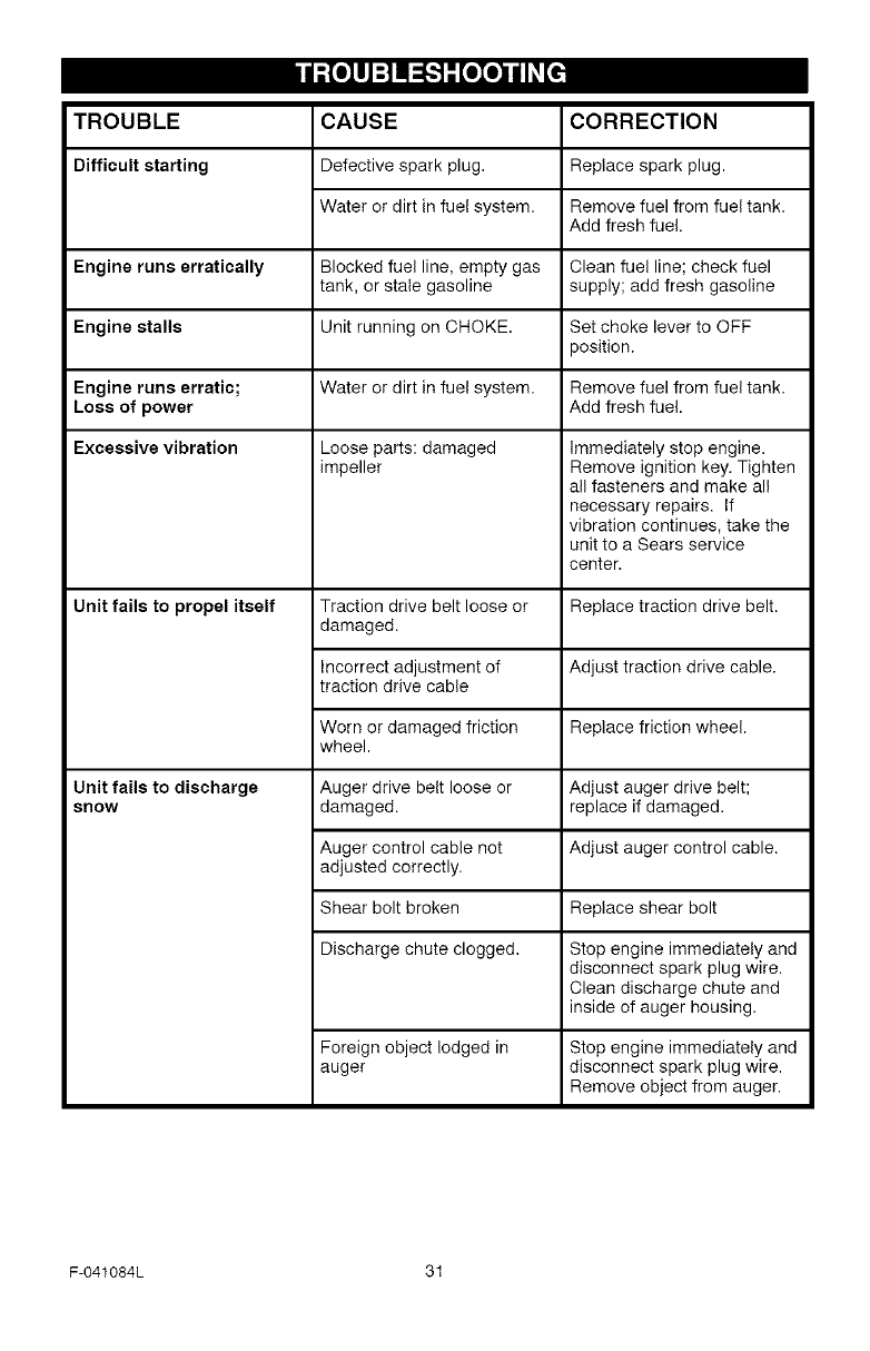
TROUBLE CORRECTION
Difficult starting Replace spark plug.
CAUSE
Defective spark plug.
Water or dirt in fuel system. Remove fuel from fuel tank.
Add fresh fuel.
Engine runs erratically Blocked fuel line, empty gas Clean fuel line; check fuel
tank, or stale gasoline supply; add fresh gasoline
Engine stalls Unit running on CHOKE. Set choke lever to OFF
position.
Engine runs erratic; Water or dirt in fuel system. Remove fuel from fuel tank.
Loss of power Add fresh fuel.
Excessive vibration
Unit fails to propel itself
Loose parts: damaged
impeller
Traction drive belt loose or
damaged.
Immediately stop engine.
Remove ignition key. Tighten
all fasteners and make all
necessary repairs. If
vibration continues, take the
unit to a Sears service
center.
Replace traction drive belt.
Incorrect adjustment of Adjust traction drive cable.
traction drive cable
Worn or damaged friction Replace friction wheel.
wheel.
Unit fails to discharge
snow
Auger drive belt loose or
damaged.
Adjust auger drive belt;
replace if damaged.
Auger control cable not Adjust auger control cable.
adjusted correctly.
Shear bolt broken Replace shear bolt
Discharge chute clogged. Stop engine immediately and
disconnect spark plug wire.
Clean discharge chute and
inside of auger housing.
Foreign object lodged in
auger
Stop engine immediately and
disconnect spark plug wire.
Remove object from auger.
F-041084L 31
SEARS, ROEBUCK AND CO.
Federal and California Emission Control Systems Limited Warranty
Small Off-Road Engines
CALIFORNIA &US EPA EMISSION
CONTROL WARRANTY STATEMENT
The U. S. Environmental Protection Agency
("EPA"), the California Air Resources Board
("CARB") and Sears, Roebuck and Co. are
pleased to explain the Federal and California
Emission Control Systems Warranty on your
new small off-road engine. In California, new
1995 and later small off-road engines must be
designed, built and equipped to meet the
State's stringent anti-smog standards. In oth-
er states, new 1997 and later model year en-
gines must be designed, built and equipped, at
the time of sale, to meet the U.S. EPA regula-
tions for small non-road engines. Sears, Roe-
buck and Co. will warrant the emission control
system on your small off-road engine for the
periods of time listed below, provided there
has been no abuse, neglect, unapproved mod-
ification, or improper maintenance of your
small off-road engine.
Your emission control system may include
parts such as the carburetor, ignition system
and exhaust system. Also included may be the
compression release system and other emis-
sion-related assemblies.
Where a warrantable condition exists, Sears,
Roebuck and Co. will repair your small off-
road engine at no cost to you for diagnosis,
parts and labor.
MANUFACTURER'S EMISSION
CONTROLSYSTEM WARRANTY
COVERAGE
Emission control systems on 1995 and later
model year California small off-road engines
are warranted for two years as hereinafter
noted. In other states, 1997 and later model
year engines are also warranted for two years.
If, during such warranty period, any emission-
related part on your engine is defective in ma-
terials or workmanship, the part will be
repaired or replaced by Sears, Roebuck and
Co.
OWNER'S WARRANTY
RESPONSIBILITIES
As the small off-road engine owner, you are
responsible for the performance of the re-
F-041084L
quired maintenance listed in your Owner's
Manual, but Sears, Roebuck and Co. will not
deny warranty solely due to the lack of receipts
or for your failure to provide written evidence
of the performance of all scheduled mainte-
nance.
As the small off-road engine owner, you
should, however, be aware that Sears, Roe-
buck and Co. may deny you warranty cover-
age if your small off-road engine or a part
thereof has failed due to abuse, neglect, im-
proper maintenance or unapproved modifica-
tions.
You are responsible for presenting your small
off-road engine to a Sears, Roebuck and Co.
Authorized Service Outlet as soon as a prob-
lem exists. The warranty repairs should be
completed in a reasonable amount of time, not
to exceed 30 days.
Warranty service can be arranged by contact-
ing either a Sears, Roebuck and Co. Autho-
rized Service Outlet, or by contacting Sears,
Roebuck and Co. at 1-800-473-7247.
32
IMPORTANT NOTE
This warranty statement explains your rights
and obligations under the Emission Oontrot
System Warranty "(ECS Warranty") which is
provided to you by Sears, Roebuck and Co.
pursuant to California law. See also the Sears,
Roebuck and Co. Limited Warranties for
Sears, Roebuck and Co. which is enclosed
therewith on a separate sheet and also is pro-
vided to you by Sears, Roebuck and Co. The
ECS Warranty applies only to the emission
control system of your new engine. To the ex-
tent that there is any conflict in terms between
the ECS Warranty and the Sears, Roebuck
and Co. Warranty, the ECS Warranty shall ap-
ply except in any circumstances in which the
Sears, Roebuck and Co. Warranty may pro-
vide a longer warranty period. Both the ECS
Warranty and the Sears, Roebuck and Co.
Warranty describe important rights and obliga-
tions with respect to your new engine.
Warranty service can only be performed by a
Sears, Roebuck and Co. Authorized Service
Outlet. At the time of requesting warranty ser-
vice, evidence must be presented of the date
of sale to the original purchaser. The purchas-
ershallpayanychargesformakingservice
callsand/orfortransportingtheproductsto
andfromtheplacewheretheinspectionand/
orwarrantyworkisperformed.Thepurchaser
shallberesponsibleforanydamageorlossin-
curredinconnectionwiththetransportationof
anyengineoranypart(s)thereofsubmittedfor
inspectionand/orwarrantywork.
Ifyouhaveanyquestionsregardingyourwar-
rantyrightsandresponsibilities,youshould
contactSears,Roebuckand Co. at
1-800-473-7247.
EMISSION CONTROL SYSTEM
WARRANTY
Emission Control System Warranty ("ECS
Warranty") for 1995 and later model year Cali-
fornia small off-road engines (for other states,
1997 and later model year engines):
A, APPLICABILITY: This warranty shall apply
to 1995 and later model year California small
off-road engines (for other states, 1997 and
later model year engines). The ECS Warranty
Period shall begin on the date the new engine
or equipment is delivered to its original, end-
use purchaser, and shall continue for 24 con-
secutive months thereafter.
B, GENERAL EMISSIONS WARRANTY
COVERAGE: Sears, Roebuck and Co. war-
rants to the original, end-use purchaser of the
new engine or equipment and to each subse-
quent purchaser that each of its small off-road
engines is:
1. Designed, built and equipped so as to con-
form with all applicable regulations adopted by
the Air Resources Board pursuant to its au-
thority in Chapters 1 and 2, Part 5, Division 26
of the Health and Safety Code, and
2. Free from defects in materials and work-
manship which, at any time during the ECS
Warranty Period, will cause a warranted emis-
sions-related part to fail to be identical in all
material respects to the part as described in
the engine manufacturer's application for certi-
fication.
O. The ECS Warranty only pertains to emis-
sions-related parts on your engine, as follows:
1. Any warranted, emissions-related parts
which are not scheduled for replacement as
required maintenance in the Owner's Manual
shall be warranted for the ECS Warranty Peri-
od. If any such part fails during the ECS War-
ranty Period, it shall be repaired or replaced by
F-041084L 33
Sears, Roebuck and 0o. according to Subsec-
tion 4 below. Any such part repaired or re-
placed under the ECS Warranty shall be
warranted for any remainder of the ECS War-
ranty Period.
2. Any warranted, emissions-related part
which is scheduled only for regular inspection
as specified in the Owner's Manual shall be
warranted for the ECS Warranty Period. A
statement in such written instructions to the ef-
fect of "repair or replace as necessary", shall
not reduce the ECS Warranty Period. Any
such part repaired or replaced under the ECS
Warranty shall be warranted for the remainder
of the ECS Warranty Period.
3. Any warranted, emissions-related part
which is scheduled for replacement as re-
quired maintenance in the Owner's Manual,
shall be warranted for the period of time prior
to the first scheduled replacement point for
that part. If the part fails prior to the first sched-
uled replacement, the part shall be repaired or
replaced by Sears, Roebuck and Co. accord-
ing to Subsection 4 below. Any such emis-
sions-related part repaired or replaced under
the ECS Warranty, shall be warranted for the
remainder of the ECS Warranty Period prior to
the first scheduled replacement point for such
emissions-related part.
4. Repair or replacement of any warranted,
emissions-related part under this ECS War-
ranty shall be performed at no charge to the
owner at a Sears, Roebuck and Co. Autho-
rized Service Outlet.
5. The owner shall not be charged for diagnos-
tic labor which leads to the determination that
a part covered by the ECS Warranty is in fact
defective, provided that such diagnostic work
is performed at a Sears, Roebuck and Co. Au-
thorized Service Outlet.
6. Sears, Roebuck and 0o. shall be liable for
damages to other original engine components
or approved modifications proximately caused
by a failure under warranty of an emission-re-
lated part covered by the ECS Warranty.
7. Throughout the ECS Warranty Period,
Sears, Roebuck and Co. shall maintain a sup-
ply of warranted emission-related parts suffi-
cient to meet the expected demand for such
emission-related parts.
8. Any Sears, Roebuck and Co. authorized
and approved emission-related replacement
part may be used in the performance of any
ECS Warranty maintenance or repair and will
be provided without charge to the owner. Such
useshallnotreduceSears,RoebuckandCo.
ECSWarrantyobligations.
9.Unapprovedadd-onormodifiedpartsmay
notbeusedtomodifyorrepairaSears,Roe-
buckandCo.engine.SuchusevoidsthisECS
Warrantyandshallbesufficientgroundsfor
disallowinganECSWarrantyclaim.Sears,
RoebuckandCo.shallnotbeliablehereunder
forfailuresofanywarrantedpartsofaSears,
RoebuckandCo.enginecausedbytheuseof
suchanunapprovedadd-onormodifiedpart.
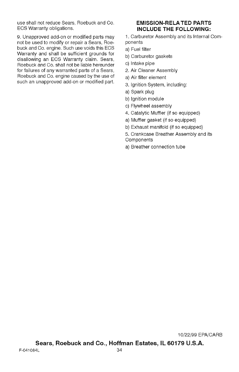
EMISSION-RELATED PARTS
INCLUDE THE FOLLOWING:
1. Carburetor Assembly and its Internal Com-
ponents
a) Fuel filter
b) Carburetor gaskets
c) Intake pipe
2. Air Cleaner Assembly
a) Air filter element
3. Ignition System, including:
a) Spark plug
b) Ignition module
c) Flywheel assembly
4. Catalytic Muffler (if so equipped)
a) Muffler gasket (if so equipped)
b) Exhaust manifold (if so equipped)
5. Crankcase Breather Assembly and its
Components
a) Breather connection tube
10/22/99 EPA/CARB
Sears, Roebuck and Co., Hoffman Estates, IL 60179 U.S.A.
F-041084L 34

NOTES
F-O41084L 35
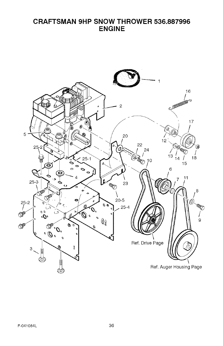
CRAFTSMAN 9HP SNOW THROWER 536.887996
ENGINE
16
25
25-2
/
2
20
22
24
/
lO
17
/
/
18
25-3 23
\\/8
/
9
3
Ref. Drive Page
Ref. Auger Housing Page
F-O41084L 36
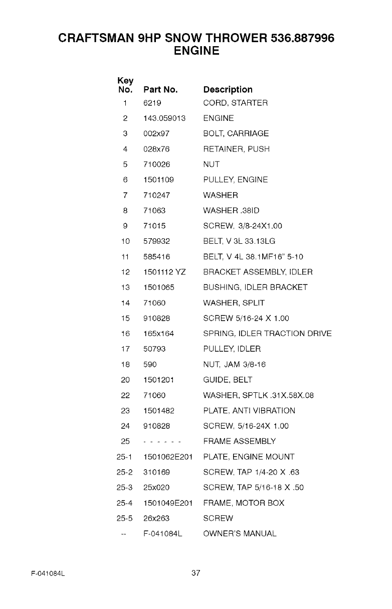
CRAFTSMAN 9HP SNOW THROWER 536.887996
ENGINE
Key
No, Part No. Description
1 6219 CORD, STARTER
2 143.059013 ENGINE
3 002x97 BOLT, CARRIAGE
4 028x76 RETAINER, PUSH
5 710026 NUT
6 1501109 PULLEY, ENGINE
7 710247 WASHER
8 71063 WASHER .381D
9 71015 SCREW, 3/8-24X1.00
10 579932 BELT, V 3L 33.13LG
11 585416 BELT, V 4L 38.1MF16" 5-10
12 1501112 YZ BRACKET ASSEMBLY, IDLER
13 1501065 BUSHING, IDLER BRACKET
14 71060 WASHER, SPLIT
15 910828 SCREW 5/16-24 X 1.0O
16 165x164 SPRING, IDLER TRACTION DRIVE
17 50793 PULLEY, IDLER
18 590 NUT, JAM 3/8-16
20 1501201 GUIDE, BELT
22 71060 WASHER, SPTLK .31X.58X.08
23 1501482 PLATE, ANTI VIBRATION
24 910828 SCREW, 5/16-24X 1.00
25 FRAME ASSEMBLY
25-1 1501062E201 PLATE, ENGINE MOUNT
25-2 310169 SCREW, TAP 1/4-20 X .63
25-3 25x020 SCREW, TAP 5/16-18 X .50
25-4 1501049E201 FRAME, MOTOR BOX
25-5 26x263 SCREW
-- F-041084L OWNER'S MANUAL
F-041084L 37
341
303
\
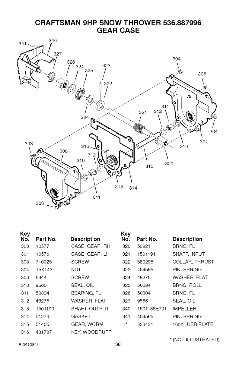
CRAFTSMAN 9HP SNOW THROWER 536.887996
GEAR CASE
34O
327
326 304
324 323 \
325 /
322
/
/
324
306
\
301
310
320
313
/
304
303
311
315 314
Key
No, Part No,
300 10577
301 10576
303 710025
304 15X143
306 9344
310 9566
311 50304
312 48275
313 1501190
314 51279
315 51405
316 431787
F-041084L
Key
Description No. Part No.
CASE, GEAR, RH 320 50221
CASE, GEAR, LH 321 1501191
SCREW 322 580295
NUT 323 454565
SCREW 324 48275
SEAL, OIL 325 50684
BEARING, FL 326 50304
WASHER, FLAT 327 9566
SHAFT, OUTPUT 340 1501188E701
GASKET 341 454565
GEAR, WORM * 333431
KEY, WOODRUFF
38
Description
BRNG, FL
SHAFT, INPUT
COLLAR, THRUST
PIN, SPRING
WASHER, FLAT
BRNG, ROLL
BRNG, FL
SEAL, OIL
IMPELLER
PIN, SPRING
100z LUBRIPLATE
* (NOT ILLUSTRATED)
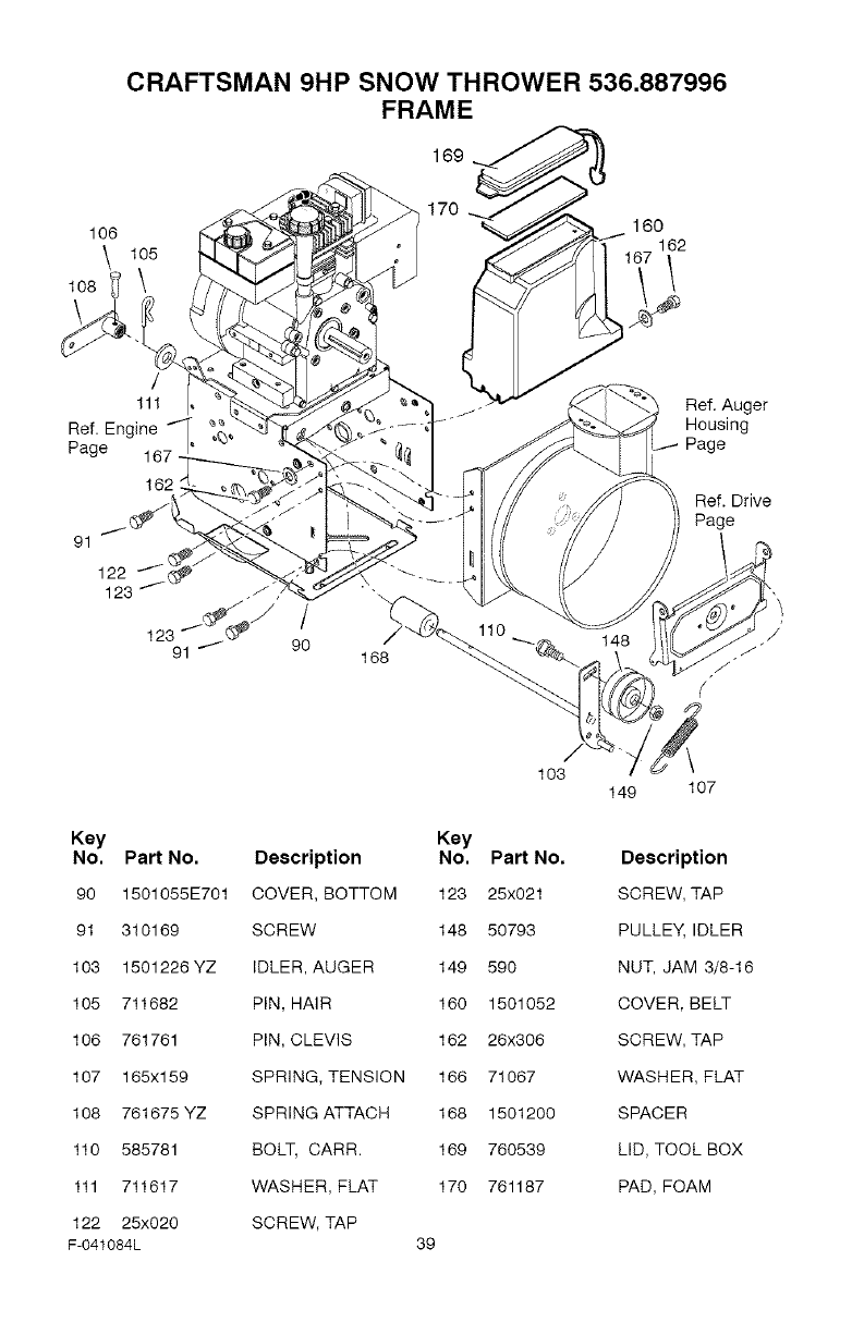
CRAFTSMAN 9HP SNOW THROWER 536.887996
FRAME
169
106
\
1o8
105
170 160
162
162
91
/
9O 168
Ref. Auger
Housing
Ref. Drive
Page
Key
No. Part No.
90 1501055E701
91 310169
103 1501226 YZ
105 711682
106 761761
107 165x159
108 761675YZ
110 585781
111 711617
122 25x020
F-041084L
103
Key
Description No. Part No.
COVER, BOTTOM 123 25x021
SCREW 148 50793
IDLER, AUGER 149 590
PIN, HAIR 160 1501052
PIN, CLEVIS 162 26x306
SPRING, TENSION 166 71067
SPRING ATTACH 168 1501200
BOLT, CARR. 169 760539
WASHER, FLAT 170 761187
SCREW, TAP
39
149 107
Description
SCREW, TAP
PULLEY, IDLER
NUT, JAM 3/8-16
COVER, BELT
SCREW, TAP
WASHER, FLAT
SPACER
LID, TOOL BOX
PAD, FOAM
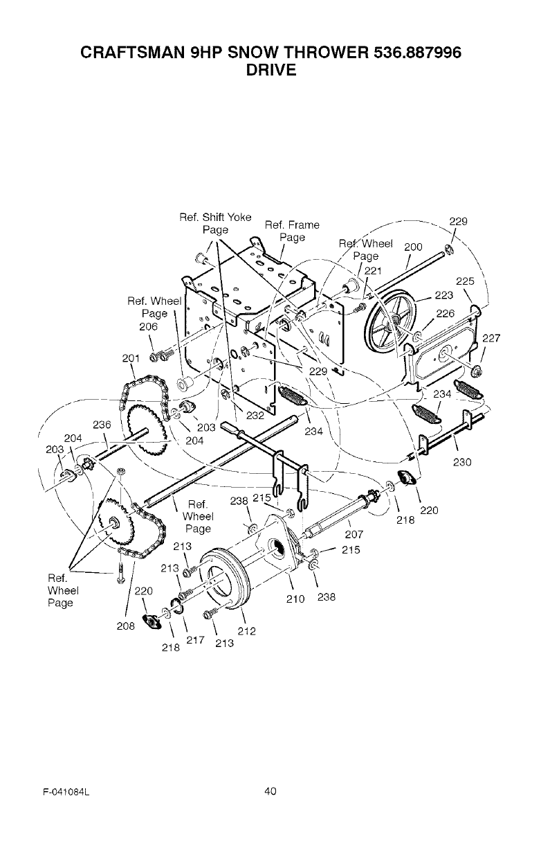
CRAFTSMAN 9HP SNOW THROWER 536.887996
DRIVE
Ref.
Page
206
201 _
Ref. Shift Yoke -_ 229
Page Ref. Frame _
Page R/eL/@heel 200
\
225
\/
J
f
/236
/204
203
\\
Ref.
Wheel
Page
2O8 212
217 213
218
207
215
\
210 238
230
\22O
218
F-041084L 40
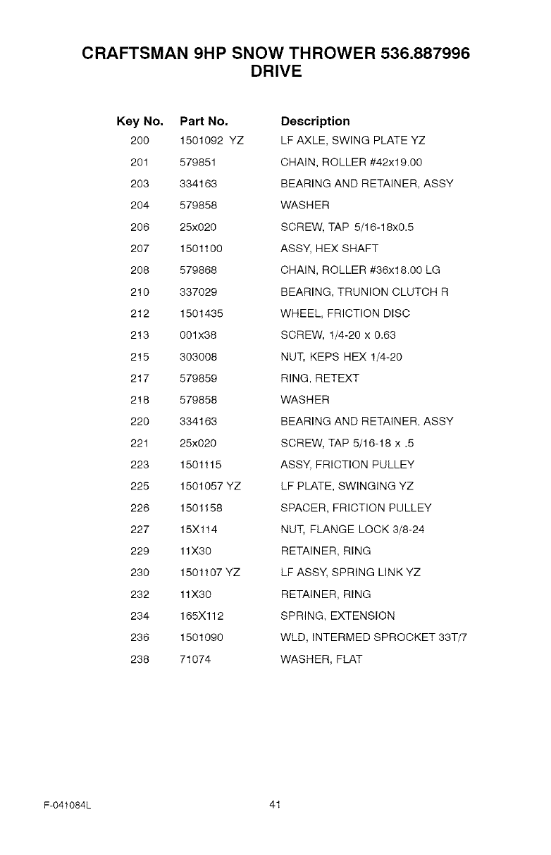
CRAFTSMAN 9HP SNOW THROWER 536.887996
DRIVE
Key No. Part No.
200 1501092 YZ
201 579851
203 334163
204 579858
206 25x020
207 1501100
208 579868
210 337029
212 1501435
213 001x38
215 303008
217 579859
218 579858
220 334163
221 25x020
223 1501115
225 1501057 YZ
226 1501158
227 15X114
229 11X30
230 1501107 YZ
232 11X30
234 165X112
236 1501090
238 71074
Description
LF AXLE, SWING PLATE YZ
CHAIN, ROLLER #42x19.00
BEARING AND RETAINER, ASSY
WASHER
SCREW, TAP 5/16-18x0.5
ASSY, HEX SHAFT
CHAIN, ROLLER #36x18.00 LG
BEARING, TRUNION CLUTCH R
WHEEL, FRICTION DISC
SCREW, 1/4-20 x 0.63
NUT, KEPS HEX 1/4-20
RING, RETEXT
WASHER
BEARING AND RETAINER, ASSY
SCREW, TAP 5/16-18 x .5
ASSY, FRICTION PULLEY
LF PLATE, SWINGING YZ
SPACER, FRICTION PULLEY
NUT, FLANGE LOCK 3/8-24
RETAINER, RING
LF ASSY, SPRING LINKYZ
RETAINER, RING
SPRING, EXTENSION
WLD, INTERMED SPROCKET 33T/7
WASHER, FLAT
F-041084L 41
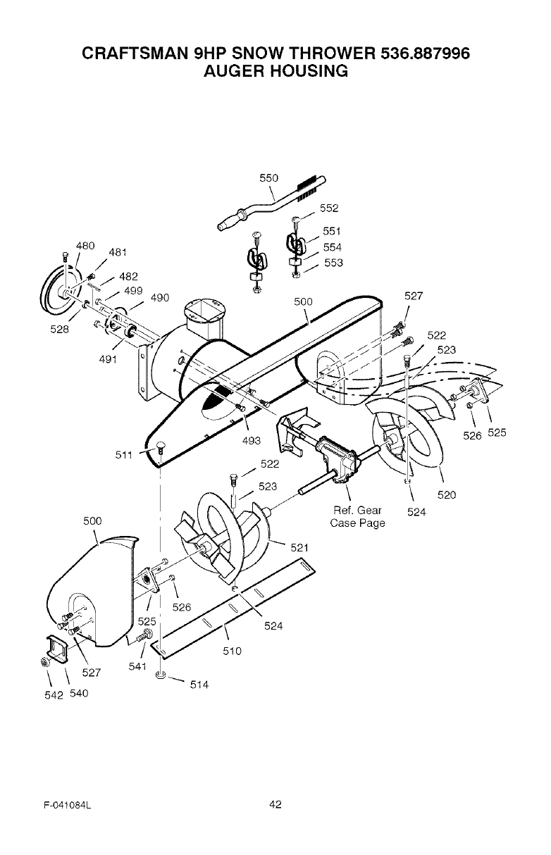
CRAFTSMAN 9HP SNOW THROWER 536.887996
AUGER HOUSING
528
480 481
/
491
490
52
5O0 527
522
523
511
\
526 525
5OO
\ 520
Ref. Gear 524
Case Page
521
\ 527
542 540
541
510
514
524
F-O41084L 42
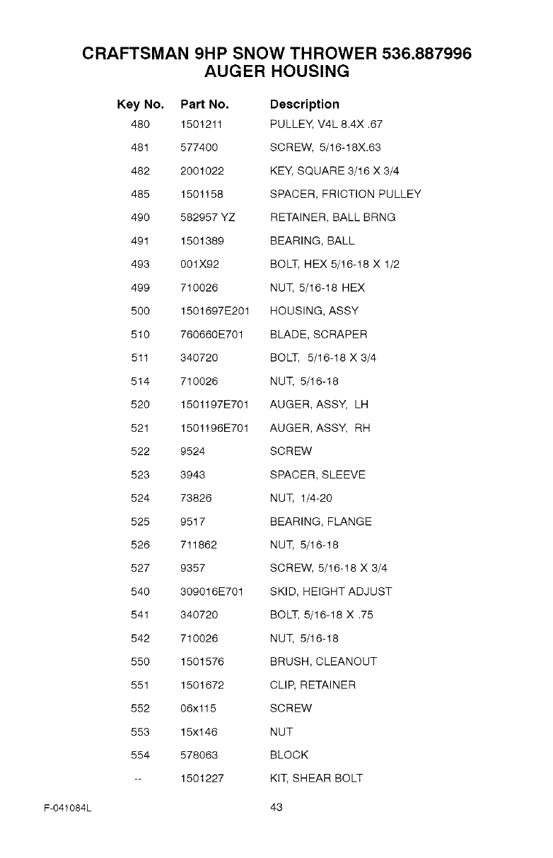
F-041084L
CRAFTSMAN 9HP SNOW THROWER 536.887996
AUGER HOUSING
Key No. Part No. Description
480 1501211 PULLEY, V4L 8.4X .67
481 577400 SCREW, 5/16-18X.63
482 2001022 KEY, SQUARE 3/16 X 3/4
485 1501158 SPACER, FRICTION PULLEY
490 582957 YZ RETAINER, BALL BRNG
491 1501389 BEARING, BALL
493 001X92 BOLT, HEX 5/16-18 X 1/2
499 710026 NUT, 5/16-18 HEX
500 1501697E201 HOUSING, ASSY
510 760660E701 BLADE, SCRAPER
511 340720 BOLT, 5/16-18 X 3/4
514 710026 NUT, 5/16-18
520 1501197E701 AUGER, ASSY, LH
521 1501196E701 AUGER, ASSY, RH
522 9524 SCREW
523 3943 SPACER, SLEEVE
524 73826 NUT, 1/4-20
525 9517 BEARING, FLANGE
526 711862 NUT, 5/16-18
527 9357 SCREW, 5/16-18 X 3/4
540 309016E701 SKID, HEIGHT ADJUST
541 340720 BOLT, 5/16-18 X .75
542 710026 NUT, 5/16-18
550 1501576 BRUSH, CLEANOUT
551 1501672 CLIP, RETAINER
552 06x115 SCREW
553 15x146 NUT
554 578063 BLOCK
-- 1501227 KIT, SHEAR BOLT
43
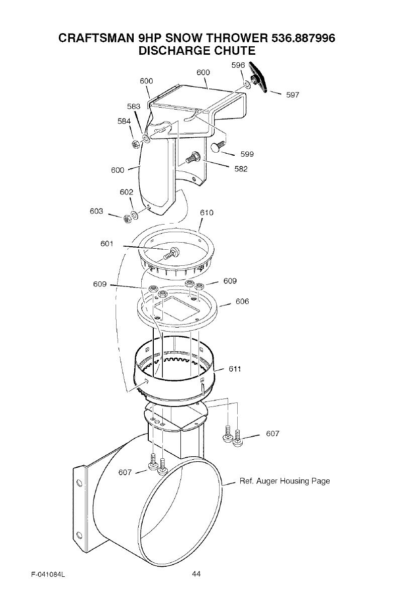
CRAFTSMAN 9HP SNOW THROWER 536.887996
DISCHARGE CHUTE
596
60O
60O
597
583
600
602
603 \ 610
601
609 609
606
611
607
Ref. Auger Housing Page
F-041084L 44
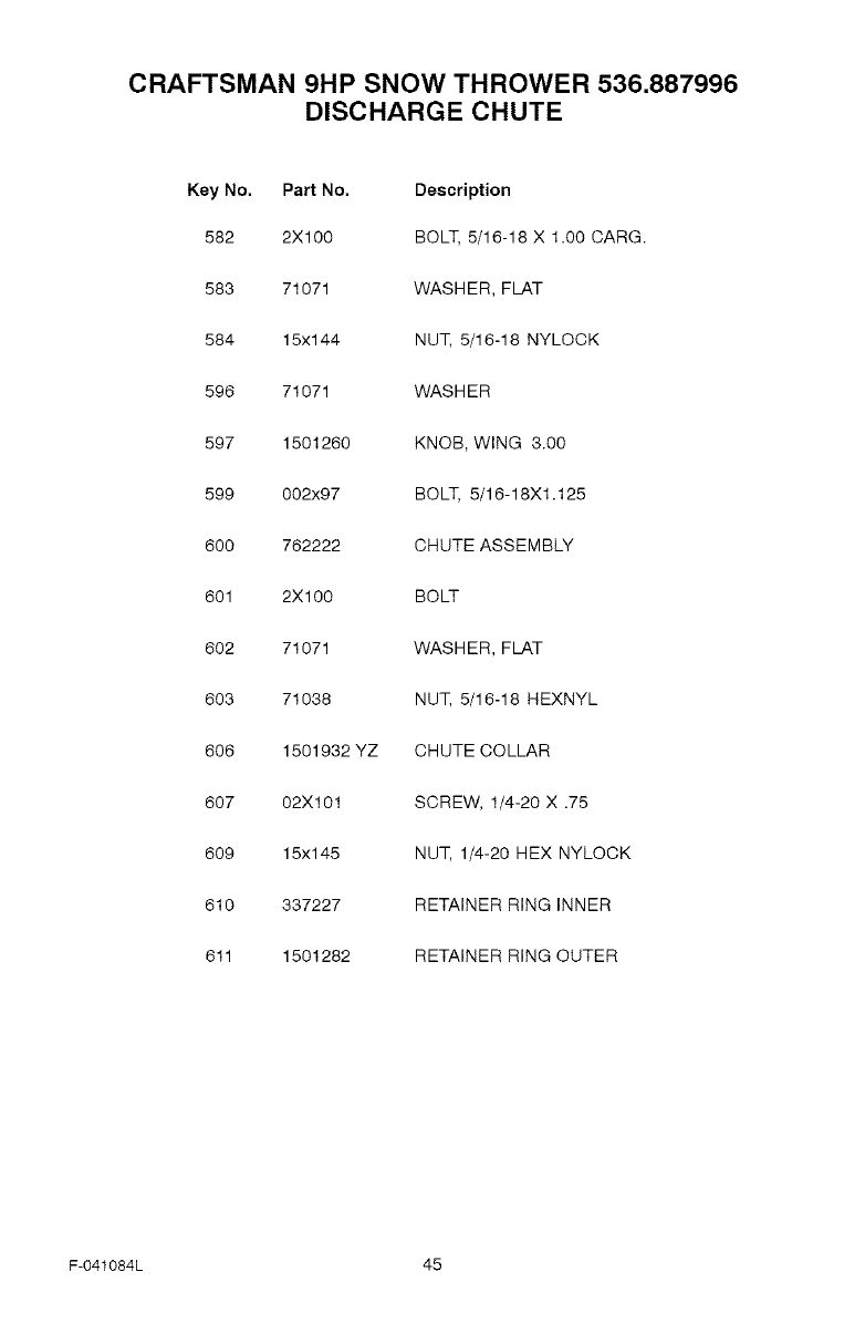
CRAFTSMAN 9HP SNOW THROWER 536.887996
DISCHARGE CHUTE
Key No. Part No. Description
582 2X100 BOLT, 5/16-18 X 1.00 CARG.
583 71071 WASHER, FLAT
584 15x144 NUT, 5/16-18 NYLOCK
596 71071 WASHER
597 1501260 KNOB, WING 3.00
599 002x97 BOLT, 5/16-18X1.125
600 762222 CHUTE ASSEMBLY
601 2X1 O0 BOLT
602 71071 WASHER, FLAT
603 71038 NUT, 5/16-18 HEXNYL
606 1501932 YZ CHUTE COLLAR
607 02X101 SCREW, 1/4-20 X .75
609 15x145 NUT, 1/4-20 HEX NYLOCK
610 337227 RETAINER RING INNER
611 1501282 RETAINER RING OUTER
F-O41084L 45
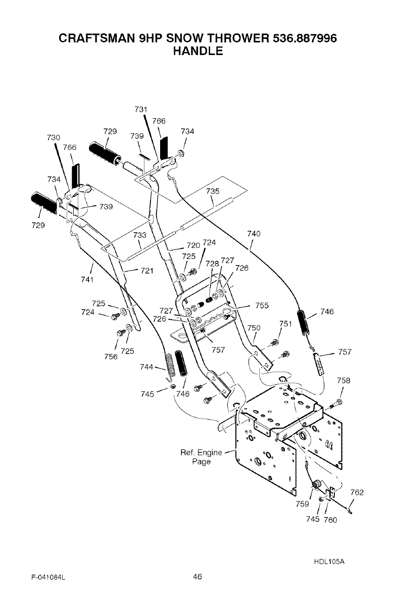
CRAFTSMAN 9HP SNOW THROWER 536.887996
HANDLE
73O 729
731
766
73_ 734
/
735
729
\
741
724
/725
756
745 /
740
720 724 727726"_/ .746
757 757
758
)
759
745 760
762
HDL105A
F-041084L 46
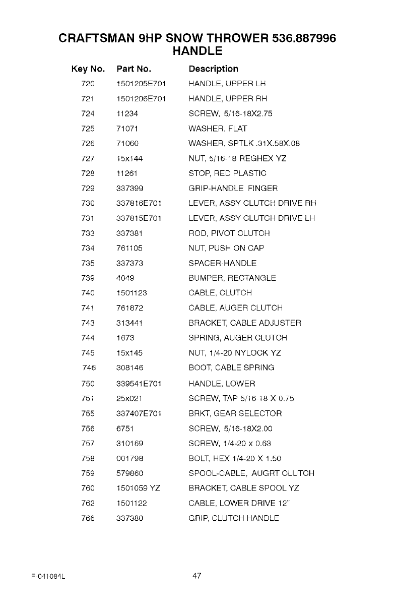
CRAFTSMAN 9HP SNOW THROWER 536.887996
HANDLE
Key No, Part No.
720 1501205E701
721 1501206E701
724 11234
725 71071
726 71060
727 15x144
728 11261
729 337399
730 337816E701
731 337815E701
733 337381
734 761105
735 337373
739 4049
740 1501123
741 761872
743 313441
744 1673
745 15x145
746 308146
750 339541E701
751 25x021
755 337407E701
756 6751
757 310169
758 001798
759 579860
760 1501059 YZ
762 1501122
766 337380
Description
HANDLE, UPPER LH
HANDLE, UPPER RH
SCREW, 5/16-18X2.75
WASHER, FLAT
WASHER, SPTLK .31X.58X.08
NUT, 5/16-18 REGHEX YZ
STOP, RED PLASTIC
GRIP-HANDLE FINGER
LEVER, ASSY CLUTCH DRIVE RH
LEVER, ASSY CLUTCH DRIVE LH
ROD, PIVOT CLUTCH
NUT, PUSH ON CAP
SPACER-HANDLE
BUMPER, RECTANGLE
CABLE, CLUTCH
CABLE, AUGER CLUTCH
BRACKET, CABLE ADJUSTER
SPRING, AUGER CLUTCH
NUT, 1/4-20 NYLOCK YZ
BOOT, CABLE SPRING
HANDLE, LOWER
SCREW, TAP 5/16-18 X 0.75
BRKT, GEAR SELECTOR
SCREW, 5/16-18X2.00
SCREW, 1/4-20 x 0.63
BOLT, HEX 1/4-20 X 1.50
SPOOL-CABLE, AUGRT CLUTCH
BRACKET, CABLE SPOOL YZ
CABLE, LOWER DRIVE 12"
GRIP, CLUTCH HANDLE
F-041084L 47
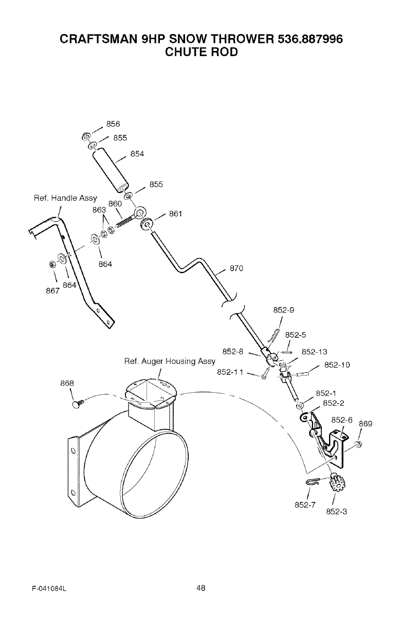
CRAFTSMAN 9HP SNOW THROWER 536.887996
CHUTE ROD
856
/
/" 855
Ref. Handle Assy
863
\
864
\
887
868
87O
F-041084L 48
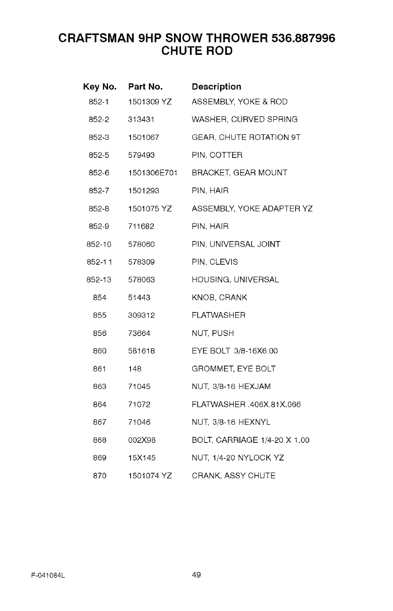
CRAFTSMAN 9HP SNOW THROWER 536.887996
CHUTE ROD
Key No. Part No. Description
852-1 1501309 YZ ASSEMBLY, YOKE & ROD
852-2 313431 WASHER, CURVED SPRING
852-3 1501067 GEAR, CHUTE ROTATION 9T
852-5 579493 PIN, COTTER
852-6 1501306E701 BRACKET, GEAR MOUNT
852-7 1501293 PIN, HAIR
852-8 1501075 YZ ASSEMBLY, YOKE ADAPTER YZ
852-9 711682 PIN, HAIR
852-10 578060 PIN, UNIVERSAL JOINT
852-1 1 578309 PIN, CLEVIS
852-13 578063 HOUSING, UNIVERSAL
854 51443 KNOB, CRANK
855 309312 FLATWASHER
856 73664 NUT, PUSH
860 581618 EYE BOLT 3/8-16X6.00
861 148 GROMMET, EYE BOLT
863 71045 NUT, 3/8-16 HEXJAM
864 71072 FLATWASH ER .406X.81X.066
867 71046 NUT, 3/8-16 HEXNYL
868 002X98 BOLT, CARRIAGE 1/4-20 X 1.00
869 15X145 NUT, 1/4-20 NYLOCK YZ
870 1501074 YZ CRANK, ASSY CHUTE
F-041084L 49
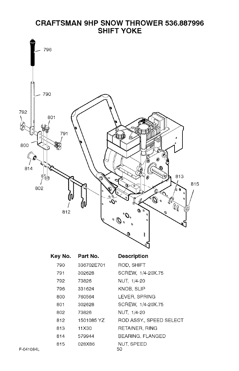
CRAFTSMAN 9HP SNOW THROWER 536.887996
SHIFT YOKE
796
j 790
792
801
791
8O0
814
802
t
812
813
815
F-041084L
Key No,
790
791
792
796
800
801
802
812
813
814
815
Part No,
336702E701
302628
73826
331624
760564
302628
73826
1501085 YZ
11X30
579944
028X86
Description
ROD, SHIFT
SCREW, 1/4-20X.75
NUT, 1/4-20
KNOB, SLIP
LEVER, SPRING
SCREW, 1/4-20X.75
NUT, 1/4-20
ROD ASSY., SPEED SELECT
RETAINER, RING
BEARING, FLANGED
NUT, SPEED
50
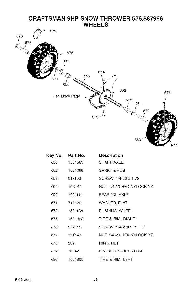
678
/
CRAFTSMAN 9HP SNOW THROWER 536.887996
WHEELS
673 OJ 679
675
671
678
655
Ref. Drive Page
654
650
653 _
652
655
/671
673
676
/
Key No.
650
852
653
654
855
871
678
675
876
677
678
879
680
Part No.
1501563
1501089
01x193
15X145
1501114
712120
1501138
1501808
577015
15X145
239
73842
1501809
Description
SHAFT, AXLE
SPRKT & HUB
SCREW, 1/4-20 x 1.75
NUT, 1/4-20 HEX NYLOCK YZ
BEARING, AXLE
WASHER, FLAT
BUSHING, WHEEL
TIRE & RIM -RIGHT
SCREW, 1/4-20X1.75 HH
NUT, 1/4-20 HEX NYLOCK YZ
RING, RET
PIN, KLIK .25 X 1.38 DIA
TIRE & RIM -LEFT
677
F-O41084L 51
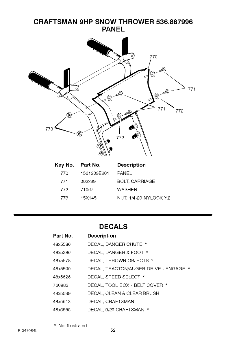
CRAFTSMAN 9HP SNOW THROWER 536.887996
PANEL
770
Key No.
770
771
772
778
Part No. Description
1501203E201 PANEL
002x99 BOLT, CARRIAGE
71067 WASHER
15X145 NUT, 1/4-20 NYLOCK YZ
Part No.
48x5580
48x5286
48x5578
48x5590
48x5626
760983
48x5599
48x5613
48x5555
DECALS
Description
DECAL DANGER CHUTE *
DECAL
DECAL
DECAL
DECAL
DECAL
DECAL
DECAL
DECAL
DANGER & FOOT *
THROWN OBJECTS *
TRACTON_UGER DRIVE-ENGAGE *
SPEED SELECT *
TOOL BOX-BELT COVER *
CLEAN & CLEAR BRUSH
CRAFTSMAN
9/29CRAFTSMAN *
* Notlllustrated
F-041084L 52

F-O41084L 53
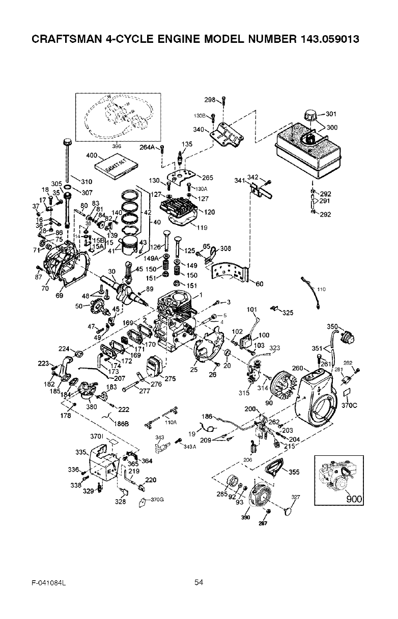
CRAFTSMAN 4-CYCLE ENGINE MODEL NUMBER 143.059013
70
69
101
182
185
25 282
370C
F-O41084L 54
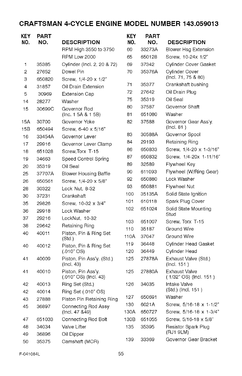
CRAFTSMAN 4-CYCLE ENGINE MODEL NUMBER 143.059013
KEY PART KEY PART
NO. NO. DESCRIPTION NO. NO. DESCRIPTION
RPM High 3550 to 3750 60 33273A Blower Hsg Extension
RPM Low 2000 65 650128 Screw, 10-24x 1/2"
1 35385 Cylinder (Incl. 2, 20 & 72) 69 37342 Cylinder Cover Gasket
2 27652 Dowel Pin 70 35376A Cylinder Cover
3 650820 Screw, 1/4-20 x 1/2" (Incl. 71,75 & 80)
4 31857 Oil Drain Extension 71 35377 Crankshaft bushing
5 30969 Extension Cap 72 27642 Oil Drain Plug
14 28277 Washer 75 35319 Oil Seal
15 306990 Governor Rod 80 37587 Governor Shaft
(Inc. 1 5A & 1 5B) 81 651080 Washer
15A 30700 Governor Yoke 82 37588 Governor Gear Ass'y.
15B 650494 Screw, 6-40 x 5/16" (Incl. 81 )
16 33454A Governor Lever 83 30588A Governor Spool
17 29916 Governor Lever Clamp 84 29193 Retaining Ring
18 651028 Screw, Torx T-15 86 650833 Screw, 1/4-20 x 1-3/16"
19 34663 Speed Control Spring 87 650832 Screw, 1/4-20x 1-11/16"
20 35319 Oil Seal 89 32589 Flywheel Key
25 37707A Blower Housing Baffle 90 611093 Flywheel (W/Ring Gear)
26 650561 Screw, 1/4-20 x 5/8" 92 650880 Lock Washer
28 30322 Lock Nut, 8-32 93 650881 Flywheel Nut
30 37231 Crankshaft 100 35135A Solid State Ignition
35 29826 Screw, 10-32 x 3/4" 101 610118 Spark Plug Cover
36 29918 Lock Washer 102 651024 Solid State Mounting
Stud
37 29216 LockNut, 10-32 103 651007 Screw, Torx T-15
38 29642 Retaining Ring 110 35187 Ground Wire
40 40011 Piston, Pin & Ring Set
(Std.) 110A 37047 Ground Wire
40 40012 Piston, Pin & Ring Set 119 36448 Cylinder Head Gasket
(.010" OS) 120 36449 Cylinder Head
41 40009 Piston, Pin Ass'y. (Std.) 125 27878A Exhaust Valve (Std.)
(Incl. 43) (Incl. 151 )
41 40010 Piston, Pin Ass'y. 125 27880A Exhaust Valve
(.010" OS) (Incl. 43) ( 1/32" OS) (Incl. 151 )
42 40013 Ring Set (Std.) 126 34035 Intake Valve
42 40014 Ring Set (.010" OS) (Std.) (Incl. 151 )
43 27888 Piston Pin Retaining Ring 127 650691 Washer
45 36897 Connecting Rod Assy 130 6021A Screw, 5/16-18 x 1-1/2"
(Incl. 47 &49) 130A 650727 Screw, 5/16-18 x 1-3/4"
47 651033 Connecting Rod Bolt 130B 651055 Screw, 5/16-18 x 5/8"
48 34034 Valve Lifter 135 35395 Resistor Spark Plug
49 36896 Oil Dipper (RJ1 9LM)
50 35375 Camshaft (MCR) 139 33369 Governor Gear Bracket
F-041084L 55
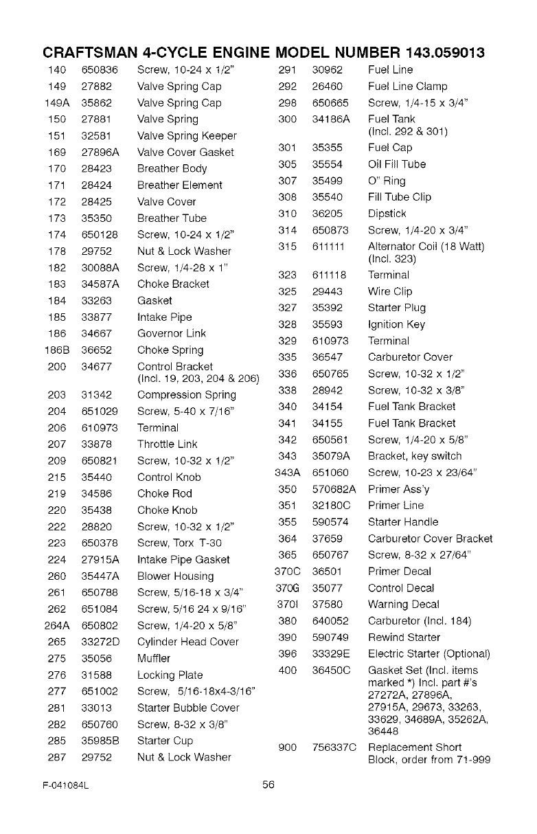
CRAFTSMAN
140 650836
149 27882
149A 35862
150 27881
151 32581
169 27896A
170 28423
171 28424
172 28426
173 35350
174 650128
178 29752
182 30088A
183 34587A
184 33263
185 33877
186 34667
186B 36652
200 34677
203 31342
204 651029
206 610973
207 33878
209 650821
215 35440
219 34586
220 35438
222 28820
223 650378
224 27915A
260 35447A
261 650788
262 651084
264A 650802
265 33272D
275 35056
276 31588
277 651002
281 33013
282 650760
285 35985B
287 29752
4-CYCLE ENGINE MODEL NUMBER 143.059013
Screw, 10-24 x 1/2" 291 30962 Fuel Line
Valve Spring Cap 292 26460 Fuel Line Clamp
Valve Spring Cap 298 650665 Screw, 1/4-15 x 3/4"
Valve Spring 300 34186A Fuel Tank
Valve Spring Keeper (Incl. 292 & 301)
Valve Cover Gasket 301 35355 Fuel Cap
Breather Body 305 35554 Oil Fill Tube
Breather Element 307 35499 O" Ring
308 35540 Fill Tube Clip
Valve Cover
Breather Tube 310 36205 Dipstick
Screw, 10-24 x 1/2" 314 650873 Screw, 1/4-20 x 3/4"
Nut & Lock Washer 815 611111 Alternator Coil (18 Watt)
(Incl. 323)
Screw, 1/4-28 x 1" 323 611118 Terminal
Choke Bracket 325 29443 Wire Clip
Gasket 327 35392 Starter Plug
Intake Pipe 328 35593 Ignition Key
Governor Link 329 610973 Terminal
Choke Spring 335 36547 Carburetor Cover
Control Bracket
(Incl. 19,203,204 & 206) 336 650765 Screw, 10-32 x 1/2"
Compression Spring 338 28942 Screw, 10-32 x 3/8"
Screw, 5-40 x 7/16" 340 34154 Fuel Tank Bracket
341 34155 Fuel Tank Bracket
Terminal
Throttle Link 342 650561 Screw, 1/4-20 x 5/8"
Screw, 10-32 x 1/2" 343 35079A Bracket, key switch
Control Knob 343A 651060 Screw, 10-23 x 23/64"
Choke Rod 350 570682A Primer Ass'y
351 321800 Primer Line
Choke Knob
Screw, 10-32 x 1/2" 355 590574 Starter Handle
Screw, Torx T-3O 364 37659 Carburetor Cover Bracket
Intake Pipe Gasket 365 650767 Screw, 8-32 x 27/64"
Blower Housing 3700 36501 Primer Decal
Screw, 5/16-18 x 3/4" 370G 35077 Control Decal
Screw, 5/16 24 x 9/16" 3701 37580 Warning Decal
Screw, 1/4-20 x 5/8" 380 640052 Carburetor (Incl. 184)
Cylinder Head Cover 390 590749 Rewind Starter
396 33329E Electric Starter (Optional)
Muffler 400 364500 Gasket Set (Incl. items
Locking Plate marked _) Incl. part #'s
Screw, 5/16-18x4-3/16" 27272A, 27896A,
Starter Bubble Cover 27915A, 29673, 33263,
33629, 34689A, 35262A,
Screw, 8-32 x 3/8" 36448
Starter Cup 900 7563370 Replacement Short
Nut & Lock Washer Block, order from 71-999
F-041084L 56
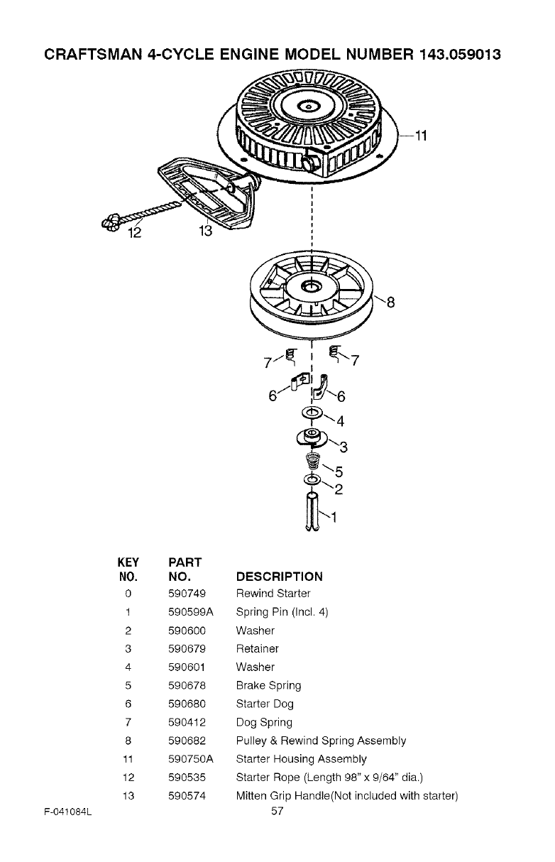
CRAFTSMAN 4-CYCLE ENGINE MODEL NUMBER 143.059013
12 13
F-041084L
KEY PART
NO. NO.
O 590749
1 590599A
2 590600
3 590679
4 590601
5 590678
6 590680
7 590412
8 590682
11 590750A
12 590535
13 590574
DESCRIPTION
Rewind Starter
Spring Pin (Incl. 4)
Washer
Retainer
Washer
Brake Spring
Starter Dog
Dog Spring
Pulley & Rewind Spring Assembly
Starter Housing Assembly
Starter Rope (Length 98" x 9/64" dia.)
Mitten Grip Handle(Not included with starter)
57
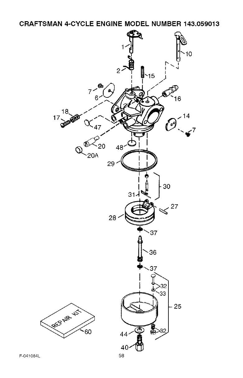
CRAFTSMAN 4-CYCLE ENGINE MODEL NUMBER 143.059013
_ L J
J I /
F-O41084L
'33 25
40/1_
58
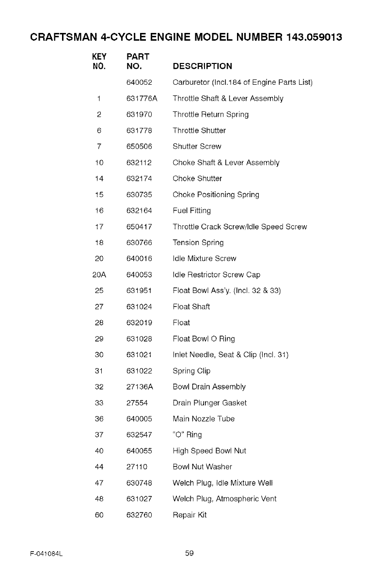
CRAFTSMAN 4-CYCLE ENGINE MODEL NUMBER 143.059013
KEY PART
NO. NO, DESCRIPTION
640052 Carburetor (Inc1.184 of Engine Parts List)
1 631776A Throttle Shaft & Lever Assembly
2 631970 Throttle Return Spring
6 631778 Throttle Shutter
7 650506 Shutter Screw
10 632112 Choke Shaft & Lever Assembly
14 632174 Choke Shutter
15 630735 Choke Positioning Spring
16 632164 Fuel Fitting
17 650417 Throttle Crack Screw/Idle Speed Screw
18 630766 Tension Spring
20 640016 Idle Mixture Screw
2OA 640053 Idle Restrictor Screw Cap
25 631951 Float Bowl Ass'y. (Incl. 32 & 33)
27 631024 Float Shaft
28 632019 Float
29 631028 Float Bowl O Ring
30 631021 Inlet Needle, Seat & Clip (Incl. 31)
31 631022 Spring Clip
32 27136A Bowl Drain Assembly
33 27554 Drain Plunger Gasket
36 640005 Main Nozzle Tube
37 632547 "O" Ring
40 640055 High Speed Bowl Nut
44 27110 Bowl Nut Washer
47 630748 Welch Plug, Idle Mixture Well
48 631027 Welch Plug, Atmospheric Vent
60 632760 Repair Kit
F-041084L 59
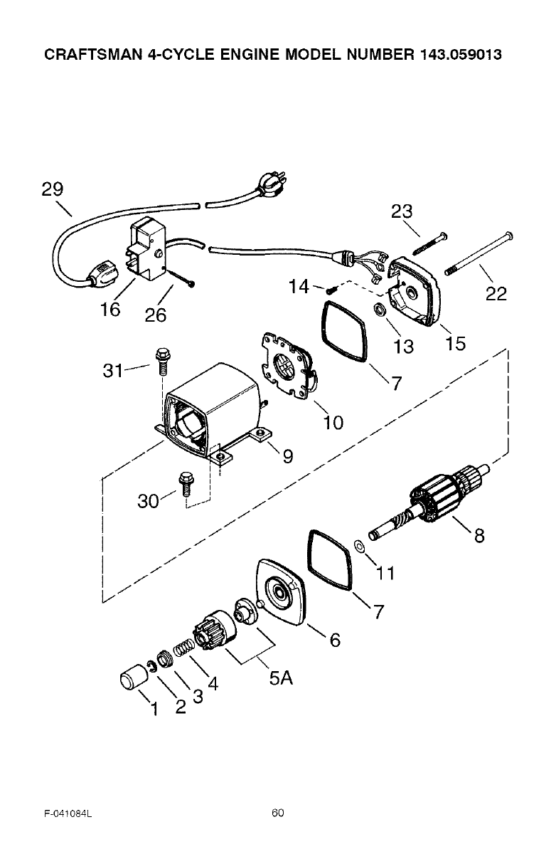
CRAFTSMAN 4-CYCLE ENGINE MODEL NUMBER 143.059013
29 J
\ 23
/
16 26
11
\7
_6
5A
F-O41084L 60
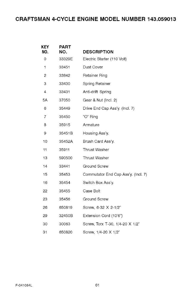
CRAFTSMAN 4-CYCLE ENGINE MODEL NUMBER 143.059013
KEY PART
NO. NO. DESCRIPTION
0 33329E Electric Starter (110 Volt)
1 33451 Dust Cover
2 33842 Retainer Ring
3 33430 Spring Retainer
4 33431 Anti-drift Spring
5A 37050 Gear & Nut (Incl. 2)
6 35449 Drive End Cap Ass'y. (Incl. 7)
7 35450 "O" Ring
8 35915 Armature
9 35451B Housing Ass'y.
10 35452A Brush Card Ass'y.
11 35911 Thrust Washer
13 590500 Thrust Washer
14 33441 Ground Screw
15 35453 Commutator End Cap Ass'y. (Incl. 7)
16 35454 Switch Box Ass'y.
22 35455 Case Bolt
23 35456 Ground Screw
26 650819 Screw, 6-32 X 2-1/2"
29 32450B Extension Cord (10'6")
30 30063 Screw, Torx %30, 1/4-20 X 1/2"
31 650820 Screw, 1/4-20 X 1/2"
F-041084L 81
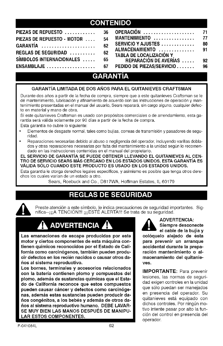
[_o_o_
PIEZASDEREPUESTO............ 36
PIEZASDEREPUESTO- MOTOR .... 54
GARANTIA ..................... 62
REGLASDESEGURIDAD .......... 62
SIMBOLOSINTERNACIONALES..... 65
ENSAMBLAJE................... 67
OPERACION .................... 71
MANTENtMIENTO................ 77
SERVlClOY AJUSTES............. 80
ALMACENAMIENTO.............. 91
TABLADELOCA,LIZACIONY
REPARAClONDEAVERIAS ..... 92
PEDIDODE PIEZAS/SERVICIO....... 96
GARANTIA LIMITADA DE DOS AI_IOS PARA EL QUITANIEVES CRAFTSMAN
Durante dos ahos a partir de la fecha de compra, siempre que a este quitanieves Craftsman se le
de mantenimiento, lubricaci6n y afinamiento de acuerdo con las hlstrucciones de operaci6n y man-
tenimJento presentadas en el manual del usuario, Sears reparar& sin cargo alguno, cualquier defec-
to en material y mano de obra.
Si este quJtanieves Craftsman es usado con propositos comerciales o de arrendamiento, esta ga-
rantia ser& valida solamente por 90 dJas a partir de la fecha de compra.
Esta garantia no cubre Io siguiente:
Elementos de desgaste normal, tales como bujias, correas de transmisJ6n y pasadores de segu-
ridad.
Reparaciones necesarias debJdo at abuso o negligencia del operador, incluyendo varifias dobla-
dos y otras reparaciones necesarias por falta del mantenimiento a la unidad segQn Io recomen-
dado en las instrucciones contenidas en el manual del propietario.
EL SERVlCIO DE GARANTIA SE PUEDE OBTENER LLEVANDO EL QUITANIEVES AL CEN-
TRO DE SERVIClO SEARS MAS CERCANO EN LOS ESTADOS UNIDOS. ESTA GARANTIA ES
VALIDA SOLO CUANDO ESTE PRODUCTO ES USADO EN LOS ESTADOS UNIDOS.
Esta garantia le otorga derechos legales especificos, y asimismo es posible que tenga otros dere-
chos los cuales varian de un estado a otto.
Sears, Roebuck and Co., D817WA, Hoffman Estates, IL 60179
Las emanaciones de escape producidas pot este
motor y ciertos componentes de esta maquina con-
tienen quimicos reconocidos pot el Estado de Cali-
fornia como carcinogenos, tambien pueden produ-
cir defectos en los recien nacidos o causar otros da-
5os al sistema reproductivo.
Los bornes, terminales y accesorios relacionados
con la bateria contienen plomo y compuestos del
plomo, ademas de sustancias quimicas que el Esta-
do de California reconoce que estos compuestos
pueden causar cancer y defectos como carcinoge-
nas, ademas estas sustancias pueden producir da-
5os congenitos, a los bebes y ademas de otros da-
5os al sistema reproductivo humano. DEBE LAVAR-
SE MUY BIEN LAS MANOS DESPUI_S DE MANIPU-
LAR ESTOS COMPONENTES.
Preste atenci6n a e ste simbolo, Je indica precauciones de seguridad importantes. Sig-
nifica--iiiA TENOION!!! iiiESTE ALERTA!!! Se trata de su seguridad.
_lb ADVERTENCIA:
Siempre desconecte
el cable de la bujia y
coloquelo alejado de esta
para prevenir un arranque
accidental durante la prepa-
racion mantenimiento o al-
macenamiento del quitanie-
ves,
F-041084L 62
IMPORTANTE: Para prevenir
lesiones, las normas de seguri-
dad exigen controles en la unidad
que s61o puedan ser manejados
en presencia del operador. Su
quitanieves est& equipado con
dichos controles. Per ningt_n mo-
tive intente pasar por alto la fun-
ci6n del control en presencia del
operador.
CAPACITACION
1. Lea con atenci6n las instrucciones en el
manual de operaci6n y servicio. Familiar?
cese completamente con los controles y
el uso apropiado del quitanieves. Apren-
daa detener el quitanieves y a desen-
ganchar rapidamente los controles.
2. Nunca permita a nifios operar el quita-
nieves. Nunca permita que adultos ope-
ren el quitanieves sin la instrucci6n
apropiada.
3. Mantenga el area libre de personas, es-
pecialmente nifios pequehos y mascotas.
4. Tenga mucho cuidado para evitar resba-
Iones o caidas, especialmente cuando
este retrocediendo.
PREPARACION
1. Inspeccione completamente el _rea don-
de se usar& el quitanieves y retire todas
las esteras, trineos, tableros, cables, y
otros objetos extraSos.
2. Desenganche todos los embragues antes
de hacer arrancar el motor.
3. No opere e! quitanieves sin vestir pren-
das de invierno adecuadas para trabajar
a la intemperie. Vista calzado que le de
buena tracci6n sobre superficies resbalo-
sas.
4. Maneje el combustible con cuidado; 6ste
es altamente inflamable.
(a) Use un contenedor aprobado para
combustible.
(b) Nunca quite la tapa del tanque de
combustible ni ahada combustible a
un motor en marcha o a un motor ca-
liente.
(c) Llene el tanque de combustible al mi-
re libre y con mucho cuidado. Nunca
Ilene el tanque en un recinto cerrado.
(d) Vuelva a colocar la tapa del tanque
de combustible de manera segura, y
limpie el combustible derramado.
(e) Nunca almacene combustible o el
quitanieves con combustible en el
tanque dentro de un edificio donde
los vapores pudiesen alcanzar algu-
na llama abierta o chispas.
(f) Verifique que el quitanieves tenga
suficiente combustible antes de cada
uso, y deje un espacio adicional en el
tanque puesto que el calor del motor
F-041084L
y/o del sol hace que el combustible
se expanda.
5. Para todos los quitanieves con motores
de arranque el6ctrico, use cables de ex-
tensi6n con certificaci6n CSA/UL. Use
solamente tomacorrientes que hayan si-
do instalados de acuerdo con los regla-
mentos de inspecci6n locales.
6. Jamas intente efectuar ningt_n ajuste
mientras el motor se encuentra en mar-
cha (excepto cuando el fabricante Io re-
comiende asi especificamente).
7. Permita que el motor y el quitanieves se
ajusten a las temperaturas exteriores an-
tes de comenzar a despejar la nieve.
8. Siempre use gafas de seguridad o pro-
tectores para los ojos durante la opera-
ci6n o mientras efectQa algt_n ajuste o
reparaci6n a la unidad, para proteger sus
ojos de objetos extra_os que pudiesen
ser lanzados por el quitanieves.
OPERACION
1. No opere este quitanieves si ester toman-
do medicinas que puedan causar somno-
lencia o afectar su habilidad para operar
el quitanieves.
2. No use el quitanieves si pot motivos
emocionales o fisicos se le dificulta ma-
nejarlo de forma segura.
3. No coloque las manos o los pies cerca o
debajo de piezas en movimiento. Man-
t6ngase en todo momento a buena dis-
tancia de la abertura del tubo de
descarga.
4. Tenga mucho cuidado al operar el quita-
nieves en o a trav6s de entradas de au-
tos, senderos o caminos de grava.
Mant6ngase alerta de peligros ocultos o
tr#.fico.
5.. Si golpea un objeto extrafio, pare e! mo-
tor, desconecte el cable de la bujia, ins-
peccione meticu!osamente el quitanieves
por si hubiera algQn da_o, y repArelo an-
tes de arrancar el motor y operar el quita-
nieves nuevamente.
6. Si el quitanieves comienza a vibrar de
manera excesiva, pare e! motor y revise-
Io inmediatamente para encontrar la cau-
sa. Generalmente, la vibraci6n es una
advertencia de algQn problema.
7. Pare el motor cuando deje la posici6n de
operaci6n, antes de desobstruir el aloja-
miento de la barrena/propulsor o el tubo
de descarga, y cuando efectOe cualquier
reparaci6n, ajuste o inspecci6n.
63
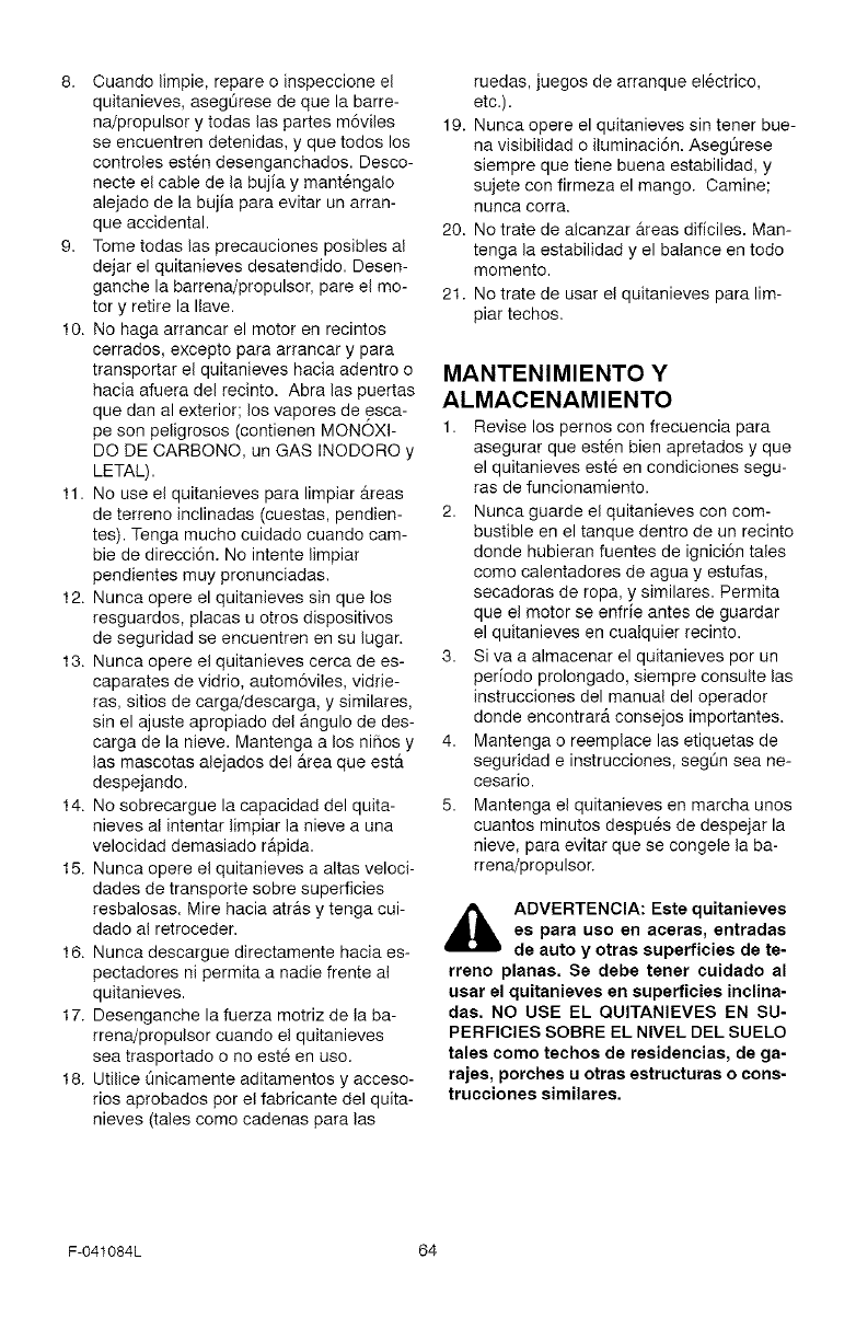
8. Cuandolimpie,repareoinspeccioneel
quitanieves,asegOresedequelabarre-
na/propulsorytodaslaspartesm6viles
seencuentrendetenidas,yquetodoslos
controlesestendesenganchados.Desco-
necteelcabledelabujiaymant6ngalo
alejadodelabujiaparaevitarunarran-
queaccidental.
9. Tometodaslasprecaucionesposiblesal
dejarelquitanievesdesatendido.Desen-
ganchelabarrena/propulsor,pareelmo-
toryretirelaIlave.
10.Nohagaarrancarelmotorenrecintos
cerrados,exceptoparaarrancarypara
transportarelquitanieveshaciaadentroo
haciaafueradelrecinto.Abralaspuertas
quedanalexterior;losvaporesdeesca-
pesonpeligrosos(contienenMONOXI-
DODECARBONO,unGASINODOROy
LETAL).
11.NouseelquitanievesparalimpiarAreas
deterrenoinclinadas(cuestas,pendien-
tes).Tengamuchocuidadocuandocam-
biededirecci6n.Nointentelimpiar
pendientesmuypronunciadas.
12.Nuncaopereelquitanievessinquelos
resguardos,placasuotrosdispositivos
deseguridadseencuentrenensulugar.
13.Nuncaopereelquitanievescercadees-
caparatesdevidrio,autom6viles,vidrie-
ras,sitiosdecarga/descarga,ysimilares,
sinelajusteapropiadodelangulodedes-
cargadelanieve.MantengaalosniBosy
lasmascotasalejadosdel_treaqueester
despejando.
14.Nosobrecarguelacapacidaddelquita-
nievesalintentarlimpiarlanieveauna
velocidaddemasiador&pida.
15.Nuncaopereelquitanievesaaltasveloci-
dadesdetransportesobresuperficies
resbalosas.Mirehaciaatr&sytengacui-
dadoalretroceder.
16.Nuncadescarguedirectamentehaciaes-
pectadoresnipermitaanadiefrenteal
quitanieves.
17.Desenganchelafuerzamotrizdetaba-
rrena/propulsorcuandoelquitanieves
seatrasportadoonoest6enuse.
18.UtiliceQnicamenteaditamentosyacceso-
riosaprobadosperelfabricantedelquita-
nieves(talescomecadenasparalas
ruedas,juegosdearranqueel6ctrico,
etc.).
19.Nuncaopereelquitanievessintenerbue-
navisibilidadoiluminaci6n.Asegt_rese
siemprequetienebuenaestabilidad,y
sujeteconfirmezaelmango.Oamine;
nuncacorra.
20.Notratedealcanzarareasdificiles.Man-
tengalaestabilidadyelbalanceentodo
memento.
21.Notratedeusarelquitanievesparalim-
piartechos.
MANTENIMIENTO Y
ALMACENAMIENTO
1. Revise los pernos con frecuencia para
asegurar que est6n bien apretados y que
el quitanieves est6 en condiciones segu-
ras de funcionamiento.
2. Nunca guarde el quitanieves con com-
bustible en el tanque dentro de un recinto
donde hubieran fuentes de ignici6n tales
come calentadores de agua y estufas,
secadoras de ropa, y similares. Permita
que el motor se enfrie antes de guardar
el quitanieves en cualquier recinto.
3. Siva a almacenar el quitanieves por un
periodo prolongado, siempre consulte las
instrucciones del manual del operador
donde encontrar_t consejos importantes.
4. Mantenga o reemplace las etiquetas de
seguridad e instrucciones, segQn sea ne-
cesario.
5. Mantenga el quitanieves en marcha unos
cuantos minutes despu6s de despejar la
nieve, para evitar que se congele la ba-
rrena/propulsor.
,_ ADVERTENCIA: Este quitanieves
es para uso en aceras, entradas
de auto y otras superficies de te-
rreno planas. Se debe tenet cuidado al
usar el quitanieves en superficies inclina-
das. NO USE EL QUITANIEVES EN SU-
PERFICIES SOBRE EL NIVEL DEL SUELO
tales como techos de residencias, de ga-
rajes, porches u otras estructuras o cons-
trucciones similares.
F-041084L 64
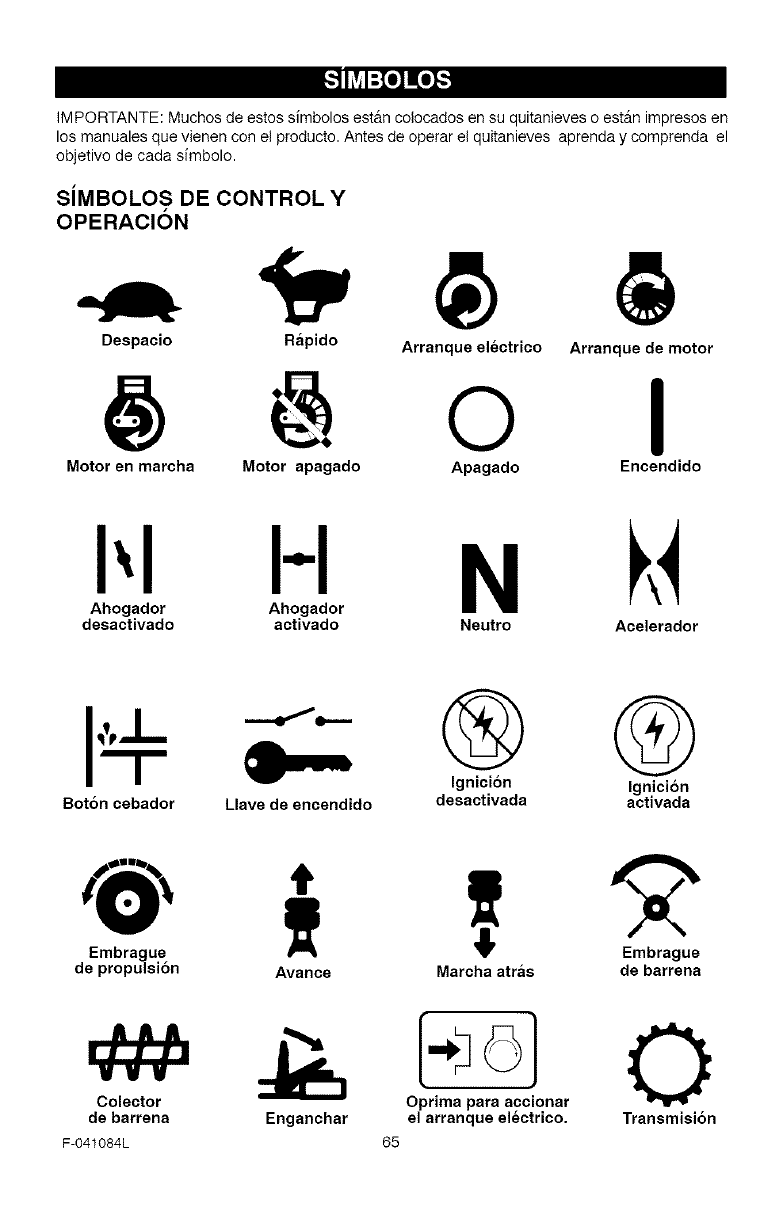
[.,,._o)nUCo_
IMPORTANTE: Muchos de estos simbolos estan colocados en su quitanieves o est_m impresos en
los manuales que vienen con el producto. Antes de operar el quitanieves aprenda y comprenda el
objetivo de cada sfmbolo.
SiMBOLOS DE CONTROL Y
OPERACI6N
Despacio Rapido Arranque electrico Arranque de motor
o I
Motor en marcha Motor apagado Apagado Encendido
HN
Ahogador Ahogador
desactivado activado Neutro Acelerador
Boton cebador Llave de encendido
® @
Ignici6n Ignici6n
desactivada activada
Embrague
de propulsi6n
Colector
de barrena
F-041084L
Avance Marcha atras
O!:!ala_acc!onar
Enganchar el arranque electrico.
65
Embrague
de barrena
O
Transmisi6n
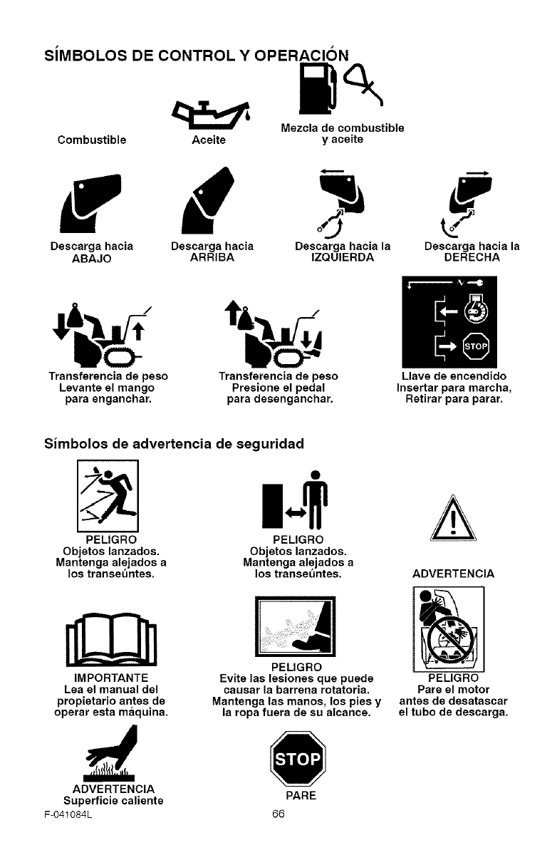
SiMBOLOS DE CONTROL YOPERACION
Mezcla de combustible
Combustible Aceite y aceite
Descarga hacia Descarga hacia Oescarga hacia la Descarga hacia la
ABAJO ARRIBA IZQUIERDA DERECHA
Transferencia de peso Transferencia de peso Llave de encendido
Levants st mango Presione el pedal Insertar para marcha,
para enganchar, para desenganchar. Retirar para parar.
Simbolos de advertencia de seguridad
PELIGRO
Objetos lanzados.
Mantenga alejados a
los transe_ntes.
IMPORTANTE
PELIGRO
Objetos lanzados.
Mantenga aleiados a
los transet_ntes.
Lea el manual del
propietario antes de
operar esta maquina.
ADVERTENCIA
Superficie caliente
F-O41084L
PELIGRO
Evite las lesiones que puede
causat la barrena rotatoria.
Mantenga las manos, los pies y
la ropa fuera de su alcance.
PARE
66
ADVERTENCIA
PELIGRO
Pare el motor
antes de desatassar
el tubo de descarga.
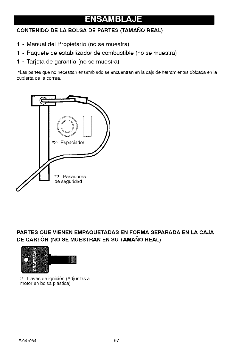
CONTENIDO DE LA BOLSA DE PARTES (TAMAI_IO REAL)
1 - Manual del Propietario (no se muestra)
1 - Paquete de estabilizador de combustible (no se muestra)
1 - Tarjeta de garantia (no se muestra)
*Las partesque no necesitanensambladose encuentranen la cajade herramientasubicadaen la
cubierta de la correa.
*2- Pasadores
de seguridad
PARTES QUE VIENEN EMPAQUETADAS EN FORMA SEPARADA EN LA CAJA
DE CARTON (NO SE MUESTRAN EN SU TAMAI_IO REAL)
2- Llaves de igniciSn (Adjuntas a
motor en bolsa pl&stica)
F-041084L 67
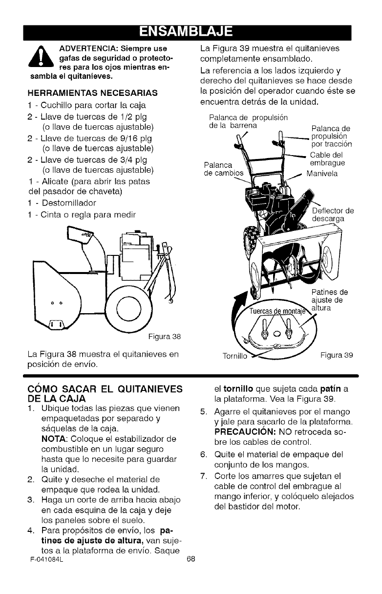
ADVERTENCIA: Siempre use
gafas de seguridad o protecto-
res para los ojos mientras en-
sambla el quitanieves.
HERRAMIENTAS NECESARIAS
1 - Cuchillo para cortar la caja
2 - Llave de tuercas de 1/2 pig
(o llave de tuercas ajustable)
2 - Llave de tuercas de 9/16 pig
(o llave de tuercas ajustable)
2 - Llave de tuercas de 3/4 pig
(o llave de tuercas ajustable)
1 - Alicate (para abrir las patas
de! pasador de chaveta)
1 - Destornillador
1 - Cinta o regla para medir
f--..,
Figura 38
La Figura 38 muestra el quitanieves en
posici6n de envio,
La Figura 39 muestra el quitanieves
completamente ensamblado.
La referencia a los lados izquierdo y
derecho del quitanieves se hace desde
la posici6n del operador cuando 6ste se
encuentra detr&s de la unidad.
Palanca de propulsi6n
de la barrena Palanca de
Dulsi6n
por tracci6n
Cable del
Palanca embrague
de cambios Manivela
Deflector de
Patines de
ajuste de
altura
Tornill Figura 39
COMO SACAR EL QUITANIEVES
DE LA CAJA
1. Ubique todas las piezas que vienen
empaquetadas por separado y
saquelas de la caja.
NOTA: Coloque el estabilizador de
combustible en un lugar seguro
hasta que Io necesite para guardar
la unidad.
2. Quite y deseche el material de
empaque que rodea la unidad.
3. Haga un corte de arriba hacia abajo
en cada esquina de la caja y deje
los paneles sobre el suelo.
4. Para prop6sitos de envio, los pa-
tines de ajuste de altura, van suje-
tos a la plataforma de envio. Saque
F-041084L 68
el tornillo que sujeta cada patina
la plataforma. Yea la Figura 39.
5. Agarre el quitanieves por el mango
y jale para s,acarlo de la plataforma.
PREOAUOION: NO retroceda so-
bre los cables de control.
6. Quite el material de empaque de!
conjunto de los mangos.
7. Corte los amarres que sujetan el
cable de control del embrague al
mango inferior, y col6quelo alejados
del bastidor del motor.
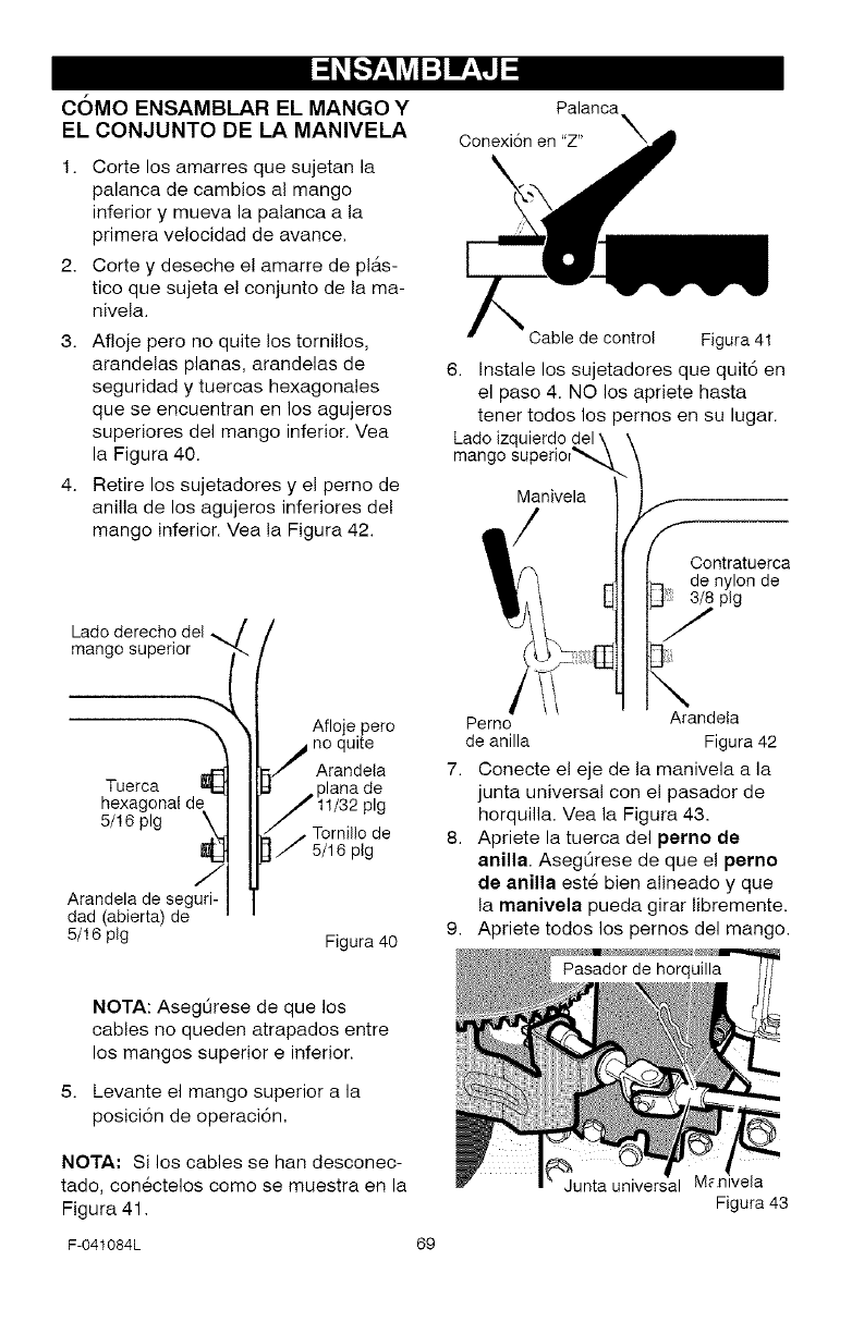
COMO ENSAMBLAR EL MANGO Y
EL CONJUNTO DE LA MANIVELA
1. Corte los amarres que sujetan la
palanca de cambios al mango
inferior y mueva la palanca a la
primera velocidad de avance.
2. Corte y deseche el amarre de pl_ts-
tico que sujeta e! conjunto de la ma-
nivela.
3. Afloje pero no quite los tornillos,
arandelas planas, arandelas de
seguridad y tuercas hexagonales
que se encuentran en los agujeros
superiores del mango inferior. Vea
la Figura 40.
4. Retire los sujetadores y el perno de
anilla de los agujeros inferiores de!
mango inferior. Vea la Figura 42.
Lado derecho del _/
mango superior
Tuerca I_
hexagonal d_
5/16 pig
Arandela de seguri-
dad (abierta) de
5/16 pig
/
Aflo e pero
j no quite
5./ Arandela
I;I ., plana de
11/32 pig
- -- Tornillo de
J 5/16 plg
Figura 40
Palanca
Conexi6n en "Z"
Cable de control Figura 41
6. Instale los sujetadores que quit6 en
el paso 4. NO los apriete hasta
tener todos los pernos en su lugar.
Lado izquierdo
mango
Manivela
Contratuerca
de nylon de
pig
Perno Arandela
de anilla Figura 42
7. Conecte el eje de la manivela a la
junta universal con el pasador de
horquilla. Vea la Figura 43.
8. Apriete la tuerca del perno de
anilla. AsegLirese de que el perno
de anilla est6 bien alineado y que
la manivela pueda girar libremente,
9. Apriete todos los pernos del mango.
NOTA: AsegL_rese de que los
cables no queden atrapados entre
los mangos superior e inferior.
Levante el mango superior a la
posici6n de operaci6n,
NOTA: Si los cables se han desconec-
tado, conectelos como se muestra en la
Figura 41.
Junta universal
Figura 43
F-041084L 69
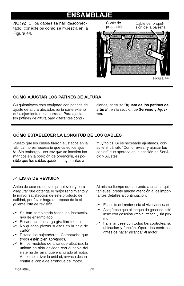
NOTA" Si los cables se han desconec-
tado, conectelos come se muestra en la
Figura 44.
Cable de
propulsi6n Cable de propul-
si6n de la barrena
C6MO AJUSTAR LOS PATINES DE ALTURA
Su quitanieves est& equipado con patines de
ajuste de altura ubicados en la parte exterior
del alojamiento de la barrena. Para ajustar
los patines de altura para diferentes condi-
Figura 44
clones, consulte "Ajuste de los patines de
altura", en la secci6n de Servicio y Ajus-
tes.
C6MO ESTABLECER LA LONGITUD DE LOS CABLES
Puesto que los cables fueron ajustados en la
fabrica, no es necesario que usted los ajus-
te. Sin embargo, una vez que se instalan los
mangos en la posici6n de operaci6n, es po-
sible que los cables queden muy tirantes o
muy flojos. Si es necesario ajustarlos, con-
suite el p_trrafo "06mo revisar y ajustar los
cables" que aparece en la secci6n de Servi-
cio y Ajustes.
_' LISTA DE REVISION
Antes de usar su nuevo quitanieves, y para
asegurar que obtenga el mejor rendimiento y
la mayor satisfacci6n de este producto de
calidad, pot favor haga un repaso de la si-
guiente lista de revisi6n:
_' Se hart completado todas las instruccio-
nes de ensamblado.
_' El canal de descarga gira libremente.
_' No quedan piezas sueltas en la caja de
cart6n.
_' Revise los sujetadores. Compruebe que
todos est6n bien apretados.
_' En los modelos de arranque electrico, la
unidad ha sido enviada con el cable del
sistema de arranque enchufado al motor.
Antes de utilizar la unidad, sfrvase desen-
chufar el cable de arranque del motor.
AI mismo tiempo que aprende a usar su qui-
tanieves, preste mucha atenci6n a los impor-
tantes detalles a continuaci6n:
_' El aceite del motor est& al nivel adecuado.
_' Aseg@ese que el tanque de gasolina este
Ileno con gasolina limpia, fresca y sin plo-
mo.
_' Familiaricese con todos los controles, su
ubicaci6n y funci6n. Opere los controles
antes de hacer arrancar el motor.
F-041084L 70
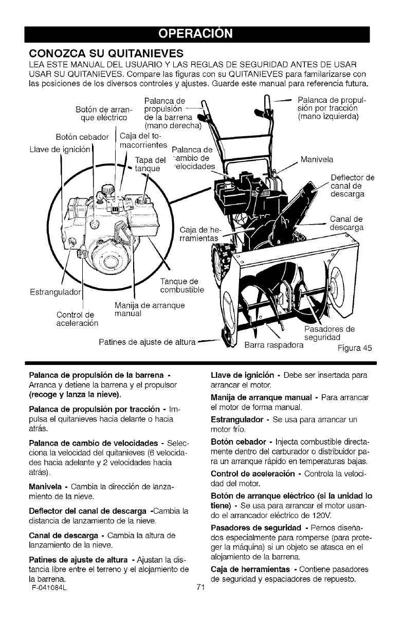
CONOZCA SU QUITANIEVES
LEA ESTE MANUAL DEL USUARIO Y LAS REGLAS DE SEGURIDAD ANTES DE USAR
USAR SU QUITANIEVES. Compare las figuras con su QUITANIEVES para familarizarse con
las posiciones de los diversos controles y ajustes, Guarde este manual para referencia futura.
Palanca de Palanca de propul-
Bot6n de arran- propulsi6n si6n pot tracci6n
que el6ctrico de la barrena (mano izquierda)
Bot6n cebador Oaja del to-
macorrientes
Llave de i(
tanque
Manivela
Defledorde
de
descarga
Oanalde
descarga
Estrangulador
Control de manual
aceleraci6n
Patines de ajuste de
Pasadores de
seguridad
Barra raspadora Figura 45
Palanca de propulsi6n de la barrena -
Arranca y detiene la barrena y el propulsor
(recoge y lanza la nieve),
Palanca de propulsion pot traccion- Im-
pulsa el quitanieves hacia delante o hacia
atr_ts.
Palanca de cambio de velocidades - Selec-
ciona la velocidad del quitanieves (6 velocida-
des hacia adelante y 2 velocidades hacia
atr&s).
Manivela - Cambia la direcci6n de lanza-
miento de la nieve.
Deflector del canal de descarga -Cambia la
distancia de lanzamiento de la nieve.
Canal de deecarga - Cambia la altura de
lanzamiento de la nieve.
Patines de ajuste de altura - Ajustan la dis-
tancia libre entre el terreno y el alojamiento de
la barrena.
F-041084L 71
Llave de ignicion -Debe ser insertada para
arrancar el motor.
Manija de arranque manual - Para arrancar
el motor de forma manual.
Eetrangulador - Se usa para arrancar un
motor frio.
Boron cebador - Injecta combustible directa-
mente dentro del carburador o distribuidor pa-
ra un arranque rapido en temperaturas bajas.
Control de aceleracion - Controla la veloci-
dad del motor.
Boton de arranque electrico (ei la unidad Io
tiene) - Se usa para arrancar el motor usan-
do el arrancador el_ctrico de 120M.
Pasadores de seguridad - Pernos diseha-
dos especialmente para romperse (para prote-
ger la m_tquina) si un objeto se atasca en el
alojamiento de la barrena.
Caja de herramientas - Contiene pasadores
de seguridad y espaciadores de repuesto.
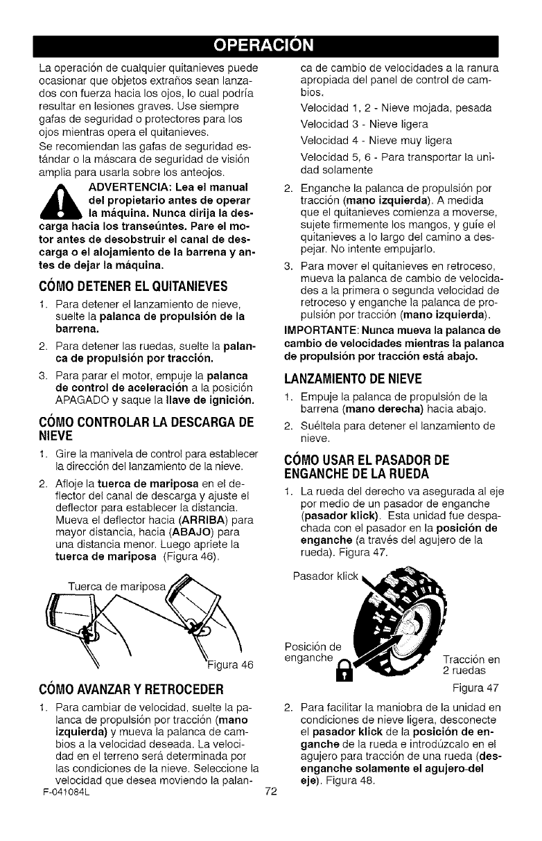
Laoperaci6ndecualquierquitanievespuede
ocasionarqueobjetosextrafiosseanlanza-
dosconfuerzahacialosojos,Iocualpodria
resultarenlesionesgraves.Usesiempre
gafasdeseguridadoprotectoresparalos
ojosmientrasoperaelquitanieves.
Serecomiendanlasgafasdeseguridades-
tandarolamascaradeseguridaddevisi6n
ampliaparausarlasobrelosanteojos.
_b ADVERTENCIA: Lea el manual
del propietario antes de oparar
la maquina. Nunca dirija la des-
carga hacia los transet_ntes. Pare el mo-
tor antes de desobstruir el canal de des-
carga o el alojamiento de la barrena y an-
tes de dejar la maquina.
COMODETENEREL QUITANIEVES
1. Para detener el lanzamiento de nieve,
suelte la palanca de propulsion de la
barrena,
2. Para detener las ruedas, suelte la palan-
ca de propulsi6n pot tracci6n.
3. Para parar el motor, empuje la palanca
de control de aceleraci6n a la posici6n
APAGADO y saque la Ilave de ignici6n.
COMOCONTROLARLADESCARGADE
NIEVE
1. Gire la manivela de control para establecer
la direcci6n del lanzamiento de la nieve.
2. Afloje la tuerca de mariposa en el de-
flector del canal de descarga y ajuste el
deflector para establecer la distancia.
Mueva el deflector hacia (ARRIBA) para
mayor distancia, hacia (ABAJO) para
una distancia menor. Luego apriete la
tuerca de mariposa (Figura 46).
Tuerca de mariposa
ca de cambio de velocidades a la ranura
apropiada del panel de control de cam-
bios.
Velocidad 1,2 - Nieve mojada, pesada
Velocidad 3 - Nieve ligera
Velocidad 4 - Nieve muy ligera
Velocidad 5, 6 - Para transportar la uni-
dad solamente
2. Enganche la palanca de propulsi6n por
tracci6n (mano izquierda). A medida
que el quitanieves comienza a moverse,
sujete firmemente los mangos, y guie el
quitanieves a Io largo del camino a des-
pejar. No intente empujarlo.
3. Para mover el quitanieves en retroceso,
mueva la palanca de cambio de velocida-
des a la primera o segunda velocidad de
retroceso y enganche la palanca de pro-
pulsi6n por tracci6n (mano izquierda).
IMPORTANTE: Nunca mueva la palanca de
cambio de velocidades mientras la palanca
de propulsi6n por traccion esta abajo.
LANZAMIENTODENIEVE
1. Empuje la palanca de propulsi6n de la
barrena (mano darecha) hacia abajo.
2. Sueltela para detener el lanzamiento de
nieve.
CC)MOUSAREL PASADORDE
ENGANCHE DE LA RUEDA
1. La rueda del derecho va asegurada al eje
per medio de un pasador de enganche
(pasador klick). Esta unidad fue despa-
chada con el pasador en la poeici6n de
enganche (a trav6s del agujero de la
rueda). Figura 47.
Pasador klick
gura 46
COMOAVANZARY RETROCEDER
1. Para cambiar de velocidad, suelte la pa-
lanca de propulsi6n por tracci6n (mano
izquierda) y mueva la palanca de cam-
bios a la velocidad deseada. La veloci-
dad en el terreno sera determinada per
las condiciones de la nieve. Seleccione la
velocidad que desea moviendo la palan-
F-041084L 72
Posici6n de
enganche Tracci6n en
2 ruedas
Figura 47
2. Para facilitar la maniobra de la unidad en
condiciones de nieve ligera, desconecte
el pasador klick de la posicion de en-
gancha de la rueda e introdOzcalo en el
agujero para tracci6n de una rueda (des-
anganche solamente el agujero-del
eje). Figura 48.
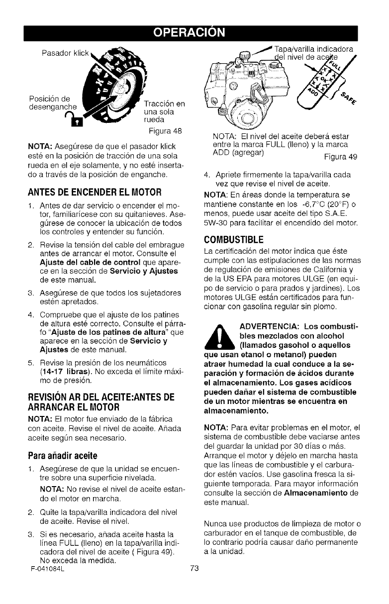
Pasadorklick
Posici6nde
desenganc Tracsi6nen
una sola
rueda
Figura 48
NOTA: AsegOrese de que el pasador klick
est6 en la posici6n de tracci6n de una sola
rueda en el eje solamente, y no este inserta-
do a traves de la posici6n de enganche.
ANTESDE ENCENDERELMOTOR
1. Antes de dar servicio o encender el mo-
tor, familiadcese con su quitanieves. Ase-
gOrese de conocer la ubicaci6n de todos
los controles y entender su funci6n.
2. Revise la tensi6n del cable del embrague
antes de arrancar e! motor. Oonsulte el
Ajuste del cable de control que apare-
ce en la secci6n de Servicio y Ajustes
de este manual.
3. AsegOrese de que todos los sujetadores
esten apretados.
4. Oompruebe que el ajuste de los patines
de altura este correcto. Consulte el parra-
fo "Ajuste de los patines de altura" que
aparece en la secci6n de Servicio y
Ajustes de este manual.
5. Revise la presi6n de los neum&ticos
(14-17 libras). No exceda el limite maxi-
me de presi6n.
REVISIONARDELACEITE:ANTESDE
ARRANCARELMOTOR
NOTA: El motor fue enviado de la f_.brica
con aceite. Revise el nivel de aceite. Ahada
aceite segOn sea necesario.
Paraa_adiraceite
1. AsegQrese de que la unidad se encuen-
tre sobre una superficie nivelada.
NOTA: No revise el nivel de aceite estan-
do el motor en marcha.
2. Quite la tapa/varilla indicadora del nivel
de aceite. Revise el nivel.
3. Si es necesario, a_ada aceite hasta la
I[nea FULL (lleno) en la tapa/varilla indi-
cadora del nivel de aceite ( Figura 49).
No exceda la medida.
F-041084L
Tapa/varilla indicadora
I nivel de ace_te J
NOTA: El nivel del aceite deber_t estar
entre la marca FULL (lleno) y la marca
ADD (agregar) Figura 49
4. Apriete firmemente la tapa/varilla cada
vez que revise el nivel de aceite.
NOTA: En areas deride la temperatura se
mantiene constante en los -6,7°0 (20°F) o
menos, puede usar aceite del tipo S.A.E.
5W-30 para facilitar el encendido del motor.
COMBUSTIBLE
La certificaci6n del motor indica que 6ste
cumple con las estipulaciones de las normas
de regulaci6n de emisiones de California y
de la US EPA para motores ULGE (en equi-
pc de servicio o para prados y jardines). Los
motores ULGE estAn certificados para fun-
cionar con gasolina regular sin plomo.
_b DVERTENCIA: Los combusti-
bles mezclados con alcohol
(llamados gasohol o aquellos
que usan etanol o metanol) pueden
atraer humedad la cual conduce a la se-
paracion y formacion de acidos durante
el almacenamiento. Los gases acidicos
pueden daftar el sistema de combustible
de un motor mientras se encuentra en
almacenamiento.
NOTA: Para evitar problemas en el motor, el
sistema de combustible debe vaciarse antes
del guardar la unidad por 30 dias o mrs.
Arranque el motor y d6jelo en marcha hasta
que las lineas de combustible y el carbura-
dor est6n vacfos. Use gasolina fresca la si-
guiente temporada. Para mayor informaci6n
consulte la secci6n de Almacenamiento de
este manual.
Nunca use productos de limpieza de motor o
carburador en el tanque de combustible, de
Io contrario podria causar daho permanente
a la unidad.
73
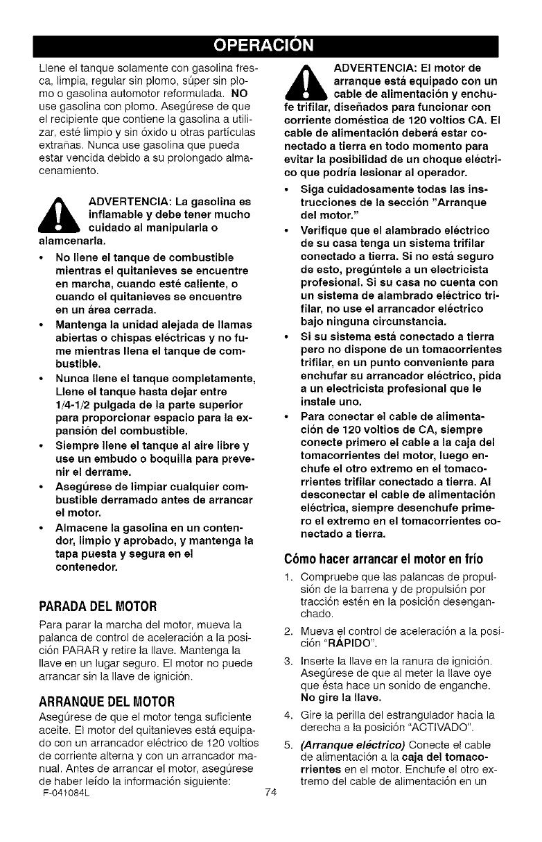
Ueneeltanquesolamentecongasolinafres-
ca,limpia,regularsinplomo,sOpersinplo-
moogasolinaautomotorreformulada.NO
usegasolinaconplomo.AsegOresedeque
elrecipientequecontienelagasolinaautili-
zar,est6limpioysin6xidouotrasparticulas
extrafias.Nuncausegasolinaquepueda
estarvencidadebidoasuprolongadoalma-
cenamiento.
ADVERTENCIA: La gasolina es
inflamable y debe tenet mucho
cuidado al manipularla o
alamcenarla.
• No Ilene el tanque de combustible
mientras el quitanieves se encuentre
en marcha, cuando este caliente, o
cuando el quitanieves se encuentre
en un area cerrada.
•Mantenga la unidad alejada de llamas
abiertas o chispas electricas y no fu-
me mientras Ilena el tanque de com-
bustible.
•Nunea Ilene el tanque completamente,
Llene el tanque hasta dejar entre
1/4-1/2 pulgada de la parte superior
para proporcionar espacio para la ex-
pansion del combustible.
•Siempre Ilene el tanque al aire libre y
use un embudo o boquilla para preve-
nit el derrame.
•Asegurese de limpiar cualquier com-
bustible derramado antes de arrancar
el motor.
•Almacene la gasolina en un conten-
der, limpio y aprobado, y mantenga la
tapa puesta y segura en el
contenedor.
PARADADELMOTOR
Para parar la marcha del motor, mueva la
palanca de control de aceleraci6n a la posi-
ci6n PARAR y retire la Ilave. Mantenga la
Ilave en un lugar seguro. El motor no puede
arrancar sin la Ilave de ignici6n.
ARRANQUEDELMOTOR
Asegt_rese de que el motor tenga suficiente
aceite. El motor del quitanieves esta equipa-
do con un arrancador el6ctrico de 120 voltios
de corriente altema y con un arrancador ma-
nual. Antes de arrancar e! motor, asegt_rese
de haber leido la informaci6n siguiente:
F-041084L 74
_DVERTENCIA: El motor de
arranque esta equipado con un
cable de alimentaci6n y enchu-
fe trifilar, disehados para funcionar con
corriente domestica de 120 voltios CA. El
cable de alimentacion debera estar co-
nectado a tierra en todo momento para
evitar la posibilidad de un choque electri-
co que podria lesionar al operador.
•Siga cuidadosamente todas las ins-
trucciones de la seccibn "Arranque
del motor."
•Verifique que el alambrado electrieo
de su easa tenga un sistema trifilar
eonectado a tierra. Si no esta seguro
de esto, preguntele a un electrieista
profesional. Si su casa no euenta con
un sistema de alambrado electrico tri-
filar, no use el arraneador eleetrieo
bajo ninguna eircunstaneia.
•Si su sistema esta conectado a tierra
pero no dispone de un tomacorrientes
trifilar, en un punto conveniente para
enehufar su arraneador electrieo, pida
a un electrieista profesional que le
instale uno.
•Para conectar el cable de alimenta-
ci6n de 120 voltios de CA, siempre
eonecte primero el cable a la eaja del
tomacorrientes del motor, luego en-
ehufe el otro extremo en el tomaco-
rrientes trifilar conectado a tierra. AI
desconectar el cable de alimentaeion
electrica, siempre desenchufe prime-
ro el extremo en el tomacorrientes eo-
nectado a tierra.
2.
3.
C6m0hacerarrancarel motorenfri0
1. Compruebe que las palancas de propul-
si6n de la barrena y de propulsi6n pot
tracci6n est6n en la posici6n desengan-
chado.
Mueva el control de aceleraci6n a la posi-
ci6n "RAPIDO".
4.
5.
Inserte la Ilave en la ranura de ignici6n.
AsegOrese de que al meter la Ilave oye
que esta hace un sonido de enganche.
No gire la Ilave.
Gire la perilla del estrangulador hacia la
derecha a la posici6n "ACTIVADO".
(Arranque electrico) Conecte el cable
de alimentaci6n a la caja del tomaco-
rrientes en el motor. Enchufe el otto ex-
tremo del cable de alimentaci6n en un
tomacorrientestrifilarde120voltiosCA,
conectadoatierra.
6. Empujeelboronoebadordelamanera
indicadaacontinuaci6n.Quiteeldedo
delbot6ncebadorentrecebados.
• Nouselafunci6ndecebadosilatem-
peraturaestasobre50°F(10°C).
• Oprimaelbot6ndosvecessilatem-
peraturaestaentre50°F(10°O)y
15° F(-10°O).
• Oprimaelbot6ncuatrovecessila
temperaturaseencuentrapordebajo
delos15° F(-10°C).
• Oprimaelbot6ncincovecessilatem-
peraturaseencuentrapordebajode
los0° F(-18°C).
7. (Arranque electrico) Presione el boton
de arranque hasta encender el motor.
No Io presione per mrs de 10 segundos
a la vez. Este motor de arranque el6ctri-
co cuenta con protecci6n termica. Si se
sobrecalienta se detendra automAtica-
mente y puede set arrancado nuevamen-
te s61o cuando se haya enfriado a una
temperatura segura (debe esperar entre
5 y 10 minutes aproximadamente).
8. (Arranque amanual) Jale rApidamente
la manija del arranque manual. No
suelte la manija inmediatamente des-
pu6s de jalarla. Deje que la manija del
arranque manual se enrolle lentamente.
9. Si el motor no arranca a los 5 6 6 inten-
tos, lea las instrucciones sobre: Dificultad
para arrancar en la "Tabla de Iocalizaci6n
y reparaci6n de averias".
10. Una vez que el motor arranque, mueva el
control de estrangulaoi6n a la posici6n
"1/2". Cuando el motor est6 trabajando
de manera uniforme, mueva el control
de estrangulacion a la posici6n "desac-
tivado".
11. (Arranque electrico) Desconecte el ca-
ble de alimentaci6n, primero del tomaco-
rrientes y luego de la caja del
tomaoorrientee.
12.Opere el motor a una velocidad de acele-
raci6n "Rh, PIDA" cuando este despejan-
do la nieve.
Deje que el motor se caliente por varios mi-
nutos antes de empezar a despejar la nieve
en temperaturas inferiores a los -18°O (0°F).
F-041084L
Cbmohacerarrancarunmotorcaliente
Si esta arrancando un motor caliente des-
pu6s de haberlo apagado por un periodo
corto, deje la palanca del estrangulador en la
posici6n "DESACTIVADO" y no oprima el
bot6n cebador. Si el motor no arranca, siga
las instrucciones sobre Arranque del motor
en fifo.
ARRANQUE CONGELADO
Si el motor de arranque esta congelado y no
enciende el motor:
1. Jale tanta cuerda del arrancador manual
como sea posible.
2. Suelte la manija de arranque manual y
d6jela enrollarse con fuerza contra el
arrancador. Repita hasta que Iogre en-
cender el motor.
Para ayudar a evitar que se congelen el
arranque manual y los controles del motor,
proceda de la manera siguiente despues de
cada trabajo de remoci6n de nieve.
1. Con el motor en marcha, jale en6rgica-
mente la cuerda de arranque manual es-
tirando su brazo completamente tres o
cuatro veces seguidas. El jalado de la
cuerda de arranque producira un sonido
de repiqueteo fuerte. Esto no causa daho
al motor ni al arrancador.
Con el motor apagado, limpie toda la nie-
ve y humedad de la cubierta del carbura-
dor en el Area de las palancas de control.
Asimismo, mueva varias veces el control
de aceleraci6n, el control del estrangula-
dory la manija de arranque manual.
_ DVERTENCIA: Nunca arran-
que el motor dentro de un re-
cinto cerrado o en Areas con
poca ventilacion. Los gases de escape
del motor oontienen MONOXlDO DE
CARBONO, UN GAS INODORO Y MOR-
TAL. Mantenga las manos, los pies, el
pelo y las ropas eueltas alejadas de las
partee en movimiento tanto del motor
como del quitanievee.
•La temperatura del eilenciador y de
las piezae alrededor del silenciador
puede exceder los 150 _' F. Evite tocar
eetae partes.
• NO PERMITA que ni_os ni adolescen-
tee operen el quitanieves ni que esten
cerca cuando este funcionando.
75
COMO QUITAR LA NIEVE Y
ESCOMBROS ATASCADOS DE
LA BARRENA
_ADVERTENCIA: No intente qui-
tar la nieve ni escombros atas-
cados en la barrena sin tomar
lae preeaueiones siguientes,
En la parte de arriba del alojamiento de la ba-
rrena se encuentra un bast6n de limpieza. Uti-
lice el bast6n de limpieza para quitar la nieve
atascada en el alojamiento de la barrena.
Suelte la palanca de propulsi6n de la ba-
rrena.
Mueva la palanca de control de acelera-
ci6n a la posici6n "parar".
Retire (sin girar) la Ilave de ignici6n.
Desconecte el cable de la bujia.
No coloque las manos en la barrena o
canal de descarga. Use el bast6n de lim-
pieza para quitar la nieve.
CONSEJOSSOBREEL
LANZAMIENTODE NIEVE
1. Para un rendimiento m_tximo de su quita-
nieves, al despejar la nieve ajuste la ve-
Iocidad sobre el terreno, NUNOA haga
este ajuste en el control de aceleraci6n. 6.
Avarice lentamente en nieve profunda,
congelada, o mojada. Si las ruedas pati-
nan, reduzca la ve!ocidad de avance. El
motor est& disehado para brindar un ren-
dimiento m&ximo bajo aceleraci6n total y
debe ser operado en este valor de poten-
cia en todo momento.
2. El lanzamiento de nieve es m&s eficiente
si el trabajo se realiza inmediatamente 7.
despu@s de la nevada.
3. Para una remoci6n completa de la nieve,
traslape ligeramente cada camino adop-
tado previamente. En nieve profunda, su-
perponga los barridos entre si para evitar 8.
sobrecargar la m&quina.
4. La nieve deberia set descargada en la 9.
direcci6n del viento siempre que sea po-
sible.
5. Para uso normal, ajuste los patines de
altura de manera que la barra raspadora
quede a 1/8 de pulgada sobre los pati-
nes. Para superficies de nieve sumamen-
te compacta, ajuste los patines de altura
hacia arriba de manera que la barra ras-
padora haga contacto con el suelo.
En superficies de grava o piedra tritura-
da, ajuste los patines de altura a 1-1/4
pulgadas pot debajo de la barra raspado-
ra. Consulte el p_rrafo "Ajuste de los
patines de altura" en la secci6n de Ser-
vioio y Ajuetes de este manual. Este
ajuste es importante para que la m6.quina
no recoja y lance piedras ni grava.
Despu@s de completar el trabajo de des-
pejar la nieve, deje el motor en marcha
por unos cuantos minutos, esto derretira
la nieve y hielo acumulados alrededor del
motor.
Limpie completamente el quitanieves
despu@s de cada uso.
Quite toda acumulaci6n de hielo y nieve
y todo material extraiio del quitanieves, y
enjuague con agua (si fuera posible) para
remover toda la sal u otros qufmicos. Se-
que el quitanieves con un paho.
F-041084L 76
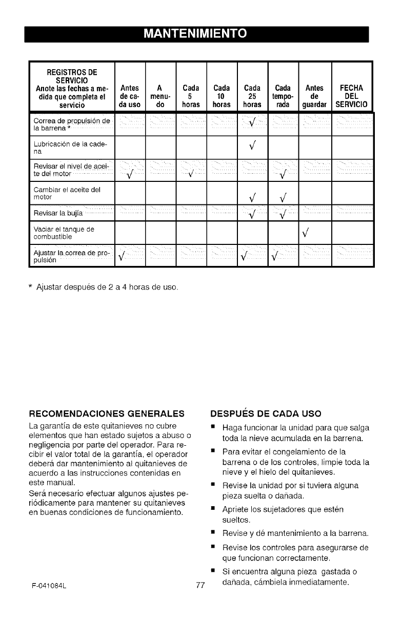
H-' h, h, H h, o]
REGISTROSDE
SERVICIO
Anote lasfechasa me- Antes A Cada Cada Cada Cada Antes FECHA
didaquecompletael deca- menu- 5 10 25 tempo, de DEL
servicio dauso do horas horas horas rada guardar SERVICIO
Correa de pr0puisi6n de
la barreRa * ........
Lubricaci6n de la cade-
na
Revisar el nivei de acei-
te det motor
V
Cambiar el aceite del
motor _/ _/
ReviSar ia bujia I I I I . _/
Vaciar el tanque de ,/
combustible V
I I I I n
Ajustar Ia correa de pto: ,/ J
pulsidn • "_ ' ' ' ¥
* Ajustar despues de 2 a 4 horas de uso.
RECOMENDAClONES GENERALES
La garantia de este quitanieves no cubre
elementos que han estado sujetos a abuso o
negligencia por parte del operador. Para re-
cibir el valor total de la garantia, el operador
debera dar mantenimiento al quitanieves de
acuerdo alas instrucciones contenidas en
este manual.
Ser_ necesario efectuar algunos ajustes pe-
ri6dicamente para mantener su quitanieves
en buenas condiciones de funcionamiento.
F-041084L 77
DESPUI_S DE CADA USO
• Haga funcionar la unidad para que salga
toda la nieve acumulada en la barrena.
• Para evitar el congelamiento de la
barrena o de los controles, limpie toda la
nieve y el hielo del quitanieves.
• Revise la unidad pot si tuviera alguna
pieza suelta o dahada.
• Apriete los sujetadores que esten
sueltos.
• Revise y de mantenimiento a la barrena.
• Revise los controles para asegurarse de
que funcionan correctamente.
• Si encuentra alguna pieza gastada o
dahada, c_mbiela inmediatamente.
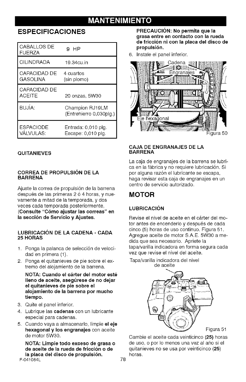
u-' h, h, uh, o]
ESPEClFICAClONES
CABALLOS DE 9 HP
FUERZA
CILINDRADA 19.34cu.in
CAPACIDAD DE 4 cuartos
GASOLINA (sin plomo)
CAPACIDAD DE
ACEITE 20 onzas, 5W30
BUJiA: Champion RJ19LM
(Entrehierro 0,030pig.)
ESPACIODE Entrada: 0,010 pig.
VALVULAS: Escape: 0,010 pig.
PRECAUCION: No permita que la
grasa entre en contacto con la rueda
de friccion ni con la placa del disco de
propulsion.
6. Instale el panel inferior.
Cadena
onal
QUITANIEVES
CORREA DE PROPULSION DE LA
BARRENA
Ajuste la correa de propulsi6n de la barrena
despues de las primeras 2 6 4 horas, y nue-
vamente a mitad de la temporada, y dos
veces cada temporada posteriormente,
(Consulte "Como ajustar las oorreas" en
la eeoeion de Servicio y Ajustes.
LUBRICACION DE LA CADENA -CADA
25 HORAS
1. Ponga la palanca de selecci6n de veloci-
dad en primera (1).
2. Ponga el quitanieves de pie sobre el ex-
tremo del alojamiento de la barrena.
NOTA: Cuando el carter del motor este
Ileno de aceite, asegt]rese de no dejar
el quitanieves de pie sobre el
alojamiento de la barrena por mucho
tiempo.
3. Quite el panel inferior.
4. Lubrique las oadenas con un lubricante
especial para cadenas.
5. Cuando vaya a almacenarlo, limpie el eje
hexagonal y los engranajes con aceite
de motor 5W30.
NOTA: Limpie todo exceeo de grasa o
de aeeite de la rueda de friecion o de
la plaoa del disco de propulsi6n.
F-041084L
CAJA DE ENGRANAJES DE LA
BARRENA
Figura 50
La caja de engranajes de la barrena se lubri-
ca en la f&brica y no requiere lubricaci6n. Si
por alguna raz6n el lubricante se escapa,
haga revisar esta caja de engranajes en un
centro de servicio autorizado.
MOTOR
LUBRICACION
Revise el nivel de aceite en el carter del mo-
tor antes de encenderlo y despues de cada
cinco (5) horas de uso continuo. Figura 51.
Agregue aceite de motor S.A.E. 5W30 a me-
dida que sea necesario. Apriete la
tapa/varilla indicadora en forma segura cada
vez que revise el nivel del aceite.
Tapa/varilla indicadora del nivel
de aceite
78
@
%Figura 51
Oambie el aceite cada veinticinco (25) horas
de uso, o pot Io menos una vez al aflo si el
quitanieves no se usa por veinticinco (25)
horas.
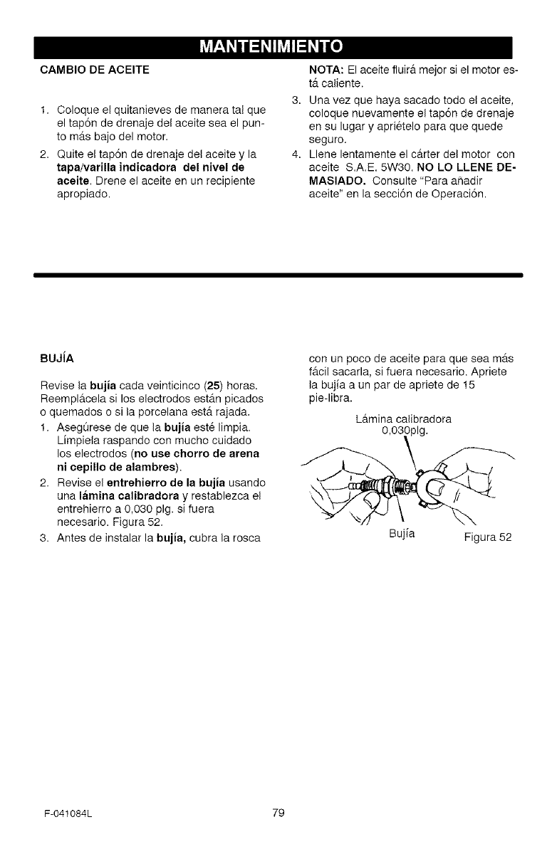
L_-' h, h, u h, o]
CAMBIO DE ACEITE
1. Coloque el quitanieves de manera tal que
el tap6n de drenaje del aceite sea el pun-
to m_.s bajo del motor.
2. Quite el tap6n de drenaje del aceite y la
tapa/varilla indicadora del nivel de
aeeite. Drene el aceite en un recipiente
apropiado.
NOTA: El aceite fluir& mejor si el motor es-
t,. caliente.
Una vez que haya sacado todo el aceite,
coloque nuevamente el tap6n de drenaje
en su lugar y aprietelo para que quede
seguro.
Llene lentamente el carter del motor con
aceite S.A.E. 5W30. NO LO LLENE DE-
MASlADO. Consulte "Para aSadir
aceite" en la secci6n de Operaci6n.
BUJJA
Revise la bujia cada veinticinco (25) horas.
Reempl&cela si los electrodos est_.n picados
o quemados o si la porcelana est& rajada.
1. AsegQrese de que la bujia est6 limpia.
Limpiela raspando con mucho cuidado
los electrodos (no use ehorro de arena
ni cepillo de alambres).
2. Revise el entrehierro de la bujia usando
una lamina calibradora y restablezca el
entrehierro a 0,030 pig. si fuera
necesario. Figura 52.
3. Antes de instalar la bujia, cubra la rosca
con un poco de aceite para que sea m_.s
f&cil sacarla, si fuera necesario. Apriete
la bujia a un par de apriete de 15
pie-libra.
L&mina calibradora
O,03_lg.
BL ta Figura 52
F-041084L 79
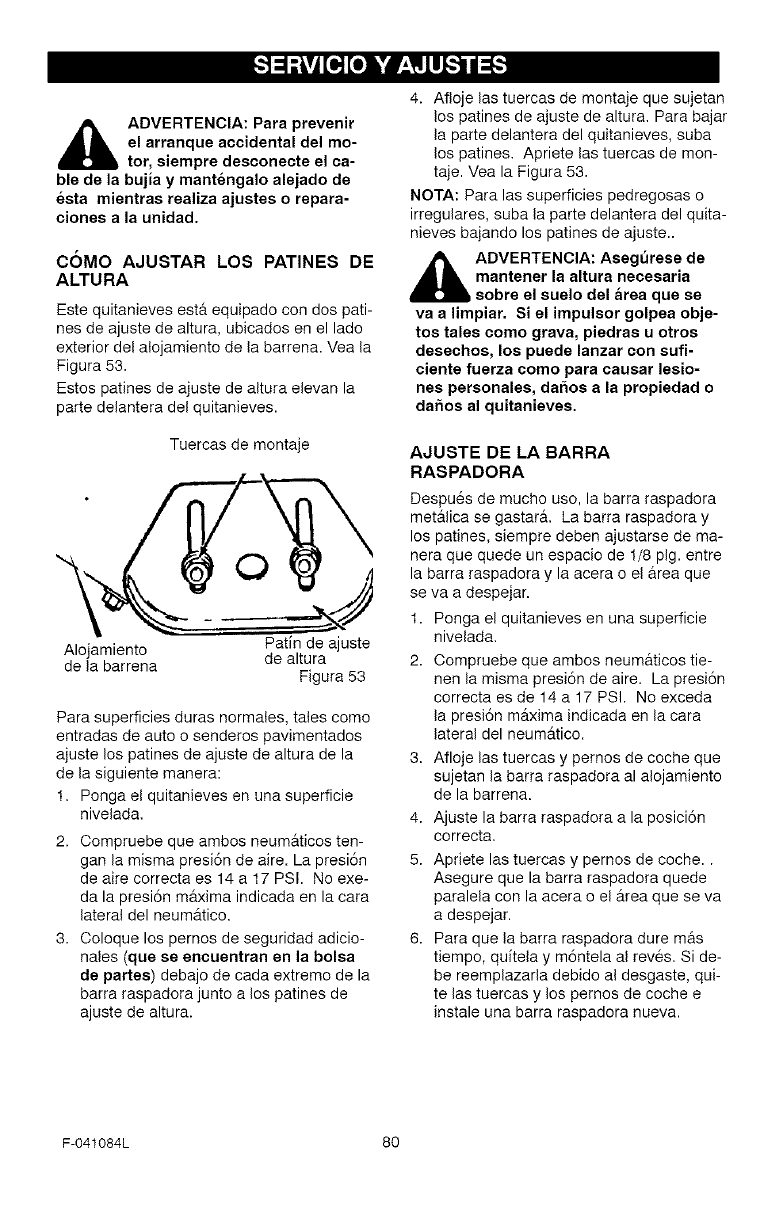
_lk ADVERTENCIA: Para prevenir
el arranque accidental del mo-
tor, siempre desconecte el ca-
ble de la bujia y mantengalo alejado de
esta mientras realiza ajustes o repara-
clones a la unidad.
COMO AJUSTAR LOS PATINES DE
ALTURA
Este quitanieves estfl equipado con dos pati-
nes de ajuste de altura, ubicados en el lade
exterior del alojamiento de la barrena. Vea la
Figura 53.
Estos patines de ajuste de altura elevan la
parte delantera del quitanieves.
Tuercas de montaje
"I O
Patin de ajuste
Alojamiento
de la barrena de altura
Figura 53
Para superficies duras normales, tales como
entradas de auto o senderos pavimentados
ajuste los patines de ajuste de altura de la
de la siguiente manera:
1. Ponga el quitanieves en una superficie
nivelada.
2. Compruebe que ambos neumflticos ten-
gan la misma presi6n de aire. La presi6n
de aire correcta es 14 a 17 PSI. No exe-
da la presi6n mflxima indicada en la cara
lateral del neumfltico.
3. Coloque los pernos de seguridad adicio-
nales (que se encuentran en la bolsa
de partes) debajo de cada extreme de la
barra raspadora junto a los patines de
ajuste de altura.
4. Afloje las tuercas de montaje que sujetan
los patines de ajuste de altura. Para bajar
la parte delantera del quitanieves, suba
los patines. Apriete las tuercas de mon-
taje. Vea la Figura 53.
NOTA: Para las superficies pedregosas o
irregulares, suba la parte delantera del quita-
nieves bajando los patines de ajuste..
_DVERTENCIA: Asegurese de
mantener la altura necesaria
sobre el suelo del area que se
va a limpiar. Si el impulsor golpea obje-
tos tales como grava, piedras u otros
desechos, los puede lanzar con sufi-
ciente fuerza como para causar lesio-
nes personales, daSos a la propiedad o
daSos al quitanieves.
AJUSTE DE LA BARRA
RASPADORA
Despu6s de mucho uso, la barra raspadora
metfllica se gastar& La barra raspadora y
los patines, siempre deben ajustarse de ma-
nera que quede un espacio de 1/8 pig. entre
la barra raspadora y la acera o el flrea que
se va a despejar.
1. Ponga el quitanieves en una superficie
nivelada.
2. Compruebe que ambos neumflticos tie-
nen la misma presi6n de aire. La presi6n
correcta es de 14 a 17 PSI. No exceda
la presi6n m_txima indicada en la cara
lateral del neum_ttico.
3. Afloje las tuercas y pernos de coche que
sujetan la barra raspadora al alojamiento
de la barrena.
4. Ajuste la barra raspadora a la posici6n
correeta.
5. Apriete las tuercas y pernos de coche..
Asegure que la barra raspadora quede
paralela con la acera o el _trea que se va
a despejar.
6. Para que la barra raspadora dure mrs
tiempo, quftela y m6ntela al reves. Si de-
be reemplazarla debido al desgaste, qui-
te las tuercas y los pernos de coche e
instale una barra raspadora nueva.
F-041084L 80
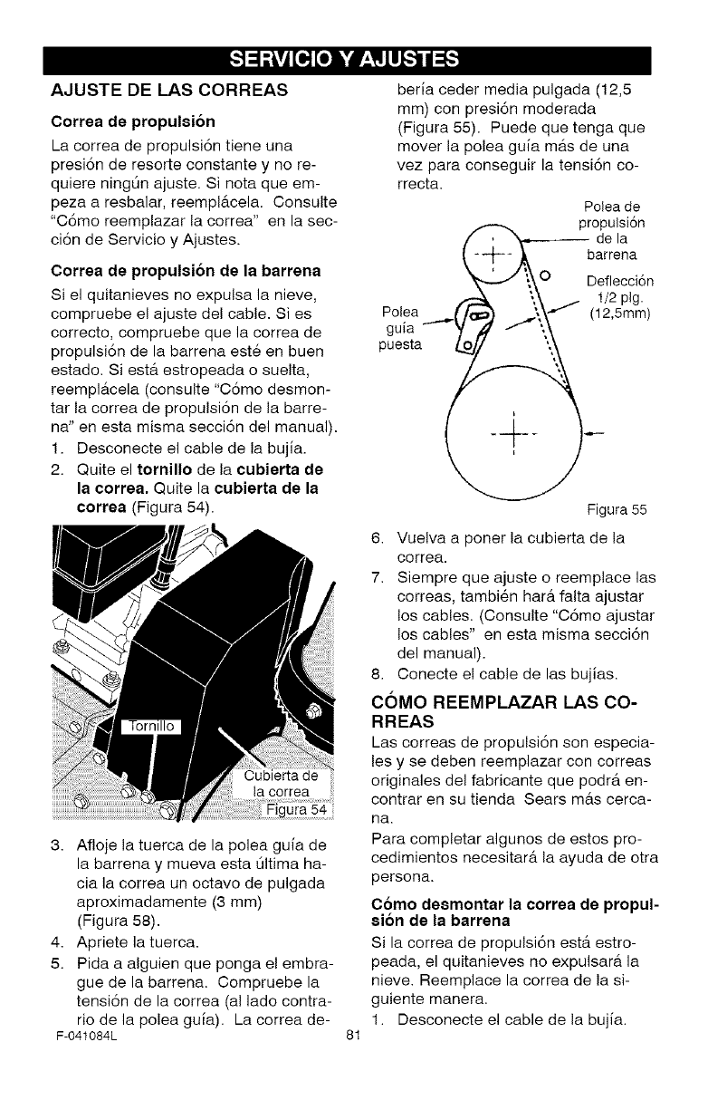
_o][o] i'd P'i_llllI_"_
AJUSTE DE LAS CORREAS
Correa de propulsion
La correa de propulsi6n tiene una
presi6n de resorte constante y no re-
quiere ningLin ajuste. Si nota que em-
peza a resbalar, reemplAcela. Consulte
"C6mo reemplazar la correa" en la sec-
ci6n de Servicio y Ajustes.
Correa de propulsion de la barrena
Si el quitanieves no expulsa la nieve,
compruebe el ajuste del cable. Si es
correcto, compruebe que la correa de
propulsi6n de la barrena est6 en buen
estado. SiestA estropeada o suelta,
reemplAcela (consulte "Como desmon-
tar la correa de propulsi6n de la barre-
na" en esta misma secci6n del manual).
1. Desconecte el cable de la bujia.
2. Quite el tornillo de la cubierta de
la correa. Quite la cubierta de la
correa (Figura 54).
ura 54
3. Afloje la tuerca de la polea guia de
la barrena y mueva esta Oltima ha-
cia la correa un octavo de pulgada
aproximadamente (3 mm)
(Figura 58).
4. Apriete la tuerca.
5. Pida a alguien que ponga el embra-
gue de la barrena. Compruebe la
tensi6n de la correa (al lado contra-
rio de la polea gufa). La correa de-
F-041084L 81
beria ceder media pulgada (12,5
mm) con presi6n moderada
(Figura 55). Puede que tenga que
mover la polea guia mas de una
vez para conseguir la tensi6n co-
rrecta.
Polea de
,, propulsi6n
/" _ de la
C -A ,,-. barrena
,i\\O Deflecci6n
_. t_ / 1/2 pig.
Polea /pc ',\-""f (12 5mm)
guia
puesta 1_ ',,_
Figura 55
6. Vuelva a poner la cubierta de la
correa.
7. Siempre que ajuste o reemplace las
correas, tambien harfi falta ajustar
los cables. (Consulte "Cdmo ajustar
los cables" en esta misma seccidn
del manual).
8. Conecte el cable de las bujias.
COMO REEMPLAZAR LAS CO-
RREAS
Las correas de propulsi6n son especia-
les y se deben reemplazar con correas
originales del fabricante que podr& en-
contrar en su tienda Sears m&s cerca-
ha.
Para completar algunos de estos pro-
cedimientos necesitar& la ayuda de otra
persona.
Como desmontar la correa de propul-
sion de la barrena
Si la correa de propulsi6n est& estro-
peada, el quitanieves no expulsara la
nieve. Reemplace la correa de la si-
guiente manera.
1. Desconecte el cable de la bujia.
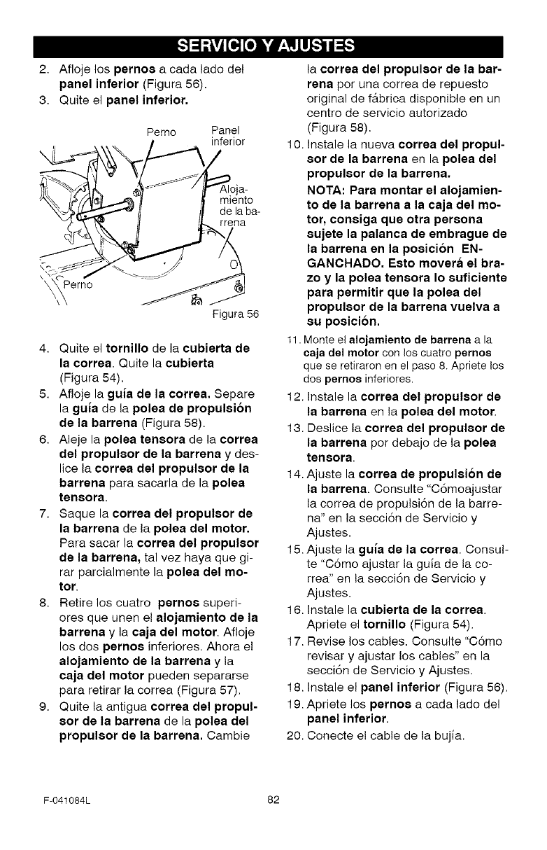
_o][o] h,*dP'i_llllI_"_
2. Afloje los pernos a cada lade del
panel inferior (Figura 56).
3. Quite el panel inferior.
Perno Panel
inferior
a-
de laba-
Figura 56
4. Quite el tornillo de la ¢ubisrta ds
la ¢orrsa. Quite la ¢ubierta
(Figura 54).
5. Afloje la guia ds la corrsa. Separe
la guia de la polea de propulsion
ds la barrena (Figura 58).
6. Aleje la polsa tsnsora de la ¢orrea
dsl propulsor de la barrsna y des-
lice la corrsa dsl propulsor ds la
barrsna para sacarla de la polea
tensora
7Saque la correa del propulsor de
la barrena de la polea del motor.
Para sacar la correa del propulsor
de la barrena, tal vez haya que gi-
rar parcialmente la polea del mo-
tor
8. Retire los cuatro pernos superi-
ores que unen el alojamisnto ds la
barrsna y la caja dsl motor. Afioje
los dos pernos inferiores. Ahora e!
alojamisnto ds la barrena y la
caja dsl motor pueden separarse
para retirar la correa (Figura 57).
9. Quite la antigua correa dsl propul-
sor ds la barrena de la polsa dsl
propulsor de la barrsna. Cambie
la correa del propulsor de la bar-
rena por una correa de repuesto
original de fAbrica disponible en un
centro de servicio autorizado
(Figura 58).
10. Instale la nueva corrsa del propul-
sor ds la barrsna en la polsa dsl
propulsor ds la barrsna.
NOTA: Para montar el alojamisn-
to ds la barrsna a la caja dsl mo-
tor, consiga qus otra persona
8ujste la palanca ds smbragus ds
la barrena sn la posici6n EN-
GANOHADO. Esto movsra el bra-
zo y la polsa tsnsora Io suficients
para permitir qus la polsa dsl
propulsor ds la barrsna vuslva a
su posicion.
11.Monte el alojamiento de barrena a la
eaja del motor con los cuatro pernos
que se retiraron en el paso 8. Apriete los
dos pernos inferiores.
12. Instale la corrsa del propulsor ds
la barrena en la polsa del motor.
13. Deslice la corrsa dsl propulsor ds
la barrena per debajo de la polea
tsnsora.
14. Ajuste la corrsa ds propulsion ds
la barrena. Consulte "C6moajustar
la correa de propulsi6n de la barre-
na" en la secci6n de Servicio y
Ajustes.
15. Ajuste la guia ds la corrsa. Consul-
te "C6mo ajustar la guia de la co-
rrea" en la secci6n de Servicio y
Ajustes.
16. Instale la cubierta de la correa.
Apriete el tornillo (Figura 54).
17. Revise los cables. Consulte "C6mo
revisar y ajustar los cables" en la
secci6n de Servicio y Ajustes.
18. Instale el panel inferior (Figura 56).
19. Apriete los psrnos a cada lado del
panel inferior.
20. Conecte e! cable de la bujia.
F-O41084L 82
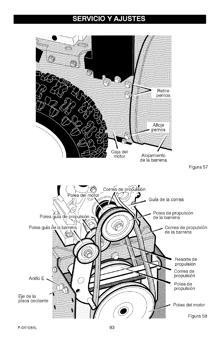
_o,][o] h,'dP'i_llllI_"_
Retire
Oaja del
motor AIojamiento
de la barrena
Figura 57
/Correa de propulsi6n
Polea del motor
Polea guia de la barrena
Guia de la correa
Polea de propulsi6n
de la barrena
Correa de propulsi6n
de la barrena
Anillo E
Eje de la
placa oscilante
Resorte de
propulsi6n
Oorrea de
propulsi6n
Polea de
propulsi6n
Polea del motor
Figura 58
F-041084L 83
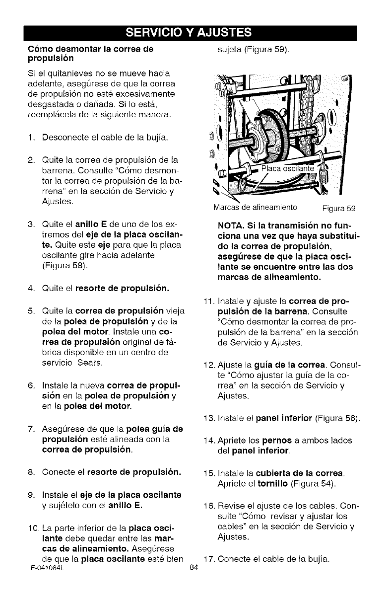
_o][o] h,'dP'i_llllI_"_
Como desmontar la correa de
propulsion
Si el quitanieves no se mueve hacia
adelante, asegOrese de que la correa
de propulsi6n no est6 excesivamente
desgastada o dar_ada. Si Io est,_,
reemplAcela de la siguiente manera.
1. Desconecte el cable de la bujia.
Quite la correa de propulsi6n de la
barrena. Consulte "C6mo desmon-
tar la correa de propulsi6n de la ba-
rrena" en la secci6n de Servicio y
Ajustes.
Quite el anillo E de uno de los ex-
tremes del eje de la placa oscilan-
re. Quite este eje para que la placa
oscilante gire hacia adelante
(Figura 58).
4. Quite el resorte de propulsion.
Quite la correa de propulsion vieja
de la polea de propulsion y de la
polea del motor. Instale una co-
rrea de propulsion original de fa-
brica disponible en un centro de
servicio Sears.
6. Instale la nueva correa de propul-
sion en la polea de propulsion y
en la polea del motor.
7. Aseg0rese de que la polea guia de
propulsion este alineada con la
correa de propulsion.
sujeta (Figura 59).
Marcas de alineamiento Figura 59
NOTA. Si la transmision no fun-
ciona una vez que haya subetitui-
do la correa de propulsion,
asegurese de que la placa osci-
lante se encuentre entre las dos
marcae de alineamiento.
11. Instale y ajuste la correa de pro-
pulsi6n de la barrena. Consulte
"C6mo desmontar la correa de pro-
pulsi6n de la barrena" en la secci6n
de Servicio y Ajustes.
12. Ajuste la guia de la correa. Consul-
te "C6mo ajustar la guia de la co-
rrea" en la secci6n de Servicio y
Ajustes.
13. Instale e! panel inferior (Figura 56).
14. Apriete los pemoe a ambos lades
del panel inferior.
8. Conecte e! reeorte de propulsion.
9. Instale el eje de la placa oecilante
y suj6telo con el anillo E.
10. La parte inferior de la plata oeci-
lante debe quedar entre las mar-
¢ae de alineamiento. Aseg0rese
de que la plata oecilante este bien
F-041084L
15. Instale la ¢ubierta de la correa.
Apriete el tornillo (Figura 54).
16. Revise el ajuste de los cables. Con-
suite "C6mo revisar y ajustar los
cables" en la secci6n de Servicio y
Ajustes.
17. Conecte e! cable de la bujia.
84
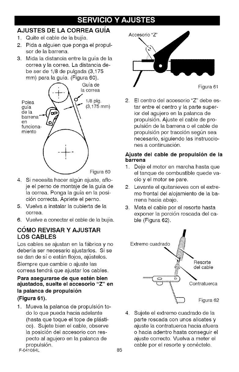
_.-]=_v_[o][o]i'd V_ILII[-'_.
AJUSTES DE LA CORREA GUiA
1. Quite el cable de la bujia.
2. Pida a alguien que ponga el propul-
sor de la barrena.
3. Mida la distancia entre la gufa de la
correa y la correa. La distancia de-
be ser de 1/8 de pulgada (3,175
mm) para la gufa. (Figura 60).
,, --., Gc%dee
t-Xj
Polea _ -J \', ... 1/8 pig.
gufa 1- jr\\° (3,175 mm)
de la Z/tOO - \\
barrena--_t \\
en _0# 't
funciena- _/ \
miente _ ___._ .
Figura 60
4. Si necesita hacer algQn ajuste, aflo-
je el perno de montaje de la guia de
la correa. Ponga la gufa en la posi-
ci6n correcta. Apriete el perno.
5. Vuelva a instalar la cubierta de la
correa.
6. Vuelve a conectar el cable de la bujia.
COMO REVISAR Y AJUSTAR
LOS CABLES
Los cables se ajustan en la fAbrica y no
deberfa ser necesario ajustarlos. Si se
se dan de s[ o estAn flojos, ajQstelos.
Siempre que cambie o ajuste las
correas tendr6 que ajustar los cables.
Para asegurarse de que esten bien
ajustados, suelte el accesorio "Z" en
la palanca de propulsion
(Figura 61).
1. Mueva la palanca de propulsi6n to-
do Io que pueda hacia adelante
(hasta que toque el tope de pl&sti-
co). Sujete bien el cable, observe
la posici6n del accesorio con res-
pecto al agujero en la palanca de
propulsiTn.
F-041084L
Acceserie "Z"
Figura 61
2. El centre del accesorio "Z" debe es-
tar entre el centre y la parte super-
ior del agujero en la palanca de
propulsiTn. Ajuste el cable de pro-
pulsiTn de la barrena o el cable de
propulsi6n per tracciTn segL_n sea
necesario, siguiendo las instruccio-
nes a continuaci6n.
Ajuste del cable de propulsion de la
barrena
1. Deje el motor en marcha hasta que
el tanque de combustible quede va-
cfoy el motor se pare.
2. Levante el quitanieves con el extre-
me frontal del alojamiento de la ba-
rrena hacia abajo.
3. Meta el cable par el resorte hasta
exporter la porciTn roscada de! ca-
ble (Figura 62).
Extreme cuadrade
Reserte
del cable
Centratuerca
85
Figura 62
Sujete el extremo cuadrado de la
parte roscada con unos alicates y
ajuste la contratuerca hacia afuera
o hacia adentro hasta conseguir el
ajuste correcto. Vuelva a meter el
cable per el resorte y conectelo.
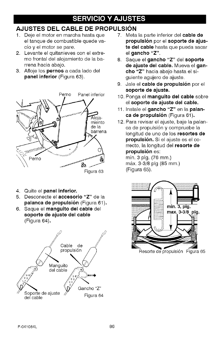
_o][o] h,'dP'i_llllI_"_
AJUSTES DEL CABLE DE PROPULSION
1. Deje el motor en marcha hasta que
el tanque de combustible quede va-
cioy el motor se pare.
2. Levante el quitanieves con el extre-
mo frontal del alojamiento de la ba-
rrena hacia abajo.
3. Afloje los perno8 a cada lado del
panel inferior (Figura 63).
Perno Panel inferior
miento
de la
barrena
Figura 63
7. Meta la parte inferior del cable de
propulsibn por el soporte de ajus-
te del cable hasta que pueda sacar
el gancho "Z".
8. Saque el gancho "Z" del eoporte
de ajuete del cable. Mueva el gan-
cho "Z" hacia abajo hasta el si-
guiente agujero de ajuste.
9. Jale el cable de propulsion por el
8oporte de ajuste.
10. Ponga el manguito del cable sobre
el 8oporte de ajuste del cable.
11. Instale el gancho "Z" en la palan-
ca de propulsion (Figura 61).
12. Para revisar el ajuste, baje la palan-
ca de propulsi6n y compruebe la
Iongitud de uno de los resortee de
propulei6n. Si el ajuste es el co-
rrecto, la Iongitud del reeorte de
propulsion es:
min. 3 pig. (76 mm.)
max. 3-3/8 pig (85 mm.)
(Figura 65).
4. Quite el panel inferior.
5. Desconecte el accesorio "Z" de la
palanca de propulsi6n (Figura 61).
6. Saque el manguito del cable del
8oporte de ajuste del cable
(Figura 64).
Cable de j/_
propulsi6n _/
SOlPCartlde ajuste i-igura......u// _ 4
min. 3, pig.
Resorte de propulsi6n Figura 65
F-O41084L 86
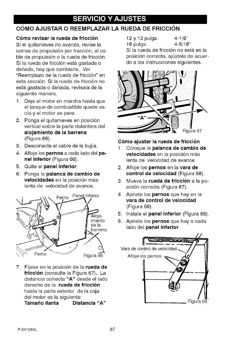
_o][o] h,'dP'i_llllI_"_
C6MO AJUSTAR O REEMPLAZAR LA RUEDA DE FRICCI6N
Como revisar la rueda de friccion
Si el quitanieves no avanza, revise la
correa de propulsi6n per tracci6n, el ca-
ble de propulsi6n o la rueda de fricci6n.
Si la rueda de fricci6n est& gastada o
dar_ada, hay que cambiarla. Ver
"Reemplazo de la rueda de fricci6n" en
esta secci6n. Si la rueda de fricci6n no
esta gastada o dafiada, revisela de la
siguiente manera.
1. Deje el motor en marcha hasta que
el tanque de combustible quede va-
cioy el motor se pare.
2. Ponga el quitanieves en posici6n
vertical sobre la parte delantera de!
alojamiento de la barrena
(Figura 66).
3. Desconecte el cable de la bujia.
4. Afloje los pernos a cada lade del pa-
nel inferior (Figura 66).
5. Quite el panel inferior.
6. Ponga la palanca de cambio de
velocidadee en la posici6n mas
lenta de ve!ocidad de avance.
'l _'-_\\_. Pe_ nferi°r
_,_/_,,_/_ena
\ \ Perno - Flgura 6\ \_c, P,_rn_, _ =_" _,
Fijese en la posici6n de la rueda de
friccion (consulte la Figura 67). La
distancia correcta "A" desde el lade
derecho de la rueda de fricci6n
hasta la parte exterior de la caja
del motor es la siguiente:
Tamar_o Ilanta Dietancia "A"
12 y 13 pulgs. 4-1/8"
16 pulgs. 4-5/16"
Si la rueda de fricci6n no esta en la
posici6n correcta, ajdstela de acuer-
do alas instrucciones siguientes.
Figura 67
Como ajuetar la rueda de friccion
1. Coloque la palanca de cambio de
velocidadee en la posici6n mas
lenta de velocidad de avance.
2. Afloje los pernos en la vara de
control de velocidad (Figura 68).
3. Mueva la rueda de friccion a la po-
sici6n correcta (Figura 67).
4. Apriete los pernos que hay en la
vara de control de velocidad
(Figura 68).
5. Instale el panel inferior (Figura 66).
6. Apriete los pernoe que hay a cada
lado de! panel inferior.
deoo troldevelooid dl .// I
Afloje los pernos "__ 1
,Figura 68
F-041084L 87
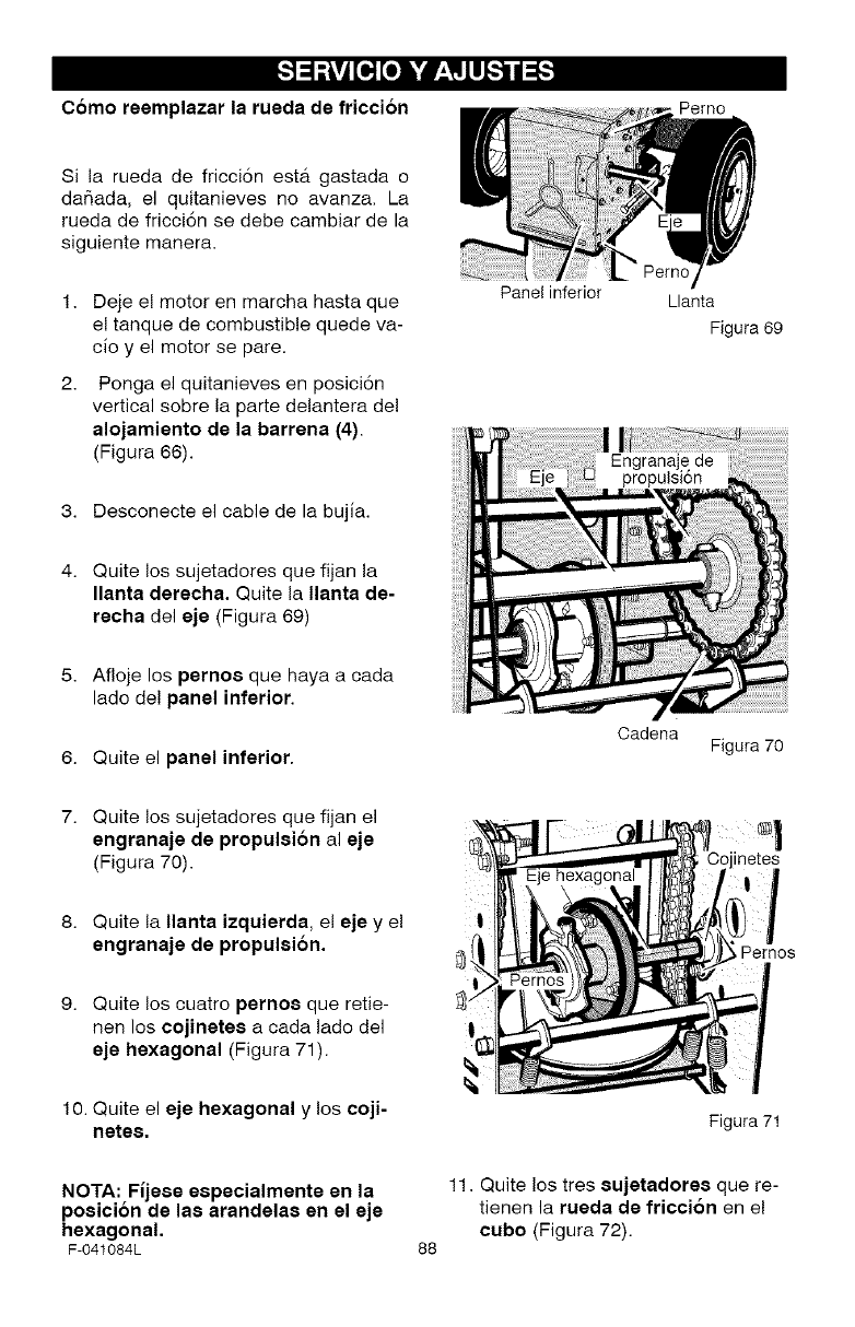
_o][o] h,'dP'i_llllI_"_
Como reemplazar la rueda de friccion Perno
Si la rueda de fricci6n esta gastada o
dar_ada, el quitanieves no avanza. La
rueda de fricci6n se debe cambiar de la
siguiente manera.
1. Deje el motor en marcha hasta que
el tanque de combustible quede va-
cio y el motor se pare.
2. Ponga el quitanieves en posici6n
vertical sobre la parte delantera de!
alojamiento de la barrena (4).
(Figura 66).
Panel inferior Llanta
Figura 69
3. Desconecte el cable de la bujia.
4. Quite los sujetadores que fijan la
Ilanta derecha. Quite la Ilanta de-
recha del eje (Figura 69)
Afloje los pernoe que haya a cada
lade de! panel inferior.
6. Quite el panel inferior.
Oadena Figura 70
7. Quite los sujetadores que fijan el
engranaje de propulei6n al eje
(Figura 70). inetes
8. Quite la Ilanta izquierda, el eje y e!
engranaje de propulsion.
9. Quite los cuatro pernoe que retie-
hen los cojinetee a cada lado del
eje hexagonal (Figura 71).
10. Quite el eje hexagonal y los coji-
netee.
NOTA:,Fijese especialmente en la
poslcnon de lae arandelae en el eje
hexagonal.
F-O41084L
,Pernos
Figura 71
88
11. Quite los tres eujetadoree que re-
tienen la rueda de friction en el
cubo (Figura 72).
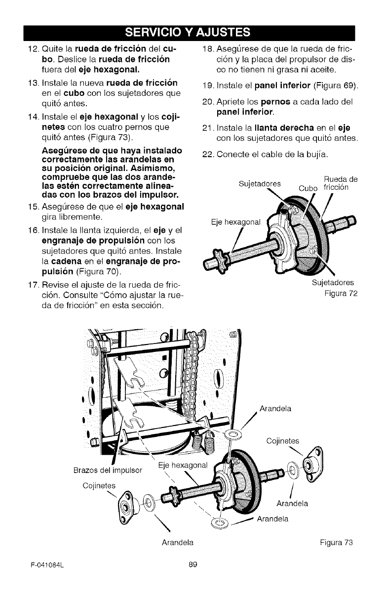
_o][o] h,'dP'i_llllI_"_
12. Quite la rueda de friccion del cu-
bo. Deslice la rueda de friccion
fuera del eje hexagonal.
13. Instale la nueva rueda de fricci6n
en el cubo con los sujetadores que
quit6 antes.
14. Instale el eje hexagonal y los coji-
netee con los cuatro pernos que
quit6 antes (Figura 73).
Asegt_rese de que haya inetalado
correctamente lae arandelae en
eu poeicion original. Aeimiemo,
compruebe que lae doe arande-
lae eeten correctamente alinea-
dae con los brazoe del impuleor.
15. Aseg6rese de que el eje hexagonal
gira libremente.
16. Instale la Ilanta izquierda, el eje yel
engranaje de propulsion con los
sujetadores que quit6 antes. Instale
la cadena en el engranaje de pro-
pulsi6n (Figura 70).
17. Revise el ajuste de la rueda de fric-
ci6n. Consulte "C6mo ajustar la rue-
da de fricci6n" en esta secci6n.
18. Aseg6rese de que la rueda de fric-
ci6n y la placa del propulsor de dis-
co no tienen ni grasa ni aceite.
19. Instale el panel inferior (Figura 69).
20. Apriete los pernoe a cada lado del
panel inferior.
21. Instale la Ilanta derecha en el eje
con los sujetadores que quit6 antes.
22. Conecte e! cable de la bujia.
Rueda de
Sujetadores Cubo fricci6n
\
Eje hexagonal
Sujetadores
Figura 72
I
Brazes del impulsor
Cojinetes
\
Arandela
Arandela
/
Cojinetes
/
Arandela
_ Arandela
Figura 73
F-041084L 89
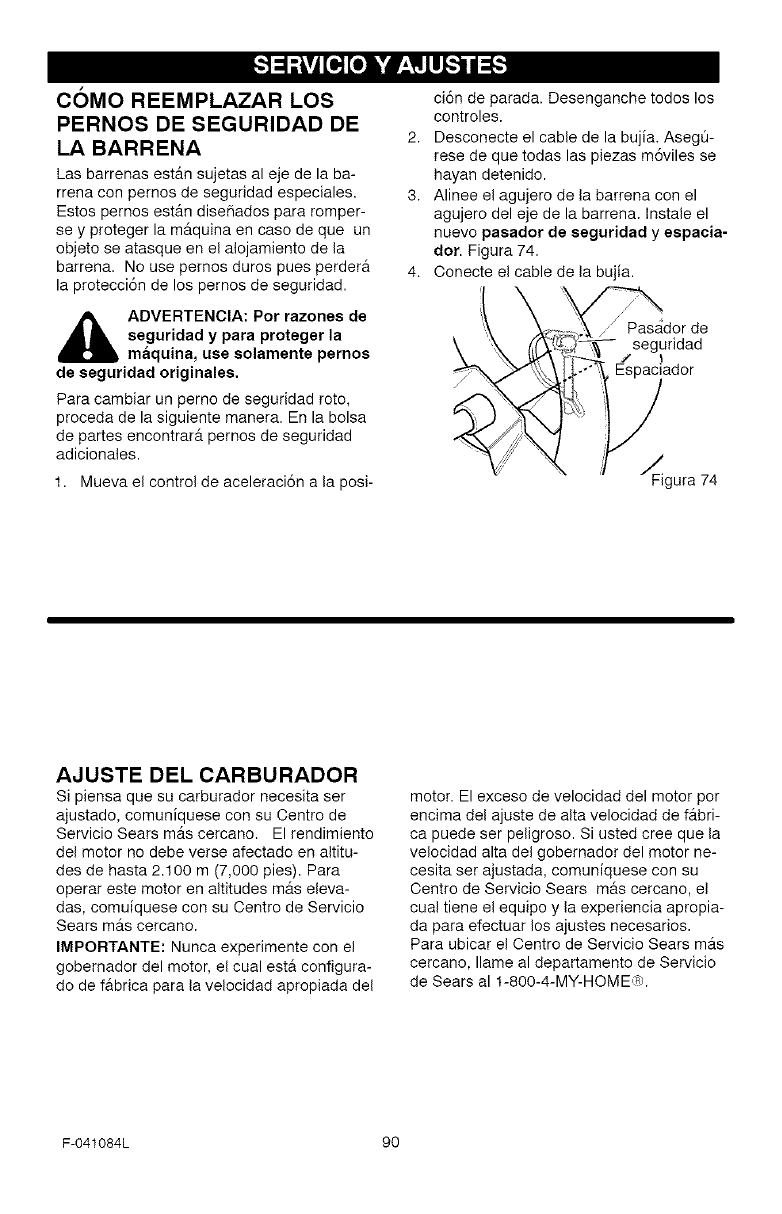
_o,][o] h,'dP'i_llllI_"_
COMO REEMPLAZAR LOS
PERNOS DE SEGURIDAD DE 2.
LA BARRENA
Las barrenas est_.n sujetas al eje de la ba-
rrena con pernos de seguridad especiales. 3.
Estos pernos est_.n disefiados para romper-
se y proteger la m_.quina en caso de que un
objeto se atasque en el alojamiento de la
barren& No use pernos duros pues perdera 4.
la protecci6n de los pernos de seguridad.
_DVERTENCIA: Pot razones de
seguridad y para proteger la
maquina, use solamente pernos
de seguridad originales.
Para cambiar un perno de seguridad roto,
proceda de la siguiente manera. En la bolsa
de partes encontrar_, pernos de seguridad
adicionales.
1. Mueva el control de aceleraci6n a la posi-
ci6n de parada. Desenganche todos los
controles.
Desconecte el cable de la bujia. Aseg0-
rese de que todas las piezas m6viles se
hayan detenido.
Alinee el agujero de la barrena con el
agujero del eje de la barrena. Instale el
nuevo pasador de seguridad yespaeia-
dor. Figura 74.
Conecte el cable de la bujia.
_ _dorde
_ seguridad
'_ _ ' /_ador
_' _N"_'x '_ _Figura 74
AJUSTE DEL CARBURADOR
Si piensa que su carburador necesita ser
ajustado, comuniquese con su Centro de
Servicio Sears m_.s cercano. El rendimiento
del motor no debe verse afectado en altitu-
des de hasta 2.100 m (7,000 pies). Para
operar este motor en altitudes m_.s eleva-
das, comuiquese con su Oentro de Servicio
Sears m_.s cercano.
IMPORTANTE: Nunca experimente con el
gobernador del motor, el cual esta configura-
do de fabrica para la velocidad apropiada del
motor. El exceso de velocidad del motor por
encima del ajuste de alta velocidad de f_.bri-
ca puede ser peligroso. Si usted cree que la
velocidad alta del gobernador del motor ne-
cesita set ajustada, comuniquese con su
Oentro de Servicio Sears mrs cercano, el
cual tiene el equipo y la experiencia apropia-
da para efectuar los ajustes necesarios.
Para ubicar el Centro de Servicio Sears m_.s
cercano, Ilame al departamento de Servicio
de Sears al 1-800-4-MY-HOME_).
F-041084L 90
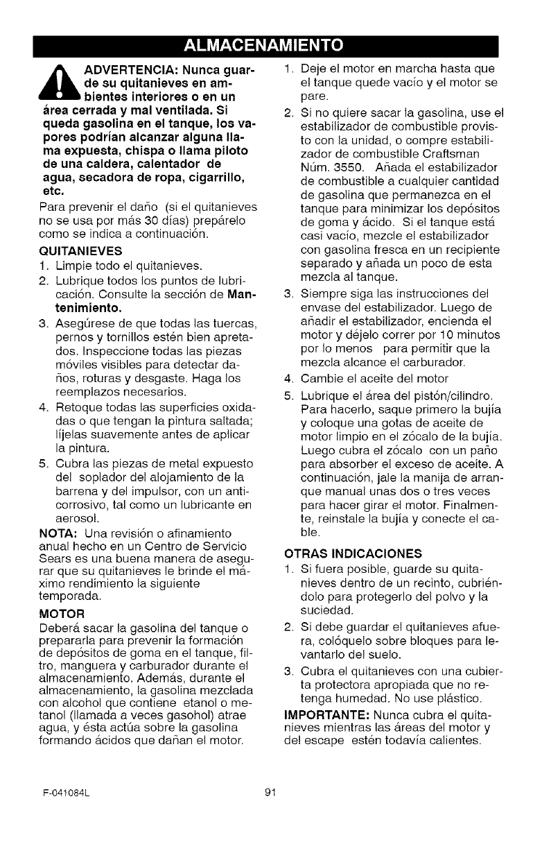
_b DVERTENCIA: Nunca guar-
de su quitanieves en am-
bientes interiores o en un
area cerrada y mal ventilada. Si
queda gasolina en el tanque, los va-
pores podrian alcanzar alguna lla-
ma expuesta, chispa o llama piloto
de una caldera, calentador de
agua, 8ecadora de ropa, cigarrillo,
etc.
Para prevenir el dar_o (si el quitanieves
no se usa por mas 30 dias) prepArelo
come se indica a continuaci6n.
QU ITANI EVES
1. Limpie todo el quitanieves.
2. Lubrique todos los puntos de lubri-
caci6n. Consulte la secci6n de Man-
tenimiento.
3. AsegL_rese de que todas las tuercas,
pernos y tornillos esten bien apreta-
dos. Inspeccione todas las piezas
m6viles visibles para detectar da-
r_os, roturas y desgaste. Haga los
reemplazos necesarios.
4. Retoque todas las superficies oxida-
das o que tengan la pintura saltada;
lijelas suavemente antes de aplicar
la pintura.
5. Cubra las piezas de metal expuesto
del soplador del alojamiento de la
barrena y del impulsor, con un anti-
corrosivo, tal come un lubricante en
aerosol.
NOTA: Una revisi6n o afinamiento
anual hecho en un Centro de Servicio
Sears es una buena manera de asegu-
rar que su quitanieves le brinde e! ma-
ximo rendimiento la siguiente
temporada.
MOTOR
DeberA sacar la gasolina del tanque o
prepararla para prevenir la formaci6n
de dep6sitos de goma en el tanque, fil-
tro, manguera y carburador durante el
almacenamiento. Ademas, durante el
almacenamiento, la gasolina mezclada
con alcohol que contiene etanol o me-
tanol (llamada a veces gasohol) atrae
agua, y 6sta actOa sobre la gasolina
formando acidos que dar_an el motor.
1. Deje el motor en marcha hasta que
el tanque quede vacio y el motor se
pare.
2. Si no quiere sacar la gasolina, use el
estabilizador de combustible provis-
to con la unidad, o compre estabili-
zador de combustible Craftsman
NOm. 3550. Armada el estabilizador
de combustible a cualquier cantidad
de gasolina que permanezca en el
tanque para minimizar los dep6sitos
de goma y Acido. Si e! tanque esta
casi vacio, mezcle el estabilizador
con gasolina fresca en un recipiente
separado y a_ada un poco de esta
mezcla al tanque.
3. Siempre siga las instrucciones del
envase del estabilizador. Luego de
a_adir el estabilizador, encienda el
motor y dejelo correr por 10 minutes
per Io menos para permitir que la
mezcla alcance e! carburador.
4. Cambie e! aceite del motor
5. Lubrique el Area del pist6n/cilindro.
Para hacerlo, saque primero la bujia
y coloque una gotas de aceite de
motor limpio en el z6calo de la bujia.
Luego cubra el z6calo con un paso
para absorber el exceso de aceite. A
continuaci6n, jale la manija de arran-
que manual unas dos o tres veces
para hacer girar el motor. Finalmen-
te, reinstale la bujia y conecte el ca-
ble.
OTRAS INDICACIONES
1. Si fuera posible, guarde su quita-
nieves dentro de un recinto, cubri6n-
dole para protegerlo del polvo y la
suciedad.
2. Si debe guardar el quitanieves afue-
ra, col6quelo sobre bloques para le-
vantarlo del suelo.
3. Cubra el quitanieves con una cubier-
ta protectora apropiada que no re-
tenga humedad. No use plastico.
IMPORTANTE: Nunca cubra el quita-
nieves mientras las Areas del motor y
de! escape est6n todavia calientes.
F-041084L 91
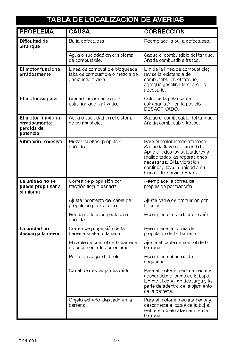
PROBLEMA
Dificultad de
arranque
CAUSA CORRECClON
Bujia defectuosa. Reemplace la bujia defectuosa.
Agua o suciedad en el sistema Saque el combustible del tanque.
de combustible. Ahada combustible fresco.
El motor funeiona Linea de combustible bloqueada, Limpie la linea de combustible;
erraticamente falta de combustible o mezcla de revise la existencia de
combustible vieja, combustible en el tanque,
agregue gasolina fresca si es
necesario.
El motor ee para Unidad funcionando con Coloque la palanca de
estrangulador activado, estrangulador en la posici6n
DESACTIVADO.
El motor funciona Agua o suciedad en el sistema Saque el combustible del tanque.
erraticamente; de combustible. Ahada combustible fresco.
perdida de
potencia
Vibraci6n excesiva Piezas sueltas; propulsor
dahado.
La unidad no se
puede propulsar a
si misma
La unidad no
descarga la nieve
Correa de propulsi6n por
tracci6n floja o da5ada.
Pare el motor inmediatamente.
Saque la Ilave de encendido.
Apriete todos los sujetadores y
realice todas las reparaciones
necesarias. Si la vibraci6n
continua, Ileva la unidad a su
Centro de Servicio Sears.
Rueda de fricci6n gastada o
dahada.
Reemplace la correa de
propulsi6n por tracci6n.
Ajuste incorrecto del cable de Ajuste cable de propulsi6n por
propulsi6n por tracci6n, tracci6n.
Reemplace la rueda de fricci6n.
Correa de propulsi6n de la Reemplace la correa de
barrena suelta o dahada, propulsi6n de la barrena.
El cable de control de la barrena Ajuste e! cable de control de la
no est& ajustado correctamente, barrena.
Perno de seguridad roto. Reemplace el perno de
seguridad.
Canal de descarga obstruido Pare el motor inmediatamente y
desconecte el cable de la bujia.
Limpie el canal de descarga y la
parte de adentro del alojamiento
de la barrena.
Objeto extra_o atascado en la
barrena. Pare el motor inmediatamente y
desconecte el cable de la bujia.
Retire el objeto atascado en la
barrena.
F-041084L 92
SEARS, ROEBUCK AND CO.
Garantia limitada de cumplimiento con el Sistema Federal
de control de emisiones ycon el sistema de control de
emisiones del Estado de California
Motores pequeSos para vehiculos todo terreno
CONTROl- DE EMISIONES DE
CAMFORNIA Y DE l,A AGENCIA DE
PROTECCI6N AMBIENTAI, (EPA) DE
E.U,A, - DI=CI,ARACION DE I_A
GARANTIA
La Agencia de Protecci6n Ambiental de los
Estados Unidos ("EPA"), el Oonsejo de Cali-
fornia para los Recursos del Aire ("CARB") y
Sears, Roebuck and Co. tienen el placer de
explicar Io que es la Garantia Federal y de Ca-
lifornia para Sistemas de Control de Emisio-
nes de su nuevo motor pequeflo para
vehiculos todo terreno. En California, los mo-
tores pequefios para vehiculos todo terreno
de modelo 1995 y modelos de afios posterio-
res deben set diseflados, construidos y equi-
pados para cumplir con las estrictas normas
anti contaminaci6n del Estado. En otros esta-
dos, los motores modelo 1997 y modelos de
aries posteriores deben estar disefiados,
construidos y equipados, al momento de su
venta, para que cumplan con las disposicio-
nes de la EPA acerca de motores pequefios
para vehiculos todo terreno. Sears, Roebuck
and Co., garantizar& el sistema para el control
de emisiones de su motor pequefio para vehi-
culos todo terreno pot los periodos de tiempo
que se mencionan m&s adelante, siempre y
cuando su motor pequeflo para vehiculos todo
terreno no haya sufrido alg0n abuse, negligen-
cia, modificaci6n no aprobada o mantenimien-
to indebido.
Su sistema para el control de emisiones puede
incluir partes como el carburador, el sistema
de encendido y el sistema de escape. Tambien
puede incluir el sistema de descompresi6n y
otras unidades relacionadas con las emisio-
nes.
Cuando surja una condici6n protegida por la
garantia, Sears, Roebuck and Co., reparar_.
su motor pequeflo para vehiculos todo terreno
sin costo alguno para usted per concepto de
diagn6stico, partes y mane de obra.
SISTEMA PARA EL CONTROl- DE
EMISIONES DEI, FABRICANTE -
COBERTURA DE l,A GARANTiA
Los sistemas para el control de emisiones del
modelo 1995 y modelos de afios posteriores
de motores pequeflos para vehiculos todo te-
rreno en California est_.n garantizados per dos
aries, tal y como se menciona en la presente
garantia. En otros estados, los motores mode-
Io 1997 y modelos de aflos posteriores tam-
bien est_.n garantizados per dos aries. En
case de que, durante dicho periodo de la ga-
rantia, cualquier pieza del motor, relacionada
con emisiones este defectuosa en sus mate-
riales o mane de obra, Sears, Roebuck and
Co., reparar& o cambiar& dicha pieza.
RESPONSABILIDADES DEL
PROPIETARIO DE LA GARANTiA
Come propietario del motor pequefio para ve-
hiculos todo terreno usted es responsable de
que se Ileve a cabo el mantenimiento requeri-
do que se menciona en el Manual del usuario,
pero Sears, Roebuck and Co., no negara la
garantia 0nicamente debido a la falta de un re-
cibo o a que usted no proporcione una prueba
escrita de que se ha Ilevado a cabo el manteni-
miento programado.
No obstante, usted, come propietario de! mo-
tor pequefio para vehiculos todo terreno, de-
ber& estar consciente de que Sears, Roebuck
and Co., le puede negar la cobertura de la ga-
rantia si su motor o alguna parte del mismo ha
fallado debido a abuso, negligencia, manteni-
miento inadecuado o modificaciones no apro-
badas.
Usted es responsable de presentar su motor
pequeflo para vehfculos todo terreno en el Ta-
ller de Servicio Autorizado de Sears, Roebuck
and Co., en cuanto surja el problema. Las re-
paraciones bajo la garantia deben Ilevarse a
cabo dentro de un periodo de tiempo razona-
ble que no exceda de 30 dias.
Se puede programar el servicio de garantia
Ilamando al Taller de Servicio Autorizado de
F-041084L 93
Sears, Roebuck and Co., o a Sears, Roebuck
and Co., al 1-800-473-7247 (llamada gratui-
ta en E.U.A.).
NOTA IMPORTANTE
Esta declaraci6n de garantia explica los dere-
chos y las obligaciones que usted tiene de
conformidad con la Garantia del Sistema para
el Control de Emisiones ("Garantia SCE"), la
cual Sears, Roebuck and Co., le proporciona
de conformidad con las leyes de California.
Consulte tambien las Garantias Limitadas de
Sears, Roebuck and Co., que se adjuntan a la
Garantia SCE en una hoja aparte y que tam-
bien le proporciona Sears, Roebuck and Co,
La Garantia SCE t_nicamente se aplica en el
sistema para el control de emisiones de su
motor nuevo. Hasta el punto en donde no haya
ning0n conflicto en t6rminos entre la Garantia
SCE y la Garantia de Sears, Roebuck and Co.,
la Garanfia SCE aplicara para cualquier cir-
cunstancia a excepci6n de aquella en que la
Garantia de Sears, Roebuck and Co., pueda
proporcionar un periodo de garantia mrs lar-
go. La Garantia SCE y la Garantia de Sears,
Roebuck and Co., describen importantes de-
rechos y obligaciones que usted tiene con res-
pecto a su motor nuevo.
S61o se puede Ilevar a cabo el servicio de ga-
rantia en un Taller de Servicio Autorizado de
Sears, Roebuck and Co. AI momento de solici-
tar un servicio de garantia, se debe presentar
una prueba de la fecha de compra por parte
del comprador original. El comprador pagarR
cualquier cargo per concepto de Ilamadas de
servicio y/o transportaci6n de productos des-
de y para el lugar en donde se Ileve a cabo el
trabajo de inspecci6n y/o garanfia. El compra-
dor sera responsable de cualquier daflo o per-
dida en el que se incurra con relaci6n a la
transportaci6n de cualquier motor o cualquier
parte del mismo que se presente para inspec-
ci6n y/o trabajo de garantia.
Si tiene alguna pregunta con relaci6n a sus de-
rechos y responsabilidades, debera Ilamar a
Sears, Roebuck and Co., al 1-800-473-7247.
GARANTiA DEL SISTEMA PARA EL
CONTROL DE EMISIONES
Garantia del Sistema para el Control de Emi-
siones ("Garantia SOE") de motores peque-
fios para vehiculos todo terreno modelo 1995
y modelos de aries posteriores en California
(para otros estados, motores modelo 1997 y
aries posteriores):
F-041084L 94
A. CAMPO DE APLICACION: Esta garantia
deberR aplicarse a los motores pequefios para
vehiculos todo terreno modelo 1995 y mode-
los de aries posteriores en California (para
otros estados, motores modelo 1997 y mode-
los de aries posteriores). El Periodo de la Ga-
rantia SCE se iniciarR en la fecha de entrega
del nuevo motor o equipo al comprador origi-
nal y continuarR durante los siguientes 24 me-
ses consecutivos.
B, COBERTURA GENERAL DE LA GA-
RANTiA DEL SISTEMA PARA EL CON-
TROL DE EMISIONES: Sears, Roebuck and
Co. garantiza al comprador original del nuevo
motor o equipo y a cada comprador subse-
cuente que su motor pequeflo para vehiculos
todo terreno estR:
1. Diseflado, construido y equipado para que
cumpla con todas las disposiciones aplicables
adoptadas per el Consejo para los Recursos
del Aire de conformidad con su autoridad es-
pecificada en los Capitulos 1 y 2, Parte 5, Divi-
si6n 26 del C6digo de Salud y Seguridad, y
2. Libre de defectos en sus materiales y mane
de obra, Io cual cause en cualquier memento
durante el Periodo de la Garantia SCE, la falla
de una parte relacionada con emisiones y que
est6 bajo la garantia en cuanto a que no sea
identica en sus materiales a la parte descrita
en la solicitud de motor del fabricante para su
certificaci6n.
C. La Garantfa SCE s61oatafie a las partes de
su motor relacionadas con emisiones de la si-
guiente manera:
1. Cualquier parte relacionada con emisiones
que no se especifique come de cambio, tal y
come se requiere en el mantenimiento especi-
ficado en el Manual del Propietario, deberR ga-
rantizarse per el Periodo de la Garantia SCE.
Si dicha parte falla durante el Periodo de la Ga-
rantia SCE, Sears, Roebuck and Co. la repa-
rarR o cambiara de acuerdo con la Subsecci6n
4 que se menciona mrs adelante. Cualquier
parte reparada o cambiada de conformidad
con la Garantia SCE debera estar garantizada
por el resto del Periodo de la misma.
2. Cualquier parte garantizada y relacionada
con emisiones que est6 especificada s61o pa-
ra inspecciones regulates conforme al Manual
del Propietario debera estar garantizada per el
Periodo de la Garantia SCE. Una declaraci6n
en dichas instrucciones pot escrito a efecto de
"reparar o cambiar tal y come sea necesario"
no reducirR el Periodo de la Garantia SCE. Di-
cha parte reparada o cambiada conforme a la
GarantiaSOEdeberagarantizarseporelresto
delPeriododelamisma.
3.Cualquierpartegarantizadayrelacionada
conemisionesqueseespecifiqueparacam-
bio,deconformidadconelManualdelPropie-
tario,deberagarantizarseporelperiodode
tiempoprevioalprimerpuntodecambiode
esaparte.Silapartefallaantesdelprimer
cambioprogramado,Sears,RoebuckandCo.
repararaocambiaraesapartedeacuerdocon
laSubsecci6n4quesemencionamAsadelan-
te.Oualquierparterelacionadaconemisiones
queserepareocambiedeconformidadconla
GarantiaSOEdeberaestargarantizadapotel
restodelPeriododelamismaprevioalprimer
puntodecambioprogramadodeesapartere-
lacionadaconemisiones.
4.Lareparaci6noelcambiodecualquierparte
garantizadayrelacionadaconemisionesde
conformidadconestaGarantiaSCEsedebe-
rAIlevaracabo,sincargoalgunoparaelpro-
pietario,enunTallerAutorizadodeServiciode
Sears,RoebuckandCo.
5.Nosecargaraalpropietarioelcostopottra-
bajodediagn6stico,elcualIlevaaladetermi-
naci6ndequeunaparteprotegidapotla
GarantiaSCEsiesterdefectuosa,provistoque
dichotrabajodediagn6sticoseIleveacaboen
unTallerAutorizadodeServiciodeSears,
RoebuckandCo.
6.Sears,RoebuckandCo.seraresponsable
deda_osaotroscomponentesoriginalesdel
motoromodificacionesaprobadasqueproba-
blementeseancausadosporunafallacom-
prendidaen la garantiade unaparte
relacionadaconemisionescubiertaporlaGa-
rantiaSOE.
7.DuranteelPeriododelaGarantiaSCE,
Sears,RoebuckandCo.deberaconservarun
suministrodepartesgarantizadasyrelaciona-
dasconemisionesqueseasuficientepara
cumplirlademandaesperadadeesaspartes
relacionadasconemisiones.
8.Sepuedeutilizarcualquierpartederepues-
to relacionadaconemisionesautorizaday
aprobadaporSears,RoebuckandCo.para
utilizarseeneldesempefiodecualquierman-
tenimientoocambiodelaGarantiaSCE,la
cualseproporcionarasincargoalgunoparael
propietario.DichousonoreducirAlasobliga-
clonesdeSears,RoebuckandCo.conforme
alaGarantiaSOE.
9.Laspartesqueseagreguenomodifiquen
sinaprobaci6nnosepodr_tnutilizarparamo-
dificarorepararunmotordeSears,Roebuck
andCo.DichouseanulaestaGarantiaSCEy
conformar_tlasbasessuficientespararecha-
zarlademandadeunaGarantiaSCE.Sears,
RoebuckandCo.noseraresponsable,con-
formeaestagarantia,potlasfallasdecual-
quietpartegarantizadadeunmotordeSears,
RoebuckandCo.causadasporelusodedi-
chaparteagregadaomodificadasinaproba-
ci6n.
LAS PARTES RELACIONADAS CON
EMISIONES INCLUYEN A LAS
SIGUlENTES:
1. Unidad del carburador y sus componentes
internos
a) Filtro de combustible
b) Empaques (juntas) del carburador
c) Tube de entrada
2. Unidad de filtro de aire
a) Elemento del filtro de aire
3. Sistema de encendido, que incluye:
a) Buj[a de encendido
b) M6dulo de encendido
c) Ensamblaje del volante
4. Silenciador catalitico (siestA equipado)
a) Empaque del silenciador (siesta equipado)
b) Colector de escape (siesta equipado)
5. Ensamblaje del respiradero del carter del ci-
g0ehal y sus componentes
a) Tubo de conexi6n del respiradero
10/22/99 EPA/CARB
Sears, Roebuck and Co., Hoffman Estates, IL 60179 U.S.A.
F-041084L 95

iiiiiiiiiiiiiiiljj¸_¸
iiiiiiiiiiiiiiii_i_
iiiiiiiiiiiiiiii'
iiiiiiiiiiiiiiii
iiiiiiiiiiiiiiii
iiiiiiiiiiiiiiii
iiiiiiiiiiiiiiii
iiiiiiiiiiiiiiii
iiiiiiiiiiiiiiii
iiiiiiiiiiiiiiii
iiiiiiiiiiiiiiii
iiiiiiiiiiiiiiii
iiiiiiiiiiiiiiii
iiiiiiiiiiiiiiii
iiiiiiiiiiiiiiii
iiiiiiiiiiiiiiii
iiiiiiiiiiiiiiii
iiiiiiiiiiiiiiii
iiiiiiiiiiiiiiii
iiiiiiiiiiiiiiii
iiiiiiiiiiiiiiii
iiiiiiiiiiiiiiii
iiiiiiiiiiiiiiii
iiiiiiiiiiiiiiii
iiiiiiiiiiiiiiii
iiiiiiiiiiiiiiii
iiiiiiiiiiiiiiii
iiiiiiiiiiiiiiii
iiiiiiiiiiiiiiii
iiiiiiiiiiiiiiii
HHHHHHHi_
iiiiiiiiiiiiiii
HHHHHHHi_
HHHHHHHi__
Your Home
For repair - in your home - of all major brand appliances,
lawn and garden equipment, or heating and cooling systems,
no matter who made it, no matter who sold it!
For the replacement parts, accessories and
owner's manuals that you need to do-it-yourself.
For Sears professional installation of home appliances
and items like garage door openers and water heaters,
1-800-4-MY-HOME ®Anytime, day or night
(1-800-469-4663) (U.S.A. and Canada)
www.sears.com www,sears.ca
Our Home
For repair of carry-in products like vacuums, lawn equipment,
and electronics, call or go on-line for the nearest
Sears Parts and Repair Center.
1-800-488-1222 Anytime, day or night (U,S,A, only)
www.sears.com
...._i_i!iii_ii_ii_ii_ii_ii_ii_ii_ii_ii_ii!ii!i;i;I
i11111111111i,
iiiiiiiiiiiiiiii
iiiiiiiiiiiiiiii
iiiiiiiiiiiiiiii
iiiiiiiiiiiiiiii
iiiiiiiiiiiiiiii
iiiiiiiiiiiiiiii
iiiiiiiiiiiiiiii
iiiiiiiiiiiiiiii
iiiiiiiiiiiiiiii
iiiiiiiiiiiiiiii
To purchase a protection agreement (U.S.A.)
or maintenance agreement (Canada) on a product serviced by Sears:
1-800.827-66s5/u.S.A./1-800-361-666S/Caoa,a
Para pedir servicio de reparaci6n Au Canada pour service en franc,,ais:
a domicilio, y para ordenar piezas: 1-800-LE-FOYER Mc
1-888-SU-HOGAR sM (1-800-533-6937)
(1-888-784-6427) www.sears.ca
S ARS
© Sears, Roebuck and Co.
_M M
® Registered Trademark /Trademark /"_ Service Mark of Sears, Roebuck and Co,
© Marca Registrada /TMMarca de Fabrica /SMMama de Servicio de Sears, Roebuck and Co.
MD
MCMarque de commerce /Marque d6pos6e de Sears, Roebuck and Co.
