Craftsman 580323610 User Manual GENERATOR Manuals And Guides L0607346
CRAFTSMAN Generator Manual L0607346 CRAFTSMAN Generator Owner's Manual, CRAFTSMAN Generator installation guides
User Manual: Craftsman 580323610 580323610 CRAFTSMAN GENERATOR - Manuals and Guides View the owners manual for your CRAFTSMAN GENERATOR #580323610. Home:Tool Parts:Craftsman Parts:Craftsman GENERATOR Manual
Open the PDF directly: View PDF ![]() .
.
Page Count: 60
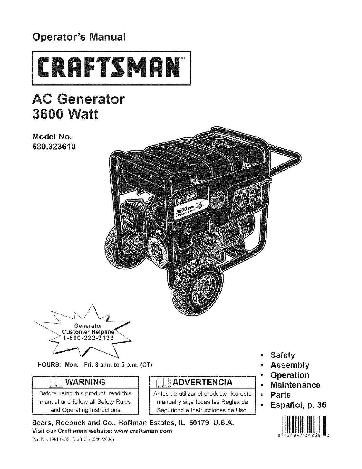
Operator's Manual
®
AC Generator
3600 Watt
Model No.
580.323610
HOURS: Mort. -Fri. 8 a.m. to 5 p.m. (CT)
! ii_[i WARNING
Before using this product, read this
manual and follow all Safety Rules
and Operating Instructions.
[i1 .,,ADVERTENCIA
Antes de utilizar el producto, lea este
manual y siga todas las Reglas de
Seguridad e Instrucciones de Uso.
Sears, Roebuck and Co., Hoffman Estates, IL 60179 U.S.A.
Visit our Craftsman website: www.craftsman.com
Part No. 198138GS [)]'aft ((05'08,2006)
.Safety
•Assembly
•Operation
•Maintenance
• Parts
. EspaSol, p. 36
WARRANTY .............................. 2
SAFETY RULES ......................... 3-4
FEATURES AND CONTROLS ................ 5
ASSEMBLY ............................. 6-8
OPERATION ........................... 9-13
SPECIFICATIONS ......................... 14
MAINTENANCE ........................ 15-18
STO RAG E ............................... 19
TROUBLESHOOTING ...................... 20
NOTES ............................. 21 & 33
SCHEMATIC/WIRING DIAGRAM .......... 22-23
REPLACEMENT PARTS ................. 24-32
EMISSIONS SYSTEM WARRANTY ........ 34-35
ESPANOL ............................. 36-59
HOW TO ORDER PARTS .......... BACK PAGE
ONE-YEAR FULL WARRANTY ON CRAFTSMAN GENERATOR
If this generator fails due to a defect in material or workmanship within one year from the date of purchase,
return it to any Sears store, other Craftsman outlet, or Sears Parts & Repair Center in the United States for free
repair (or replacement if repair proves impossible).
Additional One=Year Limited Warranty on Craftsman Generator
For the second year from the date of purchase, if any part of this generator fails due to a defect in material or
workmanship, a new part will be supplied free of charge. You must pay the labor cost if you wish to have it
installed.
All warranty coverage applies for only 90 days from date of purchase if this generator is used for commercial or
rental purposes. Once a generator has experienced commercial or rental use, it shall thereafter be considered a
commercial or rental generator for the purpose of this warranty.
This warranty gives you specific legal rights, and you may also have other rights which vary from state to state.
Sears, Roebuck and Co., D/817WA, Hoffman Estates, IL 60179 U.S.A.
© Sears Brands, LLC
_iL This is the safety alert symbol, it is used to alert you to potential personal injury hazards.
Obey all safety messages that follow this symbol to avoid possible injury or death.
[ =_-!] Read this manual carefully and become
...................familiar with your generator. Know its
applications, its limitations, and any hazards
involved.
The safety alert symbol (,A) is used with a signal
word (DANGER, CAUTION, WARNING), a pictorial
and/or a safety message to alert you to hazards.
DANGER indicates a hazard which, if not avoided, will
result in death or serious injury. WARNING indicates a
hazard which, if not avoided, could result in death or
serious injury. CAUTION indicates a hazard which, if
not avoided, might result in minor or moderate injury.
CAUTION, when used without the alert symbol,
indicates a situation that could result in equipment
damage. Follow safety messages to avoid or reduce
the risk of injury or death.
WARNING
The engine exhaust from this product contains
chemicals known to the State of California to cause
cancer, birth defects, or other reproductive harm.
WARNING
• This generator does not meet U. S. Coast Guard
Regulation 33CFR-183 and should not be used on
marine applications.
• Failure to use the appropriate U. S. Coast Guard
approved generator could result in bodily injury and/or
property damage.
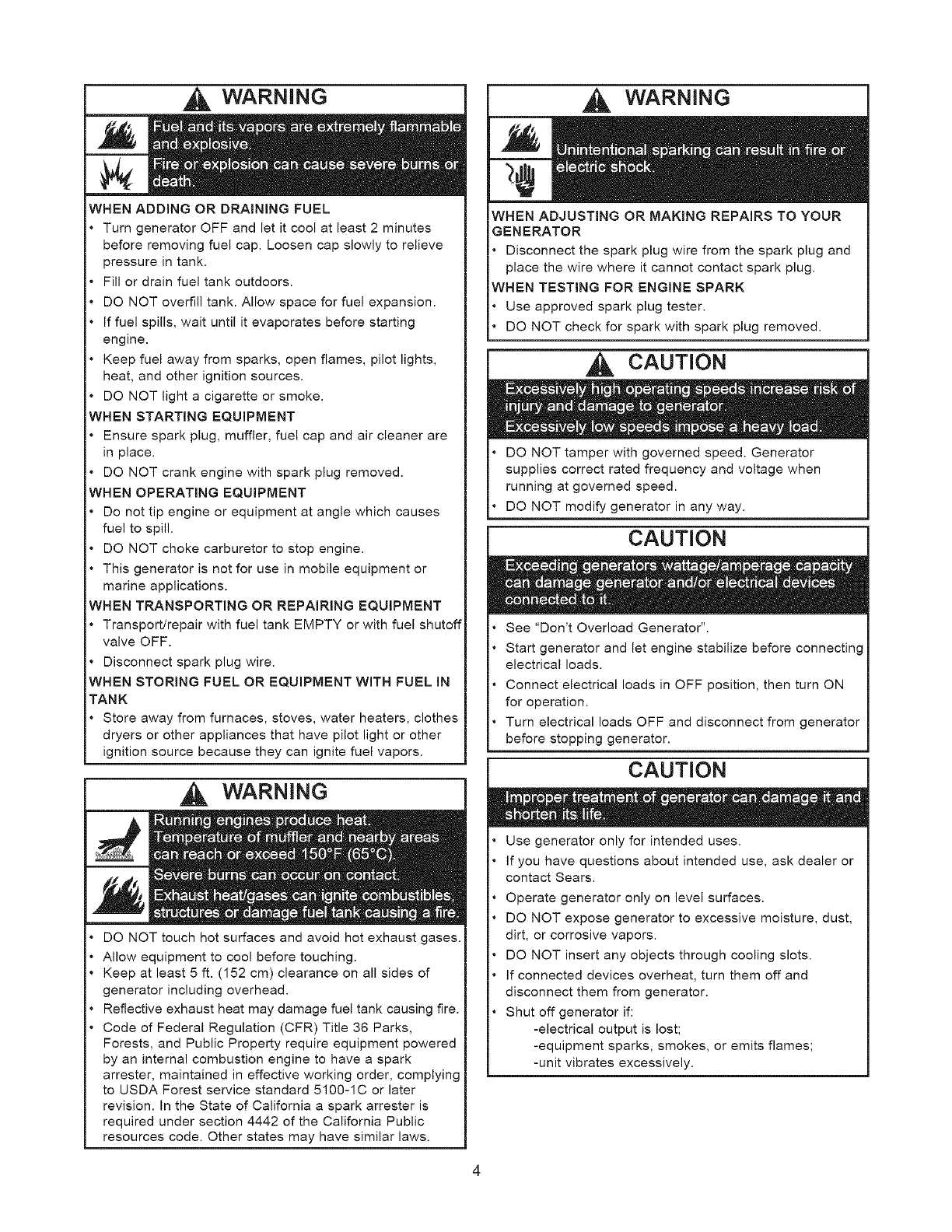
Hazard Symbols and Meanings
Explosion Fire Electrical Shock
Toxic Fumes
'W,
Hot Surface Kickback
WARNING
Operate generator ONLY outdoors.
Keep exhaust gas from entering a confined area through
windows, doors, ventilation intakes or other openings.
DO NOT operate generator inside any building or
enclosure (even if doors or windows are open), including
the generator compartment of a recreational vehicle (RV).
DANGER
Fresh Start TM fuel cap is designed to hold a cartridge
which contains fuel stabilizer.
If SWALLOWED, call physician immediately. DO NOT
induce vomiting. If inhaled, remove to fresh air. In case
of eye or skin contact, flush with water for 15 minutes.
Store unopened cartridges in a cool, dry, well ventilated
area. Keep open cartridge in fuel cap, and fuel cap
closed on fuel tank when not in use.
In the case of an emergency, contact a physician
immediately and call 1-800-424-9300 for material safety
information.
'Fuei stabilizer contains: 2,6-di-tret-butylphenol (128-39-2) and aliphatic
petroleum distillate (64742-47-8)
WARNING
When using generator for backup power, notify utility
company. Use approved transfer equipment to isolate
generator from electric utility.
Use a ground circuit fault interrupter (GFCI) in any damp
or highly conductive area, such as metal decking or steel
work.
DO NOT touch bare wires or receptacles.
DO NOT use generator with electrical cords which are
worn, frayed, bare or otherwise damaged.
DO NOT operate generator in the rain or wet weather.
DO NOT handle generator or electrical cords while
standing in water, while barefoot, or while hands or feet
are wet.
DO NOT allow unqualified persons or children to operate
or service generator.
WARNING
When starting engine, pull cord slowly until resistance is
felt and then pull rapidly to avoid kickback.
NEVER start or stop engine with electrical devices
plugged in and turned on.
WARNING
WHEN ADDING OR DRAINING FUEL
Turn generator OFF and let it cool at least 2 minutes
before removing fuel cap. Loosen cap slowly to relieve
pressure in tank.
Fill or drain fuel tank outdoors.
DO NOT overfill tank. Allow space for fuel expansion.
If fuel spills, wait until it evaporates before starting
engine.
Keep fuel away from sparks, open flames, pilot lights,
heat, and other ignition sources.
DO NOT light a cigarette or smoke.
WHEN STARTING EQUIPMENT
Ensure spark plug, muffler, fuel cap and air cleaner are
in place.
DO NOT crank engine with spark plug removed.
WHEN OPERATING EQUIPMENT
Do not tip engine or equipment at angle which causes
fuel to spill.
DO NOT choke carburetor to stop engine.
This generator is not for use in mobile equipment or
marine applications.
WHEN TRANSPORTING OR REPAIRING EQUIPMENT
Transport/repair with fuel tank EMPTY or with fuel shutoff
valve OFF.
Disconnect spark plug wire.
WHEN STORING FUEL OR EQUIPMENT WITH FUEL IN
TANK
Store away from furnaces, stoves, water heaters, clothes
dryers or other appliances that have pilot light or other
ignition source because they can ignite fuel vapors.
WARNING
DO NOT touch hot surfaces and avoid hot exhaust gases.
Allow equipment to cool before touching.
Keep at least 5 ft. (152 cm) clearance on all sides of
generator including overhead.
Reflective exhaust heat may damage fuel tank causing fire.
Code of Federal Regulation (CFR) Title 36 Parks,
Forests, and Public Property require equipment powered
by an internal combustion engine to have a spark
arrester, maintained in effective working order, complying
to USDA Forest service standard 5100-1C or later
revision. In the State of California a spark arrester is
required under section 4442 of the California Public
resources code. Other states may have similar laws.
WARNING
WHEN ADJUSTING OR MAKING REPAIRS TO YOUR
GENERATOR
• Disconnect the spark plug wire from the spark plug and
place the wire where it cannot contact spark plug.
WHEN TESTING FOR ENGINE SPARK
Use approved spark plug tester.
DO NOT check for spark with spark plug removed.
CAUTION
DO NOT tamper with governed speed. Generator
supplies correct rated frequency and voltage when
running at governed speed.
DO NOT modify generator in any way.
CAUTION
See "Don't Overload Generator".
Start generator and let engine stabilize before connecting
electrical loads.
Connect electrical loads in OFF position, then turn ON
for operation.
Turn electrical loads OFF and disconnect from generator
before stopping generator.
CAUTION
Use generator only for intended uses.
If you have questions about intended use, ask dealer or
contact Sears.
Operate generator only on level surfaces.
DO NOT expose generator to excessive moisture, dust,
dirt, or corrosive vapors.
DO NOT insert any objects through cooling slots.
If connected devices overheat, turn them off and
disconnect them from generator.
Shut off generator if:
-electrical output is lost;
-equipment sparks, smokes, or emits flames;
-unit vibrates excessively.
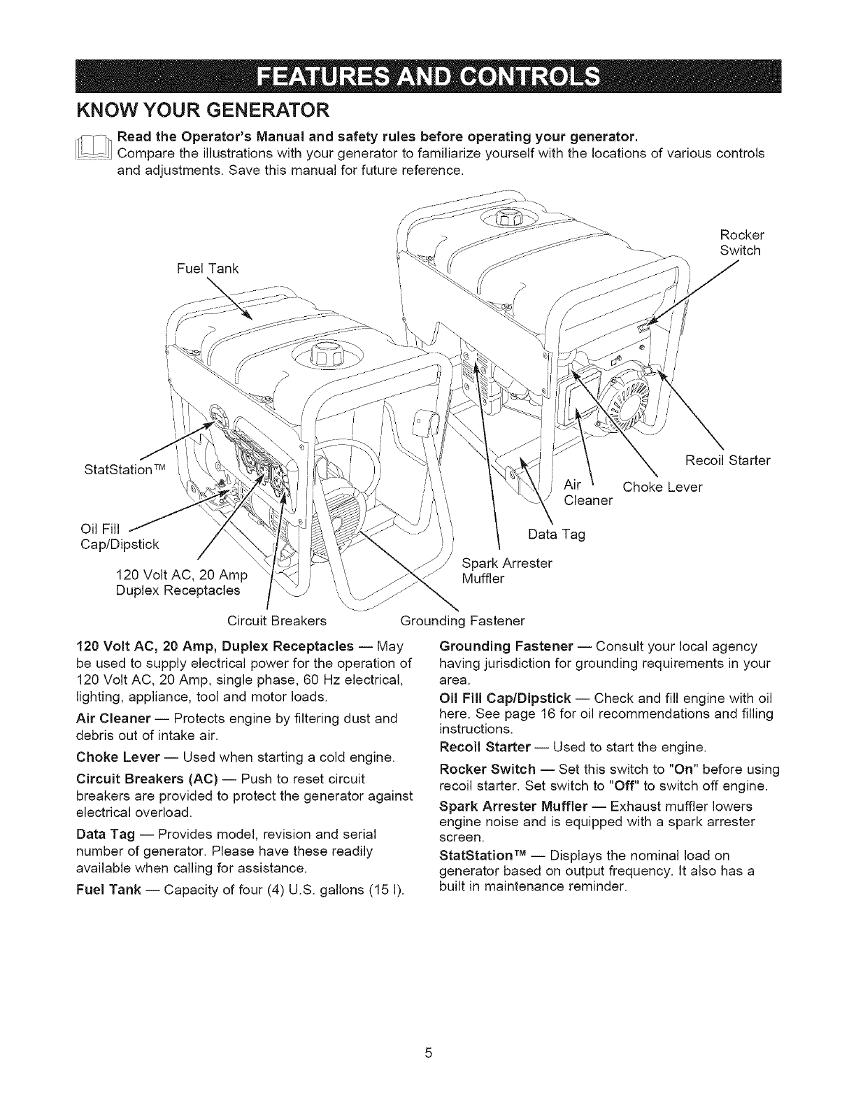
KNOW YOUR GENERATOR
ReadtheOperator'sManualandsafetyrulesbeforeoperatingyourgenerator,
Compare the illustrations with your generator to familiarize yourself with the locations of various controls
and adjustments, Save this manual for future reference,
Fuel Tank
\,
I
Rocker
Switch
StatStation TM
Cleaner
Oil Fill Data Tag
Cap/Dipstick }J
Spark Arrester
120 Volt AC, 20 Amp Muffler
Duplex Receptacles ',,
\
Circuit Breakers
120 Volt AC, 20 Amp, Duplex Receptacles iMay
be used to supply electrical power for the operation of
120 Volt AC, 20 Amp, single phase, 60 Hz electrical,
lighting, appliance, tool and motor loads.
Air Cleaner iProtects engine by filtering dust and
debris out of intake air.
Choke Lever iUsed when starting a cold engine.
Circuit Breakers (AC) iPush to reset circuit
breakers are provided to protect the generator against
electrical overload.
Data Tag -- Provides model, revision and serial
number of generator. Please have these readily
available when calling for assistance.
Fuel Tank iCapacity of four (4) U.S. gallons (15 I).
Recoil Starter
Choke Lever
Grounding Fastener
Grounding Fastener iConsult your local agency
having jurisdiction for grounding requirements in your
area.
Oil Fill Cap/Dipstick iCheck and fill engine with oil
here. See page 16 for oil recommendations and filling
instructions.
Recoil Starter iUsed to start the engine.
Rocker Switch -- Set this switch to "On" before using
recoil starter. Set switch to "Off" to switch off engine.
Spark Arrester Muffler -- Exhaust muffler lowers
engine noise and is equipped with a spark arrester
screen.
StatStation TM -- Displays the nominal load on
generator based on output frequency. It also has a
built in maintenance reminder.
YourCraftsmangeneratorrequiressomeassembly
andisreadyforuseonlyafterit hasbeenproperly
servicedwiththerecommendedoilandfuel.
if you have any problems with the assembly of
your generator, please call the generator helpline
at 1-800-222-3136.
Unpacking the Generator
1. Set the carton on a rigid flat surface.
2. Remove everything from carton except generator.
3. Open carton completely by cutting each corner
from top to bottom.
4. Leave generator on carton to install wheel kit.
Carton Contents
Check all contents against those listed below:
* Main unit
* Engine oil
* Operator's manual
* Wheel kit
* Adapter cord set
If any parts are missing or damaged, call the
generator helpline at 1-800-222-3136.
Install Wheel Kit
NOTE: Wheel kit is not intended for over-the-road
use. DO NOT tow this unit with a motorized vehicle.
You will need the following tools to install these
components:
, 13mmwrench
• Pliers
• Safety glasses
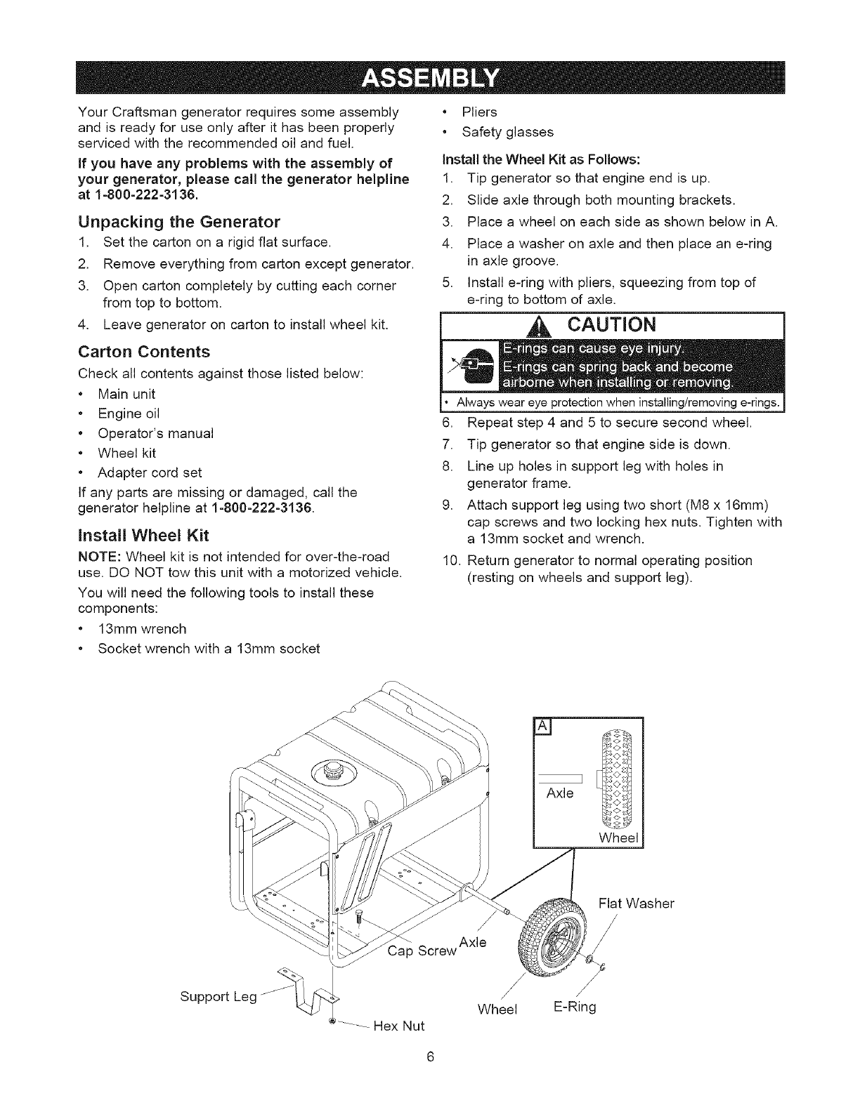
install the Wheel Kit as Follows:
1. Tip generator so that engine end is up.
2. Slide axle through both mounting brackets.
3. Place a wheel on each side as shown below in A.
4. Place a washer on axle and then place an e-ring
in axle groove.
5. Install e-ring with pliers, squeezing from top of
e-ring to bottom of axle.
CAUTION
Always wear eye when
6. Repeat step 4 and 5 to secure second wheel.
7. Tip generator so that engine side is down.
8. Line up holes in support leg with holes in
generator frame.
9. Attach support leg using two short (M8 x 16mm)
cap screws and two locking hex nuts. Tighten with
a 13mm socket and wrench.
10. Return generator to normal operating position
(resting on wheels and support leg).
* Socket wrench with a 13mm socket
Axle
Wheel
Flat Washer
Support Leg /
Screw Axle
/
/
Wheel
Hex Nut
/
/
E-Ring
BEFORE STARTING THE
GENERATOR
Add Engine Oil
CAUTION! Any attempt to crank or start the engine
before it has been properly serviced with the
recommended oil may result in an engine failure.
1. Place generator on a level surface.
2. Clean area around oil fill and remove yellow oil fill
cap.
NOTE: See the section "Oil" on page 16 to review oil
recommendations. Verify provided oil bottle is correct
viscosity for current ambient temperature.
3. Using oil funnel (optional), slowly pour entire
contents of provided oil bottle (18 oz.)into oil fill
opening.
4. Replace oil fill cap and fully tighten.
Add Fuel
All fuel is not the same. If a starting or performance
problem is encountered immediately after new fuel has
been used, try another service station or change
brands.
NOTE: This gasoline engine is certified to operate on
gasoline. Exhaust Emissions Control System: EM
(Engine Modifications).
WARNING
WHEN ADDING FUEL
Turn generator OFF and let it cool at least 2 minutes
before removing fuel cap. Loosen cap slowly to relieve
pressure in tank.
Fill fuel tank outdoors.
DO NOT overfill tank. Allow space for fuel expansion.
Wait for spilled fuel to evaporate before starting engine.
Keep fuel away from sparks, open flames, pilot lights,
heat, and other ignition sources.
DO NOT light a cigarette or smoke.
Type of Fuel
1. Always use clean, fresh, UNLEADED gasoline
with a minimum of 87 octane/87 AKI (91 RON).
DO NOT mix oil with fuel. DO NOT modify the
engine fuel system or carburetor to run on
alternative fuels.
NOTE: Fuel with up to 10% ethanol (gasohol) or up to
15% MTBE (methyl tertiary butyl ether), is acceptable.
IMPORTANT: Use of any fuel other than those
approved above will void warranty. Some areas
require that fuel pumps be marked if the fuel contains
alcohols or ethers. If you are not sure if your fuel
contains alcohol or ethers that are different than those
approved above, then check with the service station
operator.
2. Clean area around fuel fill cap, remove cap.
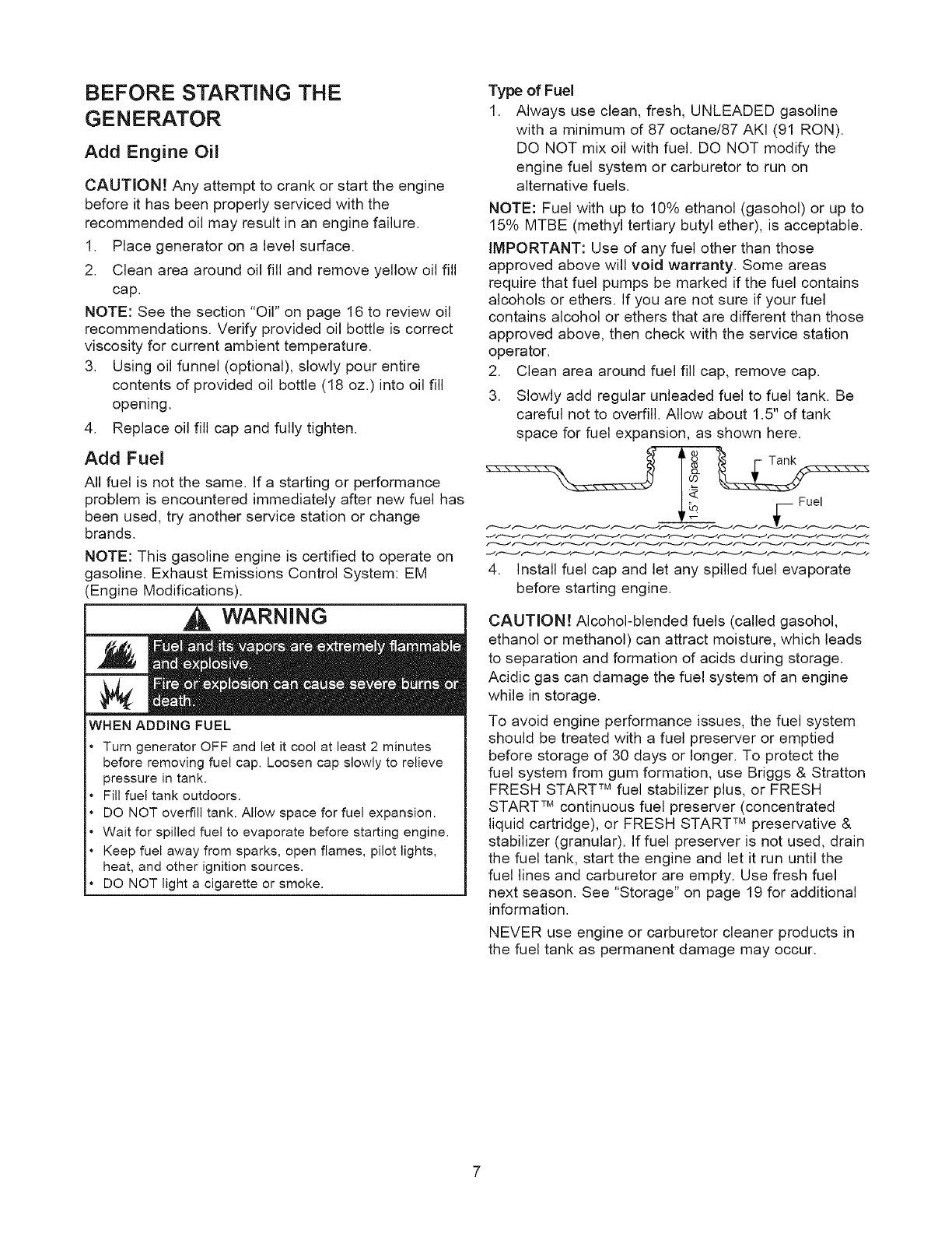
3. Slowly add regular unleaded fuel to fuel tank. Be
careful not to overfill. Allow about 1.5" of tank
space for fuel expansion, as shown here.
Lo Fuel
4. Install fuel cap and let any spilled fuel evaporate
before starting engine.
CAUTION! Alcohol-blended fuels (called gasohol,
ethanol or methanol) can attract moisture, which leads
to separation and formation of acids during storage.
Acidic gas can damage the fuel system of an engine
while in storage.
To avoid engine performance issues, the fuel system
should be treated with a fuel preserver or emptied
before storage of 30 days or longer. To protect the
fuel system from gum formation, use Briggs & Stratton
FRESH START TM fuel stabilizer plus, or FRESH
START TM continuous fuel preserver (concentrated
liquid cartridge), or FRESH START TM preservative &
stabilizer (granular). If fuel preserver is not used, drain
the fuel tank, start the engine and let it run until the
fuel lines and carburetor are empty. Use fresh fuel
next season. See "Storage" on page 19 for additional
information.
NEVER use engine or carburetor cleaner products in
the fuel tank as permanent damage may occur.
FreshStartTM Fuel Cap
Adding fuel preserver helps keep fuel fresh and
carburetors clean for easier starting, all season long.
This new fuel cap automatically drips concentrated
fuel preserver into your fuel tank.
DANGER
If SWALLOWED, call physician immediately.
In case of emergency, contact a physician immediately
and call 1-800-424-9300 for material safety information.
**Fuel stabilizer contains: 2,6-dFtret-butylphenol (128-39-2) and aliphatic
petroleum distillate (64742-47-8).
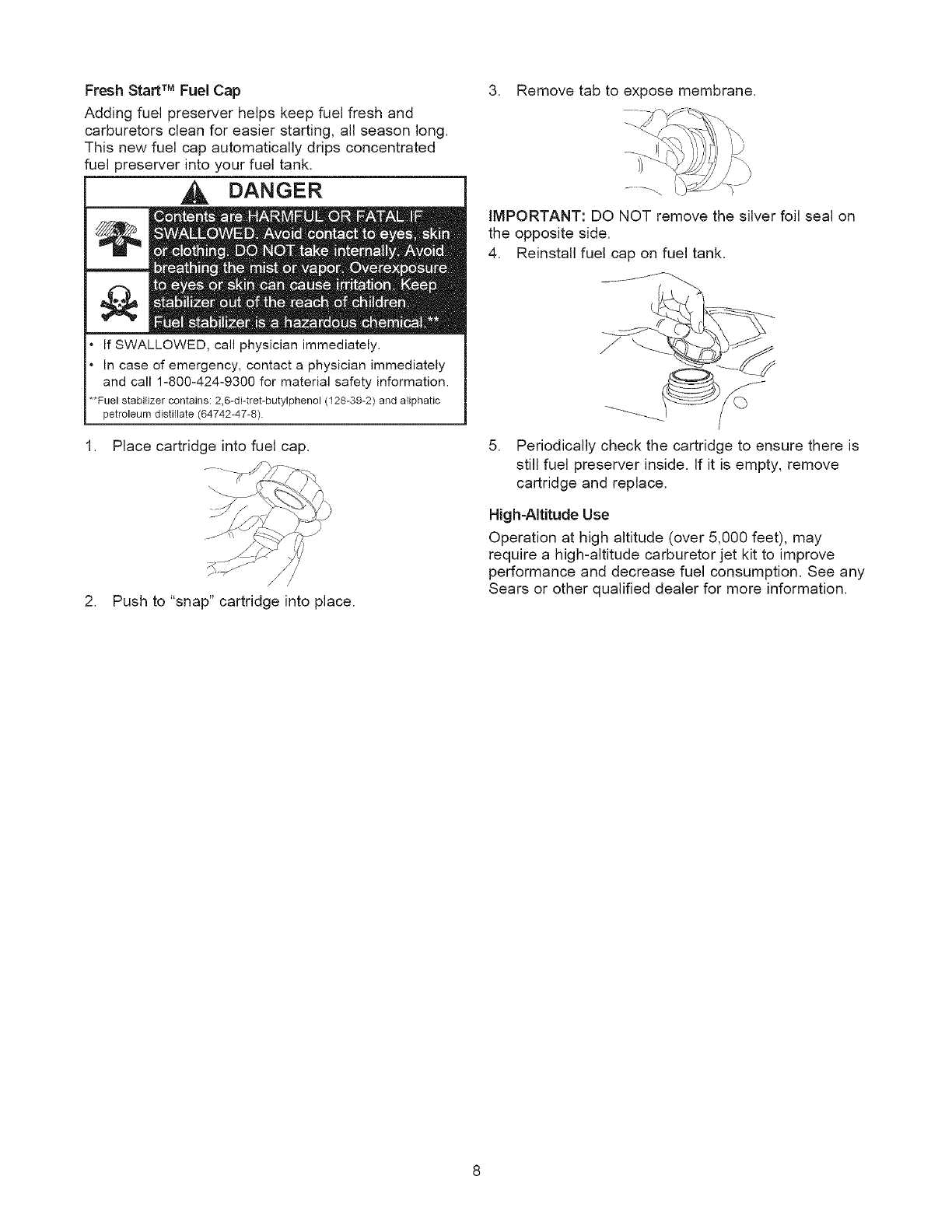
1. Place cartridge into fuel cap.
/
2. Push to "snap" cartridge into place.
3. Remove tab to expose membrane.
IMPORTANT: DO NOT remove the silver foil seal on
the opposite side.
4. Reinstall fuel cap on fuel tank.
5. Periodically check the cartridge to ensure there is
still fuel preserver inside. If it is empty, remove
cartridge and replace.
High-Altitude Use
Operation at high altitude (over 5,000 feet), may
require a high-altitude carburetor jet kit to improve
performance and decrease fuel consumption. See any
Sears or other qualified dealer for more information.
HOW TO USE YOUR GENERATOR
If you have any problems operating your generator
after reading the manual, please call the generator
helpline at 1-800-222-3136.
System Ground
The generator has a system ground that connects the
generator frame components to the ground terminals
on the AC output receptacles. The system ground is
connected to the AC neutral wire (the neutral is
bonded to the generator frame).
Special Requirements
There may be Federal or State Occupational Safety
and Health Administration (OSHA) regulations, local
codes, or ordinances that apply to the intended use of
the generator. Please consult a qualified electrician,
electrical inspector, or the local agency having
jurisdiction.
• In some areas, generators are required to be
registered with local utility companies.
• If the generator is used at a construction site, there
may be additional regulations which must be
observed.
Connecting to a Building's ElectricaR
System
Connections for standby power to a building's
electrical system must be made by a qualified
electrician. The connection must isolate the generator
power from utility power, and must comply with all
applicable laws and electrical codes.
WARNING
When using generator for backup power, notify utility
company. Use approved transfer equipment to isolate
generator from electric utility.
Use a ground circuit fault interrupter (GFCI) in any damp
or highly conductive area, such as metal decking or steel
work.
DO NOT touch bare wires or receptacles.
DO NOT use generator with electrical cords which are
worn, frayed, bare or otherwise damaged.
DO NOT operate generator in the rain.
DO NOT handle generator or electrical cords while
standing in water, while barefoot, or while hands or feet
are wet.
DO NOT allow unqualified persons or children to operate
or service generator.
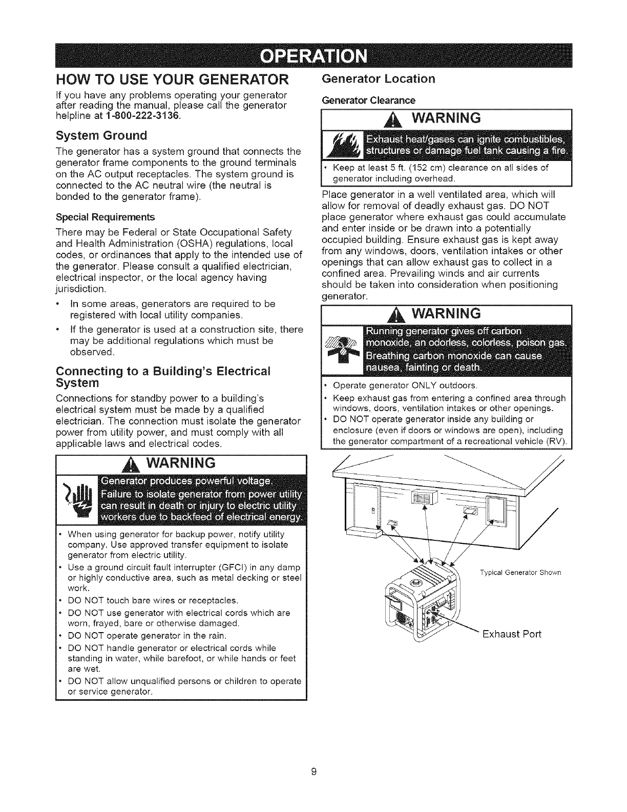
Generator Location
Generator Clearance
WARNING
Keep at least 5 ft. (152 cm) clearance on all sides of
generator including overhead.
Place generator in a well ventilated area, which will
allow for removal of deadly exhaust gas. DO NOT
place generator where exhaust gas could accumulate
and enter inside or be drawn into a potentially
occupied building. Ensure exhaust gas is kept away
from any windows, doors, ventilation intakes or other
openings that can allow exhaust gas to collect in a
confined area. Prevailing winds and air currents
should be taken into consideration when positioning
generator.
WARNING
Operate generator ONLY outdoors.
Keep exhaust gas from entering a confined area through
windows, doors, ventilation intakes or other openings.
DO NOT operate generator inside any building or
enclosure (even if doors or windows are open), including
the generator compartment of a recreational vehicle (RV).
Typical Generator Shown
Exhaust Po_
To Start The Engine
Disconnect all electrical loads from the generator.
NEVER start or stop engine with electrical devices
plugged in and turned ON. Follow start instruction
steps in numerical order:
1. Make sure unit is on a level surface.
iMPORTANT: Failure to start and operate unit on a
level surface will cause the unit not to start or shut
down during operation.
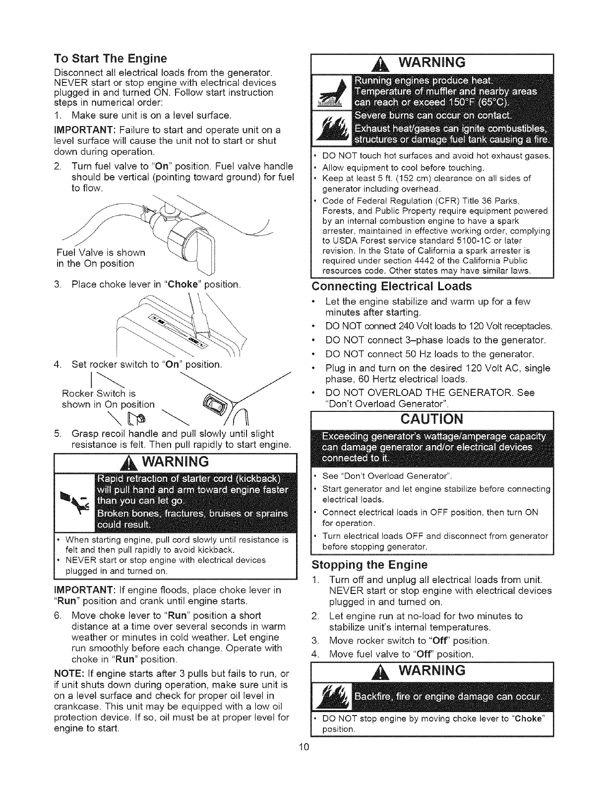
2. Turn fuel valve to "On" position. Fuel valve handle
should be vertical (pointing toward ground) for fuel
to flow.
Fuel Valve is shown
in the On position
3. Place choke lever in "Choke" position.
4. Set rocker switch to "On" position.
Rocker Switch is
shown in On position
5. Grasp recoil handle and pull slowly until slight
resistance is felt. Then pull rapidly to start engine.
WARNING 1
When starting engine, pull cord slowly until resistance is
felt and then pull rapidly to avoid kickback.
NEVER start or stop engine with electrical devices
plugged in and turned on.
iMPORTANT: If engine floods, place choke lever in
"Run" position and crank until engine starts.
6. Move choke lever to "Run" position a short
distance at a time over several seconds in warm
weather or minutes in cold weather. Let engine
run smoothly before each change. Operate with
choke in "Run" position.
NOTE: If engine starts after 3 pulls but fails to run, or
if unit shuts down during operation, make sure unit is
on a level surface and check for proper oil level in
crankcase. This unit may be equipped with a low oil
protection device. If so, oil must be at proper level for
engine to start.
10
WARNING
DO NOT touch hot surfaces and avoid hot exhaust gases.
Allow equipment to cool before touching.
Keep at least 5 ft. (152 cm) clearance on all sides of
generator including overhead.
Code of Federal Regulation (CFR) Title 36 Parks,
Forests, and Public Property require equipment powered
by an internal combustion engine to have a spark
arrester, maintained in effective working order, complying
to USDA Forest service standard 5100-1C or later
revision. In the State of California a spark arrester is
required under section 4442 of the California Public
resources code. Other states may have similar laws.
Connecting Electrical Loads
• Let the engine stabilize and warm up for a few
minutes after starting.
• DO NOT connect 240 Volt loads to 120 Volt receptacles.
• DO NOT connect 3-phase loads to the generator.
• DO NOT connect 50 Hz loads to the generator.
• Plug in and turn on the desired 120 Volt AC, single
phase, 60 Hertz electrical loads.
• DO NOT OVERLOAD THE GENERATOR. See
"Don't Overload Generator".
CAUTION
See "Don't Overload Generator".
Start generator and let engine stabilize before connecting
electrical loads.
Connect electrical loads in OFF position, then turn ON
for operation.
Turn electrical loads OFF and disconnect from generator
before stopping generator.
Stopping the Engine
1. Turn off and unplug all electrical loads from unit.
NEVER start or stop engine with electrical devices
plugged in and turned on.
2. Let engine run at no-load for two minutes to
stabilize unit's internal temperatures.
3. Move rocker switch to "Off" position.
4. Move fuel valve to "Off" position.
WARNING
DO NOT stop engine by moving choke lever to "Choke"
position.
CORD SETS AND RECEPTACLES
CAUTION
• NEVER attempt to power a device requiring more
amperage than generator or receptacle can supply.
• DO NOT overload the generator. See "Don't Overload
Generator".
Use only high quality, well-insulated, grounded
extension cords with the generator's 120 Volt electrical
receptacles. Inspect extension cords before each use.
Check the ratings of all extension cords before you
use them. Extension cord sets used should be rated
for 125 Volt AC loads at 20 Amps or greater for most
electrical devices. Some devices, however, may not
require this type of extension cord. Check the
operator's manuals of those devices for the
manufacturer's recommendations.
Keep extension cords as short as possible, preferably
less than 15 feet long, to prevent voltage drop and
possible overheating of wires.
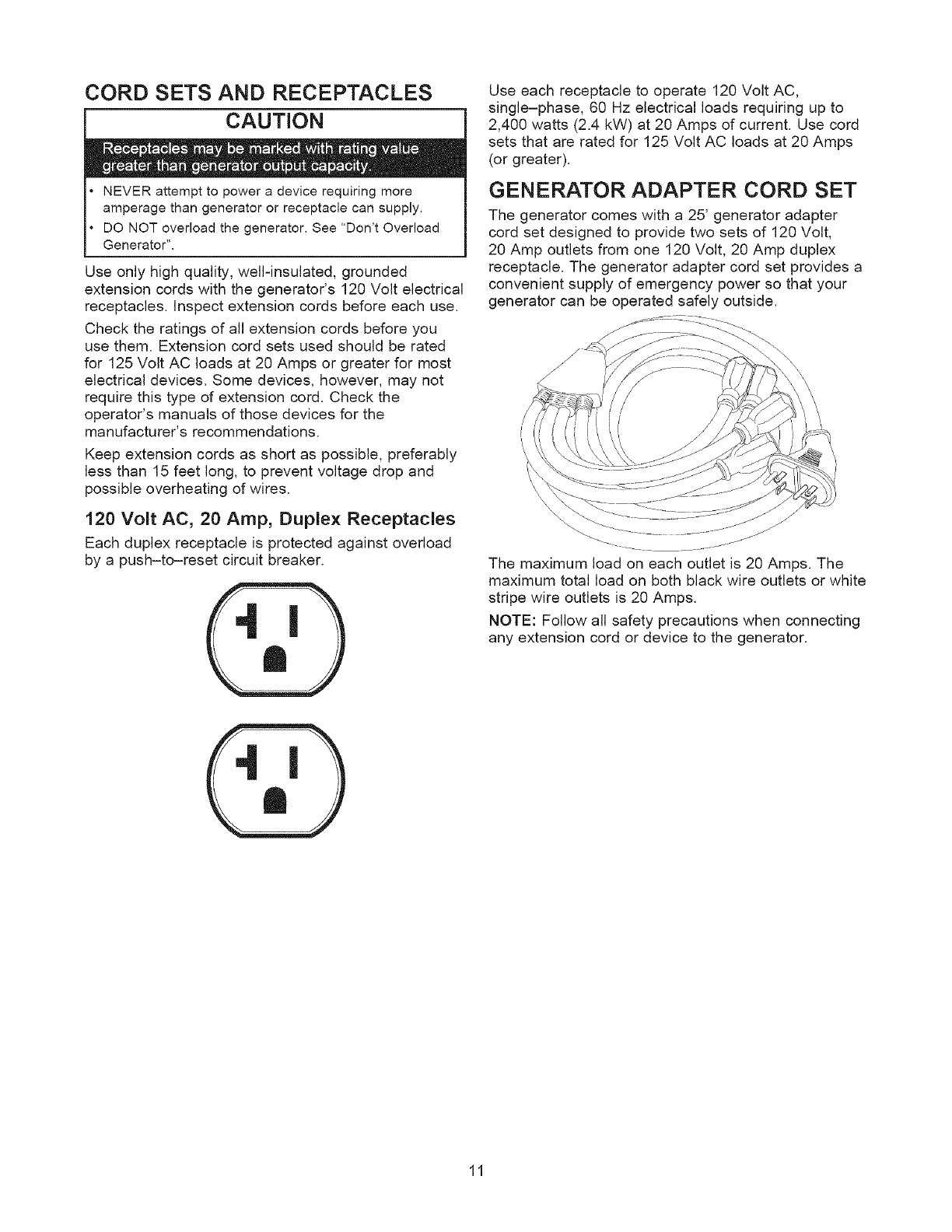
120 Volt AC, 20 Amp, Duplex Receptacles
Each duplex receptacle is protected against overload
by a push-to-reset circuit breaker.
Use each receptacle to operate 120 Volt AC,
single-phase, 60 Hz electrical loads requiring up to
2,400 watts (2.4 kW) at 20 Amps of current. Use cord
sets that are rated for 125 Volt AC loads at 20 Amps
(or greater).
GENERATOR ADAPTER CORD SET
The generator comes with a 25' generator adapter
cord set designed to provide two sets of 120 Volt,
20 Amp outlets from one 120 Volt, 20 Amp duplex
receptacle. The generator adapter cord set provides a
convenient supply of emergency power so that your
generator can be operated safely outside.
The maximum load on each outlet is 20 Amps. The
maximum total load on both black wire outlets or white
stripe wire outlets is 20 Amps.
NOTE: Follow all safety precautions when connecting
any extension cord or device to the generator.
11
COLD WEATHER OPERATION
Under certain weather conditions (temperatures below
40°F [4°C] combined with high humidity), your
Craftsman generator may experience icing of the
carburetor and/or the crankcase breather system. To
reduce this problem, you need to perform the following:
1. Make sure generator has clean, fresh fuel.
2. Open fuel valve (turn valve to open position).
3. Use SAE 5W-30 oil (synthetic preferred, see
page 16).
4. Check oil level daily or after every eight (8) hours
of operation.
5. Maintain the generator following the "Maintenance
Schedule" on page 15.
6. Shelter unit from elements.
Creating a Temporary Cold Weather
Shelter
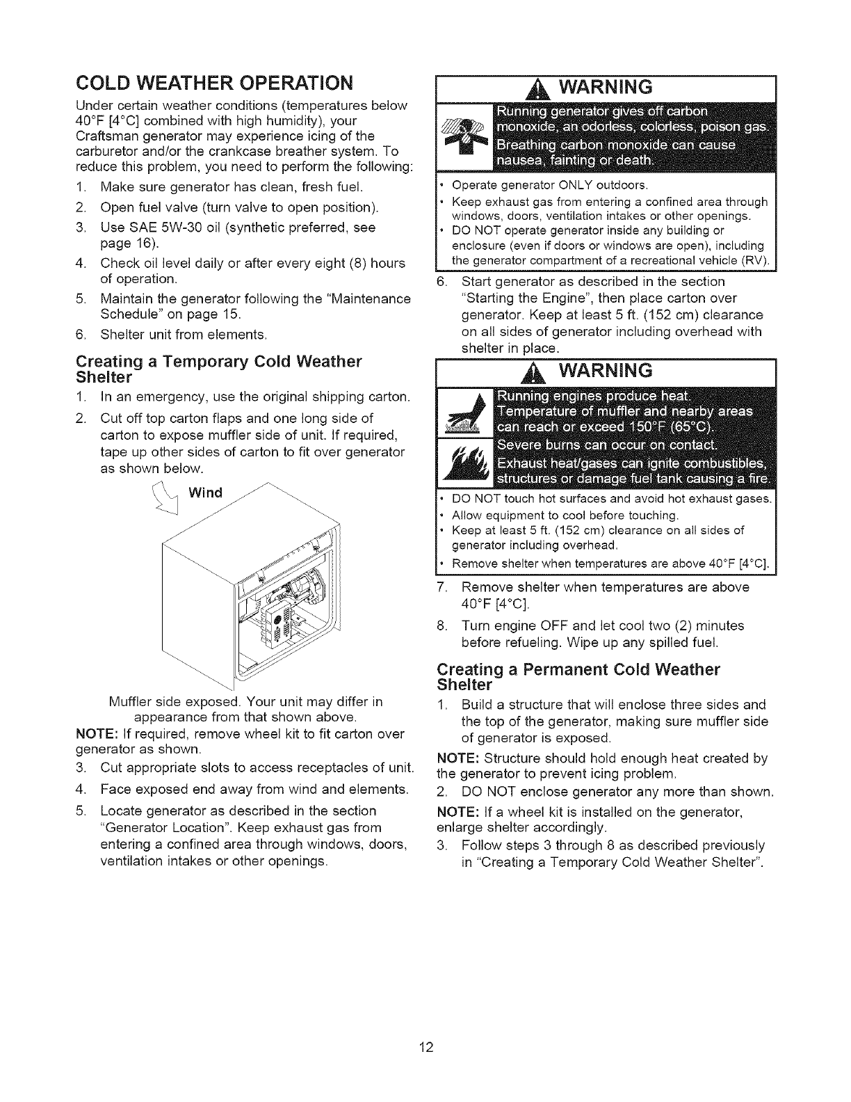
1. In an emergency, use the original shipping carton.
2. Cut off top carton flaps and one long side of
carton to expose muffler side of unit. If required,
tape up other sides of carton to fit over generator
as shown below.
Muffler side exposed. Your unit may differ in
appearance from that shown above.
NOTE: If required, remove wheel kit to fit carton over
generator as shown.
3. Cut appropriate slots to access receptacles of unit.
4. Face exposed end away from wind and elements.
5. Locate generator as described in the section
"Generator Location". Keep exhaust gas from
entering a confined area through windows, doors,
ventilation intakes or other openings.
WARNING
.
Operate generator ONLY outdoors.
Keep exhaust gas from entering a confined area through
windows, doors, ventilation intakes or other openings.
DO NOT operate generator inside any building or
enclosure (even if doors or windows are open), including
the generator compartment of a recreational vehicle (RV).
Start generator as described in the section
"Starting the Engine", then place carton over
generator. Keep at least 5 ft. (152 cm) clearance
on all sides of generator including overhead with
shelter in place.
WARNING
.
8.
DO NOT touch hot surfaces and avoid hot exhaust gases.
Allow equipment to cool before touching.
Keep at least 5 ft. (152 cm) clearance on all sides of
generator including overhead.
Remove shelter when temperatures are above 4O°F [4°C].
Remove shelter when temperatures are above
40°F [4°C].
Turn engine OFF and let cool two (2) minutes
before refueling. Wipe up any spilled fuel.
Creating a Permanent Cold Weather
Shelter
1. Build a structure that will enclose three sides and
the top of the generator, making sure muffler side
of generator is exposed.
NOTE: Structure should hold enough heat created by
the generator to prevent icing problem.
2. DO NOT enclose generator any more than shown.
NOTE: If a wheel kit is installed on the generator,
enlarge shelter accordingly.
3. Follow steps 3 through 8 as described previously
in "Creating a Temporary Cold Weather Shelter".
12
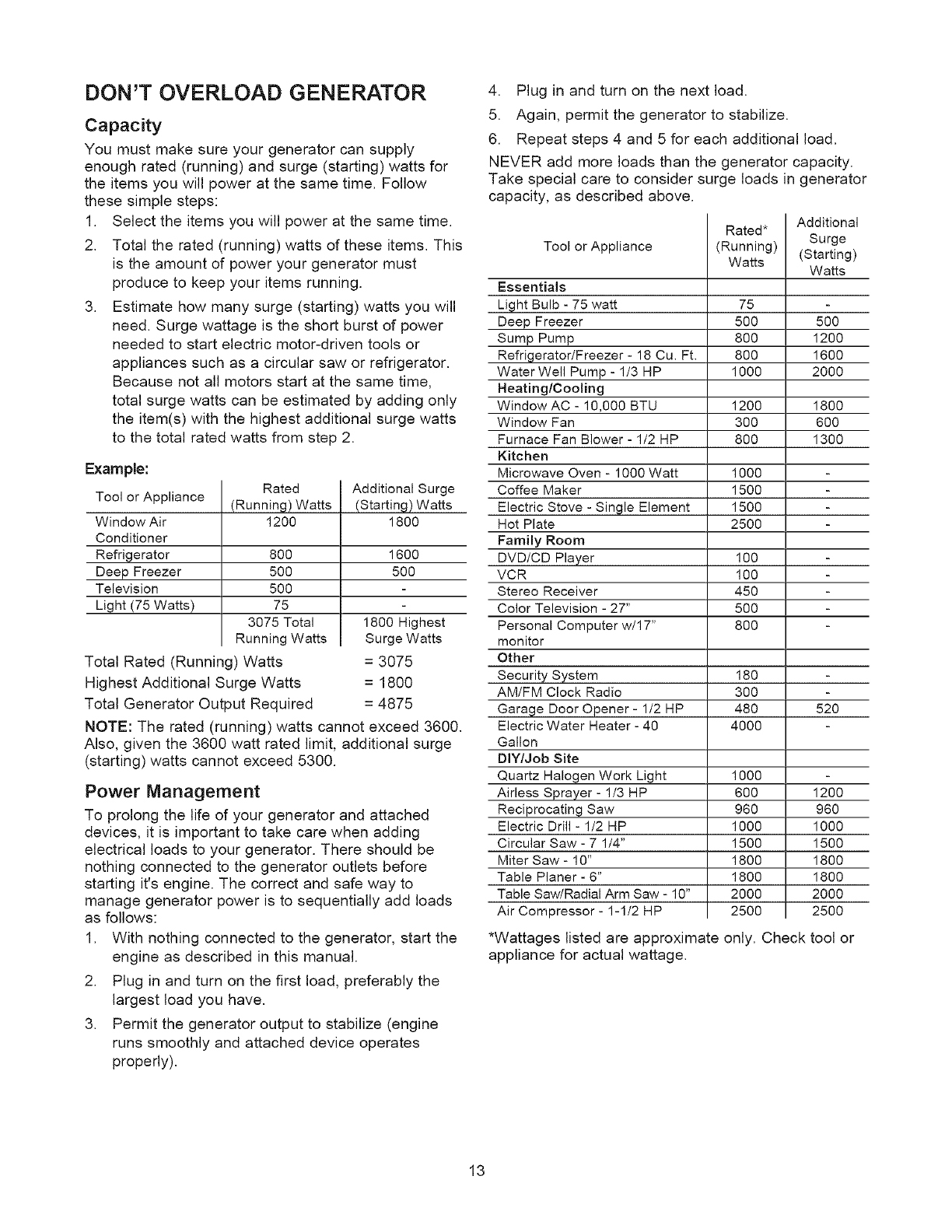
DON'T OVERLOAD GENERATOR
Capacity
You must make sure your generator can supply
enough rated (running) and surge (starting) watts for
the items you will power at the same time. Follow
these simple steps:
1. Select the items you will power at the same time.
2. Total the rated (running) watts of these items. This
is the amount of power your generator must
produce to keep your items running.
3. Estimate how many surge (starting) watts you will
need. Surge wattage is the short burst of power
needed to start electric motor-driven tools or
appliances such as a circular saw or refrigerator.
Because not all motors start at the same time,
total surge watts can be estimated by adding only
the item(s) with the highest additional surge watts
to the total rated watts from step 2.
Example:
Tool or Appliance
Window Air
Conditioner
Refrigerator
Deep Freezer
Television
Light (75 Watts)
Rated
(Running) Watts
1200
800
500
500
75
3075 Total
Running Watts
Total Rated (Running) Watts
Highest Additional Surge Watts
Total Generator Output Required
Additional Surge
(Starting) Watts
1800
1600
5OO
1800 Highest
Surge Watts
= 3075
= 1800
= 4875
NOTE: The rated (running) watts cannot exceed 3600.
Also, given the 3600 watt rated limit, additional surge
(starting) watts cannot exceed 5300.
Power Management
To prolong the life of your generator and attached
devices, it is important to take care when adding
electrical loads to your generator. There should be
nothing connected to the generator outlets before
starting it's engine. The correct and safe way to
manage generator power is to sequentially add loads
as follows:
1. With nothing connected to the generator, start the
engine as described in this manual.
2. Plug in and turn on the first load, preferably the
largest load you have.
3. Permit the generator output to stabilize (engine
runs smoothly and attached device operates
properly).
4. Plug in and turn on the next load.
5. Again, permit the generator to stabilize.
6. Repeat steps 4 and 5 for each additional load.
NEVER add more loads than the generator capacity.
Take special care to consider surge loads in generator
capacity, as described above.
Tool or Appliance
Rated*
(Running)
Watts
Essentials
Light Bulb - 75 watt 75
Deep Freezer 500
Sump Pump 800
Refrigerator/Freezer - 18 Cu. Ft. 800
Water Well Pump - 1/3 HP 1000
Heating/Cooling
Window AC - 10,000 BTU 1200
Window Fan 300
Furnace Fan Blower - 1/2 HP 800
Kitchen
Microwave Oven - 1000 Watt 1000
Coffee Maker 1500
Electric Stove - Single Element 1500
Hot Plate 2500
Family Room
DVD/CD Player 100
VCR 100
Stereo Receiver 450
Color Television - 27" 500
Personal Computer w/17" 800
monitor
Other
Security System 180
AM/FM Clock Radio 300
Garage Door Opener- 1/2 HP 480
Electric Water Heater - 40 4000
Gallon
DIY/Job Site
Quartz Halogen Work Light
Airless Sprayer - 1/3 HP
Reciprocating Saw
Electric Drill - 1/2 HP
Circular Saw - 7 1/4"
Miter Saw - 10"
Table Planer - 6"
Table Saw/Radial Arm Saw - 10"
Air Compressor - 1-1/2 HP
*Wattages listed are approximate only.
appliance for actual wattage.
1000
6oo
96o
1000
1500
1800
1800
2000
2500
Check
Additional
Surge
(Starting)
Watts
5OO
1200
1600
2000
1800
600
1300
520
1200
96O
1000
1500
1800
1800
2000
2500
tool or
13
ENGINE TECHNICAL INFORMATION
This is a single cylinder, overhead valve(OHV), air
cooled engine. It is a low emissions engine.
In the State of California, Model Series 120000
engines are certified by the California Air Resources
Board to meet emissions standards for 125 hours.
Such certification does not grant the purchaser, owner
or operator of this engine any additional warranties
with respect to the performance or operational life of
this engine. The engine is warranted solely according
to the product and emissions warranties stated
elsewhere in this manual.
Power Ratings
* The power ratings for an individual engine model are
initially developed by starting with SAE (Society of
Automotive Engineers) code J1940 (Small Engine
Power & Torque Rating Procedure) (Revision 2002-
05). Given both the wide array of products on which
our engines are placed, and the variety of
environmental issues applicable to operating the
equipment, it may be that the engine you have
purchased will not develop the rated horsepower when
used in a piece of power equipment (actual "on-site"
power). This difference is due to a variety of factors
including, but not limited to, the following: differences
in altitude, temperature, barometric pressure, humidity,
fuel, engine lubrication, maximum governed engine
speed, individual engine to engine variability, design of
the particular piece of power equipment, the manner in
which the engine is operated, engine run-in to reduce
friction and clean out of combustion chambers,
adjustments to the valves and carburetor, and other
factors. The power ratings may also be adjusted
based on comparisons to other similar engines utilized
in similar applications, and will therefore not
necessarily match the values derived using the
foregoing codes.
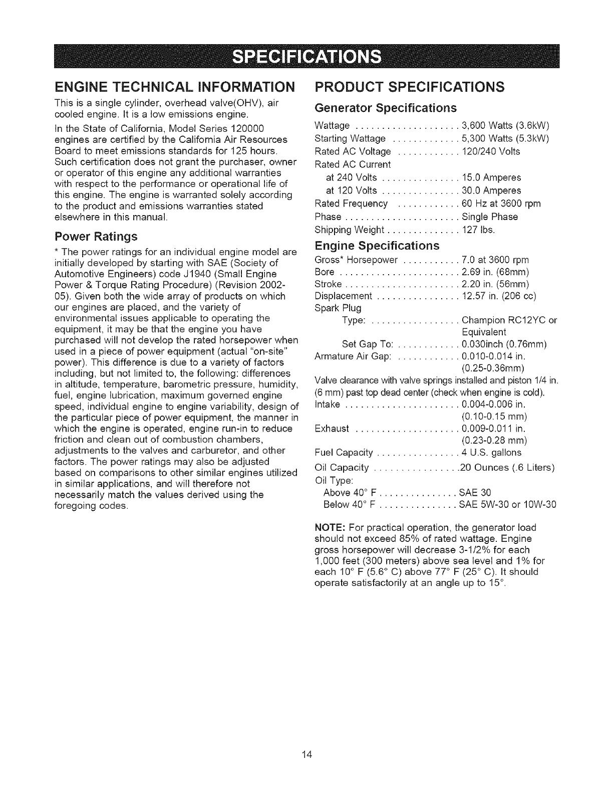
PRODUCT SPECIFICATIONS
Generator Specifications
Wattage .................... 3,600 Watts (3.6kW)
Starting Wattage ............. 5,300 Watts (5.3kW)
Rated AC Voltage ............ 120/240 Volts
Rated AC Current
at 240 Volts ............... 15.0 Amperes
at 120 Volts ............... 30.0 Amperes
Rated Frequency ............ 60 Hz at 3600 rpm
Phase ...................... Single Phase
Shipping Weight .............. 127 Ibs.
Engine Specifications
Gross* Horsepower ........... 7.0 at 3600 rpm
Bore ....................... 2.69 in. (68mm)
Stroke ...................... 2.20 in. (56mm)
Displacement ................ 12.57 in. (206 cc)
Spark Plug
Type: ................. Champion RC12YC or
Equivalent
Set Gap To: ............ 0.030inch (0.76ram)
Armature Air Gap: ............ 0.010-0.014 in.
(0.25-0.36mm)
Valve clearance with valve springs installedand piston 1/4 in.
(6 mm) past top dead center (check when engine is cold).
Intake ...................... 0.004-0.006 in.
(0.10-0.15 mm)
Exhaust .................... 0.009-0.011 in.
(0.23-0.28 mm)
Fuel Capacity ................ 4 U.S. gallons
Oil Capacity ................ 20 Ounces (.6 Liters)
Oil Type:
Above 40° F ............... SAE 30
Below 40° F ............... SAE 5W-30 or 10W-30
NOTE: For practical operation, the generator load
should not exceed 85% of rated wattage. Engine
gross horsepower will decrease 3-1/2% for each
1,000 feet (300 meters) above sea level and 1% for
each 10° F (5.6 ° C) above 77° F (25 ° C). It should
operate satisfactorily at an angle up to 15°.
14
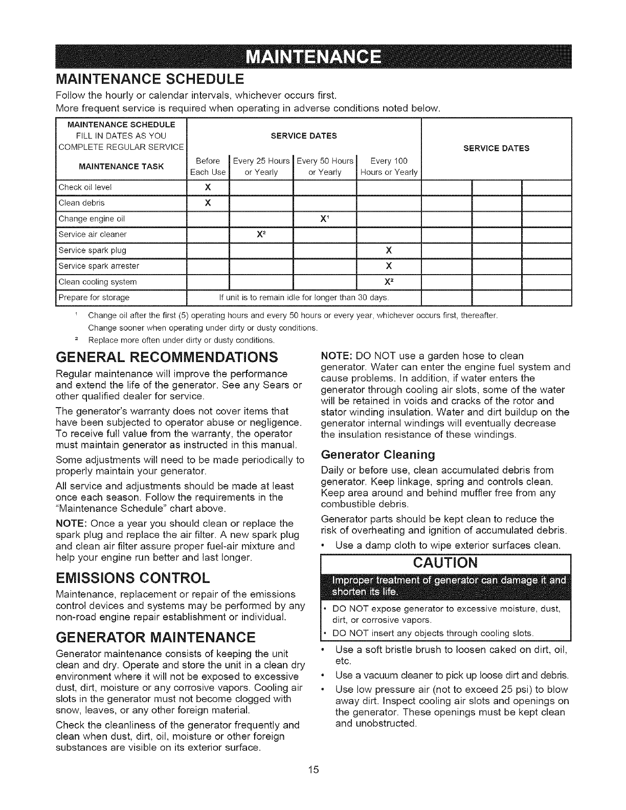
MAINTENANCE SCHEDULE
Follow the hourly or calendar intervals, whichever occurs first.
More frequent service is rec uired when operating in adverse conditions noted below.
MAINTENANCE SCHEDULE
FILL IN DATES AS YOU
COMPLETE REGULAR SERVICE
MAINTENANCE TASK
Check oil level
Clean debris
Change engine oil
Service air cleaner
Service spark plug
Service spark arrester
Clean cooling system
Prepare for storage
SERVICE DATES
Before Every 25 Hours
Each Use or Yearly
X
x
X2
Every 50 Hours
or Year y
X1
Every 100
Hours or Yearly
x
x
x _
If unit is to remain idle for longer than 30 days.
SERVICE DATES
Change oil after the first (5) operating hours and every 50 hours or every year, whichever occurs first, thereafter.
Change sooner when operating under dirty or dusty conditions.
2 Replace more often under dirty or dusty conditions.
GENERAL RECOMMENDATIONS
Regular maintenance will improve the performance
and extend the life of the generator. See any Sears or
other qualified dealer for service.
The generator's warranty does not cover items that
have been subjected to operator abuse or negligence.
To receive full value from the warranty, the operator
must maintain generator as instructed in this manual.
Some adjustments will need to be made periodically to
properly maintain your generator.
All service and adjustments should be made at least
once each season. Follow the requirements in the
"Maintenance Schedule" chart above.
NOTE: Once a year you should clean or replace the
spark plug and replace the air filter. A new spark plug
and clean air filter assure proper fuel-air mixture and
help your engine run better and last longer.
EMISSIONS CONTROL
Maintenance, replacement or repair of the emissions
control devices and systems may be performed by any
non-road engine repair establishment or individual.
GENERATOR MAINTENANCE
Generator maintenance consists of keeping the unit
clean and dry. Operate and store the unit in a clean dry
environment where it will not be exposed to excessive
dust, dirt, moisture or any corrosive vapors. Cooling air
slots in the generator must not become clogged with
snow, leaves, or any other foreign material.
Check the cleanliness of the generator frequently and
clean when dust, dirt, oil, moisture or other foreign
substances are visible on its exterior surface.
NOTE: DO NOT use a garden hose to clean
generator. Water can enter the engine fuel system and
cause problems. In addition, if water enters the
generator through cooling air slots, some of the water
will be retained in voids and cracks of the rotor and
stator winding insulation. Water and dirt buildup on the
generator internal windings will eventually decrease
the insulation resistance of these windings.
Generator Cleaning
Daily or before use, clean accumulated debris from
generator. Keep linkage, spring and controls clean.
Keep area around and behind muffler free from any
combustible debris.
Generator parts should be kept clean to reduce the
risk of overheating and ignition of accumulated debris.
* Use a damp cloth to wipe exterior surfaces clean.
CAUTION
o
o
o
DO NOT expose generator to excessive moisture, dust,
dirt, or corrosive vapors.
DO NOT insert any objects through cooling slots.
Use a soft bristle brush to loosen caked on dirt, oil,
etc.
Use a vacuum cleaner to pick up loose dirt and debris.
Use low pressure air (not to exceed 25 psi) to blow
away dirt. Inspect cooling air slots and openings on
the generator. These openings must be kept clean
and unobstructed.
15
StatStation TM
The StatStation TM displays the nominal load on
generator based on output frequency. It also has a
built in maintenance reminder.
Wattage Monitor
The LED display will indicate 0-95% nominal load.The
display will flash at 90% nominal load and above. If
above 95% nominal load the display will flash "OL"
(meaning 'overload'). When load returns to within
normal range, the display will automatically resume
nominal load indication. See the table below for
Frequency Range
62.5-62.0
61.9-61.5
61.4-61.0
60.9-60.5
60.4-60.0
59.9-59.5
59.4-59.0
58.9-58.5
58.4-58.0
57.9-57.5
57.4-57.0
57.0 and below
operation functions.
Maintenance Reminder
LED Display
0
0
10
20
40
60
70
80
Flash 90
Flash 95
Flash OL
Flash OL
The LED will display certain codes to alert you to
check oil, change oil, check or replace air filter and
check or replace spark plug. The following codes will
display:
Check oil at 8 hour increments"C1"
"C2"
"C3"
"C4"
Change oil at 50 hour increments
Check or replace air filter at 25 hour
increments
Check or replace spark plug at 100 hour
increments
Pushing "Reset" will set the indicated code timer to
zero.
If nominal load and maintenance codes appear
simultaneously, the LED shall display, alternately, the
nominal load and code as follows:
The code will display for 3 seconds, then 1/2 second
off. The load will display for 6 seconds and then
1/2 second off.
ENGINE MAINTENANCE
WARNING
WHEN ADJUSTING OR MAKING REPAIRS TO YOUR
GENERATOR
•Disconnect the spark plug wire from the spark plug and
place the wire where it cannot contact spark plug.
WHEN TESTING FOR ENGINE SPARK
Use approved spark plug tester.
DO NOT check for spark with spark plug removed.
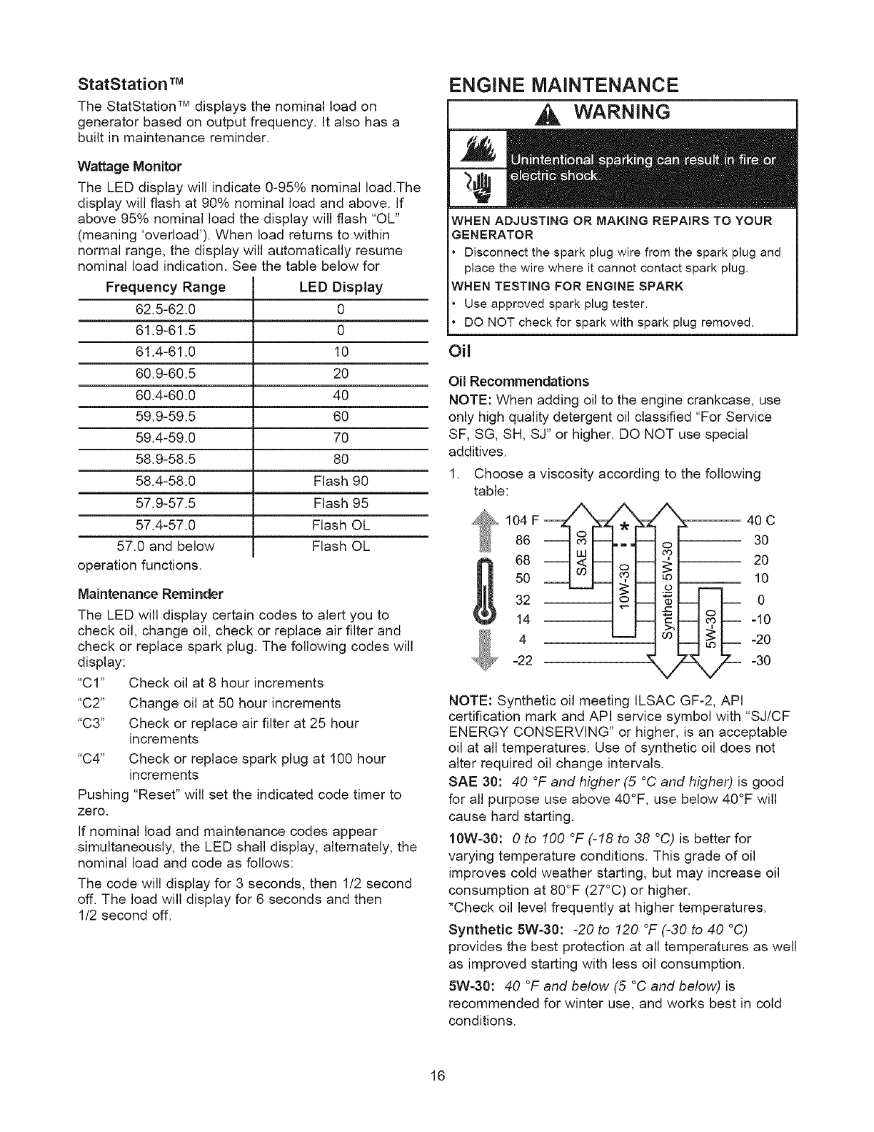
Oil
Oil Recommendations
NOTE: When adding oil to the engine crankcase, use
only high quality detergent oil classified "For Service
SF, SG, SH, SJ" or higher. DO NOT use special
additives.
1. Choose a viscosity according to the following
table:
104 F_
86
68
5O
32
14
4
"_ -22
X_ 40 C
30
20
; 10
0
-10
-20
-30
NOTE: Synthetic oil meeting ILSAC GF-2, API
certification mark and API service symbol with "SJ/CF
ENERGY CONSERVING" or higher, is an acceptable
oil at all temperatures. Use of synthetic oil does not
alter required oil change intervals.
SAE 30:40 °F and higher (5 °C and higher) is good
for all purpose use above 40°F, use below 40°F will
cause hard starting.
10W-30:0 to 100 °F (-18 to 38 °C) is better for
varying temperature conditions. This grade of oil
improves cold weather starting, but may increase oil
consumption at 80°F (27°C) or higher.
*Check oil level frequently at higher temperatures.
Synthetic 5W-30:-20 to 120 °F (-30 to 40 °C)
provides the best protection at all temperatures as well
as improved starting with less oil consumption.
5W-30:40 °F and below (5 °C and below) is
recommended for winter use, and works best in cold
conditions.
16
CheckingOil Level
Oillevelshouldbecheckedpriortoeachuseorat
leastevery5hoursof operation,Keepoillevel
maintained,
1. Makesuregeneratorisona levelsurface,
2. Removeoildipstickandwipedipstickwithclean
cloth,Replaceandtightendipstick,Removeand
andcheckoillevel,
3. Verifyoil isat"Full"markondipstick.Replaceand
tightendipstick.
AddingEngineOil
1. Makesuregeneratorisona levelsurface.
2. Checkoillevelasdescribedin"CheckingOil
Level".
3. If needed,slowlypouroilintooilfill openingto the
"Full"markondipstick.DONOToverfill.
4. Replaceandtightendipstick.
Service Air Cleaner
Your engine will not run properly and may be
damaged if you run it with a dirty air cleaner.
Replace the air cleaner every 25 hours of operation or
once each year, whichever comes first. Replace more
often if operating under dirty or dusty conditions.
To service the air cleaner, follow these steps:
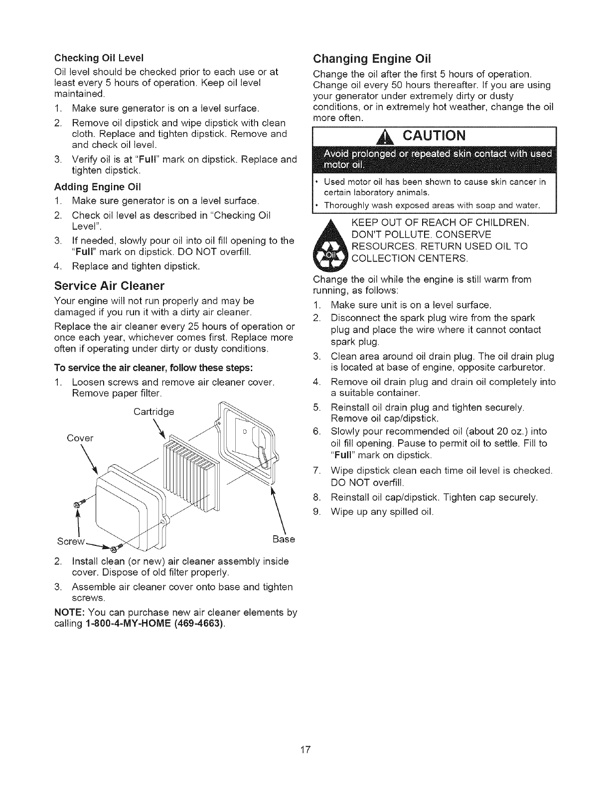
1. Loosen screws and remove air cleaner cover.
Remove paper filter.
Cartridge
Cover kk_
\
Base
2. Install clean (or new) air cleaner assembly inside
cover. Dispose of old filter properly.
3. Assemble air cleaner cover onto base and tighten
screws.
NOTE: You can purchase new air cleaner elements by
calling 1-800-4-MY-HOME (469-4663).
Changing Engine Oil
Change the oil after the first 5 hours of operation.
Change oil every 50 hours thereafter. If you are using
your generator under extremely dirty or dusty
conditions, or in extremely hot weather, change the oil
more often.
CAUTION
Used motor oil has been shown to cause skin cancer in
certain laboratory animals.
Thoroughly wash exposed areas with soap and water.
KEEP OUT OF REACH OF CHILDREN.
DON'T POLLUTE. CONSERVE
RESOURCES. RETURN USED OIL TO
COLLECTION CENTERS.
Change the oil while the engine is still warm from
running, as follows:
1. Make sure unit is on a level surface.
2. Disconnect the spark plug wire from the spark
plug and place the wire where it cannot contact
spark plug.
3. Clean area around oil drain plug. The oil drain plug
is located at base of engine, opposite carburetor.
4. Remove oil drain plug and drain oil completely into
a suitable container.
5. Reinstall oil drain plug and tighten securely.
Remove oil cap/dipstick.
6. Slowly pour recommended oil (about 20 oz.) into
oil fill opening. Pause to permit oil to settle. Fill to
"Full" mark on dipstick.
7. Wipe dipstick clean each time oil level is checked.
DO NOT overfill.
8. Reinstall oil cap/dipstick. Tighten cap securely.
9. Wipe up any spilled oil.
17
Clean/Replace Spark Plug
Change the spark plug every 100 hours of operation
or once each year, whichever comes first. This will
help your engine to start easier and run better.
1. Clean area around spark plug.
2. Remove and inspect spark plug.
3. Check electrode gap with wire feeler gauge and
set spark plug gap to 0.030 inch (0.76ram) if
necessary.
_-_ z_ ............
4. Replace spark plug if electrodes are pitted, burned
or porcelain is cracked. Use a recommended
replacement plug.
5. Install spark plug and tighten firmly.
NOTE: You can purchase a new spark plug by calling
1-800-4-MY-HOME (469-4663).
Clean Spark Arrester Screen
The engine exhaust muffler has a spark arrester
screen. Inspect and clean the screen every 100 hours
of operation or once each year, whichever comes first.
WARNING
DO NOT touch hot surfaces and avoid hot exhaust gases.
Allow equipment to cool before touching.
Keep at least 5 ft. (152 cm) clearance on all sides of
generator including overhead.
Code of Federal Regulation (CFR) Title 36 Parks,
Forests, and Public Property require equipment powered
by an internal combustion engine to have a spark
arrester, maintained in effective working order, complying
to USDA Forest service standard 5100-1C or later
revision. In the State of California a spark arrester is
required under section 4442 of the California Public
resources code. Other states may have similar laws.
NOTE: You can purchase a new spark arrester screen
by calling 1-800-4-MY-HOME (469-4663).
If you use your generator on any forest-covered, brush-
covered, or grass-covered unimproved land, it must
have a spark arrester. The spark arrester must be
maintained in good condition by the owner/operator.
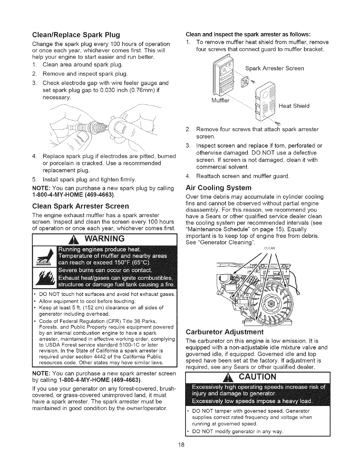
Clean and inspect the spark an'ester as follows:
1. To remove muffler heat shield from muffler, remove
four screws that connect guard to muffler bracket.
Spark Arrester Screen
Muffler .............
\..... Heat Shield
2. Remove four screws that attach spark arrester
screen.
3. Inspect screen and replace if torn, perforated or
otherwise damaged. DO NOT use a defective
screen. If screen is not damaged, clean it with
commercial solvent.
4. Reattach screen and muffler guard.
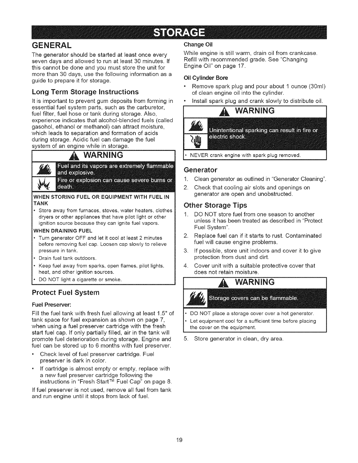
Air Cooling System
Over time debris may accumulate in cylinder cooling
fins and cannot be observed without partial engine
disassembly. For this reason, we recommend you
have a Sears or other qualified service dealer clean
the cooling system per recommended intervals (see
"Maintenance Schedule" on page 15). Equally
important is to keep top of engine free from debris.
See "Generator Cleaning".
CEEAN
Carburetor Adjustment
The carburetor on this engine is low emission. It is
equipped with a non-adjustable idle mixture valve and
governed idle, if equipped. Governed idle and top
speed have been set at the factory. If adjustment is
required, see any Sears or other qualified dealer.
CAUTION
DO NOT tamper with governed speed. Generator
supplies correct rated frequency and voltage when
running at governed speed.
DO NOT modify generator in any way.
18
GENERAL
The generator should be started at least once every
seven days and allowed to run at least 30 minutes. If
this cannot be done and you must store the unit for
more than 30 days, use the following information as a
guide to prepare it for storage.
Long Term Storage Instructions
It is important to prevent gum deposits from forming in
essential fuel system parts, such as the carburetor,
fuel filter, fuel hose or tank during storage. Also,
experience indicates that alcohol-blended fuels (called
gasohol, ethanol or methanol) can attract moisture,
which leads to separation and formation of acids
during storage. Acidic fuel can damage the fuel
system of an engine while in storage.
WARNING
WHEN STORING FUEL OR EQUIPMENT WITH FUEL IN
TANK
Store away from furnaces, stoves, water heaters, clothes
dryers or other appliances that have pilot light or other
ignition source because they can ignite fuel vapors.
WHEN DRAiNiNG FUEL
Turn generator OFF and let it cool at least 2minutes
before removing fuel cap. Loosen cap slowly to relieve
pressure in tank.
Drain fuel tank outdoors.
Keep fuel away from sparks, open flames, pilot lights,
heat, and other ignition sources.
DO NOT light a cigarette or smoke.
Protect Fuel System
Fuel Preserver:
Fill the fuel tank with fresh fuel allowing at least 1.5" of
tank space for fuel expansion as shown on page 7,
when using a fuel preserver cartridge with the fresh
start fuel cap. If only partially filled, air in the tank will
promote fuel deterioration during storage. Engine and
fuel can be stored up to 6 months with fuel preserver.
• Check level of fuel preserver cartridge. Fuel
preserver is dark in color.
• If cartridge is almost empty or empty, replace with
a new fuel preserver cartridge following the
instructions in "Fresh Start TM Fuel Cap" on page 8.
If fuel preserver is not used, remove all fuel from tank
and run engine until it stops from lack of fuel.
Change Oil
While engine is still warm, drain oil from crankcase.
Refill with recommended grade. See "Changing
Engine Oil" on page 17.
Oil Cylinder Bore
• Remove spark plug and pour about 1 ounce (30ml)
of clean engine oil into the cylinder.
• Install spark plug and crank slowly to distribute oil.
WARNING
NEVER crank enqine with spark plug removed.
Generator
1. Clean generator as outlined in "Generator Cleaning".
2. Check that cooling air slots and openings on
generator are open and unobstructed.
Other Storage Tips
1. DO NOT store fuel from one season to another
unless it has been treated as described in "Protect
Fuel System".
2. Replace fuel can if it starts to rust. Contaminated
fuel will cause engine problems.
3. If possible, store unit indoors and cover it to give
protection from dust and dirt.
4. Cover unit with a suitable protective cover that
does not retain moisture.
WARNING
,
DO NOT place a storage cover over a hot generator.
Let equipment cool for a sufficient time before placing
the cover on the equipment.
Store generator in clean, dry area.
19
Problem Cause
Engine is running, but no AC
output is available.
Engine runs good at no-load but
"bogs down" when loads are
connected.
1. One of the circuit breakers is
open.
2. Fault in generator.
3. Poor connection or defective
cord set.
4. Connected device is bad.
1. Short circuit in a connected
load.
2. Engine speed is too slow.
3. Generator is overloaded,
4. Shorted generator circuit,
1. Rocker Switch set to "Off",
2. Fuel Valve is in "Off" position,
Correction
1. Reset circuit breaker,
2. Contact Sears service facility,
3. Check and repair,
4. Connect another device that is
in good condition.
1. Disconnect shorted electrical
load,
2. Contact Sears service facility,
3. See "Don't Overload
Generator".
4. Contact Sears service facility,
1. Set switch to "On",
2. Turn fuel valve to "Open"
position,
3. Dirty air cleaner.
4. Out of fuel.
5. Stale fuel.
6. Spark plug wire not connected
3. Clean or replace air cleaner,
4. Fill fuel tank,
5. Drain fuel tank and carburetor;
fill with fresh fuel,
6. Connect wire to spark plug,
Engine will not start; or starts
and runs rough.
to spark plug,
7. Bad spark plug,
8. Water in fuel,
9. Flooded,
7. Replace spark plug,
8. Drain fuel tank and carburetor;
fill with fresh fuel,
9. Wait 5 minutes and re-crank
engine,
10. Excessively rich fuel mixture,
11. Intake valve stuck open or
closed,
12. Engine has lost compression,
O. Contact Sears service facility.
1. Contact Sears service facility.
2. Contact Sears service facility.
Engine shuts down when Out of fuel. Fill fuel tank.
running.
1. Load is too high. 1. See "Don't Overload
Engine lacks power. Generator",
2. Dirty air filter, 2. Replace air filter,
Carburetor is running too rich or too Contact Sears service facility,
Engine "hunts" or falters. lean,
20

21
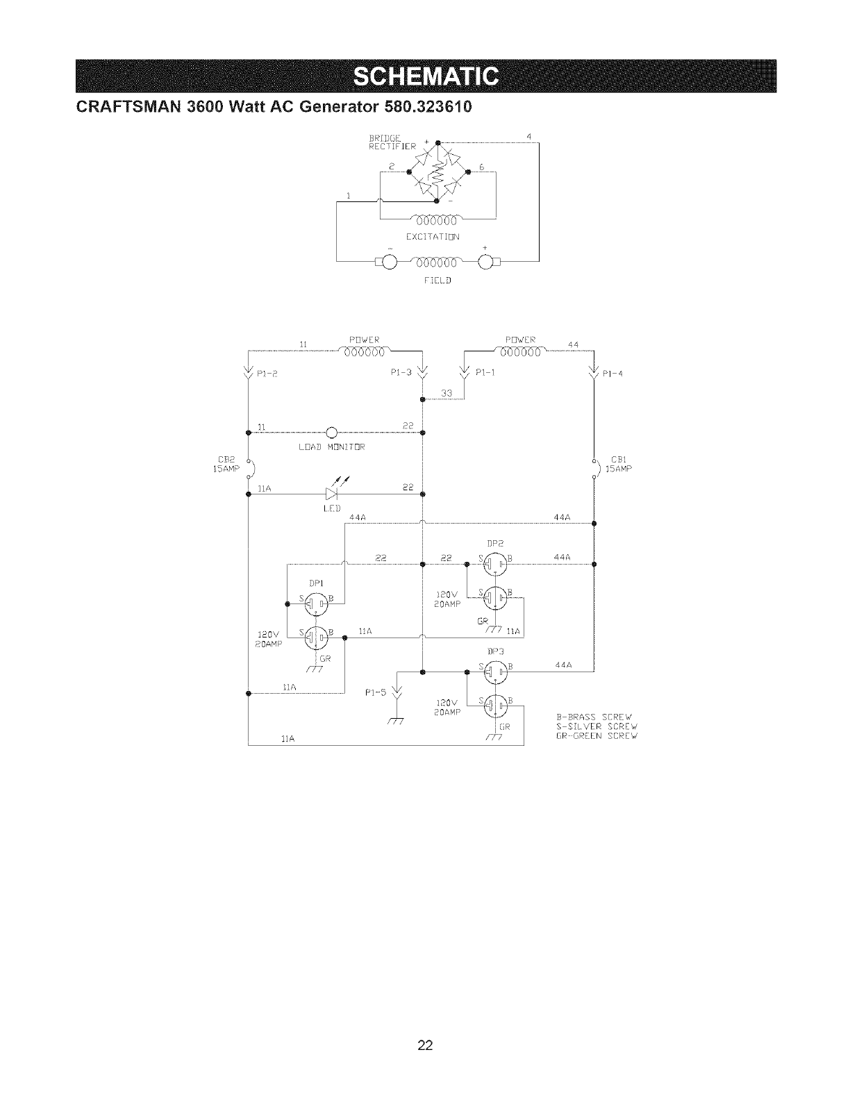
CRAFTSMAN 3600 Watt AC Generator 580.323610
FIELD
CS8
15AHP
I1 PDWER PDWER
!2
LDAD M_N!T_R
// as
lid
a4A 44A
P] 4
CS!
15ANP
I]A
22
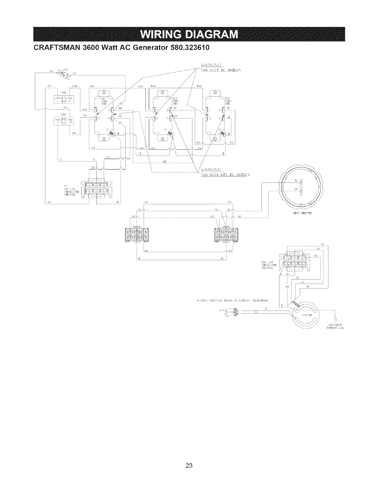
CRAFTSMAN 3600 Watt AC Generator 580.323610
,-j
:_[,N :10_ :
44 [ 0
i ................................................................... i
_, 1 £'i
33
NU F PIIS V _ %sH i_ CLIS '_ [} _ _,RN@
6
23
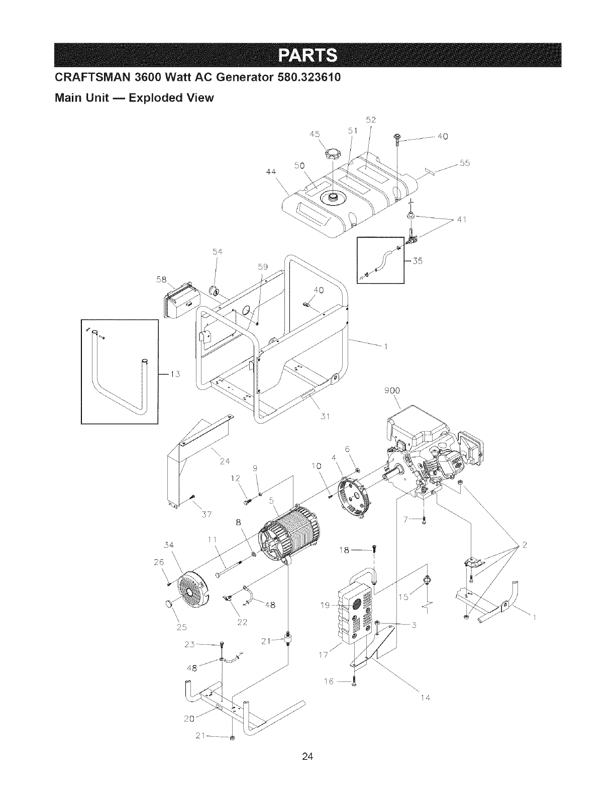
CRAFTSMAN 3600 Watt AC Generator 580.323610
Main Unit m E×ploded View
5O
44
51
58
54
59
900
\\h
\2q 9
12 /
\\\
26
\\
\\' 22
25
21
10
6
4
19
16
14
24
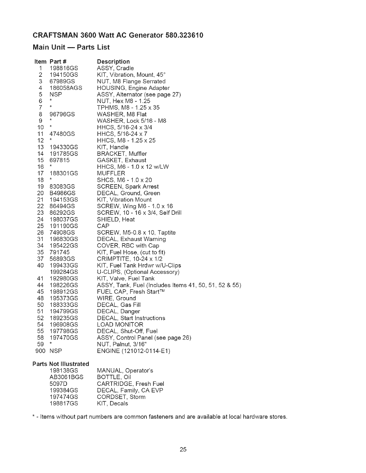
CRAFTSMAN 3600 Watt AC Generator 580.323610
Main Unit m Parts List
Item Part # Description
1 198816GS ASSY, Cradle
2 194150GS KIT, Vibration, Mount, 45 °
3 67989GS NUT, M8 Flange Serrated
4 186058AGS HOUSING, Engine Adapter
5 NSP ASSY, Alternator (see page 27)
6 * NUT, Hex M8- 1.25
7 * TPHMS, M8- 1.25 x 35
8 96796GS WASHER, M8 Flat
9 * WASHER, Lock 5/16- M8
10 * HHCS, 5/16-24 x 3/4
11 47480GS HHCS, 5/16-24 x 7
12 * HHCS, M8- 1.25 x 25
13 194330GS KIT, Handle
14 191785GS BRACKET, Muffler
15 697815 GASKET, Exhaust
16 * HHCS, M6- 1.0 x 12 w/LW
17 188301GS MUFFLER
18 * SHCS, M6- 1.0 x 20
19 83083GS SCREEN, Spark Arrest
20 B4986GS DECAL, Ground, Green
21 194153GS KIT, Vibration Mount
22 86494GS SCREW, Wing M6 - 1.0 x 16
23 86292GS SCREW, 10 - 16 x 3/4, Self Drill
24 198037GS SHIELD, Heat
25 191190GS CAP
26 74908GS SCREW, M5-0.8 x 10, Taptite
31 196830GS DECAL, Exhaust Warning
34 195422GS COVER, RBC with Cap
35 791745 KIT, Fuel Hose, (cut to fit)
37 56893GS CRIMPTITE, 10-24 x 1/2
40 199433GS KIT, Fuel Tank Hrdwr w/U-Clips
199284GS U-CLI PS, (Optional Accessory)
41 192980GS KIT, Valve, Fuel Tank
44 198226GS ASSY, Tank, Fuel (Includes Items 41,50, 51,52 & 55)
45 198912GS FUEL CAP, Fresh Start TM
48 195373GS WIRE, Ground
50 188333GS DECAL, Gas Fill
51 194799GS DECAL, Danger
52 189235GS DECAL, Start Instructions
54 196908GS LOAD MONITOR
55 197798GS DECAL, Shut-Off, Fuel
58 197470GS ASSY, Control Panel (see page 26)
59 * NUT, Palnut, 3/16"
900 NSP ENGINE (121012-0114-E1)
Parts Not Illustrated
198138GS
AB3061BGS
5097D
199384GS
197474GS
198817GS
MANUAL, Operator's
BOTTLE, Oil
CARTRIDGE, Fresh Fuel
DECAL, Family, CA EVP
CORDSET, Storm
KIT, Decals
* - Items without part numbers are common fasteners and are available at local hardware stores.
25
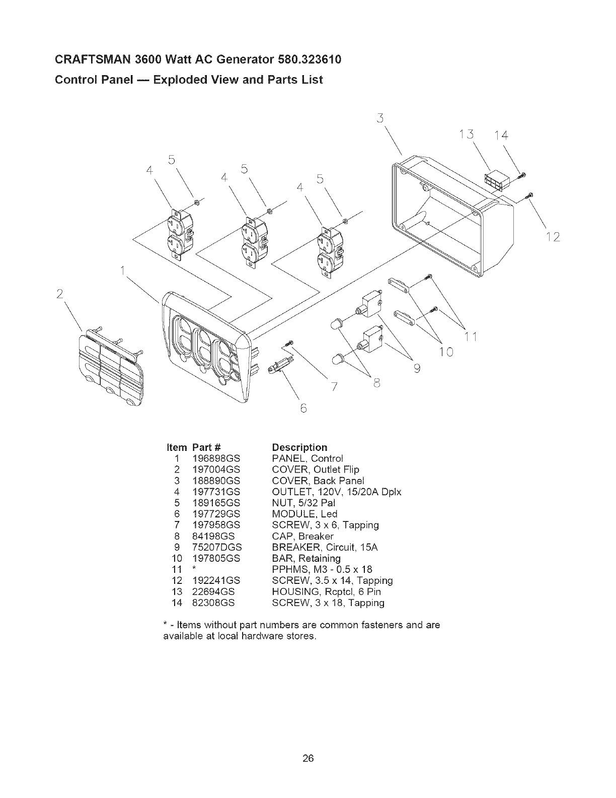
CRAFTSMAN 3600 Watt AC Generator 580.323610
Control Panel m Exploded View and Parts List
4\5
4 5
\
14
12
2\
7
10
9
item Part #
1 196898GS
2 197004GS
3 188890GS
4 197731GS
5 189165GS
6 197729GS
7 197958GS
8 84198GS
9 75207DGS
10 197805GS
11 *
12 192241GS
13 22694GS
14 82308GS
Description
PANEL, Control
COVER, Outlet Flip
COVER, Back Panel
OUTLET, 120V, 15/20A Dplx
NUT, 5/32 Pal
MODULE, Led
SCREW, 3 x 6, Tapping
CAP, Breaker
BREAKER, Circuit, 15A
BAR, Retaining
PPHMS, M3- 0.5 x 18
SCREW, 3.5 x 14, Tapping
HOUSING, Rcptcl, 6 Pin
SCREW, 3 x 18, Tapping
* - Items without part numbers are common fasteners and are
available at local hardware stores.
26
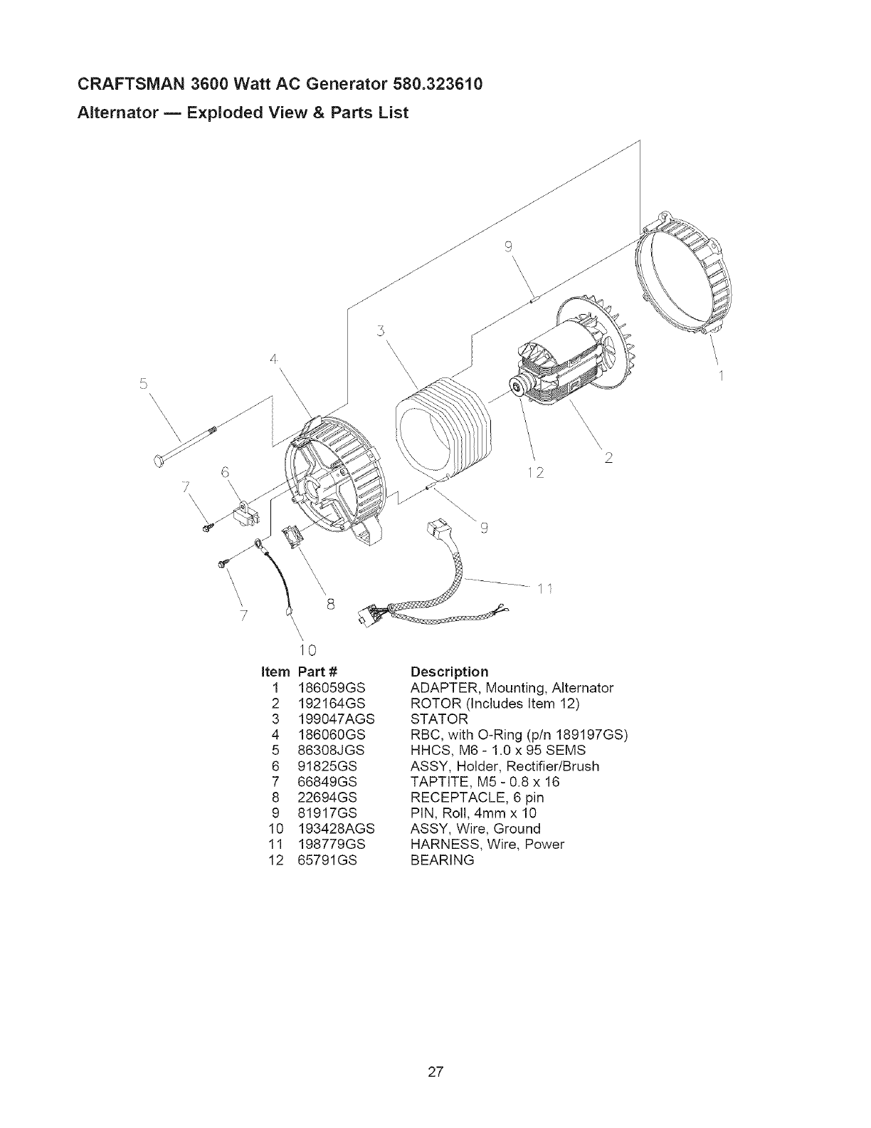
CRAFTSMAN 3600 Watt AC Generator 580.323610
Alternator m Exploded View & Parts List
5
\\\\
6
7
\\
4
\\ \\\
J
\\
\
\\ \\
\\\\\
\, 2
2
\
\1
\\\\\
7
\\,
I0
item Part #
1 186059GS
2 192164GS
3 199047AGS
4 186060GS
5 86308JGS
6 91825GS
7 66849GS
8 22694GS
9 81917GS
10 193428AGS
11 198779GS
12 65791GS
11
Description
ADAPTER, Mounting, Alternator
ROTOR (Includes Item 12)
STATOR
RBC, with O-Ring (p/n 189197GS)
HHCS, M6- 1.0 x 95 SEMS
ASSY, Holder, Rectifier/Brush
TAPTITE, M5 - 0.8 x 16
RECEPTACLE, 6 pin
PIN, Roll, 4ram x 10
ASSY, Wire, Ground
HARNESS, Wire, Power
BEARING
27
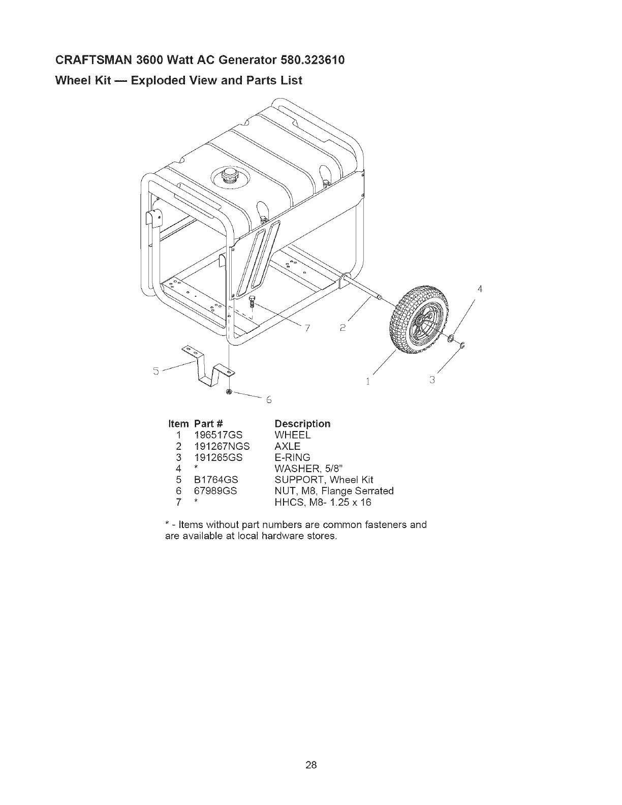
CRAFTSMAN 3600 Watt AC Generator 580.323610
Wheel Kit m Exploded View and Parts List
item Part # Description
1 196517GS WHEEL
2 191267NGS AXLE
3 191265GS E-RING
4 * WASHER, 5/8"
5 B1764GS SUPPORT, Wheel Kit
6 67989GS NUT, M8, Flange Serrated
7 * HHCS, MS- 1.25 x 16
* - Items without part numbers are common fasteners and
are available at local hardware stores,
28
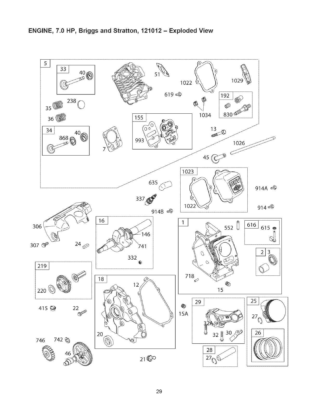
ENGINE, 7.0 HP, Briggs and Stratton, 121012 - Exploded View
415 _ 22_
12
Y
718
@
15A
1616 1615_
29
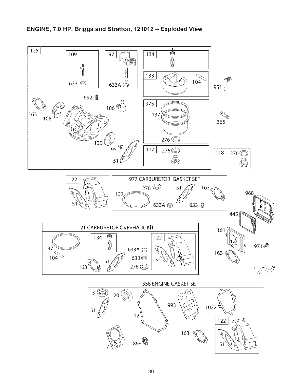
ENGINE, 7.0 HP, Briggs and Stratton, 121012 - Exploded View
I"
i
633 @
692
633A @
186_
130 95 _
51
0
137_
276
276
%
365
977 CARBURETOR GASKET SET
276_ _ 163
633A@ 633@
121 CARBURETOR OVERHAUL KIT
633A@
633@
276Q
445
161_
ItI@
163
968
_ 971 _
3@ 2O
12
358 ENGINE GASKET SET
993 % I022
868% 163
3O
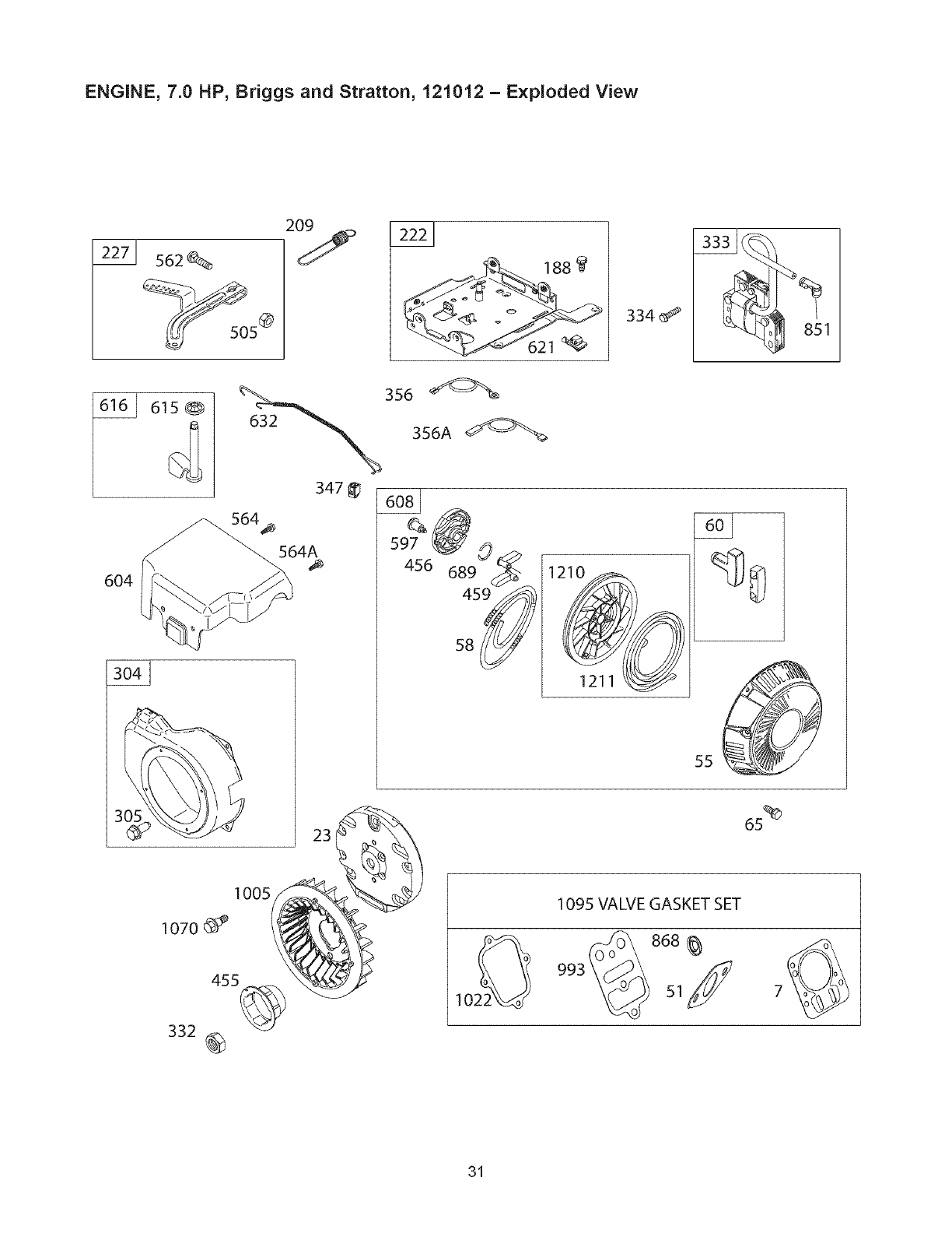
ENGINE, 7.0 HP, Briggs and Stratton, 121012 - Exploded View
s62
334 851
6O4
356 356A
615
347
564_
564A
s8
1211
55
23
1005
1070
455
332 @
1095 VALVE GASKET SET
993 868
31
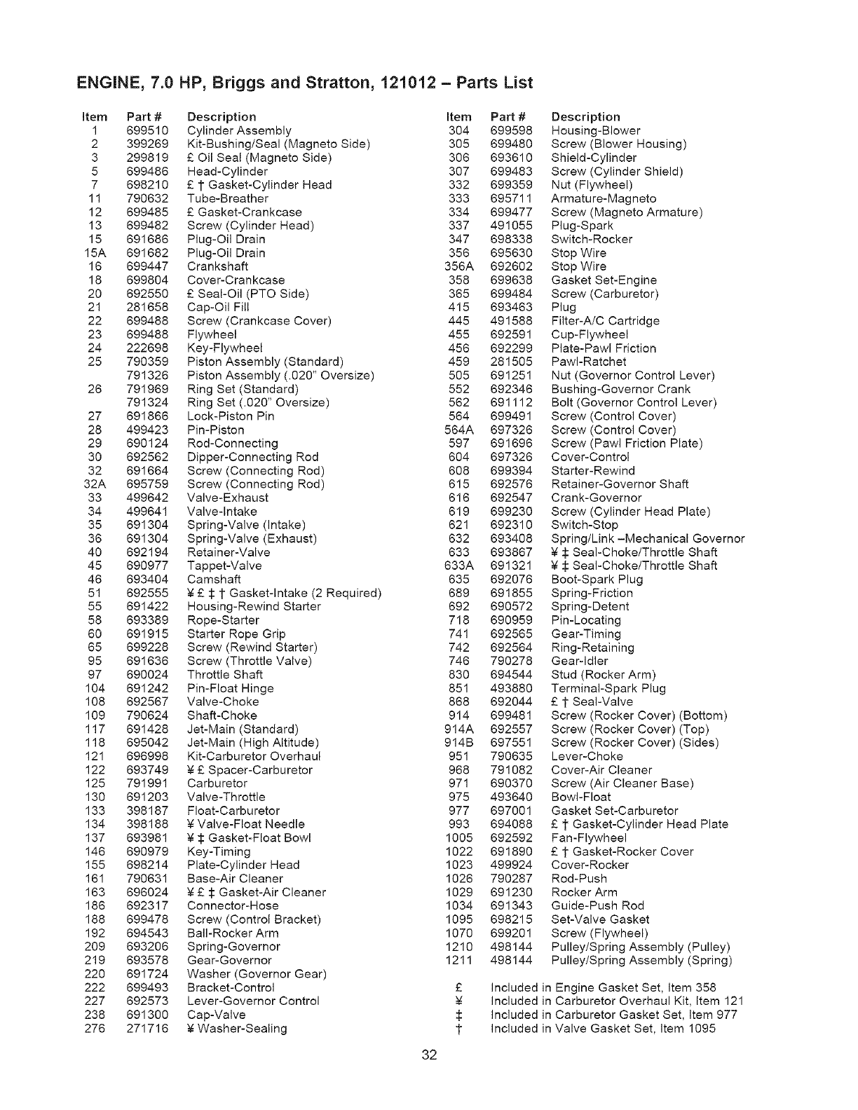
ENGINE, 7.0 HP, Briggs and Stratton, 121012 = Parts List
Item Part # Description Item Part #
1 699510 Cylinder Assembly 304 699598
2 399269 Kit-Bushing/Seal (Magneto Side) 305 699480
3 299819 £ Oil Seal (Magneto Side) 306 693610
5 699486 Head-Cylinder 307 699483
7 698210 £ 1 Gasket-Cylinder Head 332 699359
11 790632 Tube-Breather 333 695711
12 699485 £ Gasket-Crankcase 334 699477
13 699482 Screw (Cylinder Head) 337 491055
15 691686 Plug-Oil Drain 347 698338
15A 691682 Plug-Oil Drain 356 695630
16 699447 Crankshaft 356A 692602
18 699804 Cover-Crankcase 358 699638
20 692550 £ Seal-Oil (PTO Side) 365 699484
21 281658 Cap-Oil Fill 415 693463
22 699488 Screw (Crankcase Cover) 445 491588
23 699488 Flywheel 455 692591
24 222698 Key-Flywheel 456 692299
25 790359 Piston Assembly (Standard) 459 281505
791326 Piston Assembly (.O2O" Oversize) 505 691251
26 791969 Ring Set (Standard) 552 692346
791324 Ring Set (.020" Oversize) 562 691112
27 691866 Lock-Piston Pin 564 699491
28 499423 Pin-Piston 564A 697326
29 690124 Rod-Connecting 597 691696
30 692562 Dipper-Connecting Rod 604 697326
32 691664 Screw (Connecting Rod) 608 699394
32A 695759 Screw (Connecting Rod) 615 692576
33 499642 Valve-Exhaust 616 692547
34 499641 Valve-Intake 619 699230
35 691304 Spring-Valve (intake) 621 692310
36 691304 Spring-Valve (Exhaust) 632 693408
40 692194 Retainer-Valve 633 693867
45 690977 Tappet-Valve 633A 691321
46 693404 Camshaft 635 692076
51 692555 _ £ :!t:1"Gasket-Intake (2 Required) 689 691855
55 691422 Housing-Rewind Starter 692 690572
58 693389 Rope-Starter 718 690959
60 691915 Starter Rope Grip 741 692565
65 699228 Screw (Rewind Starter) 742 692564
95 691636 Screw (Throttle Valve) 746 790278
97 690024 Throttle Shaft 830 694544
104 691242 Pin-Float Hinge 851 493880
108 692567 Valve-Choke 868 692044
109 790624 Shaft-Choke 914 699481
117 691428 Jet-Main (Standard) 914A 692557
118 695042 Jet-Main (High Altitude) 914B 697551
121 696998 Kit-Carburetor Overhaul 951 790635
122 693749 _ £ Spacer-Carburetor 968 791082
125 791991 Carburetor 971 690370
130 691203 Valve-Throttle 975 493640
133 398187 Float-Carburetor 977 697001
134 398188 _ Valve-Float Needle 993 694088
137 693981 _ :l: Gasket-Float Bowl 1005 692592
146 690979 Key-Timing 1022 691890
155 698214 Plate-Cylinder Head 1023 499924
161 790631 Base-Air Cleaner 1026 790287
163 696024 _ £ :!t:Gasket-Air Cleaner 1029 691230
186 692317 Connector-Hose 1034 691343
188 699478 Screw (Control Bracket) 1095 698215
192 694543 Bali-Rocker Arm 1070 699201
209 693206 Spring-Governor 1210 498144
219 693578 Gear-Governor 1211 498144
220 691724 Washer (Governor Gear)
222 699493 Bracket-Control £
227 692573 Lever-Governor Control
238 691300 Cap-Valve $
276 271716 _ Washer-Sealing 1
Description
Housing-Blower
Screw (Blower Housing)
Shield-Cylinder
Screw (Cylinder Shield)
Nut (Flywheel)
Armature-Magneto
Screw (Magneto Armature)
Plug-Spark
Switch-Rocker
Stop Wire
Stop Wire
Gasket Set-Engine
Screw (Carburetor)
Plug
Filter-A/C Cartridge
Cup-Flywheel
Plate-Pawl Friction
PawI-Ratchet
Nut (Governor Control Lever)
Bushing-Governor Crank
Bolt (Governor Control Lever)
Screw (Control Cover)
Screw (Control Cover)
Screw (Pawl Friction Plate)
Cover-Control
Starter-Rewind
Retainer-Governor Shaft
Crank-Governor
Screw (Cylinder Head Plate)
Switch-Stop
Spring/Link-Mechanical Governor
_: Seal-Choke/Throttle Shaft
$ Seal-Choke/Throttle Shaft
Boot-Spark Plug
Spring-Friction
Spring-Detent
Pin-Locating
Gear-Timing
Ring-Retaining
Gear-Idler
Stud (Rocker Arm)
Terminal-Spark Plug
£ 1 Seal-Valve
Screw (Rocker Cover) (Bottom)
Screw (Rocker Cover) (Top)
Screw (Rocker Cover) (Sides)
Lever-Choke
Cover-Air Cleaner
Screw (Air Cleaner Base)
Bowl-Float
Gasket Set-Carburetor
£ 1 Gasket-Cylinder Head Plate
Fan-Flywheel
£ 1 Gasket-Rocker Cover
Cover-Rocker
Rod-Push
Rocker Arm
Guide-Push Rod
Set-Valve Gasket
Screw (Flywheel)
Pulley/Spring Assembly (Pulley)
Pulley/Spring Assembly (Spring)
Included in Engine Gasket Set, item 358
Included in Carburetor Overhaul Kit, Item 121
Included in Carburetor Gasket Set, Item 977
Included in Valve Gasket Set, Item 1095
32

33
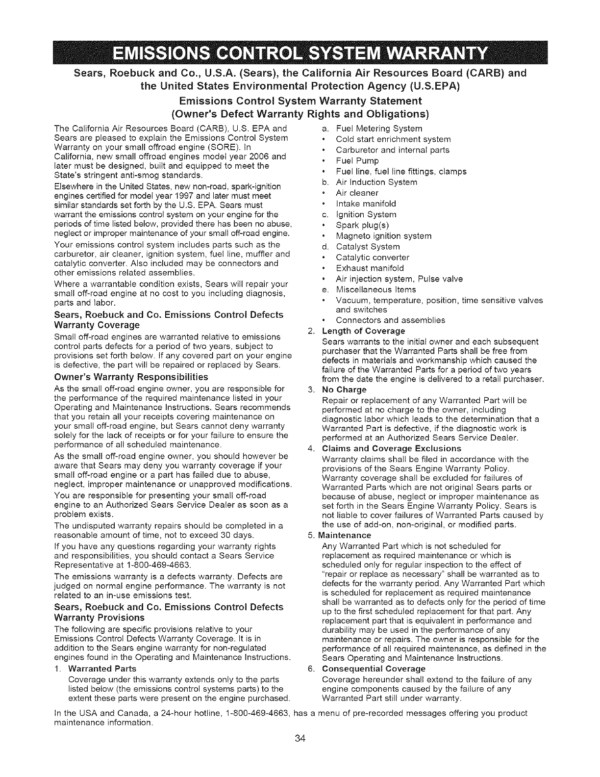
Sears, Roebuck and Co., U.S.A. (Sears), the California Air Resources Board (CARB) and
the United States Environmental Protection Agency (U.S.EPA)
Emissions Control System Warranty Statement
(Owner's Defect Warranty Rights and Obligations)
The California Air Resources Board (CARB), U.S. EPA and
Sears are pleased to explain the Emissions Control System
Warranty on your small offroad engine (SORE). In
California, new small offroad engines model year 2006 and
later must be designed, built and equipped to meet the
State's stringent anti-smog standards.
Elsewhere in the United States, new non-road, spark-ignition
engines certified for model year 1997 and later must meet
similar standards set forth by the U.S. EPA. Sears must
warrant the emissions control system on your engine for the
periods of time listed below, provided there has been no abuse,
neglect or improper maintenance of your small off-road engine.
Your emissions control system includes parts such as the
carburetor, air cleaner, ignition system, fuel line, muffler and
catalytic converter. Also included may be connectors and
other emissions related assemblies.
Where a warrantable condition exists, Sears will repair your
small off-road engine at no cost to you including diagnosis,
parts and labor.
Sears, Roebuck and Co. Emissions Control Defects
Warranty Coverage
Small off-road engines are warranted relative to emissions
control parts defects for a period of two years, subject to
provisions set forth below, if any covered part on your engine
is defective, the part will be repaired or replaced by Sears.
Owner's Warranty Responsibilities
As the small off-road engine owner, you are responsible for
the performance of the required maintenance listed in your
Operating and Maintenance instructions. Sears recommends
that you retain all your receipts covering maintenance on
your small off-road engine, but Sears cannot deny warranty
solely for the lack of receipts or for your failure to ensure the
performance of all scheduled maintenance.
As the small off-road engine owner, you should however be
aware that Sears may deny you warranty coverage if your
small off-road engine or a part has failed due to abuse,
neglect, improper maintenance or unapproved modifications.
You are responsible for presenting your small off-road
engine to an Authorized Sears Service Dealer as soon as a
problem exists.
The undisputed warranty repairs should be completed in a
reasonable amount of time, not to exceed 30 days.
If you have any questions regarding your warranty rights
and responsibilities, you should contact a Sears Service
Representative at 1-800-469-4663.
The emissions warranty is a defects warranty. Defects are
judged on normal engine performance. The warranty is not
related to an in-use emissions test.
Sears, Roebuck and Co. Emissions Control Defects
Warranty Provisions
The following are specific provisions relative to your
Emissions Control Defects Warranty Coverage. It is in
addition to the Sears engine warranty for non-regulated
engines found in the Operating and Maintenance Instructions.
1. Warranted Parts
Coverage under this warranty extends only to the parts
listed below (the emissions control systems parts) to the
extent these parts were present on the engine purchased.
a. Fuel Metering System
Cold start enrichment system
Carburetor and internal parts
Fuel Pump
Fuel line, fuel line fittings, clamps
b. Air induction System
Air cleaner
Intake manifold
c. Ignition System
Spark plug(s)
Magneto ignition system
d. Catalyst System
Catalytic converter
Exhaust manifold
Air injection system, Pulse valve
e. Miscellaneous Items
Vacuum, temperature, position, time sensitive valves
and switches
Connectors and assemblies
2. Length of Coverage
Sears warrants to the initial owner and each subsequent
purchaser that the Warranted Parts shall be free from
defects in materials and workmanship which caused the
failure of the Warranted Parts for a period of two years
from the date the engine is delivered to a retail purchaser.
3. No Charge
Repair or replacement of any Warranted Part will be
performed at no charge to the owner, including
diagnostic labor which leads to the determination that a
Warranted Part is defective, if the diagnostic work is
performed at an Authorized Sears Service Dealer.
4. Claims and Coverage Exclusions
Warranty claims shall be filed in accordance with the
provisions of the Sears Engine Warranty Policy.
Warranty coverage shall be excluded for failures of
Warranted Parts which are not original Sears parts or
because of abuse, neglect or improper maintenance as
set forth in the Sears Engine Warranty Policy. Sears is
not liable to cover failures of Warranted Parts caused by
the use of add-on, non-original, or modified parts.
5. Maintenance
Any Warranted Part which is not scheduled for
replacement as required maintenance or which is
scheduled only for regular inspection to the effect of
"repair or replace as necessary" shall be warranted as to
defects for the warranty period. Any Warranted Part which
is scheduled for replacement as required maintenance
shall be warranted as to defects only for the period of time
up to the first scheduled replacement for that part. Any
replacement part that is equivalent in performance and
durability may be used in the performance of any
maintenance or repairs. The owner is responsible for the
performance of all required maintenance, as defined in the
Sears Operating and Maintenance Instructions.
6. Consequential Coverage
Coverage hereunder shall extend to the failure of any
engine components caused by the failure of any
Warranted Part still under warranty.
In the USA and Canada, a 24-hour hotline, 1-800-469-4663, has a menu of pre-recorded messages offering you product
maintenance information.
34
Emissions Durability Period and Air Index
Information On Your Engine Emissions Label
Engines that are certified to meet the California Air
Resources Board (CARB) Tier 2 Emission Standards must
display information regarding the Emissions Durability Period
and Air Index. The engine manufacturer makes this
information available to the consumer on emissions labels.
The Emissions Durability Period describes the number of
hours of actual running time for which the engine is certified
to be emissions compliant, assuming proper maintenance in
accordance with the Operating & Maintenance Instructions.
The following categories are used:
Moderate: Engine is certified to be emissions compliant for
125 hours of actual engine running time.
Intermediate: Engine is certified to be emissions compliant
for 250 hours of actual engine running time.
Extended: Engine is certified to be emissions compliant for
500 hours of actual engine running time.
For example, a typical walk-behind lawn mower is used
20 to 25 hours per year. Therefore, the Emissions
Durability Period of an engine with an intermediate rating
would equate to 10 to 12 years.
The Air Index is a calculated number describing the relative
level of emissions for a specific engine family. The lower the
Air Index, the cleaner the engine. This information is
displayed in graphical form on the emissions label.
Emissions Compliance Period On Engine
Emissions Compliance Label
After July 1,2000 certain Sears engines will be certified to
meet the United States Environmental Protection Agency
(USEPA) Phase 2 emission standards. For phase 2 certified
engines, the Emissions Compliance Period referred to on
the Emissions Compliance label indicates the number of
operating hours for which the engine has been shown to
meet Federal emission requirements. For engines less than
225 cc displacement, Category C = 125 hours, B = 250
hours and A = 500 hours. For engines of 225 cc or more,
Category C = 250 hours, B = 500 hours and A = 1000 hours.
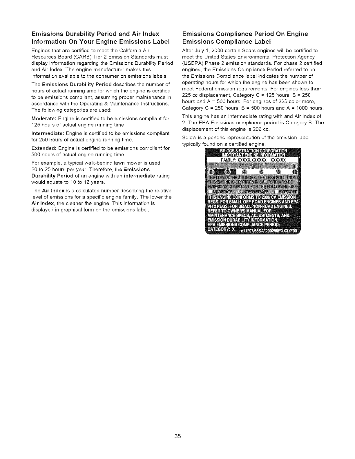
This engine has an intermediate rating with and Air Index of
2. The EPA Emissions compliance period is Category B. The
displacement of this engine is 206 cc.
Below is a generic representation of the emission label
typically found on a certified engine.
35
GARANTIA.............................. 36
REGLASDESEGURIDAD............... 37-38
CONOZCASUGENERADOR................ 39
MONTAJE............................ 40-42
FUNClONAMIENTO.................... 43-47
ESPECIFICACIONES...................... 48
MANTENIMIENTO...................... 49-52
ALMACENAMIENTO....................... 53
REPARACIONDEAVERIAS ................ 54
NOTAS................................ 55-57
GARANTIADELSISTEMADECONTROL
DEEMISIONES........................ 58-59
COMOORDENARPARTES..... ULTIMAPAGINA
GARANTiA COMPLETA DE UN ANO DEL GENERADOR CRAFTSMAN
Si el generador falla debido a defectos de materiales o mane de obra en el plazo de un afio a partir de la fecha de compra,
devuelvalo a cualquier almacen Sears, punto de venta de Craftsman o centro de reparacion y repuestos de Sears de los
Estados Unidos para su reparacion gratuita o, en caso de que esta no sea posible, para su sustitucion.
Garantia limitada de un aSo adicional del generador Craftsman
Durante el segundo afio a partir de la fecha de compra, si cualquier pieza del generador falla debido a defectos de
materiales o mano de obra, se suministrara gratuitamente una nueva pieza. Si desea que se instale la pieza, debera pagar
la mano de obra.
El periodo de garantia se reducira a 90 dias desde la fecha de compra si el generador se utiliza con fines comerciales o de
alquiler. Una vez que el generador se haya usado con fines comerciales o de alquiler, se considerar& como equipo de uso
comercial o alquiler a efectos de esta garantia.
Esta garantia le otorga determinados derechos legales y es posible que tenga otros derechos que pueden variar de un pals
o estado a otro.
Sears, Roebuck and Co., D/817WA, Hoffman Estates, IL 60179 U.S.A.
36
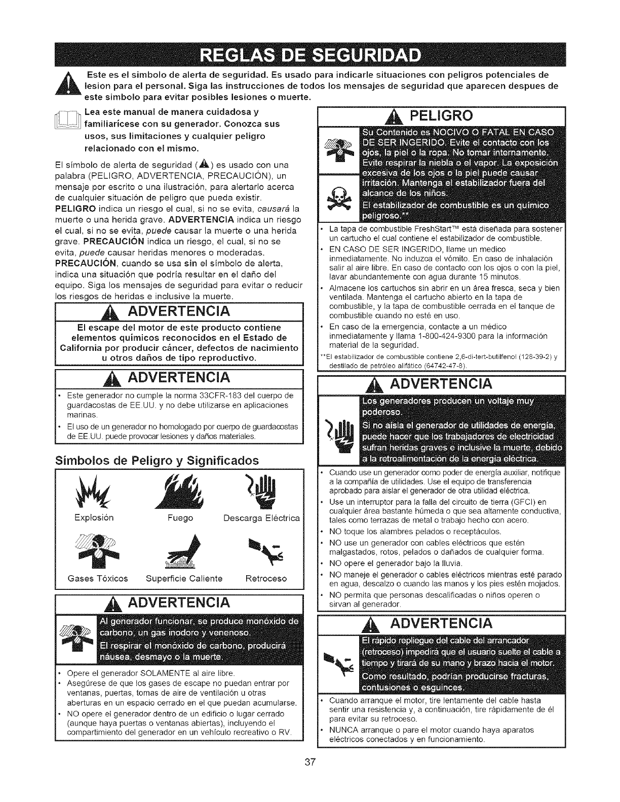
,_ Este es el simbolo de alerta de seguridad. Es usado para indicarle situaciones con peligros potenciales delesion para el personal. Siga las instrucciones de todos los mensajes de seguridad que aparecen despues de
este simbolo para evitar posibles lesiones o muerte.
Lea este manual de manera cuidadosa y
....... familiaricese con su generador. Conozca sus
usos, sus limitaciones y cualquier peligro
relacionado con el mismo.
El simbolo de alerta de seguridad (,_) es usado con una
palabra (PELIGRO, ADVERTENCIA, PRECAUCION), un
mensaje por escrito o una ilustraci6n, para alertarlo acerca
de cualquier situaci6n de peligro que pueda existir.
PELIGRO indica un riesgo el cual, si no se evita, causar& la
muerte o una herida grave. ADVERTENClA indica un riesgo
el cual, si no se evita, puede causar la muerte o una herida
grave. PRECAUClON indica un riesgo, el cua], si no se
evita, puede causar heridas menores o moderadas.
PRECAUCION, cuando se usa sin el simbolo de alerta,
indica una situaci6n que podria resultar en el daSo del
equipo. Siga los mensajes de seguridad para evitar o reducir
los riesgos de heridas einclusive la muerte.
ADVERTENCiA
El escape del motor de este producto contiene
elementos quimicos reconocidos en el Estado de
California pot producir c&ncer, defectos de nacimiento
uotros daSos de tipo reproductivo.
ADVERTENClA
• Este generador no cumpte la norma 33CFR-183 del cuerpo de
guardacostas de EE.UU. y no debe utilizarse en apticaciones
marinas.
• El use de an generador no homologado por cuerpo de guardacostas
de EE.UU. puede provocar tesiones y daSos materiales.
Simbolos de Peligro y Significados
Explosion Fuego Descarga Electrica
Gases Toxicos Superficie Caliente Retroceso
ADVERTENCIA
Opere et generador SOLAMENTE al aire libre.
Aseg0rese de que los gases de escape no puedan entrar por
ventanas, puertas, tomas de aire de ventilaci6n u otras
aberturas en un espacio cerrado en el que puedan acumularse.
NO opere el generador dentro de un edificio o lugar cerrado
(aunque haya puertas o ventanas abiertas), incluyendo el
compartimiento del generador en un vehiculo recreativo o RV.
PELIGRO
La tapa de combustible FreshStart TM esta disei_ada para sostener
un cartucho e! cuat contiene el estabilizador de combustible.
EN CASO DE SER tNGERtDO, Itame un medico
inmediatamente. No induzca el v6mito. En caso de inhalacidn
salir at aire libre. En caso de contacto con los ojos o con la piel,
tavar abundantemente con agua durante 15 minutes.
Almacene los cartuchos sin abrir en un area fresca, seca y bien
ventilada. Mantenga el cartucho abierto en la tapa de
combustible, y la tapa de combustible cerrada en el tanque de
combustible cuando no este en use.
En caso de la emergencia, contacte a an m_dico
inmediatamente y llama 1-800-424-9300 para la informacidn
material de ta seguridad.
_EIestabilizador de combustible contiene 2,6-di-tert-butilfenol (128-39-2) y
destilado de petroleo alifatico (64742-47-8).
ADVERTENCIA
Cuando use un generador come poder de energia auxiliar, notifique
a la compaSia de utilidades. Use el equipo de transferencia
aprobado para aislar el generador de otra utilidad electrica.
Use un interruptor para la falla del circuito de tierra (GFCl) en
cualquier area bastante h0meda o que sea altamente conductiva,
tales como terrazas de metal o trabajo hecho con acero.
NO toque los alambres pelados o receptaculos.
NO use un generador con cables electricos que esten
malgastados, rotos, pelados o da_ados de cualquier forma.
NO opere el generador bajo la lluvia.
NO maneje et generador o cables electricos mientras este parade
en agua, descalzo o cuando tas manes y los pies esten mojados.
NO permita que personas descalificadas o ni_os operen o
sirvan at generador.
ADVERTENCIA
Cuando arranque el motor, tire tentamente del cable hasta
sentir una resistencia y, a continuaci6n, tire rapidamente de el
para evitar su retroceso.
NUNCA arranque o pare el motor cuando haya aparatos
electricos conectados yen funcionamiento.
37
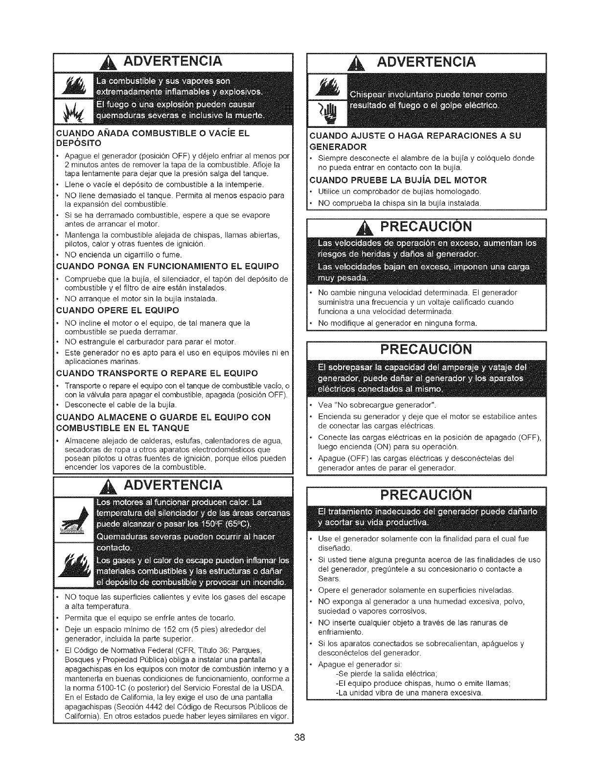
ADVERTENCIA
CUANDO ANADA COMBUSTIBLE O VACiE EL
DEP6SITO
Apague el generador (posici6n OFF) y dejelo enfriar al menos per
2 minutes antes de remover ta tapa de la combustible. Afloje ta
tapa lentamente para dejar que la presi6n salga del tanque.
Llene o vacie el dep6sito de combustible a la intemperie.
NO ttene demasiado el tanque. Permita at menos espacio para
la expansi6n del combustible.
Si se ha derramado combustible, espere a que se evapore
antes de arrancar el motor.
Mantenga la combustible alejada de chispas, llamas abiertas,
pilotos, calory otras fuentes de ignici6n.
NO encienda un cigarrillo o fume.
CUANDO PONGA EN FUNCIONAMIENTO EL EQUIPO
Compruebe que ta bujia, el silenciador, el tap6n del dep6sito de
combustible y el filtro de aire estan instalados.
NO arranque el motor sin ta bujia instalada.
CUANDO OPERE EL EQUIPO
NO incline el motor o el equipo, de ta! manera que ta
combustible se pueda derramar.
NO estrangule el carburador para parar el motor.
Este generador no es apto para el uso en equipos m6viles ni en
aplicaciones marinas.
CUANDO TRANSPORTE O REPARE EL EQUIPO
Transporte o repare el equipo con el tanque de combustible vacio, o
con ta valvula para apagar el combustible, apagada (posici6n OFF).
Desconecte el cable de ta bujia.
CUANDO ALMACENE O GUARDE EL EQUIPO CON
COMBUSTIBLE EN EL TANQUE
Almacene alejado de calderas, estufas, calentadores de agua,
secadoras de ropa u otros aparatos etectrodomesticos que
posean pi!otos u otras fuentes de igniciOn, porque eltos pueden
encender los vapores de la combustible.
ADVERTENCIA
NO toque las superficies calientes y evite los gases det escape
a atta temperatura.
Permita que el equipo se enfrie antes de tocarlo.
Deje un espacio minimo de 152 cm (5 pies) alrededor del
generador, inctuida ta parte superior.
El C6digo de Normativa Federal (CFR, Titulo 36: Parques,
Bosques y Propiedad PC_blica)obliga a instalar una pantalla
apagachispas en los equipos con motor de combustidn interne y a
mantenerla en buenas condiciones de funcionamiento, conforme a
la norma 5100-1C (o posterior) del Ser_/icio Forestal de la USDA.
En el Estado de California, ta ley exige el uso de una pantalla
apagachispas (Seccidn 4442 det C6digo de Recursos POblicos de
California). En otros estados puede haber leyes similares en vigor.
ADVERTENCIA
CUANDO AJUSTE O HAGA REPARACIONES A SU
GENERADOR
o Siempre desconecte el alambre de ta bujia y col6quelo donde
no pueda entrar en contacto con la bujia.
CUANBO PRUEBE LA BUJiA BEL MOTOR
Utitice un comprobador de bujias homologado.
NO comprueba la chispa sin la bujia instatada.
, PRECAUCION
No cambie ninguna velocidad determinada. El generador
suministra una frecuencia y un voltaje calificado cuando
funciona a una velocidad determinada.
No modifique al generador en ninguna forma.
PRECAUCION
Vea "No sobrecargue generador".
Encienda su generador y deje que el motor se estabitice antes
de conectar las cargas electricas.
Conecte tas cargas electricas en ta posici6n de apagado (OFF),
tuego encienda (ON) para su operacidn.
Apague (OFF) tas cargas el_ctricas y descon_ctelas del
generador antes de parar el generador.
PRECAUCION
Use el generador solamente con ta finatidad para el cuat fue
dise_ado.
Si usted tiene atguna pregunta acerca de las finalidades de use
del generador, pregOntete a su concesionario o contacte a
Sears.
Opere e! generador solamente en superficies niveladas.
NO exponga at generador a una humedad excesiva, polvo,
suciedad o vapores corrosivos.
NO inserte cualquier objeto a traves de tas ranuras de
enfriamiento.
Si los aparatos conectados se sobrecalientan, apaguelos y
descon_ctelos del generador.
Apague el generador si:
-Se pierde la salida electrica;
-El equipo produce chispas, humo o emite llamas;
-La unidad vibra de una manera excesiva.
38
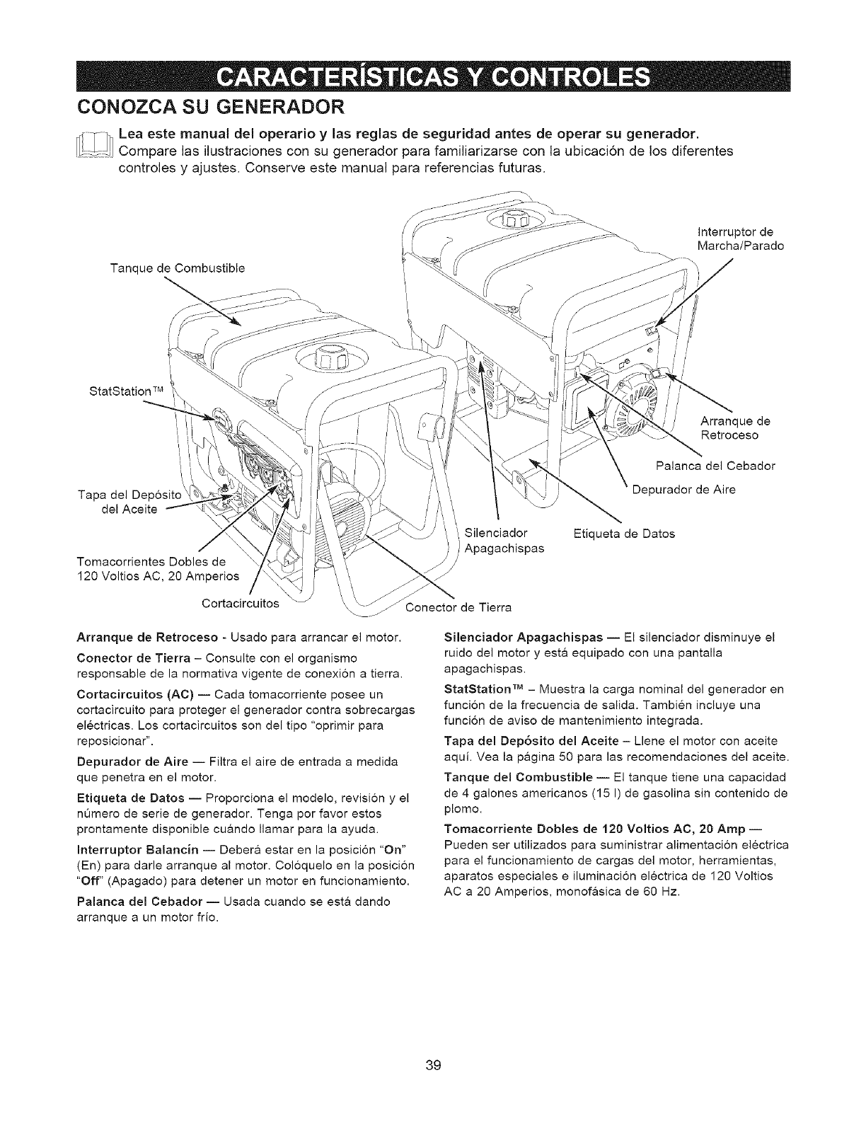
CONOZCA SU GENERADOR
_1 Lea este manual del operario ylas reglas de seguridad antes de operar su generador.
......... Compare las ilustraciones con su generador para familiarizarse con la ubicaci6n de los diferentes
controles y ajustes. Conserve este manual para referencias futuras.
Tanque de Combustible
Interruptor de
Marcha/Parado
StatStation TM
Arranque de
Retroceso
i
I i Palanca del Cebador
Tapa del Deposito \ Depurador de Aire
del Aceite
Tomacorrientes Dobles de
120 Voltios AC, 20 Amperios
Cortacircuitos
Arranque de Retroceso - Usado para arrancar el motor.
Corlector de Tierra - Consulte con el organismo
responsable de la normativa vigente de conexi6n a tierra.
Cortacircuitos (AC) -- Cada tomacorriente posee un
cortacircuito para proteger el generador contra sobrecargas
electricas. Los cortacircuitos son del tipo "oprimir para
reposicionar".
Depurador de Aire -- Filtra el aire de entrada a medida
que penetra en el motor.
Etiqueta de Datos -- Proporciona el modelo, revisi6n y el
nOmero de serie de generador. Tenga por favor estos
prontamente disponible cu&ndo Ilamar para la ayuda.
Interruptor Balancin -- Deber& estar en la posici6n "On"
(En) para darle arranque al motor. Coloquelo en la posicion
"Off" (Apagado) para detener un motor en funcionamiento.
Palanca del Cebador -- Usada cuando se esta dando
arranque a un motor frio.
! Silenciador
Apagachispas
Etiqueta de Datos
de Tierra
Silenciador Apagachispas -- El silenciador disminuye el
ruido del motor y esta equipado con una pantalla
apagachispas.
StatStation TM - Muestra la carga nominal del generador en
funci6n de la frecuencia de salida. Tambien incluye una
funci6n de aviso de mantenimiento integrada.
Tapa del Dep6sito del Aceite - Llene el motor con aceite
aqui. Yea la pagina 50 para las recomendaciones del aceite.
Tanque del Combustible -- El tanque tiene una capacidad
de 4 galones americanos (15 I) de gasolina sin contenido de
plomo.
Tomacorriente Dobles de 120 Voltios AC, 20 Amp --
Pueden ser utilizados para suministrar alimentacion electrica
para el funcionamiento de cargas del motor, herramientas,
aparates especiales e iluminacion electrica de 120 Voltios
AC a 20 Amperios, monofasica de 60 Hz.
39

Su generador requiere de ciertos procedimientos de montaje y
solo estar& listo para ser utilizado despues de habefle
suministrado servicio con el combustible y aceite recomendados.
Si usted tiene problemas con el montaje de su
generador, por favor Ilame ala linea de ayuda para
generadores al 1-800-222-3136.
Desembalaje del Generador
1. Coloque la caja de cart6n en una superficie rigida y plan&
2. Saque todo el contenido de la caja de cart6n, a
excepci6n del generador.
3. Abra completamente la caja de cart6n cortando cada
una de sus esquinas de arriba abajo.
4. Mantenga el generador sobre el cart6n para instalar el
juego de ruedas.
Contenido de la Caja
Revise todo el contenido comparandolo con la lista a
continuacion:
Unidad Principal
Aceite del Motor
Manual del Operario
Juego de Ruedas
Juego de Cables del Adaptador
Si cualquier parte falta o esta da_ada, Ilame a la Linea de
Ayuda del Generador al 1-800-222-3136.
Instale el Juego de Ruedas
NOTA: El juego de ruedas no est& diseSado para uso en
carretera. NO remolque la unidad con un vehiculo con
tracci6n mec&nica.
Necesitar& las siguientes herramientas para instalar estos
componentes:
Llave de 13 mm
Alicates
Gafas de seguridad
Instale el juego de ruedas conforme a las instrucciones
siguientes:
1. Dele la vuelta al generador de forma que el motor
quede arriba.
2. Introduzca el eje a traves de los dos soportes de montaje.
3. Coloque una rueda en cada extremo, cuando mostrado
en la A.
4. Introduzca una arandela pot el eje y coloque una anilla
en "e" en la ranura del eje.
5. Para ello, apriete con unos alicates desde la parte
superior de la anilla en "e" hacia la parte inferior del eje.
PRECAUClON
Utitice siempre protecci6n ocular para montar o desmontar
anitlas en "e".
6. Repita los pasos del 3 al 5 para asegurar la segunda
rueda.
7. Dele la vuelta al generador de forma que el lado del
motor quede abajo.
8. Haga coincidir los orificios de la pata de apoyo con los
del bastidor del generador.
9. Monte la pata de apoyo con dos tornillos de cabeza
cortos (M8 x 16 mm) y dos tuercas hexagonales.
Apriete con una Ilave de cubo de 13 mm.
10. Vuelva a colocar el generador en la posicion normal de
funcionamiento (apoyado en las ruedas y la pata de
apoyo).
Llave de cubo de 13 mm
Eje
Rueda
Arandela
Pata de Apoyo
Tornillos
_Tuercas
Eje
/
,/
Rueda
/
/
E-Ring
4O
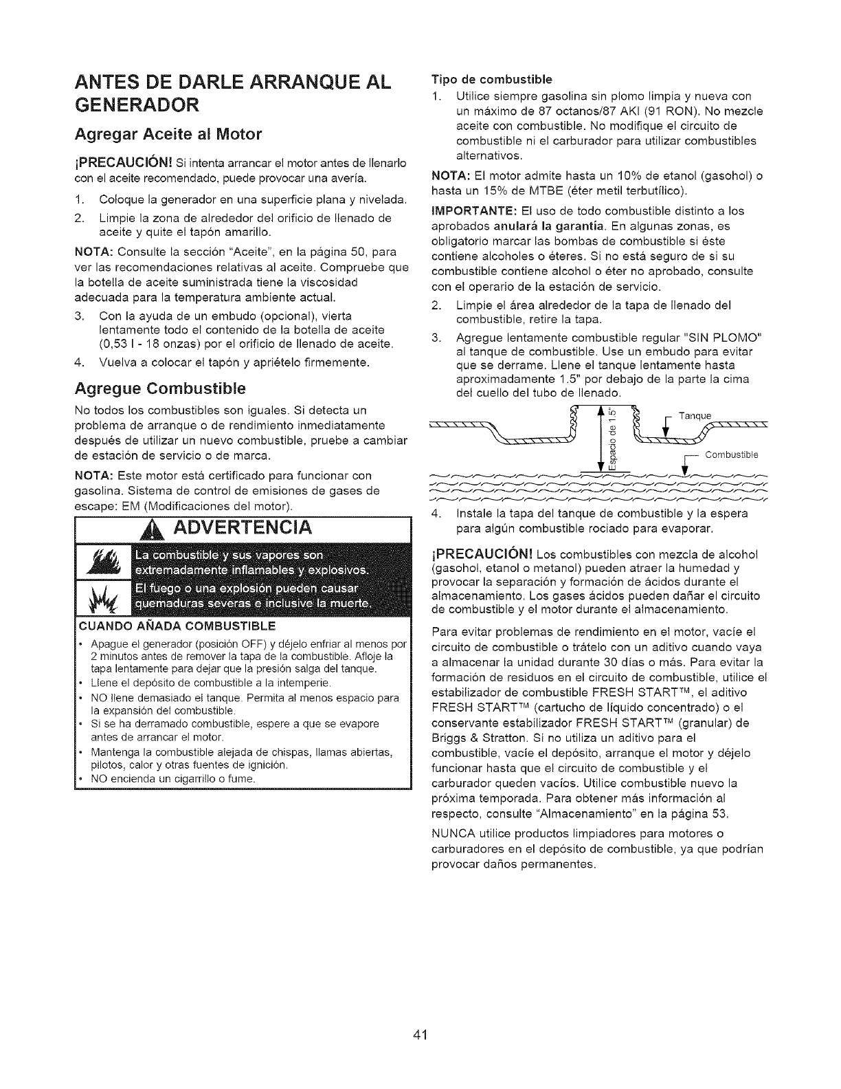
ANTES DE DARLE ARRANQUE AL
GENERADOR
Agregar Aceite al Motor
iPRECAUClON! Si intenta arrancar el motor antes de Ilenarlo
con el aceite recomendado, puede provocar una averia.
1. Coloque la generador en una superficie plana y nivelada.
2. Limpie la zona de alrededor del orificio de Ilenado de
aceite y quite el tapon amarillo.
NOTA: Consulte la seccion "Aceite", en la p&gina 50, para
ver las recomendaciones relativas al aceite. Compruebe que
la botella de aceite suministrada tiene la viscosidad
adecuada para la temperatura ambiente actual.
3. Con la ayuda de un embudo (opcional), vierta
lentamente todo el contenido de la botella de aceite
(0,53 I - 18 onzas) por el orificio de Ilenado de aceite.
4. Vuelva a colocar el tapon y aprietelo firmemente.
Agregue Combustible
No todos los combustibles son iguales. Si detecta un
problema de arranque o de rendimiento inmediatamente
despues de utilizar un nuevo combustible, pruebe a cambiar
de estacion de servicio o de marca.
NOTA: Este motor esta certificado para funcionar con
gasolina. Sistema de control de emisiones de gases de
escape: EM (Modificaciones del motor).
ADVERTENClA
CUANDO ANADA COMBUSTIBLE
Apague el generador (posici6n OFF) y dejelo enfriar al menos per
2 minutes antes de remover ta tapa de la combustible. Afloje ta
tapa lentamente para dejar que la presi6n salga del tanque.
Llene el dep6sito de combustible a la intemperie.
NO ttene demasiado et tanque. Permita at menos espacio para
la expansi6n del combustible.
Si se ha derramado combustible, espere a que se evapore
antes de arrancar el motor.
Mantenga la combustible alejada de chispas, llamas abiertas,
pilotos, calory otras fuentes de ignici6n.
NO encienda un cigarritto o fume.
Tipo de combustible
1. Utilice siempre gasolina sin plomo limpia y nueva con
un m&ximo de 87 octanos/87 AKI (91 RON). No mezcle
aceite con combustible. No modifique el circuito de
combustible ni el carburador para utilizar combustibles
altemativos.
NOTA: El motor admite hasta un 10% de etanol (gasohol) o
hasta un 15% de MTBE (eter metil terbutilico).
IMPORTANTE: El uso de todo combustible distinto a los
aprobados anular_ la garantia. En algunas zonas, es
obligatorio marcar las bombas de combustible si este
contiene alcoholes o eteres. Si no est& seguro de si su
combustible contiene alcohol o eter no aprobado, consulte
con el operario de la estacion de servicio.
2. Limpie el &rea alrededor de la tapa de Ilenado del
combustible, retire la tapa.
3. Agregue lentamente combustible regular "SIN PLOMO"
al tanque de combustible. Use un embudo para evitar
que se derrame. Llene el tanque lentamente hasta
aproximadamente 1.5" por debajo de la parte la cima
del cuello del tubo de Ilenado.
Combustible
4. Instale la tapa del tanque de combustible y la espera
para algOn combustible rociado para evaporar.
iPRECAUClON! Los combustibles con mezcla de alcohol
(gasohol, etanol o metanol) pueden atraer la humedad y
provocar la separacion y formacion de acidos durante el
almacenamiento. Los gases &cidos pueden daSar el circuito
de combustible y el motor durante el almacenamiento.
Para evitar problemas de rendimiento en el motor, vacie el
circuito de combustible o tratelo con un aditivo cuando vaya
a almacenar la unidad durante 30 dias o mas. Para evitar la
formacion de residuos en el circuito de combustible, utilice el
estabilizador de combustible FRESH START TM, el aditivo
FRESH START TM (cartucho de liquido concentrado) o el
conservante estabilizador FRESH START TM (granular) de
Briggs & Stratton. Si no utiliza un aditivo para el
combustible, vacie el deposito, arranque el motor y dejelo
funcionar hasta que el circuito de combustible y el
carburador queden vacios. Utilice combustible nuevo la
proxima temporada. Para obtener mas informacion al
respecto, consulte "Almacenamiento" en la p&gina 53.
NUNCA utilice productos limpiadores para motores o
carburadores en el deposito de combustible, ya que podrian
provocar dafios permanentes.
41
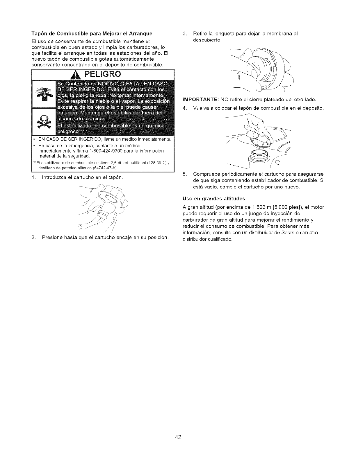
Tap6n de Combustible para Mejorar el Arranque
El uso de conservante de combustible mantiene el
combustible en buen estado y limpia los carburadores, Io
que facilita el arranque en todas las estaciones del aSo. El
nuevo tapon de combustible gotea automaticamente
conservante concentrado en el dep6sito de combustible.
PELIGRO
EN CASO DE SER INGERIDO, Ilame un medico inmediatamente.
En case de la emergencia, contacte a un medico
inmediatamente y llama 1-800-424-9300 para ta informaci6n
material de la seguridad.
**El estabilizador de combustible contiene 2,6-di-tert-butHfenol(128-39-2) y
destilado de petroleo alifatico (64742-47-8)
Introduzca el cartucho en el tapon.
/
2. Presione hasta que el cartucho encaje en su posicion.
3. Retire la lengOeta para dejar la membrana al
descubierto.
IMPORTANTE: NO retire el cierre plateado del otro lad&
4. Vuelva a colocar el tapon de combustible en el deposito.
5. Cempruebe perbdicamente el cartucho para asegurarse
de que siga centeniendo estabilizader de combustible. Si
esta vacie, cambie el cartuche per uno nuevo.
Uso en grandes altitudes
A gran altitud (por encima de 1.500 m [5.000 pies]), el motor
puede requerir el uso de un juego de inyeccion de
carburador de gran altitud para mejorar el rendimiento y
reducir el consumo de combustible. Para obtener mas
informacion, consulte con un distribuidor de Sears o con otro
distribuidor cualificado.
42
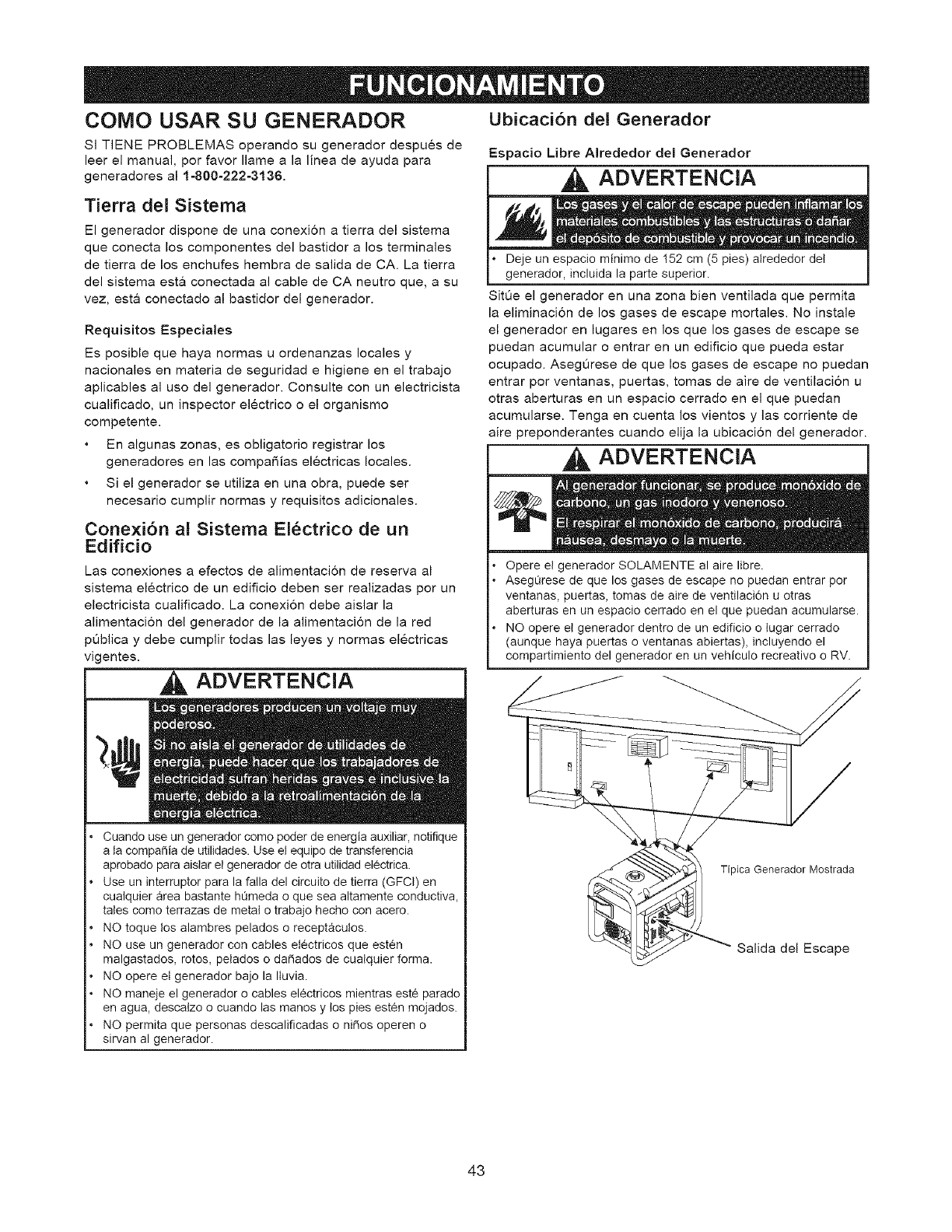
COMO USAR SU GENERADOR Ubicaci6n del Generador
Sl TIENE PROBLEMAS operando su generader despues de
leer el manual, por favor flame a la linea de ayuda para
generadores al 1-800-222-3136.
Tierra del Sistema
El generador dispone de una conexi6n a tierra del sistema
que conecta los componentes del bastidor a los terminales
de tierra de los enchufes hembra de salida de CA. La tierra
del sistema est& conectada al cable de CA neutro que, a su
vez, esta conectado al bastidor del generador.
Requisitos Especiales
Es posible que haya normas u ordenanzas locales y
nacienales en materia de seguridad ehigiene en el trabaje
aplicables al use del generador. Consulte con un electricista
cualificado, un inspector electrico o el erganismo
competente.
En algunas zenas, es obligatorio registrar los
generadores en las cempaSias electricas locales.
Si el generador se utiliza en una ebra, puede ser
necesario cumplir nermas y requisitos adicionales.
Conexi6n al Sistema El_ctrico de un
Edificio
Las conexiones a efectos de alimentaci6n de reserva al
sistema electrico de un edificio deben ser realizadas por un
electricista cualificado. La conexi6n debe aislar la
alimentacion del generador de la alimentacion de la red
p0blica y debe cumplir todas las leyes y normas electricas
vigentes.
ADVERTENClA
Cuando use un generador como poder de energia auxiliar, notifique
a la compafiia de utilidades. Use el equipo de transferencia
aprobado para aislar e! generador de otra utilidad electrica.
Use un interruptor para la falla del circuito de tierra (GFCI) en
cualquier area bastante hL_meda o que sea altamente conductiva,
tales como terrazas de metal o trabajo hecho con acero.
NO toque los alambres pelados o receptacutos.
NO use un generador con cables electricos que esten
malgastados, rotos, pelados o daSados de cualquier forma.
NO opere el generador bajo la Iluvia.
NO maneje el generador o cables el_ctricos mientras este parado
en agua, descalzo o cuando las manos y los pies est_n mojados.
NO permita que personas descalificadas o ni_os operen o
sirvan al generador.
Espacio Libre Alrededor del Generador
ADVERTENCIA
Deje un espacio minimo de 152 cm (5 pies) atrededor del
generador, incluida la parte superior.
Sit0e el generador en una zona bien ventilada que permita
la eliminacion de los gases de escape mortales. No instale
el generador en lugares en los que los gases de escape se
puedan acumular o entrar en un edificio que pueda estar
ocupado. AsegiJrese de que los gases de escape no puedan
entrar por ventanas, puertas, tomas de aire de ventilacion u
otras aberturas en un espacio cerrado en el que puedan
acumularse. Tenga en cuenta los vientos y las corriente de
aire preponderantes cuando elija la ubicacion del generador.
ADVERTENClA
Opere e! generador SOLAMENTE al aire libre.
AsegL_rese de que los gases de escape no puedan entrar por
ventanas, puertas, tomas de aire de ventilaci6n u otras
aberturas en un espacio cerrado en el que puedan acumularse.
NO opere el generador dentro de un edificio o lugar cerrado
(aunque haya puertas o ventanas abiertas), incluyendo el
compartimiento del generador en un vehiculo recreativo o RV.
Tipica Generador Mostrada
Salida del Escape
43
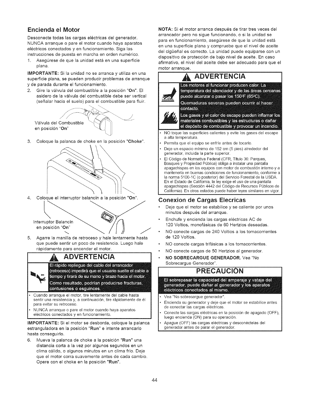
Encienda el Motor
Desconecte todas las cargas electricas del generador.
NUNCA arranque o pare el motor cuando haya aparatos
electricos conectados y en funcionamiento. Siga las
instrucciones de puesta en marcha en orden numerico.
1. AsegQrese de que la unidad esta en una superficie
plana.
IMPORTANTE: Si la unidad no se arranca y utiliza en una
superficie plana, se pueden producir problemas de arranque
y de parada durante el funcionamiento.
2. Gire la valvula del combustible ala posici6n "On". El
asidero de la valvula del combustible debe ser vertical
(seSalar hacia el suelo) para el combustible para fluir.
Valvula del Combustible
en posici6n "On"
3. Coloque la palanca de choke en la posicion "Choke".
4.
5.
Coloque el interruptor balancin a la posicion "On".
Interruptor Balancin
en posicion "On"
Agarre la manilla de retroceso y hale lentamente hasta
que puede sentir un poco de resistencia. Luego hale
rapidamente para encender el motor.
ADVERTENClA
J
I
Cuando arranque el motor, tire lentamente del cable hasta
sentir una resistencia y, a continuacidn, tire rapidamente de _I
para evitar su retrooeso.
NUNCA arranque o pare el motor cuando haya aparatos
electricos conectados yen funcionamiento.
IMPORTANTE: Si el motor se desborda, coloque la palanca
estranguladora en la posicion "Run" eintente arrancarlo
hasta conseguirlo.
6. Mueva la palanca de choke a la posicion "Run" una
distancia corta a la vez por algunos segundos en un
clima calido, o algunos minutos en un clima frio. Deje
que el motor corra suavemente antes de cada cambio.
Opere con el choke en la posicion "Run".
NOTA: Si el motor arranca despues de tirar tres veces del
arrancador pero no sigue funcionando, o si la unidad se
para en funcionamiento, asegOrese de que la unidad est&
en una superficie plana y compruebe que el nivel de aceite
del cigOefial es correcto. La unidad puede equiparse con un
dispositivo de proteccion de bajo nivel de aceite. En caso
afirmativo, el nivel del aceite debe ser adecuado para que el
motor arranque.
ADVERTENClA
NO toque las superficies catientes y evite los gases del escape
a alta temperatura.
Permita que el equipo se enfrie antes de tocarto.
Deje un espacio minimo de 152 cm (5 pies) atrededor del
generador, incluida la parte superior.
Et Cddigo de Normativa Federal (CFR, Titulo 36: Parques,
Bosques y Propiedad PQbtica) obliga a instalar una pantalla
apagachispas en los equipos con motor de combustidn interno y a
mantenerla en buenas condiciones de funcionamiento, conforme a
ta norma 5100-1C (o posterior) del Servicio Forestal de la USDA.
En e! Estado de California, la ley exige el uso de una pantalla
apagachispas (Seccidn 4442 del Cddigo de Recursos PQbticos de
California). En otros estados puede haber teyes similares en vigor.
Conexion de Cargas Elecricas
Deje que el motor se estabilice y se caliente por unos
minutos despues del arranque.
Enchufe y encienda las cargas electricas AC de
120 Voltios, monof&sicas de 60 Hertzios deseadas.
NO conecte cargas de 240 Voltios a los tomacorrientes
de 120 Voltios.
NO conecte cargas trifasicas a los tomacorrientes.
NO conecte cargas de 50 Hertzios al generador.
NO SOBRECARGUE GENERADOR. Vea "No
Sobrecargue Generador".
PRECAUCION
Vea "No sobrecargue generador".
Encienda su generador y deje que et motor se estabitice antes
de conectar las cargas electricas.
Conecte las cargas electricas en ta posici6n de apagado (OFF),
tuego encienda (ON) para su operacidn.
Apague (OFF) tas cargas electricas y descon_ctelas del
generador antes de parar el generador.
44
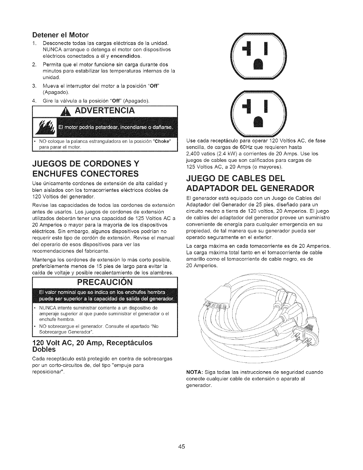
Detener el Motor
1. Desconecte todas las cargas electricas de la unidad.
NUNCA arranque o detenga el motor con dispositivos
electricos conectados a 61 y encendidos.
2. Permita que el motor funcione sin carga durante dos
minutos para estabilizar las temperaturas intemas de la
unidad.
3. Mueva el interruptor del motor a la posici6n "Off"
(Apagado).
4. Gire la valvula a la posicion "Off" (Apagado).
I _ ADVERTENCIA 1
•NO coloque la palanca estranguladora en la posiciOn "Choke"
para parar el motor.
JUEGOS DE CORDONES Y
ENCHUFES CONECTORES
Use _nicamente cordones de extensi6n de alta calidad y
bien aislados con los tomacorrientes electricos dobles de
120 Voltios del generador.
Revise las capacidades de todos las cordones de extension
antes de usarlos. Los juegos de cordones de extensi6n
utilizados deberan tener una capacidad de 125 Voltios AC a
20 Amperios o mayor para la mayoria de los dispositivos
electricos. Sin embargo, algunos dispositivos podrian no
requerir este tipo de cord6n de extensi6n. Revise el manual
del operario de esos dispositivos para ver las
recomendaciones del fabricante.
Mantenga los cordones de extensi6n Io mas corto posible,
preferiblemente menos de 15 pies de largo para evitar la
caida de voltaje y posible recalentamiento de los alambres.
PRECAUCION
• NUNCA intente suministrar oorriente a un dispositivo de
amperaje superior al que puede suministrar et generador o el
enchufe hembra.
• NO sobrecargue el generador. Consutte el apartado "No
Sobrecargue Generador".
120 Volt AC, 20 Amp, Recept_culos
Dobles
Cada recept&culo est& protegido en contra de sobrecargas
por un corto-circuitos de, del tipo "empuje para
reposicionar".
Use cada receptaculo para operar 120 Voltios AC, de fase
sencilla, de cargas de 60Hz que requieren hasta
2,400 vatios (2.4 kW) a corrientes de 20 Amps. Use los
juegos de cables que son calificados para cargas de
125 Voltios AC, a 20 Amps (o mayores).
JUEGO DE CABLES DEL
ADAPTADOR DEL GENERADOR
El generador esta equipado con un Juego de Cables del
Adaptador del Generador de 25 pies, dise_ado para un
circuito neutro a tierra de 120 voltios, 20 Amperios. El juego
de cables del adaptador del generador provee un suministro
conveniente de energia para cualquier emergencia en su
propiedad, de tal manera que su generador pueda ser
operado seguramente en el exterior.
La carga maxima en cada tomacorriente es de 20 Amperios.
La carga maxima total tanto en el tomacorriente de cable
amarillo como el tomacorriente de cable negro, es de
20 Amperios.
NOTA: Siga todas las instrucciones de seguridad cuando
conecte cualquier cable de extensi6n o aparato al
generador.
45
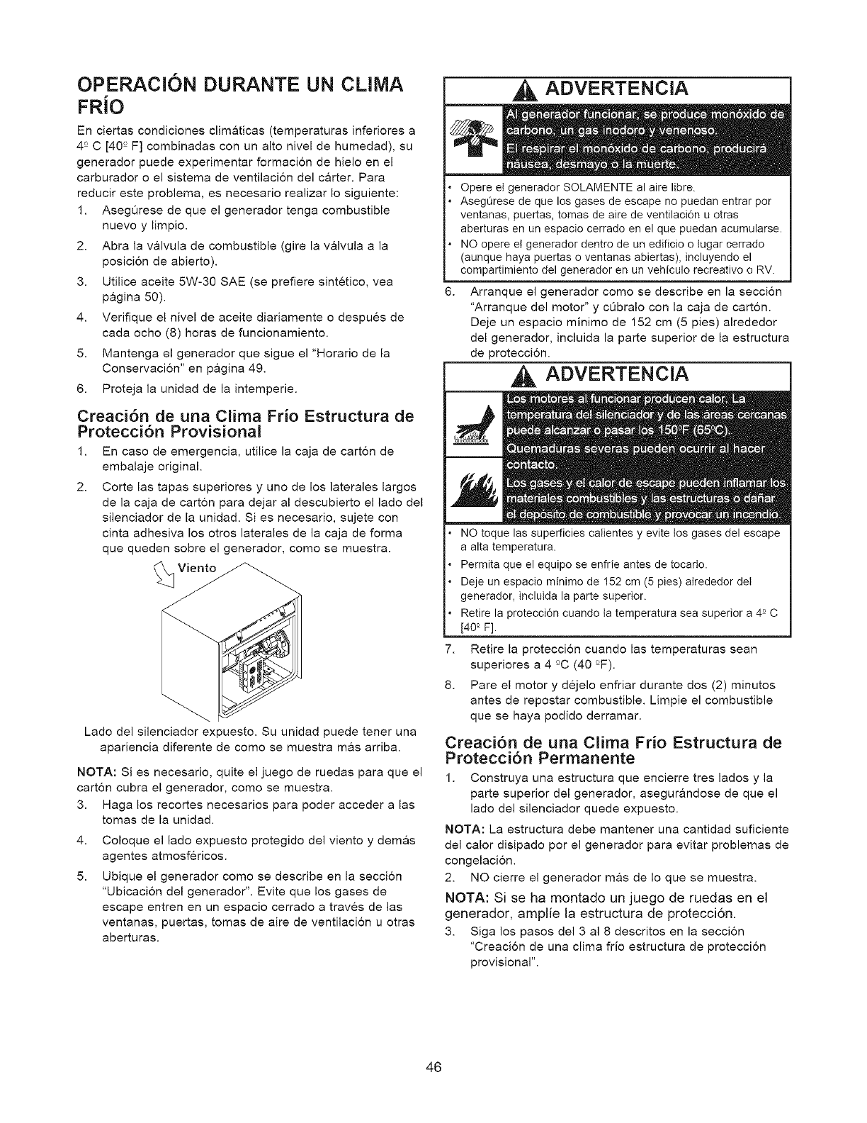
OPERACION DURANTE UN CLIMA
FRiO
En ciertas condiciones climaticas (temperaturas inferiores a
4 ° C [40 ° F] combinadas con un alto nivel de humedad), su
generador puede experimentar formacion de hielo en el
carburador o el sistema de ventilacion del carter. Para
reducir este problema, es necesario realizar Io siguiente:
1. AsegQrese de que el generador tenga combustible
nuevo y limpio.
2. Abra la valvula de combustible (gire la valvula a la
posicion de abierto).
3. Utilice aceite 5W-30 SAE (se prefiere sintetico, vea
pagina 50).
4. Verifique el nivel de aceite diariamente o despues de
cada ocho (8) horas de funcionamiento.
5. Mantenga el generador que sigue el "Horario de la
Conservacion" en pagina 49.
6. Proteja la unidad de la intemperie.
Creaci6n de una Clima Frio Estructura de
Protecci6n Provisional
1. En caso de emergencia, utilice la caja de carton de
embalaje original.
2. Corte las tapas superiores y uno de los laterales largos
de la caja de carton para dejar al descubierto el lado del
silenciador de la unidad. Si es necesario, sujete con
cinta adhesiva los otros laterales de la caja de forma
que queden sobre el generador, como se muestra.
Viento
Lade del silenciador expuesto. Su unidad puede tener una
apariencia diferente de como se muestra m&s arriba.
NOTA: Si es necesario, quite el juego de ruedas para que el
carton cubra el generador, como se muestra.
3. Haga los recortes necesarios para poder acceder a las
tomas de la unidad.
4. Coloque el lado expuesto protegido del viento y demas
agentes atmosfericos.
5. Ubique el generador como se describe en la seccion
"Ubicacion del generador". Evite que los gases de
escape entren en un espacio cerrado a traves de las
ventanas, puertas, tomas de aire de ventilacion u otras
aberturas.
ADVERTENCIA
Opere el generador SOLAMENTE al aire libre.
AsegL_rese de que los gases de escape no puedan entrar por
ventanas, puertas, tomas de aire de ventilaci6n u otras
aberturas en un espacio cerrado en el que puedan acumularse.
NO opere e! generador dentro de un edificio o lugar cerrado
(aunque haya puertas o ventanas abiertas), incluyendo el
compartimiento del generador en un vehiculo recreative o RV.
Arranque el generador como se describe en la seccion
"Arranque del motor" y cQbralo con la caja de carton.
Deje un espacio minimo de 152 cm (5 pies) alrededor
del generador, incluida la parte superior de la estructura
de proteccion.
ADVERTENCIA
7,
8.
NO toque las superficies calientes y evite los gases del escape
a alta temperatura.
Permita que el equipo se enfrie antes de tocarIo.
Deje un espacio minimo de 152 cm (5 pies) atrededor del
generador, incluida la parte superior.
Retire la protecci6n cuando ta temperatura sea superior a 4° C
[40 ° F].
Retire la proteccion cuando las temperaturas sean
superiores a 4 °C (40 °F).
Pare el motor y dejelo enfriar durante dos (2) minutos
antes de repostar combustible. Limpie el combustible
que se haya podido derramar.
Creaci6n de una Clima Frio Estructura de
Protecci6n Permanente
1. Construya una estructura que encierre tres lados y la
parte superior del generador, asegurandose de que el
lado del silenciador quede expuesto.
NOTA: La estructura debe mantener una cantidad suficiente
del calor disipado por el generador para evitar problemas de
congelacion.
2. NO cierre el generador m&s de Io que se muestra.
NOTA: Si se ha montado un juego de ruedas en el
generador, amplie la estructura de protecci6n.
3. Siga los pasos del 3 al 8 descritos en la seccion
"Creacion de una clima frio estructura de proteccion
provisional".
46
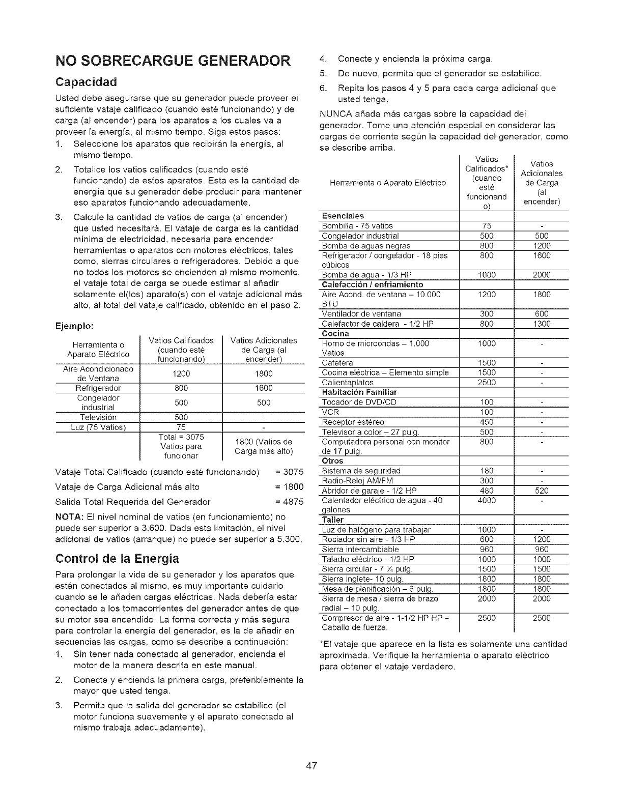
NO SOBRECARGUE GENERADOR
Capacidad
Usted debe asegurarse que su generador puede proveer el
suficiente vataje calificado (cuando este funcionando) y de
carga (al encender) para los aparatos a los cuales va a
proveer la energia, al mismo tiempo. Siga estos pasos:
1. Seleccione los aparatos que recibiran la energia, al
mismo tiempo.
2. Totalice los vatios calificados (cuando este
funcionando) de estos aparatos. Esta es la cantidad de
energia que su generador debe producir para mantener
eso aparatos funcionando adecuadamente.
3. Calcule la cantidad de vatios de carga (al encender)
que usted necesitar& El vataje de carga es la cantidad
minima de electricidad, necesaria para encender
herramientas o aparatos con motores electricos, tales
come, sierras circulares o refrigeradores. Debido a que
no todos los motores se encienden al mismo momento,
el vataje total de carga se puede estimar al ar_adir
solamente el(los) aparato(s) con el vataje adicional mas
alto, al total del vataje calificado, obtenido en el paso 2.
Ejemplo:
Herramienta o
Aparato Electrico
Aire Acondicionado
de Ventana
Refrigerador
Congelador
industrial
Televisi6n
Luz (75 ratios)
Vatios Calificados
(cuando este
funcionando)
I200
80O
5OO
5OO
75
Total = 3075
Vatios para
funcionar
Vatios Adicionates
de Carga (al
encender)
I800
I600
5OO
1800 (Vatios de
Carga mas alto)
Vataje Total Calificado (cuando este funcionando) = 3075
Vataje de Carga Adicional mas alto = 1800
Salida Total Requerida del Generador = 4875
NOTA: El nivel nominal de vatios (en funcionamiento) no
puede ser superior a 3.600. Dada esta limitacion, el nivel
adicional de vatios (arranque) no puede ser superior a 5.300.
Control de la Energia
Para prolongar la vida de su generador y los aparatos que
esten conectados al mismo, es muy importante cuidarlo
cuando se le afiaden cargas electricas. Nada deberia estar
conectado a los tomacorrientes del generador antes de que
su motor sea encendido. La forma correcta y mas segura
para controlar la energia del generador, es la de aSadir en
secuencias las cargas, como se describe a continuacion:
1. Sin tenet nada conectado al generador, encienda el
motor de la manera descrita en este manual.
2. Conecte y encienda la primera carga, preferiblemente la
mayor que usted tenga.
3. Permita que la salida del generador se estabilice (el
motor funciona suavemente y el aparato conectado al
mismo trabaja adecuadamente).
4. Conecte y encienda la proxima carga.
5. De nuevo, permita que el generador se estabilice.
6. Repita los pasos 4 y 5 para cada carga adicional que
usted tenga.
NUNCA aSada mas cargas sobre la capacidad del
generador. Tome una atencion especial en considerar las
cargas de corriente segQn la capacidad del generador, como
se describe arriba.
Herramienta o Aparato Electrico
Esenciales
Bombilta - 75 vatios
Congelador industrial
Bomba de aguas negras
Refrigerador /congetador - I8 pies
cQbicos
Bomba de agua - 1/3 HP
Calefaee{6n /enfriamiento
Aire Acond. de ventana - I0.000
BTU
Ventilador de ventana
Calefactor de caldera - I/2 HP
Cocina
Homo de microondas - 1.000
Vatios
Cafetera
Cocina electrica - Elemento simple
Calientaplatos
Habitaci6n Familiar
Tocador de DVD/CD
VCR
Receptor estereo
Televisor a color - 27 pulg.
Computadora personal con monitor
de 17 pulg.
Otros
Sistema de seguridad
Radio-Reloj AM/FM
Abridor de gara.je - I/2 HP
Calentador electrico de agua - 40
galones
Taller
Luz de hat6geno para trabajar
Rociador sin aire - 1/3 HP
Sierra intercambiable
Taladro electrico - 1/2 HP
Sierra circular - 7 X putg.
Sierra inglete- 10 pulg.
Mesa de planificaci6n - 6 pulg.
Sierra de mesa /sierra de brazo
radial- I0 pulg.
Compresor de aire- 1-1/2 HP HP =
Caba!lo de fuerza.
Vatios Vatios
Catificados* Adicionales
(cuando de Carga
este
funcionand (al
o) encender)
75
500 500
800 I200
800 I600
1000 2000
1200 I800
300 600
800 I300
1000
1500
1500
2500
100
100
45O
5OO
8OO
I80
30O
480 520
4000
1000
600 1200
960 960
1000 I000
1500 I500
1800 1800
1800 I800
2000 2000
2500 2500
*El vataje que aparece en la lista es solamente una cantidad
aproximada. Verifique la herramienta o aparato electrico
para obtener el vataje verdadero.
47
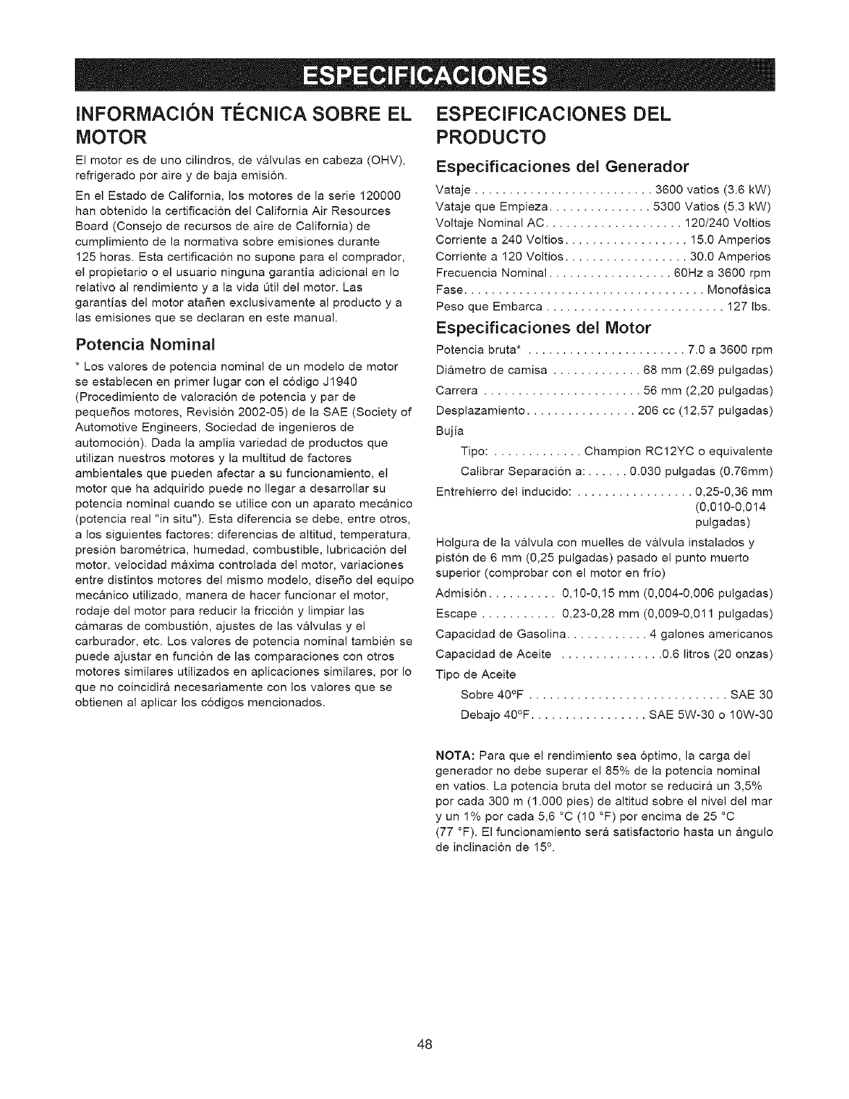
INFORMACION TECNICA SOBRE EL ESPECIFICACIONES DEL
MOTOR PRODUCTO
El motor es de uno cilindros, de v&lvulas en cabeza (OHV),
refrigerado por aire y de baja emisi6n.
En el Estado de California, los motores de la serie 120000
hart obtenido la certificaci6n del California Air Resources
Board (Consejo de recursos de aire de California) de
cumplimiento de la normativa sobre emisiones durante
125 horas. Esta certificacion no supone para el comprador,
el propietario o el usuario ninguna garantia adicional en Io
relativo al rendimiento y a la vida Qtil del motor. Las
garantias del motor ata_en exclusivamente al producto y a
las emisiones que se declaran en este manual.
Potencia Nominal
*Los valores de potencia nominal de un modelo de motor
se establecen en primer lugar con el codigo J1940
(Procedimiento de valoracion de potencia y par de
pequefios motores, Revision 2002-05) de la SAE (Society of
Automotive Engineers, Sociedad de ingenieros de
automocion). Dada la amplia variedad de productos que
utilizan nuestros motores y la multitud de factores
ambientales que pueden afectar a su funcionamiento, el
motor que ha adquirido puede no Ilegar a desarrollar su
potencia nominal cuando se utilice con un aparato mecanico
(potencia real "in situ"). Esta diferencia se debe, entre otros,
a los siguientes factores: diferencias de altitud, temperatura,
presion barometrica, humedad, combustible, lubricacion del
motor, velocidad maxima controlada del motor, variaciones
entre distintos motores del mismo modelo, disefio del equipo
mec&nico utilizado, manera de hacer funcionar el motor,
rodaje del motor para reducir la friccion y limpiar las
camaras de combustion, ajustes de las valvulas y el
carburador, etc. Los valores de potencia nominal tambien se
puede ajustar en funcion de las comparaciones con otros
motores similares utilizados en aplicaciones similares, por Io
que no coincidira necesariamente con los valores que se
obtienen al aplicar los codigos mencionados.
Especificaciones del Generador
Vataje .......................... 3600 vatios (3.6 kW)
Vataje que Empieza ............... 5300 Vatios (5.3 kW)
Voltaje Nominal AC .................... 120/240 Voltios
Corriente a 240 Voltios .................. 15.0 Amperios
Corriente a 120 Voltios .................. 30.0 Amperios
Frecuencia Nominal .................. 60Hz a 3600 rpm
Fase ................................... Monof&sica
Peso que Embarca .......................... 127 Ibs.
Especificaciones del Motor
Potencia bruta* . ...................... 7.0 a 3600 rpm
Di&metro de camisa ............. 68 mm (2,69 pulgadas)
Carrera ....................... 56 mm (2,20 pulgadas)
Desplazamiento ................ 206 cc (12,57 pulgadas)
Bujia
Tipo: ............. Champion RC12YC o equivalente
Calibrar Separacion a: ...... 0.030 pulgadas (0.76mm)
Entrehierro del inducido: ................. 0,25-0,36 mm
(0,010-0,014
pulgadas)
Holgura de la valvula con muelles de valvula instalados y
pist6n de 6 mm (0,25 pulgadas) pasado el punto muerto
superior (comprobar con el motor en frio)
Admisi6n .......... 0,10-0,15 mm (0,004-0,006 pulgadas)
Escape ........... 0,23-0,28 mm (0,009-0,011 pulgadas)
Capacidad de Gasolina ............ 4 galones americanos
Capacidad de Aceite ............... 0.6 litros (20 onzas)
Tipo de Aceite
Sobre 40°F ............................. SAE 30
Debajo 40°F ................. SAE 5W-30 o 10W-30
NOTA: Para que el rendimiento sea 6ptimo, la carga del
generador no debe superar el 85% de la potencia nominal
en vatios. La potencia bruta del motor se reducir& un 3,5%
por cada 300 m (1.000 pies) de altitud sobre el nivel del mar
y un 1% por cada 5,6 °C (10 °F) por encima de 25 °C
(77 °F). El funcionamiento sera satisfactorio hasta un &ngulo
de inclinaci6n de 15°.
48
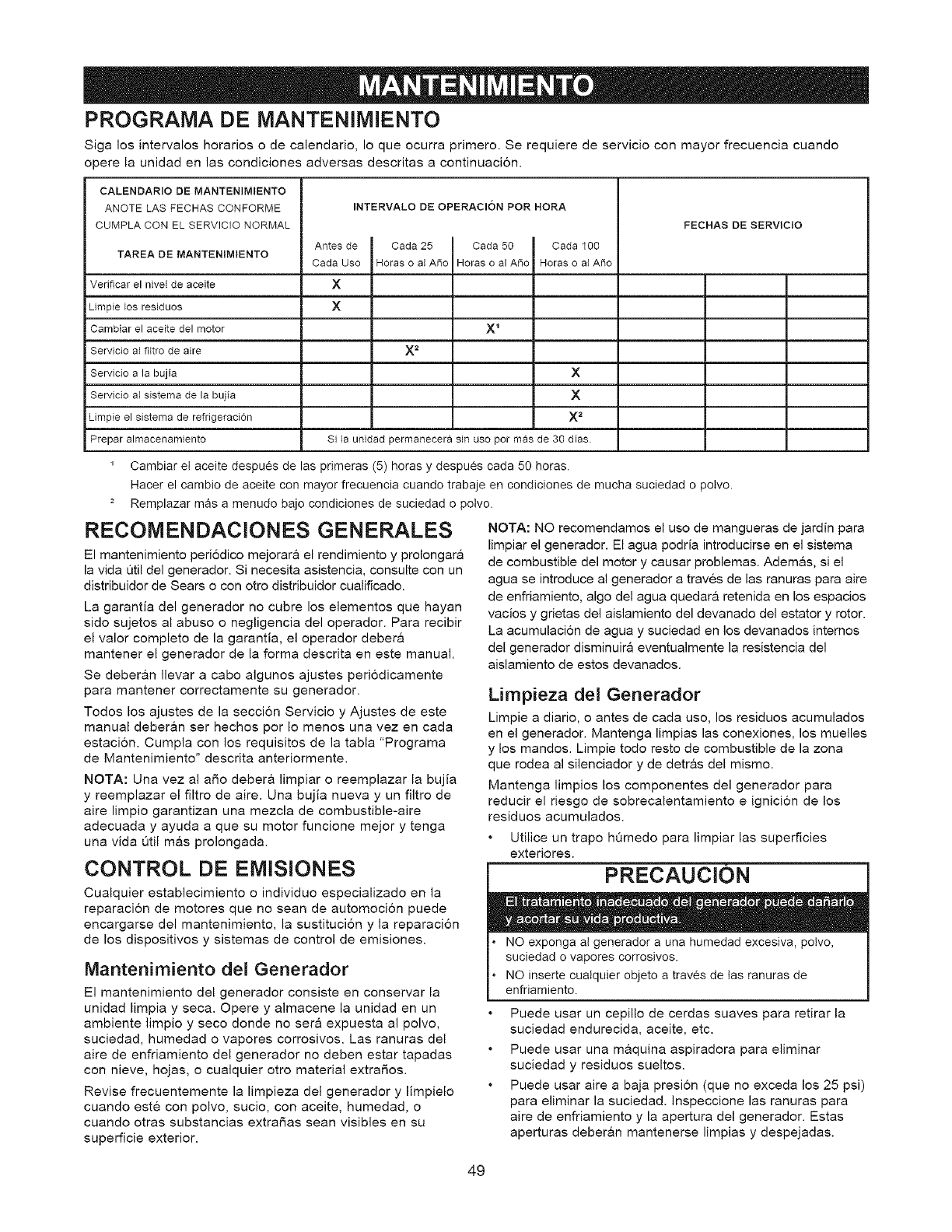
PROGRAMA DE MANTENIMIENTO
Siga los intervalos horarios o de calendario, Io que ocurra primero. Se requiere de servicio con mayor frecuencia cuando
opere la unidad en las condiciones adversas descritas a continuacion.
CALENDARIO DE MANTENIMIENTO
ANOTE LAS FECHAS CONFORME INTERVALO DE OPERACleN POR HORA
CUMPLA CON EL SERVICIO NORMAL FECHAS DE SERVICIO
Antes de Cada 25 Cada 50 Cada 100
TAREA DE MANTENIMIENTO Cada Uso Horas o a A_o Horas o a A_o Horas o a{ A_o
Verificar el nivel de aceite X
Limpie Fos residuos X
Cambiar el aceite del motor X 1
Servicio a{ fHtro de aire X 2
Servicio a la bujia X
Servicio a{ sistema de la bujia X
Limpie el sistema de refrigeracion X 2
Prepar almacenamiento Si la unidad permanecera sin uso por mas de 30 dias.
1 Cambiar el aceite despues de las primeras (5) horas y despu_s cada 50 horas.
Hacer el cambio de aceite con mayor frecuencia cuando trabaje en condiciones de mucha suciedad o polvo.
z Remplazar mas a menudo bajo condiciones de suciedad o polvo.
RECOMENDACIONES GENERALES
El mantenimiento periodico mejorara el rendimiento y prolongar&
la vida Qtil del generador. Si necesita asistencia, consulte con un
distribuidor de Sears o con otro distribuidor cualificado.
La garantia del generador no cubre los elementos que hayan
sido sujetos al abuso o negligencia del operador. Para recibir
el valor completo de la garantia, el operador deber&
mantener el generador de la forma descrita en este manual.
Se deber&n Ilevar a cabo algunos ajustes periodicamente
para mantener correctamente su generador.
Todos los ajustes de la seccion Servicio y Ajustes de este
manual deber&n ser hechos por Io menos una vez en cada
estacion. Cumpla con los requisitos de la tabla "Programa
de Mantenimiento" descrita anteriormente.
NOTA: Una vez al aSo deber& limpiar o reemplazar la bujia
y reemplazar el filtro de aire. Una bujia nueva y un filtro de
aire limpio garantizan una mezcla de combustible-aire
adecuada y ayuda a que su motor funcione mejor y tenga
una vida Qtil m&s prolongada.
CONTROL DE EMISIONES
Cualquier establecimiento o individuo especializado en la
reparacion de motores que no sean de automocion puede
encargarse del mantenimiento, la sustitucion y la reparacion
de los dispositivos y sistemas de control de emisiones.
Mantenimiento del Generador
El mantenimiento del generador consiste en conservar la
unidad limpia y seca. Opere y almacene la unidad en un
ambiente limpio y seco donde no sera expuesta al polvo,
suciedad, humedad o vapores corrosivos. Las ranuras del
aire de enfriamiento del generador no deben estar tapadas
con nieve, hojas, o cualquier otro material extraSos.
Revise frecuentemente la limpieza del generador y limpielo
cuando este con polvo, sucio, con aceite, humedad, o
cuando otras substancias extraSas sean visibles en su
superficie exterior.
NOTA: NO recomendamos el uso de mangueras de jardin para
limpiar el generador. El agua podria introducirse en el sistema
de combustible del motor y causar problemas. Ademas, si el
agua se introduce al generador a traves de las ranuras para aire
de enfriamiento, algo del agua quedara retenida en los espacios
vacios y grietas del aislamiento del devanado del estator y rotor.
La acumulaci6n de agua y suciedad en los devanados internos
del generador disminuira eventualmente la resistencia del
aislamiento de estos devanados.
Limpieza del Generador
Limpie a diario, o antes de cada uso, los residuos acumulados
en el generador. Mantenga limpias las conexiones, los muelles
y los mandos. Limpie todo resto de combustible de la zona
que rodea al silenciador y de detr&s del mismo.
Mantenga limpios los componentes del generader para
reducir el riesgo de sobrecalentamiento e ignicion de los
residuos acumulados.
Utilice un trapo ht_medo para limpiar las superficies
exteriores.
PRECAUCiON
NO exponga al generador a una humedad excesiva, polvo,
suciedad o vapores corrosivos.
NO inserte cuaiquier objeto a traves de tas ranuras de
enfriamiento.
Puede usar un cepillo de cerdas suaves para retirar la
suciedad endurecida, aceite, etc.
Puede usar una maquina aspiradora para eliminar
suciedad y residuos sueltos.
Puede usar aire a baja presion (que no exceda los 25 psi)
para eliminar la suciedad. Inspeccione las ranuras para
aire de enfriamiento y la apertura del generador. Estas
aperturas deberan mantenerse limpias y despejadas.
49
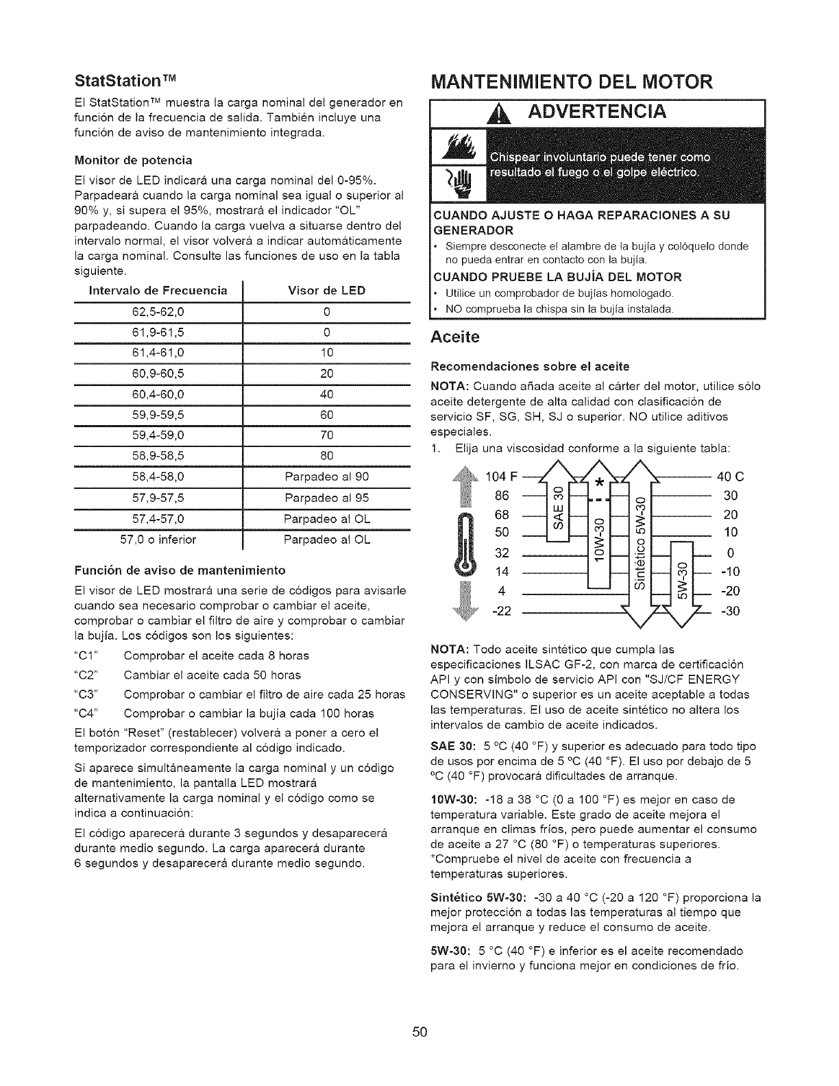
StatStation TM
El StatStation TM muestra la carga nominal del generador en
funcion de la frecuencia de salida. Tambien incluye una
funcion de aviso de mantenimiento integrada.
Monitor de potencia
El visor de LED indicara una carga nominal del 0-95%.
Parpadear& cuando la carga nominal sea igual o superior al
90% y, si supera el 95%, mostrara el indicador "OL"
parpadeando. Cuando la carga vuelva a situarse dentro del
intervalo normal, el visor volver& a indicar automaticamente
la carga nominal. Consulte las funciones de uso en la tabla
siguiente.
Intervalo de Frecuencia
62,5-62,0
61,9-61,5
61,4-61,0
60,9-60,5
60,4-60,0
59,9-59,5
59,4-59,0
58,9-58,5
58,4-58,0
57,9-57,5
57,4-57,0
57,0 o inferior
Visor de LED
0
0
10
20
40
60
70
80
Parpadeo al 90
Parpadeo al 95
Parpadeo al OL
Parpadeo al OL
Funci6n de aviso de mantenimiento
El visor de LED mostrara una serie de codigos para avisarle
cuando sea necesario comprobar o cambiar el aceite,
comprobar o cambiar el filtro de aire y comprobar o cambiar
la bujia. Los codigos son los siguientes:
"C1" Comprobar el aceite cada 8 horas
"C2" Cambiar el aceite cada 50 horas
"C3" Comprobar o cambiar el filtro de aire cada 25 horas
"C4" Comprobar o cambiar la bujia cada 100 horas
El boton "Reset" (restablecer) volvera a poner a cero el
temporizador correspondiente al codigo indicado.
Si aparece simultaneamente la carga nominal y un codigo
de mantenimiento, la pantalla LED mostrara
alternativamente la carga nominal y el c6digo como se
indica a continuacion:
El c6digo aparecera durante 3 segundos y desaparecera
durante medio segundo. La carga aparecera durante
6 segundos y desaparecera durante medio segundo.
MANTENIMIENTO DEL MOTOR
ADVERTENCIA
CUANDO AJUSTE OHAGA REPARACIONES A SU
GENERADOR
*Siempre desconecte el alambre de ta bujia y col6quelo dende
no pueda entrar en contacto con la bujia.
CUANDO PRUEBE LA BUJiA DEL MOTOR
Utitice un comprobador de bujias homologado.
NO cemprueba la chispa sin la bujia instatada.
Aceite
Recomendaciones sobre el aceite
NOTA: Cuando aSada aceite al carter del motor, utilice solo
aceite detergente de alta calidad con clasificacion de
servicio SF, SG, SH, SJ o superior. NO utilice aditivos
especiales.
1. Elija una viscosidad conforme
104 F_
86
68
50
32
14
4
-22
la siguiente tabla:
40 C
30
20
ii 10
: 0
-10
-20
-30
NOTA: Todo aceite sintetico que cumpla las
especificaciones ILSAC GF-2, con marca de certificacion
API y con simbolo de servicio API con "SJ/CF ENERGY
CONSERVING" o superior es un aceite aceptable a todas
las temperaturas. El uso de aceite sintetico no altera los
intervalos de cambio de aceite indicados.
SAE 30:5 °C (40 °F) y superior es adecuado para todo tipo
de usos por encima de 5 °C (40 °F). El uso por debajo de 5
°C (40 °F) provocar& dificultades de arranque.
10W=30: -18a38°C(0a 100 °F) esmejorencasode
temperatura variable. Este grado de aceite mejora el
arranque en climas frios, pero puede aumentar el consumo
de aceite a 27 °C (80 °F) o temperaturas superiores.
*Compruebe el nivel de aceite con frecuencia a
temperaturas superiores.
Sint_tico 5W-30:-30 a 40 °C (-20 a 120 °F) proporciona la
mejor proteccion a todas las temperaturas al tiempo que
mejora el arranque y reduce el consumo de aceite.
5W-30:5 °C (40 °F) e inferior es el aceite recomendado
para el invierno y funciona mejor en condiciones de frio.
5O
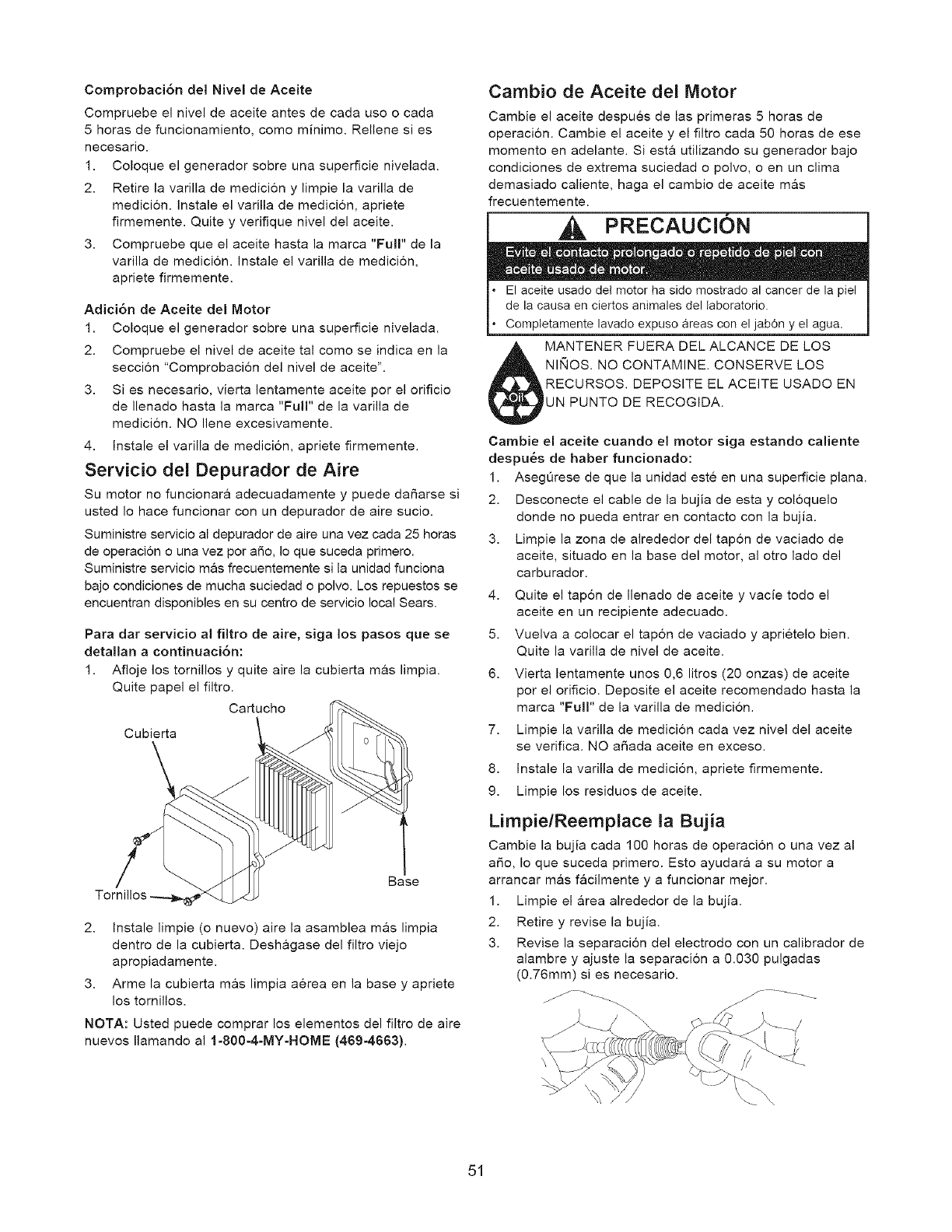
Comprobaci6n del Nivel de Aceite
Compruebe el nivel de aceite antes de cada uso o cada
5 horas de funcionamiento, como minimo. Rellene si es
necesario.
1. Coloque el generador sobre una superficie nivelada.
2. Retire la varilla de medici6n y limpie la varilla de
medicion. Instale el varilla de medicion, apriete
firmemente. Quite y verifique nivel del aceite.
3. Compruebe que el aceite hasta la marca "Full" de la
varilla de medicion. Instale el varilla de medicion,
apriete firmemente.
Adici6n de Aceite del Motor
1. Coloque el generador sobre una superficie nivelada.
2. Compruebe el nivel de aceite tal como se indica en la
seccion "Comprobacion del nivel de aceite".
3. Si es necesario, vierta lentamente aceite pot el orificio
de Ilenado hasta la marca "Full" de la varilla de
medici6n. NO Ilene excesivamente.
4. Instale el varilla de medicion, apriete firmemente.
Servicio del Depurador de Aire
Su motor no funcionara adecuadamente y puede daSarse si
usted Io hace funcionar con un depurador de aire sucio.
Suministre servicio al depurador de aire una vez cada 25 horas
de operacion o una vez por aSo, Io que suceda primero.
Suministre servicio mas frecuentemente si la unidad funciona
bajo condiciones de mucha suciedad o polvo. Los repuestos se
encuentran disponibles en su centro de servicio local Sears.
Para dar servicio al filtro de aire, siga los pasos que se
detallan a continuaci6n:
1. Afloje los tornillos y quite aire la cubierta mas limpia.
Quite papel el filtro.
Cartucho
Cubierta
/Base
2. Instale limpie (o nuevo) aire la asamblea mas limpia
dentro de la cubierta. Deshagase del filtro viejo
apropiadamente.
3. Arme la cubierta mas limpia aerea en la base y apriete
los tornillos.
NOTA: Usted puede comprar los elementos del filtro de aire
nuevos Ilamando al 1-800-4-MY-HOME (469-4663).
Cambio de Aceite del Motor
Cambie el aceite despues de las primeras 5 horas de
operacion. Cambie el aceite y el filtro cada 50 horas de ese
momento en adelante. Siesta utilizando su generador bajo
condiciones de extrema suciedad o polvo, o en un clima
demasiado caliente, haga el cambio de aceite m&s
frecuentemente.
PRECAUCION
El aceite usado del motor ha sido mostrado al cancer de la piel
de la causa en ciertos animales del laboratorio.
Completamente lavado expuso areas con el jab6n y el agua.
MANTENER FUERA DEL ALCANCE DE LOS
NIIqOS. NO CONTAMINE. CONSERVE LOS
RECURSOS. DEPOSITE EL ACEITE USADO EN
UN PUNTO DE RECOGIDA.
Cambie el aceite cuando el motor siga estando caliente
despu_s de haber funcionado:
1. AsegQrese de que la unidad este en una superficie plan&
2. Desconecte el cable de la bujia de esta y coloquelo
donde no pueda entrar en contacto con la bujia.
3. Limpie la zona de alrededor del tapon de vaciado de
aceite, situado en la base del motor, al otro lado del
carburador.
4. Quite el tapon de Ilenado de aceite y vacie todo el
aceite en un recipiente adecuado.
5. Vuelva a colocar el tap6n de vaciado y aprietelo bien.
Quite la varilla de nivel de aceite.
6. Vierta lentamente unos 0,6 litros (20 onzas) de aceite
por el orificio. Deposite el aceite recomendado hasta la
marca "Full" de la varilla de medicion.
7. Limpie la varilla de medici6n cada vez nivel del aceite
se verifica. NO aSada aceite en exceso.
8. Instale la varilla de medici6n, apriete firmemente.
9. Limpie los residuos de aceite.
Limpie/Reemplace la Bujia
Cambie la bujia cada 100 horas de operacion o una vez al
aSo, Io que suceda primero. Esto ayudar& a su motor a
arrancar m&s facilmente y a funcionar mejor.
1. Limpie el &rea alrededor de la bujia.
2. Retire y revise la bujia.
3. Revise la separacion del electrodo con un calibrador de
alambre y ajuste la separacion a 0.030 pulgadas
(0.76mm) si es necesario.
51
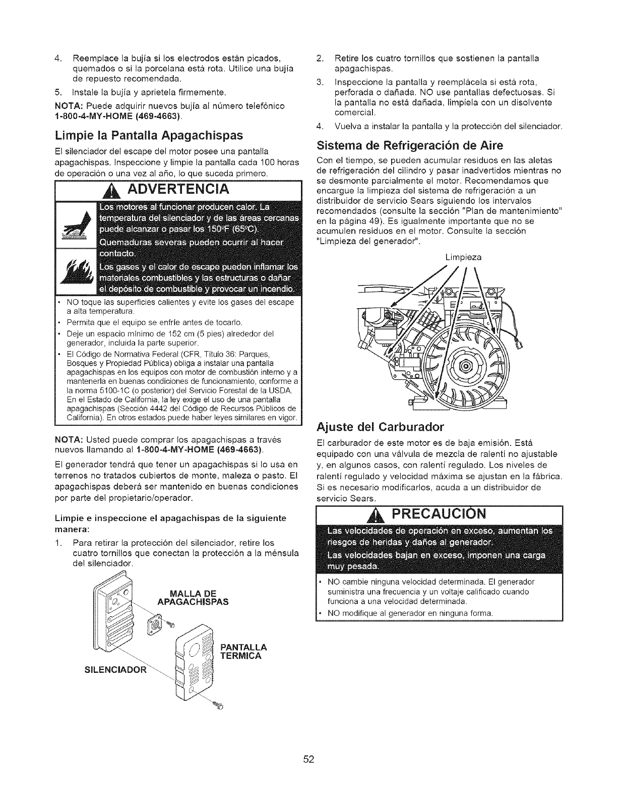
4. Reemplace la bujia si los electrodos estan picados,
quemados o si la porcelana esta rota. Utilice una bujia
de repuesto recomendada.
5. Instale la bujia y aprietela firmemente.
NOTA: Puede adquirir nuevos bujia al nQmero telefonico
1-800-4=MY-HOME (469-4663).
Limpie la Pantalla Apagachispas
El silenciador del escape del motor posee una pantalla
apagachispas. Inspeccione y limpie la pantalla cada 100 horas
de operacion o una vez al aSo, Io que suceda primero.
ADVERTENCIA
NO toque las superficies calientes y evite los gases del escape
a atta temperatura.
Permita que el equipo se enfrie antes de tocarlo.
Deje un espacio minimo de 152 cm (5 pies) alrededor del
generador, inctuida ta parte superior.
El C6digo de Normativa Federal (CFR, Titulo 36: Parques,
Bosques y Propiedad PQblica) obtiga a instalar una pantalta
apagachispas en los equipos con motor de combustidn interno y a
mantenerla en buenas condiciones de funcionamiento, conforme a
la norma 5100-1C (o posterior) del Sen/icio Forestal de ta USDA.
En el Estado de California, ta ley exige et uso de una pantalta
apagachispas (Seccidn 4442 det C6digo de Recursos POblicos de
California). En otros estados puede haber leyes similares en vigor.
NOTA: Usted puede comprar los apagachispas a traves
nuevos Ilamando al 1-800=4-MY=HOME (469-4663).
El generador tendra que tener un apagachispas si Io usa en
terrenos no tratados cubiertos de monte, maleza o pasto. El
apagachispas debera ser mantenido en buenas condiciones
por parte del propietario/operador.
Limpie einspeccione el apagachispas de la siguiente
manera:
1. Para retirar la proteccion del silenciador, retire los
cuatro tomillos que conectan la proteccion a la mensula
del silenciador.
SILENC|ADOR_
MALLA DE
APAGACHISPAS
PANTALLA
TERMICA
2. Retire los cuatro tornillos que sostienen la pantalla
apagachispas.
3. Inspeccione la pantalla y reemplacela si esta rota,
perforada o da_ada. NO use pantallas defectuosas. Si
la pantalla no esta da_ada, limpiela con un disolvente
comercial.
4. Vuelva a instalar la pantalla y la proteccion del silenciador.
Sistema de Refrigeraci6n de Aire
Con el tiempo, se pueden acumular residues en las aletas
de refrigeracion del cilindro y pasar inadvertidos mientras no
se desmonte parcialmente el motor. Recomendamos que
encargue la limpieza del sistema de refrigeracion a un
distribuidor de servicio Sears siguiendo los intervalos
recomendados (consulte la seccion "Plan de mantenimiento"
en la p&gina 49). Es igualmente importante que no se
acumulen residuos en el motor. Consulte la seccion
"Limpieza del generador".
Limpieza
Ajuste del Carburador
El carburador de este motor es de baja emision. Esta
equipado con una valvula de mezcla de ralenti no ajustable
y, en algunos casos, con ralenti regulado. Los niveles de
ralenti regulado y velocidad maxima se ajustan en la fabrica.
Si es necesario modificarlos, acuda a un distribuidor de
servicio Sears.
PRECAUCION
NO cambie ninguna velocidad determinada. El generador
suministra una frecuencia y un voltaje calificado cuando
funciona a una velocidad determinada.
NO modifique al generador en ninguna forma.
52
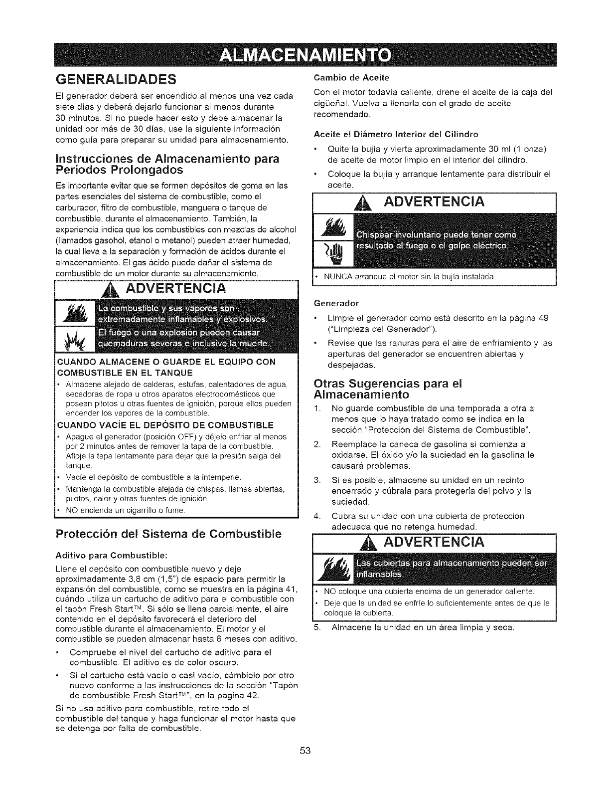
GENERALIDADES
El generador debera ser encendido al menos una vez cada
siete dias y debera dejarlo funcionar al menos durante
30 minutos. Si no puede hacer esto y debe almacenar la
unidad por mas de 30 dias, use la siguiente informacion
como guia para preparar su unidad para almacenamiento.
Instrucciones de Almacenamiento para
Periodos Prolongados
Es importante evitar que se formen dep6sitos de goma en las
partes esenciales del sistema de combustible, como el
carburador, filtro de combustible, manguera o tanque de
combustible, durante el almacenamiento. Tambien, la
experiencia indica que los combustibles con mezclas de alcohol
(llamados gasohol, etanol o metanol) pueden atraer humedad,
la cual Ileva a la separacion y formacion de &cidos durante el
almacenamiento. El gas &cido puede daSar el sistema de
combustible de un motor durante su almacenamiento.
ADVERTENCIA
CUANDO ALMACENE O GUARDE EL EQUIPO CON
COMBUSTIBLE EN EL TANQUE
AImacene atejado de calderas, estufas, calentadores de agua,
secadoras de ropa u otros aparatos etectrodomesticos que
posean pilotos u otras fuentes de ignici6n, porque eltos pueden
encender los vapores de la combustible.
CUANDO VACiE EL DEPOSITO DE COMBUSTIBLE
Apague el generador (posici6n OFF) y dejelo enfriar al menos
por 2 minutos antes de remover la tapa de ta combustible.
Afloje la tapa lentamente para dejar que la presi6n salga del
tanque.
Vacie el dep6sito de combustible a ta intemperie.
Mantenga la combustible alejada de chispas, llamas abiertas,
pilotos, calory otras fuentes de ignici6n.
NO encienda un cigarritto o fume.
Protecci6n del Sistema de Combustible
Aditivo para Combustible:
Llene el deposito con combustible nuevo y deje
aproximadamente 3,8 cm (1,5") de espacio para permitir la
expansion del combustible, como se muestra en la pagina 41,
cuando utiliza un cartucho de aditivo para el combustible con
el tapon Fresh Start TM. Si solo se Ilena parcialmente, el aire
contenido en el deposito favorecera el deterioro del
combustible durante el almacenamiento. El motor y el
combustible se pueden almacenar hasta 6 meses con aditivo.
Compruebe el nivel del cartucho de aditivo para el
combustible. El aditivo es de color oscuro.
Cambio de Aceite
Con el motor todavia caliente, drene el aceite de la caja del
cigL_eSal. Vuelva a Ilenarla con el grado de aceite
recomendado.
Aceite el Di_metro Interior del Cilindro
Quite la bujia y vierta aproximadamente 30 ml (1 onza)
de aceite de motor limpio en el interior del cilindro.
Coloque la bujia y arranque lentamente para distribuir el
aceite.
ADVERTENClA
Je el motor sin la bujia instatada.
Generador
Limpie el generador come esta descrito en la pagina 49
("Limpieza del Generador").
Revise que las ranuras para el aire de enfriamiento y las
aperturas del generador se encuentren abiertas y
despejadas.
Otras Sugerencias para el
Almacenamiento
1. No guarde combustible de una temporada a otra a
menos que Io haya tratado como se indica en la
seccion "Proteccion del Sistema de Combustible".
2. Reemplace la caneca de gasolina si comienza a
oxidarse. El oxido y/o la suciedad en la gasolina le
causara problemas.
3. Si es posible, almacene su unidad en un recinto
encerrado y cObrala para protegerla del polvo y la
suciedad.
4. Cubra su unidad con una cubierta de proteccion
adecuada que no retenga humedad.
ADVERTENCIA
5.
NO coloque una cubierta encima de un generador caliente.
Deje que la unidad se enfrie to suficientemente antes de que le
coloque ta cubierta.
Almacene la unidad en un area limpia y seca.
Si el cartucho esta vacio o casi vacio, cambielo por otro
nuevo conforme a las instrucciones de la seccion "Tapon
de combustible Fresh Start TM'', en la p&gina 42.
Si no usa aditivo para combustible, retire todo el
combustible del tanque y haga funcionar el motor hasta que
se detenga por falta de combustible.
53
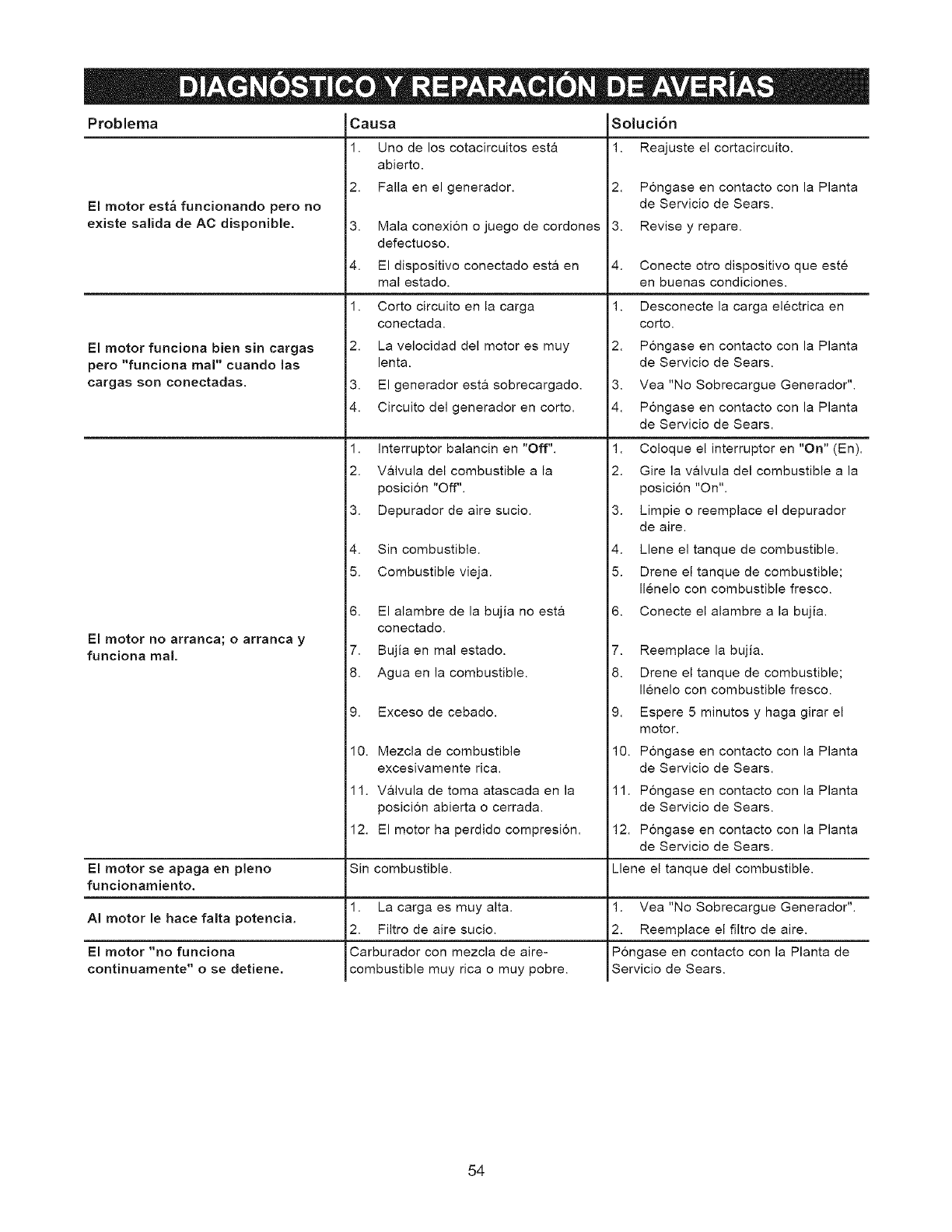
Problema Soluci6n
El motor est_ funcionando pero no
existe salida de AC disponible,
El motor funciona bien sin cargas
pero "funciona real" cuando las
cargas son conectadas.
El motor no arranca; o arranca y
funciona real.
Causa
1. Uno de los cotacircuitos esta
abierto.
2. Falla en el generador.
3.
4.
1.
2.
3.
4.
Mala conexion o juego de cordones
defectuoso.
El dispositivo conectado est& en
mal estado.
Corto circuito en la carga
conectada.
La velocidad del motor es muy
lent&
El generador est& sobrecargado.
Circuito del generador en corto.
1. Interruptor balancin en "Off".
2. V&lvula del combustible a la
posicion "Off".
3. Depurador de aire sucio.
4. Sin combustible.
5. Combustible vieja.
6. El alambre de la bujia no esta
conectado.
7. Bujia en mal estado.
8. Agua en la combustible.
1. Reajuste el cortacircuito.
2. Pongase en contacto con la Planta
de Servicio de Sears.
3. Revise y repare.
4. Conecte otro dispositivo que este
en buenas condiciones.
1. Desconecte la carga electrica en
corto.
2. Pongase en contacto con la Planta
de Servicio de Sears.
3. Vea "No Sobrecargue Generador".
4. Pongase en contacto con la Planta
de Servicio de Sears.
1. Coloque el interruptor en "On" (En).
2. Gire la valvula del combustible a la
posicion "On".
3. Limpie o reemplace el depurador
de aire.
4. Llene el tanque de combustible.
5. Drene el tanque de combustible;
Ilenelo con combustible fresco.
6. Conecte el alambre a la bujia.
7. Reemplace la bujia.
8. Drene el tanque de combustible;
Ilenelo con combustible fresco.
9. Exceso de cebado.
10. Mezcla de combustible
excesivamente rica.
9. Espere 5 minutos y haga girar el
motor.
10. Pongase en contacto con la Planta
de Servicio de Sears.
El motor se apaga en pleno
funcionamiento.
AI motor le hace falta potencia.
El motor "no funciona
continuamente" o se detiene.
1 1. V&lvula de toma atascada en la
posicion abierta o cerrada.
12. El motor ha perdido compresion.
Sin combustible.
1. La carga es muy alta.
2. Filtro de aire sucio.
Carburador con mezcla de alre-
combustible muy rica o muy pobre.
11. Pongase en contacto con la Planta
de Servicio de Sears.
12. Pongase en contacto con la Planta
de Servicio de Sears.
Llene el tanque del combustible.
1. Vea "No Sobrecargue Generador".
2. Reemplace el filtro de aire.
Pongase en contacto con la Planta de
Servicio de Sears.
54

55

56

57
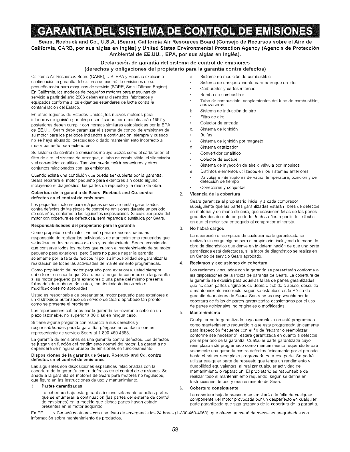
Sears, Roebuck and Co., U.S.A. (Sears), California Air Resources Board (Consejo de Recursos sobre el Aire de
California, BARB, por sus siglas en ingles) y United States Environmental Protection Agency (Agencia de Protecci6n
Ambiental de EE.UU., EPA, por sus siglas en ingles).
Declaraci6n de garantia del sistema de control de emisiones
(derechos y obligaciones del propietario para la garantia contra defectos)
California Air Resources Board (CARB), U.S. EPA y Sears le explican a
continuaci6n la garantia del sistema de control de emisiones de su
peque_o motor para maquinas de servicio (SORE_ Small Offroad Engine).
En California, los modelos de peque_os motores para maquinas de
servicio a partir del a_o 2006 deben estar dise_ados, fabricados y
equipados conforme a tos exigentes estandares de lucha contra la
contaminaci6n det Estado.
En otras regiones de Estados Unidos, tos nuevos motores para
interiores de ignici6n por chispa certificados para modelos a_o 1997 y
posteriores deben cumplir con normas similares establecidas por la EPA
de EE.UU. Sears debe garantizar el sistema de control de emisiones de
su motor para los periodos indicados a continuaci6n, siempre y cuando
no se haya abusado, descuidado o dado mantenimiento incorrecto at
motor pequeSo para exteriores.
Su sistema de control de emisiones incluye piezas como et carburador, el
flltro de aire, el sistema de arranque, el tubo de combustible, el silenciador
y el convertidor catalitico. Tambien puede incluir conectores y otros
conjuntos relacionados con las emisiones.
Cuando exista una condici6n que pueda ser cubierta por la garantia,
Sears reparara el motor pequeSo para exteriores sin costo atguno,
incluyendo el diagn6stico, las partes de repuesto y la mano de obra.
Cobertura de la garantia de Sears, Roebuck and Co, contra
defeetoe en el control de emisiones
Los pequeSos motores para maquinas de servicio estan garantizados
contra defectos de las piezas de control de emisiones durante un pedodo
de dos a5os, conforme alas siguientes disposiciones. Si cualquier pieza dei
motor con cobertura es defectuosa, sera reparada o sustituida por Sears.
Responsabilidades del propietario para la garantia
Como propietario del motor pequeSo para exteriores, usted es
responsable de realizar las actividades de mantenimiento requeridas que
se indican en tnstrucciones de uso y mantenimiento. Sears recomienda
que conserve todos los recibos que cubran el mantenimiento de su motor
pequeSo para exteriores, pero Sears no puede negar la garantia
solamente pot la fatta de recibos ni por su imposibiiidad de garantizar la
realizaci6n de todas las actividades de mantenimiento programadas.
Como propietario del motor pequeSo para exteriores, usted siempre
debe tener en cuenta que Sears podra negar la cobertura de la garantia
si su motor pequeSo para exteriores o una parte dei mismo presenta
fatlas debido a abuso, descuido, mantenimiento incorrecto o
modificaciones no aprobadas.
Usted es responsable de presentar su motor pequefio para exteriores a
un distribuidor autorizado de servicio de Sears aprobado tan pronto
como se presente el problem&
Las reparaciones cubiertas por la garantia se Itevaran a cabo en un
plazo razonable, no superior a 30 dias en ningQn caso.
Si tiene atguna pregunta con respecto a sus derechos y
responsabilidades para la garantia, p6ngase en contacto con un
representante de servicio Sears al 1-800-469-4663.
La garantia de emisiones es una garantia contra defectos. Los defectos
se juzgan en funci6n del rendimiento normal del motor. La garantia no
dependera de ninguna prueba de emisiones en funcionamiento.
Oisposiciones de la garantia de Sears, Roebuck and Co, contra
defeetos en el controt de emisionee
Las siguientes son disposiciones especificas relacionadas con la
cobertura de la garantia contra defectos en el control de emisiones. Se
al_ade a la garantia de motores de Sears para motores no regulados,
que figura en las tnstrucciones de uso y mantenimiento.
1. Partes garantizadas
La cobertura bajo esta garantia inctuye solamente aquellas partes
que se enumeran a continuaci6n (las partes del sistema de control
de emisiones) en la medida que dichas partes hayan estado
presentes en el motor adquirido.
a. Sistema de medici6n de combustible
Sistema de enriquecimiento para arranque en frio
Carburador y partes internas
Bomba de combustible
Tubo de combustible, acoplamientos del tubo de combustible,
abrazaderas
b. Sistema de inducci6n de aire
Filtro de aire
Cotector de entrada
c. Sistema de ignici6n
Bujias
Sistema de ignici6n por magneto
d. Sistema catatizador
Convertidor catalitico
Colector de escape
Sistema de inyecci6n de aire o valvula pot impulsos
e. Distintos elementos utilizados en los sistemas anteriores
Valvulas e interruptores de vacio, temperatura, posici6n y de
detecci6n de tiempo
Conectores y conjuntos
2. Vigeneia de la cobertura
Sears garantiza al propietario inicial y a cada comprador
subsiguiente que las partes garantizadas estaran libres de defectos
en material yen mano de obra, que ocasionen fallas de las partes
garantizadas durante un periodo de dos aSos a partir de la fecha
en que el motor sea entregado al comprador minorista.
3. No habr& cargos
La reparaci6n o reemplazo de cualquier parte garantizada se
realizara sin cargo alguno para el propietario, incluyendo la mano de
obra de diagn6stico que derive en la determinaci6n de que una parte
garantizada esta defectuosa, si la labor de diagn6stico se realiza en
un Centro de servicio Sears aprobado.
4. Reclamos y exclusiones de cobertura
Los reclamos vinculados con la garantia se presentaran conforme a
las disposiciones de la P61iza de garantia de Sears. La cobertura de
la garantia se excluira para aquetlas fallas de partes garantizadas
que no sean partes originales de Sears o debido a abuso, descuido
o mantenimiento incorrecto, segQn se establece en la P61iza de
garantia de motores de Sears. Sears no es responsabte por la
cobertura de fallas de partes garantizadas ocasionadas pot el uso
de partes adicionales, no originales o modificadas.
5. IVtantenimiento
Cuatquier parte garantizada cuyo reemplazo no est_ programado
como mantenimiento requerido o que est_ programada L_nicamente
para inspecci6n frecuente con el fin de "reparar o reemplazar
conforme sea necesario", estara garantizada en cuanto a defectos
por el periodo de la garantia. Cualquier parte garantizada cuyo
reemplazo este programado como mantenimiento requerido tendra
solamente una garantia contra defectos Onicamente por el periodo
hasta el primer reemplazo programado para esa parte. Se podra
utilizar cualquier parte de repuesto que tenga un rendimiento y
durabilidad equivatentes, al realizar cualquier actividad de
mantenimiento o reparaci6n. El propietario es responsable de
realizar todo el mantenimiento requerido, seg0n se define en
lnstrucciones de uso y mantenimiento de Sears.
6. Cobertura coneiguiente
La cobertura bajo la presente se ampliara a la falla de cualquier
componente del motor provocada por un desperfecto en cualquier
parte garantizada que siga gozando de la cobertura de la garantia.
En EE.UU. y Canada contamos con una linea de emergencia las 24 horas (1-800-469-4663), que ofrece un menu de mensajes pregrabados con
informaci6n sobre mantenimiento de productos.
58
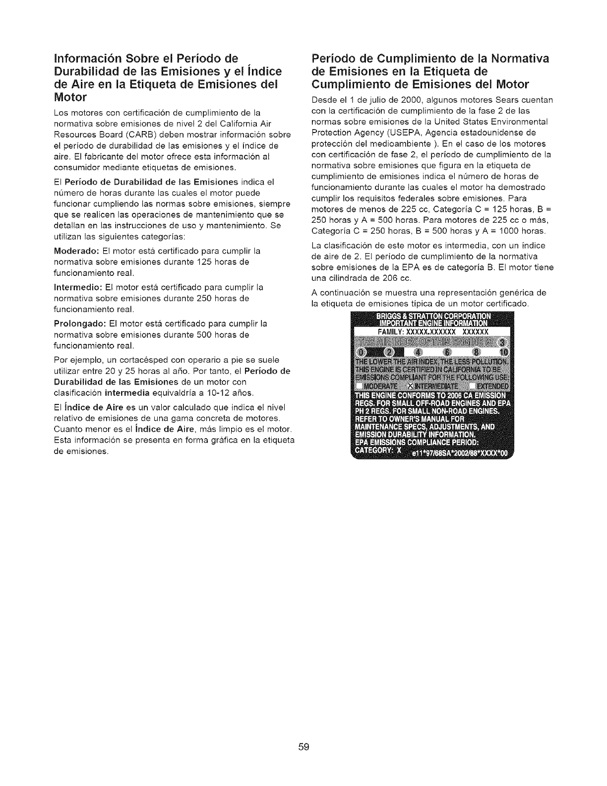
Informaci6n Sobre el Periodo de
Durabilidad de las Emisiones y el indice
de Aire en la Etiqueta de Emisiones del
Motor
Los motores con certificaci6n de cumplimiento de la
normativa sobre emisiones de nivel 2 del California Air
Resources Board (CARB) deben mostrar informacion sobre
el periodo de durabilidad de las emisiones y el indice de
aire. El fabricante del motor ofrece esta informacion al
consumidor mediante etiquetas de emisiones.
El Periodo de Durabilidad de las Emisiones indica el
nOmero de horas durante las cuales el motor puede
funcionar cumpliendo las normas sobre emisiones, siempre
que se realicen las operaciones de mantenimiento que se
detallan en las instrucciones de uso y mantenimiento. Se
utilizan las siguientes categorias:
Moderado: El motor esta certificado para cumplir la
normativa sobre emisiones durante 125 horas de
funcionamiento real.
Intermedio: El motor est& certificado para cumplir la
normativa sobre emisiones durante 250 horas de
funcionamiento real.
Prolongado: El motor est& certificado para cumplir la
normativa sobre emisiones durante 500 horas de
funcionamiento real.
Por ejemplo, un cortacesped con operario a pie se suele
utilizar entre 20 y 25 horas al aSo. Por tanto, el Periodo de
Durabilidad de las Emisiones de un motor con
clasificacion intermedia equivaldria a 10-12 aSos.
El indice de Aire es un valor calculado que indica el nivel
relativo de emisiones de una gama concreta de motores.
Cuanto menor es el indice de Aire, m&s limpio es el motor.
Esta informacion se presenta en forma grafica en la etiqueta
de emisiones.
Periodo de Cumplimiento de la Normativa
de Emisiones en la Etiqueta de
Curnplimiento de Emisiones del Motor
Desde el 1 de julio de 2000, algunos motores Sears cuentan
con la certificacion de cumplimiento de la fase 2 de las
normas sobre emisiones de la United States Environmental
Protection Agency (USEPA, Agencia estadounidense de
proteccion del medioambiente ). En el caso de los motores
con certificacion de fase 2, el periodo de cumplimiento de la
normativa sobre emisiones que figura en la etiqueta de
cumplimiento de emisiones indica el nOmero de horas de
funcionamiento durante las cuales el motor ha demostrado
cumplir los requisitos federales sobre emisiones. Para
motores de menos de 225 cc, Categoria C = 125 horas, B =
250 horas y A = 500 horas. Para motores de 225 cc o m&s,
Categoria C = 250 horas, B = 500 horas y A = 1000 horas.
La clasificacion de este motor es intermedia, con un indice
de aire de 2. El periodo de cumplimiento de la normativa
sobre emisiones de la EPA es de categoria B. El motor tiene
una cilindrada de 206 cc.
A continuacion se muestra una representacion generica de
la etiqueta de emisiones tipica de un motor certificado.
59

.................................... _i!!iiiiiii!!iiiiii!!iiiii!iiiiiiiiii
_:_H_H_i;_'.... Your Home ....'_:_!!!iiiii!!iiiii!!iiiii!!;;_
iiiiiiiiiiiiiiiiiiiiiii!!!!_
iHiiiiiiiiiiiiiiiiiiiiill Forrepair-inyourhome-ofallmajorbrandappliances, i:iiiiiiiii!!ii%
iiiiiiiiiiiiiiiiiiiiiiiill lawn and garden equipment, orheating and cooling systems, iiiiiiiiiiiiiiiiii!iiiiii
ii:iiiiiiiiiiiiiiiiiiii;;;; nomatterwhornadeit, nomatterwhosoMit!
iHiiiiiiiiiiiiiiiiiiiiill Forthereplacementparts, accessoriesand
iiiiiiiiiiiiiiiiiiiiiiiill owner's manualsthatyou need to do-it-yourself, iiiiiiiiii!iiiii!iiil;iii
i_iiiiiiiiiiiiiiiiiii.... iiiiiiiii!!iiiiiiiiiiiii_
iiiiiiiiiiiiiiiiiiiiiiiill ForSears professional installation of home appliances
ii:iiiiiiiiiiiiiiiiiiiiiill and itemslikegaragedooropenersandwaterheaters.
iiiiiiiiiiiiiiiiiiiiiiH iiiiiiiiiiiiiiiii!iiiii_
ii:iiiiiiiiiiiiiiiiiiiiiill
iiiiiiiiiiiiiiiiiiiiiiH iiiiiiiii_iiiii!!iiiiiiii
1-800-4-MY-HOME ® Anytime, day or night
(1-800-469-4663) (U.S.A. and Canada)
www.sears.corn www.seaFs.c_
iiiiiiiiiiiiiiiiiiiiiii_H..........................................................................................................................................................................................................................................................................................................................................................................................................................................................................................................................................................................................................................................................................i_iiiiii!!!iiiiiiiii_iii
i_iiiiiiiiiiiiiiiiiiiiiii
iiiiiiiiiiiiiiiiiiiiii_H Our Home i;iiii!iiiiii!!iiiiiiiiii
iiiiiiiiiiiiiiiii!!iiiiiiii!iForrepairofcarry-in items likevacuums, lawn equipment, ''';;:'_""';;_'
iiiiiiiiiiiiiiiii!!iii_ iiiiiiiiiiiii!!!iiiii!iii
HiHi}ilHiiiiHiiil}!!}! and electronics, call ergo on-line forthe nearest ,ii!!!!iiiilw!ii!ilwi
iiiiiiiiiiiiiiiiiiiiiiiill Sears Parts & Repair Center.
iiiiiiiiiiiiiiiiiiiiiiiill
iiiiiiiiiiiiiiiiiiiiiiiiii
iiiiiiiiiiiiiiiiiiiiii!!!! 1-800-488-1222 Anytime, day or night (U.S.A. only)
iiiiiiiiiiiiiiiiiiiiiiiill
iiiiiiiiiiiiiiiiiiiiiiiiii
iiiiiiiiiiiiiiiiiiiiii_!! www.sea,s.co,,
iiiiiiiiiiiiiiiiiiiiiiiiii
iiiiiiiiiiiiHiiiiiiii!!!!
,,,,,,,,,,,,,,,,,,,,,,,,,,1-800=827-6655 (U.S.A.)
iiiiiiiiiiiiiiiiiiiiii_iiiiiiiiiiiiiiiiiiiiiiiillPara pedir servicio de reparaci6n Au Canada pour service en frangais:
iiiiiiiiiiiiiiiiiiiiii!!!!a domicilio, y para ordenar piezas: I=800=LE=FOYERMC iiiiiiiiii!!iiiiiiii!iiiii
iiiiiiiiiiiiiiiiiiiiii!!!! I=888-SU-HOGAR sM (1-800=533=6937) :iiiii!!!iiii!iiii!!iiiiii
.......................... iiiiiii!!ii_i%iiil
iHiiiiiiiiiii!iiiiiiiiiii (1=888-784=6427) www.sears.ca 'iiiiiii!!!!ii;;;iiii!!iii
ii!!!!iiii!!iiiiiii!!iiiiiiiiiii ,,_ii!!iiiiiii!!iiii!!iiiiiiiiii_'
.... ea rs
`````_```_``_``_``_``_``_``_``_``_``_``_``_``_``_``_``_``_``_``_``_``_``_``_``_``_``_``_``_``_``_``_``_``_``_``_``_``_``_``_``_``_``_``_``_``_``_``_``_``_``_``_``_``_``_``_``_`J""="'%'_"',,"
© Sears Brands, LLC
® Registered Trademark /TMTrademark /SMService Mark of Sears Brands, LLC
® Marca Registrade /TM Marca de F_brica /SM Marca de Servicio de Sears Brands, LLC
Mc Marque de commerce /MDMarque d6pos6e de Sears Brands, LLC
