Craftsman 580329120 User Manual GENERATOR Manuals And Guides L0209037
CRAFTSMAN Generator Manual L0209037 CRAFTSMAN Generator Owner's Manual, CRAFTSMAN Generator installation guides
User Manual: Craftsman 580329120 580329120 CRAFTSMAN GENERATOR - Manuals and Guides View the owners manual for your CRAFTSMAN GENERATOR #580329120. Home:Tool Parts:Craftsman Parts:Craftsman GENERATOR Manual
Open the PDF directly: View PDF ![]() .
.
Page Count: 40
Owner's Manual
CRAFTSMAN+
3000 Watt
AC Generator
Model No.
580.329120
C usGemneraHt°lpline_
HOURS: Mon.- Fri. 8 a.m. to 5 p.m. (CT)
CAUTION:
Before using this product, read this
manual and follow all its Safety Rules
and Operating Instructions.
Sears, Roebuck and Co., Hoffman Estates, IL 60179
Visit our Craftsman website: www.sears.com/craftsman
Part No. 186956 Draft 1 (07/11/2001)
• Safety
• Assembly
• Operation
• Maintenance
• Parts
• Espafiol
SAFETY RULES .......................... 3
ASSEMBLY ............................. 5
OPERATION ........................... 5-9
SPECIFICATIONS ....................... 10
MAINTENANCE ....................... 10-12
STO RAG E ............................. 12
TROUBLESHOOTING .................... 13
SCHEMATIC/WIRING DIAGRAM .......... 14-15
REPLACEMENT PARTS ................ 16-22
EMISSION SYSTEM WARRANTY ......... 24-25
ESPANOL ........................... 26-39
HOW TO ORDER PARTS .......... BACK PAGE
LIMITED WARRANTY FOR CRAFTSMAN GENERATORS
SEARS warrants to the original purchaser that the alternator and engine for its portable generator will be free
from defects in materials or workmanship for the items and period set forth below from the date of original
purchase. This warranty is not transferable.
CONSUMER* COMMERCIAL*
Alternator 1 year 90 Days
Engine 1 year 90 Days
* NOTE: For the purpose of this warranty "Consumer Use" means personal residential household and emergency
use by original purchaser, not to be used as a primary source of power. "Commercial Use" means all other uses,
including rental, construction, commercial, and income producing purposes. Once a generator has experienced
commercial use, it shall thereafter be considered a commercial use generator for the purpose of this warranty.
During said warranty period, SEARS will, at its option, repair or replace any part which, upon examination by
SEARS, is found to be defective under normal use and service**. Starting batteries are not warranted by SEARS.
All transportation costs under warranty, including return to the factory if necessary, are to be borne by the
purchaser and prepaid by him. This warranty does not cover normal maintenance and service and does not apply
to a generator set, alternator or engine, or parts which have been subjected to improper or unauthorized
installation or alteration, misuse, negligence, accident, overloading, over-speeding, improper maintenance, repair
or storage so as, in SEARS's judgment, to adversely affect its performance and reliability.
** NORMAL WEAR: As with all mechanical devices, engines need periodic parts service and replacement to
perform well. This warranty will not cover repair when normal use has exhausted the life of a part or engine.
THERE IS NO OTHER EXPRESS WARRANTY. SEARS HEREBY DISCLAIMS ANY AND ALL IMPLIED
WARRANTIES, INCLUDING BUT NOT LIMITED TO THOSE OF MERCHANTABILITY AND FITNESS
FOR A PARTICULAR PURPOSE TO THE EXTENT PERMITTED BY LAW. THE DURATION OF ANY
IMPLIED WARRANTIES WHICH CANNOT BE DISCLAIMED IS LIMITED TO THE TIME PERIOD AS
SPECIFIED IN THE EXPRESS WARRANTY. LIABILITY FOR CONSEQUENTIAL, INCIDENTAL, OR
SPECIAL DAMAGES UNDER ANY AND ALL WARRANTIES IS EXCLUDED.
Some provinces do not allow limitations on how long an implied warranty lasts, or the exclusion or limitation of
incidental or consequential damages, so the above limitations or exclusions may not apply to you. This warranty
gives you specific legal rights and you may also have other rights, which vary from state to state.
For service, see your nearest SEARS authorized warranty service facility. Warranty service can be performed
only by a SEARS authorized service facility. This warranty will not apply to service at any other facility. At the time
of requesting warranty service, evidence of original purchase date must be presented.
SEARS, ROEBUCK and CO., D/817WA, Hoffman Estates, IL 60179 U.S.A.
The engine exhaust from this product
contains chemicals known to the State of
California to cause cancer, birth defects, or
other reproductive harm.
A AUTION! Before using this product, read this
manual and follow all Safety Rules and
Operating Instructions.
WARNING! You must isolate the generator
from the electric utility by opening the electrical
system's main circuit breaker or main switch if
this unit is used for backup power. Failure to
isolate the generator from the power utility
may result in injury or death to electric utility
workers and damage to the generator due to
a backfeed of electrical energy. When used as
backup power, the local power utility must be
notified.
DANGER! Generator exhaust gases contain
DEADLY carbon monoxide gas. Carbon
monoxide, if breathed in sufficient
concentrations, will cause unconsciousness
or death. Operate this equipment outdoors
where adequate ventilation is available.
CAUTION! To prevent accidental starting when
setting up, transporting, adjusting or making
repairs to your generator, always disconnect
spark plug wire and place the wire where it
cannot contact the spark plug.
• The unit requires an adequate flow of cooling air
for its continued proper operation. Never operate
the unit inside any room or enclosure where the
free flow of cooling air into and out of the unit might
be obstructed. Allow at least 3 feet of clearance on
all sides of generator or you could damage the unit.
• The generator produces dangerously high voltage
that can cause extremely hazardous electrical
shock. Avoid contact with bare wires, terminals,
etc. Never permit any untrained person to operate
or service the generator.
•Do Not overfill the fuel tank. Always allow room for
fuel expansion. If tank is overfilled, fuel can
overflow onto a hot engine and cause FIRE or an
EXPLOSION.
• Never operate the generator:
in rain; in any enclosed compartment; when
connected electrical devices overheat; if electrical
output is lost; if engine or generator sparks; if flame
or smoke is observed while unit is running; if unit
vibrates excessively.
• Never handle any kind of electrical cord or device
while standing in water, while barefoot or while
hands or feet are wet. Dangerous electrical shock
will result.
• Use a ground fault circuit interrupter in any damp
or highly conductive area (such as metal decking or
steel work).
• Do Not use worn, bare, frayed or otherwise
damaged electrical cord sets with the generator.
Using any defective cord set may result in electrical
shock or damage to property.
• Operate generator only on level surfaces and
where it will not be exposed to excessive moisture,
dirt, dust or corrosive vapors.
• Gasoline is highly FLAMMABLE and its vapors are
EXPLOSIVE. Do Not permit smoking, open flames,
sparks or heat in the vicinity while handling
gasoline. Avoid spilling gasoline on a hot engine.
Comply with all laws regulating storage and
handling of gasoline.
• Never store generator with fuel in tank where
gasoline vapors might reach an open flame or
spark or pilot light (as on a furnace, water heater or
clothes dryer). FIRE or EXPLOSION may result.
• Never add fuel while unit is running.
• Never start or stop the unit with electrical loads
connected to receptacles AND with connected
devices turned ON. Start the engine and let it
stabilize before connecting electrical loads.
Disconnect all electrical loads before shutting down
the generator.
• Do Not insert any object through cooling slots of
the engine-generator.
NOTE: Your generator is equipped with a spark
arrester muffler. The spark arrester must be
maintained in effective working order by the owner/
operator. In the State of California, a spark arrester is
required by law (Section 4442 of the California Public
Resources Code). Other states may have similar laws.
Federal laws apply on federal lands.
,_ THIS IS THE SAFETY ALERT SYMBOL. IT IS USED TO ALERT YOU TO POTENTIALPERSONAL INJURY HAZARDS. OBEY ALL SAFETY MESSAGES THAT FOLLOW THIS
SYMBOL TO AVOID POSSIBLE INJURY OR DEATH.
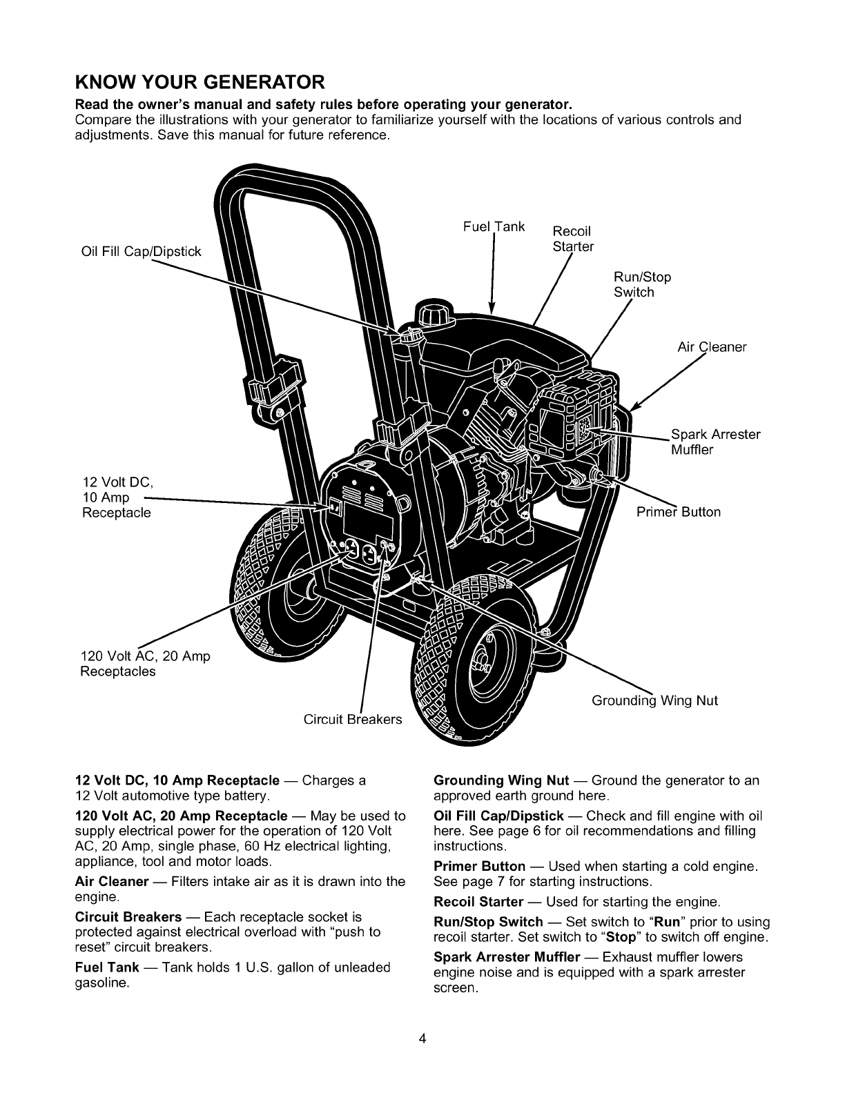
KNOW YOUR GENERATOR
Read the owner's manual and safety rules before operating your generator.
Compare the illustrations with your generator to familiarize yourself with the locations of various controls and
adjustments. Save this manual for future reference.
Oil Fill Cap/Dipstick
FuelTank Recoil
Starter
Run/Stop
Switch
Air Cleaner
12 Volt DC,
10 Amp -
Receptacle
Arrester
Muffler
Prime_ Button
120 Volt AC, 20 Amp
Receptacles
Circuit Breakers
t_tWing Nut
12 Volt DC, 10 Amp Receptacle -- Charges a
12 Volt automotive type battery.
120 Volt AC, 20 Amp Receptacle -- May be used to
supply electrical power for the operation of 120 Volt
AC, 20 Amp, single phase, 60 Hz electrical lighting,
appliance, tool and motor loads.
Air Cleaner -- Filters intake air as it is drawn into the
engine.
Circuit Breakers -- Each receptacle socket is
protected against electrical overload with "push to
reset" circuit breakers.
Fuel Tank -- Tank holds 1 U.S. gallon of unleaded
gasoline.
Grounding Wing Nut -- Ground the generator to an
approved earth ground here.
Oil Fill Cap/Dipstick -- Check and fill engine with oil
here. See page 6 for oil recommendations and filling
instructions.
Primer Button -- Used when starting a cold engine.
See page 7 for starting instructions.
Recoil Starter -- Used for starting the engine.
Run/Stop Switch -- Set switch to "Run" prior to using
recoil starter. Set switch to "Stop" to switch off engine.
Spark Arrester Muffler -- Exhaust muffler lowers
engine noise and is equipped with a spark arrester
screen.
4
TO REMOVE GENERATOR FROM
CARTON
• Slice two corners at end of carton from top to
bottom so the panel can be folded down fiat, then
remove all packing material.
• Remove the generator and contents from the
shipping carton.
CARTON CONTENTS
Check all contents against those listed below:
• Main unit
• Engine oil
• Owner's manual
• Battery charge cables
If any parts are missing or damaged, call the
generator helpline at 1-800-222-3136.
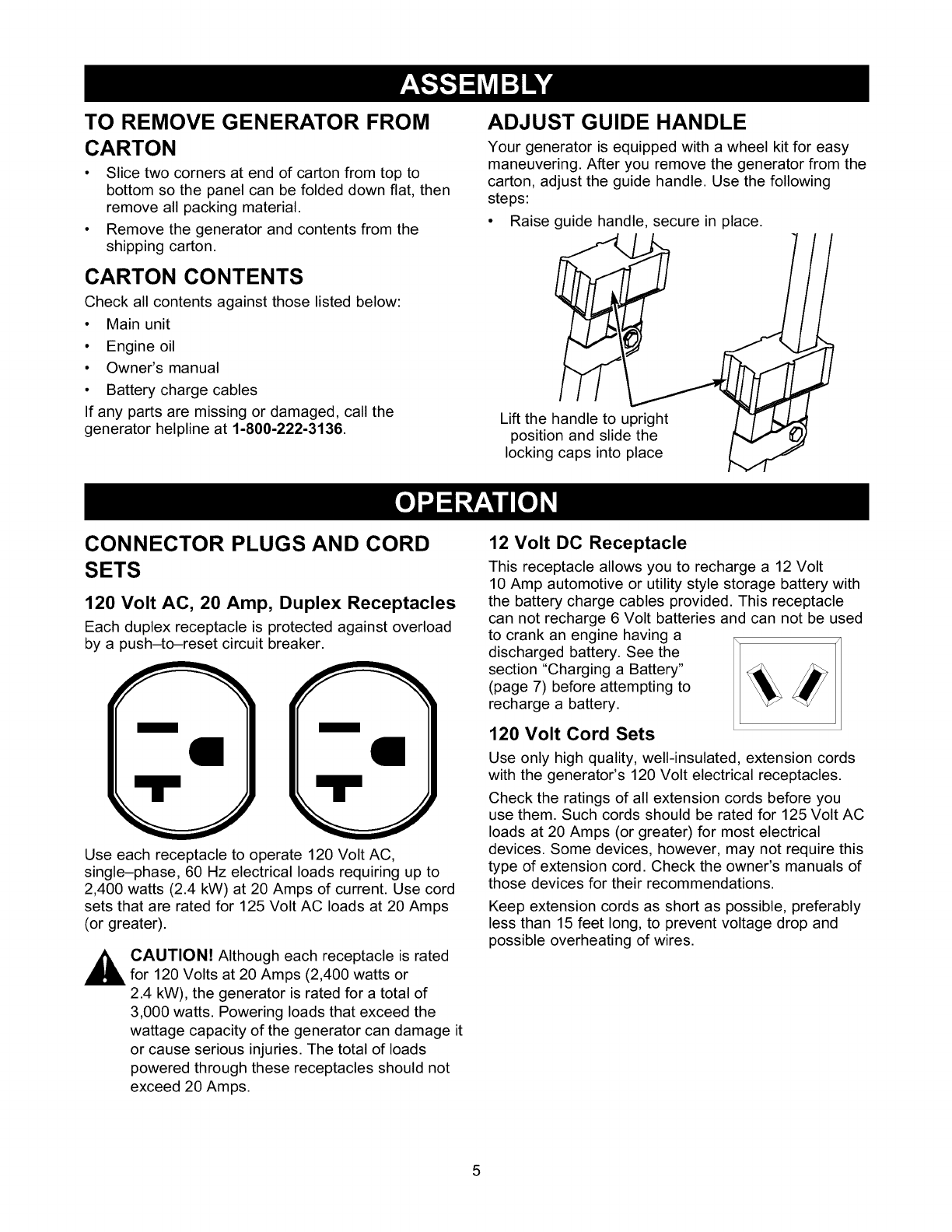
ADJUST GUIDE HANDLE
Your generator is equipped with awheel kit for easy
maneuvering. After you remove the generator from the
carton, adjust the guide handle. Use the following
steps:
• Raise guide handle, secure in place.
Lift the handle to upright
position and slide the
locking caps into place
CONNECTOR PLUGS AND CORD
SETS
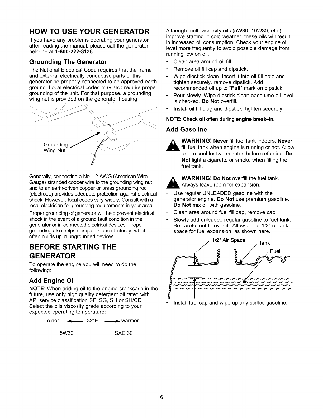
120 Volt AC, 20 Amp, Duplex Receptacles
Each duplex receptacle is protected against overload
by a push-to-reset circuit breaker.
Use each receptacle to operate 120 Volt AC,
single-phase, 60 Hz electrical loads requiring up to
2,400 watts (2.4 kW) at 20 Amps of current. Use cord
sets that are rated for 125 Volt AC loads at 20 Amps
(or greater).
CAUTION! Although each receptacle is rated
for 120 Volts at 20 Amps (2,400 watts or
2.4 kW), the generator is rated for a total of
3,000 watts. Powering loads that exceed the
wattage capacity of the generator can damage it
or cause serious injuries. The total of loads
powered through these receptacles should not
exceed 20 Amps.
12 Volt DC Receptacle
This receptacle allows you to recharge a 12 Volt
10 Amp automotive or utility style storage battery with
the battery charge cables provided. This receptacle
can not recharge 6 Volt batteries and can not be used
to crank an engine having a
discharged battery. See the
section "Charging a Battery" __
(page 7) before attempting to
recharge a battery.
120 Volt Cord Sets
Use only high quality, well-insulated, extension cords
with the generator's 120 Volt electrical receptacles.
Check the ratings of all extension cords before you
use them. Such cords should be rated for 125 Volt AC
loads at 20 Amps (or greater) for most electrical
devices. Some devices, however, may not require this
type of extension cord. Check the owner's manuals of
those devices for their recommendations.
Keep extension cords as short as possible, preferably
less than 15 feet long, to prevent voltage drop and
possible overheating of wires.
HOW TO USE YOUR GENERATOR
If you have any problems operating your generator
after reading the manual, please call the generator
helpline at 1-800-222-3136.
Grounding The Generator
The National Electrical Code requires that the frame
and external electrically conductive parts of this
generator be properly connected to an approved earth
ground. Local electrical codes may also require proper
grounding of the unit. For that purpose, a grounding
wing nut is provided on the generator housing.
Grounding
Wing Nut
Generally, connecting a No. 12 AWG (American Wire
Gauge) stranded copper wire to the grounding wing nut
and to an earth-driven copper or brass grounding rod
(electrode) provides adequate protection against electrical
shock. However, local codes vary widely. Consult with a
local electrician for grounding requirements in your area.
Proper grounding of generator will help prevent electrical
shock in the event of a ground fault condition in the
generator or in connected electrical devices. Proper
grounding also helps dissipate static electricity, which
often builds up in ungrounded devices.
BEFORE STARTING THE
GENERATOR
To operate the engine you will need to do the
following:
Add Engine Oil
NOTE: When adding oil to the engine crankcase in the
future, use only high quality detergent oil rated with
API service classification SF, SG, SH or SH/CD.
Select the oils viscosity grade according to your
expected operating temperature:
colder _ 32°F
5W30 SAE 30
Although multi-viscosity oils (5W30, 10W30, etc.)
improve starting in cold weather, these oils will result
in increased oil consumption. Check your engine oil
level more frequently to avoid possible damage from
running low on oil.
• Clean area around oil fill.
• Remove oil fill cap and dipstick.
• Wipe dipstick clean, insert it into oil fill hole and
tighten securely, remove dipstick. Add
recommended oil up to "Full" mark on dipstick.
• Pour slowly. Wipe dipstick clean each time oil level
is checked. Do Not overfill.
• Install oil fill plug and dipstick, tighten securely.
NOTE: Check oil often during engine break-in.
Add Gasoline
,_ WARNING! Never fill fuel tank indoors. Never
fill fuel tank when engine is running or hot. Allow
unit to cool for two minutes before refueling. Do
Not light a cigarette or smoke when filling the
fuel tank.
,_ WARNING! Do Not overfill the fuel tank.
Always leave room for expansion.
• Use regular UNLEADED gasoline with the
generator engine. Do Not use premium gasoline.
Do Not mix oil with gasoline.
• Clean area around fuel fill cap, remove cap.
• Slowly add unleaded regular gasoline to fuel tank.
Be careful not to overfill. Allow about 1/2" of tank
space for fuel expansion, as shown here.
1/2" Air Space Tank
Fuel
• Install fuel cap and wipe up any spilled gasoline.
To Start The Engine
•Unplug all electrical loads from the generator
receptacles before starting the engine. Never start
or stop the engine with electrical devices
connected to the receptacles AND turned on.
• Be sure the spark plug wire is attached to the spark
plug.
• Place the Run/Stop switch in the "RUN" position.
• Push the primer button 2 or 3 times. Wait about
2 seconds between each push. In cold weather
(50°F/10°C or below) push 5 times.
Primer
Button
NOTE: Primer may be needed to restart a warm
engine after a short shutdown.
• Grasp starter grip and slowly pull the rope until you
feel some resistance, then pull the cord out with a
rapid full arm stroke. Let rope return slowly. Do Not
let rope "snap back" against engine.
NOTE: If the engine fails to start after 3 pulls, push the
primer button 2 times and pull the starter rope again.
WARNING! Never run engine in enclosed
poorly ventilated areas. Engine exhaust
contains carbon monoxide, an odorless and
deadly gas.
_AUTION! Temperature of muffler and nearby
areas may exceed 150°F (65°C). Avoid these
areas.
Connecting Electrical Loads
• Let the engine stabilize and warm up for a few
minutes after starting.
• Do Not connect 240 Volt loads to 120 Volt
receptacles.
• Do Not connect 3-phase loads to the generator.
• Do Not connect 50 Hz loads to the generator.
• Plug in and turn on the desired 120 Volt AC, single
phase, 60 Hertz electrical loads.
• DO NOT OVERLOAD THE GENERATOR. Add up
the rated watts (or amps) of all loads to be
connected at one time. This total should not be
greater than the rated wattage/amperage capacity
of the generator. See "Don't Overload the
Generator" on page 9.
Stopping the Engine
• Unplug all electrical loads from the unit. Never start
or stop the engine with electrical devices plugged
in and turned on.
• Let the engine run at no-load for two minutes to
stabilize the units internal temperatures.
• Move the Run/Stop switch to "STOP" position.
Cold Weather Operation
Your unit is equipped with an anti-icing air cleaner
feature to enable the unit to run at temperatures below
32°F, without ice forming in the carburetor. The air
cleaner base will have an opening which draws warm
air from the muffler into the air cleaner housing. To
work effectively, it is necessary to block cold air from
entering the air cleaner.
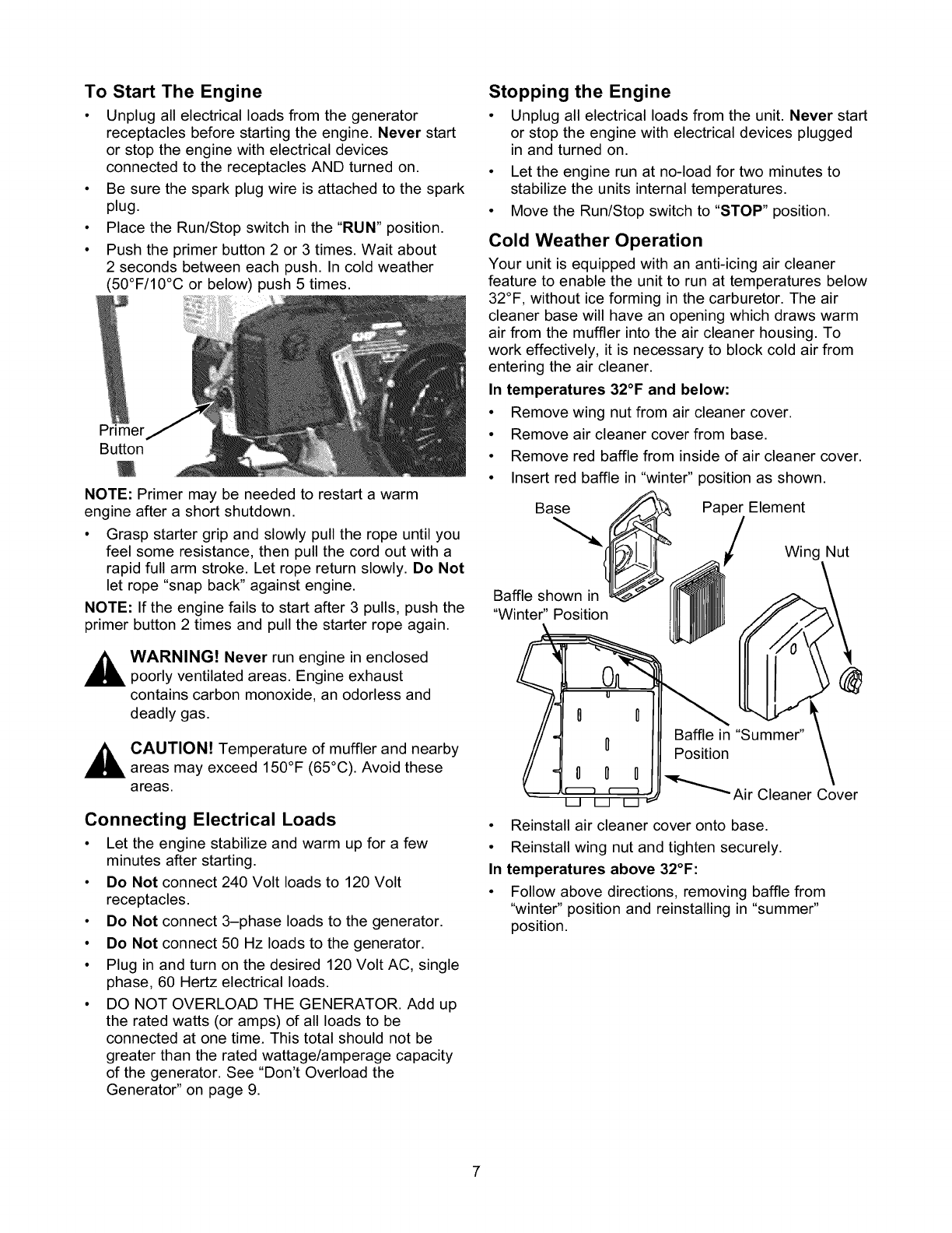
In temperatures 32°F and below:
• Remove wing nut from air cleaner cover.
• Remove air cleaner cover from base.
• Remove red baffle from inside of air cleaner cover.
• Insert red baffle in "winter" position as shown.
Ba__ Pape_tElement
Wing Nut
Baffle shown in
"Winter" Position
"_""_Air Cleaner Cover
Baffle in ' mmer" \
\
Position
• Reinstall air cleaner cover onto base.
• Reinstall wing nut and tighten securely.
In temperatures above 32°F:
• Follow above directions, removing baffle from
"winter" position and reinstalling in "summer"
position.
Charging a Battery
WARNING! Storage batteries emit explosive
gas while charging that remains around a
battery for a long time after it has been charged.
The slightest spark can ignite the gas, causing
an explosion that can shatter the battery and
cause blindness or other injury.
_ARNING! Do Not permit smoking, open
flame, sparks or any other source of heat
around a battery. Do Not use a lighter or other
flame for checking battery fluid levels. Wear
protective goggles, rubber apron and rubber
gloves when working around a battery. Battery
electrolyte fluid is an extremely caustic sulfuric
acid solution that can cause severe burns. Do
Not permit fluid contact with eyes, skin, clothing,
etc. If spill occurs, flush area with clear water
immediately.
Your generator has the capability of recharging a
discharged 12 Volt automotive or utility style storage
battery. Do Not use the unit to charge any 6 Volt
batteries. Do Not use the unit to crank an engine
having a discharged battery.
To recharge 12 Volt batteries, proceed as follows:
•If necessary, clean battery posts or terminals.
• Check fluid level in all battery cells. If necessary,
add ONLY distilled water to cover separators in
battery cells. Do Not use tap water.
• If the battery is equipped with vent caps, make
sure they are installed and are tight.
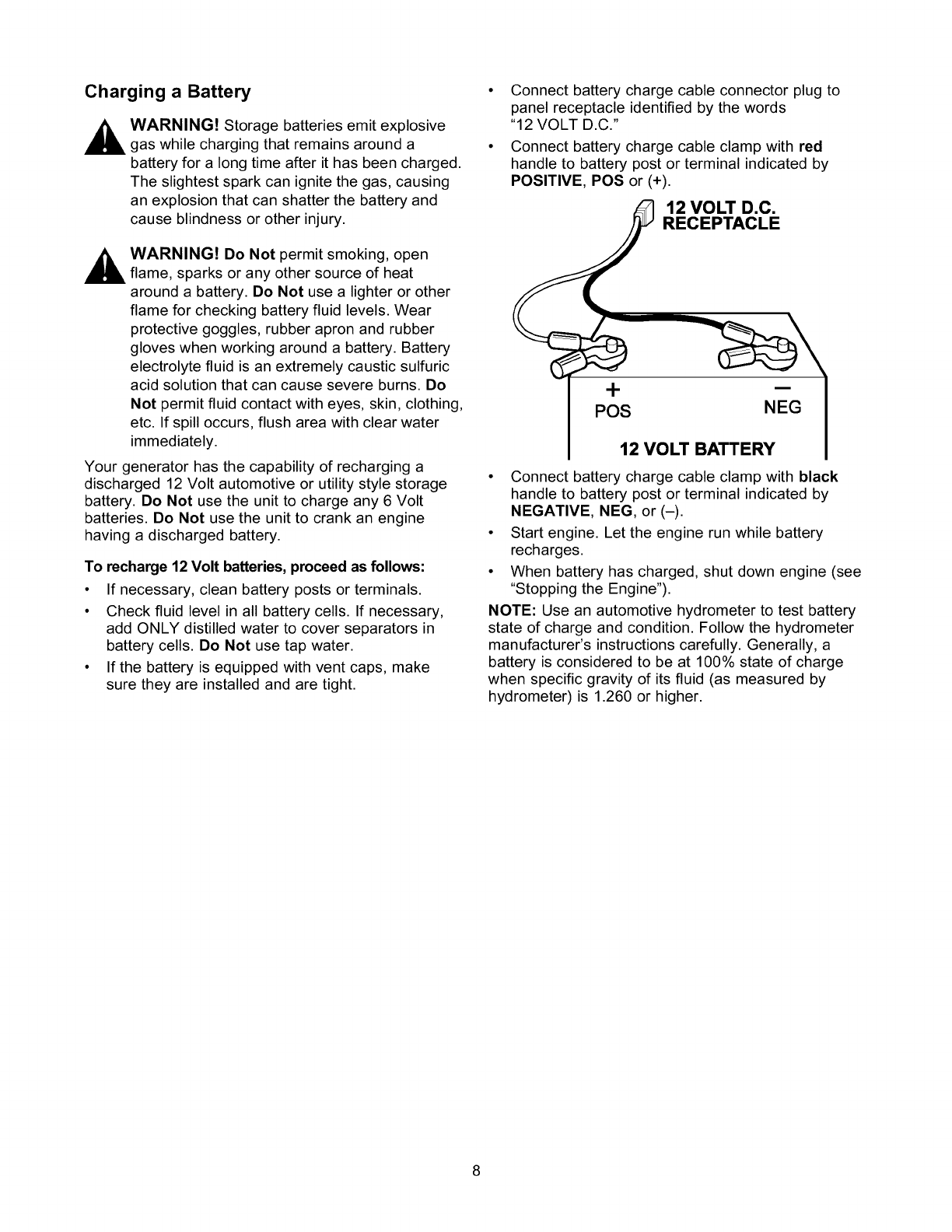
• Connect battery charge cable connector plug to
panel receptacle identified by the words
"12 VOLT D.C."
• Connect battery charge cable clamp with red
handle to battery post or terminal indicated by
POSITIVE, POS or (+).
12 VOLT D.C.
RECEPTACLE
+
POS
i
NEG
12 VOLT BATTERY
• Connect battery charge cable clamp with black
handle to battery post or terminal indicated by
NEGATIVE, NEG, or (-).
• Start engine. Let the engine run while battery
recharges.
• When battery has charged, shut down engine (see
"Stopping the Engine").
NOTE: Use an automotive hydrometer to test battery
state of charge and condition. Follow the hydrometer
manufacturer's instructions carefully. Generally, a
battery is considered to be at 100% state of charge
when specific gravity of its fluid (as measured by
hydrometer) is 1.260 or higher.
DON'T OVERLOAD THE
GENERATOR
Overloading a generator in excess of its rated wattage
capacity can result in damage to the generator and to
connected electrical devices. Observe the following, to
prevent overloading the unit:
• Add up the total wattage of all electrical devices to
be connected at one time. This total should NOT
be greater than the generator's wattage capacity.
• The rated wattage of lights can be taken from light
bulbs. The rated wattage of tools, appliances and
motors can usually be found on a data plate or
decal affixed to the device.
• If the appliance, tool or motor does not give
wattage, multiply volts times ampere rating to
determine watts (volts x amps = watts).
• Some electric motors, such as induction types,
require about three times more watts of power for
starting than for running. This surge of power lasts
only a few seconds when starting such motors.
Make sure you allow for this high starting wattage
when selecting electrical devices to connect to your
generator. First, figure the watts needed to start the
largest motor. Add to that figure the running watts
of all other connected loads.
The Wattage Reference Guide provided here may
assist you in determining generator load.
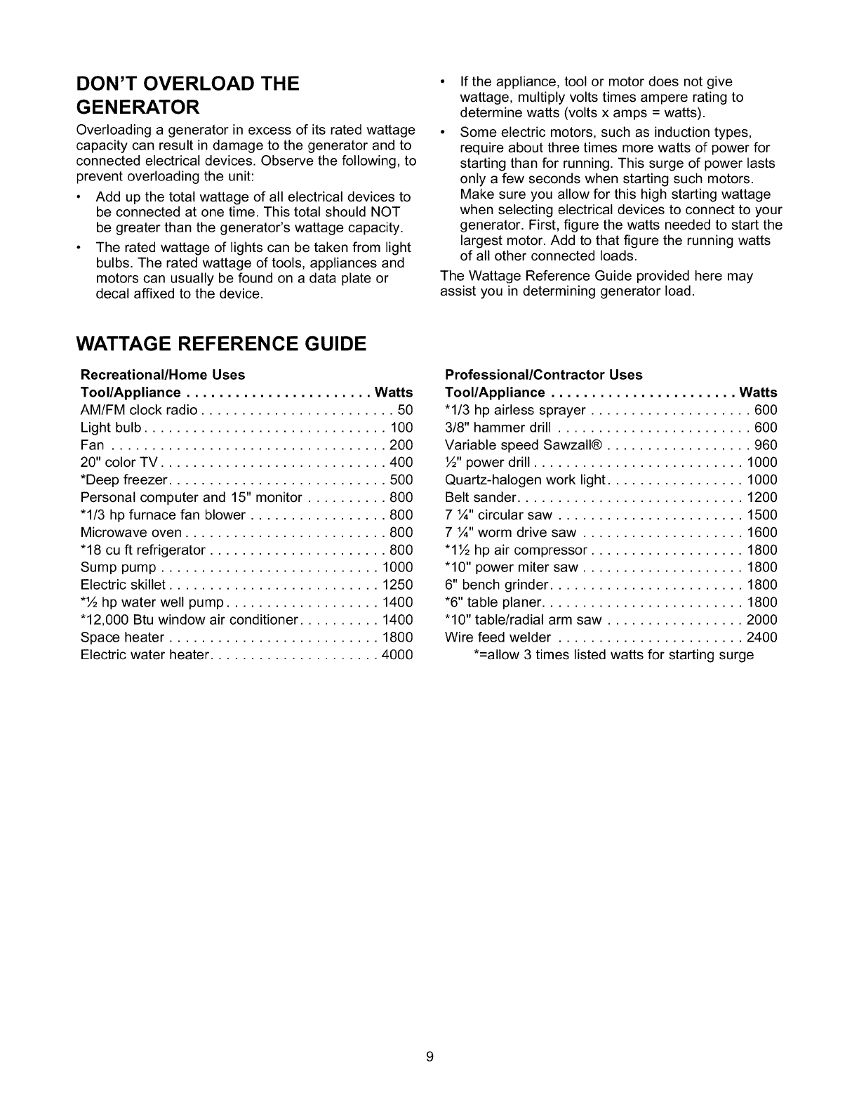
WATTAGE REFERENCE GUIDE
Recreational/Home Uses
Tool/Appliance ....................... Watts
AM/FM clock radio ........................ 50
Light bulb .............................. 100
Fan .................................. 200
20" color TV ............................ 400
*Deep freezer ........................... 500
Personal computer and 15" monitor .......... 800
"1/3 hp furnace fan blower ................. 800
Microwave oven ......................... 800
"18 cu ft refrigerator ...................... 800
Sump pump ........................... 1000
Electric skillet .......................... 1250
*½ hp water well pump ................... 1400
"12,000 Btu window air conditioner .......... 1400
Space heater .......................... 1800
Electric water heater ..................... 4000
Professional/Contractor Uses
Tool/Appliance ....................... Watts
"1/3 hp airless sprayer .................... 600
3/8" hammer drill ........................ 600
Variable speed Sawzall® .................. 960
½" power drill .......................... 1000
Quartz-halogen work light................. 1000
Belt sander ............................ 1200
7¼" circular saw ....................... 1500
7¼" worm drive saw .................... 1600
"1½ hp air compressor ................... 1800
"10" power miter saw .................... 1800
6" bench grinder ........................ 1800
*6" table planer ......................... 1800
"10" table/radial arm saw ................. 2000
Wire feed welder ....................... 2400
*=allow 3 times listed watts for starting surge
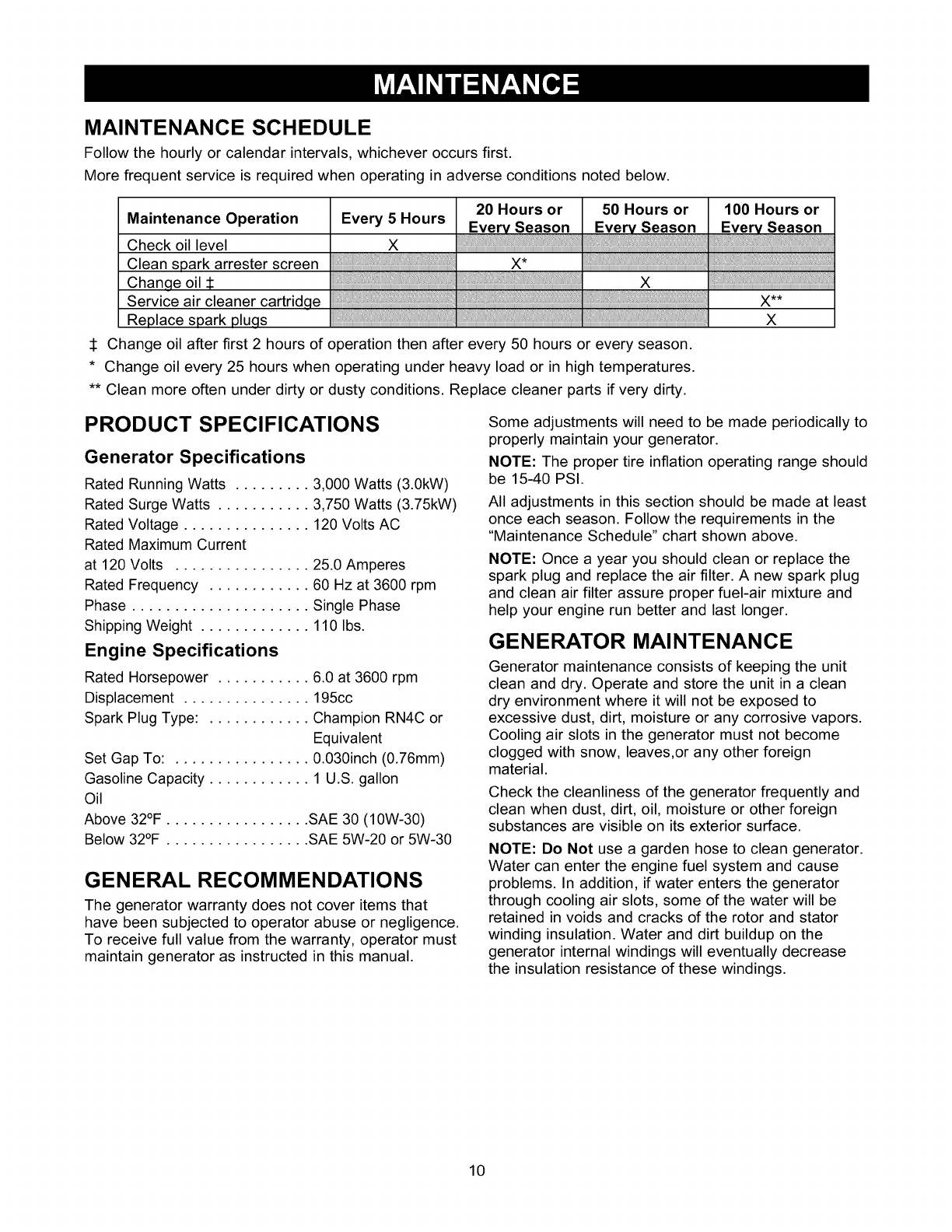
MAINTENANCE SCHEDULE
Follow the hourly or calendar intervals, whichever occurs first.
More frequent service is required when operating in adverse conditions noted below.
Maintenance Operation
Check oil level
Clean spark arrester screen
Chan_e oil
Service air cleaner cartridcle
Replace spark plucls
20 Hours or 50 Hours or 100 Hours or
Every 5 Hours Eve_ Season Eve_ Season EYe_ Season
x
x
i iiiiiiiiiiiiiiiiii, .... x**
X
:1: Change oil after first 2 hours of operation then after every 50 hours or every season.
*Change oil every 25 hours when operating under heavy load or in high temperatures.
** Clean more often under dirty or dusty conditions. Replace cleaner parts if very dirty.
PRODUCT SPECIFICATIONS
Generator Specifications
Rated RunningWatts ......... 3,000 Watts (3.0kW)
Rated Surge Watts ........... 3,750 Watts (3.75kW)
Rated Voltage ............... 120 Volts AC
Rated Maximum Current
at 120 Volts ................ 25.0 Amperes
Rated Frequency ............ 60 Hz at 3600 rpm
Phase ..................... Single Phase
Shipping Weight ............. 110 Ibs.
Engine Specifications
Rated Horsepower ........... 6.0 at 3600 rpm
Displacement ............... 195cc
Spark Plug Type: ............ Champion RN4C or
Equivalent
Set Gap To: ................ 0.030inch (0.76mm)
Gasoline Capacity ............ 1 U.S. gallon
Oil
Above 32°F ................. SAE 30 (10W-30)
Below 32°F ................. SAE 5W-20 or 5W-30
GENERAL RECOMMENDATIONS
The generator warranty does not cover items that
have been subjected to operator abuse or negligence.
To receive full value from the warranty, operator must
maintain generator as instructed in this manual.
Some adjustments will need to be made periodically to
properly maintain your generator.
NOTE: The proper tire inflation operating range should
be 15-40 PSI.
All adjustments in this section should be made at least
once each season. Follow the requirements in the
"Maintenance Schedule" chart shown above.
NOTE: Once a year you should clean or replace the
spark plug and replace the air filter. A new spark plug
and clean air filter assure proper fuel-air mixture and
help your engine run better and last longer.
GENERATOR MAINTENANCE
Generator maintenance consists of keeping the unit
clean and dry. Operate and store the unit in a clean
dry environment where it will not be exposed to
excessive dust, dirt, moisture or any corrosive vapors.
Cooling air slots in the generator must not become
clogged with snow, leaves,or any other foreign
material.
Check the cleanliness of the generator frequently and
clean when dust, dirt, oil, moisture or other foreign
substances are visible on its exterior surface.
NOTE: Do Not use a garden hose to clean generator.
Water can enter the engine fuel system and cause
problems. In addition, if water enters the generator
through cooling air slots, some of the water will be
retained in voids and cracks of the rotor and stator
winding insulation. Water and dirt buildup on the
generator internal windings will eventually decrease
the insulation resistance of these windings.
10
To Clean the Generator:
• Use a damp cloth to wipe exterior surfaces clean.
• A soft bristle brush may be used to loosen caked
on dirt, oil, etc.
_AUTION! Never insert any object or tool
through the air cooling slots, even if the engine
is not running.
• A vacuum cleaner may be used to pick up loose
dirt and debris.
Low pressure air (not to exceed 25 psi) may be
used to blow away dirt. Inspect cooling air slots
and openings on the generator. These openings
must be kept clean and unobstructed.
,_ CAUTION! When working on the generator
always disconnect spark plug wire from spark
plug and keep it away from spark plug.
ENGINE MAINTENANCE
Checking Oil Level
Oil level should be checked prior to each use or at
least every 5 hours of operation. Keep oil level
maintained.
Changing Engine Oil
Change the oil after the first 2 hours of operation.
Change oil every 50 hours thereafter. If you are using
your generator under extremely dirty or dusty
conditions, or in extremely hot weather, change the oil
more often.
Change the oil while the engine is still warm from
running, as follows:
• Clean area around oil drain plug. The oil drain plug
is located at the base of the engine, opposite the
carburetor.
• Remove oil drain plug and drain oil completely into
a suitable container.
• Install oil drain plug and tighten securely.
• Fill oil sump with recommended oil. See page 6 for
oil recommendations.
• Install the oil cap/dipstick. Check oil level. Tighten
cap securely.
• Wipe up any spilled oil.
Clean/Replace Spark Plug
Change the spark plug every 100 hours of operation
or once each year, whichever comes first. This will
help your engine to start easier and run better.
• Clean the area around the spark plug.
• Remove and inspect the spark plug.
• Replace the spark plug if electrodes are pitted or
burned or the porcelain is cracked. For
replacement use Champion RN4C or equivalent.
• Check electrode gap with wire feeler gauge and set
spark plug gap to 0.030 inch (0.76mm) if
necessary.
Service Air Cleaner
Your engine will not run properly and may be
damaged if you run it using a dirty air filter element.
Clean or replace the paper air filter element once
every 100 hours of operation or once each season,
whichever comes first. Clean or replace more often if
operating under dusty or dirty conditions.
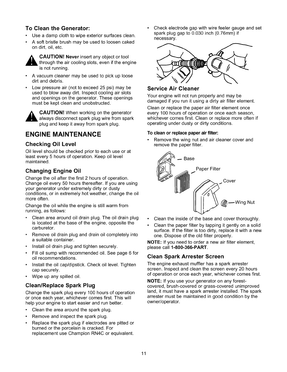
To clean or replace paper air filter:
• Remove the wing nut and air cleaner cover and
remove the paper filter.
Base
Paper Filter
_ Cover
Wing Nut
• Clean the inside of the base and cover thoroughly.
• Clean the paper filter by tapping it gently on a solid
surface. If the filter is too dirty, replace it with a new
one. Dispose of the old filter properly.
NOTE: If you need to order a new air filter element,
please call 1-800-366-PART.
Clean Spark Arrester Screen
The engine exhaust muffler has a spark arrester
screen. Inspect and clean the screen every 20 hours
of operation or once each year, whichever comes first.
NOTE: If you use your generator on any forest-
covered, brush-covered or grass-covered unimproved
land, it must have a spark arrester installed. The spark
arrester must be maintained in good condition by the
owner/operator.
11
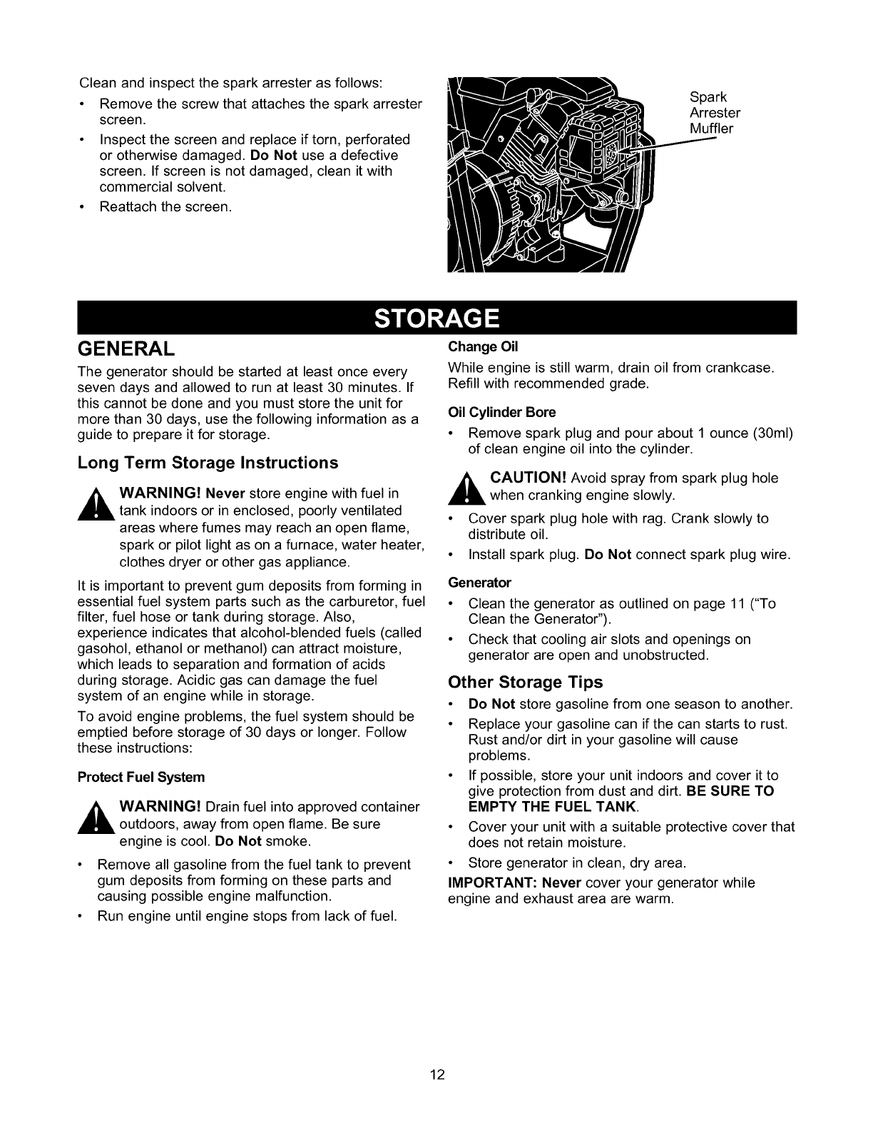
Cleanandinspectthesparkarresterasfollows:
• Removethescrewthatattachesthesparkarrester
screen.
• Inspectthescreenandreplaceiftorn,perforated
orotherwisedamaged.DoNotusea defective
screen.Ifscreenis notdamaged,cleanit with
commercialsolvent.
• Reattachthescreen.
Spark
Arrester
Muffler
GENERAL
The generator should be started at least once every
seven days and allowed to run at least 30 minutes. If
this cannot be done and you must store the unit for
more than 30 days, use the following information as a
guide to prepare it for storage.
Long Term Storage Instructions
_ARNING! Never store engine with fuel in
tank indoors or in enclosed, poorly ventilated
areas where fumes may reach an open flame,
spark or pilot light as on a furnace, water heater,
clothes dryer or other gas appliance.
It is important to prevent gum deposits from forming in
essential fuel system parts such as the carburetor, fuel
filter, fuel hose or tank during storage. Also,
experience indicates that alcohol-blended fuels (called
gasohol, ethanol or methanol) can attract moisture,
which leads to separation and formation of acids
during storage. Acidic gas can damage the fuel
system of an engine while in storage.
To avoid engine problems, the fuel system should be
emptied before storage of 30 days or longer. Follow
these instructions:
Protect Fuel System
_ ARNING! Drain fuel into approved container
outdoors, away from open flame. Be sure
engine is cool. Do Not smoke.
• Remove all gasoline from the fuel tank to prevent
gum deposits from forming on these parts and
causing possible engine malfunction.
• Run engine until engine stops from lack of fuel.
Change Oil
While engine is still warm, drain oil from crankcase.
Refill with recommended grade.
Oil Cylinder Bore
• Remove spark plug and pour about 1 ounce (30ml)
of clean engine oil into the cylinder.
_AUTION! Avoid spray from spark plug hole
when cranking engine slowly.
• Cover spark plug hole with rag. Crank slowly to
distribute oil.
• Install spark plug. Do Not connect spark plug wire.
Generator
• Clean the generator as outlined on page 11 ("To
Clean the Generator").
• Check that cooling air slots and openings on
generator are open and unobstructed.
Other Storage Tips
•Do Not store gasoline from one season to another.
• Replace your gasoline can if the can starts to rust.
Rust and/or dirt in your gasoline will cause
problems.
• If possible, store your unit indoors and cover it to
give protection from dust and dirt. BE SURE TO
EMPTY THE FUEL TANK.
• Cover your unit with a suitable protective cover that
does not retain moisture.
• Store generator in clean, dry area.
IMPORTANT: Never cover your generator while
engine and exhaust area are warm.
12
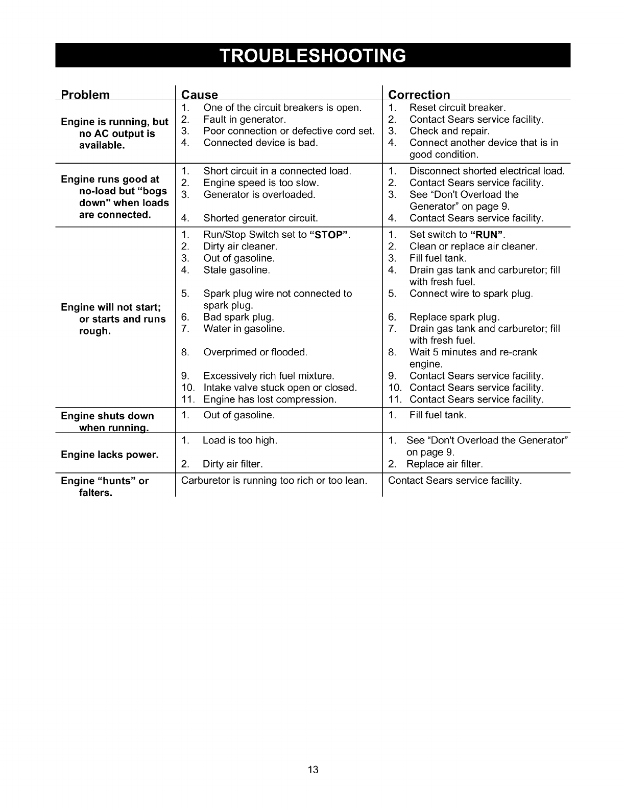
Problem Correction
Engine is running, but
no AC output is
available.
Engine runs good at
no-load but "bogs
down" when loads
are connected.
Cause
1. One of the circuit breakers is open.
2. Fault in generator.
3. Poor connection or defective cord set.
4. Connected device is bad.
1. Short circuit in a connected load.
2. Engine speed is too slow.
3. Generator is overloaded.
4. Shorted generator circuit.
1. Run/Stop Switch set to "STOP".
2. Dirty air cleaner.
3. Out of gasoline.
4. Stale gasoline.
5. Spark plug wire not connected to
1. Reset circuit breaker.
2. Contact Sears service facility.
3. Check and repair.
4. Connect another device that is in
good condition.
1. Disconnect shorted electrical load.
2. Contact Sears service facility.
3. See "Don't Overload the
Generator" on page 9.
4. Contact Sears service facility.
1. Set switch to "RUN".
2. Clean or replace air cleaner.
3. Fill fuel tank.
4. Drain gas tank and carburetor; fill
with fresh fuel.
5. Connect wire to spark plug.
Engine will not start;
or starts and runs
rough.
spark plug.
6. Bad spark plug.
7. Water in gasoline.
8. Overprimed or flooded.
9. Excessively rich fuel mixture.
6. Replace spark plug.
7. Drain gas tank and carburetor; fill
with fresh fuel.
8. Wait 5 minutes and re-crank
engine.
9. Contact Sears service facility.
Engine shuts down
when runninq.
Engine lacks power.
Engine "hunts" or
falters.
10. Intake valve stuck open or closed.
11. Engine has lost compression.
1. Out of gasoline.
1. Load is too high.
2. Dirty air filter.
Carburetor is running too rich or too lean.
10. Contact Sears service facility.
11. Contact Sears service facility.
1. Fill fuel tank.
1. See "Don't Overload the Generator"
on page 9.
2. Replace air filter.
Contact Sears service facility.
13
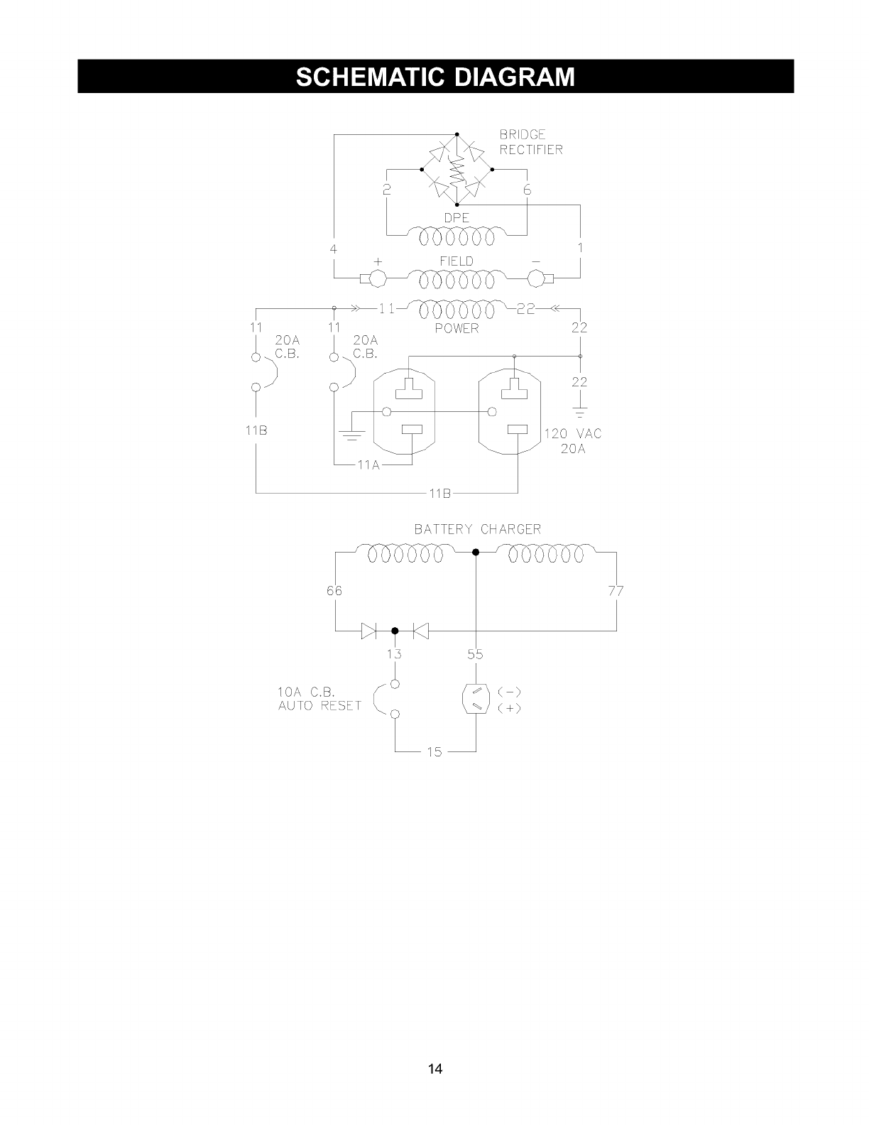
BRIDGE
RECTIFIER
FIELD
11
<_ 20A
C.B
11B
11 POWER 22
20A
C.B.
22
20 VAC
11 20A
11B
BATTERY CHARGER
66 77
13 55
15
< }
<+}
14.
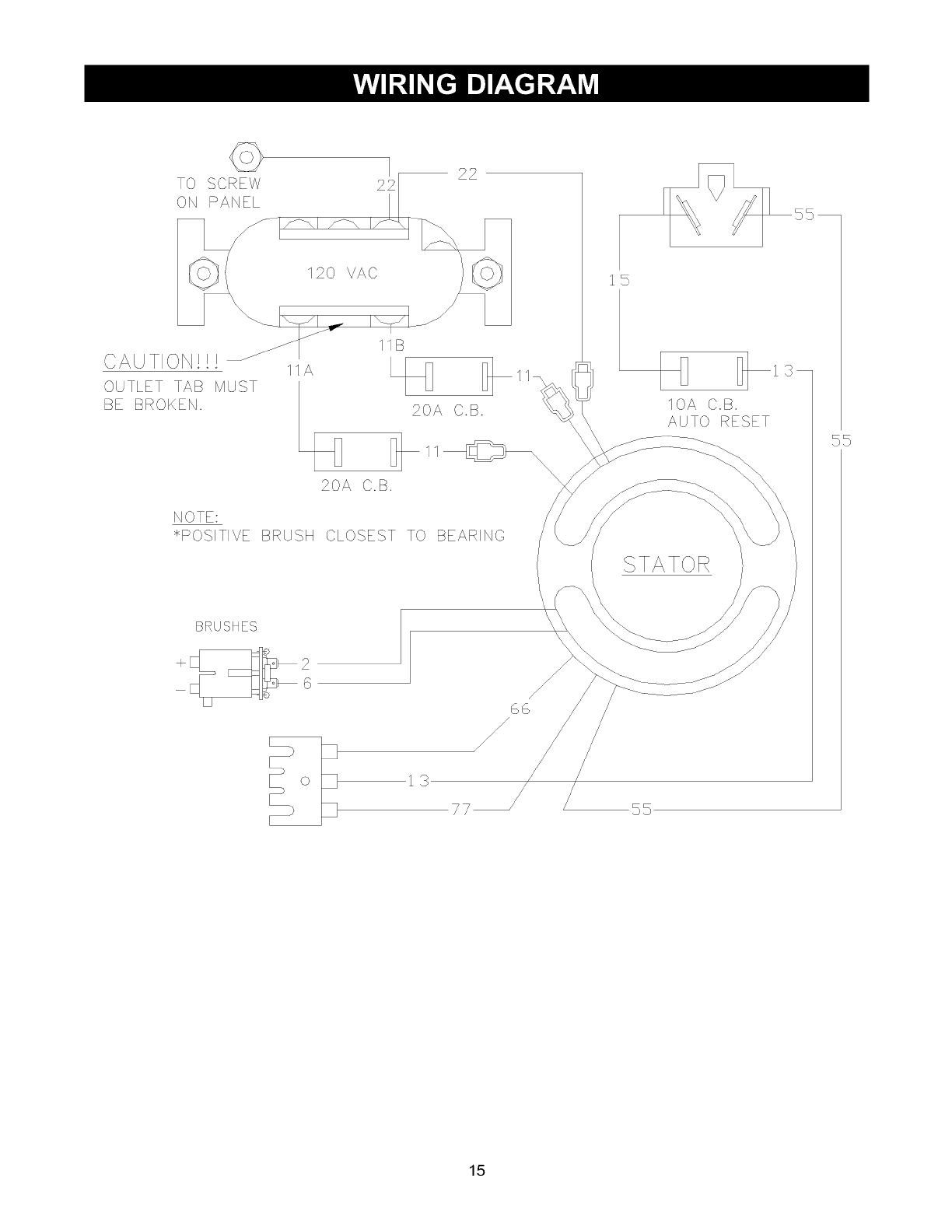
TO SCREW
ON PANEL 22 22
120 VAC
CAUTION!!!
OUTLET TAB MUST
BE BROKEN.
I
11B
20A C.B.
NOTE:
>kPOSITIVE BRUSH CLOSEST TO BEARING
BRUSHES
1S
IOA C.B.
AUTO RESET
SS
3
SS
13
77
15
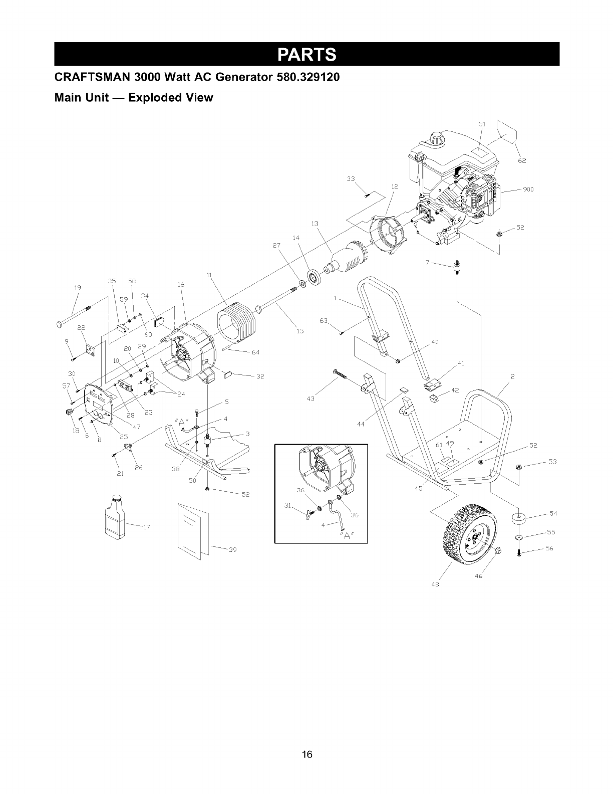
CRAFTSMAN 3000 Watt AC Generator 580.329120
Main Unit mExploded View
33
"\\\ 9OO
3S 58 16
19 / 34
3O
57\
\\
6O
/
38
/
50
----_-39
is <
14
\
43
HA_
41
/
45
/46
48
/$4
/55
_/ 56
16
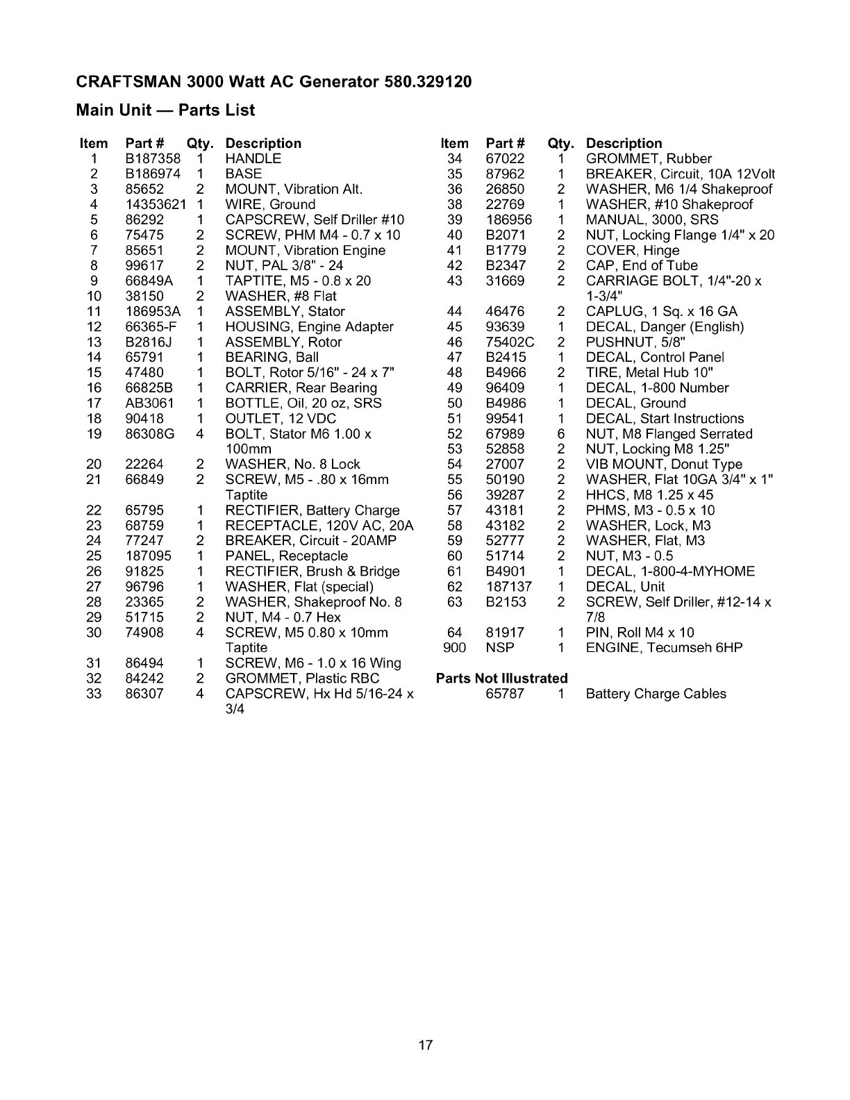
CRAFTSMAN 3000 Watt AC Generator 580.329120
Main Unit mParts List
Item PaN# Qty.
1 B187358 1
2 B186974 1
3 85652 2
4 14353621 1
5 86292 1
6 75475 2
7 85651 2
8 99617 2
9 66849A 1
10 38150 2
11 186953A 1
12 66365-F 1
13 B2816J 1
14 65791 1
15 47480 1
16 66825B 1
17 AB3061 1
18 90418 1
19 86308G 4
20 22264 2
21 66849 2
22 65795 1
23 68759 1
24 77247 2
25 187095 1
26 91825 1
27 96796 1
28 23365 2
29 51715 2
30 74908 4
31 86494 1
32 84242 2
33 86307 4
Description Item Part # Qty.
HANDLE 34 67022 1
BASE 35 87962 1
MOUNT, Vibration AIt. 36 26850 2
WIRE, Ground 38 22769 1
CAPSCREW, Self Driller #10 39 186956 1
SCREW, PHM M4 - 0.7 x 10 40 B2071 2
MOUNT, Vibration Engine 41 B1779 2
NUT, PAL 3/8"- 24 42 B2347 2
TAPTITE, M5 - 0.8 x 20 43 31669 2
WASHER, #8 Flat
ASSEMBLY, Stator 44 46476 2
HOUSING, Engine Adapter 45 93639 1
ASSEMBLY, Rotor 46 75402C 2
BEARING, Ball 47 B2415 1
BOLT, Rotor 5/16" - 24 x 7" 48 B4966 2
CARRIER, Rear Bearing 49 96409 1
BOTTLE, Oil, 20 oz, SRS 50 B4986 1
OUTLET, 12 VDC 51 99541 1
BOLT, Stator M6 1.00 x 52 67989 6
100mm 53 52858 2
WASHER, No. 8 Lock 54 27007 2
SCREW, M5 - .80 x 16mm 55 50190 2
Taptite 56 39287 2
RECTIFIER, Battery Charge 57 43181 2
RECEPTACLE, 120V AC, 20A 58 43182 2
BREAKER, Circuit - 20AMP 59 52777 2
PANEL, Receptacle 60 51714 2
RECTIFIER, Brush & Bridge 61 B4901 1
WASHER, Flat (special) 62 187137 1
WASHER, Shakeproof No. 8 63 B2153 2
NUT, M4 - 0.7 Hex
SCREW, M5 0.80 x 10mm 64 81917 1
Taptite 900 NSP 1
SCREW, M6 - 1.0 x 16 Wing
GROMMET, Plastic RBC
CAPSCREW, Hx Hd 5/16-24 x
3/4
PaNs Notlllustrated
65787 1
Description
GROMMET, Rubber
BREAKER, Circuit, 10A 12Volt
WASHER, M6 1/4 Shakeproof
WASHER, #10 Shakeproof
MANUAL, 3000, SRS
NUT, Locking Flange 1/4" x 20
COVER, Hinge
CAP, End of Tube
CARRIAGE BOLT, 1/4"-20 x
1-3/4"
CAPLUG, 1 Sq. x 16 GA
DECAL, Danger (English)
PUSHNUT, 5/8"
DECAL, Control Panel
TIRE, Metal Hub 10"
DECAL, 1-800 Number
DECAL, Ground
DECAL, Start Instructions
NUT, M8 Flanged Serrated
NUT, Locking M8 1.25"
VIB MOUNT, Donut Type
WASHER, Flat 10GA 3/4" x 1"
HHCS, M8 1.25 x45
PHMS, M3- 0.5x 10
WASHER, Lock, M3
WASHER, Flat, M3
NUT, M3- 0.5
DECAL, 1-800-4-MYHOME
DECAL, Unit
SCREW, Self Driller, #12-14 x
7/8
PIN, Roll M4 x 10
ENGINE, Tecumseh 6HP
Battery Charge Cables
17
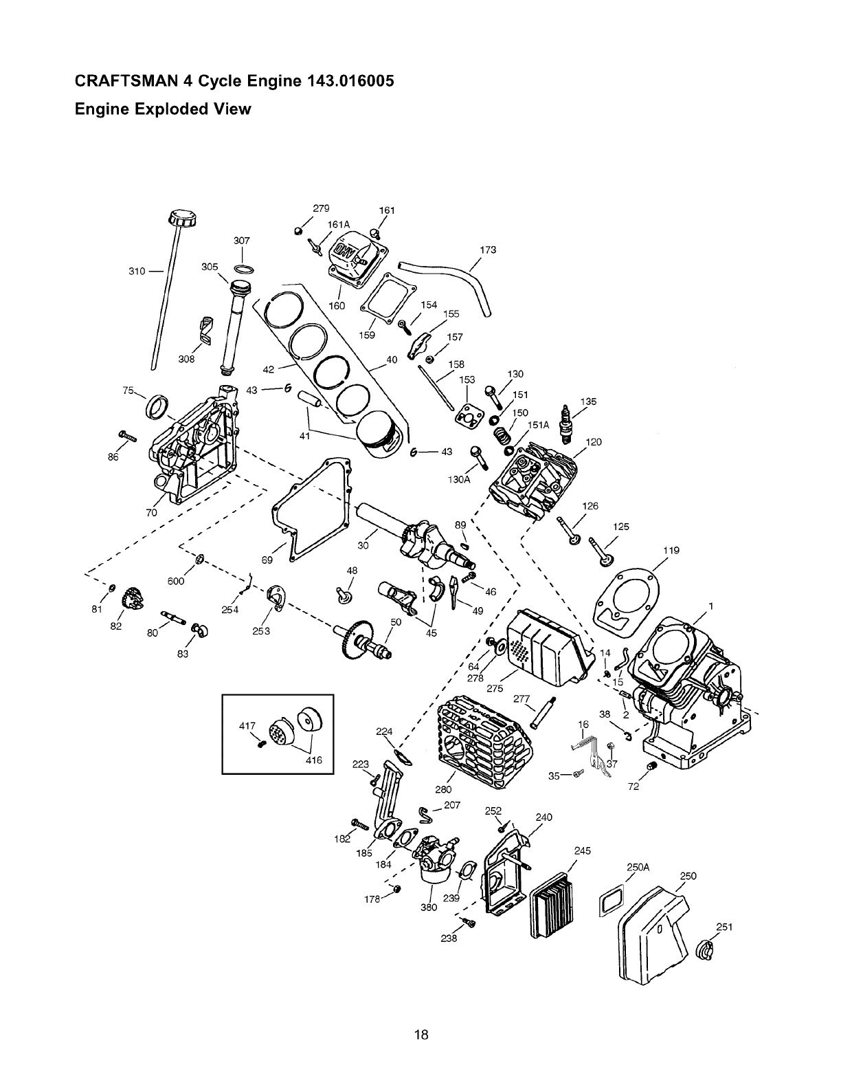
CRAFTSMAN 4 Cycle Engine 143.016005
Engine Exploded View
310 --
86
279
307
I
ao5
\
41
161
159
130
151 135
Lo
/
30
/
380 d
238
24O
/
245
250A
/250
d_ 251
d
18
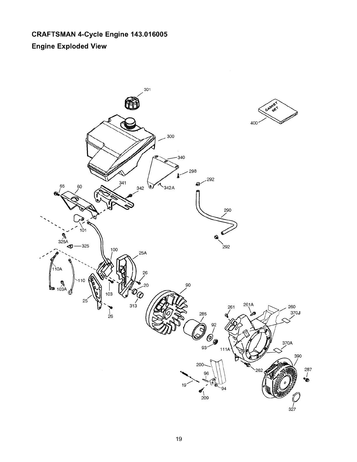
CRAFTSMAN 4-Cycle Engine 143.016005
Engine Exploded View
65 60
301
J
25A
J
26
/.20 90
313
285
/
261
111A'
4oo
261A 260
370J
370A
7
390
262 287
/
0
19
/
327
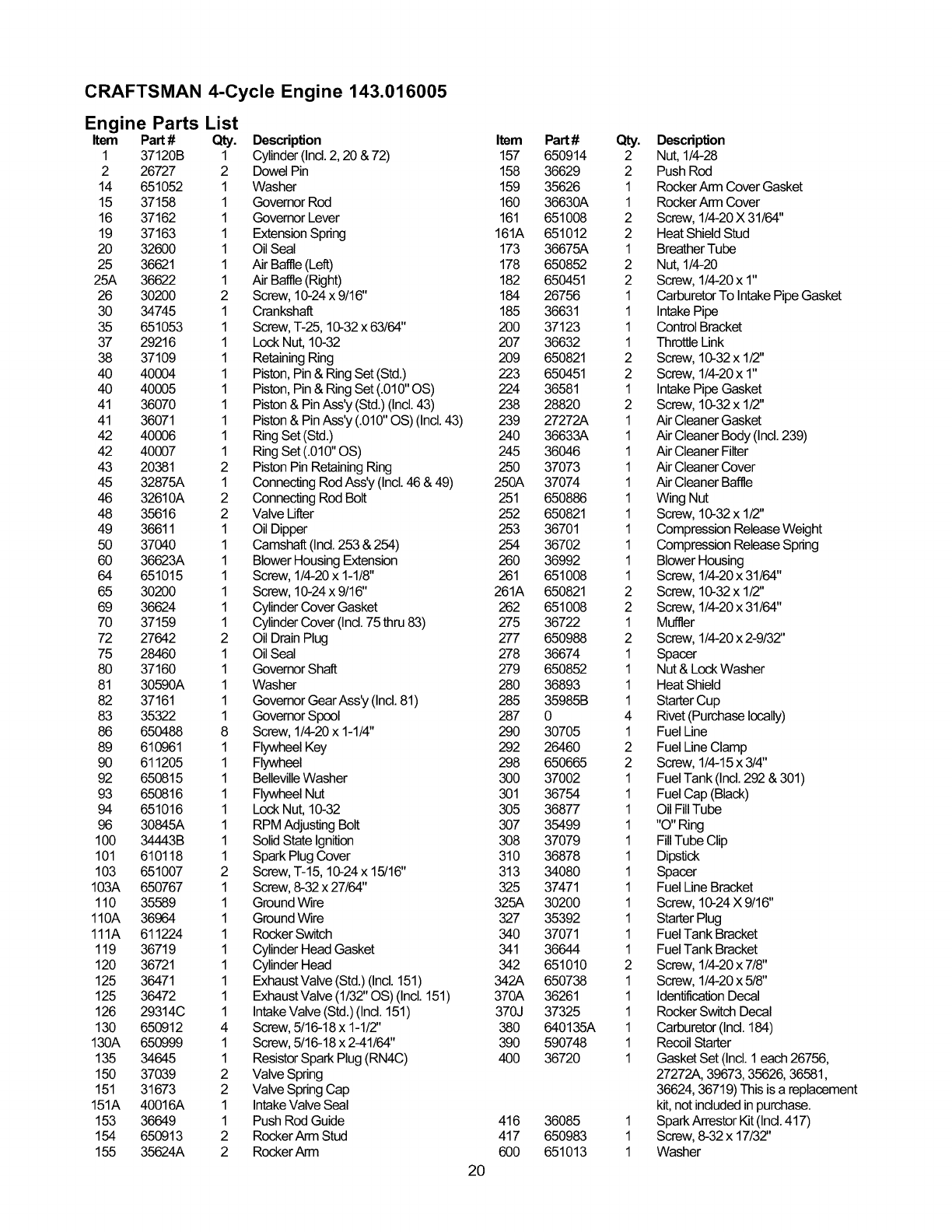
CRAFTSMAN 4-Cycle Engine 143.016005
Engine Parts List
Item Part # Qty. Description
1 37120B 1 Cylinder (Ind. 2, 20 & 72)
2 26727 2 Dowel Pin
14 651052 1 Washer
15 37158 1 Governor Rod
16 37162 1 Governor Lever
19 37163 1 Extension Spring
20 32600 1 Oil Seal
25 36621 1 Air Baffle (Left)
25A 36622 1 Air Baffle (Right)
26 30200 2 Screw, 10-24 x 9/16"
30 34745 1 Crankshaft
35 651053 1 Screw, T-25, 10-32x 63/64"
37 29216 1 Lock Nut, 10-32
38 37109 1 Retaining Ring
40 40004 1 Piston, Pin & Ring Set(Std.)
40 40005 1 Piston, Pin & Ring Set(.010" OS)
41 36070 1 Piston & Pin Ass'y (Std.) (Incl.43)
41 36071 1 Piston & Pin Ass'y (.010" OS) (Incl.43)
42 40006 1 Ring Set (Std.)
42 40007 1 Ring Set (.010" OS)
43 20381 2 Piston Pin RetainingRing
45 32875A 1 Connecting Rod Ass'y (Incl. 46 & 49)
46 32610A 2 Connecting Rod Bolt
48 35616 2 Valve Ufter
49 36611 1 Oil Dipper
50 37040 1 Camshaft (Ind. 253 & 254)
60 36623A 1 Blower Housing Extension
64 651015 1 Screw, 1/4-20 x 1-1/8"
65 30200 1 Screw, 10-24x 9/16"
69 36624 1 Cylinder Cover Gasket
70 37159 1 Cylinder Cover (Ind. 75 thru 83)
72 27642 2 Oil Drain Plug
75 28460 1 Oil Seal
80 37160 1 Governor Shaft
81 30590A 1 Washer
82 37161 1 Govemor Gear Ass'y (Incl. 81)
83 35322 1 Governor Spool
86 650488 8 Screw, 1/4-20 x 1-1/4"
89 610961 1 Flywheel Key
90 611205 1 Flywheel
92 650815 1 BellevUleWasher
93 650816 1 Flywheel Nut
94 651016 1 Lock Nut, 10-32
96 30645A 1 RPM Adjusting Bolt
100 34443B 1 SolidState Ignition
101 610118 1 Spark Plug Cover
103 651007 2 Screw, T-15, 10-24x 15/16"
103A 650767 1 Screw, 8-32 x 27/64"
110 35589 1 Ground Wire
110A 36964 1 Ground Wire
111A 611224 1 Rocker Switch
119 36719 1 Cylinder Head Gasket
120 36721 1 Cylinder Head
125 36471 1 Exhaust Valve (Std.) (Incl. 151)
125 36472 1 Exhaust Valve (1/32" OS) (Incl. 151)
126 29314C 1 Intake Valve (Std.)(Ind. 151)
130 650912 4 Screw, 5/16-18 x 1-1/2"
130A 650999 1 Screw, 5/16-18 x 2-41/64"
135 34645 1 Resistor Spark Plug (RN4C)
150 37039 2 Valve Spring
151 31673 2 Valve Spring Cap
151A 40016A 1 Intake Valve Seal
153 36649 1 Push Rod Guide
154 650913 2 Rocker Arrn Stud
155 35624A 2 Rocker Arm
Item
157
158
159
160
161
161A
173
178
182
184
185
200
207
209
223
224
238
239
240
245
250
250A
251
252
253
254
260
261
261A
262
275
277
278
279
280
285
287
290
292
298
300
301
305
307
308
310
313
325
325A
327
340
341
342
342A
370A
370J
380
390
400
416
417
600
20
Part#
650914
36629
35626
36630A
651008
651012
36675A
650852
650451
26756
36631
37123
36632
650821
650451
36581
28820
27272A
36633A
36046
37073
37074
650886
650821
36701
36702
36992
651008
650821
651008
36722
650988
36674
650852
36893
35985B
0
30705
26460
650665
37002
36754
36877
35499
37079
36878
34080
37471
30200
35392
37071
36644
651010
650738
36261
37325
640135A
590748
36720
36085
650983
651013
Qty. Description
2 Nut, 1/4-28
2 Push Rod
1 Rocker Arm Cover Gasket
1 Rocker Arm Cover
2 Screw, 1/4-20X 31/64"
2 Heat Shield Stud
1 Breather Tube
2 Nut, 1/4-20
2 Screw, 1/4-20x 1"
1 Carburetor To Intake Pipe Gasket
1 IntakePipe
1 Control Bracket
1 Throttle Link
2 Screw, 10-32x 1/2"
2 Screw, 1/4-20x 1"
1 Intake Pipe Gasket
2 Screw, 10-32x 1/2"
1 Air Cleaner Gasket
1 Air Cleaner Body (Incl.239)
1 Air Cleaner Filter
1 Air Cleaner Cover
1 Air Cleaner Baffle
1 Wing Nut
1 Screw, 10-32x 1/2"
1 Compression Release Weight
1 Compression Release Spring
1 Blower Housing
1 Screw, 1/4-20x 31/64"
2 Screw, 10-32x 1/2"
2 Screw, 1/4-20x 31/64"
1 Muffler
2 Screw, 1/4-20x 2-9/32"
1 Spacer
1 Nut & LockWasher
1 Heat Shield
1 Starter Cup
4 Rivet (Purchase locally)
1 Fuel Line
2 Fuel Line Clamp
2 Screw, 1/4-15x 3/4"
1 Fuel Tank (Incl.292 & 301)
1 Fuel Cap (Black)
1 Oil FillTube
1 "O" Ring
1 FillTube Clip
1 Dipstick
1 Spacer
1 Fuel Line Bracket
1 Screw, 10-24X 9/16"
1 Starter Plug
1 Fuel Tank Bracket
1 Fuel Tank Bracket
2 Screw, 1/4-20x 7/8"
1 Screw, 1/4-20x 5/8"
1 IdentificationDecal
1 Rocker Switch Decal
1 Carburetor (Ind. 184)
1 Recoil Starter
1 Gasket Set (Incl. 1 each 26756,
27272A, 39673, 35626, 36581,
36624, 36719) This is a replacement
kit, not included in purchase.
1 Spark Arrestor Kit (Ind. 417)
1 Screw, 8-32 x 17/3Z'
1 Washer
CRAFTSMAN 4-Cycle Engine 143.016005
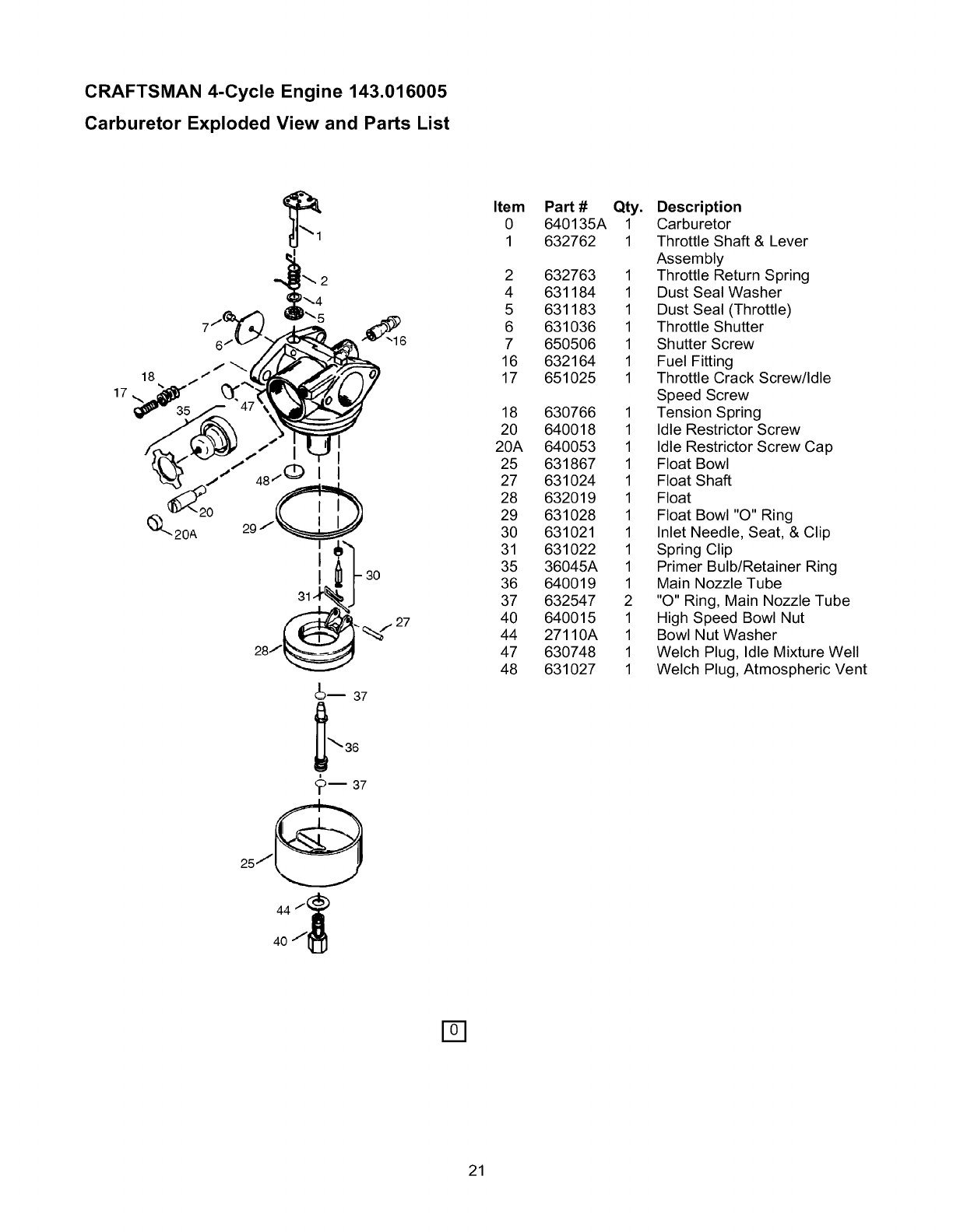
Carburetor Exploded View and Parts List
17
3O
_i 37
Item
0
1
2
4
5
6
7
16
17
18
20
20A
25
27
28
29
30
31
35
36
37
40
44
47
48
PaN #
640135A
632762
632763
631184
631183
631036
650506
632164
651025
630766
640018
640053
631867
631024
632019
631028
631021
631022
36045A
640019
632547
640015
27110A
630748
631027
Qty. Description
1 Carburetor
1 Throttle Shaft & Lever
Assembly
1 Throttle Return Spring
1 Dust Seal Washer
1 Dust Seal (Throttle)
1 Throttle Shutter
1 Shutter Screw
1 Fuel Fitting
1 Throttle Crack Screw/Idle
Speed Screw
1 Tension Spring
1 Idle Restrictor Screw
1 Idle Restrictor Screw Cap
1 Float Bowl
1 Float Shaft
1 Float
1 Float Bowl "O" Ring
1 Inlet Needle, Seat, & Clip
1 Spring Clip
1 Primer Bulb/Retainer Ring
1 Main Nozzle Tube
2 "O" Ring, Main Nozzle Tube
1 High Speed Bowl Nut
1 Bowl Nut Washer
1 Welch Plug, Idle Mixture Well
1 Welch Plug, Atmospheric Vent
<_m 37
25"/_
44 f(_
40/_
D
21
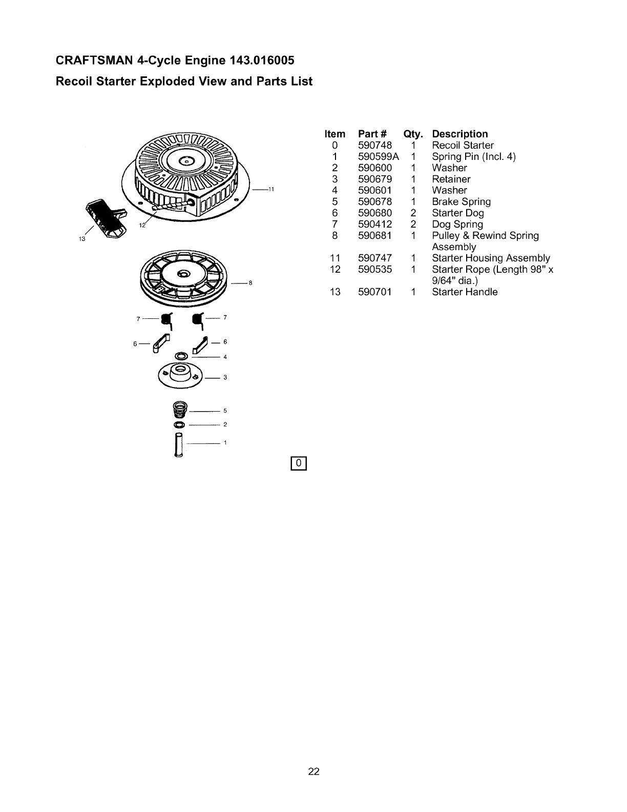
CRAFTSMAN 4-Cycle Engine 143.016005
Recoil Starter Exploded View and Parts List
/
13
--11
_8
Item
0
1
2
3
4
5
6
7
8
11
12
13
PaN #
590748
590599A
590600
590679
590601
590678
590680
590412
590681
590747
590535
590701
Qty. Description
1 Recoil Starter
1 Spring Pin (Incl. 4)
1 Washer
1 Retainer
1 Washer
1 Brake Spring
2 Starter Dog
2 Dog Spring
1 Pulley & Rewind Spring
Assembly
1 Starter Housing Assembly
1 Starter Rope (Length 98"x
9/64" dia.)
1 Starter Handle
22

23
CALIFORNIA & US EPA EMISSION
CONTROL WARRANTY STATEMENT
The U.S. Environmental Protection Agency ("EPA"), the
California Air Resources Board ("CARB") and Tecumseh
Products Co. are pleased to explain the Federal and
California Emission Control Systems Warranty on your new
small off-road engine. In California, new model year 2000
and later small off-road engines must be designed, built and
equipped to meet the State's stringent anti-smog standards.
In other states, new model year 1997 and later small off-
road engines must be designed, built and equipped, at the
time of sale, to meet U.S. EPA regulations. Tecumseh
Products Co. will warrant the emission control system on
your small off-road engine for the time periods listed below,
provided there has been no abuse, neglect, unapproved
modification, or improper maintenance of your small off-road
engine.
Your emission control system may include parts such as the
carburetor, ignition system and exhaust system. Also
included may be the compression release system and other
emission-related assemblies.
Where a warrantable condition exists, Tecumseh Products
Co. will repair your small off-road engine at no cost to you
for diagnosis, parts and labor.
Manufacturer's Emission Control System
Warranty Coverage
Emission control systems on model year 2000 and later
California small off-road engines are warranted for two
years as hereinafter noted. In other states, model year 1997
and later small off-road engines are also warranted for two
years. If during such warranty period, any emission-related
part on your engine is defective in materials or
workmanship, the part will be repaired or replaced by
Tecumseh Products Co.
Owner's Warranty Responsibilities
As the small off-road engine owner, you are responsible for
the performance of the required maintenance listed in your
Operating/Maintenance Instructions, but Tecumseh
Products Co. will not deny warranty solely due to the lack of
receipts or for your failure to provided written evidence of
the performance of all scheduled maintenance.
As the small off-road engine owner, you should, however,
be aware that Tecumseh Products Co. may deny you
warranty coverage if your small off-road engine or a part
thereof has failed due to abuse, neglect, improper
maintenance or unapproved modifications.
You are responsible for presenting your small off-road
engine to a Tecumseh Authorized Service Outlet (any
Tecumseh Registered Service Dealer, Tecumseh
Authorized Service Distributor or Tecumseh Central
Warehouse Distributor) as soon as a problem exists. The
warranty repairs should be completed in a reasonable
amount of time, not to exceed 30 days.
Warranty Service can be arranged by contacting either a
Tecumseh Authorized Service Outlet or by contacting
Tecumseh Products Co., c/o Service Manager, Engine and
Transmission Group Service Division, 900 North Street,
Grafton, WI 53024-1499. Telephone 1-262-377-2700, or see
your local telephone yellow pages under "Engines,
Gasoline" for the name, address and telephone number of a
Tecumseh Authorized Service Outlet near you.
Important Note
This warranty statement explains your rights and obligations
under the Emission Control Warranty ("ECS Warranty")
which is provided to you by Tecumseh Products Co.
pursuant to California law. Tecumseh Products Co. also
provides to the original purchasers of new Tecumseh
Products Co. engines the Tecumseh Products Co. Limited
Warranties for New Tecumseh Engine and Electronic
Ignition Modules ("Tecumseh Products Co. Warranty") which
is enclosed with all new Tecumseh Products Co. engines on
a separate sheet. The ECS warranty applies only to the
emission control system of your new engine. To the extent
that there is any conflict in terms between the ECS
Warranty and the Tecumseh Products Co. Warranty, the
ECS Warranty shall apply except in any circumstances in
which the Tecumseh Products Co. Warranty may provide a
longer warranty period. Both the ECS Warranty and the
Tecumseh Products Co. Warranty describe important rights
and obligations with respect to your engine.
Warranty service can only be performed by a Tecumseh
Products Co. Authorized Service Outlet, or by Tecumseh
Products Co. at its factory in Grafton, WI. At the time of
requesting warranty service, evidence must be presented of
the date of sale to the original purchaser. The purchaser
shall pay any charges for making service calls and/or for
transporting the products to and from the place where the
inspection and/or warranty work is performed. The
purchaser shall be responsible for any damage or loss
incurred in connection with the transportation of any engine
or any part(s) there of submitted for inspection and/or
warranty work.
If you have any questions regarding your warranty rights
and responsibilities, you should contact Tecumseh Products
Co. at 1-262-377-2700.
EMISSION CONTROL SYSTEM
WARRANTY
Emission Control System Warranty ("ECS Warranty") for
model year 2000 and later California small off-road engines
(for other states, model year 1997 and later small off-road
engines):
A. Applicability: This warranty shall apply to model year
2000 and later California small off-road engines (for other
states, model year 1997 and later small off-road engines.)
The ECS Warranty Period shall begin on the date the new
engine or equipment is delivered to its original, end-use
purchaser, and shall continue for 24 consecutive months
thereafter.
24
B. General Emissions Warranty Coverage: Tecumseh
Products Co. warrants to the original, end-use purchaser of
the new engine or equipment and to each subsequent
purchaser that each of its small off-road engines is:
1. Designed, built and equipped so as to conform with all
applicable regulations by the Air Resources Board
pursuant to its authority in Chapters 1 and 2, Part 5,
Division 26 of the Health and Safety Code, and
2. Free from defects in materials and workmanship
which, at any time during the ECS Warranty period,
will cause a warranted emissions-related part to fail to
be identical in all materials respects to the part as
described in the engine manufacturer's application for
certification.
C. The ECS Warranty only pertains to emissions-related
parts on your engine, as follows:
1. Any warranted, emissions-related parts which are not
scheduled for replacement as required maintenance in
the Operation/Maintenance Instructions shall be
warranted for the ECS Warranty Period. If any such
part fails during the ECS Warranty Period, it shall be
repaired or replaced by Tecumseh Products Co.
according to Subsection 4 below. Any such part
repaired or replaced under the ECS Warranty shall be
warranted for any remainder of the ECS Warranty
Period.
2. Any warranted, emissions-related part which is
scheduled only for regular inspection as specified in
the Operation/Maintenance Instructions shall be
warranted for the ECS Warranty Period. A statement
in such written instructions to the effect of "repair or
replace as necessary," shall not reduce the ECS
Warranty Period. Any such part repaired or replaced
under the ECS Warranty shall be warranted for the
remainder of the ECS Warranty Period.
3. Any warranted, emissions-related part which is
scheduled for replacement as required maintenance in
the Operation/Maintenance Instructions, shall be
warranted for the period of time prior to the first
scheduled replacement point for that part. If the part
fails prior to the first scheduled replacement, the part
shall be repaired or replaced by Tecumseh Products
Co. according to Subsection 4 below. Any such
emissions-related part repaired or replaced under the
ECS Warranty, shall be warranted for the remainder of
the ECS Warranty period prior to the first scheduled
replacement point for such emissions-related part.
4. Repair or replacement of any warranted, emissions
related part under this ECS Warranty shall be
performed at no charge at a Tecumseh Authorized
Service Outlet.
5. The owner shall not be charged for diagnostic labor
which leads to the determination that a part covered
by the ECS Warranty is in fact defective, provided that
such diagnostic work is performed at a Tecumseh
Authorized Service Outlet.
6. Tecumseh Products Co. shall be liable for damages to
other original engine components or approved
modifications proximately caused by a failure under
warranty of an emission-related part covered by the
ECS warranty.
7. Throughout the ECS Warranty Period, Tecumseh
Products Co. shall maintain a supply of warranted
emission-related parts sufficient to meet the expected
demand for such emission-related parts.
8. Any Tecumseh Products Co. authorized or approved
emission-related replacement part may be used in the
performance of any ECS Warranty maintenance or
repair and will be provided without charge to the
owner. Such use shall not reduce Tecumseh Products
Co. ECS Warranty obligations.
9. Unapproved add-on or modified parts may not be used
to modify or repair a Tecumseh Products Co. engine.
Such use voids this ECS Warranty shall be sufficient
grounds for disallowing an ECS Warranty Claim.
Tecumseh Products Co. shall not be liable hereunder
for failures of any warranted parts of a Tecumseh
Products Co. engine caused by the use of such an
unapproved add-on or modified part.
EMISSION-RELATED PARTS INCLUDE THE
FOLLOWING:
1. Carburetor Assembly and its Internal Components.
a) Fuel filter
b) Carburetor gaskets
c) Intake pipe
2. Air Cleaner Assembly
a) Air Cleaner Element
3. Ignition System, including:
a) Spark plug
b) Ignition module
c) Flywheel assembly
4. Catalytic Muffler (if so equipped)
a) Muffler gasket (if so equipped)
b) Exhaust manifold (if so equipped)
5. Crankcase Breather Assembly and its Components
a) Breather connection tube
25
GARANTIA...........................................................26
REGLASDESEGURIDAD..................................27
MONTAJE............................................................29
FUNCIONAMIENTO........................................29-33
MANTENIMIENTO..........................................34-36
ESPECIFICACIONES...........................................34
ALMACENAMIENTO............................................36
REPARACIONDEAVERIAS...............................37
GARANTIADELSISTEMADECONTROL
DEEMISIONES..............................................38-39
COMOORDENARPARTES........ULTIMAPAGINA
GARANTIA LIMITADA GENERADORES CRAFTSMAN
SEARS le garantiza al comprador original que el alternador y el motor de su generador portatil estara libre de defectos en
materiales y mano de obra en los componentes y por el periodo de tiempo establecido a continuaciSn a partir de la fecha
de compra original. Esta garantia no es transferible.
CLIENTE* COMERClAL*
Alternador 1 aSo 90 Dias
Motor 1 aSo 90 Dias
*NOTA: Para propositos de esta garantia el t_rmino "Uso del Cliente" representa el uso dom_stico residencial y de
emergencia por parte del comprador original, sin incluir aplicaciones donde la unidad sea usada como fuente de
potencia principal. El t_rmino "Uso Comercial" representa todos los otros usos, incluyendo alquiler, construccion,
comercial y para propositos lucrativos. Una vez el generador haya tenido uso comercial, _ste sera considerado
como un generador para uso comercial para los fines de esta garantia.
Durante dicho periodo de garantia, SEARS reparara o reemplazara, a su discreciSn, cualquier parte que haya sido
encontrada defectuosa, en examen previo realizado por SEARS, bajo uso y servicio normal**. Las baterias de arranque y
los elementos perecederos como bujias y filtros de aire, que se desgastan con el uso normal, no estan garantizados por
SEARS. Todos los costos de transporte bajo garantia, incluyendo el envio a la fabrica, de ser necesario, seran
responsabilidad del comprador y deberan ser pagados por anticipado. Esta garantia no cubre el mantenimiento y servicio
normal y no se aplica a generadores, alternadores, motores o pares que hayan sido sujetos a instalaciones o
modificaciones incorrectas o no autorizadas, mal uso, negligencia, accidente, sobrecarga, exceso de velocidad,
mantenimiento, reparaciSn o almacenamiento incorrecto que, a juicio de SEARS, afecte negativamente su funcionamiento y
confiabilidad.
** DESGASTE NORMAL: Como con todos los dispositivos mecanicos, los motores necesitan el servicio y
reemplazo periodico de las partes para funcionar en buenas condiciones. Esta garantia no cubre reparaciones
cuando el uso normal haya sobrepasado la vida (=til de una parte o motor.
NO EXISTEN OTRAS GARANTIAS EXPRESAS. SEARS POR MEDIO DE LA PRESENTE DESCONOCE TODAS LAS
GARANTIAS IMPLICITAS, INCLUYENDO, SIN LIMITARSE, A AQUELLAS DE COMERCIALIZACION Y ADAPTACION
PARA UN PROPOSITO PARTICULAR AL EXTREMO PERMITIDO POR LA LEY. LA DURACION DE CUALQUIER
GARANTIA IMPLICITA QUE NO PUEDA SER DESCONOCIDA, ESTA LIMITADA AL PERIODO DE TIEMPO
ESPECIFICADO EN LA GARANTIA EXPRESA. LA RESPONSABILIDAD LEGAL ES EXCLUIDA POR DANOS
CONSECUENCIALES, INCIDENTALES O ESPECIALES BAJO CUALQUIERA DE LAS GARANTIAS.
Algunos estados no permiten limitaciones en la duraciSn de las garantias implicitas, o la exclusiSn o limitaciSn de daSos
incidentales o consecuenciales, por tanto las limitaciones o exclusiones anteriormente mencionadas podrian no aplicarse
a usted. Esta garantia le otorga derechos legales especificos; usted podria tener otros derechos, los cuales cambian de
estado a estado.
Para servicio, visite su centro de servicio de garantia autorizado SEARS mas cercano. El servicio de garantia puede ser
Ilevado a cabo enicamente por un centro de servicio autorizado SEARS. Esta garantia no se podra aplicar para servicio en
otros centros de servicio. Evidencia de la fecha de compra original debera ser presentada en el momento de solicitar el
servicio de garantia.
SEARS, ROEBUCK AND CO., Department 817WA, Hoffman Estates, IL 60179
26
iPRECAUClON! Lea este manual y siga todas las
Reglas de Seguridad e Instrucciones de Operaci6n
antes de usar este producto.
iADVERTENClA! Siesta unidad se usa para
energia de refuerzo, usted debe aislar el generador
de cualquier utilidad el6ctrica usando un equipo de
transferencia aprobado. Si no se aisla de la manera
adecuada, puede resultar en un accidente e
inclusive la muerte para los electricistas que
trabajen alli y por Io tanto, daSo al generador
debido a la retroalimentaci6n de energia el6ctrica. En
todo momento que la unidad est6 proveyendo
energia de refuerzo, la compaSia el6ctrica de
utilidades debe ser notificada.
iPELIGRO! Los gases provenientes del
generador contienen monoxido de carbono, el
cual puede causar la MUERTE. Si se respira en
concentraciones suficientes, el monoxido de
carbono puede hacer que la persona quede
inconsciente o a_n pierda la vida. Opere este
equipo al aire libre donde haya bastante ventilaci6n.
iPRECAUCION! Siempre desconecte el alambre
de la bujia y col6quelo donde no pueda entrar en
contacto con la bujia, para evitar el arranque
accidental durante la instalaci6n, transporte, ajuste o
reparaci6n de su generador.
•El motor-generador requiere de un flujo adecuado de aire
de enfriamiento para que funcione continua y
correctamente. Nunca opere esta unidad dentro de un
sal6n o recinto cerrado donde el flujo libre de aire de
enfriamiento, hacia el interior y la parte externa de la
unidad, pueda ser obstruido. Sin suficiente flujo de aire
de enfriamiento, la unidad se recalienta rapidamente,
daSando el generador o la propiedad alrededor.
• El generador produce un voltaje muy alto, el cual puede
ocasionar descargas el6ctricas extremamente
peligrosas. Evite el contacto con terminales, alambres
pelados o sin recubrimiento, etc. Nunca permita que
personas no calificadas operen o proporcionen servicio
al generador.
• No Ilene el tanque de combustible excesivamente.
Siempre permita que exista espacio para la expansi6n
del combustible. Si el tanque esta demasiado Ileno, el
combustible podria rebosarse y caer sobre el motor
caliente y ocasionar un INCENDIO o una EXPLOSION.
• Nunca opere el generador:
en la Iluvia; en espacios encerrados; si la velocidad del
motor varia; si se recalientan los dispositivos el6ctricos
conectados; si se pierde la salida el6ctrica; si se
presentan chispas en el motor o generador; si se
observan llamas o humo cuando la unidad esta
funcionando; si la unidad vibra demasiado.
• Nunca manipule dispositivos o cordones el6ctricos
cuando se encuentre parado en agua, descalzo o con
los pies o las manos mojadas.
• Use un interruptor de circuito de falla a tierra en areas
hQmedas o de alta conductividad (como en pisos
metalicos o estructuras de acero).
• No utilice en el generador juegos de cordones el6ctricos
que est6n desgastados, pelados, raidos o daSados de
cualquier manera. El uso de un cord6n defectuoso puede
resultar en descarga el6ctrica o daSo del equipo y/o la
propiedad.
• Opere el generador sSIo en superficies planas yen
donde no sera expuesto a la humedad excesiva, la
tierra, el polvo ni vapores corrosivos.
• La gasolina es altamente INFLAMABLE y sus vapores
son EXPLOSIVOS. No permita que fumen, que existan
llamas abiertas, chispas o calor a su alrededor cuando
manipule gasolina. Evite regar gasolina sobre un motor
caliente. Cumpla con todas las leyes que regulan el
almacenamiento y el manejo de gasolina.
• Nunca almacene el generador con combustible en el
tanque, donde los vapores de la gasolina puedan entrar
en contacto con llamas abiertas, chispas o luces de piloto
(como en hornos, calentadores de agua o secadoras de
ropa). Podrian ocurrir INCENDIOS o EXPLOSIONES.
• Nunca agregue el combustible mientras la unidad corre.
• Nunca arranque o detenga el motor-generador cuando
tenga cargas el6ctricas conectadas a los tomacorrientes
y los dispositivos conectados est6n ENCENDIDOS.
Arranque el motor y permita que se estabilice antes de
conectar las cargas el6ctricas. Desconecte todas las
cargas el6ctricas antes de apagar el generador.
• No meta objetivo por la refrigeraci6n ranuras del
generador de motor.
NOTA: El motor de su generador esta equipado con un
silenciador apagachispas, el apagachispas debera ser
mantenido en buenas condiciones de funcionamiento por
parte del propietario/operador. En el estado de California es
obligatorio, segQn ley, el uso de apagachispas (SecciSn
4442 del CSdigo de Recursos P0blicos de California). Otros
estados pueden tener leyes similares. Las leyes federales
se aplican en tierras federales.
AUSQUE ESTE SIMBOLO PARA SENALAR PRECAUCIONES DE SEGURIDAD IMPORTANTES.
ESTO SIGNIFICA "iATENCION!!! iESTE ALERTA!!! SU SEGURIDAD ESTA EN PELIGRO."
27
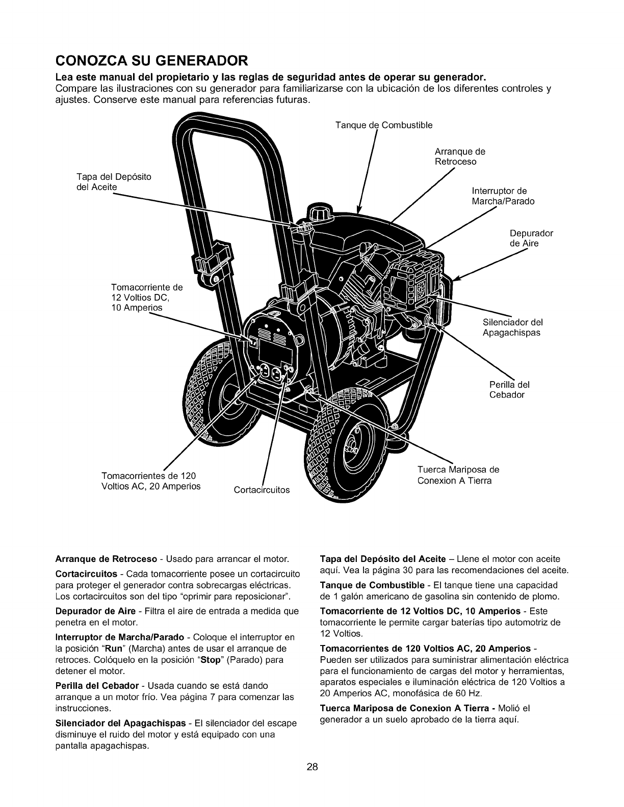
CONOZCA SU GENERADOR
Lea este manual del propietario y las reglas de seguridad antes de operar su generador.
Compare las ilustraciones con su generador para familiarizarse con la ubicaci6n de los diferentes controles y
ajustes. Conserve este manual para referencias futuras.
Tanque de Combustible
Tapa del Dep6sito
del Aceite
Arranque de
Retroceso
Interruptor de
Marcha/Parado
Tomacorriente de
12 Voltios DC,
10 Amperios
Depurador
de Aire
Silenciador del
Apagachispas
Perilla del
Cebador
Tomacorrientes de 120
Voltios AC, 20 Amperios Cortacircuitos
Tuerca Mariposa de
Conexion A Tierra
Arranque de Retroceso - Usado para arrancar el motor.
Cortacircuitos - Cada tomacorriente posee un cortacircuito
para proteger el generador contra sobrecargas el6ctricas.
Los cortacircuitos son del tipo "oprimir para reposicionar".
Depurador de Aire - Filtra el aire de entrada a medida que
penetra en el motor.
Interruptor de Marcha/Parado - Coloque el interruptor en
la posici6n "Run" (Marcha) antes de usar el arranque de
retroces. Col6quelo en la posici6n "Stop" (Parado) para
detener el motor.
Perilla del Cebador - Usada cuando se esta dando
arranque a un motor frio. Vea pagina 7 para comenzar las
instrucciones.
Silenciador del Apagachispas - El silenciador del escape
disminuye el ruido del motor y esta equipado con una
pantalla apagachispas.
Tapa del Deposito del Aceite - Llene el motor con aceite
aqui. Vea la pagina 30 para las recomendaciones del aceite.
Tanque de Combustible - El tanque tiene una capacidad
de 1 gal6n americano de gasolina sin contenido de plomo.
Tomacorriente de 12 Voltios DC, 10 Amperios - Este
tomacorriente le permite cargar baterias tipo automotriz de
12 Voltios.
Tomacorrientes de 120 Voltios AC, 20 Amperios -
Pueden ser utilizados para suministrar alimentaci6n el6ctrica
para el funcionamiento de cargas del motor y herramientas,
aparatos especiales e iluminaci6n el6ctrica de 120 Voltios a
20 Amperios AC, monofasica de 60 Hz.
Tuerca Mariposa de Conexion A Tierra - Moli6 el
generador a un suelo aprobado de la tierra aqui.
28
PARA RETIRAR EL GENERADOR
DE LA CAJA
•Corte dos esquinas en el extremo de la caja de la parte
superior a la inferior, de manera que pueda doblar el
panel hacia abajo en forma plana, despu6s retire todo el
material de protecci6n.
• Retire el generador y su contenido de la caja de envio.
CONTENIDO DE LA CAJA
Revise todo el contenido comparandolo con la lista a
continuaci6n:
• Unidad Principal
• Aceite del Motor
• Manual del Propietario
• Cables de Carga de la Bateria
Si cualquier parte falta o esta dafiada, Ilame a la Linea de
Ayuda del Generador al 1-81)0-222-3136.
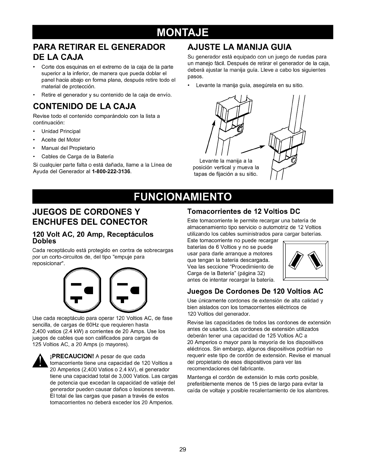
AJUSTE LA MANIJA GUIA
Su generador esta equipado con un juego de ruedas para
un manejo facil. Despu6s de retirar el generador de la caja,
debera ajustar la manija guia. Lleve a cabo los siguientes
pasos.
• Levante la manija guia, asegQrela en su sitio.
/
Levante la manija a la
posici6n vertical y mueva la
tapas de fijaci6n a su sitio.
JUEGOS DE CORDONES Y
ENCHUFES DEL CONECTOR
120 Volt AC, 20 Amp, Recept_culos
Dobles
Cada receptaculo esta protegido en contra de sobrecargas
por un corto-circuitos de, del tipo "empuje para
reposicionar". @@
Use cada receptaculo para operar 120 Voltios AC, de fase
sencilla, de cargas de 60Hz que requieren hasta
2,400 vatios (2.4 kW) a corrientes de 20 Amps. Use los
juegos de cables que son calificados para cargas de
125 Voltios AC, a 20 Amps (o mayores).
,_ iPRECAUCION! A pesar de que cada
tomacorriente tiene una capacidad de 120 Voltios a
20 Amperios (2,400 Vatios o 2.4 kV), el generador
tiene una capacidad total de 3,000 Vatios. Las cargas
de potencia que excedan la capacidad de vatiaje del
generador pueden causar dafios o lesiones severas.
El total de las cargas que pasan a trav6s de estos
tomacorrientes no debera exceder los 20 Amperios.
Tomacorrientes de 12 Voltios DO
Este tomacorriente le permite recargar una bateria de
almacenamiento tipo servicio o automotriz de 12 Voltios
utilizando los cables suministrados para cargar baterias.
Este tomacorriente no puede recargar
baterias de 6 Voltios y no se puede
usar para darle arranque a motores
que tengan la bateria descargada.
Vea las seccione "Procedimiento de
Carga de la Bateria" (pagina 32)
antes de intentar recargar la bateria.
Juegos De Cordones De 120 Voltios AC
Use Qnicamente cordones de extensi6n de alta calidad y
bien aislados con los tomacorrientes el6ctricos de
120 Voltios del generador.
Revise las capacidades de todos las cordones de extensi6n
antes de usarlos. Los cordones de extensi6n utilizados
deberan tener una capacidad de 125 Voltios AC a
20 Amperios o mayor para la mayoria de los dispositivos
el6ctricos. Sin embargo, algunos dispositivos podrian no
requerir este tipo de cord6n de extensi6n. Revise el manual
del propietario de esos dispositivos para ver las
recomendaciones del fabricante.
Mantenga el cord6n de extensi6n Io mas corto posible,
preferiblemente menos de 15 pies de largo para evitar la
caida de voltaje y posible recalentamiento de los alambres.
29
COMO USAR SU GENERADOR
SI TIENE PROBLEMAS operando su generador despu6s de
leer el manual, por favor Ilame a la linea de ayuda para
generadores al 1-81)0-222-3136.
Conexion a Tierra del Generador
El C6digo EI6ctrico Nacional exige que el bastidor y las
partes externas conductoras de electricidad del generador
se encuentren conectadas adecuadamente a una tierra
fisica aprobada. Los c6digos el6ctricos locales tambi6n
podrian exigir la conexi6n a tierra de la unidad. Para tal
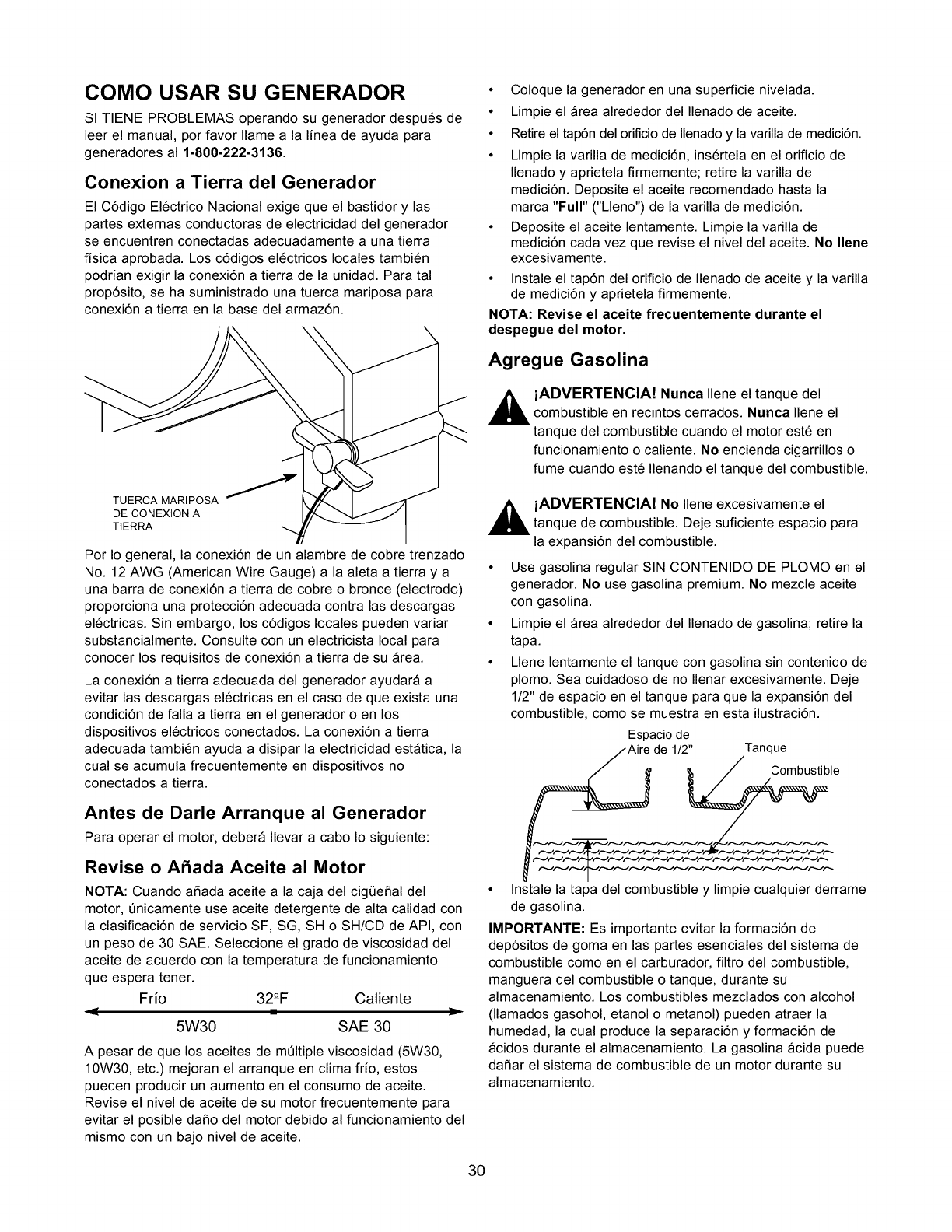
prop6sito, se ha suministrado una tuerca mariposa para
conexi6n a tierra en la base del armaz6n.
TUERCA MARIPOSA _'__DE CONEXlON A
TIERRA
Por Io general, la conexi6n de un alambre de cobre trenzado
No. 12 AWG (American Wire Gauge) a la aleta a tierra y a
una barra de conexi6n a tierra de cobre o bronce (electrodo)
proporciona una protecci6n adecuada contra las descargas
el6ctricas. Sin embargo, los c6digos locales pueden variar
substancialmente. Consulte con un electricista local para
conocer los requisitos de conexi6n a tierra de su Area.
La conexi6n a tierra adecuada del generador ayudara a
evitar las descargas el6ctricas en el caso de que exista una
condici6n de falla a tierra en el generador o en los
dispositivos el6ctricos conectados. La conexi6n a tierra
adecuada tambi6n ayuda a disipar la electricidad estatica, la
cual se acumula frecuentemente en dispositivos no
conectados a tierra.
• Coloque la generador en una superficie nivelada.
• Limpie el area alrededor del Ilenado de aceite.
• Retire el tap6n del orificio de Ilenado y la varilla de medici6n.
• Limpie la varilla de medici6n, ins6rtela en el orificio de
Ilenado y aprietela firmemente; retire la varilla de
medici6n. Deposite el aceite recomendado hasta la
marca "Full" ("Lleno") de la varilla de medici6n.
• Deposite el aceite lentamente. Limpie la varilla de
medici6n cada vez que revise el nivel del aceite. No Ilene
excesivamente.
• Instale el tap6n del orificio de Ilenado de aceite y la varilla
de medici6n y aprietela firmemente.
NOTA: Revise el aceite frecuentemente durante el
despegue del motor.
Agregue Gasolina
,_ iADVERTENCIA! Nunca Ilene el tanque del
____ combustible en recintos cerrados. Nunca Ilene el
tanque del combustible cuando el motor est6 en
funcionamiento o caliente. No encienda cigarrillos o
fume cuando est6 Ilenando el tanque del combustible.
,_ iADVERTENCIA! No Ilene excesivamente el
tanque de combustible. Deje suficiente espacio para
la expansi6n del combustible.
• Use gasolina regular SIN CONTENIDO DE PLOMO en el
generador. No use gasolina premium. No mezcle aceite
con gasolina.
• Limpie el area alrededor del Ilenado de gasolina; retire la
tapa.
• Llene lentamente el tanque con gasolina sin contenido de
plomo. Sea cuidadoso de no Ilenar excesivamente. Deje
1/2" de espacio en el tanque para que la expansi6n del
combustible, como se muestra en esta ilustraci6n.
Espacio de
1/2" Tanque
Combustible
Antes de Darle Arranque al Generador
Para operar el motor, debera Ilevar a cabo Io siguiente:
Revise o ASada Aceite al Motor
NOTA: Cuando aSada aceite a la caja del cigeeSal del
motor, enicamente use aceite detergente de alta calidad con
la clasificaci6n de servicio SF, SG, SH o SH/CD de API, con
un peso de 30 SAE. Seleccione el grado de viscosidad del
aceite de acuerdo con la temperatura de funcionamiento
que espera tener.
Frio 32°-F Caliente
5W30 SAE 30
A pesar de que los aceites de mQItiple viscosidad (5W30,
10W30, etc.) mejoran el arranque en clima frio, estos
pueden producir un aumento en el consumo de aceite.
Revise el nivel de aceite de su motor frecuentemente para
evitar el posible daSo del motor debido al funcionamiento del
mismo con un bajo nivel de aceite.
• Instale la tapa del combustible y limpie cualquier derrame
de gasolina.
IMPORTANTE: Es importante evitar la formaci6n de
dep6sitos de goma en las partes esenciales del sistema de
combustible como en el carburador, filtro del combustible,
manguera del combustible o tanque, durante su
almacenamiento. Los combustibles mezclados con alcohol
(llamados gasohol, etanol o metanol) pueden atraer la
humedad, la cual produce la separaci6n y formaci6n de
acidos durante el almacenamiento. La gasolina acida puede
daSar el sistema de combustible de un motor durante su
almacenamiento.
30
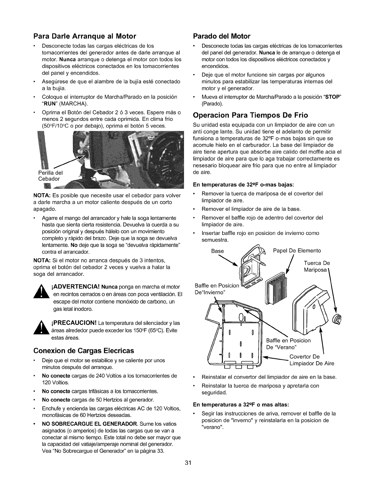
Para Darle Arranque al Motor
• Desconecte todas las cargas el6ctricas de los
tomacorrientes del generador antes de darle arranque al
motor. Nunca arranque o detenga el motor con todos los
dispositivos el6ctricos conectados en los tomacorrientes
del panel y encendidos.
• AsegQrese de que el alambre de la bujia est6 conectado
a la bujia.
• Coloque el interruptor de Marcha/Parado en la posici6n
"RUN" (MARCHA).
• Oprima el Bot6n del Cebador 2 63 veces. Espere mas o
menos 2 segundos entre cada oprimida. En clima frio
(50°F/10°C o por debajo), oprima el bot6n 5 veces.
Perilla del
Cebador
NOTA: Es posible que necesite usar el cebador para volver
a darle marcha a un motor caliente despu6s de un corto
apagado.
• Agarre el mango del arrancador y hale la soga lentamente
hasta que sienta cierta resistencia. Devuelva la cuerda a su
posici6n original y despu6s halelo con un movimiento
completo y rapido del brazo. Deje que la soga se devuelva
lentamente. No deje que la soga se "devuelva rapidamente"
contra el arrancador.
NOTA: Si el motor no arranca despu6s de 3 intentos,
oprima el bot6n del cebador 2 veces y vuelva a halar la
soga del arrancador.
,_ iADVERTENCIA! Nunca ponga en marcha el motor
en recintos cerrados o en Areas con poca ventilaci6n. El
escape del motor contiene mon6xido de carbono, un
gas letal inodoro.
,_ iPRECAUCION! La temperatura del silenciador y las
Areas alrededor puede exceder los 150=°F(65-°C).Evite
estas Areas.
Conexion de Cargas Elecricas
• Deje que el motor se estabilice y se caliente por unos
minutos despu6s del arranque.
• No conecte cargas de 240 Voltios a los tomacorrientes de
120 Voltios.
•No conecte cargas trifasicas a los tomacorrientes.
•No conecte cargas de 50 Hertzios al generador.
• Enchufe y encienda las cargas el6ctricas AC de 120 Voltios,
monofasicas de 60 Hertzios deseadas.
NO SOBRECARGUE EL GENERADOR. Sume los vatios
asignados (o amperios) de todas las cargas que se van a
conectar al mismo tiempo. Este total no debe ser mayor que
la capacidad del vatiaje/amperaje nominal del generador.
Vea "No Sobrecargue el Generador" en la pagina 33.
Parado del Motor
• Desconecte todas las cargas el6ctricas de los tomacorrientes
del panel del generador. Nunca le de arranque o detenga el
motor con todos los dispositivos el6ctricos conectados y
encendidos.
• Deje que el motor funcione sin cargas por algunos
minutos para estabilizar las temperaturas internas del
motor y el generador.
• Mueva el interruptor de Marcha/Parado a la posici6n "STOP"
(Parado).
Operacion Para Tiempos De Frio
Su unidad esta equipada con un limpiador de aire con un
anti conge lante. Su unidad tiene el adelanto de permitir
funsiona a temperaturas de 32°F o-mas bajas sin que se
acomule hielo en el carburador. La base del limpiador de
aire tiene apertura que absorbe aire calido del moffle acia el
limpiador de aire para que Io aga trabajar correctamente es
nesesario bloquear aire frio para que no entre al limpiador
de aire.
En temperaturas de 32°-F o-mas bajas:
• Remover la tuerca de mariposa de el covertor del
limpiador de aire.
• Remover el limpiador de aire de la base.
• Remover el baffle rojo de adentro del covertor del
limpiador de aire.
• Insertar baffle rojo en posicion de invierno como
semuestra.
Base _ Papel De Elemento
_'_,_ _ /TuercaDe
IIII1@_I II ]. Mariposa \
BaffleenP°sici°n_l _ _ /
De"lnvierno" ! _ _1 i_0 _ 1
n Baffle en Posicion
u De "Verano" \
/
-_ Covertor De
Limpiador De Aire
• Reinstalar el convertor del limpiador de aire en la base.
• Reinstalar la tuerca de mariposa y apretarla con
seguridad.
En temperaturas a 32°-F o mas altas:
• Segir las instrucciones de ariva, remover el baffle de la
posicion de "inverno" y reinstalarla en la posicion de
"verano".
31
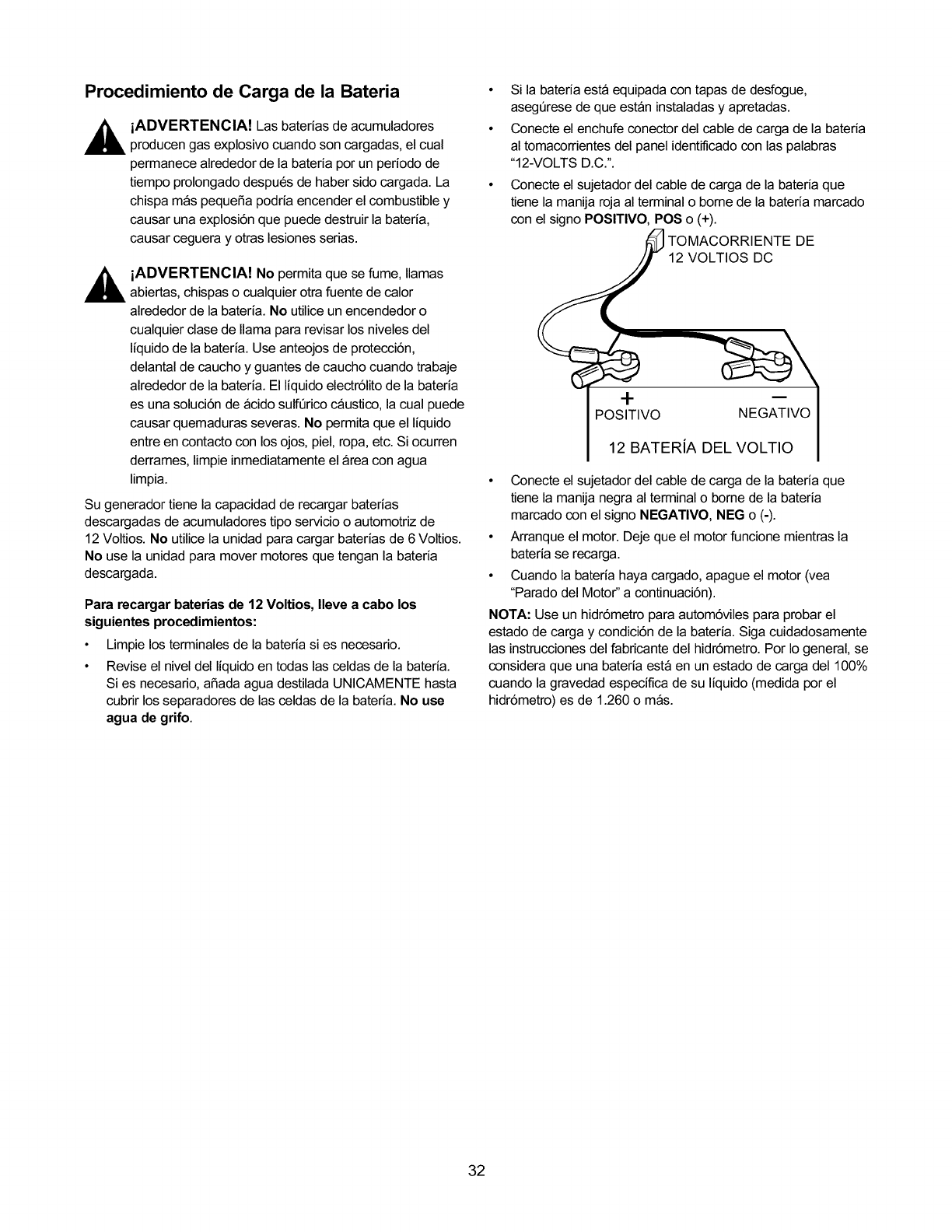
Procedimiento de Carga de la Bateria
iADVERTENCIA! Las baterias de acumuladores
producen gas explosivo cuando son cargadas, el cual
permanece alrededor de la bateria por un periodo de
tiempo prolongado despu6s de haber sido cargada. La
chispa mas pequeSa podria encender el combustible y
causar una explosi6n que puede destruir la bateda,
causar ceguera y otras lesiones serias.
,_ iADVERTENCIA! No permita que se fume, llamas
abiertas, chispas o cualquier otra fuente de calor
alrededor de la bated& No utilice un encendedor o
cualquier clase de llama para revisar los niveles del
liquido de la bated& Use anteojos de protecci6n,
delantal de caucho y guantes de caucho cuando trabaje
alrededor de la bateria. El liquido electr61itode la bateria
es una soluci6n de acido sulfQrico caustico, la cual puede
causar quemaduras severas. No permita que el Ifquido
entre en contacto con los ojos, piel, ropa, etc. Si ocurren
derrames, limpie inmediatamente el area con agua
limpia.
Su generador tiene la capacidad de recargar batedas
descargadas de acumuladores tipo servicio o automotriz de
12 Voltios. No utilice la unidad para cargar baterias de 6 Voltios.
No use la unidad para mover motores que tengan la bateria
descargada.
Para recargar baterias de 12 Voltios, Ileve a cabo los
siguientes procedimientos:
•Limpie los terminales de la bateria si es necesario.
• Revise el nivel del liquido en todas las celdas de la bated&
Si es necesario, aSada agua destilada UNICAMENTE hasta
cubrir los separadores de las celdas de la bated& No use
agua de grifo.
• Si la bateria esta equipada con tapas de desfogue,
asegQrese de que estan instaladas y apretadas.
• Conecte el enchufe conector del cable de carga de la bateria
al tomacorrientes del panel identiflcado con las palabras
"12-VOLTS D.C.".
• Conecte el sujetador del cable de carga de la bateria que
tiene la manija roja al terminal o borne de la bateria marcado
con el signo POSlTIVO, POS o (+).
TOMACORRIENTE DE
12 VOLTIOS DC
-I-
POSITIVO NEGATIVO
12 BATERiA DEL VOLTIO
• Conecte el sujetador del cable de carga de la bateria que
tiene la manija negra al terminal o borne de la bateria
marcado con el signo NEGATIVO, NEG o (-).
• Arranque el motor. Deje que el motor funcione mientras la
bateria se recarga.
• Cuando la bateria haya cargado, apague el motor (vea
"Parado del Motor" a continuaci6n).
NOTA: Use un hidr6metro para autom6viles para probar el
estado de carga y condici6n de la bated& Siga cuidadosamente
las instrucciones del fabdcante del hidr6metro. Por Io general, se
considera que una bateda esta en un estado de carga de1100%
cuando la gravedad especifica de su liquido (medida por el
hidr6metro) es de 1.260 o mas.
32
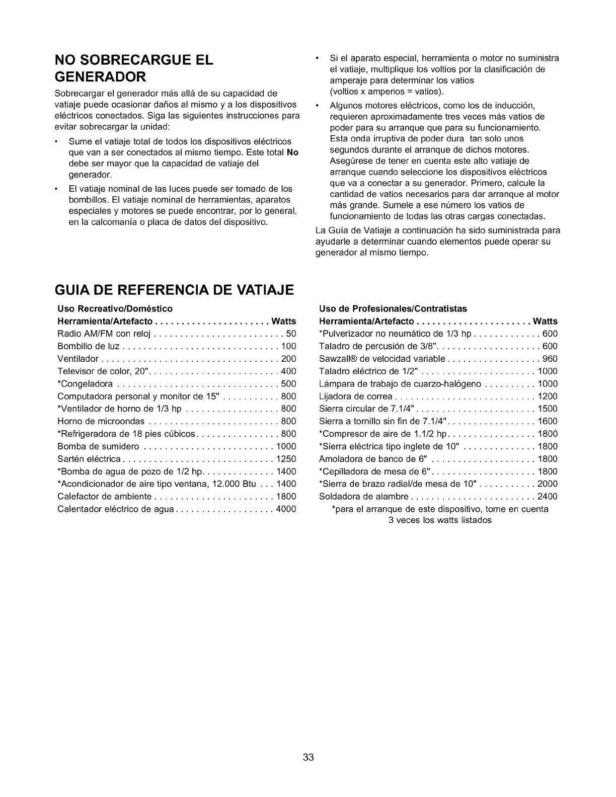
NO SOBRECARGUE EL
GENERADOR
Sobrecargar el generador mas alia de su capacidad de
vatiaje puede ocasionar daSos al mismo y a los dispositivos
el6ctricos conectados. Siga las siguientes instrucciones para
evitar sobrecargar la unidad:
• Sume el vatiaje total de todos los dispositivos el6ctricos
que van a ser conectados al mismo tiempo. Este total No
debe ser mayor que la capacidad de vatiaje del
generador.
• El vatiaje nominal de las luces puede ser tomado de los
bombillos. El vatiaje nominal de herramientas, aparatos
especiales y motores se puede encontrar, por Io general,
en la calcomania o placa de datos del dispositivo.
• Si el aparato especial, herramienta o motor no suministra
el vatiaje, multiplique los voltios por la clasificaci6n de
amperaje para determinar los vatios
(voltios x amperios = vatios).
• Algunos motores el6ctricos, como los de inducci6n,
requieren aproximadamente tres veces mas vatios de
poder para su arranque que para su funcionamiento.
Esta onda irruptiva de poder dura tan solo unos
segundos durante el arranque de dichos motores.
AsegQrese de tener en cuenta este alto vatiaje de
arranque cuando seleccione los dispositivos el6ctricos
que va a conectar a su generador. Primero, calcule la
cantidad de vatios necesarios para dar arranque al motor
mas grande. Sumele a ese nQmero los vatios de
funcionamiento de todas las otras cargas conectadas.
La Guia de Vatiaje a continuaci6n ha sido suministrada para
ayudarle a determinar cuando elementos puede operar su
generador al mismo tiempo.
GUIA DE REFERENCIA DE VATIAJE
Uso Recreativo/Dom_stico
Herramienta/Artefacto ...................... Watts
Radio AM/FM con reloj ......................... 50
Bombillo de luz .............................. 100
Ventilador .................................. 200
Televisor de color, 20". ........................ 400
*Congeladora ............................... 500
Computadora personal ymonitor de 15" . .......... 800
*Ventilador de homo de 1/3 hp .................. 800
Homo de microondas ......................... 800
*Refrigeradora de 18 pies cQbicos ................ 800
Bomba de sumidero ......................... 1000
Sart6n el6ctrica ............................. 1250
*Bomba de agua de pozo de 1/2 hp .............. 1400
*Acondicionador de aire tipo ventana, 12.000 Btu ... 1400
Calefactor de ambiente ....................... 1800
Calentador el6ctrico de agua ................... 4000
Uso de Profesionales/Contratistas
Herramienta/Artefacto ...................... Watts
*Pulverizador no neumatico de 1/3 hp ............. 600
Taladro de percusi6n de 3/8". ................... 600
Sawzall® de velocidad variable .................. 960
Taladro el6ctrico de 1/2". ..................... 1000
Lampara de trabajo de cuarzo-hal6geno .......... 1000
Lijadora de correa ........................... 1200
Sierra circular de 7.1/4". ...................... 1500
Sierra a tornillo sin fin de 7.1/4". ................ 1600
*Compresor de aire de 1.1/2 hp ................. 1800
*Sierra el6ctrica tipo inglete de 10" . ............. 1800
Amoladora de banco de 6" .................... 1800
*Cepilladora de mesa de 6". ................... 1800
*Sierra de brazo radial/de mesa de 10". .......... 2000
Soldadora de alambre ........................ 2400
*para el arranque de este dispositivo, tome en cuenta
3 veces los watts listados
33
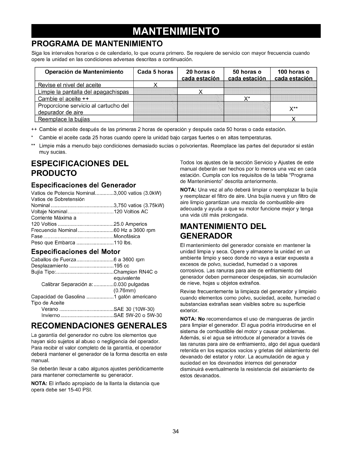
PROGRAMA DE MANTENIMIENTO
Siga los intervalos horarios o de calendario, Io que ocurra primero. Se requiere de servicio con mayor frecuencia cuando
opere la unidad en las condiciones adversas descritas a continuaci6n.
Operacibn de Mantenimiento
Revise el nivel del aceite
Limpie la pantalla del aDaclachispas
Cambie el aceite ++
Proporcione servicio al cartucho del
depurador de aire
Reemplace la buiias
Cada 5 horas
X
..........................................................................................'ill
++ Cambie el aceite despu6s de las primeras 2 horas de operaci6n y despu6s cada 50 horas o cada estaci6n.
* Cambie el aceite cada 25 horas cuando opere la unidad bajo cargas fuertes o en altas temperaturas.
** Limpie mas a menudo bajo condiciones demasiado sucias o polvorientas. Reemplace las partes del depurador si estan
muy sucias.
ESPECIFICACIONES DEL
PRODUCTO
Especificaciones del Generador
Vatios de Potencia Nominal ............. 3,000 ratios (3.0kW)
Vatios de Sobretensi6n
Nominal ............................................ 3,750 vatios (3.75kW)
Voltaje Nominal ................................ 120 Voltios AC
Corriente Maxima a
120 Voltios ....................................... 25.0 Amperios
Frecuencia Nominal ......................... 60 Hz a 3600 rpm
Fase ................................................. Monofasica
Peso que Embarca .......................... 110 Ibs.
Especificaciones del Motor
Caballos de Fuerza .......................... 6 a 3600 rpm
Desplazamiento ............................... 195 cc
Bujia Tipo: ........................................ Champion RN4C o
equivalente
Calibrar Separaci6n a: .............. 0.030 pulgadas
(0.76mm)
Capacidad de Gasolina ................... 1 gal6n americano
Tipo de Aceite
Verano ...................................... SAE 30 (10W-30)
Invierno ..................................... SAE 5W-20 o 5W-30
RECOMENDACIONES GENERALES
La garantia del generador no cubre los elementos que
hayan sido sujetos al abuso o negligencia del operador.
Para recibir el valor completo de la garantia, el operador
debera mantener el generador de la forma descrita en este
manual.
Se deberan Ilevar a cabo algunos ajustes peri6dicamente
para mantener correctamente su generador.
NOTA: El inflado apropiado de la Ilanta la distancia que
opera debe ser 15-40 PSI.
Todos los ajustes de la secci6n Servicio y Ajustes de este
manual deberan ser hechos por Io menos una vez en cada
estaci6n. Cumpla con los requisitos de la tabla "Programa
de Mantenimiento" descrita anteriormente.
NOTA: Una vez al afio debera limpiar o reemplazar la bujia
y reemplazar el filtro de aire. Una bujia nueva y un filtro de
aire limpio garantizan una mezcla de combustible-aire
adecuada y ayuda a que su motor funcione mejor y tenga
una vida etil mas prolongada.
MANTENIMIENTO DEL
GENERADOR
El mantenimiento del generador consiste en mantener la
unidad limpia y seca. Opere y almacene la unidad en un
ambiente limpio y seco donde no vaya a estar expuesta a
excesos de polvo, suciedad, humedad o a vapores
corrosivos. Las ranuras para aire de enfriamiento del
generador deben permanecer despejadas, sin acumulaci6n
de nieve, hojas u objetos extrafios.
Revise frecuentemente la limpieza del generador y limpielo
cuando elementos como polvo, suciedad, aceite, humedad o
substancias extrafias sean visibles sobre su superficie
exterior.
NOTA: No recomendamos el uso de mangueras de jardin
para limpiar el generador. El agua podria introducirse en el
sistema de combustible del motor y causar problemas.
Ademas, si el agua se introduce al generador a trav6s de
las ranuras para aire de enfriamiento, algo del agua quedara
retenida en los espacios vacios y grietas del aislamiento del
devanado del estator y rotor. La acumulaci6n de agua y
suciedad en los devanados internos del generador
disminuira eventualmente la resistencia del aislamiento de
estos devanados.
34
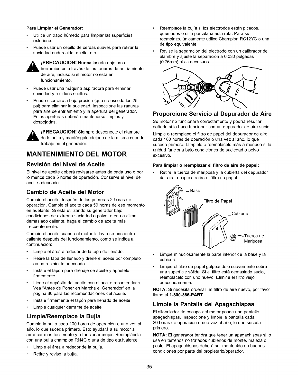
Para Limpiar el Generador:
• Utilice un trapo h6medo para limpiar las superficies
exteriores.
• Puede usar un cepillo de cerdas suaves para retirar la
suciedad endurecida, aceite, etc.
,_ iPRECAUCION! Nunca inserte objetos o
herramientas a trav6s de las ranuras de enfriamiento
de aire, incluso si el motor no esta en
funcionamiento.
Puede usar una maquina aspiradora para eliminar
suciedad y residuos sueltos.
Puede usar aire a baja presi6n (que no exceda los 25
psi) para eliminar la suciedad. Inspeccione las ranuras
para aire de enfriamiento y la apertura del generador.
Estas aperturas deberan mantenerse limpias y
despejadas.
,_ iPRECAUCION! Siempre desconecte el alambre
de la bujia y mant6ngalo alejado de la misma cuando
trabaje en el generador.
MANTENIMIENTO DEL MOTOR
Revision del Nivel de Aceite
El nivel de aceite debera revisarse antes de cada uso o por
Io menos cada 5 horas de operaci6n. Conserve el nivel de
aceite adecuado.
Cambio de Aceite del Motor
Cambie el aceite despu6s de las primeras 2 horas de
operaci6n. Cambie el aceite cada 50 horas de ese momento
en adelante. Siesta utilizando su generador bajo
condiciones de extrema suciedad o polvo, o en un clima
demasiado caliente, haga el cambio de aceite mas
frecuentemente.
Cambie el aceite cuando el motor todavia se encuentre
caliente despu6s del funcionamiento, como se indica a
continuaci6n:
• Limpie el Area alrededor de la tapa de Ilenado.
• Retire la tapa de Ilenado y drene el aceite pot completo
en un recipiente adecuado.
• Instale el tap6n para drenaje de aceite y apri6telo
firmemente.
• Llene el dep6sito del aceite con el aceite recomendado.
Vea "Antes de Poner en Marcha el Generador" en la
pagina 30 para las recomendaciones del aceite.
• Instale firmemente el tap6n para Ilenado de aceite.
• Limpie cualquier derrame de aceite.
Limpie/Reemplace la Bujia
Cambie la bujia cada 100 horas de operaci6n o una vez al
aSo, Io que suceda primero. Esto ayudara a su motor a
arrancar mas facilmente y a funcionar mejor. Reemplacela
con una bujia champion RN4C o una de tipo equivalente.
• Limpie el Area alrededor de la bujia.
• Retire y revise la bujia.
• Reemplace la bujia si los electrodos estan picados,
quemados o si la porcelana esta rota. Para su
reemplazo, 6nicamente utilice Champion RC12YC o una
de tipo equivalente.
• Revise la separaci6n del electrodo con un calibrador de
alambre y ajuste la separaci6n a 0.030 pulgadas
(0.76mm) si es necesario.
Proporcione Servicio al Depurador de Aire
Su motor no funcionara correctamente y podria resultar
daSado si Io hace funcionar con un depurador de aire sucio.
Limpie o reemplace el filtro de papel del depurador de aire
cada 100 horas de operaci6n o una vez al aSo, Io que
suceda primero. Limpielo o reemplacelo mas a menudo si la
unidad funciona bajo condiciones de suciedad o polvo
excesivo.
Para limpiar o reemplazar el filtro de aire de papel:
• Retire la tuerca de mariposa y la cubierta del depurador
de aire, despu6s retire el filtro de papel.
_- Filtro de Papel
Base
/
_ Cubierta
_Tuerca de
Mariposa
• Limpie minuciosamente la parte interior de la base y la
cubierta.
Limpie el filtro de papel golpeandolo suavemente sobre
una superficie s61ida. Si el filtro esta demasiado sucio,
reemplacelo con uno nuevo. Elimine el filtro viejo
adecuadamente.
NOTA: Si necesita ordenar un filtro de aire nuevo, por favor
Ilame al 1-800-366-PART.
Limpie la Pantalla del Apagachispas
El silenciador de escape del motor posee una pantalla
apagachispas. Inspeccione y limpie la pantalla cada
20 horas de operaci6n o una vez al aSo, Io que suceda
primero.
NOTA: El generador tendra que tener un apagachispas si Io
usa en terrenos no tratados cubiertos de monte, maleza o
pasto. El apagachispas debera ser mantenido en buenas
condiciones por parte del propietario/operador.
35
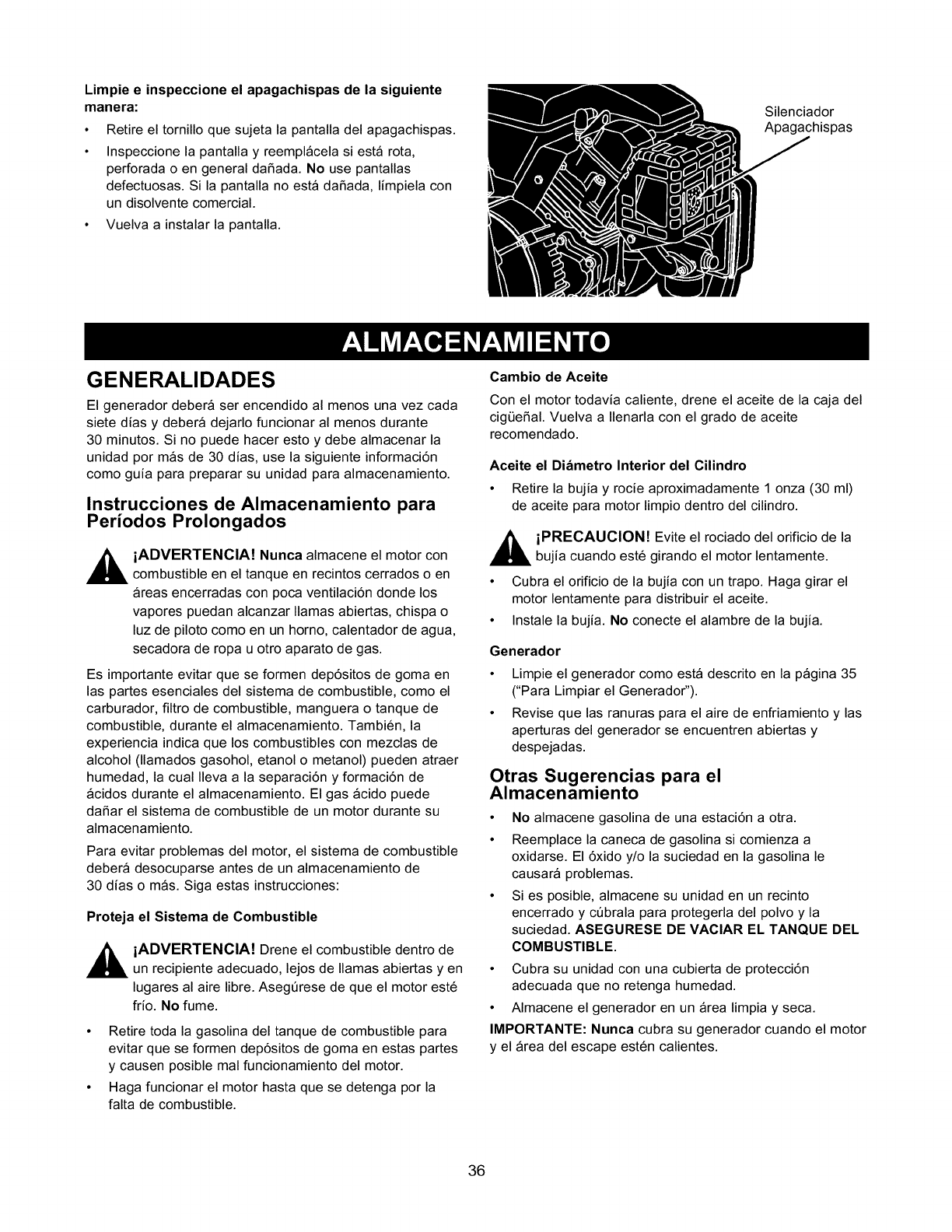
Limpie e inspeccione el apagachispas de la siguiente
manera:
• Retire el tornillo que sujeta la pantalla del apagachispas.
• Inspeccione la pantalla y reemplacela si esta rota,
perforada o en general daSada. No use pantallas
defectuosas. Si la pantalla no esta daSada, limpiela con
un disolvente comercial.
• Vuelva a instalar la pantalla.
Silenciador
Apagachispas
GENERALIDADES
El generador debera ser encendido al menos una vez cada
siete dias y debera dejarlo funcionar al menos durante
30 minutos. Si no puede hacer esto y debe almacenar la
unidad por mas de 30 dias, use la siguiente informaci6n
como guia para preparar su unidad para almacenamiento.
Instrucciones de Almacenamiento para
Periodos Prolongados
,_ iADVERTENCIA! Nunca almacene el motor con
combustible en el tanque en recintos cerrados o en
Areas encerradas con poca ventilaci6n donde los
vapores puedan alcanzar llamas abiertas, chispa o
luz de piloto como en un homo, calentador de agua,
secadora de ropa u otro aparato de gas.
Es importante evitar que se formen dep6sitos de goma en
las partes esenciales del sistema de combustible, como el
carburador, filtro de combustible, manguera o tanque de
combustible, durante el almacenamiento. Tambi6n, la
experiencia indica que los combustibles con mezclas de
alcohol (llamados gasohol, etanol o metanol) pueden atraer
humedad, la cual Ileva a la separaci6n y formaci6n de
acidos durante el almacenamiento. El gas acido puede
daSar el sistema de combustible de un motor durante su
almacenamiento.
Para evitar problemas del motor, el sistema de combustible
debera desocuparse antes de un almacenamiento de
30 dias o mas. Siga estas instrucciones:
Proteja el Sistema de Combustible
,_ iADVERTENCIA! Drene el combustible dentro de
un recipiente adecuado, lejos de llamas abiertas yen
lugares al aire libre. Asegt_rese de que el motor est6
frfo. No fume.
• Retire toda la gasolina del tanque de combustible para
evitar que se formen depSsitos de goma en estas partes
y causen posible mal funcionamiento del motor.
• Haga funcionar el motor hasta que se detenga por la
falta de combustible.
Cambio de Aceite
Con el motor todavia caliente, drene el aceite de la caja del
cigL_eSal. Vuelva a Ilenarla con el grado de aceite
recomendado.
Aceite el Diametro Interior del Cilindro
• Retire la bujia y rocie aproximadamente 1 onza (30 ml)
de aceite para motor limpio dentro del cilindro.
,_ iPRECAUCION! Evite el rociado del orificio de la
bujia cuando est6 girando el motor lentamente.
• Cubra el orificio de la bujia con un trapo. Haga girar el
motor lentamente para distribuir el aceite.
• Instale la bujia. No conecte el alambre de la bujia.
Generador
Limpie el generador como esta descrito en la pagina 35
("Para Limpiar el Generador").
Revise que las ranuras para el aire de enfriamiento y las
aperturas del generador se encuentren abiertas y
despejadas.
Otras Sugerencias para el
Almacenamiento
• No almacene gasolina de una estaci6n a otra.
• Reemplace la caneca de gasolina si comienza a
oxidarse. El 6xido y/o la suciedad en la gasolina le
causara problemas.
• Si es posible, almacene su unidad en un recinto
encerrado y cQbrala para protegerla del polvo y la
suciedad. ASEGURESE DE VAClAR EL TANQUE DEL
COMBUSTIBLE.
• Cubra su unidad con una cubierta de protecci6n
adecuada que no retenga humedad.
• Almacene el generador en un Area limpia y seca.
IMPORTANTE: Nunca cubra su generador cuando el motor
y el Area del escape est6n calientes.
36
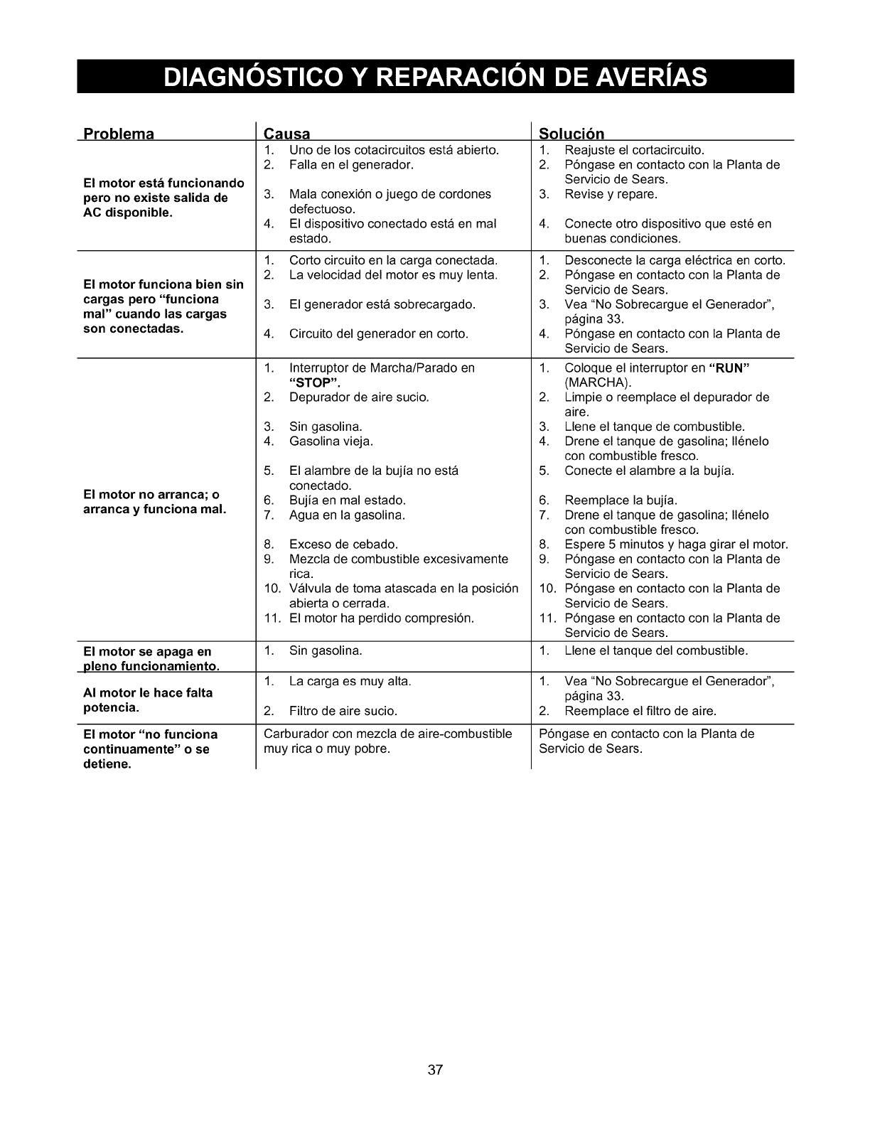
Problema
El motor esta funcionando
pero no existe salida de
AC disponible.
El motor funciona bien sin
cargas pero "funciona
mal" cuando las cargas
son conectadas.
Causa
1. Uno de los cotacircuitos esta abierto.
2. Falla en el generador.
3. Mala conexi6n ojuego de cordones
defectuoso.
4. El dispositivo conectado esta en mal
estado.
1. Corto circuito en la carga conectada.
2. La velocidad del motor es muy lenta.
3. El generador esta sobrecargado.
4. Circuito del generador en corto.
1. Interruptor de Marcha/Parado en
Solucibn
1. Reajuste el cortacircuito.
2. P6ngase en contacto con la Planta de
Servicio de Sears.
3. Revise y repare.
4. Conecte otro dispositivo que est6 en
buenas condiciones.
1. Desconecte la carga el6ctrica en corto.
2. P6ngase en contacto con la Planta de
Servicio de Sears.
3. Vea"No Sobrecargue el Generador",
pagina 33.
4. P6ngase en contacto con la Planta de
Servicio de Sears.
1. Coloque el interruptor en "RUN"
El motor no arranca; o
arranca y funciona mal.
"STOP".
2. Depurador de aire sucio.
3. Sin gasolina.
4. Gasolina vieja.
5. El alambre de la bujia no esta
conectado.
6. Bujia en mal estado.
7. Agua en la gasolina.
8. Exceso de cebado.
2.
3.
4.
5.
6.
7.
8.
(MARCHA).
Limpie o reemplace el depurador de
aire.
Llene el tanque de combustible.
Drene el tanque de gasolina; 116nelo
con combustible fresco.
Conecte el alambre a la bujia.
Reemplace la bujia.
Drene el tanque de gasolina; 116nelo
con combustible fresco.
Espere 5 minutos y haga girar el motor.
9. Mezcla de combustible excesivamente
rica.
10. Valvula de toma atascada en la posici6n
abierta o cerrada.
11. El motor ha perdido compresi6n.
El motor se apaga en 1. Sin gasolina.
pleno funcionamiento.
1. Vea"No Sobrecargue el Generador",
AI motor le hace falta pagina 33.
potencia. 2. Reemplace el filtro de aire.
El motor "no funciona
continuamente" o se
detiene.
1. La carga es muy alta.
2. Filtro de aire sucio.
Carburador con mezcla de aire-combustible
muy rica o muy pobre.
9. P6ngase en contacto con la Planta de
Servicio de Sears.
10. P6ngase en contacto con la Planta de
Servicio de Sears.
11. P6ngase en contacto con la Planta de
Servicio de Sears.
1. Llene el tanque del combustible.
P6ngase en contacto con la Planta de
Servicio de Sears.
37
DECLARACION DE LA GARANTIA
DEL CONTROL DE EMISIONES
PARA CALIFORNIA Y US EPA
La Agencia de Protecci6n Ambiental de los Estados Unidos
("EPA"), la Junta Directiva de Recursos del Aire de
California ("CARB") y Tecumseh Products Co., estan
complacidos de explicar la Garantia de los Sistemas de
Control de Emisiones Federales yen California de su nuevo
motor para equipo de servicio o c6sped y jardin. En
California, los motores nuevos para equipo de servicio,
c6sped y jardin deberan ser disefiados, construidos y
equipados para cumplir las exigentes normas contra la
contaminaci6n del estado. En otros estados, los motores
fabricados en el afio 1997 y posteriormente deberan ser
disefiados, construidos y equipados, en el momento de
venta, para cumplir las regulaciones de U.S. EPA para
motores pequefios de uso fuera de carreteras. Tecumseh
Products Co. garantizara el sistema de control de emisiones
de su motor para equipo de servicio, c6sped y jardin por el
periodo de tiempo listado a continuaci6n, con tal de que
dicho equipo no haya sido sometido a abuso, abandono,
modificaciones no aprobadas o mantenimiento incorrecto.
Su sistema de control de emisiones puede incluir pares
como el carburador, sistema de encendido y sistema de
escape. Tambi6n puede estar incluido el sistema de
eliminaci6n de compresi6n y otras partes relacionadas con
las emisiones.
Donde exista una condici6n que sea cubierta por la
garantia, Tecumseh Products Co. reparara su motor para
equipo de servicio, c6sped y jardin sin costo alguno para
usted, incluyendo diagn6stico, partes y mano de obra.
Cubrimiento de la Garantia del Sistema de
Control de Emisiones del Fabricante
Los sistemas de control de emisiones de los motores para
equipo de servicio, c6sped y jardin de California modelo
1995 y posteriores estan garantizados por dos afios segt_n
Io establecido mas adelante en este documento. En otros
estados, los motores aSos 1997 y posteriores tambi6n estan
garantizados por dos aSos. Si durante dicho periodo de
garantia, cualquiera de las partes de su motor relacionadas
con las emisiones es defectuosa en material o mano de
obra, Tecumseh Products Co. se encargara de reparar o
reemplazar dicha parte.
Responsabilidades de Garantia del
Propietario
Como propietario de un motor para equipo de servicio,
c6sped y jardin, usted es responsable por el cumplimiento
del mantenimiento exigido descrito en su Manual del
Propietario. Tecumseh Products Co. no negara la garantia
por la sola ausencia de los recibos o porque usted no haya
suministrado evidencia escrita del cumplimiento de todo el
mantenimiento programado.
Como propietario de un motor para equipo de servicio,
c6sped y jardin, usted debe saber que Tecumseh Products
Co. podria negarle cubrimiento de garantia si su equipo de
servicio, c6sped y jardin, o cualquier parte, ha fallado
debido a abuso, negligencia, mantenimiento incorrecto o
modificaciones no aprobadas.
Usted es responsable de presentar su motor para equipo de
servicio, c6sped o jardin a un Centro de Servicio Tecumseh
autorizado (cualquier Proveedor de Servicio Registrado
Tecumseh, Distribuidor de Servicio Autorizado Tecumseh o
Distribuidor de Bodega Central Tecumseh) tan pronto como
el problema aparezca. Las reparaciones de garantia
deberan ser terminadas en un periodo de tiempo razonable
sin exceder 30 dias.
El Servicio de Garantia puede ser establecido poni6ndose
en contacto con un Centro de Servicio Autorizado
Tecumseh, o poni6ndose en contacto con Tecumseh
Products Co., c/o Service Manager, Engine and
Transmission Group Service Division, 900 North Street,
Grafton, WI 53024 - 1499. Tel6fono 1-262-377-2700, o
consulte sus paginas amarillas locales bajo "Motores a
Gasolina" para el nombre, direcci6n y nt_mero telef6nico de
un Centro de Servicio Autorizado Tecumseh cerca a usted.
Nota Importante
Esta declaraci6n de garantia le explica sus derechos y
obligaciones contenidos en la Garantia del Control de
Emisiones ("Garantia ECS"), la cual es proporcionada por
Tecumseh Products Co. segQn las leyes de California.
Tecumseh Products Co. tambi6n proporciona a los
compradores originales de motores nuevos Tecumseh
Products Co., las Garantias Limitadas para M6dulos de
Encendido Electr6nicos y Motores ("Garantia de Tecumseh
Products Co."), la cual se encuentra incluida en una hoja
separada en todos los motores nuevos de Tecumseh
Products Co.. La garantia ECS se aplica Qnicamente al
sistema de control de emisiones de su motor nuevo.
Cuando exista un conflicto de t6rminos entre la Garantia
ECS y la Garantia de Tecumseh Products Co., se aplicara
la garantia ECS excepto en circunstancias en que la
Garantia de Tecumseh Products Co. pueda proporcionar un
periodo de garantia mas prolongado. Tanto la Garantia ECS
como la Garantia de Tecumseh Products Co. describen
derechos y obligaciones importantes con respecto a su
motor.
El servicio de garantia tan solo puede ser Ilevado a cabo
por un Centro de Servicio Autorizado de Tecumseh
Products Co. o por Tecumseh Products Co. en su fabrica de
Grafton, Wisconsin. En el momento de solicitar el servicio
de garantia, debera presentar evidencia de la fecha de
venta al comprador original. El comprador pagara los cargos
por Ilamadas de servicio y/o por transporte de los productos
hacia y desde el lugar donde la inspecci6n y/o el trabajo de
servicio es Ilevado a cabo. El comprador sera responsable
por cualquier dafio o p_rdida ocurrida durante el transporte
de cualquier motor o parte(s) presentada para inspecci6n
y/o trabajo de garantia.
Si tiene preguntas con respectos y responsabilidades de
garantia, debera ponerse en contacto con Tecumseh
Products Co., al 1-262-377-2700.
38
GARANTIA DEL SISTEMA DE
CONTROL DE EMISIONES
Garantia del Sistema de Control de Emisiones ("Garantia ECS")
para motores de equipo de servicio, c6sped y jardin aSos 1995
y posteriores de California (para otros estados, motores
modelos 1997 y posteriores):
A. Aplicabilidad: Esta garantia se aplicar_ a los motores para
equipo de servicio, c6sped y jardin aSos 1995 y posteriores del
estado de California (para otros estados, motores modelos
1997 y posteriores). El periodo de la Garantia ECS comenzar_
en la fecha en que el equipo o motor nuevo es entregado al
comprador final original y continuara por 24 meses
consecutivos a partir de ese momento.
B. Cubrimiento General de la Garantia de Emisiones:
Tecumseh Products Co., garantiza al comprador original final
del equipo o motor nuevo, y a cada comprador subsecuente,
que cada uno de sus motores para equipo de servicio, c6sped y
jardin est,:
1. DiseSado, construido y equipado para cumplir con todas las
leyes aplicables establecidas por la Junta Directiva de
Recursos del Aire de acuerdo a su autoridad en los
Capitulos 1 y 2, Parte 5, Divisi6n 26 del C6digo de Salud y
Seguridad, y
2. Libre de defectos en material y mano de obra que, en
cualquier momento durante el periodo de la Garantia ECS,
causen que una parte garantizada relacionada con las
emisiones no sea id6ntica en material con respecto a la
parte descrita en la aplicaci6n para certificaci6n del
fabricante del motor.
C. La Garantia ECS tan solo hace referencia alas partes de
su motor relacionadas con emisiones de la siguiente manera:
1. Cualquier parte garantizada, relacionada con emisiones,
que no est6 programada para reemplazo segQn la secci6n
de mantenimiento del Manual del Propietario, estar_
garantizada durante el Periodo de la Garantia ECS. Si
cualquiera de dichas pares falla durante el Periodo de la
Garantia ECS, la parte ser_ reparada o reemplazada por
Tecumseh Products Co., de acuerdo a la Subsecci6n 4
descrita mas adelante.
2. Cualquier parte garantizada, relacionada con emisiones,
que est6 programada 6nicamente para inspecci6n regular,
seg6n Io prescrito en el Manual del Propietario, estar_
garantizada durante el Periodo de la Garantia ECS. La
existencia de una afirmaci6n en dichas instrucciones
escritas con respecto a "reparar o reemplazar cuando sea
necesario" no reducir& el Periodo de la Garantia ECS.
Cualquier parte reparada o reemplazada bajo la Garantia
ECS estar& garantizada por el tiempo restante del Periodo
de la Garantia ECS.
3. Cualquier parte garantizada, relacionada con emisiones,
que est6 programada para reemplazo seg6n la secci6n de
mantenimiento del Manual del Propietario, estar_
garantizada por el periodo de tiempo anterior al primer
punto de reemplazo programado para esa parte. Si la parte
falla antes del primer reemplazo programado, la parte ser_
reparada o reemplazada por Tecumseh Products Co., de
acuerdo a la Subsecci6n 4 descrita mas adelante. Cualquier
parte relacionada con emisiones reparada o reemplazada
bajo la Garantia ECS, estar_ garantizada por el tiempo
restante del periodo de la Garantia ECS antes del primer
punto de reemplazo programado para dicha parte relaciona
con las emisiones.
4. La reparaci6n o reemplazo de cualquier parte garantizada
relacionada con las emisiones bajo esta Garantia ECS ser_
Ilevada a cabo sin costo alguno en un Centro de Servicio
Autorizado Tecumseh.
5. AI propietario no se le cobrar& por trabajo diagn6stico que
Ileve a la conclusi6n de que una parte cubierta por la
Garantia ECS es en realidad defectuosa, con tal de que
dicho trabajo diagn6stico sea Ilevado a cabo en un Centro
de Servicio Autorizado Tecumseh.
6. Tecumseh Products Co. ser_ responsable por daSos a otros
componentes del motor original o modificaciones
aprobadas, causados por una falla bajo garantia de una
parte relacionada con las emisiones cubierta por la Garantia
ECS.
7. Durante el periodo de la Garantia ECS, Tecumseh Products
Co. mantendr_ un suministro de partes garantizadas
relacionadas con las emisiones, suficientemente completo
como para satisfacer la demanda esperada para dichas
partes.
8. Cualquier repuesto de Tecumseh Products Co. autorizado o
aprobado, relacionado con las emisiones, puede ser usado
en el cumplimiento de cualquier mantenimiento o reparaci6n
de Garantia ECS y ser_ proporcionado sin cargo alguno
para el propietario. Dicho uso no disminuir& las obligaciones
de Garantia ECS de Tecumseh Products Co..
9. Las partes modificadas o adiciones no aprobadas no podr_n
ser usadas para modificar o reparar un motor de Tecumseh
Products Co.. Dicha pr&ctica cancela esta Garantia ECS y
ser_ motivo suficiente para denegar un Reclamo de
Garantia ECS. Tecumseh Products Co. no ser_
responsable por fallas de pares garantizadas de un motor
de Tecumseh Products Co. causadas por el uso de dichas
partes modificadas o adiciones no aprobadas.
LAS PARTES RELACIONADAS CON LAS
EMISIONES INCLUYEN"
1. Conjunto del carburador y sus componentes internos.
a) Filtro del combustible
b) Empaques del carburador
c) Tubo de toma de admisi6n
2. Conjunto del depurador de aire
a) Elemento del depurador de aire
3. Sistema de encendido, incluye:
a) Bujia
b) M6dulo de encendido
c) Conjunto de la rueda de volante
4. Silenciador catalitico (si est_ presente)
a) Empaque del silenciador (si est_ presente)
b) M61tiple del escape (si est_ presente)
5. Conjunto del respiradero de la caja del cigL_eSaly sus
componentes
a) Tubo de conexi6n del respiradero
39

For in-home major brand repair service:
Call 24 hours a day, 7 days a week
1-800-4-MY-HOM E SM(1-800-469-4663)
Para pedir servicio de reparacibn a domicilio - 1-800-676-5811
In Canada for all your service and parts needs call - 1-800-665-4455
Au Canada por tout le service ou les pi6ces
For the repair or replacement parts you need:
Call 7 am - 7 pm, 7 days a week
1-800-366-PART (1-800-366-7278)
Para ordenar piezas con entrega a domicilio - 1-800-659-7084
For the location of a Sears Parts and Repair Center in your area:
Call 24 hours aday, 7days a week
1-800-488-1222
For information on purchasing a Sears maintenance Agreement
or to inquire about an existing Agreement:
Call 9 am - 5 pm, Monday -Saturday
1-800-827-6655
The ServiceSideofSears_
