Craftsman 706139910 User Manual TOOL CHEST Manuals And Guides L1003087
CRAFTSMAN Tool Chest Manual L1003087 CRAFTSMAN Tool Chest Owner's Manual, CRAFTSMAN Tool Chest installation guides
User Manual: Craftsman 706139910 706139910 CRAFTSMAN TOOL CHEST - Manuals and Guides View the owners manual for your CRAFTSMAN TOOL CHEST #706139910. Home:Tool Parts:Craftsman Parts:Craftsman TOOL CHEST Manual
Open the PDF directly: View PDF ![]() .
.
Page Count: 3
@
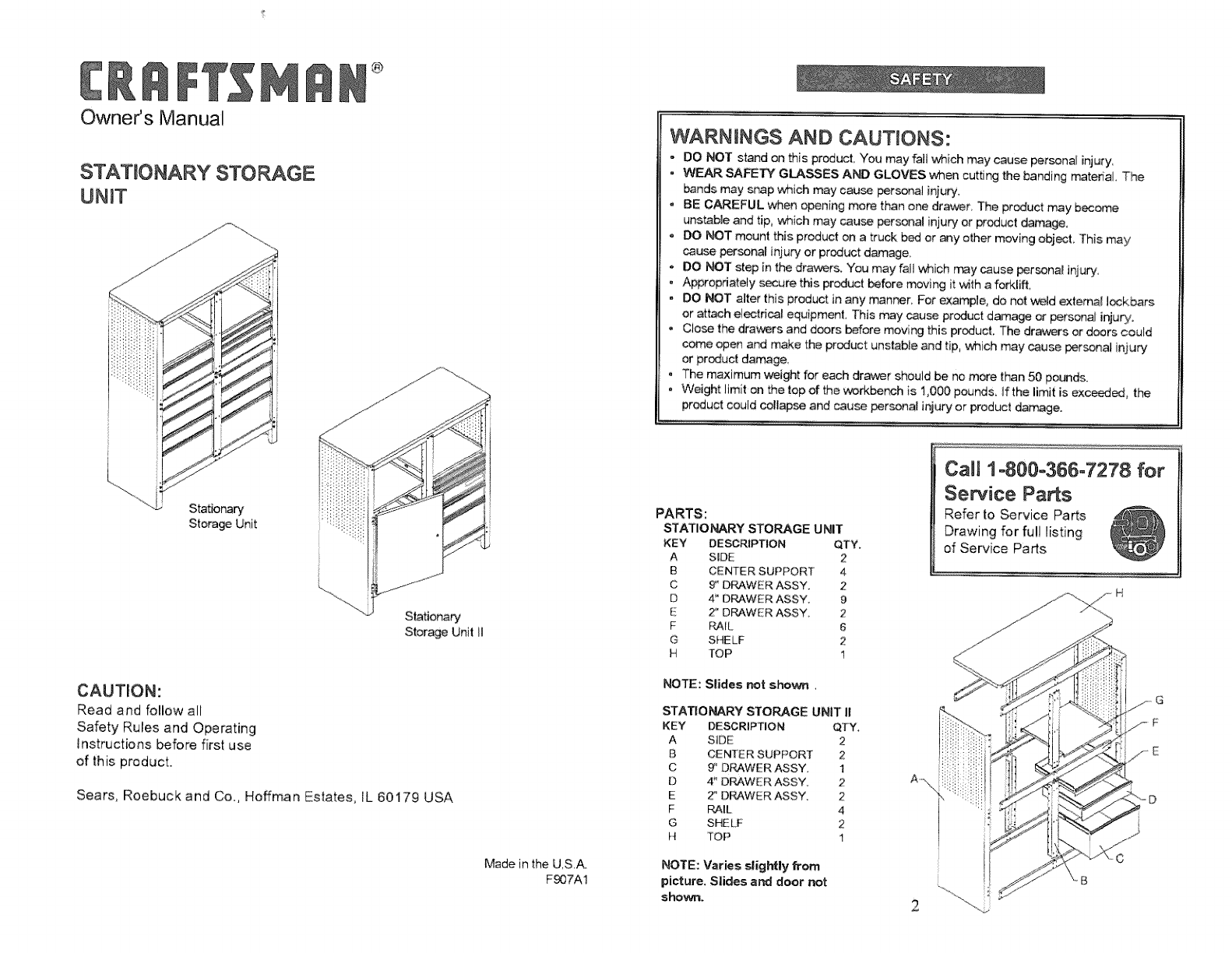
Owner's Manual
STATIONARY STOOGE
UNIT
Stationary
Storage Unit
Stationary
Storage Unit Ii
CAUTION:
Read and follow all
Safety Rules and Operating
instructions before first use
of this product.
Sears, Roebuck and Co., Hoffman Estates, IL 60179 USA
Made in the U,S,A.
Fg07A1
WARNINGS AND CAUTIONS:
- DO NOT stud on this product You may fail which may cause personal injury,
• WEAR SAFETY GLASSES AND GLOVES when cutting the banding material, The
bands may snap which may cause personal injury.
. BE CAREFUL when opening more than one drawer, The product may become
uns_ble and tip, which may cause personal injury or product damage,
DO NOT mount this product on a truck bed or any other moving object This may
cause personal injury or product damage,
DO NOT step in the dra'_rs. You may fall which n_y _use personal injury,
. Appropriately _ure this product before moving it _th a forklift,
. DO NOT alter this product in any manner, For example, do not weld external Iockbars
or attach electfica_ equipment, This may cause product damage or personal inju_.
Ciose the drovers and doors before moving this product, The dr_rs or doors could
come open and make the product unstable and tip, which may cause personal injury
or product damage.
. The maximum weight for each drawer should be no more than 50 pounds.
. Weight limit an the top of the workbench is t ,00O pounds, if the limit is exc_ the
product could collapse and cause _rsonal injury or product damage.
r ..... ii, ;......... _......... ........ ........ • ..................... .... ...................... ...............................
PARTS:
STATIO_R¥ STOOGE UNIT
KEY DESCRIPTION qTY.
A SiDE 2
B CENTER SUPPORT 4
C 9" D_WER ASSY, 2
D 4" DRAWER ASSY, 9
E 2" DRAWER ASSY 2
F F4AE_, 6
G SHELF 2
H TOP 1
NOTE: Slides wot shown.
STATIONARY STORAGE UNIT II
KEY DESCRIPTION QTY,
A SiDE 2
B CENTER SUPPORT 2
C 9" DRAWER ASSY. 1
D 4" DRAWER ASSY 2
E 2" D_WER ASSY. 2
F R4IL 4
G SHELF 2
t{ _TOP t
NOTE: Varies slightly from
picture. Slides and door not
shown.
CaUi 1o800-366-7278 for
Service Parts
Refer to Service Parts
Drawing for fu!l listing
of Service Parts
A -\.
c
2
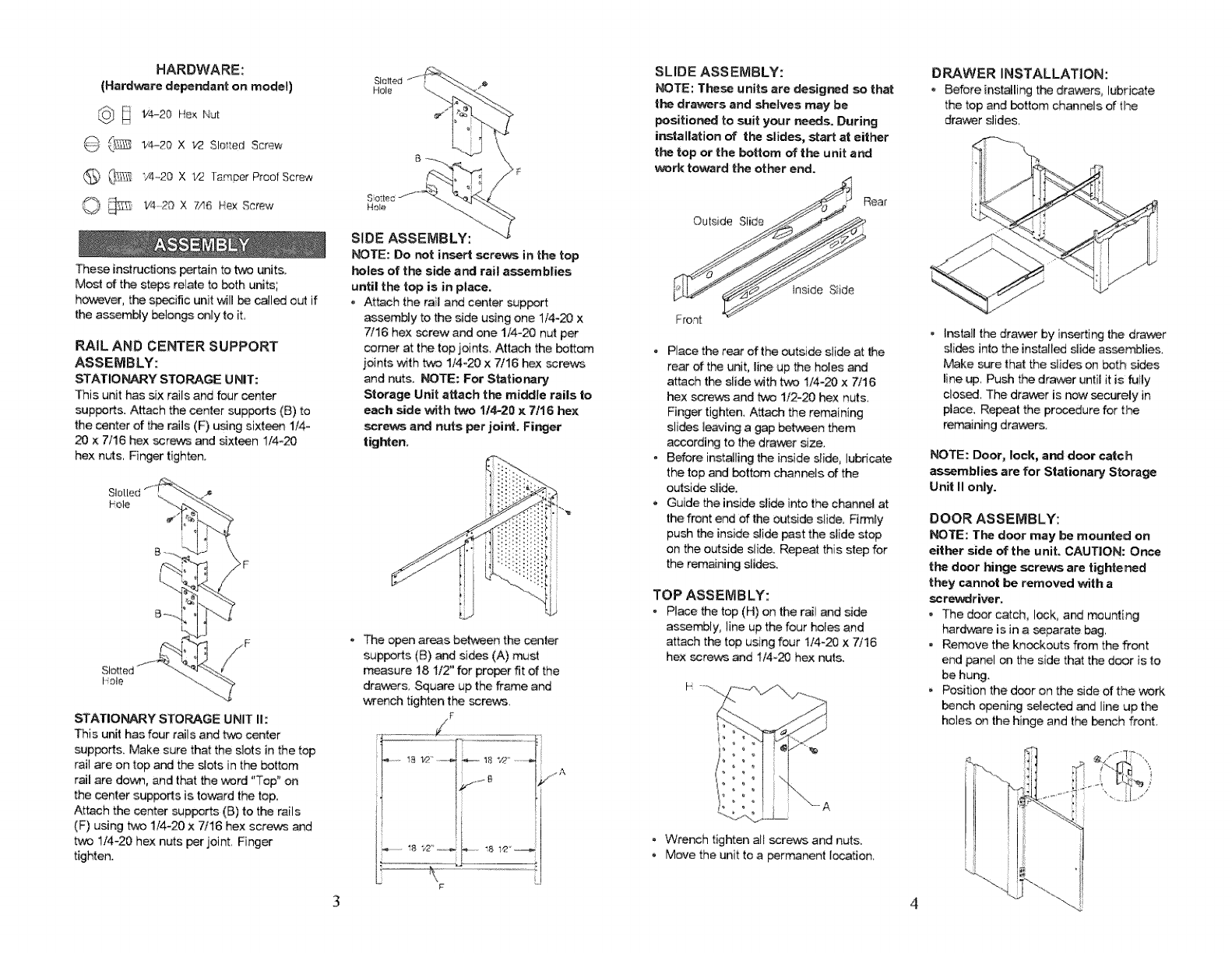
HARDWARE:
(Hard.re depe_ant on model)
_} _ 1'4-20 X t/2 Slei_ed Screw
6) @_,_ "/4_,20 XV2 Tamper Proof Screw
O _ _,_2_x 7,,I_He×screw
These instructions pertain to two units.
Most of the steps relate to both units;
however, the specific unit will _ called out if
the assembly belongs only to iL
RAIL AND CENTER SUPPORT
ASSEMBLY:
STATIO_Y STORAGE UNIT:
This unit has six rails and four _nter
suppers. Attach the center supports (B) to
the center of the rails (F) using sixt_n 1/4-
20 x 7/16 hex screws and sixteen 1/4_20
hex nuts, Finger tighten.
SIo[[ed"f_''":_- ._
?;
21--_
Slot
bole
F
STATIONARY STORAGE UNIT I1:
This unit has four rails and tv_ center
supped& Make sure that the slots in the top
rail are on top and the slots in the bottom
rail are dove, and that the word "Top" on
the center supports is toward the top,
Attach the center supports (B) to the rails
(F) using two 1/4-20 x 7/16 hex screv_ and
t/4-20 hex nuts per joint Finger
tighten.
Slotted
iqole
Hole
SIDE ASSEMBLY:
_TE: Do not insert screws in the top
holes of t_ side and rail assemblies
until the top is in place.
-Attach the rail and center support
assembly to the side using one 1/4_20 x
7/16 hex screw and one 1/4-20 nut per
comer at the top joints, Attach the bottom
joints with two 1/4-20 x 7/16 hex ssrevcs
and nuts. _TE: For Stationary
Storage Unit attach the middle rails to
each side _th _ 1/4-20 x 7/16 hex
screws and nuts per joint, Finger
tighten.
The open areas between the center
supports (B) and sides (A) must
measure 18 1/2" for proper fit of the
drav,_rs, Square up the frame and
wench tighten the screws,
SLIDE ASSEMBLY:
NOTE: These units are designed so that
the drawers and shelves may be
positioned to suit your needs. During
installation of" the slides, start at either
the top or the bottom oftl_ unit a_
work to_rd the other end.
• Place the rear of the outside slide at the
rear of the unit, line up the holes and
attach the slide with tw'3 1/4-20 x 7/16
hex screws and _ 1/2=20 hex nuts,
Finger tighten, Attach the remaining
slides leaving a gap between them
according to the dra_r size.
- Before instaJling the inside slide, lubricate
the top and bottom channels of the
outside slide.
-Guide the inside slide into the channel at
the front end of the outside slide. R_ly
push the inside slide past the slide stop
on the outside slide. Repeat this step for
the remaining slides.
TOP ASSEMBLY:
• Place the top (H) on the rail and side
assembly; line up the four hobs and
attach the top using four 1/4-20 x 7/16
hex screws and 1/4-20 hex nuts.
i °
/! °
• Wrench tighten all screws and nu_s.
• Move the unit to a permanent location,
D_WER INSTALLATION:
Before instaJling the drawers, lubricate
the top and bottom channels of the
drawer slides,
. Install the drawer by in_rting the drawer
slides into the instalbd siide assemblbs
Make sure that the slides on both sides
line up, Push the drav_r until it is fully
close, The dra_,-_r is now securely in
place Repeat the procedure for the
remaining drawers.
NOTE: Door, lock, and door catch
a_mblies are for Stationary Storage
Unit II only.
DOOR ASSEMBLY:
NOTE: The door may be mounted on
either side of the unit, CAUTION: O_e
the door hinge screws are tightened
they cannot be removed with a
screwdriver.
o The door catch, lock, a_ mounting
hard.re is in a _parate bag,
•Remove the knockouts from the front
end panel on the side that the d_r is to
be hung,
Position the door on the side of the work
bench opening se!ected and line up the
holes on the hinge and the bench front,
3 4
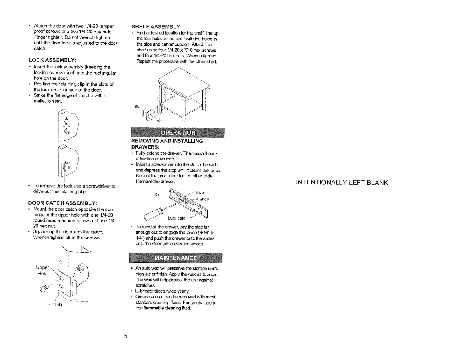
• Attach the door with _ I/4-20 tamper
proof screws and two 1/4-20 hex nuts,
Finger tighten. Do not wrench tighten
until the door lock is adjusted to the door
_tch,
LOCK ASSEMBLY:
,, insert the lock assembly (keeping the
locking cam verticai) into the rectangular
hole on the door.
° Position the retaining clip in the slots of
the _ock on the inside of the door,
• Strike the flat edge of the clip v_th a
manet to seat,
SHELF ASSEMBLY:
.Rr_ a desired iocatJon _r tl'_ sf_f, lineup
t_ fc4Jrhel_ in the _f_ the ho4es in
the side and _ter sup_. Attach the
shelf usi_ four !/4-20 x 7/16 _ scre/cs
_d four t/4-20 hex nuts. Wrench tighten.
Repeat the pr_e ,,Mththe other _f,
@
o To remove the lock u_ a screwdriver to
drive out the retaining clip.
DOOR CATCH ASSEMBLY:
.Mount the door catch opposite the door
hinge in the upper hole _th one I/4-_
round head machine _rew and one 1/4-
20 hex nut,
•Square up the door and the catch,
Wrench tighten all of the screws.
REMOVING AND INSTALLING
DRAWERS:
Fully extend the d_f. Then push it _k
a _tien of an inch.
• tns_ a screwdriver into the s!ot in the slide
and depress the stop until it dears the lan_.
Repeat the _ure for the other sli_,
P_,_r_e the drav_r,
Lubricate
• To rein_atl the drav_t_r,pry the stop far
e_ out to engage the lan_ (3/16" to
1/4") and I_ the dra_,er onto the sli_s
unti_the st_s _ _ the lar_ses,
INTENTIONALLY LEFT BLANK
Catch
An auto wax _il p_serve _ stor@ unifs
hi_ lusl_ finish. ,_4_Y the wax as to a car.
wax _,4tI_p prot_l the unit _inst
_ratch_,
o Lubricate sli_ _c_ yearly,
Grea_ ar_ oil _ be removed _th rr_st
st_rd cleaning fluids. For safety, use a
non fiam_le cleaning fluid,
