Craftsman 706208810 User Manual TOOL CHEST Manuals And Guides 1501203L
User Manual: Craftsman 706208810 706208810 CRAFTSMAN TOOL CHEST - Manuals and Guides View the owners manual for your CRAFTSMAN TOOL CHEST #706208810. Home:Tool Parts:Craftsman Parts:Craftsman TOOL CHEST Manual
Open the PDF directly: View PDF ![]() .
.
Page Count: 8
OPERATOR'S MANUAL
T °
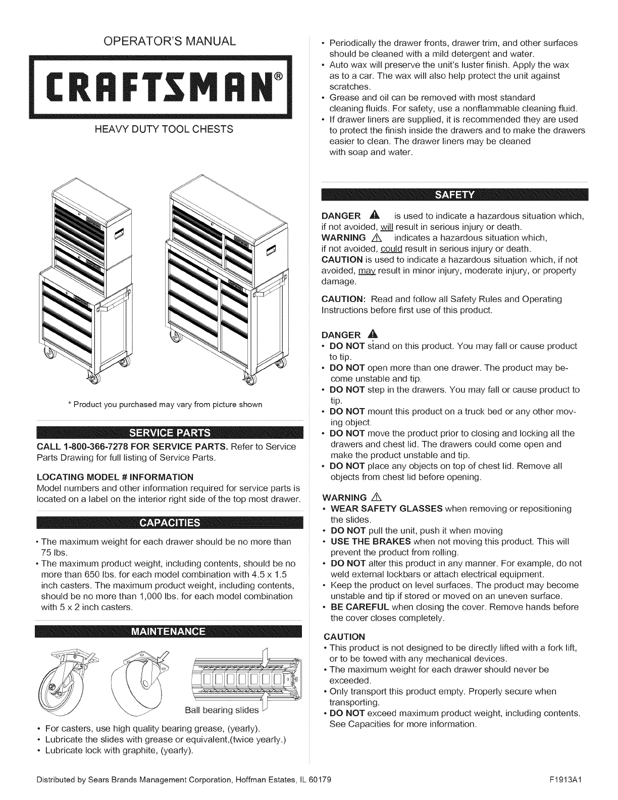
HEAVY DUTY TOOL CHESTS
• Periodically the drawer fronts, drawer trim, and other surfaces
should be cleaned with a mild detergent and water.
• Auto wax will preserve the unit's luster finish. Apply the wax
as to a car. The wax will also help protect the unit against
scratches.
• Grease and oil can be removed with most standard
cleaning fluids. For safety, use a nonflammable cleaning fluid.
• If drawer liners are supplied, it is recommended they are used
to protect the finish inside the drawers and to make the drawers
easier to clean. The drawer liners may be cleaned
with soap and water.
* Product you purchased may vary from picture shown
CALL 1-800-366-7278 FOR SERVICE PARTS. Refer to Service
Parts Drawing for full listing of Service Parts.
LOCATING MODEL #iNFORMATiON
Model numbers and other information required for service parts is
located on a label on the interior right side of the top most drawer.
• The maximum weight for each drawer should be no more than
75 Ibs.
• The maximum product weight, including contents, should be no
more than 650 Ibs. for each model combination with 4.5 x 1.5
inch casters. The maximum product weight, including contents,
should be no more than 1,000 Ibs. for each model combination
with 5 x 2 inch casters.
Ball bearing slides
• For casters, use high quality bearing grease, (yearly).
• Lubricate the slides with grease or equivalent,(twice yearly.)
• Lubricate lock with graphite, (yearly).
DANGER ,A is used to indicate a hazardous situation which,
if not avoided, will result in serious injury or death.
WARNING z_ indicates a hazardous situation which,
if not avoided, could result in serious injury or death.
CAUTION is used to indicate a hazardous situation which, if not
avoided, m_m_a_y_result in minor injury, moderate injury, or property
damage.
CAUTION: Read and follow all Safety Rules and Operating
Instructions before first use of this product.
DANGER ,_
• DO NOT stand on this product. You may fall or cause product
to tip.
• DO NOT open more than one drawer. The product may be-
come unstable and tip.
• DO NOT step in the drawers. You may fall or cause product to
tip.
• DO NOT mount this product on a truck bed or any other mov-
ing object.
• DO NOT move the product prior to closing and locking all the
drawers and chest lid. The drawers could come open and
make the product unstable and tip.
• DO NOT place any objects on top of chest lid. Remove all
objects from chest lid before opening.
WARNING /!k
• WEAR SAFETY GLASSES when removing or repositioning
the slides.
• DO NOT pull the unit, push it when moving
• USE THE BRAKES when not moving this product. This will
prevent the product from rolling.
• DO NOT alter this product in any manner. For example, do not
weld external Iockbars or attach electrical equipment.
• Keep the product on level surfaces. The product may become
unstable and tip if stored or moved on an uneven surface.
• BE CAREFUL when closing the cover. Remove hands before
the cover closes completely.
CAUTION
• This product is not designed to be directly lifted with a fork lift,
or to be towed with any mechanical devices.
• The maximum weight for each drawer should never be
exceeded.
• Only transport this product empty. Properly secure when
transporting.
• DO NOT exceed maximum product weight, including contents.
See Capacities for more information.
Distributed by Sears Brands Management Corporation, Hoffman Estates, JL60179 F1913A1
TOOLS REQUIRED:
3/8-in Wrench
7/16-in Wrench
Cross-tip Screwdriver
HARDWARE INCLUDED:
26=INCH CABINET HARDWARE
#14 - 10 x 5/8-in Hex Screws(Qty: 16)
#14 - 10 x 3/4 Cross-tip Screw
(Qty: 4)
HARDWARE INCLUDED:
40=INCH CABINET HARDWARE
#14 - 10 x 3/4-in Screws
(Qty: 16)
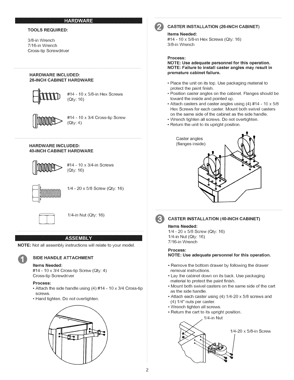
CASTER iNSTALLATiON (264NCH CABINET)
items Needed:
#14 - 10 x 5/8-in Hex Screws (Qty: 16)
3/8-in Wrench
Process:
NOTE: Use adequate personnel for this operation.
NOTE: Failure to install caster angles may result in
premature cabinet failure.
•Place the unit on its top. Use packaging material to
protect the paint finish.
•Position caster angles on the cabinet. Flanges should be
toward the inside and pointed up.
•Attach casters and caster angles using (4) #14 - 10 x 5/8
Hex Screws for each caster. Mount both swivel casters
on the same side of the cabinet as the side handle.
•Wrench tighten all screws. Do not overtighten.
•Return the unit to its upright position.
Caster angles
(flanges inside)
1/4 - 20 x 5/8 Screw (Qty: 16)
1/4-in Nut (Qty: 16)
NOTE: Not all assembly instructions will relate to your model.
SiDE HANDLE ATTACHMENT
Items Needed:
#14 - 10 x 3/4 Cross-tip Screw (Qty: 4)
Cross-tip Screwdriver
Process:
°Attach the side handle using (4) #14 - 10 x 3/4 Cross-tip
screws.
•Hand tighten. Do not overtighten.
t
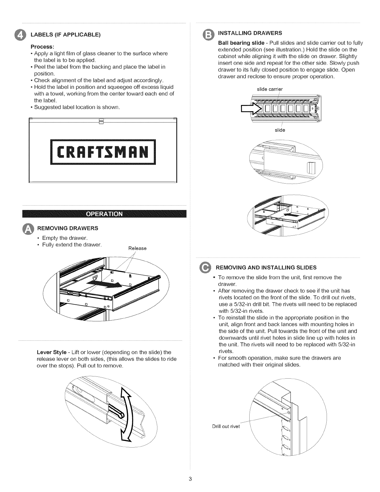
CASTER iNSTALLATION (404NCH CABINET)
Items Needed:
1/4 - 20 x 5/8 Screw (Qty: 16)
1/4-in Nut (Qty: 16)
7/16-in Wrench
Process:
NOTE: Use adequate personnel for this operation.
°Remove the bottom drawer by following the drawer
removal instructions.
•Lay the cabinet down on its back. Use packaging
material to protect the paint finish.
•Mount both swivel casters on the same side of the cart
as the side handle.
•Attach each caster using (4) 1/4-20 x 5/8 screws and
(4) 1/4" nuts per caster.
•Wrench tighten all screws.
•Return the cart to its upright position.
1/4-in Nut
1/4-20 x 5/8-in Screw
LABELS(iFAPPLICABLE)
Process:
• Apply a light film of glass cleaner to the surface where
the label is to be applied.
° Peel the label from the backing and place the label in
position.
° Check alignment of the label and adjust accordingly.
° Hold the label in position and squeegee off excess liquid
with a towel, working from the center toward each end of
the label.
° Suggested label location is shown.
U-
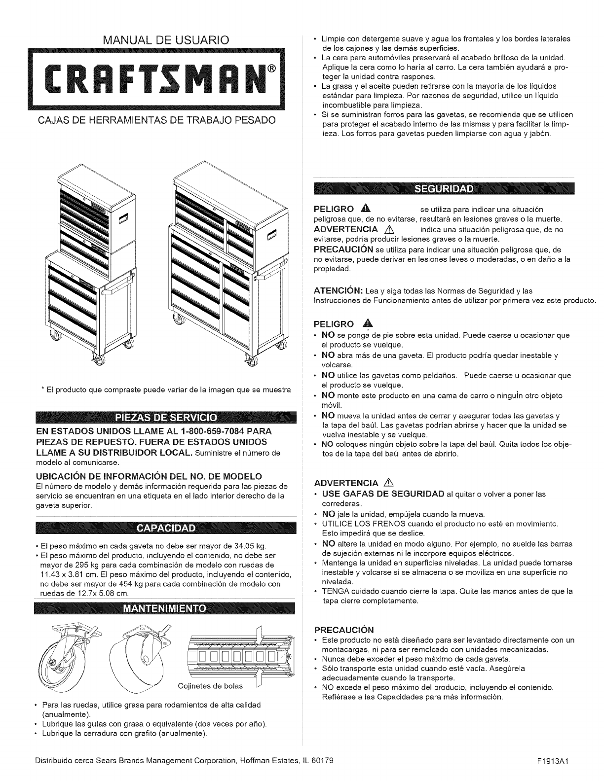
©iNSTALLiNG DRAWERS
Ball bearing slide - Pull slides and slide carrier out to fully
extended position (see illustration.) Hold the slide on the
cabinet while aligning it with the slide on drawer. Slightly
insert one side and repeat for the other side. Slowly push
drawer to its fully closed position to engage slide. Open
drawer and reclose to ensure proper operation.
slide carrier
/
slide
REMOVING DRAWERS
° Empty the drawer.
• Fully extend the drawer. Release
Lever Style - Lift or lower (depending on the slide) the
release lever on both sides, (this allows the slides to ride
over the stops). Pull out to remove.
REMOVING AND iNSTALLiNG SLIDES
To remove the slide from the unit, first remove the
drawer.
° After removing the drawer check to see if the unit has
rivets located on the front of the slide. To drill out rivets,
use a 5/32-in drill bit. The rivets will need to be replaced
with 5/32-in rivets.
° To reinstall the slide in the appropriate position in the
unit, align front and back lances with mounting holes in
the side of the unit. Pull towards the front of the unit and
downwards until rivet holes in slide line up with holes in
the unit. The rivets will need to be replaced with 5/32-in
rivets.
° For smooth operation, make sure the drawers are
matched with their original slides.
\\\\
Drill out rivet
\\\ \

MANUAL DE USUARIO
CRRFT MIIH °
CAJAS DE HERRAMIENTAS DE TRABAJO PESADO
• Limpie con detergente suave y agua los frontales y los bordes laterales
de los cajones y las demos superficies.
• La cera para autom6vJJes preservar_ el acabado briJJoso de Jaunidad.
Aplique la cera como Io hada al carro. La cera tambi6n ayudar_ a pro-
teger la unidad contra raspones.
• La grasa y el aceite pueden retirarse con la mayoda de los liquidos
est_ndar para limpieza. Por razones de seguridad, utilice un liquido
incombustible para limpieza.
• Si se suministran forros para las gavetas, se recomienda que se utilicen
para proteger el acabado interno de Jas mismas y para faciJitar Jalimp-
ieza. Los forros para gavetas pueden limpiarse con agua y jab6n.
* El producto que compraste puede variar de la imagen que se muestra
EN ESTADOS UNIDOS LLAME AL 1=800=659-7084 PARA
PiEZAS DE REPUESTO. FUERA DE ESTADOS UNiDOS
LLAME A SU DJSTRiBUJDOR LOCAL. Suministre el nQmero de
modeJo aJcomunicarse.
UBICACION DE JNFORMACl6N DEL NO. DE MODELO
El nQmero de modeJo y demos informaci6n requerida para Jas piezas de
servicio se encuentran en una etiqueta en el Jado interior derecho de Ja
gaveta superior.
• El peso m_ximo en cada gaveta no debe ser mayor de 34,05 kg.
• El peso m_ximo deJ producto, incJuyendo el contenido, no debe ser
mayor de 295 kg para cada combinaci6n de modeJo con ruedas de
11.43 x 3.81 cm. El peso m_ximo deJ producto, induyendo el contenido,
no debe ser mayor de 454 kg para cada combinaci6n de modeJo con
ruedas de 12.7x 5.08 cm.
F
Cojinetes de bolas
• Para Jas ruedas, utiJice grasa para rodamientos de aka caJidad
(anuaJmente).
• Lubrique Jas guias con grasa o equivaJente (dos veces por aSo).
• Lubrique Jacerradura con grafito (anuaJmente).
PEUGRO _, se utiJiza para indicar una situaci6n
peJigrosa que, de no evitarse, resuJtar_ en Jesiones graves o Ja muerte.
ADVERTENCiA z_ indica una situaci6n peJigrosa que, de no
evitarse, podria producir Jesiones graves o Ja muerte.
PREOAUOKSN se utiJiza para indicar una sJtuaci6n peJigrosa que, de
no evitarse, puede derivar en Jesiones Jeves o moderadas, o en daSo a Ja
propiedad.
ATENCI(SN: Lea y siga todas Jas Normas de Seguridad y Jas
Jnstrucciones de Funcionamiento antes de utiJizar por primera vez este producto.
PELIGRO ,_,
• NO se ponga de pie sobre esta unidad. Puede caerse u ocasionar que
el producto se vueJque.
• NO abra m_s de una gaveta. El producto podria quedar inestabb y
voJcarse.
• NO utiJice Jas gavetas como peJdaSos. Puede caerse u ocasionar que
el producto se vueJque.
• NO monte este producto en una cama de carro o ninguin otro objeto
m6vJJ.
• NO mueva la unidad antes de cerrar y asegurar todas Jas gavetas y
la tapa del baOl. Las gavetas podrian abrirse y hacer que la unidad se
vuelva inestable y se vuelque.
• NO coloques ningOn objeto sobre la tapa del baOl. Quita todos los obje-
tos de la tapa del baOl antes de abrirlo.
ADVERTENCIA Z_
• USE GAFAS DE SEGURJDAD al quitar o volver a poner las
correderas.
• NO jaJe Ja unJdad, empQjeJa cuando Ja mueva.
• UTJUCE LOS FRENOS cuando el producto no est6 en movimiento.
Esto impedir_ que se desJice.
• NO aJtere Ja unJdad en modo aJguno. Por ejempJo, no sueJde Jas barras
de sujeci6n externas ni Je incorpore equipos eJectricos.
• Mantenga Ja unidad en superficies niveJadas. La unidad puede tornarse
inestabJe y voJcarse si se aJmacena o se moviJiza en una superficie no
niveJada.
• TENGA cuidado cuando cJerre Ja tapa. Quite Jas manos antes de que Ja
tapa cierre compJetamente.
PRECAUCJON
°Este producto no est_ diseSado para ser bvantado directamente con un
montacargas, ni para ser remoJcado con unidades mecanizadas.
°Nunca debe exceder el peso m_ximo de cada gaveta.
°S6Jo transporte esta unidad cuando est6 vacia. AsegQreJa
adecuadamente cuando Jatransporte.
°NO exceda el peso m_ximo deJ producto, incJuyendo el contenido.
Refi@ase a Jas Capacidades para m_s informaci6n.
Distribuido cerca Sears Brands Management Corporation, Hoffman Estates JL60179 F1913A1
HERRAMENTAS NECESARIAS:
Llave Inglesa de 3/8 inch
Llave Inglesa de 7/16 inch
Destornillador de Punta en Cruz
PIEZAS INCLUIDAS:
FERRETERIA PARA GABINETE DE 26 PULG.
Tornillo Hexagonal de No. 14 - 10x 5/8 (Cant: 16)
Tuerca Phillips de No. 14 - 10 x
3/4 (Cant: 4)
PIEZAS INCLUIDAS:
FERRETERIA PARA GABINETE DE 40 PULG.
[__ No. 14 - 10 x 3/4 Tomillo
(Cant: 4)
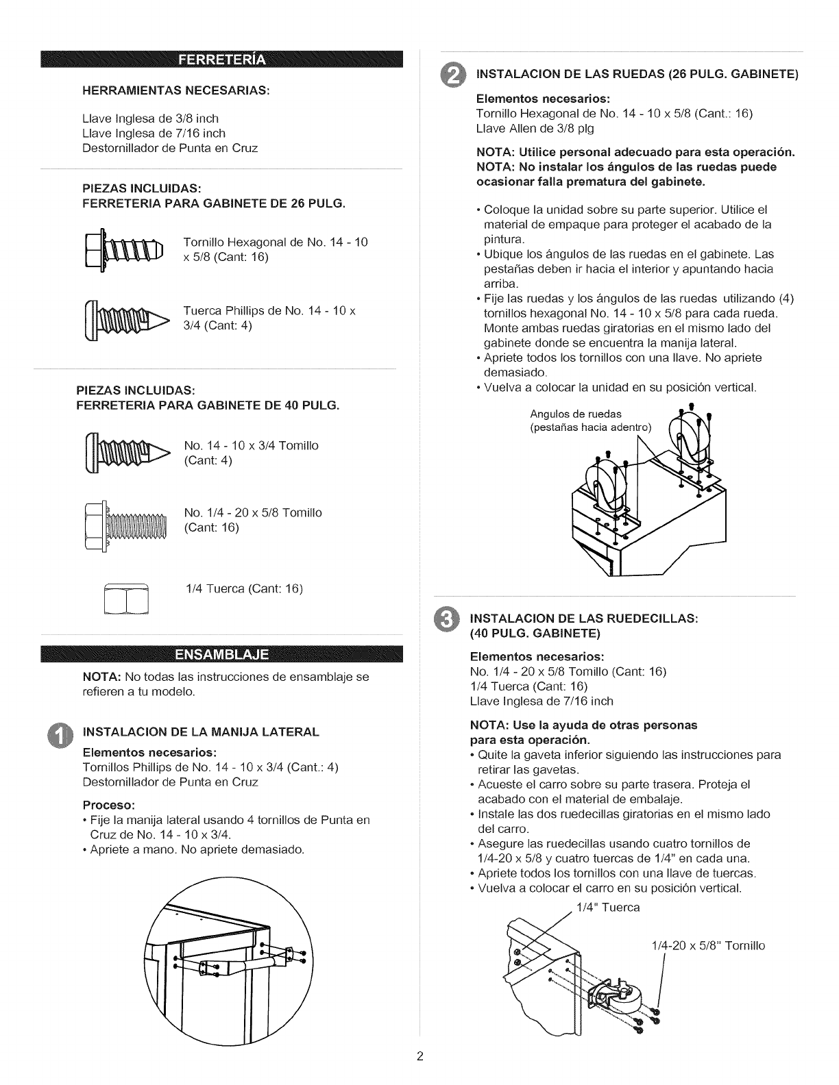
INSTALACION DE LAS RUEDAS (26 PULG. GABINETE)
Elementos necesarios:
Tornillo Hexagonal de No. 14 - 10 x 5/8 (Cant.: 16)
Llave Allen de 3/8 pig
NOTA: Utilice personal adecuado para esta operaci6n.
NOTA: No instalar los angulos de las ruedas puede
ocasionar falla prematura del gabinete.
°Coloque la unidad sobre su parte superior. Utilice el
material de empaque para proteger el acabado de la
pintura.
•Ubique los &ngutos de las ruedas en el gabinete. Las
pesta5as deben ir hacia el interior y apuntando hacia
arriba.
•Fije las ruedas y los &ngulos de las ruedas utilizando (4)
tornillos hexagonal No. 14 - 10 x 5/8 para cada rueda.
Monte ambas ruedas giratorias en el mismo lado del
gabinete donde se encuentra la manija lateral.
•Apriete todos los tornillos con una Ilave. No apriete
demasiado.
•Vuelva a colocar la unidad en su posici6n vertical.
I
Angulos de ruedas
(pestaSas hacia adentro)
No. 1/4 - 20 x 5/8 Tomillo
(Cant: 16)
1/4 Tuerca (Cant: 16)
NOTA: No todas las instrucciones de ensamblaje se
refieren a tu modelo.
INSTALACION DE LA MANIJA LATERAL
Elementos necesarios:
Tornillos Phillips de No. 14 - 10 x 3/4 (Cant.: 4)
Destornillador de Punta en Cruz
Proceso:
°Fije la manija lateral usando 4 tornillos de Punta en
Cruz de No. 14 - 10 x 3/4.
•Apriete a mano. No apriete demasiado.
t
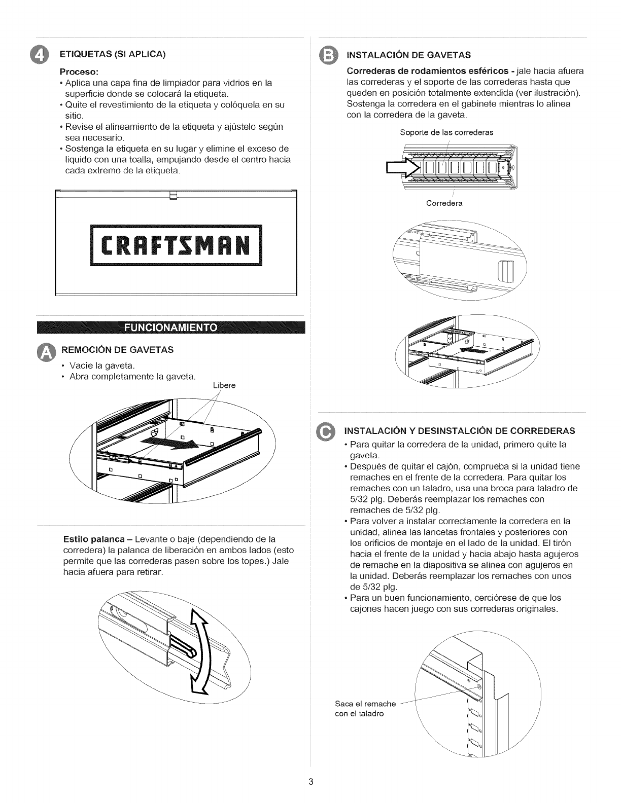
INSTALACION DE LAS RUEDECILLAS:
(40 PULG. GABINETE)
Elementos necesarios:
No. 1/4 - 20 x 5/8 Tomillo (Cant: 16)
1/4 Tuerca (Cant: 16)
Llave Inglesa de 7/16 inch
NOTA: Use la ayuda de otras personas
para esta operacion.
•Quite la gaveta inferior siguiendo las instrucciones para
retirar las gavetas.
•Acueste el carro sobre su parte trasera. Proteja el
acabado con el material de embalaje.
•Instale las dos ruedecillas giratorias en el mismo lado
del carro.
•Asegure las ruedecillas usando cuatro tornillos de
1/4-20 x 5/8 y cuatro tuercas de 1/4" en cada una.
•Apriete todos los tornillos con una Ilave de tuercas.
•Vuelva a colocar el carro en su posici6n vertical.
1/4" Tuerca
1/4-20 x 5/8" Tornillo
ETIQUETAS (Sl APLICA)
Proceso:
•Aplica una capa fina de limpiador para vidrios en la
superficie donde se colocar_ la etiqueta.
• Quite el revestimiento de la etiqueta y col6quela en su
sitio.
• Revise el alineamiento de la etiqueta y ajQstelo segQn
sea necesario.
• Sostenga la etiqueta en su lugar y elimine el exceso de
liquido con una toalla, empujando desde el centro hacia
cada extremo de la etiqueta.
U
INSTALACION DE GAVETAS
Correderas de rodamientos esf_ricos -jale hacia afuera
las correderas y el soporte de las correderas hasta que
queden en posiciOn totalmente extendida (ver ilustraci6n).
Sostenga la corredera en el gabinete mientras Io alinea
con la corredera de la gaveta.
Soporte de las correderas
i
Corredera
__-- __-::--:-: ......
- _-:_-_q:- :7:.........
_ REMOCI6N DE GAVETAS
°Vacie la gaveta.
°Abra completamente la gaveta. Libere
Estilo palanca -Levante o baje (dependiendo de la
corredera) la palanca de NberaciOn en ambos lados (esto
permite que las correderas pasen sobre los topes.) Jale
hacia afuera para retirar.
INSTALACION YDESINSTALCION DE CORREDERAS
•Para quitar la corredera de la unidad, primero quite la
gaveta.
•Despu6s de quitar el cajOn, comprueba si la unidad tiene
remaches en el frente de la corredera. Para quitar los
remaches con un taladro, usa una broca para taladro de
5/32 pig. Deber_s reemplazar los remaches con
remaches de 5/32 pig.
•Para volver a instalar correctamente la corredera en la
unidad, alinea las lancetas frontales y posteriores con
los orificios de montaje en el lado de la unidad. El tir6n
hacia el frente de la unidad y hacia abajo hasta agujeros
de remache en la diapositiva se alinea con agujeros en
la unidad. Deber_s reemplazar los remaches con unos
de 5/32 pig.
• Para un buen funcionamiento, cerci6rese de que los
cajones hacen juego con sus correderas originales.
Saca el remache
con el taladro
\\\
\\