Craftsman 706449601 User Manual TOOL CHEST Manuals And Guides 1501321L
User Manual: Craftsman 706449601 706449601 CRAFTSMAN TOOL CHEST - Manuals and Guides View the owners manual for your CRAFTSMAN TOOL CHEST #706449601. Home:Tool Parts:Craftsman Parts:Craftsman TOOL CHEST Manual
Open the PDF directly: View PDF ![]() .
.
Page Count: 8
OPERATOR'S MANUAL
T °
• Lubricate lock with graphite, (yearly).
• Periodically the drawer fronts, drawer trim, and other surfaces
should be cleaned with a mild detergent and water.
• Auto wax will preserve the unit's luster finish. Apply the wax
as to a car. The wax will also help protect the unit against
scratches.
• Grease and oil can be removed with most standard
cleaning fluids. For safety, use a nonflammable cleaning fluid.
• If drawer liners are supplied, it is recommended they are used
to protect the finish inside the drawers and to make the drawers
easier to clean. The drawer liners may be cleaned
with soap and water.
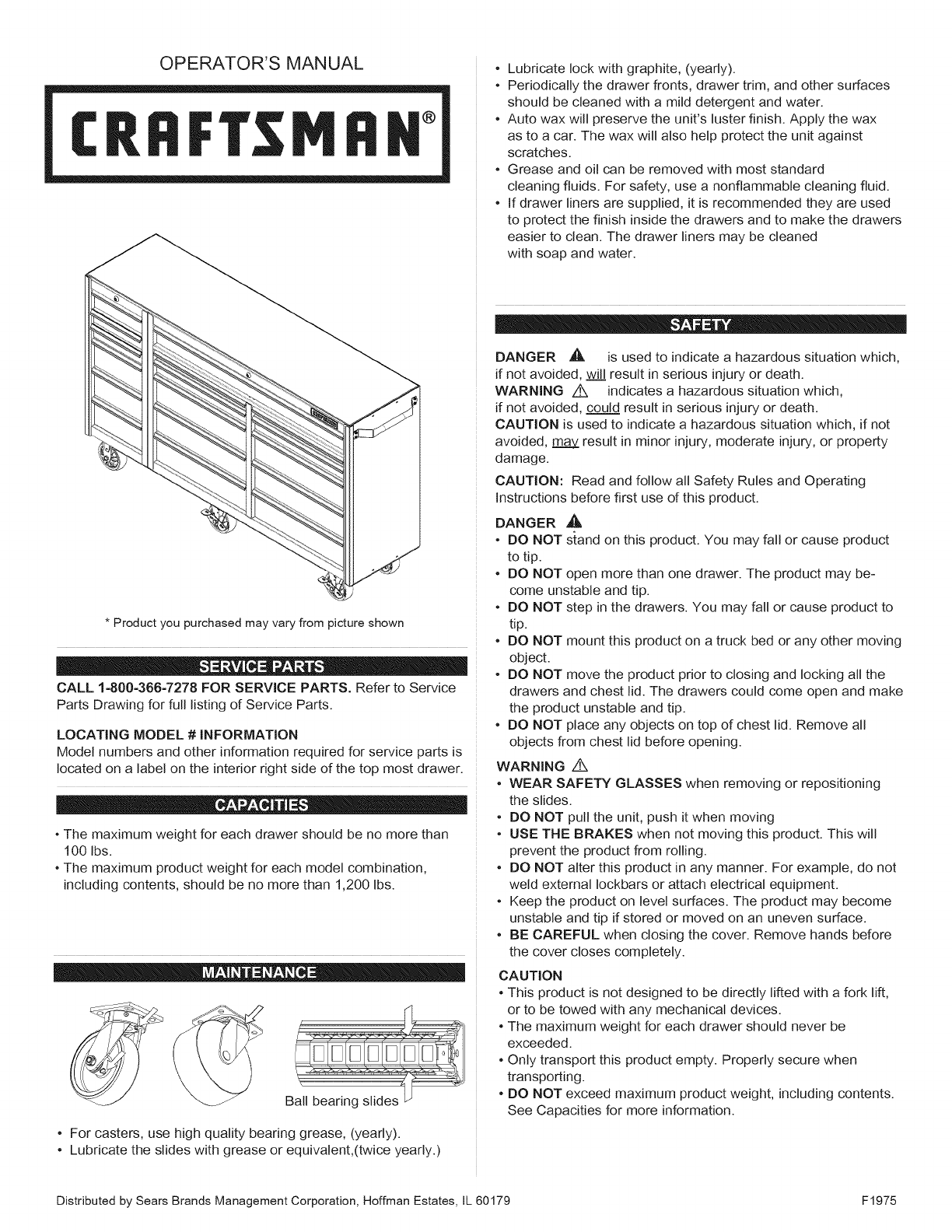
* Product you purchased may vary from picture shown
CALL 1-800-366-7278 FOR SERVICE PARTS. Refer to Service
Parts Drawing for full listing of Service Parts.
LOCATING MODEL #iNFORMATiON
Model numbers and other information required for service parts is
located on a label on the interior right side of the top most drawer.
• The maximum weight for each drawer should be no more than
100 Ibs.
• The maximum product weight for each model combination,
including contents, should be no more than 1,200 Ibs.
Ball bearing slides
• For casters, use high quality bearing grease, (yearly).
• Lubricate the slides with grease or equivalent,(twice yearly.)
DANGER ,A is used to indicate a hazardous situation which,
if not avoided, wiJ.JIresult in serious injury or death.
WARNING z_ indicates a hazardous situation which,
if not avoided, could result in serious injury or death.
CAUTION is used to indicate a hazardous situation which, if not
avoided, may result in minor injury, moderate injury, or property
damage.
CAUTION: Read and follow all Safety Rules and Operating
Instructions before first use of this product.
DANGER _,
• DO NOT stand on this product. You may fall or cause product
to tip.
• DO NOT open more than one drawer. The product may be-
come unstable and tip.
• DO NOT step in the drawers. You may fall or cause product to
tip.
• DO NOT mount this product on a truck bed or any other moving
object.
• DO NOT move the product prior to closing and locking all the
drawers and chest lid. The drawers could come open and make
the product unstable and tip.
• DO NOT place any objects on top of chest lid. Remove all
objects from chest lid before opening.
WARNING /!k
• WEAR SAFETY GLASSES when removing or repositioning
the slides.
• DO NOT pull the unit, push it when moving
• USE THE BRAKES when not moving this product. This will
prevent the product from rolling.
• DO NOT alter this product in any manner. For example, do not
weld external Iockbars or attach electrical equipment.
• Keep the product on level surfaces. The product may become
unstable and tip if stored or moved on an uneven surface.
• BE CAREFUL when closing the cover. Remove hands before
the cover closes completely.
CAUTION
• This product is not designed to be directly lifted with a fork lift,
or to be towed with any mechanical devices.
• The maximum weight for each drawer should never be
exceeded.
• Only transport this product empty. Properly secure when
transporting.
• DO NOT exceed maximum product weight, including contents.
See Capacities for more information.
Distributed by Sears Brands Management Corporation, Hoffman Estates, IL 60179 F1975
TOOLS REQUIRED:
Cross-tip Screwdriver
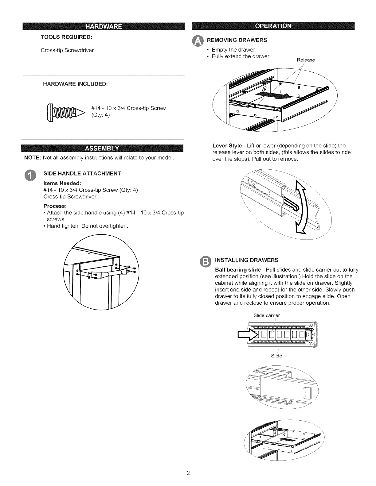
_ REMOVING DRAWERS
• Empty the drawer.
• Fully extend the drawer. Release
HARDWARE INCLUDED:
#14 - 10 x 3/4 Cross-tip Screw
(Qty: 4)
NOTE: Not all assembly instructions will relate to your model.
SiDE HANDLE ATTACHMENT
Items Needed:
#14 - 10 x 3/4 Cross-tip Screw (Qty: 4)
Cross-tip Screwdriver
Process:
° Attach the side handle using (4) #14 - 10 x 3/4 Cross-tip
screws.
• Hand tighten. Do not overtighten.
t
Lever Style - Lift or lower (depending on the slide) the
release lever on both sides, (this allows the slides to ride
over the stops). Pull out to remove.
O INSTALLING DRAWERS
Ball bearing slide - Pull slides and slide carrier out to fully
extended position (see illustration.) Hold the slide on the
cabinet while aligning it with the slide on drawer. Slightly
insert one side and repeat for the other side. Slowly push
drawer to its fully closed position to engage slide. Open
drawer and reclose to ensure proper operation.
Slide carrier
/
Slide
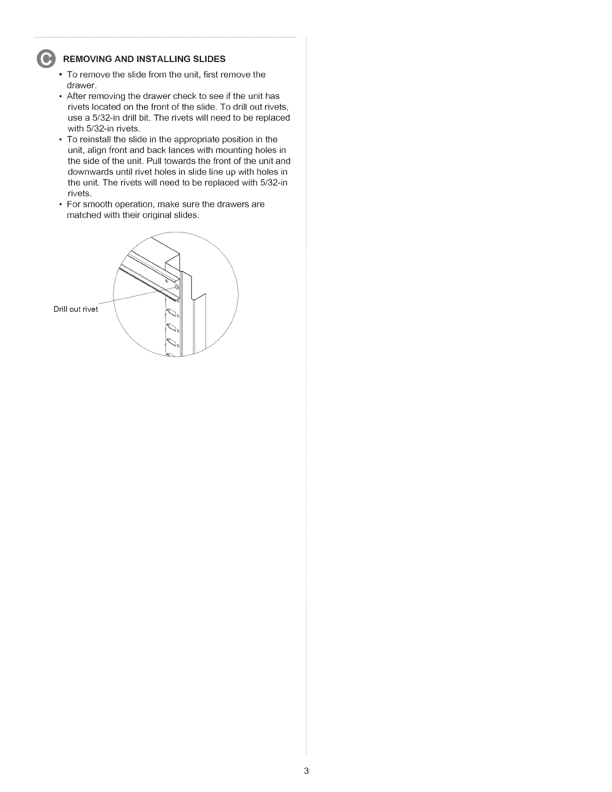
REMOVING AND iNSTALLiNG SLIDES
•To remove the slide from the unit, first remove the
drawer.
• After removing the drawer check to see if the unit has
rivets located on the front of the slide. To drill out rivets,
use a 5/32-in drill bit. The rivets will need to be replaced
with 5/32-in rivets.
• To reinstall the slide in the appropriate position in the
unit, align front and back lances with mounting holes in
the side of the unit. Pull towards the front of the unit and
downwards until rivet holes in slide line up with holes in
the unit. The rivets will need to be replaced with 5/32-in
rivets.
• For smooth operation, make sure the drawers are
matched with their original slides.
\\\\\\
Drill out rivet
\\\ \/
\/
J

MANUAL DE USUARIO
CRRFT MIIH °
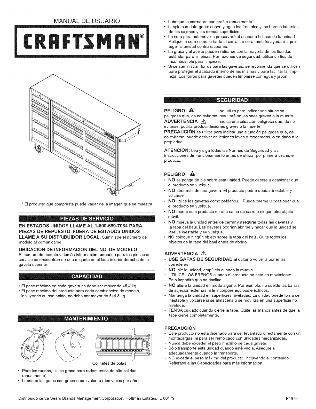
* El producto que compraste puede variar de la imagen que se muestra
EN ESTADOS UNIDOS LLAME AL 1=800=659-7084 PARA
PIEZAS DE REPUESTO. FUERA DE ESTADOS UNIDOS
LLAME A SU DISTRIBUIDOR LOCAL. Suministre el nQmero de
modelo al comunicarse.
UBICACION DE INFORMAClON DEL NO. DE MODELO
El nQmero de modelo y demos informaci6n requerida para las piezas de
servicio se encuentran en una etiqueta en el lado interior derecho de la
gaveta superior.
• El peso m_ximo en cada gaveta no debe ser mayor de 45,4 kg.
• El peso m_ximo del producto para cada combinaci6n de modelo,
incluyendo su contenido, no debe ser mayor de 544,8 kg.
Cojinetes de bolas
• Para las ruedas, utilice grasa para rodamientos de alta calidad
(anualmente).
• Lubrique las gu[as con grasa o equivalente (dos veces por aSo).
• Lubrique la cerradura con grafito (anualmente).
• Limpie con detergente suave y agua los frontabs y los bordes laterales
de los cajones y las demos superficies.
• La cera para autom6viles preservar_ el acabado brilloso de la unidad.
Aplique la cera como Io haria al carro. La cera tambi6n ayudar_ a pro-
teger la unidad contra raspones.
• La grasa y el aceite pueden retirarse con la mayoria de los liquidos
est_ndar para limpieza. Por razones de seguridad, utilice un liquido
incombustible para limpieza.
• Si se suministran forros para las gavetas, se recomienda que se utilicen
para proteger el acabado interno de las mismas y para facilitar la limp-
ieza. Los forros para gavetas pueden limpiarse con agua y jab6n.
PEUGRO _, se utiliza para indicar una situaci6n
peligrosa que, de no evitarse, resultar_ en lesiones graves o la muerte.
ADVERTENClA ,4X indica una situaci6n peligrosa que, de no
evitarse, podria producir lesiones graves o la muerte.
PREOAUOKSN se utiliza para indicar una sJtuaci6n peligrosa que, de
no evitarse, puede derivar en lesiones leves o moderadas, o en daSo a la
propiedad.
ATENOION: Lea y siga todas las Normas de Seguridad y las
InstruccJones de Funcionamiento antes de utilizar por primera vez este
producto.
PELIGRO ,_,
• NO se ponga de pie sobre esta unidad. Puede caerse u ocasionar que
el producto se vuelque.
• NO abra m_s de una gaveta. El producto podria quedar inestabb y
volcarse.
• NO utilice las gavetas como peldaSos. Puede caerse u ocasionar que
el producto se vuelque.
• NO monte este producto en una cama de carro o ningQn otro objeto
m6vJJ.
• NO mueva la unidad antes de cerrar y asegurar todas las gavetas y
la tapa del baOl. Las gavetas podrian abrirse y hacer que la unidad se
vuelva inestable y se vuelque.
• NO coloque ningOn objeto sobre la tapa del baOl. Quite todos los
objetos de la tapa del baQI antes de abrirlo.
ADVERTENClA Z_
• USE GAFAS DE SEGURIDAD al quitar o volver a poner las
correderas.
• NO jale la unJdad, empQjela cuando la mueva.
• UTILICE LOS FRENOS cuando el producto no est6 en movimiento.
Esto impedir_ que se deslice.
• NO altere la unJdad en modo alguno. Por ejemplo, no suelde las barras
de sujeci6n externas ni le incorpore equipos electricos.
• Mantenga la unidad en superficies niveladas. La unidad puede tornarse
inestable y volcarse si se almacena o se moviliza en una superficie no
nivelada.
• TENGA cuidado cuando cJerre la tapa. Quite las manos antes de que la
tapa cierre completamente.
PRECAUCKSN
• Este producto no est_ disefiado para ser bvantado directamente con un
montacargas, ni para ser remolcado con unidades mecanizadas.
• Nunca debe exceder el peso m_ximo de cada gaveta.
• $61o transporte esta unidad cuando est6 vacia. AsegQrela
adecuadamente cuando la transporte.
• NO exceda el peso m_ximo del producto, incluyendo el contenido.
Refi@ase alas Capacidades para m_s informaci6n.
Distribuido cerca Sears Brands Management Corporation, Hoffman Estates IL 60179 F1975
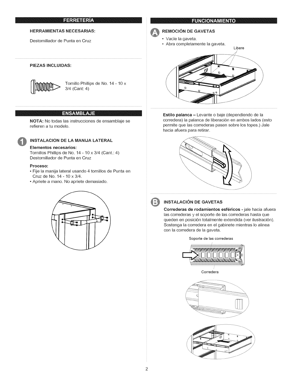
HERRAMIENTAS NECESARIAS:
Destomillador de Punta en Cruz
_REMOCION DE GAVETAS
•Vacie la gaveta.
•Abra completamente la gaveta. Libere
PIEZAS INCLUIDAS:
[__ TomiNo Phillips de No. 14 - 10 x
3/4 (Cant: 4)
NOTA: No todas las instrucciones de ensamblaje se
refieren a tu modelo.
INSTALACION DE LA MANIJA LATERAL
Elementos necesarios:
Tornillos Phillips de No. 14 - 10 x 3/4 (Cant.: 4)
Destomillador de Punta en Cruz
Proceso:
•Fije la manija lateral usando 4 tornillos de Punta en
Cruz de No. 14 - 10 x 3/4.
•Apriete a mano. No apriete demasiado.
Estilo palanca - Levante o baje (dependiendo de la
corredera) la palanca de liberaci6n en ambos lados (esto
permite que las correderas pasen sobre los topes.) Jale
hacia afuera para retirar.
INSTALACION DE GAVETAS
Correderas de rodamientos esf_ricos =jale hacia afuera
las correderas y el soporte de las correderas hasta que
queden en posiciOn totalmente extendida (ver ilustraci6n).
Sostenga la corredera en el gabinete mientras Io alinea
con la corredera de la gaveta.
Soporte de las correderas
Corredera
-_--_L_-_-----_
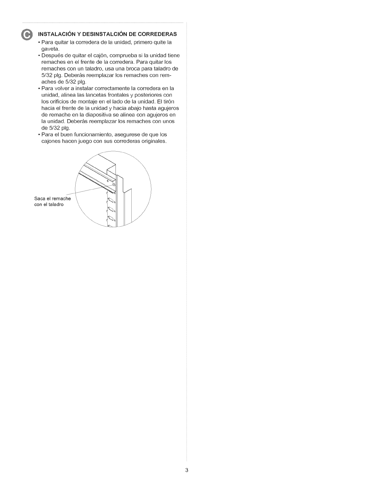
INSTALACION YDESINSTALCION DE CORREDERAS
• Para quitar la corredera de la unidad, primero quite la
gaveta.
• Despu6s de quitar el cajOn, comprueba si la unidad tiene
remaches en el frente de la corredera. Para quitar los
remaches con un taladro, usa una broca para taladro de
5/32 pig. Deber&s reemplazar los remaches con rem-
aches de 5/32 pig.
• Para volver a instalar correctamente la corredera en la
unidad, alinea las lancetas frontales y posteriores con
los orificios de montaje en el lado de la unidad. El tir6n
hacia el frente de la unidad y hacia abajo hasta agujeros
de remache en la diapositiva se alinea con agujeros en
la unidad. Deber&s reemplazar los remaches con unos
de 5/32 pig.
• Para el buen funcionamiento, asegurese de que los
cajones hacen juego con sus correderas originales.
Saca el remache
con el taladro
\\\
\
\
\\\ \\

