Craftsman 706452790 User Manual TOOL CHEST Manuals And Guides 1504105L
User Manual: Craftsman 706452790 706452790 CRAFTSMAN TOOL CHEST - Manuals and Guides View the owners manual for your CRAFTSMAN TOOL CHEST #706452790. Home:Tool Parts:Craftsman Parts:Craftsman TOOL CHEST Manual
Open the PDF directly: View PDF ![]() .
.
Page Count: 8

OPERATOR'S MANUAL
SIDE CABINET
DANGER _ is used to indicate a hazardous situation which,
if not avoided, wit===Jiresult in serious injury or death.
WARNING z_ indicates a hazardous situation which, if not
avoided, could result in serious injury or death.
CAUTION is used to indicate a hazardous situation which, if not
avoided, _ result in minor injury, moderate injury, or property
damage.
CAUTION: Read and follow all Safety Rules and Operating
Instructions before first use of this product.
DANGER
- DO NOT stand on this product. You may fatt or cause product to
tip.
DO NOT open more than one drawer. The product may become
unstable and tip.
DO NOT step in the drawers. You may fatt or cause product to
tip.
DO NOT mount this product on a truck bed or any other moving
object.
Lock the drawers before moving this product. The drawers could
come open and make the product unstable and tip, which could
cause personal injury or product damage.
CALL 1o800o833o4405 FOR SERVICE PARTS. Refer to Service
Parts Drawing for futt listing of Service Parts.
LOCATING MODEL # INFORMATION
Model numbers and other information required for service parts is
located on a label on the interior right side of the top most drawer.
• Empty weight 155 Ibs.
• The maximum load capacity for each drawer is 100 Ibs.
WARNING z_
WEAR SAFETY GLASSES when removing or repositioning
the stides.
DO NOT tow with power equipment. The product may cause
personal injury or product damage.
DO NOT alter this product in any manner. For example, do not
weld extemat iockbars or attach electrical equipment.
Keep the product on level surfaces. The product may become
unstable and tip if stored or moved on an uneven surface.
A heavy duty side cabinet must be used on an equally heavy
duty cart.
CAUTION
DO NOT exceed maximum product weight, including contents.
See Operations Sections: Capacities for more information.
USE ADEQUATE MANPOWER WHEN LIFTING OR MOV-
iNG THE CHEST OR CABINET.
Lubricate the stides with grease or equivalent,(twice yearly.)
Lubricate lock and locking system components with graphite,
(yearly).
Periodically the drawer fronts, drawer trim, and other surfaces
should be cleaned with a mild detergent and water.
Auto wax wiii preserve the unit's luster finish. Apply the wax as
to a car. The wax wiii also help protect the unit against scratch-
es.
Grease and oil can be removed with most standard cleaning
fluids. For safety, use a nonflammable cleaning fluid.
if drawer liners are supplied, it is recommended they are used
to protect the finish inside the drawers and to make the drawers
easier to clean. The drawer liners may be cleaned with soap and
water.
Waterloo Industries, 139 West Forest Hill Avenue, Oak Creek, WI 53154, USA F1994

TOOLS REQUIRED:
Cross-tip Screwdriver
3/8" Wrench
Hardware included:
3/8-16 x 3/4 Pan Head Screw
(Qty: 2)
14-10 x 5/8 Hex Screw (Qty: 2)
BRACKET iNSTALLATiON
items Needed:
3/8-16 x 3/4 Pan Head Screw (Qty: 2)
Cross4ip Screwdriver
Note: The hanging brackets and bumpers can be
mounted to either side of the cabinet.
Process:
-Attach the adhesive-backed rubber bumpers at the
bottom corners of the side cabinet.
Attach the bracket to the side of the cabinet using two
3/8-16 x 3/4 pan head screws.
Locker:
Literature
Hardware bag
Upper Bracket
Lower Bracket
Bumper
Screw J"
Lower
Bracket
Upper
Bumper
Drawer Liner Roll
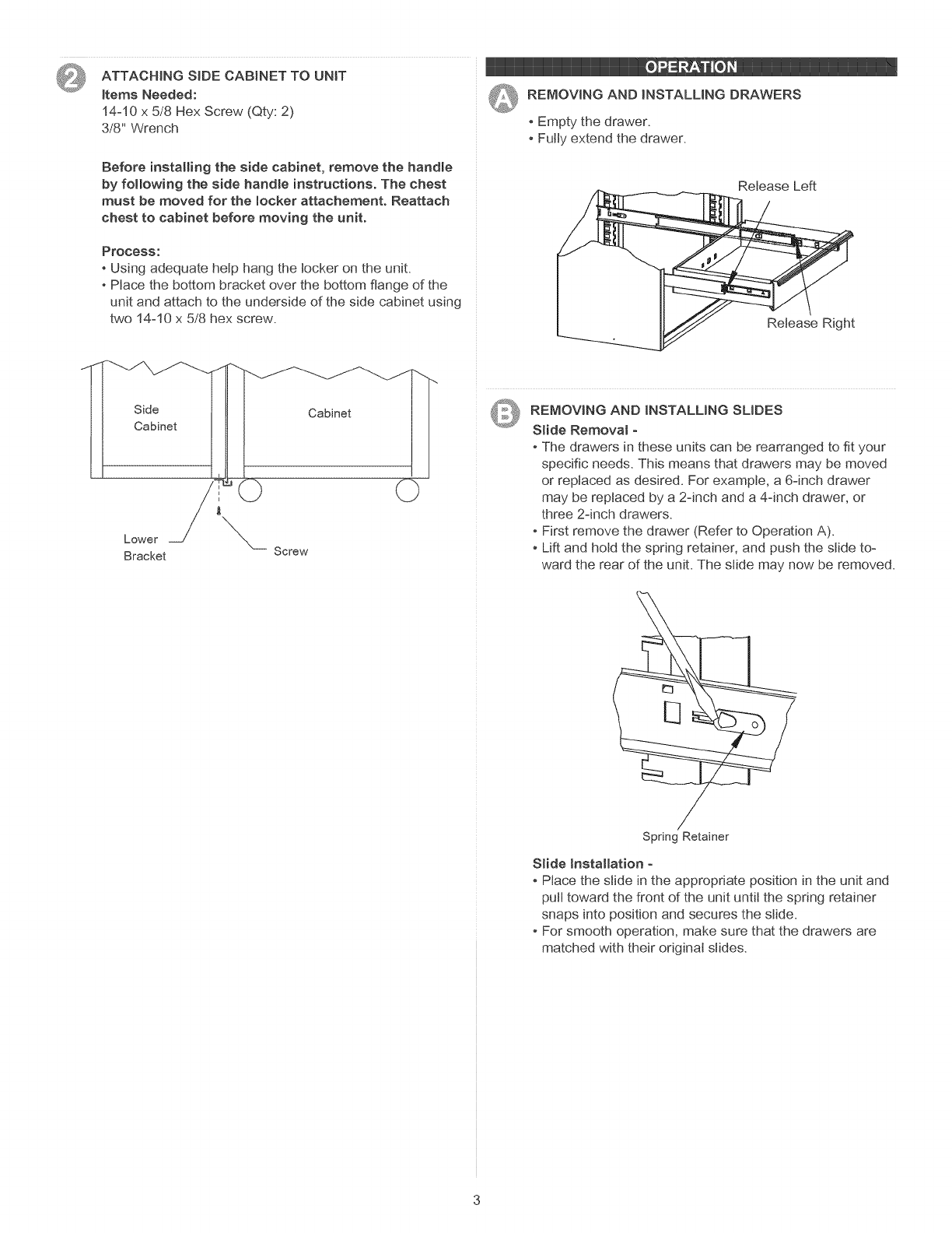
ATTACHINGSIDECABINETTOUNiT
itemsNeeded:
14-10x5/8HexScrew(Qty:2)
3/8"Wrench
Beforeinstallingthesidecabinet,removethehandle
byfollowingthesidehandleinstructions. The chest
must be moved for the locker attachement. Reattach
chest to cabinet before moving the unit.
PrOCeSS:
-Using adequate help hang the locker on the unit.
-Place the bottom bracket over the bottom flange of the
unit and attach to the underside of the side cabinet using
two 14-10 x 5/8 hex screw.
o _ :± ®
' REMOVING AND iNSTALLiNG DRAWERS
QEmpty the drawer.
Fully extend the drawer.
Release Left
Release Right
J
J
Side
Cabinet
Lower
Bracket Screw
_!_ REMOVING AND iNSTALLiNG SLIDES
Slide Removal -
- The drawers in these units can be rearranged to fit your
specific needs. This means that drawers may be moved
or replaced as desired. For example, a 6=inch drawer
may be replaced by a 2-inch and a 4-inch drawer, or
three 2-inch drawers.
-First remove the drawer (Refer to Operation A).
- Lift and hold the spring retainer, and push the slide to=
ward the rear of the unit. The slide may now be removed.
Spring Retainer
Slide Installation -
Place the slide in the appropriate position in the unit and
pull toward the front of the unit until the spring retainer
snaps into position and secures the slide.
For smooth operation, make sure that the drawers are
matched with their original slides.

MANUAL DE USUARIO
GABINETE LATERAL
PELIGRO _, se utiliza para indicar una situaci6n
peligrosa que, de no evitarse, resultar8 en lesiones graves o la muerte.
ADVERTENOIA z_ indica una situaci6n peligrosa que, de no
evitarse, podr{a producir lesiones graves o la muerte.
PREOAUOJ6N se utiliza para indicar una situaci6n peligrosa que, de
no evitarse, puede derivar en lesiones leves o moderadas, o en da_o a la
propiedad.
ATENOK)N: Lea y siga todas las Normas de Seguridad y las
Instrucciones de Funcionamiento antes de utilizar por primera vez este
producto.
PEUGRO
• NO se ponga de pie sobre esta unidad_ Puede caerse u ocasionar que
el producto se vuelque.
• NO abra m_s de una gaveta. El producto podr{a quedar inestable y
volcarse.
• NO utilice las gavetas como pelda_os. Puede caerse u ocasionar que
el producto se vuelque.
NO monte este producto en una cama de carro o ninguin otro objeto
m6vil.
Asegure las gavetas y puertas antes de mover este producto. Estas se
podr{an abrir y hacer que el producto quede inestable y se vuelque, Io
cual podr{a causar lesiones personales o da_os al producto.
EN ESTADOS UNtDOS LLAME AL 1-800-833-4405 PARA
PIEZAS DE REPUESTO. FUERA DE ESTADOS UNIDOS
LLAME A SU DtSTRIBUIDOR LOCAL. Suministre el nQmero de
modelo al comunicarse.
UBICACION DE INFORMACION DEL NO. DE MODELO
El nQmero de modelo y demos informaci6n requerida para las piezas de
servicio se encuentran en una etiqueta en el lado interior derecho de la
gaveta superior.
• El peso vac{o del gabinete es 155 Ibs (70.30 kg.)
• El peso mSximo en cada gaveta no debe ser mayor de 100 Ibs
(45,4 Kg.)
ADVERTENClA Z_
USE GAFAS DE SEGURIDAD al quitar o volver a poner las corredo
eras.
• Antes de mover este producto con un montacargas, asegOrelo de
manera adecuad&
• NO altere la unidad en modo alguno. Por ejemplo, no suelde las barras
de sujeci6n externas nile incorpore equipos el¢ctricos.
• Mantenga la unidad en superficies niveladas. La unidad puede tornarse
inestable y volcarse si se almacena o se moviliza en una superficie no
nivelad&
• Un gabinete lateral extrafuerte se debe usar en un carro que tabi6n sea
extrafuerte.
PRECAUCKSN
• NO exceda el peso m_ximo del producto, incluyendo el contenido. Re-
fiCrase alas Capacidades para m_s informaci6n.
UTILICE EL PERSONAL ADECUADO PARA LEVANTAR O
MOVER EL BAUL O EL GABINETE.
Cojinetes de bolas
• Lubrique las diapositivas con grasa o equivalente, (dos veces cada a_o.)
• Lubrique la cerradura y la fijaci6n de componentes de sistema con el
grafito, (anualmente).
• Limpie con detergente suave y agua los frontales y los bordes laterales
de los cajones y las demas superficies.
• La cera para autom6viles preservara el acabado brilloso de la unidad.
Aplique la cera como Io har{a al carro. La cera tambi6n ayudara a prote-
ger la unidad contra raspones.
• La grasa y el aceite pueden retirarse con la mayor{a de los I{quidos
estandar para limpieza. Por razones de seguridad, utilice un I{quido
incombustible para limpieza.
• Si se suministran forros para las gavetas, se recomienda que se utilicen
para proteger el acabado interno de las mismas y para facilitar la limpo
ieza. Los forros para gavetas pueden limpiarse con agua y jab6n.
Waterloo Industries, 13g West Forest Hill Avenue, Oak Creek, WI 53154, USA F1994
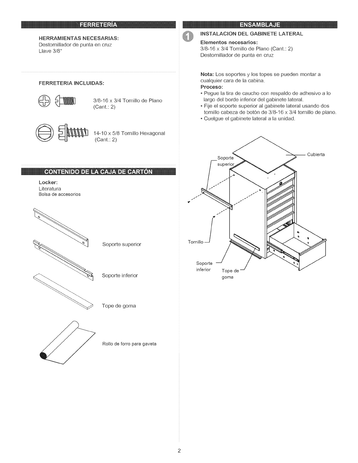
HERRAMIENTAS NECESARtAS:
DestorniIIador de punta en cruz
Mave 3/8"
m ii :i
INSTALACION DEL GABJNETE LATERAL
E_ementos necesarios:
3/8-16 x 3/4 Tornitto de Piano (Cant.: 2)
Destomittador de punta en cruz
FERRETERIA mNCLUIDAS:
_l _\\_1 3/8-16 3/4 Tornitto de Piano
X
(Cant.: 2)
(_ _ 14-10 x 5/8 Tomitto Hexagonal
(Cant.: 2)
Nora: Los soportes y tos topes se pueden montar a
cualquier cara de ta cabina.
Proceso:
-Pegue la tira de caucho con respatdo de adhesive a to
largo det borde inferior det gabinete taterat.
Fije et soporte supedor al gabinete laterat usando dos
torniIIo cabeza de botOn de 3/8-16 x 3/4 tomitto de ptano.
Cuetgue et gabinete taterat a ta unidad.
Locker:
Mteratura
Bolsa de accesorios
Soporte superior
Soporte inferior
Tope de goma
So
1€
TornilloJ
Soporte
inferior Tope de
goma
-- Cubierta
Rollo de forro para gaveta
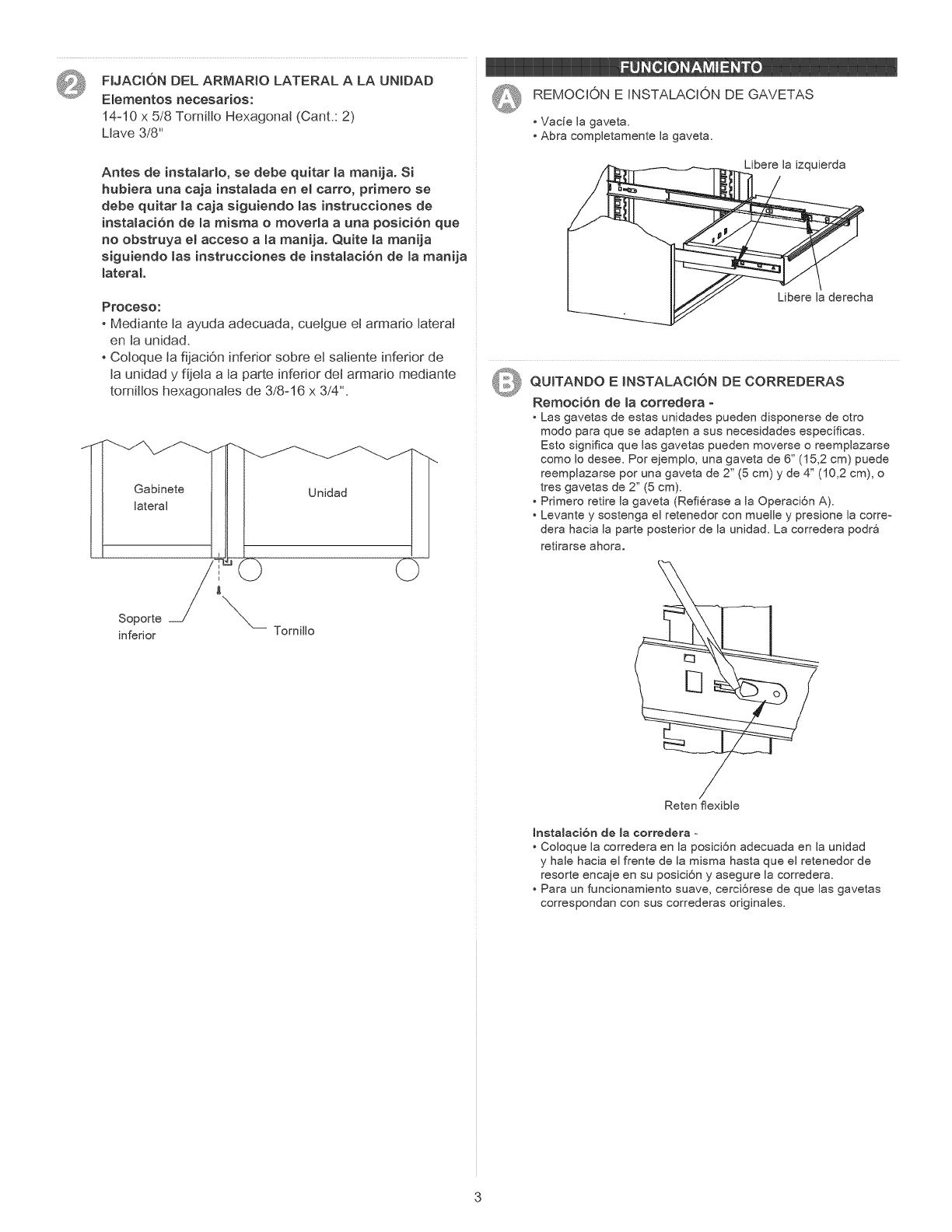
FUAGI6NDELARMARtOLATERALALAUNIDAD REMOCJONEINSTALACIONDEGAVETAS
E_ementosnecesarios:
14=10x5/8TomifloHexagonal(Cant.:2) •Vac{elagaveta.
LJave3/8" •Abracompletamentelagaveta.
Antesdeinstalarlo,sedebequitarlamanija.Si
hubiera una eaja instalada en el carro, pdmero se
debe quitar _a eaja siguiendo _as instrueeiones de
instataci6n de la misma o moverla a una posici6n que
no obstruya el acceso a la manija. Quite la manija
siguiendo _as instrucciones de insta_aci6n de _a manija
_ateraL
Libere la izquierda
Proceso:
-Mediante la ayuda adecuada, cuetgue et armano taterat
en la unidad.
-Coloque la fijaciOn inferior sobre el satiente inferior de
ta unidad y fijeta a ta parte inferior det armado mediante
tomittos hexagonates de 3/8-16 x 3/4".
J
J
Gabinete
lateral
Soporte
inferior
Unidad __
Tornillo
Libere la derecha
AI_ QUITANDO E MNSTALACK)N DE CORREDERAS
©Remocion de _a eorredera °
• Las gavetas de estas unidades pueden disponerse de otro
modo para que se adapten a sus necesidades especificas.
Esto significa que las gavetas pueden moverse o reemplazarse
como Io desee. Por ejemplo, una gaveta de 6" (15,2 cm) puede
reemplazarse por una gaveta de 2" (5 cm) y de 4" (10,2 cm), o
tres gavetas de 2" (5 cm).
• Primero retire la gaveta (Refi6rase a la Operaci6n A).
• Levante y sostenga el retenedor con muefle y presione la corre-
dera hacia la parte posterior de la unidad. La corredera podr8
retirarse ahora.
Reten flexible
InstaJaci6n de Jacorredera =
• Coloque la corredera en la posici6n adecuada en la unidad
y hale hacia el frente de la misma hasta que el retenedor de
resorte encaje en su posici6n y asegure la corredera.
• Para un funcionamiento suave, cerci6rese de que las gavetas
correspondan con sus correderas originales.