Craftsman 706461080 User Manual TOOL CHEST Manuals And Guides 1502188L
User Manual: Craftsman 706461080 706461080 CRAFTSMAN TOOL CHEST - Manuals and Guides View the owners manual for your CRAFTSMAN TOOL CHEST #706461080. Home:Tool Parts:Craftsman Parts:Craftsman TOOL CHEST Manual
Open the PDF directly: View PDF ![]() .
.
Page Count: 8
OPERATOR'S MANUAL
CRFIFTSMRH°
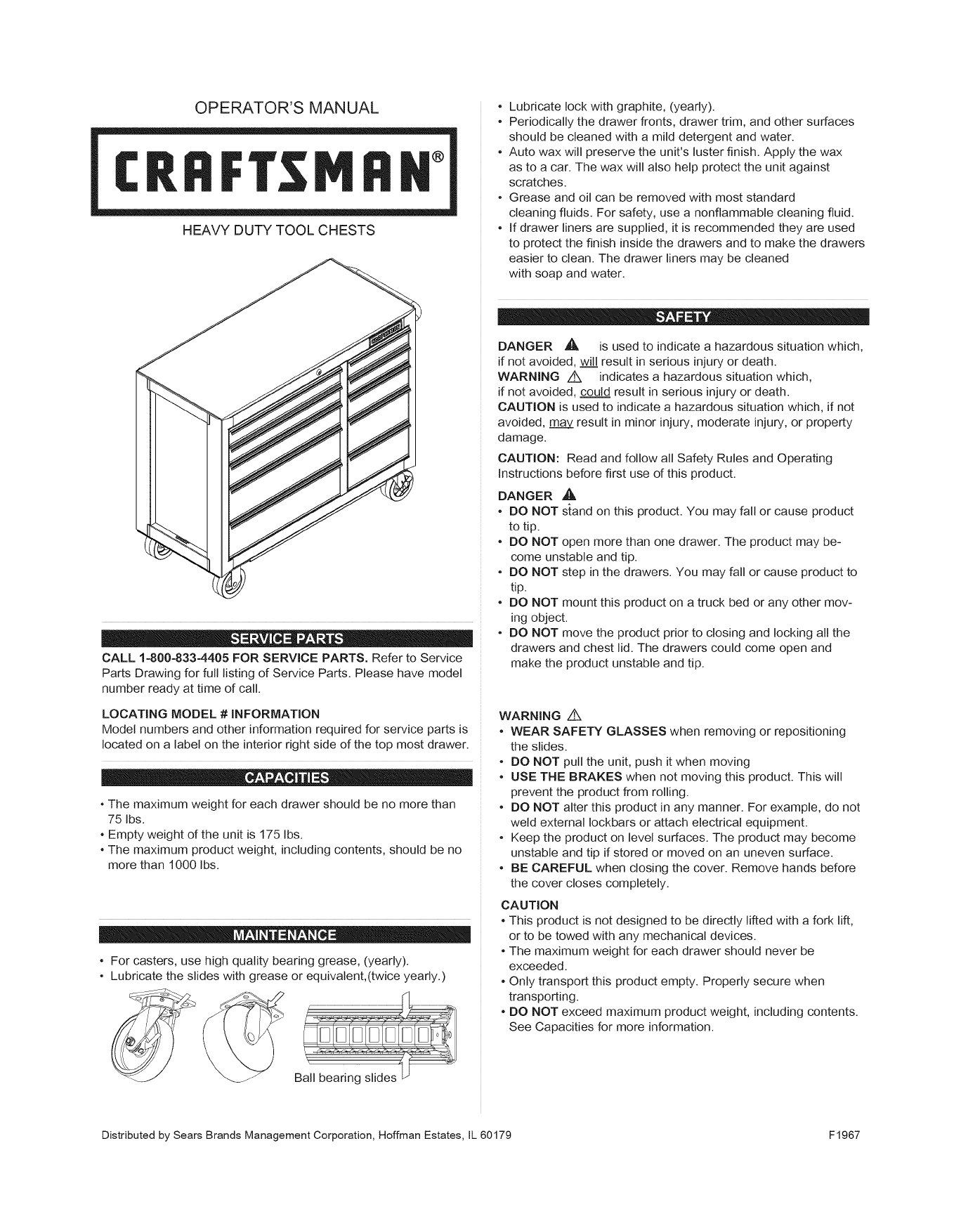
HEAVY DUTY TOOL CHESTS
CALL 1=800-833=4405 FOR SERVICE PARTS. Refer to Service
Parts Drawing for full listing of Service Parts. Please have model
number ready at time of call.
LOCATING MODEL #iNFORMATiON
Model numbers and other information required for service parts is
located on a label on the interior right side of the top most drawer.
•The maximum weight for each drawer should be no more than
75 Ibs.
•Empty weight of the unit is 175 Ibs.
•The maximum product weight, including contents, should be no
more than 1000 Ibs.
•For casters, use high quality bearing grease, (yearly).
•Lubricate the slides with grease or equivalent,(twice yearly.)
•Lubricate lock with graphite, (yearly).
•Periodically the drawer fronts, drawer trim, and other surfaces
should be cleaned with a mild detergent and water.
•Auto wax will preserve the unit's luster finish. Apply the wax
as to a car. The wax will also help protect the unit against
scratches.
•Grease and oil can be removed with most standard
cleaning fluids. For safety, use a nonflammable cleaning fluid.
•If drawer liners are supplied, it is recommended they are used
to protect the finish inside the drawers and to make the drawers
easier to clean. The drawer liners may be cleaned
with soap and water.
DANGER _, is used to indicate a hazardous situation which,
if not avoided, will result in serious injury or death.
WARNING Z_ indicates a hazardous situation which,
if not avoided, could result in serious injury or death.
CAUTION is used to indicate a hazardous situation which, if not
avoided, may result in minor injury, moderate injury, or property
damage.
CAUTION: Read and follow all Safety Rules and Operating
Instructions before first use of this product.
DANGER ,_
• DO NOT stand on this product. You may fall or cause product
to tip.
• DO NOT open more than one drawer. The product may be-
come unstable and tip.
• DO NOT step in the drawers. You may fall or cause product to
tip.
• DO NOT mount this product on a truck bed or any other mov-
ing object.
• DO NOT move the product prior to closing and locking all the
drawers and chest lid. The drawers could come open and
make the product unstable and tip.
WARNING Z_
•WEAR SAFETY GLASSES when removing or repositioning
the slides.
•DO NOT pull the unit, push it when moving
•USE THE BRAKES when not moving this product. This will
prevent the product from rolling.
•DO NOT alter this product in any manner. For example, do not
weld external Iockbars or attach electrical equipment.
•Keep the product on level surfaces. The product may become
unstable and tip if stored or moved on an uneven surface.
•BE CAREFUL when closing the cover. Remove hands before
the cover closes completely.
CAUTION
•This product is not designed to be directly lifted with a fork lift,
or to be towed with any mechanical devices.
•The maximum weight for each drawer should never be
exceeded.
•Only transport this product empty. Properly secure when
transporting.
•DO NOT exceed maximum product weight, including contents.
See Capacities for more information.
Distributed by Sears Brands Management Corporation, Hoffman Estates, IL 60179 F1967
TOOLS REQUIRED:
3/8-in Wrench
Cross-tip Screwdriver
HARDWARE iNCLUDED:
©
1/4 - 20 x 5/8-in Screw (Qty: 16)
1/4 - 20 Hex Nut (Qty: 4)
NOTE: Not aJJassembly instructions wilt relate to your model.
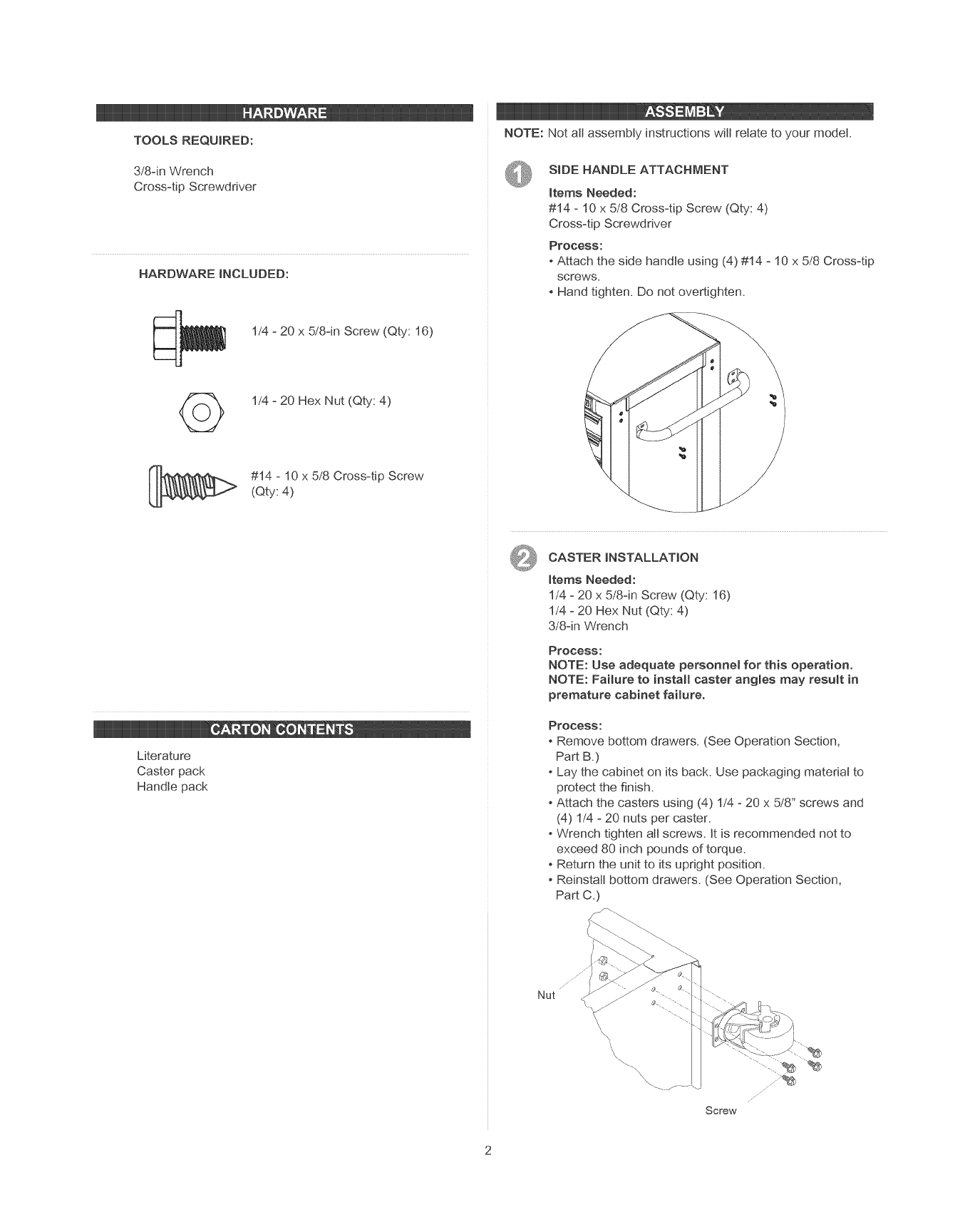
SiDE HANDLE ATTACHMENT
items Needed:
#14 - 10 x 5/8 Cross-tip Screw (Qty: 4)
Cross-tip Screwdriver
Process:
-Attach the side handle using (4) #14 - 10 x 5/8 Cross-tip
screws.
- Hand tighten. Do not overtighten.
#14 - 10 x 5/8 Cross-tip Screw
(Qty: 4)
Literature
Caster pack
Handle pack
CASTER iNSTALLATiON
items Needed:
1/4 - 20 x 5/8-in Screw (Qty: 16)
1/4 - 20 Hex Nut (Qty: 4)
3/8-in Wrench
Process:
NOTE: Use adequate personne_ for this operation.
NOTE: Failure to install easter angles may result in
premature cabinet failure.
PrOCeSS:
-Remove bottom drawers. (See Operation Section,
Part B.)
Lay the cabinet on its back. Use packaging matedat to
protect the finish.
-Attach the casters using (4) 1/4 - 20 x 5/8" screws and
(4) 1/4 - 20 nuts per caster.
Wrench tighten all screws. It is recommended not to
exceed 80 inch pounds of torque.
Return the unit to its upright position.
Reinstall bottom drawers. (See Operation Section,
Part C.
Nut
Screw
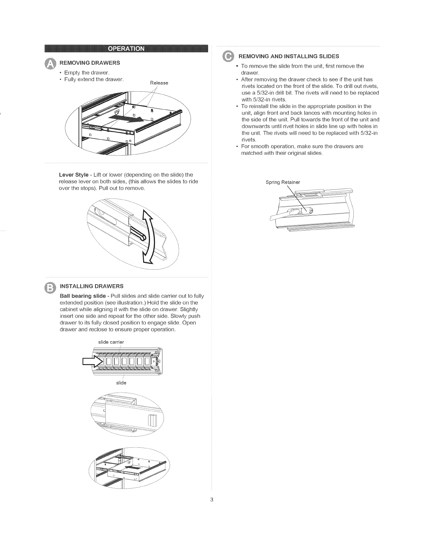
Q REMOVING DRAWERS
Empty the drawer.
Fully extend the drawer. Release
Lever Style - Lift or lower (depending on the slide) the
release lever on both sides, (this allows the slides to ride
over the stops). Putt out to remove.
REMOVING AND iNSTALLiNG SLIDES
To remove the slide from the unit, first remove the
drawer.
After removing the drawer check to see if the unit has
rivets located on the front of the slide. To drill out rivets,
use a 5/324n drill bit. The rivets wilt need to be replaced
with 5/324n rivets.
To reinstall the slide in the appropriate position in the
unit, align front and back lances with mounting holes in
the side of the unit. Pull towards the front of the unit and
downwards until rivet holes in slide line up with holes in
the unit. The rivets wilt need to be replaced with 5/324n
rivets.
For smooth operation, make sure the drawers are
matched with their original slides.
Spring Retainer
\\\\\\\\\\\\\\\\
iNSTALLiNG DRAWERS
Ball bearing slide - Putt slides and slide carrier out to fully
extended position (see illustration.) Hold the slide on the
cabinet while aligning it with the slide on drawer. Slightly
insert one side and repeat for the other side. Slowly push
drawer to its fully closed position to engage slide. Open
drawer and rectose to ensure proper operation.
slide carrier
slide

MANUAL DE USUARIO
®
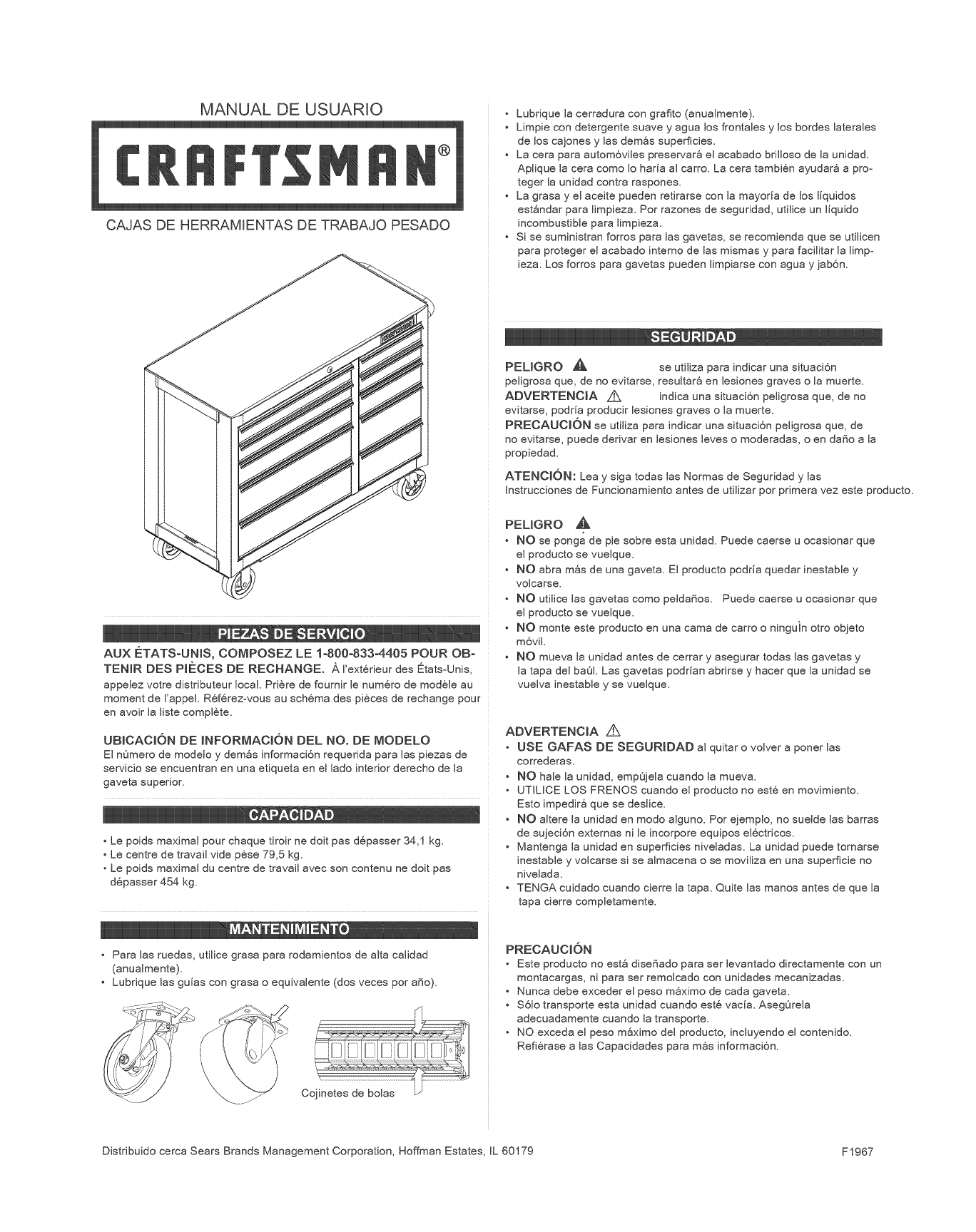
CAJAS DE HERRAMIENTAS DE TRABAJO PESADO
AUX _:TATSoUNIS, COMPOSEZ LE 1o800-833-4405 POUR OBo
TENIR DES PIECES DE REOHANGE. A I'ext6rieur des [_tatsoUnis,
appelez votre distributeur local. Priere de fournir le num6ro de mod4_le au
moment de I'appeL R6f6rezovous au sch6ma des pieces de rechange pour
en avoir la liste complete.
UBICACION DE INFORMACI6N DEL NO. DE MODELO
El nOmero de modelo y demos informaci6n requerida para las piezas de
servicio se encuentran en una etiqueta en el lado interior derecho de la
gaveta superior.
D i
• Le poids maximal pour chaque tiroir ne doit pas d6passer 34,1 kg.
• Le centre de travail vide pSse 79,5 kg.
• Le poids maximal du centre de travail avec son contenu ne doit pas
d6passer 454 kg.
iiii.:.L L , L o
• Para las ruedas, utilice grasa para rodamientos de alta calidad
(anualmente).
• Lubrique las guias con grasa o equivalente (dos veces por afio).
J
================================:
Cojinetes de bolas
• Lubrique la cerradura con grafito (anualmente).
• Limpie con detergente suave y agua los frontales y los bordes laterales
de los cajones y las demSs superficies.
• La cera para autom6viles preservar8 el acabado brilloso de la unidad.
Aplique la cera como Io haria al carro. La cera tambi6n ayudar8 a pro°
teger la unidad contra raspones.
• La grasa y el aceite pueden retirarse con la mayoda de los liquidos
est_ndar para limpieza. Por razones de seguridad, utilice un liquido
incombustible para limpieza.
• Si se suministran forros para las gavetas, se recomienda que se utilicen
para proteger el acabado interno de las mismas y para facilitar la limpo
ieza. Los forros para gavetas pueden limpiarse con agua y jab6n.
PELIGRO _ se utiliza para indicar una situaci6n
peligrosa que, de no evitarse, resultar_ en lesiones graves o la muerte.
ADVERTENOIA Z_ indica una situaci6n peligrosa que, de no
evitarse, podria producir lesiones graves o la muerte.
PREOAUOI6N se utiliza para indicar una situaci6n peligrosa que, de
no evitarse, puede derivar en lesiones leves o moderadas, o en dafio a la
propiedad.
ATENOION: Lea y siga todas las Normas de Seguridad y las
Instrucciones de Funcionamiento antes de utilizar por primera vez este producto.
PEUGRO
• NO se ponga de pie sobre esta unidad. Puede caerse u ocasionar que
el producto se vuelque.
• NO abra m_s de una gaveta. El producto podria quedar inestable y
volcarse.
NO utilice las gavetas como peldafios. Puede caerse u ocasionar que
el producto se vuelque.
NO monte este producto en una cama de carro o ninguin otro objeto
m6vil.
NO mueva la unidad antes de cerrar y asegurar todas las gavetas y
la tapa del ba01. Las gavetas podrian abrirse y hacer que la unidad se
vuelva inestable y se vuelque.
ADVERTENClA Z_
• USE GAFAS DE SEGURIDAD al quitar o volver a poner las
correderas.
NO hale la unidad, empOjela cuando la mueva.
UTILICE LOS FRENOS cuando el producto no est6 en movimiento.
Esto impedir8 que se deslice.
NO altere la unidad en modo alguno. Por ejemplo, no suelde las barras
de sujeci6n externas nile incorpore equipos el6ctricos.
Mantenga la unidad en superficies niveladas. La unidad puede tornarse
inestable y volcarse si se almacena o se moviliza en una superficie no
nivelada.
TENGA cuidado cuando cierre la tapa. Quite las manos antes de que la
tapa cierre completamente.
PRECAUCION
Este producto no est_ disefiado para ser levantado directamente con un
montacargas, ni para ser remolcado con unidades mecanizadas.
Nunca debe exceder el peso mSximo de cada gaveta.
$61o transporte esta unidad cuando est6 vacia. AsegOrela
adecuadamente cuando la transporte.
NO exceda el peso m_ximo del producto, incluyendo el contenido.
Refi6rase alas Capacidades para m_s informaci6n.
Distribuido cerca Sears Brands Management Corporation, Hoffman Estates, IL 60179 F1967
HERRAMIENTAS NECESARIAS:
Llave Jnglesa de 3/8 inch
Destornittador de Punta en Cruz
PIEZAS INCLUJDAS:
Vis no 1/4-20 x 5/8 po
(Qt6.: 16)
NOTA: No todas las instrucciones de ensambtaje se
refieren a tu modeio.
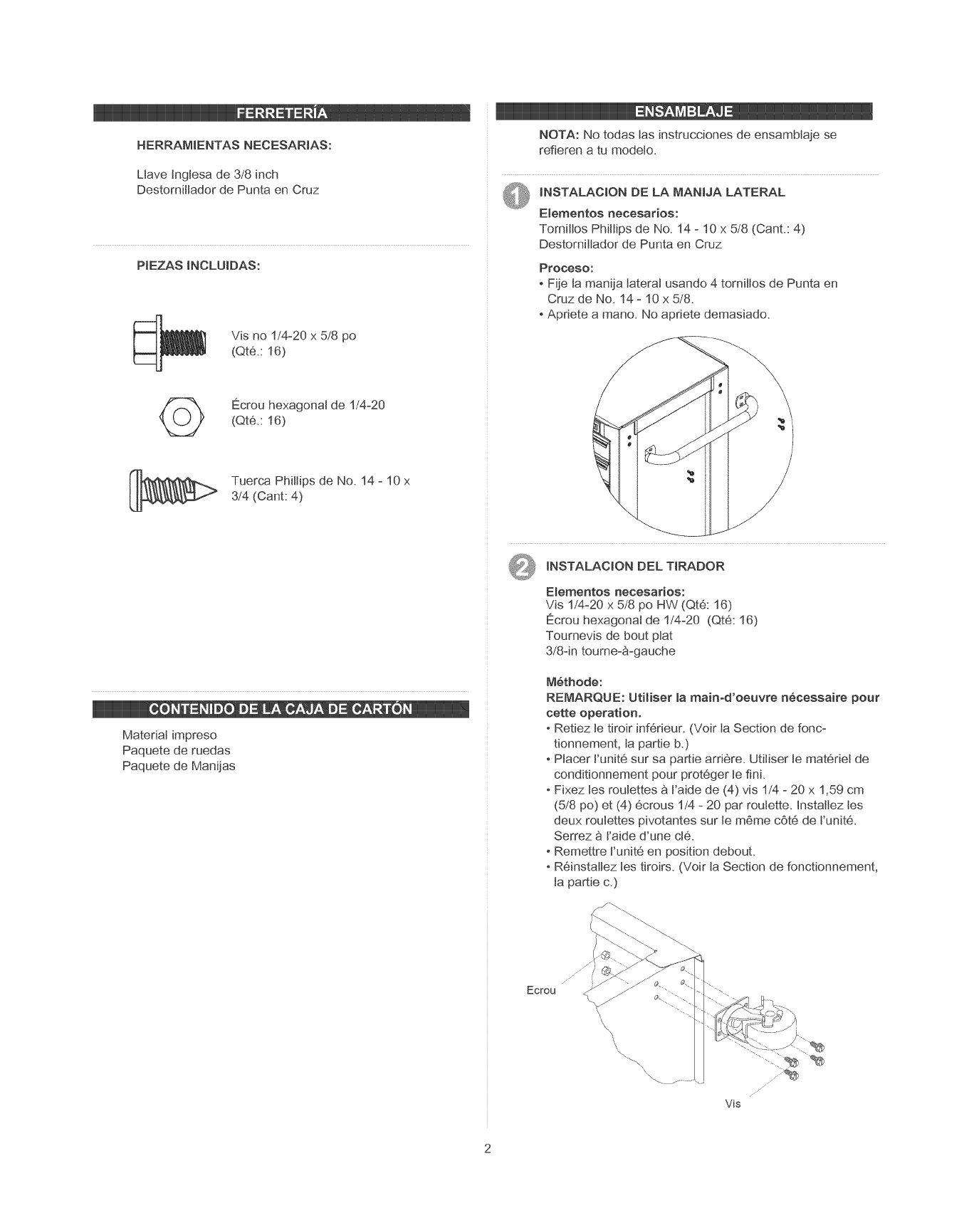
INSTALACION DE LA NIANJJA LATERAL
Elementos necesarios:
Tornillos Phillips de No. 14 - 10 x 5/8 (Cant.: 4)
Destomittador de Punta en Cruz
Proceso:
Fije ta manija tateral usando 4 tornittos de Punta en
Cruz de No. 14 -10 x 5/8.
Apnete a mane. No apriete demasiado.
<_ Ecrou hexagonaJ de 1/4-20
(Qt6.: 16)
Tuerca Phillips de No. 14 -10 x
3/4 (Cant: 4)
Material impreso
Paquete de ruedas
Paquete de Manijas
Q INSTALACION DEL TIRADOR
Elementos necesarios:
Vis 1/4-20 x 5/8 po HW (Qt6: 16)
E_crouhexagonal de 1/4-20 (Qt6: 16)
Toumevis de bout plat
3/8-in toume-a-gauche
Methode:
REMARQUE: Utiliser la main-d'oeuvre necessaire pour
cette operation.
Retiez te tiroir inf6rieur. (Voir ta Section de fonc-
tionnement, la pantie b.)
Ptacer t'unit6 sur sa pantie arri6re. Utitiser te mat6rieJ de
conditionnement pour prot6ger te fini.
-Fixez les roulettes a Faide de (4) vis 1/4 - 20 x 1,59 cm
(5/8 po) et (4) 6crous 1/4 - 20 par roulette. Instaltez tes
deux roulettes pivotantes sur te m6me c6t6 de t'unit&
Serrez a I'aide d'une cI&
Remettre t'unit6 en position debout.
R6instaltez les tiroirs. (Voir ta Section de fonctionnement,
ta pattie c.)
Ecrou
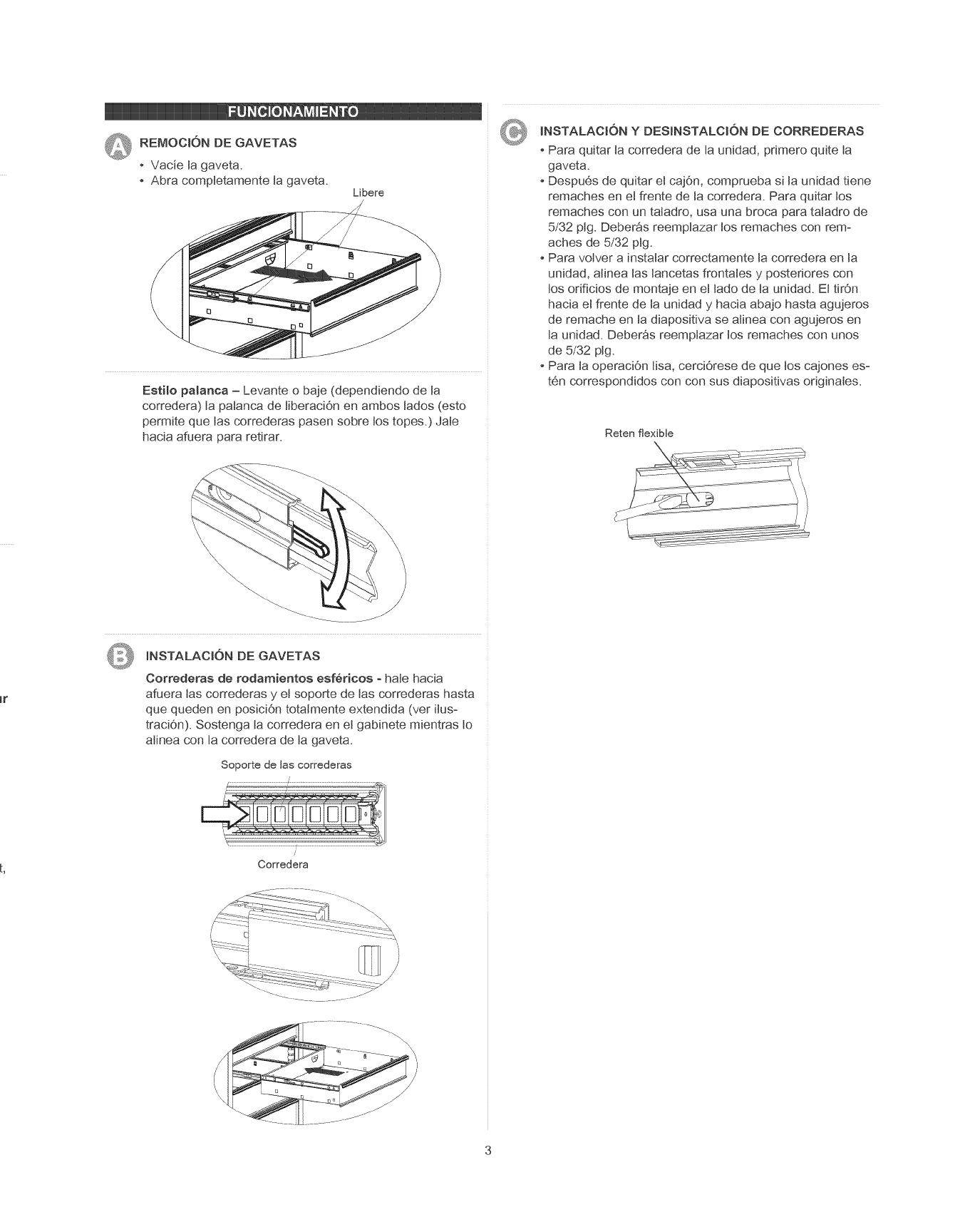
Q REMOCION DE GAVETAS
Vade ta gaveta.
Abra comptetamente ta gaveta. Libere
Estilo palanca - Levante o baje (dependiendo de ta
corredera) ta paJanca de tiberaci6n en ambos tados (esto
permite que las correderas pasen sobre tos topes.) JaJe
hacia afuera para retirar.
INSTALACION DE GAVETAS
Correderas de rodamientos esfedcos -hate hacia
afuera tas correderas y el soporte de las correderas hasta
que queden en posici6n totalmente extendida (vet Hus-
traciOn). Sostenga ta corredera en et gabinete mientras to
aJinea con ta corredera de ta gaveta.
Soporte de las correderas
Corredera
®INSTALACJON Y DESJNSTALCION DE CORREDERAS
Para quitar ta corredera de ta unidad, primero quite ta
gaveta.
Despu6s de quitar el cajdn, comprueba si ta unidad tiene
remaches en et frente de la corredera. Para quitar tos
remaches con un taladro, usa una broca para tatadro de
5/32 plg. Deber_s reemptazar tos remaches con rem:
aches de 5/32 plg.
Para votver a instalar correctamente la corredera en la
unidad, atinea las lancetas frontales y postedores con
tos orificios de montaje en et tado de la unidad. Et tir0n
hacia et frente de la unidad y hacia abajo hasta agujeros
de remache en ta diapositiva se atinea con agujeros en
ta unidad. Deber_s reemptazar tos remaches con unos
de 5/32 plg.
Para ta operaci6n tisa, cerciOrese de que los cajones es=
t6n correspondidos con con sus diapositivas originates.
Reten flexible

