Craftsman 917250230 User Manual TRACTOR Manuals And Guides 1110173L
User Manual: Craftsman 917250230 917250230 CRAFTSMAN TRACTOR - Manuals and Guides View the owners manual for your CRAFTSMAN TRACTOR #917250230. Home:Lawn & Garden Parts:Craftsman Parts:Craftsman TRACTOR Manual
Open the PDF directly: View PDF ![]() .
.
Page Count: 64
Operator's
CRII
Manual
LAWN TRACTOR
24.0 HP,*42" Mower
Electric Start
6Speed Transaxle
Model No.
917.25023
• EspaSol, p. 33
This product has a low emission engine which operates
_] differently from previously built Before
engines, you start the
engine, read and understand this Owner's Manual.
IMPORTANT:
Read and follow all Safety
Rules and Instructions before
operating this equipment.
For answers to your questions
about this product, Call:
1-800-659-5917
Sears Craftsman Help Line
5am - 5 pm, Mon -Sat
Gasoline containing up to 10% ethanol (El0) is acceptable for use in this machine. The
use of any gasoline exceeding 10% ethanol (El0) will void the product warranty.
Esta mhquina puede uUlizar gasolina con un contenido de hasta el 10% de etanol (El0), El
uso de una gasolina que supere el 10% de etanol (El0) anulard la garantfa del producto.
Sears Brands Management Corporation, Hoffman Estates, tL 60179 U,S.A.
Visit our Craftsman website:www.sears.com!craftsman *As _ated by the engine manufacturer
446621
Warranty ................................................ 2
Safety Rules .......................................... 3
Product Specifications ........................... 6
Assembly/Pro-Operation ....................... 7
Operation ............................................... 9
Maintenance ........................................ 16
Maintenance Schedule ........................ 16
Service and Adjustments ..................... 21
Storage ................................................ 27
Troubleshooting ................................... 28
Sears Service ........................ Back Cover
Craftsman Riding Equipment Warranty
CRAFTSMAN FULL WARRANTY
FOR TWO YEARS from the date of purchase, all non-expendable parts of this ridingequipment are
warranted against any defects in material or workmanship. A defective non-expendable part will
receive free in-home repair or replacement if repair is impossible.
FOR FIVE YEARS from the date of purchase, the frame and front axle of this riding equipment are
warranted against any defects in material or workmanship. A defective frame or front axle will receive
free in-home repair or replacement if repair is impossible.
FOR 90 DAYS from the date of purchase, the battery (an expendable part) of this riding equipment
is warranted against any defects in material or workmanship (our testingproves that it will not hold a
charge). A defective battery will receive free in-home replacement.
ADDITIONAL LIFETIME LIMITED WARRANTY on CAST iRON FRONT AXLE (if equipped)
FOR AS LONG AS 1TIS USED by the original owner after the fifth year from the date of purchase,the
cast iron front axle (if equipped) of this riding equipment is warranted against any defects in matedal or
workmanship. With proof of purchase, a defective castfront axle wiI]receive free in-home replacement.
WARRANTY SERVICE
For warranty coverage details to obtain free repair or replacement, call 1-800-659-59t 7 or visit the
web site: www.craftsman.com
In all cases above, if part repair or replacement is impossible, the riding equipment will be replaced
free of charge with the same or an equivalent model.
All of the above warranty coverage is void if this riding equipment is ever used while providing
commercial services or if rented to another person.
This warranty covers ONLY defects in material and workmanship. Warranty coverage does NOT
include:
• Expendable parts (except battery) that can wear out from normal use within the warranty period,
including but not limited to blades, spark plugs, air cleaners, belts, and oil filters.
• Standard maintenance servicing, oil changes, or tune-ups.
,Tire replacement or repair caused by punctures from outside objects, such as nails, thorns,
stumps, or glass.
• Tire_rwhee_rep_acement_rrepairresu_tingfr_mn_rma_wear_accident_orimpr_per_perati_n_r
maintenance.
• Repairs necessary because of operator abuse, including but not limited to damage caused by
towing objects beyond the capability of the riding equipment, impacting objects that bend the
frame, axle assembly or crankshaft, or over-speeding the engine.
• Repairs necessary because of operator negligence, including but not limited to, electrical and
mechanical damage caused by improper storage, failure to use the proper grade and amount
of engine oil, failure to keep the deck clear of flammable debris, or failure to maintain the riding
equipment according to the instructions contained in the operator's manual.
• Engine (fuel system) cleaning or repairs caused by fuel determined to be contaminated or oxidized
(stale). In general, fuel should be used within 30 days of its purchase date.
• Normal deterioration and wear of the exterior finishes, or product label replacement.
This warranty gives you specific legal rights, and you may also have other rights which vary from
state to state.
Sears Brands Management Corporation, Hoffman Estates, IL 60179
_kDANGER: This cutting machine is capable of amputating hands and feet and
throwing objects. Failure to observe the following safety instructions could result
in serious injury or death.
A(_WARNING: Inorderto preventacciden- •
tat starting when setting up, transporting,
adjusting or making repairs, alway.s discon-
nect spark plug wire and place wire where
it cannot contact spark plug.
_[;|t,WARNING: Do not coast down a hill in .
neutral, you may lose control of the tractor.
_kWARNING: Tow only the attachments .
that are recommended by and comply with •
specifications of the manufacturer of your
tractor. Use common sense when towing.
Operate only at the lowest possible speed
when on a slope. Too heavy of a load, while .
on a slope, is dangerous. Tires can lose
traction with the ground and cause you to
lose control of your tractor,
_IbWARNING: Engine exhaust, some of
itsconstituents, and certain vehicle compo- "
nents contain or emit chemicals known to
the State of California to cause cancer and °
birth defects or other reproductive harm. !
_WARN1NG: Battery posts, terminals and
related accessories contain lead and lead •
compounds, chemicals knowntothe State of
Califomiato cause cancer and birth defects •
or other reproductive harm. Wash hands
after handling. °
1. GENERAL OPERATION
•Read, understand,andfoUowallinstruc-
tions on the machine and inthe manual
before starting,
• Do not put hands or feet near rotating
parts or under the machine. Keep clear
of the discharge opening at all times.
° Only allow responsible adults, who are
familiar with the instructions, to operate
the machine.
• Clearthe area of objects such as rocks,
toys, wire, etc., which could be picked
up and thrown by the blades.
- Be sure the area is clear of bystanders
before operating. Stop machineifanyone
enters the area.
• Never carry passengers.
• Do not mow in reverse unless absolutely
necessary. Always look down and behind
before and while backing.
Never direct discharged material toward
anyone. Avoid discharging material
against a wall or obstruction. Material
may ricochet back toward the operator.
Stop the blades when crossing gravel
surfaces.
Do not operate machine without the en-
tire grass catcher, discharge chute, or
other safety devices inplace and working.
Slow down before turning.
Never leave a running machine unat-
tended. Always turn off blades, set
parking brake, stop engine, and remove
keys before dismounting.
Disengage blades when not mowing.
Shut off engine and wait for all parts to
come to a complete stop before cleaning
the machine, removing the grass catcher,
or unclogging the discharge chute.
Operate machine only in daylight or good
artificial light.
Do not operate the machine while under
the influence of alcohol or drugs.
Watch for traffic when operating near or
crossing roadways,
Useextra carewhen loading or unloading
the machine into a trailer or truck.
Always wear eye protection when operat-
ing machine.
Data indicates that operators, age 60
years and above, are involved in a large
percentage of riding mower-related inju-
ries. These operators should evaluate
their ability to operate the riding mower
safely enough to protect themselves and
others from serious injury.
Fo]lowthe manufacturer's recommenda-
tionforwheel weights or counterweights.
Keep machine free of grass, leaves or
other debris build-up which cantouchhot
exhaust/engine parts and burn. Do not
allow the mower to plow leaves or other
debris which can cause build-up to oc-
cur. Clean any oil or fuel spillage before
operating or storing the machine. Allow
machine to cool before storage.
3
Iio SLOPE OPERATION
Slopes are a major factor related to lossof
control and tip-over accidents, which can
result in severe injury or death. Operation
on all slopes requires extra caution. If you
cannot back up the slope or ifyou feel uneasy
on it, do not mow it;
•Mow up and down slopes, not across.
• Watch for holes, ruts, bumps, rocks, or
other hidden objects. Uneven terrain
could overturn the machine. Tall grass
can hide obstacles.
• Choose a low ground speed so that you
will not have to stop or shift while on the
slope.
• Do not mowon wet grass, Tires may lose
traction.
Always keep the machine in gear when
going down slopes, Do not shift to neutral
and coast downhill.
• Avoid starting, stopping, or turning on a
slope, lfthetires losetraction, disengage
the blades and proceed slowly straight
down the slope.
.Keep all movement on the slopes slow
and gradual. Do not make sudden
changes in speed or direction, which
could cause the machine to roll over.
- Use extra care while operating machine
with grass catchers or other attachments;
they can affect the stability of the ma-
chine. Do no use on steep slopes.
• Do not try to stabilize the machine by
putting your foot on the ground.
•Do not mow near drop-offs, ditches,
or embankments. The machine could
suddenly roll over if a wheel is over the
edge or if the edge caves in.
IlL CHILDREN
_WARNING: CHILDREN CAN BE INJURED
BY THIS EQUIPMENT.The American Acade-
my of Pediatrics recommends that children
be a minimum of 12 year of age before op-
erating a pedestrian controlled lawn mower
and a minimum of 16 years of age before
operating a riding lawn mower,
Tragic accidents can occur if the operator
is not alert to the presence of children.
Children are often attracted to the machine
and the mowing activity. Never assume
that children wilt remain where you last
saw them.
•Keep children out of the mowing area
and inthe watchfulcare of a responsible
adult other than the operator.
• Be alert and turn machine off if a child
enters the area.
• Before and while backing, look behind
and down for small children.
• Never carrychildren, even withthe blades
shutoff. They mayfall off and beseriously
injured or interfere with safe machine
operation. Children who have been given
rides in the past may suddenly appear in
the mowing area for another ride and be
run over or backed over bythe machine.
•Never allow children to operate the ma-
chine.
• Use extra care when approaching blind
corners, shrubs, trees, or other objects
that may block your view of a child.
IV. TOWING
• Tow only with a machine that has a hitch
designed for towing. Do notattach towed
equipment except at the hitch point.
•Folfewthe manufacturer's recommenda-
tion for weight limitsfor towed equipment
and towing on slopes.
• Never allow children or others in or on
towed equipment,
•On slopes, theweight ofthe towed equip-
ment may cause loss of traction and loss
of control.
. Travel slowly and allow extra distance to
stop.
V. SERVICE
SAFE HANDLING OF GASOLINE
To avoid personal injury or property dam-
age, use extreme care inhandling gasoline,
Gasoline is extremely flammable and the
vapors are explosive,
.Extinguish all cigarettes, cigars, pipes,
and other sources of ignition,
• Use only approved gasoline container.
• Never remove gas cap or add fuel with
the engine running. Allow engine to cool
before refueling.
Never fuel the machine indoors.
•Neverstorethemachineorfuelcontainer
where there is an open flame, spark, or
pilot light such as on a water heater or
other appliances.
° Never fill containers inside a vehicle or
on a truck or trailer bed with plastic liner.
Always place containers on the ground
away from your vehicle when filling.
4 •
• Remove gas-powered equipment from
the truck or trailer and refuel it on the
ground. If this is not possible, then refuel
suchequipmentwith a portablecontainer,
rather than from a gasoline dispenser
nozzle.
• Keep the nozzle in contact with the rim
of the fuel tank or container opening at
all times until fueling is complete. Do not
use a nozzle lock-open device.
• Iffuel is spilled onclothing, change cloth-
ing immediately.
• Never overfill fuel tank. Replace gas cap
and tighten securely.
GENERAL SERVICE
• Never operate machine inaclosed area.
• Keep all nuts and boltstightto besure the
equipment is in safe working condition.
Never tamper withsafety devices. Check
their proper operation regularly.
Keep machine free of grass, leaves, or
other debris build-up. Clean oil or fuel
spillage and remove any fuel-soaked de-
bris. Allow machineto cool before stodng.
If you strike a foreign object, stop and
inspectthe machine. Repair, ifnecessary,
before restarting.
Never make any adjustments or repairs
with the engine running.
Check grass catcher components and the
discharge chute frequently and replace
with man ufacturer's recommended parts,
when necessary.
Mower blades are sharp. Wrap the blade
or wear gloves, and use extra caution
when servicing them.
Check brake operation frequently. Adjust
and service as required.
• Maintain or replace safety and instruction
labels, as necessary.
• Be sure the area is clear of bystanders
before operating. Stop machine ifanyone
enters the area.
• Never carry passengers.
• Do not mow in reverse unless absolutely
necessary. Always look down and behind
before and while backing.
• Never carry children, even with the
blades shut off. They may fall off and
be seriously injured or interfere with safe
machine operation. Children who have
been given rides inthe past maysuddenly
appear in the mowing area for another
ride and be run over or backed over by
the machine.
- Keep children out of the mowing area
and in the watchful care of a responsible
adult other than the operator.
•Be alert and turn machine off if a child
enters the area.
• Before and while backing, look behind
and down for small children.
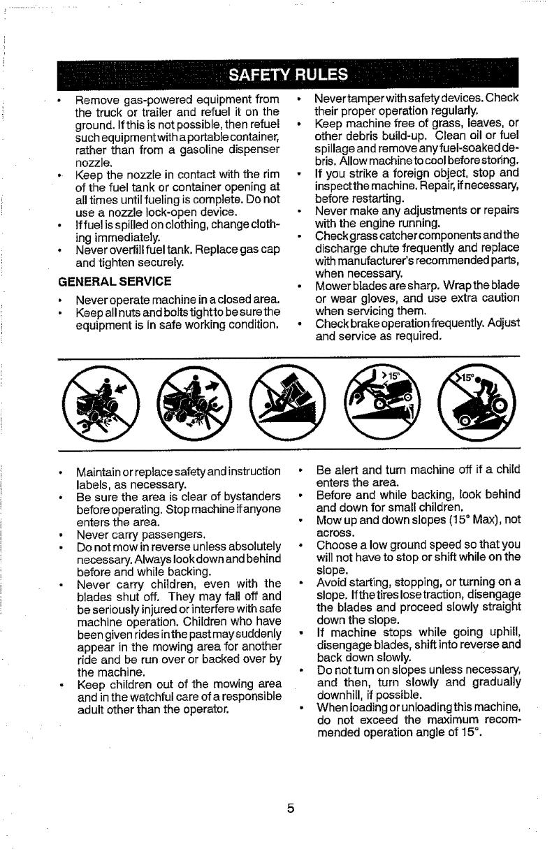
• Mow up and down slopes (15° Max), not
across.
• Choose alow ground speed so that you
will not have to stop or shift while on the
slope.
• Avoid starting, stopping, or turning on a
slope. Ifthetiras Iosetraction, disengage
the blades and proceed slowly straight
down the slope.
• If machine stops while going uphill,
disengage blades, shift into reverse and
back down slowly.
• Do notturn onslopes unless necessary,
and then, turn slowly and gradually
downhill, ff possible.
• When Ioadingoruntoadingthismachine,
do not exceed the maximum recom-
mended operation angle of 15°,

PRODUCT SPECIFICATIONS
Gasoline Capacity 3 GalJonsi11,35 L
and type: Regular Unleaded
Oil Type: SAE 30 (above 32°F/0°C)
(API: SG-SL) SAE 5W30 (below 32°F/0°C
Oil Capacity: W/Filler: 64 Oz./1.96 L
W/out Filter: 60 Oz.i1.77 L
Spark Plug: Champion QCt2YC
(Gap: .040"/1,02 ram)
Ground Speed Forward: 1st 1,0/1,6
(Mph/Kph): 2nd 1,4/2,3
3rd 2,113,4
4th 3.1/5,1
5th 4.0/6,4
6th 5.4/8,2
Reverse: 0 - 2.9/4,7
Charging 3Arnps Battery
System: 5 Amps Headlights
Battery: AmpiHr: 28
Min. CCA: 230
Case size: UIR
Blade Bolt Torque: 45-55 Ft, LbsJ62-75 Nm
CONGRATULATIONS onyour purchaseof
a new tractor. It has been designed, engi-
neered and manufactured to give you the best
possible dependability and performance.
Should youexperience any problem you can-
not easily remedy, please contact a Sears or
other qualified service center. We have com-
petent, well-trained representatives and the
proper tools to service or repair this tractor.
Please read and retain this manual, The
instructions will enable you to assemble
and maintain your tractor properly, Always
observe the "SAFETY RULES",
CUSTOMER RESPONSIBILITIES
• Read and observe the safety rules,
° Follow a regular schedule in maintaining,
caring for and using your tractor.
• Follow instructions under "Maintenance"
and "Storage" sections of this manual.
- Wear proper Personal Protective Equip-
ment (PPE) while operating this machine,
including (at a minimum) sturdy footwear,
eye protection, and hearing protection. Do
notmowin shortsand/oropentoed footwear.
• Atways let someone know youare outside
mowing,
_,WAR NING: This tractor isequipped with
an internal combustion engine and should
not be used on or near any unimproved
forest-covered, brush-covered or grass-
covered land unless the engine's exhaust
system is equipped with a spark arrester
meeting applicable local or state laws (if
any), If a spark arrestor is used, it should
be maintained in effective working order by
the operator.
Inthestate of Californiathe above is required
by law (Section 4442 ofthe California Public
Resources Code). Other states may have
similar laws. Federal laws apply on federal
lands. A spark arrestor for the muffler is
available through your nearest Sears service
center (See REPAIR PARTS manual).
REPAIR PROTECTION AGREEMENTS
Congratulations on making a smart pur-
chase. "Your new Craftsman® product is
designed and manufactured for years of
dependable operation. But like all products,
it may require repair from time to time. That's
when having a Repair Protection Agreement
can save you money and aggravation,
Purchase a Repair Protection Agreement
now and protect yourself from unexpected
hassle and expense.
Here's what's included in the Agreement:
Expert service byour 12,000 professional
repair specialists.
° Unlimited serviceand no charge for parts
and labor on all covered repairs.
Product replacement if your covered
product can't be fixed.
• Discount of I0% from regular price of
service and service-related parts not
covered by the agreement; also, 10% off
regular price of preventive maintenance
check.
- Fast help by phone - phone support
from a,Sears representative on products
requlnng in-home repair, plus convenient
repair scheduling,
Once you purchase theAgreement, asimple
phone call isall that ittakes for you to sched-
ule service. You can call anytime day or night,
or schedule a service appointment online,
Sears has over 12,000 professional repair
specialists, who have access to over 4.5
million quality parts and accessories. That's
the kind of professionalism you can count on
to help prolong the life of your new purchase
for years to come. Purchase your Repair
Protection Agreement today!
Some limitations and exclusions apply.
For prices and additional information call
1-800-827-6655.
SEARS INSTALLATION SERVICE
For Sears professional installation of home
appliances, garage door openers, water
heaters, and other major home items, inthe
U.S.A. call 1-800-4-MY-HOME®
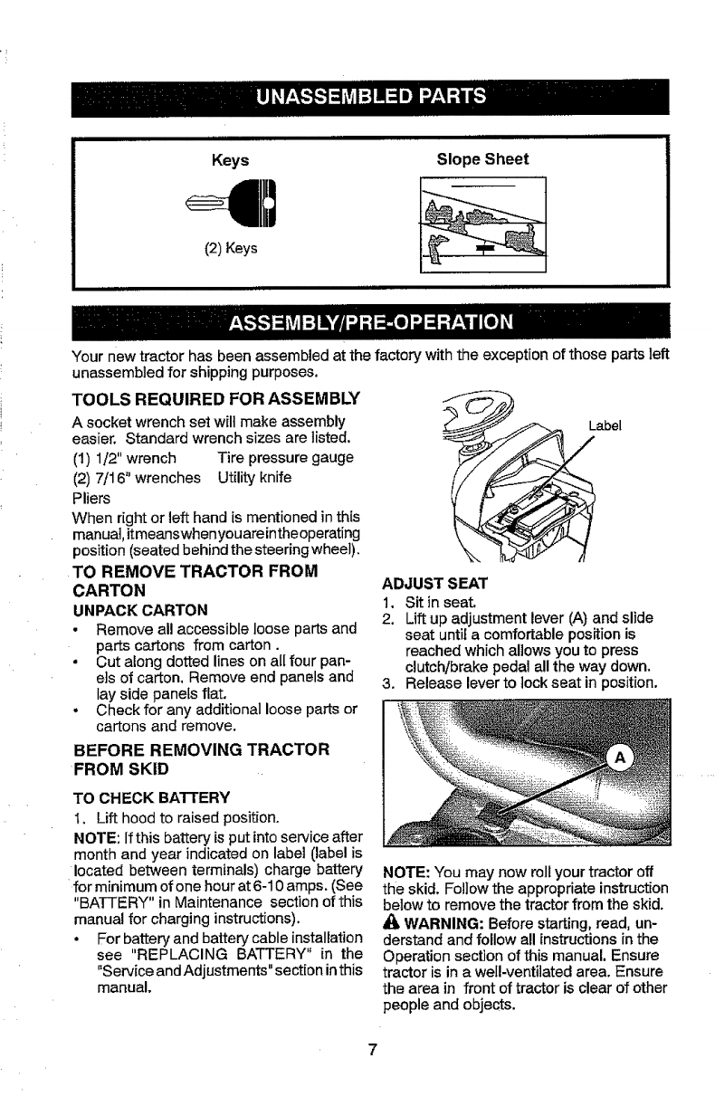
Keys
(2) Keys
Slope Sheet
ii iiiiill
Your new tractor has been assembled at the factory with the exception of those parts left
unassembied for shipping purposes.
TOOLS REQUIRED FOR ASSEMBLY
A socket wrench set wiltmake assembly
easier, Standard wrench sizes are listed.
(1) 1/2" wrench Tire pressure gauge
(2) 7/16" wrenches Utility knife
Pliers
When right or left hand is mentioned inthis
manual, itmeanswhenyouareintheoperating
position (seated behind the steering wheel).
TO REMOVE TRACTOR FROM
CARTON
UNPACK CARTON
• Remove all accessible loose parts and
parts cartons from carton.
•Cut along dotted lines on all four pan-
els of carton, Remove end panels and
lay side panels flat,
. Check for any additional loose parts or
cartons and remove.
BEFORE REMOVING TRACTOR
FROM SKID
J
abel
ADJUST SEAT
t, Sit in seat,
2. Lift up adjustment lever (A) and slide
seat untila comfortablepositionis
reached which allows you to press
clutch/brake pedal all the way down,
3. Release lever to lock seat in position.
TO CHECK BATTERY
1, Lift hood to raised position.
NOTE: Ifthis battery is putinto service after
month and year indicated on label (label is
located between terminals) charge battery
for minimum of one hour at 6-10 amps. (See
"BATTERY" in Maintenance section of this
manual for charging instructions).
•For battery and battery cable installation
see "REPLACING BATTERY" in the
"Service and Adjustments" section inthis
manual.
NOTE: You may now roll yourtractor off
the skid. Foi}ow the appropriate instruction
below to remove the tractor from the skid.
WARNING: Before starting, read, un-
derstand and follow all instructions inthe
Operation section of this manual. Ensure
tractor is in a weLl-ventilated area. Ensure
the area in front of tractor is clear of other
people and objects.
7
TO ROLL TRACTOR OFF SKID
(See Operation section for location
and function of controls)
f. Raise attachment lift lever to its high-
est position,
2. Release parking brake by depressing
clutch/brake pedal.
3, Place gearshift lever in neutral posi-
tion,
4. Roll tractor forward off skid.
5, Remove banding holding the deflector
shield up against tractor.
Continue with the instructions that follow.
CHECK TIRE PRESSURE
The tires on your tractor were overinflated
at the factory for shipping purposes. Cor-
rect tire pressure is important for best
cutting performance,
• Reduce tire pressure to PSi shown on
tires.
CHECK DECK LEVELNESS
For best cutting results, mower hous-
ing should be properly leveled. See "TO
LEVEL MOWER" in the Service and
Adjustments section of this manual.
CHECK FOR PROPER POSITION
OF ALL BELTS
See the figures that are shown for replac-
ing motion and mower blade drive belts
in the Service and Adiustments section
of this manual. Verify that the belts are
routed correctly,
CHECK BRAKE SYSTEM
After you _earn how to operate your trac-
tor, check to see that the brake is operat-
ing properly. See "TO CHECK BRAKE"
in the Service and Adjustments section of
this manual,
,/CHECKLIST
Before you operate your new tractor, we
wish to ensure that you receive the best
performance and satisfaction from this
Quality Product.
Please review the following checklist:
#"All assembly instructions have been
completed.
,/No remaining loose parts in carton,
,/Battery is properly prepared and
charged.
v" Seat is adjusted comfortably and tight-
ened securely.
#' All tires are properly inflated. (For ship-
ping purposes, the tires were overin-
flated at the factory).
_" Ensure mower deck is properly leveled
side-to-sideflront-to-rear for best cutting
results. (Tires must be properly inflated
for leveling).
v" Check mower and drive belts. Ensure
they are routed properly around pulleys
and inside all belt keepers.
v"Check wiring. See that all connections
are still secure and wires are properly
clamped.
While learning hew to use your tractor, pay
extra attention to the following important
items:
J Engine oil is at proper level.
J Fuel tank is filled with fresh, clean, regu-
lar unleaded gasoline.
J Become familiar with all controls, their
location and function. Operate them
before you start the engine,
JEnsure brake system is in safe operat-
ing condition.
,/Ensure Operator Presence System
and Reverse Operation System (ROS)
are working properly (See the Opera-
tion and Maintenance sections in this
manual).
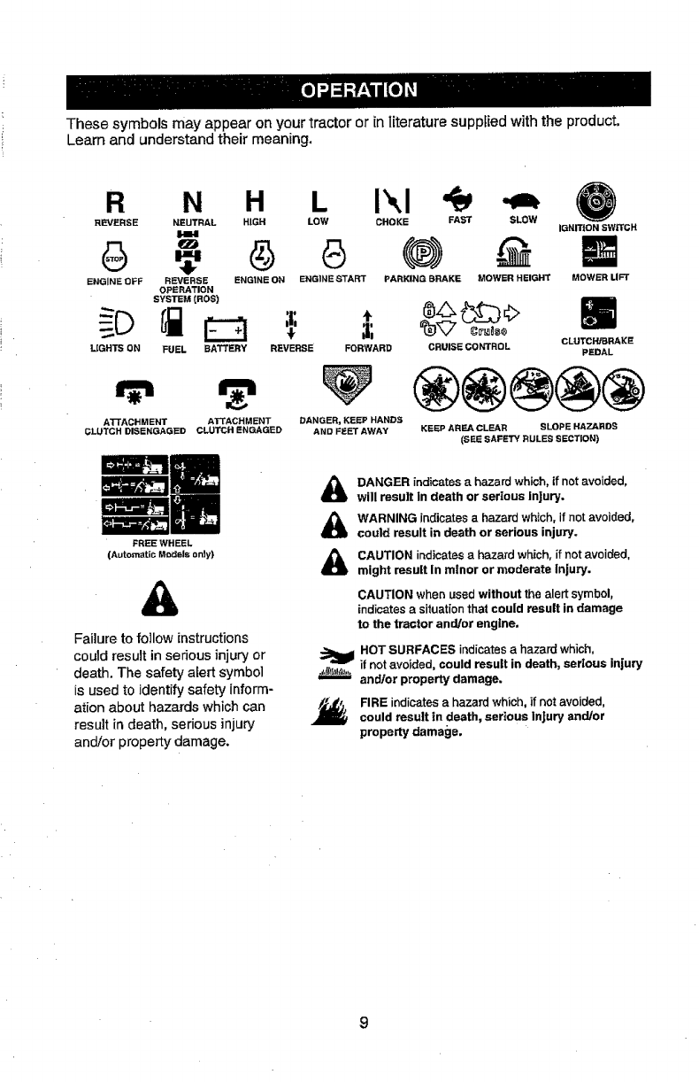
Thesesymbolsmayappearonyourtractororinliteraturesuppliedwiththeproduct,
Learnandunderstandtheirmeaning.
R N H L IXI
REVERSE NEUTRAL HIGH LOW CHOKE FAT SLOW
i.ml
ENGINE OFF REVERSE ENGINE ON ENGINE START PARKING BRAKE MOWER HEIGHT
OPERATION
SYSTEM[ROS)
FUEL
IGNITION SWITCH
MOWER UFT
LIGHTS ON BATTERY REVERSE FORWARD CRUISE CO l'#rRO LPEDAL
ATTACHMENT ATTACHMENT DANGER, KEEP HANDS
CLUTCH DISENGAGED CLUTCH ENGAGED AND FEET AWAY
FREE WHEEL
(Automatic MeiOsis only)
®@@@@
KEEP AREA CLEAn SLOPE HAZARDS
(SEE SAFETY RULES SECT|ON)
Failure to follow instructions
could result in serious injury or
death. The safety alert symbol
is used to identify safety inform-
ation about hazards which can
result in death, serious injury
and/or property damage.
DANGER indicates a hazard which, tf not avoided,
will result in death or serious Injury.
WARNING indicates a hazard which, if not avoided,
could result in death or serious injury,
CAUTION indicates ahazard which, if not avoided,
might result In minor or moderate Injury.
CAUTION when used without the alert symbol,
indicates a siluation that could result in damage
to the tractor and/or engine.
HOT SURFACES indicates a hazard which,
.-"mr if not avoided could result in death, serious injury
"-'-- and/or property damage.
FIRE indicates ahazard which, if not avoided,
could result in death, serious injury and/or
property damage.
9
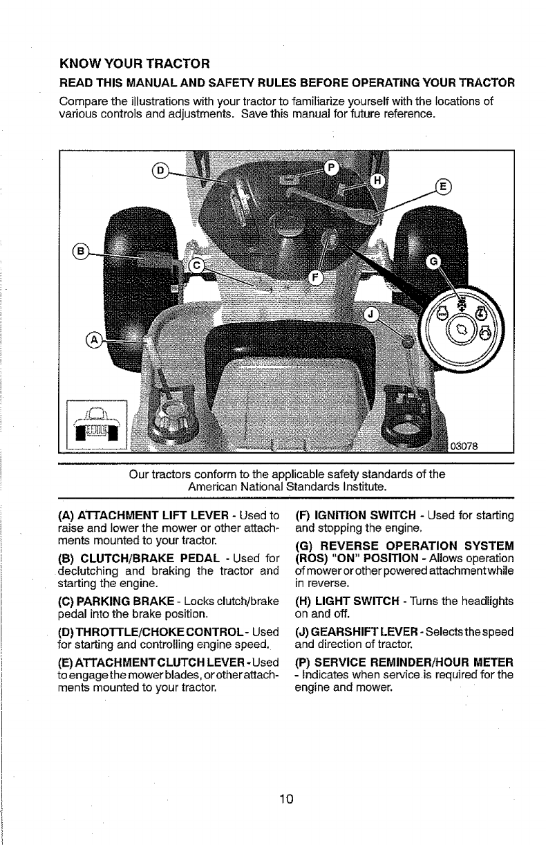
KNOW YOUR TRACTOR
READ THIS MANUAL AND SAFETY RULES BEFORE OPERATING YOUR TRACTOR
Compare the illustrations withyour tractor to familiarize yourself with the locations of
various controls and adjustments. Save this manual for future reference.
03078
Our tractors conform to the applicable safety standards of the
American National Standards Institute.
(A) ATTACHMENT LIFT LEVER - Used to
raise and lower the mower or other attach-
ments mounted to your tractor.
(B) CLUTCH/BRAKE PEDAL -Used for
declutching and braking the tractor and
starting the engine.
(C) PARKING BRAKE - Locks clutch/brake
pedal into the brake position.
(D)THROTTLE/CHOKE CONTROL- Used
for starting and controlling engine speed,
(E) ATTACHMENT CLUTCH LEVER- Used
to engage the mower blades, or other attach-
ments mounted to your tractor,
(F) IGNITION SWITCH - Used for starting
and stopping the engine,
(G) REVERSE OPERATION SYSTEM
(ROS) "ON" POSITION - Allows operation
of mower or other powered attachment while
in reverse.
(H) LIGHT SWITCH - Turns the headlights
on and off.
(J) GEARSHIFT LEVER - Selects the speed
and direction of tractor.
(P) SERVICE REMINDER/HOUR METER
- Indicates when service is required for the
engine and mower,
10
I
The operation of any tractor can result in foreign objects thrown into the I
eyes which can result in severe eye damage. Always wear safety glasses I
or eye shields while operating your tractor or performing any adjustments I
or repairs, We recommend standard safety glasses or a wide vision safety I
mask worn over spectacles, I
HOW TO USE YOUR TRACTOR
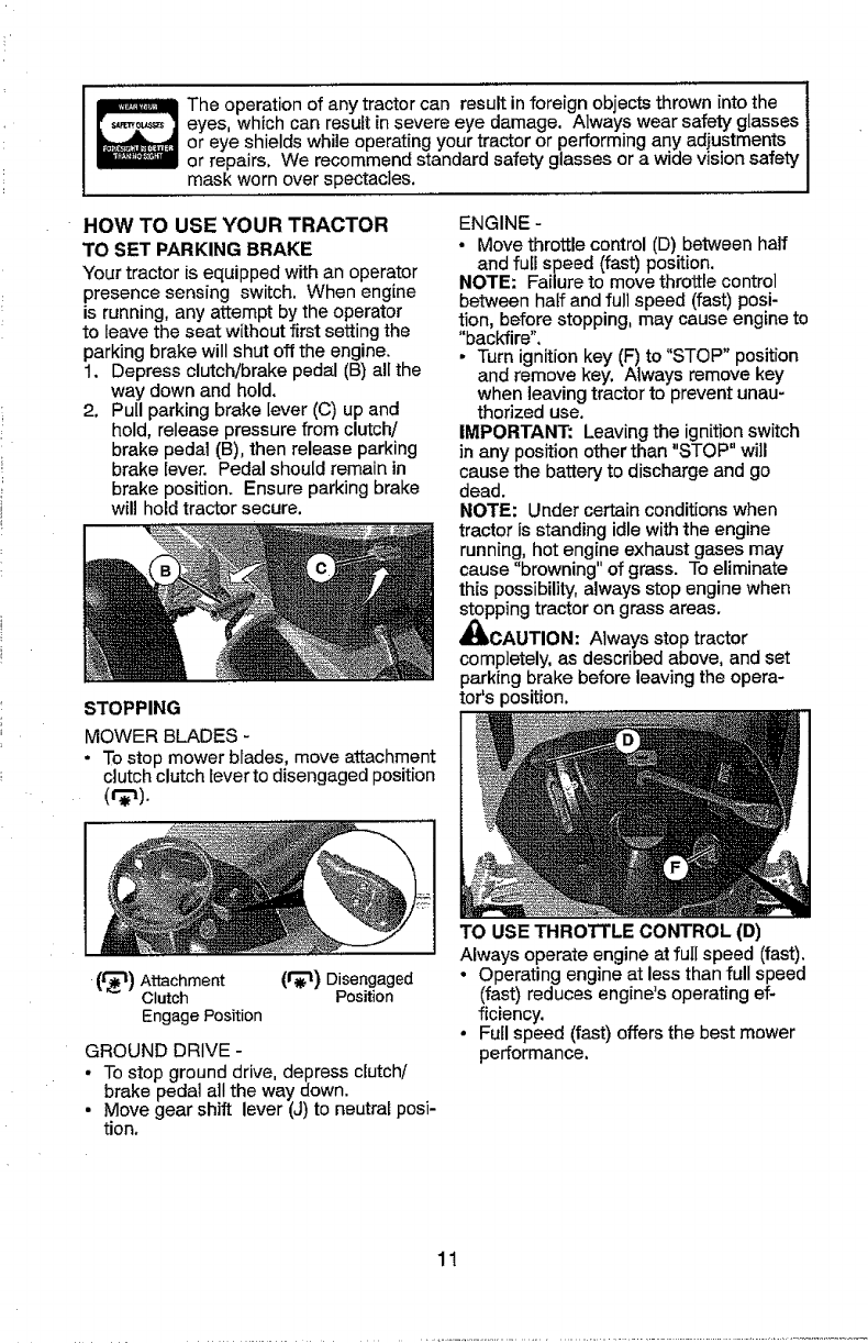
TO SET PARKING BRAKE
Your tractor is equipped with an operator
presence sensing switch. When engine
is running, any attempt by the operator
to leave the seat without first setting the
parking brake will shut off the engine.
1. Depress clutch!brake pedal (B) all the
way down and hold.
2. Pull parking brake lever (C) up and
hold, release pressure from clutch/
brake pedal (B), then release parking
brake lever. Pedal should remain in
brake position. Ensure parking brake
will hold tractor secure.
STOPPING
MOWER BLADES -
• To stop mower blades, move attachment
clutch clutch lever to disengaged position
ENGINE -
• Move throttle control (D) between half
and full speed (fast) position.
NOTE: Failure to move throttle control
between haft and full speed (fast) posi-
tion, before stopping, may cause engine to
"backfire",
• Turn ignition key (F) to "STOP" position
and remove key. Always remove key
when leaving tractor to prevent unau-
thorized use.
IMPORTANT: Leavingthe ignition switch
in any position other than "STOP" will
cause the battery to discharge and go
dead.
NOTE: Under certain conditions when
tractor is standing idle with the engine
running, hot engine exhaust gases may
cause "browning" of grass. To eliminate
this possibility, always stop engine when
stopping tractor on grass areas.
_CAUTION: Always stop tractor
completely, as described above, and set
parking brake before leaving the opera-
tor's position.
(t_l) Attachment (1_'!) Disengaged
Clutch Position
Engage Position
GROUND DRIVE -
• To stop ground drive, depress clutch/
brake pedal all the way down.
• Move gear shift lever (J) to neutral posi-
tion.
TO USE THROTTLE CONTROL (D)
Always operate engine at full speed (fast).
° Operating engine at less than full speed
(fast) reduces engine's operating ef-
ficiency.
•Full speed (fast) offers the best mower
performance.
11
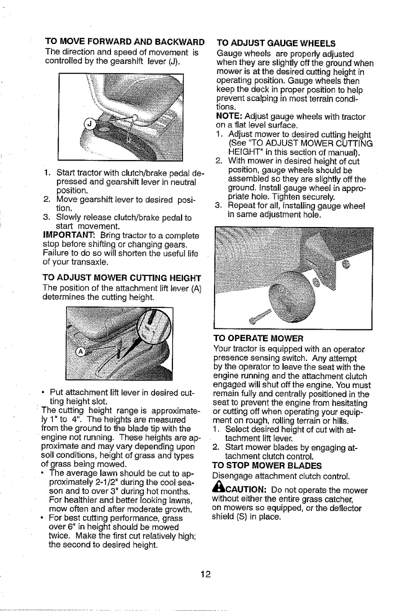
TO MOVE FORWARD AND BACKWARD
The direction and speed of movement is
controlled by the gearshift lever (J).
!. Start tractor with clutch/brake pedai de-
pressed and gearshift lever in neutral
position.
2, Move gearshift lever to desired posi-
tion.
3. Slowly release clutch/brake pedal to
start movement.
IMPORTANT: Bring tractor to a complete
stop before shifting or changing gears,
Failure to do so will shorten the useful life
of your transaxle.
TO ADJUST MOWER CUTTING HEIGHT
The position of the attachment lift lever (A)
determines the cutting height,
TO ADJUST GAUGE WHEELS
Gauge wheels are properly adjusted
when they are slightly off the ground when
mower is at the desired cutting height in
operating position. Gauge wheels then
keep the deck in proper position to help
prevent scalping in most terrain condi-
tions.
NOTE: Adjust gauge wheels with tractor
on a flat _evel surface.
1. Adjust mower to desired cutting height
(See "TO ADJUST MOWER CUTTING
HEIGHT" in this section of manual).
2. With mower in desired height of cut
position, gauge wheels should be
assembled so they are slightly off the
ground. Install gauge wheel in appro-
priate hole. Tighten securely.
3, Repeat for all, installing gauge wheel
in same adjustment hole.
• Put attachment liftlever in desired cut-
ting height slot.
The cutting height range is approximate-
}y 1" to 4", The heights are measured
from the ground to the blade tip with the
engine not running. These heights are ap-
proximate and may vary depending upon
soil conditions, height of grass and types
of grass being mowed.
• The average lawn should be cut to ap-
proximately 2-1/2" during the cool sea-
son and to over 3" during hot months.
For healthier and better looking lawns,
mow often and after moderate growth.
- For best cutting performance, grass
over 6" in height should be mowed
twice. Make the first cut relatively high;
the second to desired height.
TO OPERATE MOWER
"four tractor is equipped with an operator
presence sensing switch. Any attempt
by the operator to leave the seat with the
engine running and the attachment clutch
engaged wilt shut off the engine, You must
remain fully and centrally positioned inthe
seat to prevent the engine from hesitating
or cutting off when operating your equip-
ment on rough, rolling terrain or hills.
1. Select desired height of cut with at-
tachment lift lever.
2. Start mower blades by engaging at-
tachment clutch control.
TO STOP MOWER BLADES
Disengage attachment clutch control.
_I_CAUTION: Do not operate the mower
without either the entire grass catcher,
on mowers so equipped, or the deflector
shield (S) in place,
12
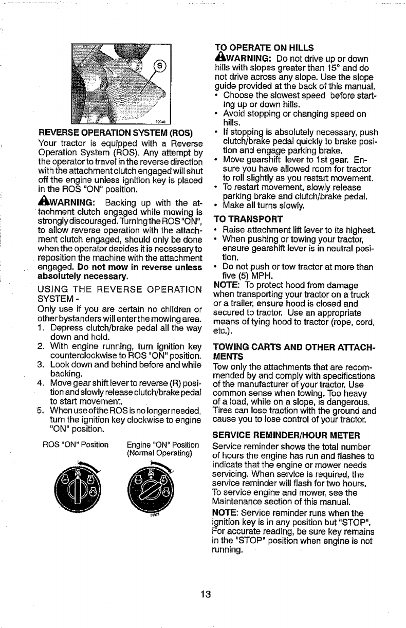
REVERSE OPERATION SYSTEM (ROS)
Your tractor is equipped with a Reverse
Operation System (ROS). Any attempt by
the operator to travel inthe reverse direction
with the attachment clutch engaged will shut
off the engine unless ignition key is placed
in the ROS "ON" position,
_kWARNING: Backing up with the at-
tachment clutch engaged while mowing is
strongly discouraged, Turningthe ROS"ON",
to allow reverse operation with the attach-
ment clutch engaged, should only be done
when the operator decides it is necessary to
reposition the machine with the attachment
engaged, Do not mow in reverse unless
absolutely necessary.
USING THE REVERSE OPERATION
SYSTEM -
Only use if you are certain no children or
other bystanders will enter the mowing area,
1. Depress clutch/brake pedal all the way
down and hold.
2. With engine running, turn ignition key
counterclockwiseto ROS "ON" position.
3. Look down and behind before and while
backing,
4. Move gear shift leverto reverse (R) posi-
tion and slowly release clutch!brake pedal
to start movement.
5. When useofthe ROS isnolonger needed,
turn the ignition key clockwise to engine
"ON" position.
ROS "ON" Position Engine "ON" Position
(Normal Operating)
TO OPERATE ON HILLS
_WARNING: Do notdrive up or down
hillswith slopes greater than t5 ° and do
not drive across any slope. Use the slope
guide providedat the back of this manual.
,Choose the slowest speed before start-
ing upor down hills.
•Avoid stoppingor changingspeed on
hills.
•If stopping is absolutelynecessary, push
clutch/brake pedal quicklyto brake posi-
tion and engage parking brake.
- Move gearshift leverto 1st gear. En-
sure you have allowed room for tractor
to roll slightlyas you restart movement.
• Torestart movement, slowly release
parking brake and clutch/brakepedal,
• Make all turnsslowly.
TO TRANSPORT
•Raise attachment liftlever to its highest.
• When pushingortowingyourtractor,
ensure gearshift lever is in neutral posi-
tion,
-Do not push ortow tractor at more than
five (5) MPH.
NOTE: To protect hood from damage
when transporting yourtractor on a truck
or atrailer,ensure hood is closed and
secured to tractor. Use an appropriate
means of tying hood to tractor (rope, cord,
etc.),
TOWING CARTS AND OTHER A'n'ACH-
MENTS
Tow only the attachments that are recom-
mended by and complywith specifications
of the manufacturer of yourtractor, Use
common sense when towing. Too heavy
of a load, whileon a slope, is dangerous.
Tires can losetractionwith the ground and
cause you to lose controlof yourtractor,
SERVICE REMINDER/HOUR METER
Service reminder showsthe total number
of hours the engine has run and flashes to
indicatethat the engine or mower needs
servicing. When service is required, the
service reminder will flash for two hours.
Toservice engine and mower, see the
Maintenance sectionof this manual.
NOTE: Service reminder runs when the
ignition key is in any positionbut "STOP".
For accuratereading, be sure key remains
inthe "STOP" position when engine is not
running.
13
BEFORE STARTING THE ENGINE
CHECK ENGINE OIL LEVEL
The engine in your tractor has beenshipped,
from the factory, already filled with summer
weight oil.
1. Check engine oil with tractor on level
ground.
2, Remove oil fill cap/dipstick and wipe
clean, reinsertthe dipstick and screw cap
tight, wait for afew seconds, remove and
read oil level. If necessary, add oil until
"FULE' mark on dipstick is reached. Do
not overfill.
• For cold weather operation you should
change oil for easier starting (See the oil
viscosity chart in the Maintenance section
of this manual).
° Tochange engine oil, seethe Maintenance
section in this manual.
ADD GASOLINE
•Fill fuel tank to bottom of filler neck. Do
not overfill. Use fresh, clear,, regular
unleaded gasoline with a minimum of
87 octane, (Use of leaded gasoline will
increase carbon and lead oxide deposits
and reduce valve life), Do not mix oil with
gasoline, Purchase fuel in quantities that
can be used within 30 days to ensure fuel
freshness,
_!IbGAUTION: Wipe off any spilled oil or fuel,
Do not store, spill or use gasoline near an
open flame.
IMPORTANT: When operating in tem-
peratures below 32°F(0°G), use fresh, clean
winter grade gasoline to heJp ensure good
cold weather starting.
CAUTION: Alcohol blended fuels (called
gasohol or using ethanol or methanol) can
attract moisture which leads to separation
and formation of acids during storage. Acidic
gas can damage the fuet system of an engine
while in storage, To avoid engine problems,
the fuel system should be emptied before
storage of 30 days or longer. Drain the gas
tank, start the engine and let it run until the
fuel lines and carburetor are empty. Use
fresh fuel next season. See Storage Instruc-
tions for additional information. Never use
engine or carburetor cleaner products in the
fuel tank or permanent damage may occur.
TO START ENGINE
When starting the engine for the first time or
if the engine has run out of fuel, it will take
extra cranking time to move fuel from the
tank to the engine.
t. Siton seatin operating position, depress
clutch/brake pedal and set parkingbrake.
2, Place gear shift lever in neutral position.
3. Move attachment clutch to disengaged
position.
4, Move throttle control to choke position.
NOTE: Before starting, read the warm and
cold starting procedures below.
5. Insert key into ignition and turn key
clockwise to start position and release
key as soon as engine starts. Do not run
starter continuouslyfor more than fifteen
seconds per minute. If the engine does
not start after several attempts, move
throttle control to fast position, wait a
few minutes and try again, tf engine still
does not start, move the throttle control
back to the choke position and retry.
WARM WEATHER STARTING
(50° F/I0 ° C and above)
6. When engine starts, move the throttle
control to the fast position.
• The attachments and ground drive can
now be used. Ifthe engine does not accept
the load, restart the engine and allow it to
warm up for one minute using the choke
as described above.
COLD WEATHER STARTING
(50° F/10 ° Cand below)
7. When engine starts, leave throttle control
in choke position until engine warms up
and begins to run roughly. Once rough
running begins, immediately move the
throttle control to thefast position. Engine
warm-up maytake from several seconds
to several minutes (the colder the tem-
perature, the longer the warm-up).
• The attachments can also beused during
the engine warm-up period.
NOTE: If at a high altitude (above 3000 feet)
or in cold temperatures (below 32°F/0°C)
the carburetor fuel mixture may need to be
adjusted for best engine performance (see
'q-OADJUST CARBURETOR"in the Service
and Adjustments section of this manual).
I4
MOWING TIPS
•Tire chains cannot be used when the
mower housing is attached to tractor.
•Mower should be properly IeveIedfor best
mowing performance. See "TO LEVEL
MOWER HOUSING" in the Service and
Adjustments section of this manual.
•The left hand side of mower should be
used for trimming.
• Drive so that clippings aredischarged onto
the area that has a[ready been cut, Have
the cut areato the right ofthe tractor. This
will result in a more even distribution of
clippings and more uniform cutting,
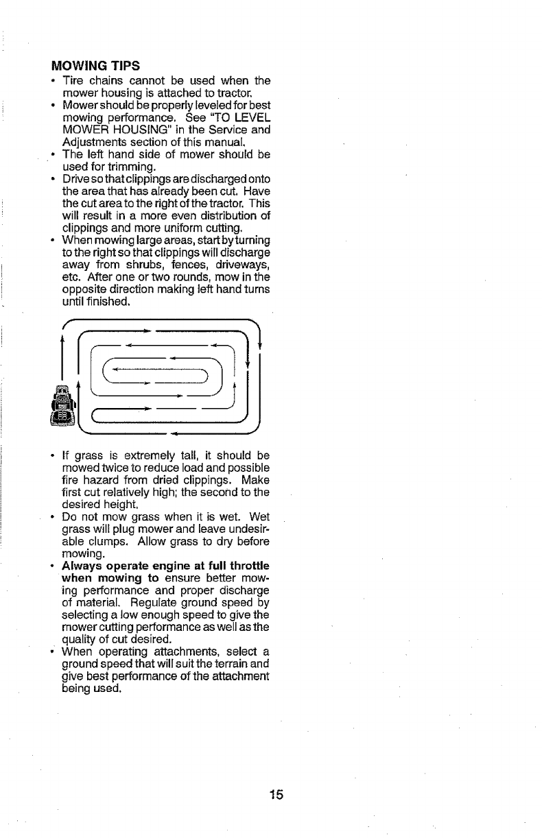
° When mowing large areas, start byturning
to the right so that clippings will discharge
away from shrubs, fences, driveways,
etc. After one ortwo rounds, mow in the
opposite direction making left hand turns
until finished.
° If grass is extremely tall, it should be
mowed twice to reduce load and possible
fire hazard from dried clippings. Make
first cut relatively high; the second to the
desired height,
° Do not mow grass when it is wet. Wet
grass will plug mower and leave undesir-
able clumps. Allow grass to dry before
mowing.
• Always operate engine at full throttle
when mowing to ensure better mow-
ing performance and proper discharge
of material. Regulate ground speed by
selecting a low enough speed to give the
mower cutting performance as well as the
quality of cut desired.
•When operating attachments, select a
ground speed that will suit the terrain and
give best performance of the attachment
being used.
15
MAINTENANCE
SCHEDULE
Check Bra_<e Operation
TCheek Tire Pressure ,.,
Check Operator Presence & ROe Systems
ACheek, for Loose Fasteners
C ChecWReplacff, Mower Blades
!T LubricationChart
0Check Battery Lever '
R Clean Battei'y and Terminals
(3leaP, Debris Off Steering Plate ....
Check T_nsaxle Cooiiag
i Check Mower Leveln_ss
Check V-Belts
Check Engine,Oi Leve
Chanqe ,Er_qiee Oil (with o!! tilter)
Change Engine 0 (w houto I_ er)
NE CEean Air Filter
GClean Air Screen
inspect MufflertSpark Attester
NReplace OiI Filter (If equipped)
ECtsan Engine Coolie 9F,ins
Replace Spa_'k Plug
,,R,eptace Air Filter Paper Cartridge
Reptace Fu, e,},Filler ..............
eS_=FORE
EACH
USE
v"
v'
v'
I/
EVERY EVEry _vem' _ve_ eveRY BEFORE
8 25 eD 100 SEAaOl_ STORAGE
HOURS HOURS HOUR_ HOt,IRe
VIII iiii
v'
.... I/ v'
v' m/
nl .....
m/ v',,_ ....V
v% f/
ll/=,
V_,,
V%
V' v"
............... VF
GENERAL RECOMMENDATIONS
The warranty on this tractor does not cover
items that have been subjected to operator
abuse or negligence. To receive full value
from the warranty, operator must maintain
tractor as instructed in this manual.
Some adjustments will need to be made pe-
riodically to properly maintain your tractor.
At least once a season, check to see if
you should make any of the adjustments
described in the Service and Adjustments
section of this manual.
-At least once a year you should replace
the spark plug, clean or replace air filter,
and check blades and belts for wear. A
new spark plug and clean air filter assure
proper air-fuel mixture and help your en-
gine run better and last longer.
BEFORE EACH USE
t, Check engine oi! level.
2. Check brake operation.
3. Check tire pressure.
4. Check operator presence and
Roe systems for proper operation.
5. Check for loose fasteners.
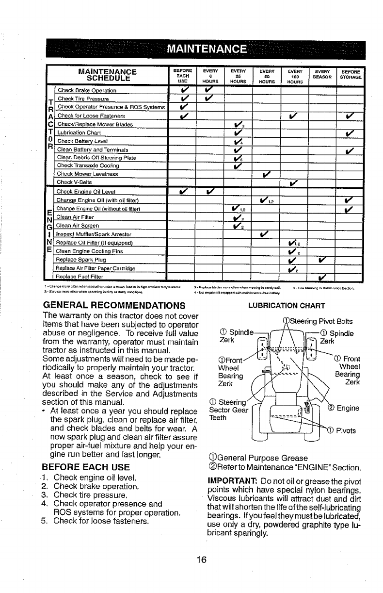
LUBRICATION CHART
OSteedng Pivot Bolts
O Spindle__r-_ _ Spindle
@Front/ "_/9! _,_ N. _ J -(_Front
Wheel _ _: \\_ _ Wheel
Bearing /_ _:--L"" 7'_'_ Beadng
Zerk _ _[_r_ _,_ _ ZeEK
(_ Steerin_ _--_'_' "_ en ine
Sector Gear I I I h_[_ I 1 1"_ g
LL .3 ivo s
General Purpose Grease
Referto Maintenance "ENGINE" Section.
IMPORTANT: Do not oil or greasethe pivot
points which have speciat nylon bearings,
Viscous lubricantswill attract dust and dirt
that will shorten the life of the self-lubricating
bearings. Ifyoufeel they must be lubricated,
use only a dry, powdered graphite type lu-
bricant sparingly.
16
TRACTOR
Alwaysobservesafetyruleswhen per-
forming any maintenance.
BRAKE OPERATION
tf tractor requires more than five (5) feet to
stop at highest speed in highest gear on a
level, dry concrete or paved surface, then
brake must be serviced. (See "TO CHECK
BRAKE" in the Service and Adjustments
section of this manual).
TIRES
-Maintain proper air pressure inall tires
(See PSI on tires).
Keep tires free of gasoline, oil, or insect
control chemicals which can harm rubber.
• Avoid stumps, stones, deep ruts, sharp
objects and other hazards that may
cause tire damage.
NOTE: To seal tire punctures and prevent
flat tires due to slow leaks, tire sealant
may be purchased from your local parts
dealer. Tire sealant also prevents tire dry
rot and corrosion.
OPERATOR PRESENCE SYSTEM AND
REVERSE OPERATION SYSTEM (ROS)
Ensure operator presence and reverse
operation systems are working properly, if
your tractor does not function as de-
scribed, repair the problem immediately.
• The engine should not start unless the
brake pedal is fully depressed, and the
attachment clutch control is in the disen-
gaged position.
CHECK OPERATOR PRESENCE
SYSTEM
• When the engine is running, any at-
tempt by the operator to leave the seat
without first setting the parking brake
should shut off the engine.
• When the engine is running and the
attachment clutch is engaged, any at-
tempt by the operator to leave the seat
should shut off the engine.
• The attachment clutch should never op-
erate unless the operator is in the seat.
ROS"ON" Position Engine"ON"Position
(NormalOperating)
CHECK REVERSE OPERATION (ROS)
SYSTEM
•When the engine is running with the
ignition switch in the engine "ON" posi-
tion and the attachment clutch engaged,
any attempt by the operator to drive in
reverse should shut off the engine.
• When the engine is running with the
ignition switch in the ROS "ON" position
and the attachment clutch engaged,
any attempt by the operator to drive in
reverse should NOT shut off the engine.
BLADE CARE
For best results mower blades must be
sharp. Replace worn, bent or damaged
blades.
&CAUTION: Use only a replacement blade
approved bythe manufacturer of your tractor.
Using a blade not approved by the manu-
facturer of your tractor is hazardous, could
damage your tractor and void your warranty.
BLADE REMOVAL
1. Raise mower to highest position to al-
low access to blades.
NOTE: Protect your hands with gloves
and/or wrap blade with heaW cloth.
2. Remove blade bolt by turning counter-
clockwise.
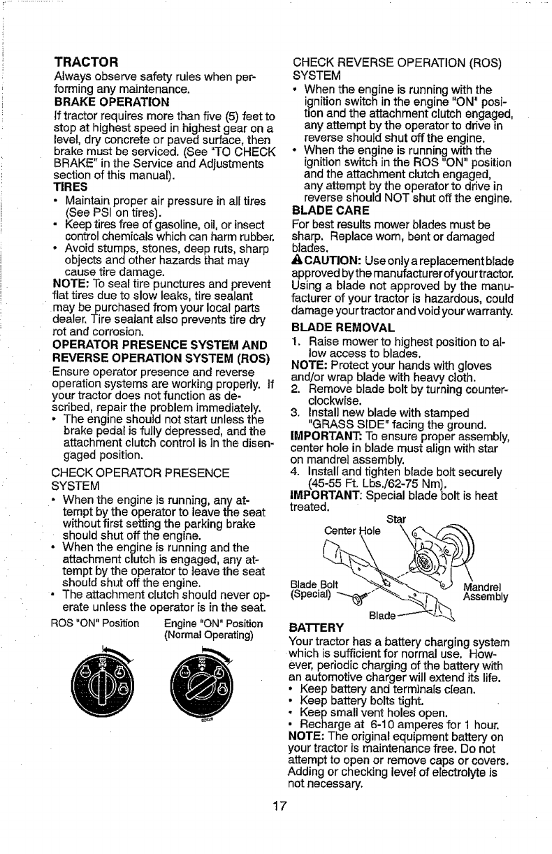
3. Instal] new blade with stamped
"GRASS SIDE" facing the ground.
IMPORTANT: To ensure proper assembly,
center hole in blade must align with star
on mandrel assembly.
4. Install and tighten blade bolt securely
(45-55 Ft. Lbs.!62-75 Nm).
IMPORTANT: Special blade bolt is heat
treated. Star
CenterHole
Blade Bolt Mandrel
(Special) ---_,J Assembly
BATTERY
Your tractor has a battery chargingsystem
which is sufficient for normal use. How-
ever, periodic charging of the battery with
an automotive charger will extend its life.
Keep battery and terminals clean.
Keep battery bolts tight.
Keep small vent holes open.
• Recharge at 6-10 amperes for 1 hour.
NOTE: The original equipment battery on
your tractor is maintenance free. Do not
attempt to open or remove caps or covers.
Adding or checking level of electrolyte is
not necessary.
17
TOCLEANBATTERYANDTERMINALS
Corrosionanddirtonthebatteryandtermi-
nalscancausethebatteryto"leak"power.
1. DisconnectBLACKbatterycablefirst
thenREDbatterycableandremove
batteryfromtractor.
2. Rinsethebatterywithplainwateranddry.
3. Cleanterminalsandbatterycableends
with wire brush until bright.
4. Coat terminals with grease or petro-
leum jelly.
5. Reinstall battery (See "REPLACING
BATTERY in the SERVICE AND AD-
JUSTMENTS section of this manual),
TRANSAXLE MAINTENANCE
Keep transaxle free from build-up of dirt and
chaff which can restrict cooling.
Do not attempt to clean transaxle while
engine is running or while the transax[e is
hot. To prevent possible damage to seals,
do not use high pressure water or steam to
clean transaxle,
V-BELTS
Check V-belts for deterioration and wear after
100 hours of operation and replace if neces-
sary. The belts are not adjustable. Replace
belts if they begin to slip from wear.
ENGINE
LUBRICATION
Only use high quality detergent oil rated
with APt service classification SG-SL,
Select the oil's SAE viscosity grade
according to your expected operating
temperature.
SAE VISCOSITY GRADES
TO CHANGE ENGINE OIL
Determine temperature range expected
before oil change, All oil must meet API
service classification SG-SL.
• Be sure tractor is on level surface.
• Oil will drain more freely when warm,
• Catch oil in a suitable container,
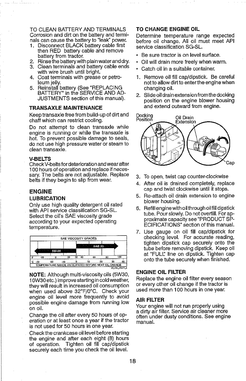
t. Remove oil fill cap/dipstick, Be careful
not to allow dirt to enter the engine when
changing oil.
2. Slide oil drain extension from the docking
position on the engine blower housing
and extend out_#ardfrom engine,
Docking
sition Oil Drain
3, To open, twist cap counter-clockwise
4. After oil is drained completely, replace
cap and twist clockwise until it stops.
5. Re-attach oil drain extension to engine
blower housing.
6. Refill engine with oil through oil filldipstick
tube. Pour slowly. Do not overfill. For ap-
proximate capacity see "PRODUCT SP-
ECI FICATIQNS" section of this manual.
7. Use gauge on oil fill cap/dipstick for
checking bevel, For accurate reading,
tighten dipstick cap securely onto the
tube before removing dipstick, Keep oil
at "FULt2 line on dipstick. Tighten cap
onto the tube securely when finished.
NOTE: Although multi-viscosity oils (5W30,
IOW30 etc.) improve starting in cold weather,
they will result in increased oil consumption
when used above 32°F/0°C. Check your
engine oil level more frequently to avoid
possible engine damage from running low
on oil.
Change the oil after every 50 hours of op-
eration or at least once a year if the tractor
is not used for 50 hours in one year.
Checkthe crankcase oil level before starting
the engine and after each eight (8) hours
of operation. Tighten oil fill cap!dipstick
securely each time you check the oil level.
ENGINE OIL FILTER
Replace the engine oil filter every season
or every other oil change if the tractor is
used more than 100 hours in one year.
AIR FILTER
Your engine willnot run properly using
a dirty air filter. Service air cleaner more
often under dusty conditions. See engine
manual.
18
CLEAN AIR SCREEN
Air screen must be kept free of dirt and
chaff to prevent engine damage from
overheating, Clean with a wire brush or
compressed air to remove dirt and stub-
born dried gum fibers.
ENGINE COOUNG SYSTEM
To ensure proper cooling, make sure the
grass screen, cooling fins, and other exter-
nal surfaces of the engine are kept clean
at a!l times.
Every 100 hours of operation (more often
under extremely dusty, dirty conditions),
remove the blower housing andother cooling
shrouds. Cleanthe cooling fins and external
surfaces as necessary. Ensure the cooling
shrouds are reinstalled.
NOTE: Operating the engine with a blocked
grass screen, dirty or plugged cooling fins,
and/or cooling shrouds removed will cause
engine damage due to overheating.
MUFFLER
Inspect and replace corroded muffler and
spark arrestor (if equipped) as it could cre-
ate a fire hazard and/or damage.
SPARK PLUG(S)
Replace spark plug(s) at the beginning
of each mowing season or after every
100 hours of operation, whichever occurs
first. Spark plug type and gap setting are
shown in "PRODUCT SPECIFICATIONS"
section of this manual.
IN-LINE FUEL FILTER
The fuel filter should be replaced once
each season, lffuet filter becomes
clogged, obstructing fuel flow to carbure-
tor, replacement is required.
1. With engine cool, remove filter and
plug fuel line sections.
2. Place new fuel filter inposition infuel line
with arrow pointing towards carburetor.
3. Ensure there are no fuel line leaksand
clamps are properly positioned.
4. Immediately wipe up any spilled gaso-
line.
_amp
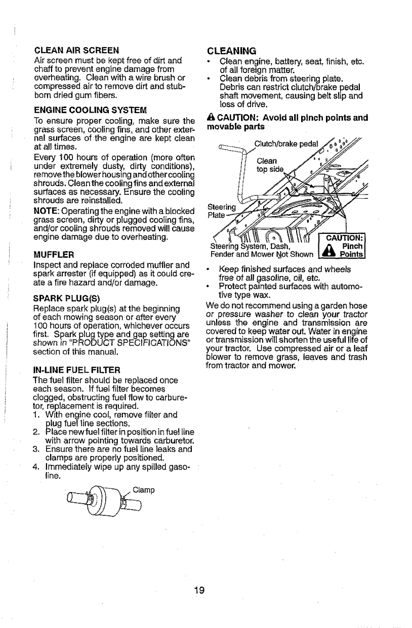
CLEANING
• Clean engine, battery, seat, finish, etc.
of all foreign matter.
•Clean debris from steering plate.
Debris can restrict clutch/brake pedal
shaft movement, causing belt slip and
loss of drive.
& CAUTION: Avoid all pinch points and
movable parts
Clutchtbrakepedal
Clean /
Steering_/___._,/_f/_/'_
Steering System, Dash,
Fenderand MowerNotShown
sy
CAUTION:I
PinchI
413 PointsJ
- Keep finished surfaces and wheels
free of all gasoline, oil, etc.
•Protect painted surfaces with automo-
tive type wax.
We do not recommend using a garden hose
or pressure washer to clean your tractor
unless the engine and transmission are
covered to keep water out. Water in engine
or transmission will shorten the useful lifeof
your tractor. Use compressed air or a leaf
blower to remove grass, leaves and trash
from tractor and mower.
19
DECK WASHOUT PORT
Your tractor's deck is equipped with a
washout port on its surface as part of its
deck wash system. It should be utilized af-
ter each use,
1. Drive the tractor to a level, clear spot
on your lawn, near enough to a water
spigot for your garden hose to reach.
IMPORTANT: Make certain the tractor's
discharge chute is directed AWAY from your
house, garage, parked cars, etc, Remove
bagger chute or mulch cover if attached.
2. Ensure the attachment clutch control
is in the "DISENGAGED" position, set
the parking brake, and stop the engine.
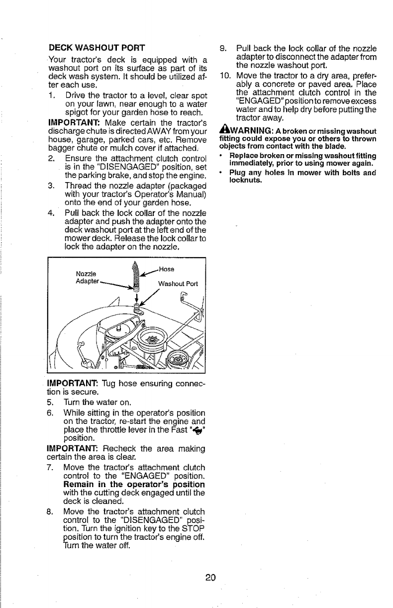
3, Thread the nozzle adapter (packaged
with your tractor's Operator's Manual)
onto the end of your garden hose.
4. Pull back the lock collar of the nozzle
adapter and push the adapter onto the
deck washout port at the left end of the
mower deck. Release the lock collar to
lock the adapter on the nozzle.
9. Pull back the lock collar of the nozzle
adapter to disconnect the adapter from
the nozzle washout port,
10, Move the tractor to a dry area, prefer-
ably a concrete or paved area, Place
the attachment clutch control in the
"ENGAGED" position to remove excess
water and to help dry before putting the
tractor away.
AI_WARNING: A broken or missing washout
fitting could expose you or others to thrown
objects from contact with the blade.
• Replace broken or missing washout fitting
immediately, prior to using mower again.
• Plug any holes in mower with bolts and
Iocknuts.
Nozzle
Washout Port
IMPORTANT: Tug hose ensuring connec-
tion is secure.
5. Turn thewater on.
6, While sitting in the operator's position
on the tractor, re-start the engine and
place the throttle lever in the Fast ",_"
position.
IMPORTANT: Recheck the area making
certain the area is clear.
7. Move the tractor's attachment clutch
control to the "ENGAGED" position.
Remain in the operator's position
with the cutting deck engaged until the
deck is cleaned.
8, Move the tractor's attachment clutch
control to the "DISENGAGED" posi-
tion. Turn the ignition key to the STOP
positionto turn the tractor's engine off.
Turn the water off.
2O
WARNING: TO AVOID SERIOUS INJURY, BEFORE PERFORMING ANY
SERVICE OR ADJUSTMENTS:
1. Depress clutch/brake pedal fully and set parkingbrake.
2. Place gearshift lever in neutral position.
3, Place attachment clutch in "DISENGAGED" position.
4. Turn ignition key to "STOP" and remove key.
5, Ensure the b]ades and all moving parts have completely stopped,
6. Disconnect spark plug wire from spark plugand place wire where it cannot
come in contact with plug,
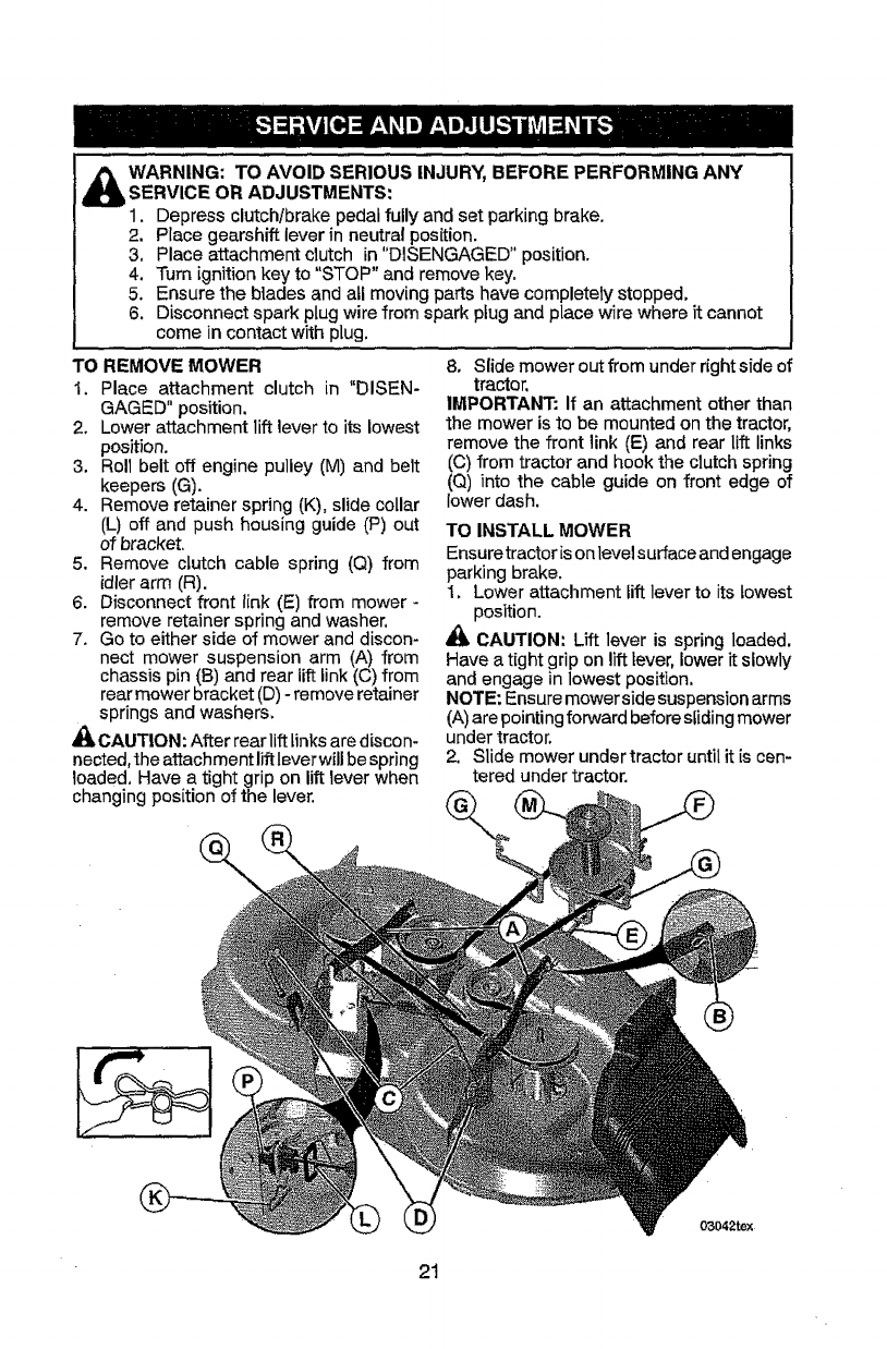
TO REMOVE MOWER
1, Place attachment clutch in "DISEN-
GAGED" position.
2, Lower attachment lift lever to its lowest
position.
3. Roll belt off engine pulley (M) and belt
keepers (G).
4. Remove retainer spring (K), slide collar
(L) off and push housing guide (P) out
of bracket,
5. Remove clutch cable spring (Q) from
idler arm (R).
6. Disconnect front link (E) from mower -
remove retainer spring and washer,
7. Go to either side of mower and discon-
nect mower suspension arm (A) from
chassis pin (B) and rear lift link (C) from
rear mower bracket (D) - remove retainer
springs and washers.
_A CAUTION: After rear lift links arediscon-
nected, the attachment lift lever will bespring
loaded, Have a tight grip on lift lever when
changing position of the lever.
8, Slide mower out from under right side of
tractor,
IMPORTANT: If an attachment other than
the mower is to be mounted on the tractor,
remove the front link (E) and rear lift links
(C) from tractor and hook the clutch spring
(Q) into the cable guide on front edge of
lower dash,
TO INSTALL MOWER
Ensuretractor ison level surface and engage
parking brake.
1, Lower attachment lift lever to its lowest
position.
_1_CAUTION: Lift lever is spring loaded.
Have a tight grip on lift lever, lower it slowly
and engage in lowest position,
NOTE: Ensure mower side suspension arms
(A)are pointing forward before sliding mower
under tractor,
2. Slide mower under tractor until it is cen-
tered under tractor.
21
03042rex
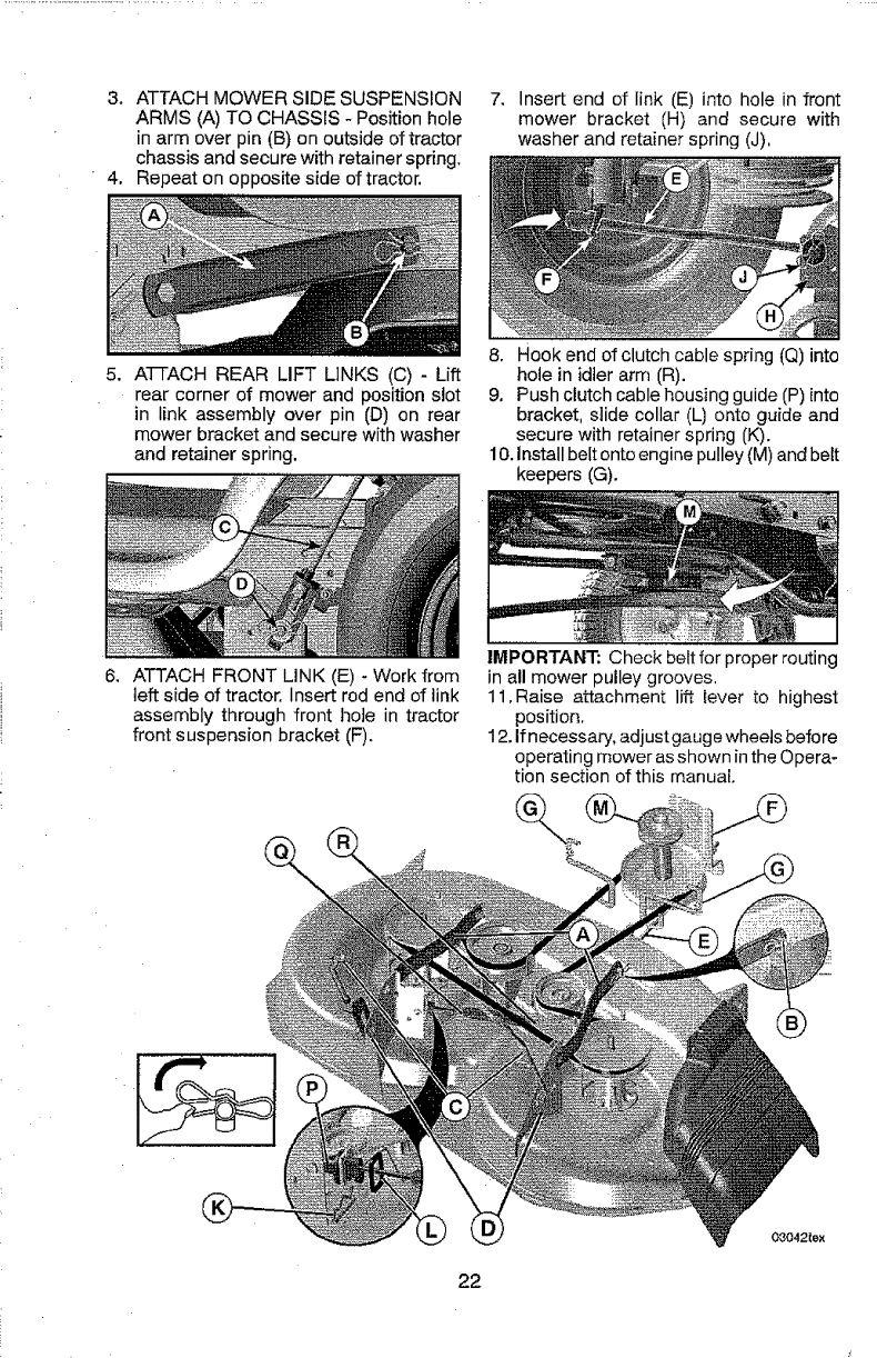
3. ATTACH MOWER SIDE SUSPENSION
ARMS (A) TO CHASSIS - Position hole
in arm over pin (B) on outside of tractor
chassis and secure with retainer spring.
4. Repeat on opposite side of tractor.
7. Insert end of link (E) into hole in front
mower bracket (H) and secure with
washer and retainer spring (J).
5. A-FFACH REAR LIFT LINKS (C) - Lift
rear corner of mower and position slot
in link assembly over pin (D) on rear
mower bracket and secure with washer
and retainer spring.
8, Hook end of clutch cable spring (Q) into
hole in idler arm (R).
9, Push clutch cable housing guide (P) into
bracket, slide collar (L) onto guide and
secure with retainer spring (K).
10. install belt onto engine pulley (M) and belt
keepers (G).
6, ATTACH FRONT LINK (E) - Work from
left side of tractor. Insert rod end of link
assembly through front hole in tractor
front suspension bracket (F).
IMPORTANT: Check belt for proper routing
in all mower pulley grooves.
11,Raise attachment lift iever to highest
position.
12. If necessary, adjust gauge wheels before
operating mower as shown in the Opera-
tion section of this manual
08042tex
22

TO LEVEL MOWER
Make sure tires are properly inflated to the
PStshown ontires, lftires are over or under
inflated, it may affect the appearance of your
lawn and lead you to think the mower is not
adjusted properly.
VISUAL SIDE-TO-SIDE ADJUSTMENT
t. With alltires properly inflatedand ifyour
lawn appears unevenly cut, determine
which side of mower is cutting lower.
2. With a 3/4" or adjustable wrench, turn lift
link adjustment nut (A) to the left to lower
LH side of mower, or, to the rightto raise
LH side of mower.
NOTE: Each full turn of adjustment nut will
change mower height about 3/16".
Turn nut right
to raise mower Turn nut left
to lower mower
3. Test your adjustment by mowing some
uncut grass and visually checking the
appearance. Readjust, if necessary, until
you are satisfied with the results.
PRECISION SIDE-TO-SIDE ADJUSTMENT
1. With alltires properly inflated, parktractor
on level ground or driveway.
CAUTION: Blades are sharp. Protect
your hands with gloves and/or wrap blade
with heavy cloth,
2. Raise mower to its highest position.
3. At both sides of mower, position blade at
side and measure the distance (A) from
bottom edge of blade to the ground. The
distance should be the same on beth
sides.
4. If adjustment is necessary, see step 2 in
Visual Adjustment instructions above.
5. Recheck measurements, adjust ifneces-
sary until both sides are equal,
AI "i
FRONT-TO-BACK ADJUSTMENT
IMPORTANT: Deck must be level side-
to-side,
To obtain the best cutting results, the mower
blades should be adjusted so the front tip is
1/8"to 1/2" lower than the rear tip when the
_lhoweris in itshighest position.
CAUTION: Blades are sharp, Protect
your hands with gloves andlor wrap blade
with heavy cloth.
• Raise mower to highest position.
• Position any blade so the tip is pointing
straight forward. Measure distance (B)
to the ground at front and rear tip of the
blade.
• If fronttip.of blade is not 1/8" to t/2" lower
than the rear tip, go to the front of tractor.
• With an 11/16" or adjustable wrench,
loosen jam nut A several turns to clear
adjustment nut 13.
•With a 3/4" or adjustable wrench, turn
front link adjustment nut (B) clockwise
(tighten) to raise the front of mower, or,
counterclockwise (loosen) to lower the
front mower.
Tighten adjustnut Loosenadjust
B to raise mower nutBto lower
ITIower
Loosen jam nut Afirst
NOTE: Each full turn of the adjustment nut
will change mower height about 1/8".
Recheck measurements, adjust if neces-
sary until front tip of blade is 1/8" to 1/2"
lower than the rear tip.
• Hold adjustment nutinposition with wrench
and tighten jam nut securely against ad-
justment nut.
23
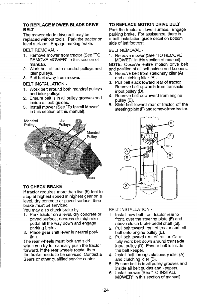
TO REPLACE MOWER BLADE DRIVE
BELT
The mower blade drive belt may be
replaced without tools. Park the tractor on
level surface. Engage parking brake.
BELT REMOVAL -
1. Remove mower from tractor (See "TO
REMOVE MOWER" in this section of
manual).
2. Work belt off both mandrel pulleys and
idler pulleys.
3. Pull belt away from mower,
BELT INSTALLATION -
I, Work belt around both mandrel pulleys
and idler pulleys
2. Ensure belt is in all pulley grooves and
inside all belt guides,
.3. Install mower (See "To Install Mower"
in this section of this manual).
Mandrel idler
Pulleys
Mandrel
TO CHECK BRAKE
If tractor requires more than five (5) feet to
stop at highest speed in highest gear on a
level, dry concrete or paved surface, then
brake must be serviced.
You may also check brake by:
1. Park tractor on a level, dry concrete or
paved surface, depress clutch/brake
pedal all the way down and engage
parking brake.
2, Place gear shift lever in neutral posi-
tion,
The rear wheels must lock and skid
when you try to manua[Iy push the tractor
forward. If the rear wheels rotate, then
the brake needs to be serviced. Contact a
Sears or other qualified service center.
TO REPLACE MOTION DRIVE BELT
Park the tractor on level surface. Engage
parking brake. For assistance, there is
a belt installationguide decal on bottom
side of left footrest.
BELT REMOVAL -
1. Remove mower (See "TO REMOVE
MOWER" in this section of manual).
NOTE: Observe entire motion drive belt
and position of all belt guides and keepers.
2. Remove belt from stationary idler (A)
and clutching idler (B).
3. Pull belt slack toward rear of tractor.
Remove belt upwards from transaxle
input pulley (D),
4. Remove belt downward from engine
pulley (E).
5. Slide belt toward rear of tractor, off the
steering plate (F)and remove fromtractor.
BELT INSTALLATION -
1. Install new belt from tractor rear to
front, over the steering plate (F) and
above clutch brake pedal shaft (G).
2. Pull belt toward front of tractor and roll
belt onto engine pulley (E).
3, Pull belt toward rear of tractor. Care-
fully work belt down around transaxle
input pulley(D). Ensure belt is inside
the belt keeper.
4. Install beltthrough stationary idler (A)
and clutching idler (B).
5, Ensure belt is in all pulley grooves and
inside all belt guides and keepers,
6. Install mower (See "TO INSTALL
MOWER" in this section of manual).
24
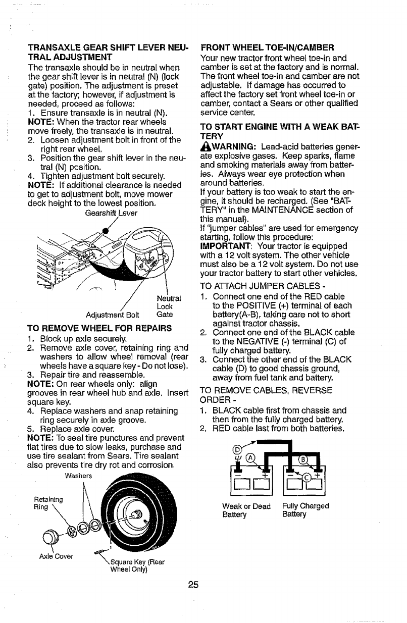
TRANSAXLE GEAR SHIFT LEVER NEU-
TRAL ADJUSTMENT
The transaxle should be in neutral when
the gear shift lever is in neutral (N) (lock
gate) position. The adjustment is preset
at the factory; however, if adjustment is
needed, proceed as follows:
1. Ensure transaxle is in neutral (N).
NOTE" When the tractor rear wheels
move freely, the transaxle is in neutral,
2. Loosen adjustment bolt infront of the
right rear wheel.
3. Position the gear shift lever in the neu-
tral (N) position,
4. Tighten adjustment bolt securely.
NOTE: If additionaf clearance is needed
to get to adjustment boll move mower
deck height to the lowest position.
Gearshift Lever
j.-
Neutral
Lock
AdjustmentBolt Gate
TO REMOVE WHEEL FOR REPAIRS
1. Block up axle securely.
2. Remove ax{e cover, retaining ring and
washers to allow wheel removal (rear
wheels have a square key- Do notlose).
3. Repair tire and reassemble.
NOTE: On rear wheels only: align
grooves in rear wheel hub and axle, insert
square key.
4. Replace washers and snap retaining
ring securely in axle groove,
5. Replace axle cover.
NOTE: To seal tire punctures and prevent
flat tires due to slow leaks, purchase and
use tire sealant from Sears. Tire sealant
atso prevents tire dry rot and corrosion,
Washers
FRONT WHEEL TOE-IN/CAMBER
Your new tractor front wheel toe-in and
camber is set at the factory and is normal.
The front wheel toe-in and camber are not
adjustable. If damage has occurred to
affect the factory set front wheel toe-in or
camber, contact a Sears or other qualified
service center.
TO START ENGINE WITH A WEAK BAT-
TERY
_II_WARNING: Lead-acid batteries gener-
ate explosive gases. Keep sparks, flame
and smoking materials away from batter-
ies. Always wear eye protection when
around batteries.
If your battery is too weak to start the en-
gine, it should be recharged. (See "BAT-
TERY" in the MAINTENANCE section of
this manual).
If "jumper cables" are used for emergency
starting, follow this procedure:
IMPORTANT: Your tractor is equipped
with a 12 volt system. The ether vehicle
must also be a 12 volt system. Do not use
your tractor battery to start other vehicles.
TO ATTACH JUMPER CABLES -
1. Connect one end of the RED cable
to the POSITIVE (+) terminal of each
battery(A-B), taking care not to short
against tractor chassis.
2, Connect one end of the BLACK cable
to the NEGATIVE (-)terminal (C) of
fully charged battery.
3. Connect the other end of the BLACK
cable (D) to good chassis ground,
away from fuel tank and battery.
TO REMOVE CABLES, REVERSE
ORDER -
1. BLACK cable first from chassis and
then from the fully charged battery.
2, RED cable last from both batteries.
Retaining
Ring _\\
Weak or Dead Fully Charged
Battery Battery
Axle Cover '_Square Key (Rear
Wheel Only)
25
REPLACING BATTERY
_JLWARNING: Do not short battery termi-
nals by allowing a wrenchorany otherobject
to contact both terminals at the same time.
Before connecting battery, remove metal
bracelets, wrist-watch bands, rings, etc.
Positive terminal must be connected first to
prevent sparking from accidental grounding.
1. Lift hood to raised position.
2. Remove terminal cover.
3. Disconnect BLACK battery cable then
RED battery cable and carefully remove
battery from tractor.
4. tnstall new battery with terminals in same
position as old battery.
5. Reinstall terminal cover.
6. First connect RED battery cable to posi-
tive (+) battery terminal with bolt and nut
as shown. Tighten securely,
7. Connect BLACK grounding cable to
negative (-)battery terminal with remain-
ing bolt and nut. Tighten securely
8. Close hood,
__-_ Negative
I"._ _ ,F'./_ f _ / (Black)
\___" Cable
Terminal _ _._"_
Cover ___
Positive_1"_ "_",_ ,_, ._...j
(Red)--" "_.\ _ /_
TO REPLACE HEADLIGHT BULB
1. Raise hood.
2. Remove bulb hoiderfrom the hole in the
backside of the grill,
3. Replace bulb in holder and install bulb
holder securely back into the hole in the
backside of the grill.
4, Close hood.
INTERLOCKS AND RELAYS
Loose or damaged wiring may cause your
tractor to run poorly, stop running, or prevent
it from starting,
* Check wiring.
TO REPLACE FUSE
Replace with 30amp automotive-type plug-in
fuse, Thefuseholderislocated behindthedash.
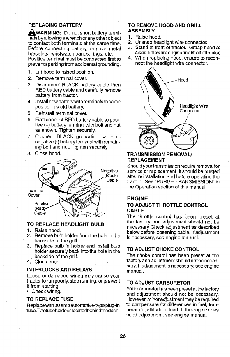
TO REMOVE HOOD AND GRILL
ASSEMBLY
1. Raise hood.
2. Unsnap headlight wire connector,
3. Stand in front of tractor. Grasp hood at
sides,tilttowardengine andliftoffoftractor.
4. When replacing hood, ensure to recon-
nect the headlight wire connector.
Headlight Wire
Connector
TRANSMISSION REMOVAL/
REPLACEMENT
Shouldyourtransmission require removalfor
service or replacement, it should be purged
after reinstallation and before operating the
tractor. See "PURGE TRANSMISSION" in
the Operation section of this manual.
ENGINE
TO ADJUST THROTTLE CONTROL
CABLE
The throttle control has been preset at
the factory and adjustment should not be
necessary Check adjustmentas described
below before looseningcable. If adjustment
is necessary, see engine manual.
TO ADJUST CHOKE CONTROL
The choke control has been preset at the
factory and adjustment should not be neces-
sary. If adjustment is necessary, see engine
manual.
TO ADJUST CARBURETOR
Your carburetor has been preset at the factory
and adjustment should not be necessary.
However, minor adiustment may be required
to compensate for differences in fuel, tem-
perature, altitude or load. If the engine does
need adjustment, see engine manual.
26
Immediately prepare your tractor for storage
at the end of the season or ifthe tractor will
not be used for 30 days or more.
_iWARNING: Never storethe tractor with
gasoline in the tank inside a building where
fumes may reach an open flame or spark.
Allow the engine to cool before storing in
any enclosure.
TRACTOR
Remove mower from tractor for winter stor-
age. When mower is to be stored for a period
of time, clean it thoroughly, remove all dirt,
grease, leaves, etc. Store inaclean, dryarea.
1. Clean entire tractor (See"CLEANING" in
the Maintenance section of this manual).
2. Inspect and replace belts, if necessary
(See belt replacement instructions inthe
Service and Adjustments section of this
manual).
3. Lubricate as shown inthe Maintenance
section of this manual.
4. Be sure that a!l nuts, bolts and screws
are securely fastened. Inspect moving
parts for damage, breakage and wear.
Replace if necessary,
5. Touch up all rusted or chipped paint
surfaces; sand lightly before painting.
BATTERY
• Fully charge the battery for storage.
• After a period of time in storage, battery
may require recharging,
• To help prevent corrosion and power
leakage during long periods of storage,
battery cables should be disconnected
and battery cleaned thoroughly (see "TO
CLEAN BATTERY AND TERMINALS" in
the Maintenance section of this manual).
' After cleaning, leave cables disconnected
and place cables where they cannot come
in contact with battery terminals,
• If battery is removed from tractor for
storage, do not store battery directly on
concrete or damp surfaces.
ENGINE
FUEL SYSTEM
IMPORTANT: It is important to prevent
gum deposits from forming in essential fuel
system parts such as carburetor, fuel hose,
ortank during storage. Also, alcohol blended
fuels (called gasohol or using ethanol or
methanol) can attract moisture which leads
to separation and formation of acids during
storage. Acidic gas can damage the fuel
system of an engine while in storage.
• Empty the fuel tank by starting the engine
and letting it run until the fuel lines and
carburetor are empty.
• Never use engine or carburetor cleaner
products in the fuel tank or permanent
damage may occur.
•Use fresh fuel next season.
NOTE: Fuel stabilizer is an acceptable al-
ternative in minimizing the formation of fuel
gum deposits during storage. Add stabilizer
to gasoline infuel tank or storage container.
Always followthe mix ratio found on stabilizer
container, Run engine at least 10 minutes
afteradding stabilizer to allowthe stabilizer to
reach the carburetor. Do not empty the gas
tank and carburetor if using fue! stabilizer.
ENGINE OIL
Drain oil (with engine warm) and replace
with clean engine oil. (See"ENGINE" in the
Maintenance section of this manual).
CYLINDER(S)
1. Remove spark plug(s).
2. Pourone ounce ofoilthrough sparkplug
hole(s) into cylinder(s),
3. Turn ignitionkey to "START" position for
a few seconds to distribute oil.
4, Replace with new spark plug(s),
OTHER
•Do not store gasoline from one season to
another,
• Replaceyour gasoline canifyour canstarts
to rust, Rust and/or dirt in your gasoline
will cause problems.
•If possible,store your tractor indoors and
cover itto give protectionfrom dustand dirt.
•Cover your tractor with a suitable protec-
tive cover that does not retain moisture.
Do not use plastic. Plastic cannot breathe
which allows condensation to form and will
cause your tractor to rust.
IMPORTANT: Never cover tractor while
engine and exhaust areas are still warm.
27
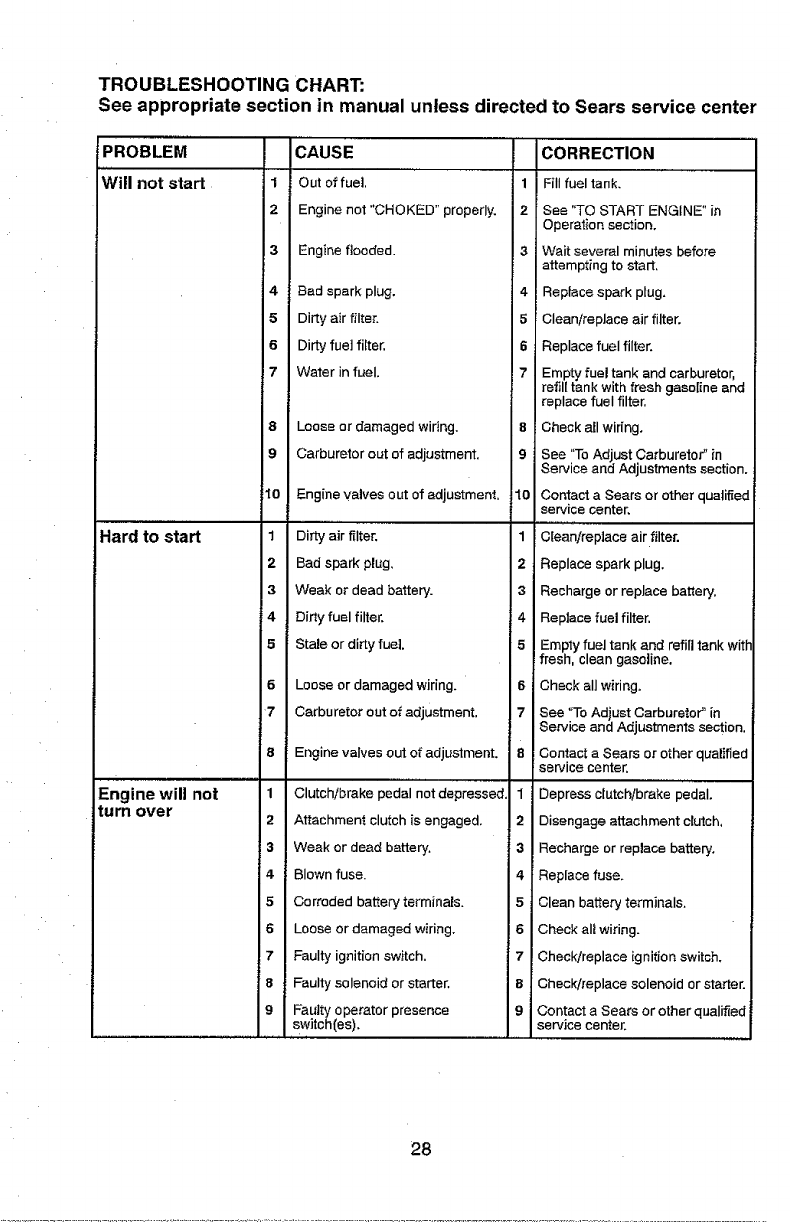
TROUBLESHOOTING CHART:
See appropriate section in manual unless directed to Sears service center
PROBLEM
Will not start
Hard to start
Engine will not
turn over
1
2
8
9
4
5
6
7
Io
CAUSE
Out of fuel,
Engine not "CHOKED" properly.
,,,,,,,,,,,,
Engine flooded.
Bad spark plug.
Dirty air filter.
Dirty fuel filter.
Water in fuel.
Loose or damaged wiring.
Carburetor out of adjustment,
Engine valves out of adjustment,
1Dirty air filter.
2Bad spark plug.
3Weak or dead battery.
'_4 Dirty fuel filter.
5 Stale or dirty fuel
6Loose or damaged wiring.
7Carburetor out of adjustment,
1
2
3
4
5
6
7
8
9
Engine valves out of adjustment.
Clutch/brake pedal not depressed.
Attachment clutch is engaged,
Weak or dead battery.
Blown fuse.
Corroded battery terminals.
Loose or damaged wiring.
Faulty ignition switch.
Faulty solenoid or starter.
Faulty operator presence
switch(es).
1
2
4
5
6
7
8
9
10
1
2
3
_4
5
6
7
1
2
3
4
5
6
7
8
CORRECTION
Fill fuel tank.
See "TO START ENGINE" in
Operation section.
Wait several minutes before
attempting to start,
Replace spark plug.
Clean/replace air filter.
Replace fuel filter.
Empty fuel tank and carburetor,
refill tank with fresh gasoline and
replace fuel filter.
Check all wiring.
See "To Adjust Carburetor _in
Service and Adjustments section.
Contact a Sears or other qualified
service center.
Clean/replace air filter.
Replace spark plug.
Recharge or replace battery.
Replace fuel filter,
I Emply fue tank and ref tank w t_"
fresh, clean gasoline.
Check all wiring.
See "To Adjust Carburetor" in
Service and Adjustments section,
Contact aSears or other qualified
service center.
Depress clutch/brake pedal.
Disengage attachment clutch,
Recharge or replace battery.
Replace fuse.
Clean battery terminals.
Check all wiring.
Check/replace ignition switch.
Check/replace solenoid or starter.
Contact a Sears or other qualified
service center,
28
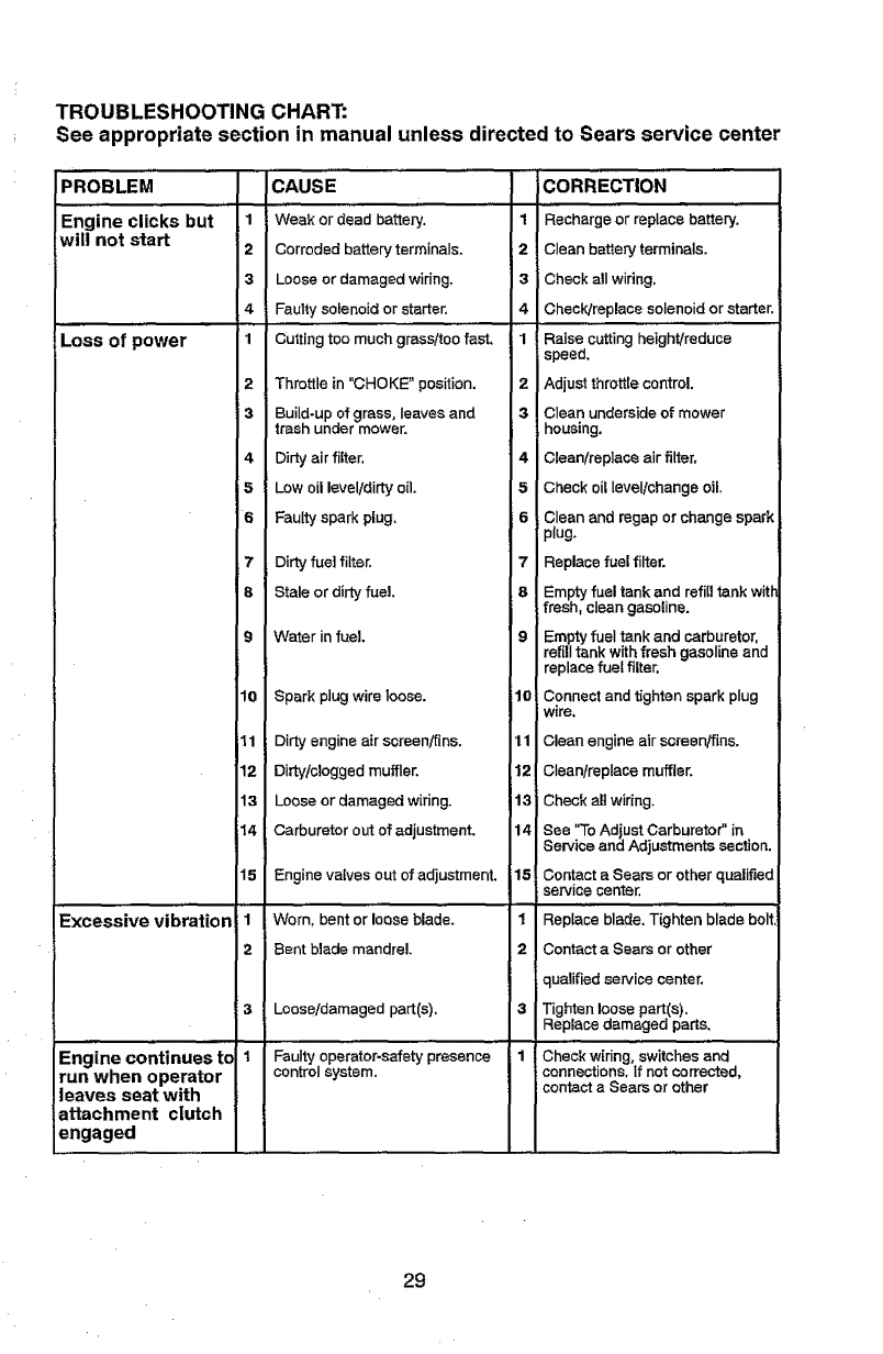
TROUBLESHOOTING CHART:
See appropriate section in manual unless directed to Sears service center
PROBLEM ....
Engine clicks but
will not start
Loss of power
Excessive vibration
Engine continues to
run when operator
leaves seat with
attachment clutch
engaged
1
2
3
4
1
CAUSE
Weak or dead battery. 1
Corroded battery terminals. 2
Loose or damaged wiring. 3
Faulty sofenoid or starter. 4
Cutting too much grass/too fast. 1
Throttle in"CHOKE" position. 2
Build-up of grass, leaves and 3
trash under mower.
2
3
4Dirty air filter.
5Low oil level/dirty oil.
6Faulty spark plug.
7Dirty fuel filter.
8Stale or dirty fuel.
9 Water in fuel.
10 Spark plug wire loose.
11
12
13
14
15
il
2
4
5
6
7
_8
10
Dirty engine air screen/fins. 11
Dirb//clogged muffler. 12
Loose or damaged wiring. 13
Carburetor out of adjustment. 14
Engine valves out of adjustment. 15
Worn, bent or loose blade. 1
Bent blade mandrel. 2
Loose!damaged part(s). 3
Faulty operator-safety presence 1
control system.
i3
it
COR.ECTIO....................
Recharge or replace battery.
Clean battery terminals.
Check all widng.
Chec_'Jreplace solenoid or starter.
Raise cutting height/reduce
speed.
Adjust throttle control.
Clean underside of mower
housing.
Clean/replace air filter.
Check oil level/change oil.
Clean and regap or change spark
plug.
Replace fuel filter.
Empty fuel tank and refill tank with
fresh, clean gasoline.
Empty fuel tank and carburetor,
refill tank with fresh gasoline and
replace fuel filter.
Connect and tighten spark plug
were.
Clean engine air screen/fins.
Clean/replace muffler.
Check all widng.
See "To Adjust Carburetor" in
Sewiee and Adjustments section.
Contact a Sears or other qualified
service center,
,,,,i
Replace blade. Tighten blade bolt
Contact a Sears or other
qualified service center,
Tighten loose part(s).
Replace damaged parts.
Check w[ring, switches and
connections. If not corrected,
contact a Sears or other
29
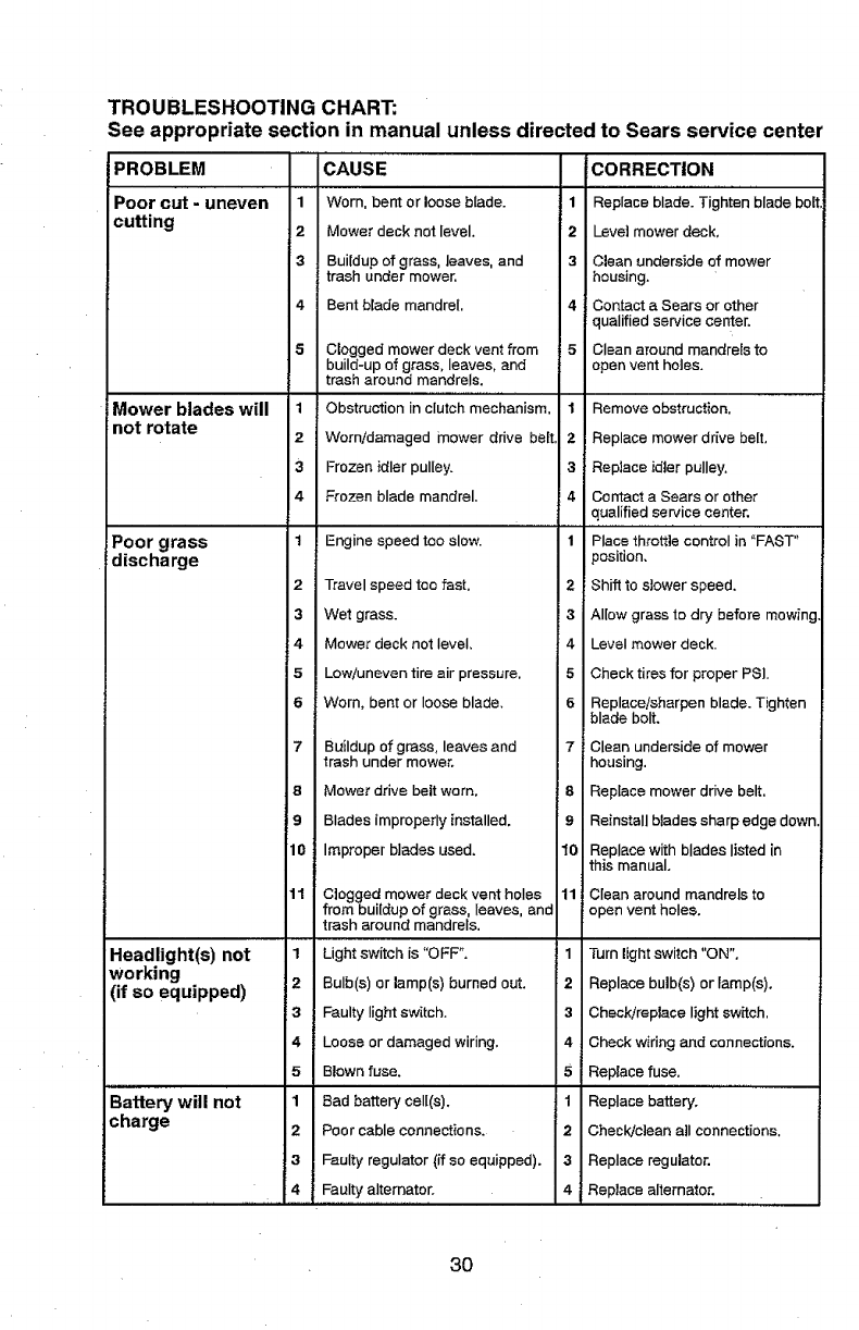
TROUBLESHOOTING CHART:
See appropriate section in manual unless directed to Sears service center
PROBLEM
Poor cut -uneven
cutting
Mower blades will
not rotate
Poor grass
discharge
Headlight(s) not
working
(if so equipped)
Battery will not
charge
CAUSE
1 Worn, bent or loose blade.
2Mower deck not level.
3Buildup of grass, leaves, and
trash under mower,
4 Bent blade mandrel,
1
2
3
4
Clogged mower deck vent from
build-up of grass, leaves, and
trash around mandrels.
Obstruction in clutch mechanism,
'Worn/damaged mower drive be(t,
Frozen idler pulley.
Frozen blade mandrel.
1 Engine speed tco slow.
2Travel speed toe fast.
3Wet grass.
4 Mower deck not level,
5Low/uneven tire air pressure,
6 Worn, bent or loose blade.
7Buildup of grass, leaves and
trash under mower.
8Mower drive belt worn.
9 Blades improperly installed.
10 Improper blades used.
11 Clogged mower deck vent holes
from buildup of grass, leaves, and
trash around mandrels,
1 Light switch is "OFP.
2Bulb(s) or lamp(s) burned out.
3 Faulty light switch.
4 Loose or damaged wiring.
5Blown fuse.
1Bad battery ceil(s).
2Poor cable connections.
3Faulty regulator (ff so equipped).
4 Faulty alternator.
CORRECTION
1Replace blade. Tighten blade bolt
2Levet mower deck,
3 Clean underside of mower
housing.
4 Contact a Sears or other
qualified service center.
i 5 Clean around mandrels to
open vent holes.
1Remove obstruction,
2Replace mower drive belt,
3Replace idler pulley.
4 Contact a Sears or other
qualified service center.
1 Place throttle control in "FAST"
position.
2 : Shift to s}ower speed.
3Allow grass to dry before mowing,
4 Level mower deck.
5Check tires for proper PSL
6 Replace/sharpen blade. Tighten
blade bolt.
7Clean underside of mower
housing,
8 Replace mower drive belt,
9Reinstall blades sharp edge down.
10 Replace with blades listed in
this manual.
11 Clean around mandrels to
open vent holes.
1 Turn light switch "ON".
2Replace bulb(s) or lamp(s),
3Check/replace light switch,
4Check wiring and connections.
5Replace fuse.
1 Replace battery.
2Check]clean all connections.
3Replace regulator.
4 Reptace alternator,
30
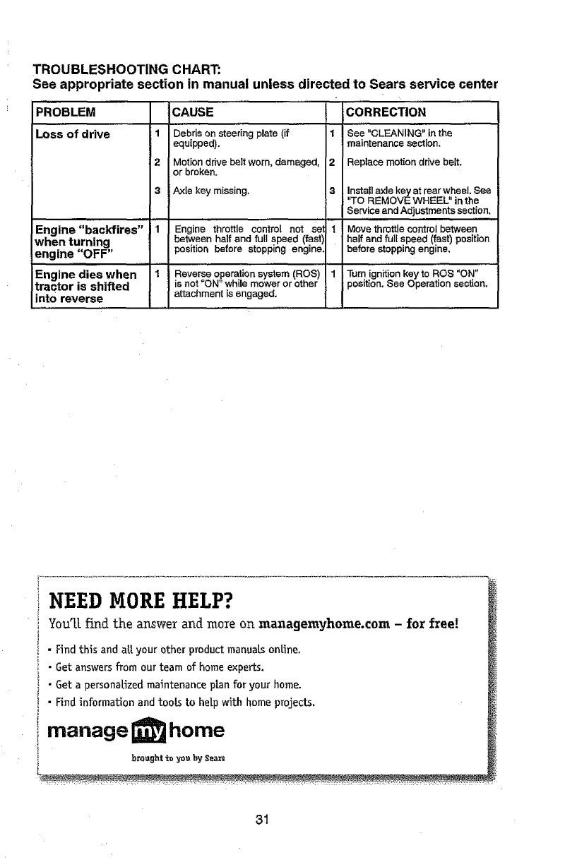
TROUBLESHOOTING CHART:
See appropriate section in manual unless directed to Sears service center
PROBLEM
Loss of drive 1
2
3
Engine "backfires"
when turning
engine "OFF"
Engine dies when
tractor is shifted
into reverse
CAUSE CORRECTION
, ,,_.......... , ......
Debris on steering plate (if 1 See "CLEANING" in the
equipped), maintenance section.
Motion drive belt worn, damaged, 2Replace motion drive belt.
or broken.
Axle key missing. 3Install axle key at rearwheeL See
"TO REMOVE WHEEU' in the
Service and Adjustments section.
Engine throttle control not so'
between haft and ful! speed (fastl
position before stopping engine
Reverse operation system (ROS)
is not "ON" while mower or other
attachment is engaged.
Move throttle control between
half and full speed (fast) position
before stopping engine.
Turn ignition key to ROS "ON"
position, See Operation section,
NEED MORE HELP?
You'[[findtheanswerand more on managemyhome.com - forfree!
•Find this and aU your other product manuals online.
i•Get answers from our team of home experts.
i"Get a personalized maintenance plan for your home.
i • Find information and tooL_ to help with home projects.
imanage home
; broughtto you by Sear_
31
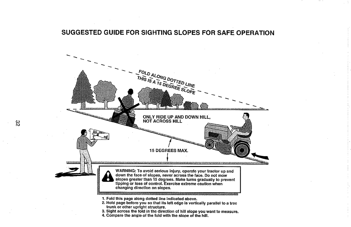
SUGGESTED GUIDE FOR SIGHTING SLOPES FOR SAFE OPERATION
O3
r_
_ARNING: To avoid serious injury, operate your tractor up and
down the face of slopes, never across the face. Do not mow
.slopes greater than 15 degrees. Make turns gradually to prevent
tipping or loss of control. Exercise extreme caution when
changing direction on slopes.
1. Fold this page along dotted line indicated above.
2. Hold page before you so that its left edge is vertically parallel to a tree
trunk or other upright structure.
3. Sight across the fold in the direction of hill slope you want to measure.
4. Compare the angle of the fold with the slope of the hill.
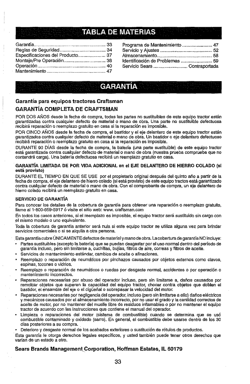
Garantia ....................................................... 33
Reglas de Seguridad ................................... 34
Especificaciones deI Producto ..................... 37
Montaje/Pre Operaci6n ................................ 38
Operaci6n .................................................... 40
Mentenimiento ............................................. 47
Programa de Mantenimiento ....................... 47
Servicio y Ajustes .......................... _............. 52
Almacenamiento .......................................... 58
Identificaci6n de Problemas ........................ 59
Servicio Sears .......................... Contraportada
Garant{a para equipos tractores Craftsman
GARANTJA COMPLETA DE CRAFTSMAN
PeR DOS A_'_OS desde la fecha de compra, todas las partes no sustituibles de este equipo tractor estdn
garantizadas contra cualquier defecto de material o mane de obra. Una paste no sustituible defectuosa
recibird reparaci6n o reemplazo gratuito encasa sita reparaci6n es imposible.
PeR CINCO AI_OS desde la fecha de compra0 el bastidor yel eie delantero de este equipo tractor estdn
garantizados contra cualquier defecto de material omane de obra, Un bastidor o eje delantero defectuoso
recibir_ reparaci6n oreemplazo gratuito en case sila reparaei6n es imposible.
DURANTE 90 D{AS desde la fecha de compra, la bateria (una parte sustituible) de este equipo tractor
estd garantizada contra cualquier defecto de material omane de obra (nuestra prueba comprueba que no
contendr_ cargo). Una bater{a defectuosa recibir_ un reemptazo gratuito en case.
GARANTJA LIMITADA DE PeR VIDA ADICIONAL en el F_JE DELANTERO DE HIERRO COLADO (s!
eat& proviato)
DURANTE EL TIEMPO EN QUE SE USE per el propietario original despu_s del quinto a_o a partir de la
fecha de compra, el eje de[antero de hierro colado (si estd provisto) de este equipo tractos estd garantizado
centre cualquier defecto de material omane de obra. Con e] comprobante de compra, un eje delantero de
hierro colado recibir_ un reemplazo gr_tuito en ease.
SERVICIO DE GARANTiA
Para conecer los detalles de [a cobertura de garantla pare obtener una reparac{6n oreemplazo gratuito,
liame aI 1-800-659-5917 6visits el sitio web: www. craftsman.corn
En todos los cases anteriores, si el reemplazo es imposibie, et equips tractor ser& sustituido sin cargo con
el mismo modelo o uno equivalente.
Toda ]a cobertura de garantia anterior ser& nula si este equipo tractor se utilize alguna vez pare brindar
servicios comerciales o si se alquila a otra persona,
Esta garantia cubre 0NICAM ENTE defectos de material y mane de obra. La cobertura de garantia NO incluye:
• Partes sustituibles (excepto la bater{a) que se puedan desgastar per el use normal dentro del periods de
garantia incluso, pete sin lirnitarse a, cuchillas, buj{as, filtros de aire, correas y filtros de aceite.
• Servicios de mantenimiento est_ndar, cambios de aceite o afinaciones.
•Reemplazo o reparaci6n de neumAlicos per pinchazos causados per objetos extemos come claves,
espinas, tocones o vidrios.
•Reemplazo o reparaci6n de neum_ticos o ruedas per desgaste normal, accidentes o per operaci6n o
mantenimiento inco_ectos.
•Reparaciones necesarias per abuse deI operador incluso, pare sin limitarse a, defies causados per
remolcar objetos que superen la capacidad del equipo tractor, chocar centre objetos que deblen el
bastidor, et ensamble del eje o el cigQeSal o sobrepasar fa velocidad del motor.
•Reparaci_nesnecesariasp_rneg_igenciade_perador_inc_us_(per_sin_imitarseae_[_)da_se_ctric_s
y mec&nicos causados per el almacenamiento incorrecto, per no user el grade y Ia cantidad correctes de
aceite de motor, per no mantener del muelle libra de residues inflamables oper no mantener el equipo
tractor de acuerdo con los instrucciones que contiene el manual deI operador.
• Limpieza o reparaeiones del motor (sistema de combustible) cuando se determine que se us6
combustible contaminado y oxidado (sarro). En general, el combL=stible debe usarse dentro de los 30
dias posteriores a su compra.
• Deterioro y desgaste normal de los acabados exteriores o sustituci6n de rdtulos de productos.
Esta garantia le otorga derechos legales especfficos, y us'ted tambi6n puede toner otros derechos que
vat{an de un estado a otto.
Sears Brands Managemen[CorporaUon, Hoffman Estates, IL 60179
33
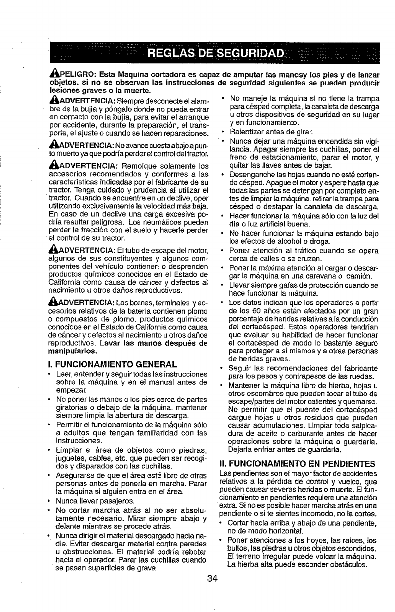
_kPELIGRO: Esta Maquina cortadora es capaz de arnputar |as manosy los pies y de lanzar
objetos, si no se observan las instrueciones de seguridad siguientes se pueden producir
lesiones graves o la muerte,
_ADVERTENCIA: Siempre desconecte el alam-
bre de Ia bujia y p6ngalo donde no pueda entrar
en contacto con Ia bujia, para evitar el arranque
per accidente, durante Ia preparaci6n, el trans-
porte, el ajuste o cuando se hacen reparaciones.
_,DVERTENCIA: Noavance cuestaabajoapun-
tomuerto ya que podria perder e]control del tractor.
_I_ADVERTENCIA: Remolque solamente los
accesorios recomendados y conformes alas
caracteristicas indicadas per el fabricante de su
tractor. Tenga cuidado y prudencia al utilizar el
tractor. Cuando se encuentre en un declive, oper
utilizando exciusivamente la ve]ocidad m&sbaja.
En case de un declive una carga excesiva po-
drfa resultar petigrosa. Los neum&ticos pueden
perder la tracciSn con el suelo y hacerle perder
el control de su tractor.
_DVERTENGIA: El tube de escape del motor,
algunos de sus constituyentes y algunos com-
ponentes del vehiculo contienen odesprenden
productos quimicos conocidos en el Estado de
California come causa de c&ncer y defectos a_
nacimiento u otros daSos reproductivos.
_,ADVERTENCtA: Los bornes, terminales y ac-
cesorios relatives de Ia baterla contienen plomo
ocompuestos de plomo, productos quimicos
conocidos en el Estado de California come causa
de c&ncer y defectos al nacimiento u otros dafios
reproductivos. Lavar tas manes despu_s de
maniputados.
I. FUNCIONAMIENTO GENERAL
• Leer, entender y seguir todas las instrucciones
sobre [a m&quina yen e] manual antes de
empezar.
•No poner Ias manes o los pies cerca de partes
giratorias o debajo de ta m_quina, mantener
siempre limpia la abertura de descarga.
• Permitir el funcionamiento de la m_.quina s61o
aadultos que tengan familiaridad con las
instrucciones.
•Umpiar el &rea de objetos come piedras,
juguetes, cables, etc. que pueden ser recogi-
dos y disparados con las cuchillas.
• Asegurarse de que el &tea est_ ]ibre de otras
personas antes de ponerla en marcha. Parar
la m&quina si alguien entra en el &rea.
• Nunca llevar pasajeros.
•No cortar marcha atr&s aI no ser absolu-
tamente necesario. Mirar siempre abajo y
de]ante mientras se precede atr_s.
•Nunca dingir et material descargado hacia na-
die. Evitar descargar material contra paredes
u obstrucciones. El material podria rebotar
hacia el operador. Parar Ins cuchillas cuando
se pasan superficies de grava.
•No maneje Ia maquina si no tiene la trampa
para c_sped completa, Ia canaleta de descarga
u otros dispositivos de seguridad en su Iugar
y en funcionamiento.
• Ralentizar antes de girar.
•Nunca dejar una m&quina encendida sin vigi-
lancia. Apagar siempre Ins cuchilJas, poner el
freno de estacionamiento, parar el motor, y
quitar Ins Jlaves antes de bajar.
•Desenganche Ins hojas cuando no est@cortan-
do c_sped. Apag ue el motor y espere basraque
todas Ins partesse detengan per completo an-
tes de Iimpiar ta m&quina, retirar latrampa para
c@sped o destapar la canaleta de descarga.
•Hacer funcionar la m_.quina s61ocon la IuzdeI
dia o luz artificial buena.
• No hacer funcionar ta m&quina estando bajo
los efectos de alcohol odroga.
•Porter atenci6n al tr&fico cuando se opera
cerca de calles o se cruzan.
•Porter la m_ima atenci6n al cargar o descar-
gar la m&quina en una caravana o cami6n.
•Llevar siempre gafas de protecciSn cuando se
hace funcionar la m__quina.
•Los dates indican que los operadores a partir
de los 60 aries est&n afectados per un gran
porcentajede heridas relativas a Ia conducci6n
del cortac_sped. Estos operadores tendrian
que evaluar su habilidad de hacer funcionar
el cortac@sped de mode Io bastante seguro
para proteger a si mismos y a otras personas
de heridas graves.
•Seguir las recomendaciones del fabricante
para los pesos y contrapesos de las ruedas.
• Mantener la m&quina Iibre de hierba, hojas u
otrosescombros que pueden tocar el tube de
escape/partes deI motor catientes y q uemarse.
No permitir que el puente deI cortac6sped
cargue hojas u otros residues que pueden
causar acumulaciones. Limpiar toda salpica-
dura de aceite o carburante antes de hacer
operaciones sobre la m&quina e guardarla.
Dejarla enfriar antes de guardarla.
IL FUNCIONAMIENTO EN PENDIENTES
Las pendientes son el mayor factor de accidentes
relatives a Ia p_rdida de control y vuelco, que
pueden causar severas heridas o muerte. Elfun-
cionamiento en pendientes requiere una atenci6n
extra. Si no es posible hacer marcha atr&sen una
pendiente o site sientes incomodo, no la cortes.
• Cortar hacia arriba y abajo de una pendiente,
no de mode horizontal
•Poner atenciones a los hoyos, Ins raices, tos
bultos, Ins piedras u otrosobjetos escondides.
El terreno irregular puede volcar la m_.quina.
La hierba alta puede esconder obst&culos.
34
• Escoger una velocidad de marcha baja de
mode que no sea necesario pararse o cambiar
estando en una pendiente.
•No cortar la hierba mojada. Las ruedas pueden
perder tracci6n.
Poner siempre una marcha cuando se est&
en pendientes. No poner en punto muerto e ir
cuesta abajo.
•Evitar arrancar, pararse o giraren una pendien-
te. Si las ruedas pierden tmcci6n, desconectar
Inscuchillas y preceder despacio cuesta abajo
en la pendiente.
•Mantener todo los movimientos en tas pen-
dientes lentos y gradual. No hater cambios
repentinos de ve]ocidad o direcci6n, ya que
pueden causar el escape de la m&quina.
.Poner Ia m_.xima atenci6n cuando Ia m_.quina
funciona con captadores de hierba u otros
dispositivos enganchados; pueden afectar la
estabilidad de la m&quina, No usar en pendi-
entes empinados,
• No {ntentarestabilizar la m&quina poniendo el
pie en el terreno.
• No cortar cerca de bajadas, cunetas y orillas,
Las m&quina puede volcarse improvisamente
si una rueda est& en el horde o se hunde.
!il. NiI_IOS
_ADVERTENCtA: LOS NIF_OS PUEDEN
SUFRJR DANES CON EL use DE ESTE EQUI-
PC. La Academia Estadounidense de Pediatria
(American Academy of Pediatrics) recomienda
que s61ose permita aniSos con una edad mini-
ma de 12 aries manejar m&quinas cortac6sped
manuales, y aI menos de 16 aries para manejar
tractores cortac6sped,
Si el operader no pone atenci6n a la presencia
de los nifios pueden ocurrir accidentes tr&gicos.
Los nifios a menudo est&n atra{dos per la m_,qui-
nay las actividad de cortar. No dar per hecho
de que los nir_os se queden adonde estaban la
131timavez que los vistes.
• Mantener los nifios fuera det _.rea de corte y
vigilados per un adulto responsable que no sea
el operador.
•Estar alerta y apagar la m&quina si un niftos
entra en el &tea,
• Antes y durante la marcha atr&s,mirar adelante
y aba_o para ver si hay nixies pequefios.
• Nunca Ilevar nifios, incluso si hay las cuchillas
apagadas. Podrian caer y hedrse seriamente
o interferir con el funcionamiento seguro de Ia
m&quina, los nifios que se hart Ilevado prec-
edentemente pueden aparecer de pronto en el
&tea de corte per otro paseo y ser atropellados
o tumbados per la m_.quina.
• Nunca dejar que los nifios manipulen la m&-
quina.
• Tener el m_ximo cuidado cuando se acerca
acantos ciegos, arbustos, &rboles uotros
objetos que pueden impedir la vista de nifios.
IV. REMOLQUE
• Remolcar s61ocon una m_.quina que tenga un
gancho disefiado para remolcar.Enganchar el
equipo o remolcar s61oen el punto dispuesto
al efecto.
• Seguir ias recomendaciones delproductorcon
respecto a los Ifmites del equipo per remolcar
y el remolque en pendientes.
• Nunca permitir que nifios u otras personas
est_n dentro del equipo per remolcar.
•En pendientes, el peso deI equipo remolcado
puede causar la p_rdida de tracci6n y la p_r-
dida de control.
•Viajar despacio y dejar m_.s distancia para
frenar.
V, SERVIC|O
MANIPULACI6N SEGURA DE LA GASOLINA
Para evitar heridas personales o da_os a Ins
cosas, poner el m_ximo cuidado a la hera de
manipular la gasolina. La gasoUna es extrema-
mente inflamable y los vapores son explosives.
• Apagar todos los cigarrillos, cigarros, pipas y
otrasfuentes de ignici6n.
•Usar s6lo contenedores para gasolina aproba-
dos.
• Nunca quitar el tap6n de la gasolina oafiadir
carburante con el motor en marcha, dejar
enfdar el motor antes del abastecimiento de
la gasolina,
•Nunca abastecer la m_.quina al interior de un
local.
• Nunca guardar Ia m&quina oel contenedor
del carburante donde haya una Ilama abierta,
chispas ouna luz pi[oto come un ca[entador
de agua uotros dispositivos,
• Nunca Ilenar los contenedores al interior de
un vehiculo o en una caravana o cami6n
recubiertos con un forte de pI_.stico. Colocar
siempre los contenedores en el terreno ]ejos
del vehlculo cuando se es_ llenando.
•Quitar el equipo de gas de[ cami6no caravana
y abastecerlo en el terreno. Si no es posible,
abastecer dicho equipo con un contenedor por-
t&til, m&s bien que de un surtidor de gasolina.
•Mantener la boquUla a contacto deI borde
del dep6sito de carburante o Ia abertura del
contenedor durante toda la operaci6n de
abastecimiento. No utilizar un dispositivo con
boquilla cerrada-abierta.
•Si se vierte carburante sobre la ropa, cambi-
arse la ropa inmediatamente.
•Nunca Ilenar el dep6sito m&s de 1odebido.
Volver a colocar el tap6n del gas y cerrar de
mode firme.
35
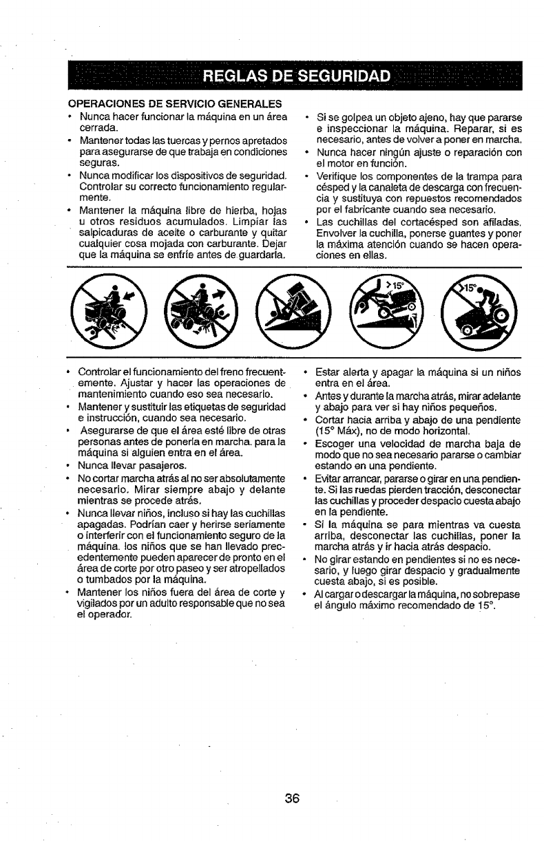
OPERACIONES DE SERVICIO GENERALES
•Nunca hacer funcionarIa m_tquina en un &rea
cerrada.
-Mantener tedas las tuercas y pemos apretados
para asegurarse de que trabaja en condiciones
seguras.
•Nunca modificar Ios dispositivos de seguridad.
Controlar su correcto funcionamiento regular-
mente.
•Mantener la m#,quina iibre de hierba, hojas
u otres residues acumu]ados. Limpiar tas
salpicaduras de aceite o carburante y quitar
cualquier cosa mojada con carburante Dejar
que la m_tquina se enfr{e antes de guardarla.
•Si se golpea un objeto ajeno, hay que pararse
e inspeccionar la m&quina. Reparar, si es
necesario, antes de volver a poner en marcha,
.Nunca hacer ning_n ajuste o reparaci6n con
el motor en funci6n.
- Verifique Ies compenentes de ta trampa para
c_sped y la canaieta de descarga con frecuen-
ciay sustituya con repuestos recomendados
per el fabricante cuando sea necesario.
•Las cuchillas deI cortac_sped son affiadas.
Envolver Ia cuchilla, ponerse guantes y poner
la m_txima atenci6n cuando se hacen opera-
cienes en elias.
@@@@@
*Contro]ar el funcionamiente deI frene frecuent-
emente. Ajustar y hacer las operaciones de
mantenimiento cuando eso sea necesario.
. Mantener y sustituir ]as etiquetas de seguridad
e instrucci6n, cuando sea necesario.
. Asegurarse de que el &rea est@libre de otras
personas antes de ponerla en marcha, para la
m&quina si alguien entra en el &tea.
•Nunca Ilevar pasajeros.
oNo cortar marcha atr&s al no ser absolutamente
necesario. Mirar siempre abajo y delante
mientras se precede atr&s.
, Nunca Itevar ni_os, inclusosi hay las cuchillas
apagadas. Podrian caer y herirse seriamente
o interfedr con el funcionamiento seguro de ]a
m_.quina, los niSos que se han Ilevado prec-
edentemente pueden aparecer de pronto en el
&rea de corte per otro paseo y set atropeltados
o tumbados per la m_.quina.
°Mantener los niSos fuera del &tea de corte y
vigi]ados per un adulto responsable que no sea
el operation
• Estar alerta y apagar Ia m_quina si un nif_os
entra en el _.rea.
• Antes y durante fa marcha atr&s, mirar adelante
y abajo para ver si hay niSos pequeflos.
• Cortar hacia arriba y abajo de una pendiente
(t 5° M&x), no de mode horizontal.
• Escoger una velocidad de marcha baja de
mode que no sea necesario pararse o cambiar
estando en una pendiente.
• Evitar arrancar, pararseo girar en una pendien-
te. Si las ruedas pierden tracci6n, desconectar
las cuchillas y preceder despacio cuesta abajo
en Ia pendiente.
- Si la m_quina se para mientras va cuesta
arriba, desconectar las euchitlas, poner la
marcha atr&s y ir hacia atr&s despacio.
• No girar estando en pendientes si no es nece-
sario, y fuego girar despacio y gradualmente
cuesta abajo, si es posible.
• AI cargar o descargar la m&quina, nosobrepase
el &ngulo m&ximo recomendado de 15°.
36
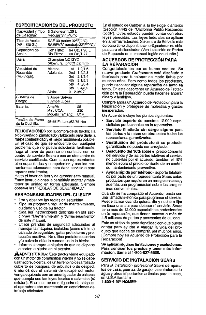
ESPECIFICACIONES DEL PRODUCTO
Oapacidad y Tipo 3Galones/11,35 L
de Gasolina"
Tipo de Aceite
(API; SG-SL);
Capacidad de
Aceite:
i
Bujia
Velocidad de
Recarrido
(Mph/Kph):
Regular Sin Plomo
SAfE 30 (sobre 32_F/0°C)
SAE 5W30 (deabajo 32_F/0°0)
Con Filtro: 64 0z./1.96 L
Sin,,,,,Filtro: 60 Oz./1.77 L
Champion QC12YC
(Abertura: .040"/1.02 ram)
Marcha 1st 1.0/1,6
Adelante; 2nd 1.4/2,3
3rd 2.1/3,4
4th .3.1/5,1
51h 4.0/6.4
6th 5.4/8,2
AltOs: 0 - 2.9/4,7
Sistema de 3Amps Bateria
Carga; 5 Amps Luces
Bateria; Amp!Hr: 28
Min. COA: 230
Modelo TamaSo: UIR
Torsidn del Pemo
de la Cuchilla: 45-55 Ft. Lbs.i62-75 Nm
FELICITACIONES per lacomprade sutractor Ha
side diser_ado,planificadoyfabricadopara darle la
meier confiabilidady el meier rendimiento posible
En el case de que se encuentre con cualquier
problema que no pueda solucionar f_.cilmente,
haga el favor de ponerse en contacto con un
centre de servicio Sears o con un otto centre de
servicio cualificado. Cuenta con representantes
bien capacitados y competentes y con Ias her-
rarnientas adecuadas para darle servicio o para
reparar este tractor,
Haga el favor de leer y de guardar este manual.
Estas instruc-ciones le permitir&n montar y man-
tenor su unidad en forma adecuada. Siempre
observe las "REGLAS DE SEGURIDAD."
RESPONSABILIDADES DEL CUENTE
•Lea y observe las reglas de seguridad,
- Siga un programa regular de mantenimiento,
cuidado y use de su tractor.
-Siga {as instrucciones descritas en las sec-
clones "Mantenimiento" y '_Almacenamiento"
de este manual.
•Utilice prendas de seguridad adecuadas aI
manejar la m&quina, incluidos (come mlnimo)
calzado de seguridad, gafas protectoras y pro-
tecci6n auditiva. No utilice pantalones cortes
y/o calzado abierto cuando corte la hierba.
•Inferme siempre a alguien de que se dispone
a cortar [a hierba en el exterior.
_ADVERTENCIA: Este tractor viene equipado
con un motor de cornbusti6n interna y no se debe
usarsobre, ocerca, de un terreno no desarrollado
cubierto de bosques, de arbustos o de c_sped,
omenos que el sistema de escape det motor
venga equipado con un amortiguador de chispas
que cumpla con las leyes locales o estata[es (si
existen). Si se usa un amortiguador de chispas,
el operador debe mantenerlo en condiciones de
trabajo eficientes.
En et estado de California, la ley exige Io anterior
(Secci6n 4442 deI "California Public Resources
Code"). Otros estados pueden contar con otras
Ieyes parecidas. Las leyes federales se aplican
en Ia tierras federales. Su centre de Servicio m&s
cercano tiene disponib}e amortiguadores de chis-
pas para el silenciador. (Vea la secci6n de Partes
de Repuesto en el manual Ingles dot duefio.)
AGUERDOS DE. PROTECClON PARA
LA REPARACION
Congratulaciones per su buena compra Su
nuevo producto Craftsman® est& diseSado y
fabricado para funcionar de mode fiable per
touches aSos Pero come todos los productos,
puede necesitar alguna reparaci6n de tanto en
tanto En este case toner un Acuerdo de Protec-
ci6n para la Reparaci6n puede hacerles ahorrar
dinero yfastidios
Compre ahora un Acuerdo de ProtecciSnpara la
Reparaci(Sny prot_gese de molestias ygastos
inesperados
Un Acuerdo lncluye los puntos siguientes:
•Servicio experto de nuestros 12.000 espe-
cialistas profesionalesen Ia reparacibn
• Servicio ilim|tado sin cargo alguno para
las partes y la mane de obra sobre todas las
reparaciones garantizadas
• Sustituei6n del producto si su producto
garantizado no puede ser arreglado
• Descuento de110% sobreel precio corriente
del servicio yde fas partes relativas al servicio
no cubiertas per el acuerdo; tambi_n el 10%
menos sobre el precio corriente de un control
de mantenimiento preventive.
• Ayuda r_pida per te|_fono - soporte telef6ni-
co per parte de un representante Sears sobre
productosque requieren un arreglo en casa, y
adem&s una programaciSn sobre losarreglos
mds convenientes.
Cuando se ha comprado el Acuerdo, basta con
una llamada telef6nica para programar el servicio.
Puede llamar cuando quiera, d{a y noche o fijar
en linea una cita para obtener el servicio. Sears
tiene re,is de 12.000 especialistas profesionates
en ]a reparaci6n, que tienen acceso am&s de
4.5 railleries de partes y accesorios de caiidad.
Este es el tipo de profesionalidadcon que puede
contar para ayudar a aiargar la vida del pro-
ducto que acaba de comprar, per muchos a6os.
iCompre hey su Acuerdo de Protecci6n para la
Reparaci6n!
Se aplican algunas limitaciones y exclusiones.
Para conocer los prectos y toner m_s Infor-
maci6n, Ilame al 1-800-827-6655.
SERVIClO DE INSTALACI(_N SEARS
Para /a instalaci6n profesiona/ Seam de apara-
tos de casa, puertas de garaje, calentadores de
agua y otros importantesarticulos para la casa,
en U.S.A Ilarnar a
1-800-4-MY-HOME®
37
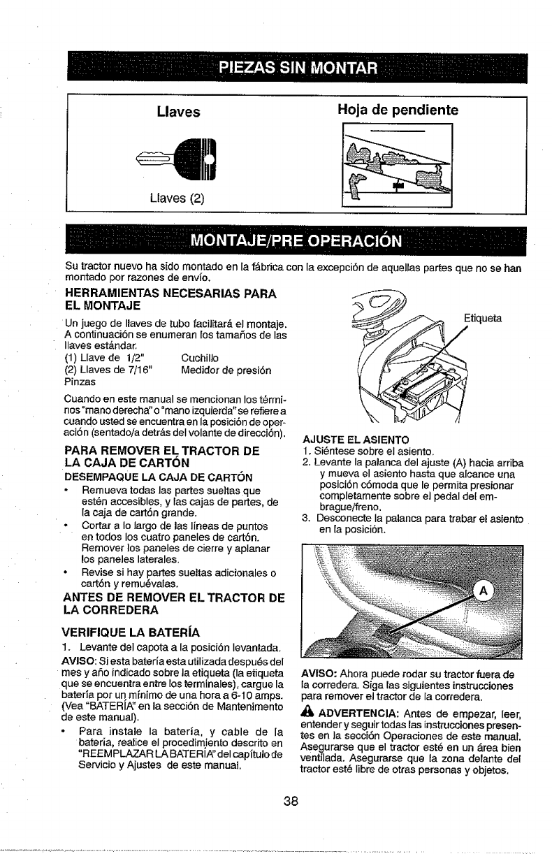
Llaves
Llaves (2)
Hoja de pendiente
Su tractor nuevo ha sido rnontado en Ia f'&brieacon la exeepci6n de aquellas partes que no se han
montado pot razones de envi'o,
HERRAMIENTAS NECESARIAS PARA
EL MONTAJE
Un juego de Ilaves de tubo facilitate, el montaje,
A continuaei6n se enurneran los tarnaSos de Ias
Ilaves estandar,
(1) Llave de 1/2" Cuchil]o
(2) Llaves de 7/16" Medidor de presi6n
Pinzas
Cuando en este manual se mencionan Ios t@rmi-
nos"rnano derecha" o "mano izquierda"se refierea
cuando usted se encuentra en la posici6n de oper-
aci6n (sentadoiadetr&s deI volante de direcci6n).
PARA REMOVER EL TRACTOR DE
LA CAJA DE CARTON
DESEMPAQUE LA CAJA DE CARTON
•Remueva todas las partes sue]tas que
est@naccesibles, y tascajas de partes, de
{a caja de cart6n grande,
.Cortar a Io largo de las lineas de puntos
en todos los cuatro paneles de cart6n,
Remover los paneles de cierre y aplanar
los paneles laterales,
•Revise si hay panes sueitas adicionales o
cart6n y rernu@valaso
ANTES DE REMOVER EL TRACTOR DE
LA CORREDERA
tiqueta
AJUSTE EL ASIENTO
1, Si@ntesesobre el asiento.
2. Levante Ia palanca del ajuste (A) hacia arriba
y mueva el asiento hasta que alcance una
posiciSn e6rnoda que le permita presionar
completamente sobre el pedal del em-
brague/freno.
3. Desconecte la palanca para trabar el asiento
en [aposici6n.
VERIFIQUE LA BATERiA
1. Levante del capota a la posfci6n Ievantada.
AVISO: Siesta bateria esta utilizadadespu_s del
rnes y aSo indicadosobre Jaetiqueta (Ia etiqueta
que se encuentra entre los terminales), cargue la
bateda por un minimo de una hora a 6-10 arnps.
(Vea °BATERIA_'en la secci6n de Mantenimento
de este manual).
°Para instale Ia bateria, y cable de la
bateria, realice el procedirn!ento descrito en
"REEMPLAZAR LA BATERI_' del capitulo de
Servicio y Ajustes de este manual.
AVISO: Ahora puede rodar su tractorfuera de
la corredera. Siga las siguientes instrucciones
para remover el tractor de la corredera.
ADVERTENGIA: Antes de empezar, leer,
entender y seguir todas las instruccionespresen-
tes en la secci6n Operaciones de este manual
Asegurarse que el tractor est@en un _.reabien
ventilada, Asegurarse que ta zona delante del
tractor est@Iibre de otras personas y objetos,
38
PARA HACER RODAR EL TRACTOR
FUERA DE LA CORREDERA (Vea |a
secci6n de la operaci6n para ia Iocali-
dad y la funci6n de los controles)
1. Levante la palanca de levantamiento de[
accesorio a su posici6n m&s altar
2. Suelte el irene de estacionamiento presien-
ando el pedal det embrague/_eno.
3. Ponga la palanca de cambios en la posici6n
de neutro.
4. Haga rodar el tractor hacia delante fuera de
la eorredera.
5, Remueva Ias bandas que sujetan la protein
ci6n contra la descarga en contra deI tractor.
REVISI6N DE LA PRESION DE LAS
LLANTAS
Las Ilantas en su unidad fueron infladas de-
masiado en la f&brica per razones de envio. La
presibn de las llantas correctas es importante
para obtener el meier rendimiento en e[ corte.
• Reduzca la presi6n de los neum&ficos a la PSt
que se indicaen estos.
REVISION DE LA NIVELACI6N DEL
COHJUNTO
Para obtener los mejores resuftados en et corte,
la caja de ta segadora tiene que estar nive]ada
en la forma adecuada. Vea "PARA N1VELAR
LA CAJA DE LA SEGADOR_' en la secciSn de
Servicio y Ajustes de este manual.
REVIS1ON DE LA POSICION ADECUADA
DE TODAS LAS CORREAS
Vea las figuras que aparecen para cambiar las
correas de impulsi6n de la cuchilla de la sega-
dora y de movimiento en la secci6n de Servicio y
Ajustes de este manual. Verifique que las correas
sigan su paso correcto.
REVISI6N DEL SISTEMA DE FRENOS
Una vez que usted haya aprendide a manejar su
tractor, verifique que el freno funcione correct_-
mente. Ver "PARA VERIFICAR SI FUNCIONA
BIEN EL FRENO" en el capltuto de servicio y
ajustes de este manual,
/LISTA DE REVISI6N
Antes de operar y de disfrutarde su trac-
tor nuevo, le deseamos que reciba e_mejor
rendimiento yla mayor satisfaccion de este
productode calidad.
Haga el favor de revisar la lista a continuacion:
/Se han completadotodas las instrucciones
de montaje,
,/No quedan partes sueltas en la caja de
oatt6n.
/La batefia est& preparada y cargada en
forma adecuada.
/El asiento ha side ajustado en forma c6moda
y apretado en forma segura.
J Todas las tlantas han side infladas en forma
adecuada. (Para fines de envlo, las Iiantas
se inflaron demasiado en la f_.brica.)
v" Aseg_rese que et conjunto segador est6
nivelado en forma adecuada, de iado a lade
y desde adelante hacia arT,s, para obtener
fos mejores resultadosen el corte, (Las
Ilantas tienen que estar infladas en forma
adecuada para la nivelaci6n.)
•/Revise Ias correas de impulsi6n y de Ia
segadora. Aseg0rese que recorran el paso
adeeuado airededor de las poleas y dentro
de redes los fijadores de las correas.
,/Revise el alambrado. Fijese que todas Ias
conexiones todav[a est_n seguras y que los
alambres est_n sujetos en forma adecuada.
A1mismo tiempo que aprende a come usar su
tractor, preste atenci6n extra a los puntos de
importancia que se presentan a continuaci6n:
,/E1 aceite del motor tiene que Itegar al nivel
adecuado.
/El estanque de combustibletiene que estar
lleno con gasolina sin plomo regular, nueva y
limpia.
,," Familiadoese con redes los controles- su
ubioaci6n y sufunci6n. Op_relos antes de
hacer arrancar el motor.
/Aseg_rese que el sistema de frenos est6 en
una condici6nde operaci6n segura.
/Asegurarse de que el Sistema de Presencia
del Operador yel Sistema de Funcionamien-
to Atr&s (ROS) funcionan de mode adecuado
(Vet Ias Secciones de Funcionamiento y
Mantenimiento en este manual),
39
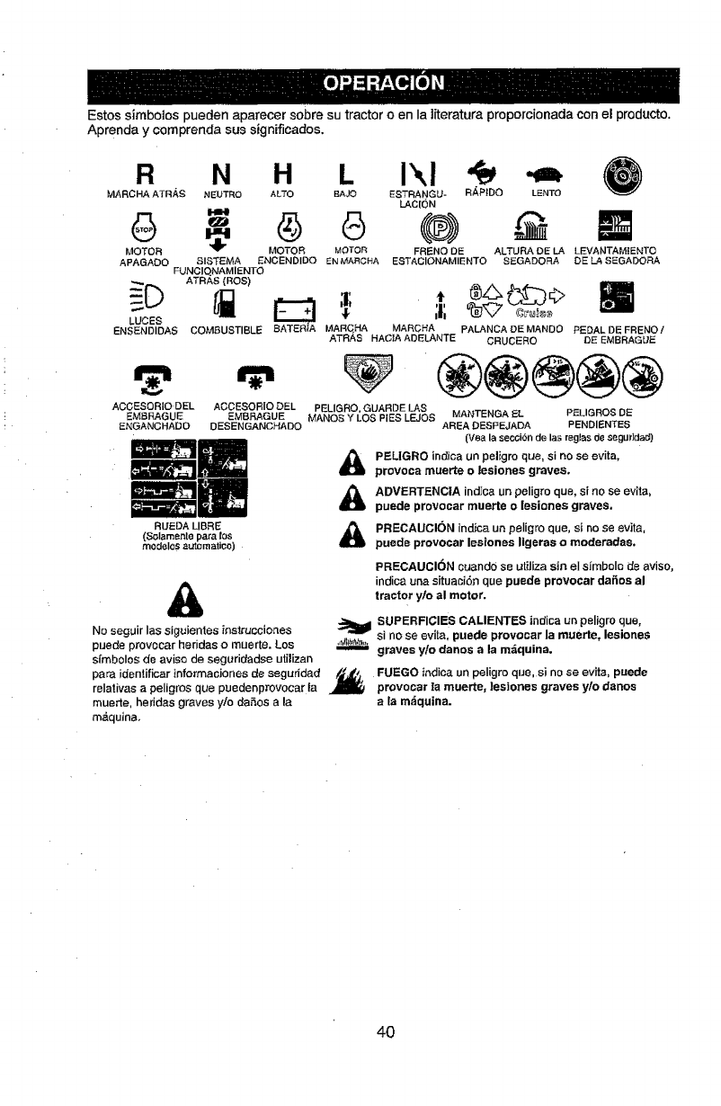
Estos simbolos pueden aparecer sobre su tractor o en Ia literatura proporcionada con el producto.
Aprenda y comprenda sus stgnificados.
R
MARCHA ATRAS
6
MOTOR
APAGADO
LUCES
ENSENDIDAS
ACOESORIO DEL
EMBRAGUE
ENGANCHADO
N H L Ikl
NEUTRO ALTO BAJO ESTRANGU- RAPtDO LENTO
LAC[ON
- 45 (®) N
MOTOR MOTOR FRENO DE ALTURA DE LA LEVANTAMtENTO
SISTEMA ENCENDIDO EN MARCHA ESTACIONAMIENTO SEGADORA DE LA SEGADORA
FUNOIQNAMIENTO
ATRAS {ROS)
COMBUSTIBLE SATER_A MARCHA MARCHA PALANCADEMANOO PEDALDE FRENOI
ATRAS HACIAADELANTE CRUCERO DEEMBRAGUE
ACCESOR|O DEL PELIGRO, GUARDE LAS
EMBRAGUE MANOS Y LOS PIES LEJOS MANTENGA EL PELIGROS DE
OESENGANCHADO AREA DESPEjADA PENDIENTES
RUEDA LIBRE
(Solamente para los
modelos automatico)
&
(Veala secci6nde las reglasdesegLl_']da_
PELIGRO indicaun peligro que, si no se evita,
provoca muerte o lesiones graves.
ADVERTENCIA indica un peligro que, si no se evita,
puede provocar muette olesiones graves,
PRECAUCION indica un peligro que, si no se evita,
puede provocar lesiones ligeras o moderadas.
PRECAUCION cuando se utiJiza sin el simbole de aviso,
indicauna situaci6n que puede provooar da_os al
tractor ylo al motor.
No seguir las sigt_ientes instrucciones
puede provocar heridas o muerte. Los
simbolos de aviso de seguridadse utilizan
para identificar informaoJones de seguridad
relativas a peligros que puedenpmvocar la
muerte, heridas graves y/o da_.os a la
m,_quina.
SUPERFICIES CALIENTES indica URpeligro clue,
si no se evita, puede provocar la muerte, lesionet_
graves ylo danes a la m_quina.
FUEGO inclica un peligro que, si no se evita, puede
provecar la muerte, ]esiones graves ylo danes
ala m_quina.
40
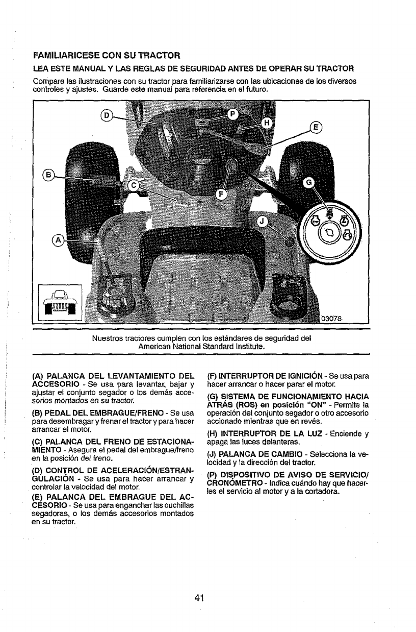
FAMILIARICESE CON SU TRACTOR
LEA ESTE MANUAL Y LAS REGLAS DE SEGURIDAD ANTES DE OPERAR SU TRACTOR
Compare 1asi!ustraciones con su tractor para familiarizarse con las ubicaciones de tos d!versos
controles y ajustes. Guarde este manual para referencia en el future.
03078
Nuestros tractores cumplen con los est&ndares de seguddad del
American National Standard Institute,
(A) PALANCA DEL LEVANTAMIENTO DEL
ACCESORIO -Se usa para tevantar, bajar y
ajustar el conjunto segador o los dem&s acce-
series montados en su tractor.
(B) PEDAL DEL EMBRAGUE/FRENO - Se usa
para desembragar yfrenar el tractor ypara hacer
arrancar el motor.
(C) PALANCA DEL FRENO DE ESTACIONA-
MIENTO - Asegura el pedal del embragueifreno
en _aposicibndel frene.
(D) CONTROL DE ACELERAClON/ESTRAN-
GULAC|ON - Se usa para hacer arrancar y
controlarla velocidad de1motor.
(E) PALANCA DEL EMBRAGUE DEL AC-
CESORIO - Se usa para enganchar Ias euchillas
segadoras, o los demb_s accesorios montados
en su tractor.
(F) INTERRUPTER DE IGNICION - Se usa para
hacer arrancar ohacer parar el motor,
(G) SISTEMA DE FUNC|ONAMIENTO HACIA
ATRAS (ROS) en posici6n "ON" - Permits !a
operaci6n del conjuntosegador o otro accesorio
accionado mientras queen rev_s,
(H) INTERRUPTER DE LA LUZ -Enciende y
apaga las !uces delanteras,
(J) PALANCA DE CAMBIO -Selecciona la ve-
tocidady la direcci6n deI tractor.
(P) DIS,POSIT|VO DE AVISO DE SERVICIO/
CRONOMETRO - Indica cubndo hayque hacer-
les el servicioal motor y a la cortadora.
41
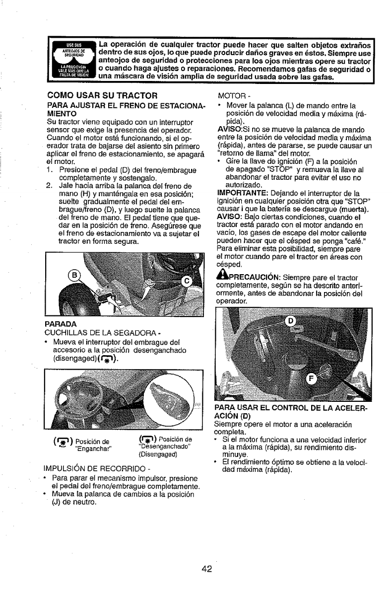
illl
La operaci6n de cualquier tractor puede hacer que salten objetos extra_os I
dentro de sus ojos, Io que puede producir dafios graves en dstos. Siempre use !
anteojos de seguridad o protecciones para los ojos mientras opere su tractor !
o cuando haga ajustes o reparaciones. Recomendamos gafas de seguridad o I
....una m_scara de visi6n amplia de seguridad usada sobre las gafas. I
COMe USAR SU TRACTOR
PARA AJUSTAR EL FRENO DE ESTACIONA-
MtENTO
Su tractor viene equipado con un interrupter
sensor que exige Ia presencia deI operador.
Cuanclo el motor estA funcionando, si el op-
erador trata de bajarse del asiento sin primero
aplicar el freno de estacionamiento, se apagarA
el motor.
1. Presione el pedat (D) del freno/embrague
compretamente y sostengalo.
2. Jale hacia ardba la palanca det freno de
mane (H) y mant@ngala en esa posici6n;
suelte gradualmente el pedal del em-
bragueffreno (D), y Iuego suelte la patanca
del frene de mane. El peda_tiene que que-
dar en la posici6n de freno. Asegfirese que
el freno de estacionamiento va a sujetar el
tractor en forma segura.
MOTOR -
• Mover la palanca (L) de rnando entre la
posici6n de velocidad media y maxima (rA-
p!da).
AVISO:Si no se mueve la palanca de mando
entre la posici6n de velocidad media y maxima
(rApida), antes de pararse, se puede causar un
"retorno de llama" del motor.
• Gire la [Iavede ignicion (F) a la posicidn
de apagado "STOP" y remueva Ia tlave al
abandonar el tractor para evitar el use no
autorizado.
IMPORTANTE: Dejando el interrupter de Ia
igniciSn en cualquier posici6n otra que "STOP"
causar i que la baterla se descargue (muerta).
AVISO: Bajo ciertas condiciones, cuando el
tractor estA parade con el motor andando en
vacio, los gases de escape deI motor ca]iente
pueden hacer que et c_sped se ponga "caf_."
Para eliminar esta posibilidad, siempre pare
el motor cuando pare el tractor en Areas con
c@sped.
_IbPRECAUCI(_N: Siempre pare el tractor
completamente, segfln se ha descrito anteri-
ormente, antes de abandonar la posici6n del
operador.
PARADA
CUCHILLAS DE LA SEGADORA -
- Mueva el interrupter deI embrague det
accesorio a la posici6n desenganchado
(d[sengaged)(t'_l).
(=l_'t) Posici6n de (_) Posici6n de
"Engancha_' "Deseng anchad°_'
(Disengaged)
IMPULSION DE RECORRIDO -
• Para parar el mecanismo impulsor,presione
el pedal de] freno/embrague completamente.
• Mueva _apalanca de cambios a la posici6n
(J) de neutro.
PARA LISAR EL CONTROL DE LA ACELER-
ACION (D)
Siempre opere el motor a una aceleraci6n
compieta,
- Si el motor funciona a una velocidad inferior
ala maxima (rApida), stJrendimiento dis-
minuye.
• EI rendimiento 6ptimo se obtiene a la veloci-
dad m_ima (rApida).
42
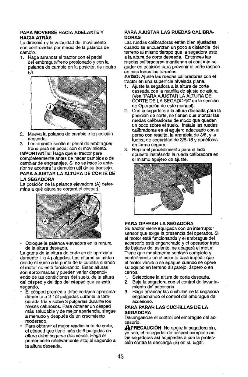
PARA MOVERSE HACIA ADELANTE ¥
HACIA ATRAS
La direcci6n y Ia veiocidad del movimiento
son contro[adaspar media de ta palanca de
cambio,
1. Haga arrancar el tractor con el pedal
de[ embrague/freno presionado y con Ia
palanca de cambio en la posici6nde neutro
(J),
2. Mueva la palanca de cambio a Ia posici6n
deseada.
3. Lentamente suelte el pedal de embrague/
freno para empezar con el movimiento.
IMPORTANTE: Haga que el tractor pare
completeamente antes de hacer cambios ode
cambiar de engranajes. Si no se hace lo ante-
rior se acortara la durac[6n util de su transeje.
PARA AJUSTAR LA ALTURA DE CARTE DE
LA SEGADORA
La posici6n de Lapalanca elevadora (A} deter-
mina a qu@altura se cortar&el c_sped.
PAPA AJUSTAR LAS RUEDAS CALIBRA-
DORAS
Las ruedes calibradoras est&n bien ajustadas
cuandose encuentran un poco adistancia det
terreno al mismo tiempo que la segadora est_
ala attura de carte deseada, Entonces las
ruedascatibradoras mantienen el conjuntose-
gador en posici6n para prevenir el carte raspeo
an casi todos losterrenos.
AVISO: Ajuste Ias ruedas calibradoras con el
tractor en una superficie nive[ada plana,
1. Ajuste la segadora a [aaltura de carte
deseada con la maniI]ade ajuste de altura
(Yea "PARAAJUSTAR LA ALTURA DE
CARTE DE LA SEGADORA" en la secci6n
de Operaci6n de este manual).
2. Con la segadora a la altura deseada para la
posici6n de carte, se tienen que montar las
ruedas calibradoras de modo qua queden
un poco sabre el suelo, lnstale las ruedas
catibradoras en el agujero adecuado con el
perno con resalto, la arandela de 3,/8, y ta
tuerca de seguridad de 3/8-16 y apri_telos
en forma segura.
3. Repita el procedimiento para el lade
opuesto instalando la rueda calibradora en
el mismo agujero de ajuste.
• Coloque la palanca elevadora en la ranura
de la altura deseada.
La gama de ta aLtura de carte es de aproxima-
damente 1 a 4 pulgadas. Las alturas se miden
desde el suelo a ta punta de Ia cuchitla cuando
el motor no est,. funcionando. Estas alturas
son aproximadas y pueden variar dependi-
endo de las condiciones del suelo, de la altura
del c6sped ydel tipo deI c@spedque se est&
segando.
• Et c_sped promedio debe cortarse aproxima-
damente a 2-1/2 pulgadas durante la tem-
porada fria y sabre 3pulgadas durante los
meses calurosos. Para obtener un c_sped
m&s saludable y de mejor apariencia, siegue
a menudo y despu6s de un crecimiento
moderado.
• Para obtener el mejor rendimiento de carte,
el c_sped que tiene m_.sde 6 pulgadas de
altura debe segarse dos races. Haga eI
primer carte relativamente alto; el segundo a
la altura deseada.
PARA OPERAR LA SEGADORA
Su tractor viene equipada con un interruptor
sensor que exige la presencia del operador. Si
el motor est_ funcionando y el embrague del
accesorio est& enganchado y el operador trata
de bajarse del asiento, se apagar_ el motor.
Tiene que mantenerse sentado completa y
centralmente en el asiento para impedirque
el motor vacile o se apague cuando se opera
su equipo en terreno disparejo, _,spero o en
tetras.
1, Seleccione ta altura de carte deseada.
2. Baje la segadora con el control de levanta-
miento del accesorio.
3. Haga arrancar las cuchillas de la segadora
enganchando el control del embrague de[
accesorio.
PARA PARAR LAS CUCHtLLAS DE LA
SEGADORA
Desenganche el control de] embrague dei ac-
cesorJOo
_PRECAUCI6N: No opere Ia segadora sin,
ya sea, el recogedor de rasped camp[eta en
las segadoras asl equipadas o con la protec-
ci6n contra la descarga (S) en su lugar.
43
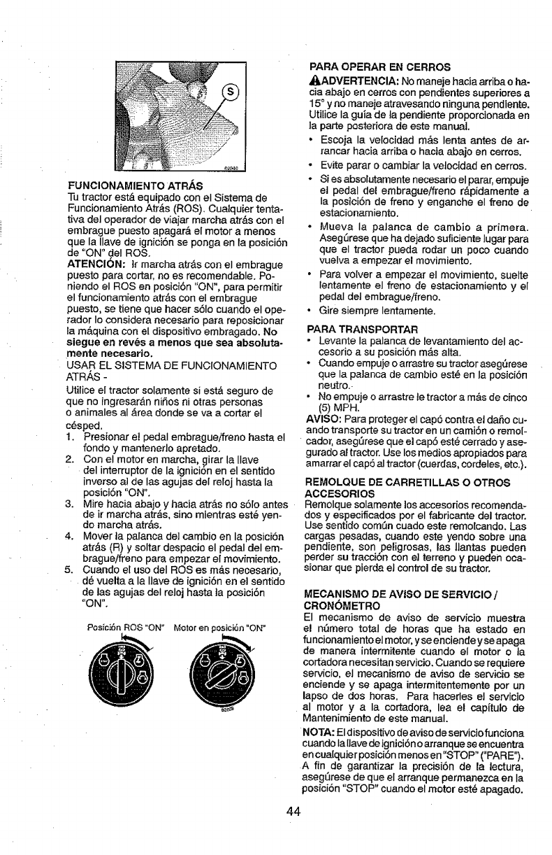
FUNCIONAMIENTO ATRAS
-Ib tractor est&equipado con el Sisterna de
FuncionamientoAtr&s (ROS). Cualquier tenta-
tiva del operador de viajar marcha atr_s con el
embrague puesto apagar& el motor a menos
que la Ilave de ignici6nse ponga en la posicJ6n
de "ON" deI ROS.
ATENCI6N: }rrnarcha atr&s con el embrague
puesto para cortar, no es recomendable. Po-
niendo el ROS en posici6n "ON", para permitir
el funcionarniento atr&s con el embrague
puesto, se tiene que hacer s61ocuando el ope-
rador Io considera necesario para reposioionar
la m&quina con el dispositivo embragado. No
siegue en reves a menos que sea absoluta-
mente necesario.
USAR EL SISTEMA DE FUNCIONAMIENTO
ATRAS -
Utilice el tractor solarnente si est& seguro de
que no ingresar&n niSos ni otras personas
o anirnales al &rea donde se va a cortar el
c6sped,
1. Presionar et pedal embragueifreno hasta el
fondo y mantenedo apretado,
2. Con el motor en marcha, girar la Ilave
del interruptor de la igniciTn en el sentido
inverso al de Ias agujas def reloj hasta la
posiciTn "ON".
3. Mire hacia abajo y hacia atr&s no sT[o antes
de ir marcha atr&s, sino rnientras est@yen-
do marcha atr&s.
4. Mover ta palanca del cambio en la posici6n
atr&s (R) y soltar despacio el pedal del em-
brague/freno para empezar el movirniento.
5. Cuando el uso deI ROSes m_.snecesarJo,
d6 vuelta a Ia Ilave de ignici6n en el sentido
de las agujas deI reloj hasta ta posJci6n
"ON".
F'osici6n ROS "ON" Motor en posici6n "ON"
PARA OPERAR EN CERROS
,_.ADVERTENCIA: No maneje hacia arriba oha-
cia abajo en cerroscon pendientes superiores a
15° y no rnaneje atravesando ninguna pendiente.
Utilice Ia guia de ta pendiente proporcionada en
la parte posteriora de este manuaL
•Escoja la ve{ocidad m&s lenta antes de ar-
rancar hacia arriba ohacia abajo en cerros.
-Evite parar o cambiar la vetocidad en cerros.
•Si es absolutamente necesario el parar,empuje
et pedal del embragueifreno r&pidamente a
Ia posici6n de freno y enganche el freno de
estacionarniento.
• Mueva Ia palanca de cambio a primera.
AsegLirese que ha dejado suficiente Iugar para
que el tractor pueda rodar un poco cuando
vuelva a ernpezar el movimiento.
•Para volver a empezar el movimiento, suelte
lentamente el freno de estacionamiento y el
pedal del embragueifreno.
•Gire siempre Ientamente.
PARA TRANSPORTAR
• Levante la palanca de levantamiento deI ac-
cesorio a su posici6n m&s alta.
•Cuando ernpuje o arrastre su tractor aseg5rese
que la palanca de cambio est@en Ia posici6n
neutro..
•No ernpuje o arrastre ie tractor a m&sde cinco
(5) MPH.
AVISO: Para proteger el cap6 contra et daSo cuo
ando transporte su tractor en un camiSn o rerno[-
cador, asegSrese que e! cap5 est@cerrado y ase-
gurado ar tractor. Use los medios apropiados para
amarrar el cap5 al tractor (cuerdas, cordeles, etc.).
REMOLQUE DE CARRETILLAS O OTROS
ACCESORIOS
Remolque solamente los accesodos recomenda-
dos y especificados por el fabricante del tractor.
Use sentido corn[in cuado este remolcando. Las
cargas pesadas, cuando este yendo sebre una
pendiente, son peligrosas, las llantas pueden
perder su tracciSn con el terreno y pueden oca-
sionar que pierda el control de su tractor.
MECANISMO DE AV!SO DE SERVICIO /
CRONOMETRO
El mecanisrno de aviso de servicio muestra
el nSmero total de horas que ha estado en
funcionamiento el motor, y seenciendeyse apaga
de manera intermitente cuando el motor o ta
cortadora necesJtan servicio. Cuando se requiere
servicio, el mecanismo de avJso de servicio se
enciende y se apaga intermitentemente por un
lapso de dos horas. Para hacerles el servicio
al motor y a la cortadora, lea el cap[tulo de
Mantenirniento de este manual.
NOTA: Eldispositivo de aviso de servicJofunciona
cuando Iallave de igniciTnoarranque se encuentra
en cua[quJerposiciSn rnenos en "STOP" ("PARE").
A fin de garantizar la precisiTn de la lectura,
aseg_rese de que el arranque permanezca en Ia
posiciSn"STOP" cuando el motor est6 apagado.
44
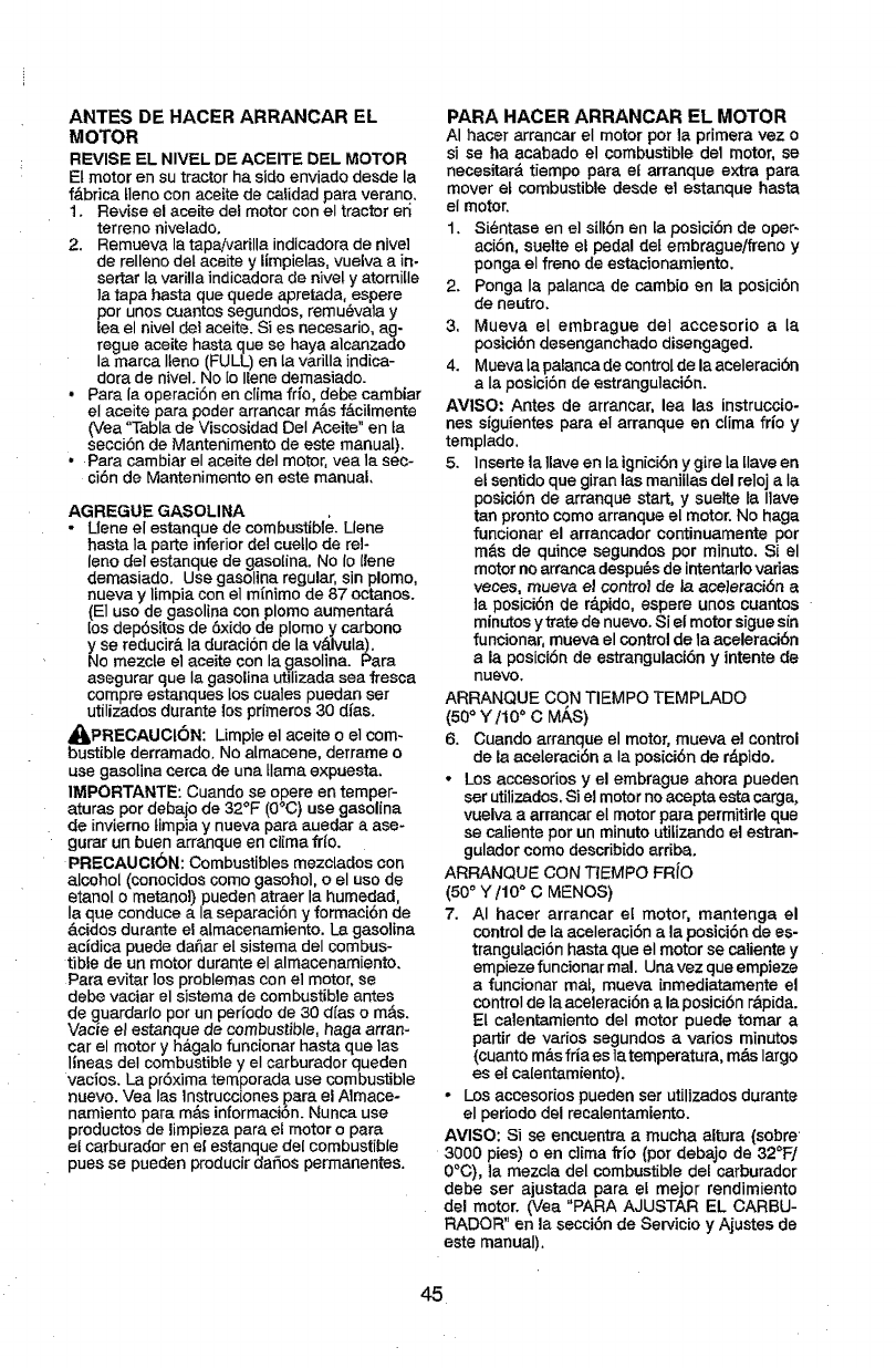
ANTES DE HACER ARRANCAR EL
MOTOR
REVISE EL NIVEL DE ACEITE DEL MOTOR
El motor en su tractor ha side enviado desde la
f&brica tleno con ace[re de calidad para verano.
t. Revise e! aceite del motor con el tractor eri
terreno nivelado.
2. Remueva la tap_varilla indicadora de hive1
de relleno del aceite y limpielas, vuelva a in-
sertar Ia varilla indicadora de nivel y atornitle
la tapa basra que quede apretada, espere
per unos cuantos segundos, remu_vala y
lea el nivel de1aceite. Si es necesario, ag-
regue aceite hasta que se haya alcanzado
la marca Irene (FULL) en la vari[la indica-
dora de nivel. No [oIlene demasiado.
• Para la operaci6n en clima frfo, debe cambiar
el aceite para poder arrancar m&s fAcilmente
(Vea "Tabla de Viscosidad Del Aceite" en ta
secci6n de Mantenimento de este manual).
•Para cambiar el aceite del motor, yea la seo-
ci6n de Mantenimento en este manual.
AGREGLIE GASOLINA
•Llene el estanque de combustible. Llene
hasta Ia parte inferior delcuetlo de tel-
lone deI estanque de gasolina. No Io (lene
demasiado. Use gasolina regular, sin plomo,
nueva y limpia con el m{nimo de 87 octanes.
(El use de gasolina con plomoaumentar_.
los dep6sitos de 6xido de plomo y carbono
y se reducir& Ia duraciSnde la v_lvula).
No mezcle el aceite con la gasolina. Para
asegurar que Ia gasolina utilizada sea fresca
compre estanques los cuales puedan ser
utilizados durante los primeros 30 d(as.
_IbPRECAUCI6N: Limpie el aceite oeI com-
bustible derramado. No almacene, derrame o
use gasolina cerca de una llama expuesta.
IMPORTANTE: Cuando se opere en temper-
aturas per debaio de 32°F (0°C) use gasolina
de invierno timpia y nueva para auedar a ase-
gurar un buen arranque en cIima fr{o.
PRECAUC|6N: Combustibles mezolados con
alcohol (conocidos come gasohol, oel use de
etanol o metanol) pueden atraer la humedad,
Ia que conduce a la separacibn y formaci6n de
&cidos durante el almacenamiento. La gasolina
acidica puede daSar el sistema del combus-
tible de un motor durante el almacenamiento.
Para evitar los problemas con el motor, se
debe vaciar el sistema de combustible antes
de guardarlo per un periodo de 30 d{as o m&s.
Vacie eI estanque de combustible, haga arran-
car el motor y h_.galo funcionar hasta que ias
lineas deI combustible y el carburador queden
vacios. La pr6xima temporada use combustible
nuevo. Vea Ias lnstrucciones para el Almace-
namiento para m_.sinformaci6n. Nunca use
productos de limpieza para el motor o para
el carburador en el estanque del combustible
pues se pueden producir dafios permanentes.
PARA HACER ARRANCAR EL MOTOR
AI hacer arrancar el motor per la primera vez o
si se ha acabado el combustible de1 motor, se
necesitar& tiempo para el arranque extra para
mover et combustible desde el estanque hasta
el motor.
1. Si@ntase en el sill6n en [a posici6n de oper-
aciSn, suelte el pedal det embrague/freno y
ponga el freno de estacionamiento.
2. Ponga la palanca de cambio en la posici6n
de neutro.
3, Mueva el embrague del accesodo a la
posici@ndesenganchado disengaged.
4. Mueva la palanca de controlde la aceleraci6n
a Ia posici6n de estrangulacibn.
AVISO: Antes de arrancar, lea las instruccio-
nes siguientes para el arranque en clima frio y
templado,
5. lnserte la 1laveen la ignici6ny gire la [lave en
et sentido que giran las manillas del reloj a Ia
posicibn de arranque start, y suelte ta Ilave
tan pronto come arranque el motor. No haga
funcionar el arrancador continuamente per
m&s de quince segundos per minute. Si el
motor no arranca despu_s de intentarlo vadas
veees, mueva el control de la ace]eraci6n a
ta posici6n de r_.pido, espere unos cuantos
minutes y trate de nuevo. $i el motor siguesin
funcionar, mueva el control de la aceleracibn
a la posici6n de estrangulaci6n y intente de
nuevo.
ARRANQUE CON TIEMPO TEMPLADO
(50° Y/10 ° C M/_S)
6. Cuando arranque el motor, mueva el control
de la aceleraei6n aIa posici6n de r&pido.
•Los accesorios y el embrague ahora pueden
ser utilizados. Si el motor no acepta esta carga,
vuelva a arrancar el motor para permitirle que
se caliente per un minute utilizando el estran-
gulador come describido arriba.
ARRANQUIE CON TIEMPO FRiO
(500Ytl0" C MENOS)
7. AI hater arrancar el motor, mantenga el
control de la aceleraci6n a la posici6nde es-
trangulaci6n hasta que el motor se caliente y
empieze funcionar ma!, Una vez que empieze
a funcionar mal, mueva inmediat_mente el
control de la aceleraci6n a la posici6n r&pida.
Et calentamiento del motor puede tomar a
partir de varies segundos a varies minL_os
(cuanto m&sfria es ]a temperatura, m&s largo
es et ca[entamiento).
-Los accesorios pueden set utilizados durante
el periodo del reca[entamiento.
AVISO: Si se encuentra a mucha altura (sobre
3000 pies) o en c]ima fdo (per debajo de 32_F/
0°C), la mezcla del combustible de[ carburador
debe ser ajustada para el meier rendimiento
del motor. (Vea "PARA AJUSTAR EL CARBU-
RADOR" en la secci6n de Servicio y Ajustes de
este manual).
45
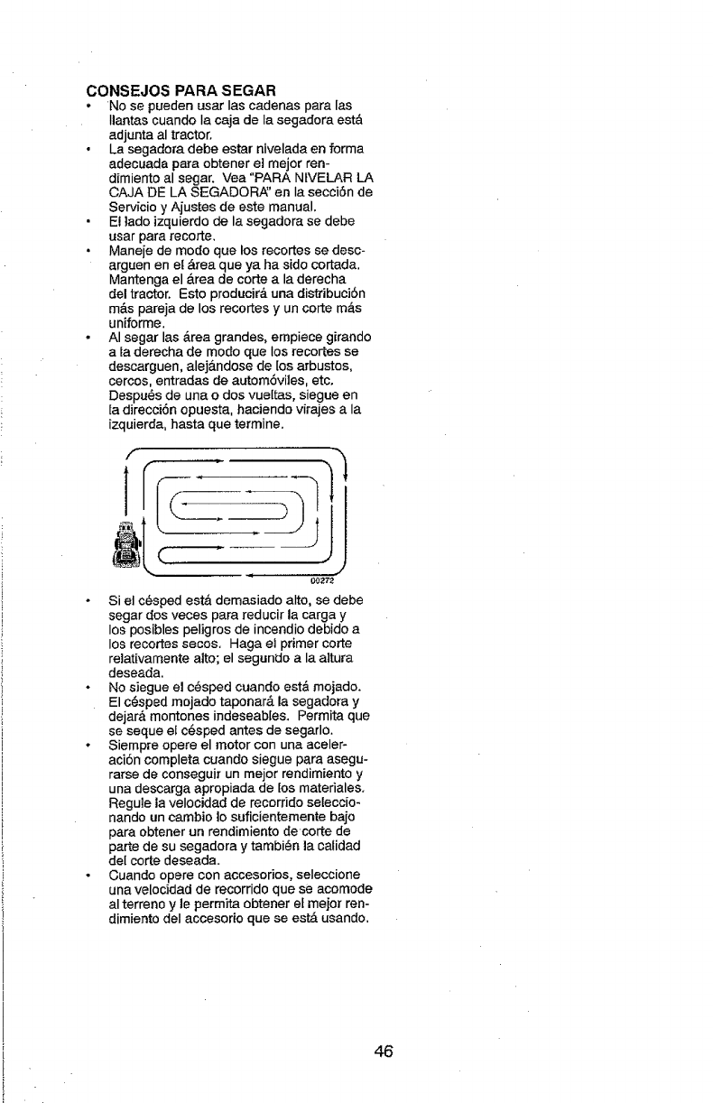
CONSEJOS PARA SEGAR
,No se pueden usar Ias cadenas para las
Ilantas cuando la caja de Ia segadora est&
adjunta al tractor.
• La segadora debe estar nivelada en forma
adecuada para obtener el mejor ren-
dimiento al segar. ',lea "PARA NiVELAR LA
CAJA DE LA SEGADOP_' en la secciSn de
Servicio y Ajustes de este manual.
El lado izquierdo de la segadora se debe
usar para recorte,
° Maneje de mode que los recortes se desc-
arguen en el &rea que ya ha side cortada.
Mantenga el &rea de corte a la derecha
del tractor. Esto preducir& una distdbuci6n
m&s pareja de los recortes y un carte m&s
uniforme.
• AI segar las &rea grandes, empiece girando
a ta derecha de mode que los recortes se
descarguen, alej&ndose de los arbustos,
cercos, entradas de autom6viles, etc.
Despu_s de una o dos vueltas, siegue en
la direcci6n opuesta, haciendo virajes a la
izquierda, hasta que terrnine.
Si et c_sped est& demasiado alto, se debe
segar des veces para reducir la carga y
los posibles peligros de incendio debido a
los recortes secos. Haga el primer corte
re]ativamente alto; el segundo ala a]tura
deseada.
°No siegue el c@sped cuando est& mojado.
El c@sped mejado taponarA la segadora y
dejar& montones indeseab[es. Permita que
se seque el c@spedantes de segarlo.
* Siempre opere el motor con una aceler-
aci6n completa cuando siegue para asegu-
rarse de conseguir un rnejor rendimiento y
una descarga apropiada de los matedales.
Regu]e la velocidad de recorrido seleccio-
nando un cambio Io suficientemente bajo
para obtener un rendimiento de corte de
parte de su segadora y tambi@n la caiidad
del corte deseada.
°Cuando opere con accesodos, seleccione
una velocidad de recorrido que se acomode
al terreno y le permita obtener el meier ren-
dimiento deI accesorio que se est& usando.
46
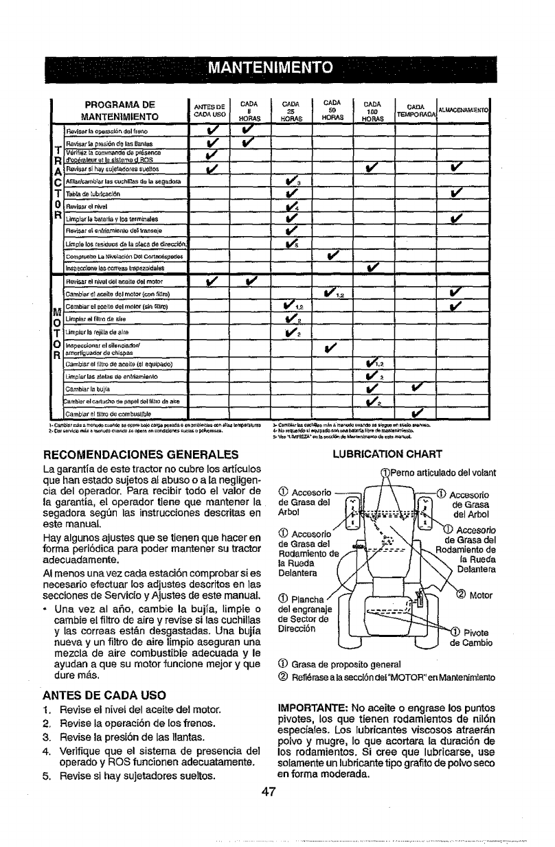
PROGRAMADE
MANTENIM|ENTO
_o_,.o...,o_.o._;'_'_....V' V
....." V';IV'
Tw,f_z_ oo_,_ 4.pr_ent._ V_.....
C AfJla,r,_bl_ar las cuchl_as de la Seg_dol_, V_3
TT=b_ _,b_=_6. J ......................
oIRevis_,rel n_=l
RsvL_a_ete n(liamisnlo 6s$ _seje V_
Umpie IOS raslduo$ _e la p_, de di_._i6,n ........... _1_ ............
Compr_e La _k_c_6n De(¢._zt_sp_ V"
I_eccl_ne I_ c_rre_ trape_idalee
IIIIIII
Flevisar el I_1 c_elat.eiie del motor _ _ ......
V',._ V'
_ ( _,b,r ,1,_)te d,l (sin(i,lto).... .......................................Umpiar el 611t_d_ _)m _2
TLJmpiarlarej_)aCLealtL_ V#_t
0Inspec_onar el siI_.cisdorl V #
R_mertigL_a_orde_;hL_pas
Limplar las _J_las d_ e_t_a_ie_(o V_
)ambi)r _1 _d)r, ho _e p)pel ¢_el(ii(m de aim _2
loo )'o'°'ii(trod°c°mbust) °le
RECOMENDACIONES GENERALES
La garantia de este tractor no cubre losarticulos
que hen estado sujetos at abuse oala negligen-
cia del operador Pare recibir rode el valor de
la garantia, el eperador tiene qua mantener la
segadora seg_n las instrucciones descritas en
este manual.
Hay algunos ajustes que se tienen qua hacer en
forma peri6dica para poder mantener su tractor
adecuadamente.
AI menos una vez carla estaci6n comprobar s(es
necesario efectuar los adjustes descritos en las
secciones de Servicio y Ajustes deeste manual.
• Una vez aI aSo, cambie la buj(a, Iimpie o
cambie el filtro de aire yrevise si las cuchillas
y Ias correas est&n desgastadas. Una bujia
nueva y un fUtro de aire limpio aseguran una
mezcla de aire combustible adecuada y le
ayudan a qua su motor funcione major y qua
dure m&s.
ANTES DE CADA USO
1. Revise el n[vet deI aceite del motor.
2. Revise ta operaci6n de los frenos.
3. Revise la presi6n de las llantas.
4. Vefifique que el sistema de presencia de]
operado y ROS funcionen adecuatamente.
5. Revise si hay sujetadores sueltos.
LUBRICATION CHART
articulado del volant
OAccesorio
de Grasa deI de Grasa
Arbol del Arbol
de Grasa del
Rodamlento de
la Ruada
Delantera
_)
delengranaje
deSectorde
Direcci6n
de Grasa del
damiento de
la Rueda
]antera
Motor
ivote
mbio
(]) Grasa de proposito general
(_ Refi_rasealasecc(6ndef"MOTOR"enMantenimiento
IMPORTANTE: No aceite o engrase los puntos
pivotes, los que tienen rodamientos de nil6n
especiales. Los lubricantes viscosos atraer_n
polvo y mugre, Io qua acortara la duraci6n de
los rodamientos. Si tree que lubricarse, use
solamente un lubricante tipo grafito de polvoseco
en forma moderada.
47
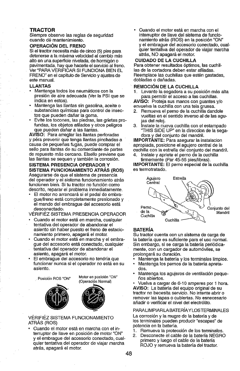
TRACTOR
Siempre observe las reglas de seguridad
cuando d@mantenimiento.
OPERACION DEL FRENO
Si el tractornecesita m&s de cinco (5) piespare
detenerse ala m_ima velocidad al ca.mbio m&s
alto en una superficie nivelada, de hormigSno
pavimentada, hay que hacerle el se_cio al freno.
Ver "PARA VERIFICAR SI FUNCIONA B[EN EL
FRENO" en el capitulo de Servicio y ajustes de
este manual.
LLANTAS
•Mantenga todos los neum&ticos con la
presibn de aire adecuada 0'er la PSi que se
indica en estos).
• Mantenga las Ilantas sin gasolina, aceite o
substancias quimicas pare control de insec-
tos que pueden daSar la goma.
• Evite los tocones, las p[edras, ]as grietes pro-
fundas, los objetos afilados y otros peligros
que pueden daSar a Ias llantas.
AVISO: Pare arreglar Ies ifantas perforadas
y p_ra prevenir que tenga Ilantas pinchadas a
cause de pequer_as fugas, puede comprar el
sello para llantas de su comerciante de partes
de repuesto mAs cercano. Elsel]o previene que
las llantas se sequen y tambi_n Ia corrosi6n.
SISTEMA PRESENCIA OPERADOR Y
SISTEMA FUNCIONAM|ENTO ATRAS (ROS)
Asegurarse de que el sistema de presencia
del operador y el sistema funcionamiento atr_.s
funcionen bien. Si tu tractor no funci6n come
descrito, reparar el problema inmediatamente.
° El motor no errancar_ si el pedal de embra-
gue/freno est& compJetamente presionado y
el mando del embrague deI accesorio estA
desconectado.;
VI_RIFIE_ZSISTEMA PRESENCIA OPERADOR
• Cuando el motor est& en marche, cualquier
tentative deI operador de abandonar el
asiento sin haber puesto el freno de estacio*
namiento primero, apagar& el motor,
- Cuando el motor est_ en marcha y el embre-
gue de] accesorie est& conectado, cualquier
tentativa del operador de abandonar el
asiento, epager& el motor.
• El embrague del acoesorio no tendria que
func[onar nunca si el operador no est& on su
asiento.
Posici6n ROS "ON" Motor en pesici6n "ON"
(Operaoi6n Normal)
VERIFII_Z SISTEMA FUNCfONAMIENTO
ATR,g,S(ROS)
• Cuando el motor est& en marcha con el in-
terrupter de Ilave en posici6n de motor "ON"
y el embrague del accesorio conectado, cuaI-
quier tentative deI operador de viajar marcha
ate&s, apagarA el motor.
• Cuando el motor est,. on marcha con el
interrupter de Ilave del sistema de funcio-
namiento atr&s (ROS) en la posici6n "ON"
y el embrague de{ accesorio conectado, cua[-
quier tentativa del operador de viajar rnarcha
err&s, NO apagar& el motor.
CUIDADO DE LA CUCHILLA
Pare obtener resultados6ptimos, las cuchil-
las de la cortadora deben ester afiladas.
Reemplace las cuchillas que est6n gastadas,
dobladas o daSadas.
REMOCION DE LA CUCHtLLA
1. Levante ta segadora a su posici6n m_s atta
pare permitir el acceso alas cuchiIIas.
AVISO: Proteja sus manes con guantes y/o
envuelva la cuchilla con una tela gruesa.
2. Remueve el perno de la cuchiI]a dandole
vueltes on el sentido inversc al de las agu-
jas del reloj.
3. Instale la nueva cachilla con el estampado
'qHIS SIDE UP" en la direccion de la sega-
dora y del conjunto del mandril.
IMPORTANTE: Para asegurar la instalacion
apropiada, posicioneel agujero central de Ie
cuchilla con la estreila deI conjunto del mandril.
4. ]nstale y epriete el perno de ]a cuchilla
firmemente (Par 45-55 piesi[ibras).
IMPORTANTE: El perno especial de ]a cuchilla
es termotratado.
Agujero EstrelJa
Central
de Ia
Cuch[lla
Conjunto deI
Manddl
BATERiA
Su tractor cuenta con un sistema de carga de
la bateria que es sufieiente pare el use normal.
Sin embargo, si se carga la bateda peri6dica-
mente, con un cargador de autom6viles, so
pro]ongar&su duraci6n.
-Mantenga la bateda y lostermina[es limpios.
•Mantenge los pemos de la baterle apreta-
dos.
° Mantenge los agujeros de ventilaciSn peque-
r_osabiertos.
• Vue]va a cargar de 6-10 amperes per I hera.
AVISO: La bateria de] equipo original de su
tractor no becesita servicio. No intente abrir o
remover las tapes o cubiertas. No esnecesario
ar_adir o verificar el niveI del electr61ito.
PARA LIMPIAR LA BATERiAY LOSTERMINALES
La corrosi6n y Ia mugre de fa bateria y de
los terminales pueden producir "escapes" de
potencia on la bateria.
1. Remueva ta protecci6n de los termina[es.
2. Desconecte et cable de Ia bateria NEGRO
primere y Iuego el cable de la bateria
ROJO y remueve la bateria del tractor.
48
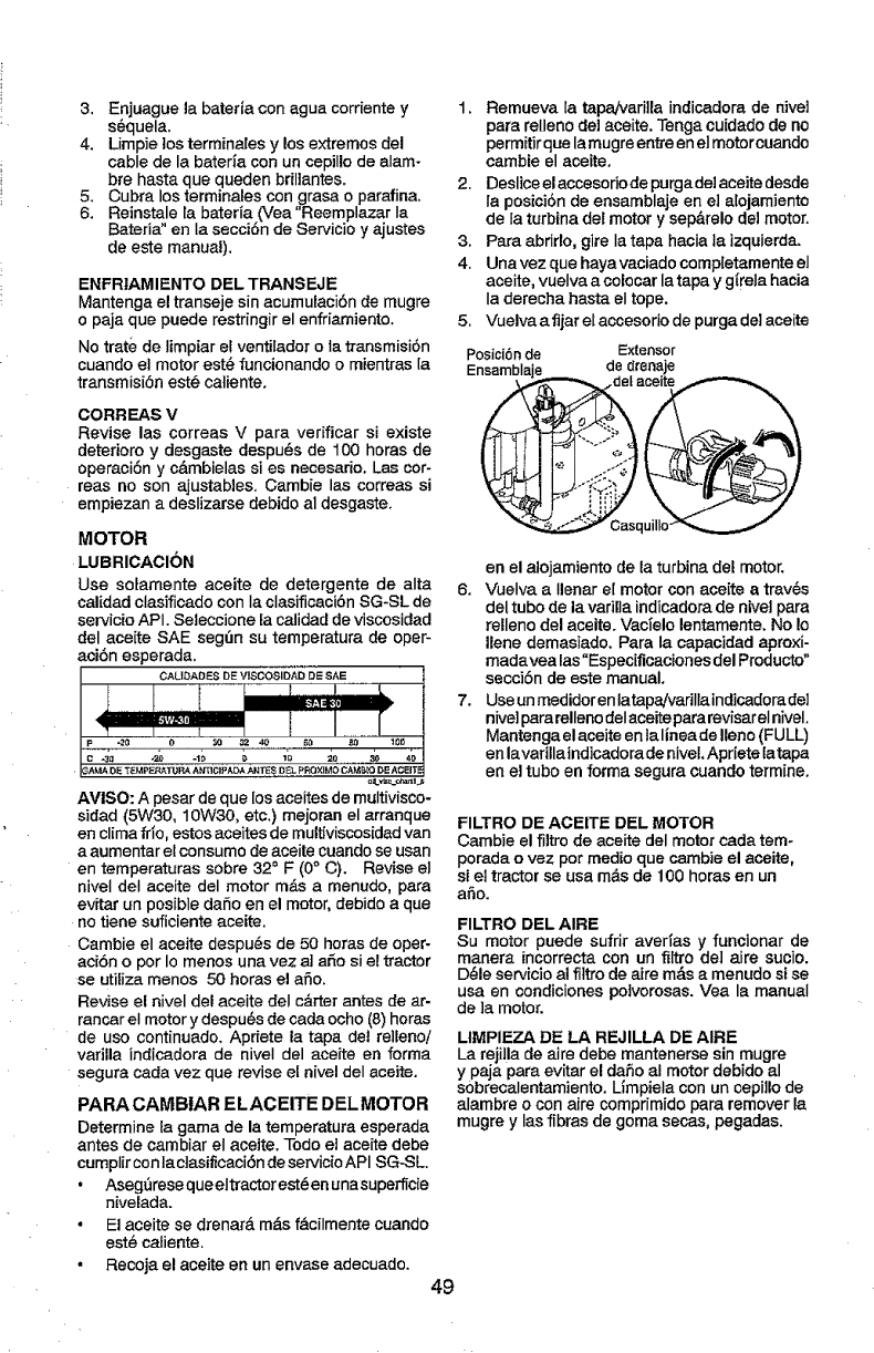
3. Enjuague la bateria con agua corriente y
sL=quela.
4. Limpie los terminafes y los extremos (]el
cable de la bateria con un cepillo de alam-
bre hasta que queden brMantes.
5. Cubra los terminales con grasa o parafina.
6. Reinstale la bateria (Vea "Reemplazar Ia
Bateria" en Ia secci6n de Servicio y ajustes
de este manual).
ENFRIAMIENTO DEL TRANSEJE
Mantenga el transeje sin acumulaci6n de mugre
o paja que puede restringir el enffiamiento.
No trate de timpiar el ventilador otatransmisi6n
cuando ei motor est_ funcionandoo mientras la
transmisi6n est_ catiente.
CORREAS V
Revise las correas V para verificar si existe
deterioro y desgaste despu_s de 100 horas de
operaci6n y c&mbielas si es necesario. Las cor-
reas no son ajustables. Gambie las correas si
empiezan a deslizarse debido al desgaste.
MOTOR
LUBRICACION
Use solamente aceite de detergente de alta
cafidad clasificado con Ia clasificaci6n SG-SL de
servicio API. Seleccione [a calidad de viscosidad
del aceite SAE seg[3n su temperatura de oper-
aei6n esperada.
GAMA Dff T_MPEP_TURA ANTICI_=A_. _T_S DF_L PROXIMO CAMP_ DE ACEIT E
AVISO: Apesar de que los aceites de multivisco-
sidad (5W30, 10W30, etc.) mejoran el arranque
en clima fdo, estos aeeites de multiviscosidad van
a aumentar el consumo deaceite cuando se usan
en temperaturas sobre 32 °F (0° C). Revise el
nivel deI aceite del motor rods amenudo, para
evitar un posible daSoen el motor, debido aque
no tiene suficiente aceite.
Cambie el aceite despu_s de 50 horas de oper-
acibn opot Io menos una vez a] ado si el tractor
se utiIiza menos 50 horas el afio.
Revise el nivel del aceite deI c&rter antes de ar-
rancar el motor y despu6s de carla ocho (8) horas
de uso continuado. Apriete la tapa det re]lenoi
varilla indicadora de niveI del aceite en forma
segura cada vez que revise ef nivel del aceite.
PARA CAMB|AR ELACEITE DELMOTOR
Determine la gama de la temperatura esperada
antes de cambiar el aceite. Todo el aceite debe
cumplir con]a clasificaci6n de servicio API SG-SL.
• AsegSrese que eltractor est_ en una superficie
nivelada.
° El aceite se drenarA m_s f_.cilmente cuando
est_ catiente.
• Recoja el aceite en un envase adecuado.
49
1. Remueva la tapa/varilla indicadora de hive]
para relleno de] aceite. Tenga cu[dado de no
permitirque lamugreentreen el motorcuando
cambie el aceite.
2. Deslice el accesodo de purga del aceite desde
la posici6n de ensamblaje en el a[ojamiento
de la turbina del motor y sep&relo de] motor.
3. Para abrido, gire Ia tapa hacia ta izquierda.
4. Una vez que haya vaciado compietamente el
aceite, vuelva a colocar la tapa y gtreia hacia
la derecha hasta el tope.
5. Vuelva afljar et accesodo de purga dei aceite
Posici6 n de Extensor
Ensamblaje de drenaje
en el alojamiento de la turbina del motor.
6. Vuelva a Ilenar e[ motor con aceite a trav6s
del tubo de la varilla indicadora de hive] para
relleno del aceite. VacTelolentamente, No Io
llene demasiado. Para la capacidad aproxi-
madavea las"Especificaciones del Producto"
seccibn de este manual,
7. Use un medidor enlatapa!varillaindicadora de]
nive] para rellenodelaceite pararevisarel nivel.
Mantenga elaceite en talinea de Ileno (FULL)
en lavafillaindicadorade niveL Apriete latapa
en e] tubo en forma segura cuando termine.
FILTRO DE ACEITE DEL MOTOR
Cambie el fiitm de aceite del motor cada tem-
porada ovez por medio que cambie el aceite,
si el tractor se usa m&s de 100 horas en un
afio.
FILTRO DEL AIRE
Su motor puede sufrir avefias yfuncionar de
manera incorrecta con un filtro del aire sucio.
D_le servicio a! fittro de aim m&s a menudo si se
usa en condiciones poivorosas. Vea la manual
de ]a motor.
LIMPIEZA DE LA REJILLA DE AIRE
La rejilla de aire debe mantenerse sin mugre
ypaja para evitar el daSo al motor debido al
s0brecalentamiento. L_mpielacon un cepillode
alambre o con aire comprimido para remover la
mugre y lasfibras de goma secas, pegadas.
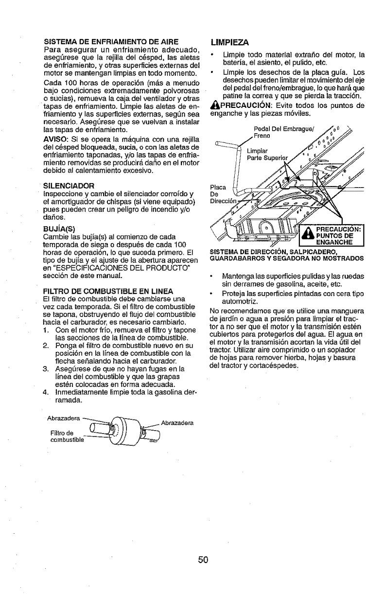
SISTEMA DE ENFRIAMIENTO DE AIRE
Para asegurar un enfriamiento adecuado,
aseg_rese que la rejilla del c_sped, las aletas
de enfdamiento, yotras superficiesexternas del
motor se mantengan Iimpias en todo momento.
Carla 100 horas de operaci6n (m_.s a menudo
bajo condiciones extremadamente polvorosas
o sUcias), remueva Ia caja del ventilador y otras
tapas de enfriamiento. Umpie las aletas de en-
friamiento y las superficies externas, seg0n sea
necesario. AsegOrese que se vuelvan a instalar
las tapas de enfriamiento.
AVISO: Si se opera la m_iquina con una rejilla
deI c@sped bloqueada, sucia, ocon las aletas de
enfriamiento taponadas, y/o Ias tapas de enfria-
miento removidas se producir& daSo en el motor
debido al calentamiento excesivo.
SILENCIADOR
fnspeccione y cambie el silenciador corrofdo y
el amortiguador de chispas (si viene equipado)
pues pueden croat un peligro de incendio y/o
dar_os.
BUJiA(S)
Cambie Ias bujia(s) aI comienzo de cada
temporada de siega odespu6s de cada 100
horas de operaci6n, Io qua suceda primero. El
tipo de bujia y el ajuste de la abertura aparecen
en "ESPECIFtCAC]ONES DEL PRODUCTO"
secciSn de este manual
FILTRO DE COMBUSTIBLE EN LINEA
El filtro de combustible debe cambiarse una
vez cada temporada. Si el filtro de combustible
se tapona, obstruyendo el flujo del combustible
hacia el carburador, es necesario cambiado,
t, Con el motor frio, remueva el filtroy tapone
tas secciones de ta Ifnea de combustible,
2, Ponga el fiftro de combustible nuevo en su
posici6n en la Ifnea de combustible con la
flecha seSalando hacia el carburador.
3. Aseg0rese de que no hayan fugas en la
Iinea del combustible y que las grapas
est_n colocadas en forma adecuada.
4. Inmediatamente limpietoda Ia gasolina der-
ramada.
Abrazadera ___ Abrazadera
combustible _.,_____/_
LIMPIEZA
•Limpie todo material extra_o del motor, [a
bateria, el asiento, el pulido, etc.
•Limpie los desechos de la placa guia. Los
desechos puedenlimitar el movimiento del eje
del pedal deI frenoiembrague, Ioque har& que
patina ia correa y que se pierda la traccibn.
_,LPREOAUG16N: Evite todos los puntos de
enganche y Ias piezas mSviJes.
Placa
De
Direcci6n
,_PREGAUC|_
\ ,B'iPUNTOS DE I
ENGANCHE I
S|STEMA DE DIRECCI6N, SALPICADERO,
GUARDABARROS Y SEGADORA NO MOSTRADOS
Mantenga Iassuperficies pulidas ytas ruedas
sin derrames de gasolina, aceite, etc.
Proteja las superficies pintadas con cera tipo
automotriz.
No recomendamos que se utilice una manguera
de jardin o agua a presi6n para limpiar el trac-
tor a no ser qua et motor y la transmisi6n est_n
cubiertos para protegerlos dei agua. El agua en
el motor y la transmisi6n acortan Ia vida 0til del
tractor. Utilizar aire comprimido o un soplador
de hojas para remover hierba, hojas y basura
del tractor y cortac@spedes:
5O
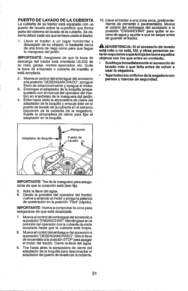
PUERTO DE LAVADO DE LA CUBIERTA
La cubierta de su tractor est.. equipada con un
puerto de Iavado sobre Easuperficie que forma
parte del sistema de Iavado de la cubierta, Se de-
berfa utilfzar carlavez que se haya usado el tractor.
1. Lleve el tractor a un lugar horizontal y
despejado de su c@sped, Io bastante cerca
de una boca de dego come para que Zlegue
la manguera del jardln.
IMPORTANTE: AsegSrese de que ]a boca de
descarga del tractor estd orientada LEJOS de
su casa, garaje, coches aparcados, etc. Quite
la boca de ensacado o cubierta de mantillo si
est& acoplada.
2, Mueva el control del embrague del accesorio
a fa posic[6n "DESENGANCHADO", ponga el
freno de estacionamiente y apague eJmotor,
3. Enrosque et adaptador de [a boqui]la (empa-
quetado con el manual del operador del trac-
tor) en el extreme de la manguera del jardln.
4, Eche hacia atr&s la abrazadera de cierre del
adaptador de la boquilla y empuje 6ste en el
puerto de lavado de la cubierta en el extreme
izquferdo de la cubierta de ta segadora.
Suelte Ia abrazadera de cierre para fijar el
adaptador en la boquilla.
t 0, Lleve el tractor auna zona seca, preferente-
mente de cemento o pavimentada. Mueva
el control del embrague del accesorio a Ia
posici6n "ENGANCHAR" para quitar el ex-
ceso de agua y ayudar a que se seque antes
de guardar el tractor.
,_ ADVERTENCIA: Si el accesorio de lavado
estd rote o no estd, Ud. y otras personas es-
tardn expuestos aquela hojaleslance aquellos
objetos con los que entre en contacto.
• Sustituya inmediatamente el accesorio de
lavado rote o que falta antes de volver a
usar la segadora.
• Tapetodos los orif_ciosde la segadora con
pernos y tuercas de seguridad.
Puerto de
IMPORTANTE: Tire de la manguera para asegu-
rarse de que ta conexi6n est& bien fija.
5, Abra Ia Ilave det agua,
6. Desde la posici6n del operador deI tractor,
vuelva a arrancar el motor y ponga la palanca
de aceleraci6n en la posicion "Fast" (r&pido),
IMPORTANTE: Vuelva a comprobar lazona para
asegurarse de que est& despejada.
7. Mueva el control delembrague del accesorio a
taposici6n"ENGANCHAR", Mant@ngaseen la
posici6ndel operadorcon Iacubierta de corte
acoplada hasta que }a cubierta est@limpia.
8. Mueva el controtdel embrague del accesorio a
la posici6n "DESENGANCHADO", Gire Ia Ilave
de encendido a la posici6n STOP para apagar
el motor del tractor. Cierre Ia !lave del agua.
9. Tire hacia atr&s la abrazadera de cierre del
adaptador de Ia boqui[la para desconectar el
adaptador deI puertode Iavado de la cubierta,
51
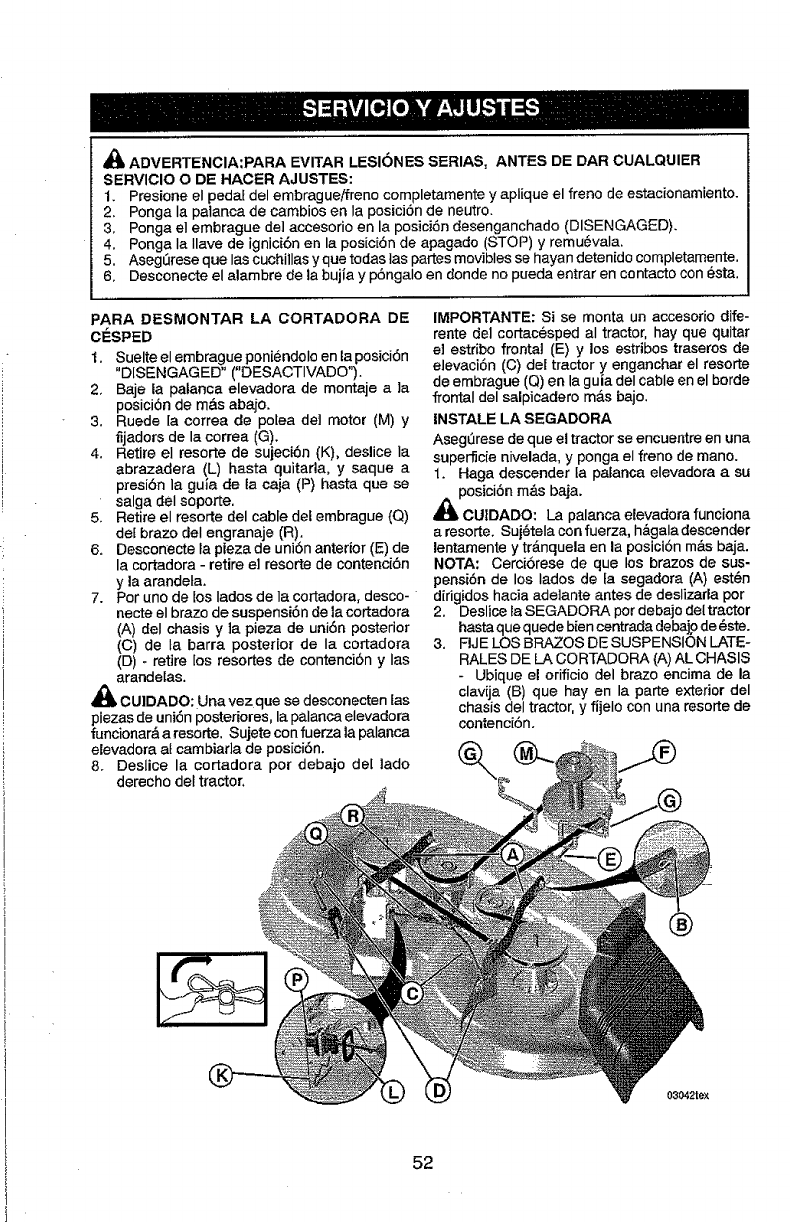
,_ ADVERTENCIA:PARA EVITAR LESIONES SERIAS, ANTES DE DAR CUALQUIER
SERVICIO O DE HACER AJUSTES:
1. Presione el pedal del embragueifreno completamente y aplique el freno de estacionamiento.
2. Ponga Ia palanca de cambios en la posici6n de neutro.
3. Ponga el embrague de] accesorio en la posici6n desenganchado (DISENGAGED).
4. Ponga la Ilave de ignici6n en la posici6n de apagado (STOP) y remu6vala.
5. AsegLirese que Ias cuchillas y que todas tas partes movibles se hayan detenido completamente.
6. Desconecte el alambre de la bujia y p6ngalo en donde no pueda entrar en contacto con _sta.
PARA DESMONTAR LA CORTADORA DE
ClaSPED
I. Suelte el embrague poniendoloen la posici6n
"DISENGAGED" ("DESACTIVADO").
2. Baje la patanca elevadora de montaje a la
posici6n de m&s abajo.
3. Ruede [a correa de potea del motor (M) y
fijadors de la correa (G).
4. Retire el resorte de sujeci6n (K), deslice la
abrazadera (L) hasta quitarla, y saque a
presi6n la guia de la caja (P) hasta que se
salga del soporte.
5. Retire el resorte del cable del embrague (Q)
det braze del engranaje (R).
6. Desconecte ta pieza de uni6n anterior (E) de
la cortadora - retire el resorte de contenci6n
y la arandeta.
7. Por uno de los lados de la cortadora, desco-
necte el brazo de suspensi6n de la cortadora
(A) deI chasis y ]a pieza de uni6n posterior
(C) de la barra posterior de la cortadora
(D) -retire los resortes de contenci6n y Ias
arandelas.
CUlDADO: Unavez que se desconecten tas
piezas de uni6n posteriores, la palanca elevadora
funcionar& a resorte. Sujete con fuerza la palanca
elevadora at cambiarla de pos[ci6n.
8. Deslice la cortadora por debajo del lado
derecho det tractor.
IMPORTANTE: Si se monta un accesorio dife-
rente del cortac_sped aI tractor, hay que quitar
el estdbo frontal (E) y los estribos traseros de
elevaci6n (C) del tractor y enganchar el resorte
de embrague (Q)en la guia deI cable en el horde
frontal del salpicadero m&s bajo.
INSTALE LA SEGADORA
Aseg_rese de que el tractor se encuentre en una
superficie nivelada, y ponga el freno de mano.
1. Haga descender ta palanca elevadora a su
_lPOSici6n m&s baja.
CUIDADO: La palanca elevadora funciona
aresorte. Suj6tela con fuerza, h&galadescender
lentamente y tr&nquela en la posici6n m&s baja.
NOTA: Cerci6rese de que los brazes de sus-
pensi6n de los lades de la segadora (A) est6n
dirigidos hacia ade]ante antes de deslizada por
2. Deslice la SEGADORA pot debajo del tractor
hastaque quede bien centrada debajode _ste.
3. FIJE LOS BRAZOS DE SUSPENSION LATE-
RALES DE LA CORTADORA (A) AL CHASIS
- Ubique el orificio del braze encima de la
clavija (B) que hay en la parte exterior del
chasis del tractor, y fijelo con una resorte de
contenci6n.
®
03042rex
52
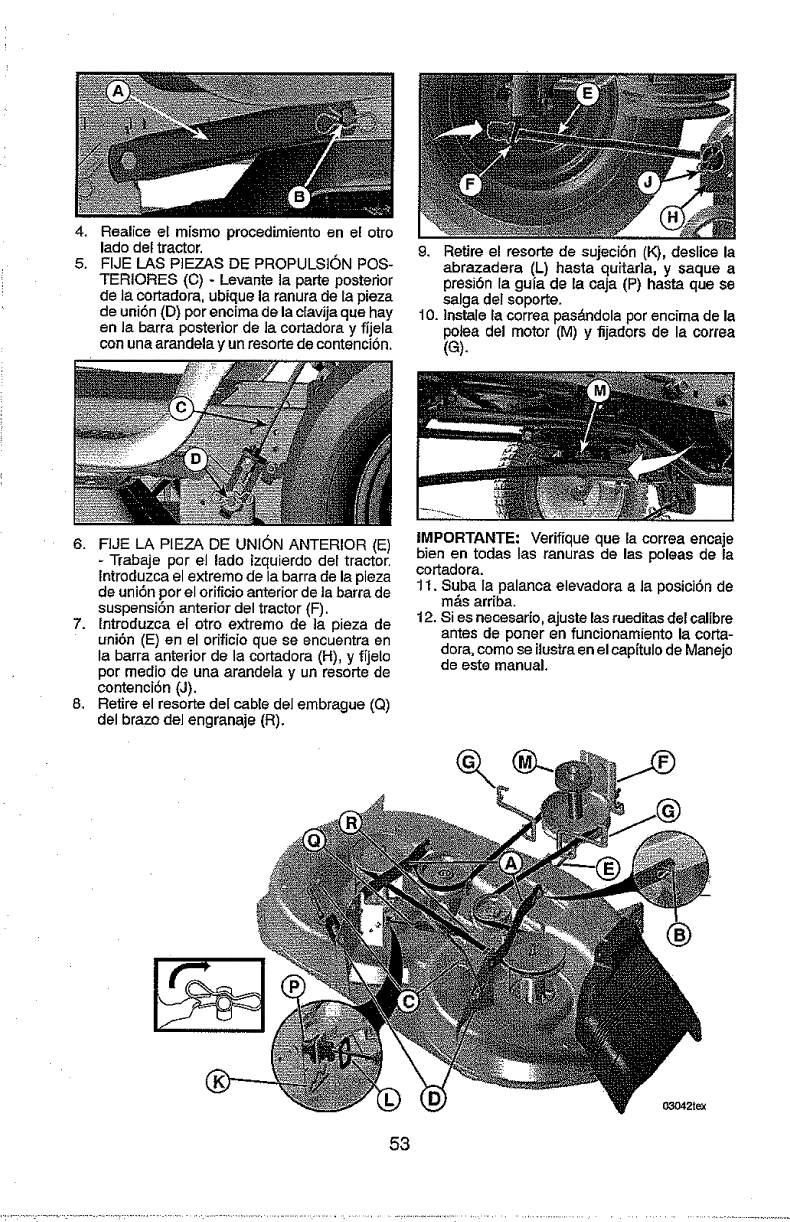
4,
5.
Realice el mismo procedimiento en el otro
lado clef tractor.
FIJE LAS P]EZAS DE PROPULS]0N POS-
TERIORES ((3) - Levante la parte posterior
de la cortadora, ubique la ranura de ta pieza
de uni6n (13)por encima de la c[avija que hay
en la barra posterior de la cortadora y fijela
con una arandela y un resorte de contenciSn.
9. Retire el resorte de sujeciSn (K), deslice la
abrazadera (L) hasta quitar]a, y saque a
presi6n la gufa de la caja (P) hasta que se
salga deI soporte.
10. tnstale la correa pas_ndola por encima de la
potea del motor (M) y fijaffors de la correa
(G).
6. FIJE LA PIEZA DE UNION ANTERIOR (E)
- Trabaje por el lado izquierdo del tractor.
lntroduzca el extrerno de Ia barra de la pieza
de uni6n por el orificio anterior de la barra de
suspensi6n anterior del tractor (F).
7. Introduzca el otro extremo de ]a pieza de
uni6n (E) en el orificio que se encuentra en
Ia barra anterior de la cortadora (H), y fijelo
por medio de una arandela y un resor_e de
contenci6n (J).
8. Retire el resorte del cable del embrague (Q)
del brazo del engranaje (R).
IMPORTANTE" Verifique que la correa encaje
bien en todas Ias ranuras de las poleas de la
cortadora.
1t. Suba la palanca elevadora a la posici6n de
m_,sarriba.
12. Si es necesario, ajuste las rueditas del calibre
antes de porter en funoionamiento la corta-
dora, como se itustra en el cap(tulo de Manejo
de este manual.
53
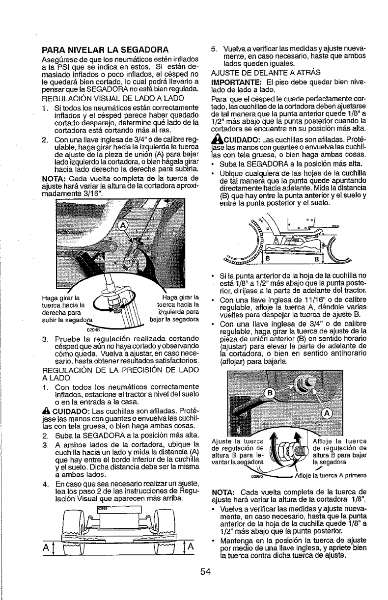
PARA NIVELAR LA SEGADORA
Asegt3rese de que Ios neum_ticos est@ninflados
a la PSI que se indica en estos. Si est,_n de-
masiado inflados o poco inflados, el c_sped no
le quedar& bien cortado, Io cual podr& Ilevarlo a
pensar que la SEGADORA no est& bien regulada.
REGULACION VISUAL DE LADO A LADO
I. Si todos los neum_.ticos est&n correctamente
inflados y eI c@sped parece haber quedado
cortado desparejo, determine qu_ ]ado de la
cortadora est& cortando m&s at ras.
2. Con una Ilave inglesa de 3/4" o de calibre reg-
ulable, haga girar hacia Ia izquierda la tuerca
de ajuste de la pieza de uniSn (A) para bajar
lado izquierdo ]a cortadora, o bien h&gala girar
hacia Iado derecho Ia derecha para subirla.
NOTA: Cada vuelta completa de ]a tuerca de
a|uste har& variar ia altura de la cortadora aproxio
madamente 3/16".
Haga girar la Haga girar Ia
tuerca hacia la tuerca hacia Ia
derecha para izquierda para
subir la segadora bajar la segadora
3. Pruebe la regulaci6n realizada cortando
c(_spedq ue aSn no haya cortado yobservando
c6mo queda. Vue]va a ajustar, en caso nece-
sario, hasta obtener resultados satisfactorios.
REGULACtON DE LA PRECISION DE LADO
A LADO
1. Con todos los neumAticos correctamente
inflados, estacione eI tractor a nivel del suelo
oen la entrada a ]a casa.
CUIDADO: Las cuchillas son afiladas. Prot_-
jase las manos con guantes o envuelva las cuchil-
Ias con tela gruesa, o bien haga ambas cosas.
2. Suba la SEGADORA a Ia posiciSn m&s alta.
3. A ambos lados de Ia cortadora, ubique la
cuchilla hacia un lado y mida Ia distancia (A)
que hay entre eI borde inferiorde Ia cuchilla
yel suelo. Dicha distancia debe ser Ia misma
a ambos lados.
4. En caso que sea necesario realizarun ajuste,
lea los paso 2 de las instrucciones de Regu-
]aciSn Visual que aparecen m&s arriba.
'
5. Vuelva a verificar las medidas y ajuste nueva-
mente, en caso necesario, hasta que ambos
Iados queden iguales.
AJUSTE DE DELANTE A ATP_S
IMPORTANTE: El piso debe quedar bien nive-
lado de lado a lado.
Para que el c_sped [equede perfectamente cot-
tado, las cuchillas de la cortadora deben ajustarse
de tal manera que Ia punta anterior quede 1/8" a
1/2" m&s abajo que la punta posterior cuando la
cortadora se encuentre en su posioibn m_.salta.
_t_CUIDADO: Las cuchillas son afiladas. Prot@-
jase las manos con guantes o envuelva lascuchil-
las con teta gruesa, o bien haga ambas cosas.
• Suba la SEGADORA a la posici6n m&s alta.
• Ubique cualquiera de las hojas de la cuehilla
de ta_manera que la punta quede apuntando
directamente hacia adelante. Mida la distancia
(B) que hay entre la punta anterior y el suelo y
entre Ia punta posterior y eI suelo.
•Si la punta anterior de la hoja de la cuchifla no
est& 1/8" a 1/2" m&s abajo que Ia puntaposte-
rior, dir{jase a ta parte de adelante del tractor.
o Con una ]tave inglesa de 11/16" o de calibre
regulable, afloje Ia tuerca A, d_ndole varias
vueltas para despejar Ia tuerca de ajuste B.
• Con una Ilave inglesa de 3/4" o de calibre
regulable, haga girar ia tuerca de ajuste de ta
pieza de uni6n anterior (B) en sentido horario
(ajustar) para elevar la parte de adelante de
la cortadora, o bien en sentido antihorado
(aflojar) pare bajarla.
Ajuste Ia tuerca Af]oje la tuerca
de regulaciSn de de regulaci6n de
alt_ra B para le- altura B para bajar
Ia segadora
J
je la tuerca A primero
NOTA: Carla vuelta completa de ]a tuerca de
ajuste har& variar la altura de la cortadora 1/8".
- Vuelva averificar [as medidas y ajuste nueva-
mente en caso necesario, hasta que la punta
anterior de Ia hoja de Ia cuchiI[a quede 1t8 a
t/2" m&s abajo que ta punta posterior.
•Mantenga en Ia posiciSn la tuerca de ajuste
pot rnedio de una Ilave inglesa, y apriete bien
la tuerca contra dicha tuerca de ajuste.
54
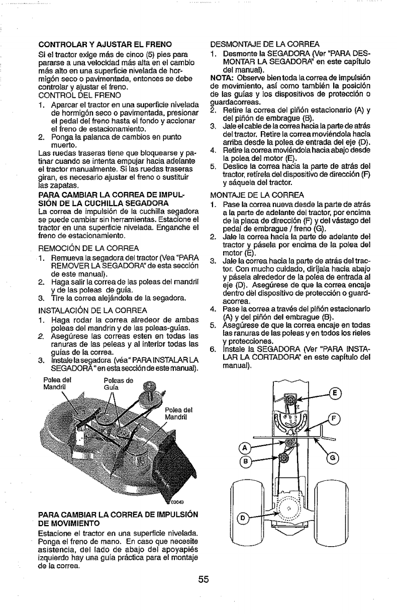
CONTROLAR Y AJUSTAR EL FRENO
Si el tractor exige m_.s de cinco (5) pies para
pararse a una velocidad m__salta en el cambio
mds alto en una superficie nivelada de hor-
mig6n seco o pavimentada, entonces se debe
contro]ar y ajustar el freno.
CONTROL DEL FRENO
I. Aparcar el tractor en una superfJcienivelada
de hormig6n seco o pavimentada, presionar
el pedal det freno hasta el fondo y accionar
el freno de estacionamiento.
2. Ponga la palanca de cambios en punto
muerto.
Las ruedas traseras tiene que bloquearse y pa-
tinar cuando se intenta empuiar hacia adelante
el tractor manualmente, Si Ias ruedas traseras
giran, es necesario ajustar el freno o sustituir
las zapatas,
PARA CAMBIAR LA CORREA DE IMPUL-
S|ON DE LA CUCHILLA SEGADORA
La correa de impulsi6n de Ia cuchitla segadora
se puede cambiar sin herramientas. Estacione el
tractor en una superficie nivelada. Enganche el
freno de estacionamiento.
REMOCION DE LA CORREA
1. Remueva la segadora del tractor (Vea "PARA
REMOVER LA SEGADORA_'de esta secci6n
de este manual).
2. Haga salir la correa de Ias poleas del mandril
y de las poleas de guta.
3. Tire {a correa atej_.ndola de Ia segadora.
INSTALACION DE LA CORREA
1. Haga rodar Ia correa alredeor de ambas
poleas del mandrin y de las poleas-guias.
2. Aseg_rese las correas esten en todas fas
ranuras de {as peleas y al interior todas las
guias de la correa.
3. tnstale la segadora (v_a" PARA INSTALAR LA
SEGADORA"en estasecci6n de este manual).
Poleade[ Poleasde
Mandril Gu{a
DESMONTAJE DE LA CORREA
1. Desmonte la SEGADORA (Ver "PAPA DES-
MONTAR LA SEGADORA" en este capttulo
del manual).
NOTA: Observe bientodalacorreade impuisi6n
de movimiento, asi como tambi_n la posici6n
de las gu_as y los dispositivos de protecci6n o
guardacorreas.
2, Retire ia correa deI pi56n estacionario (A) y
del p[56n de embrague (B).
3. Jale elcable dela correahacia la partede atrds
deltractor. Retire la correamovi@ndotahacia
arriba desde la polea de entrada del eje (D).
4. Retirelacorrea movi6ndolahaciaabajodesde
Ia po[ea del motor (E).
5. Deslice la correa hacia la parte de atr&s de]
tractor,ret|rela deldispositivode direcci6n (F_
y s&quela del tractor.
MONTAJE DE LA CORREA
1. Pase la correa nueva desde la parte de atr&s
ala parte de adelante deltractor,por encima
de Ia placa de direcci6n (F) ydel vdstago del
pedal de embrague ]freno (G).
2. Jale Ia correa hacia la parte de adelante de]
tractor y p&sela por encima de la polea del
motor (E).
3. Jale la correa hacia ta parte de atr_.sdel trac-
tor. Con mucho cuidado, dirijala hacia abajo
y p_tselaalrededor de la po[ea de entrada al
eje (D). Aseg_rese de que la correa encaje
dentro del dispositivode proteccibno guard-
acorrea,
4. Pase lacorrea a trav_s del pifi6n estacionario
(A) y deI pi56n del embrague (B).
5. Aseg_rese de que la correa encaje en todas
las ranuras de las poleas yen todos los rieles
y protecciones.
6. Instale la SEGADORA (Ver "PARA INSTA-
LAR LA CORTADORA" en este eapltuto del
manual).
=olea del
Manddl
PARA CAMBIAR LA CORREA DE IMPULSION
DE MOVlMIENTO
Estacione el tractor en una superficie nivelada.
Ponga el frano de mano. En caso que necesite
asistencia, deI lado de abajo del apoyapi_s
izquierdohay una guia pr&cticapara el rnontaje
de la correa,
55
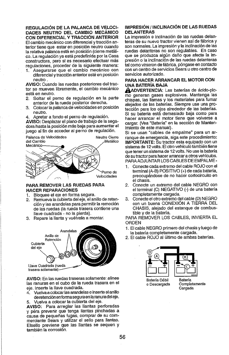
REGULAC!ON DE LA PALANCA DE VELOCI-
DADES NEUTRO DEL CAMB|O MECANICO
CON DIFERENCIAL Y TRACCI(_N ANTERIOR
El cambio mec&nico con diferencial y tracci6n an-
terior tiene que estar en posici6n neutro cuando
la relativa palanca est& en posici6n (cierre met&li-
ce+La regulaci6n ya est& predefinida per la Casa
constructora, pete si es necesario efectuar m_s
regulaciones, preceder de Ia siguiente manera:
t. Asegurarse que e] cambio mec&nico con
diferenciaI y tracci6n anterior est@en posici6n
neutro.
AVlSO: Cuando Ias ruedas posteriores del trac-
tor se mueven libremente, el cambio mec&nico
est& en neutro+
2+ Soltar el perno de regulaci6n en la parte
anterior de la rueda posterior derecha.
3, Colocar la palanca de velocidades en posici6n
neutro,
4, Apretar a rondo el perno de regulaci6n.
AVISO: Desptazar el plane de trabajo de la segm
dora hasta la posici6n m&s baja para aumentar el
juego al fin de acceder al perno de regulaci6n.
Palancade Velocidades NeutroCierre
de] Cambio
PARA REMOVER LAS RUEDAS PARA
HACER REPARACIONES
1, Bloquee el eje en forma segura+
2. Remuevala cubiertadeIeje, e]ani]lo de reten-
ci6n yIas arandelas para permitirla remoci6n
de Ias ruedas {la rueda trasera contiene una
Ilave cuadrada +no la pierda).
3. Repare la Ilanta y vu_lvala a montar.
Arandelas
AniHo de
Retencibn
Cubierta
del eje
AVISO: En las ruedas traseras solamente: alinee
las ranuras en el cube de la rueda trasera en el
eje. tnserte la Ilave cuadrada,
4_ Vuelva a colocar las arandelase inserte elanillo
deretenci6n enforrnaseguraenla ranurade[eje,
5. Vuefva a colocar la cubierta del eje.
AVISO: Para arreglar Ias Ilantas perforadas
y p6ra prevenir que tenga Ilantas pinchadas a
causa de pequeSas fugas, comprar de su com-
merciante Sears y utilizar e] sello para ]_antas+
ElseUo previene que ]as Ilantas se sequen y
tambi_n ta corrosi6n+
56
IMPRESION /INCLINACION DE LAS RUEDAS
DELANTERAS
La impresi6neinctinaci6n de las ruedas delan-
teras de su nuevo tractorvienen asl de f&bricay
son normales+ Laimpresi6n y la inclinaci6nde Ias
ruedas detanteras no son regulables. En case
que se produzca algSn daSo que afecte la im-
presi6n o ]a inclinaci6n de las ruedas delanteras
tal come vinieron de f_.brica, p6ngase en contacto
con un centre de servicios Sears u etro centre de
servicios autorizado+
PARA HACER ARRANCAR EL MOTOR CON
UNA BATERiA BAJA
_DVERTENCIA: Las baterias de _,cido-pto-
me generan gases explosives, Mantenga Ias
chispas, [as llamas y los materiates para fumar
alejados de las baterias+ Siempre use una pro+
tecci6n para los o_os alrededor de Ias batedas.
Si su bateria esta demasiado baja come para
hacer arrancar el motor tiene que volverse a
cargar. (Vea "Bateria" en la secci6n de Manten+
imiento de este manual).
Si se usan "cables de empalme" para un ar-
ranque de emergencia, siga este procedimiento:
IMPORTANTE: Su tractor esta equipado con un
sistema de 12 volts. El otro vehiculo tambi@ntiene
que tenet un sistema de 12 volts. No use Ia bateria
de su tractor para hacar arrancar a otros vehicu[os.
PARAADJUNTAR LOS CABLES DE EMPALME-
1. Conecte cada extreme del cable ROJO con el
terminal (A-B) POSIT1VO (+) de cada bateria,
preocup&ndese de no hacer cortocircuito en
el chasis.
2. Conecte un extreme del cable NEGRO con
el terminal (C) NEGATIVe (+)de una bateria
completamente cargada+
3. Conecte el otro extreme det cable (D) NEGRO
con un buena CONEXION A TERRA DEL
CHASIS, alejado del estanque de combus-
tible y de Ia bateria,
PARA REMOVER LOS CABLES, INVIERTA EL
ORDEN
1. El cable NEGRO primero dei chasis y luegode
la bateda completamente cargada.
2+El cable ROJO aI _ltimo de arnbas baterias+
BateHaO_bil Bateria
oDescargada Completamente
Cargada
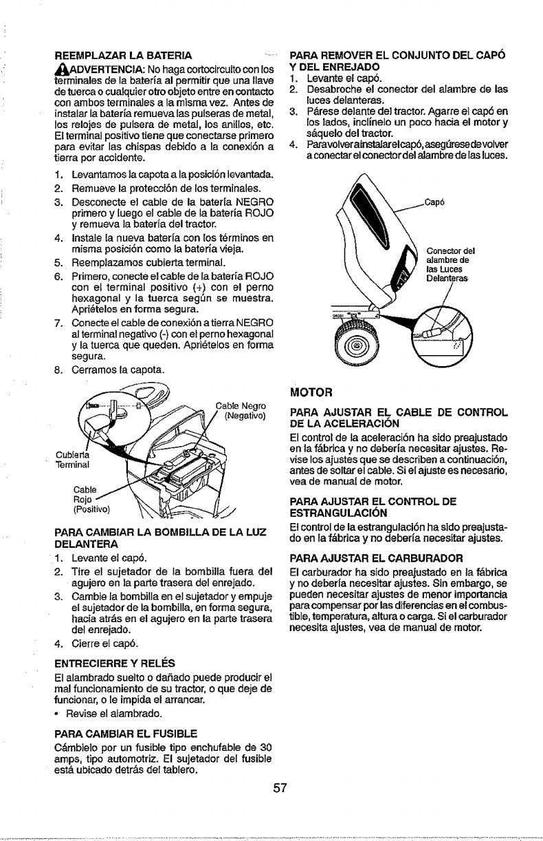
REEMPLAZAR LA BATERIA .....
_,DVERTENCIA: No haga cortocircuitocon los
terminales de Ia baterta al permitir que una llave
de tuercao cualquierottoobjeto entre en contacto
con ambos terminales a la misma vez. Antes de
instalar la baterfa remueva las pulserasde metal,
los relojes de pulsera de metal, los ani[Ios, etc.
El terminal positivetiene que conectarseprimero
para evitar las chispas debido a ta ccnexi6n a
tierra peraccidente.
I. Levantamosla capota ala posici6nlevantada.
2. Remueve la protecci6n de los terminales.
3. Desconecte el cable de la baterfa NEGRO
primero y tuego el cable de Ia bateria ROJO
y remueva la bateria del tractor.
4. Instale ta nueva bateHa con _ost@rminos en
misma posici6n come fa bateria vieja.
5. Reemplazamos cubierta terminal.
6. Primero, conecte el cable de la bater_a ROJO
con et terminal positive (+) con el perno
hexagonal y la tuerca segSn se muestra,
Apri_telos en forma segura.
7. Conecte el cable de conexi6n a tierra NEGRO
aI terminal negative (-) con et perno hexagonal
y ta tuerca que queden. Apri_telos en forma
segura.
8. Cerramosla capota.
__ _ CableNegro
Terminal
Cable /\ _ _..J/
PARA CAMBIAR LA BOMBILLA DE LA LUZ
DELANTERA
1. Levante el cap6.
2. Tire el sujetador de Ia bombilla fuera del
agujero en la parte trasera deI enrejado.
3. Gamble la bombilla en el sujetador y empuje
el sujetador de la bombilla,en forma segura,
hacia atr&sen el agujero en la parte trasera
deI enrejado.
4. Cierre el cap6.
ENTRECIERRE Y RELI_S
El alambrado sueIto o daSado puede producir el
real funcionamientode su tractor, o que deje de
funcionar,o le impida el arrancar.
• Revise el atambrado.
PARA CAMBIAR EL FUSIBLE
Cdmbielo per un fusible tipo enchufable de 30
amps, tipo automotriz. El sujetador del fusible
est_ ubicado detr_s del tablero.
57
PAR& REMOVER EL CONJUNTO DEL CAPe
Y DEL ENREJADO
1. Levante el cap6.
2. Desabroche el conector del alambre de las
luces delanteras.
3. P&rese de]ante del tractor. Agarre el cap6 en
[os lades, incllnelo un poco hacia el motor y
s&quelo del tractor.
4. ParavolverainstaJarelcap6,aseg_resede volver
a conectar el conectordel aJambrede las luces.
Conector del
alambre de
lasLuces
Delanteras
MOTOR
PARA AJUSTAR EL CABLE DE CONTROL
DE LA ACELERACI6N
El control de la aceleraci6n ha side preajustado
en la f,_bricay no deberla necesitar ajustes. Re-
vise losajustes que se describenacontJnuaci6n,
antes de soltarel cable. Si el ajustees necesario,
yea de manual de motor.
PAR& AJUSTAR EL CONTROL DE
ESTRANGULACION
Etcontrolde la estrangulaci6n ha side preajusta-
do en fa f&brica y no deberia necesitar ajustes.
PARA AJUSTAR EL CARBURADOR
El carburador ha side preajustado en la f&brica
y no deberfa necesitar ajustes. Sin embargo, se
pueden necesitar ajustes de menor importancia
papacompensarper las diferenciasenel combus-
tible,temperatura,alturaocarga. SI el carburador
necesita ajustes, yea de manual de motor.
lnmediatamente prepare su tractor para el alma-
eenamiento al final de la temporada o si el tractor
no se va a usar por 30 dias o m_.s.
_I_DVERTENCIA: Nunca almacene el tractor
con gaso[ina en el estanque dentro de un edificio
en donde los gases pueden alcanzar una llama
expuesta o una chispa. Permita que el motor se
enfrfe antes de atmacenarlo en cualquier recinto
privado.
TRACTOR
Cuando el tractor se va a almacenar por cierto
periodo de tiempo, limpiela cuidadosamente,
quite toda la mugre, la grasa, las hojas, etc.
Gu&rdela en una Area limpia y seca.
1. Limpie todo el tractor (yea "LIMPIEZ_' en la
secci6n de Mantenimiento en este manual).
2. ]nspeccioney cambie ]ascorreas, si es nece-
sario (vea Ias instrucciones para e! cambio de
Iascorreas en Ia secci6n de Servicio y Ajustes
de este manual).
3. Lubriquelo, segLin se muestra en ta secciSn
de Mantenimiento de este manual.
4. Asegt3rese que todas las tuercas, los pemos y
lostornillos est6n sujetados en forma segura.
Inspeccione Ias partes movibles para verificar
si hay da_o, rotura o desgaste. C&mbielas si
es necesario.
5. Retoque todas superficies pintadas oxidadas
opicadas; aplique lija antes de pintar.
BATERIA
• Cargue ]a bater_a completamente antes de
guardarla.
•Despu_s de cierto perfodode tiempo en alma-
cenamiento, la bateria puede necesitar volver
a cargarse.
• Para ayudar a evitar Ia corrosi6n y Ias fugas
de potencia durante largos per_odosde aima-
cenamiento, se deben desconectar los cables
de ta bateria y se debe Iimpiar cuidadosamen°
te (vea "PARA LIMPIAR LA BATER_A Y LOS
TERMINALES" an la secci6n de Mantenimien-
tode este manual).
.Despu_s de fimpiada, deje los cables desco-
nectados y p6ngalos en donde no puedan
entrar en contacto con los terminales de la
bater|a.
- Si se remueve la bateria del tractor para el
almacenamiento, no la guarde directamente
sobre concrete o sobre superficies h_medas.
o
MOTOR
SISTEMA DE COMBUSTIBLE
IMPORTANTE: Es importantevitar que se for-
man depositos de goma en partes fundamen-
tales deI sistema de combus-tible tales como el
carburador, et filtro del combustible, la manguera
del combustibles mezclados con alcohol (cono-
eido como gasohol o que tienen etanol o meta-
nol) pueden atraer humedad, Io que conduce a
Ia separaci6n y a la formaci6n de acudos du-
rante elalmacenamiento. La gasolina acidica
puede daSar el sistema de combustible de un
motor durante et periodo de almacenamiento.
• Vaciar e] dep6sito del carburante poniendo en
marcha el motor y dej&ndolo funcionar basra que
el carburante termine et carburador est,6vacfo.
• Nunca uselosproductosparalimpieza delcarbu-
rador o del motor en el estanque de combustible
pues se pueden producir daSos permanentes.
•Use combustible nuevo la pr6ximatemporada,
AVlSO: El estabilizador de combustible es una
alternativa aceptable para reducir a un mTnimo
la formaci6n de dep6sitos de goma en el com-
bustible durante el periodo de almacenamiento.
Agregue estabilizador a la gasolina en eJ es-
tanque de combustible o en el envase para el
almacenamiento. Siempre siga la proporoi6n de
mezcla que se encuentra en el envase de] estabi-
[izador.Haga funcionar el motor pot Io menos t0
minutos despu_s de agregar el estabilizador, para
permitir que @steHegueaI carburador.Novaciar la
gasolina delestanque degasolinayel carburador
si se esta usando estabilizador de combustible.
ACEITE DEL MOTOR
Drene el aceite (con el motor caliente) yc_,mbie]o
con aceite de motor Iimpio. (Vea "MOTOR" en
la secci6n de Mantenimiento"de este manual.)
CILINDRO(S)
l. Remueva la(s) bujia(s).
2. Vacie una onza de aceite a tray, s del
agujero(s) de la bujia en el cjlindro(s).
3. Gire la llave de ignici6na la posici6nde "Ar-
ranque" (Start), por unos cuantos segundos
para distdbuir el aceite.
4. Cambie por bujia(s) nueva(s).
OTROS
. No guarde ta gasolina de unatemporada alaolra,
•Cambie e] envase de la gasolina si se emp-
ieza a oxidar, La oxidaci6n yio fa mugre en su
gasolina producirAn problemas.
Si es posible, guarde su unidad en un recinto
cerrado y cSbrala para protegerla contra el
polvo y ta mugre.
Cubra su unidad con un forro protector ad-
ecuado que no retenga ta humedad. No use
pl&stico.El pl&stico no puede respirar, lo que
permite la formaci6n de condensaci6n, [o que
producir_, la oxidaci6n de su unidad,
IMPORTANTE: Nunca cubra el tractor mientras et
motory lasareasde escapetodavia estancalientes.
58
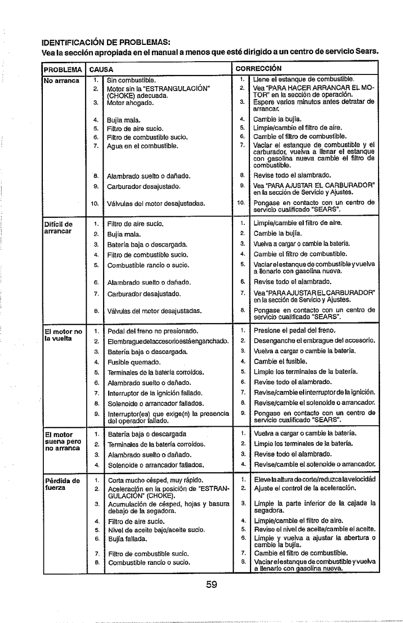
IDENTIFICACION DE PROBLEMAS:
Vea la secci6n apropiada en el manual a menos que est_ dirigido a un centre de servicio Sears.
PROBLEMA
NO armnca
Difici| de
errancar
,_,,,
El motor no
fa vuelta
El motor
suena pete
no erranea
P_rdida de
'uerza
CAUSA
_'"i"' Sin combustible."'
2, Motor sin la"ESTRANGULACION"
(CHOKE) adecuads.
3, Motor &hog&do.
4, Bujia male.
5. Fi[tro de aim sucio.
6, Filtro de combustible sucio.
7. Ague en el combustible,
e. Alambrado suelto o daEado.
9. Carburador desajustedo,
lO, V&Ivulas deI motor desajustadas,
l, Filtro de'airs sucio.
2, Bujia male,
3. Bateria baja odescergade.
4. Filtro de combustible sucio,
5. Combustible rancio o sucio.
6. Alambrade suelto odahado.
7. Carburader desajustado.
8. V_vulas del motor des&just&des.
,, , ,,,,,, .....
1. Pedal del freno no presionedo,
2, Elembraguede]eccesorioest&enganchado.
3. Baterla baja 0 descargada,
4, Fusible quemado.
5. Terminales de la batetia corroidos.
6. Alambrado suelto 0 deE&do,
7. Interrupter de Ia ignici6nfell&do,
s. Solenoide 0 arrancador fallados.
9. tnterruptor(es) que exige(n) [a presencia
del operador falIado,
1. Baterla beja o descargada
2. Terminales de la beteda csrroidos,
3. Alambrado suelto 0 daEado,
4, Solenoide o&franc&dot fell&dos.
1. Corta mucho c_isped,muy r&pido,
2" Aceleracien en Ia posicien de "ESTRAN*
GULACION _(CHOKE),
3, Acumulaci6n de c_sped, hojas y besura
deba]o de la segadom,
4. Filtro de airs sucio,
s. Nivel de aceite bajo/eceite sucio.
s. Bujfa fall&de.
7. Filtm de combustible sucio,
s. Combustible mncio o sucio,
CORRECC|6N
1. Llene el estanque de combustfble.
2, Vea"PAPA HACER ARRANCAR EL MO-
TOR" en Ia seCci6n de opemci6n.
3. Espere redes minutes antes detratar de
err&near.
4. Cambie ta bujia.
5. Limpie/cambie el filtro de aire,
6. Cambie eIl_ltm de combustible,
7. Vaciar el estanque de combustibte y el
carburador, vueiva a Ilenar el estanque
con gasolina nueva cambie el filtro de
combustible.
8. Revise todo e] alambrado.
e. Vea"PARA AJUSTAR EL CARBURADOR"
en la secci6o de Servicio y Ajustes.
10. Pone&so en contacts con un centre de
serv_ciocuaUficado"SEARS".
4. Limpieicambie el filtro de aim.
2. Cambie Ia bujia,
3. Vuslva acargar o cambisIa bsteria,
4. Cambie et filtro de combustible.
5. Vaciar elestanque de combustible yvuelve
a ltenarlo con gasoline nueva,
6, Revise todo et alambrado.
7. Vea "PARA AJUSTAR ELCARBURADOR"
en lasecci6n de Serviciey Ajustes,
8. Pongase en contacts con un centre de
servicio cualificado "SEARS".
, ,,,,,,,
1. Presione el pedat del freno,
2, Desengancheelembrague del accesorio.
3, Vuelva a cargar o cambie Is bateria.
4. Cambie el fusible,
s. Limpie los terminales de ]a baterie.
6. Revise redo el alambrado,
7. Revisejcambieelintermptordelaignici6n.
8. Revise/eatable eLsolenoide 0&franc&dot.
9. Pon_ase en contacts con un centre de
senJ_ciocualificado "SEARS",
, ,,,,,
1. Vuelva acargar o cambie la bsteda,
2. Umpie losterminales de ]a baterfa.
3, Revise redo el alambrado,
4. Revise/cambie e] solenoids oarrancador.
,,,,,
1, Elevela altu m de corte/roduzcalavelocid_d
2. Ajuste el controlde {a aceleraci6n.
3. [Jmpie la parte inferior de la csjade Ia
segadora,
4. Limpie/cambie el filtro de airs,
5, Revise el nivelde aceite/cambie el aceite.
6. Limpie y vuelva aajustar Ia ebertura o
cambie Ia bujia,
7. Gamble el filtrode combustible,
8. Vaciarelestanquedecombustib]eyvuelva
alien&rio con _lasolina nueva.
59
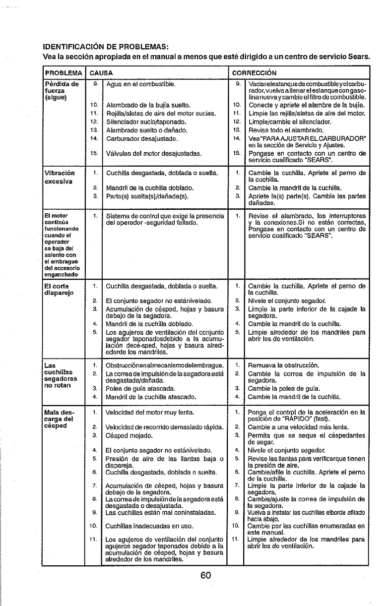
IDENTIFICACION DE PROBLEMAS:
Vea la secciSn apropiada en el manual a manes que est_ dirigido aun centre de servicio Sears.
PROBLEMA CAUSA CORRECCION
P_rdida de e_ Ague en el Combustible. 9. VaciareIestanquedecombusiibleyelcarbu-
fuerza rador, vuetva allenar elestanque congaso-
(sigue) lina nueva y cambie elfiltro de combustible.
1o. 1o. Conecte yapriete el atambre de Ia bujla.
11. 11, Limpie las rejilla/aletas de aire del motor.
12. 12. Limpie/cambie eI silenciador.
13. 13. Revise todo el aiambrado,
14, 14. Yea "PARA AJUSTAR EL CARBU RADAR"
en [a secci6n de Servicio yAjustes.
15, VaIvulas del motor desajusiadas. 15. Pongase en contacto con un centre de
servicio cuaiificado "SEARS",
VIbracibn
excesiva
El motor
contia,3a
funcionando
cuando el
operador
se baja del
astento con
et embrague
del accesorio
onganchado
El carte
disparejo
Lee
cuchitlas
segadoraa
no retort
Alambrado de la buj[a suelto,
Rejillaia{etas de aire del motor sucias.
Silenciado r suciottaponado,
Alambrado suelto 0dafiado.
Carburador desajustada.
1. CuchilIa desgastada, dobEada osuelta, 1. Cambie Ia cuchil]a, Apdete el perno de
la cuchilla.
2. Mandril de la cuchilla doblado, 2. Cambie la manddl de Ia cuchilla.
3. Parte(s) sue[ta(s)idaSada(s). 3. Apriete [a(s) porte(s). Gamble las partes
daSadas,
1. Sistema de controlqua e×ige Ia presencia 1. Revise el alambrado, los interruptores
del operador-seguddad falIado, y Ia conexiones.Si no est&n correetas.
Pongase en contaoto con un centre de
servicio cualificado "SEARS".
11
2_
3,
4,
5.
Cuchilla desgastada, doblada osuelta.
El conjunto segader no estanivelado.
Acumulaci6n de c_sped, hojas y basura
debajo de la eegadora.
MandrElde Ia cuchilla doblado.
Los agujeros de ventilaciSn del cenjunto
segador taponadosdebido ala acumu-
laciSn dace%sped, hojas y basura alred-
edorde los mandriles,
ObstrucciSnenelmecanismodetembragae,
La correa de impulsiSn de la sagadora est_
desgastadaldaSada.
Polea de gu_a atascada.
Mandril de [a cuchilla atascada,
1. Oambie la cuchilla. Apriete el perno de
la cuchilIa.
2. Nivele el conjunto segador.
3. Limpie la porte inferior de la cajade la
segadora.
4. Cambie la mandri[ de la cuchilIa.
5. Limpie alrededor de los mandriles pate
abrir los de ventilaci_n.
1, Remueva la obstrucciSn.
2. Cambie la correa de impulsiSn de Ia
segadora,
3. Gambie la poIea de guia,
4. Cambie la mandril de Ia cuchilla.
Male des.
carga del
c_sped
1.
2_
3,
4,
5.
6.
7.
8.
9.
t0.
11.
Velocidad del motor muy [enta,
Ve]ocidad de recorrido demasiado r_pida.
C_sped mojado,
Ef eoniunto segador no est&nivelado,
PresiSn de aire de las llantas baja o
dispareja,
Cuchilla dasgastada, doblada o suelta.
AcumulasiSn de c_sped, hojas y basura
debajo de la segadora.
La correa de impulsiSnde la segadom est&
desgastada o desajustada.
I.as cuchiilas est&n mal coninstaladas,
Cuchi[las inadecuadas en usa,
Los agujeros de ventiIaci6n del conjunto
agujeros segador taponados debido a Ea
asumulasiSn de cSsped, hojas y basura
alrededor de los mandriles,
1. Ponga el contrpI de la aceleraci6n en la
posici6n de "RAPIDO" (fast),
2. Cambie auna velocidad mds Ienta.
3, Permita qua se seque el cespedantes
de sager.
4. Nivele el conjunto eegader,
5, Revise las Ilantas paraverificarquetienen
la presiSn de aire.
s, Cambie/afi]e ia cuchilla, Apdete el perno
de laouchilla,
7. Limpie la paste inferior de Ia cajade ta
segadora.
8. Cambie/ajuste ta correa de impulsiSn de
la segadora.
s. Vuelvaa instaIar las cuchillas elborde afilado
i hacia abajo,
"_o. Cambie par Ias cuchillas enumeradas en
este manual,
11. Limpie aIrededor de los mandriles para
abrir tos de ventilaciSn.
6O
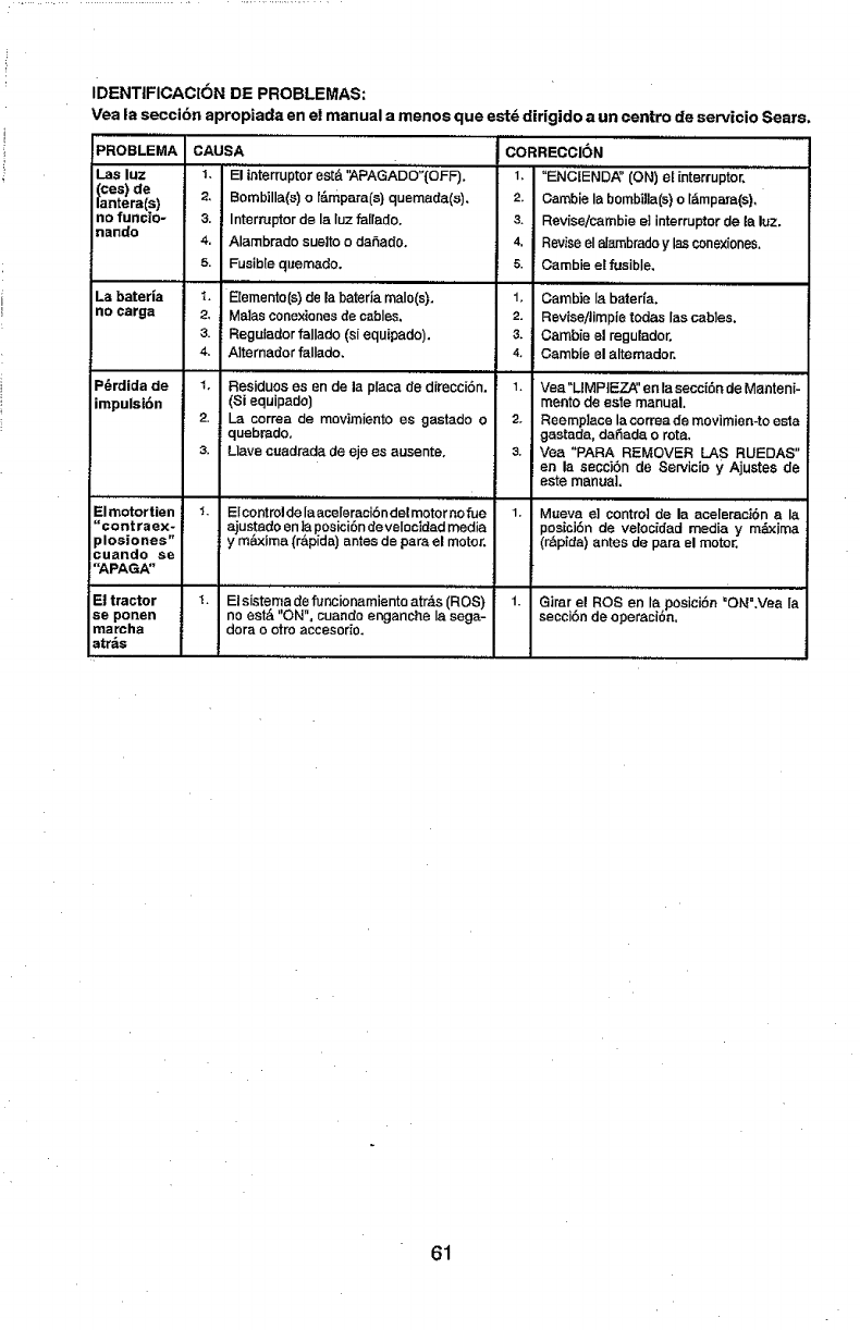
IDENTtFICACION DE PROBLEMAS:
Vea la seccibn apropiada en el manual a manes qua estd dirigido a un centre de servicio Sears,
............. ,,,,,,,, ,
PROBLEMA
Las luz
CeS) de
ntera(s}
no fun¢_o-
nando
La baterla
no earga
P_rdida de
impulsi6n
ElmotorUen
"contraex-
plosiones"
cuando se
"APAGA"
EJtractor
se ponen
marcha
atr_,s
CAUSA
El inierruptor
1. est& '_.PAGADO";(OFF),
2. Bombilla(s) o t6mpara(s) quemada(s),
3. Intem,_ptorde la Iuz falradoo
4. Alambrado suelto oda_ado,
5. Fusible quemado,
!,,,,,,,................
t. E[emento(s)de la bateria malo(s),
2, Males conexianesde cablss.
3. Regulador falIado (si equipado),
4. Altemador fallado,
,,, ,,, ,
1. Residues es en de laplaca de direcci6n.
(Si equipado)
2. La correa de movimiento es gastado o
quebradoo
3. Llave cuadrada de eje es ausente.
1° E[controlde la aceleraci6ndel motor norue
ajustado en la posicibnde velocidad media
y m&xima (r&p[da) antes de pare el motor.
CORRECCI6N
1. "ENCtE'N'DA" (ON) el interrupter, .............
2. Gamble la bombilla(s)o l_,mpara(s),
3. Rev[se/cambie el interrupter de la luz,
4. Reviseel aJ_mbradoy lasconexiones.
5. Carnbie el fusible,
1, Cambie Ia baterfa.
2. Revise/timpte redes las cables.
3. Camb[e el regulador,
4, Gamble el altemador,
1. Vea"LIMPIEZ_' en la secci6n de Manteni-
mento de eats manual.
2, Reemplace la correa de movimien-to esta
gastada, da_ada orata,
3. Vea "PARA REMOVER LA S RUEDAS"
en la secci6n de Servicie yAjustes de
este manual,
1. Mueva e] control de la aceleraci6n ala
posicJ6n de vetoc[dad medea y m_xima
(r6pida) antes de p_ra el motor,
El sistema de funcionamiento atr,_s(ROS)
no eat& "ON", cuanda enganche Ia saga-
dora o otro accesorio.
..... ,,, ,,
1. Girar el ROSen la posioi6n "ON".Vea Ia
secci6n de operaclon,
61

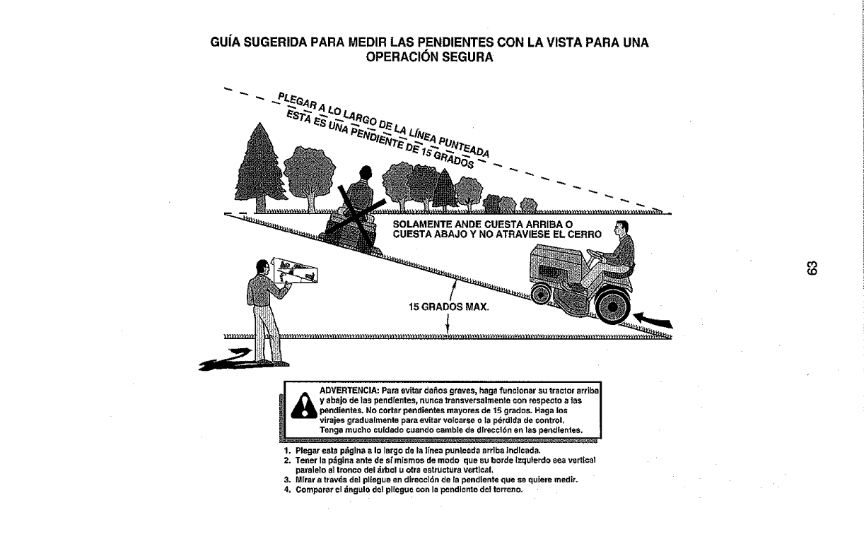
GUiASUGERIDAPARAMEDIRLASPENDIENTESCONLAVISTAPARAUNA
OPERACIONSEGURA
O3
(.O
ADVERTENCIA: Para evit_r daPios graves, haga funcionar su tractor arriba I
y abajo de las pendlentes, nunca transversalmente con respecto a1as I
pendlentes. No cortar pendientes mayores de 15 grados. Haga los I
virajes gradualmente para evitar volcarse o la pdrdlda de control, !
Tenga mucho cu[dado ¢uando camb]e de dlrecc16n en las pendientes,
1. Plegar esta pdglna aIo largo de _a]i'nea punteada arrlba |ndlcada.
2. Tener la pdgina ante de sf mismos de modo que su horde Ezquierdo sea vertical
paraleto a]tronco del _rbo! u otra astructura vertical,
3. Mfrar atravds de] pliegue en direcci6n de _apendtente que se quiere medir.
4, Comparar el z_ngulo de] plZegue con la pendiente de] terreno.

NEED MORE HELP?
Youq.t find Lhe answe_ and more on managerayhome.com -for fle!!
• Findthis and airyourother product manuals onSne.
• Get answer_from our team of homeexperts.
, Get a persooatizedmaintenanceplan for your home,
-Findinformation and tooL_to help with homeprojects.
managel_horne
b_v_ht to you _y Seazs
Your Home
For repair - in your home - of all major brand appliances,
lawn and garden equipment, or heating and cooling systems,
no matter who made it, no matter who sold it!
For the replacement parts, accessories and
owner's manuals that you need to do-it-yourself.
For Sears professional installation of home appliances
and items like garage door openers and water heaters.
1-800-4-MY-HOME ® Anytime, dayor night
(!-800-469-4_63) (U.S.A.an_ Canada)
W'_N.se3 r_S,COrrl w'ww,se;_rs,c _
Our Home
For repair of carry-in products like vacuums, lawn equipment,
and electronics, call or go on-line for the nearest
Sears Parts and Repair Center.
1-800-488-1222 Ar_ytime,dayornight(U.S.A. Qnly)
www.sears.com
To purchase a protection agreement (U.S.A,)
or maintenance agreement (Canada) on aproduct serviced by Sears:
1-800-827.6655 {u3J_) 1-800-361-6665 (Canada)
Para pedir servicio de reparaci6n Au Canada pour se_ce en franc_ais: _
adomidlb, y para ordenar piezas: 1.800.LE.FOYER_
1-S88-SU-HOGAR _ (t_o_3_937) _
{1-888-784-5427) www.seam.ca
©_P.._mBrands, LLC
® Regisl_red T_dsma[k /Ttade_ar_ !sService Mark of Sea_, Brands, LLC
® M_ca R_gist_da /TM Marc_ da F_bti_ Is_ Marca ds Se rv_c_o_e Sears B_'a_d$, LLC
Marque de commerce lMatUre d_posde de Sears Bran_ts, LLC
09.27.11 CL/AP Printed in the U.S.A
