Craftsman 917250520 User Manual Lawn, Tractor Manuals And Guides L0307154
CRAFTSMAN Lawn, Tractor Manual L0307154 CRAFTSMAN Lawn, Tractor Owner's Manual, CRAFTSMAN Lawn, Tractor installation guides
User Manual: Craftsman 917250520 917250520 CRAFTSMAN Lawn, Tractor - Manuals and Guides View the owners manual for your CRAFTSMAN Lawn, Tractor #917250520. Home:Lawn & Garden Parts:Craftsman Parts:Craftsman Lawn, Tractor Manual
Open the PDF directly: View PDF ![]() .
.
Page Count: 64

SEARS oFTXMoN
MODEL NUMBER 917.250520 OWNER'SMANUAL
• Assembly
• Operation
° Customer Responsibilities
° Service and Adjustments
° Repair Parts
CAUTION: Read and follow all safety rules and instructions before operating this equipment.
FOR CONSUMER ASSISTANCE HOT LINE, CALL THIS TOLL FREE NUMBER: 1-800-659-5917
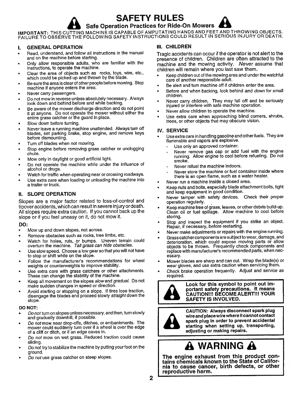
SAFETY RULES A
Safe Operation Practices for Ride-On Mowers
IMPORTANT: THIS CUTTING MACHINE [S CAPABLE OF AMPUTATING HANDS AND FEET AND THROWING OBJECTS.
FAILURE TO OBSERVE THE FOLLGWING SAFETY INSTRUCTIONS COULD RESULT IN SERIOUS INJURY OR DEATH.
L GENERAL OPERATION
•Read, understand, and foltow all instructions in the manual
and on the machine before starting.
Only allow responsible adults, who are familiar with the
instructions, to operate the machine.
° Clear the area of objects such as rocks, toys, wire, etc.,
which could be picked up and thrown by the blade.
°Besuretheareaisclearofotherpeoplebeforemowing. Stop
machine if anyone enters the area.
Never carry passengers.
Do not mow inreverse unless absolutely necessary. Always
look down and behind before and while backing.
•Be aware of the mower discharge direction and do not point
it at anyone. Do not operate the mower without either the
entire grass catcher or the guard in place.
• Slow down before turning.
Never leave a running machine unattended. Always turn off
blades, set parking brake, stop engine, and remove keys
before dismounting.
Turn off blades when not mowing.
.Stop engine before removing grass catcher or unclogging
chute.
=Mow only in daylight or good artificial light.
Do not operate the machine while under the influence of
alcohol or drugs.
Watch for traffic when operating near or crossing roadways.
Use extra care when loading or unloading the machine into
a trailer or truck.
IL SLOPE OPERATION
Slopes are a major factor related to loss-of-control and
tipover accidents, which can result in severe injury or death.
All slopes require extra caution. If you cannot back up the
slope or if you feel uneasy on it, do not mow it.
DO:
Mow up and down slopes, not across.
Remove obstacles such as rocks, tree limbs, etc.
oWatch for holes, ruts, or bumps. Uneven terrain could
overturn the machine. Ta//grasseanhideobstaeles.
Use slowspeed. Choose alow gear so that you will nothave
to stop or shift while on the slope.
Follow the manufacturer's recommendations for wheel
weights or counterweights to improve stability.
Use extra care with grass catchers or other attachments.
These can change the stability of the machine.
Keep all movement on the slopes slowand gradual Do not
make sudden changes in speed or direction.
Avoid starting or stopping on a slope. If tires lose traction,
disengage the blades and proceed slowly straight down the
slope.
DO NOT:
Do not turn on slopes unless necessary, andthen, turn slowly
and gradually downhill, ff possible.
Do notmow near drop-offs, ditches, or embankments. The
mower could suddenly turn over if a wheel is over the edge
of a cliff or ditch, or if an edge caves in.
Do not mow on wet grass. Reduced traction could cause
sliding.
=Do not try to stabilize the machine by putting your foot on the
ground.
Do not use grass catcher on steep slopes.
Ill. CHILDREN
Tragic accidents can occur ifthe operator is not alert to the
presence of children. Children are often attracted to the
machine and the mowing activity. Never assume that
children will remain where you last saw them.
Keep children out of the mowing area and under the watchful
care of another responsible adult.
° Be alert and turn machine off if children enter the area.
° Before and when backing, took behind and down for small
children.
*Never carry children. They may fall off and be seriously
injured or interfere with safe machine operation.
= Never allow children to operate the machine.
Use extra care when approaching blind comers, shrubs,
trees, or other objects that may obscure vision.
IV. SERVICE
Use extra care inhandling gasoline and other fuels. They are
flammable and vapors are explosive.
Use only an approved container.
Never remove gas cap or add fuel with the engine
running. Allow engine to cool before refueling. Do not
smoke.
Never refuel the machine indoors.
Never store the machine or fuel container inside where
there is an open flame, such as a water heater.
°Never run a machine inside a closed area.
Keep nuts and bolts, especially blade attachment bolts, tight
and keep equipment in good condition.
Never tamper with safety devices. Check their proper
operation regularly.
°Keep machine free of grass, leaves, or other debris build-up.
Clean oil or fuel spillage. Allow machine to cool before
storing.
Stop and inspect the equipment if you strike an object.
Repair, if necessary, before restarting.
* Never make adjustments or repairs with the engine running.
Grass catcher components are subject to wear, damage, and
deterioration, which could expose moving parts or allow
objects to be thrown. Frequently check components and
replace with manufacturer's recommended parts, when nec-
essary.
Mower blades are sharp and can cut. Wrap the blade(s) or
wear gloves, and use extra caution when servicing them.
Check brake operation frequently. Adjust and service as
required.
Look for this symbol to point out im-
portant safety precautions. It means
CAUTION!it BECOMEALERT!t! YOUR
SAFETY IS INVOLVED.
ACAUTION: Always disconnect spark plug
wire and place wire where it cannot contact
spark plug in order to prevent accidental
starting when setting up, transporting,
adjusting or making repairs.
2
A WARNING
The engine exhaust from this product con-
tains chemicals known to the State of Califor-
nia to cause cancer, birth defects, or other
reproductive harm.

CONGRATULATEONS on your purchase of a Sears
Tractor. It has been designed, engineered and manufac-
tured to give you the best possible dependability and
performance.
Should you experience any problem you cannot easily
remedy, please contact your nearest Sears Authorized
Service Center/Department Department. We have com-
petent, well-trained technicians and the proper tools to
service or repair this tractor.
Please read and retain this manual. The instructions will
enable you to assemble and maintain you rtractor prope fly.
Always observe the "SAFETY RULES".
MODEL
NUMBER 917.250520
SERIAL
NUMBER
DATEOFPURCHASE
THEMODELANDSERIALNUMBERSWILLBEFOUND
ON A PLATE UNDER THE SEAT.
YOUSHOULDRECORDBOTHSERIALNUMBERAND
DATE OF PURCHASE AND KEEP IN A SAFE PLACE
FOR FUTURE REFERENCE.
MAINTENANCE AGREEMENT
A Sears Maintenance Agreement is available on this prod-
uct. Contact your nearest Sears store for details.
CUSTOMER RESPONSIBILITIES
Read and observe the safety rules.
Follow a regular schedule in maintaining, caring forand
using your tractor,
•Follow the instructions under"Customer Responsibili-
ties" and "Storage" sections of this owner's manual.
PRODUCT SPECIFICATIONS
HORSEPOWER: 1&5
GASOLINE CAPACITY 3.5 GALLONS
AND TYPE: UNLEADED REGULAR
OIL TYPE (API-SF/SG): SAE 30 (above 32°F)
SAE 5W-30 (below 32°F)
OIL CAPACITY: W/FILTER: 4.0 PINTS
W/O FILTER: 3.5 PINTS
SPARK PLUG: CHAMPION RV17YC
GAP: .025")
VALVE CLEARANCE: INTAKE: .003" - .006"
EXHAUST: .013" - _016"
GROUND SPEED (MPH): FORWARD: 0- 5.6
REVERSE: 0- 2.5
TIRE PRESSURE: FRONT: 14 PSI
REAR: 10 PSI
CHARGING SYSTEM: 15 AMPS @ 3600 RPM
BLADE BOLT TORQUE: 30-35 FT. LBS.
WARNING: This tractor is equipped with an internal
combustion engine and should not be used on or near any
unimproved forest-covered, brush-covered or grass-cov-
ered land unless the engine's exhaust system is equipped
with a spark arrester meeting applicable local or state laws
(if any). tf a spark arrester is used, it should be maintained
in effective working order by the operator.
In the state of California the above is required by law
(Section 4442 of the California Public Resources Code).
Other states may have similar laws. Federal laws apply on
federal lands. A sparkarrester for the muffler is available
through your nearest Sears Authorized Service Center/
Department (See REPAIR PARTS section of this manual).
LIMITED TWO YEAR WARRANTY ON CRAFTSMAN RIDING EQUIPMENT
For two (2) years from the date of purchase, if this Craftsman Riding Equipment is maintained, lubricated and tuned up according
to the instructions in the owner's manual, Sears will repair or replace, free of charge, any parts found to be defective in material
or workmanship.
This Warranty does not cover:
Expendable items which become worn during normal use, such as blades, spark plugs, air cleaners, belts, etc.
Tire replacement or repair caused by punctures from outside objects, such as nails, thorns, stumps, or glass.
Repairs necessary because of operator abuse, negligence, improper storage or accident or the failure to maintain the
equipment according to the instructions contained in the owner's manual.
Riding equipment used for commercial or rental purposes.
LIMDTED 90 DAY WARRANTY ON BATTERY
For ninety (90) days from date of purchase, if any battery included with this riding equipment proves defective in material or
workmanship and our testing determines the battery will not hold a charge, Sears will replace the battery at no charge.
IN-HOME WARRANTY SERVICE ON YOUR CRAFTSMAN RIDING EQUIPMENT IS AVAILABLE AT NO-CHARGE FOR 30
DAYS FROM THE DATE OF PURCHASE. PLEASE CONTACT YOUR NEAREST SERVICE CENTER. AFTER 30 DAYS
FROM THE DATE OF PURCHASE, WARRANTY SERVICE IS AVAILABLE BY TAKING YOUR CRAFTSMAN RIDING EQUIP-
MENT TO YOUR NEAREST SEARS SERVICE CENTER. (IN-HOME WARRANTY SERVICE WILL STILL BE AVAILABLE
AFTER 30 DAYS FROM THE DATE OF PURCHASE BUT A STANDARD TRIP CHARGE WILL APPLY.) THIS WARRANTY
APPLIES ONLY WHILE THIS PRODUCT IS IN THE UNITED STATES.
This Warranty gives you specific legal rights, and you may also have other rights which may vary from state to state.
SEARS, ROEBUCK AND CO., D/817 WA, HOFFMAN ESTATES, IL 60179
3
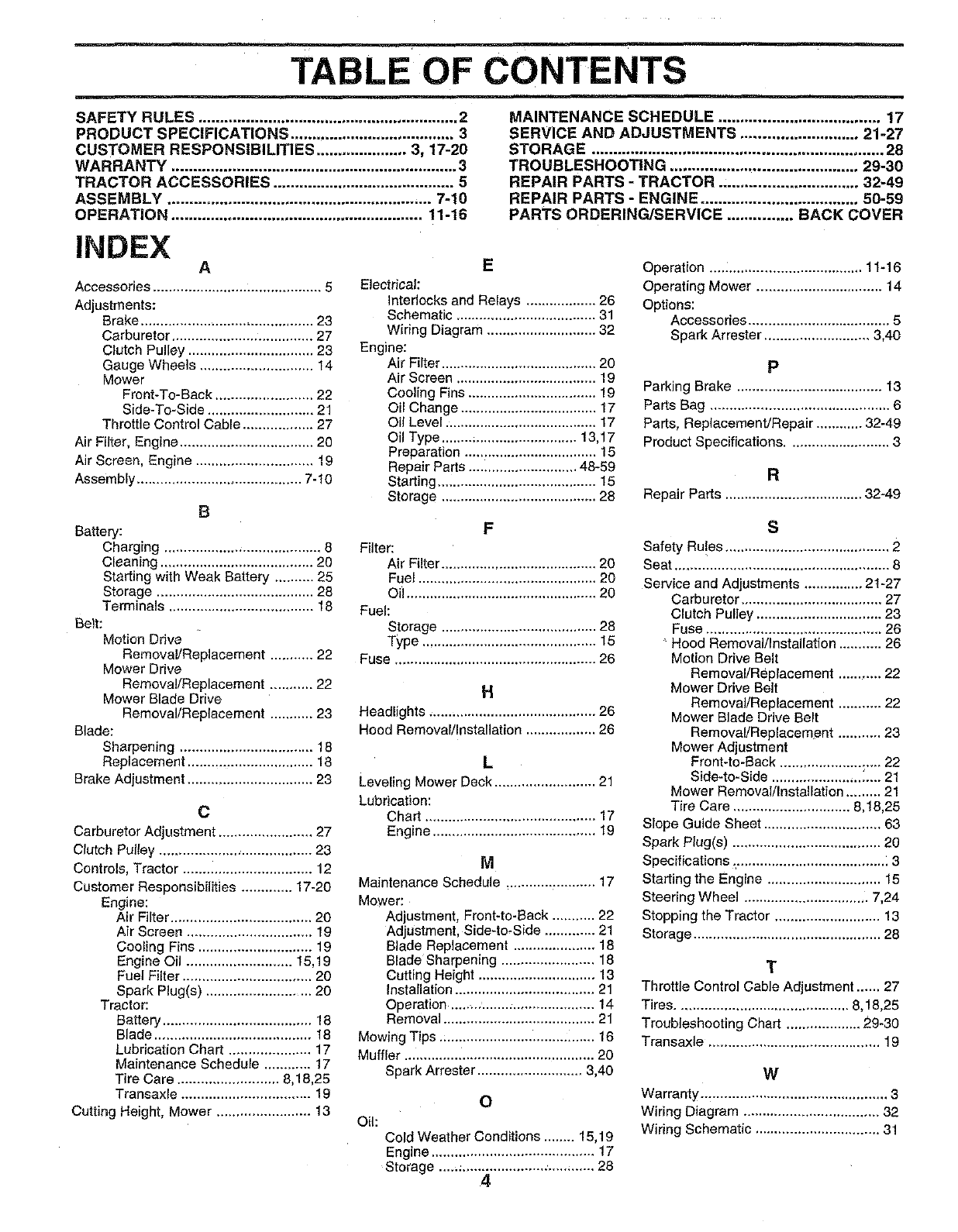
TABLE OF CONTENTS
SAFETY RULES ............................................................ 2
PRODUCT SPECIFICATIONS ...................................... 3
CUSTOMER RESPONSIBILITIES ..................... 3, 17-20
WARRANTY .................................................................. 3
TRACTOR ACCESSORIES .......................................... 5
ASSEMBLY ............................................................. 7-10
OPERATION .......................................................... 11-16
MAINTENANCE SCHEDULE ..................................... 17
SERVICE AND ADJUSTMENTS ........................... 21-27
STORAGE ................................................................... 28
TROUBLESHOOTING ........................................... 29-30
REPAIR PARTS -TRACTOR ................................ 32-49
REPAIR PARTS - ENGINE .................................... 50-59
PARTS ORDERING/SERVICE ............... BACK COVER
INDEX A
Accessories ........................ :.................. 5
Adjustments:
Brake ............................................ 23
Carburetor .................................... 27
Clutch Pulley ................................ 23
Gauge Wheels ............................. 14
Mower
Front-To-Back ......................... 22
Side-To-Side ........................... 21
Throttle Control Cable .................. 27
Air Filter, Engine .................................. 20
Air Screen, Engine .............................. 19
Assembly .......................................... 7-10
B
Battery:
Charging ........................................ 8
Cleaning ....................................... 20
Starting with Weak Battery .......... 25
Storage ........................................ 28
Terminals ..................................... 18
Belt:
Motion Drive
Removal/Replacement ........... 22
Mower Drive
Remova!/Replacement ........... 22
Mower Blade Drive
RemovaVReplacement ........... 23
Blade:
Sharpening .................................. 18
Replacement ......... _,..................... 18
Brake Adjustment ................................ 23
C
Carburetor Adjustment ........................ 27
Clutch Pulley ....................................... 23
Controls, Tractor ................................. 12
Customer Responsibilities ............. 17-20
Engine:
Air Filter .................................... 20
Air Screen ................................ 19
Cooling Fins ............................. 19
Engine Oil ........................... 15,19
Fuel Filter ................................. 20
Spark Plug(s) ........................... 20
Tractor:
Battery ...................................... 18
Blade ........................................ 18
Lubrication Chart ..................... 17
Maintenance Schedule ............ 17
Tire Care .......................... 8,18,25
Transaxle ................................. 19
Cutting Height, Mower ........................ 13
E
Electrical:
Interlocks and Relays .................. 26
Schematic .................................... 31
Wiring Diagram ............................ 32
Engine:
Air Filter ........................................ 20
Air Screen .................................... 19
Cooling Fins ................................. 19
Oil Change ................................... 17
Oil Level ....................................... 17
Oil Type ........;.......................... 13,17
Preparation .................................. 15
Repair Parts ............................ 48-59
Starting ......................................... 15
Storage ........................................ 28
F
Filter:
Air Filter ........................................ 20
Fuel .............................................. 20
Oil ................................................. 20
Fuel:
Storage ........................................ 28
Type ............................................. 15
Fuse .................................................... 26
H
Headlights ........................................... 26
Hood Removalllnstallation .................. 26
L
Leveling Mower Deck .......................... 21
Lubrication:
Chart ............................................ 17
Engine .......................................... 19
M
Maintenance Schedule ....................... 17
Mower:
Adjustment, Front-to-Back ........... 22
Adjustment, Side-to, Side ............. 21
Blade Replacement ..................... 18
Blade Sharpening ........................ 18
Cutting Height .............................. 13
Installation .................................... 21
Operation ........ ............................. 14
Removal ....................................... 21
Mowing Tips ........................................ 16
Muffler .............. :.................................. 20
Spark Arrester ........................... 3,40
O
Oil:
Cold Weather Conditions ........ 15,19
Engine .......................................... 17
Storage ........................... .............. 28
4
Operation ....: .................................. 11-16
Operating Mower ................................ 14
Options:
Accessories .................................... 5
Spark Arrester ........................... 3,40
P
Parking Brake ..................................... 13
Parts Bag .............................................. 6
Parts, Replacement/Repair ............ 32-49
Product Specifications .......................... 3
R
Repair Parts ................................... 32-49
S
Safety Ru!es .......................................... 2
Seat ....................................................... 8
Service and Adjustments ............... 21-27
Carburetor .................................... 27
Clutch Pulley ................................ 23
Fuse ............................................. 26
Hood Removal/Installation ........... 26
Motion Drive Belt
Removal/Replacement ........... 22
Mower Drive Belt
Removal/Replacement ........... 22
Mower Blade Drive Belt
RemovaVReplacement ........... 23
Mower Adjustment
Front-to-Back .......................... 22
Side-to-Side ....................... L... 21
Mower Removal/Installation ......... 21
Tire Care .............................. 8,18,25
Slope Guide Sheet .............................. 63
Spark Plug(s) ...................................... 20
Specifications _...................................... : 3
Starting the Engine ............................. 15
Steering Wheel ................................ 7,24
Stopping the Tractor ........................... 13
Storage ................................................ 28
T
Throttle Control Cable Adjustment ...... 27
Tires ............................................ 8,18,25
Troubleshooting Chart ................... 29-30
Transaxle ............................................ 19
W
Warranty ................................................ 3
Wiring Diagram ................................... 32
Wiring Schematic ................................ 31
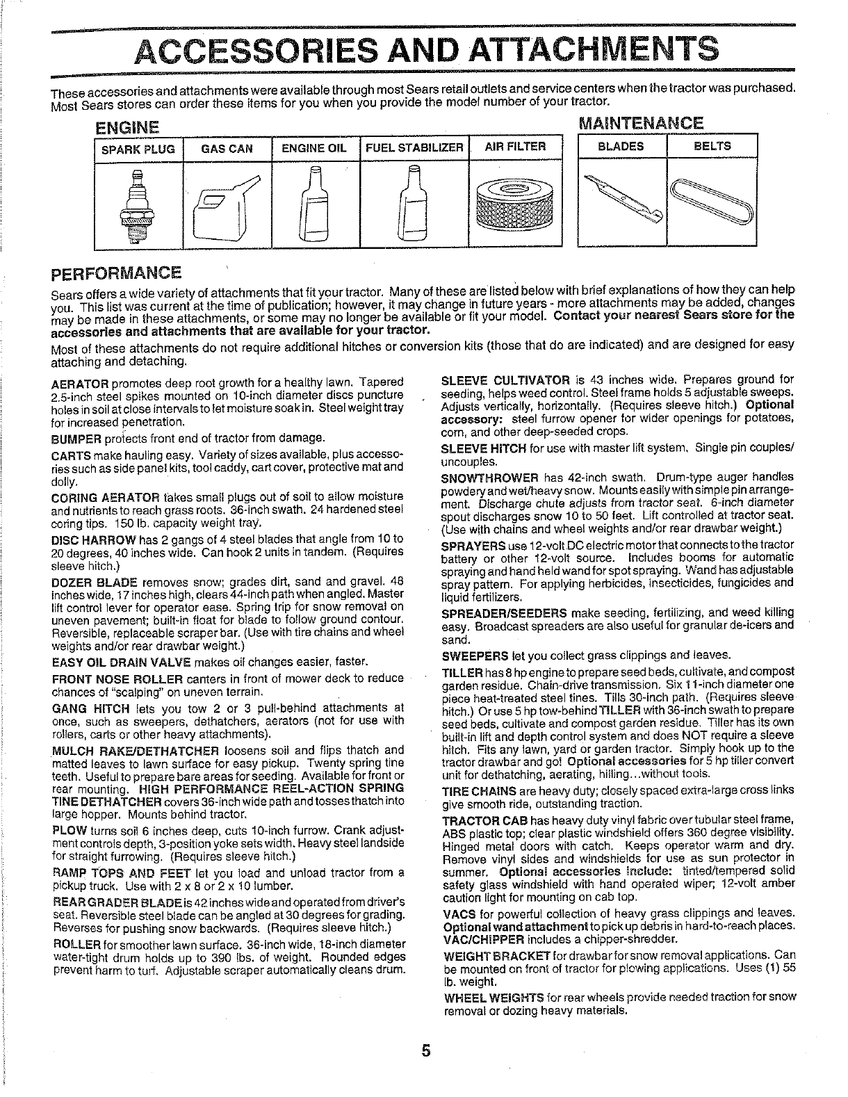
ACCESSORIES AND ATTACHMENTS
These accessories and attachments were available through most Sears retail outlets and service centers when the tractor was purchased.
Most Sears stores can order these items for you when you provide the model number of your tractor.
!NGINE MAINTENANCE
SPARK PLUG GAS CAN FUEL STABILIZER
i
AIR FILTER BLADES BELTS
PERFORMANCE
Sears offers a wide variety of attachments that fit your tractor, Many of these are listed below with bdef explanations of how they can help
you Th s ist was current at the time of publication; however, it may change in future years - more attachments may be added, changes
may be made in these attachments, or some may no onger be available or t t your model. Contact your nearest Sears store for the
accessories and attachments that are available for your tractor.
Most of these attachments do not require additional hitches or conversion kits (those that do are indicated) and are designed for easy
attaching and detaching.
AERATOR promotes deep root growth for a healthy lawn. Tapered
2.5-inch steel spikes mounted on 10-inch diameter discs puncture
holes in soil at close intervals to Ietmoisture soak in. Steelweight tray
for increased penetration.
BUMPER proiects front end of tractor from damage.
CARTS make hauling easy. Variety of sizes available, plus accesso-
riessuch as side panel kits, too! caddy, cart cover, protective mat and
dolly.
CORING AERATOR t;akes smalt plugs out of soil to allow moisture
and nutrients to reach grass roots. 36-inch swath. 24 hardened steel
coring tips. 150 Ib, capacity weight tray.
DISC HARROW has 2 gangs of 4 steel blades that angle from 10to
20 degrees, 40 inches wide. Can hook 2 units in tandem. (Requires
sleeve hitch.)
DOZER BLADE removes snow; grades dirt, sand and gravel. 48
inches wide, 17inches high, clears 44-inch path when angled. Master
lift control lever for operator ease. Spdng trip for snow removal on
uneven pavement; built-in float for bIade to follow ground contour.
Reversible, replaceable scraper bar. (Use with tire chains and wheel
weights and/or rear drawbar weight.)
EASY OIL DRAIN VALVE makes oil changes easier, faster.
FRONT NOSE ROLLER canters in front of mower deck to reduce
chances of "scalping" on uneven terrain.
GANG HITCH lets you tow 2 or 3 pull-behind attachments at
once, such as sweepers, dethatchers, aerators (not for use with
rollers, carts or other heavy attachments).
MULCH RAKF_JDETHATCHER loosens soil and flips thatch and
matted leaves to lawn surface for easy pickup. Twenty spring tine
teeth. Usafultopreparebare areas forsseding. Availableforfrontor
rear mounting. HIGH PERFORMANCE REEL=ACTION SPRING
TINE DETHATCHER covers 36-inch wide path and tosses thatch into
large hopper. Mounts behind tractor.
PLOW turns soil 6 inches deep, cuts 10-inch furrow. Crank adjust-
ment controls depth, 3-position yoke sets width. Heavy steel landside
for straight furrowing. (Requires sleeve hitch.)
RAMP TOPS AND FEET let you load and unload tractor from a
pickup truck. Use with 2 x 8 or 2 x 10 lumber.
REAR GRADER BLADE is42 inches wide and operated from driver's
seat. Reversible steel b{ade can be angled at 30 degrees for grading.
Reverses for pushing snow backwards. (Requires sleeve hitch.)
ROLLER for smoother lawn surface. 36-inch wide, 18-inch diameter
water-tight drum holds up to 390 ibs. of weight. Rounded edges
prevent harm to tur[ Adjustable scraper automatically cleans drum.
SLEEVE CULTIVATOR is 43 inches wide, Prepares ground for
seeding, helps weed control. Steel frame holds 5 adjustable sweeps.
Adjusts vertically, horizontally. (Requires sleeve hitch.) Optional
accessory: steel furrow opener for wider openings for potatoes,
corn, and other deep-seeded crops.
SLEEVE HITCH for usa with master lift system, Single pin couples/
uncouples.
SNOWTHROWER has 42-inch swath, Drum-type auger handles
powdery and wetJheavy snow. Mounts easily with simple pin arrange-
ment. Discharge chute adjusts from tractor seat. 6-inch diameter
spout discharges snow 10 to 50 feet. Lift controlled at tractor seat.
(Use with chains and whee! weights and/or rear drawbar weight.)
SPRAYERS use 12-volt DC electric motor that connects to the tractor
battery or other 12-volt source, includes booms for automatic
spraying and hand held wand for spot spraying. Wand has adjustable
spray pattern. For applying herbicides, insecticides, fungicides and
liquid fertilizers.
SPREADER/SEEDERS make seeding, fertilizing, and weed killing
easy. Broadcast spreaders are also useful for granular de-icers and
sand.
SWEEPERS let you coI]ect grass clippings and leaves.
TILLER has8 hp engineto prepare seed beds, cultivate, and compost
garden residue. Chain-drive transmission, Six t t-inch diameter one
piece heat-traated steel tines. Tins 30-inch path. (Requires sleeve
hitch.) Or use 5 hp tow-behind TILLER with 36-inch swath to prepare
seed beds, cultivate and compost garden residue. Tiller has its own
built-in lift and depth control system and does NOT require a sleeve
hitch. Fits any lawn, yard or garden tractor. Simply hook up to the
tractor drawbar and go! Optional accessories for 5 hp tiIler convert
unit for dethatching, aerating, hiHing.,.without tools.
TIRE CHAINS are heavy duty; closely spaced extraqarge cross links
give smooth ride, outstanding traction.
TRACTOR CAB has heavy duty vinyl fabric over tubular steel frame,
ABS plastic top; clear plastic windshield offers 360 degree visibility.
Hinged metal doors with catch. Keeps operator warm and dry.
Remove vinyl sides and windshields for use as sun protector in
summer. Optional accessories include: tinted!tempered solid
safety glass windshieJd with hand operated wiper; 12-volt amber
caution light for mounting on cab top.
VACS for powerful collection of hear:/grass clippings and leaves.
Opt!anal wand attachment to pick updebris inhard-to-reach places.
VAC/CHIPPER includes a chipper-shredder.
WEIGHT BRACKET for drawbar for snow removal applications. Can
be mounted on front of tractor for plowing applications. Uses (t) 55
lb. weight,
WHEEL WEIGHTS for rear wheels provide needed traction for snow
removal or dozing heavy materials.
5
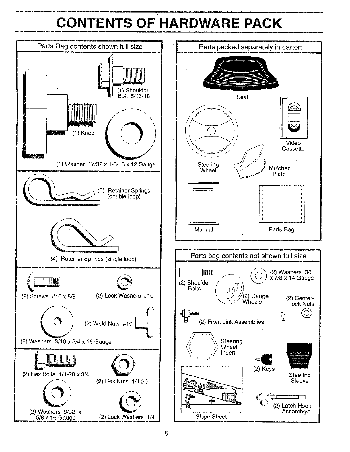
CONTENTS OF HARDWARE PACK
Parts Bag contents shown full size
m
m
/
(1) Shoulder
Bolt 5/16-18
(1) Knob O
(1) Washer 17/32 x 1-3/16 x 12 Gauge
3) etainer Springs(double loop)
(4) Retainer Springs (single loop)
(2) Screws #10 x 5/8 (2) Lock Washers #10
(2) Weld Nuts #10
(2) Washers 3/16 x 3/4 x 16 Gauge
(2) Hex Bolts 1/4-20 x 3/4
@
(2) Washers 9/32 x
@
"(2) Hex Nuts 1/4-20
5/8 x 16 Gau e (2) Lock Washers 1/4
Parts packed separately in carton
r
Steering
Wheel
Seat
C3
Video
Cassette
Mulcher
Plate
,i
Manual Parts Bag
Parts bag contents not shown full size
(2) Shoulder
Bolts
l_'m_(2) Front Link Assemblies
/_'_ (2)Washers 3/8
x 7/8 x 14 Gauge
Gauge (2) Center-
eels lock Nuts
©
_ teering
Wheel
Insert
Steering
Sleeve
(2) Keys
Slope Sheet
_ok
Assemblys
6
ASSEMBLY
Your new tractor has been assembled at the factory with exception of those parts left unassembled for shipping purposes,
To ensure safe and proper operation of your tractor all parts and hardware you assemble must be tightened securely. Use
the correct tools as necessary to insure proper tightness.
TOOLS REQUIRED FOR ASSEMBLY
A socket wrench set will make assembly easier. Standard
wrench sizes are listed.
(2) 7/16" wrenches (1) Tire pressure gauge
(1) 9/16" wrench (1) Utility knife
(1) 1/2" wrench (1) 3/4" socket w/drive ratchet
When right or left hand is mentioned in this manual, it
means when you are in the operating position (seated
behind the steering wheel).
TO REMOVE TRACTOR FROM CARTON
UNPACK CARTON
•Remove all accessible loose parts and parts cartons
from ca[ton (See page 6).
• Cut, from top to bottom, along lines on all four corners
of carton, and lay panels flat.
•Remove mower and packing materials.
°Check for any'additional loose parts or cartons and
remove.
BEFORE ROLLING TRACTOR OFF SKID
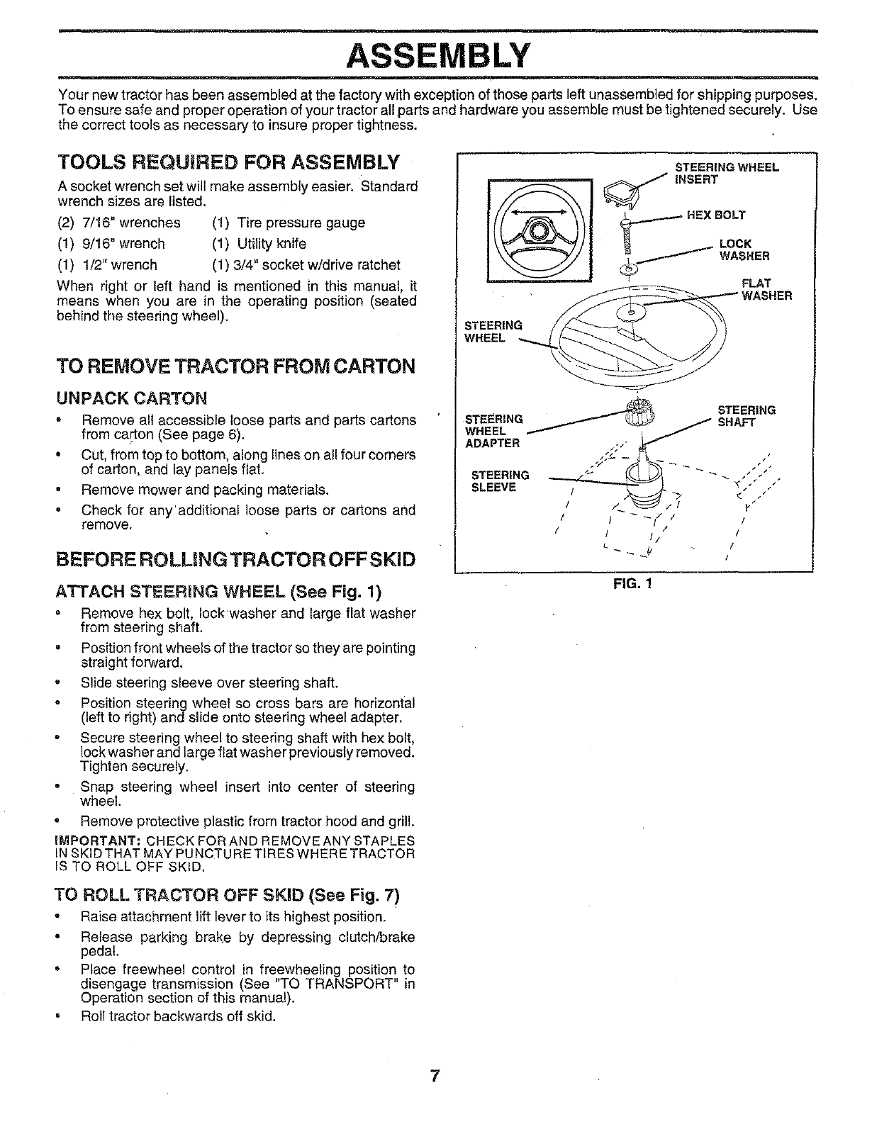
ATTACH STEERING WHEEL (See Fig. 1)
=Remove hex bolt, Iockwasher and large flat washer
from steering shaft.
° Position front wheels of the tractor so they are pointing
straight forward.
°Slide steering sleeve over steering shaft.
• Position steering wheel so cross bars are horizontal
(left to right) and slide onto steering wheel adapter.
• Secure steering wheel to steering shaft with hex bolt,
lock washer and large flat washer previously removed.
Tighten securely.
= Snap steering wheel insert into center of steering
wheel.
•Remove protective plastic from tractor hood and grill.
IMPORTANT; CHECK FOR AND REMOVE ANY STAPLES
IN SKID THAT MAY PUNCTURE TIRES WHERE TRACTOR
IS TO ROLL OFF SKID.
STEERING WHEEL
"INSERT
HEX BOLT
_ -- LOCK
STEERING
WHEEL
FIG. 1
TO ROLL TRACTOR OFF SKID (See Fig. 7)
°Raise attachment lift lever to its highest position.
•Release parking brake by depressing clutch!brake
pedal
• Place freewheel control in freewheeling position to
disengage transmission (See "TO TRANSPORT" in
Operation section of this manual).
•Roll tractor backwards off skid.
7
m
ASSEMBLY
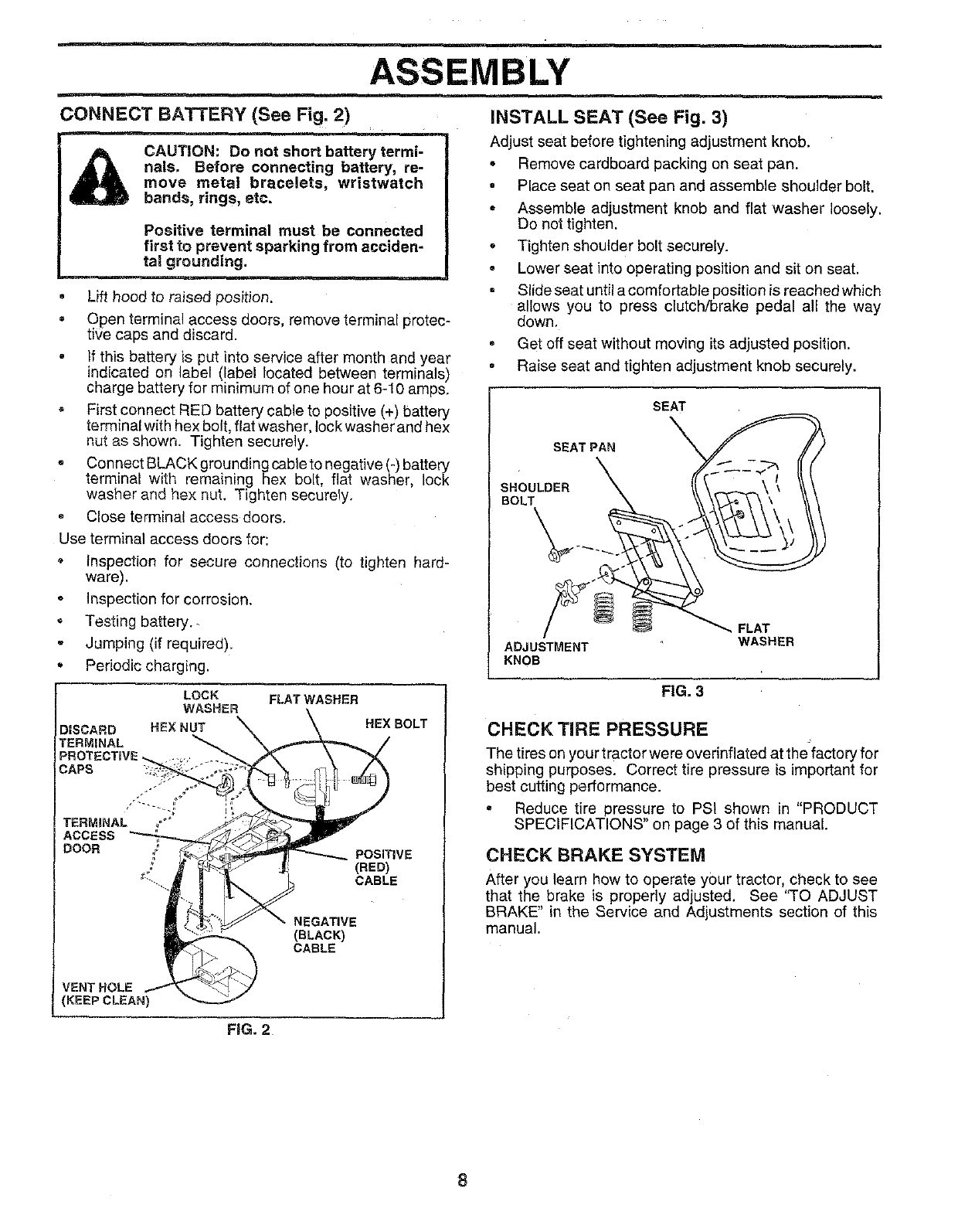
CONNECT BATTERY (See Fig. 2)
CAUTION: Do not short battery termi-
nals. Before connecting battery, re-
move metal bracelets, wristwatch
bands, rings, etc.
Positive terminal must be connected
first to prevent sparking from acciden-
tal grounding.
°Lift hood tD raised position.
° Open terminal access doors, remove terminal protec-
tiqe caps and discard•
if this battery is put into service after month and year
indicated on label (label located between terminals)
charge battery for minimum of one hour at 6-10 amps.
,First connect RED battery cable to positive (+) battery
terminal with hex bolt, flat washe r, lock washer and hex
nut as shown• Tighten securely•
,, Connect BLACK grounding cable to negative (-) battery
terminal with remaining hex bolt, flat washer, lock
washer and hex nut. Tighten securely.
• Close terminal access doDrs.
Use terminal access doors for:
inspection for secure connections (to tighten hard-
ware).
Inspection for corrosion.
• Testing battery.
Jumping (if required).
• Periodic charging.
LOCK FLAT WASHER
WASHER
DISCARD HEX NUT
TERMINAL
CAPS
NEGATIVE
(BLACK)
CABLE
HEX BOLT
POSITIVE
(RED)
CABLE
INSTALL SEAT (See Fig. 3)
Adjust seat before tightening adjustment knob.
• Remove cardboard packing on seat pan.
° Place seat on seat pan and assemble shoulder bolt.
° Assemble adjustment knob and flat washer loosely.
Do not tighten.
° Tighten shoulder bolt securely•
• Lower seat into operating position and sit on seat.
Slide seat until a comfortable position is reached which
allows you to press clutch/brake pedal all the way
down.
° Get off seat without moving its adjusted position.
•Raise seat and tighten adjustment knob securely.
SEAT
SEAT PAN_
SHOULDER \ /_ \ _ \ " \\
ADJUSTMENT WASHER
KNOB
FIG. 3
CHECK TIRE PRESSURE
The tires on your tractor were overinfiated at thefactory for
shipping purposes. Correct tire pressure is important for
best cutting performance.
= Reduce tire pressure to PSi shown in "PRODUCT
SPECIFICATIONS" on page 3 of this manual.
CHECK BRAKE SYSTEM
After you learn how to operate your tractor, check to see
that the brake is properly adjusted. See "TO ADJUST
BRAKE" in the Service and Adjustments section of this
manual.
FiG. 2
8
ASSEMBLY
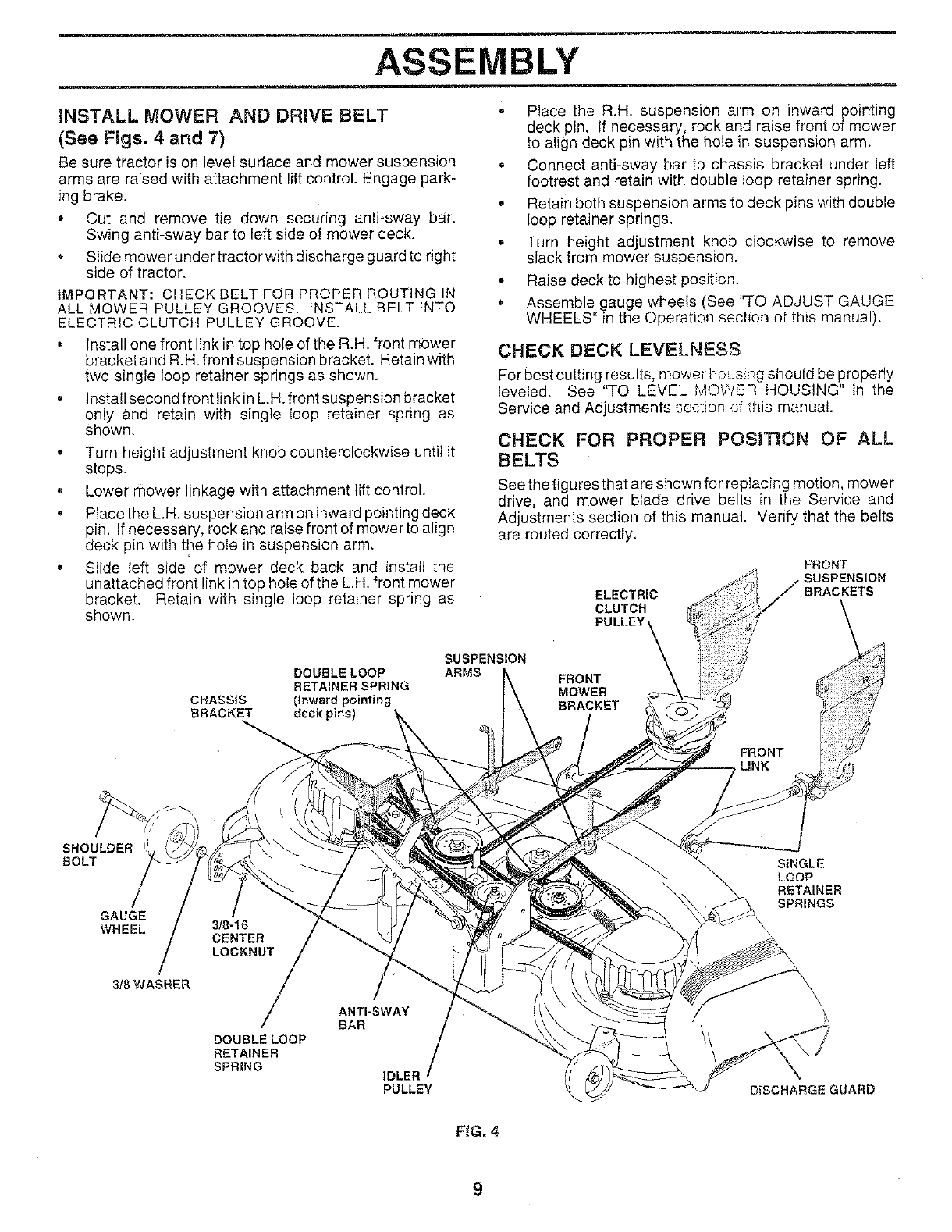
iNSTALL MOWER AND DRIVE BELT
(See Figs. 4 and 7)
Be sure tractor is on level surface and mower suspension
arms are raised with attachment lift control. Engage park-
ing brake•
• Cut and remove tie down securing anti-sway bar.
Swing anti-sway bar to left side of mower deck.
• Slide mower under tractor with discharge guard to right
side of tractor.
iMPORTANT: CHECK BELT FOR PROPER ROUTING IN
ALL MOWER PULLEY GROOVES= INSTALL BELT INTO
ELECTRIC CLUTCH PULLEY GROOVE.
Install one front link in top hole of the R.H. front mower
bracketand R.H.front suspension bracket. Retain with
two single loop retainer springs as shown•
•Install second front linkin L.H. front suspension bracket
only and retain with single loop retainer spring as
shown.
Turn height adjustment knob counterclockwise until it
stops.
Lower rnower linkage with attachment lift control.
Ptace the L.H. suspension arm on inward pointing deck
pin. If necessary, rock and raise front of mower to align
deck pin with the hole in suspension arm.
Slide left side of mower deck back and install the
unattached front link in top hole of the LH. front mower
bracket. Retain with single loop retainer spring as
shown•
•Place the R.H. suspension arm on inward pointing
deck pin. If necessary, rock and raise front of mower
to align deck pin with the hole in suspension arm.
• Connect anti-sway bar to chassis bracket under left
footrest and retain with double loop retainer spring.
• Retain both suspension arms to deck pins with double
loop retainer springs.
.Turn height adjustment knob clockwise to remove
slack from mower suspension.
Raise deck to highest position.
.Assemble gauge wheels (See "TO ADJUST GAUGE
WHEELS" in the Operation section of this manual).
CHECK DECK LEVELNESS
For best cutting results, mower hous ng should be properly
leveled. See 'q-o LEVEL MOWER HOUSING" in the
• _ _ ÷_ ÷ ,
Service and Adjustments ._ec,,on ._f,h_s manual.
CHECK FOR PROPER POSITION OF ALL
BELTS
See the figures that are shown for replacing motion, mower
drive, and mower blade drive belts in the Service and
Adjustments section of this manual. Verify that the belts
are routed correctly.
ELECTRIC
CLUTCH
PULLEY
FRONT
SUSPENSION
BRACKETS
DOUBLE LOOP
RETAINER SPRING
CHASSIS (Inward pointing
BRACKET deck pins)
SUSPENSION
ARMS
//
SHOULDER
BOLT
GAUGE
WHEEL 3/8-16
SINGLE
LOOP
RETAINER
SPRINGS
3/8 WASHER
DOUBLE LOOP
RETAINER
SPRING
ANTI-SWAY
BAR
IDLEI
PULLEY
\\\\
DISCHARGE GUARD
F_G. 4
9
ASSEMBLY
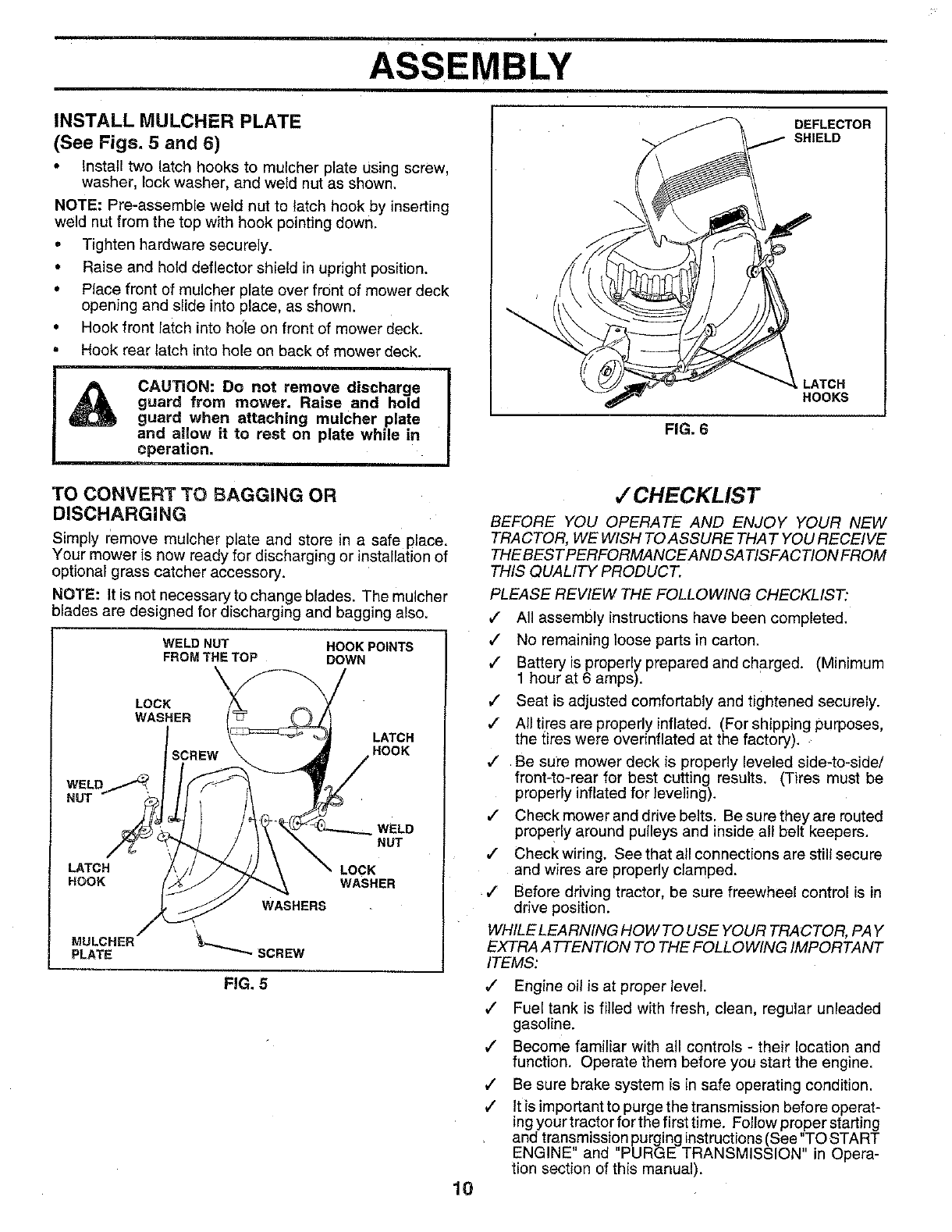
INSTALL MULCHER PLATE
(See Figs. 5and 6)
•Install two latch hooks to mulcher plate Using screw,
washer, lock washer, and weld nut as shown.
NOTE: Pro-assemble weld nut to latch hook by inserting
weld nut from the top with hook pointing down.
• Tighten hardware securely.
• Raise and hold deflector shield in upright position.
• Place front of mulcher plate over front of mower deck
opening and slide into place, as shown.
• Hook front latch into hole on front of mower deck.
. Hook rear latch into hole on back of mower deck.
CAUTION: Do no_
guard from mower. Raise and hold J
guard when attaching mulcher plate
and allow it to rest on plate while in J
epe...._.._ ratio n, IFIG. 6
DEFLECTOR
SHIELD
HOOKS
TO CONVERT TO BAGGING OR
DISCHARGING
Simply remove mulcher plate and store in a safe place,
Your mower is now ready for discharging or installation of
optional grass catcher accessory.
NOTE: It is not necessary to change blades. The mulcher
blades are designed for discharging and bagging also.
WELD NUT HOOK POINTS
FROM THE TOP DOWN
LOCK
WASHER
LATCH
HOOK
WELD
NUT
LATCH LOCK
HOOK WASHER
WASHERS
MULCHER
PLATE SCREW
FiG. 5
10
,/CHECKLIST
BEFORE YOU OPERATE AND ENJOY YOUR NEW
TRACTOR, WE WISH TO ASSURE THAT YOU RECEIVE
THE BEST PERFORMANCE AND SATISFACTION FROM
THIS QUALITY PRODUCT.
PLEASE REVIEW THE FOLLOWING CHECKLIST:
,/ All assembly instructions have been completed.
,/ No remaining loose parts in carton.
,/ Battery is properly prepared and charged. (Minimum
1 hour at 6 amps).
/Seat is adjusted comfortably and tightened securely.
,/ All tires are properly inflated. (For shipping purposes,
the tres were overinflated at the factory).
,/ Be sure mower deck is properly leveled side-to-side/
front-to-rear for best cutting results. (Tires must be
properly inflated for leveling).
,I Check mower and drive belts. Be sure they are routed
properly around pulleys and inside all belt keepers.
,/ Check wiring. See that all connections are still secure
and wires are properly clamped•
,I Before driving tractor, be sure freewheel control is in
drive position.
WHILE LEARNING HOW TO USE YOUR TRACTOR, PAY
EXTRA A TTENTION TO THE FOLLOWING IMPORTANT
ITEMS:
/Engine oil is at proper level.
,/ Fuel tank is filled with fresh, clean, regular unleaded
gasoline.
/Become familiar with all controls - their location and
function. Operate them before you start the engine.
/Be sure brake system is in safe operating condition.
,/ Itis important to purge the transmission before operat-
ing your tractor for the first time. Follow proper starting
and transmission purging instructions (See "TO START
ENGINE and PURGE TRANSMISSION" in Opera-
tion section of this manual).
OPERATION
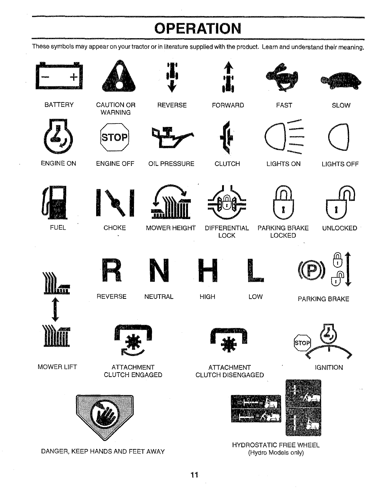
These symbols may appear on your tractor or in literature supplied with the product. Learn and understand their meaning.
E3& 4!, t
BATTERY CAUTION OR
WARNING
ENGINE ON ENGINE OFF
REVERSE FORWARD
OIL PRESSURE CLUTCH
FAST SLOW
LIGHTS ON LIGHTS OFF
FUEL CHOKE MOWER HEIGHT
MOWER LIFT
REVERSE NEUTRAL
ATTACHMENT
CLUTCH ENGAGED
DIFFERENTIAL PARKING DRAKE UNLOCKED
LOCK LOCKED
L
HIGH LOW
ATTACHMENT
CLUTCH DISENGAGED
PARKING BRAKE
IGNITION
DANGER, KEEP HANDS AND FEET AWAY HYDROSTATIC FREE WHEEL
(Hydro Models only)
11
OPERATION
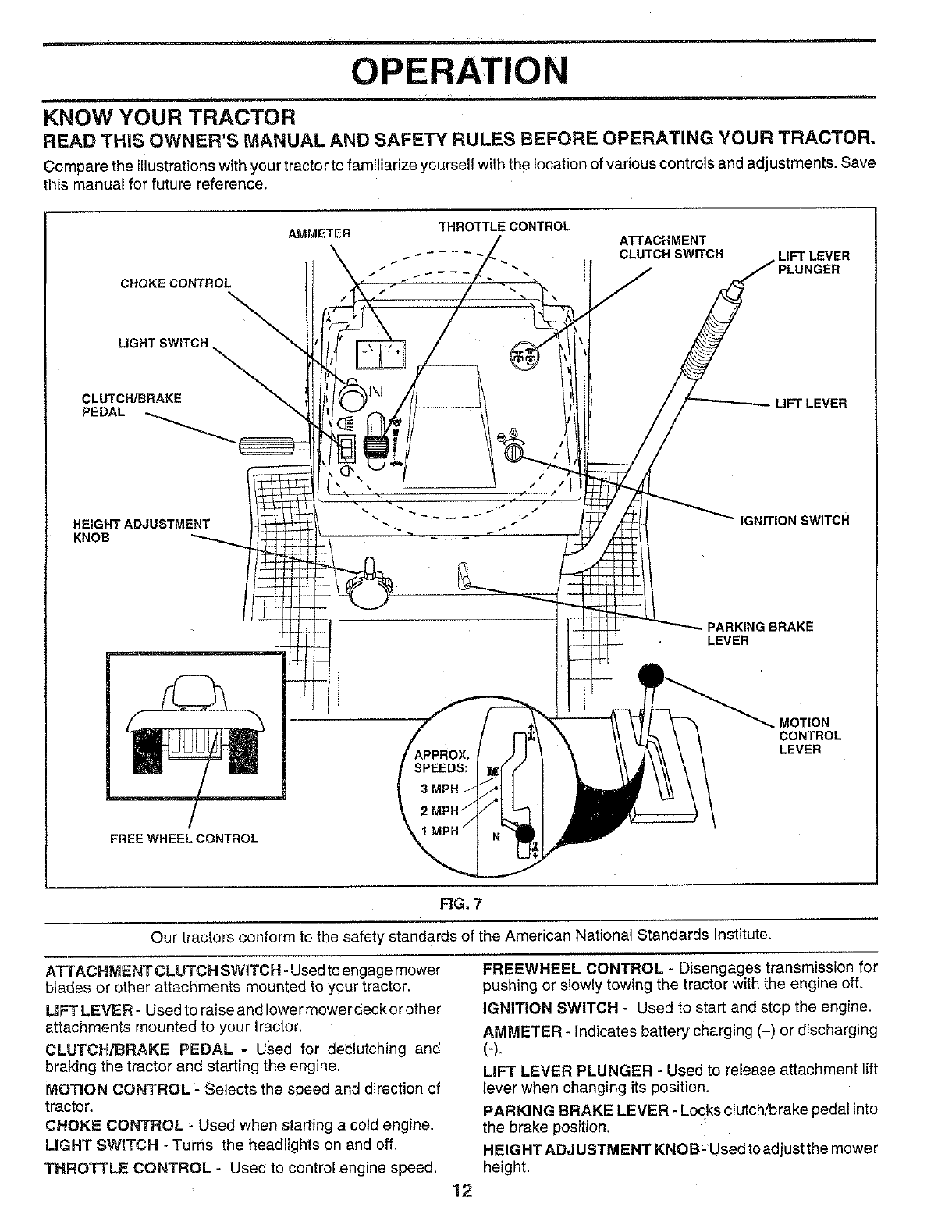
KNOW YOUR TRACTOR
READ THiS OWNER'S MANUAL AND SAFETY RULES BEFORE OPERATING YOUR TRACTOR.
Compare the illustrations with your tractor to familiarize yourself with the location of various controls and adjustments. Save
this manual for future reference.
AMMETER
CROKECONTROL
LIGHT SWITCH_ '_
CLUTCH/BRAKE
PEDAL
THROTTLE CONTROL
ATTACHMENT
CLUTCH SWITCH LIFT LEVER
LIFT LEVER
HEIGHT ADJUSTMENT
KNOB
IGNITION SWITCH
PARKING BRAKE
LEVER
FREE WHEEL CONTROL
SPEEDS:
3
2
MOTION
CONTROL
LEVER
FIG. 7
Our tractors conform to the safety standards of the American National Standards Institute.
ATTACHMENT CLUTCH SWITCH -Used to engage mower
blades or other attachments mounted to your tractor.
UFT LEVER - Used to raise and lower mowerdeck orother
attachments mounted to your tractor.
CLUTCH/BRAKE PEDAL - Used for declutching and
braking the tractor and starting the engine.
MOTION CONTROL- Selects the speed and direction of
tractor.
CHOKE CONTROL - Used when starting a cold engine.
LIGHT SWITCH - Turns the headlights on and off.
THROTTLE CONTROL - Used to control engine speed.
12
FREEWHEEL CONTROL -Disengages transmission for
pushing or slowly towing the tractor with the engine off,
IGNITION SWITCH - Used to start and stop the engine.
AMMETER - Indicates battery charging (+) or discharging
(-).
LIFT LEVER PLUNGER - Used to release attachment lift
lever when changing its position,
PARKING BRAKE LEVER -Locks clutch/brake pedal into
the brake position.
HEIGHT ADJ USTM ENT KNOB- Used to adjust the mower
height,
OPERATION
HOW TO USE YOUR TRACTOR
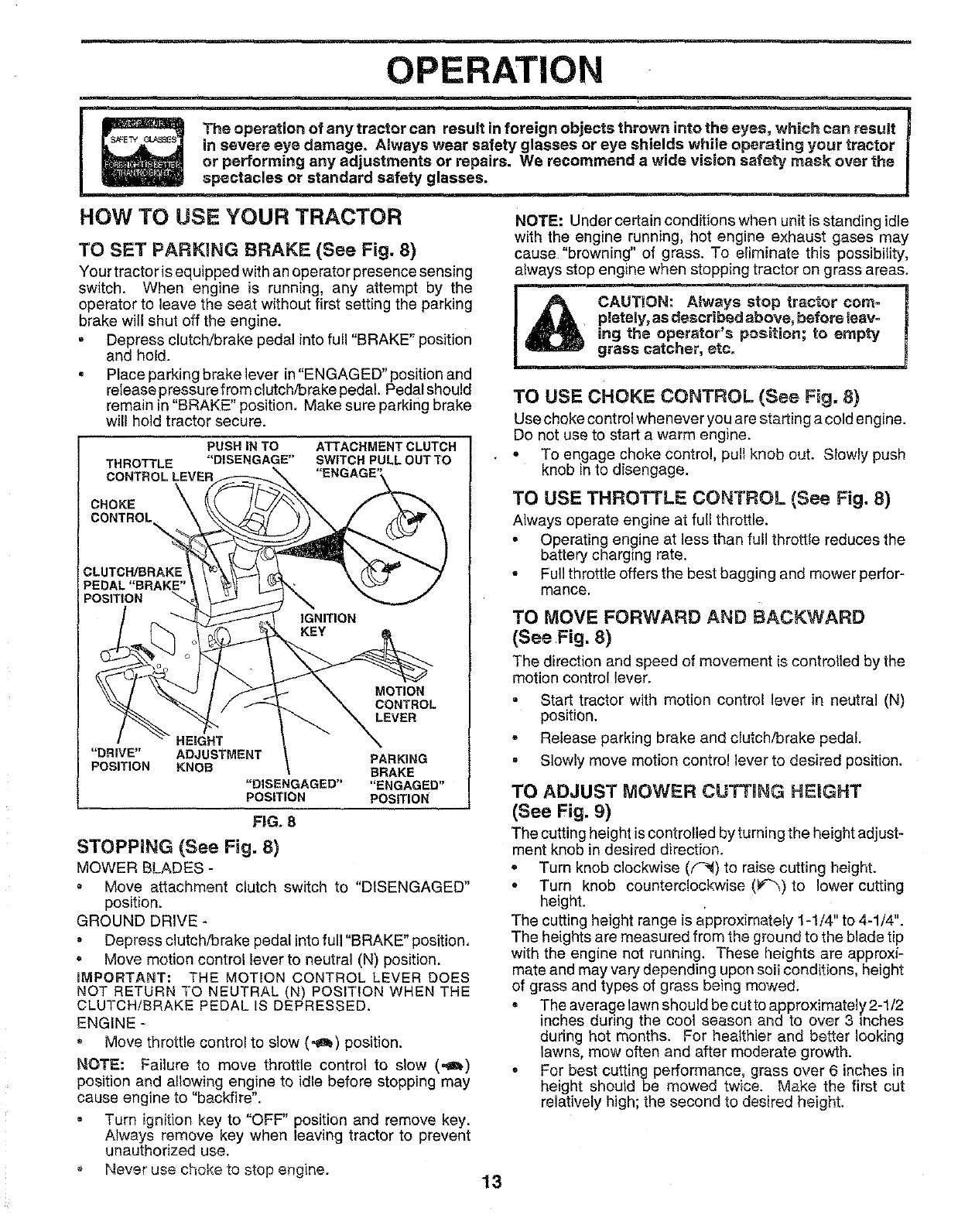
TO SET PARKmNG BRAKE (See Fig. 8)
Your tractor is equipped with an operator presence sensing
switch. When engine is running, any attempt by the
operator to leave the seat without first setting the parking
brake will shut off the engine.
,Depress clutch/brake pedal into full "BRAKE" position
and hold.
°Place parking brake lever in "ENGAGED" position and
release pressu refrom clutch/brake pedal Pedal should
remain in "BRAKE" position. Make sure parking brake
will hold tractor secure.
PUSH IN TO ATTACHMENT CLUTCH
THROTTLE "DISENGAGE" SWITCH PULL OUT TO
CONTROL LEVER
CHOKE
CONTROL\
CLUTCH/BRAK[
PEDAL "BRAKE"
POSITION
IGNITION
MOTION
CONTROL
LEVER
HEIGHT
"DRIVE" ADJUSTMENT PARKING
POSITION KNOB BRAKE
"DISENGAGED .... ENGAGED"
POSITION POSITION
FiG. 8
STOPPING (See Fig. 8)
MOWER BLADES -
"Move attachment clutch switch to "DISENGAGED"
position.
GROUND DRIVE -
• Depress clutch/brake pedal into full "BRAKE" position,
Move motion control lever to neutral (N) position.
JlVIPORTANT: THE MOTION CONTROL LEVER DOES
NOT RETURN TO NEUTRAL (N) POSIT!ON WHEN THE
CLUTCH/BRAKE PEDAL IS DEPRESSED.
ENGINE -
• Move throttle control to slow (._a_) position.
NOTE: Failure to move throttle control to slow (,_)
position and allowing engine to idle before stopping may
cause engine to "backfire".
Turn ignition key to "OFF" position and remove key.
Always remove key when leaving tractor to prevent
unauthorized use.
Never use choke to stop e_-_gine.
NOTE: Under certain conditions when unit is standing idle
with the engine running, hot engine exhaust gases may
cause "browning" of grass. To eliminate this possibility,
always stop engine when stopping tractor on grass areas.
TO USE CHOKE CONTROL (See Fig. 8)
use choke control whenever you are starting a cold engine.
De not use to start a warm engine,
° To engage choke Control, pull knob out, Slowly push
knob in to disengage.
TO USE THROTTLE CONTROL {See Fig. 8)
Always operate engine at full throttle.
° Operating engine at less than full throttle reduces the
battery charging rate.
•Full throttle offers the best bagging and mower perfor-
mance.
TO IVIOVE FORWARD AND BACKWARD
(See Fig. 8)
The direction and speed of movement is controlled by the
motion control lever,
° Start tractor with motion control lever in neutral (N)
position.
•Release parking brake and clutch/brake pedal.
° Slowly move motion control lever to desired position.
TO ADJUST MOWER CUTTHNG HEIGHT
(See Fig. 9)
The cutting height is controlled by turning the height adjust-
ment knob in desired direction.
•Turn knob clockwise (f_) to raise cutting height.
°Turn knob counterclockwise (P_)to lower cutting
height.
The cutting height range is approximately 1-1/4" to 4-1/4".
The heights are measured from the ground to the blade tip
with the engine not running. These heights are approxi-
mate and may vary depending upon soil conditions, height
of grass and types of grass being mowed.
• The average lawn should be cut to approximately 2-1/2
inches during the coot season and to over 3 inches
during hot months, For healthier and better looking
lawns, mow often and after moderate growth.
o For best cutting performance, grass over 6 inches in
height should be mowed twice. Make the first cut
relatively high; the second to desired height.
13
OPERATION
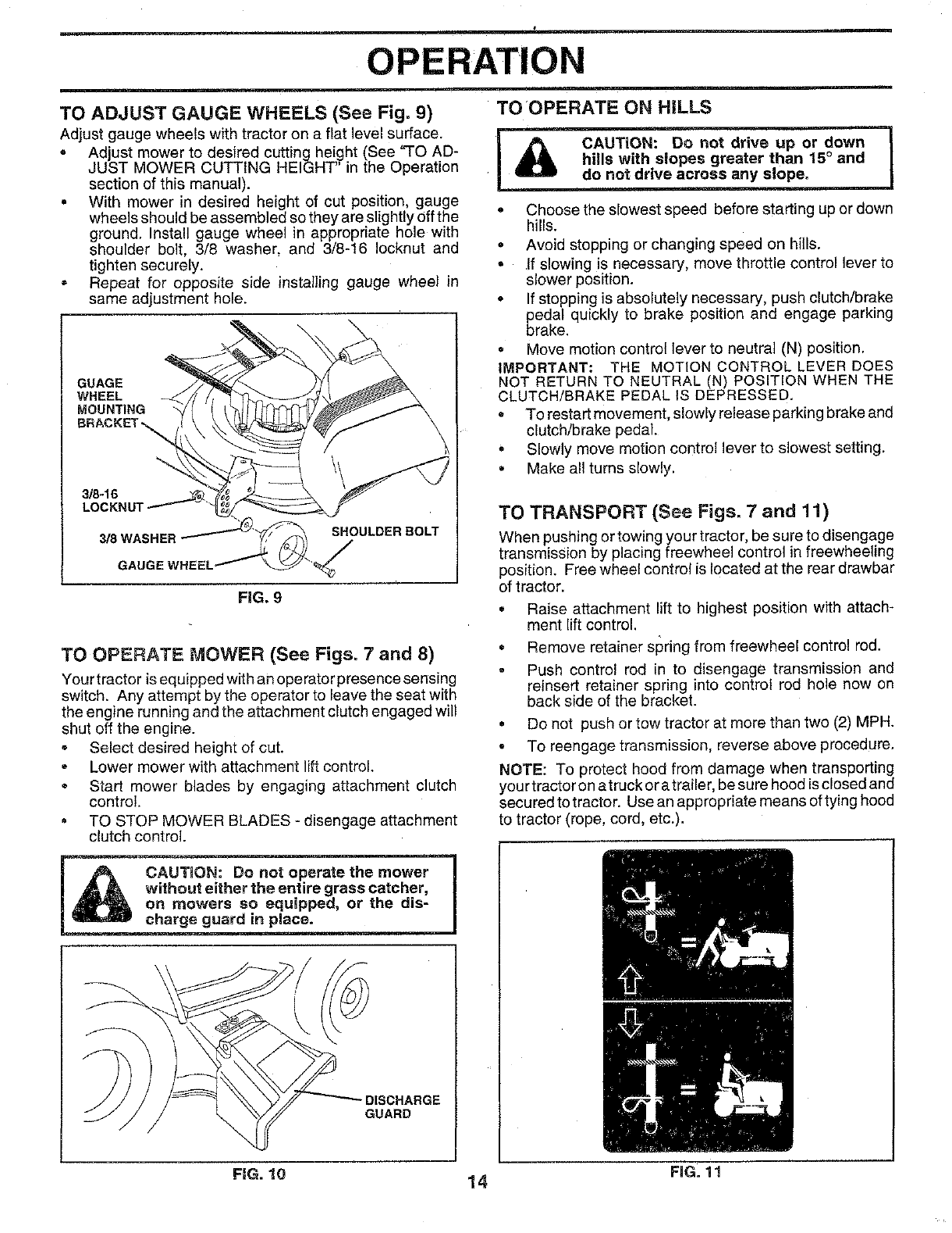
TO ADJUST GAUGE WHEELS (See Fig. 9) TO OPERATE ON HILLS
Adjust gauge wheels with tractor on a flat level surface.
• Ad ust mower to desired cutting height (See "TO AD-
JUST MOWER CUTT NG HE GHT n the Operation
section of this manual).
° With mower in desired height of cut position, gauge
wheels should be assembled so they are slightly off the
ground. Install gauge wheel in appropriate hole with
shoulder bolt, 3/8 washer, and 3/8-16 Iocknut and
tighten securely.
.Repeat for opposite side installing gauge wheel in
same adjustment hole.
GUAGE
WHEEL
MOUNTING
FIG. 9
TO OPERATE MOWER (See Figs, 7 and 8)
Your tractor is equipped withan operator presence sensing
switch. Any attempt by the operator to leave the seat with
the engine running and the attachment clutch engaged will
shut off the engine.
• Select desired height of cut.
= Lower mower with attachment lift control.
®Start mower blades by engaging attachment dutch
control.
• TO STOP MOWER BLADES - disengage attachment
clutch control.
oChoose the slowest speed before starting up or down
hills.
° Avoid stopping or changing speed on hills.
°If slowing is necessary, move throttle control lever to
slower position.
° If stopping is absolutely necessary, push clutch/brake
pedal quickly to brake position and engage parking
brake.
= Move motion control lever to neutral (N) position.
IMPORTANT: THE MOTION CONTROL LEVER DOES
NOT RETURN TO NEUTRAL (N) POSITION WHEN THE
CLUTCH/BRAKE PEDAL IS DEPRESSED.
o To restart movement, slowly release parking brake and
clutch/brake pedal.
°Slowly move motion control lever to slowest setting.
° Make all turns slowly.
TO TRANSPORT (See Figs. 7and 11)
When pushing or towing your tractor, be sure to disengage
transmission by placing freewheel control in freewheeling
position. Free wheel control is located at the rear drawbar
of tractor.
Raise attachment lift to highest position with attach-
ment lift control.
*Remove retainer st_ring from freewheel control rod.
Push control rod in to disengage transmission and
reinsert retainer spring into control rod hole now on
back side of the bracket.
° Do not push or tow tractor at more than two (2) MPH.
° To reengage transmission, reverse above procedure.
NOTE: To protect hood from damage when transporting
your tractoron atruck ora trailer, be sure hood is closed and
secured to tractor. Use an appropriate means of tying hood
to tractor (rope, cord, etc.).
CAUTION: Do not operate the mower
without either the entire grass catcher,
on mowers so equipped, or the dis-
charge guard in place.
,DISCHARGE
GUARD
FiG. !0 14 FiG. 11
OPERATION
BEFORE STARTING THE ENGINE
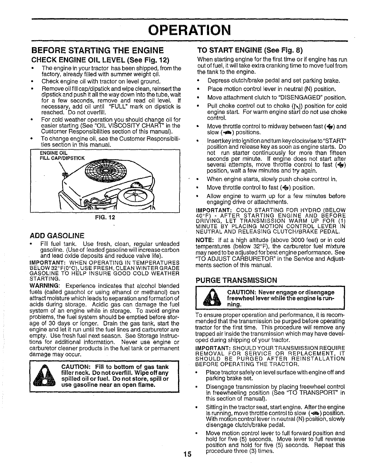
CHECK ENGINE OIL LEVEL (See Fig. 12)
• The engine in your tractor has been shipped, from the
factory, already filled with summer weight oil.
• Check engine oil with tractor on level ground.
o Remove oil fill cap/dipstick and wipe clean, reinsert the
dipstick and push itall the way down into the tube, wait
for a few seconds, remove and read oil level. If
necessary, add oil until "FULL" mark on dipstick is
reached. Do not overfill.
• For cold weather operation you should change oil for
easier starting (See "OIL VISCOSITY CHART" in the
Customer Responsibilities section of this manual).
• To change engine oi!, see the Customer Responsibili-
ties section in this manual.
ENGINE OIL
FILL CAP/DIPSTICK
FIG. 12
ADD GASOLINE
•Fill fuel tank. Use fresh, clean, regular unleaded
gasoline. (Use of leaded gasoline will increase carbon
and lead oxide deposits and reduce valve life).
IMPORTANT: WHEN OPERATING IN TEMPERATURES
BELOW 32°F(0°C), USE FRESH, CLEAN WINTER GRADE
GASOLINE TO HELP INSURE GOOD COLD WEATHER
STARTING.
WARNING: Experience indicates that alcohol blended
fuels (called gasohol or using ethanol or methanol) can
attract moisture which leads to separation and formation of
acids during storage. Acidic gas can damage the fuel
system of an engine while in storage. To avoid engine
problems, the fuel system should be emptied before stor-
age of 30 days or longer. Drain the gas tank, start the
engine and let it run until the fuel lines and carburetor are
empty. USe fresh fuel next season. See Storage Instruc-
tions for additional information. Never use engine or
carburetor cleaner products in the fuel tank or permanent
damage may occur.
_i to bottom of gas tank I
AA filler neck. Do notoverfill. Wipeoffany !
spiraled oil.or rue!. Do not store, spill or I
us_ ga_ine near an open flame.
TO START ENGINE (See Fig. 8)
When starting engine for the first time or if engine has run
out of fuel, itwill take extra cranking time to move fuel from
the tank to the engine,
.Depress clutch/brake pedal and set parking brake.
° Place motion control lever in neutral (N) position.
• Move attachment clutch to "DISENGAGED" position.
• Pull choke control out to choke (\I) position for cold
engine start, For warm eng ne start do not use choke
control.
•Move throttle control to midway between fast (4) and
slow (,_b) positions.
• lnsertkeyintoignitionandturnkeyclockwiseto"START"
position and release key as soon as engine starts. Do
not run starter continuously for more than fifteen
seconds per minute, tf engine does not start after
several attempts, move throttle control to fast (=_)
position, wait a few minutes and try again.
•When engine starts, slowly push choke control in.
•Move throttle control to fast (,_) position.
• Allow engine to warm up for a few minutes before
engaging drive or attachments.
IMPORTANT: COLD STARTING FOR HYDRO (BELOW
40°F) - AFTER STARTING ENGINE AND BEFORE
DRIVING, LET TRANSMISSION WARM UP FOR (It)N
MINUTE BY PLACING MOTION CONTROL LEVER
NEUTRAL AND RELEASING CLUTCH/BRAKE PEDAL.
NOTE: If at a high altitude (above 3000 feet) or in cold
temperatures (below 32°F), the carburetor fuel mixture
may need to be adjusted for best engine performance. See
'qO ADJUST CARBURETOR" in the Service and Adjust-
ments section of this manual.
15
PURGE TRANSMISSION
ning.
To ensure proper operation and performance, it is recom-
mended that the transmission be purged before operating
tractor for the first time. This procedure wif( remove any
trapped air inside the transmission which may have devel-
oped during shipping of your tractor.
IMPORTANT: SHOULD YOU.R TRANSMISSION REQUIRE
REMOVAL FOR SERVICE OR REPLACEMENT, IT
SHOULD BE PURGED AFTER REINSTALLATION
BEFORE OPERATING THE TRACTOR.
m
Place tractor safely on level surface withengine off and
parking brake set.
Disengage transmission by placing freewheel control
in freewheeling position (See "TO TRANSPORT" in
this section of manual).
Sitting inthe tractor seat, start engine. After the engine
is running, move throttle control to slow (,,a_) position.
With motion control lever in neutreJ (N) position, slowly
disengage clutch/brake pedal.
Move motion control lever to ful! fo_'ard position and
hold for five (5) seconds. Move lever to full reverse
position and hold for five (5) seconde. Repeat this
procedure three (3) times.
OPERATION
NOTE: During this procedure there wilt be no movement of
drive wheels. The air isbeing removed from hydraulic drive
system.
•Move motion control leverto neutral (N) position. Shut-
off engineand set parking brake.
• Engage transmission by placing freewheel control in
driving position (See "TO TRANSPORT' inthis section
of manual).
• Sitting inthetractor seat, start engine. After the engine
is running, move throttle control to half (1/2) speed.
With motion control lever in neutral (N) position, slowly
disengage clutch/brake pedal.
• Slowly move motion control lever forward, after the
tractor moves approximately five (5) feet, slowly move
motion control lever to reverse position. After the
tractor moves approximately five (5) feet return the
motion control lever tothe neutral (N) position. Repeat
this procedure with the motion control lever three (3)
times.
• Your tractor is now purged and now ready for normal
operation.
MOWING TiPS
• Tire chains cannot be used when the mower housing is
attached to tractor.
" Mower should be properly leveled for best mowing
performance. See "TO LEVEL MOWER HOUSING" in
the Service and Adjustments section of this manual.
• The left hand side of mower should be used for trim-
ming.
• Drive so that clippings are discharged onto the area
that has been cut. Have the cut area to the right of the
tractor. This wil! result in a more even distribution of
clippings and more uniform cutting.
•When mowing large areas, start byturning to the right
so that clippings will discharge away from shrubs,
fences, driveways, etc. After one or two rounds, mow
in the opposite direction making left hand turns until
finished (See Fig. 13).
•If grass is extremely tail, it should be mowed twice to
reduce load and possible fire hazard from dried clip-
pings. Make first cut relatively high; the second to the
desired height.
J
FIG. 13
• Do not mow grass when it is wet. Wet grass will plug
mower and leave undesirable clumps. Allow grassto
dry before mowing.
• Always operate engine at full throttle when mowing to
assure better mowing performance and proper dis-
charge of material. Regulate ground speed by select-
ing a low enough gear to give the mower cutting
performance as well as the quality of cut desired.
• When operating attachments, select a ground speed
that will suit the terrain and give best performance of
the attachment being used.
MULCHING MOWING TIPS
IMPORTANT: FOR BEST PERFORMANCE, KEEP
MOWER HOUSING FREE OF BUILT-UP GRASS AND
TRASH. CLEAN AFTER EACH USE.
The special mulching blade will recut the grass clip-
pings many times and reduce them in size so that as
they fall onto the lawn they will disperse into the grass
and not be noticed. Also, the mulched grass will
biodegrade quickly to provide nutrients for the lawn,
Always mulch With your highest engine (blade) speed
as this will provide the best recutting action of the
blades.
• Avoid cutting your lawn when it is wet. Wet grass tends
to form clumps and interferes with the mulching action.
The best time to mow your lawn is the early afternoon.
At this time the grass has dried and the newly cut area
will not be exposed to the direct sun.
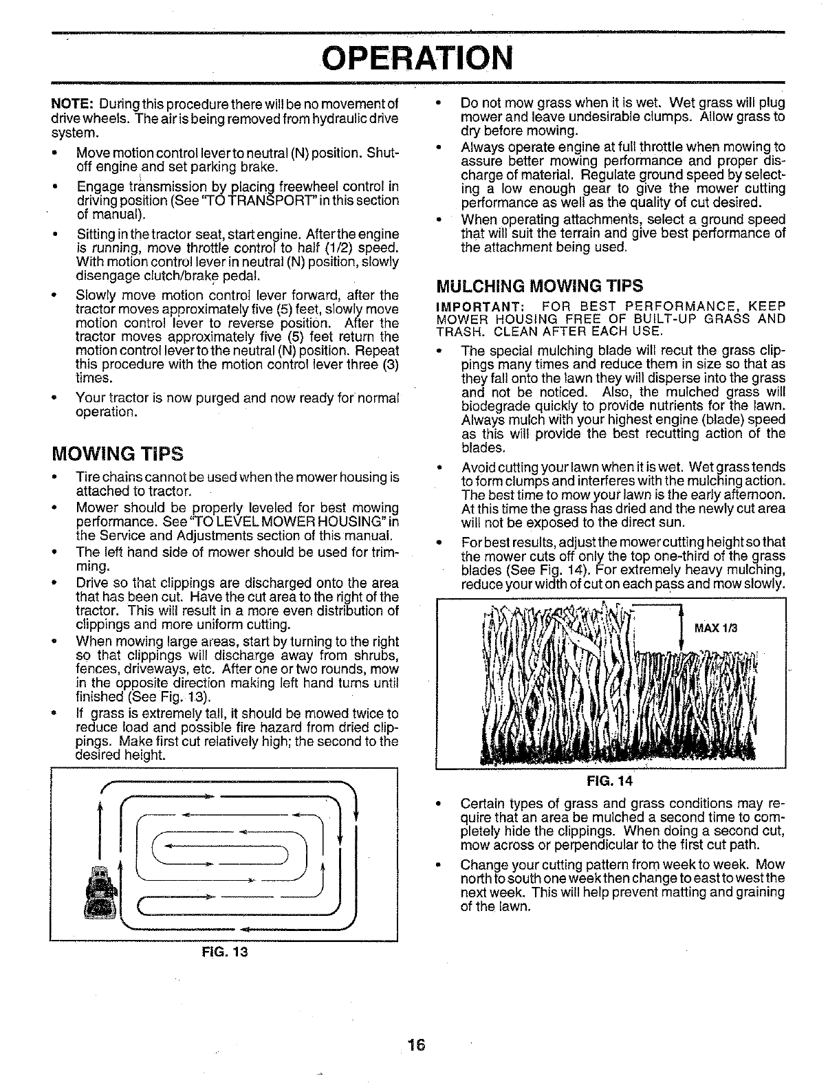
• For best results, adjust the mower cutting height so that
the mower cuts off only the top one-third of the grass
blades (See Fig. 14). For extremely heavy mulching,
reduce your width of cut on each pass and mow slowly.
FIG. 14
MAX 1/3
• Certain types of grass and grass conditions may ra-
quire that an area be mulched a second time to com-
pletely hide the clippings. When doing a second cut,
mow across or perpendicular to the first cut path.
• Change your cutting pattern from week to week. Mow
north to south one week then change to east to west the
next week. This will help prevent matting and graining
of the lawn.
16
CUSTOMER RESPONSIBILiTiES
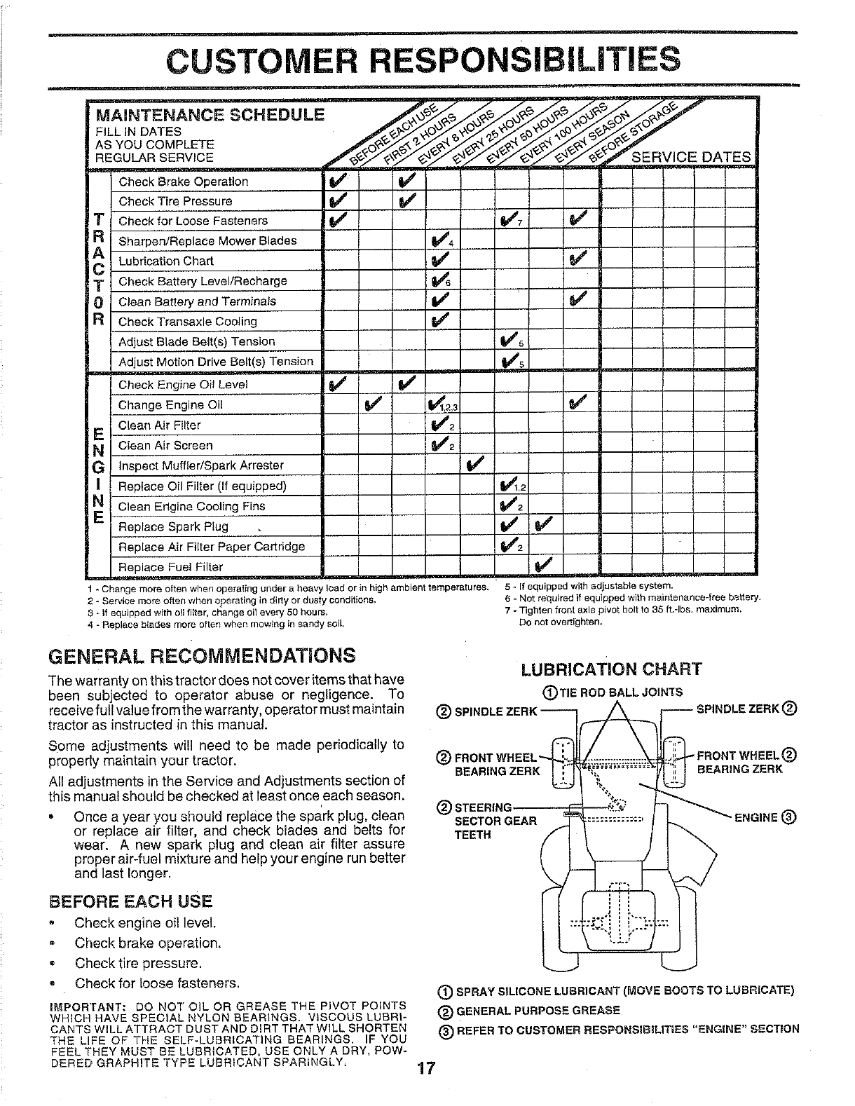
MAINTENANCE SCHEDULE
FILL IN DATES
AS YOU COMPLETE
REGULAR SERVICE ;ERVlCE DATES
Check Brake Operation
Check Tire Pressure I_ V'
Check for LooseFasteners V4' _7
Sharpen/Replace Mower Blades _4
LubricationChart _
Check Battery Level/Recharge
Clean Battery and Terminals if (_'
Check Transaxle Cooling f_
Adjust Blade Belt(s)Tension Ik_'5
Adjust Motion Drive Belt(s)Tension I_s
Check Engine Oil Level if _
Change Engine Oil (_' _1,2,_
Clean Air Filter _#_2
Clean Air Screen (t_2
Inspect Muffler/Spark Arrester V_
Replace Oil Filter(If equipped) _.2 __
Clean Engine Cooling Fins If2
Replace Spark Plug _
Replace Air Filter Paper Cartridge f_#_2
Replace Fuel Filter
1-Change more often when operating under a heavy load or in high ambient temperatures.
2 - Service more often when operating in dirty or dusty conditions,
3-I1 equipped with oil filter, change oii every 50 hours,
4 - Replace biades more often when mowing in sandy soil.
GENERAL RECOMMENDATIONS
The warranty on this tractor does not cover items that have
been subjected to operator abuse or negligence. To
receive full value from the warranty, operator must maintain
tractor as instructed in this manual.
Some adjustments wi!l need to be made periodically to
properly maintain your tractor.
Al! adjustments in the Service and Adjustments section of
this manual should be checked at least once each season.
• Once a year you should replace the spark plug, clean
or replace air filter, and check blades and belts for
wear. A new spark plug and clean air filter assure
proper air-fuel mixture and help your engine run better
and last longer.
BEFORE EACH USE
Check engine oil level,
Check brake operation.
• Check tire pressure.
•Check for loose fasteners.
5 - If equipped with adjustable system.
6-Not required if equipped with maintenance-free batter].
7 - Tighten front axle pivot bolt to 35 ft.-Ibs, maximum.
Do not overtighten.
LUBRICATION CHART
(DTIE ROD BALL JOINTS
(_) SPINDLE ZERK "--_
(_) FRONT WHEEL'_:_._
REARING ZERK
(_) STEERING
SECTOR GEAR _._
TEETH I i
IMPORTANT: DO NOT OIL OR GREASE THE PIVOT POINTS
WHICH HAVE SPECIAL NYLON BEARINGS. VISCOUS LUBRI-
CANTS WILL ATTRACT DUST AND DIRT THAT WILL SHORTEN
THE LIFE OF THE SELF-LUBRICATING BEARINGS. IF YOU
FEEL THEY MUST BE LUBRICATED, USE ONLY A DRY, POW-
DERED GRAPHITE "TYPE LUBRICANT SPARINGLY,
;PINOLE ZERK (_)
BEARING ZERK
(_) SPRAY SILICONE LUBRICANT (MOVE BOOTS TO LUBRICATE)
(_ GENERAL PURPOSE GREASE
(_) REFER TO CUSTOMER RESPONSIBmLITIES "ENGINE" SECTION
17

CUSTOMER ,RESPONSIBILITIES
TRACTOR TO SHARPEN BLADE (See Fig. 16)
Always observe safety rules when performing any mainte- Care should be taken to keep the blade balanced.
nance.
BRAKE OPERATION
If tractor requires more than six (6) feet stopping distance
at high speed inhighest gear, then brake must be adjusted.
(See 'q'O ADJUST BRAKE" in the Service and Adjust-
ments section of this manual).
TIRES
, Maintain proper air pressure in all tires (See "PROD-
UCT SPECIFICATIONS" on page 3 of this manual).
= Keep tires free of gasoline, oil, or insect control chemi-
cals which can harm rubber.
Avoid stumps, stones, deep ruts, sharp objects and
other hazards that may cause tire damage.
BLADE CARE
For best results mower blades must be kept sharp. Re-
place bent or damaged blades.
An
unbalanced blade willcause excessive vibration and even-
tual damage to mower and engine.
•The blade can be sharpened with a file or on a grinding
BLADE REMOVAL (See Fig. 15)
• Raise mower to highest position to allow access to
blades.
• Remove hex bolt, lock washer and flat washer securing
blade.
°Install new or resharpened blade with trailing edge up
towards deck-as shown.
• Reassemble hex bolt, lock washer and flat washer in
exact order as shown.
°Tighten bolt securely (30-35 Ft. Lbs. torque).
IMPORTANT: BLADE BOLT IS GRADE 8 HEAT TREATED.
NOTE: We do not recommend sharpening blade- but if you
de, be sure the blade is balanced.
MANDREL
BLADE
LOCK WASHER_
HEX BOLT
wheel. Do not attempt to sharpen while on the mower.
• To check blade balance, you will need a5/8" diameter
steel bolt, pin, or a cone balancer. (When using a cone
balancer, follow the instructions supplied with bal-
anger),
• Slide blade on to an unthreaded portion of the steel bolt
or pin and hold the bolt or pin parallel with the ground.
If blade is balanced, it should remain in a horizontal
position. If either end of the blade moves downward,
sharpen the heavy end until the blade is balanced.
NOTE: Do not use a nail for balancing blade. The lobes of
the center hole may appear to be centered, but are not.
TRAILING
EDGE UP
*A GRADE 8HEAT TREATED BOLT CAN BE
iDENTIFiED BY SIX LINES ON THE HOLT HEAD.
FiG. 15
518" BOLT
CENTER HOLE
FIG, 16
BLADE
BATTERY
Your tractor has a battery charging system which is suffi-
cient for normal use. However, periodic charging of the
battery with an automotive charger will extend its life.
• Keep battery and terminals clean.
°Keep battery bolts tight.
•Keep small vent holes open (See "CONNECT BAT-
TERY" in the Assembly section of this manual).
° Recharge at 6-10 amperes for 1 hour.
TO CLEAN BATTERY AND TERMINALS
Corrosion and dirt on the battery and terminals can cause
the battery to "leak" power.
• Remove terminal guard.
. Disconnect BLACK battery cable first then RED bat-
tery cable and remove battery from tractor.
,Wash battery with solution of four tablespoons of
baking soda to one gallon of water. Be careful not to get
the soda solution into the cells.
° Rinse the battery with plain water and dry.
. Clean terminals and battery cable ends with wire brush
until bright.
• Coat terminals with grease or petroleum jelly.
" Reinstall battery (See "CONNECT BATTERY" in the
Assembly section of this manual).
18
CUSTOMER
TRANSAXLE COOLING
RESPONSIBILITi
The fan and cooling fins of transmission should be kept
clean to assure proper cooling,
Do not attempt to clean fan or transmission while engine is
running or while the transmission is hot. To prevent
possible damage to seals, no not use high pressure water
or steam to clean transaxle.
-Inspect cooling fan to be sure fan blades are intact and
clean.
•Inspect cooling fins for dirt, grass clippings and other
materials. To prevent damage to seals, do not use
compressed air or high pressure sprayer.
TRANSAXLE PUMP FLUID
The transaxle was sealed at the factory and fluid mainte-
nance is not required for the life of the transaxle. Should
the transaxle ever leak or require servicing, contact your
nearest authorized service center/department.
V-BELTS
Check V-belts for deterioration and wear after 100 hours of
operation and replace if necessary. The belts are not
adjustable. Replace belts if they begin to slip from wear.
ENGINE
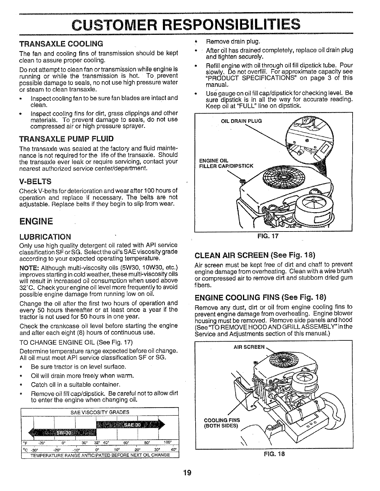
* Remove drain plug.
, After oil has drained completely, replace oil drain plug
and tighten securely.
° Refill engine with oil through oil fill dipstick tube. Pour
slowly, Do not overfill. For approximate capacity see
"PRODUCT SPECIFICATIONS" on page 3 of this
manual,
,Use gauge on oil fill cap/dipstick for checking level. Be
sure dipstick is in all the way for accurate reading.
Keep oil at "FULL" line on dipstick.
OIL DRAIN PLUG
ENGINE OIL
FILLER CAP/DIPSTICK
LUBRICATION
Only use high quality detergent oil rated with API service
classification SF or SG. Select the oi!'s SAE viscosity grade
according to your expected operating temperature.
NOTE: Although multi-viscosity oils (5W30, 10W30, etc.)
improves starting in cold weather, these multi-viscosity oils
will result in increased oi! consumption when used above
32°C. Checkyourengine oil level more frequently to avoid
possible engine damage from running low on oil.
Change the oil after the first two hours of operation and
every 50 hours thereafter or at least once a year if the
tractor is not used for 50 hours in one year.
Check the crankcase oil level before starting the engine
and after each eight (8) hours of continuous use.
TO CHANGE ENGINE OIL (See Fig, 17)
Determine temperature range expected before oil change.
All oil must meet API service classification SF or SG,
oBe sure tractor is on level surface.
• Oil will drain more freely when warm.
• Catch oil in a suitable container.
,Remove oil fill cap/dipstick. Be careful not to altow dirt
to enter the engine when changing oil.
SAE VISCOSITY GRADES
_20° 30° 60_
-30 _ -20 _ -I 0 ° 0_ 20 _ 30 °
TEMPERATURE RANGE ANTICIPATED BEFORE NEXT OIL CHANGE
FIG. 17
CLEAN AIR SCREEN (See Fig. 18)
Air screen must be kept free of dirt and chaff to prevent
engine damage from overheating. Clean with a wire brush
or compressed air to remove dirt and stubborn dried gum
fibers.
ENGINE COOLING FINS (See Fig. 18)
Remove any dust, dirt or oi! from engine cooling fins to
prevent engine damage from overheating. Engine blower
housing must be removed. Remove side panels and hood
(Bee"TO REMOVE HOOD AND GRILL ASSEMBLY" in the
Service and Adjustments section of this manual.)
\
\
COOLING FINS
(BOTH SIDES)
FIG. 18
19
CUSTOMER RESPONSIBILITIES
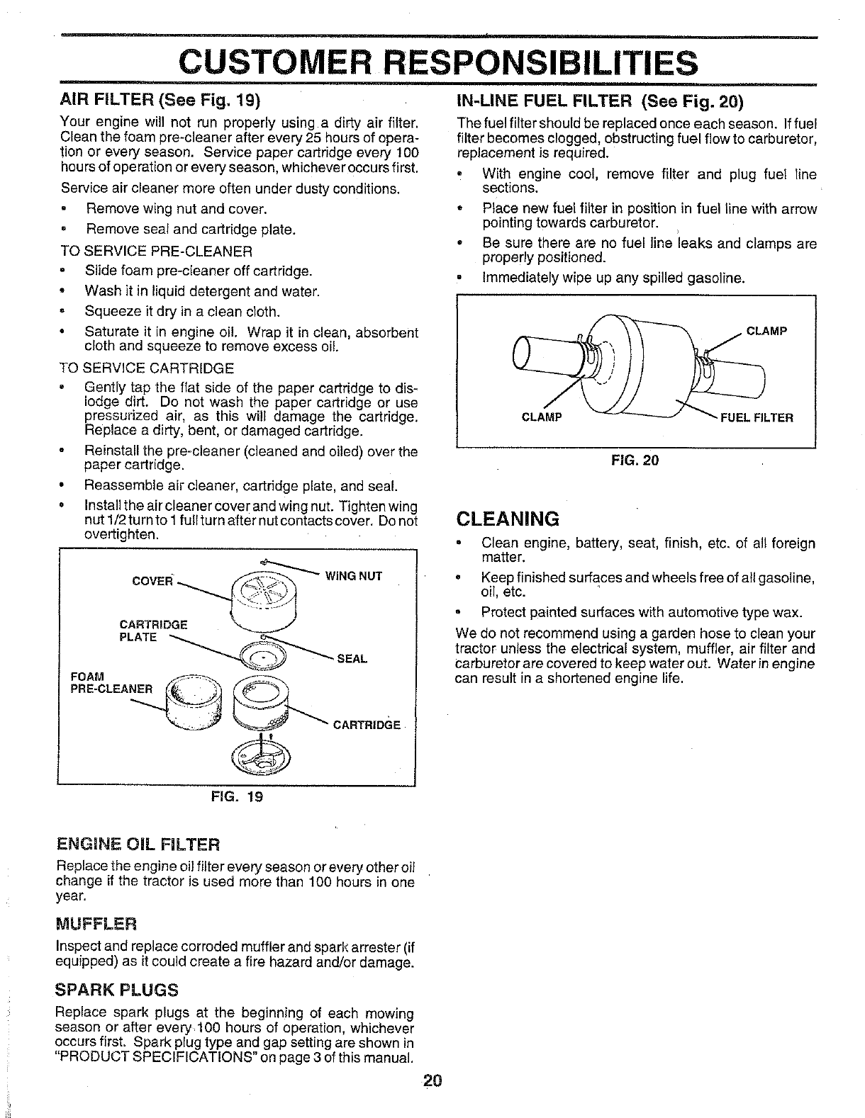
AIR FILTER (See Fig. 19)
Your engine will not run properly using a dirty air filter.
Clean the foam pre-cleaner after every 25 hours of opera-
tion or every season. Service paper cartridge every t00
hours of operation or every season, whichever occurs first.
Service air cleaner more often under dusty conditions.
Remove wing nut and cover.
• Remove seal and cartridge plate.
TO SERVICE PRE-CLEANER
• Slide foam pre-cleaner off cartridge.
• Wash it in liquid detergent and water.
° Squeeze it dry in a clean cloth.
• Saturate it in engine oil. Wrap it in clean, absorbent
cloth and squeeze to remove excess oi!.
TO SERVICE CARTRIDGE
° Gently tap the flat side of the paper cartridge to dis-
lodge dirt. Do not wash the paper cartridge or use
pressurized air, as this will damage the cartridge.
Replace a dirty, bent, or damaged cartridge.
Reinstall the pre-cleaner (cleaned and oiled) over the
paper cartridge.
• Reassemble air cleaner, cartridge plate, and seal.
• Installtheaircleanercoverandwingnut. Tightenwing
nut 1/2turnto I fullturn after nut contacts cover. Donot
overtighten.
- ,--_"_'_ WING
covE. NOT
CARTRIDGE "-.._..__..._/
PLATE _o,_,.....,_ SEAL
0ARTRIDGE
IN-LINE FUEL FILTER (See Fig. 20)
The fuel filter should be replaced once each season. If fuel
filter becomes clogged, obstructing fuel flow to carburetor,
replacement is required.
•With engine cool, remove filter and plug fuel line
sections.
• Place new fuel filter in position in fuel line with arrow
pointing towards carburetor.
• Be sure there are no fuel line leaks and clamps are
properly positioned.
•Immediately wipe up any spilled gasoline.
FIG. 20
CLEANING
° Clean engine, battery, seat, finish, etc. of all foreign
matter.
• Keep finished surfaces and wheels free of all gasoline,
oil, etc.
oProtect painted surfaces with automotive type wax.
We do not recommend using a garden hose to clean your
tractor unless the electrical system, muffler, air filter and
carburetor are covered to keep water out. Water in engine
can result in a shortened engine life.
FIG. 19
ENGINE OIL FILTER
Replace the engine oil filter every season or every other oi!
change if the tractor is used more than t00 hours in one
year.
MUFFLER
Inspect and replace corroded muffler and spark arrester (if
equipped) as it could create a fire hazard and/or damage.
SPARK PLUGS
Replace spark plugs at the beginn!ng of each mowing
season or after every 100 hours of operation, whichever
occurs first. Spark plug type and gap setting are shown in
"PRODUCT SPECIFICATIONS" on page 3 of this manual.
20
SERVICE AND ADJUSTMENTS
CAUTION: BEFORE PERFORMING ANY SERVICE OR ADJUSTMENTS:
=Depress clutch/brake pedal fully and set parking brake.
°Place motion control lever in neutral (N) position.
=Place attachment clutch in "DISENGAGED" position.
° Turn ignition key "OFF" and remove key.
° Make sure the blades and all moving parts have completely stopped.
°Disconnect spark plug wire from spark plug and place wire where it cannot come in contact with
plug.
TRACTOR
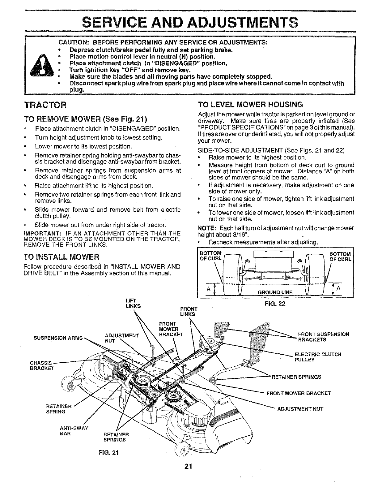
TO REMOVE MOWER (See Fig. 21)
, Place attachment clutch in "DISENGAGED" position.
= Turn height adjustment knob to lowest setting.
Lower mower to its lowest position.
= Remove retainer spring holding anti-swaybar to chas-
sis bracket and disengage anti-swaybar from bracket.
, Remove retainer springs from suspension arms at
deck and disengage arms from deck.
Raise attachment lift to its highest position.
• Remove two retainer springs from each front link and
remove links.
Slide mower forward and remove belt from electric
clutch pulley.
• Slide mower out from under Hght side of tractor.
IMPORTANT: LF AN ATTACHME_NT OTHER THAN THE
MOWER DECK IS TO BE MOUNTED ON THE TRACTOR,
REMOVE THE FRONT LINKS.
TO INSTALL MOWER
Follow procedure describaa in "INSTALL MOWER AND
DRIVE BELT' in the Assembly section of this manual.
LIFT
LINKS FRONT
LINKS
TO LEVEL MOWER HOUSING
Adjust the mower while tractor is parked on level ground or
driveway. Make sure tires are properly inflated (See
"PRODUCT SPECIFICATIONS" on page 3 of this manual).
If tires are over or underinflated, you wil not properly adjust
your mower.
SIDE-TO-SIDE ADJUSTMENT (See Figs. 21 and 22)
• Raise mower to its highest position.
• Measure height from bottom of deck curl to ground
level at front corners of mower. Distance "A" on both
sides of mower should be the same.
• If adjustment is necessary, make adjustment on one
side of mower only.
•To raise one side of mower, tighten lift link adjustment
nut on that side.
° To lower one side of mower, loosen lift Ink adjustment
nut on that side.
NOTE: Each half turn of adjustment nut wil change mower
height about 3/16".
Recheck measurements after adjusting.
FIG. 22
SUSP! NUT
FRONT
MOWER
BRACKET FRONT SUSPENSION
BRACKETS
BRACKET
ELECTRIC CLUTCH
PULLEY
RETAINER SPRINGS
RETAINER
SPRING
FRONT MOWER BRACKET
ADJUSTMENT NUT
ANTI-SWAY
BAR RETAINER
SPRINGS
21
SERVICE AND ADJUSTMENTS
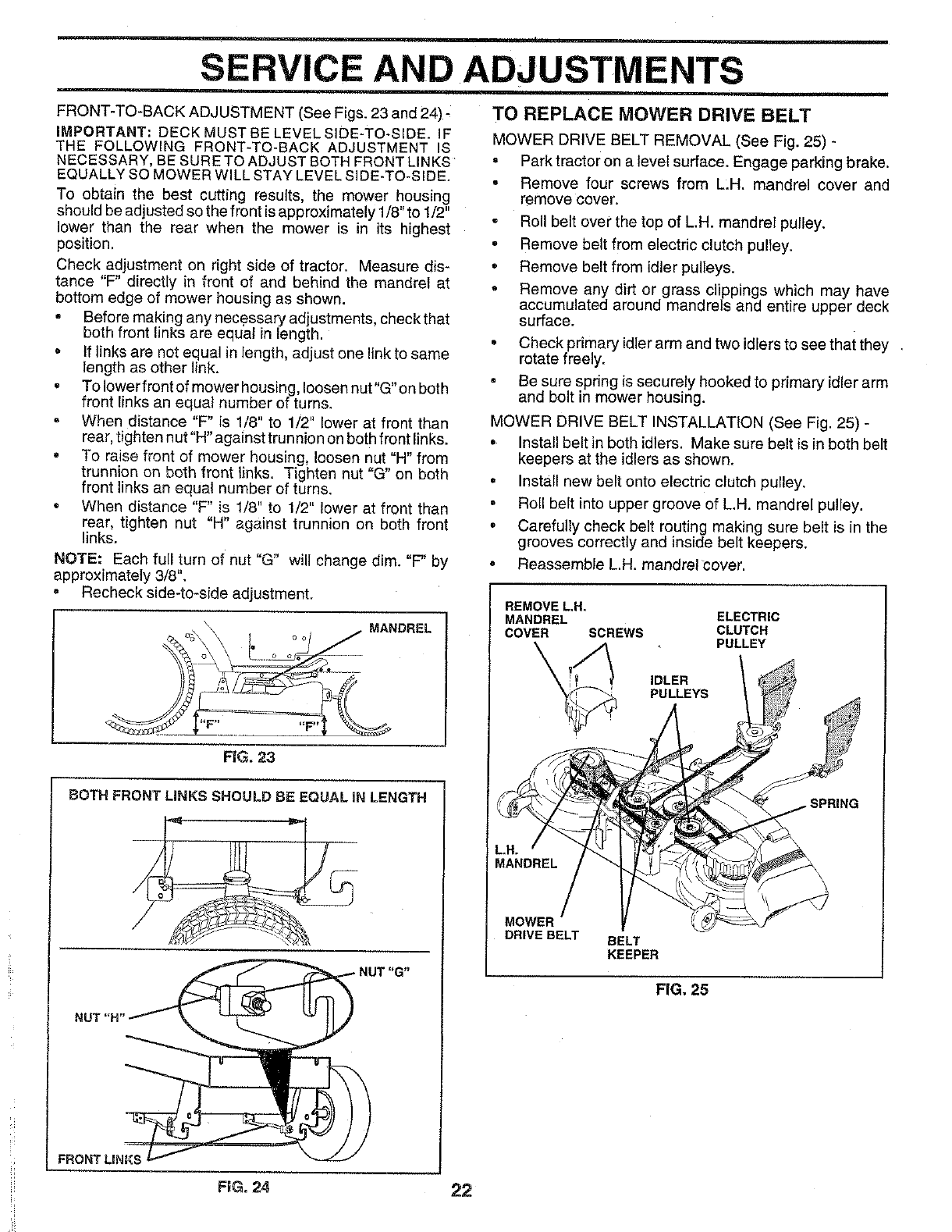
FRONT-TO-BACK ADJUSTMENT (See Figs. 23 and 24) -
IMPORTANT: DECK MUST BE LEVEL SIDE-TO-SIDE. IF
THE FOLLOWING FRONT-TO-BACK ADJUSTMENT IS
NECESSARY, BE SURE TO ADJUST BOTH FRONT LINKS
EQUALLY SO MOWER WILL STAY LEVEL SIDE-TO-SIDE.
To obtain the best cutting results, the mower housing
should be adjusted so the front is approximately 1/8" to 1/2"
lower than the rear when the mower is in its highest
position,
Check adjustment on right side of tractor. Measure dis-
tance "F" directly in front of and behind the mandrel at
bottom edge of mower housing as shown.
Before making any necessary adjustments, check that
both front links are equal in length.
o If links are not equal in length, adjust one link to same
length as other link.
• To lower front of mower housing, loosen nut"G"on both
front links an equal number of turns.
When distance "F" is 1/8" to 1/2" lower at front than
rear, tighten nut"H" against trunnion on both front links.
° To raise front of mower housing, loosen nut "H" from
trunnion on both front links. Tighten nut "G" on both
front links an equal number of turns.
° When distance "F" is !/8" to 1/2" lower at front than
rear, tighten nut "H" against trunnion on both front
links.
NOTE: Each full turn of nut "G" will change dim. "F" by
approximately 3/8".
° Recheck side-to-side adjustment.
MANDREL
FiG. 23
BOTH FRONT LINKS SHOULD BE EQUAL iN LENGTH
NUT "G"
NUT "H'
FRONT LINKS
TO REPLACE MOWER DRIVE BELT
MOWER DRIVE BELT REMOVAL (See Fig. 28) -
= Park tractor on a level surface. Engage parking brake.
°Remove four screws from LH. mandrel cover and
remove cover.
• Roll belt over the top of L,H. mandrel pulley.
° Remove belt from electric clutch pulley.
°Remove belt from {dler pulleys.
°Remove any dirt or grass clippings which may have
accumulated around mandrels and entire upper deck
surface.
=Check primary idlerarm and two idlers to see that they
rotate freely.
= Be sure spring is securely hooked to primary idler arm
and bolt in mower housing.
MOWER DRIVE BELT INSTALLATION (See Fig, 25) -
° Install belt in both idlers. Make sure belt is in both belt
keepers at the idlers as shown.
°Install new belt onto electric clutch pulley.
• Roll belt into upper groove of L.H. mandrel pulley.
• Carefully check belt routing making sure belt is in the
grooves correctly and inside belt keepers.
• Reassemble L.H. mandrel cover.
REMOVE LH.
MANDREL ELECTRIC
COVER SCREWS CLUTCH
PULLEY
IDLER
PULLEYS
• SPRING
MANDREL
MOWER
DRIVE BELT BELT
KEEPER
FiG. 25
FEG.24 22
SERVICE AND ADJUSTMENTS
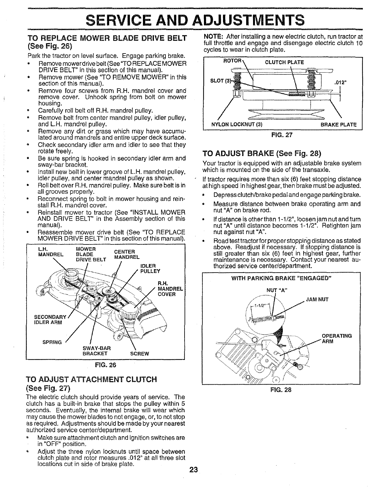
TO REPLACE MOWER BLADE DRIVE BELT
(See Fig, 26)
Park the tractor on level surface, Engage parking brake.
• Remove mowerdrive belt (See"TO REPLACE MOWER
DRIVE BELT" in this section of this manual).
° Remove mower (See '`TO REMOVE MOWER" in this
section of this manual).
• Remove four screws from R.H. mandrel cover and
remove cover. Unhook spring from bolt on mower
housing.
•Carefully roll belt off R.H. mandrel pulley.
, Remove belt from center mandrel pulley, idler pulley,
and L.H. mandrel pulley.
° Remove any dirt or grass which may have accumu-
lated around mandrels and entire upper deck surface.
• Check secondary idler arm and idler to see that they
rotate freely.
° Be sure spring is hooked in secondary idler arm and
sway-bar bracket.
• install new belt in lower groove of L.H. mandrel pulley,
idler pulley, and center mandrel pulley as shown.
•Roll belt over R.H. mandrel pulley. Make sure belt is in
all grooves properly.
,Reconnect spring to bolt in mower housing and rein-
stall R.H. mandrel cover.
° Reinstall mower to tractor (See "INSTALL MOWER
AND DRIVE BELT" in the Assembly section of this
manual).
°Reassemble mower drive belt (See "TO REPLACE
MOWER DRIVE BELT" in this section of this manual).
L.H. MOWER
MANDREL BLADE CENTER
\DRIVE BELT MANDREL IDLER
\_._---_i _ _/ COVER
SPRING
SWAY-BAR
BRACKET SCREW
F_G. 26
TO ADJUST ATTACHMENT CLUTCH
(See Fig. 27)
The electric clutch should provide years of service. The
clutch has a built-in brake that stops the pulley within 5
seconds. Eventually, the internal brake will wear which
may cause the mower blades to not engage, or, to not stop
as required. Adjustments should be made by your nearest
authorized service center/department.
= Make sure attachment clutch and ignition switches are
in "OFF" position.
Adjust the three nylon Iocknuts until space between
clutch plate and rotor measures .012" at all three slot
locations cut in side of brake plate.
NOTE: After installing a new electric clutch, run tractor at
full throttle and engage and disengage electric clutch 10
cycles to wear in clutch plate.
NYLON LOCKNUT(3)
CLUTCH PLATE
,012"
BRAKE PLATE
FIG, 27
TO ADJUST BRAKE (See Fig. 28)
Your tractor is equipped with an adjustable brake system
which is mounted on the side of the transaxle.
if tractor requires more than six (6) feet stopping distance
at high speed in highest gear, then brake must be adjusted.
°Depress clutch/brake pedal and engage parking brake.
°Measure distance between brake operating arm and
nut "A" on brake rod.
If distance is other than 1-1/2", loosen jam nut and turn
nut"A" until distance becomes 1-1/2". Retighten jam
nut against nut "A".
Road test tractor for proper stopping distance as stated
above. Readjust if necessary. If stopping distance is
still greater than six (6) feet in highest gear, further
maintenance is necessary. Contact your nearest au-
thorized service center/department.
WITH PARKING BRAKE "ENGAGED"
NUT"A"
JAM NUT
OPERATING
ARM
FIG. 28
23
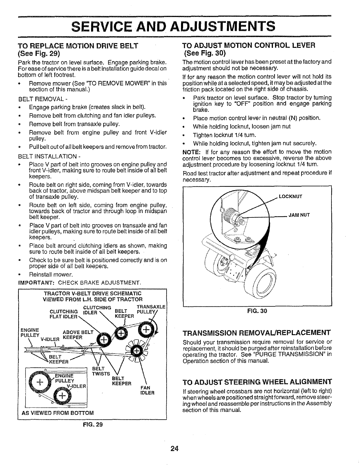
SERVICE AND ADJUSTM !NTS
TO REPLACE MOTION DRIVE BELT
(See Fig. 29)
Park the tractor on level surface. Engage parking brake.
For ease of service there is a belt installation guide decal on
bottom of left footrest.
• Remove mower (See "TO REMOVE MOWER" in this
section of this manual.)
BELT REMOVAL -
° Engage parking brake (creates slack in belt).
° Remove belt from clutching and fan idler pulleys.
° Remove belt from transaxfe pulley.
=Remove belt from engine pulley and front V-idler
pulley.
• Pull belt out of all belt keepers and remove from tractor.
BELT INSTALLATION -
•Place V part of belt into grooves on engine pulley and
front V-idler, making sure to route belt inside of all belt
keepers.
, Route belt on right side, coming from V-idler, towards
back of tractor, above midspan belt keeper and to top
of transaxle pulley.
° Route belt on left side, coming from engine pulley,
towards back of tractor and through loop in rnidspan
belt keeper.
° Place V part of belt into grooves on transaxle and fan
idler pulleys, making sure to route belt inside of all belt
keepers.
•Place belt around clutching idlers as shown, making
sure to route belt inside of all belt keepers.
•Check to be sure belt is positioned correctly and is on
proper side of all belt keepers.
,, Reinstall mower.
IMPORTANT: CHECK BRAKE ADJUSTMENT.
TRACTOR V-BELT DRIVE SCHEMATIC
VIEWED FROM L,R. SIDE OF TRACTOR
CLUTCHING TRANSAXLE
CLUTCHING BELT
KEEPER
ENGINE ABOVE
PULLEY V-iDLER KEEPER
BELT
TWISTS BELT
KEEPER FAN
IDLER
TO ADJUST MOTION CONTROL LEVER
(See Fig. 30)
The motioncontrol lever has been preset at the factory and
adjustment should not be necessary.
If for any reason the motion control lever will not hold its
position while at a selected speed, it may be adjusted at the
friction pack located on the right side of chassis.
• Park tractor on level surface. Stop tractor by turning
ignition key to "OFF" position and engage parking
brake.
•Place motion control lever in neutral (N) position.
° While holding Iocknut, loosen jam nut
°Tighten Iocknut 1/4turn.
•While holding locknut, tighten jam nut securely.
NOTE: If for any reason the effort to move the motion
control lever becomes too excessive, reverse the above
adjustment procedure by loosening locknut 1/4 turn.
Road test tractor after adjustment and repeat procedure if
necessary.
LOCKNUT
JAM NUT
FIG. 30
TRANSMISSION REMOVAL/REPLACEMENT
Should your transmission require removal for service or
replacement, it should be purged after reinstallation before
operating the tractor. See "PURGE TRANSMISSION" in
Operation section of this manual.
TO ADJUST STEERING WHEEL ALIGNMENT
If steering wheel crossbars are not horizontal (left to right)
when wheels are positioned straight forward, remove steer-
ing wheel and reassemble per instructions in the Assembly
section of this manual.
FiG. 29
24
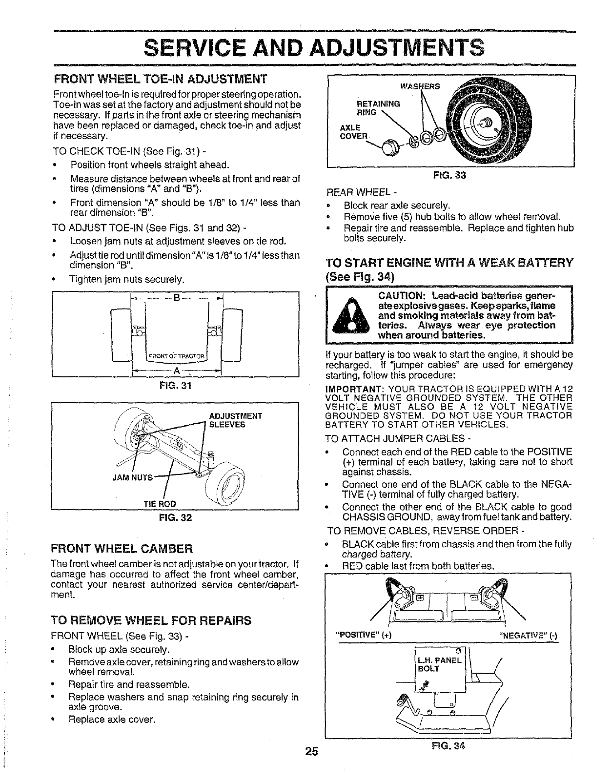
SERVICE AND ADJUSTMENTS
FRONT WHEEL TOE=IN ADJUSTMENT
Front wheel toe-in is required for proper steering operation.
Toe-in was set at the factory and adjustment should not be
necessary. Ifparts in the front axle or steering mechanism
have been replaced or damaged, check toe-in and adjust
if necessary.
TO CHECK TOE-IN (See Fig. 31) -
•Position front wheels straight ahead.
•Measure distance between wheels at front and rear of
tires (dimensions "A" and "B").
° Front dimension "A" should be 1/8" to 1/4" less than
rear dimension "B".
TO ADJUST TOEqN (See Figs. 31 and 32) -
• Loosen jam nuts at adjustment sleeves on tie rod,
° Adjusttieroduntitdimension"A"isl/8"tol/4"lessthan
dimension "B".
° Tighten jam nuts securely.
FiG. 31
ADJUSTMENT
rSLEEVES
!
TIE ROD
FiG. 32
FRONT WHEEL CAMBER
The front wheel camber is not adjustable on your tractor, If
damage has occurred to affect the front wheel camber,
contact your nearest authorized service centeddepart-
ment,
TO REMOVE WHEEL FOR REPAIRS
FRONT WHEEL (See Fig. 33) -
•Block up axle securely.
Remove axle cover, retaining ring and washers to allow
wheel removal.
• Repair tire and reassemble.
•Replace washers and snap retaining ring securely in
axle groove.
° Replace axle cover.
WAS
RETAINING
RING
AXLE
COVER
FiG. 33
REAR WHEEL -
•Block rear axle securely.
= Remove five (5) hub bolts to allow wheel removal.
o Repair tire and reassemble. Replace and tighten hub
bolts securely.
TO START ENGINE WITH A WEAK BATTERY'
(See Fig. 34)
•_a mdbatteries gener-
_ ateexplosive gases. Keep sparks, flame
I_andsmok'mg materials away from bat-
J _ t_ys.wear eye protection
.,=-=w when around batteries.
tf your battery is too weak to start the engine, it should be
recharged, If "jumper cables" are used for emergency
starting, follow this procedure:
IMPORTANT: YOUR TRACTOR IS EQUIPPED WITH A 12
VOLT NEGATIVE GROUNDED SYSTEM. THE OTHER
VEHICLE MUST ALSO BE A 12 VOLT NEGATIVE
GROUNDED SYSTEM. DO NOT USE YOUR TRACTOR
BATTERY TO START OTHER VEHICLES.
TO ATTACH JUMPER CABLES -
• Connect each end of the RED cable to the POSITIVE
(+) terminal of each battery, taking care not to short
against chassis•
°Connect one end of the BLACK cable to the NEGA-
TIVE (-) terminal of fully charged battery.
oConnect the other end of the BLACK cable to good
CHASSIS GROUND, away from rue! tank and battery.
TO REMOVE CABLES, REVERSE ORDER -
, BLACK cable first from chassis and then from the fully
charged battery.
RED cable last from both batteries.
"POSITIVE" (+) "NEGATIVE" (-)
25 FIG, 34
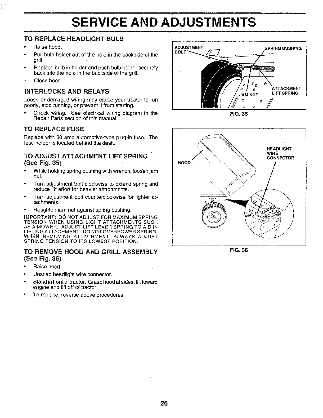
SERVICE AND ADJUSTMENTS
TO REPLACE HEADLIGHT BULB
• Raise hood. ADJUSTMENT SPRINGRUSHING
•Pull bulb holder out of the hole in the backside of the
grill.
,Replace bulb in holder and push bulb holder securely
back into the hole in the backside of the grill.
° Close hood.
INTERLOCKS AND RELAYS
Loose or damaged wiring may cause your tractor to run
poorly, stop running, or prevent it from starting.
° Check wiring; See'electrical wiring diagram in the
Repair Parts section of this manual.
ATTACHMENT
JAMNUT LIFTSPRING
FIG. 35
TO REPLACE FUSE
Replace with 30 amp automotive-type plug-in fuse. The
fuse holder is located behind the dash.
TO ADJUST ATTACHMENT LIFT SPRING
(See Fig. 35}
° While holding spring bushing with wrench, loosen jam
nut.
• Turn adjustment bolt clockwise to extend spring and
reduce lift effort for heavier attachments.
• Turn adjustment bolt counterclockwise for lighter at-
tachments.
° Retighten jam nut against spring bushing.
IMPORTANT: DC) NOT ADJUST FOR MAXIMUM SPRING
TENSION WHEN USING LIGHT ATTACHMENTS SUCH
AS A MOWER. ADJUST LIFT LEVER SPRING TO AID IN
LIFTING ATTACHMENT, DO NOT OVERPOWER SPRING.
WHEN REMOVING ATTACHMENT, ALWAYS ADJUST
SPRING TENSION TO iTS LOWEST POSITION.
HOOD
HEADLIGHT
WIRE
CONNECTOR
TO REMOVE HOOD AND GRILL ASSEMBLY
(See Fig. 36)
°Raise hood.
•Unsnap headlight wire connector.
• Stand infront of tractor. Grasp hood at sides, tilttoward
engine and lift off of tractor.
° To replace, reverse above procedures.
FIG. 36
26
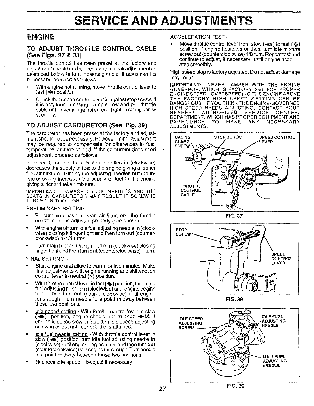
SERVICE AND ADJUSTMENTS
ENGINE
TO ADJUST THROTTLE CONTROL CABLE
(See Figs, 37 & 38)
The throttle control has been preset at the factory and
adjustment should not be necessary. Check adjustment as
described below before loosening cable. If adjustment is
necessary, proceed as follows:
With engine not running, move throttle control lever to
fast (,_) position.
. Check that speed control lever is against stop screw. If
it is not, loosen casing clamp screw and pull throttle
cable until lever is against screw. Tighten clamp screw
securely.
TO ADJUST CARBURETOR (See Fig. 39)
The carburetor has been preset at the factory and adjust-
ment should not be necessary. However, minor adjustment
may be required to compensate for differences in fue!,
temperature, altitude or load. if the carburetor does need
adjustment, proceed as follows:
In general, turning the adjusting needles in (clockwise)
decreases the supply of fuel to the engine giving a leaner
fuel/air mixture. Turning the adjusting needles out (coun-
terclockwise) increases the supply of fuel to the engine
giving a richer fuel/air mixture.
IMPORTANT: DAMAGE TO THE NEEDLES AND THE
SEATS IN CARBURETOR MAY RESULT IF SCREW IS
TURNED IN TOO TIGHT.
PRELIMINARY SETTING -
ACCELERATION TEST -
• Move throttle control lever from slow (,_) to fast (,_)
position. If engine hesitates or dies, turn idle mixture
screw out (counterclockwise) 1/8 turn. Repeat test and
continue to adjust, if necessary, untff engine acceler-
ates smoothly.
High speed stop is factory adjusted. Do not adjust_damage
may result.
IMPORTANT: NEVER TAMPER WITH THE ENGINE
GOVERNOR, WHICH IS FACTORY SET FOR PROPER
ENGINE SPEED. OVERSPEEDING THE ENGINE ABOVE
THE FACTORY HIGH SPEED SETTING CAN BE
DANGEROUS. IF YOU THINK TH E ENGINE-GOVERNED
HIGH SPEED NEEDS ADJUSTING, CONTACT YOUR
NEAREST AUTHORIZED SERVICE CENTER/
DEPARTMENT, WHICH HAS PROPER EQUIPMENT AND
EXPERIENCE TO MAKE ANY NECESSARY
ADJUSTMENTS.
CASING STOP SCREW SPEED CONTROL
THROTTLE
CONTROL
CABLE
o Be sure you have a clean air filter, and the throttle
control cable is adjusted properly (see above).
•With engine off turn idle fuel adjusting needle in (clock-
wise) closing it finger tight and then turn out (counter-
clockwise) 1-1/4 turns.
• Turn main fuel adjusting needle in (clockwise) closing
finger tight and then turn out (counterclockwise) I turn.
FINAL SETTING -
= Start engine and allow to warm for five minutes. Make
final adjustments with engine running and shift/motion
control lever in neutral (N) position.
• With throttle control lever in fast (,t_) position, turn main
fuel adjusting needle in (clockwise) until engine begins
to die then turn out (counterclockwise) until engine
runs rough. Turn needle to a point midway between
those two positions.
idle speed setting - With throttle control lever in slow
(,_l.) position, engine should idle at 1400 RPM. If
engine idles too slow or fast, turn idle speed adjusting
screw in or out until correct idle is attained.
•Idle fuel needle setting -With throttle control lever in
slow (,_) position, turn idle fuel adjusting needle in
(clockwise) until engine begins to die and then turn out
(counterclockwise) until engine runs rough. Turn needle
to a point midway between those two positions.
= Recheck idle speed. Readjust if necessary.
FIG. 37
STOP
SPEED
CONTROL
LEVER
FiG. 38
IDLE SPEED iDLE FUEL
ADJUSTING
SCREW _EEDLE
ADJUSTING
NEEDLE
27 FIG. 39
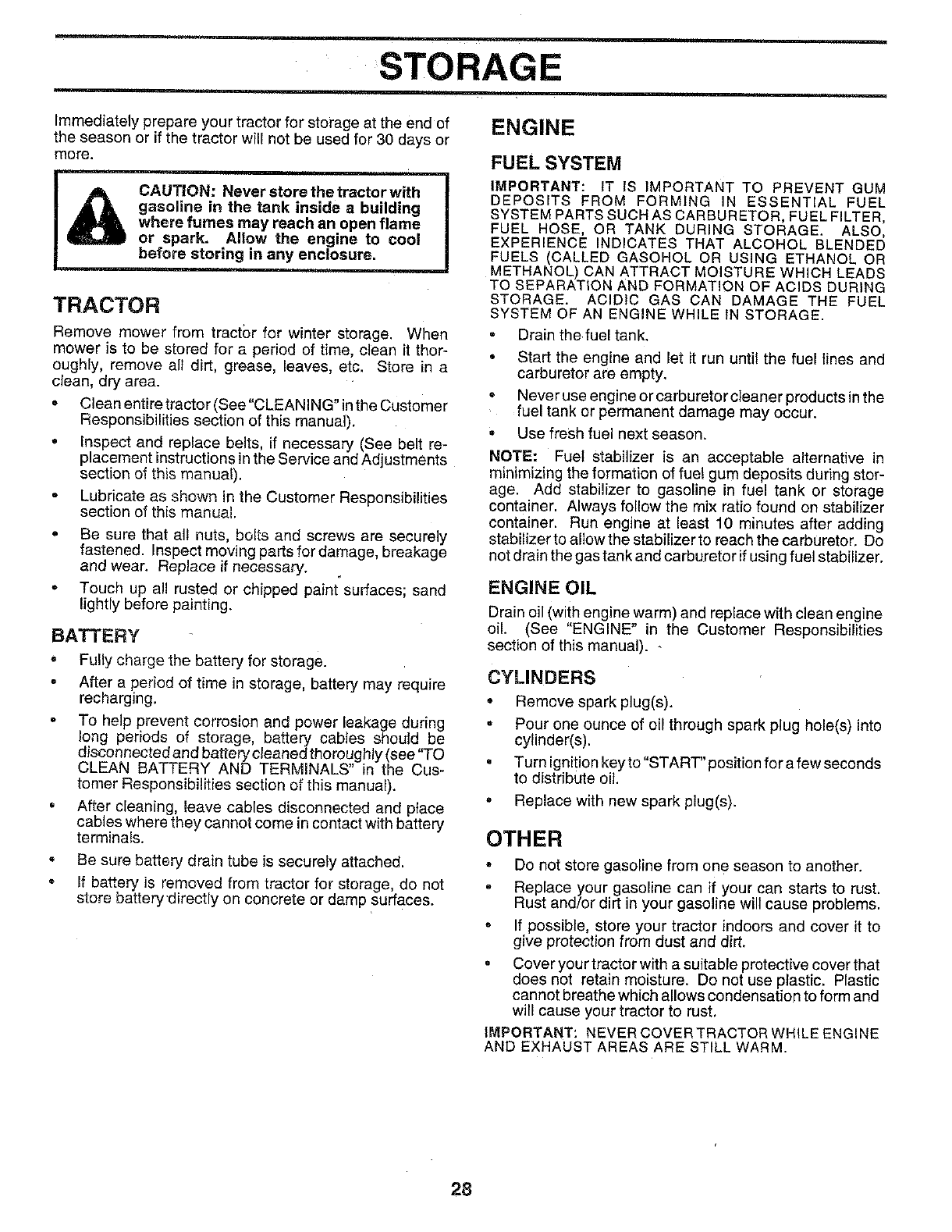
STORAGE
ENGINE
Immediately prepare your tractor for storage at the end of
the season or if the tractor will not be used for 30 days or
more.
CAUTION: Never store the tractor with
gasoline in the tank inside abuilding
where fumes may reach an open flame
or spark. Allow the engine to cool
before storing in any enclosure.
TRACTOR
Remove mower from tractbr for winter storage. When
mower is to be stored for a period of time, clean it thor-
oughly, remove all dirt, grease, leaves, etc. Store in a
clean, dry area.
= Clean entire tractor (See"CLEANING" inthe Customer
Responsibilities section of this manual).
* inspect and replace belts, if necessary (See belt re-
placement instructions in the Service and Adjustments
section of this manual).
,Lubricate as shown in the Customer Responsibilities
section of this manual.
°Be sure that all nuts, bolts and screws are securely
fastened. Inspect moving parts for damage, breakage
and wear. Replace if necessary.
-Touch up all rusted or chipped paint surfaces; sand
lightly before painting.
BATTERY
o
o
Fully charge the battery for storage.
After a period of time in storage, battery may require
recharging.
To help prevent corrosion and power leakage during
long periods of storage, battery Cables should,, be
disconnectedandbatterycleanedthoroughly(see TO
CLEAN BATTERY AND TERMINALS" in the Cus-
tomer Responsibilities section of this manual).
After cleaning, leave cables disconnected and place
cables where they cannot come in contact with battery
terminals.
Be sure battery drain tube is securely attached.
If battery is removed from tractor for storage, do not
store battery "directly on concrete or damp surfaces.
FUEL SYSTEM
IMPORTANT: tT IS IMPORTANT TO PREVENT GUM
DEPOSITS FROM FORMING IN ESSENTIAL FUEL
SYSTEM PARTS SUCH AS CARBURETOR, FUEL FILTER,
FUEL HOSE, OR TANK DURING STORAGE. ALSO,
EXPERIENCE INDICATES THAT ALCOHOL BLENDED
FUELS (CALLED GASOHOL OR USING ETHANOL OR
METHANOL) CAN ATTRACT MOISTURE WHICH LEADS
TO SEPARATION AND FORMATION OF ACIDS DURING
STORAGE. ACIDIC GAS CAN DAMAGE THE FUEL
SYSTEM OF AN ENGINE WHILE IN STORAGE.
•Drain the fuel tank.
• Start the engine and let it run until the fuel lines and
carburetor are empty.
•Never use engine or carburetor cleaner products in the
fuel tank or permanent damage may occur.
• Use fresh fuel next season.
NOTE: Fuel stabilizer is an acceptable alternative in
minimizing the formation of fuel gum deposits during stor-
age. Add stabilizer to gasoline in fuel tank or storage
container. Always follow the mix ratio found on stabilizer
container. Run engine at least 10 minutes after adding
stabilizer to allowthe stabilizer to reach the carburetor. Do
not drain the gas tank and carburetor if using fuel stabilizer.
ENGINE OIL
Drain oil (with engine warm) and replace with clean engine
oil. (See "ENGINE" in the Customer Responsibilities
section of this manual).
CYLINDERS
• Remove spark plug(s).
° Pour one ounce of oil through spark plug hole(s) into
cylinder(s).
• Turn ignition keyto "START" position for a few seconds
to distribute oil.
•Replace with new spark plug(s).
OTHER
•Do not store gasoline from one season to another.
, Replace your gasoline can if your can starts to rust.
Rust and/or dirt in your gasoline will cause problems.
•If possible, store your tractor indoors and cover it to
give protection from dust and dirt.
°Cover your tractor with a suitable protective cover that
does not retain moisture. Do not use plastic. Plastic
cannot breathe which allows condensation to form and
will cause your tractor to rust.
IMPORTANT: NEVERCOVERTRACTORWHILE ENGINE
AND EXHAUST AREAS ARE STILL WARM.
28
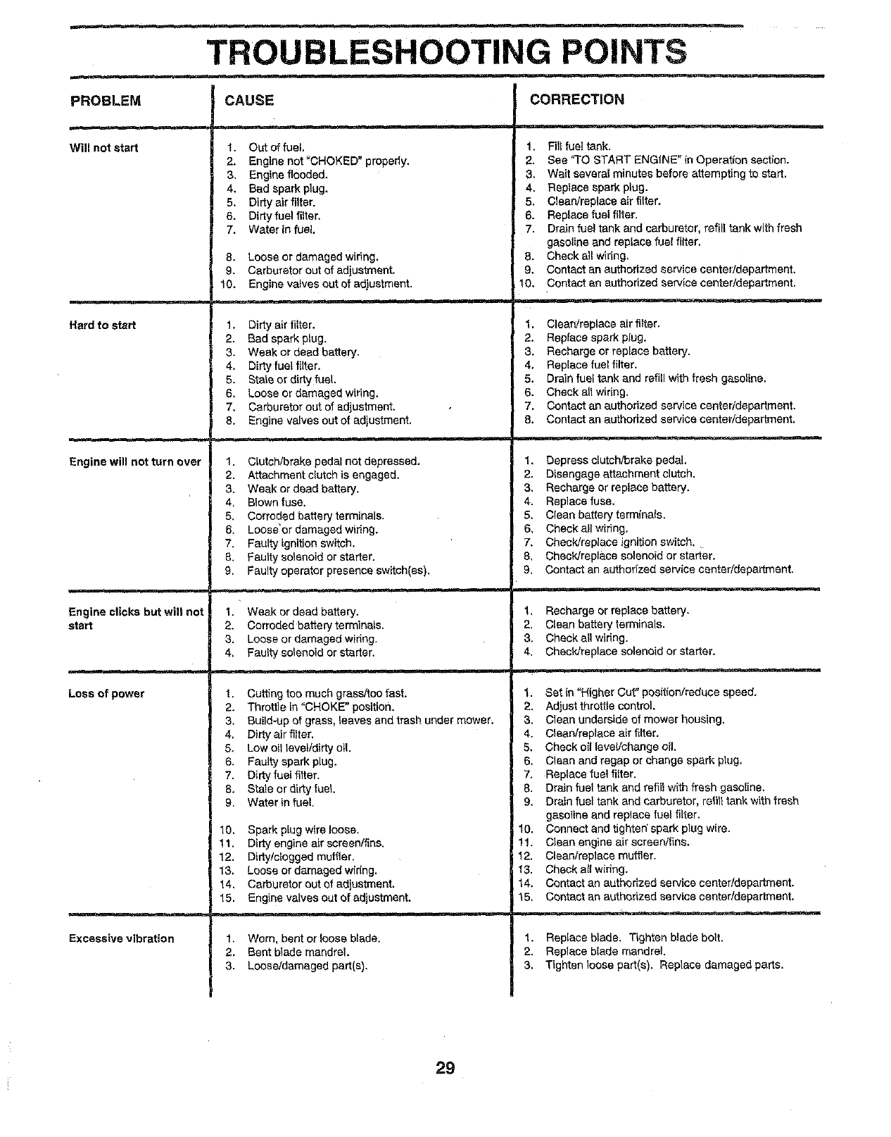
TROUBLESHOOTING POINTS
PROBLEM
Will not start
Hard to start
Engine will not turn over
Engine clicks but will not
start
Loss of power
Excessive vibration
CAUSE
1. Oat of fuel.
2. Engine not"CHOKED" properly+
3. Engine flooded.
4. Bad spark plug.
5. Dirty air filter.
6. Dirty fuel filter,
7+ Water {nfuel.
8, Loose or damaged wiring.
9. Carburetor out of adjustment.
10. Engine valves out of adiuatmant.
1. Dirtyair fi{ter.
2. Bad spark plug.
3. Weak or dead battery.
4, Dirty fuel filter.
5. Stals or dirty fuel.
6, Loose or damaged widng,
7, Carburetoroat of adjustment,
8, Engine valves out of adjustment.
1. Clutch/brake pedal not depressed.
2. Attachment clutch is engaged.
3. Weak or dead battery.
4+ Blown fuse.
5. Corroded battery terminals.
6+ Loose'or damaged wiring.
7. Faulty ignition switch.
8. Faulty solenoid or starter.
9. Faulty operator presence switch(as).
1. Weak or dead battery+
2. Corroded battery terminals.
3. Loose or damaged wiring.
4, Faulty solenoid or starter.
1. Cutting too much grass/foe fast.
2. Throttle in "CHOKE" position.
3+ Build-up of grass, leaves and trash under mower,
4, Dirty air filter.
5, Law oil level/dirty oil.
6, Faulty spark plug.
7. Dirty fuel filter.
8. State or dirty fuel.
9. Water in fuel.
10, Spark plug wire loose.
!1. Dirty engine air screen/flns.
12. Dirty/clogged muffler.
13. Loose or damaged widng.
14, Carburetor out of adjustment.
t5. Engine valves out of adjustment.
1. Worn, bent or loose blade;
2. Bent blade mandrel.
3. Loose/damaged part(s),
CORRECTION
1, Fill rue!tank.
2. See "TO START ENGINE" in Operation section.
3. Wait several minutes before attempting to start.
4. Replace spark plug.
5. Clean/replace air filter.
6. Replace fuel filter.
7. Drain fuel tank and carburetor, refill tank with fresh
gasoline and rep{ace fuel filter,
8. Check ell wiring,
9. Contact an authorized service center/department,
10. Contact an authorized service canter/department.
1. ClearVreplace air filter.
2. Replace spark plug.
3. Recharge or replace battery.
4. Rep[ace fuel filter.
5. Drain fuel tank and refill with fresh gasoline,
6. Check all wiring,
7. Contact an authorized service center/department.
8. Contact an authorized service center/department,
1. Depress clutch/brake pedal.
2. Disengage attachment clutch.
3. Recharge or replace battery.
4. Replace fuse.
5, Clean battery terminals.
6, Check all wiring.
7, Check/replace ignition switch.
8, Check/replace solenoid or starter.
9. Contact an authorized service center/department.
t, Recharge or replace battery.
2. Clean battery terminals.
3. Check all wiring.
4, Check/raplace solenoid or starter.
1. Set in "Higher Cut + position/reduce speed,
2. Adjust throttle control.
3. Clean underside of mower housing.
4. Clean/replace air fitter.
5, Check oil {oval/change oil.
6, Clean and regap or change spark plug,
7. Replace fuel filter.
8. Drain fuel tank and refill with fresh gasoline.
9. Drain fuel tank and carburetor, refill tank with fresh
gasoline and replace fue! filter.
10. Connect and tighten'spark plug wire.
11. Clean engine air screen/fins.
12. Clean/replace muffler.
t3. Check al{ wiring.
14. Contact an authorized eervice center/department,
15. Contact an authorized service center/department,
1. Replace blade. Tighten blade bolt.
2. Replace blade mandrel.
3. Tighten loose part(s), Replace damaged parts.
29

TROUBLESHOOTING POINTS
PROBLEM
Engine continues to run
when operator leaves seat
with attachment clutch
engaged
Poorcut- uneven
Mower blades will not
rotate
Poor grass discharge
Headlight(s) not working
(if so equipped)
Battery will not charge
Loss of drive
Engine "backfires"
when turning engine
"OFF"
CAUSE
1. Faulty operator-safety presence control system.
1. Worn, bent or loose blade,
2, Mower deck not level,
3. Buildup of grass, leaves, and trash under mower.
4. Bent blade mandrel.
5. Clogged mower deck vent holes from buildup of
' grass, leaves, end trash around mandrels,
1. Obstruction in clutch mechanism.
2. Worn/damaged mower drive belt.
3. Frozen idler puliey.
4. Frozen blade mandrel.
t. Engine speed too slow.
2. Travel speed too fast.
3. Wet grass.
4. Mower deck not level.
5. Low/uneven tire air pressure.
6. Worn, bent or loose blade.
7. Buildup of grass, leaves and trash under mower.
8. Mower ddve belt worn.
9. Blades improperlyinstal]ed.
10. improper blades used.
11. Clogged mower deck vent holes from buildup of
grass, leaves, and trash around mandrels.
1. Switch is "OFF".
2. Bulb(s) burned out.
3. Faulty light switch.
4. Loose or damaged wiring.
5, B!own fuse.
t. Bad battery cell(s).
2. Poor cable connections.
3. Faulty regulator (if so equipped).
4. Faulty alternator.
1. Freewheel control in "disengaged" position.
2. Motion drive belt worn, damaged or broken.
3. Air trapped in transmission during shpment
or ser,,icing.
1. Engine throttle control not set at "SLOW"
positionfor 30 seconds before stopping engine,
_m
CORRECTION
1. Check wiring, switches and connections, if not
corrected, contact an authorized service center/
depattmant,
1. Replace blade. Tighten blade bolt.
2, Level mower deck.
3. Clean underside of mower housing.
4. Replace blade mandrel.
5. Clean around mandrels to open vent holes,
1, Remove obstruction,
2. Replace mower drive belt.
3. Replace idler pulley.
4. Replace blade mandrel.
1. Place throttle control in "FAST" position.
2. Shift to slower speed.
3. Allow grass to dry before mowing.
4. Level mower deck.
5. Check tires for proper air pressure.
6, Replace/sharpan blade. Tighten blade bolt.
7, Clean underside of mower housing,
8. Replace mower drive belt.
9, Reinstall blades sharp edge down.
10, Replace with blades listed in this manual.
11. Clean around mandrels to open vent holes.
1, Turn switch "ON".
2, Replace bulb(s).
3. Check/replace light switch.
4. Check wiring and connections.
5, Reptece fuse.
1. Replace battery,
2. Check/clean all connections.
3. Reptace regulator,
4. Replace aJtemator.
1. Place freewheel control in "engaged" position,
2. Replace motion drive belt.
3. Purge transmission.
1. Move throttIecontrol to "SLOW" position and allow
to idle for 30 seconds before stopping engine,
3O
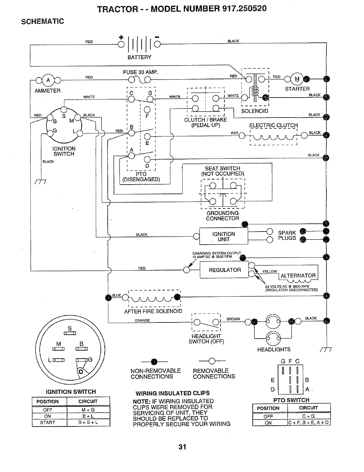
SCHEMATIC
TRACTOR - =MODEL NUMBER 917,250520
RED
BATTERY
BLACK
AMMETER
RED
WHITE
FUSE 30 AMP.
IGNITION
SWITCH
BLACK
S BLACK
E
i D
PTO
RED
WHITE { 0 I
L-- ...... J
(PEDALUP)
I
I STARTER
BLACK
..... J
SOLENOID BLACK ,
ELECTRIC CLUTCH
RED BLACK
i
(DISENGAGED)
SEAT SWITCH
(NOT OCCUPIED)
7111_11 ...... -F'111
BL&CK
BLACK
IRED
I I
AFTER FIRE SOLENOID
ORANGE
GROUNDING
CONNECTOR • 1
IGNITION _ SPARK
UNIT _ PLUGS _
CHARGING SYSTEM OUTPUT
28 VOLTS AC @ 3600 RPM
(REGULATOR D_SCONHEGTED)
SWITCH (OFF)
HEADLIGHTS /_,
IGNITION SWITCH
PosmoN CIRCUIT
OFF M+G
ON B+L
START B + S + L
NON-REMOVABLE
CONNECTIONS
O-
REMOVABLE
CONNECTIONS
WIRING INSULATED CLIPS
NOTE: IF WIRING INSULATED
CLIPS WERE REMOVED FOR
SERVICING OF UNIT, THEY
SHOULD BE REPLACED TO
PROPERLY SECURE YOUR WIRING
GFC
nuul
E B LB
D_A:
PTO SWITCH
Ipos,T,o,c,.co,T
[ _ _+F,B+E,A+[
31
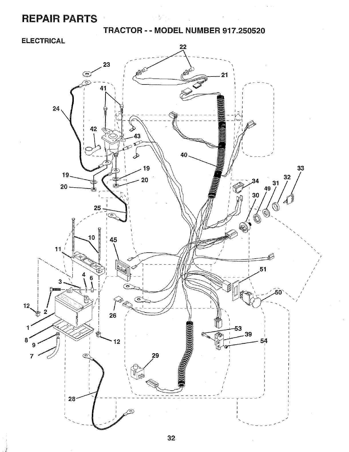
REPAIR PARTS
ELECTRICAL
TRACTOR - -MODEL NUMBER 917.250520
22
7
42
45
19
\
\
\
r
31
29
\
\
\
\
f
I
i
54
y
32
33
32
\
\\
\
\
\
• \
/
/
/
/
/
/
/
/
l
/
/
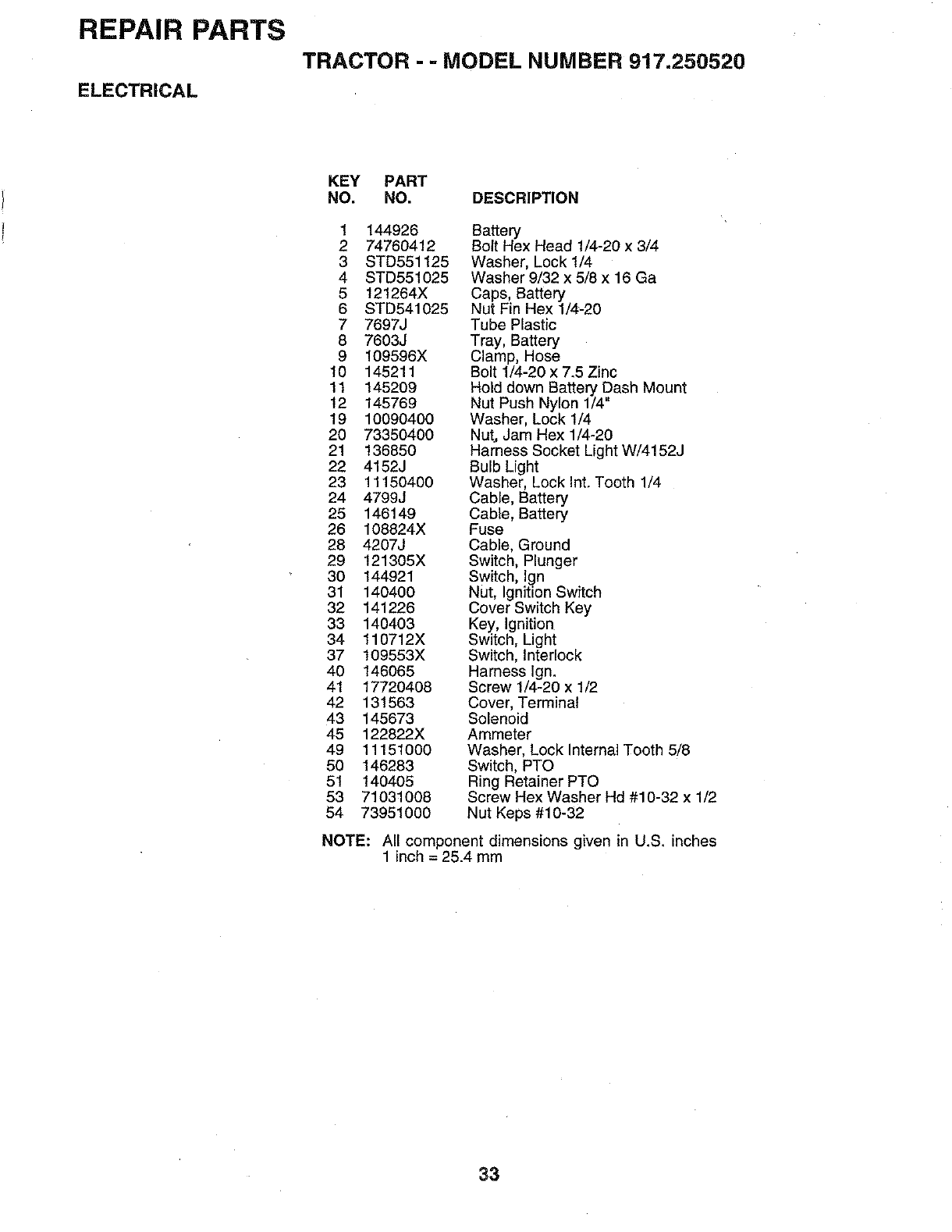
REPAIR PARTS
TRACTOR - - MODEL NUMBER 917=250520
ELECTRICAL
KEY PART
NO. NO. DESCRIPTION
1 144926 Battery
2 74760412 Bolt Hex Head 1/4-20 x 3/4
3 STD551125 Washer, Lock 1/4
4 STD551025 Washer 9/32 x 5/8 x 16 Ga
5 121264X Caps, Battery
6 STD541025 Nut Fin Hex 1/4_20
7 7697J Tube Plastic
8 7603J Tray, Battery
9 109596X Clamp, Hose
10 145211 Bolt 1/4-20 x 7.5 Zinc
11 145209 Hold down Battery Dash Mount
12 145769 Nut Push Nylon 1/4"
19 10090400 Washer, Lock 1/4
20 73350400 Nut, Jam Hex 1/4-20
21 136850 Harness Socket Light W/4152J
22 4152J Bulb Light
23 11150400 Washer, Lock Int. Tooth 1/4
24 4799J Cable, Battery
25 146149 Cable, Battery
26 108824X Fuse
28 4207J Cable, Ground
29 121305X Switch, Plunger
30 144921 Switch, Ign
31 140400 Nut, Ignition Switch
32 141226 Cover Switch Key
33 140403 Key, Ignition
34 110712X Switch, Light
37 109553X Switch, Interlock
40 146065 Harness Ign.
41 17720408 Screw 1/4-20 x 1/2
42 131563 Cover, Terminal
43 145673 Solenoid
45 122822X Ammeter
49 11151000 Washer, Lock Internal Tooth 5/8
50 146283 Switch, PTO
51 140405 Ring Retainer PTO
53 71031008 Screw Hex Washer Hd #10-32 x 1/2
54 73951000 Nut Keps #10-32
NOTE: All component dimensions given in U.S. inches
1inch = 25.4 mm
33
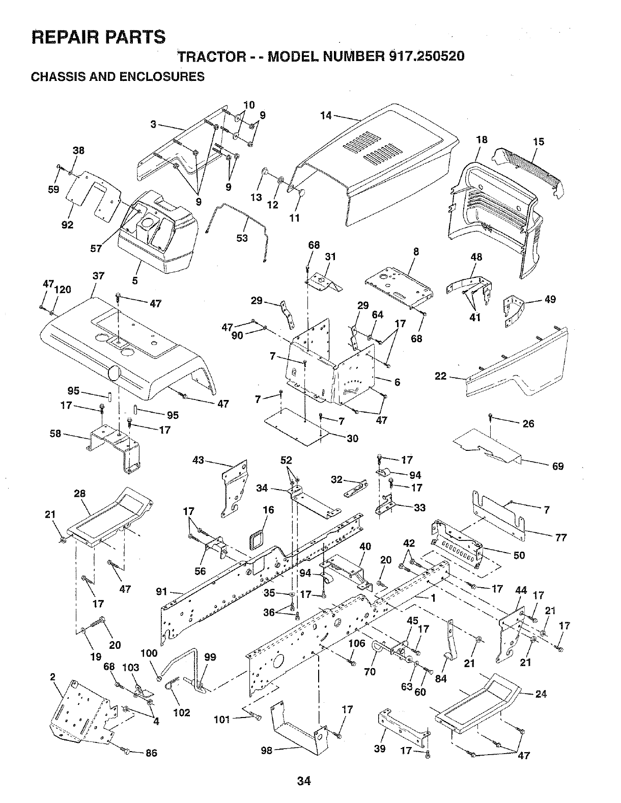
REPAIR PARTS
TRACTOR --MODEL NUMBER 917.250520
CHASSIS AND ENCLOSURES
38
10 9
18
/15
59 9
9 13
47120
92
57
37 5
53
11
68
21 28_.
47
17
17
56
20
19 100
68 103
2
\
102
86
52
16
98
47
42
70
6360
34
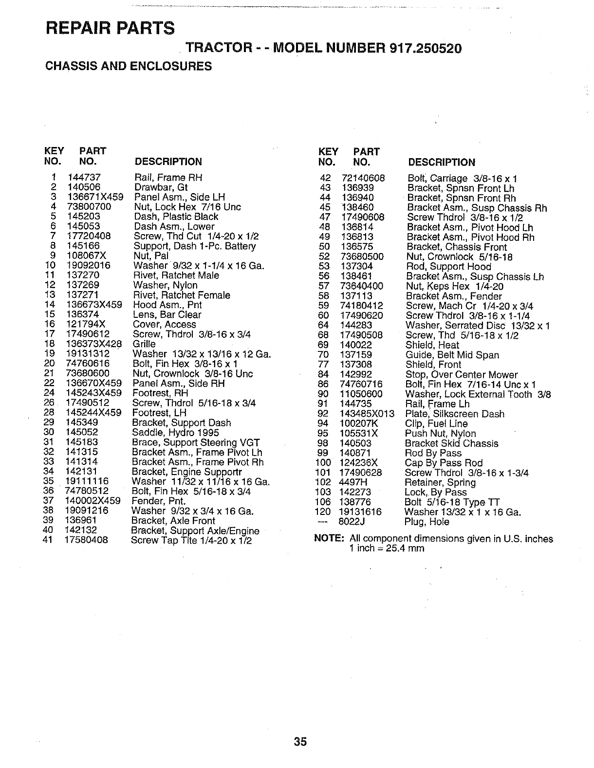
REPAIR PARTS
TRACTOR --MODEL NUMBER 917.250520
CHASSIS AND ENCLOSURES
KEY PART KEY PART
NO. NO. DESCRIPTION NO. NO. DESCRIPTION
1 144737
2 140506
3 136671X459
4 73800700
5145203
6 145053
7 17720408
8 145166
9 108067X
10 19092016
11 137270
12 137269
13 137271
14 136673X459
15 136374
16 121794X
17 17490612
18 136373X428
19 19131312
20 74760616
21 73680600
22 136670X459
24 145243X459
26 17490512
28 145244X459
29 145349
30 145052
31 145183
32 141315
33 141314
34 142131
35 19111116
36 74780512
37 140002X459
38 19091216
39 136961
40 142132
41 17580408
Rail, Frame RH 42 72140608
Drawbar, Gt 43 136939
PanetAsm., Side LH 44 136940
Nut, Lock Hex 7/16 Unc 45 138460
Dash, Plastic Black 47 17490608
Dash Asm., Lower 48 136814
Screw, Thd Cut 1/4-20 x 1/2 49 136813
Support, Dash 1-Pc. Battery 50 136575
Nut, Pal 52 73680500
Washer 9/32 x 1-1/4 x 16 Ga. 53 137304
Rivet, Ratchet Male 56 138461
Washer, Nylon 57 73640400
Rivet, Ratchet Female 58 137113
Hood Asm., Pnt 59 74180412
Lens, Bar Clear 60 17490620
Cover, Access 64 144283
Screw, Thdrol 3/8-16 x 3/4 68 17490508
Grille 69 140022
Washer 13/32 x 13/16 x 12 Ga. 70 137159
Bolt, Fin Hex 3/8-16 x 1 77 137308
Nut, Crowntock 3/8-16 Uric 84 142992
PanelAsm., Side RH 86 74760716
Footrest, RH 90 11050600
Screw, Thdrol 5/16-18 x 3/4 91 144735
Footrest, LH 92 143485X013
Bracket, Support Dash 94 100207K
Saddle, Hydro 1995 95 105531X
Brace, Support Steering VGT 98 140503
Bracket Asm., Frame Pivot Lh 99 140871
Bracket Asm., Frame Pivot Rh 100 124236X
Bracket, Engine Supportr 101 17490628
Washer 11/32 x 11/16 x 16 Ga. 102 4497H
Bolt, Fin Hex 5/16-18 x 3/4 103 142273
Fender, Pnt. 106 138776
Washer 9/32 x 3/4 x 16 Ga. 120 19131616
Bracket, Axle Front --- 8022J
Bracket, Support Axle/Engine
Screw Tap Tite 1/4-20 x 1/2
Boltl Carriage 3/8-16 x 1
Bracket, Spnsn Front Lh
Bracket, Spnsn Front Rh
Bracket Asm., Susp Chassis Rh
Screw Thdrot 3/8-16 x 1/2
Bracket Asm., Pivot Hood Lh
Bracket Asm., Pivot Hood Rh
Bracket, Chassis Front
Nut, Crownlock 5/16-18
Rod, Support Hood
Bracket Asm., Susp Chassis Lh
Nut, Keps Hex 1/4-20
Bracket Asm., Fender
Screw, Mach Cr 1/4-20 x 3/4
Screw Thdrol 3/8-16 x 1-1/4
Washer, Serrated Disc 13/32 x 1
Screw, Thd 5/16-18 x 1/2
Shield, Heat
Guide, Belt Mid Span
Shield, Front
Stop, Over Center Mower
Bolt, Fin Hex 7/16-14 Uncx 1
Washer, Lock External Tooth 3/8
Rail, Frame Lh
Plate, Silkscreen Dash
Clip, Fuel Line
Push Nut, Ny!on
Bracket Skid Chassis
Rod By Pass
Cap By Pass Rod
Screw Thdrol 3/8-16 x 1-3/4
Retainer, Spring
Lock, By Pass
Bolt 5/16-18 Type TT
Washer 13/32 x I x 16 Ga.
Plug, Hole
NOTE: All component dimensions given in U.S. inches
1 inch = 25.4 mm
35
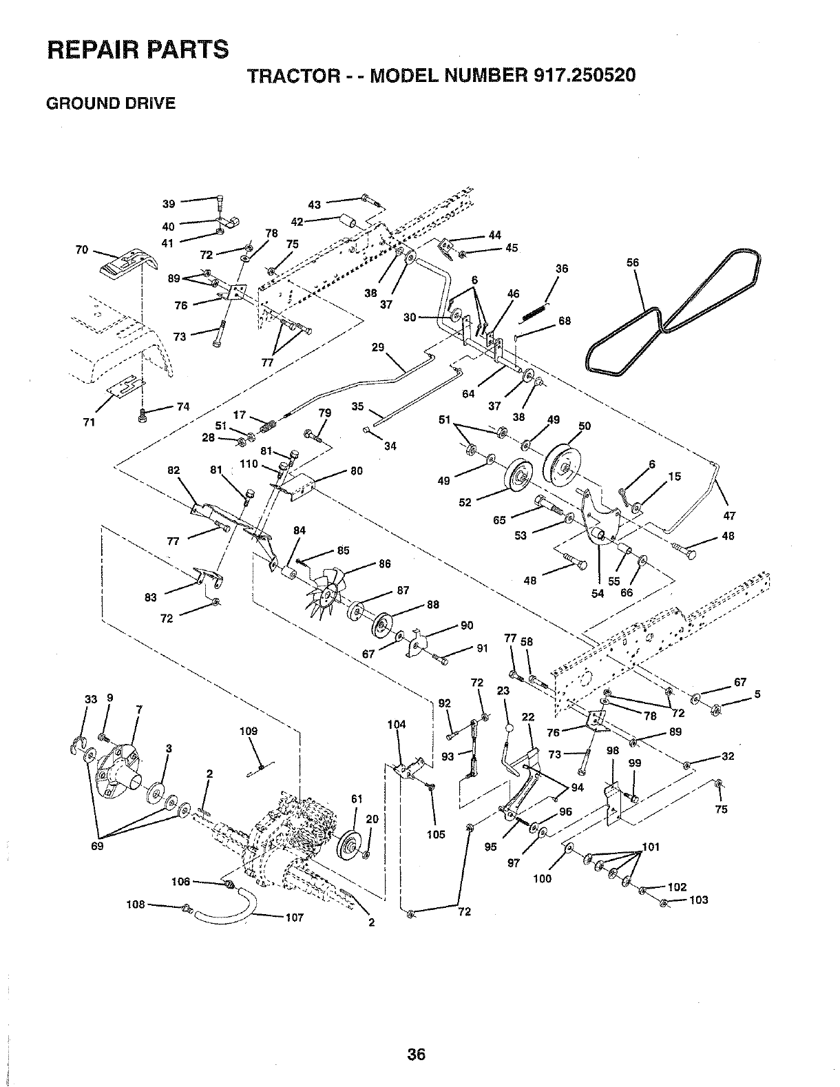
REPAIR PARTS
TRACTOR - -MODEL NUMBER 917.250520
GROUND DRIVE
3
79
84
109
61
6
46
64 37
51 38
52
65
36
/
97
758
lOO
56
15
47
101
i!
36
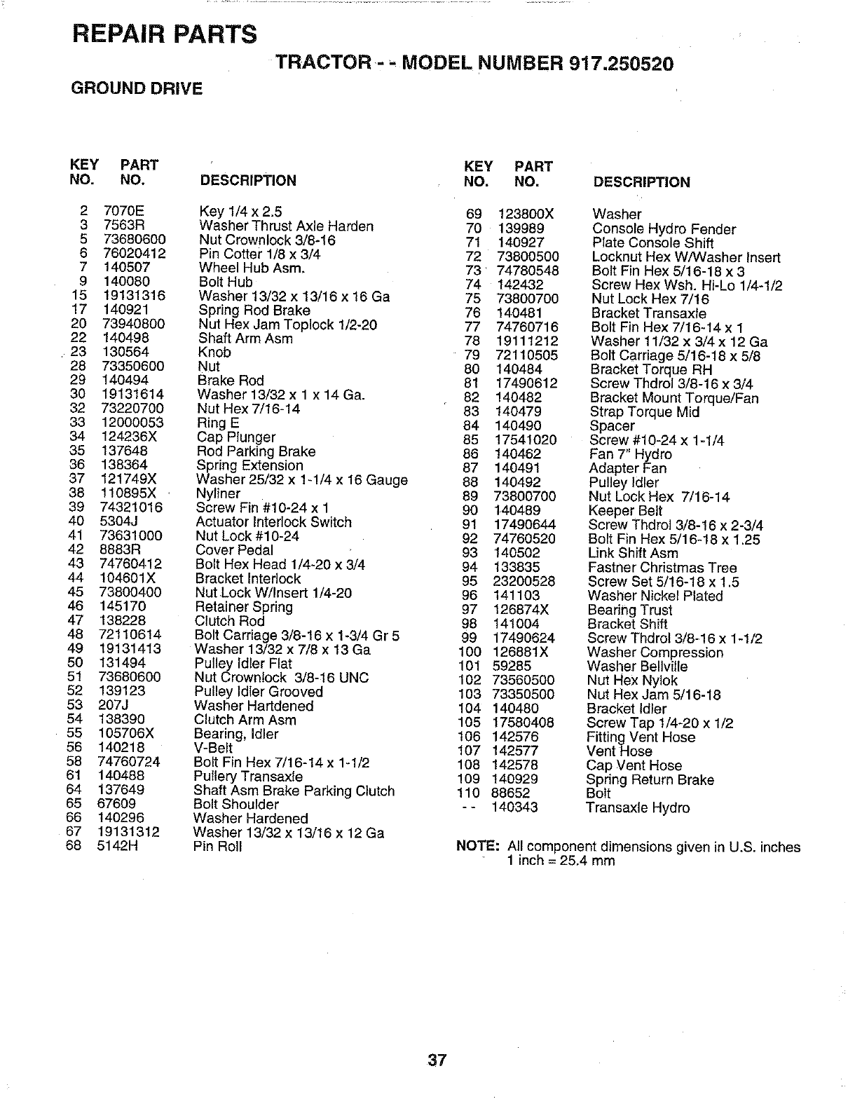
REPAIR PARTS
TRACTOR MODEL NUMBER 917.250520
GROUND DRIVE
KEY PART KEY PART
NO. NO. DESCRIPTION NO. NO, DESCRIPTION
2 7070E Key 1/4 x 2.5 69 123800X
3 7563R Washer Thrust Axle Harden 70 139989
5 73680600 Nut Crownlock 3/8-16 71 140927
6 76020412 Pin Cotter 1/8 x 3/4 72 73800500
7 140507 Wheel Hub Asm, 73 74780548
9 140080 Bolt Hub 74 142432
15 19131316 Washer 13/32 x 13/16 x 16 Ga 75 73800700
17 140921 Spring Rod Brake 76 140481
20 73940800 Nut Hex Jam Toplock 1/2-20 77 74760716
22 140498 ShaftArmAsm 78 19111212
23 130564 Knob 79 72110505
28 73350600 Nut 80 140484
29 140494 Brake Rod 81 17490612
30 19131614 Washer 13/32 x 1 x 14 Ga. 82 140482
32 73220700 Nut Hex 7/16-14 83 140479
33 12000053 Ring E 84 140490
34 124236X Cap Plunger 85 17541020
35 137648 Rod Parking Brake 86 140462
36 138364 Spring Extension 87 140491
37 121749X Washer 25/32 x 1-1/4 x 16 Gauge 88 140492
38 110895X ,Nyliner 89 73800700
39 74321016 Screw Fin #10-24 x 1 90 140489
40 5304J Actuator Interlock Switch 91 17490644
41 73631000 Nut Lock#10-24 92 74760520
42 8883R Cover Pedal 93 140502
43 74760412 Bolt Hex Head 1/4-20 x 3/4 94 133835
44 104601X Bracket Interlock 95 23200528
45 73800400 Nut Lock W/Insert 1/4-20 96 141103
46 145170 Retainer Spring 97 126874X
47 138228 Clutch Rod 98 141004
48 72110614 Bolt Carriage 3/8-16x 1-3/4 Gr 5 99 17490624
49 19131413 Washer 13/32 x 7/8 x 13 Ga 100 126881X
50 131494 Pulley Idler Flat 101 59285
51 73680600 Nut Crewnlock 3/8-16 UNC 102 73560500
52 139123 Pulley Idler Grooved 103 73350500
53 207J Washer Hartdened 104 140480
54 138390 Clutch Arm Asm 105 17580408
55 105706X Bearing, Idler 106 142576
56 140218 V-Belt 107 142577
58 74760724 Bolt Fin Hex 7/16-14x 1-1/2 108 142578
61 140488 PutteryTransaxle 109 140929
64 137649 Shaft Asm Brake Parking Clutch 110 88652
65 67609 Bolt Shoulder - - 140343
66 140296 Washer Hardened
67 19131312 Washer 13/32 x 13/16 x 12 Ga
68 5142H Pin Roll
Washer
Console Hydro Fender
Plate Console Shift
Locknut Hex W/Washer Insert
Bolt Fin Hex 5/16-18 x 3
Screw Hex Wsh. Hi-Lo 1/4-1/2
Nut Lock Hex 7/16
Bracket Transaxle
Bolt Fin Hex 7/16-14 x 1
Washer 11/32 x 3/4 x 12 Ga
Bolt Carriage 5/!6-18 x 5/8
Bracket Torque RH
Screw Thdrol 3/8-16 x 3/4
Bracket Mount Torque/Fan
Strap Torque Mid
Spacer
Screw #10-24 x 1-1/4
Fan 7" Hydro
Adapter Fan
Pulley Idler
Nut Lock Hex 7/16-14
Keeper Belt
Screw Thdrol 3/8-18 x 2-3/4
Bolt Fin Hex 5/16-18 x 1.25
Link Shift Asm
Fastner Christmas Tree
Screw Set 5/16-18 x 1.5
Washer Nickel Plated
Bearing Trust
Bracket Shift
Screw Thdrot 3/8-16 x 1-1/2
Washer Compression
Washer Bellville
Nut Hex Nylok
Nut Hex Jam 5/16-18
Bracket Idler
Screw Tap 1/4-20 x 1/2
Fitting Vent Hose
Vent Hose
Cap Vent Hose
Spring Return Brake
Bolt
Transaxle Hydro
NOTE: All component dimensions given in U,S. inches
1inch = 25,4 mm
37
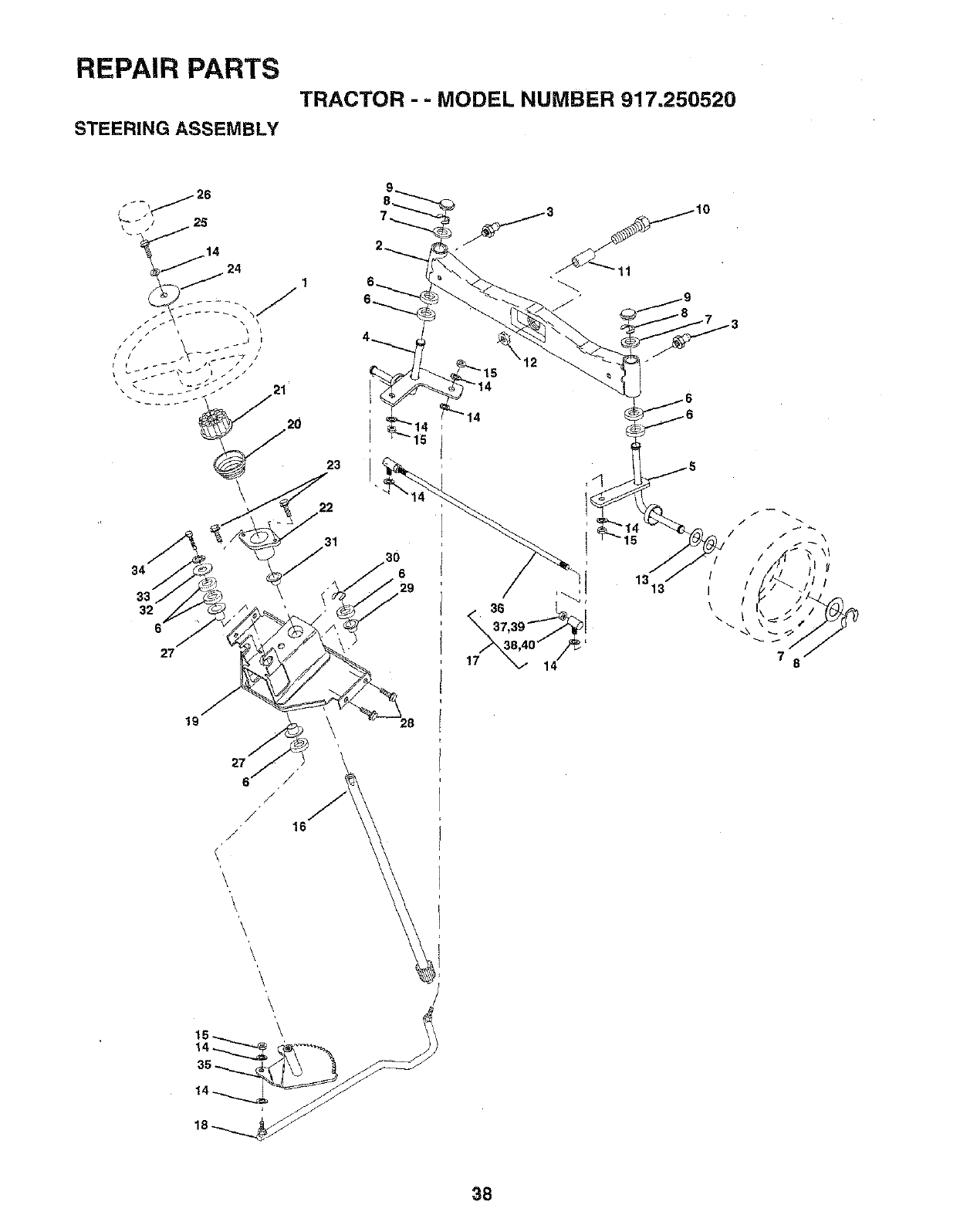
REPAIR PARTS
TRACTOR - =MODEL NUMBER 917.250520
STEERING ASSEMBLY
34
32
27
19
27
6/"
/
/16
/
23
14
15
1313 i/
\
\
78
38
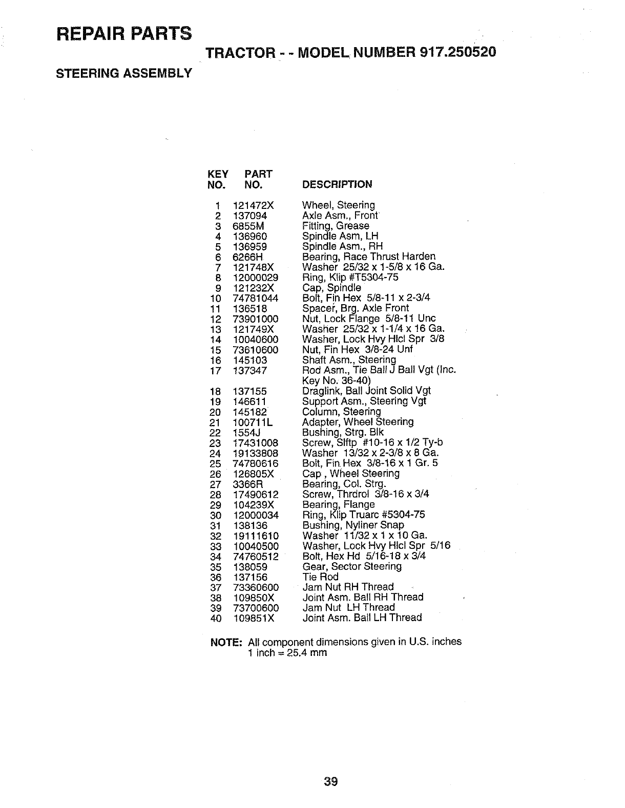
REPAIR PARTS
TRACTOR =- MODEL NUMBER 917.250520
STEERING ASSEMBLY
KEY PART
NO. NO. DESCRIPTION
1 121472X
2 137094
36855M
4 136960
5 136959
6 6266H
7 121748X
8 12000029
9 121232X
10 74781044
11 136518
12 73901000
13 121749X
14 10040600
15 73610600
16 145103
17 137347
18 137155
19 146611
20 145182
21 100711L
22 1554J
23 17431008
24 19133808
25 74780616
26 126805X
27 3366R
28 17490612
29 104239X
30 12000034
31 138136
32 19111610
33 10040500
34 74760512
35 138059
36 137156
37 73360600
38 109850X
39 73700600
40 I09851X
Wheel, Steering
Axle Asm, Front
Fitting, Grease
Spindle Asm, LH
Spindle Asm., RH
Bearing, Race Thrust Harden
Washer 25/32 x 1-5/8 x 16 Ga.
Ring, KIip #T5304-75
Cap, Spindle
Bolt, Fin Hex 5/8-11 x 2-3/4
Space_, Brg. Axle Front
Nut, Lock Flange 5/8-11 Unc
Washer 25/32 x 1-1/4 x 16 Ga.
Washer, Lock Hvy Hlcl Spr 3/8
Nut, Fin Hex 3/8-24 Unf
Shaft Asm., Steering
Rod Asm, Tie Ball J Ball Vgt (Inc.
Key No. 36-40)
Draglink, Ball Joint Solid Vgt
Support Asm., Steering Vgt
Column, Steering
Adapter, Wheel Steering
Bushing, Strg. BIk
Screw, SIftp #10-16 x 1/2 Ty-b
Washer 13/32 x 2-3/8 x 8 Ga.
Bolt, Fin Hex 3/8-16 x 1 Gr. 5
Cap, Wheel Steering
Bearing, Col. Strg.
Screw, Thrdrol 3/6-16 x 3/4
Bearing, Flange
Ring, Klip Truarc #5304-75
Bushing, Nyliner Snap
Washer 11/32x 1 xl0Ga.
Washer, Lock Hvy Hlcl Spr 5/16
Bolt, Hex Hd 5/16-18 x 3/4
Gear, Sector Steering
Tie Rod
Jam Nut RH Thread
Joint Asm. Ball RH Thread
Jam Nut LH Thread
Joint Asm. Ball LH Thread
NOTE: All component dimensions given in U.S. inches
1inch = 25.4 mm
39
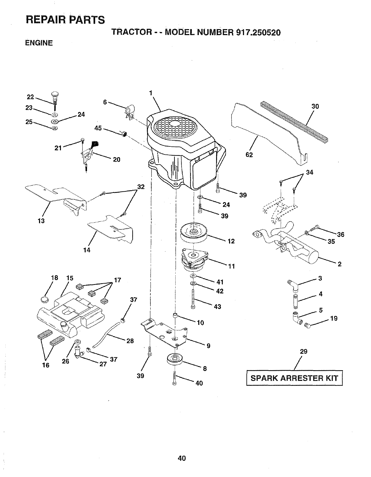
REPAIR PARTS
ENGINE
TRACTOR - - MODEL NUMBER 917.250520
13
18 15
26
16 27
20
32
14
17
28 _
39
4O
39
12
11
41
42
9
3O
62
2
_j3
j5
29
/
[SPARK ARRESTER KIT J
4O
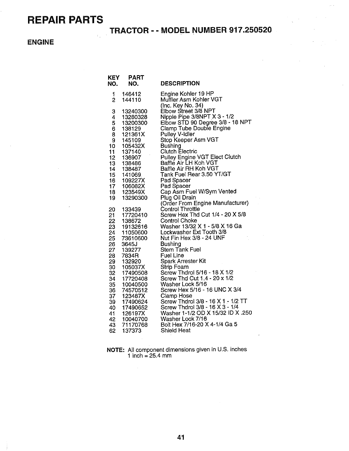
REPAIR PARTS
TRACTOR =- MODEL NUMBER 917.250520
ENGINE
KEY PART
NO. NO. DESCRIPTION
146412
144110
3 13240300
4 13280328
5 13200300
6 138129
8 121361X
9 145109
10 105432X
11 137140
12 136907
13 138486
14 138487
15 141069
16 109227X
17 106082X
18 123549X
19 13290300
20 133439
21 17720410
22 138672
23 19132616
24 11050600
25 73610600
26 3645J
27 139277
28 7834R
29 132920
30 105037X
32 17490508
34 17720408
35 10040500
36 74570512
37 123487X
39 17490624
40 17490652
41 126197X
42 10040700
43 71170768
62 137373
Engine Kohler 19 HP
Muffler Asm Kohler VGT
(tnc. Key No. 34)
Elbow Street 3/8 NPT
Nipple Pipe 3/8NPT X 3 - 1/2
Elbow STD 90 Degree 3/8 - 18 NPT
Clamp Tube Double Engine
Pulley V-Idler
Stop Keeper Asm VGT
Bushing
Clutch Electric
Pulley Engine VGT Elect Clutch
Baffle Air LH Koh VGT
Baffle Air RH Koh VGT
Tank Fuel Rear 3.50 YT/GT
Pad Spacer
Pad Spacer
Cap Asm Fuel W/Sym Vented
Plug Oil Drain
(Order From Engine Manufacturer)
Control Throttle
Screw Hex Thd Cut 1/4 - 20 X 5/8
Control Choke
Washer 13/32 X 1 - 5/8 X 16 Ga
Lockwasher Ext Tooth 3/8
Nut Fin Hex 3/8 - 24 UNF
Bushing
Stem Tank Fuel
Fuel Line
Spark Arrester Kit
Strip Foam
Screw Thdrol 5/16 - 18 X 1/2
Screw Thd Cut 1.4 - 20 x 1/2
Washer Lock 5/16
Screw Hex 5/16 - 16 UNC X 3/4
Clamp Hose
Screw Thdrol 3/8 - 16 X 1 - 1/2 ]-T
Screw Thdrol 3/8 - 16 X 3 - 1/4
Washer 1-1/20D X 15/32 ID X .250
Washer Lock 7/16
Bolt Hex 7/16-20 X 4-1/4 Ga 5
Shield Heat
NOTE: AIt component dimensions given in U.S. inches
1 inch = 25.4 mm
41
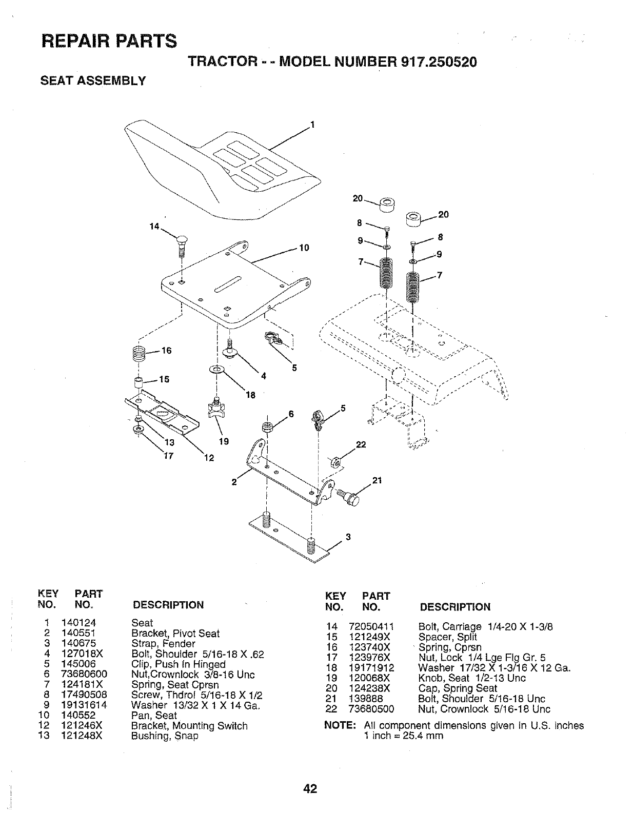
REPAIR PARTS
TRACTOR - - MODEL NUMBER 917.250520
SEAT ASSEMBLY
12
L_ _ _,_
KEY
NO,
1
2
3
4
5
6
7
8
9
10
12
13
PART
NO,
140124
140551
140675
127018X
145006
73680600
124181X
17490508
19131614
140552
121246X
121248X
DESCRIPTION
Seat
Bracket, Pivot Seat
Strap, Fender
Bolt, Shoulder 5/16-18 X .62
Clip, Push In Hinged
Nut,Crownlock 3/8-16 Unc
Spring, Seat Cprsn
Screw, Thdrol 5/16-18 X 1/2
Washer 13/32 X I X 14Ga.
Pan, Seat
Bracket, Mounting Switch
Bushing, Snap
KEY PART
NO. NO. DESCRIPTION
14 72050411
15 121249X
16 123740X
17 123976X
18 19171912
19 120068X
20 124238X
21 139888
22 73680500
Bolt, Carriage 1/4-20 X 1-3/8
Spacer, Split
Spring, Cprsn
Nut, Lock 1/4 Lge Fig Gr. 5
Washer 17/32 X 1-3/16 X 12 Ga.
Knob, Seat 1/2-13 Unc
Cap, Spring Seat
Bolt, Shoulder 5/16-18 Uric
Nut, Crewnlock 5/16-18 Unc
NOTE: All component dimensions given in U.S. inches
1 inch = 25.4 mm
42
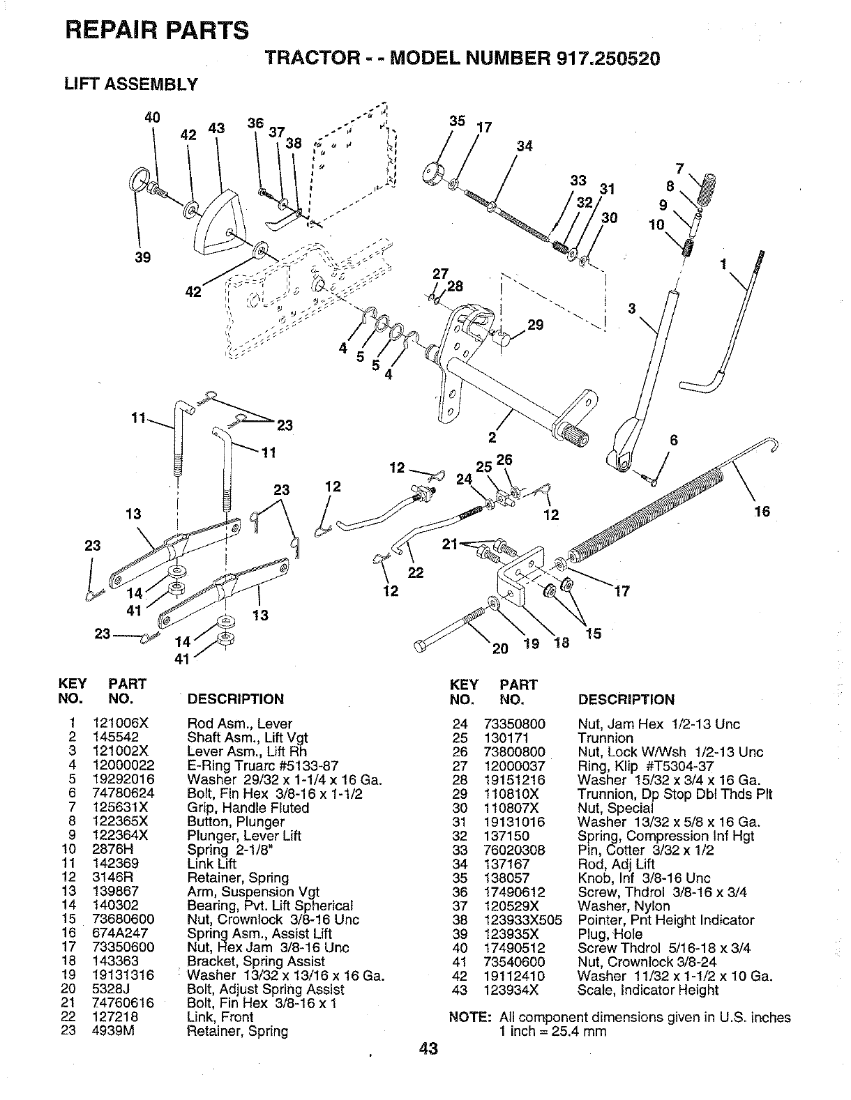
REPAIR PARTS
TRACTOR -- MODEL NUMBER 917.250520
LIFT ASSEMBLY
40
42 43
39
42
35 17
34
33 31 g
10
3
4
7
8
13
23
41
23 --.-_
KEY PART
NO. NO.
1 121006X
2 145542
3 121002X
4 12000022
5 19292016
6 74780624
7 125631X
8 122365X
9 122364X
10 2876H
11 142369
12 3146R
13 139867
14 140302
15 73680600
16 674A247
17 73350600
18 143363
19 19131316
20 5328J
21 74760616
22 127218
23 4939M
23
23
2
25 26
12 _ 24
12
6
DESCRIPTION
Rod Asm., Lever
Shaft Asm., Lift Vgt
Lever Asm., Lift Rh
E-Ring Truarc #5133-87
Washer 29/32 x 1-1/4 x 16 Ga.
Bolt, Fin Hex 3/8-16 x I-1/2
Grip, Handle Fluted
Button, Plunger
Plunger, Lever Lift
Spring 2-1/6"
Link Lift
Retainer, Spring
Arm, Suspension Vgt
Bearing, Pvt. Lift Spherical
Nut, Crownlock 3/8-16 Unc
Spring Asm., Assist Lift
Nut, Hex Jam 3/8-16 Unc
Bracket, Spring Assist
Washer 13/32 x 13/16 x 16 Ga.
Bolt, Adjust Spring Assist
Bolt, Fin Hex 3/8-16 x 1
Link, Front
Retainer, Spring
22
12
43
15
20 19 18
KEY PART
NO. NO. DESCRIPTION
24 73350800
25 130171
26 73800800
27 12000037
28 19151216
29 110810X
30 110807X
31 19131016
32 137150
33 76020308
34 137167
35 138057
36 17490612
37 120529X
38 123933X505
39 123935X
40 17490512
41 73540600
42 19112410
43 123934X
Nut, Jam Hex 1/2-13 Unc
Trunnion
Nut, Lock W/Wsh 1/2-13 Unc
Ring, Klip #T5304-37
Washer 15/32 x 3/4 x 16 Ga.
Trunnion, Dp Stop Dbl Thds Pit
Nut, Special
Washer 13/32 x 5/8 x 16 Ga.
Spring, Compression tnf Hgt
Pin, Cotter 3/32 x 1/2
Rod, Adj Lift
Knob, Inf 3/8-16 Unc
Screw, Thdrol 3/8-16 x 3/4
Washer, Nylon
Pointer, Pnt Height Indicator
Plug, ;Hole
Screw Thdrol 5/16-18 x 3/4
Nut, Crownleck 3/8-24
Washer 11/32 x 1-1/2 x 10 Ga.
Scale, indicator Height
NOTE: All component dimensions given in U.S. inches
1 inch = 25.4 mm
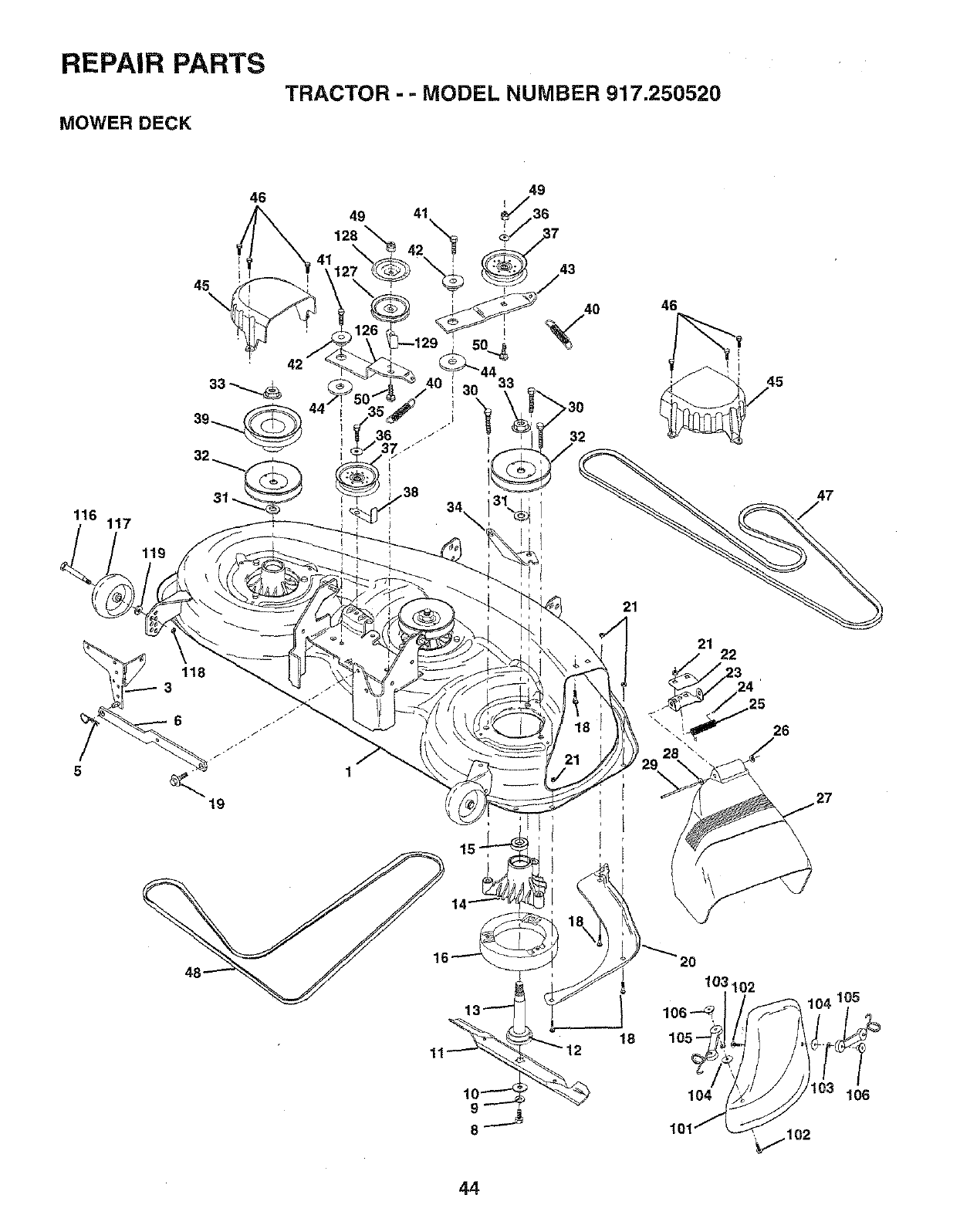
REPAIR PARTS
TRACTOR - - MODEL NUMBER 917.250520
MOWER DECK
46
45
116 117
119
49 41
49
I
743
>30
32
46
21
21 22
47
26
1\
8
18
44
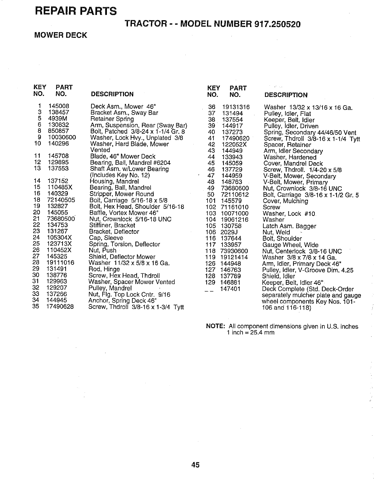
REPAIR PARTS
TRACTOR --MODEL NUMBER 917.250520
MOWER DECK
KEY PART KEY PART '
NO. NO. DESCRIPTION NO. NO. DESCRIPTION
1 145008
3 138457
5 4939M
6 130832
8 850857
9 10030600
10 140296
11 145708
12 129895
13 137553
14 137152
15 1t0485X
16 140329
18 72140505
19 132827
20 145055
21 73680500
22 134753
23 131267
24 105304X
25 123713X
26 110452X
27 145325
28 19111016
29 131491
30 138776
31 129963
32 129207
33 137266
34 144945
35 17490628
DeckAsm., Mower 46" 36 19131316
Bracket Asm., Sway Bar 37 131494
Retainer Spring 38 137554
Arm, Suspension, Rear (Sway Bar) 39 144917
Bolt, Patched 3/8-24 x 1-1/4 Gr. 8 40 137273
Washer, Lock Hvy., Unplated 3/8 41 17490620
Washer, Hard Blade, Mower 42 122052X
Vented 43 144949
Blade, 46" Mower Deck 44 133943
Bearing, Ball, Mandrel #6204 45 145059
Shaft Asm. w/Lower Bearing 46 137729
(Includes Key NO. 12) 47 144959
Housing, Mandrel 48 148763
Bearing, Ball, Mandrel 49 73680600
Stripper, Mower Round 50 72110612
Bolt, Carriage 5/16-18 x 5/8 101 145579
Bolt, Hex Head, Shoulder 5/16-18 102 7i 161010
Baffle, Vortex Mower 46" 103 10071000
Nut, Crownlock 5/16-18 UNC 104 19061216
Stiffiner, Bracket 105 130758
Bracket, Deflector 106 2029J
Cap, Sleeve 116 137644
Spring, Torsion, Deflector 117 133957
Nut, Push 118 73930600
Shield, Deflector Mower 119 19121414
Washer 11/32 x 5/8 x 16 Ga. 126 144948
Rod, Hinge 127 146763
Screw, Hex Head, Thdroll 128 137789
Washer, Spacer Mower Vented 129 146881
Pulley, Mandrel __ 147401
Nut, Fig. Top Lock Cntr. 9/16
Anchor, Spring Deck 46
Screw, Thdro!l 3/8-16 x 1-3/4 Tytt
Washer 13/32 x 13/16 x 16 Ga.
Pulley, Idler, Flat
Keeper, Belt, Idler
Pulley, Idler, Driven
Spring, Secondary 44/46/50 Vent
Screw, Thdroll 3/8-16 x 1-1/4 Tytt
Spacer, Retainer
Arm, Idler Secondary
Washer, Hardened
Cover, Mandrel Deck
Screw, Thdrolt. 1/4-20 x 5/8
V-Belt, Mower, Secondary
V-Belt, Mower, Primary
Nut, Crownlock 3/8-16 UNC
Bolt, Carriage 3/8-16 x 1-1/2 Gr. 5
Cover, Mulching
Screw
Washer, Lock #10
Washer
Latch Asm. Bagger
Nut, Weld
Bolt, Shoulder
Gauge Wheel, Wide
Nut, Centerlock 3/8-16 UNC
Washer 3/8 x 7/8 x 14 Ga.
Arm, Idler, Primary Deck 46"
Pulley, Idler, V-Groove Dim. 4.25
Shield, Idler
Keeper, Belt, Idler 46"
Deck Complete (Std. Deck-Order
separately mulcher plate and gauge
wheel components Key Nos. 101-
106 and 116-118)
NOTE: All component dimensions given in U.S. inches
1 inch = 25.4 mm
45
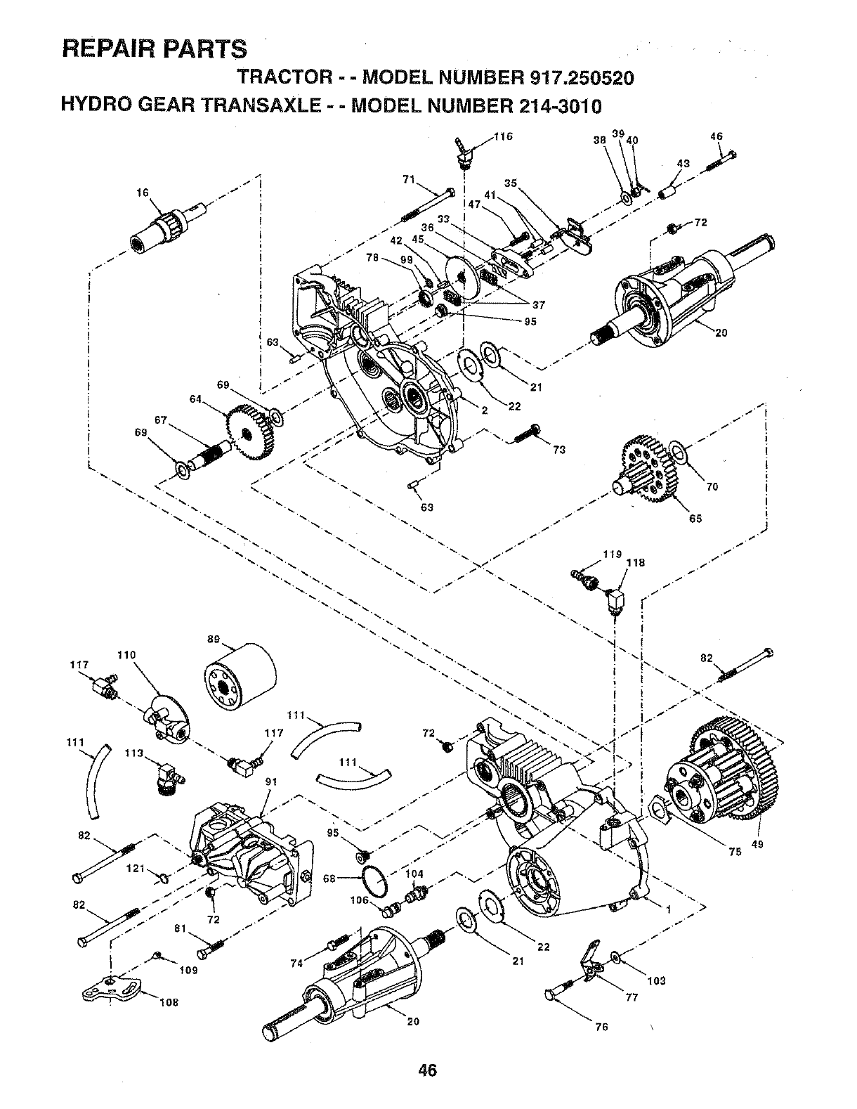
REPAIR PARTS
TRACTOR - - MODEL NUMBER 917.250520
HYDRO GEAR TRANSAXLE - - MODEL NUMBER 214-3010
49
75
46
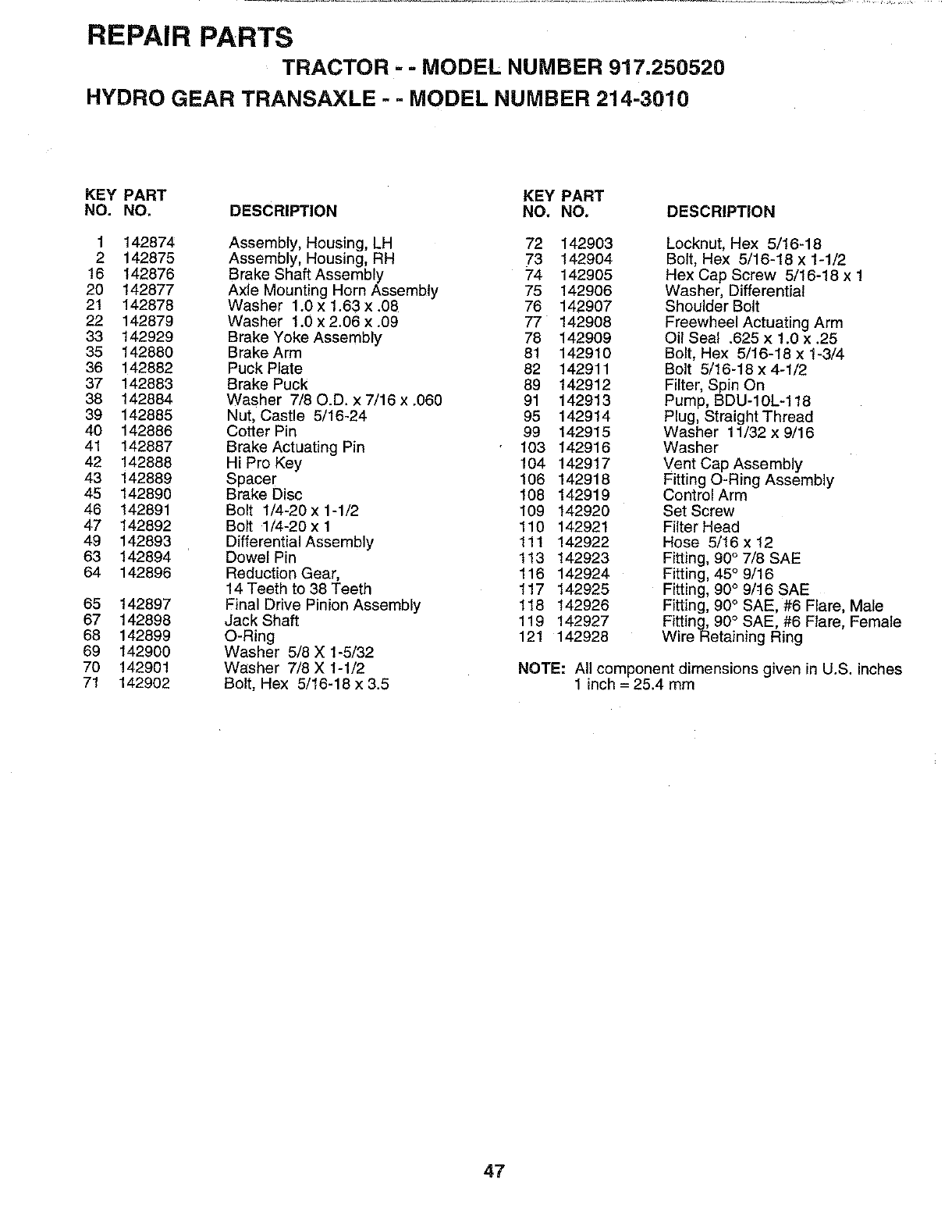
REPAIR PARTS
TRACTOR -- MODEL NUMBER 917.250520
HYDRO GEAR TRANSAXLE -- MODEL NUMBER 214-3010
KEY PART KEY PART
NO. NO. DESCRIPTION NO. NO. DESCRIPTION
1 142874 Assembly, Housing, LH 72 142903
2 142875 Assembly, Housing, RH 73 142904
16 142876 Brake Shaft Assembly 74 142905
20 142877 Axle Mounting Horn Assembly 75 142906
21 142878 Washer 1.0 x 1.63 x.08 76 142907
22 142879 Washer 1.0 x 2.06 x.09 77 142908
33 142929 Brake Yoke Assembly 78 142909
35 142880 Brake Arm 81 142910
36 142882 Puck Plate 82 142911
37 142883 Brake Puck 89 142912
38 142884 Washer 7/80.D. x 7/16 x.060 91 142913
39 142885 Nut, Castle 5/16-24 95 142914
40 142886 Cotter Pin 99 142915
41 142887 Brake Actuating Pin 103 142916
42 142888 Hi Pro Key 104 142917
43 142889 Spacer 106 142918
45 142890 Brake Disc 108 142919
46 142891 Bolt 1/4-20 x 1-1/2 109 142920
47 142892 Bolt 1/4-20x 1 110 142921
49 142893 Differential Assembly 111 142922
63 142894 Dowel Pin 113 142923
64 142896 Reduction Gear, 116 142924
14 Teeth to 38 Teeth 117 142925
65 142897 Final Drive Pinion Assembly 118 142926
67 142898 JackShaft 119 142927
68 142899 O-Ring 121 142928
69 142900 Washer 5/8 X 1-5/32
70 142901 Washer 7/8 X 1-1/2
71 142902 Bolt, Hex 5/16-18 x 3.5
Locknut, Hex 5/16-18
Bolt, Hex 5/16-18 x 1-1/2
Hex Cap Screw 5/16-18 x 1
Washer, Differential
Shoulder Bolt
Freewheel Actuating Arm
Oil Seal .625 x 1.0 x .25
Bolt, Hex 5/16-18 x 1-3/4
Bolt 5/16-18 x 4-1/2
Filter, Spin On
Pump, BDU-IOL-118
Plug, Straight Thread
Washer 11/32 x 9/16
Washer
Vent Cap Assembly
Fitting O-Ring Assembly
Control Arm
Set Screw
Filter Head
Hose 5/16x 12
Fitting, 90 ° 7/8 SAE
Fitting, 45 °9/16
Fitting, 90 °9/t6 SAE
Fitting, 90 ° SAE, #6 Flare, Male
Fitting, 90 °SAE, #6 Flare, Female
Wire Retaining Ring
NOTE: All component dimensions given in U.S. inches
1inch = 25.4 rnm
47
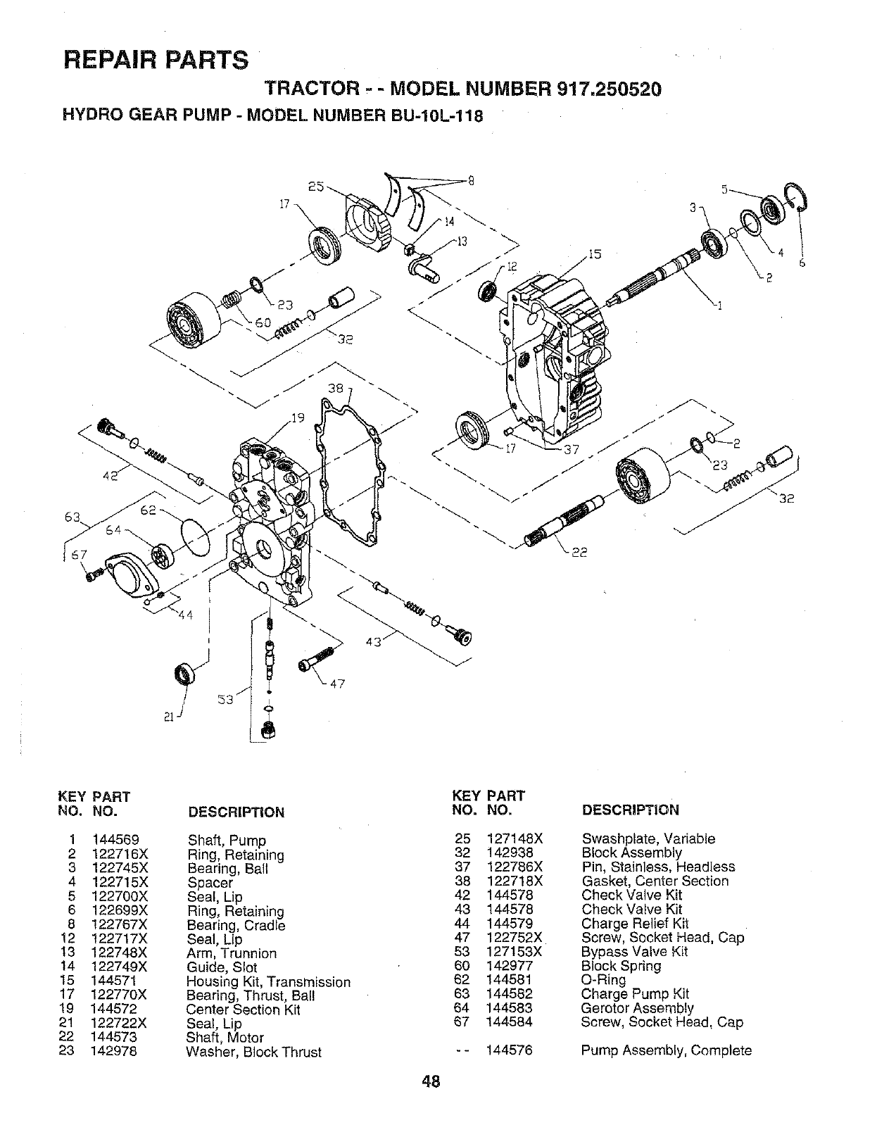
REPAIR PARTS
TRACTOR -- MODEL NUMBER 917.250520
HYDRO GEAR PUMP -MODEL NUMBER BU-10L-118
44
32
KEY PART
NO. NO.
1 144569
2 122716X
3 122745X
4 122715X
5 122700X
6 122699X
8 122787X
12 122717X
t3 122748X
14 122749X
15 144571
17 122770X
19 144572
21 122722X
22 144573
23 142978
DESCRIPTION
Shaft, Pump
Ring, Retaining
Bearing, Ball
Spacer
Seal, Lip
Ring, Retaining
Bearing, Cradle
Seal, Lip
Arm, Trunnion
Guide, Slot
Housing Kit, Transmission
Bearing, Thrust, Ball
Center Section Kit
Seal, Lip
Shaft, Motor
Washer, Block Thrust
KEY PART
NO. NO,
25 127148X
32 142938
37 122766X
38 122718X
42 144578
43 144578
44 144579
47 122752X
53 127153X
60 142977
62 144581
63 144582
64 144583
67 144584
144576
DESCRIPTION
Swashplate, Variable
Block Assembly
Pin, Stainless, Headless
Gasket, Center Section
Check Valve Kit
Check Valve Kit
Charge Relief Kit
Screw, Socket Head, Cap
Bypass Valve Kit
Block Spring
O-Ring
Charge Pump Kit
Gerotor Assembly
Screw, Socket Head, Cap
Pump Assembly, Complete
48
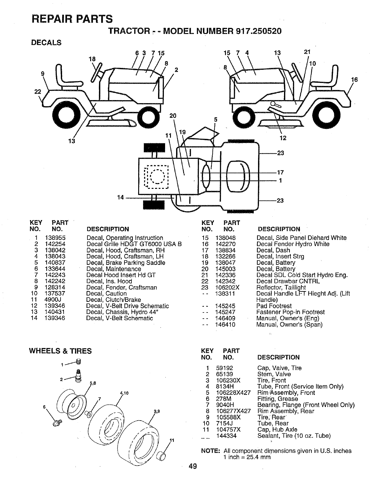
REPAIR PARTS
TRACTOR"- MODEL NUMBER 917.250520
DECALS
6 3 7 15 15 7 4 13
18 82
9
22
21
16
20 5
13 12
14
KEY PART
NO. NO.
1 138955
2 142254
3 138042
4 138043
5 140837
6 133644
7 142243
8 142242
9128314
10 137537
11 4900J
12 139346
13 140431
14 139346
DESCRIPTION
Decal, Operating Instruction
Decal Grille HDGT GT6000 USA B
Decal, Hood, Craftsman, RH
Decal, Hood, Craftsman, LH
Decal, Brake Parking Saddle
Decal, Maintenance
Decal Hood Insert Hd GT
Decal, Ins. Hood
Decal, Fender, Craftsman
Decal, Caution
Decal, Clutch/Brake
Decal, V-Belt Drive Schematic
Decal, Chassis, Hydro 44"
Decal, V-Belt Schematic
KEY PART
NO. NO.
15 138048
16 142270
17 138834
18 132266
19 138047
20 145003
21 142336
22 142342
23 106202X
-- 138311
-- 145245
-- 145247
-- 146409
-- 146410
DESCRIPTION
Decal, Side Panel Diehard White
Decal Fender Hydro White
Decal, Dash
Decal, insert Strg
Decal, Battery
Decal, Battery
Decal SDL Cold Start Hydro Eng+
Decal Drawbar CNTRL
Reflector, Taillight
Decal Handle LFT Hieght Adj. (Lift
Handle)
Pad Footrest
Fastener Pop-in Footrest
Manual, Owner's (Eng)
Manual, Owner's (Span)
WHEELS & TIRES
lO
KEY PART
NO. NO.
1 59192
2 65139
3 106230X
4 8134H
5 106228X427
6 278M
7 9O4OH
8 106277X427
9 105588X
10 7154J
11 104757X
144334
DESCRIPTION
Cap, Valve, Tire
Stem, Valve
Tire, Front
Tube, Front (Service Item Only)
Rim Assembly, Front
Fitting, Grease
Bearing, Flange (Front Wheel Only)
Rim Assembly, Rear
Tire; Rear
Tube, Rear
Cap, Hub Axle
Sealant, Tire (10 oz. Tube)
NOTE: All component dimensions given in U.S+ inches
1 inch = 25.4 mm
49
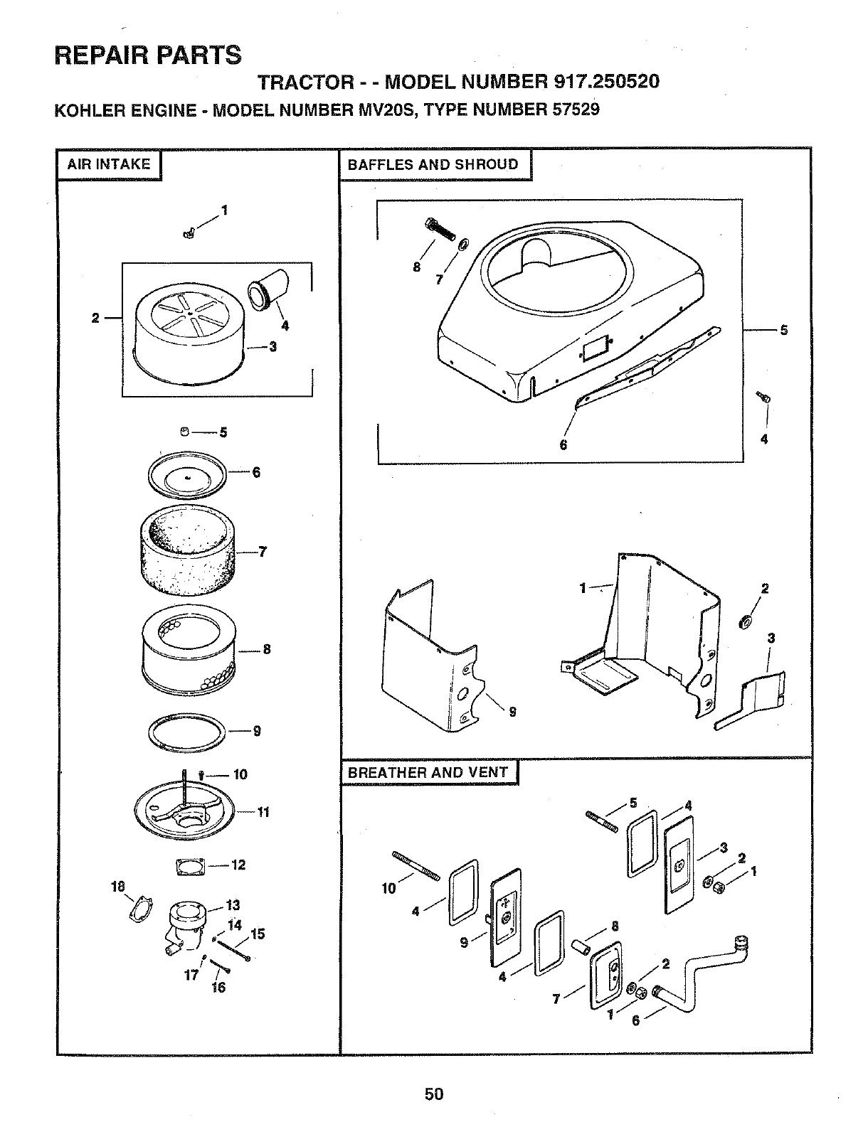
REPAIR PARTS
TRACTOR -- MODEL NUMBER 917.250520
KOHLER ENGINE -MODEL NUMBER MV20S, TYPE NUMBER 57529
1
6--5
6
--9
--11
_--12
18
_"_--_ _/'/4 15
16
BAFFLES AND SHROUD I
I/
87
!
6
--5
%
/
4
2
3
BREATHER AND VENT
5O
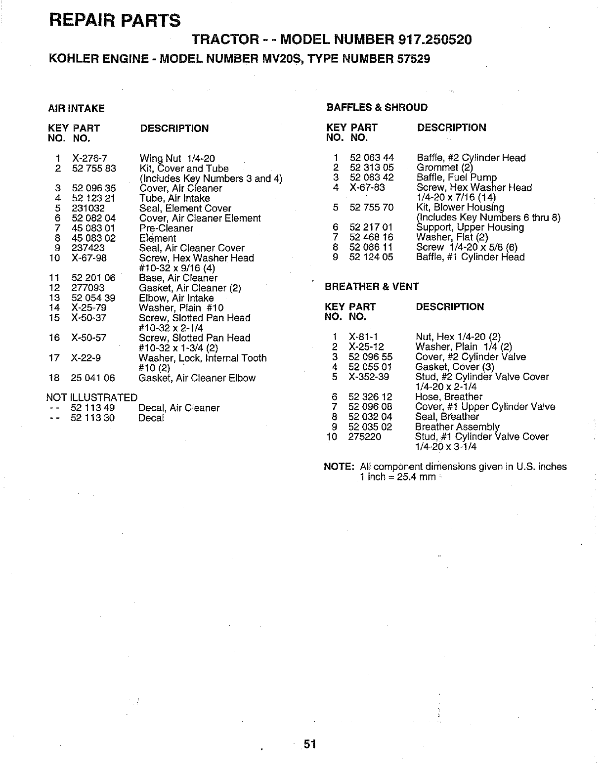
REPAIR PARTS
TRACTOR - = MODEL NUMBER 917.250520
KOHLER ENGINE -MODEL NUMBER MV2OS, TYPE NUMBER 57529
AIR INTAKE BAFFLES & SHROUD
KEY PART DESCRIPTION KEY PART
NO. NO. NO. NO.
Wing Nut 1/4-20 1 52 063 44
Kit, Cover and Tube 2 52 313 05
(Includes Key Numbers 3 and 4) 3 52 063 42
3 52 096 35 Cover, Air Cleaner 4 X-67-83
4 52 123 21 Tube, Air Intake
5 231032 Seal, Element Cover 5 52 755 70
6 52 082 04 Cover, Air Cleaner Element
7 45 083 01 Pre-Cleaner 6 52 217 01
8 45 083 02 Element 7 52 468 16
9 237423 Seal, Air Cleaner Cover 8 52 086 1!
10 X-67-98 Screw, Hex Washer Head 9 52 124 05
#10-32 x 9/16 (4)
11 52 201 06 Base, Air Cleaner
12 277093 Gasket, Air Cleaner (2) BREATHER & VENT
13 52 054 39 Elbow, Air Intake
14 X-25-79 Washer, Plain #!0 KEY PART
15 X-50-37 Screw, Slotted Pan Head NO. NO.
#10-32 x 2-1/4
Screw, Slotted Pan Head
#10-32 x 1-3/4 (2)
Washer, Lock, Internal Tooth
#10 (2)
Gasket, Air Cleaner Elbow
X-276-7
52 755 83
1
2
16 X-50-57
17 X-22-9
18 25 041 06
1
2
3
4
5
DESCRIPTION
Baffle, #2 Cylinder Head
Grommet (2)
Baffle, Fuel Pump
Screw, Hex Washer Head
1/4-20 x 7/16 (14)
Kit, Blower Housing
(Includes Key Numbers 6 thru 8)
Support, Upper Housing
Washer, Flat (2)
Screw 1/4-20x 5/8 (6)
Baffle, #1 Cylinder Head
DESCRIPTION
X-81-1
X-25-12
52 096 55
52 055 01
X-352-39
NOT ILLUSTRATED 6 52 326 12
- - 52 113 49 Decal, Air Cleaner 7 52 096 08
-- 5211330 Decal 8 52 032 04
9 52 035 02
10 275220
Nut, Hex 1/4-20 (2)
Washer, Plain 1/4 (2)
Cover, #2 Cylinder Valve
Gasket, Cover (3)
Stud, #2 Cylinder Valve Cover
1/4-20 x 2-1/4
Hose, Breather
Cover, #1 Upper Cylinder Valve
Seal, Breather
Breather Assembly
Stud, #1 Cylinder Valve Cover
1/4-20 x 3-1/4
NOTE: All component dimensions given in U.S. inches
1inch = 25.4 mm
• 51
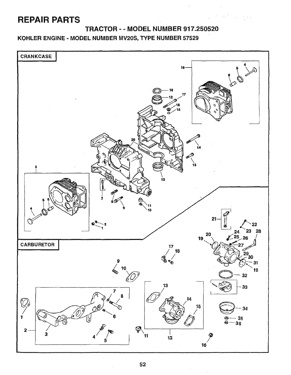
REPAIR PARTS
TRACTOR - -MODEL NUMBER 917.250520
KOHLER ENGINE -MODEL NUMBER MV20S, TYPE NUMBER 57529
CRANKCASE J
4
9
/1_0 19
0_ 32
0_3
11 I
12
16
52
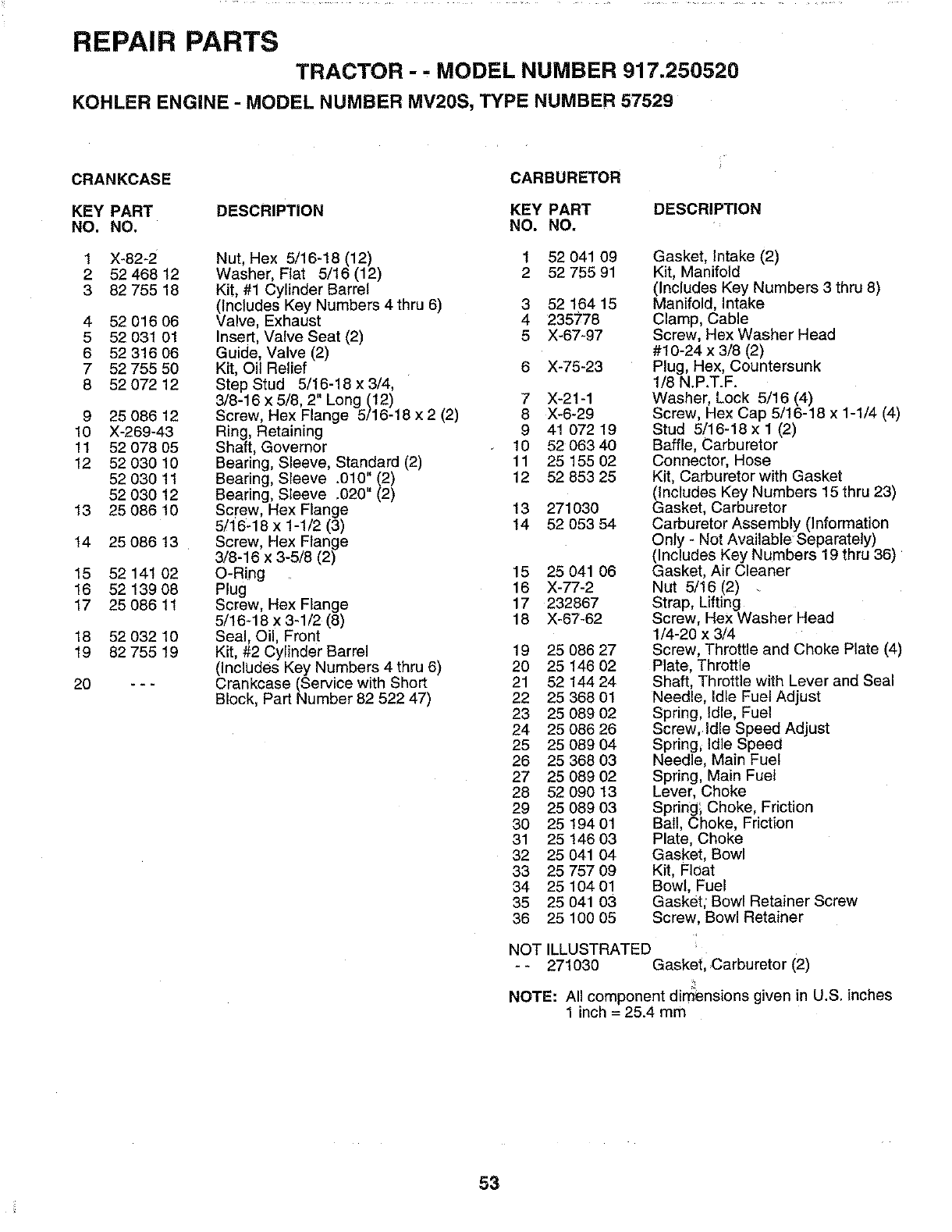
REPAIR PARTS
TRACTOR - , MODEL NUMBER 917.250520
KOHLER ENGINE - MODEL NUMBER MV20S, TYPE NUMBER 57529
CRANKCASE CARBURETOR
KEY PART DESCRIPTION KEY PART DESCRIPTION
NO. NO. NO. NO.
1 X-82-2 1 52 041 09
2 52 468 12 2 52 755 91
3 82 755 18
4 5201606
5 52 031 01
6 5231606
7 52 755 50
8 52 072 12
9 25 086 12
10 X-269-43
11 52 078 05
12 52 030 10
52 030 11
52 030 12
13 25 086 10
t4 25 086 13
15 52 141 02
16 52 139 08
17 25 086 11
18 52 032 10
19 82 755 19
Nut, Hex 5/16-18 (12)
Washer, Flat 5/16 (12)
Kit, #1 Cylinder Barrel
(Includes Key Numbers 4 thru 6)
Valve, Exhaust
Insert, Valve Seat (2)
Guide, Valve (2)
Kit, Oil Relief
Step Stud 5/16-18 x 3/4,
3/8-16 x 5/8, 2" Long (12)
Screw, Hex Flange 5/16-18 x 2 (2)
Ring, Retaining
Shaft, Governor
Bearing, Sleeve, Standard (2)
Bearing, Sleeve .010" (2)
Bearing, Sleeve .020" (2)
Screw, Hex Flange
5/16-18 x 1-1/2 (3)
Screw, Hex Flange
3/8-16 x 3-5/6 (2)
O-Ring
Plug '
Screw, Hex Flange
5/16-18 x 3-1/2 (8)
Seal Oil, Front
Kt, #2 Cy nder Barrel
(InclUdes Key Numbers 4 thru 6)
Crankcase (Service with Short
Block, Part Number 62 522 47)
20 -_ .
3
4
5
52 164 15
235778
X-67-97
X-75-23
7 X-21-1
8 X-6-29
9 41 072 19
10 52 063 40
11 25 155 02
12 52 853 25
13 271030
14 52 053 54
15 25 041 06
16 X-77-2
17 232867
18 X-67-62
19 25 086 27
20 25 146 02
21 52 144 24
22 25 368 01
23 25 089 02
24 25 086 26
25 25 089 04
26 25 368 03
27 25 089 02
28 52 090 13
29 25 089 03
30 25 194 01
31 25 146 03
32 25 041 04
33 25 757 09
34 25 104 01
35 25 041 03
36 25100 05
Gasket, Intake (2)
Kit, Manifold
(Includes Key Numbers 3 thru 8)
Manifold, Intake
Clamp, Cable
Screw, Hex Washer Head
#10-24 x 3/8 (2)
Plug, Hex, Countersunk
1/8 N.P.T.F.
Washer, Lock 5/16 (4)
Screw, Hex Cap 5/16-18 x 1-1/4 (4)
Stud 5/16-18 x 1 (2)
Baffle, Carburetor
Connector, Hose
Kit, Carburetor with Gasket
(Includes Key Numbers 15 thru 23)
Gasket, Carburetor
Carburetor Assembly (Information
Only - Not Available Separately)
(Includes Key Numbers 19 thru 36)
Gasket, Air Cleaner
Nut 5/16 (2)
Strap, Lifting
Screw, Hex Washer Head
1/4-20 x 3/4
Screw, Throttle and Choke Plate (4)
Plate, Throttle
Shaft, Throttle with Lever and Seal
Needle, Idle Fuel Adjust
Spring, Idle, Fuel
Screw, Idle Speed Adjust
Spring, Idle Speed
Needle, Main Fuel
Spring, Main Fuel
Lever, Choke
Spring', Choke, Friction
Ball, Choke, Friction
Plate, Choke
Gasket, Bowl
Kit, Float
Bowl, Fuel
Gasket; Bowl Retainer Screw
Screw, Bowl Retainer
NOT ILLUSTRATED
-- 271030 Gasketl Carburetor (2)
NOTE: All component dimensions given in U.S. inches
1 inch = 25.4 mm
53
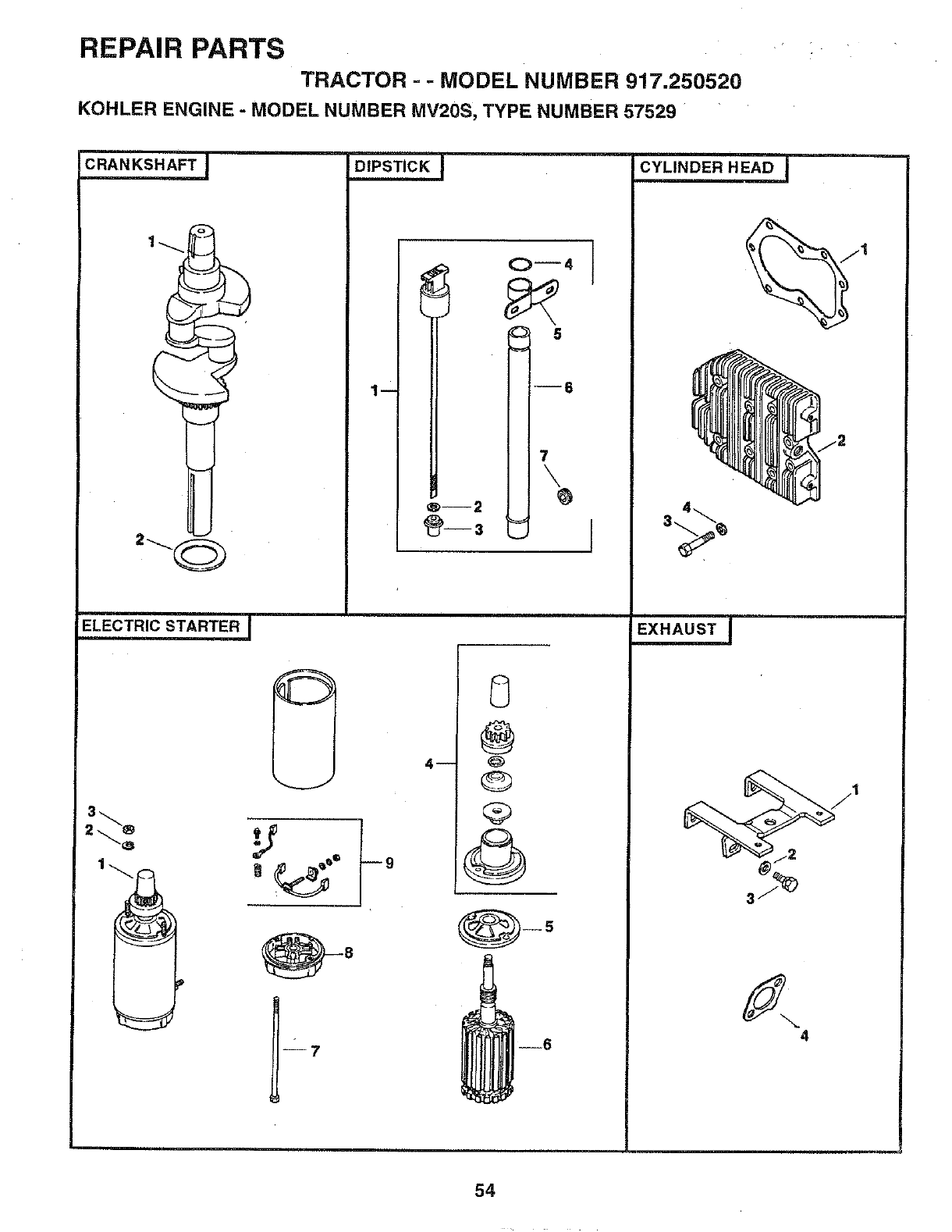
REPAIR PARTS
TRACTOR = - MODEL NUMBER 917.250520
KOHLER ENGINE - MODEL NUMBER MV20S, TYPE NUMBER 57529
2
ELECTRIC STARTER I
@°
O--4
5
1- J6
7
\
®--2
@ 3 ="
8
@
Q
@
--6
t
4
54
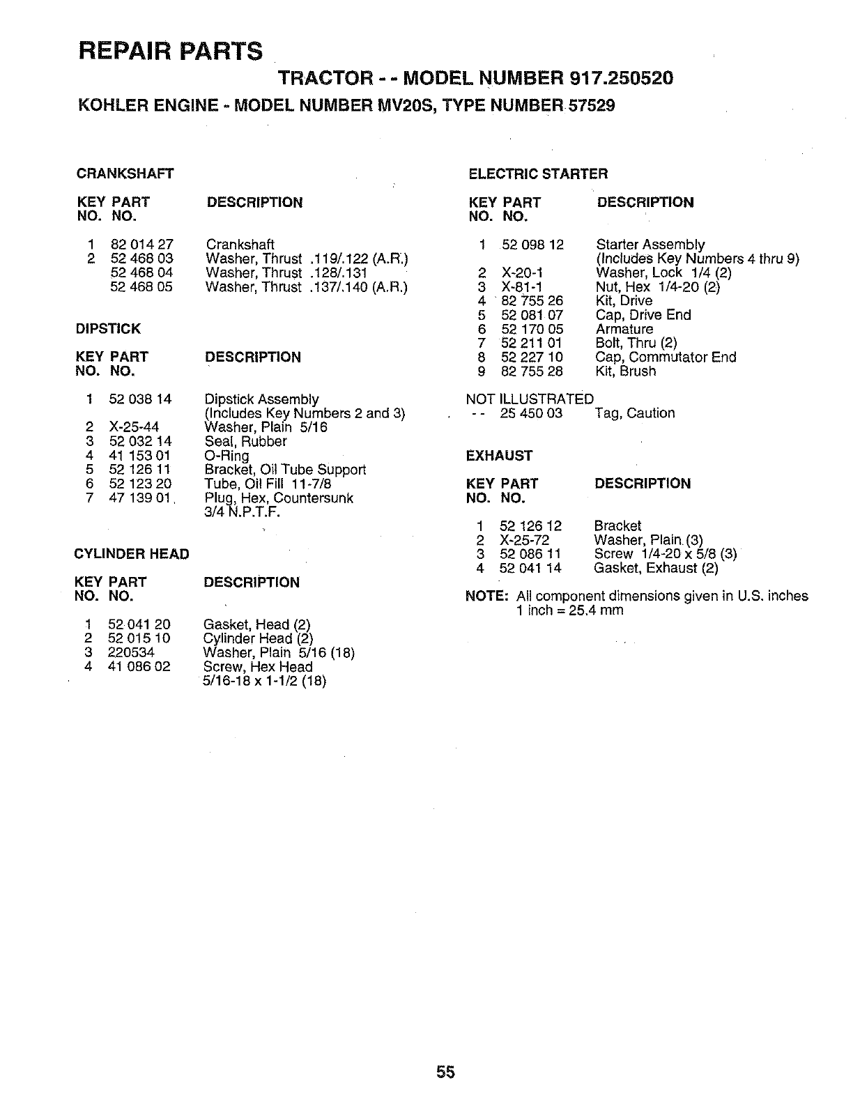
REPAIR PARTS
TRACTOR --MODEL NUMBER 917.250520
KOHLER ENGINE -MODEL NUMBER MV20S, TYPE NUMBER 57529
CRANKSHAFT ELECTRIC STARTER
KEY PART DESCRIPTION KEY PART
NO. NO, NO. NO.
1 82 014 27
2 52 468 03
52 468 04
52 468 05
DIPSTICK
KEY PART
NO. NO.
1 52 038 14
2 X-25-44
3 52 032 14
4 41 15301
5 52 126 11
6 52 123 20
7 47 139 01
Crankshaft
Washer, Thrust .119/. 122 (A.R_)
Washer, Thrust .128/. 131
Washer, Th rust .137/. 140 (A.R.)
DESCRIPTION
Dipstick Assembly
(Includes Key Numbers 2 and 3)
Washer, Plain 5/16
Seal, Rubber
O-Ring
Bracket, Oil Tube Support
Tube, Oil Fill 11-7/8
Plug, Hex, Countersunk
3/4 N.P.T.F.
DESCRIPTION
Gasket, Head (2)
Cylinder Head (2)
Washer, Plain 5/16 (18)
Screw, Hex Head
5/16-18 x 1-1/2 (18)
CYLINDER HEAD
KEY PART
NO. NO.
152 041 20
2 52 0t5 10
3220534
4 41 086 02
DESCRIPTION
2
3
4
5
6
7
8
9
52 098 12
X-20-1
X-81-1
82 755 26
52 081 O7
52 170 05
52211 01
52 227 10
82 755 28
Starter Assembly
(Includes Key Numbers 4 thru 9)
Washer, Lock 1/4 (2)
Nut, Hex 1/4-20 (2)
Kit, Drive
Cap, Drive End
Armature
Bolt, Thru (2)
Cap, Commutator End
Kit, Brush
NOT ILLUSTRATED
-- 25 450 03 Tag, Caution
EXHAUST
KEY PART
NO. NO, DESCRIPTION
1
2
3
4
52 126 12
X-25-72
52 086 11
52 041 14
Bracket
Washer, Plain (3)
Screw 1/4-20 x 5/8 (3)
Gasket, Exhaust (2)
NOTE: All component dimensions given in U.S. inches
1 inch = 25.4 mm
55
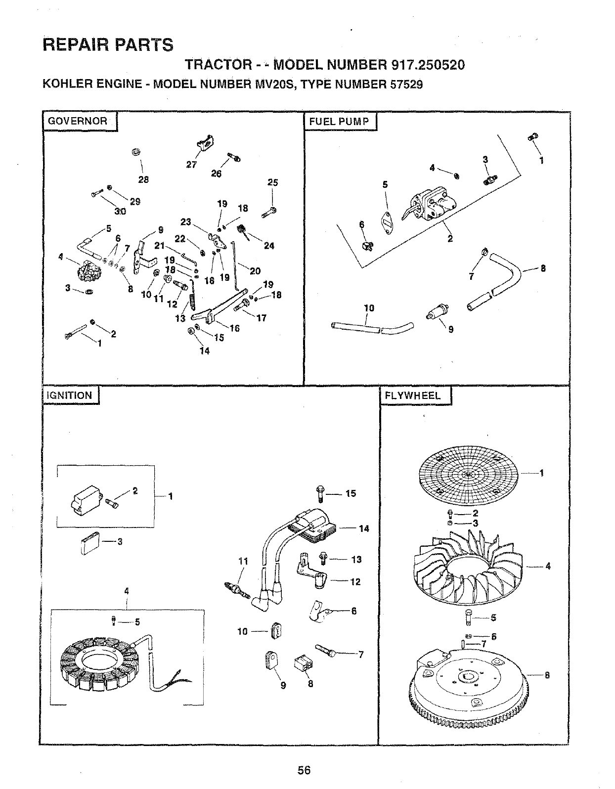
REPAIR PARTS
TRACTOR -_MODEL NUMBER 917.250520
KOHLER ENGINE - MODEL NUMBER MV20S, TYPE NUMBER 57529
27 26 25
19 18
13 17
14
I
4
--14
9 8
31
8
56
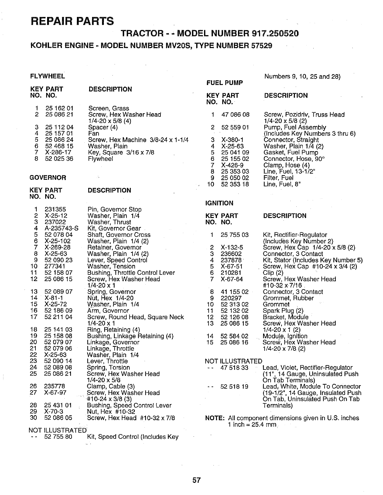
REPAIR PARTS
TRACTOR -- MODEL NUMBER 917.250520
KOHLER ENGINE -MODEL NUMBER MV20S, TYPE NUMBER 57529
FLYWHEEL
KEY PART
NO. NO. DESCRIPTION
1 25 162 01 Screen, Grass
2 25 088 21 Screw, Hex Washer Head
1/4-20 x 5/8 (4)
3 25 112 04 Spacer (4)
4 25 157 01 Fan
5 25 086 24 Screw, Hex Machine 3/8-24 x 1-1/4
6 52 468 15 Washer, Plain
7 X-286-17 Key, Square 3/16 x 7/8
8 52 025 36 Flywheel
GOVERNOR
KEY PART
NO. NO. DESCRIPTION
1 231355
2 X-25-12
3 237022
4 A-235743-S
5 52 078 O4
6 X-25-102
7 X-269-28
8 X-25-63
9 52 090 23
10 277341
11 52 158 07
12 25 086 15
13 52 089 07
14 X-81-1
15 X-25-72
16 52 186 09
17 52211 04
18 25 141 03
19 25 158 08
20 52 079 07
21 52 079 06
22 X-25-63
23 52 090 14
24 52 089 08
25 25 086 21
26 235778
27 X-67-97
28 25 431 01
29 X-70-3
30 52 086 05
Pin, Governor Stop
Washer, Plain 1/4
Washer, Thrust
Kit, Governor Gear
Shaft, Governor Cross
Washer, 15lain 1/4 (2)
Retainer, Governor
Wasl_er, Plain 1/4 (2)
Lever, Speed Control
Washer, Tension
Bushing, Throttle Control Lever
Screw, Hex Washer Head
1/4-20 x 1
Spring, Governor
Nut, Hex 1/4-20
Washer, Plain 1/4
Ai:m, Governor
Screw, Round Head, Square Neck
1/4-20 x 1
Ring, Retaining (4)
Bushing, Linkage Retaining (4)
Linkage, Governor
Linkage, Throttle
Washer, Plain 1/4
Lever, Throttle
Spring, Torsion
Screw, Hex Washer Head
1/4-20 x 5/8
Clamp, Cable (3)
Screw, Hex Washer Head
.... i#10-24 x 3/8 (3)
Bushing, Speed Control Lever
Nut, Hex #10-32
Screw, Hex Head #10-32 x 7/8
NOT ILLUSTRATED
- - 52 755 80 Kit, Speed Control (Includes Key
FUEL PUMP
KEY PART
NO. NO.
1 47086 08
2 52 559 01
3 X-380-1
4 X-25-63
5 25 041 09
6 25 155 02
7 X-426-9
8 25 353 03
9 25 050 02
10 52 353 18
Numbers 9, 10, 25 and 28)
DESCRIPTION
Screw, Pozidriv, Truss Head
1/4-20 x 5/8 (2)
Pump, Fuel Assembly
(Includes Key Numbers 3 thru 6)
Connector, Straight
Washer, Plain 1/4 (2)
Gasket, Fuel Pump
Connector, Hose, 90 °
Clamp, Hose (4) ,,
Line, Fuel, 13-1/2
Filter, Fuel
Line, Fuel, 8"
IGNITION
KEY PART
NO. NO. DESCRIPTION
2
3
4
5
6
7
8
9
10
11
12
13
14
15
25 755 03
X-132-5
236602
237878
X-67-51
210281
X-67-64
41 15502
220297
52 313 02
52 132 02
52 126 08
25 086 15
52 584 02
25 086 16
Kit, Rectifier-Regulator
(Includes Key Number 2)
Screw, Hex Cap 1/4-20 x 5/8 (2)
Connector, 3 Contact
Kit, Stator (Includes Key Number 5)
Screw, Hex Cap #10-24 x 3/4 (2)
Clip (2)
Screw, Hex Washer Head
#10-32 x 7/18
Connector, 3 Contact
Grommet, Rubber
Grommet
Spark Plug (2)
Bracket, Module
Screw, Hex Washer Head
1/4-20 x 1 (2)
Modu!e, Ignition
Screw, Hex Washer Head
1/4-20 x 7/8 (2)
NOT ILLUSTRATED
- - 47 518 33 Lead, Violet, Rectifier-Regulator
(11", 14 Gauge, Uninsulated Push
On Tab Terminals)
- - 52 518 19 Lead, White, Module To Connector
(19:1/2", 14 Gauge, Insulated Push
On Tab, Uninsulated Push On Tab
Terminals)
NOTE: All component dimensions given in U.S. inches
1 inch = 25.4 mm
57
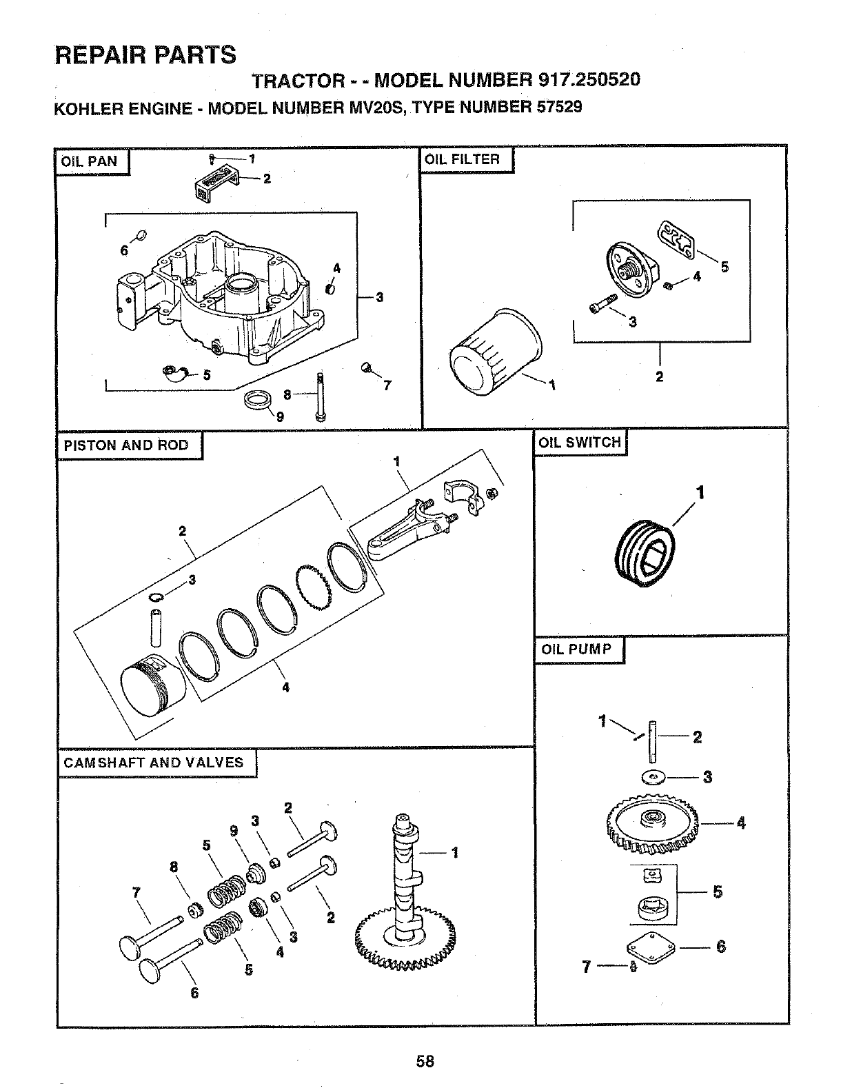
REPAIR PARTS
TRACTOR -- MODEL NUMBER 917,250520
KOHLER ENGINE -MODEL NUMBER MV20S, TYPE NUMBER 57529
I
6
PISTON AND ROD I
9
5
6
2
3 \
4
5
7
II
2
|
OIL PUMP I
@-,
® s
7_ -6
58
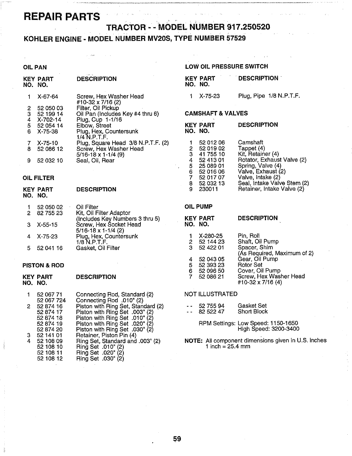
REPAIR PARTS .........
TRACTOR= -MODEL NUMBER 917.250520
KOHLER ENGINE- MODEL NUMBER MV20S, TYPE NUMBER 57529
OIL PAN
KEY PART
NO. NO.
1 X-67-64
2 52 050 03
352 199 14
4 X-702-14
5 52 054 14
6 X-75-38
7 X-75-10
8 52 086 12
9 52 032 10
OIL FILTER
KEY PART
NO. NO.
1 52 050 02
2 82 755 23
3 X-55-15
4 X-75-23
5 52 041 16
PISTON & ROD
KEY PART
NO. NO.
1 52 06771
52 067 724
2 52 874 16
52 874 17
52 874 18
52 874 19
52 874 20
3 52 141 01
4 52 108 09
52 108 10
52 108 11
52 108 12
DESCRIPTION
Screw, Hex Washer Head
#10-32 x 7/16 (2)
Filter, Oil Pickup
Oil Pan (Includes Key #4 thru 6)
Plug, Cup 1-1/16
Elbow, Street
Plug, Hex, Countersunk
1/4N.P.T.F.
Plug, Square Head 3/8 N.P.T.F. (2)
Screw, Hex Washer Head
5/16-18 x 1-1/4 (9)
Seal, Oil, Rear
DESCRIPTION
Oil Filter
Kit, Oil Filter Adaptor
(Includes Key Numbers 3 thru 5)
Screw, Hex Socket Head
5/16-18 x 1-1/4 (2)
Plug, Hex, Countersunk
1/8 N.P.T.F.
Gasket, Oil Filter
DESCRIPTION
Connecting Rod, Standard (2)
Connecting Rod .010" (2)
Piston with Ring Set, Standard (2)
Piston with Ring Set .003" (2)
Piston with Ring Set .010" (2)
Piston with Ring Set .020" (2)
Piston with Ring Set .030" (2)
Retainer, Piston Pin (4)
Ring Set, Standard and .003" (2)
Ring Set .010" (2)
Ring Set .020'! (2)
Ring Set ,030" (2)
LOW OIL PRESSURE SWITCH
KEY PART DESCRIPTION
NO. NO.
1X-75-23 Plug, Pipe 1/8 N.P.T.F.
CAMSHAFT & VALVES
KEY PART DESCRIPTION
NO. NO.
1
2
3
4
5
6
7
8
9
52 012 06
52 019 02
41 755 10
52 413 01
25 089 01
52 016 06
52 017 07
52 032 13
230011
Camshaft
Tappet (4)
Kit, Retainer (4)
Rotator, Exhaust Valve (2)
Spring, Valve (4)
Valve, Exhaust (2)
Valve, intake (2)
Seal, intake Valve Stem (2)
Retainer, Intake Valve (2)
OIL PUMP
KEY PART
NO. NO. DESCRIPTION
1
2
3
4
5
6
7
X-280-25
52 t44 23
52 422 01
52 043 05
52 393 23
52 096 50
52 086 21
Pin, Roll
Shaft, Oil Pump
Spacer, Shim
(As Required, Maximum of 2)
Gear, Oil Pump
Rotor Set
Cover, Oil Pump
Screw, Hex Washer Head
#10-32 x7/16 (4)
NOT ILLUSTRATED
- - 52 755 94 Gasket Set
- - 82 522 47 Short Block
RPM Settings: Low Speed: 1150-1650
High Speed: 3200-3400
NOTE: All component dimensions given in U.S. inches
1 inch = 25.4 mm
5g

L • ,i
SERVICE NOTES
6O

SERVICE NOTES
i i i
61

62

SUGGESTED GUIDE FOR SIGHTING SLOPES FOR SAFE OPERATION
,,,,,.
"T
SIGHTING
ONLY RIDE UP AND DOWN HILL,
NOT ACROSS HILL
SIGHT AND HOLD THIS LEVEL WITH
SKY LINE OR TREE.
15 ° MAX.
Operate your Tractor up and down the face of slopes (not
greater than 15°), never across the face. Make turns gradu-
ally to prevent tipping or loss of control. Exercise extreme
caution when changing direction on slopes.
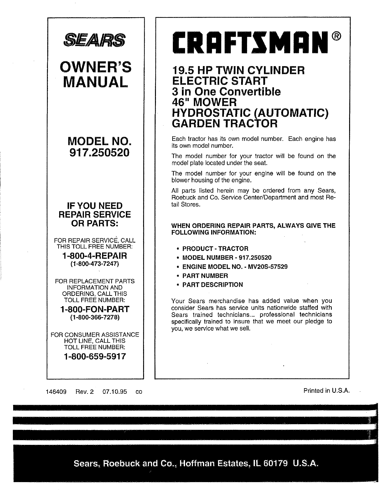
SWA/RS
OWNER'S
MANUAL
MODEL NO.
917.250520
IF YOU NEED
REPAIR SERVICE
OR PARTS:
FOR REPAIR SERVICE, CALL
THIS TOLL FREE NUMBER:
1-800-4-REPAIR
(1-800-473-7247)
FOR REPLACEMENT PARTS
INFORMATION AND
ORDERING, CALL THIS
TOLL FREE NUMBER:
1-800-FON-PART
(1-800-366-7278)
FOR CONSUMER ASSISTANCE
HOT LINE, CALL THIS
TOLL FREE NUMBER:
1-800-659-5917
CRAFTSMAN+
19.5 HP TWIN CYLINDER
ELECTRIC START
3 in One Convertible
46" MOWER
HYDROSTATIC (AUTOMATIC)
GARDEN TRACTOR
Each tractor has its own model number. Each engine has
its own model number.
The model number for your tractor will be found on the
model plate located under the seat.
The model number for your engine will be found on the
blower housing of the engine.
All parts listed herein may be ordered from any Sears,
Roebuck and Co. Service Center/Department and most Re-
tail Stores.
WHEN ORDERING REPAIR PARTS, ALWAYS GIVE THE
FOLLOWING INFORMATION:
• PRODUCT- TRACTOR
•MODEL NUMBER -917.250520
• ENGINE MODEL NO. -MV20S-57529
•PART NUMBER
•PART DESCRIPTION
Your Sears merchandise has added value when you
consider Sears has service units nationwide staffed with
Sears trained technicians.., professional technicians
specifically trained to insure that we meet our pledge to
you, we service what we sell.
146409 Rev. 2 07.10.95 co Printed in U.S.A.
