Craftsman 917251561 User Manual GARDEN TRACTOR Manuals And Guides L0711398
CRAFTSMAN Lawn, Tractor Manual L0711398 CRAFTSMAN Lawn, Tractor Owner's Manual, CRAFTSMAN Lawn, Tractor installation guides
User Manual: Craftsman 917251561 917251561 CRAFTSMAN GARDEN TRACTOR - Manuals and Guides View the owners manual for your CRAFTSMAN GARDEN TRACTOR #917251561. Home:Lawn & Garden Parts:Craftsman Parts:Craftsman GARDEN TRACTOR Manual
Open the PDF directly: View PDF ![]() .
.
Page Count: 60
CRIIFTSMnN+
MODEL NUMBER 917.251561 OWNER'SMANUAL
• Assembly
• Operation
" Customer Responsibilities
• Service and Adjustments
•Repair Parts
CAUTION: Read and follow all safety rules and instructions before operating this equipment.
FOR CONSUMER ASSrSTANCE HOT LINE, CALL TH_S TOLL FREE NUMBER: 1-B00-659-5917
................... II IIIII I I
im
SAFETY RULES
Safe OperatiOn?ractices-for Ride-On Mowers
IMPORTANT: THIS CUTTING MACHINE IS CAPABLE OF AMPUTATING HANDS AND FEET AND THROWING OBJECTS.,
FAILURE TO OBSERVE THE FOLLOWING SAFETY INSTRUCTIONS COULD RESULT IN SERIOUS iNJURY OR DEATH,
LGENERAL OPERATION iii. CHILDREN
Reed, understand, and to_low a_linstructions In the manual Tragic accidents can occur it the operator is not alert to Ihe
and on the machine before slatting presence of chlIdren Children are often attracted to the
Only allow responsible adul[s, who are familiar with the machine and the mowing actMty Never assume that
instructions, to operate the machine children wH! remain where you last saw them.
C{ear the area of ob ects such as rocks, toys wire, etc,
which could be pcked up and {1rowe by the b ads Keep children Out of the mowing area and under the watchful
Be sure the area Is clear of other people before mowing Slop
machine if anyone enters the area
•Never carry passengers
•Do not mow tn reverse unless absolutely necessary Nways
look down and behind balers end while becking
Be aware of the mower discharge direction and do not point
it at anyone Do not operate the mower without either the
entire grass catcher or lhe guard in place
. Stow down before tumlng
• Never leave a running maohtne unattended, Always tu re elf
blades, sat parking brake, stop engine, and remove keys
before dlsmountlng,
•Turn off blades when not mowing
• Stop engine before removing grass calcher or unclogging
chute
Mow only in daylight or good artificial light
• Do not operate Iha machine while under the influence of
alcohol or drugs.
• Watch for Iraflte when operating near or crossing roadways
Use extra care when loading or unloading the machine into
a trailer or Iruck
IL SLOPE OPERATION
Slopes are a major factor related Io loss-of-control and
tipover accidents, whlch can result in save re Injury or deafh
All slopes require extra caution, ff yotJ cannot back up the
slope or if you feel uneasy on It, do nol mow it
DO.
"Mow up and down slopes, not across
,, Remove obstacles such as rocks, tree limbs, ate
•Watch lot holes, ruts, or bumps. Uneven terrain could
overturn the machine Tallgrasscanhideobstscfes
•Use slow speed Choose a low gear so lhat you will not have
to stop or shill while on the slope.
Follow the manufacturer's recommendations for whee!
weights or counterweights to Improve slabiltty
.USa extra care wt[h grass catchers or other at.tachments
These can change the stability of the machine
, Kaepalimevamantonthesfopeestowandgraduaf, Donut
make sadden changes In speed or direction
Avoid staffing Dr stopping on a slope. It tires lose traction,
disengage the blades and proceed slowly straight down the
slope,
DO NOT:
.Do not turn on slopes unless necessary, and then, turn slowly
and gradually downhill, if possible
•Do not mew near drop-otis, ditches, or embankments The
mower could suddenly turn over if awheel Is over the edge
o! a cltlf or ditch, or il an edge caves in
Do not mow on wel grass. Reduced traction could cause
eliding
•Do not hy to stabilize the machine by putting your loot on the
ground
•Do not use grass catcher on steep slopes,
t,
=,
e
care of another responsible adult
•Be alert and turn machir_e og tf children enter the ares
Before and when backing, took behind and down for small
children
•Never carry children They may fall off and be seriously
injured or interfere with sale machine operation
•Never allow children to operate the machine
• Use extra care when approaching blindcornea shrubs,
trees, or other objects thai may obscure vision
IV. SERVICE
Use extra care in handling gasoiine and otherfuels, They ara
flammable and vapors are explosive
Use only an approved container,
Never remove gas cap or add fuel wtlh the engine
running Allow engine to cool belora refueling Do not
smoke,
- Never refuel the machine indoors
Never store the machine or fuel conlatner inside where
there ls an open flame, such as a water heater
Never run a machine inside a closed area.
Keep nuts and bolts, especially blade attachment bolts, tight
and keep equipment in good condition
Never leaper wilh safely devices Check their proper
operation regularly.
Keep machfne free el grass leaves, orother debris build-up.
C san oil or fuel spillage Allow machine to coot before
alodng
Stop end inspect the equipment if you strike an obiect
Repair, il necessan/, before restarting,
Never make adjustments or repairs with tire engine running,
Graescatcher components are sub eel to wear damage, and
deterioration, whfeh could expose moving parts or allow
objects to be throwm Frequently check components and
replace with manuiacturer's recommended pads, when nec-
essary
Mower blades are sharp and can cut Wrap the b}ade s) or
wear gloves, and use extra caution when servicing them
Check brake operation frequently Adjust and serviceas
required,
Look for IhI8 symbol to point out Impor-
tant safety precautions. It means
CAUTION|If BECOME ALERTIII YOUR
SAFETY IS INVOLVED.
CAUTION: Always disconnect spark plug
wire end place wtre where It cannot contact
spark plug in order to prevent eccldentsl
starting when setting up, transpodlng_
adjustEng or making repair s.
WARNING &
The engine exhaust from this product con-
tains chemicals known to the State of Califor-
nia to cause cancer, birth defects, or other
reproductive harm.
rr
LU
I.g
14.
n-
O
LI.
O3
UJ
O
...J
O3
(5
Z
m
I--
-!-
(5
m
or)
u=
ILl
!:3
I-,
o9
uJ
(5
(5
o3
CONGRATULATIONS on your purchase of a Sears
Tractor tt has been designed, englheered and manufac..
tured to give you the best possible dependability and
pefformance_
Should you experience any problem you cannot easily
remedy, please contac! your nearest Sears Authorized
Service centedDepadment Department. We have com-
petent, welt-trained technicians and the.proper tools to
service 0_"repair thts tractor.
Please read and retain this manual The inskuctions will
enable you to assemble and maintain your tractorproperly]
Always observe the "SAFETY RULES"
MODEL
NUMBER 917 25t 56t
SERIAL
NUMBER
DATEOFPURCHASE
THE MODELAND SERIAL NUMBERS WILL BE FOUND
ON A pLATE UNDER THE SEAT
YOU SHOULD RECORD BOTH SERIAL N UMBER AND
DATE OF PURCHASE AND KEEP IN A SAFE PLACE
FOR FUTURE REFERENCE..
MAINTENANCE AGREEMENT
.A Sears Maintenance Agreement ls available on _his prod_
uct ContacJ your nearest Sears store for de|&its
CUSTOMER RESPONSIBILITIES
•Read and observe the safety rules
• Fol!ow a regutar schedule in maintaining caring ferand
using your tractor '
- Foitow the instruct_onsunder "Customer Responsibili-
ties" and "Storage'* sections of this owner's manual
PRODUCT SPECIFICATIONS
HORSEPOWER: 22 5
GASOLINE CAPACITY 3 5 GALLONS
AND TYPE: UNLEADED REGULAR
OIL TYPE (API_SF/SG): SAE toW30'(above 32"F)
SAE 5W-30 (batew32_F)
O_LCAPACITY: W!FILTER: 42 PINTS
W/O FILTER: 3 7 PINTS
SPARK PLUG: CHAMPION RC12YC
(GAP- .030")
VALVE CLEARANCE: NOT ADJUSTABLE
GROUND SPEED (MPH): FORWARD; 0 - 5 6
REVERSE; 0-25
TIRE PRESSURE: FRONT: 14 PSi
REAR: I0 PSI
CHARGING SYSTEM: 15 AMPS @ 3600 RPM
BATTERY'. AMP/HR: 35
MfN CCA; 280
CASE SIZE: UtR
BLADE BOLT TORQUE: 30.-35 FT LBS.
WARNING: This Iractor is equipped with an internal
combustion engine and should not be'used on or near any
unimproved torest-.covered, brush-covered or grass-cov-
ered land unless the engine's exhaust system is equipped
wilh aspark attester meeting applicable local or state taws
(if any) If a spark arrestor is used, tt should be maintained
in effective working order by lhe operatOr.r
in the state of California the above Is required by law
(Section 4442 ol the California Public Resources Code).
Other states may have similar taws Federal iaws apply on
federal lands A spark arrestor for the muffler is available
through youi" nearest Sears Aulhorized Service Center/
Department (See REPAIR PARTS section ol this manua )
, H,,,i i
LIMITED TWO YEAR WARRANTY ON CRAFTSMAN RIDING EQUIPMENT
For two (2) years from Ihe date of purchase if thisCraftsman R_dtngEquipment telmainla ned, ubficated and laned up according
to fhe instructions in the ewnePs manuaF_Sears wll!repair or replace, tree of charge, any partsfound to be detective in maledal
or Workmanship '
This Warranty does natcover.
Expendable ilems which become worn dadng normal use such as blades, spark plugs• air cleaners, bells, elc
"Tire replacementor repair causedby puncturesfrom outside objecls, such as nails, thorns, stumps, or gtass
•Repa|ts neeesse_ because of operator abuse, negligence, improperstorage or accident or 4hafailure to maintain the
equipment according to the lnstruction_ containedtn the owner's manual
Riding equipmenlused for commercialor _nlal purposes.
LIMITED 90 DAY WARRANTY ON BATTERY
For ninety (90) days from date of purchase, if any batlen/]ncruded with ths rid ng equipment proves defecllve in matedal or
workmanship and ourtesting determines the balten/will not hold a charge,Searswt_ireplacethe bat ery a! no charge
IN-HOME WARRANTY SERVICE ON YOUR CRAFTSMAN RIDING EQUIPMENT IS AVAILABLE AT NO-CHARGE FOR 30
DAYS FROM THE DATE OF PURCHASE PLEASE CONTACT YOUR NEAREST SERVICE CENTER. AFTER 30 DAYS
FROM THE DATE OF PURCHASE, WARRANTY'SERVICE IS AVAILABLE BY TAKING YOUR CRAFTSMAN RIDING EQUIP-
MENT TO YOUR NEAREST SEARS SERVICE CENTER, (IN-HOME WARRANTY SERVICE WILL STILL BE AVAILABLE
AFTER 30 DAYS FROM THE DATE OF' PURCHASE BUT A STANDARD TRIP CHARGE WiLL APPLY ) THIS WARRANTY
APPLIES ONLY WHILE THIS PRODUCT IS IN THE UNITED STATES
This _/artanty gives you specIflc legal rights, end you may alsohave other rightswhich may van/from state to stale
SEARS, ROEBUCK AND CO, Dt817 WA, HOFFMAN ESTATES, iL 60179
! , t ,1 = ,,,,i HH I
3
SAFETY RULES ........ ;....... _............................................. 2
PRODUCT SPECtFtCATIONS.....,:._ ....... _...._..o...; ...... 3
CUSTOMER RESPONSIBILITIES .......................... 3, 16-19
WARRANT'Y _...: .................................... _............................. 3
TRACTOR ACCESSORIES ....................................... 5,15
ASSEMBLY" ..................................... i.......................... 7-t0
OPERATION ......... ,:............................................... _....... t2-16
TABLE OF CONTENTS
MAINTENANCE SCHEDULE ..o: .................................. 17
SERVICE AND ADJUSTMENTS ............................. 21-27
STORAGE ....... _._................................................................ 28
TROUBLESHOOTING ............... :..................... ,..... 29-30
REPAIR PARTS - TRACTOR .............................. _ 32-50
REPAIR PARTS- ENGINE ........................................ 51-58
PARTS ORDERING/SERVICE ............... BACK COVER
INDEX A
Accessories ....................... ;......... 5
Adjustments;
Brake ........................................ 23
Carbu_'eter .......................... 27
Clutch Putley ........................... 23
Gauge Wheels ............. t 4
Mower
Front*To-Back .................. 22
Side-To-Side ................... 21
Threltle Control Cable. .......... 27
Air Filler. Eng!ee ............................ 20
Air Screen, Engine .......... ;19
Assembly ............................... 7.10
B
Battery:
Charging .............................. 8
Cleaning ................................. 20
Starting wilh Weak Bailer,/ ..... 25
Storage., .= .......... : ................ 28
Terminals ........ :..... t9
Belt:
Motieh Ddve
RemovaL/Replacement ........ 24
Mower Drive
Remeva_Replecemenl ......... 22
Mower Blade Drive
RemovaltReplsoement ........ 23
Blade:
Sharpening ........................... 18
Replacement ............... _ m ....... 18
Brake Adjustment ............. : ............ 23
C
Carburetor Adjustment .......... 27
Clutch Pulley ................... :...... 23
Conlrola, Tractor .................. :. 12
Cuslomer Responsibilities ........ 17-20
Engine:
Air Filter........................ 20
Air Screen ........................ 19
CscItng Eins ..... : ............. 20
Engine OII ...................... t5,19
Fuel Filter ......................... 20
Spark Ping(s) ............ 20
Tractor:.
BatterY ........... :...... tB
Blade ....... .................. 18
Lubrication Chad .......... ;:,:...... 17
Maintenance Schedule ....... _., 17
Tire Care ......................&tB,25
Trsnssxle ................... 19
Culling Height, Mower ............... 13
E_
Etectrtcati
Interlocks and Relays .......... 26
Schematic ;........................ 3t
Wiring Diagram .................. 32
Engine:
Air Filler .................... 20
Atr Screen .......................... t9
Cooling Fins .................................20
OIl Change ...................... 19
Oil Level ............................. 15
Oil Type ...... ; ................. 15,19
Preparation .......... ',..... : 15
Repair Pads ...................... 51-58
Starting ................ _ ,, ,15-16
Storage ..... _......... : ........... 28
F
Filter:'
Air Filler .......................... 20
Fuel ................................... 20
Oil.........................................20
Fuel:
Storage ......................... 28
Type ............................ ,15
Fuse ,,........................ 26
H
Headlights ............................. 26
Hood Removal/lnstaliation ..... ::, , 26
L
Leveling Mower Deck .................... 22
Lubdcalion:
Chan ..................................... 17
Engine ........................... t9
M
Matnlenanee Scheduie ..................... I7
Mower:
Adjustment, Front4e..Back. ..... 22
Adjustment, Side-4o-Side ...... 2.1
Blade Replacement .............. 18
Blade Sharpening ..... 18
Cutting Height ..:................. !3
installation ...................... 21
Operatisn _...................... t4
Remdval ............... _... .. 2t
Mowing TIps _................... 16
Muffler ..................... :..... 20
Spark Arrestor ...................... 3,40
Oil:
O
Cold Weather Conditions ..... 15,19
Engine ......................... 19
Storage .............................. 2B
4
Operallsn ............................. , 12-16
Operating Mower . :.... ............ 14
Options:
Accessories ,: ................. , ...........5
Spark Arrestor ..........:.: ........ 3,40
P
Paddng Brake .................... , .... 13
Paris Bag ........ _,, .,,: .................... :* 6
Pads, ReplacemenVRepair.:. 32-50
Product Specifications ................. 3
R
Repair Parts ............................. 32-50
s
Safely Rules ........................ 2
Seat ............... , .... : B
Service end Adjuslment8 ..... ,21-27
Carburetor :...... ...... _ , 27
Clutch Pulley ................ ;::. _..... 23
FUSe .............. ;_,;, .......... : ........ 26
Hood Remova!/Inst@llatien ........... 26
Motion Ddve Belt
'_ Removal/Replacement .... 22
Mower Drive Belt"
Removal/Reprasemeni ...... 22
Mower Blade Drive Belt
Removal/Replacement • . 23
Mower Adjustmef_t
Froat-lo-Bsck ........... ......... 22
Side-to-Side' ................... :, 21
Mower RemovaVtnstallaiFon ....... ;. 21
Tire Care ........... _.............. 8.16.25
Slope Guide Sheet ................... 59
Spark Plug(s) ,; r,_ ................. 20
Specifications ....... :................. 3
Starting the Engine .......... 15-16
SteedngWheel ,, ........... 1..., ,7,24
Stopping the Tractor ........... 13
Storage ........................................ 26
T
Throtile Control Cable AdjUstment ', 27
Tires .................................... 8,1B,25
Troubleshooting Chart ...... 29..30
Transaxle ..... ............. ..... 19
W
Warranty ............................. :. 3
Wiring Diagram ................................... 32
Wiring Schematic ................. : 3!
ACCESSORIES AND ATTACHMENTS
111 ,111 1i1 ,i•:L
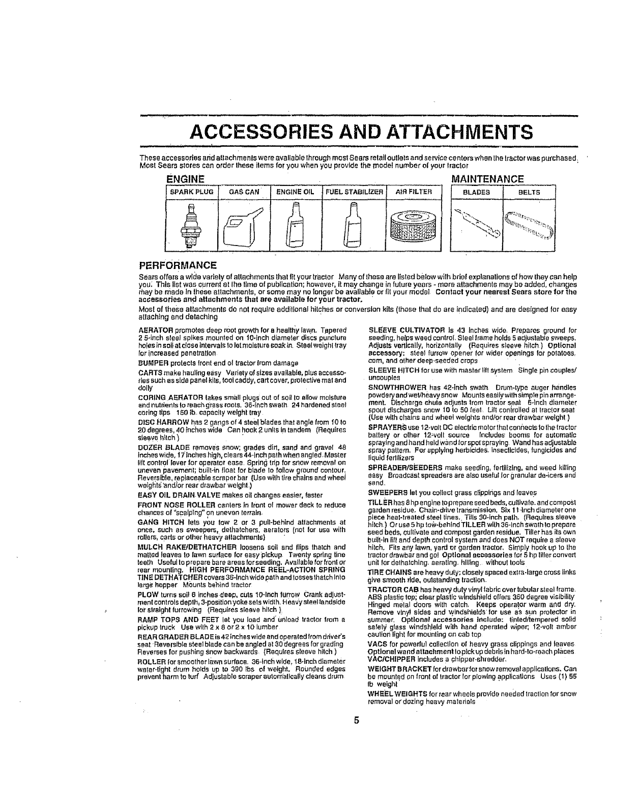
These accessories end attachme n!s we re r_vailable through most .Seam retail outlets and ae trice centers when the tractor was purchased;
Most Sears stores can order these Items for you when you provide the model number el your tractor
ENGINE MAINTENANCE
BLADES BELTS
PERFORMANCE
FUEL STABILIZER AtR FILTER
Sesrs offers'awida varietyof sttachments thatflt your traetor Many of these are lisled betow w_thbriefexplanattons ef how theycanhelp
you; This tlstwas currentat the timeof pobflcalion; however, it may change infuIure years -more attachments may be added, changes
they be made In theseattachments, or somemay no longer be available or tit yourmodet Contact your nearest Sears store for the
accessories and attachments that are available for your tractor.
Most of these altachments do not requl_eadditionalhitchesor conversionkits (those that do are indicated)and ere designed for easy
attaching and detaching
AERATOR promotes deep reel growth for e healtr_y la_n. Tapered
2 54nch sleet spikes mounted on 104nob diameter discs punciure
holes in soit st dose Inlervais to tel moisture soak tn Stselweighttray
for trnCreaaedpenetration
BUMPER protects front end of tractor from damage
CARTS make hautfng easy Vadety of sizes avallab!e, pius accesso-
ries such as side panel kits, fool caddy, cart cover, proteclJve mat and
doily
CORING AERATOR takes smaii plugs out of soilto allow moisture
and nuidenls to reach grsss roots, 36-inch swath 24 hardened steel
codng tips 150 lb. capacity weight trsy
DISC HARROW has 2 gangs of 4steel blades that angle from 10 to
20 degrees, 40 _nches wide Can hook 2 units in tandem (Requires
sleey_h_ch )
DOZER BLADE removes snow; grades dirt, sand sod gravel 48
Inches wtde, 17Inches high, clears 44-inch path whe_ angled, Master
i_ft control lever Ior op erefer ease Spring frtp for snow remover on
uneven I_avement; buiiNn float for blade to foliow ground contour,
Reversible, replaceable scraper bar (Use with tire chains and wheet
we!g_ts'lsn_or rear drawbat welght_)
EASY OIL DRAIN VALVE makes ell changes easier, faster
FRONT NOSE ROLLER canters In trent of mower deck to reduce
chances o! "scslptng" on uneven lerraln_
GANG HITCH lets you tow 2or 3 pull-behind attachments at
once, such as sweepers, delhatchers, aerators (not Ior use with
rollers ca_e or other heavy attachmenls)
MULCH RAKFJDETHATCHER loosens eoif end Itips thalch and
matted {saves to lawn surface lot easy pickup Twenty spdng tine
teelh Useful to prepare bare areas for seeding, Available for tronl or
rear mounting, HIGH PERFORMANCE REEL-ACTION SPRING
TINE DETHATCHER covers 36qnch wlde path end losses thatch Into
large hopper Mounts behind tractor
PLOW turns soil 6 inches deep, cuts t0-Inch farrow Crank adjust-
meet controls deplh_ 3-position yoke sets width. Hea'Jy sleeHendside
lot slralght furrowing (Requires sleeve hllch }
RAMP TOPS AND FEET let you 10ad and unlcad Itactm" from a
pickup truck Use with 2 x 8 or 2x 10 lumber
REAR GRADER B LAD E is 42 Inches wlde and operated from ddve r's
seat Reversible steel blade can be angled at 30 degrees for g_adtng
Reverses for pushing Snow backwards (Requires sleeve hitch )
ROLLER [or smoother t'_,v,,'neudar._, 36_Inch wlde, 1Soinch diameter
water-tight drum he{de up to 390 }bs of weight. Rounded edges
prevent harm to tuff Adjustable scraper automatically cleans drum
SLEEVE CULTIVATOR Is 43 inches wide, Prepares ground for
seeding, helps weed control Sloe! frame holds 5 edtuslsble sweeps,
Adjusts vertically, horizontally (Requires sleeve hitch ) Optional
accessory: steel furrow opener tot wider openings for potaloes,
cam, and other deep-seeded crops
SLEEVE HITC H for use wiih master till system Stngts pin couples/
uncauptss
SNOWTHROWER has 42-inch swath Drum-type auger h_ndles
powdery and welrneavy snow Mounts esstlywtlh simpie pin srrsnge-
ment. Discharge chute adjusts Irom tractor s._st E-inch diameter
spout dtscharges snow to to 50 feet Lift controlled at tractor sest
(Use with chains and who et weights end/or rear drawbar welghl )
SPRAYERS use 12-volt DC electdc meier thai connects 1othe tractor
battery or other 12welt source Includes booms for automatic
spraying and hand held wand ior spotspraytng Wend has adjustable
spray pattern, For applying herbicides. Insecticides, fungicides and
tiqutd fedilizers
SPREADERISEEDERS make seeding, fertilizing, and weed killing
BaBy Ercado_stspresdarsarsatsouselultorgrenularde-icersand
sand•
SWEEPERS let you collect grass cIipplhgs and {eave s
TILLER has 8 hpengtne topmpsre seed beds, cullivste, and compost
garden residue. Chain-drive transmission. Six It,inch dtameler one
piece heat-trsaled steel tines,, Tills 304nch path, (Requires sleeve
h_{ch ) Or use 5 hp to',;v-behtndTILLER with 36qnsh swath to prepare
seed beds, cultFvatesod compost garden residue. Tiller has its own
built-to Jill and depth oontroI system and does NOT require e sleeve
hIlch, Fits any lawn, yard or garden tractor, Simply hook up 1o the
tractor drswbar end gel Optional accessories for 5hp tilter convert
unit lor dethstching, aerating, hiUing Without toots
TIRE CHAINS are heavy duty; closely spaced exlra.iarge cross links
give smooth ride, oulstandtng tracfton
TRACTOR CA B has heavy duty vinyl fabric overtubular steel frame.
ABe ptasfic top; clear plastic windshield offers 380 degree vlsibility
Hinged metal doors with cstch, Keeps operator warm and dry.
Remove vinyl sides and windshields'for use o's sun prolecter in
summer, Optional accessories Include: lintedltempered solid
sorely glass windshield wilh hand operated wiper; ?2-vstt amber
caulionlightfsr mounting on cab fop
VACS for powerful collection of heavy grass clippings end teaves
Opt lonst wand attachment to pick up dab rJsin hard-!o-roach pl&ees
VAO/CHIPPER includes s chipper-shredder.
WEIGHT BRACKET lor drawber for snow remqve/appl_catlona, Can
be mounted on f reel el tractor {orplowing applications Uses (1) 55
Ib weight
WHEEL WEIGHTS for tear wheels provide needed traction Tot snow
removal or dozing heavy ma_etists
CONTENTS OF HARDWARE PACK
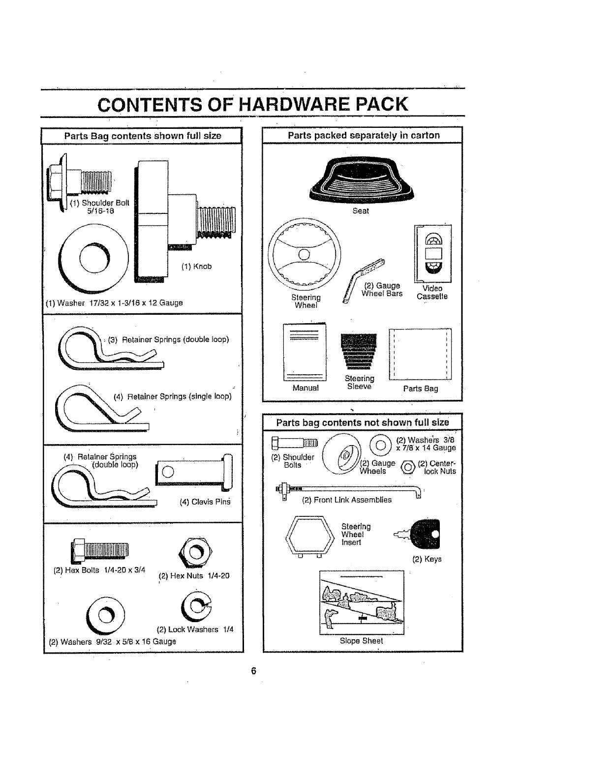
Parts Bag contents Shown full size
(1) Knob
(1) Shoulder Bolt
5/!6qB
(1) Washer 17/32 x 1-3/t6 x 12 Gauge
/(_ (3) Re,ainer Springs (doub|e ,oop)
4) Retainer Springs (single loop) _'
(_etoiner Springs .
io" l!
(4) Clovis P_n_
J. ti
(2) Hex Bolts 1t4-20 x 3/4 (2) Hex Nuts 114-20
@ ®
(2) Lock Washers 1,/4
(2) W_shers 9/32 x 5/8 x 16 Gauge
Parts packed separately in carton
Steering
Wheel
Manual
Seat
Video
Cassetle
J,,
Steering
Sleeve Parts Bag
*" t, ,
Parts bag contents not shown full size
_/"¢""-'_ _ (2)Washers 3;'a
_i;) Fron,t,n,,Assemb,,es_'
Steering C
Wheel
Insert
(2) Keys
Slope Sheet
ASSEMBLY
YOU_"new tractor has been assembled at the factory wit" the exception ofthOSe paris le_ssembled for shipping purp0ses_.
To ensure safe and proper operation of your tractor all paris and hardware you assemble must be tightened Securefy.. Use
the cor'rect tools as necessary to insure proper tightness. '
TOOLS REQUIRED FOR ASSEMBLY
A socket Wrench set wilt make assembly easier Standard
wrench sizes are listed
(2) 7/16" wrenches Tire pressure gauge
(1) 1/2" wrench Utflity knife
(1) 9/16" wrench
(t) 3/4_' socket with drive ratchet
When i'ight or left hand Is mentioned in fhls manual, it
means when you are in the operating position (seated
behind the steering wheel)
TO REMOVETRACTOR FROM CARTON
UNPACK CARTON
• Remove atl accessible loose parts and parts cartons
from carton (See page 6)
,' Cut, from top Io bottom, along lines on all four corners
of carton, an d toy panels fla!.
"Remove mower and packing materials
• Check for any additional loose parts or cartons and
remove
BEFORE ROLLING TRACTOR OFF SKID
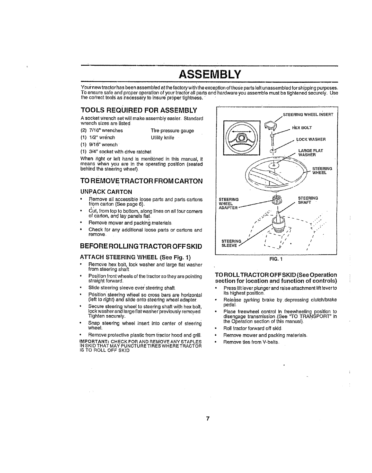
ATTACH STEERING WHEEL (See Fig. 'I)
• Remove hex bolt, lock washer and large fiat washer
from steering shaft
, PosiIIon front wheels of the tractor so they are pointing
straight forward.
,, Slide steering sleeve over sfeedng shaft.
•Posilion sl;eerfng whee! so cross bars are horizontal
(_eft to right) andsiide onto steertng wheel adapter
• Secure steering wheel to steering shaft with hex boil,
lock washer and large fiat washer previously removed
Tighten securely..
• Snap steering wheat insert into center of steeffng
wheel
•Remove protective plastic from tractor hood and grill
IMPORTANT; CHECK FOR AND REMOVE ANY STAPLES
IN SKID THAT MAY PU NCTUR E TIRES WHERE TRACTOR
tS TO ROLL OFF SKID
FIG. 1
TO ROLLTRACTOR OFF SKID (See Operation
section for location and function of controls)
• Press lift tever ptunger and ratse altachment ltfHever to
Its highest position
,' Rete&se p_.rking bt'ake by.depressing clutch/brake
pedal
,, Place freewheel control In freewheeling posilten to
disengage transmission .(See "TO TRANSPORT" In
the Operation section of this manuat)
•Roll tractor forward off skid
. Remove mower and packing materials
•Remove ties from V-belts
ASSEMBLY
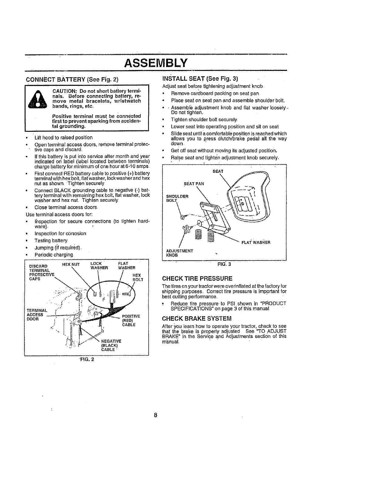
;ONNECT BATTERY (See Fig,2)
iii ,nuHu nm ,m,U,l
CAU_rlON: Do not short battery termi-
nals., Before connecting battery, re-
move metal bracelets, wristwatch
bands, rings, etco
Positive terminal must be Connected
first to prevent sparking from acciden-
tal grounding. i_ 11 1..1 , J,,,,
•Lilt hood to raised position
• Open terminar access doors, remove terminal protec-
• tire caps and discard..
If this battery is put into service alter month and year
indicated on label (iabel located between terminals)
charge battery for minimum of one hour at 6=10 amps.
•First connect RED battery cable to posi{ive (+) battery
terminal with hex bolt, fiat washer, lock washer and hex
nut as shown, Tighten'secUre{y
• Connect BLACK grounding cable to negative (-) bat-
tery terminal with remaining hex boEt,flat washer, lock
washer and hex nut. Tighlen securely
•Close terminal access doors
Use terminal access doors for:
• _hspectton for secure conneclions (to tighten hard-
ware),
•inspec(ion for cbr_osion
• Tesling battery
• Jumping (if required)
Periodic charging
DISCARD HEX NUT LOCK FLAT
WASHER WASHER
TERMINAL
PROTECTIVE HEX
CAPS BOLT
TERMINAL :"
ACCESS
DOOR ,-"
°':_ .
POSITIVE
(RED)
CABLE
NEGATIVE
(BLACK)
CAeLE "
INSTALL SEAT (See Fig. 3)
Adjust seat before tightening adjustment knob,
•Remove cardboard packing on seat pan.
• Place seat on seat pan and assemble shoulder bdtt.,
• • Assemble adjustment knob and flat washer _oosely.-
DO not tighten,,
•Tighten shoulder bolt securely
,, Lower seat inlo operating position and sl! on seat
• Slide seat untila comfodable position is reached which
allows you to press clutch/brake pedal all the way
down
•Get off seat wilhout moving its adjusted positton.
• Raise seat and tighten adjustmenl knob securely,
.SEAT
W.SnER
ADJUSTMENT
KNOB
FIG'. 3
CHECK TIRE PRESSURE
The fires on your tractor were overinflated at the faclory for
shipping purposes. Correct tire pressure is important for
best culting performance.
,. Reduce tire pressure to PSi shown in "PRODUCT
SPECIFICATIONS on page 3 of this manual
CHECK BRAKE SYSTEM
After you learn how to operate your tractor, check to see
that the brake is prqperty adjusted See "TO ADJUST
BRAKE" !n the Service and Adiustments seclion of this
manual
'FIG. 2
8
ASSEMBLY
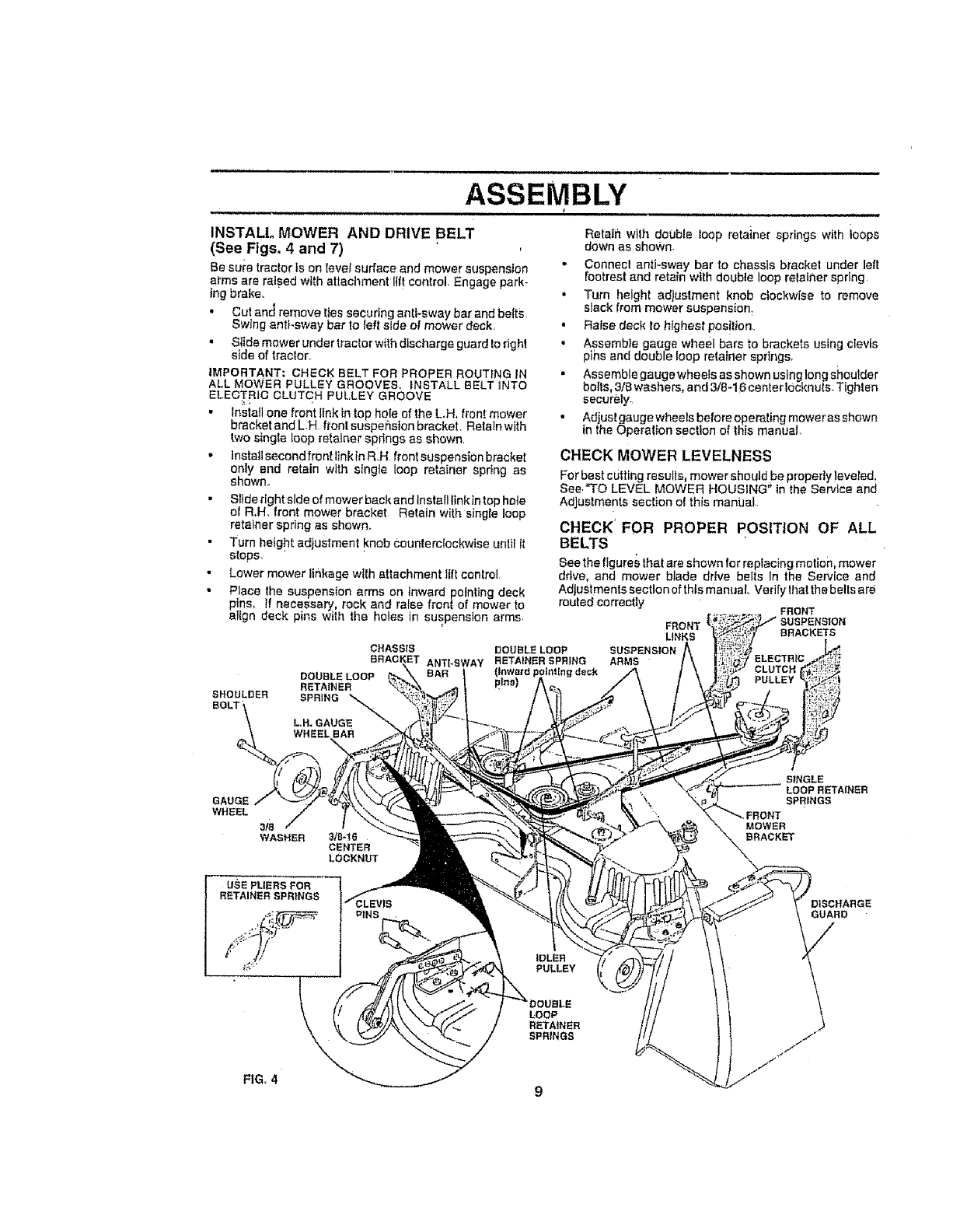
INSTALl. MOWER AND DRIVE BELT
(See Figs, 4 and 7)
Be sui'a tractor ts on leve! surface and mower suspension
al'ms are raised with attachment llft control. Engage park-
ing brake.
,, Cut and remove ties securing anti-sway bar and belts
Swing sntFsway bar to Jeffside of mower deck_
" Stlde mower under tractor with discharge guard to right
side of tractor,
iMPORTANT; CHECK BELT FOR PROPER ROUTING iN
ALL MOWER PULLEY GROOVES, INSTALL BELT1NTO
ELECTRIC CLUTCH PULLEY GROOVE
h
•lnstatl one front link in top hole of the LH, front mower
bracket and L H front susper_ston bracket. Retain with
two singte loop retainer spdngs as shown
•InstallsecondfronttinkinR.H frontsuspensionbracket
only and retain with singte loop retainer spring as
shown.
" Stide right side of mower back and Install linkin top hole
of R,H, front mower bracket Relain with single loop
retainer spring as shown.,
Turn height adjusfment knob c:ountercfockwise unt[t it
stops.
• Lower mower ltr_kage with attachment lift control,
•Place the suspension arms on inward pointtng deck
pins, If necessary rock and raise front of mower to
alton deck pins with the holes in suspension arms.
SHOULDER
CHASSIS
DOUBLELOOP
RETAINER
ANTI-SWAY
Retain wllh double loop retainer springs with ioops
down as shown
• Connect anti-sway bar to chasss bracket under left
footrest and retain with double loop relainer spring
•Turn height adjustment knob clockwise to remove
slack from mower suspension
°Raise deck to highest pos!tion_
• Assemble gauge wheel bars to brackets using clevis
pihs and doubie toop retainer springs,
, Assemble gaugewhee[s asshown us_nglongshoutder
bolts, 3/8 washers, and 3/8-16 canto rlOcknuts. Tighten
securely.
• Adjust gauge wheels before operating mower as shown
in the Operalton section of this manual,
CHECK MOWER LEVELNESS
For best cutting results mower shouldbe properly eveled
See."TO LEVEL MOWER HOUSING in the Serv ce and
Adjustments section oI this mantJal
CHECK' FOR PROPER POSITION OF ALL
BELTS
See the ftgures Ihat are shown for replacing motion, mower
drive, and mower blade drive beets In the Service and
Adjustments section of thts manuaL Verify that the belts are
routed correctly FRONT
FRONT
LINKS BRACKETS
L,H. GAUGE
GAUGE
WHEEL
3_
WASHER
USE PLIERS FOR
RETAINER SPRINGS
31S-16
CENTER
LOCKNUT
SINGLE
LOOP RETAINER
SPRINGS
MOWER
BRACKET
DISCHARGE
GUARD
PULLEY
LOOP
RETAINER
SPRINGS
FIG_4 9
i_,,,,u,i, i i , i,i
,/CHECKLIST
BEFORE YOU OPERATE AND ENJOY YOUR NEW
TRA CTOR, WE WISH TO ASSURE THAT YOU RECEtVE
THE BEST PERFORMANCE AND SA TISFA C TION FROM
THIS QUALITY PRODUCT
PLEASE REVIEW THE FOLLOWING CHECKLIST:
,/ All assembly instructions have been completed
.,,z No remaining loose parts in carton.
,/ Battery Is properly prepared and charged. (Minimum .
1 hour at 6 crops)
,/ Seat is adjusted comfortably and tightened securely
,/ AI{ tires ere properly lnflated_ (For shipping purposes,
the tires were overmflated at the factory).
v" Be sure mower deck _spz:operty leveled s_de4o-sidei
front4o-rear for best cutting rest._tts° (Tires must be
properly infla!ed for leveling)..
J Check mower and drive belts, Be sure they are routed
properly around pulleys and inside all bell keepers,
,/ Check wiring See thai all connections are still secure
and wires are properly clamped
,/ Before driving tractor, be sure freewhee! control is in
drive position
WHILE LEARNING HOWTO USE YOUR TRACTOR, PAY
EXTRA A TTENTtON TO THE FOLLOWING IMPORTANT
ITEMS:
v" Engine oil ts at proper level.
v' Fuel tank is filled With fresh, clean, regular unleaded
gasoline
•/Become familiar with all controls -their location and
function. Operate them before you start the engine
,/ Be sure brake system is tn safe operating cond[tIen
,/ It is important to purge the transmission before operat-:
ing ydur tractor Ior the first time. Foflow proper starting
and transmission purging )nstnlcltons (See '%0 START
ENGINE" and "PURGE.TRANSMISSION" in the Op_-
eration section of this man'Jal).,
"i i ii ,i,,nnlnlnl,i ,I lu,,i III I , _ t • ,
ASSEMBLY
n i ,, i, i ,,
10
OPERATION
m
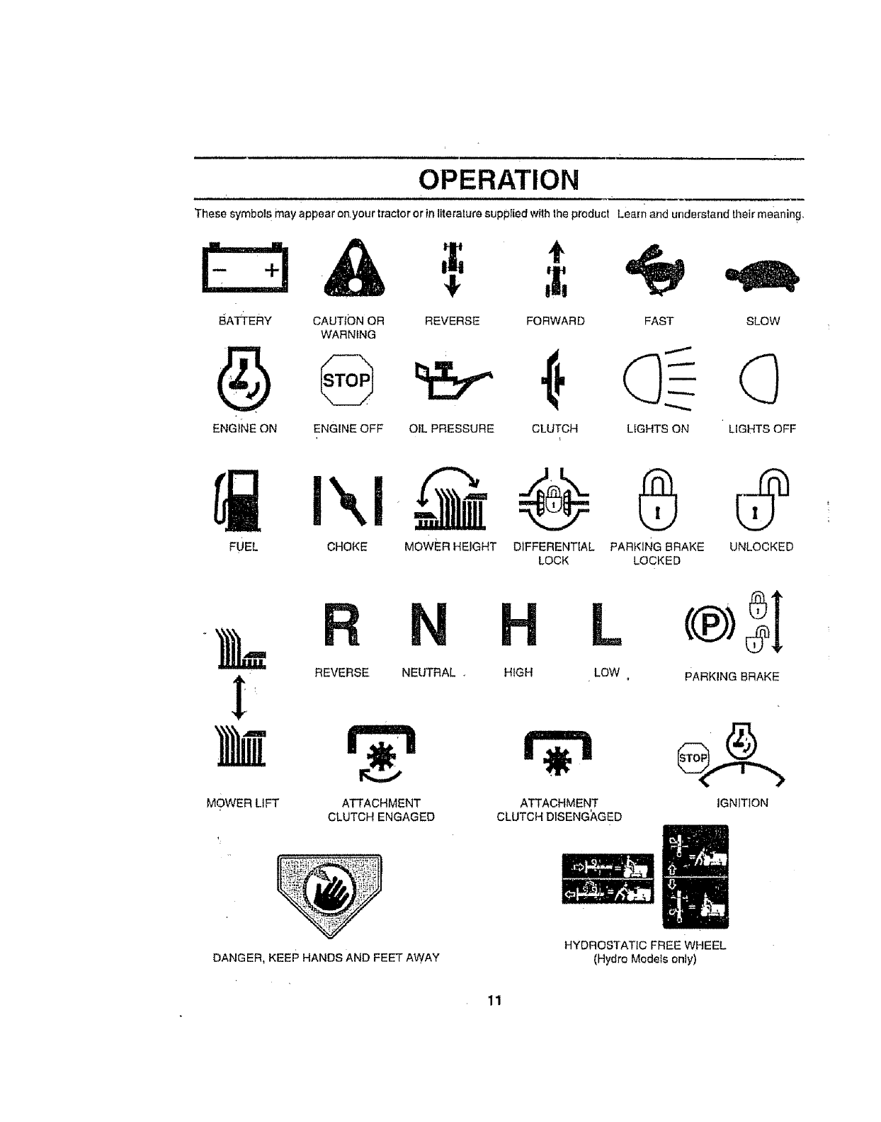
These symbols may appear on.your tractor or in literature suppFied with Ihe product Learn and understand their meaning..
E:3&
BATTEFIY CAUTfON OR
WARNING
@
ENGINE OFF
4!, t
REVERSE FORWARD SLOW
ENGINE ON OIL PRESSURE CLUTCH LIGHTS OFF
FAST
LIGHTS ON
FUEL CHOKE MOWER HEIGHT DIFFERENTIAL PARKING BRAKE UNLOCKED
LOCK LOCKED
REVERSE NEUTRAL.
MOWER LIFT ATTACHMENT
CLUTCH ENGAGED
L
HIGH LOW
ATTACHMENT
CLUTCH DISENG_GED
®SI
PARKING BRAKE
_':'_r,_,_ 'i-'_ _:
DANGER, KEEP HANDS AND FEET AWAY
HYDROSTATIC FREE WHEEL
(Hydro Models only)

OPERATION
• • ...... ,,,,,,, ,,,,,i, , ,, , ,,,,,,,,,,,,,,_, i, ,
KNOW YOUR TRACTOR
READ THIS OWNER'S MANUAL AND SAFETY RULES BEFORE OPERATING YOUR TRACTOR,
Compare the I{iustrations with your tractor to familiarize yourseif Withthe focalion of various controls and adjustments. Save
this manual for future reference
CROKECONTROL
CLUTCH/BRAKE
PEDAL
HEIGHTADJUSTMENT
KNOB
AMME'TSR THROTTLE COHTRDL
ATTACHMENT UFTLEVER
.÷"" .... CLUTCH SWITCH PLUNGER
HOUR
METER
LIFT LEVER
IGNITION SWITCH
PARKING BRAKE
LEVER
MOTION
CONTROL
LEVER
FREE WHEEL CON"i'ROL
FIG,, 5
Our tractors conform to the salary standards of
ATTACHMENTCLUTCH SWITCH, Usedto engage mower
btades Orether'attachments mounted to your tractor
LIFT LEVER- Used to raise and tower mower deck or other
attachments mounted to your tractor.
Ct.UTCHtBRAKE PEDAL - Used for dectutching and
braking the lractor and sta ding the engine
MOTION CONTROL - Selects the speed and direction of
tractor
CHOKE CONTROL - Used when starting a cold engine,
LIGHT SWITCH - Turns the headt!ghls on _nd off_
THROTTLE cONTROL - Used to controt engine speed. 12
the American National Standards institute°
FREEWHEEL CONTROL *Disengages transmission for
pushing or stowly towing the tractor with the engine off
IGNITION SWITCH - Used to start and stop the en_jine_
AMMETER - indicates battery charging (+) or dfscharglng
(-),
PARKING BRAKE LEVER - Locks c)utch/brake pedal Into
the brake position
HEIGHTADJUSTMENT KNOB -Used to adjust the mower
heighL •
HOURMETER -indicates hours of ope_'atlon_
i i
HOW TO USE YOUR TRACTOR
OPERATION
.u, i iii iiiii,11,,,11iiiii ii i
The operation of any tractor can result in foreign objects thrown into the eyes, which can resu t l
in severe eye damage. Always wear Safety glasses or aye shields while operating your tractor f
or performing any adjustments or repairs. We recommend a wide vision safety mask over the
spectacles or standard safety glasses,
.,,HHH
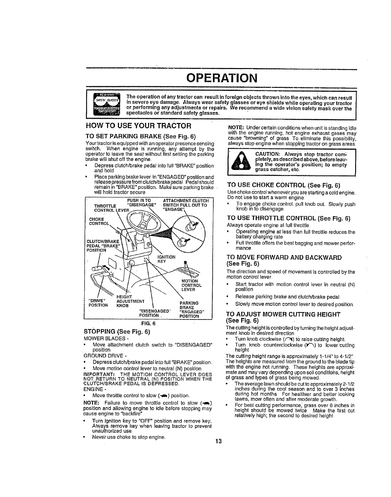
TO SET PARKING BRAKE (See Fig. 6)
Your tracfor is equipped with an opera!or presence sensing
switch. When engine is running, any atlempt by the
operator to leave the seat Without first setting the parking
brake Will shut off the engine.
•Depress clutch/brake pedat into full "BRAKE" position
and hotd
•Place parking brake tever In"ENGAGED" position and
releasepressurefromc}utch/brakepedal Pedalshould
remain in "BRAKE" posi!tOnoMak_ sure parking brake
wiil hold tract6r secure
PUSHiNTO ATTACHMENTCt.UTCH
THROTTLE "DISENGAGE" SWITCHPULLOUTTO
NOTE: Undercedaln conditions when unJtis standing idle
with the engine running, hot engine exhaust gases may
cause "browning" of grass To eliminate this possibility,
always stop engine when stopping tractor on grass areas
'_ CAUTION: Always stop tractor corn:
pletely, asdescribed above, before leav-
ing the operator's position; to empty
grass catcher, etc..
TO USE CHOKE CONTROL (See Fig. 6)
Use choke €ontrol whenever you are stading a coldengine.
Do not use to slart a warm engine
•To engage choke conlroL pull knob out. Slowly push
knob in to disengage
CONTROL LEVER _,---=--,_. "ENGAGE'_
##
o.o,o,o2%,
PEDAL"BRAKE" \ \ _ i _'_ \\-_'-'_ ./
_-_ I / _'-_. \ CONTROL
t.EI . " "X
POSITION KNOB BRAKE
"DIS ENGAGJSD'" "ENGAGED"
POSITION. POSFION
FIG: 6
STOPPING (See Fig, 6)
MOWER BLADES o
TO USE THROTTLE CONTROL (See Fig. 6}
Always operate engin_ at ful] throttle
•Operallng engine at tess than full throttle reduces the
baltery charging rate
•Full Ihrattle offers the best baggirlg and mower perfor-
mance
TO MOVE FORWARD AND BACKWARD
(See Fig, 6)
The direction and speed o_movement is controlled by lhe
motion control lever
• Start tractor wilh motion Control lever in neutral (N)
position
• Release parking brake and clutch/brake peda!.
• Slowly move molion control lever todesired position,
TO ADJUST MOWER CUTTING HEIGHT
(See Fig_ 6)
Thecuttingheight is controlled by turninglhe heightadiusl-
ment knob in desired direction
• Turn knob clockwise ((-_1)to raise cutting height,
• Move attachment clutch switch to "DISENGAGED"
posilton
GROUND DRIVE -
• Depress clutch/brake pedal into lull "BRAKE" position.
• Move motion control lever to neutral (N) poe!lion
IMPORTANT: THE MOTION CONTROL LEVER DOES
NOT..RETURN TO NEUTRAL (N) POSIT!ON WHEN THE
CLUTCHtBRAKE PEDAL IS DEPRESSED
ENGINE -
• Move throttle control tO slow (.,=_) position.
NOTE: Failure to move throttle control to stow (,,a_)
position and allowing engine to idle before stopping may
cause engine to "backfire"
• Turn ignition l<ey to "OFF" position and remove key.
Always remove key when leaving tractor to prevent
unalJthorlzed use.
• Never use choke tO slop engine..
• Turn knob counterclockwise ()¢%} to lower'cutilng
height
The culling height range is approximately 1-1/4" Io 4-1/2"
The heights are measured from the ground to the blade tip
with the engine not running These heights are approxi;
mate and may vary depending upon soil csndittohs, height
_?lgrass and types of grass being mowed.
•The average lawn should be cut to approximately 2-I12
inches during the cool season and to over 3inches
during hot months For healthier and better looking
lawns, mow often and after moderate growth°
, For best culling performance, grass over 6 inches in
heighl should be mowed Iwice Make the flrsl cut
relatively high; !he second to desired height
13
OPERATION
,, ,, ,,,,,,,,,,,, i,,,11,
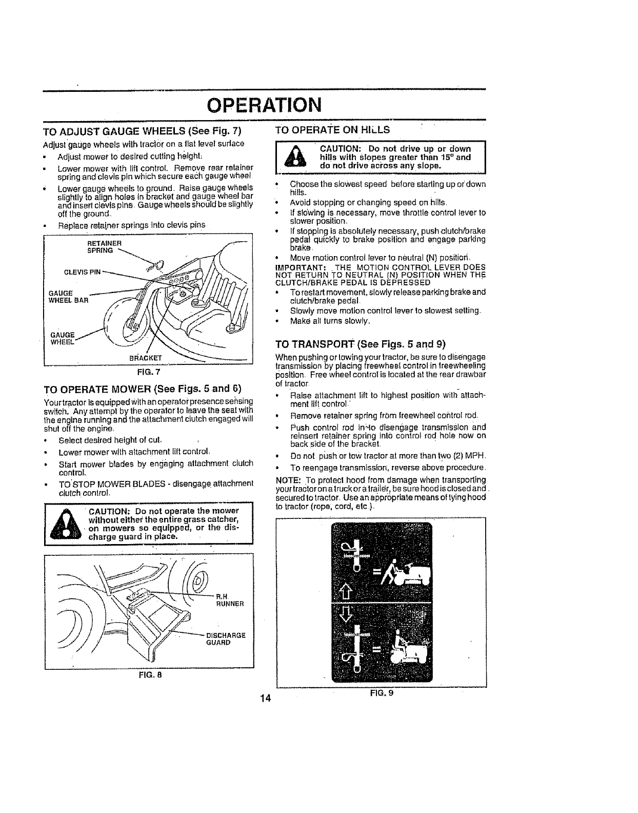
TO ADJUST GAUGE WHEELS (See Fig. 7)
Adjust gauge wheel swith trac|or on a flat level suriace
• Adjust mower to desired cutting height:
• Lower mower w_th lift control Remove rear relainer
spring and clevts pin which secure eac:h gauge wheet
.Lower gauge wheels to ground Raise gauge wheels
slightly to align holes in bracket and gauge wheel bar
and insert clevis pins Gauge wheels should be slightly
off the ground_
• Repiace retainer springs lnto clevis pins
RETAINER
SPRING _,_
GAUGE
WHEEL BAR
GAUGE
WHEEL
FIG. 7
TO OPERATE MOWER (See Figs. 5 and 6)
Your tractor is equipped With an operaloi'presence sensing
sw teh. Any attempt by the operator to leave the seal wilh
the engine running and the attachment cLutc _ engaged w II
shut elf the engine,
•Select desired height of cuL
•Lower mower with altachment lift control,
• Start mower blades by eng&ging altachment clutch
control
,. TO STOP MOWER BLADES - disengageaftachment
clutch control,
l_CAUTION: Do'not operate the m_wer_
without either the entire grass catcher, !
.on mowers so equipped, or the dis- !
charge guard in place. ..I
.m _ m " =J
RUNNER
GUARD
FIGo 8
TO OPERATE ON HILLS
I CAUTION: Do not drive up or down !
hills with SlOpes greater than 15 ° and I
do not drive aci'oss any slope. •
,_ Choose the slowest speed before stading up or down
hi_ls°
• Avoid stopping or changing speed on httls,
• if sldw]ng is necessary, move throttle control lever to
slower position.
• If stopping is absolutely necessary, push clutch/brake
pedal quickly to brake posilion and engage parking
brake
• Move motion control lever to neutral (N) pos_tiorl,
IMPORTANT: THE MOTION CONTROL LEVER DOES
NOT RETURN TO NEUTRAL IN) POSITION WHEN TH 5
CLUTCHtBRAKE PEDAL iS DEPRESSED
"To restart movement, slowly release parking brake and
clutch!brake pedal
•Slewty m0ve motion control lever to slowest setting.
•Make all turns slowly
TO TRANSPORT (See Figs, 5 and 9)
When pushing or lowing your tractor, be sure 1odisengage
t[ar_smisslon by placing freewhee! control in treewheeling
posltion_ Free wheel conlrot is tocaled at the rear drawbar
of traclor
•Raise altachment tilt to highest PoStiion with-attach-
ment lift control/
• Remove retainer spring from freewheel cohlroI rod.
• Push control rod tn'.to disengage transmission and
retnsert retainer spring inl0 control rod hole now on
back Side of lhe bracket
• Do not push or low tractor at more than ly¢o (2) MPH
• To reengage transmission, reverse above procedure
NOTE: To protect hood from damage when transpodtng
your tractor on a truck or a tra_ie[_ be su re hocd is clese d and.
secured to tractor_ Use an e ppropriate means of tying hood
to lractor (rope; cord, etc ),
14 FIG, g
OPERATION
BEFORE STARTING THE ENGINE
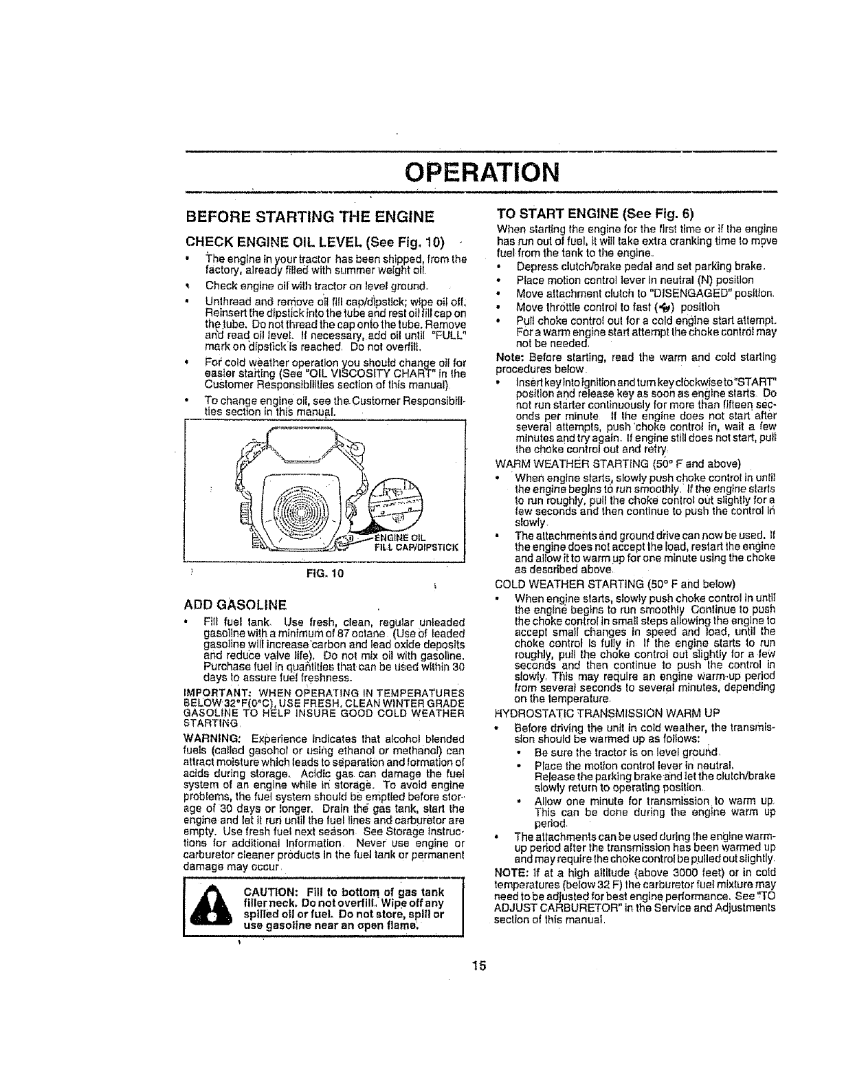
CHECK ENGINE OIL LEVEL (See Fig, 10)
• The engine tn your tractor has been shipped, from the
factory, already filled with summer weight oil
Check engine oil with tractor on level ground,
• Unlhread and remove oit fill cap/dipstick; wipe oil off,
Reinsert the dlpslick Into the tube and rest oii fill cap on
the tube. De not thread the cap onto the tube. Remove
arid read oil level, it necessary, add oi! until "FULL"
mark on _Ipstick IS reached, Do not overfitL
,Fo='cold weather operation you shoutd change oil for
easier stait}ng (See "OiL VISCOSITY CHART" tn the
Customer Responsibilities section of this manual)
• To change engine oil, see the.Customer Responsibili-
ties section in this manual.
i
FILL CAP/DIPSTICK
FIG. 10
ADD GASOLINE
•Filt fuel tank, Use fresh, clean, regular unleaded
gasoline with a minimum of 87 octane (Use Of leaded
gasoline will increase'carbon and lead oxide deposits
afld reduce valve life), Do nol mix oil with gasoline,
Purchase fuel In quar_ttttes that can be Used within 30
days to assure fuel f(eshnesso
IMPORTANT; WHEN OPERATING IN TEMPERATURES
BELOW 32"F(0°C), USE FRESH. CLEAN WINTER GRADE
GASOLINE TO HELP INSURE GOOD COLD WEATHER
STARTING
WARNING: Experience indicates that alcohof blended
fuels (called gasohot or using ethanol or methanol) can
attract moisture which Ieads to se_paralien and formation of
acids during storage. Acidic gas Can damage the fuel
system of an engine while tn storage To avoid engine
problems, the fuel system should be emptied before stor-
age of 30 days or longer. Drain the gas tank, start Ihe
engine and let tt run until the fuel lines and carburetor are
empty_ Use fresh rue! next season See Storage instruc-
tions for additional Ir}format_on Never use engine or
carburetor cleaner products In the fueJ tank or permanent
damage may occur
CAUTION: FIll to bottom of gas tank-_l
filler neck. Do not overfilL Wipeoffany I
spilledo orfueL Do not store, splllor I
use gasoline near an open flame. /
TO START ENGINE (See Fig. 6)
When starting the engine for the firs_ time or if Ihe engine
has run out of fuel, II wiil take extra cranking time to move
fuel from the tank to the engine
• Depress clutch/brake pedal and set parking brake,
•Place motion control lever tn neutral (N) position
•Move attachment clutch to "DISENGAGED" position,
•Move Ihr6ttle control to fast (,f_) pos[tloh
• Pull choke control out for a cold engine start attempL
For a warm engine start attempt the choke control may
not be needed,
Note: Before starting, read the warm and cold starting
procedures below
•Insert key Intotgnllionand rum key clockwise to°START"
position and release key as soon as engine alerts Do
not run Starter continuously for more than fifteen sec-
onds per minute If Ihe engine does not alert after
several attempts, push 'choke control In, wait a few
minutes and try again, tf engine still does not start, pull
the choke control out end re|_
WARM WEATHER STARTING (50 ° F and above)
•When engine starts, slowly push choke control in unlt]
the engine begins t0 run smoothly, if ihe engine sfarts
to run roughly, pull Ihe choke control out s}ightly for a
few seconds and then continue to push the control In
slowly
• The altechmeflls and ground drive can now be used. _1
%heengine does not accept the lea& restart the engine
and allow i_to warm up for one m_nute using the choke
as described above,
COLD WEATHER STARTING (50 ° F and below)
• When engine starts, slowty push choke control in unti!
lhe engine begins to run smoothly Continue to push
the choke control in smalt steps at_owing the engine to
accept small changes in speed and toad, until the
choke control Is fully in If the engine starts to run
roughly pull the choke control out s_ightly for a few
seconds and then continue to push the control in
sloWly, This may require an englne warm-up period
from several seconds to severe! minutes, depending
on the temperature,
HYDROSTATIC TRANSMISSION WARM UP
-Before driving the unit in cold wealher, the transmis-
slon should be warmed up as foIIows:
• Be sure the tractor Is on level ground,
•Place the motion control lever in neutral,
Release the parking brake and let the clutch/brake
slowly return to operating posi!ion.
• Allow one minute for transmission to warm up,
This can be done during the engine warm up
pedod.
• The attachments can be used during the engine warm-
up period after the transmission has been warmed up
and may requlrethe choke control be puff ed out siighIly
NOTE: if at ahigh altitude (above 3000 feet) or in cold
temperatures (below 32 F) the carburetor rue! mixture may
need to be adjusted for best engine performance, See 'rTO
ADJUST CARBURETOR" in the service and Adjustments
section of this mant_al
15
uiH illll
OPERATION
PURGE TRANSMISSION
CAUTION; Neverengageordisengage
freewheel lever while the engine is run-
ning_
To ensure proper operation and performance, it is recom-
mended thai the transmission be purged before operating
tractor for the first time. This procedure wi!t remove any
trapped air inside the transmission which may have devel-
oped dudng shipping of your traclor
IMPORTANT; SHOULD YOLtR TRANSMiSSiON REQUIRE
REMOVAL FOR SERVICE OR REPLACEMENT, tT
SHOULD BE PURGED AFTER REINSTALLATtON
BEFORE OPERATING THE TRACTOR
• Piace tractorsafety on level surface with engine off and
parking brake set
Disengage tran'smtsslon by placing freewheel control
[n freewheeling position (See "TO TRANSPORT" in
this sectbr_ of manual)
- SIttingtnthetractorseat,stadengine Afterfheengine
ts running, move throttle control to stow (.gh) position
W th Got on control lever inneutral (N) position, slowty
disengage clutch/brake _0edal
• Move motion control lever to full forward position and
hold for five (5} seconds. Move Iever to full reverse
position and hold lot five (5) seconds° Repeat this
• procedure three (3) times,
NOTE; During th_sprocedure ther_ wilI be no movement of
drive wheels. The air is being removed from hydratJtlc drive
system.
•Move motion controileverto neulral (N) position. ShuF
off engine and set parking brake-
. Engage transmission by placing freewheel control in
driving position (See "TO TRANSPORT" inthis section
o4 manua!).
• Sitting tn the tractor seat, start engine. After the engine
is.running move lhrottte control to half (1t2) speed.
With metbn control lever tn neutral (N) pos I on, s ow y
disengage clutch/brake pedal
• Slowly move motion control lever forward, alter the
tractor moves approximately live (5) feet, sIewly move
motion control lever to reverse posltton. After the
tractor moves approximately five(5)feet return the
motion control lever to the neutral (N) position. Repeat
this procedure with the moti0fl conlrol lever three (3)
times_
• Your tractor is now purged and now ready for normal
operation.
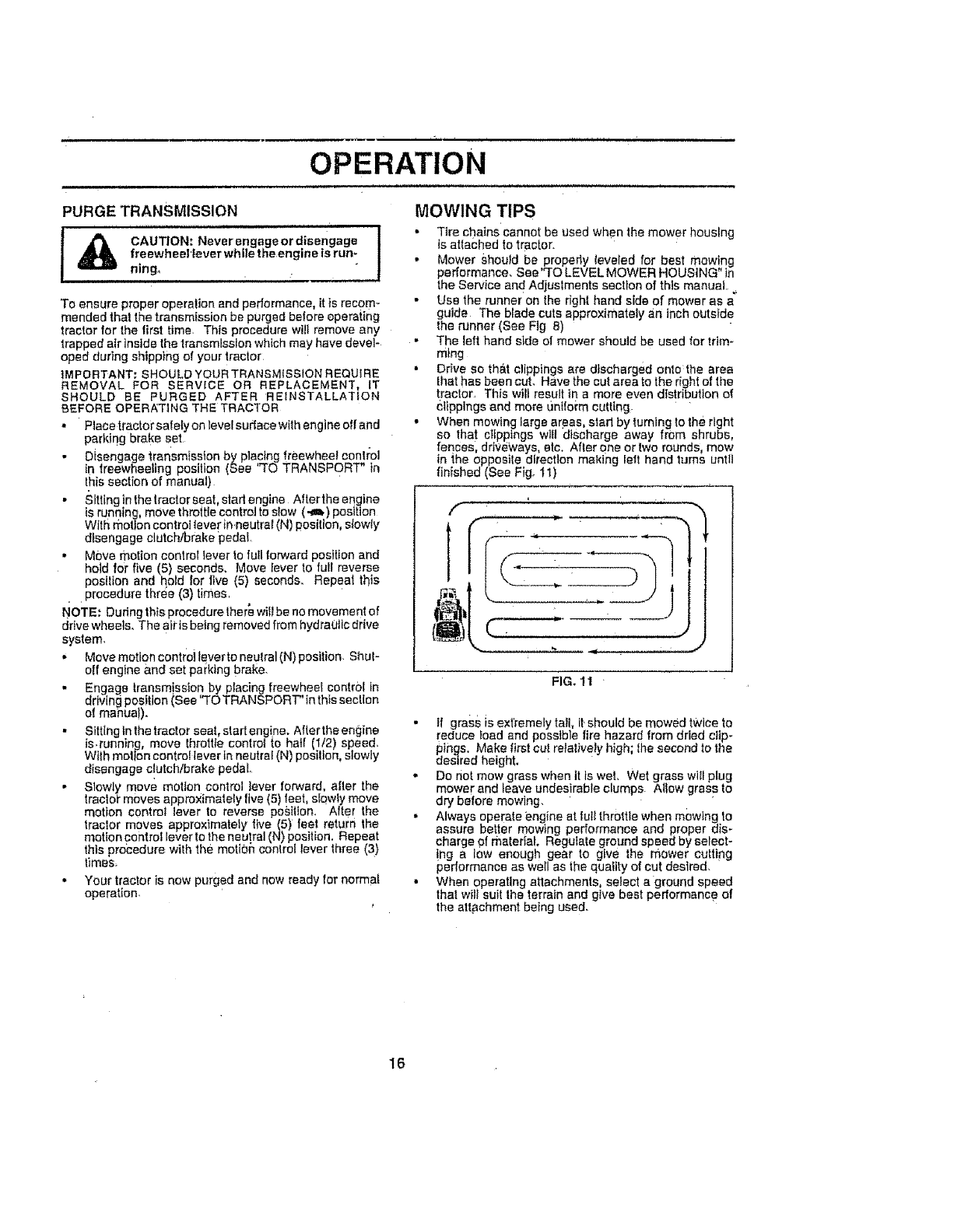
MOWING TIPS
• Tire chains cannot be used when the mower housing
is attached to tractor.
• Mower should be propedy leveled for best mowing
performance. Sea'TO LEVEL MOWER HOUSING" in
the Service and Adjuslments section of this manual.
•Use the runner on the right hand side of mower as a
guide The blade cuts approximately an inch outside
the runner (See Fig 8)
•The left hand side el mower should be used for trim-
ming
•Drive so tha.t clippings are discharged onto the area
that has been cut. Have the cut area to the right of the
traclor. This will result in a more even distribution of
Clippings and more _intfoim cutting.
• When mowing Iarge areas, starl by turning to the right
so that cFIpptngs will discharge away from shrubs,
fences, driveways, etc. After one ortwo rounds mow
in _,he opposile direction making left hand turns until
finished (See Fig. tl)
[;
f
FIG. 11 '
• ff grass is extremely tall, it should be mowed twice to
[educe Ioad and possible fire hazard from dried cllp-
pings. Make first cu_ relatively high; the second to the
desired height.
• Do not mow grass when tt is wet, Wet grass will plug
mower and leave undes!rable clumps AIIow grass to
dry before mowing,
• Always operate engine at ful_throttle when mowing to
assure better mowing performance and proper dis-
charge f_f material, Regulate ground speed by seFect-
!ng a low enough gear to give the mower culling
performance as well as the quaitty of cut desired.
• When operating attachments, select a ground speed
thai will suit the terrain and give best performance of
the att#chment being used.
16
, ,,, .,,...Hi, ,
CUSTOMER RESPONSIBILITIES
,,u,, Jl ,,,,, ,1111, ,,,, , m .........J,u,,,,,,,,,,,,,,,,u
......... _ _ ..........._ ......
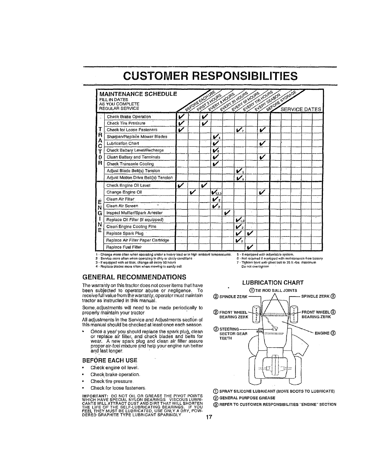
'MAINTENANCE SCHEDULE _.,_ ._,_/_'_,,_, o_'_,_X_' '''"
AS YOU COMPLETE
REGULAR SERVICE ,##-,_o_ _',_7 _'_ _,.._" _'_,.._/_.,-" _.T/" '_,Y'_,,,,'_SERVICE DATES
Check _rB Pressure i tf t,/
iTCheck lo_ LOOSe Fasteners If ......1 #m##_' if - --
c Sho eo,Ra,lo oMow ,;,,'0,ee,""';;;;;..... V', -- .__Lubrication Chart ! If
TCheck earlap/LeveIIRechsrge
0Ctean_a_ta_aedTe_._a!e ---_ _ iV' V"
aCheck Tr_nsa×le c6oting if
Adjust Blade Bell(e} Tension V"s ,,
Ad_,etMe,.:.T....,vo._.a,(e)._.no Tenancy, v', : ......
Ch_o_E_g!_,ao,Lena,............_ _ I {"
,,Change Englne OI! ...... .•,I#/ t_.z.= {lt_
ECIean Air Filler V_
N C!a_,n,AIrScreen,, I V'= .........
G Inspect Mu{fler/gpark Arresler J 1_ ......
Replece 011 FHIer (Ifequipped) I."_,_
Replace Spark Plug V_ If
Replace Air Fi_ler Paper Cartridge ...... _ __ _ .... _
R_p_aeaFuel_I!!,£.................. V'
1 ..Ch_,ngt_more oft_r_ wM_n 0_e_ling _zl_of t_hn_tv_{o_d .o_I_ high _bi_t _mpe_BlU/_ S -II eq_ipped wilh ad_tlsiabl_* uy_im.
2 Se_lco n_olo o[I_n wt_en Operating I_1ditty ot d_ly ¢o_lt_or_ r6_NOI _r_qt_red I1 equipped wilh m_l_l_na_ce-hee battery
3,,I__qulpp._t't.,l_t_oillille,+change oI_ow_ 50 t_u_ 7 ,.TJEii_I_n(_o_n[it._iepivotb_IIIo35 {I_tbs_Imitm
4..RepF_cr_t_lado,_morn ellen wf_en mowh_g in s_nd_ soil Co r_otov_ttlghlen
GENERAL RECOMMENDATIONS
Thewarrantyonthlstractordoesnot coveritems thathave
been subjected to operator at_use or negIigenee, To
receive fu!lvatue from the warra}ity operator must maintain
tractor as Instructed in this manuat
Some;adjustments willneed to be made periodicallyto
propeily maintain your tractor
All adjustments tn the Service and Adjustments sectlc)n of
this manL_at should be checked at least once each season
• Once a yea€ you should replace the spark plug, clean
or replace air filter, and check blades and bells for
wear, A new spark plug and clean air filter assure
proper air-fueJ mixture ,and help your engine ruh better
andlast longer
BEFORE EACH USE
•C_eek engine oil level°
•Check brake Operation.
• Checktire pressure
•Check for loose fasteners,
IMPORTANT: DO NOT OIL OR GREASE THE PIVOT POINTS
WHICH HAVE SPECIAL NYLON BEARINGS VISCOUS LUBRI-
CANTS WILL ATTRACT BUST AND DIRT THAT WILL SHORTEN
THE L_FE OF THE SELF-LUBRICATING BEARINGS. _F YOU
FEEL THEY MUST BE LUBRICATED, USE ONLY A DRY, POW-
DERED GRAPHITE TYPE LUBEIICANT SPARINGLY
LUBRICATION CHART
(_TtB ROD BALL JOINTS ®
®FRONT _FRONT WHEEL_[)
BEARING ZERK BEARING ZERK
®SECTOR GEAR ®
TEETH
(_) SPRAY SILICONE LUBRICANT (MOVE SOOTS TO LUBRICATE}
(_ GENERAL PURPOSE GREASE
®REFER TO CUSTOMER REBPONSIBtLITIES "ENGINE" SECTiON
17
CUSTOMER RESPONSIBILITIES
TRACTOR
Always observe safety rules when performing any mainte-
narcs
BRAKE OPERATION
If tractor requires more than six (6) feet stopping distance
a{ high speed fn highest gear, Ihen brake must be adjusted.
(See "TO ADJUST BRAKE" In the Service and Adjust-
ments section of this manual)
TIRES
• Maintain proper airpressure in all tires (See "PROD-
UCT SPECIFICATIONS" on page 3 of this manual):
• Keep tires free ol gasot(ne, oil, or insect control chemi-
cals which can harm rubber,
• Aveid.slumps, slones, deep ruts, sharp objects and
other hazard s that may cause tire damage.
BLADE CARE
For best results mower blades must be kept sharp, Re-
place bent or damaged blades,
BLADE REMOVAL, (See Fig, 12)
• Raise mower to highest position to allow access to
blades, "
• Remove hexboit, lock washer and flat washer securing
blade
• tnstall new or resharpened blade with trailing edge up
towards deck as shown
,, Reassemble hex bolt, tock washer and fiat washer in
exact order as shown
,, Tighten bolt securely (30-35 FI. Lbso torque).
iMPORTANT: BLADE BOLTISGRADEBHEATTREATED
NOTE: We do net recommend sharpening blade -,bul ifyou
do, be su_'ethe blade is balanced,
a.... _ MANDREL
_,_u_ t",__-_.._.*,_ ASSEMBLY
J
REX BOLT (GRADE 81 "--_.' "_
'AGRADE aHEAT TREATED BOLT CAN BE
IDENTIFIEDBY SIXLINESON THE BOLT HEAD.
FIG. 12
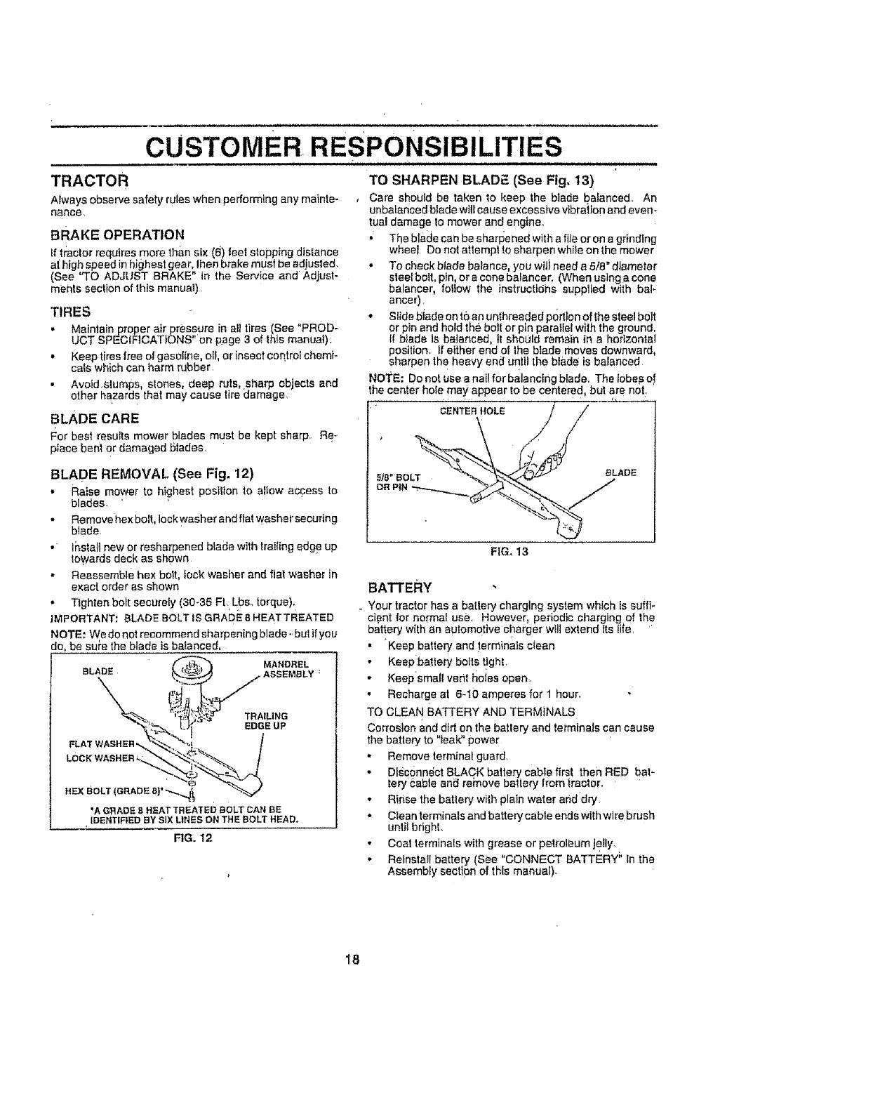
TO SHARPEN BLADF_(See Fig, 13)
,Care should be taken to keep the blade balanced. An
unbaianced btade will cause excessive vibration and even*
tuB! damage to mower and engine.
• The blade can be sharFJened with a file or on a grinding
wheel Do not attempt to sharpen while on the mower
• To check blade balance, you will need a 5/8" diameter
ales{bolt pin, or a cone ba_ancer, (When using a cone
balancer, follow the instructtdhs supplied with bal*
anger)
• Slide biade on to an unthreaded portion of the steel bolt
or pin and hold the bolt or pin parallel wilh the ground.
If btade is balanced, it shoLJld remain in a horizontal
position, tf either end of the biade moves downward,
sharpen the heavy end until the blade is balanced
NOTE; Do not use a nail for balancing blade. The lobes o!
the center hole may appear to be centered, but are not.
NTE"HOLE //
FIG, 13
BATTERY
Your tractor has a battery charging system which is suffi-
cient for normal use However, periodic charging of the
battery with an automotive charger will extend Its {ire, '
•"Keep battery and !erminals ctsan
• Keep battery botts t!ght,
• Keepsmall vent tlo_esopen.
•Recharge at 6-!O amperes for I hour,
TO CLEAN BATTERY AND TERMINALS
Corrosion and dirt on the batlery and tei_minalscan cause
the batte_ to "Ieal¢' power
• Remove termina_ guard
Digc0nn6ct BLACK battery cabte first then RED bat-
tery Cable ani_ rei'nove batlery from tractor.
• Rinse the battery with plain water and dry,
• Clean terminals and batterycable ends with wire brush
unlit bright.
• Coat terminals with grease or petroleum Jetly.
• Reinstall battery (See "CONNECT BATTERY _'In the
Assembly section of this manuaI).
18
CUSTOMER
TRANSAXLE COOLING
The fan and cooting fins of transmission should be kept
clean to assure proper cooling
Do not attempt to clean fan or transmission while engine is
running ,or while the transmission is hot To prevent
possible damage to seals, nonot use high pressure water
or steam to clean transax/e
• Inspectcooilng fan to be sure fan blades are intact and
clean,
• Inspect cooiing fins for dirt, grass clippings and other
mateflats. To prevent damage to seals, do not use
c_ompressed air or high pressure sprayer
TRANSAXLE PUMP FLUID
The transaxie was sealed at the factory and fluid mainte-
nance is not required for the tife of the transaxle; Should
the transaxle ever feak or require servl_:ing, centacl your
neares t' authorized service cenlerldepartment
V-BELTS
CheekV-belts Tordeterioration and wear af er !00 hoursof
operallon and replace if necessary, The belts are not
adjustable_Repiace belts if theybegin to s}ip from wear,,
ENGINE
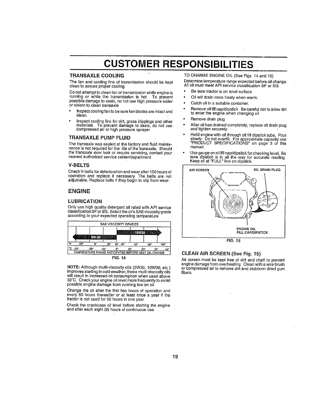
LUBRICATION
Only use high quality detergent oil ratedwithAPI service
classification SFor SG. Select the olt=sSAEviscosity grade
according to you/' expected operating temperature
i
SAEVtSCOSITYGRADES
NOTE: Although multi_viscosity oils (5W30, t0W30, etc )
Improves starting in cold wealher, these multi.viscosity oils
wiJ'lresutt in increased oil consumption when used above
32'C; Check your engine oil level more frequently to avoid
possible engine damage item running low on oft
Chanf_e the oil after the first iwo hours of operation and
every 50 ho_.Jrsthereafter or at least once a year if the
tractor is not used for 50 hours in one year
Check lhe crankcase oil level before stad_ng the engine
and after each eight (8) hours of continuous use,
RESPONSIBiLiTiES
...,i H ill
TO CHANGE ENGINE OIL (See Figs 14 and 15)
Determine temperature range expected before oil changei,
AIr oil must meet API service classification SF or SG
• Be sure tractor is on level surface,
• Oil will drain mere freely when warm.
• Calch oil in asuitable conlalner,
•Remove oi! till cap/dipsl}ck Be careful not to allow dirt
to enter the engine when changing oil
• Remove drain plug
• Alter oil has drained comptetety, replace oil drain plug
end lighten securely.
•Refill engine wilh oil lhrough of! fill dipslick tube, Pour
siowty. Do not overfill., For approximate capacity see
"PROD[JOT SPEC{F CAT ONS" on page 3 of this
manual,
• Use gauge on oil fill captdipslick for checking level. Be
sure dipstick is in all the way for accurate reading.
Keep oil at "FULL" l!ne on dipstick.
AIR SCREEN OIL DRAIN PLUG
ENGINE OIL
FILL CAP/DIPSTICK
FIG) 15
CLEAN AIR SCREEN (See Fig. 15)
Air screen must be kept free of dirt and chaff to prevent
engine damage from overheating CIean wilh a wire brush
or compressed air to remove dirt and stubborn dded gum
fibers.
19
CUSTOMER RESPONSIBILITIES
CLEAN AIR INTAKE/COOLING AREAS
To insure proper cooling, make sure the grass screen;
cooling fins and other external sud&ces 0l the engine are
kept cfean at all times
Every 100 t_eursof operation (more often under extremely
dusty dirty conditions) remove the blower housing and
other cooling shrouds, Clean the cooling f ns and exlema
surfaces as necessary Make sure the cooling shrouds are
reinstalled,.
NOTE: Operating the engine with a blocked grass sci'een,
dirty or plugged coating fins, and/or cooting shrouds re-
moved wilt cause engine damage due to overheating,
AIR FILTER (See Fig. 16)
Your engine wtil not run properly using a dirty air fit_er
Clean the foam pre-cleaner after every 25 hours of opera.
lion or every season: Service paper cartridge every 100
hours of operation or every season_ whichever occurs first
Service air cleaner more often under dusty conditions
. Loosen knob and removecover_
TO SERVICE PRE-CLEANER
, Slide foam pro-cleaner eft cartridge.
• Wash it in liquid detergent and water
•Squeeze it dry in ac_ean cloth,
• Saturate it in engine oil Wrap it in clean, absorbent
cloth and squeeze to remove excess oil
TO SERVICE CARTRIDGE
•Remove nut and cartridge plate.
• Gently tap the flat side of the paper cartridge to dis-
lodge dirt Do not wash the paper cadddge or use
pressurized air, as this will damage the cartridge
Replace adilly, bent, or damaged cadddge.
• Reinstall the pre-cleaner (cleaned and oiled) over the
paper cartridge,
• Check rubber seal for damage and proper position
around stud. Replace if necessary
• Reassemble air c_eaner, cadddge plate, and nut.
• Reinstall air cleaner cover and secure by tightening
knob.
CARTR|DGE
FOAM
PRE-CLEANER
\
CARTRIDGE
PLATE RUBBER
SEAL
ENGINE OIL FILTER
Replace the engine oil filter every sea_on o!"every other ol_
change il the tractor is used more than 100 hours in one
year.
MUFFLER
Inspect and replace corroded muffler and spark arrestor (if
equipped) as {tcodid create a fire hazard and/or damage
SPARK PLUGS "
ReplaCe spark plugs at the begihntng of each mewing.
season or alter every 100 hours of operation, whichever
occurs first. Spark plug type and gap setttng are shown in
"PRODUCT SPECIFICATIONS" on page 3of this manual
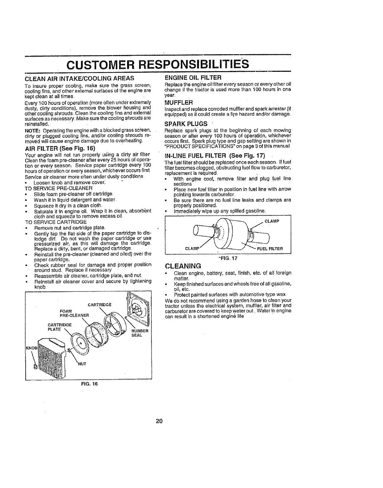
IN-LINE FUEL FILTER (See Fig. 17)
"_he fuel filter sheuEd be repfaoed once each season. If fuel
_ter becomes clogged, obstructing fuel flow to carburetor,
replacement is required-
• With engine cool, remove tilter and plug !ue{ line
sections
-Place new {uel/iIler in position in fuel line with arrow
pointing towards carburetor
-Be sure there are no fuel line leaks and clamps are
property positioned.
• Immediately wipe up any spilled gas0]Ine.
-FIG. 17
CLEANING
• Clean engine, battery, seat, finish, eteo of el! loreign
matter,
• Keep f n shed surfaces and wheels free of all gasoline
oil_ etc,
• Protect painled surfaces with autombtive type wax
We do not recommend using a garden hose to clean your
tractor unless the efeclrical system, muffler, air filter and
carburalor are covered to keep water out. Water in engine
can resu{t in ashortened engln_ life
FIG. 16
2O
SERVICE AND ADJUSTMENTS
.,HI., H., ,,J ,,,,H., 11 ,..............................
CAUTION; BEFORE PERFORMING ANY SERVICE OR ADJUSTMENTSi ...............
Depress clutch/brake pedal fully and set parking brake,,
Place motion control lever in neutral (N} position_
Place attachment clutch In "DISENGAGED" positiom
Turn ignition key "OFF" and remove key.
•Make su_e the blades and all moving parts have completely stopped.
•Disconnect sparkplug wire from spark plug and place wire Where it cannot come In contact with
plug,
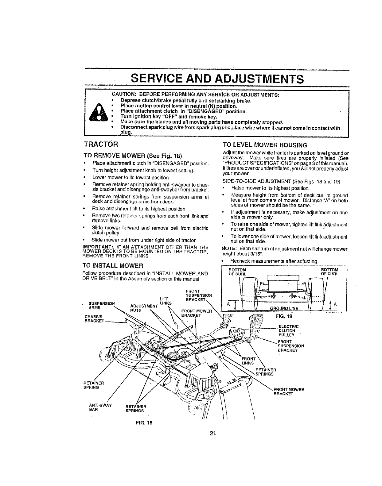
TRACTOR TO LEVEL MowER HOUSING
Adlust the mower white tractor is parked on level ground or
TO REMOVE MOWER (See Fig_ 18) driveway, Make sure liree are properly inflated (See
• Place attachment clutch in "DISENGAGED" pos[tiOn.r "PRODUCTSPECIFICATIONS"onpage3oIthismanual),
• Turn height adjustment knob fo lowest setting Iltlresareoverorunderinflated, you_viltnoipreperlyad ust
your mower
• Lower mower to Its lowest position siDE-TO-SIDE ADJUSTMENT (See Figs 18 and 19)
•Remove retainer spring holding antJ-swaybar to chas-
Sis bracket and disengage anli-swaybar from bracket •Raise mower to its highest position
, Remove relalner springs from suspension arms at " Measure height from bottom of dec{ cur!, oground
deck and disengage arms from deck levef at front corners of mower, Distance A on bo{h
• sides of mower should be the same.
•Raise atlachmen! till to its highest position, • If adjustment is necessary, make adjustment on one
• Remove two retainer springs from each front link and side of mower only
remove links. .To raise one side of mower, tighten lift link adjustment
• Slide mower forward and remove bell !,_om electric nut on that Side
clutch
-"_"pudey •To fewer one side of mower, loosen lift }Ink adjustment
• Slide mower out from under right side el tractor nut on that side
IMPORTANT:, iF AN ATTACHMENT OTHER THAN THE NOTE: Eachhaffturnofadiustmentnutwillchangemower
MOWER DECK IS TO BE MOUNTED ON THE TRACTOR, height about 3/16"
REMOVE THE FRONT LINKS
TO INSTALL MOWER Recheck measurements after adjusting
BOTTOM BOTTOM
FoIIow procedure described in "INSTALL MOWER AND OF CURL t- _, ..1 OF CURL
DR'VE BELT' in the Assembly section of this manua, l(_tf_ _._ _--'-_ /
FHONT /J I_-=,, -_I_l It
LIFT BRACKET_ _ _...... LV_ " -" ,-- _'_ tvl .....
SUSPENSION LINKS A
"NUTS FRONTMOWER_,, _' ..............
CHASSIS BRACKET X,,_I'_;; FIG. 19
ELECTRIC
CLUTCH
PULLEY "
FRONT
SUSPENSION
i/ BRACKET
\
RETAINER
SPRING
FIG. 18
FRONT MOWER
BRACKET
21
SERVICE AND
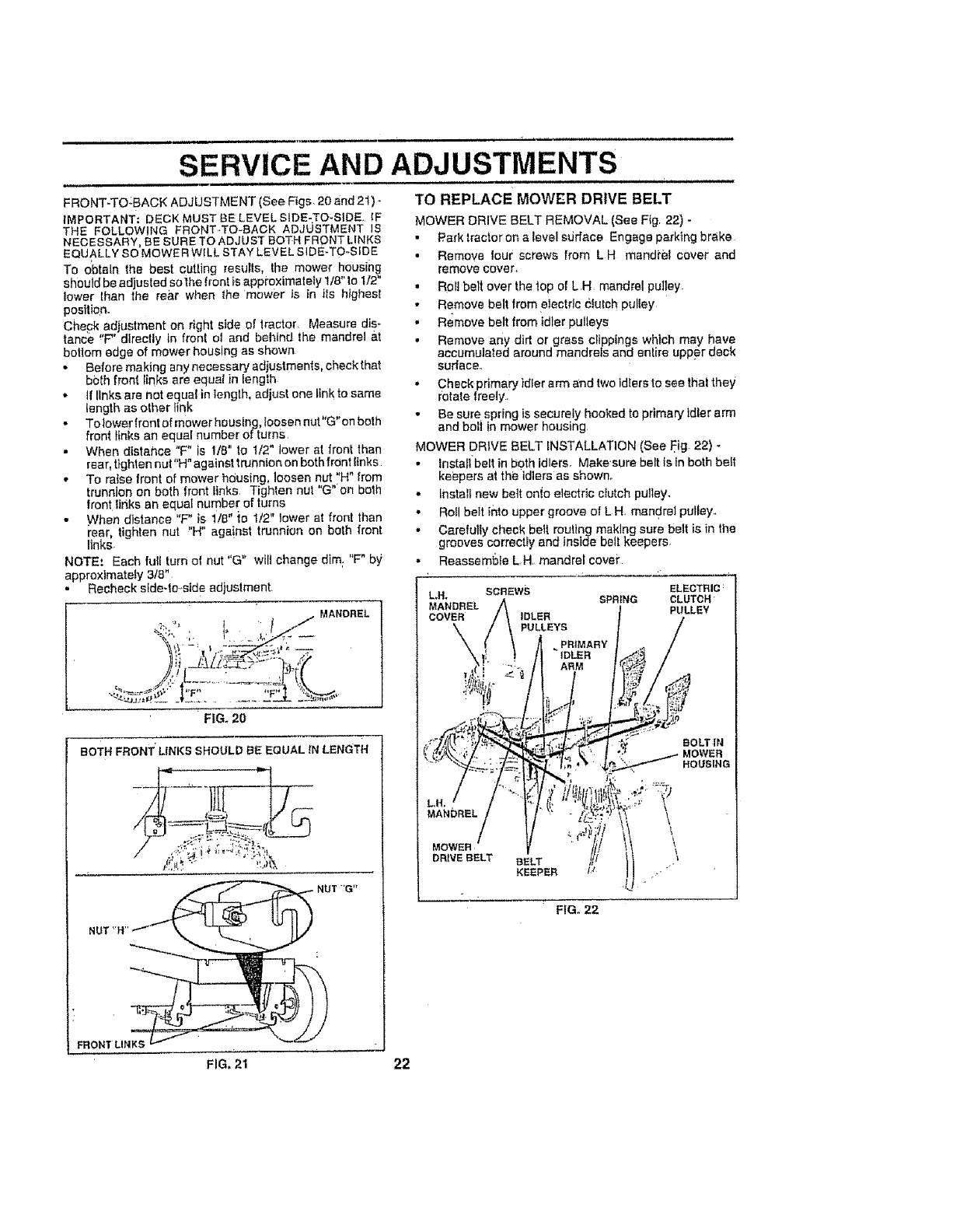
FRONT-TO.:BACK ADJUSTMENT (See Figs. 20 and 2t) _
IMPORTANT; DECK MUST BE LEVEL SIDE-TO-SIDE, IF
THE FOLLOWING FRONT,.TO-BACK ADJUSTMENT iS
NECESSARY. BE SURE TO ADJUST BOTH FRONT LINKS
EQUALLY SO MOWER WILL STAY LEVEL SIDE-TO-SfDE
To obtain the best cutling resuIls, the mower housing
should be adjusted so ]he front is appioximately 1/8" to 1/2"
tower than the rear when the mower is in tls highest
position.
Check adjustment on right side of tractor, Measure dis-
fence _'F' directly in front ol and behind the mandrel at
botlom edge of mower housing as shown
* Before making anynecessaryad_ustments, checkthat
both front links are equal in lenglh
°tf links are not equal in length, adjust one link to same
length as other link
. Tolower front of mower housing. Ioosen nut"G"on both
front links an equal number of turns
•When distance "F" is 1/8" to I/2" lower at front than
ADJUSTMENTS
TO REPLACE MOWER DRIVE BELT
MOWER DRIVE BELT REMOVAL (See Fig 22) -
• Park tractor on a level sdrface Engage parking brake
• Remove tour screws from L H mandi'el cover and
remove cover,
• Roll belt over the top of L H mandrel pulley.
•Remove belt from electrlc Clutch puliey
• Remove belt from idler pulleys
• Remove any dirt or grass clippings which may have
accumulated around mandrels and enIire upper deck
sudace.,
" Check primary idler arm and two ldlers to see that they
rotate freely
• Be sure spring is securely hooked to primaryldler arm
and boil in mower housing
MOWER DRIVE BELT INSTALLATION (See Fig 22) -
rear. tighten nut"H" against trunnion on both frOnt links
,, To raise front of mower hdusing loosen nut"H" from
trunnion on both front links Tighten nut 'G on both
front rinks an equal number of turns
• When distance "F" is 1/8" {o 1/2" lower at front than
rear. tighten nut "H" aga!nst trunnion on both front
links-
NOTE.' Each full turn o! nut "G" wilt change dim; "F" by
approxlmateLy 3/8"
° Recheck s_de-to.std eadjustment
.MANDREL
"FIG. 20
BoTH FRONT" LINKS SHOULD BE EQUAL tN LENGTH
,' Install belt in both idlers. Make'sure belt is in both belt
keepers at the idlers as shown.
,, Install new bett onie electric cIutch pulley.
• Roll bett into upper groove of L H. mandrel pulley..
•Carefully cheek betl rou!lng making sure belt is in the
grooves correctly and inside belt keepers.
•Reassembfe L.H, mandrel covet"
ELECTRIC:
CLUTCH
PULLEY
BOLT IN
HOUSING
MANDREL
DRNEBELT BELT
KEEPER tJ
\
\\
FIG. 22
FRONT LINKS
FIG. 21 22
Li_ ii,ll, ,, ,i , ,,i,l,,lll,,,i,,i u,l,llllllll ill i
SERVICE..AND ADJUSTMENTS
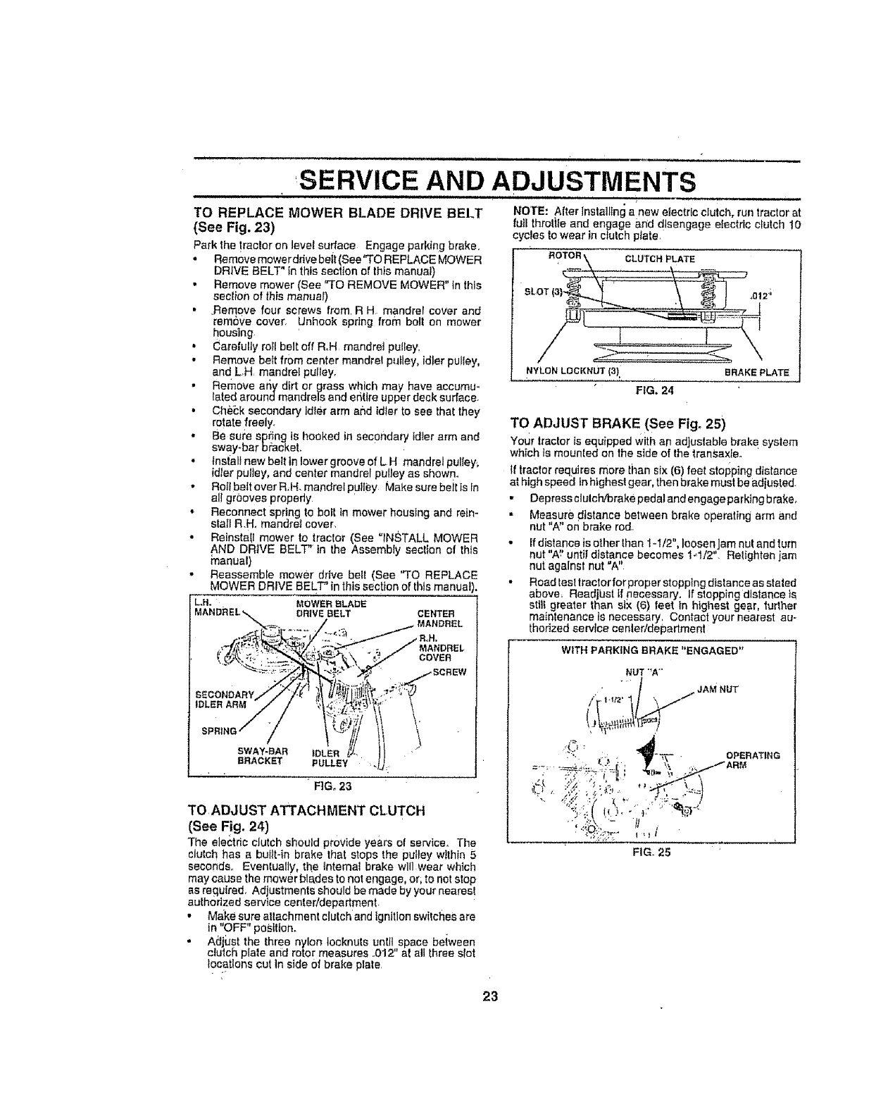
TO REPLACE MOWER BLADE DRIVE BELT NOTE: After Installing a new electric clutch, run tractor at
(See Fig. 23) ful_ throtile and engage and disengage electric clutch 10
cycles to wear in dutch plate,
Park the !rector on level surface Engage parking brake, _.
•Remove mowe rddve beit (See"TO REPLACE MOWER ROTOR\ CLUTCH PLATE
DRIVE BELT" In this section of this manual ) _ _
•Remove mower (See "TO REMOVE MOWER" In this _ _-_ 0,2';
sect}on of this manual) SLOT(_)
• .RemovefourscrewsfromR. mandre °oVerand
remove cover. Unhook spring from boll on mower ,,,_=5'1_
houslng /
oCarefully toil belt off R,H mandret putley.
•Remove belt from center mandret pulley, idler pulley, /'" ' _" ,
and L.H mandrel pulley. NYLONLOCKNUT{3)i .RAKE PLATE
• Remove ar_y dirt or grass which may have accumu- FIG. 24
tared araundmandrels and entire upper deck surface.
• Che_k secondary Idler arm and idter to see that they
rotatefreely, TO ADJUST BRAKE (See Fig, 25)
• Be sut:e spring ts hooked in secondary ldter arm and Your Iractor Is equipped with an adjustable brake system
sway-bar bracket, which ls mounted on the side of the transax{e. '
•fnstalt new belt in lower groove of L H mandrel pulley.
idler pulley, and center mandrel pulley as shown, tf tractor requires more than six (6) feet stopping distance
• RoftbetteverR_H.ma,ndre pu ey Make sure belt ls ln at high speed tnhtghestgear, thenbrakemustbeadiusted.
ailgr0oves propedy ,, Depressclulctvbrakepedalandengageparktngbrake_
• Reconnect spring to boll in mower houslng and reim • Measure distance between brake operating arm and
stai'i R.H. mandrel cover, nut "A" or_brake rod
• Reinstafl mower to tractor (See "tNSTALL MOWER •Ifdistanceisotherlhant-1/2",leosenjamnutandtum
AND DRIVE BELT" tn the Assembly section of this
;"nanual} nut "A_'until distance becomes 1_1/2" Relighten jam
nut against nut "A"
" Reassemble mower drive belt (See "TO REPLACE
MOWER DRIVE BELT' in this section of this manual •Road test tractor for proper stopping distance as stated
above, Readjust t{ necessary, If stopping distance _s
L... MOWERBLADE stilt greater than six (6) feet In highest gear, furlher
DRIVEBELT CENTER maintenance Is necessary, Contact your nearest au-
thorized service toni.r/department
MANDREL WITH PARKING BRAKE "ENGAGED"
COVER
NUT"A"
• • /i,,.. JAM NUT
IDLER ARM /"_ ,,,t2' "1/_
SWAY-BAR IDLER ?:r. ."_= •OPERATING
_.b -_R
BRACKET PULLEY ""_'"_":_;_-i "'_" _" \_
FIG, 23 -_ ,: ._.?/; .-._: . _, .=_=)
TO ADd UST ATTACH MENT CLUTCH ' _ _'I .;t!'_'_}_., I1'_' ...
(See Fig. 24) ,_:::,_._,_ t
The eIe_;trio clutch should provide years of service, The
ciulch has a buitt-in brake that stops the pulley wtthin 5 FIG. 25
seconds,, Eventually, the Internal brake will wear which
may cause the mow. r blades to not engage, or; to not stop
as required. Adjustments should be made by your nearesl
authorized service center/depadment.
,' Make sure attachment clutchand Ignition swilches are
in "OFF" position.
• Adjust the three nylon Iocknuts unlit space beiween
clutch plate and rotor measures .012" at all three slot
leo.aliens cut tn side Of brake plate
23
SERVICE AND ADJUSTMENTS ,,
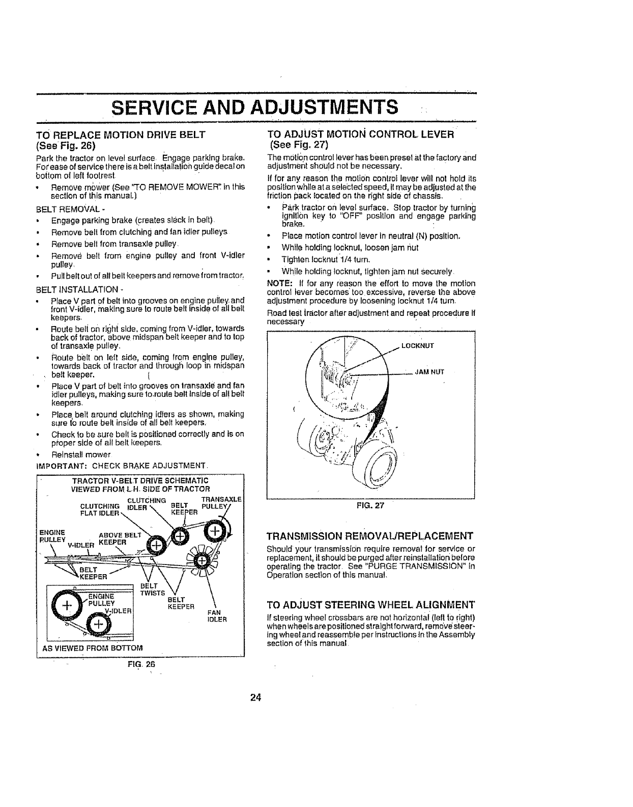
TO REPLACE MOTION DRIVE BELT
(See Fig. 26)
Park the tractor on level surface Engage parking brake°
Fo( ease of service the re iea belt lnslallatiOn guide decal on
bottom of left footrest
• Remove mc,wer (See "TO REMOVE MOWER': In this
section of this manual.)
BELT REMOVAL -
• Engage parking brake (creates slack in belt),
, Remove belt from clutching and lan idler pulleys
,, Remove belt from Iransaxle pulley
• Remove belt from engine pulley and front Vqdler
pu!ley,
Pull bett out ot all bett keepers and remove irom fractor_
BELT INSTALLATION -
• Place V part of belt into grooves on engine putley and
front V-idler, making sure to route bert insid e of all belt
keepers.
• Route bell on righ{ side, coming from Vqdter, towards
back of tractor, above midspan belt keeper and to top
of transaxt e pulley,,
• Route bblt on left side coming from engine pulley,
towards back of tractor and through loop in m dspan
• belt keeper. [
• Place V part of belt into grooves on transaxte and fan
idler pulleys, making sure to.route belt Inside of el! belt
keepers,
• Piece belt around cMchfng idlers as shown, making
s_lre Io route bell inside of all belt keepers,
• Check fobe sure bett is positioned correctly and is on
proper side of all belt keepers,
., Reinstall mower
iMPORTANT: CHECK BRAKE ADJUSTMENT
ENGINE
TRACTOR V-BELT DRIVE SCHEMATIC
VIEWED FROM L-H. SiDE OF TRACTOR
CLU"[CHING TRANSAXLE
CLUTCH}NG eELT
FLAT IDLER,
AS VIEWED FROM BOTTOM
TO ADJUST MOTION CONTROL LEVER
(See Fig, 27)
The motion control lever has been preset at the factory and
adjustment should not be necessary°
If for any reason the motion contro_ lever wilt not hold its
position while at aselebted speed, it may be adjusted at the
fdction pack located on the right side of chassis.
• Park tractor on level surfacm Stop tractor by turning
ignitibn key to "OFF" position and engage parking
brake. "
.Place motion control lever in neutral (N) position.
• Whtle holdingtocknul, loosen Iam flut
•Tighten !acknut 1/4 furno
• While holding locknut, tighten jam nut Securely.
NOTE: I{ for any reason the effort to move the motion
control lever becomes too excessive reverse the above
adjustment procedure by loosening Iocknut 1/4 turn.
Read test iraclor after adjustment and repeat procedure If
necessary
LOOKNUT
(
FIG. 27
TRANSMISSION REMOVAL/REPLACEMENT
Should your transmlssidn require removal for service or
replacement, itshould be purged after reinsteIlatton before
operating the tractor, See "PURGE TRANSMISSION" in
Operation section of thls manual.
TO ADJUST STEERING WHEEL ALIGNMENT
If steering wheel crossbars are not horizontal (left |o right)
when wheel s are positioned straight forward, re move_steer-
ing whee! and reassemble per instructions In the Assembly
section of'this manual
FIG. 26
24
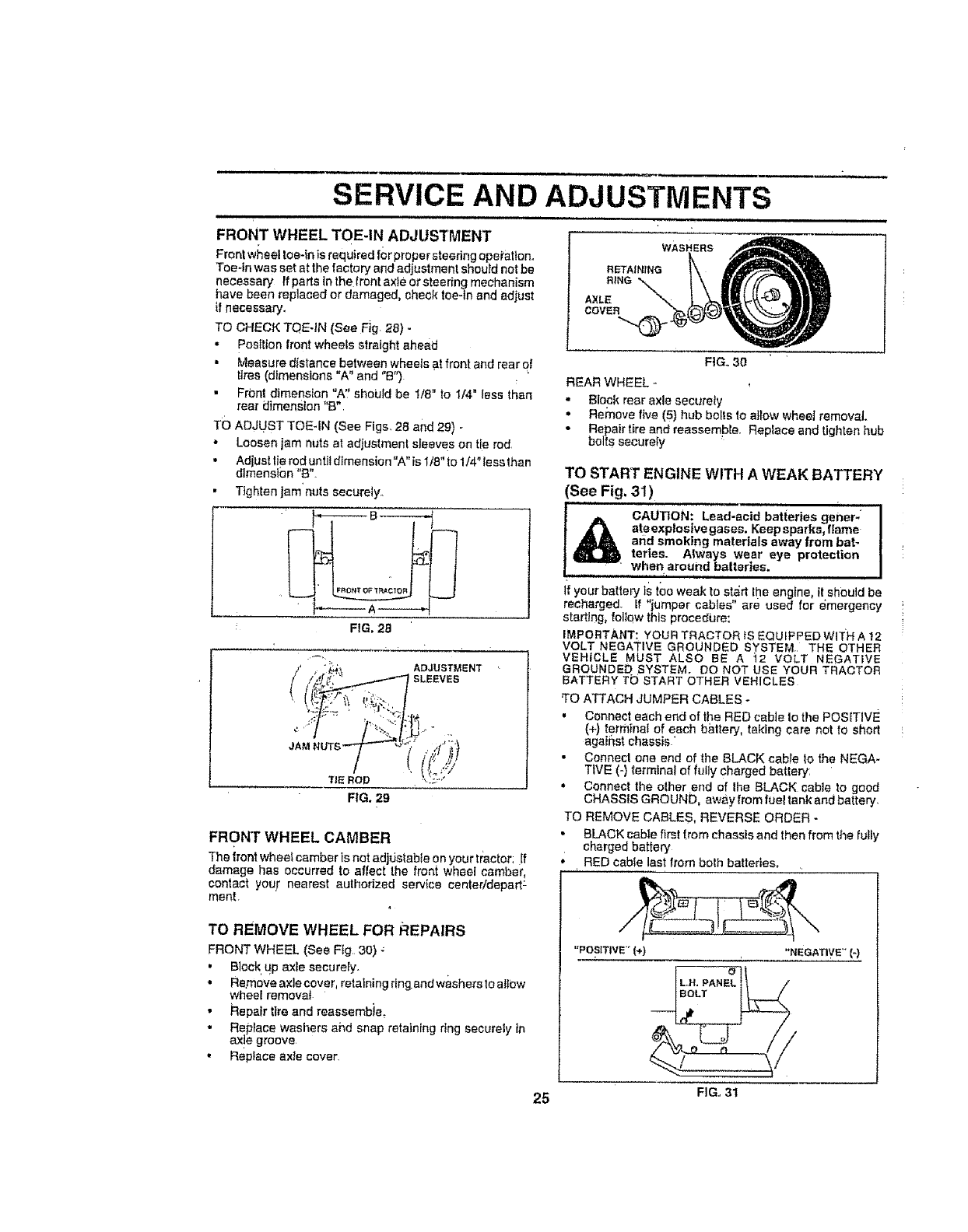
SERVICE AND ADJUSTMENTS
,, ,,,H,,,,,, ,, ,,,
FRONT WHEEL TOE-IN ADJUSTMENT
Front w;_eel toe-in is required f0rpropersteedng opei'ation°
Toe-in was set at the factory and adjustment should not be
necessary If parts tn the front axis or steering mechanism
have been replaced or damaged, cheek toe-in and adjust
if necessary.
TO CHECK TQE-IN (See Fig 28) -
-Posttion front wheels straight ahead
• Measure distance between wheels at front and rear o!
tires (dimensions "A" and "B")
• FrOnt dimension "A" should be 1/8" to 1/4" less than
rear dimension "B"
TO ADJUST TOE-IN (See Figs. 28 and 29) -
•Loosen jam nuts at adjustment sleeves on tie rod.
• Adjust lie rod untit dimension "A" is 1t8" to 1/4" less than
dimension "B".
• Tighten jam nuts securely.
FIG, 28
_'_:_, ADJUSTMENT
//_,_r_ /"-'1 SLEEVES
t
JAM NUTS _ ,,_1/ "/_;;}
t((U;
TiE ROD _',!:.:"*
FIG. 29
FRONT WHEEL CAMBER
The frontwheef camber Is net adjdstabte on your tr:actor: If
damage has occurred to aflect Ihe front wheel combe;t,
contact you_" nearest authorized service centeddepart:
ment r
TO REMOVE WHEEL FOR REPAIRS
FRONT WHEEL (See Fig 30)
•Block up axle securely.
• Remove axle cover, retaining rlngend washers to allow
wheel removal
•Repair tlre and reassembie_
•Replace washers and snap retaining ring securely in
axle groove
•Reptace axle cover
25
WAS
FIG. 30
REAR WHEEL -
• Block rear axle securely
• Remove five (5) hub belts Io allow wheel removal.
• Repair tire and reassemble. Replace and tighten hub
bolts securely
TO START ENGINE WITH AWEAK BATTERY
(See Fig. 31)
CAUTioN: Lead-acid bat{eries gener-
ate explosive gases. Keep sparks, flame
and smoking materials away from bat-
terles. A|ways wear eye protection
when around batteries.
H,, '1 =
if your battery is too weak to start the engine, it should be
recharged. If "jumper cables" are used for emergency
starting, follow this procedL=re:
IMPORTANT: YOUR TRACTOR tS EQUIPPED WITH A 12
VOLT NEGATIVE GROUNDED SYSTEM. THE OTHER
VEHICLE MUST ALSO BE A 12 VOLT NEGATIVE
GROUNDED SYSTEM. DO NOT USE YOUR TRACTOR
BATTERY TO START OTHER VEHICLES
'TO ATTACH JUMPER CABLES -
• Connect each end of the RED cable Io the POSITIVE
(+) termfnal of each battery, taking care not to short
against chassis _
•Connect one end of the BLACK cable Io the NEGA-
TIVE (-) terminal of fully charged battery
• Connect the elher end of the BLACK cable to good
CHASSIS GROUND, away from fuel tank and battery,
TO REMOVE CABLES, REVERSE ORDER -
• BLACK cable first {rein chassis and then from the fully
charged battery
RED cable last from both batteries,
"POSITIVE" 1+) "NEGATIVE" {-)
L H. PANEL
4/
I
FIGo 31

SERVICE AND ADJUSTMENTS
TO REPLACE HEADLIGHT BULB
°Raise hood
•Pull bulb holder out of the hole in the backside of the
gfilt
•Replace bulb in holder' and push bulb holder securely
beck into the hole in the backside of the griII.
•Close hood
=
INTERLOCKS AND RELAYS
Loose or damaged wiring may cause your, tractor to run
poorfy stop running or prevent II from starling.
•Check wiring. See electrical wiring diagram in the
Repair Pads Section ol this manual:
TO REPLACE FUSE
Replace with 30 ah_p autOmotive-type plug-in luse. The
fuse hoider is !0cared behind the dash_
TO ADJUST ATTACHMENT LIFT SPRING
(See Fig. 32)
•While holding spring bushing with wrench, loosen jam
nut,
•Tum adjustment bolt clockwise to extend spring and
reduce Iilt effort for heavier attachments_
•Turn adjustm0nt bott counterclockwise for lighter at-
tachmentso
•Retlghten jam nut against spring bushing..
IMPORTANT: DO NOT ADJUST FOR MAXIMUM SPRING
TENSION WHEN USING LIGHT ATTACHMENTS SUCH
AS A MOWER. ADJUST LLFT LEVER SPRING TO AID IN '
LIFTING ATTACHMENT, DO NOT OVERPOWER SPRING.
WHEN REMOVING ATTACHMENT, ALWAYS ADJUST
SPRING TENSiON TO ITS LOWEST POSITION
ADJUSTMENT SPRING BUSHING
ATTACHMENT
JAM NUT LIFTSPRING
TO REMOVE HOOD AND GRILL ASSEMBLY
(See Fig. 33)
.Raise hood,
•Unsnap headlight wire connector.
• Stand infront of tractor. Grasp hood at sides, flittoward
engine and lift off of tractor,
•To replace, reverse above procedures-
H_ADUGHT
WIRE
CONNECTOR
FIG, 33
ENGINE
TO ADJUST THROTTLE CONTROL CABLE
(See Fig, 34)
The throttle control has been preset at the factory and
adjustment should not be necessary, Check adjustment as
described be!ow before loosening cable, if adjustment is
necessary, proceed as fofJoWa:
• With engine not running, move throttle control lever to
fast (,,_) position
,, Check that speed controllever is against stop screw, If
it is not, loosen casing clamp screwand pu]t throttle
Cable until lever is against screw. Tighten clamp screw
secure]yo
FIGo 32
26
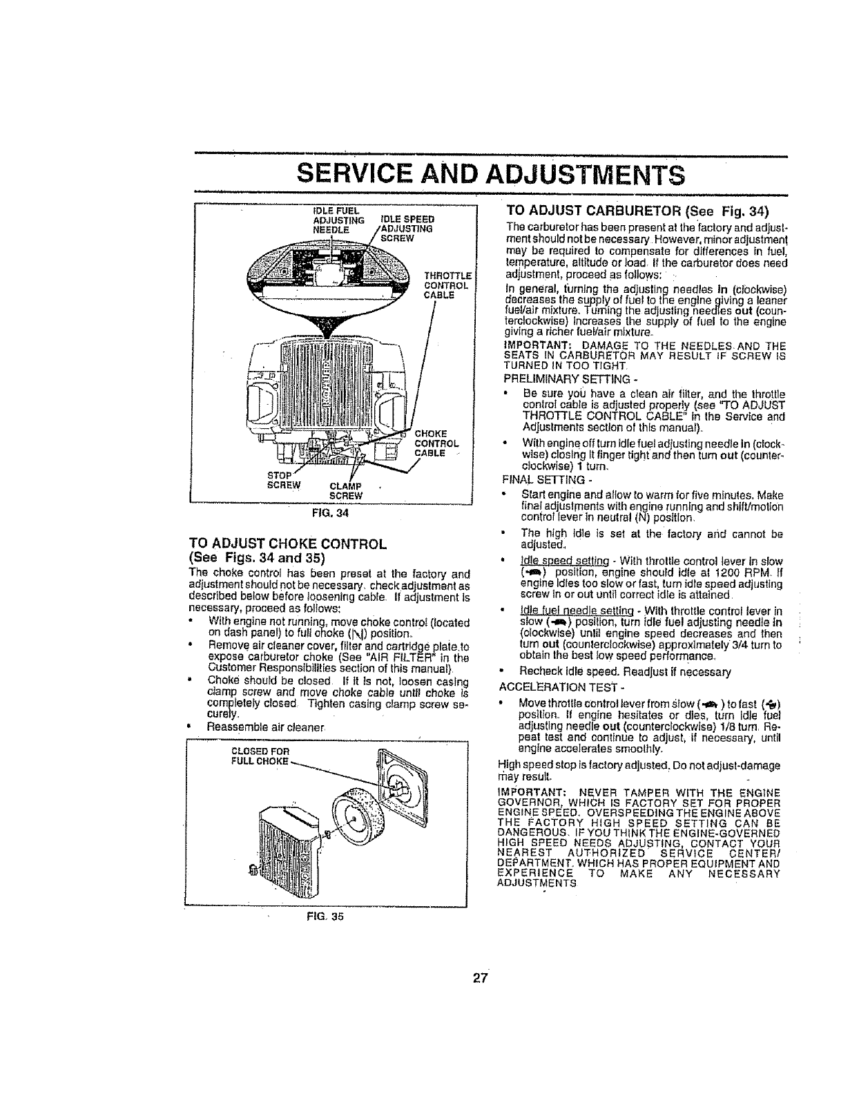
i,+.............. i ulu i' i+l ul u i lu,i ,n
SERVICE AND ADJUSTMENTS
STO
SCREW CLAMP
SCREW
FIG+ 34
tDLE FUEL
ADJUSTING _DLE SPEED
NEEDLE
THROTTLE
CONTROL
CABLE
CONTROL
CABLE
TO ADJUST CHOKE CONTROL
(See Figs. 34 and 35)
The choke control has been preset at the factory and
adjustment should not be necessary check adjustment as
described below before loosening cable If adjustment is
necessary, proceed as follows:
• With engine not running, move choke contro+ (located
on dash panel) to full choke (N) position
•Remove air cleaner cover, filter and cartridge plaie to
expose carburetor choke (See "AIR FILTER" in the
Customer Responslb+ltties section of this manual)
" Choke should be closed if tt +s not, loosen casfng
clamp screw and move choke cable unttl choke is
completely closed Tighten casing clamp screw se-
curely
, Reassemble air cleaner
CLOSED FOR
FULLCHOKE
luui,llul i i i
TO ADJUST CARBURETOR (See Fig. 34)
The carburetor has been present at the factory and adjust-
mentshould notbe necessary However, minor adjustment
may be required to compensate for differences in fuel,
temperature, altitude or load If the carburetor does need
adjustment, proceed as follows: +
In general, turning the adjusting needles tn (ct0ckwise)
decreases the supply of fuel to the engtnegMng a leaner
fueValr mixture+ Turning the adjusting needles out (court
terctockwise) increases the supply of fuel to the engine
giving a richer fuel/air mixture+
IMPORTANT: DAMAGE TO THE NEEDLESAND THE
SEATS IN CARBURETOR MAY RESULT IF SCREW IS
TURNED iN TOO TIGHT
PRELIMINARY SEI_ING
Be sure yoiJ have a clean air filter and the throttle
control cable is adjusted properly (see "TO ADJUST
THROTTLE CONTROL CABLE' +n the Service and
Adjustments section of thEsmanual).
• With engine off turn idle fuel adiusfing needle in (cIock+
wise) closing It finger tight and then turn out (counter+
clockwise) 1 turn
FINAL SETTING
• Start engine and allow to warm for five minutes Make
final adjustments with engine running and shift/mot+0n
control lever in neutral (N) posffton
• The high td]e is set at the factory and cannot be
adjusted.
• _ - With throttle control lever Jnslow
(,a_) position, engine should id+e at t200 RPM ff
engine Idles too slow or fast, turn idle speed ad usttng
screw In or out untlt correct idle is atta ned
• !die fuel needle set ng - W th throttle control !ever in
slow (a_) position, turn idle fuel adjusting needie in
(clockwise) until englne speed decreases and then
tum out (counlerclockwtse) approximately 3/4 turn to
obtain the best low speed perforrqance.
• Recheck idle speed. Readjust if necessary
ACCELERATION TEST -
• Moyethroltle ct:ntrollever from.4tow (.m,_) to fast (_)
pestlton If engine hesitates or dies, turn Idle fuel
adjusting needle out (counterclockwise) 1/8 turn Re-
peat test and continue to adjusl+ if necessary, until
engine accelerates smoothly
High speed stop is factory adjusted Do not adjustdamage
rflay result
IMPORTANT: NEVER TAMPER WITH THE ENGINE
GOVERNOR, WHICH IS FACTORY SET FOR PROPER
ENGINE SPEED OVERSPEEDING THE ENGINE ABOVE
THE FACTORY HIGH SPEED SETTING CAN BE
DANGEROUS IF YOU THINK THE ENGINE-GOVERNED
HIGH SPEED NEEDS ADJUSTING, CONTACT YOUR
NEAREST AUTHORIZED SERVtCE CENTER/
DEPARTMENT WHICH HAS PROPER EQUIPMENTAND
EXPERIENCE TO MAKE ANY NECESSARY
ADJUSTMENTS
FIG+ 35
27
STORAGE
mu,_L ,,,,, ,, r ,,
Immediately prepare your tractor for storage at the end of
the season or if the tractor will not be used for 3D days or
more.
!'A CAUTION: Never store the tractor with
gasoline tn the tank inside a bulldicg
where fumes may, reach an open flame
or spark. Allow the' engine to coo!
.............. before storing in any enclosure. "
TRACTOR
Remove mower from traclor for winter storage. When
mower is to be stored for a period of time, c{eafi il thor-
oughly, remove all dirt, grease, leaves, etb. Store in a
clean, dr/area.
•Clean entire tractor(See"CLEANING"tn the Customer
Responslbllittes section of this manual).,
•fnspect and replB.ce belts if necessa_ {See belt re-
placement Instruct one in the Sei'vlce and Adjustments
section of this manuar).
• Lubricate as shown in the Customer Responsibitffies
section of _hts manual
,, Be sure that all nuts, boiis and screws are securely
fastened., lnspec! nioving parts for damage, breakage
and wear Replace it necessary
Touch up all rusted or chipped paint surfaces; sand
lightly before painting
BATTERY
•Fulty charge the batter_, for storage.
,, After a period of time in storage, battery may require
recharging
• To help prevent corrosion and power le_kage during
long periods of slorage, battery cables should be
disconnected and batter/cleaned thoroughly (see "TO
CLEAN BATTERY ANC) TERMINALS" n the Cus:-
tomer Responsibilities section of this manua!)
• After cleaning, le_ive ceb!es disconnected and place
cables where they Cannot come in contact wtlh battery
terminals_
-Be sure battery drain tube is securely attached,,
•Hbatter/is removed Irom tractor for storage,,do not
s ore batter! directly on concrete or damp surfaces
ENGINE
FUEL SYSTEM
IMPORTANT: tT iS _MPORTANT TO PREVENT GUM
DEPOSITS FROM FORMING IN ESSENTIAL FUEL
SYSTEM PARTS SUCH AS CARBURETOR, FUEL FILTER.
FUEL HOSE, OR TANK DURING S'FORAGE. ALSO,
EXPERIENC_ iNDICATES THAT ALCOHOL BLENDED
FUELS (CALLED GASOHOL OR USING ETHANOL OR
METHANOL) CAN ATTFIAOT MOISTURE WHICH LEADS
TO SEPARATION AND FORMATION OF ACIDS DURING
STORAGE, ACtDIO GAS CAN DAMAGE THE FUEL
SYSTEM OF AN ENGINE WHILE iN STORAGE,,
• Draintbe fuellahk.,
.Start the engine and let tl run until the fuel !ines an_l
carburetor are empty,
•Never us0 engineorcarburelorcleanerproductsinthe
fuel tank or permanent damage may occur,
• Use fresh _lua]next season.
NOTE; Fuel stabilizer is an acceptable alternative in
minimizing the formation of fuel gum deposits (:luring stor-
age, Add stalhilizer to gasoline in fuel tank or storage
container, A{ways follow the mlx ratio found on stabilizer
container. Run engine at least 10 min_ttes a{ler adding
stabilizer to allow the stabilizer to reach the carburetor. Do
not drain the gas lank and carburetor if using fuel stabilizer
ENGINE OIL
Drainoil (withenginewarm) and replace with clean engine
oil, (See "ENGINE" in the Customer Responsibilities
section of this manual)
CYLINDERS "
•Remo;,,e spark plug(s)
.Pour one ounce of oiI through spark plLig hole(s) into
Cytinder(s)
,, Turn Ignition key to "START:" posi{ion (0r a few seconds
Io distribute oil,
• Replace with new spark plug(s)
OTHER
• Do not sl0re gasoline from one season to another.
• Replade your gasoline can i! your' can starts to rust,
Rust andlor dirt In your gasoline will cause problems:
• i if possible,, store your tractor Indoors and cover it to
give protection from dust and dirt,
• Cover your tractor with asuitable pirotective cover that
does not. retain'moisture, Do not use plastic. Ptaslic
canhot breathe which allows condo nsatlon to form and
witl cause your traclor to rust,
IMPORTANT: NEVER COVERTRACTOR WHILE ENGINE
AND EXHAUST AREAS ARE STILL WARM
28

," %- r....
PROBLEM
Wgl not start
Hard to start
Engine will not turn over
Engine cricks but will net
start
-• ' ,,, ,,i
Excessive vibration
,H,,pl m ,H,H mill rail mH
TROUBLESHOOTING POINTS
CAUSE
!: Oui oHueL t
2Engine not "CHOKED" propedy 2
3 Engine fl_sd 3,
4 Bad_pad_ p{ug _ 4
5Dldy alr fillar 5:
6Dirty _a! rater 6.
7 Weter In fuel 7
8 Loses or d0magsd wldng B
9 Carburetor out ef adjustment 9
t0 Engine vaivee out of adjuslmen :
4.
6
7
1 Clulchroreke pods!netdepressed
2Attachment clutch Is sngsged
3. Weak or dead b0_ery,
4: Blown fuss. '
_Corroded batte_ far.rials
6 Loose or damaged wiring
7 Faulty Ignition swileh:
g Faulty solsn0ld or stealer:
gFeugy opemlor presence switch(so)
f0
Dilly air filter "_
Bad sperk ptUg'r 2
'Week or d_ad battery 3.
Dirty fusi lifter 4
Slate or dldy fuel 5
Loose or demaged wiring, 6
Carb0retor outer ad us_'aant 7
Engine vsiv_s out el edluslment B
ui,Jl mmHH N, m,
f
2,
3.
4
5
6
7.
8.
9
1 Weakordsadbatfsry
2:Corroded bsitery terinlnels
3 Loose or damaged wldng
4Faulty solenoid or starter
I CUlling to0.much gr0se,loo fast
1
3
4
1
2ThrottleIn"CHOKE" postttbn, 2
3Buil_i-up of grass, leeves an_ trash under mower. 3:
4 Dirty air rifler. 4,
5 Low ell levePdldy oil 5
CORRECTION
Faulty spark plug
,Dldy _dal filler
9 Stale or dirty fuel
9 Water In fuel
10, Spark plugwire 10osa.
11, Dirty engine sir ssrssn/ens
12 Dlrltylclogg_d_nulger
13 Loose or damaged wiring
! 4 Carburetor a_t of adjustment
15 Engtnsvanes outof edJuetn_aht
_, Worn, banlor looseblade
2Rent b{ademandrel
3 Loose/damaged part(s),
Ftfi lust tank
See "TO START ENGINE" in Operalten section
Walt several minutes befsre attempting to start.
Replace spark plug.
Cle_nJreplacs alrfilter,
Replace,fuel filter'
Drain fuel tank end carburalar, refill tank with fresh
gasoline end replace fuel fillar
Check all wldng,
See "TOAdjust Carburetor" tn Se^,iseAdjustments
SeCtiOn.
Contact an aulhorized servicecanlar/depadment
Clash/replace sir fliter
Raplans spa_k plug
Recharge orrephlco battery
Replace fuel f}_lar
Drain fuet tank end letlll with fresh gasoline
Check sit wiring,
See "To Adjust Carburetor" in Service Adjustments
section, '
Contact erl eulhorizsd service canlar/depsdmenL
i
Depress dutchferaks pedal
Disengage attachment clUlch
Recharge or replace baffery
Replace/usa
Clean battery larmlnois:
Check all wtdng
CbecWreplace tgnlllon switch
ChsckJreptace solenoid or slader
Contact an eulh0dzed servicecenlarldspedment
Rectmrgs or replace battery
Cfean bettery terminals
CIlack sii wiring.
Chbek/replans sotanold or starlet
Set la "Higher Cut" position/reduce speed
Adjust throttle control
Clean underside of mower houstng
Clean/replace air filter
Check ol_levsiichangs oil
6 Ctoan end regap or change spa_k plug;
7Replace fuel filler.
8Dra!n fuel tank end _ef_llwi_hIresh gasoline,
g Drain fuel tank.end carburetor, refill lank wlth flesh
gasoline and replace fuel filter •
'iO Connect and tighten spark pIug Wire.
'i1 Clean engine sir screen/fins,
!2 Cteentreplace muffler
t3 Choc k all wiring,
14 See "To Adjust Carburetor" in Service AdJuslmenls
section.
15 Contact _n authorized service cenlar/depa_nent
f. Replace blade Ttgt_tenblade bolt
2. Replace blade mandrel
3, Tighten loose pad(s) Replace damaged paris
2g

TROUBLESHOOTING POINTS
PROBLEM CORRECTION
=
Engine continues to run
when operator reaves seat
with attachment clutch
engaged
Poor oat _uneven
u,,,,,, , ,, i i,
Mower blades wttt not
rotate
Poor grass discharge
Headlight(s) not working
(!f so equipped)
i
Battery wgt nut charge
Loss of drive
,,i
Engine "backfires _"
when turning engfne
"OFF"
=, ,_.
rCAUSE
1Faulty operator-safety presence cohtral syslera
1Worn, bent Ortease blade
2Maw_ rdeck net teve[
3Buildup of grass,leaves, and frash under rnews_.
4 Benl btads mandrel
BOiogg_d mower deck vent holes from buildup o!
grass, ]eaves, and trash around mandrels
1 Obsln_ctloninclutch mechanism
2, Worn/damaged mower drivs beg
3Frozen idler pufley
,_ Frozen blade mandrel
1. Engine speed leo slow.
2 Ttavsf speed too fast
3, Wet grasa_
4, Mowa_deck not level
5Lnwluneven lira air pressure
gWorn, bsntOr loose blade
7 Buildup Ofgrass, leaves and trash under mower
g Mower drive heft worn
gBlades Impropady tnstafted
10 tmpmper blades used.
11 Clogged mower deck vent holes from buildup of
grass, _eaves, and trash around rnandrets
! Switch ts "OFF"
2 Bu}b(a) burned out
3Faugy light swltch
4Loose or damaged wiring_
5g_ov_nruse
k
I Bad batterye@ll(a)
Poor esbto ecnnecllons
3 FBUityregulator(ifss equipped)
4r really s11ernator
1Freewheel controlin=disengaged" position
2, Motion ddve bell worn, damaged, or broken
3. Nr trapped tn transmissionduring shtpment
ors_r_lcing
1Check Wiring,swl_ehee and connecgons .If not
corrastod,contact an aulhodze dservleecenter/
depaffment
1Replace blade..'Tight_n blade bait
2 Level mower deck.
3C_ean underside o! mower houalng:
4Replace blade mandrel
5Clean around mandrels fo open vent hates
1 Remove obstruction
2 Replace mower ddve bell
3Replace ]dler pulley
4. asp|ace blade rnandret
• .ill
1 Race throttle controltn "FAST" pastgon
2Shift to slower speed.
3AgOwgrass to dry before mpwing.
4Level mower deck
5 Check t_res for proper air pressure
B Bsptaceteharpen blade T_ghtsnbrads bolt
7. Cleanundemide atmows Fhousing
B: Replace mower drivebelt.
g Reinstall blades sharp adgs down
1O, Replace with blades gated In IhIe manual
ll Clean around mandrels foopen vent hates
1. Turn s'Mlch"ON"
2Replace bulbis)
3. Cheek/reptabs light switch
4Cheekwlring and connec_0ne
5; Replace fuse
i ' Jl,=,
1Replace battery,
2 Check!cteafl allconni_ctlons
3Replace regulatsr
4 Replace alternator
=
1Place frsewhaat controltn "engaged" position
2Rapists motion d_ive bell
3Purge transmission
1Engine throlttB conlrol net set at "SLOW" "[ Move throltle'contrel to 'SLOW" position and allow
positionfor 30 seconds before stoppingengine to Idle for 30 seconds before stopp!ng engine "
30
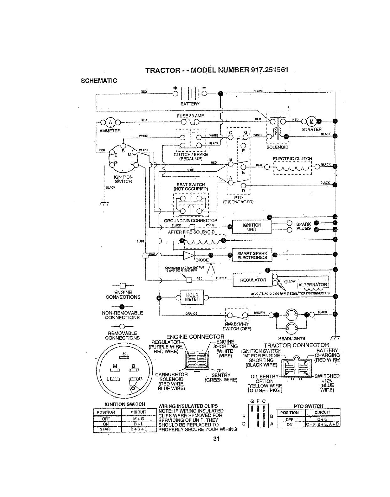
SCHEMATIC
TRACTOR -- MODEL NUMBER 917.251561
BATTERY
IGNITION
SWITCH
FUSE 30 AMP
S EAT SWITCH
(NOT OCCUPIED)
GROUNDINGCONNECTOR
;_ER FiRE _OLENoID
ENG{NE
CONNECTIONS
__@__
NON-REMOVABLE
CONNECTIONS
REMOVABLE
<
,E i
l
D
PTO
(DISENGAGED)
i_ _ IGNITIONUNIT
STARTER
SOLENOID
ELECTRICCLUTCH
CONNECTIONS
IGNITION SWITCH
POSfftONoFFl ¢IRCUITM4.G
.ON B"÷'L "'
STAR T
HEADLIGHTS
ENGINE CONNECTOR
EGULATOR-,, f-- ENGINE_
PURPLE WIRE,\ /SHORTING
RED WIRE) _(WHITE '
CARBURETOR .SENTRY
SOLENOID (GREEN WIRE)
_RED WIRE,
LUE WIRE)
TRACTOR CONNECTOR
IGNITION SWITCH BATTERY :
_M_'FOR ENG_NE-._. _ r--CHARGING'
SHORTING £-_ _ (RED WIF!E)
OILBENTRY4 _ _ "_! SWITCHED
OPTION +I2V
._YELLOWWIRE (BLUE
0 LIGHT PKG ) WIRE]
WIRING INSULATED CLIPS
NOTE: IF WIRING iNSULATED
CLIPS WERE REMOVED FOR
SERVICING OF UNIT THEY
SHOULD BE REPLACED TO
PROPERLY SECURE YOUR WIRING
31
E
D
GFC
PTO SWITCH
A/ON I_+F S+_"A;OJ
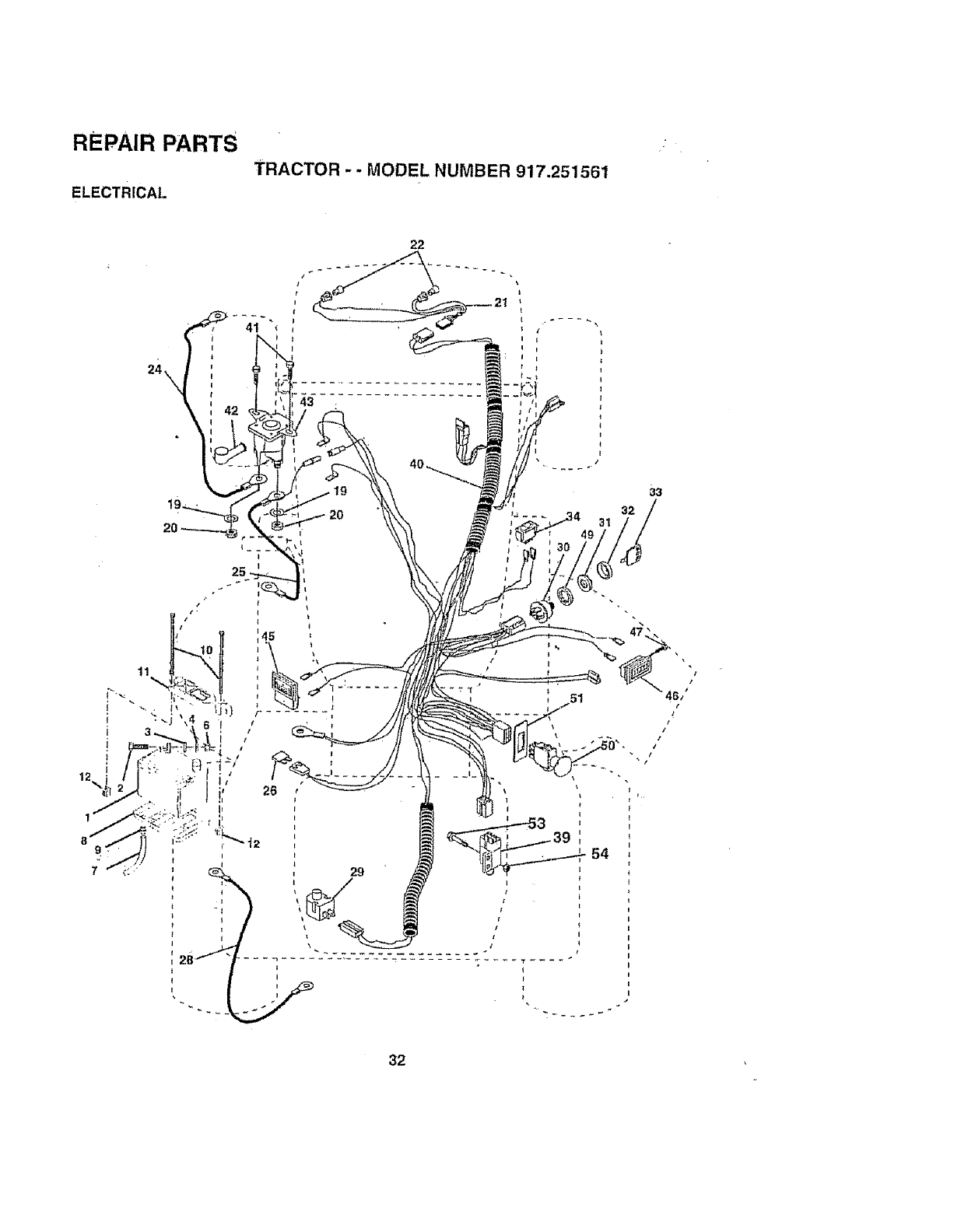
REPAIR PARTS
TRACTOR -. MODEL NUMBER 917.251561
ELECTRICAL
33
32
al
32
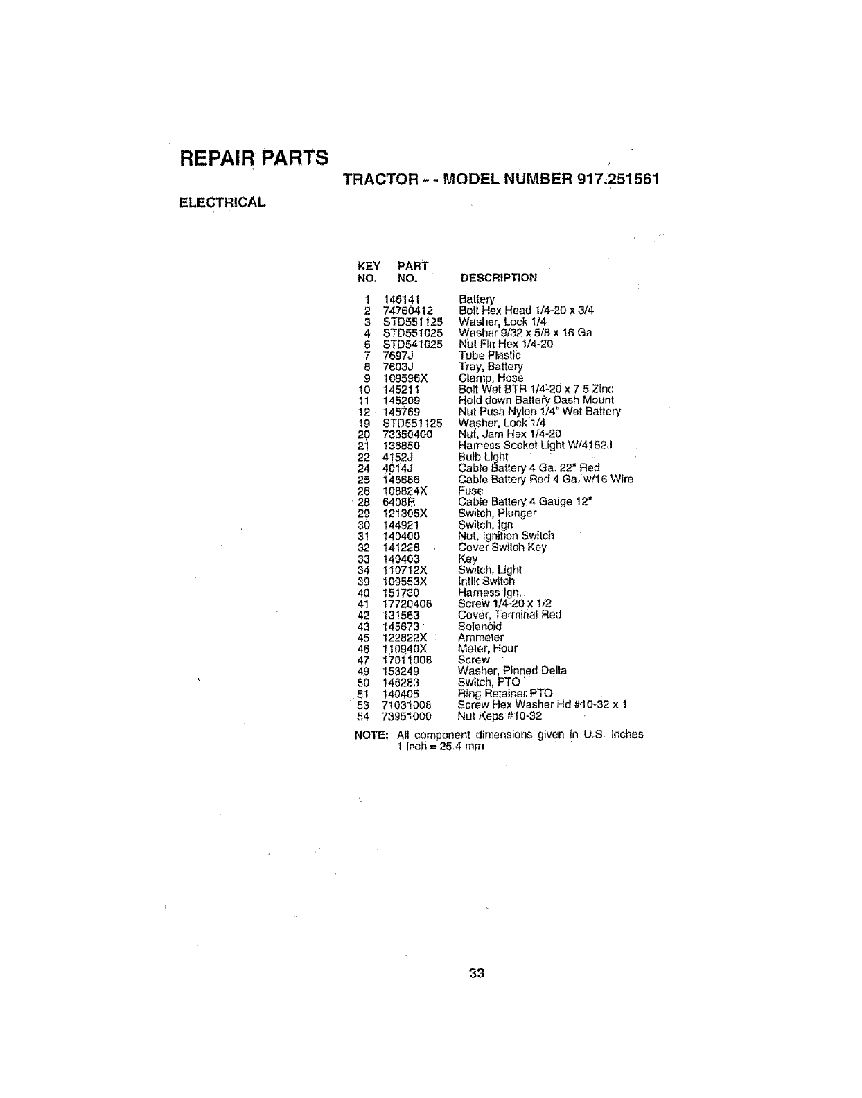
REPAIR PARTS
TRACTOR - - MODEL NUMBER 917;251561
ELECTRICAL
KEY PART
NO_ NO. DESCRIPTION
20 73350400
2i 136650
22 4152J
24 4p14J
25 146666
26 108824X
28 6408B
29 121305X
30 144921
31 140400
32 141226 ,
33 140403
34 110712X
39 109553X
40 151730
41 17720408
42 131563
43 145673
45 t22822X
46 110Q40X
47 17011008
49 153249
50 146283
51 140405
53 71031008
54 73951000
t 145141 Battery
274760412 Bolt Hex Head 1/4-20 X 3/4
3STD551125 Washer, Lock 1/4
4 STD551025 Washerg132x5/Sx16Ga
6 STD541025 Nut Fin Hex 114o20
7 7697J 'Tube Plastic
87603J Tray, Battery
9109596X Clamp, Hose
10 145211 Bolt Wet BTR 1/4_20 x 7 5 Zinc
tl 145209 Hold down Bal|eh/Dash Mount
12, 145769 Nut Push Nylon 1/4" Wet Battery
19 8TD551125 Washer, Lock 1/4
Nui, Jam Hex 1/4-20
Ha rne_s S oc ket L{ght W/4 ! 52J
Bulb Ltght "
Cable Battery 4 Ga, 22 °Red
Gable Battery Red 4 Ga, w/16 Wire
Fuse
Cable Battery 4 Gauge 12"
Switch, Plunger
Switch, ]gn
Nut, lgni{ton Switch
Cover SwIIch Key
Key
Switch, Ugh!
tntlk Switch
Harness Ign,
Screw 1/4-20 x 1/2
Cover, Terminal Red
Solen0id
Ammeter
Meter, Hour
Screw "
Washer, Pfnqed Delta
Switch, PTO
Ring Retainer. PTO
Screw Hex Washer Hd #,10-32 x 1
Nut Keps #10-32
NOTE; All component dimensions given !n US inches
1 Inc#,= 2&4 mm
33
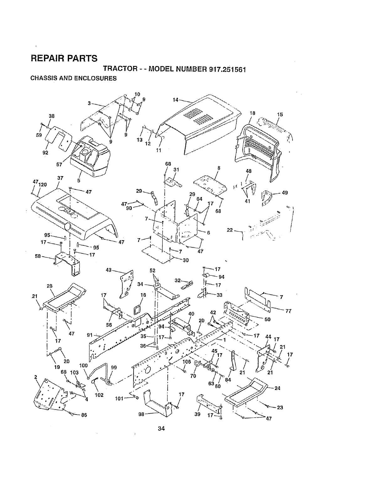
REPAIR PARTS
TRACTOR -- MODEL NUMBER 9t7,251561
CHASSIS AND ENCLOSURES
38
10 9
18 15
59 9
9 13
92
37
47,
2L
17
_20
19 100
68
2 \
86
102
17
56
11
42
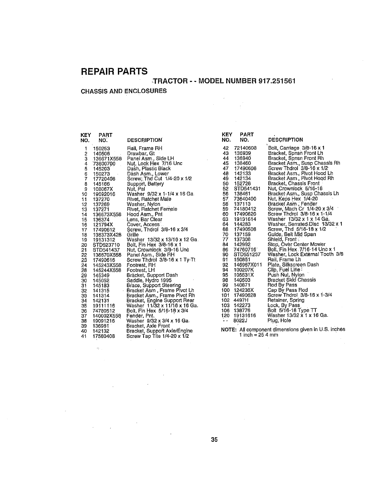
REPAIR PARTS
;.TRACTOR -. MODEL NUMBER 917.251561
CHASSIS AND ENCLOSURES
KEY PART
NO. NO_ DESCRIPTION
I150253 Ratl, Frame RH
2 140506 Drawbar, Gt
3t36671X558 PanetAsm.., SIdeLH
4 73800700 Nut, Lock Hex 7/16 Unc
'DaSh, Plastic Black
D&sh Asm., Lower
ScreW;.Thd Cut t/4-20 x 1/2
Support Battery
Nut, Pal
Washer 9/32x 1-1/4x 16Ga
Rivet, Ratchet Ma!e
Washer, Nylon
Rivet, Ratchet Female
5 145203
6 150273
717720408
8 145166
9 t05067X
10 19092016
11 137270
12 137269
13 137271
14 136673X558 Hood Asm. Pi_t
I5 136374 Lens, Bar Clear
16 121794)( Cover, Access
17 17490612 Screw, Thdrol 3/8-16 ×3/4
18 I36373X426 Grille
19 19131312 Washer 13/32x13/16x12Ga.
20 STD523710 Bolt, Fin Hex 3_/8-16 x !
21 STD641437 Nat, Crowniock 3/8-16 Unc
22 136670X558 Panel AStor, Side RH
23 17490616 ScrewThdrbl 3/8-16 × 1 Ty-Tt
24 146243X558 Footrest, RH
28 145244X556 Footrest, LH
29 145349
30 145052
31 145183
32 141315
39 141314
34 142131
35 19111116
36 74780512
Bracket, Support Dash
Saddle, Hydro 1995
B_ce, Support Steering
•Bracket Asm, Frame Pivot Lh
Bracket Asm., Frame Plvot Rh
Bracket, Engine Support Rear
Washer t 1/32 x 11/16 x 16 Gao
Bolt, Fin Flex 5/16-18 x 3/4
37 140002X558. Fender, PnL
38 19091216 Washer 9/32 x3/4 X t6 Ga.
39 136961 Bracket, Axle Front
40 142132 Bracket, Suppoff Axle/Engine
4t 17560406 Screw Tap Tile 1/4-20 x 1/2
KEY PART
NO. NO,
42 72140608
43 136939
44 136940
45 138460
47 17490608
46 142133
49 142134
50 162728
52 STD541431
56 138461
57 73640400
58 137113
59 74180412
60 17490620
63 19131614
64 144283
68 17490508
70 i37159
77 137308
84 142992
86 74760716
DESCRIPTION
Belt, Carriage 3/,8-16 x 1
Bracket, Spnsn Front Lh
Bracket. Spnsn Front Rh
8racket Asrn. Susp Chassis Rh
Screw Thdro 3/8-16 x 1/2
Brackel Asmo, Pivot Hood Lh
Brackel Asm, Pivot Hoqd Rh
BrackeLi Chassis Front,
Nuti Crowniock 5/16-18
Bracket Asm., Susp Chassis Lh
Nut, Keps Hex 1/4-20
Bracket Asm._ Fender .
Screw, Mach Cr 1/4-20 x 3/4
Screw Thdrol 3/8-16 x 1_1/4
Washer t'3/32 x t x 14 Ga.
Washer, Serrated, Disc 13132x 1
Screw, Thd 5/16:18 x 1/2 '
Guide, Belt Mid Span
Shield, Front :
Stop', Over center MoWer
Be .:F n Hex. 71!6_14 UnC x I
90 STD551237 Washer, Lock ExtemalTooth 3/8
91 150851 Rail, Frame Lh
92 146967X0tl Plate, Silkscreen Dash
94 100207K Clfp, Fuel I_lne:
95 105531X Push Nut, Nylon
Bracket Skid Chassis
98 140503
99 140871
100 124238X
101 17490826
102 4497H
103 142273
108 138776
i2O 19131616
-_ 8022J
Rod By Pass
Cap By Pass Rod
Screw Thdrol 318-16 xi.3/4
Retainer, Spring
Eock, By Pass
Bolt 5116-18 Type TT
Washer 13/32 x 1 x16 Ga_
Ptugl Hole
NOTE: Alt component dimensions given in U.S, inches
1 inch = 254 mm
35
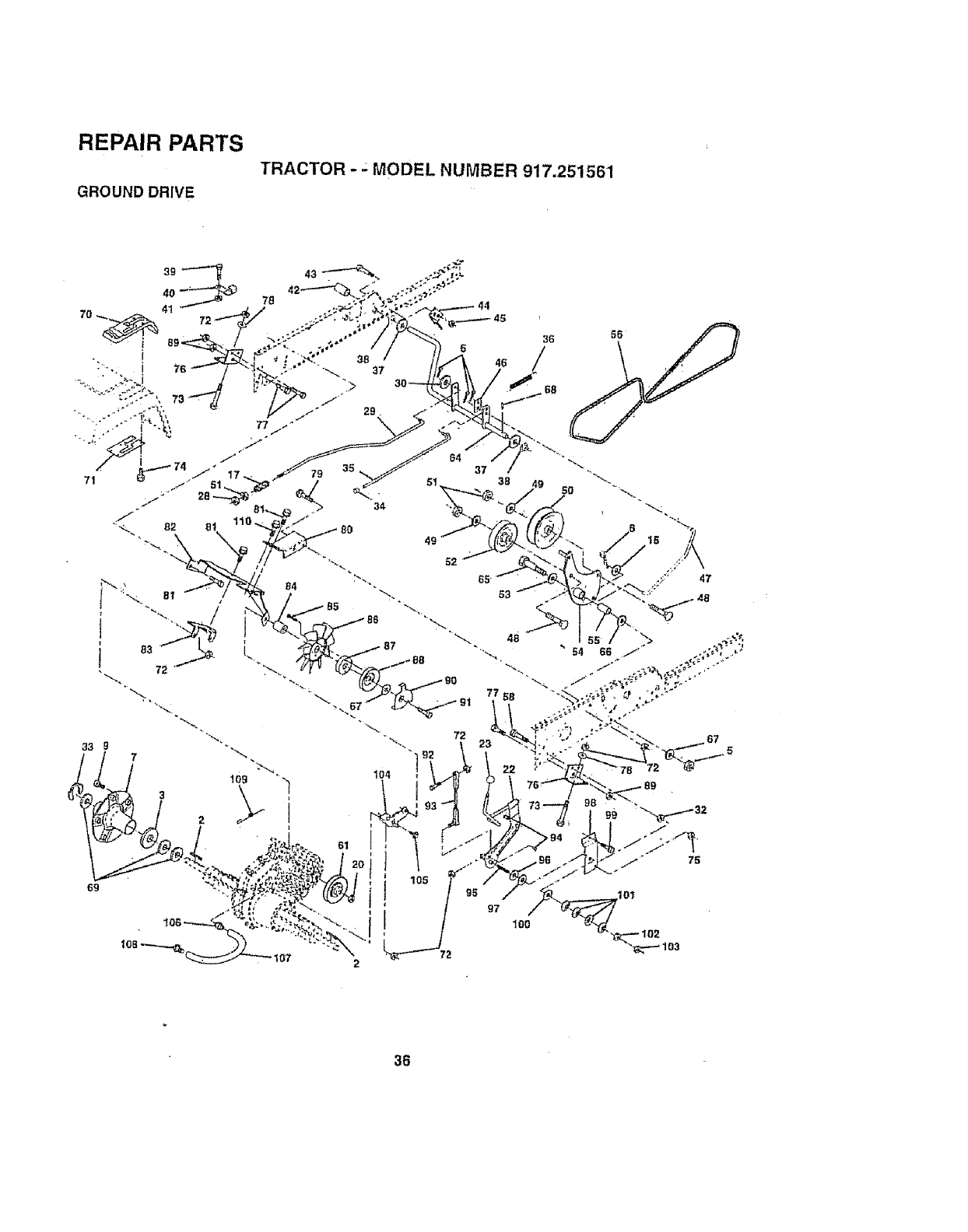
REPAIR PARTS
TRACTOR -.: MODEL NUMBER 917.251561
GROUND DRIVE
69
35
34
8O
48
"54
36
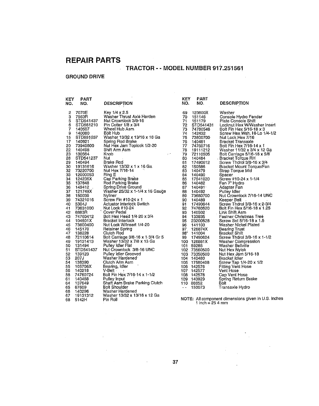
REPAIR PARTS
TRACTOR - - MODEL NUMBER 917.251561
GROUND DRIVE
KEY PART KEY PART
NO_ NO. 0ESCRtPTtON NO, NO, DESCRIF_TION
,r
27070E Key 1/4 x2.5
3 7563R Washer Thrust AxleHarden
5 STD541437 Nut Crownlock 3/8-t6
6 STD561210 Pin Cotter 1/8x 3/4
7 140507 Wheel Hub Asm,
9 140080 BSIt Hub
15 STD55!037 Washer 13/32 x 13/16 × I6 Ga
17 140921 ' Spring Rod Brake
20 73940800 Nut Hex JamToplock 1/2-20
22 140496 ShiftArm Asm
23 130564 Knob
28 STD541237 Nut
29 140494 Brake Rod
30 19131616
32 73220700
33 12000053
34 !24236X
35 137648
36 149412,:
37 121749X
38 150035
39 74321016
40 5304J
41 73631000
42 8863R
43 7476o412
44 104601X
45 73800400
46 145170 '
47 138228
48 72110614
49 19131413
5O 131494
5! STD541437
52 139123
53 207J
54 138390
55 105706X
56 140218
58 74760724
61 140488
64 137649
65 67609
66 140296
67 19131312
68 5t42H
Washer 13/32 x 1 x16 Ga
Nut Hex 7/1644
Ring E
Cap Parking Brake
Rod Parking Brake
Spring Ddve Ground
Washer 25/32 x 1-1/4 x i6 Gauge
NyHner
Screw Fin #10-24 x 1
Actuator Interlock Switch
Nut Lock #10_24
Cover Pedal
Bo}t Hex Head 1/4-20 x 3/4
Bracket Interlock
Nut Lock W/Insert t/4-20
Retainer Spring
Clutch Rod
Bolt Carriage 318-16 x 1-3/4 Gr 5
Washer 13/32 x 7/8 x 13 Ga
Pulley idler Fta{
N{Jt Crownlock 3/8-16 UNC
Pulley _dler Grooved
Washer Hardened'
Clu!chAim Asm
Beadng, Idiot '
V-Belt r,
Bolt Fin Hek7/16-t4 x 1-1/2
Pultey tnpijt '
Shaft Asm Brake Parking Clutch
Bolt Shoulder
Washer Hardened
Washer 13/32 x 13/16 x 12 Ga
Pin Roll
69 123800X Washer
70 151146 Console Hydro Fender
71 151179 Plate Console Shift
72 STD541431 Lecknut He;_ W/Washer Insert
73 74780548 Bolt Fin Hex 5/16d8 x 3
74 142432
75 73800700
78 140461
77 74760716
78 19111212
79 72110505
80 140484
81 17490612
82 150586
83 140479
84 140490
85 1754102O
86 140462
87 140491'
88 140492
89 73680700
90 140489
91 17490644
92 74760520
93 140502
94 133835
95 23200528
96 141103
97 126874X
98 _ 141004
99 17490624
100 126881X
101 59285
102 73560500
103 73350500
104 140480
105 17580408
106 142576
107 142577
!08 142578
109 140929
1!0 88652
*- 150073
Screw Hex Wsh: Hi-Lo 1/4-!/2
NiJt Lock Hex 7/16
Bracket Transaxle
Bolt Fin Hex 7/_6-14 x 1
Washer 11/32 x 3/4 x 12 Ga
Bolt Carriage 5116-18 x5/8
Bracket Torque RH
Screw Thdrol 3/84 6 x 3/4
Bracket Mount T0rqueiFan
Strap Torque Mid
Spacer
Screw #10-24 x1-1/4
Ean 7, Hydro
Adapter Fan
Pulley Idler
Nut Crownlock 7/16-t4 UNC
Keeper Beft .
Screw Thdrol 3/8-16 x 2,.3/4
Bo_t FTn Rex 5116d8 x 1_25
Link Shitt Asm
Fastner Christmas Tree
Screw Set 5/16-18 x 1,,5
Washer Nickel Plated
Bearing Trust
Bracket Shift
Screw Thdro{ 3/8-16 x 1-1/2
Washer Compression
Washer Beltvii{e
Nut Hex Ny[ok
Nut Hex Jam 5/16_18
Bracket Idler
Screw Tap 1/4-20 x 1/2
FittingVent Hose
Vent _4ose
Cap Vent Hose
Spring Return Brake
B01t
Transaxle Hydro
NOTE; Allcomponentdimensions givenln u,&tnches
linch = 25 4 mm
37
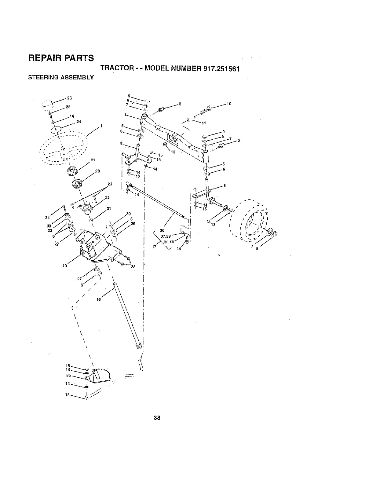
REPAIR PARTS
TRACTOR - - MODEL NUMBER 917.251561
STEERING ASSEMBLY
/
/
/
/
\
\
\
\
\
\
14_
16
]
38
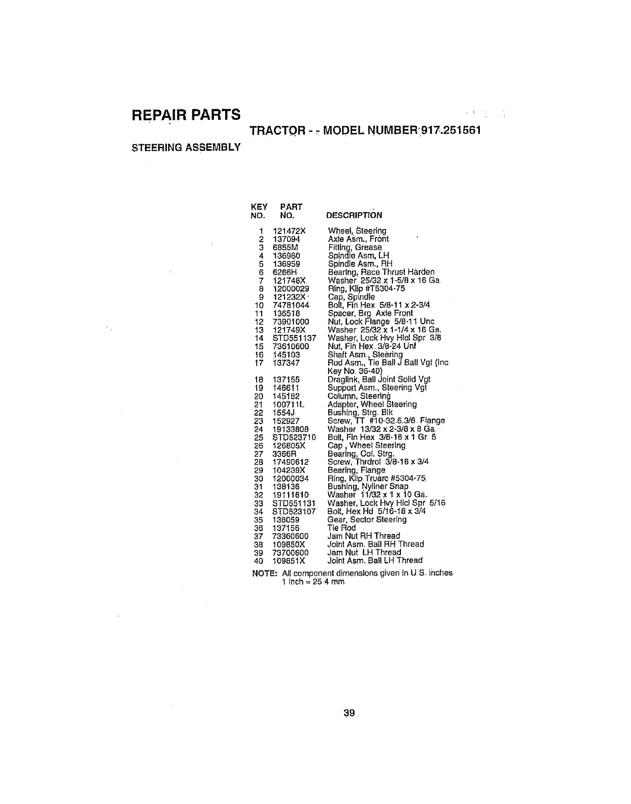
REPAIR PARTS ......
TRACTOR - _MODEL NUMBER917.251561
STEERING ASSEMBLY
KEY PART
NO_ No.,
1 121472X
2 137O94
36855M
4 136960
5136959
6 6266H
7 121748X
8 12000029
9 121232X'
10 74781044
11 136518
12 73901000
13 121749X
14 STD551137
15 73610600
16 145103
17 137347
18 13'7155
19 146611
20 145182
21 100711L
22 1554J
23 152927
24 19133808
25 STD523710
26 126805X
27 3366R
28 17490612
29 t04239X
30 12000034
31 138136
32 19111610
33 STD551131
34 STD523107
35 138059
36 137156
37 73360600
38 109850X
39 73700600
40 109851X
DESCRIPTtCiN
wheel, Steering
Axie Asm., Front
Fitting, Grease
Spindle Asm, LH
Spindle Asm.., RH
Bearing, Race Thrust Harden
Washer 25/32 x 1-5/8 x 16 Ga.
Ring, Kiip #T5304:75
Cap, Spindle
Bolt, Fin Hex 5/8-! t x 2-3/4
Spacer, Brg Axle Fronl
Nut, Lock Flange 518-11 Unc
Washer 25/32 x 1-1/4 x 16 Ga,
Washer, Lock Hvy Htel Spr 318
Nut, Fin Hex 3/8-24 Unf
Shaft Asm., Steering
Rod Asm., Tie Bali J Bait Vgt (lnc
Key No. 36-40)
Dragltnk, BateJoint Solid Vgt
Support Asm., Steering vgt
Column, Steering
Adapter, Wheel Sleeting
Bushing, Strg; Blk
Screw, TT #10-32.6,3/8 Flange
Washer 13/32 x 2_3/8 x 8 Ga
BoIt, Fin Hex 3t8-16 x 1 Gr 5
Cap, Whee_ Steering
Bearing, Col, Strg.
Screw, Thrdrot 3/8-16 x 3/4
Bearing; Ftange
Ring Kitp Truarc #5304-75,
Bushing, Nyllner Snap
Washer 1'1/32 x I x t0 Ga.
Washer, Lock HW Hlcl Spr 5/16
Bott. Hex Hd 5/!6-18 x 3/4
Gear, Sector Steering
Tie Rod
Jam Nut RH Thread
Joint Asm_ Ball RH Thread
Jam Nut LH Thread
Joint Asm. Ball LH Thread
NOTE: Ail component dimensions given in U S. inches
1 Inch = 25 4 mm
39
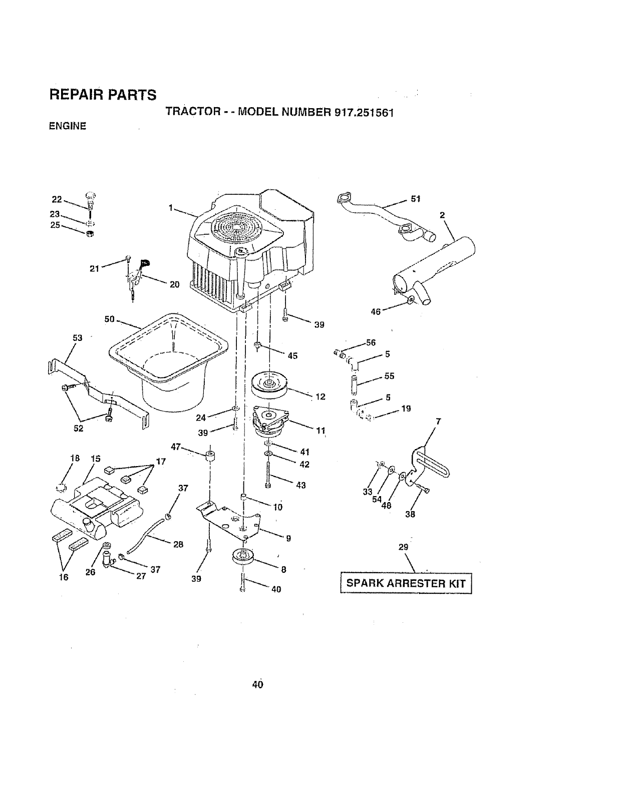
'i
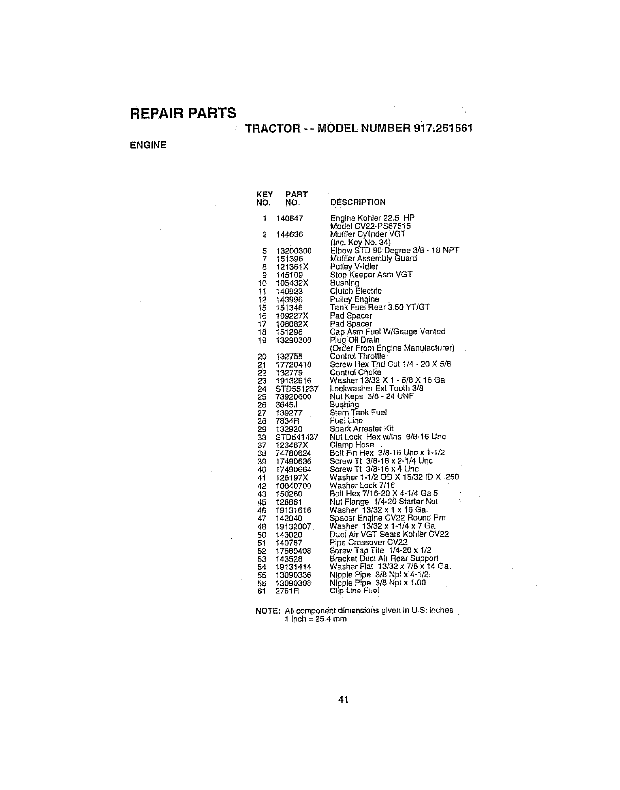
REPAIR PARTS
TRACTOR --MODEL NUMBER 9i7;251561
ENGINE
KEY PART
NO. NOo
140647
144636
5 132oo36o
7 151396
8 121361X
g t45109
10 105432X
11 140923 ,
12 143996
I5 151346
16 109227X
17 !06082X
18 151296
t9 13290300
20 132755
21 17720410
22 132779
23 19132616
24 STD551237
25 73920600
26 3645J
27 139277
28 7634R
29 132920
33 STD541437
37 123487X
38 74760624
39 17490636
40 17490664
41 _26197X
42 10040760
43 154280
45 128861
46 19131616
47 142040
48 i9132007_
50 143020
51 440787
52 47580408
53 143528
54 19131414
55 13690336
56 13090308
61 275iR
DESCRIPTION
Engine KoNer 22.5 HP
Model CV22-PS67515
Muffler Cylinder VGT
(Inc. Key No. 34)
Etbow STD gO Degree 3/8 - 18 NPT
Muffter Assembly Guard
Pulley V-Idler
Stop Keeper Asm VGT
BusNng
Clutch Etectdc
Pulley Engine ,
Tank FueIRear 350 YT/GT
Pad Spacer
Pad Spacer
Cap Asm Fuel W/Gauge Vented
Plug Oil Dratn
(Order From Engine Manufacturer)
Controt Throttle
Screw Hex Thd Cut 1/4 - 20 X 5/e
Conlrol Cho_e
Washer 13/32 X 1 - 5/8 X 16 Ga
Lockwasher Ext Tooth 3/8
Nut Keps 3/8 - 24 UNF
Bushing
stem Tank Fuel
Fuel Une
Spark Arrestor Kit
Nut Lock Hex w/ins 3/8-16 Unc
Clamp Hose .
Bolt Fin Hex 3/8-16 Unc x "i-1/2
Screw Tt 3t8-16 x 2-1/4 Unc
Screw Tt 3t8-'16 x 4 Unc
Washer t-1/20D X 15/32 ID X 250
Washer Lock 7/16
Bolt Hex 7/16-20 X 4-I/4 Ga 5
Nut Flange 114-20 Starter Nut
Washe_' 13/32 x 1 x 16 Ga
Spacer Engine CV22 Round Pm
Washer 13/32 x 1-1/4 x 7 Ga,
Duci Air VGT Sears Kohler CV22
Pipe Crossover CV22 ,
Screw Tap Tile 114-20 x 1/2
Bracket Ducl_ Air Rear Support
Washer Flat 13/32 x 716 x 14 Ga.,
Nipple Pipe 3/8 Npt X4-1/2,
Nipple Pipe 3/8 Npl x 1,00
Clip Line Fuel
NOTE: All component dimensions given tn US: inches
I inch = 25 4 mm
41
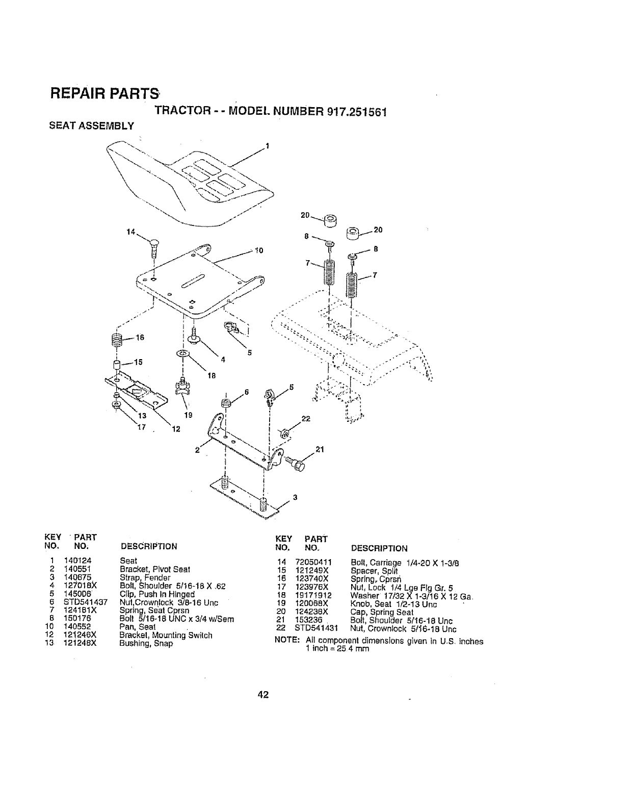
REPAIR PARTS
TRACTOR-- MODEl. NUMBER 917,251561
SEAT ASSEMBLY
KEY "PART
NO, NO;
1 140124
2140551
3t40675
4 127018X
5145006
6 ST0541437
7 t24151X
8 150176
10 140552
12 12!246X
13 121248X
DESCRIPTION
Seat
Bracket, Pivot Seat
Strap, Fender
Boll, Shoulder 5/16-18 X ,62
Clip, Push In Hinged
Nut, Crowntock 3/8-16 Unc
Spring, Seat Cprsn
Bolt 5/16-18 UNO x 3/4 w/Sam
Pan, Seat
Bracket, Mounting Switch
Bushing, Snap
KEY PART
NO NO,r
14 72050411
15 1212_9X
16 123740X
17 123976X
t8 19171912
19 120068X
20 124238X
21 153236,
22 ST0541431
DESCRIPTION
Belt, Carriage 1/4-20 ×1-3/8
Spacer, Split
Spring, Cprsfl
Nut, Lock 1/4 Lge Fig Gr, 5
Washer 17/32 X1-3/t6 X t2 Ga,
Knob, Seat !/2-13 Unc
Cap, Spring Seat
Be|t, Shoulder 5/16-18 Unc
Nut, Crewn|ock 5/'_6-18 Unc
NOTE: All component dimensions given in U,S inches
1inch = 254 mm
42
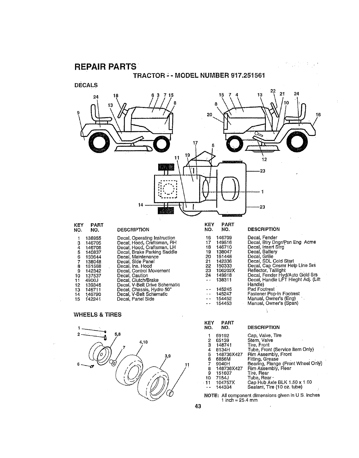
REPAIR PARTS
TRACTOR .: - MODEL NUMBER 017.251561
DECALS
24 18 6 3 7 15 15 7 4 13
8 8
20
21 24
11 12
KEY PART
NO, NO.
1 138955
3 146705
4 146706
5140837
6 133644
7 138048
8151568
9 142342
10 137537
11 4900J
12 139346
13 146711
14 146790
15 142241
DESCRIPTION
Decal, Operating Irlstructton
Decal, Hood_ Craftsman, RH
Decal, Hood, Craftsman, LH
Decal, Brake Parking Saddle
Decal, Maintenance
Decal, Stde Panel
Decal_ Ins, Hood
Decal_ Control Movement
Decal, Caution
Decal, Clutch/Brake
Decal, V*Beit Drive Schematic
Decal, Chassts, Hydro 50"
Decal, V-Belt Scliematte
Decaf, Panel Side
43
KEY PART
NO, NO.
16 146709
17 149516
18 146710
19 138047
20 151448
2t 142336
22 150333
23 105202X
24 149918
-- 138311
w_
145245
145247
154452
154453
DESCRIPTION
Decal, Fender
Deca!, Biry Dngr/Psn Eng Acme
Decal_ Irisert Strg
Decal, Batlery
Decal, Gri!le
Decal, SDL Cold Stad
Decal, Cap Cnsmr Help Line Srs
Reflector, TattIIght '.
Decat, Fender HydlAuto Gold Srs
Decal, Handle LFT Hleght Adj. (Lift
Handle)
Pad Footrest
Fastener Popoln Footrest
Manual, Owner's (Eng)
Manual, Owner's (Span)
KEY PART
NO. NO.
1 59192
2 65139
3 148741
4 8134H
5148736X427
6 6856M
7 9040H
8 148738X427
9151607
10 7154J
11 104757X
-- 144334
DESCRIPTtQN
Cap, Valve, Tire
Stem, Valve
Tire, Froflt
Tube, Front (Service Item Only)
Rim Assembly, Front
Fitting, Grease
Bearing, Flange (Front Wheei Only)
Rim Assembly, Rear
Tire, Rear
Tube, Rear-.
Cap Hub Axle BLK 1.50 x 1O0
Sealant; Tire (10 oz. tube)
NOTE: All component dimensions given tn U S, inches
1 inch = 25,4 mm
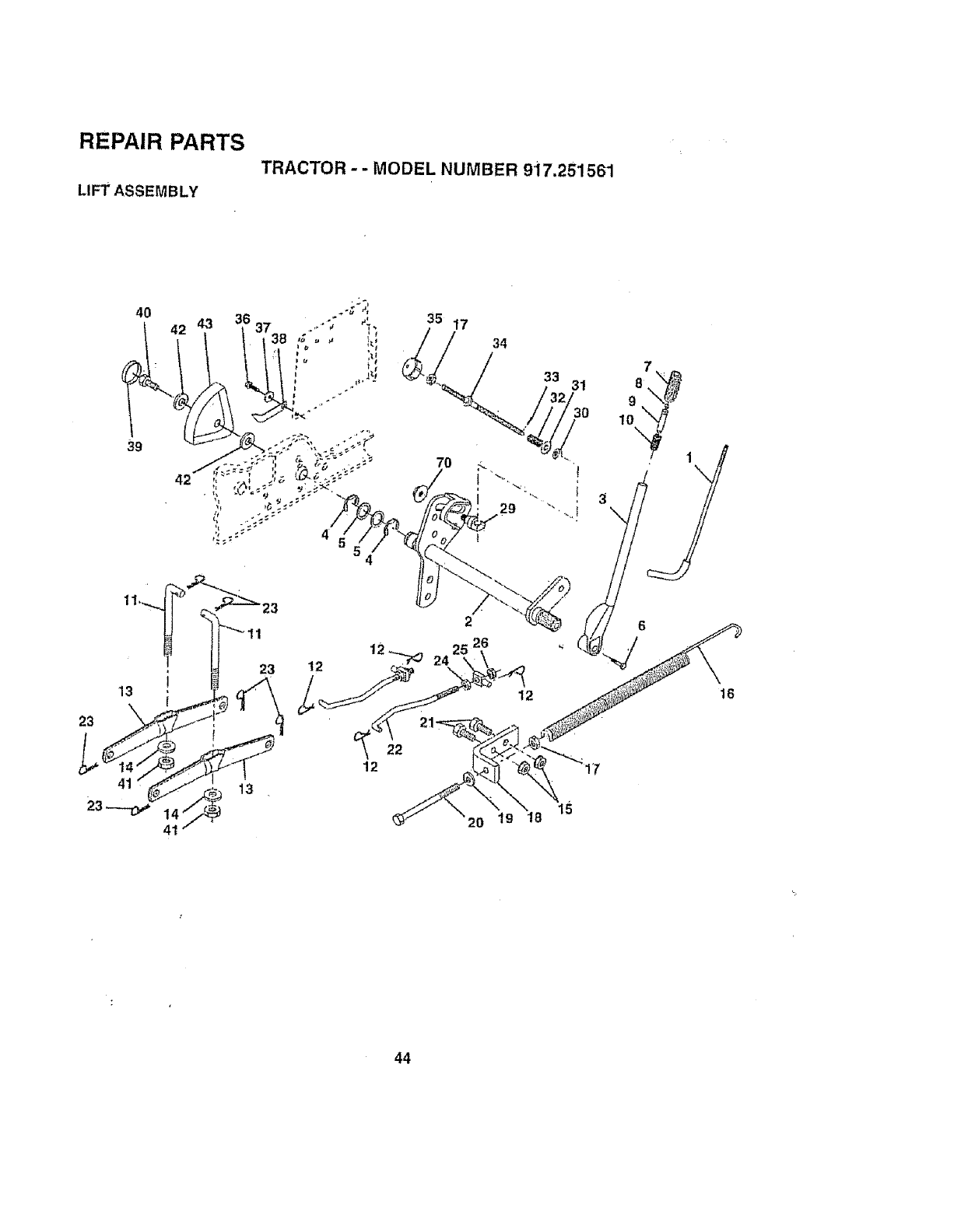
REPAIR PARTS
TRACTOR -- MODEL NUMBER 9i7.251561
LIFT ASSEMBLY
23
13
41
11
23 12
22
12
13
41
35 17
7O
34
2
,26
20 19 18
33 31 8
g
10
12 16
15
44

REPAIR PARTS
TRACTOR - - MODEL NUMBER 917.251561
LIFT ASSEMBLY
KEY PART
NO. NO.
1 12!006X
2 145542
3 t21002X
4 1200O022
5 19292016
674780624
7 125631X
B 122365X
9 t22364X
10 2876H
11 146704
12 3146R
13 139868
14 140302.
15 STD541437
t6 674A247
17 STD541237
18 143363
19 STD551037
20 5328J
2t STD523710
22 127215
23 4939M
24 73350800
25 13O171
26 73800600
29 150233
30 !t0807X
31 19131016
82 137150
33 76020308
34 137167
35 138057
36 17490612
37 120529X
38 t23933X505
39 I23935X "
40 17490512
41 73540600
42 19112410
43 123934×
70 154212
DESCRIPTION
Rod Asm., Lover
Shaft Asm., Lilt Vgt
Lover Asm., Lilt Rh . .
E.Ring Truam #5t33-87
Washer 29/32 x 1-1/4 × 16 Ga.
Bolt, Fin Hex 3/8-16 X1-1/2
Grip, Handle Ruted
Button, Plunger
Plunger, Leyer Lift
Spring 2-1/8"
Ltnk Lift
Retainer, Spring
Arm, Suspension Vgt -
Bearing, Pvt. Lift Spherical
Nut, Crowntock 3/8-16 Uric
Spring Asm, Assist Lifl
Nut, HeX Jam 3/8-16 Unc
Btacket, Spring Assist
Washer 13/32 x 13/t6 x 16 Ga
Bo{t, Ad ust Spring Assist
Bo t, F n Hex 3/8-16 X 1
Link, Front ,
Retainer; Spring
Nut, Jam Hek 1/2-13 Unc
Trunnion
Nut, Lock W/Weh 1/2_13 Unc
Truhnien, tnfin. Height
Nut, Special
Washer 13/32 x 5/8 x 16 Ga
Spdng, Compression tnf Hgt
PIn_ Cotter 3/32 x t/2
Rod, Adj Lift
Knob; lnf 3/8-16 Une
Screw, Thdrol 3/8-16 x 3f4
Washer, Nylon
Pointer, Pnt Height Indicator
Plug, Hole
Screw Thdrot 5116_18 x 3f4
Nut, Crewnlock 3/8-24
Washer t t/32 x 1-1/2 X 10 Ga_
Scale, Indicator Height
Nut, Hex, Flange, Lock
NOTE: AII component dimensions given in U Sinches
.1inch = 25 4 mm
45
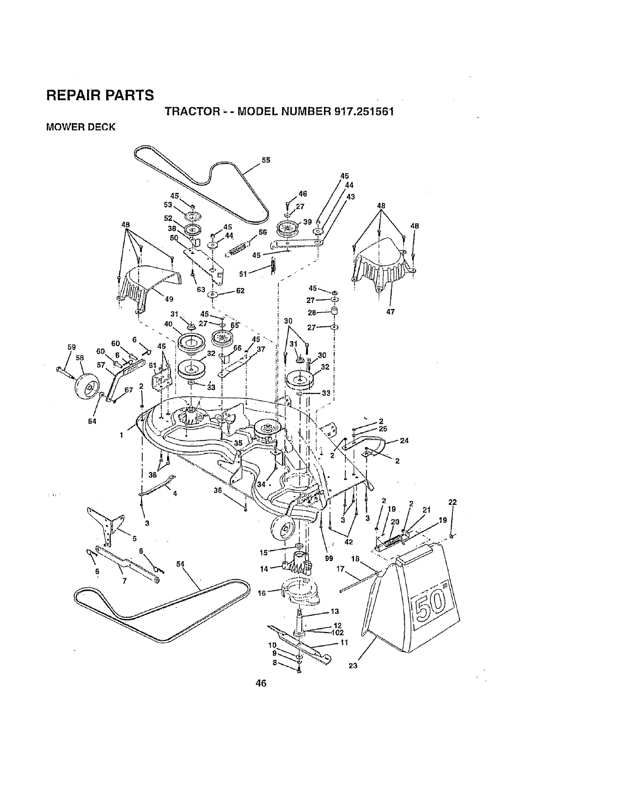
REPAIR PARTS
TRACTOR ..- MODEL NUMBER 917.251561
MOWER DECK
55
45
48
59 6O
S8
64
1
i
46
99
4B
47
22
21
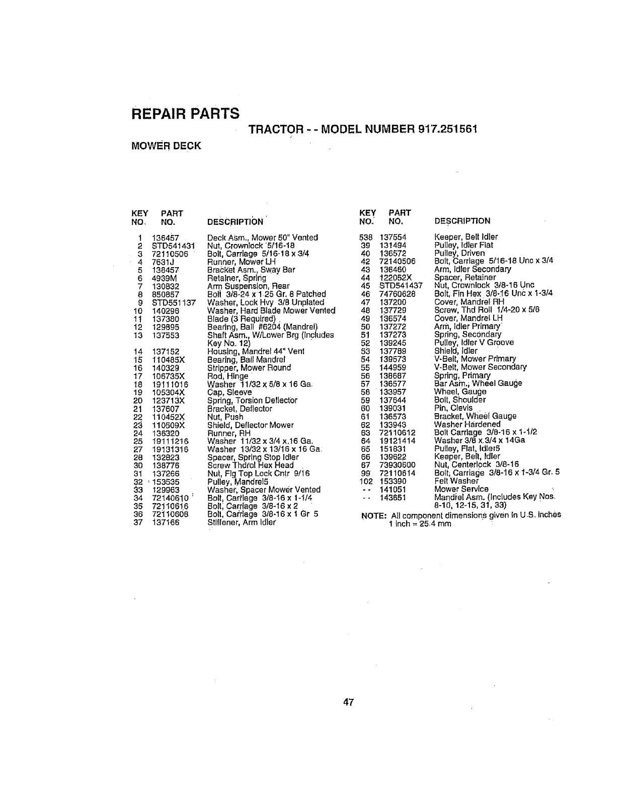
REPAIR PARTS
MOWER DECK
TRACTOR - - MODEL NUMBER 917.251561
J
KEY PART
NO, NO. DESCRIPTIbN "
1 136457
2 STD541431
3 72110506
4 7531J
5138457
6 4939M
7 130832
B 850857
98TD551137
10 140296
1t 137380
12 t29895
!3 137553
14 137152
15 110485X
16 140329
17 106735X
18 19111016
19 105304X
20 123713X
21 137607
22 110452X
23 t10509X
24 136320
25 19111216
27 19131316
28 132823
30 138776
3t 137266
32 ,153535
33 129963
34 72140610 _
35 72110616
36 72_t0608
37 137166
Deck Asm. Mower 50" Vented
Nut, CrownIock 5t16-18
Bolt, Carriage 5/16q8 ×3/4
Runner, Mower LH
Bracket Asm., Sway Bar
Retainer, Sprtrig
Arm Suspension, Rear
Boli 3/8-24 ×1 25 Gr. 6 Patched
Washer, Lock Hvy 3/8 Unplated
Washer, Hard Blade Mower Vented
Blade (3 Required),
Beartng, Ball #6264 (Mandrel)
Shaft Asm., WtLewer Brg (Includes
Key No,, 12) . "
Houstng, Mandrel 44 Vent
Bearfng, Ba,_lManUreS
Stripper, Mower Round
Red, Hinge
Washer !1/32 x 5t8 x 16 Ga,
Cap, Sleeve
Spring, Tors[on Dellect0r
Bracket, Deflector
Nut, Push
Shield, Deflector Mower
Runner, RH
Washer "_1/32 x 3/4 ×.t6 Ca.
Washer 13/32 x 13/I8 x 16 Ga:
Spacer, Spr!ngStop Idler
Screw Thdto{ Hex Head
Nut, Fig Top Lock Cnt.r 9/16
Pulley, Mandrel5
Washer, Spacer Mower Vented
Be{t, Carriage 3/8-16 xt-I14
Bolt; Cardage 3/8-16 x 2
Bolt, Cai;rlage 3/8-16 x t Gr 5
Stiffener, Arm idler
KEY PART
NO_ NO. DESCRIPTION
538 137554 Keeper, Belt Idler
39 131494 Pulley, idler Flat
40 136572 Pulley Driven
42 72140506 Bolt, Can'/age 5/16-18 Un¢ × 3/4
43 136460 Arm, Idler Secondary
44 122052X Spacer, Retainer
45 STD541437 Nut, Crewnlock 3t8-16 Unc
46 74760628 £1olt, Ffn He× 3/8,I6 Unc x 1.3/4
47 137200
48 197729
49 136574
50 137272
51 137273
52 139245
53 137789
54 139573
55 144959
56 138687
57 136577
58 133957
59 137644
60 139031
61 136573
62 f33943
63 72110612
64 19121414
65 151831
66 139622
67 73930600
99 72110614
I02 153390
-- 141051
-- 143651
Cover, Mandrel RH
S,crew, Thd Roll 1/4-20 x 518
Cover, Mandrel LH
Arm, Idler Pflmary _
Spring, Secondary
Pulley, Idler V Groove
Shield, idler '
V-Belt, Mower Pdman/
V-Belt, Mower Secondary
Spring, Primary
Bar Asm.; Wheel Gauge
Wheel, Gauge
Bolt, Shoulder
Pin, CIevls .
Bracket. Wheef Gauge
Washer Hardened
8ell Cart]age 3/8-16 x 1;4/2
Washer 3/8 x3/4 x14Ga
Pulley, Flat, tdler5
Keeper, Bail, tdler
Nul, Centeriock 3/8-16
Bolt, Carriage 318-16 x 1-3/4 Gr. 5
Felt Washer
Mower Service
Mandiet Asm. (Includes Key Nos.
8-10, 12-15, 31, 33)
NOTE: A_icomponent dimensior;.s given In U & inches
1inch =254 mm
47
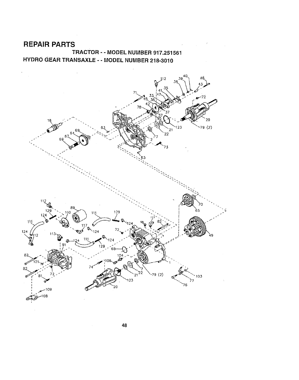
REPAIR PARTS
TRACTOR -- MODEL NUMBER 917.251561
HYDRO GEAR TRANSAXLE -- MODEL NUMBER 218-3010
71
(2)
48
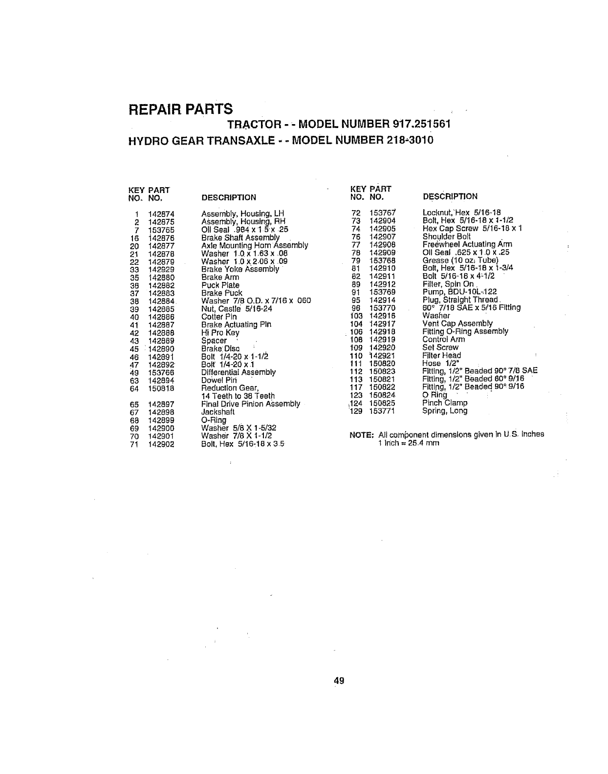
REPAIR PARTS
TRACTOR - _-MODEL NUMBER 917.251561
HYDRO GEAR TRANSAXLE - - MODEL NUMBER 218-_3010
KEY PART KEY PART
NOr NO. DESCRIPTION NO. NO. DEsCRiPTION
1 142874 Assembly, Housing, LH 72 153767'
2 142875 ASsembly, Housing, RH 73 142904
7 153765 O]lSeat .984xt 5× 25 74 142905
16 i42876 Brake.Shaft Assembly . 76 142907
20 142877 Axle MountlngHam Assembty 77 142908
21 142878 Washer 1.0 x1.63 x.08 78 142909
22 142879 Washer 1Ox2.06x 09 79 153768
33 142929 Brake Yoke Assembly 61 142910
35 142880 Brake Arm 82 142911
38 142882 Puck Plate 89 142912
37 142883 Brake Puck 91 153769
38 142884 Washer 7/80,D. xT/t6x 060 95 142914
39 142885 Nut, Csslle 5/16-24 96 153770
40 142886 Cotter Pin 103 142916
41 142887 Brake Actuating Pin 104 142917
42 142868 Hi ProKey 106 142918
43 142889 Spacer 108 142919
45 1142890 Brake:DIs_ ; 109 142920
46 142891 Boll 114-20x1-1/2 110 142921
47 142892 _ Bolt' 1/4-20x.i tll 150820
49 153766 DifferentialAesembfy 112 150823
63 142894 DoWel Pin 113 150821
64 150818 Reduction Gear, 117 150822
14 Teeth to 38 Teeth 123 150824
65 142897 Final Ddve Pinion Assembly ,124 150825
67 142898 Jackshaft '129 153771
63 142899 O-Ring
69 142900 Waslier 5/8 X 1-5/32
70 142901 Washer 7/8 X 1-112
71 142902 Boll, Hex 5/16.:18 x 3.5
Locknut, Hex 5116-18
Bolt, Hex 5/16-18 x 1-t/2
Hex Cap Screw 5/16-18 x 1
Shoulder Bolt
Free:wheel Actuating Arm
011Seal ,625 x 1 0 x .25
Grease (10 oz_ Tube)
Bolt, Hex 5/16-18 x!-3/4
Bolt 5t16-18 x 4_t/2 "
Filter, Spin On.
Pump, BDU- 1OL_122
Plug, Straight Thread.
60 '_ 7/18 SAE x 5/16 Fitting
Washer
Vent Cap Assembly
Fitting O-Ring Assembly
Control Arm
Set Screw
Filter Head
Hose 1/2"
Fitting, 1t2" Beaded 90 ° 7t8 SAB
Fitting, 1/2" Beaded 80 '=9/16
Fittlpgl t/2" Beaded 90 '=9/16
O Ring " "
Pinch Clamp
Spring_ Long
NOTE: AII com{:)onent dimensions given In u.S. Inches
t Inch = 25.4 mm
49
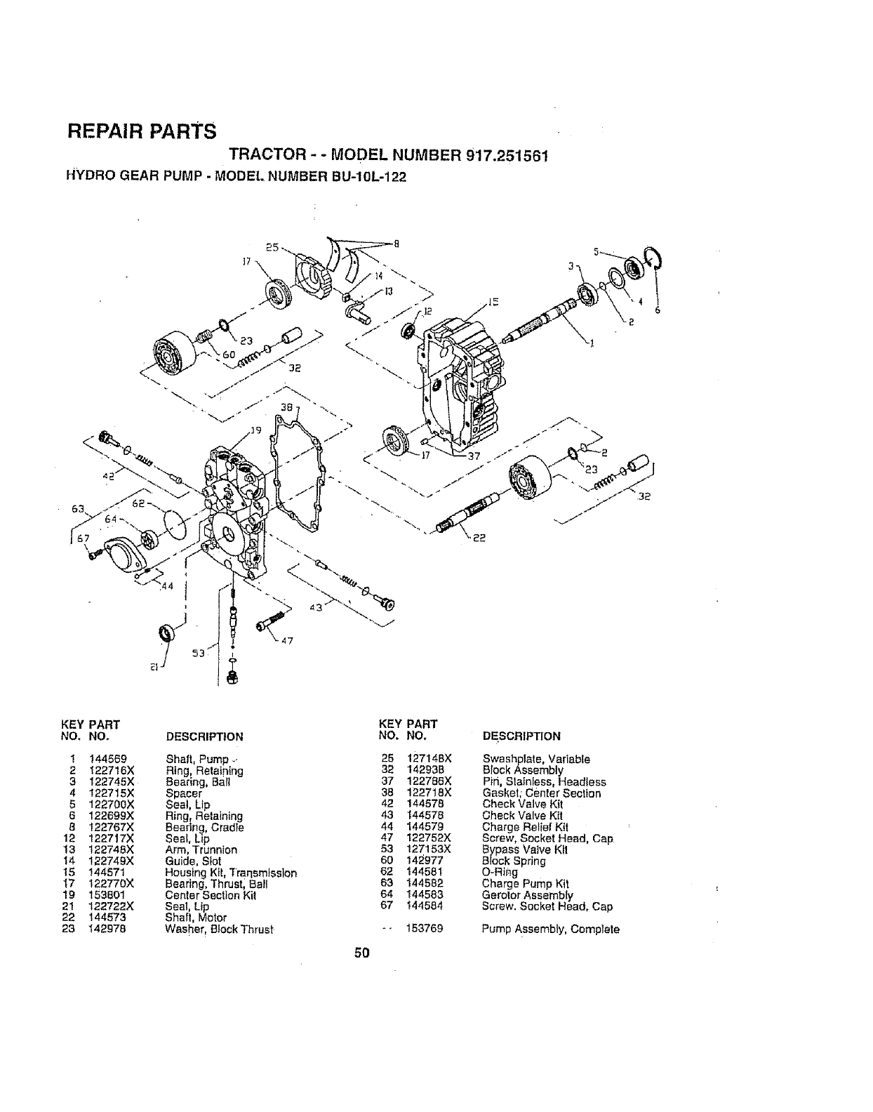
REPAIR PARTS
TRACTOR -- MODEL NUMBER 917.251561
HYDRO GEAR PUMP - MODEL NUMBER BU-10L-122
T
KEY PART KEY PART
NO_ NOo DESCRIPTION NO. NO, DESCRIPTION
1 144569 Shaft, Pump _ 25 127t4BX
2 1227!6X Ring, Relatntng 32 14293B
3 122745X Searing, Ba_l 37 122786X
4 122715X Spacer 38 122718X
5 122700X Seal, Lip 42 144578
6 122699X Ring, Retaining 43 144578
8 122767X Bearing, Cradle 44 144579
12 122717X Seal, Lip 47 122752X
13 122748X Arm, Trunnion 53 127153X
14 122749X Guide, Slot 60 142977
15 144571 Housing Kit, Traqsmtsslon 62 144581
17 122770X Bearing, Thrustl Ball 63 144582
19 153801 Center Section Kit 64 144583
21 122722X Seat, Up 67 _44584
22 144573 Shaft, Motor
23 142978 Washer ! BtockThrust -- 153769
5O
Swashplate, Variable
Block Assembly
Pid, Stainless, Headless
Gasket; Center Section
Check Valve Kit
Check Valve Ktt
Charge Relief Kit
Screw, Socket Head, Cap
Bypass Valve Ktl
Brock Spring
O-Ring
Charge Pump Kit
Gerolor Assembly
Screw. Socket Head, Cap
Pump Assembly, Complete
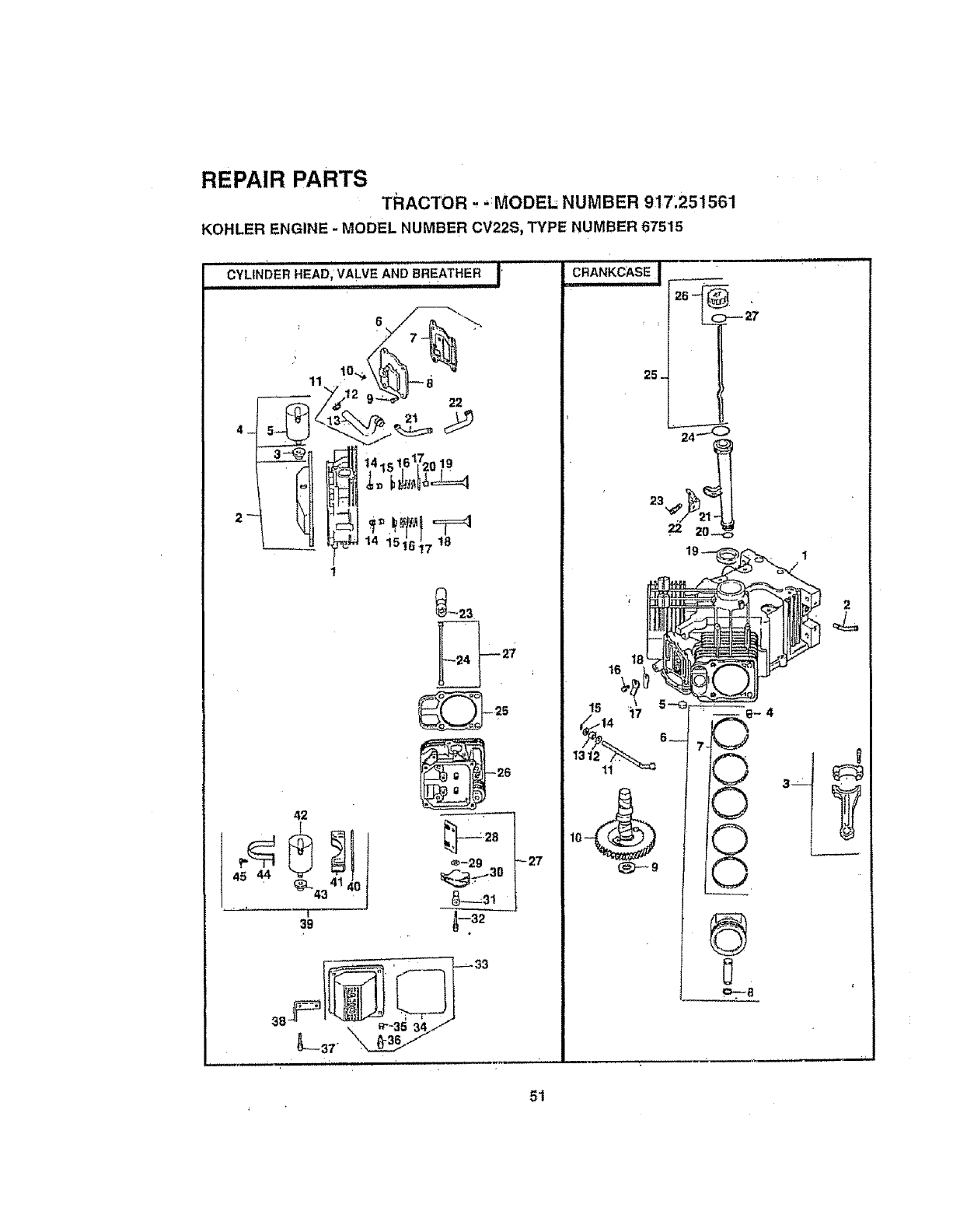
REPAIR PARTS
TRACTOR --MODEL NUMBER 917.251561
KOHLER ENGINE -MODEL NUMBER CV22S, TYPE NUMBER 67515
CYLINDER HEAP' VALVE AND BREATHER I
-Ur_ 14 15t6_7 18
42
s
39
_23
25
27
_32
25-
16
23 ,_
22 2o-<:,
_J
O
0
0
LO_
1
51
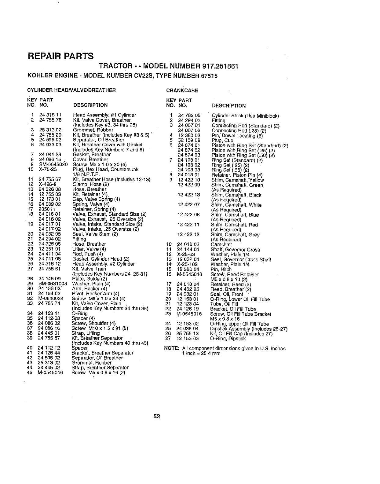
REPAIR PARTS
TRACTOR,- -MODEL NUMBER 917.251561
KOHLER ENGINE - MODEL NUMBER CV22S, TYPE NUMBER 67515
CYLINDER HEAD/VALVE)BREATHER
I{EY PART
NO_ NO. DESCRIPTION
124318 11
2 24 755 76
325313 02
424 755 20
5 24 595 02
8 24 033 03
724 04t 23
824098 15
9 SM-064502_0
10 X-75-23
11 24 755 87
12 X_426-9
13 24 326 08
14 12 755 03
15 1217301
I6 24 089 02
I7 235011
18 2401601
24 016 02
19 24 017 01
24 017 02
20 24 032 05
21 24 294 02
22 24 326 05
23 12 351 01
24 24 411 04
25 24 D41 08
26 24 318 12
27 24 755 61
28
29
30
31
32
33
34
35
38
37
38
39
4O
41
42
43
44
45
24 146 09
SM-0631005
24 !86 03"
24 194 02
M-0640034
24 755 74
24 t53 11
24 112,08
24 086 32
24 086 16
24 445 01
24 755 57
24 112 12
24 126 44
24 595 02
25 313 02
24 445 02
M*0545016
CRANKCASE
KEY PART
NO. NO, DESCRIP_ON
Head Assembly, #t Cylinder i24 782 05
Kit, Valve Cover, Breather 2 24 294 03
(tnctudes Key #3, 34 thru 36) 3 24 067 01
Grommet, Rubber 24 067 02
Kit, Breather (Includes Key #3 & 5) *4 12 380 03
Separator, O#Breather 5 52 139 09
Kil, Brealher Cover wiih Gasket 6 24 874 01
(includes KeyNumbers 7 and 8) 24 874 02
Gasket, Breather 24 874 03
Cover,'Brealher 7 24 108 01
Screw M6 x 1 O x 20 (4) 24 108 02
Plug, Hex Head, Countersunk 24 t08 03
1/8 N,P,T,F. B 24 018 01
Ktl, Breather Hose (includes 12-13) 912 422 10
C}amp, Hose (2) 12 422 09
Hose, Breather
Kit, Retalner (4}. 12 422 13
cap, Valve Spnng (4)
Spring, Va!ve (4) 12 422 07
Retainer, Spring (4)
Valve, Exhaust, Standard Size (2) 12 422 08
Valve, Exhaust, 25 Oversize (2)
Valve, Intake; Standard Size (2) 12 422 11
Valve, intake, .25 Oversize (2)
Seal, Valve Stern (2) 12 422 t2
Fitting
Hose, Breather 10
Litter, Valve (4) 11
Rod, Pus_ (4) 12
Gasket, Cylinder Head (2) 13
Head Assembly, #2 Cylinder t4
Kit, Valve Train !5
(Includes Key Numbers 24, 28-31) t6
Plate Guide (2)
Washer, Plain (4) t7
Arm, Rockei" (4) 18
Pivot, Rocker Arm _4) 19
Sct'ew M6x 1,0 x 34 (4) 20
Kit, Valve Cover, Ptain 21
(Includes Key Numbers ;_4 thru 26) 22
O-Ring 23
Spacer (4)
Screw, Shoulder (4) 24 12 153 02
Screw M10x15x91(8) 25 24 038 04
Strap, Lifting 26 25 755 13
Kit, Breather Separator 27 12 153 03
(includes Key Numbers 40 thru 45)
Spacer
Bracket, Brealher Separator
Separator, Otl Brealher
Grommet, Rubber
Strap, Breather Separator
Screw M5 x 0.8 x 16 (2)
24 010 03
24 144 0t
X-28-63
12 032 01
X-25-102
12 380 04
M-0545010
;_4018 04
24 402 O5
24 032 01
12 153 01
12 I23 04
24 I26 I9
M-0545016
Cylinder Block (Use Miniblock)
Fitting
Connecting Rod (SIandard (2)
Connecting Rod (,25) (2)
Pin, Dowel Locating (6)
lug, Cup
islon with Ring Set (Standard) (2)
Pislon wilh.Rtng Set (25) {2)
Pislon wilh Ring Set (,50) (2)
Ring Set (Standard) (2)
Ring Sol (25) (2)
Ring Set (.50) (2)
Retainer, Piston Pin (4)
Shim, Camshaft, Yellow
Shim, Camshaft, Green
(As Required)
Shim,' Camshaft, Black
(As Requtrecl)-
Shim, Camshaft, White
(As Required)
Shim, Camshafl, Blue
(As Required)
Shim, Camshaft, Red
(As Required)
Shtm, Camshaft, Grey
(As Required)
Camshaft
Shatt', Governor Cress
Washer, Plain 1/4
Seal, Governor Cross Sha|t
Washer, Plain 1/4
Pin, Hitch
Screw, Reed Retainer
M5 x 0,8 x 1O (2)
Retainer, Reed (2)
Reed, Breather (2)
Seal, Oil, Front
O-Ring, Lower Oil Fill Tube
Tube, Oil Fill
Bracket, Qil Fill Tube
Screw, Oil Fill Tube Bracket
M5x0.Sx 16
O-Ring, upper Oil Fili Tube
Dipstick Assembly (includes 26-27)
Kit, Otl Flit cap (Includes 27)
O-Ring, Dipsbck
NOTE: All component dimensions given in U,S, Inches
1 inch = 25,4 mm
52
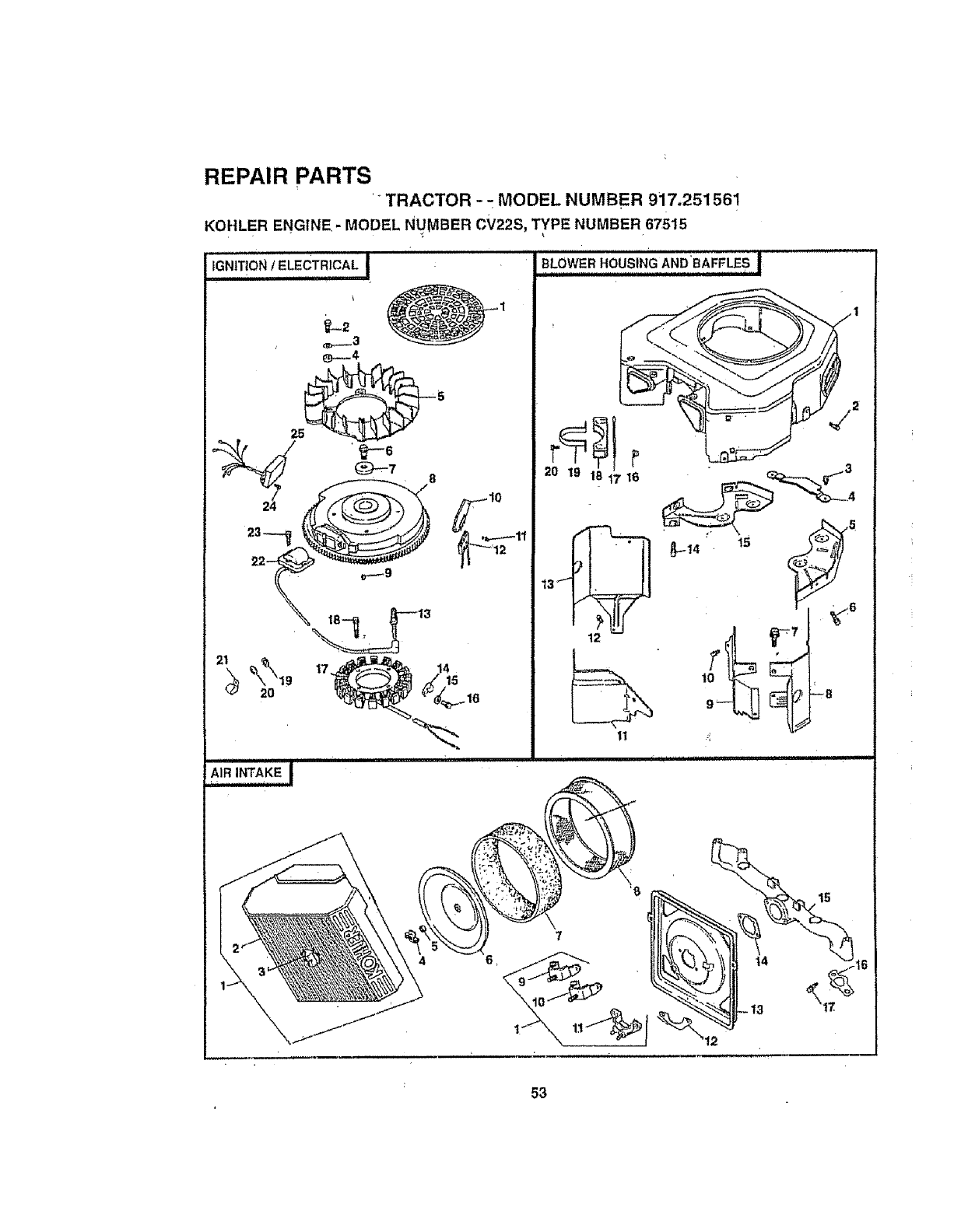
REPAIR PARTS
TRACTOR - -- MODEL NUMBER 917.251561
KOHLER ENGINE- MODEL NUMBER cV22S, TYPE NUMBER 67515
iGNITION IELECTRICAL •
............;.... '_
10
BLOWER HOUSING AND'BAFFLES I
AIRINTAKEI
4
,i Hill =11=1111
16
53
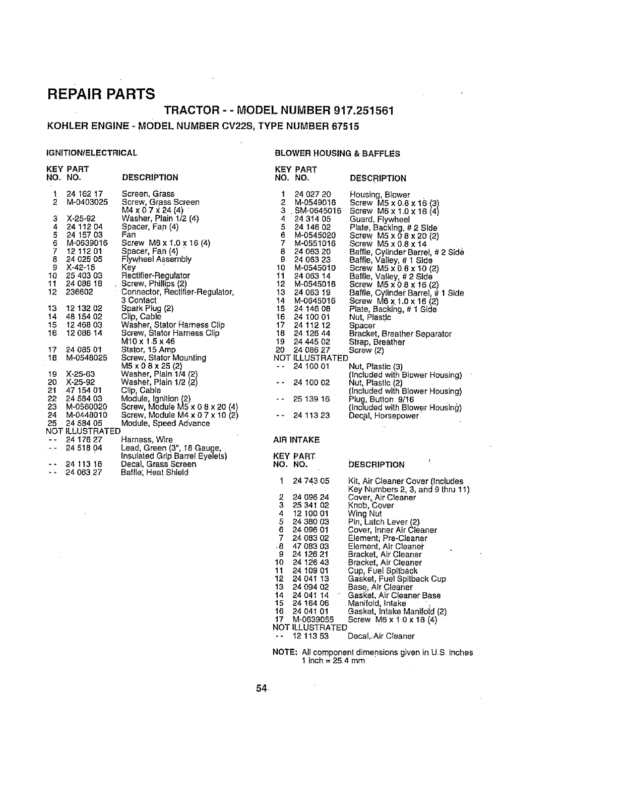
REPAIR PARTS
TRACTOR - - MODEL NUMB ER 917,251561
KOHLER ENGINE ,_MODEL NUMBER CV22S, TYPE NUMBER 67515
IGNITION/ELECTRICAL BLOWER HOUSING &BAFFLES
KEY PART KEY PART
Nee NO. DESCRIPTION NO. NOr DESCRIPTION
1 24 162 17 Screen, Gi'ass 1 24 027 20
2 M-0403025 Screw, Giass Screen 2 M-0549016
M4 x 0.7 X 24 (4) " 3.SM-0645016
3X-25-g2 Washer, Plain 1/2 (4) 4 24 3!4 05
4 24:112 04 Spacer, Fan (4) 5 24 146 02
5 24 157 03 Fan 6 M-0545020
6 M_0639016 Screw M6 x 1.0 x 16 (;4) 7 M-0551016
712 112 01 Spacer, Fan (4) " 8 24 063 20
8 24 025 0.5 Flywheel Assembly 9 24 063 23
9 X-42_15 Key '10 M_05450"10
10 25 403 03 Rectifier-Regulator 11 24 063 14
11 24 086 18 , Screw, Phillips (2) 12 M-0545016
12 236602 Connector, Rectifier-Regulator, 13 24 063 19
3 Contact 14 M-0645016
13 12 132 02 Spark Plug (2) 15 24 146 08
14 48 154 02 Clip, Cable 16 24 100 01
15 t2 46B 03 Washer, Staler Harness Ctip 17 24 112 12
16 12 086 14 Screw, Staler Harness CIip 18 24 126 44
M10x 15x46 19 2444502
17 24 085 01 Staior, "15Amp 20 24 086 27
18 M-0548025 Screw, Slator Mounting
M5 x 0 8 x25 (2)
19 X-25-63 Washer, Plain 1/4 (2)
20 X-25_92 Washer, Plain 1/2 (2)
21 47 t54 01 Ctip, Cable
22 24 584 03 Module, lgnIlion (2)
23 M-0560020 Screw, Module M5 x 0 8 x 20 (4)
24 M-0448010 Screw, Module M4 x 0 7 x 10 (2)
25 24 584 05 Module, Speed Advance
NOT ILLUSTRATED
- - 24 176 27 Harness, Wire
- - 24 518 04 Lead, Green (3", 18 Gauge,
' Insulated Grip Barrel Eyetets)
--24 t13 18 Decal, Grass Screen
* _ 24 063 27 Baffle; Heat Shield
Housing, Blower
Screw M5 x 0.8 x 16 (3)
Screw M6 ×1.0 x 16 (4)
Guard, Flywheel
PIate; Backing, # 2 Side
Screw M5 x 0 8 x 20 (2)
Screw M5 x 0.8 x t4
Baffle, Cylinder Barre_, # 2 Side
Baffle, Valley, # 1 Side
Screw M5 x 08 x t0 (2)
Bafffe, Valley, # 2 Side
Screw M5 x 0-8 x 16 (2)
Raffle, Cyllndel; Barrel, # 1Side
Screw M6 x 1.0 x 16 (2)
Piate, Backing, # 1 Side
Nut, Plastic
Spacer
Bracket, Breather Separator
Strap, Breather
Screw (2)
NOT ILLUSTRATED
- - 24 100 01 Nut, Plastic (3)
(Included with Blower Housing)
- - 24 t00 02 Nut, Plastic (2)
(included with Blower Housing)
-- 25 139 16 Plug, Button 9/16
(included with Blower Heusin_I)
*- 24 113 23 Decal, Horsepower"
AIR INTAKE
KEY PART:
NO, NO. 'DESCRIPTION
1 24 74.3 05 Kit, Air Cleaner Cover (Includes
Key Numbers 2, 3, and g thru 1 t)
2 24 096 24 Cover, Air Cleaner
3 25 341 02 Knob, iSover
4"I2 100 01 Wing Nut
5 24 380 03 Pin, Latch Lever(2)
6 24 096 01 Cover, Inner Air Cleaner
724 083 02 Element; Pre-C]eaner
,8 47 083 03 Element, Air C]eanei"
9 24 126 21 Bracket, Air Cleaner
10 24 I:_6 43 Bracket, Air Cleaner
11 24 109 0t Cup, Fuel Spltback
12 24 041 13 Gasket, Fuel Spttback Cup
13 24 094 02 Base_ Air Cleaner
14 24 04I 14 "GasHer, Ai_"Cleaner Base
15 24 164 06 Manifold, intake
16 24 04t 01 Gasket, intake Manifoid (2)
17 M-0639055 Screw M6 x 1 0 x 18 (4)
NOT ILLUSTRATED
-- 12 113 53 DecaL_Air Cleaner
NOTE; AIt component dimepsions given in U-S. Inches
1 inch = 25.4 mm
54,
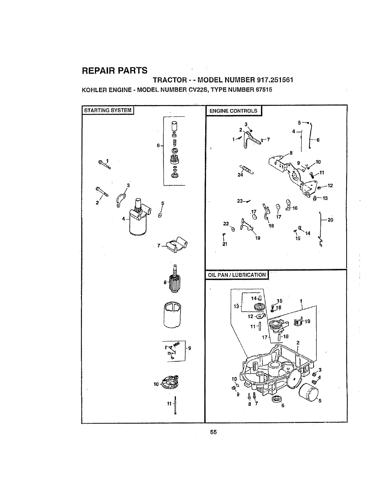
REPAIR PARTS
TRACTOR - - MODEL NUMBER 917.251561
KOHLER ENGINE - MODEL NUMBER CV22S, TYPE NUMBER 67515
6_@
o
o
5
/
O
ENGINE CONTROLS i
3 5+'--+,++
=_ ,-s /
c_2. o__,o
22 18
"_ _ e-,14
1 19 15 "
OIL PAN/LUlamcATioN I'+
55
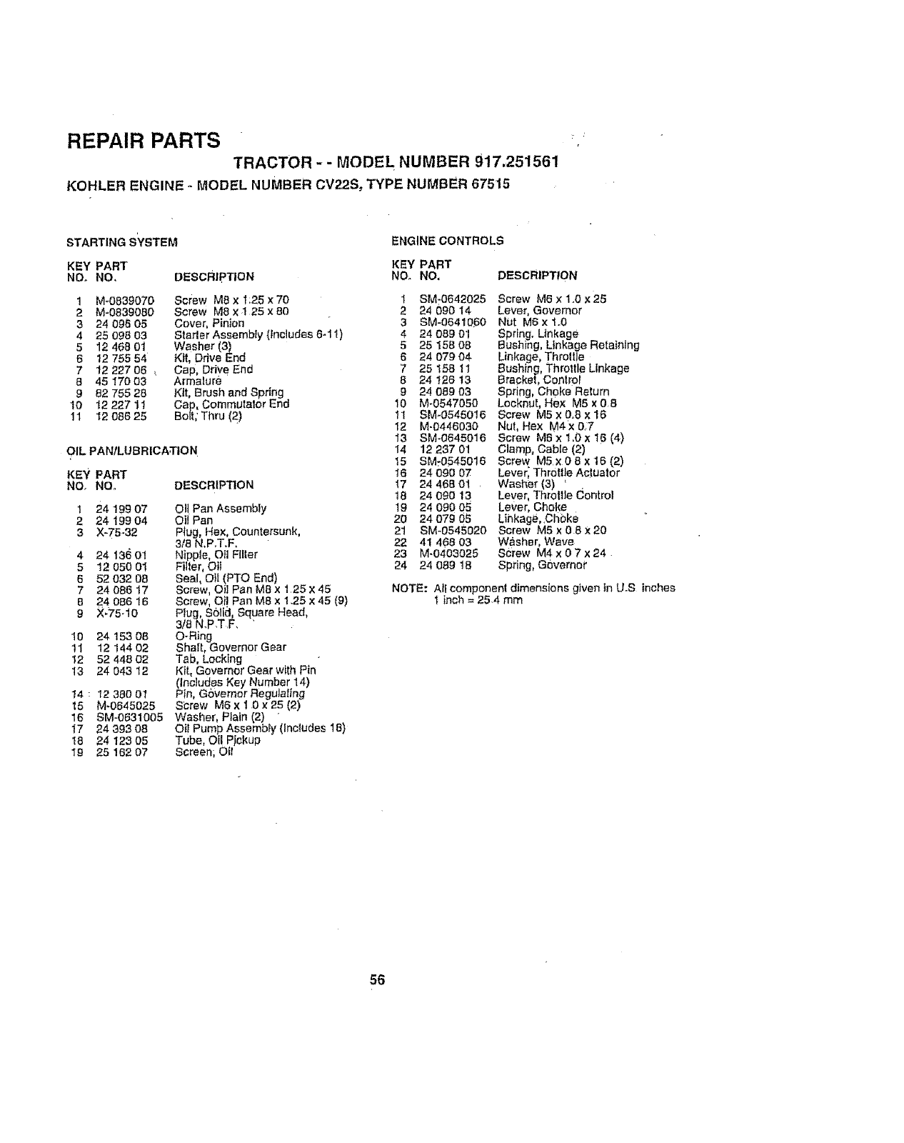
REPAIR PARTS
TRACTOR -- MODEL NUMBER 917.251561
KOHLER ENGINE -MODEL NUMBER CV22S: TYPE NUMBER 67515
STARTING sYsTEM ENGINE CONTROLS
KEY PART KEY PART
NOD NO, DEscRIpTION NO. NO.
1 M-0839070 Screw M8 x "r:25 x 70
2 M-0839080 Screw M8 x 1 25 x 80
324 096 05 Cover, Pinion
4 25 098 03 Statler Assembly (includes 6-11)
5 12 468 01 Washer (3)
6 12 755 54 Kit, Drive End
7 12 227 06 ,. Gap, Drive End
8 45 17003 Armalure
982 755 28 Kit, Brush and Spring
t0 12 227 11 Cap, Commutator End
11 12 086 25 Bolt, Thru (2)
OIL PANILUBRICATION
DESCRIPTION
KEY PART
NO, NO.
Ol! Pen Assembly
Oi! Pan
Plug, Hex, Countersunk,
3/8 N,P,T.F.
Nipple, Oil Filter
Filter, Oil
Seal, Oil (PTO End)
Screw, Oil Pan M8 x 125 x 45
Screw, Oil Pen M8 x 1.25 x 45 (9)
Plug, S0tlcl, Square Head,
3/8N.P.T.F. '
O-Ring
Shaft, Governor Gear
Tab, Locking
Kit, Governor Gear with Pin
(fnciudes Key Number 14)
Pin, Governor Regulating
S_rew M6 x 1 0 × 25 (2)
Washer, Plain (2) "
Oil Pump Assembly (Includes 18)
Tube, Oi! PJ_kup
Screen; Oil
I 2419907
2 24 199 04
3X-75_32
4 24 13(_01
512 050 01
6 52 032 08
7 24 086 17
8 24 086 16
9 X_75-10
10 24 153 08
11 12 144 02
12 52 448 02
13 24 043 I2
14:1235001
15 M-0645025
16 SM-0631005
17 24 393 08
I8 24 123 05
19 25 162 07
DEscRIPTION
I SM-0542025 Screw M6 x 1..0 x 25
2 24 090 14 Lever, Governor
3 SM-0641[&60 Nut M6 x 1.0
4 24 089 0! Sprtng. Linkage
5 25 158 08 Bushing, Linkage Retaining
6 24 079 04 Linkage, Throlfle
7 25 158 11 Bushing, Throttle Linkage
8 24 126 t3 Bracket, Conlro
9 24 089 03 Spring, Choke Return
10 M-0547050 Locknut, Hex M5 x 08
"_1 SM-0545016 Screw M5 x 0.8 x 16
12 M-0446030 Nut, Hex M4x 07
I3 SM-0645016 Screw M6xl,0x16(4)
14 12 237 01 Clamp, Cable (2)
!5 SM_0545016 Screw M5x08xt6(2)
16 24 090 07 Lever; Throttle Ac!uator
17 24 468 01 Washer (3) '
t8 24 0gO 13 Lever Throttle Control
19 24 090 05 Lever, Choke
20 24 079 05 Lihkage,.Ch0ke
21 SM-0545020 Screw M5 x 0 8x20
22 41 468 03 W&sher, Wave
23 M-0403025 Sciew M4 x 0 7 x 24
24 24 089 t8 Spring, Governor
NOTE: All component dimensions given in U°S inches
Iinch = 25.4 mm
56
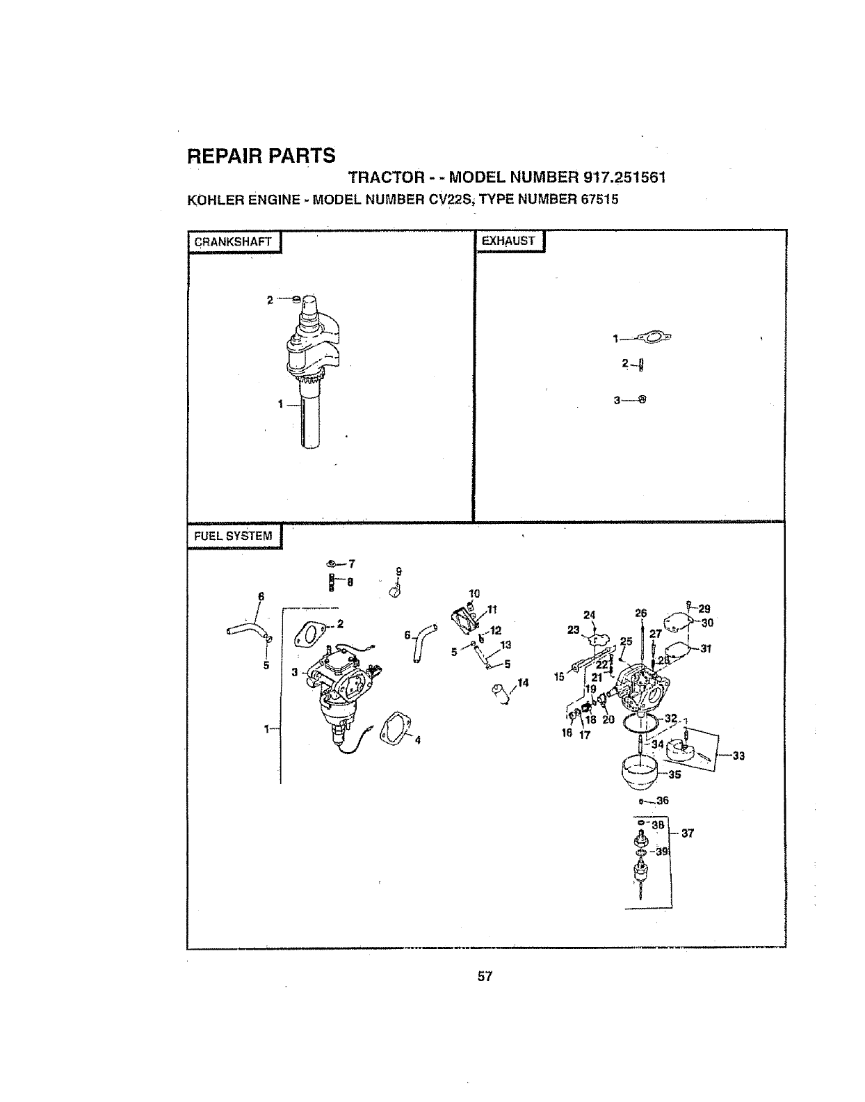
REPAIR PARTS
TRACTOR - - MODEL NUMBER 917.251561
KOHLER ENGINE -MODEL NUMBER CV22S, TYPE NUMBER 67515
€.ANKS_'_FT! EXHAUST I
3---_
iii i ,
6
s 3_
1--
_-7
i i1,,i iii i ii iiii iiiii i HIIIII IIII I'11111
9
= _' 10
_11 24 26
o_36
_t.s7
57
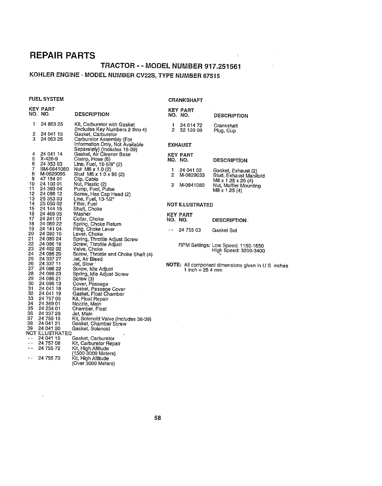
REPAIR PARTS
TRACTOR - - MODEL NUMBER 917.251561
KOHLER ENGINE- MODEL NUMBER CV22S, TYPE NUMBER 67515
FUEL SYSTEM
KEY PART
Nee NO. DESCRIP_ON
1 24 853 25 Kit, Carburetor wilh Gaskel
(Includes Key Numbers 2thru 4)
2 24 041 !5 Gasket, Carburetor
324 053 25 Carburetor Assembly (For
Information Only, Nol Available
Sep_ralely) (Includes 15-39)
4 24 041 14 Gaskel, Air Cleaner Base
5 X-426-9 Clamp, Hose (6}
6 24 353 03 Llne_ Fuel_ 10,5/8" (2)
7 SM-0641060 Nul M6 x t.0 (2)
8 M=0629095 Stud M6 x 1 0 x 95 (2)
9 47 154 01 Clip, Cable
10 24 t00 01 Nut, Plastic (2)
11 24 393 04 Pump, Fuel, Putse
12 24 088 12 Screw, Hex Cap Hf_ad (2)
'13 25 353 03 Line, Fuel, 13-1/2
14 25 050 02 Filler, Fuel
15 24 144 15 Shaft, Choke
18 24 468 05 Washer
17 24 241 01 Collar, Choke
18 24 089 22 Spring, Choke Return
19 24 141 04 Ring, Choke Lever
20 24 0g0 10 Levei', Choke
21 24 089 24 Spring, Throttle Ad)ust Screw
22 24 086 19 Screw, Throttle Adjust
23 24 462 02 Valve, Choke
24 24 086 20 Screw, Throttle and Choke Shaft (4)
25 24 337 27 .Jet, Air Bleed
26 24 337 11 Jet, Slow '
27 24 086 22 Screw, Idle Adjust
28 24 089 23 Spdng,.Idle Adjust Screw
29 24 086 21 Screw (3)
30 24 096 !3 Cover, Passage
31 24 041 18 Gasket, Passage Cover
32 24 041 19 Gasket, Float Chamber
33 24 757 05 Kit, Ftoat Repair .
34 24 369 0! Nozzle, Math
35 24 234 01 Chamber, F_oat
36 24 33728 Jet, Main
37 24 755 15 Kit, Solenoid Valve (Includes 36_39)
38 24 041 21 Gaskel, Chamber Screw
39 24 041 20 Gasket, Solenoid
NOT ILLUSTRATED
-- 24 04I 15 Gasket, Carburetor
-24 757 O0 Kit, Carburetor Repair
- - 24 755 72 Kit, High Altitude
(!500"3000 Meters)
-- 24 755 73 Kit, High Attitude
(O_'er 3000 Meters)
CRANKSHAFT
KEY PART
NO. NO, DESCRIPTION
1 24 014 72 Crankshaft
252 139 09 Piug, Cup
EXHAUST
KEY PART
NO, Nee DESCR|PTION
1 24 041 02 Gasket, Exhaust (2)
2M-0B29033 Stud, Exhaust Manifold
M8 x 1.25 x20 (4)
3 M-0841080 Nut, Muffler Mounting
M8x 1,25(4)
NOTILLUSTRATED
KEY PART
NO. NOr DESCRtPTIONI
*- 2475503 GasketSe!
RPM Settings: Low _peed: 1t50-1650
High Speed: 3200-3400
NOTE: Alt component dimensions gtven tn U S inches
1 inch = 254 mm
58
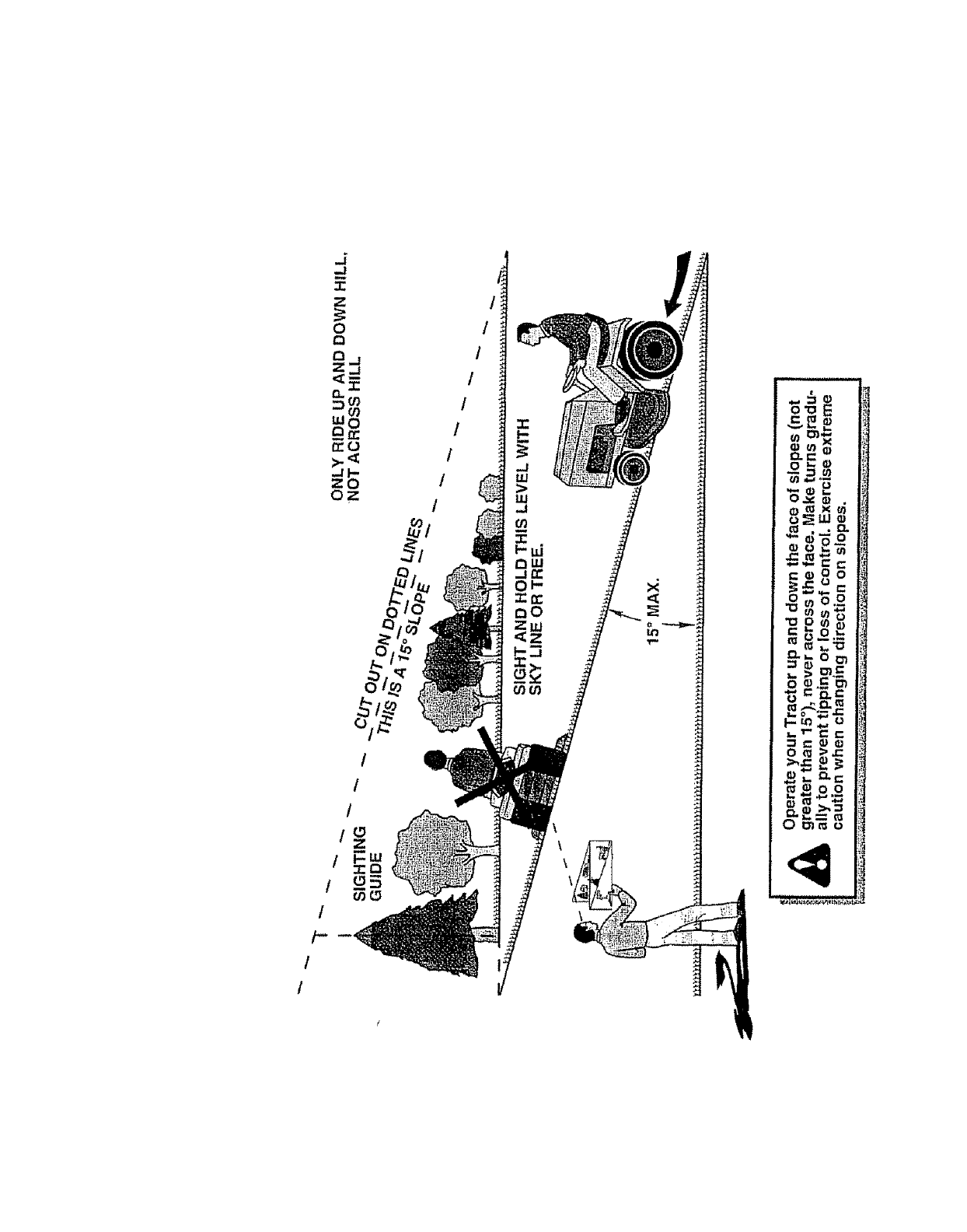
I
t
/
f
I-
!
o'o E
_ _ua
o _'_
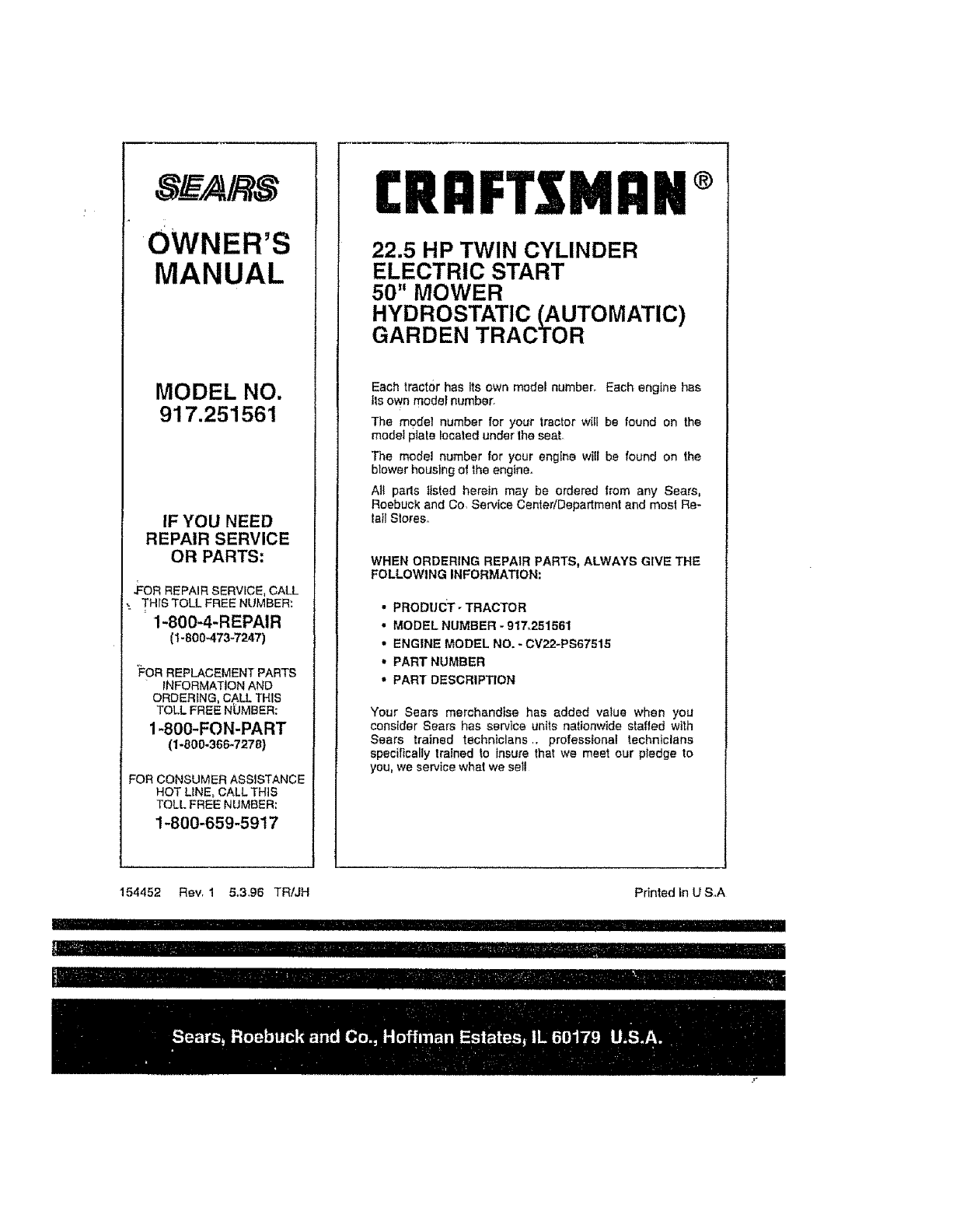
OWNER'S
MANUAL
MODEL NO.
917.251561
IF YOU NEED
REPAIR SERVICE
OR PARTS:
.FoR REPAIR SERVICE, CALL
-. THrSTOLL FREE NUMBER:
1-800-4-REPAIR
(t-800"473-7247)
'FOR REPLACEMENT PARTS
iNFORMATiON AND
ORDERING, CALL THIS
TOLL FREE NbMBER:
1-800-FON-PART
(1-800-366-7278)
FOR CONSUMER ASSISTANCE
HOT UNE, CALL THiS
TOLL FREE NUMBER:
1-800-659-5917
£RRFTXMRN®
22.5 HP TWIN CYLINDER
ELECTRIC START
50" MOWER
HYDROSTATIC (AUTOMATIC)
GARDEN TRACTOR
Each tractor has Its own model number, Each engine has
tie own model number°
The model number for your tractor w{II be found on the
model plate Iocaled under Ihe seal
The model number for your eng[ne wi{l be found on the
blower housing of the engine.
All pads listed herein may be ordered from any Sears,
Roebuck and Co, Service CentedDepartment and moel Re-
tail Stores,
WHEN ORDERING REPAIR PARTS, ALWAYS GIVE THE
FOLLOWING INFORMATION:
•PRODUCT- TRACTOR
• MODEL NUMBER -917.251561
•ENGINE MODEL NO. *CV22-PS67515
• PART NUMBER
•PART DESCRIPTION
Your Sears merchandise has added value when you
consider Sears has service units nationwide staffed with
Sears trained technicians ,, professional technicians
specifically trained to insure that we meet our p_edge to
you, we service what we set!
154452 ReVr 1 5,3,96 TR/JH
Ill I .................
IllllllNIIIIIl!IIIIIII
Printed in U S,,A
Illlll III III II1'1IIII I II
IIIIIIIIrllllllll I iii1'11111 iiiiii
